Embed Size (px)
Citation preview

CITY OF MURRAY FIRE DEPARTMENT
Eric Pologruto – Fire Chief
INVITATION TO BID The City of Murray Fire Department will receive sealed bids for a new custom
aerial fire apparatus. Specifications are available at the City of Murray Fire Department Administration Office located at 207 South 5th St., Murray, Ky 42071
or on the City of Murray's website at www.murrayky.gov. Sealed bids must be clearly marked "Bid-Ladder Truck” on the outside of the envelope and delivered to the City of Murray Fire Department Administration Office by 1:00 p.m. local time on Wednesday, August 7th, 2013. Questions regarding the bid can be directed to Eric Pologruto at 270-762-0320. The City of Murray reserves the right to waive
informalities and to reject any and all bids.
City of Murray Kentucky Fire Department Aerial Specifications
2 of 126
TABLE OF CONTENTS
Section 1 – General 2 – Liability/Insurance/Bonds 3 – Chassis 4 – Engine 5 – Transmission 6 – Driveshaft/Steering 7 – Cab 8 – Electrical System 9 – Exterior Lighting – DOT Lighting 9A – Non-Emergency Exterior Lighting – Chassis & Body 9B – Non-Emergency Exterior Lighting – Aerial Ladder 10 – Water Tank 11 – Hose Bed 12 – Truck Bed 13 – Compartmentation 14 – Ground Ladder/Equipment Storage Tunnel 15 – Pump/Pump Accessories/Plumbing/Pump Panel 16 – Four Section Aluminum Aerial Ladder 17 – Emergency Audible/Lighting Warning Devices 18 – Paint 19 – Reflective Tape 20 – Service Manuals 21 – Warranties 22 – Certifications and Testing 23 – Loose Equipment 24 – Mounted Equipment 25 – Exceptions 26 – Payment Terms 27 – Bidder Questionnaire 28 – Bid Submission Summary
City of Murray Kentucky Fire Department Aerial Specifications
3 of 126
SECTION 1 – GENERAL The framework of this document has been developed using specifications for a stock Pierce Manufacturing Inc. aerial ladder truck. This is not meant to limit other manufacturer’s ability to submit a bid. Consideration will be given to all bids regardless of the vehicle manufacturer. Bids are requested for one custom fire aerial ladder apparatus, with a full tilt cab. The manufacturer, who is awarded the bid, shall meet with a Fire Department representative to review the apparatus, attached equipment, and loose equipment specifications, to ensure the specifications (model numbers, sizes, etc.) are the most appropriate, as to ensure the completed apparatus functions at the most appropriate performance levels. 1-1 Intent The apparatus shall comply with all Federal, State, I.C.C. and D.O.T. regulations, standards, and laws relating to commercial vehicles as well as to fire apparatus. The unit shall be able to pass a Kentucky, Ohio and Tennessee state motor vehicle inspection for commercial vehicles. Any error, omission, or inconsistency that is identified by the bidder shall be listed as such in the exceptions, and a proposal to meet the intent of the specifications shall be listed. Bids shall only be considered from companies that have an established reputation in the field of fire apparatus construction. Further, bidder shall maintain dedicated service facilities for the repair and service of products. Evidence of such a facility shall be included in bidder proposal.
Each bid shall be accompanied by a detailed set of Contractor's Specifications consisting of a detailed description of the apparatus and equipment proposed, and to which the apparatus furnished under contract shall conform. These specifications shall indicate size, type, model and make of all component parts and equipment.
1-2 Bid Requirements Bidders shall also clearly indicate any item that does not meet the specification of this bid. All exceptions must be fully explained in Section 25. Any exceptions not taken shall be assumed by the purchaser to be included in the proposal, regardless of the cost to the bidder.
Bid responses and the “Bidder Questionnaire” shall be responded to in their entirety.
1-3 NFPA Standards This apparatus and associated equipment shall comply with the most current applicable NFPA standards. Any specifications that differ from NFPA specifications shall be indicated in the proposal as "non-NFPA" in Section 25. Any parts/equipment not included in this document, that are required by NFPA shall be included in Section 25 by the bidder. Some items in the specifications may exceed NFPA standards. If these higher standards are not met, the bidder shall list them in Section 25.
City of Murray Kentucky Fire Department Aerial Specifications
4 of 126
Certification of slip resistance of all stepping, standing and walking surfaces shall be supplied with delivery of the apparatus.
A plate that is highly visible to the driver while seated shall be provided. This plate shall show the overall height, length, and gross vehicle weight rating.
The manufacturer shall have programs in place for training, proficiency testing and performance for any staff involved with certifications.
An official of the company shall designate, in writing, who is qualified to witness and certify test results.
1-4 General Construction The apparatus shall be designed with due consideration to distribution of load between the front and rear axles. Weight balance and distribution shall be in accordance with the recommendations of the National Fire Protection Association. The overall apparatus length shall not exceed 503”. The apparatus height shall not exceed 147”. The apparatus width shall not exceed 118”. The maximum wheel base shall not exceed 246”. These maximum measurements shall include the apparatus (no water in booster tank), the aerial ladder, mirrors and installed equipment.
1-5 Quality and Workmanship The design of the apparatus shall embody the latest approved automotive engineering practices. Special consideration shall be given to the following points: Accessibility of the various units which require periodic maintenance; ease of operation (including both pumping and driving); and symmetrical proportions. Construction shall be rugged and ample safety factors shall be provided to carry the loads specified and to meet both on and off road requirements and speed conditions as set forth under Performance Tests and Requirements. Welding shall not be employed in the assembly of the apparatus in a manner that shall prevent the ready removal of any component part for service or repair. All steel welding shall follow American Welding Society D1.1-2004 recommendations for structural steel welding. All aluminum welding shall follow American Welding Society and ANSI D1.2-2003 requirements for structural welding of aluminum. All sheet metal welding shall follow American Welding Society B2.1-2000 requirements for structural welding of sheet metal. Flux core arc welding to use alloy rods, type 7000, American Welding Society standards A5.20-E70T1. Employees classified as welders are tested and certified to meet American Welding Society codes upon hire and every three (3) years thereafter. The manufacturer shall be required to have an American Welding Society certified welding inspector in plant during working hours to monitor weld quality.
1-6 ISO Compliance The manufacturer shall operate a Quality Management System under the requirements of ISO 9001. These standards sponsored by the International Organization for Standardization (ISO) specify the quality systems that shall be established by the manufacturer for design, manufacture, installation and service. A copy of the certificate of compliance shall be included with the bid.
1-7 Single Source Manufacturer Bids shall only be accepted from a single source apparatus manufacturer. The definition of single source is a manufacturer that designs and manufactures their products using an integrated approach, including the chassis, cab and body being fabricated and assembled on the bidder's
City of Murray Kentucky Fire Department Aerial Specifications
5 of 126
premises. The warranties relative to the chassis and body design (excluding component warranties such as engine, transmission, axles, pump, etc.) must be from a single source manufacturer and not split between manufacturers (i.e. body and chassis). The bidder shall provide evidence that they comply with this requirement.
1-8 Approval Drawing A drawing of the proposed apparatus shall be provided for approval before construction begins. The sales representative shall also have a copy of the same drawing. This drawing shall indicate the chassis make and model, location of the lights, siren, horns, compartments, major components, etc.
1-9 Electrical Wiring Diagrams Two (2) electrical wiring diagrams, prepared for the model of chassis and body, shall be provided.
1-10 Loose Equipment The manufacturer shall provide loose equipment in accordance with the current edition of NFPA 1901 standards. 1-11 Mandatory and Optional Work/Equipment All items listed in the specifications are to be considered minimum. Equipment/options included in Sections 23 and 24 shall be considered optional which the fire department may choose to include. The Fire Department has the right to adjust the quantity of this equipment/options. Bidders shall submit the cost of each optional piece of equipment. The Fire Department may choose to include all, none, or a portion of the equipment when considering the bid price to determine the award.
1-15 Information Required at Delivery The manufacturer shall supply at time of delivery, complete operation and maintenance manuals covering the completed apparatus as delivered. A permanent plate shall be mounted in the driver's compartment which specifies the quantity and type of fluids required including engine oil, engine coolant, transmission, pump transmission lubrication, pump primer and drive axle. Documentation provided at the time of delivery shall also include an apparatus safety video, in DVD format. This video shall address key safety considerations for personnel to follow when they are driving, operating, and maintaining the apparatus. Safety procedures for the following shall be included: vehicle pre-trip inspection, chassis operation, pump operation, aerial ladder operation and maintenance. 1-16 The Right to Reject Bids The City of Murray reserves the right to reject any and all bids received and accept any bid that, in its judgment, best serves the interest of the township. 1-17 Acceptance The finished apparatus will be inspected upon delivery for compliance with specifications, proof of required tests, inspections, change orders, and previously authorized exceptions. Deviations will not be tolerated and will be cause for rejection of apparatus. Equipment items not delivered at the time of the delivery or not in conformance with the proposal will be cause for the City of Murray to withhold payment until delivery is complete and acceptable.
City of Murray Kentucky Fire Department Aerial Specifications
6 of 126
1-18 Training On initial delivery of the fire apparatus, the contractor shall supply a qualified representative to demonstrate the apparatus and provide initial instruction to fire department personnel regarding the operation, care, and maintenance of the apparatus. These training sessions shall be administered to three separate shifts of firefighting personnel. Firefighters work a 24 hour on, 48 hour off schedule. The manufacturer shall include complimentary training for one (1) individual to the below three classes developed by the manufacturer. Classes shall be a minimum of two days each. Travel and lodging costs shall be paid for by the City of Murray.
• Basic Chassis Electrical • Advanced Multi-plex Systems • Independent Front Suspension
City of Murray Kentucky Fire Department Aerial Specifications
7 of 126
SECTION 2 - LIABILITY/INSURANCES/BONDS
2-1 Liability The successful bidder shall defend any and all suits and assume all liability for the use of any patented process including any device or article forming a part of the apparatus or any appliance furnished under the contract.
2-2 Commercial General Liability Insurance
The successful bidder shall, during the performance of the contract and for three (3) years following acceptance of the product, keep in force at least the following minimum limits of commercial general liability insurance:
Each Occurrence: $1,000,000
Products/Completed Operations Aggregate: $1,000,000
Personal and Advertising Injury: $1,000,000
General Aggregate: $5,000,000
Coverage shall be written on a Commercial General Liability form. The policy shall be written on an occurrence form and shall include Contractual Liability coverage for bodily injury and property damage subject to the terms and conditions of the policy. The policy shall include Owner as an additional insured when required by written contract.
2-3 Commercial Automobile Liability Insurance The successful bidder shall, during the performance of the contract keep in force at least the following minimum limits of commercial automobile liability insurance:
Each Accident Combined Single Limit: $1,000,000
Coverage shall be written on a Commercial Automobile liability form.
2-4 Umbrella/Excess Liability Insurance The successful bidder shall, during the performance of the contract and for three (3) years following acceptance of the product, keep in force at least the following minimum limits of umbrella liability insurance:
Aggregate: $25,000,000
Each Occurrence: $25,000,000
The umbrella policy shall be written on an occurrence basis and at a minimum provide excess to the Bidder's General Liability, Automobile Liability and Employer's Liability policies.
The required limits can be provided by one (1) or more policies provided all other insurance requirements are met.
Coverage shall be provided by a carrier(s) rated A- or better by A.M. Bests.
All policies shall provide a 30 day notice of cancellation to the named insured. The Certificate of Insurance shall provide the following cancellation clause: Should any of the above described polices be cancelled before the expiration date thereof, notice shall be delivered in accordance
City of Murray Kentucky Fire Department Aerial Specifications
8 of 126
with the policy provisions. Bidder agrees to furnish owner with a current Certificate of Insurance with the coverage’s listed above along with its bid. The certificate shall show the purchaser as certificate holder.
2-5 Bid Bond All bidders shall provide a bid bond as security for the bid in the form of a 10% bid bond to accompany their bid. This bid bond shall be issued by a Surety Company who is listed on the U.S. Treasury Departments list of acceptable sureties as published in Department Circular 570. The bid bond shall be issued by an authorized representative of the Surety Company and shall be accompanied by a certified power of attorney dated on or before the date of bid. The bid bond shall include language, which assures that the bidder/principal shall give a bond or bonds as may be specified in the bidding or contract documents, with good and sufficient surety for the faithful performance of the contract, including the Basic One (1) Year Limited Warranty, and for the prompt payment of labor and material furnished in the prosecution of the contract.
Proposals received from bidders who do not manufacture the chassis shall provide a warranty that shall be issued jointly and severally by, and signed by, both the bidder and the chassis manufacturer.
If the successful bidder does not manufacture the chassis, the bidder shall supply a warranty bond, in addition to their performance bond, along with their signed contract. This warranty bond shall guarantee all terms and conditions of the Basic One (1) Year Limited Warranty and names both the bidder and chassis manufacturer as co-principals. This warranty bond shall be issued for the contract amount and shall remain in force for a term which is consistent with the term of the Basic One (1) Year Limited Warranty.
Notwithstanding any document or assertion to the contrary, any surety bond related to the sale of a vehicle shall apply only to the Basic One (1) Year Limited Warranty for such vehicle. Any surety bond related to the sale of a vehicle shall not apply to any other warranties that are included within this bid (OEM or otherwise) or to the warranties (if any) of any third party of any part, component, attachment or accessory that is incorporated into or attached to the vehicle. In the event of any contradiction or inconsistency between this provision and any other document or assertion, this provision shall prevail.
2-6 Performance Bond, 1 Year The successful bidder shall furnish a Performance and Payment bond (Bond) equal to 100 percent of the total contract amount within 30 days of the notice of award. Such Bond shall be in a form acceptable to the Owner and issued by a surety company included within the Department of Treasury's Listing of Approved Sureties (Department Circular 570) with a minimum A.M. Best Financial Strength Rating of A and Size Category of XV. In the event of a bond issued by a surety of a lesser Size Category, a minimum Financial Strength rating of A+ is required.
Bidder and Bidder's surety agree that the Bond issued hereunder, whether expressly stated or not, also includes the surety's guarantee of the vehicle manufacturer's Basic One (1) Year Limited Warranty period included within this proposal. Owner agrees that the penal amount of this bond shall be simultaneously amended to 100% percent of the total contract amount upon satisfactory acceptance and delivery of the vehicle(s) included herein. Notwithstanding anything contained within this contract to the contrary, the surety's liability for any warranties of any type shall

City of Murray Kentucky Fire Department Aerial Specifications
9 of 126
not exceed one (1) year from the date of such satisfactory acceptance and delivery, or the actual Basic One (1) Year Limited Warranty period, whichever is shorter.
City of Murray Kentucky Fire Department Aerial Specifications
10 of 126
SECTION 3 – CHASSIS Chassis provided shall be a new, tilt type custom fire apparatus. The chassis shall be manufactured in the apparatus body builder's facility eliminating any split responsibility. The chassis shall be designed and manufactured for heavy duty service, with adequate strength, capacity for the intended load to be sustained, and the type of service required. The chassis shall be the manufacturer's heavy duty line tilt cab.
3-1 GVW Rating The gross vehicle weight rating shall be a minimum of 76,800 pounds.
3-2 Frame The chassis frame shall be built with two (2) steel channels bolted to five (5) cross members or more, depending on other options of the apparatus. The side rails shall have a 13.38" tall web over the front and mid sections of the chassis, with a continuous smooth taper to 10.75" over the rear axle. Each rail shall have a section modulus of 25.992 cubic inches and a resisting bending moment (rbm) of 3,119,040 in-lb over the critical regions of the frame assembly, with a section modulus of 18.96 cubic inches with an rbm of 2,275,200 in-lb over the rear axle. The frame rails shall be constructed of 120,000 psi yield strength heat-treated .38" thick steel, with 3.50" wide flanges.
3-3 Frame Reinforcement In addition, a mainframe inverted "L" liner shall be provided. It shall be heat-treated steel measuring 12.00" x 3.00" x .25". Each liner shall have a section modulus of 7.795 cubic inches, yield strength of 110,000 psi, and rbm of 857,462 in-lb. Total rbm at wheelbase center shall be 3,976,502 pounds per rail.
The frame liner shall be mounted inside of the chassis frame rail and extend the full length of the frame.
3-4 Front Non-Drive Axle The front axle shall be of the independent suspension design with a ground rating of 22,800 pounds.
Upper and lower control arms shall be used on each side of the axle. Upper control arm castings shall be made of 100,000-psi yield strength 8630 steel and the lower control arm casting shall be made of 55,000-psi yield ductile iron.
The center cross members and side plates shall be constructed out of 80,000-psi yield strength steel.
Each control arm shall be mounted to the center section using elastomeric bushings. These rubber bushings shall rotate on low friction plain bearings and be lubricated for life. Each bushing shall also have a flange end to absorb longitudinal impact loads, reducing noise and vibrations.
There shall be nine (9) grease fittings supplied, one (1) on each control arm pivot and one (1) on the steering gear extension.
The upper control arm shall be shorter than the lower arm so that wheel end geometry provides positive camber when deflected below rated load and negative camber above rated load.
City of Murray Kentucky Fire Department Aerial Specifications
11 of 126
Camber at load shall be zero degrees for optimum tire life.
The ball joint bearing shall be of low friction design and be maintenance free.
Toe links that are adjustable for alignment of the wheel to the center of the chassis shall be provided.
The wheel ends must have little to no bump steer when the chassis encounters a hole or obstacle.
The steering linkage shall provide proper steering angles for the inside and outside wheel, based on the vehicle wheelbase.
The axle shall have a third party certified turning angle of 45 degrees. Front discharge, front suction, or aluminum wheels shall not infringe on this cramp angle.
3-5 Front Suspension Front independent suspension shall be provided with a minimum ground rating of 22,800 pounds.
The independent suspension system shall be designed to provide maximum ride comfort. The design shall allow the vehicle to travel at highway speeds over improved road surfaces and at moderate speeds over rough terrain with minimal transfer of road shock and vibration to the vehicle's crew compartment.
Each wheel shall have torsion bar type spring. In addition, each front wheel end shall also have energy absorbing jounce bumpers to prevent bottoming of the suspension.
The suspension design shall be such that there is at least 10.00" of total wheel travel and a minimum of 3.75" before suspension bottoms.
The torsion bar anchor lock system allows for simple lean adjustments, without the use of shims. One can adjust for a lean within 15 minutes per side. Anchor adjustment design is such that it allows for ride height adjustment on each side.
The independent suspension shall be put through a durability test that has simulated a minimum of 140,000 miles of inner city driving.
3-6 Shock Absorbers Heavy-duty telescoping shock absorbers (KONI) shall be provided on the front suspension.
3-7 Oil Seals Oil seals with viewing window shall be provided on the front axle.
3-8 Front Tires Front tires shall be Michelin 425/65R22.50 radials, 20 ply all-position XZY3tread rated for 22,800 pound maximum axle load and 65 mph maximum speed.
The tires shall be mounted on Alcoa 22.50" x 12.25" polished aluminum disc-type wheels with a ten (10)-stud, 11.25" bolt circle.
3-9 Rear Axle The rear axle shall be a outboard drum Meritor™, Model RT-52-185, tandem axle assembly with a capacity of 54,000 pounds.
City of Murray Kentucky Fire Department Aerial Specifications
12 of 126
An inter-axle differential, which divides torque evenly between axles, shall be provided with an indicator light mounted on the cab instrument panel.
3-10 Top Speed of Vehicle A rear axle ratio shall be furnished to allow the vehicle to reach a top speed of 60 MPH.
3-11 Rear Suspension Rear suspension shall be a Neway model AD 252, air ride with a ground rating of 54,000 pounds. The suspension shall have the following features:
- Outboard vertical mounted heavy-duty shock absorbers
- Utilizes track bars and Ultra Torque Rod Plus torque rods to restrict lateral axle movement and maintain constant pinion angles
- Super heavy-duty transverse beam to help reduce axle stress while increasing roll stability or resistance to lean
- Low spring rate air springs for excellent ride quality
- Dual height control valves to maintain level vehicle from side to side
3-12 Oil Seals Oil seals shall be provided on the rear axle.
3-13 Rear Tires Rear tires shall be eight (8) Michelin 12R22.50 radials, 16 ply XDN2 all season tread, rated for 54,240 lb maximum axle load and 75 mph maximum speed.
The tires shall be mounted on Alcoa 22.50" x 8.25" polished aluminum disc wheels with a ten (10)-stud 11.25" bolt circle.
3-14 Tire Balance All tires shall be balanced with Counteract balancing beads. The beads shall be inserted into the tire and eliminate the need for wheel weights.
3-15 Tire Pressure Management There shall be a VECSAFE LED tire alert pressure management system provided that shall monitor each tire's pressure. A chrome plated brass sensor shall be provided on the valve stem of each tire for a total of 10 tires.
The sensor shall calibrate to the tire pressure when installed on the valve stem for pressures between 20 and 120 psi. The sensor shall activate an integral battery operated LED when the pressure of that tire drops eight (8) psi. Removing the cap from the sensor shall indicate the functionality of the sensor and battery. If the sensor and battery are in working condition, the LED shall immediately start blinking.
3-16 Hub Covers (Front) Stainless steel hub covers shall be provided on the front axle. An oil level viewing window shall be provided.
3-17 Hub Covers (Rear) A pair of stainless steel, high hat, hub covers shall be provided on the rear axle hubs.
City of Murray Kentucky Fire Department Aerial Specifications
13 of 126
3-18 Covers, Lug Nut, Chrome Chrome lug nut covers shall be supplied on front and rear wheels.
3-19 Mud Flaps Mud flaps shall be installed behind the front and rear wheels of the apparatus.
3-20 Wheel Chocks There shall be two (2) pairs of folding Ziamatic SAC-44-E, aluminum alloy, Quick-Choc wheel blocks with easy-grip handle provided.
3-21 Wheel Chock Brackets There shall be two (2) pairs of Ziamatic SQCH-44-H horizontal mounting wheel chock brackets provided for the Ziamatic SAC-44-E folding wheel chocks. The brackets shall be mounted; locations shall be determined at drawing approval.
3-22 Electronic Stability Control A vehicle control system shall be provided as an integral part of the ABS brake system from Meritor Wabco.
The system shall monitor and update the lateral acceleration of the vehicle and compare it to a critical threshold where a side roll event may occur. If the critical threshold is met, the vehicle control system shall automatically reduce engine RPM, engage the engine retarder (if equipped), and selectively apply brakes to the individual wheel ends of the front and rear axles to reduce the possibility of a side roll event.
The system shall monitor directional stability through a lateral accelerometer, steer angle sensor and yaw rate sensor. If spinout or drift out is detected, the vehicle control system shall selectively apply brakes to the individual wheel ends of the front and rear axles to bring the vehicle back to its intended direction.
3-23 Anti-Lock Brake System The vehicle shall be equipped with a Wabco 6S6M, anti-lock braking system. The ABS shall provide a six (6) channel anti-lock braking control on both the front and rear wheels. A digitally controlled system that utilizes microprocessor technology shall control the anti-lock braking system. Each wheel shall be monitored by the system. When any wheel begins to lockup, a signal shall be sent to the control unit.
This control unit shall then reduce the braking of that wheel for a fraction of a second and then reapply the brake. This anti-lock brake system shall eliminate the lockup of any wheel thus helping to prevent the apparatus from skidding out of control.
3-24 Automatic Traction Control An anti-slip feature shall be included with the ABS. The Automatic Traction Control shall be used for traction in poor road and weather conditions. The Automatic Traction Control shall act as an electronic differential lock that shall not allow a driving wheel to spin, thereby supplying traction at all times. The ABS electronic control unit (ECU) shall work with the engine ECU, sharing information concerning wheel slip. Engine ECU shall use information to control engine speed, allowing only as much throttle application as required for the available traction, regardless of how much the driver is asking for. A "mud/snow" switch shall be provided on the instrument
City of Murray Kentucky Fire Department Aerial Specifications
14 of 126
panel. Activation of the switch shall allow additional tire slip to let the truck climb out and get on top of deep snow or mud.
3-25 Brakes The service brake system shall be full air type.
The front brakes shall be Knorr/Bendix disc type with a 17.00" ventilated rotor for improved stopping distance.
The brake system shall be certified, third party inspected, for improved stopping distance.
The rear brakes shall be Meritor™ 16.50" x 7.00" cam operated with automatic slack adjusters. Dust shields shall be provided.
3-26 Air Compressor, Brake System The air compressor shall be a Bendix BA-921 with 15.80 cubic feet per minute output at 1,250 RPM.
3-27 Brake System The brake system shall include:
- Bendix dual brake treadle valve with vinyl covered foot surface
- Heated automatic moisture ejector on air dryer
- Total air system capacity of 6,653 cubic inches
- Two (2) air pressure gauges with a red warning light and an audible alarm, that activates when air pressure falls below 60 psi
- Spring set parking brake system
- Parking brake operated by a push-pull style control valve
- A parking "brake on" indicator light on instrument panel
- Park brake relay/inversion and anti-compounding valve, in conjunction with a double check valve system, shall be provided with an automatic spring brake application at 40 psi
The air tank shall be primed and painted to meet a minimum 750 hour salt spray test.
To reduce the effects of corrosion, the air tank shall be mounted with stainless steel brackets.
- Wabco System Saver 1200 air dryer with spin-on coalescing filter cartridge
- 100 Watt Heater
3-28 Brake Lines Color-coded nylon brake lines shall be provided. The lines shall be wrapped in a heat protective loom where necessary in the chassis.
3-29 Air Inlet One (1) air inlet with male coupling shall be provided. It shall allow station air to be supplied to the apparatus brake system through a shoreline hose. The inlet shall be located in the driver’s side lower step well of the cab. A check valve shall be provided to prevent reverse flow of air.
City of Murray Kentucky Fire Department Aerial Specifications
15 of 126
The inlet shall discharge into the "wet" tank of the brake system. A mating female coupling shall also be provided with the loose equipment.
3-30 All Wheel Lock-up An additional all wheel lock-up system shall be installed which applies air to the front brakes only. The standard spring brake control valve system shall be used for the rear.
3-31 Bumper A one (1)-piece, ten (10) gauge, 304-2B type polished stainless steel bumper, a minimum of 10.00" high, shall be attached to a bolted modular extension frame constructed of 50,000 psi tensile steel C channel mounted directly behind it to provide adequate support strength.
The bumper shall be extended 19.00" from front face of cab.
Documentation shall be provided, upon request to show that the options selected have been engineered for fit-up and approval for this modular bumper extension. A chart shall be provided to indicate the option locations and shall include, but not be limited to the following options: air horns, mechanical sirens, speakers, hose trays (with hose capacities), winches, lights, discharge, and suction connections.
3-32 Hose Tray A hose tray, constructed of aluminum, shall be placed in the center of the bumper extension.
The tray shall have a capacity of 150' of 1.75" double jacket cotton-polyester hose.
Black rubber grating shall be provided at the bottom of the tray. Drain holes are also provided.
3-33 Cover, Hose Tray A bright aluminum treadplate cover shall be provided over the hose tray.
The cover shall be attached with a stainless steel hinge and located center.
A lift and turn latch shall secure the cover in the closed position and a mechanical stay arm shall hold the cover in the open position.
3-34 Gravel Pan A gravel pan, constructed of bright aluminum treadplate, shall be furnished between the bumper and cab face. The gravel pan shall be properly supported from the underside to prevent flexing and vibration of the aluminum treadplate.
3-35 Lift and Tow Mounts Mounted to the frame extension shall be lift and tow mounts. The lift and tow mounts shall be designed and positioned to adapt to certain tow truck lift systems.
The lift and tow mounts with eyes shall be painted the same color as the frame.
3-26 Tire Chains A set of Onspot Automatic Tire Chains shall be installed near the rear of the apparatus.
City of Murray Kentucky Fire Department Aerial Specifications
16 of 126
SECTION 4 – ENGINE
4-1 Engine The chassis shall be powered by an electronically controlled engine as described below:
Make: Detroit Diesel
Model: DD13
Power: 500 hp @ 1800 rpm
Torque: 1650 lb-ft at 1200 rpm
Governed Speed: 2080 rpm
Emissions Level: EPA 2013
Fuel: Diesel
Cylinders: Six (6)
Displacement: 781 cubic inches (12.8L)
Starter: Delco 39MT
Fuel Filters: Dual cartridge style with check valve, water separator, and water in fuel sensor
Coolant Filter: Cartridge style with shut off valves on the supply and return line.
The engine shall include On-board diagnostics (OBD), which provides self diagnostic and reporting. The system shall give the owner or repair technician access to state of health information for various vehicle sub systems.
The system shall monitor vehicle systems, engine and after treatment. The system shall illuminate a malfunction indicator light on the dash console if a problem is detected.
4-2 High Idle A high idle switch shall be provided, inside the cab, on the instrument panel, that shall automatically maintain a preset engine rpm. A switch shall be installed, at the cab instrument panel, for activation/deactivation.
The high idle shall be operational only when the parking brake is on and the truck transmission is in neutral. A green indicator light shall be provided, adjacent to the switch. The light shall illuminate when the above conditions are met. The light shall be labeled "OK to Engage High Idle."
4-3 Engine Brake A Jacobs’s engine brake is to be installed with the controls located on the instrument panel within easy reach of the driver.
The driver shall be able to turn the engine brake system on/off and have a high and medium setting.
The engine brake shall be installed in such a manner that when the engine brake is slowing the vehicle the brake lights are activated.
City of Murray Kentucky Fire Department Aerial Specifications
17 of 126
The ABS system shall automatically disengage the auxiliary braking device when required.
4-4 Clutch Fan A Horton fan clutch shall be provided. The fan clutch shall be automatic when the pump transmission is in "Road" position, and fully engaged in "Pump" position.
4-5 Engine Air Intake The air intake with an ember separator shall be mounted high on the passenger side of the cab, to the front of the crew cab door. The ember separator is designed to prevent road dirt and re-circulating hot air from entering the engine.
The ember separator shall be easily accessible through a hinged stainless steel grille, with one (1) flush quarter turn latch.
4-6 Exhaust System The exhaust system shall include a diesel particulate filter (DPF) and a selective catalytic reduction (SCR) device to meet current EPA standards. The exhaust system shall be stainless steel from the turbo to the inlet of the SCR device and shall be 5.00" in diameter. An insulation wrap shall be provided on all exhaust pipe between the turbo and SCR to minimize the transfer of heat to the cab. The exhaust shall terminate horizontally ahead of the passenger side rear wheels. A tailpipe diffuser shall be provided to reduce the temperature of the exhaust as it exits. Heat deflector shields shall be provided to isolate chassis and body components from the heat of the tailpipe diffuser.
4-7 Radiator The radiator and the complete cooling system shall meet or exceed NFPA and engine manufacturer cooling system standards.
For maximum cooling performance, the radiator core shall be made of copper fins having a serpentine design, soldered to brass tubes. The tubes shall be welded to brass headers using the patented Beta-Weld process for increased strength, longer road life and solder bloom corrosion protection. The radiator core shall have a minimum frontal area of 1396 square inches. Steel supply and return tanks shall be bolted to the core headers and steel side channels to complete the radiator assembly. The radiator shall be compatible with commercial antifreeze solutions.
The radiator shall be mounted in such a manner as to prevent the development of leaks caused by twisting or straining when the apparatus operates over uneven ground. The radiator assembly shall be isolated from the chassis frame rails with rubber isolators.
The radiator shall include an integral deaeration tank, with a remote-mounted overflow tank. For visual coolant level inspection, the radiator shall have a built-in sight glass. The radiator shall be equipped with a 15 psi pressure relief cap.
A drain port shall be located at the lowest point of the cooling system and/or the bottom of the radiator to permit complete flushing of the coolant from the system.
A heavy-duty fan shall draw in fresh, cool air through the radiator. Shields or baffles shall be provided to prevent recirculation of hot air to the inlet side of the radiator.
City of Murray Kentucky Fire Department Aerial Specifications
18 of 126
4-8 Coolant Lines Silicone hoses shall be used for all engine/heater coolant lines installed by the chassis manufacturer.
Hose clamps shall be stainless steel constant torque type to prevent coolant leakage. They shall react to temperature changes in the cooling system and expand or contract accordingly while maintaining a constant clamping pressure on the hose.
4-9 Fuel Tank A 65-gallon fuel tank shall be provided and mounted at the rear of the chassis. The tank shall be constructed of 12-gauge, hot rolled steel. It shall be equipped with swash partitions and a vent. To eliminate the effects of corrosion, the fuel tank shall be mounted with stainless steel straps.
A .75" drain plug shall be provided in a low point of the tank for drainage.
A fill inlet shall be located on the left hand side of the body and be covered with a hinged, spring loaded, stainless steel door that is marked "Ultra Low Sulfur - Diesel Fuel Only."
A .50" diameter vent shall be provided running from top of tank to just below fuel fill inlet.
The tank shall meet all FHWA 393.67 requirements including a fill capacity of 95 percent of tank volume.
All fuel lines shall be provided as recommended by the engine manufacturer.
4-10 Diesel Exhaust Fluid Tank A 4.5 gallon diesel exhaust fluid (DEF) tank shall be provided and mounted in the driver's side body forward of the rear axle.
The tank shall be constructed of 16-gauge type 304- L stainless steel.
A .50" drain plug shall be provided in a low point of the tank for drainage.
A fill inlet shall be located on the driver's side of the body and be covered with a hinged, spring loaded, stainless steel door that is marked "Diesel Exhaust Fluid Only".
The tank shall meet the engine manufacturer’s requirement for 10 percent expansion space in the event of tank freezing.
The tank shall include an integrated heater unit that utilizes engine coolant to thaw the DEF in the event of freezing.
4-11 Fuel Cooler An air to fuel cooler shall be installed in the engine fuel return line.
City of Murray Kentucky Fire Department Aerial Specifications
19 of 126
SECTION 5 – TRANSMISSION
5-1 Transmission An Allison Gen IV, model EVS 4000P, electronic, torque converting, automatic transmission shall be provided.
The transmission shall be equipped with prognostics to monitor oil life, filter life, and transmission health. A wrench icon on the shift selector's digital display shall indicate when service is due.
Two (2) PTO openings shall be located on left side and top of converter housing (positions 8 o'clock and 1 o'clock).
A transmission temperature gauge with red light and buzzer shall be installed on the cab instrument panel.
5-2 Transmission Shifter A six (6)-speed push button shift module shall be mounted to right of driver on console. Shift position indicator shall be indirectly lit for after dark operation.
The transmission ratio shall be 1st - 3.51 to 1.00, 2nd - 1.91 to 1.00, 3rd - 1.43 to 1.00, 4th - 1.00 to 1.00, 5th - 0.75 to 1.00, 6th - 0.64 to 1.00, R - 4.80 to 1.00.
5-3 Transmission Cooler A transmission oil cooler shall be provided that is integral to the radiator and located at the bottom of the radiator. The cooler shall use engine coolant to control the transmission oil temperature.
City of Murray Kentucky Fire Department Aerial Specifications
20 of 126
SECTION 6 – DRIVE SHAFT/STEERING
6-1 Driveline Drivelines shall be a heavy-duty metal tube and be equipped with Spicer 1810 universal joints.
The shafts shall be dynamically balanced before installation.
A splined slip joint shall be provided in each driveshaft, slip joint shall be coated with Glide coat or equivalent.
6-2 Steering Dual Sheppard M110 steering gears, with integral heavy-duty power steering, shall be provided. For reduced system temperatures, the power steering shall incorporate an air to oil cooler and an Eaton model VN20F hydraulic pump with integral pressure and flow control. All power steering lines shall have wire braded lines with crimped fittings.
A tilt and telescopic steering column shall be provided to improve fit for a broader range of driver configurations.
6-3 Steering Wheel The steering wheel shall be 18.00" in diameter have tilting and telescoping capabilities, and a four (4)-spoke design.
City of Murray Kentucky Fire Department Aerial Specifications
21 of 126
SECTION 7 – CAB
7-1 Cab The cab shall be designed specifically for the fire service and shall be manufactured by the chassis builder.
Construction of the cab shall consist of 5052-H32 .125" aluminum welded to extruded aluminum framing.
The cab shall be built by the apparatus manufacturer in a facility located on the manufacturer's premises.
The outboard crew cab positions shall have a 12” raised roof.
The crew cab shall be of the totally enclosed design with access doors constructed in the same manner as the driver and passenger doors.
The cab shall be a full tilt cab style. The engine shall be easily accessible and capable of being removed with the cab tilted. The cab shall be capable of tilting 45 degrees and 90 degrees with crane assist.
The cab shall have a three (3)-point rubber mounting and shall be tilted by a hydraulic pump connected to two (2) cab lift cylinders. The cab shall then be locked down by a two (2)-point automatic locking mechanism that actuates after the cab has been lowered.
7-2 Interior Cab Insulation The cab shall include 1.50" insulation in the ceiling and side walls, and 2.00" insulation in the rear wall to maximize acoustic absorption and thermal insulation.
7-3 Engine Tunnel Engine hood side walls shall be constructed of .50" aluminum. The top shall be constructed of .19" aluminum and shall be tapered at the top to allow for more driver and passenger elbow room.
The engine hood shall be insulated for protection from heat and sound. The noise insulation keeps the DBA level within the limits stated in the current NFPA series 1900 pamphlet.
7-4 Fender Liners Full circular inner fender liners in the wheel wells shall be provided.
7-5 Windshield A curved safety glass windshield shall be provided with over 2,754 square inches of clear viewing area. The cab windshield shall have bright trim inserts in the rubber molding holding the glass in place. Economical windshield replacement glass shall be readily available from local auto glass suppliers.
All cab glass shall be tinted.
7-6 Sun Visors Two (2) smoked Lexan sunvisors, 8.75" x 31.00" long, shall be provided. The sunvisors shall be located above the windshield with one (1) mounted on each side of the cab.
City of Murray Kentucky Fire Department Aerial Specifications
22 of 126
7-7 Windshield Wipers Two (2) electric windshield wipers with washer shall be provided that meet FMVSS and SAE requirements.
The washer reservoir shall be able to be filled without raising the cab.
7-7A Glove Box A glove box with a drop-down door shall be installed in the front dash panel in front of the officer position.
7-8 Cab Rear Wall Exterior Covering The exterior surface of the rear wall of the cab shall be overlaid with bright aluminum treadplate except for areas that are not typically visible when the cab is lowered.
7-9 Cab Lift A hydraulic cab lift system shall be provided consisting of an electric powered hydraulic pump, dual lift cylinders, and necessary hoses and valves.
The hydraulic pump shall have a manual override for backup in the event of electrical failure.
Lift controls shall be on a panel located on the officer side pump panel or front area of the body in a convenient location.
Cab shall be locked down by a two (2)-point automatic spring-loaded hook mechanism that actuates after the cab has been lowered.
The hydraulic cylinders shall be equipped with a velocity fuse that protects the cab from accidentally descending when the control is located in the tilt position.
For increased safety, a redundant mechanical stay arm shall be provided that must be manually put in place on the driver side between the chassis and cab frame when the cab is in the raised position. This device shall be manually stowed to its original position before the cab can be lowered.
7-10 Interlock, Cab Lift to Parking Brake The cab lift system shall be interlocked to the parking brake. The cab tilt mechanism shall be active only when the parking brake is set and the ignition switch is in the on position. If the parking brake is released the cab tilt mechanism shall be disabled.
7-11 Trim Band (Cab Face) A 10.00" band of 22 gauge pattern finish stainless steel trim is to be installed across the front of the cab, from door hinge to door hinge. The trim band shall be centered at the headlight height, and applied with two-sided tape. A 0.625" self adhesive trim strip shall be applied around the perimeter of the trim band.
7-12 Molding (On Sides of Cab) Chrome molding shall be provided on both sides of cab.
7-13 Mirrors One (1) Ramco, Model 6000FFHR-750, polished aluminum mirror shall be mounted on each of the cab doors. The mirrors shall be 9.25" x 13.50", with a full flat face. An additional convex
City of Murray Kentucky Fire Department Aerial Specifications
23 of 126
section shall be bolted to the top of each mirror. The mirror head shall have a highly polished aluminum finish.
The flat glass in each mirror shall be heated and adjustable, with remote controls that are convenient to the driver.
The convex section in each mirror shall be adjusted manually.
7-14 Doors The doors shall be full height design.
The forward cab and crew cab doors shall be constructed of extruded aluminum with a nominal material thickness of .125". The exterior door skins shall be constructed from .090" aluminum.
A flush mounted, chrome plated paddle type door handle shall be provided on the exterior of each cab door. Each door shall also be provided with an interior flush paddle handle.
The cab doors shall be provided with both interior (rotary knob) and exterior (keyed) locks as required by FMVSS 206. The locks shall be capable of activating when the doors are open or closed. The doors shall remain locked if locks are activated when the doors are opened, then closed.
A full length, heavy duty, stainless steel, piano-type hinge with a .38" pin and 11 gauge leaf shall be provided on all cab doors. There shall be double automotive-type rubber seals around the perimeter of the door framing and door edges to ensure a weather-tight fit.
A chrome handrail shall be provided on the inside of each front cab door, for ease of entry.
The cab steps at each cab door location shall be located inside the cab doors to protect the steps from weather elements.
7-15 Door Panels There shall be a full height brushed stainless steel door panel installed on the inside of all cab doors. The cab door panels shall be removable without disconnecting door and window mechanisms.
7-16 Manual Cab Door Windows All cab entry doors shall contain a conventional roll down window.
7-17 Cab Steps The forward cab and crew cab access steps shall be a full size two (2) step design to provide largest possible stepping surfaces for safe ingress and egress. The bottom steps shall be designed with a grip pattern punched into bright aluminum treadplate material to provide support, slip resistance, and drainage. The bottom steps shall be a bolt-in design to minimize repair costs should they need to be replaced. The forward cab steps shall be a minimum 24.75" wide, and the crew cab steps shall be 21.25" wide with an 8.00" minimum depth. The inside cab steps shall not exceed 18.00" in height and be limited to two (2) steps. A slip-resistant handrail shall be provided adjacent to each cab door opening to assist during cab ingress and egress.
7-19 Step Lights For reduced overall maintenance costs compared to incandescent lighting, there shall be four (4) white LED, step lights provided. The lights shall be installed at each cab and crew cab door, one
City of Murray Kentucky Fire Department Aerial Specifications
24 of 126
(1) per step, in the driver side front doorstep, driver side crew cab doorstep, passenger side front doorstep and passenger side crew cab doorstep.
In order to ensure exceptional illumination, each light shall provide a minimum of 25 foot-candles (fc) covering an entire 15" x 15" square placed ten (10) inches below the light and a minimum of 1.5 fc covering an entire 30" x 30" square at the same ten (10) inch distance below the light.
The lights shall be activated when the adjacent door is opened.
7-20 Fender Crowns Stainless steel fender crowns shall be installed at the cab wheel openings. The fender crowns shall have a radius outside corner that allows the fender crown to extend beyond the side wall of the front tires and also allow the crew cab doors to open fully.
7-22 Cab Interior The cab dash fascias shall be a flat faced design to provide easy of maintenance and shall be constructed out of painted aluminum.
The engine tunnel shall be padded and covered with 46 ounce leather grain vinyl resistant to oil, grease and mildew.
The headliner shall be installed in both forward and rear cab sections. Headliner material shall be vinyl. A sound barrier shall be part of its composition. Material shall be installed on aluminum sheet and securely fastened to interior cab ceiling.
Forward portion of cab headliner shall provide easy access for servicing electrical wiring or for other maintenance needs without removing the entire unit.
7-23 Cab Interior Upholstery The cab interior upholstery shall be dark silver gray.
7-24 Interior Paint (Cab) The cab interior metal surfaces shall be painted gray, vinyl texture paint.
7-25 Cab Floor The cab and crew cab floor areas shall be covered with Polydamp™ acoustical floor mat consisting of a black pyramid rubber facing and closed cell foam decoupler.
The top surface of the material has a series of raised pyramid shapes evenly spaced, which offer a superior grip surface. Additionally, the material has a .25" thick closed cell foam (no water absorption) which offers a sound dampening material for reducing sound levels.
7-26 Cab Defroster There shall be a 41,000 BTU/hr defroster in the cab located under the engine tunnel.
The defroster ventilation shall be built into the design of the cab dash instrument panel and shall be easily removable for maintenance.
The defroster shall have a three (3)-speed blower and temperature controls accessible to the driver and officer.
City of Murray Kentucky Fire Department Aerial Specifications
25 of 126
The defroster ducts shall be designed to provide maximum defrosting capabilities for the front cab windows.
7-27 Cab/Crew Cab Heater Two (2) auxiliary heaters with 32,000 BTU/hr each shall be provided in the cab. The heaters shall have a three (3)-speed blower and temperature controls accessible to the driver and officer. There shall also be louvers located below the rear facing seat riser and below the driver and officer positions for airflow.
The heaters shall be mounted, one (1) within each rear facing seat riser.
7-28 Air Conditioning A high-performance, customized air conditioning system shall be furnished inside the cab and crew cab. A 19.1 cubic inch compressor shall be installed on the engine.
The air conditioning system shall be capable of cooling the average cab temperature from 100 degrees Fahrenheit to 75 degrees Fahrenheit at 50 percent relative humidity within 30 minutes. The cooling performance test shall be run only after the cab has been heat soaked at 100 degrees Fahrenheit for a minimum of 4 hours.
A roof-mounted condenser that meets and exceeds the performance specification shall be installed on the cab roof. Mounting the condenser below the cab or body would reduce the performance of the system and shall not be acceptable.
An evaporator unit that meets and exceeds the performance specification shall be installed in the cab, located in the center of the cab ceiling over the engine tunnel. The evaporator shall include two (2) high performance cores and plenums with multiple outlets, one plenum directed to the front and one plenum directed to the rear of the cab.
The evaporator unit shall be provided with adjustable air outlets strategically located to direct air flow to the driver, officer and crew cab area.
All hose used shall be class one (1) type to reduce moisture ingression into the air conditioning system.
The air conditioner refrigerant shall be R-134A and shall be installed by a certified technician.
The air conditioner shall be controlled by a single electronic control panel. For ease of operation, the control panel shall include variable adjustment for temperature and fan control and be conveniently located on the dash in clear view of the driver. The control panel shall include robust knobs for both fan speed and temperature adjustment.
7-29 Grab Handle A black rubber covered grab handle shall be mounted on the lower portion of the driver's side cab entrance to assist in entering the cab. The grab handle shall be securely mounted to the post area between the door and steering wheel column.
A long rubber grab handle shall be mounted on the dash board in front of the officer.
City of Murray Kentucky Fire Department Aerial Specifications
26 of 126
7-30 Engine Compartment Light An engine compartment light shall be installed under the engine hood, of which the switch is an integral part. Light shall have a .125" diameter weep hole in its lens to prevent moisture retention.
7-31 Access to Engine Dipsticks For access to the engine oil and transmission fluid dipsticks, there shall be a door on the engine tunnel, inside the crew cab. The door shall be on the rear wall of the engine tunnel, on the vertical surface. The door shall be 17.75" wide x 12.75" high and be flush with the wall of the engine tunnel.
The engine oil dipstick shall allow for checking only. The transmission dipstick shall allow for both checking and filling. An additional tube shall be provided for filling the engine oil.
The door shall have a rubber seal for thermal and acoustic insulation. One (1) flush latch shall be provided on the access door.
7-32 Seating Capacity The seating capacity in the cab shall be five (5).
7-33 Driver Seat A seat shall be provided in the cab for the driver. The seat design shall be a cam action type, with air suspension. For increased convenience, the seat shall include a manual control to adjust the horizontal position (6.00" travel). The manual horizontal control shall be a towel-bar style located below the forward part of the seat cushion. To provide flexibility for multiple driver configurations, the seat shall have an adjustable reclining back. The seat back shall be a high back style with side bolster pads for maximum support. For optimal comfort, the seat shall be provided with 17.00" deep foam cushions designed with EVC (elastomeric vibration control).
The seat shall be furnished with a three (3)-point, shoulder type seat belt. The seat belt tongue shall be stored at waist position for quick application by the seat occupant. The seat belt receptacle shall be provided on a cable conveniently nested next to the seat cushion, providing easy accessibility. The seat belt shall be furnished with dual automatic retractors that shall provide ease of operation in the normal seating position.
7-34 Officer Seat A seat shall be provided in the cab for the passenger. The seat shall be a fixed type, with no suspension. For optimal comfort, the seat shall be provided with 17.00" deep foam cushions designed with EVC (elastomeric vibration control). To ensure safe operation, the seat shall be equipped with seat belt sensors in the seat cushion and belt receptacle that shall activate an alarm indicating a seat is occupied but not buckled.
The seat back shall be an SCBA back style with 5 degree fixed recline angle. The SCBA cavity shall be adjustable from front to rear in 1.00" increments, to accommodate different sized SCBA cylinders. Moving the SCBA cavity shall be accomplished by unbolting, relocating, and re-bolting it in the desired location.
The seat shall be furnished with a three (3)-point, shoulder type seat belt. The seat belt tongue shall be stored at waist position for quick application by the seat occupant. The seat belt receptacle shall be provided on a cable conveniently nested next to the seat cushion, providing
City of Murray Kentucky Fire Department Aerial Specifications
27 of 126
easy accessibility. The seat belt shall be furnished with dual automatic retractors that shall provide ease of operation in the normal seating position.
7-35 Radio Compartment A radio compartment shall be provided under the officer's seat.
The inside compartment dimensions shall be 14.50" deep x 14.00" across x 7.50" high.
A drop-down door with a chrome plated lift and turn latch shall be provided for access.
The compartment shall be constructed of smooth aluminum and painted to match the cab interior.
7-38 Forward Facing Outboard Seats There shall be two (2) forward facing, fold up seats provided in the rear cab on the driver’s side outboard position and the officer’s side. For optimal comfort, the seat shall be a minimum of 15.00" from the front of the cushion to the face of the seat back and designed with EVC (elastomeric vibration control). To ensure safe operation, the seat shall be equipped with seat belt sensors in the seat cushion and belt receptacle that shall activate an alarm indicating a seat is occupied but not buckled. The seat back shall be a SCBA style with 90 degree back. The SCBA cavity shall be adjustable from front to rear in 1.00" increments, to accommodate different sized SCBA cylinders. Moving the SCBA cavity shall be accomplished by unbolting, relocating, and re-bolting it in the desired location. The seat shall be furnished with a three (3)-point, shoulder type seat belt. The seat belt tongue shall be stored at waist position for quick application by the seat occupant. The seat belt receptacle shall be provided on a cable conveniently nested next to the seat cushion, providing easy accessibility. The seat belt shall be furnished with dual automatic retractors that shall provide ease of operation in the normal seating position.
There shall be one (1) forward facing seat in the rear cab provided at the center outboard position in the crew cab. The seat shall be a fixed type, with no suspension. For optimal comfort, the seat shall be provided with 17.00" deep foam cushions designed with EVC (elastomeric vibration control). To ensure safe operation, the seat shall be equipped with seat belt sensors in the seat cushion and belt receptacle that shall activate an alarm indicating a seat is occupied but not buckled. The seat back shall be an SCBA back style with 5 degree fixed recline angle. The SCBA cavity shall be adjustable from front to rear in 1.00" increments, to accommodate different sized SCBA cylinders. Moving the SCBA cavity shall be accomplished by unbolting, relocating, and re-bolting it in the desired location. The seat shall be furnished with a three (3)-point, shoulder type seat belt. The seat belt tongue shall be stored at waist position for quick application by the seat occupant. The seat belt receptacle shall be provided on a cable conveniently nested next to the seat cushion, providing easy accessibility. The seat belt shall be furnished with dual automatic retractors that shall provide ease of operation in the normal seating position.
7-39 EMS Compartments Two (2) rear facing EMS compartments shall be provided in the crew cab behind the driver and officer seats.
City of Murray Kentucky Fire Department Aerial Specifications
28 of 126
The compartments shall be approximately 22” W x 40”H x 30”D with “bread basket” style doors. The compartments shall be constructed of smooth aluminum, and painted to match the cab interior.
7-40 Compartment Lights There shall be two (2) LED strip lights installed, one (1) each side of the compartment opening. The lights shall be controlled by an automatic door switch.
7-41 Shelving There shall be two (2) shelves provided in each of the EMS compartments. Each shelf shall be constructed of .090" aluminum with a 1.25" up-turned lip. Shelving shall be infinitely adjustable by means of a threaded tightener sliding in a track.
7-43 Seat Upholstery All Seats Inc. 911 seat upholstery shall be gray woven with black Imperial 1200 material.
7-44 Air Bottle Holders The officers seat and all seats in the rear cab shall have a SmartDock handsfree SCBA holding system by IMMI installed. The holders shall accommodate SCBA cylinders from the high pressure 30-minute to the high pressure 60-minute and shall hold all major brands of SCBA. Seats shall be adjustable up and down by unbolting, relocating, and re-bolting in the desired position.
7-45 Shoulder Harness Height Adjustment All seating positions furnished with three (3)-point shoulder type seat belts shall include a height adjustment. This adjustment shall optimize the belts effectiveness and comfort for the seated firefighter.
7-46 Seat Belts All seating positions in the cab and crew cab shall have red seat belts.
7-47 Seat Belt Monitoring System A seat belt monitoring system (SBMS) shall be provided. The SBMS shall be capable of monitoring up to ten (10) seat positions indicating the status of each seat position with a green or red LED indicator as follows:
Seat Occupied Buckled Green
Seat Occupied Unbuckled Red
No Occupant Buckled Red
No Occupant Unbuckled Not Illuminated
Alarm:
The SBMS shall include an audible alarm that shall be activated when a red illumination condition exists and the parking brake is released, or a red illumination condition exists and the transmission is not in park.
7-48 Helmet Storage Helmet storage shall be located in a body compartment.
City of Murray Kentucky Fire Department Aerial Specifications
29 of 126
7-49 Cab Dome Lights There shall be two (2) Weldon LED dome lights, Model 8080/8081-7000-13 installed in the cab. The lights shall be mounted above the inside shoulder of the driver and officer.
The forward, white, light shall be controlled by the door switch and the lens switch.The rear, red, light shall be controlled by the lens switch only.
In addition, there shall be two (2) adjustable map lights with an integral switch recessed into the cab ceiling. One (1) light shall be located above the driver's seat and one (1) light shall be located above the officer's seat.
7-50 Crew Cab Dome Lights There shall be two (2) Weldon, Model 8081-7000-13, LED dome lights with grey bezels installed in the crew cab and located one (1) each side, controlled by the following:
The forward, clear light shall be controlled by the door switch and the lens switch. The rear, red light shall be controlled by the lens switch only.
A courtesy light at each door opening, controlled by automatic door switches.
7-51 Handheld Spotlight There shall be one (1) spotlight provided; which shall be a Collins, Model CL-12-M hand held spot/flood installed; location determined at drawing approval. The light shall be furnished with a 9 foot coil cord and momentary switch. The housing shall be made from aircraft aluminum that is powder coat painted black. The mounting bracket shall be fabricated from stainless steel.
7-52 Cab Instrumentation The cab instrument panel shall consist of gauges, an LCD display, telltale indicator lights, alarms, control switches, and a diagnostic panel. The function of instrument panel controls and switches shall be identified by a label adjacent to each item. Actuation of the headlight switch shall illuminate the labels in low light conditions. Telltale indicator lamps shall not be illuminated unless necessary. The cab instruments and controls shall be conveniently located within the forward cab section directly forward of the driver. Gauge and switch panels shall be designed to be removable for ease of service and low cost of ownership.
7-53 Gauges The gauge panel shall include the following ten (10) ivory gauges with chrome bezels to monitor vehicle performance:
- Voltmeter gauge (Volts)
Low volts (11.8 VDC)
Amber indicator on gauge assembly with alarm
High volts (15 VDC)
Amber indicator on gauge assembly with alarm
Very low volts (11.3 VDC)
City of Murray Kentucky Fire Department Aerial Specifications
30 of 126
Amber indicator on gauge assembly with alarm
Very high volts (16 VDC)
Amber indicator on gauge assembly with alarm
- Tachometer (RPM)
- Speedometer (Primary (outside) MPH, Secondary (inside) Km/H)
- Fuel level gauge (Empty - Full)
Low fuel (1/8 full)
Amber indicator on gauge assembly with alarm
Very low fuel (1/32) fuel
Amber indicator on gauge assembly with alarm
- Engine oil pressure gauge (PSI)
Low oil pressure to activate engine warning lights and alarms
Red indicator on gauge assembly with alarm
- Front air pressure gauge (PSI)
Low air pressure to activate warning lights and alarm
Red indicator on gauge assembly with alarm
- Rear air pressure gauge (PSI)
Low air pressure to activate warning lights and alarm
Red indicator on gauge assembly with alarm
- Transmission oil temperature gauge (Fahrenheit)
High transmission oil temperature activates warning lights and alarm
Amber indicator on gauge assembly with alarm
- Engine coolant temperature gauge (Fahrenheit)
High engine temperature activates an engine warning light and alarm
Red indicator on gauge assembly with alarm
- Diesel Exhaust Fluid Level Gauge (Empty - Full)
Low fluid (1/8 full)
Amber indicator on gauge assembly with alarm
All gauges and gauge indicators shall perform prove out at initial power-up to ensure proper performance.
City of Murray Kentucky Fire Department Aerial Specifications
31 of 126
7-54 Indicator Lamps To promote safety, the following telltale indicator lamps shall be integral to the gauge assembly and are located above and below the center gauges. The indicator lamps shall be "dead-front" design that is only visible when active. The colored indicator lights shall have descriptive text or symbols.
The following amber telltale lamps shall be present:
- Low coolant
- Trac cntl (traction control) (where applicable)
- Check engine
- Check trans (check transmission)
- Aux brake overheat (Auxiliary brake overheat)
- Air rest (air restriction)
- Caution (triangle symbol)
- Water in fuel
- DPF (engine diesel particulate filter regeneration)
- Wait to start (where applicable)
- HET (engine high exhaust temperature) (where applicable)
- ABS (antilock brake system)
- MIL (engine emissions system malfunction indicator lamp) (where applicable)
- SRS (supplemental restraint system) fault (where applicable)
-- DEF (low diesel exhaust fluid level)
The following red telltale lamps shall be present:
- Warning (stop sign symbol)
- Seat belt
- Parking brake
- Stop engine
The following green telltale lamps shall be provided:
- Left turn
- Right turn
- Battery on
The following blue telltale lamp shall be provided:
City of Murray Kentucky Fire Department Aerial Specifications
32 of 126
-High beam
7-55 Alarms Audible steady tone warning alarm: A steady audible tone alarm shall be provided whenever a warning message is present.
Audible pulsing tone caution alarm: A pulsing audible tone alarm (chime/chirp) shall be provided whenever a caution message is present without a warning message being present.
Alarm silence: Any active audible alarm shall be able to be silenced by holding the ignition switch at the top position for three (3) to five (5) seconds. For improved safety, silenced audible alarms shall intermittently chirp every 30 seconds until the alarm condition no longer exists. The intermittent chirp shall act as a reminder to the operator that a caution or warning condition still exists. Any new warning or caution condition shall enable the steady or pulsing tones respectively.
7-56 Indicator Lamp and Alarm Prove-out A system shall be provided which automatically tests basic indicator lights and alarms located on the cab instrument panel.
7-57 Control Switches For ease of use, the following controls shall be provided immediately adjacent to the cab instrument panel within easy reach of the driver.
Emergency master switch: A molded plastic push button switch with integral indicator lamp shall be provided. Pressing the switch shall activate emergency response lights and siren control. A green lamp on the switch provides indication that the emergency master mode is active. Pressing the switch again disables the emergency master mode.
Headlight / Parking light switch: A three (3)-position maintained rocker switch shall be provided. The first switch position shall deactivate all parking lights and the headlights. The second switch position shall activate the parking lights. The third switch position shall activate the headlights.
Panel backlighting intensity control switch: A three (3)-position momentary rocker switch shall be provided. The first switch position decreases the panel backlighting intensity to a minimum level as the switch is held. The second switch position is the default position that does not affect the backlighting intensity. The third switch position increases the panel backlighting intensity to a maximum level as the switch is held.
The following standard controls shall be integral to the gauge assembly and are located below the right hand gauges. All switches have backlit labels for low light applications.
High idle engagement switch: A two (2)-position momentary rocker switch with integral indicator lamp shall be provided. The first switch position is the default switch position. The second switch position shall activate and deactivate the high idle function when pressed and released. The "Ok To Engage High Idle" indicator lamp must be active for the high idle function to engage. A green indicator lamp integral to the high idle engagement switch shall indicate when the high idle function is engaged.
City of Murray Kentucky Fire Department Aerial Specifications
33 of 126
"Ok To Engage High Idle" indicator lamp: A green indicator light shall be provided next to the high idle activation switch to indicate that the interlocks have been met to allow high idle engagement.
The following standard controls shall be provided adjacent to the cab gauge assembly within easy reach of the driver. All switches shall have backlit labels for low light applications.
Ignition switch: A three (3)-position maintained/momentary rocker switch shall be provided. The first switch position shall deactivate vehicle ignition. The second switch position shall activate vehicle ignition. The third momentary position shall disable the Command Zone audible alarm if held for three (3) to five (5) seconds. A green indicator lamp shall be activated with vehicle ignition.
Engine start switch: A two (2)-position momentary rocker switch shall be provided. The first switch position is the default switch position. The second switch position shall activate the vehicle's engine. The switch actuator is designed to prevent accidental activation.
4-way hazard switch: A two (2)-position maintained rocker switch shall be provided. The first switch position shall deactivate the 4-way hazard switch function. The second switch position shall activate the 4-way hazard function. The switch actuator shall be red and includes the international 4-way hazard symbol.
Heater, defroster, and optional air conditioning control panel: A control panel with membrane switches shall be provided to control heater/defroster temperature and heater, defroster, and air conditioning fan speeds. A green LED status bar shall indicate the relative temperature and fan speed settings.
Turn signal arm: A self-canceling turn signal with high beam headlight and windshield wiper/washer controls shall be provided. The windshield wiper control shall have high, low, and intermittent modes.
Parking brake control: An air actuated push/pull park brake control valve shall be provided.
Chassis horn control: Activation of the chassis horn control shall be provided through the center of the steering wheel.
7-58 Custom Switch Panels The design of cab instrumentation shall allow for emergency lighting and other switches to be placed within easy reach of the operator thus improving safety. There shall be positions for up to four (4) switch panels in the overhead console on the driver's side, up to four (4) switch panels in the engine tunnel console facing the driver, up to four (4) switch panels in the overhead console on the officer's side and up to two (2) switch panels in the engine tunnel console facing the officer. All switches shall have backlit labels for low light applications.
7-58A Tire Chains Wiring A locking style switch shall be installed on the instrument panel for activation of tire chains.
7-59 Back-up Alarm A PRECO, Model 1040, solid-state electronic audible back-up alarm that actuates when the truck is shifted into reverse shall be provided. The device shall sound at 60 pulses per minute and
City of Murray Kentucky Fire Department Aerial Specifications
34 of 126
automatically adjust its volume to maintain a minimum ten (10) DBA above surrounding environmental noise levels.
7-60 Diagnostic Panel A diagnostic panel shall be accessible while standing on the ground and located inside the driver's side door left of the steering column. The diagnostic panel shall allow diagnostic tools such as computers to connect to various vehicle systems for improved troubleshooting providing a lower cost of ownership. Diagnostic switches shall allow engine and ABS systems to provide blink codes should a problem exist.
The diagnostic panel shall include the following:
- Engine diagnostic port
- Transmission diagnostic port
- ABS diagnostic port
- SRS diagnostic port (where applicable)
- Command Zone USB diagnostic port
- Engine diagnostic switch (blink codes flashed on check engine telltale indicator)
- ABS diagnostic switch (blink codes flashed on ABS telltale indicator)
- Diesel particulate filter regeneration switch (where applicable)
- Diesel particulate filter regeneration inhibit switch (where applicable)
7-61 Air Restriction Indicator A high air restriction warning indicator light LCD message with amber warning indicator and audible alarm shall be provided.
7-62 “Do Not Move Apparatus” Indicator Messages shall be displayed on the gauge panel LCD located forward of the steering wheel directly in front of the driver whenever the Do Not Move Truck light is active. The messages shall designate the item or items not in the stowed for vehicle travel position (parking brake disengaged).
The following messages shall be displayed (where applicable):
Do Not Move Truck
DS Cab Door Open (Driver’s Side Cab Door Open)
PS Cab Door Open (Passenger's Side Cab Door Open)
DS Crew Cab Door Open (Driver’s Side Crew Cab Door Open)
PS Crew Cab Door Open (Passenger's Side Crew Cab Door Open)
DS Body Door Open (Driver’s Side Body Door Open)
PS Body Door Open (Passenger's Side Body Door Open)
City of Murray Kentucky Fire Department Aerial Specifications
35 of 126
Rear Body Door Open
Aerial Nozzle Not Stowed
Hatch Door Open
Any other device that is opened, extended, or deployed that creates a hazard or is likely to cause major damage to the apparatus if the apparatus is moved shall be displayed as a caution message after the parking brake is disengaged.
7-63 Open Door Indicator Light Two (2) red indicator lights shall be provided and located in clear view of the driver, warning of an open passenger or equipment compartment door.
One (1) light shall indicate status of doors on the driver's side of the vehicle and the other light shall indicate the status of the passenger side and rear compartment doors.
7-64 Switch Panels The emergency light switch panel shall have a master switch for ease of use plus individual switches for selective control. Each switch panel shall contain eight (8) membrane-type switches each rated for one million (1,000,000) cycles. Panels containing less than eight (8) switch assignments shall include non-functioning black appliqués. Documentation shall be provided by the manufacturer indicating the rated cycle life of the switches. The switch panel(s) shall be located in the overhead position above the windshield on the driver side overhead to allow for easy access.
The switches shall be membrane-type and also act as an integral indicator light. For quick, visual indication the entire surface of the switch shall be illuminated white whenever backlighting is activated and illuminated red whenever the switch is active. For ease of use, a two (2)-ply, scratch resistant laser engraved Gravoply label indicating the use of each switch shall be placed in the center of the switch. The label shall allow light to pass through the letters for ease of use in low light conditions.
7-65 Information Center An information center employing a 7.00" diagonal color LCD display shall be encased in an ABS plastic housing.
The information center shall have the following specifications:
• Operate in temperatures from -40 to 185 degrees Fahrenheit • An Optical Gel shall be placed between the LCD and protective lens • Five weather resistant user interface switches • Black enclosure with gray decal • Sunlight Readable • Linux operating system • Minimum of 400nits rated display • Display can be changed to an available foreign language
The information center shall be designed for easy operation for everyday use.
City of Murray Kentucky Fire Department Aerial Specifications
36 of 126
The page button shall cycle from one screen to the next screen in a rotating fashion.
A video button shall allow a NTSC signal into the information center to be displayed on the LCD. Pressing any button while viewing a video feed shall return the information center to the vehicle information screens.
A menu button shall provide access to maintenance, setup and diagnostic screens.
All other button labels shall be specific to the information being viewed.
Where possible, background colors shall be used to provide "At a Glance" vehicle information. If information provided on a screen is within acceptable limits, a green background shall be used. If a caution or warning situation arises the following shall occur:
• An amber background/text color shall indicate a caution condition. • A red background/text color shall indicate a warning condition.
Every screen shall include the following:
• Exterior Ambient Temperature • Time (12 or 24 hour mode)
Text Alert Center:
• The information center shall utilize an "Alert Center" to display text messages for audible alarm tones. The text messages shall be written to identify the item(s) causing the audible alarm to sound. If more than one (1) text message occurs, the messages shall cycle every second until the problem(s) have been resolved. The background color for the "Alert Center" shall change to indicate the severity of the "warning" message. If a warning and a caution condition occur simultaneously, the red background color shall be shown for all alert center messages.
Button Labels: A label for each button shall exist. The label shall indicate the function for each active button for each screen.
Buttons that are not utilized on specific screens shall have a button label with no text.
The Information center shall include the following screens:
Load Manager Screen: A list of items to be load managed shall be provided. The list shall provide:
• Description of the load • Individual load shed priority: The lower the priority number the earlier the device shall be
shed should a low voltage condition occur. • Load Status: The screen shall indicate if a load has been shed (disabled) or not shed.
"At a Glance" color features are utilized on this screen
City of Murray Kentucky Fire Department Aerial Specifications
37 of 126
Do Not Move Truck: The Do Not Move Truck screen shall indicate the approximate location and type of item that is open or is not stowed for travel. The actual status of the following devices shall be indicated:
• Driver’s Side Cab Door • Passenger's Side Cab Door • Driver’s Side Crew Cab Door • Passenger's Side Crew Cab Door • Driver’s Side Body Doors • Passenger's Side Body Doors • Rear Body Door(s) • Deck Gun (if applicable) • Hatch Door (if applicable)
Chassis Information: The following information shall be shown:
• Engine RPM • Fuel Level • Battery Voltage • Engine Coolant Temperature • Engine Oil Pressure
"At a Glance" color features are utilized on this screen
Active Alarms List: This screen shall show a list of all active text messages. The list items text shall match the text messages shown in the "Alert Center". The date and time the message occurred is displayed with each message in the list.
The following screens shall be available through the Menu button:
View System Information: A detailed list of vehicle information: • Battery Volts • Pump Hours • Transmission Oil Temperature • Pump Engaged • Engine Coolant Level • Engine Oil Level • Oil level shall only be shown when the engine is not running • Power Steering Level
Set daytime and nighttime Display Brightness: • Brightness: Increase and decrease • Default setting button
Configure Video Mode: • Set Video Contrast • Set Video Color • Set Video Tint
Set Startup Screen:
City of Murray Kentucky Fire Department Aerial Specifications
38 of 126
• Choose the screen that shall be active at vehicle power-up Set Date & Time:
• 12 or 24 hour format • Set time • Set date
View Active Alarms: • Shows a list of all active alarms • Date and time of the occurrence is shown with each alarm • Silence alarms • All alarms are silenced
System Diagnostics: • Module type and ID number • Module version
Module diagnostics information: • Input or output number • Circuit number connected to that input or output • Circuit name (item connected to the circuit) • Status of the input or output
Power and Constant Current module diagnostic information: • Button functions and button labels may change with each screen.
7-66 On-Board Advanced/Visual Electrical System Diagnostics The on-board information center shall include the following diagnostic information:
Text description of active warning or caution alarms
Simplified warning indicators
Amber caution light with intermittent alarm
Red warning light with steady tone alarm
All control system modules, with the exception of the main control module, shall contain on-board visual diagnostic LEDs that assist in troubleshooting. The LEDs shall be enclosed within the sealed, transparent module housing near the face of the module. One LED for each input or output shall be provided and shall illuminate whenever the respective input or output is active. Color-coded labels within the modules shall encompass the LEDs for ease of identification. The LED indicator lights shall provide point of use information for reduced troubleshooting time without the need for an additional computer.
7-67 Advanced Diagnostics An advanced, Windows-based, diagnostic software program shall be provided for this control system. The software shall provide troubleshooting tools to service technicians equipped with an IBM compatible computer. The service and maintenance software shall be easy to understand and use and have the ability to view system input/output (I/O) information.
City of Murray Kentucky Fire Department Aerial Specifications
39 of 126
7-68 Wiper Control Wiper control shall consist of a two (2)-speed shared windshield wiper control with intermittent feature and windshield washer controls. The control shall also have a "return to park" provision, which allows the wipers to return to the stored position when the wipers are not in use. One switch shall control both wipers.
7-69 Hour Meter-Aerial Device An hour meter for the aerial device shall be provided and located in the cab display or instrument panel.
7-70 Aerial Master There shall be a master switch for the aerial operating electrical system provided.
7-71 Aerial PTO A PTO switch for the aerial with indicator light shall be provided.
7-72 Spare Circuit There shall be one (1) pair of wires, including a positive and a negative, installed on the apparatus.
The above wires shall have the following features:
The positive wire shall be connected directly to the battery power.
The negative wire shall be connected to ground.
Wires shall be protected to 15 amps at 12 volts DC.
Power and ground shall terminate at the officer's side cab dash panel.
Termination shall be with 15 amp, power point plug with rubber cover.
Wires shall be sized to 125% of the protection.
This circuit(s) may be load managed when the parking brake is set.
7-73 Vehicle Data Recorder A vehicle data recorder (VDR) shall be provided. The VDR shall be capable of reading and storing vehicle information. The VDR shall be capable of operating in a voltage range from 8VDC to 16VDC. The VDR shall not interfere with, suspend, or delay any communications that may exist on the CAN data link during the power up, initialization, runtime, or power down sequence. The VDR shall continue operation upon termination of power or at voltages below 8VDC for a minimum of 10ms.
The information stored on the VDR can be downloaded through a USB port mounted in a convenient location determined by cab model. A CD provided with the apparatus shall include the programming to download the information from the VDR. A USB cable can be used to connect the VDR to a laptop to retrieve required information.
The vehicle data recorder shall be capable of recording the following data via hardwired and/or CAN inputs:
Vehicle Speed - MPH
City of Murray Kentucky Fire Department Aerial Specifications
40 of 126
Acceleration - MPH/sec
Deceleration - MPH/sec
Engine Speed - RPM
Engine Throttle Position - % of Full Throttle
ABS Event - On/Off
Seat Occupied Status - Yes/No by Position (7-12 Seating Capacity)
Seat Belt Buckled Status - Yes/No by Position (7-12 Seating Capacity)
Master Optical Warning Device Switch - On/Off
Time - 24 Hour Time
Date - Year/Month/Day
7-74 Radio Antenna Mount There shall be three (3) standard antenna-mounting bases, Model MATM, with 17 feet of coax cable and weatherproof cap provided for two, mobile radio installation. The standard mount shall be located on the cab roof just to the rear of the officer’s seat and the additional mounts shall be located the cab roof; locations determined at drawing approval. The cables shall be routed the instrument panel. Radio mounts shall not be installed in locations where the overall height of the vehicle is increased after the installation of antennas measuring 12”.
City of Murray Kentucky Fire Department Aerial Specifications
41 of 126
SECTION 8 – ELECTRICAL SYSTEM 8-1 Electrical Power Control System The primary power distribution shall be located forward of the officer's seating position and be easily accessible while standing on the ground for simplified maintenance and troubleshooting. Additional electrical distribution centers shall be provided throughout the vehicle to house the vehicle's electrical power, , and control components. The electrical distribution centers shall be located strategically throughout the vehicle to minimize wire length. For ease of maintenance, all electrical distribution centers shall be easily accessible. All distribution centers containing fuses, circuit breakers and/or relays shall be easily accessible.
Distribution centers located throughout the vehicle shall contain battery powered studs for supplying customer installed equipment thus providing a lower cost of ownership.
Circuit protection devices, which conform to SAE standards, shall be utilized to protect electrical circuits. All circuit protection devices shall be rated per NFPA requirements to prevent wire and component damage when subjected to extreme current overload. General protection circuit breakers shall be Type-I automatic reset (continuously resetting). When required, automotive type fuses shall be utilized to protect electronic equipment. Control relays and solenoid shall have a direct current rating of 125 percent of the maximum current for which the circuit is protected per NFPA.
A solid-state electronics based control system shall be utilized to achieve advanced operation and control of the vehicle components. A fully computerized vehicle network shall consist of electronic modules located near their point of use to reduce harness lengths and improve reliability. The control system shall comply with SAE J1939-11 recommended practices.
The control system shall operate as a master-slave system whereas the main control module instructs all other system components. The system shall contain patented Mission Critical software that maintains critical vehicle operations in the unlikely event of a main controller error. The system shall utilize a Real Time Operating System (RTOS) fully compliant with OSEK/VDX™ specifications providing a lower cost of ownership.
For increased reliability and simplified use the control system modules shall include the following attributes:
Green LED indicator light for module power
Red LED indicator light for network communication stability status
Control system self test at activation and continually throughout vehicle operation
No moving parts due to transistor logic
Software logic control for NFPA mandated safety interlocks and indicators
Integrated electrical system load management without additional components
Integrated electrical load sequencing system without additional components
Customized control software to the vehicle's configuration
City of Murray Kentucky Fire Department Aerial Specifications
42 of 126
Factory and field reprogrammable to accommodate changes to the vehicle's operating parameters
Complete operating and troubleshooting manuals
USB connection to the main control module for advanced troubleshooting
To assure long life and operation in a broad range of environmental conditions, the solid-state control system modules shall meet the following specifications:
Module circuit board shall meet SAE J771 specifications
Operating temperature from -40C to +70C
Storage temperature from -40C to +70C
Vibration to 50g
IP67 rated enclosure (Totally protected against dust and also protected against the effect of temporary immersion between 15 centimeters and one (1) meter)
Operating voltage from eight (8) volts to 16 volts DC
The main controller shall activate status indicators and audible alarms designed to provide warning of problems before they become critical.
The solid-state control system shall include the following software enhancements:
All perimeter lights and scene lights (where applicable) shall be deactivated when the parking brake is released.
Cab and crew cab dome lights shall remain on for ten (10) seconds for improved visibility after the doors close. The dome lights shall dim after ten (10) seconds or immediately if the vehicle is put into gear.
Cab and crew cab perimeter lights shall remain on for ten (10) seconds for improved visibility after the doors close. The dome lights shall dim after ten (10) seconds or immediately if the vehicle is put into gear.
8-2 Voltage Monitor System A voltage monitoring system shall be provided to indicate the status of the battery system connected to the vehicle's electrical load. The system shall provide visual and audible warning when the system voltage is below or above optimum levels.
The alarm shall activate if the system falls below 11.8 volts DC for more than two (2) minutes.
8-3 Power and Ground Studs There shall be two (2) studs provided in the primary power distribution center for two-way radio equipment.
The studs shall consist of the following:
12-volt 150-amp battery switched power
12-volt 75-amp direct battery power
City of Murray Kentucky Fire Department Aerial Specifications
43 of 126
There shall also be two (2)12-volt ground studs located in or adjacent to the power distribution center.
8-4 EMI/RFI Protection To prevent erroneous signals from crosstalk contamination and interference, the electrical system shall meet, at a minimum, SAE J551/2, thus reducing undesired electromagnetic and radio frequency emissions. An advanced electrical system shall be used to ensure radiated and conducted electromagnetic interference (EMI) or radio frequency interference (RFI) emissions are suppressed at their source.
The apparatus shall have the ability to operate in the electromagnetic environment typically found in fire ground operations to ensure clean operations. The electrical system shall meet, without exceptions, electromagnetic susceptibility conforming to SAE J1113/25 Region 1, Class C EMR for 10KHz-1GHz to 100 Volts/Meter. The vehicle OEM, upon request, shall provide EMC testing reports from testing conducted on an entire apparatus and shall certify that the vehicle meets SAE J551/2 and SAE J1113/25 Region 1, Class C EMR for 10KHz-1GHz to 100 Volts/Meter requirements. Component and partial (incomplete) vehicle testing is not adequate as overall vehicle design can impact test results and thus is not acceptable by itself.
EMI/RFI susceptibility shall be controlled by applying appropriate circuit designs and shielding. The electrical system shall be designed for full compatibility with low-level control signals and high-powered two-way radio communication systems. Harness and cable routing shall be given careful attention to minimize the potential for conducting and radiated EMI/RFI susceptibility.
8-5 Electrical Harnessing Installation To ensure rugged dependability, all 12-volt wiring harnesses installed by the apparatus manufacturer shall conform to the following specifications:
SAE J1128 - Low tension primary cable
SAE J1292 - Automobile, truck, truck-tractor, trailer and motor coach wiring
SAE J163 - Low tension wiring and cable terminals and splice clips
SAE J2202 - Heavy duty wiring systems for on-highway trucks
NFPA 1901 - Standard for automotive fire apparatus
FMVSS 302 - Flammability of interior materials for passenger cars, multipurpose passenger vehicles, trucks and buses
SAE J1939 - Serial communications protocol
SAE J2030 - Heavy-duty electrical connector performance standard
SAE J2223 - Connections for on board vehicle electrical wiring harnesses
NEC - National Electrical Code
SAE J561 - Electrical terminals - Eyelet and spade type
SAE J928 - Electrical terminals - Pin and receptacle type A
City of Murray Kentucky Fire Department Aerial Specifications
44 of 126
For increased reliability and harness integrity, harnesses shall be routed throughout the cab and chassis in a manner which allows the harnessing to be laid into its mounting location. Routing of harnessing which requires pulling of wires through tubes shall not be allowed.
Wiring shall be run in loom or conduit where exposed, and have grommets or other edge protection where wires pass through metal. Wiring shall be color, function and number coded. Wire colors shall be integral to each wire insulator and run the entire length of each wire. Harnessing containing multiple wires and uses a single wire color for all wires shall not be allowed. Function and number codes shall be continuously imprinted on all wiring harness conductors at 2.00" intervals. All wiring installed between the cab and into doors shall be protected by an expandable rubber boot to protect the wiring. Exterior exposed wire connectors shall be positive locking, and environmentally sealed to withstand elements such as temperature extremes, moisture and automotive fluids. Electrical wiring and equipment shall be installed utilizing the following guidelines:
1. All wire ends not placed into connectors shall be sealed with a heat shrink end cap. Wires without a terminating connector or sealed end cap shall not be allowed.
2. All holes made in the roof shall be caulked with silicon (no exception). Large fender washers, liberally caulked, shall be used when fastening equipment to the underside of the cab roof.
3. Any electrical component that is installed in an exposed area shall be mounted in a manner that shall not allow moisture to accumulate in it. Exposed area shall be defined as any location outside of the cab or body.
4. For low cost of ownership, electrical components designed to be removed for maintenance shall be quickly accessible. For ease of use, a coil of wire shall be provided behind the appliance to allow them to be pulled away from the mounting area for inspection and service work.
5. Corrosion preventative compound shall be applied to non-waterproof electrical connectors located outside of the cab or body. All non-waterproof connections shall require this compound in the plug to prevent corrosion and for easy separation of the plug.
6. Any lights containing non-waterproof sockets in a weather-exposed area shall have corrosion preventative compound added to the socket terminal area.
7. All electrical terminals in exposed areas shall have DOW 1890 protective Coating applied completely over the metal portion of the terminal.
8. Rubber coated metal clamps shall be used to support wire harnessing and battery cables routed along the chassis frame rails.
9. Heat shields shall be used to protect harnessing in areas where high temperatures exist. Harnessing passing near the engine exhaust shall be protected by a heat shield.
10. Cab and crew cab harnessing shall not be routed through enclosed metal tubing. Dedicated wire routing channels shall be used to protect harnessing therefore improving the overall integrity of the vehicle electrical system. The design of the cab shall allow for easy routing of additional wiring and easy access to existing wiring.
11. All braided wire harnesses shall have a permanent label attached for easy identification of the harness part number and fabrication date.
12. All standard wiring entering or exiting the cab shall be routed through sealed bulkhead connectors to protect against water intrusion into the cab.
City of Murray Kentucky Fire Department Aerial Specifications
45 of 126
8-6 Battery Cable Installation All 12-volt battery cables and battery cable harnessing installed by the apparatus manufacturer shall conform to the following requirements:
SAE J1127 - Battery Cable
SAE J561 - Electrical terminals, eyelets and spade type
SAE J562 - Nonmetallic loom
SAE J836A - Automotive metallurgical joining
SAE J1292 - Automotive truck, truck-tractor, trailer and motor coach wiring
NFPA 1901 - Standard for automotive fire apparatus
Battery cables and battery cable harnessing shall be installed utilizing the following guidelines:
All battery cables and battery harnesses shall have a permanent label attached for easy identification of the harness part number and fabrication date. Splices shall not be allowed on battery cables or battery cable harnesses. For ease of identification and simplified use, battery cables shall be color coded. All positive battery cables shall be red in color or wrapped in red loom the entire length of the cable. All negative battery cables shall be black in color. For ease of identification, all positive battery cable isolated studs throughout the cab and chassis shall be red in color.
For increased reliability and reduced maintenance, all electrical buss bars located on the exterior of the apparatus shall be coated to prevent corrosion.
8-7 Electrical Component Installation
All lighting used on the apparatus shall be, at a minimum, a two (2) wire light grounded through a wired connection to the battery system. Lights using an apparatus metal structure for grounding shall not be allowed. All lights and reflectors, required to comply with Federal Vehicle Safety Standard #108, shall be furnished. Rear identification lights shall be recessed mounted for protection. Lights and wiring mounted in rear bulkheads shall be protected from damage by installing a false bulkhead inside the rear compartments.
An operational test shall be conducted to ensure that any equipment that is permanently attached to the electrical system is properly connected and in working order. The results of the tests shall be recorded and provided to the purchaser at time of delivery.
8-8 Cab Switching Installation All emergency light switches shall be mounted on a separate panel installed in the cab. A master warning light switch and individual switches shall be provided to allow pre-selection of emergency lights. The light switches shall be rocker type with an internal indicator light to show when switch is energized. All switches shall be properly identified and mounted in a removable panel for ease in servicing. Identification of the switches shall be done by either printing or etching on the switch panel. The switches and identification shall be illuminated.
City of Murray Kentucky Fire Department Aerial Specifications
46 of 126
8-9 Battery System Six (6) 12 volt, Exide Model 31S950X3W batteries that include the following features shall be provided:
- 950 CCA, cold cranking amps
- 190 amp reserve capacity
- High cycle
- Group 31
- Rating of 3800 CCA at 0 degrees Fahrenheit
- Threaded stainless steel studs
Each battery case shall be a black polypropylene material with a vertically ribbed container for increased vibration resistance. The cover shall be manifold vented with a central venting location to allow a 45 degree tilt capacity.
The inside of each battery shall consist of a "maintenance free" grid construction with poly wrapped separators and a flooded epoxy bottom anchoring for maximum vibration resistance.
8-10 Battery System A single starting system shall be provided.
An ignition switch and starter button shall be located on the instrument panel.
8-11 Master Battery Switch A master battery switch, to activate the battery system, shall be provided inside the cab within easy reach of the driver.
An indicator light shall be provided on the instrument panel to notify the driver of the status of the battery system.
8-12 Battery Compartments Batteries shall be stored in well-ventilated compartments that are located under the cab and bolted directly to the chassis frame. The battery compartments shall be constructed of 3/16" steel plate and be designed to accommodate a maximum of three (3) group 31 batteries in each compartment. The battery hold-downs shall be of a non-corrosive material. All bolts and nuts shall be stainless steel.
Heavy-duty battery cables shall be used to provide maximum power to the electrical system. Cables shall be color-coded.
Battery terminal connections shall be coated with anti-corrosion compound. Battery solenoid terminal connections shall be encapsulated with semi-permanent rubberized compound.
8-13 Jumper Studs One (1) set of battery jumper studs with plastic color-coded covers shall be installed on the bottom of the driver's side battery box. This shall provide for easy jumper cable access.
City of Murray Kentucky Fire Department Aerial Specifications
47 of 126
8-14 Battery Charger A Kussmaul Auto charge battery charger with internal battery saver shall be provided. A bar graph display indicating the state of charge shall be included.
The battery saver circuit shall be capable of supplying up to three (3) amps for external loads such as hand light or auxiliary radio batteries.
The battery charger shall be wired to the AC shoreline inlet through an AC receptacle adjacent to this battery charger.
8-15 Battery Charger Location The battery charger shall be located in the left body compartment mounted high (forward) on the water tank wall.
The battery charger indicator shall be displayed through the window behind the driver’s seat. The display shall be mounted on a bracket so that it is visible from outside the apparatus in the front lower corner of the window.
8-16 Kussmaul Auto Eject for Shoreline One (1) shoreline receptacle shall be provided to operate the dedicated 120-volt circuits on the truck without the use of the generator.
The shoreline receptacle (s) shall be provided with a NEMA 5-15, 120 volt, 15 amp, straight blade Kussmaul auto eject plug with a yellow weatherproof cover. The cover is spring loaded to close, preventing water from entering when the shoreline is not connected.
A solenoid wired to the vehicle's starter is energized when the engine is started. This instantaneously drives the plug from the receptacle.
The shoreline shall be connected to the battery charger.
A mating connector body shall also be supplied with the loose equipment.
The shoreline receptacle shall be located on the driver’s side exterior of the cab behind the crew cab door.
8-17 Battery Trays Formed fit heavy-duty roto-molded polyethylene battery trays with drain tubes shall be provided for the batteries to sit in.
8-18 Alternator A C.E. Niehoff, model C680-1, alternator shall be provided. It shall have a rated output current of 430 amp as measured by SAE method J56. Also, it shall have a custom three (3)-set point voltage regulator, manufactured by C. E. Niehoff. The alternator shall be connected to the power and ground distribution system with heavy-duty cables sized to carry the full rated alternator output.
8-19 Electronic Load Management A Kussmaul electronic load management (ELM) system shall be provided that monitors the vehicles 12-volt electrical system, and automatically reduces the electrical load in the event of a low voltage condition and by doing so, ensures the integrity of the electrical system.
City of Murray Kentucky Fire Department Aerial Specifications
48 of 126
The ELM shall monitor the vehicle's voltage while at the scene (parking brake applied). It shall sequentially shut down individual electrical loads when the system voltage drops below a preset value. Five (5) separate electrical loads shall be controlled by the load manager. The ELM shall sequentially re-energize electrical loads as the system voltage recovers.
The (ELM) also includes sequencer function for the five (5) managed loads and two (2) additional.
8-20 Electrical System General Design for Alternating Current The following guidelines shall apply to the 120/240 VAC system installation:
General
Any fixed line voltage power source producing alternating current (ac) line voltage shall produce electric power at 60 cycles plus or minus 5 cycles.
Except where superseded by the requirements of NFPA 1901, all components, equipment and installation procedures shall conform to NFPA 70, National Electrical Code (herein referred to as the NEC).
Line voltage electrical system equipment and materials included on the apparatus shall be listed and installed in accordance with the manufacturer's instructions. All products shall be used only in the manner for which they have been listed.
Grounding
Grounding shall be in accordance with Section 250-6 "Portable and Vehicle Mounted Generators" of the NEC. Ungrounded systems shall not be used. Only stranded or braided copper conductors shall be used for grounding and bonding.
An equipment grounding means shall be provided in accordance with Section 250-91 (Grounding Conductor Material) of the NEC.
The grounded current carrying conductor (neutral) shall be insulated from the equipment grounding conductors and from the equipment enclosures and other grounded parts. The neutral conductor shall be colored white or gray in accordance with Section 200-6 (Means of Identifying Grounding Conductors) of the NEC.
In addition to the bonding required for the low voltage return current, each body and driving or crew compartment enclosure shall be bonded to the vehicle frame by a copper conductor. This conductor shall have a minimum amperage rating of 115 percent of the nameplate current rating of the power source specification label as defined in Section 310-15 (amp capacities) of the NEC. A single conductor properly sized to meet the low voltage and line voltage requirements shall be permitted to be used.
All power source system mechanical and electrical components shall be sized to support the continuous duty nameplate rating of the power source.
Operation
City of Murray Kentucky Fire Department Aerial Specifications
49 of 126
Instructions that provide the operator with the essential power source operating instructions, including the power-up and power-down sequence, shall be permanently attached to the apparatus at any point where such operations can take place.
Provisions shall be made for quickly and easily placing the power source into operation. The control shall be marked to indicate when it is correctly positioned for power source operation. Any control device used in the drive train shall be equipped with a means to prevent the unintentional movement of the control device from its set position.
A power source specification label shall be permanently attached to the apparatus near the operator's control station. The label shall provide the operator with the information detailed in Figure 19-4.10.
Direct drive (PTO) and portable generator installations shall comply with Article 445 (Generators) of the NEC.
Over current protection
The conductors used in the power supply assembly between the output terminals of the power source and the main over current protection device shall not exceed 144 inches. (3658 mm) in length.
For fixed power supplies, all conductors in the power supply assembly shall be type THHW, THW, or use stranded conductors enclosed in nonmetallic liquid tight flexible conduit rated for a minimum of 194 degree Fahrenheit (90 degrees Celsius).
For portable power supplies, conductors located between the power source and the line side of the main over current protection device shall be type SO or type SEO with suffix WA flexible cord rated for 600-volts at 194 degrees Fahrenheit (90 degrees Celsius).
Wiring Methods
Fixed wiring systems shall be limited to the following:
- Metallic or nonmetallic liquid tight flexible conduit rated at not less than 194 degrees Fahrenheit (90 degrees Celsius)
- Type SO or Type SEO cord with a WA suffix, rated at 600 volts at not less than 194 degrees Fahrenheit (90 degrees Celsius)
Electrical cord or conduit shall not be attached to chassis suspension components, water or fuel lines, air or air brake lines, fire pump piping, hydraulic lines, exhaust system components, or low voltage wiring. In addition the wiring shall be run as follows.
- Separated by a minimum of 12 inches (305 mm), or properly shielded, from exhaust piping
- Separated from fuel lines by a minimum of six (6) inches (152 mm) distance.
Electrical cord or conduit shall be supported within six (6) inches (152 mm) of any junction box and at a minimum of every 24 inches (610 mm) of continuous run. Supports shall be made of nonmetallic materials or corrosion protected metal. All supports shall be of a design that does not cut or abrade the conduit or cable and shall be mechanically fastened to the vehicle.
City of Murray Kentucky Fire Department Aerial Specifications
50 of 126
Wiring Identification
All line voltage conductors located in the main panel board shall be individually and permanently identified. The identification shall reference the wiring schematic or indicate the final termination point. When pre-wiring for future power sources or devices, the unterminated ends shall be labeled showing functions and wire size.
Wet Locations
All wet location receptacle outlets and inlet devices, including those on hardwired remote power distribution boxes, shall be of the grounding type provided with a wet location cover and installed in accordance with Section 210-7 "Receptacles and Cord Connections" of the NEC.
All receptacles located in a wet location shall be not less than 24 inches (610 mm) from the ground. Receptacles on off-road vehicles shall be a minimum of 30 inches (762 mm) from the ground.
The face of any wet location receptacle shall be installed in a plane from vertical to not more than 45 degrees off vertical. No receptacle shall be installed in a face up position.
Dry Locations
All receptacles located in a dry location shall be of the grounding type. Receptacles shall be not less than 30 inches (762 mm) above the interior floor height.
All receptacles shall be marked with the type of line voltage (120-volts or 240-volts) and the current rating in amps.
If the receptacles are direct current, or other than single phase, they shall be so marked.
Listing
All receptacles and electrical inlet devices shall be listed to UL 498, Standard for Safety Attachment Plugs and Receptacles, or other appropriate performance standards. Receptacles used for direct current voltages shall be rated for the appropriate service.
8-21 Generator The apparatus shall be equipped with a complete electrical power system. The generator shall be a Harrison Model MCR Stealth 10.0 kW Hydraulic unit. The wiring and generator installation shall conform to the present National Electrical Codes Standards of the National Fire Protection Association. The installation shall be designed for continuous operation without overheating and undue stress on components.
Generator Performance
- Continuous Duty Rating: 10,000 watts
- Nominal Volts: 120/240
- Amperage: 80 @ 120 volts, 40 @ 240 volts
- Phase: Single
- Cycles: 60 hertz
City of Murray Kentucky Fire Department Aerial Specifications
51 of 126
- Engine Speed at Engagement: Idle
- RPM range: 900 to 3,000 (hydraulic pump)
The output of the generator shall be controlled by an internal hydraulic system. An electrical instrument gauge panel shall be provided for the operator to monitor and control all electrical operations and output.
The generator shall be driven by a transmission power take off unit, through a hydraulic pump and motor.
The generator shall include an electrical control inside the cab. The hydraulic engagement supply shall be operational at any time (no interlocks).
An electric/hydraulic valve shall supply hydraulic fluid to the clutch engagement unit provided on the chassis PTO drive.
Generator Instruments and Controls
To properly monitor the generator performance a digital meter panel shall be furnished and mounted next to the circuit breaker panel. The meter shall indicate the following items:
- Voltage
- Amperage for both lines
- Frequency
- Generator run hours
- Over current indication
- Over temperature indication
- "Power On" indication
- Two (2) fuse holders with two (2) amp fuses (for indicator light protection)
The meter and indicators shall be installed near eye level in the compartment. Instruments shall be flush mounted in an appropriate sized weatherproof electrical enclosure. All instruments used shall be accurate within +/- two (2) percent.
Generator Wiring:
The system shall be installed by highly qualified electrical technicians to assure the required level of safety and protection to the fire apparatus operators. The wiring, electrical fixtures and components shall be to the highest industry quality standards available on the domestic market.
The equipment shall be the type as designed for mobile type installations subject to vibration, moisture and severe continuous usage. The following electrical components shall be the minimum acceptable quality standards for this apparatus:
Wiring:
City of Murray Kentucky Fire Department Aerial Specifications
52 of 126
All electrical wiring shall be fine stranded copper type. The wire shall be sized to the load and circuit breaker rating; ten (10) gauge on 30 amp circuits, 12 gauge on 20 amp circuits and 14 gauge on 15 amp circuits. The cable shall be run in corner areas and extruded aluminum pathways built into the body for easy access.
Load Center:
The main load center shall be a Cutler Hammer with circuit breakers rated to load demand.
Circuit Breakers:
Individual breakers shall be provided for all on-line equipment to isolate a tripped breaker from affecting any other on-line equipment.
8-22 Generator Location The generator shall be mounted in the basket on driver's side. The flooring in this area shall be either reinforced or constructed, in such a manner, that it shall handle the additional weight of the generator.
8-23 Generator Start A switch shall be located on the cab instrument panel to engage the generator. Flashing light on dash to indicate generator is running.
8-24 Circuit Breaker Panel Location The circuit breaker panel location shall be determined at drawing approval.
8-25 Electric Cord Reel Furnished with the 120 volt AC electrical system shall be an Akron cord reel. The reel shall be provided with a 12-volt electric rewind switch, that is guarded to prevent accidental operation and labeled for its intended use. The switch shall be protected with a fuse and installed at a height not to exceed 72 inches above the operators standing position.
The reel shall be capable holding 12/3 600 volt cable or 10/3 600 volt cable.
The reel shall include the following features:
- Heavy-duty construction for durability
- All stainless steel hardware
- Rolled disc edges
- Live slip ring design
- Universal frame with four motor locations
- Meets NFPA requirements for reel overage of 10%
The exterior finish of the reels shall be painted job color matching the body exterior.
A captive roller assembly shall be provided to aid in the payout and loading of the reel. A ball stop shall be provided to prevent the cord from being wound on the reel.
City of Murray Kentucky Fire Department Aerial Specifications
53 of 126
A label shall be provided in a readily visible location adjacent to the reel. The label shall indicate current rating, current type, phase, voltage and total cable length.
A total of one (1) cord reel shall be provided and be located in the basket on the officer’s side.
The cord reel should be configured with three (3) conductors.
8-26 Cord Reel Provided for electric distribution shall be one (1) length installed on the reel of 200 feet of yellow 10/3 electrical cord. A Hubbell L5-15, 15 amp, 120 volt, twist lock connector body shall be installed on the end of the cord. Exact mounting location in basket to be determined.
8-27 Portable Junction Box There shall be four (4) 15 amp, 120 volt, three wire, three prong residential style with weather resistant covers provided in a portable junction box. The junction box shall be of weatherproof construction and have flip up lids lined with soft neoprene rubber at each outlet opening. The junction box shall connect to the cord reel described in 8-26.
Each side of the junction box shall be fitted with a .25 inch thick, polypropylene faceplate which is brightly backlit with a 25 watt lamp.
8-28 Junction Box Holder There shall be an aluminum junction box holder installed adjacent to the cord reel.
8-29 15 Amp Receptacle Wired to the power supply shall be two (2) receptacles – both sides; 120 volt 15 amp three wire three prong residential with weather resisting cover; exact locations determined at drawing approval.
City of Murray Kentucky Fire Department Aerial Specifications
54 of 126
SECTION 9 – EXTERIOR LIGHTING – D.O.T.
9-1 Directional/DOT Lighting Exterior lighting shall meet or exceed Federal Department of Transportation, Federal Motor Vehicle Safety Standards and National Fire Protection Association requirements in effect at time of proposal. Front headlights shall be halogen rectangular shape; one (1) pair mounted in each front trim housing.
The LED directional lights shall wrap-around on the outside corners of the trim housing. The headlight and LED directional lights shall be in the same assembly.
Five (5) LED clearance and marker lights shall be installed across the leading edge of the cab.
The three (3) identification lights located at the rear shall be installed per the following:
• LED light • As close as practical to the vertical centerline. • Centers spaced not less than six (6) inches or more than twelve (12) inches apart. • Red in color. • All at the same height.
The four (4) clearance lights located at the rear shall be installed per the following:
• LED light • To indicate the overall width of the vehicle. • One (1) each side of the vertical centerline. • All at the same height. • As near the top as practical. • To be visible from the rear and the side. • One (1) each side, facing the side. • One (1) each side, facing the rear. • Per FMVSS 108 and CMVSS 108 requirements.
9-2 Marker Lights There shall be one (1) pair of amber and red LED marker lights with rubber arm, located one (1) each side at the rear of the apparatus body. The amber lens shall face the front and the red lens shall face the rear of the truck.
These lights shall be activated with the running lights of the vehicle.
9-3 Rear FMVSS Lighting The rear stop/tail and directional lighting shall consist of the following:
• Two (2) Whelen, Model 60R00XRR red LED combination stop/tail lights. • Two (2) Whelen, Model 60A00TAR, amber LED populated arrow turn signal lights. • These lights shall be installed at the rear of the truck in a polished housing.
• Four (4) red reflectors shall be provided.
City of Murray Kentucky Fire Department Aerial Specifications
55 of 126
• Two (2) Whelen, Model: 60C00VCR, LED backup lights shall be provided.
9-4 License Plate Bracket There shall be one (1) license plate bracket mounted on the driver's side above the warning lights.
A white LED light shall illuminate the license plate. A bright finish light shall be provided over the light that shall direct illumination downward, preventing white light to the rear.
9-5 Light, Intermediate There shall be one (1) pair, of Truck-Lite, Model: 60115Y, amber, LED, turn signal, marker lights furnished, one (1) each side, horizontally in the rear fender panel.
A stainless steel trim shall be included with this installation.
9-6 Lighting Bezel Two light aluminum housings shall be provided for mounting four (4) LED lights.
City of Murray Kentucky Fire Department Aerial Specifications
56 of 126
SECTION 9A – NON EMERGENCY EXTERIOR LIGHTING – CHASSIS AND BODY
9A-1 Flood Lights • There shall be two (2) Whelen, Pioneer PFP1 LED flood lights with semi recessed
housing installed on the passenger and driver’s side top rear corner of the crew cab. A manual switch control for the lights above shall be located on the driver’s side switch panel. These lights may be load managed when the parking brake is set.
• There shall be two (2) Whelen, Pioneer PFP1 LED flood lights with semi recessed housing installed on the rear of the truck. A manual switch control for the lights above shall be located on the driver’s side switch panel. Additionally, the rear lights shall be automatically turned on when the vehicle is placed in reverse. These lights may be load managed when the parking brake is set.
9A-2 Underbody Scene Lights - Cab There shall be a LED grommet mount weatherproof light provided for each cab door. Lighting shall be designed to provide illumination on areas under the driver, officer, and crew cab riding area exits, which shall be activated automatically when the exit doors are opened and by the same means as the body perimeter lights.
The lighting shall be capable of providing illumination at a minimum level of two (2) foot-candles on ground areas within 30.00" of the edge of the apparatus in areas which personnel climb in or out of the apparatus or descend from the apparatus to the ground level.
9A-3 Underbody Scene Lights - Body There shall be a total of four (4) weatherproof lights provided on the apparatus.
There shall be two LED lights with a clear lens provided under the rear step area, one on each side of the apparatus.
There shall be two LED 35 watt lights with 0 degree optics and clear lenses mounted under the front body compartment, rearward of the pull out platform step, one each side of the apparatus. The lights shall be angled to provide ground illumination when the pull out platform step is deployed.
The perimeter scene lights shall be activated by a switch in the cab.
The lighting shall be capable of providing illumination at a minimum level of two (2) foot-candles on ground areas within 30.00" of the edge of the apparatus in areas designed for personnel to climb onto the apparatus or descend from the apparatus to the ground level.
9A-4 Pump Step Lights Two (2) white LED step lights shall be provided, one (1) on each side of the front body.
In order to ensure exceptional illumination, each light shall provide a minimum of 25 foot-candles (fc) covering an entire 15" x 15" square placed ten (10) inches below the light and a minimum of 1.5 fc covering an entire 30" x 30" square at the same ten (10) inch distance below the light.
The lights shall be actuated with the pump panel light switch.
All other steps on the apparatus shall be illuminated per the current edition of NFPA 1901.
City of Murray Kentucky Fire Department Aerial Specifications
57 of 126
9A-5 Compartment Lighting All compartments shall be equipped with LED compartment light strips. The strips shall be centered vertically along each side of the door framing. The compartments with these strip lights shall be; one (1) set located in each equipment compartment including the compartment above the front outriggers.
Any remaining compartments shall include 6.00" diameter Truck-Lite, Model: 79384 light in each enclosed compartment. Each light shall have a number 1076 one filament, two wire bulb.
Opening the compartment door shall automatically turn the compartment lighting on.
9A-6 Stabilizer Beam Warning Lights Two (2) 4.00" diameter red LED flashing lights shall be mounted on each stabilizer, one (1) facing forward and one (1) facing rearward.
The lights shall be Grote Supernova 40 series LED lights.
The lights shall be recessed in the horizontal beam of the stabilizer.
These warning lights shall be activated with the aerial master switch.
9A-7 Stabilizer Scene Flood Lights A 4.00" white LED floodlight shall be provided on each stabilizer to illuminate the surrounding area. The light shall be actuated by the aerial master switch.
9A-8 Catwalk Flood/Spot Lighting A total of three (3) Whelen PCP2 LED lights with aluminum four way enclosure shall be provided. Two of these lights shall be located on top of the catwalk on both driver and passenger sides above the rear tire compartment. One of these lights shall be installed on front of cab.
These lights shall be controlled independently with switches near the driver.
9A-9 Aerial Step Lights There shall be three (3) white LED step lights provided for the aerial turntable access steps.
In order to ensure exceptional illumination, each light shall provide a minimum of 25 foot-candles (fc) covering an entire 15" x 15" square placed ten (10) inches below the light and a minimum of 1.5 fc covering an entire 30" x 30" square at the same ten (10) inch distance below the light.
The step lights shall be actuated by the aerial master switch in the cab.
9A-10 Pump Operator’s Platform Perimeter Light There shall be an On Scene Solutions, Model Night Stick Access, 20.00" white 12 volt DC LED strip light provided to illuminate the ground area under the platform.
9A-11 Pump Compartment Light A pump compartment light shall be provided inside the right side pump enclosure and accessible through a door on the pump panel.
A .125" weep hole shall be provided in each light lens, preventing moisture retention.
City of Murray Kentucky Fire Department Aerial Specifications
58 of 126
SECTION 9B – NON EMERGENCY EXTERIOR LIGHTING – AERIAL LADDER
9B-1 Turntable Lighting The turntable shall be lighted for nighttime operation with a minimum of two (2) LED work lights activated by the aerial master switch that shall provide sufficient lighting for all areas of the turntable including the foot switch described in the next sentence. A foot switch shall be located at the turntable console to allow hydraulic flow to the aerial device. The foot switch shall be protected by a cover to prevent accidental activation. Activation of the foot switch is necessary for aerial device operation.
9B-2 Aerial Device Lighting
• One (1) white Whelen PSP1 LED spotlight with pedestal base shall be installed on the right side of the base section of the ladder.
• One (1) white Whelen PSP1 LED spotlight with pedestal base shall be installed on the left side of the base section of the ladder.
• One (1) white Whelen PFP1 LED floodlight shall be installed on the right side at the end of the aerial device.
• One (1) white Whelen PFP1 LED floodlight shall be installed on the left side at the end of the aerial device.
This lighting shall be 120 volt provided by generator.
Separate on/off switches shall control the base and aerial lights and shall be controlled by a master on/off switch at the turntable control operator's position.
The lights shall be mounted below the top edge of the aerial device so as not to increase the overall height of the unit.
9B-3 LED Locator Beacon A LED locator beacon shall be installed near the tip of the fly section of the ladder. Color of light shall be determined.
City of Murray Kentucky Fire Department Aerial Specifications
59 of 126
SECTION 10 – WATER TANK It shall have a capacity of 500 gallons and shall be constructed of polypropylene plastic in a rectangular shape.
The joints and seams shall be nitrogen welded inside and out.
The tank shall be baffled in accordance with NFPA Bulletin 1901 requirements.
The baffles shall have vent openings at both the top and bottom of each baffle to permit movement of air and water between compartments.
The longitudinal partitions shall be constructed of .38" polypropylene plastic and extend from the bottom of the tank through the top cover to allow positive welding.
The transverse partitions extend from 4" off the bottom to the underside of the top cover.
All partitions interlock and shall be welded to the tank bottom and sides.
The tank top shall be constructed of .50" polypropylene.
It shall be recessed .38" and shall be welded to the tank sides and the longitudinal partitions.
It shall be supported to keep it rigid during fast filling conditions.
Construction shall include 2.00" polypropylene dowels spaced no more than 30.00" apart and welded to the transverse partitions.
Two of the dowels shall be drilled and tapped (.50" diameter, 13.00" deep) to accommodate lifting eyes.
A sump shall be provided at the bottom of the water tank. The sump shall include a drain plug and the tank outlet.
Tank shall be installed in a fabricated "cradle" assembly constructed of structural steel.
Sufficient crossmembers are provided to properly support bottom of tank.
Crossmembers are constructed of steel bar channel or rectangular tubing.
Tank "floats" in cradle to avoid tortional stress caused by chassis frame flexing.
Rubber cushions, .50" thick x 3.00" wide, shall be placed on all horizontal surfaces that the tank rests on.
Stops are provided to prevent an empty tank from bouncing excessively while moving vehicle.
Tank mounting system is approved by the manufacturer.
Fill tower shall be constructed of .50" polypropylene and shall be a minimum of 8.00" wide x 14.00" long.
Fill tower shall be furnished with a .25" thick polypropylene screen and a hinged cover.
An overflow pipe, constructed of 4.00" schedule 40 polypropylene, shall be installed approximately halfway down the fill tower and extend through the water tank and exit to the rear of the rear axle.
City of Murray Kentucky Fire Department Aerial Specifications
60 of 126
SECTION 11 – HOSE BED The hose body shall be fabricated of .125"-5052 aluminum with a tensile strength range of 31,000 to 38,000 psi.
The upper and rear edges of the hose bed side panels shall have a double break for rigidity.
The hose bed shall be located ahead of the ladder turntable and partitioned off so hose can be stored the full width of the available hose bed.
Hose removal shall be via separate "chutes" at the passenger and driver’s side of the body to allow for payout/removal of the hose. The hose chutes shall be enclosed with a full height smooth aluminum door and a spring-loaded hinge at the top of the door.
Flooring of the hose bed shall be removable aluminum grating with the top surface corrugated to aid in hose aeration.
The grating slats shall be .50" wide x 4.50" long with spacing between slats for hose ventilation.
Hose capacity shall be a minimum of 700 feet of 5.00" large diameter hose on the officer side. Hose capacity shall be a minimum of 800 feet of 3.00” rubber jacketed hose on the driver side. Hose tunnels/beds shall extend from the extreme rear of the truck up to, but not including compartment # 4 on both the driver and officer side of truck.
11-1 Aerial Hosebed Hose Restraint The hose in the hosebed shall be restrained by one black nylon Velcro strap at the top of the hosebed. The strap shall be installed to the top of the hosebed side sheets.
City of Murray Kentucky Fire Department Aerial Specifications
61 of 126
SECTION 12 – TRUCK BED
12-1 Running Boards The running boards shall be fabricated of .125" bright aluminum treadplate and supported by structural steel angle assemblies bolted to the chassis frame rails.
Running boards shall be 13.00" deep and are spaced away from the body .50".
A splash guard shall be provided to keep road dirt or water from splashing up onto the pump panels.
The running boards shall have a riser on the body to protect the painted surface from damage by stepping on the running boards.
The entire surface of the running boards shall be covered with bright aluminum treadplate.
12-2 Turntable Steps Steps to access the turntable from the driver side shall be provided just behind the most rear compartment.
The steps shall be a swing-down design, with the stepping area made of Morton Tread-Grip® channel.
The step height for the bottom step (the distance from the top surface of the step to the ground) shall not exceed 24.00" with the step in its extended position.
No step height (the distance between the top surfaces of any two (2) adjacent steps) shall be greater than 18.00".
The step well shall be lined with bright aluminum treadplate to act as scuffplates.
The steps shall be connected to the "Do Not Move Truck" indicator.
A handrail shall be provided on each side of the access steps.
12-4 Rear Wall The rear wall shall be smooth aluminum.
12-5 Tow Eyes Two (2) painted tow eyes shall be located at the rear of the apparatus and shall be mounted directly to the torque box. The inner and outer edges of the tow eyes shall be radiused.
12-6 Rear Bumper An 8.00" rear bumper shall be furnished. The bumper shall be constructed of steel framework and shall be covered with polished aluminum treadplate. The bumper shall be 7.00" deep x 4.50" high and shall be spaced away from the body approximately 1.00". The corners of the bumper shall be angled at 30 degrees. It shall extend the full width of the body. The driver's side 12.00" portion shall be notched to allow clearance for the elbow on the aerial inlet.
12-7 Body Fender Crowns Stainless steel fender crowns shall be provided around the rear wheel openings.
A rubber welting shall be provided between the body and the crown to seal the seam and restrict moisture from entering.
City of Murray Kentucky Fire Department Aerial Specifications
62 of 126
12-8 Handrails The handrails shall be 1.25" diameter anodized aluminum extrusion, with a ribbed design, to provide a positive gripping surface.
Chrome plated end stanchions shall support the handrail. Plastic gaskets shall be used between end stanchions and any painted surfaces.
Drain holes shall be provided in the bottom of all vertically mounted handrails.
- Four (4) handrails shall be provided, two above each side pump panel.
- One (1) vertical handrail shall be provided on the driver's side body, on the front bulkhead door frame.
12-9 Air Bottle Storage Compartments A total of two (2) air bottle compartments shall be provided and located one (1) on the driver's side and one (1) on the passenger's side centered between the tandem rear wheels. The air bottle compartment shall be in the form of a round tube (7.63" diameter maximum) and of adequate depth (26.00" maximum) to accommodate different size air bottles.
Each compartment shall hold four (4) air bottles. The compartment shall accommodate three (3) bottles across the top and one (1) centered below. The bottom air bottle shall be accessible only when the top center bottle is removed. Each bottle shall be separated by a partition.
Flooring shall be rubber lined and have a drain hole. A drop down door with support cables and two flush mounted lift and turn latches shall be provided for each compartment. The door shall be polished stainless steel. A dielectric barrier shall be provided between the door hinge, hinge fasteners and the body sheet metal.
12-10 Air Bottle Storage (Singles) A total of two (2) air bottle compartments shall be provided; one (1) located in front and behind the rear wheels on the passenger's side. The air bottle compartment shall be in the form of a round tube (7.63" diameter minimum) and of adequate depth to accommodate different size air bottles. Flooring shall be rubber lined and have a drain hole. A stainless steel door with a chrome-plated latch shall be provided to contain the air bottle. A dielectric barrier shall be provided between the door hinge, hinge fasteners and the body sheet metal.
12-11 Steps A folding step shall be provided on the front of each fender compartment for access to the hose bed. The step shall be bright finished, non-skid with a black coating. The step shall incorporate an LED light to illuminate the stepping surface. The step can be used as a hand hold with two openings wide enough for a gloved hand.
Two (2) additional folding steps; one (1) located each side on the front bulkheads. The steps shall be bright finished non-skid with a black coating. Each step shall incorporate an LED light to illuminate the stepping surface. The steps can be used as a hand hold with two openings wide enough for a gloved hand.
City of Murray Kentucky Fire Department Aerial Specifications
63 of 126
SECTION 13 – COMPARTMENTATION Compartmentation shall be fabricated of .125" 5052 aluminum. The side compartments are an integral assembly with the rear fenders. Fully enclosed rear wheel housings shall be provided to prevent rust pockets and for ease of maintenance.
Due to the severe loading requirements of this aerial, a method of compartment body support suitable for the intended load shall be provided.
The backbone of the support system shall be the chassis frame rail, which is the strongest component of the chassis and is designed for sustaining maximum loads.
A support system shall be used which shall incorporate a floating substructure by using Neoprene Elastomeric isolators to allow the body to remain rigid while the chassis goes through its natural flex. The isolators shall have a broad range of proven viability in vehicular applications, be of a failsafe design, and allow for all necessary movement in three (3) transitional and rotational modes. This shall result in 500 lb equipment rating for each lower compartment of the body.
The compartmentation in front of the rear axle shall include a 3.00" steel support assemblies which are bolted to the chassis frame rails. A steel framework shall be mounted to the body above these support assemblies connected to the support assemblies with isolators. There shall be one (1) support assembly mounted to each chassis frame rail.
The compartmentation behind the rear axle shall include 3.00" steel support assemblies which are bolted to the chassis frame rails and extend underneath to the outside edge of the body. The support assembly shall be coated to isolate the dissimilar metals before it is bolted to the body. There shall be one (1) support assembly mounted to each chassis frame rail.
Compartment flooring shall be of the sweep out design with the floor higher than the compartment door lip. The compartment door openings are framed by flanging the edges in 1.75" and bending out again .75" to form an angle. Drip protection is provided over all door openings by means of bright aluminum extrusion or formed bright aluminum treadplate. Side compartment tops shall be covered with bright aluminum treadplate with a 1.00" rolled over edge on the front, rear and outward side. The covers are fabricated in one (1) piece and have the corners welded. A bright aluminum treadplate cover shall be provided on the front wall of each side compartment. All screws and bolts which protrude into a compartment shall have acorn nuts at the ends to prevent injury.
The body design has been fully tested. Proven engineering and test techniques such as finite element analysis, model analysis, stress coating and strain gauging have been performed with special attention given to fatigue life and structural integrity of the compartment body and substructure.
13-1 Aggressive Walking Surface All exterior surfaces designated as stepping, standing, and walking areas shall comply with the required average slip resistance of the current NFPA standards.
13-2 Louvers All body compartments shall have a minimum of one (1) set of louvers stamped into a wall to provide the proper airflow inside the compartment and to prevent water from dripping into the
City of Murray Kentucky Fire Department Aerial Specifications
64 of 126
compartment. These louvers shall be formed into the metal and not added to the compartment as a separate plate.
13-3 Driver Side Compartments/Trays Driver’s Side #1 – A compartment with a pan door shall be located immediately behind the rear passenger door. Driver’s Side #2 – A compartment capable of storing at least one (1) vertically stored backboard (Backboard dimension 72”x 16”x 1.75”) shall be installed along the exterior back wall of the cab. The compartment will have a vertical door that faces towards the street and will have two open/close type twist locks. The exterior of this compartment shall be made of diamond plate. Driver’s Side #3 - A compartment with a single pan stainless steel door shall be located above the front stabilizer. The compartment shall be 18.00" wide x 23.00" high x 12.00" deep with a door opening of 12.00" wide x 15.75" high.
Driver’s Side #4 - A full height roll-up door compartment, ahead of the rear wheels, shall be approximately 41.75" wide x 64.00" high x 24.25" deep inside with a clear door opening of approximately 38.75" wide x 56.38" high.
• There shall be one (1) slide-out/tilt down tray provided.
The capacity rating (in the extended position) shall be 215 pounds minimum.
Approximately two-thirds of the tray shall slide-out from its stored position and shall tilt 30 degrees down from horizontal. The vertical position within the compartment shall be adjustable.
Construction shall consist of .188" thick aluminum for the tray bottom and end, and special aluminum extrusions for the tray sides, front and tracks.
The tray corners shall be welded for strength and rigidity.
The tray shall be equipped with ball bearing rollers for smooth operation.
Two spring loaded locks shall be provided at the front of the tray, one on each end.
Rubber padded stops shall be provided for both the in out tray position.
• There shall be one (1) adjustable height slide-out tray with 4.00" sides and a minimum
capacity of 250 pounds provided. Capacity rating shall be in the extended position.
Slides shall be equipped with ball bearings for ease of operation and years of dependable service.
Tray location shall be determined at drawing approval.
Automatic locks shall be provided for both the "in" and "out" positions. The trip mechanism for it shall be located at the front of the tray for ease of use with a gloved hand.
City of Murray Kentucky Fire Department Aerial Specifications
65 of 126
The tray shall be adjustable up and down within the compartment.
Driver’s Side #5 - One (1) roll-up door compartment, above the fender compartments and over the rear axles, shall be provided. The compartment shall be approximately 72.13" wide x 33.25" high x 12.00" deep inside with a clear door opening of approximately 63.75" wide x 25.50" high.
Driver’s Side #6 One (1) roll-up door compartment, over the rear tire, shall be provided. The compartment shall be approximately 36.50" wide x 16.75" high x 12.00" deep.
Driver’s Side #7 - A full height roll-up door compartment, behind the rear wheels, shall be approximately 43.75" wide x 57.25" high. The upper portion shall have an approximate depth of 12” with the lower portion having an approximate depth of 21.25". The clear door opening shall be approximately 40.75" wide x 49.63" high.
• There shall be one (1) shelf with a capacity of 500 pounds provided that has an approximate depth of 12” that will be located in the upper portion of this compartment. The shelf construction shall consist of .188" aluminum with 2.00" sides. Each shelf shall be painted to match the compartment interior. Each shelf shall be infinitely adjustable by means of a threaded fastener, which slides in a track.
The shelves shall be held in place by .12" thick stamped plated brackets and bolts.
• There shall be one (1) slide-out tray with 2.00" sides and a capacity of 500 pounds located in the bottom of this compartment. Capacity rating shall be in the extended position.
Slides (a minimum of two per tray) shall be an under mount-roller bearing type rated at 500lbs per pair with a factor of safety of 2.
To ensure years of dependable service the slides shall be coated with a finish that is tested to withstand a minimum of 1,000 hours of salt spray per ASTM B117.
To ensure years of easy operation, the slides shall require no more than a 50 pound force for push-in or pull-out movement when fully loaded after having been subjected to a 40 hour vibration (shaker) test under full load. The vibration drive file shall have been generated from accelerometer data collected from a heavy truck chassis driven over rough gravel roads in an unloaded condition. Proof of compliance shall be provided upon request.
Automatic locks shall be provided for both the "in" and "out" positions. The trip mechanism for it shall be located at the front of the tray for ease of use with a gloved hand.
Heavy-duty steel angle iron assembly shall support the body under the compartment floor. It shall be attached to the chassis frame for load transfer and to reduce stress on body.
City of Murray Kentucky Fire Department Aerial Specifications
66 of 126
13-4 Passenger Side, Compartments/Trays Passenger Side #1 – A compartment with a single pan door shall be located immediately behind the rear passenger door. Passenger Side #2 – A compartment capable of storing at least one (1) vertically stored backboard (Backboard dimension 72”x 16”x 1.75”) shall be installed along the exterior back wall of the cab. The compartment will have a vertical door that faces towards the street and will have two open/close type twist locks. The exterior of this compartment shall be made of diamond plate. Or Passenger Side #2 – A compartment approximately 36” x 16” x 8” shall be installed along the exterior back wall of the cab. The compartment will have a vertical door that faces towards the street and will have two open/close type twist locks. The exterior of this compartment shall be made of diamond plate. Passenger Side #2A - A compartment approximately 36” x 16” x 8” shall be installed along the exterior back wall of the cab. The compartment will have a vertical door that faces towards the street and will have two open/close type twist locks. The exterior of this compartment shall be made of diamond plate and will be located below Passenger Side #2 compartment above. Passenger Side #3 - A compartment with a single pan stainless steel door shall be located above the front stabilizer. The compartment shall be 18.00" wide x 23.00" high x 12.00" deep with a door opening of 12.00" wide x 15.75" high. Passenger Side #4 - A full height roll-up door compartment, ahead of the rear wheels, shall be approximately 41.75" wide x 64.00" high x 24.25" deep inside with a clear door opening of approximately 38.75" wide x 56.38" high.
• There shall be one (1) slide-out/tilt down tray provided.
The capacity rating (in the extended position) shall be 215 pounds minimum.
Approximately two-thirds of the tray shall slide-out from its stored position and shall tilt 30 degrees down from horizontal. The vertical position within the compartment shall be adjustable.
Construction shall consist of .188" thick aluminum for the tray bottom and end, and special aluminum extrusions for the tray sides, front and tracks.
The tray corners shall be welded for strength and rigidity.
The tray shall be equipped with ball bearing rollers for smooth operation.
Two spring loaded locks shall be provided at the front of the tray, one on each end.
City of Murray Kentucky Fire Department Aerial Specifications
67 of 126
Rubber padded stops shall be provided for both the in out tray position.
• There shall be one (1) adjustable height slide-out tray with 2.00" sides and a minimum
capacity of 250 pounds provided. Capacity rating shall be in the extended position.
Slides shall be equipped with ball bearings for ease of operation and years of dependable service.
Tray location shall be determined at drawing approval.
Automatic locks shall be provided for both the "in" and "out" positions. The trip mechanism for it shall be located at the front of the tray for ease of use with a gloved hand.
The tray shall be adjustable up and down within the compartment.
Passenger Side #5 - One (1) roll-up door compartment, above the fender compartments and over the rear axles, shall be provided. The compartment shall be approximately 72.13" wide x 33.25" high x 12.00" deep inside with a clear door opening of approximately 63.75" wide x 25.50" high.
Passenger Side #6 - One (1) roll-up door compartment, over the rear tire, shall be provided. The compartment shall be approximately 36.50" wide x 16.75" high x 12.00" deep.
Passenger Side #7 - A full height roll-up door compartment, behind the rear wheels, shall be approximately 43.75" wide x 57.25" high. The upper portion shall have an approximate depth of 12” with the lower portion having an approximate depth of 21.25". The clear door opening shall be approximately 40.75" wide x 49.63" high.
• There shall be one (1) shelf with a capacity of 500 pounds provided that has an approximate width of 12” that will be located in the upper portion of this compartment. The shelf construction shall consist of .188" aluminum with 2.00" sides. Each shelf shall be painted to match the compartment interior. Each shelf shall be infinitely adjustable by means of a threaded fastener, which slides in a track.
The shelves shall be held in place by .12" thick stamped plated brackets and bolts.
• There shall be one (1) slide-out tray with 2.00" sides and a capacity of 500 pounds located in the bottom of this compartment. Capacity rating shall be in the extended position.
Slides (a minimum of two per tray) shall be an under mount-roller bearing type rated at 500lbs per pair with a factor of safety of 2.
To ensure years of dependable service the slides shall be coated with a finish that is tested to withstand a minimum of 1,000 hours of salt spray per ASTM B117.
To ensure years of easy operation, the slides shall require no more than a 50 pound force for push-in or pull-out movement when fully loaded after having been subjected to a 40 hour vibration (shaker) test under full load. The vibration drive file shall have been generated from accelerometer data collected from a heavy truck chassis driven over
City of Murray Kentucky Fire Department Aerial Specifications
68 of 126
rough gravel roads in an unloaded condition. Proof of compliance shall be provided upon request.
Automatic locks shall be provided for both the "in" and "out" positions. The trip mechanism for it shall be located at the front of the tray for ease of use with a gloved hand.
Heavy-duty steel angle iron assembly shall support the body under the compartment floor. It shall be attached to the chassis frame for load transfer and to reduce stress on body.
Passenger Side #8 –A full height roll-up door compartment, beneath the aerial turntable, shall be approximately 22" wide x 57.25" high. The upper portion shall have an approximate depth of 12” with the lower portion having an approximate depth of 21.25". It shall be mandatory that the below slide out tray (dimensions as given) fit in this compartment.
• There shall be one (1) slide-out tray with 2.00" sides and a capacity of 500 pounds
located in the bottom of this compartment. Capacity rating shall be in the extended position. The tray shall not be any smaller than 18” wide and 22.5” deep.
Slides (a minimum of two per tray) shall be an under mount-roller bearing type rated at 500lbs per pair with a factor of safety of 2.
To ensure years of dependable service the slides shall be coated with a finish that is tested to withstand a minimum of 1,000 hours of salt spray per ASTM B117.
To ensure years of easy operation, the slides shall require no more than a 50 pound force for push-in or pull-out movement when fully loaded after having been subjected to a 40 hour vibration (shaker) test under full load. The vibration drive file shall have been generated from accelerometer data collected from a heavy truck chassis driven over rough gravel roads in an unloaded condition. Proof of compliance shall be provided upon request.
Automatic locks shall be provided for both the "in" and "out" positions. The trip mechanism for it shall be located at the front of the tray for ease of use with a gloved hand.
Heavy-duty steel angle iron assembly shall support the body under the compartment floor. It shall be attached to the chassis frame for load transfer and to reduce stress on body.
• There shall be one (1) shelf with a capacity of 500 pounds provided that has an approximate width of 12” that will be located in the upper portion of this compartment. The shelf construction shall consist of .188" aluminum with 2.00" sides. The shelf shall be painted to match the compartment interior. The shelf shall be infinitely adjustable by means of a threaded fastener, which slides in a track.
City of Murray Kentucky Fire Department Aerial Specifications
69 of 126
13-5 Roll-up Doors, Side Compartments The doors shall be double faced aluminum construction painted one (1) color to match the lower portion of the body manufactured by A&A Manufacturing (Gortite).
Lath sections shall be an interlocking rib design and shall be individually replaceable without complete disassembly of door.
Between each slat at the pivoting joint shall be a PVC inner seal to prevent metal to metal contact and prevent dirt or moisture from entering the compartments. Seals shall allow door to operate in extreme temperatures ranging from plus 180 to minus 40 degrees Fahrenheit. Side, top and bottom seals shall be provided to resist ingress of dirt and weather and be made of Santoprene.
All hinges, barrel clips and end pieces shall be nylon 66. All nylon components shall withstand temperatures from plus 300 to minus 40 degrees Fahrenheit. Hardened plastic shall not be acceptable.
A polished stainless steel lift bar to be provided for each roll-up door. Lift bar shall be located at the bottom of door and have latches on the outer extrusion of the doors frame. A ledge shall be supplied over lift bar for additional area to aid in closing the door.
Doors shall be constructed from an aluminum box section. The exterior surface of each slat shall be flat. The interior surfaces shall be concave to provide strength and prevent loose equipment from jamming the door from inside.
To conserve space in the compartments, the spring roller assembly shall not exceed 3.00" in diameter. A garage style roll door shall not be acceptable.
The header for the roll-up door assembly shall not exceed 4.00".
A heavy-duty magnetic switch shall be used for control of open compartment door warning lights.
13-6 Mounting Tracks Tracks for mounting shelves shall be installed in seven (7) compartments ; one (1) set located in each side equipment compartment. These tracks shall be installed vertically to support the adjustable shelves full height of the compartment. The tracks shall be painted to match the compartment interior.
13-7 Rear Wall The entire rear surface of the apparatus and all the doors shall be covered with smooth aluminum.
13-8 Rub Rail Bottom edge of the side compartments shall be trimmed with a bright aluminum extruded rub rail.
Trim shall be 2.12" high with 1.38" flanges turned outward for rigidity.
The rub rails shall not be an integral part of the body construction, which allows replacement in the event of damage.
City of Murray Kentucky Fire Department Aerial Specifications
70 of 126
SECTION 14 – LADDER/EQUIPMENT STORAGE TUNNEL
14-1 Ground Ladder Storage The ground ladders are stored within the torque box and are removable from the rear.
Ladders shall be enclosed to prevent road dirt and debris from fouling or damaging the ladders.
The ladders rest in full length stainless steel slides and are arranged in such a manner that any one ladder can be removed without having to move or remove any other ladder.
A Gortite roll-up door shall be provided at the rear, double faced, aluminum construction, anodized satin finish manufactured by A&A Manufacturing (Gortite). The latching mechanism shall consist of a full length lift bar lock with latches on the outer extrusion of the door frame.
A stainless plate with a two bend flange and a stainless steel hinge shall be provided to secure the aerial ladder complement. The plate assembly shall be mounted to the bottom of the entrance of the torque box ladder storage area.
When the plate is vertical, it shall secure the ladders and prevent them from migrating to the rear of the apparatus. When the plate is down and not securing the ladders, the roll-up door cannot close, which shall activate the "Open Door Indicator Light" within the cab. The roll-up door together with hinge friction shall secure the plate in place during driving operations.
A door guard shall be provided to prevent tools inside the torque box from damaging the roll-up door.
14-2 Pike Poles/Hooks Storage
The pike poles and hooks shall be stored in tubular holders located above the ladders and/or slide out tray described in 14-3 below.
14-3 Slide Out Tray
• There shall be one (1) 500 lb slide-out tray located at the bottom of this compartment adjacent to the ladder storage area. Capacity rating shall be in the extended position. This tray shall be used to store cribbing toward the rear and extrication tools towards the front, which will require 12” sides towards the rear and 2” sides towards the front. The tray shall be a minimum 14” wide and have a minimum 120” depth.
• Slides (a minimum of two per tray) shall be an under mount-roller bearing type rated at 500lbs per pair with a factor of safety of 2.To ensure years of dependable service the slides shall be coated with a finish that is tested to withstand a minimum of 1,000 hours of salt spray per ASTM B117.To ensure years of easy operation, the slides shall require no more than a 50 pound force for push-in or pull-out movement when fully loaded after having been subjected to a 40 hour vibration (shaker) test under full load. The vibration drive file shall have been generated from accelerometer data collected from a heavy truck chassis driven over rough gravel roads in an unloaded condition. Proof of compliance shall be provided upon request. Automatic locks shall be provided for both the "in" and "out" positions. The trip mechanism for it shall be located at the front of the tray for ease of use with a gloved hand. Heavy-duty steel angle iron assembly shall support the body

City of Murray Kentucky Fire Department Aerial Specifications
71 of 126
under the compartment floor. It shall be attached to the chassis frame for load transfer and to reduce stress on body.
City of Murray Kentucky Fire Department Aerial Specifications
72 of 126
SECTION 15 – PUMP/PUMP ACCESSORIES/PLUMBING/PUMP PANEL
15-1 Pump Pump shall be a Waterous CSU, 2000 gpm single (1) stage midship mounted centrifugal type.
Pump shall be the class "A" type.
Pump shall deliver the percentage of rated discharge at pressures indicated below:
- 100% of rated capacity at 150 psi net pump pressure.
- 70% of rated capacity at 200 psi net pump pressure.
- 50% of rated capacity at 250 psi net pump pressure.
Pump body shall be close-grained gray iron, bronze fitted, and horizontally split in two (2) sections for easy removal of the entire impeller shaft assembly (including wear rings).
Pump shall be designed for complete servicing from the bottom of the truck, without disturbing the pump setting or apparatus piping.
Pump case halves shall be bolted together on a single horizontal face to minimize a chance of leakage and facilitate ease of reassembly. No end flanges shall be used.
Discharge manifold of the pump shall be cast as an integral part of the pump body assembly and shall provide a minimum of three (3) 3.50" openings for flexibility in providing various discharge outlets for maximum efficiency.
The three (3) 3.50" openings shall be located as follows: one (1) outlet to the right of the pump, one (1) outlet to the left of the pump, and one (1) outlet directly on top of the discharge manifold.
Impeller shaft shall be stainless steel, accurately ground to size. It shall be supported at each end by sealed, anti-friction ball bearings for rigid precise support. Impeller shall have flame plated hubs assuring maximum pump life and efficiency despite any presence of abrasive matter in the water supply.
Bearings shall be protected from water and sediment by suitable stuffing boxes, flinger rings, and oil seals. No special or sleeve type bearings shall be used.
Stuffing boxes shall be of the conventional two (2) piece, split-gland type, to permit adjustment or replacement of Grafoil packing without disturbing the pump. Water shall be fed into stuffing box lantern rings for proper lubrication and cooling when the pump is operating.
Lantern rings shall be located at the inner ends of the stuffing boxes, to avoid having to remove them when replacing pump packing.
Wear rings shall be bronze and easily replaceable to restore original pump efficiency and eliminate the need to replace the entire pump casing due to wear.
15-2 Pump Transmission Pump transmission shall be made of a three (3) piece, aluminum, horizontally split casing. Power transfer to pump shall be through a high strength Morse HY-VO silent drive chain.
City of Murray Kentucky Fire Department Aerial Specifications
73 of 126
Drive shafts shall be a minimum of 2.35" diameter hardened and ground alloy steel. All shafts shall be ball bearing supported. The case shall be designed as to eliminate the need for water cooling.
15-3 Air Pump Shift Pump shift engagement shall be made by a two (2) position sliding collar, actuated pneumatically (by air pressure), with a three (3) position air control switch located in the cab. A manual back-up shift control shall also be located on the driver's side pump panel.
Two (2) indicator lights shall be provided adjacent to the pump shift inside the cab. One (1) green light shall indicate the pump shift has been completed and be labeled "pump engaged". The second green light shall indicate when the pump has been engaged, and that the chassis transmission is in pump gear. This indicator light shall be labeled "OK to pump".
Another green indicator light shall be installed adjacent to the hand throttle on the pump panel and indicate either the pump is engaged and the road transmission is in pump gear, or the road transmission is in neutral and the pump is not engaged. This indicator light shall be labeled "Warning: Do not open throttle unless light is on".
The pump shift control in the cab shall be illuminated to meet NFPA requirements.
15-4 Transmission Lock-up The direct gear transmission lock-up for the fire pump operation shall engage automatically when the pump shift control, in the cab, is activated.
15-5 Auxiliary Cooling System A supplementary heat exchange cooling system shall be provided to allow the use of water from the discharge side of the pump for cooling the engine water. Heat exchanger shall be cylindrical type and shall be a separate unit. It shall be installed in the pump or engine compartment with the control located on the pump operator's control panel. Exchanger shall be plumbed to the master drain valve.
15-6 Intake Relief Valve An Elkhart relief valve shall be installed on the suction side of the pump preset at 125 psig Relief valve shall have a working range of 75 psig to 250 psig.
Outlet shall terminate below the frame rails with a 2.50" National Standard hose thread adapter and shall have a "do not cap" warning tag.
Control shall be located behind an access door at the right (passenger's) side pump panel.
15-7 Relief Valve A Waterous adjustable relief valve, specially designed for fire service, shall be provided.
Valve shall be positive, quick acting, and include an instantaneous on/off control. When in the off position, the relief valve shall functionally be removed from the system. When turned back to the on position, the relief valve shall again monitor and maintain the previous pressure setting.
Control for adjusting pressure shall be elliptical shaped for positive grip.
An easily removable pilot valve strainer shall be provided and be accessible from the pump operator's panel.
City of Murray Kentucky Fire Department Aerial Specifications
74 of 126
Two (2) indicator lights shall be furnished, showing the position of the relief valve (amber for open and green for closed).
15-8 Primer An electric pump priming system shall be furnished with the apparatus. It shall consist of a rotary vane priming pump, driven by a 12 volt electric motor.
All rotating parts of the pump shall be made of corrosion resistant aluminum, stainless steel, or laminated phenolic.
Pump cylinder shall be made of aluminum alloy, hard anodized and Teflon coated, for corrosion resistance and long life.
The primer shall be built by the manufacturer of the fire pump.
A control located at the pump control panel shall operate the primer.
When dry, the pump system shall be capable of taking suction through 20 feet of hard suction hose and discharging water in not more than the time allowed by current NFPA 1901 standard. Also, rated capacity of the pump shall be achieved at the lift stated in current NFPA 1901 standard table.
15-9 Water Level Gauge An electronic water level gauge shall be provided on the operator's panel that registers water level by means of five colored LED lights. The lights shall be durable, ultra-bright five LED design viewable through 180 degrees. The water level indicators shall be as follows:
- 100% = Green
- 75% = Yellow
- 50% = Yellow
- 25% = Yellow
- Refill = Red
The light shall flash when the level drops below the given level indicator to provide an eighth of a tank indication. To further alert the pump operator, the lights shall flash sequentially when the water tank is empty.
The level measurement shall be based on the sensing of head pressure of the fluid in the tank.
The display shall be constructed of a solid plastic material with a chrome plated die cast bezel to reduce vibrations that can cause broken wires and loose electronic components. The encapsulated design shall provide complete protection from water and environmental elements. An industrial pressure transducer shall be mounted to the outside of the tank. The field calibrated display measures head pressure to accurately show the tank level.
15-10 Light Shield There shall be a polished, 16 gauge stainless steel light shield installed over the pump operators panel.
City of Murray Kentucky Fire Department Aerial Specifications
75 of 126
There shall be 12 volt DC white LED lights installed under the stainless steel light shield to illuminate the controls, switches, essential instructions, gauges, and instruments necessary for the operation of the apparatus. These lights shall be activated by the pump panel light switch. Additional lights shall be included every 18.00" depending on the size of the pump house.
One (1) pump panel light shall come on when the pump is in ok to pump mode.
There shall be a light activated above the pump panel light switch when the parking brake is set. This is to afford the operator some illumination when first approaching the control panel.
There shall be a green pump engaged indicator light activated on at the operator's panel when the pump is shifted into gear from inside the cab.
15-11 Plumbing All inlet and outlet plumbing, 3.00" and smaller, shall be plumbed with either stainless steel pipe or synthetic rubber hose reinforced with high-tensile polyester braid. If hose is used, it must have a minimum burst rating of 1,000 psi and be equipped with high pressure couplings. Larger inlets and outlets shall be threaded or welded black iron pipe. Small diameter secondary plumbing such as drain lines shall be stainless steel, brass or hose.
Where vibration or chassis flexing may damage or loosen piping or where a coupling is required for servicing, the piping shall be equipped with Victaulic or rubber couplings.
All lines to drain through either a master drain valve or shall be equipped with individual drain valves. All individual drain lines for discharges shall be extended with a hose to drain below the chassis frame.
All water carrying gauge lines shall be of flexible polypropylene tubing.
15-12 Main Pump Inlets A 6.00" pump manifold inlet shall be provided on each side of the vehicle. The suction inlets shall include removable die cast zinc screens that are designed to provide cathode protection for the pump, thus reducing corrosion in the pump.
The main pump inlets shall have National Standard Threads with a long handle chrome cap.
The cap shall be the VLH, which incorporates an exclusive thread design to automatically relieve stored pressure in the line when disconnected. See Section 24 for description of suction valve to be connected.
15-13 Short Suction Tube The suction tubes on the midship pump shall have "short" suction tubes to allow for installation of adapters without excessive overhang.
15-14 Valves All ball valves shall be Akron Brass in-line valves. The Akron valves shall be the 8000 series heavy-duty style with a stainless steel ball and a simple two-seat design. No lubrication or regular maintenance is required on the valve.
Valves shall have a ten (10) year warranty.
City of Murray Kentucky Fire Department Aerial Specifications
76 of 126
15-15 Inlet (Left Side) On the left side pump panel shall be; one (1) 2.50" auxiliary suction terminating in 2.50" National Standard Hose Thread. The auxiliary suction shall be provided with a strainer, chrome swivel and plug.
Inlet valve location shall be outside of the pump panel.
15-16 Inlet Control Control for the side auxiliary inlet shall be located at the inlet valve.
15-17 Inlet Bleeder Valve A .75" bleeder valve shall be provided for each side gated inlet. The valves shall be located behind the panel with a swing style handle control extended to the outside of the panel. The handles shall be chrome plated and provide a visual indication of valve position. The swing handle shall provide an ergonomic position for operating the valve without twisting the wrist and provides excellent leverage. The water discharged by the bleeders shall be routed below the chassis frame rails.
15-18 Tank to Pump The booster tank shall be connected to the intake side of the pump with heavy duty piping and a quarter turn 3.00" full flow line valve with the control remotely located at the operator's panel. Tank to pump line shall run straight (no elbows) from the pump into the front face of the water tank and angle down into the tank sump. A rubber coupling shall be included in this line to prevent damage from vibration or chassis flexing.
A check valve shall be provided in the tank to pump supply line to prevent the possibility of "back filling" the water tank.
15-19 Tank Refill A 1.50" combination tank refill and pump re-circulation line shall be provided, using a quarter-turn full flow ball valve controlled from the pump operator's panel.
15-20 2 ½” Side Discharge Outlets There shall be two (2) discharge outlets with a 2.50" valve on the left side of the apparatus, terminating with a male 2.50" National Standard hose thread adapter.
There shall be one (1) discharge outlet 2.50" valve on the right side of the apparatus, terminating with a male 2.50" National Standard hose thread adapter.
15-21 2 ½” Front Discharge Outlet There shall be one (1) 2.50" gated discharge outlet, with a swivel, piped to center of the front bumper hose tray. Plumbing shall consist of 2.50" piping with a 2.50" full flow ball valve controlled at the pump operator's panel. Automatic drains shall be provided at all low points in the plumbing. 15-22 4” Large Diameter Discharge There shall be one (1) 4” valve on the right side of the apparatus, terminating with a 4” LDH outlet. See Section 24 for description of elbow and cap for this discharge.
City of Murray Kentucky Fire Department Aerial Specifications
77 of 126
15-23 2.5” Discharge Caps Chrome plated, rocker lug, caps with chains shall be furnished for all side discharge outlets.
The 2.5” caps shall be the VLH, which incorporates an exclusive thread design to automatically relieve stored pressure in the line when disconnected.
15-24 Outlet Bleeder Valve A .75" bleeder valve shall be provided for each outlet 1.50" or larger. Automatic drain valves are acceptable with some outlets if deemed appropriate with the application.
The valves shall be located behind the panel with a swing style handle control extended to the outside of the side pump panel. The handles shall be chrome plated and provide a visual indication of valve position. The swing handle shall provide an ergonomic position for operating the valve without twisting the wrist and provides excellent leverage. Bleeders shall be located at the bottom of the pump panel. They shall be properly labeled identifying the discharge they are plumbed in to. The water discharged by the bleeders shall be routed below the chassis frame rails.
15-25 2.5” Elbows The 2.50" discharge outlets, located on the left side pump panel, shall be furnished with a 2.50"(F) National Standard hose thread x 2.50"(M) National Standard hose thread, chrome plated, 45 degree elbow.
The 2.50" discharge outlet, located on the right side pump panel, shall be furnished with a 2.50"(F) National Standard hose thread x 2.50"(M) National Standard hose thread, chrome plated, 45 degree elbow.
The elbow shall be the VLH, which incorporates an exclusive thread design to automatically relieve stored pressure in the line when disconnected.
15-27 Discharge Outlet Controls The discharge outlets shall incorporate a quarter-turn ball valve with the control located at the pump operator's panel. The valve operating mechanism shall indicate the position of the valve. The large diameter discharge shall be controlled with a hand wheel.
15-28 Aerial Outlet The aerial waterway shall be plumbed from the pump to the water tower line with 5.00" pipe and a 3.50" Waterous valve. The control for the waterway valve shall be located at the pump operator's panel.
An indicator shall be provided to show when the valve is in the open or closed position.
15-29 Crosslays The crosslay trays shall be constructed to afford efficient and safe deployment. To assist with this effort and as long as it does not interfere or clog the pump panel controls, the height of the trays shall be positioned approximately 9” lower than the standard height.
• Two (2) crosslays with 1.50" outlets shall be provided. Each bed to be capable of carrying 200 feet of 1.75" double jacketed hose double stacked and shall be plumbed with 2.00" i.d. pipe and gated with a 2.00" quarter turn ball valve.
Outlets to be equipped with a 1.50" National Standard hose thread 90 degree swivel located in the hose bed so that hose may be removed from either side of apparatus.
City of Murray Kentucky Fire Department Aerial Specifications
78 of 126
The crosslay controls shall be at the pump operator's panel.
The center crosslay dividers shall be fabricated of .25" aluminum and shall provide adjustment from side to side. The divider shall be unpainted with a brushed finish.
Vertical scuffplates, constructed of stainless steel, shall be provided at the front and rear ends of the bed on each side of vehicle.
Crosslay bed flooring shall consist of removable perforated brushed aluminum.
• One (1) crosslay with 2.50" outlet shall be provided. This bed to be capable of carrying 200 feet of 2.50" double jacketed hose double stacked and shall be plumbed with 2.50" i.d. pipe and gated with a 2.50" quarter turn ball valve.
Outlet to be equipped with a 2.50" National Standard hose thread 90 degree swivel located in the hose bed so that hose may be removed from either side of apparatus.
The crosslay control shall be at the pump operator's panel.
The center crosslay dividers shall be fabricated of .25" aluminum and shall provide adjustment from side to side. The divider shall be unpainted with a brushed finish.
Stainless steel vertical scuffplates shall be provided at hose bed ends (each side of vehicle). Bottom of hose bed ends (each side) shall also be equipped with a stainless steel scuff plate.
Crosslay bed flooring shall consist of removable perforated brushed aluminum.
15-30 Crosslay/Deadlay Hose Restraint Elastic netting shall be provided across the top and ends of the three (3) crosslay openings to secure the hose during travel. The netting shall be permanently attached at the top center of the crosslay bed and removable on each end.
15-31 Pump Compartment The pump compartment shall be separate from the hose body and compartments so that each may flex independently of the other. It shall be a fabricated assembly of steel tubing, angles and channels which supports both the fire pump and the side running boards.
The pump compartment shall be mounted on the chassis frame rails with rubber biscuits in a four point pattern to allow for chassis frame twist.
Pump compartment, pump, plumbing and gauge panels shall be removable from the chassis in a single assembly.
15-32 Pump Mounting Pump shall be mounted to a substructure which shall be mounted to the chassis frame rail using rubber isolators. The mounting shall allow chassis frame rails to flex independently without damage to the fire pump.
15-33 Side Pump Control Panel All pump controls and gauges shall be located at the left (driver's) side of the apparatus and properly marked.
City of Murray Kentucky Fire Department Aerial Specifications
79 of 126
The pump panel on the right (passenger's) side is removable with lift and turn type fasteners. The left (driver's) side is fastened with screws.
The control panels shall be 48.00" wide.
The gauge and control panels shall be two (2) separate panels for ease of maintenance.
The side gauge panel shall be hinged at the bottom with a full length stainless steel hinge. The fasteners used to hold the panel in the upright position shall be quarter turn type. Vinyl covered cable or chains shall be used to hold the gauge panel in the dropped position.
Polished stainless steel trim collars shall be installed around all inlets and outlets.
All push/pull valve controls shall have 1/4 turn locking control rods with polished chrome plated zinc tee handles. Guides for the push/pull control rods shall be chrome plated zinc castings securely mounted to the pump panel. Push/pull valve controls shall be capable of locking in any position. The control rods shall pull straight out of the panel and shall be equipped with universal joints to eliminate binding.
The identification tag for each valve control shall be recessed in the face of the tee handle.
All discharge outlets shall have color coded identification tags, with each discharge having its own unique color. Color coding shall include the labeling of the outlet and the drain for each corresponding discharge.
All line pressure gauges shall be mounted in individual chrome plated castings with the identification tag recessed in the casting below the gauge. All remaining identification tags shall be mounted on the pump panel in chrome plated bezels. Mounting of the castings and identification bezels shall be done with a threaded peg cast on the back side of the bezel or screws.
15-34 Pump Panel Configuration The pump panel configuration shall be neat and orderly.
15-35 Pump Operator’s Platform A pull out, flip down platform shall be provided at the pump operator's control panel.
The front edge and the top surface of the platform shall be made of DA finished aluminum with a Morton Cass insert.
The platform shall be approximately 13.75" deep when in the stowed position and approximately 22.00" deep when extended. The platform shall be 35.00" wide. The platform shall lock in the retracted and the extended position.
The platform shall be wired to the "step not stowed" indicator in the cab.
15-36 Pump and Gauge Panel The pump and gauge panels shall be constructed of black vinyl covered aluminum, to allow easy identification of the gauges and controls and to eliminate glare.
The black vinyl shall be bonded to the aluminum, by the company that supplies the product.
A polished aluminum trim molding shall be provided around each panel.
City of Murray Kentucky Fire Department Aerial Specifications
80 of 126
The passenger's side pump panel shall be removable and fastened with swell type fasteners.
15-37 Pump Panel Gauges and Controls The following shall be provided on the pump and gauge panels in a neat and orderly fashion:
- Class 1 Enfo 4 System: With LED display of the engine oil pressure, engine temperature and engine rpm. A warning alarm shall be provided for these items.
- Tachometer: Electric
- Voltmeter
Also provided at the pump panel shall be the following:
- Master Pump Drain Control
- Engine Throttle
15-38 Air Horn Switch An air horn control switch shall be provided at the pump operator's control panel. This switch shall be red and properly labeled and put within easy reach of the operator in the electrical switch panel.
15-39 Gauges, Vacuum and Pressure The pump vacuum and pressure gauges shall be liquid filled and manufactured by Class 1, Inc.
The gauges shall be a minimum of 4.00" in diameter and shall have white faces with black lettering, with a pressure range of 30.00"-0-600#.
Gauge construction shall include a Zytel nylon case with adhesive mounting gasket and threaded retaining nut.
The pump pressure and vacuum gauges shall be installed adjacent to each other at the pump operator's control panel.
Test port connections shall be provided at the pump operator's panel. One shall be connected to the intake side of the pump, and the other to the discharge manifold of the pump. They shall have 0.25 in. standard pipe thread connections and non-corrosive polished stainless steel or brass plugs. They shall be marked with a label.
This gauge shall include a 10 year warranty against leakage, pointer defect, and defective bourdon tube.
15-40 Pressure Gauges The individual "line" pressure gauges for the discharges shall be interlube filled and manufactured by Class 1.
They shall be a minimum of 2.00" in diameter and shall have white faces with black lettering.
Gauge construction shall include a Zytel nylon case with adhesive mounting gasket and threaded retaining nut.
Gauges shall have a pressure range of 30"-0-400#.

City of Murray Kentucky Fire Department Aerial Specifications
81 of 126
The individual pressure gauge shall be installed as close to the outlet control as practical.
This gauge shall include a 10 year warranty against leakage, pointer defect, and defective bourdon tube.
City of Murray Kentucky Fire Department Aerial Specifications
82 of 126
SECTION 16 – FOUR (4)-SECTION 100 FOOT ALUMINUM AERIAL LADDER
16-1 Construction Standards The ladder shall be constructed to meet all requirements described in the current edition of NFPA 1901 standards. Some portions of this specification exceed minimum NFPA recommendations and shall be considered a minimum requirement to be met.
A safety factor of 2:1 is desired for environmental loading (wind plus .25" of ice build-up). This structural safety factor shall apply to all structural aerial components including turntable and torque box stabilizer components. Definition of the structural safety factor shall be as outlined in NFPA standards:
DL = Dead load stress. Stress produced by the weight of the aerial device and all permanently attached components.
RL = Rated capacity stress. Stress produced by the rated capacity load of the ladder.
WL= Water load stress. Stress produced by nozzle reaction force and the weight of water in the water delivery system.
FY = Material yield strength. The stress at which material exhibits permanent deformation.
2.5 x DL + 2.5 x RL + 2.5 x WL equal to/less than FY. The minimum NFPA specification is exceeded here by providing a safety factor above 2:1 while flowing water.
2.0 x DL + 2.0 x RL + 2.0 x WL + 2.0 x ice loading equal to/less than FY. The stability factor or tip over safety factor shall be a minimum of 1.5:1 as defined by NFPA standards.
An independent engineering firm shall verify the aerial safety factor. Design verification shall include computer modeling and analysis and extensive strain gauge testing witnessed by an independent registered professional engineer. Verification shall include written certification from the independent engineering firm made available by the manufacturer upon request from the purchaser.
All welding of aerial components, including the aerial ladder sections, turntable, pedestal, and outriggers shall be performed by welders who are certified to American Welding Society (AWS) standards and shall be performed by personnel who are certified as qualified under AWS welding codes. The weldment assemblies of each production unit shall be tested visually and mechanically by an ASNT certified level II non-destructive test technician to comply with NFPA standards. Testing procedures shall conform to the AWS standards guide for non-destructive testing. Test methods may include dye penetrant, ultrasound, and magnetic particle where applicable.
16-2 Ladder Construction The ladder shall be designed to provide continuous egress for firefighters and civilians from an elevated position to the ground. The egress section shall be designed to maintain the rated load of the aerial device. It shall be bolted on for easy replacement. To insure a high strength to weight ratio and an inherent corrosion resistance, the aerial ladder shall be completely constructed of high-strength aluminum. The ladder shall have the capability to support a minimum of 750 lbs. at the tip and 100 lb. equipment allowance in the unsupported configuration, based upon 360-degree rotation, up to full extension and from 8 degrees below horizontal to 76 degrees above
City of Murray Kentucky Fire Department Aerial Specifications
83 of 126
horizontal. All side rails, rungs, handrails, uprights and K braces shall be made of structural 6061T6 alloy aluminum extrusions.
All material shall be tested and certified by the material supplier. All ladder sections shall be semi-automatically welded by shielded arc welding methods using 5356 aluminum alloy welding wire. Structural rivets or bolts shall not be utilized in the ladder weldment sections. Due to the unpredictable nature of fire ground operations, a minimum safety factor of 2.5:1 is desired without .25" of ice build-up.
The aerial ladder shall consist of four (4) welded, extruded aluminum telescopic ladder sections. Each ladder section shall consist of two (2) extruded aluminum side rails and a combination of aluminum rungs, tubular diagonals, verticals and two (2) full-length handrails. The rungs on all sections shall be K braced for maximum lateral stability. This K bracing shall extend to the center of each rung to minimize ladder side deflection.
The ladder rungs shall be designed to eliminate the need to replace rubber-rung covers. The rungs shall be spaced on 14.00" centers and have an integral skid-resistant surface as outlined in NFPA standards. An oval shaped rung shall be utilized to provide a larger step surface at low angles and more comfortable grip at elevated positions. The minimum design load shall be 500 lbs. distributed over a 3.50" wide area as outlined in NFPA standards.
Each aerial ladder section shall have heat sensor labels that are preset to 300 degrees Fahrenheit with expiration year. The heat labels shall meet NFPA standards.
The aerial ladder shall exceed NFPA standards governing the minimum ladder section width and handrail height:
- Base section: 44.38" wide x 36.56" high
- Lower mid-section: 34.75" wide x 31.69" high
- Upper mid-section: 27.50" wide x 27.19" high
- Fly section: 21.38" wide x 23.63" high
16-3 Vertical Height The ladder shall extend to a minimum height of 100' above the ground at full extension and elevation. The measurement of height shall be consistent with NFPA standards.
16-4 Horizontal Reach The rated horizontal reach shall be 91'7". The measurement of horizontal reach shall be consistent with NFPA standards. The measurement shall be from the outermost rung at full extension to the centerline of turntable rotation.
16-5 Operation Range The operating range of the ladder shall be 8 degrees below horizontal to 76 degrees above horizontal.
16-6 Turntable The upper turntable assembly shall connect the aerial ladder to the turntable bearing. The steel structure shall have a mounting position for the aerial elevation cylinders, ladder connecting pins, and upper turntable operator's position.
City of Murray Kentucky Fire Department Aerial Specifications
84 of 126
A 46.64" diameter turntable bearing with a 3.00" drive gear face shall be bolted to the top of the bearing mounting plate with .88" diameter Grade 8 plated bolts. The gear teeth shall be stub tooth form. The rated overturning moment of the turntable bearing shall be a minimum of 441,400 ft. lbs.
The operator's turntable platform shall be constructed of 1.00" steel deck plate with non-skid aluminum oxide surface. The platform shall extend from the left side of the aerial control station to the right side ladder rail. The platform shall extend 23.00" from the turntable control station base with a width of approximately 18.00". The rear of the platform shall extend approximately 26.00" back from the turntable and shall be approximately 38.00" wide at the rear. The platform shall be fastened by Grade 8 bolts.
The turntable handrails shall be a minimum of 42.00" high and shall not increase the overall travel height of the vehicle. The handrails shall be constructed from aluminum and have a slip-resistant, knurled surface.
16-7 Elevation System Dual 6.00" diameter elevating cylinders shall be mounted on the underside of the base section of the ladder. Two (2) 2.50" diameter stainless steel pins shall fasten the cylinder to the turntable and also fasten to the ladder. The pins shall have 125,000 psi minimum yield strength and shall be secured with .50" Grade 8 bolts with lock nuts. The bolts are to ensure that the pins do not walk out of the mounting brackets on the turntable and base section.
The elevating cylinders shall be mounted utilizing maintenance-free spherical bearings on both ends of the cylinders. (no exception) The aerial base pivot bearings shall be maintenance-free type bearings with no external lubrication required. (no exception) The cylinders shall function only to elevate the ladder and not as a structural member to stabilize the ladder side movement. The elevating cylinders shall be provided with pilot-operated check valves on the barrel and rod side of the piston to prevent movement of the ladder in case of a loss of hydraulic pressure.
The operation envelope shall be 8 degrees below horizontal to 76 degrees above horizontal.
The elevation system shall be designed following NFPA standards. The elevation hydraulic cylinders shall incorporate cushions on the upper limit of travel.
The hydraulic system shall have a hydraulic circuit to reduce the elevation raising speed of the aerial. When the aerial reaches approximately 65 degrees, the circuit shall be activated and the elevation speed shall be reduced. The reduced speed shall minimize the whipping action of the aerial at maximum elevation. This circuit shall only be for the raise function of the aerial. The hydraulic elevation cylinders shall also serve as a locking device to hold the aerial in the stored position for road travel. The lowering circuit for the hydraulic cylinders shall have a relief valve to prevent damage to the aerial base section or boom support when the aerial is being stored.
16-8 Extension/Retraction System Both power extension and retraction shall be furnished and meet the requirements of NFPA standards. Extension shall be by way of two (2) extending cylinders mounted underneath the base section of the ladder. The cylinders shall be supplied with dual-pilot operated check valves on each stabilizer cylinder to hold the cylinder in position should a charged line be severed at any point in the hydraulic system. No hoses shall be permitted between a holding valve and cylinder. The extension cylinders shall have a 4.00" internal diameter (bore) and a 119.00"
City of Murray Kentucky Fire Department Aerial Specifications
85 of 126
stroke. The cylinders shall operate through a block and tackle wire rope arrangement to extend and retract the ladder. Maximum extension of the ladder is to be automatically limited by the stroke of the cylinders. All cylinder and sheave pivot pins shall be made of 125,000 psi yield stainless steel material. The cylinder and sheaved bearing shall be designed to not require external lubrication (maintenance free).
The normal operating wire rope safety factor shall be 5:1, and the stall safety factor shall be 2:1 based on the breaking strength of the wire ropes. The minimum ratio of the diameter of wire rope used to the diameter of the sheave used shall be 1:12. Wire ropes shall be constructed of seven (7) strands over an inner wire core for increased flexibility. The wire rope shall be galvanized to reduce corrosion. The first section shall have four (4), two (2) extend and two (2) retract, 1/2" 7 x 19 galvanized wire ropes. The second section shall have four (4), two (2) extend and two (2) retract, 5/16" 7 x 19 galvanized wire ropes.
The ladder assembly shall consist of four (4) separate weldments that shall extend and retract within each other. Nylatron PAG + OIL slide pads shall be utilized between each section to minimize friction. Four (4) T type interlocking load transfer stations shall enclose the slide pads. The transfer stations shall be located at the upper portion of the base and second ladder sections. Additional guide pads shall be located along the aerial section to guide the ladder during retraction and extension.
16-9 Rotation System The aerial shall be supplied with a powered rotation system as outlined in NFPA standards. The hydraulic rotation motor shall provide continuous rotation under all rated conditions and be supplied with a brake to prevent unintentional rotation. The swing drive brake shall meet the side pull test as stated in NFPA standards. A high torque, hydraulic motor driven through a spring applied hydraulically released multiple disk brakes into a planetary gearbox shall accomplish rotation. The gearbox shall have a minimum continuous torque rating of 60,000 in. lbs. and a minimum intermittent rating of 130,000 in. lbs. The turntable bearing, ring gear teeth, pinion gear, planetary gearbox, and output shaft shall be certified by the manufacturer of the components for the application.
16-10 Rotation Interlock A permanently installed prevention mechanism shall be provided as part of the rotation system to prevent the rotation of the aerial device to the side in which the stabilizers have not been fully deployed or are short-jacked.
The mechanism shall allow full and unrestricted use of the aerial in the 180 degree area on the side(s) where the stabilizers have been fully deployed.
The system shall also have a manual override to comply with NFPA 1901.
SYSTEMS THAT PERMIT THE AERIAL TO ROTATE TO THE "SHORT JACK" SIDE WITHOUT AUTOMATICALLY STOPPING THE ROTATION AND/OR WITHOUT ACTUATION OF THE "MANUAL OVERRIDE" SHALL NOT BE ACCEPTED. SYSTEMS THAT ONLY INCLUDE AN ALARM ARE NOT CONSIDERED AN INTERLOCK AND SHALL NOT BE ACCEPTED.
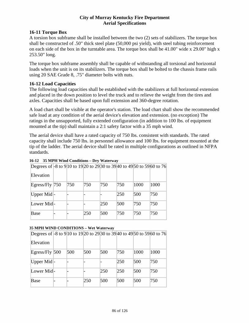
City of Murray Kentucky Fire Department Aerial Specifications
86 of 126
16-11 Torque Box A torsion box subframe shall be installed between the two (2) sets of stabilizers. The torque box shall be constructed of .50" thick steel plate (50,000 psi yield), with steel tubing reinforcement on each side of the box in the turntable area. The torque box shall be 41.00" wide x 29.00" high x 253.50" long.
The torque box subframe assembly shall be capable of withstanding all torsional and horizontal loads when the unit is on its stabilizers. The torque box shall be bolted to the chassis frame rails using 20 SAE Grade 8, .75" diameter bolts with nuts.
16-12 Load Capacities The following load capacities shall be established with the stabilizers at full horizontal extension and placed in the down position to level the truck and to relieve the weight from the tires and axles. Capacities shall be based upon full extension and 360-degree rotation.
A load chart shall be visible at the operator's station. The load chart shall show the recommended safe load at any condition of the aerial device's elevation and extension. (no exception) The ratings in the unsupported, fully extended configuration (in addition to 100 lbs. of equipment mounted at the tip) shall maintain a 2:1 safety factor with a 35 mph wind.
The aerial device shall have a rated capacity of 750 lbs. consistent with standards. The rated capacity shall include 750 lbs. in personnel allowance and 100 lbs. for equipment mounted at the tip of the ladder. The aerial device shall be rated in multiple configurations as outlined in NFPA standards.
16-12 35 MPH Wind Conditions – Dry Waterway Degrees of
Elevation
-8 to 9 10 to 19 20 to 29 30 to 39 40 to 49 50 to 59 60 to 76
Egress/Fly 750 750 750 750 750 1000 1000
Upper Mid - - - - 250 500 750
Lower Mid - - - 250 500 750 750
Base - - 250 500 750 750 750
35 MPH WIND CONDITIONS – Wet Waterway Degrees of
Elevation
-8 to 9 10 to 19 20 to 29 30 to 39 40 to 49 50 to 59 60 to 76
Egress/Fly 500 500 500 500 750 1000 1000
Upper Mid - - - - 250 500 750
Lower Mid - - - 250 250 500 750
Base - - 250 500 500 500 750
City of Murray Kentucky Fire Department Aerial Specifications
87 of 126
16-13 Boom Support A heavy duty boom support shall be provided for support of the ladder in the travel position. On the base section of the ladder, a stainless steel scuff plate shall be provided where the ladder comes into contact with the boom support.
The boom support shall be located just to the rear of the chassis cab.
16-14 Aerial Boom Panel There shall be one boom panel provided on each side of the aerial ladder base section. The boom panel shall be painted RED.
The boom panels shall be designed so no mounting bolts are in the face of the panel. This shall keep the lettering surface free of holes.
16-15 Extension Indicator Extension markings and corresponding numerical indicators shall be provided along each inside and outside top rail of the base section of the aerial every ten (10) feet. They shall indicate various positions of extension up to full. Markings and indicators shall be clearly visible to the console operator.
To aid in visibility during hours of darkness, the markings and numerical indicators shall be of a red reflective material.
16-16 Folding Steps One (1) set of folding steps shall be provided at the tip of the ladder. An additional set of folding steps shall be provided at the base of the fly section. The steps shall be bright finished, non-skid with a luminescent coating that is rechargeable from any light source and can hold a charge for up to 24 hours.
16-17 Rotation Bearing Cover An aluminum treadplate cover shall be fitted over the aerial rotation bearing and drive pinion gear(s). The cover shall be attached to the turntable deck and shall able to be easily removed for available access to the gears. The cover shall be made from aluminum treadplate.
16-18 Stabilizer Control Station There shall be two (2) easily accessible control stations, one (1) for driver side stabilizers and one (1) for passenger side stabilizers, located at the rear of the apparatus.
The following controls and indicator lights shall be clearly identified, illuminated, and conveniently located for ease of operation and viewing at each of the control stations except where otherwise noted:
- Left Rear Stabilizer Firm On Ground indicator light (driver side panel only)
- Left Rear Stabilizer Fully Extended Indicator light (driver side panel only)
- Left Rear Stabilizer In/Out switch (driver side panel only)
- Left Rear Stabilizer Up/Down switch (driver side panel only)
- Left Front Stabilizer Firm On Ground indicator light (driver side panel only)
City of Murray Kentucky Fire Department Aerial Specifications
88 of 126
- Left Front Stabilizer Fully Extended indicator light (driver side panel only)
- Left Front Stabilizer In/Out switch (driver side panel only)
- Left Front Stabilizer Up/Down switch (driver side panel only)
- Right Rear Stabilizer Firm On Ground indicator light (passenger side panel only)
- Right Rear Stabilizer Fully Extended indicator light (passenger side panel only)
- Right Rear Stabilizer In/Out switch (passenger side panel only)
- Right Rear Stabilizer Up/Down switch (passenger side panel only)
- Right Front Stabilizer Firm On Ground indicator light (passenger side panel only)
- Right Front Stabilizer Fully Extended indicator light (passenger side panel only)
- Right Front Stabilizer In/Out switch (passenger side panel only)
- Right Front Stabilizer Up/Down switch (passenger side panel only)
- Hydraulic emergency power switch
- High idle switch
16-19 Turntable Control Station There shall be a turntable control station located on the left hand side of the turntable so the operator shall be able to easily observe the ladder tip while operating the controls. The controls shall permit the operator to regulate the speed of the aerial functions within safe limits (as determined by the manufacturer and NFPA standards). The controls shall be clearly marked and lighted for nighttime operation. A hinged aluminum cover shall be provided. The momentary foot switch located at the turntable control station shall activate the aerial function controls.
The following controls and indicator lights shall be clearly identified, illuminated, and conveniently located for ease of operation and viewing:
- Elevation, extension/retraction, and rotation controls
- High idle switch
- Rung alignment indicator light
- Tip/Tracking lights switch
- Hydraulic system pressure gauge
- Indicator/Alarm test switch
- EPU switch
- Operator's load chart
- Stabilizer Not Fully Extended indicator light and alarm
- Monitor controls
City of Murray Kentucky Fire Department Aerial Specifications
89 of 126
- Aerial waterway flow meter
16-20 Stabilizers The vehicle shall come equipped with a stabilization system consisting of four (4) hydraulically operated out and down style stabilizers. This system shall meet or exceed all requirements of the NFPA specifications related to stabilization and setup on sloped surfaces.
The stabilizer/leveling jacks shall have a maximum spread of 12' measured from the centerline of the jack footpads when the beams are fully extended. The beams shall be 6.88" wide x 9.00" high with 3/4" thick top and bottom plates and 1/2" thick sides of 100,000-PSI minimum yield strength steel. The cylinders shall have pilot-operated check valves with thermal relief designed to insure that the beams shall not drift out of the stowed position during travel. Wear pads shall guide the stabilizers.
The horizontal extension cylinders shall be totally enclosed within the beams and shall incorporate telescoping hydraulic tubing to supply the jack cylinder hydraulic power. Stabilizer hydraulic hoses shall remain stationary during operation of the stabilizers to prevent hose wear and potential failure. The cylinders shall be equipped with decelerators to reduce the speed of extension and retraction when the beams are near the fully retracted and extended positions. The stabilizer extension hydraulic cylinders shall have the following dimensions: 2.25" bore, 1.38" rod, and 27.25" stroke.
The vertical jack cylinders shall be capable of 12.00" ground penetration. The cylinders shall be supplied with pilot operated check valves on each jack cylinder to hold the cylinder in the stowed or working position, should a charged line be severed at any point in the hydraulic system. For safety, the integral holding valves shall be located in the cylinder base end, NOT in the transfer tube. Vertical jack cylinder rods shall be fully enclosed by a telescoping inner box to protect the cylinder rods from damage. The stabilizer jack hydraulic cylinders shall have the following dimensions: 4.25" bore, 3.00" rod, and 28.88" stroke.
Each stabilizer jack shall have a polished stainless steel shield. The stainless steel shield shall be a maximum of 14.00" wide so as to allow the extension of the stabilizer between parked cars or other obstacles. This plate shall serve as a protective guard and a mounting surface for warning lights. The top, forward, and rear edges shall be flanged back 90 degrees for added strength. A 4.00" diameter clear work light shall be provided to illuminate the stabilizer and the ground. Lighting shall automatically activate with the aerial master switch.
16-21 Stabilizer Pads The stabilizer footpad shall be 12.00" in diameter. The footpad shall be attached to the jack cylinder rod by means of a machined ball at the end of the jack cylinder rod which mates to a socket machined into the footpad. The footpad shall have the ability to pivot 20 degrees from horizontal in any direction to allow setup on uneven terrain.
16-22 Auxiliary Stabilizer Pads An auxiliary ground pad shall be supplied for each stabilizer to provide additional load distribution on soft surfaces. The pads shall be 33" x 26" and made from a lightweight composite material. The ground pressure shall not exceed 75 pounds per square inch when the ground pads are used and the apparatus is fully loaded and the aerial device is carrying its rated capacity in
City of Murray Kentucky Fire Department Aerial Specifications
90 of 126
any position. The pads shall be stored in a double stacked configuration, two (2) behind each rear tandem axle in a single bracket.
16-23 Stabilizer Controls An electrically controlled hydraulic valve shall power stabilizer movement. The valve can also be manually controlled in the event of electrical malfunction. Hydraulic power override controls shall be incorporated into the valve. The manual override mechanism shall be completely sealed within the valve assembly to prevent any possibility of corrosion.
The stabilizer controls shall be located to provide the operator with a full view of each stabilizer being positioned. All stabilizer control functions can be operated independently or simultaneously, so that the vehicle may be set up in a restricted area or on uneven terrain. Each stabilizer control panel shall include the following:
-In/out stabilizer beam control toggle switch
-Up/down stabilizer jack control toggle switch
-Emergency hydraulic power unit (EPU) control toggle switch
-High idle control toggle switch
-Stabilizer fully extended LED indicator lights
-Stabilizer planted LED indicator lights
As a safety device, an electrically actuated diverter valve shall be provided. The hydraulic power shall be diverted to the aerial ladder controls automatically the instant all stabilizer jacks are firmly planted on the ground. Once the aerial ladder is raised from the bedded position, the stabilizer hydraulic power is cut off so the stabilizers shall not accidentally be moved while the aerial is being operated.
To aid in leveling the unit, two bubble type angle indicators shall be located near the stabilizer controls. One indicator shall show the angle of the truck from the front to rear and the other shall show the side to side angle of the truck. The indicators shall be color coded green to show when the truck has been properly leveled allowing the aerial device to be operated at full capacity.
A stabilizer deployment audible warning alarm shall be provided at each side of the body, activated by the stabilizer movement.
A "Stabilizers Not Stowed" indicator light shall be provided in the cab within view of the driver. It shall illuminate automatically whenever the stabilizers are not fully stowed to prevent damage to the vehicle if it is moved. The stabilizer system shall also be wired to the "Do Not Move Truck" indicator light. This light shall flash whenever the apparatus parking brake is not engaged and the stabilizers are not fully stowed.
16-24 Hydraulic System All high pressure hoses shall have an abrasion resistant cover, and have a rating greater than or equal to the working pressure of the circuit in which they are installed. All hydraulic fittings shall be plated to minimize corrosion. The fitting shall use an O ring face seal, where possible, to minimize hydraulic leaks. All pressure carrying hydraulic hoses shall have a 4:1 safety rating based on burst pressure
City of Murray Kentucky Fire Department Aerial Specifications
91 of 126
An interlock shall be provided that prevents activation of the hydraulic pump until the transmission is placed in neutral and the parking brake is set as outlined in NFPA standards.
The hydraulic system shall be of the load sense design to minimize heat build up and provide smooth control of the aerial ladder. The system shall meet the performance requirement in NFPA standards, which requires adequate cooling after less than 2 1/2 hours of operations.
All hydraulic components that are non-sealing, where failure could result in the aerial movement, shall comply with NFPA standards and have burst strength of 4:1. Dynamic sealing components, where failure could cause aerial movement, shall have a margin of 2:1 on maximum operating pressure per NFPA standards. All hydraulic hoses, tubes, and connections shall have minimum burst strength of 3:1 per NFPA standards.
A hydraulic oil pressure gauge shall be supplied at the base control location per NFPA standards.
The aerial hydraulic system shall be designed in such a manner that a hydraulic pump failure or line rupture shall not allow the aerial or outriggers to lose position. Hydraulic holding valves shall be mounted directly into cylinders. To insure reliable performance of holding valves, no hoses or tubing shall be permitted between a holding valve and cylinder. The aerial shall incorporate the use of trombone steel tubes inside the stabilizer beams to eliminate hydraulic hose wear and leaks. Hydraulic power to the ladder shall be transferred from the pedestal by a hydraulic swivel.
16-25 Hydraulic Reservoir The hydraulic system shall consist of a 51-gallon reservoir mounted to the torque box and plumbed to the hydraulic pump. There shall be plumbing for a supply and return line and a tank drain on the reservoir.
The hydraulic pump suction line shall have a shut-off ball valve for pump servicing.
The hydraulic oil reservoir fill shall be labeled per NFPA standards. The hydraulic system shall use multi-weight SAE grade oil. ISO grade shall be based on geographical location. The manufacturer shall certify that the oil meets or exceeds the hydraulic cleanliness rating of 18/15/13 per ISO 4406:1999 before delivery.
16-26 Hydraulic Filters The system shall incorporate the following filters to provide dependable service:
- Separate magnet (not on strainer)
- Reservoir suction strainer: 125 mesh
- Pressure filter with by-pass indicator: 2/3/5 micron, Beta rating of 2/20/75 or better
- Return filter with by-pass indicator: 2/3/5 micron, Beta rating of 2/20/75 or better
- Desiccant breather filter: Water capacity 4 fluid oz, 5 micron rating
16-27 Hydraulic Cylinders All hydraulic cylinders used on the aerial device shall be produced by a manufacturer that specializes in the production of hydraulic cylinders.
City of Murray Kentucky Fire Department Aerial Specifications
92 of 126
16-28 Power Takeoff/Hydraulic Pump The apparatus shall be equipped with a power takeoff driven by the chassis transmission and actuated by an electric shift located inside the cab. The power takeoff, which drives the hydraulic pump, shall meet all the requirements for the aerial unit operations. The hydraulic pump shall be a variable displacement piston pump, for consistent and rapid response, and be capable of supplying hydraulic oil at a nominal 26 gpm flow at pressures up to 2800 psi. The system shall operate between 500-2800 psi with flow controls to protect hydraulic components and incorporate a relief valve set at 2950 psi to prevent over pressurization. The hydraulic pump shall be solely dedicated to aerial operations. (no exception) An amber indicator light shall be installed on the cab instrument panel to notify the operator that the power takeoff is engaged.
An interlock shall be provided that allows operation of the aerial power takeoff shift only after the chassis spring brake has been set and the chassis transmission has either been placed in the neutral position or drive position after the driveline has been disengaged from the rear axle.
16-29 Emergency Pump The hydraulic system shall be designed with an auxiliary power unit meeting the guidelines of NFPA standards. The auxiliary power unit shall be a 12-volt pump connected to the chassis electrical system. The pump shall provide operation at reduced speeds to store the aerial device and outriggers for road transportation.
Self-centering switches shall be provided at the turntable and each stabilizer control station to activate the system. The system shall be designed to provide a minimum of 30 minutes of hydraulic power to operate functions.
16-30 Hydraulic Swivel The aerial ladder shall be equipped with a three (3) port, high pressure hydraulic swivel which shall connect the hydraulic lines from the hydraulic pump and reservoir through the rotation point to the aerial control bank. The hydraulic swivel shall allow for 360 degree continuous rotation of the aerial.
16-31 Electric Swivel The ladder shall be equipped with an electric swivel to allow 360 degrees rotation of the aerial while connecting all electrical circuits through the rotation point. A minimum of 32 collector rings shall be provided that are capable of supplying 20 amp continuous service. All collector rings shall be enclosed and protected with desiccant plugs against condensation and corrosion. No oil or silicone shall be used.
16-32 12-BIT Absolute Encoder The aerial ladder shall be equipped with a 12-Bit Absolute Encoder which provides 4096 counts per shaft turn for position and direction reference.
The 12-Bit Absolute Encoder shall provide a unique binary word to reference each position and direction for all 360 degrees of rotation.
If the power is interrupted for any reason, the 12-Bit Absolute Encoder shall allow power to be returned to the system without having to re-zero the settings.
The 12-Bit Absolute Encoder shall be an integral part of a micro-processor based control system.
City of Murray Kentucky Fire Department Aerial Specifications
93 of 126
16-33 Aerial Electrical System The aerial electrical system shall be designed and manufactured in such a way that the power and signal protection and control compartments shall contain circuit protection
devices and power control devices. The power and signal protection and control components shall be protected against corrosion, excessive heat, excessive vibration, physical damage, and water spray.
The aerial electrical system shall be designed and manufactured to allow the following:
- All of the serviceable components shall be readily accessible.
- Circuit protection devices shall be utilized to protect each circuit.
- All circuit protection devices shall be sized to prevent wire and component damage when subjected to extreme current overload.
- General protection circuit breakers shall be Type-I automatic reset (continuously resetting) or Type-II (manual resetting) and conform to SAE requirements. When required, automotive type fuses conforming to SAE requirements shall be utilized to protect electronic equipment.
- Power control relays and solenoids, when utilized, shall have a direct current (dc) rating of 125% of the maximum current for which the circuit is protected.
The aerial electrical system shall be designed and manufactured to allow the following:
- Toggle switches shall be utilized that are certified for the outside conditions that fire apparatus experience (no exception).
- All wiring shall be protected through conduit or loom.
- All wiring harnesses shall be properly supported to eliminate harness damage through rubbing.
- All connectors utilized in the system shall be of a waterproof design.
- An inductive proximity switch and illumination light shall be incorporated into the boom support.
- The aerial master and aerial PTO can be engaged after the water pump has been engaged without having to bring the RPM back to idle.
- Standard cabling to the tip of the aerial shall consist of one (1) 16/20 cable and one (1) 12/8 cable.
16-34 Driver Side Torque Box Power Distribution Panel A fuse and relay panel, located behind the driver side stabilizer, shall include the following:
- NEMA 4x rated weatherproof enclosure
- Relays, fuses, and circuit breakers for aerial and stabilizer control power and interlocks
16-35 Turntable Console The following switches and indicator lights shall be standard on the turntable console:
- High idle on/off switch
City of Murray Kentucky Fire Department Aerial Specifications
94 of 126
- Tip/Tracking light switch
- Indicator and alarm test switch
- Emergency hydraulic power switch
- "Stabilizers Not Fully Extended" amber indicator light
- Rung alignment green indicator light
The turntable control station shall be lighted for nighttime operation with one (1) work light activated by the aerial master switch. A fuse panel shall be located in the turntable console.
16-36 Turntable Override Controls The aerial manual override controls shall be located in the turntable console.
16-37 Boom Support A Turck inductive proximity switch shall be provided on the boom support to detect if the aerial device is fully stowed within the boom support.
16-38 Stabilizer Indicator A "Stabilizers Not Stowed" indicator shall be provided in the driver's compartment. It shall illuminate automatically whenever the stabilizers are not fully stowed, to prevent damage to the apparatus if moved. The stabilizer system shall also be wired to the "Do Not Move" indicator light, which shall flash whenever the apparatus parking brake is not fully engaged and the stabilizers are not fully stowed.
16-39 Cradle Interlock System A cradle interlock system shall be provided to prevent the lifting of the aerial from the nested position until the operator has positioned all the stabilizers in a load supporting configuration. A switch shall be installed at the cradle to prevent operation of the stabilizers once the aerial has been elevated from the nested position.
16-40 Stabilizer Alarm An electronic warning device shall be provided at each stabilizer to warn personnel that the stabilizers are being deployed. The alarms shall activate whenever a stabilizer control switch is operated and shall produce a fast-pulsing 90 dB signal. The alarms shall cancel when the stabilizer control switch is released.
16-41 Communication System An Atkinson communication system shall be furnished between the aerial tip and the turntable operator's position. The communication system shall be a two (2)-way system with the communication speaker at the tip requiring no operator attention to transmit or receive. The transmitting and receiving volume controls shall be located at the turntable operator's position.
16-42 Lifting Eye-Rope Rescue Attachment Two (2) eyes shall be welded; one (1) to each ladder beam at the ladder egress with a spreader bar mounted between the eyes. This design shall distribute a load evenly across the ladder beams because of a single lifting eye on the spreader bar. The bar is retained by two (2) locking pins, one (1) at each end outboard of each eye. Leveling is maintained by the bar rotating in the eyes.
City of Murray Kentucky Fire Department Aerial Specifications
95 of 126
16-43 Collision Avoidance The aerial device shall be supplied with a collision avoidance control system. The collision avoidance control system shall be calibrated so that the aerial device does not make contact with any part of the fire apparatus during normal operation. The collision avoidance control system shall consist of the following sensors:
Single axis sensor to determine aerial device elevation.
Angle sensors to determine turntable angle with reference to aerial device position.
Absolute encoder integral to the swivel to determine aerial device rotation.
The aerial ladder shall be equipped with an absolute encoder for position and direction reference.
The absolute encoder shall provide a unique binary word to reference each position and direction for all 360 degrees of rotation.
If the power is interrupted for any reason, the absolute encoder shall allow power to be returned to the system without having to re-zero the settings.
The absolute encoder shall be an integral part of a microprocessor based control system
The collision avoidance control system shall be divided up to a maximum of nine (9) control zones. Each zone shall have its own independent rotation and elevation parameters.
The collision avoidance control system shall be equipped with a warning system that alerts the operator when the aerial device has reached the limits of each control zone. The warning system shall sound when either the rotation or elevation movements reach the limits of the control zone.
The warning system alarm and red light shall be active whenever the ladder is in a restricted area and shall then prevent aerial device movement.
A green indicator light shall activate when the aerial is in a position to be safely stowed.
16-44 Mansaver Bars, Aerial Turntable Man Saver™ bars shall be installed at the aerial turntable.
16-45 Water System There shall be a 5.00" diameter pipe that is connected to the water supply on one end and to a waterway rotation swivel with a 4.00" internal diameter at the rotation point of the turntable. The waterway rotation swivel shall allow 360-degree continuous rotation of the aerial device.
The waterway shall be routed through the rotation swivel up to the horizontal swivel and two slip-tube assemblies, separated by a flexible connection. The horizontal swivel and slip-tube assemblies shall allow the water to flow to the ladder pipe, while the aerial ladder is elevated from -8 degrees to +76 degrees. The heel pivot pin shall not be integral with the waterway swivel at any point. The design of the waterway shall allow complete servicing of the waterway swivel without disturbance to the heel pivot pin.
The integral telescopic water system shall consist of the following sections:
- 4.50" diameter tube in the base section
- 4.00" diameter tube in the lower mid-section
City of Murray Kentucky Fire Department Aerial Specifications
96 of 126
- 3.50" diameter tube in the upper mid-section
- 3.00" diameter tube in the fly section
The rotational torque shall have sufficient power to rotate the ladder into a full 1,500 gpm water stream directed at 90 degrees to the side, while maintaining the 500 pound tip load.
The aerial shall be capable of discharging up to 1,500 gpm at 100 psi parallel to the ladder and 90 degrees to each side of center, while maintaining the 500 pound tip load.
An adjustable pressure relief valve shall be furnished to protect the aerial waterway from a pressure surge. A 1.50" drain valve shall be located at the lowest point of the waterway system.
16-46 Waterway Seals The waterway seals shall be of Type B PolyPak™ design, composed of a nitroxile seal and a nitrile wiper, which together offer maximum stability and extrusion resistance on the waterway. The seals shall be capable of withstanding pressures up to 2,000 psi and temperatures in excess of 250 degrees Fahrenheit, and shall have resistance to all foam generating solutions. The seals shall be internally lubricated.
The waterway seals shall have automatic centering guides constructed of synthetic thermal polymer. To insure longer service life and smoother operation, the guides shall provide positive centering of the extendable sections within each other and the base section.
16-47 2.50" Auxiliary Outlet at Aerial Tip An auxiliary hose connection outlet shall be supplied at the tip of the aerial ladder. It shall be located on the left hand side of the aerial waterway.
Flow to the auxiliary outlet shall be supplied by 2.50" piping. A 2.50" gate valve with a non-rising stem and crank handle shall be supplied. A cap and chain shall be provided.
Flow to the aerial waterway monitor shall be controlled by a 4.00" aluminum butterfly valve with a non-rising stem and crank handle. The valve shall be located at the monitor inlet.
A 200 psi relief valve and a .75" automatic drain valve shall be supplied in the waterway at the tip.
16-48 Aerial Monitor An Elkhart Brass Cobra EXM monitor with SM-1500E nozzle capable of flowing 1500 gpm shall be installed on the aerial ladder. All controls/functions shall be hard wired.
Other functions that the monitor shall have include:
• Two (2) Panel Mount Controllers – (Installed on pump panel and ladder control console) • Position Display Module (Installed on pump panel)
16-49 Flow Meter (Aerial Waterway) A Fire Research Corporation (FRC), Model DF430, digital flow indicator with a four (4) digit LED display shall be provided for the aerial waterway at the turntable control station.
The display shall have a flow totalizer, programmable high and low flow warnings, and automatically adjust LED brightness for day/night viewing.
City of Murray Kentucky Fire Department Aerial Specifications
97 of 126
16-50 Rear Inlet A 5.00" NST inlet to the aerial waterway shall be provided at the rear of the apparatus. See Section 24 for description of elbow and cap for this discharge.
16-51 Waterway Locking System The aerial ladder waterway monitor shall be capable of being positioned at either the fly section or at the next lower section of the ladder.
The monitor location shall be changeable by the use of a single handle, located at the side of the ladder.
The handle, attached to a cam bracket, shall simply be moved forward to lock the monitor at the fly section and back to lock it to the previous section.
There shall be no pins to remove and reinstall.
The monitor shall be operational at all times, regardless of its position, without connecting or disconnecting electrical lines.
16-52 Remote Aerial Tip Control A remote control shall be provided whereby all ladder movements can be controlled at the ladder tip in addition to the control console.
The three (3) ladder functions (extension, rotation, elevation) shall be controlled individually by means of spring loaded, return to center 12-volt proportional controls.
A momentary switch at the turntable control station shall activate the controls at the ladder tip.
The remote control aerial speed shall be set in accordance with the current NFPA 1901 standards.
City of Murray Kentucky Fire Department Aerial Specifications
98 of 126
SECTION 17 – EMERGENCY AUDIBLE/LIGHTING WARNING DEVICES
17-1 Air Horn System Two (2) Grover air horns shall be provided located in the front bumper recessed one (1) each side. The horn system shall be piped to the air brake system wet tank utilizing 0.38" tubing. A pressure protection valve shall be installed in-line to prevent loss of air in the air brake system.
17-2 Air Horn Control Two (2) lanyard rope pull controls shall be provided, one (1) within reach of the driver and one (1) within reach of the officer.
17-3 Electric Siren A "Code 3", model 3692, electronic siren with noise canceling microphone shall be provided.
This siren shall be active when the battery switch is on and that emergency master switch is on.
Siren head shall be located on a swivel bracket mounted on the headliner so that it is accessible to both the driver and officer. The swivel bracket shall be capable of rotating a minimum of 180 degrees.
The electronic siren shall be controlled on the siren head only. No horn button or foot switches shall be required.
17-4 Speaker There shall be one (1) Code-3 Model PB100C speaker with chrome finish provided connected to the siren amplifier.
The speaker shall be recessed in the front bumper on the passenger's side.
17-4 Mechanical Siren A Federal Q2B siren shall be furnished. A siren brake button shall be installed on the switch panel.
The control solenoid shall be powered up after the emergency master switch is activated.
The mechanical siren shall be mounted on the bumper deck plate on the left side. The siren mounting shall include a reinforcement plate.
The mechanical siren shall be actuated by a foot switch on the officer's side and by the horn button in the steering wheel. The driver shall have the option to control the siren or the chassis horns from the horn button by means of a selector switch located on the instrument panel.
17-5 Lightbar (Cab Roof) There shall be two (2) 24.00" Whelen LED light bars mounted on the cab roof, one (1) on each side, above the driver's and passenger's door, facing forward.
Each lightbar shall include the following:
• Two (2) red flashing LED module facing forward. • Two (2) red flashing corner LED module, one (1) in each front corner. • One (1) red flashing LED module on the end facing to the side. • All the lenses shall be clear.
City of Murray Kentucky Fire Department Aerial Specifications
99 of 126
There shall be one (1) switch, located in the cab, to control these lights.
17-6 Warning Lights (Front of Cab) Two (2) pair of Whelen model 60*00F*R LED lights shall be installed on the cab face, above the headlights, mounted in a common bezel.
The outer LEDS shall be required for NFPA and shall meet or exceed the NFPA required light output for the front lower zone.
The color of these LEDs shall be red Super LED/clear lens.
The inner LEDs shall be additional lighting.
The color of these lights shall be red Super LED/red lens.
Both sets of lights shall be activated by the same switch in the cab.
17-7 Side Zone Lighting (Sides of Cab) Six (6) flashing super LED lights shall be located at the following positions:
Two (2) lights; one (1) located each side on the front bumper extension - red Super LED/red lens each side.
Two (2) lights; one (1) located each side at the lower rear corners of the crew cab - red Super LED/rd lens each side.
Two (2) lights; one (1) located each side in the rear fender panels - red Super LED/red lens each side.
The lights shall be controlled by a lighted switch on the cab instrument panel.
These lights shall be installed with polished trim flange kits.
17-8 Rear Zone Lower Lighting There shall be two (2) Whelen, Model 60*02F*R, LED, red Super LED/red lens lights located at the rear of the apparatus.
Each light shall be mounted in the Whelen tail light housing
17-9 Warning Lights (Rear of Hose Bed) Two (2) Whelen L31H*FN LED warning beacons shall be provided at the rear of the truck, located one (1) each side. These lights shall be activated by a lighted switch on the instrument panel.
The color of the lights shall be red LEDs with both domes red.
17-10 Stabilizer Warning Lights Four (4) Whelen model 60*02F*R, flashing Super LED warning light shall be mounted on the stabilizer cover panel, one (1) for each panel.
Front stabilizers; LEDs shall be red Super LED/red lens each side.
Rear stabilizers; LEDs shall be red Super LED/red lens each side.
These warning lights shall be activated by the NFPA side zone switch.

City of Murray Kentucky Fire Department Aerial Specifications
100 of 126
These lights shall be provided with a polished trim flange.
City of Murray Kentucky Fire Department Aerial Specifications
101 of 126
SECTION 18 – PAINT The exterior custom cab and body painting procedure shall consist of a seven (7) step finishing process as follows:
1. Manual Surface Preparation - All exposed metal surfaces on the custom cab and body shall be thoroughly cleaned and prepared for painting. Surfaces that shall not be painted include all chrome plated, polished stainless steel, anodized aluminum and bright aluminum treadplate. Each imperfection on the exterior metal surface shall be removed or filled and then sanded smooth for a smooth appearance. All seams shall be sealed before painting.
2. Chemical Cleaning and Treatment - The metal surfaces shall be properly cleaned using a high pressure and high temperature cleaning system. Surfaces are chemically cleaned to remove all dirt, oil, grease and metal oxides to ensure the subsequent coatings bond well. An ultra pure water final rinse shall be applied to all metal surfaces at the conclusion of the metal treatment process.
3. Primer/Surfacer Coats - A two (2) component urethane primer/surfacer shall be hand applied to the chemically treated metal surfaces to provide a strong corrosion protective base coat and to smooth out the surface.
4. Hand Sanding - The primer/surfacer coat shall be lightly sanded to an ultra smooth finish.
5. Sealer Primer Coat - A two (2) component sealer primer coat shall be applied over the sanded primer.
6. Topcoat Paint - Urethane base coat shall be applied to opacity for correct color matching.
7. Clear coat - Two (2) coats of an automotive grade two (2) component urethane shall be applied. Lap style doors shall be clear coated to match the body. Roll-up doors shall not be clear coated and the standard roll-up door warranty shall apply.
All removable items such as brackets, compartment doors, door hinges, trim, etc. shall be removed and painted separately to insure paint behind all mounted items. Body assemblies that cannot be finish painted after assembly shall be finish painted before assembly.
The cab and the body shall be painted #90 - RED.
Prior to reassembly and reinstallation of lights, handrails, door hardware and any miscellaneous items an isolation tape, gasket or dielectric material shall be used to prevent damage to the finish painted surfaces. (no exception). A nylon washer shall be installed under each acorn nut or metal screw that is fastened directly to an exterior painted surface.
18-1 Environmental Impact The contractor shall meet or exceed his current State regulations concerning paint operations. Pollution control shall include measures to protect the atmosphere, water and soil. Controls shall include the following conditions:
- Topcoats and primers shall be chrome and lead free.
- Metal treatment chemicals shall be chrome free. The wastewater generated in the metal treatment process shall be treated on-site to remove any other heavy metals.
City of Murray Kentucky Fire Department Aerial Specifications
102 of 126
- Particulate emission collection from sanding operations shall have a 99.99 percent efficiency factor.
- Particulate emissions from painting operations shall be collected by a dry filter or water wash process. If the dry filter means is used, it shall have an efficiency rating of 98 percent. Water wash systems shall be 99.97 percent efficient.
- Water from water wash booths shall be reused. Solids shall be removed mechanically on a continual basis to keep the water clean.
- Paint wastes shall be disposed of in an environmentally safe manner.
- Empty metal paint containers shall be crushed and recycled to recover the metal.
- Solvents used in cleanup operations shall be collected, recycled on-site, or sent off-site for distillation and returned for reuse. Residue from the distillation operation shall be used as fuel in off-site kilns.Additionally, the finished apparatus shall not be manufactured with or contain products that have ozone depleting substances. The contractor shall, upon demand, present evidence that his manufacturing facility meets the above conditions and that it is in compliance with his State EPA rules and regulations.
18-2 Paint Chassis Frame Assembly The chassis frame assembly shall be painted black before the installation of the cab and body, and before installation of the engine and transmission assembly, air brake lines, electrical wire harnesses, etc. Components that are included with the chassis frame assembly that shall be painted black are frame rails, cross members, axles, suspension, steering gear, fuel tank, body substructure supports, miscellaneous mounting brackets, etc.
18-3 Painted Air Conditioning Cover and Mounts The cover of the air conditioning condenser and the mounting feet shall be red.
18-4 Compartment Interior Paint The interior of compartmentation shall be painted with gray spatter type paint.
18-5 Aerial Turntable Paint Color All aerial device ladder components above the rotation point that are not chrome plated or stainless steel shall have a natural swirl finish.
The turntable and aerial ladder control console shall be covered in aluminum treadplate.
The lift cylinders and extension cylinders shall be sanded to remove any metal flakes and smooth any rough surfaces. These components shall be prime painted with an epoxy primer and finished painted with the same red color as the chassis and body.
The support structure shall be painted with the same red color as the chassis body.
The rotation motor, components below the rotation point, and the stabilizers shall be painted high gloss black.
The tip of the ladder shall be painted red (same color as body).

City of Murray Kentucky Fire Department Aerial Specifications
103 of 126
18-6 Exterior Body/Chassis/Roof
Color shall be red to match existing fleet.
City of Murray Kentucky Fire Department Aerial Specifications
104 of 126
SECTION 19 – REFLECTIVE TAPE The truck builder shall use a CAD program to demonstrate the reflective tape installation locations in this section. The City of Murray shall approve the design prior to installation taking place.
19-1 Reflective Band REFLECTIVE BAND A 5.00" white reflective band shall be provided across the front of the vehicle and along the sides of the cab and apparatus body.
19-2 Stripe, Reflective, “S” Ribbon "S" type ribbons shall be added to the reflective stripe; locations determined at drawing approval.
Areas adjacent to the "S" portion of the stripe shall be shaded and highlighted with an air brush to give it a ribbon affect.
19-3 Outline, Reflective Stripe A black outline shall be applied on the top and the bottom of the reflective band.
19-4 Chevron Striping, Rear There shall be alternating chevron striping located on the rear-facing vertical surface of the apparatus. Covered surfaces shall include the rear wall and aluminum doors. Rear compartment doors, stainless steel access doors, and the rear bumper shall not be covered.
The colors shall be red and fluorescent yellow green diamond grade.
Each stripe shall be 6.00" in width.
This shall meet the requirements of NFPA 1901, 2009 edition, which states that 50% of the rear surface shall be covered with chevron striping.
19-5 Reflective Stripe on Stabilizers There shall be a 4.00" wide ruby red reflective stripe provided on the forward and rear facing side of all aerial stabilizers.
19-6 Reflective Stripe, Cab Doors A 6.00" x 16.00" white reflective stripe shall be provided across the interior of each cab door. The stripe shall be located approximately 1.00" up from the bottom, on the door panel.
This stripe shall meet the NFPA 1901 requirement.
19-7 Lettering The lettering shall be totally encapsulated between two (2) layers of clear vinyl.
19-8 Lettering There shall be genuine gold leaf letters, 3.00" high, with outline and shade provided. There shall be six (6) letters provided.
19-9 Lettering Forty-one (41) to sixty (60) genuine gold leaf letters, 2.00" high, with outline and shade shall be provided.
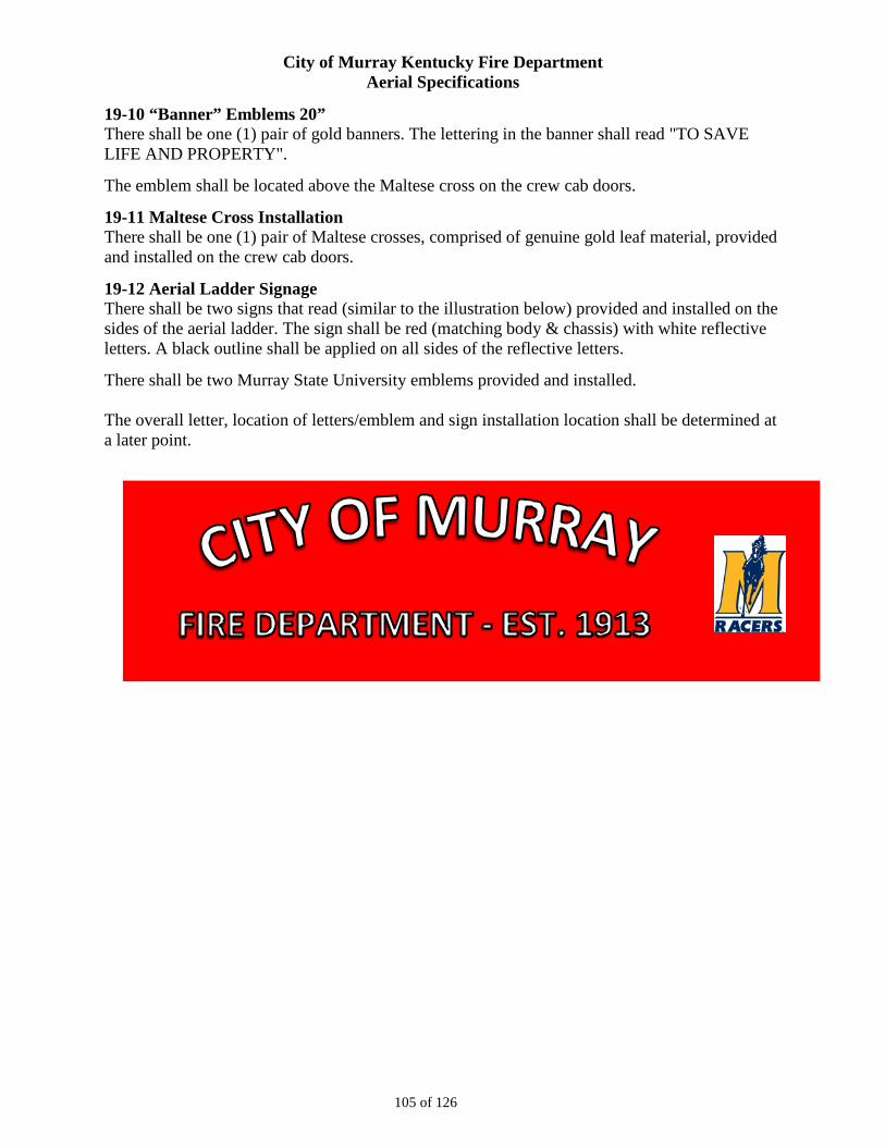
City of Murray Kentucky Fire Department Aerial Specifications
105 of 126
19-10 “Banner” Emblems 20” There shall be one (1) pair of gold banners. The lettering in the banner shall read "TO SAVE LIFE AND PROPERTY".
The emblem shall be located above the Maltese cross on the crew cab doors.
19-11 Maltese Cross Installation There shall be one (1) pair of Maltese crosses, comprised of genuine gold leaf material, provided and installed on the crew cab doors.
19-12 Aerial Ladder Signage There shall be two signs that read (similar to the illustration below) provided and installed on the sides of the aerial ladder. The sign shall be red (matching body & chassis) with white reflective letters. A black outline shall be applied on all sides of the reflective letters.
There shall be two Murray State University emblems provided and installed. The overall letter, location of letters/emblem and sign installation location shall be determined at a later point.
City of Murray Kentucky Fire Department Aerial Specifications
106 of 126
SECTION 20– SERVICE MANUALS
20-1 Manuals and Service Information The manufacturer shall supply at time of delivery, complete operation and maintenance manuals covering the complete apparatus as delivered. A permanent plate shall be mounted in the driver’s compartment which specifies the quantity and type of fluid required including engine oil, engine coolant, transmission, pump transmission lubrication, pump primer and drive axle.
20-2 Safety Video Since video is much more effective than written documentation and can be replayed for new personnel and as a refresher for existing personnel, an apparatus safety video, in DVD format shall be provided at time of delivery. This video shall address key safety considerations for personnel to follow when they are driving, operating, and maintaining the apparatus. Safety procedures for the following shall be included on the video: vehicle pre trip inspection, chassis operation, pump operation and maintenance.
20-3 Pump Manuals Two (2) pump manuals from the pump manufacturer shall be furnished in compact disc format with the apparatus. Manuals shall cover pump operation, maintenance, and parts.
20-4 Manuals Two (2) operator maintenance manuals and two (2) wiring diagrams pertaining to the aerial device shall be provided with the apparatus at time of pick-up.
20-5 CD Manual Fire Apparatus Parts Two (2) custom parts manuals for the complete fire apparatus shall be provided in CD format with the completed unit.
The manual shall contain the following:
- Job number
- Part numbers with full descriptions
- Table of contents
- Parts section sorted in functional groups reflecting a major system, component, or assembly
- Parts section sorted in Alphabetical order
- Instructions on how to locate parts
The manual shall be specifically written for the chassis and body model being purchased. It shall not be a generic manual for a multitude of different chassis and bodies.
20-6 CD Manuals, Chassis Service Two (2) CD format chassis service manuals containing parts and service information on major components shall be provided with the completed unit.
The manual shall contain the following sections:
- Job number
- Table of contents
City of Murray Kentucky Fire Department Aerial Specifications
107 of 126
- Troubleshooting
- Front Axle/Suspension
- Brakes
- Engine
- Tires
- Wheels
- Cab
- Electrical, DC
- Air Systems
- Plumbing
- Appendix
The manual shall be specifically written for the chassis model being purchased. It shall not be a generic manual for a multitude of different chassis and bodies.
20-7 CD Manual, Chassis Operation Two (2) CD format chassis operation manuals shall be provided.
20-8 Circuit Protection and Control Diagram Copies of all job-specific, computer network input and output (I/O) connections shall be provided with each chassis. The sheets shall indicate the function of each module connection point, circuit protection information (where applicable), wire numbers, wire colors and load management information.
City of Murray Kentucky Fire Department Aerial Specifications
108 of 126
SECTION 21 – WARRANTIES The items listed in this section do not include all of the items warranties are expected to be included with. Bidders shall include a supplemental page(s) with warranty items that they feel should be included/disclosed but are not included in the below section.
21-1 Service and Warranty Support – Dealership TO INSURE FULL SERVICE AFTER DELIVERY, THE SELLING BIDDER/DEALERSHIP MUST BE CAPABLE OF PROVIDING SERVICE WHEN REQUIRED.
The bidder/dealership shall show that the company is in position to render prompt service and to furnish replacement parts.
Each bidder/dealership must be able to display that they are actively in the fire apparatus service business by operating a factory authorized service center and parts repository capable of satisfying the warranty service requirements and parts requirements of the vehicle(s) being purchased.
The bidder/dealership must state the location of this authorized service center. This service center must have a staff of factory-trained mechanics, well versed in all aspects of service for all major components of the apparatus.
21-2 Service and Warranty Support – Manufacturer The manufacturer shall stock inventory dedicated to service and replacement parts to ensure quick response and minimize down time. Furthermore, the manufacturer shall house the inventory in a dedicated facility, with a dedicated shipping area that ensures service parts are given priority. The bidder shall provide detailed documentation of service and replacement part resources.
The manufacturer must also maintain a 24 hour/ 7 day a week, toll free emergency hot line.
The manufacturer shall employ a staff of adequate size specifically dedicated to providing customer support and parts for the fielded fleet of vehicles it has produced.
The manufacturer must be capable of providing both in-house and on-site service for the apparatus.
The manufacturer shall offer regional factory hands-on repair and maintenance training classes.
The manufacturer shall employ certified EVT technicians, not only providing technical expertise in the repair of fire apparatus, but also demonstrating the commitment to service after the sale.
21-3 Command Zone Warranty The Command Zone components shall be warranted against defective materials or workmanship for a period of five (5) years from the date of delivery to the original purchaser. The warranty shall also include a standard repair time for covered components.
A copy of the fire apparatus manufacturer's warranty shall be included with the bid.
21-4 Material and Workmanship Each new piece of apparatus shall be provided with a minimum one (1) year basic apparatus material and workmanship limited warranty. The warranty shall cover such portions of the
City of Murray Kentucky Fire Department Aerial Specifications
109 of 126
apparatus built by the manufacturer as being free from defects in material and workmanship that would arise under normal use and service.
A copy of the warranty certificate shall be submitted with the bid package.
21-5 Engine Warranty A Detroit Diesel five (5) year limited engine warranty shall be provided. A copy of the warranty certificate shall be submitted with the bid package.
21-6 Steering Gear Warranty A Sheppard three (3) year limited steering gear warranty shall be provided. A copy of the warranty certificate shall be submitted with the bid package.
21-7 Structural Integrity The chassis frame shall be provided with a minimum fifty (50) year material and workmanship limited warranty. The warranty shall cover the chassis frame as being free from defects in material and workmanship that would arise under normal use and service.
A copy of the warranty certificate shall be submitted with the bid package.
The new cab shall be provided with a minimum ten (10) year material and workmanship limited warranty. The warranty shall cover such portions of the cab built by the manufacturer as being free from structural failures caused by defects in material and workmanship that would arise under normal use and service.
A copy of the warranty certificate shall be submitted with the bid package.
Each new piece of apparatus shall be provided with a ten (10) year material and workmanship limited warranty on the apparatus body. The warranty shall cover such portions of the apparatus built by the manufacturer as being free from defects in material and workmanship that would arise under normal use and service.
A copy of the warranty certificate shall be submitted with the bid package.
The aerial device shall be provided with a minimum twenty (20) year material and workmanship limited warranty. The warranty shall cover such portions of the apparatus built by the manufacturer as being free from defects in material and workmanship that would arise under normal use and service. This warranty shall be limited to the torque box, turntable, aerial sections and other structural components.
A copy of the warranty certificate shall be submitted with the bid package.
21-8 Front Axle Independent front suspension shall be provided with a minimum three (3) year material and workmanship limited warranty. The manufacturer's warranty shall provide that the independent front suspension and steering gears be free from any defect related to material and workmanship on the portion of the apparatus built by the manufacturer that would arise under normal use and service. A copy of the warranty certificate shall be submitted with the bid package.
21-9 Rear Axle A Meritor™ Axle 2 year limited warranty shall be provided.
City of Murray Kentucky Fire Department Aerial Specifications
110 of 126
21-10 ABS Brake System A Meritor Wabco™ ABS brake system; minimum three (3) year limited warranty shall be provided
21-11 Paint and Corrosion Each new piece of apparatus shall be provided with a minimum ten (10) year pro-rated paint and corrosion limited warranty on the apparatus cab. The warranty shall cover painted exterior surfaces of the body to be free from blistering, peeling, corrosion, or any other adhesion defect caused by defective manufacturing methods or paint material selection that would arise under normal use and service.
A copy of the warranty certificate shall be submitted with the bid package.
21-12 Transmission Warranty The transmission shall have a minimum five (5) year/unlimited mileage warranty covering 100 percent parts and labor.
21-13 UPF Poly Water Tank The UPF poly water tank shall be provided with a lifetime material and workmanship limited warranty.
A copy of the warranty certificate shall be submitted with the bid package.
21-14 Roll Up Door Material and Workmanship Warranty A Gortite roll-up door limited warranty shall be provided. The mechanical components of the roll-up door shall be warranted against defects in material and workmanship for the lifetime of the vehicle. A minimum six (6) year limited warranty shall be provided on painted and satin roll up doors.
A copy of the warranty certificate shall be submitted with the bid package.
21-15 Pump The Waterous pump shall be provided with a five (5) year material and workmanship limited warranty.
A copy of the warranty certificate shall be submitted with the bid package.
21-16 Pump Plumbing The stainless steel plumbing components and ancillary brass fittings used in the construction of the water/foam plumbing system shall be warranted for a minimum ten (10) years or 100,000 miles. This covers structural failures caused by defective design or workmanship, or perforation caused by corrosion, provided the apparatus is used in a normal and reasonable manner. This warranty is extended only to the original purchaser for a period of ten years from the date of delivery.
A copy of the warranty certificate shall be submitted with the bid package.
21-17 Aerial Swivel A minimum five (5) year limited swivel warranty shall be provided. A copy of the warranty certificate shall be submitted with the bid package.
City of Murray Kentucky Fire Department Aerial Specifications
111 of 126
21-18 Hydraulic System Components Aerial hydraulic system components shall be provided with a minimum five (5) year material and workmanship limited warranty.
Aerial hydraulic seals shall be provided with a three (3) year material and workmanship limited warranty.
A copy of the warranty certificates shall be submitted with the bid package.
21-19 Aerial Waterway A minimum ten (10) year limited waterway warranty shall be provided. A copy of the warranty certificate shall be submitted with the bid package.
21-20 Paint and Corrosion Each new piece of apparatus shall be provided with a minimum ten (10) year pro-rated paint and corrosion limited warranty on the apparatus body. The warranty shall cover painted exterior surfaces of the body to be free from blistering, peeling, corrosion, or any other adhesion defect caused by defective manufacturing methods or paint material selection that would arise under normal use and service.
A copy of the warranty certificate shall be submitted with the bid package.
21-21 Generator A Harrison Hydra-Gen generator 2 year limited warranty shall be provided.
21-22 Gold Leaf Lamination The gold leaf lamination shall be provided with a minimum three (3) year material and workmanship limited warranty. The warranty shall cover the gold leaf lamination as being free from defects in material and workmanship that would arise under normal use and service.
A copy of the warranty certificate shall be submitted with the bid package.
City of Murray Kentucky Fire Department Aerial Specifications
112 of 126
SECTION 22 – CERTIFICATION AND TESTING
22-1 Apparatus Delivery Tests and Delivery Apparatus shall be delivered under its own power - rail or truck freight shall not be acceptable. A qualified delivery engineer representing the contractor shall deliver the apparatus and remain for a sufficient length of time to instruct personnel in the proper operation, care and maintenance of the equipment delivered. A road test shall be conducted with the apparatus fully loaded and a continuous run of ten (10) miles or more shall be made under all driving conditions, during which time the apparatus shall show no loss of power or overheating. The transmission drive shaft or shafts, and rear axles shall run quietly and be free from abnormal vibration or noise throughout the operating range of the apparatus. Vehicle shall adhere to the following parameters:
A) The apparatus, when fully equipped and loaded, shall have not less than 25 percent nor more than 50 percent of the weight on the front axle, and not less than 50 percent nor more than 75 percent on the rear axle.
B) The apparatus shall be capable of accelerating to 35 mph from a standing start within 25 seconds on a level concrete highway without exceeding the maximum governed rpm of the engine.
C) The service brakes shall be capable of stopping a fully loaded vehicle in 35 feet at 20 mph on a level concrete highway. The air brake system shall conform to Federal Motor Vehicle Safety Standards (FMVSS) 121.
D) The apparatus, fully loaded, shall be capable of obtaining a speed of 50 mph on a level concrete highway with the engine not exceeding its governed rpm (full load).
22-2 Performance Tests and Requirements A road test shall be conducted with the apparatus fully loaded and a continuous run of ten (10) miles or more shall be made under all driving conditions, during which time the apparatus shall show no loss of power or overheating. The transmission drive shaft or shafts, and rear axle shall run quietly and be free from abnormal vibration or noise throughout the operating range of the apparatus. Vehicle shall adhere to the following parameters:
A) The apparatus, when fully equipped and loaded, shall have not less than 25 percent nor more than 50 percent of the weight on the front axle, and not less than 50 percent nor more than 75 percent on the rear axle.
B) The apparatus shall be capable of accelerating to 35 mph from a standing start within 25 seconds on a level concrete highway without exceeding the maximum governed rpm of the engine.
C) The service brakes shall be capable of stopping a fully loaded vehicle in 35 feet at 20 mph on a level concrete highway. The air brake system shall conform to Federal Motor vehicle Safety Standards (FMVSS) 121.
D) The apparatus, fully loaded, shall be capable of obtaining a speed of 50 mph on a level concrete highway with the engine not exceeding the governed rpm (full load).
City of Murray Kentucky Fire Department Aerial Specifications
113 of 126
22-3 Failure to Meet Test In the event the apparatus fails to meet the test requirements of these specifications on the first trial, second trials may be made at the option of the bidder within 30 days of the date of the first trial. Such trials shall be final and conclusive and failure to comply with these requirements shall be cause for rejection. Failure to comply with changes to conform to any clause of the specifications, within 30 days after notice is given to the bidder of such changes, shall also be cause for rejection of the apparatus. Permission to keep or store the apparatus in any building owned or occupied by the purchaser or its use by the purchaser during the above-specified period with the permission of the bidder shall not constitute acceptance.
22-4 Vehicle Inspection Program Certification To assure the vehicle is built to current NFPA standards, the apparatus, in its entirety, shall be third-party, independent, audit-certified through Underwriters Laboratory (UL) that it is built and complies to all applicable standards in the current edition of NFPA 1901. The certification includes: all design, production, operational, and performance testing of not only the apparatus, but those components that are installed on the apparatus. (no exception)
A placard shall be affixed in the driver's side area stating the third party agency, the date, the standard and the certificate number of the whole vehicle audit.
22-5 Inspection Certificate A third party inspection certificate for the aerial device shall be furnished upon delivery of the aerial device. The certificate shall be Underwriters Laboratories Inc. Type 1 and shall indicate that the aerial device has been inspected on the production line and after final assembly.
The following tests shall be conducted:
- Magnetic particle inspection shall be conducted on every structural weld to assure the integrity of the weldments and to detect any flaws or weaknesses. Magnets shall be placed on each side of the weld while iron powder is placed on the weld itself. The powder shall detect any crack that may exist. This test shall conform to ASTM E709 and be performed prior to assembly of the aerial device.
- With aluminum structural components, visual inspection shall be performed on aluminum surfaces (non-magnetic). A liquid penetrant test shall be performed on any suspected defective area. This test shall conform to ASTM E165 and be performed prior to assembly of the aerial device.
- Ultrasonic inspection shall be used to detect any flaws in pins, bolts and other critical mounting components.
Functional tests, load tests, stability tests, and visual structural examinations shall be performed. These tests shall determine any unusual deflection, noise, vibration, or instability characteristics of the unit.
22-6 Pump Test The pump shall be tested, approved and certified by Underwriter's Laboratory at the manufacturer's expense. The test results and the pump manufacturer's certification of hydrostatic test; the engine manufacturer's certified brake horsepower curve; and the manufacturer's record of pump construction details shall be forwarded to the Fire Department.
City of Murray Kentucky Fire Department Aerial Specifications
114 of 126
22-7 Electrical System Testing The wiring and associated equipment shall be tested by the apparatus manufacturer or the installer of the line voltage system. The wiring and permanently connected devices and equipment shall be subjected to a dielectric voltage withstand test of 900-volts for one (1) minute. The test shall be conducted between live parts and the neutral conductor, and between live parts and the vehicle frame with any switches in the circuit(s) closed. This test shall be conducted after all body work has been completed.
Electrical polarity verification shall be made of all permanently wired equipment and receptacles to determine that connections have been properly made.
Operational Test per Current NFPA 1901 Standard
The apparatus manufacturer shall perform the following operation test and ensure that the power source and any devices that are attached to the line voltage electrical system are properly connected and in working order. The test shall be witnessed and the results certified by Underwriters Laboratories.
The prime mover shall be started from a cold start condition and the line voltage electrical system loaded to 100 percent of the nameplate rating.
The power source shall be operated at 100 percent of its nameplate voltage for a minimum of two (2) hours unless the system meets category certification as defined in the current NFPA 1901 standard.
Where the line voltage power is derived from the vehicle's low voltage system, the minimum continuous electrical load as defined in the current NFPA 1901 standard shall be applied to the low voltage electrical system during the operational test.
22-8 Generator Test The generator shall be tested, approved, and certified by Underwriters Laboratories at the manufacturer's expense. The test results shall be provided to the Fire Department at the time of delivery.
22-9 Vehicle Stability Certification The fire apparatus manufacturer shall provide a certification stating the apparatus complies with NFPA 1901, current edition, section 4.13, Vehicle Stability. The certification shall be provided at the time of bid.
22-10 Engine Installation Certification The fire apparatus manufacturer shall provide a certification, along with a letter from the engine manufacturer stating they approve of the engine installation in the bidder's chassis. The certification shall be provided at the time of bid.
22-11 Power Steering Certification The fire apparatus manufacturer shall provide a certification stating the power steering system as installed meets the requirements of the component supplier. The certification shall be provided at the time of bid.
City of Murray Kentucky Fire Department Aerial Specifications
115 of 126
22-12 Cab Integrity Certification The fire apparatus manufacturer shall provide a cab crash test certification with this proposal. The certification states that the cab must meet or exceed the requirements below:
- European Occupant Protection Standard ECE Regulation No.29
- SAE J2422 Cab Roof Strength Evaluation - Quasi-Static Loading Heavy Trucks
- SAE J2420 COE Frontal Strength Evaluation - Dynamic Loading Heavy Trucks
- Roof Crush
The cab shall be subjected to a roof crush force of 100,000 lb. This value shall be 450 percent of the ECE 29 criteria, which must be equivalent to the front axle rating up to a maximum of ten (10) metric tons.
- Side Impact
The cab shall be subjected to dynamic preload with a 13,275-lb moving barrier is slammed into the side of the cab at 5.50 mph, striking with an impact of 13,000 ft-lb of energy. This test shall closely represent the forces a cab shall see in a rollover incident.
- Frontal Impact
The cab shall withstand a frontal force produced from 65,200 ft-lb of energy using a swing-bob type platen.
The same cab shall withstand all tests without any measurable intrusion into the survival space of the occupant area.
There shall be no exception to any portion of the cab integrity certification. Nonconformance shall lead to immediate rejection of bid.
22-13 Cab Door Durability Certification Robust cab doors help protect occupants. Cab doors shall survive a 200,000 cycle door slam test where the slamming force exceeds 20 G's of deceleration. The bidder shall certify that the sample doors similar to those provided on the apparatus have been tested and have met these criteria without structural damage, latch malfunction, or significant component wear.
22-14 Windshield Wiper Durability Certification Visibility during inclement weather is essential to safe apparatus performance. Windshield wipers shall survive a 3 million cycle durability test in accordance with section 6.2 of SAE J198 Windshield Wiper Systems - Trucks, Buses and Multipurpose Vehicles. The bidder shall certify that the wiper system design has been tested and that the wiper system has met these criteria.
22-15 Seat Belt Anchor Strength Seat belt attachment strength is regulated by Federal Motor Vehicle Safety Standards and should be validated through testing. Each seat belt anchor design shall withstand 3000 lb of pull on both the lap and shoulder belt in accordance with FMVSS 571.210 Seat Belt Assembly Anchorages. The bidder shall certify that each anchor design was pull tested to the required force and met the appropriate criteria.
City of Murray Kentucky Fire Department Aerial Specifications
116 of 126
22-16 Seat Mounting Strength Seat attachment strength is regulated by Federal Motor Vehicle Safety Standards and should be validated through testing. Each seat mounting design shall be tested to withstand 20 G's of force in accordance with FMVSS 571.207 Seating Systems. The bidder shall certify that each seat mount and cab structure design was pull tested to the required force and met the appropriate criteria.
22-17 Cab Defroster Certification Visibility during inclement weather is essential to safe apparatus performance. The defroster system shall clear the required windshield zones in accordance with SAE J381 Windshield Defrosting Systems Test Procedure And Performance Requirements - Trucks, Buses, And Multipurpose Vehicles. The bidder shall certify that the defrost system design has been tested in a cold chamber and passes the SAE J381 criteria.
22-18 Cab Heater Certification Good cab heat performance and regulation provides a more effective working environment for personnel, whether in-transit, or at a scene. The cab heaters shall warm the cab 77 degrees Fahrenheit from a cold-soak, within 30 minutes when tested using the coolant supply methods found in SAE J381. The bidder shall certify that a substantially similar cab has been tested and has met these criteria.
22-19 AMP Draw Report The bidder shall provide, at the time of bid and delivery, an itemized print out of the expected amp draw of the entire vehicle's electrical system.
The manufacturer of the apparatus shall provide the following:
1) Documentation of the electrical system performance tests.
2) A written load analysis, which shall include the following:
A) The nameplate rating of the alternator.
B) The alternator rating under the conditions specified per:
Applicable NFPA 1901 or 1906 (Current Edition).
C) The minimum continuous load of each component that is specified per:
Applicable NFPA 1901 or 1906 (Current Edition).
D) Additional loads that, when added to the minimum continuous load, determine the total connected load.
E) Each individual intermittent load.
All of the above listed items shall be provided by the bidder per the applicable NFPA 1901 or 1906 (Current Edition).
City of Murray Kentucky Fire Department Aerial Specifications
117 of 126
SECTION 23 – LOOSE EQUIPMENT Prior to the ordering of any loose equipment, the manufacturer’s representative will meet with the Fire Chief to review the model numbers and/or sizes to ensure the loose equipment is the most appropriate size and/or model number. It shall be of utmost importance that all loose equipment function as designed when used with the apparatus and the apparatus function as designed when used with the equipment.
The below equipment shall be furnished with the completed unit. Insert a bid price on the lines below for each item(s). You will submit the total cost for all “loose equipment” in Section 28.
23-1 Nozzles Bid Price
Qty 1 – Spumifer Medium Expansion Foam Nozzle Model 95/120ML Qty 1 – TFT Blitzfire XXC-52 Nozzle, Tips, Mounting Bracket Qty 1 - Akron 3’ Piercing Nozzle Item # 1088 with shutoff Qty 2 – TFT Metro 2 Nozzle Item # ME2-2VPGI Qty 4 – TFT Metro 1 Nozzles Item # ME1-VPGI Qty 1 – TFT Stacked Tips YST-4NN
23-2 Forcible Entry Bid Price Qty 2 – Fire Hooks Unlimited Pro-Bar 30 Halligan Bar Qty 1 - Partner K950 Saw 12” Blade Qty 1 - Stihl MS460 R Magnum Ventilation Chain Saw Qty 3 - Fire hooks Unlimited Hydra Ram Qty 1 – Ajax Tool Air Hammer - 811RK Heavy Duty Kit 23-3 Hose Bid Price Qty 1 – 25’ Section of 3” Hose – Interior of synthetic woven yarn/Exterior nitrile rubber Qty 1 – 25’ Section of 5” – Interior of synthetic woven yarn/Exterior nitrile rubber yellow Qty 12 – 100’ Sections of Key Pro Flow 5" Rubber Supply Hose – Yellow RC50-400 Qty 21 – 50’ Sections of Key Pro Flow 3” Rubber Supply Hose – Red RC30-500 Qty 6 – 50’ Sections of Key Combat Ready 2 ½” – Blue Qty 12 – 50’ Sections of Key Combat Ready 1 ¾” – Off White
Substitute brands of hose may be acceptable. Substitute hose shall meet or exceed the friction loss, kinking characteristics, other physical characteristics of the Key hose.
23-4 Appliances/Hose Tools/Water Supply Tools Bid Price Qty 2 – 4.5” LHF Hydrant to 5” Storz Connection with handles Qty 1 - 5” Storz to 2 ½” Female Reducer Qty 1 – 2.5” to (2) 1.5” Gated Wye Qty 1 - High Rise Pack Pressure Gauge 228A 2.5” Inline Gauge Qty 2 – TFT Blind Caps A01ST
23-5 Rope Bid Price Qty 1 – 100’ of Rescue Tech 5/8” multifilament polypropylene Utility Rope 230319101 Qty 1 – 150’ of Rescue Tech ½” NFPA Lifeline Rescue Kernmantle Rope 5158150OR Qty 1 - Rescue Tech Med Rope Bag Black 801311
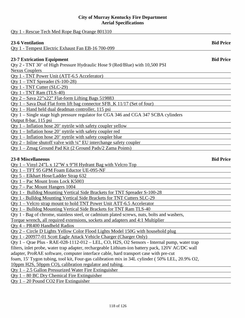
City of Murray Kentucky Fire Department Aerial Specifications
118 of 126
Qty 1 - Rescue Tech Med Rope Bag Orange 801310 23-6 Ventilation Bid Price Qty 1 - Tempest Electric Exhaust Fan EB-16 700-099 23-7 Extrication Equipment Bid Price Qty 2 - TNT 30’ of High Pressure Hydraulic Hose 9 (Red/Blue) with 10,500 PSI Nexus Couplers Qty 1 - TNT Power Unit (ATT-6.5 Accelerator) Qty 1 – TNT Spreader (S-100-28) Qty 1 - TNT Cutter (SLC-29) Qty 1 - TNT Ram (TLS-40) Qty 2 – Sava 22”x22” Flat-form Lifting Bags 519883 Qty 1 – Sava Dual Flat form lift bag connector SFB_K 11/17 (Set of four) Qty 1 – Hand held dual deadman controller, 115 psi Qty 1 – Single stage high pressure regulator for CGA 346 and CGA 347 SCBA cylinders Output 8-bar, 115 psi Qty 1 – Inflation hose 20’ nytrile with safety coupler yellow Qty 1 – Inflation hose 20’ nytrile with safety coupler red Qty 1 – Inflation hose 20’ nytrile with safety coupler blue Qty 2 – Inline shutoff valve with ¼” EU interchange safety coupler Qty 1 – Zmag Ground Pad Kit (2 Ground Pads/2 Zama Points) 23-8 Miscellaneous Bid Price Qty 1 – Vinyl 24”L x 12”W x 9”H Hydrant Bag with Velcro Top Qty 1 – TFT 95 GPM Foam Eductor UE-095-NF Qty 5 – Elkhart Hose/Ladder Strap 632 Qty 1 – Pac Mount Irons Lock K5003 Qty 7 – Pac Mount Hangers 1004 Qty 1 - Bulldog Mounting Vertical Side Brackets for TNT Spreader S-100-28 Qty 1 - Bulldog Mounting Vertical Side Brackets for TNT Cutters SLC-29 Qty 1 – Velcro strap mount to hold TNT Power Unit ATT-6.5 Accelerator Qty 1 – Bulldog Mounting Vertical Side Brackets for TNT Ram TLS-40 Qty 1 - Bag of chrome, stainless steel, or cadmium plated screws, nuts, bolts and washers, Torque wrench, all required extensions, sockets and adapters and 4:1 Multiplier Qty 4 – PR400 Handheld Radios Qty 2 – Circle D Lights Yellow Color Flood Lights Model 150G with household plug Qty 1 - 200977-01 Scott Eagle Attack Vehicle Charger (Charger Only) Qty 1 – Qrae Plus - RAE-028-1112-012 – LEL, CO, H2S, O2 Sensors - Internal pump, water trap filters, inlet probe, water trap adapter, rechargeable Lithium-ion battery pack, 120V AC/DC wall adapter, ProRAE software, computer interface cable, hard transport case with pre-cut foam, 15' Tygon tubing, tool kit, Four-gas calibration mix in 34L cylinder ( 50% LEL, 20.9% O2, 10ppm H2S, 50ppm CO), calibration regulator and tubing. Qty 1 – 2.5 Gallon Pressurized Water Fire Extinguisher Qty 1 – 80 BC Dry Chemical Fire Extinguisher Qty 1 – 20 Pound CO2 Fire Extinguisher
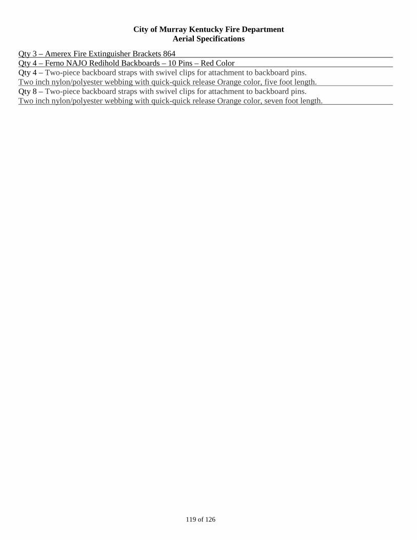
City of Murray Kentucky Fire Department Aerial Specifications
119 of 126
Qty 3 – Amerex Fire Extinguisher Brackets 864 Qty 4 – Ferno NAJO Redihold Backboards – 10 Pins – Red Color Qty 4 – Two-piece backboard straps with swivel clips for attachment to backboard pins. Two inch nylon/polyester webbing with quick-quick release Orange color, five foot length. Qty 8 – Two-piece backboard straps with swivel clips for attachment to backboard pins. Two inch nylon/polyester webbing with quick-quick release Orange color, seven foot length.
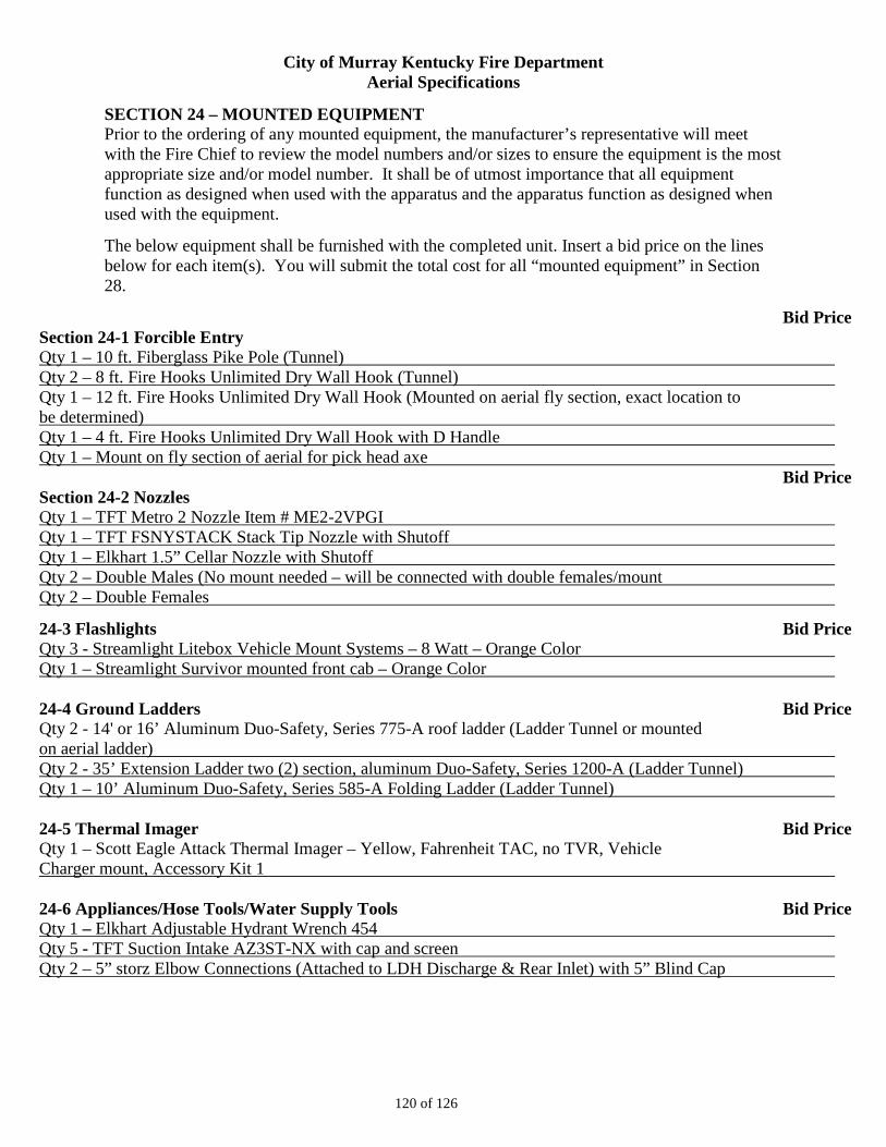
City of Murray Kentucky Fire Department Aerial Specifications
120 of 126
SECTION 24 – MOUNTED EQUIPMENT Prior to the ordering of any mounted equipment, the manufacturer’s representative will meet with the Fire Chief to review the model numbers and/or sizes to ensure the equipment is the most appropriate size and/or model number. It shall be of utmost importance that all equipment function as designed when used with the apparatus and the apparatus function as designed when used with the equipment.
The below equipment shall be furnished with the completed unit. Insert a bid price on the lines below for each item(s). You will submit the total cost for all “mounted equipment” in Section 28.
Bid Price Section 24-1 Forcible Entry Qty 1 – 10 ft. Fiberglass Pike Pole (Tunnel) Qty 2 – 8 ft. Fire Hooks Unlimited Dry Wall Hook (Tunnel) Qty 1 – 12 ft. Fire Hooks Unlimited Dry Wall Hook (Mounted on aerial fly section, exact location to be determined) Qty 1 – 4 ft. Fire Hooks Unlimited Dry Wall Hook with D Handle Qty 1 – Mount on fly section of aerial for pick head axe Bid Price Section 24-2 Nozzles Qty 1 – TFT Metro 2 Nozzle Item # ME2-2VPGI Qty 1 – TFT FSNYSTACK Stack Tip Nozzle with Shutoff Qty 1 – Elkhart 1.5” Cellar Nozzle with Shutoff Qty 2 – Double Males (No mount needed – will be connected with double females/mount Qty 2 – Double Females
24-3 Flashlights Bid Price Qty 3 - Streamlight Litebox Vehicle Mount Systems – 8 Watt – Orange Color Qty 1 – Streamlight Survivor mounted front cab – Orange Color
24-4 Ground Ladders Bid Price Qty 2 - 14' or 16’ Aluminum Duo-Safety, Series 775-A roof ladder (Ladder Tunnel or mounted on aerial ladder) Qty 2 - 35’ Extension Ladder two (2) section, aluminum Duo-Safety, Series 1200-A (Ladder Tunnel) Qty 1 – 10’ Aluminum Duo-Safety, Series 585-A Folding Ladder (Ladder Tunnel)
24-5 Thermal Imager Bid Price Qty 1 – Scott Eagle Attack Thermal Imager – Yellow, Fahrenheit TAC, no TVR, Vehicle Charger mount, Accessory Kit 1 24-6 Appliances/Hose Tools/Water Supply Tools Bid Price Qty 1 – Elkhart Adjustable Hydrant Wrench 454 Qty 5 - TFT Suction Intake AZ3ST-NX with cap and screen Qty 2 – 5” storz Elbow Connections (Attached to LDH Discharge & Rear Inlet) with 5” Blind Cap
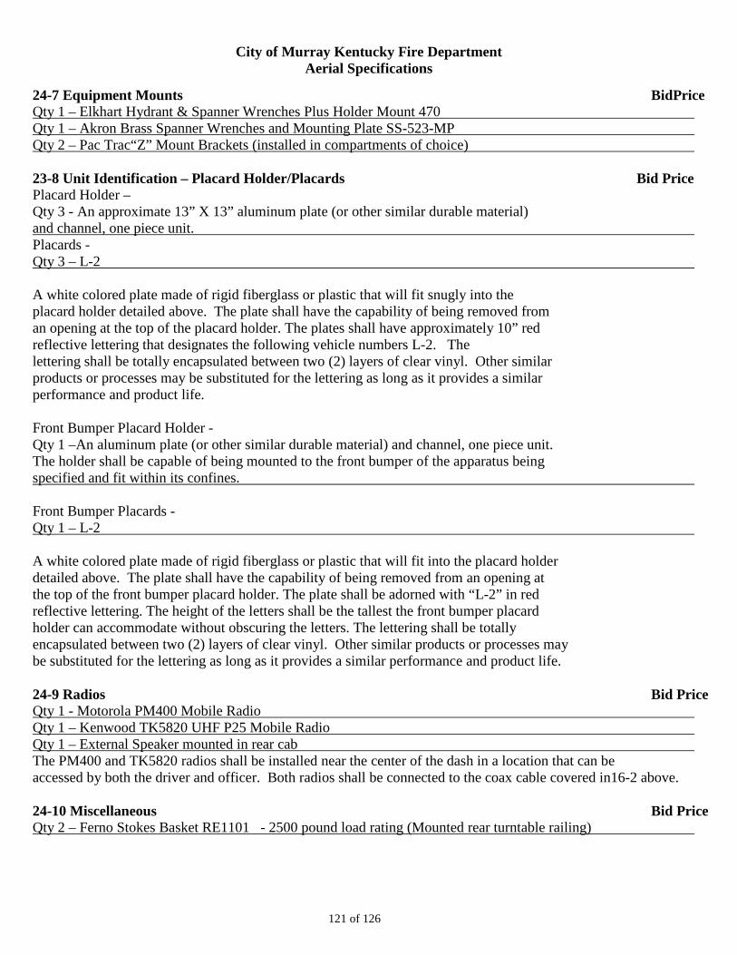
City of Murray Kentucky Fire Department Aerial Specifications
121 of 126
24-7 Equipment Mounts BidPrice Qty 1 – Elkhart Hydrant & Spanner Wrenches Plus Holder Mount 470 Qty 1 – Akron Brass Spanner Wrenches and Mounting Plate SS-523-MP Qty 2 – Pac Trac“Z” Mount Brackets (installed in compartments of choice) 23-8 Unit Identification – Placard Holder/Placards Bid Price Placard Holder – Qty 3 - An approximate 13” X 13” aluminum plate (or other similar durable material) and channel, one piece unit. Placards - Qty 3 – L-2 A white colored plate made of rigid fiberglass or plastic that will fit snugly into the placard holder detailed above. The plate shall have the capability of being removed from an opening at the top of the placard holder. The plates shall have approximately 10” red reflective lettering that designates the following vehicle numbers L-2. The lettering shall be totally encapsulated between two (2) layers of clear vinyl. Other similar products or processes may be substituted for the lettering as long as it provides a similar performance and product life. Front Bumper Placard Holder - Qty 1 –An aluminum plate (or other similar durable material) and channel, one piece unit. The holder shall be capable of being mounted to the front bumper of the apparatus being specified and fit within its confines. Front Bumper Placards - Qty 1 – L-2 A white colored plate made of rigid fiberglass or plastic that will fit into the placard holder detailed above. The plate shall have the capability of being removed from an opening at the top of the front bumper placard holder. The plate shall be adorned with “L-2” in red reflective lettering. The height of the letters shall be the tallest the front bumper placard holder can accommodate without obscuring the letters. The lettering shall be totally encapsulated between two (2) layers of clear vinyl. Other similar products or processes may be substituted for the lettering as long as it provides a similar performance and product life. 24-9 Radios Bid Price Qty 1 - Motorola PM400 Mobile Radio Qty 1 – Kenwood TK5820 UHF P25 Mobile Radio Qty 1 – External Speaker mounted in rear cab The PM400 and TK5820 radios shall be installed near the center of the dash in a location that can be accessed by both the driver and officer. Both radios shall be connected to the coax cable covered in16-2 above. 24-10 Miscellaneous Bid Price Qty 2 – Ferno Stokes Basket RE1101 - 2500 pound load rating (Mounted rear turntable railing)
City of Murray Kentucky Fire Department Aerial Specifications
122 of 126
SECTION 25 – EXCEPTIONS Bidders shall complete this section if they will not comply with any of the specifications as outlined in this document. ALL non-compliance items must be listed individually in this section. Attach additional sheets of paper if needed, but follow the same format provided below.
Section Number
Page Number
Item Description Proposed Substitute (If applicable) Section Number
Page Number Item Description Proposed Substitute (If applicable) Section Number Page Number
Item Description
Proposed Substitute (If applicable) Section Number Page Number Item Description Proposed Substitute (If applicable)
City of Murray Kentucky Fire Department Aerial Specifications
123 of 126
SECTION 26 – PAYMENT TERMS 26-1 The City of Murray will accept no contract that requires down payments, progressive payments during construction, or contracts with escalator clauses. Terms of payment shall be 100 percent payment after acceptance of the vehicle. See SECTION 1-17 for terms of acceptance. No other terms shall be acceptable. 26-2 The bidder shall be aware that it can take up to thirty (30) days to process payment. 26-3 All certificates of origin are to be transferred to the City of Murray and the vehicle shall be titled to the City of Murray by the vendor and delivered with the apparatus.
City of Murray Kentucky Fire Department Aerial Specifications
124 of 126
SECTION 27 – BIDDER QUESTIONAIRE Bidders shall provide answers to each of the following questions. Documentation shall be provided upon request. Responses may be included on separate paper if additional room is needed. 1. How long has the manufacturer been building fire apparatus? 2. How many custom pumper apparatus has the manufacturer built in the past five years? 3. Is the manufacturer International Standards Organization 9001 certified? 4. Does the manufacturer have a training program for vehicle operator’s that ensures familiarity with all modes of operation and with the proper maintenance procedures? 5. Does the manufacturer have a training program for fire mechanics? 6. List any other customer support services offered by the manufacturer. 7. How long has the dealer been selling this brand of apparatus? 8. How many years of experience do the dealer’s sales representative have selling this brand of apparatus? 9. How many fire apparatus has the dealer’s sales representative sold? 10. Where is the dealer’s parts and service facility located? 11. Does the dealer have mobile service units to provide service in the City of Murray? 12. Are all the service technician’s factory trained and EVTCC certified? 13. Does the manufacturer have an engineering staff? 14. Does the engineering staff design the cab, chassis, body, electrical system on their apparatus? 15. Does the manufacturing staff build the cab, chassis, body and electrical system on their apparatus? 16. Does the apparatus you are bidding comply with ALL portions of the applicable vehicles standards (NFPA Standards and FMVSS)? List all items that do not. 17. Will the manufacturer perform fatigue life analysis and testing of all structural components on the apparatus model being bid? Provide which tests and results.
City of Murray Kentucky Fire Department Aerial Specifications
125 of 126
18. Has the manufacturer conducted ride quality testing on the apparatus model being bid? Provide which tests and results. 19. Has the manufacturer conducted cab crashworthiness testing on the apparatus model being bid? Provide which tests and results. 20. Has the manufacturer conducted any other analyses or tests as part of the development of the apparatus model being bid? Provide which tests and results. 21. Has the manufacturer submitted their products to an independent, third party company for testing? If so, provide written certification on which components or systems and the results. 22. What is the apparatus frame and frame crossmembers warranty? 23. What is the cab structural warranty? 24. What is the paint warranty? 25. What is the body structural warranty? 26. What is the pump warranty? 27. What is the pump plumbing warranty? 28. What is the water tank warranty? 29. What is the standard warranty for all components manufactured by the apparatus manufacturer and not covered above? 30. Are there any other specific warranties, either from the manufacturer or from a component supplier? If so, provide what and how long.
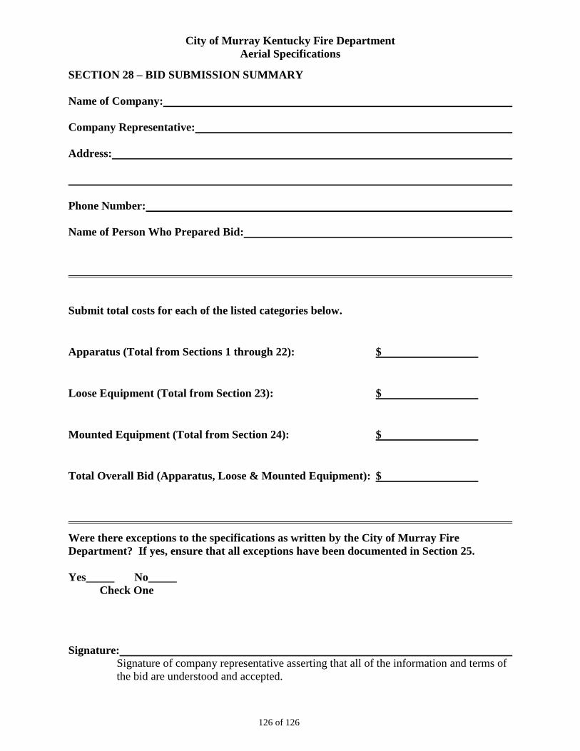
City of Murray Kentucky Fire Department Aerial Specifications
126 of 126
SECTION 28 – BID SUBMISSION SUMMARY Name of Company: Company Representative: Address: Phone Number: Name of Person Who Prepared Bid: Submit total costs for each of the listed categories below.
Apparatus (Total from Sections 1 through 22): $
Loose Equipment (Total from Section 23): $
Mounted Equipment (Total from Section 24): $
Total Overall Bid (Apparatus, Loose & Mounted Equipment): $
Were there exceptions to the specifications as written by the City of Murray Fire Department? If yes, ensure that all exceptions have been documented in Section 25. Yes_____ No_____ Check One
Signature: Signature of company representative asserting that all of the information and terms of the bid are understood and accepted.