Embed Size (px)
Citation preview
City of Lawrence Revised Utilities Department January 2018 Section 2900-Waterline
City of Lawrence
Construction and Material Specifications
Section 2900 – Waterlines
Revised: January 2018

City of Lawrence Revised Utilities Department January 2018 Section 2900-Waterline
City of Lawrence
Construction and Material Specifications
Section 2900 – Waterlines Page No.
SECTION 2901 GENERAL 2900-1
2901.1 Description 2900-1
2901.2 Specification Modification 2900-1
2901.3 Revision of Standards 2900-1
2901.4 Definitions 2900-1
2901.5 Contractor’s Warranty 2900-1
SECTION 2902 MATERIALS 2900-2
2902.1 Scope 2900-2
2902.2 Pipe and Fittings 2900-2
2902.3 Valves and Valve Boxes 2900-5
2902.4 Fire Hydrants 2900-7
2902.5 Stainless Bolts 2900-7
2902.6 Specials 2900-8
2902.7 Bedding Material 2900-10
2902.8 Location Wire and Marking Tape 2900-10
2902.9 Concrete 2900-11
2902.10 Flowable Mortar 2900-11
2902.11 Casing Pipe 2900-11
SECTION 2903 CONSTRUCTION DETAILS 2900-12
2903.1 Grading and Excavation 2900-12
2903.2 Installation 2900-18
2903.3 Jointing 2900-22
2903.4 Connection to Existing Mains 2900-24
2903.5 Polyethylene Encasements 2900-25
2903.6 Setting Valves, Fittings, and Hydrants 2900-26
2903.7 Thrust Restraint 2900-27
2903.8 Embedment and Backfilling 2900-27
2903.9 Disinfection and Testing 2900-28
2903.10 Surface Restoration 2900-31
2903.11 Sanitary Sewer Separation Requirements 2900-31
2903.12 General Utility Separation Requirements 2900-32
2903.13 Abandonments 2900-32
SECTION 2904 MEASUREMENT AND PAYMENT 2900-33
2904.1 Scope 2900-33
2904.2 General 2900-33
2904.3 Items Not Listed in the Proposal 2900-33
2904.4 Basis of Payment 2900-33
2904.5 Standard Bid Items 2900-33
City of Lawrence Revised Section 2900-1 Utilities Department January 2018
SECTION 2901 GENERAL
2901.1 Description: Waterline construction shall consist of furnishing all labor, materials and
equipment for the complete installation of waterlines and appurtenances in accordance
with the contract documents, standard drawings, approved shop drawings, General
Provisions and these specifications. These specifications govern materials for water
mains having a diameter of two inches (50 mm) through 12 inches (300 mm).
2901.2 Specification Modifications: It is understood that throughout this section these
Specifications may be modified by appropriate items in the Special Project
Specifications or notes on the Contract Drawings.
2901.3 Revisions of Standards: When reference is made to a Standard Specification i.e.
ASTM, ANSI, AWWA, MCIB the Specification referred to shall be understood to
mean the latest revision of said specification as amended at the time of the Notice to
Bidders, except as noted on the Plans or in the Special Project Specifications. The City
may, at its option, update and revise these specifications periodically in response to
changing technology and construction methodologies.
2901.4 Definitions: “Engineer” shall mean the Utilities Engineer or the Department of
Utilities authorized representative. “Design Engineer” shall mean the licensed
individual or firm who developed, sealed, and signed the improvement plans.
“Contractor” shall mean any employee, agent or subcontractor of the construction
company responsible for completing the work. “Inspector” shall mean the City of
Lawrence Utilities Department inspector assigned to the project or authorized
representative thereof. “Special Project Specifications” shall mean specifications
modified due to special or unusual project conditions identified by the Design
Engineer that warrant deviation from the City of Lawrence Construction and Material
Specifications Section 2900 – Waterlines, current edition.
2901.5 Contractor’s Warranty: During a period of one year from the date of final acceptance
by the City, the Contractor is responsible for making any necessary repairs arising out
of defective workmanship or materials. This includes, but is not limited to, trench
settlement of water lines constructed as part of this project. The Contractor is
responsible for repairing all trench settlement including removing and replacing
sidewalks, streets, driveways, and entrance walks constructed since the project was
accepted by the City. Representatives from the City and the Contractor shall conduct
an inspection of this project 11 months after the project has been accepted by the City
to determine what repairs need to be made.

City of Lawrence Revised Section 2900-2 Utilities Department January 2018
SECTION 2902 MATERIALS
2902.1 Scope: This section governs materials that may be required to complete waterline
construction as shown on the Plans and/or as provided for in the Special Project
Specifications.
1. Requirements: Furnish pipe of materials, joint types, sizes, and strength classes
indicated or specified. Higher strengths may be furnished at the Contractor’s
option at no additional cost to the project.
2. Manufacturer: The manufacturer shall be experienced in the design, manufacture
and commercial supplying of the specific material.
3. Inspection and Testing: Inspection and testing shall be performed by the
Manufacturer’s quality control personnel in conformance with applicable
standards. Testing may be witnessed by Design Engineer, Engineer or approved
independent testing laboratory. The Contractor shall provide one (1) copy of
certified test reports indicating the materials conform to the specifications to the
Inspector.
4. Handling: Handling of materials used in waterline construction shall conform
with section 2903.2 of these specifications. Damage to materials that cause
reasonable doubt as to their structural strength or water-tightness will cause that
material to be rejected.
2902.2 Pipe, Fittings and Anchor Couplings:
1. Ductile Iron Pipe, Fittings and Anchor Couplings: Unless indicated otherwise on
the plans all ductile iron pipe shall be Class 50 conforming to ANSI A21.51,
AWWA C151, ASTM A536, and shall be of Grade 64-42-10.
All ductile iron fittings and anchor couplings shall be mechanical joint fittings,
class 350, meeting all applicable requirements of ANSI A21.53 and A21.11 and
AWWA C153 and C111. Fittings shall be supplied with all necessary
appurtenances to accomplish installation as shown on the plans. All fittings shall
be provided with stainless steel grade 304 or better bolts, washers, and nuts; nuts
shall be coated to prevent seizing and galling per section 2902.5 of these
specifications.
a. Pipe Joints: Unless otherwise specified, shall be of the push-on type
conforming to ANSI A21.11/AWWA C111, except gaskets shall be neoprene
or synthetic rubber. Natural rubber gaskets will not be acceptable. Mechanical
joints shall conform to ANSI A21.11. Restrained joints shall be Griffin
SnapLok or approved equal.

City of Lawrence Revised Section 2900-3 Utilities Department January 2018
b. Lining: All ductile iron pipe shall be cement mortar lined, conforming to ANSI
A21.4and AWWA C104. All ductile iron fittings shall be lined with a fusion
bonded epoxy conforming to ANSI 21.16 and AWWA C116.
c. Pipe Coating: All ductile iron pipe shall be coated with a layer of arc-sprayed
zinc per ISO 8179 and bituminous top coated per AWWA C151. The mass of
the zinc applied shall be 200 g/m2 of pipe surface area. A finishing layer of
topcoat shall be applied to the zinc. The coating system shall conform in every
respect to ISO 8179-1 “Ductile iron pipes – External zinc-based coating – Part
1: Metallic zinc with finishing layer. Second edition 2004-06-014.”
d. Fitting Coating: All ductile iron fittings shall be shop coated with a fusion
bonded epoxy inside and outside conforming to ANSI A21.16 and AWWA
C116. Anchor couplings shall be shop coated with a fusion bonded epoxy;
asphalt varnish tar coating shall be acceptable when a fusion bonded epoxy
coating is not available for the specified anchor coupling
2. Polyvinyl Chloride Pipe (PVC) and Fittings: PVC shall meet the requirements of
ASTM D1784, cell classification 12454-B, for PVC compounds, and AWWA
C900 with cast iron pipe O.D., for PVC pipe. Materials from which the pipe is
manufactured shall have been tested and approved for conveying potable water by
the National Sanitation Foundation. Pipe shall be marked with nominal pipe size,
dimension ratio, AWWA pressure class, AWWA standard designation number,
NSF-61 mark verifying suitability for potable water service, extrusion production
record code, and cell classification. PVC pipe shall be blue in color and pressure
rated at 200 psi with a dimension ratio (D.R.) of 14 as defined in AWWA C900.
All fittings shall be ductile iron and anchor couplings shall be mechanical joint
fittings, class 350, meeting all applicable requirements of ANSI A21.53 and
A21.11 and AWWA C153 and C111. Fittings shall be supplied with all necessary
appurtenances to accomplish installation as shown on the plans. All fittings shall
be provided with stainless steel grade 304 or better bolts, washers, and nuts; nuts
shall be coated to prevent seizing and galling per section 2902.5 of these
specifications.
a. Joints: Joints for PVC pipe shall be slip on type with integral bell and spigot
pipe, or pipe with extruded type couplings, meeting the requirements of ASTM
D3139, except flexible elastomeric gaskets meeting the requirements of ASTM
F477, shall be synthetic rubber. Natural rubber will not be acceptable.
Restrained joints shall be Certa-Lok C900 RJ (Coupled) or C900 RJIB
(Integral Bell) or approved equal.
b. Lining: All ductile iron fittings shall be lined in conformance with Section
2902.2.1.b of these specifications.
c. Coating: All ductile iron fittings shall be coated in conformance with Section
2902.2.1.c of these specifications.
City of Lawrence Revised Section 2900-4 Utilities Department January 2018
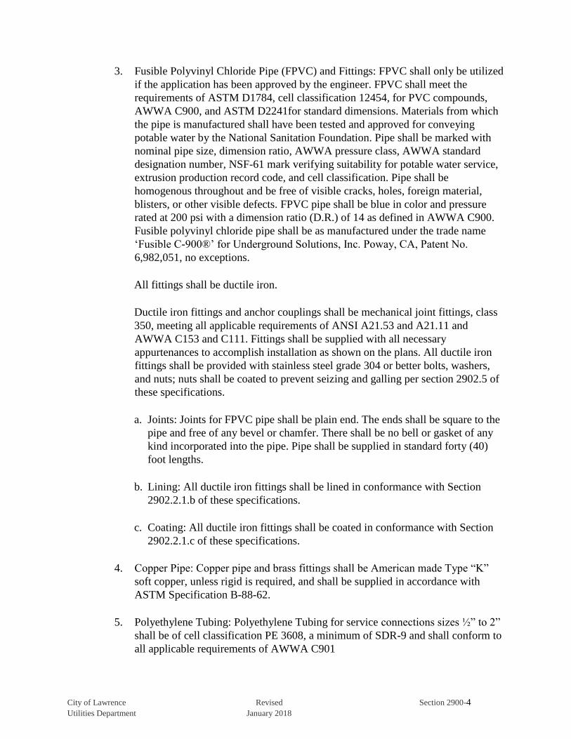
3. Fusible Polyvinyl Chloride Pipe (FPVC) and Fittings: FPVC shall only be utilized
if the application has been approved by the engineer. FPVC shall meet the
requirements of ASTM D1784, cell classification 12454, for PVC compounds,
AWWA C900, and ASTM D2241for standard dimensions. Materials from which
the pipe is manufactured shall have been tested and approved for conveying
potable water by the National Sanitation Foundation. Pipe shall be marked with
nominal pipe size, dimension ratio, AWWA pressure class, AWWA standard
designation number, NSF-61 mark verifying suitability for potable water service,
extrusion production record code, and cell classification. Pipe shall be
homogenous throughout and be free of visible cracks, holes, foreign material,
blisters, or other visible defects. FPVC pipe shall be blue in color and pressure
rated at 200 psi with a dimension ratio (D.R.) of 14 as defined in AWWA C900.
Fusible polyvinyl chloride pipe shall be as manufactured under the trade name
‘Fusible C-900®’ for Underground Solutions, Inc. Poway, CA, Patent No.
6,982,051, no exceptions.
All fittings shall be ductile iron.
Ductile iron fittings and anchor couplings shall be mechanical joint fittings, class
350, meeting all applicable requirements of ANSI A21.53 and A21.11 and
AWWA C153 and C111. Fittings shall be supplied with all necessary
appurtenances to accomplish installation as shown on the plans. All ductile iron
fittings shall be provided with stainless steel grade 304 or better bolts, washers,
and nuts; nuts shall be coated to prevent seizing and galling per section 2902.5 of
these specifications.
a. Joints: Joints for FPVC pipe shall be plain end. The ends shall be square to the
pipe and free of any bevel or chamfer. There shall be no bell or gasket of any
kind incorporated into the pipe. Pipe shall be supplied in standard forty (40)
foot lengths.
b. Lining: All ductile iron fittings shall be lined in conformance with Section
2902.2.1.b of these specifications.
c. Coating: All ductile iron fittings shall be coated in conformance with Section
2902.2.1.c of these specifications.
4. Copper Pipe: Copper pipe and brass fittings shall be American made Type “K”
soft copper, unless rigid is required, and shall be supplied in accordance with
ASTM Specification B-88-62.
5. Polyethylene Tubing: Polyethylene Tubing for service connections sizes ½” to 2”
shall be of cell classification PE 3608, a minimum of SDR-9 and shall conform to
all applicable requirements of AWWA C901
City of Lawrence Revised Section 2900-5 Utilities Department January 2018
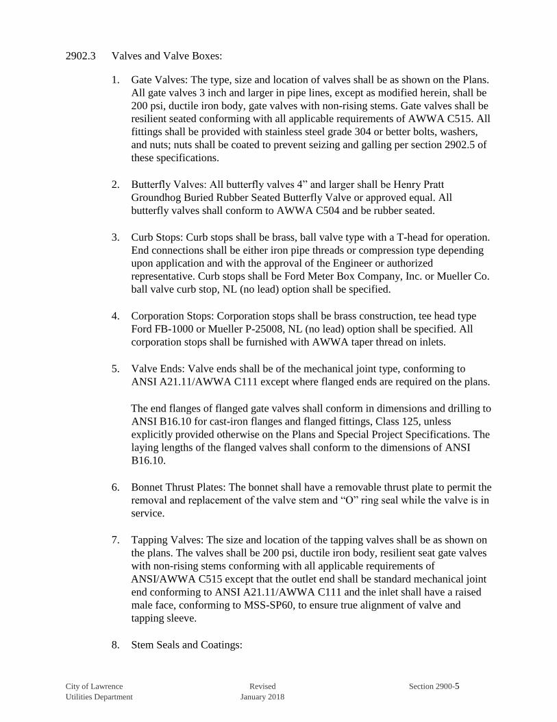
2902.3 Valves and Valve Boxes:
1. Gate Valves: The type, size and location of valves shall be as shown on the Plans.
All gate valves 3 inch and larger in pipe lines, except as modified herein, shall be
200 psi, ductile iron body, gate valves with non-rising stems. Gate valves shall be
resilient seated conforming with all applicable requirements of AWWA C515. All
fittings shall be provided with stainless steel grade 304 or better bolts, washers,
and nuts; nuts shall be coated to prevent seizing and galling per section 2902.5 of
these specifications.
2. Butterfly Valves: All butterfly valves 4” and larger shall be Henry Pratt
Groundhog Buried Rubber Seated Butterfly Valve or approved equal. All
butterfly valves shall conform to AWWA C504 and be rubber seated.
3. Curb Stops: Curb stops shall be brass, ball valve type with a T-head for operation.
End connections shall be either iron pipe threads or compression type depending
upon application and with the approval of the Engineer or authorized
representative. Curb stops shall be Ford Meter Box Company, Inc. or Mueller Co.
ball valve curb stop, NL (no lead) option shall be specified.
4. Corporation Stops: Corporation stops shall be brass construction, tee head type
Ford FB-1000 or Mueller P-25008, NL (no lead) option shall be specified. All
corporation stops shall be furnished with AWWA taper thread on inlets.
5. Valve Ends: Valve ends shall be of the mechanical joint type, conforming to
ANSI A21.11/AWWA C111 except where flanged ends are required on the plans.
The end flanges of flanged gate valves shall conform in dimensions and drilling to
ANSI B16.10 for cast-iron flanges and flanged fittings, Class 125, unless
explicitly provided otherwise on the Plans and Special Project Specifications. The
laying lengths of the flanged valves shall conform to the dimensions of ANSI
B16.10.
6. Bonnet Thrust Plates: The bonnet shall have a removable thrust plate to permit the
removal and replacement of the valve stem and “O” ring seal while the valve is in
service.
7. Tapping Valves: The size and location of the tapping valves shall be as shown on
the plans. The valves shall be 200 psi, ductile iron body, resilient seat gate valves
with non-rising stems conforming with all applicable requirements of
ANSI/AWWA C515 except that the outlet end shall be standard mechanical joint
end conforming to ANSI A21.11/AWWA C111 and the inlet shall have a raised
male face, conforming to MSS-SP60, to ensure true alignment of valve and
tapping sleeve.
8. Stem Seals and Coatings:

City of Lawrence Revised Section 2900-6 Utilities Department January 2018
a. All valves shall be provided with stem seals of the “O” ring type. Two “O”
rings shall be used with at least one “O” ring inserted above the thrust collar.
The packing plate shall be attached to the valve bonnet by not less than two (2)
bolts and one “O” ring below the thrust collar.
b. All ferrous metal surfaces of valves and accessories, both interior and exterior,
shall be shop coated with a fusion bonded epoxy for corrosion protection. The
valve manufacturer’s standard epoxy coating will be acceptable.
9. Valve Operation: All valves shall be equipped with a 2 inch square wrench nut
and the direction of rotation to open the valve shall be counterclockwise. Each
valve body shall have the word “OPEN” and an arrow indicating the direction to
open the valve cast thereon. Wrench nuts shall comply with AWWA C515.
10. Extension Stems: When the distance from the top of the valve cover to the valve
operating nut exceeds 3 feet, an extension stem to bring the valve stem to within 3
feet of the top of the valve cover shall be provided.
11. Valve Boxes, Lids and Covers: All valve boxes, lids, and covers shall be coated in
bituminous varnish.
a. Valve Boxes: All buried valves shall be provided with valve boxes.
1. Valve box shall be cast iron screw type within paved areas.
2. Valve box shall be 6” IPS SDR-26 PVC cut to depth required in turf areas.
3. All valve boxes shall be set plumb and placed directly over the valve it
serves.
4. Valve Boxes shall be installed per City of Lawrence Standard Valve
Adjustment Details.
b. Lids and Covers:
1. Lid and cover shall be Clay and Bailey #2194 or Star Pipe Products
VB0045 or an approved alternative for turf areas.
2. All lids shall have “Water” cast in the lid.
3. All lids shall be installed flush with finished grade.
c. Valve box adapters:
1. Valve box adapters shall be Clay and Bailey #P-1080 with drop type lid or
approved equal.

City of Lawrence Revised Section 2900-7 Utilities Department January 2018
12. The type, size and location of valves shall be as shown on the Plans.
2902.4 Fire Hydrants:
1. General: Fire hydrants shall be open right, dry barrel, standard compression, two-
piece standpipe, break-away design conforming to AWWA C502 and shall
comply with the following:
a. Fire hydrants shall be supplied with one 4 ½” pumper nozzle, two 2 ½” hose
nozzles, 5 ¼” minimum mechanical valve opening with bronze to bronze
seating.
b. Hydrant shall be equipped with a 6” mechanical joint shoe connection with all
joint accessories furnished.
c. Hydrant shoe shall be fusion bonded epoxy coated internally and externally
and all below grade bolts, washers, and nuts shall be stainless steel grade 304
or better; nuts shall be coated to prevent seizing and galling
d. Hydrants shall be Waterous WB-67, U.S or Mueller “Super Centurion”, or
AVK Model 2700 or 2780with traffic safety flanges.
2. Fire hydrants shall be painted Federal Safety Yellow to the ground line.
3. Nut Dimensions: Operating stem and nozzle cap nuts shall be 1 ½” point to flat
pentagon.
4. Nozzle Threads and Caps: Hydrant nozzles shall meet NFPA standard thread
requirements. All hydrant threads shall be oil lubricated by means of an oil
reservoir.
2902.5 Stainless Bolts:
1. Mechanical joint bolts and nuts shall be stainless steel conforming to ASTM F593
for bolts and ASTM F594 for nuts. All T-Bolts and nuts shall be threaded in
accordance with ANSI/ASME B1.1, Class 2A fit, with coarse-thread series.
Heavy hex nuts shall be used. Bolt heads shall be in accordance with the
dimensions of ASSI/AWWA C111/A21.11-95. Nuts shall be finished with
fluoropolymer coating system to minimize galling and ensure proper torque.
Antiseize compound shall not be utilized with the fluoropolymer coated nuts.
Identification on the head of the bolt shall be T-304, 304, F593C or F593D
2. Flange joint bolts and nuts shall be stainless steel conforming to ASTM A193
Grade B8 for bolts and ASTM A194 Grade 8 for nuts. All bolts and nuts shall be
threaded in accordance with ANSI/ASME B1.1, Class 2A fit, with coarse-thread
series. Bolt heads and nuts shall be heavy hexagonal. Nuts shall be finished with
fluoropolymer coating system to minimize galling and ensure proper torque.
City of Lawrence Revised Section 2900-8 Utilities Department January 2018
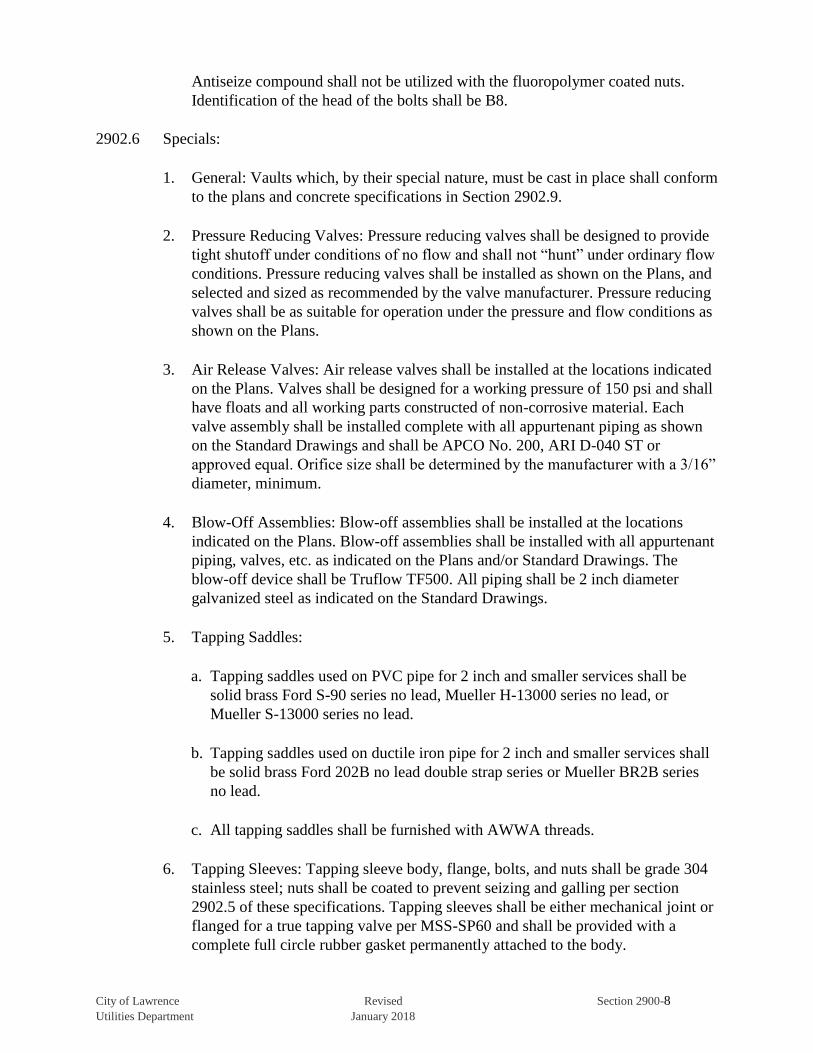
Antiseize compound shall not be utilized with the fluoropolymer coated nuts.
Identification of the head of the bolts shall be B8.
2902.6 Specials:
1. General: Vaults which, by their special nature, must be cast in place shall conform
to the plans and concrete specifications in Section 2902.9.
2. Pressure Reducing Valves: Pressure reducing valves shall be designed to provide
tight shutoff under conditions of no flow and shall not “hunt” under ordinary flow
conditions. Pressure reducing valves shall be installed as shown on the Plans, and
selected and sized as recommended by the valve manufacturer. Pressure reducing
valves shall be as suitable for operation under the pressure and flow conditions as
shown on the Plans.
3. Air Release Valves: Air release valves shall be installed at the locations indicated
on the Plans. Valves shall be designed for a working pressure of 150 psi and shall
have floats and all working parts constructed of non-corrosive material. Each
valve assembly shall be installed complete with all appurtenant piping as shown
on the Standard Drawings and shall be APCO No. 200, ARI D-040 ST or
approved equal. Orifice size shall be determined by the manufacturer with a 3/16”
diameter, minimum.
4. Blow-Off Assemblies: Blow-off assemblies shall be installed at the locations
indicated on the Plans. Blow-off assemblies shall be installed with all appurtenant
piping, valves, etc. as indicated on the Plans and/or Standard Drawings. The
blow-off device shall be Truflow TF500. All piping shall be 2 inch diameter
galvanized steel as indicated on the Standard Drawings.
5. Tapping Saddles:
a. Tapping saddles used on PVC pipe for 2 inch and smaller services shall be
solid brass Ford S-90 series no lead, Mueller H-13000 series no lead, or
Mueller S-13000 series no lead.
b. Tapping saddles used on ductile iron pipe for 2 inch and smaller services shall
be solid brass Ford 202B no lead double strap series or Mueller BR2B series
no lead.
c. All tapping saddles shall be furnished with AWWA threads.
6. Tapping Sleeves: Tapping sleeve body, flange, bolts, and nuts shall be grade 304
stainless steel; nuts shall be coated to prevent seizing and galling per section
2902.5 of these specifications. Tapping sleeves shall be either mechanical joint or
flanged for a true tapping valve per MSS-SP60 and shall be provided with a
complete full circle rubber gasket permanently attached to the body.
City of Lawrence Revised Section 2900-9 Utilities Department January 2018
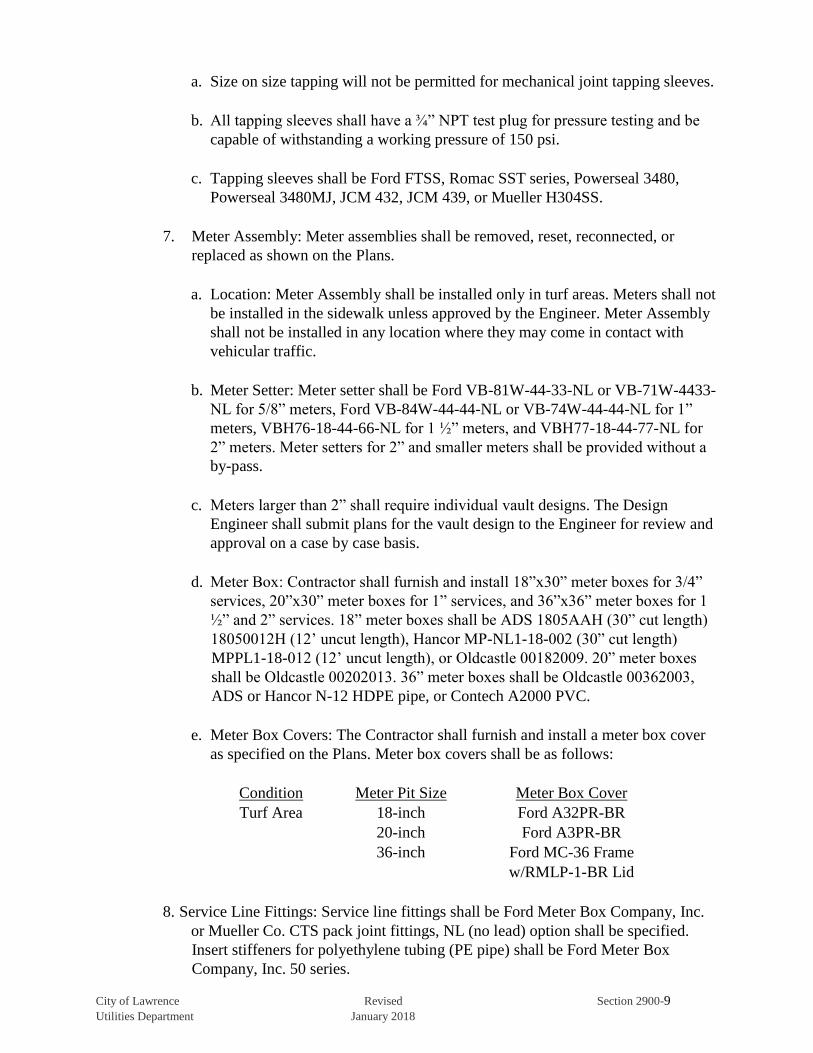
a. Size on size tapping will not be permitted for mechanical joint tapping sleeves.
b. All tapping sleeves shall have a ¾” NPT test plug for pressure testing and be
capable of withstanding a working pressure of 150 psi.
c. Tapping sleeves shall be Ford FTSS, Romac SST series, Powerseal 3480,
Powerseal 3480MJ, JCM 432, JCM 439, or Mueller H304SS.
7. Meter Assembly: Meter assemblies shall be removed, reset, reconnected, or
replaced as shown on the Plans.
a. Location: Meter Assembly shall be installed only in turf areas. Meters shall not
be installed in the sidewalk unless approved by the Engineer. Meter Assembly
shall not be installed in any location where they may come in contact with
vehicular traffic.
b. Meter Setter: Meter setter shall be Ford VB-81W-44-33-NL or VB-71W-4433-
NL for 5/8” meters, Ford VB-84W-44-44-NL or VB-74W-44-44-NL for 1”
meters, VBH76-18-44-66-NL for 1 ½” meters, and VBH77-18-44-77-NL for
2” meters. Meter setters for 2” and smaller meters shall be provided without a
by-pass.
c. Meters larger than 2” shall require individual vault designs. The Design
Engineer shall submit plans for the vault design to the Engineer for review and
approval on a case by case basis.
d. Meter Box: Contractor shall furnish and install 18”x30” meter boxes for 3/4”
services, 20”x30” meter boxes for 1” services, and 36”x36” meter boxes for 1
½” and 2” services. 18” meter boxes shall be ADS 1805AAH (30” cut length)
18050012H (12’ uncut length), Hancor MP-NL1-18-002 (30” cut length)
MPPL1-18-012 (12’ uncut length), or Oldcastle 00182009. 20” meter boxes
shall be Oldcastle 00202013. 36” meter boxes shall be Oldcastle 00362003,
ADS or Hancor N-12 HDPE pipe, or Contech A2000 PVC.
e. Meter Box Covers: The Contractor shall furnish and install a meter box cover
as specified on the Plans. Meter box covers shall be as follows:
Condition Meter Pit Size Meter Box Cover
Turf Area 18-inch Ford A32PR-BR
20-inch Ford A3PR-BR
36-inch Ford MC-36 Frame
w/RMLP-1-BR Lid
8. Service Line Fittings: Service line fittings shall be Ford Meter Box Company, Inc.
or Mueller Co. CTS pack joint fittings, NL (no lead) option shall be specified.
Insert stiffeners for polyethylene tubing (PE pipe) shall be Ford Meter Box
Company, Inc. 50 series.
City of Lawrence Revised Section 2900-10 Utilities Department January 2018
2902.7 Bedding Material:
1. Pipe Embedment: Embedment for pipe shall be in accordance with these
specifications.
a. Pipe embedment shall be clean sand or CA-5 both above and below the pipe.
Sand embedment shall be a minimum of 6 inches and a maximum of 12 inches
both above and below the pipe. Trench width shall conform to the Standard
Drawings and Section 2903.1.7 of these specifications.
1. Clean sand shall be non-cohesive and free of ice, clay, rocks, soil, organic
matter or other deleterious materials.
2. CA-5 shall meet the requirements specified in Division 1100 of the Kansas
Department of Transportation (KDOT) specifications.
2902.8 Location Wire and Tape: Location wire and marking tape shall be buried above all
waterlines in accordance with the following:
1. Location Wire:
a. Location wire shall be installed to enable the detection of all plastic, ductile
iron, and copper pipe. Location wire shall be 12 AWG copper clad steel (CCS),
minimum break load of 280 lbs. with blue 30mil HDPE jacket for open trench
installations or 12 AWG copper clad steel (CCS), minimum break load of
1,100 lbs. with blue 45 mil HDPE jacket for directional drill installation.
b. The location wire shall be placed no further than 6 inches to the side or above
the waterline. For directional drill installations tracer wire shall be taped every
8-10 feet.
c. The location wire shall be accessible at valve boxes, fire hydrants, meter tiles,
or test stations at least every 1,500 feet. The location wire shall be installed on
the outside of the valve box with a 3/16” hole drilled three inches from the top
of the valve box for the location wire to pass through. Test stations shall be
Copperhead Industries Snake Pit magnetized Tracer Boxes; lite duty XL box
for unpaved areas and roadway box for paved areas.
d. Splicing of location wire shall be accomplished by the use of Copperhead
Industries LLC Locking SnakeBite Wire Connector, Copperhead Industries
LLC SCB-01SR direct bury splice kit, Copperhead Industries LLC 3WB-01
DryConn Three-way direct bury Lug Connector, or 3M DBR/Y-6 direct bury
splice kit. Copperhead Industries LLC Locking Snake Bite splice kit shall only
be used with Copperhead Industries LLC wire.
e. Anodes shall be a minimum of one pound bare magnesium or zinc drive-in
grounding anode rod and shall be driven into the ground at the same elevation
City of Lawrence Revised Section 2900-11 Utilities Department January 2018
as the waterline. Anodes shall be placed at the beginning and end of the
watermain, at the meter end of every service line, at every valve box or test
station, at all dead ends, at the end of service lines where not connected to the
wire at the main, and/or at least every fifteen hundred feet (1,500’).
2. Marking Tape:
a. Underground marker tape shall be installed 18 inches above waterline.
b. The marking tape shall be at least 3 inches in width, blue in color, and shall
have black lettering stating “Caution Buried Waterline Below”. Lettering shall
be printed on the tape at 20 to 30 inch intervals.
2902.9 Concrete: All concrete shall conform to the requirements of the City of Lawrence
Technical Specifications Section 2000, Concrete.
2902.10 Flowable Mortar: All flowable mortar shall conform to the requirements of the City of
Lawrence Technical Specifications Section 1100, Grading.
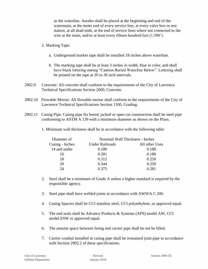
2902.11 Casing Pipe: Casing pipe for bored, jacked or open cut construction shall be steel pipe
conforming to ASTM A 139 with a minimum diameter as shown on the Plans.
1. Minimum wall thickness shall be in accordance with the following table:
Diameter of Nominal Wall Thickness - Inches
Casing - Inches Under Railroads All other Uses
14 and under 0.188 0.188
16 0.281 0.188
18 0.312 0.250
20 0.344 0.250
24 0.375 0.281
2. Steel shall be a minimum of Grade A unless a higher standard is required by the
responsible agency.
3. Steel pipe shall have welded joints in accordance with AWWA C 206.
4. Casing Spacers shall be CCI stainless steel, CCI polyethylene, or approved equal.
5. The end seals shall be Advance Products & Systems (APS) model AW, CCI
model ESW or approved equal.
6. The annular space between lining and carrier pipe shall be not be filled.
7. Carrier conduit installed in casing pipe shall be restrained joint pipe in accordance
with Section 2902.2 of these specifications.

City of Lawrence Revised Section 2900-12 Utilities Department January 2018
8. Cathodic and corrosion protection shall be provided for all casing conduits. One
32 lb sacrificial anode package per 100 feet of casing pipe shall be provided at
each end of the casing. Sacrificial, magnesium anodes shall be attached to the
encasement pipe by a #12 A.W.G. grounding wire at each end of the casing. For
casing pipes less than 100 feet in length sacrificial anodes shall be provided at a
rate of 0.50lb/ft of casing with a minimum anode size of 5 lbs. required.
9. Minimum casing pipe size shall be in accordance with the following table:
Diameter of Recommended Casing Minimum Casing
Carrier Pipe (in) Pipe Diameter (in) Pipe Diameter (in)
8 16 12
12 20 18
SECTION 2903 CONSTRUCTION DETAILS
2903.1 Grading and Excavation:
1. Scope: Excavation and trenching work shall include the necessary clearing,
grubbing, and preparation of the site; removal and disposal of all debris;
excavation and trenching as required; the handling, storage, transportation and
disposal of all excavated material; all necessary sheeting, shoring, and protection
work; preparation of subgrades; pumping and dewatering as necessary or
required; protection of adjacent property; and other appurtenant work.
2. General: The terms “excavation” and “trenching” shall mean the removal and
subsequent handling of all material required to perform the work.
a. All waterline excavation work shall be accomplished under supervision of a
person experienced with the materials and procedures, which will provide
protection to existing improvements, including utilities and the proposed
waterline. A currently certified competent person shall be present during all
excavation operations according to OSHA regulations.
b. Contractor shall have a trench safety plan for the trench conditions to be
encountered on the project. The trench safety plan shall be available on the job
site at all times it shall be designed by a licensed professional engineer should
conditions warrant.
c. When pipe is to be installed in embankment or fill, the embankment shall be
built up to a plane at least 18 inches above the top of the pipe prior to the
excavation of the trench.
d. The Contractor shall not open more trench in advance of pipe laying than is
necessary to expedite the work. One block or 400 feet (whichever is the
shorter) shall be the maximum length of open trench on any line under
City of Lawrence Revised Section 2900-13 Utilities Department January 2018
construction. All open trenches shall be adequately protected and shall
conform with OSHA safety standards.
e. In the event hazardous wastes as defined by the Resource Conservation and
Recovery Act of 1976 (PL94-580) are encountered, work shall be halted and
the Engineer shall be notified. Work shall be resumed only after the Contractor
has notified the proper authorities and permission has been given by the
governing authority to resume construction activities. Regulation of removal,
handling and disposal of hazardous wastes is the responsibility of Federal and
State agencies.
f. Except where tunneling, horizontal directional drilling, or boring and jacking is
specified and shown on the Plans, all trench excavation shall be open cut from
the surface.
3. Unclassified Excavation: Unclassified excavation is defined as the removal of all
material encountered regardless of its nature. All material excavated will be
considered as Unclassified Excavation.
4. De-Watering: The Contractor shall remove any water that may accumulate or be
found in the trenches and other excavations made under the Contract.
The Contractor shall form all dams, flumes or other works necessary to keep the
excavation clear of water while the waterlines, and other appurtenant works, are
being constructed. All water shall be removed from such excavation in a manner
that will not damage property.
5. Blasting: When blasting is permitted by Lawrence-Douglas County Fire and
Medical Services, the Contractor shall use the utmost care to protect life and
property. The Contractor shall comply with all laws, ordinances, and the
applicable safety code requirements and regulations relative to the handling,
storage and use of explosives and protection of life and property, and shall be
responsible for all damage thereto caused by his or his subcontractor’s operations.
The Contractor shall provide insurance as required by the General Provisions and
Covenants and Special Project Specifications before performing any blasting. The
governing agency shall be notified at least 24 hours before blasting operations
begin.
6. No Blasting Areas: No blasting of any kind for rock excavations or any other
purpose will be allowed within areas noted as such on the Plans.
7. Open-Cut Method (Trenching):
a. Scope: This item establishes the requirements to be followed for waterline
excavation performed by the open-cut method (trenching).

City of Lawrence Revised Section 2900-14 Utilities Department January 2018
b. General: Excavations for waterlines shall be accomplished by the open-cut
method (trenching) except as specified or approved by the Engineer. Trenching
shall be with a minimum inconvenience and disturbance to the general public.
The Contractor shall sort and stockpile the excavated material so the proper
material is available for backfill.
c. Trench bottoms which become soft, mucky, or otherwise unstable during
construction operations shall be stabilized, by and at the expense of the
Contractor, with one or more layers of crushed rock or other suitable material,
where and as necessary to provide a firm and stable base for granular fill pipe
foundation material to be placed thereon. Not more than one-half inch (1/2”)
depth of mud or muck shall be allowed to remain on the stabilized trench
bottom when the granular fill pipe foundation material is installed.
d. Trench Depths: All trenches shall be excavated to depths required for proper
pipe embedment. Overdepth excavation shall be required when the subgrade is
unstable. Overdepth excavations that result in a stable trench shall be
backfilled with pipe embedment material unless otherwise directed by the
Engineer.
e. Trench Walls: Undercutting of trench walls is not permitted.
f. Trench Sheeting: Except where banks are cut back on a stable slope,
excavation for structures and trenches shall be properly and substantially
sheeted, braced and shored, as necessary, to prevent caving or sliding, to
provide protection for workmen and the work, and to provide protection for
existing structures and facilities. Sheeting, bracing and shoring shall be
designed and built to withstand all loads that might be caused by earth
movement or pressure and shall be rigid, maintaining shape and position under
all circumstances.
Trench sheeting shall not be pulled before backfilling unless the pipe strength
is sufficient, in the opinion of the Design Engineer, to carry trench loads based
on trench width to the back of sheeting. Sheeting shall not be pulled after
backfilling. When ordered by the Design Engineer, sheeting shall be left
permanently in the trench. Payment for such sheeting will be made in
accordance with the contract provisions for extra work.
When trench sheeting is left in place, such sheeting shall not be braced against
the pipe, but shall be supported in a manner which will preclude concentrated
loads or horizontal thrusts on the pipe. Cross braces installed above the pipe to
support sheeting may be removed after pipe embedment has been completed.
g. Limiting Trench Width: Trenches shall be excavated to a width which will
provide adequate working space and pipe clearances for proper pipe
installation, jointing, and embedment. However, the limiting trench widths
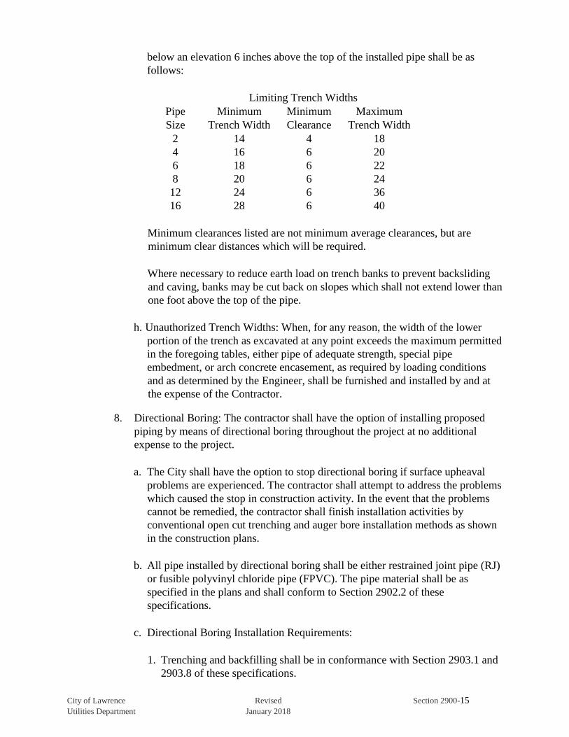
City of Lawrence Revised Section 2900-15 Utilities Department January 2018
below an elevation 6 inches above the top of the installed pipe shall be as
follows:
Limiting Trench Widths
Pipe Minimum Minimum Maximum
Size Trench Width Clearance Trench Width
2 14 4 18
4 16 6 20
6 18 6 22
8 20 6 24
12 24 6 36
16 28 6 40
Minimum clearances listed are not minimum average clearances, but are
minimum clear distances which will be required.
Where necessary to reduce earth load on trench banks to prevent backsliding
and caving, banks may be cut back on slopes which shall not extend lower than
one foot above the top of the pipe.
h. Unauthorized Trench Widths: When, for any reason, the width of the lower
portion of the trench as excavated at any point exceeds the maximum permitted
in the foregoing tables, either pipe of adequate strength, special pipe
embedment, or arch concrete encasement, as required by loading conditions
and as determined by the Engineer, shall be furnished and installed by and at
the expense of the Contractor.
8. Directional Boring: The contractor shall have the option of installing proposed
piping by means of directional boring throughout the project at no additional
expense to the project.
a. The City shall have the option to stop directional boring if surface upheaval
problems are experienced. The contractor shall attempt to address the problems
which caused the stop in construction activity. In the event that the problems
cannot be remedied, the contractor shall finish installation activities by
conventional open cut trenching and auger bore installation methods as shown
in the construction plans.
b. All pipe installed by directional boring shall be either restrained joint pipe (RJ)
or fusible polyvinyl chloride pipe (FPVC). The pipe material shall be as
specified in the plans and shall conform to Section 2902.2 of these
specifications.
c. Directional Boring Installation Requirements:
1. Trenching and backfilling shall be in conformance with Section 2903.1 and
2903.8 of these specifications.
City of Lawrence Revised Section 2900-16 Utilities Department January 2018
2. All open trenches and excavations shall be backfilled within forty-eight (48)
hours after work is completed or as directed by the Engineer.
3. The contractor shall install carrier piping at planned locations at required
depth and length as noted on the approved plans, along with any fittings,
valves, fire hydrants and tracer wire.
4. All carrier pipe installed by directional boring shall be pressure tested for
integrity by the prescribed method as outlined in section 2903.9 of these
specifications.
5. The contractor shall dispose of drilling fluids in accordance with any local,
state or federal regulations. Restoration of damage to any surface or
structure caused by escaping drilling fluid, or directional drilling operation,
shall be the responsibility of the contractor.
6. Precautions shall be taken to keep drilling fluid out of streets, manholes,
sanitary and storm sewers and other drainage systems, including streams
and rivers. The contractor shall make every effort to minimize spills during
construction and shall act promptly to clean up any drilling mud overflows
or spills if experienced.
7. The contractor shall be responsible for the restoration of all areas uplifted
(pavement or sidewalk heaving, etc.) and/or settlement resulting from
directional drilling construction activities.
8. The proposed pipe shall not be installed with more than 5 feet (60 inches) of
cover unless attaining depth to clear utilities.
9. The contractor shall expose (pothole) all utilities in advance of directional
boring activities. Utilities shall remain exposed during drilling activities to
prevent damage to existing utilities due to increased soil pressure resulting
from construction activities.
9. Minimum and Maximum Cover: Trenches shall be excavated to a depth sufficient
to provide a minimum depth of backfill cover over the top of pipe of 42 inches
when back of curb, and with a maximum depth of backfill cover over the top of
the pipe of 60 inches in paved areas, except where connections to existing
waterlines are made, unless otherwise shown in the plans. Depth of cover shall be
measured from the top of pipe to the finished grade or pavement surface
elevation. Greater depths of cover may be necessary on vertical curves or to
provide necessary clearance beneath existing pipes, conduits, drains, drainage
structures, or other obstructions encountered at normal waterline grades. When
greater depths of cover are necessary, measures shall be taken to bring the pipe
back to the proper depth as quickly as possible utilizing either allowable pipe

City of Lawrence Revised Section 2900-17 Utilities Department January 2018
deflection or pipe fittings in accordance with Section 2902.2 of these
specifications.
10. Trench Bottom in Earth: The trench in earth shall have a flat bottom the full width
of the trench and shall be excavated to the grade to which the pipe is to be laid.
The surface shall be graded to provide uniform bearing and continuous support
for each pipe at every point along its entire length.
11. Trench Bottoms in Rock: All rock excavation shall be carried to a minimum of 6
inches below the bottom of the pipe. Pipe embedment material shall be used to
restore the trench bottom to the desired elevation and grade and to provide a
uniform bearing and continuous support for the pipe along its entire length. Care
shall be exercised to prevent any portion of the pipe from coming to bear on solid
rock or boulders.
12. Pipe Embedment: Embedment material shall be spread and the surface graded to
provide a uniform and continuous support beneath the pipe at all points between
bell holes or pipe joints. It will be permissible to slightly disturb the finished
subgrade surface by withdrawal of pipe slings or other lifting tackle.
After each pipe has been graded, aligned, and placed in final position on the
bedding material and shoved home, sufficient pipe embedment material shall be
deposited and compacted under and around each side of the pipe and back of the
bell or end thereof to hold the pipe in proper position and alignment during
subsequent pipe jointing and embedment operations. Embedment material shall be
deposited and compacted uniformly and simultaneously on each side of the pipe
to prevent lateral displacement.
13. Rock Exploration: Unless shown otherwise on the plans or noted in the Special
Project Specifications, no rock exploration has been made. On those projects
where rock exploration has been made, test holes have been drilled at locations
and intervals as shown on the Plans or subsurface information report to determine
the approximate location and depth of rock. Resistance to penetration was
assumed to be “solid rock”. This information is furnished for general reference
purposes only.
The Contractor must form his own opinion as to the character of materials which
will be encountered from an inspection in the ground, from his own investigation
of the test hole information, or from such other investigations as he may desire.
14. Mechanical Excavation: The use of mechanical equipment will not be permitted
in locations where its operations would cause damage to trees, buildings, culverts,
or other existing property, utilities, or structures above or below ground. In all
such locations, alternate excavating methods shall be used
Mechanical equipment used for trench excavation shall be of the type, design, and
construction and shall be so operated that the rough trench excavation bottom
City of Lawrence Revised Section 2900-18 Utilities Department January 2018
elevation can be controlled, that uniform trench widths and vertical sidewalls are
obtained at least from the bottom of the trench, and that trench alignment will be
centered in the trench with adequate clearance between the pipe and the sidewalls
of the trench. Undercutting the trench to obtain sidewall clearance will not be
permitted.
All mechanical trenching equipment, its operating conditions, and the manner of
its operations shall be subject at all times to the approval of the Engineer.
15. Stream Crossings: Stream crossings shall be made in accordance with these
specifications and as shown on the Plans.
The trench width shall be as required for proper pipe installation and the trench
depth shall be as required to give minimum cover shown on the Plans. Pipe
encasement, where required, shall be in accordance with the specifications and
placed as indicated on the Plans.
16. Highway and Railroad Crossings: The Contractor shall make highway and
railroad crossings in accordance with these specifications, the Special Project
Specifications and as shown on the Plans.
All construction or work performed and all operations of the Contractor, his
employees, or subcontractors within the limits of highway or railroad right-
ofways shall be in conformance with all the requirements and regulations of the
authority having jurisdiction of said right-of-ways.
The Contractor shall pay all fees and obtain all permits to make the crossings
unless otherwise directed.
2903.2 Installation:
1. General: Laying of ductile iron pipe, polyvinyl chloride pipe; fusible polyvinyl
chloride pipe, installation of valves, and hydrants; and embedment and backfill
shall conform to the following specifications.
a. Unless otherwise specified herein or as shown on the plans, back of curb water
mains shall be installed with a minimum cover of forty two (42) inches
measured from the top of pipe to the finished grade and water mains installed
under pavement shall be installed with a minimum of sixty (60) inches of cover
measured from the top of pipe to the top of pavement.
b. Whenever pipe laying is stopped, the open end of the line shall be sealed with a
watertight plug which will prevent trench water from entering the pipe.
2. Ductile Iron Pipe:

City of Lawrence Revised Section 2900-19 Utilities Department January 2018
a. Handling: Pipe, fittings, and accessories shall be handled in a manner that will
ensure installation in a sound, undamaged condition. Equipment, tools, and
methods used in unloading, reloading, hauling, and laying pipe and fittings
shall be such that pipe, pipe coating, and fittings are not damaged. Hooks shall
not be used. Under no circumstances shall pipe or accessories be dropped or
dumped. Pipe and fittings on which the cement lining has been broken or
loosened shall be replaced by the Contractor at his sole expense. Where
damaged areas are small and readily accessible, the Contractor may be
permitted to repair the lining.
All pipe coating which has been damaged shall be repaired by the Contractor
prior to installing the pipe.
b. Cutting pipe: Ductile iron pipe shall be cut with either a saw or an abrasive
wheel. Cutting of existing cast iron pipe shall be done with either a saw or
abrasive wheel, or when there is a free end, with mechanical pipe cutters. The
cutting of pipe with a torch will not be permitted.
Cutting shall be done in a neat manner without damage to the pipe, or the
cement lining. Cuts shall be smooth, straight, and at right angles to the pipe
axis. After cutting, the end of the pipe shall be dressed with a file to remove all
roughness and sharp corners.
c. Cleaning. The interior of all pipe and fittings shall be thoroughly cleaned of
foreign matter prior to installation and shall be kept clean until the work has
been accepted. Such surfaces shall be wire brushed, if necessary, wiped clean,
and kept clean until jointing is completed.
d. Inspection: Pipe and fittings shall be carefully examined for cracks and other
defects immediately before installation. Spigot ends shall be examined with
particular care since they are vulnerable to damage from handling. All
defective, damage, or unsound pipe and fittings shall be rejected and marked as
such and removed from the site of work.
e. Alignment: Waterlines or runs intended to be straight shall be laid straight.
Deflections from a straight line or grade shall not exceed the quantities
stipulated in AWWA C600.
f. Laying Pipe: Pipe shall be protected from lateral displacement by pipe
embedment material installed per section 2903.8 of these specifications. Under
no circumstances shall the pipe be laid in water, and no pipe shall be laid under
unsuitable trench conditions.
3. Polyvinyl Chloride Pipe (PVC)
a. Handling: Pipe, fittings, and accessories shall be handled in a manner that will
insure installation in sound, undamaged condition. Equipment, tools, and
methods used in reloading, hauling, and laying pipe and fittings shall be such

City of Lawrence Revised Section 2900-20 Utilities Department January 2018
that the pipe and fittings are not damaged. Hooks inserted in ends of pipe shall
have broad, well padded contact surfaces.
b. Cutting Pipe: All pipe shall be cut with a saw or special cutting tool. Cutting
shall be done in a neat manner without damage to the pipe. Cuts shall be
smooth, straight, and at right angles to the pipe axis. After cutting, the end of
the pipe shall be dressed and beveled. Beveling shall be done with a
specifically designed beveling tool. Hand beveling will not be allowed. When
cutting pipe with couplings, mark the field cut pipe end the same distance in as
the mark appeared on the original full length pipe section.
c. Cleaning: The interior of all pipe and fittings shall be thoroughly cleaned of
foreign matter before being installed and shall be kept clean until the work has
been accepted.
d. Inspection: PVC pipe shall be installed in strict accordance with the
requirements and instructions of the pipe manufacturer. It shall be protected
from lateral displacement and deflection by pipe embedment material installed
per Section 2903.8 of these specifications and as shown on the Standard
Drawings. No pipe shall be laid under unsuitable trench conditions.
e. Alignment: Waterlines or runs intended to be straight shall be laid straight.
Deflections from a straight line or grade shall not exceed the quantities
stipulated in AWWA C605.
f. Laying Pipe: Pipe shall be protected from lateral displacement by pipe
embedment material installed as specified. Under no circumstances shall the
pipe be laid in water, and no pipe shall be laid under unsuitable trench
conditions.
4. Fusible Polyvinyl Chloride Pipe (FPVC)
a. Handling (Pipe): Pipe shall be loaded, off-loaded, and otherwise handled in
accordance with AWWA M23 and all pipe suppliers’ guidelines shall be
followed. The use of chains, wire rope, chokers, or other pipe handling
implements that may scratch, nick, cut, or gouge the pipe are strictly
prohibited. Any scratch or gouge greater than 10% of the wall thickness will be
considered significant and may be cause for rejection. Damaged areas may be
removed by cutting, limits of acceptable length of pipe shall be determined by
the owner or engineer.
b. Handling (Fittings and Accessories): Fittings and accessories shall be handled
in a manner that will ensure installation in a sound, undamaged condition.
Equipment, tools, and methods used in unloading, reloading, and hauling
fittings and accessories shall be such that fittings and accessories are not
damaged. Fittings on which the cement lining has been broken or loosened
shall be replaced by the Contractor at his sole expense. Where damaged areas
City of Lawrence Revised Section 2900-21 Utilities Department January 2018
are small and readily accessible, the Contractor may be permitted to repair the
lining.
c. Cutting Pipe: All pipe shall be cut with facing blades specifically designed for
cutting fusible polyvinyl chloride pipe.
d. Cleaning: The interior of all pipe and fittings shall be thoroughly cleaned of
foreign matter before being installed and shall be kept clean until the work has
been accepted.
e. Inspection: FPVC pipe shall be installed in strict accordance with the
requirements and instructions of the pipe supplier for open cut, horizontal
directional drilling (HDD), or pipe bursting installation methods.
f. Alignment: Waterlines or runs intended to be straight shall be laid straight.
Deflections from a straight line or grade shall not exceed the pipe suppliers
recommended bending radius guidelines.
g. Laying Pipe: Pipe shall be protected from lateral displacement by pipe
embedment material installed as specified. Under no circumstances shall the
pipe be laid in water, and no pipe shall be laid under unsuitable trench
conditions.
5. Casing and Carrier Conduits: Casing and carrier conduits shall be installed at
required locations by methods acceptable to the Engineer. Installation of the
carrier conduit shall be completed prior to installation of the adjacent portions of
the pipeline to allow for adjustments.
a. Casing Types:
1. Steel Casing Pipe: Steel casing pipe is flexible conduit and shall be designed
to conform with the following design concept (other methods may be
submitted to the Engineer for approval).
(a) The steel casing conduit is considered a permanent installation to protect
the carrier conduit and to support all loads, therefore, cathodic and
corrosion protection and watertight removable end seals are required for
the casing conduit. Care shall be exercised to prevent the carrier conduit
from floating and receiving any load transfer from the casing conduit
unless it is designed for such loading. The void between casing and
carrier conduits shall not be filled. Cathodic and corrosion protection
shall be provided for all casing conduits. One 32 lb sacrificial anode
package per 100 feet of casing pipe shall be provided at each end of the
casing. Sacrificial, magnesium anodes shall be attached to the casing
pipe by a #12 A.W.G. grounding wire at each end of the casing.
City of Lawrence Revised Section 2900-22 Utilities Department January 2018
b. Casing Installation: Installation of casing shall be supervised by a contractor
experienced in such work. Casing shall be installed by a combination of
horizontal directional drilling, augering and jacking or open cut trenching,
where allowed. Alignment and gradient shall be such that the carrier conduit
can be installed to line and grade shown on the drawings.
Welding of steel casing pipe, when multiple pipe sections are used, shall be
performed by a person experienced with the type of welding necessary. All
welds shall conform to AWWA C 206.
c. Liner Plate Installation: Liner plates shall be assembled immediately following
the excavation. Advance liner plates or casing continuously with excavation.
All voids between liner and surrounding earth shall be filled with a pumpable
grout resulting in a minimum set strength of 4000psi in 28 days, forced in
under pressure. As the pumping through any hole is completed, it shall be
plugged to prevent the back-flow of grout. After lining installation is complete,
it shall be cleaned of all debris and all leaks sealed.
d. Carrier Conduit Installation: After completion of the installation of the casing,
the carrier conduit shall be carefully pushed or pulled through the casing in a
manner that will maintain proper jointing of the pipe joints and provide
required gradient and alignment. Carrier conduit installed in casing pipe shall
be restrained joint pipe in accordance with Section 2902.2 of these
specifications.
e. Casing Spacers: Casing spacer type shall conform to section 2902.11.4. Casing
spacer interval, size and installation method shall be as recommended by the
manufacturer for the particular installation.
f. End Seals: End seals shall conform to Section 2902.11.5. End seal installation
shall be as recommended by the manufacturer and shall be constructed after
sewer pipe has been installed and approved.
g. The annular space between lining and sewer pipe shall not be filled.
h. Initial Testing: Air pressure and/or exfiltration test shall be required and shall
be successfully performed on the carrier conduit prior to the sealing of the ends
of the casing conduit.
2903.3 Jointing:
1. Push-on Joints: All instructions and recommendations of the pipe manufacturer,
relative to gasket installation and other jointing operations, shall be followed by
the Contractor. All joint surfaces shall be lubricated immediately before the joint
is completed.
City of Lawrence Revised Section 2900-23 Utilities Department January 2018
The lubricant and the gaskets shall be as recommended and supplied by the pipe
manufacturer. The lubricant shall be suitable for use in potable water, shall be
stored in closed containers, and shall be kept clean.
Field cut pipe and each spigot end shall be suitably beveled to facilitate
installation.
2. Mechanical Joints: Mechanical joints shall be carefully assembled in accordance
with the manufacturer’s recommendations. If effective sealing is not obtained the
joint shall be disassembled, thoroughly cleaned, and reassembled. Under no
circumstance will over-tightening of bolts be permitted.
3. Flanged Joints: When bolting flanged joints, care shall be taken to ensure that
there is no restraint on the opposite end of the pipe or fitting which would prevent
uniform gasket compression or which would cause unnecessary stress in the
flanges. One flange shall be free to move in any direction while the flange bolts
are being tightened. Bell and Spigot joints shall not be packed or assembled until
all flanged joints affected thereby have been tightened. Bolts shall be tightened
gradually and at a uniform rate so that gasket compression is uniform. All
fasteners shall be grade 304 stainless steel or better and shall be coated to prevent
seizing and galling.
4. Restrained Joints: Restrained joints and anchoring joints shall be installed in strict
accordance with the pipe manufacturer’s recommendations.
5. Fused Joints: fusible polyvinyl chloride pipe lengths shall be assembled in the
field with butt fused joints. Butt fusion shall be completed in strict accordance
with the pipe suppliers’ written guidelines for this procedure.
a. Butt fusion shall be performed by qualified fusion technicians as documented
by the pipe supplier.
b. Fusion joints shall be recorded and logged by an electronic monitoring device
(data logger) connected to the fusion machine. The fusion data logging and
joint report shall be generated by software developed specifically for the
buttfusion of fusible polyvinyl chloride pipe. The software shall register and/or
record the parameters required by the pipe supplier and these specifications.
Data not logged by the data logger shall be logged manually and be included in
the Fusion Technician’s joint report. Joint reports shall be submitted and
approved by the pipe supplier prior to installation of any fusible polyvinyl
chloride pipe.
c. Only appropriately sized and outfitted machines that have been approved by
the pipe supplier shall be used for the fusion process. Fusion machines must
incorporate the following elements:

City of Lawrence Revised Section 2900-24 Utilities Department January 2018
1. Heat Plate: Heat plates shall be in good condition with no deep gouges or
scratches. Plates shall be clean and free of any debris or contamination.
Heater controls shall function properly, cord and plug shall be in good
condition. The appropriately sized heat plate shall be capable of maintaining
a uniform and consistent heat profile and temperature for the size of pipe
being fused per the pipe suppliers’ guidelines.
2. Carriage: Carriage shall travel smoothly with no binding at less than 50 psi.
Jaws shall be in good condition with proper inserts for the pipe size being
fused. Insert pins shall be installed with no interference to carriage travel.
3. General Machine: Overview of machine body shall yield no obvious
defects, missing parts, or potential safety issues during fusion.
4. Data Logging Device: An approved data logging device with the current
version of the pipe suppliers’ recommended and compatible software shall
be used. Data logging device operations and maintenance manual shall be
with the unit at all times. If fusing for extended periods of time, an
independent 110V power source shall be available to extend battery life.
d. Other equipment specifically required for the fusion process shall include the
following:
1. Pipe rollers shall be used for support of pipe to either side of the machine.
2. A weather protection canopy that allows full machine motion of the heat
plate, fusion assembly and carriage shall be provided for fusion in
inclement, extreme temperatures, and /or windy weather, per the pipe
supplier’s recommendations.
3. An infrared (IR) pyrometer for checking pipe and heat plate temperatures.
4. Fusion machine operations and maintenance manual shall be kept with the
fusion machine at all times.
2903.4 Connection to Existing Mains: The Contractor shall furnish and install all fittings
necessary to join the existing and new water mains as shown on the plans.
The Department of Utilities shall be given at least 24 hours’ notice prior to turning off
any water supply mains. The Contractor shall coordinate tie-ins with the Department
of Utilities to minimize down time.
Connections shall be made using suitable fittings for the conditions encountered. Each
connection with an existing pipe shall be made at a time and under conditions which
will minimize any disruption in service. Special care shall be taken to prevent
contamination when dewatering, cutting into, and making connections with existing
pipe. The interior of all pipe, fittings, and valves installed in such connections shall be
City of Lawrence Revised Section 2900-25 Utilities Department January 2018
thoroughly cleaned and swabbed with, or dipped in, chlorine solution having a
chlorine content of 200 ppm.
2903.5 Polyethylene Encasements:
1. General: Polyethylene encasement shall be installed on all ductile iron pipe and
fittings.
2. Polyethylene Encasement for use with ductile iron pipe shall meet all the
requirements for ANSI/AWWA C105/A21.5, Polyethylene Encasement for
Ductile Iron Pipe Systems.
3. Polyethylene Film: Polyethylene film shall consist of three layers of co-extruded
linear low density polyethylene (LLDPE), fused into a single thickness of not less
than 8 mils. The inside surface of the polyethylene wrap to be in contact with the
pipe exterior shall be infused with a blend of antimicrobial biocide to mitigate
microbiologically influenced corrosion and a volatile corrosion inhibitor to
control galvanic corrosion.
4. PVC Pipe Wrapping Tape: PVC pipe wrapping tape, minimum 2” width and 10
mil thickness, shall be used to secure all ends, joints, and repairs of polyethylene
film. Duct tape shall not be used. Installation shall be as described in detail in
ASTM 674-05.
5. Repairs: Repair any cuts, tears, punctures, or damage to polyethylene film with
PVC pipe wrapping tape or short length of polyethylene sheet or cut open tube,
wrapped around pipe to cover damaged area, and secured in place.
6. Installation: Polyethylene encasement shall be installed in accordance with
AWWA C600 and ANSI/AWWA C105/A21.5 and also in accordance with all
recommendations and practices of the AWWA M41, Manual of Water Supply
Practices – Ductile Iron Pipe and Fittings. Specifically, the wrap shall be
overlapped one foot in each direction at joints and secured in place around the
pipe, and any wrap at tap locations shall be taped tightly prior to tapping and
inspected for any needed repairs following the tap.
7. Backfill: Prevent damage to film by assuring that backfill material is free from
cinders, refuse, boulders, rocks, stones, or other material that could damage the
film. Follow AWWA C600 for backfilling.
8. Certification: The installing contractor shall submit an affidavit stating
compliance with the requirements and practices of ANSI/AWWA C150/A21.50,
ANSI/AWWA C151/A21.51, ANSI/AWWA C105/A21.5, AWWA C600 and
M41. This certification shall be provided in duplicate to the City Inspector.
City of Lawrence Revised Section 2900-26 Utilities Department January 2018
2903.6 Setting Valves, Fittings, and Hydrants
1. Valves and Fittings: All valves, fittings, plugs, and caps shall be set and joined to
the pipe in the manner heretofore specified for cleaning, laying and joining pipe,
except that large valves may require special support so that the pipe will not be
required to support the valve weight.
Each valve shall be inspected before installation to ensure that all foreign
substances have been removed from within the valve body, and shall be opened
and closed to see that all parts are in a new working condition. Gate valves shall
be set vertical in the horizontal waterline. Valves and pipe shall be supported in
such a manner as to prevent stress in either with no deflection in the valve/pipe
joint.
Valve boxes and lids shall be installed at each valve and shall be supported and
maintained centered and plumb over the operating nut of the valve. The valve box
shaft shall not transmit shock or stress to the valve. Install valve box covers flush
with the surface of the finished grade or as directed by the Engineer.
All bends and tees shall be provided with thrust blocks as specified. All dead ends
on new mains shall be closed with plugs or caps suitably restrained to prevent
blowing off under test pressure.
2. Hydrants: All new hydrant installations shall be as shown on the Plans or
Standard Drawings and shall include all necessary excavation and backfill to
make the installation complete.
Each hydrant shall be inspected before installation for direction opening, nozzle
size and threading, nozzle caps and chains, operating nut, and cap nut dimensions,
tightness of pressure-containing bolting, cleanliness of inlet elbow and weep hole
openings, and handling damage and cracks. Defective hydrants shall be corrected
or replaced.
All hydrants shall stand plumb. The weep holes of the hydrant shall be kept clear
and free to drain and shall be covered with three (3) cubic feet of ¾” wash rock.
The areas around each hydrant and hydrant valve shall be thoroughly compacted
to prevent settlement of these areas.
Hydrants shall be set to a grade that allows their proper operation. Traffic
hydrants with breakaway joint must be set with the joint above the ground line.
Hydrants shall be placed with the hydrant centerline a minimum of four (4) feet
and a maximum of twelve (12) feet from the back of curb line. Hydrants shall be
rotated so as to have the pumper nozzle facing the street or rotated to face any
direction as required by the Engineer.
Hydrants shall be repainted upon completion of installation.
City of Lawrence Revised Section 2900-27 Utilities Department January 2018
2903.7 Thrust Restraint:
1. Hydrants: The back of the base elbow of each hydrant shall be braced against a
sufficient area of unexcavated earth or rock with a concrete thrust block and be
restrained by suitable restrained joints as shown on the Plans or Standard
Drawings.
2. Fittings: All plugs, caps, tees, bends, and other fittings, unless otherwise
specified, shall be provided with reaction blocking and suitable restrained joints
as shown on the Plans or Standard Drawings.
3. Thrust Blocks: Vertical and Horizontal reaction blocking shall be concrete
conforming with Section 2902.9 of these specifications. Thrust blocks shall be
installed between solid ground and the fitting to be restrained. Concrete shall be
located to contain the resultant force and permit access to pipe and fitting joints
for repairs.
2903.8 Embedment and Backfilling: Embedment and backfill shall be accomplished in
accordance with the laying condition as specified and as shown on the Plans and
Standard Drawings.
1. Pipe Embedment: Embedment for pipe shall be in accordance with Section 2902.7
of these specifications and details of the laying condition as indicated on the
Plans.
2. Trench Backfill: Backfill for the entire length of the waterline shall be compacted
full depth of the trench above the embedment.
a. Compacted backfill shall be finely divided job excavated material free from
debris, organic material, frozen materials, and stones larger than three (3)
inches in greatest dimension. Masses of moist, stiff clay shall not be used and
no rock shall be allowed within thirty six (36) inches of a waterline.
b. Select Backfill Material: Select backfill material shall be equivalent to the
Kansas Department of Transportation Standard Specifications for AB-3.
c. Trench backfill shall be flowable mortar, conforming to Section 2902.10 of
these specifications, for all trenches crossing existing or proposed public
streets, alleyways or sidewalks to a point two (2) feet beyond the edge of the
public pavement, and for all portions of trenches running parallel to and within
two (2) feet of the edge of the public pavement. All other trench backfill shall
be either flowable mortar or compacted earth as indicated on the drawings and
standard details, or as specified in the Special Project Specifications.
d. Earth backfill material to be placed above pipe embedment shall be free of
brush, roots more than two (2) inches in diameter, debris, cinders, or other
corrosive material, but may contain rubble and detritus from rock excavation,
stones, and boulders in certain portions of the trench depth. No backfill
City of Lawrence Revised Section 2900-28 Utilities Department January 2018
material containing rocks, or rock excavation detritus material, shall be placed
within two (2) feet of final surface. No rock greater than six (6) inches in its
largest axis shall be placed in any trench excavation as backfill. No rock shall
be placed within thirty six (36) inches of a waterline.
e. Structure Backfill: Backfill around structures shall be compacted to the extent
necessary to prevent future settlement, by tamping or other means acceptable
to the Engineer.
f. Whenever, in the opinion of the Engineer, the material excavated from the
trenches is not suitable for backfilling, or there is a deficiency of material
suitable for backfilling, the Contractor shall provide suitable material. The
Contractor shall remove all excess excavated materials and shall dispose of
them at locations provided by the Contractor.
3. Placement and Compaction:
a. Job excavated materials shall be placed in lifts not to exceed 8 inches in depth.
Each lift shall be compacted to the required density prior to the next lift being
placed. Increased layer thickness may be permitted for non-cohesive material if
the Contractor demonstrates to the satisfaction of the Engineer that the
specified compacted density will be obtained. The method of compaction and
the equipment used shall be appropriate for the material to be compacted and
shall not transmit damaging shocks to the pipe.
b. Select backfill placement shall be in lifts of not more than 6 inches in
compacted thickness, which shall be compacted by means of mechanical
tampers to a density of at least 95 percent of maximum as determined from
ASTM D698.
c. Flowable mortar shall be discharged from the mixer by a reasonable means
into the trench area to be filled. Flowable mortar shall be placed to the bottom
of existing or future pavement.
d. Trench backfill, unless otherwise specified, shall be compacted to a minimum
of 95% of the standard proctor maximum density for the material used as
determined by ASTM D698
4. Testing: All laboratory tests required ensuring compliance of embedment and
backfill with specified requirements herein shall be paid for directly by the
Contractor. Copies of test results shall be submitted to and approved by the
Engineer.
2903.9 Disinfection and Testing:
1. General: All water mains constructed shall be disinfected and tested as specified
herein.
City of Lawrence Revised Section 2900-29 Utilities Department January 2018
a. All hydrostatic testing shall be done in the presence of the Engineer, Inspector
or authorized representative.
b. All water sampling shall be performed by the Engineer, Inspector or authorized
representative.
c. Bacteriological testing shall be performed by the City of Lawrence Utilities
Department Laboratory.
d. The Contractor shall notify the Engineer 72 hours in advance of the times and
places at which testing work is to be done.
e. Temporary discharge piping shall be provided for disposing of test water. Test
water shall be disposed of without damage to public or private property.
2. Disinfection: After installation, the entire main shall be flushed and disinfected by
chlorination per AWWA C651-05. The Contractor shall disinfect the main or
prepare the main for disinfection by the owning authority when so noted in the
Special Project Specifications.
a. Flushing shall be carried out until water free of visual turbidity is obtained
from all points along the main.
b. Disinfection may be performed concurrently with pressure testing if acceptable
to the Inspector, or after pressure testing is completed.
c. Disinfection of newly constructed waterlines shall be accomplished by the
introduction of a chlorinated solution of not less than 25mg/L into the lines.
The contact period shall not be less than 24 hours and the free chlorine residual
at the end of the contact period shall not be less than 10mg/L. Following
chlorination, all chlorinated water shall be flushed from the system.
Chlorinated water to be flushed from the system shall be de-chlorinated as
environmental conditions warrant per Section 4.5.2 of AWWA C651-05. Type
and application of neutralizing chemicals shall conform to Appendix C, Table
C.1 of AWWA C651-05.
d. All existing mains which require a section to be removed for connection work
shall be disinfected. The interior of all pipe and fittings used in making the
connection shall be swabbed with a 5-10% hypochlorite solution immediately
prior to their installation in the system. When the assembly is completed, the
existing main shall be thoroughly flushed.
e. Two consecutive sets of acceptable samples taken at least 24 hours apart, shall
be collected from the new main. If the initial disinfection fails to produce
satisfactory bacteriological results or if other water quality is affected, the new
main may be reflushed and shall be resampled. If second set of samples also
fail to produce acceptable results, the main shall be rechlorinated until
City of Lawrence Revised Section 2900-30 Utilities Department January 2018
satisfactory results are obtained—that being two consecutive sets of acceptable
samples taken 24 hr apart.
f. Each water main tested shall be allowed two sets of disinfection tests. Should
the main fail to produce satisfactory results and additional testing is required,
the contractor will be charged a fee of $500 per test for inspection and testing.
3. Hydrostatic Testing: The Contractor shall perform hydrostatic pressure testing in
accordance with AWWA C600 or AWWA C605 procedures as applicable. Where
practicable, waterlines shall be tested in lengths between line valves or plugs of
no more than 1500 feet in length.
a. General:
1. All waterlines shall be subjected to hydrostatic testing. All shutoff valves
shall be open during pressure testing. Anchored or blocked test plugs shall
be placed as necessary to limit testing length as specified above.
2. The Contractor shall provide all necessary pumping equipment, piping
connections, pressure gauges, anchored or blocked test plugs, and all other
equipment, materials, and facilities for the testing.
3. The contractor shall replace materials, repair waterlines, and repeat testing
as necessary should the initial testing fail to yield satisfactory results.
Testing shall be repeated until satisfactory results are obtained.
4. Gauges shall have documentation of calibration. .
b. Hydrostatic Pressure Testing:
1. The test pressure at any point in the waterline shall be 2.5 times the
operating pressure not to exceed 200 psi.
2. The test pressure shall be maintained for a minimum of (2 hours is AWWA
Standard with allowable leakage) 30 minutes or whatever period is
necessary for the Inspector to inspect the waterline. Under no circumstance
shall the Inspector be permitted to leave the project site during pressure
testing activities.
3. Any drop in pressure across the tested section of the waterline shall
constitute failure of the pressure test.
4. All pipe, fittings, valves, pipe joints, and other materials which are found to
be defective shall be removed immediately and replaced with new and
acceptable material, by and at the expense of the Contractor.
City of Lawrence Revised Section 2900-31 Utilities Department January 2018
5. Pressure testing shall be repeated until the line and all parts thereof
withstand the test pressure in a satisfactory manner.
2903.10 Surface Restoration: This section covers restoration of asphalt pavement, gravel
surfacing, sidewalk, driveways, curbs, and other surface construction removed or
damaged during the progress of the work:
1. All surface restoration work shall comply with City of Lawrence Technical
Specifications, current edition, and Kansas Department of Transportation
Standard Specifications for State Road and Bridge Construction, latest edition.
2. All restoration work shall be subject to acceptance by the Engineer, owner, and
agency having jurisdiction thereof. All materials utilized for surface restoration
work shall be new unless otherwise specified on the Plans, Special Project
Specifications, or as approved by the Engineer.
2903.11 Sanitary Sewer Separation Requirements:
1. Horizontal Separation:
a. A minimum of ten (10) feet horizontal separation, as measured from the
outside edge to outside edge, shall be required between a potable waterline and
a sanitary sewer main, force main, service line, or manhole.
b. Under no circumstance shall potable waterline and sanitary sewer be placed in
the same trench.
c. Potable waterlines shall meet the minimum separation requirements from all
pollution sources as set forth by the appropriate reviewing agency.
d. When waterlines and other utilities are laid parallel to each other the separation
distance shall be determined based on geotechnical considerations. A minimum
of three (3) feet of undisturbed earth separating the trenches shall be required.
Under no circumstance shall waterlines and other utilities be installed in the
same trench.
2. Vertical Separation:
a. A minimum of two (2) feet vertical separation, as measured from the outside
walls of the pipe, shall be required between a sanitary sewer main or service
line and potable waterline.
b. In general potable waterlines shall be located above sanitary sewer lines.
c. Potable waterlines shall maintain a minimum of two (2) feet of vertical
separation, as measured from the outside walls of the pipe, and shall always
cross above any sewer force main.
City of Lawrence Revised Section 2900-32 Utilities Department January 2018
3. Protective Measures: When potable waterlines and gravity sanitary sewers cross
with less than two (2) feet of vertical clearance, and in all cases where the potable
waterline is located below the gravity sanitary sewer, additional measures must be
employed to protect the potable waterline.
Acceptable measures include:
a. Construction of the sanitary sewer line using one of the following materials:
1. Ductile iron pipe conforming to ASTM A536 or ANSI/AWWA
C151/A21.52 with a minimum thickness class 50, and gasketed, push-on, or
mechanical joints in conformance with ANSI/AWWA C110/A21.10 or
ANSI/AWWA C111/A21.11.
2. PVC pipe conforming to ASTM D3034 with minimum wall thickness of
SDR41, ASTM F679, or ASTM F794, with gasketed push-on joints in
conformance with ASTM D3212.
3. Reinforced concrete pipe conforming to ASTM C76 with gasketed joints in
conformance with ASTM C361 or ASTM C443.
Install a minimum twenty (20) foot length of sanitary sewer pipe on the
crossing to maximize the joint spacing to a minimum of ten (10) feet from the
crossing.
b. Provide concrete encasement of the sanitary sewer line a minimum of six (6)
inches in thickness for a minimum distance of ten (10) feet either side of the
waterline crossing.
c. Sanitary sewer service lines may be constructed using schedule 40 PVC pipe
with solvent welded joints. Pipe joints shall be located a minimum of ten (10)
feet either side of the waterline crossing.
2903.12 General Utility Separation Requirements:
1. Horizontal Separation: A minimum of five (5) feet of horizontal separation, as
measured from outside walls of the pipe, shall be required between all utilities,
excluding sanitary sewer, and potable waterlines.
2. Vertical Separation: A minimum of two (2) foot of vertical separation, as
measured from the outside walls of the pipe, shall be required between all utilities
and potable waterlines.
2903.13 Abandonments:
1. Waterline: The abandoned waterline shall be disconnected and capped. At the
point of disconnection any valve remaining shall be removed and the waterline

City of Lawrence Revised Section 2900-33 Utilities Department January 2018
remaining active shall be capped with a mechanical joint plug and a thrust block
shall be installed.
2. Service Line: Water service lines shall be abandoned at the main. The curb
stop/corporation stop and tapping saddle shall be removed, and the main shall be
repaired with stainless steel repair clamp. If in the opinion of the Department of
Utilities a repair clamp cannot be properly installed, a section of main may need
to be replaced as directed by the Department.
3. Fire Line: Fire lines shall be abandoned at the main. The curb stop, corporation
stop, or valve and tapping saddle or tapping sleeve shall be removed and the main
shall be repaired with a stainless steel repair clamp. If in the opinion of the
Department of Utilities a repair clamp cannot be properly installed, a section of
main may need to be replaced as directed by the Department.
4. Fire Hydrant: Fire hydrants shall be abandoned at the main. The entire hydrant
assembly shall be removed at the tee and the tee shall be plugged and blocked. If
a tapping saddle is present the tapping saddle shall be removed and the main
repaired with a stainless steel repair clamp. If in the opinion of the Department of
Utilities a repair clamp cannot be properly installed, a section of main may need
to be replaced as directed by the Department.
SECTION 2904 MEASUREMENT AND PAYMENT
2904.1 Scope: This section covers the methods of measurement, and the basis of payment, for
the furnishing of all labor, equipment, tools and materials and for the performance of
all related work necessary to complete any construction covered in Section 2900.
2904.2 General: The methods of measurement and payment shall be in accordance with City
of Lawrence Technical Specifications Section 0010: General Technical Provisions, as
specified herein, and as listed in the Proposal.
2904.3 Items not listed in the Proposal: There will be no measurement or separate payment
for any items of work not specifically identified and listed in the Proposal and all costs
pertaining thereto will be included in the Lump Sum Proposal or Contract Unit Prices
for other items listed in the Proposal.
2904.4 Basis of Payment: Payment will be made of the respective unit at the unit or lump-sum
price listed in the proposal and shall be full compensation for all labor, materials, and
equipment necessary to complete the respective unit in place. There will be no
separate measurement or payment for any item of work not specifically identified and
listed in the proposal, and all such work shall be considered a subsidiary item with all
costs pertaining thereto included in the prices for other items listed in the proposal. At
the Engineer’s option, partial payment may be made for any lump sum item listed in
the proposal, providing that the Contractor is diligently and satisfactorily pursuing full
completion of such partially complete item in accordance with the approved job
progress schedule.
2904.5 Standard Bid Items: The following is a list of standard bid items and quantity units for
waterline projects. Project-specific or special items shall be added to the list where

City of Lawrence Revised Section 2900-34 Utilities Department January 2018
appropriate. Lack of inclusion of a specific item from the Standard Bid Items List will
not be justification for non-performance. All work must meet City Standards.
Bid Item Quantity Unit
Mobilization LS
__-inch Waterline LF
__-inch Gate Valve EA
__-inch Bend and Block EA
__-inch Fitting (Tee, Cross, Reducer, Sleeves) EA
Connect to Existing Waterline EA
Water Meter Removal and Abandonment EA
Water Meter Installation or Relocation EA
Fire Hydrant Assembly EA
Valve Lid Adjustment EA
Air Release Valves EA
Seed, Fertilize, and Mulch LS
Erosion Control LS
Construction Staking LS
Traffic Control LS
Disinfection and Pressure Testing LS
Demobilization LS