Embed Size (px)
Citation preview


Table of Contents
i
CITY OF INDIANAPOLIS DEPARTMENT OF PUBLIC WORKS
INDIANAPOLIS SANITARY DISTRICT STANDARDS MANUAL
TABLE OF CONTENTS
CHAPTER 100 POLICIES AND PROCEDURES
SECTION 101 Introduction Page
101.01 Purpose......................................................................................................................1-2 101.02 Sanitary Sewer Manual Organization ........................................................................1-2 101.03 Updating.....................................................................................................................1-2 101.04 Abbreviations and Definitions ....................................................................................1-3 101.05 Enforcement of Standards .........................................................................................1-7 101.06 Penalties ....................................................................................................................1-7
SECTION 102 General - Procedures and Requirements Applicable to All Permits
102.01 Introduction ................................................................................................................1-8 102.02 Applicability ................................................................................................................1-8 102.03 Exemptions ................................................................................................................1-8 102.04 Fees .........................................................................................................................1-8 102.05 Refunds......................................................................................................................1-8 102.06 Expiration of Permit ...................................................................................................1-8 102.07 Transfer of Permit ......................................................................................................1-9 102.08 Notice of Change in Permit Information.....................................................................1-9 102.09 Amendment of Permits and Plans ...........................................................................1-10 102.10 Revocation of Permit or Variance............................................................................1-10 102.11 Stop-Work Order......................................................................................................1-10 102.12 Variance Procedures ...............................................................................................1-10 102.13 Appeals ....................................................................................................................1-11
SECTION 103 Laterals - Procedures and Requirements
103.01 Introduction ..............................................................................................................1-12 103.02 Responsibility...........................................................................................................1-12 103.03 Applicability ..............................................................................................................1-12 103.04 Connection Fee and EDU Calculation.....................................................................1-12 103.05 Submittal Requirements for a Lateral Permit...........................................................1-14 103.06 Who May Apply........................................................................................................1-15 103.07 Lateral Inspection Requirements.............................................................................1-15 103.08 Enforcement of Bond ...............................................................................................1-16
SECTION 104 – Sanitary Sewer Facilities - Procedures and Requirements
104.01 Introduction ..............................................................................................................1-17 104.02 Sanitary Sewer Approval and Construction Permit – General ................................1-17 104.03 Capacity Certification / Allocation ............................................................................1-17 104.04 Submittal Requirements for Approval and Construction Permit ..............................1-17 104.05 Who May Apply for an Approval and Obtain a Permit .............................................1-20 104.06 Who Can Do the Work.............................................................................................1-20

Table of Contents
ii
SECTION 105 – Sanitary Sewer Construction Inspection and Acceptance Procedures
105.01 Introduction ..............................................................................................................1-21 105.02 General Authority for Investigations and Inspections ..............................................1-21 105.03 Construction Inspection Requirements....................................................................1-21 105.04 Requirements for Project Acceptance and Dedication............................................1-22 105.05 Record (As-Built”) Drawings ....................................................................................1-23 105.06 Digital Data Submission Standards .........................................................................1-23 105.07 Dedication of Existing Private Sewers.....................................................................1-24
CHAPTER 200 DESIGN
SECTION 201 Lateral Design
201.01 Introduction .................................................................................................................2-2 201.02 General .......................................................................................................................2-2 201.03 Prohibited Connections...............................................................................................2-2 201.04 Maximum Number of Building Connections................................................................2-2 201.05 Point of Connection.....................................................................................................2-2 201.06 Size, Depth, and Slope of Lateral ...............................................................................2-3 201.07 Location, Length, and Spacing of Lateral ...................................................................2-3 201.08 Cleanouts ....................................................................................................................2-4 201.09 Minimum Elevations for Gravity Connection...............................................................2-4 201.10 Connections Utilizing an Existing Lateral....................................................................2-4 201.11 Laterals Crossing Drainage Ways ..............................................................................2-5 201.12 Future Connections.....................................................................................................2-5
SECTION 202 Gravity Sanitary Sewer Design
202.01 Introduction .................................................................................................................2-6 202.02 General .......................................................................................................................2-6 202.03 Sanitary Sewer Service Area Study............................................................................2-6 202.04 Design Flow ................................................................................................................2-7 202.05 Pipe Size, Slope, and Depth.......................................................................................2-8 202.06 Extensions for Off-site Unsewered and/or Undeveloped Areas .................................2-9 202.07 Location of Sanitary Sewer Facilities..........................................................................2-9 202.08 Location and Elevation of Sanitary Sewer Facilities within Special Flood Hazard Zones............................................................................................................2-10 202.09 Capacity Certification ................................................................................................2-11 202.10 Downstream Evaluation ............................................................................................2-11 202.11 Inadequate Downstream Evaluation.........................................................................2-12 202.12 Connections to Existing Sanitary Sewers ................................................................2-13 202.13 Connections in the Combined Sewer Area...............................................................2-13
SECTION 203 Sewer Structures - Manholes
203.01 Introduction ...............................................................................................................2-15 203.02 Location.....................................................................................................................2-15 203.03 Protection Against Ponding.......................................................................................2-15 203.04 Maximum Manhole Spacing......................................................................................2-16 203.05 Manhole Dimensions ................................................................................................2-16 203.06 Drop Connections .....................................................................................................2-16
SECTION 204 Other Requirements
204.01 Drafting Standards ....................................................................................................2-18 204.02 Easements ................................................................................................................2-18

Table of Contents
iii
204.03 Protection of Water Supplies ....................................................................................2-19 204.04 Existing Utility Structures and Facilities ....................................................................2-20 204.05 Utility Coordination....................................................................................................2-20 204.06 Sanitary Sewers Crossing Drainage Ways...............................................................2-20 204.07 Aerial Crossings and Siphons...................................................................................2-21
CHAPTER 300 MATERIALS
SECTION 301- General
301.01 Introduction ................................................................................................................3-2 301.02 General for All Materials ...........................................................................................3-2 301.03 Material Markings ......................................................................................................3-2 301.04 Certification of Materials ............................................................................................3-2 301.05 Handling, Storage, and Color ....................................................................................3-2
SECTION 302 - Sanitary Sewer Pipe Material
302.01 Introduction ................................................................................................................3-3 302.02 Allowable Pipe Materials ...........................................................................................3-3 302.03 Polyvinyl Chloride Pipe (PVC) ...................................................................................3-4 302.04 Closed Profile Large Diameter PVC .........................................................................3-5 302.05 Centrifugally Cast Fiberglass Reinforced Polymer Mortar Pipe ................................3-6 302.06 Reinforced Concrete Pipe (RCP) ..............................................................................3-8 302.07 Ductile Iron Pipe (DIP).............................................................................................3-10 302.08 Prestressed Concrete Cylinder Pipe (PCCP)..........................................................3-11
SECTION 303 – Laterals
303.01 Introduction ..............................................................................................................3-13 303.02 Lateral Materials ......................................................................................................3-13 303.03 Controlled Settlement (Slip) Joints ..........................................................................3-13
SECTION 304 – Force Main Material 304.01 Introduction ..............................................................................................................3-14 304.02 Allowable Force Main Material ................................................................................3-14 304.03 Polyvinyl Chloride (PVC) Pipe ................................................................................3-14 304.04 High Density Polyethylene (HDPE) Pipe.................................................................3-15 304.05 Ductile Iron Pipe (DIP).............................................................................................3-16 304.06 Prestressed Concrete Cylinder Pipe (PCCP)..........................................................3-17 SECTION 305 - Manhole Material and Appurtenances
305.01 Introduction ..............................................................................................................3-18
305.02 Precast Sanitary Manholes......................................................................................3-18 305.03 Drop Manholes ........................................................................................................3-19 305.04 Monolithic (Cast-In-Place) Sanitary Sewer Structures ............................................3-19 305.05 Concrete Bases .......................................................................................................3-19 305.06 Flow Channels and Bench Walls.............................................................................3-19 305.07 Manhole Adjusting Rings.........................................................................................3-19 305.08 Steps …...................................................................................................................3-19 305.09 Sewer Pipe to Manhole Connectors ........................................................................3-20 305.10 Manhole Chimney Seal ...........................................................................................3-20 305.11 Casting, Frames and Covers...................................................................................3-20
Table of Contents
iv
CHAPTER 400 INSTALLATION
SECTION 401 Installation Requirements Applicable to Sanitary Sewer, Force Mains and Laterals
401.01 Introduction ................................................................................................................4-2 401.02 Workmanship.............................................................................................................4-2 401.03 Trench Box and Sheeting ..........................................................................................4-3 401.04 Trench Dewatering ....................................................................................................4-4 401.05 Trench Installations....................................................................................................4-4 401.06 Bedding and Backfill Requirements...........................................................................4-5 401.07 Locating (Tracer) Wire ...............................................................................................4-7 401.08 Abandoning Sanitary Sewer Facilities .......................................................................4-8 401.09 Embankment Installations ................................................................................4-9
SECTION 402 – Installation Requirements Specific Laterals
402.01 Introduction ..............................................................................................................4-10 402.02 General Requirements.............................................................................................4-10 402.03 Lateral Stubs............................................................................................................4-10 402.04 Controlled Settlement Joint......................................................................................4-10 402.05 Saddle Connections to Sewers................................................................................4-11 402.06 Connections to Brick Sewers...................................................................................4-11 402.07 Connections to Pressure-rated PVC Pipe ...............................................................4-11
SECTION 403 – Installation of Precast Manholes, Wet Wells, Valve Vaults, or Other
Appurtenant Structures
403.01 Introduction ..............................................................................................................4-12 403.02 Bedding....................................................................................................................4-12 403.03 Backfilling.................................................................................................................4-12 403.04 Placement of Manhole Sections ..............................................................................4-12 403.05 Placement of Adjusting Rings .................................................................................4-12 403.06 Butyl Rubber Backplaster ........................................................................................4-12 403.07 Internal Manhole Chimney Seal ..............................................................................4-12 403.08 Connections to Manholes ........................................................................................4-13 403.09 Groundwater Monitoring Points ...............................................................................4-13
SECTION 404 - Trenchless Installation
404.01 Introduction ..............................................................................................................4-14 404.02 General Requirements ............................................................................................4-14 404.03 Auger Boring and Pipe Jacking ...............................................................................4-14 404.04 Horizontal Directional Drilling (HDD) ......................................................................4-17 404.05 Pipe Bursting (Lateral Rehabilitation Only) .............................................................4-20
SECTION 405 – Erosion Control, Site Restoration and Safety
405.01 Introduction ..............................................................................................................4-22 405.02 General Requirements ........................................................................................... 4-22 405.03 Erosion Control ........................................................................................................4-22 405.04 Site Restoration .......................................................................................................4-22 405.05 Final Cleanup...........................................................................................................4-22 405.06 Traffic Control ..........................................................................................................4-22 405.07 Trench Safety Systems ...........................................................................................4-22

Table of Contents
v
CHAPTER 500 LIFT STATIONS AND LOW PRESSURE SYSTEMS SECTION 501 Requirements Common to Both Lift Stations and Low Pressure Systems
501.01 Introduction ...................................................................................................................5-2 501.02 General .........................................................................................................................5-2 501.03 Justification ...................................................................................................................5-2
SECTION 502 Lift Station Design
502.01 Introduction ...................................................................................................................5-3 502.02 General .........................................................................................................................5-3 502.03 Submittal Requirements for Approval and Construction Permit ...................................5-3 502.04 Lift Station Service Area ...............................................................................................5-3 502.05 Lift Station Location.......................................................................................................5-3 502.06 Lift Station Type ............................................................................................................5-4 502.07 Pumping Capacity .........................................................................................................5-5 502.08 Initial Pumping Capacity ...............................................................................................5-5 502.09 Total Dynamic Head Calculations.................................................................................5-5 502.10 Pump Selection .............................................................................................................5-7 502.11 Variable Speed Pumping Systems ...............................................................................5-7 502.12 Wet Well Sizing .............................................................................................................5-7 502.13 Operating Set Points .....................................................................................................5-9 502.14 Valve and Meter Vaults.................................................................................................5-9 502.15 Force Main Design........................................................................................................5-9 502.16 Buoyancy ....................................................................................................................5-10 502.17 Connections to Wet Well.............................................................................................5-10
SECTION 503 Lift Station Equipment and Operating Requirements 503.01 Introduction .................................................................................................................5-11 503.02 General .......................................................................................................................5-11 503.03 Equipment Vendors.....................................................................................................5-11 503.04 Submittal Requirements: Pre-Construction ................................................................5-11 503.05 Power Requirements ..................................................................................................5-11 503.06 Pump Equipment.........................................................................................................5-11 503.07 Lift Station Components..............................................................................................5-13 503.08 Control System Requirements – Level 3 Lift Stations ................................................5-14 503.09 Control System Requirements – Level 2 Lift Stations ................................................5-23 503.10 Operation and Maintenance Manuals.........................................................................5-35 503.11 Spare Parts .................................................................................................................5-35 503.12 Station Warranty .........................................................................................................5-35
SECTION 504 – Low Pressure Pump Stations and Appurtenances 504.01 Introduction .................................................................................................................5-36 504.02 General .......................................................................................................................5-36 504.03 Submittal Requirements for Approval and Construction Permit .................................5-36 504.04 Low Pressure System Service Area ...........................................................................5-36 504.05 Responsibility ..............................................................................................................5-36 504.06 System Design and Layout .........................................................................................5-37 504.07 Maximum Connections to Grinder Pump Units...........................................................5-38 504.08 Grinder Pump Types...................................................................................................5-38 504.09 Grinder Pump Equipment ...........................................................................................5-38

Table of Contents
vi
CHAPTER 600 TESTING
SECTION 601 General
601.01 Introduction ................................................................................................................6-2 601.02 General Testing Requirements..................................................................................6-2
SECTION 602 Gravity Sanitary Sewer Testing Requirements
602.01 Introduction ................................................................................................................6-3 602.02 General Requirements ..............................................................................................6-3 602.03 Low Pressure Air Test ..............................................................................................6-3 602.04 Joint Test ...................................................................................................................6-5 602.05 Water Infiltration Test ................................................................................................6-6 602.06 Mandrel Deflection Test for Flexible Pipe.................................................................6-7 602.07 Air Test or Mandrel Test Failures ..............................................................................6-8
SECTION 603 Force Main Testing Requirements
603.01 Introduction ................................................................................................................6-9 603.02 General Requirements ..............................................................................................6-9 603.03 Hydrostatic Leak Test................................................................................................6-9
SECTION 604 Manhole Testing Requirements
604.01 Introduction ..............................................................................................................6-10 604.02 General Requirements.............................................................................................6-10 604.03 Leakage ...................................................................................................................6-10 604.04 Negative Air (Vacuum) Test.....................................................................................6-10 604.05 Chimney Seal Leakage Test....................................................................................6-13
SECTION 605 Lift Station Testing
605.01 Introduction ..............................................................................................................6-15 605.02 General Requirements.............................................................................................6-15 605.03 Wet Well Leakage Testing.......................................................................................6-15 605.04 Lift Station Testing ...................................................................................................6-15
APPENDICIES
Appendix A – Fees.................................................................................................................... A-1 Appendix B – Average Daily Flow Estimates............................................................................ B-1 Appendix C – Forms Air Test Data Sheet......................................................................................... C-1 Sewer Manhole Test Report ........................................................................... C-2 Sewer Force Main Test Report – Hydrostatic Leak Test ................................ C-3 Sewer Force Main Test Report - Alternate Test Method ............................... C-4

Table of Contents
vii
DETAILS
100.01 Terms Used in Trench Detail 200.01 Minimum Elevations for Gravity Connection 300.01 Standard Manhole for Pipe Sizes 8” – 24” (Straight Through) 300.02 Manhole Base, Riser and Reducer Cap for Pipes 21” – 48” 300.03 Special Manhole, 48” – 144” Sewers 300.04 Internal Drop Manhole 300.05 Precast Drop Manhole 300.06 Sanitary Sewer Doghouse Manhole 300.07 Standard Manhole Benches 300.08 Adjusting Ring 300.09 Sanitary Sewer Manhole Frame and Cover – Standard Manhole 400.01 Flexible Pipe Bedding and Backfill Requirements 400.02 Semi-Rigid Pipe Bedding and Backfill Requirements 400.03 Rigid Pipe Bedding and Backfill Requirements 400.04 Acceptable Methods of Capping an Abandoned Sewer Lateral 400.05 Service Connection for Shallow Sewers (Less than 15’ deep) 400.06 Service Connection for Deep Sewers (15’ deep and Over) 400.07 Controlled Settlement Joint Installation 400.08 Concrete Collar Detail Level 3 Lift Station Standard Details Level 2 Lift Station Standard Details Low Pressure System Standards Details

CHAPTER 100
POLICIES AND PROCEDURES

Chapter 100 page 1-2 Policies and Procedures
SECTION 101 Introduction 101.01 Purpose
This Manual provides the design and construction standards for laterals and sanitary sewer facilities constructed within the Indianapolis Sanitary District. Included are submittal requirements and procedures for the issuance of Approvals and Permits, and the requirements and procedures for inspection, testing, and final acceptance of sanitary sewer facilities. The Department has been granted authority through Chapter 671 of the Code of the City of Indianapolis, Marion County, Indiana, to "protect public health, ensure a sound sewer infrastructure system in the future and comply with all applicable local, state and federal laws relating thereto (ref. Article 1 Section 671-1 “Purpose and Policy”). All provisions of Article II & VII of Chapter 671 and subsequent revisions, whether stated herein or not, are made fully a part of this Manual. The contents of this Manual have been adopted by the Department of Public Works in conformance with standard promulgation procedures listed in Chapter 141 “Rules and Regulations” of the Code. This Manual presumes its user will possess a basic understanding in the area of civil engineering design, construction, or land alteration. Readers of this Manual who are not qualified by education or experience should consult with a more qualified person or persons possessing professional expertise in one or more of these fields prior to application of the requirements set forth herein. This Manual, together with all future revisions, will be referred to as the "City of Indianapolis Department of Public Works Sanitary District Standards". All information required to be submitted by this Manual will be made available to any person upon written request to the Division.
101.02 Sanitary Sewer Manual Organization
This Manual is organized to present procedures and criteria needed for the design and construction of laterals and sanitary sewer facilities. Each chapter contains an initial introduction Section which states the intent of the Section. The remaining Sections present all the requirements applicable to the Chapter.
101.03 Updating
The process of updating this Manual will be in accordance with Chapter 141, “Rules and Regulations." This manual may be reviewed annually, and updated when necessary, to reflect up-to-date engineering practices and information applicable to the Indianapolis Sanitary District. The Department may make revisions or clarifications to any part of this Manual through policy prior to the annual update, if deemed necessary.
Chapter 100 page 1-3 Policies and Procedures
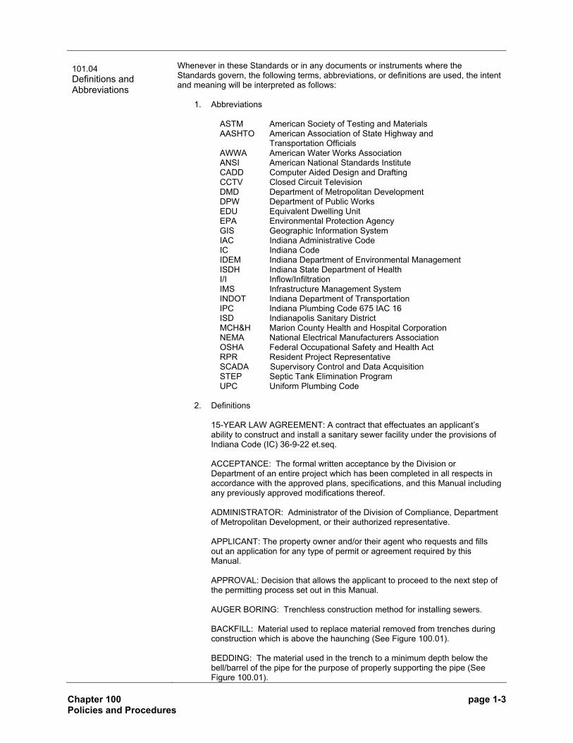
101.04 Definitions and Abbreviations
Whenever in these Standards or in any documents or instruments where the Standards govern, the following terms, abbreviations, or definitions are used, the intent and meaning will be interpreted as follows:
1. Abbreviations
ASTM American Society of Testing and Materials AASHTO American Association of State Highway and
Transportation Officials AWWA American Water Works Association ANSI American National Standards Institute CADD Computer Aided Design and Drafting CCTV Closed Circuit Television DMD Department of Metropolitan Development DPW Department of Public Works EDU Equivalent Dwelling Unit EPA Environmental Protection Agency GIS Geographic Information System IAC Indiana Administrative Code IC Indiana Code IDEM Indiana Department of Environmental Management ISDH Indiana State Department of Health I/I Inflow/Infiltration IMS Infrastructure Management System INDOT Indiana Department of Transportation IPC Indiana Plumbing Code 675 IAC 16 ISD Indianapolis Sanitary District MCH&H Marion County Health and Hospital Corporation NEMA National Electrical Manufacturers Association OSHA Federal Occupational Safety and Health Act RPR Resident Project Representative SCADA Supervisory Control and Data Acquisition STEP Septic Tank Elimination Program UPC Uniform Plumbing Code
2. Definitions
15-YEAR LAW AGREEMENT: A contract that effectuates an applicant’s ability to construct and install a sanitary sewer facility under the provisions of Indiana Code (IC) 36-9-22 et.seq. ACCEPTANCE: The formal written acceptance by the Division or Department of an entire project which has been completed in all respects in accordance with the approved plans, specifications, and this Manual including any previously approved modifications thereof. ADMINISTRATOR: Administrator of the Division of Compliance, Department of Metropolitan Development, or their authorized representative. APPLICANT: The property owner and/or their agent who requests and fills out an application for any type of permit or agreement required by this Manual. APPROVAL: Decision that allows the applicant to proceed to the next step of the permitting process set out in this Manual. AUGER BORING: Trenchless construction method for installing sewers. BACKFILL: Material used to replace material removed from trenches during construction which is above the haunching (See Figure 100.01). BEDDING: The material used in the trench to a minimum depth below the bell/barrel of the pipe for the purpose of properly supporting the pipe (See Figure 100.01).

Chapter 100 page 1-4 Policies and Procedures
BOARD: The Board of Public Works – City of Indianapolis. BUILDING SEWER: An alternate term for Lateral. See Lateral definition. CLEANOUT: A pipe fitting with a removable plug for inspecting and cleaning a lateral. CODE: Municipal Code of the City of Indianapolis COMBINED SEWER: A sewer which has been designed or intended to receive both surface runoff and sewage. COMMON LATERAL: A lateral which serves more than one building or residential unit. CONNECTION FEE: Assessment to compensate the city for all the costs of capacity for the city’s sewer system including the entire combined sewer system and its treatment facilities. CONTRACTOR: Any Contractor who meets the Department’s requirements and is licensed by the Department of Metropolitan Development to enter into contracts for and to perform the work of installing sewers under the Department’s jurisdiction. COUNTY: The county of Marion, State of Indiana. DEDICATION: The inspection, and if necessary, the rehabilitation of a sanitary sewer facility for public acceptance, ownership, operation, and maintenance. DEPARTMENT: Department of Public Works, City of Indianapolis, and any Division therein. DIGITAL DATA SUBMISSION STANDARDS: Standards in which the City of Indianapolis can integrate CADD drawings into the GIS and IMS environment thus maintaining the integrity and positional accuracy of the data. DIRECTOR: Director of the Department of Public Works, City of Indianapolis, or their authorized representative. DIVISION: The Division of Compliance, Department of Metropolitan Development, or their authorized representative EASEMENT: Areas along the line of all public sanitary sewer facilities which are outside the road easements or rights-of-way, and are recorded and dedicated to the Department granting rights along the line of the sanitary sewer facility.
EQUIVALENT DWELLING UNIT (EDU): Unit used to calculate the connection fee. ENGINEER: The Engineer for the Owner. FINAL BACKFILL: Material used to replace material removed from trenches during construction which is above the initial backfill (See Figure 100.01). FORCE MAIN: A pipe that carries wastewater under pressure from a lift station. FOUNDATION: The supporting material upon which the bedding is placed.

Chapter 100 page 1-5 Policies and Procedures
FOUNDATION DRAINS: Any network of pipes, pumps or drainage mechanism located at, near, or under a footing, foundation or floor slab of any building or structure that intentionally or unintentionally conveys groundwater away from a building or structure. HAUNCHING: The area in the trench from the top of the bedding to the springline of the pipe. (See Figure 100.01). HORIZONTAL DIRECTIONAL DRILLING (HDD): Trenchless construction method for installing sewer pipe. INDIANAPOLIS SANITARY DISTRICT (ISD): The area incorporated into the Marion County liquid waste district which includes the City of Indianapolis and the areas for which it is legally responsible. INFILTRATION/INFLOW (I/I): The total quantity of water from both infiltration and inflow without distinguishing the source. INITIAL BACKFILL: Material used in the trench above the haunching. (See Figure 100.01). LAND SURVEYOR: A person registered as a land surveyor by the Indiana State Board of Registration as provided by Indiana Code (IC) 25-21.5. LATERAL: A pipe used for transporting waste from the building to the public or private sewer commencing at and including the cleanout, and ending at and excluding the wye or tee fitting at the connection to the sanitary or combined sewer. Same as Building Sewer. LATERAL CONNECTION: Shall mean the point in which a lateral is connected to a sanitary or combined sewer within the Indianapolis Sanitary District. LIFT STATION: Any arrangement of pumps, valves and controls that lift, and/or convey wastewater to a higher elevation. Same as Pump Station. LOW PRESSURE SYSTEM: A wastewater collection system in which multiple users pump wastewater into a common force main. MANHOLE: A structure used in a sewer system to provide access for maintenance. MANUAL: The City of Indianapolis Department of Public Works Sanitary District Standards. Same as Standards. MANUFACTURER: The producer of those materials required by this Manual having direct responsibility and authority for the satisfaction of those minimum material specifications set forth herein. NEW CONNECTION: Shall mean a new lateral connection to the ISD sewer system, or a repair, replacement or modification to an existing lateral that increases the capacity of the lateral to accommodate a proposed increase in the average daily flow. OWNER: Any individual, partnership, firm, corporation or other entity who, as property owner, is initiating the Work. PERMIT: Clearance to perform specific work under specific conditions at specific locations. PIPE JACKING: Trenchless construction method for installing sewer pipe. PLANS: Construction plans which show the location, character, dimensions, and details of the work to be done.

Chapter 100 page 1-6 Policies and Procedures
PRIVATE SEWER: Any sanitary sewer facility that is not dedicated as public. PROFESSIONAL ENGINEER: A person registered as a professional engineer by the Indiana State Board of Registration for Professional Engineers under IC 25-31. PUBLIC SEWER: Any sanitary sewer facility owned, operated, and maintained by the City of Indianapolis. PUMP STATION: An alternate term for a Lift Station. See Lift Station definition. RECORD DRAWING (AS-BUILTS): Plans certified, signed and dated by a professional engineer or land surveyor registered in the State of Indiana, indicating the Plans have been reviewed and revised, if necessary, to accurately show all as-built construction and installation details including, but not limited to, key elevations, locations and distances. RESIDENT PROJECT REPRESENTATIVE (RPR): The lead inspector in the field who is responsible for all field inspection operations. RESIDENTIAL UNIT(S): Those units generating domestic wastewater. RIGHT-OF-WAY: All land or interest therein which by deed, conveyance, agreement, easement, dedication or process of law is reserved for or dedicated to the use of the general public, within which the Department shall have the right to install and maintain sanitary sewer facilities. SANITARY SEWER: A sewer that conveys wastewater from residences, commercial buildings, industrial plants, and institutions from lateral connections, and to which storm, surface, and ground waters are not intentionally allowed to enter. Commonly referred to as a “sanitary sewer main.” SANITARY SEWER CONSTRUCTION AGREEMENT: An agreement entered into by Owner/Contractor and the City requiring the construction of those sewer facilities to be in accordance with the technical and procedural standards of this Manual. This Agreement includes inspection services. SANITARY SEWER FACILITY: Any sanitary sewer, lift station or other appurtenance used to transport wastewater from its source to the wastewater treatment plant, excluding the lateral. SERVICE AREA: Any area that contributes, or has the potential to contribute, wastewater to a sanitary sewer facility. SEWER: A pipe for carrying wastewater (sanitary sewer), storm water (storm sewer) or a combination of both (combined sewer). Wherever in these Standards the word “sewer” is used without distinguishing type, “sewer” shall mean sanitary sewer. SEWER SERVICE AGREEMENT - A legal document that establishes the rights and responsibilities of an Applicant who connects to the Indianapolis Sanitary District’s sewer system, in addition to establishing the size, location and time for which that property is serviced by sanitary sewers. STANDARD DRAWINGS (DETAILS): The drawing of structures, sanitary sewer lines or devices commonly used and referred to on the Plans and in this Manual.

Chapter 100 page 1-7 Policies and Procedures
STANDARDS: The City of Indianapolis Department of Public Works Sanitary District Standards. The requirements for the design and construction of sanitary sewer facilities and laterals within the Indianapolis Sanitary District as contained herein and all subsequent additions, deletions or revisions. Same as Manual. STANDARD PROCTOR DENSITY: The maximum dry density of a backfill material as determined by those methods set forth within ASTM D 698.
STOP WORK ORDER: An order requiring the suspension of the pertinent construction activity for any construction project within the Indianapolis Sanitary District. STORMWATER: Any flow occurring during or following any form of natural precipitation and resulting therefrom. TEN STATE STANDARDS: Recommended Standards for Sewage Works, latest edition, developed by the Committee of the Great Lakes - Upper Mississippi River Board of State Sanitary Engineers. UNIFORM PLUMBING CODE (UPC): The Uniform Plumbing Code adopted by the International Association of the Plumbing and Mechanical Officials, current edition. WASTEWATER: A combination of the liquid and water-carried wastes from residences, commercial businesses, institutions and industrial establishments and other sources, together with such groundwater, surface water and stormwater as may be present. WATERBODY: Any area that in a normal year has water flowing or standing above ground to the extent that evidence of an ordinary high water mark is established. WORK: All the activities to be done under the permit, in accordance with the approved plans, specifications, these Standards, and conditions.
101.05 Enforcement of Standards
Failure to comply with requirements set forth by this Manual may necessitate one or more of the following actions to be taken by the Administrator or Director:
1. Posting of a Stop-Work-Order;
2. The invoking of performance sureties;
3. Denial of any future permits (either owner, contractor, or both); and/or
4. Necessary legal action by the Division or Department to effect the implementation of the approved plan or restoration of the site.
101.06 Penalties
Any person violating any provisions of this Manual shall be subject to the penalties in accordance with Section 671-16 and 671-22 of the City Code and may be required to correct such violation at their expense. The City Controller shall deposit any fines collected under this Section into an account for the use and benefit of the Division of Compliance.

Chapter 100 page 1-8 Policies and Procedures
SECTION 102 General - Procedures and Requirements for all Permits 102.01 Introduction
This Section provides the procedures and requirements common to both laterals and sanitary sewer facilities. For specific procedures and requirements related to laterals refer to Section 103. For specific procedures and requirements related to sanitary sewer facilities refer to Section 104. All information related to approvals and permits pursuant to this Manual can be tracked on the City’s Website, http://www.indygov.org/. The Department of Metropolitan Development’s instructions for tracking the Approvals and Permits can be found on the Division’s website or by contacting the Division directly.
102.02 Applicability
Lateral Permits for laterals, and Approvals and Construction Permits for sanitary sewer facilities are required to construct, repair, modify, connect, or abandon any lateral or sanitary sewer facility within the Indianapolis Sanitary District. This does not relieve any person from obtaining any and all applicable approvals and permits from other appropriate regulatory agencies.
102.03 Exemptions
Permits and Fees as required by this Chapter must be obtained and paid before the construction of sanitary sewer facilities or laterals in the ISD, except for:
1. Sewer construction or lateral permits for which a fee cannot be charged by the municipality because of federal or state law; or
2. Sanitary sewer construction performed by an employee or contractor on behalf of the City.
The fee exclusion only applies to the permit application fees. All other fees associated with the construction, repair, modification, abandonment or connection must be paid. A sanitary sewer permit is not required for maintenance work performed by or on behalf of the Department.
102.04 Fees
All applicable fees are listed in Appendix A. Unless specified, all fees must be paid to the City Controller through the Department of Metropolitan Development.
102.05 Refunds
Fees paid under this Section will not be refunded except upon written request to the Administrator and only in instances where the permit was issued in error. However, the Administrator shall, upon a written request, refund the connection fee paid pursuant to Section 103.04, for an expired permit.
102.06 Expiration of Permit
If construction activity has not commenced within one hundred eighty (180) calendar days from the date of issuance of the Permit, the Permit shall expire and will no longer be of any force or effect. The Administrator may however, for good cause shown in a written request to the Division, extend the validity of any such Permit for an additional period which is reasonable under the circumstances to allow commencement of the construction activity. In no event shall the extension exceed a period of sixty (60) calendar days.
If the construction activity has commenced, but only is partially completed, and thereafter, no visible construction activity occurs on the construction site over a period of one hundred eighty (180) calendar days, the Permit shall expire and no longer be of any force or effect.

Chapter 100 page 1-9 Policies and Procedures
102.07 Transfer of Permit
A Permit may be transferred with the approval of the Administrator to a person, partnership or corporation which would be eligible to obtain such a Permit in the first instance (hereinafter called "transferee"), after both the payment of the fee in Appendix A and the completion and filing of a Form furnished by the Division. Such a transfer form shall contain, in substance, the following certifications, releases, and agreement:
1. The person who obtained the original Construction Permit or a person who is employed by and authorized to act for the obtainer (hereinafter called "transferor") shall:
a. Certify under penalties for perjury that such person is familiar with the
construction activity accomplished pursuant to the Construction Permit; such person is familiar with the construction standards and procedures provided in this Manual; and to the best of such person's knowledge, information and belief the construction activity, to the extent performed, is in conformity with all standards and procedures provided in this Manual; and
b. Sign a statement releasing all rights and privileges secured under the
Permit to the transferee.
2. The transferee shall:
a. Certify the transferee is familiar with the information contained in the original Permit Application, the design plans and specifications, and any other documents filed in support of the application for the Permit;
b. Certify the transferee is familiar with the present condition of the premises
on which the construction activity is to be accomplished pursuant to the Permit; and
c. Agree to adopt and be bound by the information contained in the original
application for the Permit, the design plans and specifications, and other documents supporting the original Permit Application; or in the alternative, agree to be bound by such application plans and documents modified by plan amendments submitted to the Division of Compliance for approval.
3. The transferee shall assume the responsibilities and obligations of and shall comply with the same procedures required of the transferor (including, but not being limited to, the requirement of a Certificate of Completion and Compliance be executed and filed) and shall be subject to any written orders issued by the Division.
4. A permit for construction activity at a specified location may not be transferred
to construction activity at another location.
102.08 Notice of Change in Permit Information
After a Permit has been issued, the permittee shall give written notice to the Division within seven (7) calendar days after becoming aware of the change in the information contained in the Permit Application. Failure to do so may result in the Permit being revoked or the issuance of a Stop Work Order.

Chapter 100 page 1-10 Policies and Procedures
102.09 Amendment of Permits and Plans
After a Permit has been issued, any deviation or change in the information contained in the Permit Application and supporting documentation or the plans shall be considered an amendment subject to approval by the Administrator. Prior to the time construction activity involving the change occurs, the permittee shall file with the Division a written request for an amendment, including a detailed statement of the requested change and the submission of any amended plans. The Division shall give the permittee written notice that the request for amendment has been approved or denied, and if approved, copies of the amended application or plans shall be attached to the original application or plans. Reinspection fees and other fees which are required as a result of the amendment shall be assessed and paid in the same manner as for original Permits or plans.
102.10 Revocation of Permit or Variance
The Division of Compliance may revoke a Permit or Variance when:
1. The application, plans, or supporting documents contain a false statement or
misrepresentation as to a material fact; or
2. The application, plans or supporting documents reflect a lack of compliance with the requirements of this Manual; or
3. Additional information becomes available that would necessitate the revocation of the Permit or Variance (Permit issued in error).
102.11 Stop-Work Order
The Administrator and/or Director has the authority to direct the issuance of an order requiring the suspension of the pertinent construction activity ("Stop-Work Order") whenever it is determined that construction activity:
1. Is proceeding in an unsafe manner;
2. Is proceeding in violation of a requirement of this Manual;
3. Is proceeding in a manner which is materially different from the application,
plans, or supporting documents; or
4. For which a permit is required is proceeding without such a permit being in force. In such an instance, the stop-work order shall indicate the effect of the order terminates when the required permit is issued.
The Stop-Work Order shall be in writing by the Division or the Department and shall state to what construction it is applicable and the reason for its issuance. One (1) copy of the Stop-Work Order shall be conspicuously posted on the property, and one (1) copy shall be delivered via certified mail to the owner of the property or their agent. The Stop-Work Order shall state the conditions under which construction may be resumed. If a Stop-Work Order is issued, the contractor shall restore the site to a safe condition prior to stopping the work pursuant to the Order. The sanctions provided in this Section shall in no way limit the imposition of penalties provided elsewhere in this Manual.
102.12 Variance Procedures
The Administrator, after consultation with and concurrence of the Department, has the power to modify or waive any requirement found in this Manual or in any regulations promulgated by the Board pursuant to Chapter 671 of the Code. A Variance can only be granted if an Applicant for a permit submits a completed Variance Request Form and makes a substantial showing that:
1. The design standard or regulation is unfeasible or unreasonably burdensome; and

Chapter 100 page 1-11 Policies and Procedures
2. An alternate plan submitted by the Applicant will achieve the same objective
and purpose as compliance with the minimum requirements contained in the Manual, and
3. The alternative plan will not increase the direct cost of operation and/or maintenance to the City.
Cost to the Applicant shall not be the sole factor used to determine whether the design standards or regulations are unfeasible or unreasonably burdensome. The Division will respond in writing within fourteen (14) calendar days from receipt of the Variance Request. If a Variance is requested for any requirement in Chapters 300, 400, 500, or 600, a review may be required through the Department’s “New Products Committee” before a decision can be made. The review requirements shall be determined on a case-by-case basis depending on the complexity of the request. All costs associated with a New Products Committee review are the responsibility of the Applicant.
102.13 Appeals
Any person affected by the exercise of any discretionary authority delegated by this Chapter to any official of the Division or Department, including a decision to deny or partially deny a Variance or Permit, and who objects to the decision made or action taken by such official is entitled to appeal the decision. The appeal procedure is as follows:
1. The appeal of such a decision shall be filed with the Administrator in writing within twenty-one (21) calendar days following the date of the decision.
2. If the Administrator denies the appeal, the appellant may file a written request for a hearing, including a statement of their objections, with the Director who will call the same to the attention of the Board. Such request shall be filed with the Director within fourteen (14) calendar days from the date of notification by the Administrator.
3. The appeal hearing shall be scheduled before the Board within thirty (30)
calendar days after such request is filed. Notice shall be given to the appellant identifying the time, place, and date of the appeal hearing at least seven (7) calendar days prior to the scheduled date. The Board may hear any evidence it deems relevant. After the hearing, the Board may confirm, reverse, or modify the decision or action. The order of the Board is final. Such order shall be made within fourteen (14) calendar days after the hearing and must be in writing and sent to the appellant.

Chapter 100 page 1-12 Policies and Procedures
SECTION 103 Laterals - Procedures and Requirements 103.01 Introduction
This Section provides procedures and requirements specific to Laterals. For general procedures and requirements common to both laterals and sanitary sewer facilities refer to Section 102. For specific procedures and requirements related to sanitary sewer facilities refer to Section 104.
103.02 Responsibility
It shall be the responsibility of the Owner whose property is benefited to make all necessary repairs, extensions, relocations, changes, or replacements thereof, and of any accessories thereto for the entire length of lateral, including the portion within public easements and right-of-ways. These requirements may be altered, modified, or waived, at the discretion of the Division or Department when it is shown compliance is not possible due to extenuating circumstances.
103.03 Applicability
A Lateral Permit is required to construct, repair, modify, connect, or abandon any lateral within the Indianapolis Sanitary District. Lateral Permits shall not be granted for connections to sanitary sewers not dedicated and accepted in accordance with the provisions contained in Section 105.04 or 105.07 of this Manual. Requirements for Lateral Permits issued for connections to existing private systems shall be determined at the time of application. The Applicant shall supply written permission from the Owner of the private sewer and may be required to comply with the requirements of 105.07.
All work and other construction activity performed on or associated with the lateral and its connection to the sewer shall be in accordance with this Manual and the rules and regulations of the Indiana Plumbing Code.
103.04 Connection Fee and EDU Calculation
A Connection Fee shall be assessed for all new connections to the sanitary or combined sewer system prior to the issuance of a Lateral Permit, unless the Applicant has been granted a waiver per Board Resolution No. 100, 2005, or there is Special Agreement in place pursuant to 671-12. New Connections and Connection Fees shall be determined and calculated as follows:
1. New Connections
a. The following are considered New Connections:
i. New lateral connections to the ISD sewer system .
ii. A repair, replacement, or modification to an existing lateral that increases the capacity of the lateral to accommodate a proposed increase in the average daily flow.
Note: A repair, replacement, or modification intended to return the lateral to its original design capacity shall not be interpreted as increasing the capacity. Examples include, but may not be limited to: normal maintenance activities, cleaning the lateral, repairing offset joints, repairing a broken or collapsed lateral, or any other repair, replacement, or modification that does not increase the capacity of the lateral (i.e. Increasing the size or slope) in order to accommodate an increase in average daily flow.

Chapter 100 page 1-13 Policies and Procedures
The connection fee will only be charged for the proposed increase in average daily flow.
b. The following are NOT considered new connections:
i. A repair, replacement, or modification to an existing lateral that does not increase the capacity of the lateral.
ii. A repair, replacement, or modification to an existing lateral that
increases the capacity of the lateral without increasing the size of the water meter as a part of the project.
iii. A repair, replacement, or modification to an existing lateral that
increases the capacity of the lateral and a water meter is not present, but the Department has determined by appropriate means that there is not a proposed increase in the average daily flow.
2. Connection Fees
The connection fee for each New Connection shall be calculated as follows:
Connection Fee = Number of EDU’s x $2,500
A minimum of one (1) EDU shall be used for each Connection Fee calculation for all New Connections. The Number of EDU’s for each connection shall be determined as follows: a. For New Connections that are new lateral connections as defined in
Section 103.04.1.a.i, the Number of EDU’s shall be as follows:
i. For Single Family Homes, Apartments, and Condominiums, the Number of EDU’s per connection shall be as follows:
Unit Type EDUs
Single Family Home 1.0
Apartment/Condominiums 0.751,2
1 For apartments or condominiums, the total number of EDU’s per connection shall be (Total number of units) x 0.75. The 0.75 multiplier shall only be used when a lateral serves multiple units. 2 For apartments or condominiums having individual laterals for each unit, the number of EDU’s shall be one (1) per minimum EDU requirement.
ii. For all other uses, the Number of EDU’s per connection shall be
based on water meter size as follows:
EDUs based on Water Meter Size
Water Meter Size, inches No. of EDU’s Water Meter
Size, inches No. of EDU’s
5/8 or 3/4 1.0 4.0 41
1.0 2.5 6.0 92
1.5 5.8 8.0 164
2.0 10 10.0 253
3.0 23 12.0 364

Chapter 100 page 1-14 Policies and Procedures
A Lateral Connection Fee Calculation Worksheet, furnished by the Department or Division, shall be submitted with the Lateral Permit Application. The Worksheet shall address situations in which there are multiple users of an individual water meter. The Worksheet will also address situations where a new lateral connection to the ISD sewer system does not require a change to the size of the existing water meter. If there is not an increase in the water meter size, a connection fee will not exceed the 1.0 EDU minimum fee referenced above. In such a situation, if the Applicant can document and prove to the satisfaction of the Department there is not a proposed increase in the average daily flow, there will be no Connection Fee assessed.
b. For New Connections that are associated with an increase in the size of the water meter and for a new connection that are repairs, replacements, or modifications to existing laterals as defined in Section 103.04.1.a.ii, the number of EDU’s shall be calculated based on the increase in average daily flow before and after the project.
The increase in average daily flow before and after a project shall be determined using one of the following:
i. If a water meter is present, the proposed increase in average daily
flow and number of EDU’s, shall be determined by the difference between the size of the water meter, and corresponding number of EDU’s per above Section 103.04.2.a.ii, before and after the completion of the project.
ii. If a water meter is not present, the Department may calculate the
proposed increase in average daily flow by any means determined appropriate that results in connection fees assessed comparable to the differences in water meter sizes that correspond to the average daily flow before and after the project. Such means may include, but not be limited to, using the estimated average daily flow based on use as shown in Appendix B, using Table 11-1 of 327-IAC 3-11, or any other appropriate means as approved by the Department.
Credits or refunds will not be given for the removal of a water meter, the installation of a smaller water meter, or a reduction in average daily flow. For purposes of the connection fee, a water meter means a City water supply meter at the point of water withdrawal from the water main owned by the City of Indianapolis.
103.05 Submittal Requirements for a Lateral Permit
The following are submittal requirements for a Lateral Permit:
1. Application The application for a Lateral Permit shall be made on a Form provided by the Division.
2. Plans Plans for the lateral connection shall be submitted and at a minimum shall include:
a. Drawing(s) of the building;
b. Plot Plan including parcel boundaries;
c. Connection details including the location of the connection and routing of
the lateral;
d. Lateral construction material;

Chapter 100 page 1-15 Policies and Procedures
e. Installation method; and
f. Elevation of the lowest floor and building drain, specifically the elevation
of the lowest gravity sanitary service. All elevations must be tied to USGS data.
3. Lateral Connection Fee Calculation Worksheet
A completed Lateral Connection Fee Calculation Worksheet shall be submitted at the time of application.
4. Sewer Service Agreement
A fully completed Sewer Service Agreement and supporting documentation may be required when a new connection is proposed to the sanitary sewer or whenever deemed necessary by the Division or Department.
5. Easement If an easement is required to gain access to the sanitary sewer, proof of such easement is required at the time of application.
6. Inspection Video When requested, the CCTV video and inspection log of the existing lateral, as required per Section 201.10, shall be required at the time of the application.
7. Additional Information Any additional information deemed necessary for ensuring conformance to this Manual.
All appropriate fees shall be paid before a Permit will be issued.
103.06 Who May Apply
An application for a Lateral Permit shall only be made by the following persons:
1. A plumbing contractor licensed by the State and registered in accordance with Section 875-501 of the City Code; or
2. A general contractor who has met the surety bond and insurance requirements
of the Department of Metropolitan Development. Surety bond requirements are met if the lateral contractor has filed and maintains with the City a surety bond, as set forth in Section 875-109 of the City/County Code. Insurance requirements are met if the contractor has secured and maintains a public liability and property damage Insurance Policy as set for in Section 875-110 of the Code.
103.07 Lateral Inspection Requirements
Laterals shall be inspected to assure compliance with the Standards contained in this Manual. It is the responsibility of the permittee to notify the Division, in the manner described on the Lateral Permit, the lateral is available for inspection. The Division will conduct inspections on lateral connections from 7:30 A.M. to 4:30 P.M. local time, Monday through Friday, except for observed City holidays. The lateral, in its entirety from the foundation to the connection with the sewer or existing lateral, or at the location of the repair/modification, shall be exposed for inspection and be properly bedded in accordance with this Manual to one-half (1/2) the diameter of the lateral with the tracer wire installed (taped) to the top of the pipe. After the lateral has passed the inspection, the Contractor is responsible for placement of the initial and final backfill per Section 401.06.

Chapter 100 page 1-16 Policies and Procedures
The responsibility for safety measures rests solely with the permit holder. All excavations shall be adequately protected by barricades, fences, lights, and other such means as necessary to protect the public, and as required by other regulatory agencies, such as, but not limited, to OSHA. The permittee shall reapply for a new Lateral Permit and pay all of the necessary fees as contained in Appendix A, excluding the Connection Fee per Section 103.04, if:
1. The lateral does not meet the requirements of this Manual; or 2. The entire length of the lateral is not completely exposed; or
3. Only a portion of the lateral is completed.
The Division and the Department shall each have the right of entry to, upon, or through, any premises for purposes of inspection of work and any other construction activity performed on or associated with the work on the lateral including inspection for clear water discharges into the sewer. Such entry includes the right to enter the building being served by the lateral.
103.08 Enforcement of Bond
Any action may be initiated in a court of competent jurisdiction relative to the bond provided for in Section 103.06 as follows:
1. The Corporation Counsel of the City may initiate proceedings to forfeit a bond: a. As a penalty for repeated Code violations by a contractor, his agents or
employees; or b. To indemnify the City against any loss, damage, or expense sustained by
the City by reason of the conduct of the contractor, his agents or employees.
2. A person, partnership or corporation which holds a property interest in the real
estate on which work has occurred may bring an action against the bond for expenses necessary to correct code deficiencies therein after written notice of the code deficiency has been given to the contractor and after the contractor has been given a reasonable opportunity to correct performance. If such a person, partnership or corporation prevails in any action brought under this section, they may also be allowed by the court to recover as part of the judgment a sum equal to the aggregate amount of costs and expenses, including attorney's fees based on actual time expended as determined by the court to have been reasonably incurred by the plaintiff for, or in connection with, the commencement and prosecution of such action.

Chapter 100 page 1-17 Policies and Procedures
SECTION 104 Sanitary Sewer Facilities - Procedures and Requirements 104.01 Introduction
This Section provides the procedures and requirements specific to sanitary sewer facilities. For general procedures and requirements common to both laterals and sanitary sewer facilities refer to Section 102. For procedures and requirements specific to laterals refer to Section 103.
104.02 Sanitary Sewer Approval and Construction Permit - General
A sanitary sewer Approval and Construction Permit is required for the construction of new sanitary sewer facilities and/or modifications of existing sanitary sewer facilities within the Indianapolis Sanitary District. To assist the Applicant in the permitting process, the Division will issue an Approval letter prior to the Construction Permit being issued. The Approval is intended to inform the Applicant all the requirements related to the design of the sanitary sewer facility have been met. An Approval is not a Construction Permit. The Applicant shall submit, either concurrently or consecutively, all the requirements for a Construction Permit prior to the Construction Permit being issued by the Division.
The Approval is valid for a period of one (1) year from the date such Approval was granted, or until the Construction Permit is issued. However, prior to the issuance of the Construction Permit, if there are any material changes to approved design plans and specifications, or circumstances which cause the design plans and specifications to be inaccurate or incomplete, then new or corrected design plans and specifications shall be submitted to the Division as a precondition for obtaining a Construction Permit. All proposed sanitary sewer facilities, excluding laterals, shall be dedicated as public facilities. Construction Permits for sanitary sewer facilities will not be issued for connections to existing private sewers unless pre-existing written agreements or Memorandums of Understanding have been granted.
104.03 Capacity Certification/ Allocation
During the Approval process, the Division may forward a Capacity Certification/ Allocation Letter to IDEM. At the discretion of the Division and after consultation with the Department, the Applicant may be required to evaluate the downstream system if sufficient information and data are not available from the Department. Refer to Section 202.10 for the downstream evaluation requirements.
104.04 Submittal Requirements for Approval and Construction Permit
The following are the submittal requirements for a Sanitary Sewer Approval and Construction Permit:
1. Sanitary Sewer Approval
To obtain a Sanitary Sewer Approval, the following shall be submitted at the time of application:
a. Application
An application for a Construction Permit shall be made on a Form furnished by the Division.

Chapter 100 page 1-18 Policies and Procedures
b. Plans and Specifications
Plans and specifications for the construction of sanitary sewer facilities shall be developed by, or under the direction of, a Professional Engineer registered in accordance with IC 25-31-1. All sheets shall include the Professional Engineer’s seal, signature, and date plans were certified including any revision dates. At a minimum, the plans and specifications shall include the following:
i. Title Sheet;
ii. Index Sheet showing the overall sanitary sewer configuration and
sheet where the Plan/Profile sheets can be found;
iii. Sewer and/or Lift Station Service Area Map;
iv. Site Plan;
v. Plan/Profile Sheets which include backfill requirements;
vi. Standard Detail Sheets;
vii. Structure/Data Table;
viii. Lift Station Standard Detail Sheets (when applicable);
ix. Specifications shown on plans; and
x. Other sheets as deemed necessary for ensuring conformance to this Manual.
The Plans must conform with the requirements of the latest edition of the Indianapolis Drafting Standards.
c. Design Calculations
Design calculations shall be submitted on a Design Summary Form furnished by the Division.
d. Certificate of Sufficiency of Plan
A Certificate of Sufficiency of Plan shall be submitted by a Professional Engineer registered in accordance with IC 25-31-1 on a form furnished by the Division.
e. Lift Station Submittal Requirements
When applicable, the requirements per Section 502.03 and/or 504.03 shall be submitted.
f. Zoning Commitments
All recorded Zoning Commitments, or Commitments being negotiated, shall be submitted.
Zoning Commitments shall not be justification to violate any provisions of this Manual, or be justification for a Variance. If Zoning Commitments violate any provision of this Manual, contact the Department of Metropolitan Development to determine the necessary steps to amend the Zoning Commitments.

Chapter 100 page 1-19 Policies and Procedures
g. Execution of Covenant
The Administrator may require the execution of covenants and/or easements running in form to the City of Indianapolis, and County of Marion by the Owner or Owners of such parcel. At a minimum in such cases, the Administrator shall require that the following covenant be executed by the Owner or Owners of such parcels, and which shall be included in a recorded plat:
i. It is the responsibility of the Owner of any lot or parcel of land within
the area of the plat to comply at all times with the provisions of the sanitary sewer construction plan approved by the Division, and the requirements of all sanitary sewer Construction Permits for the plan issued by the Division.
ii. Owner further covenants that no building, structure, tree or other
obstruction shall be erected, maintained, or allowed to continue on the portion of the owner's real estate in which the easement and right-of-way are granted without express written permission from the Division. Such permission, when duly recorded, shall run with the real estate. The Department and the Division and their agents shall have the right to ingress and egress, for temporary periods only, over the owner's real estate adjoining said easement and right-of-way, when necessary to construct, repair or maintain sanitary sewer facilities.
Any person who violates a covenant required under this Section, and/or the owner of any parcel of land who permits such a violation, who is notified in writing by the Department of Public Works or Division of Compliance that a violation exists, will be given a reasonable period of time, not to exceed thirty (30) calendar days, in which to correct such violation. The notice shall specify the nature of the violation and must stipulate a required correction date.
If there has been no activity on the Project during the Approval Process for more than sixty (60) days, the Application has expired and shall be resubmitted.
2. Construction Permit
The following shall be submitted to the Division prior to the issuance of a Construction Permit:
a. Performance Bond
The Administrator may, as a prerequisite to the issuance of a Construction Permit, require the posting of a Performance Bond, by the Owner, from a company licensed by the State of Indiana to provide such surety. Such bond shall be equal to 100% of the contract amount, or an amount established by the Administrator to provide surety for the satisfactory completion of the improvements required by the construction permit, and shall name the City of Indianapolis and Marion County as parties who can enforce the obligations thereunder. Said bond may be a part of the total bonding required by the Plats Committee of the Metropolitan Development Commission.
In instances where the Administrator has required a bond pursuant to this Section, the Administrator may, as an alternative to the posting of such bond, accept a properly conditioned irrevocable Letter of Credit which meets the same objective as the bonds described in this Section. In lieu of the Performance Bond or the Letter of Credit, the Division may allow the posting of a Performance Security per the current Division requirements. This is subject to approval of any other department or agency whose interests are protected by the same bonding requirement.

Chapter 100 page 1-20 Policies and Procedures
If the surety on any bond furnished to the Division becomes a party to a supervision, liquidation, or rehabilitation action pursuant to I.C. 27-9 et. seq. or its right to do business in the State of Indiana is terminated, it shall be required that, within thirty (30) days thereafter, a substitute bond and surety be provided, both of which shall be acceptable to the City. Failure to obtain a substitute bond within the stated time frame shall be cause for revocation or suspension of the Construction Permit, until such time that the bond is furnished to the Division.
b. Sewer Service Agreement
Where applicable and when required, a Sewer Service Agreement shall be executed and submitted.
c. Preliminary Plat
When applicable, the preliminary plat shall be submitted.
d. Recorded Easements When required, easements shall be obtained and recorded.
e. Written Notification The Administrator may require Applicants to send written notification to property owners whose properties abut the route of the proposed sewer.
f. Sanitary Sewer Construction Agreement The Applicant shall execute the applicable Agreement for Construction.
g. Payment of Fees The Applicant shall pay all applicable fees listed in Appendix A.
h. Additional Information Applications shall include any additional information deemed necessary by the Department and the Division to thoroughly evaluate an application for a Construction Permit and carry out the provisions of this Manual.
104.05 Who May Apply for an Approval and Obtain a Permit
The Owner or their authorized agent may apply for and obtain an Approval and/or Construction Permit.
104.06 Who Can Do the Work
A general contractor who has met the surety bond and insurance requirements of the Department of Metropolitan Development. Surety bond requirements are met if the general contractor has filed and maintains with the City a surety bond, as set forth in Section 875-109 of the City/County Code. Insurance requirements are met if the Contractor has secured and maintains a public liability and property damage Insurance Policy as set forth in Section 875-110 of the Code.

Chapter 100 page 1-21 Policies and Procedures
SECTION 105 Sanitary Sewer Construction Inspection and Acceptance Procedures 105.01 Introduction
This Section provides the procedures and requirements specific to the inspection and acceptance of sanitary sewer facilities.
For the requirements for the inspection of laterals refer to Section 103.07.
105.02 General Authority for Investigations and Inspections
The Division and Department have the power to inspect and investigate all phases of construction. These inspections and/or investigations may be made at any time by going upon, around, or about the affected property. Such investigation and inspection may be made before, during, and after the construction is completed and shall be made for the purpose of determining whether the construction has been completed in a manner consistent with the approved plans and specifications and the minimum requirements of this Manual. Persons working on, or having control, of the construction shall cooperate fully with the RPR and/or other representatives of the Division or Department. They shall have a copy of the approved plans and specifications used to obtain the Construction Permit available on-site.
105.03 Construction Inspection Requirements
Full time inspection is required during the installation and testing of all sanitary sewer facilities.
All the construction shall be inspected and tested to assure compliance with the requirements of this Manual. The minimum requirements prior to and during construction are as follows:
1. Prior to Construction Prior to construction the following are required: a. Sanitary Sewer Construction Agreement
The Owner shall execute the applicable Sanitary Sewer Construction Agreement with the Division for construction inspection services. The City shall provide, at the Owners expense, inspection services during the construction of the sanitary sewer facility. The Owner shall reimburse the RPR directly, per the executed Sanitary Sewer Construction Agreement, the cost of the full time inspection services. The Owner shall submit the balance of the cost of the inspection to the RPR prior to acceptance of the sanitary sewer facilities by the Department or Division. The inspection services do not include construction engineering or construction stake-out. The Owner or their designated representative is responsible for the construction engineering and stake-out for all construction work.
b. Pre-Construction Meeting After all applicable permits have been obtained, a pre-construction meeting, to include a representative of the Division, the Division’s RPR, the Contractor, and the Owner, shall be required. This meeting will be scheduled upon request of the Applicant. Construction may not begin until the Pre-Construction Meeting has been held.

Chapter 100 page 1-22 Policies and Procedures
2. During Construction
After construction begins, the contractor shall be responsible for informing and/or notifying the RPR at least forty-eight (48) hours in advance of the following:
a. Daily work schedule including any changes in schedule; b. If work is to be performed on weekends and/or holidays; c. Dates trenches will be open and sewers will be installed; d. Dates structures will be installed; e. Date all applicable tests are to be performed; f. Date "as-built" verification is to be performed; and g. Any other information deemed necessary to assure the sanitary sewer
facilities are properly constructed.
The Division or Department, upon request of the Contractor and/or Owner, will schedule the Final Inspection. All testing required per Chapter 600 of this Manual, shall be performed under the observation of the Division’s or the Department’s RPR. It is the Contractor's responsibility to schedule the testing with the RPR and/or Department. Test results obtained in the absence of the Division's RPR or Department shall not be accepted. Any portion of the sanitary sewer facility not inspected as prescribed by this Manual may require excavation to the extent required by the Division or Department. Any portion of the sanitary sewer facility not passing the tests prescribed in Chapter 600 shall be repaired or replaced to the extent required by the Division or Department and retested. Failure to comply with these requirements may result in the Division or Department not accepting the sanitary sewer facilities and denying future permits.
105.04 Requirements for Project Acceptance and Dedication
The following shall be submitted and approved prior to a sanitary sewer facility being accepted, lateral permits being issued, and the performance bond being released:
1. Three (3) Year Maintenance Bond
The Administrator shall require the posting of a Maintenance Bond by the Contractor, in an amount not to exceed twenty (20%) percent of the contract amount, or subject to the approval by the Administrator, a provision for maintenance for a period of three (3) years from the date of acceptance by the Department. Said bond shall name the City of Indianapolis and Marion County as parties who can enforce the obligations thereunder.
2. Certificate of Completion and Compliance
A Certificate of Completion and Compliance, as furnished by the Division, shall be filed by a Professional Engineer. The Certificate of Completion and Compliance shall be filed within fourteen (14) calendar days after satisfactory completion of the tests on the sanitary sewer facility for which a Construction Permit was issued.

Chapter 100 page 1-23 Policies and Procedures
3. Final Inspection Documentation
The completion of a final inspection and all required Forms which confirm all sanitary sewer facilities have been constructed and tested in accordance with this Manual shall be submitted prior to acceptance.
4. Record (“As-built”) Drawings
Record ("As built") drawings shall be submitted in accordance with Section 105.05 of this Manual.
5. GIS/IMS Data Submittals
Submittals shall be made in accordance with Section 105.06 of this Manual. 6. Payment of Inspection Fees
Payment of all fees shall be made prior to acceptance of any sanitary sewer facility.
The original Performance Bond will be released upon acceptance of the sanitary sewer facility.
105.05 Record (“As-Built”) Drawings
As part of the final acceptance process, record drawings of the sanitary sewer facilities shall be submitted to the Division. Record Drawings shall be certified by a Professional Engineer or Land Surveyor registered in the State of Indiana. The Record Drawings shall include the following information and all revision dates:
1. Title Sheet; 2. Index Sheet showing the overall sanitary sewer configuration and sheet where
the Plan/Profile sheets can be found; 3. Sewer and/or Lift Station Service Area Map;
4. Site Plan; 5. Plan/Profile Sheets; 6. Standard Detail Sheets;
7. Structure/Data Table; 8. Lift Station Sheets (when applicable); 9. Specifications shown on Plans; 10. Structure inverts, pipe inverts and top-of-castings; 11. Horizontal alignment of sanitary sewer and force main pipes, streets, to a
minimum accuracy of +/- two (2) feet; and
12. Any other information deemed relevant.
Record Drawings shall be submitted on original mylars and in a digital format.
105.06 Digital Data Submission Standards
As part of the final acceptance process, GIS and IMS data shall be submitted in accordance with the latest version of the Digital Data Submission Standards.

Chapter 100 page 1-24 Policies and Procedures
105.07 Dedication of Existing Private Sewers
The Owner of a private sanitary sewer facility may apply to the City for dedication of the facility as public, provided the facility is located within the ISD boundaries. An Application shall be submitted on a Form furnished by the Division. Dedication of such sewer facilities are subject to all applicable requirements in this Manual or rehabilitated to an acceptable level as determined by the Department. At the discretion of the Division and the Department, the following may be required to determine if the facilities are acceptable or what improvements are necessary to make the facilities acceptable:
1. Proof of legal ownership;
2. Recorded easements;
3. Flow monitoring results;
4. CCTV video inspection results;
5. Three (3) year Maintenance Bond;
6. Record Drawings;
7. GIS/IMS Data Submittal; and/or
8. Any other requirements deemed necessary by the Division and/or Department.
The Owner of the private sewer facility shall, at their expense, be required to correct any deficiencies or remove any sources of clear water found as a result of any inspection, flow monitoring, CCTV, and/or other related testing. The Division and/or Department may deny acceptance of private sewer facilities with or without cause even if the private sewer facilities meet the requirements contained in this Manual.

CHAPTER 200
DESIGN

Chapter 200 page 2-2 Design
SECTION 201 Lateral Design
201.01 Introduction
This Section provides design requirements specific to laterals. For design requirements specific to gravity sanitary sewers refer to Section 202. For design requirements specific to manholes refer to Section 203. For design requirements specific to lift stations and low pressure sewer systems refer to Chapter 500.
201.02 General
The design criteria for laterals shall conform to the latest edition of the 675 IAC 16 - Indiana Plumbing Code (IPC) and to these Standards, whichever is more restrictive.
201.03 Prohibited Connections
Except as provided in an Industrial Pretreatment Permit issued by the Department, no person shall connect a lateral to a sanitary or combined sewer when the lateral has any of the following sources of clear water:
1. Foundation/footing drains;
2. Sump pumps with or without foundation drains connected;
3. Roof drains;
4. Heat pump discharge;
5. Cooling water; or
6. Any other sources of clear water, such as, but not limited to, yard and/or driveway drains.
201.04 Maximum Number of Building Connections
Common laterals are prohibited. No more than one (1) building will be permitted to connect to a lateral. Common laterals for one (1) building with multiple residential units are also prohibited, except for the following:
1. Apartment buildings. 2. Condominiums where different floors have different owners.
The intent is to have individually owned residential units served by individual laterals. Industrial facilities will be evaluated on a case-by-case basis.
201.05 Point of Connection
Laterals shall connect to sanitary or combined sewers at manufactured mainline fittings or terminal manholes. Saddle connections are only allowed if a manufactured fitting does not exist and shall be installed per Section 402.05. Saddle connections to Vitrified Clay Pipe (VCP) sewers are not allowed. See Section 402.05 for installation requirements for connections to VCP without manufactured fittings. Lateral connections to existing sewers eighteen (18) inches and larger will be reviewed on a case-by-case basis. A separate sewer may be required to be extended from an existing manhole.
No more than three (3) connections to a terminal manhole will be allowed. See Section 403.08 for installation requirements on connections to manholes.

Chapter 200 page 2-3 Design
201.06 Size, Depth, and Slope of Lateral
The minimum size, depth and slope of laterals shall be as follows:
1. Pipe size
The minimum pipe size shall be as follows:
a. Within the right-of-way or easement - six (6) inches. b. Outside the right-of-way or easement - four (4) inches.
2. Pipe Depth
The minimum depth from the finished grade to the crown of all laterals shall be as follows:
a. Within the right-of-way or easement - four (4) feet. b. Outside the right-of-way or easement - three (3) feet.
3. Pipe Slope
The minimum slope shall be 1.04% (1/8” per foot). For laterals eight (8) inches and larger, the slope may only be reduced if justified by the design flow.
201.07 Location, Length, and Spacing of Lateral
The location, maximum length, and spacing of laterals shall be as follows:
1. Location
The location of the lateral shall be as follows: a. All properties shall be served from the street or alley side of the property. b. Where possible, laterals shall not cross abutting properties if the existing
gravity sewer can be extended to serve the property.
If crossing an abutting property is unavoidable, laterals shall not cross more than one (1) property. A dedicated easement on the abutting property shall be recorded.
c. Properties to the rear may not be crossed. d. Laterals shall be located a minimum of five (5) feet from the side
property lines.
2. Length
The maximum lengths for laterals are as follows:
a. On-site length – No maximum length. Cleanouts shall be provided per Section 201.08.
b. Offsite Length – One hundred (100) feet.
The off-site length includes the total distance within both the abutting property (if crossed) and the right-of-way.
3. Spacing between adjacent laterals
The minimum horizontal distances between adjacent laterals and their connections are as follows:

Chapter 200 page 2-4 Design
a. Laterals on the same side of the street/sewer – ten (10) feet.
Common trenches for more than one lateral are not allowed, unless the minimum horizontal spacing between laterals can be maintained.
b. Laterals on opposite sides of the street/sewer – four (4) feet.
201.08 Cleanouts
Cleanouts shall be installed on all laterals as follows:
1. Location
Laterals shall have a wye cleanout located between eighteen (18) and sixty (60) inches from the building’s exterior. The cleanout shall be extended to grade.
2. Spacing
Cleanouts shall be spaced a maximum of every one hundred (100) feet.
3. Size
Cleanouts shall match the size of the lateral pipe up to a maximum of eight (8) inches.
4. Type
Cleanout covers shall be a threaded-type, water tight, and capped at all times. Covers within the paved areas shall be metallic and able to withstand traffic loads.
Cleanouts installed under concrete or asphalt paving shall be made accessible by yard boxes or extended flush with the paving. Manholes may not be used in lieu of cleanouts unless the facility has been issued an Industrial Pretreatment Permit by the Department.
201.09 Minimum Elevation for Gravity Connection
To reduce the occurrence of sewer backups, the lowest floor elevation with gravity service shall be a minimum of one (1) foot above either the first upstream or first downstream manhole casting elevation. See Figure 200.01. If this condition cannot be met due to the natural topography of the area, then either an alternate manhole will be evaluated or the connection to the sewer must be made using a sewage ejector pump system.
201.10 Connections Utilizing an Existing Lateral
When an existing or abandoned lateral is intended to be reused, the Owner and Contractor are responsible for verifying the lateral does not have any defects by means of a CCTV inspection. The record of the inspection shall be maintained by the Owner and Contractor for one (1) year from the date of the inspection. Upon request, the results of the CCTV Inspection shall be submitted to the Division and/or the Department for review. If the Division or Department determines the existing lateral has deficiencies, the Owner will be required to either replace the existing lateral per requirements of this Manual, or rehabilitate the lateral per Department direction. Rehabilitation requirements will be determined on a case-by-case basis.

Chapter 200 page 2-5 Design
201.11 Laterals Crossing Drainage Ways
Laterals shall be separated from existing or proposed waterbodies as required by Section 202.07.5. Lateral’s crossing proposed or existing lakes, ponds, and/or retention or detention areas (either wet or dry) are prohibited.
201.12 Future Connections
Laterals installed for future connections shall be terminated at the right-of-way or easement and sealed with a manufactured cap/stopper made specifically for the purpose of sealing/capping the end of the sanitary sewer to ensure 100% water tightness. A tracer wire shall be installed per Section 401.07 terminating at a one-half (½) inch metal locator rod at the end of the plugged line to within three (3) feet of the finished grade.

Chapter 200 page 2-6 Design
SECTION 202 Gravity Sanitary Sewer Design
202.01 Introduction
This Section provides design requirements specific to gravity sanitary sewers. For design requirements specific to laterals refer to Section 201. For design requirements specific to manholes refer to Section 203. For design requirements specific to lift stations and low pressure sewer systems refer to Chapter 500.
202.02 General
Gravity sanitary sewers shall be extended to proposed developments per the Sanitary Sewer Masterplan. The Department will consider alternate routes for the gravity sanitary sewer extension if the proposed route identified in the Masterplan is impractical, not possible, or a more desirable route is available. The Department maintains and periodically updates the Sanitary Sewer Masterplan.
202.03 Sanitary Sewer Service Area Study
The Applicant shall prepare a Service Area Study for all proposed sanitary sewer facilities. The intent is to maximize the service area to the greatest extent practical. The Division or Department will determine if the projected service area has been maximized. The Service Area Study shall include, at a minimum, the following:
1. Service Area Map
The map shall include, at a minimum, the following information:
a. Project boundaries;
b. Projected service area boundaries including the following:
i. All on-site areas; ii. Undeveloped off-site areas excluding floodways and existing
waterbodies; iii. Developed unsewered off-site areas, such as areas currently served
by septic systems; and iv. Other areas as deemed appropriate by the Division or Department. The Engineer and Applicant shall not assume the boundaries of the projected service area to be only those areas that can be serviced by gravity sewer extensions. Other areas within the service area may need to be served by a lift station.
c. Elevation contour lines; d. Existing sanitary sewer facilities with invert and top of casting elevations.
As-built information may be used; e. All relevant topographic information; and f. Any other information deemed necessary.
All relevant information on the Service Area Map shall be clearly labeled and easy to read. The Service Area Map shall be included in the Plans.
2. Design Flow Projections
Design flow projections shall be determined for the entire service area per Section 202.04.

Chapter 200 page 2-7 Design
202.04 Design Flow
All sanitary sewer facilities shall be designed to carry the projected design flow from the projected Sanitary Sewer Service Area, as defined in Section 202.03, contributing to each respective reach of the sanitary sewer facility. The Design Flow shall be calculated as follows:
Design Flow = Average Daily Flow X Peaking Factor
where: Design Flow = Flow used to design a sanitary sewer facility, gpd. Average Daily Flow = Estimated average daily flow, gpd. Peaking Factor = Ratio of peak hourly flow to average daily flow.
The above variables shall be calculated as follows:
1. Average Daily Flow (ADF)
The ADF shall be the total ADF from the entire Service Area. Each area shall be calculated as follows:
a. Proposed Developments
The ADF for proposed residential developments shall be determined using the following flow rates multiplied by the number of units:
Unit Type Flow, gpd Single Family Home 310 One Bedroom Apartment/Condominium 200 Two Bedroom Apartment/Condominium 300 Three Bedroom Apartment/Condominium 350
For additional Residential-type, Commercial, Industrial, and all other land uses refer to Appendix B for the ADF. If a land use being proposed is not included in either Appendix B or 327 IAC Article 3, engineering judgment may be used to estimate the flow. The Division or Department reserves the right to determine the appropriateness or applicability of the estimated flow.
b. Developed Unsewered Off-site Areas
The ADF for developed unsewered off-site areas may be determined using the same flow rates listed in 202.04.1.a. multiplied by the actual number of unsewered units. The Division or Department will determine if an alternate method may be used.
c. Undeveloped Off-site Areas
The ADF for undeveloped off-site areas shall be determined by using the greater of the following: i. Proposed land use as shown in the most recent version of the
Department of Metropolitan Development Comprehensive Plan, or ii. Five (5) Single Family Residential Units/Acre (1,550 gpd/Acre).

Chapter 200 page 2-8 Design
2. Peaking Factor
A peaking factor of four (4) shall be used for all calculations unless directed otherwise by the Department.
Alternate methods to determine the peaking factor such as ”Recommended Standards for Wastewater Facilities” latest edition (also known as ‘Ten States Standards’) may be approved on a case-by-case basis.
202.05 Pipe Size, Slope, and Depth
The minimum pipe size, slope, and depth shall be as follows:
1. Pipe Size
The required diameter of gravity sewers shall be determined by using the Design Flow as calculated in Section 202.04 and Manning’s formula using a roughness coefficient, “n”, of 0.013 or the pipe manufacturer’s recommendation, whichever is greater, and the following:
a. Minimum pipe diameter - eight (8) inches. b. Maximum depth of flow - two-thirds (2/3) full.
2. Pipe Slope
The minimum and maximum slope shall be as follows:
a. Minimum Slope
All sanitary sewers shall be designed and constructed to provide a minimum velocity of 2.0 ft/sec when flowing full. The minimum acceptable slopes for the design and construction of sanitary sewers are as follows:
Pipe Size, inches
Minimum Slope (feet per 100 feet, %)
8 0.40
10 0.28
12 0.22
15 0.15
18 0.12
21 0.10
24 0.08
27 0.067
30 0.058
36 0.046
42 0.037
48 0.030
54 and larger 0.026
b. Maximum Slope
Sewers shall not be designed with a slope greater than 20% or a maximum velocity greater than 10.0 ft/sec.
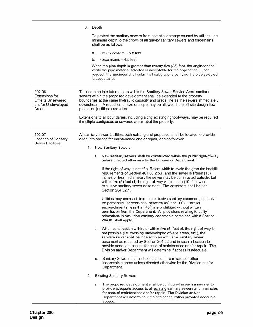
Chapter 200 page 2-9 Design
3. Depth
To protect the sanitary sewers from potential damage caused by utilities, the minimum depth to the crown of all gravity sanitary sewers and forcemains shall be as follows:
a. Gravity Sewers – 6.5 feet
b. Force mains – 4.5 feet
When the pipe depth is greater than twenty-five (25) feet, the engineer shall verify the pipe material selected is acceptable for the application. Upon request, the Engineer shall submit all calculations verifying the pipe selected is acceptable.
202.06 Extensions for Off-site Unsewered and/or Undeveloped Areas
To accommodate future users within the Sanitary Sewer Service Area, sanitary sewers within the proposed development shall be extended to the property boundaries at the same hydraulic capacity and grade line as the sewers immediately downstream. A reduction of size or slope may be allowed if the off-site design flow projection justifies a reduction. Extensions to all boundaries, including along existing right-of-ways, may be required if multiple contiguous unsewered areas abut the property.
202.07 Location of Sanitary Sewer Facilities
All sanitary sewer facilities, both existing and proposed, shall be located to provide adequate access for maintenance and/or repair, and as follows:
1. New Sanitary Sewers
a. New sanitary sewers shall be constructed within the public right-of-way unless directed otherwise by the Division or Department.
If the right-of-way is not of sufficient width to avoid the granular backfill requirements of Section 401.06.2.b.i., and the sewer is fifteen (15) inches or less in diameter, the sewer may be constructed outside, but within five (5) feet of, the right-of-way within a ten (10) feet wide exclusive sanitary sewer easement. The easement shall be per Section 204.02.1.
Utilities may encroach into the exclusive sanitary easement, but only for perpendicular crossings (between 45o and 90o). Parallel encroachments (less than 45o) are prohibited without written permission from the Department. All provisions relating to utility relocations in exclusive sanitary easements contained within Section 204.02 shall apply.
b. When construction within, or within five (5) feet of, the right-of-way is
not possible (i.e. crossing undeveloped off-site areas, etc.), the sanitary sewer shall be located in an exclusive sanitary sewer easement as required by Section 204.02 and in such a location to provide adequate access for ease of maintenance and/or repair. The Division and/or Department will determine if access is adequate.
c. Sanitary Sewers shall not be located in rear yards or other
inaccessible areas unless directed otherwise by the Division and/or Department.
2. Existing Sanitary Sewers
a. The proposed development shall be configured in such a manner to
provide adequate access to all existing sanitary sewers and manholes for ease of maintenance and/or repair. The Division and/or Department will determine if the site configuration provides adequate access.

Chapter 200 page 2-10 Design
Acceptable locations for existing sanitary sewer facilities within proposed developments may be as follows:
i. Within common areas; ii. Within proposed right-of-ways; iii. Adjacent proposed right-of-ways provided the existing sanitary
sewer is in, and remains in, an exclusive sanitary sewer easement; and/or
iv. Others as deemed acceptable by the Division and/or Department. b. The proposed subdivision or development shall not be configured in
such a manner that would cause existing sanitary sewer facilities to be located in rear yards or other areas determined to be inaccessible by the Division and/or Department.
3. Lift Stations
Existing and Proposed Lift Stations shall be located per Section 502.05. 4. Force Mains
Existing and proposed force mains shall be located per the same requirements as sewers per the above Section 202.07.1 & 2.
5. Adjacent Waterbodies
All sanitary sewer facilities and laterals shall be separated from existing or proposed waterbodies by a minimum twenty (20) feet horizontally as measured from the outside edge of the sanitary sewer facility to the top of bank. Sanitary sewers, force mains, and laterals crossing existing or proposed lakes, ponds, and/or retention or detention areas (either wet or dry) are prohibited.
202.08 Location and Elevation of Sanitary Sewer Facilities within Special Flood Hazard Areas
The elevation and location of sanitary sewer facilities within Special Flood Hazard Areas shall be as follows:
1. Sanitary Sewers and Force Mains
Sanitary sewers and force mains may be located within Special Flood Hazard Areas, but not within the floodway, unless the location is a perpendicular crossing. Refer to Section 204.06 for design criteria for crossing drainageways.
2. Manholes
Manholes may be located within the Special Flood Hazard Area, but not within the floodway.
The elevation of the top of casting shall be at or above the 25-year flood elevation. The surrounding ground must have a 3:1 slope. If the top of casting elevation is below the 100-year flood elevation, bolt down castings with watertight, non-rocking/self-sealing covers shall be used.
3. Lift Stations
Lift stations may be located within the Special Flood Hazard Area, but not within the floodway.
The elevation of the lift station base slab, all above ground equipment, and access drive shall be a minimum two (2) feet above the 100-year flood elevation.

Chapter 200 page 2-11 Design
202.09 Capacity Certification
For existing and proposed sanitary sewer facilities, the City of Indianapolis is required to submit Certifications in accordance with 327 IAC 3-6-4 to the Indiana Department of Environmental Management. The required Certifications are limited to additional flow generated as a result of the construction, installation, or modification of sanitary sewers. When determining if the Certification can be submitted to IDEM, the following factors will be considered when reviewing new sewer connection applications:
1. Capacity of receiving sewer during wet and dry weather, including contractual obligations to reserve future capacity for another party.
2. Compelling public need for the project, such as economic development or
conversion of areas currently serviced by septic systems, such as the City’s STEP program.
3. Mitigating or offsetting capital, operations, or maintenance projects
designed to improve sewer capacity. A downstream capacity evaluation may be required for the City to submit the necessary Certification. Refer to Section 202.10 for guidelines for the downstream evaluation. The Department and/or Division will document the basis for its decision for issuing or denying a Capacity Certification.
202.10 Downstream Evaluation
To evaluate the downstream capacity of a receiving sanitary sewer facility, the Division or Department will rely on the following:
1. Available Data/Information Available data/information may include the following:
a. Existing flow monitoring data;
b. Sanitary sewer studies;
c. Maintenance records;
d. Complaint records;
e. Past and/or proposed Capital Improvement Projects; and/or
f. Any other information deemed relevant by the Division and/or Department.
2. Additional Data/Information
If adequate data/information is not available, the applicant may be required to conduct, at no cost to the City, all the necessary tasks to assure the Division and Department makes an informed decision on the adequacy of the downstream sanitary sewer facilities. Such tasks may include the following:
a. Temporary Flow Monitoring
The requirements for temporary flow monitoring will be determined on a case-by-case basis by the Department at the time of application. General guidelines include the following:
i. Number of Monitors – The complexity of the downstream system
will determine the number of temporary monitors required. The maximum number shall not exceed five (5).

Chapter 200 page 2-12 Design
ii. Monitoring Duration – The monitoring duration shall be a
minimum of sixty (60) days or until one and one-half (1½) inches of rainfall in a 24-hour period is recorded, whichever is the greater period of time.
iii. Monitoring Period – If possible, part of the monitoring period shall
be done during the months of March, April, May, and June. However, if monitoring cannot be done during those months, the Department will consider an alternate time period.
Monitoring shall not be done during the month of January.
iv. Temporary Rain Gages – Temporary rain gages shall be installed
at or near the temporary flow monitoring site(s) during the flow monitoring period unless the monitors are located within one-half (1/2) mile of an operating City rain gage. An alternate rainfall measuring method may be approved by the Department on a case-by-case basis.
v. Flow Monitoring Data and Format – At a minimum, the following
shall be included:
(1) Depth / Velocity Hydrographs; (2) Flow Hydrographs; (3) Scatterplots / Scattergraphs; and (4) Any other data deemed necessary
vi. Other requirements as deemed necessary.
b. Hydraulic Modeling
The Department may require the extension of the City’s existing sanitary sewer collection system model to the point of connection of the proposed development. If a Model extension is necessary, the SWMM Model shall be used. To assure consistency, the Model shall be coordinated with the consultant currently being used by the City.
c. Lift Station System Evaluation
The Department may require an evaluation of one or more lift station systems. The evaluation may include the following systems:
i. Hydraulic; ii. Electrical; iii. Mechanical; iv. Instrumentation & Control; and v. Others as deemed necessary.
d. Other evaluations as deemed necessary.
202.11 Inadequate Downstream Capacity
If the Department determines downstream capacity is not available for the proposed flow from the development, the Applicant has the following options:
1. Make additional capacity available in the downstream system by:
a. Increasing the capacity in the system, and/or
b. Removing a sufficient volume of Infiltration/Inflow.
2. Connecting to an alternate point within the sanitary or combined sewer
system. A downstream analysis of the alternate system may be required.

Chapter 200 page 2-13 Design
202.12 Connections to Existing Sanitary Sewers
Sanitary sewers and force mains shall only be connected to the existing sewer system at manholes and shall be per Section 403.08. For lateral connections refer to Section 201.05. Blind tee connections to existing sewers are prohibited. If an existing manhole is not available, as determined by the Division or Department, a new manhole shall be installed as shown in Figure 300.06 and installed per Section 403. Connections to existing manholes will be evaluated on a case-by-case basis. Rehabilitation may be required and will be at the discretion of the Division or Department. Rehabilitation methods will be determined on a case-by-case basis. For brick or block manholes, at a minimum, a structural liner approved by the Department shall be installed prior to the connection of the new sanitary sewer. Brick or block manholes may need to be replaced in lieu of a structural liner. No more than four (4) connections to existing manholes, three (3) incoming and one (1) outgoing, will be allowed.
202.13 Connections in the Combined Sewer Area
The construction of new combined sewers is prohibited. The Department maintains and periodically updates a map of both the combined and sanitary sewer areas within the City. When constructing sanitary sewer facilities within the combined sewer area, the City will address each application on a case-by-case basis using the following guidelines:
1. Connections to Combined Sewers All new or proposed sanitary and storm sewers shall be separated prior to connecting to the combined system. Each system shall be connected individually to the combined sewer if a separate storm sewer is not available. The connections shall be per Section 202.12.
2. Sewer Separation To remove stormwater from the combined sewer system, the Division or Department may require an off-site extension of the proposed storm sewer if an alternate stormwater discharge location is available. The following factors shall be considered by the Division when evaluating the separate storm sewer requirement:
a. Capacity in receiving sewers to accept stormwater flow, and planned
capital improvement projects identified within the City’s CSO Long Term Control Plan (LTCP), or other plans;
b. Impacts on Water Quality; c. Feasibility of separation, including costs to treat, construct, and
manage the sewer system as a separate or combined system; and d. Other appropriate factors deemed relevant by the Division and/or
Department.
3. Stormwater release rates to the combined sewer system.
The stormwater release rates to any combined sewer shall, at a minimum, comply with all requirements set forth in the latest version of the City of Indianapolis Stormwater Design Manual.

Chapter 200 page 2-14 Design
The Division and/or Department may further restrict the stormwater release rates, if justified.
The Division and/or Department will document the basis for its decision for requiring, or not requiring, sewer separation in the project area.

Chapter 200 page 2-15 Design
SECTION 203 Sewer Structures - Manholes
203.01 Introduction
This Section provides design requirements specific to manholes. For design requirements specific to laterals refer to Section 201. For design requirements specific to gravity sewers refer to Section 202. For design requirements specific to lift stations and low pressure sewer systems refer to Chapter 500.
203.02 Location
Manholes shall be installed in the following locations:
1. At the end of each sewer segment; 2. At all changes in sewer slope, size, or alignment;
At changes in sewer alignment and/or sizes, the energy gradient elevation shall not increase by: a. Matching the crown elevations when changes in pipe sizes are
necessary.
b. Providing an elevation difference between incoming and outgoing pipe inverts as follows:
i. For sewer angles between zero (0o) degrees (straight through) to and
including ninety (90o) degrees – 0.1 feet minimum; ii. Over ninety (90o) degrees – Not allowed.
3. At all sewer segment intersections. 4. In areas that will minimize the potential for I/I entering the sewer system.
To minimize the potential for I/I, manholes shall NOT be designed or installed in any drainage path such as, but not limited to, the following locations:
a. Swales or ditches. b. Roadside gutters. c. Inverted crowns of streets. d. Low points of paved or unpaved areas. e. Adjacent stormwater inlets. f. Other areas the Division or Department deems necessary.
Cleanouts shall not be used in lieu of manholes.
203.03 Protection against Ponding
To provide protection against ponding, manholes shall be designed and constructed to provide positive drainage away from the top of casting as follows:
1. Paved areas – Top of casting flush with finished grade.
2. Unpaved areas – Top of casting a minimum of three (3) inches above finished
grade.

Chapter 200 page 2-16 Design
203.04 Maximum Manhole Spacing
The maximum distances between manholes shall be based on the sewer size and as follows:
Sewer Size, inches
Max. Spacing, feet
12 or less 400 15 – 27 500
30 and larger 600
203.05 Manhole Dimensions
The following Table contains the minimum manhole diameters for sanitary sewer pipes entering or exiting a sanitary sewer manhole at the given range of angles.
Minimum Manhole Diameters, inches Pipe Size,
inches Pipes Entering or Leaving at a 45o
Angle
Pipes Entering or Leaving at a 46o -
90o Angle
Reference Figure
18 or less 48 48 300.01
21-24 48 60 300.02
27 60 72 300.02
30 to 36 60 84 300.02
42 72 96 300.02
48 84 Special Design 300.02*
54 or larger N/A N/A 300.03 *Only for straight through pipes otherwise use Figure 300.03
The number and entrance angle of pipe connections, with consideration given to outside pipe diameter(s), shall be limited to those guidelines established in the previous Table to ensure the structural integrity of the manhole. If at any time the structural integrity of the manhole cannot be maintained, a cast-in-place structure will be required.
203.06 Drop Connections
Drop pipe connections shall be provided for all sanitary sewers or laterals entering a manhole at an elevation twenty-four (24) inches or greater above the invert of the manhole. Inside or outside drop connections may be used and are shown in Figures 300.04 and 300.05. However, the Division or Department may require either an inside or outside drop connection, if conditions necessitate. The size of the drop pipe shall be the same size as the incoming sewer. The Division or Department may require an increase in the slope of one or more upstream sewer segments or the lateral to eliminate the need for a drop manhole. When inside drop connections are installed, the minimum inside diameter of the manhole shall be as follows:
Total Number of Drop Lines
Pipe Size, inches
Inside Manhole Diameter, inches
1 8 to 12 60 2 or 3 8 to 12 72
No more than three (3) inside drop connections are allowed in one manhole. Sewers larger than twelve (12) inches proposing drop connections will be evaluated on a case-by-case basis.
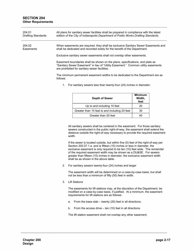
Chapter 200 page 2-17 Design
SECTION 204 Other Requirements 204.01 Drafting Standards
All plans for sanitary sewer facilities shall be prepared in compliance with the latest edition of the City of Indianapolis Department of Public Works Drafting Standards.
204.02 Easements
When easements are required, they shall be exclusive Sanitary Sewer Easements and shall be dedicated and recorded solely for the benefit of the Department. Exclusive sanitary sewer easements shall not overlap other easements. Easement boundaries shall be shown on the plans, specifications, and plats as “Sanitary Sewer Easement” in lieu of “Utility Easement.” Common utility easements are prohibited for sanitary sewer facilities. The minimum permanent easement widths to be dedicated to the Department are as follows:
1. For sanitary sewers less than twenty-four (24) inches in diameter:
Depth of Sewer Minimum
Width, feet
Up to and including 10 feet 20
Greater than 10 feet to and including 20 feet 30
Greater than 20 feet 40
All sanitary sewers shall be centered in the easement. For those sanitary sewers constructed in the public right-of-way, the easement shall extend the distance outside the right-of-way necessary to provide the required easement width.
If the sewer is located outside, but within five (5) feet of the right-of-way per Section 202.07.1.a. and is fifteen (15) inches or less in diameter, the exclusive easement is only required to be ten (10) feet wide. The remainder of the required easement width may be shown as a DU&SE. For sewers greater than fifteen (15) inches in diameter, the exclusive easement width shall be as shown in the above table.
2. For sanitary sewers twenty-four (24) inches and larger
The easement width will be determined on a case-by-case basis, but shall not be less than a minimum of fifty (50) feet in width.
3. Lift Stations The easements for lift stations may, at the discretion of the Department, be modified on a case-by-case basis, if justified. At a minimum, the easement requirements for lift stations are as follows:
a. From the base slab – twenty (20) feet in all directions; b. From the access drive – ten (10) feet in all directions.
The lift station easement shall not overlap any other easement.

Chapter 200 page 2-18 Design
Except for perpendicular crossings as described in Section 202.07.1.a, utility companies are not allowed to use the sewer easements for the installation of their utility lines without the expressed written permission of the Department. If permission is granted, utilities shall agree to relocate or support their respective facilities, at no expense to the City, if the City requires access to maintain or repair the sanitary sewer facility. All site development and plan/profile sheets shall clearly identify the sanitary sewer easement and the location of all existing and proposed utilities. The plan/profile sheets shall also show the location and elevation of existing and proposed utilities, on both plan and profile sections, proposed to cross the sanitary sewer easement.
204.03 Protection of Water Supplies
To protect public and private drinking water supplies, the IDEM, ISDH, and MCH&HC have established minimum clear distances between sanitary sewer facilities and drinking water supplies. Applicant is responsible for complying with all applicable regulations. Where discrepancies are found between the requirements set forth herein and any other requirements by agencies having jurisdiction relating to water supplies, the more restrictive requirement shall be followed. The clear distances shall be as measured from the outside edge of the sanitary sewer facility (sewer, force main, manhole, or lift station) to the outside edge of the water supply (water main or well screen). The minimum separation distances between sanitary sewer facilities and water supplies shall be as follows:
1. Water Mains
The minimum separation distance between the following sanitary sewer facilities and existing or proposed water mains shall be as follows: a. Sanitary Sewers / Force Mains
The minimum horizontal and vertical separation distances shall be as follows:
i. Horizontal Separation – Ten (10) feet ii. Vertical Separation – Eighteen (18) inches
The vertical separation shall only be applicable when sanitary sewers and water mains cross. When crossing, the sewer and watermain shall cross at a minimum angle of forty-five (45) degrees as measured from the centerlines of the pipes and maintain the minimum vertical separation a minimum distance of ten (10) feet on either side of the sanitary sewer. The joints of the sanitary sewer shall be equidistant and as far as possible from the water main joints.
Separation distances less than the above will be considered and may be allowed if all the following conditions are met:
• The pipe material is pressure rated PVC, DIP, or PCCP force main material per Section 304.
• The sanitary sewer and water main are not in contact.
• The sanitary sewer joints are compression type and placed
equidistant from the water main.
• The sanitary sewer and water main are laid on separate trench shelves.

Chapter 200 page 2-19 Design
b. Manholes – Eight (8) feet c. Lift Stations – Ten (10) feet
2. Public Water System Drinking Water Wells
The minimum separation distance between the following sanitary sewer facilities and public water system drinking water wells shall be as follows: a. Sanitary Sewers – Two hundred (200) feet
Sanitary sewers may be located within two hundred (200) feet, but under no circumstances less than fifty (50) feet, from a public water system drinking water well if pressure rated PVC, DIP, or PCCP force main material per Section 304 is used.
b. Manholes – Two hundred (200) feet
c. Lift Stations – Two hundred (200) feet
3. Private Water Supply Wells
The minimum separation distance between the following sanitary sewer facilities and private water supply wells shall be as follows:
a. Sanitary Sewers – Fifty (50) feet
Sanitary sewers may be located within fifty (50) feet, but under no circumstances less than ten (10) feet, from a private water supply well if pressure rated PVC, DIP, or PCCP force main material per Section 304 is used.
b. Manholes – Fifty (50) feet
c. Lift Stations – Fifty (50) feet
204.04 Existing Utility Structures and Facilities
Based on the best available information and field surveying, all existing overhead and underground utility lines and existing sewers shall be shown on the plans.
204.05 Utility Coordination
It is the responsibility of the Owner or their authorized representative to coordinate with and get approvals from the various utilities, including other Departments of the City for all proposed Work. Further, it is the responsibility of the Owner to get authorization to encroach upon any other utility easement(s) and secure such recorded encroachment as a requirement for dedication of the sanitary sewer facility.
204.06 Sanitary Sewers Crossing Drainage Ways
When crossing streams or rivers, sanitary sewers shall be constructed with DIP or PVC SDR 21, with mechanical joints rated to two hundred (200) psi and backfilled with stone, gravel, or coarse aggregate with a minimum cover depth as follows:
1. Under a Paved Channel – Below the pavement; 2. When located in rock - Twelve (12) inches; or 3. All other areas - Thirty-six (36) inches.
The Division and/or Department may require cover depths greater than those specified above, if justified.

Chapter 200 page 2-20 Design
204.07 Aerial Crossings and Siphons
If possible, siphons and aerial crossings shall be avoided. If not possible, the requirements shall be determined on a case-by-case basis and will be at the sole discretion of the Department.

CHAPTER 300
MATERIALS

Chapter 300 page 3-2 Materials
SECTION 301 General 301.01 Introduction
This Chapter contains the minimum material requirements for construction of sanitary sewer facilities within the Indianapolis Sanitary District.
301.02 General for all Materials
The materials used in the construction shall be in full conformance with those guidelines set forth below and according to the applicable ASTM, AWWA, and ANSI specifications. These material requirements are minimum requirements and are in part restatements of requirements set forth within the referenced standards, with noted exceptions. The Engineer shall be ultimately responsible for designing and selecting the appropriate material for each specific application. Information from the referenced specifications has been included within this Chapter for the convenience of the reader. However, the engineer, contractor, and manufacturer must also assume the responsibility of familiarizing themselves with these requirements. The City will not assume responsibility for noncompliance with the referenced specifications as a result of information not provided in this Manual.
301.03 Material Markings
Each length of pipe and each manhole or other structure shall be marked per the requirements of each respective ASTM, AWWA and/or ANSI Standard referenced within this Chapter.
301.04 Certification of Materials
The Division or Department reserves the right to require material certification from the manufacturer prior to construction to ensure the material supplied conforms to the prescribed requirements. Upon request, the Contractor shall furnish a certificate of conformance to the required ASTM, AWWA, and/or ANSI Standards, this Manual, and other conformance certifications in the form of affidavits of conformance, test results, and/or copies of test reports. Provisions for obtaining this certification shall be the responsibility of the Applicant. The City of Indianapolis does not assume the responsibility for the expense of obtaining material certification.
301.05 Handling, Storage, and Color
The handling, storage and color requirements for pipe material are as follows:
1. Handling and Storage
The manufacturer shall package the pipe in a manner designed to deliver the pipe to the project site neatly, intact, and without physical damage. The transportation carrier shall use an appropriate method to ensure the pipe is properly supported, stacked, and restrained during transport. On-site, the pipe shall be stored on clean, level ground to prevent undue scratching or gouging.
2. Color
The interior of the pipe shall be light colored to facilitate CCTV inspection. The pipe exterior may be colored per the manufacturer’s standard color scheme with the exception of blue. Blue pipe shall not be used to avoid confusion with water pipes.

Chapter 300 page 3-3 Materials
SECTION 302 Sanitary Sewer Pipe Material 302.01 Introduction
This Section applies to materials to be used for the construction of gravity sewers. For materials to be used for laterals refer to Section 303. For materials to be used for force mains refer to Section 304. For materials to be used for manholes refer to Section 305.
302.02 Allowable Pipe Materials
The following pipe materials are the only materials that may be used for gravity sanitary sewer installations:
Sizes (Nominal Diameter, in.) Material Designation
Max. Depth,
ft.1 Minimum Maximum
Polyvinyl Chloride Pipe (PVC)
ASTM D 3034 ASTM F 679
ASTM D 2241 AWWA C900 AWWA C905
25 25 40 40 40
8 18 8 8 14
15 48 36 12 36
Reinforced Concrete Pipe (RCP)
ASTM C 76 ASTM C 655 252 24 144
Ductile Iron Pipe (DIP)
ASTM A 746 AWWA C151 40 8 60
Closed Profile Large Diameter PVC Pipe
ASTM F 1803 25 18 54
Centrifugally Cast Fiberglass Reinforced Polymer Mortar Pipe
ASTM D 3262 40 18 60
Prestressed Concrete Cylinder Pipe (PCCP)
AWWA C301 40 30 144
1 – The maximum depth is a guideline. Due to the variability of site conditions, the Engineer is ultimately responsible for certifying the pipe selected is acceptable for the depths listed and the specific project application. 2 – The depth can be increase to forty (40) feet provided the joints and gaskets are designed per ASTM C 361. See Section 302.06.3 for specific requirements.
The individual requirements and specifications for the above pipe materials are listed in the remainder of this Section. Vitrified Clay Pipe (VCP) for gravity sewer construction is not allowed.

Chapter 300 page 3-4 Materials
302.03 Polyvinyl Chloride Pipe (PVC)
The minimum requirements for PVC are as follows:
1. Size
Maximum size – Forty-eight (48) inches
2. Material
a. Pipe installations up to twenty-five (25) feet deep
Polyvinyl Chloride (PVC) sanitary sewer pipe and fittings eight (8) inches through fifteen (15) inches in diameter shall be the integral wall bell and spigot-type with elastomeric seal joints and smooth walls conforming to ASTM D 3034 and a minimum of SDR 35. PVC sanitary sewer pipe and fittings eighteen (18) inches in diameter and larger shall be smooth wall conforming to ASTM F 679. All fittings shall be heavy walled fittings. Pipe shall have a minimum pipe stiffness of 46 psi when measured at 5% vertical ring deflection and tested in accordance with ASTM D 2412 and a minimum tensile strength of 34.50 MPa.
b. Pipe installations over twenty-five (25) feet deep
PVC pipe materials shall be ASTM D 2241 (SDR 26 minimum) with minimum cell classification of 12454, AWWA C900 (DR 25 min), or AWWA C905 (DR 25 min). When pipe conforming to AWWA Standards is used, all fittings shall also be made of PVC.
3. Joints and Gaskets
a. Joints
i. Flexible gasketed joints shall be compression type so that when assembled, the gasket inside the bell will be compressed radially on the pipe spigot to form a watertight seal.
ii. Joints shall be as follows:
• For pipe conforming to ASTM D 3034 and F 679, the joint shall meet the requirements of ASTM D 3212.
• For pipe conforming to ASTM D 2241, AWWA C900, and AWWA C905, the joint shall meet the requirements of ASTM D 3139.
iii. The assembly of joints shall be in accordance with the pipe
manufacturer’s recommendations.
b. Gaskets
All gaskets shall meet the requirements of ASTM F 477.
Solvent welded joints and coupling joints are not acceptable.

Chapter 300 page 3-5 Materials
4. Field Cutting of Pipe
All field-cutting of pipe shall be done in a neat, trim manner using a hand or power saw, and the cut end shall be beveled using a file or wheel to produce a smooth bevel of approximately 15° and be a minimum depth of one-third (1/3) the pipe wall thickness or beveled as specifically recommended by the pipe manufacturer. Field cut pipe will only be allowed to be installed at manholes, at prefabricated tees and wyes, and at the connection of new sanitary sewer to existing sanitary sewer.
5. Rejection of Damaged Pipe
PVC pipe possessing the following defects may be rejected for installation: variation from straight centerline; elliptical shape; illegible markings as required; deep or excessive gouges or scratches of the pipe wall; fractures, punctures, or cracks passing through the pipe wall; and damaged ends where such damage would prevent making a satisfactory joint.
6. Pipe Markings
For PVC pipe, each length of pipe must be marked per ASTM and AWWA requirements and at a minimum with the following: name of manufacturer, tradename or trademark, nominal pipe size, production/extrusion code, material and cell class designation, ASTM designation, and SDR number. In addition, the plain end of each pipe length shall have rings painted around the pipe at the proper location to allow field checking of the correct setting depth of the pipe in the bell.
7. Manufacture and Construction
a. Pipes
Pipes shall be manufactured and tested in accordance with appropriate ASTM and AWWA standards to result in a solid wall pipe.
b. Fittings
Tees, wyes, and other fittings shall be heavy-walled and capable of withstanding the same stresses as the pipe to which they are connected. All fittings shall be fabricated from pipe meeting the requirements of these standards.
302.04 Closed Profile Large Diameter PVC
The minimum requirements for Closed Profile PVC pipe are as follows:
1. Size
Maximum Size – Fifty-four (54) inches 2. Materials
Pipe and fittings shall be made from polyvinyl chloride compounds which comply with the requirements as specified by ASTM F 1803 with a minimum cell classification of 12364. Minimum pipe stiffness shall be 46 psi when tested in accordance with ASTM D 2412. The actual inside and outside diameter of the pipes shall be in accordance with current manufacturer’s literature, unless otherwise agreed to by the Department. Pipe shall be supplied in nominal lengths of fourteen (14) feet unless special sections are needed for construction in which case shorter or longer lengths may be used. Actual laying length shall be nominal plus or minus two (±2) inches.

Chapter 300 page 3-6 Materials
3. Joints and Gaskets
All pipe joints shall be of the bell and spigot type with elastomeric seals and conform to the requirements of ASTM D 3212. Gaskets shall be factory installed and chemically bonded to the bell end of the pipe. Gasket material shall conform to the requirements of ASTM F 477.
4. Rejection of Damaged Pipe
Pipe possessing the following defects may be rejected for installation: variation from straight centerline; elliptical shape; illegible markings as required herein; deep or excessive gouges or scratches of the pipe wall; fractures, punctures, or cracks passing through the pipe wall or wall profile; damaged ends where such damage would prevent making a satisfactory joint, voids in the pipe walls, or other noticeable defects in pipe manufacture.
5. Marking
Each PVC closed profile wall pipe length and fitting shall be clearly marked per ASTM F 1803 and at a minimum with the following: manufacturer’s name, nominal pipe size, cell classification, pipe stiffness - 46 PSI, and certification.
6. Manufacture and Construction
a. Pipes
Manufacture pipe by the I-beam profile construction process to result in a non-porous, corrosion-resistant, consistent structure.
b. Fittings
Flanges, elbows, reducers, tees, wyes, laterals and other fittings shall be capable of withstanding the same stresses as the pipe to which they are connected. All fittings shall be fabricated from pipe meeting the requirements of these standards. Fabricated miter joints shall be reinforced by fusion heat welding.
Closed Profile Large Diameter PVC Gravity Sewer shall be Lamson Vylon Pipe or an approved equal.
302.05 Centrifugally Cast Fiberglass Reinforced Polymer Mortar Pipe
The specifications herein shall be considered as the minimum requirements for Centrifugally Cast Fiberglass Reinforced Polymer Mortar Pipe. Due to the differing manufacturing processes and strength characteristics between the different manufacturers, the pipe shall be designed for site specific conditions. The minimum requirements for Centrifugally Cast Fiberglass Reinforced Polymer Mortar Pipe are as follows:
1. Size
Maximum size – Sixty (60) inches
2. Materials
Pipe shall be manufactured per ASTM D 3262. The actual inside and outside diameter of the pipes shall be in accordance with current manufacturer’s literature, unless otherwise agreed to by the Department.

Chapter 300 page 3-7 Materials
Pipe shall be supplied in nominal lengths of twenty (20) feet unless special sections are needed for construction in which case shorter or longer lengths may be used. Actual laying length shall be nominal ± two (2) inches. Minimum pipe stiffness shall be 46 psi when tested in accordance with ASTM D 2412. Applications which are to be directly jacked into place or micro-tunneled shall utilize pipe configurations specifically designed for jacking or tunneling applications with no protrusions for the joint coupling.
a. Resin Systems
The manufacturer shall use vinylester resin systems for greater chemical resistance. Polyester resin systems with a proven history of performance in resisting sanitary sewerage may only be used with prior written approval from the Department and then only after the Engineer determines the greater chemical resistance is not needed.
b. Glass Reinforcements
The reinforcing glass fibers used to manufacture the components shall be of commercial grade E-glass filaments with binder and sizing compatible with impregnating resins.
c. Silica Sand
Sand shall be minimum 98% silica with a maximum moisture content of 0.2%.
d. Additives
Resin additives, such as curing agents, pigments, dyes, fillers, thixotropic agents, etc., when used, shall not detrimentally affect the performance of the product.
3. Joints and Gaskets
Fiberglass sleeve couplings that utilize elastomeric sealing gaskets of an appropriate profile shall be the sole means to maintain joint water-tightness. The joints must meet the performance requirements of ASTM D 4161. All joints shall be certified by the pipe manufacturer to perform at fifty (50) feet of hydrostatic head at 5% deflection. The gaskets shall be made of EDPM elastomeric membrane and shall be resistant to sewage, industrial wastes, and groundwater.
4. Rejection of Damaged Pipe
Pipe possessing the following defects may be rejected for installation: variation from straight centerline; elliptical shape; illegible markings as required herein; deep or excessive gouges or scratches of the pipe wall or liner; fractures, punctures, or cracks passing through the pipe wall; damaged ends where such damage would prevent making a satisfactory joint, voids in the pipe walls, delamination, cracking and crazing of liner or pipe wall, or other noticeable defects in pipe manufacture.
5. Markings
Each length of pipe shall be clearly marked per ASTM D 3262 and at a minimum with the following: manufacturer’s name, tradename or trademark, nominal pipe size, pipe stiffness, production code, and ASTM number.

Chapter 300 page 3-8 Materials
6. Manufacture and Construction
a. Pipes
Manufacture pipe by the centrifugal casting process to result in a dense, non-porous, corrosion-resistant, consistent composite structure. Pipes shall be tested in accordance with ASTM D 3262. MANDREL PROCESSES TO BUILD UP THE PIPE WALL ARE NOT ALLOWED.
b. Fittings
Flanges, elbows, reducers, tees, wyes, laterals, and other fittings shall be capable of withstanding the same stresses as the pipe to which they are connected. They may be contact molded or manufactured from mitered sections of pipe joined by glass-fiber-reinforced overlays. Properly protected standard ductile iron, fusion-bonded epoxy coated steel and stainless steel fittings may also be used.
Centrifugally Cast Fiberglass Reinforced Polymer Mortar Pipe shall be Hobas pipe or an approved equal.
302.06 Reinforced Concrete Pipe (RCP)
The minimum requirements for Reinforced Concrete Pipe are as follows:
1. Size
Minimum – Twenty-four (24) inches Maximum – One hundred forty-four (144) inches
2. Material
a. Reinforced Concrete:
Reinforced concrete pipe shall be in accordance with ASTM C 76. Pipe wall thickness shall be either Wall B or Wall C as appropriate for the size and installation. When deep burial depths are greater than twenty-five (25) feet require an improved joint to resist higher head conditions, joint sections manufactured in accordance with ASTM C 361 with a joint rating of at least fifty (50) feet shall be incorporated.
When special conditions exist and as authorized by the Department, reinforced concrete pipe manufactured in accordance with ASTM C 655 may be used. The minimum D-load design for ASTM C 655 pipe shall be 1000 and the minimum increment of D-load shall be at least 200, if multiple pipe designs are proposed on a single project.
For pipe designed in accordance with ASTM C 76 or C 655, factors of safety shall be 1.5 for D-loads of 2000 and less, 1.25 for D-loads of 3000 and higher and uniformly decreasing between 1.5 and 1.25 for D-loads between 2000 and 3000. The wall thickness shall not be less than the wall thickness used to verify the D-load strength.
b. Steel Reinforcement
Steel reinforcement shall be in accordance with and placed to the requirements of the applicable tables in ASTM C 76, ASTM C 361, or per the approved D-load design. Longitudinal reinforcement shall be continuous and all reinforcement shall have a minimum concrete cover of 1 inch. Minimum cover requirements do not apply to the mating surfaces of the joint, gasket seat, or end of longitudinals. Elliptical reinforcement shall not be permitted.

Chapter 300 page 3-9 Materials
c. Lift Holes
Lift holes are not allowed. d. Lining
All reinforced concrete pipe for sanitary sewers shall be factory lined with one of the following materials: T-Lock PVC by Ameron, GSE Studliner by Grundle/SLT Environmental, Agru Sure Grip by Agru America, or approved equal.
i. Liners shall be completed with heat welded joints at all pipe joints
where the liner is discontinuous across the joint. Liner sheets with adhesive backing or other non-heat welded joint overlays are not permitted.
ii. Liner shall be embedded in concrete to withstand a test pull of at
least 100 pounds per linear inch, applied perpendicularly to the concrete surface for a period of one minute, without rupture of the locking extensions or withdrawal from embedment. This test shall be made at a temperature of 70-80 degrees Fahrenheit inclusive.
iii. Lining material shall have good impact resistance, shall be flexible,
and shall have an elongation sufficient to bridge up to one-quarter (¼) inch settling cracks, which may occur in the joint after installation, without damage to the lining.
iv. The lining shall be repairable at any time during the life of the pipe or
structure by heat welding additional materials to the liner. v. The lining materials shall be resistant to municipal sewage.
3. Joints and Gaskets
All joints for pipes in accordance with ASTM C 76 and ASTM C 655 shall comply with the requirements of ASTM C 443. Joints and gaskets designated to be in excess of twenty-five (25) feet of head shall be designed in accordance with ASTM C 361. Only one style of joint system or configuration shall be permitted between adjacent manholes.
4. Rejection of Damaged Pipe
Pipe possessing the following defects may be rejected for installation: variation from straight centerline; elliptical shape; illegible markings; fractures in excess of 0.01 inch or cracks passing through the pipe wall; damaged ends where such damage would prevent making a satisfactory joint, voids and/or honeycombing in the pipe walls, delamination of pipe liner, cracking and crazing of liner, or other noticeable defects in pipe or liner manufacture.
5. Marking
All markings required by the appropriate ASTM specification shall be legibly marked on each section of pipe.
6. Manufacturer and Construction Manufacture and test pipe sections in accordance with ASTM C 76, C 361, or C 655 as appropriate for the strength, class, size, and joint design utilized.

Chapter 300 page 3-10 Materials
7. Special Shaped Pipe
Special shaped pipe shall conform to the specifications for straight pipe insofar as applicable. Special design or construction necessary for specials shall be subject to approval by the Department on a case-by-case basis.
302.07 Ductile Iron Pipe (DIP)
The minimum requirements for Ductile Iron Pipe (DIP) are as follows:
1. Size
Maximum – Sixty (60) inches
2. Materials
Ductile Iron Pipe shall be centrifugally cast and shall conform to ANSI/AWWA A21.51/C151 and ASTM A 746. Thickness or pressure class requirements of ductile iron pipe may be used for design in the conveyance of sanitary sewage by gravity. The minimum pipe wall thickness allowed shall be Class 250. Weights of pipe fittings shall conform strictly to the requirements of Specifications. The minimum laying lengths shall be eighteen (18) feet.
3. Coatings and Linings
a. Coatings
The outside surfaces of the pipe and fittings shall be bituminous-coated complying with ANSI/AWWA A21.51/C151 and ANSI/AWWA A21.10/C110.
b. Linings
The inside surfaces of all pipe, fittings, and adapters shall be lined with factory applied Protecto 401® ceramic epoxy lining, or approved equal.
4. Joints
Mechanical, push on or restrained joints shall be provided. Flanged joints are not allowed for buried applications.
a. Mechanical joints and accessories shall conform to AWWA C111/ ANSI
A21.11. The bolts and nuts shall be corrosion resistant high strength alloy steel.
b. Ductile iron pipe push-on type joints shall conform to ANSI A21.11/AWWA C111. Fittings shall be ductile iron and shall comply with ANSI Specification A21.10/AWWA C110.
c. Restrained joints shall be manufactured in accordance with pipe
manufacturers’ requirements. Locking rings, tabs, inserts, or gaskets with inset steel grips may all be used for gravity sanitary sewer applications.
5. Fittings
Fittings shall be standardized for the type of pipe and joint specified, and shall comply with ANSI A21.10/AWWA C110.
6. Rejection of Damaged Pipe
Pipe possessing the following defects may be rejected for installation: variation from straight centerline; elliptical shape; illegible markings as required herein; deep or excessive gouges or scratches of the pipe wall or lining; fractures or cracks in the pipe wall or lining; damaged ends where such damage would prevent making a satisfactory joint, delamination of linings, cracking and crazing of liner, or other noticeable defects in pipe manufacture.

Chapter 300 page 3-11 Materials
7. Markings
Each pipe length shall be marked per ASTM A 746 and at a minimum the following: nominal size and class designations for the various classes of pipe and fittings shall be cast onto fittings in raised numerals, and cast or stamped on the outside of each section of pipe. Weights shall be plainly and conspicuously painted in white on the outside of each section of pipe and each fitting after the exterior coating has hardened.
8. Manufacturer and Construction
Manufacture and test completed pipe sections in accordance with ANSI/AWWA A21.4/C104, ANSI/AWWA A21.51/C151, ANSI/AWWA A2110/C110 and AWWA C111 (ANSI A-21.11) as appropriate.
302.08 Prestressed Concrete Cylinder Pipe (PCCP)
The minimum requirements for pre-stressed concrete cylinder pipe for gravity applications are as follows:
1. Size
Minimum Size – thirty (30) inches Maximum Size – One hundred forty-four (144) inches
2. Material The pipe shall conform to the requirements of AWWA C301. C301 pipe shall be designed in accordance with AWWA Standard C304. The pipe design shall be based on the working pressures, surge pressures, earth cover, and live load criteria provided in the contract documents. The external load design shall be suitable for the installation conditions shown in the project plans.
3. Lining All PCCP pipe shall be factory lined with one of the following materials: T-Lock PVC by Ameron, GSE Studliner by Grundle/SLT Environmental, Agru Sure Grip by Agru America, or approved equal.
a. Liners shall be completed with heat welded joints at all pipe joints where
the liner is discontinuous across the joint. Liner sheets with adhesive backing or other non-heat welded joint overlays are not permitted.
. b. Liner shall be embedded in concrete to withstand a test pull of at least
100 pounds per linear inch, applied perpendicularly to the concrete surface for a period of one minute, without rupture of the locking extensions or withdrawal from embedment. This test shall be made at a temperature of 70-80o Fahrenheit inclusive.
c. Lining material shall have good impact resistance, shall be flexible, and
shall have an elongation sufficient to bridge up to one-quarter (¼) inch settling cracks, which may occur in the joint after installation, without damage to the lining.
d. The lining shall be repairable at any time during the life of the pipe or structure by heat welding additional materials to the liner.
e. The lining materials shall be resistant to municipal sewage.
4. Joints Steel and rubber gaskets shall conform to AWWA C301.

Chapter 300 page 3-12 Materials
5. Fittings and Special Sections
Fittings and special pipe sections shall be designed and fabricated to the requirements of the appropriate AWWA standards and AWWA Manual M9 Chapter 8, as applicable.
All required flanges shall conform to AWWA C207 Class D requirements for standard steel flanges corresponding to the pipe working pressures. The PVC lining in fittings and special sections shall be attached to the mortar lining using methods acceptable to the manufacturer of the lining material.
6. Rejection of Damaged Pipe Pipe possessing the following defects may be rejected for installation: variation from straight centerline; elliptical shape; illegible markings; fractures in excess of 0.01 inch, cracks passing through the pipe wall; damaged ends where such damage would prevent making a satisfactory joint, voids and/or honeycombing in the pipe walls, or other noticeable defects in pipe manufacture.
7. Marking of Pipe
The inside of each pipe section, fitting, or special pipe section shall be plainly marked with the pipe diameter and pressure class for which the section or fitting is designed. In addition, all fittings and special pipe sections shall be marked with an identifying number or station corresponding to that shown on the layout schedule. All fittings or special sections requiring special field orientation during installation shall be properly marked.

Chapter 300 page 3-13 Materials
SECTION 303 Laterals 303.01 Introduction
This Section applies to the materials to be used for the construction of laterals. For materials to be used for gravity sewers refer to Section 302. For materials to be used for force mains refer to Section 304. For materials to be used for manholes refer to Section 305.
303.02 Lateral Materials
The minimum requirements for laterals shall conform to the following:
1. Allowable Pipe Materials:
The following are the only materials that shall be used for laterals.
Material Designation Classification
PVC ASTM D 3034 SDR 35 Cell Class 12454 or 12364
PVC ASTM D 2241 SDR 32.5 Cell Class 12454
PVC ASTM D 2466 Schedule 40 Cell Class 12454
PVC ASTM D 2467 Schedule 80 Cell Class 12454
HDPE* ASTM F 714 DR 17 Hydrostatic Design Basis of 1600 psi
*HDPE is only allowed for pipe bursting applications, shall utilize DIPS pipe sizing, and shall have a light reflective interior. Standard black interior lined pipe shall not be accepted. Vitrified Clay Pipe (VCP) for lateral construction is not allowed.
2. Joints
a. For four (4) inch and six (6) inch laterals
Joints shall be solvent cement type for PVC or butt fused type for HDPE. b. For eight (8) inch and larger laterals
Joints shall be either flexible gasket push-on type or solvent cement type for PVC or butt fused type for HDPE.
Joints shall be installed in accordance with the manufacturer’s recommendations.
303.03 Controlled Settlement (Slip) Joints
The controlled settlement joint shall be a double gasketed joint made specifically for the purpose of allowing axial movement of the riser pipe for forces from 500 lb/ft to 1,970 lb/ft. The allowable movement within the joint shall be five and one-half (5½) inches. The controlled settlement joint shall be as manufactured by Plastic Trends Inc., or approved equal.

Chapter 300 page 3-14 Materials
SECTION 304 Force Main Material 304.01 Introduction
This Section applies to materials to be used for the construction of force mains. For materials to be used for gravity sewers refer to Section 302. For materials to be used for laterals refer to Section 303. For materials to be used for manholes refer to Section 305.
304.02 Allowable Force Main Material
The following pipe materials are the only materials that may be used for sanitary sewer force main installations:
Designation Material
ASTM AWWA
Polyvinyl Chloride Pipe (PVC) D 2241 C900 C905
High Density Polyethylene Pipe (HDPE) F 714 C906
Ductile Iron Pipe (DIP) A 746 C151
Prestressed Concrete Cylinder Pipe ------ C301
304.03 Polyvinyl Chloride (PVC) Pipe
The minimum requirements for PVC pipe for force mains are as follows:
1. Material
PVC force main pipe shall conform to ASTM D 2241, AWWA C900 or AWWA C905. For ASTM D 2241, the material shall conform to ASTM D 1784, Cell Class 12454 and a hydrostatic design stress of 2000 psi. The minimum pressure class/SDR rating shall be Class 200/SDR 21. For AWWA C900 the material shall conform to ASTM D 1784 for cell class 12454 and a hydrostatic design basis of 4000 psi. The minimum pressure class/DR rating shall be Class 200/DR 14. For AWWA C 905 the material shall conform to ASTM D 1784 for cell class 12454 and a hydrostatic design basis of 4000 psi. The minimum pressure class/DR rating acceptable shall be Class 200/DR 21.
2. Joints
Joints shall be a bell end coupling push-on type with joint restraints as needed. Joint restraints shall be Megalug® style mechanical joints for PVC pipe as manufactured by EBAA IRON or approved equal. The push-on joint and gaskets shall meet the requirements for ASTM D 3139 and F 477.
3. Fittings
Fittings shall be restrained joint ductile iron fittings conforming to ANSI A21.10/AWWA C110 and ANSI A21.11/AWWA C111. Restrained joints shall be Megalug® style for PVC as manufactured by EBAA Iron, or approved equal.

Chapter 300 page 3-15 Materials
4. Rejection of Damaged Pipe
Pipe possessing the following defects may be rejected for installation: variation from straight centerline; elliptical shape; illegible markings as required herein; deep or excessive gouges or scratches of the pipe wall; fractures, punctures, or cracks passing through the pipe wall; damaged ends where such damage would prevent making a satisfactory joint.
5. Markings Each length of pipe must be marked per ASTM and AWWA and at a minimum with the following information: name of manufacturer; tradename or trademark; nominal pipe size; production/extrusion code; material and cell class designation; and ASTM designation.
304.04 High Density Polyethylene (HDPE) Pipe
The minimum requirements for HDPE pipe for force main applications are as follows:
1. Material
Materials used for the manufacture of HDPE pipe shall be extra high molecular weight, high density ethylene/hexane copolymer PE 3408 polyethylene resin meeting the requirements of ASTM D 3350 with a cell classification of PE345434C for materials in accordance with ASTM F 714, DR11 or PE334434C for materials in accordance with AWWA C906, DR14. Pipe shall be sized in accordance with DIPS. All material shall have a hydrostatic design basis of 1600 psi.
The pipe shall contain no recycled compound except that generated in the manufacturer's own plant from resin of the same specification from the same raw material. All material shall be listed by the Plastic Pipe Industry in the name of the pipe manufacturer and shall be based on ASTM D 2837 and PPI TR-3 testing and validation for samples of the pipe manufacturer's production pipe.
2. Joints
HDPE pipe shall be joined into continuous lengths on the job-site above ground. The joining method shall be the butt fusion method and shall be performed in strict accordance with the pipe manufacturer's recommendations. Electrofusion shall not be used except as needed to connect adjacent directionally drilled sections which are to be connected in the trench bottom. Mechanical joint adapters are required to mechanically connect the HDPE pipe to the main line. Joint restraint to prevent axial separation shall be incorporated into the design of the sleeve or coupling used to connect HDPE pipe plain ends. Internal pipe wall stiffeners must be used when restraining HDPE. The restrained coupling system shall be Series 4800 manufactured by EBAA Iron, Inc. or an approved equal.
3. Fittings
Fittings shall be either HDPE or ductile iron. HDPE fittings shall be manufactured in accordance with ASTM D 3261 by injection molding, a combination of extrusion and machining or fabricated from HPDE pipe conforming to this Standard. Fittings shall be fully pressure rated and provide a working pressure equal to the adjacent pipe with an included two (2) to one (1) safety factor. Ductile iron fittings shall be restrained joint ductile iron fittings conforming to ANSI A21.10/AWWA C110 and ANSI A21.11/AWWA C111 with MJ Adapters.

Chapter 300 page 3-16 Materials
4. Rejection of Damaged Pipe
Pipe possessing the following defects may be rejected for installation: variation from straight centerline; elliptical shape; illegible markings as required herein; deep or excessive gouges or scratches of the pipe wall; fractures, punctures, or cracks passing through the pipe wall; damaged ends where such damage would prevent making a satisfactory joint.
5. Markings
During the extrusion production, the HDPE pipe shall be continuously marked per ASTM and AWWA with durable printing with at a minimum the following: nominal pipe size, dimension ratio, pressure rating, trade name, material classification, certification bases, and date.
6. Handling and Storage
In addition to the requirements in Section 301.05, when moving fused sections of pipe, chains or cable type chokers shall be avoided, nylon slings are preferred. Care must be exercised to avoid cutting or gouging the pipe.
304.05 Ductile Iron Pipe (DIP)
The minimum requirements for ductile iron pipe for force main applications are as follows:
1. Material
Pipe shall be centrifugally cast in metal or sandlined molds and shall conform to ANSI A21.51/AWWA C151. The minimum pipe wall thickness allowed shall be Class 250 for all sizes.
2. Fittings
Fittings shall be push-on or mechanical joint, iron or ductile iron conforming to ANSI A21.10/AWWA C110.
3. Coatings
Outside surfaces of the pipe and fittings shall be bituminous-coated complying with ANSI/AWWA A21.51/C151 and ANSI/AWWA A21.10/C110.
4. Joints and Gaskets
Pipe joints shall be push-on type or mechanical-type complying with ANSI A21.11/AWWA C111 unless otherwise noted on the drawings. Restrained joints shall be Megalug® by EBAA Iron, Flex-Ring or Lok-Ring by American Pipe, TR-Flex and Field Lok by US Pipe, Snap-Lok or Bolt-Lok by Griffin Pipe, or other similar manufacturer supplied systems.
Gaskets for mechanical joints, push on joints, and restrained joints shall conform to ANSI A21.11/AWWA C111.
5. Rejection of Damaged Pipe
Pipe possessing the following defects may be rejected for installation: variation from straight centerline; elliptical shape; illegible markings as required herein; deep or excessive gouges or scratches of the pipe wall or lining; fractures or cracks in the pipe wall or lining; damaged ends where such damage would prevent making a satisfactory joint, delamination of linings, cracking and crazing of liner, or other noticeable defects in pipe manufacture.

Chapter 300 page 3-17 Materials
6. Markings
The size and class designations for the various classes of pipe and fittings shall be cast onto fittings in raised numerals, and cast or stamped on the outside of each section of pipe. Weights shall be plainly and conspicuously painted in white on the outside of each section of pipe and each fitting after the exterior coating has hardened.
304.06 Prestressed Concrete Cylinder Pipe (PCCP)
The minimum requirements for pre-stressed concrete cylinder pipe for force main applications are as follows:
1. Material
The pipe shall conform to the requirements of AWWA C301 or C303. C301 pipe shall be designed in accordance with AWWA Standard C304. C303 pipe shall be designed in accordance with the procedures shown in AWWA Manual M9, Chapter 7. The pipe design shall be based on the working pressures, surge pressures, earth cover, and live load criteria provided in the contract documents. The external load design shall be suitable for the installation conditions shown in the project plans.
2. Joints Steel and rubber gaskets shall conform to AWWA C-301 or AWWA C-303 as appropriate.
3. Fittings and Special Sections
Fittings and special pipe sections shall be designed and fabricated to the requirements of the appropriate AWWA standards and AWWA Manual M9 Chapter 8, as applicable.
All required flanges shall conform to AWWA C207 requirements for standard steel flanges corresponding to the pipe working pressures.
4. Rejection of Damaged Pipe Pipe possessing the following defects may be rejected for installation: variation from straight centerline; elliptical shape; illegible markings; fractures in excess of 0.01 inch, cracks passing through the pipe wall; damaged ends where such damage would prevent making a satisfactory joint, voids and/or honeycombing in the pipe walls, or other noticeable defects in pipe manufacture.
5. Marking of Pipe The inside of each pipe section, fitting, or special pipe section shall be plainly marked with the pipe diameter and pressure class for which the section or fitting is designed. In addition, all fittings and special pipe sections shall be marked with an identifying number or station corresponding to that shown on the layout schedule. All fittings or special sections requiring special field orientation during installation shall be properly marked.

Chapter 300 page 3-18 Materials
SECTION 305 Manhole Materials and Appurtenances 305.01 Introduction
This Section applies to the materials and specifications for manholes, wetwells, valve vaults, meter vaults and appurtenant structures.
305.02 Precast Sanitary Manholes
Precast manholes, including drop manholes, shall be per Figures 300.01 through 300.06 and the following:
1. Material
Precast reinforced concrete manholes shall be manufactured, tested, and marked in accordance to ASTM C 478. Manhole sections shall not be installed until at least five (5) days after having been cast unless permitted in writing by the Department.
2. Joints
All joints between precast manhole elements (excluding adjusting rings) shall have a rubber gasket per ASTM C 443, and one-half (½) inch diameter butyl rubber rope sealant per ASTM C 990.
3. Lift Holes
No “see through” lift holes shall be allowed on precast concrete manholes.
4. Rejection of Damaged Manholes
Manholes possessing any of the following defects shall be subject to rejection:
a. Fractures or cracks passing through the shell, except for a single end crack that does not exceed the depth of the joint;
b. Defects that indicate imperfect proportioning, mixing and molding;
c. Surface defects indicating honeycombed or open profile; damaged ends,
when such damage would prevent making a satisfactory joint;
d. The internal diameter of the manhole section shall not vary more than 1% from the nominal diameter;
e. Deviations more than one-quarter (¼) inch from the straight edge at any
point across the top of the manhole cone section or riser ring;
f. Visible steel bars along the inside or outside surface of the manhole except for reinforcement stirrups or spacers used to position the cage during manufacture, and reinforcement bars visible at the manhole structure end, provided these reinforcement bar ends are properly grouted in conformance with applicable ASTM specifications; and/or
g. Illegible or unmarked manhole sections not clearly marked with date of
manufacture, Tradename, size designation part number, or ASTM number.
5. Other Requirements
Precast manhole cones shall be as follows:
a. Eccentric offset type;
b. The top internal portion of the cone shall have a minimum four (4) inch uniform circumference to accept an internal chimney seal as shown in Figures 300.01 through 300.06; and

Chapter 300 page 3-19 Materials
c. The top of the cone shall be cast to accept the one of the precast
adjusting rings as shown in Figure 300.08.
305.03 Drop Manholes
Inside or outside drop manholes shall be constructed consistent with the requirements of Section 305.02.
305.04 Monolithic (Cast-In-Place) Sanitary Sewer Structures
Monolithic pour structures will be approved on a case-by-case basis provided plans and specifications identifying the concrete mix, steel reinforcement details, pipe connections, and manhole dimensions are submitted and approved prior to construction. Substantial field changes of the approved construction drawings shall be certified by the Engineer, and receive approval of the Division prior to completion of the proposed work.
305.05 Concrete Bases
Base sections for forty-eight (48) and sixty (60) inch diameter precast manholes shall be constructed with the base and first riser section as one complete integral (monolithic) precast unit. The concrete base shall be as follows: a minimum of six (6) inch thickness for forty-eight (48) inch diameter structures and a minimum of eight (8) inch thickness for larger diameter structures. Monolithic pour or precast manholes shall be constructed of Class A concrete having a compressive strength of 4000 psi. Precast manholes seventy-two (72) inches in diameter and larger with separate base sections shall utilize a gasketed joint between the base section and first riser section.
305.06 Flow Channels and Bench Walls
The channels shall be shaped and formed for a clean transition with proper hydraulics to allow the smooth conveyance of flow through the manholes. The bench wall shall be formed from the invert to a minimum height of 80% of the inside diameter of the inlet and outlet pipes to form a “U” shaped channel. The bench top shall be constructed at a one-half (½) inch per foot slope from the manhole wall. Refer to Figure 300.07 for typical details of flow channels in manholes. Where a flow channel is constructed as an integral part of the precast base, it shall be shaped and formed as described above, with the exception that the bottom of the flow channel may be formed from the bottom of inlet and outlet pipes if the pipe wall thickness is not greater than one (1) inch. For cast-in-place flow channels, the bottom invert of all pipes entering a manhole shall be at least three (3) inches above the top of the base slab to the outlet invert so the finished sewer channel may be installed and shaped. For connections to existing sanitary sewer structures, flow channels shall be shaped as if it were a new manhole.
305.07 Manhole Adjusting Rings
Only concrete adjusting rings are allowed. Concrete adjusting rings shall conform to ASTM C 478 and be free from voids, cracks, and other defects. The adjusting ring shall be from the same manufacturer as the manhole cone section to assure compatibility and a watertight seal per Figure 300.08. The minimum thickness of the concrete adjusting ring shall be four (4) inches.
305.08 Steps
Steps shall conform to the requirements of ASTM C 478 and be manufactured using steel rods encased in polypropylene plastic. Steps shall be factory installed when the manhole is manufactured.

Chapter 300 page 3-20 Materials
305.09 Sewer to Manhole Connectors
Sewer pipe connections to manholes shall be made with resilient rubber connectors manufactured in accordance with ASTM C 923. Connectors shall be secured to the manhole by either being cast-in or connected with an expandable stainless steel band. Connector shall be secured to the pipe with a stainless steel band. The stainless steel elements of the connector shall be totally non-magnetic, Series 305 stainless steel. The connector shall be the sole element relied upon to assure a flexible, watertight seal from the sewer to the manhole. The connectors shall be as manufactured by Kor-N-Seal, Press Seal, A-Lok, or approved equal.
305.10 Manhole Chimney Seal
Internal Manhole Chimney Seals shall consist of a flexible internal rubber sleeve, interlocking extensions, and stainless steel compression bands conforming to ASTM C 923. The seal shall remain flexible throughout a 25-year design life, allowing repeated vertical movement of the frame of not less than two (2) inches and repeated horizontal movement of the frame of not less than one-half (½) inch. The sleeve portion of the seal shall be a minimum double pleated with a minimum unexpanded vertical height of 8, 10, or 13 inches, respectively. The sleeve and extension shall have a minimum thickness of three-sixteenths (3/16) inches and shall be made from a high quality rubber compound conforming to the applicable requirements of ASTM C 923, with a minimum 1500 psi tensile strength, a maximum 18% compression set, and a hardness (durometer) of 48 ± 5. The area of the seal that compresses against the manhole frame/casting and the chimney/cone shall provide a watertight seal. The bands shall be fabricated from 16 gauge stainless steel with no welded attachments and shall have a minimum adjustment range of two (2) diameter inches. Any screws, bolts, or nuts used to lock the band in place shall be stainless steel. The internal seals shall be as manufactured by Cretex Specialty Products, NPC Specialty Products, or an approved equal.
305.11 Casting, Frames and Covers
Castings shall be as follows:
1. Catalog Number
The frame and cover shall be as follows:
a. Neenah R-1713-B-SP, or
b. East Jordan Iron Works Model 1022-1AGSMD. All castings shall have a machined bearing surface with Type F concealed pickholes.
2. Markings
Sanitary sewer manhole covers shall be a solid lid casting as detailed in Figure 300.09. The words “Sanitary Sewer” and “City of Indianapolis” must be cast in recess letters two (2) inches in height onto solid lid covers.
3. Requirements
Castings shall be manufactured in accordance with ASTM A 48 - Class 35B, and have a minimum tensile strength of 35,000 psi.

Chapter 300 page 3-21 Materials
Boltdown castings shall be provided in Special Flood Hazard Areas. Casting shall be of uniform quality, free from blow holes, porosity, hard spots, shrinkage, distortion, or other defects. They shall be smooth and well-cleaned by shot blasting or other approved method.
All castings shall be manufactured true to pattern; component parts shall fit together in a satisfactory manner. Round frames and covers shall be of non-rocking design or shall have machined horizontal bearing surfaces to prevent rocking and rattling under traffic. All castings shall be fully interchangeable.

CHAPTER 400
INSTALLATION

Chapter 400 page 4-2 Installation
SECTION 401 Installation Requirements Applicable to Sanitary Sewers, Force Mains, and Laterals 401.01 Introduction
This Section provides the minimum installation requirements common to sanitary sewers, force mains, and laterals. For specific installation requirements for laterals refer to Section 402. For specific installation requirements for manholes, wetwells, valve vaults, and other appurtenant structures refer to Section 403. For trenchless installation requirements refer to Section 404.
401.02 Workmanship
The minimum workmanship requirements during construction are as follows:
1. Establishment of Line and Grade
The Contractor, Engineer, and/or Land Surveyor shall furnish and set all line and grade stakes (HUB). A Professional Engineer or Land Surveyor registered in the State of Indiana will be required to set, or oversee the setting of, all bench mark stakes necessary for the installation of any sanitary sewer facility being constructed. Bench marks shall be set in strategic locations within the project to facilitate the installation of grade stakes. Horizontal and vertical control will be required to be provided with record drawings to be submitted to the Division upon completion of the project. The method of establishing and following line and grade in conformance with the approved construction plans may be determined by the Contractor.
2. Material Handling
Suitable tools and equipment shall be used for the safe and convenient handling of all materials and for the installation of all sanitary sewer facilities. All material shall be unloaded with care. Care shall be taken to prevent pipe coatings, encasements or wrappings from being damaged. Each section of pipe shall be carefully examined for cracks and other defects prior to installation. Pipe or fittings found to be cracked, broken, or otherwise defective either before, during, or after installation, shall be removed and replaced with material free from defects. All pipes, gaskets, and other fittings shall be thoroughly cleaned prior to installation and shall be kept clean during construction.
3. Point of Commencement and Direction of Laying Pipe The point of commencement for laying pipe should be the lowest point in the proposed line. Provisions for beginning construction at other than the lowest point in the proposed line shall be approved by the RPR. All bell and spigot pipe shall be laid with the bell end, or with the receiving groove end of tongue and groove pipe pointing upgrade or toward the lift station end of force mains. Each pipe shall be laid on an even firm bed, as required in Section 401.06 throughout its length, so that no uneven strain will come to any single portion of the pipe. Particular care shall be taken to prevent the total load from bearing on the pipe sockets. All bells of bell and spigot pipes shall be carefully placed into a receiving hole excavated into the pipe bedding material. All pipes shall be properly joined utilizing the manufacturer's assembly marks. Adequate pressure shall be applied to the center of each tongue and groove pipe to ensure the proper joint seal is achieved.

Chapter 400 page 4-3 Installation
4. Construction Bulkheads
Before extending a sanitary sewer, the Contractor shall provide a watertight bulkhead or seal, in the existing sewer immediately downstream of the point of connection or the most practical location as determined by the RPR. This bulkhead shall be left in place until the new sanitary sewer has been cleaned of all accumulated water and debris and accepted by the Division. During all work stoppages in construction of the sanitary sewer, the open face of the last pipe laid shall be plugged with a watertight seal to prevent sand, water, earth, or other materials from entering the pipe. Whenever pipe and special castings are required to be cut, the cutting shall be done by skilled workers in such manner as to leave a smooth end at right angles to the axis of the pipe without damage to the pipe casting or lining. CUTTING TORCHES SHALL NOT BE USED.
5. Minimum Construction Cover
Until such time as a minimum of four (4) feet of compacted fill material has been placed over the installed sanitary sewer, lateral, or force main, the Contractor shall not use heavy equipment in such a way as to cause damage to these pipelines or structures.
6. Laying of Pipe in Cold Weather The Division or Department reserves the right to order pipe installation discontinued whenever, in their opinion, there is danger of the quality of work being impaired because of cold weather. The Contractor shall be responsible for heating the pipe and jointing material so as to prevent freezing of joints. No flexible or semi-rigid pipe shall be laid when the air temperature is less than 32° F unless proper precautions, per the manufacturer’s recommendations, are taken by the Contractor and the method is approved by the Engineer and the Division or Department. When pipes with rubber gaskets or resilient-type joints are to be laid in cold weather, sufficiently warm the gasket or joint material to facilitate making a proper joint. No portion of a sanitary sewer facility shall be installed directly onto frozen ground or backfilled with frozen material.
7. Construction Activities within the Public Right-of Way All construction activities within the public right-of-way, including but not limited to surface removal, backfilling, and restoration, shall be per the latest version of the Department of Metropolitan Developments “Regulations for Cuts within the Public Right-of-Way.”
401.03 Trench Box and Sheeting
When required by the Occupational Safety and Health Act (OSHA) or any other entity having jurisdiction to protect life, property, or the work, sufficient protective measures shall be utilized in accordance with 29 CFR Part 1926 or any other applicable regulation. Upon completion of the work, all temporary forms, shores, and bracing, other than as specified herein, shall be removed. The minimum required density of structural backfill shall not be reduced due to trench box pulling. All voids left by the removal of sheeting shall be carefully filled with properly compacted bedding material. The Contractor shall employ adequate safeguards to prevent movement of the pipe joint. If movement should occur, the Contractor shall reinstall the pipe. Any damage to pavement or other structures due to sheeting, shoring, or bracing shall be repaired by the Contractor at his own expense.

Chapter 400 page 4-4 Installation
Sheeting and bracing which is to remain in place after construction shall be cut off three (3) feet below the finished grade elevation. The City of Indianapolis will not assume any liability for the actions of the Owner, Contractor, or their agent(s), in the performance of the required sheeting, shoring, and bracing operations.
401.04 Trench Dewatering
Where groundwater is encountered, the Contractor shall make every practical effort necessary to secure a dry trench bottom prior to laying pipe and/or the installation of the sanitary sewer facility. The Contractor shall provide, install, and operate sufficient trenches, sumps, pumps, hoses, piping, wellpoints or other means necessary to depress and maintain the groundwater level below the base of the excavation. In addition, the dewatering shall be sufficient to stop weeping and running water from displacing soil and entering the trench through the trench walls. If unable to remove the standing water in the trench, the Contractor shall over-excavate the proposed bottom grade of the sewer bedding, and place not less than six (6) inches of either No. 2 crushed stone, No. 8 crushed stone, or No. 8 fractured faced aggregate in the over-excavated area. The Contractor shall be responsible for diverting or removing surface runoff and other accumulations of surface water from excavations in compliance with all applicable rules and regulations. The City will not assume any liability for the actions of the Owner, or their agent(s), in the performance of the required dewatering operations. The Division or Department shall reserve the right to cease installation activities when trench conditions are not in conformance with this Manual. Under no circumstances shall surface water and/or groundwater be discharged to, disposed of, or allowed to flow into the City of Indianapolis sanitary sewer system except as provided in an Industrial Discharge Pretreatment Permit.
401.05 Trench Installations
The minimum requirements for trench installations are as follows:
1. Trench Width The minimum width of the trench at and below the top of the sanitary sewer, lateral, or force main shall be only as wide as necessary for proper installation and backfilling. The minimum trench width for sanitary sewers, laterals, and force mains shall not be less than the greater of the following:
Minimum Width = Pipe O.D. + 16 inches
or Minimum Width = (Pipe O.D. x 1.25) + 12 inches
Under no circumstances shall the distance from the trench wall to the outside edge of the pipe be less than six (6) inches for pipes six (6) inches and less, and eight (8) inches for pipes eight (8) inches and larger. For flexible conduits, the lateral resistance of in-situ soils shall be of sufficient stiffness to provide the required pipe support. Where unstable trench sidewall conditions exist, or where trench depth dictates the use of a moveable trench box, the Engineer shall determine the width of compacted bedding and backfill material necessary to provide adequate pipe side support.

Chapter 400 page 4-5 Installation
The minimum and maximum trench widths above the top of the sanitary sewer, lateral, and force main shall be determined by the Contractor and shall be in conformance with all applicable safety regulations including, but not limited to, those promulgated by OSHA.
2. General Trenching Requirements
Whenever pipe trenches are inadvertently excavated below the designed bedding bottom, the Contractor shall fill the over-excavated area with compacted No. 8 crushed stone or No. 8 fractured face aggregate and shaped to form a firm, uniform trench base. In cases where a firm foundation is not encountered at the required grade, the Contractor shall remove the unstable material to a sufficient depth not less than six (6) inches and replaced with either No. 2 crushed stone, No. 8 crushed stone, or No. 8 fractured faced aggregate. When compacted and properly shaped, the fill material shall produce a uniform and stable foundation along the entire length of the pipe. If more than one (1) foot of unstable material is encountered, the Contractor shall take additional measures to ensure that additional stabilization is provided, such as geotextile fabric wrapping of the trench section or as approved by the Department. All rocks, boulders and stones six (6) inches in diameter and larger shall be removed. Boulders or rocks are not to be used for any portion of the trench backfill. The pipe trench shall not be excavated more than one hundred (100) feet in advance of pipe laying unless approved by the RPR or Department. In cases where material is deposited along open trenches, the material shall be placed and protected so that no damage will result to the work or adjacent property as a result of rain or surface wash.
401.06 Bedding and Backfill Requirements
Bedding, haunching, initial backfill, and final backfill requirements are the same for sanitary sewers, laterals, and force mains. The minimum requirements are shown in Figures 400.01 through 400.03 and are as follows:
1. Bedding, Haunching, and Initial Backfill.
The requirements are determined by the type and size of pipe being installed and are as follows:
a. Flexible Pipe – PVC, HDPE, Centrifugally Cast Fiberglass Reinforced
Polymer Mortar, and Closed Profile Large Diameter PVC Bedding, Haunching, and Initial Backfill – No.8 crushed stone or No. 8 fractured-faced aggregate. The minimum depths shall be as follows:
Pipe Size, inches Depth Below Barrel, inches
Depth Above Top of Pipe, inches
6 or less 4 4
8 to 15 4 12
18 and larger 8 12

Chapter 400 page 4-6 Installation
b. Semi-Rigid Pipe – Ductile Iron Pipe (DIP)
Bedding, Haunching, and Initial Backfill – No. 8 crushed stone or No. 8 fractured-faced aggregate. The minimum depths shall be as follows:
Pipe Size, inches Depth Below Barrel, inches
Depth Above Top of Pipe, inches
8 to 16 4 6
18 and larger 8 6
c. Rigid Pipe – Reinforced Concrete Pipe (RCP) and Prestressed Concrete Cylinder Pipe (PCCP) i. Bedding and Haunching - No. 8 crushed stone or No. 8 fractured
faced aggregate a minimum of eight (8) inches below the pipe barrel to the springline (1/2 the outside diameter) of the pipe.
ii. Initial Backfill - Clean fill material free of rocks larger than six (6)
inches in diameter, frozen lumps of soil, wood, or other extraneous material unless the construction is within five (5) feet of pavement then Section 401.06.2.b.i. shall apply.
For all installations, the bedding material shall be placed in the trench bottom and compacted prior to laying the pipe. The bell holes shall be excavated for bell and spigot pipe so the entire pipe barrel rests on the bedding. The bedding shall be such that after the pipe has been placed to line and grade, there remains a four (4) inch minimum depth of material below the pipe barrel and a minimum of three (3) inches below the bell. For all installations, the haunching material shall be shovel sliced or otherwise carefully placed and “walked” or hand tamped to the springline (1/2 the outside diameter) to ensure compaction of the haunch area and complete filling of all voids. The initial backfill shall be added in six (6) inch lifts “walked” in for compaction.
2. Final Backfill
Final backfill requirements are determined by the location of the excavation and are as follows: a. Excavations within existing roadways or public right-of-ways.
Final backfill requirements shall be per the latest revision of the Department of Metropolitan Developments “Regulations For Cuts Within The Public Right-of-Way.”
b. For all other installations.
Final backfill requirements are as follows:
i. Within five (5) feet of the edge of pavement, curbs, gutters, or similar
structures: Trenches shall be backfilled with structural “B-Borrow” for structural installations per INDOT Standard Specifications - Section 211. Backfill shall be compacted to achieve not less than 95% Standard Proctor Dry Density per INDOT Standard Specifications Section 203.23. The Contractor shall use in-house or independent testing to verify proper compaction. The Division or Department may require independent testing to verify Contractor results at any time during the duration of the project.

Chapter 400 page 4-7 Installation
Backfill shall be added and compacted in twelve (12) inch balanced lifts by means of mechanical tampers. If the Contractor can demonstrate, through testing, the compaction requirements can be met with lifts greater than twelve (12) inches, it may be approved on a case-by-case basis. The maximum compaction depth shall not exceed six (6) feet. Flowable fill may be used as a substitute for structural “B-Borrow.”
ii. Outside five (5) feet of the edge of pavement, curbs, gutters, or similar structures: Trench shall be backfilled with clean fill material free of rocks larger than six (6) inches in diameter, frozen lumps of soil, wood, or other extraneous material.
Jetting or flooding of the backfill shall not be used to meet the compaction requirements.
401.07 Locating (Tracer) Wire
For all force main and lateral installations, a 10-gauge solid copper insulated locating (tracer) wire shall be installed as follows:
1. Force Mains
Wire shall be installed on top of the initial backfill in one continuous length between the lift station valve vault and the force main discharge manhole. The wire shall be brought up to ground level every four hundred (400) feet through a vinyl-coated aluminum riser pipe with a cap. If any appurtenant structure, such as an air release valve, is required as part of the force main installation, the wire shall be cut with each end entering the structure under the casting frame.
2. Laterals Wire shall be installed (taped) on the top of the pipe along the entire length of the lateral from the sewer to the cleanout. The lateral may be installed in either one or two phases. The requirements for each phase are as follows:
a. One phase
When the entire lateral is to be constructed in one phase (from the sanitary sewer to the cleanout), the wire shall be installed in one continuous length along the entire length of the lateral. The wire shall be exposed at the cleanout for access.
b. Two phases When the lateral is installed in two phases, the first as part of the sewer construction to the edge of the right-of-way (lateral stub) and the second as part of the building construction from the lateral stub to the cleanout, the wire shall be installed as follows:
i. Lateral as part of the sanitary sewer installation from the sewer to the
right-of-way (lateral stub): Wire shall be installed along the length of lateral beginning at the sanitary sewer and terminating at the stub or locating rod. The wire shall be easily accessible for future extension to the cleanout.
ii. Lateral as part of the building construction from the lateral stub to the cleanout:

Chapter 400 page 4-8 Installation
Wire shall be connected to the wire at the lateral stub and installed along the remaining length of lateral terminating at the cleanout. The wire shall be exposed at the cleanout for access.
All wire-to-wire connections, such as those for laterals installed in two phases, shall be joined using a DBR Direct Burial Splice Kit as manufactured by 3M Electrical Products Division or a Department approved equal.
401.08 Abandoning Sanitary Sewer Facilities
Sanitary Sewer Facilities shall be abandoned as follows:
1. Combined Sewers, Sanitary Sewers, and Force Mains Combined sewers, sanitary sewers, or force mains to be abandoned shall be bulkheaded with mortar and an eight (8) inch thick concrete brick wall. The facility being abandoned shall be filled with sand or cellular concrete and plugged, unless an alternate plan is approved by the Division or Department. Service shall be maintained within sanitary and combined sewers until the Division orders bulkheads placed. No timber bulkheads shall be allowed.
2. Laterals Numerous existing buildings use common or shared laterals. The Contractor shall determine if the lateral is common/shared prior to construction.
The requirements to abandon laterals, shown in Figure 400.04, are as follows: a. If the lateral serves one building and is NOT part of a common/shared
lateral: The end of the lateral shall be sealed with a manufactured watertight cap/stopper made specifically for the purpose of sealing/capping the end of a sanitary sewer. The cap/stopper shall be installed per manufacturer’s recommendation and in such a way to prevent any source of water from entering the sanitary sewer system. Any device or material that may slide into the lateral and potentially cause a blockage or obstruction in the mainline sewer will not be allowed.
The cap/stopper shall be installed on a defect free portion of the lateral at the right-of-way line on the building side of the street, or at the edge of the sanitary easement if located in the rear yard. If defects are found, the Contractor shall excavate toward the mainline sanitary sewer until an acceptable segment of lateral is found. At the cap/stopper, a one-half (1/2) inch cast iron locator rod or magnetic locator tape shall be installed to within three (3) feet of the ground surface to provide for ease of location of the stub.
b. If the lateral serves more than one building and IS part of a
common/shared lateral:
i. If at least one service from the common lateral is intended to remain, the connecting fitting for the laterals shall be removed and replaced with an elbow of sufficient angle to provide a smooth transition between the existing portions of the lateral. Elbow shall be a manufactured fitting and shall be installed per manufacturer’s recommendation to assure a watertight seal.
ii. If all services from the common lateral are to be abandoned, requirements per Section 401.08.2.a shall apply.

Chapter 400 page 4-9 Installation
When connections are made between non-similar pipe materials, a non-shear flexible coupling shall be used such as manufactured by Mission, Fernco, or approved equal.
Bedding and backfill requirements for abandoning any lateral shall be per Section 401.06.
3. Structures
Unless otherwise specified, all structures to be abandoned shall be removed to a depth of three (3) feet below the proposed ground elevation, or existing street grade, whichever is lower. The portions of the structure which are abandoned and left in place shall have holes drilled in a sufficient number to allow groundwater to enter and exit. The structure shall be backfilled with sand or B-Borrow and compacted to 95% Standard Proctor Dry Density. The Division or Department may modify the requirements if deemed necessary.
All existing pipe, equipment, or any other material is the property of the City of Indianapolis. When abandoning any sanitary sewer facility, the contractor shall contact the Department to determine if any of the abandoned material is to be salvaged. The determination will be at the sole discretion of the Department. The Contractor shall deliver all salvageable material and/or equipment to a location within the Indianapolis Sanitary District as determined by the Department. The Contractor shall be responsible for disposal of all material not being salvaged.
401.09 Embankment Installations
For embankment installations, a minimum width of properly compacted bedding and backfill material is required to ensure that adequate stiffness of the pipe envelope is developed. The Engineer shall determine the minimum embedment width, utilizing those bedding and backfill materials specified herein, in full conformance with those minimum standards set forth by the American Association for State Highway and Transportation Officials Standard Specifications for Highway Bridges, latest revision. Such factors as pipe stiffness, embedment stiffness, nature of in-situ soil, and anticipated construction and service loading shall be evaluated.

Chapter 400 page 4-10 Installation
SECTION 402 Installation Requirements Specific to Laterals
402.01 Introduction
This Section provides the minimum installation requirements specific to laterals. For installation requirements common to sanitary sewers, force mains, and laterals refer to Section 401. For specific installation requirements for manholes, wetwells, valve vaults, and other appurtenant structures refer to Section 403. For trenchless installation requirements refer to Section 404.
402.02 General Requirements
Unless specifically stated in this Section, all other installation requirements for laterals shall be per Section 401. Laterals shall be installed under the same or similar requirements and guidelines as sanitary sewers. Several critical clarifications for certain requirements, not intending to be all inclusive, are as follows:
1. Trench installation requirements, including but not limited to trench widths,
shall be the same as for sanitary sewers per Section 401.05.
2. Bedding and backfill requirements shall be the same as for sanitary sewers per Section 401.06.
3. Only materials listed in Section 303.02 shall be used for laterals.
4. Connections to sanitary sewers shall be made per Section 201.05.
5. Locating wire shall be installed per Section 401.07. Typical Lateral Connections are shown in Figures 400.05 and 400.06.
402.03 Lateral Stubs
Laterals are often installed in two phases: the first as part of the sanitary sewer installation, the lateral stub, and the second as part of the lateral installation when the building is constructed. When installing the portion of the lateral as part of the sanitary sewer installation (the lateral stub), the Contractor shall terminate the lateral at the right-of-way line or easement, and plug the end with a manufactured watertight plug. A one-half (1/2) inch metal locator rod and copper tracer wire per Section 401.07 shall be installed at the end of the plugged line to within three (3) feet of finished grade to provide for ease of location of the stub.
402.04 Controlled Settlement Joint
A Controlled Settlement Joint, or “Slip Joint”, shall be installed per manufacturer’s recommendation on all lateral riser pipes exceeding five (5) feet in vertical length. Figures 400.06 and 400.07 show a typical installation of the Controlled Settlement Joint and the maximum angle in which the joint should be installed. Refer to Section 303.03 for the Controlled Settlement Joint material standard. The riser pipe and fittings shall be bedded per Section 401.06.

Chapter 400 page 4-11 Installation
402.05 Saddle Connections to Sewers
Saddle connections are only allowed if a manufactured fitting is not available and the sewer is not vitrified clay pipe (VCP). Saddle connections shall be as follows:
1. The connections shall be a seated saddle that will not allow the lateral to protrude into the mainline sewer.
2. The saddle shall have at least two (2) stainless steel bands connecting around
the existing sewer.
3. The cut into the existing sewer shall be core drilled. Saw cuts and hammer taps are not allowed.
When a manufactured fitting is not available when connecting to a VCP sewer, the connection shall be made by installing a new PVC manufactured wye fitting. Non-shear couplings shall be used to connect the new manufactured fitting to the existing sewer.
402.06 Connections to Brick Sewers
Connections to brick sewers will be evaluated on a case-by-case basis. If the connection is allowed, a concrete collar shall be installed to provide reinforcement to the brick sewer as shown in Figure 400.08. The connection shall be core-drilled after the collar has been installed. A rubber connector with a stainless steel clamp meeting the requirements of ASTM C 923 shall be used for the connection. The connector shall be a Kor-N-Tee or approved equal. If connections to the brick sewer can be avoided, the Division or Department may require the lateral to be connected to an alternate connection point.
402.07 Connections to Pressure-rated PVC Pipe
When connecting laterals to gravity sewers that use pressure-rated PVC pipe (ASTM D 2241, AWWA C 900, or AWWA C905), adapters may be required to assure proper connection to the sewer. The adapters shall meet the same requirements as the pressure-rated pipe.

Chapter 400 page 4-12 Installation
SECTION 403 Installation of Precast Manholes, Wet wells, Valve Vaults, or other Appurtenant Structures
403.01 Introduction
This Section provides the minimum installation requirements for manholes, wet wells, valve vaults, and other appurtenant structures. For clarity, only manholes are referenced throughout this Section. Unless noted, all other structures are to be installed in accordance with the same requirements. The minimum requirements are show in Figures 300.01 through 300.06.
403.02 Bedding
The bedding for all manholes shall be a minimum of six (6) inches of No. 8 crushed stone or No. 8 fractured-face aggregate. The stone and/or aggregate shall be placed to form a stable base. Where poor or unstable soil conditions exist, or over excavation has occurred, additional No. 8 crushed stone, No. 8 fractured faced aggregate, No. 2 stone, or Class B concrete shall be used to form a stable base.
403.03 Backfilling
Manhole backfilling and compaction requirements shall comply with the minimum requirements for the adjacent sanitary sewer pipe as stated in Section 401.06.
403.04 Placement of Manhole Sections
Precast manhole sections shall be placed and aligned to provide vertical sides. The completed manhole shall be rigid, true to dimensions, and watertight. The joints between manhole sections shall be properly sealed utilizing an approved rubber gasket and butyl rubber rope.
403.05 Placement of Adjusting Rings
Where one (1) solid riser or barrel section cannot be used, final adjustments in elevation of the casting frame and cover shall be accomplished by the use of precast concrete adjusting rings of a minimum thickness of four (4) inches per Section 305.07 and as shown in Figure 300.08. The total number of adjusting rings shall not exceed three (3) and the total height of adjusting rings shall not exceed twelve (12) inches. Concrete adjustment rings less than four (4) inches thick are not allowed. A water tight seal shall be provided between the cone section of the manhole and adjusting ring, each adjoining adjusting ring, and between the adjusting ring and casting by the use of two (2) rows of one-half (1/2) inch diameter cords of extrudable preformed gasket material, non-asphaltic mastic, or trowelable grade butyl rubber, as shown on Figure 300.08. This material shall be placed in joints and keyways and be of sufficient quantity to completely fill the joint cavity. The use of brick or block in lieu of adjustment rings is not allowed.
403.06 Butyl Rubber Backplaster
A trowelable grade butyl rubber base exterior backplaster material one-quarter (1/4) inch minimum thickness, when dry, shall be installed on the outside of the manhole at each joint, extending six (6) inches above and below the joint. It shall also be placed on the chimney section from two (2) inches below the bottom adjustment ring on the cone section to, and covering, the base of the casting.
403.07 Internal Manhole Chimney Seal
Internal Chimney Seals per Section 305.10 shall be installed on the joints of all manholes between the casting frame and the cone section per manufacturer’s recommendation.

Chapter 400 page 4-13 Installation
403.08 Connections To Manholes
Sanitary sewer connections to existing manholes shall be core-drilled and made using a flexible rubber connector per Section 305.09. Saw cutting and hammer taps are prohibited. All connections shall provide for a watertight seal between the pipe and the manhole. The connector shall be the sole element relied upon to assure a flexible water tight seal of the pipe to the manhole. When connecting new pipe to existing manholes, a flow channel and bench walls shall be installed per Section 305.06.
403.09 Groundwater Monitoring Points
An air pressure test is required for all sanitary sewers. When performing the test, an adjustment to the starting air pressure is required to compensate for groundwater above the top of pipe. The measurement of groundwater is optional. However, this Section provides a recommendation on the number of groundwater monitoring points and their locations. If the Contractor chooses not to install the groundwater monitoring point(s), the air pressure adjustment shall be the maximum required per Section 602.03 (2.0 psi adjustment, starting air pressure 6.0 psi). If groundwater monitoring points are installed as part of the project, then one (1) or more monitoring points shall be installed adjacent the manhole(s). The monitoring points may be a three (3) inch diameter PVC pipe, slotted at the bottom with a well screen, located adjacent to the manhole. The elevation of the bottom of the PVC pipe shall be at approximately the same elevation as the top of the highest adjacent sanitary sewer pipe. The number of monitoring points shall be as follows:
1. If groundwater is not present during pipe installation, one (1) monitoring point
is required.
2. If groundwater is present during pipe installation, the number of monitoring points shall be as follows:
Number of Manholes
Number of Monitoring Points
1 - 10 1
11 – 20 2
21 – 30 3
31 – 40 4
41 – 50 5
51 or More 6
The monitoring points shall be installed adjacent to selected manholes and spaced as evenly as possible throughout the project. The Contractor shall submit the locations to the RPR for approval.
If dewatering wells are used during construction to draw down the groundwater elevation, the site shall be considered to have groundwater present. In both instances, one (1) of the monitoring points shall be installed at the furthest downstream manhole installed as part of the project unless directed otherwise by the RPR. If the development has more than one connection point to existing sewers, the manhole with the lowest invert elevation shall be selected.

Chapter 400 page 4-14 Installation
SECTION 404 Trenchless Installation
404.01 Introduction
This Section provides the minimum requirements for the allowable trenchless methods for construction in the Indianapolis Sanitary District.
404.02 General Requirements
The following three trenchless methods, with their specific applications, are allowed:
1. Auger Boring and Pipe Jacking (Section 404.03) - All installations. 2. Horizontal Directional Drilling (Section 404.04) – Force main installations. 3. Pipe Bursting (Section 404.05) – Existing lateral rehabilitation.
The use of an alternate method for site specific conditions will be evaluated on a case-by-case basis. At a minimum, the alternate method will be reviewed through the variance process as contained in Section 102.12. At the discretion of the Department, the alternate method may be required to undergo a thorough evaluation by the Department’s “New Products Committee” before any deviations will be considered. The applicant shall be responsible for all variance and product review fees.
404.03 Auger Boring and Pipe Jacking
The following are the minimum requirements when using boring and jacking installation methods.
1. General Boring and jacking will be allowed for the installation of force mains, gravity sanitary sewers, and laterals. The casing pipe or jacked pipe shall extend beyond a minimum of a 1:1 slope extending downward and outward from the edge of pavement plus four (4) feet on each end of the bore and jack alignment. The Engineer or Applicant shall be responsible for obtaining the necessary agency permits for boring and jacking under highways and railroads.
2. Specific requirements for Carrier, Casing, and Jacking pipes are as follows: a. Carrier Pipe
Carrier pipe for insertion within casing pipe shall conform to the requirements of Chapter 300 of these Standards and the following requirements:
i. Provisions shall be made to prevent over-homing of joints in all
acceptable carrier pipe materials to prevent damage during insertion into the casing pipe. RCP, PCCP, and HDPE do not require such provisions;
ii. All force main pipe shall have restrained joints.
b. Casing Pipe
Casing pipe for installation by jacking and augering shall be steel pipe per ASTM A 139 Grade B and shall have a smooth exterior wall. Additional requirements are as follows: i. Joints - Pipe joints shall be butt welded with a continuous
circumferential weld. ii. Size - The inside diameter of the casing pipe shall be a minimum of
six (6) inches greater than the largest outside diameter of the carrier pipe, bells, or fittings which are placed inside of the casing pipe.

Chapter 400 page 4-15 Installation
iii. Pipe wall thickness - Minimum pipe wall thicknesses are as follows:
Minimum Wall Thicknesses for Steel Casing Pipe
Casing Pipe Highway Crossing
Railroad Crossing
Nominal Size, in.
Actual O.D., in. Bare Bare
8 8 5/8 0.250 0.250 10 10 3/4 0.250 0.250 12 12 3/4 0.250 0.250 14 14 0.281 0.250 16 16 0.281 0.281 18 18 0.312 0.312 20 20 0.312 0.344 24 24 0.312 0.375 30 30 0.375 0.469 36 36 0.469 0.532 42 42 0.500 0.625 48 48 0.500 0.688 54 54 0.500 0.781 60 60 0.563 0.844 66 66 0.625 0.938 72 72 0.688 1.000
NOTE: The Contractor shall conform to the requirements of agencies having jurisdiction over the work, such as INDOT or railroads, where such requirements are greater than those shown above.
c. Jacking Pipe
Jacking pipe shall be used in a one pass method where the jacked pipe acts as the carrier pipe. Only reinforced concrete pipe (RCP) and centrifugally cast fiberglass reinforced mortar pipe are acceptable for pipe jacking. RCP and centrifugally cast fiberglass reinforced mortar pipe for jacking shall meet the requirements of Chapter 300 of these Standards and the following:
i. Size - Pipe shall be thirty-six (36) inches in diameter or larger;
ii. RCP shall be Class III or greater and centrifugally cast fiberglass
reinforced mortar pipe shall be specifically manufactured for jacking;
iii. RCP and centrifugally cast fiberglass reinforced mortar pipe shall have a constant outside diameter (no bell or joint protrusions);
iv. For RCP pipe, steel reinforcement shall be concentric with the pipe wall, and where required, additional reinforcement shall be provided at the ends of the pipe.
3. Auger Boring and Pipe Jacking Equipment and Construction
The holes shall be bored from the low or downstream end, unless site conditions dictate otherwise.

Chapter 400 page 4-16 Installation
The Contractor shall provide boring equipment which is capable of advancing the bore hole within the required limits of accuracy and can be adjusted during installation to return to the planned alignment if deviations are discovered. Installations shall have a bored hole essentially the same diameter as the outside of the installed pipe. If voids develop or if the bored diameter is greater than the outside diameter of the pipe by more than one (1) inch, grouting shall be used to fill such voids. Provisions for removal of boulders or other large obstructions shall be included without retracting the casing pipe. When boring in loose, granular, or running soils, the cutting head shall be retracted inside the casing an adequate amount to prevent voiding. For crossings performed in granular materials under the water table, adequate dewatering shall be installed to lower the water table to below the invert of the casing. All cutting heads shall be removable without retracting the casing pipe. Following installation, the casing pipe shall be carefully inspected to ensure the carrier pipe can be properly placed. During placement of the carrier pipe in the casing, the carrier pipe shall be blocked or otherwise supported with casing pipe spacers or wood blocking to secure the proper flow line elevations throughout its full length and to ensure backfilling around the pipe can be done without any displacement or floating. The annular space between the carrier pipe and the casing pipe shall be completely filled with grout and/or cellular grout with minimum compression strength of 150 psi. Details on the material to be used to fill the void and the method of construction shall be submitted to the RPR.
4. Pipe Jacking Equipment and Construction
Pipe jacking equipment shall meet all the requirements for boring equipment under No. 3 above. Excavation may be performed by handmilling or with the utilization of a tunnel boring machine (TBM). When utilizing RCP or centrifugally cast fiberglass reinforced mortar pipe, wood cushion rings or other resilient materials which do not affect joint integrity shall be placed between the joints and at the thrust rings to prevent point loading of the joints. The jacked pipe shall be constructed to prevent leakage of the pipe throughout its length. Soil, earth, and other material removal methods shall be installed, operated, and removed in such a manner that prevents damage to interior linings of jacked pipe. Auger removal of materials is not allowed on lined RCP or centrifugally cast fiberglass reinforced mortar pipe.
5. Unforeseen Obstructions
If an obstruction stops progress of the pipe during installation, the installation method shall be modified to best suit the conditions encountered, except that line and grade may not be changed. Before proceeding, the Contractor shall notify the RPR in writing of the difficulty, diagnosis and proposed procedural modification. If the Contractor proposes abandonment of in-place piping and initiation of a new attempt at an alternate location, such a proposal will be considered only under the following conditions:

Chapter 400 page 4-17 Installation
a. The Contractor assures the RPR, in writing, that he will perform all
proposed work in compliance with applicable laws, regulations, requirements of agencies having jurisdiction, and this Manual.
b. In-place pipe shall be left in place and filled with grout with a minimum
compression strength of 150 psi.
Note: The contractor may use ASCE, Manuals and Reports on Engineering Practice No. 106, “Horizontal Auger Boring Projects” as a reference.
404.04 Horizontal Directional Drilling (HDD)
The following are the minimum requirements when using the Horizontal Directional Drilling (HDD) installation method.
1. General
HDD is only allowed for force main construction and only after a detailed review by the Department and Division of the specific pumping and force main design and installation conditions associated with the project. The Department’s concerns are related to the potential for creating unknown high points in the force main as part of the directional drilling process, which may then accumulate air, and the sensitivity of centrifugal pumps to such air accumulations. To assure unknown high points are minimized, the minimum allowable slope for HDD installations is 1.5% per Section 502.15. All HDPE pipe shall be cut, fabricated, and installed in strict conformance with the pipe manufacturer’s recommendations, or these Standards, whichever is more stringent. Joining, laying, and pulling of HDPE pipe shall be accomplished by personnel experienced in working with HDPE pipe. The pipe supplier shall certify in writing that the Contractor is qualified to join, lay, and pull the pipe.
2. Utility Locations
All buried crossing or parallel utilities, including laterals, within ten (10) feet of the proposed alignment shall be accurately located and marked in plan and elevation. If sufficient information is not available from surface techniques, the Contractor shall excavate as required to establish with certainty the location of the utility.
3. Pipe Material
Only smooth-walled HDPE pipe (minimum DR 11) is acceptable per Section 304.04. All piping system components shall be the products of one manufacturer and shall conform to this Manual and the following:
a. Mechanical connections of the HDPE pipe to auxiliary equipment (pipe or
structures) shall be through flanged connections which shall consist of the following:
i. A polyethylene “stub end” shall be thermally butt-fused to the ends of
the pipe.
ii. Provide ASTM A 240, Type 304 stainless steel backing flange, 125-pound, ANSI B16.1 standard, and gaskets as required by the manufacturer.
iii. Stainless Steel bolts and nuts of sufficient length to show a minimum
of three complete threads when the joint is made and tightened to the manufacturer’s standard.
MJ Adapters may be used when joining HDPE pipe to pipe of other materials.

Chapter 400 page 4-18 Installation
b. Connections to manholes or other structures shall be restrained from
movement by special fittings at each connection point specifically designed to prevent pullout, or extension into the structures as a result of thermal or other forces.
4. Drilling Fluid Bentonite, used in the drilling process, shall be environmentally safe.
5. Installation
HDD shall consist of the drilling of a small diameter pilot bore from one end of the alignment to the other, followed by enlarging the hole diameter for the pipeline insertion. It is recommended the pipeline shall be assembled, supported, and pretested prior to installation in the directional drill tunnel. The Contractor shall be required to remove and reinstall the pipeline if the test fails after the inspection. The pipe shall be joined using the thermal butt fusion method per Section 304.04. The required piping shall be assembled in a manner that does not obstruct adjacent roadways or public activities.
Prior to commencement of drilling operations, drill path shall be surveyed for any surface geo-magnetic variations or anomalies. Directional drilling machines shall consist of a hydraulically powered system to rotate and push hollow drilling pipe into the ground at a variable angle while delivering a pressurized fluid mixture to a guidable drill (bore) head. The drill pipe shall be a diameter sufficient for the torque and longitudinal loads and fluid capacities required for the work. A smoothly drilled pilot bore shall follow the design centerline of the pipe profile and alignment described on the construction drawings. The X, Y and Z axis locations relative to the planned alignment and planned elevations shall be monitored along the course of the pilot bore. An electronic guidance system capable of continuously monitoring the location of the drilling head and providing a readout of the inclination and azimuth on the drilling head to an accuracy of 1% incline and 1o bearing shall be available and utilized. The indicated pipe elevation from location readings shall be accurate to within 2% of the depth vertically at all depths up to fifty (50) feet in any soil condition including hard rock. Pipe elevation may not be based on the depth below the indicated surface grade on the profile drawings but shall be shown based on surveyed USGS elevations. The position shall be determined a minimum of once every twenty (20) feet by personnel trained and experienced with electronic guidance systems. All data and readouts pertaining to the position of the bore head and the fluid pressures and flows shall be accessible to the Department, Division and the RPR at all times. The pilot bore location shall be compared to the designed location to determine the deviation. This information shall be submitted to the RPR for approval prior to pipe installation. Refer to Section 404.04.9, Testing and Inspection, for guidelines on acceptable deviations. Reaming operations shall be conducted to enlarge the pilot after acceptance of the pilot bore location. The number and size of such reaming operations shall be conducted as the operation dictates but in no case shall the size of the reaming operations result in a hole greater than 150% of the O.D. of the installed pipe. Note: For crossings under INDOT right-of-way, INDOT Specification Section 716 where this method is limited to a maximum reamer size of twenty-four (24) inches unless otherwise approved by INDOT.

Chapter 400 page 4-19 Installation
The maximum allowable pull exerted on the HDPE pipelines shall be measured continuously and limited to 75% of the maximum allowed by the pipe manufacturer so the pipe or joints are not over stressed. If necessary, the pipelines shall be adequately supported by rollers, skids, slings, or other low friction devices to prevent over stressing, over bending, excessive tensile forces, or buckling during the pullback operation. The method of pipe support shall be part of the Installation Plan which shall be made available to the RPR or Department upon request. The HDPE pipe shall at all times be handled in a manner that does not over stress the pipe. Vertical and horizontal curves shall be limited so that wall stresses do not exceed 50% of yield stress for flexural bending of the HDPE pipe. If the pipe is buckled or otherwise damaged, the damaged section shall be removed and replaced. Appropriate steps shall be taken during pullback to ensure that the HDPE pipe will be installed without damage. When adjacent sections of directionally drilled pipe are to be connected together, the Contractor shall excavate a sufficiently large area at the planned grade to assure the adjoining sections of pipe can be installed without sags or humps. Joining of the pipe shall be performed utilizing butt fused mechanical joint fittings or electrofusion couplings.
6. Locating (Tracer) Wire
All lines installed by HDD shall be provided with a minimum two (2) continuous type TW insulated #8 solid copper tracer wires. The wire shall be installed along the pipe, fastened securely to the pipe at five (5) foot intervals, and terminated above ground with the lead taped around each structure.
The wire shall be brought up to ground level every four hundred (400) feet through a vinyl coated aluminum riser pipe with cap and/or at all line valve boxes. The tracer wires shall be connected using DBR Direct Burial Splice Kit manufactured by 3M Electrical Products Division, Austin, TX or equal. The riser pipe and cap shall not be placed in areas subject to vehicular traffic. The tracer wire shall be capable of, and demonstrated to have, continuous transmission of tracing signal along the full length of the installed pipe.
7. Environmental Provisions
The Contractor shall be responsible for additional environmental provisions associated with the HDD operation beyond those covered by Section 405.03. The HDD operation is to be operated in a manner to prevent the discharge of water, drilling mud, and cuttings to adjacent creeks or land areas involved during the construction process. Equipment and procedures to maximize the recirculation or reuse of drilling mud to minimize waste may be provided. All excavated pits used in the drilling operation shall be constructed to completely contain the drill fluid and prevent its escape to waterways and/or groundwater. The Contractor shall be responsible for submitting to the RPR the proposed plan for erosion control/environmental protection. At a minimum the Contractor shall have on site in sufficient quantity equipment (graders, shovels, etc.) and materials (such as groundsheets, hay bales, booms, and absorbent pads) for cleanup and contingencies for use in the event of inadvertent leaks, seeps or spills. Waste drilling mud and cuttings shall be disposed by the Contractor to an approved offsite location.
8. Pipe Relaxation
After the pipe has been installed, allow pipe manufacturer’s recommended amount of time, but not less than four (4) hours, for cooling and relaxation due to tensile stressing prior to hydrostatic testing.

Chapter 400 page 4-20 Installation
9. Testing and Inspection
The pipe is ONLY required to be hydrostatically tested one (1) time, after the complete installation. However, to identify any defects prior to installation, the Department recommends the pipe be hydrostatically tested a total of three (3) times: after joining into continuous pullback sections prior to installation, after installation of each pullback section, and again when all the pullback sections are joined together end-to-end. Hydrostatic testing shall be performed in accordance with Section 603. Any material not passing the hydrostatic testing shall be replaced. A horizontal tolerance of up to three (3) feet left or right of the planned alignment will be permitted at any point on the alignment provided the pipeline is still within the easement or right-of-way where it was planned. Tolerances for vertical alignment compared to planned alignment will be judged on a case-by-case basis depending on the location relative to surrounding utilities, creation of new high or low points, required relocation of air/vacuum valves, and the effect on the pumping system curves. There shall be no allowance for length. The alignment of each pilot bore must be approved by the RPR before pipe can be pulled. If the pilot bore fails to conform to the above tolerances, the RPR may require a new pilot boring to be made.
404.05 Pipe Bursting (Lateral Rehabilitation Only)
Pipe bursting shall only be used for lateral rehabilitation/replacement and shall conform to the latest editions of the UPC (IAPMO IS 26-2003) and the following requirements.
1. General
The Contractor shall be certified by the particular pipe-bursting system manufacturer and personnel shall be certified as fusion technicians by a manufacturer of HDPE pipe. Certifications shall be submitted with the lateral application.
The Contractor shall perform a pre-construction Closed Circuit Television (CCTV) inspection to evaluate the condition of the existing pipe and determine whether the pipe-bursting method is a valid alternative for repair. Inspection video shall be made available to the Division or Department upon request.
2. Materials Only HDPE and butt fusion joints per Section 303.02 or 304.04 shall be used for lateral pipe bursting applications.
3. Construction – General At a minimum, the Contractor shall adhere to the following requirements during construction: a. Defects and Obstructions
Contractor shall perform all necessary point repairs and remove all obstructions when pre-construction CCTV inspection reveal heavy solids, offset joints, sags in the pipe, or collapsed pipe that will prevent the completion of the pipe bursting process.
If preconstruction CCTV inspection reveals a sag in the lateral that is greater than one half (1/2) the diameter of the existing pipe, Contractor shall excavate and replace those sections of pipe to result in acceptable grade without the sag.

Chapter 400 page 4-21 Installation
b. Utility Location and Required Clearances
A minimum of one foot of clearance (vertical or horizontal) from the outside edge of the lateral to the outside edge of the utility pipe, wire or structure is required. Contractor shall confirm this clearance exists based on above-ground evidence including utility location marks or as-built drawings.
Due to the hazards associated with pipe-bursting near natural gas lines, all natural gas lines, including but not limited to distribution mains, transmission mains, and service lines, marked within four (4) feet of the existing lateral shall be uncovered (pot-holed) to confirm the required clearance exists. If the existing gas line is installed parallel and within four (4) feet horizontally to the existing lateral, the gas line shall be uncovered a minimum of once every one hundred (100) feet along the length of the lateral.
c. Pipe Relaxation
After the pipe has been installed, allow pipe manufacturer’s recommended amount of time, but not less than four (4) hours, for cooling and relaxation due to tensile stressing prior to reconnecting to the lateral or sewer.
d. Reconnections to Existing Laterals
Connections to existing laterals shall be made with a watertight non-shear coupling such as manufactured by Mission, Fernco, or approved equal.
e. Bedding and Backfill Requirements
Bedding and backfill for all point repairs or connections to the existing lateral shall be per Section 401.06.
4. Post-Construction CCTV Inspection Contractor shall perform a post-construction CCTV inspection to verify the repair was successful and acceptable. Contractor shall repair any sections of pipe that do not meet the requirements of this Section. The inspection video shall be made available to the Division or Department upon request.

Chapter 400 page 4-22 Installation
SECTION 405 Erosion Control, Site Restoration, and Safety
405.01 Introduction
This Section provides the minimum erosion control requirements, site restoration requirements, and safety guidelines for the construction of all sanitary sewer facilities. This Section is not intended to replace any applicable safety requirements such as, but not limited, to OSHA requirements.
405.02 General Requirements
The Contractor and Owner are responsible for ensuring safe working conditions and safety procedures are being followed at the work site. The City, or any authorized representative of the City, is NOT responsible for policing the Contractor’s safety program. A Stop Work order may be issued per Section 102.11 of this Manual if work is, in the opinion of the Division, Department, or RPR, proceeding in an unsafe manner.
405.03 Erosion Control
Erosion control requirements shall be per the latest edition of “Chapter 600 Erosion and Sediment Control” of the City of Indianapolis Stormwater Specifications Manual.
405.04 Site Restoration
Site restoration for all disturbed areas within the project shall be as follows:
1. For off-site areas
a. All areas shall be restored to the original or better condition.
b. Paved areas within the public right-of-way shall be restored per the latest revision of the Department of Metropolitan Development’s “Regulations of Cuts Within the Public Right-of-Way.”
2. For on-site areas
The area shall be restored per approved construction plans.
405.05 Final Cleanup
When construction is complete, the Contractor shall remove all surplus material, trash, and debris from the site. Contractor shall be responsible for repairs of all unsatisfactory work.
405.06 Traffic Control
The Contractor shall maintain vehicular and pedestrian traffic during all operations as required by all the permits issued by the Division. It is the responsibility of the Contractor to apply for and obtain all necessary permits. Protection of vehicular and pedestrian traffic shall be the sole responsibility of the Contractor. The Contractor shall comply with the latest edition of the “Indiana Manual on Uniform Traffic Control Devices for Streets and Highways” during work operations and for the duration of the project.
405.07 Trench Safety Systems
The Contractor shall be responsible for the design, installation, and maintenance, of any required trench safety system in compliance with OSHA Part 1926, of the Code of Federal Regulations, and all other applicable Federal, State, and Local regulations and requirements.

CHAPTER 500
LIFT STATIONS AND LOW PRESSURE SYSTEMS

Chapter 500 page 5-2 Lift Stations and Low Pressure Systems
SECTION 501 Requirements Common to both Lift Stations and Low Pressure Systems
501.01 Introduction
This Section provides the planning, design, and submittal requirements common to both lift stations and low pressure sewer systems. For requirements specific to lift stations refer to Section 502 and 503. For requirements specific to low pressure sewer systems refer to Section 504.
501.02 General
When possible, gravity sewers shall be extended to the proposed development. Lift Stations will be allowed if ALL the following conditions are met:
1. The proposed lift station or low pressure system is justified per Section 501.03;
2. The force main is designed per Section 502.15; and 3. Existing Service Area boundaries are not crossed.
Sanitary Sewer Service Area boundaries shall not be crossed to avoid extending gravity sanitary sewers.
When an existing lift station requires a capacity upgrade for a proposed development, the entire lift station system will be evaluated to determine the necessary upgrades. The requirements shall be determined on a case-by-case basis and shall be at the discretion of the Department. The intent is to upgrade the existing lift station to the Standards set forth in this Manual.
501.03 Justification
Lift stations and low pressure systems shall be justified and will only be approved if the installation of a gravity sanitary sewer alternative exceeds the 50-year life cycle cost for the proposed system AND the criteria in Section 501.02 are met. An accurate cost estimate to construct a gravity sanitary sewer alternative and a 50-year life cycle cost estimate for the proposed lift station shall be submitted prior to Approval. The Department, at its sole discretion, may choose to estimate the 50-year life cycle cost for the proposed lift station.

Chapter 500 page 5-3 Lift Stations and Low Pressure Systems
SECTION 502 Lift Station Design 502.01 Introduction
This Section provides the planning, design, and submittal requirements for lift stations with pumping capacities of 1,000 gpm or less. Requirements for lift stations with capacities greater than 1,000 gpm will be determined by the Department on a case-by-case basis.
502.02 General
Due to the variability of site conditions, each site and proposed lift station will be evaluated on a case-by-case basis. If deemed necessary, the Department may make additional requirements not covered in this Manual. To avoid unnecessary delays in the Permitting process, a pre-submittal meeting with the Division and Department during the planning stages of the project is recommended.
502.03 Submittal Requirements for Approval and Construction Permit
When submitting for an Approval and a Construction Permit, the following are required:
1. Lift Station Service Area – Per Section 502.04. 2. Lift Station Justification – Per Section 501.03.
a. 50-year life cycle analysis. b. Gravity sewer alternative cost estimate.
3. Lift Station Calculations
a. Pumping Capacity – Per Section 502.07. b. Total Dynamic Head (TDH) Calculations – Per Section 502.09. c. Pump and System Head Curves – Per Section 502.10.
4. Standard Lift Station Details
The most recent version of the Standard Lift Station Detail Sheets, as furnished by the Department, shall be submitted for lift stations.
5. Pre-Construction Submittal Requirements - Per Section 503.04. 6. Any other information the Division and/or Department deems necessary to
review and evaluate the proposed pumping system.
502.04 Lift Station Service Area
The Applicant shall prepare a Lift Station Service Area Study in accordance with all the requirements in Section 202.03. In addition to the requirements of Section 202.03, if it determined an existing lift station can be abandoned and connected to the proposed sanitary sewer system, the area served by the existing lift station shall be included in the proposed Lift Station Service Area.
502.05 Lift Station Location
Lift station locations will be evaluated by the Department on a case-by-case basis. At a minimum, the lift station shall be located to assure the following:
1. SCADA Connectivity.
The lift station shall be located within the proposed development to assure connectivity to the ISD’s SCADA wireless monitoring and control network.

Chapter 500 page 5-4 Lift Stations and Low Pressure Systems
Connectivity shall be verified prior to Approval. To verify connectivity, the location of the lift station shall staked by the Engineer. Connectivity will be verified by a radio path test done by the Department, or a representative of the Department, and paid for by the Applicant. If the location does not provide adequate connectivity, an alternate location shall be chosen. To assure future connectivity, the development shall be configured in such a way to provide for a thirty (30) feet wide by seven hundred (700) feet long “clear zone” between the antenna at the lift station and the designated receiving radio tower. The clear zone is not required to be extended onto adjacent properties. However, if site conditions allow, the Department may require an alternate location for the proposed lift station to have the entire clear zone, or as much as practical, located within the project boundaries. If possible, the clear zone shall be located in obstruction-free areas that cannot be built upon such as, but not limited to, right-of-ways, easements, common areas, flood hazard areas, or detention areas. If any of the above conditions cannot be met, the Department will evaluate alternatives, including building height restrictions, on a case-by-case basis. The clear zone shall be shown on the plans.
2. Adequate Access
The lift station shall be located to assure adequate access is available for operation and maintenance activities. Clearance requirements are as follows:
a. Concrete Pad
i. To adjacent property lines – twenty (20) feet minimum;
ii. To public right-of-way – thirty (30) feet maximum;
iii. To private paved streets or paved areas – twenty (20) feet minimum and thirty (30) feet maximum; and
iv. To structures or buildings – thirty (30) feet minimum.
b. Access Drive
To adjacent property lines – ten (10) feet minimum.
Lift stations shall not be located in areas the Department determines to be inaccessible such as, but not limited to, rear yards.
502.06 Lift Station Type
Only submersible duplex lift stations will be allowed. The configuration shall be per the Department’s most recent version of the Standard Lift Station Detail Sheets.

Chapter 500 page 5-5 Lift Stations and Low Pressure Systems
502.07 Pumping Capacity
The pumping capacity shall be calculated as follows:
Q = Design Flow / 1440
where:
Q = Pumping rate, gpm Design Flow = Flow as determined per Section 202.04, gpd 1440 = Conversion from gpd to gpm
Each pump in a duplex station shall have a pumping capacity of Q. The second pump shall act as a backup in the event one (1) pump is out-of-service. Q shall be rounded up in increments of 10 gpm (i.e. 233 gpm shall be rounded up to 240 gpm). The Department may require the pumping capacity to be increased or decreased, if deemed necessary. The minimum pumping capacity shall be 100 gpm.
502.08 Initial Pumping Capacity
Because proposed developments may only be a portion of the overall Lift Station Service Area, the Department may allow or require the pumping capacity to be reduced for the proposed development if the following conditions are met:
1. The area of the proposed development is less than 50% of the Lift Station Service Area.
2. The required Pumping Capacity for the proposed development is less than
50% of the required Pumping Capacity for the Lift Station Service Area. At a minimum, each pump shall be sized to accommodate the Design Flow of the proposed development plus 20%. Meeting the above criteria does not guarantee a reduction will be allowed. The specific equipment requirements and allowable reductions will be at the discretion of the Department and will be evaluated on a case-by-case basis. Only the pumps, motors, and relevant control panel equipment will be considered for allowable reductions. The wet well, valve and meter vaults, piping, valves, and force main shall be sized for the overall Lift Station Service Area.
502.09 Total Dynamic Head Calculations
The Total Dynamic Head (TDH) shall be calculated for the pumping capacity of the lift station. The TDH is the sum of the static head and friction losses for a given pumping rate in a defined pumping system. TDH shall be calculated as follows:
TDH = Static Head + hf + hm
where:
TDH = Total Dynamic Head, feet Static Head = Elevation difference between the force main discharge elevation and the pump off elevation, feet

Chapter 500 page 5-6 Lift Stations and Low Pressure Systems
hf = Piping friction losses, feet hm = Minor losses, feet
The above variables shall be calculated as follows:
1. Static Head, feet Static Head = Force Main Discharge Elevation –
Pump Off Elevation
When the high point in a force main is not at the discharge elevation, the elevation of the high point shall be evaluated to determine if the pump performance characteristics are adversely affected.
2. hf = Piping friction losses, feet
Piping friction losses shall be calculated as follows:
hf = 10.44 L Q 1.85 C 1.85 D 4.8655 where:
D = pipe diameter, inches Q = pumping rate, gpm C = pipe roughness coefficient (100, 120, & 140)* L = force main length, feet * A roughness coefficient of C = 120 shall be use to determine the Operating Point. However, due to changing force main conditions over time, the TDH shall also be calculated using C = 100 at the Pump Off elevation and C = 140 at the Pump On elevation. See Section 502.10 for Pump Selection Criteria and further explanation.
3. hm = Minor losses, feet
Minor losses are due to pipe fittings and shall be calculated as follows:
hm = KV 2 2g
where:
K = proportionality constant** V = velocity, ft/sec g = gravitation constant = 32.2 ft/sec2
** The proportionality constant, K, is dependent on the type of fitting. Unless justified, K, shall be as follows:
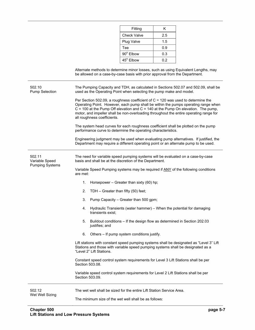
Chapter 500 page 5-7 Lift Stations and Low Pressure Systems
Fitting K
Check Valve 2.5 Plug Valve 1.5 Tee 0.9 90o Elbow 0.3 45o Elbow 0.2
Alternate methods to determine minor losses, such as using Equivalent Lengths, may be allowed on a case-by-case basis with prior approval from the Department.
502.10 Pump Selection
The Pumping Capacity and TDH, as calculated in Sections 502.07 and 502.09, shall be used as the Operating Point when selecting the pump make and model. Per Section 502.09, a roughness coefficient of C = 120 was used to determine the Operating Point. However, each pump shall be within the pumps operating range when C = 100 at the Pump Off elevation and C = 140 at the Pump On elevation. The pump, motor, and impeller shall be non-overloading throughout the entire operating range for all roughness coefficients. The system head curves for each roughness coefficient shall be plotted on the pump performance curve to determine the operating characteristics. Engineering judgment may be used when evaluating pump alternatives. If justified, the Department may require a different operating point or an alternate pump to be used.
502.11 Variable Speed Pumping Systems
The need for variable speed pumping systems will be evaluated on a case-by-case basis and shall be at the discretion of the Department. Variable Speed Pumping systems may be required if ANY of the following conditions are met:
1. Horsepower – Greater than sixty (60) hp;
2. TDH – Greater than fifty (50) feet;
3. Pump Capacity – Greater than 500 gpm;
4. Hydraulic Transients (water hammer) – When the potential for damaging transients exist;
5. Buildout conditions – If the design flow as determined in Section 202.03 justifies; and
6. Others – If pump system conditions justify. Lift stations with constant speed pumping systems shall be designated as “Level 3” Lift Stations and those with variable speed pumping systems shall be designated as a “Level 2” Lift Stations. Constant speed control system requirements for Level 3 Lift Stations shall be per Section 503.08. Variable speed control system requirements for Level 2 Lift Stations shall be per Section 503.09.
502.12 Wet Well Sizing
The wet well shall be sized for the entire Lift Station Service Area. The minimum size of the wet well shall be as follows:

Chapter 500 page 5-8 Lift Stations and Low Pressure Systems
1. Diameter of Wet Well
The minimum wet well diameter shall be six (6) feet.
2. Depth of Wet Well, below the invert of the incoming sewer
The minimum required depth of the wet well below the invert of the incoming sewer shall be calculated as follows:
Depth = 1.5 feet + Operating Depth + Height of pump
where:
1.5 feet = Difference between the lowest incoming gravity sewer invert and the lead pump on elevation. Height of Pump = Distance from the bottom of the wet well to the top of the pump, feet.
Operating Depth = Depth between the lead pump on and pump off elevations, feet.
The operating depth is a function of the volume and diameter.
The volume shall be based on four (4) starts per hour and shall be calculated as follows:
V = t Q 4
where:
V = Volume, gallons t = 15 minutes (15 minute station cycle time) Q = Pumping rate per 502.07, gpm.
The minimum Operating Depth shall be 2.5 feet. Only one (1) incoming sewer connection is allowed per Section 502.17. When Variable Speed Pumps are required per Section 502.11, the Department may consider or require a reduction of the volume. Both pumps shall remain fully submerged at all times during the full pumping cycle.
3. Detention Time
The maximum detention time (pump off time) shall be thirty (30) minutes based on the average daily flow.
There may be some situations when one or more of the above wet well sizing criteria cannot be met. The Department will evaluate those instances on a case-by-case basis. Note: If noticeable odors are being generated at any time before the Maintenance Bond expires, the Applicant shall determine the cause and construct an odor control facility at either the wet well or the discharge end of the force main. The method used for odor control will be approved by the Department on a case-by-case basis.
Chapter 500 page 5-9 Lift Stations and Low Pressure Systems
502.13 Operating Set Points
The elevation of the set points for the operation of the lift station shall be as follows:
1. Primary level sensor - Pressure Transducer (Per Section 503.08 or 503.09).
a. Alarm Level = 0.5 feet below the lowest incoming invert;
b. Lag Pump On = 1.0 feet below the lowest incoming invert; c. Lead Pump On = 1.5 feet below the lowest incoming invert; d. Pump Off = (Lead Pump On Elev. – Operating Depth per Section 502.12.)
2. Backup (Alarm) level sensors - Ball Floats (Per Section 503.08 or 503.09)
a. Pump On = (Lowest incoming pipe invert + 1/2 diameter of pipe.) b. Pump Off = 0.5 feet below the lowest incoming pipe invert.
502.14 Valve and Meter Vaults
The minimum vault dimensions for Level 2 and Level 3 lift stations shall be per the most recent version of the Standard Lift Station Detail Sheets.
502.15 Force Main Design
The force main shall be designed as follows:
1. Lift stations shall not pump downhill. Prior to discharging into the receiving manhole, the force main shall not flow downhill. When possible, the receiving gravity sewer shall be extended a sufficient distance to avoid downhill pumping. The discharge elevation of the force main at the discharge location shall not be below the elevation in the valve vault and greater than two (2) feet above the invert of the incoming sewer.
2. The size, depth, slope, and location shall be as follows:
a. Size The diameter shall be sized using the Pumping Capacity as determined in Section 502.07 with the following velocities:
i. Minimum Velocity – 2.5 ft/sec
ii. Maximum Velocity – 6.0 ft/sec
Higher velocities will be considered and evaluated on a case-by-case basis. If the Pumping Capacity is reduced per Section 502.08, the minimum velocity may be reduced to 2.0 ft/sec when using the Initial Pumping Capacity.
The minimum diameter force main shall be 4 inches.
b. Depth
The minimum depth to the top of the pipe shall be 4.5 feet. The depth may be required to be increased if air release valves can be avoided or the minimum slope cannot be achieved.

Chapter 500 page 5-10 Lift Stations and Low Pressure Systems
c. Slope
The minimum slope for force mains is determined by the installation method and shall be as follows:
i. Open Cut Installation – Greater than 0%
The force main shall not be designed on a flat slope (0%). ii. Horizontal Directional Drilling (HDD) – Minimum 1.5%
The Division or Department may limit the length installed with HDD or require open cut installation if the number of air release valves can be reduced.
d. Location
Existing and proposed force mains shall be located per Section 202.07.1 & 2.
. 3. Air Release / Vacuum Relief Valves
When possible, force mains shall be designed to avoid the need for air release or vacuum relief valves. When high points cannot be avoided, A.R.I. D-020, stainless steel air release valves shall be installed per the most recent version of the Standard Lift Station Detail Sheets and at each high point where air could become trapped.
4. Force Main Anchorage
Force mains shall be anchored to resist thrusts at all bends, angles, tees, etc. in the force main pipe. The required anchorage shall be achieved by installing restrained pipe joints and concrete thrust blocks or anchor blocks as designed by the Engineer, and shown on the plans. Restrained joints shall be per Section 304. The Engineer shall determine the number of joints and/or length of pipe to be restrained on each side of all bends. The number of restrained joints or length of pipe shall be shown on the plans.
5. Connections to force mains are prohibited, except for connections to common force mains in Low Pressure Systems.
502.16 Buoyancy
The wet well shall be designed to prevent “floating” by assuring:
Opposing Forces > Buoyancy Forces
where:
Opposing Forces = Weight resisting buoyancy forces (lbs). Buoyancy Forces = Uplifting forces due to groundwater (lbs).
The groundwater elevation shall be assumed to be at the surface elevation immediately adjacent the base slab.
502.17 Connections to the Wet Well
For proposed lift stations, only one (1) incoming connection to the wet well will be allowed. The connection shall be of sufficient depth to provide service to the entire Lift Station Service Area.

Chapter 500 page 5-11 Lift Stations and Low Pressure Systems
SECTION 503 Lift Station Equipment and Operating Requirements 503.01 Introduction
This Section provides the equipment and operating requirements for lift stations.
503.02 General
Lift station equipment meeting or exceeding the requirements set herein will be approved. However, the Department may modify any of the requirements in this Section, if justified. All components of the lift station exposed to weather shall be constructed of material that is resistant to corrosion and will not require surface protection throughout the expected life of the lift station. In general, these materials are stainless steel, aluminum, fiberglass reinforced polyester (FRP), and ultraviolet stabilized PVC.
503.03 Equipment Vendors
All equipment shall be an integral package supplied by the pump manufacturer with local representation so as to provide undivided responsibility.
503.04 Submittal Requirements: Pre-Construction
Prior to construction, the Contractor shall submit the following:
1. A cover letter from the Engineer and Contractor indicating all proposed equipment and components meet the requirements of this Manual and the approved Plans.
2. Four (4) sets of shop drawings, detailed specifications, pump warranty, and performance characteristics for all equipment and components to be furnished and installed.
503.05 Power Requirements
Only electric-utility-delivered 3-phase, 60 Hz, 4-wire wye, or delta power will be allowed. The use of phase converters to derive 3-phase power from 1-phase power is prohibited.
503.06 Pump Equipment
Pumps shall be either Hydromatic or Flygt pumps. Pump Equipment shall be as follows:
1. Pumps Pumps shall be of the submersible type for handling raw unscreened sewage. Pump volute, motor, and seal housing shall be high quality gray cast iron. Impeller shall be either cast iron or cast bronze of a non-clog design capable of handling minimum three (3) inch sphere solids, fibrous material, heavy sludge, and other matter found in normal sewage applications. Impeller shall have pump out vanes on the back shroud of the impeller to keep pumped material away from the seal area and increase operating life. Impeller shall be either slip fit or taper fit with key to securely lock the impeller to the driving shaft. The pump volute shall be fit with a replaceable bronze wear ring to minimize wear on the impeller and help achieve longer balance operating life. All fasteners shall be of stainless steel.
2. Mating Surfaces All mating surfaces where watertight sealing is required shall be machined and fitted with nitrile rubber O-rings. Sealing shall be accomplished when metal-to-metal contact is made, resulting in controlled compression of the rubber O-rings without requirement of a specific torque limit.

Chapter 500 page 5-12 Lift Stations and Low Pressure Systems
3. Seal System
The pump shall be provided with a mechanical rotating shaft seal system running in an oil reservoir having separate, constantly lubricated lapped seal faces. The lower seal unit between the pump and oil chamber shall consist of one (1) stationary seat and one (1) rotating ring held in place by its own spring. The lower seal shall be removable without disassembling the seal chamber. The upper seal between the motor and the seal chamber shall be of the same design with its own separate spring system. The seals shall require neither maintenance nor adjustment, but shall be easily inspected and replaceable. Shaft seals with conventional double seal utilizing a single spring between the two (2) seals and requiring a pressure differential to offset external pressure shall not be considered acceptable nor equal to the dual independent seal system specified. The shaft sealing system shall be capable of operating submerged to pressures equivalent to two hundred (200) feet. No seal damage shall result from operating the pump unit out of its liquid environment. The seal system shall not rely upon the pumped media for lubrication. The seal chamber shall also be equipped with a seal failure sensor probe which will sense water intrusion through the lower seal. This sensor shall be connected to an alarm in the control panel to indicate lower seal failure.
4. Housing The stator winding, rotor and bearings shall be mounted in sealed submersible type housing. Insulation utilized in the stator windings shall be Class H with maximum temperature capability of 180o C. Motor housing shall be filled with a high dielectric oil to give superior heat transfer and allow the bearing to run in a clean, well lubricated environment; or the housing shall be air filled with grease lubricated bearings. The pump and motor are to be specifically designed so that they may be operated partially or completely submerged in the liquid being pumped. The pump shall not require cooling water jackets. Stator shall be securely held in place with a removable end ring and threaded fasteners so that it may be easily removed in the field without use of heat or press. Shaft shall be stainless steel and supported by ball bearings. Motor shall be provided with heat sensing units attached to the motor windings which shall be connected to the control panel to shut down pump if overheating occurs.
5. Cables Pump motor cable and heat sensor/seal failure sensor cable shall be suitable for submersible pump applications and this shall be indicated by a code or legend permanently embossed on the cable. Cable sizing shall conform to NEC specifications for pump motors and shall be of adequate size to allow motor voltage conversion without replacing the cable. Cable of the proper length shall be provided to eliminate need for splices or junction boxes between pump and “control center.” The cable shall enter the motor through a cord cap assembly which is double sealed allowing disassembly and disconnect of the wires and the motor and still not damage the sealed characteristics of the motor housing. Each individual conductor shall be color coded in accordance with generally accepted industry standards. The color coding shall designate the application of the conductor.
6. Mounting Base The pump mounting base shall include adjustable guide rail supports and a discharge connection with a one hundred twenty-five (125) pound standard flange. The base and the discharge piping shall be permanently mounted in place. The base plates shall be anchored in place utilizing epoxy type anchors with stainless steel studs and nuts as manufactured by HILTI Fasteners, Inc. or equal.

Chapter 500 page 5-13 Lift Stations and Low Pressure Systems
7. Guide Rails
A rail system shall be provided for easy removal of the pump and motor assembly for inspection and service. The system shall not require a man to enter the wet well to remove the pump and motor assembly. Two (2) rails of two (2) inch stainless steel pipe for Flygt pumps or one rail of fiberglass reinforced plastic (FRP) I-Beam for Hydromatic pumps shall be provided for each pump unless the size of the pump dictates otherwise. The guide rails shall be positioned and supported by the pump mounting base. The guide rails shall be aligned vertically and supported at the top by attachment to the access hatch frame. One (1) intermediate guide rail support shall be required for each nine (9) feet of guide rail length for FRP and fifteen (15) feet for stainless steel pipe. All mounting equipment shall be stainless steel.
8. Rail Guide and Lifting Chain The pumps shall be equipped with sliding brackets or rail guides. To insure easy removal of the pumps, the rail guides attached to each pump shall not encircle the rails. A stainless steel lifting chain of adequate length for the basin depth shall be provided for each pump. Each pump shall be equipped with a permanent, stationary lifting handle with a minimum clearance of twelve (12) inches between the top of the pump and bottom of the handle. The rails and the rail guide shall function to allow the complete weight of the pumping unit to be lifted on dead center without binding and stressing the pump housing. The rail system shall function to automatically align the pumping unit to the discharge connection by a simple downward movement of the pump. No twisting or angle approach will be considered acceptable. The actual sealing of the discharge interface may be of the hydraulically sealing diaphragm type assembly with removable Buna-N diaphragm as supplied by Hydromatic Pump or may be of the metal-to-metal contact as provided by Flygt Pump.
9. Warranty Pump warranty shall be provided by the pump manufacturer and shall warrant the units being supplied to the Owner and City against defects in workmanship and materials for a period of five (5) years under normal use, operation and service. The warranty shall be in printed form and apply to all similar units. A copy of the warranty statement shall be submitted with the approval drawings.
503.07 Lift Station Components
The lift station shall be configured and shall include all components shown on the most recent version of the Standard Details Lift Station Details Sheets and the following:
1. Wet Well, Valve and Meter Pits, Flat Top, and Base Slab
a. Material
The wet well, valve and meter vaults, flat tops and base slabs shall be constructed of precast concrete meeting the requirements of ASTM C 478. Cast-in-place monolithic structures may be substituted with the prior written approval from the Department.
b. Joints
All joints between precast sections shall be per Section 305.02. c. Waterproofing
The outside wall below grade shall be coated with bituminous waterproofing material.

Chapter 500 page 5-14 Lift Stations and Low Pressure Systems
2. Concrete Pad
The wet well and valve and meter vaults shall be enclosed at grade level with a minimum eight (8) inch thick reinforced concrete pad rectangular in shape.
3. Access Drive
The Lift Station shall be provided with a minimum eight (8) inch thick by fifteen (15) feet wide reinforced concrete access drive conforming to the latest DOT Standards for Design of Driveways.
4. Access Hatches and Frames
a. An aluminum two (2) door access hatch frame and door assembly shall
be installed in the concrete top for the wet well. This door assembly shall provide access for removal of the pumps and shall support the guide rails. The doors shall be provided with a lifting handle, safety latch to hold the door in the open position, and a hasp suitable for a padlock. The doors shall have a non-skid finish and be designed with a minimum 300 psi, live loading.
b. Valve and Meter Vaults An aluminum single door access hatch frame and door assembly similar to the one described above for the wet well shall be installed in the concrete top for the valve and meter vaults. Minimum opening shall be thirty-six (36) inches by thirty-six (36) inches.
5. Check and Shutoff Valves
A swing check valve with a weight operated external swing arm and an eccentric plug valve shall be installed in the valve vault on each pump’s discharge piping. A minimum clearance of twelve (12) inches shall be allowed from the bottom of the valves to the invert of the vault. A drain pipe and check valve shall be installed to drain the valve vault back to the wet well but not allow the wet well liquid to enter the valve vault. In addition, a tee or cross with bleedable blind flange shall be provided in the valve vault.
6. Magnetic Flow Meter and Shutoff Valves When variable speed pumping systems are required, a magnetic flow meter and an eccentric plug valve shall be installed on the discharge piping per Section 503.09. A minimum clearance of twelve (12) inches shall be allowed between the bottom of the valves to the invert of the vault. Straight sections of pipe upstream and downstream of the magnetic flow meter shall be per manufacture’s recommendation.
7. Drop Pipes Drop pipes shall be installed in all incoming pipes four (4) feet or greater above the pump-on elevation or as directed by the Department.
503.08 Control System Requirements – Level 3 Lift Stations
The Control System Requirements for Level 3 lift stations with constant speed pumps shall be per the current Department specifications or as follows:
1. Overall Lift Station Control System Enclosure Requirements
a. General Requirements:
i. Control and electrical components shall be individually equipment rack mounted as shown on schematics and as follows:

Chapter 500 page 5-15 Lift Stations and Low Pressure Systems
• Pump Control Panel. NEMA 4X stainless steel with dead front
and internal swing out panel door. Include pump controls, operator interface, telemetry equipment, and uninterruptible power supply.
• Power distribution panel. NEMA 4X stainless steel. Include phase monitor, surge protection devices, branch circuit breakers, and motor starters.
• Utility approved meter socket. • Service entrance rated NEMA 3R double throw fused main
disconnect switch for utility power and portable emergency generator connection. Include exterior mounted weather proof generator receptacle mounted to disconnect enclosure. Disconnect and receptacle shall be suitable for outdoor use.
• NEMA 3R control power transformer, suitable for outdoor use. Note to specifier: Covert alarm system required on interim basis until SCADA System is operational
• NEMA 4X rated “Covert” alarm system. ii. Enclosures shall be mounted on lift station concrete pad. Concrete
pad shall be a minimum three inches higher than the adjacent ground. Concrete pad shall be a minimum of one foot larger in dimension than enclosure plus radius of door swings. Orientate panel placement so that panel doors do not open over or near wet well opening.
iii. Provide enclosures with following additional accessories:
• Drip shield. • Padlock hasp. • Stainless steel 3-point latch to allow panel opening without tools. • In addition to above, Pump Control Panel shall be provided with:
− Fluorescent door switch activated light.
− GFI 120 VAC receptacle.
− Thermostatically controlled heaters sized to maintain panel internal temperature at 50°F with outdoor temperature of -20°F.
2. Electrical Requirements
a. The lift station shall have electric-utility-delivered 3-phase, 60Hz, 4-wire
wye, or delta power. All stations powered by 3-phase primary voltage shall have a minimum 2.0 KVA single-phase, 480/240 to 120/240 VAC transformer. Use of phase converters to derive 3-phase power from 1-phase power source is prohibited.
b. Include provision for connection of OWNER provided portable emergency generator. Receptacle shall be rated for 200 amps, 600 volts. Coordinate receptacle type and manufacturer with OWNER to assure capability with OWNER’S generator plug.
c. Motor starters shall be NEMA-rated magnetic type with a 120 volt control coil, and three thermal overload relays with a minimum size of NEMA-1.
3. Wiring, Termination, and Labeling Requirements
a. Wiring:
i. In addition to NEC and NEMA requirements, wiring shall conform to
following:
• Power: 12 AWG stranded minimum, type MTW, 600 V.

Chapter 500 page 5-16 Lift Stations and Low Pressure Systems
• Control: 16 AWG stranded minimum, type MTW, 300 V. • Analog Signal: Twisted pair, 18 AWG, Beldon 8760 or equal.
ii. Wire color code:
• AC neutral conductor: White. • AC hot conductor: Black. • Grounding conductor: Green. • AC control conductor, powered from within panel: Color coded
and numbered. • AC control conductor, powered from remote source: Yellow. • DC (+) power conductor: Blue. • DC (-) power conductor: Blue. • DC control conductor: Blue. • Twisted pair cable (-) signal conductor: White. • Twisted pair cable (+) signal conductor: Black. • Intrinsically safe conductors – light blue.
iii. Design control panels to keep 3-phase power, 120-vac power and
discrete signals, and analog and other low voltage signals separated.
• Do not run 3-phase power, 120-vac power and discrete signals, and analog or other low voltage signals in the same conduit or wire-duct.
• Where 3-phase power, 120-vac power and discrete signals, and analog or other low voltage signals must cross, they shall do so at right angles.
iv. Internal Panel Wiring Within Wire Duct:
• Wherever feasible plastic wire duct with cover shall be used for
routing of wire within control panel. • Size wire duct to be no more than 50% full. • Maintain 2” clearance between wire duct and terminals.
v. Internal Panel Wiring outside of wire duct.
• Wiring outside of ducts shall be restrained by use of plastic wire-
ties. • Restrain wiring a minimum of every six inches. • Provide abrasion protection for wires passing through holes or
across abrasive metal edges. • Adhesive type wire fasteners shall not be used. Hard screw type
shall be employed.
b. Terminations:
i. Wiring within control panel shall be continuous and terminated only at terminal blocks or equipment terminals. Splices or butt connectors shall not be used within panel.
ii. Other than terminal to terminal bussing as described below, no more than one wire shall be terminated at any one terminal.
iii. Make external connections by way of numbered terminal blocks on numbered terminal strips.
iv. When signals are powered from remote location, switched terminal blocks shall be used where conductors enter or leave panel.
v. When signals are powered from within panel, fused terminal blocks shall be used where conductors enter or leave panel.
vi. Provide integral bussing system on terminal block array where more than two terminations require common source or drain connection. Jumpered terminations shall not be acceptable.
vii. Include provisions for grounding of shields on shielded twisted pair cables entering or leaving panel. Cable shields shall be grounded at terminal block end only.

Chapter 500 page 5-17 Lift Stations and Low Pressure Systems
viii. Provide separate locations on terminal strips for each of the following
types of signals.
• 480 or 240-vac power circuits. • 120-vac power circuits. • 120-vac discrete signals. • 24 or 48 Vdc discrete signals. • Analog signals. • Serial or parallel digital communication signals.
ix. Provide separate terminal strip for intrinsically safe circuits.
Intrinsically safe wiring shall be separated by non-conducting or grounded barrier within panel, and not combined with any other wiring within conduit or wire duct.
c. Power Distribution:
i. Panels having 3-phase power supply:
• Service entrance rated NEMA 3R double throw fused main
disconnect switch to isolate utility power to panel and allow connection of portable emergency generator. Mount generator receptacle to disconnect enclosure. Disconnect and generator receptacle shall be rated for 200 A.
• Provide circuit breakers for all motor starters provided. • Provide phase monitor relay (PMR). • If panel includes separate 120 vac control power supply, provide
auxiliary contact to isolate control power when main circuit breaker is opened.
• 480(240, 208) / 120 control power transformer requirements:
− Both primary leads shall be fused.
− First secondary lead shall be fused.
− Second secondary lead shall be grounded.
ii. Panels having 120 vac power supply:
• Provide circuit breaker on power supply entering panel. iii. Provide separately fused power supply to each major panel
component. iv. Panels using modular or solid state I/O devices.
• Provide separately fused power circuit for panel powered I/O
signals entering panel from field devices. Provide separate circuit for each module.
• Include digital transient surge suppressor/varistor installed in parallel with output contact at terminal strip for each output signal driving an inductive load including:
− Relays.
− Solenoids.
− Motor starters.
− Motors.
4. UPS Requirements Note to specifier: Covert alarm system replaces radio on interim basis until SCADA System is operational. Delete radio and Ethernet switch in item b below if Covert alarm system is to be included in lift station specification.

Chapter 500 page 5-18 Lift Stations and Low Pressure Systems
a. Provide true on-line non switching uninterruptible power supply (UPS).
b. UPS shall supply power to PLC, OIU, radio, Ethernet switch, field
instruments, and other low voltage control devices.
c. UPS shall have enough capacity to power these devices for a period of 2 hours after the utility power has failed. Provide with extended battery module to meet this requirement.
d. UPS shall provide dry contacts to PLC for utility fail and low battery power alarms.
e. Minimum UPS size shall be 700 VA.
f. Double power conversion on-line operation including rectifier and inverter, constantly conditioned AC output.
g. Provide make before break manually operated bypass switch or other means to bypass UPS to allow operation of system controls in event of UPS failure.
h. Eaton Powerware Model 9125.
Note to specifier: Covert alarm system replaces radio and antenna on interim basis until SCADA System is operational. Delete item 5 below if Covert alarm system is to be included in lift station specification.
5. Ethernet Switch, Radio, Antenna, and Antenna Mounting Requirements
a. Provide Ethernet switch, radio, antenna, antenna cable, and antenna
mounting pole.
b. Radio, antenna cable, antenna, and lightning and surge protection devices shall be purchased from the City’s approved radio equipment supplier to ensure compatibility with City’s radio based SCADA communication network used for lift station monitoring.
c. Ethernet switch and radio shall be mounted within Pump Control Panel.
d. Contractor shall determine signal strength available at lift station location using both 900 MHz and 5.7 GHz radio test unit supplied by the City. Available signal strength shall be tested at elevations of 20’ and 15’ above ground level and signal strength test results shall be supplied to the City.
e. Contractor shall determine the most suitable location for the antenna based on the results of signal strength testing. Antenna pole shall be affixed to lift station concrete pad.
f. Based on the results of signal strength testing, the Contractor shall purchase either the 900 MHz or 5.7 GHz radio, as selected by the City, from the City’s approved radio equipment supplier.
g. Contractor shall mount the antenna in the selected location, and provide antenna cable in conduit.
h. Where lift station structure does not exist or is unsuitable for antenna mounting, antenna mounting pole shall be up to 20‘ tall, 4” in diameter, aluminum, and set within concrete or firmly affixed to pump station.
i. Where lift station structure is suitable for antenna mounting, antenna mounting pole shall be 2” in diameter, aluminum, and firmly affixed to pump station.
j. Provide grounding of antenna pole in accordance with NEC requirements.

Chapter 500 page 5-19 Lift Stations and Low Pressure Systems
k. Programming of radio shall by City.
6. Field Instrument Requirements
a. Provide submersible level transmitter to sense level in wet well and
control pump on/off operation.
i. Hydrostatic pressure measurement. ii. Loop powered. iii. 4 – 20 mAdc output signal. iv. 316 stainless steel submersible housing and diaphragm, Viton
grommet and o-ring. Provide with stainless steel braided support cable to prevent transmitter from being supported by signal cable.
v. Accuracy +/- 0.25% of span including linearity, hysteresis, and repeatability.
vi. Provide with lightning and surge protector to be mounted in Pump Control Panel.
vii. CSA approved intrinsically safe when used with appropriate barrier. viii. Ametek model 575.
b. Provide wet well float switches to sense high and low level in wet well and
control standby pump on/off operation. Standby pump operation shall be independent of PLC.
i. SPDT contacts, rated 1 amp at 150 VAC/VDC inductive, mechanical
life 10 million operations. ii. 316 stainless steel mounting hardware. Mounting shall be via weight
and chain/cable not requiring entry to wet well for cleaning or replacement.
iii. Connery Model 2900 pear shaped neoprene covered mercury switch ball float of standard size, supported by stainless steel cable.
c. For lift stations containing a dry well, or areas prone to flooding due to pump seal or piping failure, provide dry well float switch to sense dry well flooding.
i. SPDT contacts, rated 1 amp at 150 VAC/VDC inductive, mechanical
life 10 million operations. ii. Connery Model 2900 pear shaped neoprene covered mercury switch
ball float of standard size.
d. Provide intrusion detection switches.
i. When control and electrical components are mounted outdoors, provide intrusion detection switches for electrical and control equipment enclosure.
ii. When control and electrical components are mounted indoors provide intrusion detection switches for all entrances into pump station.
iii. Reed switch enclosed in ABS plastic case, normally closed contact. iv. Sentrol 1045 series or approved equal.
7. Pump Control Panel Requirements
Note to specifier: Covert alarm system replaces radio and Ethernet switch on interim basis until SCADA System is operational. Delete radio and Ethernet switch in item a below if Covert alarm system is to be included in lift station specification.
a. A Pump Control Panel shall be provided to house the Programmable
Logic Controller (PLC), Operator Interface Unit (OIU), Ethernet switch, radio, lightning and surge protection devices, and pump monitoring equipment.

Chapter 500 page 5-20 Lift Stations and Low Pressure Systems
b. When Pump Control Panel is mounted outdoors, provide with a low
temperature switch, set at 40 °F, mounted within the enclosure to alarm failure of heater.
c. The automatic pump operation, automatic pump lead-lag alteration, and all control logic commands shall be performed by the PLC. The PLC shall be Allen Bradley Micrologix 1200, with no substitutions allowed, and shall meet the following requirements:
i. Minimum 24 Discrete Inputs ii. Minimum 12 Discrete Outputs iii. Minimum 4 Analog Inputs iv. Minimum 2 Analog Output v. 6 K-word memory minimum, 2 K data storage, 4 K program. vi. Real time clock vii. Floating point math viii. PID control ix. Ethernet interface
d. The OIU shall be Allen Bradley Panelview Plus 400 meeting the following
requirements:
i. 3.7” monochrome display ii. 320 X 240, 32 level greyscale resolution iii. Keypad iv. NEMA 12/4X v. DC Powered
e. The Ethernet switch shall be Phoenix Contact meeting the following
requirements:
i. 4 RJ45 ports ports ii. 10/100 Mbits/s iii. 0 to 55 °C operating temperature iv. DC Powered
f. Provide the following front of panel mounted devices to be labeled as
indicated. For outdoor locations, devices shall be mounted to swing out panel door.
i. “Hand-Off-Automatic” selector switch for each pump, with the hand
mode wired for manual operation independent of the PLC. ii. Operator interface.
g. PLC I/O signals:
i. Discrete Inputs:
• Pump 1 running • Pump 2 running • Pump 1 “Auto” (from panel mounted HOA switch) • Pump 2 “Auto” (from panel mounted HOA switch) • Pump 1 seal fail (submersible pump applications only, alarm
display only – no pump interlock) • Pump 2 seal fail (submersible pump applications only, alarm
display only – no pump interlock) • Pump 1 motor high motor temperature (submersible pump
applications only), motor breaker trip, and motor starter overload combined into common alarm and used to interlock pump operation.
• Pump 2 motor high motor temperature (submersible pump applications only), motor breaker trip, and motor starter overload combined into common alarm and used to interlock pump operation.

Chapter 500 page 5-21 Lift Stations and Low Pressure Systems
• Alarm test (from pushbutton) • Alarm silence (from pushbutton) • High wet well level • Low wet well level • Dry well flood • Lift station intrusion • Low temperature • Low battery power • Utility power fail • Phase fail
ii. Discrete Outputs:
• Pump 1 required • Pump 2 required • Pump 1 seal test (submersible pump applications only) • Pump 2 seal test (submersible pump applications only) • Common alarm to horn and light
Note to specifier: Covert alarm outputs required on interim basis until SCADA System is operational
• Covert Alarm 1 • Covert Alarm 3 • Covert Alarm 4 • Covert Alarm 5
iii. Analog Inputs:
• Wet well level
h. OIU shall be configured to allow:
i. Display pump run, fail, automatic mode, overload, seal fail, motor
over-temperature, accumulated pump run time, and accumulated pump number of starts for each pump. Display all discrete and analog signals input to PLC, and calculated or derived parameters including communication fail, crew on site, intrusion, and float control mode.
ii. Wetwell level, high and low level alarms. iii. “Lead Pump 1 / Lead Pump 2 / Lead Pump Alternate” selection. iv. Calculated lift station flow rate and accumulated flow total. v. Display communication fail (to SCADA central). vi. Display status of all input signals to PLC. vii. Capability to place pump “Out of Service”. Display “Out of Service”
status at OIU. viii. Configure to allow “Crew on Site” input. Allow entry of operator’s 4
digit identification number after “Crew on Site” has been entered. This function is to work in conjunction with the Intrusion switch. Once an intrusion has been detected the crew will have a set amount of time to enter a valid code before the intrusion alarm is activated.
ix. Operator data entry for adjustable set points, including pump on/off levels, time delays, etc. Allow for operator entry of 4 digit password prior to accepting parameter changes.
i. System programming guidelines:
i. Provide program documentation for all OIU and PLC program files
developed for the system. PLC program documentation shall include comments for all registers used and sufficient rung comments to describe operation of logic used within program. Provide four copies of program documentation on CD.
ii. Automatic pump control shall start and stop pumps in a lead and lag fashion based on wet well level input.

Chapter 500 page 5-22 Lift Stations and Low Pressure Systems
iii. Provide lead pump alternation on each successive lead pump
shutdown when automatic alternation is selected. iv. Provide pump fault logic to sense discrepancy between pump-
required output being turned on and no pump run signal being received. Configure system to generate fault on any condition including motor overload, motor over temperature, seal failure or power disconnect.
v. Provide time delay on pump required outputs, initially set at 10 seconds and 20 seconds, to prevent simultaneous pump restart on restoration of control power.
vi. “Out of Service” entry shall remove pump from operating sequence, and prevent alarms from being generated for pump.
vii. All alarms shall automatically reset when the alarm condition has cleared. An adjustable 0-15 minute time delay relay shall be activated and timed-out prior to transmitting the high or low wet well level condition.
viii. Pump accumulated run time shall be calculated for each pump. ix. Pump accumulated number of starts shall be calculated for each
pump. x. Provide routine to calculate lift station draw down time. Draw down
time data shall be time stamped, and indicate which pump(s) running during draw down event.
xi. Program to ensure that regardless of configuration of backup hardware, (re: back up ball floats when primary level control device is pressure transducer) primary level control device automatically takes over when level of wet well returns to desired operating level.
xii. Provide routine to calculate lift station flow rate and accumulated lift station accumulated flow total. Calculation shall be based on following:
• Wet well dimensions, include adjustable offset for equipment,
piping, or other items affecting wet well volume and account for cross-sectional changes between minimum and maximum levels. Calculation shall be made such that changes to pump on and off level set-points shall not require change to flow calculation routine.
• Wet well level rate of rise shall be used to calculate inflow rate when pump are not operating.
• During pump run events, inflow rate shall be calculated as the average inflow rate occurring immediately before and after pump run event.
xiii. PLC shall be configured to periodically transfer information to SCADA
Central HMI. Transfer of information shall occur periodically based on information request from SCADA Central HMI, and be initiated by lift station PLC on occurrence of alarm condition. Periodic data transfer of information to SCADA Central HMI shall include:
• Lift station accumulated flow total. • 10 minute averaged flow rate data. Time stamped average flow
rate data values shall be logged internally to PLC memory. Logged data shall be retained until data successfully transferred to HMI, at which point it shall be deleted.
• Pump draw down data. Time stamped data values shall be logged internally to PLC memory. Logged data shall be retained until data successfully transferred to HMI, at which point it shall be deleted.
• Pump elapsed run time data • Accumulated number of starts for each pump • Coordinate programming requirements with City

Chapter 500 page 5-23 Lift Stations and Low Pressure Systems
• Data transfer shall be configured to allow SCADA Central HMI to
emulate all data input and display functions present at OIU, including display all discrete and analog signals input to PLC, and calculated or derived parameters including communication fail, crew on site, intrusion, and float control mode.
• Data transfer to and from SCADA Central HMI shall take place using contiguous PLC register locations to maximize efficiency of data transfer. Register usage and addressing shall be coordinated with City.
• Include provision for periodic receipt of current time and date SCADA Central HMI.
j. Required modifications to the Lift Station Central SCADA system
monitoring software at the Waste Water Treatment Plant will be performed by the City.
503.09 Control System Requirements – Level 2 Lift Stations
The Control System Requirements for Level 2 Lift Stations with variable speed pumps shall be per the current Department specifications or as follows:
1. Overall Lift Station Control System Enclosure Requirements
Note to specifier: Select item a or b below as appropriate
a. Outdoor Location Requirements:
i. Control and electrical components shall be individually equipment rack mounted as shown on schematics and as follows:
• Pump Control Panel. NEMA 4X stainless steel with dead front
and internal swing out panel door. Include pump controls, operator interface, flow meter transmitter, telemetry equipment, and uninterruptible power supply.
• Power distribution panel. NEMA 4X stainless steel. Include phase monitor, surge protection devices, and branch circuit breakers.
• Utility approved meter socket. • Service entrance rated NEMA 3R double throw fused main
disconnect switch for utility power and portable emergency generator connection. Include exterior mounted weather proof generator receptacle mounted to disconnect enclosure. Disconnect and receptacle shall be suitable for outdoor use.
• NEMA 3R control power transformer, suitable for outdoor use.
Note to specifier: Covert alarm system required on interim basis until SCADA System is operational
• NEMA 4X stainless steel rated “Covert” alarm system.
ii. Provide NEMA 4X rated variable speed drives suitable for outdoor
use. Drive enclosure shall be end product of drive manufacturer. Drive may be mounted to equipment rack or freestanding as shown on schematics.
iii. Enclosures shall be mounted on lift station concrete pad. Concrete pad shall be a minimum three inches higher than the adjacent ground. Concrete pad shall be a minimum of one foot larger in dimension than enclosure plus radius of door swings. Orientate panel placement so that panel doors do not open over or near wet well opening.
iv. Provide enclosures with following additional accessories:

Chapter 500 page 5-24 Lift Stations and Low Pressure Systems
• Drip shield. • Padlock hasp. • Stainless steel 3-point latch to allow panel opening without tools. • In addition to above, Pump Control Panel shall be provided with:
− Fluorescent door switch activated light.
− GFI 120 VAC receptacle.
− Thermostatically controlled heaters sized to maintain panel internal temperature at 50°F with outdoor temperature of -20°F.
b. Indoor Location Requirements:
i. Control and electrical components shall be individually wall mounted
in NEMA 12 rated enclosures as follows:
• Pump Control Panel. Include GFI 120 VAC receptacle within panel.
• Service rated fused disconnect switch for utility power connection
• Power distribution panel, including surge protection devices, branch circuit breakers, and motor starters.
• Uninterruptible power supply. • Flow meter transmitter. • Control power transformer. • Variable speed drives. • Double throw transfer switch for use with portable emergency
generator. • “Covert” alarm system.
Note to specifier: Covert alarm system required on interim basis until SCADA System is operational
ii. Size enclosures to adequately dissipate heat generated by
equipment mounted in or on panel.
iii. Include exterior mounted weather proof generator connection.
2. Electrical Requirements
a. The lift station shall have electric-utility-delivered 3-phase, 60Hz, 4-wire wye, or delta power. All stations powered by 3-phase primary voltage shall have a minimum 2.0 KVA single-phase, 480/240 to 120/240 VAC transformer. Use of phase converters to derive 3-phase power from 1-phase power source is prohibited.
b. Include provision for connection of OWNER provided portable emergency generator. Receptacle shall be rated for 200 amps, 600 volts. Coordinate receptacle type and manufacturer with OWNER to assure capability with OWNER’S generator plug.
3. Wiring, Termination, and Labeling Requirements
a. Wiring:
i. In addition to NEC and NEMA requirements, wiring shall conform to
following:
• Power: 12 AWG stranded minimum, type MTW, 600 V. • Control: 16 AWG stranded minimum, type MTW, 300 V. • Analog Signal: Twisted pair, 18 AWG, Beldon 8760 or equal.

Chapter 500 page 5-25 Lift Stations and Low Pressure Systems
ii. Wire color code:
• AC neutral conductor: White. • AC hot conductor: Black. • Grounding conductor: Green. • AC control conductor, powered from within panel: Color coded
and numbered. • AC control conductor, powered from remote source: Yellow. • DC (+) power conductor: Blue. • DC (-) power conductor: Blue. • DC control conductor: Blue. • Twisted pair cable (-) signal conductor: White. • Twisted pair cable (+) signal conductor: Black. • Intrinsically safe conductors – light blue.
iii. Design control panels to keep 3-phase power, 120-vac power and
discrete signals, and analog and other low voltage signals separated.
• Do not run 3-phase vac power, 120-vac power and discrete signals, and analog or other low voltage signals in the same conduit or wire-duct.
• Where 3-phase vac power, 120-vac power and discrete signals, and analog or other low voltage signals must cross, they shall do so at right angles.
iv. Internal Panel Wiring Within Wire Duct:
• Wherever feasible plastic wire duct with cover shall be used for
routing of wire within control panel. • Size wire duct to be no more than 50% full. • Maintain 2” clearance between wire duct and terminals.
v. Internal Panel Wiring outside of wire duct.
• Wiring outside of ducts shall be restrained by use of plastic wire-
ties. • Restrain wiring a minimum of every six inches. • Provide abrasion protection for wires passing through holes or
across abrasive metal edges. • Adhesive type wire fasteners shall not be used. Hard screw type
shall be employed.
b. Terminations:
i. Wiring within control panel shall be continuous and terminated only at terminal blocks or equipment terminals. Splices or butt connectors shall not be used within panel.
ii. Other than terminal to terminal bussing as described below, no more than one wire shall be terminated at any one terminal.
iii. Make external connections by way of numbered terminal blocks on numbered terminal strips.
iv. When signals are powered from remote location, switched terminal blocks shall be used where conductors enter or leave panel.
v. When signals are powered from within panel, fused terminal blocks
shall be used where conductors enter or leave panel. vi. Provide integral bussing system on terminal block array where more
than two terminations require common source or drain connection. Jumpered terminations shall not be acceptable.
vii. Include provisions for grounding of shields on shielded twisted pair cables entering or leaving panel. Cable shields shall be grounded at terminal block end only.
viii. Provide separate locations on terminal strips for each of the following types of signals.
Chapter 500 page 5-26 Lift Stations and Low Pressure Systems
• 480 or 240-vac power circuits. • 120-vac power circuits. • 120-vac discrete signals. • 24 or 48 Vdc discrete signals. • Analog signals. • Serial or parallel digital communication signals.
ix. Provide separate terminal strip for intrinsically safe circuits.
Intrinsically safe wiring shall be separated by non-conducting or grounded barrier within panel, and not combined with any other wiring within conduit or wire duct.
c. Power Distribution:
i. Panels having 3-phase power supply:
• Service entrance rated NEMA 3R double throw fused main
disconnect switch to isolate utility power to panel and allow connection of portable emergency generator. Mount generator receptacle to disconnect enclosure. Disconnect and generator receptacle shall be rated for 200 A.
• Provide circuit breakers for all variable frequency drives provided.
• Provide phase monitor relay (PMR). • If panel includes separate 120 vac control power supply, provide
auxiliary contact to isolate control power when main circuit breaker is opened.
• 480(240, 208) / 120 control power transformer requirements:
− Both primary leads shall be fused.
− First secondary lead shall be fused.
− Second secondary lead shall be grounded.
ii. Panels having 120 vac power supply:
• Provide circuit breaker on power supply entering panel. iii. Provide separately fused power supply to each major panel
component.
iv. Panels using modular or solid state I/O devices. • Provide separately fused power circuit for panel powered I/O
signals entering panel from field devices. Provide separate circuit for each module.
• Include digital transcient surge suppressor/varistor installed in
parallel with output contact at terminal strip for each output signal driving an inductive load including:
− Relays.
− Solenoids.
− Motor starters.
− Motors.
4. VFD Requirements
a. Drive enclosure shall be end product of drive manufacturer.
b. Provide pulse width modulated variable speed drives (VFDs).
c. Provide with bypass contactor to allow across the line operation.

Chapter 500 page 5-27 Lift Stations and Low Pressure Systems
d. Suitable for outdoor mounting, with maximum ambient temperature of
105°F.
e. Mount in pad-lockable NEMA 4X stainless steel rated dead-front enclosure. Drive enclosure shall be end product of VFD manufacturer.
f. Include thermostatically controlled heaters sized to maintain drive panel internal temperature at 50°F with outdoor temperature of -20°F.
g. Use of air conditioning or heat exchangers to allow operation of VFD in elevated ambient temperatures is prohibited. Include externally mounted heat sinks (one per VFD) sized to maintain drive panel internal temperature at 100°F with outdoor temperature of 105°F. If required to meet specified ambient temperature requirements, derate drive capacity to meet temperature requirements. Provide with a high temperature switch, set at 110°F, mounted within the enclosure to alarm high drive temperature.
h. Capable of withstanding line voltage transients up to 3000 V in accordance wit ANSI 37.90.1.
i. IGBT switching.
j. Match output power to motor, 0.5% speed regulation, 110% overload capacity for 60 seconds, 100% rated torque from 60 Hz to required turndown.
k. 3% input line reactors.
l. Instantaneous over-current trip shutdown, under-voltage protection with automatic restart.
m. Include keypad/display mounted within enclosure, accessible when enclosure is opened.
n. Manufacturers
i. Allen Bradley. ii. Eaton/Cutler Hammer. iii. Saftronics. iv. Toshiba. v. No substitutions allowed.
5. UPS Requirements
Note to specifier: Covert alarm system replaces radio on interim basis until SCADA System is operational. Delete radio and Ethernet Switch in item b below if Covert alarm system is to be included in lift station specification.
a. Provide true on-line non switching uninterruptible power supply (UPS).
b. UPS shall supply power to PLC, OIU, radio, Ethernet switch, field
instruments, and other low voltage control devices.
c. UPS shall have enough capacity to power these devices for a period of 2 hours after the utility power has failed. Provide with extended battery module to meet this requirement.
d. UPS shall provide dry contacts to PLC for utility fail and low battery power alarms.
e. Minimum UPS size shall be 700 VA.
f. Double power conversion on-line operation including rectifier and inverter, constantly conditioned AC output.

Chapter 500 page 5-28 Lift Stations and Low Pressure Systems
g. Provide make before break manually operated bypass switch or other
means to bypass UPS to allow operation of system controls in event of UPS failure.
h. Eaton Powerware Model 9125. Note to specifier: Covert alarm system replaces radio and antenna on interim basis until SCADA System is operational. Delete item 6 below if Covert alarm system is to be included in lift station specification.
6. Ethernet Switch, Radio, Antenna, and Antenna Mounting Requirements
a. Provide Ethernet switch, radio, antenna, antenna cable, and antenna
mounting pole.
b. Radio, antenna cable, antenna, and lightning and surge protection devices shall be purchased from the City’s approved radio equipment supplier to ensure compatibility with City’s radio based SCADA communication network used for lift station monitoring.
c. Ethernet switch and radio shall be mounted within Pump Control Panel.
d. Contractor shall determine signal strength available at lift station location using both 900 MHz and 5.7 GHz radio test unit supplied by the City. Available signal strength shall be tested at elevations of 20’ and 15’ above ground level and signal strength test results shall be supplied to the City.
e. Contractor shall determine the most suitable location for the antenna based on the results of signal strength testing. Antenna pole shall be affixed to lift station concrete pad.
f. Based on the results of signal strength testing, the Contractor shall purchase either the 900 MHz or 5.7 GHz radio, as selected by the City, from the City’s approved radio equipment supplier.
g. Contractor shall mount the antenna in the selected location, and provide antenna cable in conduit.
h. Where lift station structure does not exist or is unsuitable for antenna mounting, antenna mounting pole shall be up to 20‘ tall, 4” in diameter, aluminum, and set within concrete or firmly affixed to pump station.
i. Where lift station structure is suitable for antenna mounting, antenna mounting pole shall be 2” in diameter, aluminum, and firmly affixed to pump station.
j. Provide grounding of antenna pole in accordance with NEC requirements.
k. Programming of radio shall by City.
7. Field Instrument Requirements
a. Provide submersible level transmitter to sense level in wet well and control pump on/off operation.
i. Hydrostatic pressure measurement. ii. Loop powered. iii. 4 – 20 mAdc output signal. iv. 316 stainless steel submersible housing and diaphragm, Viton
grommet and o-ring. Provide with stainless steel braided support cable to prevent transmitter from being supported by signal cable.
v. Accuracy +/- 0.25% of span including linearity, hysteresis, and repeatability.
vi. Provide with lightning and surge protector to be mounted in Pump Control Panel.
Chapter 500 page 5-29 Lift Stations and Low Pressure Systems
vii. Suitable for use in Class 1, Division 1, Group D hazardous classified
location when used with appropriate barrier. viii. Ametek model 575.
b. In high grease or other applications, ultrasonic level sensor may be used with
approval from OWNER.
i. Ultrasonic level measurement. ii. 120 VAC powered. iii. 4 – 20 mAdc output signal. iv. Accuracy +/- 0.1 % of span including linearity, hysteresis, and
repeatability. v. Provide with lightning and surge protector to be mounted in Pump
Control Panel. vi. Suitable for use in Class 1, Division 1, Group D hazardous classified
location. vii. Manufacturers:
• Milltronics MINI-Ranger • Endress and Hauser Prosonic M • No substitutions allowed.
c. Provide wet well float switches to sense high and low level in wet well and
control standby pump on/off operation. Standby pump operation shall be independent of PLC.
i. SPDT contacts, rated 1 amp at 150 VAC/VDC inductive, mechanical
life 10 million operations. ii. Connery Model 2900 pear shaped neoprene covered mercury switch
ball float of standard size , supported by stainless steel cable.
d. For lift stations containing a dry well, or areas prone to flooding due to pump seal or piping failure, provide dry well float switch to sense dry well flooding.
i. SPDT contacts, rated 1 amp at 150 VAC/VDC inductive, mechanical
life 10 million operations. ii. Connery Model 2900 pear shaped neoprene covered mercury switch
ball float of standard size.
e. Provide intrusion detection switches.
i. When control and electrical components are mounted outdoors, provide intrusion detection switches for electrical and control equipment enclosure.
ii. When control and electrical components are mounted indoors provide intrusion detection switches for all entrances into pump station.
iii. Reed switch enclosed in ABS plastic case, normally closed contact. iv. Sentrol 1045 series or approved equal.
f. Provide magnetic flow meter.
i. Size meter to maintain average velocity of 3 ft/sec. ii. System accuracy of +/- 25% of flow rate with 10:1 turndown. iii. Meter body:
• Utilize low frequency dc pulse. • Accidental submergence rating of 30 ft. water for 48 hours. • Polyurethane or hard rubber liner, 316 stainless steel electrodes. • Provide with 316 stainless steel grounding rings, use of
grounding probes not acceptable. • Suitable for Class 1, Division II, Hazardous classified location. • Include isolating plug valves before and after meter body to
facilitate meter removal. Include spool piece of same dimensions as meter body.

Chapter 500 page 5-30 Lift Stations and Low Pressure Systems
• Maintain minimum of 5 upstream and 3 downstream
unobstructed pipe diameters before and after meter body. Provide separate meter vault if required to meet dimensional requirement. Meter vault shall be provided with sump and flood alarm float switch.
iv. Transmitter:
• 120 VAC, 60 Hz power. • For outdoor locations, mount on Pump Control Panel internal
swing out panel as shown. • Provide pulsed DC voltage to meter body magnet coils. • Integral keypad/display. • Automatic empty pipe detection.
v. Manufacturers:
• Rosemount • Krohne • ABB • Foxboro • Sparling • No substitutions allowed.
8. Pump Control Panel Requirements
Note to specifier: Covert alarm system replaces radio and Ethernet switch on interim basis until SCADA System is operational. Delete radio and Ethernet switch in item a below if Covert alarm system is to be included in lift station specification.
a. A Pump Control Panel shall be provided to house the Programmable
Logic Controller (PLC), Operator Interface Unit (OIU), Ethernet switch, radio, lightning and surge protection devices, and pump monitoring equipment.
b. When Pump Control Panel is mounted outdoors, provide with a low temperature switch, set at 40 °F, mounted within the enclosure to alarm failure of heater.
c. The automatic pump operation, automatic pump lead-lag alteration, and all control logic commands shall be performed by the PLC. The PLC shall be Allen Bradley Micrologix 1200, with no substitutions allowed, and shall meet the following requirements:
i. Minimum 32 Discrete Inputs ii. Minimum 12 Discrete Outputs iii. Minimum 8 Analog Inputs iv. Minimum 4 Analog Output v. 6 K-word memory minimum, 2 K data storage, 4 K program. vi. Real time clock vii. Floating point math viii. PID control ix. Ethernet interface x. DC Powered
d. The OIU shall be Allen Bradley Panelview Plus 400 meeting the following
requirements:
i. 3.7” monochrome display ii. 320 X 240, 32 level greyscale resolution iii. Keypad iv. NEMA 12/4X v. Ethernet Interface

Chapter 500 page 5-31 Lift Stations and Low Pressure Systems
vi. DC Powered
e. The Ethernet switch shall be Phoenix Contact meeting the following
requirements:
i. 4 RJ45 ports ports ii. 10/100 Mbits/s iii. 0 to 55 °C operating temperature iv. DC Powered
f. Provide the following front of panel mounted devices to be labeled as
indicated. For outdoor locations, devices shall be mounted to swing out panel door.
i. “Hand-Off-Automatic” selector switch for each pump, with the hand
mode wired for manual operation independent of the PLC. ii. “Constant Speed (CS)/Variable Speed (VS)” selector switch for each
pump. Selector switch active in the “Hand” mode of operation. iii. “Speed Control” potentiometer for each pump. Potentiometer shall be
wired for manual mode operation independent of the PLC when “Hand” mode, “Variable Speed” operation has been selected via front of panel mounted hand switches.
iv. Operator interface. g. PLC I/O signals:
i. Discrete Inputs:
• Pump 1 running • Pump 2 running • Pump 1 “Auto” (from panel mounted hand switch) • Pump 2 “Auto” (from panel mounted hand switch) • Pump 1 seal fail (submersible pump applications only, alarm
display only – no pump interlock) • Pump 2 seal fail (submersible pump applications only, alarm
display only – no pump interlock) • Pump 1 motor high motor temperature (submersible pump
applications only), motor breaker trip, and motor starter overload combined into common alarm and used to interlock pump operation.
• Pump 2 motor high motor temperature (submersible pump applications only), motor breaker trip, and motor starter overload combined into common alarm and used to interlock pump operation.
• VFD 1 fault • VFD 2 fault • VFD 1 high temperature • VFD 2 high temperature • VFD 1 low temperature • VFD 2 low temperature • High wet well level • Low wet well level • Dry well flood • Meter vault flood • Lift station intrusion • Low temperature • Low battery power • Utility power fail • Phase fail
ii. Discrete Outputs:
• Pump 1 required – variable speed
Chapter 500 page 5-32 Lift Stations and Low Pressure Systems
• Pump 2 required – variable speed • Pump 1 required – constant speed • Pump 2 required – constant speed • Pump 1 seal test (submersible pump applications only) • Pump 2 seal test (submersible pump applications only) • Common alarm to horn and light
Note to specifier: Covert alarm outputs required on interim basis until SCADA System is operational
• Covert Alarm 1 • Covert Alarm 3 • Covert Alarm 4 • Covert Alarm 5
ii. Analog Inputs:
• Pump 1 speed • Pump 2 speed • Pump 1 current • Pump 2 current • Wet well level • Flow
iii. Analog Outputs:
• Pump 1 speed control • Pump 2 speed control
h. OIU shall be configured to allow:
i. Display pump run, pump fail, VFD fail, pump speed, automatic mode,
overload, seal fail, motor over-temperature, accumulated pump run time, and accumulated pump number of starts for each pump. Display all discrete and analog signals input to PLC, and calculated or derived parameters including communication fail, crew on site, intrusion, and float control mode.
ii. Wetwell level, high and low level alarms. iii. “Lead Pump 1 / Lead Pump 2 / Lead Pump Alternate” selection. iv. “Pump Manual/Automatic” mode selection for each pump. v. “Pump Start”, “Pump Stop”, and “Manual Speed Control” entry for
each pump, active when in the manual mode of control. vi. Capability to place pump “Out of Service”. Display “Out of Service”
status at OIU. vii. Lift station flow rate and integrated flow total. viii. Display communication fail (to SCADA central). ix. Display status of all input signals to PLC. x. Configure to allow “Crew on Site” input. Allow entry of operator’s 4
digit identification number after “Crew on Site” has been entered. This function is to work in conjunction with the Intrusion switch. Once an intrusion has been detected the crew will have a set amount of time to enter a valid code before the intrusion alarm is activated.
xi. Operator data entry for adjustable set points, including pump on/off levels, time delays, etc. Allow for operator entry of 4 digit password prior to accepting parameter changes.
i. System programming guidelines:
i. Provide program documentation for all OIU and PLC program files
developed for the system. PLC program documentation shall include comments for all registers used and sufficient rung comments to describe operation of logic used within program. Provide four copies of program documentation on CD.

Chapter 500 page 5-33 Lift Stations and Low Pressure Systems
ii. Automatic pump control shall start and stop pumps in a lead and lag
fashion and control pump speed based on wet well level input. iii. Configure controls to maintain operator entered wet well level set
point using PID control. Pump start request shall be initiated when:
• Wet well level rises operator adjustable amount above wet well level set point
• Lead pump, if operating, speed control output is at 100% • The wet well is not falling
Pump immediate start command shall be issued if wet well level rises to adjustable high level “Immediate Start” level.
iv. Pump stop request shall be initiated when:
• Wet well level falls operator adjustable amount below wet well level set point.
• Speed control output is at minimum speed setting for currently operating number of pumps. Provide separate adjustable minimum speed setting for one pump running and two pumps operating scenarios.
• The wet well is not rising.
Pump immediate stop command shall be issued if wet well level falls to adjustable low level “Immediate Stop” level.
v. Provide weekly lead pump alternation based on operator entered
time of day and day of week. vi. Provide pump fault logic to sense discrepancy between pump-
required output being turned on and no pump run signal being received. Configure system to generate fault on any condition including motor overload, motor over temperature, seal failure or power disconnect.
vii. Provide time delay on pump required outputs, initially set at 10 seconds and 20 seconds, to prevent simultaneous pump restart on restoration of control power.
viii. “Out of Service” entry shall remove pump from operating sequence, and prevent alarms from being generated for pump.
ix. All alarms shall automatically reset when the alarm condition has cleared. An adjustable 0-15 minute time delay relay shall be activated and timed-out prior to transmitting the high or low wet well level condition.
x. Pump accumulated run time shall be calculated for each pump. xi. Pump accumulated number of starts shall be calculated for each
pump. xii. Program to ensure that regardless of configuration of backup
hardware, (re: back up ball floats when primary level control device is pressure transducer) primary level control device automatically takes over when level of wet well returns to desired operating level.
xiii. Provide integration routine to calculate accumulated lift station accumulated flow total based on flow rate input signal.
xiv. Periodic data transfer of information to SCADA Central HMI shall include:
• Lift station accumulated flow total. • 10 minute averaged flow rate data. Time stamped average flow
rate data values shall be logged internally to PLC memory. Logged data shall be retained until data successfully transferred to HMI, at which point it shall be deleted.
• Pump elapsed run time data • Accumulated number of starts for each pump • Coordinate programming requirements with City

Chapter 500 page 5-34 Lift Stations and Low Pressure Systems
• Data transfer shall be configured to allow SCADA Central HMI to emulate all data input and display functions present at OIU, including display all discrete and analog signals input to PLC, and calculated or derived parameters including communication fail, crew on site, intrusion, and float control mode.
• Data transfer to and from SCADA Central HMI shall take place using contiguous PLC register locations to maximize efficiency of data transfer. Register usage and addressing shall be coordinated with City.
• Include provision for periodic receipt of current time and date SCADA Central HMI.
j. Required modifications to the Lift Station Central SCADA system
monitoring software at the Waste Water Treatment Plant will be performed by the City.

Chapter 500 page 5-35 Lift Stations and Low Pressure Systems
503.10 Operation & Maintenance Manuals
Four (4) Operation and Maintenance Manuals shall be submitted to the Department in both hard copy and .pdf format.
Manuals shall include, at a minimum, the following:
1. Warranty Statement; 2. Pump down test from the initial start-up test; 3. Operation instructions; 4. Maintenance instructions; 5. Recommended spare parts list; 6. Lubrication schedules; 7. Structural diagrams; 8. As-built wiring diagrams; 9. Piping and Instrumentation Drawings (P&ID); and 10. Bill of materials.
503.11 Spare Parts
At the discretion of the Department, the Contractor may be required to supply one set of spare parts for each station, including, at a minimum, the following:
1. Impeller;
2. Upper seal assembly;
3. Lower seal assembly;
4. Upper bearing assembly;
5. Lower bearing assembly;
6. Wear rings; and
7. O-Rings and gaskets - two (2) sets.
503.12 Station Warranty
Warranties for the lift station and all equipment, except for the pumps, shall be three (3) years from the date of acceptance per City Maintenance Bond requirements. Warranty for the pumps shall be five (5) years from the date of acceptance and per Section 503.06.

Chapter 500 page 5-36 Lift Stations and Low Pressure Systems
SECTION 504 Low Pressure Pump Stations and Appurtenances 504.01 Introduction
This Section describes, in general terms, the guidelines and requirements for the planning, design, and submittal requirements for low pressure sewer systems.
504.02 General
Low-pressure systems will only be considered in areas where sanitary sewers currently serve the surrounding areas and where conventional sanitary sewer facilities cannot be constructed.
504.03 Submittal Requirements for Approval and Construction Permit
Approval of low-pressure sewer systems will be evaluated on a case-by-case basis and will only be allowed with prior written approval from the Department. At the discretion of the Department, a lift station may be required in lieu of a low pressure system. When submitting for an Approval and Construction Permit, the following are required:
1. Written approval from the Department;
2. Low pressure system service area – Per Section 504.04; 3. Low pressure system justification – Per Section 501.03;
a. 50-year life cycle analysis; and b. Gravity sewer alternative cost estimate.
4. Low pressure system calculations – Per manufacturer’s recommendations and
at a minimum the following:
a. Calculation worksheet – Per manufacturer; b. Individual pump curves; and c. Make and model number of pumps.
5. Standard Low Pressure System Detail Sheet; 6. Identification of the person/entity responsible for the maintenance of the
pumps and other components of the system that are not the responsibility of the City;
7. Homeowners Association Covenants and Restrictions, if applicable; and 8. Any other information the Division and/or Department deems relevant to
review and evaluate the proposed low-pressure system.
504.04 Low Pressure System Service Area
The Applicant shall prepare a Low Pressure System Service Area Study in accordance with all the requirements in Section 202.03.
504.05 Responsibility
The City will only be responsible for the operation and maintenance of the common force main and the portion of the lateral from the common force main to, and including, the shutoff valve. The homeowner shall be responsible for all piping, pumping equipment, and appurtenances between the building and the shutoff valve.

Chapter 500 page 5-37 Lift Stations and Low Pressure Systems
For low-pressure systems with multiple units, the City of Indianapolis is NOT responsible for assuring replacement equipment is compatible with the existing equipment in the system.
504.06 System Design and Layout
Due to the variability of each site, the design of low-pressure systems shall rely on sound engineering judgment and manufacturer’s recommendations. The Division or Department may, if reasonably justified, make any requirement deemed necessary to assure the system performs as intended. The minimum requirements for the design and layout of low-pressure systems shall be per the most recent version of the Standard Detail Sheets, the manufacturers’ recommendations, and as follows:
1. Pipe Size Pipe size shall be per pump manufacturer’s recommendations with a minimum size of two (2) inches for the common force main and one and one-quarter (1-1/4) inches between the grinder pump and the common force main. The Engineer shall assure adequate cleansing velocities in the common force main.
2. Overall System Design/Layout
The design shall be as follows:
a. Sufficient to achieve a cleansing velocity of two (2) feet per second in the
common force main; and b. Without any “loops” or parallel pumping segments in the system.
3. Cleanouts
Cleanouts shall be per pump manufacturers recommendations but at a minimum the following locations:
a. At the terminal end of each common force main; b. When two (2) or more force mains are connected; and c. Every 1,000 feet.
4. Flushing Stations
Flushing stations shall be incorporated into the system.
5. Air Relief Valves
Air relief valves shall be installed at the following locations:
a. All high points in the system; and b. At intervals of 2,000 feet on all horizontal runs lacking a clearly defined
high point. 6. Lateral Assembly Installation
A lateral assembly installation shall be installed on each service line.
7. Other requirements as deemed necessary.

Chapter 500 page 5-38 Lift Stations and Low Pressure Systems
504.07 Maximum Connections to Grinder Pump Units
No more than one (1) building will be permitted to connect to a Grinder Pump Unit. Common Grinder Pumps for one (1) building with multiple residential units are also prohibited, except for the following:
1. Apartment buildings (only one apartment building per grinder pump unit); and
2. Condominiums where different floors have different owners (only one building per grinder pump unit).
The intent is to have individual residential units be served by individual Grinder Pump Units. Industrial facilities will be handled on a case-by-case basis.
504.08 Grinder Pump Types
To assure all the Grinder Pump Units are compatible, all units shall be the same Make, Model Number, and have the same pump performance characteristics, unless justified. Replacement units shall be the same make and model as was originally approved by the Division. Pump specifications and pump replacement requirements shall be part of the Homeowners Association (HOA) Covenants and Restrictions if a HOA is planned. The type of pumps and allowable applications are as follows:
1. Positive Displacement Pumps May be used in all low pressure system applications.
2. Semi-Positive Displacement Pumps May be used in all low pressure system applications.
3. Centrifugal Pumps May only be used if the number of units is ten (10) or less and the Total Dynamic Head is less than forty (40) feet.
The Engineer and manufacturer are responsible for assuring the system will operate as intended.
504.09 Grinder Pump Equipment
Simplex or duplex grinder pumps may be used for single dwelling units. For uses other than single dwelling units, the Engineer shall determine which is appropriate. General equipment requirements are as follows:
1. Grinder Pump Station The grinder pump stations shall be a complete package consisting of all equipment and appurtenances required for a fully operable pumping system. Pump level controls, starter, alarm, piping, fittings, valves, and all accessories shall be part of a factory fabricated package so that after burying the wet well, the field connection of the gravity lateral, discharge line and electrical service line to the control box will complete the installation.
2. Manufacturer Each grinder pump station shall be manufactured and assembled by a single manufacturer.

Chapter 500 page 5-39 Lift Stations and Low Pressure Systems
3. Pumps
The pumps shall be capable of macerating all material in normal domestic and commercial sewage, including reasonable amounts of foreign objects such a wood, plastic, glass, rubber, disposable diapers and the like to a fine slurry that will pass freely through the pump and one and one-quarter (1-1/4) inch discharge pipe.
4. Electrical Motor and Level Controls Electrical and level controls shall be provided by the pump manufacturer. All controls shall be mounted so they can be cleaned or replaced without disturbing the pump or piping.
5. Control Panels The control panels and all associated components on each standard unit shall be U.L. Approved and installed per manufacturer’s recommendations. All equipment associated with each unit shall meet the current requirements of all applicable Federal, State, and Local electrical codes. An Electrical Permit issued by DMD is required for each grinder pump unit.
The Engineer and manufacturer are responsible for assuring the equipment is designed properly and will operate in a safe manner.

Chapter 600 page 6-1 Testing
CHAPTER 600
TESTING

Chapter 600 page 6-2 Testing
SECTION 601 General 601.01 Introduction
This Section provides the testing requirements common to all sanitary sewer facilities. For testing requirements specific to sanitary sewers refer to Section 602. For testing requirements specific to force mains refer to Section 603. For testing requirements specific to manholes refer to Section 604. For testing requirements specific to lift stations refer to Section 605.
601.02 General Testing Requirements
All testing shall be performed under the observation of the RPR. It is the Contractor's responsibility to schedule the testing. Test results obtained in the absence of the Division's RPR or Department will not be accepted. The Contractor shall be responsible for providing all testing equipment at no cost to the City. All pressure gages used shall be calibrated within one (1) year of use for any test. Calibration papers and test date information shall be made available at the request of the RPR, Division, or Department. The City of Indianapolis will not assume any liability for the actions of the Owner, Contractor, or their agent(s), in the performance of the required tests.

Chapter 600 page 6-3 Testing
SECTION 602 Gravity Sanitary Sewer Testing Requirements 602.01 Introduction
This Section provides the testing requirements specific to gravity sanitary sewers. For testing requirements specific to force mains refer to Section 603. For testing requirements specific to manholes refer to Section 604. For testing requirements specific to lift stations refer to Section 605. For testing requirements common to all sanitary sewer facilities refer to Section 601.
602.02 General Requirements
All sanitary sewers twenty-four (24) inches and less shall be air tested by means of a low pressure air test per Section 602.03. All sewers larger than twenty-four (24) inches shall be joint tested per Section 602.04. All sanitary sewers constructed of flexible pipe (PVC and Centrifugally Cast Fiberglass Reinforced Polymer Mortar) shall be tested for deflection by means of a mandrel test per Section 602.06.
602.03 Low Pressure Air Test
All sewers twenty-four (24) inches and less shall be tested by means of a low-pressure air test to detect damaged piping and/or improper jointing. Testing shall be done per ASTM F 1417 for flexible and semi-rigid pipe and ASTM C 924 for RCP. The use of the low pressure air test for flexible and semi-rigid pipe larger that twenty-four (24) inches will be evaluated on a case-by-case basis. The Contractor is responsible for assuring the test is conducted in a safe manner and all applicable safety procedures are followed. Do not enter, or allow anyone to enter, the manhole during testing. The low pressure air test shall be as follows:
1. Waiting Period The air test may be done immediately after final backfill is placed in the trench.
2. Equipment
At a minimum, the following shall be provided:
a. Mechanical or pneumatic plugs;
b. Air control panel;
c. Shut-off valve, pressure regulative valve, pressure relief valve, and input pressure gauge. The pressure regulator or relief valve shall be set no higher than 9 psig (6 psig for RCP) to avoid over pressurization;
d. Continuous monitoring pressure gauge having a range of 0 to at least 10 psi. The gauge shall be no less than four (4) inches in diameter with minimum divisions of 0.10 psi and an accuracy of ± 0.04 psi;
e. To reduce the potential for sewer line over-pressurization, two (2) separate hoses shall be used to:
i. Connect the control panel to the sealed line for introducing low
pressure air; and ii. Constantly monitor air pressure buildup in the line.

Chapter 600 page 6-4 Testing
If pneumatic plugs are utilized, a separate hose shall be required to inflate the pneumatic plugs.
3. Testing Procedures
The Test Data Sheet per Appendix C shall be used when conducting the air test.
The procedures for the low pressure air test are as follows:
a. Plug Installation
After a segment of pipe has been backfilled to final grade, securely place and brace suitable test plugs in the ends of the sewer segment and in all lateral stubs included in the test. All plugs shall be securely restrained and braced prior to and during the test.
b. Line Pressurization Add air slowly to the test section until the pressure inside the pipe reaches 4.0 psig PLUS the necessary adjustment for groundwater (Maximum 2.0 psig adjustment for a 6.0 psig maximum total). The air pressure adjustment for groundwater shall be determined by the following:
Adjustment = Depth of Groundwater x 0.43
where:
Adjustment = Adjustment added to the starting pressure of the low-pressure air test, psig. The maximum adjustment shall be 2.0 psig. Depth of Groundwater = As measured above the top of pipe, feet. 0.43 = Conversion factor
Do not exceed 6.0 psig at any time during the low-pressure air test. The groundwater monitoring wells installed per Section 403.09 shall be used to determine the depth of groundwater. If more than one well was installed, take the average depth of the nearest downstream and nearest upstream monitoring locations. If the monitoring wells were not installed, the adjustment shall be 2.0 psig.
c. Pressure Stabilization
After a constant pressure of 4.0 psig (PLUS the necessary adjustment for groundwater) is reached, the air supply shall be throttled to maintain that internal pressure for at least two (2) minutes. This time permits the temperature of the entering air to equalize with the temperature of the pipe wall.
d. Timing Pressure Loss
When temperatures have been equalized and the pressure stabilized at 4.0 psig (PLUS the necessary adjustment for groundwater), the air hose from the control panel to the air supply shall be shut off or disconnected.

Chapter 600 page 6-5 Testing
The continuous monitoring pressure gauge shall then be observed while the pressure is decreased to no less than 3.5 psig (PLUS the necessary adjustment for groundwater). At this reading, or any convenient observed pressure reading between 3.5 psig and 4.0 psig (PLUS the necessary adjustment for groundwater), timing shall begin.
A timed pressure drop of either 1.0 psig or 0.5 psig shall be used. The RPR shall determine the appropriate pressure drop. The allowable time shall be predetermined using either Table 600.01 or 600.02, depending on which pressure drop is used.
When testing RCP sewers, a 1.0 psig pressure drop shall be used.
e. Time adjustment for laterals No time adjustment for lateral lengths will be allowed.
f. Determination of Line Acceptance If the time shown for the designated pipe size and length elapses before the pressure drops (1.0 or 0.5 psig), the section of pipe being tested shall have passed the test. The test may be discontinued once the prescribed time has elapsed even though the pressure drop has not occurred.
g. Determination of Line Failure If the pressure drops before the appropriate time has elapsed, the air loss rate shall be considered excessive and the section of pipe being tested shall have failed the test. The Contractor shall be required to uncover, replace, or repair any section of sewer not passing the test. The method of repair shall be per approval of the Division and/or Department. Grouting is not an acceptable method of repair.
602.04 Joint Test
All sewers greater than twenty-four (24) inches shall be joint tested using air or water under low pressure. All joints shall be tested. Testing procedures shall be per ASTM C 1103 and as follows:
1. Waiting Period
The joint test may be done immediately after final backfill is placed.
2. Equipment Equipment used shall be made specifically for joint testing of pipelines.
3. Testing Procedures
a. Joint Test Apparatus Installation
i. Clean the joint and interior joint surfaces.
ii. Move the joint test apparatus into the sewer line to the joint to be tested and position it over the joint. Make sure the end element sealing tubes straddle both sides of the joint and the hoses are attached. For the water test, the bleed-off petcock must be located at top dead center.
iii. Inflate end element sealing tubes with air in accordance with
equipment and manufacturer’s instructions.

Chapter 600 page 6-6 Testing
b. Joint Air Test
i. Pressurize the void volume with air to 3.5 psi PLUS the necessary adjustment for groundwater above the top of pipe (maximum 2.0 psi adjustment for a 5.5 psi maximum total). Allow the air pressure and temperature to stabilize before shutting off the air supply. Start the timing of the test.
The air pressure adjustment shall be per Section 602.03.3.b.
ii. Measure the pressure drop for five (5) seconds.
iii. After the joint test is completed, exhaust void volume, then exhaust
end element tubes prior to removal of the testing apparatus.
c. Joint Water Test
i. Introduce water into the void volume until water flows evenly from open petcock. Close the petcock and pressurize with water to 3.5 psi PLUS the necessary adjustment for groundwater above the top of pipe (maximum 2.0 psi adjustment for a 5.5 psi maximum total). Shut off the water supply and start test timing.
ii. Measure the pressure drop for five (5) seconds. iii. After the joint test is completed, exhaust end element tubes which will
automatically release the water from the void volume, prior to removal of the testing apparatus.
d. Determination of Line Acceptance
If the pressure holds or drops less than one (1) psi for the five (5) second test time, the joint shall have passed the test.
e. Determination of Line Failure If the pressure drops one (1) psi or more during the five (5) second test time, the joint shall have failed the test. If the joint fails, the Contractor shall repair and retest as necessary. The method of repair shall be per approval of the Division and/or Department. Grouting is not an acceptable method of repair.
602.05 Water Infiltration Test
All gravity sanitary sewers shall be watertight and free from leakage. The rate of infiltration into the sanitary sewer system between any two adjacent manholes or the entire system shall not be in excess of 100 gallons per inch of pipe diameter per mile per day (100 gpd/in-dia/mi). The Contractor may be required to conduct a weir test to determine if the 100 gal/in/mi/day maximum allowable infiltration rate is being exceeded. The weir test will be required if water is observed in the sewer at any time during the acceptance process. The weir test will be at the sole discretion of the RPR, Division, or Department. The Contractor shall be required to repair all visible leaks, even if the allowable infiltration requirements are met. The method of repair shall be per the approval of the Division and/or Department.

Chapter 600 page 6-7 Testing
Grouting of the joint or crack to repair the leakage shall not be permitted. If the defective portion of the sanitary sewer cannot be located, the Contractor shall remove and reconstruct as much of the work as necessary to obtain a system that passes infiltration requirements.
602.06 Mandrel Deflection Test for Flexible Pipe
All sanitary sewers using flexible pipe shall be tested for deflection by means of a go/no-go mandrel gage or other methods as approved by the Department. The mandrel deflection test shall be as follows:
1. Waiting Period
The mandrel deflection test shall be done no sooner than thirty (30) days after final backfill has been placed.
2. Equipment
Mandrels shall be constructed with nine (9) or ten (10) arms. Mandrels with fewer than nine (9) arms are not allowed. The Length (L) shall be measured between points of contact on the mandrel arm. The Diameter (D) mandrel dimension shall carry a tolerance of + 0.01 inches.
3. Allowable Deflection
The allowable deflection shall be based on the pipe type as follows:
a. PVC Pipe The allowable deflection for PVC pipe shall be 5% of the base inside diameter as determined by ASTM D 3034 and F 679. The dimensions are as follows:
DIMENSIONS FOR MANDREL
Nominal Pipe Diameter,
inches
Length (L) of Mandrel, inches
Base ID of Pipe, inches
Diameter (D)1 for Deflection of 5%, inches
8 8.0 7.665 7.28
10 10.0 9.563 9.08
12 10.0 11.361 10.79
15 12.0 13.898 13.20
1 – The diameter is based on SDR 35 pipe thickness, if thicker pipe is used, the diameter may be adjusted accordingly.
b. Closed Profile PVC
The allowable deflection for Closed Profile PVC shall be 5% based on the inside diameter as determined on a case-by-case evaluation of the pipe design.

Chapter 600 page 6-8 Testing
c. Centrifugally Cast Fiberglass Reinforced Polymer Mortar Pipe
i. Polyester Resin
The allowable deflection for Centrifugally Cast Fiberglass Reinforced Polymer Mortar pipe made with polyester resin shall be 4% based on the inside diameter as determined on a case-by-case evaluation of the pipe design.
ii. Vinyl Ester Resin
The allowable deflection for Centrifugally Cast Fiberglass Reinforced Polymer Mortar pipe made with vinyl ester resin shall be 3% based on the inside diameter as determined on a case-by-case evaluation of the pipe design.
The Contractor shall provide proving rings to check the mandrel. The proving rings shall be clearly labeled with the dimensions and ASTM Standard.
4. Testing Procedure
a. The mandrel shall be hand pulled through all sections of the sewer lines. b. Determination of Line Acceptance
If the mandrel can be hand pulled through the entire length of the section tested, the section shall have passed the test.
c. Determination of Line Failure
If the mandrel cannot be hand pulled through the entire length of the section tested, the section shall have failed the test. The Contractor shall be required to uncover, replace, or repair any section of sewer not passing the mandrel test.
602.07 Air Test or Mandrel Test Failures
To determine the location of any failure, a visual inspection by means of closed circuit televising (CCTV) is recommended when the air or mandrel tests fail. The pipe shall be thoroughly cleaned before televising. If a CCTV inspection was conducted, then a digital copy of the inspection shall be submitted to the Division for review.

Chapter 600 page 6-9 Testing
SECTION 603 Force Main Testing Requirements 603.01 Introduction
This Section provides the testing requirements for force mains and low pressure systems. For testing requirements specific to sanitary sewers, refer to Section 602. For testing requirements specific to manholes refer to Section 604. For testing requirements specific to lift stations refer to Section 605. For testing requirements common to all sanitary sewer facilities refer to Section 601.
603.02 General Requirements
All force mains for lift stations and common force mains in low pressure systems shall be tested for leakage by a Hydrostatic Leak Test per Section 603.03.
603.03 Hydrostatic Leak Test
The hydrostatic leak test shall be done in accordance with AWWA standards based on force main material, in accordance with ASTM E 1003, and as follows:
1. Waiting Period
The hydrostatic test may be done immediately after final backfill is placed and the air and/or vacuum release valves are installed.
2. Equipment
At a minimum, the following shall be provided:
a. Hydrostatic Test Pump (jockey pump). b. Continuous monitoring pressure gage having a range of 0 – 150 psi
graduated in 1 psi increments. The gauge shall be no less than four (4) inches in diameter.
c. Pipe plugs and/or caps. The plugs/caps shall be equipped with a
minimum of two (2) openings for filling/draining the force main and for bleeding air from the line.
d. Calibrated/graduated container to measure the quantity of water required
to be added during the hydrostatic test to maintain the test pressure. 3. Testing Procedures
The procedures for the hydrostatic test are as follows:
a. Plug/cap installation
After the force main has been backfilled to final grade, securely plug and/or bulkhead the ends being tested. Thrust blocking restraints shall be installed at each bulkhead in accordance with the bulkhead manufacturer’s requirements.
b. Air and/or Vacuum Release Valves
All air and/or vacuum release valves shall be installed and in normal (open) in-service position during the test.
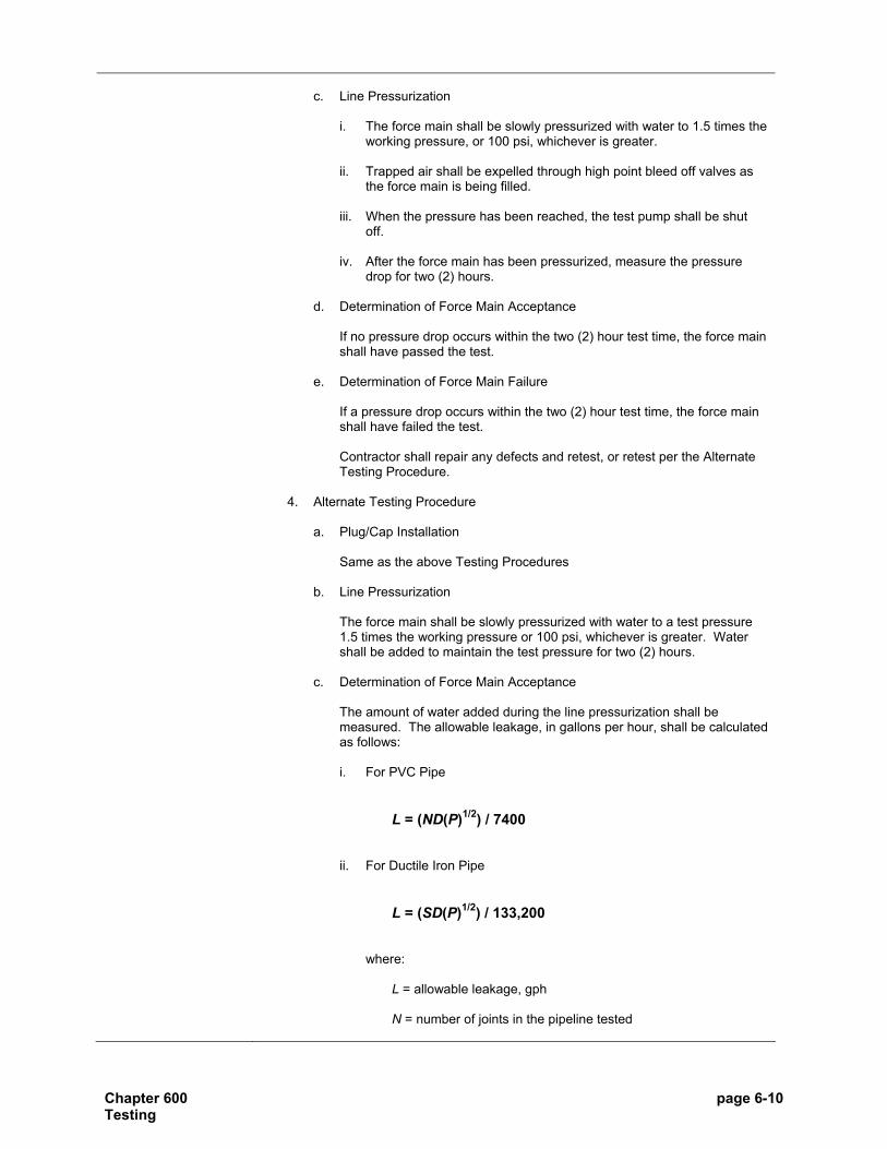
Chapter 600 page 6-10 Testing
c. Line Pressurization
i. The force main shall be slowly pressurized with water to 1.5 times the
working pressure, or 100 psi, whichever is greater.
ii. Trapped air shall be expelled through high point bleed off valves as the force main is being filled.
iii. When the pressure has been reached, the test pump shall be shut off.
iv. After the force main has been pressurized, measure the pressure
drop for two (2) hours.
d. Determination of Force Main Acceptance
If no pressure drop occurs within the two (2) hour test time, the force main shall have passed the test.
e. Determination of Force Main Failure
If a pressure drop occurs within the two (2) hour test time, the force main shall have failed the test.
Contractor shall repair any defects and retest, or retest per the Alternate Testing Procedure.
4. Alternate Testing Procedure
a. Plug/Cap Installation
Same as the above Testing Procedures b. Line Pressurization
The force main shall be slowly pressurized with water to a test pressure 1.5 times the working pressure or 100 psi, whichever is greater. Water shall be added to maintain the test pressure for two (2) hours.
c. Determination of Force Main Acceptance
The amount of water added during the line pressurization shall be measured. The allowable leakage, in gallons per hour, shall be calculated as follows: i. For PVC Pipe
L = (ND(P)1/2) / 7400
ii. For Ductile Iron Pipe
L = (SD(P)1/2) / 133,200
where:
L = allowable leakage, gph N = number of joints in the pipeline tested

Chapter 600 page 6-11 Testing
S = length of pipe tested, feet D = nominal diameter of the pipe, in. P = average test pressure (psi)
If the amount of water added is less than the allowable leakage, the force main shall have passed the test.
d. Determination of Force Main Failure
If the amount of water added is greater than the allowable leakage, the force main shall have failed the test.
The Contractor shall be required to uncover, replace, or repair the force main and/or air release valve and retest.

Chapter 600 page 6-12 Testing
SECTION 604 Manhole Testing Requirements
604.01 Introduction
This Section provides the testing requirements for manholes. For testing requirements specific to sanitary sewers refer to Section 602. For testing requirements specific to force mains refer to Section 603. For testing requirements specific to lift stations refer to Section 605. For testing requirements common to all sanitary sewer facilities refer to Section 601.
604.02 General Requirements
All manholes shall be tested for infiltration by means of a negative air (vacuum) pressure test per Section 604.04. All internal chimney seals shall be tested per Section 604.05.
604.03 Leakage
All manholes shall be watertight and free from leakage. Each manhole shall be visually inspected for leakage by the Division’s RPR after assembly and backfilling. If the manhole shows signs of leakage, the manhole shall be repaired to the satisfaction of the Division and reinspected.
604.04 Negative Air (Vacuum) Test
All manholes shall be tested for infiltration by means of a Negative Air (Vacuum) Pressure Test. Testing shall be done per ASTM C 1244. All joints between the top of casting to the bottom of the manhole base shall be included in the test. The vacuum test shall be as follows:
1. Waiting Period
If possible, each manhole shall be tested immediately after assembly and prior to backfilling. If the test is done after backfilling, the Contractor shall be responsible for re-excavation to locate and correct any leaks that have been identified. The vacuum test shall be done BEFORE the chimney seal is installed and tested.
2. Equipment
Equipment used shall be made specifically for vacuum testing of manholes. 3. Testing Procedures
a. Plug Installation
All pipes entering the manhole shall be temporarily plugged, taking care to securely brace the pipes and plugs to prevent them from being drawn into the manhole.
b. Test Head Installation The test head shall be placed at the top of the manhole casting in accordance with the manufacturer’s recommendations.

Chapter 600 page 6-13 Testing
c. Air Evacuation
A vacuum of ten (10) inches of mercury shall be drawn on the manhole, the valve on the vacuum line of the test head closed, and the vacuum pump shut off.
d. Timing Pressure Rise The time for the vacuum reading to drop from ten (10) inches to nine (9) inches of mercury shall be measured. The allowable time shall be determined by using the following:
Minimum Test Times Manhole Diameter, in 48 60 72
Manhole Depth,
feet Time, seconds 8 20 26 33 10 25 33 41 12 30 39 49 14 35 46 57 16 40 52 67 18 45 59 73 20 50 65 81 22 55 72 89 24 59 78 97 26 64 85 105 28 69 91 113 30 74 98 121
e. Determination of Manhole Acceptance
If the time shown for the designated manhole depth and diameter elapses before the vacuum reading drops one (1) inch, the manhole shall have passed the test.
f. Determination of Manhole Failure If the vacuum reading drops more than one (1) inch before the appropriate time has elapsed, the manhole shall have failed the test. The Contractor shall be required to uncover, replace, or repair any or all sections of the manhole and retest.
604.05 Chimney Seal Leakage Test
All internal chimney seals shall be tested using a leakage test. The leakage test shall be as follows:
1. Waiting Period The leakage test shall be done AFTER the manhole has passed the vacuum test.

Chapter 600 page 6-14 Testing
2. Testing Procedures
a. Install the chimney seal and only the bottom expansion band per
manufacturer’s recommendation. Fully tighten the bottom band. Do not install the top expansion band.
b. Pulling the top of the seal away from the manhole frame, pour one (1) gallon of water behind the seal.
c. Observe the bottom seal for a minimum of one (1) minute for leakage.
d. Drain the water by folding the top of the chimney seal down.
e. If the chimney seal passes the test, install the top expansion band per manufacturer’s recommendation.
3. Determination of Chimney Seal Acceptance
If the bottom expansion band holds water without leaking, the chimney seal will have passed the test.
4. Determination of Chimney Seal Failure If the bottom expansion band has any leakage during the test time, the chimney seal will have failed the test. The Contractor shall be required to remove, replace, or reposition the bottom expansion band and retest.

Chapter 600 page 6-15 Testing
SECTION 605 Lift Station Testing
605.01 Introduction
This Section provides the testing requirements for lift stations. For testing requirements specific to sanitary sewers refer to Section 602. For testing requirements specific to force mains refer to Section 603. For testing requirements specific to manholes refer to Section 604. For testing requirements common to all sanitary sewer facilities refer to Section 601.
605.02 General Requirements
The force main and all gravity sanitary sewers constructed as part of the project shall have passed all required tests prior to the startup and final acceptance of the lift station.
605.03 Wet Well Leakage Testing
All wet wells shall be watertight and free from leakage. The wet well shall be visually inspected for leakage by the Division’s RPR after assembly and backfilling. All dewatering activities shall be ceased a minimum of eight (8) hours prior to the leak testing. If the wet well shows signs of leakage, it shall be repaired to the satisfaction of the Division and reinspected.
605.04 Lift Station Testing
All equipment testing shall be observed by the Department and the RPR during the lift station’s final inspection. Partial testing will not accepted. The testing must be done on the complete lift station. It is not the RPR’s, Division’s, or Department’s responsibility to engage in ANY activity or supply ANY equipment to test and/or accept the lift station. The Contractor shall provide the clean water to run the pumps and perform all tests. The startup and final inspection shall be as follows:
1. Waiting Period The waiting period shall be after BOTH of the following:
a. AFTER the force main, gravity sewers and manholes constructed as part
of the project have passed all required tests contained in Sections 602, 603, and/or 604.
b. After ALL equipment has been installed, been determined to be in working order by the Contractor and manufacturer, and been previously tested by the manufacturer.
2. Equipment
The Contractor or manufacturer shall provide all necessary equipment to safely complete all the tasks necessary to test and accept the lift station.

Chapter 600 page 6-16 Testing
3. Testing Procedures
A lift station checklist provided by the Department shall be completed during the start-up and final inspection. The test shall verify all equipment performs in accordance with the design and the requirements of this Manual. Procedures for each component shall be determined by the Department at the time of startup. At a minimum, the following shall be tested: a. Pumping rate for all pumps in gpm;
b. Communications equipment;
c. Programmable Logic Controller;
d. All electronic equipment;
e. All mechanical equipment;
f. All instrumentation and control equipment;
g. All programming;
h. Incoming power;
i. The overall operating condition of the lift station; and
j. Any other test the Department deems necessary.
4. Calibration
All measuring equipment supplied for the lift station shall be calibrated prior to acceptance. Calibration test results shall be made available upon request. The measuring equipment shall include at a minimum the following: a. Level Transducers;
b. Flow Meters;
c. Gauges; and
d. Other equipment as deemed necessary by the Department.
5. Determination of Lift Station Acceptance
If the station performs to the satisfaction of the Department, as designed, and per the requirements of this Manual, the lift station shall have passed the test.
6. Determination of Lift Station Failure If the station does not perform to the satisfaction of the Department, as designed, and per the requirements of this Manual, the lift station shall have failed the test. The Contractor shall be required to correct all deficiencies and retest.

Cha
pter
600
pa
ge 6
-17
Te
stin
g
TAB
LE 6
00.0
1
MIN
IMU
M S
PEC
IFIE
D T
IME
REQ
UIR
ED F
OR
A 1
.0 P
SIG
PR
ESSU
RE
DR
OP
FOR
SIZ
E A
ND
LEN
GTH
OF
PIPE
FO
R A
LL P
IPE
1 - Per
Sec
tion
602.
03, t
he lo
w p
ress
ure
air t
est f
or th
ese
pipe
dia
met
ers
can
only
be
cond
ucte
d w
ith p
rior a
ppro
val o
f the
Dep
artm
ent.
Spe
cific
atio
n Ti
me
for L
engt
h (L
) Sho
wn
(min
:sec
) 1
Pip
e D
iam
eter
(in
)
2 M
inim
um
Tim
e (m
in:s
ec)
3 Le
ngth
fo
r M
inim
um
time
(ft)
4 Ti
me
for
Long
er
Leng
th
100
ft 15
0 ft
200
ft 25
0 ft
300
ft 35
0 ft
400
ft 45
0 ft
500
ft
4 3:
46
597
.380
L3:
46
3:46
3:
46
3:46
3:
46
3:46
3:
46
6 5:
40
398
.854
L5:
40
5:40
5:
40
5:40
5:
40
5:40
5:
42
8 7:
34
298
1.52
0 L
7:34
7:
34
7:34
7:
34
7:36
8:
52
10:0
8
10
9:26
23
9 2.
374
L9:
26
9:26
9:
26
9:53
11
:52
13:5
1 15
:49
12
11:2
0 19
9 3.
418
L11
:20
11:2
0 11
:24
14:1
5 17
:05
19:5
6 22
:47
15
14:1
0 15
9 5.
342
L14
:10
14:1
0 17
:48
22:1
5 26
:42
31:0
9 35
:36
40:0
4 44
:31
18
17:0
0 13
3 7.
692
L17
:00
19:1
3 25
:38
32:0
3 38
:27
44:5
2 51
:16
57:4
1 64
:06
21
19:5
0 11
4 10
.470
L19
:50
26:1
0 34
:54
43:3
7 52
:21
61:0
0 69
:48
78:3
1 87
:15
24
22:4
0 99
13
.674
L22
:47
34:1
1 45
:34
56:5
8 68
:22
79:4
6 91
:10
102:
33
113:
57
271
25:3
0 88
17
.306
L28
:51
43:1
6 57
:41
72:0
7 86
:32
100:
57
115:
57
129:
48
144:
13
301
28:2
0 80
21
.366
L35
:37
53:2
5 71
:13
89:0
2 10
6:50
12
4:38
14
2:26
16
0:15
17
8:03
331
31:1
0 72
25
.852
L43
:05
64:3
8 86
:10
107:
43
129:
16
150:
43
172:
21
193:
53
215:
26
361
34:0
0 66
30
.768
L51
:17
76:5
5 10
2:34
12
8:12
15
3:50
17
9:29
20
5:07
23
0:46
25
6:40
Rei
nfor
ced
Con
cret
e Pi
pe (R
CP)
24
3.6
100
0.03
6L3:
36
5:24
7:
12
9:00
10
:48
12:3
6 14
:24
16:1
2 18
:00

Cha
pter
600
pa
ge 6
-18
Te
stin
g
TAB
LE 6
00.0
2
MIN
IMU
M S
PEC
IFIE
D T
IME
REQ
UIR
ED F
OR
A 0
.5 P
SIG
PR
ESSU
RE
DR
OP
FOR
SIZ
E A
ND
LEN
GTH
OF
PIPE
FO
R F
LEXI
BLE
AN
D S
EMI-R
IGID
PIP
E
4 Ti
me
for
Long
er
Leng
th
Spe
cific
atio
n Ti
me
for L
engt
h (L
) Sho
wn
(min
:sec
)
1 P
ipe
Dia
met
er
(in)
2 M
inim
um
Tim
e (m
in:s
ec)
3 Le
ngth
for
Min
imum
tim
e (ft
)
100
ft 15
0 ft
200
ft 25
0 ft
300
ft 35
0 ft
400
ft 45
0 ft
500
ft
4 1:
53
597
0.19
0 L
1:53
1:
53
1:53
1:
53
1:53
1:
53
1:53
6 2:
50
398
0.42
7 L
2:50
2:
50
2:50
2:
50
2:50
2:
50
2:51
8 3:
47
298
0.76
0 L
3:47
3:
47
3:47
3:
47
3:48
4:
26
5:04
10
4:43
23
9 1.
187
L4:
43
4:43
4:
43
4:57
5:
56
6:55
7:
54
12
5:40
19
9 1.
709
L5:
40
5:40
5:
42
7:08
8:
33
9:58
11
:24
15
7:05
15
9 2.
671
L7:
05
7:05
8:
54
11:0
8 13
:21
15:3
5 17
:48
20:0
2 22
:16
18
8:30
13
3 3.
846
L8:
30
9:37
12
:49
16:0
1 19
:14
22:2
6 25
:38
28:5
1 32
:03
21
9:55
11
4 5.
235
L9:
55
13:0
5 17
:27
21:4
9 26
:11
30:3
2 34
:54
39:1
6 43
:38
24
11:2
0 99
6.
837
L11
:24
17:5
7 22
:48
28:3
0 34
:11
39:5
3 45
:35
51:1
7 56
:59
271
12:4
5 88
8.
653
L14
:25
21:3
8 28
:51
36:0
4 43
:16
50:3
0 57
:42
64:5
4 72
:06
301
14:1
0 80
10
.683
L17
:48
26:4
3 35
:37
44:3
1 53
:25
62:1
9 71
:13
80:0
7 89
:01
331
15:3
5 72
12
.926
L21
:33
32:1
9 43
:56
53:5
2 64
:38
75:2
4 86
:10
96:5
7 10
7:43
361
17:0
0 66
15
.384
L25
:39
38:2
8 51
:17
64:0
6 76
:55
89:4
4 10
2:34
11
5:23
12
8:12
1 - Per
Sec
tion
602.
03, t
he lo
w p
ress
ure
air t
est f
or th
ese
pipe
dia
met
ers
can
only
be
cond
ucte
d w
ith p
rior a
ppro
val o
f the
Dep
artm
ent.

Chapter 600 page 6-19 Testing
EXAMPLE LOW PRESSURE AIR TESTS
A. GENERAL The purpose of this Section is to illustrate the proper application of this recommended practice with regard to appropriate test time selection. The examples that follow include a variety of conditions which may be encountered in the field.
1. EXAMPLE A
A manhole to manhole reach of nominal 12-inch pipe is 350 feet long. No lateral connections exist in the reach. What is the required test time for a 0.5 psig pressure drop? Solution: The required test time can be read directly from Table 600.02. For 350 feet of 12-inch pipe, the required test time is 9:58 (9 minutes and 58 seconds).
2. EXAMPLE B What should the required test time be for a 1.0 psig pressure drop in 327 feet of nominal 8-inch diameter pipe between two manholes? Solution: The exact test time is easily calculated by using Table 600.01. Table 600.01 is used because a 1.0 psig pressure drop is specified. Since 327 feet exceeds the minimum test time for an 8-inch pipeline, the fourth column in Table 600.01shall be used to quickly calculate the required test time as follows:
T = 1.520 L T = 1.520 x 327 ft = 497 seconds
Therefore, the required test time for a 1.0 psig pressure drop is 497 seconds, or 8 minutes and 17 seconds (8:17).
3. EXAMPLE C A manhole-to-manhole reach of nominal 24-inch pipe is 82-feet long. What is the required test time for a 0.5 psig pressure drop?
Solution: Table 600.02 must be used because a 0.5 psig pressure drop is specified. Since 82 feet is less than the 99 foot length associated with the minimum test for a 24-inch pipeline, the minimum test time shall apply. Thus, the required test time for a 0.5 psig pressure drop must be 11 minutes and 20 seconds (11:20).
4. EXAMPLE D A 412 foot section of nominal 15-inch sewer pipe has been readied for air testing. A total of 375 feet of nominal 6-inch lateral piping and 148 feet of nominal 4-inch lateral piping branch off of the 15-inch sewer line. All laterals have been capped and/or plugged and will be tested together with the 15-inch main line. The specified pressure drop which will be timed is 0.5 psig. What is the appropriate test time for this pipe network? Solution: All lateral sewer sizes and lengths may be disregarded since their influence is generally not significant enough to warrant computation. Table 600.02 must be used for a 0.5 psig pressure drop. The fourth column in the Table provides the appropriate formula for calculating the required test time because 412 feet is longer than the third column valve of 159 feet.
T = 2.671 L T = 2.671 x 412 = 1,100 seconds.
The required test time is 1,100 seconds or 18 minutes, 20 seconds (18:20

APPENDIX A
A-1
FEES
Fee Type Fee
Amount SWR - Sewer Lateral Lateral Permit Fee $120.001
Administrative Fee (per acre) $515.001
15-yr Law Agreement Fee TBD2
Transfer of Lateral Permit $50.001
Connection Fee (per EDU) $2,500.003
SWC - Sewer Main Initial Submittal Fee $200.001
Initial Submittal Fee - Accelerated $275.001
Sanitary Review - Hourly $215.001
Accelerated Review - Hourly $275.001
Administrative Fee (per acre) $515.001
15-yr Law Administration Fee $395.001
15-yr Law Agreement Fee TBD2
Inspecting Engineer (per hour) $65.00
1 – Fee adopted per Public Works Resolution #104, 2005 2 – Fee is based on 15-yr Law Contract 3 – Fee adopted per Public Works Resolution #100, 2005

APPENDIX B
B-1
Estimated Average Daily Flow (ADF)
Service Connection Description ADF (gallons per day) Agricultural labor camp 50 per occupant Airport 3 per passenger plus 20 per employee Apartment/Condominium, multi-family dwelling: one bedroom 200 per unit
Apartment/Condominium, multi-family dwelling: two bedroom 300 per unit
Apartment/Condominium, multi-family dwelling: three bedroom 350 per unit
Apartment/Condominium, one and two family dwelling 150 per bedroom
Assembly hall 3 per seat Athletic field (baseball, soccer, football, etc.) 1 per participant and spectator with additions
for concessions Auction and flea market: with full kitchen 5 per customer Auction and flea market: with warming kitchen 4 per customer Auction and flea market: without kitchen 3 per customer Automatic self-cleaning bathroom 20 per cycle (3 per day) Banquet caterer 10 per person Bar (without food) 10 per seat
Barber Shop 90 per chair
Beauty salon: perm or color changes 35 per customer Beauty salon: cut with wash 10 per customer Beauty salon: cut without wash 5 per person Bed and breakfast 150 per bedroom Bowling alley (with bar and/or food) 125 per lane Bowling alley (without food) 75 per lane Bus station 3 per passenger Campground (organizational) with flush toilets, showers, central kitchen 40 per camper
Campground (organizational) without flush toilets, privy use, central dining hall, no showers, handwashing 20 per camper
Campground (recreational) with individual sewer connection 100 per campsite
Campground (recreational) without individual sewer connection 50 per campsite
Car Wash 240 per sq. ft. inside
Church with full kitchen 5 per sanctuary seat Church with warming kitchen 4 per sanctuary seat Church without kitchen 3 per sanctuary seat Conferences 10 per attendee Correctional facilities 120 per inmate Day care center 20 per person Dentist 200 per chair plus 75 per employee Doctor’s office 75 per doctor, plus 75 per nurse, plus 20 per
support staff Factory (Industrial Discharger) with showers 35 per employee Factory (Industrial Discharger) without showers 20 per employee Fire station: manned 75 per firefighter Fire station: unmanned 35 per firefighter Food service operations: cocktail lounge or tavern 35 per seat

B-2
Food service operations: restaurant (not open 24 hours) 35 per seat Food service operations: restaurant (open 24 hours) 50 per seat Food service operations: restaurant (not open 24 hours but located along an interstate)
50 per seat
Food service operations: restaurant (open 24 hours and located along an interstate) 70 per seat
Food service operations: tavern 35 per seat Food service operations: curb service (drive-in) 50 per car space Golf comfort station 3 per 50% of maximum number of golfers Golf main clubhouse 5 per golfer with additions for food service
and showers Hospital, medical facility 200 per bed Hotel 100 per room Kennels and vet clinics (sum of all of the following services at a facility):
1) a. cages 5 per cage b. inside runs 10 per run c. outside runs 20 per run d. grooming 10 per animal e. surgery plus 50 per surgery room
2) staff 75 per veterinary doctor, plus 7 per veterinary assistant, plus 20 per support staff
Laundry 200 per machine
Mental health facility 100 per patient Mobile home park 200 per lot Motel 100 per room Nursing home 100 per bed Office building without showers 20 per employee Office building with showers 35 per employee Outpatient surgical center 50 per patient Picnic area 5 per visitor Race tracks 5 per attendee, 20 per staff Rooming House 100 per renter
School: elementary 15 per pupil School: secondary 25 per pupil School with dormitory 100 per bed Service station: convenience store/service center 1,000 with additions for food preparation and
seating Service station with only two (2) restrooms 400 per restroom Service station with only unisex restroom 600 per restroom Service station: automatic self-cleaning bathroom 60 per day Shopping center 0.1 per square foot of floor space, plus 20
per employee Swimming pool bathhouse 10 per swimmer Theater: drive-in 5 per car space Theater: inside building 5 per seat

C-1
AIR
PR
ESS
UR
E T
EST
DA
TA
SH
EE
T
Indi
anap
olis
San
itary
Dis
tric
t
Tes
t No.
___
____
____
____
__
Job
nam
e, L
ocat
ion,
Pro
ject
num
ber o
r Sub
divi
sion
Nam
e __
____
____
___
____
____
____
____
____
____
____
____
____
____
____
____
____
____
____
____
____
Fiel
d T
est D
ata
(To
be fi
lled
in b
y In
spec
tor)
D
ate
Spec
ified
Max
imum
Pre
ssur
e D
rop:
___
____
____
____
____
___
psig
Id
entif
icat
ion
of P
ipe
Mat
eria
l Ins
talle
d Pi
pe U
nder
Tes
t
Fiel
d Te
st O
pera
tions
Dat
a U
pstre
am
MH
No.
D
owns
tream
M
H N
o.
Dia
. D
(in)
Le
ngth
, L
(ft)
Tim
e fr
om
Tabl
e __
_ (m
in:s
ec)
Air
Pres
sure
A
djus
tmen
t (p
sig)
Initi
al
Pres
sure
(p
sig)
Tim
e A
llow
ed
for P
ress
ure
to
Stab
ilize
(min
)
Star
t Pr
essu
re
(psi
g)
Stop
Pr
essu
re
(psi
g)
Elap
sed
Tim
e (m
in:s
ec)
Pass
or
Fail
(P
or F
)
In
spec
tors
nam
e an
d T
itle
Sign
atur
e of
Insp
ecto
r: If
a se
ctio
n fa
ils, t
he fo
llow
ing
item
s mus
t be
com
plet
ed:
Iden
tify
sect
ion(
s) th
at fa
iled:
Le
ak (w
as) (
was
not
) ide
ntifi
ed.
Met
hod
used
: D
escr
iptio
n of
leak
: C
orre
ctiv
e A
ctio
n Ta
ken:
R
esul
ts a
fter r
epai
r ref
er to
Tes
t No.
: In
spec
tor:
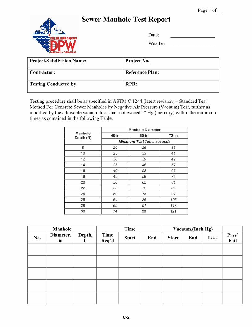
Page 1 of __
C-2
Sewer Manhole Test Report
Date: __________________
Weather: __________________
Project/Subdivision Name:
Project No.
Contractor: Reference Plan:
Testing Conducted by: RPR:
Testing procedure shall be as specified in ASTM C 1244 (latest revision) – Standard Test Method For Concrete Sewer Manholes by Negative Air Pressure (Vacuum) Test, further as modified by the allowable vacuum loss shall not exceed 1" Hg (mercury) within the minimum times as contained in the following Table.
Manhole Diameter 48-in 60-in 72-in Manhole
Depth (ft) Minimum Test Time, seconds
8 20 26 33 10 25 33 41 12 30 39 49 14 35 46 57 16 40 52 67 18 45 59 73 20 50 65 81 22 55 72 89 24 59 78 97 26 64 85 105 28 69 91 113 30 74 98 121
Manhole Time Vacuum,(Inch Hg)
No. Diameter, in
Depth, ft
Time Req’d Start End Start End Loss Pass/
Fail

Page 2 of __
C-2
Sewer manhole Test Report
Manhole Time Vacuum,(Inch Hg)
No. Diameter, in
Depth, ft
Time Req’d Start End Start End Loss Pass/
Fail
Comments: .
.
.
_____________________________________________________________________________

C-3
Sewer Force Main Test Report Hydrostatic Leak Test
Date: __________________
Weather: __________________
Right-of-Way: Project/Subdivision Name:
Contractor: Reference Plan:
Testing Conducted by: RPR:
Testing procedure shall be as specified in AWWA C600 and/or C900 (latest revisions) – Standard Hydrostatic Test Method Of (DIP and PVCP) Sewer Force Mains and ASTM 1003. The required test time shall be two (2) hours, the required pressure shall be 1.5 times the working pressure of the pipe or 100 psi whichever is greater.
Pipe Diameter (inches)
Pipe Type Pipe
Length Tested, ft
Starting Pressure
(psi)
Ending Pressure
(psi)
Pressure Loss (psi)
Pass Or Fail
Comments:
_________________________________________________________________________________
_________________________________________________________________________________
_________________________________________________________________________________
_________________________________________________________________________________

C-4
Sewer Force Main Test Report Alternate Test Method
Date: __________________
Weather: __________________
Right-of-Way: Project/Subdivision Name:
Contractor: Reference Plan:
Testing Conducted by: RPR:
Testing procedure shall be as specified in AWWA C600 and/or C900 (latest revisions) – Standard Hydrostatic Test Method Of (DIP and PVCP) Sewer Force Mains, further as modified by the required test time shall be two (2) hours, the required pressure shall be 1.5 times the working pressure of the pipe or 100 psi and the allowable leakage shall not exceed “L” in the following formulas:
For PVC Pipe For Ductile Iron Pipe
L = (ND(P)1/2)/7400 L = (SD(P)1/2)/133,200 Where: L = allowable leakage (gph) N = number of joints in the pipeline tested S = length of pipe tested (feet) D = nominal diameter of the pipe (in) P = average test pressure (psi)
Pipe Diameter & Type
Pipe Length
Tested, ft.
Starting Pressure
(psi)
Amount of Water
Added (gal)
Allowable Leakage
(gph)
Actual Leakage
(gph)
Pass Or Fail
Comments: ______________________________________________________________________ ________________________________________________________________________________ ________________________________________________________________________________


![The Indianapolis Star - Indianapolis, IN - Publisher ... · The Indianapolis Star - Indianapolis, IN - Publisher, Broadcasting & Media Production | Facebook 1/10/2013 4:09:30 PM]](https://img.pdfslide.us/doc/110x75/5b84ed5a7f8b9a317e8cea29/the-indianapolis-star-indianapolis-in-publisher-the-indianapolis-star.jpg)


![The Indianapolis journal. (Indianapolis [Ind.]) 1899-11-09](https://img.pdfslide.us/doc/110x75/61689f47d394e9041f713c5f/the-indianapolis-journal-indianapolis-ind-1899-11-09-.jpg)