Embed Size (px)
Citation preview
2 7 0 0 Y G N A C I O V A L L E Y R O A D • S U I T E 3 0 0 • W A L N U T C R E E K , C A L I F O R N I A 9 4 5 9 8 • ( 9 2 5 ) 9 3 2 - 1 7 1 0 • F A X ( 9 2 5 ) 9 3 0 - 0 2 0 8 C l i e n t / C A / S u n n y v a l e / 9 2 6 5 A 0 0 / P r o j e c t S p e c i f i c T e m p l a t e s / D e s i g n S t a n d a r d s T e m p l a t e d o c
CITY OF SUNNYVALE WATER POLLUTION CONTROL PLANT DESIGN STANDARDS ELECTRICAL August 2014
Prepared By:
Larry Smithey Reviewed By:
Theresa Rearick Reviewed By:
Chris Carvalho

August 2014– FINAL i pw://Carollo/Documents/Client/CA/Sunnyvale/9265A00/Deliverables/Final DS – Electrical – 2014-08-18.doc
CITY OF SUNNYVALE
WATER POLLUTION CONTROL PLANT
DESIGN STANDARDS
ELECTRICAL
TABLE OF CONTENTS
Page No.
1.0 PURPOSE AND CONTENTS ..................................................................................... 1
2.0 STANDARD DEFINITIONS AND ABBREVATIONS .................................................. 1
3.0 CODES AND STANDARDS ....................................................................................... 3 3.1 Codes ............................................................................................................ 3 3.2 Safety Standards ........................................................................................... 4
4.0 GUIDELINES AND PROCEDURES ........................................................................... 4 4.1 Flexibility and Expansion ............................................................................... 4 4.2 Power Quality ................................................................................................ 5 4.3 Electrical Efficiency Compliance .................................................................... 5 4.4 Electrical System Design ............................................................................... 5 4.5 Electrical Design Calculations ..................................................................... 11 4.6 Lighting ........................................................................................................ 13 4.7 Electrical Drawings ...................................................................................... 15 4.8 Technical Specifications .............................................................................. 18
5.0 REFERENCES ......................................................................................................... 20
6.0 ATTACHMENTS ...................................................................................................... 20

August 2014 – FINAL 1 pw://Carollo/Documents/Client/CA/Sunnyvale/9265A00/Deliverables/Final DS – Electrical – 2014-08-18.doc
Design Standards
ELECTRICAL
1.0 PURPOSE AND CONTENTS
This document describes the electrical engineering design standards to be used for improvement projects at the City of Sunnyvale (City) Water Pollution Control Plant (WPCP). Included are required design standards for electrical methods and components. These standards will be used for preliminary and final design of WPCP improvements.
In case of this document’s overlap and conflict with governing codes and standards, the stricter interpretation or directive shall be followed.
2.0 STANDARD DEFINITIONS AND ABBREVATIONS
Indoor Locations
Areas which are protected from exposure to the weather with four walls and roof.
Outdoor Locations
Areas which are exposed to the weather.
Wet Locations Areas either underground or subject to saturation with water or other liquids, such as vehicle washing areas, and in unprotected locations exposed to weather.
Dry Locations A location not normally subject to dampness or wetness. A location classified as dry may be temporarily subject to dampness or wetness, as in the case of a building under construction.
Hazardous (Classified) Location
A location in which fire or explosion hazards may exist due to flammable gases or vapors, flammable liquids, combustible dust, or easily ignitable fibers or filings.
Class I, Division 1 Location
A location (1) in which ignitable concentrations of flammable gases or vapors can exist under normal operating conditions; (2) in which ignitable concentrations of such gases or vapors may exist frequently because of repair or maintenance operations or because of leakage; or (3) in which breakdown or faulty operation of equipment or processes might release ignitable concentrations of flammable gases or vapors and might also cause simultaneous failure of electrical equipment that could act as a source of ignition.
Class I, Division 2 Location
A location (1) in which volatile flammable liquids or flammable gases are handled, processed, or used, but in which the liquids, vapors, or gases will normally be confined within closed containers or closed systems from
August 2014 – FINAL 2 pw://Carollo/Documents/Client/CA/Sunnyvale/9265A00/Deliverables/Final DS – Electrical – 2014-08-18.doc
which they can escape only in case of accidental rupture or breakdown of such containers or systems, or in case of abnormal operation of equipment; (2) in which ignitable concentrations of gases or vapors are normally prevented by positive mechanical ventilation and might become hazardous through failure or abnormal operation of the ventilating equipment; or (3) that is adjacent to a Class I, Division 1 location and to which ignitable concentrations of gases or vapors might occasionally be communicated unless such communication is prevented by adequate positive-pressure ventilation from a source of clean air and effective safeguards against ventilation failure are provided.
Intrinsic Safety A type of protection in which a portion of the electrical system contains only intrinsically safe equipment (apparatus, circuits, and wiring) that is incapable of causing ignition in the surrounding atmosphere. No single device or wiring is intrinsically safe by itself (except for battery-operated self-contained apparatus such as portable pagers, transceivers, gas detectors, etc., which are specifically designed as intrinsically safe self-contained devices) but is intrinsically safe only when employed in a properly designed intrinsically safe system.
1. Intrinsic Safety Barrier: A component containing a network designed to limit the energy (voltage and current) available to the protected circuit in the hazardous (classified) location under specified fault conditions.
2. Intrinsically Safe Circuit: A circuit in which any spark or thermal effect, produced either normally or in specified fault conditions, is incapable of releasing sufficient electrical or thermal energy to cause ignition of a specific hazardous atmospheric mixture in its most easily ignitable concentration.
3. Intrinsically Safe Equipment (apparatus, circuits, and wiring): Equipment and wiring that, under normal or abnormal conditions, are incapable of releasing sufficient electrical or thermal energy to cause ignition of a specific hazardous atmospheric mixture in its most easily ignitable concentration.
Labeled Equipment
Equipment or materials, to which has been attached a label, symbol, or other identifying mark of an organization concerned with product evaluation, that may maintain periodic inspection of the production of labeled equipment or materials, and by whose labeling the manufacturer indicates compliance with appropriate standards or performance in a specified manner.
Listed Equipment or materials, included in a list published by an organization
August 2014 – FINAL 3 pw://Carollo/Documents/Client/CA/Sunnyvale/9265A00/Deliverables/Final DS – Electrical – 2014-08-18.doc
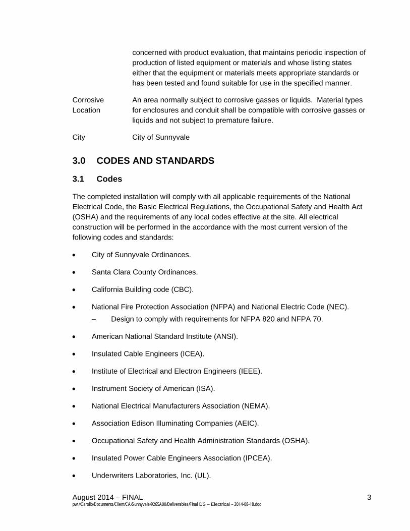
concerned with product evaluation, that maintains periodic inspection of production of listed equipment or materials and whose listing states either that the equipment or materials meets appropriate standards or has been tested and found suitable for use in the specified manner.
Corrosive Location
An area normally subject to corrosive gasses or liquids. Material types for enclosures and conduit shall be compatible with corrosive gasses or liquids and not subject to premature failure.
City City of Sunnyvale
3.0 CODES AND STANDARDS
3.1 Codes
The completed installation will comply with all applicable requirements of the National Electrical Code, the Basic Electrical Regulations, the Occupational Safety and Health Act (OSHA) and the requirements of any local codes effective at the site. All electrical construction will be performed in the accordance with the most current version of the following codes and standards:
City of Sunnyvale Ordinances.
Santa Clara County Ordinances.
California Building code (CBC).
National Fire Protection Association (NFPA) and National Electric Code (NEC).
– Design to comply with requirements for NFPA 820 and NFPA 70.
American National Standard Institute (ANSI).
Insulated Cable Engineers (ICEA).
Institute of Electrical and Electron Engineers (IEEE).
Instrument Society of American (ISA).
National Electrical Manufacturers Association (NEMA).
Association Edison Illuminating Companies (AEIC).
Occupational Safety and Health Administration Standards (OSHA).
Insulated Power Cable Engineers Association (IPCEA).
Underwriters Laboratories, Inc. (UL).
August 2014 – FINAL 4 pw://Carollo/Documents/Client/CA/Sunnyvale/9265A00/Deliverables/Final DS – Electrical – 2014-08-18.doc
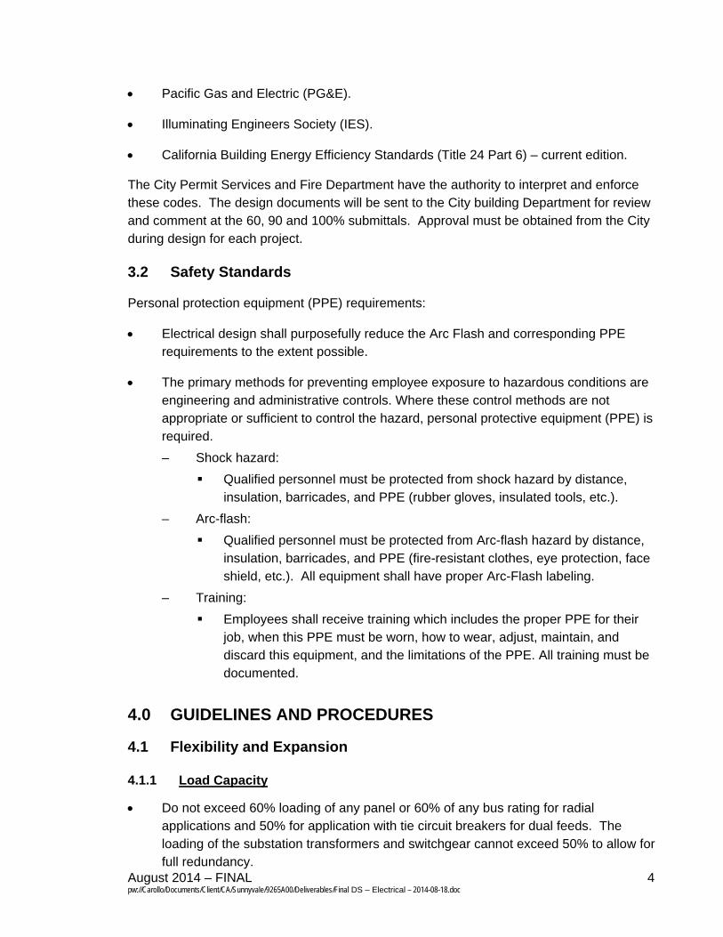
Pacific Gas and Electric (PG&E).
Illuminating Engineers Society (IES).
California Building Energy Efficiency Standards (Title 24 Part 6) – current edition.
The City Permit Services and Fire Department have the authority to interpret and enforce these codes. The design documents will be sent to the City building Department for review and comment at the 60, 90 and 100% submittals. Approval must be obtained from the City during design for each project.
3.2 Safety Standards
Personal protection equipment (PPE) requirements:
Electrical design shall purposefully reduce the Arc Flash and corresponding PPE requirements to the extent possible.
The primary methods for preventing employee exposure to hazardous conditions are engineering and administrative controls. Where these control methods are not appropriate or sufficient to control the hazard, personal protective equipment (PPE) is required.
– Shock hazard:
Qualified personnel must be protected from shock hazard by distance, insulation, barricades, and PPE (rubber gloves, insulated tools, etc.).
– Arc-flash:
Qualified personnel must be protected from Arc-flash hazard by distance, insulation, barricades, and PPE (fire-resistant clothes, eye protection, face shield, etc.). All equipment shall have proper Arc-Flash labeling.
– Training:
Employees shall receive training which includes the proper PPE for their job, when this PPE must be worn, how to wear, adjust, maintain, and discard this equipment, and the limitations of the PPE. All training must be documented.
4.0 GUIDELINES AND PROCEDURES
4.1 Flexibility and Expansion
4.1.1 Load Capacity
Do not exceed 60% loading of any panel or 60% of any bus rating for radial applications and 50% for application with tie circuit breakers for dual feeds. The loading of the substation transformers and switchgear cannot exceed 50% to allow for full redundancy.
August 2014 – FINAL 5 pw://Carollo/Documents/Client/CA/Sunnyvale/9265A00/Deliverables/Final DS – Electrical – 2014-08-18.doc
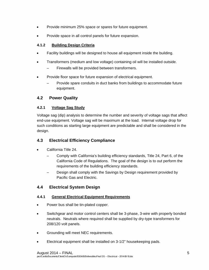
Provide minimum 25% space or spares for future equipment.
Provide space in all control panels for future expansion.
4.1.2 Building Design Criteria
Facility buildings will be designed to house all equipment inside the building.
Transformers (medium and low voltage) containing oil will be installed outside.
– Firewalls will be provided between transformers.
Provide floor space for future expansion of electrical equipment.
– Provide spare conduits in duct banks from buildings to accommodate future equipment.
4.2 Power Quality
4.2.1 Voltage Sag Study
Voltage sag (dip) analysis to determine the number and severity of voltage sags that affect end-use equipment. Voltage sag will be maximum at the load. Internal voltage drop for such conditions as starting large equipment are predictable and shall be considered in the design.
4.3 Electrical Efficiency Compliance
California Title 24.
– Comply with California’s building efficiency standards, Title 24, Part 6, of the California Code of Regulations. The goal of the design is to out perform the requirements of the building efficiency standards.
– Design shall comply with the Savings by Design requirement provided by Pacific Gas and Electric.
4.4 Electrical System Design
4.4.1 General Electrical Equipment Requirements
Power bus shall be tin-plated copper.
Switchgear and motor control centers shall be 3-phase, 3-wire with properly bonded neutrals. Neutrals where required shall be supplied by dry-type transformers for 208/120 volt panels.
Grounding will meet NEC requirements.
Electrical equipment shall be installed on 3-1/2” housekeeping pads.
August 2014 – FINAL 6 pw://Carollo/Documents/Client/CA/Sunnyvale/9265A00/Deliverables/Final DS – Electrical – 2014-08-18.doc
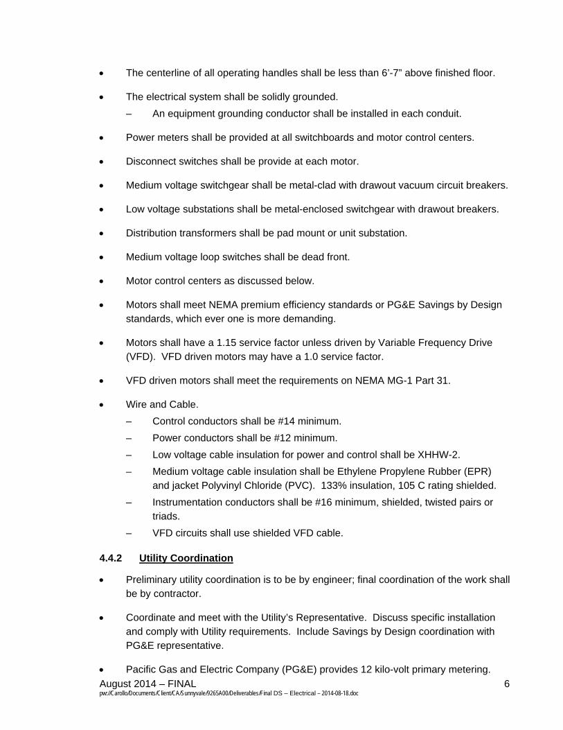
The centerline of all operating handles shall be less than 6’-7” above finished floor.
The electrical system shall be solidly grounded.
– An equipment grounding conductor shall be installed in each conduit.
Power meters shall be provided at all switchboards and motor control centers.
Disconnect switches shall be provide at each motor.
Medium voltage switchgear shall be metal-clad with drawout vacuum circuit breakers.
Low voltage substations shall be metal-enclosed switchgear with drawout breakers.
Distribution transformers shall be pad mount or unit substation.
Medium voltage loop switches shall be dead front.
Motor control centers as discussed below.
Motors shall meet NEMA premium efficiency standards or PG&E Savings by Design standards, which ever one is more demanding.
Motors shall have a 1.15 service factor unless driven by Variable Frequency Drive (VFD). VFD driven motors may have a 1.0 service factor.
VFD driven motors shall meet the requirements on NEMA MG-1 Part 31.
Wire and Cable.
– Control conductors shall be #14 minimum.
– Power conductors shall be #12 minimum.
– Low voltage cable insulation for power and control shall be XHHW-2.
– Medium voltage cable insulation shall be Ethylene Propylene Rubber (EPR) and jacket Polyvinyl Chloride (PVC). 133% insulation, 105 C rating shielded.
– Instrumentation conductors shall be #16 minimum, shielded, twisted pairs or triads.
– VFD circuits shall use shielded VFD cable.
4.4.2 Utility Coordination
Preliminary utility coordination is to be by engineer; final coordination of the work shall be by contractor.
Coordinate and meet with the Utility’s Representative. Discuss specific installation and comply with Utility requirements. Include Savings by Design coordination with PG&E representative.
Pacific Gas and Electric Company (PG&E) provides 12 kilo-volt primary metering.
August 2014 – FINAL 7 pw://Carollo/Documents/Client/CA/Sunnyvale/9265A00/Deliverables/Final DS – Electrical – 2014-08-18.doc
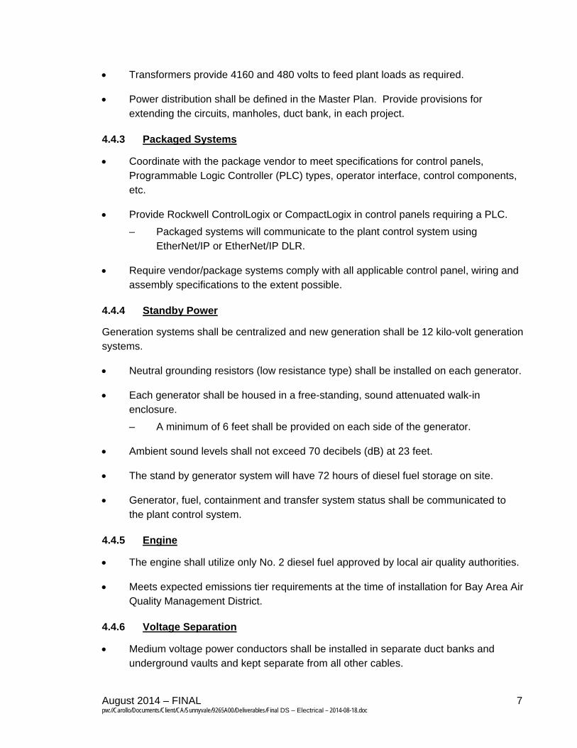
Transformers provide 4160 and 480 volts to feed plant loads as required.
Power distribution shall be defined in the Master Plan. Provide provisions for extending the circuits, manholes, duct bank, in each project.
4.4.3 Packaged Systems
Coordinate with the package vendor to meet specifications for control panels, Programmable Logic Controller (PLC) types, operator interface, control components, etc.
Provide Rockwell ControlLogix or CompactLogix in control panels requiring a PLC.
– Packaged systems will communicate to the plant control system using EtherNet/IP or EtherNet/IP DLR.
Require vendor/package systems comply with all applicable control panel, wiring and assembly specifications to the extent possible.
4.4.4 Standby Power
Generation systems shall be centralized and new generation shall be 12 kilo-volt generation systems.
Neutral grounding resistors (low resistance type) shall be installed on each generator.
Each generator shall be housed in a free-standing, sound attenuated walk-in enclosure.
– A minimum of 6 feet shall be provided on each side of the generator.
Ambient sound levels shall not exceed 70 decibels (dB) at 23 feet.
The stand by generator system will have 72 hours of diesel fuel storage on site.
Generator, fuel, containment and transfer system status shall be communicated to the plant control system.
4.4.5 Engine
The engine shall utilize only No. 2 diesel fuel approved by local air quality authorities.
Meets expected emissions tier requirements at the time of installation for Bay Area Air Quality Management District.
4.4.6 Voltage Separation
Medium voltage power conductors shall be installed in separate duct banks and underground vaults and kept separate from all other cables.
August 2014 – FINAL 8 pw://Carollo/Documents/Client/CA/Sunnyvale/9265A00/Deliverables/Final DS – Electrical – 2014-08-18.doc
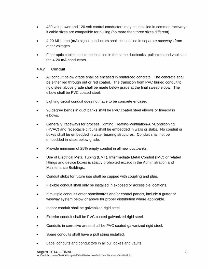
480 volt power and 120 volt control conductors may be installed in common raceways if cable sizes are compatible for pulling (no more than three sizes different).
4-20 Milli-amp (mA) signal conductors shall be installed in separate raceways from other voltages.
Fiber optic cables should be installed in the same ductbanks, pullboxes and vaults as the 4-20 mA conductors.
4.4.7 Conduit
All conduit below grade shall be encased in reinforced concrete. The concrete shall be either red through out or red coated. The transition from PVC buried conduit to rigid steel above grade shall be made below grade at the final sweep elbow. The elbow shall be PVC coated steel.
Lighting circuit conduit does not have to be concrete encased.
90 degree bends in duct banks shall be PVC coated steel elbows or fiberglass elbows.
Generally, raceways for process, lighting, Heating-Ventilation-Air-Conditioning (HVAC) and receptacle circuits shall be embedded in walls or slabs. No conduit or boxes shall be embedded in water bearing structures. Conduit shall not be embedded in slabs below grade.
Provide minimum of 25% empty conduit in all new ductbanks.
Use of Electrical Metal Tubing (EMT), Intermediate Metal Conduit (IMC) or related fittings and device boxes is strictly prohibited except in the Administration and Maintenance Buildings.
Conduit stubs for future use shall be capped with coupling and plug.
Flexible conduit shall only be installed in exposed or accessible locations.
If multiple conduits enter panelboards and/or control panels, include a gutter or wireway system below or above for proper distribution where applicable.
Indoor conduit shall be galvanized rigid steel.
Exterior conduit shall be PVC coated galvanized rigid steel.
Conduits in corrosive areas shall be PVC coated galvanized rigid steel.
Spare conduits shall have a pull string installed.
Label conduits and conductors in all pull boxes and vaults.
August 2014 – FINAL 9 pw://Carollo/Documents/Client/CA/Sunnyvale/9265A00/Deliverables/Final DS – Electrical – 2014-08-18.doc
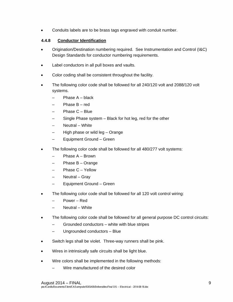
Conduits labels are to be brass tags engraved with conduit number.
4.4.8 Conductor Identification
Origination/Destination numbering required. See Instrumentation and Control (I&C) Design Standards for conductor numbering requirements.
Label conductors in all pull boxes and vaults.
Color coding shall be consistent throughout the facility.
The following color code shall be followed for all 240/120 volt and 2088/120 volt systems.
– Phase A – black
– Phase B – red
– Phase C – Blue
– Single Phase system – Black for hot leg, red for the other
– Neutral – White
– High phase or wild leg – Orange
– Equipment Ground – Green
The following color code shall be followed for all 480/277 volt systems:
– Phase A – Brown
– Phase B – Orange
– Phase C – Yellow
– Neutral – Gray
– Equipment Ground – Green
The following color code shall be followed for all 120 volt control wiring:
– Power – Red
– Neutral – White
The following color code shall be followed for all general purpose DC control circuits:
– Grounded conductors – white with blue stripes
– Ungrounded conductors – Blue
Switch legs shall be violet. Three-way runners shall be pink.
Wires in intrinsically safe circuits shall be light blue.
Wire colors shall be implemented in the following methods:
– Wire manufactured of the desired color
August 2014 – FINAL 10 pw://Carollo/Documents/Client/CA/Sunnyvale/9265A00/Deliverables/Final DS – Electrical – 2014-08-18.doc
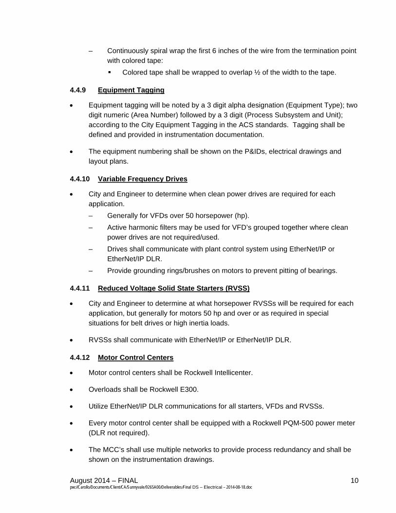
– Continuously spiral wrap the first 6 inches of the wire from the termination point with colored tape:
Colored tape shall be wrapped to overlap ½ of the width to the tape.
4.4.9 Equipment Tagging
Equipment tagging will be noted by a 3 digit alpha designation (Equipment Type); two digit numeric (Area Number) followed by a 3 digit (Process Subsystem and Unit); according to the City Equipment Tagging in the ACS standards. Tagging shall be defined and provided in instrumentation documentation.
The equipment numbering shall be shown on the P&IDs, electrical drawings and layout plans.
4.4.10 Variable Frequency Drives
City and Engineer to determine when clean power drives are required for each application.
– Generally for VFDs over 50 horsepower (hp).
– Active harmonic filters may be used for VFD’s grouped together where clean power drives are not required/used.
– Drives shall communicate with plant control system using EtherNet/IP or EtherNet/IP DLR.
– Provide grounding rings/brushes on motors to prevent pitting of bearings.
4.4.11 Reduced Voltage Solid State Starters (RVSS)
City and Engineer to determine at what horsepower RVSSs will be required for each application, but generally for motors 50 hp and over or as required in special situations for belt drives or high inertia loads.
RVSSs shall communicate with EtherNet/IP or EtherNet/IP DLR.
4.4.12 Motor Control Centers
Motor control centers shall be Rockwell Intellicenter.
Overloads shall be Rockwell E300.
Utilize EtherNet/IP DLR communications for all starters, VFDs and RVSSs.
Every motor control center shall be equipped with a Rockwell PQM-500 power meter (DLR not required).
The MCC’s shall use multiple networks to provide process redundancy and shall be shown on the instrumentation drawings.
August 2014 – FINAL 11 pw://Carollo/Documents/Client/CA/Sunnyvale/9265A00/Deliverables/Final DS – Electrical – 2014-08-18.doc
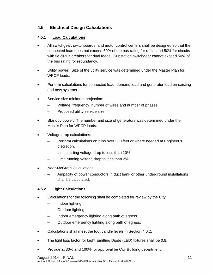
4.5 Electrical Design Calculations
4.5.1 Load Calculations
All switchgear, switchboards, and motor control centers shall be designed so that the connected load does not exceed 60% of the bus rating for radial and 50% for circuits with tie circuit breakers for dual feeds. Substation switchgear cannot exceed 50% of the bus rating for redundancy.
Utility power: Size of the utility service was determined under the Master Plan for WPCP loads.
Perform calculations for connected load, demand load and generator load on existing and new systems.
Service size minimum projection:
– Voltage, frequency, number of wires and number of phases
– Proposed utility service size
Standby power: The number and size of generators was determined under the Master Plan for WPCP loads.
Voltage drop calculations:
– Perform calculations on runs over 300 feet or where needed at Engineer’s discretion.
– Limit starting voltage drop to less than 10%.
– Limit running voltage drop to less than 2%.
Near-McGrath Calculations:
– Ampacity of power conductors in duct bank or other underground installations shall be calculated.
4.5.2 Light Calculations
Calculations for the following shall be completed for review by the City:
– Indoor lighting
– Outdoor lighting
– Indoor emergency lighting along path of egress.
– Outdoor emergency lighting along path of egress.
Calculations shall meet the foot candle levels in Section 4.6.2.
The light loss factor for Light Emitting Diode (LED) fixtures shall be 0.9.
Provide at 30% and 100% for approval be City Building department.
August 2014 – FINAL 12 pw://Carollo/Documents/Client/CA/Sunnyvale/9265A00/Deliverables/Final DS – Electrical – 2014-08-18.doc
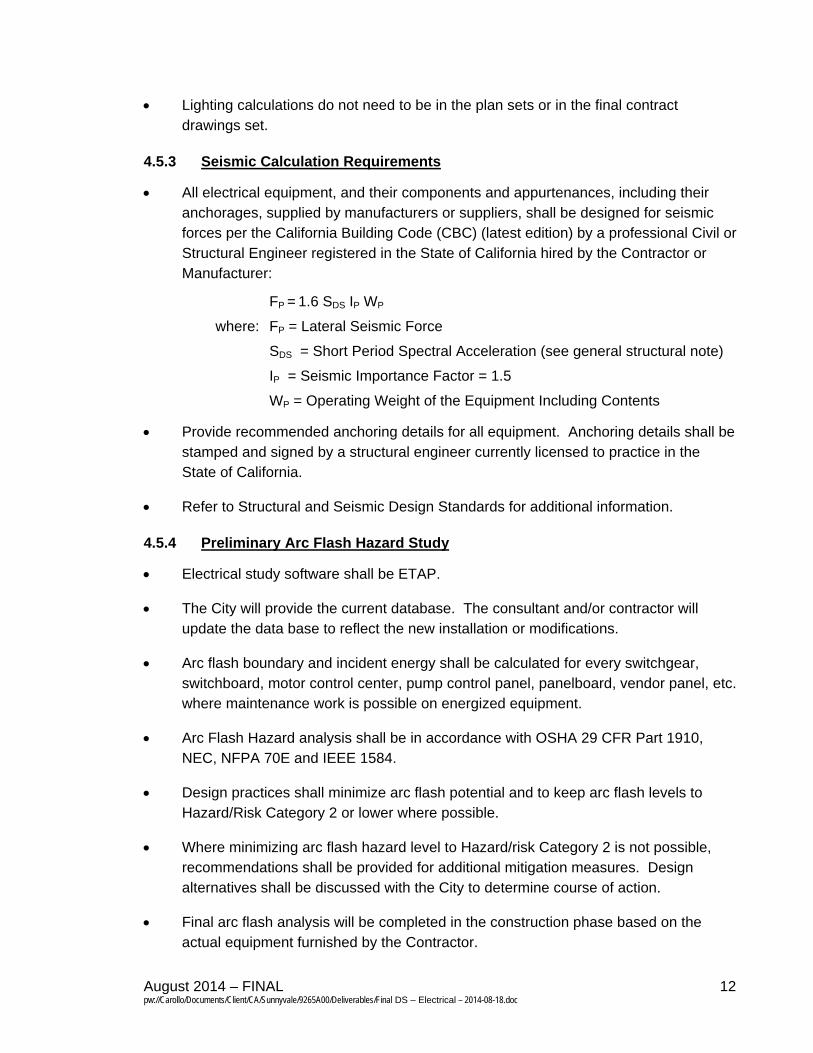
Lighting calculations do not need to be in the plan sets or in the final contract drawings set.
4.5.3 Seismic Calculation Requirements
All electrical equipment, and their components and appurtenances, including their anchorages, supplied by manufacturers or suppliers, shall be designed for seismic forces per the California Building Code (CBC) (latest edition) by a professional Civil or Structural Engineer registered in the State of California hired by the Contractor or Manufacturer:
FP = 1.6 SDS IP WP
where: FP = Lateral Seismic Force
SDS = Short Period Spectral Acceleration (see general structural note)
IP = Seismic Importance Factor = 1.5
WP = Operating Weight of the Equipment Including Contents
Provide recommended anchoring details for all equipment. Anchoring details shall be stamped and signed by a structural engineer currently licensed to practice in the State of California.
Refer to Structural and Seismic Design Standards for additional information.
4.5.4 Preliminary Arc Flash Hazard Study
Electrical study software shall be ETAP.
The City will provide the current database. The consultant and/or contractor will update the data base to reflect the new installation or modifications.
Arc flash boundary and incident energy shall be calculated for every switchgear, switchboard, motor control center, pump control panel, panelboard, vendor panel, etc. where maintenance work is possible on energized equipment.
Arc Flash Hazard analysis shall be in accordance with OSHA 29 CFR Part 1910, NEC, NFPA 70E and IEEE 1584.
Design practices shall minimize arc flash potential and to keep arc flash levels to Hazard/Risk Category 2 or lower where possible.
Where minimizing arc flash hazard level to Hazard/risk Category 2 is not possible, recommendations shall be provided for additional mitigation measures. Design alternatives shall be discussed with the City to determine course of action.
Final arc flash analysis will be completed in the construction phase based on the actual equipment furnished by the Contractor.
August 2014 – FINAL 13 pw://Carollo/Documents/Client/CA/Sunnyvale/9265A00/Deliverables/Final DS – Electrical – 2014-08-18.doc
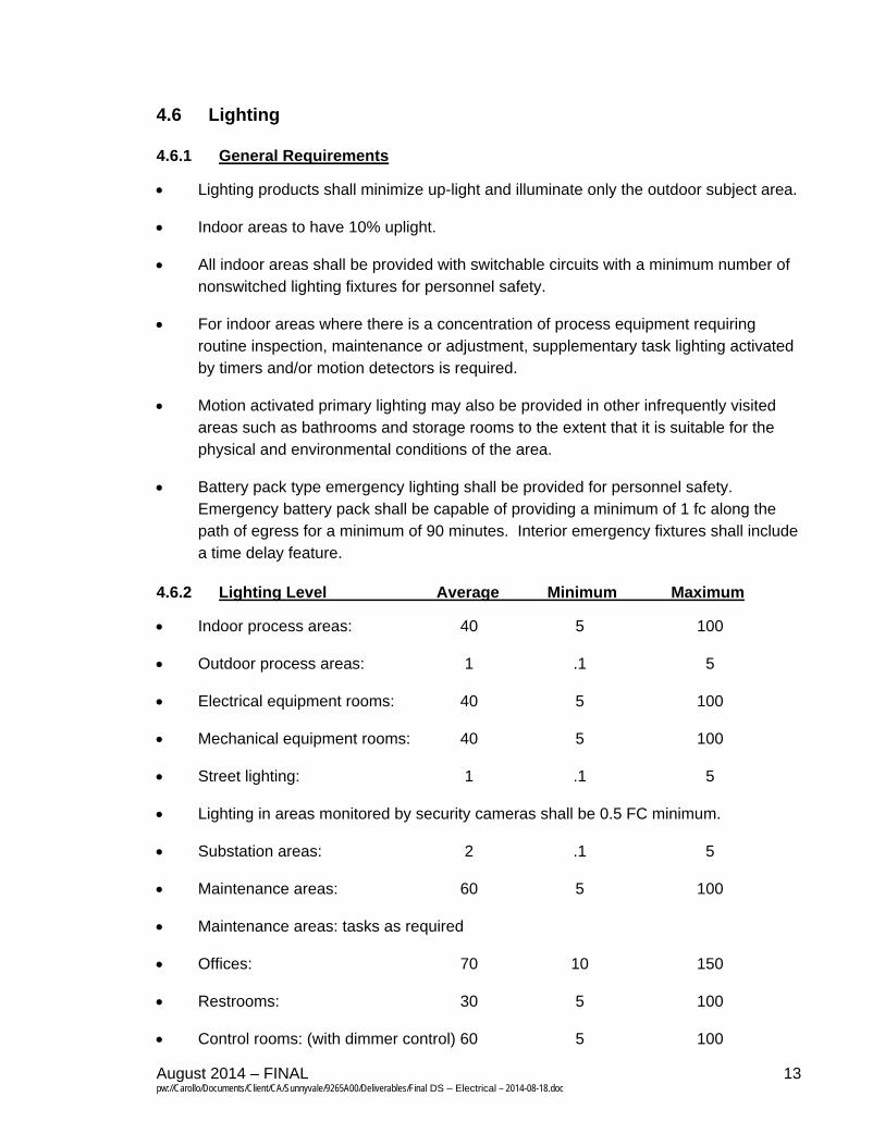
4.6 Lighting
4.6.1 General Requirements
Lighting products shall minimize up-light and illuminate only the outdoor subject area.
Indoor areas to have 10% uplight.
All indoor areas shall be provided with switchable circuits with a minimum number of nonswitched lighting fixtures for personnel safety.
For indoor areas where there is a concentration of process equipment requiring routine inspection, maintenance or adjustment, supplementary task lighting activated by timers and/or motion detectors is required.
Motion activated primary lighting may also be provided in other infrequently visited areas such as bathrooms and storage rooms to the extent that it is suitable for the physical and environmental conditions of the area.
Battery pack type emergency lighting shall be provided for personnel safety. Emergency battery pack shall be capable of providing a minimum of 1 fc along the path of egress for a minimum of 90 minutes. Interior emergency fixtures shall include a time delay feature.
4.6.2 Lighting Level Average Minimum Maximum
Indoor process areas: 40 5 100
Outdoor process areas: 1 .1 5
Electrical equipment rooms: 40 5 100
Mechanical equipment rooms: 40 5 100
Street lighting: 1 .1 5
Lighting in areas monitored by security cameras shall be 0.5 FC minimum.
Substation areas: 2 .1 5
Maintenance areas: 60 5 100
Maintenance areas: tasks as required
Offices: 70 10 150
Restrooms: 30 5 100
Control rooms: (with dimmer control) 60 5 100

August 2014 – FINAL 14 pw://Carollo/Documents/Client/CA/Sunnyvale/9265A00/Deliverables/Final DS – Electrical – 2014-08-18.doc
4.6.3 Light Fixtures
Outdoor lighting fixtures shall be Light Emitting Diode (LED) type. Provide full cutoff fixtures that have no direct uplight (no light emitted above horizontal).
Poles shall be designed to withstand 100 miles per hour wind force with specified fixtures.
Indoor low and high-bay fixtures shall be Light Emitting Diode (LED) type.
Architecturally finished office type areas shall be provided with standard recessed Light Emitting Diode (LED) troffer or where recessed lighting is impractical, wrap-around, surface mounted Light Emitting Diode (LED) as applicable.
Storage closets and similar space and usage areas shall be provided with Light Emitting Diode (LED) fixtures.
Emergency lighting adequate for safe movement shall be provided in all interior areas. Self contained battery packs with LED type lamps are required. 1 FC along the path of egress is required with .1 minimum.
Self illuminating type exit lights are required
Stairway lighting shall be LED.
Provide receptacles for portable task lighting at indoor and outdoor equipment areas.
Provide equipment numbers on all light poles/lamps including all area and street lighting.
Light fixtures shall be rated for the environment in which they are to be installed.
The light fixtures shall be standardized after first project.
4.6.4 Controls
Indoor non-process areas shall have occupancy sensor activated lighting. Occupancy sensor shall be dual-technology type.
Indoor process areas shall have programmable timer control (minimum 10 hour duration) switches.
Provide day lighting control where applicable.
Outdoor lights shall have automatic lighting controls based on photocell and time of day control.
Photocells hall be mounted at 6 to 10 feet above ground. On the north side of the building where possible.
August 2014 – FINAL 15 pw://Carollo/Documents/Client/CA/Sunnyvale/9265A00/Deliverables/Final DS – Electrical – 2014-08-18.doc
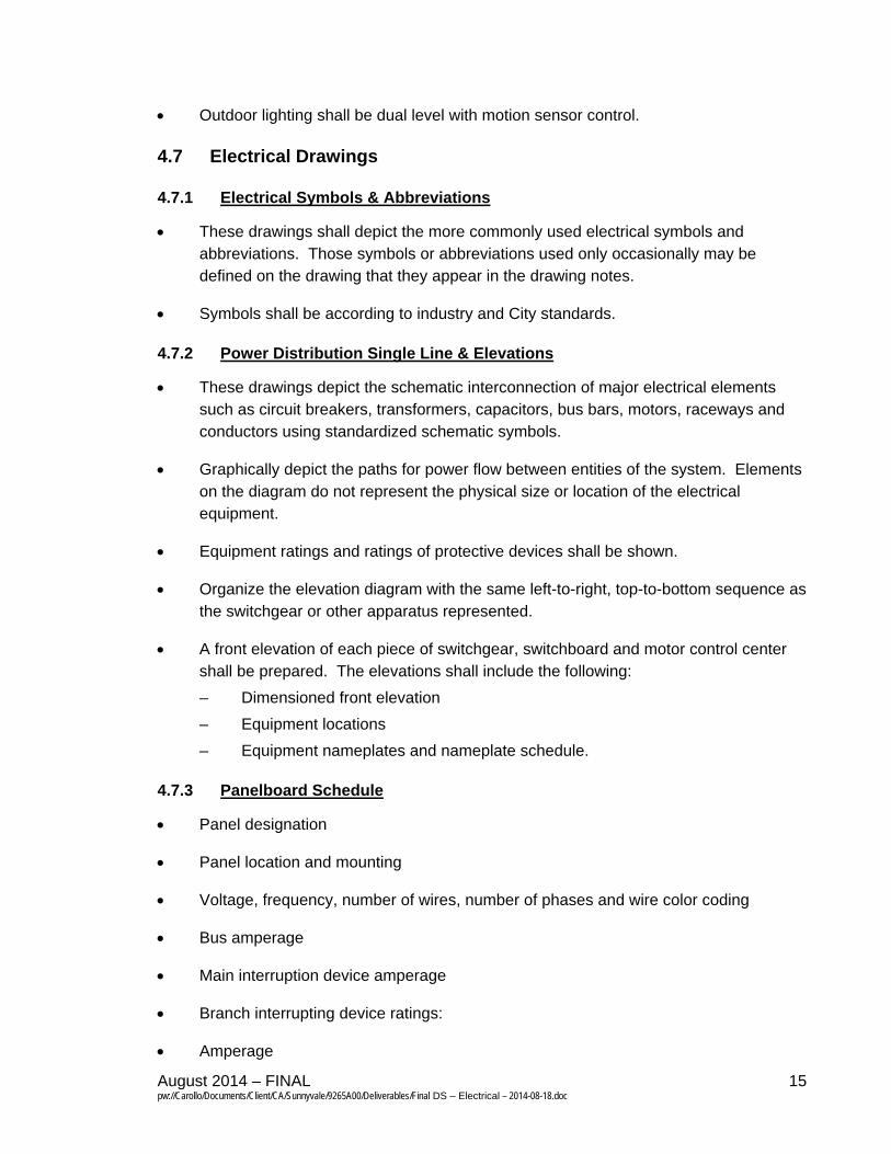
Outdoor lighting shall be dual level with motion sensor control.
4.7 Electrical Drawings
4.7.1 Electrical Symbols & Abbreviations
These drawings shall depict the more commonly used electrical symbols and abbreviations. Those symbols or abbreviations used only occasionally may be defined on the drawing that they appear in the drawing notes.
Symbols shall be according to industry and City standards.
4.7.2 Power Distribution Single Line & Elevations
These drawings depict the schematic interconnection of major electrical elements such as circuit breakers, transformers, capacitors, bus bars, motors, raceways and conductors using standardized schematic symbols.
Graphically depict the paths for power flow between entities of the system. Elements on the diagram do not represent the physical size or location of the electrical equipment.
Equipment ratings and ratings of protective devices shall be shown.
Organize the elevation diagram with the same left-to-right, top-to-bottom sequence as the switchgear or other apparatus represented.
A front elevation of each piece of switchgear, switchboard and motor control center shall be prepared. The elevations shall include the following:
– Dimensioned front elevation
– Equipment locations
– Equipment nameplates and nameplate schedule.
4.7.3 Panelboard Schedule
Panel designation
Panel location and mounting
Voltage, frequency, number of wires, number of phases and wire color coding
Bus amperage
Main interruption device amperage
Branch interrupting device ratings:
Amperage
August 2014 – FINAL 16 pw://Carollo/Documents/Client/CA/Sunnyvale/9265A00/Deliverables/Final DS – Electrical – 2014-08-18.doc
Number of poles
Magnitude of load on branch circuit
Description of branch circuit load
Total load per phase
25 percent adder for continuous loads
Total load
Current per phase
Special requirements:
– GFI breakers
– Heating, Air Conditioning and Refrigeration (HACR) breakers
– Padlocking attachments
4.7.4 Electrical Details
Detailed drawings shall provide general electrical installation requirements. Additional details may be provided for a project specific installation.
Details shall provide the information needed to understand the construction in three dimensions.
Electrical detail drawings shall be drawn according to a set of conventions, which include all necessary views (plan, section, elevation etc.), sheet references, units of measurement and scales, annotation and cross referencing.
Provide a detail for any special connections to equipment. Detail shall show conduit final termination requirements, local junction boxes, wireway, conduit mounting and flexible conduit.
Provide conduit transition details through grade (concrete and earth), horizontal and vertical, per area designation (corrosive and non-corrosive) and final connection.
4.7.5 Site Plan
Overall Plan
– Site plan shall show a representation of the arrangement of buildings, parking, drives, major electrical equipment and any other structure that is part of the project.
– Scaled plan shall show the entire site with conduit routes, conduit identification, area classifications, equipment names and tag references. All outdoor
August 2014 – FINAL 17 pw://Carollo/Documents/Client/CA/Sunnyvale/9265A00/Deliverables/Final DS – Electrical – 2014-08-18.doc
equipment, pull boxes, building, utility equipment, shall be shown with conduit routes related to power, utility feeds, instrumentation and controls.
Area site plans
– Ductbank, Pullbox and vault plan:
Depict routing of all underground ductbanks, major and minor.
Show location, tag name and size, of all underground pullboxes and vaults.
Power distribution and grounding: Provide drawing of each area provided to show the location of each piece of equipment, device, instrument, junction box, terminal box and yard box required for a complete electrical installation. Raceway and cable sizes are not required to be shown on these drawings; designated raceway routings however shall be shown on the drawings. Duct bank sections of routing shall be shown. Raceway and cable sizes shall be identified on separate conduit and cable schedules. Show demolition where applicable.
– Area site plans may not be needed for smaller projects.
4.7.6 Schedules
Ductbank Schedule
– Provide sections with conduit size, quantity, spacing, and overall dimensions.
Conduit Schedule
– Show in the contract drawings.
– Columns depicting: Conduit number, from, to, size, wire fill and notes.
– Conduit type and fill shall not be called out directly on the Plan drawings.
– Generic conduit schedule may be used for smaller conduits.
Lighting Fixture Schedule
– The fixture schedule shall define each type of lighting fixture used on the project. The schedule shall describe the type of fixture, voltage, materials of construction, lumen distribution, mounting, accessories and acceptable manufacturers.
– The lighting schedule shall be shown on the drawings.
4.7.7 Building Power and Control Plan
The scaled plans shall show all electrical equipment, conduit routes, conduit identification, area classifications, equipment names and tag references. All equipment related to power, instrumentation and controls shall be shown.
August 2014 – FINAL 18 pw://Carollo/Documents/Client/CA/Sunnyvale/9265A00/Deliverables/Final DS – Electrical – 2014-08-18.doc
4.7.8 Building Lighting and Receptacle Plan
The scaled plan shall show locations of lights, receptacles, switches, smoke detectors, and miscellaneous other devices not included on the power and control plan. Lighting plan shall meet State of California Title 24 requirements.
Drawings shall depict the location and mounting requirement for each lighting fixture, receptacle, switches, exit sign, battery pack emergency lighting and communications device within each building. Fixtures shall be identified by type, panelboard, circuit and switch.
4.7.9 Communication Plan
Communications and other plans where needed for clarity, but maybe included on other plans if clearly depicted.
4.7.10 Cathodic Protection Plan
Provide drawing indicating the location of all components that make up the cathodic protection system.
4.7.11 Control Elementary Diagrams
Schematic diagrams depicting control wiring for motor controllers, control panels and miscellaneous control devices shall be provided.
4.8 Technical Specifications
The following specifications are suggested to be used on all design projects where applicable. The list shall be used as a guide to complete the overall project specifications. Specifications will use CSI format.
Electrical: Basic Requirements
Seismic Bracing Systems
Grounding
Acceptance Testing
Wire and Cable: 600 Volt and Below
Medium Voltage Cable
Low Voltage Busway
Heat Tracing Cable
Raceways and Boxes
August 2014 – FINAL 19 pw://Carollo/Documents/Client/CA/Sunnyvale/9265A00/Deliverables/Final DS – Electrical – 2014-08-18.doc
Cable Tray
Electrical: Exterior Underground
Wiring Devices
Motors
Engine Generator: Diesel
Battery and Battery Charging Systems
Static Uninterruptible Power Supply System
Variable frequency Drives: Low Voltage
Variable Frequency Drives: Medium Voltage
Reduced Voltage Solid State Starters – Low Voltage
Distribution Transformers
Power Factor Correction Equipment
Medium Voltage Metal-Clad Switchgear {and Motor Control Center)
Unit Substation
Power Distribution Center
Safety Switches
Transfer Switches
Separately Mounted Circuit Breakers
Switchgear
Switchboards
Panelboards
Motor control Equipment
Automatic Throwover System
Dry Type Transformers
Package Power Supply
Overcurrent and Short Circuit Protective Devices
August 2014 – FINAL 20 pw://Carollo/Documents/Client/CA/Sunnyvale/9265A00/Deliverables/Final DS – Electrical – 2014-08-18.doc
Low Voltage Surge Protection Devices (SPD)
Electrical Metering Devices
Control Equipment Accessories
Interior and Exterior Lighting
Low Voltage Lighting Control System
5.0 REFERENCES
None
6.0 ATTACHMENTS
None