Embed Size (px)
Citation preview

1 Revised February 2021
CITY OF BURLINGTON STANDARD SPECIFICATIONS

CITY OF BURLINGTON STANDARD SPECIFICATIONS
General
2 Revised February 2021
GENERAL
This document stipulates the requirements for construction work within the public right-of-way, in the City of Burlington. These standards apply to all work on public lands in the City of Burlington. Additional conditions and specifications may be imposed for any work within MTO governed lands, the regulated boundary of Conservation Halton, and the Niagara Escarpment Commission Boundaries. This includes construction activities, as well as excess/surplus materials for disposal and/or re-use off-site.
ONTARIO PROVINCIAL STANDARDS All work shall be carried out in accordance with the Ontario Provincial Standards (OPS) as referenced herein or in the Contract Documents and Drawings. The City of Burlington Construction Specifications are supplemental to the Ontario Provincial Standards and thus take precedence over the Ontario Provincial Standard Specifications (OPSS) or Ontario Provincial Standard Drawings (OPSD) when specified.
SPECIAL PROVISIONS City of Burlington Construction Specifications and Ontario Provincial Standards may be altered on a project via Special Provisions as indicated in the Contract Documents.
AGENCIES OF PARTNERSHIP
• The City of Burlington is a municipality within Halton Region and has working partnerships with the following agencies:
• Halton Region (ROH)
• Conservation Halton (CH)
• Ministry of Transportation of Ontario (MTO)
• Niagara Escarpment Commission (NEC)
• Burlington Hydro (BHI)
• Union Gas (UG)
• Trans Northern Pipeline (TNPL)
• Communication Companies – Bell, Cogeco, Rogers, Allstream, Telus In addition to the specifications set out in this document, Contractors should be familiar with these agencies’ standards, specification, and conditions for work as they may be applied as indicated in the contract documents.
CITY OF BURLINGTON STANDARD SPECIFICATIONS
General
3 Revised February 2021
DEFINITIONS See City of Burlington General Conditions Section 101.

CITY OF BURLINGTON STANDARD SPECIFICATIONS
Revisions
4 Revised February 2021
STANDARD SPECIFICATIONS REVISIONS TRACKER
Major 2021 Revisions
ID No. Specification Revision Detail
A.2.1 Site Trailer Language revised.
A.2.2 Portable Restroom New specification.
A.5 Construction Layout Language revised.
B.2 Tree Removal Changed dbh size requirement.
B.7 Remove Asphalt via Cold Planing Added 0-50mm butt joint item and payment language.
B.8 Remove Concrete Sidewalk and Bus Bays Language revised.
C.1 Storm Pipe Installation Lateral Drain language added. Spot repair payment language added.
C.1 Storm Pipe Installation Added language regarding "full pipe" placement.
C.1 Storm Pipe Installation Edited OPSS reference to native soils.
C.5 CCTV Storm Sewer Inspection Added items for Pre, Post, and Spot Repair CCTV language.
C.10 Core Subdrain Hole for Catch Basin Connection New specification.
G.3 Concrete Works Language revised, Re: High early and curing.
G.3.1 Concrete Curbs, Curb and Gutter Language revised, Re: High early and curing.
G.3.2 Concrete Sidewalks and Bus Stop Bays Language revised, Re: High early and curing.
G.4.2 Hot Mix Asphalt - Materials Material testing and sampling language added.
G.4.6 Temporary Asphalt Pavement New specification.
G.8 Tactile Plates Full specification replacement.
H.1.1 Temporary Pavement Markings New specification.
H.1.2 Permanent Pavement Markings New specification.
H.1.3 Durable Pavement Markings New specification.
H.2 Traffic Signs New specification.
J.1 Private Property Restoration Language added, re: interlock driveway restoration.

CITY OF BURLINGTON STANDARD SPECIFICATIONS
Table of Contents
5 Revised February 2021
TABLE OF CONTENTS
Table of Contents
GENERAL ....................................................................................................................... 2
STANDARD SPECIFICATIONS REVISIONS TRACKER ............................................... 4
TABLE OF CONTENTS .................................................................................................. 5
Section A – Site Preparation & Miscellaneous Works ..................................................... 9
A.1 Mobilization & Demobilization ........................................................................... 9
A.2.1 Site Trailer ......................................................................................................... 9
A.2.2 Portable Restroom .......................................................................................... 11
A.3 Insurance ........................................................................................................ 12
A.4 Traffic Control and Maintenance ..................................................................... 12
A.5 Construction Layout ........................................................................................ 13
A.6 Install Project Sign Boards .............................................................................. 14
A.7 Tree Protection ................................................................................................ 14
A.8 Silt Logs .......................................................................................................... 15
A.9 Vacuum Excavation ........................................................................................ 15
A.10 Hand Dig Test Pit ............................................................................................ 16
A.11 Temporary Cold Patch .................................................................................... 17
A.12 Calcium Flake Dust Suppressant .................................................................... 17
A.13 Premium Surcharge for High Early Concrete (PROVISIONAL)....................... 17
A.14 Supply and place sediment control units on exist. CB Inlet ............................. 18
A.15 Street Cleaning ............................................................................................... 18
A.16 Structure Cleaning .......................................................................................... 19
Section B - Removals .................................................................................................... 20
B.1 Clear & Grub ................................................................................................... 20
B.2 Tree Removal .................................................................................................. 20
B.3 Stumping ......................................................................................................... 21

CITY OF BURLINGTON STANDARD SPECIFICATIONS
Table of Contents
6 Revised February 2021
B.4 Remove of Curb and Gutter ............................................................................ 22
B.5 Remove Pipe and Subdrain ............................................................................ 23
B.6 Remove Hydrants, Valves & Watermain Appurtenances ................................ 23
B.7 Remove Asphalt via Cold Planing ................................................................... 23
B.8 Remove Concrete Sidewalk and Bus Pads ..................................................... 25
B.9 Asphalt Removal (roadways and driveways)................................................... 26
B.10 Remove Concrete Road Base ......................................................................... 26
Section C – Storm Sewer Works ................................................................................... 27
C.1 Storm Pipe Installation .................................................................................... 27
C.2 Maintenance Holes, Catch Basins & Ditch Inlets ............................................ 29
C.3 Frames & Covers ............................................................................................ 30
C.4 Adjust Maintenance Holes & Catch Basins ..................................................... 31
C.5 CCTV Storm Sewer Inspection ....................................................................... 33
C.6 Lower Existing Water Services – Storm Sewer Conflict .................................. 35
C.7 Relay / Reconnect Sanitary Laterals – Storm Sewer Conflict ......................... 36
C.8 Transfer Existing Storm Lateral/Lead .............................................................. 36
C.9 Subdrain .......................................................................................................... 36
C.10 Core Subdrain Hole for Catch Basin Connection ............................................ 37
Section D – Bridge Works ............................................................................................. 38
Section E – Watermain Works ...................................................................................... 39
Section F – Sanitary Sewer Works ................................................................................ 40
Section G – Road Works ............................................................................................... 41
G.1 Excavation....................................................................................................... 41
G.2 Granular Materials & Soils .............................................................................. 41
G.3 Concrete Works .............................................................................................. 44
G.3.1 Concrete Curbs, Curb and Gutter ............................................................. 45
G.3.2 Concrete Sidewalks & Bus Stop Bays ...................................................... 47
G.3.3 Concrete Speed Humps ........................................................................... 49
G.3.4 Coloured / Impressed Concrete ................................................................ 50

CITY OF BURLINGTON STANDARD SPECIFICATIONS
Table of Contents
7 Revised February 2021
G.3.5 Concrete Bench Pad Materials ................................................................. 51
G.4 Hot Mix Asphalt Works .................................................................................... 51
G.4.1 General ..................................................................................................... 51
G.4.2 Materials ................................................................................................... 51
G.4.3 Asphalt Paving and Placement ................................................................. 54
G.4.4 Commercial, Industrial & Multi-Residential Driveways .............................. 56
G.4.5 Residential Driveways .............................................................................. 56
G.4.6 Temporary Asphalt Pavement (PROVISIONAL) ....................................... 57
G.5 Adjust Existing Water Valves .......................................................................... 57
G.6 Fine Grade Roadway ...................................................................................... 59
G.7 Concrete Water Valve and Water Valve Chamber Adjustment ....................... 59
G.8 Tactile Plates ................................................................................................... 60
G.9 Topsoil and Sod .............................................................................................. 61
Section H – Pavement Markings & Traffic Signage ....................................................... 62
H.1 Pavement Markings ........................................................................................ 62
H.1.1 Temporary Pavement Marking ................................................................. 62
H.1.2 Permanent Pavement Marking ................................................................. 62
H.1.3 Durable Pavement Marking ...................................................................... 63
H.2 Traffic Signs .................................................................................................... 63
H.2.1 Specialized Sign Installation Hardware .................................................... 64
H.2.2 Sign Supports ........................................................................................... 65
Section I – Electrical Works ........................................................................................... 68
I.1 Street Lighting Works ....................................................................................... 69
PART I - TRAFFIC SIGNALS -- UNDERGROUND .................................................... 73
PART II - TRAFFIC SIGNAL ABOVE GROUND ........................................................ 77
PART III – TEMPORARY AND/OR OVERHEAD SIGNAL INSTALLATION .............. 85
PART IV - TRAFFIC SIGNAL CABLE ........................................................................ 87
PART V - TRAFFIC SIGNAL COMMUNICATION CABLE ......................................... 90
PART VI - MATERIAL SUPPLIERS ........................................................................... 91
CITY OF BURLINGTON STANDARD SPECIFICATIONS
Table of Contents
8 Revised February 2021
Section J – Landscaping & Private Property Restoration .............................................. 94
J.1 Remove & Reinstate / Replace Private Property Works ................................. 94
J.2 Tree Planting & Transplanting ......................................................................... 95
J.3 Mature Tree Pruning & Fertilizing .................................................................. 103
J.4 Topsoil & Sod ................................................................................................ 103
J.5 Seed & Mulch with 150mm Topsoil ............................................................... 106
J.6 Timber Bollards ............................................................................................. 107
J.7 Metal Hinged Bollards ................................................................................... 107
J.8 Decorative Litter Receptacle ......................................................................... 108
J.9 Concrete Litter Receptacle ............................................................................ 108
J.10 Street Bench ................................................................................................. 109
J.11 Armour Stone .............................................................................................. 110

CITY OF BURLINGTON STANDARD SPECIFICATIONS
Section A: - Site Preparation & Miscellaneous Works
9 Revised February 2021
Section A – Site Preparation & Miscellaneous Works
This section covers the requirements as set out in the contract documents, to prepare the site for construction activities to commence.
A.1 Mobilization & Demobilization
Scope Mobilization shall include all of the contractor’s costs to facilitate bringing equipment, materials, manpower etc. to the project site throughout the duration of the work for all items of work in the contract. Demobilization shall include all of the contractor’s costs to remove all equipment, left over materials, construction waste, traffic control devices, signs or any other materials that are a result of construction activity.
Basis of Payment Payment shall be 50% lump sum for mobilization and 50% lump sum for demobilization unless otherwise stated in the special provision of the contract. Payment shall be full compensation for all labour, materials and equipment required to facilitate Mobilization and Demobilization as specified in the Contract Documents. This applies to all projects, regardless of duration, staging, or year carry-over.
A.2.1 Site Trailer
Scope The Contractor shall supply and furnish an Inspector’s Field Office in accordance with Section 105-9 of the General Conditions of Contract. Construction Activities cannot commence until the trailer item, as specified, has been set
up with power.
The following additional equipment is to be supplied within the Inspector’s Field Office for his/her exclusive use.
• a supply of fresh cold drinking water

CITY OF BURLINGTON STANDARD SPECIFICATIONS
Section A: - Site Preparation & Miscellaneous Works
10 Revised February 2021
• a flush type portable restroom meeting the requirements of the Occupational Health & Safety Act shall be provided in the area of the field office for the exclusive use of City staff. The Contractor shall maintain and service the portable toilet on a weekly basis.
• a working fire extinguisher mounted next to all entrances
• a supply of working smoke alarm and a working carbon monoxide detector
• a properly equipped and maintained first aid kit
• adequate heating and air-conditioning to maintain the trailer at 22°C
• one wastepaper basket.
• one angle broom with dustpan.
• one microwave
• one small refrigerator.
• electrical supply - The Contractor shall provide a continuous supply of electricity to the office trailer, 24 hours a day, or as a minimum, during business hours if temperature requirements can be maintained, from the start of construction to completion. Power supply can be in the form of a quiet diesel generator, or direct hook up to a nearby power supply. All trailers must have a dedicated 20-amp circuit and accessible outlet for the charging of all-electric and plug-in hybrid cars.
Burlington Hydro (BHI) is the governing electrical authority and the Contractor shall contact BHI to understand all requirements and costs to make the electrical connection. The Contractor shall service, maintain, and carry insurance on the field office and contents and provide evidence of insurance to the Contract Administrator before work commences. The windows of the trailer must be protected by bars, cage, or equivalent.
Under no circumstances shall the field office be used for the storage of tools or materials or for the Contractor’s use, with the exception of regularly scheduled site meetings. The field office shall be cleaned, and garbage shall be disposed of weekly to the satisfaction of the Contract Administrator. Site trailer must be of adequate size to accommodate the Inspector office space, as outlined in Section 105-9 of the General Conditions, and an area to hold site meetings, which will include a minimum of one table and eight chairs. In the case of a joint Region-City project, additional space and furnishings must be provided. In addition to the 2.4m x 2.4m space allocated for the City Inspector, a space of the same size must be allocated for the sole use of an additional Inspector. This area must include a minimum 0.9m x 1.5m desk with shelves and/or drawers and chair. Any costs associated with tree hoarding, or environmental controls that may be required due to the location of the trailer site and laydown/staging area, shall be included in the trailer item. Supply, installation, maintenance, removal and all restoration required at the

CITY OF BURLINGTON STANDARD SPECIFICATIONS
Section A: - Site Preparation & Miscellaneous Works
11 Revised February 2021
location of the site trailer and laydown/staging area shall be included under the trailer item.
Basis of Payment Payment shall be lump sum and be full compensation for all labour, materials, equipment required. Removal and disposal of all materials required to accommodate the trailer placement, laydown area, compound, the maintenance thereof, and all restoration, topsoil and sod or other, shall be included in this item. Payment shall be paid as follows:
• Initial set up of Site Trailer – 20%
• And then progressively in monthly draws - 80%
A.2.2 Portable Restroom
A heated portable restroom with running water and a flush-type toilet, meeting the requirements of the Occupational Health & Safety Act, shall be provided in the area of the field office for the exclusive use of City staff. In the situation that a field office is not feasible, a restroom will be provided and located in a suitable location. The Contractor shall maintain and service the portable restroom on a weekly basis.
Removal and disposal of all materials required to accommodate the portable restroom placement, the maintenance thereof, and all restoration, topsoil and sod or other, shall be included in this item
Basis of Payment
Payment shall be lump sum and be full compensation for all labour, materials, equipment required.
Payment shall be paid as follows:
•Initial set up of portable washroom –20%
•And then progressively in monthly draws -80%

CITY OF BURLINGTON STANDARD SPECIFICATIONS
Section A: - Site Preparation & Miscellaneous Works
12 Revised February 2021
A.3 Insurance
Scope Insurance requirements are specified in City of Burlington General Conditions section 103.
Basis of Payment Lump sum payment for Insurance shall be made on the first payment certificate and shall be full compensation for all costs associated to meet the insurance requirements specified.
A.4 Traffic Control and Maintenance The requirements of OPSS.MUNI 706 shall apply shall apply except as modified herein. The Contractor shall be solely responsible for the supply, placement, maintenance, and removal of all temporary traffic control measures within the limits of Construction as defined in the Ontario Traffic Manual (OTM), Book 7 (Temporary Conditions) and for all intersecting streets for the entire length and duration of the project. Traffic control measures shall include, but not be limited to, all temporary construction signs, delineators, flashers, barricades, Traffic Control Persons (TCP's) required to comply with the requirement of the Ontario Traffic Control Manual (OTM), Book 7 (Temporary Conditions). The Contractor shall ensure that each employee is familiar with the manual and wears all required safety equipment. Traffic Control Plans The contractor is required to submit to the City, prior to start of construction, a Traffic Control Plan that outlines how traffic will be controlled through each stage of the work and shall include provisions for cyclists, pedestrians and accessibility requirements.

CITY OF BURLINGTON STANDARD SPECIFICATIONS
Section A: - Site Preparation & Miscellaneous Works
13 Revised February 2021
Maintenance of Temporary Work
Until the final course of asphalt and the permanent pavement markings have been placed, the travelled portion of the road shall be considered as temporary traffic lanes.
Temporary traffic lanes shall be maintained so that there are no irregularities exceeding 35 mm. Utility frames and covers, valve boxes, etc. shall be covered over with a steel plate ramped with asphalt or maintained flush with the surface of the asphalt. After final adjustment to finish grade, the appurtenances shall be ramped as described above. Prior to the placement of the final course of hot mix asphalt, the ramps must be removed without disturbing the base to allow the final course asphalt to be placed to its full depth.
Should the Contractor fail to correct any unsatisfactory condition upon notification from the Contract Administrator to do so, the Contract Administrator may proceed to maintain the project and deduct the entire cost of such maintenance from moneys due to the Contractor.
Basis of Payment Payment shall be lump sum and be full compensation for all labour, materials, equipment required and shall be paid as follows:
• Initial set up of roadway construction signage, barrels etc. – 20%
• And then progressively in monthly draws - 80%
A.5 Construction Layout
Scope The Contractor is responsible to provide construction layout for items in the Contract Documents. Layout in the field shall be in the form of a wooden stake, nail, or equivalent marking the physical location and an offset location on the ground. A grade sheet shall accompany the field layout and one copy of the grade sheet shall be provided to the City Inspector prior to construction. The Contractor shall provide construction layout for the following items:
• Excavation/Widening
• Granular A and Granular B Road Grading
• Sidewalk, Curb, Curb/Gutter
• Storm Structures
• Storm Pipe
• Electrical Poles, Boxes, Fixtures

CITY OF BURLINGTON STANDARD SPECIFICATIONS
Section A: - Site Preparation & Miscellaneous Works
14 Revised February 2021
Prior to construction the contractor is responsible to ensure layout is relative to City of
Burlington site specific horizontal control points and vertical benchmarks. Points and
benchmarks will be provided by the contract administrator or will be identified in the
contract drawings. The contractor shall provide the contract administrator with a
GNSS survey report and coordinates of the control points c/w existing “check shot”
accuracies prior to commencing construction layout.
• City of Burlington Coordinate system: UTM17 NAD83 (Original)
• City of Burlington Vertical datum: Canadian Geodetic Vertical Datum of 1928, 1978
adjustment (CGVD-1928:1978)
Basis of Payment The Contractor will be paid for layout progressively based on a lump sum price for the item. The duration of the project (# of months) will be divided by the lump sum price and the value for each month will be paid as a fraction of the total lump sum price until 100% of the lump sum has been compensated. Payment shall be full compensation for all labour, materials, and equipment required to facilitate Construction Layout as specified in the Contract Documents.
A.6 Install Project Sign Boards
Scope This item shall be used for the installation of site-specific project sign boards, as identified in the contract. Signs shall be erected in locations directed by the Contract Administrator and shall remain standing for the duration of the project. Photographic documentation of the erected signs shall be the Contractor’s responsibility and is to be provided to the Contract Administrator for verification.
Basis of Payment Payment shall be full compensation for all labour, materials, and equipment required to facilitate the installation and removal of project sign boards, as specified in the Contract Documents.
A.7 Tree Protection The requirements of COB Standard Specification SS-12 (found at www.burlington.ca) shall apply, except as amended herein;

CITY OF BURLINGTON STANDARD SPECIFICATIONS
Section A: - Site Preparation & Miscellaneous Works
15 Revised February 2021
Page 3, Section 6b) Modu-Loc fencing will not be allowed as an acceptable alternative to the materials and installation requirements outlined in “Tree Protection Barrier”, i.e. t-posts, 2x4 lumber, snow fencing, unless approved by the Contract Administrator.
A.8 Silt Logs
Scope The contractor shall supply, place, and, maintain Terrafix Siltsoxx, or approved equivalent product, as an erosion and sediment control measure where specified on the contract drawings. The silt logs shall buffer the edge of construction and be staked in place as per the manufacturer’s specifications for installation. No materials or equipment shall be stored, stockpiled or staged outside the silt log barrier. The silt log shall have no foreign materials laying on it or abutting it and shall be maintained throughout construction and stabilization period.
Basis of Payment Payment by the lineal metre shall be full compensation for all labour, materials, and equipment required to facilitate the Silt Log item.
A.9 Vacuum Excavation
Scope Hydrovac units shall be used when requested by the City to daylight utilities, tree roots, or for any other excavation requested by the City. The contractor shall not use the Hydrovac item unless prior approval has been provided by the City. If locates provided to the contractor show underground utilities that were not illustrated on the contract drawings within areas of excavation, the hydrovac item may be used. Where practical, the City will expect the use of the “Hand Dig” item for utility locate rather than use of the hydrovac truck.
Equipment The Hydrovac Equipment shall possess the following minimum requirements;
• measurable water pressure adjustment

CITY OF BURLINGTON STANDARD SPECIFICATIONS
Section A: - Site Preparation & Miscellaneous Works
16 Revised February 2021
• 175 cubic metre per minute positive displacement vacuum blower system
• 5 cubic metre water tank
• 8 cubic metre debris containment system
• Diesel (or comparable) burner system able to supply hot water rapidly in large amounts
• Neoprene wand heads and excavating tubes, complete with rubber coatings to protect buried infrastructures
• 150mm hose with 60 metre of remote capability, immediately available
Crew The Hyrdovac company shall provide Two (2) operators with the truck. One operator shall operate the vacuum hose, while the second operates the wand. The City will not accept Hydrovac services when only one operator is deployed.
Daylighting Tree Roots When excavations are required in the critical root zone (CRZ) the contractor shall daylight the roots with low-pressure vacuum excavation. The City will assess the significance of the tree roots and determine if they can be removed, or if an alternate excavation option is required. If a contractor is found excavating and damaging significant tree roots, financial penalties will be imposed. The penalties will be determined by the City arborist’s economic assessment of the tree and the damage to it.
Basis of Payment Payment shall be full compensation for all labour, equipment, and materials required to perform the work. This will only be compensation for time spent on site. No additional payment will be made for filling, dumping, mechanical downtime, and travel to and from the site.
A.10 Hand Dig Test Pit
Scope This item shall be used to daylight shallow utilities (1.2m or less) that are not shown on the contract drawings, or when the City requests. The utility shall be daylighted by hand excavation and its depth and location shall be recorded or surveyed. The excavation shall be protected at all times and backfilled when no longer required. The City shall approve the quantity of holes to be dug prior to commencement. Basis of Payment

CITY OF BURLINGTON STANDARD SPECIFICATIONS
Section A: - Site Preparation & Miscellaneous Works
17 Revised February 2021
Payment for each hole dug shall be full compensation for all labour, materials, and equipment required to facilitate the item.
A.11 Temporary Cold Patch
Scope The material requirements are as specified in OPSS.MUNI 1153 and the construction requirements are as per OPSS.MUNI 307 except as amended herein: OPSS.MUNI 307.07.03 Placement and Compaction The Contract Administrator will determine when and where temporary cold patch shall be used. Times when the use of cold patch is commonly used are for temporarily ramping pedestrian facilities and filling in potholes in the existing surface during construction.
Basis of Payment Follows OPSS.MUNI 307
A.12 Calcium Flake Dust Suppressant The requirements of OPSS.MUNI 506 shall apply except as amended herein: The contractor shall ensure that an adequate supply of dust suppressant is available on site to facilitate the potential control of dust on the entire site at all times.
Basis of Payment OPSS.MUNI 506.09 Measurement for payment – there will be no compensation for water as use as a dust suppressant. Dust Suppressant paid per tonne shall be full compensation for all labour, materials and equipment required to facilitate dust control as required. Item – Calcium or Magnesium Flake Dust Suppressant
A.13 Premium Surcharge for High Early Concrete (PROVISIONAL)
Scope

CITY OF BURLINGTON STANDARD SPECIFICATIONS
Section A: - Site Preparation & Miscellaneous Works
18 Revised February 2021
When the City requests the use of High-Early concrete, this item shall be used in addition to the concrete item being placed.
Material Material shall be 24 hour high-early concrete and meet the requirements as set out in Section G.3 Concrete Works.
Basis of Payment Payment per cubic metre shall be full compensation for the costs associated to supply the high-early concrete. This item is only the premium increase per cubic metre for high-early, unless specified in the concrete item itself. Copies of the concrete tickets must be submitted.
A.14 Supply and place sediment control units on exist. CB Inlet
The Contractor shall install Siltsack or Flexstorm or approved equivalent Inlet Filters in all storm sewer inlets in accordance with manufacturer’s instructions.
The Contractor shall inspect, repair, and maintain all sedimentation control measures weekly. The Contractor shall remove and dispose of accumulated sediments and debris within the inlet filter as directed by the Inspector and shall clean all catchbasins at the end of the project. Basis of Payment Measurement - Measurement will be made on a pro-rated basis of the percentage of the total contract works completed. Payment for this item of work shall be made as follows:
• 50% for supply, installation, and maintenance
• 50% for removal
The payment for maintenance will be made upon satisfactory condition of the Works and removal of any accumulated sediment at the time of payment.
A.15 Street Cleaning Scope The Contractor shall for the unit price bid, provide all labour and equipment required to clean mud and dust from roads affected by this contract. The roads will be cleaned on Friday afternoon or more often as directed by the Engineer, using a vacuum street
CITY OF BURLINGTON STANDARD SPECIFICATIONS
Section A: - Site Preparation & Miscellaneous Works
19 Revised February 2021
sweeper with mechanical type pickup, followed by a 4-nozzle street flusher to remove the dirt residue. The unit price bid shall also include the disposal of all material collected during the sweeping operation and water. This item shall not, in any way, remove the Contractor’s responsibility for “Mud and Dust Control and Street Maintenance” as outlined in section 107-16 of the General Conditions of Contract, but shall be considered as an added measure over and above these responsibilities. Basis of Payment Payment shall be full compensation for all labour, equipment, and materials required to perform the work. This will only be compensation for time spent on site street cleaning. There will be no duration minimum associated with this item. No additional payment will be made for travel, water fill-up, or dumping of collected materials.
A.16 Structure Cleaning Scope
Once top asphalt and all final adjustments are complete, the Contractor shall remove the sediment and debris from all new and existing structures. This will include all catchbasins, maintenance holes, and water valve chambers. This work will primarily require Hydrovaccing, but may also require that structures are entered, and debris removed by hand or other mechanical means. This work must be carried out with the City Inspector present to verify cleaning is required on each structure and to confirm the cleaning process was completed. Compensation will not be provided for any structures cleaned without City inspection.
Basis of Payment
The unit price bid by each shall be full compensation of all labour, equipment, and material required to complete this work as specified. It will include the removal and disposal of materials removed from all structures.

CITY OF BURLINGTON STANDARD SPECIFICATIONS
Section B - Removals
20 Revised February 2021
Section B - Removals
All construction removals shall follow OPSS.MUNI 510 – “Construction Specification for Removal” unless noted otherwise.
B.1 Clear & Grub
Scope The requirements of OPSS.MUNI.201 apply for all Clearing and Grubbing identified in the Contract unless otherwise amended. The General Contractor and all sub-contractors should be aware of the City of Burlington Tree Protection and Preservation Standard prior to initiating any clearing and grubbing operation. All trees under 300mm diameter shall be included as Clearing & Grubbing works. Stumping will be included in this item and be performed as per Section B.3 Stumping.
Basis of Payment OPSS 201.10 is amended by the following: Item – Clearing and Grubbing is one complete item compensated for by the unit of measure in the contract for all labour, equipment and materials required to clear, grub and remove vegetation from site as indicated in the Contract Documents. Item – Boulder Removal compensated for by each boulder removed as indicated in the Contract Documents. Compensation is from all labour, equipment and materials required to remove and dispose of the boulders. Payment shall be full compensation for all labour, materials, and equipment required to facilitate clearing and grubbing, stumping, and boulder removal as specified in the Contract Documents.
B.2 Tree Removal
Scope Tree removals, as indicated on the Contract Drawings, include the removal of all branches, limbs, trunk, The Contractor shall notify the City prior to removal of trees to

CITY OF BURLINGTON STANDARD SPECIFICATIONS
Section B - Removals
21 Revised February 2021
provide sufficient time for the City’s representative to mark out the trees proposed for removal. Tree diameters are measured at breast height (dbh). Any tree removal shown under 200mm dbh is included under the item for clearing and grubbing. Trees 200mm or larger dbh shall be itemized under tree removal Stumping will be included in this item and be performed as per Section B.3 Stumping. Basis of Payment Payment for each tree removal will include stumping, and shall be full compensation for all labour, materials and equipment required to facilitate tree removal as specified in the Contract Documents. Sod and topsoil fill, added in multiple lifts and firmly tamped between lifts to minimize settling, will be included will be included in this item.
B.3 Stumping
Scope
The contractor is to facilitate the removal of stumps with a stump grinding machine(s) designed specifically for the task of grinding stumps. It shall have the capability (supported with manufacturer specifications) to grind to a minimum depth of 61cm (24in) and have an engine Hp rating not less than 56Hp (41.8kw).
The Contractor will obtain all utility locates in advance of work and all cost(s) associated with obtaining the utility locates will be the Contractors responsibility. In the event that a utility structure or device, utility cable/conduit, or utility related infrastructure is damaged, the contractor shall notify the City representative the same working day of any service disruption or damage and will immediately notify the utility company to initiate repair. The contractor will additionally make every reasonable effort to advise impacted resident(s) of a service disruption. If the contractor is unable to complete the specifications set forth in the contract due to a Utility conflict or other unforeseen object, the contractor must make the City representative aware of the location issue or obstacle encountered.
All stump locations designated will be ground to a minimum depth of 61cm (24in) below existing grade and a minimum of 75cm x 75cm (30in x 30in) in area. All wire baskets encountered when grinding will be removed. All stump flares, sub-surface and surface roots shall be ground out and removed to allow the facilitation of planting 50mm caliper wire basketed trees and soil/turf installation.
The contractor is to remove all stump grinding debris/excess soil immediately after the grinding process is finished.
The turf restoration area shall be cut square with a sod spade or equivalent tool. Replacement topsoil fill shall be added in multiple lifts and firmly tamped between lifts to minimize settling. The soil shall be placed at the final elevation to be level with the surrounding grade. All stump machine tire or track ruts shall be restored. The stump
CITY OF BURLINGTON STANDARD SPECIFICATIONS
Section B - Removals
22 Revised February 2021
removal area shall be adequately watered immediately after soil/seed installation to fully saturate the restored area. A stump grinding notice, supplied by the City, and delivered by the contractor, is to be left with the resident.
All stump cutter tire or track ruts shall be minimized with the use of AlternaMATS®, or equivalent mats when encountering soft soil conditions. In the event that tire or track ruts are created, they are to be restored to the same specifications as a stump removal location.
The contractor is responsible for ensuring that airborne stump grinding wood chips, soil and stone debris is confined to a 2m x 2m (approx. 6.5ft x 6.5ft) area by incorporating the use of a modular debris screen and/or debris shield. As a minimum a “Tri-Guard” stump grinding screen or equivalent commercial debris screen will be used while the stump is being ground. The City representative or designate may inspect the stumping operation at any time and refuse the use of any debris screening, equipment or practices deemed inappropriate or unsafe.
Basis of Payment
All disposal cost of the stump grinding debris, wire baskets and excess soil shall be included in the unit price. All wood chip and stump grinding debris will be considered the property of the contractor who will dispose of them in a manner consistent with applicable Provincial Statutes and Municipal by-laws. No debris is to be stored on City property or left overnight.
Full restoration of the site is to include a minimum of 100mm of triple mix topsoil and sod.
Measurement for payment shall be by the each, regardless of the size of stump.
B.4 Remove of Curb and Gutter OPSS.MUNI 510.07.03.03 is hereby amended by the addition of following: Scope When curb or curb and gutter removal is specified adjacent to existing asphalt that is not identified for full depth removal, the adjacent asphalt shall be sawcut full depth longitudinally and transversely 300mm from the edge of pavement along the entire length of the curb to be removed prior to removal. Sawcutting and removal/disposal of the 300mm wide adjacent asphalt is included in the item for curb & gutter removal. Earth removal behind the curbing to facilitate the work shall be to a maximum width of 300mm. The removal item shall include all costs for the removal of earth and driveway granular materials as required. Driveway asphalt removal and replacement will be paid separately under the respective items, where applicable. Basis of Payment

CITY OF BURLINGTON STANDARD SPECIFICATIONS
Section B - Removals
23 Revised February 2021
Payment by the linear metre shall be full compensation for all labour, equipment and materials required to remove concrete curb and gutter as specified. Disposal of all surplus material is to be included.
B.5 Remove Pipe and Subdrain OPSS.MUNI 510.09.01.08 is hereby amended by the following: Subdrains are to be removed when encountered during excavation works. Drawings shall specify if subdrains are present in the excavation. There is no payment for the removal and disposal of subdrain. All costs are included in the costs to excavate. OPSS.MUNI.510.07.03.09 is hereby amended by the following: All pipes proposed to be abandoned shall have the exposed end(s) plugged with 30MPa concrete. The concrete plug shall extend 1.0m into the pipe and completely plug the opening. Costs associated with plugging pipes shall be compensated under the item Removal of Pipes and Culverts. OPSS.MUNI.510.10.01 is hereby amended by the following: There will be no item for Abandonment of Pipes and Culverts. Pipes and culverts shall be abandoned as specified and all payment is as specified under the item “Removal of Pipes and Culverts”.
B.6 Remove Hydrants, Valves & Watermain Appurtenances OPSS.MUNI 510.07.03.11 is hereby amended by the following: The requirements for removal of watermains and appurtenances are specified by Halton Region
B.7 Remove Asphalt via Cold Planing
Scope This specification covers the removal of asphalt to a specified depth and the disposal of the asphalt grindings off-site.

CITY OF BURLINGTON STANDARD SPECIFICATIONS
Section B - Removals
24 Revised February 2021
Equipment The milling equipment shall be self-propelled machine, designed and built for milling of bituminous pavements without the addition of heat. The equipment shall contain automatic grade and slope controls capable of cold milling existing asphalt pavements to an accurate depth of cut, profile and grade and shall be capable of loading the material safely and directly into trucks. The milling equipment shall be equipped with a spray-bar and water tank of sufficient size to provide thorough soaking of asphalt millings to reduce the quantity of air-borne dust and particulate. The spray-bar shall be in full working operation during milling. The milling machine(s) shall be able to mill flush to all curbs and gutters, maintenance holes, catch basins and any other surface appurtenance that requires asphalt removal around its perimeter. A smaller milling machine shall be provided by the contractor to trim areas, if the large machine in not capable. The milled surface shall be swept such that the quantity of air-borne dust and particulate is minimized. The City reserves the right to request a vacuum-type sweeper unit, if required to mitigate dust. No additional payment shall be made for this request.
Operation The nature and condition of all milling equipment and the manner in which the equipment performs the work shall be such that the pavement is not torn, gouged, broken, sooted, oil-coated, or otherwise damaged by the cutting operation. The proposed asphalt cross-slope grades shall govern and match the grade of the milling and milled surface.
Ownership of Milled Material The moment, at which the asphalt surface is milled, the contractor takes ownership of the milled material. The City takes no ownership or responsibility for any milled materials, or any excess materials generated from construction activities.
Construction The locations to be cold-planed shall be at the limits as shown on the contract drawings. The depth of removal shall be in accordance with the Contract Documents. Cold milling asphalt pavement shall be performed in a manner which prevents the tearing and breaking of underlying and adjacent pavement surfaces. If granular material is exposed during cold-planing, the City Inspector shall be immediately notified. Prior to paving the milled surface, the Contractor shall arrange, with the City, an inspection of the surface. At the requests of the City, the Contractor may be required to perform additional milling. Additional payment will be made based on the quoted tender item cost, pro-rated based on thickness. This inspection shall be carried out prior to the contractor

CITY OF BURLINGTON STANDARD SPECIFICATIONS
Section B - Removals
25 Revised February 2021
removing the milling equipment from the site. The milled surface shall be smooth and not deviate by more that 10mm along the cross-fall or longitudinal grade. Corrections to the surface to meet these requirements shall not be compensated. Prior to opening a lane of milled surface to traffic, the Contractor shall ensure that the milled surface does not deviate more than 10mm in elevation from the existing “un-milled” surface. All deviations shall be ramped via milling or with temporary asphalt. The cost of temporary asphalt used to ramp milled surfaces is the Contractors responsibility. The ramping shall not be removed more than 24hrs prior to paving. Upon removal of the ramping, fluorescent orange marking paint shall be used to identify the hazards by painting the vertical face of the pavement. 0-50mm Cold Plane Butt Joints
The item “Cold Plane Butt Joints 0-50mm” shall refer to any location where the proposed roadworks abuts an existing pavement such as side streets and limits of construction. Prior to the placement of the top asphalt, the contractor shall mill a uniform cut line across the full width of the roadway, ensuring the proposed asphalt thickness is paved adjacent the existing roadway surface. The proposed pavement shall butt against the existing and no lap joint is required. The width of milling will be minimum 0.5m and shall be done to provide adequate thickness and uniform transition to existing pavement. Milling beyond the 0.5m width may be necessary and is not considered additional work under this item. Linear meter measurement will form the payment quantity, regardless of the width of milling.
Basis of Payment Item – 50mm Cold Planning Payment, measured by the square metre, shall be full compensation for all labour, equipment, and materials required to facilitate the cold planning work as per the requirements in the Contract Documents. Item – 0-50mm Butt Joint Payment, measured perpendicular across the roadway per linear meter from edge of pavement to edge of pavement, shall be full compensation for all labour, equipment and materials required to facilitate the 0-50mm butt joint items as specified.
B.8 Remove Concrete Sidewalk and Bus Pads Scope The requirements of OPSS.MUNI 510.07.06.02 are amended by the following:
CITY OF BURLINGTON STANDARD SPECIFICATIONS
Section B - Removals
26 Revised February 2021
When sidewalks and bus bays are proposed for removal, the earth removal and disposal adjacent to the concrete to facilitate the work shall be to a maximum width of 300mm and shall be included in the sidewalk removal item. Basis of Payment
Payment, measured per square metre, shall be full compensation for all labour, equipment and materials required to facilitate the item as specified.
B.9 Asphalt Removal (roadways and driveways)
OPSS.MUNI.510.10.01 is hereby amended by the following:
There will be no item for Cutting Asphalt. Asphalt shall be sawcut prior to removal as specified in OPSS.MUNI.07.06.02. Costs for cutting asphalt shall be included in the item for asphalt removal and asphalt driveway removal.
OPSS.MUNI.510.09.01.19 is amended by the following:
There will be no item for Removal of Asphalt from Concrete Surfaces on Structures. Asphalt removal on Concrete Structures shall be paid for under the item for Asphalt Removal.
Basis of Payment Payment per square metre of asphalt removed shall be full compensation for all labour, equipment and materials required to remove asphalt as specified.
B.10 Remove Concrete Road Base OPSS.MUNI.510.07.06.02 is hereby amended by the following:
Payment for cutting concrete road base or concrete pavements shall be included in the item Remove Concrete Road Base.
Basis of Payment Payment per square metre of concrete removed shall be full compensation for all labour, equipment and materials required to remove concrete as specified.

CITY OF BURLINGTON STANDARD SPECIFICATIONS
Section C – Storm Sewer Works
27 Revised February 2021
Section C – Storm Sewer Works
This section provides the requirements of how storm sewers and their associated service connections and appurtenances are to be installed, commissioned, and tested to meet the requirements in the Contract Documents. For sanitary sewer and watermain installation specifications, refer to Halton Regions Standards.
C.1 Storm Pipe Installation
Scope The requirements of OPSS.MUNI 410, OPSS.MUNI 401 & OPSS.MUNI 421 shall apply except as modified herein. All proposed storm sewer works shall include in the unit pricing, costs to connect to existing systems, as shown on the contract drawings.
Construction The requirements of OPSS.MUNI 401.07 shall apply except as modified herein. No additional payment shall be made for rock excavation. At all times, when feasible, full pipe length shall be used. Cut pipe may only be used as the final piece to connect to structures, or when required to install Tees, or other fittings. All pipe must be in new condition and show no visual signs of prolonged UV exposure.
Layout The Contractor shall provide layout for all storm lines, catch basin structures, and maintenance holes. The sewer pipe layout shall include sewer chainage stations at intervals of 20 metres minimum, the location of all sewer tees, the proposed slope of the sewer, and the cut/fill information documented on a grade sheet. The Contractor shall provide one copy of all sewer grade sheets to the City of Burlington’s Inspector prior to installation.
CITY OF BURLINGTON STANDARD SPECIFICATIONS
Section C – Storm Sewer Works
28 Revised February 2021
Materials The City reserves the right to reject materials delivered to the project site should they not meet the requirements of the conditions set out in Contract Documents.
Plastic Pipe Products All Polyvinylchloride (PVC) products must conform to OPSS.MUNI.1841 High Density Polyethylene (HDPE) pipe is not permitted for use as mainline storm sewer. The diameter of Polyvinyl Chloride (PVC) Pipe shall not exceed 450mm.
Concrete Pipe Products All Concrete precast pipe products must conform to OPSS.MUNI 1820, unless otherwise specified in the contract. All concrete pipe shall be Class 100-D.
Pipe Bedding and Cover The requirements of OPSS.MUNI 401.05.02 shall apply, except as amended herein. When indicated in the contract documents, or where approved for use by the City Inspector, the use of 7.5mm to 19mm washed clear stone bedding is acceptable for pipe bedding and cover.
Trench Backfill OPSS.MUNI 401.05.05 shall apply except as amended herein. Unless stated otherwise in the Contract Documents, all trench backfill material shall be Granular B, and is included in the unit price for the storm pipe item. Backfill shall be considered the material placed from 300mm above top of pipe to the underside of road sub-base.
Native Soils The requirements of OPSS.MUNI 401.05.04.02 shall apply except as amended herein. When native soils appear suitable, the contractor may request the use of such material as trench backfill. If the City agrees, a sample shall be tested by the City’s geotechnical consultant. The contractor shall pay for all costs to verify conformance of the native soil for use, whether it is deemed acceptable or a failure. The City will deduct the costs as a negative change order to the payment certificate. All native soils must meet a granular B1 gradation and approved by the City prior to use.

CITY OF BURLINGTON STANDARD SPECIFICATIONS
Section C – Storm Sewer Works
29 Revised February 2021
At any time, if the City deems that the soil type has changed, the contractor will be requested to stop use and continue with the specified backfill materials. All costs or downtime associated with the City requesting the backfill material change, are solely the Contractors. Lateral Drains When lateral drains are shown on the drawing at sewer repair/replacement locations, the contractor shall supply and install the appropriate size fittings/couplers/pipe to reconnect the existing lateral drain. The repair/replacement shall be from the sewer to the Property Line, as indicated on the drawings, or to the nearest section of sound existing pipe as directed by the Inspector. The size of the lateral shall be specified in the contract under a separate pay item for storm lateral pipe.
Basis of Payment Spot repairs shall be measured by lineal metre from the point of connection to existing pipe/structure to the opposing connection and shall be measured prior to backfilling. Full sewer runs shall be measured by the lineal metre on the ground surface from centre of structure frame and cover to center of structure frame and cover. Payment shall be full compensation for all labour, materials, and equipment required to facilitate storm sewer pipe installation as specified in the Contract Documents.
C.2 Maintenance Holes, Catch Basins & Ditch Inlets
Scope The requirements of OPSS 407 and OPSS.MUNI 402 shall apply except as amended herein. Unless otherwise specified, all catch basin installations (CB) and catchbasin/maintenance hole (CBMH) installations are to include an OPSD 400.020 frame and cover and all maintenance hole (MH) installations shall include an OPSD 401.010 installed in accordance with City of Burlington Standard Specification C.4. Benching and Channeling shall follow OPSD 701.021 on all sumpless maintenance holes and shall be included in the cost of installation of the CBMH or MH.
Layout

CITY OF BURLINGTON STANDARD SPECIFICATIONS
Section C – Storm Sewer Works
30 Revised February 2021
Catch basin layout shall include minimum of two wooden stakes (or equivalent) laid out in the field providing line and grade for the alignment and depth required for each structure. A grade sheet, indicating structure number, and a cut/fill measurement from top of stake to the proposed finished elevation to the top of the frame and cover is required and is to be provide to the Inspector prior to construction. Maintenance Holes are to be laid out with a minimum of one wooden stake (or equivalent) offset so that it can be maintained during installation of the Maintenance Hole. A grade sheet, indicating structure number and a cut/fill measurement from top of stake to proposed pipe invert elevation, or to the proposed finished elevation of the frame and cover and is to be provide to the Inspector prior to construction. Layout information for catchbasins and maintenance holes may be contained on the same grade sheet as the storm sewer pipe layout.
Basis of Payment Payment shall be full compensation for all labour, materials, and equipment required to facilitate the structure installation as specified in the Contract Documents.
C.3 Frames & Covers
Supply Maintenance Hole Frame & Cover This item requires the Contractor to purchase and supply to the site a Type A - OPSD 401.010 frame and cover. The adjustment of the frame and cover is paid separately.
• Sanitary Sewer Maintenance Holes – OPSD 401.010 type A “Sanitary” cast into the cover
• Storm Sewer Maintenance Holes – OPSD 401.010 type A “Storm” cast into the cover
• Water Valve Chambers – OPSD 401.010 type A “Water” cast into cover Only specified frame and covers are to be replaced. Otherwise frame and covers shall be salvaged as per OPSS.MUNI 501 during removals.
Supply Catch Basin Frame and Cover This item requires the Contractor to purchase and supply to the site an OPSD 400.010 or an OPSD 400.020 frame and cover. The contract shall specify the type of frame and cover. The adjustment of the frame and cover is paid separately.

CITY OF BURLINGTON STANDARD SPECIFICATIONS
Section C – Storm Sewer Works
31 Revised February 2021
Basis of Payment Payment for each frame and cover shall be full compensation for all labour, materials, and equipment required to facilitate frame and cover installation as specified in the Contract Documents. Item – Supply Maintenance Hole Frame and Cover Item – Supply Catch Basin Frame and Cover
C.4 Adjust Maintenance Holes & Catch Basins
Scope
The requirements of OPSS 408 shall be followed for all existing manhole and catch basin adjustments except as amended herein. New structures include the supply and installation of frame/grate/cover and adjustment to the proposed grades. Type of frame and cover is specified under COB Standard Specification C.3.
OPSS 408.03 is amended with the following:
DEFINITIONS
“Adjusting” – means changing the final grade of the frame and cover or grate on an existing structure and includes the following:
• remove the existing frame and cover,
• salvage the existing frame and cover,
• remove existing unsuitable adjustment units (may be old bricks and mortar),
• temporarily cover via steel plate,
• install new precast concrete adjustment units as per OPSD 704.010 and re-install salvaged frame and cover (if new frame and cover is required, supply is a separate item).
“Adjustment Units” – existing adjustment units could be plastic, concrete or brick and shall be removed and replaced with reinforced concrete adjustment units. Reinforced concrete adjustment units shall be square for adjusting catch basins and shall be circular for maintenance hole adjustments. Adjustment units can be (in milimetres) 50, 75, 100, 150 or 300.
“Lift Rings” – The City of Burlington does not permit the use of lift rings.
“Rebuilding” – an adjustment greater than 900mm or where precast components are required to be removed and replaced will deemed to be a Rebuild and will be done under a separate item.
“Structure” – means cast-in-place and precast maintenance holes, catch basins, ditch inlets and valve chambers.

CITY OF BURLINGTON STANDARD SPECIFICATIONS
Section C – Storm Sewer Works
32 Revised February 2021
Adjustment
OPSS 408 07.01 is hereby amended by the addition of the following:
Only precast, reinforced concrete adjustment units are acceptable. A minimum of one, and maximum of three adjustment units shall be installed. The first adjustment unit shall be adhered to the precast structure laid in a bed of unshrinkable mortar. The following adjustment units shall be adhered together using butyl tape or an approved adhesive sealant. The frame and cover shall be shimmed using plastic or concrete shims and the frame shall be set in a bed of unshrinkable mortar. Under no circumstances shall the frame and cover be set, with voids between the adjustment unit and underside of the frame and cover.
If new steps are required, they shall be installed. Installation of any steps required after adjusting shall be included in the unit rate for adjustment. The maximum distance between steps shall not exceed 300mm and the distance from the top of the frame and cover to the first step shall not exceed 450mm.
Adjusting via Coring
Maintenance Holes (Drawing S-130)
Water Valve & Water Valve Chamber Adjustment (Drawing S-131)
The Contractor shall adjust the maintenance holes, water valve and water valve chamber and or water valve (structure) via coring when the Contract Documents indicate to follow City of Burlington Standard Drawing S-130 and or Drawing S-131. When this method of adjustment is specified, the Contractor shall mark and record the exact centre point location of the structure openings during construction.
Upon completion of paving top asphalt, the structure openings shall be located and cored to the specified diameter. The core shall be centered directly over the centre point of the structure opening, so that the structure cover can be set accurately over the structure opening. The core shall cut to enough depth to ensure removal of all materials between the top of the precast structure and the top of asphalt. A circular form shall be used to form the inside of the adjustment. All forms shall be removed from the structure once the concrete has met its specified strength.
If new steps are required, they shall be installed. Installation of any steps required after adjusting shall be included in the unit rate for adjustment. The maximum distance between steps shall not exceed 300mm and the distance from the top of the frame and cover to the first step shall not exceed 450mm.
Concrete shall be “high early” and meet the requirements as specified in City of Burlington Concrete Mix Design Standards.
Deferred Top Asphalt
When top asphalt paving is deferred, new and existing catch basins and maintenance holes are to be set to proposed base asphalt elevations. The frame and cover shall not

CITY OF BURLINGTON STANDARD SPECIFICATIONS
Section C – Storm Sewer Works
33 Revised February 2021
be set in a bed of mortar until such time that top asphalt paving is completed. The contractor shall not raise catch basins and maintenance holes to finished grade more than one week prior to top asphalt paving. The Contractor shall sawcut asphalt, remove temporary curbing and asphalt and excavate as necessary to facilitate final adjustment. All costs are included in the item to adjust the frame and cover.
Basis of Payment
The requirements of OPSS 408.10 are amended by the following:
Item – Adjust existing catch basin
Item – Adjust catch basin to finished grades
Item – Adjust maintenance hole
Item – Adjust maintenance hole to finished grades
Item – Adjust maintenance hole via coring
Item – Adjust Water Valve & Water Valve Chamber via coring
Item – Adjust Valve via coring
The catch basin and maintenance hole sump are to be left clean and free of debris of construction material. It is the contractor’s responsibility to identify any pre-construction issues.
Payment shall be full compensation for all labour, materials and equipment required to facilitate the items noted above and as specified herein.
C.5 CCTV Storm Sewer Inspection The requirements of OPSS.MUNI 409 shall apply except as amended herein. Submission Requirements OPSS 409.04.01 is amended with the following: Defect Coding – survey data shall be properly referenced and recorded as per CSA PACP version 6 format.
CCTV Inspection OPSS 409.07.04.01 is amended by the following:
• Only CSA PACP Canadian Edition coding format will be accepted.
• Survey Data Format

CITY OF BURLINGTON STANDARD SPECIFICATIONS
Section C – Storm Sewer Works
34 Revised February 2021
• Computer generated tabular and image data shall be compiled as per the CSA PACP coding requirements and data specification. Data shall be submitted on industry standard Microsoft Windows Compatible DVD.
• The contractor shall consistently populate the following information on all reports to documented field locations (supplied to the City) in the data file:
• Lateral dimensions
• Start/End structure numbers (provided by the City)
• Nearest Adjacent address location of Start and End structures
• All street Names
• Pipe Numbers Pipe Cleaning OPSS 409.07.01 is amended by the following: When cleaning is specified, 48 hours +/- 6 hours must pass before the CCTV inspection is carried out for the purpose of identifying sanitary cross contamination. When sanitary waste is suspected to be found in the storm sewer, the City of Burlington shall be notified immediately upon finding. Pre-construction Cleaning and Video
Scope
The contractor shall follow the CCTV Storm Sewer Inspections to investigate and provide the owner a pre-construction condition video and report, prior to the start of construction as evidence of the condition. The contractor shall allow one week for review of this submission prior to the start of construction activity.
If Sanitary Sewers are present, the pre-construction CCTV investigation shall include all mainline sanitary within the limits of construction.
Post-Construction Cleaning and Video
Scope
Upon completion of base asphalt paving, the contractor shall provide a CCTV report of the same sewers that were videoed in the pre-construction video.
When new sewers are constructed, the contractor shall provide a CCTV report of all the new sewers. The contractor must provide a minimum one-week period for owner review of the report.
If Sanitary Sewers are present, the post-construction CCTV investigation shall include all mainline sanitary within the limits of construction.

CITY OF BURLINGTON STANDARD SPECIFICATIONS
Section C – Storm Sewer Works
35 Revised February 2021
Final asphalt paving may not commence without written approval that all the CCTV is accepted and there are no defects in the sewers that require repairs.
CCTV spot Repair
Scope
All storm sewer spot repairs shall have a CCTV report completed and submitted to the owner. The video shall be from the nearest maintenance hole, through the repair and show all the connections to existing pipe
Basis of Payment Item - CCTV Spot Repair Item - Pre-construction Cleaning and Video Item - Post-Construction Cleaning and Video Measurement for spot repairs shall only be from the nearest structure to the end point of the repair unless otherwise specified. Measurement for all CCTV items shall be lineal metre and shall be full compensation for all labour, equipment and materials required to facilitate the items as specified.
C.6 Lower Existing Water Services – Storm Sewer Conflict
Scope When Water services are encountered during installation of storm sewers they should be located and protected as per OPSS.MUNI 491. When the storm sewer grades conflict with the water service elevations, the water services shall be lowered to a minimum depth of 1.7m below the finished elevation of the ground surface. The water service cannot be spliced with a fitting unless it is more than 20m from the watermain. Otherwise, the water service shall be re-installed from the watermain in a continuous length to the curb box shut off valve. ROH water service installation standards shall be followed, and the Region shall be contacted when any watermain works are required.
Basis of Payment Payment for each water service lowered shall be full compensation for all labour, materials, and equipment required to facilitate the water service lowering when required.

CITY OF BURLINGTON STANDARD SPECIFICATIONS
Section C – Storm Sewer Works
36 Revised February 2021
C.7 Relay / Reconnect Sanitary Laterals – Storm Sewer Conflict
Scope Sanitary sewer laterals in direct conflict in elevation with the storm sewer must be re-laid. Laterals not in direct conflict shall be protected as per OPSS.MUNI 491 during storm sewer installation. The contractor shall connect to the existing lateral to achieve a grade that provides positive drainage to the sanitary main and connect with DR 35 pipe or approved equivalent of the same diameter as the existing lateral. A shielded coupling must be used for all lateral connections. All wastewater materials used must conform to Halton Region’s Approved Manufacturers List. CCTV inspection of the lateral repair is required and shall be paid under the item for CCTV storm sewer inspection.
Basis of Payment Payment for each lateral pipe lowered shall be full compensation for all labour, materials and equipment required to facilitate the relaying / reconnecting of sanitary lateral as specified.
C.8 Transfer Existing Storm Lateral/Lead
Scope Existing storm laterals within a section of storm sewer replacement must be transferred to the new sewer. The contractor will be required to connect to sound piece of existing lateral and shall transfer the lateral to the new sewer to achieve a grade that provides positive drainage. PVC pipe, a plastic tee, solid sleeve (PVC to PVC) or shielded coupling (PVC to other material) must be used for all storm lateral transfers.
Basis of Payment Payment for each lateral transfer will be full compensation for all labour, materials, and equipment, regardless of lateral and mainline material or diameter, required to transfer existing storm laterals to the new storm sewer. This includes all tees, couplings, pipe, excavation, disposal of material off-site, bedding/cover, and backfill.
C.9 Subdrain OPSS.MUNI 405 shall be followed, except for the amendments noted herein:
405.05.01 Materials
The diameter of subdrain will be specified in the contract documents.

CITY OF BURLINGTON STANDARD SPECIFICATIONS
Section C – Storm Sewer Works
37 Revised February 2021
All mainline subdrain pipe shall follow 405.05.03 Polyethylene Pipe Products and shall be wrapped in a geotextile as per 405.05 except at outlets where 405.07.06.02 shall be followed.
405.07.04 Geotextile The subdrain trench shall follow OPSD 216.021 “unwrapped” trench detail. The trench shall be backfilled with 19mm crusher run limestone.
405.07.08 Closed Circuit Television Inspection
CCTV will be required when specified and paid under a separate item.
Basis of Payment All labour materials and equipment required to install subdrain as specified shall be included in item paid by the lineal metre. Granular backfill material shall be paid under the item “Granular A”
C.10 Core Subdrain Hole for Catch Basin Connection Scope
When subdrain is installed and proposed to be connected to an existing catch basin a hole shall be cored in the upstream side of the catch basin structure if one is not present. The cored hole shall be sized to fit the specified diameter of subdrain. The hole shall be cored at the proposed subdrain elevation (below sub grade). The subdrain shall be adhered to the inside of the cored catch basin hole with grout. The subdrain shall be installed flush with the inside wall of the existing catch basin.
Basis of Payment
Payment, measured by each, shall be full compensation for all labour, equipment and materials required to core and connect subdrain as specified.

CITY OF BURLINGTON STANDARD SPECIFICATIONS
Section D – Bridge Works
38 Revised February 2021
Section D – Bridge Works
See the Special Provisions Section of the Contract Documents for all Bridge Specifications.

CITY OF BURLINGTON STANDARD SPECIFICATIONS
Section E – Watermain Works
39 Revised February 2021
Section E – Watermain Works
All Watermain Works conducted in the City of Burlington shall follow Halton Region Standards, Specifications, Drawings, Amendments to OPSS and Approved Products/Manufacturers requirements found at www.halton.ca

CITY OF BURLINGTON STANDARD SPECIFICATIONS
Section F – Sanitary Sewer Works
40 Revised February 2021
Section F – Sanitary Sewer Works
All Sanitary Sewer Works conducted in the City of Burlington shall follow Halton Regions Standards, Specifications, Drawings, Amendments to OPSS and Approved Products/Manufacturers requirements found at www.halton.ca

CITY OF BURLINGTON STANDARD SPECIFICATIONS
Section G – Road Works
41 Revised February 2021
Section G – Road Works
This section covers the specifications and standards used for construction of roadways in Burlington. Amendments to OPS are contained within these standards.
G.1 Excavation The requirements of OPSS 206 shall be followed unless amended herein. OPSS 206.04.01 – Submission Requirements is amended by the following: Prior to start of excavation, the Contractor shall provide all documents as specified in City of Burlington General Conditions 106-7. OPSS 206.07 – Construction is amended by the addition of the following: Sub-grade shall be rolled and compacted to the grades and slopes shown in the contract drawings. Compaction shall be as per OPSS.MUNI 501
Open Excavations The Contractor shall not leave open excavations for any works adjacent to, or on, an opened lane of traffic at night time, or when men are not actively working in the area with the excavation protected. The Contractor shall not allow traffic to travel on subgrade material during road excavation operations. Similarly, any trench shall be backfilled or protected with a steel plate, of adequate strength and size to carry the loading prior to opening all or adjacent lanes of traffic. All other excavations shall be fenced off and protected during night time and non-working times.
Basis of Payment As per OPSS 206.10
G.2 Granular Materials & Soils
Scope This specification covers the use and management of granular materials and soils used and stockpiled on site.

CITY OF BURLINGTON STANDARD SPECIFICATIONS
Section G – Road Works
42 Revised February 2021
Granular Material Source and Supply The requirements of OPSS 1010 shall apply except as amended herein. OPSS 1010.05.01 - The Contract Administrator or their representative shall have access, without any prior notice, to the premises of the gravel pit or quarry operation for the purpose of inspection. The Contractor shall confirm the source of Granular Material a minimum of two weeks prior to start of construction. The City will require a list of all materials being used. A sample of each material will be obtained by the City and tested to determine all properties necessary to determine conformance. All granular material shall be delivered with an accompanying weighed material ticket from the supplier. Tickets shall be electronically printed and submitted to the City Inspector by 9:00 am the following day with the total tonnage summarized. Late submissions may not be accepted. Ticket shall be submitted complete, in order, with load numbers sequentially ordered starting at Load#1. Late or missing tickets submitted may not be accepted by the City for payment. The Contract Administrator may appoint a designate to collect granular material tickets at their discretion.
Granular A OPSS 1010.05.02 – Contractor shall supply Granular A produced by crushing:
a) Quarried bedrock (100% crushed) b) Quarried bedrock (100% crushed) with RAP max.30% by mass.
Granular B Type II OPSS 1010.05.03.02 – Contractor shall supply Granular B Type II produced by crushing:
a) Quarried bedrock (100% crushed) b) Quarried bedrock (100% crushed) with RAP max.30% by mass.
Recycled Granular A Produced from reclaimed asphalt pavement material:

CITY OF BURLINGTON STANDARD SPECIFICATIONS
Section G – Road Works
43 Revised February 2021
a) may contain up to 100% by mass of crushed RCM (Reclaimed Concrete Material) but shall not contain more than 30% RAP by mass.
b) shall not contain glass or ceramic material c) shall not contain more than a combined total of 0.5% by mass of deleterious
material.
Testing and Sampling The City will arrange for all quality assurance testing related to the supply and placement of granular materials, soils or existing subgrade. The contractor must provide the source of the supply of materials two weeks prior to the start of construction to allow the City time to sample the source stockpiles for conformance and approvals. The City will issue written approval once the test results have proven acceptable for use. The contractor shall provide the Inspector a minimum of 24 hours notice prior to the placement of granular materials to allow for the scheduling of on-site material testing.
Stockpiling Materials The contractor shall make efforts not to stockpile materials on-site. Payment for weighed granular material will not be paid for until placed. Stockpile areas must be approved by the City prior to use. Stockpiles shall be contained in an orderly manner and protected as required.
Joint City/Region Projects On joint projects where multiple granular items and items that include granular exist, it is the Contractor’s responsibility to track and ensure these materials brought to site are paid for under and included in their respective items. If a contractor is found to be poorly managing materials and the City cannot rely on the tonnage of the tickets for quantity, a theoretical plan quantity will be calculated for payment and tickets will only be collected for verification of material type and source.
Construction The requirements set out in OPSS.MUNI 501.07 shall apply except as amended herein. Granular materials shall be stored, handled and placed in a manner to avoid segregation. Placement of granular materials shall not proceed until the excavation tolerances in OPSS 206 have been verified by the Contract Administrator. Granular grading tolerances are as follows:
• Trench Backfill +/- 20mm of proposed elevation

CITY OF BURLINGTON STANDARD SPECIFICATIONS
Section G – Road Works
44 Revised February 2021
• Granular B Road Base +/- 15mm of proposed elevation
• Granular A Road Base +/- 10mm of proposed elevation
Basis of Payment Payment shall be full compensation for all labour, materials and equipment required to facilitate the placement of granular materials as specified in the Contract Documents. Item – Granular A 19mm Crusher Run Limestone – paid per tonne Item – Granular B Type II 50mm Crusher Run Limestone – paid per tonne Item – Granular B Type II for soft spots – paid per tonne
G.3 Concrete Works
Scope This specification covers the placement of plastic concrete for exterior use. The specification shall apply to all types of concrete work shown in the contract drawings, unless noted otherwise.
General The requirements of OPSS.MUNI 1350 apply except as amended or extended herein. The Contract Administrator or his/her representative shall have access without prior notice to premises of the concrete plant for the purpose of inspection. The City requires minimum 24 hours notice prior to placing concrete. Concrete Quality Assurance testing will be carried out by the City in accordance with OPSS.MUNI 1350.08. Concrete test reports can be distributed to Contractor and concrete supplier when requested. All costs associated with the preparation, placement, protection, and curing of concrete in hot or cold weather, including concrete, labour and materials, shall be included in the unit cost for the item. Hot Weather: according to OPSS.MUNI 1350 – conditions when air temperature is at or above 28°C or is likely to rise above 28°C within 24 hours. Placement and protection of concrete shall in accordance with CSA 23.1-09 clause 7.4.1.4-Hot Weather Concreting. Cold Weather: according to OPSS.MUNI 904 – when air temperature is at or below 5°C or likely to fall below 5°C within 96 hours of placing. Placement and protection of concrete shall be in accordance with OPSS 904.

CITY OF BURLINGTON STANDARD SPECIFICATIONS
Section G – Road Works
45 Revised February 2021
All materials and equipment needed for protection and curing shall be on hand and ready for use before concrete placement is started. Newly constructed concrete shall be closed to all vehicular traffic, including construction equipment, until the concrete has reached a strength of 20 Mpa. The Contractor shall provide adequate measures to protect the newly constructed concrete section from damage by vehicular or pedestrian traffic.
Design & Submission Requirements At least 14 days prior to placing any concrete, the Contractor, in concert with the concrete supplier shall:
a) Provide most current documentation verifying that the concrete supplier’s plant and equipment meet the certification requirements of the RMCAO Approved Quality Program.
b) Submit to the Owner OPSF 1350-1 detailing the material and sources of materials to be used for each class of concrete.
Performance Criteria Sidewalks and Hand Work/Curbs:
• Exposure Class: C-2
• Minimum Strength: 32 MPa @ 28 days
• Air Content (%): 5.0 – 8.0
• Slump (mm): 110 maximum
• Max. W/C ratio: 0.45
• Max Size Aggregate: 19mm Crushed Limestone (Min. 80% Two Face . Crushed)
High Early Strength Concrete High Early Strength Concrete shall obtain 20.0 MPa within 24 hours of placement. It shall only be used as directed by the Inspector. See item A.14 for placement and payment details. Curing All concrete shall be cured in accordance with OPSS.904.07.10
G.3.1 Concrete Curbs, Curb and Gutter
CITY OF BURLINGTON STANDARD SPECIFICATIONS
Section G – Road Works
46 Revised February 2021
Scope The requirements of OPSS 353 shall apply, except as amended herein: OPSS 353.05.01 - Concrete shall meet the requirements of COBSS-C.5.2.1 – “Concrete Mix Designs” OPSS 353.07.06 – Curb placement greater than 15m must be placed by machine, unless preapproved by the Contract Administrator. OPSS 353.07.07 – Unless specified in the Contract Documents expansion joint materials shall not be used to construct curbs or curbs and gutter. OPSS 353.07.06 – Concrete that is placed using a slip-form curb machine must have a string line set to guide the machine along the proposed line and grade of the curb. A GPS guided curb machine may not be used without a string line in place unless approved by the Contract Administrator. The OPSD for the specific Ontario Provincial Curb type shall be specified in the Contract Documents. This standard applies to all concrete gutter outlets, curb terminations and any curb type specified. When curb or curb and gutter is placed adjacent to existing asphalt that is not identified for full depth removal, the area where asphalt and granular was removed to accommodate the curb placement will be filled with HL8 asphalt compacted in 50mm lifts and shall be included in the unit price bid per linear metre of curb. Related City of Burlington Standard Drawings:
• S - 120 - Modified Curbs
Construction The forming and finishing of drops, transitions and run-outs shall also be included as part of the Work of this item. The backside of all curbs must be backfilled within 48 hours of placement. The standard drawings for concrete curb and gutter shall be modified such that at all pedestrian ramps (dropped curb), the 25mm “lip” shall be eliminated along the gutter line

CITY OF BURLINGTON STANDARD SPECIFICATIONS
Section G – Road Works
47 Revised February 2021
(minimum distance of 1.5 meters) during the forming and finishing of the gutter surface to provide a smoother, barrier-free access.
Commercial, Industrial, Multi-Residential Entrances Concrete curb and gutter construction, which will temporarily restrict access to intersecting roadways, or driveways, must be done with advance notice and scheduling consultations with the Contract Administrator and the affected occupants to ensure that alternative arrangements can be worked out for the period of restricted access. High Early Strength Concrete may be requested by the Inspector. Typically, it is used at high volume commercial/industrial entrances. A copy of the ticket shall be given to the inspector for payment under High-Early surcharge item. Related City of Burlington Standard Drawings:
• S – 112 – Commercial, Industrial, Multi-Residential Entrances Curb construction shall include all costs for the reinstatement of earth adjacent to the curb, as required, as well as topsoil and sod restoration to a minimum width of 400mm.
Basis of Payment Basis of Payment shall be according to OPSS 353.09.01.01 Measurement – Measurement for the above item(s) shall be by length in linear meters along the front face of the curb. No deduction will be made for utility frames and covers. Curb placed by slip-form will be paid under the machine curb item regardless of length. OPSS 353.09.01.01- Payment at the Contract Price for above tender item shall be full compensation for all labour, equipment, and material to do the work.
G.3.2 Concrete Sidewalks & Bus Stop Bays The requirements of OPSS.MUNI.351 shall apply, except as amended herein: OPSS 351.05.01 – Concrete shall meet the requirements found in specification G.3 - Concrete Mix Design Requirements. OPSS 351.05.04 – Granular Base requirements shall be specified on the cross-sectional drawings.
CITY OF BURLINGTON STANDARD SPECIFICATIONS
Section G – Road Works
48 Revised February 2021
OPSS 351.05.06 – Tactile Walking Surface Indicator Plates shall follow City of Burlington Standard Drawing S-123A – Tactile Walking Surface Indicators for Pedestrian Crossing. OPSS 351.07.11 – Contraction Dummy Joints are not acceptable. Sidewalks shall be saw-cut after initial curing. Saw cut detail is shown on City of Burlington Standard Drawing S-121. OPSS 351.07.11.04 – There shall not be an expansion joint placed between curb and sidewalks. Expansion joints shall be placed minimum every 30 lineal metres of sidewalk placed. Sidewalk thickness shall be as follows:
• Standard thickness – 125mm
• Residential Driveways – 150mm
• Commercial / Industrial Driveways – 200mm
• Intersection pedestrian ramps – 150mm City of Burlington Sidewalks shall be constructed based on the cross-section drawings provided and the following City of Burlington Standard Drawings:
• S - 121 - Sidewalk with Boulevard
• S - 123 - Concrete Sidewalk Ramps at Intersections
• S - 123A - Tactile Walking Surface Indicators for Pedestrian Crossing
• S - 125A - Sidewalk Adjacent to Curb and Gutter (Standard Height Curb)
• S - 125B - Sidewalk Adjacent to Curb and Gutter (Modified Height Curb)
Commercial, Industrial, Multi-Residential Entrances Concrete sidewalk construction that will temporarily restrict access to intersecting roadways or driveways must be done with advance notice and scheduling consultations with the Contract Administrator and the affected occupants to ensure that alternative arrangements can be worked out for the period of restricted access. When high early strength concrete is requested by the Inspector, it shall be used. Typically, this is used at high volume commercial entrances where access disruptions are to be minimized. Related City of Burlington Standard Drawings:
• S – 112 – Commercial, Industrial, Multi-Residential Entrances
CITY OF BURLINGTON STANDARD SPECIFICATIONS
Section G – Road Works
49 Revised February 2021
Basis of Payment Shall be according to OPSS 351.10.01 except as amended herein: Measurement - Concrete sidewalks shall be paid by the square metre (m2), regardless of thickness.
G.3.3 Concrete Speed Humps The following City of Burlington Standard Drawings shall be referenced when indicated in the Contract Documents:
• S-190 Concrete Split Speed Hump
• S-220 Concrete Speed Hump
Construction Concrete speed hump locations shall be illustrated in the Contract Documents. The Contractor shall layout the concrete speed hump location. The existing pavement within the limits of the proposed speed hump shall be saw-cut full depth, removed and disposed of. If additional excavation is required to achieve the specified thickness of concrete for the speed hump, the Contractor shall excavate, remove, and dispose of surplus materials. If the asphalt thickness removed exceeds the specified thickness for the concrete speed hump, the Contractor shall supply and place granular A limestone and compact to 98% standard proctor density. Granular A is paid under the item “Granular A 19mm Crusher Run Limestone”. All other works associated with the speed hump are included in the speed hump item. The placement, curing and protection of concrete shall be according to OPSS 353.07.08 Placement of steel reinforcement shall be according to OPSS 905.
Materials Concrete mix shall be as specified in City of Burlington Standard Specification G.3. Granular A shall meet the requirements as specified in City of Burlington Standard Specification G.2 - “Granular A”. Reinforcing Steel shall be 20M rebar and meet the requirements in OPSS 1440. Pavement markings and flexible delineator shall be installed by the City of Burlington.

CITY OF BURLINGTON STANDARD SPECIFICATIONS
Section G – Road Works
50 Revised February 2021
Basis of Payment Payment for each speed hump shall be full compensation for all labour, materials and equipment required to facilitate the installation of concrete speed humps as specified in the Contract Documents.
G.3.4 Coloured / Impressed Concrete Colour
All proposed coloured concrete works shall use Burlington Heritage Brick Red Integral Colour Pigment as supplied by Form & Build Supply, or approved equivalent. No surface “hardener” type of colour agent will be considered.
Pattern The pattern shall match the details shown on City of Burlington Standard Drawing S-140.
Preconstruction Sample The Contractor shall provide a 1.0m2 sample prior to placing any coloured concrete showing colour and pattern for approval by the Contract Administrator.
Concrete Mix Design All coloured concrete mix designs shall adhere to section G.3 – Concrete Mix Designs. The rate of colour admixture shall be specified by the supplier. Mix design shall be approved by the Contract Administrator prior to placement.
Curing The colour pigment manufacturer’s recommendations shall be followed for curing of coloured concrete. When a liquid cure and seal product is recommended by the manufacturer, the Contractor shall include for the application of the cure in the unit rate for the works at the specified application rate.
Basis of Payment Payment shall be full compensation for all labour, materials, and equipment required to facilitate installation of impressed coloured concrete as specified in the Contract Documents.

CITY OF BURLINGTON STANDARD SPECIFICATIONS
Section G – Road Works
51 Revised February 2021
G.3.5 Concrete Bench Pad Materials Concrete mix shall be as specified in City of Burlington Standard Specification G.3. Granular A shall meet the requirements as specified in City of Burlington Standard Specification G.2 - “Granular A”.
Drawing City of Burlington Standard Drawing S-148 Concrete Bench Pad shall be referenced for construction details.
Basis of Payment Payment for each concrete bench pad will be full compensation for all labour, materials and equipment required to facilitate the installation as specified.
G.4 Hot Mix Asphalt Works
G.4.1 General The Quality Control staff or their representative shall have access without any prior notice to the premises of the asphalt plant for the purpose of inspection. All asphalt tickets shall be electronically printed and submitted in numerical order to Contract Administrator by 9:00 am the morning following the placement of asphalt. Under no circumstances will hand written tickets be accepted. Payment for asphalt cement to be included in the cost of the quoted items.
G.4.2 Materials
Asphalt Cement Asphalt Cement shall conform to OPSS.MUNI. 1101 Performance Graded Asphalt Cement (PGAC) is an asphalt binder supplied from MTO DSM #3.05.22 (Designated Sources for Materials) and meeting requirements of OPSS.MUNI. 1101. (Example: PGAC 58-28) Performance Graded Asphalt Cement with Elastic Recovery is a performance graded asphalt cement with an additional elastic recovery requirement and must meet the requirements of OPSS.MUNI. Appendix 1101-B. (Example: PGAC 58H-28).

CITY OF BURLINGTON STANDARD SPECIFICATIONS
Section G – Road Works
52 Revised February 2021
Asphalt Aggregates Asphalt Aggregates shall conform to OPSS 1001 and OPSS.MUNI. 1003 Use of steel slag or blast furnace slag in asphalt mixtures will not be allowed.
Asphalt Mix Designs Asphalt Mix Designs shall conform to OPSS 1150, except as amended or extended herein. Mix designs shall be completed by the contractor in accordance with OPSS 1150.04.01.02.02 (Mix Design Method) A minimum of 14 Business Days prior to the start of paving operation, the proposed mix design and Job Mix Formula (JMF) shall be submitted in writing to the Contract Administrator for approval. The documents included in the mix design submittal shall show the information listed in OPSS 1150.04.02.03 Mix Types and Design Properties
Mix Type PGAC Grade
A/C Content (%),Minimum
RAP (%), Maximum
Air Voids %
Stability (N @ 60°C, Min
HL-3 58-28 5.30 0 3.5 – 4.5 10,000
HL-8 58-28 5.00 15 3.5 – 4.5 10,000
HL-3 HS(R) 58-28 5.30 0 3.5 – 4.5 12,000
HL-3 HS(M) 58H-28 5.30 0 3.5 – 4.5 12,000
HL-1 58H-28 5.20 0 3.5 – 4.5 12,000
HDBC 58H-28 5.00 0 3.5 – 4.5 12,000
HL-3F 58-28 5.8 15 4.0 – 5.0 5,800
Testing and Sampling The City will hire a 3rd party quality assurance testing company to sample asphalt at certain intervals. Samples will be taken at minimum every 500 tonnes placed. Tests will be carried out in the laboratory to confirm mix properties as well as in-field compaction testing during the paving operations. The contractor may choose to hire their own testing company to confirm results, however it is the City’s results that govern over the work and materials placed. Notes:

CITY OF BURLINGTON STANDARD SPECIFICATIONS
Section G – Road Works
53 Revised February 2021
• Stockpiles of RAP shall be free of any slag or slag material and shall be tested on a regular basis for A/C content. All stockpiles of recycled asphalt shall be examined and approved for use by the City’s Quality Control Staff.
• HMA with RAP is permitted for use from April 1st – October 31st only. HL-3: Residential/Collector/Parking Lots/Pathways
- Surface course - As per OPSS 1003 - Zero percent RAP, 5.30% Asphalt Cement Content - Max. 15% Limestone Screening
HL-3 HS(R): Residential/Collector
- Surface course - Aggregates: Coarse and Fine - 100% crushed limestone (HDBC sand & HL-3
stone) - Zero percent RAP, 5.30% Asphalt Cement Content - Max. 15% Limestone Screening
HL-3 HS(M): Collector/Arterial
- Surface course - Aggregates: Coarse and Fine - 100% crushed limestone (HDBC sand & HL-3
stone) - Zero percent RAP, 5.30% Asphalt Cement Content - Max. 15% Limestone Screening
HL-8: Residential/Collector/Parking Lot/Pathway
- Base course - Max. 15% RAP, Min. 5.00% Asphalt Cement - Max. 15% Limestone Screenings
HL-1: Arterial road
- Surface course - Coarse Aggregate: from approved MTO source list - Zero Percent RAP, Min. 5.20% Asphalt Cement - Max. 10% Limestone Screenings - Polymer Modified Asphalt Cement (58H-28)
HDBC: Arterial road
- Base course - Aggregates: Coarse and Fine - 100% crushed limestone (HDBC sand, HL-
3/19mm stone)
CITY OF BURLINGTON STANDARD SPECIFICATIONS
Section G – Road Works
54 Revised February 2021
- Zero Percent RAP, Min. 5.00% Asphalt Cement Content - Max. 10% Limestone Screenings - Polymer Modified Asphalt Cement (58H-28)
HL-3F: Driveway/Pathway
- Surface course - Aggregates: Coarse and Fine - 100% crushed limestone (HDBC sand & HL-3
stone) - Max. 15% RAP, Min. 5.80% Asphalt Cement - Max. 15% Limestone Screenings
G.4.3 Asphalt Paving and Placement
Scope The placement of hot-mix asphalt shall follow the requirements set out in OPSS 310 unless amended herein.
Material Transfer Vehicle The placement of all mainline roadway asphalt mixes require the use of a Material Transfer Vehicle (MTV). The bid price per tonne for placing hot mix asphalt shall include all costs related to use of the material transfer vehicle. In circumstances where an MTV machine is not practical due to physical constraints, the delivery of hot mix asphalt must be made via live bottom trailers.
Paving Equipment – Road Right-of-Way The requirements of OPSS 310.07.07 shall apply except as modified herein. Highway class Pavers and Rollers shall be used to accomplish the placement and compaction of hot mix asphalt pavement. Equipment shall be approved by the City of Burlington’s Contract Administrator and operated by an experienced, manufacturer-trained operator. Trackless pavers only will be allowed for paving when using glass grid. Paving spreader shall have a uniformly heated screed, fully floating, hydraulically operated with gradual vibrating controller, and a minimum width of 3m, extended to 5m, with automatic grade and slope controls. The screed must be capable of producing a desirable, smooth surface and even texture, free of any mat defects such as tearing, shoving, gouging and segregation. Spreader shall be certified annually by the manufacturer before each paving season. The following parameters shall apply to paving spreaders:
• Hopper capacity: minimum 12 tonne

CITY OF BURLINGTON STANDARD SPECIFICATIONS
Section G – Road Works
55 Revised February 2021
• Track length: 3 metres or equivalent with Rubber tires
• Operating weight: 16 tonne
• Paving speed: 76m per minute
Paving Equipment – Parking Lots Placement of hot mix asphalt pavement for parking lots shall be accomplished by using a paver and roller approved by the City’s Contract administrator. The paving spreader must have a uniformly heated screed, fully floating, hydraulically operated with gradual vibrating controllers and a minimum width of 2.5m, extended to 4.0m, with an automatic grade and slope controller. The screed should be capable of producing a desirable, smooth surface and even texture, free from any mat defects such as tearing, shoving, gouging, and segregation. Screed shall be certified annually by the manufacturer before the start the paving season. Hopper capacity must be minimum 8 tonnes and a minimum rubber track length of 2.0m is required.
Placement of Hot Mix for Pedestrian and Bike Pathways Mainline paving of pedestrian and bike pathways must be done using a paving spreader. Hand work will only be accepted when patching areas less than 20m2 in size.
Joints The requirements of OPSS 310.07.11 shall apply except as amended herein. Where proposed toplift asphalt paving abuts existing pavement, a butt joint shall be used. Lap joints shall not be accepted in the top course of pavement. Existing pavement shall be saw cut or milled to the depth of the proposed toplift paving thickness. The face of the existing pavement shall be flat, smooth, and clean of any debris and shall have SS-1 tack coat (or equivalent) applied prior to paving.
Scheduling The City of Burlington must be notified a minimum of 48 hours prior to any paving operation.
Pre-Paving Meetings Prior to any paving works, the Contractor shall schedule a meeting with the City Inspector to review the existing surface condition. The City Inspector will notify the Contractor in writing of all deficiencies. All deficiencies noted in the meeting shall be corrected prior to paving. If the Contractor fails to schedule a pre-pave meeting, the City reserves the right to deny the paving work from taking place.
CITY OF BURLINGTON STANDARD SPECIFICATIONS
Section G – Road Works
56 Revised February 2021
A/C Price Index Payment for asphalt price index adjustment shall be as described in the City of Burlington General Conditions document. Asphalt Ramping and Curbing The construction of temporary asphalt ramping is required at all pedestrian crossings and at tie-in locations to facilitate deferred top asphalt or the staging of the construction project. The labour and materials required to supply and install ramping at crosswalks and tie into existing pavement shall be included in the Base Course Item. The Contractor is required to install and maintain asphalt curbing at all CBs and DCBs until final adjustments and top asphalt is placed as per OPSD 601.010. The ramps shall be installed and formed in such a way as to present a smooth ridable surfacing with a smooth transition. No lip shall be left at the sidewalk ramp curb. Grade of the ramp to be a max of 6%. Ramping removal will be paid under item Cold Plane 0-50mm Joint.
G.4.4 Commercial, Industrial & Multi-Residential Driveways Commercial driveways affected during construction shall be repaired/restored. The Contractor shall notify the City 48 hours in advance of driveway paving to allow the Inspector time to mark out the physical location of the final removal limits of the driveway. The following City of Burlington Standard Drawings shall apply accordingly. S-110 - Commercial, Industrial Driveway Standard Entrance S-111 - Commercial, Industrial Driveway Standard Restricted Access Entrances S-112 - Commercial, Industrial Multi-Residential Driveway Entrances Paving thickness shall be 50mm of HL8 base and 40mm of HL3 toplift.
G.4.5 Residential Driveways Residential driveways affected during construction, shall be repaired/restored. The contractor shall notify the City in advance of driveway paving with enough time to allow the Inspector to mark out the physical location of the final removal limits of the driveway. Residential Driveways shall be paved with 50mm of HL-3F.

CITY OF BURLINGTON STANDARD SPECIFICATIONS
Section G – Road Works
57 Revised February 2021
G.4.6 Temporary Asphalt Pavement (PROVISIONAL)
Scope Temporary hot mix asphalt shall be used at the direction of the Contract Administrator. It can be hand laid or laid with a paving machine. It shall be placed in uniform min. 30mm thickness and be deemed temporary, to be removed at the time permanent paving takes place. The costs to remove the temporary asphalt and grading of the existing driveway to accommodate 50mm of new asphalt shall be included in the unit rate for the temporary asphalt. Material Any hot mix asphalt can be used with up to 20% RAP.
Basis of Payment (for all G.4 items) Payment by the tonne shall be full compensation for all labour, equipment and materials required to facilitate the paving work as per the requirements in the Contract Documents. Item – HL-8 Hot mix asphalt Item – HDBC Hot mix asphalt Item – HL-3 Hot mix asphalt Item – HL-1 Hot mix asphalt Item – HL-3F Hot mix asphalt Item – HL-8 Hot mix hand work Item – HL-3 Hot mix hand work Item – Temporary Hot Mix Asphalt (PROVISIONAL) Item – Residential Driveway Paving (50mm HL3F) Item – Commercial Driveway Base Pavement (50mm HL-8) Item – Commercial Driveway Toplift Pavement (40mm HL-3) Note* Quantity overruns in tonnage will result in theoretical quantity payment based on the measured areas. It is the contractors’ responsibility to ensure the specified thicknesses are adhered to and waste minimized.
G.5 Adjust Existing Water Valves
Scope

CITY OF BURLINGTON STANDARD SPECIFICATIONS
Section G – Road Works
58 Revised February 2021
Existing water valves boxes shall be adjusted to the proposed elevation of the surrounding material within which the top of the valve box extension lies. This may be concrete, asphalt, soil, interlocking brick or any other surface material. Valves shall be excavated to a depth at which the valve box extension can be adjusted vertically. The top section of the water valve box extension shall be raised to the proposed elevation. The proposed elevation may be temporary or interim, for example when paving base asphalt; the valve shall be adjusted to the proposed base asphalt elevation. The valve box extension shall be backfilled and compacted with Granular A limestone when located in concrete or asphalt and backfilled with native material when in the vegetated boulevard. The permitted uses of road leveler rings for adjustments are described below. The Contractor shall protect all water valve boxes that have been adjusted vertically prior to paving. City Contracts which defer the toplift of asphalt paving into year 2 of works, require existing water valve adjustments to be completed twice. Under no circumstances shall the Contractor adjust the water valve boxes to the toplift asphalt elevation more than one week prior to paving the toplift.
Use of Road Leveler Rings The City of Burlington permits 50mm road leveler rings in following circumstances:
• Within the limits of any intersection of two or more roadways when paving toplift asphalt on existing base asphalt material.
• When paving toplift asphalt 50mm thick on any roadway.
• A maximum of one road leveler ring is permitted. Road leveler rings shall be cast iron of the same quality and standard as the valve box extension. See ROH Standard Specifications for specific requirements with respect to water valve box requirements.
Curb Box Adjustment Under the water valve adjustment item, property line curb box adjustments shall be included as part of this item. Curb boxes shall be adjusted to the proposed elevation of the surrounding material. Basis of Payment
Payment shall be full compensation for all labour, materials and equipment required to facilitate the water valve adjustments as specified in the Contract Documents.

CITY OF BURLINGTON STANDARD SPECIFICATIONS
Section G – Road Works
59 Revised February 2021
G.6 Fine Grade Roadway Scope Work shall be done in accordance with OPSS 206 and OPSS 501.
Fine grading shall be considered the work necessary to bring new and existing granular road base materials to the required road grades prior to the installation of asphalt materials in all full depth asphalt removal and shoulder areas.
Finished surfaces shall not deviate more than +/- 10 mm from the specified grades cross-sections.
No ruts or depressions shall be allowed to form in the compacted sub-grade and all traffic must be kept off the sub-grade where possible until the fine grading operations are completed.
Basis of Payment
Payment at the unit bid price shall be compensation for all labour, equipment and materials to complete the work as specified. Granular A will be paid for under a separate item.
G.7 Concrete Water Valve and Water Valve Chamber Adjustment Scope Water Valve Chambers – Chambers frame and covers and valve box extensions that are part of the chamber shall be encased in 30MPa high-early strength concrete (20MPa @ 24hrs) as per the details shown on City of Burlington Standard Drawing S-131. The roadways surface shall be sawcut following the placement of the top layer of asphalt to the dimensions shown on the standard drawing. Chamber sizes will vary; however, removal shall be done to ensure 300mm of concrete surrounds any valve and frame and cover. Asphalt removal shall be done to create a uniform rectangular shape with parallel sides. All road surface material and any granular material a top the chamber shall be removed and disposed. A concrete bond breaker shall be applied to the top of the precast chamber prior to pouring concrete on top. Concrete shall be placed to encase the valves and frame & cover. Finished concrete elevation shall match evenly with the road surface elevation and concrete finish tolerance shall be in accordance with OPSS 904. Valve covers, and chamber frame and cover shall be clean and free of any concrete or asphalt.
Water valves – Valves that are standalone and are not part of a chamber shall be adjusted using 30MPa high-early strength concrete (20MPa @ 24hrs). The roadway surface shall be cored for removal after the placement of toplift about the centre point of

CITY OF BURLINGTON STANDARD SPECIFICATIONS
Section G – Road Works
60 Revised February 2021
the valve box extension. The diameter of the core shall be 750-800mm. The asphalt and granular base shall be removed and disposed to a uniform depth of 200mm below finished grade. Concrete shall be placed to fill the void and encase the valve. Finished concrete elevation shall match evenly with the road surface elevation and concrete finish tolerance shall be in accordance with OPSS 904. Valve covers shall be clean and free of any concrete or asphalt. Basis of Payment
Item – Adjust water valve chamber with concrete.
Payment for each water valve chamber adjusted with concrete shall be full compensation for all labour, equipment and materials required to facilitate the adjustment as specified.
Item – Adjust water valve with concrete
Payment for each water valve adjusted with concrete shall be full compensation for all labour, equipment and materials required to facilitate the adjustment as specified.
G.8 Tactile Plates Scope
Tactile plates shall be installed in plastic concrete at location shown on the contract drawings.
They shall be placed so that two corners of each plate are precisely 150mm behind back of curb.
City of Burlington standard drawings S-123, S-123A and S-123B shall be referenced for layout and dimension requirements when installing tactile plates.
Material
The requirements of OPSS 351.05.06 shall apply except as amended herein:
Cast iron plates shall be coated on all sides with yellow, powder coat paint. Plates shall all be 0.61m long x 0.61m wide.
Refer to OPSD 310.039 for material details. Basis of Payment
CITY OF BURLINGTON STANDARD SPECIFICATIONS
Section G – Road Works
61 Revised February 2021
Payment for each tactile plate installed shall be full compensation for all labour, materials and equipment required to supply and install each tactile warning plate as specified.
G.9 Topsoil and Sod Scope All contractors should take special note of restoration requirements. Sod and topsoil restoration shall be included under the respective items in the quantity and price schedule. This item is only to be used in areas that require additional grading or restoration outside the contracted works, as directed and approved by the Inspector. Topsoil is to be placed to a minimum depth of 150mm. Sod must be paced in minimum width of 200mm, i.e. half-roll. Any minor grading and excavation up to 300mm in depth, including the depth of topsoil, required in the areas of restoration and the disposal off-site of excess material will be included in this item. Basis for Payment Payment by m2 shall be full compensation for all labour, equipment, and materials to complete the work as specified.

CITY OF BURLINGTON STANDARD SPECIFICATIONS
Section H – Pavement Markings and Traffic Signals
62 Revised February 2021
Section H – Pavement Markings & Traffic Signage
All pavement markings to be install according to OPSS 710 except as amended herein:
H.1 Pavement Markings
H.1.1 Temporary Pavement Marking Scope Temporary Pavement markings shall be applied as directed by the Contract Administrator. Temporary markings are to be applied after milling, or on base asphalt. Temporary pavement markings intended to remain in place over winter are to receive a second application of paint and bead prior to winter shutdown. Second applications of temporary pavement markings will be paid under the appropriate tender items. Materials Temporary pavement markings are to be installed using solvent-borne traffic paint as per OPSS 1712 or water-borne traffic paint as per OPSS 1716. Basis of Payment Item – 10cm temporary solid yellow or white line - measured per lineal metre Item – 40cm temporary white stop bar – measured per lineal metre Item – Temporary Arrow – measured by each Payment shall be full compensation for all labour, equipment and materials required to facilitate the temporary paint items as specified.
H.1.2 Permanent Pavement Marking Scope
Permanent pavement markings are to be installed on surface asphalt as per the pavement marking drawings.
Materials
Solvent-borne traffic paint as per OPSS 1712 or water-borne traffic paint as per OPSS 1716 shall be used. Permanent pavement markings are to receive a second application of paint and bead after the first application is track free.

CITY OF BURLINGTON STANDARD SPECIFICATIONS
Section H – Pavement Markings and Traffic Signals
63 Revised February 2021
Basis of Payment Item – 10cm solid yellow or white line - measured per lineal metre Item – 40cm white stop bar – measured per lineal metre Item – 60cm hatching – measured per lineal metre Item – 20cm wide white or yellow – measured per lineal metre
Payment shall be full compensation for all labour, equipment and materials required to facilitate the paint items as specified.
H.1.3 Durable Pavement Marking Durable pavement markings are to be installed on surface lift asphalt using field reacted polymeric pavement marking materials as per OPSS 1714. Application of field reacted polymeric pavement marking materials shall be by extrusion; spray products and materials will not be accepted.
Basis of Payment Item – 10cm solid white crosswalk lines - measured per lineal metre Item – 40cm white stop bar – measured per lineal metre Item – Arrow (Left, Right or Straight) – measured by each Item – Bike Symbol – measured by each Item – 60cm hatching – measured per lineal metre Payment shall be full compensation for all labour, equipment and materials required to facilitate the paint items as specified.
H.2 Traffic Signs Scope
All signs shall be installed in accordance and locations shown on the contract drawings.
Traffic signs shall include standard signs and custom signs. Standard signs are to be supplied by the contractor and custom sign are to be obtained from the city.
All traffic signs shall be to be installed in accordance with OPSS.MUNI 703 subject to the following: All required hardware, brackets and supports required shall be supplied by the contractor and shall be included in the bid price to install per sign. Signs may require posts or supports to be installed or may be proposed to mount on existing poles or posts.

CITY OF BURLINGTON STANDARD SPECIFICATIONS
Section H – Pavement Markings and Traffic Signals
64 Revised February 2021
Standard Traffic Signs
Standard traffic signs are to be supplied and installed by the contractor. Signs shall be and shall be in accordance with OPSS 2001 and the Ontario Traffic Manual. Costs to purchase these signs shall be included in the bid price per each to install.
Custom Signs
The contractor is responsible for installing custom sign in accordance with the standards The Contractor shall pick up custom signs at the City of Burlington Operations Centre on Cumberland Avenue. Costs to pick up sign to be included in the bid price per each to install.
H.2.1 Specialized Sign Installation Hardware Note* - refer to mounting location, for hardware required for each sign specified. Round pole or post mount Installation Hardware
• BAND-IT® VALUSTRAP brand ¾” width stainless steel strapping (part no. 133990)
• BAND-IT® Valuclip brand ¾” width stainless steel strapping buckles (Part no. 15699)
• BAND-IT® brand single bolt straight leg brack-it (3/4” width, part # D001)
• Banding shall be installed in a manner that does not damage any existing cables, wires, conduits that may be situated on the pole being used
• For 2” round posts, extruded aluminum double sided sign brackets shall be used. Flush-mount Sign Installation (affixed to wood poles or posts)
• Galvanized 3/8” lag bolts - 2½” length
• 3/8” (1” OD) galvanized washers for signs up to and including 60cm
• 3/8” (1¼” OD) galvanized washers for signs greater than 60cm in width Hardware for Street Name Signs
• Criss-Cross for two ¼” Extruded Signs (4)-Set Screw 5/16” – 18-½”
• Post Cap ⅛” Flat Sign 2 ⅜” O.D. (6)-Set Screw 5/16” – 18-½”
• Circular Support Post Cap Adapter 2 ¼” O.D. Basis of Payment

CITY OF BURLINGTON STANDARD SPECIFICATIONS
Section H – Pavement Markings and Traffic Signals
65 Revised February 2021
Payment for each sign installed, including the hardware shall be full compensation for all labour, materials and equipment required to facilitate the sign installation as specified.
H.2.2 Sign Supports Scope
The contractor shall install posts where shown on the contract drawings.
The contractor shall replace any damaged signs and supports occurring during construction at their own expense and shall follow City of Burlington Sign installation standards when installing.
The minimum post depth shall be 1000mm. The minimum width for concrete base installation shall be 250mm in diameter. If material from post hole excavation is not suitable to be used as backfill, granular screenings is to be used. The cost of excavation, backfilling, supply of nonnative backfill (granular or concrete), compaction and disposal of surplus material is to be included in the unit price bid.
H.2.2.1 U-Channel Posts U-channel post shall conform to OPSD 990.110 All U-channel support posts shall be installed as a single uniform post Shall be cold formed steel and hot dip galvanized after fabrication as per ASTM 123 U-Channel Sign Mounting Hardware
• 3/8” galvanized bolts – 2” length
• 3/8” galvanized hex nuts
• 3/8” (1” OD) galvanized washers for signs up to and including 60cm in width and to be placed on the face side of the signs only.
• 3/8” (1¼” OD) galvanized washers for signs greater than 60cm in width
• Galvanized U-channel spacers
H.2.2.2 Square Steel Post Square steel telescopic (Telespar) post system and related hardware shall conform to OPSD 989.110

CITY OF BURLINGTON STANDARD SPECIFICATIONS
Section H – Pavement Markings and Traffic Signals
66 Revised February 2021
Materials and installation shall conform to OPSD 989.110, including material galvanizing in accordance with ASTM A653 Where Telespar system is identified as the sign support type, anchor posts (2” x 2”) are to be set in concrete prior to the concrete curing with approximately 75 mm of material above the finished surface. Material dimensions:
Main Post: 1 ¾” x 1 ¾” (Cut to length) Anchor Post: 2” x 2” (Cut to length) Sleeve: 2 ¼” x 2 ¼” (Cut to length)
H.2.2.3 2” Round Posts
Any post in this category shall have a concrete base poured. Concrete is to be set in a sono-tube.
H.2.2.4 4” x 4” Wooden Post
Installation shall conform to OPSD 985.110 Pressure treated lumber, with all new cuts and holes dressed pressure treated Material dimensions:
Width 3 ½” (or 89 mm) Thickness 3 ½” (or 89 mm) Length varies
H.2.2.5 6” x 6” Wood Post Installation shall conform to OPSD 985.110 Pressure treated lumber, with all new cuts and holes dressed pressure treated Holes drilled perpendicular to the direction of traffic as detailed in OPSD 985.110 Material dimensions:
Width 5 ½” (or 140 mm) Thickness 5 ½” (or 140 mm)

CITY OF BURLINGTON STANDARD SPECIFICATIONS
Section H – Pavement Markings and Traffic Signals
67 Revised February 2021
Length varies
Basis of Payment
Payment for each sign support installed shall be full compensation for all labour, materials and equipment required to install sign support as specified.
CITY OF BURLINGTON STANDARD SPECIFICATIONS
Section I – Electrical Works
68 Revised February 2021
Section I – Electrical Works

CITY OF BURLINGTON STANDARD SPECIFICATIONS
Section I – Electrical Works
69 Revised February 2021
I.1 Street Lighting Works
See “Special Provisions” in the contract for street lighting works specifications and requirements.

CITY OF BURLINGTON STANDARD SPECIFICATIONS
Section I – Electrical Works
70 Revised February 2021
I.2 Traffic Signal Works
GENERAL
This specification covers the requirements for all signal work in the City of Burlington. Unless otherwise amended herein, or as specified in the contract drawings and documents, the provisions of the City of Burlington’s Standards and the provisions of the Ontario Provincial Standard Specifications (OPSS) listed under Uniform Traffic Signal Control (UTSC) - Specifications and Standards for Operating Authorities within the Region of Halton, Section 2 - REFERENCES shall apply to this work.
ABBREVIATIONS
ACI – shall mean “American Concrete Institute”
AODA - shall mean "Accessibility for Ontarians with Disabilities Act”
ASTM - shall mean "The American Society of Testing Materials"
AWG - shall mean "American Wire Gauge"
CSA - shall mean "Canadian Standards Association"
ESA - shall mean "Electrical Safety Authority"
IMSA - shall mean "International Municipal Signals Association"
ITE - shall mean "Institute of Transportation Engineers"
LED - shall mean "Light Emitting Diode"
OPSD - shall mean "Ontario Provincial Standard Drawings"
OPSS - shall mean "Ontario Provincial Standard Specification"
OTM - shall mean "Ontario Traffic Manual"
UTSS – shall mean “Uniform Traffic Control Signals and Specifications for Operating Authorities within the Region of Halton”
UL – shall mean “Underwriters Laboratories”
Whenever a publication of any one of the above or similar organization is mentioned in these specifications, such mention shall refer to the latest issue of the said publication, including all appendices and revisions.
CONTRACTOR QUALIFICATIONS & RESPONSIBILITIES
All electrical work shall be performed under the direct supervision of a licensed (Construction and Maintenance 309A or 309D or Master) electrician with a minimum

CITY OF BURLINGTON STANDARD SPECIFICATIONS
Section I – Electrical Works
71 Revised February 2021
of five (5) years previous experience in traffic signal installations as well as related experience in the assembly and maintenance of traffic signal control equipment.
All persons employed by the Contractor to work on the above ground traffic signal installation must have successfully completed the I.M.S.A. Level II Traffic Signal Technician Certification program. The Contractor shall provide proof that the individuals performing the electrical work are currently certified as part of the tender submission.
The Contractor shall provide an unconditional warranty on the work done by the Contractor for a period of one year from the date of acceptance by the City of the completed installation.
Contractors currently qualified and permitted by the City to bid on this project are:
• Ducon Utilities Limited
• Guild Electric Limited
• Utility Installation Limited (Weinmann Electric)
• E.C. Power & Lighting Limited
• TM3 Electrical Contractors Inc
Contractors not presently pre-qualified and wishing to become so for future bid opportunities are invited to complete the required certification programs and submit the respective documentation as well as proof of relative experience as detailed above. The pre-qualification process may take up to four (4) weeks to complete.
MATERIALS GENERAL
Unless otherwise specified in the Contract, all materials shall be new, of uniform pattern throughout the work and fabricated and supplied by recognized equipment manufacturers to meet the requirements of the City of Burlington. All materials, components or completed assemblies of components shall be approved and certified by either:
Canadian Standards Association,
An organization that has been accredited by the Standards Council of Canada; or
Electrical Safety Authority.
All materials shall be stored in accordance with manufacturer’s instructions to prevent damage, soiling, or finish spoilage. New poles shall be stacked to prevent bending or warping and shall be protected against any condition that may cause chipping or pitting in the finish.
The Contractor shall supply all materials as specified in the contract documents and any miscellaneous hardware and material (electrical tape, marrettes, connectors, etc.), required for installation.

CITY OF BURLINGTON STANDARD SPECIFICATIONS
Section I – Electrical Works
72 Revised February 2021
If the Contractor is unable to comply with all items in this specification but still wishes to submit a bid, all variances from this specification must be submitted in writing to the Contract Administrator prior the Tender.
WORK BY CITY TRAFFIC SIGNAL MAINTENANCE STAFF
City Traffic Signal Maintenance staff will supply and install the controller cabinet, which shall include all intersection and system control equipment contained within the cabinet.
City Traffic Signal Maintenance staff will be responsible for the final signal hookup (pedestal/controller cabinet) and must be present for signal turn on after final approval by the ESA. The Contractor shall notify the Contract Administrator three (3) working days in advance of signal work completion, so arrangements can be made for City Traffic Signal Maintenance staff to complete final pre-activation inspection of the installation. The new traffic signal installation shall not be activated until all deficiencies have been rectified or a mutually agreed upon plan for correction has been established.
a) The City Traffic Signal Maintenance staff shall complete the following:
b) Test the emergency vehicle pre-emption equipment installed by the Contractor;
c) Program and test the accessible pedestrian pushbutton equipment installed by the Contractor;
d) Splice/terminate all communication cable installed by the Contractor;

CITY OF BURLINGTON STANDARD SPECIFICATIONS
Section I – Electrical Works
73 Revised February 2021
PART I - TRAFFIC SIGNALS -- UNDERGROUND A. WORK INCLUDED
Underground Work – consists of the supply of all labour, equipment and material for the installation of conduit, concrete pole bases, electrical chambers, service boxes, bell boxes, junction boxes, concrete controller base, island marker bases and any other items as shown on the contract documents. The quantities listed in the contract documents may be subject to change; therefore, the Contractor must be willing to perform additional work using the same unit prices.
These installations shall be made as shown on the contract document(s) which form part of this tender. All work on any one intersection must be complete within 21 days after starting. If the contractor does not fulfill this requirement, the Contractor shall be liable to a penalty of Five Hundred dollars ($500.00) for each calendar day that exceeds the said time period, regardless of the type of delay.
B. MATERIAL
Materials supplied by the Contractor shall meet the following specifications:
CONDUIT
a. Open cut installations shall be rigid polyvinyl chloride (PVC) conforming to CSA Standards C.22.2 No. 211.2 as manufactured by Scepter Manufacturing Co. or approved equivalent.
b. Directional boring road crossings shall be High Density Polypipe conforming to CSA Standards B137.
CONCRETE
CITY OF BURLINGTON – OPS AMENDMENTS FOR CONCRETE
The requirements of OPSS 904, 1002, 1212, 1301, 1302, 1303, 1305, 1306, 1308, 1315 and 1350 shall apply except as modified:
a. Slag cement is not permitted in concrete mix on hot and windy days or after November 1st. The City will accept a maximum of 25% of slag by mass in the total quantity of Portland cement in the mix design. No fly ash is permitted in any concrete mix design supplied to any City of Burlington projects.
b. Crushed percentage for coarse aggregate shall not be less than 80%, shall be fractured on two faces, and must meet A.C.I. Gradation.
c. Approved concrete mix design by Type "A" certified lab shall be submitted two weeks prior to structural pours over 10m3 including the cement content.
d. All concrete plants shall be approved by the Contract Administrator or his representative.
e. The Contact Administrator or their representative shall have access without prior notice to premises of the concrete plant for the purpose of inspection.
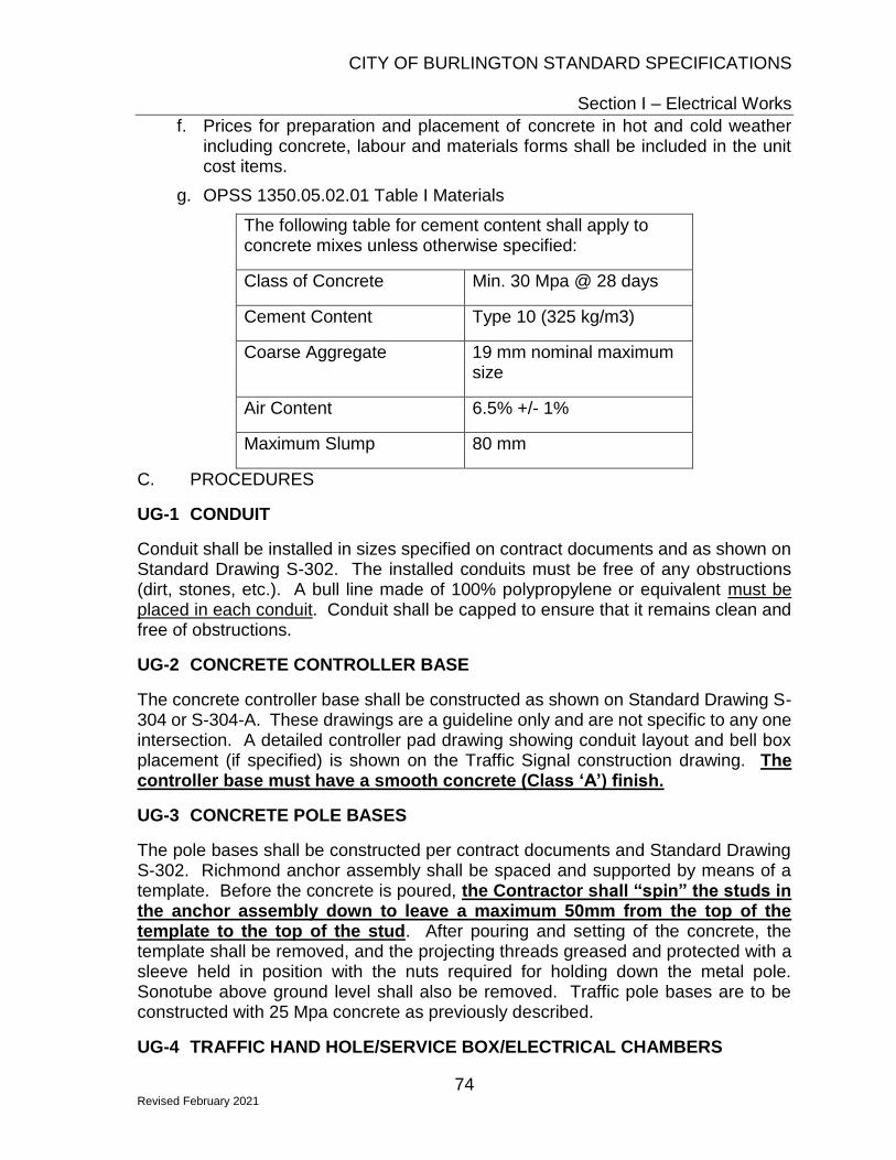
CITY OF BURLINGTON STANDARD SPECIFICATIONS
Section I – Electrical Works
74 Revised February 2021
f. Prices for preparation and placement of concrete in hot and cold weather including concrete, labour and materials forms shall be included in the unit cost items.
g. OPSS 1350.05.02.01 Table I Materials
The following table for cement content shall apply to concrete mixes unless otherwise specified:
Class of Concrete Min. 30 Mpa @ 28 days
Cement Content Type 10 (325 kg/m3)
Coarse Aggregate 19 mm nominal maximum size
Air Content 6.5% +/- 1%
Maximum Slump 80 mm
C. PROCEDURES
UG-1 CONDUIT
Conduit shall be installed in sizes specified on contract documents and as shown on Standard Drawing S-302. The installed conduits must be free of any obstructions (dirt, stones, etc.). A bull line made of 100% polypropylene or equivalent must be placed in each conduit. Conduit shall be capped to ensure that it remains clean and free of obstructions.
UG-2 CONCRETE CONTROLLER BASE
The concrete controller base shall be constructed as shown on Standard Drawing S-304 or S-304-A. These drawings are a guideline only and are not specific to any one intersection. A detailed controller pad drawing showing conduit layout and bell box placement (if specified) is shown on the Traffic Signal construction drawing. The controller base must have a smooth concrete (Class ‘A’) finish.
UG-3 CONCRETE POLE BASES
The pole bases shall be constructed per contract documents and Standard Drawing S-302. Richmond anchor assembly shall be spaced and supported by means of a template. Before the concrete is poured, the Contractor shall “spin” the studs in the anchor assembly down to leave a maximum 50mm from the top of the template to the top of the stud. After pouring and setting of the concrete, the template shall be removed, and the projecting threads greased and protected with a sleeve held in position with the nuts required for holding down the metal pole. Sonotube above ground level shall also be removed. Traffic pole bases are to be constructed with 25 Mpa concrete as previously described.
UG-4 TRAFFIC HAND HOLE/SERVICE BOX/ELECTRICAL CHAMBERS

CITY OF BURLINGTON STANDARD SPECIFICATIONS
Section I – Electrical Works
75 Revised February 2021
The Traffic Hand Hole/Service Box shall be installed as shown on contract documents and Standard Drawing S-302.
When specified, traffic hand hole/steel frame & cover shall be constructed where indicated on the contract documents. They shall be constructed as shown on Standard Drawing S-339. After pouring and setting of concrete, all interior sonotube and outside sonotube above ground level shall be removed
The Contractor shall supply and install a 20mm diameter by 3000mm copper clad ground rod with a CSA approved U-Strap ground wire connector or a 600mm x 600mm x 10mm hot dipped galvanized plate (where required) in all types of new and existing Traffic Hand Holes.
The following Traffic Hand Hole/Service Box assemblies are approved for installation:
Type I – 13x24 Type II – 17x30
Brand Item Straig
ht Flared Straight Flared
Quazite (Hubbell)
Enclosure PG1324BA18
PD1324BA18 PG1730BA
18 PD1730BA1
8
Cover PG1324HA0046 PG1730HA0046
Oldcastle (Synertec
h)
H-Series Enclosure
PC1324-18S
PC1324-18F PC1730-
18S PC1730-18F
Cover PC1324-T22 TRAFFIC
SIGNAL PC1730-T22 TRAFFIC
SIGNAL
UG-5 JUNCTION BOXES
Junction boxes shall be Quazite #PC1212BA12 with cover #PC1212HA0046 or Synertech H-Series PC1212-12 with cover #PC1212 TRAFFIC SIGNAL. Junction boxes shall be installed as shown on Standard Drawing S-303.
UG-6 ISLAND MARKER BASES
Island marker bases shall be constructed as shown on Standard Drawing S-300.
UG-7 GENERAL
All installations shall be made to the satisfaction of the Contract Administrator. The Contractor shall take all necessary measurements in the field in order to enable him/her to completely confirm the dimensions on all drawings. The Contractor shall demonstrate that the supplied material meets the standards set forth in the specifications. The Contractor at his/her expense shall correct all defects.
UG-8 BASIS OF PAYMENT
Measurement of conduit shall be in meters and shall be along the horizontal from centre of a hand hole or pole base to centre of a hand hole or pole base. No additional payment will be made for bends, risers, etc. unless specifically indicated.

CITY OF BURLINGTON STANDARD SPECIFICATIONS
Section I – Electrical Works
76 Revised February 2021
Payment for conduit shall include the supply and installation of the conduits, fish line, all bends, risers, caps, spacers, concrete, excavation of trenches, removal and disposal of materials, bedding, backfill and compaction.
UG-9 INSPECTION
All underground work (ducts, pole bases, junction boxes, controller pad, THH’s, etc.), must be inspected by one of the City Traffic Signal Maintenance staff before the above ground installation can proceed.

CITY OF BURLINGTON STANDARD SPECIFICATIONS
Section I – Electrical Works
77 Revised February 2021
PART II - TRAFFIC SIGNAL ABOVE GROUND A. WORK INCLUDED
Aboveground Work – consists of the supply of all labour, equipment and materials (excluding City-supplied materials as specified in the contract documents) required for the above ground installation of signalized traffic control and roadway lighting devices. These installations shall be made as shown on the contract documents. The quantities listed in this tender may be subject to change; therefore, the Contractor must be willing to perform additional work using the same unit price.
B. MATERIAL
Unless otherwise specified in the Contract, the City of Burlington shall supply the Contractor with the following items ONLY:
• Assembled traffic signal controller cabinet (City to install as well);
• Traffic Signal Pedestals complete with terminal strip (for installation on the controller pad, if specified);
• Street name signs
The items supplied by the City may be picked up at the Operations Centre, 3330 Harvester Road, Burlington, Ontario. The Contractor shall phone the City signal shop at 905-335-7671, ext 6163 between 7:00 A.M. and 3:00 P.M. Monday to Friday to arrange for pickup of material. A minimum of 24 hours notice is required.
C. PROCEDURES
The installation shall be made in a manner to the satisfaction of the Contract Administrator. The above ground installation shall not proceed until all deficiencies noted in the underground inspection have been corrected. Upon completion of the installation, the Contractor shall test all cable, signal heads, pedestrian heads and loops to ensure that there are no short circuits or open circuits, and that all exposed equipment is grounded. All defects disclosed by testing shall be corrected by the Contractor at their expense until all equipment is accepted as satisfactory by the Contract Administrator. Installation of the controller cabinet by the City Traffic Signal Maintenance staff shall not proceed until all deficiencies have been corrected.
If required, the Contractor shall be responsible to arrange for Pay Duty Police to control traffic during the activation of the traffic control system.
The Contractor shall provide the Contract Administrator a minimum of three (3) working days notice prior to scheduling the traffic signal control activation. This is to ensure that the signal equipment and system are fully operational, and all noted deficiencies identified during inspections have been corrected. Please note that activations/turn on is restricted to Tuesdays, Wednesdays, or Thursdays.
D. VARIANCE FROM SPECIFICATION

CITY OF BURLINGTON STANDARD SPECIFICATIONS
Section I – Electrical Works
78 Revised February 2021
If the Contractor is unable to comply with all items in this specification, but still wishes to submit a bid, all variances from this specification must be submitted in writing to the Contract Administrator.
Any variations from this specification must be approved in writing by the Contract Administrator prior to the installation.
The decision of the Contract Administrator as to the suitability of any or all installations shall be final.
E. SUPPLY AND/OR INSTALLATION
AG-1 TRAFFIC SIGNAL POLES
The Contractor shall supply and install Valmont West Coast Engineering 8620 (6.1m) and 8315 (4.6m) poles, or Spina Steel OCT-T-20H and OCT-T-15, in quantities as outlined in the contract documents, or as directed by the Contract Administrator. These poles shall be complete with pole caps and hand holes for underground wiring. The poles shall be erected in accordance with procedures specified by manufacturer and/or Contract Administrator.
On poles requiring an extension for mounting luminaires and/or video detection cameras, the Contractor shall use pole extensions as manufactured by Valmont West Coast Engineering or Spina Steel to the City of Burlington Specification detailed in S-322.
Where poles are perforated for cables or cut for any reason, any sharp edges shall be filed, then treated with a zinc rich compound and fitted with rubber grommets.
AG-2 TRAFFIC SIGNAL ARMS
The Contractor shall supply and install the following types or approved equivalent of single member mast arms in quantities as outlined in the contract documents and in locations as shown on contract drawings or as directed by the Contract Administrator or their representative.
Description Size Type
Mast arm 0.6m R2-JA
Mast arm 1.2m R4-JA
Mast arm 1.8m TR6SMA-78
Mast arm 3.0m TR10SMA-78
Mast arm 3.6m TR12SMA-78
Mast arm 4.6m TR15SMA-78
Mast arm 5.5m TR18SMA-78

CITY OF BURLINGTON STANDARD SPECIFICATIONS
Section I – Electrical Works
79 Revised February 2021
Mast arm 6.0m TR20SMA-78
Mast arm 6.7m TR22SMA-78
Tapered Elliptical Arm
2.4m RE-8MA
The mast arms and tapered elliptical arms shall be installed in accordance with procedures specified by the manufacturer and/or Contract Administrator. All mounting hardware must be either stainless steel or hot dipped galvanized. All banding used for installation of traffic signal and street light arms shall be BAND-IT C20699, 0.75" width and 0.030" thickness, or approved equivalent.
AG-3 SIGNAL HEADS
The contractor shall supply and install traffic signal heads and mounting hardware as specified in the contract documents. Signal heads shall be polycarbonate with a yellow front (door) section and grey rear (housing) section. Polycarbonate backboards shall have a yellow front surface and a grey back surface. The front surface shall include 3” wide “3M Fluorescent Yellow 4081” reflective sheeting applied along the perimeter of the backboard.
Cable termination shall be made in the amber housing with approved wing-nut connectors. Terminal strips shall not be used to make connections in the traffic signal heads.
The City’s current traffic signal head specifications are as follows:
Signal Type Description Vendor/Product Number
300-200-200
Pre-assembled 1 section x 300mm + 2 section x 200mm highway signal head including LED modules, visors, bird stops, and polycarbonate backboard
Fortran Traffic Systems Ltd: P1LHM00/BSP1374R/SCC001
300-300-300
Pre-assembled 3-section x 300mm signal head including LED modules, visors, bird stops, and polycarbonate backboard
Fortran Traffic Systems Ltd: P3LHM00/BSP3374R/SCC001
300-300-300-300
(Type 9A)
Pre-assembled 4-section x 300mm signal head including LED modules, visors, bird stops, and polycarbonate backboard
Fortran Traffic Systems Ltd: P3LEM00/BSP3474R/SCC001
The following table is a general guideline of typical traffic signal mounting hardware applications. The contractor shall supply and install hardware as specified in the contract documents.

CITY OF BURLINGTON STANDARD SPECIFICATIONS
Section I – Electrical Works
80 Revised February 2021
Signal Type Mounting Location Hardware
Face/Side Mount Rigid Arm Brackets
300-200-200 Mast Arm Cushion Hanger
Face/Side Mount Rigid Arm Brackets
300-300-300 Mast Arm Plumbizer
Face/Side Mount Rigid Arm Brackets
(300-300-300-300) Mast Arm Dual End Bracket
Mounting hardware shall be:
• Cushion hangers: Fortran HAN555, or Sentinel STE4025, or Traffic Hardware & Design RCH-001N
• Plumbizers: Sentinel AP4020-T or Traffic Hardware & Design PLU-001N
• Dual end brackets:
o Sentinel VSB-C-46 or Traffic Hardware & Design CCL-300VN for 3-section heads
o Sentinel VSB-C-58 or Traffic Hardware & Design CCL-400VN for 4-section heads
• Rigid Arm Pairs:
o 0.4m - Sentinel DB-RDPSA-16-2 or Traffic Hardware & Design DPA-16T
o 0.6m - Sentinel DB-RDPSA-24-2 or Traffic Hardware & Design DPA-24T
Signal heads and mounting hardware shall be installed in accordance with procedures specified by the manufacturers and/or Contract Administrator. When installed over the travelled portion of the roadway, the bottom of the signal head backboard must be between 5.0m and 5.4m above roadway. All signal heads shall be covered with burlap or black plastic bags while mounted in place but not in operation.
The Contractor shall install all signal heads as indicated on the contract drawings and in quantities as noted in the contract documents.
AG-4 PEDESTRIAN HEADS
The Contractor shall supply and install pedestrian heads and mounting hardware as indicated on the contract drawings and in quantities as noted on the contract documents. Pedestrian heads shall have yellow front (door) and yellow rear (housing) sections.

CITY OF BURLINGTON STANDARD SPECIFICATIONS
Section I – Electrical Works
81 Revised February 2021
The City’s current pedestrian signal head specifications are as follows:
Type Description Vendor Product Number
Countdown Pedestrian
Head
Pre-assembled 2 section Pedestrian head which includes LED modules and visors installed
Fortran Traffic Systems Ltd: P4LO440I
Single-section Pedestrian
Head
Pre-assembled 1 section Pedestrian head which includes LED module visors and bird stop installed
Fortran Traffic Systems Ltd: P4LU440/SEA500
Pedestrian heads mounted with rigid arm pairs shall be wired from the bottom of the head directly into the pole (no drip loop required).
Countdown indications shall only count the Flashing Don’t Walk and have a blank indication when resting in Don’t Walk.
The bottom of the pedestrian heads shall be mounted at heights as indicated on the contract drawings. All pedestrian heads shall be covered with burlap or black plastic bags or turned away from traffic while mounted in place but not in operation.
AG-5 PEDESTRIAN PUSH BUTTONS
Unless otherwise specified on the contract documents, the contractor shall supply and install push buttons as per OPSS 620.
Push buttons shall be placed on the poles as indicated on the contract drawing or as directed by the Contract Administrator.
The push button shall be mounted 1.0m above the sidewalk, and on the pole face indicated on the drawings, or as specified by the Contract Administrator. Wiring shall be carried down inside the poles.
All new installations shall include Accessible Pedestrian Signals (APS). The Contractor shall supply and install either Polara iNS or Campbell Guardian with Yellow face plates.
APS systems shall be supplied and installed complete with the push button units, signs, control units, Bluetooth connectivity modules for programming, and all required wiring and associated hardware.
APS systems will be programmed by City maintenance staff.
AG-6 MAST ARM STREET NAME SIGNAGE
The City shall supply all street name signs. The contractor shall supply all mounting hardware, affix signs to the brackets, and install them as indicated on the contract drawings and in the quantities as noted on the contract documents.

CITY OF BURLINGTON STANDARD SPECIFICATIONS
Section I – Electrical Works
82 Revised February 2021
Sign bracket – Sentinel Versa-Brac Sign Assembly VSMB-C, or Traffic Hardware & Design CCS-E of length as specified in the contract documents. Stainless steel hardware shall be used to affix the sign to the bracket.
AG-7 CABLE
The Contractor shall supply and install all cable. All signal cable used must meet City of Burlington specification SS4 Part IV, Section B. Loop lead in cable must be either Belden #8720 or Carol 14/2, style 2106, type CL2. NO SUBSTITUTION FOR THESE CABLES ARE PERMITTED. The installation of cables shall be carried out in the following manner and according to construction drawings:
1. Materials used to facilitate the pulling of cables in conduit must first be approved by the Contract Administrator. Cable shall not be pulled at temperatures below -6 degrees C.
2. Cable runs shall be continuous between poles. Signal cable splices shall only be made at poles (steel/aluminum pole hand holes or wood pole junction boxes). No signal cable splices are permitted below ground level.
3. Sufficient length of free cable shall be left in pole hand holes or junction boxes to permit proper connection to be made with cable coming from signal and/or pedestrian heads.
4. Cable from signal and/or pedestrian heads on steel poles shall run inside the mast arms and carry on down inside the pole to the hand hole. Pedestrian head cables shall run inside the rigid arm and directly into the pole.
5. Cable from signal and /or pedestrian heads on wood poles shall run inside the mast arms and carry on up or down the outside of the pole to a 200mm x 200mm x 100mm (8” x 8” x 4”) PVC watertight junction box. The junction box shall be mounted 5m above finished grade. Cable shall be attached to the wood pole using appropriate fastening devices, and drip loops shall be provided at entry points to mast arms and junction boxes.
6. Belden cable from the vehicle detector loops shall be brought to the controller pad through the designated conduit and 1.5m coiled up on the pad. These cables shall be one continuous piece with no splices and run from the curbside junction box to the controller pad.
7. Wires for luminaires shall be installed in accordance with procedures specified by the Contract Administrator.
8. All signal cables shall terminate at the controller pad (or in the bell box, if specified), and be properly labeled by cable number as indicated on the wiring layout.
9. A wiring schedule showing the distribution of cables from the bell box, color and number coding, and detailed hook-up instructions shall be supplied by the City at the time of installation.

CITY OF BURLINGTON STANDARD SPECIFICATIONS
Section I – Electrical Works
83 Revised February 2021
AG-8 VEHICLE DETECTION
Loops
Unless otherwise specified on the contract documents, the contractor shall supply and install all labour, equipment, and material required for the installation of vehicle detector loops. The installation shall be made as shown on the contract drawings and Standard Drawing S-303. City Traffic Signal Maintenance staff will pre-mark the loop layout.
The Contractor shall use RWU-90 #14 AWG stranded wire for the loop and 3M Detector Loop Sealant 5000 sealer for sealing the road cut.
The following procedure shall be adhered to:
1. Loops may not be installed under conditions where temperatures are below 10 degrees C. Each loop shall be completed the same day the road cut is made. Road cuts are NOT to be left open overnight
2. Unless otherwise specified, all loops are to be installed in the final layer of asphalt; the slot is to be 10mm wide and cut to a depth that places the last loop 50mm below the roadway surface. Recommended depths for slots having 2 turns are 60mm and for slots having 3 turns are 65mm.
3. Corners of all loops shall be cut diagonally as shown on City of Burlington Standard Drawing S-303. The slot must be wet cut, and then blown dry with all debris and dust removed from the slot.
4. A 7mm layer of sealant is placed in the slot before laying the wire. The loop wire must be a continuous wire beginning and ending inside the junction box. The loop wire must be installed in a clockwise direction, the designated number of turns. Absolutely no splices are allowed. The lead end of each loop must be identified, and each loop pair must be marked to identify the loop location in the road as per the construction drawing (i.e. LP1, LP2, etc.). The two lead wires between the junction box and loop are to be twisted symmetrically at a rate of 2 - 5 turns per 300mm.
5. The Contractor shall measure and record DC wire resistance and leakage resistance with a “Megger”. If the loop resistance measures between 1 and 5 ohms and leakage resistance measures 10 megohms, complete the filling of slot with sealer. If high DC resistance (5 ohms or more) or less than 10 megohms of leakage resistance occurs, the complete loop wire must be replaced. The sealant shall completely encapsulate the loop wires to prevent movement of wires and roadway abrasion to insulation. Only pure sealer shall be used to fill the entire slot, with no excess overflow.
6. The Contractor shall measure and record the inductance of each loop at the junction box ensuring a minimum inductance reading of 150 uh and maximum reading of 400 uh. One Belden cable shall be installed for each traffic lane. The cabinet end of the lead-in must be labeled by loop number as labeled on the construction drawing.

CITY OF BURLINGTON STANDARD SPECIFICATIONS
Section I – Electrical Works
84 Revised February 2021
7. Connections in the loop junction boxes shall be made by the contractor. Loops shall be connected in series, twisted, and encapsulated using a terminating device suitable for an underground application
8. Final connections in the controller cabinet are to be made by City Traffic Signal Maintenance staff.
Overhead/Non-Intrusive Detection
Unless otherwise specified on the contract documents, the contractor shall supply equipment and materials required for the installation of the overhead/non-intrusive detection system. Systems shall be installed as per contract drawings and following the manufacturer’s installation instructions.
The contractor shall install detection devices on the poles as indicated on the contract drawings or as directed by the Contract Administrator. The Contractor shall connect the cable to the detection device and bring each detection cable from the device(s) to the controller pad and leave 1.5m coiled up on the pad. Cables shall be labeled according to the pole number onto which the corresponding device is mounted (i.e. TS1, TS2, etc.).
All hardware to be installed into the controller cabinet shall be provided to the City two (2) weeks in advance of traffic signal activation for installation by City Traffic Signal Maintenance staff into the controller cabinet. City Traffic Signal Maintenance staff will activate and configure the detection system prior to signal activation.
AG-9 EMERGENCY VEHICLE PRE-EMPTION
Unless otherwise specified on the contract documents, the contractor shall supply and install emergency vehicle pre-emption detectors.
Each of the detectors shall be placed on the poles as indicated on the contract drawing or as directed by the Contract Administrator. The Contractor shall bring each pre-emption cable from the detector(s) to the controller pad and leave 1.5m coiled up on the pad. Cables shall be labeled according to the pole number onto which the corresponding detector unit is mounted (i.e. TS1, TS2, etc.).
Phase selector shall be GTT Opticom Model 764 (as specified in contract). Detectors shall be GTT Opticom Model 722 - mounting brackets will be supplied by the City. Model 138 Detector Cable shall be used (contractor supplied).
AG-10 POWER FEED and DISCONNECT INSTALLTION (PERMANENT and TEMPORARY TRAFFIC SIGNALS)
The power feed and disconnect shall be installed as shown on the wiring schematics, which will be supplied by the City once the above ground work has started. The type of wire, size of conductors and colour coding must be as shown on the wiring schematic.
Unless otherwise specified in the contract documents, for pole-mounted service the contractor shall supply equipment and materials to install the disconnect box as

CITY OF BURLINGTON STANDARD SPECIFICATIONS
Section I – Electrical Works
85 Revised February 2021
specified in the contract documents. The disconnect box shall be mounted at a height of 2.6m - 3.0m above final grade. The contractor is to supply and install grounding devices as per ESA standards.
For ground-mounted service, the contractor shall supply and install the load centre and concrete base including breakers. The concrete base shall be Brooklyn Concrete Products BCP-20PED, and the load centre shall be Pedestal Solutions Inc SLS1-X-40 with Square-D QO-120 20amp (traffic signals) and QO-130 30amp (street lights) circuit breakers. Circuit breakers shall be installed as shown on the wiring schematics and in accordance with procedures specified by the Contract Administrator.
The Contractor shall bring one each of #6 TWU black, white and green from the disconnect to the controller pad and leave 1.5m coiled up on the pad. The black and white wires must be one continuous piece from the disconnect to the controller pad with no splices.
The Contractor shall pay for all permits including ESA inspection permits, licenses and fees and the price for these inspections shall be included in the appropriate bid item. The Contractor shall provide the City with a "Certificate of Inspection" certified by the ESA, after which time the City will arrange for the connection of electrical power with the local hydro authority. City Traffic Signal Maintenance staff will install the controller cabinet and connect the power feed in the cabinet after the service has been energized.
AG-11 STREET LIGHTING
The contractor shall supply and install streetlight luminaires as indicated on the contract documents and as shown on contract drawings. Unless otherwise specified, the luminaires shall be cobra head style, single piece die cast aluminum housing containing the light source, associated control gear and mounting mechanism, with an optical aperture with a flat lens, mounted in a fixed position with photometric files tested to IES LM-79-08 using Type C photometry per IES LM-75-01 and designed with a minimum efficacy of 100Lm/W. The wattages will be as indicated on the contract drawings. The unit shall have a 7-pin receptacle for Photoelectric control.
The contractor shall supply and install NMW 12/2 solid copper wire from the luminaire down the inside of the pole to the service box or traffic hand hole where it will be spliced to the street light feed. An inline type fuse holder equipped with a 6A HEB-AD-RYC or HEB-AB-RLC-J type fuse shall be installed in the pole hand hole.
The contractor shall be responsible for all equipment and materials to energize this system. The City of Burlington’s current standard is the Philips Road Focus series of fixtures.
PART III – TEMPORARY AND/OR OVERHEAD SIGNAL INSTALLATION WORK INCLUDED
This specification covers the requirements of the Contractor to install, maintain, operate, and modify an overhead or a temporary signal installation, as shown on the

CITY OF BURLINGTON STANDARD SPECIFICATIONS
Section I – Electrical Works
86 Revised February 2021
contract drawings and in accordance with OPSD 2540.01, 2242.02, and 2245.01, as applicable.
The Contractor shall perform all routine and emergency maintenance work required for proper operation of the temporary traffic signal and roadway lighting systems during the period of construction. Routine maintenance of the temporary traffic signal control devices shall include, but not limited to weekly measurement of the traffic signal cable spans to confirm the minimum signal head mounting heights of the overhead traffic signal facilities. The Contractor shall provide a summary of the weekly measurements to the City for review and record. There will be no additional payment for this work.
The Contractor shall arrange for connection of electrical power with the local Hydro Authority and shall pay for all costs associated with installation, energizing, maintenance, operation, and removal of the temporary service connections and traffic control equipment.
Under the different stages of the temporary traffic signal operations, traffic signal heads, pedestrian signal heads, emergency pre-emption detection units, and video detection units may need to be relocated to the positions identified on the Contract drawings or as directed by the Contract Administrator. The Contractor shall be responsible for all costs associated with the relocation.
The Contractor shall notify the City three (3) working days in advance of any work needing to be completed in the traffic controller cabinet, so arrangements can be made for City Traffic Signal Maintenance staff to be on site.
Unless otherwise specified on the Contract, all temporary traffic signal equipment supplied by the Contractor shall remain the Contractor’s property at the end of the project, excluding items that are to be transferred to the permanent installation. Pricing for temporary traffic signal installations shall also provide for removal of the same.
USED EQUIPMENT AND MATERIALS – Temporary
Used equipment and materials may be utilized in the maintenance and operation of temporary installations (excluding those items that will remain permanently) provided that:
a) All material components or completed assemblies of components have C.S.A or UL approval;
b) Complies with the requirements of the contract; and
c) It is in good condition.
Used equipment and material meeting the specifications shall be acceptable for use for the following items only:

CITY OF BURLINGTON STANDARD SPECIFICATIONS
Section I – Electrical Works
87 Revised February 2021
a) Poles
b) Luminaires and Elliptical Brackets
c) Traffic and pedestrian signal heads
The Contractor shall indemnify and hold the City harmless from all and every claim arising from the use of used materials.
PAY DUTY POLICE
The Contractor shall notify the Contract Administrator in advance when pay duty officers are required for traffic control in addition to the Ontario Traffic Manual Book 7 Temporary Conditions. Unless otherwise specified in the contract documents, the Contractor shall be responsible for contacting, scheduling, and payment for services.
The City reserves the right to reject requests made by the Contractor should there be insufficient justification. Where the Contractor elects to contract the services of pay duty officers, all cost associated shall be their responsibility. No payment shall be made by the City for services unless mutually agreed upon in advance.
The Contractor shall note that no payment shall be made without the receipt from the pay duty officers. Payment shall be made based on the hourly rate as identified by the Halton Regional Police Service in accordance with their Service Policy.
PART IV - TRAFFIC SIGNAL CABLE GENERAL
This specification is intended to govern the supply and delivery of 2 conductor pushbutton cable, and 4, 7, and 19 conductor traffic signal cable.
No individual reel shall contain more than 600 meters of cable or be made up of more than one continuous piece. The reels shall not be more than 110 cm (42”) in diameter and 75 cm (30”) high.
The individual conductors of the completed cable shall be capable of withstanding a test application of 3600 volts DC when tested in accordance with A.S.T.M. - D2219 and D2220, latest version.
If, in the opinion of the Contract Administrator, any material used in the construction of any part of the cable is defective, or otherwise unsuitable, or if, in their opinion, the workmanship does not conform with accepted standards, the contractor shall replace such defective cable at the contractor’s own expense.
Any errors or omissions in, or misinterpretation of the specifications, or order shall not relieve the supplier of the responsibility of providing cable conforming to modern practices and the best workmanship.
Cable type and sequential length markings shall be printed everyone (1) meter on the surface of the outer jacket.
SPECIFICATION

CITY OF BURLINGTON STANDARD SPECIFICATIONS
Section I – Electrical Works
88 Revised February 2021
All traffic signal cable shall meet or exceed Ontario Provincial Standard Specification 604/2409.
The coding of the individual conductors forming a cable shall consist of a combination of colour, conductor number and size of conductor as shown in Tables “A” to “D”. The colours used shall be clearly distinguishable under all conditions of illumination and shall be permanent and not subject to fading, bleaching, or darkening due to aging or the action of light, oil, water, abrasion or other causes met within normal usage. The conductor number and wire size shall be printed in black and shall consist of sharp, clearly defined letters and figures, approximately 0.16cm tall, applied in such a way as to resist all normal abrasion. The ink or other material used shall be insoluble in all common liquids, especially water, oil and carbon tetrachloride. The spacing between words or numerals forming one group shall be) .6cm and the spacing between groups shall be 25cm. These markings shall be printed parallel to the conductor.
TABLE “A” 2 CONDUCTOR CABLE for Pushbuttons
General Cable part #C4213A
Colour of P.V.C. Insulation
Lettering Imprinted on P.V.C.
AWG Size Conductor
Shielded
Black 16 White 16
TABLE “B” 4 CONDUCTOR CABLE
Colour of P.V.C. Insulation
Lettering Imprinted on P.V.C.
AWG Size Conductor
Red Red One 14 Yellow Yellow One 14 Blue Green One 14
White 14
TABLE “C” 7 CONDUCTOR CABLE

CITY OF BURLINGTON STANDARD SPECIFICATIONS
Section I – Electrical Works
89 Revised February 2021
Colour of P.V.C. Insulation
Lettering Imprinted on P.V.C.
AWG Size Conductor
Red Red One 14 Red Red Two 14
Yellow Yellow One 14 Yellow Yellow Two 14 Blue Green One 14 Blue Green Two 14
White 14
TABLE “D” 19 CONDUCTOR CABLE
Colour of P.V.C.
Insulation
Lettering Imprinted on P.V.C.
AWG Size Conductor
Red Red One 14 Red Red Two 14 Red Red Three 14 Red Red Four 14 Red Red Five 14
Yellow Yellow One 14 Yellow Yellow Two 14 Yellow Yellow Three 14 Yellow Yellow Four 14 Yellow Yellow Five 14 Blue Green One 14 Blue Green Two 14 Blue Green Three 14 Blue Green Four 14 Blue Green Five 14
White White One 14 White White Two 14 Black Not Numbered 14
Orange Not Numbered 14

CITY OF BURLINGTON STANDARD SPECIFICATIONS
Section I – Electrical Works
90 Revised February 2021
TABLE “E” CAT5E
Shielded underground-rated ethernet cable
Colour of P.V.C. Insulation
Lettering Imprinted on P.V.C.
AWG Size Conductor
Black 24
PART V - TRAFFIC SIGNAL COMMUNICATION CABLE A. GENERAL
The City will supply all communication cable unless otherwise specified in the contract document.
The reels shall not be larger than 150cm (60”) in diameter and 85cm (33.5”) wide.
The individual conductors of the completed cable shall be capable of withstanding a test application of 3600 volts DC when tested in accordance with A.S.T.M. - D2219 and D2220, latest revision.
If in the opinion of the Contract Administrator, any material used in the construction of the cable is defective, or otherwise unsuitable, or if in his/her opinion, the workmanship does not conform to accepted standards, the supplier shall replace such defective cable at his own expense.
Any error or omission in, or misinterpretation of the specifications or order shall not relieve the supplier of the responsibility of providing cable intended by this specification.
Cable type and sequential length markings shall be printed every one (1) meter on the surface of the outer jacket.
B. SPECIFICATION
1. This cable shall be P.I C. Alpeth Figure 8 Exchange Area cable equal to specification PES-1006 for aerial installation. (Equal to Canada Wire 22T83 figure 8 or 19T83 Figure 8)
a. 6 pair, 22 AWG
b. 12 pair, 22 AWG
c. 25 pair, 22 AWG
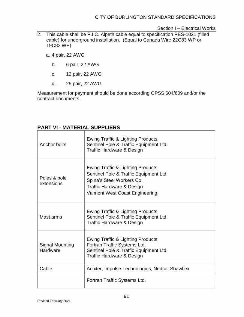
CITY OF BURLINGTON STANDARD SPECIFICATIONS
Section I – Electrical Works
91 Revised February 2021
2. This cable shall be P.I.C. Alpeth cable equal to specification PES-1021 (filled cable) for underground installation. (Equal to Canada Wire 22C83 WP or 19C83 WP)
a. 4 pair, 22 AWG
b. 6 pair, 22 AWG
c. 12 pair, 22 AWG
d. 25 pair, 22 AWG
Measurement for payment should be done according OPSS 604/609 and/or the contract documents.
PART VI - MATERIAL SUPPLIERS
Anchor bolts
Ewing Traffic & Lighting Products Sentinel Pole & Traffic Equipment Ltd. Traffic Hardware & Design
Poles & pole extensions
Ewing Traffic & Lighting Products
Sentinel Pole & Traffic Equipment Ltd.
Spina’s Steel Workers Co.
Traffic Hardware & Design
Valmont West Coast Engineering,
Mast arms
Ewing Traffic & Lighting Products Sentinel Pole & Traffic Equipment Ltd. Traffic Hardware & Design
Signal Mounting Hardware
Ewing Traffic & Lighting Products Fortran Traffic Systems Ltd. Sentinel Pole & Traffic Equipment Ltd. Traffic Hardware & Design
Cable Anixter, Impulse Technologies, Nedco, Shawflex
Fortran Traffic Systems Ltd.

CITY OF BURLINGTON STANDARD SPECIFICATIONS
Section I – Electrical Works
92 Revised February 2021
Traffic and Pedestrian Signal Heads
Vehicle Detection Systems (see contract documents for specified system)
Autoscope – Econolite
Gridsmart - Electromega
Iteris – GGI Road & Traffic
Wavetronix – Fortran Traffic System Ltd
APS Pushbuttons
Fortran Traffic Systems Ltd (Campbell) Tacel Ltd (Polara)
Contact Information
Econolite Canada, Inc. 110 Travail Road Markham, Ontario L3S 3J1 Phone: 905-294-9920
Sentinel Pole & Traffic Equipment Ltd 375 Admiral Blvd., Unit #3 Mississauga, Ontario L5T 2N1 Phone: 905-564-2929
Electromega 1155 North Service Road West, Unit 11 Oakville, Ontario L6M 3E3 Phone: 905-847-5458
Shawflex 25 Bethridge Road Etobicoke, Ontario M9W 1M7 Phone: 416-743-2565
Ewing Traffic & Lighting Products 1445 Hopkins Street Whitby, Ontario L1N 2C2 Phone: 905-666-5600
Spina’s Steel Workers Co. Ltd. 229 Wilkinson Road, Brampton, Ontario L6T 4M2 Phone: 905-453-2111
Fortran Traffic Systems Ltd. 470 Midwest Road Scarborough, Ontario M1P 4Y5 Phone: 647-801-6879
Tacel Ltd. 179 Bartley Dr, Unit B Toronto, ON M4A 1E6 Phone: 416-750-4646
GGI Road & Traffic Traffic Hardware & Design
CITY OF BURLINGTON STANDARD SPECIFICATIONS
Section I – Electrical Works
93 Revised February 2021
9 Allaura Boulevard, Unit 9 Aurora, Ontario L4G 3N2 Phone: 416-849-2228
1641 Trinity Drive Mississauga, Ontario L5T 1K4 Phone: 905-670-3444
Impulse Technologies Ltd. 170 Admiral Blvd. Mississauga, Ontario, L6T 2N6 Phone: 905-670-1269
Valmont West Coast Engineering 100 Ellis Drive Barrie, Ontario L4N 9B2 Phone: 705-721-1090
Nedco 515 Wilson Street Hamilton, Ontario L8T 1T4 Phone: 905-528-0261
CITY OF BURLINGTON STANDARD SPECIFICATIONS
Section J – Landscaping & Private Property Works
94 Revised February 2021
Section J – Landscaping & Private Property Restoration
J.1 Remove & Reinstate / Replace Private Property Works Scope The following list of items shall be carefully removed, salvaged or disposed, and restored to existing condition:
• Precast concrete curb
• Poured-in-place concrete curb
• Wooden curb
• Exposed aggregate concrete Driveway
• Stamped / coloured concrete driveway
• Plain concrete driveway
• Interlocking brick driveway
• Crushed brick driveway
• Asphalt walkway
• Flagstone walkway
• Wooden fence
• Metal fence
• Garden
• Stone/brick pillar
• Post/bollard when new materials are required, the cost of the new materials in included for in the item, with the following exceptions:
• Asphalt driveways – reinstated with hot mix item for HL-3F
All concrete works done on private property shall meet the mix design requirements specified in “Concrete Mix Designs”. When colored concrete works are proposed on private property restoration items, the concrete mix design shall be approved by the Contract Administrator prior to use. Interlocking Brick Driveway
Scope
The work included under the item Interlocking Brick Driveway shall include the removal and salvage of existing bricks, and edging as required to facilitate the work, until final replacement.

CITY OF BURLINGTON STANDARD SPECIFICATIONS
Section J – Landscaping & Private Property Works
95 Revised February 2021
Regrading, shaping and compacting the granular base to allow for reinstatement, and all saw cutting bricks as required is included in the item
Placement of bricks shall match the existing driveway pattern and all edging replaced in kind. The contractor shall photograph the interlock brick work and ensure the bricks are replaced exactly as they were prior to construction. Lost or broken brick resulting from construction activities is the Contractor’s responsibility to replace and the contractor shall coordinate the brick and pattern if the exact same brick cannot be purchased.
Sand shall be used to fill the joints. If polymeric sand exists, polymeric sand shall be used when reinstating the bricks.
Cracked, broken and surplus bricks are to be removed and disposed off-site in accordance with OPSS 510.
It may be necessary to source and acquire bricks if there is a shortfall. At these locations, the Contractor shall coordinate with the Inspector.
Basis of Payment Item - Fences, curbs, rails shall be measured by the lineal metre.
Item – Driveways (not including asphalt), slabs, walkways shall be measured by the square metre.
Item - Gardens, posts, boulders, pillars to be counted by each.
For asphalt driveways, payment will be made Asphalt Works under Section G of City of Burlington Standard Specifications.
Payment shall be full compensation for all labour, materials and equipment required to facilitate the items identified as private property restoration work as per the requirements in the Contract Documents.
J.2 Tree Planting & Transplanting Scope
The work included under these specifications shall consist of supplying all materials, labour and equipment necessary for planting and transplanting trees. All work shall be done in accordance with these specifications or as directed by the Contract Administrator.
Examination

CITY OF BURLINGTON STANDARD SPECIFICATIONS
Section J – Landscaping & Private Property Works
96 Revised February 2021
• Report to the Contract Administrator, in writing, of any conditions or defects encountered on the site during or before construction upon which the work of this section depends and which may adversely affect its performance.
• Do not commence work until such conditions or defects have been investigated and corrected.
• Commencement of work shall imply acceptance of surfaces and conditions and no claim for damages or extras resulting from such conditions or defects will be accepted thereafter, except in cases where such conditions cannot be known prior to or during the course of construction.
Qualifications
All planting work described in the Section shall be executed by experienced personnel under the direction of a qualified supervisor.
Substitution
• All plants shall be supplied as specified on the Plant List. Substitution will not be allowed unless approved in writing by the Contract Administrator.
• Give timely notice in writing to the Contract Administrator when applying for substitutions.
• The contractor must, at the signing of the contract, verify to the Contract Administrator, the availability and source of the specified plant material.
Inspection
• Make plant materials available for inspection at source of supply when requested in writing by the Contract Administrator.
• Give timely notice in writing to the Contract Administrator when such materials are available for inspection.
• Approval of plant materials at source of supply shall not impair the right of the Contract Administrator or City Forestry Staff to inspect plants upon arrival on the site or during the course of construction and reject plants which have been damaged or which, in any way, do not conform to the Specifications.
• At the time of inspection, all plants shall be alive and in a healthy, satisfactory growing conditions.
Guarantee
All plant materials shall be guaranteed for a period of two (2) year commencing on the date of inspection for acceptance of the planting.
Replacements
CITY OF BURLINGTON STANDARD SPECIFICATIONS
Section J – Landscaping & Private Property Works
97 Revised February 2021
• All plant materials found dead, or not in a healthy, satisfactory growing condition or which, in any other way, do not meet the requirements of the Specifications, shall be replaced by the Contractor at their own expense.
• The cost of replacements resulting from theft, vandalism, carelessness or neglect on the part of others, or any causes due to circumstances beyond the control of the Contractor, shall be borne by the Owner.
• All required replacement shall be by plants of the same size and species as specified on the plant list and shall be supplied and planted in accordance with the Drawings and Specifications.
Maintenance
• The maintenance of plant materials during the guarantee period shall be the responsibility of the Contractor.
• Such maintenance shall include all measures necessary to establish and maintain all plants in an acceptable, vigorous and healthy growing condition including cultivating and weeding, watering when required, pruning, maintenance of all accessories in good condition.
• At time of inspection for acceptance to begin the maintenance period, all planting beds and tree pits shall be freshly cultivated, free of weeds, leaves, broken branches and rubbish, and shall be in a neat and tidy condition.
• The removal of stakes shall be completed by the contractor after materials are inspected at the end of the warranty period and as indicated by City staff.
Digging of Plants
• All plants shall be dug and delivered to the site as specified on the Plant List, or in the case of relocation of existing plant material on the site, dug according to the following specification.
o Plants specified "B/R" shall be moved with bare roots. They shall be dug and moved while dormant, with the major portion of the fibrous root system provided.
o Immediately after digging, the root system shall be wrapped or puddled and shall be kept moist to prevent drying out until planted on the site.
o All plants specified "B & B" shall be moved with solid balls wrapped in burlap.
o No plant shall be used when the ball of earth surrounding the roots has been cracked or broken preparatory to or during the process of planting, or when the burlap and ropes holding the soil ball have been removed prior to planting.
The sizes of root balls for trees shall be as specified below. Ball sizes are minimums and shall be adjusted according to growth habits of plants and shall be sufficiently large to contain at least 75% of the fibrous root system.

CITY OF BURLINGTON STANDARD SPECIFICATIONS
Section J – Landscaping & Private Property Works
98 Revised February 2021
Deciduous Trees – Caliper and Root Ball Diameter requirements
Caliper Size (mm) Root Ball (m)
25 .040
50 – 75 0.90
100 1.05
125 1.35
150 1.5
200 1.8
250 2.5
Coniferous Trees - Height and Root Ball Diameter requirements
Height (m) Root Ball (m)
1.8-2.4 0.75
2.4-3.0 0.90
3.0-3.6 1.05
3.6-4.6 1.20
4.6-5.4 1.35
For deciduous trees with a caliper of more than 250mm and for coniferous trees over 5.4m in height, the diameter of the root ball shall be increased 150mm for every additional 25mm in caliper, or every 300mm in height.
The ball depth-ratio for "B & B" deciduous and coniferous trees shall be not less than as follows:
Root Ball Diameter Depth
Up to 0.60m Not less than 0.45m
0.6m to 1.35m Not less than 0.45m to 0.75
1.35m and Over Not less than 50% of ball diameter
• All root balls less than 0.45m in diameter shall be burlapped with 140 grams Hessian burlap or approved equal. Balls from 0.45m to 0.75m in diameter shall be double burlapped. Balls 0.90m and larger in diameter shall be double burlapped and drum laced with 6.35mm rope at 200mm spacing.
• Plants relocated on site with a Tree Spade shall be moved and planted as soon as possible after digging a pre-dug hole.
• Root balls requiring a wire basket shall have the burlap liner drawn tight and fastened by sowing or clamps prior to transportation out of the field.

CITY OF BURLINGTON STANDARD SPECIFICATIONS
Section J – Landscaping & Private Property Works
99 Revised February 2021
Handling of Plants
• All plants shall be well protected against damage and drying out from the time of digging until they are planted on the site. Roots shall be protected with wet straw or suitable moisture retaining materials over the roots.
• All roots shall be cleanly cut; split roots are not acceptable. Where combing is not practiced, the roots shall be evenly cut at the edges of the ball. The cut ends of all roots 25mm in diameter and larger shall be painted with asphalt emulsion.
• Root balls, trunks, branches and leaves shall be protected from sun and wind desiccation. Transporting trees shall be restricted to closed vans or trucks, or trucks covered with mesh tarpaulin or similar material to prevent windburn and desiccation in transit.
• Plants shall be transported with care taken to prevent damage. Branches shall be carefully tied in such a manner so as not to break or damage trunks. Points of contact with equipment shall be padded. Bark should be protected against chafing from chains, cables, equipment, or other trees by a wrapping of cardboard or burlap, especially during transport
• Plants with broken or abraded trunks or branches will not be accepted.
Materials
All tree planting soils, where supplied by the Contractor, shall be fertile, friable and be composed of 50-60% sand, 20-40% silt, 6-10% clay and 2-5% organic matter, with an allowable acidity range of 6.8pH - 7.5pH, and be capable of sustaining vigorous plant growth. It shall be free of any admixture or subsoil, clay lumps and shall be free from stones and roots over 50mm in diameter and other extraneous matter.
Peat Moss - Peat Moss shall be of partially decomposed fibrous or cellular stems and leaves with a texture varying from porous fibrous to spongy fibrous, fairly elastic and substantially homogenous with a pH value of not less than 4.5 and not greater than 6.0. It shall be baled and free of decomposed colloidal residue, wood, sulphur and iron, be brown in colour and finely shredded, suitable for horticultural purposes. Shredded particles shall not exceed 6 mm in size.
Fertilizer - The Contractor shall be prepared to provide all necessary fertilizers to eliminate any chemical deficiencies as indicated by a soil analysis report of imported top soil. Where top soil is supplied by the Contractor, the quantities of fertilizers required shall be based on the following minimum rates and shall be included in the Contract sum:
• 10-6-4 @ 36g/l mm cal. for trees
• 12-6-4 @ 890g/m3 of top soil for shrubs
Fertilizers shall be complete, commercial fertilizers containing not less than 60% urea formaldehyde and the following percentages by weight:

CITY OF BURLINGTON STANDARD SPECIFICATIONS
Section J – Landscaping & Private Property Works
100 Revised February 2021
Nitrogen Phosphoric Acid Potash
10-6-4
12-6-6
Plant Material
• All plant materials shall meet the latest edition of the Canadian Nursery Stock Standard with respect to grading and quality.
• They shall be nursery grown, under proper cultural practices as specified in most current Canadian Nursery Stock Standard.
• Nomenclature of specified plants shall conform to the International Code of Nomenclature for Cultivated Plants and shall be in accordance with the approved scientific names given in the latest edition of Standardized Plant Names. The names of varieties not named therein are generally in conformity with the name accepted in the nursery trade.
• Any plants dug from nature stands, wood lots, orchards or neglected nurseries and which have not received proper cultural maintenance as advocated by the Canadian Nursery Stock Standard shall be designated as "collected plants".
• The use of "collected plants" shall not be permitted unless approved, in writing, by the Contract Administrator and City of Burlington Roads, Parks, and Forestry staff.
• Plants shall be true to type and structurally sound, well-branched, healthy and vigorous and free of disease, insect infestations, rodent damage, sun scald, frost cracks, and other abrasions or scars to the bark. They shall be densely foliated when in leaf and have a healthy, well developed root system. Pruning wounds shall show vigorous bark on all edges and all parts shall be moist and show live, green cambium tissue when cut.
• All plant materials shall conform to the minimum measurements specified in the Plant List except that plants larger than specified may be used. The use of such plants shall not increase the Contract price. If larger plants are used, the ball of earth shall be increased in proportion to the size of the plant, as per the root ball diameter and depth requirements above.
• All plants shall be measured when the branches are in their normal position. Height and spread dimensions specified refer to the main body of the plant and not from branch tip to root base or from branch tip to branch tip. Caliper measurements for trees less than 100mm in diameter are taken at 150mm, and trees larger than 10mm in diameter are taken at 300mm above ground as the tree stands in the nursery.
• All plants shall come from pre-approved vendors as noted by City of Burlington Roads, Parks, and Forestry staff.
Planting Pits

CITY OF BURLINGTON STANDARD SPECIFICATIONS
Section J – Landscaping & Private Property Works
101 Revised February 2021
Planting pits for trees and large shrubs shall be excavated to the following minimums.
Deciduous Tree Planting Pit Sizes
Root Ball Diameter (m) Planting Pit width around root ball (mm)
0.6 120
0.75 230
0.90 300
1.05 380
1.35-1.50 460
1.80 – 2.25 610
Coniferous Tree Planting Pit Sizes
Root Ball Diameter (m) Planting Pit width around root ball (mm)
0.75 – 0.90 300
1.05 - 1.20 460
1.20 - 1.35 600
• Pits shall be deep enough to allow a minimum depth of 150mm of planting soil mixture under the root ball.
• The location of all planting pits shall be staked by the Contractor and approved by the Contract Administrator as per the approved planting plan prior to excavation. Major modifications to the planting plan shall be approved by COB Forestry Staff and comply with City of Burlington Tree Planting Guidelines.
• Surface soil of planting pit shall be fractured or scarified and compacted soils shall be loosened prior to planting.
Plant Installation
• Planting shall be done during periods suitable with respect to species, weather conditions, and locally accepted practice. Plants shall be set plumb in the centre of the pits and at the same relation to grade as originally grown, after settlement has taken place.
• Plants shall be set in partly filled pits or beds of prepared soil mixture at which time all burlap, ropes, wires, etc. shall be pulled away from the top of the ball. Root ball using a wire basket shall have the top 30cm of the basket cut away prior to planting. A layer of loose, unfrozen planting soil mixture at least 150mm deep shall be placed under each plant and tamped. Bare root plants shall be placed so that their roots lie in their natural position. Planting soil mixture shall be backfilled in layers not exceeding 150mm in depth. Each layer shall be firmly tamped in place in such

CITY OF BURLINGTON STANDARD SPECIFICATIONS
Section J – Landscaping & Private Property Works
102 Revised February 2021
a manner that the plant retains its vertical position. Particular care shall be taken to ensure that no air pockets remain under or around the roots. The soil mixture shall be thoroughly watered with a minimum of 40L after backfilling the planting hole.
• The planting soil mixture for the filling of planting pits and planting beds shall consist of five (5) parts top soil and one (1) part peat moss. Fertilizer as specified shall then be added to the soil mixture at rates as indicated in the specifications.
• All amendments shall be thoroughly mixed prior to backfilling. Planting soil shall not be mixed while in a frozen or muddy condition.
• Each plant (other than those in planting beds) shall have an earth saucer at its base which shall have a diameter as large as the excavated area. The saucer shall be constructed so as to retain water around the roots of the plant. The saucer shall be filled to a minimum of 50mm depth with approved hardwood chips. Chips shall be kept away from the trunks of trees, with no chips within 25mm of the trunk. Tree wrapping shall be installed to further protect the main stem.
Trunk Wrapping
• Rodent protection o Sliced weeper o Tree bark guard o Spiral protection tubes
• Additional Trunk wrapping as required: o Where a burlap protective wrapping material for tree trunks is specified, it
shall be a premium quality burlap, not less than 150mm nor more than 250mm in width, or a heavy waterproof crepe paper 100mm or 150mm wide. The wrapping shall be applied in a spiral manner with overlap, each time starting at grade and extending upwards to just above the second branches. All wrapping shall be neat and snug and held in place by suitable cord. For borer protection, the trunks shall be sprayed with a wettable powder of a long residual insecticide before applying the wrapping.
Tree Support
All tree stabilization methods shall be such so that they do not damage the tree.
Above Ground Staking (TYP)
• Trees shall be braced upright in position by a minimum of two guys fastened to anchors. Guys shall be placed around the trunk at a point higher than the lowest branches of the trees in such a manner that branches will not be subject to undue strain.

CITY OF BURLINGTON STANDARD SPECIFICATIONS
Section J – Landscaping & Private Property Works
103 Revised February 2021
• Acceptable guys: Burlap ties, Arbor Tie or approved equal shall be used.
• Two wooden stakes 50mm square (50mm diameter round) and 1.75m in length shall be placed on either side of the tree and be located parallel with the road wherever possible.
• Stakes shall not penetrate the root ball.
• Stakes shall be driven to a minimum of 60cm deep
• See coniferous or deciduous planting specs as applicable for more detail.
Underground Anchoring (where indicated)
• Root ball anchors shall be equally spaced around the tree pit at a distance of 60cm or more from the outside edge of the tree pit. The top of the anchor shall be 5cm or more below finished grade.
• A minimum of 3 anchors shall be provided.
• Root ball anchor stakes shall be wooden stakes no less than 75cm long
• For further information, see underground tree anchoring details
Pruning
All plants shall be inspected, and only dead or broken/injured branches shall be pruned at time of planting. Pruning shall be done in such a manner as to preserve the natural character of the plants. Leaders shall not be removed. A tree whose leader has been damaged will be rejected. Only clean, sharp tools shall be used. All cuts shall be clear and flush leaving no stubs. Cuts, bruises or scars on the bark shall be traced back to living tissue and removed. The affected areas shall be shaped so as not to retain water.
Mulching
Install approved mulch in all tree saucers and planting beds to a depth of 75mm unless otherwise indicated. Cultivate and remove weeds before placing mulch. Mulch shall be a clean shredded pine bark, free of sticks and leaves, and not greater than 20mm in diameter. Mulch must not touch the trunk of the tree.
J.3 Mature Tree Pruning & Fertilizing See City of Burlington Standard Specification SS-3 “Mature Tree Pruning and Fertilizing”.
J.4 Topsoil & Sod Scope
The requirements in OPSS 802 & OPSS 803 shall apply except as amended herein.
CITY OF BURLINGTON STANDARD SPECIFICATIONS
Section J – Landscaping & Private Property Works
104 Revised February 2021
Topsoil Materials
OPSS.802.05 – All topsoil shall be screened using 35mm (1 ½”) size screen. This applies to all topsoil whether acquired from the jobsite or imported from offsite. The topsoil shall be a fertile, friable natural loam containing not less than 4% of organic matter for clay loams and not less than 2% for sandy loams with an acidity value ranging from PH 6.0 to 7.5 and capable of sustaining vigorous plant growth. It shall be free of any admixtures of subsoil, clay lumps and free of stones, roots and other extraneous matter. If this is not attainable from the topsoil on site, then either this topsoil shall not be used, or it shall be mixed with imported material to attain the above-mentioned specification.
Placing Topsoil
Subsection 802.07.03 – Topsoil shall be placed to a uniform depth of 150mm for local/collector residential areas and 150mm on arterial roads and in commercial/industrial collector roads.
The topsoil shall be rolled with a 50kg roller for compaction. The finished topsoil surface shall be smooth and firm against footprints.
Stockpiling Topsoil
Subsection 802.07.01 is hereby amended by the addition of the following:
Topsoil shall be salvaged and stockpiled on-site at a location approved by the Contract Administrator. Stockpiled topsoil shall be stored in mounds no greater than 1.3m in height for less than 1 year. Where space limitations apply, topsoil stockpile mound should not exceed 3.0m where feasible.
Topsoil stockpiles should be stabilized by covering with geotextile material to prevent soil erosion and contamination by weeds during storage. Where stockpiles are intended to store topsoil for periods longer than one-year, temporary ground cover vegetation composed of a non-invasive stabilizing ground cover (such as annual rye grass) will be requested.
All stockpiling shall be completely surrounded by the required erosion and sediment control fencing, at no additional cost to the City.
Salvaged topsoil shall be re-used on-site prior to the import of topsoil to the site.
• When re-applying topsoil stockpiles in mounds 1.3m in height or less, the top 30cm of the mound shall be mixed with the remainder of the stockpile.
• Topsoil stockpiles in mounds greater than 1.3m or stored longer than 6 months should be amended with compost to re-establish healthy soil structure. To achieve the appropriate amendment rates, a 3:1 ratio of topsoil to compost by volume may

CITY OF BURLINGTON STANDARD SPECIFICATIONS
Section J – Landscaping & Private Property Works
105 Revised February 2021
be mechanically mixed, or stockpiled topsoil applied to a depth of 110mm with 40mm of compost and incorporated to a depth of 20cm.Sod Materials
OPSS 803.05.01 is hereby amended by the following:
Sod shall be rolls of No. 1 premium grade nursery cultivated turfgrass sod, Kentucky Blue Grass/Fine Fescue.
Scheduling
Turfgrass sod shall be installed within 24 hours of delivery, and within 36 hours of harvest, unless otherwise authorized and a suitable preservation method is approved prior to delivery.
Sod not installed within 36 hours of harvesting or within 24 hours of delivery may be rejected if there is any evidence of deterioration.
Placement of Sod
OPSS 803.07.04 is hereby amended with the addition of the following:
Sod shall be placed in boulevards between the sidewalk and curbs, adjacent to concrete sidewalk abutting commercial or residential buildings, driveways and walkways, the bottom of swales and ditches, or as directed by the Contract Administrator.
Placement of sod shall include supply and placement of No. 1 premium grade nursery cultivated turfgrass sod, pegging, rolling, watering, and maintenance as necessary. Topsoil shall be included in the item for sod.
Staking Sod
OPSS 803.07.04 is hereby amended by the addition of following:
Sod shall be staked on slopes steeper than 2.5H:1V and in the bottom of all swales or ditches. Sod shall be laid at right angles to slopes or the flow of water. Sodding shall start at the bottom of the slope and shall be laid crosswise and staggered on the slope. Every row shall be pegged with wooden lath pegs, of sufficient length to ensure satisfactory anchorage of the sod, and at intervals of not more than 0.5m (1.5ft.). Pegs shall be driven flush with the sod. Before pedestrian traffic is permitted on any staked turf, and after the turf is well rooted into the growing medium, pegs or stakes shall be removed or driven at least 5cm (2in.) below the sod surface. Maintenance of Completed Sod
OPSS 803.07.05 is hereby amended by the following:
CITY OF BURLINGTON STANDARD SPECIFICATIONS
Section J – Landscaping & Private Property Works
106 Revised February 2021
Maintenance for sodded areas shall begin immediately after sodding has been completed and shall continue for 12 months following Total Completion of the Contract. Maintenance shall include all measures necessary to establish and maintain grass in accordance with its class, and in a vigorous growing condition, including, but not limited to the following:
• Mowing shall be carried out at regular intervals as required, to maintain grass at a maximum height of 8cm (3in.)
• No more than 1/3 of the blade shall be cut at any one time.
• Edges of lawns shall be maintained in a neatly trimmed condition.
• Heavy clippings that may interfere with the healthy growth of the sod shall be removed immediately after mowing and trimming.
• Irrigation shall be scheduled and carried out when required and with sufficient quantities of water to prevent sod and underlying soil from drying out.
• When environmental conditions allow, all sodded areas showing shrinkage cracks shall be top-dressed and seeded with a seed mix matching the original.
This requirement shall be suspended during the winter dormant period shown in OPSS 803 – Table 1 “Winter Dormant Period”. Performance Measures OPSS 803.08.01 is hereby amended with the following: Prior to the end of the Guaranteed Maintenance Period (See COB General Conditions Section 109-11 “Guaranteed Maintenance”) the Contract Administrator shall inspect all placed sod. The condition of the sod shall be as specified in COB SS-F.4.3. The sod shall be in the same location as originally placed and shall not have moved, eroded, slipped, or sloughed. Sod shall show evidence of rooting into the underlying soil. The sod shall be of sufficient density that no surface soil is visible and there shall be no competitive growth emerging from the sod or from between the joints.
Basis of Payment
Payment for sod is not deemed as final acceptance.
Payment shall be full compensation for all labour, equipment and materials required to facilitate the placement and maintenance of topsoil and sod as one complete item as per the requirements in the Contract Documents.
J.5 Seed & Mulch with 150mm Topsoil Scope The requirements of OPSS 804 “Construction Specification for Seed and Cover” shall apply except as amended herein.

CITY OF BURLINGTON STANDARD SPECIFICATIONS
Section J – Landscaping & Private Property Works
107 Revised February 2021
OPSS 804.07.05.04 - Erosion Control Blanket (ECB) Application only to be completed if specified in the Contract Documents. OPSS 804.05.01 – Seed mix type and application rate shall be specified in the Contract Documents. If not specified, the Contractor shall use “Standard Roadside Mix” as indicated in OPSS 804 Table 1. Work paid under this item includes the placement of 150mm of topsoil meeting the requirements specified in Standard J.4 “Topsoil”. Basis of Payment Payment for 50% of seed and mulch will be made at time of placement. The remaining 50% will be paid at 60 days providing the performance measures as set out in OPSS 804.08.01 have been fulfilled to the satisfaction of the Contract Administrator.
Payment shall be full compensation for all labour, equipment and materials required to facilitate the seed and mulch work as per the requirements in the Contract Documents.
J.6 Timber Bollards See City of Burlington Standard Drawing S-144 “Wood Bollard”
Materials
When concrete footings are specified concrete shall be in accordance with COBSS-C.2 concrete mix designs.
Wood shall be 150mm x 150mm green pressure treated posts and species shall be Jack Pine, Red Pine, Lodgepole, or Ponderosa Pine.
Except for maximum allowable wane, bollards shall be No. 1 Grade - Structural Posts and Timbers graded according to the NLGA Standard Grading Rules for Canadian Lumber.
Wane on blocks and on the portion of posts to be set above ground shall not exceed a total width of 25 mm on any one face. Wane on the lower 1.2 m or on the portion of posts to be set below ground shall not exceed a total width of 60 mm on any one face. The total width of wane on any face shall be determined by deducting the portion of the face that is entirely free from wane from the minimum permissible dimension as specified in the Contract Documents.
J.7 Metal Hinged Bollards See City of Burlington Standard Drawing S-145 “Metal Hinged Bollard”
CITY OF BURLINGTON STANDARD SPECIFICATIONS
Section J – Landscaping & Private Property Works
108 Revised February 2021
Basis of Payment
Payment of each bollard installed shall be full compensation for all labour, materials and equipment required to facilitate the installation of bollards as specified in the Contract Documents.
J.8 Decorative Litter Receptacle Unless otherwise specified in the Contract, any decorative litter receptacle shall be:
• Placed in locations as approved on plan.
• Welded steel construction
• 6.35 mm thickness vertical strap design with rounded edge flare top
• 6.35 mm thickness upper and lower horizontal straps
• Hot dipped galvanized prior to paint process
• Cast aluminum hinged lid with 31 cm circular waste opening
• Under mounted lid opening stop chain
• Approximate capacity - 120 litres
• Commercial duty removable plastic liner with handles
• Approximate overall height – 90 cm
• Anchor mounting feet with 10mm holes in each
• Powder coated paint - Black
• Have no sharp edges
• All containers shall be mechanically surface mounted
• Stainless steel anchoring hardware
• Installed within 3 metres of curb (roadside) Basis of Payment
Payment for each decorative litter receptacle shall be full compensation for all labour, materials and equipment required to facilitate the installation of litter receptacles as specified in the Contract Documents.
J.9 Concrete Litter Receptacle Unless otherwise specified in the Contract, any concrete litter receptacle shall be:
• Placed in locations approved on plan.
• Cylindrical wire cage reinforced concrete
• Centre drain design
• 55.9 cm outside diameter
• 50 mm wall thickness
CITY OF BURLINGTON STANDARD SPECIFICATIONS
Section J – Landscaping & Private Property Works
109 Revised February 2021
• Approximate overall height without lid– 81 cm
• Approximate capacity – 110 litres
• Rubbermaid #2637-88 dome lid
• Rust resistant chain bolted between lid and container
• Heavy duty removable plastic liner with lifting handles
• Exposed aggregate exterior – Natural Grey
• Dome lid - Grey
• Smooth surface concrete interior walls
• All containers shall be mechanically surface mounted
• Stainless steel bolts for concrete surface mounting
• 60 cm long X 10 mm dia. steel rods for patio stone mounting
• Installed within 3 metres of curb Basis of Payment
Payment for each concrete litter receptacle shall be full compensation for all labour, materials and equipment required to facilitate the installation of litter receptacles as specified in the Contract Documents.
J.10 Street Bench Also see City of Burlington Construction and Material Specification G.4 Concrete Bench Pad
Bench Materials
Unless otherwise specified in the Contract, any bench installed shall be:
• Commercial duty aluminum or steel construction
• Welded construction where possible
• Arm rests on each end
• Horizontal slats or perforated seat and back panels
• Vandal resistant design
• Standard seating height
• Skateboard resistant
• Recognition plaque ready via recess or opening
• Four leg design with anchor mounting holes in each
• All steel components to be treated against corrosion prior to paint
• Powder coated “black” paint or approved equal
• No sharp edges or pinch points Installation

CITY OF BURLINGTON STANDARD SPECIFICATIONS
Section J – Landscaping & Private Property Works
110 Revised February 2021
All benches shall be mechanically surface mounted to concrete or other approved surface utilizing:
• Stainless steel anchoring hardware
• Theft resistant fasteners
• Placed in locations approved on plan. Installations next to litter or recycling containers will be avoided.
Basis of Payment
Payment for each litter receptacle shall be full compensation for all labour, materials and equipment required to facilitate the installation of litter receptacles as specified in the Contract Documents.
J.11 Armour Stone
Scope
Supply all labour, materials and equipment necessary for the placement of armour stone, filter fabric and granular backfill. Armour stone retaining wall shall consist of tightly placed armour stone, as required by the plans. All armour stone walls shall consist of squared natural limestone as supplied by a quarry acceptable to the Contract Administrator. The exposed face will have a natural chipped appearance and be free of drill holes.
Unless otherwise noted, minimum size 800mm high x 800 deep x 600 mm long, where the long dimension is measured along the face of the wall. All measurements may have an acceptable tolerance of +/-250mm.
Have all excavation inspected and approved prior to installation of armour stone. Armour stone shall be placed with tight joints. Stagger joints on subsequent courses. Fill gaps between armour stone to eliminate potential settlement or washout problems. Where material is loose, or gaps are not filled, the contractor will fill the voids with a low slump mortar to the satisfaction of the Consultant.
Material
Terrafix R270 filter fabric or an approved alternate is to be used under and behind all armour stone Work.
Granular base, if required shall be Type 1 (19mm Crusher Run Limestone). The Contractor shall report to the Consultant in writing, any conditions or defects encountered on site before or during construction which may adversely affect the armour stone wall’s performance.
CITY OF BURLINGTON STANDARD SPECIFICATIONS
Section J – Landscaping & Private Property Works
111 Revised February 2021
Backfill shall be select native material, unless otherwise specified by the contract administrator.
Basis of Payment
Payment by tonne shall be full compensation for all labour, equipment and materials to facilitate the armour stone installation. Excavation, geotextiles, subdrains, backfill and restoration will be paid separately under the respective items.