Embed Size (px)
Citation preview
CITY OF BEECH GROVE, INDIANA
STORMWATER UTILITY
STORMWATER STANDARDS MANUAL
Prepared for:
City of Beech Grove
Prepared by:
6219 South East Street
Indianapolis, Indiana 46227
www.wesslerengineering.com
September 2015

City of Beech Grove
Stormwater Standards Manual i
Table of Contents
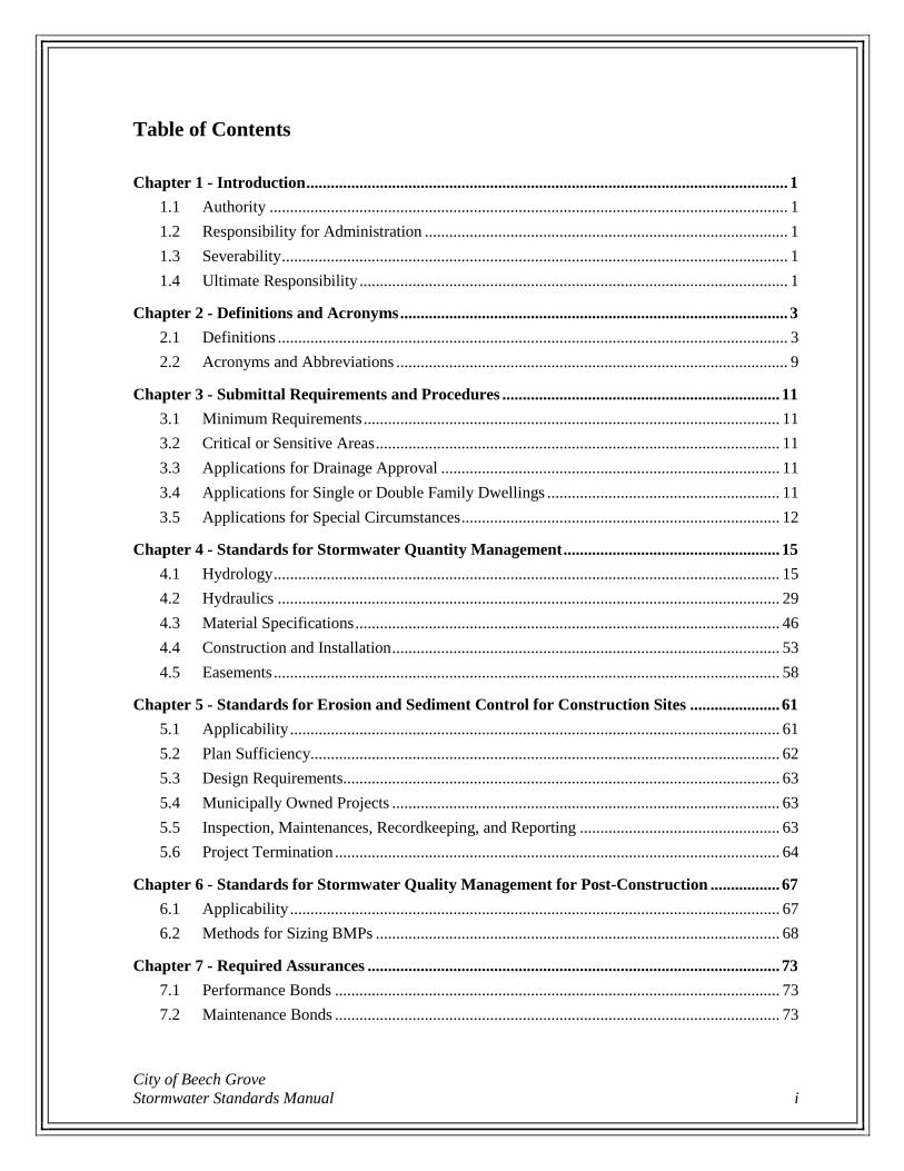
Chapter 1 - Introduction ...................................................................................................................... 1
1.1 Authority ............................................................................................................................... 1
1.2 Responsibility for Administration ......................................................................................... 1
1.3 Severability ............................................................................................................................ 1
1.4 Ultimate Responsibility ......................................................................................................... 1
Chapter 2 - Definitions and Acronyms ............................................................................................... 3
2.1 Definitions ............................................................................................................................. 3
2.2 Acronyms and Abbreviations ................................................................................................ 9
Chapter 3 - Submittal Requirements and Procedures .................................................................... 11
3.1 Minimum Requirements ...................................................................................................... 11
3.2 Critical or Sensitive Areas ................................................................................................... 11
3.3 Applications for Drainage Approval ................................................................................... 11
3.4 Applications for Single or Double Family Dwellings ......................................................... 11
3.5 Applications for Special Circumstances .............................................................................. 12
Chapter 4 - Standards for Stormwater Quantity Management ..................................................... 15
4.1 Hydrology ............................................................................................................................ 15
4.2 Hydraulics ........................................................................................................................... 29
4.3 Material Specifications ........................................................................................................ 46
4.4 Construction and Installation ............................................................................................... 53
4.5 Easements ............................................................................................................................ 58
Chapter 5 - Standards for Erosion and Sediment Control for Construction Sites ...................... 61
5.1 Applicability ........................................................................................................................ 61
5.2 Plan Sufficiency................................................................................................................... 62
5.3 Design Requirements........................................................................................................... 63
5.4 Municipally Owned Projects ............................................................................................... 63
5.5 Inspection, Maintenances, Recordkeeping, and Reporting ................................................. 63
5.6 Project Termination ............................................................................................................. 64
Chapter 6 - Standards for Stormwater Quality Management for Post-Construction ................. 67
6.1 Applicability ........................................................................................................................ 67
6.2 Methods for Sizing BMPs ................................................................................................... 68
Chapter 7 - Required Assurances ..................................................................................................... 73
7.1 Performance Bonds ............................................................................................................. 73
7.2 Maintenance Bonds ............................................................................................................. 73
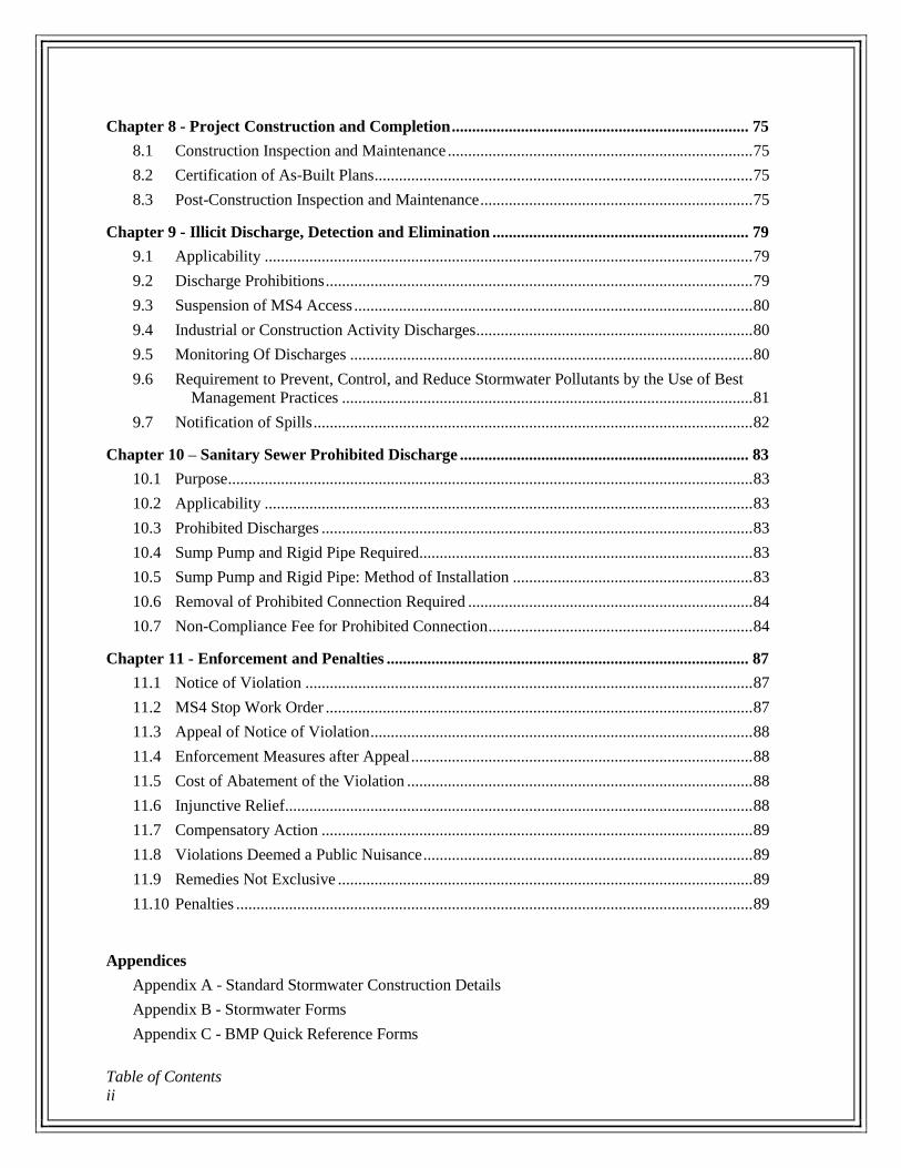
Table of Contents
ii
Chapter 8 - Project Construction and Completion ......................................................................... 75
8.1 Construction Inspection and Maintenance ........................................................................... 75
8.2 Certification of As-Built Plans ............................................................................................. 75
8.3 Post-Construction Inspection and Maintenance ................................................................... 75
Chapter 9 - Illicit Discharge, Detection and Elimination ............................................................... 79
9.1 Applicability ........................................................................................................................ 79
9.2 Discharge Prohibitions ......................................................................................................... 79
9.3 Suspension of MS4 Access .................................................................................................. 80
9.4 Industrial or Construction Activity Discharges.................................................................... 80
9.5 Monitoring Of Discharges ................................................................................................... 80
9.6 Requirement to Prevent, Control, and Reduce Stormwater Pollutants by the Use of Best
Management Practices ..................................................................................................... 81
9.7 Notification of Spills ............................................................................................................ 82
Chapter 10 – Sanitary Sewer Prohibited Discharge ....................................................................... 83
10.1 Purpose ................................................................................................................................. 83
10.2 Applicability ........................................................................................................................ 83
10.3 Prohibited Discharges .......................................................................................................... 83
10.4 Sump Pump and Rigid Pipe Required .................................................................................. 83
10.5 Sump Pump and Rigid Pipe: Method of Installation ........................................................... 83
10.6 Removal of Prohibited Connection Required ...................................................................... 84
10.7 Non-Compliance Fee for Prohibited Connection ................................................................. 84
Chapter 11 - Enforcement and Penalties ......................................................................................... 87
11.1 Notice of Violation .............................................................................................................. 87
11.2 MS4 Stop Work Order ......................................................................................................... 87
11.3 Appeal of Notice of Violation .............................................................................................. 88
11.4 Enforcement Measures after Appeal .................................................................................... 88
11.5 Cost of Abatement of the Violation ..................................................................................... 88
11.6 Injunctive Relief ................................................................................................................... 88
11.7 Compensatory Action .......................................................................................................... 89
11.8 Violations Deemed a Public Nuisance ................................................................................. 89
11.9 Remedies Not Exclusive ...................................................................................................... 89
11.10 Penalties ............................................................................................................................... 89
Appendices
Appendix A - Standard Stormwater Construction Details
Appendix B - Stormwater Forms
Appendix C - BMP Quick Reference Forms
City of Beech Grove
Stormwater Standards Manual iii
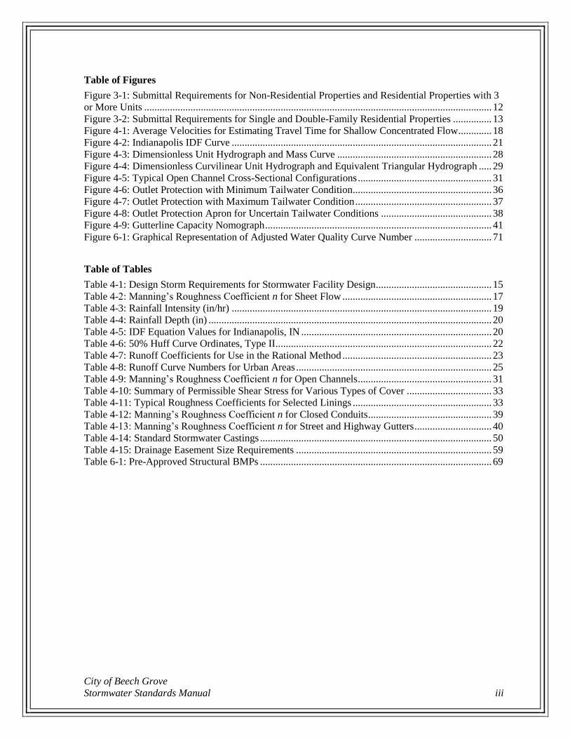
Table of Figures
Figure 3-1: Submittal Requirements for Non-Residential Properties and Residential Properties with 3
or More Units ....................................................................................................................................... 12
Figure 3-2: Submittal Requirements for Single and Double-Family Residential Properties ............... 13
Figure 4-1: Average Velocities for Estimating Travel Time for Shallow Concentrated Flow ............. 18
Figure 4-2: Indianapolis IDF Curve ..................................................................................................... 21
Figure 4-3: Dimensionless Unit Hydrograph and Mass Curve ............................................................ 28
Figure 4-4: Dimensionless Curvilinear Unit Hydrograph and Equivalent Triangular Hydrograph ..... 29
Figure 4-5: Typical Open Channel Cross-Sectional Configurations .................................................... 31
Figure 4-6: Outlet Protection with Minimum Tailwater Condition...................................................... 36
Figure 4-7: Outlet Protection with Maximum Tailwater Condition ..................................................... 37
Figure 4-8: Outlet Protection Apron for Uncertain Tailwater Conditions ........................................... 38
Figure 4-9: Gutterline Capacity Nomograph ........................................................................................ 41
Figure 6-1: Graphical Representation of Adjusted Water Quality Curve Number .............................. 71
Table of Tables
Table 4-1: Design Storm Requirements for Stormwater Facility Design ............................................. 15
Table 4-2: Manning’s Roughness Coefficient n for Sheet Flow .......................................................... 17
Table 4-3: Rainfall Intensity (in/hr) ..................................................................................................... 19
Table 4-4: Rainfall Depth (in) .............................................................................................................. 20
Table 4-5: IDF Equation Values for Indianapolis, IN .......................................................................... 20
Table 4-6: 50% Huff Curve Ordinates, Type II .................................................................................... 22
Table 4-7: Runoff Coefficients for Use in the Rational Method .......................................................... 23
Table 4-8: Runoff Curve Numbers for Urban Areas ............................................................................ 25
Table 4-9: Manning’s Roughness Coefficient n for Open Channels .................................................... 31
Table 4-10: Summary of Permissible Shear Stress for Various Types of Cover ................................. 33
Table 4-11: Typical Roughness Coefficients for Selected Linings ...................................................... 33
Table 4-12: Manning’s Roughness Coefficient n for Closed Conduits ................................................ 39
Table 4-13: Manning’s Roughness Coefficient n for Street and Highway Gutters .............................. 40
Table 4-14: Standard Stormwater Castings .......................................................................................... 50
Table 4-15: Drainage Easement Size Requirements ............................................................................ 59
Table 6-1: Pre-Approved Structural BMPs .......................................................................................... 69

Table of Contents
iv
City of Beech Grove
Stormwater Standards Manual 1
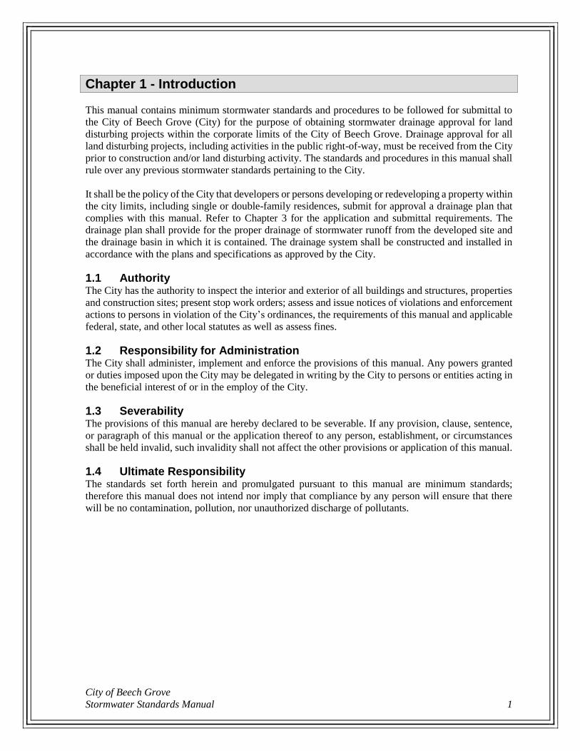
Chapter 1 - Introduction
This manual contains minimum stormwater standards and procedures to be followed for submittal to
the City of Beech Grove (City) for the purpose of obtaining stormwater drainage approval for land
disturbing projects within the corporate limits of the City of Beech Grove. Drainage approval for all
land disturbing projects, including activities in the public right-of-way, must be received from the City
prior to construction and/or land disturbing activity. The standards and procedures in this manual shall
rule over any previous stormwater standards pertaining to the City.
It shall be the policy of the City that developers or persons developing or redeveloping a property within
the city limits, including single or double-family residences, submit for approval a drainage plan that
complies with this manual. Refer to Chapter 3 for the application and submittal requirements. The
drainage plan shall provide for the proper drainage of stormwater runoff from the developed site and
the drainage basin in which it is contained. The drainage system shall be constructed and installed in
accordance with the plans and specifications as approved by the City.
1.1 Authority The City has the authority to inspect the interior and exterior of all buildings and structures, properties
and construction sites; present stop work orders; assess and issue notices of violations and enforcement
actions to persons in violation of the City’s ordinances, the requirements of this manual and applicable
federal, state, and other local statutes as well as assess fines.
1.2 Responsibility for Administration The City shall administer, implement and enforce the provisions of this manual. Any powers granted
or duties imposed upon the City may be delegated in writing by the City to persons or entities acting in
the beneficial interest of or in the employ of the City.
1.3 Severability The provisions of this manual are hereby declared to be severable. If any provision, clause, sentence,
or paragraph of this manual or the application thereof to any person, establishment, or circumstances
shall be held invalid, such invalidity shall not affect the other provisions or application of this manual.
1.4 Ultimate Responsibility The standards set forth herein and promulgated pursuant to this manual are minimum standards;
therefore this manual does not intend nor imply that compliance by any person will ensure that there
will be no contamination, pollution, nor unauthorized discharge of pollutants.

Chapter 1- Introduction
2
City of Beech Grove
Stormwater Standards Manual 3
Chapter 2 - Definitions and Acronyms
2.1 Definitions
As used in this manual, the following terms shall have meanings attributed to them as follows:
Agricultural Land Disturbing Activity – tillage, planting, cultivation, or harvesting operations for the
production of agricultural or nursery vegetative crops. The term also includes pasture
renovation and establishment, the construction of agricultural conservation practices, and the
installation and maintenance of agricultural drainage tile. For purposes of this ordinance, the
term does not include land disturbing activities for the construction of agricultural related
facilities, such as barns; buildings to house livestock; roads associated with infrastructure;
agricultural waste lagoons and facilities; lakes and ponds; wetlands; and other infrastructure.
As-Built Plans – a drawing or drawings accurately indicating the locations and dimensions of all
improvements installed in relation to development and/or redevelopment of a property or site.
Authorized Enforcement Agency – employees or designees of the City addressing the enforcement of
this manual.
Backfill, Initial – granular or other specified material placed from the springline of the pipe to the
specified height above the crown of the pipe, to provide adequate pipe support and to protect
the pipe from damage due to compaction of the final backfill.
Backfill, Final – granular or other specified material placed from the top of the initial backfill to the top
of the trench.
Bedding – granular material placed beneath the pipe to provide pipe support and to establish line and
grade.
Best Management Practice (BMP) – schedule of activities, prohibition of practices, general good
housekeeping practices, pollution prevention and educational practices, maintenance
procedures, treatment practices, operating procedures, and practices to control site runoff,
spillage or leaks, sludge or water disposal, or drainage from raw materials storage, and any
other management practices to prevent or reduce the discharge of pollutants directly or
indirectly to stormwater, receiving waters, or stormwater conveyance systems. BMPs also
include any structural or nonstructural control measures utilized to improve the quality and, as
appropriate, reduce the quantity of stormwater runoff.
Certified Contractor – a person who has received training and is licensed by the state or other local
agency to inspect and maintain erosion and sediment control practices and best management
practices.
Clean Water Act – the Federal Water Pollution Control Act (33 U.S.C. § 1251 et seq.), and any
subsequent amendments thereto.
Clearing – any activity that removes the vegetative surface cover.
Combined Sewer – sewer which has been designed or intended to receive both surface runoff and
sewage.
Compacted Gravel – a gravel, crushed stone, or rock surface that impedes or prevents the infiltration
of stormwater into the soil. Such surfaces are subject to vehicular or equipment traffic or may
be used as a roadway, driveway, alley or parking surface.
Chapter 2- Definitions and Acronyms
4
Construction Activity – land disturbing activities and land disturbing activities associated with the
construction of infrastructure and structures. This term does not include routine ditch or road
maintenance or minor landscaping projects.
Construction General Permit – see NPDES Stormwater Construction General Permit.
Construction Plan - a representation of a project site and all activities associated with the project. The
plan includes the location of the project site, buildings and other infrastructure, grading
activities, schedules for implementation, and other pertinent information related to the project
site. A stormwater pollution prevention plan is a part of the construction plan.
Conveyance – any structure for transferring stormwater between two points, including public streets,
roads, alleyways, and highways; curb and gutter; inlets, catch basins, manholes, and structures;
pumping stations; pipes and culverts; outfalls; channels, legal drains, creeks, ditches, swales,
and streams; retention or detention facilities; and other structural components and equipment
that transport, move or regulate stormwater.
Cover – the depth of backfill material over a pipe installation, measured from the crown of the pipe to
the bottom of asphalt pavement sections or to the ground surface for concrete pavement
sections or installations outside pavement.
Culvert – a pipe or conduit open on both ends, intended to provide for the free passage of surface water
runoff under highways, streets, roads, railroads, and embankments.
Detention – holding back stormwater runoff in temporary storage.
Detention Facility – a facility that collects and stores stormwater runoff thereby reducing the rate at
which runoff is discharged from the property. Detention storage involves detaining or slowing
runoff and then releasing it. A detention basin has a positive outlet that completely empties
stored stormwater between storm events.
Developer – any person financially responsible for construction activity; or an owner of property who
sells or leases, or offers for sale or lease, any lots in a subdivision.
Discharge – the flow of any stormwater runoff, pollutant, or other substance into or from a watershed,
point source, or stormwater facility into a stormwater system. The rate of flow may be measured
in cubic feet per second.
Drainage Area – the area that contributes runoff to a point of interest, such as a development site.
Drainage Basin – as in the Ohio River Basin or the Lick Creek Watershed, it is the land comprised of
one or more drainage areas or subbasins, from which the drainage flows to a common point.
The boundaries are determined by aerial photograph interpretation, topographic maps, and
visually viewing the land. Also called a Watershed.
Erosion – the detachment and movement of soil, sediment, or rock fragments by water, wind, ice, or
gravity.
Erosion and Sediment Control Measure – a practice, or a combination of practices, to control erosion
and resulting sedimentation.
Freeboard – the additional depth above the maximum flow elevation through the spillway of stormwater
detention/retention facilities, serving as a factor of safety to compensate for unknown factors.
Grading – the cutting and filling of the land surface to a desired slope or elevation.
City of Beech Grove
Stormwater Standards Manual 5
Haunching – granular or other specified material placed from the top of the bedding to the springline
of the pipe, installed uniformly in lifts on either side of the pipe and shoveled under the sides
of the pipe to provide resistance against soil and traffic loading.
Hazardous Materials – any material, including any substance, waste, or combination thereof, which
because of its quantity, concentration, or physical, chemical, or infectious characteristics may
cause, or significantly contribute to, a substantial present or potential hazard to human health,
safety, property, or the environment when improperly treated, stored, transported, disposed of,
or otherwise managed.
Illegal Discharge – any direct or indirect non-stormwater discharge to the stormwater conveyance
system, except as exempted in Part 9.2(A)(1) of this manual.
Illicit Connections – an illicit connection is defined as either of the following:
Any drain or conveyance, whether on the surface or subsurface, which allows an illegal
discharge to enter the stormwater conveyance system including but not limited to any
conveyances which allow any non-stormwater discharge including sewage, process
wastewater, and wash water to enter the stormwater conveyance system and any connections
to the stormwater conveyance system from indoor drains and sinks, regardless of whether said
drain or connection had been previously allowed, permitted, or approved by the City; or
Any drain or conveyance connected from a commercial or industrial land use to the stormwater
conveyance system which has not been documented in plans, maps, or equivalent records and
approved by the City.
Illicit Discharge – any discharge to an MS4 conveyance that is not composed entirely of stormwater,
except naturally occurring floatables, such as leaves or tree limbs. Sources of illicit discharges
include, but are not limited to, sanitary wastewater, septic tank effluent, car wash wastewater,
oil disposal, radiator flushing disposal, laundry wastewater, roadway accident spillage, and
household hazardous wastes. Exempted activities are identified in Part 9.2(A)(1) of this
manual.
Impervious Surface – the horizontal surface area of property covered with materials that include, but
are not limited to, concrete, asphalt, rooftop, blacktop, and compacted gravel, such that the
infiltration of stormwater is prevented or impeded.
Industrial Activity – activities subject to NPDES Industrial Permits as defined in 40 CFR 122.26
(b)(14).
Infiltration – passage or movement of water into the soil.
Land Disturbance – any manmade change of the land surface, including removing vegetative cover that
exposes the underlying soil, excavating, filling, transporting, and grading. Also called a Land
Disturbing Activity.
Land Disturbing Activity – see Land Disturbance.
Low-Impact Development – systems and practices that mimic a site's pre-development condition by
using design techniques to infiltrate, filter, store, evaporate, detain, and reuse stormwater runoff
on the site where it is generated. Low-impact development practices result in less surface runoff
and less pollution to streams, rivers, lakes, and other waterways.
Measurable Storm Event – a precipitation event that results in a total measured precipitation
accumulation equal to, or greater than, 0.5 inch of rainfall.

Chapter 2- Definitions and Acronyms
6
MS4 General Permit – see NPDES Stormwater Municipal Separate Storm Sewer Permit (MS4).
MS4 Stop Work Order – a legal notice requiring persons to immediately suspend all work and
operations.
Municipal Separate Storm Sewer System (MS4) – see Stormwater Conveyance System.
National Pollutant Discharge Elimination System (NPDES) – A permit issued by EPA (or by a State
under authority delegated pursuant to 33 USC §1342(b)) that authorizes the discharge of
pollutants to waters of the United States, whether the permit is applicable on an individual,
group, or general area-wide basis.
Non-Stormwater Discharge – any discharge to the stormwater conveyance system that is not composed
entirely of stormwater.
NPDES Stormwater Construction General Permit – State issued permit for authorization for stormwater
discharges associated with construction activities. Commonly known as a Rule 5 Permit (327
IAC 15-5). Also called a Construction General Permit.
NPDES Stormwater Municipal Separate Storm Sewer Permit (MS4) – State issued permit for
authorization for stormwater discharges associated with MS4 activities. Commonly known as
a Rule 13 Permit (327 IAC 15-13). Also called an MS4 General Permit.
Nuisance – no person shall erect, construct, cause, permit, keep or maintain within the city limits,
anything whatsoever which is injurious to the public health or safety, or offensive to the senses
of inhabitant. The existence of any of the above is declared to be a nuisance and shall be
regulated as set forth in Part 11.8 of this manual.
Pavement Loading Zone – the area within 5 feet horizontally of any edge of pavement, curb, gutter,
sidewalk, building, or other structure.
Person – any individual, association, organization, partnership, firm, corporation or other entity
recognized by law and acting as either the owner or as the owner's agent.
Pervious Surface Area – the horizontal surface area of property covered with materials that include, but
are not limited to, undisturbed land, tilled agricultural land, ponds, lawns (grass and landscaped
areas), and fields, such that the infiltration of stormwater is allowed or encouraged.
Pollutant – anything which causes or contributes to pollution. Pollutants may include, but are not
limited to: paints, varnishes, and solvents; oil and other automotive fluids; non-hazardous liquid
and solid wastes and yard wastes; refuse, rubbish, garbage, litter, or other discarded or
abandoned objects, ordinances, and accumulations, so that same may cause or contribute to
pollution; floatables; pesticides, herbicides, and fertilizers; hazardous substances and wastes;
sewage, fecal coliform and pathogens; dissolved and particulate metals; animal wastes; wastes
and residues that result from constructing a building or structure; and noxious or offensive
matter of any kind.
Post-Development Condition – the condition of a site which has been developed.
Pre-Development Condition – the condition of a site prior to land altering activities.
Premises – any building, lot, parcel of land, or portion of land whether improved or unimproved
including adjacent sidewalks and parking strips.
Project Site – the entire area on which construction activity is to be performed.
City of Beech Grove
Stormwater Standards Manual 7
Project Site Owner – the person required to submit the Notice of Intent (NOI) letter per the General
Permit and required to comply with the terms of these standards, this ordinance, and the General
Permit, including either a developer; or a person who has financial and operational control of
construction activities and project plans and specifications, including the ability to make
modifications to those plans and specifications.
Property Owner – the individual, partnership, corporation, or other legal entity holding the deed or
record of title to the property. A contract purchaser whose contract has been recorded shall be
considered a property owner.
Public Stormwater Facilities – facilities designed to transport, move or regulate stormwater that are
subject to the control and/or under the ownership of the local, state or federal government. This
shall include facilities in the right-of-way. Public stormwater facilities do not include
connections from underdrains, subsurface drainage tiles, building floor drains, downspout
outlets, or sump pump lines.
Retention – holding back stormwater runoff naturally in undrained ponds or artificially by man-made
ponds and planned retention basins for flood control.
Retention Facility – a facility that collects stormwater runoff without releasing it. Retention facilities
store runoff indefinitely and have no positive outlet. Stored stormwater is removed only by
infiltration into the ground or evaporation.
Runoff – the portion of precipitation that flows from a drainage area on the land surface, in open
channels, or in the stormwater conveyance system.
Sanitary Sewer – a sewer which carries sanitary and industrial wastes, and to which stormwater, surface
water and ground water are not intentionally admitted.
Sediment – solid material (both mineral and organic) that is in suspension, is being transported, or has
been moved from its site of origin by air, water, gravity, or ice and has come to rest on the
earth's surface.
Sediment Control – measures that prevent eroded sediment from leaving the project site.
Sewage – raw, untreated wastewater.
Soil – the unconsolidated mineral and organic material on the surface of the earth that serves as the
natural medium for the growth of plants.
Spill – any unexpected, unintended, abnormal, or unapproved dumping, leakage, drainage, seepage,
discharge or other loss of petroleum, hazardous substances, extremely hazardous substances,
or objectionable substances. The term does not include releases to impermeable surfaces when
the substance does not migrate off the surface or penetrate the surface and enter the soil.
Storm Sewer – a sewer (underground piped system) which carries storm and surface water and drainage,
but excludes sewage and industrial wastes, other than unpolluted cooling water and which is
part of the stormwater conveyance system.
Stormwater – any surface flow, runoff, and drainage consisting entirely of water from any form of
natural precipitation, and resulting from such precipitation.
Stormwater Conveyance System – all publicly-owned facilities and conveyances used for collecting
and conveying stormwater to, through and from drainage areas to the point of final outlet. Also
called a Municipal Separate Storm Sewer System (MS4).

Chapter 2- Definitions and Acronyms
8
Stormwater Facilities – all stormwater and drainage components used for collecting and conveying
stormwater including but not limited to conduits and appurtenant features; public streets, roads,
alleyways, and highways; gutters; curbs; inlets, catch basins, manholes, and structures;
pumping stations; pipes and culverts; outfalls; natural and human-made or altered channels,
creeks, ditches, swales, and streams; retention or detention facilities; and other structural
components and equipment that transport, move or regulate stormwater.
Stormwater Management Activities – activities conducted by the Public Works Department and the
City of Beech Grove that benefit stormwater utility customers and allow the City to comply
with federal and state laws and regulations. Stormwater management activities may include:
stormwater monitoring and sampling; storm grate marking; street sweeping; public stormwater
facilities maintenance and cleaning; capital improvement projects for flood control; stormwater
quality education; erosion and sediment control; post-construction stormwater quality; illicit
discharge detection and elimination; and utility administrative functions.
Stormwater Pollution Prevention Plan (SWPPP) – a written document that addresses stormwater runoff,
identifies potential sources of pollution and outlines specific management activities designed
to minimize the introduction of pollutants into stormwater.
Stormwater Quality – a measurement of pollutant loadings contained in stormwater runoff. An increase
in stormwater quality is a reduction of the amount of pollutants in the stormwater runoff.
Stormwater Quality Measure – a practice, or a combination of practices, to control or minimize
pollutants associated with stormwater runoff.
Subdivision – any land that is divided or proposed to be divided into lots, whether contiguous or subject
to zoning requirements, for the purpose of sale or lease as part of a larger common plan of
Development or Sale.
Trained Individual – an individual who is trained and experienced in the principles of stormwater
quality, including erosion and sediment control as may be demonstrated by state registration,
professional certification, experience, or completion of coursework that enable the individual
to make judgments regarding stormwater control or treatment and monitoring.
Wastewater – any water or other liquid, other than uncontaminated stormwater, discharged from a
facility.
Watercourse – a natural or manmade channel through which water flows; includes legal drains, creeks,
ditches, swales, streams, and other open channels. Also called a Waterway.
Watershed – see Drainage Basin.
Waterway – see Watercourse.

City of Beech Grove
Stormwater Standards Manual 9
2.2 Acronyms and Abbreviations
AASHTO American Association of State Highway and Transportation Officials
ACOE Army Corps of Engineers
ASTM American Society of Testing and Materials
BMP Best Management Practice
CMP Corrugated Metal Pipe
EPA United States Environmental Protection Agency
HDPE High Density Polyethylene
IAC Indiana Administrative Code
IC Indiana Code
IDEM Indiana Department of Environmental Management
IDF Intensity-Duration-Frequency
IDNR Indiana Department of Natural Resources
INDOT Indiana Department of Transportation
LID Low Impact Development
MS4 Municipal Separate Storm Sewer System
NOI Notice of Intent
NOT Notice of Termination
NPDES National Pollutant Discharge Elimination System
NRCS Natural Resources Conservation Service
O&M Operations and Maintenance
PCPP Perforated Corrugated Polyethylene Pipe
PP Polypropylene
PVC Polyvinyl Chloride
RCP Reinforced Concrete Pipe
SCS Soil Conservation Service
SDR Standard Dimension Ratio
SWCD Soil and Water Conservation District
SWPPP Stormwater Pollution Prevention Plan
TSS Total Suspended Solids
USDA United States Department of Agriculture
USGS United States Geological Survey

Chapter 2- Definitions and Acronyms
10
City of Beech Grove
Stormwater Standards Manual 11
Chapter 3 - Submittal Requirements and Procedures
3.1 Minimum Requirements
(A) All projects shall comply with the requirements of this manual, including both Residential and
Non-Residential properties. Refer to Figure 3-1 and Figure 3-2 for an overview of the submittal
requirements for all projects.
(B) An Application for Drainage Approval and all other applicable documents must be submitted
to the City for the purpose of obtaining stormwater drainage approval for all land disturbing
projects, including activities in the public right-of-way, prior to construction and/or land
disturbing activity.
3.2 Critical or Sensitive Areas
(A) A project is considered within a critical or sensitive area when the project site is located within,
near, or tributary to an environmentally critical / sensitive area (e.g. wetlands) or an area with
known erosion or drainage problems.
(B) The City may require projects within these critical or sensitive areas to comply with Stormwater
Pollution Prevention Plan, erosion control, post-construction water quality, downstream
analysis, stormwater detention analysis, and other requirements as necessary to protect the
critical or sensitive area.
3.3 Applications for Drainage Approval
(A) All Non-Residential properties and Residential properties with 3 or more units may refer to the
submittal requirements summarized in Figure 3-1.
(B) A complete Application for Drainage Approval (Form B-1 in Appendix B) shall include the
items identified on the Application for Drainage Approval Submittal Checklist (Form B-2 in
Appendix B). A submittal will not be considered complete until all applicable items on the
submittal checklist have been submitted. Application fees are non-refundable.
(C) New development projects may include with their Application for Drainage Approval the
Application for Stormwater User Fee Credit found in the City of Beech Grove Stormwater
Utility Policies and Procedures Manual, if applicable.
(D) A response letter with any comments generated as a result of the drainage review will be issued
to the professional engineer/land surveyor responsible for completing the design.
(E) Upon notification of final drainage approval, 3 sets of professionally certified plans and
specifications shall be submitted to the City.
3.4 Applications for Single or Double Family Dwellings
(A) Single and Double-Family Residential properties may refer to the submittal requirements
summarized in Figure 3-2.
(B) A single or double family dwelling constructed or placed on an individual lot with land
disturbance greater than or equal to 10,000 square feet shall require drainage approval from the
City. Application fees are non-refundable.
(C) Submittal requirements shall be as defined in the Application for Drainage Approval for Single
and Double-Family Dwellings (Form B-3 in Appendix B).
Chapter 3- Submittal Requirements and Procedures
12
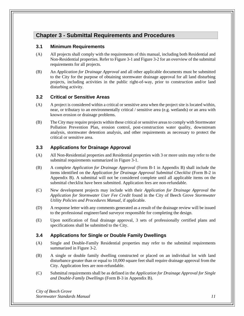
3.5 Applications for Special Circumstances Special circumstances that are not covered by these Stormwater Standards shall be regulated and
reviewed on a case-by-case basis.
Figure 3-1: Submittal Requirements for Non-Residential Properties and Residential Properties
with 3 or More Units
Non-Residential Propertiesand
Residential Properties with 3 or More Units
Land Disturbance < 10,000 sfAND
< 25% Increase in Impervious Surface Area
Critical/sensitive area?
No
No Application Necessary
Yes
Application for Drainage Approval
(Forms B-1 and B-2)
SWPPP May Be Required
Post-Construction
Water Quality May Be Required
Downstream Analysis May Be Required
Land Disturbance ≥ 10,000 sfand/or
≥ 25% Increase in Impervious Surface Area
Critical/sensitive area?
No
Application for Drainage Approval
(Forms B-1 and B-2)
Detention Analysis Required
Yes
Application for Drainage Approval
(Forms B-1 and B-2)
Detention Analysis Required
SWPPP May Be Required
Post-Construction
Water Quality May Be Required
Downstream Analysis May Be Required
Land Disturbance ≥ 1 acre
Critical/sensitive area?
No
Application for Drainage Approval
(Forms B-1 and B-2)
Detention Analysis Required
SWPPP Required
Post-Construction
Water Quality Required
Yes
Application for Drainage Approval
(Forms B-1 and B-2)
Detention Analysis Required
SWPPP Required
Post-Construction
Water Quality Required
Downstream Analysis Required
City of Beech Grove
Stormwater Standards Manual 13
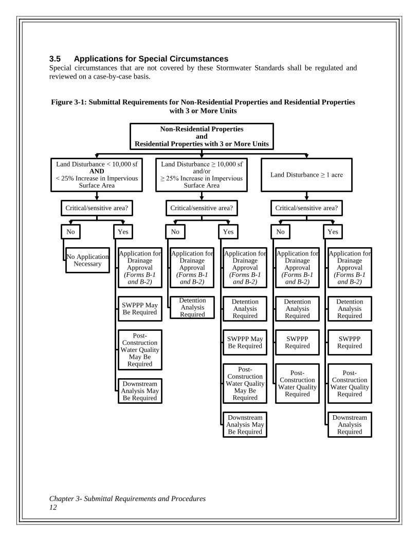
Figure 3-2: Submittal Requirements for Single and Double-Family Residential Properties
Single and Double-FamilyResidential Properties
When Building Permit is Not RequiredAND
Land Disturbance < 10,000 sf
Critical/sensitive area?
No
No Application Necessary
Yes
Application for Drainage Approval forSingle and Double-Family Dwellings
(Form B-3)
When Building Permit is Requiredand/or
Land Disturbance ≥ 10,000 sf
Application for Drainage Approval forSingle and Double-Family Dwellings
(Form B-3)

Chapter 3- Submittal Requirements and Procedures
14

City of Beech Grove
Stormwater Standards Manual 15
Chapter 4- Standards for Stormwater Quantity Management
4.1 Hydrology
(A) Hydrologic Method
(1) The same hydrologic method shall be used for runoff peak determination for both pre-
developed and post-developed condition calculations.
(2) Recommended hydrologic methods are listed in Part 4.1(G) of this manual. If a
designer proposes an alternative method, the method must first be calibrated to local
conditions and tested for accuracy and reliability. Complete source documentation
shall be submitted for review and approval by the City. USGS Regression equations
are not applicable for projects within Marion County.
(B) Design Storm Frequency
(1) Peak runoff calculations and stormwater facility design shall be based upon the design
storm frequency for each type of facility as shown in Table 4-1.
Table 4-1: Design Storm Requirements for Stormwater Facility Design
Stormwater Facility Type Return Interval
Storm Sewer (Enclosed Stormwater Facility) 10-year(1)
Storm Inlet Grates 10-year
Culvert (Public) 25-year
Bridge Structure (2) 100-year
Open Channel 10-year
Regulatory Floodway 100-year
Detention/Retention Facilities Varies, see Part 4.2(F) of this manual (1) Stormwater facilities are considered bridge structures with upstream watersheds
greater than or equal to 1 square mile. The Indiana Department of Natural
Resources (IDNR) has authority over the design of all bridge structures. (2) The water surface elevation resulting from a 10-year storm shall remain in the
storm sewer pipe. The water surface elevation resulting from a 25-year storm
shall remain within the drainage easement.
(C) Upstream Off-Site Hydrologic Analysis
(1) Stormwater systems shall be designed to accommodate the following:
(a) Upstream off-site overland drainage and diffused stormwater flows
(b) Upstream drainage tiles, storm sewers, open channels, or other stormwater
facilities
(c) Stormwater runoff and stormwater collected within the project site or property
(2) Due to the potential impact of site development on the character of a watershed and
area-wide drainage, investigation of stormwater facilities outside the boundaries of the
site shall be required as part of the design process except in the case where an oversized
detention facility is provided in lieu of downstream analysis as described in Part 4.1(D)
of this manual. The extent of these analyses shall depend upon the nature of the off-
site stormwater facilities, and circumstances unique to each developing property. These
guidelines for off-site analysis should be viewed by the designer as a minimum
performance standard only, and are not intended to replace engineering judgment. As
Chapter 4- Standards for Stormwater Quantity Management
16
such, site conditions may dictate a more extensive off-site analysis than that set forth
herein.
(D) Downstream Conveyance Analysis
(1) Downstream analysis may be required on a case-by-case basis as determined by the
City of Beech Grove to evaluate impacts to existing systems and to known erosion and
drainage problems. The extent of downstream conveyance analysis shall be sufficient
to demonstrate an adequate outlet, as determined by the City of Beech Grove.
(E) Time of Concentration
(1) Time of concentration shall be the time it takes for runoff to travel from the
hydraulically most distant point in the subarea to its outfall point under consideration.
Time of concentration calculations shall consist of overland (sheet) flow time, shallow
concentrated flow time, and travel time in channels, pipes, gutters, etc.
(2) A worksheet for time of concentration calculations is provided as Form B-7 in
Appendix B.
(3) The minimum time of concentration shall be 5 minutes.
(4) Overland (Sheet) Flow
(a) The maximum overland (sheet) flow length shall be 300 feet for pervious area
and 100 feet for impervious area. After these distances, flow over land shall
be calculated as shallow concentrated flow or channel flow as appropriate.
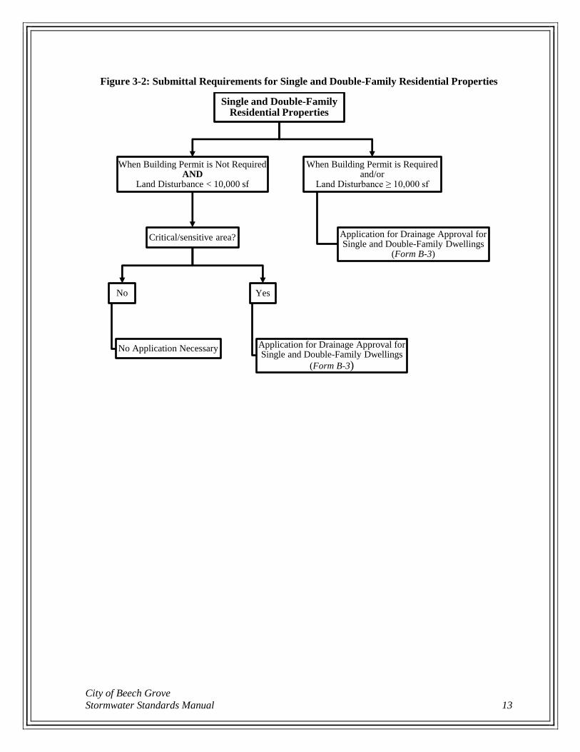
(b) Overland flow time shall be calculated as follows:
Equation 4-1
Tt = 0.007 (n L) 0.8
(P2) 0.5 S 0.4
where:
Tt = travel time (hours, hr)
n = Manning’s roughness coefficient for sheet flow – see Table 4-2
L = flow path length (feet, ft)
P2 = rainfall depth for the 2-year, 24-hour rainfall (inches, in) – see Table 4-4
S = land slope (feet/feet, ft/ft)
City of Beech Grove
Stormwater Standards Manual 17
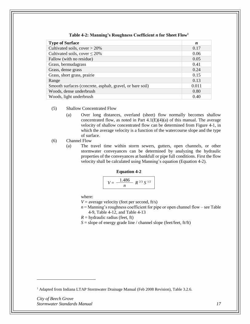
Table 4-2: Manning’s Roughness Coefficient n for Sheet Flow1
Type of Surface n
Cultivated soils, cover > 20% 0.17
Cultivated soils, cover ≤ 20% 0.06
Fallow (with no residue) 0.05
Grass, bermudagrass 0.41
Grass, dense grass 0.24
Grass, short grass, prairie 0.15
Range 0.13
Smooth surfaces (concrete, asphalt, gravel, or bare soil) 0.011
Woods, dense underbrush 0.80
Woods, light underbrush 0.40
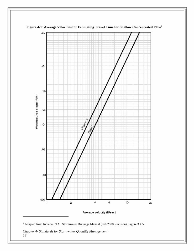
(5) Shallow Concentrated Flow
(a) Over long distances, overland (sheet) flow normally becomes shallow
concentrated flow, as noted in Part 4.1(E)(4)(a) of this manual. The average
velocity of shallow concentrated flow can be determined from Figure 4-1, in
which the average velocity is a function of the watercourse slope and the type
of surface.
(6) Channel Flow
(a) The travel time within storm sewers, gutters, open channels, or other
stormwater conveyances can be determined by analyzing the hydraulic
properties of the conveyances at bankfull or pipe full conditions. First the flow
velocity shall be calculated using Manning’s equation (Equation 4-2).
Equation 4-2
V = 1.486
R 2/3 S 1/2
n
where:
V = average velocity (feet per second, ft/s)
n = Manning’s roughness coefficient for pipe or open channel flow – see Table
4-9, Table 4-12, and Table 4-13
R = hydraulic radius (feet, ft)
S = slope of energy grade line / channel slope (feet/feet, ft/ft)
1 Adapted from Indiana LTAP Stormwater Drainage Manual (Feb 2008 Revision), Table 3.2.6.
Chapter 4- Standards for Stormwater Quantity Management
18
Figure 4-1: Average Velocities for Estimating Travel Time for Shallow Concentrated Flow2
2 Adapted from Indiana LTAP Stormwater Drainage Manual (Feb 2008 Revision), Figure 3.4.5.
City of Beech Grove
Stormwater Standards Manual 19
(b) Using the flow velocity, the travel time can be calculated as follows:
Equation 4-3
Tt = L
3600 V
where:
Tt = travel time in pipe, channel, gutter, etc. (hours, hr)
L = reach length (feet, ft)
V = average flow velocity in reach (feet per second, ft/s)
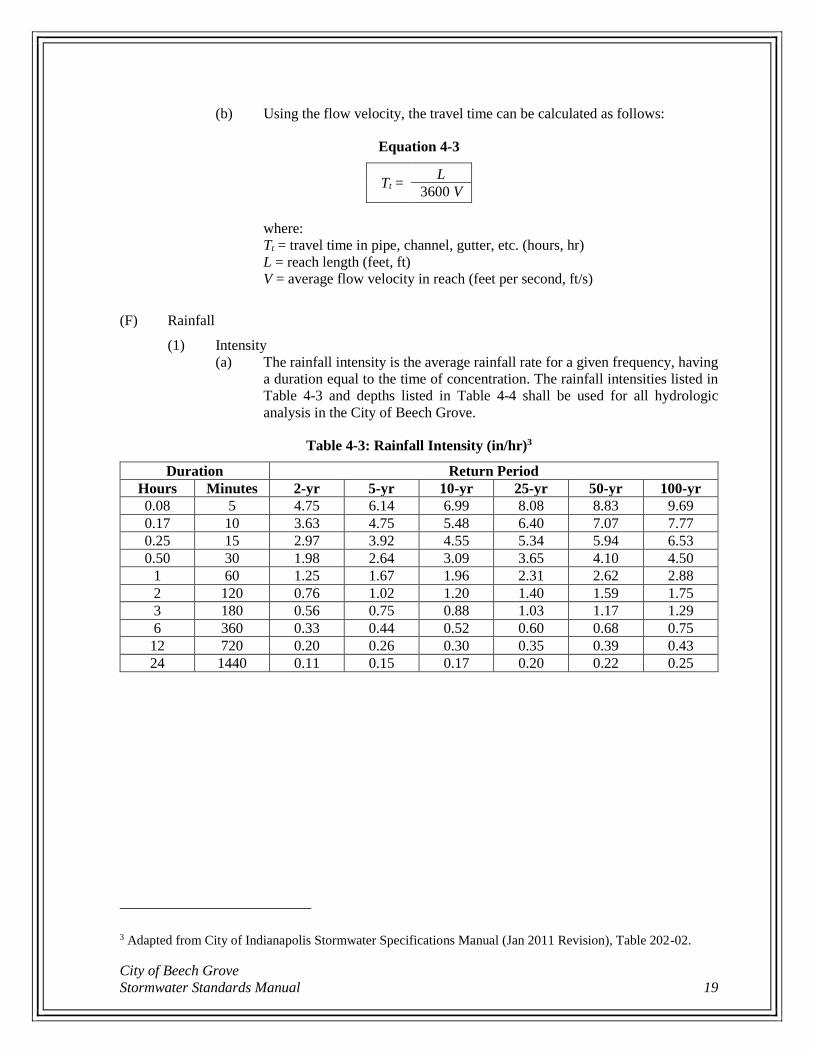
(F) Rainfall
(1) Intensity
(a) The rainfall intensity is the average rainfall rate for a given frequency, having
a duration equal to the time of concentration. The rainfall intensities listed in
Table 4-3 and depths listed in Table 4-4 shall be used for all hydrologic
analysis in the City of Beech Grove.
Table 4-3: Rainfall Intensity (in/hr)3
Duration Return Period
Hours Minutes 2-yr 5-yr 10-yr 25-yr 50-yr 100-yr
0.08 5 4.75 6.14 6.99 8.08 8.83 9.69
0.17 10 3.63 4.75 5.48 6.40 7.07 7.77
0.25 15 2.97 3.92 4.55 5.34 5.94 6.53
0.50 30 1.98 2.64 3.09 3.65 4.10 4.50
1 60 1.25 1.67 1.96 2.31 2.62 2.88
2 120 0.76 1.02 1.20 1.40 1.59 1.75
3 180 0.56 0.75 0.88 1.03 1.17 1.29
6 360 0.33 0.44 0.52 0.60 0.68 0.75
12 720 0.20 0.26 0.30 0.35 0.39 0.43
24 1440 0.11 0.15 0.17 0.20 0.22 0.25
3 Adapted from City of Indianapolis Stormwater Specifications Manual (Jan 2011 Revision), Table 202-02.
Chapter 4- Standards for Stormwater Quantity Management
20
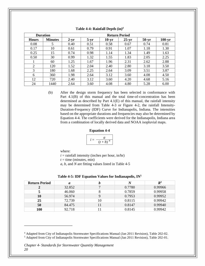
Table 4-4: Rainfall Depth (in)4
Duration Return Period
Hours Minutes 2-yr 5-yr 10-yr 25-yr 50-yr 100-yr
0.08 5 0.40 0.51 0.58 0.67 0.74 0.81
0.17 10 0.61 0.79 0.91 1.07 1.18 1.30
0.25 15 0.74 0.98 1.14 1.34 1.49 1.63
0.50 30 0.99 1.32 1.55 1.83 2.05 2.25
1 60 1.25 1.67 1.96 2.31 2.62 2.88
2 120 1.52 2.04 2.40 2.80 3.18 3.50
3 180 1.68 2.25 2.64 3.09 3.51 3.87
6 360 1.98 2.64 3.12 3.60 4.08 4.50
12 720 2.40 3.12 3.60 4.20 4.68 5.16
24 1440 2.64 3.60 4.08 4.80 5.28 6.00
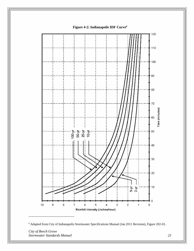
(b) After the design storm frequency has been selected in conformance with
Part 4.1(B) of this manual and the total time-of-concentration has been
determined as described by Part 4.1(E) of this manual, the rainfall intensity
may be determined from Table 4-3 or Figure 4-2, the rainfall Intensity-
Duration-Frequency (IDF) Curve for Indianapolis, Indiana. The intensities
based on the appropriate durations and frequencies may also be determined by
Equation 4-4. The coefficients were derived for the Indianapolis, Indiana area
from a combination of locally derived data and NOAA isopluvial maps.
Equation 4-4
i = a
(t + b) N
where:
i = rainfall intensity (inches per hour, in/hr)
t = time (minutes, min)
a, b, and N are fitting values listed in Table 4-5
Table 4-5: IDF Equation Values for Indianapolis, IN5
Return Period a b N R2
2 32.852 7 0.7780 0.99966
5 46.060 8 0.7859 0.99958
10 56.974 9 0.7953 0.99952
25 72.739 10 0.8115 0.99942
50 84.475 11 0.8147 0.99940
100 92.718 11 0.8145 0.99942
4 Adapted from City of Indianapolis Stormwater Specifications Manual (Jan 2011 Revision), Table 202-02. 5 Adapted from City of Indianapolis Stormwater Specifications Manual (Jan 2011 Revision), Table 202-01.
City of Beech Grove
Stormwater Standards Manual 21
Figure 4-2: Indianapolis IDF Curve6
6 Adapted from City of Indianapolis Stormwater Specifications Manual (Jan 2011 Revision), Figure 202-01.
Chapter 4- Standards for Stormwater Quantity Management
22
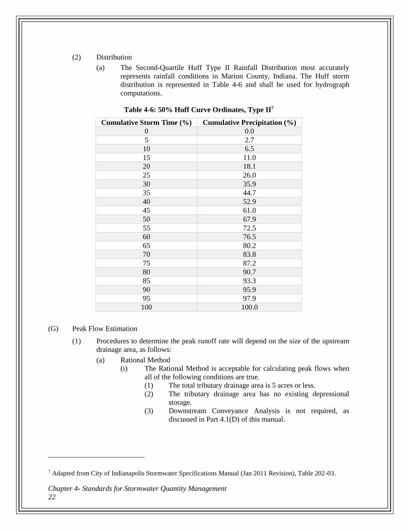
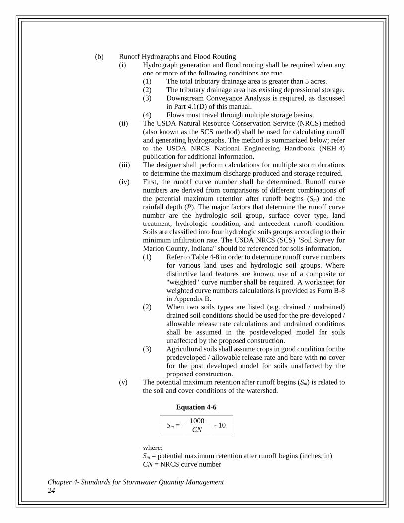
(2) Distribution
(a) The Second-Quartile Huff Type II Rainfall Distribution most accurately
represents rainfall conditions in Marion County, Indiana. The Huff storm
distribution is represented in Table 4-6 and shall be used for hydrograph
computations.
Table 4-6: 50% Huff Curve Ordinates, Type II7
Cumulative Storm Time (%) Cumulative Precipitation (%)
0 0.0
5 2.7
10 6.5
15 11.0
20 18.1
25 26.0
30 35.9
35 44.7
40 52.9
45 61.0
50 67.9
55 72.5
60 76.5
65 80.2
70 83.8
75 87.2
80 90.7
85 93.3
90 95.9
95 97.9
100 100.0
(G) Peak Flow Estimation
(1) Procedures to determine the peak runoff rate will depend on the size of the upstream
drainage area, as follows:
(a) Rational Method
(i) The Rational Method is acceptable for calculating peak flows when
all of the following conditions are true.
(1) The total tributary drainage area is 5 acres or less.
(2) The tributary drainage area has no existing depressional
storage.
(3) Downstream Conveyance Analysis is not required, as
discussed in Part 4.1(D) of this manual.
7 Adapted from City of Indianapolis Stormwater Specifications Manual (Jan 2011 Revision), Table 202-03.
City of Beech Grove
Stormwater Standards Manual 23
(ii) The Rational Method is based on:
Equation 4-5
Q = C i A
where:
Q = peak discharge (cubic feet per second, cfs)
C = runoff coefficient, or the ratio of peak runoff rate to average
rainfall rate over the watershed during the time of concentration
i = rainfall intensity (inches/hour, in/hr)
A = contributing area of watershed under consideration (acres)
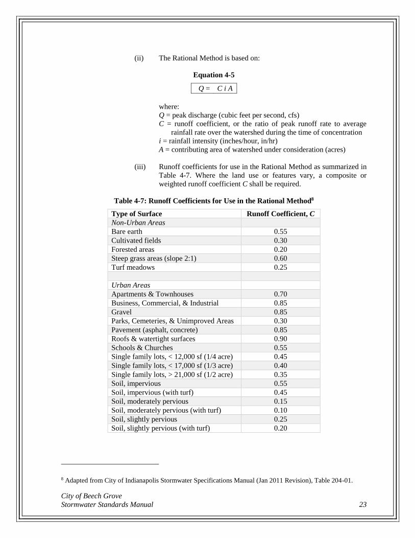
(iii) Runoff coefficients for use in the Rational Method as summarized in
Table 4-7. Where the land use or features vary, a composite or
weighted runoff coefficient C shall be required.
Table 4-7: Runoff Coefficients for Use in the Rational Method8
Type of Surface Runoff Coefficient, C
Non-Urban Areas
Bare earth 0.55
Cultivated fields 0.30
Forested areas 0.20
Steep grass areas (slope 2:1) 0.60
Turf meadows 0.25
Urban Areas
Apartments & Townhouses 0.70
Business, Commercial, & Industrial 0.85
Gravel 0.85
Parks, Cemeteries, & Unimproved Areas 0.30
Pavement (asphalt, concrete) 0.85
Roofs & watertight surfaces 0.90
Schools & Churches 0.55
Single family lots, < 12,000 sf (1/4 acre) 0.45
Single family lots, < 17,000 sf (1/3 acre) 0.40
Single family lots, > 21,000 sf (1/2 acre) 0.35
Soil, impervious 0.55
Soil, impervious (with turf) 0.45
Soil, moderately pervious 0.15
Soil, moderately pervious (with turf) 0.10
Soil, slightly pervious 0.25
Soil, slightly pervious (with turf) 0.20
8 Adapted from City of Indianapolis Stormwater Specifications Manual (Jan 2011 Revision), Table 204-01.
Chapter 4- Standards for Stormwater Quantity Management
24
(b) Runoff Hydrographs and Flood Routing
(i) Hydrograph generation and flood routing shall be required when any
one or more of the following conditions are true.
(1) The total tributary drainage area is greater than 5 acres.
(2) The tributary drainage area has existing depressional storage.
(3) Downstream Conveyance Analysis is required, as discussed
in Part 4.1(D) of this manual.
(4) Flows must travel through multiple storage basins.
(ii) The USDA Natural Resource Conservation Service (NRCS) method
(also known as the SCS method) shall be used for calculating runoff
and generating hydrographs. The method is summarized below; refer
to the USDA NRCS National Engineering Handbook (NEH-4)
publication for additional information.
(iii) The designer shall perform calculations for multiple storm durations
to determine the maximum discharge produced and storage required.
(iv) First, the runoff curve number shall be determined. Runoff curve
numbers are derived from comparisons of different combinations of
the potential maximum retention after runoff begins (Sm) and the
rainfall depth (P). The major factors that determine the runoff curve
number are the hydrologic soil group, surface cover type, land
treatment, hydrologic condition, and antecedent runoff condition.
Soils are classified into four hydrologic soils groups according to their
minimum infiltration rate. The USDA NRCS (SCS) "Soil Survey for
Marion County, Indiana" should be referenced for soils information.
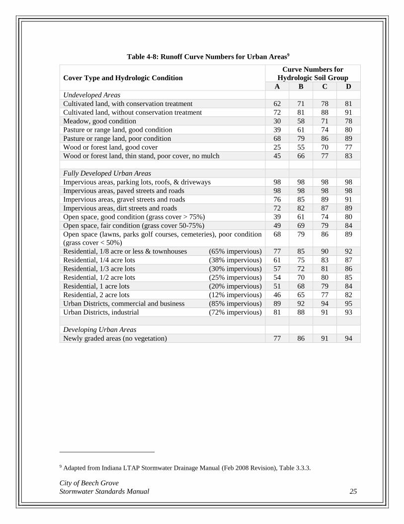
(1) Refer to Table 4-8 in order to determine runoff curve numbers
for various land uses and hydrologic soil groups. Where
distinctive land features are known, use of a composite or
"weighted" curve number shall be required. A worksheet for
weighted curve numbers calculations is provided as Form B-8
in Appendix B.
(2) When two soils types are listed (e.g. drained / undrained)
drained soil conditions should be used for the pre-developed /
allowable release rate calculations and undrained conditions
shall be assumed in the postdeveloped model for soils
unaffected by the proposed construction.
(3) Agricultural soils shall assume crops in good condition for the
predeveloped / allowable release rate and bare with no cover
for the post developed model for soils unaffected by the
proposed construction.
(v) The potential maximum retention after runoff begins (Sm) is related to
the soil and cover conditions of the watershed.
Equation 4-6
Sm = 1000
- 10 CN
where:
Sm = potential maximum retention after runoff begins (inches, in)
CN = NRCS curve number
City of Beech Grove
Stormwater Standards Manual 25
Table 4-8: Runoff Curve Numbers for Urban Areas9
Cover Type and Hydrologic Condition
Curve Numbers for
Hydrologic Soil Group
A B C D
Undeveloped Areas
Cultivated land, with conservation treatment 62 71 78 81
Cultivated land, without conservation treatment 72 81 88 91
Meadow, good condition 30 58 71 78
Pasture or range land, good condition 39 61 74 80
Pasture or range land, poor condition 68 79 86 89
Wood or forest land, good cover 25 55 70 77
Wood or forest land, thin stand, poor cover, no mulch 45 66 77 83
Fully Developed Urban Areas
Impervious areas, parking lots, roofs, & driveways 98 98 98 98
Impervious areas, paved streets and roads 98 98 98 98
Impervious areas, gravel streets and roads 76 85 89 91
Impervious areas, dirt streets and roads 72 82 87 89
Open space, good condition (grass cover > 75%) 39 61 74 80
Open space, fair condition (grass cover 50-75%) 49 69 79 84
Open space (lawns, parks golf courses, cemeteries), poor condition
(grass cover < 50%)
68 79 86 89
Residential, 1/8 acre or less & townhouses (65% impervious) 77 85 90 92
Residential, 1/4 acre lots (38% impervious) 61 75 83 87
Residential, 1/3 acre lots (30% impervious) 57 72 81 86
Residential, 1/2 acre lots (25% impervious) 54 70 80 85
Residential, 1 acre lots (20% impervious) 51 68 79 84
Residential, 2 acre lots (12% impervious) 46 65 77 82
Urban Districts, commercial and business (85% impervious) 89 92 94 95
Urban Districts, industrial (72% impervious) 81 88 91 93
Developing Urban Areas
Newly graded areas (no vegetation) 77 86 91 94
9 Adapted from Indiana LTAP Stormwater Drainage Manual (Feb 2008 Revision), Table 3.3.3.
Chapter 4- Standards for Stormwater Quantity Management
26
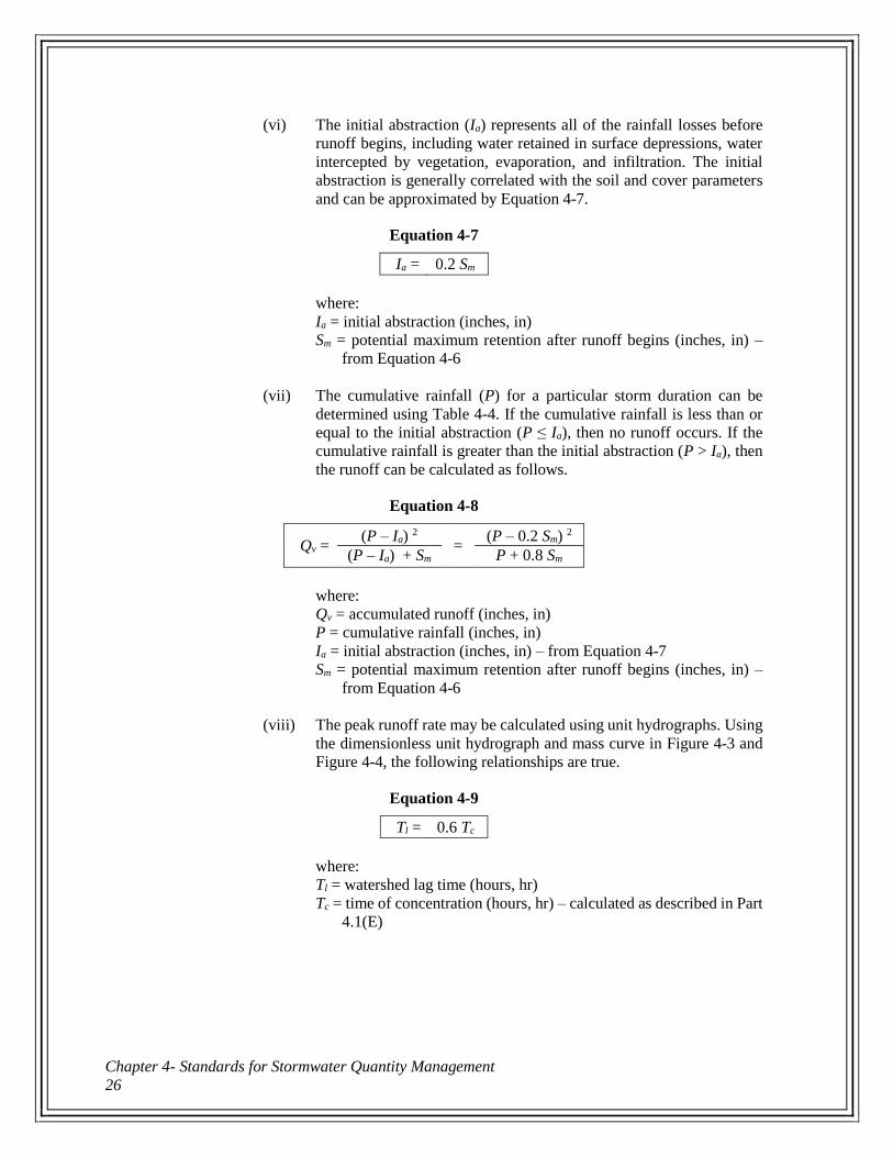
(vi) The initial abstraction (Ia) represents all of the rainfall losses before
runoff begins, including water retained in surface depressions, water
intercepted by vegetation, evaporation, and infiltration. The initial
abstraction is generally correlated with the soil and cover parameters
and can be approximated by Equation 4-7.
Equation 4-7
Ia = 0.2 Sm
where:
Ia = initial abstraction (inches, in)
Sm = potential maximum retention after runoff begins (inches, in) –
from Equation 4-6
(vii) The cumulative rainfall (P) for a particular storm duration can be
determined using Table 4-4. If the cumulative rainfall is less than or
equal to the initial abstraction (P ≤ Ia), then no runoff occurs. If the
cumulative rainfall is greater than the initial abstraction (P > Ia), then
the runoff can be calculated as follows.
Equation 4-8
Qv = (P – Ia) 2
= (P – 0.2 Sm) 2
(P – Ia) + Sm P + 0.8 Sm
where:
Qv = accumulated runoff (inches, in)
P = cumulative rainfall (inches, in)
Ia = initial abstraction (inches, in) – from Equation 4-7
Sm = potential maximum retention after runoff begins (inches, in) –
from Equation 4-6
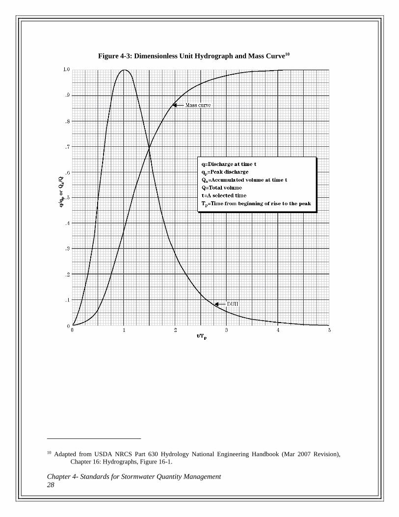
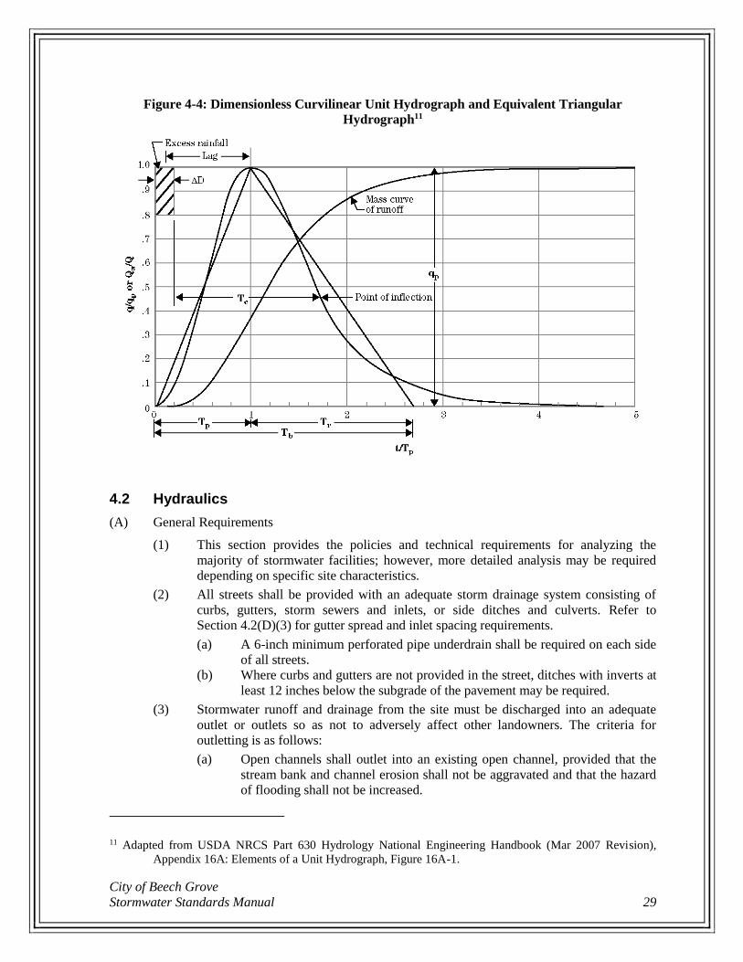
(viii) The peak runoff rate may be calculated using unit hydrographs. Using
the dimensionless unit hydrograph and mass curve in Figure 4-3 and
Figure 4-4, the following relationships are true.
Equation 4-9
Tl = 0.6 Tc
where:
Tl = watershed lag time (hours, hr)
Tc = time of concentration (hours, hr) – calculated as described in Part
4.1(E)
City of Beech Grove
Stormwater Standards Manual 27
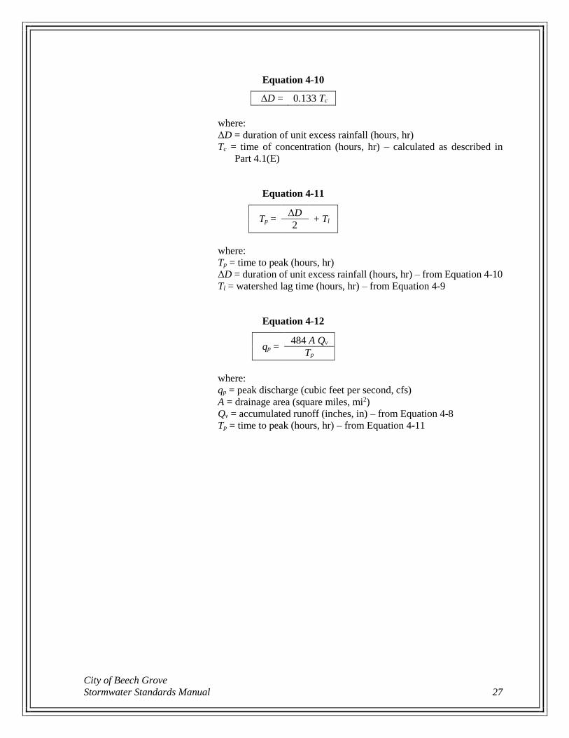
Equation 4-10
ΔD = 0.133 Tc
where:
ΔD = duration of unit excess rainfall (hours, hr)
Tc = time of concentration (hours, hr) – calculated as described in
Part 4.1(E)
Equation 4-11
Tp = ΔD
+ Tl 2
where:
Tp = time to peak (hours, hr)
ΔD = duration of unit excess rainfall (hours, hr) – from Equation 4-10
Tl = watershed lag time (hours, hr) – from Equation 4-9
Equation 4-12
qp = 484 A Qv
Tp
where:
qp = peak discharge (cubic feet per second, cfs)
A = drainage area (square miles, mi2)
Qv = accumulated runoff (inches, in) – from Equation 4-8
Tp = time to peak (hours, hr) – from Equation 4-11
Chapter 4- Standards for Stormwater Quantity Management
28
Figure 4-3: Dimensionless Unit Hydrograph and Mass Curve10
10 Adapted from USDA NRCS Part 630 Hydrology National Engineering Handbook (Mar 2007 Revision),
Chapter 16: Hydrographs, Figure 16-1.
City of Beech Grove
Stormwater Standards Manual 29
Figure 4-4: Dimensionless Curvilinear Unit Hydrograph and Equivalent Triangular
Hydrograph11
4.2 Hydraulics
(A) General Requirements
(1) This section provides the policies and technical requirements for analyzing the
majority of stormwater facilities; however, more detailed analysis may be required
depending on specific site characteristics.
(2) All streets shall be provided with an adequate storm drainage system consisting of
curbs, gutters, storm sewers and inlets, or side ditches and culverts. Refer to
Section 4.2(D)(3) for gutter spread and inlet spacing requirements.
(a) A 6-inch minimum perforated pipe underdrain shall be required on each side
of all streets.
(b) Where curbs and gutters are not provided in the street, ditches with inverts at
least 12 inches below the subgrade of the pavement may be required.
(3) Stormwater runoff and drainage from the site must be discharged into an adequate
outlet or outlets so as not to adversely affect other landowners. The criteria for
outletting is as follows:
(a) Open channels shall outlet into an existing open channel, provided that the
stream bank and channel erosion shall not be aggravated and that the hazard
of flooding shall not be increased.
11 Adapted from USDA NRCS Part 630 Hydrology National Engineering Handbook (Mar 2007 Revision),
Appendix 16A: Elements of a Unit Hydrograph, Figure 16A-1.
Chapter 4- Standards for Stormwater Quantity Management
30
(b) All storm sewers shall outlet into an open channel, storm sewer pipe, or
stormwater detention/retention facility.
(c) Underdrains shall outlet into an open channel, storm sewer pipe, or stormwater
detention/retention facility.
(d) Detention/retention facilities shall outlet into an open channel or storm sewer
pipe.
(4) Down spouts and sump pump outlets discharging onto a grass surface shall be at least
10 feet from the edge of pavement or back of curb but no closer to the road than the
building setback line.
(B) Open Channel Design
(1) Design Criteria
(a) In general, Manning’s equation (Equation 4-13) may be used for open channel
flow calculations for unobstructed channels. Open channels with culverts may
require additional analysis.
Equation 4-13
Q = 1.486
A R 2/3 S 1/2
n
where:
Q = discharge flow (cubic feet per second, cfs)
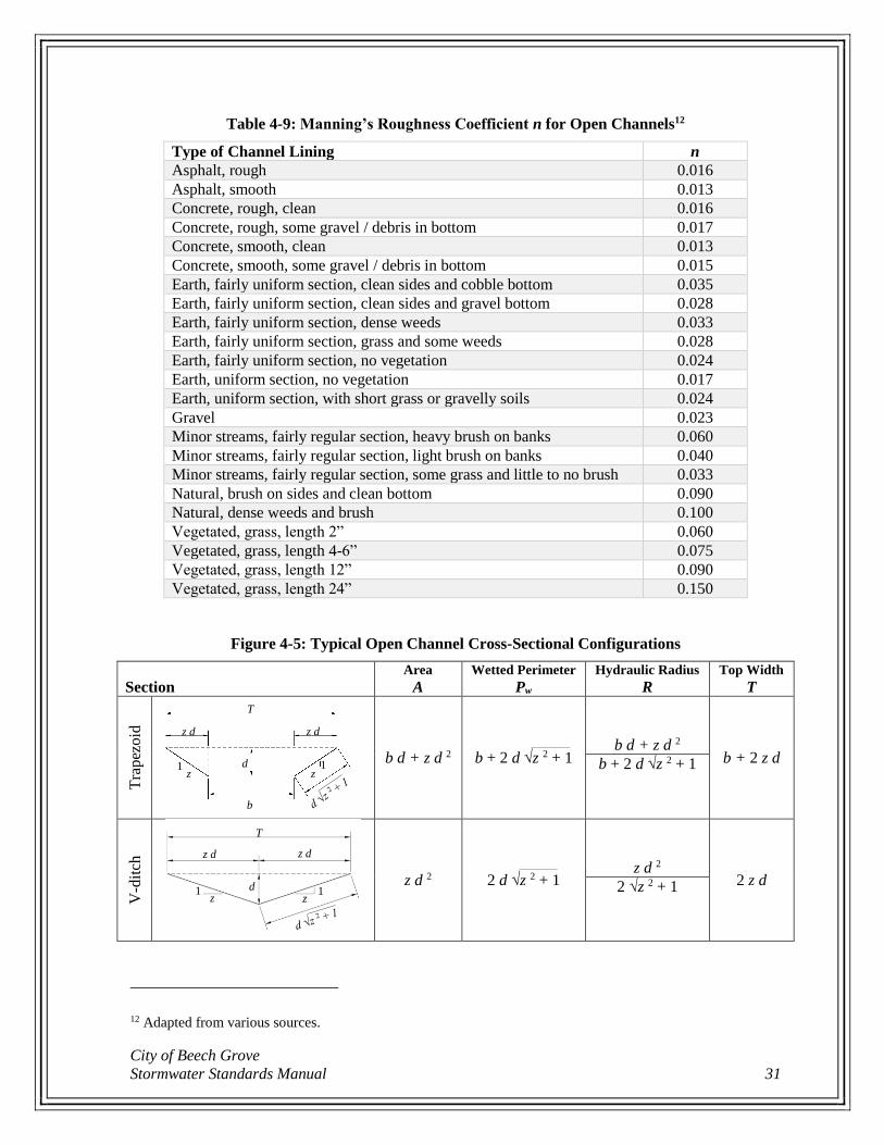
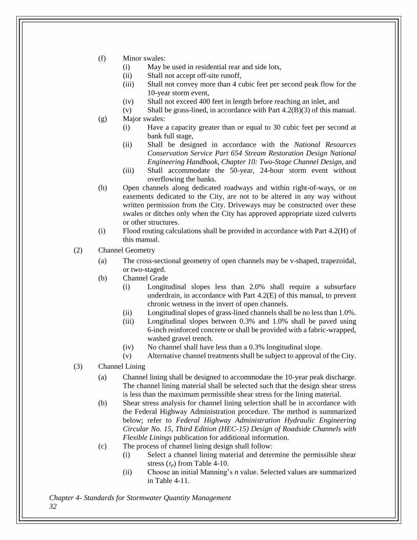
n = Manning’s roughness coefficient – see Table 4-9
A = cross sectional area (square feet, ft2) – see Figure 4-5
R = hydraulic radius (feet, ft) – see Figure 4-5
S = slope of energy grade line / channel slope (feet/feet, ft/ft)
(b) Backwater analysis shall be performed to determine the 100-year water surface
elevation along open channel systems. The 100-year flood boundary shall be
delineated on the plans.
(c) Any alteration of an existing open channel shall be sized as described below
or for the capacity of the existing channel, whichever is greater. Provisions
shall be made to prevent flooding of adjacent structures, buildings, or
properties for the peak 100-year storm event.
(d) For all areas within their jurisdiction, Indiana Department of Natural
Resources (IDNR), Indiana Department of Environmental Management
(IDEM), and United States Army Corps of Engineers (ACOE) approval must
be obtained and requirements must be followed.
(e) All open channels:
(i) Shall have a minimum channel velocity of 2 feet per second to prevent
sediment deposition within the channel,
(ii) Shall accommodate the peak runoff from the 10-year storm event,
(iii) Shall accommodate the peak runoff from the 25-year storm event
without overflowing the banks, and
(iv) Shall accommodate the peak runoff from the 100-year storm event
within the drainage easement.
City of Beech Grove
Stormwater Standards Manual 31
Table 4-9: Manning’s Roughness Coefficient n for Open Channels12
Type of Channel Lining n
Asphalt, rough 0.016
Asphalt, smooth 0.013
Concrete, rough, clean 0.016
Concrete, rough, some gravel / debris in bottom 0.017
Concrete, smooth, clean 0.013
Concrete, smooth, some gravel / debris in bottom 0.015
Earth, fairly uniform section, clean sides and cobble bottom 0.035
Earth, fairly uniform section, clean sides and gravel bottom 0.028
Earth, fairly uniform section, dense weeds 0.033
Earth, fairly uniform section, grass and some weeds 0.028
Earth, fairly uniform section, no vegetation 0.024
Earth, uniform section, no vegetation 0.017
Earth, uniform section, with short grass or gravelly soils 0.024
Gravel 0.023
Minor streams, fairly regular section, heavy brush on banks 0.060
Minor streams, fairly regular section, light brush on banks 0.040
Minor streams, fairly regular section, some grass and little to no brush 0.033
Natural, brush on sides and clean bottom 0.090
Natural, dense weeds and brush 0.100
Vegetated, grass, length 2” 0.060
Vegetated, grass, length 4-6” 0.075
Vegetated, grass, length 12” 0.090
Vegetated, grass, length 24” 0.150
Figure 4-5: Typical Open Channel Cross-Sectional Configurations
Section
Area
A
Wetted Perimeter
Pw
Hydraulic Radius
R
Top Width
T
Tra
pez
oid
b d + z d 2 b + 2 d √z 2 + 1 b d + z d 2
b + 2 z d b + 2 d √z 2 + 1
V-d
itch
z d 2 2 d √z 2 + 1 z d 2
2 z d 2 √z 2 + 1
12 Adapted from various sources.
T
z d z d
d
b
z z 1 1
T
z d z d
d z z
1 1
Chapter 4- Standards for Stormwater Quantity Management
32
(f) Minor swales:
(i) May be used in residential rear and side lots,
(ii) Shall not accept off-site runoff,
(iii) Shall not convey more than 4 cubic feet per second peak flow for the
10-year storm event,
(iv) Shall not exceed 400 feet in length before reaching an inlet, and
(v) Shall be grass-lined, in accordance with Part 4.2(B)(3) of this manual.
(g) Major swales:
(i) Have a capacity greater than or equal to 30 cubic feet per second at
bank full stage,
(ii) Shall be designed in accordance with the National Resources
Conservation Service Part 654 Stream Restoration Design National
Engineering Handbook, Chapter 10: Two-Stage Channel Design, and
(iii) Shall accommodate the 50-year, 24-hour storm event without
overflowing the banks.
(h) Open channels along dedicated roadways and within right-of-ways, or on
easements dedicated to the City, are not to be altered in any way without
written permission from the City. Driveways may be constructed over these
swales or ditches only when the City has approved appropriate sized culverts
or other structures.
(i) Flood routing calculations shall be provided in accordance with Part 4.2(H) of
this manual.
(2) Channel Geometry
(a) The cross-sectional geometry of open channels may be v-shaped, trapezoidal,
or two-staged.
(b) Channel Grade
(i) Longitudinal slopes less than 2.0% shall require a subsurface
underdrain, in accordance with Part 4.2(E) of this manual, to prevent
chronic wetness in the invert of open channels.
(ii) Longitudinal slopes of grass-lined channels shall be no less than 1.0%.
(iii) Longitudinal slopes between 0.3% and 1.0% shall be paved using
6-inch reinforced concrete or shall be provided with a fabric-wrapped,
washed gravel trench.
(iv) No channel shall have less than a 0.3% longitudinal slope.
(v) Alternative channel treatments shall be subject to approval of the City.
(3) Channel Lining
(a) Channel lining shall be designed to accommodate the 10-year peak discharge.
The channel lining material shall be selected such that the design shear stress
is less than the maximum permissible shear stress for the lining material.
(b) Shear stress analysis for channel lining selection shall be in accordance with
the Federal Highway Administration procedure. The method is summarized
below; refer to Federal Highway Administration Hydraulic Engineering
Circular No. 15, Third Edition (HEC-15) Design of Roadside Channels with
Flexible Linings publication for additional information.
(c) The process of channel lining design shall follow:
(i) Select a channel lining material and determine the permissible shear
stress (τp) from Table 4-10.
(ii) Choose an initial Manning’s n value. Selected values are summarized
in Table 4-11.
City of Beech Grove
Stormwater Standards Manual 33
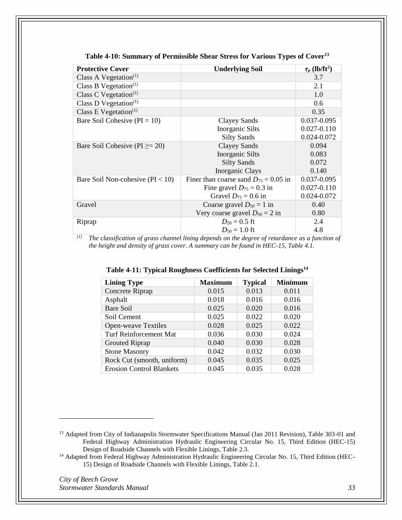
Table 4-10: Summary of Permissible Shear Stress for Various Types of Cover13
Protective Cover Underlying Soil τp (lb/ft2)
Class A Vegetation(1) 3.7
Class B Vegetation(1) 2.1
Class C Vegetation(1) 1.0
Class D Vegetation(1) 0.6
Class E Vegetation(1) 0.35
Bare Soil Cohesive (PI = 10) Clayey Sands
Inorganic Silts
Silty Sands
0.037-0.095
0.027-0.110
0.024-0.072
Bare Soil Cohesive (PI ≥= 20) Clayey Sands
Inorganic Silts
Silty Sands
Inorganic Clays
0.094
0.083
0.072
0.140
Bare Soil Non-cohesive (PI < 10) Finer than coarse sand D75 = 0.05 in
Fine gravel D75 = 0.3 in
Gravel D75 = 0.6 in
0.037-0.095
0.027-0.110
0.024-0.072
Gravel Coarse gravel D50 = 1 in
Very coarse gravel D50 = 2 in
0.40
0.80
Riprap D50 = 0.5 ft
D50 = 1.0 ft
2.4
4.8 (1) The classification of grass channel lining depends on the degree of retardance as a function of
the height and density of grass cover. A summary can be found in HEC-15, Table 4.1.
Table 4-11: Typical Roughness Coefficients for Selected Linings14
Lining Type Maximum Typical Minimum
Concrete Riprap 0.015 0.013 0.011
Asphalt 0.018 0.016 0.016
Bare Soil 0.025 0.020 0.016
Soil Cement 0.025 0.022 0.020
Open-weave Textiles 0.028 0.025 0.022
Turf Reinforcement Mat 0.036 0.030 0.024
Grouted Riprap 0.040 0.030 0.028
Stone Masonry 0.042 0.032 0.030
Rock Cut (smooth, uniform) 0.045 0.035 0.025
Erosion Control Blankets 0.045 0.035 0.028
13 Adapted from City of Indianapolis Stormwater Specifications Manual (Jan 2011 Revision), Table 303-01 and
Federal Highway Administration Hydraulic Engineering Circular No. 15, Third Edition (HEC-15)
Design of Roadside Channels with Flexible Linings, Table 2.3. 14 Adapted from Federal Highway Administration Hydraulic Engineering Circular No. 15, Third Edition (HEC-
15) Design of Roadside Channels with Flexible Linings, Table 2.1.
Chapter 4- Standards for Stormwater Quantity Management
34
(iii) Calculate normal flow depth (D) at design discharge, using Manning’s
formula.
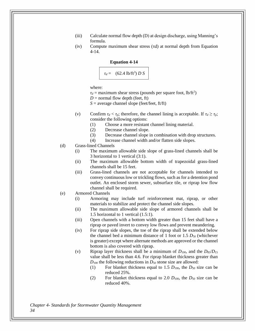
(iv) Compute maximum shear stress (τd) at normal depth from Equation
4-14.
Equation 4-14
τd = (62.4 lb/ft3) D S
where:
τd = maximum shear stress (pounds per square foot, lb/ft2)
D = normal flow depth (feet, ft)
S = average channel slope (feet/feet, ft/ft)
(v) Confirm τd < τp; therefore, the channel lining is acceptable. If τd ≥ τp;
consider the following options:
(1) Choose a more resistant channel lining material.
(2) Decrease channel slope.
(3) Decrease channel slope in combination with drop structures.
(4) Increase channel width and/or flatten side slopes.
(d) Grass-lined Channels
(i) The maximum allowable side slope of grass-lined channels shall be
3 horizontal to 1 vertical (3:1).
(ii) The maximum allowable bottom width of trapezoidal grass-lined
channels shall be 15 feet.
(iii) Grass-lined channels are not acceptable for channels intended to
convey continuous low or trickling flows, such as for a detention pond
outlet. An enclosed storm sewer, subsurface tile, or riprap low flow
channel shall be required.
(e) Armored Channels
(i) Armoring may include turf reinforcement mat, riprap, or other
materials to stabilize and protect the channel side slopes.
(ii) The maximum allowable side slope of armored channels shall be
1.5 horizontal to 1 vertical (1.5:1).
(iii) Open channels with a bottom width greater than 15 feet shall have a
riprap or paved invert to convey low flows and prevent meandering.
(iv) For riprap side slopes, the toe of the riprap shall be extended below
the channel bed a minimum distance of 1 foot or 1.5 D50 (whichever
is greater) except where alternate methods are approved or the channel
bottom is also covered with riprap.
(v) Riprap layer thickness shall be a minimum of D100, and the D85/D15
value shall be less than 4.6. For riprap blanket thickness greater than
D100 the following reductions in D50 stone size are allowed:
(1) For blanket thickness equal to 1.5 D100, the D50 size can be
reduced 25%.
(2) For blanket thickness equal to 2.0 D100, the D50 size can be
reduced 40%.
City of Beech Grove
Stormwater Standards Manual 35
(C) Culvert Design
(1) Design Criteria
(a) Culverts shall be sized in accordance with the Federal Highway
Administration’s Hydraulic Design Series No. 5 (HDS-5) Hydraulic Design of
Highway Culverts. Computer models such as the Federal Highway
Administration’s HY-8 Culvert Hydraulic Analysis Program may be used to
perform culvert and bridge design computations.
(b) All culverts:
(i) Shall be a minimum of 12 inches,
(ii) Shall have a minimum full-flow velocity of 2.5 feet per second to
prevent sedimentation in the pipe,
(iii) Are recommended to have full-flow velocity less than 10.0 feet per
second,
(iv) Shall have a minimum of 12 inches of cover for CMP and RCP
culverts and a minimum of 24 inches of cover for flexible (HDPE, PP,
and PVC) culverts.
(v) Shall be designed to safely pass the peak discharge from the 25-year
storm event without overtopping the roadway, and
(vi) Shall result in a ponding water depth of no more than 7 inches above
the surface of the pavement during peak discharge from the 100-year
storm event.
(c) Flood routing calculations shall be provided in accordance with Part 4.2(H) of
this manual.
(2) Outlet Protection
(a) Outlet protection and energy dissipaters shall be used wherever the velocity of
the flow leaving a culvert exceeds the erosive velocity of the downstream
channel.
(b) Outlet Protection Apron Design
(i) If possible, determine the tailwater conditions for the channel. If
tailwater is less than one-half the discharge flow depth (pipe diameter,
if flowing full), minimum tailwater conditions exist and Figure 4-6
applies. Otherwise, maximum tailwater exists and Figure 4-7 applies.
(ii) If tailwater conditions are unknown or if both minimum and maximum
tailwater conditions may occur, the outlet protection apron shall be
designed for both conditions, as shown in Figure 4-8.
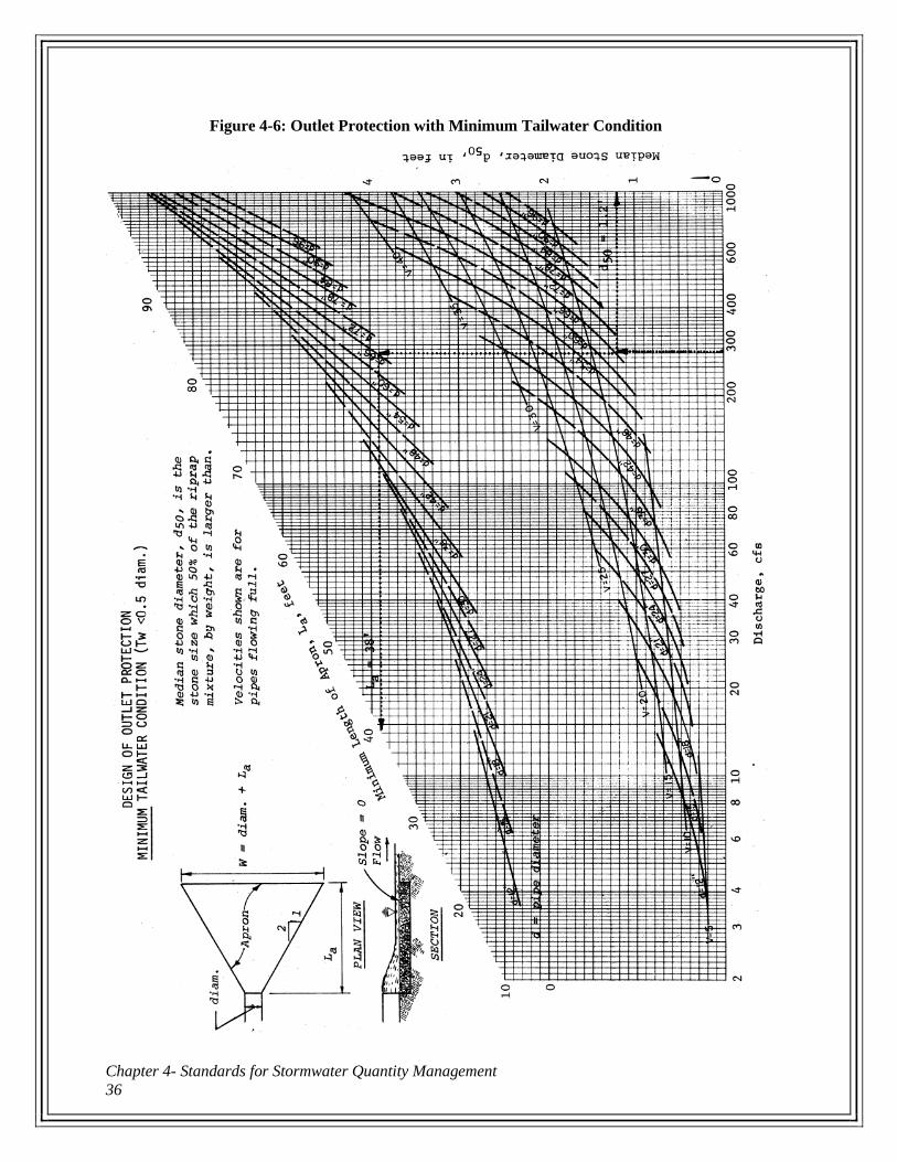
Chapter 4- Standards for Stormwater Quantity Management
36
Figure 4-6: Outlet Protection with Minimum Tailwater Condition
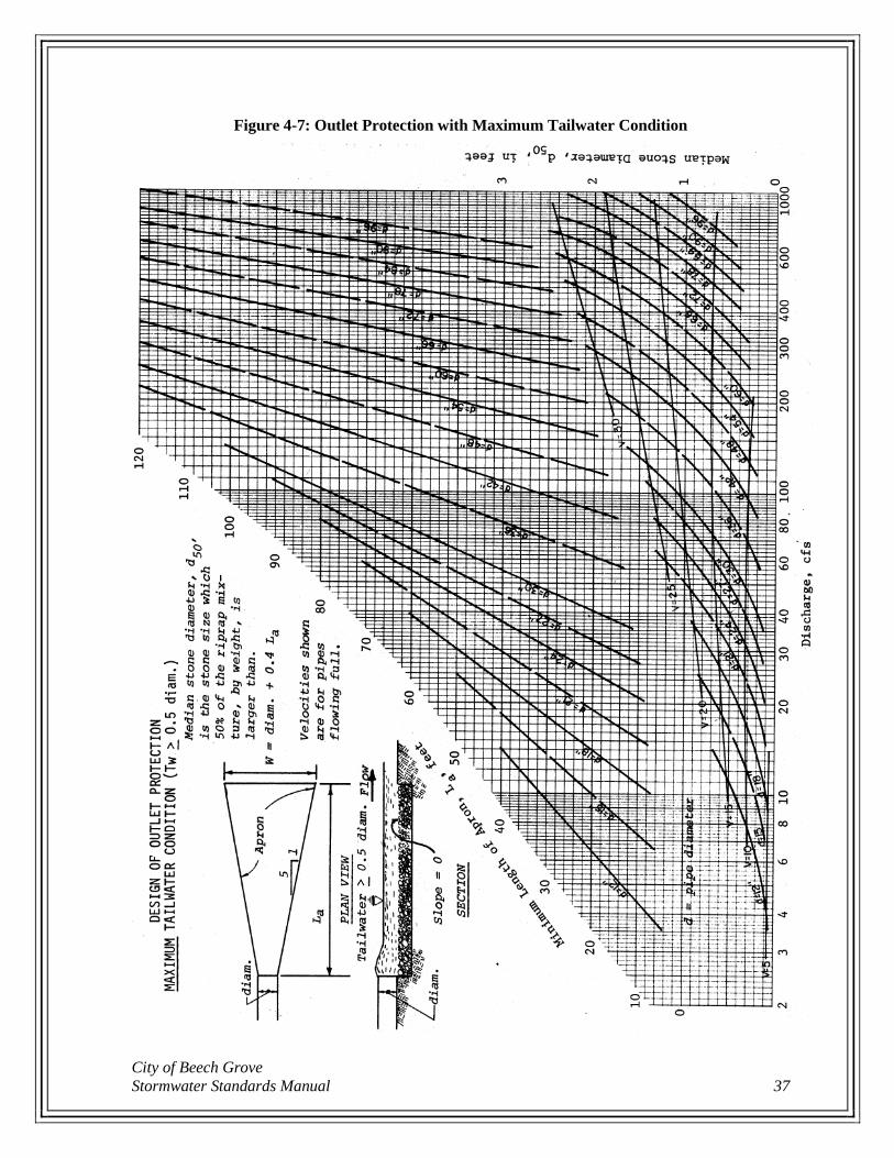
City of Beech Grove
Stormwater Standards Manual 37
Figure 4-7: Outlet Protection with Maximum Tailwater Condition
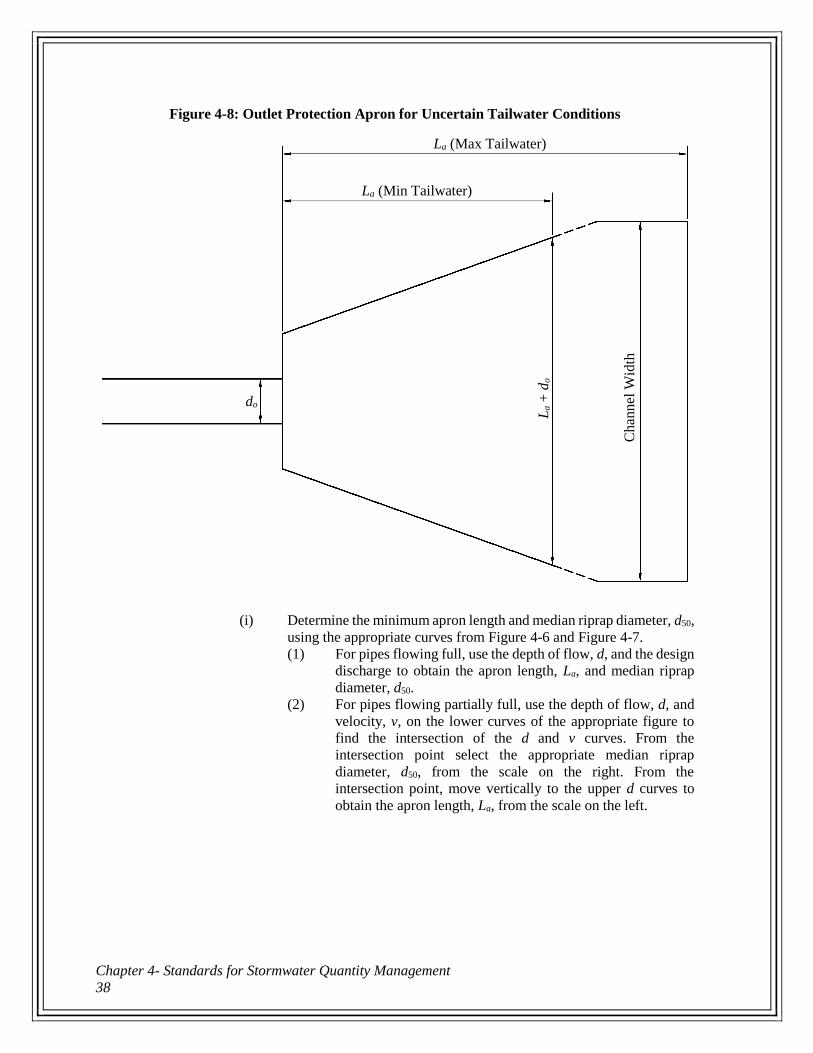
Chapter 4- Standards for Stormwater Quantity Management
38
Figure 4-8: Outlet Protection Apron for Uncertain Tailwater Conditions
(i) Determine the minimum apron length and median riprap diameter, d50,
using the appropriate curves from Figure 4-6 and Figure 4-7.
(1) For pipes flowing full, use the depth of flow, d, and the design
discharge to obtain the apron length, La, and median riprap
diameter, d50.
(2) For pipes flowing partially full, use the depth of flow, d, and
velocity, v, on the lower curves of the appropriate figure to
find the intersection of the d and v curves. From the
intersection point select the appropriate median riprap
diameter, d50, from the scale on the right. From the
intersection point, move vertically to the upper d curves to
obtain the apron length, La, from the scale on the left.
La (Min Tailwater)
La (Max Tailwater)
La +
do
Chan
nel
Wid
th
do
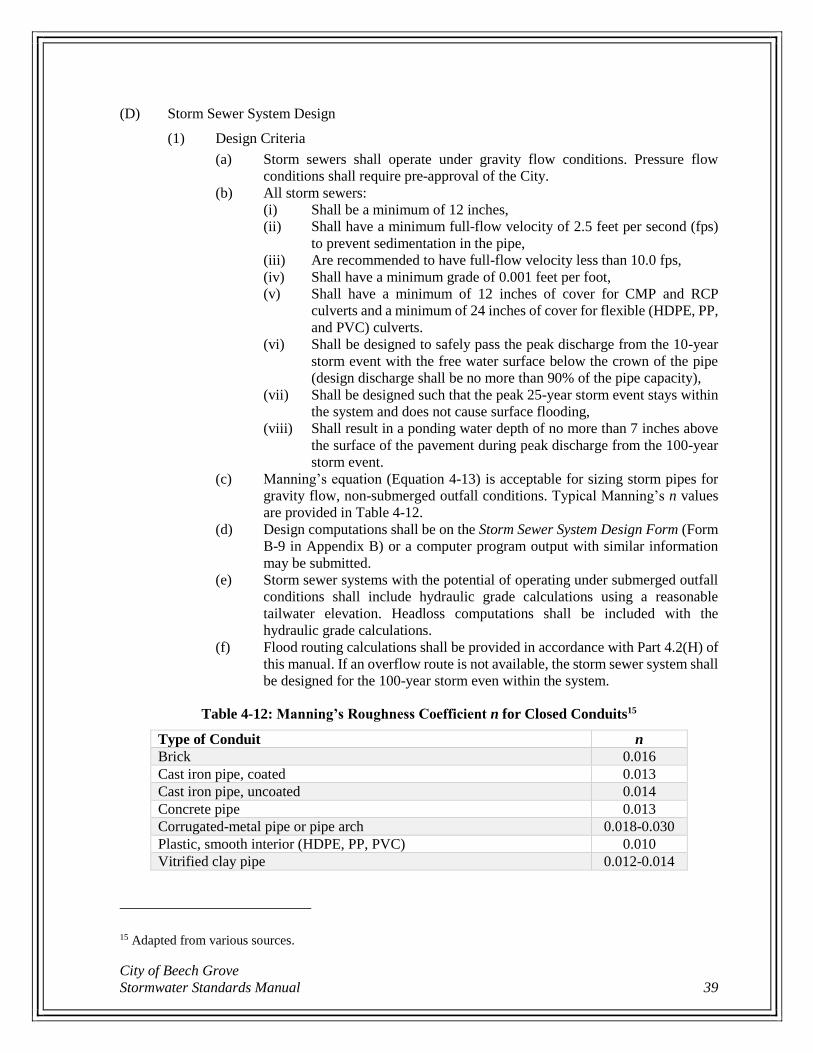
City of Beech Grove
Stormwater Standards Manual 39
(D) Storm Sewer System Design
(1) Design Criteria
(a) Storm sewers shall operate under gravity flow conditions. Pressure flow
conditions shall require pre-approval of the City.
(b) All storm sewers:
(i) Shall be a minimum of 12 inches,
(ii) Shall have a minimum full-flow velocity of 2.5 feet per second (fps)
to prevent sedimentation in the pipe,
(iii) Are recommended to have full-flow velocity less than 10.0 fps,
(iv) Shall have a minimum grade of 0.001 feet per foot,
(v) Shall have a minimum of 12 inches of cover for CMP and RCP
culverts and a minimum of 24 inches of cover for flexible (HDPE, PP,
and PVC) culverts.
(vi) Shall be designed to safely pass the peak discharge from the 10-year
storm event with the free water surface below the crown of the pipe
(design discharge shall be no more than 90% of the pipe capacity),
(vii) Shall be designed such that the peak 25-year storm event stays within
the system and does not cause surface flooding,
(viii) Shall result in a ponding water depth of no more than 7 inches above
the surface of the pavement during peak discharge from the 100-year
storm event.
(c) Manning’s equation (Equation 4-13) is acceptable for sizing storm pipes for
gravity flow, non-submerged outfall conditions. Typical Manning’s n values
are provided in Table 4-12.
(d) Design computations shall be on the Storm Sewer System Design Form (Form
B-9 in Appendix B) or a computer program output with similar information
may be submitted.
(e) Storm sewer systems with the potential of operating under submerged outfall
conditions shall include hydraulic grade calculations using a reasonable
tailwater elevation. Headloss computations shall be included with the
hydraulic grade calculations.
(f) Flood routing calculations shall be provided in accordance with Part 4.2(H) of
this manual. If an overflow route is not available, the storm sewer system shall
be designed for the 100-year storm even within the system.
Table 4-12: Manning’s Roughness Coefficient n for Closed Conduits15
Type of Conduit n
Brick 0.016
Cast iron pipe, coated 0.013
Cast iron pipe, uncoated 0.014
Concrete pipe 0.013
Corrugated-metal pipe or pipe arch 0.018-0.030
Plastic, smooth interior (HDPE, PP, PVC) 0.010
Vitrified clay pipe 0.012-0.014
15 Adapted from various sources.
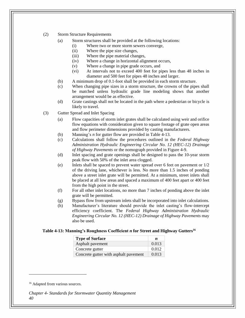
Chapter 4- Standards for Stormwater Quantity Management
40
(2) Storm Structure Requirements
(a) Storm structures shall be provided at the following locations:
(i) Where two or more storm sewers converge,
(ii) Where the pipe size changes,
(iii) Where the pipe material changes,
(iv) Where a change in horizontal alignment occurs,
(v) Where a change in pipe grade occurs, and
(vi) At intervals not to exceed 400 feet for pipes less than 48 inches in
diameter and 500 feet for pipes 48 inches and larger.
(b) A minimum drop of 0.1-foot shall be provided in each storm structure.
(c) When changing pipe sizes in a storm structure, the crowns of the pipes shall
be matched unless hydraulic grade line modeling shows that another
arrangement would be as effective.
(d) Grate castings shall not be located in the path where a pedestrian or bicycle is
likely to travel.
(3) Gutter Spread and Inlet Spacing
(a) Flow capacities of storm inlet grates shall be calculated using weir and orifice
flow equations with consideration given to square footage of grate open areas
and flow perimeter dimensions provided by casting manufacturers.
(b) Manning’s n for gutter flow are provided in Table 4-13.
(c) Calculations shall follow the procedures outlined in the Federal Highway
Administration Hydraulic Engineering Circular No. 12 (HEC-12) Drainage
of Highway Pavements or the nomograph provided in Figure 4-9.
(d) Inlet spacing and grate openings shall be designed to pass the 10-year storm
peak flow with 50% of the inlet area clogged.
(e) Inlets shall be spaced to prevent water spread over 6 feet on pavement or 1/2
of the driving lane, whichever is less. No more than 1.5 inches of ponding
above a street inlet grate will be permitted. At a minimum, street inlets shall
be placed at all low areas and spaced a maximum of 400 feet apart or 400 feet
from the high point in the street.
(f) For all other inlet locations, no more than 7 inches of ponding above the inlet
grate will be permitted.
(g) Bypass flow from upstream inlets shall be incorporated into inlet calculations.
(h) Manufacturer’s literature should provide the inlet casting’s flow-intercept
efficiency coefficient. The Federal Highway Administration Hydraulic
Engineering Circular No. 12 (HEC-12) Drainage of Highway Pavements may
also be used.
Table 4-13: Manning’s Roughness Coefficient n for Street and Highway Gutters16
Type of Surface n
Asphalt pavement 0.013
Concrete gutter 0.012
Concrete gutter with asphalt pavement 0.013
16 Adapted from various sources.
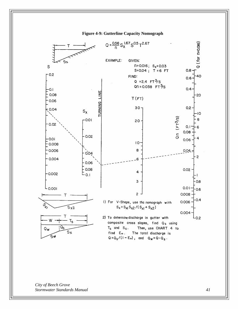
City of Beech Grove
Stormwater Standards Manual 41
Figure 4-9: Gutterline Capacity Nomograph
Chapter 4- Standards for Stormwater Quantity Management
42
(E) Underdrain and Hybrid Ditch System Design
(1) Design Criteria
(a) Underdrains:
(i) Shall be a minimum of 6 inches in diameter for areas receiving only
subsurface flow,
(ii) Shall be a minimum of 12 inches in diameter for areas receiving both
surface (downspouts, yard inlets, etc.) and subsurface flows,
(iii) Shall have a minimum of 24 inches of cover, and
(iv) Shall have an access structure at minimum 300-foot intervals.
(2) General Requirements
(a) For residential lots with basements, a “tee” should be provided to the lot’s
underdrain or to a stormwater structure for the purpose of discharging footing
drains and sump pumps directly into the drain.
(b) Residential sump pumps shall not discharge into pavement underdrains.
(c) Flood routing calculations shall be provided in accordance with Part 4.2(H) of
this manual.
(F) Stormwater Detention/Retention
(1) Stormwater detention analysis shall be required for all new developments and site
redevelopment where land disturbance is greater than or equal to 10,000 square feet or
where the development or redevelopment will increase the impervious surface area of
the site by 25% or more.
(2) Allowable Release Rates
(a) All impervious area of the site shall drain through a detention/retention facility.
(b) When computing the discharges for detention/retention basin design the entire
upstream area that contributes runoff to the design point must be included in
the computations. Upstream drainage areas may be bypassed and therefore not
considered in the computations as long as the flows are bypassed for all levels
of flow. If any overflow discharge will be routed to the detention/retention
facility, the drainage area may not be reduced.
(c) The peak discharge for a stormwater facility must meet the following
minimum hydraulic requirements.
Equation 4-15
Q2p = 0.5 Q2e
Q10p = 0.5 Q10e
Q100p = Q10e
where:
Q2p = 2-year discharge rate for the proposed (developed) condition
Q2e = 2-year discharge rate for the existing condition
Q10p = 10-year discharge rate for the proposed (developed) condition
Q10e = 10-year discharge rate for the existing condition
Q100p = 100-year discharge rate for the proposed (developed) condition
(d) In the event the downstream receiving channel or sewer is inadequate to
accommodate the release rate as determined above, then the allowable release
City of Beech Grove
Stormwater Standards Manual 43
rate shall be reduced to that rate permitted by the capacity of the receiving
conveyance.
(3) Storage Volume
(a) Storage volume shall be calculated using runoff hydrographs and routing
techniques as described in USDA Natural Resources Conservation Service
(NRCS) Conservation Engineering Division Technical Release 55 (TR-55)
Urban Hydrology for Small Watersheds, Chapter 6: Storage Volume for
Detention Basins.
(b) Storm durations shall be used that maximize the peak flow for the pre-
developed condition and maximize detention storage volume for the post-
developed condition. The storm duration shall be equal to or greater than the
site time of concentration, but shall not be less than 30 minutes.
(4) General Detention/Retention Facility Requirements
(a) A minimum of 90% of the water storage volume shall be released from the
facility at the design release rate within 48 hours of the start of the peak
100-year storm event.
(b) Detention/retention facilities shall be designed with an additional 10%
available capacity to account for sediment accumulation in order to allow the
facility to function for reasonable periods between cleansings. Facilities
should be designed to collect sediment and debris in specific locations to
minimize cleaning and removal costs.
(c) No building or structure may be located within 25 feet horizontally of the 100-
year water surface elevation of a detention/retention facility.
(d) No electric pole or high voltage electric lines may be located within 20 feet
horizontally of any detention/retention facility, permanent or temporary.
(e) The Lowest Adjacent Grade for all residential, commercial, industrial, or
otherwise occupied buildings shall be a minimum of 2 feet above the 100-year
water surface elevation or 2 feet above the emergency overflow weir elevation,
whichever is higher. Any basement floor must be at least 1-foot above the
normal pool water elevation of any wet-bottom facility.
(f) Maximum vegetated side slopes shall be 3 horizontal to 1 vertical (3:1) for
safety, erosion control, stability, and ease of maintenance.
(g) Every detention/retention facility (including surface and underground
detention/retention facilities and those facilities which are serving less than
1-acre sites) shall be equipped with an upstream pretreatment system to
capture sediments and floatables. Pretreatment shall be in the form of a
sediment forebay, isolator row, or BMP immediately upstream of each inlet to
the detention/retention facility unless the inlet provides less than 10% of the
total design storm inflow to the pond. Pre-approved stormwater BMPs are
listed in Table 6-1 and shall be designed in accordance with Chapter 6 and
Appendix C.
(h) Underground detention facilities shall have inspection ports or observation
wells, minimum 10-inch diameter, sufficiently arranged to allow access to all
portions of the facility.
(i) Each facility shall be designed with an emergency overflow facility for the
release of exceptional storm runoff or in the event that the normal outlet device
becomes totally or partially inoperable, in accordance with Part 4.2(F)(9) of
this manual.
Chapter 4- Standards for Stormwater Quantity Management
44
(j) Flood routing calculations shall be provided in accordance with Part 4.2(H) of
this manual.
(k) All facilities shall have a minimum freeboard of 1 foot.
(l) For leveed detention/retention facilities which generate 3 feet or more head
pressure, the principal spillway outlet pipe shall be provided with anti-seep
devices. As a general guide, anti-seep collars shall be a minimum of 5 feet by
5 feet square and be spaced a maximum of 25 feet apart.
(5) Additional Requirements for Dry Detention Facility Design
(a) Dry detention basins shall have minimum longitudinal and transverse bottom
slopes of 1.0% or be designed with underdrains.
(b) An underdrain system shall be provided in the flow path from each inlet to the
basin outlet.
(c) The stormwater storage depth shall not exceed 4 feet.
(6) Additional Requirements for Wet Detention/Retention Facility Design
(a) Wet detention/retention facilities shall have a minimum 6 foot wide safety
ledge placed 18 inches below the normal pool water elevation at a maximum
slope of 10 horizontal to 1 vertical (10:1). The slope of the bank below the
safety ledge shall not exceed 3 horizontal to 1 vertical (3:1).
(b) Wet detention/retention facilities shall have a minimum 6 foot wide
maintenance ledge placed 12 inches above the normal pool water elevation at
a maximum slope of 10 horizontal to 1 vertical (10:1). The slope of the bank
between the maintenance ledge and safety ledge shall not exceed 6 horizontal
to 1 vertical (6:1). The slope of the bank above the maintenance ledge shall
not exceed 6 horizontal to 1 vertical (6:1).
(c) The minimum normal depth shall be 8 feet, maintained over at least 25% of
the pond area.
(d) Fencing or a barrier is recommended around wet detention/retention facilities
to discourage unauthorized access.
(7) Parking Lot Storage Design
(a) Stormwater may be stored on remote areas of parking lot pavement with a
maximum water depth of 7 inches for the peak 100-year storm event.
Stormwater may not be stored on any pavement with pedestrian traffic.
(b) The parking lot shall be designed to drain completely a maximum of
30 minutes after rainfall termination
(8) Rooftop Storage Design
(a) Stormwater may be stored on roofs with a maximum water depth of 3 inches
for flat roofs and 6 inches for sloped roofs.
(b) Provide sufficient membrane liners to create a watertight seal on the roof to
prevent leakage.
(c) Overflow drains shall be provided at the design depth to reduce damage due
to excessive events or clogging. Provide at least one drain for every
10,000 square feet of roof area.
(d) The roof shall be designed by a structural engineer licensed in the State of
Indiana. The roof shall be designed to structurally withstand a live load of at
least 35 pounds per square foot.

City of Beech Grove
Stormwater Standards Manual 45
(9) Emergency Spillway
(a) The overflow facility or emergency spillway shall be designed to operate
automatically and shall not require manual attention.
(b) At a minimum, emergency spillways shall be capable of handling 125% of the
inlet peak discharge resulting from the 100-year storm event from the entire
contributing watershed, assuming proposed (developed) conditions.
(c) Design calculations and cross sections shall be submitted for review.
(10) Outlet
(a) Outlet control structures shall be designed to meet the required release rates in
accordance with Part 4.2(F)(2) of this manual.
(G) Low Impact Development Measures
(1) Low Impact Development (LID) is an approach to land planning and engineering
design which manages rainfall at the source to reduce stormwater runoff and manage
runoff timing, emphasizes conservation and natural features, and protects water quality
by controlling pollutants.
(2) Designers and developers are encouraged to consider methods of runoff reduction such
as reducing impervious surface area, disconnecting impervious surfaces, promoting
infiltration, stormwater capture and reuse, and other LID methods in order to reduce
requirements for on-site detention.
(3) LID features shall conform to current industry guidelines and will be reviewed on a
case-by-case basis. Pre-approved stormwater BMPs are listed in Table 6-1 and shall
be designed in accordance with Chapter 6 and Appendix C. All design calculations and
justification shall be submitted for review.
(H) Flood Routing
(1) Stormwater ponding and overflow path routing throughout a site or development shall
be evaluated for the peak 100-year storm event.
(2) Peak runoff flows shall be estimated for all contributing drainage areas, on-site and
off-site, in their proposed (developed) land use.
(3) The stormwater collection system (storm sewers, open channels, etc.) shall be assumed
full (at capacity) from a previous storm event at the beginning of the flood routing
analysis.
(4) The overflow path/ponding resulting from the flood routing event shall be clearly
shown as a hatch area on the plans. Plans shall include cross sections along the flood
route path. Cross sections shall include the existing surface, proposed grading, and the
maximum water elevation for the peak 100-year storm event. The flood routing path
and ponding areas shall be placed in a right-of-way or drainage easement in accordance
with Part 4.5 of this manual.
Chapter 4- Standards for Stormwater Quantity Management
46
4.3 Material Specifications Materials used in construction shall be in full conformance with the guidelines set forth in this manual
and all applicable AASHTO, ASTM, and INDOT standards. These material specifications are
minimum requirements. The Engineer shall ultimately be responsible for designing and selecting the
appropriate material for each specific application. The City shall reserve the right to require material
certification from the manufacturer prior to or during construction as deemed necessary to ensure the
material supplied conforms to the requirements of this manual.
(A) Channel Lining & Energy Dissipation
(1) The types of treatments used to stabilize open channels may vary with flow velocities
and individual site conditions within the following guidelines:
(a) Grass: The grass seed mixture shall be selected based on specific site
conditions (drainage tolerance, shade tolerance, maintenance requirements,
etc.) and shall contain no weeds.
(b) Turf Reinforcement Mat: Turf reinforcement mat shall be a permanent product
which shall not degrade in less than 48 months. Turf reinforcement mat shall
be capable of withstanding design channel velocities or 9.0 feet per second,
whichever is greater.
(c) Riprap: Riprap gradation shall meet the Indiana Department of Transportation
(INDOT) specifications. Riprap used on channel side slopes shall have rocks
no smaller than 6 inches.
(d) All other channel lining products must be pre-approved by the City.
(B) Geotextile Fabric
(1) For use under riprap or other aggregates: Provide non-woven geotextile fabric
consisting of strong, rot resistant, chemically stable long-chain synthetic polymer
materials which are dimensionally stable relative to each other. The geotextile plastic
yarn or fibers shall consist of at least 85% by weight of polyolefins, polyesters, or
polyamides and resist deterioration from ultraviolet and heat exposure. Geotextile
fabric shall meet or exceed the requirements of INDOT Standard Specifications
Section 918.02.
(2) For use with underdrains or other below-grade applications: Provide non-woven needle
punched or heat bonded geotextile fabric consisting of strong, rot resistant, chemically
stable long-chain synthetic polymer materials which are dimensionally stable relative
to each other. The geotextile plastic yarn or fibers shall consist of at least 85% by
weight of polyolefins, polyesters, or polyamides and resist deterioration from
ultraviolet and heat exposure. Geotextile fabric shall meet or exceed the requirements
of INDOT Standard Specifications Section 918.03.
(C) Trench Bedding & Backfill
(1) Bedding and backfill materials shall be as follows:
(a) Class I: Angular, 6 to 40 millimeters (1/4 to 1-1/2-inch) graded coarse
aggregate such as crushed stone, meeting the gradation requirements for an
INDOT No. 8 coarse aggregate in accordance with INDOT Standard
Specifications Section 904. A gravel possessing a minimum 50% mechanical
crush count and meeting the INDOT No. 8 gradation will be considered an
equivalent Class I material.
(b) Class II: Coarse sands and gravel-sand mixtures with a maximum particle size
of 40 millimeters (1-1/2 inches), including variously graded sands and gravels
City of Beech Grove
Stormwater Standards Manual 47
containing small percentages of fine, generally granular and non-cohesive,
either wet or dry, meeting the gradation requirements of INDOT Structure
Backfill in accordance with INDOT Standard Specifications Section 904. Soil
types GW, GP, SW and SP are included in this class.
(c) Clean Sand: Fine aggregate No. 23 sand, in accordance with INDOT Standard
Specification Section 904.
(d) Excavated Material: Excavated material suitable for use as trench backfill must
be clean and free of rocks and frozen soil lumps larger than 6 inches, wood,
debris, or other extraneous material.
(e) Flowable Fill: Flowable Fill: Removable, self-leveling, self-compacting,
flowable material with a minimum unconfined compressive strength (28-day)
of 50 psi and a maximum unconfined compressive strength of 150 psi. Provide
Removable Flowable Backfill material which meets the requirements of
INDOT Standard Specifications Section 213 and Section 904 classification for
Type 4 Structure Backfill.
(f) Washed Aggregates: Double-washed coarse aggregate No. 8, class E or higher,
in accordance with INDOT Standard Specification Section 904.
(D) Culvert & Storm Sewer Pipe
(1) Culverts and storm sewers shall be corrugated metal pipe (CMP), high-density
polyethylene (HDPE) pipe, polypropylene (PP) pipe, polyvinyl chloride (PVC) pipe,
or reinforced concrete pipe (RCP).
(2) Corrugated Metal Pipe (CMP) – for pipe sizes 12-inch and larger
(a) Pipe Material
(i) Provide CMP of continuous lock seam or welded seam construction
from end to end of each length of pipe (helical corrugations),
conforming to AASHTO M36 and INDOT Standard Specification
Section 908.
(ii) Provide aluminum coated steel Type II corrugated pipe fabricated in
accordance with ASTM A760 for the gauge indicated below:
(1) 14 gauge for 12 to 36-inch diameter
(2) 12 gauge for 42-inch and larger diameter
(iii) Provide zinc coated (galvanized) steel pipe manufactured in
accordance with ASTM A760, fabricated from zinc-coated steel sheet
material conforming to ASTM A929.
(iv) Sheet metal used to fabricate pipe shall be the same brand from the
same manufacturer in any one length of finished pipe.
(b) Joints
(i) Supply external coupling bands with corrugations that mesh with the
corrugations of the pipe and which conform to ASTM A760.
(ii) Provide coupling bands of the same gauge and coating material as the
pipe for which the band is used.
(c) Pipe Markings
(i) Each length of CMP shall be clearly marked with the following
information at a minimum:
(1) Name of manufacturer or identification symbol
(2) Alloy and temper
(3) Specified thickness
(4) ASTM designation
Chapter 4- Standards for Stormwater Quantity Management
48
(5) Heat number
(6) Nominal pipe size
(3) High Density Polyethylene (HDPE) Pipe – for pipe sizes 12 to 24-inch only
(a) Pipe Material
(i) Provide dual wall corrugated HDPE pipe and fittings, consisting of an
annular outer corrugated pipe wall and a smooth inner wall, in
accordance with ASTM F2648 and INDOT Standard Specification
Section 907.
(ii) Pipe and fittings material shall be, in accordance with ASTM D3350,
either:
(1) Virgin high density polyethylene with a minimum cell class
of 435400C, or
(2) Engineered compound of virgin and recycled high density
polyethylene with a minimum cell class of 435420C
(iii) Flexibility factor shall not exceed 0.095.
(b) Joints
(i) Furnish HDPE pipe with bell and spigot joints in conformance with
ASTM F2648.
(ii) Gasket material shall conform to ASTM F477.
(c) Fittings
(i) Provide fittings of the same manufacturer for each type of HDPE pipe.
(ii) Manufactured fittings such as wyes, tees, elbows, or adaptors will not
be accepted for use in place of storm sewer manholes, inlets, catch
basins, or drain basins unless otherwise indicated on the Drawings.
(d) Pipe Markings
(i) Provide pipe with each length clearly marked with the following
information:
(1) Name of manufacturer or identification symbol
(2) Nominal pipe size
(3) Product/extrusion code
(4) Polypropylene (PP) Pipe – for pipe sizes 12 to 24-inch only
(a) Pipe Material
(i) Provide double wall polypropylene pipe with a smooth interior and
annular exterior corrugations in accordance with ASTM F2736.
(ii) Polypropylene compound for pipe and fitting production shall be
impact modified copolymer meeting the material requirements of
ASTM F2736, section 4, ASTM F2881, Section 5 and AASHTO
M330, Section 6.1, for the respective diameters.
(iii) Pipe shall have minimum stiffness of 46 pounds per square inch when
tested in accordance with ASTM D2412.
(b) Fittings and Joints
(i) Provide pipe joined with a gasketed integral bell and spigot joint
meeting the requirements of ASTM F2736. Joints shall be watertight.
(ii) Fittings shall conform to ASTM F2736. Corrugated couplings shall be
split collar, engaging at least 2 full corrugations.
(c) Pipe Markings
(i) Provide pipe with each length clearly marked with the following
information:
(1) Name of manufacturer or identification symbol
City of Beech Grove
Stormwater Standards Manual 49
(2) Nominal pipe size
(3) Product/extrusion code
(5) Polyvinyl Chloride (PVC) Pipe – for pipe sizes 12 to 24-inch only
(a) Pipe Material
(i) Provide solid wall gravity flow PVC storm sewer pipe and fittings
with bell and spigot joints with elastomeric seals and smooth inner
walls in accordance with ASTM D3034 (SDR 35, 12 to 15-inch
diameter), ASTM F679 (PS 46, 18 to 36-inch diameter), and INDOT
Standard Specification Section 907.
(ii) Minimum cell class in accordance with ASTM D1784:
(1) Cell class 12364 for 12 to 15-inch diameter pipes
(2) Cell class 12454 for 18 to 24-inch diameter pipes.
(iii) Pipe shall have minimum stiffness of 46 pounds per square inch when
tested in accordance with ASTM D2412.
(b) Joints
(i) Furnish PVC pipe with flexible, gasketed compression type joints so
that, when assembled, the gasket inside the bell is compressed radially
on the pipe spigot to form a soil-tight seal. Assemble joints in
accordance with the pipe manufacturer’s recommendations and
ASTM D3212.
(ii) The gasket shall conform to ASTM F477.
(c) Fittings
(i) Manufactured fittings such as wyes, tees, elbows, or adaptors will not
be accepted for use in place of storm sewer manholes, inlets, catch
basins, or drain basins unless otherwise indicated on the Drawings.
(d) Pipe Markings
(i) Provide pipe with each length clearly marked with the following
information:
(1) Name of manufacturer or identification symbol
(2) Trade name or trademark
(3) Nominal pipe size
(4) Production/extrusion code
(5) Material and cell class designation
(6) ASTM designation
(6) Reinforced Concrete Pipe (RCP) – for pipe sizes 12-inch and larger
(a) Pipe Material
(i) Provide minimum Class III, Wall B type RCP which conforms to
ASTM C76, AASHTO M170, and INDOT Standard Specification
Section 907.
(ii) Provide elliptical RCP which conforms to ASTM C507, AASHTO
M207, and INDOT Standard Specification Section 907.
(b) Joints
(i) Provide RCP with tongue and groove joints with compression type
rubber gasket which conforms to ASTM C443.
(c) Fittings
(i) Provide fabricated wye and tee branches.
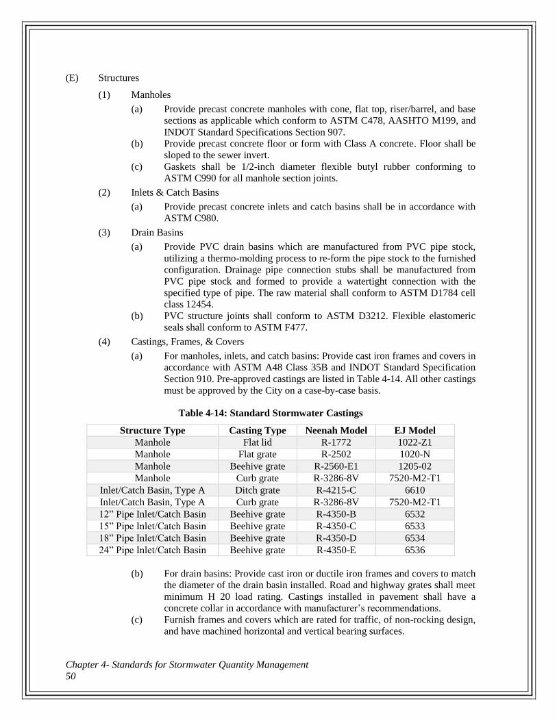
Chapter 4- Standards for Stormwater Quantity Management
50
(E) Structures
(1) Manholes
(a) Provide precast concrete manholes with cone, flat top, riser/barrel, and base
sections as applicable which conform to ASTM C478, AASHTO M199, and
INDOT Standard Specifications Section 907.
(b) Provide precast concrete floor or form with Class A concrete. Floor shall be
sloped to the sewer invert.
(c) Gaskets shall be 1/2-inch diameter flexible butyl rubber conforming to
ASTM C990 for all manhole section joints.
(2) Inlets & Catch Basins
(a) Provide precast concrete inlets and catch basins shall be in accordance with
ASTM C980.
(3) Drain Basins
(a) Provide PVC drain basins which are manufactured from PVC pipe stock,
utilizing a thermo-molding process to re-form the pipe stock to the furnished
configuration. Drainage pipe connection stubs shall be manufactured from
PVC pipe stock and formed to provide a watertight connection with the
specified type of pipe. The raw material shall conform to ASTM D1784 cell
class 12454.
(b) PVC structure joints shall conform to ASTM D3212. Flexible elastomeric
seals shall conform to ASTM F477.
(4) Castings, Frames, & Covers
(a) For manholes, inlets, and catch basins: Provide cast iron frames and covers in
accordance with ASTM A48 Class 35B and INDOT Standard Specification
Section 910. Pre-approved castings are listed in Table 4-14. All other castings
must be approved by the City on a case-by-case basis.
Table 4-14: Standard Stormwater Castings
Structure Type Casting Type Neenah Model EJ Model
Manhole Flat lid R-1772 1022-Z1
Manhole Flat grate R-2502 1020-N
Manhole Beehive grate R-2560-E1 1205-02
Manhole Curb grate R-3286-8V 7520-M2-T1
Inlet/Catch Basin, Type A Ditch grate R-4215-C 6610
Inlet/Catch Basin, Type A Curb grate R-3286-8V 7520-M2-T1
12” Pipe Inlet/Catch Basin Beehive grate R-4350-B 6532
15” Pipe Inlet/Catch Basin Beehive grate R-4350-C 6533
18” Pipe Inlet/Catch Basin Beehive grate R-4350-D 6534
24” Pipe Inlet/Catch Basin Beehive grate R-4350-E 6536
(b) For drain basins: Provide cast iron or ductile iron frames and covers to match
the diameter of the drain basin installed. Road and highway grates shall meet
minimum H 20 load rating. Castings installed in pavement shall have a
concrete collar in accordance with manufacturer’s recommendations.
(c) Furnish frames and covers which are rated for traffic, of non-rocking design,
and have machined horizontal and vertical bearing surfaces.
City of Beech Grove
Stormwater Standards Manual 51
(d) All storm grate castings shall be pre-stamped with a pollution prevention
message permanently attached.
(e) All grates shall be safe for bicycle and pedestrian traffic.
(5) Steps
(a) Provide steps in all structures 4 feet deep or greater in accordance with
AASHTO M199 and INDOT Standard Specification Section 907.
(b) Provide steps with a minimum 10 inches of clear step width.
(c) Provide copolymer polypropylene coated steel steps meeting the requirements
of ASTM D4101 and composed of deformed 1/2-inch minimum diameter
reinforcing steel in accordance with ASTM A615, Grade 60.
(d) Non-coated cast iron steps will not be accepted.
(6) Pipe Connections
(a) Pipe penetration holes shall be either pre-formed by manufacturer or core
drilled in the field.
(b) For CMP and RCP, provide non-shrink grout mixture of two parts No. 23 fine
aggregate in accordance with INDOT Standard Specification Section 904 and
one part Portland cement.
(c) For HDPE, PP, and PVC pipe, provide flexible neoprene molded boot or
resilient seal which conforms to ASTM C923.
(F) Underdrains
(1) Underdrains shall be perforated high-density polyethylene (HDPE) pipe or polyvinyl
chloride (PVC) pipe.
(2) High Density Polyethylene (HDPE) Pipe – for pipe sizes 6 to 24-inch only
(a) Pipe Material
(i) For pipe sizes 12-inch and larger: Provide dual wall corrugated HDPE
pipe and fittings, consisting of an annular outer corrugated pipe wall
and a smooth inner wall, in accordance with ASTM F2648 and
INDOT Standard Specification Section 907.
(ii) For pipe sizes under 12-inch: Provide perforated corrugated
polyethylene drainage pipe (PCPP) and fittings in accordance with
AASHTO M252, ASTM F2648, and INDOT Standard Specification
Section 907. Perforations shall be AASHTO Class II.
(iii) HDPE pipe and fittings material shall be either:
(1) Virgin high density polyethylene with a minimum cell class
of 424420C for 6 to 10-inch diameter pipe or 435400C for 12
to 24-inch diameter, as defined in ASTM D3350
(2) Engineered compound of virgin and recycled high density
polyethylene with a minimum cell class of 424420C for 6 to
10-inch diameter pipe or 435420C for 12 to 24-inch diameter,
as defined in ASTM D3350
(iv) The flexibility factor of HDPE pipe shall not exceed 0.095.
(b) Joints
(i) Furnish HDPE pipe with bell and spigot joints in conformance with
ASTM F2648.
(ii) Gasket material shall conform to ASTM F477.
(c) Fittings
(i) Provide fittings of the same manufacturer for each type of HDPE pipe.
Chapter 4- Standards for Stormwater Quantity Management
52
(ii) Manufactured fittings such as wyes, tees, elbows, or adaptors will not
be accepted for use in place of drain basins unless otherwise indicated
on the Drawings.
(d) Pipe Markings
(i) Provide pipe with each length clearly marked with the following
information:
(1) Name of manufacturer or identification symbol
(2) Nominal pipe size
(3) Product/extrusion code
(3) Polyvinyl Chloride (PVC) Pipe – for pipe sizes 6 to 24-inch only
(a) Pipe Material
(i) Provide solid wall gravity flow PVC storm sewer pipe and fittings
with bell and spigot joints with elastomeric seals and smooth inner
walls in accordance with ASTM D3034 (SDR 35, 15-inch diameter
and smaller), ASTM F679 (PS 46, 18 to 24-inch diameter), and
INDOT Standard Specification Section 907.
(ii) Minimum cell class in accordance with ASTM D1784:
(1) Cell class 12364 for 6 to 15-inch diameter pipes
(2) Cell class 12454 for 18 to 24-inch diameter pipes.
(iii) Pipe shall have minimum stiffness of 46 pounds per square inch when
tested in accordance with ASTM D2412.
(b) Joints
(i) Furnish PVC pipe with flexible, gasketed compression type joints so
that, when assembled, the gasket inside the bell is compressed radially
on the pipe spigot to form a soil-tight seal. Assemble joints in
accordance with the pipe manufacturer’s recommendations and
ASTM D3212.
(ii) The gasket shall conform to ASTM F477.
(c) Fittings
(i) Manufactured fittings such as wyes, tees, elbows, or adaptors will not
be accepted for use in place of storm sewer manholes, inlets, catch
basins, or drain basins unless otherwise indicated on the Drawings.
(d) Pipe Markings
(i) Provide pipe with each length clearly marked with the following
information:
(1) Name of manufacturer or identification symbol
(2) Trade name or trademark
(3) Nominal pipe size
(4) Production/extrusion code
(5) Material and cell class designation
(6) ASTM designation
(G) Pipe End Treatments
(1) Metal End Sections: Metal end sections shall conform to AASHTO M36 and INDOT
Standard Specification Section 908.
(2) Concrete End Sections: Concrete end sections shall conform to INDOT Standard
Specification Section 907.
(3) Outlet Protectors: Class A concrete shall conform to INDOT Standard Specifications
Section 702.
City of Beech Grove
Stormwater Standards Manual 53
(H) Underground Detention
(1) Underground detention storage vaults shall be constructed of accepted storm sewer
pipe materials (Part 4.3(D) of this manual), manufactured, tested, and installed
according to the manufacturer’s recommendations and the guidelines set forth herein.
(2) Poured-in-place, reinforced concrete vaults for underground detention storage shall be
pre-approved by the City on a case-by-case basis.
4.4 Construction and Installation
(A) Open Channels
(1) Construct open channels to the minimum requirements as shown in Appendix A, Detail
No. A-1, A-2, and A-3.
(2) Vegetated channels shall be permanent seeded within 7 days after finish grading. To
facilitate vegetative establishment, protect grass-lined channels with an erosion control
blanket to the top of bank or to 12 inches above the flowline, whichever is less.
(3) Filter fabric or a filter course of gravel shall be placed under the riprap.
(B) Trench Bedding & Backfill
(1) Preparation
(a) Complete site clearing and grubbing.
(b) Remove existing pavement and walks from the areas of excavation.
(c) Strip topsoil and vegetation from the areas of excavation.
(d) Clean topsoil may be stockpiled for reuse. Do not mix grass, weeds, roots,
brush, and stones larger than 1-inch in diameter with stockpiled topsoil.
Dispose of root contaminated topsoil.
(2) Excavation
(a) Excavate carefully and cautiously to avoid damaging existing underground
utilities and structures.
(b) Remove excavated material not suitable for backfilling and excess suitable
material from the site. Dispose of the materials in accordance with all local,
state, and federal regulations.
(3) Sheeting & Bracing
(a) Properly shore, sheet, brace, or cut back at the proper slope, all excavations to
safely install utilities and to protect adjacent streets and structures.
(b) Renew and maintain sheeting, planking, timbering, shoring, bracing, and
bridging, and do not remove until sufficient backfill has been placed to protect
the pipe.
(c) The City shall not be responsible or accountable for sheeting and bracing used
and for damages to persons or property resulting from the improper quality,
strength, placement, maintenance and removal of the sheeting, shoring, and
bracing, including damage to trees, shrubs, walkways and other property.
(4) Trenching
(a) Excavate trenches to the depths and widths required for the proper installation
of the pipe and appurtenances.
(b) Provide a continuous, uniform bearing support for the pipe on bedding within
the trench, dished to provide circumferential support to the lower third of each
pipe. Dig out holes to receive pipe bells.
Chapter 4- Standards for Stormwater Quantity Management
54
(c) Remove rock and soft material encountered in the trench which, in the opinion
of the Engineer is incapable of providing adequate bearing to support the pipe.
Remove material to accommodate the minimum specified bedding depth
below the required elevation and fill with Class I or Class II material as
specified.
(d) Support all sewer, gas, water or other pipes or conduits crossing the trench to
prevent damage and service interruptions. The manner of supporting such
pipes or conduits will be subject to the approval of the Utility involved.
(5) Backfilling
(a) For any trench that intersects any portion of the pavement loading zone use
Class I or Class II backfill materials, as shown in Appendix A, Detail No. A-4,
A-5, and A-6.
(b) Placement and Compaction Requirements:
(i) Place Bedding, Haunching, and Initial Backfill materials in 6 to 8-inch
balanced lifts to ensure proper compaction and filling of all voids.
(ii) Use procedures and equipment for the Standard Proctor compaction
test in accordance with ASTM D698/AASHTO T99.
(iii) Outside the pavement loading zone:
(1) Place final backfill in maximum 12-inch lifts.
(2) Compact each layer to a minimum of 90% of the maximum
Standard Proctor dry density.
(3) Additional compaction if required to minimize settling.
(4) Place 6 inches of topsoil over areas to be seeded.
(iv) Within the pavement/structure loading zone:
(1) Place final backfill in 6 to 8-inch lifts, except place final
12 inches in 6-inch lifts.
(2) Compact each layer to 95% of the maximum Standard Proctor
dry density, except the final 12 inches under pavement,
compact each 6-inch lift to 100% of the maximum Standard
Proctor dry density.
(3) Prepare upper portion of trench for pavement replacement as
applicable.
(v) Stone and unpaved driveways and alleys:
(1) Place final backfill in 6 to 8-inch lifts.
(2) Compact each layer to 95% of the maximum Standard Proctor
dry density.
(3) Replace the last 12 inches of surface with the same material
as the original surface unless otherwise specified and compact
to 100% of the maximum Standard Proctor dry density.
(c) Compaction Procedures
(i) Place trench backfill in balanced lifts to ensure proper compaction and
filling of all voids.
(ii) Class I material: Shovel slice or otherwise carefully place; walk or
hand tamp into place.
(iii) Class II material: For the first 24 inches of backfill over the pipe, use
hand-operated tamping devices. Use standard mechanical methods
(powered tampers, vibrators, etc.) for the remainder of the trench.
(iv) Do not flood or puddle with water to consolidate backfill.
City of Beech Grove
Stormwater Standards Manual 55
(v) When compaction test results are unsatisfactory, re-excavate, re-
compact the backfill and retest until the specified compaction is
obtained.
(d) Flowable Fill
(i) Discharge the mixture from mixing equipment into the space to be
filled. Do not float pipe when placing flowable fill. Bring the flowable
fill up uniformly to the fill line. Keep each filling stage continuous.
(ii) Protect flowable fill from freezing until the material has stiffened and
bleeding water has subsided. As the temperature nears freezing,
additional curing time may be needed.
(iii) Concrete may be placed on the flowable fill as soon as bleeding water
has subsided. Place all pavements on flowable fill according to
manufacturer’s recommendations.
(e) Maintain backfilled trenches in a smooth and uniform condition until paving
or seeding operations are completed.
(6) Testing
(a) Notify the City a minimum of 72 hours prior to tests so that a representative
may be present for the testing.
(b) Class II Compaction Tests: Perform compaction tests for Class II trench
backfill material in accordance with ASTM D698. Tests shall be performed
vertically, at 2-foot intervals in the trench:
(i) At each road crossing, and
(ii) At every 1,000 feet longitudinally in roadways along the pipe
alignment.
(c) Flowable Fill Tests:
(i) Unconfined Compressive Strength
(ii) Flow Test: Conduct flow consistency testing in accordance with
ASTM D6103 by filling a 3-inch diameter by 6-inch high open ended
cylinder placed on a smooth, nonporous, level surface. Pull the
cylinder straight up within 5 seconds and measure the spread of the
fill. The diameter of the spread shall be 8 inches or more with no
noticeable segregation.
(iii) Setting and Early Strength Test: Determine whether the flowable fill
has hardened sufficiently for loads to be applied and construction
activities to continue by conducting one of the following tests:
(1) Penetration Resistance test in accordance with ASTM C403 –
minimum value of 500 pounds per square inch required for
loading
(2) Ball Drop test in accordance with ASTM D6024 – maximum
indentation diameter of less than 3 inches required for loading
(C) Culverts & Storm Sewers
(1) Installation
(a) Lay storm sewer pipe uniformly to line and grade so that finished storm sewer
will present a uniform conduit.
(b) Set line and grade by means of laser beam and target for alignment and grade.
(c) Lay storm sewer pipe progressively upgrade in a manner to form close,
concentric joints with smooth bottom inverts.
Chapter 4- Standards for Stormwater Quantity Management
56
(d) Maintain 18 inches of vertical separation and 10 feet of horizontal separation
between new storm sewer and new or existing water mains unless otherwise
directed.
(e) After joint is made, place sufficient bedding material along each side of the
pipe to prevent conditions that might tend to move the pipe off line or grade.
(f) Temporarily plug installed piping systems at end of each day’s work or other
interruption of progress on a given line. Plug shall be adequate to prevent entry
of animals and entrance or insertion of deleterious materials.
(g) Securely attach fabricated branches for wyes and tees to wall of pipe in such a
manner as to not restrict or otherwise interfere with flow characteristics of the
pipe.
(h) Complete all field-cutting of pipe in a neat, trim manner using a hand or power
saw. Field cutting of closed profile pipe requires any exposed channels be
sealed in accordance with the manufacturer’s recommendation.
(i) If any existing drainage tile systems are encountered during construction,
reconstruct the tile to its original conditions or connect tile to the new storm
drainage system as approved by the City.
(2) Inspection & Testing
(a) Deflection Test for Flexible (HDPE, PP, PVC) Pipes
(i) Perform testing in presence of the City’s representative.
(ii) Perform deflection testing on all flexible pipes 12-inch diameter and
larger after the final backfill has been in place for at least 30 days.
(iii) Perform deflection test using a mandrel pulled by hand. The mandrel
(go/no-go) device shall be cylindrical in shape and constructed with
nine or ten evenly spaced arms or prongs.
(iv) No pipe shall exceed a vertical deflection of 5%. Uncover, replace,
and retest any pipe not passing the deflection test until a satisfactory
result is achieved.
(b) Television Inspection
(i) Televise all mainline storm sewers (manhole to manhole).
(ii) Televise all lateral storm sewers (manhole to inlet, inlet to inlet, etc.)
in excess of 40 feet in length.
(iii) Perform all television inspection in presence of the City’s
representative.
(iv) Clean all new storm sewers prior to television inspection. The image
shall be clear so the interior condition of the pipe is easily evaluated.
(v) Correct all unacceptable conditions found during the television
inspection and re-televise until no unacceptable conditions are found.
(vi) Unacceptable conditions are conditions that adversely affect the
ability of the system to function as designed or to be properly
maintained and may include, but are not limited to, the following:
(1) Protruding taps
(2) Cracked or faulty pipe
(3) Misaligned or deformed pipe
(4) Debris in line
(5) Infiltration/exfiltration
(6) Excessive gaps at joints
City of Beech Grove
Stormwater Standards Manual 57
(7) Bellies or sags with a depth greater than or equal to 10% of
the pipe diameter (maximum of 3 inches) or a length greater
than 25 feet
(vii) Submit copy of the televising recording (DVD format) to the City
within 14 calendar days of the inspection.
(D) Structures
(1) Installation
(a) Storm structure installations shall meet the requirements herein and as shown
in Appendix A on Detail No. A-7, A-8, A-9, A-10, A-11, and A-12.
(b) Keep structure excavations free from water during construction.
(c) Fill all areas excavated below the depth required for the manhole base with
Class I material.
(d) Install precast concrete risers and adjusting rings in such combination that the
manhole frame will be at the proper elevation. Supply a minimum of 1
adjusting ring for each manhole. Adjusting rings shall be a minimum of
4 inches and maximum of 12 inches in height, in accordance with Detail
No. A-8. Supply precast concrete riser sections for adjustment greater than
12 inches in height.
(e) Drain basin bodies shall be cut to final grade. No brick, stone, or concrete
block will be permitted to set the casting to the finish grade level.
(f) Install steps beginning at 8 inches below the top of the cone or flat top section.
Install steps at 10 inches on center minimum to 16 inches on center maximum,
continuous and spaced uniformly.
(g) Install steps with minimum 3-inch wall embedment and minimum 4-inch clear
distance projection from the wall as measured from the point of embedment.
(h) Install all storm structures so that the axis of the structure is vertical.
(i) Install gaskets for joints in accordance with the manufacturer’s
recommendations.
(j) Prior to backfilling, fill all holes used for handling with rapid setting patch
material or with precast concrete plugs secured with Portland cement mortar.
(k) Unless otherwise indicated, set castings for all structures at finish grade level.
(l) Remove all debris and excess soil from structures after installation and prior
to flushing the storm sewer pipes, to the satisfaction of the City.
(2) Pipe Connections
(a) For precast concrete structures, core drill or cast new pipe penetration at the
proper location where the pipe enters the structure.
(i) For CMP and RCP, fill the annular space between the pipe and
structure wall with grout.
(ii) For HDPE, PP, and PVC pipe, install flexible neoprene molded boot
or resilient seal to secure the pipe in the structure wall.
(b) Join pipe bell spigot to the body of drain basins by use of a swage mechanical
joint.
(E) Underdrains
(1) Installation
(a) French drain, underdrain, and hybrid ditch installations shall meet the
requirements herein and as shown in Appendix A on Detail No. A-13, A-14,
A-15, A-16, A-17, A-18, and A-19.
Chapter 4- Standards for Stormwater Quantity Management
58
(b) After excavating to design grade, cut geotextile to a width sufficient to provide
for non-tight placement in trenches and overlaps of the ends of adjacent rolls.
(c) Avoid contamination of the geotextile during construction. If it becomes
contaminated, remove and replace geotextile with new material.
(d) Place the geotextile with the machine direction in the direction of water flow
in the drainage system. It shall be placed loosely, but with no wrinkles or folds.
(e) Overlap the ends and edges of subsequent rolls and parallel rolls of geotextile
a minimum of 1 foot. The upstream geotextile shall always be overlapped over
the downstream geotextile. Join seams which are required in the longitudinal
direction by means of either sewing or overlapping. Overlapped seams shall
have a minimum overlap equal to the width of the trench.
(f) Place perforated pipe with the perforations facing down and securely join the
pipe sections with the appropriate coupling, fitting or bands. Non-perforated
pipe shall be laid with the bell end upgrade and with open joints wrapped with
suitable material to permit entry of water.
(g) Place aggregate in a manner which minimizes contamination of the pipe.
(h) Place washed aggregate bedding and backfill material in 6 to 8-inch balanced
lifts to ensure proper compaction and filling of all voids. Hand tamp or "walk"
aggregate into place.
(i) Place fine aggregate backfill material, where required, in maximum 12-inch
balanced lifts to ensure proper compaction. Compact each lift to 95% of
Standard Proctor dry density in accordance with ASTM D698.
(j) Take necessary precautions to protect pipe and tile. All damaged sections shall
be replaced.
(k) Locate outlet pipe(s) as close as possible to the center of the outlet protector.
(F) Pipe End Treatments
(1) Pipe end sections shall meet the requirements herein and as shown in Appendix A on
Detail No. A-20 and A-21.
(G) Detention/Retention Basins
(1) Wet detention/retention basins shall meet the requirements herein and as shown in
Appendix A on Detail No. A-22.
(2) Embankments and earthen levees or berms shall be compacted to a minimum 95%
standard proctor dry density, utilizing suitable soil materials at appropriate moisture
levels.
4.5 Easements
(A) Drainage Easements must be provided for maintenance of publicly-owned stormwater
management systems and privately-owned detention/retention facilities, water quality BMPs,
and LID practices located outside public right-of-way. Easements are not required for other
private systems.
(B) Hydrologic and hydraulic calculations must be performed to determine the maximum
inundated area resulting from the peak 25-year storm event. At a minimum, all inundated areas
resulting from the peak 25-year storm event shall remain in the designated permanent drainage
easement, as summarized in Table 4-15.
(C) Access easements must be provided from a public roadway to the drainage easement, for access
to stormwater facilities.
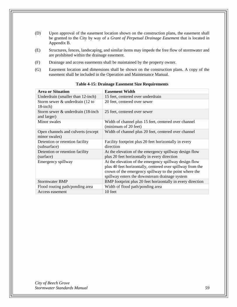
City of Beech Grove
Stormwater Standards Manual 59
(D) Upon approval of the easement location shown on the construction plans, the easement shall
be granted to the City by way of a Grant of Perpetual Drainage Easement that is located in
Appendix B.
(E) Structures, fences, landscaping, and similar items may impede the free flow of stormwater and
are prohibited within the drainage easement.
(F) Drainage and access easements shall be maintained by the property owner.
(G) Easement location and dimensions shall be shown on the construction plans. A copy of the
easement shall be included in the Operation and Maintenance Manual.
Table 4-15: Drainage Easement Size Requirements
Area or Situation Easement Width
Underdrain (smaller than 12-inch) 15 feet, centered over underdrain
Storm sewer & underdrain (12 to
18-inch)
20 feet, centered over sewer
Storm sewer & underdrain (18-inch
and larger)
25 feet, centered over sewer
Minor swales Width of channel plus 15 feet, centered over channel
(minimum of 20 feet)
Open channels and culverts (except
minor swales)
Width of channel plus 20 feet, centered over channel
Detention or retention facility
(subsurface)
Facility footprint plus 20 feet horizontally in every
direction
Detention or retention facility
(surface)
At the elevation of the emergency spillway design flow
plus 20 feet horizontally in every direction
Emergency spillway At the elevation of the emergency spillway design flow
plus 40 feet horizontally, centered over spillway from the
crown of the emergency spillway to the point where the
spillway enters the downstream drainage system
Stormwater BMP BMP footprint plus 20 feet horizontally in every direction
Flood routing path/ponding area Width of flood path/ponding area
Access easement 10 feet

Chapter 4- Standards for Stormwater Quantity Management
60

City of Beech Grove
Stormwater Standards Manual 61
Chapter 5 - Standards for Erosion and Sediment Control for Construction Sites
During the construction process, soil is highly vulnerable to erosion by wind and water. Eroded soil
endangers water resources by reducing water quality and causing the siltation of aquatic habitat for fish
and other desirable species. Eroded soil also necessitates repair of sewers and ditches and the dredging
of ponds. In addition, clearing and grading during construction cause the loss of native vegetation
necessary for terrestrial and aquatic habitat.
The purpose of this section is to safeguard persons, protect property, and prevent damage to the
environment in the City. This section will also promote the public welfare by guiding, regulating, and
controlling the design, construction, use, and maintenance of any development or other activity that
disturbs or breaks the topsoil or results in the movement of earth on land in the City.
These standards were developed in accordance with the requirements of the MS4 General Permit (327
IAC 15-13) and the Construction General Permit (327 IAC 15-5). A Stormwater Pollution Prevention
and Erosion and Sediment Control Plan (SWPPP) shall be submitted and shall be in accordance with
the Construction General Permit and the standards in this manual. Permits as required by Indiana
Department of Environmental Management (IDEM), Indiana Department of Natural Resources
(IDNR), Army Corps of Engineers (ACOE), Indiana Department of Transportation (INDOT) and any
other local, state, and federal regulatory agencies are the responsibility of the property owner/developer.
5.1 Applicability
(A) The requirements under this chapter are in compliance with the Construction General Permit.
In general, this chapter requires the control of polluted runoff from construction sites with a
land disturbance greater than or equal to 1 acre, or disturbances of less than 1 acre of land that
are part of a larger common plan of development or sale if the larger common plan will
ultimately disturb 1 or more acres of land.
(B) The requirements under this Construction General Permit do not apply to persons who are
involved in agricultural land disturbing activities; or forest harvesting activities.
(C) The requirements under this Construction General Permit do not apply to the following
activities, provided other applicable permits contain provisions requiring immediate
implementation of soil erosion control measures:
(1) Landfills that have been issued a certification of closure under 329 IAC 10.
(2) Coal mining activities permitted under IC 14-34.
(3) Municipal solid waste landfills that are accepting waste pursuant to a permit issued by
the IDEM under 329 IAC 10 that contains equivalent stormwater requirements,
including the expansion of landfill boundaries and construction of new cells either
within or outside the original solid waste permit boundary.
(D) Single-family residential development consisting of 4 or fewer lots or a single-family
residential strip development where the developer offers for sale or lease without land
improvements, and the project is not part of a larger common plan of development or sale, shall
meet the detailed submittal requirements contained in 327 IAC 15-5-6.5(b).
Chapter 5- Standards for Erosion and Sediment Control for Construction Sites
62
5.2 Plan Sufficiency
(A) The City or the designated technical reviewer will review each application to determine its
conformance with the provisions of this manual and the Construction General Permit. Within
28 days after receiving an application, the City shall, in writing:
(1) Approve the Erosion and Sediment Control Plan and SWPPP and provide a Technical
Review and Comment Form (Form B-6 in Appendix B) stating that the "Plan is
Adequate" and issue a building permit;
(2) Approve the Erosion and Sediment Control Plan and SWPPP subject to such
reasonable conditions as may be necessary to secure substantially the objectives of this
regulation, and issue the Technical Review and Comment Form stating that the "Plan
is Adequate"; or
(3) Provide a Technical Review and Comment Form stating that the "Plan is Deficient"
and indicating the reason(s) and procedure for submitting a revised application and/or
submission.
(B) A Technical Review and Comment Form stating that the "Plan is Adequate" and a building
permit (as necessary) shall be obtained from the City prior to the initiation of any land
disturbing activities.
(C) Failure of the City to act on an original or revised application within 28 days of receipt shall
authorize the applicant to proceed in accordance with the plans as filed unless such time is
extended by agreement between the applicant and the City.
(D) The sufficiency of the construction plans shall be based upon Construction General Permit
regulations and the criteria described in this manual.
(E) After receiving a Technical Review and Comment Form stating that the "Plan is Adequate", if
revisions to the construction plans require a change in measures appropriate to control the
quality or quantity of stormwater runoff, then revised plans must be submitted to the City.
Pending preparation and approval of a revised plan, development activities shall be allowed to
proceed in accordance with conditions established by the City.
(F) As required by Part 7.1, the applicant will be required to file with the City a faithful
performance bond, letter of credit, or other improvement security in an amount deemed
sufficient by the City to cover all costs of improvements, landscaping maintenance of
improvements for such period as specified by the City, and engineering and inspection costs to
cover the cost of failure to repair of improvements installed on the project site.
(G) After receiving a Technical Review and Comment Form stating that the "Plan is Adequate"
from the City, and within 48 hours of the start of construction, the following shall be submitted
to IDEM:
(1) Notice of Intent (NOI) form (required by the Construction General Permit). The IDEM
NOI form is sufficient for the submittal;
(2) A copy of the Technical Review and Comment Form stating that the "Plan is
Adequate"; and
(3) Proof of Publication required by the Construction General Permit.
(H) A copy of the signed NOI must also be submitted to the City.
City of Beech Grove
Stormwater Standards Manual 63
5.3 Design Requirements The SWPPP and erosion and sediment control measures shall meet the requirements contained in
Construction General Permit, and be designed and installed in accordance with the Construction
General Permit, this manual, and the Indiana Stormwater Quality Manual.
5.4 Municipally Owned Projects
(A) For those construction activities owned by the MS4 operator (City of Beech Grove), project
construction plans must include:
(1) A traffic phasing plan for those projects that have the potential to alter vehicular traffic
routes,
(2) Requirements of the Construction General Permit, and
(3) The project SWPPP must address all requirements for construction plans and the
following areas located outside of right-of-ways:
(a) Utility relocation areas.
(b) Material hauling and transportation routes/roads.
(c) Borrow pits.
(d) Temporary staging and material stockpile areas.
(e) Temporary disposal areas for waste materials.
(B) For MS4 construction activities, construction plans must be submitted to the Marion County
SWCD for review and approval. If the MS4 operator does not receive either a Notice of
Deficiency or an approval within 35 days of the submittal, the plan will be considered adequate.
5.5 Inspection, Maintenances, Recordkeeping, and Reporting
(A) Inspection Responsibilities:
(1) A self-monitoring program must be implemented by the project site owner.
(2) A trained individual shall perform a written evaluation of the project site by the end of
the next business day following each measurable storm event (0.5” rainfall) and at a
minimum of 1 time per week. A Self-Monitoring Inspection From is provided in
Appendix B.
(3) The evaluation must address the maintenance of existing stormwater quality measures
to ensure they are functioning properly; and identify additional measures necessary to
remain in compliance with all applicable statutes and rules.
(4) Written evaluation reports must include the following:
(a) the name of the individual performing the evaluation;
(b) the date of the evaluation;
(c) problems identified at the project site; and
(d) details of corrective actions recommended and completed.
(5) All evaluation reports for the project site must be made available to the inspecting
authority within 48 hours of a request.
(6) All persons engaging in construction activities on a project site must comply with the
SWPPP, this manual, and the Construction General Permit.
(7) The City will perform inspections and provide recommendations to evaluate the
installation, implementation and maintenance of control measures, and management
practices at any project site involved in construction activities.
Chapter 5- Standards for Erosion and Sediment Control for Construction Sites
64
(B) Priority Sites
(1) When construction plans are submitted for review, the reviewer will identify priority
sites for inspection and enforcement. The criteria for priority sites will be based on the
nature and extent of construction, proximity to sensitive areas, steep topography on or
adjacent to proposed construction site, proximity to wetlands, and potential for direct
runoff to receiving waters. Construction site inspections will be based on priority
determinations.
(2) The City, or local, county, or state regulatory agency with jurisdiction, or a
representative thereof may make recommendations to the project site owner or their
representative to install appropriate measures beyond those specified in the SWPPP to
achieve compliance.
5.6 Project Termination
(A) Final Stabilization
(1) Final stabilization of a project site shall be achieved when:
(a) All land disturbing activities have been completed and a uniform (for example,
evenly distributed, without large bare areas) 70% density of perennial
vegetative cover has been established on all unpaved areas and areas not
covered by permanent structures, or equivalent permanent stabilization
measures have been employed; and
(b) Construction projects on land used for agricultural purposes are returned to its
preconstruction agricultural use or disturbed areas, not previously used for
agricultural production, such as filter strips and areas that are not being
returned to their preconstruction agricultural use, meet the final stabilization
requirements listed above.
(2) The project site owner shall plan an orderly and timely termination of the construction
activities, including the implementation of stormwater quality measures that are to
remain on the project site.
(B) Notice of Termination
(1) The project site owner , or a representative thereof, shall submit a written Notice of
Termination (NOT) form to the City and IDEM upon project termination once the
following requirements are met:
(a) All land disturbing activities, including construction on all building lots, have
been completed.
(b) Final stabilization of the entire site has been completed.
(c) All permanent stormwater quality measures (if required per Post-Construction
Stormwater Quality section) have been implemented and are operational.
(d) Temporary erosion and sediment control measures have been removed.
(2) The IDEM NOT for Storm Water Runoff Associated with Construction Activity form
is sufficient for this submittal.
(3) The NOT must be submitted within 2 weeks of project termination, and contain a
statement(s) verifying that each of these conditions have been met.
(4) The City or a representative thereof may inspect the project site to confirm the
information provided in the NOT.
City of Beech Grove
Stormwater Standards Manual 65
(C) Early Project Termination Requirements
(1) The project site owner may submit a NOT to obtain early release from compliance with
these Standards and the Construction General Permit.
(2) The project site owner must meet the requirements per Construction General Permit as
outlined below:
(a) The remaining, undeveloped acreage does not exceed 5 acres, with contiguous
areas not to exceed 1 acre.
(b) A map of the project site, clearly identifying all remaining undeveloped lots,
is attached to the NOT. The map must be accompanied by a list of names and
addresses of individual lot owners or individual lot operators of all
undeveloped lots.
(c) All public and common improvements, including infrastructure, have been
completed and permanently stabilized and have been transferred to the
appropriate local entity.
(d) The remaining acreage does not pose a significant threat to the integrity of the
infrastructure, adjacent properties, or water quality.
(e) All permanent stormwater quality measures have been implemented and are
operational.
(3) Upon verification of the NOT, the City shall issue written approval to the project site
owner. Upon receipt of this approval, the project site owner shall notify all current
individual lot owners and all subsequent individual lot owners of the remaining
undeveloped acreage and acreage with construction activity that they be responsible
for complying with the General Requirements for Individual Building Lots within a
Permitted Project. The remaining individual lot owners do not need to submit an NOI
or NOT form. The notice must contain a verified statement that each of the conditions
in Items (a) through (e), listed above, have been met. The notice must also inform the
individual lot owners of the requirements to:
(a) Install and maintain appropriate measures to prevent sediment from leaving
the individual building lot; and
(b) Maintain all erosion and sediment control measures that are to remain on-site
as part of the construction plan.

Chapter 5- Standards for Erosion and Sediment Control for Construction Sites
66

City of Beech Grove
Stormwater Standards Manual 67
Chapter 6- Standards for Stormwater Quality Management for Post-Construction
Land development projects and associated increases in impervious cover alter the hydrologic response
of local watersheds and increase stormwater runoff rates, runoff volumes, flooding, stream channel
erosion, and sediment transport and deposition. This stormwater runoff contributes to increased
quantities of water-borne pollutants. Stormwater runoff, soil erosion and nonpoint source pollution can
be controlled and minimized through the regulation of stormwater runoff from development sites.
The purpose of this chapter is to establish minimum stormwater management requirements and controls
to provide reasonable guidance for the regulation of stormwater runoff for the purpose of protecting
local water resources from degradation and to protect and safeguard the general health, safety, and
welfare of the public residing in watersheds within the City. This chapter seeks to meet that purpose
through minimizing increases in stormwater runoff rates and volumes, erosion and nonpoint source
pollution caused by stormwater runoff, wherever possible, through stormwater management controls
and to ensure that these management controls are properly maintained.
6.1 Applicability
(A) The provisions of this chapter are in compliance with the MS4 General Permit (327 IAC 15-
13) and apply to all persons meeting the requirements of 327 IAC 15-13-16.
(B) In general, this chapter requires the post-construction control of stormwater discharges for both
new development and redevelopment, with a land disturbance greater than or equal to 1 acre,
or disturbances of less than 1 acre of land that are part of a larger common plan of development
or sale if the larger common plan will ultimately disturb 1 or more acres of land.
(C) The requirements of this chapter do not apply to the following:
(1) Construction of, or modifications to, single family structures that are not a part of a
larger common plan of development,
(2) Single family residential development consisting of four or fewer lots,
(3) Individual lots within a larger common development plan that has been previously
permitted for stormwater management,
(4) Any logging, agricultural, or other activity which is consistent with an approved soil
conservation plan or a timber management plan prepared or approved by county, state,
or federal regulating agencies, and
(5) Land disturbance that results in no impervious surface area following construction
(i.e. underground utility projects, grading projects that will establish vegetative cover).
(D) This chapter is not intended to interfere with, abrogate, or annul any other chapter, rule or
regulation, stature, or other provision of law. The requirements of this chapter should be
considered minimum requirements, and where any provision of this chapter imposes
restrictions different from those imposed by any other chapter, rule or regulation, or other
provision of law, whichever provisions are more restrictive or impose higher protective
standards for human health or the environment shall be considered to take precedence.
(E) If the provisions of any section, subsection, paragraph, subdivision or clause of this chapter
shall be judged invalid by a court of competent jurisdiction, such order of judgment shall not
affect or invalidate the remainder of any section, subsection, paragraph, subdivision or clause
of the chapter.
Chapter 6- Standards for Stormwater Quality Management for Post-Construction
68
(F) Post-Construction Policy
(1) The City has adopted a policy that the control of stormwater runoff quality will be
based on the management of total suspended solids (TSS). This requirement will serve
as the basis of the stormwater quality management program for all areas within the
jurisdiction of the City.
(2) BMPs shall incorporate floatables control. BMPs shall capture floating debris and
remove it as part of routine maintenance of the BMP. Standalone BMPs must include
floatables control. BMP systems or treatment trains shall have at least one component
of the system providing floatable control, located after the last inflow point to the
system.
(3) In addition, designers may be required to include in their designs the control of fecal
bacteria or pollutants that are associated with a specific land use, such as hydrocarbons
associated with retail gasoline outlets.
(4) Post-construction stormwater quality measures must be properly maintained to ensure
stormwater runoff is continuously treated from the developed and stabilized site.
(5) Special circumstances that are not covered by these standards shall be regulated and
reviewed on a case-by-case basis.
(6) New gasoline outlets and refueling areas, or outlets' and refueling areas that replace
their existing tank systems shall be designed and installed using appropriate practices
to reduce lead, copper, zinc, and polyaromatic hydrocarbons in stormwater runoff.
(G) Where appropriate, storage, infiltration, filtering, or vegetative practices shall be used to reduce
the impact of pollutants in stormwater runoff on receiving waters. In addition to the practices,
the following requirements shall be utilized:
(1) Infiltration practices will not be allowed in wellhead protection areas.
(2) Discharges will not be allowed directly into sinkholes or fractured bedrock without
treatment that results in the discharge meeting Indiana ground water quality standards
as referenced in 327 IAC 2-11.
(3) Any stormwater practice that is a Class V injection well must ensure that the discharge
meets Indiana groundwater quality standards as referenced in 327 IAC 2-11.
(4) As site conditions allow, the rate at which water flows through conveyances shall be
regulated to reduce outfall scouring and stream bank erosion.
(5) As site conditions allow, a vegetated filter strip of appropriate width shall be
maintained along unvegetated swales and ditches.
6.2 Methods for Sizing BMPs
(A) The target TSS removal rate is 80%. For the purposes of this requirement, TSS is defined as
particles smaller than 125 microns in diameter.
(B) There are two methods for calculating the required size of a BMP. The first method calculates
the water quality volume to be treated, which applies to detention-based BMPs. The second
method calculates the water quality peak flow rate to be treated, which applies to filtration
processes and mechanical-type BMPs such as hydrodynamic devices.
(C) The appropriate stormwater quality volume (WQv) and/or stormwater quality flow rate (Qwq)
generated from a qualifying site shall be adequately treated before discharge. Pre-approved
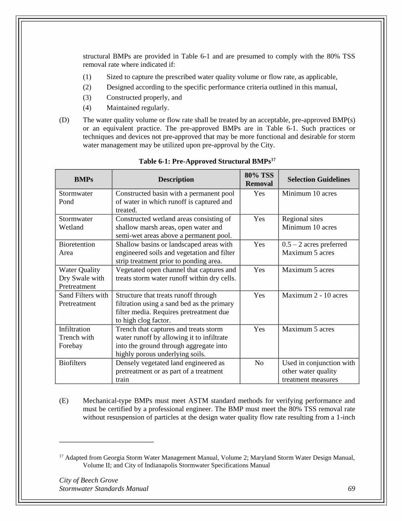
City of Beech Grove
Stormwater Standards Manual 69
structural BMPs are provided in Table 6-1 and are presumed to comply with the 80% TSS
removal rate where indicated if:
(1) Sized to capture the prescribed water quality volume or flow rate, as applicable,
(2) Designed according to the specific performance criteria outlined in this manual,
(3) Constructed properly, and
(4) Maintained regularly.
(D) The water quality volume or flow rate shall be treated by an acceptable, pre-approved BMP(s)
or an equivalent practice. The pre-approved BMPs are in Table 6-1. Such practices or
techniques and devices not pre-approved that may be more functional and desirable for storm
water management may be utilized upon pre-approval by the City.
Table 6-1: Pre-Approved Structural BMPs17
BMPs Description 80% TSS
Removal Selection Guidelines
Stormwater
Pond
Constructed basin with a permanent pool
of water in which runoff is captured and
treated.
Yes Minimum 10 acres
Stormwater
Wetland
Constructed wetland areas consisting of
shallow marsh areas, open water and
semi-wet areas above a permanent pool.
Yes Regional sites
Minimum 10 acres
Bioretention
Area
Shallow basins or landscaped areas with
engineered soils and vegetation and filter
strip treatment prior to ponding area.
Yes 0.5 – 2 acres preferred
Maximum 5 acres
Water Quality
Dry Swale with
Pretreatment
Vegetated open channel that captures and
treats storm water runoff within dry cells.
Yes Maximum 5 acres
Sand Filters with
Pretreatment
Structure that treats runoff through
filtration using a sand bed as the primary
filter media. Requires pretreatment due
to high clog factor.
Yes Maximum 2 - 10 acres
Infiltration
Trench with
Forebay
Trench that captures and treats storm
water runoff by allowing it to infiltrate
into the ground through aggregate into
highly porous underlying soils.
Yes Maximum 5 acres
Biofilters Densely vegetated land engineered as
pretreatment or as part of a treatment
train
No Used in conjunction with
other water quality
treatment measures
(E) Mechanical-type BMPs must meet ASTM standard methods for verifying performance and
must be certified by a professional engineer. The BMP must meet the 80% TSS removal rate
without resuspension of particles at the design water quality flow rate resulting from a 1-inch
17 Adapted from Georgia Storm Water Management Manual, Volume 2; Maryland Storm Water Design Manual,
Volume II; and City of Indianapolis Stormwater Specifications Manual
Chapter 6- Standards for Stormwater Quality Management for Post-Construction
70
rainfall depth. Testing of the TSS removal rate must be conducted by an independent testing
facility rather than by the manufacturer.
(F) A quick reference, minimum design criteria, and maintenance and inspection checklists for
each pre-approved BMP are provided in Appendix C of this manual.
(G) Water Quality Volume (WQV)
(1) The WQv is the storage needed to capture and treat the runoff from the first 1-inch of
rainfall. The WQv is equivalent to 1 inch of rainfall multiplied by the volumetric runoff
coefficient (Rv) and the site area. The volume of runoff is directly related to the amount
of impervious cover at the site and is calculated using Equation 6-1.
Equation 6-1
WQv = P Rv A
12
where:
WQv = water quality volume (acre-feet, ac-ft)
P = rainfall depth (inches, in) = 1 inch
Rv = volumetric runoff coefficient – see Equation 6-2
A = site area (acres)
Equation 6-2
Rv = 0.05 + 0.009 I
where:
Rv = volumetric runoff coefficient
I = percentage of impervious cover (%)
(H) Water Quality Flow Rate (Qwq)
(1) The Qwq is needed to size BMP devices designed to treat runoff at a peak design flow
rate through the system. Conventional NRCS (SCS) methods have been found to
underestimate the volume and rate of runoff for rainfall events less than 2 inches. The
following procedure can be used to calculate the Qwq. The method relies on the water
quality volume in conjunction with an adjusted curve number (CNwq) and the NRCS
TR-55 methodology.
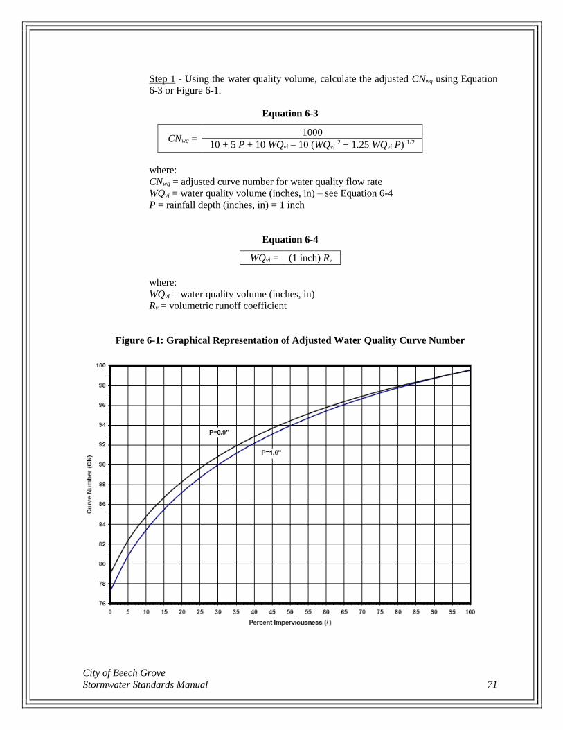
City of Beech Grove
Stormwater Standards Manual 71
Step 1 - Using the water quality volume, calculate the adjusted CNwq using Equation
6-3 or Figure 6-1.
Equation 6-3
CNwq = 1000
10 + 5 P + 10 WQvi – 10 (WQvi 2 + 1.25 WQvi P) 1/2
where:
CNwq = adjusted curve number for water quality flow rate
WQvi = water quality volume (inches, in) – see Equation 6-4
P = rainfall depth (inches, in) = 1 inch
Equation 6-4
WQvi = (1 inch) Rv
where:
WQvi = water quality volume (inches, in)
Rv = volumetric runoff coefficient
Figure 6-1: Graphical Representation of Adjusted Water Quality Curve Number

Chapter 6- Standards for Stormwater Quality Management for Post-Construction
72
Step 2 – Calculate the site time of concentration in minutes (Tc) and area in acres (A).
Step 3 – Use the adjusted CNwq, Tc and A as input for TR-55 calculations in conjunction
with the Huff II rainfall distribution, for 1-inch of rainfall depth using the storm
duration that produces the highest peak flow rate to calculate the Qwq.
City of Beech Grove
Stormwater Standards Manual 73
Chapter 7 - Required Assurances
7.1 Performance Bonds
(A) Applicant shall provide financial performance assurance in the form of a performance bond,
certified check, irrevocable letter of credit, or certificate of deposit before construction begins.
(B) Said performance bond shall guarantee a good faith execution of the SWPPP, Erosion and
Sediment Control Plan, and any other conditions of plan approval including proper installation
of all approved stormwater infrastructure.
(C) to cover all costs of improvements, landscaping maintenance of improvements for such period
as specified by the City, and engineering and inspection costs to cover the cost of failure to
repair of improvements installed on the project site
(D) Assurance shall be made out to the City of Beech Grove for an amount equal to 100% of the
total costs of implementing measures required by this manual. The total costs shall be for the
cost of installation of stormwater improvements including detention/retention facilities,
stormwater quality BMPs, and other stormwater infrastructure and the continuous installation,
monitoring, and maintenance of temporary and permanent sediment and erosion control
measures, as regulated under this manual. The intent of this performance bond is not only to
complete the installation of stormwater infrastructure for the project, but also to ensure that
adequate stormwater pollution prevention measures are properly installed and maintained for
such as period as specified by the City.
(E) Performance bonds shall be kept current until the project receives final approval from the City.
Delinquent performance bonds or other assurances will result in penalties and corrective
actions as defined in Chapter 11.
(F) Should the owner/applicant fail to comply with the provisions of this manual, in addition to
any other remedies the City may redeem the performance bond to complete all necessary work,
after giving reasonable notice and opportunity for compliance as defined in Chapter 11.
(G) Upon completion of the required temporary and permanent sediment and erosion control
measures, detention/retention facilities, and stormwater quality BMPs according to the
approved plans, the applicant shall provide the City with “as-built” plans in accordance with
Part 8.1 of this manual. The applicant may then request the release of the performance bond.
Upon satisfaction of all performance requirements, issuance of the NOT, and receipt of the
maintenance guarantee as described in Part 7.2(C) of this manual, the City will release the
performance bond within 60 days.
7.2 Maintenance Bonds
(A) Prior to the release of the performance assurance, the applicant shall provide financial
maintenance guarantee in the form of a Maintenance Bond (Form B-14 in Appendix B) or
certified check. Assurance shall be made out to the City of Beech Grove.
(B) Said maintenance bond shall guarantee the materials and workmanship of all permanent
sediment and erosion control measures, detention/retention facilities, water quantity BMPs, and
other stormwater infrastructure and that stormwater quality BMPs shall be maintained in
accordance with the approved plans, O&M manual, and the requirements described herein.
Chapter 7- Required Assurances
74
(C) Said financial maintenance guarantee shall meet the following conditions:
(1) The Maintenance Bond shall run and be in force for a period of 3 years from the date
of release of the performance bond.
(2) A penal sum shall be fixed and approved by the City, but in no case shall the penal sum
be less than 20% of the total construction cost. The minimum Maintenance Bond shall
be no less than $5,000.00.
(3) The Maintenance Bond shall be issued in the applicant’s name alone or in the name of
the applicant and his subcontractor as co-signers. All certified checks provided for
financial maintenance guarantee shall be signed by the applicant alone.
(D) All maintenance bonds shall expire at the end of the 3-year period for which they were
established. Within 60 days of the expiration date, the proper authority will return said expired
maintenance bond to the applicant. In the case where a certified check has been posted as a
financial maintenance guarantee, the applicant shall, at the end of the 3-year maintenance
period, contact the proper authority in order to obtain the release of the maintenance guarantee.
City of Beech Grove
Stormwater Standards Manual 75
Chapter 8 - Project Construction and Completion
8.1 Construction Inspection and Maintenance
(A) Prior to beginning construction activities, conduct a Pre-Construction Conference with the City
and other stakeholders. Notify the City at least 2 business days prior to the Pre-Construction
Conference.
(B) The City may conduct inspections of the installation of the stormwater management system to
ensure compliance with the terms of this manual and the Stormwater Management Approval.
(C) The applicant must notify the City at least 2 business days in advance of installation of the
stormwater facilities. Inspections of the system construction may be conducted by the City or
their designated representative. If required, the applicant shall execute an Agreement Between
Owner / Contractor and City of Beech Grove for Construction Inspection Services (Form B-12
in Appendix B) and pay all applicable inspection fees per the terms stated in the agreement.
(D) The City has the authority to conduct post-construction inspections to ensure the stormwater
facility is maintained in good condition. Parties responsible for the operation and maintenance
of a stormwater facility shall make and keep records of the installation and of all maintenance
and repairs. These records shall be made available to the City upon request and shall be retained
for a period of 5 years.
(E) If the responsible party fails to meet the requirements of the installation and maintenance
conditions per this manual and the terms and conditions of the stormwater management
approval, the City shall pursue enforcement action according to Chapter 11.
8.2 Certification of As-Built Plans
(A) For public stormwater facilities and sites 1 acre or larger, record drawings of installed
stormwater facilities shall be completed within 30 days after the completion of the project and
submitted to the City for final approval of the project.
(B) Record drawings shall be certified by a Professional Engineer or Land Surveyor.
(C) Record drawings shall include both a hard copy and an electronic copy (AutoCAD compatible
drawings on CD) of as-built information including easements, horizontal alignments,
elevations, inverts, top-of-castings, pond cross sections, and flow lines of swales.
8.3 Post-Construction Inspection and Maintenance
(A) Operations and Maintenance (O&M) Manual Requirements.
(1) Privately-owned stormwater facilities including pipes, structures, detention/retention
facilities, swales, open channels, subsurface drains, water quality BMPs, and low
impact development practices shall have an O&M manual. The O&M manual shall be
submitted with the General Application for Drainage Approval.
(2) The O&M manual should include all maintenance recommendations for all ponds and
other stormwater facilities. Owners of ponds will be responsible for all maintenance of
pond banks, erosion control measures, riprap, and outfall protection and all periodic
dredging. It is the designer’s responsibility to determine which additional operation
and maintenance measures are necessary to prolong the optimal function of the facility.
(3) The approved O&M manual shall be signed by the owner and notarized. A copy of the
approved O&M manual shall be provided to the owner and the City. The signed and
Chapter 8- Project Construction and Completion
76
approved O&M manual shall be recorded with the property by the County Recorder’s
office. A copy of the O&M manual shall be provided to each new owner before the
consummation of a sale. The O&M manual shall be signed by the new owner,
notarized, and submitted to the City to be kept on record.
(4) All O&M manuals shall include the following information, at a minimum:
(a) Owner Information. The first section of the manual shall contain information
about all people involved with the operations and maintenance of the facility.
This section shall list the names and contact information of all responsible
parties, including property owner(s), maintenance staff, and person(s)
responsible for performing inspections. The responsibilities of each individual
shall be clearly defined. Contact information shall include business or mobile
phone number, address for giving notice, and email address (if available).
(b) Site Map. The O&M manual shall include a site map that clearly indicates the
following:
(i) The location of the stormwater facility or BMP.
(ii) Plan and cross-section details, showing applicable features.
(iii) The flow of stormwater through the site, including an overview of the
stormwater’s path through the onsite stormwater facilities and BMPs.
(iv) Dimensions, easements, outlets/discharge points and outfall locations,
drainage patterns, stormwater runoff flow directions, the extent and
depth (elevation) of high water levels, flood routing path, signage,
connecting structures, weirs, invert elevations, structural controls used
to control stormwater flows, and other relevant features.
(c) O&M Practices. Each stormwater facility and BMP shall require specific
inspection and maintenance procedures.
(i) Guidance shall be written in simple, layman’s terms, including:
(1) Guidance on owner-required periodic inspections and
inspections to be performed by the City.
(2) Guidance on routine maintenance including mowing, litter
removal, woody growth removal, etc. to be performed by the
owner.
(3) Guidance on remedial maintenance such as inlet replacement,
outlet work, etc. to be performed by the owner.
(4) Guidance on sediment removal, both narrative and graphical,
describing when sediment removal shall occur in order to
ensure that the stormwater facility or BMP remains effective
as a stormwater management device. Guidance shall include
instructions as to how the depth of sediment shall be measured
and at what measurement removal will be required.
(5) Instructions on inspection and clean-out of BMP sumps, trash
screens, settling pits, and oil/grease collection chambers.
(6) Instructions on proper disposal of removed sediments, trash,
debris, and other substances.
(ii) The minimum requirements below shall also be incorporated into the
inspection and maintenance regimen and clearly documented in the
O&M manual.
(1) Operation and maintenance procedures and practices shall be
reviewed and assessed annually.
City of Beech Grove
Stormwater Standards Manual 77
(2) Access routes, including roadways and sidewalks, shall be
inspected annually and maintained as needed.
(3) Drainage structures and flow restrictors shall be inspected and
cleaned semi-annually or per the manufacturer’s
recommendations, whichever is more stringent.
(4) Volume control facilities and BMPs shall be inspected semi-
annually or per the manufacturer’s recommendations,
whichever is more stringent.
(5) The owner shall keep an updated log book or inspection
worksheets documenting the performance of the required
operation and maintenance activities for perpetuity. Note
inspection dates, facility components inspected, facility
condition, and any maintenance performed or repairs made.
Documentation must be produced upon the request of the
City, within 48 hours of the request.
(6) Vegetation shall be maintained on a regular basis per design
specifications.
(7) Pest control measures shall be implemented to address insects,
rodents, and other pests. Natural pest control is preferred over
chemical treatments.
(8) Signage and fencing shall be installed and maintained where
necessary to protect property and the public. Native
vegetation plantings shall have “No Mow” or other
appropriate signage.
(9) Underground vaults and structures shall include design
measures to facilitate regular cleaning and maintenance.
Confined space entry procedures shall be followed.
(d) Right-of-Entry Statement. The O&M manual shall include a statement that the
City has the right to enter the property to inspect the stormwater facility or
BMP. The statement shall be signed and notarized.
(e) Implementation Schedule. An inspection and maintenance schedule shall be
prepared in a tabular format and included in the O&M manual. This schedule
shall provide for routine examination of all stormwater facilities and BMPs on
the property and incorporate the varying maintenance needs of each.
(f) Employee Training. Specific individuals shall be assigned responsibility for
operation, maintenance, and inspection of all onsite stormwater facilities and
BMPs. Employee training shall be conducted so that these individuals are
aware of proper procedures and practices. The training program and schedule
shall be incorporated into the O&M manual. All personnel should be familiar
with the components of the O&M manual and their personal level of
responsibility. Training documentation may be requested by the City.
(g) Drainage Easement(s) Documentation. The O&M manual shall include
documentation of drainage easement(s) around the stormwater facilities and
BMPs. The documentation may be in text or graphic format.
(B) Stormwater Facility and BMP Maintenance.
(1) Stormwater facilities and BMPs shall be maintained in a properly functioning
condition so that their effectiveness in managing and treating stormwater runoff is not
diminished, in accordance with the operation and maintenance procedures and
schedules listed in Appendix C, the Indiana Stormwater Quality Manual, the approved
Chapter 8- Project Construction and Completion
78
O&M manual, and the terms and conditions of the approved Drainage Plan. The
stormwater facility or BMP owner is considered in violation of this manual if the
facility or BMP is not maintained properly.
(2) Following construction completion and the issuance of an NOT, inspection and
maintenance of stormwater facilities and BMPs shall be the long-term responsibility
of the owner of those facilities (including Homeowners Associations or any other entity
as specified in restrictive covenants).
(C) Records of Inspection and Maintenance Activities.
(1) The stormwater facility or BMP owner must conduct necessary inspections, at least
once per year. The inspections shall follow the operation and maintenance procedures
listed in Appendix C, the Indiana Stormwater Quality Manual, the approved O&M
manual, and the terms and conditions of the approved Drainage Plan for each facility
or BMP. The inspection shall cover physical conditions, available water quality storage
capacity, and the operational condition of key facility elements. Completed inspection
forms must be maintained by the owner and produced upon request by the City within
48 hours of the request.
(2) Annual inspection reports shall be completed by the Owner, beginning one year after
construction is completed. Subsequent reports shall be completed each year within the
same month of the initial report in perpetuity. All deficiencies found during the
inspection shall be addressed. Reports shall be made available to the City within
48 hours of a request. If the annual inspection report is not completed within the month
it is due, if there are deficiencies which exist but were not included in the report, or if
any deficiencies included in the report are not addressed in a timely manner, the City
may take enforcement action in accordance with this manual.
(3) The City must be notified of any changes in ownership, major repairs, or failure in
writing within 30 days.
(4) In the event that the City finds a stormwater facility in need of maintenance or repair,
the City will notify the owner on record of the necessary maintenance or repairs and
give the owner a timeframe for completing the work. If the maintenance or repairs are
not completed within the designated timeframe, the City may perform the work and
bill the owner for the actual costs of the work.
(5) The City also has the authority to perform long-term inspection of all public or
privately-owned stormwater facilities. Such inspections will be in addition to the
regular inspections required to be performed by the facility owner. The inspections will
follow the operation and maintenance procedures included in Appendix C and/or the
operation and maintenance procedures listed in the approved Drainage Plan for each
facility or BMP. Noted deficiencies and recommended corrective action will be
included in an inspection report.
City of Beech Grove
Stormwater Standards Manual 79
Chapter 9 - Illicit Discharge, Detection and Elimination
The purpose of this chapter is to provide for the health, safety, and general welfare of the citizens of
the City of Beech Grove through the regulations of non-stormwater discharges to the storm drainage
system to the maximum extent practicable as required by federal and state law. This chapter establishes
methods for controlling the introduction of pollutants into the municipal separate storm sewer system
(MS4) in order to comply with requirements of the National Pollutant Discharge Elimination System
(NPDES) permit process. The objectives of this chapter are:
To regulate the contribution pollutants to the MS4 by stormwater discharges by any user;
To prohibit illicit connections and discharges to the MS4; and
To establish legal authority to carry out all inspection, surveillance and monitoring procedures
necessary to ensure compliance with this chapter.
9.1 Applicability This chapter shall apply to anything entering the MS4 generated on any developed and undeveloped
lands unless explicitly exempted by the City.
9.2 Discharge Prohibitions
(A) Prohibition of illegal discharges. No person shall discharge or cause to be discharged into the
MS4 or waterways any materials, including but not limited to pollutants, wastewater or waters
containing any pollutants. The commencement, conduct or continuance of any illegal discharge
to the MS4 is prohibited except as described as follows:
(1) The following discharges are exempt from discharge prohibitions established by this
chapter:
(a) water line flushing or other potable water sources,
(b) landscape irrigation or lawn watering (without chemical additives),
(c) diverted stream flows,
(d) rising ground water,
(e) uncontaminated ground water infiltration,
(f) uncontaminated pumped ground water,
(g) discharge from potable sources,
(h) foundation or footing drains (not including active groundwater dewatering
systems),
(i) water from crawl space pumps,
(j) air conditioning condensation,
(k) springs,
(l) noncommercial washing of vehicles,
(m) natural riparian habitat or wetland flows,
(n) swimming pools (if dechlorinated to less than 1 part per million chlorine),
(o) fire-fighting activities, and
(p) any other water source not containing pollutants.
(2) Discharges specified in writing by an authorized representative of the City as being
necessary to protect public health and safety.
(3) Dye testing is an allowable discharge, but requires a verbal notification to the City prior
to the time of the test.
(4) The prohibition shall not apply to any non-stormwater discharge permitted under an
NPDES permit, waiver, or waste discharge order issued to the discharger and
Chapter 9- Illicit Discharge, Detection and Elimination
80
administered under the authority of the Federal or State agency, provided that the
discharger is in full compliance with all requirements of the permit, waiver, or order
and other applicable laws and regulations, and provided that written approval has been
granted for any discharge to the stormwater conveyance system.
(B) Prohibition of illicit connections.
(1) The construction, use, maintenance or continued existence of illicit connections to the
stormwater conveyance system is prohibited.
(2) This prohibition expressly includes, without limitation, illicit connections made in the
past, regardless of whether the connection was permissible under law or practices
applicable or prevailing at the time of connection.
(3) A person is considered to be in violation of this chapter if the person connects a line
conveying sewage to the MS4, or allows such a connection to continue.
(4) All connections shall also be in compliance with other applicable City ordinances,
including sanitary sewer and sump pump requirements.
9.3 Suspension of MS4 Access
(A) Suspension due to illicit discharges in emergency situations.
(1) The City may, without prior notice, suspend MS4 discharge access to a person when
such suspension is necessary to stop an actual or threatened discharge which presents
or may present imminent and substantial danger to the environment, or to the health or
welfare of persons, or to the MS4 or waterways.
(2) If the violator fails to comply with a suspension order issued in an emergency, the City
may take such steps as deemed necessary to prevent or minimize damage to the MS4
or waterways, or to minimize danger to persons.
(B) Suspension due to the detection of illicit discharge.
(1) Any person discharging to the MS4 in violation of this ordinance may have their MS4
access terminated if such termination would abate or reduce an illicit discharge.
(2) The City will notify a violator of the proposed termination of its MS4 access.
(3) The violator may petition the City for a reconsideration and hearing.
(4) A person commits an offense if the person reinstates MS4 access to premises
terminated pursuant to this section, without the prior approval of the City.
9.4 Industrial or Construction Activity Discharges Any person subject to an industrial or construction activity NPDES stormwater discharge permit shall
comply with all provisions of such permit. Proof of compliance with said permit may be required in a
form acceptable to the City prior to the allowing of discharges to the MS4.
9.5 Monitoring Of Discharges
(A) Access to facilities and properties.
(1) The City shall be permitted to enter and inspect facilities and properties subject to
regulation under this chapter as often as may be necessary to determine compliance
with this chapter. If a discharger has security measures in force which require proper
identification and clearance before entry into its premises, the discharger shall make
the necessary arrangements to allow access to representatives of the City.

City of Beech Grove
Stormwater Standards Manual 81
(2) Facility operators and property owners shall allow the City ready access to all parts of
the premises for the purposes of inspection, sampling, examination, and copying of
records that must be kept under the conditions of an NPDES permit to discharge
stormwater and the performance of any additional duties as defined by State and
Federal law.
(3) The City shall have the right to set up on any property or permitted facility such devices
as are necessary in the opinion of the City to conduct monitoring and/or sampling of a
stormwater discharge.
(4) The City has the right to require the discharger to install monitoring equipment as
necessary. The sampling and monitoring equipment shall be maintained at all times in
a safe and proper operating condition by the discharger at its own expense. All devices
used to measure stormwater flow and quality shall be calibrated to ensure their
accuracy.
(5) Any temporary or permanent obstruction to safe and easy access to a facility or
property to be inspected arid/or sampled shall be promptly removed by the owner or
operator at the written or oral request of the City and shall not be replaced. The costs
of clearing such access shall be borne by the owner or operator.
(6) Unreasonable delays in allowing the City access to a facility or property is a violation
of a stormwater discharge permit and of this chapter. A person who is the owner or
operator of a facility with a NPDES permit to discharge stormwater associated with
industrial activity commits an offense if the person denies the City reasonable access
to the permitted facility for the purpose of conducting any activity authorized or
required by this chapter.
(7) If the City has been refused access to any part of the premises from which stormwater
is discharged, and he/she is able to demonstrate probable cause to believe that there
may be a violation of this chapter, or that there is a need to inspect and/or sample as
part of a routine inspection and sampling program designed to verify compliance with
this chapter or any order issued hereunder, or to protect the overall public health, safety,
and welfare of the community, then the City may seek issuance of a search warrant
from any court of competent jurisdiction.
9.6 Requirement to Prevent, Control, and Reduce Stormwater Pollutants by the Use of Best Management Practices
(A) The City will require Best Management Practices for any activity, operation, or facility which
may cause or contribute to pollution or contamination of stormwater, the MS4, or waterways.
(B) The owner or operator of a property or facility shall provide, at their own expense, reasonable
protection from accidental discharge of prohibited materials or other wastes into the municipal
stormwater conveyance system or watercourses through the use of these structural and non-
structural BMPs.
(C) Further, any person responsible for a property or premise, which is, or may be, the source of
an illicit discharge, may be required to implement, at said person's expense, additional
structural and non-structural BMPs to prevent the further discharge of pollutants to the MS4.
(D) Compliance with all terms and conditions of a valid NPDES permit authorizing the discharge
of stormwater associated with industrial activity, to the extent practicable, shall be deemed
compliance with the provisions of this section. These BMPs shall be part of a stormwater
Chapter 9- Illicit Discharge, Detection and Elimination
82
pollution prevention plan (SWPPP) as necessary for compliance with requirements of the
NPDES permit.
9.7 Notification of Spills
(A) Notwithstanding other requirements of law, as soon as any person responsible for a property,
facility or operation, or responsible for emergency response for a facility or operation has
information of any known or suspected release or spill of materials which are resulting or may
result in illegal discharges or pollutants discharging into stormwater, the MS4, or waterways
said person shall take all necessary steps to ensure the discovery, containment, and cleanup of
such release or spill in accordance with State regulations.
(B) In the event of a spill, said person shall immediately notify emergency response agencies of
the occurrence via emergency dispatch services. Within 2 hours of becoming aware of the spill,
the person shall notify the City in person or by phone or facsimile. This requirement does not
relieve the discharger from notifying other entities as required by State or Federal requirements.
(C) Notifications in person or by phone shall be confirmed by written notice addressed and mailed
to the City within 5 days of the phone notice. The written notice shall contain the necessary
information identified in the Indiana Spill Rule (327 IAC 2-6.1).
(D) If the discharge of prohibited materials emanates from a commercial or industrial
establishment, the owner or operator of such establishment shall also retain an on-site written
record of the discharge and the actions taken to prevent its recurrence. Such records shall be
retained for at least 3 years.
City of Beech Grove
Stormwater Standards Manual 83
Chapter 10 – Sanitary Sewer Prohibited Discharge
10.1 Purpose
(A) The purpose of this chapter is to eliminate sump pump and other stormwater connections to the
sanitary sewer system in order to reduce the burden to the system and reduce treatment of clear,
unpolluted water.
(B) The rules and regulations governing the use of sump pumps or other clear water conveyance
systems are being established:
(1) To set forth uniform requirements for the use and discharge of sump pumps or
groundwater conveyance systems.
(2) To prevent the introduction of clean surface water, including but not limited to, water
from roof or cellar drains, basement sump pumps, French drains, yard drains, and other
clear water sources.
10.2 Applicability This chapter shall apply to all water entering the sanitary sewer system generated on any developed or
undeveloped lands unless explicitly exempted by an authorized enforcement authority.
10.3 Prohibited Discharges
(A) No property owner, occupant, user, or person shall discharge or cause to be discharged any
stormwater, surface water, groundwater, roof runoff, subsurface drainage, cooling water, or
unpolluted industrial process waters to any sanitary sewer. Unlawful connections include, but
are not limited to: sump pumps, foundation drains, French drains, yard drains, gutter
downspouts, cistern overflow pipes, and any other stormwater drainage receptacle(s).
(B) Stormwater and other unpolluted drainage shall be discharged to public stormwater facilities.
Industrial cooling water or unpolluted process waters may be discharged to public stormwater
facilities upon approval of the City of Beech Grove or its authorized representative.
10.4 Sump Pump and Rigid Pipe Required Any existing or new construction in which a sump pump has been or will be installed, shall be required
to install a rigid pipe connection discharge in accordance with Part 10.5. It shall be unlawful to maintain
any connection with the sanitary sewer carrying roof water, ground water, surface water or any other
natural precipitation after the effective date of this ordinance.
10.5 Sump Pump and Rigid Pipe: Method of Installation
(A) The building shall have a drain tile placed around the inside or outside perimeter of the
foundation connected to a sump pit. All baseboard seepage collection systems shall be
discharged to the sump pit. The sump pit shall be located at least 10 feet away from the inside
sanitary floor drain.
(B) The sump pump discharge pipe shall be connected to a storm sewer when available and abutting
on the property unless otherwise approved by the City. Connections to the storm sewer system
shall have an approved backflow prevention device installed. The sump pump discharge pipe
shall not be connected to underdrains, subsurface drainage tiles, building floor drains,
downspout outlets, or other sump pump lines
Chapter 10– Sanitary Sewer Prohibited Discharge
84
(C) When an existing sump pump discharges to the ground or when a storm sewer is not available,
the sump pump shall discharge to grade and must meet all of the following provisions, unless
otherwise approved by the City:
(1) The discharge pipe shall be installed to the outside wall of the building with rigid pipe
(plastic, copper, galvanized or black pipe) with a 1-inch inside diameter minimum.
(2) The discharge pipe must have a check valve within 1 foot of the floor grade and a union
or other approved coupling for easy disconnection for repair or replacement.
(3) The discharge pipe shall exit the building at 1 foot above finished grade.
(4) The point of discharge must be a minimum of 3 feet from the foundation wall and 5 feet
from the property line.
(5) The discharge must flow parallel to or away from the nearest property line.
(6) The discharge water shall not discharge to a public way including, sidewalks, streets,
or alleys. The discharge pipe shall terminate no less than 10 feet from such impervious
surfaces.
(7) The discharge water shall not create an icy condition on any pedestrian walkways
within or adjacent to the subject premises lot lines.
10.6 Removal of Prohibited Connection Required
(A) Any property owner who previously made any connection or installation in violation of this
chapter shall immediately remove such connection or correct such an installation. All direct or
indirect connections of a system as defined above intended to collect and convey unpolluted
stormwater or groundwater along, adjacent to, beside, or under the foundation or basement of
any building connected to the City of Beech Grove sanitary sewer shall be disconnected from
the sanitary sewer system.
(B) Disconnection shall mean removal of any direct or indirect prohibited connection to the
sanitary sewer system, including direction connections to the sanitary sewer service line,
connections to a sanitary sewer floor drain or similar plumbing fixture that would allow
unpolluted stormwater or groundwater flow to enter the sanitary sewer system. Any
disconnections or openings in the sanitary sewer shall be closed or repaired in a workmanlike
manner with proper materials unless the connection to the sanitary sewer is used for the proper
discharge of wastewater.
10.7 Non-Compliance Fee for Prohibited Connection
(A) Every person owning property shall allow an employee of the City, a designated representative
of the City, or a licensed plumber to inspect the building to determine if sump pumps or other
prohibited discharges are connected to the sanitary sewer system. Any person refusing to allow
their property to be inspected shall become subject to the monthly fee as defined below.
(B) Any sanitary sewer customer found with a direct or indirect prohibited connection to the
sanitary sewer system or refusing a property inspection shall be provided written notice that
the property will be subject to a monthly fee of $20.00 to cover the cost for treating the
extraneous flow or potential extraneous flow contributed to the sanitary sewer system. The fee
will be in addition to all other sanitary sewer user charges and will be added to the property
owner’s utility bill until the property is found to be in compliance. The fee will be included on
the utility bill within 45 days of discovery of the prohibited connection.

City of Beech Grove
Stormwater Standards Manual 85
(C) Any property found to have a prohibited connection, either direct or indirect, to the sanitary
sewer system shall receive a written notice from the City that will require the property owner
to make the necessary repairs and furnish proof of the repairs to the City. Upon confirmation
of the elimination of the prohibited connection, the monthly fee will be removed from the
property’s sewer bill within 30 days. Additional enforcement and penalties may be
incorporated in accordance with Chapter 11 of this manual.
(D) Exemptions may be granted in the form of a waiver for a particular property owner who can
demonstrate undue hardship because of unique or extenuating circumstances. A waiver would
allow the property owner to discharge directly into the sanitary sewer system. A waiver request
shall be submitted to the City (City Hall, 806 Main Street, Beech Grove, Indiana 46107) in
writing and, at a minimum, shall identify the property for which the waiver is being requested,
the name of the property owner/applicant, and a detailed description of the circumstances
justifying the request. Any person granted a waiver shall be charged a reduced monthly fee of
$10.00 to cover the cost for treating the extraneous flow or potential extraneous flow
contributed to the sanitary sewer system. The fee will be in addition to all other sanitary sewer
user charges and will be added to the property owner’s utility bill until the waiver is removed
or the property is found to be in compliance.

Chapter 10– Sanitary Sewer Prohibited Discharge
86
City of Beech Grove
Stormwater Standards Manual 87
Chapter 11- Enforcement and Penalties
11.1 Notice of Violation
(A) Whenever the City finds that a person has violated a prohibition or failed to meet a requirement
of this manual, the City or the City’s representative may order compliance by written notice of
violation to the responsible person. Such notice may require without limitation:
(1) The performance of maintenance activities, monitoring, analyses, and reporting;
(2) The elimination of illicit connections or discharges;
(3) That violating discharges, practices, or operations shall cease and desist;
(4) The abatement or remediation of stormwater pollution or contamination hazards and
the restoration of any affected property;
(5) Payment of a fine to cover administrative and remediation costs, including but not
limited to remediation costs, legal fees, consultant fees, monitoring costs, construction
costs, collection fees and any other costs borne by the Town related to the violation;
(6) The implementation of source control or treatment BMPs;
(7) The issuance of a Stop Work Order; and/or
(8) Revocation or suspension of Stormwater Management Plan approval.
(B) If abatement of a violation or restoration of affected property is required, the notice shall set
forth a deadline within which such remediation or restoration must be completed. Said notice
shall further advise that, should the violator fail to remediate or restore within the established
deadline, the work will be done by the City or a contractor and the expense thereof shall be
charged to the violator.
11.2 MS4 Stop Work Order
(A) Issuance
(1) If conditions exist such that any work activity must be stopped immediately to cease
an illicit discharge, the City issues a verbal order to stop work to the responsible person.
(2) After a verbal order is issued, the City immediately notifies the person of the condition.
(3) The City initiates a written "MS4 Stop Work Order" by providing detailed information
to the person. The order states the reason for the order, the conditions under which the
cited work will be permitted to resume, and the name and contact information of the
official issuing the order.
(4) Any person who continues to engage in any work after having been served with an
MS4 Stop Work Order, except such work as that person is directed to perform to
remove a violation or unsafe condition, shall be provided a Notice of Violation and
potentially be assessed penalties.
(5) Violators receiving an MS4 Stop Work Order are required to respond to the City within
2 business days of the issued notice to receive instructions on how to rescind the order.
(6) The City may impose penalties in accordance with this ordinance.
(B) Appeal
(1) Any person receiving an MS4 Stop Work Order may appeal the determination of the
City. The notice of appeal must be filed with the City within 10 days from the date of
the notice.
Chapter 11- Enforcement and Penalties
88
(2) Hearing on the appeal before the Board of Public Works and Safety shall take place
within 30 days from the date of its receipt of the notice of appeal.
(3) The decision of the Board of Public Works and Safety shall be final.
(C) Restart Work
(1) Once the person notifies the City that they are ready to restart the work that had been
stopped, the City shall verify corrective/preventative actions have been completed.
(2) The City indicates the verification of satisfactory completion of corrective and/or
preventative actions, and notifies the person that work is authorized to be resumed.
(3) The City issues the approved restart to the affected persons via a letter or memorandum.
11.3 Appeal of Notice of Violation
(A) Any person receiving a notice of violation may appeal the determination of the City. The notice
of appeal must be received within 15 days from the date of the notice of violation.
(B) Hearing on the appeal before the appropriate authority or his or her designee shall take place
within 30 days from the date of receipt of the notice of appeal. The decision of the City or their
designee shall be final.
11.4 Enforcement Measures after Appeal
(A) If the violation has not been corrected pursuant to the requirements set forth in the notice of
violation or, in the event of an appeal, within 15 days of the decision of the Board of Public
Works and Safety upholding the decision of the City, then representatives of the City shall
enter upon the subject private property and are authorized to take any and all measures
necessary to abate the violation and/or restore the property.
(B) It shall be unlawful for any person, owner, agent, or person in possession of any premises to
refuse to allow the government agency or designated contractor to enter upon the premises for
the purposes set forth above.
11.5 Cost of Abatement of the Violation
(A) After completion of abatement activities, the owner of the property will be notified of the cost
of abatement, including administrative costs.
(B) The property owner may file a written protest objecting to the amount of the assessment within
15 days.
(C) If the amount due is not paid within a timely manner as determined by the decision of the Board
of Public Works and Safety or by the expiration of the time in which to file an appeal, the
charges shall become a special assessment against the property and shall constitute a lien on
the property for the amount of the assessment.
(D) Any person violating any of the provisions of this manual shall become liable to the City by
reason of such violation. The liability shall be paid in not more than 12 equal payments. Interest
at the rate of 8% per annum shall be assessed on the balance beginning on the first day
following discovery of the violation.
11.6 Injunctive Relief
(A) It shall be unlawful for any person to violate any provision or fail to comply with any of the
requirements of this manual.
City of Beech Grove
Stormwater Standards Manual 89
(B) If a person has violated or continues to violate the provisions of this manual, the City may
petition for a preliminary or permanent injunction restraining the person from activities which
would create further violations or compelling the person to perform abatement or remediation
of the violation.
11.7 Compensatory Action
(A) In lieu of enforcement proceedings, penalties, and remedies authorized by this manual, the City
may impose upon a violator alternative compensatory actions, such as storm grate stenciling,
attendance at compliance workshops, creek cleanup, etc.
(B) If the compensatory action is not completed according to the provided schedule, then all fines
and penalties will be immediately due from the violator.
11.8 Violations Deemed a Public Nuisance
(A) In addition to the enforcement processes and penalties provided, any condition caused or
permitted to exist in violation of any of the provisions of this manual is a threat to public health,
safety, and welfare, and is declared and deemed a nuisance, and may be summarily abated or
restored at the violator's expense, and/or a civil action to abate, enjoin, or otherwise compel the
cessation of such nuisance may be taken.
11.9 Remedies Not Exclusive
(A) The remedies listed in this manual are not exclusive of any other remedies available under any
applicable federal, state, or local law, and it is within the discretion of the City to seek
cumulative remedies.
11.10 Penalties
(A) Any person who violates any of the provisions of this manual may be fined.
(B) The fines described in the notice of violation may include a civil infraction and is subject to a
minimum $100 fine for investigation, inspection and administrative costs and a maximum fine
of $2,500 for a first offense. A maximum of $7,500 may be assessed for a subsequent offense.
Each day such a violation occurs or continues shall be deemed a separate offense and shall
make the violator liable for the imposition of a fine for each day.
(C) Any person responsible for the discharge or potential discharge of a prohibited substance into
the stormwater drainage system shall be subject to all remedial and punitive enforcement
procedures specified in this manual. In addition to fines, the owner shall be responsible for:
stormwater administrative costs including labor, materials, and other fees; all costs associated
with eliminating the illegal discharge or connection; any emergency response, clean-up,
installation of infrastructure, remediation, or disposal fees; and ensuring that all sanitary and
stormwater connections originating from the property are in full compliance with the
requirements of this ordinance.

Chapter 11- Enforcement and Penalties
90

APPENDIX A
STANDARD STORMWATER CONSTRUCTION DETAILS

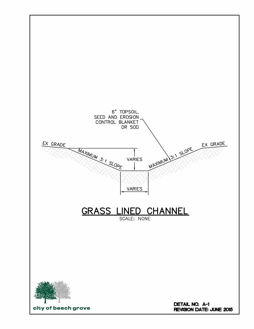
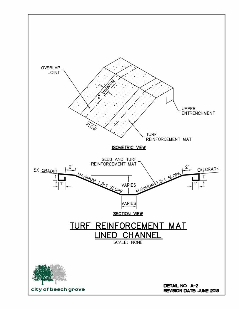
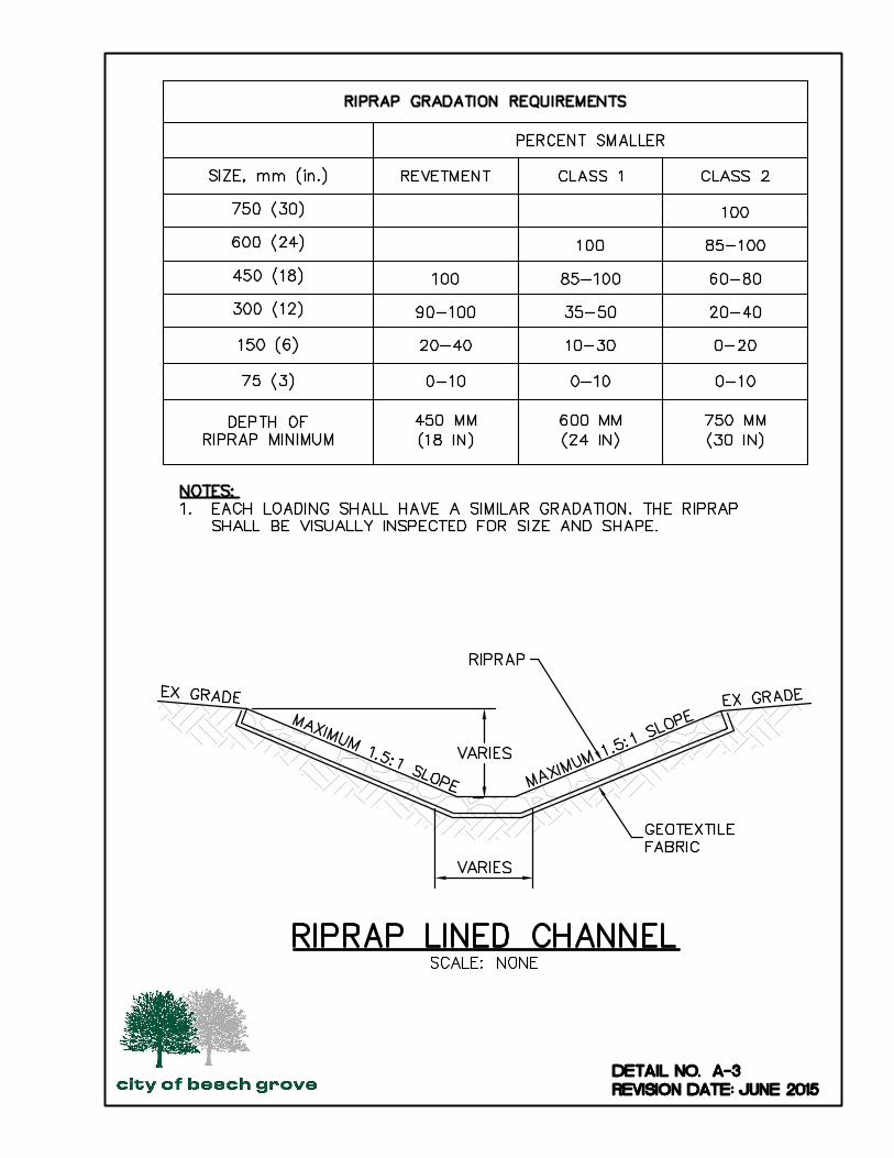
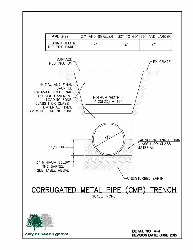
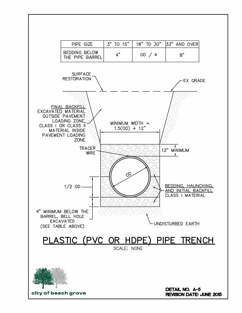
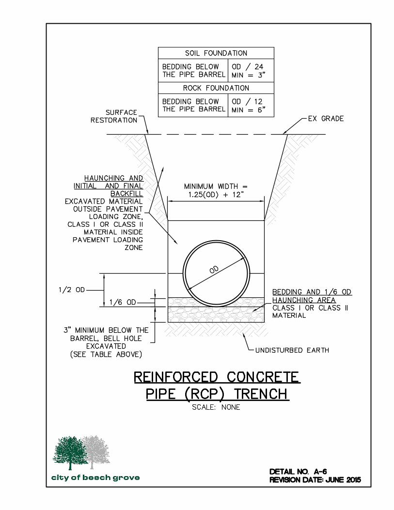
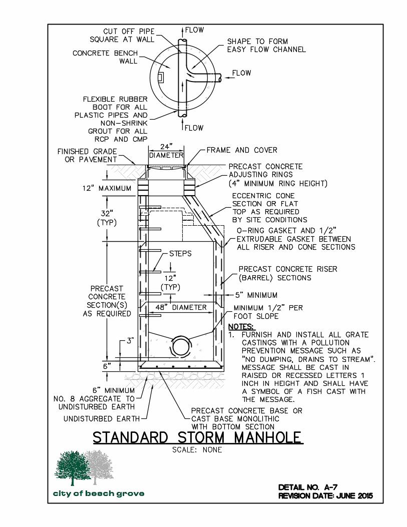
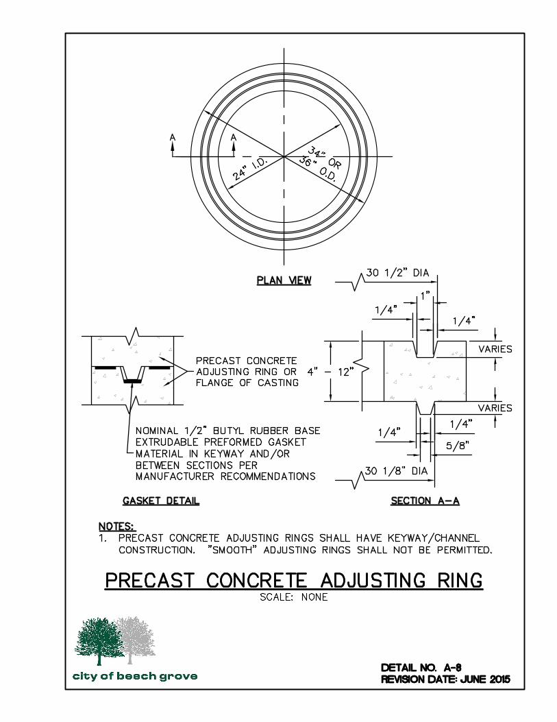
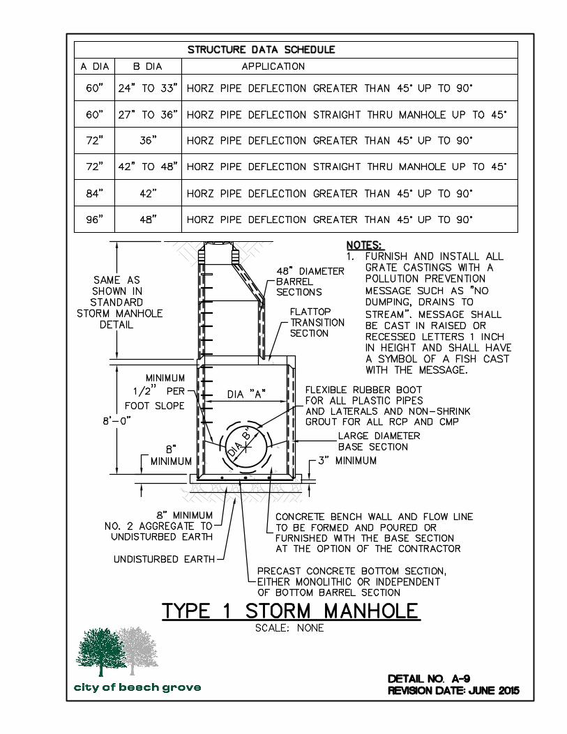
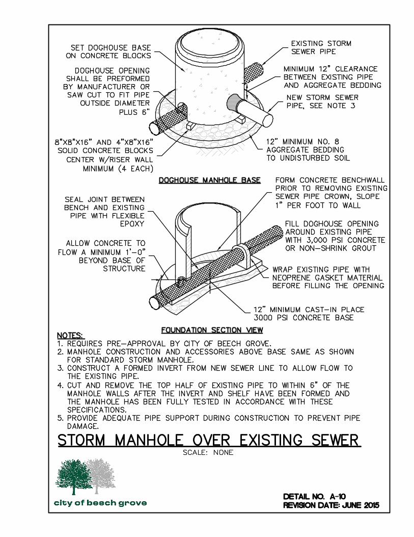
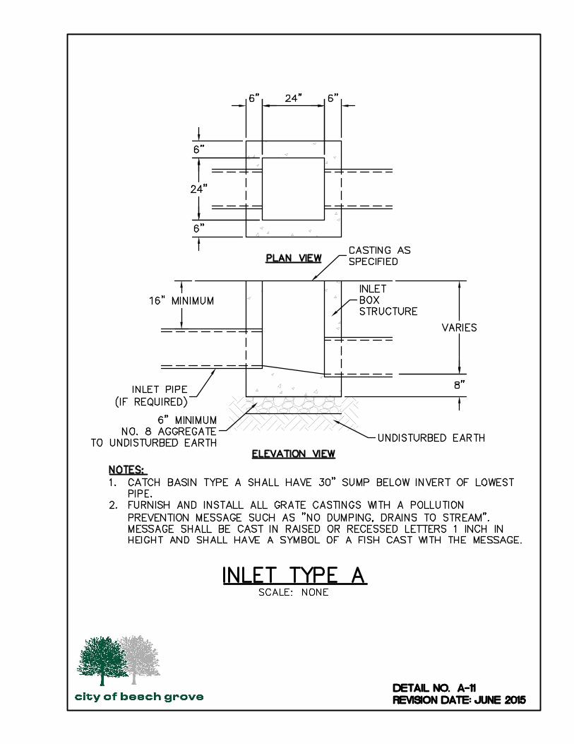
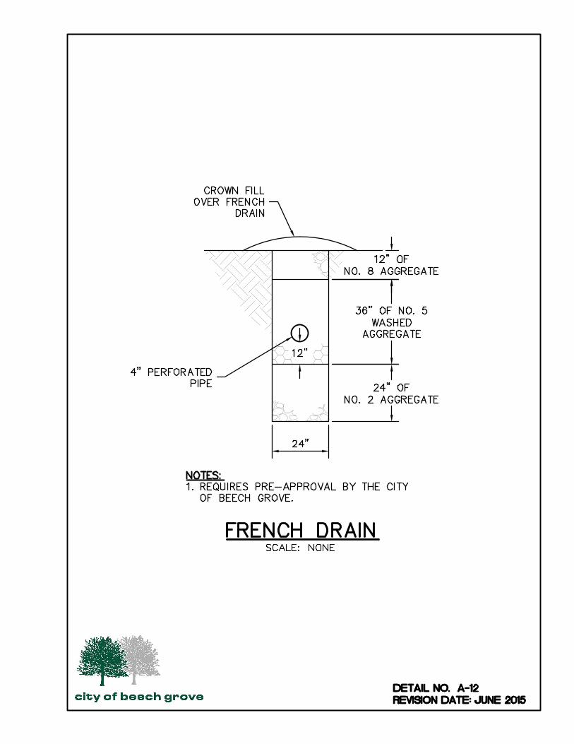
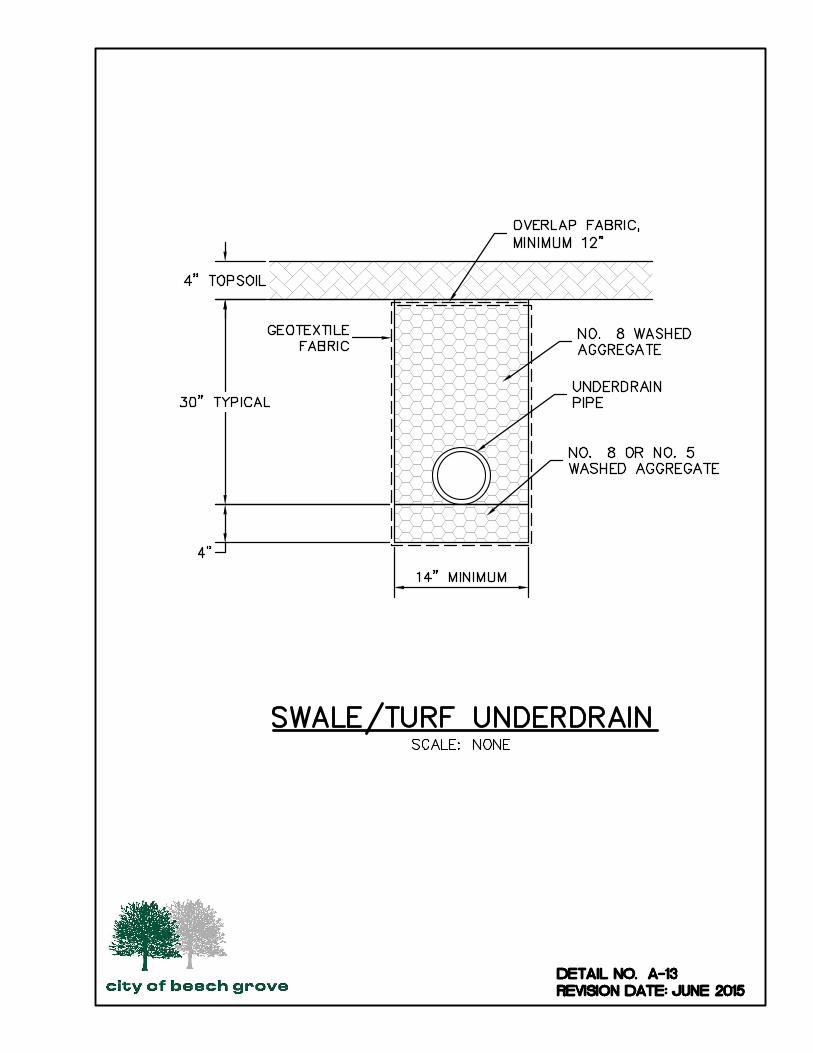
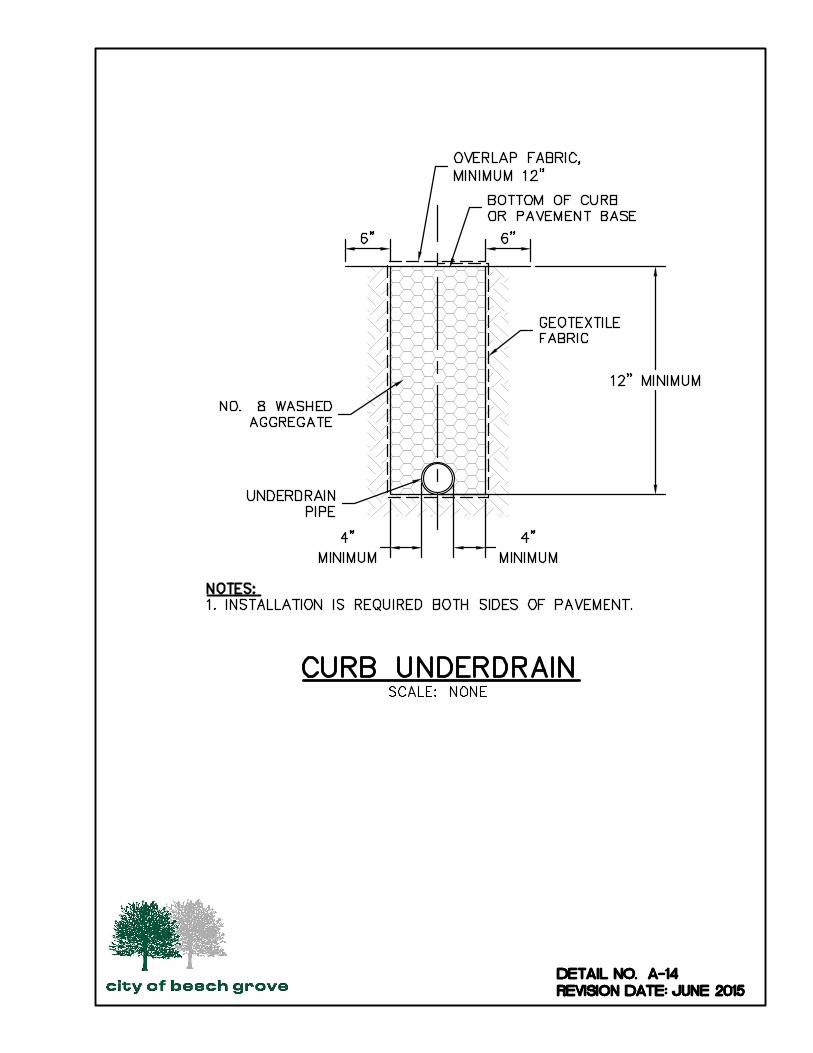
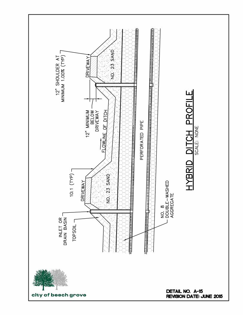
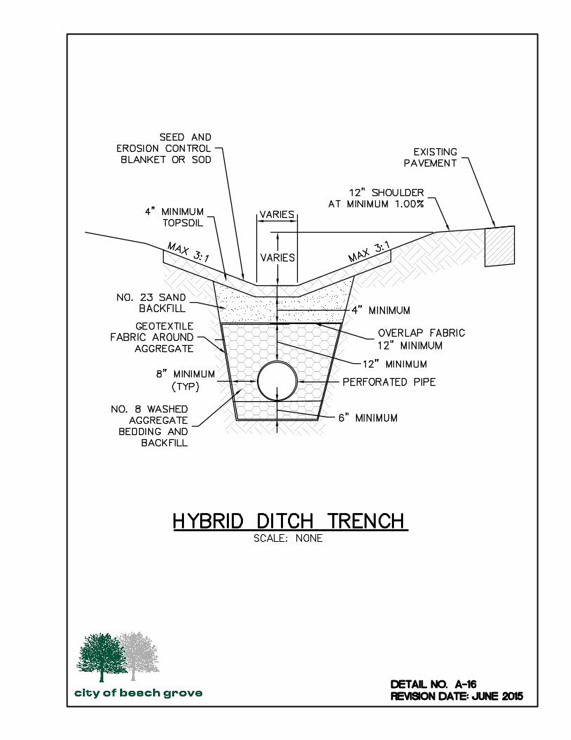
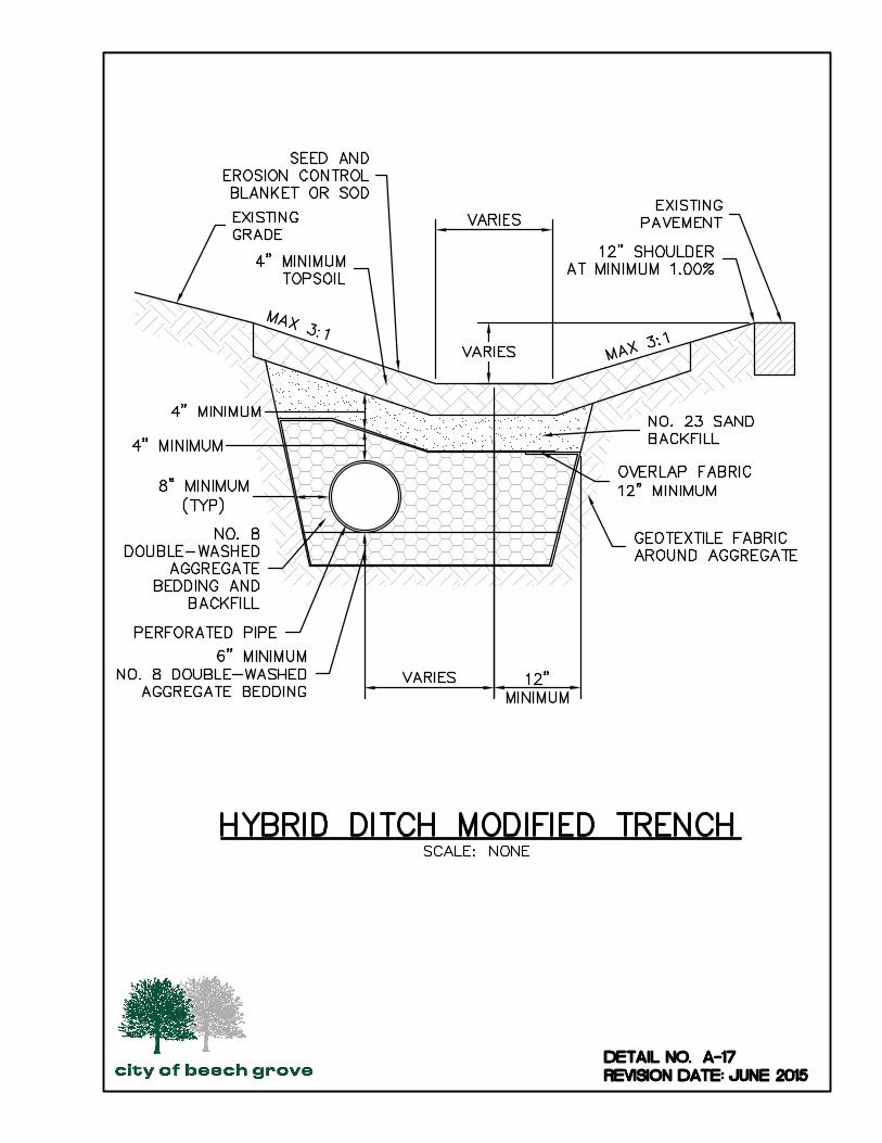
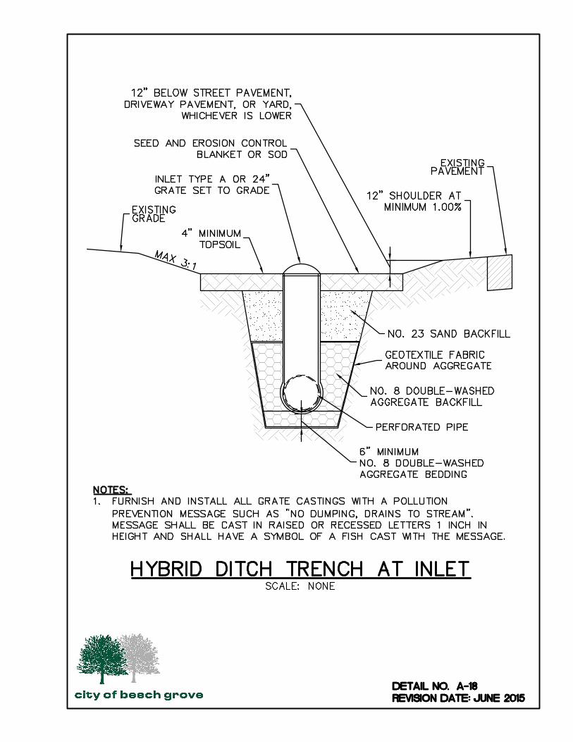
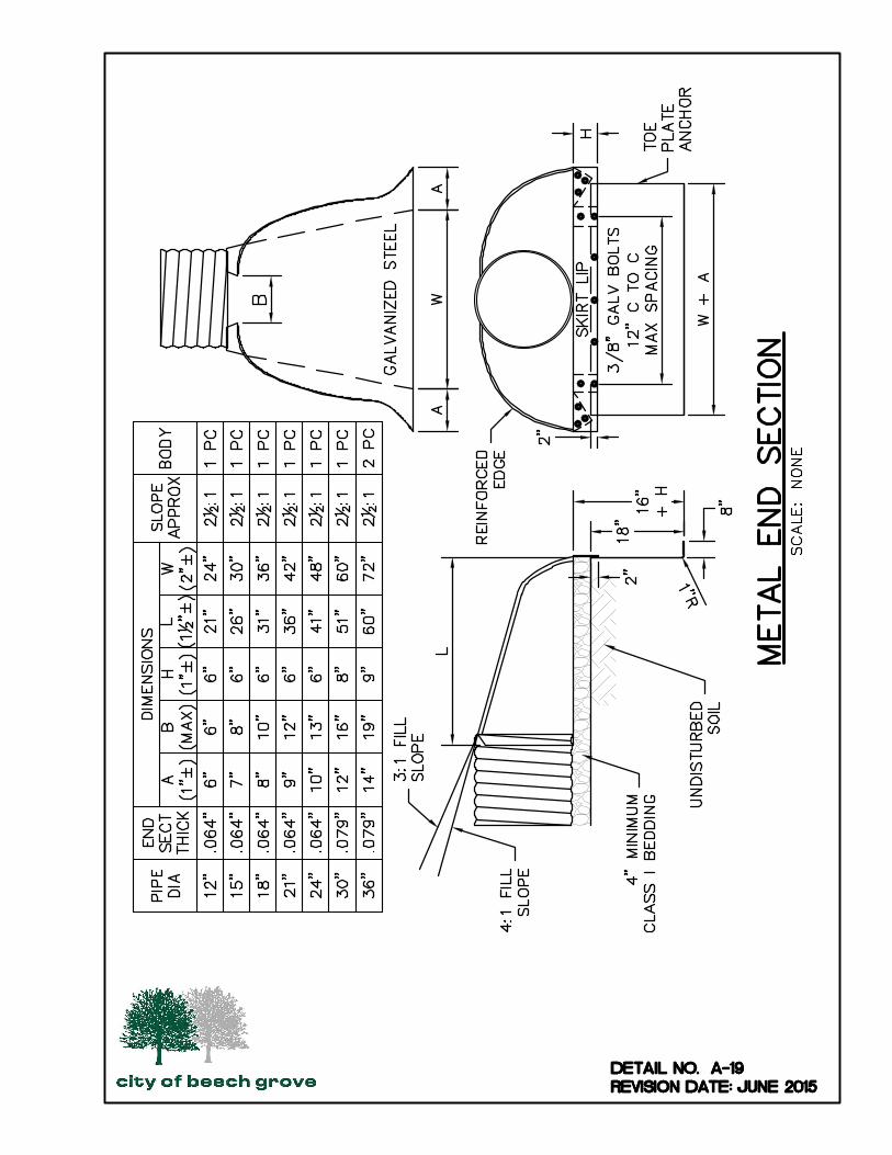
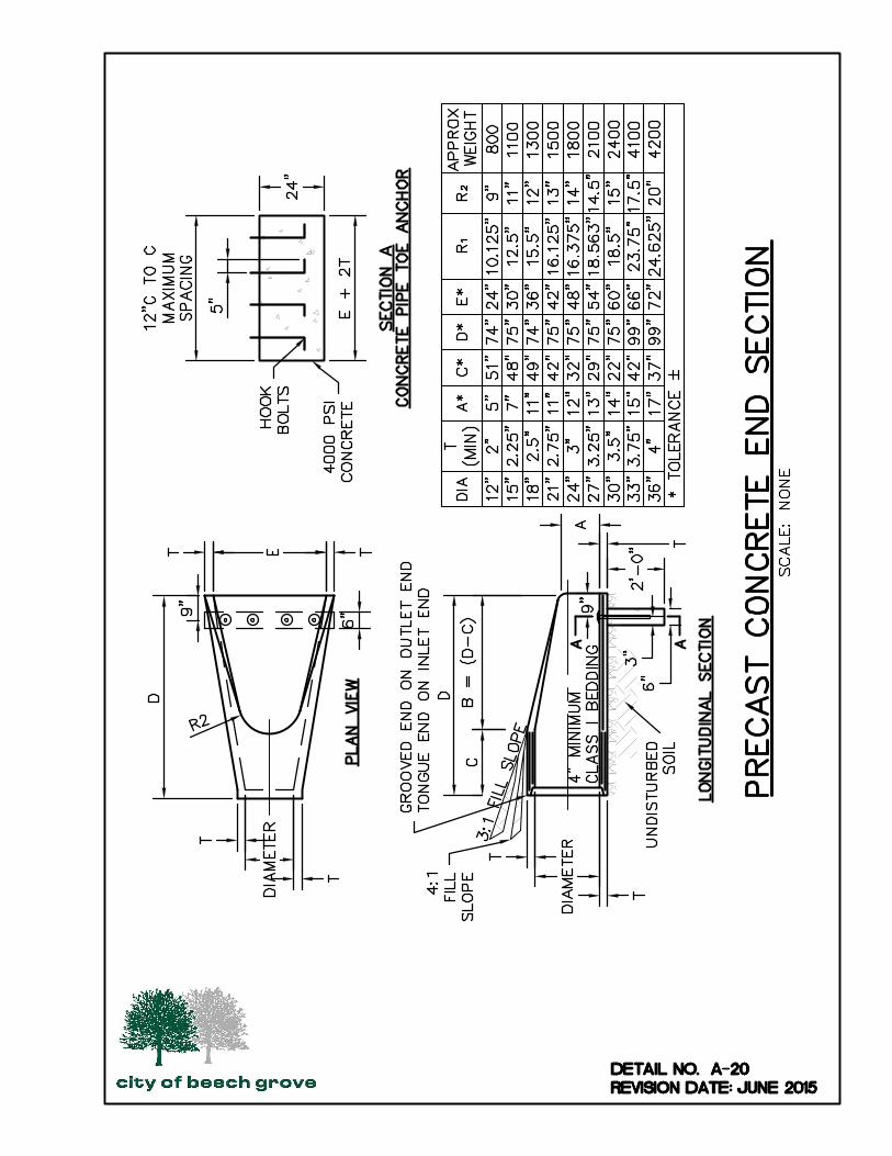
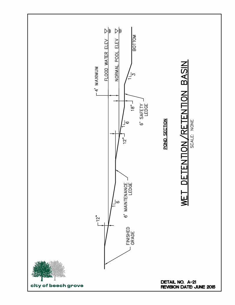


APPENDIX B
STORMWATER FORMS


Page 1 of 1
FORM B-1: APPLICATION FOR DRAINAGE APPROVAL
*Refer to Chapter 3 – Submittal Requirements and Procedures and Figures 3-1 and 3-2 for submittal requirements.
Project Information:
Name of Project:
Legal Address:
Township: Parcel No.:
Total Acres of Site: Proposed Construction:
Disturbed Acres of Site: ☐ Subdivision
Impervious Area: ☐ Commercial/Industrial/Apartment
☐ Other:
Owner Information:
Name:
Address:
Contact Person:
Telephone: Email:
Design Firm Information:
Name:
Address:
Professional Engineer:
Contact Person:
Telephone: Email:
As owner, or an authorized representative of the owner, I certify that the above information is true and
correct to the best of my knowledge.
Signature: Date:
Print Name: Title:
Address:
City of Beech Grove Use Only:
Date Submitted: Project No.:
Approval Date: Approved By:


Page 1 of 2
FORM B-2: APPLICATION FOR DRAINAGE APPROVAL SUBMITTAL CHECKLIST
*Refer to Chapter 3 – Submittal Requirements and Procedures and Figures 3-1 and 3-2 for submittal requirements.
All applicable items listed below shall be completed, signed and notarized (when applicable), and submitted
to the City of Beech Grove for review prior to initiating any land disturbing activities.
Checks shall be made payable to the City of Beech Grove.
Application package should be submitted to City Hall, 806 Main Street, Beech Grove, Indiana 46107. The
completed submittal to the City shall include:
CITY USE ONLY
N/A Acceptable Deficient
☐ General Application for Drainage Approval, Form B-1
☐ Application Fee, $100.00
☐ Statement of Financial Responsibility, Form B-4
☐ City of Beech Grove Building Permit Application Forms
☐ Construction Plans, 3 sets, which contain the following:
☐ Name and location map of proposed project
☐ Owner’s name
☐ Date of plans and revision number
☐ North arrow and scale (maximum scale of 1” = 50’ for site plans)
☐ Existing and proposed site conditions, including 1-foot contours,
elevations, stormwater conveyance system with applicable inverts
and elevations, storm sewer profiles, drainage flow arrows, pond
cross section, utilities, building footprints and finished floor
elevations, streets, drives, parking areas, easements, rights-of-
way, property lines, benchmarks, floodway/floodplain
boundaries, flood routing path, all applicable
construction/installation details, and erosion control measures and
details
☐ Traffic phasing plan
☐ Signature and certification by a Professional Engineer/Land
Surveyor licensed in the State of Indiana
☐ Storm Water Pollution Prevention Plan (SWPPP)
☐ SWPPP for Erosion and Sediment Control Plan, Form B-5
☐ Application fee for Erosion and Sediment Control Plan, $50.00
☐ Application fee for Post-Construction Stormwater Quality Plan,
$50.00
☐ Technical Specifications
☐ Drainage Report, which contains the following:
☐ Description of project, including pre-developed and post-
developed site condition
☐ Description of existing drainage problems
☐ Summary of all calculation or location of information by page
number reference
☐ List of assumptions and any special conditions associated with
the analysis methods used

Page 2 of 2
CITY USE ONLY
N/A Acceptable Deficient
☐ Stormwater runoff exhibits and calculations including:
☐ Drainage area delineation, including upstream off-site areas
☐ Time of concentration, Form B-7
☐ Weighted runoff coefficient or curve number, Form B-8
☐ Design storm frequency(ies)
☐ Peak runoff rates
☐ Channel, culvert, and storm sewer design calculations including:
☐ Size of pipe and typical channel cross section
☐ Pipe and channel slopes
☐ Channel lining or pipe material and roughness coefficient
☐ Pipe flow and hydraulic grade line calculations
☐ Velocities in feet per second (fps)
☐ Capacities in cubic feet per second (cfs)
☐ Outlet protection apron geometry
☐ Gutter spread and inlet spacing
☐ Name of computer model used, where applicable (highlight
pertinent data if computer printouts are submitted)
☐ Detention/Retention facility design calculations including:
☐ Description of facility
☐ Description of outlet control structure
☐ Outlet control structure discharge rating curve and peak
discharge rates
☐ Stage/storage/discharge information during storm events
☐ Emergency spillway calculations
☐ Low Impact Development and Stormwater BMP sizing and
design calculations
☐ Flood routing calculations
☐ Performance Bond
☐ Grant of Perpetual Right-of-Way and Easement, Form B-10
☐ Draft IDEM Notice of Intent (NOI)
☐ Operation & Maintenance (O&M) Manuals, which contain the
following:
☐ Owner information
☐ Site map
☐ O&M practices
☐ Right-of-Entry statement
☐ Implementation schedule
☐ Employee training
☐ Drainage easement documentation
☐ Agreement for Construction of Stormwater Facilities under
Private Contract, Form B-11
☐ Inspection Services Agreement, Form B-12

Page 1 of 2
FORM B-3: APPLICATION FOR DRAINAGE APPROVAL FOR SINGLE AND DOUBLE-FAMILY DWELLINGS
*Refer to Chapter 3 – Submittal Requirements and Procedures and Figures 3-1 and 3-2 for submittal requirements.
All applicable items listed below shall be submitted to the City of Beech Grove for review prior to initiating
any land disturbing activities. Application package should be submitted to City Hall, 806 Main Street,
Beech Grove, Indiana 46107.
Project Information:
Legal Address:
Township: Parcel No.:
Total Acres of Site:
Description of Project:
Owner Information:
Name:
Address:
Contact Person:
Telephone: Email:
Submittal Requirements:
□ Application Fee, $50.00 check made payable to the City of Beech Grove
□ Construction Plans or Exhibits, including location of project, north arrow, existing conditions,
and proposed improvements
As owner, or an authorized representative of the owner, I certify that the above information is true and
correct to the best of my knowledge.
Signature: Date:
Print Name: Title:
Address:
City of Beech Grove Use Only:
Date Submitted: Project No.:
Approval Date: Approved By:
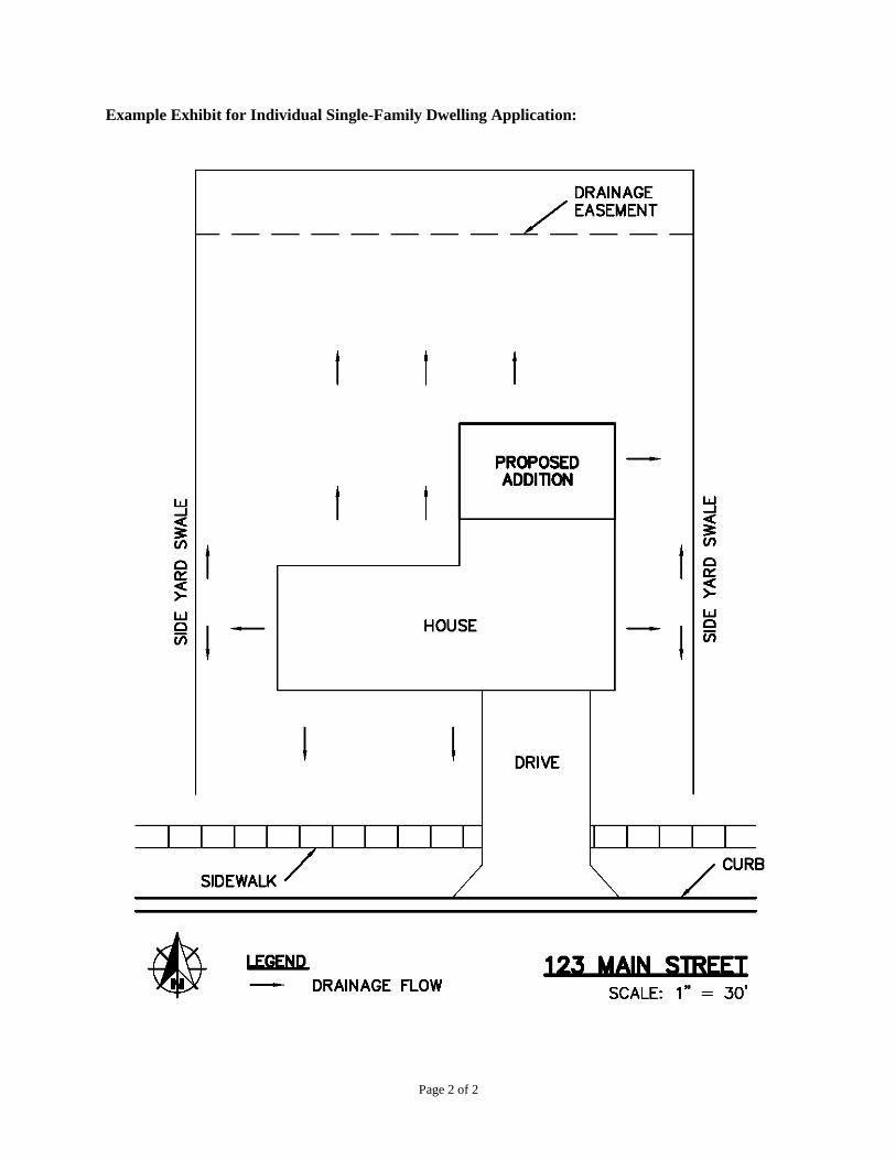
Page 2 of 2
Example Exhibit for Individual Single-Family Dwelling Application:

FORM B-4:STATEMENT OF FINANCIAL RESPONSIBILITY
The undersigned of the proposed project to be known as:
(project name and location or address)
do hereby agree to take full responsibility of financial payment of plan review fees incurred on the above project.
I am aware that the review fees apply for projects that require engineering review (for sanitary, stormwater, transportation or drinking water design) and will begin upon the submittal of an Application for Drainage Approval and continue until the project is approved and/or withdrawn. Review fees are charged according to the current hourly rate of the engineer performing the review. I understand that if the project is withdrawn the review fees are still due and payable from the application date to the date on the letter of withdrawal. Final review fees are due within 30 days of notification of the fee.
All review fees are to be made payable to City of Beech Grove.
The undersigned, having duly sworn upon oath, that the above information has been read and fully understood to be true and correct and is (undersigned) voluntary act and deed. The undersigned assumes responsibility for the aforementioned fees.
Signature Mailing Address
Printed City, State, Zip Code
STATE OF INDIANA ) )
COUNTY OF )
Subscribed and sworn before me, a Notary Public, within and for said County and State, this
____________ day of _______________, 20_____.
My Commission Expires _____________
Notary Public ______________________
(Notary Stamp or Seal)

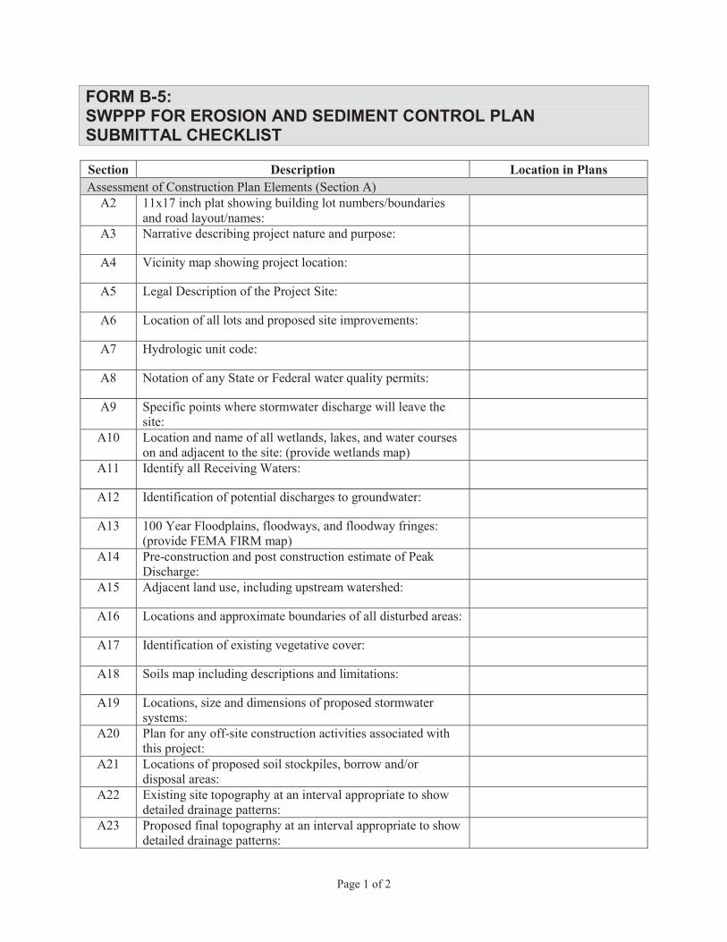
FORM B-5:SWPPP FOR EROSION AND SEDIMENT CONTROL PLANSUBMITTAL CHECKLIST
Section Description Location in Plans
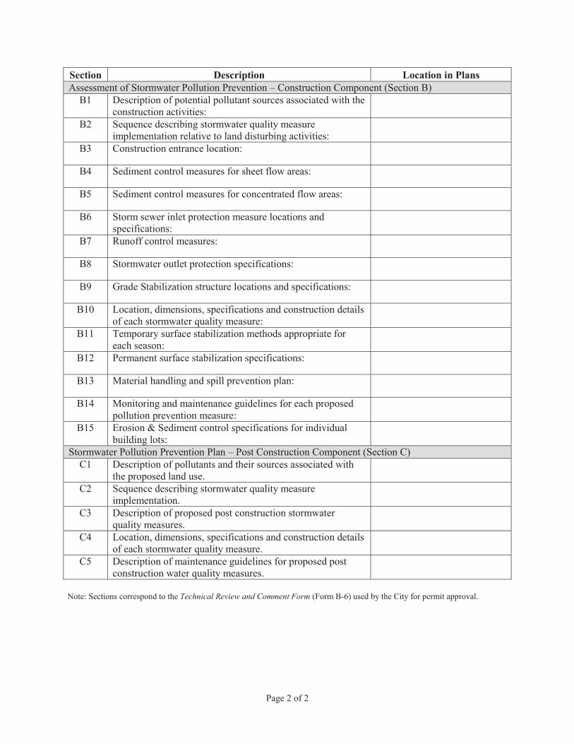
Section Description Location in Plans
Technical Review and Comment Form
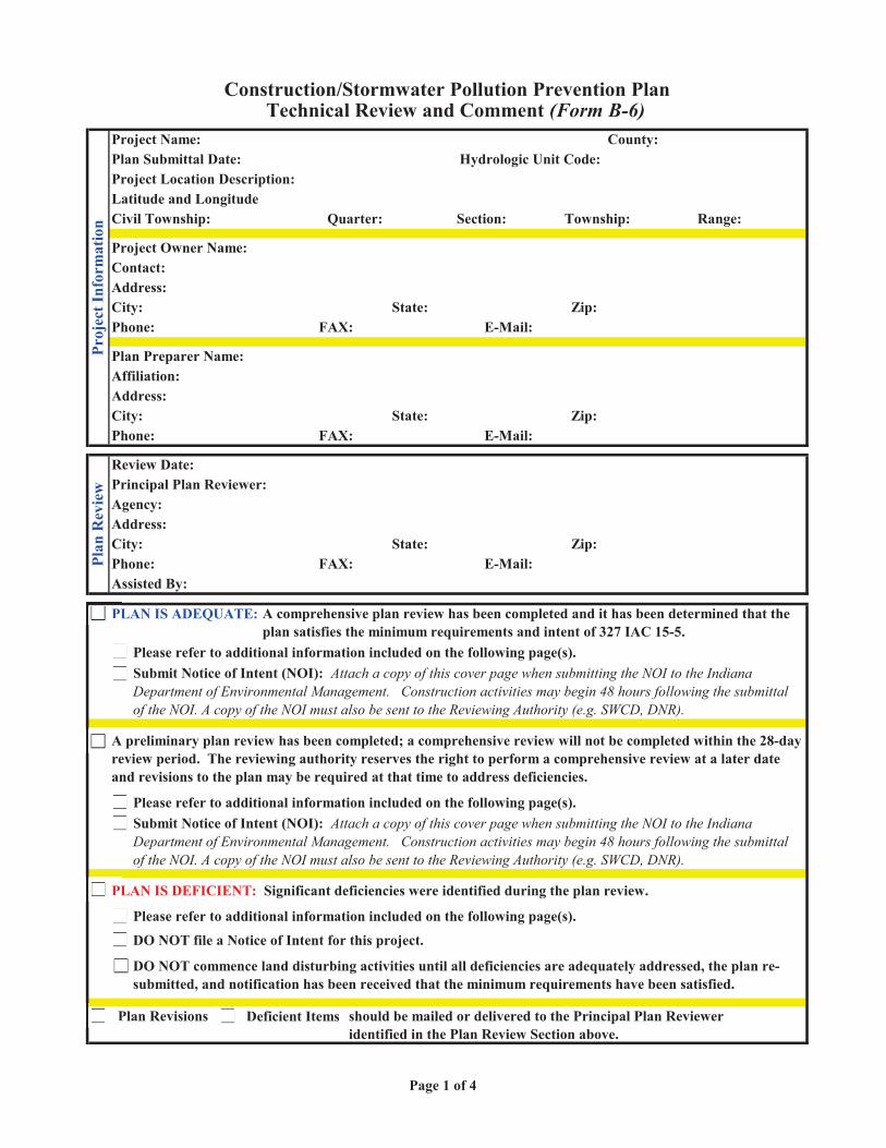
Affiliation:Address:
Quarter:
Plan Revisions Deficient Items
PLAN IS DEFICIENT: Significant deficiencies were identified during the plan review.
PLAN IS ADEQUATE: A comprehensive plan review has been completed and it has been determined that the plan satisfies the minimum requirements and intent of 327 IAC 15-5.
Please refer to additional information included on the following page(s).Submit Notice of Intent (NOI): Attach a copy of this cover page when submitting the NOI to the Indiana Department of Environmental Management. Construction activities may begin 48 hours following the submittal of the NOI. A copy of the NOI must also be sent to the Reviewing Authority (e.g. SWCD, DNR).
Submit Notice of Intent (NOI): Attach a copy of this cover page when submitting the NOI to the Indiana Department of Environmental Management. Construction activities may begin 48 hours following the submittal of the NOI. A copy of the NOI must also be sent to the Reviewing Authority (e.g. SWCD, DNR).
Review Date:Principal Plan Reviewer:Agency:
Please refer to additional information included on the following page(s).
DO NOT commence land disturbing activities until all deficiencies are adequately addressed, the plan re-submitted, and notification has been received that the minimum requirements have been satisfied.
Address:City:
Assisted By:
A preliminary plan review has been completed; a comprehensive review will not be completed within the 28-day review period. The reviewing authority reserves the right to perform a comprehensive review at a later date and revisions to the plan may be required at that time to address deficiencies.
Phone: E-Mail:State:
Project Owner Name:
Address:City:
Zip:E-Mail:
State: Zip:E-Mail:
Plan Preparer Name:
Phone:
City: State:Phone:
Plan Submittal Date: Hydrologic Unit Code:Project Location Description:Latitude and Longitude:Civil Township: Section:
DO NOT file a Notice of Intent for this project.
FAX:
Zip:FAX:
FAX:
Contact:
should be mailed or delivered to the Principal Plan Reviewer identified in the Plan Review Section above.
Please refer to additional information included on the following page(s).
Construction/Stormwater Pollution Prevention PlanTechnical Review and Comment
Proj
ect I
nfor
mat
ion
Plan
Rev
iew
Township: Range:
Project Name: County:
PL
Pl
D
DO
Pl
A
PL
P
Su
PlSu
D
Page 1 of 4

1 2
3 4
5 6
7 8
9 10
11 12
13 14
15 16
17 18
19 20
21 22
23
Hydrologic unit code (14 Digit)
Assessment of Construction Plan Elements
Please refer to the address and contact information identified in the Plan Review Section on page 1.
Yes No
A
Proposed final topography at an interval appropriate to indicate drainage patterns
Locations and approximate boundaries of all disturbed areas (Construction Limits)
Existing site topography at an interval appropriate to indicate drainage patterns
Adjacent landuse, including upstream watershed
Soils map including soil descriptions and limitationsIdentification of existing vegetative cover
01/00/00
100 year floodplains, floodways, and floodway fringes
Plans for any off-site construction activities associated with this project (sewer/water tie-ins)
A
Legal Description of the Project Site (Include Latitude and Longitude - NOI Requirement)
Index showing locations of required Plan Elements
Pre-construction and post construction estimate of Peak Discharge (10 Year storm event)
Specific points where stormwater discharge will leave the site
Location and name of all wetlands, lakes and water courses on and adjacent to the site
Narrative describing the nature and purpose of the project
Location of all lots and proposed site improvements (roads, utilities, structures, etc.)
Notation of any State or Federal water quality permits
0
Construction/Stormwater Pollution Prevention Plan - Technical Review and Comment
Identification of all receiving waters
Vicinity map showing project location
Identification of potential discharges to ground water (abandoned wells, sinkholes, etc.)
Please direct questions and/or comments regarding this plan review to:
The Construction Plan Elements are adequately represented to complete a plan review:
The items checked below are deficient and require submittal to meet the requirements of the rule.
Locations, size and dimensions of proposed stormwater systems (e.g. pipes, swales and channels)Locations of proposed soil stockpiles and/or borrow/disposal areas
The technical review and comments are intended to evaluate the completeness of the Construction/Stormwater Pollution Prevention Plan for the project. The Plan submitted was not reviewed for the adequacy of the engineering design. All measures included in the plan, as well as those recommended in the comments should be evaluated as to their feasibility by a qualified individual with structural measures designed by a qualified engineer. The Plan has not been reviewed for other local, state, or federal permits that may be required to proceed with this project. Additional information, including design calculations may be requested to further evaluate the Plan.
11 by 17 inch plat showing building lot numbers/boundaries and road layout/names
Project Name: 0Date Reviewed:
All proposed stormwater pollution prevention measures and those referenced in this review must meet the design criteria and standards set forth in the "Indiana Stormwater Quality Manual" from the Indiana Department of Natural Resources, Division of Soil Conservation or similar Guidance Documents.
1
Y N
3
5
7
9
11
13
15
17
19
21
23
22
2r
1
1
14
12
1
8
6
4
2
Page 2 of 4
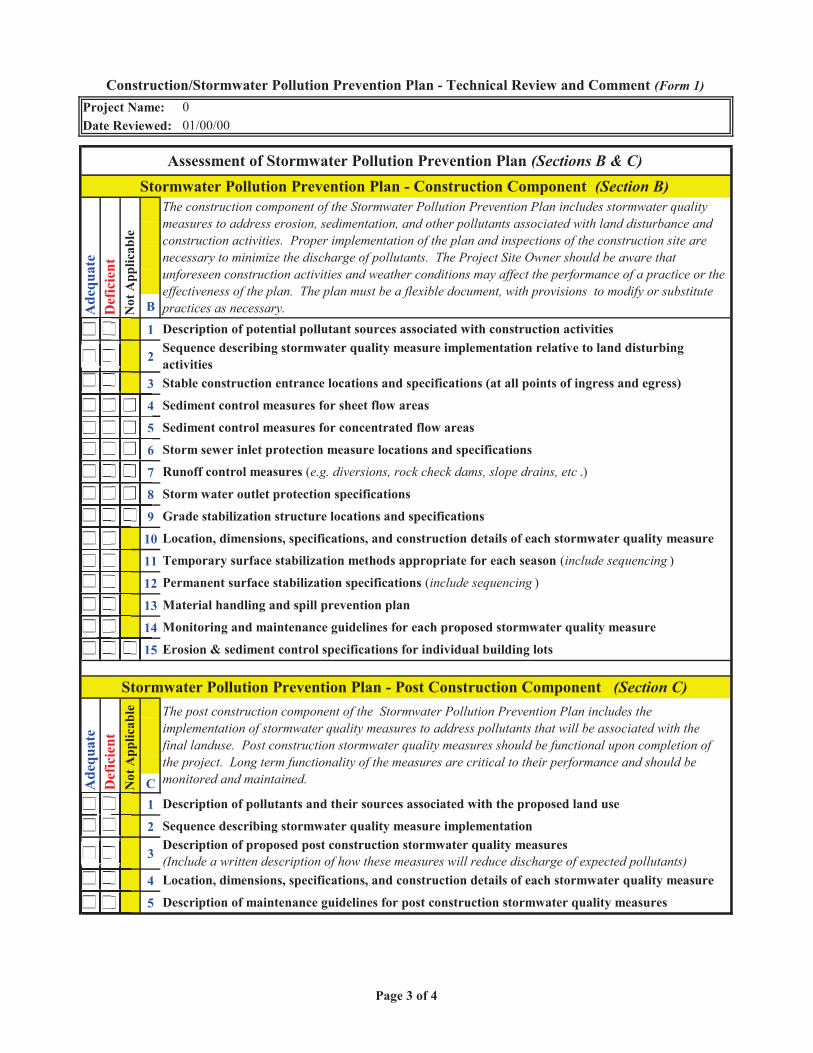
B
1
2
3
4
5
6
7
8
9
10
11
12
13
14
15
C1
2
3
4
5
01/00/00
Permanent surface stabilization specifications (include sequencing )
Stormwater Pollution Prevention Plan - Post Construction Component
Sediment control measures for sheet flow areas
Sediment control measures for concentrated flow areas
Storm sewer inlet protection measure locations and specifications
Runoff control measures (e.g. diversions, rock check dams, slope drains, etc .)
Assessment of Stormwater Pollution Prevention Plan
Description of potential pollutant sources associated with construction activities
Not
App
licab
le
Construction/Stormwater Pollution Prevention Plan - Technical Review and Comment Project Name:Date Reviewed:
0A
dequ
ate
Location, dimensions, specifications, and construction details of each stormwater quality measure
Description of maintenance guidelines for post construction stormwater quality measures
Sequence describing stormwater quality measure implementation relative to land disturbing activitiesStable construction entrance locations and specifications (at all points of ingress and egress)
The construction component of the Stormwater Pollution Prevention Plan includes stormwater quality measures to address erosion, sedimentation, and other pollutants associated with land disturbance and construction activities. Proper implementation of the plan and inspections of the construction site are necessary to minimize the discharge of pollutants. The Project Site Owner should be aware that unforeseen construction activities and weather conditions may affect the performance of a practice or the effectiveness of the plan. The plan must be a flexible document, with provisions to modify or substitute practices as necessary.
Ade
quat
eD
efic
ient
Not
App
licab
le
Storm water outlet protection specifications
Grade stabilization structure locations and specifications
Description of proposed post construction stormwater quality measures (Include a written description of how these measures will reduce discharge of expected pollutants)
Material handling and spill prevention plan
Monitoring and maintenance guidelines for each proposed stormwater quality measure
The post construction component of the Stormwater Pollution Prevention Plan includes the implementation of stormwater quality measures to address pollutants that will be associated with the final landuse. Post construction stormwater quality measures should be functional upon completion of the project. Long term functionality of the measures are critical to their performance and should be monitored and maintained.
Description of pollutants and their sources associated with the proposed land use
Sequence describing stormwater quality measure implementation
Stormwater Pollution Prevention Plan - Construction Component
Erosion & sediment control specifications for individual building lots
Def
icie
nt
Location, dimensions, specifications, and construction details of each stormwater quality measure
Temporary surface stabilization methods appropriate for each season (include sequencing )
4
5
6
7
8
9
15
Page 3 of 4
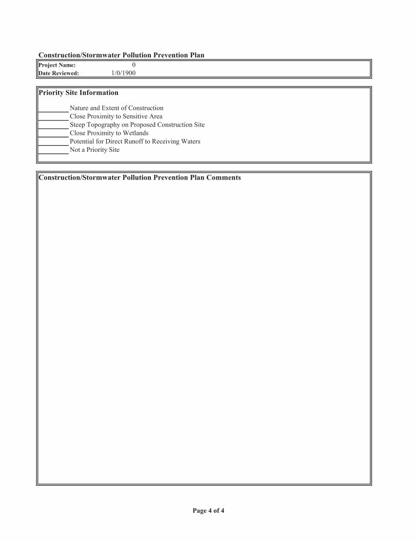
Construction/Stormwater Pollution Prevention Plan Project Name: 0Date Reviewed: 1/0/1900
Priority Site Information
Nature and Extent of ConstructionClose Proximity to Sensitive AreaSteep Topography on Proposed Construction SiteClose Proximity to WetlandsPotential for Direct Runoff to Receiving WatersNot a Priority Site
Construction/Stormwater Pollution Prevention Plan Comments
Page 4 of 4
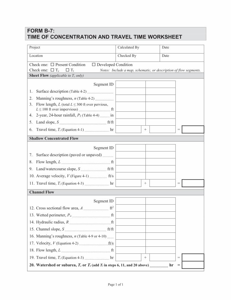
FORM B-7:TIME OF CONCENTRATION AND TRAVEL TIME WORKSHEET
Notes: Include a map, schematic, or description of flow segments.Sheet Flow (applicable to Tc only)
nL L
LP
S
Tt
Shallow Concentrated Flow
L
S
V
Tt
Channel Flow
A
Pw
R
S
n
V
L
Tt
20. Watershed or subarea, Tc or Tt (add Tt in steps 6, 11, and 20 above) hr =

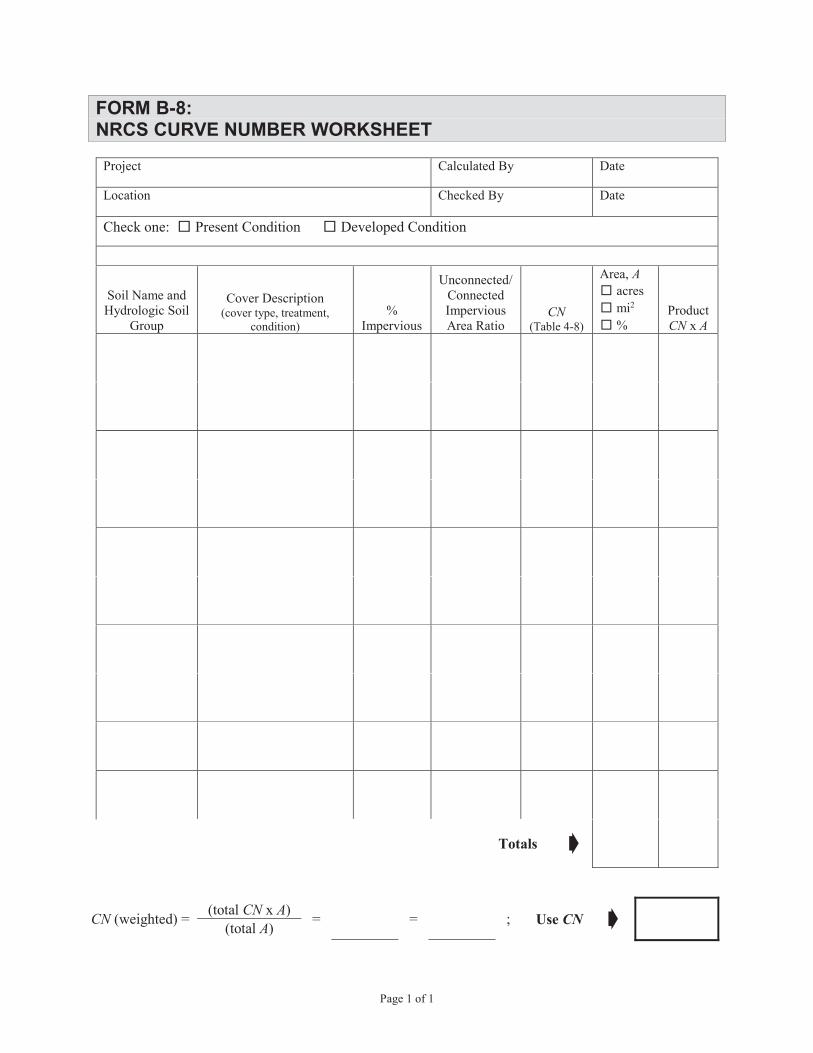
Page 1 of 1
FORM B-8:NRCS CURVE NUMBER WORKSHEET
Project Calculated By Date
Location Checked By Date
Check one: Present Condition Developed Condition
Soil Name and Hydrologic Soil
Group
Cover Description(cover type, treatment,
condition)%
Impervious
Unconnected/Connected Impervious Area Ratio
CN(Table 4-8)
Area, Aacresmi2
%ProductCN x A
Totals
CN (weighted) = (total CN x A) = = ; Use CN(total A)


FORM B-9:STORM SEWER SYSTEM DESIGN WORKSHEET

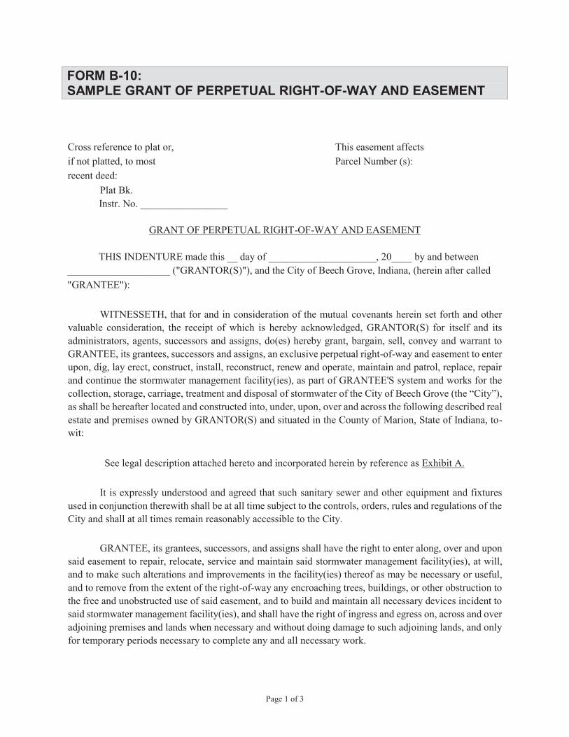
Page 1 of 3
FORM B-10: SAMPLE GRANT OF PERPETUAL RIGHT-OF-WAY AND EASEMENT
Cross reference to plat or, This easement affects if not platted, to most Parcel Number (s): recent deed:
Plat Bk. Instr. No. _________________
GRANT OF PERPETUAL RIGHT-OF-WAY AND EASEMENT
THIS INDENTURE made this __ day of _____________________, 20____ by and between ____________________ ("GRANTOR(S)"), and the City of Beech Grove, Indiana, (herein after called "GRANTEE"):
WITNESSETH, that for and in consideration of the mutual covenants herein set forth and other valuable consideration, the receipt of which is hereby acknowledged, GRANTOR(S) for itself and its administrators, agents, successors and assigns, do(es) hereby grant, bargain, sell, convey and warrant to GRANTEE, its grantees, successors and assigns, an exclusive perpetual right-of-way and easement to enter upon, dig, lay erect, construct, install, reconstruct, renew and operate, maintain and patrol, replace, repair and continue the stormwater management facility(ies), as part of GRANTEE'S system and works for the collection, storage, carriage, treatment and disposal of stormwater of the City of Beech Grove (the “City”), as shall be hereafter located and constructed into, under, upon, over and across the following described real estate and premises owned by GRANTOR(S) and situated in the County of Marion, State of Indiana, to-wit:
See legal description attached hereto and incorporated herein by reference as Exhibit A.
It is expressly understood and agreed that such sanitary sewer and other equipment and fixtures used in conjunction therewith shall be at all time subject to the controls, orders, rules and regulations of the City and shall at all times remain reasonably accessible to the City.
GRANTEE, its grantees, successors, and assigns shall have the right to enter along, over and upon said easement to repair, relocate, service and maintain said stormwater management facility(ies), at will, and to make such alterations and improvements in the facility(ies) thereof as may be necessary or useful, and to remove from the extent of the right-of-way any encroaching trees, buildings, or other obstruction to the free and unobstructed use of said easement, and to build and maintain all necessary devices incident to said stormwater management facility(ies), and shall have the right of ingress and egress on, across and over adjoining premises and lands when necessary and without doing damage to such adjoining lands, and only for temporary periods necessary to complete any and all necessary work.

Page 2 of 3
GRANTOR(S) covenants(s) for itself, its administrators, agents, successors and assigns that it will not erect or maintain any buildings or other structures or obstruction on or over said stormwater management facility(ies) under said tract of land in which the perpetual right-of-way and easement is hereby granted, except by express permission from GRANTEE, in writing and in accordance with the terms thereof, and which permission when in writing and recorded shall run with the real estate.
A diagram map showing the route, courses and distances through the above-described real estate and premises and the width of the right-of-way and easement is attached hereto and incorporated herein by reference as Exhibit B.
GRANTOR(S) covenant(s) that it is the owner(s) in fee simple of the above described real estate, is lawfully seized thereof and has a good right to grant and convey the foregoing right-of-way and easement therein; that it guarantee(s) the quiet possession thereof, that said real estate is free from any and all encumbrances except the following:
1. Current taxes are not delinquent
and that GRANTOR(S) will warrant and defend GRANTEE'S title to said right-of-way and easement against all lawful claims.
It is further expressly understood and agreed that such stormwater management facility(ies) and other equipment and fixtures used in connection therewith shall be and remain the sole property of the City, upon inspection and exception of same by the City.
*GRANTOR(S), additionally covenants(s) for itself, its administrators, agents, successors and assigns that if right-of-way and easement is not exclusively in favor of GRANTEE, GRANTOR does hereby indemnify and hold GRANTEE harmless for all relocation costs or damages to the property of any other occupant(s) of said right-of-way and easement.
GRANTOR(S), hereby affirm that no unauthorized alterations of this document have taken place.
Page 3 of 3
IN WITNESS WHEREOF, GRANTOR(S) has/have hereunto set his, her, their respective hand(s) as of the day and year first written above. ________________________ _________________________ Signature Signature ________________________ _________________________ Printed Name Printed Name STATE OF INDIANA ) ) SS: COUNTY OF MARION ) BEFORE ME, the undersigned, a Notary Public in and for said County and State, personally appeared ____________________________________________________________________ GRANTOR(S), who acknowledged the execution of the above and foregoing instrument to its voluntary act and deed on the ____ day of _________________________, 20____. ________________________ ___________________________ Commission Expiration Date Notary _________________ ___________________________ County of Residence Printed Name

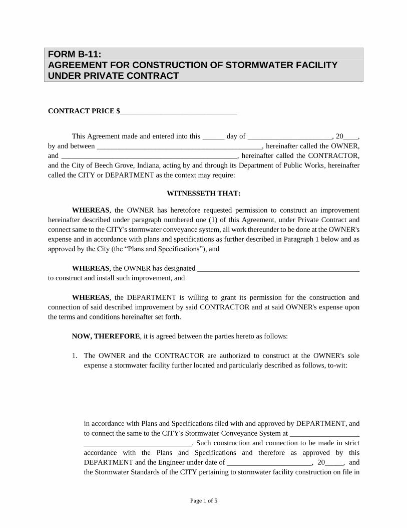
Page 1 of 5
FORM B-11: AGREEMENT FOR CONSTRUCTION OF STORMWATER FACILITY UNDER PRIVATE CONTRACT
CONTRACT PRICE $________________________________
This Agreement made and entered into this ______ day of _______________________, 20____,
by and between _____________________________________________, hereinafter called the OWNER,
and ________________________________________________, hereinafter called the CONTRACTOR,
and the City of Beech Grove, Indiana, acting by and through its Department of Public Works, hereinafter
called the CITY or DEPARTMENT as the context may require:
WITNESSETH THAT:
WHEREAS, the OWNER has heretofore requested permission to construct an improvement
hereinafter described under paragraph numbered one (1) of this Agreement, under Private Contract and
connect same to the CITY's stormwater conveyance system, all work thereunder to be done at the OWNER's
expense and in accordance with plans and specifications as further described in Paragraph 1 below and as
approved by the City (the “Plans and Specifications”), and
WHEREAS, the OWNER has designated
to construct and install such improvement, and
WHEREAS, the DEPARTMENT is willing to grant its permission for the construction and
connection of said described improvement by said CONTRACTOR and at said OWNER's expense upon
the terms and conditions hereinafter set forth.
NOW, THEREFORE, it is agreed between the parties hereto as follows:
1. The OWNER and the CONTRACTOR are authorized to construct at the OWNER's sole
expense a stormwater facility further located and particularly described as follows, to-wit:
in accordance with Plans and Specifications filed with and approved by DEPARTMENT, and
to connect the same to the CITY's Stormwater Conveyance System at
. Such construction and connection to be made in strict
accordance with the Plans and Specifications and therefore as approved by this
DEPARTMENT and the Engineer under date of , 20_____, and
the Stormwater Standards of the CITY pertaining to stormwater facility construction on file in
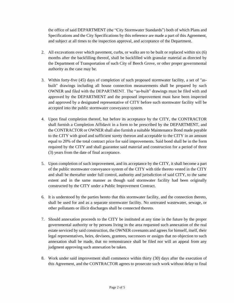
Page 2 of 5
the office of said DEPARTMENT (the “City Stormwater Standards”) both of which Plans and
Specifications and the City Specifications by this reference are made a part of this Agreement,
and subject at all times to the inspection approval, and acceptance of the Department.
2. All excavations over which pavement, curbs, or walks are to be built or replaced within six (6)
months after the backfilling thereof, shall be backfilled with granular material as directed by
the Department of Transportation of such City of Beech Grove, or other proper governmental
authority as the case may be.
3. Within forty-five (45) days of completion of such proposed stormwater facility, a set of "as-
built" drawings including all house connection measurements shall be prepared by such
OWNER and filed with the DEPARTMENT. The “as-built” drawings must be filed with and
approved by the DEPARTMENT and the proposed improvement must have been inspected
and approved by a designated representative of CITY before such stormwater facility will be
accepted into the public stormwater conveyance system.
4. Upon final completion thereof, but before its acceptance by the CITY, the CONTRACTOR
shall furnish a Completion Affidavit in a form to be prescribed by the DEPARTMENT, and
the CONTRACTOR or OWNER shall also furnish a suitable Maintenance Bond made payable
to the CITY with good and sufficient surety thereon and acceptable to the CITY in an amount
equal to 20% of the total contract price for said improvements. Said bond shall be in the form
required by the CITY and shall guarantee said material and construction for a period of three
(3) years from the date of final acceptance.
5. Upon completion of such improvement, and its acceptance by the CITY, it shall become a part
of the public stormwater conveyance system of the CITY with title thereto vested in the CITY
and shall be thereafter under full control, authority and jurisdiction of said CITY, to the same
extent and in the same manner as though said stormwater facility had been originally
constructed by the CITY under a Public Improvement Contract.
6. It is understood by the parties hereto that this stormwater facility, and the connection thereto,
shall be used for and as a separate stormwater facility. No untreated wastewater, sewage, or
other pollutants or illicit discharges shall be connected thereto.
7. Should annexation proceeds to the CITY be instituted at any time in the future by the proper
governmental authority or by persons living in the area requested such annexation of the real
estate serviced by said construction, the OWNER covenants and agrees for himself, itself, their
legal representatives, heirs, devisees, grantees, successors or assigns that no objection to such
annexation shall be made, that no remonstrance shall be filed nor will an appeal from any
judgment approving such annexation be taken.
8. Work under said improvement shall commence within thirty (30) days after the execution of
this Agreement, and the CONTRACTOR agrees to prosecute such work without delay to final

Page 3 of 5
completion. The construction of the improvement provided for under this Agreement shall be
completed by _______________________________________________________________.
9. No liability of any kind for any part of the improvements shall attached to said CITY or
DEPARTMENT. The OWNER and CONTRACTOR, shall indemnify, defend and hold
harmless the CITY and DEPARTMENT and their respective officers, employees, elected
officials, agents and assigns harmless from and against any and all losses, claims, liabilities,
damages, costs and expenses, including but not limited to reasonable attorneys fees, which
CITY and/or DEPARTMENT may incur as a result of or arising out of or in any way connected
with this location, installation and/or construction of the improvements provided for in this
Agreement. In addition, prior to the commencement of the construction authorized by this
Agreement to the CONTRACTOR shall furnish to the CITY and DEPARTMENT evidence of
a public liability insurance policy in the minimum amount of One Million Dollars
($1,000,000.00), each occurrence, and each aggregate for bodily injury limits, and One Million
Dollars ($1,000,000.00), each occurrence, and One Million Dollars ($1,000,000.00), each
aggregate for property damage limits indemnifying and holding the CITY harmless against all
claims, demands, actions, causes of action, loss and expense of every nature and kind therein
at any time asserted against the CITY for or on account of any person, arising out of or in any
way connected with this location, installation and/or construction of said improvement.
10. CONTRACTOR further agrees that prior to the commencement of the work contemplated
herein, said CONTRACTOR shall furnish a suitable irrevocable Letter of Credit or
Performance Bond made payable to the DEPARTMENT with good and sufficient surety
thereon and acceptable to the DEPARTMENT in an amount equal to 100% of the total contract
price for said improvements.
11. CONTRACTOR further agrees that prior to the commencement of the work contemplated
herein, said CONTRACTOR shall pay to said CITY, the sum of $
as an inspection charge covering the cost of inspecting such project. Such OWNER and/or
CONTRACTOR shall also, in the event any part of such stormwater facility is to be constructed
across, on, through or under any public highway or right-of-way, furnish CITY evidence of
authority so to do, procured from the proper governmental agency having jurisdiction and
control over such public right-of-way.

Page 4 of 5
IN WITNESS WHEREOF, the Parties have hereunto set their hands and seals on the day and
year first above written.
CONTRACTOR OWNER
Name of Contracting Company Name Of Corp. (If Applicable)
Signature Signature (Of Officer in Corp.)
Printed Name & Title Printed Name & Title
CITY OF BEECH GROVE
Mayor
Signature
ATTEST:
Clerk-Treasurer
Signature
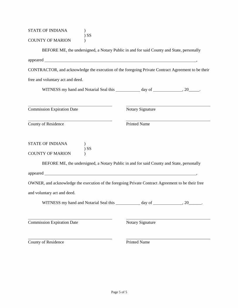
Page 5 of 5
STATE OF INDIANA )
) SS
COUNTY OF MARION )
BEFORE ME, the undersigned, a Notary Public in and for said County and State, personally
appeared ,
CONTRACTOR, and acknowledge the execution of the foregoing Private Contract Agreement to be their
free and voluntary act and deed.
WITNESS my hand and Notarial Seal this day of , 20_____.
Commission Expiration Date Notary Signature
County of Residence Printed Name
STATE OF INDIANA )
) SS
COUNTY OF MARION )
BEFORE ME, the undersigned, a Notary Public in and for said County and State, personally
appeared ,
OWNER, and acknowledge the execution of the foregoing Private Contract Agreement to be their free
and voluntary act and deed.
WITNESS my hand and Notarial Seal this day of , 20______.
Commission Expiration Date Notary Signature
County of Residence Printed Name

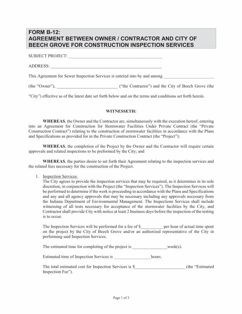
Page 1 of 3
FORM B-12:AGREEMENT BETWEEN OWNER / CONTRACTOR AND CITY OF BEECH GROVE FOR CONSTRUCTION INSPECTION SERVICES
SUBJECT PROJECT: ___________________________________________
ADDRESS: ___________________________________________________
This Agreement for Sewer Inspection Services is entered into by and among _______________________
(the “Owner”), ____________________________ (“the Contractor”) and the City of Beech Grove (the
“City”) effective as of the latest date set forth below and on the terms and conditions set forth herein.
WITNESSETH:
WHEREAS, the Owner and the Contractor are, simultaneously with the execution hereof, entering into an Agreement for Construction for Stormwater Facilities Under Private Contract (the “Private Construction Contract”) relating to the construction of stormwater facilities in accordance with the Plans and Specifications as provided for in the Private Construction Contract (the “Project”);
WHEREAS, the completion of the Project by the Owner and the Contractor will require certain approvals and related inspections to be preformed by the City; and
WHEREAS, the parties desire to set forth their Agreement relating to the inspection services and the related fees necessary for the construction of the Project.
1. Inspection Services. The City agrees to provide the inspection services that may be required, as it determines in its sole discretion, in conjunction with the Project (the “Inspection Services”). The Inspection Services will be performed to determine if the work is proceeding in accordance with the Plans and Specifications and any and all agency approvals that may be necessary including any approvals necessary from the Indiana Department of Environmental Management. The Inspections Services shall include witnessing of all tests necessary for acceptance of the stormwater facilities by the City, and Contractor shall provide City with notice at least 2 business days before the inspection of the testing is to occur.
The Inspection Services will be performed for a fee of $__________ per hour of actual time spent on the project by the City of Beech Grove and/or an authorized representative of the City in performing said Inspection Services.
The estimated time for completing of the project is ________________week(s).
Estimated time of Inspection Services is _________________hours.
The total estimated cost for Inspection Services is $_______________________ (the “Estimated Inspection Fee”).
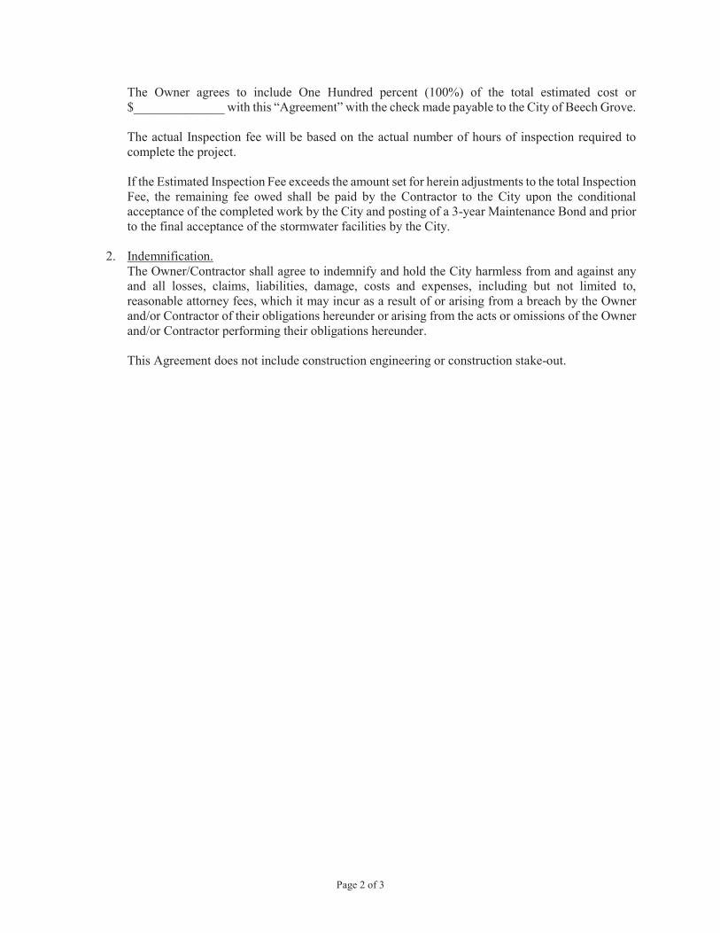
Page 2 of 3
The Owner agrees to include One Hundred percent (100%) of the total estimated cost or $______________ with this “Agreement” with the check made payable to the City of Beech Grove.
The actual Inspection fee will be based on the actual number of hours of inspection required to complete the project.
If the Estimated Inspection Fee exceeds the amount set for herein adjustments to the total Inspection Fee, the remaining fee owed shall be paid by the Contractor to the City upon the conditional acceptance of the completed work by the City and posting of a 3-year Maintenance Bond and prior to the final acceptance of the stormwater facilities by the City.
2. Indemnification. The Owner/Contractor shall agree to indemnify and hold the City harmless from and against any and all losses, claims, liabilities, damage, costs and expenses, including but not limited to, reasonable attorney fees, which it may incur as a result of or arising from a breach by the Owner and/or Contractor of their obligations hereunder or arising from the acts or omissions of the Owner and/or Contractor performing their obligations hereunder.
This Agreement does not include construction engineering or construction stake-out.

Page 3 of 3
IN WITNESS WHEREOF, the parties have executed this Agreement effective as of the latest date set forth below.
Owner:
_______________________________Organization (Print)
BY:____________________________Name Title
Notary:STATE OF INDIANACOUNTY OF MARIONSubscribed and sworn to before me a notarypublic in and for said county and state this
_____ day of __________, 20____
My Commission Expires_________________
_____________________________________Notary Public
Resident of ________________________
City of Beech Grove, Indiana:
_______________________________Organization (Print)
BY:____________________________Name Title
Notary:STATE OF INDIANACOUNTY OF MARIONSubscribed and sworn to before me a notarypublic in and for said county and state this
_____ day of __________, 20____
My Commission Expires_________________
_____________________________________Notary Public
Resident of ________________________
Contractor:
_______________________________Organization (Print)
BY:____________________________Name Title
Notary:STATE OF INDIANACOUNTY OF MARIONSubscribed and sworn to before me a notarypublic in and for said county and state this
_____ day of __________, 20____
My Commission Expires_________________
_____________________________________Notary Public
Resident of ________________________

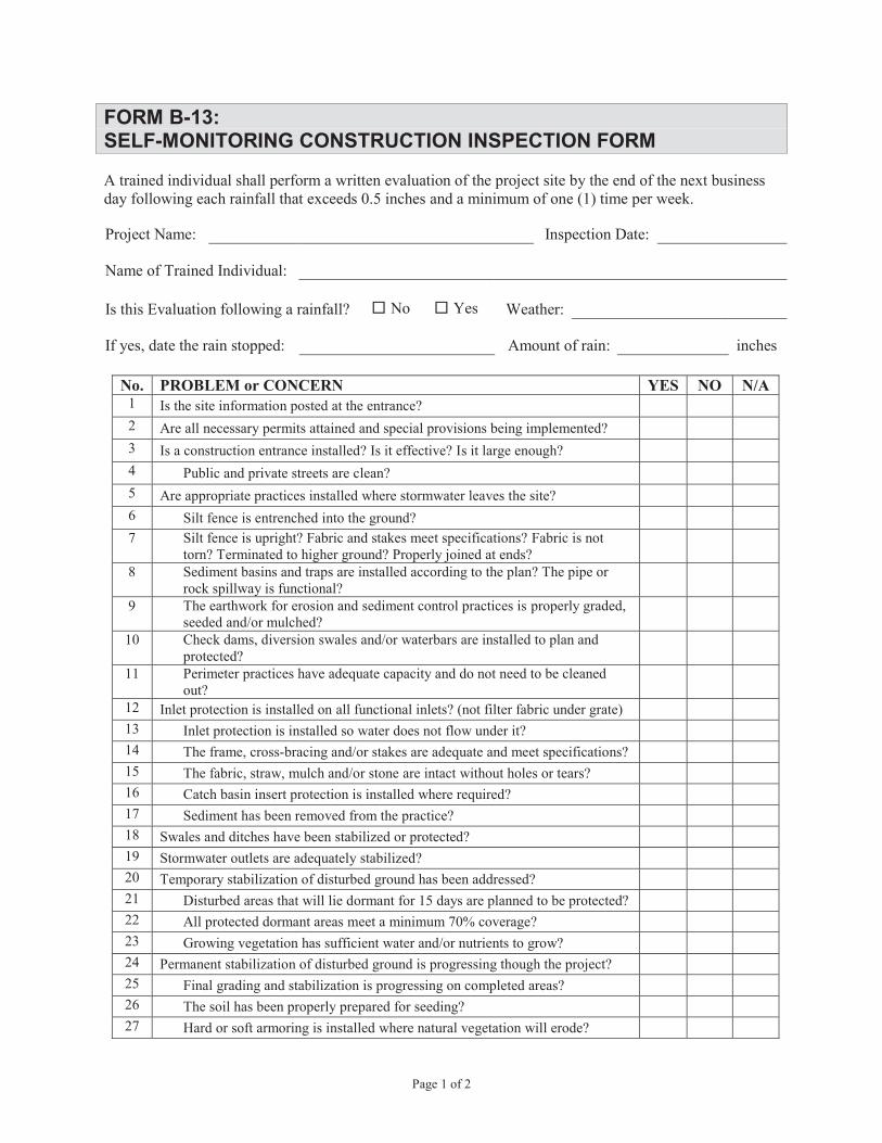
Page 1 of 2
FORM B-13:SELF-MONITORING CONSTRUCTION INSPECTION FORM
A trained individual shall perform a written evaluation of the project site by the end of the next business day following each rainfall that exceeds 0.5 inches and a minimum of one (1) time per week.
Project Name: Inspection Date:
Name of Trained Individual:
Is this Evaluation following a rainfall? No Yes Weather:
If yes, date the rain stopped: Amount of rain: inches
No. PROBLEM or CONCERN YES NO N/A1 Is the site information posted at the entrance?2 Are all necessary permits attained and special provisions being implemented?3 Is a construction entrance installed? Is it effective? Is it large enough? 4 Public and private streets are clean?5 Are appropriate practices installed where stormwater leaves the site?6 Silt fence is entrenched into the ground?7 Silt fence is upright? Fabric and stakes meet specifications? Fabric is not
torn? Terminated to higher ground? Properly joined at ends?8 Sediment basins and traps are installed according to the plan? The pipe or
rock spillway is functional?9 The earthwork for erosion and sediment control practices is properly graded,
seeded and/or mulched?10 Check dams, diversion swales and/or waterbars are installed to plan and
protected?11 Perimeter practices have adequate capacity and do not need to be cleaned
out?12 Inlet protection is installed on all functional inlets? (not filter fabric under grate)13 Inlet protection is installed so water does not flow under it?14 The frame, cross-bracing and/or stakes are adequate and meet specifications?15 The fabric, straw, mulch and/or stone are intact without holes or tears?16 Catch basin insert protection is installed where required?17 Sediment has been removed from the practice? 18 Swales and ditches have been stabilized or protected?19 Stormwater outlets are adequately stabilized?20 Temporary stabilization of disturbed ground has been addressed?21 Disturbed areas that will lie dormant for 15 days are planned to be protected? 22 All protected dormant areas meet a minimum 70% coverage? 23 Growing vegetation has sufficient water and/or nutrients to grow?24 Permanent stabilization of disturbed ground is progressing though the project?25 Final grading and stabilization is progressing on completed areas? 26 The soil has been properly prepared for seeding?27 Hard or soft armoring is installed where natural vegetation will erode?

Page 2 of 2
No. PROBLEM or CONCERN YES NO N/A28 Water pumping operations have a protected outlet and discharge water is clear?29 A designated washout area is established for concrete trucks? 30 A dumpster is onsite for trash disposal?31 Fuel tanks and other toxic materials are safely stored and protected?32 Smaller construction sites not required to file a separate NOI are complying with
the overall plan?
ALL PROBLEMS OR CONCERNS NEED TO BE ADDRESSED WITH A CORRECTIVE ACTION
Identify the problem by number and/or provide additional explanation as needed.
Developer Representative contacted, name and date:
Contractor Representative contacted, name and date:
Report Submitted By: Date:Signature

Page 1 of 2
FORM B-14: MAINTENANCE BOND
Instructions:
1. Contractor/Developer must use this form or other form containing the same material conditions
and provisions as approved in advance by the City of Beech Grove.
2. Date of Bond must not be prior to date of Contract. If Contractor/Developer is a Partnership, all
partners should execute bond.
3. Surety company executing this bond shall appear on the most current list of "Surety Companies
Acceptable on Federal Bonds," as specified in the U.S. Treasury Department Circular 570, as
amended, and be authorized to transact business in the State of Indiana.
KNOW ALL MEN BY THESE PRESENTS: that
“Contractor” or “Developer”
and
“Surety” Name
Address
a corporation chartered and existing under the laws of the State of _________________, and authorized to
do business in the State of Indiana, are held and firmly bound unto the City of Beech Grove, in the penal
sum of Dollars, ($______________) in lawful
money of the United States, for the payment of which sum well and truly to be made, together with interest
at the maximum legal rate from date of demand and any attorney fees and court costs incurred by Obligee
to enforce this instrument, we bind ourselves, successors, and assigns, jointly and severally, firmly by these
presents.
WHEREAS, the Contractor or Developer has entered into an Agreement for Construction of
by which Contractor/Developer has agreed to
perform and furnish certain work for or in furtherance of construction of public improvements described
generally as the which Agreement, and the
"Contract Documents" as referred to therein, are hereby incorporated herein by reference;
WHEREAS, the Contractor/Developer has installed and completed and met all improvements,
installations and requirements applicable to the above described work, but said improvements and
installations have not yet been accepted for public maintenance; and
WHEREAS, the City of Beech Grove requires a guarantee from the Contractor/Developer against
defective materials and workmanship in connection with such maintenances.
NOW, THEREFORE, Contractor/Developer warrants the workmanship and all materials used in
the construction, installation and completion of said Work, to be of good quality and completed in a
workmanlike manner in accordance with the Agreement and Contract Documents and all laws, ordinances,
rules, standards and regulations applicable to said Work;
FURTHERMORE, the conditions of the Surety's obligation hereunder are such that if
Contractor/Developer at his own expense, for a period of three years after said Work, improvements and
installations are accepted for public maintenance by the City of Beech Grove, shall make all repairs or
replacements thereto which may become necessary by reason of improper or defective workmanship or
materials, or any failure thereof to conform to the provisions of the Agreement or Contract Documents,

Page 2 of 2
then Surety's obligation is to be null and void; otherwise such obligation shall remain in full force and
effect. Any repairs or replacements made under this Bond shall in like manner be subject to the terms and
conditions hereof.
Contractor/Developer and Surety covenant that all action required by law to be taken by them to authorize
the execution and delivery of this bond have been previously been taken, that the officers whose signatures
appear below have been fully empowered to execute and deliver this instrument and that once executed and
delivered, it shall represent the lawful and binding obligation of the parties.
IN WITNESS WHEREOF, this instrument is executed in duplicate counterparts, each one of
which shall be deemed an original, this the ______ day of ___________________, 20_____.
Contractor/Developer:
By:
Signature Printed Name
Attest:
Signature Title
Surety:
By:
Signature, Attorney-in-Fact Printed Name
Address:

APPENDIX C
BMP QUICK REFERENCE FORMS


C-1: DETENTION / RETENTION FACILITIES
QUICK REFERENCE
Description: Constructed stormwater detention/retention basin that has a permanent pool of
water in which runoff from each rain event is captured and treated in the
pool.
Site Feasibility: Drainage Area: Minimum 10 acres
Residential Subdivision Use: Yes
High Density/Ultra-Urban: No
Design Criteria: Sediment forebay required
Length to width ratio shall be at least 3:1
Maximum depth of permanent pool should not exceed 8 feet
Side slopes of pond – see Appendix A, Detail No. 22
High permeable soils (hydrologic group A or B) may require a liner
Advantages: Moderate to high removal rate of urban pollutants
Can use for water quality and flood control
High community acceptance when designed with attention to aesthetics and
maintained properly
Opportunity for wildlife habitat
Disadvantages: Potential for thermal impacts/downstream warming
Pond drainage can be problematic for low relief terrain
Dam height restrictions for high relief areas
Improperly designed or maintained ponds may become stagnant causing
unpleasant conditions
Maintenance: Monitor sediment accumulation and remove periodically
Remove debris from inlet and outlet structures
Maintain side slopes and remove invasive vegetation
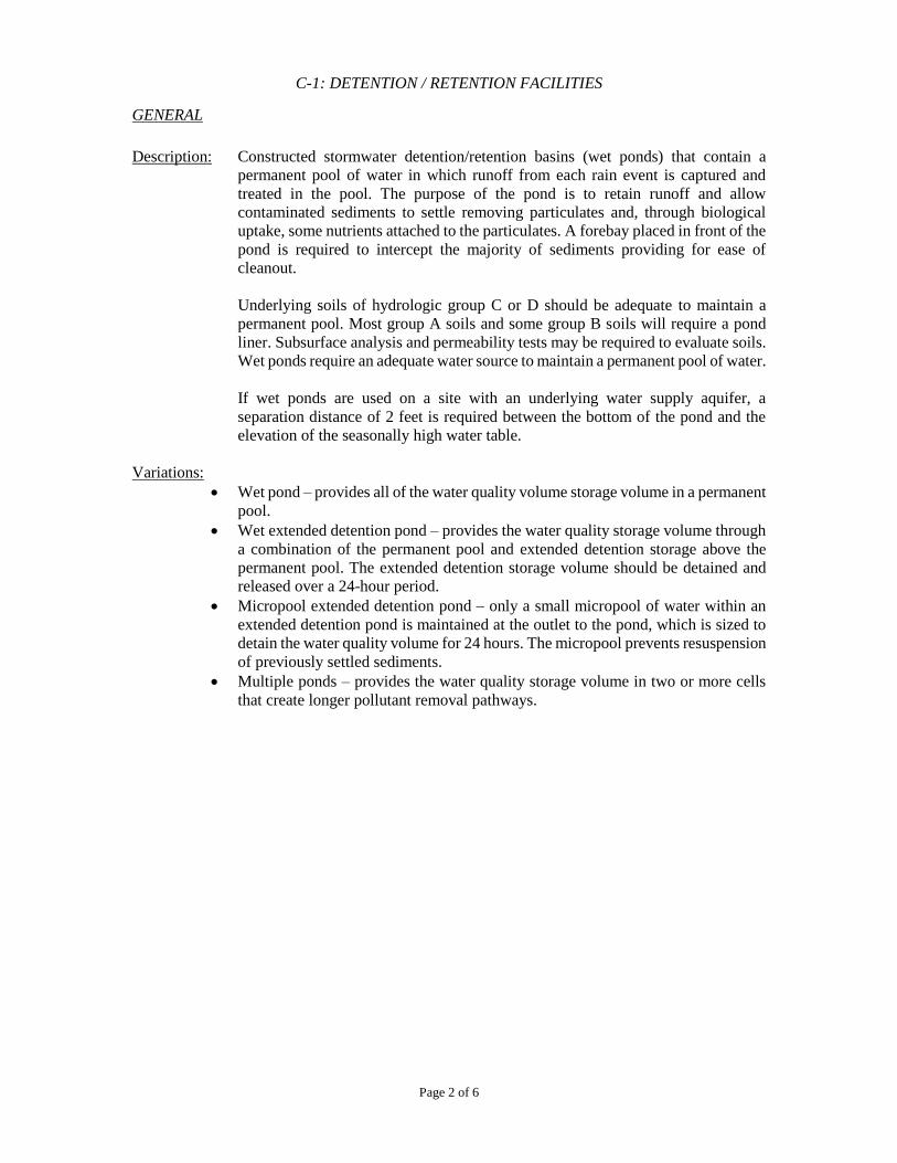
C-1: DETENTION / RETENTION FACILITIES
Page 2 of 6
GENERAL
Description: Constructed stormwater detention/retention basins (wet ponds) that contain a
permanent pool of water in which runoff from each rain event is captured and
treated in the pool. The purpose of the pond is to retain runoff and allow
contaminated sediments to settle removing particulates and, through biological
uptake, some nutrients attached to the particulates. A forebay placed in front of the
pond is required to intercept the majority of sediments providing for ease of
cleanout.
Underlying soils of hydrologic group C or D should be adequate to maintain a
permanent pool. Most group A soils and some group B soils will require a pond
liner. Subsurface analysis and permeability tests may be required to evaluate soils.
Wet ponds require an adequate water source to maintain a permanent pool of water.
If wet ponds are used on a site with an underlying water supply aquifer, a
separation distance of 2 feet is required between the bottom of the pond and the
elevation of the seasonally high water table.
Variations:
Wet pond – provides all of the water quality volume storage volume in a permanent
pool.
Wet extended detention pond – provides the water quality storage volume through
a combination of the permanent pool and extended detention storage above the
permanent pool. The extended detention storage volume should be detained and
released over a 24-hour period.
Micropool extended detention pond – only a small micropool of water within an
extended detention pond is maintained at the outlet to the pond, which is sized to
detain the water quality volume for 24 hours. The micropool prevents resuspension
of previously settled sediments.
Multiple ponds – provides the water quality storage volume in two or more cells
that create longer pollutant removal pathways.
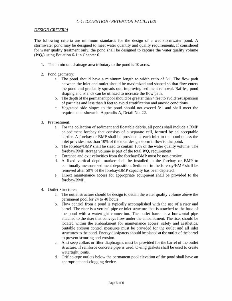
C-1: DETENTION / RETENTION FACILITIES
Page 3 of 6
DESIGN CRITERIA
The following criteria are minimum standards for the design of a wet stormwater pond. A
stormwater pond may be designed to meet water quantity and quality requirements. If considered
for water quality treatment only, the pond shall be designed to capture the water quality volume
(WQv) using Equation 6-1 in Chapter 6.
1. The minimum drainage area tributary to the pond is 10 acres.
2. Pond geometry:
a. The pond should have a minimum length to width ratio of 3:1. The flow path
between the inlet and outlet should be maximized and shaped so that flow enters
the pond and gradually spreads out, improving sediment removal. Baffles, pond
shaping and islands can be utilized to increase the flow path.
b. The depth of the permanent pool should be greater than 4 feet to avoid resuspension
of particles and less than 8 feet to avoid stratification and anoxic conditions.
c. Vegetated side slopes to the pond should not exceed 3:1 and shall meet the
requirements shown in Appendix A, Detail No. 22.
3. Pretreatment:
a. For the collection of sediment and floatable debris, all ponds shall include a BMP
or sediment forebay that consists of a separate cell, formed by an acceptable
barrier. A forebay or BMP shall be provided at each inlet to the pond unless the
inlet provides less than 10% of the total design storm inflow to the pond.
b. The forebay/BMP shall be sized to contain 10% of the water quality volume. The
forebay/BMP storage volume is part of the total WQv requirement.
c. Entrance and exit velocities from the forebay/BMP must be non-erosive.
d. A fixed vertical depth marker shall be installed in the forebay or BMP to
continually measure sediment deposition. Sediment in the forebay/BMP shall be
removed after 50% of the forebay/BMP capacity has been depleted.
e. Direct maintenance access for appropriate equipment shall be provided to the
forebay/BMP.
4. Outlet Structures:
a. The outlet structure should be design to detain the water quality volume above the
permanent pool for 24 to 48 hours.
b. Flow control from a pond is typically accomplished with the use of a riser and
barrel. The riser is a vertical pipe or inlet structure that is attached to the base of
the pond with a watertight connection. The outlet barrel is a horizontal pipe
attached to the riser that conveys flow under the embankment. The riser should be
located within the embankment for maintenance access, safety and aesthetics.
Suitable erosion control measures must be provided for the outlet and all inlet
structures to the pond. Energy dissipaters should be placed at the outlet of the barrel
to prevent scouring and erosion.
c. Anti-seep collars or filter diaphragms must be provided for the barrel of the outlet
structure. If reinforce concrete pipe is used, O-ring gaskets shall be used to create
watertight joints.
d. Orifice-type outlets below the permanent pool elevation of the pond shall have an
appropriate anti-clogging device.
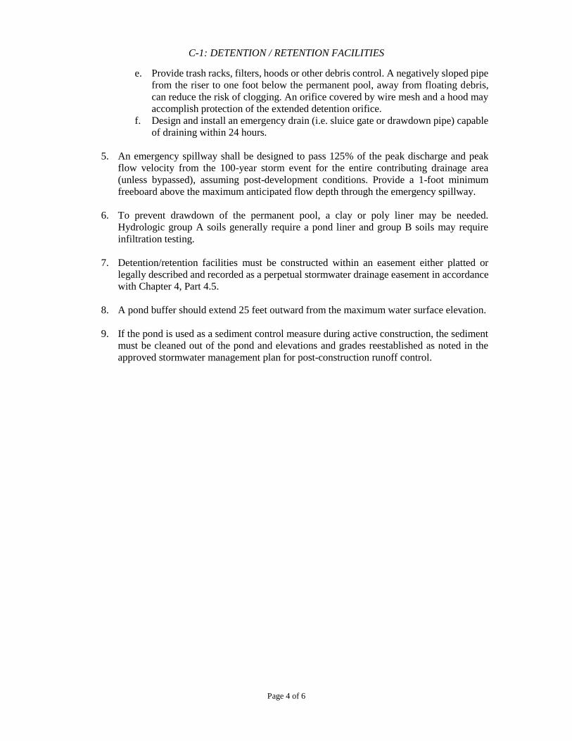
C-1: DETENTION / RETENTION FACILITIES
Page 4 of 6
e. Provide trash racks, filters, hoods or other debris control. A negatively sloped pipe
from the riser to one foot below the permanent pool, away from floating debris,
can reduce the risk of clogging. An orifice covered by wire mesh and a hood may
accomplish protection of the extended detention orifice.
f. Design and install an emergency drain (i.e. sluice gate or drawdown pipe) capable
of draining within 24 hours.
5. An emergency spillway shall be designed to pass 125% of the peak discharge and peak
flow velocity from the 100-year storm event for the entire contributing drainage area
(unless bypassed), assuming post-development conditions. Provide a 1-foot minimum
freeboard above the maximum anticipated flow depth through the emergency spillway.
6. To prevent drawdown of the permanent pool, a clay or poly liner may be needed.
Hydrologic group A soils generally require a pond liner and group B soils may require
infiltration testing.
7. Detention/retention facilities must be constructed within an easement either platted or
legally described and recorded as a perpetual stormwater drainage easement in accordance
with Chapter 4, Part 4.5.
8. A pond buffer should extend 25 feet outward from the maximum water surface elevation.
9. If the pond is used as a sediment control measure during active construction, the sediment
must be cleaned out of the pond and elevations and grades reestablished as noted in the
approved stormwater management plan for post-construction runoff control.
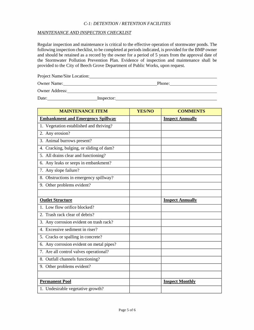
C-1: DETENTION / RETENTION FACILITIES
Page 5 of 6
MAINTENANCE AND INSPECTION CHECKLIST
Regular inspection and maintenance is critical to the effective operation of stormwater ponds. The
following inspection checklist, to be completed at periods indicated, is provided for the BMP owner
and should be retained as a record by the owner for a period of 5 years from the approval date of
the Stormwater Pollution Prevention Plan. Evidence of inspection and maintenance shall be
provided to the City of Beech Grove Department of Public Works, upon request.
Project Name/Site Location:
Owner Name: Phone:
Owner Address:
Date: Inspector:
MAINTENANCE ITEM YES/NO COMMENTS
Embankment and Emergency Spillway Inspect Annually
1. Vegetation established and thriving?
2. Any erosion?
3. Animal burrows present?
4. Cracking, bulging, or sliding of dam?
5. All drains clear and functioning?
6. Any leaks or seeps in embankment?
7. Any slope failure?
8. Obstructions in emergency spillway?
9. Other problems evident?
Outlet Structure Inspect Annually
1. Low flow orifice blocked?
2. Trash rack clear of debris?
3. Any corrosion evident on trash rack?
4. Excessive sediment in riser?
5. Cracks or spalling in concrete?
6. Any corrosion evident on metal pipes?
7. Are all control valves operational?
8. Outfall channels functioning?
9. Other problems evident?
Permanent Pool Inspect Monthly
1. Undesirable vegetative growth?
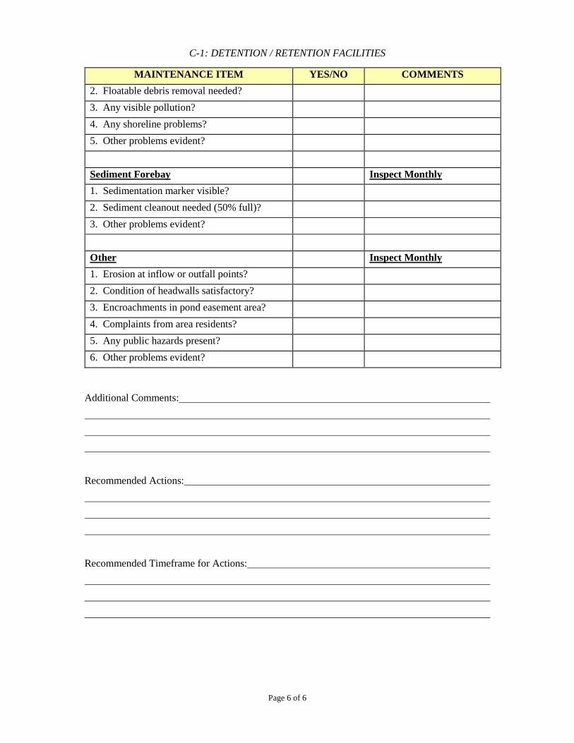
C-1: DETENTION / RETENTION FACILITIES
Page 6 of 6
MAINTENANCE ITEM YES/NO COMMENTS
2. Floatable debris removal needed?
3. Any visible pollution?
4. Any shoreline problems?
5. Other problems evident?
Sediment Forebay Inspect Monthly
1. Sedimentation marker visible?
2. Sediment cleanout needed (50% full)?
3. Other problems evident?
Other Inspect Monthly
1. Erosion at inflow or outfall points?
2. Condition of headwalls satisfactory?
3. Encroachments in pond easement area?
4. Complaints from area residents?
5. Any public hazards present?
6. Other problems evident?
Additional Comments:
Recommended Actions:
Recommended Timeframe for Actions:
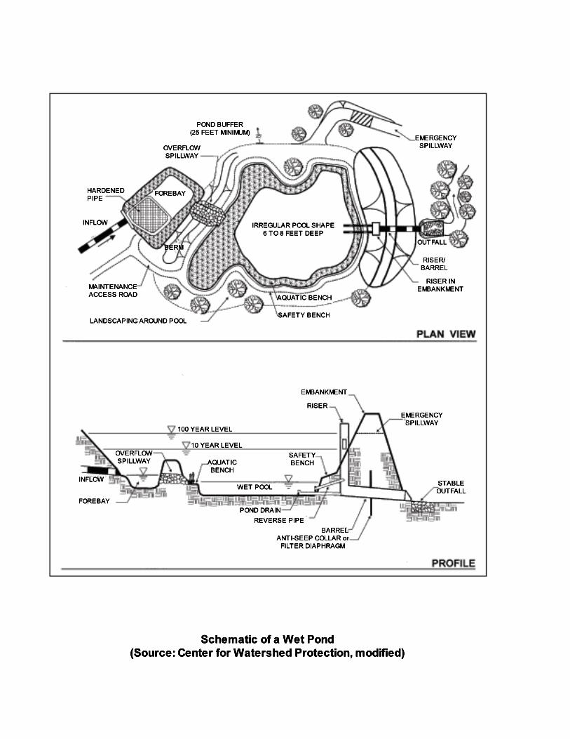
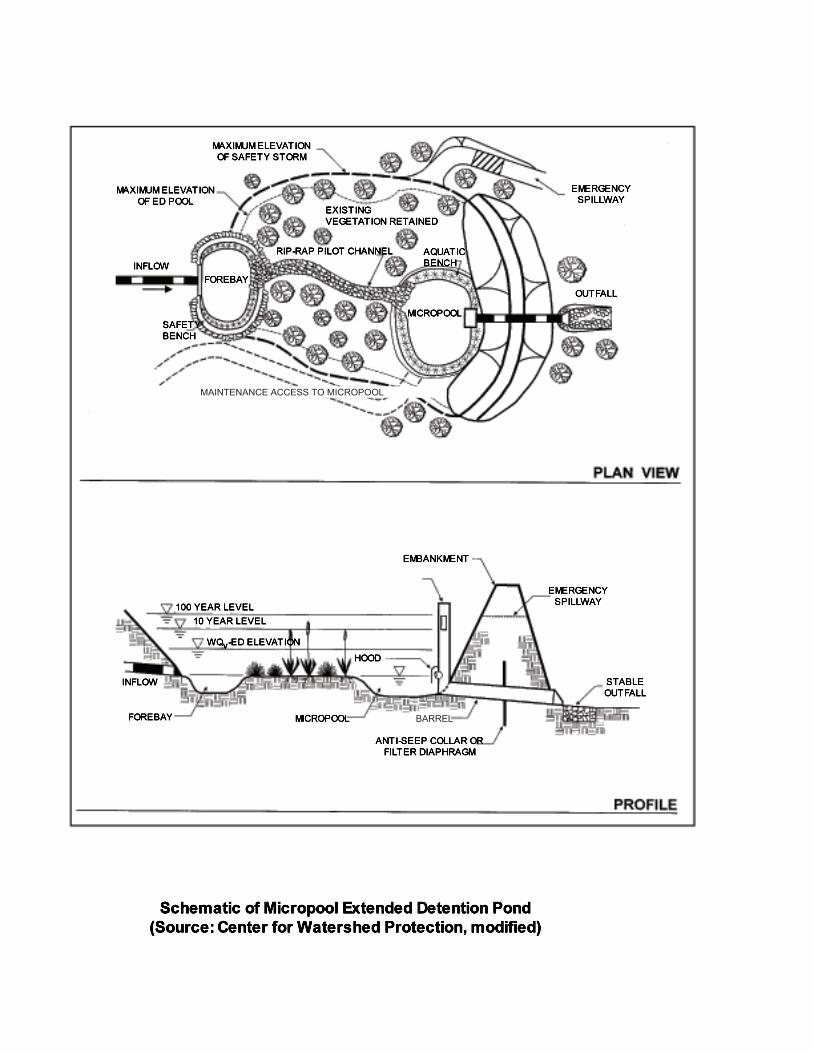
MAINTENANCE ACCESS TO MICROPOOL
BARREL
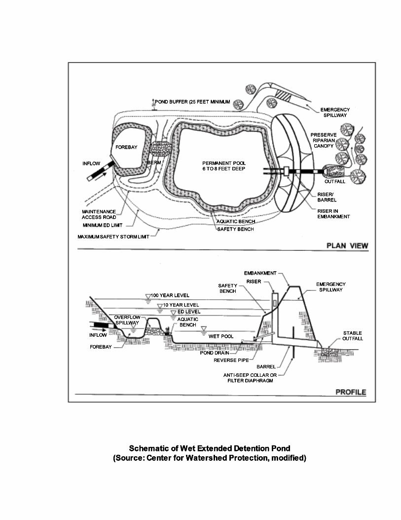
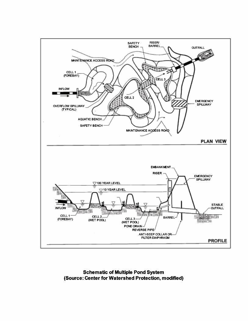
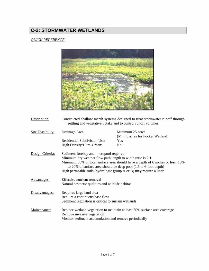
Page 1 of 7
C-2: STORMWATER WETLANDS
QUICK REFERENCE
Description: Constructed shallow marsh systems designed to treat stormwater runoff through
settling and vegetative uptake and to control runoff volumes.
Site Feasibility: Drainage Area: Minimum 25 acres
(Min. 5 acres for Pocket Wetland)
Residential Subdivision Use: Yes
High Density/Ultra-Urban: No
Design Criteria: Sediment forebay and micropool required
Minimum dry weather flow path length to width ratio is 2:1
Minimum 35% of total surface area should have a depth of 6 inches or less; 10%
to 20% of surface area should be deep pool (1.5 to 6-foot depth)
High permeable soils (hydrologic group A or B) may require a liner
Advantages: Effective nutrient removal
Natural aesthetic qualities and wildlife habitat
Disadvantages: Requires large land area
Require a continuous base flow
Sediment regulation is critical to sustain wetlands
Maintenance: Replace wetland vegetation to maintain at least 50% surface area coverage
Remove invasive vegetation
Monitor sediment accumulation and remove periodically
C-2: STORMWATER WETLANDS
Page 2 of 7
GENERAL
Description: Stormwater wetlands are constructed shallow marsh systems designed to control the
quantity and quality of stormwater runoff. Microbial breakdown, settling, adsorption,
retention, and vegetative uptake remove pollutants as stormwater moves through the
wetland under low flow conditions. Runoff volumes are reduced by evapotranspiration
and infiltration. Peak flow is reduced by storage and slow release. Wetlands further
offer erosion control, aesthetic value, and wildlife habitat.
A sediment forebay at the inflow point to a wetland is required to allow heavier
sediments to drop out before the runoff enters the wetland marsh. Underlying soils of
hydrologic group C or D should be adequate to maintain a permanent pool. Most group
A soils and some group B soils may require a liner. Subsurface analysis and
permeability tests may be required to evaluate soils. A continuous base flow or a high
water table is required to support aquatic vegetation in a wetland facility. A water
balance must be performed to demonstrate the wetland can withstand a thirty-day
drought at summer evaporation rates without completely drawing down.
If stormwater wetlands are used on a site with an underlying water supply aquifer, a
separation distance of 2 feet is required between the bottom of the pond and the
elevation of the seasonally high water table. A pocket wetland is typically below the
water table.
Variations:
Shallow Wetland – most of the water quality treatment volume is in the shallow high
marsh or low marsh depths. The only deep portions of the shallow wetland are the
forebay and the micropool. A relatively large amount of land is typically needed to
store the water quality volume.
Extended Detention (ED) Shallow Wetland – the same as the shallow wetland, except
part of the water quality treatment volume is provided as extended detention above the
surface of the marsh and released over a period of 24 hours. This design allows for
treatment in a smaller space than the shallow wetland. Plants that can tolerate both wet
and dry periods need to be specified in the ED zone.
Pond/Wetland System – this system has two separate cells, a wet pond and a shallow
marsh. The wet pond traps sediments and reduces runoff velocities prior to entry into
the wetland where stormwater flows receive additional treatment. Less land is required
than for the shallow wetland or the ED shallow wetland systems.
Pocket Wetland – intended for smaller drainage areas of 5 to 10 acres and typically
requires excavation down to the water table for a reliable water source to support the
wetland system.
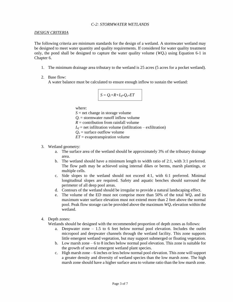
C-2: STORMWATER WETLANDS
Page 3 of 7
DESIGN CRITERIA
The following criteria are minimum standards for the design of a wetland. A stormwater wetland may
be designed to meet water quantity and quality requirements. If considered for water quality treatment
only, the pond shall be designed to capture the water quality volume (WQv) using Equation 6-1 in
Chapter 6.
1. The minimum drainage area tributary to the wetland is 25 acres (5 acres for a pocket wetland).
2. Base flow:
A water balance must be calculated to ensure enough inflow to sustain the wetland:
S = Qi+R+Inf-Qo-ET
where:
S = net change in storage volume
Qi = stormwater runoff inflow volume
R = contribution from rainfall volume
Inf = net infiltration volume (infiltration – exfiltration)
Qo = surface outflow volume
ET = evapotranspiration volume
3. Wetland geometry:
a. The surface area of the wetland should be approximately 3% of the tributary drainage
area.
b. The wetland should have a minimum length to width ratio of 2:1, with 3:1 preferred.
The flow path may be achieved using internal dikes or berms, marsh plantings, or
multiple cells.
c. Side slopes to the wetland should not exceed 4:1, with 6:1 preferred. Minimal
longitudinal slopes are required. Safety and aquatic benches should surround the
perimeter of all deep pool areas.
d. Contours of the wetland should be irregular to provide a natural landscaping effect.
e. The volume of the ED must not comprise more than 50% of the total WQv and its
maximum water surface elevation must not extend more than 2 feet above the normal
pool. Peak flow storage can be provided above the maximum WQv elevation within the
wetland.
4. Depth zones:
Wetlands should be designed with the recommended proportion of depth zones as follows:
a. Deepwater zone – 1.5 to 6 feet below normal pool elevation. Includes the outlet
micropool and deepwater channels through the wetland facility. This zone supports
little emergent wetland vegetation, but may support submerged or floating vegetation.
b. Low marsh zone – 6 to 8 inches below normal pool elevation. This zone is suitable for
the growth of several emergent wetland plant species.
c. High marsh zone – 6 inches or less below normal pool elevation. This zone will support
a greater density and diversity of wetland species than the low marsh zone. The high
marsh zone should have a higher surface area to volume ratio than the low marsh zone.
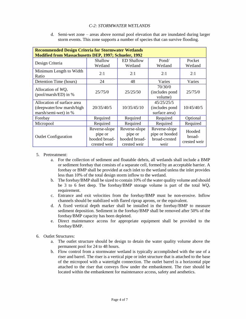
C-2: STORMWATER WETLANDS
Page 4 of 7
d. Semi-wet zone – areas above normal pool elevation that are inundated during larger
storm events. This zone supports a number of species that can survive flooding.
Recommended Design Criteria for Stormwater Wetlands
Modified from Massachusetts DEP, 1997; Schueler, 1992
Design Criteria Shallow
Wetland
ED Shallow
Wetland
Pond/
Wetland
Wetland
Minimum Length to Width
Ratio 2:1 2:1 2:1 2:1
Detention Time (hours) 24 48 Varies Varies
Allocation of WQv
(pool/marsh/ED) in % 25/75/0 25/25/50
70/30/0
(includes pond
volume)
25/75/0
Allocation of surface area
(deepwater/low marsh/high
marsh/semi-wet) in %
20/35/40/5 10/35/45/10
45/25/25/5
(includes pond
surface area)
10/45/40/5
Forebay Required Required Required Optional
Micropool Required Required Required Required
Outlet Configuration
Reverse-slope
pipe or
hooded broad-
crested weir
Reverse-slope
pipe or
hooded broad-
crested weir
Reverse-slope
pipe or hooded
broad-crested
weir
Hooded
broad-
crested weir
5. Pretreatment:
a. For the collection of sediment and floatable debris, all wetlands shall include a BMP
or sediment forebay that consists of a separate cell, formed by an acceptable barrier. A
forebay or BMP shall be provided at each inlet to the wetland unless the inlet provides
less than 10% of the total design storm inflow to the wetland.
b. The forebay/BMP shall be sized to contain 10% of the water quality volume and should
be 3 to 6 feet deep. The forebay/BMP storage volume is part of the total WQv
requirement.
c. Entrance and exit velocities from the forebay/BMP must be non-erosive. Inflow
channels should be stabilized with flared riprap aprons, or the equivalent.
d. A fixed vertical depth marker shall be installed in the forebay/BMP to measure
sediment deposition. Sediment in the forebay/BMP shall be removed after 50% of the
forebay/BMP capacity has been depleted.
e. Direct maintenance access for appropriate equipment shall be provided to the
forebay/BMP.
6. Outlet Structures:
a. The outlet structure should be design to detain the water quality volume above the
permanent pool for 24 to 48 hours.
b. Flow control from a stormwater wetland is typically accomplished with the use of a
riser and barrel. The riser is a vertical pipe or inlet structure that is attached to the base
of the micropool with a watertight connection. The outlet barrel is a horizontal pipe
attached to the riser that conveys flow under the embankment. The riser should be
located within the embankment for maintenance access, safety and aesthetics.
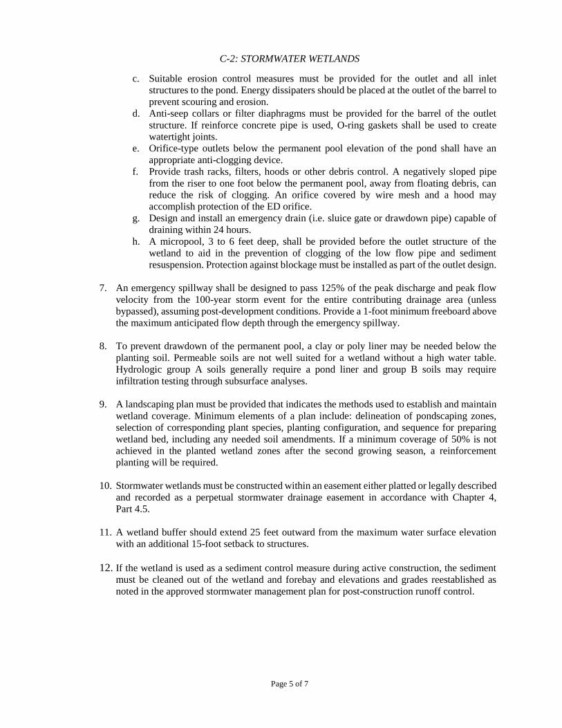
C-2: STORMWATER WETLANDS
Page 5 of 7
c. Suitable erosion control measures must be provided for the outlet and all inlet
structures to the pond. Energy dissipaters should be placed at the outlet of the barrel to
prevent scouring and erosion.
d. Anti-seep collars or filter diaphragms must be provided for the barrel of the outlet
structure. If reinforce concrete pipe is used, O-ring gaskets shall be used to create
watertight joints.
e. Orifice-type outlets below the permanent pool elevation of the pond shall have an
appropriate anti-clogging device.
f. Provide trash racks, filters, hoods or other debris control. A negatively sloped pipe
from the riser to one foot below the permanent pool, away from floating debris, can
reduce the risk of clogging. An orifice covered by wire mesh and a hood may
accomplish protection of the ED orifice.
g. Design and install an emergency drain (i.e. sluice gate or drawdown pipe) capable of
draining within 24 hours.
h. A micropool, 3 to 6 feet deep, shall be provided before the outlet structure of the
wetland to aid in the prevention of clogging of the low flow pipe and sediment
resuspension. Protection against blockage must be installed as part of the outlet design.
7. An emergency spillway shall be designed to pass 125% of the peak discharge and peak flow
velocity from the 100-year storm event for the entire contributing drainage area (unless
bypassed), assuming post-development conditions. Provide a 1-foot minimum freeboard above
the maximum anticipated flow depth through the emergency spillway.
8. To prevent drawdown of the permanent pool, a clay or poly liner may be needed below the
planting soil. Permeable soils are not well suited for a wetland without a high water table.
Hydrologic group A soils generally require a pond liner and group B soils may require
infiltration testing through subsurface analyses.
9. A landscaping plan must be provided that indicates the methods used to establish and maintain
wetland coverage. Minimum elements of a plan include: delineation of pondscaping zones,
selection of corresponding plant species, planting configuration, and sequence for preparing
wetland bed, including any needed soil amendments. If a minimum coverage of 50% is not
achieved in the planted wetland zones after the second growing season, a reinforcement
planting will be required.
10. Stormwater wetlands must be constructed within an easement either platted or legally described
and recorded as a perpetual stormwater drainage easement in accordance with Chapter 4,
Part 4.5.
11. A wetland buffer should extend 25 feet outward from the maximum water surface elevation
with an additional 15-foot setback to structures.
12. If the wetland is used as a sediment control measure during active construction, the sediment
must be cleaned out of the wetland and forebay and elevations and grades reestablished as
noted in the approved stormwater management plan for post-construction runoff control.
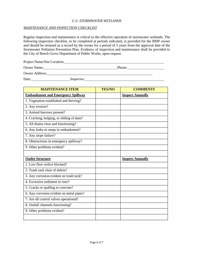
C-2: STORMWATER WETLANDS
Page 6 of 7
MAINTENANCE AND INSPECTION CHECKLIST
Regular inspection and maintenance is critical to the effective operation of stormwater wetlands. The
following inspection checklist, to be completed at periods indicated, is provided for the BMP owner
and should be retained as a record by the owner for a period of 5 years from the approval date of the
Stormwater Pollution Prevention Plan. Evidence of inspection and maintenance shall be provided to
the City of Beech Grove Department of Public Works, upon request.
Project Name/Site Location:
Owner Name: Phone:
Owner Address:
Date: Inspector:
MAINTENANCE ITEM YES/NO COMMENTS
Embankment and Emergency Spillway Inspect Annually
1. Vegetation established and thriving?
2. Any erosion?
3. Animal burrows present?
4. Cracking, bulging, or sliding of dam?
5. All drains clear and functioning?
6. Any leaks or seeps in embankment?
7. Any slope failure?
8. Obstructions in emergency spillway?
9. Other problems evident?
Outlet Structure Inspect Annually
1. Low flow orifice blocked?
2. Trash rack clear of debris?
3. Any corrosion evident on trash rack?
4. Excessive sediment in riser?
5. Cracks or spalling in concrete?
6. Any corrosion evident on metal pipes?
7. Are all control valves operational?
8. Outfall channels functioning?
9. Other problems evident?
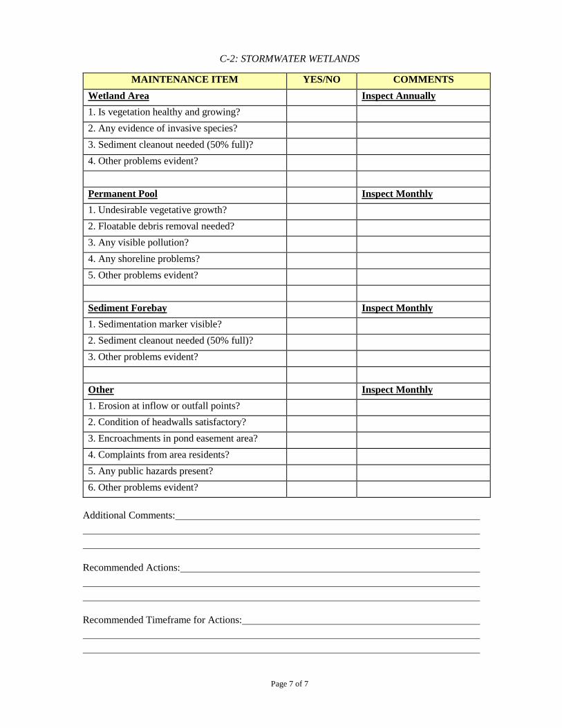
C-2: STORMWATER WETLANDS
Page 7 of 7
MAINTENANCE ITEM YES/NO COMMENTS
Wetland Area Inspect Annually
1. Is vegetation healthy and growing?
2. Any evidence of invasive species?
3. Sediment cleanout needed (50% full)?
4. Other problems evident?
Permanent Pool Inspect Monthly
1. Undesirable vegetative growth?
2. Floatable debris removal needed?
3. Any visible pollution?
4. Any shoreline problems?
5. Other problems evident?
Sediment Forebay Inspect Monthly
1. Sedimentation marker visible?
2. Sediment cleanout needed (50% full)?
3. Other problems evident?
Other Inspect Monthly
1. Erosion at inflow or outfall points?
2. Condition of headwalls satisfactory?
3. Encroachments in pond easement area?
4. Complaints from area residents?
5. Any public hazards present?
6. Other problems evident?
Additional Comments:
Recommended Actions:
Recommended Timeframe for Actions:
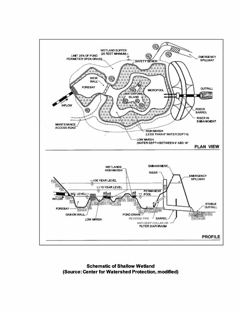
REVERSE PIPEANTI-SEEP COLLAR OR
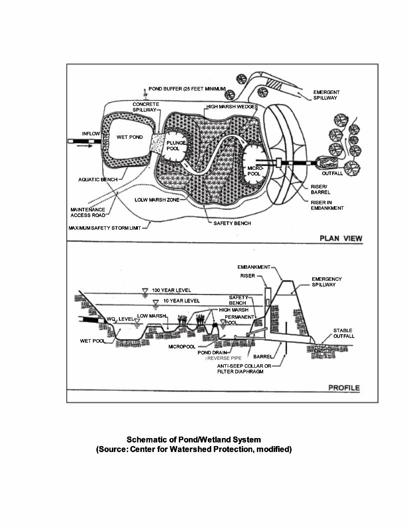
REVERSE PIPE
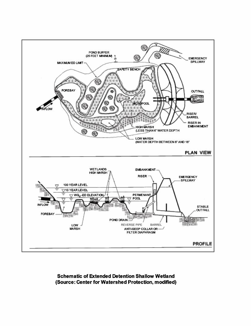
REVERSE PIPE BARREL
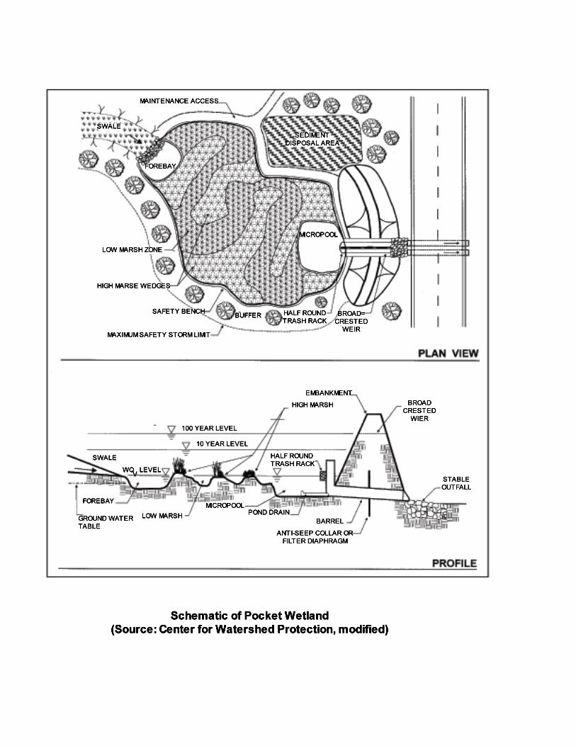

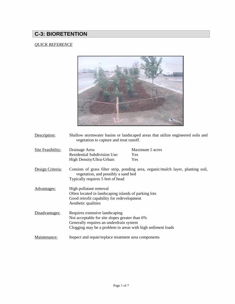
Page 1 of 7
C-3: BIORETENTION
QUICK REFERENCE
Newly Constructed Bioretention Area
Description: Shallow stormwater basins or landscaped areas that utilize engineered soils and
vegetation to capture and treat runoff.
Site Feasibility: Drainage Area: Maximum 5 acres
Residential Subdivision Use: Yes
High Density/Ultra-Urban: Yes
Design Criteria: Consists of grass filter strip, ponding area, organic/mulch layer, planting soil,
vegetation, and possibly a sand bed
Typically requires 5 feet of head
Advantages: High pollutant removal
Often located in landscaping islands of parking lots
Good retrofit capability for redevelopment
Aesthetic qualities
Disadvantages: Requires extensive landscaping
Not acceptable for site slopes greater than 6%
Generally requires an underdrain system
Clogging may be a problem in areas with high sediment loads
Maintenance: Inspect and repair/replace treatment area components
C-3: BIORETENTION
Page 2 of 7
GENERAL
Description: Bioretention areas are structural stormwater controls that capture and temporarily store
the WQv using engineered soils and vegetation in shallow basins or landscaped areas
to remove pollutants from stormwater runoff. Runoff is conveyed as sheet flow to the
bioretention area, which consists of a grass filter strip, ponding area, organic or mulch
layer, planting soil, and vegetation. A sand bed can also be included in the design to
provide aeration and drainage of the planting soil. The filtered runoff is typically
collected and returned to the conveyance system, though it can also be exfiltrated into
the surrounding soil in areas with porous soils.
Bioretention systems are designed for intermittent flow and need to drain and reaerate
between rainfall events. The systems should not be used on sites with a continuous
flow from groundwater, sump pumps, or other sources.
A separation distance of 2 feet is required between the bottom of the bioretention
facility and the elevation of the seasonally high water table.
Bioretention Components:
Stone diaphragm at the beginning of the grass filter strip - to reduce runoff velocities
and spread flow into the grass filter strip.
Grass filter strip – further reduces incoming runoff velocity and filters particulates from
runoff.
Ponding area – provides temporary storage of stormwater runoff prior to its
evaporation, infiltration, or uptake and provides settling capacity.
Organic or mulch layer – provides filtration as well as an environment conducive to
the growth of microorganisms that degrade hydrocarbons and organic material.
Planting soil – acts as a filtration system, and clay in the soil provides adsorption sites
for hydrocarbons, heavy metals, nutrients and other pollutants.
Woody and herbaceous plants – provide vegetative uptake of runoff and pollutants and
serve to stabilize the surrounding soils.
Sand bed – provides positive drainage and aerobic conditions in the planting soil and
serves as a final treatment media.
Gravel and perforated pipe underdrain system – collects runoff that has filtered through
the soil layers. Bioretention areas can be designed to infiltrate into surrounding soils
having infiltration rates greater than 0.5 inches per hour.
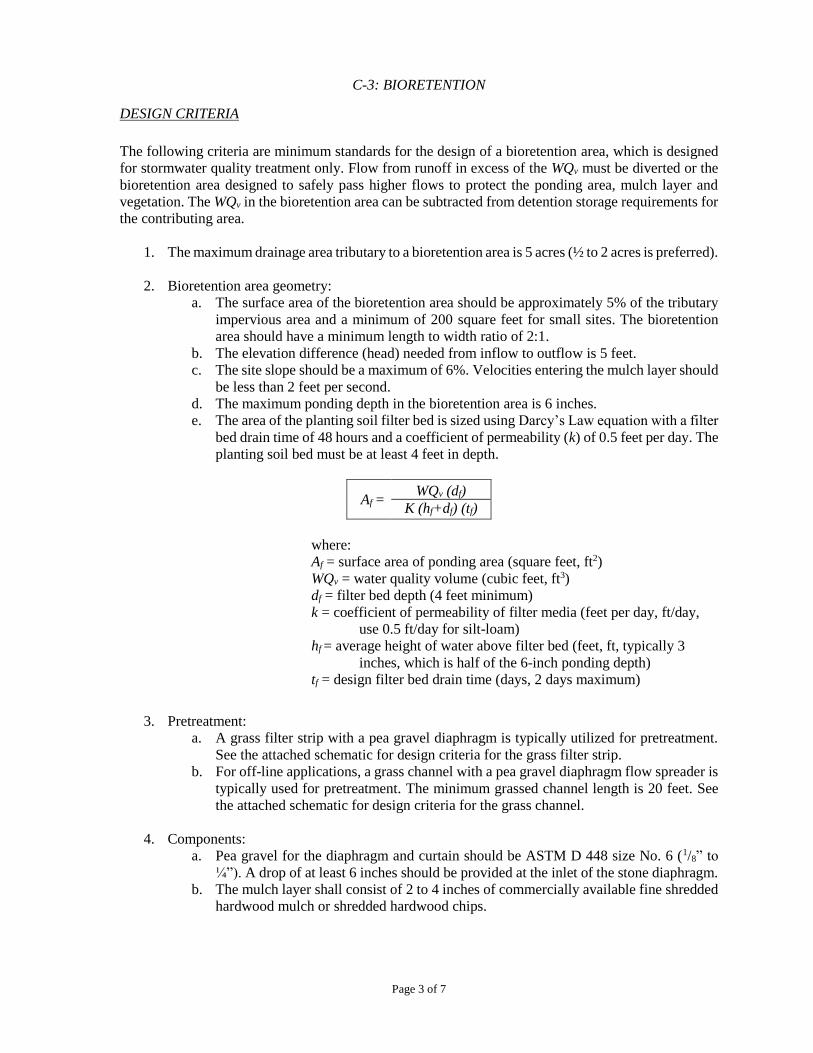
C-3: BIORETENTION
Page 3 of 7
DESIGN CRITERIA
The following criteria are minimum standards for the design of a bioretention area, which is designed
for stormwater quality treatment only. Flow from runoff in excess of the WQv must be diverted or the
bioretention area designed to safely pass higher flows to protect the ponding area, mulch layer and
vegetation. The WQv in the bioretention area can be subtracted from detention storage requirements for
the contributing area.
1. The maximum drainage area tributary to a bioretention area is 5 acres (½ to 2 acres is preferred).
2. Bioretention area geometry:
a. The surface area of the bioretention area should be approximately 5% of the tributary
impervious area and a minimum of 200 square feet for small sites. The bioretention
area should have a minimum length to width ratio of 2:1.
b. The elevation difference (head) needed from inflow to outflow is 5 feet.
c. The site slope should be a maximum of 6%. Velocities entering the mulch layer should
be less than 2 feet per second.
d. The maximum ponding depth in the bioretention area is 6 inches.
e. The area of the planting soil filter bed is sized using Darcy’s Law equation with a filter
bed drain time of 48 hours and a coefficient of permeability (k) of 0.5 feet per day. The
planting soil bed must be at least 4 feet in depth.
Af = WQv (df)
K (hf+df) (tf)
where:
Af = surface area of ponding area (square feet, ft2)
WQv = water quality volume (cubic feet, ft3)
df = filter bed depth (4 feet minimum)
k = coefficient of permeability of filter media (feet per day, ft/day,
use 0.5 ft/day for silt-loam)
hf = average height of water above filter bed (feet, ft, typically 3
inches, which is half of the 6-inch ponding depth)
tf = design filter bed drain time (days, 2 days maximum)
3. Pretreatment:
a. A grass filter strip with a pea gravel diaphragm is typically utilized for pretreatment.
See the attached schematic for design criteria for the grass filter strip.
b. For off-line applications, a grass channel with a pea gravel diaphragm flow spreader is
typically used for pretreatment. The minimum grassed channel length is 20 feet. See
the attached schematic for design criteria for the grass channel.
4. Components:
a. Pea gravel for the diaphragm and curtain should be ASTM D 448 size No. 6 (1/8” to
¼”). A drop of at least 6 inches should be provided at the inlet of the stone diaphragm.
b. The mulch layer shall consist of 2 to 4 inches of commercially available fine shredded
hardwood mulch or shredded hardwood chips.
C-3: BIORETENTION
Page 4 of 7
c. Planting soils shall be sandy loam, loamy sand, or loam texture and shall have an
infiltration rate of at least 0.5 inches per hour. The planting soil shall be tested and shall
meet the following criteria:
clay content 10% to 25% by volume
silt content 30% to 55% by volume
sand content 35% to 60% by volume
pH 5.2 to 7.0
organic matter 1.5% and 4% by weight
magnesium 35 lb./ac
phosphorus (phosphate–P2O5) 75 lb./ac
potassium (potash-K2O) 85 lb./ac
soluble salts 500 ppm maximum
d. The sand bed should be 12 to 18 inches thick. Sand should be clean and have less than
15% silt or clay content.
e. The underdrain collection system shall consist of a 4 to 6-inch perforated PVC pipe
(Schedule 40 or greater in strength) in an 8-inch gravel layer (clean washed aggregate
0.5 to 2 inches in diameter). The pipe is spaced at a maximum of 10 feet on center at a
minimum grade of 0.5%. A permeable filter fabric is required between the gravel layer
and the planting soil bed. An observation well/clean out must be provided; a minimum
of one well for every 1000 square feet of surface area. A visible floating marker shall
be provided to indicate the water level. The ends of the underdrain pipes must be
capped. The underdrain pipe must discharge to an appropriate facility.
f. Compaction during construction must be minimized at both the base of the bioretention
area and for the backfill materials. Use of equipment causing excessive compaction
will result in reduced infiltration rates contributing to failure of the system and is not
acceptable. Do not use heavy equipment within the bioretention basin.
5. Overflow structure:
a. An overflow structure and nonerosive overflow channel must be provided to safely
pass flows from the bioretention area that exceeds the system storage capacity to a
stabilized downstream area or watercourse. An overflow structure within the
bioretention system may consist of a catch basin with the inlet placed 6 inches above
the mulch layer at the elevation of the shallow ponding area.
b. An overflow structure may consist of a weir sized using the Weir equation.
Q = CLH3/2
where:
Q = peak flow (cubic feet per second, cfs)
C = 2.65 for a smooth crested grass weir
L = length (feet, ft)
H = 0.5 feet of head
6. A landscaping plan must be provided. The bioretention area should be vegetated to resemble a
terrestrial forest ecosystem, with a mature tree canopy, sub canopy of understory trees, scrub
C-3: BIORETENTION
Page 5 of 7
layer, and herbaceous ground cover. Three species each of trees and shrubs should to be
planted. The tree-to-shrub ratio should be 2:1 to 3:1. Trees should be spaced 8 feet apart.
7. Bioretention areas must be constructed within an easement either platted or legally described
and recorded as a perpetual stormwater drainage easement in accordance with Chapter 4,
Part 4.5.
8. The bioretention facility shall not be constructed until all contributing drainage area has been
stabilized. The bioretention facility shall not be used as a sediment control measure during
active construction.

C-3: BIORETENTION
Page 6 of 7
MAINTENANCE AND INSPECTION CHECKLIST
Regular inspection and maintenance is critical to the effective operation of bioretention facilities. The
following inspection checklist, to be completed at periods indicated, is provided for the BMP owner
and should be retained as a record by the owner for a period of 5 years from the approval date of the
stormwater Pollution Prevention Plan. Evidence of inspection and maintenance shall be provided to the
City of Beech Grove Department of Public Works, upon request.
Project Name/Site Location:
Owner Name: Phone:
Owner Address:
Date: Inspector:
MAINTENANCE ITEM YES/NO COMMENTS
Vegetation Inspect Monthly
1. Vegetation established and thriving?
2. Does mulch require replacement due to
erosion, silting, or deterioration? (Mulch should
be replaced every 3 years).
3. Any weeding or pruning needed?
4. Grass less than 6 inches in height?
5. Any trash or plant debris to be cleared?
6. Any dead or diseased vegetation or trees to be
cleared and replaced?
7. Is soil pH test satisfactory? (5.2 to 7.0) Inspect Annually
8. Is surface of ponding area becoming clogged
with sediment?
9. Other problems evident?
Inflow/outlet areas Inspect Annually
1. Does filter strip need reseeding?
2. Does sediment need to be removed?
3. Does pea gravel diaphragm need to be
replaced due to clogging?
4. Any clogging of underdrain? Inspect Monthly
5. Is overflow structure operating properly?
6. Other problems evident?
C-3: BIORETENTION
Page 7 of 7
Additional Comments:
Recommended Actions:
Recommended Timeframe for Actions:
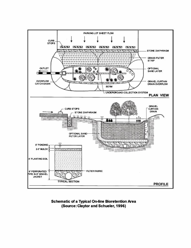
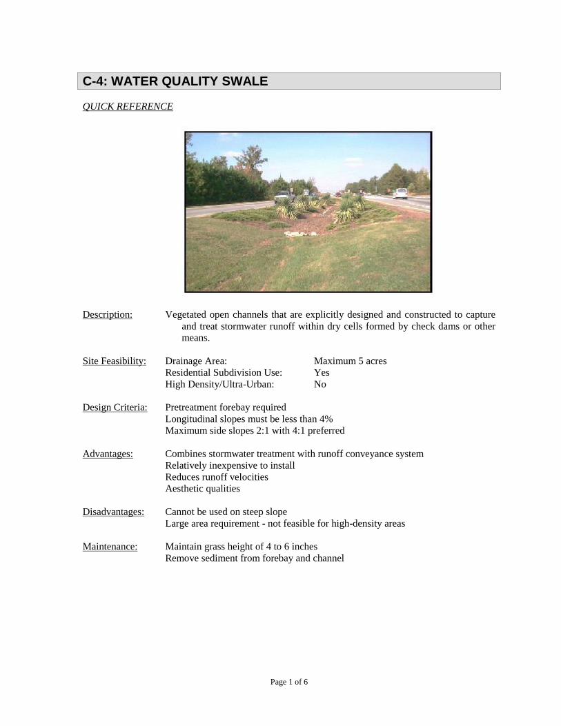
Page 1 of 6
C-4: WATER QUALITY SWALE
QUICK REFERENCE
Description: Vegetated open channels that are explicitly designed and constructed to capture
and treat stormwater runoff within dry cells formed by check dams or other
means.
Site Feasibility: Drainage Area: Maximum 5 acres
Residential Subdivision Use: Yes
High Density/Ultra-Urban: No
Design Criteria: Pretreatment forebay required
Longitudinal slopes must be less than 4%
Maximum side slopes 2:1 with 4:1 preferred
Advantages: Combines stormwater treatment with runoff conveyance system
Relatively inexpensive to install
Reduces runoff velocities
Aesthetic qualities
Disadvantages: Cannot be used on steep slope
Large area requirement - not feasible for high-density areas
Maintenance: Maintain grass height of 4 to 6 inches
Remove sediment from forebay and channel
C-4: WATER QUALITY SWALE
Page 2 of 6
GENERAL
Description: Water quality swales are conveyance channels engineered to capture and treat the WQv
for a drainage area. They differ from normal drainage channels or swales through the
incorporation of specific features that remove stormwater pollutants by filtration
through an engineered media. Water quality swales are not the same as filter strips,
which are limited application structural controls and not considered acceptable for
meeting the TSS removal requirements independently. Water quality swales are
designed to include a forebay in addition to a filter bed of prepared soil that overlays
an underdrain system. The swales are sized to allow the entire WQv to be filtered and
discharged or infiltrated through the bottom of the swale. Limited longitudinal slopes,
in conjunction with berms and/or check dams installed perpendicular to the flow path,
force the flow to be slow and shallow allowing for particulates to settle and limiting
erosion. Runoff is collected by a perforated pipe and discharged to an appropriate
outlet.
A separation distance of 2 feet is required between the bottom of the water quality
swale and the elevation of the seasonally high water table.
C-4: WATER QUALITY SWALE
Page 3 of 6
DESIGN CRITERIA
The following criteria are minimum standards for the design of a water quality swale, which is
acceptable for stormwater quality treatment only and does not provide detention storage. Flow from
runoff in excess of the WQv must be diverted or the water quality swale adequately designed to safely
pass higher flows to prevent erosion of the swale.
1. The maximum drainage area tributary to a water quality swale is 5 acres.
2. Peak flows are limited to 10 cubic feet per second and runoff velocities are limited to 2.5 feet
per second.
3. The maximum ponding time in the water quality swale is 48 hours.
4. The swale shall have a maximum ponding time of 48 hours. Soil media shall have an infiltration
rate of at least 1 foot per day (fc > 0.5 inches per hour), with 1.5 feet per day maximum.
Infiltration of the WQv will only be allowed when proven by geotechnical evaluation that
underlying soils have an infiltration rate of 0.5 inches per hour (typically hydrologic group A
soils). Infiltration will not be allowed in wellhead protection areas.
5. Water quality swale geometry:
a. The surface area of the water quality swale should be approximately 10% to 20% of
the tributary impervious area.
b. The elevation difference (head) generally needed from inflow to outflow is 3 to 5 feet.
c. The longitudinal slope of the swale shall be a maximum of 4%, with 1% to 2%
preferred.
d. Side slopes of the swale shall be no greater than 3:1. Swales shall be parabolic or
trapezoidal in shape to maximize vegetative areas and to provide ease of maintenance.
e. The maximum design flow depth shall be 12 inches. The depth of the WQv at the
downstream end of the swale should not exceed 18 inches.
f. A minimum bottom channel width of 2 feet is required to ensure adequate filtration.
g. The bed of the swale shall have a minimum permeable soil layer 30 inches in depth.
h. The swale must have a minimum length of 100 feet.
6. Pretreatment:
a. For the collection of sediment and floatable debris, all water quality swales shall
include a BMP or sediment forebay that consists of a separate cell, formed by an
acceptable barrier. See C-1: Detention/Retention Facilities for design criteria for a
forebay/BMP.
b. Runoff can also enter along the sides of the channel as sheet flow through a grass filter
strip containing a pea gravel flow spreader trench (diaphragm) along the entrance to
the filter strip. Slopes to the diaphragm shall not exceed 6% for the last 20 feet prior to
entering the spreader.
7. The underdrain collection system shall consist of a 4 to 6-inch perforated PVC pipe (Schedule
40 or greater in strength) in an 8-inch gravel layer (clean washed aggregate 0.5 to 2 inches in
diameter). A permeable filter fabric is required between the gravel layer and the planting soil
bed. A clean out must be provided and the underdrain pipe must discharge to an appropriate
facility.
C-4: WATER QUALITY SWALE
Page 4 of 6
8. Compaction during construction must be minimized at both the base of the water quality swale
and for the backfill materials. Use of equipment causing excessive compaction will result in
reduced infiltration rates contributing to failure of the system and is not acceptable. Do not use
heavy equipment within the bioretention basin.
9. An overflow structure and nonerosive overflow channel must be provided to safely pass flows
from the water quality swale that exceeds the system storage capacity to a stabilized
downstream area or watercourse.
10. Proper grass species and plants should be specified for the water quality swale.
11. Water quality swales must be constructed within an easement either platted or legally described
and recorded as a perpetual stormwater drainage easement in accordance with Chapter 4,
Part 4.5.
12. The water quality swale shall not be constructed until all contributing drainage area has been
stabilized. The swale shall not be used as a sediment control measure during active
construction.
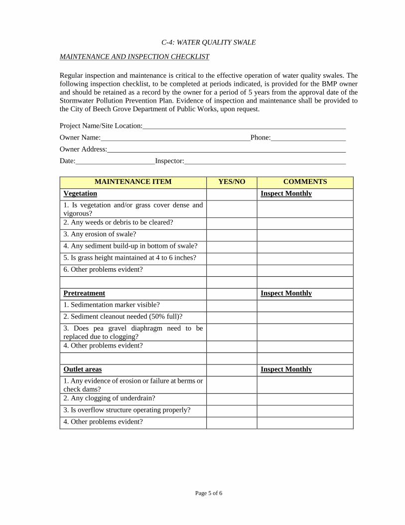
C-4: WATER QUALITY SWALE
Page 5 of 6
MAINTENANCE AND INSPECTION CHECKLIST
Regular inspection and maintenance is critical to the effective operation of water quality swales. The
following inspection checklist, to be completed at periods indicated, is provided for the BMP owner
and should be retained as a record by the owner for a period of 5 years from the approval date of the
Stormwater Pollution Prevention Plan. Evidence of inspection and maintenance shall be provided to
the City of Beech Grove Department of Public Works, upon request.
Project Name/Site Location:
Owner Name: Phone:
Owner Address:
Date: Inspector:
MAINTENANCE ITEM YES/NO COMMENTS
Vegetation Inspect Monthly
1. Is vegetation and/or grass cover dense and
vigorous?
2. Any weeds or debris to be cleared?
3. Any erosion of swale?
4. Any sediment build-up in bottom of swale?
5. Is grass height maintained at 4 to 6 inches?
6. Other problems evident?
Pretreatment Inspect Monthly
1. Sedimentation marker visible?
2. Sediment cleanout needed (50% full)?
3. Does pea gravel diaphragm need to be
replaced due to clogging?
4. Other problems evident?
Outlet areas Inspect Monthly
1. Any evidence of erosion or failure at berms or
check dams?
2. Any clogging of underdrain?
3. Is overflow structure operating properly?
4. Other problems evident?

C-4: WATER QUALITY SWALE
Page 6 of 6
Additional Comments:
Recommended Actions:
Recommended Timeframe for Actions:
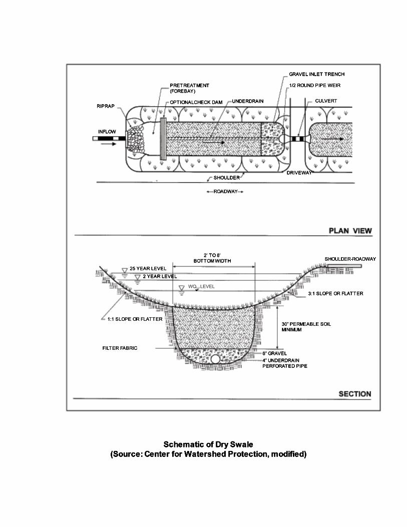
WQ LEVELV
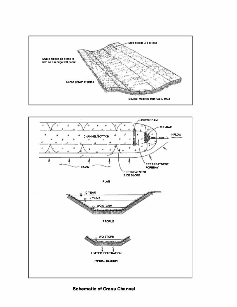
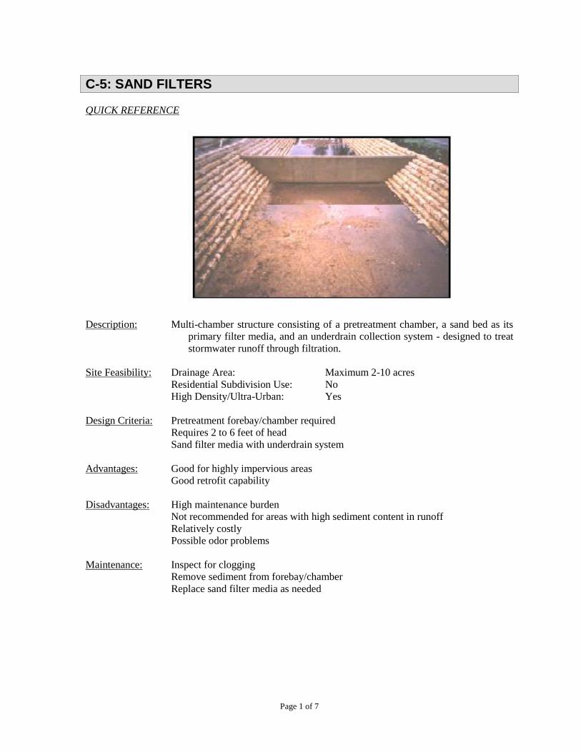
Page 1 of 7
C-5: SAND FILTERS
QUICK REFERENCE
Description: Multi-chamber structure consisting of a pretreatment chamber, a sand bed as its
primary filter media, and an underdrain collection system - designed to treat
stormwater runoff through filtration.
Site Feasibility: Drainage Area: Maximum 2-10 acres
Residential Subdivision Use: No
High Density/Ultra-Urban: Yes
Design Criteria: Pretreatment forebay/chamber required
Requires 2 to 6 feet of head
Sand filter media with underdrain system
Advantages: Good for highly impervious areas
Good retrofit capability
Disadvantages: High maintenance burden
Not recommended for areas with high sediment content in runoff
Relatively costly
Possible odor problems
Maintenance: Inspect for clogging
Remove sediment from forebay/chamber
Replace sand filter media as needed
C-5: SAND FILTERS
Page 2 of 7
GENERAL
Description: Sand filters are structural stormwater controls that capture and temporarily store
stormwater runoff and pass it through a filter bed of sand. Most sand filter systems
consist of two-chamber structures. The first chamber is a sediment forebay or chamber,
which removes floatables and heavy sediments. The second is the filtration chamber,
which removes additional pollutants by filtering the runoff through a sand bed. The
filtered runoff is collected and returned to the conveyance system by way of an
underdrain system.
Sand filters are typically designed as off-line systems. Stormwater pollutants are
removed through a combination of gravitational settling, filtration and adsorption.
Surface sand filters with a grass cover have additional opportunities for bacterial
decomposition as well as vegetation uptake of pollutants, particularly nutrients. Sand
filter systems are designed for intermittent flow and must be allowed to drain and
reaerate between rainfall events. They should not be used on sites with a continuous
flow from groundwater, sump pumps, or other sources.
Because they have few site constraints besides head requirements, sand filters can be
used on development sites where the use of other structural controls may be precluded.
However, sand filter systems can be relatively expensive to construct and install.
Variations:
Surface sand filter – a ground-level open-air structure that consists of a pretreatment
sediment forebay and a filter bed chamber. This system can treat drainage areas up to
10 acres in size and is typically located off-line. Surface sand filters can be designed
as an excavation with earthen embankments or as a concrete or block structure.
Perimeter sand filter – an enclosed filter system typically constructed just below grade
in a vault along the edge of an impervious area such as a parking lot. The system
consists of a sedimentation chamber and a sand bed filter. Runoff flows into the
structure through a series of inlet grates located along the top of the control.
Underground sand filter – located in an underground vault designed for high-density
land use or ultra-urban applications. Typically a three-chamber system consisting of a
sedimentation chamber, a filter chamber, and an overflow chamber. Underground sand
filters have a high maintenance burden and should only be used where adequate
inspection and maintenance can be ensured. Underground sand filters are typically
constructed on-line, but can be constructed off-line. For off-line construction, the
overflow between the second and third chambers is not included.
C-5: SAND FILTERS
Page 3 of 7
DESIGN CRITERIA
The following criteria are minimum standards for the design of a sand filter system, which is acceptable
for stormwater quality treatment only and does not provide detention storage. The WQv is generally
routed to the sand filter using a diversion structure. Runoff in excess of the WQv must be diverted or
the sand filter adequately designed to safely pass higher flows to prevent erosion of pretreatment
sediment and filter media.
Surface Sand Filter Criteria
1. Description - A surface sand filter facility consists of a two-chamber open-air structure, which
is located at ground level. The first chamber is the sediment forebay and the second chamber
contains the sand filter bed. Flow enters the forebay for settling of larger sediment particles.
Runoff is then discharged from the forebay through a perforated standpipe into the filtration
chamber. After passing through the filter bed, runoff is collected by a perforated pipe and gravel
underdrain system. In the following pages, a schematic of a surface sand filter is provided.
2. The maximum drainage area tributary to a surface sand filter is 10 acres.
3. Surface sand filter geometry:
a. The elevation difference (head) needed from inflow to outflow is 5 feet.
b. The slope across the filter location shall be a maximum of 6%.
c. The area of the filter bed is sized using Darcy’s Law equation with a filter bed drain
time of 36 hours and a coefficient of permeability (k) of 3.5 feet per day.
Af = WQv (df)
K (hf+df) (tf)
where:
Af = surface area of filter bed (square feet, ft2)
WQv= water quality volume (cubic feet, ft3)
df = filter bed depth (1.5 feet minimum)
k = coefficient of permeability of filter media (feet per day, ft/day, use 3.5
ft/day for sand)
hf = average height of water above filter bed (feet, ft)
tf = design filter bed drain time (days, 1.5 days maximum)
4. Pretreatment:
a. For the collection of sediment and floatable debris, all surface sand filter system shall
include a BMP or sediment forebay that consists of a separate cell, formed by an
acceptable barrier. The forebay/BMP shall be sized to contain 25% of the WQv.
b. The forebay shall have a minimum length-to-width ratio of 2:1.
c. Inlet and outlet structures shall be located at opposite ends of the forebay.
d. Entrance and exit velocities to the forebay/BMP shall be non-erosive. A flow
distribution chamber shall be provided at the entrance to the filter media to spread the
flow evenly across the surface of the filter media. Erosion protection shall be provided
over the filter media using riprap, grass or other dissipation devices.
C-5: SAND FILTERS
Page 4 of 7
5. Filter media shall be a minimum 18-inch layer of clean washed medium sand (ASTM C-33
concrete sand) on top of an underdrain system. Three inches of topsoil (or other erosion
protection) are placed over the sand bed. Permeable filter fabric is required above and below
the sand bed to prevent clogging of the sand filter and underdrain system.
6. The underdrain collection system shall consist of a 4 to 6-inch perforated PVC pipe (Schedule
40 or greater in strength) in an 8-inch gravel layer (clean washed aggregate 0.5 to 2 inches in
diameter). The underdrain shall have a minimum slope of 1%. A clean out must be provided
and the underdrain pipe must discharge to an appropriate facility.
7. The surface sand filter structure may be constructed of concrete or earthen embankments. When
constructed with earthen walls/embankments, filter fabric shall be used to line the bottom and
side slopes of the structures before installation of the underdrain system and filter media.
8. An emergency spillway must be included to safely pass flows that exceed the design storm
flows.
Perimeter Sand Filter Criteria
1. Description - A perimeter sand filter facility is a vault structure located just below grade level.
Runoff enters a sedimentation chamber through inlet grates along the top of the structure.
Runoff is discharged from the sedimentation chamber through a weir into the filtration
chamber. After passing through the filter, runoff is collected by a perforated pipe and gravel
underdrain system. Refer to the schematics on the following pages for a perimeter sand filter.
2. The maximum drainage area tributary to a perimeter sand filter is 2 acres.
3. Perimeter sand filter geometry:
a. The elevation difference (head) needed from inflow to outflow is 2 to 3 feet.
b. The area of the filter bed is sized using Darcy’s Law equation with a filter bed drain
time of 36 hours and a coefficient of permeability (k) of 3.5 feet per day (See 3.c. above
- surface sand filter criteria).
4. Pretreatment:
a. The perimeter sand filter system shall include a sediment chamber that consists of a
separate cell. The sediment chamber shall be sized to contain 50% of the WQv.
5. Filter media shall be a minimum 18-inch layer of clean washed medium sand (ASTM C-33
concrete sand) on top of an underdrain system. Permeable filter fabric is required between the
sand bed and the underdrain gravel layer to prevent clogging.
6. The underdrain collection system shall consist of a 4 to 6-inch perforated PVC pipe (Schedule
40 or greater in strength) in an 8-inch gravel layer (clean washed aggregate 0.5 to 2 inches in
diameter). The underdrain shall have a minimum slope of 1%. A clean out must be provided
and the underdrain pipe must discharge to an appropriate facility.
C-5: SAND FILTERS
Page 5 of 7
Underground Sand Filter Criteria
1. Description – An underground sand filter is located in an underground vault. The filter is a
three-chamber system. The first chamber is a sedimentation chamber that temporarily stores
runoff and utilizes a wet pool to capture sediment. The sedimentation chamber is connected to
the sand filter chamber by a submerged wall that protects the filter bed from oil and trash. The
filter bed is 18 to 24 inches deep and may have a protective screen of gravel or permeable
geotextile to limit clogging. The sand filter chamber also includes an underdrain system with
inspection and clean out wells. Perforated pipes under the sand filter bed extend into a third
chamber that collects filtered runoff. Flows beyond the filter capacity are diverted through an
overflow weir.
2. The maximum drainage area tributary to a perimeter sand filter is 2 acres.
3. Underground sand filters are typically constructed on-line, but can be constructed off-line. For
off-line construction, the overflow between the second and third chambers is not included.
4. The underground vault shall be tested for water tightness prior to placement of filter layers.
5. Adequate maintenance access must be provided to the sedimentation and filter bed chambers.
General
1. Sand filter facilities must be constructed within an easement either platted or legally described
and recorded as a perpetual stormwater drainage easement in accordance with Chapter 4,
Part 4.5.
2. The sand filter facility shall not be constructed until all contributing drainage area has been
stabilized. The sand filter facility shall not be used as a sediment control measure during active
construction.

C-5: SAND FILTERS
Page 6 of 7
MAINTENANCE AND INSPECTION CHECKLIST
Regular inspection and maintenance is critical to the effective operation of sand filter facilities. The
following inspection checklist, to be completed at periods indicated, is provided for the BMP owner
and should be retained as a record by the owner for a period of years from the approval date of the
Stormwater Pollution Prevention Plan. Evidence of inspection and maintenance shall be provided to
the City of Beech Grove Department of Public Works, upon request.
Project Name/Site Location:
Owner Name: Phone:
Owner Address:
Date: Inspector:
MAINTENANCE ITEM YES/NO COMMENTS
Pretreatment Inspect Monthly
1. Any evidence of erosion?
2. Are grass clippings removed from
contributing areas that are mowed?
3. Are inlets, outlets, and filter area clear of
debris?
4. Is normal pool level being retained (perimeter
and underground facilities)? Any leaks evident?
5. Other problems evident?
Filter Bed Inspect Monthly
1. Is filter bed free of sediments? Is sediment
cleanout needed (50% full or 6 inches,
whichever is less)?
2. Is filter bed free of oil and grease?
3. If clogging of filter bed is present, remove the
top few inches of sand and replace.
4. Any clogging of underdrain?
5. Any clogging of filter fabric?
6. Other problems evident?
Structural Inspect Annually
1. Any evidence of deterioration, spalling or
cracking of concrete vault, spillway, etc.?
2. Are inlet grates in good condition?
3. Is overflow structure operating properly?
4. Other problems evident?
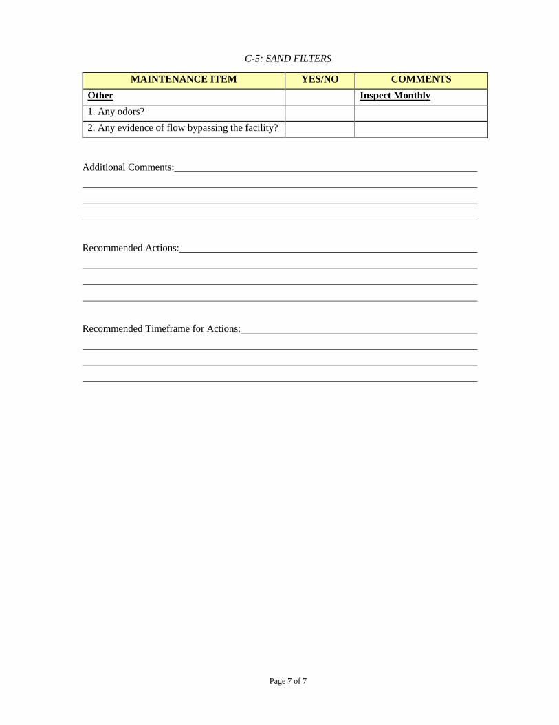
C-5: SAND FILTERS
Page 7 of 7
MAINTENANCE ITEM YES/NO COMMENTS
Other Inspect Monthly
1. Any odors?
2. Any evidence of flow bypassing the facility?
Additional Comments:
Recommended Actions:
Recommended Timeframe for Actions:
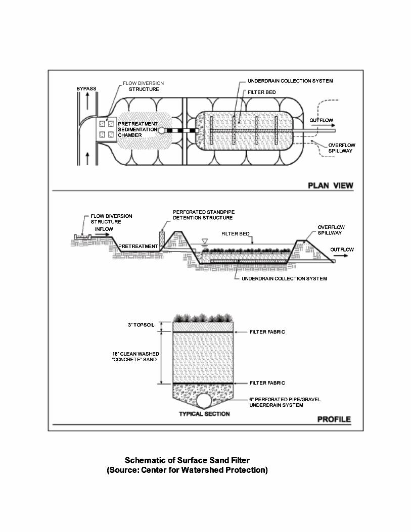
FLOW DIVERSION
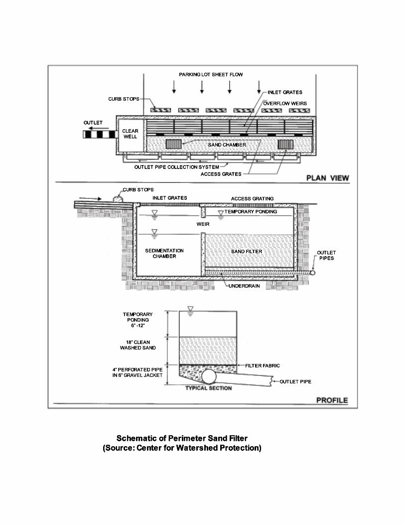
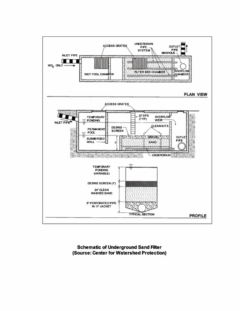
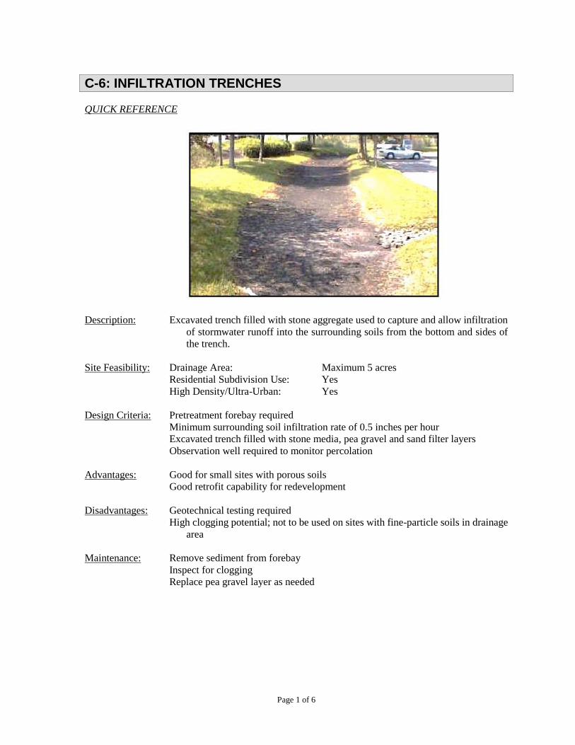
Page 1 of 6
C-6: INFILTRATION TRENCHES
QUICK REFERENCE
Description: Excavated trench filled with stone aggregate used to capture and allow infiltration
of stormwater runoff into the surrounding soils from the bottom and sides of
the trench.
Site Feasibility: Drainage Area: Maximum 5 acres
Residential Subdivision Use: Yes
High Density/Ultra-Urban: Yes
Design Criteria: Pretreatment forebay required
Minimum surrounding soil infiltration rate of 0.5 inches per hour
Excavated trench filled with stone media, pea gravel and sand filter layers
Observation well required to monitor percolation
Advantages: Good for small sites with porous soils
Good retrofit capability for redevelopment
Disadvantages: Geotechnical testing required
High clogging potential; not to be used on sites with fine-particle soils in drainage
area
Maintenance: Remove sediment from forebay
Inspect for clogging
Replace pea gravel layer as needed

C-6: INFILTRATION TRENCHES
Page 2 of 6
GENERAL
Description: Infiltration trenches are excavations filled with stone to create an underground
reservoir of stormwater runoff. The runoff volume gradually exfiltrates through the
bottom and sides of the trench into the subsoil over a 2-day period and eventually
reaches the water table. By diverting runoff into the soil, an infiltration trench treats
the water quality volume and helps to preserve the natural water balance on a site and
can recharge groundwater and preserve base flow. Due to this fact, infiltration systems
are limited to areas with highly porous soils where the water table and/or bedrock are
located well below the bottom of the trench. Infiltration trenches must be carefully
sited to avoid the potential of groundwater contamination.
Infiltration trenches are not intended to trap sediment and must always be designed
with a sediment forebay and grass channel or filter strip, or other appropriate
pretreatment measures to prevent clogging and failure. The facility is only for
impervious areas where there are not high levels of fine particulates (clay/silt soils) in
the runoff and will only be considered for sites where the sediment load is relatively
low.
A separation distance of 4 feet is required between the bottom of the infiltration trench
and the elevation of the seasonally high water table.
Infiltration trenches are designed for intermittent flow and need to drain and reaerate
between rainfall events. The systems should not be used on sites with a continuous
flow from groundwater, sump pumps, or other sources.
Infiltration trenches shall not be used for manufacturing and industrial sites, where
there is a potential for high concentrations of soluble pollutants and heavy metals. In
addition, infiltration shall not be considered for areas with a high pesticide
concentration.
C-6: INFILTRATION TRENCHES
Page 3 of 6
DESIGN CRITERIA
The following criteria are minimum standards for the design of an infiltration trench, which is designed
for stormwater quality treatment only. Flow from runoff in excess of the WQv must be diverted. The
WQv in the infiltration trench can be subtracted from detention storage requirements for the contributing
area.
1. The maximum drainage area tributary to an infiltration trench is 5 acres.
2. Underlying soils shall have a minimum infiltration rate (fc) of 0.5 inches per hour as determined
from geotechnical tests. The minimum geotechnical testing is one test hole per 5,000 square
feet, with a minimum of two borings per facility taken within the limits of the facility.
Infiltration trenches cannot be used in fill soils.
3. Soils on the drainage area tributary to an infiltration trench shall have a clay content of less
than 20% and a silt/clay content of less than 40% to prevent clogging and failure.
4. Clay lenses, bedrock and other restrictive layers below the bottom of the trench will reduce
infiltration rates unless excavated.
5. To reduce the potential for costly maintenance and/or system reconstruction, the trench should
be located in a lawn or open area. Infiltration trenches shall not be located beneath paved
surfaces.
6. Minimum setback requirements for infiltration trench facilities (unless otherwise specified by
local ordinance or criteria):
a. From a property line – 10 feet
b. From a building foundation – 25 feet
c. From a private well – 100 feet
d. From a public water supply well – 1,200 feet
e. From a septic system tank/leach field – 100 feet
f. From surface waters – 100 feet
g. From surface drinking water sources – 400 feet (100 feet for a tributary)
7. Infiltration trench geometry:
a. The required trench storage volume is equal to the WQv.
b. The trench must be designed to fully dewater the WQv within 24 to 48 hours. The
slowest infiltration rate obtained from geotechnical tests performed at the site should
be used in the design calculations.
c. Trench depths should be 3 to 8 feet. The width of the trench must be less than 25 feet.
d. Broader, shallow trenches reduce the risk of clogging by spreading the flow over a
larger area for infiltration.
e. The surface area is calculated based on the trench depth, soil infiltration rate, aggregate
void space, and fill time (assume a fill time of 2 hours for most designs).
f. The bottom of a trench shall be flat across its length and width to evenly distribute
flow, encourage uniform infiltration through the bottom, and reduce the risk of
clogging.
g. Stone aggregate should be washed, bank-run gravel, 1.5 to 2.5 inches in diameter with
a void space of about 40%. Aggregate contaminated with soil shall not be used. A
C-6: INFILTRATION TRENCHES
Page 4 of 6
porosity value (void space/total volume) of 0.32 should be used in calculations, unless
aggregate specific data exist.
h. A 6-inch layer of clean, washed sand is placed on the bottom of the trench to encourage
drainage and prevent compaction of the native soil while the stone aggregate is added.
i. The trench shall be lined on the sides and top by an appropriate geotextile filter fabric
that prevents soil piping but has greater permeability than the parent soil. The top layer
of filter fabric is placed 2 to 6 inches from the top of the trench to prevent sediment
from passing into the stone aggregate. This top layer will need to be replaced more
frequently and must be readily separated from the side section.
j. The top surface of the trench above the filter fabric is covered with pea gravel to
improve sediment filtering. It shall be removed and replaced should the device clog.
Alternatively, the trench can be covered with permeable topsoil and planted with grass
in a landscaped area.
k. An observation well consisting of 4 to 6-inch perforated PVC pipe must be installed
and extend to the bottom of the trench. The well should be installed along the centerline
of the structure, flush with the ground elevation of the trench. A visible floating marker
shall be provided to indicate the water level.
l. The trench excavation shall be limited to the width and depth specified in the design.
The bottom of the excavated trench shall not be loaded in a way that causes soil
compaction and shall be scarified prior to placement of sand. The sides of the trench
shall be trimmed of all large roots.
8. Pretreatment:
a. For an infiltration trench receiving sheet flow from an adjacent drainage area, the
pretreatment system may consist of a vegetated filter strip with a minimum 25-foot
length. A vegetated buffer strip around the entire trench is required if the facility is
receiving runoff from other directions. See the attached schematic for design criteria
for the vegetated filter strip.
b. For off-line applications, pretreatment shall consist of a sediment forebay or similar
sedimentation chamber (with energy dissipaters) sized to 25% of the WQv. Exit
velocities from the pretreatment chamber must be nonerosive.
9. Overflow structure - a nonerosive overflow channel must be provided to safely pass flows from
the infiltration trench that exceeds the system storage capacity to a stabilized downstream area
or watercourse.
10. Infiltration trenches must be constructed within an easement either platted or legally described
and recorded as a perpetual stormwater drainage easement in accordance with Chapter 4,
Part 4.5.
11. The infiltration trench shall not be constructed until all contributing drainage area has been
stabilized. The infiltration trench shall not be used as a sediment control measure during active
construction.
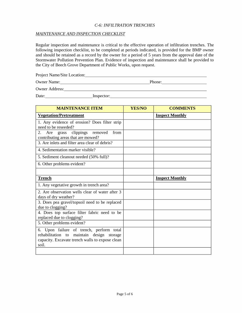
C-6: INFILTRATION TRENCHES
Page 5 of 6
MAINTENANCE AND INSPECTION CHECKLIST
Regular inspection and maintenance is critical to the effective operation of infiltration trenches. The
following inspection checklist, to be completed at periods indicated, is provided for the BMP owner
and should be retained as a record by the owner for a period of 5 years from the approval date of the
Stormwater Pollution Prevention Plan. Evidence of inspection and maintenance shall be provided to
the City of Beech Grove Department of Public Works, upon request.
Project Name/Site Location:
Owner Name: Phone:
Owner Address:
Date: Inspector:
MAINTENANCE ITEM YES/NO COMMENTS
Vegetation/Pretreatment Inspect Monthly
1. Any evidence of erosion? Does filter strip
need to be reseeded?
2. Are grass clippings removed from
contributing areas that are mowed?
3. Are inlets and filter area clear of debris?
4. Sedimentation marker visible?
5. Sediment cleanout needed (50% full)?
6. Other problems evident?
Trench Inspect Monthly
1. Any vegetative growth in trench area?
2. Are observation wells clear of water after 3
days of dry weather?
3. Does pea gravel/topsoil need to be replaced
due to clogging?
4. Does top surface filter fabric need to be
replaced due to clogging?
5. Other problems evident?
6. Upon failure of trench, perform total
rehabilitation to maintain design storage
capacity. Excavate trench walls to expose clean
soil.

C-6: INFILTRATION TRENCHES
Page 6 of 6
Additional Comments:
Recommended Actions:
Recommended Timeframe for Actions:
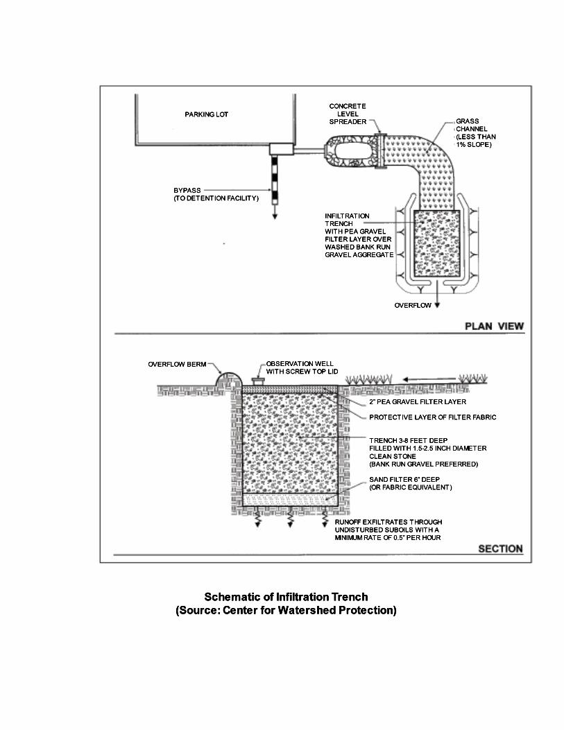

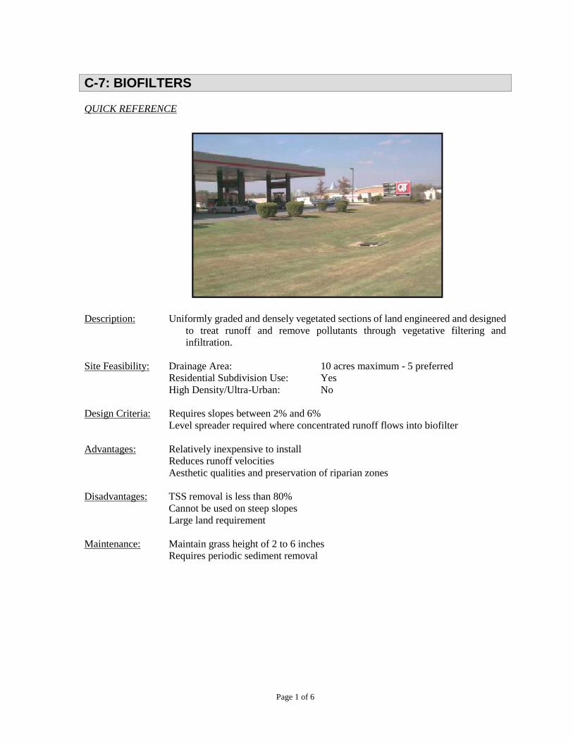
Page 1 of 6
C-7: BIOFILTERS
QUICK REFERENCE
Description: Uniformly graded and densely vegetated sections of land engineered and designed
to treat runoff and remove pollutants through vegetative filtering and
infiltration.
Site Feasibility: Drainage Area: 10 acres maximum - 5 preferred
Residential Subdivision Use: Yes
High Density/Ultra-Urban: No
Design Criteria: Requires slopes between 2% and 6%
Level spreader required where concentrated runoff flows into biofilter
Advantages: Relatively inexpensive to install
Reduces runoff velocities
Aesthetic qualities and preservation of riparian zones
Disadvantages: TSS removal is less than 80%
Cannot be used on steep slopes
Large land requirement
Maintenance: Maintain grass height of 2 to 6 inches
Requires periodic sediment removal

C-7: BIOFILTERS
Page 2 of 6
GENERAL
Description: Biofilters are densely vegetated sections of land designed to treat runoff and remove
pollutants through vegetative filtering and infiltration. Biofilters must receive runoff
from adjacent areas as sheet flow to provide treatment and prevent erosion. The
vegetation slows the runoff and filters out sediment and other pollutants. Biofilters
provide less than 80% TSS removal but can be used as pretreatment measures in
conjunction with other water quality treatment practices.
Biofilters are best suited to treat runoff from roads and highways, rooftops, small
parking lots, and pervious surfaces. Biofilters can be incorporated into residential
developments as land-use buffers and setbacks.
Variations:
Filter strip – a uniformly graded and densely vegetated strip of land. The vegetation
can be grasses or a combination of grass and woody plants.
Riparian buffer – a strip of land with natural, woody vegetation along a stream or other
watercourse. The riparian zone includes deep-rooted trees with undergrowth of grasses
and herbaceous vegetation.
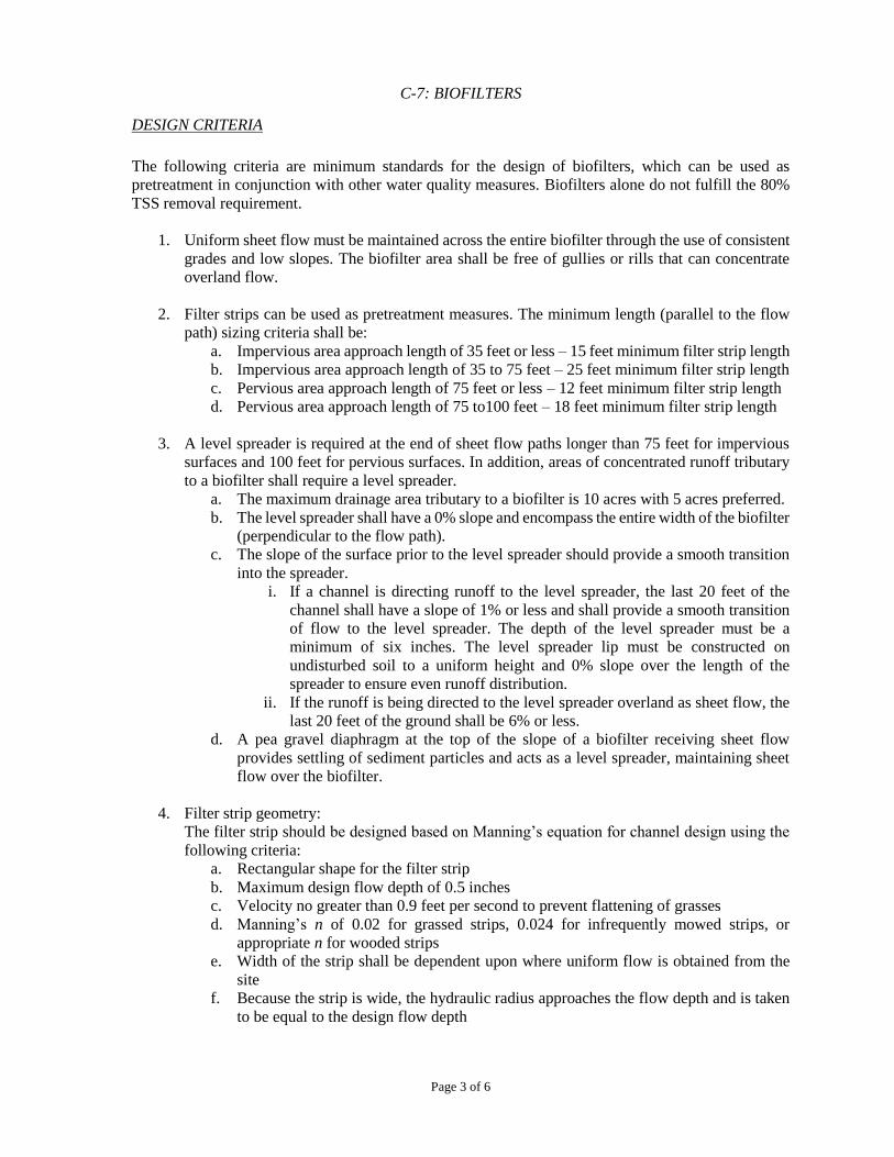
C-7: BIOFILTERS
Page 3 of 6
DESIGN CRITERIA
The following criteria are minimum standards for the design of biofilters, which can be used as
pretreatment in conjunction with other water quality measures. Biofilters alone do not fulfill the 80%
TSS removal requirement.
1. Uniform sheet flow must be maintained across the entire biofilter through the use of consistent
grades and low slopes. The biofilter area shall be free of gullies or rills that can concentrate
overland flow.
2. Filter strips can be used as pretreatment measures. The minimum length (parallel to the flow
path) sizing criteria shall be:
a. Impervious area approach length of 35 feet or less – 15 feet minimum filter strip length
b. Impervious area approach length of 35 to 75 feet – 25 feet minimum filter strip length
c. Pervious area approach length of 75 feet or less – 12 feet minimum filter strip length
d. Pervious area approach length of 75 to100 feet – 18 feet minimum filter strip length
3. A level spreader is required at the end of sheet flow paths longer than 75 feet for impervious
surfaces and 100 feet for pervious surfaces. In addition, areas of concentrated runoff tributary
to a biofilter shall require a level spreader.
a. The maximum drainage area tributary to a biofilter is 10 acres with 5 acres preferred.
b. The level spreader shall have a 0% slope and encompass the entire width of the biofilter
(perpendicular to the flow path).
c. The slope of the surface prior to the level spreader should provide a smooth transition
into the spreader.
i. If a channel is directing runoff to the level spreader, the last 20 feet of the
channel shall have a slope of 1% or less and shall provide a smooth transition
of flow to the level spreader. The depth of the level spreader must be a
minimum of six inches. The level spreader lip must be constructed on
undisturbed soil to a uniform height and 0% slope over the length of the
spreader to ensure even runoff distribution.
ii. If the runoff is being directed to the level spreader overland as sheet flow, the
last 20 feet of the ground shall be 6% or less.
d. A pea gravel diaphragm at the top of the slope of a biofilter receiving sheet flow
provides settling of sediment particles and acts as a level spreader, maintaining sheet
flow over the biofilter.
4. Filter strip geometry:
The filter strip should be designed based on Manning’s equation for channel design using the
following criteria:
a. Rectangular shape for the filter strip
b. Maximum design flow depth of 0.5 inches
c. Velocity no greater than 0.9 feet per second to prevent flattening of grasses
d. Manning’s n of 0.02 for grassed strips, 0.024 for infrequently mowed strips, or
appropriate n for wooded strips
e. Width of the strip shall be dependent upon where uniform flow is obtained from the
site
f. Because the strip is wide, the hydraulic radius approaches the flow depth and is taken
to be equal to the design flow depth

C-7: BIOFILTERS
Page 4 of 6
g. Slope is between 2% and 6%
h. Dense grasses must be specified
5. Riparian zone geometry:
At a minimum, a riparian zone should consist of a 20-foot strip of trees and herbaceous
vegetation closest to the stream or watercourse and a 30-foot strip of dense grasses prior to the
tree zone.
6. Biofilters must be constructed within an easement either platted or legally described and
recorded as a perpetual stormwater drainage easement in accordance with Chapter 4, Part 4.5.
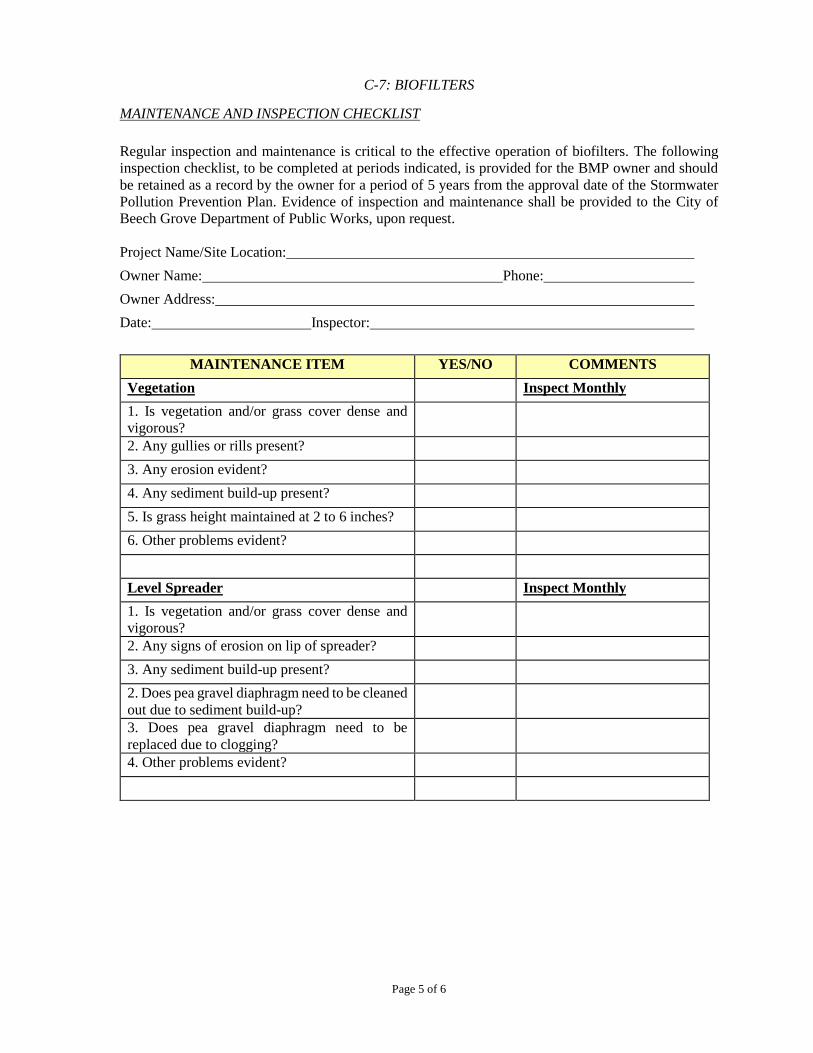
C-7: BIOFILTERS
Page 5 of 6
MAINTENANCE AND INSPECTION CHECKLIST
Regular inspection and maintenance is critical to the effective operation of biofilters. The following
inspection checklist, to be completed at periods indicated, is provided for the BMP owner and should
be retained as a record by the owner for a period of 5 years from the approval date of the Stormwater
Pollution Prevention Plan. Evidence of inspection and maintenance shall be provided to the City of
Beech Grove Department of Public Works, upon request.
Project Name/Site Location:
Owner Name: Phone:
Owner Address:
Date: Inspector:
MAINTENANCE ITEM YES/NO COMMENTS
Vegetation Inspect Monthly
1. Is vegetation and/or grass cover dense and
vigorous?
2. Any gullies or rills present?
3. Any erosion evident?
4. Any sediment build-up present?
5. Is grass height maintained at 2 to 6 inches?
6. Other problems evident?
Level Spreader Inspect Monthly
1. Is vegetation and/or grass cover dense and
vigorous?
2. Any signs of erosion on lip of spreader?
3. Any sediment build-up present?
2. Does pea gravel diaphragm need to be cleaned
out due to sediment build-up?
3. Does pea gravel diaphragm need to be
replaced due to clogging?
4. Other problems evident?

C-7: BIOFILTERS
Page 6 of 6
Additional Comments:
Recommended Actions:
Recommended Timeframe for Actions: