Embed Size (px)
Citation preview

City of Alexandria, Virginia
MEMORANDUM
DATE: JUNE 9,20 10
TO: THE HONORABLE MAYOR AND MEMBERS OF CITY COUNCIL
FROM: JAMES K. HARTMANlV, CITY MANAGER
SUBJECT: CITYIMIRANT SETTLEMENT - RECEIPT AND CONSIDERATION OF DRAFT PHASE I1 PROJECT REPORT (STACK PM2.5 '
EMISSION CONTROLS) AND MIRANT CONIMUNITY MONITORING GROUP (MCMG) RECOMMENDATIONS
ISSUE: City Council's receipt and consideration of the draft Phase I1 project report under the 2008 CityIMirant Agreement; and Council's consideration of the MCMG7s recommendations made at the MCMG meeting of May 13,201 0.
RECOMMENDATION: That City Council:
Receive the draft Phase I1 project report (Attachment I) prepared by the Engineer Worley Parsons and endorse MCMG7s recommendations made at the MCMG meeting on May 13,2010, as follows:
o Support the conclusion by the Engineer Worley Parsons that the baghouse is the preferred technology for stack fine particulate (PMz,5) emissions control, and that the CityIMirant proceed pursuant to the settlement agreement with steps to install it on as many boilers as possible within the Phase I1 project budget.
o Should the final report on the Phase I1 Project be significantly different than the current draft report under consideration by the MCMG and City Council (e.g., different control technology recommendations for boilers # 3,4, and 5), direct that staff hold another meeting with MCMG to consider a new course of action.
o Based on the Engineer's budgetary cost estimate for the Phase I1 project of $32 million and the revised and more accurate installed cost for the wind screens of $1.02 million, which is higher than previously estimated, that the installation of the wind screens and the drip pans (two Phase I projects previously approved by City Council) be deferred until the cost for the phase I1 project have been determined accurately.

DISCUSSION:
Draft Phase I1 Report bv the Engineer WorlevParsons
Worley Parson (Project Engineer) prepared the submitted draft Phase I1 project and presented the results of this report to the MCMG on May 13, 201 0. The City, Mirant and Virginia DEQ officially now have 45 days (starting April 30,2010) to comment on this draft before the Engineer finalizes it within the following 60 days.
The report recommends installation of polishing baghouses on boilers # 3,4, and 5. This will be achieved by retrofitting existing cold side electrostatic precipitators with new baghouses. The report also recommends upgrades to the existing hot electrostatic precipitators for boilers # 1 and 2. The Engineer's estimate for the Phase I1 project is $27.01 million plus $4.074 million in contingencies for a total of $31.06 million. Due to the uncertainties normally associated with retrofitting projects, and since the budget cap for the Phase I1 project is $32 million, it is not certain at the present time if the baghouse conversion could be done on two or three boilers until the firm bids are received, and contracts signed with appropriate terms and conditions.
As you may recall, the City had previously argued in front of the State Air Pollution Control Board for the use of baghouses for PM2.5 emissions control at this facility. Since this project involves retrofitting an existing facility, there were significant technical challenges that needed to be overcome to insure that baghouse option was feasible. Additional time was needed to address numerous technical challenges of retrofitting a baghouse into the existing shell of the cold precipitator without compromising the plant's structural integrity and safety as well as not exceeding the budget cap of $32 million.
Progress on the Phase I Proiects
As you may recall, Council authorized moving forward with the five projects targeting fugitive dust under Phase I in November 2009 which included a dust suppression system, a street '
sweeper, an ash loader, drip pans, and wind screens. The dust suppression system and street sweeper have been ordered and delivery is expected this summer. The new ash loader has been installed and currently being operated (with a temporary power supply).
With respect to the remaining two Phase I projects, the installation of the drip pans was put on hold because of requirement of a permit modification by VDEQ. With respect to the wind screens project, the projected cost has increased significantly by $405,000 from the initial estimates and is now at $1.02 million. This is primarily due to poor soil conditions at this site, resulting in a more extensive (and expensive) foundation for the poles supporting the screens.
MCMG Meeting of Mav 13,2010
The meeting (Attachment 2) was co-chaired by Councilwoman Del Pepper and Councilman Paul Smedberg. The objectives of this meeting were to: (i) review the Engineer Worley Parsons's draft Phase I1 report regarding controls on fine particulate (PM2.5) from the stacks; (ii) review

progress of the Phase 1 projects that were previously approved by City Council; and (iii) update the group members and attendees on recent regulatory developments and the recent Miranti RRI Energy merger.
Staff also discussed the two recent Notice of Violations (NOVs) issued by Virginia Department of Environmental Quality to Mirant. Mirant representative discussed the recent merger between Mirant and RRI Energy and confirmed that the CityIMirant agreement remains unaffected by the merger.
MCMG members also requested that the City Attorney's Office review the Escrow Account in consultation with the Office of Management and Budget due to concern about reduced interest yields on the principal balance. Following this meeting, the City Attorney's Office has reviewed the Settlement Agreement in connection with this concern. The City Attorney's Office, in consultation with OMB, advises that the Settlement Agreement was designed primarily to protect the $34 million in principal, not generate particular yields from it. While the account chosen by Mirant in creating the Escrow Account has generated lower amounts of interest as market interest rates have dropped, the primary goal of preservation of principal continues to be met. Based on the information presented, there does not appear to be any issue of non-compliance with the Settlement Agreement associated with the reduced interest yields on the account.
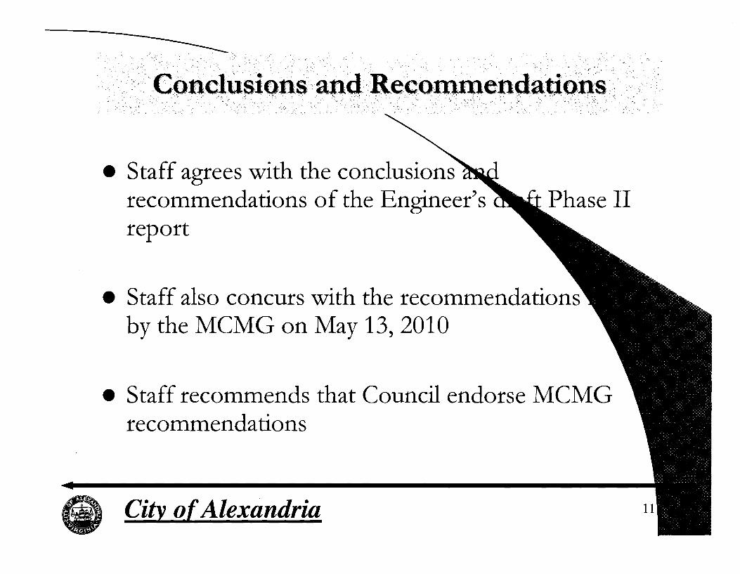
In conclusion, staff agrees with and supports the conclusions and recommendations made by the Engineer Worley Parsons in their draft Phase I1 study. Furthermore, staff concurs with the MCMG's recommendations expressed at its meeting on May 13, 201 0.
FISCAL IMPACTS: There is no fiscal impact involved since the costs of the projects will be paid for by the escrow account that was established as part of the MirantICity Settlement Agreement.
ATTACHMENTS: Attachment 1: WorleyParsons, Draft Phase I1 PM2.5 Emissions Reduction Study, April 23,
2010 Attachment 2: William J. Skrabak May 28,201 0, Memorandum to Honorable Mayor and
Members of City Council
STAFF: Rich J. Baier, P.E., LEED AP, Director, T&ES William J. Skrabak, Director, OEQ, T&ES Chris Spera, Deputy City Attorney Lalit Sharma, P.E., Division Chief, OEQ, T&ES Khoa Tran, Sr. Air Pollution Control Specialist, OEQ, T&ES

resources & energy
MIRANT POTOMAC RIVER, LLC - POTOMAC RIVER GENERATING STATION
PHASE II - PM2.5 EMISSIONS REDUCTION STUDY
MIRANT POTOMAC RIVER, LLC POTOMAC RIVER GENERATING STATION
PHASE ll PMZm5 EMISSIONS REDUCTION STUDY PRGS-O-LI-O~~-O~O~-RC.~OC
April 23, 2010
This document is a draft report for comments only.
It is not intended to be used for anv other purposes.
WorleyParsons 2675 Morgantown Road Reading, Pa. 19607 United States Telephone: 610 855-2000 Facsimile: 610 855 2001 www. worley parsons.com
O Copyright 2010 WorleyParsons

WorIeyParsons resources & energy
MIRANT POTOMAC RIVER, LLC - POTOMAC RIVER GENERATING STATION
This report has been prepared on behalf of and for the exclusive use of Mirant PRGS and the City of Alexandria, and is subject to and issued in accordance with the Agreement between Mirant PRGS and WorleyParsons. WodeyPatsons accepts no liability or responsibility whatsoever for it in respect of any use of or reliance upon this report by any third party.
Copying this report without the permission of Mirant PRGS or WorleyPatsons is not permitted.
PROJECT - PHASE II - PMzs EMISSIONS REDUCTION STUDY REV DESCRIPTION ORlG REVIEW WORLEY- DATE CLIENT DATE
PARSONS APPROVAL APPROVAL
A Issued for preliminary W.M. G.A. L.J. 1- NIA review W. Moms G. Andes L. Jones
B Preliminary Draft W.M. G.A. L.J. NIA
- - -. - PRGS-0-L1022M102 Page ii Rev C
4

WorIeyParronr resources & energy
MIRANT POTOMAC RIVER. LLC . POTOMAC RIVER GENERATING STATION PHASE II . PMz.5 EMISSIONS REDUCTION STUDY
CONTENTS .................................................................................................... 1 . EXECUTIVE SUMMARY 1
................................................................................................................ 2 . INTRODUC'TION 3
....................................................................................... 2.1 Defining PM2.5 Emissions 4
2.2 Existing Plant Configuration ................................................................................... 4
..................................................................................... 2.3 Existing Unit Configuration 4
3 . DISCUSSION ..................................................................................................................... 6
...................................... 3.1 PM2.5 EMISSION REDUCTION ENGINEERING STUDY 6
3.1.1 Kick-off Meeting ...................................................................................................... 6
3.1.2 Site Visits ................................................................................................................ 7
3.1.3 Vendor Technology Proposals ............................................................................... 7
3.1.4 PM2.5 Emission Reduction Options - Technology Screening Document ............... 7
3.1.5 Explanation of PM2.5 Emission Reduction Control Options .................................... 8
3.2 SUMMARY OF VENDOR TECHNOLOGY CONCEPTS ..................................... 12
3.2.1 Scope ................................................................................................................... 12
3.2.2 Vendor A ............................................................................................................... 12
3.2.3 Vendor B ............................................................................................................... 12
3.2.4 Vendors C, D, E, and F ........................................................................................ 14
3.2.5 Vendor C .............................................................................................................. 15
3.2.6 VendorG .............................................................................................................. 16
3.2.7 Vendor Predicted Performance ............................................................................ 17
3.3 BOP CONSIDERATIONS .................................................................................... 18
3.3.1 Current ID Fan Capacity Study ............................................................................ 18
3.3.2 Transient Analysis of Draft Equipment ................................................................. 18
3.3.3 Trona System Impact ........................................................................................... 20
3.3.4 Ash Handling Systems ......................................................................................... 21
4 . CONCLUSIONS ............................................................................................................... 23
Page iii
6 Rev C

resources 81 energy
MIRANT POTOMAC RIVER. LLC . POTOMAC RIVER GENERATING STATION PHASE II . PM2.5 EMISSIONS REDUCTION STUDY
TECHNOLOGY OPTIONS ................................................................................... 23
4.1 . 1 ESP Upgrade ........................................................................................................ 23
4.1.2 ESP Conversions to PJFF .................................................................................... 23
4.1.2.1 . CESP Conversions into PJFFs as Primary Collectors ......................................... 24
4.1.2.2. HESP conversions to PJFFs ................................................................................ 24
4.1.2.3.CESP Conversions to PJFF as Polishing Collectors ........................................... 24
PJFF FILTER BAG OPTIONS .............................................................................. 25
COST ESTIMATES .............................................................................................. 26
4.3.1 Total Installed Costs ............................................................................................. 26
4.3.2 Operating Costs .................................................................................................... 27
RECOMMENDATION ........................................................................................... 27
ATTACHMENTS ............................................................................................................... 28
PM2.5 EMISSIONS REDUCTION TECHNOLOGY SCREENING DOCUMENT .. 28
................................ PM2.5 EMISSIONS REDUCTION EPC COST ESTIMATES 32
REFERENCES ................................................................................................................. 37
PRGS-0-LI-022-0002 Page iv Rev C

WorIeyParsons resources & energy
MIRANT POTOMAC RIVER, LLC - POTOMAC RIVER GENERATING STATION
PHASE II - PM2.s EMISSIONS REDUCTION STUDY
AQC
CESP
CFD
DESP
DFGD
ESP
FGD
FPCS
grlacf
H2S04 HESP
HFPS
H g LblMMBtu
LPHV
MCC
M FT
NOx
PAC
PCF
PFD
PJFF
PM
PM2.5
PMl0 PPS
PRGS
RFP
so2 so3 T&M
TIR
TPH
v- l WESP
PERTINENT TECHNOLOGY ACRONYMS, INITIALISMS, AND ABBREVIATIONS
Air Quality Control
Cold-side ESP
Computational Fluid Dynamics (computer model)
Dry ESP
Dry FGD
Electrostatic Precipitator
Flue Gas Desulfurization or WFGD ("Wet FGD")
Fine Particulate Control System
Grains per actual cubic foot
Sulfuric Acid
Hot-side ESP
High Frequency Power Supplies (also known as "Switch Mode Power Supply or SMPS")
Mercury
Pounds per Million British Thermal Units
Low Pressure High Volume
Motor Control Center
Master Fuel Trip (boiler control scenario)
Nitrogen Oxides
Powdered Activated Carbon
Pounds per Cubic Foot
Process Flow Diagram
Pulse Jet Fabric Filter (also known as "Baghouse" and "Fabric Filter")
Particulate Matter
PM with an aerodynamic diameter that is less than or equal to 2.5 micrometers in size
PM with an aerodynamic diameter that is less than or equal to 10 micrometers in size
Polyphenylene Sulfide
Potomac River Generating Station
Request For Proposal
Sulfur Dioxide
Sulfur Trioxide
Time and Material
TransformerlRectifier
Tons Per Hour
Voltage-Current
Wet ESP
PRGS-0-LI-022-0002
""' S Rev C

resources & energy
MIRANT POTOMAC RIVER, LLC - POTOMAC RIVER GENERATING STATION PHASE II - PM2.5 EMISSIONS REDUCTION STUDY
EXECUTIVE SUMMARY
On July 17, 2008, Mirant Potomac River, LLC ("Mirant") and the City of Alexandria ("City'!) entered an Agreement to implement emissions reduction controls with respect to the fugitive dust (Phase I) and fine particulate matter (PM,.,) emissions (Phase II) at Mirant's Potomac River Generating Station (PRGS). On October 24, 2008, WorleyParsons received a purchase order from Mirant to provide engineering services in support of this Project. The work was officially kicked off with a joint meeting between Mirant, the City, and WorleyParsons on October 30 and 31, 2008.
This study addresses the PM2.5 Emission Reduction (Phase It) portion of this Agreement. A separate study addressed the fugitive dust emissions (Phase I) portion of the Agreement.
WorleyParsons' approach to evaluating the possible PM2., Emission Reduction technologies and arriving at a recommendation for this Phase II report was as follows:
Attend Kick-off Meeting with Mirant, the City, and the City Consultant to review scope documents;
Review the listing of potential PM2., Emission Reduction technologies given in the Agreement;
Brainstorming with Mirant, the City, and the City Consultant to list additional PM2,5 Emission Reduction technologies for consideration;
In-house review with other Air Quality Control (AQC) specialists to list additional PM,, Emission Reduction technologies for consideration;
Literature and Internet search for additional PM,., Emission Reduction technologies for consideration;
Preparation of a letter-style performance specification and solicitation of technology solutions from leading AQC vendors and contractors for the latest commercially available PM,., Emission Reduction technologies;
Observation and collection of information on PRGS's existing electrostatic precipitator (ESP) systems, including coal analysis and ash samples;
Review of available prior PM2.5 emission reports and recommendations;
Review of previous and on-going PM2., control projects at the site;
Preparation of a technology screening matrix listing all possible PM2.5 Emission Reduction technologies;
Research and conducting performance testing on PRGS's existing ID fans;
PRGS-0-I-I-022-0002 Page 1 Rev C

--
resources & energy
MIRANT POTOMAC RIVER, LLC - POTOMAC RIVER GENERATING STATION
PHASE II - PM2.~ EMISSIONS REDUCTION STUDY
Research, conducting performance testing of pressure drop of in-duct silencers, and recommending pressure drop saving alternatives;
Careful, methodical, and reasoned elimination of listed possible PM2,, Emission Reduction technologies (moved to the bottom of the matrix listing); and
Regular progress meetings and on-site meetings to review and screen selections with Mirant, the City, and the City Consultant.
Most of the PM2.5 Emission Reduction technologies reviewed involved modifications to the existing cold-side ESPs (CESPs) and/or hot-side ESPs (HESPs). Such modifications were either to upgrade the existing ESP(s) or convert the ESP(s) to pulse jet fabric filters (PJFFs). Although industry experience is that PJFFs are more capable of removing particulate, particularly PMlo and PM2.5, than ESPs, it was found that a mix was required due to physical space constraints and financial limitations. Mirant has both base-loaded and cycling units at PRGS; therefore, to maximize the PM2.5 Emissions Reduction, application'of the PJFF technology was considered for the base-loaded units first.
PRGS's current ID fans were found to be capable of handling the future PJFF pressure drop with some modifications to the existing flue gas path. A transient analysis has been conducted and has verified that the existing control system can provide protection for typical furnace upset conditions such as MFTs due to operator initiation or positive furnace pressure excursions.
Recommendation: As a result of the above program, WorleyParsons recommends that the CESPs on base-loaded Units 3, 4, and 5 be converted to PJFF polishing baghouses and that T/R controller upgrades be added to the HESPs for Units 1 and 2, the cycling units. The installation of PJFF baghouses will provide improved particulate removal in a more consistent fashion than the current Air Quality Control (AQC) equipment is capable of providing.
Projected costs are estimated (&30%) to be $31.1 million (April 2010 dollars) for the recommended technology. With the engineering required for preparing and following up on this report, the total projected costs are estimated (&30%) to be $32 million. At this level of cost, it is further recommended that the CESP conversion be bid for two (2) of the three base loaded units with an option to include the third unit.
These modifications should provide the maximum PM2.5 Emissions Reductions possible within the financial limits. Filterable PM2.5 emissions of less than 0.010 IbIMMBtu may be achievable with the conversion of the CESPs on Units 3, 4, and 5 to P.IFF baghouses.
PRGS-0-LI-022-0002 Page 2 /O Rev C

resources & energy
MIRANT POTOMAC RIVER, LLC - POTOMAC RIVER GENERATING STATION PHASE II - PM2.5 EMISSIONS REDUCTION STUDY
The purpose of this engineering study is to compile, screen, and recommend the PM2., Emissions Reduction technology(s) that would provide the greatest benefit in reducing the PM2.5 emissions at Mirant's PRGS in Alexandria, VA. As part of the Agreement between Mirant and the City, the total installed cost of the recommended PM2.5 Emissions Reduction technology(s) is limited to the thirty- four million dollars ($34,000,000) in the Escrow Account, minus the up to two million dollars ($2,000,000) spent on implementing the Phase I study, or approximately thirty-two million dollars ($32,000,000).
WorleyParsons' approach to compiling, screening, and recommending the most beneficial PM2.5 Emissions Reduction technology(s) was to prepare a matrix of potential PM2.5 Emissions Reduction technologies through a brainstorming session with Iblirant, the City, and the City Consultant personnel during the initial project kick-off meeting. Following the preparation of this matrix, criteria were added to the matrix by which the PM2.5 Emissions Reduction technologies could be screened and ranked to come up with a final recommendation. The screening process was carried out in three phases with reviews with Mirant, the City, and the City Consultant:
Coarse Screening - Criteria consisting of:
o Technical Feasibility;
o Estimated Level of PM2.5 Reduction for Both Filterable and Condensable PM2.5 Fraction (Levels - High, Medium, and Low);
o Rough Order of Magnitude Estimated Cost (Supply and Installation) - Ranges of 0 to$lMillion, $1 to $5Million, $5 to $32Million, and over $32 Million; and
o Schedule Constraints - Ranges of 0 to 12 Months, 12 to 36 Months, and over 36 months.
Detailed Screening - Criteria consisting of:
o Operation Issues;
o Maintenance Issues;
o Advantages; and
o Disadvantages.
Final Screening - Criteria consisting of:
o Relative Importance Ranking (1 being the Highest).
The results of this screening process can be reviewed in Attachment 5.1 of this study. It should be noted that as control options were screened from the list of potential candidates; the options were retained in the lower section of the list thereby maintaining a record of the screening process.
PRGS-0-LI-022-0002 Page 3 I I Rev C

resources & energy
MIRANT POTOMAC RIVER, LLC - POTOMAC RIVER GENERATING STATION PHASE II - PM2.5 EMISSIONS REDUCTION STUDY
Additional comments were added to the options noting why any particular option was screened from the list of potential technologies.
2.1 Defining PM2.5 Emissions
PM2.5 consists of particulate matter that has an aerodynamic diameter that is less than or equal to 2.5 microns in size. PMlo consists of particulate matter that has an aerodynamic diameter that is less than or equal to 10 microns in size.
Actual PM2.5 emissions are mostly aerosols present in the flue gas, mainly SO3. Fabric filters as standalone equipment are very efficient at removing particulate matter but not as efficient at removing aerosols. At the flue gas temperatures entering the fabric filter, the aerosols are still mostly in the gaseous phase and a high percentage will pass through the fabric filter bags.
PM2.5 emissions due to H2S04 aerosols can be reduced by the injection on a sorbent such as lime, Trona, sodium bicarbonate, and other sorbents. The sorbent is injected prior to the fabric filter in the inlet duct where it collects on the filter bag and reacts very efficiently with the SO2 and SO3.
2.2 Existing Plant Configuration
There are five units at PRGS. Units 1 and 2 are rated at 93 MW and are cycling units. As the result of the recent stack merge project, their exhausts are combined and exit from the Unit 1 stack. Units 3, 4, and 5 are rated at 108 MW and are base-loaded units which exhaust through the Unit 4 stack.
To achieve the maximum overall PM2.5 emissions reduction within the limits of the available funding, the larger capacity and base-loaded units are recommended for more extensive PM2.5 controls than the smaller, cycling units.
2.3 Existing Unit Configuration
For each of the five units, the existing gas flow is from the boiler, through the economizer and into ductwork that goes to the HESP. From the HESP the gas goes through the Air Preheater and on to the CESP. The gas flow then goes through the ID Fans and on to one of the two merged stacks. Trona is injected upstream of the HESP to promote SO2 capture and reduction.
The following PFD (Process Flow Diagram) shows the basics of the existing unit configuration for all five units:
- -
Page 4 Rev C

resources & energy
MIRANT POTOMAC RIVER, LLC - POTOMAC RIVER GENERATING STATION
PHASE II - PM2.5 EMISSIONS REDUCTION STUDY
Hot Side ESP
Potom.c RIvar Genemtin~~ Stalon
PRGS-0-LI-022-0002 Page 5 Rev C

MIRANT POTOMAC RIVER, LLC - POTOMAC RIVER GENERATING STATION PHASE II - PM2.5 EMISSIONS REDUCTION STUDY
3. DISCUSSION
3.1 P M Z . ~ EMISSION REDUC'TION ENGINEERING STUDY
3.1.1 Kick-off Meeting
On October 30-31, 2008 a Project Kick-off Meeting was held at the Mirant PRGS site with Mirant, the City, the City Consultant, and WorleyParsons.
The Project Schedule and the Agreement ("Agreement") between Mirant and the City was reviewed. Section 4 of the Agreement specifically listed the following improvement technologies for consideration in the PM2.5 Emissions Reduction Project:
Install fabric filters or other technologies in the current housings for the hot-side and/or cold- side precipitators on Units 1 through 5, taking into account the cost of retrofitting such fabric filters on these boilers and any impacts to the structural integrity of the boilers and the facility.
Improving the performance and reliability of existing hot-side andlor cold-side precipitators such as, but not limited to:
o Supercharging (ESP re-sectionalization);
o Gas conditioning; and
o Increased collection area and/or residence time.
Other commercially available technologies identified by the Engineer that may be applied in any location of the Facility including but not limited to hybrid PM2.5 control systems such as:
C O H P A C ~ ~ ;
o Advanced Hybrid FilterTM;
o MAX8 Electrostatic Fabric FilterTM; and
o Polishing fabric filters serving combined stacks.
In addition, the Agreement stated that any PM2.5 Emission Reduction technology must also:
Address condensables via higher removal of sulfur acid, and
Utilize Tesf Method 27 for PM2.5 filterable and Test Method 202 or equivalent for PM2.j condensables.
A plant walk-thru and a brainstorming session were held to formulate a list for later screening. Twenty-six items were suggested for the original list, as tabulated in the matrix in Attachment 5.1.
PRGS-0-LI-022-0002 Page 6 Rev C

''3
WorIeyParsons resources & energy
MIRANT POTOMAC RIVER, LLC - POTOMAC RIVER GENERATING STATION PHASE II - PM2.5 EMISSIONS REDUCTION STUDY
Additionally, during the same brainstorming session, five parameters were suggested to be followed in looking at PM2.5 Emission Reduction control technology including:
Must be commercially available and demonstrated technologies;
No un-reasonable scale-up required to implement the technology;
No R&D efforts;
Buying from the United States of America is good, but not required; and
Technology must have support infrastructure in the United States of America.
Over the course of reviewing technology proposals from outside sources, an additional parameter was developed:
Exclude improvements which would come under routine maintenance.
WorleyParsons was directed by Mirant to use the 2004 coal and ash quantities from the City of Alexandria Table 4A - Coal Data. These quantities are:
Coal: 900,000 tons annual consumption; 300,000 tons maximum quarterly consumption;
Fly Ash: 120,000 tons annual generation; and
Bottom Ash: 14,000 tons annual generation.
3.1.2 Site Visits
In addition to the initial Project Kick-off Meeting at the site, additional site visits were made to observe and evaluate the existing equipment, review the technology screening document and design data, and to oversee fan performance testing and to oversee in-duct silencer performance testing.
3.1.3 Vendor Technology Proposals
Nationally recognized AQC vendors were invited to propose technology solutions.
A pre-bid meeting was also held on site with all prospective Vendors in attendance. This meeting was held to review project requirements and allow the Vendors to observe and evaluate the existing equipment. Concept offerings were received, reviewed in detail, with follow-up questions sent to the Vendors, and follow-up discussions were held. Section 3.2 provides additional detail on the proposals and their evaluation.
3.1.4 PM2., Emission Reduction Options - Technology Screening Document
All PM2.5 Emission Reduction Study options from the brainstorming session were compiled into an initial draft of a technology screening document. These options, along with other options added as a result of the site visits and progress meetings, were reviewed and screened through three screenings
Page 7
[C Rev C

resources & energy
MIRANT POTOMAC RIVER, LLC - POTOMAC RIVER GENERATING STATION PHASE II - PM2.5 EMISSIONS REDUCTION STUDY
- "Coarse", "Detailed", and "Final" resulting in the recommended PM2.5 emission control options. The final technology screening document is included as Attachment 5.1.
3.1.5 Explanation of PM2.5 Emission Reduction Control Options
Although over 25 possible PM2.5 emission control options were considered, they all fall into only a few general categories. A brief explanation of each of those general categories is as follows:
Coal Cleaning - Coal, after it is mined, goes through a coal cleaning process to remove impurities from the coal in order to improve the coal's heat content. Impurities removed include rocks, overburden (soil), and pyrites (iron disulfide). Physical coal cleaning only reduces some of the inorganic sulfur (pyrites) from the coal. Sulfur in coal has the potential for forming condensable particulate matter. Coal cleaning is an off-site activity not considered to be within the limits of this study.
Flue Gas Desulfurization - Flue Gas Desulfurization (FGD) systems are primarily designed to reduce SO2 emissions from combustion exhaust. SO2 in the exhaust has the potential for forming condensable particulate matter. There are three primary types of FGD systems - wet, dry, and dry sorbent injection.
o Wet FGD: Wet flue gas desulfurization (WFGD) systems use alkaline slurries (containing limestone or lime) to saturate the exhaust gas to remove SO2 and acid gas emissions. The SO2 in the exhaust gas comes in contact with the reagent and a chemical reaction occurs producing insoluble calcium salts. The calcium salts are treated and dewatered and removed as a by-product that is either disposed of as a solid waste or sold for beneficial use.
o Dry FGD: Dry flue gas desulfurization (DFGD) systems typically inject aqueous sorbent slurry similar to a WFGD system; but the slurry (typically lime) has higher solids content and does not saturate the flue gas. The sorbent slurry is injected into the exhaust stream, mixes with the flue gas, and reacts with SO2 and acid gases to form solid particles. These particles are collected by particulate control equipment and removed. Most commonly the collection equipment is a fabric filter (FF) which provides improved performance by the additional acid gas absorption as the exhaust stream passes through the accumulated filter cake on the bags.
o Dry Sorbent Injection: Dry Sorbent Injection systems inject dry powdered alkaline material into the flue gas stream to react with acid gases. Typical sorbent materials injected are: calcium based alkaline sorbent (lime or hydrated lime) andlor sodium based alkaline sorbents (Trona or sodium bicarbonate). The resulting solid salts and any excess alkaline material are collected by downstream particulate control equipment.
Fabric Filter - A fabric filter uses filtration to separate the particulate from the flue gas. As the exhaust gas through fabric filter bags, the solid particles are captured on the filter bag
Page 8
16 Rev C

WorIeyParsons resources & energy
MIRANT POTOMAC RIVER, LLC - POTOMAC RIVER GENERATING STATION PHASE I1 - PM2.5 EMISSIONS REDUCTION STUDY
and the cleaned gas is exhausted. In addition, if dry sorbent injection is used, particles of dry sorbent are captured on the bags forming a filter cake which enhances removal of the aerosols which would normally pass through the filter bag.
o COHPACm: The EPRl COHPACm Technology enhances particulate capture by installing a high ratio PJFF in series with an existing, energized ESP such that the PJFF serves as a polishing, or final collection device. The ESP removes most of the particulate prior to entering the PJFF where the filtration rate (air-to-cloth-ratio) can be increased, while maintaining the same performance.
o Advanced Hybrid Filter: The EERC I W.L. Gore ADVANCED HYBRIDTM filter technology combines two technologies: electrostatic precipitation and fabric filtration. The configuration consists of alternating rows of ESP components (discharge electrodes and collecting plates) and GORE-TEX@ membrane filter bags within a collector. The flue gas passes into the ESP zone, which removes most of the particulate before reaching the FF zone.
o MAX-Sm Electrostatic Fabric Filters: MAX-Sm Electrostatic Fabric Filter (ES-FF) combines discharge electrodes and fabric filters in the same casing. General Electric Energy (GE) is the exclusive licensee of this EPA patented technology. The ES-FF technology is fundamentally an electrostatic precipitator1 pulse-jet fabric filter hybrid, employing high voltage discharge electrodes to charge the particles with the fabric filter used to collect the particles instead of collecting plates.
Dry ESPs - An ESP uses electrical forces to remove dust particles from the exhaust gas stream and onto collection electrodeslplates. The particles are given an electric charge by forcing them to pass through the corona, a region that surrounds a highly charged electrode, frequently a wire. The electrical field then forces the charged particles to the opposite charged electrode, frequently a plate. The particles collected on the plate are removed by knocking them loose from the plate or "rapping", into a hopper for removal.
Wet ESPs - Wet electrostatic precipitators (WESPs) can be configured as any of the previously discussed precipitators but with wet collection plates instead of dry. A WESP aids in further collection of particles by preventing the collected particulate from being re-entrained in the exhaust stream. This effect also improves the effectiveness at removing small particles. Small particle removal efficiency is also enhanced by the high humidity in the chamber by improving collection of highly resistive particles. A WESP facilitates removal of condensable particulate because the gas stream must be conditioned to a temperature below about 190°F. The disadvantages of WESPs are the complexity of handling the wash water and waste disposal. They are also unable to handle large particulate loads and could not serve as a primary particulate control device on a utility boiler.
o Condensing WESP: The condensing WESP is a proprietary self-cleaning device provided by Croll-Reynolds. The system includes: a pre-scrubbing and direct
PRGS-0-LI-022-0002 Page 9 Rev C

WorIeyParsons resources & energy
MIRANT POTOMAC RIVER, LLC - POTOMAC RIVER GENERATING STATION PHASE II - PM2.5 EMISSIONS REDUCTION STUDY
coolinglscrubbing section to remove large particulate. Water injected upstream or condensed within the device moves to the collecting surfaces. The resulting slurry slides off the collecting plates. IVo further cleaning is necessary.
o Wet Membrane ESP: Wet Membrane ESPs use the same principles as in traditional wet ESPs, but polypropylene is utilized as the collecting electrode rather than stainless steel. The membranes are corrosion-resistant fibers that transport flushing liquid by capillary action which promotes an even distribution of water throughout the entire membrane. In addition to flushing collected particles, the water acts as the charge-carrying electrode.
Enhanced ESP - Several technologies have been developed to enhance the performance of ESPs. These enhancements include basic design modifications and add-on supplemental equipment, including:
o High Frequency Power Supplies (HFPS): HFPS are considered to be the "state of the art" in ESP energization technology. High frequency technology has the ability to maximize the amount of power provided to the ESP under a wide range of operating conditions.
o lndigo Agglomerator: The lndigo Agglomerator is essentially a pre-charging and conditioning device designed to enhance the collection efficiency of an existing ESP. 'The lndigo Agglomerator is located upstream of an existing ESP. It uses both electrostatic and fluidic methods to pre-treat all of the dust particles entering the ESP, agglomerating small and large particles together creating larger more easily collected particles and reducing the number of small particles for the existing ESP to collect.
o Bi-Corona Technology (BCT): The principle is to divide each electrical field of the ESP into several different ionization and collection zones (Bi-Corona Principle) with special discharge and collecting electrodes for highly effective particle charging and collection. This technology is intended for new and retrofit applications.
Innovative and Developing Fine Particulate Control Technologies - A review of the literature shows there are developing technologies that may be applicable for control of PM,,, emissions. These technologies include the ElectroCorem electrostatic centrifuge, the Powerspan's Electro-Catalytic Oxidation technology, EnviroScrub's PahlmanTM Process, and the E-Scrub electron beam dry scrubbing process. However, one of the parameters for evaluation of all possible technologies is they must be commercially available and have been demonstrated on similar sized units. These emerging technologies do not meet that requirement.
Other potential technologies for PM2.5 Emissions Reductions at the PRGS, include:
o Hot to Cold conversion on existing HESP: Converting the HESP to a CESP by rerouting of the ductwork and fan modifications which increase the particulate removal by routing a reduced volume flow of cooler gas through the large ESP designed for a higher gas flow.
PRGS-0-LI-022-0002 Page 10
f57 Rev C

resources & energy
MIRANT POTOMAC RIVER, LLC - POTOMAC RIVER GENERATING STATION PHASE II - PM2.5 EMISSIONS REDUCTION STUDY
o Removing more SO2 (to reduce the condensables fraction): Increasing the SO2 removal can potentially remove the amount of H2S04 available to condense, and thus reduce the condensable portion of the particulate.
Technology Combinations - Combinations of control technologies are possible. This can be both multiple control technologies applied to a single unit, as well as multiple technologies being applied across the 5 units (as stated in the previous section, budget limits may require that not all five units receive the same technology solution).
PRGS-0-LI-022-0002 Page 1 1 Rev C

WorIeyParsons resources & energy
MIRANT POTOMAC RIVER, LLC - POTOMAC RIVER GENERATING STATION
PHASE II - PM2.5 EMISSIONS REDUCTION STUDY
3.2 SUMMARY OF VENDOR TECHNOLOGY CONCEPTS
3.2.1 Scope
An inquiry was issued to nationally recognized AQC Vendors to provide technical concepts and solutions (along with budgetary information) for Mirant's PRGS PMZ5 Emissions Reduction Program.
A total of twelve potential Vendors were identified who could offer technologies to address Mirant's PM2.5 Emissions Reduction Program. Of that listing, eleven expressed interest in responding to the inquiry. In turn, eight of the Vendors attended a site visit and discussion on the details of the program. Seven Vendors submitted a technology concept and remained active throughout an in-depth review of their proposal, to include responses to follow-up questions and attending face-to-face meetings or teleconferences, as appropriate.
The technology concepts from the responding Vendors are summarized below, along with a summary of the budgetary information that was provided.
3.2.2 Vendor A
One Vendor limited their technical proposal to modifications to the existing Trona system. While modifications to the existing Trona system are appropriate and may help reduce current PMZ5 emissions, this technology alone was considered insufficient to provide all of the emissions reduction desired. The team felt that this single control, by itself, did not merit further consideration.
3.2.3 Vendor B
One Vendor proposed their patented Fine Particulate Control System. This system is a bi-polar agglomerator that would be installed immediately upstream of the HESP.
The PFD on the following page shows the basics of this Vendor's concept:
PRGS-0-LI-022-0002 Page 12 Rev C

resources & energy
MIRANT POTOMAC RIVER, LLC - POTOMAC RIVER GENERATING STATION PHASE II - PMzs EMISSIONS REDUCTION STUDY
Although the Vendor provided predicted emission reductions ranging from 30 - 50%, the team felt that inconsistent results did not support these values nor the further consideration of this technology.
PRGS-0-1-1-022-0002 Page 13 Rev C

WorIeyParsons resources & energy
MIRANT POTOMAC RIVER, LLC - POTOMAC RIVER GENERATING STATION PHASE II - PM25 EMISSIONS REDUCTION STUDY
3.2.4 Vendors C, D, E, and F
Four Vendors proposed converting some of the CESPs into PJFFs as polishing baghouses. (For one of those Vendors, this was given as an alternate to their preferred solution.) In each case, the CESP conversion was only the preliminary feature of the Vendors' proposal. Each Vendor also recommended various upgrades to the HESPs, to the CESPs that were not converted, and/or to the Trona injection system. Those upgrades included:
Replace the conventional HESP T/R (Transformer/Rectifier) control sets with High Frequency Power Supplies (HFPS);
ESP optimization studies;
General ESP repairs;
Upgrading the ESP controls to new microprocessor controls;
Upgrade Trona injection system (and injection locations); and/or
Include state-of-the-art filter bags with microdenier PPS for CESPs converted to PJFFs.
The following PFD shows the basic Vendors' concept to go with the CESP conversion, but without showing the various enhancements that the different Vendors proposed:
Cold Slde ESP
There would be approximately 6 inches of additional pressure drop that would have to be overcome if this option was implemented.
Page 14
2 4 Rev C

resources & energy
MIRANT POTOMAC RIVER, LLC - POTOMAC RIVER GENERATING STATION PHASE II - PM2.5 EMISSIONS REDUCTION STUDY
Normal lead-time to design and supply a PJFF of this size was 32 - 36 weeks from date of award. It is estimated that the work would require a major outage of 8 - 10 weeks per unit.
3.2.5 Vendor C
One Vendor, who proposed conversion of some of the CESPs into PJFFs as polishing baghouses, also proposed a different solution. Their preferred solution was converting some of the CESPs into PJFFs as the primary articulate collectors and bypassing the HESPs. The two primary advantages to this approach were the lower additional pressure drop versus the CESP conversion to PJFF as polishing baghouses and the power savings and improvement in the plant heat rate by deactivating the HESPs and associated TIR sets.
The following PFD shows the basics of this Vendor's concept:
(Abandon in Place)
However, Vendor C's conceptual proposal is based upon the existing ash system of the CESPs having adequate capacity for the increased loading that it would see. Without the HESP in service, the full ash loading in the flue gas would have to be removed by the converted CESPIPJFF. This would overwhelm the existing ash hoppers and the existing ash collection system, which would be subject to loading beyond their original design parameters. Therefore the ash hoppers would be a bottleneck if the CESPIPJFF is made the primary particulate collector. Modifications required to expand the ash hoppers, and increase capacity of the ash collection system would be significant due to space constraints with their location in the basement of the boiler house.
PRGS-0-LI-022-0002 Page 15 Rev C

resources & energy
MIRANT POTOMAC RIVER, LLC - POTOMAC RIVER GENERATING STATION
PHASE II - PM2.5 EMISSIONS REDUCTION STUDY
3.2.6 Vendor G
One Vendor proposed to upgrade the existing HESPs with the methods listed below:
Replace the existing discharge electrodes with Rigid Discharge Electrodes.
Add Switch Mode Power Supplies.
Modify the existing HESP designs with wide (16") collecting plate spacing.
The following PFD shows the basics of this Vendor's concept:
Internals Relaced
It is WorleyParsons opinion that even though this vendors ESP upgrade option guarantees meet the PM2.5 reduction goals, as a long term solution for reductions in PM2.5 emissions, this solution would not offer the same long term advantages as the proposed recommendation of a polishing baghouse.
Page 16 a(/ Rev C

resources & energy
MIRANT POTOMAC RIVER, LLC - POTOMAC RIVER GENERATING STATION PHASE II - PM2.s EMISSIONS REDUCTION STUDY
3.2.7 Vendor Predicted Performance
The Vendors were provided with emission rate targets for filterable and condensable particulate at the stack outlets (using EPA CTM 401202). These targets were discussed during an early project meeting and represent WorleyParsons best estimate of the current stat-of-the-art for PM2.5 emissions. Five of the seven Vendors predicted that the performance targets could be met and provided values as follows:
(1) Using EPA Modified Test Method 202 for condensable fraction (2) Filterable PM2.5 only
Present Permit Limits PM - IblMMBtu PMio - IblMMBtu PM2.5 - IblMMBtu (Filterable + Condensable 0.045 0.030 PM)
The vendor predictions above represent their best estimate of guarantee levels based on their understanding of the design conditions, test methodology to be used, and typical T's and C's (to be negotiated). The Vendors each provided indicative cost estimates, for their own particular recommended PM2.5 Emissions Reduction control technology. Most of these estimates excluded installation cost and all excluded any Balance of Plant (BOP) costs. For this type of retrofit work, the installation costs typically exceed the capital equipment costs and the BOP costs can also exceed the capital equipment costs. There were also substantial differences between the Vendors for similar scopes. WorleyParsons estimated these additional costs. Attachment 5.2 provides the capital cost, installation cost, and BOP cost for the recommended option as well as for three other options.
Vendor Predictions Vendor B (Agglomerator)
Vendor C (Primary PJFF)
Vendor D (Polishing P.IFF)
Vendor F (Polishing PJFF) Vendor G (HESP Upgrades)
- -
Page 17 Rev C
0.030 (1)
0.030 0.010 (2)
0.005 (2) 0.0122
(0.0170 guarantee)
0.020 (1)
0.020
0.010 (2)
0.0103 (0.0135 guarantee)
0.01 5 (1 ) 0.010
0.010 (2)
0.0100 (0.0131 guarantee)

MIRANT POTOMAC RIVER, LLC - POTOMAC RIVER GENERATING STATION
PHASE II - PM2.5 EMISSIONS REDUCTION STUDY
3.3 BOP CONSIDERATIONS
An installation concept was established for mechanical, electrical, structural, civil, and controls modifications for each Vendor's technology concept and an estimate or appropriate allowance was prepared. The following discussion represents the major BOP considerations for the project.
3.3.1 Current ID Fan Capacity Study
Performance testing of the current ID fan capacity was done by Howden as well as PRGS. It was determined that the current ID fans could be sufficient to handle future PJFF operating conditions by modification to the existing gas path pressure drop and to current operating parameters. Below is the list of fan conditions as well as system conditions for a future PJFF.
ID Fans currently operate at 1180 RPM, but will be speeded up to operate at 1320 RPM (the maximum speed allowed for continuous fan and motor operation).
The ID Fan motors currently operate at 140 A but will be required to operate at 166 A (the design rating).
The ID Fan inlet damper will have 4 in W.G. pressure drop across for boiler protection and unit operating response.
The PJFF vendors will be required to guarantee a pressure drop of no more than 6 in W.G. during normal operating conditions.
The current silencers downstream of the ID fans will be modified by removing one baffle to gain a minimum of 1.8 in W.G. pressure.
Five thin turning vanes will be added to the Stack 4's inlet breaching to gain a minimum of 0.9 in W.G. pressure.
Electrical System Capacity
Because the ID fan motors will run at their design rating for future PJFF conditions, the current electrical system should be able to handle the future load. Also the cold ESP electrical components will be taken out of service offsetting the electrical demand for the PJFF equipment.
3.3.2 Transient Analysis of Draft Equipment
A transient analysis was recommended for the future PJFF configuration due to the ID Fans operating at maximum capacity. That analysis has been performed and predicts the furnace transient pressure during a typical operator initiated Master Fuel Trip (MFT) (not a MFT initiated due to a negative furnace pressure). During a typical MFT, the furnace pressure will drop due to a sudden flame collapse and the inlet dampers of the ID Fans receive a decrease-demand signal to control the furnace pressure from going more negative. For the future PJFF configuration, the transient analysis
Page 18 $LIP
Rev C
- --

resources & energy
MIRANT POTOMAC RIVER, LLC - POTOMAC RIVER GENERATING STATION
PHASE II - PM25 EMISSIONS REDUCTION STUDY
determined that the current inlet damper operating settings are adequate to protect the furnace when the ID fans are operating at maximum capacity. In addition, the transient analysis predicted the furnace transient pressure during a positive furnace pressure MFT. In this case, the inlet dampers receive an increase-demand signal when the furnace pressure starts to increase. The transient analysis predicts that the ID fan inlet dampers control of furnace pressure during a positive pressure excursion at maximum capacity will work satisfactorily.
Below is the summary result of the transient analysis for a future PJFF configuration. The MFT case and the Positive Transient Case columns show the pressure ranges from the minimum to maximum during the analysis.
(1) S&L Report - "Flue Gas System Design Pressure Review (NFPA 85) for Potomac River Stack Merge Project". Revision 2,
June 30,2009
Location
Furnace
Econ Outlet
According to the transient analysis result, there are no significant increases in transient pressure resulting from the addition of the PJFF system. Therefore the current control scheme for boiler protection is and will be sufficient to protect the furnace from excessive pressure excursion for the PJFF configuration. Also the furnace and most of the ductwork design pressures are adequate for the PJFF installation. The pressure ratings of the ductwork between the new PJFF and the ID fans will need to be evaluated and may require reinforcement to ensure safe operation.
PRGS-0-LI-022-0002 Page 19 Rev C
Original Design pressure("
-4
-20
PJFF Outlet
ID Fan Outlet
Stack Inlet
Operating Pressure (in. w.g.)
-0.2
-3.63
NA
+/- 40
, +/- 20
MFT Case (in. w.g.)
-19.65
+12.79
, +I 1.2
Minimum Transient Pressure
-2.77
-5.35
Positive Transient (in. w.g.)
Maximum Transient Pressure
+O. 15
-1.67
Minimum Transient Pressure
-0.23
-3.65
-1 9.68
+5.81
, + 5.4
Maximum Transient Pressure
+10.38
+6.24
-5.91
+12.84
, +11.25
-19.66
+12.78
, +11.19
-16.55
+16.0
, +13.72

WorIeyParsons resources 81 energy
MIRANT POTOMAC RIVER, LLC - POTOMAC RIVER GENERATING STATION PHASE II - PM2.5 EMISSIONS REDUCTION STUDY
3.3.3 Trona System Impact
For the scenario of turning the CESPs into the primary particulate filter, the Trona injection needs to be moved. For the remaining scenarios, modification of the Trona injection point is considered as a potential future enhancement and is not included in this study's recommendations for implementation nor in cost. As a future enhancement, it may be possible to modify the Trona injection location by splitting the Trona flow to both the HESP and to the new PJFF (at the inlet to the CESP). The potential benefits would be a reduction of Trona consumption while maintaining the same SO2 removal as currently achieved and a reduction of condensable particulate via use of the PJFF in place of the CESP. Trona is very effective at removing sulfur compounds and condensed acids due to interaction with the alkaline filter cake on the bags. The more the Trona injection split favors the PJFF, the more reagent that can be saved If all Trona goes to the PJFF, the HESP ash catch may be re-used instead of disposed along with the Trona by-product. Although modification to the existing Trona injection system is outside the scope of this PM2.5 project, it could be very beneficial at PRGS.
Solvay, provider of Trona for Mirant PRGS, was contacted and they recommended trials at potential injection locations to determine the SO2 removal rate. Solvay also provided graphs that plotted the Normalized Stoichiometric Ratio (NSR) for typical reagents against SO2 removal efficiencies. The table below shows NSR at 70% SO2 removal efficiency:
When injecting Trona downstream of the air heater, the residence time would be shortened. Solvay has stated that a PJFF will perform better at acid gas removal than an ESP even though the flue gas residence time is shorter. Trona and/or bicarbonate use would be less than the current injection rate; however, the injection conditions and other variables would need to be examined to determine the new Trona injection stoichiometry. Solvay has stated that when injected downstream of the air heater, good mixing between Trona and flue gas is the key; a mixing device would be helpful, but not always required. A Computational Fluid Dynamic (CFD) model would be needed to define the optimum configuration. Additionally, modifications to the current CESP ash collection system would likely be needed if Trona is injected at the PJFF inlet.
Normalized Stoichiometric Ratio @ 70% SO2 Removal
Page 20 d28
Trona
Bicarbonate
Rev C
NSR for Baghouse
1.25 - 1.95
0.8 - 1.01
NSR for ESP
2.6 - 3.5
1.2 - 2

resources & energy
MIRANT POTOMAC RIVER, LLC - POTOMAC RIVER GENERATING STATION PHASE II - PM2.5 EMISSIONS REDUCTION STUDY
3.3.4 Ash Handling Systems
There are 4 ash handling sub-systems, two associated with the bottom ash and CESP and two associated with the HESP. All four systems have both a vacuum and a pressure component. The four systems are as follows:
1. Bottom Ash System A for Units 1, 2, and 3
2. Bottom Ash System B for Units 4 and 5
3. Fly Ash System A for Units 1, 2, and 3
4. Fly Ash System B for Units 4 and 5
Bottom Ash systems handle the ash that falls to the bottom of the boiler, ash collected by the CESP, and ash that accumulates in the economizer hoppers. Fly Ash systems handle all ash collected by the HESPs. The design capacity of each bottom ash system is 15 TPH for the vacuum system and 25 TPH for the pressure system. The design capacity for the fly ash system is 43 TPH for the vacuum system and 75 TPH for the pressure system.
Current Conditions:
The HESP design conditions are 585,000 acfm, with inlet dust loading of 4.5 grlacf = 11.25 TPH (from Jan 1977 data). The HESP hoppers are designed to provide 12 hours storage with fly ash bulk density of 35 PCF (from Jan 1977 data). The HESP guaranteed collection efficiency is 99.5% with one field out of service which produces an outlet dust loading of 0.022 grlacf; This means that at design conditions, 0.056 TPH of flyash is going to the CESP (from Jan 1977 data).
The CESP hopper design condition is unknown, but assumed to have been based on fly ash only (no Trona) and for reduced fly ash inlet loading due to mechanical collectors which were originally upstream of each CESP. The CESP design collection efficiency is 95% on Units 1 and 2 and 97% on Units 3 ,4 and 5.
Trona injection rates can reach as high as about 6,000 Iblhr, depending on unit load and coal sulfur content.
Current Options:
Assume that current ash collection system in the HESPs and CESPs are adequate for current conditions.
Upgrading the HESPs to improve their performance would make only a minimal change to HESP ash collection (only 0.5 % not currently collected).
Turning the CESPs into primary P.IFFs would increase flyash loading to those structures substantially from both their original design and from current conditions. At issue is that it would be very costly to increase the size of the CESP hoppers due to space constraints in the boiler house basement. With the expected flyash and Trona loading, the hoppers would only be capable of approximately 3 hours
Rev C

MIRANT POTOMAC RIVER, LLC - POTOMAC RIVER GENERATING STATION
PHASE I1 - PM2.5 EMISSIONS REDUCTION STUDY
storage volume (using the actual storage volume of approximately 115 CF per hopper and 45 PCF flyashrrrona density.) This is as opposed to the design value of 12 hours storage capacity and 35 PCF (per HESP design) or a value of 8 hours storage time and 45 PCF (standard design values).
Turning the HESP into a PJFF would have minimal impact on the HESP ash collection as only 0.5 % of the fly ash is not currently collected in the HESP. This is for exhausting one boiler unit into one converted HESP. Exhausting two units into one converted HESP would not maintain the hoppers' original design parameters of 12 hours storage and 35 PCF but would be close to standard design parameters of 8 hours storage and 45 PCF. Exhausting two units into one converted HESP would also require an increased collection pipe size up to the subsystem header. However, there is presently no practical way to route two boiler units into one converted HESP, due to ductwork and equipment layout interferences.
Turning any of the CESPs into polishing baghouses where the HESP remains in service, would make no changes to HESP and only very minor increase to the CESP ash collection systems (excluding any potential future enhancements being made to the current Trona injection system).
Page 22
3 0 Rev C

WorIeyParsons resources & energy
MIRANT POTOMAC RIVER, LLC - POTOMAC RIVER GENERATING STATION PHASE II - PM2.5 EMISSIONS REDUCTION STUDY
4. CONCLUSIONS
The WorleyParsons' PM,,, Emission Reduction Study, based on good engineering judgment, has technically evaluated the control options and recommended the most beneficial control strategies for reducing the PM2.5 emissions at Mirant's PRGS.
4.1 TECHNOLOGY OPTIONS
4.1.1 ESP Upgrade
One Vendor only proposed to upgrade the HESPs internals adding rigid discharge electrodes, wide (16") collecting plate spacing, and High Frequency Power Supply (HFPS). The CESPs were not addressed and no conversions to PJFF were proposed. This vendor also proposed three options to upgrade each of the HESPs:
a) Upgrading the ESP internals with a rebuild;
b) TIR control upgrade; and
c) Upgrade HESP T/R sets to HFPS.
While upgrading the HESP may be the simplest technology option, ESP performance will, by its very nature, always vary somewhat depending on the flue gas conditions. It is this variation in particulate removal performance that suggests the conversion to a PJFF baghouse as a more stable particulate collector. Baghouses have much more consistent and typically lower particulate emissions, especially for fine particulate.
4.1.2 ESP Conversions to PJFF
Baghouses (PJFFs) are known to provide excellent results in minimizing particulate emissions, including PM,, and PM2.5 emissions - superior to that which can be consistently achieved by even the best ESPs. Variations of this theme accounted for most of the recommendations from the Vendors who responded to the RFP. The variations are as follows:
Convert the CESPs into PJFF that will serve as the prima^ particulate collectors with the HESPs removed from service.
Convert a HESP into a PJFF that will serve as the primary particulate collector for one or more boiler units.
Convert the CESPs into PJFF that will serve as polishinq particulate collectors with the HESP in service.
Each of these three technology options are further discussed in more detail below.
PRGS-0-LI-022-0002 Page 23 Rev C

WorIeyParsons resources & energy
MIRANT POTOMAC RIVER, LLC - POTOMAC RIVER GENERATING STATION
PHASE II - PM2.5 EMISSIONS REDUCTION STUDY
It should also be noted that any future requirement for Mercury control will be enhanced by the use of a fabric filter for particulate control in place of the current ESPs.
4.1.2.1. CESP Conversions into P.IFFs as Primary Collectors
This variation of converting the CESPs into PJFFs as the primary collector (removing the HESP from the gas path) was proposed by one Vendor who listed a number of advantages to this approach. However; this configuration could cause an issue with the current CESP fly ash handling system. The original CESP's hoppers and fly ash conveying piping were designed for only a small percentage of the fly ash produced by the boilers (with most of the fly ash in the original design captured by the mechanical collectors that originally preceded the CESP). Those mechanical collectors no longer exist and the total material flow has increased significantly since the original CESP design due to the introduction of Trona for SO2 removal. Correspondingly, the still original CESP fly ash hoppers, which would be retained in the CESP to PJFF conversion, are very small and would not provide sufficient storage capacity when receiving the full Trona and fly ash loadings. To install the larger hoppers and the larger fly ash piping would require space that does not exist. The hoppers and fly ash piping are currently at the basement level so there is no space below them; and the CESP is located beneath the existing stacks, so that raising the entire PJFF is also not an option.
4.1.2.2. HESP conversions to PJFFs
None of the prospective Vendors chose to bid this option due to the complexity of the ductwork modifications required to convert the hot-side ductwork to cold-side to enable the use of a conventional PJFF. However, at the request of Mirant and the City of Alexandria, WorleyParsons has investigated the possibility of doing this conversion at the PRGS site.
The HESP casings are approximately 2.5 times the size of the CESP casings and the conversion of one HESP to a PJFF could possibly handle up to three units. This conversion would also require redirecting the gas flow from the economizer back through the airheater prior to entering a converted PJFF. WorleyParsons has investigated the potential to convert a HESP into a PJFF, including the feasibility to reroute the ductwork. We have concluded the following based on this analysis.
o The required duct routing is feasible for a single unit, but not feasible for multiple units in the extremely congested boilerhouse.
o New ductwork that would be required for multiple units would put additional loads on the existing building structure which is not acceptable.
4.1.2.3.CESP Conversions to PJFF as Polishing Collectors
Four of the Vendors who responded to the RFP recommended some version of converting the existing CESPs to polishing baghouses. This solution is considered to have the best capability to minimize particulate matter and PM2.5 emissions from the PRGS boilers. The different Vendors
Page 24
34 Rev C

q?
WorIeyParsons resources & energy
MIRANT POTOMAC RIVER, LLC - POTOMAC RIVER GENERATING STATION PHASE II - PM2.5 EMISSIONS REDUCTION STUDY
proposed different configurations that could produce air to cloth ratios in the range of 4 to 6 (lower being better) and felt that they could offer bag life guarantees up to 4 years. To have this technology work, it would be necessary to keep the HESPs in service - with or without upgrades to the HESPs.
The fly ash handling issues associated with a CESP conversion to PJFF as the primary particulate collector are eliminated by still having the majority of the fly ash captured in the HESPs where the hoppers and fly ash collection piping are designed to handle that load.
4.2 PJFF FILTER BAG OPTIONS
A wide variety of fabric filter materials exist for Fabric Filter (FF) installations. Standard filters are typically made from woven fiberglass or synthetics. Specialty bags potentially provide additional emissions control and can withstand unique operating conditions such as high temperature or acidity. Some types of bags and/or fabric filter designs potentially provide enhanced PM2.5 control and may be appropriately considered for application to the PRGS boilers. Fabric filter enhancements that may reduce PM2.5 emissions include utilization of intrinsically coated (IC) fabric bags, microdenier fiber fabrics, and membrane bags. It should be noted that bags with smaller pore size have a higher pressure drop associated with them and can constrain flue gas flow. These are described further below.
lntrinsicallv Coated Baas: As the name indicates, IC bags use fabric made of coated fibers. The coating is typically Teflon@ or a similar fluoropolymer material. Besides improving bag durability, the coating reduces the pore size between the fibers, which improves particulate removal efficiency, especially for smaller particles.
Microdenier Fiber Fabric Baqs: Special laboratory tests have found enhanced PM2.~ particle efficiency with a special composite PPS felt filter bag material. This material consists of a 0.9 denier PPS fiber needled onto the filtering surface of a larger denier (2.7 or 7.0) PPS base fabric. The microdenier fiber reduces the pore size between the fibers, which improves smaller particle removal efficiency.
Membrane Baas: Membrane bags have a fluoropolymer or similar coating applied to the surface rather than to the individual fibers. Membrane bags contain smaller pore sizes than IC bags and, consequently, provide theoretically higher control efficiency for very small particles. The coating also inhibits filter cake formation. This latter effect generally results in an overall reduction in pressure drop and increase in bag life relative to standard woven bag materials. Reduced filter cake accumulation can also reduce the control effectiveness of other systems, such as alkali injection FGD system, that rely on the filter cake for increased reagent-gas contact.
Page 25 33 Rev C

WorIeyParronr resources 81 energy
MIRANT POTOMAC RIVER, LLC - POTOMAC RIVER GENERATING STATION PHASE II - PM2.5 EMISSIONS REDUCTION STUDY
A summary of the filter bag materials proposed by each of the vendors is shown below:
Vendor F (Polishing PJFF)
It is the opinion of WorleyParsons that any one of the PJFF filter bag materials being offered will achieve the required PM2.j reduction targets. The micro-denier felt has shown superior fine particle efficiency in laboratory tests and may be viable in this application, but may result in unacceptable resistance to gas flow. This filter bag material can be supplied by any of the PJFF vendors.
4.3 COST ESTIMATES
4.3.1 Total Installed Costs
The estimated total installed costs (*30%) of each technology are summarized below:
Technology
Units 1 & 2 HESP controls upgrade
Total Cost (April 2010s)
ESP UPGRADE Units 3, 4, & 5 HESP Full Upgrade Units 1 & 2 HESP controls upgrade
ESP CONVERSION TO PJFF Units 3, 4, & 5 CESP Conversion into PJFFs as Primary
Particulate Collectors, eliminating the HESP and ductwork
$27.0 M
$ 38.6 M
Unit 4 HESP Conversion to PJFF as Primary Particulate Collector Units I, 2, 3 & 5 HESP controls upgrade
For all four of the above cases, the total cost figure includes approximately $1.2 million for Unit 1 & 2 HESP controls upgrade. In the case of Unit 4 HESP conversion to PJFF, the total cost figure also includes an additional approximately $1.2 million for Unit 3 & 5 HESP controls upgrade.
$ 27.3 M
Units 3,4,5 CESP Conversion to PJFFs as Polishing Baghouses Units 1 & 2 HESP controls upgrade
Page 26
3 Y
$ 31.
Rev C

resources & energy
MIRANT POTOMAC RIVER, LLC - POTOMAC RIVER GENERATING STATION PHASE II - PM2.5 EMISSIONS REDUCTION STUDY
In each case, due to costs, all five units could not receive the same technology. Therefore, emphasis was placed on putting the best technology on the base-loaded units 3,4 and 5. Peaking units 1 and 2 were recommended to only receive control upgrades for their HESPs. The exception is for the HESP conversion to PJFF where only one unit could be converted and all the remaining units were recommended for only the controls upgrades for their HESPs.
4.3.2 Operating Costs
Operating cost estimates for each technology are not included. They are beyond the scope of this report.
4.4 RECOMMENDATION
Based on WorleyParsons review of all potential PM2,, Emissions Reduction technologies that were recommended from the Agreement, from brainstorming sessions, from canvassing our own in-house AQC specialists, from literature and internet searches and from RFP responses from leading AQC vendors and contractors, we have the following technology recommendations which are expected to be within the available project funding:
For the base-loaded units (Units 3, 4, and 5), WorleyParsons recommends conversion of the CESPs to PJFFs (polishing baghouses). Current existing ID fans will be able to accommodate the PJFF pressure drop with modifications to the existing system as listed in 3.3.1. It is believed that this conversion provides the best opportunity for PM2., reductions from these units. Additionally, it should also be noted that each PJFF polishing baghouse could also serve as the basis of a mercury capture system in the future. Due to estimated costs being very close to project funding limits, it is recommended that the CESP conversion
be bid for two (2) of the three base loaded units with an option to include the third unit. Any base-load unit that does not receive a PJFF would receive HESP upgrades similar to Units 1 & 2, described below, as funding allows.
For the cycling units (Units 1 and 2), conversion of the CESPs to PJFFs would remain the preferred technology; however, financial limitations appear to require a different solution. Therefore, for these cycling units, WorleyParsons recommends as a minimum the upgrading of the HESPs to the next generation of microprocessor controls. If sufficient funding is available, we would recommend other enhancements to the HESPs which could have a combination effect when added to the controls upgrade. While not as effective as the PJFF polishing baghouses, improved particulate performance can be achieved with the increases in applied power that the new power supplies can provide.
Page 27 3s Rev C
WorIeyParsons resources & energy
MIRANT POTOMAC RIVER, LLC - POTOMAC RIVER GENERATING STATION PHASE II - PM2.5 EMISSIONS REDUCTION STUDY
5. ATTACHMENTS
5.1 PM2.5 EMISSIONS REDUCTION TECHNOLOGY SCREENING DOCUMENT
PRGS-0-LI-022-0002 Page 28
36 Rev C

I -
--~ p.-.p-p -7- - 7- +-- ,:.>< -
U-Kb
.qoc-%'-, v"xr'*., ,.:I". LJS s,..opi, w-;r..?rrr $ 1 7i.:>.,n r .4.~su".Lwarrr?. ",*l.cr"n Pl,'<%',>r iq".'., *,Ail.GOJ I" l,",:, rr:..
!c,",lx~.;~:,**:<o~ 36: -4aqs:>,* .,;. :(.".ii.i.%. LC" aiP,:,3:px< l, r$mLi(,f, 3i *?,*I i re,. .* r ,w *l <a s.z*;urz
fdVi5I irdT,ini..Y,rr r:r;k.:i.a<*IX, ,. L3ILrcF .<1: :>-?.''ar~.,0 .*""?̂ ilir&,l
YL, \?r",,Cr.7-,sUiia8.Ci ;.*:s.LEa. 3 .,~~.~8~~'jW ~x,t~Ftm G4 .e<<-<??C# 8
LC 3. I
.:Ti .><"vr.; s,-r*.1 '!.olr.,i.li.'ium .,,. ',:I i::l".Sbiei~r~2L,1n IOL
sw*U. rn,m,A,Wrn iddm
dlunbul .Cq WWW
0wwOlsn 3sw. WLJW 4 P&d
-- Isl'W lq podad wa,mnN,m
-Dl 6%
: 0, >a ...s iliT.. c.I;I1lqCLOI ,.:.*a4- .* ?.,.;.3>- ,.,"-..a,r.w.
-'.'"iitr..: .-: 2- bi. *..' ,"' I ,rr:r.?i::r L r-Q1n.",*:,..L
"~dS ,,<<,z,.nw,, .,,*<.,,t~#, ,"?.5.<".,V*
.- 3:- ,,,: .,.. >-"*: .st?:; u'#:...?P& .&: ,O?,. ,, ..."r.*,:>~z.Lr; a-2 *:,? ,,,,,, +,.t.-. . ,?>,
_Pc,:,,bJ .Pr*.*.;.ilPiT,: b'i a"..* v";,:?.~:?~S~C.~U~,~ <A% =q,fi+- SL.,
...I~:d;-,~ ,,#..V *;,7 N! 3 >WFuol SEr WiCi.lp( r,iY. 'lrdl
-?ad *..,e.i..ry1.Uic,jhraP u*r.,n3... iwld .%"S-1 'is*)
.3h> 5,<?.6"0 ><:.:,*,+?,.a,*,:* :*.,,>we :scJ,<w.,<'4 ?>,N<,(? irt,7:.s.,v."&>
'a"" ::t.9 ," P .C d>:?"rr;.,rU lr *i,";.P!li..
: ..:., >>W.d . ,?>P.,? .'a,>, *+.we ;.A,F,?,* ,,., z:,:,"; ~ d,,??w:, :w7*;2z ,.~r.2,.. .,.Al
4 PNYItad d03 I,m""sod swdF Y"b8
psrnM,& ...I mmwlndvo d-rs *",, dSl Ollsod "8 .i..,,"l XOT 'I d0
383 nvl-S sll,.lOd. I,.=& wsc. WL.
.""'"DU'wwP"-, .
~~18 ~91~' ~.III ~S.Y
4'u.o==d-~~- J-~BH ds30llmd u-o.~~,
@ "L,*i"l. ..~.E, .,: '=,Ed .c,,*
"., m" '..-*e; ",. ~ , .. i;a,;l;2r:
3A,Pl,Pe,. <2.,q <>S ..:WCSS r.,bs. ras* :rg rrarr pai q-,,.i~si .:
i*..n,;d P.r XC. ,***..r lyrL, .O.@Y ,~!;ii,:,, . ..,WU,WY. T85.6
nl.*.:?.?"lil.., 1 >...:, .,~.rr*?r,~:~..c.,i*II~~,'.I m10:-.3aLr;Ojn~.i.-lp0il rl:oa~~ ?,I i Cipo-
11 ':".""3.'.,*. -3: ,n ,O .u,,.;a.,..i;#.;-,a..: :r,*:.* 3.4 P.*
%<v:!>qm .,.. ,s3."e.2 v.;, .G,2kaa,~A5,:e:,:". .t,,,:< Lrdnn,~~N..~l..sir+.orl?a
,w"sii';r_i sir, rr;oara.s,,:.I,,,l,.a ..I:;: .i,*ii i'.*",,' '",>.+ ,,,. ",, i"'" !,.":.,.,,w
-::.,.'~,#>?a,,"<. .%. ,8 ,<e -:.PG ,.:,..:. 8 ..,>"% ,+w.L7:,s,,.,s;., ~%,:,,.*,,e;L,,$ ..., <I, r.,:#,a~,,* ,,-,:
c,r. .&"i. b si:iib".:*ib"-,i'Y* +*.".": .-- :,i *Y.,, <,.,*a :t
.,.c:*. .... 3"'+"'., ,.. i!,. .;,i...C:,
..C*tl *W.W* LO, P.LYII.3 1D I.- PIW3 1.14m.1
*,'*.', Z3,.,,' p2r.s-.n3r Dn
*:n ,r i pa,..< :A -.>:,,.-os
%; + ., .Fu.a->:.z.i ,cy<
'IFVil BOlul'PnS'dS33
IYWUbULUd YI.
IrnoloUw.3 PIYIUW- P" *P.(J.U s mnl.
uuwd~q~nuwoa s mnm .
1 ,1313 *: ..,"."
-
.,WWPd",D3 o,dlUnW
.MYdYII
E
z
;so= >%.':~:4 cas.5 S.,d> , 4re:>,, ?,$',C>rn> b ..A ,G>>l6
:>,, ":,? ~ .*,, :,r*; bm ,+:, ,s,bb,s r.iiEji ii.k.4 l..tl";~.s --2g6:e .i.k,.. )*liii-
..,r ..it*,: ,,>c. .rtii A < i,,:-2.* 1
9qdlum ~J~~~~~~~~
I-. . ,)
" ;nj?,?; <<; !S ,*. ,rnr,ii
mmmf .<.. ,#<< ?+(. 3s:
LLI< RW-I "s~lllt
my- -4z1
==II< "lWuplD1 ..urn ynll . bll"..
V~YU fi@ull=.~vta
'.4 ..., / n:, 41"
L.?FL?L.FnrC
mstl
rm-iwrpl .--.P.Io
u4,pns w.l. wwv,o,Idr ,;"0'zk
CrC .~i. 2s 15d:a_131 . :hFEnll~1 F I > iIz.;";a, .I ,... ;;no#. :i.l r\l;8".,s;-' =r.
.*:**. i L.., a, ,r;iFF:*ri ;rn_r.,."l,r~i., :" in-. 3:. .>-;A
..: i- rX,JrE ~l,~.,.G,4,~ ,:.. il,wdl
rw;o5 ,"md ". .3Kl ,BI,F1*.I~FF: 3u3 :?
i.*-ricw.,,a '>"A"- , &.: .*',,, "*:'.Pi *"IW "j-, ..,*' .:L
.itd .~d..-+~6-.v> n," ,.,"9: -,,, ,,," , ,< ?. sc:e'- ,, ..:b,, ;,
a33 mro a(huew mrulwd vmlyu8ie raw i,rd
<<.,J.eL<.,, .:: mi - -Ci 2; cs , *d:w,32
,,,, .. '.p"F:"17 >8 bc ssE;.,::s ' I1Cfi llEVlllf
,.~ . ,.iiru ?IF? or wmms
::~~!~~%~~L~ZI$ -S"~Z..-~.C -..- s a,.: >,U'W? ,%
irlr: F.2 ryi
"-lN@H
I-'-!pm
p" h,#> a'- ,~::..3 ?3
"br:.~ .... eeja %ad.
*'*is ei,.,,. ,"I. ~. .A; =+.be.
ps <., ./,",*, i,..lvl.,*uu.l:r
;"t,"*. ", - ",V sa,,.,.,'.:
b.,. :".n> *.' Y;*w6
,,., ;>*,as.:, *~.:o '%.,,
:*.rr c: , ..%$
mm ~a
s - = z
:'('iCII .*S'ii ,... r,.-:bnS:i
$$3 pb= ,, 13
< ,: >,\, c . . vE.7 ",Y'B,FAII~~S> urrp ,r:..ii:
ni. t? .,.xrr o rrr ,a : * mo llt .~? ,"Ci,i
i*il nil; fiRnm
:+...,a,<
.on= -anz,
06-D mulo =UN.~BW~W-W~IN*~~I
s.., ;.'.I?' W'FP'J .c
,,i, i..,,b." ,,:;%&. 3m.
7:ri'. a=~s-irc~~~an~-rrr:i;..~~~ =I. IS:*
",L.rrr i*, ,,,"...D>i.,rli .i-,l.lv.gw :,
-mnsn
m-7
-A
(+..N
s:~z>> 4 ,?
Lo,:,s,",
O,,P+~..iii,,
*ovum-
'*
SA
'AIC~J w I' ur!!- =yl JV Nuam pnuMl aylol Ndmr &m Pee
lo 3anoqss qJor nmusmr ,O ,ma ,yl ,"nornE nm drnp,'(>
'I'P1'U ryllo, rlllmnc., yum ..q, PM p, '3'13llJ n'"m ...~.,ldpl'd
" Y,ao,omq"t .*q,o lo .moqn.q ""sol
~wna
"
VI
moawrw .*a>r =p.aan (E*q.r"q"oo
*"",,ad mopu 0,) '05 am s*allug
P~~PU ~SB rpu%d~ l-uuo~d ds~
':."s>.",.,=rss~rr.~ p!ry,F, ~~?dsr.)! w,3v6n03 - s1flo1-8
a~qq~n~s &rp!>~amolo~ rqqvrj
0,
'et
(<fdd.b rzn.., iW!\ -v.wliu\ sdws) .al rrmmbur ,an
rpu%di a=wopd dsa
"

MIRANT POTOMAC RIVER, LLC - POTOMAC RIVER GENERATING STATION
PHASE II - PMzs EMISSIONS REDUCTION STUDY
Page 30
I 8
. ,,
TS.
5.
a
Rev C
P I C . i" w ?N: >,A? L r ar.9 -.e.=::i mrrrr comoarvuy .rul,,eucamlosin - M u
V s m a r - a p n l r . . .*ar.Y..r F.b* FU~'"<CCIY,: _, LOI" >..rr"iCFPll:ni Z1 m,.
l i -rrlr.mr..l-n-rrir .r nnynri.r+.-.i:"?, 1., *rr. z r u-.a:.cll P,=F
3: A?.,?. :,, ,r-** . w,:. .< ee +u ,..
I . . I I " b . * b u r . r ~ , . C ~ l . o l ~ . b Uu rvrrro, h".i.~' a,*. L 0,-.I d. P-lP4Ymr.m unrmCL. C2, "3, C4-d C l . 6 ~ urm r s n m lr m, of rnmflnvll such bsghuur. m Lbc* b i b -dm)- mpn, * Ul. -d tmwgn,, of Ihr boiicrl mathe frilil,
LmPN'US S k vdo-ee Pd ..li*,l,l" oTCX~... hot- mnoor u.ld-.i& w=xpiuorr S.-bWac: lunbas l lud .m
lmprarvlp the pdom."c. rod,Cll.l*t, orr.uun% hn- -or u.ld..,* .r~Ip,IPYT'. I ~ m . l s l -Urso. .". -*or rdd- dm.:
-o.. oun sT)2 0. = d u e Ptrod SO**~S,
6mbuce 1 0 2 n l l 0 v . l by om-d= mUha .,Tro.r
ESP P d o r o r n . urn& m u 10 o d r-ven*n.. nerk
, r n p m w g e p n o m - = md ddhblii,, 01 c.Ylmp hs- sad/., mi66dd p , ~ , p 1 ~ ~ . C.. Cmm&nIn.:
canmmuliy .rul*,t Ycbqol0w.r.
COBPAC'": ,<.u",:,r,rHr.,rW PdE.cm,"te < b"=,~2r,
comm-dl) srul*icfrrblogr.a - +.dr.rd nrbrw FU*~'": -EL= mybnd Turn.:
"a
I"
"
""
I..
I..
Ye.
ye,
Q
L - l a
lDIMd
--- La&..
4-
-1
ILY432" :.hC71--8I
,y::;.,,;;;;q: . ,> . , , ICUY >%a,,'
ISYW
W J I U I :Il 7 i ; L l ) S N YM
r-.- ",V *,S*,"w
llUY l l i U
I12V YC.C m *. rnq:3m.. .r-di-
"-ma.,
:,'"-;:;
S l Y I Y s . : < . - ,: ..:> .qs, :~h,>,
SLY41% l i i-xl.>s: h.
i:w*,k: %>,:,La fer
CO*i;'...: .,;
LUUY
-2 P"-- L3.b.
0.11-
l2 - - *. 0 - ' 2 Y a
$2 -- - .. k.
0 . 7 2 *0.
, IYD.. S B k . .
IIW- M L ~ S
UullW. c.m.-.-" N-
N.- -r F W
"."War,."
4; t,"? %. .,* ... : *" Y r t i i I <-.u", ,,.*:9'
* n r * e w d r ~ ~ M *.dm w, * aionpln* h* sllm .rr -I.. n r r
-. ,dYI.Tla. ""* \", , -:tm .,.,; :*.
WUld w, La .m .lW .ma Mum in Iqn lcA
, , " , , , : , ; , , . ~ . : : > CGZ.*>CZ,.". v.:: ?
. , ~ ~ . > : ' J S . . < C . . ~ ~ : rzx2r.i rg ui.. FL9,:-?:nvcr-a>; :< ,S>..LW*",
1: _I r,lFrr, ."rr."..l *.').:)A: s>rtr -. .. . , , : ..,.G!:,a,7 -~d* .%lat ;, 5: .pmus* xv..a
0 cs+,b:- ov.i-~ !'., UW EEE EE:.:E EEE % =c.
I,'ri.Fi." -. i.,.:,~n,rnre.;,rrr.i~~i.:r c...rii..r?"~. p*-3*%*:3 c~,>.*7 ,... c ,,.!.
?;c,..""::-.S"'..,i+ ... : .Y-,:>>.* ,>*> ec- = , 8 , ' c ,
~ g y m . m a d d m n r . o o n F ..., D*dum-.w
8""" dud- -a.m. Lumwnp rum- m n LulOnD .as- ?Durn M r u , lrna.rnD
and l-hlar
-re", -dam yl b .g-nn*n
T l p h l - m n w . n l d u ~ and E6P. e n d .Ill. -.'" 8.- rmdrm-3 a b ..2n<-,.
M'"w -'a'P*~~a"-n-m.-"*-' *.- - CL( M n p *."" Lulaing. nol*.*m. .dm- Low b.b. &obam U U w u n d m o .
, : r & ~ . . r s , 71;r..r.I..r.T lili!.ii;;.r-,:. ",1*-1..1 i , '4.. B;E sm-. IYmr: r.:c Z"flO"5%+.. '4.11r:re."IY PS -iVi>:sI-.)*ln : :i+r-=. 1 sxu... arz714.,1-, %-r: ~ d ~ ~ : ~ ' " ~ ~ r ..& *a:.u, .m.
z ; B * ~ . ~ t . . ~ ,,.**...*< c: ?.*,.!>+<\>O
-,,;..re, r r L I x* I ,.:%me r r a r :as-* Ir .C..~c?l.,ni.:-.
_i,F.'.i,Y,~.L.'..X,.",., I,iz?LY:.a =.ix1* ..,L.i":i .""",.>' >'::>'a'$ nu.rrmr.rgf.,,,b ..,I."r 1 *5..1..,,-,1r i.r r r M I S Urn w li
. " rm*.o-.".nl
BoU.4 0- ,m-, IO *nupa,?
H a w W-mb -8- *"ESP#
- h pm..g".-
Y b -l.Y..,,PY. WesP ha na
. -. .C-nL
M- m.7
. -1 ,MU*" ell-.- PY IS .=-lib m 68C?
. , : 7 . .r,.:prl+ +,77Fn7y ,..a c.-i.. <.i::>,:>s L. r,r..*#, "* ..-.., r CP ,.., r
M s S Z L I E S P l r t m & l m . Ub.lla.aonqU-7 I m - a T- hlclrn,
' h p m n q - n n l - s ? p ~ - - m . - d m
7-. *ESP-SnD "sO.SIX
C E S S . n W . m l . I M m u n t r Y . n G . . --he
.hpm.q...- O ~ N l b . * P W H O S m O 7 .
--nmYCr. CESPCU* m..W zra :,;li",.b,.
=.ems> BDlr- O M a t .m-? :..l m*=.;r-.
2 L s W m ! ID,." - ; .nw.&.i. rr::.u.:
:-'*-'C,"-, "'"m "I" ti",. " ? ,."I. -4 ww :*,.:"
is.. L..,.,, ' ....,. ,.,. .OH., . ;. ,,a. st "rm*-Br. < 8 ;:.>ssG <.<,,.,,,A:: :. :. 3.:- *?..., '*-: ,m 9 - 2 :.*I. ,,7 ,,a 6,:s =- :*;
T"c ,-csr L E U - " '0XErC.T *:-I
.?r<L-.sli*.rnl .dl* 3% i",W Sl i;;.wm:r 3' ,~..::>>,r.al . . pml--"l
U F , U . " l l E--YI"O E l a - P W
omm. E4Um-.-. OW. un.ue-.rul#
Ylurrn C-m blm in EU. W.. m on",-, .ra".Io.P . :-,t.,-,, M <.br r-,'+-, .?~,C."~?, A,:,
LIU- *li-.,: ,v;91. hllllliilCLI II&~,-.~ ""I""". "C"" " 7 ' "U -itr,
.. -, mm-
""" MOVE TO 80m0w
MOVE TO BOrrOM
P r n d 4 Y I . wm.ltbl O M -"a MOVE TO BOTTOM -man +"bYCBEEC MOVE TO BOTTOM No rmorpa- nnwmn MOVE TO BOTTOM
MOVE TO B O n O M
Combined With 1 A MOVE T,, BOl-rOM
MOVE TO B O n O M

MIRANT POTOMAC RIVER, LLC - POTOMAC RIVER GENERATING STATION
PHASE II - PM25 EMISSIONS REDUCTION STUDY
. , -. . . ,'(. '. ~ . . . . . . , , . . , , . . > . , . ,. . - .
P ~ G S - O - L I = O ~ ~ ~ U O O . , , ,. .P?gp32 .. Rev C , . .. .. . . . ., . . , ,: , :,, ; , . 4 ,
. I . .
t . . a*.,. \ ,, ;. . " . . I , / , : . , . .
i d
>,
L2
26
.
P l u (iU DndfYYYlan ( W e or R Y )
Cod 'lunlng ' . R4.E. .dhl ..MI.
M~ldnumb"ofrEhn~hn*)sI~ " d o n dlancnl -u
ESP PsBrm.ocs Up@* BCTorouB IeeI.aba
.
Ne
"7
Ye.
' Y.. ,
-*lm
La&*.
Ydlum
Uad-
.131Y
I 1 M . S Y
ICY.U2H
\'
. .
w-UIY
.
7mMo '
0-11YC.
11Y-- W-
I t 2 Y o - -Yo.
. .
. -
. .
. .
*:'t%d",~,<.-r 8.. ,.;" ,.,, ,,>-:.,.., ~ 9 ~ . ~ , ~ ~ ~ ~ L , c ~ ~ . ~ r : - ~ r ~ . ~ ~ l ~ d , : .,<a,< % .. ,,,,..:
:.=?.ms,.?m,* ..h\~v,ov>:.r?;>~..< *e ,.-, ;.. ?.-?.:r".",s *> .>.rvQ: ~.S* a*,, :*-: rk e,, :t,"?. ,v*w.
C, .. . ; a L . , i i * i :
!!s,, ,, L , , : > ~ ! . , ~ ~ J,..,r, #.~.,l ?,?,., + ,% ,<<..;; s.--.:, p+. -a" 2"
.
sp.raaxl.n,m. Rrp.nt-naihe.ranmp.--
mPrcm FUD- dud Vlwolumel
""_-OX 5 -una - i ara.0.
.om-" eo-.sa E m . a"@,, '*ighr."ma mlusm.,,
: .,:a<,:,.. m..~.,.,;"."" 2.v- :A :<r:> :+nar 07r2r ne :&v I:+. v::~ ;;Id.. -
*r,rwr* .;u xu =,., ri su;-* r. .nu P~ .-.. e,a"z,,.? 3 s..F %?..?%2.
R . ~ . I ...--.- tr : ;r..rr5!,a,ur:rr. r n r a a : n m r ! i n t . l r . r r l r r ~ * - ., ,vra"am>.,,: ?*.*,* ,,.m~,?mm.%,.m,L-t>%: . , : . ; X G ~ ~ * . ; . . , ~ . . C ~ . ~ ~ :u.n.,g 1410E
I..,* - O,..r:q.
4 , p , ~ ~ : ~ ~ ~ ~ ~ . ~ : ~ ~ ~ ~ ' f ~ ~ ~ ~ E 6i CJ..>Y",' ir"i.:'l&i:_l,r
c,:,.,s .,.,. fm?,,-.~ , ?*ne,,+.c.?....z c.>r wL::,a, n""",,.,,%:.%A"-..,!
. ~ ,<,:a*. ~'?'.>:.,,,,,-,,,a?.>~.c,,c~.>>"~.<? 3.c 8"L:- Ihb -?e!m,.mL?zm.m..
~...(rr4...L","~.i
MOVE TO BOTTOM
MOVE BOTTOM MOVE TO BOTTOM
,
This t sohno lo~y is not vet matwe MOVE TO SOTTOM

WorIeyParsons -
resources & energy
MIRANT POTOMAC RIVER, LLC - POTOMAC RIVER GENERATING STATION
PHASE II - PM2.5 EMISSIONS REDUCTION STUDY
5.2 PM2.5 EMISSIONS REDUCTION EPC COST ESTIMATES
ESTIMATE BASIS
Estimate:
The estimate is a conceptual type with an accuracy of +I- 30 percent.
Mechanical: Budgetary vendor quote provided costs for converting Unit 3,4, and 5 CESP to a PJFF and for the full upgrades to the HESPs - including material and labor costs. Upgrading of a HESP to a PJFF was estimated by WorIeyParsons. An allowance was used for the controller upgrades to HESPs. Other costs were included with vendor data, were estimated by WorIeyParsons or are allowances.
BOP Costs: Compressor foundations are based on preliminary sizes and quantities. Piping and duct modification costs are based on preliminary engineering quantity information. Asbestos abatement is based on preliminary calculated quantities using average rates for the metropolitan DC area. Insulation costs are based on preliminary engineering quantity information. Other costs were included as allowances.
Other Costs:
Other Costs include Engineering and Procurement Services, Construction and Start-up Oversight, and are based on preliminary information.
Continaency:
Contingency is developed using the following categories: Contingency (Quoted Items) @ 10.0 percent Contingency (Services) @ 10.0 percent Contingency (Construction) @ 20.0 percent
PRGS-0-LI-022-0002 Page 32 Rev C

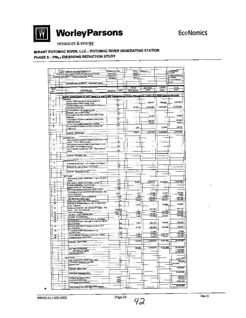


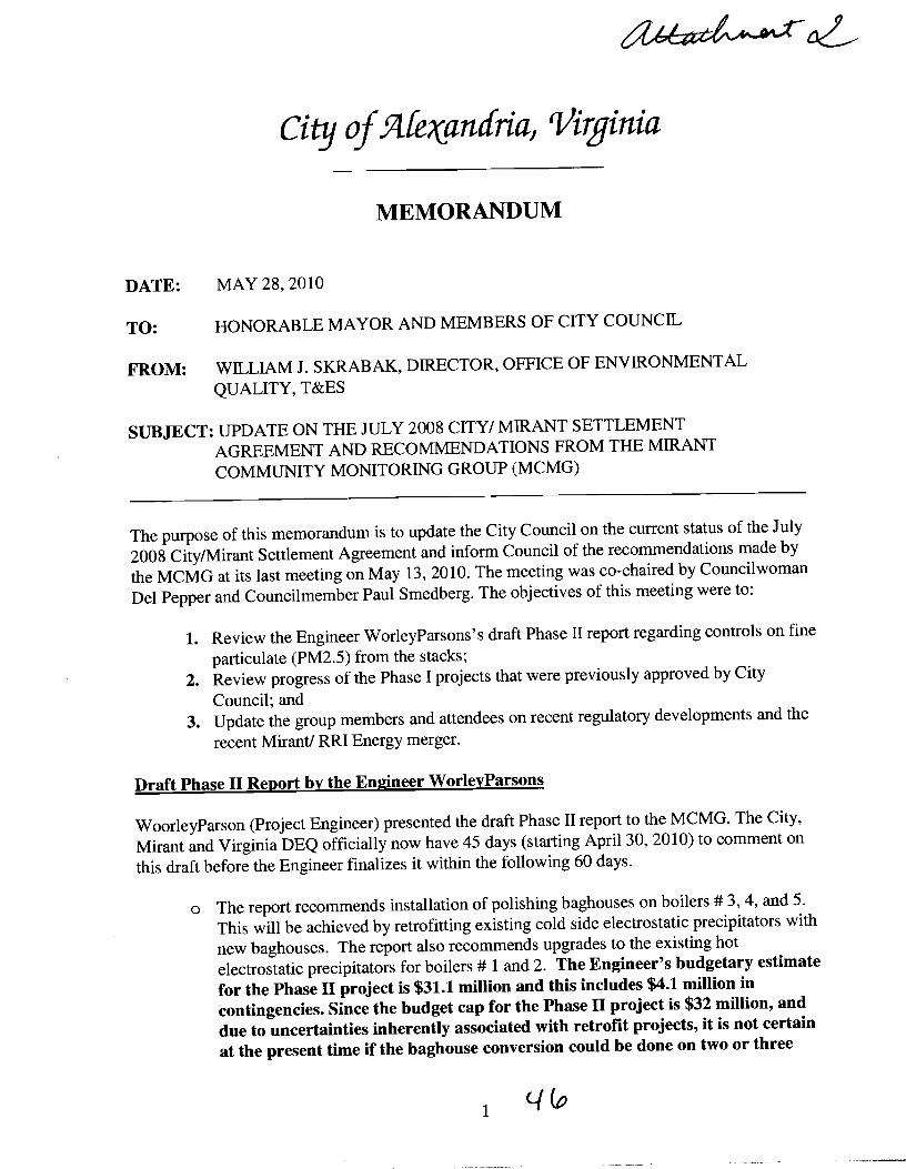


irant Settlement Agreement - eceipt and Consideration of Phase I1


Phase I engineering study comp with five fugitive control options re approved by Council in November 2
Ash loadng dust suppression system - ord delivery expected ths summer Street sweeper - ordered, delivery this summer W a n t New ash loader installation - installed an operational with temporary power source Drip pans - required a permit modfication whlch be applied for at the same time as Phase I1 project Wind screens - revised cost is $1.02 d o n
City of Alexandria


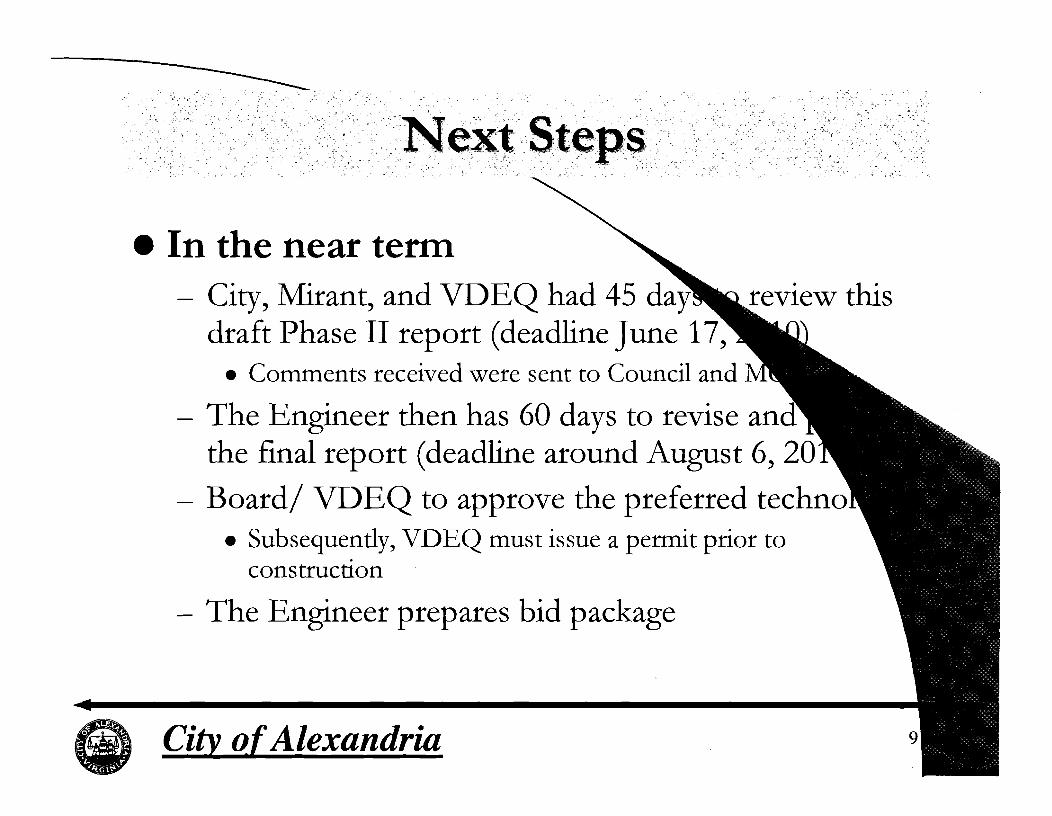
In the near term \