Embed Size (px)
Citation preview

CITY ENGINEERS ASSOCIATION OF MINNESOTA
STANDARD SPECIFICATIONS
2600 Trench Excavation and Backfill/Surface Restoration
2611 Water Main and Service Line Installation
2621 Sanitary Sewer and Storm Sewer Installation
1999 Edition

TABLE OF CONTENTS
SECTION 2600......................................................................................................... 6
STANDARD SPECIFICATIONS FOR TRENCH EXCAVATION & BACKFILL/SURFACE RESTORATION .................................................... 6
2600.1 DESCRIPTION............................................................................................. 6
2600.2 MATERIALS ................................................................................................ 6 A Granular Materials .................................................................................................. 6
A1 Granular Material Gradation Classifications .................................................. 6 A2 Granular Material Use Designations............................................................... 7
B Piling ...................................................................................................................... 7 C Insulation................................................................................................................ 8 D Geotextile Fabric..................................................................................................... 8
2600.3 CONSTRUCTION REQUIREMENTS...................................................... 8 A General Provisions .................................................................................................. 8
A1 Maintenance of Traffic ................................................................................... 8 A2 Establishing Line and Grade.......................................................................... 8 A3 Protection of Surface Structures ................................................................... 10 A4 Interference of Underground Structures ....................................................... 11 A5 Removal of Surface Improvements .............................................................. 11 A6 Temporary Service Measures ....................................................................... 12
B Excavation and Preparation of Trench.................................................................. 12 B1 Operational Limitations and Requirements .................................................. 12 B2 Classification and Disposition of Materials.................................................. 13 B3 Excavation Limitations and Requirements ................................................... 14 B4 Sheeting and Bracing Excavations................................................................ 15 B5 Preparation and Maintenance of Foundations............................................... 16
C Non Open Cut Pipe Installation ............................................................................ 17 C1 Jacking/Boring .............................................................................................. 17 C2 Directional Boring ....................................................................................... 19
D Placement of Insulation......................................................................................... 19 E Pipeline Backfilling Operations............................................................................ 20 F Restoration of Surface Improvements ................................................................. 22
F1 Turf Restoration........................................................................................... 22 F2 Pavement Restoration ................................................................................... 22 F3 Restoration of Miscellaneous Items.............................................................. 23
G Maintenance and Final Cleanup............................................................................ 23
2600.4 METHOD OF MEASUREMENT............................................................. 24 A Rock Excavation ................................................................................................... 24
2

B Granular Materials ............................................................................................... 24 C Geotextile Fabric.................................................................................................. 24 D Piling ..................................................................................................................... 25
D1 Pile Bents ..................................................................................................... 25 E Insulation............................................................................................................... 25
2600.5 BASIS OF PAYMENT ............................................................................... 25
SECTION 2611....................................................................................................... 26
STANDARD SPECIFICATIONS FOR WATER MAIN AND SERVICE LINE INSTALLATION..................................................................... 26
2611.1 DESCRIPTION........................................................................................... 26
2611.2 MATERIALS .............................................................................................. 28 A Water Pipe Materials............................................................................................. 28
Al Ductile Iron Pipe and Ductile Iron and Gray Iron Fittings ........................... 28 A2 Prestressed Concrete Cylinder Pipe and Fittings ......................................... 29 A3 Polyvinyl Chloride (PVC) Pressure Pipe and Fittings.................................. 29 A4 Polyethylene (PE) Pressure Pipe and Fittings............................................... 29
B Fire Hydrants ........................................................................................................ 30 C Valves and Valve Housing................................................................................... 31
Cl Valve Housings................................................................................................ 31 C2 Gate Valves.................................................................................................. 31 C3 Butterfly Valves ............................................................................................ 31
D Water Service Pipe and Fittings............................................................................ 32 E Polyethylene Encasement Material....................................................................... 33 F Restrained Joint Retainer Glands.......................................................................... 33 G Mortar ................................................................................................................... 33 H Concrete ................................................................................................................ 33
2611.3 CONSTRUCTION REQUIREMENTS....................................................... 33 A Installation of Pipe and Fittings ............................................................................ 33 Al Inspection and Handling ................................................................................... 34
A2 Pipe Laying Operations................................................................................. 34 A3 Aligning and Fitting of Pipe ......................................................................... 35 A4 Blocking and Anchoring of Pipe.................................................................. 36 A5 Polyethylene Encasement of Pipeline........................................................... 37
B Connection and Assembly of Joints...................................................................... 38 B1 Ductile Iron Pressure Pipe and Fitting Joints................................................ 38
B1a Push-On Joints .......................................................................................... 38 B1b Mechanical Joints...................................................................................... 39 B1c Flanged Joints ........................................................................................... 39
B2 Prestressed Concrete Cylinder Pipe Joints.................................................... 39 B3 Polyvinyl Chloride Pipe Joints...................................................................... 40
3

B3a Push-On Joints .......................................................................................... 40 B4 Polyethylene Pipe Joints ............................................................................... 40
C Water Service Installations ................................................................................... 40 C1 Tee Branch Service Lines ............................................................................. 41 C2 Tapped Service Lines.................................................................................... 41
D Setting Valves, Hydrants, Fittings and Specials .................................................. 42 E Disinfection of Water Mains................................................................................. 43 F Electrical Conductivity Test ................................................................................ 43 G Hydrostatic Testing of Water Mains.................................................................... 44 H Operational Inspection .......................................................................................... 45
2611.4 METHOD OF MEASUREMENT............................................................. 45 A Water Pipe............................................................................................................. 46 B Valves ................................................................................................................... 46 C Corporation Stops ................................................................................................. 46 D Curb Stops............................................................................................................. 46 E Hydrants................................................................................................................ 46 F Air Vents............................................................................................................... 46 G Rearrangement of Inplace Facilities ..................................................................... 46 H Polyethylene Encasement ..................................................................................... 46 I Ductile and Gray Iron Fittings .............................................................................. 46 J Polyvinyl Chloride or Polyethylene...................................................................... 46 K Access Structures .................................................................................................. 47
2611.5 BASIS OF PAYMENT ............................................................................... 47
SECTION 2621....................................................................................................... 48
STANDARD SPECIFICATIONS FOR SANITARY SEWER AND STORM SEWER INSTALLATION.................................................................. 48
2621.1 DESCRIPTION.............................................................................................. 48
2621.2 MATERIALS ................................................................................................. 49 A Sewer Pipe and Service Line Materials ................................................................ 50
A1 Vitrified Clay Pipe and Fittings ................................................................... 50 A2 Ductile Iron Pipe and Ductile Iron and Gray Iron and Fittings ................... 50 A3 Reinforced Concrete Pipe and Fittings ........................................................ 51 A4 Corrugated Steel Pipe and Fittings ............................................................... 51 A5 Polyvinyl Chloride Pipe and Fittings............................................................ 51 A6 Cast Iron Soil Pipe ....................................................................................... 52 A7 Acrylonitrile-Butadiene-Styrene Pipe.......................................................... 52 A8 Dual-Wall Corrugated Polyethylene Pipe..................................................... 52
B Metal Sewer Castings ........................................................................................... 52 C Precast Concrete Manhole and Catch Basin Sections........................................... 53 D Concrete ................................................................................................................ 53
4
E Mortar .................................................................................................................. 54
2621.3 CONSTRUCTION REQUIREMENTS.................................................... 54 A Installation of Pipe and Fittings ............................................................................ 54
A1 Inspection and Handling ............................................................................... 54 A2 Pipe Laying Operations................................................................................. 54 A3 Connection and Assembly of Joints.............................................................. 55 A4 Bulkheading Open Pipe Ends ....................................................................... 56
B Appurtenance Installations.................................................................................... 56 C Sewer Service Installations ................................................................................... 57 D Manhole and Catch Basin Structures.................................................................... 58 E Reconnecting Existing Facilities........................................................................... 59 F Sanitary Sewer Leakage Testing.......................................................................... 59
F1 Air Test Method............................................................................................ 60 F2 Hydrostatic Test Method............................................................................... 61 F3 Test Failure and Remedy .............................................................................. 62
G Deflection Test..................................................................................................... 62 G1 Test Failure and Remedy .............................................................................. 63
H Televising.............................................................................................................. 63
2621.4 METHOD OF MEASUREMENT............................................................. 63 A Sewer Pipe ........................................................................................................... 63 B Manholes............................................................................................................... 63 C Catch Basins.......................................................................................................... 64 D Outside Drop Connection ..................................................................................... 64 E Service Connection ............................................................................................... 64 F Service Pipe ......................................................................................................... 64 G Special Pipe Fittings ............................................................................................. 64 H Appurtenant Items................................................................................................ 65
2621.5 BASIS OF PAYMENT ............................................................................... 65
5

SECTION 2600
STANDARD SPECIFICATIONS FOR TRENCH EXCAVATION & BACKFILL/SURFACE RESTORATION
2600.1 DESCRIPTION This work shall consist of the excavation, backfilling, and restoration of existing surface improvements for the purposes of installing new and/or relocating or adjusting existing underground utilities. Use of the term "Plans, Specifications and Special Provisions" within this specification shall be construed to mean those documents which compliment, modify, or clarify these specifications and are accepted as an enforceable component of the Contract or Contract Documents. All references to Mn/DOT Specifications shall mean the latest published edition of the Minnesota Department of Transportation Standard Specifications for Construction, as modified by any Mn/DOT Supplemental Specification edition published prior to the date of advertisement for bids. All reference to other Specifications of AASHTO, ASTM, ANSI, AWWA, etc. shall mean the latest published edition available on the date of advertisement for bids. 2600.2 MATERIALS A Granular Materials Granular materials furnished for foundation, bedding, encasement, backfill, or other purposes as may be specified shall consist of any natural or synthetic mineral aggregate such as sand, gravel, crushed rock, crushed stone, or slag, that shall be so graded as to meet the gradation requirements specified herein for each particular use by the material manufacturer or as indicated in the Plans, Specifications, or Special Provisions. A1 Granular Material Gradation Classifications Granular materials furnished for use in Foundation, Bedding, Encasement, or Backfill construction shall conform to the following requirements: Foundation materials shall have 100 percent by weight passing the 1-1/2 inch sieve and a maximum of 10 percent by weight passing the No. 4 sieve. Backfill materials shall consist of existing trench materials, except as otherwise specified in this specification or in the Special Provisions. Bedding and encasement materials for flexible pipe, where improved pipe foundation is not required, shall meet the requirements of Mn/DOT Specification
6

3149.2B1, Granular Borrow, except that 100 percent by weight shall pass the one-inch sieve. A gradation report from an approved Independent Testing laboratory of the proposed granular materials shall be furnished to the Engineer before any of the granular materials are delivered to the project. A2 Granular Material Use Designations Granular materials provided for Foundation, Bedding, Encasement, or Backfill use as required by the Plans, Specifications, and Special Provisions, either as part of the pipe item work unit or as a separate contract item, shall be classified as to use in accordance with the following: Material Use Designation Zone Designation Granular Foundation ---------------- Placed below the bottom of pipe grade as
replacement for unsuitable or unstable soils, to achieve better foundation support.
Granular Bedding -------------------- Placed below the pipe midpoint, prior to pipe
installation, to facilitate proper shaping and to achieve uniform pipe support.
Granular Encasement -------------- Placed below an elevation one foot above the
top of pipe, after pipe installation, for protection of the pipe and to assure proper filling of voids or thorough consolidation of backfill.
Granular Backfill --------------------- Placed below the surface base course, if any,
as the second stage of backfill, to minimize trench settlement and provide support for surface improvements.
In each case above, unless otherwise indicated, the lower limits of any particular zone shall be the top surface of the next lower course as constructed. The upper limits of each zone are established to define variable needs for material gradation and compaction or void content, taking into consideration the sequence of construction and other conditions. The material use and zone designations described above shall only serve to fulfill the objectives and shall not be construed to restrict the use of any particular material in other zones where the gradation requirements are met. B Piling Piling shall be constructed in accordance with the provisions of Mn/DOT Specification 2452 and special plan details relating to piling.
7
C Insulation Main Insulation shall be extruded rigid board material having a thermal conductivity of 0.23 BTU/hour/square foot/degree Fahrenheit/per inch thickness, maximum, at 40âF mean, a comprehensive strength of 35 psi minimum, and water absorption of 0.25 percent by volume minimum. Unless otherwise specified in the Plans, specifications, or Special Provisions, board dimensions shall measure 8 feet long, 2 or 4 feet wide, and 1, 1-1/2, 2, or 3 inches thick. D Geotextile Fabric Geotextile fabric shall meet the requirements of Mn/DOT Specification 3733 and be used as required by the Plans, Specifications, and Special Provisions. 2600.3 CONSTRUCTION REQUIREMENTS A General Provisions A1 Maintenance of Traffic Whenever work interferes with the flow of traffic along a roadway, the Contractor shall provide for traffic control and signing and public safety in accordance with the provisions of the field manual of Temporary Control Zone Layouts of the Minnesota Manual of Uniform Traffic Control Devices and Mn/DOT Specifications 1404 and 1710, and the Special Provisions. Neither road closures nor detours shall be permitted unless specified in the Special Provisions or authorized by the Engineer. Where road closures or detours are permitted by the Engineer, the Engineer shall determine the appropriate agencies, boards, or departments the Contractor must notify prior to taking the action and the proper advance notice to be provided to each body. Compliance with this requirement shall not be construed to relieve the Contractor from the responsibility of notifying agencies or institutions whose services may be predicated upon a roadway being opened to traffic or whose services would be hindered if a roadway is closed to traffic. Such agencies or institutions shall include, but not be limited to, the police department, the fire department, municipal bus service, school bus service, and ambulance service. The Contractor shall keep the required agencies informed of changing traffic patterns and detour situations. A2 Establishing Line and Grade The primary line and grade will be established by the Engineer. For trench installation, line and grade stakes will be set parallel to the proposed pipeline at an appropriate offset therefrom as will best serve the Contractor's operations wherever practical. For tunnel installation, line and grade stakes will be set directly above the proposed pipeline setting. Grade and line stakes will be set at 25-foot intervals along the pipeline; at each change in line or grade; and as needed for pipeline appurtenances and service lines.
8

The Contractor shall arrange operations to avoid unnecessary interference with the establishment of the primary line and grade stakes; and shall render whatever assistance may be required by the Engineer in accomplishing the staking. The Contractor shall be responsible for preservation of the primary stakes and, if negligent in providing necessary protection, shall bear the full cost of any restaking. The Contractor shall be solely responsible for the correct transfer of the primary line and grade to all working points and for construction of the work to the prescribed lines and grades as established by the Engineer. Following construction of a work shaft on tunnel installations, the line and grade shall be transferred down the shaft and be projected into and throughout the length of each tunnel heading. Unless otherwise specified in the Plans, Specifications, and Special Provisions, the water main shall generally be placed with the minimum specified cover. However, a greater depth may be required to clear existing storm and sanitary sewers and sewer services, and no additional compensation shall be provided for such adjustments. In locations where sewer is in direct conflict with existing water main and water services the water main and water services shall be lowered to provide at least 18 inches of vertical distance between the top of the water main or service and the bottom of the sanitary or relocated in accordance with the Plans. Watermains crossing above storm or sanitary sewers shall be laid to provide a separation of at least18 inches between the bottom of the water main and the top of the sewer. When local conditions prevent a vertical separation as described, the following construction shall be used: (1) Sewers passing over or under Water mains shall be constructed of
materials equal to water main standards of construction for a distance of at least 9 feet on either side of the water main.
(2) Watermain passing under sewers shall, in addition, be protected by providing:
(a) a vertical separation of at least 18 inches between the bottom of the sewer and the top of the water main; (b) adequate structural support for the sewers to prevent excessive deflection of joints and settling on and breaking of the Water mains; (c) a length of water pipe shall be centered at the point of crossing so that the joints will be equidistant and as far as possible from the sewer.
9

Water mains shall be laid at least 10 feet horizontally from any sanitary sewer or storm sewer, whenever possible. When local conditions prevent a horizontal separation of 10 feet, a water main may be laid closer to a storm or sanitary sewer provided that: (1) The bottom of the water main is at least 18 inches above the top of the sewer; (2) Where this vertical separation cannot be obtained, the sewer shall be
constructed of materials and with joints that are equivalent to water main standards of construction and shall be pressure tested to assure water tightness prior to backfilling.
No deviation shall be made from the required line or grade except with the consent of the Engineer. A3 Protection of Surface Structures All surface structures and features located outside the permissible excavation limits for underground installations, together with those within the construction areas which are indicated in the Plans as being saved, shall be properly protected against damage and shall not be disturbed or removed without approval of the Engineer. Within the construction limits, as required, the removal of improvements such as paving, curbing, walks, turf, etc., shall be subject to acceptable replacement after completion of underground work, with all expense of removal and replacement being borne by the Contractor to the extent that separate compensation is not specifically provided for in the Contract. Obstructions such as street signs, guard posts, small culverts, mailboxes, and other items of prefabricated construction may be temporarily removed during construction provided that essential service is maintained in a relocated setting as approved by the Engineer and that nonessential items are properly stored for the duration of construction. Upon completion of the underground work, all such items shall be replaced in their proper setting at the sole expense of the Contractor. The Contractor shall be responsible for protection of existing overhead utilities and poles. This shall include arranging with the utility and paying the utility for holding poles that will be close to the edge of any trench. Holding of poles and repair of any damage to these facilities shall be considered incidental to the project with no additional compensation allowed. If relocation or removal of these facilities is required, the Owner will contact the concerned utility and pay for the relocation or removal at no additional expense to the Contractor. In the event of damage to any surface improvements, either privately or publicly owned, in the absence of construction necessity, the Contractor will be required
10

to replace or repair the damaged property to the satisfaction of the Engineer and without cost to the Owner. A4 Interference of Underground Structures When any underground structure interferes with the planned placement of the pipeline or appurtenances to such an extent that alterations in the work are necessary to eliminate the conflict or avoid endangering effects on either the existing or proposed facilities, the Contractor shall immediately notify the Engineer and the Owner of the affected structure. When any existing facilities are endangered by the Contractor's operations, the Contractor shall cease work at the site and take such precautions as may be necessary to protect the inplace structures until a decision is made as to how the conflict will be resolved. Without specific authorization from the Engineer, no essential utility service shall be disrupted, nor shall any change be made in either the existing structures or the planned installations to overcome the interference. Alterations in existing facilities will be allowed only to the extent that service will not be curtailed unavoidably and then only when the encroachment or relocation will satisfy all applicable regulations and conditions. Wherever alterations are required as a result of unforeseen underground interferences not due to any fault or negligence of the Contractor, the Engineer will issue a written order covering any additional or extra work involved and specifying the revised basis of payment, if any. Any alterations made strictly for the convenience of the Contractor, shall be subject to prior approval and shall be at the Contractor's expense. No extra compensation will be allowed for delays caused by the interference of underground structures. A5 Removal of Surface Improvements Removal of surface improvements in connection with trench excavation shall be limited to actual needs for installation of the pipeline and appurtenances, based on the allowable trench widths and any other controls imposed in connection with the work. Removal operations shall be coordinated effectively with the excavation and installation operations as will cause the least practical disruption of traffic or inconvenience to the public. The debris resulting from removals shall become the property of the Contractor and shall be disposed of by the Contractor in accordance with Mn/DOT Specification 2104. Removal debris shall not be deposited at locations that will block access to fire hydrants, private driveways, or other essential service areas, nor obstruct surface drainage. Removal and final disposal of debris shall be accomplished as a single operation wherever possible and, in any event, the debris shall be removed from the site before starting the excavating operations. Removal of concrete or bituminous structures shall be by methods producing clean-cut breakage to prescored lines as will preserve the remaining structure without damage. Removal equipment shall not be operated in a manner that will
11

cause damage to the remaining structure or adjoining property. Where not removed to an existing joint, concrete structures shall be sawed along the break lines to a minimum depth of one-third of the structure depth. Any reusable materials generated during the work, such as aggregate, sod, topsoil, shall be segregated from other waste materials and be stockpiled so as to maintain suitability and permit proper reuse. The use of drop weight equipment for breaking pavement will be allowed to the extent that the Contractor shall assume full responsibility for any damages caused thereby. The pavement breaking operation shall not be allowed to become a nuisance to the public or a source of damage to underground or adjacent structures. The Engineer reserves the right to order discontinuance of drop weight breaking operations at any time. A6 Temporary Service Measures While any open excavations are maintained, the Contractor shall have available a supply of steel plates suitable for temporary bridging of open trench sections where either vehicular or pedestrian traffic must be maintained. Use of the plates shall be as directed or approved by the Engineer and where installed they shall be secured against possible displacement and be replaced with the permanent structure as soon as possible. B Excavation and Preparation of Trench B1 Operational Limitations and Requirements Excavating operations shall proceed only so far in advance of pipe laying as will satisfy the needs for coordination of work and permit advance verification of unobstructed line and grade as planned. Where interference with existing structures is possible or in any way indicated, and where necessary to establish elevation or direction for connections to inplace structures, the excavating shall be done at those locations in advance of the main operation so actual conditions will be exposed in sufficient time to make adjustments without resorting to extra work or unnecessary delay. Where possible, excavated materials shall be placed in areas that will not block existing vehicle and pedestrian traffic and drainage ways. The Contractor shall review proposed methods of operation with the Engineer prior to beginning the work. All installations shall be accomplished by open trench construction except for short tunnel sections approved by the Engineer and with the exception that boring and jacking or tunnel construction methods shall be employed where so specifically required by the Plans, Specifications, or Special Provisions.
12

Installation of pipe through tunnel excavations will be allowed only where the surface structure can be properly supported and the backfill restored to the satisfaction of the Engineer. The excavating operations shall be conducted so as to carefully expose all inplace underground structures without damage. Wherever the excavation extends under or approaches so close to an existing structure as to endanger it in any way, precautions and protective measures shall be taken as necessary to preserve the structure and provide temporary support. Hand methods of excavating shall be utilized to probe for and expose such critical or hazardous installations as gas pipe and power or communication cables. The Engineer shall be notified of any need for blasting to remove materials which cannot be broken up mechanically, and there shall be no blasting operations conducted until the Engineer's approval has been secured. Blasting will be allowed only when proper precautions are taken to protect life and property, and then shall be restricted as the Engineer directs. The hours of blasting operations shall be set by the Owner. The Contractor shall assume full responsibility for any damages caused by blasting, regardless of the requirements for notification and approval. The Contractor shall secure any required permits for blasting and shall conduct blasting operations in conformance with all applicable local, state and federal laws, regulations, and ordinances. B2 Classification and Disposition of Materials Excavated materials will be classified for payment only to the extent that the removal of materials classified by the Engineer as Rock will be paid for as provided in the Special Provisions or shown in the Proposal. All other materials encountered in the excavations, with the exception of items classified for payment as structure removals, will be considered as Unclassified Excavation and unless otherwise specified in the Plans, Specifications, and Special Provisions, no additional compensation shall be provided for their removal. Unclassified materials shall include muck, rubble, wood debris, and boulder stone, masonry or concrete fragments less than one cubic yard in volume, together with other miscellaneous matter that can be removed effectively with power operated excavators without resorting to drilling and blasting. Rock excavation shall be defined to include all hard, solid rock in ledge formation, bedded deposits and unstratified masses; all natural conglomerate deposits so firmly cemented as to present all the characteristics of solid rock; and any boulder stone, masonry or concrete fragments exceeding one cubic yard in volume. Materials such as shale, hard pan, soft or disintegrated rock which can be dislodged with a hand pick or removed with a power operated excavator will not be classified as Rock Excavation.
13

Excavated materials will be classified for reuse as being either Suitable or Unsuitable for backfill or other specified use, subject to selective controls. All suitable materials shall be reserved for backfill to the extent needed, and any surplus remaining shall be utilized for other construction on the project as may be specified or ordered by the Engineer. To the extent practicable, granular materials and topsoil shall be segregated from other materials during the excavating and stockpiling operations so as to permit best use of the available materials at the time of backfilling. Unless otherwise specified in the Plans, Specifications, and Special Provisions, material handling as described above shall be considered incidental with no additional compensation provided. All excavated materials reserved for backfill or other use on the project shall be stored at locations approved by the Engineer that will cause a minimum of inconvenience to public travel, adjacent properties, and other special interests. The material shall not be deposited so close to the edges of the excavations as would create hazardous conditions, nor shall any material be placed so as to block the access to emergency services. All materials considered unsuitable by the Engineer, for any use on the project, shall be immediately removed from the project and be disposed of as arranged for by the Contractor at no extra cost to the Contract. B3 Excavation Limitations and Requirements Trench excavating shall be to a depth that will permit preparation of the foundation as specified and installation of the pipeline and appurtenances at the prescribed line and grade, except where alterations are specifically authorized. Trench widths shall be sufficient to permit the pipe to be laid and joined properly and the backfill to be placed and compacted as specified. Extra width shall be provided as necessary to permit convenient placement of sheeting and shoring and to accommodate placement of appurtenances. Excavations shall be extended below the bottom of structure as necessary to accommodate any required Granular Foundation material. When rock or unstable foundation materials are encountered at the established grade, additional materials shall be removed as specified or ordered by the Engineer to produce an acceptable foundation. Unless otherwise indicated or directed, rock shall be removed to an elevation at least six inches below the bottom surface of the pipe barrel and below the lowest projection of joint hubs. All excavations below grade shall be to a minimum width equal to the outside pipe diameter plus two feet. Rock shall be removed to such additional horizontal dimensions as will provide a minimum clearance of six inches on all sides of appurtenant structures such as valves, housings, access structures, etc. Where no other grade controls are indicated or established for the pipeline, the excavating and foundation preparations shall be such as to provide a minimum cover over the top of the pipe as specified. Trench widths shall allow for at least six inches of clearance on each side of the joint hubs. The maximum allowable
14

width of the trench at the top of pipe level shall be the outside diameter of the pipe plus two feet, subject to the considerations for alternate pipe loading set forth below. The width of the trench at the ground surface shall be held to a minimum to prevent unnecessary destruction of the surface structures. The maximum allowable trench width at the level of the top of pipe may be exceeded only by approval of the Engineer, after consideration of pipe strength and loading relationships. Any alternate proposals made by the Contractor shall be in writing, giving the pertinent soil weight data and proposed pipe strength alternate, at least seven days prior to the desired date of decision. Approval of alternate pipe designs shall be with the understanding that there will be no extra compensation allowed for any increase in material or construction costs. If the trench is excavated to a greater width than that authorized, the Engineer may direct the Contractor to provide a higher class of bedding and/or a higher strength pipe than that required by the Plans, Specifications, and Special Provisions in order to satisfy design requirements, without additional compensation. B4 Sheeting and Bracing Excavations All excavations shall be sheeted, shored, and braced as will meet all requirements of the applicable safety codes and regulations; comply with any specific requirements of the Contract; and prevent disturbance or settlement of adjacent surfaces, foundations, structures, utilities, and other properties. Any damage to the work under contract or to adjacent structures or property caused by settlement, water or earth pressures, slides, cave-ins, or other causes due to failure or lack of sheeting, shoring, or bracing or through negligence or fault of the Contractor in any manner shall be repaired at the Contractor's expense and without delay. Where conditions warrant extreme care, the Plans, Specifications, and Special Provisions may require special precautions to protect life or property, or the Engineer may order the installation of sheet piling of the interlocking type or direct that other safety measures be taken as deemed necessary. Failure of the Engineer to order correction of improper or inadequate sheeting, shoring, or bracing shall not relieve the Contractor's responsibilities for protection of life, property, and the work. The Contractor shall assume full responsibility for proper and adequate placement of sheeting, shoring, and bracing, wherever and to such depths that soil stability may dictate the need for support to prevent displacement. Bracing shall be so arranged as to provide ample working space and so as not to place stress or strain on the inplace structures to any extent that may cause damage. Sheeting, shoring and bracing materials shall be removed only when and in such manner as will assure adequate protection of the inplace structures and prevent
15

displacement of supported grounds. Sheeting and bracing shall be left in place only as required by the Plans, Specifications, and Special Provisions or ordered by the Engineer. Otherwise, sheeting and bracing may be removed as the backfilling reaches the level of respective support. Wherever sheeting and bracing is left in place, the upper portions shall be cut and removed to an elevation of three feet or more below the established surface grade as the Engineer may direct. All costs of furnishing, placing and removing sheeting, shoring, and bracing materials, including the value of materials left in place as required by the Contract, shall be included in the prices bid for pipe installation and will not be compensated for separately. When any sheeting, shoring, or bracing materials are left in place by written order of the Engineer, in the absence of specific requirements of the Contract to do so, payment will be made for those materials as an Extra Work item, including waste material resulting from upper cut-off requirements. B5 Preparation and Maintenance of Foundations Foundation preparations shall be conducted as necessary to produce a stable foundation and provide continuous and uniform pipe bearing between bell holes. The initial excavating or backfilling operations shall produce a subgrade level slightly above finished grade as will permit hand shaping to finished grade by trimming of high spots and without the need for filling of low spots to grade. Final subgrade preparations shall be such as to produce a finished grade at the centerline of the pipe that is within 0.03 foot of a straight line between pipe joints and to provide bell hole excavation at each joint as will permit proper joining of pipe and fittings. In excavations made below grade to remove rock or unstable materials, the backfilling to grade shall be made with available suitable materials unless placement of Granular Foundation or Bedding material is specified and provided for or is ordered by the Engineer. Placement of the backfill shall be in relatively uniform layers not exceeding 8 inches in loose thickness. Each layer of backfill shall be compacted thoroughly, by means of approved mechanical compaction equipment, as will produce uniform pipe support throughout the full pipe length and facilitate proper shaping of the pipe bed. Where placement of foundation materials will not provide an adequate foundation for laying pipe due to the instability of the existing materials and where ordered by the Engineer, the Contractor shall place Geotextile Type I fabric on top of the unstable materials prior to placing foundation materials. Sufficient geotextile fabric shall be used to completely enclose the foundation materials and pipe. It shall be the Contractor's responsibility to notify the Engineer of changing soil conditions which may be of poor bearing capacity and when organic soils are encountered. Where utilities are placed on unstable soils without notification of
16
the Engineer, the Contractor shall be responsible for all repairs and correction of the installation without further compensation. Where the foundation soil is found to consist of materials that the Engineer considers to be so unstable as to preclude removal and replacement to a reasonable depth to achieve solid support, a suitable foundation shall be constructed as the Engineer directs in the absence of special requirements in the Plans, Specifications, and Special Provisions. The Contractor may be required to furnish and drive piling and construct concrete or timber bearing supports or other work as may be ordered by the Engineer. Care shall be taken during final subgrade shaping to prevent any over-excavation. Should any low spots develop, they shall only be filled with approved material, which shall have optimum moisture content and be compacted thoroughly without additional compensation to the Contractor. The finished subgrade shall be maintained free of water and shall not be disturbed during pipe lowering operations except as necessary to remove pipe slings. The discharge of trench dewatering pumps shall be directed to natural drainage channels or storm water drains. Draining trench water into sanitary sewers or combined sewers will not be permitted. The Contractor shall install and operate a dewatering system of wells or points to maintain pipe trenches free of water wherever necessary or as directed by the Engineer to meet the intent of these specifications. Unless otherwise specified in the Plans, Specifications, and Special Provisions, such work shall be considered incidental. All costs of excavating below grade and placing foundation or bedding aggregates as required shall be included in the bid prices for pipe items to the extent that the need for such work is indicated in the Contract provisions and the Proposal does not provide for payment under separate Contract Items. Any excavation below grade and any foundation or bedding aggregates required by order of the Engineer in the absence of Contract requirements will be compensated for separately. If examination by the Engineer reveals that the need for placement of foundation aggregate was caused by the Contractor's manipulation of the soils in the presence of excessive moisture or lack of proper dewatering, the cost of the corrective measures shall be borne by the Contractor. C Non Open Cut Pipe Installation C1 Jacking/Boring The terms "auger", "boring", "jack", "jacking", and "tunneling" in the proposal, specifications, and plans refers only to non-open cut construction. The Contractor shall inspect and verify soil conditions to his own satisfaction in order to
17
determine the type of construction to employ. During the construction, the Contractor shall be responsible for protecting all existing utilities above the pipe invert. The minimum diameter of the casing pipe shall be four (4) inches greater than the outside diameter of the bell of the carrier pipe. For any installation beneath a railroad, the top of the casing pipe shall not be closer than the specified dimensions indicated in the permit. If the Contractor elects to install steel casing, the minimum wall thickness shall be as specified on the Plans, in the Special Provisions, or in the applicable Permit. Where required by the Engineer, two 17-pound anode packs shall be attached to the casing for corrosion protection. A 1-1/2 inch pipe shall be forced along the top of the casing pipe. The front end of this pipe shall be 18 inches behind the front end of the casing pipe. A mixture of water and bentonite clay shall be forced through this pipe at all times during the casing installation to fill any voids that may be present above the casing pipe. Upon completion of the casing installation, this pipe shall be slowly withdrawn while bentonite is forced through the pipe to fill any remaining voids. The Contractor shall prevent excavated materials from flowing back into the excavation during the non-open cut construction. This shall include the use of a shield conforming to the size and shape of the casing that will prevent materials from flowing into the leading edge of the casing. The machine used shall be capable of controlling line and grade and shall conform to the size and shape of the casing pipe. No jacking/augering of pipe will be allowed below the water table unless the water table has been lowered sufficiently to keep the water below the pipe being installed. The use of water under pressure (jetting) or puddling will not be permitted to facilitate jacking/augering operations. If any installation is augered, the head shall be approved by the Engineer and the auger shall be located six (6) inches behind the lead edge of the casing or carrier pipe. If a void develops, the jacking/augering shall be stopped immediately and the void shall be filled by pressure grouting. The grout material shall consist of a sand-cement slurry of at least two sacks of cement per cubic yard and a minimum of water to assure satisfactory placement. Skids and blocking shall be used as necessary to install the carrier pipe to the proper line and grade inside the casing pipe. Voids between carrier and casing pipes shall be filled with sand and the casing pipe sealed at both ends with a suitable material to prevent water or debris from entering the casing pipe.
18

C2 Directional Boring Direction boring/drilling installation shall be accomplished where required on the Plans or in the Special Provisions to minimize disturbance of existing surface improvements. The installer shall have a minimum of three years of experience in this method of construction and have installed at least 1,000 feet of 8-inch or larger diameter pipe to specified grades. The field supervisor employed by the Contractor shall have at least three years of experience and shall be at the site at all times during the boring/drilling installation, and be responsible for all of the work. The Contractor shall submit boring/drilling pit locations to the Engineer before beginning construction. The drilling equipment shall be capable of placing the pipe as shown on the plans. The installation shall be by a steerable drilling tool capable of installing continuous runs of pipe, without intermediate pits, a minimum distance of 200 feet. The guidance system shall be capable of installing pipe within 1-1/2 inch of the plan vertical dimensions and 2 inches of the plan horizontal dimensions. The Contractor shall be required to remove and reinstall pipes which vary in depth and alignment from these tolerances. Pull back forces shall not exceed the allowable pulling forces for the pipe being installed. Drilling fluid shall be a mixture of water and bentonite clay. Disposal of excess fluid and spoils shall be the responsibility of the Contractor. D Placement of Insulation Rigid insulation board shall be placed within the pipe encasement zone, 6 inches above the pipe. Prior to placement of the insulation, Granular Borrow (MnDOT 3149) shall be leveled and compacted until there is no further visual evidence of increased consolidation or the density of the compacted layer conforms to the density requirements specified in the Special Provisions, then leveled and lightly scarified to a depth of 1/2 inch. Borrow material placed above and below the insulation shall be free of rock or stone fragments measuring 1-1/2 inches or greater. Insulation boards shall be placed on the scarified material with the long dimension parallel to the centerline of the pipe. Boards shall be placed in a single layer with tight joints. No continuous joints or seams shall be placed directly over the pipe. If two or more layers of insulation boards are used, each layer shall be placed to cover the joints of the layer immediately below. The Contractor shall exercise precaution to insure that all joints between boards are tight during placement and backfilling with only extruded ends placed end to end or edge to edge.
19

The first layer of material placed over the insulation shall be 6 inches in depth, free of rock or stone fragments measuring 1-1/2 inches or greater. The material shall be placed in such a manner that construction equipment does not operate directly on the insulation and shall be compacted with equipment which exerts a contract pressure of less than 80 psi. The first layer shall be compacted to conform to the density requirements specified in the Special Provisions. E Pipeline Backfilling Operations All pipeline excavations shall be backfilled to restore preexisting conditions as the minimum requirement, and fulfill all supplementary requirements indicated in the Plans, Specifications, and Special Provisions. The backfilling operations shall be started as soon as conditions will permit on each section of pipeline, so as to provide continuity in subsequent operations and restore normal public service as soon as practicable on a section-by-section basis. All operations shall be pursued diligently, with proper and adequate equipment, as will assure acceptable results. The backfilling shall be accomplished with the use of Suitable Materials selected from the excavated materials to the extent available and practical. Should the materials available within the trench section be unsuitable or insufficient, without loading and hauling or the employment of unreasonable measures, the required additional materials shall be furnished from outside sources as an Extra Work item in the absence of any Special Provision requirements. Suitable Material shall be defined as a mineral soil free of foreign materials (rubbish, debris, etc.), frozen clumps, oversize stone, rock, concrete or bituminous chunks, and other unsuitable materials, that may damage the pipe installation, prevent thorough compaction, or increase the risks of after settlement unnecessarily. Material selection shall be such as to make the best and fullest utilization of what is available, taking into consideration particular needs of different backfill zones. Material containing stone, rock, or chunks of any sort shall only be utilized where and to the extent there will be no detrimental effects. Within the pipe bedding and encasement zones described as that portion of the trench which is below an elevation one foot above the top of the pipe, the materials placed shall be limited in particle size to 1-1/2 inches maximum in the case of pipe of 12 inches in diameter or less and to 2 inches maximum in the case of larger pipe. Above these zones, the placement of material containing stones, boulders, chunks, etc. greater than 8 inches in any dimension shall not be allowed. All flexible pipe shall be bedded in accordance with ASTM Specification D2321, "Recommended Practice for Underground Installation of Flexible Thermoplastic Sewer Pipe". This shall include placement of granular bedding and encasement materials from a point six inches below the bottom of pipe to a point twelve
20

inches above the top of the pipe. Placement and compaction of bedding and encasement materials around the pipe shall be considered incidental to the installation of the pipe. Where existing soils do not meet the requirements of bedding and encasement materials, the Contractor shall furnish the required granular materials. Compaction of materials placed within the pipe bedding and encasement zones shall be accomplished with portable or hand equipment methods, so as to achieve thorough consolidation under and around the pipe and avoid damage to the pipe. Above the cover zone material, the use of heavy roller type compaction equipment shall be limited to safe pipe loading. Backfill materials shall be carefully placed in uniform loose thickness layers up to 12 inches thick spread over the full width and length of the trench section to provide simultaneous support on both sides of the pipeline. Granular backfill may be placed in 12 inch layers above an elevation one foot above the top of the pipe, and with the provision that, by authority and at the discretion of the Engineer in consideration of the demonstrated capability of special type vibrating compactors, the stated maximums may be increased. Each layer of backfill material shall be compacted effectively, by approved mechanical or hand methods, until there is no further visual evidence of increased consolidation or the density of the compacted layer conforms to the density requirements specified in the Special Provisions. Compaction of the inplace layer shall be completed acceptably before placing material for a succeeding layer thereon. The manner of placement, compaction equipment, or procedure effectiveness shall be subject to approval of the Engineer. All surplus or waste materials remaining after completion of the backfilling operations shall be disposed of in an acceptable manner within 24 hours after completing the backfill work on each particular pipeline section. Disposal at any location within the project limits shall be as specified, or as approved by the Engineer; otherwise, disposal shall be accomplished outside the project limits at the Contractor's discretion. The backfilling and surplus or waste disposal operations shall be a part of the work required under the pipeline installation items, not as work that may be delayed until final cleanup. Compaction of backfill within Roadbed areas shall meet the density requirements of Mn/DOT Specification 2105. Compaction of backfill in all other areas shall be as required in the Special Provisions. Until expiration of the guarantee period, the Contractor shall assume full responsibility and expense for all backfill settlement and shall refill and restore the work as directed to maintain an acceptable surface condition, regardless of location. All additional materials required shall be furnished without additional cost to the Owner.
21

Any settlement of road surfaces that are either placed under this Contract or by others under either public or private contract; that are in excess of one inch, as measured by a ten foot straight edge; and that are within the guarantee period shall be considered failure of the mechanical compaction. The Contractor shall be required to repair such settlement including all items placed by others. F Restoration of Surface Improvements Wherever any surface improvements such as pavement, curbing, pedestrian walks, fencing, or turf have been removed, damaged or otherwise disturbed by the Contractor's operations, they shall be repaired or replaced to the Engineer's satisfaction, as will restore the improvement in kind and structure to the preexisting condition. Each item of restoration work shall be done as soon as practicable after completion of installation and backfilling operations on each section of pipeline. In the absence of specific payment provisions, as separate Contract Items, the restoration work shall be compensated for as part of the work required under those Contract Items which necessitated the destruction and replacement or repair, and there will be no separate payment. If separate pay items are provided for restoration work, only that portion of the repair or reconstruction which was necessitated by the Contract work will be measured for payment. Any improvements removed or damaged unnecessarily or undermined shall be replaced or repaired at the Contractor's expense. F1 Turf Restoration Turf restoration shall be accomplished by sod placement except where seeding is specifically allowed or required. Topsoil shall be placed to a minimum depth of four inches under all sod and in all areas seeded. The topsoil material used shall be light friable loam containing a liberal amount of humus and shall be free of heavy clay, coarse sand, stones, plants, roots, sticks and other foreign matter. Topsoil meeting these requirements shall be selected from the excavated materials to the extent available and needed. All turf establishment work shall be done in substantial compliance with the provisions of Mn/DOT Specification 2575 using seed mixtures as specified in the Special Provisions or Proposal. F2 Pavement Restoration The inplace pavement structure (including base aggregates) shall be restored in kind and depth as previously existed, using base aggregates salvaged from the excavated materials to the extent available and needed, and with new materials being provided for reconstruction of the concrete or bituminous surface courses.
22

If, through no fault of the Contractor in failing to reserve sufficient aggregate materials from the excavations, there should be insufficient quantity of suitable aggregate to reconstruct the pavement base courses, the additional materials required will be furnished by the Owner at its expense, or the Contractor will be ordered to furnish the additional materials from outside sources. Placement of any additional aggregate materials delivered to the site by the Owner or of any additional materials furnished by the Contractor shall be an incidental expense, as will also be the disposal of any excess materials resulting therefrom, unless special payment provisions are otherwise agreed upon. Reconstruction of aggregate base courses and concrete or bituminous surface courses shall be in substantial compliance with all applicable Mn/DOT Specifications pertaining to the item being restored. The materials used shall be comparable to those used in the inplace structure, and the workmanship and finished quality shall be equal to that of new construction to the fullest extent obtainable in consideration of operational restrictions. Existing concrete and bituminous surfaces at the trench wall shall be sawed or cut with a cutting wheel to form a neat edge in a straight line before surfaces are to be restored. Sawing or cutting may be accomplished as a part of the removal or prior to restoration at the option of the Contractor. However, all surface edges will be inspected prior to restoration. F3 Restoration of Miscellaneous Items Wherever any curbing, curb and gutter sections, pedestrian walks, fencing, driveway surfacing, or other improvements are removed or in any way damaged or undermined, they shall be restored to original condition by repair or replacement as the Engineer considers necessary. Replacement of old materials will be acceptable only to the extent that existing quality can be fully achieved, such as in the case of fencing. Otherwise new materials shall be provided and placed as the Engineer directs. Workmanship and finished quality shall be equal to that of new construction, where new materials are used, to the extent obtainable in consideration of operational restrictions. A proper foundation shall be prepared before reconstructing concrete or bituminous improvements. Unless otherwise directed, granular material shall be placed to a depth of at least four inches under all concrete and bituminous items. No direct compensation will be made for furnishing and placing this material even though such course was not part of the original construction. G Maintenance and Final Cleanup All subgrade surfaces shall be maintained acceptably until the start of surfacing construction or restoration work, and until the work has been finally accepted. Additional materials shall be provided and placed as needed to compensate for trench settlement and to serve as temporary construction pending completion of the final surface improvements.
23

Final disposal of debris, waste materials, and other remains or consequences of construction, shall be accomplished intermittently as new construction items are completed and shall not be left to await final completion of all work. Cleanup operations shall be considered as being a part of the work covered under the Contract Items involved and only that work which cannot be accomplished at any early time shall be considered as final cleanup work not attributable to a specific Contract Item. If disposal operations and other cleanup work are not conducted properly as the construction progresses, the Engineer may withhold partial payments until such work is satisfactorily pursued or he may deduct the estimated cost of its performance from the partial estimate value. Maintenance of sodded and seeded areas shall include adequate watering for plant growth and the replacement of any dead or damaged sod as may be required for acceptance of the work. 2600.4 METHOD OF MEASUREMENT All items will be measured separately according to design designation as indicated in the Pay Item name and as may be detailed and defined in the Plans, Specifications, or Special Provisions. Complete-in-Place items shall include all component parts thereof as described or required to complete the unit, but excluding any excesses covered by separate Pay Items A Rock Excavation Rock Excavation shall be measured by volume in cubic yards. Depth shall be measured from the top of the rock to a point six inches below the outside barrel of the pipe and width shall be the inside diameter of the pipe plus twenty-four inches (12" from each side). The minimum width of measurement shall be four feet. B Granular Materials Granular materials furnished and placed as special foundation, bedding, encasement, or backfill construction will be measured by weight or volume of material furnished by the Contractor from outside sources and placed within the limits defined. Unless otherwise specified, volume will be determined by vehicular measure (loose volume) at the point of delivery. Measurements will not include any materials required to be placed as a component part of other Contract Items as may be specified. C Geotextile Fabric Where geotextile fabric is used for improving pipe foundation, it shall be measured by the square foot of material installed.
24

D Piling Piling shall be measured according to the provisions of Mn/DOT Specification 2452. D1 Pile Bents Pile bents shall be measured as a unit and shall include all materials and labor required, except the pile. E Insulation Rigid board insulation shall be measured on a square foot basis installed to the specified thickness noted on the Plans, Specifications, and Special Provisions and shall include all materials, equipment, and labor required for placement. 2600.5 BASIS OF PAYMENT All costs of excavating to foundation grade, preparing the foundation, placing and compacting backfill materials, restoring surface improvements, and other work necessary for prosecution and completion of the work as specified, shall be included for payment as part of the pipe and pipe appurtenance items without any direct compensation being made. When special aggregate backfill materials are required to be furnished and placed to comply with the indicated Laying Conditions, the costs shall be included for payment as part of the pipe items without any direct compensation. Otherwise, the furnishing of aggregate materials for backfill by order of the Engineer in the absence of such requirements will be compensated for as an Extra Work item. In the absence of special payment provisions, all costs of restoring surface improvements as required, disposal of surplus or waste materials, maintenance and repair of completed work, and final cleanup operations shall be incidental to the Contract Items under which the costs are incurred. Granular materials furnished for foundation, bedding, cover, or backfill placement as specified in connection with pipe or structure items will only be paid for as separate Contract Items to the extent that the Proposal contains specific Pay Items. Otherwise the furnishing and placing of granular materials as specified shall be incidental to the pipe or structure item without any direct compensation being made.
25

SECTION 2611 STANDARD SPECIFICATIONS FOR WATER MAIN AND
SERVICE LINE INSTALLATION 2611.1 DESCRIPTION This work shall consist of the construction of water main and building service pipelines utilizing plant fabricated pipe and other appurtenant materials, installed for conveyance of potable water. The work includes the relocation or adjustment of existing facilities as may be specified in the Plans, Specifications and Special Provisions. Use of the term "Plans, Specifications and Special Provisions" within this specification shall be construed to mean those documents which compliment, modify, or clarify these specifications and are accepted as an enforceable component of the Contract or Contract Documents. All references to Mn/DOT Specifications shall mean the latest published edition of the Minnesota Department of Transportation Standard Specifications for Construction, as modified by any Mn/DOT Supplemental Specification edition published prior to the date of advertisement for bids. All reference to other Specifications of AASHTO, ASTM, ANSI, AWWA, etc. shall mean the latest published edition available on the date of advertisement for bids. The following American Water Works Association (AWWA) Specifications have been referenced in this Specification: C104 American National Standard for Cement-Mortar Lining for Ductile-Iron
Pipe and Fittings for Water C105 American National Standard for Polyethylene Encasement for Ductile-Iron
Pipe Systems C110 American National Standard for Ductile-Iron and Gray-Iron Fittings, 3 In.
Through 48 In. (75 mm Through 1200 mm), for Water and Other Liquids C111 American National Standard for Rubber-Gasket Joints for Ductile-Iron
Pressure Pipe and Fittings C115 American National Standard for Flanged Ductile-Iron Pipe With Ductile-
Iron or Gray-Iron Threaded Flanges C150 American National Standard for Thickness Design of Ductile-Iron Pipe C151 American National Standard for Ductile-Iron Pipe, Centrifugally Case, for
Water or Other Liquids C153 American National Standard for Ductile-Iron Compact Fittings, 3 In.
Through 24 In. (76 mm Through 610 mm) and 54 In. Through 64 In. (1,400 mm Through 1,600 mm), for Water Service
C301 AWWA Standard for Prestressed Concrete Pressure Pipe, Steel-Cylinder Type, for Water and Other Liquids
C304 AWWA Standard for Design of Prestressed Concrete Cylinder Pipe
26

C500 AWWA Standard for Metal-Seated Gate Valves for Water Supply Service (Includes addendum C500a-95.)
C502 AWWA Standard for Dry-Barrel Fire Hydrants (Includes addendum C502a-95.) C504 AWWA Standard for Rubber-Seated Butterfly Valves C509 AWWA Standard for Resilient-Seated Gate Valves for Water Supply
Service (Includes addendum C509a-95.) C600 AWWA Standard for Installation of Ductile-Iron Water Mains and Their
Appurtenances C605 AWWA Standard for Underground Installation of Polyvinyl Chloride (PVC)
Pressure Pipe and Fittings for Water C651 AWWA Standard for Disinfecting Water Mains C800 AWWA Standard for Underground Service Line Valves and Fittings C900 AWWA Standard for Polyvinyl Chloride (PVC) Pressure Pipe, 4 In.
Through 12 In., for Water Distribution (Includes addendum C900a-92.) C901 AWWA Standard for Polyethylene (PE) Pressure Pipe and Tubing, 1/2 In.
Through 3 In., for Water Service C905 AWWA Standard for Polyvinyl Chloride (PVC) Pressure Pipe and
Fabricated Fittings, 14 In. Through 48 In., (350mm Through 1,200mm), for Water Transmission and Distribution
C906 AWWA Standard for Polyethylene (PE) Pressure Pipe and Fittings, 4 In. Through 63 In., for Water Distribution
C907 AWWA Standard for Polyvinyl Chloride (PVC) Pressure Fittings for Water - 4 In. Through 8 In. (100mm Through 200mm)
Service installations shall include either Branch Service Lines or Tapped Service Lines in accordance with the standards set forth herein. Tapped Service installations shall include all water service lines less than three inches nominal inside diameter pipe. The component parts of a tap service installation shall include a corporation stop coupling complete with water main tap and saddle where required; a curb stop coupling complete with service box; and copper piping extending from the corporation stop to the curb stop coupling and beyond to the property line or to the limits as established by the Engineer. Tapped Service lines shall be installed at the size specified in the Plans, Specifications, and Special Provisions. Branch Service installations shall include all water service lines of three inches nominal inside diameter pipe and larger. The component parts of a branch service installation shall include a tapping sleeve and valve or a tee connection and valve complete with valve box, and piping extending from the water main connection, to the property line or to the limits as specified by the Engineer. All references to Gray Iron material shall be construed to include both Gray Iron and Ductile Iron products, except where one or the other is specified, and all
27

references to Polyvinyl Chloride pipe shall be construed to include only pressure pipe complying with AWWA C-900 or C-905. All references to "structure" shall include any man-made object that is not otherwise exempted by special terminology or definition. 2611.2 MATERIALS All materials required for this work shall be new material conforming to requirements of the reference specifications for the class, kind, type, size, grade, and other details indicated in the Contract. Unless otherwise indicated, all required materials shall be furnished by the Contractor. If any options are provided for, as to type, grade, or design of the material, the choice shall be limited as may be stipulated in the Plans, Specifications, or Special Provisions. All manufactured products shall conform in detail to such standard design drawings as may be referenced or furnished in the Plans. Otherwise, the Owner may require advance approval of material suppliers, product design, or other unspecified details as it deems desirable for maintaining adopted standards. At the request of the Engineer, the Contractor shall submit, in writing, a list of materials and suppliers for approval. A Certificate of Compliance shall be furnished stating that the materials furnished have been tested and are in compliance with the specification requirements. A Water Pipe Materials All pipe furnished for water main and branch line installations shall be of the type, kind, size, and class indicated for each particular line segment as shown in the Plan and designated in the Contract Items. Wherever connection of dissimilar materials or designs is required, the method of joining and any special fittings employed shall be subject to approval of the Engineer. Al Ductile Iron Pipe and Ductile Iron and Gray Iron Fittings The pipe furnished shall be Ductile Iron pipe fittings furnished shall be of the Ductile Iron or Gray Iron type as specified for each particular use of installation. When Gray Iron is specified, either type may be furnished. Gray Iron may not be substituted for Ductile Iron unless specifically authorized in the Special Provisions. Ductile iron pipe shall conform to the requirements of AWWA C115 or C151 for water and thickness design shall conform to AWWA C 150. In addition, the pipe shall comply with the following supplementary provisions: (1) Fittings shall conform to the requirements of AWWA C110 OR 153 (Gray
Iron and Ductile Iron Fittings) (Ductile Iron Compact Fittings) for the joint type specified.
28

(2) Unless otherwise specified all pipe and fittings shall be furnished with
cement mortar lining meeting the requirements of AWWA C104 for standard thickness lining. All exterior surfaces of the pipe and fittings shall have an asphaltic coating at least one mil thick. Spotty or thin seal coating, or poor coating adhesion, shall be cause for rejection.
(3) Rubber gasket joints for Ductile Iron Pressure Pipe and fittings shall
conform to AWWA C111. A2 Prestressed Concrete Cylinder Pipe and Fittings Prestressed Concrete Cylinder pipe, fittings and specials shall conform to the requirements of AWWA C-301 and C-304 (Prestressed Concrete Pressure Pipe, Steel Cylinder Type) for the size, working pressure, external loading, laying condition, and other design considerations indicated in the Plans, Specifications, and Special Provisions. The Contractor shall furnish plans and specifications to the pipe manufacturer giving such special details and other information as are necessary for manufacture of the pipe, fittings, and specials in accordance with the specific requirements of the project. A3 Polyvinyl Chloride (PVC) Pressure Pipe and Fittings Polyvinyl chloride (PVC) pressure pipe, produced by a continuous extrusion process employing a prime grade of unplasticized polyvinyl chloride, shall conform to the requirements of AWWA C-900 for the size, grade, and pressure class indicated on the Plans, Specifications, and Special Provisions. Fittings shall conform to AWWA C907 and C908. The grade used shall be resistant to aggressive soils or corrosive substances in accordance with the requirements of ASTM D-543. Unless otherwise specified, the dimensions and tolerances of the pipe barrel should conform to ductile iron or cast iron pipe equivalent outside diameters. A4 Polyethylene (PE) Pressure Pipe and Fittings Polyethylene pressure pipe and fittings shall conform to the requirements of AWWA C906 for the size and pressure class indicated on the Plans, Specifications and Special Provisions. Unless otherwise specified, the dimensions and tolerances of the pipe barrel should conform to Ductile Iron pipe equivalent outside diameters. The method of joining material shall be by the Thermal Butt- Fusion Method. The standard HDPE fittings shall be standard commercial products manufactured by injection molding or by extrusion and machining, or, shall be fabricated from PE pipe conforming to this specification. The fittings shall be fully pressure rated by the manufacturer to provide a working pressure equal to the pipe, for 50 years service at 73.4 degrees Fahrenheit with an included 2:1 safety factor. The fittings
29

shall be manufactured from the same resin type, grade, and cell classification as the pipe itself. The manufacture of the fittings shall be in accordance with good commercial practice to provide fittings homogeneous throughout and free from crack, holes, foreign inclusions, voids, or other injurious defects. The fittings shall be as uniform as commercially practicable in color, opacity, density and other physical properties. The minimum "quick-burst" strength of the fittings shall not be less than that of the pipe with which the fitting is to be used. B Fire Hydrants Fire hydrants shall be of the type, size, and construction specified in the Plans and shall conform to the applicable requirements of AWWA C-502. Unless otherwise specified in the Plans, Specifications, and Special Provisions, hydrants shall be furnished in conformance with the following supplementary requirements: (1) Hydrants shall have a five-inch (nominal diameter) main valve opening of
the type that opens against water pressure. (2) Hydrant barrels shall be two piece, non-jacket type, with flanged joint
above finished grade line and with mechanical joint connection at the hub end for joining a six-inch ductile iron branch pipe.
(3) Hydrant bury length, measured from the bottom of the branch pipe
connection to the finished ground line at the hydrant, shall be 7'-6". (4) Hydrants shall have two outlet nozzles for 2-1/2 inch (I.D.) hose
connection and one outlet nozzle for 4 inch (I.D.) steamer connection. All outlet nozzle threads shall be National Standard Fire-Hose Coupling Screw Threads (NFPA 1963).
(5) Hydrant operating mechanisms shall be provided with "O" ring seals
preventing entrance of moisture and shall be lubricated through an opening in the operating nut or bonnet.
(6) Hydrants shall be provided with outlets for drainage in the base or barrel,
or between the base and barrel, unless the Special Provisions require that drain outlets be omitted or plugged.
(7) The hydrant operating nut shall be rotated counterclockwise to open. (8) Detailed drawings, catalog information, and maintenance data shall be
furnished as requested by the Engineer.
30

C Valves and Valve Housing Cl Valve Housings Valve housings shall be of ductile or cast iron, High Density Polyethylene or masonry construction as specified in the Plans, Specifications, and Special Provisions for the particular valve size or installation. Masonry manhole or vault type units shall be constructed in accordance with the provisions of Mn/DOT Specification 2506. Precast Concrete Manholes shall conform to ASTM Specification C-478 suitable for HS 20 traffic loading for all units located in driving areas. Ductile or cast iron valve boxes and all castings for manhole or vault type units shall conform to the requirements of Mn/DOT Specification 3321. C2 Gate Valves Gate Valves shall be manufactured and furnished in accordance with an approved pattern and shall conform to all applicable requirements of AWWA C-500 or AWWA C-509, together with such supplementary requirements as may be covered in the Plans, Specifications, and Special Provisions or the provisions hereof. Unless otherwise specified, the gate valves furnished shall comply with the following supplementary requirements: (1) Gate valves meeting the requirements of AWWA C-500 shall be two-
faced, double disc type, with parallel seats. Gate valves meeting the requirements of AWWA C-509 shall be single disc type with resilient seat bonded or mechanically attached to either the gate or valve body. All valves shall be provided with a two-inch square operating nut opening counterclockwise and mechanical joint ends.
(2) All gate valves shall be non-rising stem type furnished with O-Ring stem seals. (3) All gate valves 16 inches or larger in size shall be arranged for operation
in the horizontal position and shall be equipped with bypass valves. (4) All gate valves 12 inches or larger in size shall be equipped with approved
barrel type rugged gate position. (5) All gears on gate valves shall be cut tooth steel gears, housed in heavy
ductile or cast iron extended type grease cases of approved design. (6) All gate valves shall have an open indicating arrow, the manufacturer's
name, pressure rating and year of manufacture cast on the valve bodies. C3 Butterfly Valves Butterfly valves shall be manufactured in conformance with all applicable requirements of AWWA C-504 for 150 p.s.i. working pressure minimum, together with such supplementary requirements as may be covered in the Plans,
31

Specifications, and Special Provision or the provisions hereof. Unless otherwise specified, the butterfly valves furnished shall comply with the following supplementary requirements. (1) The butterfly valves shall be short body of ductile or cast iron with
mechanical joint ends. (2) The butterfly valves shall be rubber seated with ductile or cast disc, non-
rising stem type furnished with O-ring stem seals. (3) The butterfly valves shall be equipped with a two-inch square operating
nut opening counterclockwise. (4) The butterfly valves shall be designed for direct burial installation. (5) All butterfly valves shall have an open indicating arrow, the
manufacturer's name, pressure rating and year of manufacture on the valve bodies.
D Water Service Pipe and Fittings Water service pipe of 3 inches or larger inside diameter shall conform to the requirements for Ductile Iron Pipe and Ductile Iron and Gray Iron Fittings as set forth under the provisions of 2611.2A1, and Polyvinyl Chloride Pressure Pipe as set forth under the provisions of 2611.2A3, and Polyethylene pipe as set forth under the provision of 2611.2A4. Water service pipe of less than 3 inches in inside diameter shall conform to the requirements of ASTM B 88 for Seamless Copper Water Tube, Type K, Soft Annealed temper, Polyethylene Pipe as per AWWA C901 or Polyvinyl Chloride Pipe and fittings as per a ASTM D1785, D2241, D2466, D2467 and D2740 as specified on the Proposal or in the Special Provisions. Corporation stops, saddles, curb stops, and curb stop service boxes shall conform to the requirements of AWWA C800 be as detailed in the Plans, Specifications, and Special Provisions or approved designations. All fittings for copper tubing shall be cast brass, having uniformity in wall thickness and strength, and shall be free of defects affecting serviceability. All copper pipe fittings shall be flared or compression type. All threads for underground service line fittings shall conform to the requirements of AWWA C-800. Each fitting shall be permanently and plainly marked with the name or trademark of the manufacturer. Curb stop service boxes shall be gray iron castings conforming to the requirements of ASTM A 48 for Class 20 or higher tensile strength and shall have
32

18 inches of vertical adjustment for the cover depth specified in the Plans, Specifications, and Special Provisions. E Polyethylene Encasement Material Polyethylene encasement material shall conform to the requirements of AWWA C-105 for tube type installation and 8 mil nominal film thickness. F Restrained Joint Retainer Glands Where water main joint restraint is required by the use of retainer glands, the retainer glands shall be American, US Pipe or Mega-Lug type, ductile iron, and be designed to withstand the design pressures indicated in the Plans, Specifications, and Special Provisions. All nuts, bolts, and tie rod type restraints shall be stainless steel or coated with an approved rustproofing material. G Mortar Mortar for use in masonry construction shall be an air-entrained mixture of one part Masonry Cement (Type I) and two parts mortar sand, with sufficient water added to produce proper consistency, and with sufficient air-entraining agent added to maintain an air content within the range of 7 to 10 percent. Mortar shall meet the requirements of ASTM C270. H Concrete Concrete for cast-in-place masonry construction shall be produced and furnished in accordance with the provisions of Mn/DOT Specification 2461 for the mix design indicated in the Plans, Specifications, or Special Provisions. The requirements for Grade B concrete shall be met where a higher grade is not specified. Type 3, air-entrained, concrete shall be furnished and used in all structures having weather exposure. 2611.3 CONSTRUCTION REQUIREMENTS A Installation of Pipe and Fittings Installation of ductile iron water mains and their appurtenances shall conform to the requirements of AWWA C-600 Specifications, the Plans, Specifications and Special Provisions. Prestressed concrete cylinder pipe and their appurtenances shall conform to the requirements of AWWA C301 and C304. The installation shall be to the bedding and backfill conditions specified in the Plans, Specifications, or Special Provisions. Installation of Polyvinyl Chloride (PVC) pipe and their appurtenances shall conform to the requirements of AWWA C900. The installation shall be to the
33

bedding and backfill conditions specified by the Manufacturer, Plans, Specifications, or Special Provisions. Installation of Polyethylene Pipe and their appurtenances shall conform to the requirements of AWWA C906. The installation shall be to the bedding and backfill conditions specified by the Manufacturer, Plans, Specifications, or Special Provisions. Installation of pipe and fittings shall also conform to the following general guidelines: Al Inspection and Handling Proper and adequate implements, tools, and facilities satisfactory to the Engineer shall be provided and used by the Contractor for the safe and convenient prosecution of the work. During the process of unloading, all pipe and accessories shall be inspected by the Contractor for damage. The Contractor shall notify the Engineer of all material found to have cracks, flaws or other defects. The Engineer shall inspect the damaged material and have the right to reject any materials found to be unsatisfactory. The Contractor shall promptly remove all rejected material from the site. All materials shall be handled carefully, as will prevent damage to protective coatings, linings, and joint fittings; preclude contamination of interior areas; and avoid jolting contact, dropping, or dumping. While suspended and before being lowered into laying position, each pipe section and appurtenant unit shall be inspected by the Contractor to detect damage or unsound conditions that may need corrective action or be cause for rejection. The Contractor shall inform the Engineer of any defects discovered and the Engineer will prescribe the required corrective actions or order rejection. Immediately before placement, the joint surfaces of each pipe section and fitting shall be inspected for the presence of foreign matter, coating blisters, rough edges or projections, and any imperfections so detected shall be corrected by cleaning, trimming, or repair as needed. A2 Pipe Laying Operations Trench excavation and bedding preparations shall proceed ahead of pipe placement as will permit proper placement and joining of the pipe and fittings at the prescribed grade and alignment without unnecessary hindrance. All foreign matter or dirt shall be removed from the inside of the pipe and fittings before they are lowered into position in the trench, and they shall be kept clean by approved means during and after laying. The water main materials shall be carefully
34

lowered into laying position by the use of suitable restraining devices. Under no circumstances shall the pipe be dropped or dumped into the trench. At the time of pipe placement, the bedding conditions shall be such as to provide uniform and continuous support for the pipe between bell holes. Bell holes shall be excavated as necessary to make the joint connections, but they shall be no larger than would be adequate to support the pipe throughout its length. No pipe material shall be laid in water nor when the trench or bedding conditions are otherwise unsuitable or improper. When placement or handling precautions prove inadequate, in the Engineer's opinion, the Contractor shall provide and install suitable plugs or caps effectively closing the open ends of each pipe section before it is lowered into laying position, and they shall remain so covered until removal is necessary for connection of an adjoining unit. As each length of bell and spigot pipe is placed in laying position, the spigot end shall be centered in the bell and the pipe forced home and brought to correct line and grade. The pipe shall be secured in place with approved backfill material, which shall be thoroughly compacted by tamping around the pipe to a height of at least 12 inches above its top. Acceptable tamping techniques include hand tamping and use of hand operated mechanical tamping devices. At all times when pipe laying is not in progress, including noon hour and overnight periods, all open ends of the pipe line shall be closed by watertight plugs or other means approved by the Engineer. If water is present in the trench, the seals shall remain inplace until the trench is pumped completely dry. When connecting to existing stubs, the Contractor shall take every precaution necessary to prevent dirt or debris from entering the existing lines. All necessary work to make the connection shall be done at no additional compensation, except where noted otherwise. A3 Aligning and Fitting of Pipe The cutting of pipe for inserting valves, fittings, or closure pieces shall be done in a neat and workmanlike manner without damage to the pipe and so as to leave a smooth square-cut end. Pipe shall be cut with approved mechanical cutters. The electric-arc cutting method, using carbon or steel rod, will be approved for use on larger size ductile or gray pipe where mechanical cutters are not available. Flame cutting will not be allowed under any conditions. All rough edges shall be removed from the cut ends of pipe and, where rubber gasket joints are used, the outer edge shall be rounded or beveled by grinding or filing to produce a smooth fit.
35

Wherever it is necessary to deflect ductile iron pipe from a straight line either in the vertical or horizontal plane, to avoid obstructions, plumb stems, or produce a long radius curve when permitted, the amount of deflection allowed at each joint shall not exceed the allowable limits for maintaining a satisfactory joint seal as given in AWWA C-600 for mechanical joints and push-on joints. The maximum angular deflection at any joint for other pipe materials and joints shall not exceed the manufacturer's recommendations. If the specified alignment requires angular deflections greater than recommended or allowed, the Contractor shall provide appropriate bends or shorter pipes such that the maximum angular deflection is not exceeded. Connection and assembly of joints shall be accomplished during the setting, aligning, and fitting operations, in accordance with the provisions of Section 2611.2D, to the extent that the jointing requirements will permit. A4 Blocking and Anchoring of Pipe All plugs, caps, tees, bends, and other thrust points shall be provided with reaction backing, or movement shall be prevented by attachment of suitable restraining devices or tie rods, in accordance with the requirements of the Plans, Specifications, and Special Provisions. In the absence of other specified requirements for reaction backing or restraining devices, the following provisions shall apply: (1) All horizontal bends exceeding 20 degrees deflection, and all caps, plugs,
and branch tees shall be provided with concrete buttress blocking. (2) All vertical bends exceeding 20 degrees deflection shall be provided with
concrete buttress blocking at the low points and with metal tie rod or strapping restraints at the high points.
(3) Offset bends made with standard offset fittings need not be strapped or
buttressed. Hardwood blocking shall only be used as temporary reaction backing until acceptable permanent reaction blocking or restraining devices have been installed. Blocking shall be nominal 2-inch timber having an area equivalent to at least four times the area of the surface of the cap or plug it restrains. Concrete buttresses shall be poured against firm, undisturbed ground and shall be formed in such a way that the joints will be kept free of concrete and remain accessible for repairs. The concrete mix used in buttress construction shall meet the requirements for Grade B concrete in conformance with Mn/DOT Specification Section 2461. Buttress dimensions shall be a minimum of 12 inches in thickness, and the minimum area, in square feet shall be as follows.
36

PIPE TEE OR 1/32 BEND SIZE PLUG 1/4 BEND 1/8 BEND 1/16 BEND
6" 2.9 3.1 1.6 0.8 8" 3.7 5.3 2.9 1.4
10" 5.7 8.1 4.4 2.2 12" 8.1 13.4 6.6 3.2 16" 15.1 21.4 11.6 5.9 20" 23.2 30.2 18.1 9.3 24" 33.6 48.5 26.1 13.3
Contractors are instructed to size concrete buttress blocking on fittings and dead ends where the blocking must withstand the pressure of larger main line fittings equipped with reducers, for the larger sized main line thrust and not for smaller fitting size only. This is of particular importance on tees and crosses where the main size is reduced on the run from large to small size by use of reducers. All metal parts of tie rod or strap type restraints shall be galvanized or coated with other approved asphaltic type rustproofing. All necessary fittings, bands, tie rods, nuts, and washers, and all labor and excavation required for installation of reaction restraints shall be furnished at the Contractor's expense with no direct compensation provided therefore. A5 Polyethylene Encasement of Pipeline Wherever so required by the Plans, Specifications, or Special Provisions, the pipeline, including valves, fittings, and appurtenances, shall be fully encased in polyethylene film meeting the requirements of these Specifications. The film shall be furnished in tube form for installation on pipe and all pipe-shaped appurtenances such as bends, reducers, off- sets, etc. Sheet film shall be provided and used for encasing all odd-shaped appurtenances such as valves, tees, crosses, etc. The polyethylene tubing shall be installed on the pipe prior to being lowered into the trench. Tubing length shall be sufficient to provide a minimum overlap at all joints of one foot or more. Overlap may be accomplished with a separate sleeve tube placed over one end of the pipe prior to connecting another section of pipe, or by bunching extra overlap material at the pipe ends in accordion fashion. After completing the pipe jointing and positioning the overlap material, the overlap shall be secured in place with plastic adhesive tape wrapped circumferentially around the pipe not less than three turns. After encasement, the circumferential slack in the tubing film shall be folded over at the top of the pipe to provide a snug fit along the barrel of the pipe. The fold shall be held in place with plastic adhesive tape applied at intervals of approximately three feet along the pipe length. Also, any rips, punctures, or other
37
damage to the tubing shall be repaired as they are detected. These repairs shall be made with adhesive tape and overlapping patches cut from sheet or tubing material. At odd-shaped appurtenances such as gate valves, the tubing shall overlap the joint and be secured with tape, after which the appurtenant piece shall be wrapped with a flat film sheet or split length of tubing by passing the sheet under the appurtenance and bringing it up around the body. Seams shall be made by bringing the edges together, folding over twice, and taping down. Wherever encasement is terminated, it shall extend for at least two feet beyond the joint area. Openings in the tubing for branches, service taps, air valves and similar appurtenances shall be made by cutting an X-shaped slit and temporarily folding back the film. After installing the appurtenance, the cut tabs shall be secured with tape and the encasement shall be completed as necessary for an odd-shaped appurtenance. Unless otherwise specified in the Plans, Specifications, and Special Provisions, hydrants encased in polyethylene tubing shall have plugged drain outlets. B Connection and Assembly of Joints Where rubber gasketed joints are specified, care shall be taken during the laying and setting of piping materials to insure that the units being joined have the same nominal dimension of the spigot outside diameter and the socket inside diameter. A special adaptor shall be provided to make the connection when variations in nominal dimension might cause unsatisfactory joint sealing. Immediately before making the connection, the inside of the bell or socket and the outer surface of the spigot ends shall be thoroughly cleaned to remove oil, grit, excess coating, and other foreign matter. Insertion of spigot ends into the socket or bell ends shall be accomplished in a manner that will assure proper centering and insertion to full depth. The joint seal and securing requirements shall be as prescribed below for the applicable pipe and joint type. B1 Ductile Iron Pressure Pipe and Fitting Joints Ductile iron pressure pipe and fitting joints shall conform to AWWA C-111. B1a Push-On Joints The circular rubber gasket shall be kept in a warm, flexible condition at all times, and for purposes of placement shall be flexed inward and inserted in the gasket recess of the bell socket. A thin film of approved gasket lubricant shall be applied to either the inside surface of the gasket or the outside surface of the spigot end, or to both. Care shall be taken while inserting the spigot end to prevent introduction of contaminants. The joint shall be completed by forcing the spigot end to the bottom of the socket by the use of suitable pry-bar or jack type
38

equipment. Spigot ends which do not have depth marks shall be marked before assembly to insure full insertion. Field cut pipe shall be filed or ground at the spigot edge to resemble the manufacturer's fabricated detailing. The use of the bucket on the excavation equipment to force the pipe into the socket shall not be permitted. B1b Mechanical Joints The last eight inches of the outside spigot surface and the inside bell surface of each pipe and appurtenance joint shall be painted with a soap solution, after being thoroughly cleaned. The gland shall then be slipped on the spigot end with the lip extension toward the socket or bell end. The rubber gasket shall be kept in a warm, flexible condition at all times, and for purposes of placement shall be painted with soap solution and be placed on the spigot end with the thick edge toward the gland. An approved lubricant provided by the pipe manufacturer may be used in lieu of the soap solution. After the spigot end is inserted into the socket to full depth and centered, the gasket shall be pressed into place within the bell evenly around the entire joint. After the gland is positioned behind the gasket, all bolts shall be installed and the nuts tightened alternately to the specified torque, such as to produce equal pressure on all parts of the gland. Unless otherwise specified, the bolts shall be tightened by means of a suitable torque-limiting wrench to within a foot-pound range of: 45 to 60 for 5/8 inch bolts; 75 to 90 for 3/4 inch bolts; 85 to 100 for 1 inch bolts; and 105 to 120 for 1-1/4 inch bolts. After tightening, all exposed parts of the bolts and nuts shall be completely coated with an approved asphaltic type rust preventive material. B1c Flanged Joints Flanged joints shall be installed only in above grade or exposed locations and shall conform to the requirements of AWWA C115 Specifications, the Plans, Specifications and Special Provisions. Flanged joints shall have full face gaskets. B2 Prestressed Concrete Cylinder Pipe Joints Unless otherwise indicated, all pipe and appurtenances shall be joined by means of the rubber gasketed bell and spigot connection in accordance with AWWA C301 or C304 and with the recommendations of the pipe manufacturer and the provisions hereof. All contact surfaces of the steel bell and spigot assembly shall be thoroughly lubricated with approved material before the connection is made. After the joint has been set in the home position, the outside joint recess shall be filled with cement grout, poured into place by means of a paper or cloth diaper. The grout shall contain at least one part Portland cement for each two parts of sand. Care shall be taken in pouring the grout to assure complete filling of the recess around the entire pipe circumference.
39

B3 Polyvinyl Chloride Pipe Joints B3a Push-On Joints The circular rubber gasket shall be bonded to the inner wall of the gasket recess of the bell socket. Installation of pipe spigot into the bell socket shall conform to the requirements for Ductile Iron Push-On Joints as set forth under the provisions of 2611.3B1a B4 Polyethylene Pipe Joints Polyethylene pipe joints shall conform to the requirements of AWWA C-906, and shall be made by the Thermal Butt-Fusion Method. C Water Service Installations Water service facilities consisting of Tap Service Lines and Branch Service Lines, complete with all required appurtenances, shall be installed as required by in the Plans, Specifications, and Special Provisions, in accordance with all pertinent requirements for main line installations together with the provisions hereof. It shall be the responsibility of the Contractor to keep an accurate record of the location, depth and size of each service connection and other pertinent data such as the location of curb stops and pipe endings. Tap locations shall be recorded in reference to survey line stationing. Curb stops shall be tied to definable land marks such as building corners, lot corner markers, etc. Pipe terminals at the property line shall be marked to the ground surface with a suitable wood timber 4 by 4 inch, 8 feet long set vertically into the ground with the top 2 feet painted blue. Approved record keeping forms will be furnished by the Engineer and the completed records shall be submitted by the Contractor upon completion of the work. Water service lines shall normally be installed by trenching and be subject to the same requirements as prescribed for the main pipeline installation, except for those which may not be pertinent or applicable. Where water service lines are installed alongside of sanitary service lines, installation shall be such as to maintain the minimum specified clearances between pipelines and provide proper and adequate bearing for all pipes and appurtenances. For separate installation, the trench width shall be not less than two feet. Subject to minimum clearances, the water lines may be laid in a common trench excavated principally for sewer installation, either by widening the trench as necessary or by providing a shelf in the trench wall where ground stability will permit. When water service pipe is placed in a common trench with sewer service pipe, the sewer service pipe shall be constructed of materials and with joints equivalent to water main standards.
40

Water service lines shall be installed to provide for the specified cover over the top of the pipe and with not less than 18 inches of clearance between pipelines. A minimum 3 inches of clearance shall be maintained in crossing over or under other structures. Where the service pipe may be exposed to freezing due to insufficient cover or exposure from other underground structures, the water pipe shall be insulated as directed by the Engineer. C1 Tee Branch Service Lines Tee branch service piping shall be of the type, size, and wall thickness specified. The pipe and appurtenances shall have rubber gasketed push-on or mechanical joints. Tee branch service lines shall be provided as required by the Plans. Installation of tee branch service facilities shall be in accordance with all applicable requirements of these specifications as pertain to the mainline installations. C2 Tapped Service Lines Service piping shall be of the size and type specified. Unless otherwise specified, minimum pipe size for tap service installations shall be one inch nominal inside diameter. Larger size pipe may be specified for commercial and industrial uses or for some domestic service as specifically identified. Installation of service facilities shall be in accordance with all applicable requirements of these specifications as pertain to the mainline installations, subject to the exceptions and supplementary provisions set forth hereinafter. Unless otherwise indicated, service piping may be laid directly on any solid foundation soil that is free of stones and hard lumps. However, when specified or ordered, aggregate materials shall be furnished and placed as necessary to secure proper foundation drainage, pipe covering, or backfill support. Tapped service piping of 3/4 inch to and including 1-1/4 inches in diameter shall be installed in one piece without intermediate joint couplings between the corporation stop and the curb stop. Service pipe of 1-1/2 inches in diameter and larger shall be furnished in standard roll lengths to eliminate any intermediate joints. When full roll lengths are less than the service length the rolls may be joined with approved couplings. Unless otherwise specified, connection of tapped service lines to the water main shall be made at an angle of not more than 22 degrees from the horizontal. A double wrap of Teflon tape shall be placed on the corporation stop threads prior to installation in the main. Expansion loops shall be directed downward or horizontal from the tap. Unless otherwise indicated, tap service lines shall be installed on a straight line at right angles to the water main or property line as directed by the Engineer. In
41

the absence of specific requirements, the service line shall be terminated at the property line, where it shall be connected to an existing line or, in the case of undeveloped property, it shall be capped, plugged, or peened as approved by the Engineer. The flaring of copper tubing ends shall be accomplished only with the use of the proper size and type of tools as designed for the purpose. Tubing shall be cut squarely and all edge roughness shall be removed prior to flaring. All couplings shall be tightened securely, so the flared end fits snugly against the bevel of the fitting without leakage. The flared joint couplings shall be made up without the use of jointing compounds. The service pipe and curb stop coupling depth shall be such as to maintain not less than the specified minimum cover. The service box shall be connected to or centered over the curb stop and be firmly supported on concrete blocking as required by the Plans, Specifications, and Special Provisions. Clearance shall be provided so the service box does not rest on the water pipe. Service boxes shall be installed plumb. The service boxes shall be brought to proper surface grade when the final ground surface has been established. D Setting Valves, Hydrants, Fittings and Specials Valves, hydrants, fittings, and specials shall be provided and installed as required by the Plans, Specifications, and Special Provisions, with the exact locations and setting as directed by the Engineer, and with each installation accomplished in accordance with the requirements for installation of mainline pipe to the extent applicable. Support blocking, reaction backing, and anchorage devices shall be provided as required by the Plans, Specifications, and Special Provisions, or as otherwise ordered by the Engineer. Hydrants shall be installed plumb, with the height and orientation of nozzles as shown in the Plans or as directed by the Engineer. Unless otherwise specified, the hydrants shall be connected to the mainline pipe with 6-inch diameter ductile iron pipe, controlled by an independent valve. When a hydrant with an open drain outlet is set in clay or other impervious soil, a drainage pit of at least one cubic yard shall be excavated below and around the hydrant base and the pit shall be filled with Foundation Material to a level six inches above the drain outlet. Two layers of tar paper, or other material approved by the Engineer, shall be carefully placed over the rock to prevent backfill material from entering voids in the rock drain. Hydrants located where the groundwater table is above the drain outlet shall have the outlet drain hole plugged or the drain tube cut off to prevent draining, and shall be equipped with a tag stating, "Pump After Use".
42

Valve boxes shall be centered over the valve wrench nut and be installed plumb, with the box cover flush with the surface of the finished pavement or at such other level as may be directed. Masonry valve pit structures, for valves with exposed gearing or operating mechanisms, shall be constructed in accordance with the details shown in the Plans and with the applicable provisions of these Specifications. Drainage blow-offs, air vents, and other special appurtenances shall be provided and installed as required by the Plans, Specifications, and Special Provisions. All dead ends shall be closed with approved plugs or caps and shall be equipped with suitable blow-off facilities. E Disinfection of Water Mains Before being placed in service, the completed water main shall be disinfected. Disinfection materials and procedures, and the collection and testing of water samples, shall be in accordance with the provisions of AWWA C-651. After the final flushing the water shall be tested for bacteriologic quality and found to meet the standards prescribed by the Minnesota Department of Health. Where an existing water main is cut for the installation of any fitting, the pipe and fittings proposed to be installed shall be disinfected prior to installation as follows: (1) The interior of the pipe and fittings shall be cleaned of all dirt and foreign
material. (2) The interior of the pipe and fittings shall be thoroughly swabbed or
sprayed with a 1 percent minimum hypochlorite solution. Unless otherwise indicated in the Plans, Specifications, and Special Provisions, the Contractor shall furnish all materials and perform the disinfecting, flushing, and testing as necessary for meeting the water quality requirements. The flushing operations and the form of chlorine and method of application to be used shall be subject to approval by the Engineer. F Electrical Conductivity Test The Contractor shall perform a conductivity test within one week after completion of pressure testing of the main on all iron pipe water mains to establish that electrical thawing may be carried out in the future The system (pipeline, valves, fittings and hydrants) shall be tested for electrical continuity and current capacity. The electrical test shall be made after the hydrostatic pressure test and while the line is at normal operating pressure. Backfilling shall have been completed. The line may be tested in sections of convenient length as approved by the Engineer.
43

Direct current of 350 amperes + 10%, shall be passed through the pipeline for 5 minutes. Current flow through the pipe shall be measured continuously on a suitable ammeter and shall remain steady without interruption or excessive fluctuation throughout the 5-minute test period. Insufficient current or intermittent current or arcing, indicated by large fluctuation of the ammeter needle, shall be evidence of defective contact in the pipeline. The cause shall be isolated and corrected. Thereafter, the section in which the defective test occurred shall be retested as a unit and shall meet the requirements. Sources of Direct Current for these tests may be motor generators, batteries, arc welding machines, etc. Direct Current arc welding machines will probably be the usual source. These machines are available in adequate capacity for these tests and are equipped with controls for regulating the current output. All such equipment shall be furnished by the Contractor, subject to the approval of the Engineer. Cables from the power source to the section of system under test should be of sufficient size to carry the test current without overheating or excessive voltage drop. Usable sizes will probably be in the range of 2/0 to 4/0 A.W.G. Connections for the test shall be made at hydrants. The hydrants shall be in the open position with the caps on during the test. The cable shall be clamped to the body of the hydrant. Note: After the test the hydrant shall be shut off and a cap loosened to allow hydrant drainage or the hydrant shall be pumped dry. Tighten cap after drainage. In using arc welding machines, the current control should be set at minimum before starting. After starting the machines, advance the control until the current indicated on the ammeter is at the desired test value. Caution: In case of open circuits at joints or connections, the voltage across the defective joint or connection will be in order of 50-100 volts. G Hydrostatic Testing of Water Mains After the pipe has been laid, including fittings and valves and blocking, all newly-laid pipe or any valved section thereof, unless directed otherwise by the Engineer, shall be subject to hydrostatic pressure of 150 pounds per square inch. The duration of each such test shall be at least two hours. Each section of pipe to be tested shall be filled with water and all air expelled at the highest point. The required taps to expel air or to fill the water main shall be supplied and installed by the Contractor and shall be 3/4 inch and shall include an approved service saddle when required.
44

The test apparatus shall be applied at the lowest elevation on the section to be tested. The apparatus shall be connected to the main at a service tap or special tap location. The pressure gauge shall be a standard pressure gauge. The dial shall register from 0 - 200 psi and have a dial size of 4 1/2 inches with 1 psi increments. The hydrostatic test, pressure requirement for an acceptable test shall be a maximum pressure drop of 2 psi during the last hour of the two hour pressure test. If this test requirement cannot be met, the Contractor shall investigate the cause, make corrections, and retest until the pressure drop requirement can be met. Only if several consecutive tests indicate a consistent pressure drop and only after the Contractor has made numerous attempts to resolve the problem, acceptable to the Engineer, may the Contractor request in writing and the Engineer consider the use of the leakage test. The leakage test may be performed by the Contractor to determine the magnitude of the leak, however, meeting the leakage allowance shall not automatically be considered acceptance, in lieu of the pressure test, for the section being tested. Final acceptance shall be at the discretion of the Engineer. When allowed, the leakage test shall be performed in accordance with AWWA C-600, Section 4.1.5, 4.1.6 and the line will be accepted as per Section 4.1.7. H Operational Inspection At the completion of the project and in the presence of the Engineer and the Contractor, representatives of the Owner shall operate all valves, hydrants, and water services to ascertain that the entire facility is in good working order; that all valve boxes are centered and valves are opened; that all hydrants operate and drain properly; that all curb boxes are plumb and centered; and that water is available at all curb stops. 2611.4 METHOD OF MEASUREMENT All items will be measured separately according to design designation as indicated in the Pay Item name and as may be detailed and defined in the Plans, Specifications, or Special Provisions. Pipe will generally be designated by size (inside diameter or span), strength class, kind or type, and laying condition. Payment shall include all component parts thereof as described or required to complete the unit, but excluding any item covered by a separate pay item. Lineal measurement of piping will include the running length of any special fittings (tees, wyes, bends, gates, etc.) installed within the line of measure between specified terminal points.
45
A Water Pipe Mainline pipe and service pipe of each kind and size will be measured separately by the overall length along the axis of the pipeline, from beginning to end of each installation and without regard to intervening valves or specials. Terminal points of measure will be the spigot or cut end, base of hub or bell end, center of valves or hydrants, intersecting centers of tee or wye branch service connections, and center of corporation stop or curb stop couplings. B Valves Valves of each size and type will be measured separately as complete units, including the required manhole or valve box setting. C Corporation Stops Corporation stops of each size and type will be measured separately by the number of units installed, including the water main tap and saddle. D Curb Stops Curb stops of each size and type will be measured separately by the number of units installed, including the required curb box. E Hydrants Hydrants will be measured by the number of units installed. F Air Vents Air vents of each type and size will be measured separately by the number of complete units installed, including the required manhole or valve box setting. G Rearrangement of Inplace Facilities The removal, relocation, extension, or adjustment of existing inplace facilities will be measured, as indicated in the Proposal. H Polyethylene Encasement Polyethylene encasement of pipe will be measured by the linear foot of pipe encased of each specified size. I Ductile and Gray Iron Fittings Ductile Iron and Gray Iron fittings shall be measured by the pound without joint accessories or on an each basis as specified on the Proposal or in the Special Provisions. The standard weight of Ductile Iron and Gray Iron fittings, for payment basis, shall be as published in AWWA C-110. J Polyvinyl Chloride or Polyethylene Polyvinyl Chloride or Polyethylene fittings shall be measured on an each basis as specified and shown on the Proposal or in the Special Provisions.
46

K Access Structures Access structures, such as valve boxes, service boxes, manholes and vaults, will be measured for payment only when and to the extent that the Proposal contains specific items therefore. Otherwise, the required structures are included for payment as part of the pipe appurtenance (Gate Valve, Curb Stop, Air Vent, etc.) item which is served. When applicable, measurement will be by the number of individual units installed of each type and design. 2611.5 BASIS OF PAYMENT Payment for construction of water distribution facilities will be made as detailed in the method of measurement and as shown on the Bid Proposal or detailed in the Special Provisions. Payment shall include all costs of furnishing and installing the complete facility as required by the Plans, Specifications, and Special Provisions. Payment shall be made for Water Main Pipe, Service Pipe, and Tapped Service Pipe, of each size and kind at the appropriate Contract prices per linear foot installed All costs of pipeline disinfection, leakage testing, pipe jointing materials, dead end plugs and caps, making connections to existing facilities, blocking and anchorage materials, and other work necessary for proper installation of pipe as specified shall be included for payment as part of the pipe item, without any direct compensation being made therefore unless specific pay items are included on the Proposal. Payment shall be made for Valves, Corporation Stops, Curb Stops, Hydrants, Air Vents, Polyethylene Encasement, Insulation, and other specially identified appurtenant items, at the appropriate Contract prices per unit of measure for each size and type or kind installed. Access structures such as Valve Boxes, Service Boxes, Manholes, and Vaults will be paid for as separate items only when separate pay items are included on the Proposal. Payment for rearrangement of inplace facilities or vertical offset of proposed facilities shall be made under specially named items at the appropriate Contract prices per unit of measure and shall be compensation in full for all costs of performing the work as specified. All costs of excavating to foundation grade, preparing the foundation, placing and compacting backfill materials, restoring surface improvements, and other work necessary for prosecution and completion of the work as specified, shall be included for payment as part of the pipe and pipe appurtenance items without any direct compensation being made therefore, unless specific pay items are included on the Proposal.
47

When special aggregate backfill materials are required to be furnished and placed to comply with the indicated Laying Conditions, the costs thereof shall be included for payment as part of the pipe items without any direct compensation therefore. In the absence of special payment provisions, all costs of repairing, replacing, or otherwise restoring surface improvements as required by the Contract shall be included for payment as part of other Contract items without any direct compensation being made therefore.
SECTION 2621 STANDARD SPECIFICATIONS FOR SANITARY SEWER AND
STORM SEWER INSTALLATION 2621.1 DESCRIPTION This work shall consist of the construction of pipe sewers utilizing plant fabricated pipe and other appurtenant materials, installed for conveyance of sewage, industrial wastes, or storm water. The work includes construction of manhole and catch basin structures and other related items as specified. Use of the term "Plans, Specifications, and Special Provisions" within this specification shall be construed to mean those documents which compliment, modify, or clarify these specifications and are accepted as an enforceable component of the Contract or Contract Documents. All references to Mn/DOT Specifications shall mean the latest published edition of the Minnesota Department of Transportation Standard Specifications for Construction as modified by any Mn/DOT Supplemental Specifications issued before the date of advertisement for bids. All references to other Specifications of AASHTO, ASTM, ANSI, AWWA, etc. shall mean the latest published edition available on the date of advertisement for bids. The following specifications have been referenced in this Specification: AASHTO M198 Specification for Joints for Circular Concrete Sewer and
Culvert Pipe Using Flexible Watertight Gaskets AASHTO M294 Specification for Corrugated Polyethylene Pipe, 300-to
1200-mm Diameter ASTM A48 Specification for Gray Iron Castings ASTM A74 Specification for Cast Iron Soil Pipe and Fittings ASTM C76 Specification for Reinforced Concrete Pipe ASTM C270 Mortar for Unit Masonry ASTM C361 Specification for Reinforced Concrete Low Head Pressure
Pipe ASTM C425 Specification for Compression Joints for VCP and Fittings ASTM C443 Specification for Joints for Circular Concrete Sewer and
Culvert Pipe, Using Rubber Gaskets
48

ASTM C478 Specification for Precast Reinforced Concrete Manhole ASTM D543 Test Method for Resistence of Plastic to Chemicals ASTM C564 Specification for Rubber Gaskets for Cast Iron Soil Pipe and
Fittings ASTM C700 Specification for Vitrified Clay Pipe ASTM D2321 Recommended Practice for Installation of Flexible Thermo-
plastic Sewer Pipe ASTM D2751 Specification for ABS Pipe and Fittings ASTM D3034 Specification for PVC Sewer Pipe and Fittings ASTM D3212 Specification for Joints for Drain and Sewer Plastic Pipes
Using Flexible Elastomeric Seals ASTM F679 Specification for Large-Diameter PVC Sewer Pipe and
Fittings ASTM F949 Specification for Poly (Vinyl Chloride) (PVC) Corrugated
Sewer Pipe with a Smooth Interior and Fittings AWWA C104 American National Standard for Cement-Mortar Lining for
Ductile-Iron Pipe and Fittings for Water AWWA C110 American National Standard for Ductile-Iron and Gray-Iron
Fittings, 3 In. Through 48 In. (75 mm Through 1200 mm), for Water and Other Liquids
AWWA C111 American National Standard for Rubber-Gasket Joints for Ductile-Iron Pressure Pipe and Fittings
AWWA C115 American National Standard for Flanged Ductile-Iron Pipe With Ductile-Iron or Gray-Iron Threaded Flanges
AWWA C150 American National Standard for Thickness Design of Ductile-Iron Pipe
AWWA C151 American National Standard for Ductile-Iron Pipe, Centrifugally Case, for Water or Other Liquids
AWWA C153 American National Standard for Ductile-Iron Compact Fittings, 3 In. Through 24 In. (76 mm Through 610 mm) and 54 In. Through 64 In. (1,400 mm Through 1,600 mm), for Water Service
2621.2 MATERIALS All materials required for this work shall be new material conforming to requirements of the referenced specifications for the class, kind, type, size, grade, and other details indicated in the Contract. Unless otherwise indicated, all required materials shall be furnished by the Contractor. If any options are provided for, as to type, grade, or design of the material, the choice shall be limited as may be stipulated in the Plans, Specifications, or Special Provisions. All manufactured products shall conform in detail to such standard design drawings as may be referenced or furnished in the Plans. Otherwise, the Owner
49

may require advance approval of material suppliers, product design, or other unspecified details as it deems desirable for maintaining adopted standards. At the request of the Engineer, the Contractor shall submit in writing a list of materials and suppliers for approval. Suppliers shall submit a Certificate of Compliance that the materials furnished have been tested and are in compliance with the specifications. A Sewer Pipe and Service Line Materials All pipe furnished for main sewer and service line installations shall be of the type, kind, size, and class indicated for each particular line segment as shown in the Plans and designated in the Contract Items. Wherever connection of dissimilar materials or designs is required, the method of joining and any special fittings employed shall be products specifically manufactured for this purpose and subject to approval by the Engineer. A1 Vitrified Clay Pipe and Fittings Vitrified clay extra strength pipe and fittings shall conform to the requirements of ASTM M-65 for the size and type and class specified, subject to the following supplementary provisions: (1) Unless otherwise specified, the pipe and fittings shall be non-perforated,
full circular type, either glazed or unglazed. (2) All pipe and fittings manufactured with bell-and-spigot ends shall be
urnished with factory fabricated compression joints conforming to the requirements of ASTM C-425.
(3) In lieu of the bell-and-spigot jointing requirements, the pipe and fittings
may be furnished with plain ends, in which case the jointing shall be by means of compression couplings conforming to the requirements of ASTM C-425, Type B.
(4) All clay pipe fittings (wyes, tees, bends, plugs, etc.) shall be of the same
pipe class and joint design as the pipe to which they are to be attached. (5) Pipe and fittings manufactured to the standards of AASHTO 52;65 may be
accepted by prior approval of the Engineer. A2 Ductile Iron Pipe and Ductile Iron and Gray Iron and Fittings The pipe furnished shall be Ductile Iron pipe and fittings furnished shall be of the Ductile Iron or Gray Iron type as specified for each particular use of installation. When Gray Iron is specified, either type may be furnished. Gray Iron may not be substituted for Ductile Iron unless specifically authorized in the Special Provisions.
50

Ductile iron pipe shall conform to the requirements of AWWA C115 or C151 for water and thickness design shall conform to AWWA C150. In addition, the pipe shall comply with the following supplementary provisions: (1) Fittings shall conform to the requirements of AWWA C110 OR 153 (Gray
Iron and Ductile Iron Fittings or Ductile Iron Compact Fittings) for the joint type specified.
(2) Unless otherwise specified, all pipe and fittings shall be furnished with
cement mortar lining meeting the requirements of AWWA C104 for standard thickness lining. All exterior surfaces of the pipe and fittings shall have an asphaltic coating at least one mil thick. Spotty or thin seal coating, or poor coating adhesion, shall be cause for rejection.
(3) Rubber gasket joints for Ductile Iron Pressure Pipe and fittings shall
conform to AWWA C111. A3 Reinforced Concrete Pipe and Fittings Reinforced concrete pipe, fittings and specials shall conform with the requirements of ASTM C-76 (Reinforced Concrete Pipe) with rubber O-ring or profile joints for the type, size, and strength class specified, subject to the following supplementary provisions: (1) All branch fittings such as tees, wyes, etc. shall be cast as integral parts of
the pipe. All fittings and specials shall be of the same strength class as the pipe to which they are attached.
(2) Joints shall meet the requirements of ASTM C-361. (3) Lift holes will not be permitted unless specifically authorized in the Plans,
Specifications, and Special Provisions A4 Corrugated Steel Pipe and Fittings Corrugated steel pipe and fittings shall conform to the requirements of Mn/DOT Specification 3226 (Corrugated Steel Pipe) for the type, size and sheet thickness specified. When specifically provided for in the Plans, Specifications, and Special Provisions, the galvanized steel pipe and fittings shall be furnished with special aramid fiber bonded, bituminous, or plastic coating or concrete lining as required. A5 Polyvinyl Chloride Pipe and Fittings Smooth walled polyvinyl chloride pipe and fittings shall conform with the requirements of ASTM D-3034 and ASTM F-679 for the size, standard dimension ratio (SDR), and strength requirements indicated on the Plans, Specifications, and Special Provisions. The grade used shall be resistant to aggressive soils or corrosive substances in accordance with the requirements of ASTM D-543.
51

Unless otherwise specified, all pipe and fittings shall be SDR 35 and connections shall be push-on with elastomeric gasketed joints which are bonded to the inner wall of the gasket recess of the bell socket. Corrugated polyvinyl chloride pipe and fittings with smooth interior shall conform with the requirements of ASTM F-949 for the size and wall thickness indicated on the Plans, Specifications, and Special Provisions. Unless otherwise specified, all pipe and fittings shall be push-on with snug fit elastomeric joints meeting tightness requirements of ASTM D-3212. A6 Cast Iron Soil Pipe Unless otherwise specified in the Plans, Specifications, and Special Provisions, cast iron soil pipe shall be service weight pipe meeting the requirements of ASTM A-74 and the Plans, Specifications, and Special Provisions. Unless otherwise specified, pipe joints shall be push-on, sealed with elastomeric gaskets, meeting the requirements of ASTM C-564. A7 Acrylonitrile-Butadiene-Styrene Pipe Acrylonitrile-Butadiene-Styrene (ABS) solid wall pipe and fittings shall conform to the requirements of ASTM D-2751 for 4 inch and 6 inch diameter and shall be gasket seal joints, assembled as recommended by the pipe manufacturer. Solvent cemented joints, assembled as recommended by the pipe manufacturer, shall be provided only where specifically indicated in the Plans, Specifications, and Special Provisions. A8 Dual-Wall Corrugated Polyethylene Pipe Dual-Wall Corrugated Polyethylene Pipe shall conform to the requirements of AASHTO M-294 and Design 18 of the AASHTO Standard Specifications for Highway Bridges for storm sewer pipe sizes 12-inch through 36-inch. Joints shall be water-tight unless the engineer approves a soil-tight joint. Pipe manufacture, water-tight joint testing, and installation shall conform to current Mn/DOT requirements and/or as indicated in the Plans, Specifications, and Special Provisions. B Metal Sewer Castings Metal castings for sewer structures such as manhole frames and covers, catch basin frames, grates and curb boxes, shall conform to the requirements of ASTM A-48 (Gray Iron Castings), subject to the following supplementary provisions: (1) Casting assemblies or dimensions, details, weights, and class shall be as
indicated in the detailed drawings for the design designation specified. Unless otherwise specified, the castings shall be Class 30 or better.
(2) Lid-to-frame surfaces on round casting assemblies shall be machine
milled to provide true bearing around the entire circumference.
52

(3) Casting weight shall be not less than 95 percent of theoretical weight for a unit cast to exact dimensions, based on 442 pounds per cubic foot.
(4) A Certificate of Compliance shall be furnished with each shipment of
castings stating that the materials furnished have been tested and are in compliance with the specification requirements.
(5) Unless otherwise specified, sanitary sewer manholes in areas subject to
flooding by surface water shall have self-sealing lids and recessed pick holes.
(6) Unless otherwise specified, sanitary sewer manhole lids shall have
recessed pick holes. C Precast Concrete Manhole and Catch Basin Sections Precast concrete riser sections and appurtenant units (grade rings, top and base slabs, special sections, etc.) used in the construction of manhole and catch basin structures shall conform with the requirements of ASTM C-478, Mn/DOT 2506 and the following supplementary provisions: (1) The precast sections and appurtenant units shall conform to all
requirements as shown on the detailed drawings. (2) Joints of manhole riser sections shall be tongue and groove with rubber
"O" ring or profile joints provided on sanitary sewer manholes. Sanitary sewer inlet and outlet pipes shall be joined to the manhole with a gasketed, flexible, watertight connection or any watertight connection arrangement that allows differential settlement of the pipe and manhole wall to take place.
(3) Air-entrained concrete shall be used in the production of all units. Air
content shall be maintained within the range of 5 to 7 percent. (4) A Certificate of Compliance shall be furnished with each shipment of
precast manhole and catch basin sections stating that the materials furnished have been tested and are in compliance with the specification requirements.
(5) Lift holes will not be permitted in precast manholes. D Concrete Concrete for cast-in-place masonry construction shall be produced and furnished in accordance with the requirements of Mn/DOT Specification 2461 for the mix designation indicated in the Plans. The requirements for Grade B concrete shall
53

be met where a higher grade is not specified. Type 3 (air-entrained) concrete shall be furnished and used in all structures having weather exposure. E Mortar Mortar for use in masonry construction shall be an air-entrained mixture of one part Masonry cement, Type S, and two parts mortar sand, with sufficient water to produce proper consistency, and with sufficient air-entraining agent added to maintain an air content within the range of 7 to 10 percent. Mortar shall meet the requirements of ASTM C-270. 2621.3 CONSTRUCTION REQUIREMENTS A Installation of Pipe and Fittings A1 Inspection and Handling Proper and adequate implements, tools, and facilities satisfactory to the Engineer shall be provided and used by the Contractor for the safe and convenient prosecution of the work. During the process of unloading, all pipe and accessories shall be inspected by the Contractor for damage. The Contractor shall notify the Engineer of all material found to have cracks, flaws or other defects. The Engineer shall inspect the damaged materials and have the right to reject any materials found to be unsatisfactory. The Contractor shall promptly remove all rejected material from the site. All materials shall be handled carefully, as will prevent damage to protective coatings, linings, and joint fillings; preclude contamination of interior areas; and avoid jolting contact, dropping, or dumping. All work and materials are subject to tests by the Owner at such frequency as may be determined by the Engineer. While suspended and before being lowered into laying position, each pipe section and appurtenant unit shall be inspected by the Contractor to detect damage or unsound conditions that may need corrective action or be cause for rejection. The Contractor shall inform the Engineer of any defects discovered and the Engineer will prescribe the required corrective actions or order rejection. Immediately before placement, the joint surfaces of each pipe section and fitting shall be inspected for the presence of foreign matter, coating blisters, rough edges or projections, and any imperfections so detected shall be corrected by cleaning, trimming, or repair as needed. A2 Pipe Laying Operations Trench excavation and bedding preparations shall proceed ahead of pipe placement as will permit proper laying and joining of the units at the prescribed grade and alignment without unnecessary deviation or hindrance. All foreign matter or dirt shall be removed from the inside of the pipe and fittings before they are lowered into position in the trench and they shall be kept clean by
54

approved means during and after laying. The sewer materials shall be carefully lowered into laying position by the use of suitable restraining devices. Under no circumstances shall the pipe be dropped into the trench. At the time of pipe placement, the bedding conditions shall be such as to provide uniform and continuous support for the pipe between bell holes. Bell holes shall be excavated as necessary to make the joint connections, but they shall be no larger than would be adequate to support the pipe throughout its length. No pipe material shall be laid in water nor when the trench or bedding conditions are otherwise unsuitable or improper. When placement or handling precautions prove inadequate, in the Engineer's opinion, the Contractor shall provide and install suitable plugs or caps effectively closing the open ends of each pipe section before it is lowered into laying position, and they shall remain so covered until removal is necessary for connection of an adjoining unit. Unless otherwise permitted by the Engineer, bell and spigot pipe shall be laid with the bell ends facing upgrade and the laying shall start on the downgrade end and proceed upgrade. As each length of bell and spigot pipe is placed in laying position, the spigot end shall be centered in the bell and the pipe forced home and brought to correct line and grade. The pipe shall be secured in place with approved backfill material, which shall be thoroughly compacted by tamping around the pipe to a height of at least 12 inches above the top with hand operated mechanical tamping devices or by hand. The joint areas shall remain exposed and precautions shall be taken to prevent the soil from entering the joint space, until the joint seal is effected. Backfill in the bell area shall be left loose. Connection of pipe to existing lines or previously constructed manholes or catch basins shall be accomplished as shown in the Plans or as otherwise approved by the Engineer. Where necessary to make satisfactory closure or produce the required curvature, grade or alignment deflections at joints shall not exceed that which will assure tight joints and comply with any limitations recommended by the pipe manufacturer. Entrance of foreign matter into pipeline openings shall be prevented at all times to the extent that suitable plugs or covering can be kept in place over the openings without interfering with the installation operations. Installation of thermoplastic pipe shall conform to ASTM D-2321. A3 Connection and Assembly of Joints All pipe and fitting joints shall fit tightly and be fully closed. Spigot ends shall be marked as necessary to indicate the point of complete closure. All joints shall be soil tight, as the minimum requirement, and shall be watertight in all sanitary sewer pipe lines and in all storm sewer pipe lines installed within the limits of a
55

paved street or highway traffic lanes. Where specified, the joints in certain assemblies shall be made structurally integral by being completely encased in concrete to form a rigid watertight unit as indicated in the standard drawings. All joints shall be sealed as follows, subject to such other approved method as the Engineer may authorize as being an acceptable alternative: (1) Concrete pipe and fitting joints - compression type rubber gasket seals
conforming to the requirements of ASTM C-443, ASTM C-361 or AASHTO M-198 for circular pipe, or as otherwise approved by the Engineer in the case of non-circular pipe sections.
(2) PVC pipe, and ABS solid wall pipe and fittings assembled gasket seal
joints. (3) Corrugated smooth wall PVC and corrugated-double wall HDPE pipe and
fittings - assembled push-on gasketed joints shall pass performance tests as listed in ASTM D-3212. Solvent welds shall not be permitted.
(4) Vitrified clay pipe and fittings - factory fabricated compression seals or
compression type couplings. (5) Corrugated steel pipe and fittings - sealed with approved type
compression seals. A4 Bulkheading Open Pipe Ends All pipe and fitting ends left open for future connection shall be bulkheaded by approved methods prior to backfilling. Unless otherwise specified or approved, all openings of 24 inches in diameter or less shall be closed off with prefabricated plugs or caps and all openings larger than 24 inches in diameter shall be closed off with masonry bulkheads. Prefabricated plugs and caps shall be of the same material as the pipe material, or an approved alternate material, and they shall be installed with watertight seal as required for the pipeline joints. Masonry bulkheads shall be constructed with clay or concrete brick to a wall thickness of eight inches. Bulkheads installed for temporary service during construction may be constructed with two- inch timber planking securely fastened together and adequately braced, as an alternate to the masonry construction. B Appurtenance Installations Appurtenance items such as aprons, trash guards, gates and castings shall be installed where and as required by the Plans and in accordance with such standard detail drawings or supplementary requirements as may be specified.
56

Casting assemblies installed on manhole or catch basin structures shall be set in a full mortar bed and be adjusted to the specified elevation without the use of shims or blocking. Sewer aprons shall be subject to all applicable requirements for installation of pipe. All aprons and outfall end sections shall have the last three sections tied. Two tie bolt fasteners shall be placed in each of the last three joints, one on each side of top center at the 60 degree point (from vertical). Tie bolt diameter shall be: 1/2 inch for 12" to and including 21" pipe; 5/8 inch for 24" to and including 36" pipe; 3/4 inch for 42" to and including 54" pipe; and 1" for 60" and larger pipe. The tie bolts shall be of a design approved by the Engineer. C Sewer Service Installations Main sewer service connections and building service sewer pipe shall be installed as provided for in the Contract and as may be directed by the Engineer. The sewer service connections and pipe lines shall be installed in conformance with all applicable requirements of the main sewer installation and as more specifically provided for herein. The Engineer, with the assistance of the Contractor, shall keep accurate records of all service installations as to type, location, elevation, point of connection and termination, etc. This service record shall be maintained jointly by the Contractor and Engineer on forms provided by the Engineer. The service installations shall not be backfilled until all required information has been obtained and recorded. The main sewer service connection shall consist of installing a Branch Tee or Wye section in the main sewer line at designated locations or providing an insert type Saddle Tee in a pipe cutout where and as permitted or required in lieu of the built-in fitting. Orientation of service connection fitting shall be as shown in the standard drawings unless otherwise directed by the Engineer. Where the depth of cover over the main sewer invert is greater than 15 feet (or such other maximum as may be indicated), the service connection shall be extended upward by means of a Service Riser Section in accordance with the details shown in the standard drawings. Unless otherwise specified, service pipe shall be installed at right angles to the main sewer and at a straight line grade to the property line. The standard and minimum grades shall be a uniform rise of one inch in four feet for sanitary service lines and one inch in eight feet for storm sewer service lines. These minimum grades may be reduced (by not more than one-half pitch) where the Engineer so approves in the case of restrictive elevation differences. Building service pipe lines shall generally be kept as deep as required to serve the building elevation and maintain the specified minimum pipe grades. Pipe bends shall be provided as necessary to bring the service lines to proper location
57
and grade. Pipe bends shall not exceed 22-1/2 degrees without approval of the Engineer. Unless otherwise indicated, service pipe installation shall terminate at property line or as designated on the Plans, with a gasketed plug placed in the end, at which point the Contractor shall furnish and set a 4 x 4 inch wooden timber 6 feet to 8 feet in length embedded 4 feet below grade, or approved steel post to mark the exact end of pipe. The timber or post shall be set vertically, with the top 2 feet painted green. Wherever service line connections to the main sewer are permitted or required to be made by the open cut-out method in the absence of a built-in Tee or Wye fitting, the connection shall be made by using an approved type of Saddle Tee fitting. The pipe cut-out shall be made with an approved type coring machine or by other approved methods producing a uniform, smooth circular cut-out as required for proper fit. The cut-out discs shall be retrieved and shall not be allowed to remain within the main sewer pipe. The Saddle Tee shall be securely fastened to the main sewer pipe by means of epoxy resin or other approved adhesive. The entire connection fitting shall be encased in concrete to a minimum thickness of six inches and as may be shown in the standard drawings. Wherever service line connections to the main sewer are required to be made by means of built-in Branch Tee or Wye fittings, the Contractor shall, in the absence of such fitting, remove a section of the main sewer pipe and replace it with the required Branch Tee or Wye section connected by means of an approved sleeve coupling. Sanitary sewer service lines shall not be connected to a manhole at an elevation more than 24 inches above the crown of the outgoing sewer. Where the elevation difference is greater than 24 inches, the connection shall be made by means of an Outside Drop Connection in accordance with the details shown in the standard drawings. All pipe and fitting openings at temporary terminal points shall be fitted with suitable plugs or shall be bulkheaded as required for the main sewer pipe. D Manhole and Catch Basin Structures Manholes, catch basins, and other special access structures shall be constructed at designated locations as required by the Plans and in accordance with any standard detail drawings or special design requirements given therefor. Unless otherwise specified or approved, manholes and catch basins shall be constructed on a precast or cast-in-place concrete base and the barrel riser sections, cone section and top adjusting rings shall all be of precast concrete. All units shall be properly fitted and sealed to form a completely watertight structure. Barrel and cone height shall be such as to permit placement of at least two and
58
not more than six standard two-inch precast concrete adjusting rings or as shown on the plan immediately below the casting assembly. Unless otherwise specified or approved, manholes and catch basins shall have an inside barrel diameter at the bottom of 48 inches minimum and the inside diameter at the top of the cone section and all adjusting rings shall be of the same size and shape as the casting frame. Casting assemblies shall be as specified in the Plans. Catch basin grate elevation shall be adjusted as necessary to maintain the required dip below normal gutter grade. as shown on the plans. Concrete cast-in-place base shall be poured on undisturbed or firmly compacted foundation material which shall be trimmed to proper elevation. The bottom riser section shall be set in fresh concrete or mortar and all other riser section joints of the tongue and groove design shall be sealed with rubber gaskets. The concrete base under an outside drop connection shall be monolithic with the manhole base. Wherever special designs so require or permit, and as otherwise may be approved by the Engineer, a precast concrete base may be used or the structure may be constructed with solid sewer brick or block units or with cast-in-place concrete. Any combination of cast-in-place concrete and brick or block mortar construction will be allowed and may be required where it is impossible to complete the construction with standard precast manhole sections. All annular wall space surrounding the inplace storm sewer pipes shall be completely filled with mortar or concrete, and the inside bottom of each manhole and catch basin shall be shaped with fresh concrete to form free flow through invert troughs as directed. E Reconnecting Existing Facilities Disposition of abandoned facilities and reconnection of existing facilities shall be as provided for in the Plans, Specifications, and Special Provisions. F Sanitary Sewer Leakage Testing All sanitary sewer lines, including service connections, shall be substantially watertight and shall be tested for excessive leakage upon completion and before connections are made to the service by Others. Each test section of the sewer shall be subjected to exfiltration testing, either by hydrostatic or air test method as described below and at the Contractor's option. The requirements set forth for maximum leakage shall be met as a condition for acceptance of the sewer section represented by the test. If the ground water level is greater than three feet above the invert elevation of the upper manhole and the Engineer so approves, infiltration testing may be
59
allowed in lieu of the exfiltration testing, in which case the allowable leakage shall be the same as would be allowed for the Hydrostatic Test. All testing shall be performed by the Contractor without any direct compensation being made therefore, and the Contractor shall furnish all necessary equipment and materials, including plugs and standpipes as required. F1 Air Test Method The pipeline shall be sealed with plug whose sealing length is greater than the diameter of the pipe and constructed in such a nature that it will not require external blocking or bracing and maintain a seal against the line's test pressure. All wyes, tees, outlets or ends of lateral streets shall be suitably capped and braced to withstand the internal pressures. Such caps or plugs shall be easily removable. One plug shall be tapped for the air supply hose and the return air pressure hose. The air supply hose, connected from the compressor to the plug shall be a throttling valve, bleeding valve and shut off valve for control. The air pressure tap shall have a sensitive pressure gauge, 0 to 10 psi range, protected by a gauge cock and a pressure relief valve set at 10 psi. In performing the test, air is added slowly to the pipeline until pressure inside the pipeline reaches 4.0 psi. If air is added too rapidly, the test accuracy will decrease because a change in temperature also has an effect on the change in pressure. When the air pressure inside the pipeline reaches 4.0 psig above external hydrostatic pressure, the supply air is stopped. A minimum two-minute time interval is allowed for the temperature difference to stabilize before the actual test is performed. If the air pressure drops below 3.5 psig during this time interval, more air will be supplied to the pipeline and throttled to maintain a pressure between 3.5 psig and 4.0 psig for a minimum of two minutes after which time the supply air will be shut off. The portion of line being tested shall be accepted if the portion under test does not lose air at a rate greater than 0.0015 cfm per square foot (for PVC) or 0.003 cfm per square foot (for RCP) per internal pipe end area at an average pressure of 3.0 psig greater than any back pressure exerted by groundwater that may be over the pipe at the time of test. The test shall be accomplished by determining the time in minutes for the pressure to decrease from 3.5 psig to 3.0 psig greater than the average groundwater that may be over the pipe. That time shall not be less than the time shown on the given diameter in the following table:
60
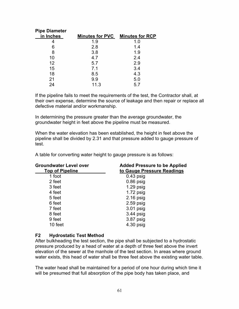
Pipe Diameter in Inches Minutes for PVC Minutes for RCP
4 1.9 1.0 6 2.8 1.4 8 3.8 1.9 10 4.7 2.4 12 5.7 2.9 15 7.1 3.4 18 8.5 4.3 21 9.9 5.0 24 11.3 5.7
If the pipeline fails to meet the requirements of the test, the Contractor shall, at their own expense, determine the source of leakage and then repair or replace all defective material and/or workmanship. In determining the pressure greater than the average groundwater, the groundwater height in feet above the pipeline must be measured. When the water elevation has been established, the height in feet above the pipeline shall be divided by 2.31 and that pressure added to gauge pressure of test. A table for converting water height to gauge pressure is as follows: Groundwater Level over Added Pressure to be Applied Top of Pipeline to Gauge Pressure Readings
1 foot 0.43 psig 2 feet 0.86 psig 3 feet 1.29 psig 4 feet 1.72 psig 5 feet 2.16 psig 6 feet 2.59 psig 7 feet 3.01 psig 8 feet 3.44 psig 9 feet 3.87 psig 10 feet 4.30 psig
F2 Hydrostatic Test Method After bulkheading the test section, the pipe shall be subjected to a hydrostatic pressure produced by a head of water at a depth of three feet above the invert elevation of the sewer at the manhole of the test section. In areas where ground water exists, this head of water shall be three feet above the existing water table. The water head shall be maintained for a period of one hour during which time it will be presumed that full absorption of the pipe body has taken place, and
61

thereafter for an extended period of one hour the water head shall be maintained as the test period. During the one hour test period, the measured water loss within the test section, including service stubs, shall not exceed the Maximum Allowable Loss (in Gallons Per Hour per 100 Feet of Pipe) given below for the applicable Main Sewer Diameter.
Main Sewer Diameter (In Inches)
Maximum Allowable Loss* (In Gallons Per Hour Per 100 Feet)
6 0.5 8 0.6
10 0.8 12 1.0 15 1.2 18 1.4 21 1.7
24 & Larger 1.9 * Based on 100 Gallons Per Day Per Pipe Diameter Inch Per Mile
If measurements indicate exfiltration within a test action section is not greater than the allowable maximum, the section will be accepted as passing the test. F3 Test Failure and Remedy In the event of test failure on any test section, testing shall be continued until all leakage has been detected and corrected to meet the requirements. All repair work shall be subject to approval of the Engineer. Introduction of sealant substances by means of the test water will not be permitted. Unsatisfactory repairs or test results may result in an order to remove and replace pipe as the Engineer considers necessary for test conformance. All repair and replacement work shall be at the Contractor's expense. G Deflection Test Deflection tests shall be performed on all plastic gravity sewer pipes. The test shall be conducted after the sewer trench has been backfilled to the desired finished grade and has been in place for 30 days. The deflection test shall be performed by pulling a rigid ball or nine-point mandrel (Mn/DOT Technical Memorandum 98-24-B-01 or latest revision) through the pipe without the aid of mechanical pulling devices. The ball or mandrel shall have a minimum diameter equal to 95% of the actual inside diameter of the pipe. The maximum allowable deflection shall not exceed five percent of the pipe's internal diameter. The line will be considered acceptable if the mandrel can progress through the line without binding. The time of the test, method of testing, and the equipment to be used for the test shall be subject to the approval of the Engineer.
62

All testing shall be performed by the Contractor at his expense without any direct compensation being made therefor, and he shall furnish all necessary equipment and materials required. G1 Test Failure and Remedy In the event of test failure on any test section, the section shall be replaced, with all repair work subject to approval of the Engineer. The replaced section shall be retested for leakage and deflection in conformance with the specifications contained herein. All repairs, replacement, and retesting shall be at the Contractor's expense. H Televising Sewer line televising may be required by the Engineer, at the cost of the Contractor, if visual inspection, leakage testing, or deflection testing indicate the sewer has not been constructed in accordance with these specifications and the requirements of the Plans, Specifications, and Special Provisions. 2621.4 METHOD OF MEASUREMENT All items will be measured separately according to design designation as indicated in the Pay Item name and as may be detailed and defined in the Plans, Specifications, or Special Provisions. Pipe will generally be designated by size (inside diameter or span), strength class, kind or type, and laying condition. Complete-in-place items shall include all component parts thereof as described or required to complete the unit, but excluding any excesses covered by separate Pay Items. Linear measurement of piping will include the running length of any special fittings (tees, wyes, elbows, gates, etc.) installed within the line of measure between specified terminal points. A Sewer Pipe Sewer pipe of each design designation will be measured by length in linear feet along the line of pipe. Terminal points of measurement will be the pipe end at free outlets; the point of connection with inplace pipe; the center of manholes or catch basins; the point of centerline intersections at branch fittings; or the point of juncture with other appurtenances or units as defined. Separation of quantities according to "depth zone classification", when so designated in the Pay Item, will be determined by depth of pipe invert below the ground surface profile. B Manholes Manholes of each design designation will be measured by number of each constructed complete-in-place, including the base and castings as required, but
63

excluding any excess depth greater than 8.0 feet measured from top of manhole cover to invert elevation of lowest pipe. Excess manhole depth of each design designation will be measured by the linear foot difference in depth between the 8.0 feet allowed as standard and the actual increased depth as constructed. C Catch Basins Catch basins of each design designation will be measured by number of each constructed complete-in-place, including the base and castings as required, but excluding any excess depth greater than 5.0 feet measured from top of grate (low point) to invert elevation of lowest outlet pipe. Excess catch basin depth of each design designation will be measured by the linear foot difference in depth between the 5.0 feet allowed as standard and the actual increased depth as constructed. D Outside Drop Connection Outside drop connections of each design will be measured by number of each constructed complete-in-place, including granular encasement, fittings, and any special piping details as required, including two holes into existing manholes for the drop connection, but excluding any excess vertical drop greater than 2.0 feet measured between invert of high pipe inlet and invert of low pipe outlet. Excess drop connection depth will be measured by the linear foot difference in vertical drop between the 2.0 feet allowed as standard and the actual increased vertical drop as constructed. E Service Connection Service Connections of each design will be measured by number of each constructed complete-in-place as specified. F Service Pipe Service pipe of each design will be measured separately by length in linear feet, horizontally along the line of installation, between the service end and the point of juncture with the main pipe connection fitting. G Special Pipe Fittings Special pipe fittings (wyes, tees, bends, etc.) of each design designation will be measured by number of each installed complete-in-place as specified, but excluding any such fittings required to be installed as a component part of any other Work Unit.
64

65
H Appurtenant Items Appurtenant items such as aprons, trash guards, gates and other prefabricated units or assemblies as identified by Pay Item name will be measured separately by number of each installed complete-in-place as specified. 2621.5 BASIS OF PAYMENT Payment for sewer pipe and service pipe items at the Contract prices per linear foot of pipe of each design shall be compensation in full for all costs of providing a complete-in-place pipeline, including excavation, foundation preparation, backfilling, leakage testing, restoration of surface improvements, disposal of surplus or waste materials, final cleanup, and such other work as may be specified, but excluding the construction of other structures or special sections and the placement of special fittings, appurtenances or materials specifically designated for payment under other Contract Items. Payment for manhole, catch basin, outside drop connection, service connection, and other structures as specified, at the Contract prices per structure, shall be compensation in full for all costs of constructing each unit complete-in-place as specified, including all required castings, special fittings, base or encasement, and appurtenant materials as specified for the complete structure or section, but excluding such additional work as may be designated for payment under other Contract Items. Where the specified standard manhole, catch basin, or outside drop connection depths are exceeded, the excess depth of each design will be paid for separately as linear footage items and payment at the Contract prices therefor shall be compensation in full for all costs of providing the extra depth. Special pipe fittings such as wyes, tees and bends will be paid for as separate Contract Items to the extent they are required to be installed in the sewer pipe and service pipe lines and not as a component part of a complete-in-place structure (outside drop connections, service connections, etc.) Appurtenant items such as aprons, trash guards, drainage gates, and other prefabricated units or assemblies and specials as designated will be paid for as separate Contract Items to the extent they are not included as a component part of any complete-in-place structure.