Embed Size (px)
Citation preview
August 15, 2012
By
Reference Architecture Guide
Citrix XenDesktop 5.5 on VMware 5 with Hitachi Virtual Storage Platform
Roger Clark
FeedbackHitachi Data Systems welcomes your feedback. Please share your thoughts by sending an email message to [email protected]. To assist the routing of this message, use the paper number in the subject and the title of this white paper in the text.
Table of ContentsSolution Overview ............................................................................................................2
Key Solution Components...............................................................................................5
Hitachi Virtual Storage Platform.............................................................................5Hitachi Dynamic Provisioning ...............................................................................5Hitachi Compute Blade 2000 .................................................................................6VMware vSphere 5 ................................................................................................6Citrix XenDesktop 5.5 ............................................................................................7
Solution Design ................................................................................................................8
Infrastructure Block................................................................................................8Desktop Block........................................................................................................9Server Design ......................................................................................................10Storage Design ....................................................................................................12SAN Design .........................................................................................................15Citrix XenDesktop Design....................................................................................16Scalability.............................................................................................................17
Engineering Validation...................................................................................................19
Conclusion ......................................................................................................................20
1
1
Citrix XenDesktop 5.5 on VMware 5 with Hitachi Virtual Storage PlatformReference Architecture Guide
The purpose of this reference architecture on Hitachi Virtual Storage Platform is to present a Microsoft Windows 7 virtual desktop infrastructure environment that does the following:
Lowers administration costs
Improves system efficiency
Maintains performance
Using a building block design, this reference architecture helps you deploy Citrix XenDesktop in a virtualized environment using the following:
VMware vSphere
Hitachi Dynamic Provisioning
Hitachi Compute Blade 2000
Hitachi Virtual Storage Platform
This reference architecture assumes a light end-user workload. There is guidance for sizing and deploying a Microsoft Windows 7 virtual desktop infrastructure (VDI) to support up to 160 users per building block. You can add building blocks to scale up to many thousands of users.
This paper is intended for you if you are an IT administrator responsible for desktops and storage administration. You need some familiarity with Hitachi Storage Navigator, VMware vSphere, and Citrix XenDesktop components.
Note — All testing was done in a lab environment. In production environments, results can be affected by many factors that cannot be predicted or duplicated in a lab. Conduct proof-of-concept testing using your target applications in a non-production, isolated test environment that is identical to your production environment. Following this recommended practice allows you to obtain results closest to what you can expect to experience in your deployment.
2
2
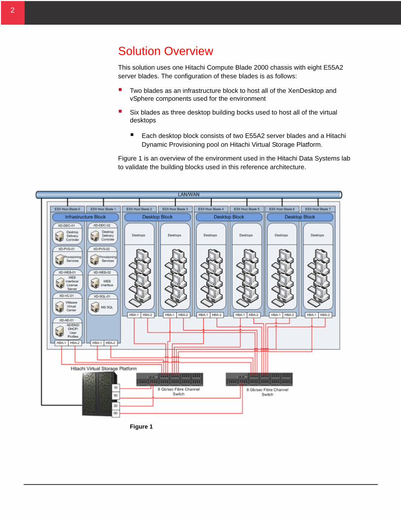
Solution OverviewThis solution uses one Hitachi Compute Blade 2000 chassis with eight E55A2 server blades. The configuration of these blades is as follows:
Two blades as an infrastructure block to host all of the XenDesktop and vSphere components used for the environment
Six blades as three desktop building bocks used to host all of the virtual desktops
Each desktop block consists of two E55A2 server blades and a Hitachi Dynamic Provisioning pool on Hitachi Virtual Storage Platform.
Figure 1 is an overview of the environment used in the Hitachi Data Systems lab to validate the building blocks used in this reference architecture.
Figure 1
3
3
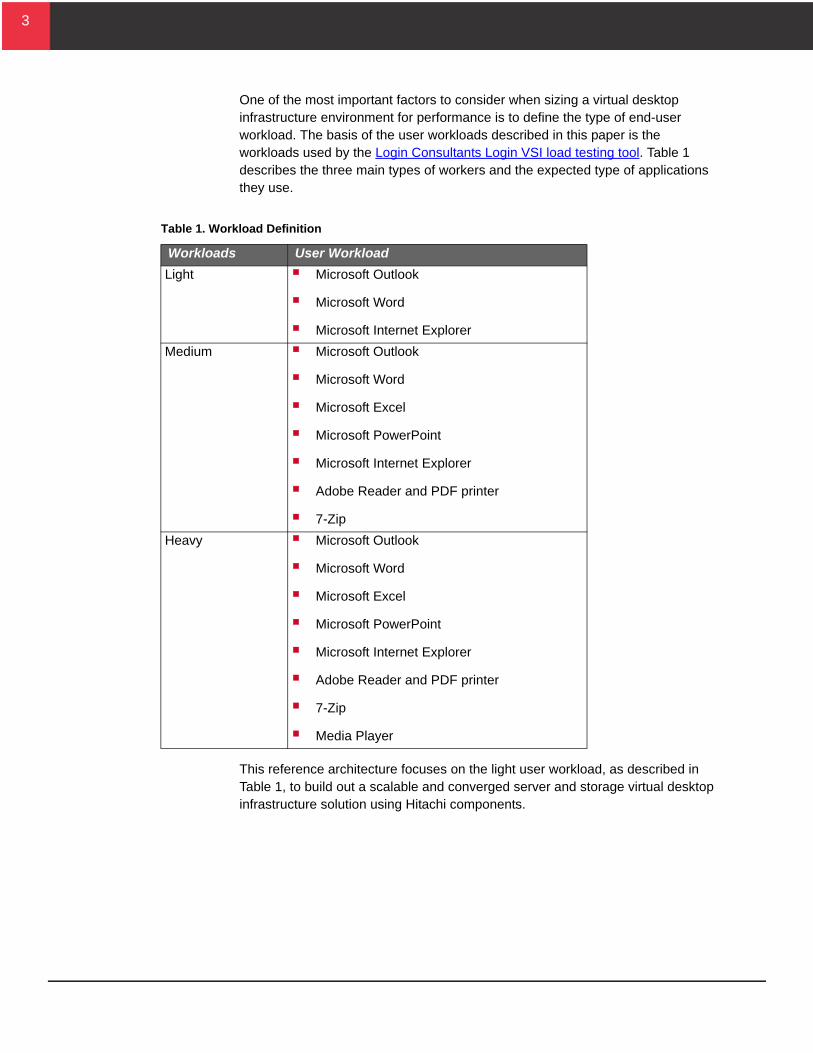
One of the most important factors to consider when sizing a virtual desktop infrastructure environment for performance is to define the type of end-user workload. The basis of the user workloads described in this paper is the workloads used by the Login Consultants Login VSI load testing tool. Table 1 describes the three main types of workers and the expected type of applications they use.
This reference architecture focuses on the light user workload, as described in Table 1, to build out a scalable and converged server and storage virtual desktop infrastructure solution using Hitachi components.
Table 1. Workload Definition
Workloads User Workload
Light Microsoft Outlook
Microsoft Word
Microsoft Internet Explorer
Medium Microsoft Outlook
Microsoft Word
Microsoft Excel
Microsoft PowerPoint
Microsoft Internet Explorer
Adobe Reader and PDF printer
7-Zip
Heavy Microsoft Outlook
Microsoft Word
Microsoft Excel
Microsoft PowerPoint
Microsoft Internet Explorer
Adobe Reader and PDF printer
7-Zip
Media Player
4
4
The following are characteristics of a light user, as defined by the Login Consultants Login VSI tool:
Light User Workload—These users do the following:
Use Microsoft Word for editing document files
Use Microsoft Outlook to view and compose email messages
Browse simple Web sites
Only two applications are opened simultaneously
5
5
Key Solution ComponentsThe following are descriptions of the components used in this reference architecture.
Hitachi Virtual Storage PlatformHitachi Virtual Storage Platform is the first 3-D scaling storage platform designed for all data types. Its storage architecture flexibly adapts for performance, capacity, and multi-vendor storage. Combined with the unique Hitachi Command Suite management platform, it transforms the data center.
Scale Up—Meet increasing demands by dynamically adding processors, connectivity, and capacity in a single unit. Provide the highest performance for both open and mainframe environments.
Scale Out—Meet multiple demands by dynamically combining multiple units into a single logical system with shared resources. Support increased demand in virtualized server environments. Ensure safe multi-tenancy and quality of service through partitioning of cache and ports.
Scale Deep—Extend storage value by virtualizing new and existing external storage systems dynamically. Extend the advanced functions of Hitachi Virtual Storage Platform to multivendor storage. Offload less demanding data to external tiers to save costs and to optimize the availability of tier-one resources.
The trend in desktop virtualization is to consolidate the I/O workload of many desktops onto a single storage system. Consolidating more virtual machines on a physical host requires storage systems to be able to dynamically add more storage resources to keep pace with the I/O demand. The 3-D scaling capability of Hitachi Virtual Storage Platform meets that requirement.
Hitachi Dynamic Provisioning On Hitachi storage systems, Hitachi Dynamic Provisioning provides wide striping and thin provisioning functionalities.
Using Hitachi Dynamic Provisioning is like using a host-based logical volume manager (LVM), but without incurring host processing overhead. It provides one or more wide-striping pools across many RAID groups. Each pool has one or more dynamic provisioning virtual volumes (DP-VOLs) of a logical size you specify of up to 60 TB created against it without allocating any physical space initially.
Deploying Hitachi Dynamic Provisioning avoids the routine issue of hot spots that occur on logical devices (LDEVs). These occur within individual RAID groups when the host workload exceeds the IOPS or throughput capacity of that RAID group. Dynamic provisioning distributes the host workload across many RAID groups, which provides a smoothing effect that dramatically reduces hot spots.
6
6
When used with Hitachi Virtual Storage Platform, Hitachi Dynamic Provisioning has the benefit of thin provisioning. Physical space assignment from the pool to the dynamic provisioning volume happens as needed using 42 MB pages, up to the logical size specified for each dynamic provisioning volume. There can be a dynamic expansion or reduction of pool capacity without disruption or downtime. You can rebalance an expanded pool across the current and newly added RAID groups for an even striping of the data and the workload.
Hitachi Dynamic Provisioning in a Citrix XenDesktop environment allows a leveling of the workload across a large number of disks. This allows sizing the disks for an average workload instead of a peak burst workload.
The advantages of using Hitachi Dynamic Provisioning in a virtual desktop infrastructure are:
Performance balance—Distributes data across all disks in the pool
Over provisioning—Allows over provisioning of the storage
Hitachi Compute Blade 2000Hitachi Compute Blade 2000 is an enterprise-class blade server platform. It features the following:
Configuration flexibility
Eco-friendly power-saving capabilities
Fast server failure recovery using a N+1 cold standby design that allows replacing failed servers within minutes
VMware vSphere 5VMware vSphere 5 is a virtualization platform that provides a datacenter infrastructure. It features vSphere Distributed Resource Scheduler (DRS), high availability, and fault tolerance.
VMware vSphere 5 has the following components:
ESXi 5.0—This is a hypervisor that loads directly on a physical server. It partitions one physical machine into many virtual machines that share hardware resources.
vCenter Server—This allows management of the vSphere environment through a single user interface. With vCenter, there are features available such as vMotion, Storage vMotion, Storage Distributed Resource Scheduler, High Availability, and Fault Tolerance.
Use of the round robin multipathing policy in vSphere 5 distributes load across multiple host bus adapters (HBAs) and multiple storage ports. Use of DRS with Hitachi Dynamic Provisioning automatically distributes loads on the ESX host and across the back end of the storage system.
7
7
Citrix XenDesktop 5.5Citrix XenDesktop is a desktop virtualization solution that transforms Windows desktops and applications into an on-demand service available to any user, anywhere, on any device. With XenDesktop, you can securely deliver individual Windows, web and SaaS applications, or full virtual desktops, to PCs, Macs, tablets, smart phones, laptops and thin clients—all with a high-definition user experience.
This reference architecture describes a proven approach to help simplify the design and planning of the most commonly used form of virtual desktops, Provisioning Services (PVS).
8
8
Solution DesignUsing the key solution components, this reference architecture provides the infrastructure details and methodology for calculating the compute and storage requirements necessary to build a desktop block while sustaining ideal performance supporting a light end-user workload.
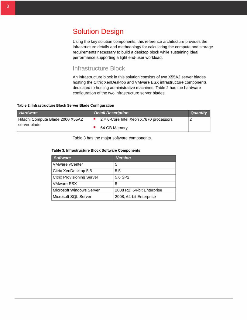
Infrastructure BlockAn infrastructure block in this solution consists of two X55A2 server blades hosting the Citrix XenDesktop and VMware ESX infrastructure components dedicated to hosting administrative machines. Table 2 has the hardware configuration of the two infrastructure server blades.
Table 3 has the major software components.
Table 2. Infrastructure Block Server Blade Configuration
Hardware Detail Description Quantity
Hitachi Compute Blade 2000 X55A2 server blade
2 × 6-Core Intel Xeon X7670 processors
64 GB Memory
2
Table 3. Infrastructure Block Software Components
Software Version
VMware vCenter 5
Citrix XenDesktop 5.5 5.5
Citrix Provisioning Server 5.6 SP2
VMware ESX 5
Microsoft Windows Server 2008 R2, 64-bit Enterprise
Microsoft SQL Server 2008, 64-bit Enterprise
9
9
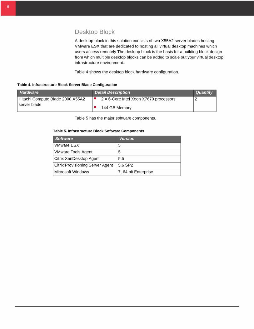
Desktop BlockA desktop block in this solution consists of two X55A2 server blades hosting VMware ESX that are dedicated to hosting all virtual desktop machines which users access remotely The desktop block is the basis for a building block design from which multiple desktop blocks can be added to scale out your virtual desktop infrastructure environment.
Table 4 shows the desktop block hardware configuration.
Table 5 has the major software components.
Table 4. Infrastructure Block Server Blade Configuration
Hardware Detail Description Quantity
Hitachi Compute Blade 2000 X55A2 server blade
2 × 6-Core Intel Xeon X7670 processors
144 GB Memory
2
Table 5. Infrastructure Block Software Components
Software Version
VMware ESX 5
VMware Tools Agent 5
Citrix XenDesktop Agent 5.5
Citrix Provisioning Server Agent 5.6 SP2
Microsoft Windows 7, 64 bit Enterprise
10
10
Server DesignCalculate the scaling for a desktop block using the following recommendations. Use the smaller of the two results as the recommended starting number of desktops per desktop block.
Calculate Maximum Users by HardwareThe following factors play a part to determine the number of desktops your hardware can support:
User workload
Desktop operating system
Applications running on the desktops
The amount of random access memory required for each desktop
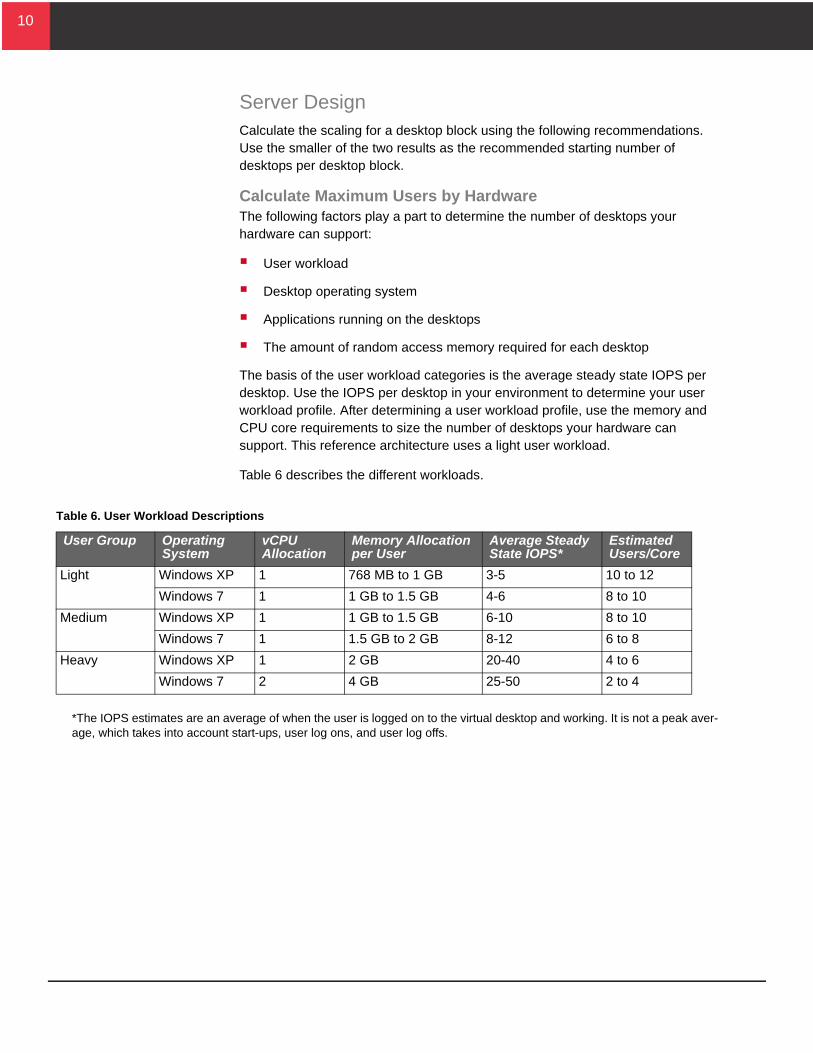
The basis of the user workload categories is the average steady state IOPS per desktop. Use the IOPS per desktop in your environment to determine your user workload profile. After determining a user workload profile, use the memory and CPU core requirements to size the number of desktops your hardware can support. This reference architecture uses a light user workload.
Table 6 describes the different workloads.
*The IOPS estimates are an average of when the user is logged on to the virtual desktop and working. It is not a peak aver-age, which takes into account start-ups, user log ons, and user log offs.
Table 6. User Workload Descriptions
User Group Operating System
vCPU Allocation
Memory Allocation per User
Average Steady State IOPS*
Estimated Users/Core
Light Windows XP 1 768 MB to 1 GB 3-5 10 to 12
Windows 7 1 1 GB to 1.5 GB 4-6 8 to 10
Medium Windows XP 1 1 GB to 1.5 GB 6-10 8 to 10
Windows 7 1 1.5 GB to 2 GB 8-12 6 to 8
Heavy Windows XP 1 2 GB 20-40 4 to 6
Windows 7 2 4 GB 25-50 2 to 4
11
11
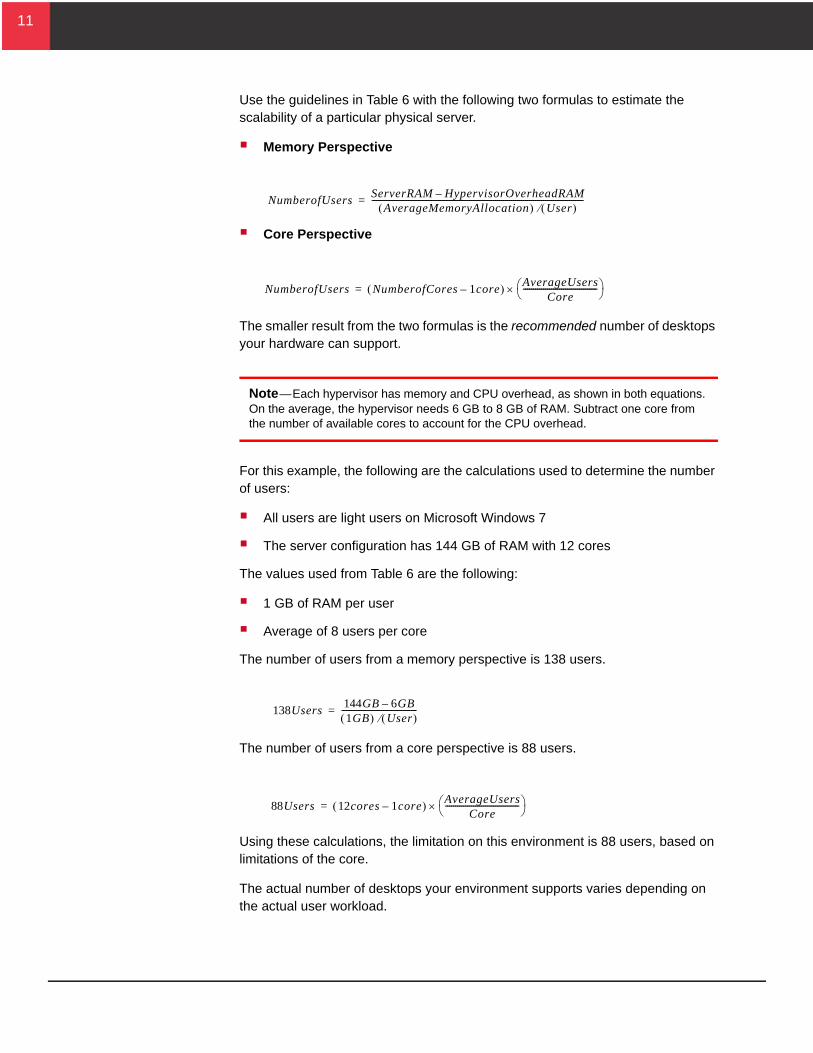
Use the guidelines in Table 6 with the following two formulas to estimate the scalability of a particular physical server.
Memory Perspective
Core Perspective
The smaller result from the two formulas is the recommended number of desktops your hardware can support.
Note—Each hypervisor has memory and CPU overhead, as shown in both equations. On the average, the hypervisor needs 6 GB to 8 GB of RAM. Subtract one core from the number of available cores to account for the CPU overhead.
For this example, the following are the calculations used to determine the number of users:
All users are light users on Microsoft Windows 7
The server configuration has 144 GB of RAM with 12 cores
The values used from Table 6 are the following:
1 GB of RAM per user
Average of 8 users per core
The number of users from a memory perspective is 138 users.
The number of users from a core perspective is 88 users.
Using these calculations, the limitation on this environment is 88 users, based on limitations of the core.
The actual number of desktops your environment supports varies depending on the actual user workload.
NumberofUsersServerRAM HypervisorOverheadRAM–
AverageMemoryAllocation User ----------------------------------------------------------------------------------------------------------=
NumberofUsers NumberofCores 1core– AverageUsersCore
------------------------------------- =
138Users144GB 6GB–1GB User
--------------------------------------=
88Users 12cores 1core– AverageUsersCore
------------------------------------- =
12
12
Storage DesignThis reference architecture uses Hitachi Dynamic Provisioning on Hitachi Virtual Storage Platform. This simplifies the management of the storage through the use of wide striping and on-line expansion of dynamic provisioning pools.
The storage used by the desktop block comprises a single dynamic provisioning pool. The basis of the sizing of the pool is assumptions made about the disks used and virtual desktop infrastructure environments.
Disk
Disk speed
RAID level
Required IOPS
Virtual desktop infrastructure
Estimated IOPS for light user workloads
Industry-standard numbers were used to calculate the number of IOPS required supporting 160 desktops.
User type—Light workload user
Estimated IOPS per desktop—4 IOPS
Estimated IOPS for 160 desktops—640 IOPS
From a capacity standpoint, the validated environment configures each desktop with a 5 GB drive to be used for the write cache and page file. In addition to the cache drive, each desktop utilizes about 1 GB of storage for virtual machine files.
The following information was used to calculate the estimated storage capacity needed for 160 desktops.
Desktop cache drive—5 GB
Hypervisor machine files—1 GB
Total storage per desktop—6 GB
Estimated storage capacity for 160 desktops—960 GB
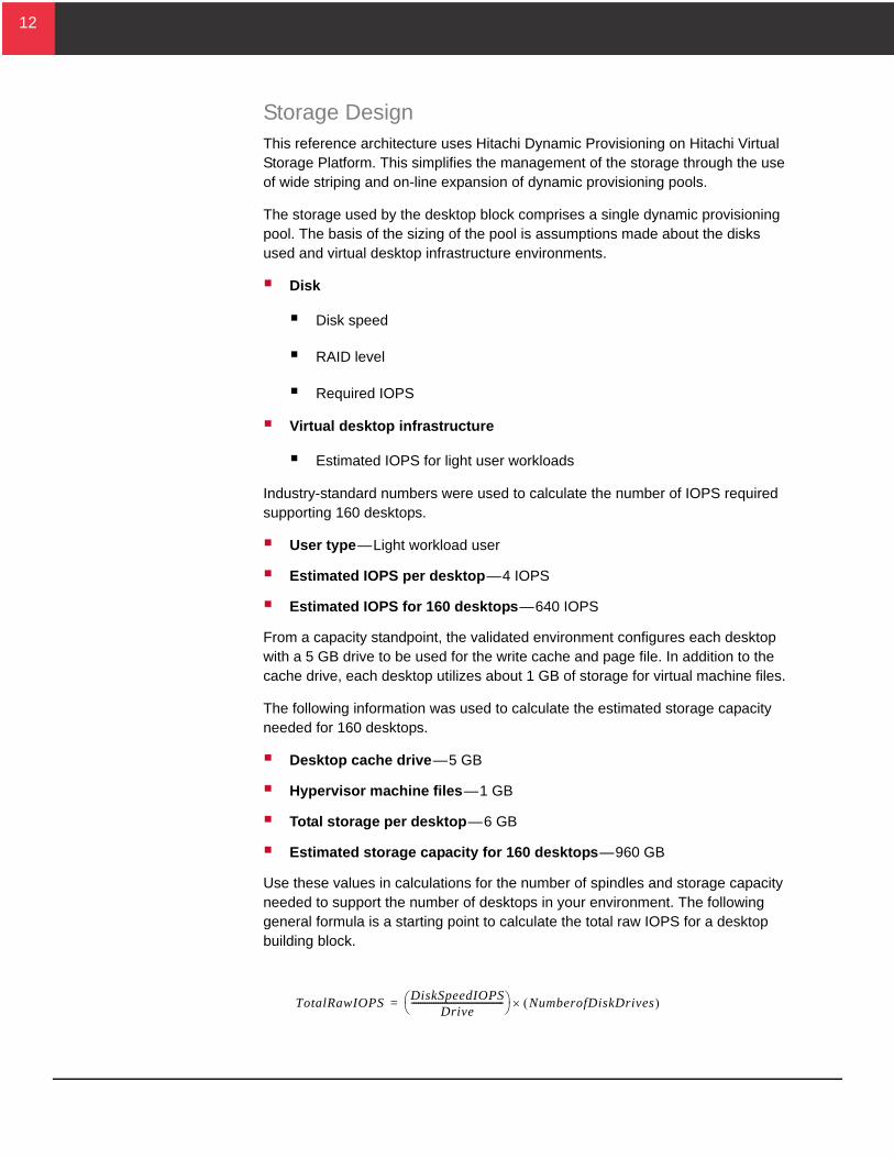
Use these values in calculations for the number of spindles and storage capacity needed to support the number of desktops in your environment. The following general formula is a starting point to calculate the total raw IOPS for a desktop building block.
TotalRawIOPSDiskSpeedIOPS
Drive------------------------------------------ NumberofDiskDrives =
13
13
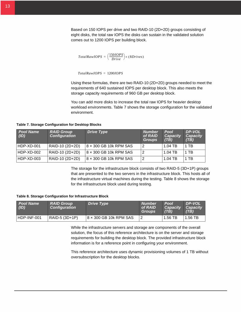
Based on 150 IOPS per drive and two RAID-10 (2D+2D) groups consisting of eight disks, the total raw IOPS the disks can sustain in the validated solution comes out to 1200 IOPS per building block.
Using these formulas, there are two RAID-10 (2D+2D) groups needed to meet the requirements of 640 sustained IOPS per desktop block. This also meets the storage capacity requirements of 960 GB per desktop block.
You can add more disks to increase the total raw IOPS for heavier desktop workload environments. Table 7 shows the storage configuration for the validated environment.
The storage for the infrastructure block consists of two RAID-5 (3D+1P) groups that are presented to the two servers in the infrastructure block. This hosts all of the infrastructure virtual machines during the testing. Table 8 shows the storage for the infrastructure block used during testing.
While the infrastructure servers and storage are components of the overall solution, the focus of this reference architecture is on the server and storage requirements for building the desktop block. The provided infrastructure block information is for a reference point in configuring your environment.
This reference architecture uses dynamic provisioning volumes of 1 TB without oversubscription for the desktop blocks.
TotalRawIOPS150IOPS
Drive----------------------- 8Drives =
TotalRawIOPS 1200IOPS=
Table 7. Storage Configuration for Desktop Blocks
Pool Name (ID)
RAID Group Configuration
Drive Type Number of RAID Groups
Pool Capacity (TB)
DP-VOL Capacity (TB)
HDP-XD-001 RAID-10 (2D+2D) 8 × 300 GB 10k RPM SAS 2 1.04 TB 1 TB
HDP-XD-002 RAID-10 (2D+2D) 8 × 300 GB 10k RPM SAS 2 1.04 TB 1 TB
HDP-XD-003 RAID-10 (2D+2D) 8 × 300 GB 10k RPM SAS 2 1.04 TB 1 TB
Table 8. Storage Configuration for Infrastructure Block
Pool Name (ID)
RAID Group Configuration
Drive Type Number of RAID Groups
Pool Capacity (TB)
DP-VOL Capacity (TB)
HDP-INF-001 RAID-5 (3D+1P) 8 × 300 GB 10k RPM SAS 2 1.56 TB 1.56 TB
14
14
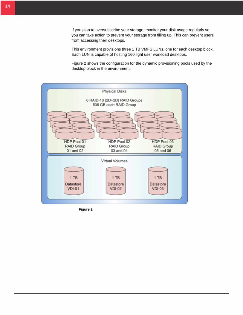
If you plan to oversubscribe your storage, monitor your disk usage regularly so you can take action to prevent your storage from filling up. This can prevent users from accessing their desktops.
This environment provisions three 1 TB VMFS LUNs, one for each desktop block. Each LUN is capable of hosting 160 light user workload desktops.
Figure 2 shows the configuration for the dynamic provisioning pools used by the desktop block in the environment.
Figure 2
15
15
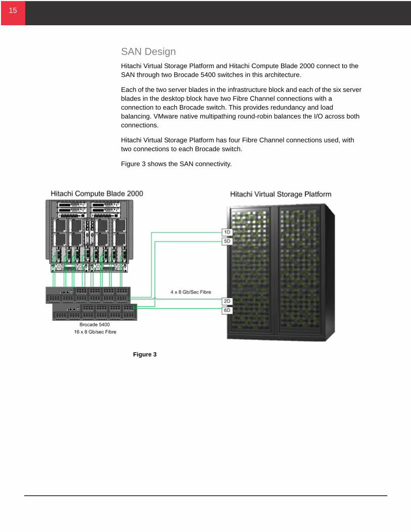
SAN DesignHitachi Virtual Storage Platform and Hitachi Compute Blade 2000 connect to the SAN through two Brocade 5400 switches in this architecture.
Each of the two server blades in the infrastructure block and each of the six server blades in the desktop block have two Fibre Channel connections with a connection to each Brocade switch. This provides redundancy and load balancing. VMware native multipathing round-robin balances the I/O across both connections.
Hitachi Virtual Storage Platform has four Fibre Channel connections used, with two connections to each Brocade switch.
Figure 3 shows the SAN connectivity.
Figure 3
16
16
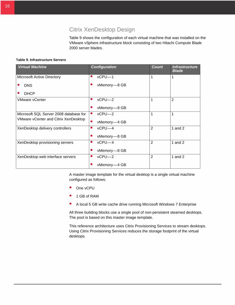
Citrix XenDesktop DesignTable 9 shows the configuration of each virtual machine that was installed on the VMware vSphere infrastructure block consisting of two Hitachi Compute Blade 2000 server blades.
A master image template for the virtual desktop is a single virtual machine configured as follows:
One vCPU
1 GB of RAM
A local 5 GB write cache drive running Microsoft Windows 7 Enterprise
All three building blocks use a single pool of non-persistent steamed desktops. The pool is based on this master image template.
This reference architecture uses Citrix Provisioning Services to stream desktops. Using Citrix Provisioning Services reduces the storage footprint of the virtual desktops.
Table 9. Infrastructure Servers
Virtual Machine Configuration Count Infrastructure Blade
Microsoft Active Directory
DNS
DHCP
vCPU—1
vMemory—8 GB
1 1
VMware vCenter vCPU—2
vMemory—8 GB
1 2
Microsoft SQL Server 2008 database for VMware vCenter and Citrix XenDesktop
vCPU—2
vMemory—4 GB
1 1
XenDesktop delivery controllers vCPU—4
vMemory—8 GB
2 1 and 2
XenDesktop provisioning servers vCPU—4
vMemory—8 GB
2 1 and 2
XenDesktop web interface servers vCPU—2
vMemory—4 GB
2 1 and 2
17
17
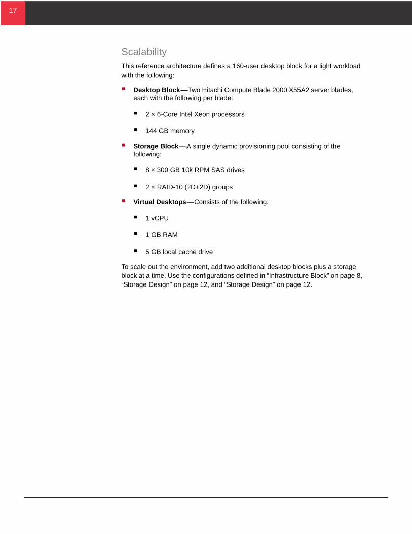
ScalabilityThis reference architecture defines a 160-user desktop block for a light workload with the following:
Desktop Block—Two Hitachi Compute Blade 2000 X55A2 server blades, each with the following per blade:
2 × 6-Core Intel Xeon processors
144 GB memory
Storage Block—A single dynamic provisioning pool consisting of the following:
8 × 300 GB 10k RPM SAS drives
2 × RAID-10 (2D+2D) groups
Virtual Desktops—Consists of the following:
1 vCPU
1 GB RAM
5 GB local cache drive
To scale out the environment, add two additional desktop blocks plus a storage block at a time. Use the configurations defined in “Infrastructure Block” on page 8, “Storage Design” on page 12, and “Storage Design” on page 12.
18
18
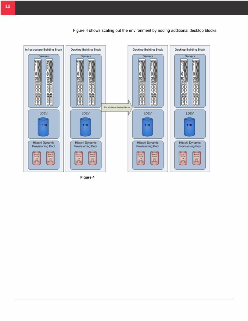
Figure 4 shows scaling out the environment by adding additional desktop blocks.
Figure 4
19
19
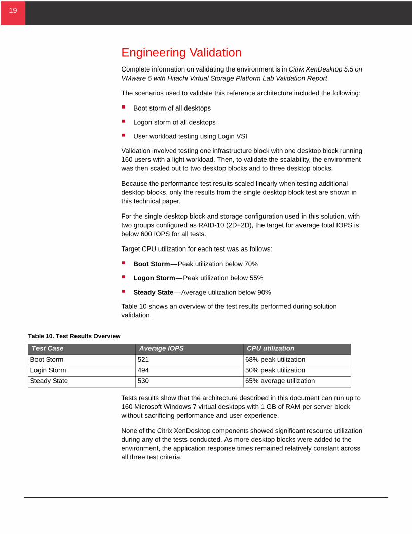
Engineering ValidationComplete information on validating the environment is in Citrix XenDesktop 5.5 on VMware 5 with Hitachi Virtual Storage Platform Lab Validation Report.
The scenarios used to validate this reference architecture included the following:
Boot storm of all desktops
Logon storm of all desktops
User workload testing using Login VSI
Validation involved testing one infrastructure block with one desktop block running 160 users with a light workload. Then, to validate the scalability, the environment was then scaled out to two desktop blocks and to three desktop blocks.
Because the performance test results scaled linearly when testing additional desktop blocks, only the results from the single desktop block test are shown in this technical paper.
For the single desktop block and storage configuration used in this solution, with two groups configured as RAID-10 (2D+2D), the target for average total IOPS is below 600 IOPS for all tests.
Target CPU utilization for each test was as follows:
Boot Storm—Peak utilization below 70%
Logon Storm—Peak utilization below 55%
Steady State—Average utilization below 90%
Table 10 shows an overview of the test results performed during solution validation.
Tests results show that the architecture described in this document can run up to 160 Microsoft Windows 7 virtual desktops with 1 GB of RAM per server block without sacrificing performance and user experience.
None of the Citrix XenDesktop components showed significant resource utilization during any of the tests conducted. As more desktop blocks were added to the environment, the application response times remained relatively constant across all three test criteria.
Table 10. Test Results Overview
Test Case Average IOPS CPU utilization
Boot Storm 521 68% peak utilization
Login Storm 494 50% peak utilization
Steady State 530 65% average utilization
20
20
ConclusionThis reference architecture supports up to 160 users with a light workload per desktop block.
Using the building block design consisting of desktop and storage blocks in this reference architecture can help you design a virtual desktop infrastructure environment.
When sizing out a virtual desktop infrastructure environment, characterize the user workload before migrating to a Citrix XenDesktop environment.
This document provides proven methods to assist you in sizing and testing your virtual desktop infrastructure environment. The conditions in your production environment can vary greatly from the lab environment at Hitachi Data Systems, and may not apply to your situation. A full desktop capacity planning assessment provides more precise sizing requirements for your environment.
For More InformationHitachi Data Systems Global Services offers experienced storage consultants, proven methodologies and a comprehensive services portfolio to assist you in implementing Hitachi products and solutions in your environment. For more information, see the Hitachi Data Systems Global Services website.
Live and recorded product demonstrations are available for many Hitachi products. To schedule a live demonstration, contact a sales representative. To view a recorded demonstration, see the Hitachi Data Systems Corporate Resources website. Click the Product Demos tab for a list of available recorded demonstrations.
Hitachi Data Systems Academy provides best-in-class training on Hitachi products, technology, solutions and certifications. Hitachi Data Systems Academy delivers on-demand web-based training (WBT), classroom-based instructor-led training (ILT) and virtual instructor-led training (vILT) courses. For more information, see the Hitachi Data Systems Services Education website.
For more information about Hitachi products and services, contact your sales representative or channel partner or visit the Hitachi Data Systems website.
Corporate Headquarters750 Central Expressway, Santa Clara, California 95050-2627 USAwww.HDS.com
Regional Contact InformationAmericas: +1 408 970 1000 or [email protected], Middle East and Africa: +44 (0) 1753 618000 or [email protected] Asia-Pacific: +852 3189 7900 or [email protected] is a registered trademark of Hitachi, Ltd., in the United States and other countries. Hitachi Data Systems is a registered trademark and service mark of Hitachi, Ltd., in the United States and other countries. All other trademarks, service marks, and company names in this document or website are properties of their respective owners.
Notice: This document is for informational purposes only, and does not set forth any warranty, expressed or implied, concerning any equipment or service offered or to be offered by Hitachi Data Systems Corporation.
© Hitachi Data Systems Corporation 2012. All Rights Reserved. AS-156-00, August 2012


![VSP 5.5 Virtual Machine Management Test [V5.5] deutsch](https://img.pdfslide.us/doc/110x75/55cf8644550346484b95e9ac/vsp-55-virtual-machine-management-test-v55-deutsch.jpg)