Embed Size (px)
Citation preview
11944 Phys. Chem. Chem. Phys., 2012, 14, 11944–11952 This journal is c the Owner Societies 2012
Cite this: Phys. Chem. Chem. Phys., 2012, 14, 11944–11952
The effect of intermolecular hydrogen bonding on the planarity of
amidesw
James A. Platts,* Hasmerya Maarof, Kenneth D. M. Harris,* Gin Keat Lim and
David J. Willock
Received 25th May 2012, Accepted 11th July 2012
DOI: 10.1039/c2cp41716b
Ab initio and density functional theory (DFT) calculations on some model systems are presented
to assess the extent to which intermolecular hydrogen bonding can affect the planarity of amide
groups. Formamide and urea are examined as archetypes of planar and non-planar amides,
respectively. DFT optimisations suggest that appropriately disposed hydrogen-bond donor or
acceptor molecules can induce non-planarity in formamide, with OCNH dihedral angles deviating
by up to ca. 201 from planarity. Ab initio energy calculations demonstrate that the energy
required to deform an amide molecule from the preferred geometry of the isolated molecule is
more than compensated by the stabilisation due to hydrogen bonding. Similarly, the NH2 group
in urea can be made effectively planar by the presence of appropriately positioned hydrogen-bond
acceptors, whereas hydrogen-bond donors increase the non-planarity of the NH2 group. Small
clusters (a dimer, two trimers and a pentamer) extracted from the crystal structure of urea
indicate that the crystal field acts to force planarity of the urea molecule; however, the interaction
with nearest neighbours alone is insufficient to induce the molecule to become completely planar,
and longer-range effects are required. Finally, the potential for intermolecular hydrogen bonding
to induce non-planarity in a model of a peptide is explored. Inter alia, the insights obtained in the
present work on the extent to which the geometry of amide groups may be deformed under the
influence of intermolecular hydrogen bonding provide structural guidelines that can assist the
interpretation of the geometries of such groups in structure determination from powder X-ray
diffraction data.
Introduction
The geometry of amide CONH2 groups, particularly concerning
the planarity at the N atom, has been the subject of a range of
experimental and computational studies, revealing that the
ground-state geometry of the isolated molecule in the gas
phase is planar in some cases (e.g. formamide) and non-planar
in other cases (e.g. urea).1 In contrast, in the crystal structure
of ‘‘pure’’ urea2 and the crystal structures of the widely studied
urea inclusion compounds3 (which contain a tunnel host
structure constructed from a hydrogen-bonded arrangement
of urea molecules), the urea molecule is completely planar. The
potential energy involved in the perturbation of amides from
planarity has been studied in detail, and many studies of the
origin of planarity versus non-planarity have been reported.1
These calculations generally support the conventional reso-
nance view of the bonding in amides, showing charge transfer
from N to C and O giving some double bond character to the
C–N bond. However, it is also pointed out that there is
accompanying C to N s-donation so that the calculated
atomic charges are smaller than expected from transfer of
the N lone pair density to C and O. The hydrogen bonding
interactions of amides, most notably with water, have also
been the focus of many reports.4
Clearly, as observed for urea in the crystalline state, the
energy required to deform the amide group from the ground-
state geometry of the isolated molecule can be compensated by
the formation of an appropriate arrangement of intermolecular
hydrogen bonds. Although such observations are already well
known, there is nevertheless the need for systematic studies to
establish, on a more quantitative basis, the extent to which the
degree of planarity of amide groups may be modulated by the
formation of intermolecular hydrogen bonds. This may involve
one or both of the N–H bonds of the NH2 group as the donor in
an N–H� � �X hydrogen bond to a neighbouring hydrogen-bond
School of Chemistry, Cardiff University, Park Place,Cardiff CF10 3AT, Wales, UK. E-mail: [email protected],[email protected]; Fax: +44 (0)2920-874030;Tel: +44 (0)2920-874950, +44 (0)2920-870133w Electronic supplementary information (ESI) available: Optimisedcoordinates of all molecules and complexes reported, basis set depen-dence of the binding energy of the urea dimer, and method dependenceof formamide� � �HF geometry and binding energy. See DOI: 10.1039/c2cp41716b
PCCP Dynamic Article Links
www.rsc.org/pccp PAPER
Ope
n A
cces
s A
rtic
le. P
ublis
hed
on 1
2 Ju
ly 2
012.
Dow
nloa
ded
on 0
9/12
/201
3 12
:52:
25.
Thi
s ar
ticle
is li
cens
ed u
nder
a C
reat
ive
Com
mon
s A
ttrib
utio
n 3.
0 U
npor
ted
Lic
ence
.
View Article Online / Journal Homepage / Table of Contents for this issue
This journal is c the Owner Societies 2012 Phys. Chem. Chem. Phys., 2012, 14, 11944–11952 11945
acceptor X and/or may involve the N atom of the NH2 group
as the acceptor in a Y–H� � �N hydrogen bond to a neighbouring
hydrogen-bond donor Y–H. A recent example comes from the
anticonvulsant drug carbamazepine, for which accurate pre-
dictions of observed crystal structures were only possible if the
amide group was allowed to deform in order to optimise
hydrogen bonding.5 Thus, one of the main motivations under-
lying the present study is to establish reasonable geometric
guidelines for the types of deformation from the ground-state
geometry of isolated amide molecules that might occur in
crystal structures involving hydrogen bonding of the amide
group of the same molecules.
Although neutron diffraction is the most definitive tech-
nique for accurate determination of the positions of H (or
deuterium) atoms in crystal structures,6 single-crystal X-ray
diffraction (XRD) can also establish the positions of H atoms
in organic crystal structures with a reasonable degree of
accuracy (particularly by exploiting modern instrumenta-
tion for high-quality data collection), allowing the degree of
planarity of amide groups to be established reliably from
analysis of such data.6 However, although single-crystal
XRD is a powerful experimental technique for determining
crystal structures, the requirement for a suitable single-crystal
specimen imposes a limitation on the applicability of such
methods. When a suitable single crystal of the material of
interest cannot be prepared, structure determination must be
tackled instead from powder XRD data.7 The task of carrying
out structure determination directly from powder XRD data is
considerably more challenging than from single-crystal XRD
data, particularly in the case of organic materials, and the
accuracy of the structural information obtained from analysis
of powder XRD data is significantly lower. Thus, in general,
crystal structure determination from powder XRD data cannot
establish unambiguously the positions of H atoms in organic
crystal structures, and hence the geometry of an amide group
may be difficult to establish reliably by this technique. In
favourable cases, the locations of the H atoms might be inferred
from the positions that give the most reasonable N–H� � �Xhydrogen bonds to neighbouring hydrogen-bond acceptor
groups, but if optimization of the hydrogen-bond geometry
would entail a significant deformation of the amide group from
its geometry in the isolated molecule, then caution must be
exercised in making such assignments. The positions of H atoms
are the consequence of a balance between intra-molecular forces
and inter-molecular forces, so that relying on geometric con-
siderations alone without insights into the true balance between
these two effects is unlikely to be reliable. Thus, another aim of
this work is to provide quantitative insights on the extent to
which the planarity of amide groups may be deformed under the
influence of intermolecular hydrogen bonding, in order to assist
the interpretation of the geometries of such groups when
carrying out structure determination from powder XRD data.
For this study, we focus on formamide and urea as model
amide molecules, recognizing (as stated above) that the degree
of planarity of the amide group in the isolated molecule is
significantly different in the case of formamide and urea.
Furthermore, we also consider glycyl glycine as an example
of an amide group in a model peptide. We consider com-
plexes comprising these molecules together with one or more
hydrogen-bond acceptor or hydrogen-bond donor molecules,
focusing on hydrogen cyanide (NCH) as a model hydrogen-
bond acceptor and hydrogen fluoride (HF) as a model hydrogen-
bond donor. Rather than searching for minima on the potential
energy surface, we take the approach of fixing the position of
the hydrogen-bond donor or acceptor to explore the response
of the amide in a systematic and controlled manner. In each
case, the linear geometry of these molecules ensures that the
results are not influenced by the formation of secondary
interactions. In the case of glycyl glycine, water is also
considered as a hydrogen-bond donor.
Computational methods
All geometries were optimised using tight convergence criteria
at the B3LYP/aug-cc-pVnZ (n = D or T) level8,9 using
Gaussian03.10 B3LYP was chosen due to its proven ability
to describe the geometry and strength of hydrogen bonds.11 In
the calculations on individual molecules, point group symmetry
was conserved, i.e. Cs for formamide, C2 for urea and CNv for
HF and NCH. For the calculations on the hydrogen-bonded
complexes, no such symmetry constraints were applied. Glycyl
glycine was constructed in its extended form, i.e. f= c=1801,
but no symmetry constraints were applied. Local minima and
transition states were confirmed as such from the number of
negative eigenvalues of the Hessian matrix following harmonic
frequency calculation. The effect of the orientation of hydrogen
bonding was explored by fixing relevant dihedral angles that
define the geometry of interaction of the donor and acceptor,
and possible complications due to secondary interactions were
avoided by enforcing linearity of all hydrogen bonds. All other
geometric parameters, including donor–acceptor distances,
were fully optimized in all cases.
Single-point energies were evaluated at these constrained
optimized geometries using the density-fitting, local 2nd order
Møller–Plesset (DF-LMP2) method,12 again with the aug-
cc-pVTZ basis set.9 This method has been shown to closely
reproduce conventional MP2 energies at a fraction of the
computational cost, and also renders basis set superposition
error negligible by construction, and hence has been tested
extensively for a range of non-covalent interactions.13 Auxiliary
fitting basis sets appropriate to aug-cc-pVTZ were taken
from ref. 14, and orbitals were localized by the Pipek–Mezey
scheme15 with orbital domains selected using the criteria of
Broughton and Pulay.16 All such calculations were performed
using Molpro version 2010.1.17
In this study, we use Ebind to denote the binding energy of
the complex, representing the total energy associated with
formation of the geometry-optimized complex starting from
the individual (isolated) molecules in their ground-state geo-
metries. The binding energy Ebind can be broken down into
two separate contributions denoted Edef (deformation energy)
and Eint (interaction energy). Thus, Edef is the energy asso-
ciated with deformation of the isolated molecules from their
ground-state geometry to the geometry that they adopt in the
geometry-optimized complex, and Eint is the energy associated
with formation of the (geometry-optimized) complex starting
from the isolated molecules already in the deformed geometry
adopted in the complex, such that Ebind = Edef + Eint.
Ope
n A
cces
s A
rtic
le. P
ublis
hed
on 1
2 Ju
ly 2
012.
Dow
nloa
ded
on 0
9/12
/201
3 12
:52:
25.
Thi
s ar
ticle
is li
cens
ed u
nder
a C
reat
ive
Com
mon
s A
ttrib
utio
n 3.
0 U
npor
ted
Lic
ence
.
View Article Online
11946 Phys. Chem. Chem. Phys., 2012, 14, 11944–11952 This journal is c the Owner Societies 2012
Results and discussion
1. Formamide
The geometry of formamide optimized in Cs symmetry is in
excellent agreement with the results of previous experiments
and high-level ab initio calculations,1a and harmonic frequency
calculation confirms that the planar structure is a true minimum.
In this geometry, the amide N atom may be expected to act
only as a weak hydrogen-bond acceptor due to delocalization
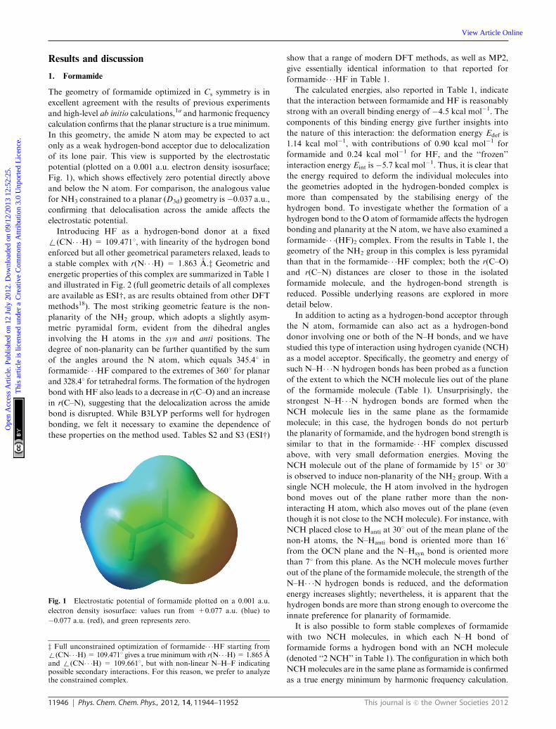
of its lone pair. This view is supported by the electrostatic
potential (plotted on a 0.001 a.u. electron density isosurface;
Fig. 1), which shows effectively zero potential directly above
and below the N atom. For comparison, the analogous value
for NH3 constrained to a planar (D3d) geometry is�0.037 a.u.,confirming that delocalisation across the amide affects the
electrostatic potential.
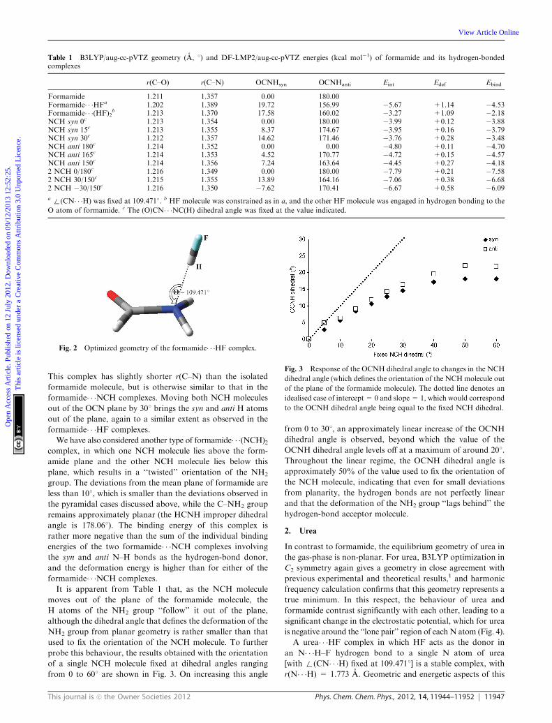
Introducing HF as a hydrogen-bond donor at a fixed
+(CN� � �H) = 109.4711, with linearity of the hydrogen bond
enforced but all other geometrical parameters relaxed, leads to
a stable complex with r(N� � �H) = 1.863 A.z Geometric and
energetic properties of this complex are summarized in Table 1
and illustrated in Fig. 2 (full geometric details of all complexes
are available as ESIw, as are results obtained from other DFT
methods18). The most striking geometric feature is the non-
planarity of the NH2 group, which adopts a slightly asym-
metric pyramidal form, evident from the dihedral angles
involving the H atoms in the syn and anti positions. The
degree of non-planarity can be further quantified by the sum
of the angles around the N atom, which equals 345.41 in
formamide� � �HF compared to the extremes of 3601 for planar
and 328.41 for tetrahedral forms. The formation of the hydrogen
bond with HF also leads to a decrease in r(C–O) and an increase
in r(C–N), suggesting that the delocalization across the amide
bond is disrupted. While B3LYP performs well for hydrogen
bonding, we felt it necessary to examine the dependence of
these properties on the method used. Tables S2 and S3 (ESIw)
show that a range of modern DFT methods, as well as MP2,
give essentially identical information to that reported for
formamide� � �HF in Table 1.
The calculated energies, also reported in Table 1, indicate
that the interaction between formamide and HF is reasonably
strong with an overall binding energy of �4.5 kcal mol�1. The
components of this binding energy give further insights into
the nature of this interaction: the deformation energy Edef is
1.14 kcal mol�1, with contributions of 0.90 kcal mol�1 for
formamide and 0.24 kcal mol�1 for HF, and the ‘‘frozen’’
interaction energy Eint is �5.7 kcal mol�1. Thus, it is clear that
the energy required to deform the individual molecules into
the geometries adopted in the hydrogen-bonded complex is
more than compensated by the stabilising energy of the
hydrogen bond. To investigate whether the formation of a
hydrogen bond to the O atom of formamide affects the hydrogen
bonding and planarity at the N atom, we have also examined a
formamide� � �(HF)2 complex. From the results in Table 1, the
geometry of the NH2 group in this complex is less pyramidal
than that in the formamide� � �HF complex; both the r(C–O)
and r(C–N) distances are closer to those in the isolated
formamide molecule, and the hydrogen-bond strength is
reduced. Possible underlying reasons are explored in more
detail below.
In addition to acting as a hydrogen-bond acceptor through
the N atom, formamide can also act as a hydrogen-bond
donor involving one or both of the N–H bonds, and we have
studied this type of interaction using hydrogen cyanide (NCH)
as a model acceptor. Specifically, the geometry and energy of
such N–H� � �N hydrogen bonds has been probed as a function
of the extent to which the NCH molecule lies out of the plane
of the formamide molecule (Table 1). Unsurprisingly, the
strongest N–H� � �N hydrogen bonds are formed when the
NCH molecule lies in the same plane as the formamide
molecule; in this case, the hydrogen bonds do not perturb
the planarity of formamide, and the hydrogen bond strength is
similar to that in the formamide� � �HF complex discussed
above, with very small deformation energies. Moving the
NCH molecule out of the plane of formamide by 151 or 301
is observed to induce non-planarity of the NH2 group. With a
single NCH molecule, the H atom involved in the hydrogen
bond moves out of the plane rather more than the non-
interacting H atom, which also moves out of the plane (even
though it is not close to the NCHmolecule). For instance, with
NCH placed close to Hanti at 301 out of the mean plane of the
non-H atoms, the N–Hanti bond is oriented more than 161
from the OCN plane and the N–Hsyn bond is oriented more
than 71 from this plane. As the NCH molecule moves further
out of the plane of the formamide molecule, the strength of the
N–H� � �N hydrogen bonds is reduced, and the deformation
energy increases slightly; nevertheless, it is apparent that the
hydrogen bonds are more than strong enough to overcome the
innate preference for planarity of formamide.
It is also possible to form stable complexes of formamide
with two NCH molecules, in which each N–H bond of
formamide forms a hydrogen bond with an NCH molecule
(denoted ‘‘2 NCH’’ in Table 1). The configuration in which both
NCHmolecules are in the same plane as formamide is confirmed
as a true energy minimum by harmonic frequency calculation.
Fig. 1 Electrostatic potential of formamide plotted on a 0.001 a.u.
electron density isosurface: values run from +0.077 a.u. (blue) to
�0.077 a.u. (red), and green represents zero.
z Full unconstrained optimization of formamide� � �HF starting from+(CN� � �H)= 109.4711 gives a true minimum with r(N� � �H)= 1.865 Aand +(CN� � �H) = 109.6611, but with non-linear N–H–F indicatingpossible secondary interactions. For this reason, we prefer to analyzethe constrained complex.
Ope
n A
cces
s A
rtic
le. P
ublis
hed
on 1
2 Ju
ly 2
012.
Dow
nloa
ded
on 0
9/12
/201
3 12
:52:
25.
Thi
s ar
ticle
is li
cens
ed u
nder
a C
reat
ive
Com
mon
s A
ttrib
utio
n 3.
0 U
npor
ted
Lic
ence
.
View Article Online
This journal is c the Owner Societies 2012 Phys. Chem. Chem. Phys., 2012, 14, 11944–11952 11947
This complex has slightly shorter r(C–N) than the isolated
formamide molecule, but is otherwise similar to that in the
formamide� � �NCH complexes. Moving both NCH molecules
out of the OCN plane by 301 brings the syn and anti H atoms
out of the plane, again to a similar extent as observed in the
formamide� � �HF complexes.
We have also considered another type of formamide� � �(NCH)2complex, in which one NCH molecule lies above the form-
amide plane and the other NCH molecule lies below this
plane, which results in a ‘‘twisted’’ orientation of the NH2
group. The deviations from the mean plane of formamide are
less than 101, which is smaller than the deviations observed in
the pyramidal cases discussed above, while the C–NH2 group
remains approximately planar (the HCNH improper dihedral
angle is 178.061). The binding energy of this complex is
rather more negative than the sum of the individual binding
energies of the two formamide� � �NCH complexes involving
the syn and anti N–H bonds as the hydrogen-bond donor,
and the deformation energy is higher than for either of the
formamide� � �NCH complexes.
It is apparent from Table 1 that, as the NCH molecule
moves out of the plane of the formamide molecule, the
H atoms of the NH2 group ‘‘follow’’ it out of the plane,
although the dihedral angle that defines the deformation of the
NH2 group from planar geometry is rather smaller than that
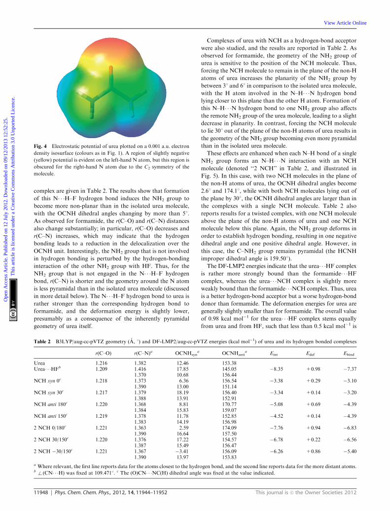
used to fix the orientation of the NCH molecule. To further
probe this behaviour, the results obtained with the orientation
of a single NCH molecule fixed at dihedral angles ranging
from 0 to 601 are shown in Fig. 3. On increasing this angle
from 0 to 301, an approximately linear increase of the OCNH
dihedral angle is observed, beyond which the value of the
OCNH dihedral angle levels off at a maximum of around 201.
Throughout the linear regime, the OCNH dihedral angle is
approximately 50% of the value used to fix the orientation of
the NCH molecule, indicating that even for small deviations
from planarity, the hydrogen bonds are not perfectly linear
and that the deformation of the NH2 group ‘‘lags behind’’ the
hydrogen-bond acceptor molecule.
2. Urea
In contrast to formamide, the equilibrium geometry of urea in
the gas-phase is non-planar. For urea, B3LYP optimization in
C2 symmetry again gives a geometry in close agreement with
previous experimental and theoretical results,1 and harmonic
frequency calculation confirms that this geometry represents a
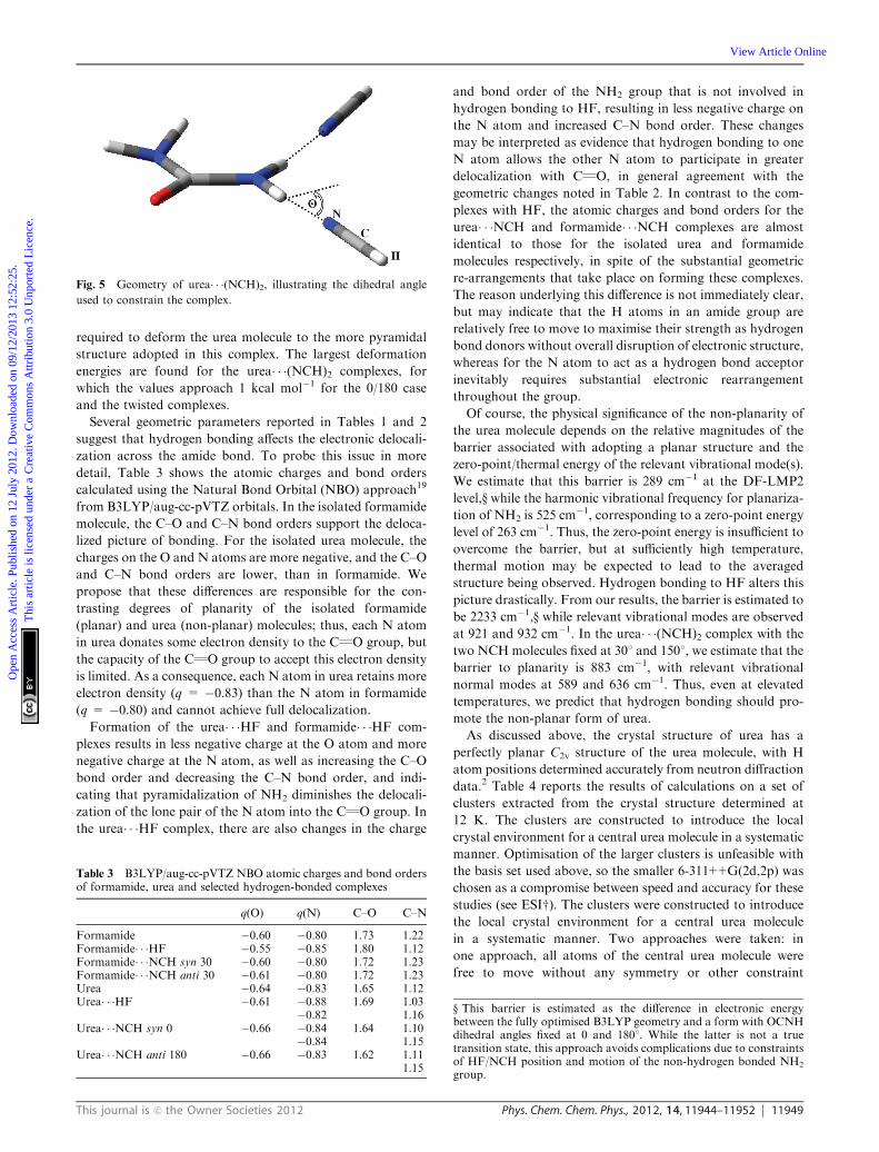
true minimum. In this respect, the behaviour of urea and
formamide contrast significantly with each other, leading to a
significant change in the electrostatic potential, which for urea
is negative around the ‘‘lone pair’’ region of each N atom (Fig. 4).
A urea� � �HF complex in which HF acts as the donor in
an N� � �H–F hydrogen bond to a single N atom of urea
[with +(CN� � �H) fixed at 109.4711] is a stable complex, with
r(N� � �H) = 1.773 A. Geometric and energetic aspects of this
Table 1 B3LYP/aug-cc-pVTZ geometry (A, 1) and DF-LMP2/aug-cc-pVTZ energies (kcal mol�1) of formamide and its hydrogen-bondedcomplexes
r(C–O) r(C–N) OCNHsyn OCNHanti Eint Edef Ebind
Formamide 1.211 1.357 0.00 180.00Formamide� � �HFa 1.202 1.389 19.72 156.99 �5.67 +1.14 �4.53Formamide� � �(HF)2
b 1.213 1.370 17.58 160.02 �3.27 +1.09 �2.18NCH syn 0c 1.213 1.354 0.00 180.00 �3.99 +0.12 �3.88NCH syn 15c 1.213 1.355 8.37 174.67 �3.95 +0.16 �3.79NCH syn 30c 1.212 1.357 14.62 171.46 �3.76 +0.28 �3.48NCH anti 180c 1.214 1.352 0.00 0.00 �4.80 +0.11 �4.70NCH anti 165c 1.214 1.353 4.52 170.77 �4.72 +0.15 �4.57NCH anti 150c 1.214 1.356 7.24 163.64 �4.45 +0.27 �4.182 NCH 0/180c 1.216 1.349 0.00 180.00 �7.79 +0.21 �7.582 NCH 30/150c 1.215 1.355 13.89 164.16 �7.06 +0.38 �6.682 NCH �30/150c 1.216 1.350 �7.62 170.41 �6.67 +0.58 �6.09a+(CN� � �H) was fixed at 109.4711. b HF molecule was constrained as in a, and the other HF molecule was engaged in hydrogen bonding to the
O atom of formamide. c The (O)CN� � �NC(H) dihedral angle was fixed at the value indicated.
Fig. 2 Optimized geometry of the formamide� � �HF complex.
Fig. 3 Response of the OCNH dihedral angle to changes in the NCH
dihedral angle (which defines the orientation of the NCHmolecule out
of the plane of the formamide molecule). The dotted line denotes an
idealised case of intercept = 0 and slope = 1, which would correspond
to the OCNH dihedral angle being equal to the fixed NCH dihedral.
Ope
n A
cces
s A
rtic
le. P
ublis
hed
on 1
2 Ju
ly 2
012.
Dow
nloa
ded
on 0
9/12
/201
3 12
:52:
25.
Thi
s ar
ticle
is li
cens
ed u
nder
a C
reat
ive
Com
mon
s A
ttrib
utio
n 3.
0 U
npor
ted
Lic
ence
.
View Article Online
11948 Phys. Chem. Chem. Phys., 2012, 14, 11944–11952 This journal is c the Owner Societies 2012
complex are given in Table 2. The results show that formation
of this N� � �H–F hydrogen bond induces the NH2 group to
become more non-planar than in the isolated urea molecule,
with the OCNH dihedral angles changing by more than 51.
As observed for formamide, the r(C–O) and r(C–N) distances
also change substantially; in particular, r(C–O) decreases and
r(C–N) increases, which may indicate that the hydrogen
bonding leads to a reduction in the delocalization over the
OCNH unit. Interestingly, the NH2 group that is not involved
in hydrogen bonding is perturbed by the hydrogen-bonding
interaction of the other NH2 group with HF. Thus, for the
NH2 group that is not engaged in the N� � �H–F hydrogen
bond, r(C–N) is shorter and the geometry around the N atom
is less pyramidal than in the isolated urea molecule (discussed
in more detail below). The N� � �H–F hydrogen bond to urea is
rather stronger than the corresponding hydrogen bond to
formamide, and the deformation energy is slightly lower,
presumably as a consequence of the inherently pyramidal
geometry of urea itself.
Complexes of urea with NCH as a hydrogen-bond acceptor
were also studied, and the results are reported in Table 2. As
observed for formamide, the geometry of the NH2 group of
urea is sensitive to the position of the NCH molecule. Thus,
forcing the NCH molecule to remain in the plane of the non-H
atoms of urea increases the planarity of the NH2 group by
between 31 and 61 in comparison to the isolated urea molecule,
with the H atom involved in the N–H� � �N hydrogen bond
lying closer to this plane than the other H atom. Formation of
this N–H� � �N hydrogen bond to one NH2 group also affects
the remote NH2 group of the urea molecule, leading to a slight
decrease in planarity. In contrast, forcing the NCH molecule
to lie 301 out of the plane of the non-H atoms of urea results in
the geometry of the NH2 group becoming even more pyramidal
than in the isolated urea molecule.
These effects are enhanced when each N–H bond of a single
NH2 group forms an N–H� � �N interaction with an NCH
molecule (denoted ‘‘2 NCH’’ in Table 2, and illustrated in
Fig. 5). In this case, with two NCH molecules in the plane of
the non-H atoms of urea, the OCNH dihedral angles become
2.61 and 174.11, while with both NCH molecules lying out of
the plane by 301, the OCNH dihedral angles are larger than in
the complexes with a single NCH molecule. Table 2 also
reports results for a twisted complex, with one NCH molecule
above the plane of the non-H atoms of urea and one NCH
molecule below this plane. Again, the NH2 group deforms in
order to establish hydrogen bonding, resulting in one negative
dihedral angle and one positive dihedral angle. However, in
this case, the C–NH2 group remains pyramidal (the HCNH
improper dihedral angle is 159.501).
The DF-LMP2 energies indicate that the urea� � �HF complex
is rather more strongly bound than the formamide� � �HF
complex, whereas the urea� � �NCH complex is slightly more
weakly bound than the formamide� � �NCH complex. Thus, urea
is a better hydrogen-bond acceptor but a worse hydrogen-bond
donor than formamide. The deformation energies for urea are
generally slightly smaller than for formamide. The overall value
of 0.98 kcal mol�1 for the urea� � �HF complex stems equally
from urea and from HF, such that less than 0.5 kcal mol�1 is
Fig. 4 Electrostatic potential of urea plotted on a 0.001 a.u. electron
density isosurface (colours as in Fig. 1). A region of slightly negative
(yellow) potential is evident on the left-hand N atom, but this region is
obscured for the right-hand N atom due to the C2 symmetry of the
molecule.
Table 2 B3LYP/aug-cc-pVTZ geometry (A, 1) and DF-LMP2/aug-cc-pVTZ energies (kcal mol�1) of urea and its hydrogen bonded complexes
r(C–O) r(C–N)a OCNHsyna OCNHanti
a Eint Edef Ebind
Urea 1.216 1.382 12.46 153.38Urea� � �HFb 1.209 1.416 17.85 145.05 �8.35 +0.98 �7.37
1.370 10.68 156.44NCH syn 0c 1.218 1.373 6.36 156.54 �3.38 +0.29 �3.10
1.390 13.00 151.14NCH syn 30c 1.217 1.379 18.19 156.40 �3.34 +0.14 �3.20
1.388 13.91 152.91NCH anti 180c 1.220 1.368 8.81 170.77 �5.08 +0.69 �4.39
1.384 15.83 159.07NCH anti 150c 1.219 1.378 11.78 152.85 �4.52 +0.14 �4.39
1.383 14.19 156.982 NCH 0/180c 1.221 1.363 2.59 174.09 �7.76 +0.94 �6.83
1.390 16.64 157.502 NCH 30/150c 1.220 1.376 17.22 154.57 �6.78 +0.22 �6.56
1.387 15.49 156.472 NCH �30/150c 1.221 1.367 �3.41 156.09 �6.26 +0.86 �5.40
1.390 13.97 153.83
a Where relevant, the first line reports data for the atoms closest to the hydrogen bond, and the second line reports data for the more distant atoms.b+(CN� � �H) was fixed at 109.4711. c The (O)CN� � �NC(H) dihedral angle was fixed at the value indicated.
Ope
n A
cces
s A
rtic
le. P
ublis
hed
on 1
2 Ju
ly 2
012.
Dow
nloa
ded
on 0
9/12
/201
3 12
:52:
25.
Thi
s ar
ticle
is li
cens
ed u
nder
a C
reat
ive
Com
mon
s A
ttrib
utio
n 3.
0 U
npor
ted
Lic
ence
.
View Article Online
This journal is c the Owner Societies 2012 Phys. Chem. Chem. Phys., 2012, 14, 11944–11952 11949
required to deform the urea molecule to the more pyramidal
structure adopted in this complex. The largest deformation
energies are found for the urea� � �(NCH)2 complexes, for
which the values approach 1 kcal mol�1 for the 0/180 case
and the twisted complexes.
Several geometric parameters reported in Tables 1 and 2
suggest that hydrogen bonding affects the electronic delocali-
zation across the amide bond. To probe this issue in more
detail, Table 3 shows the atomic charges and bond orders
calculated using the Natural Bond Orbital (NBO) approach19
from B3LYP/aug-cc-pVTZ orbitals. In the isolated formamide
molecule, the C–O and C–N bond orders support the deloca-
lized picture of bonding. For the isolated urea molecule, the
charges on the O and N atoms are more negative, and the C–O
and C–N bond orders are lower, than in formamide. We
propose that these differences are responsible for the con-
trasting degrees of planarity of the isolated formamide
(planar) and urea (non-planar) molecules; thus, each N atom
in urea donates some electron density to the CQO group, but
the capacity of the CQO group to accept this electron density
is limited. As a consequence, each N atom in urea retains more
electron density (q = �0.83) than the N atom in formamide
(q = �0.80) and cannot achieve full delocalization.
Formation of the urea� � �HF and formamide� � �HF com-
plexes results in less negative charge at the O atom and more
negative charge at the N atom, as well as increasing the C–O
bond order and decreasing the C–N bond order, and indi-
cating that pyramidalization of NH2 diminishes the delocali-
zation of the lone pair of the N atom into the CQO group. In
the urea� � �HF complex, there are also changes in the charge
and bond order of the NH2 group that is not involved in
hydrogen bonding to HF, resulting in less negative charge on
the N atom and increased C–N bond order. These changes
may be interpreted as evidence that hydrogen bonding to one
N atom allows the other N atom to participate in greater
delocalization with CQO, in general agreement with the
geometric changes noted in Table 2. In contrast to the com-
plexes with HF, the atomic charges and bond orders for the
urea� � �NCH and formamide� � �NCH complexes are almost
identical to those for the isolated urea and formamide
molecules respectively, in spite of the substantial geometric
re-arrangements that take place on forming these complexes.
The reason underlying this difference is not immediately clear,
but may indicate that the H atoms in an amide group are
relatively free to move to maximise their strength as hydrogen
bond donors without overall disruption of electronic structure,
whereas for the N atom to act as a hydrogen bond acceptor
inevitably requires substantial electronic rearrangement
throughout the group.
Of course, the physical significance of the non-planarity of
the urea molecule depends on the relative magnitudes of the
barrier associated with adopting a planar structure and the
zero-point/thermal energy of the relevant vibrational mode(s).
We estimate that this barrier is 289 cm�1 at the DF-LMP2
level,y while the harmonic vibrational frequency for planariza-
tion of NH2 is 525 cm�1, corresponding to a zero-point energy
level of 263 cm�1. Thus, the zero-point energy is insufficient to
overcome the barrier, but at sufficiently high temperature,
thermal motion may be expected to lead to the averaged
structure being observed. Hydrogen bonding to HF alters this
picture drastically. From our results, the barrier is estimated to
be 2233 cm�1,y while relevant vibrational modes are observed
at 921 and 932 cm�1. In the urea� � �(NCH)2 complex with the
two NCHmolecules fixed at 301 and 1501, we estimate that the
barrier to planarity is 883 cm�1, with relevant vibrational
normal modes at 589 and 636 cm�1. Thus, even at elevated
temperatures, we predict that hydrogen bonding should pro-
mote the non-planar form of urea.
As discussed above, the crystal structure of urea has a
perfectly planar C2v structure of the urea molecule, with H
atom positions determined accurately from neutron diffraction
data.2 Table 4 reports the results of calculations on a set of
clusters extracted from the crystal structure determined at
12 K. The clusters are constructed to introduce the local
crystal environment for a central urea molecule in a systematic
manner. Optimisation of the larger clusters is unfeasible with
the basis set used above, so the smaller 6-311++G(2d,2p) was
chosen as a compromise between speed and accuracy for these
studies (see ESIw). The clusters were constructed to introduce
the local crystal environment for a central urea molecule
in a systematic manner. Two approaches were taken: in
one approach, all atoms of the central urea molecule were
free to move without any symmetry or other constraint
Fig. 5 Geometry of urea� � �(NCH)2, illustrating the dihedral angle
used to constrain the complex.
Table 3 B3LYP/aug-cc-pVTZ NBO atomic charges and bond ordersof formamide, urea and selected hydrogen-bonded complexes
q(O) q(N) C–O C–N
Formamide �0.60 �0.80 1.73 1.22Formamide� � �HF �0.55 �0.85 1.80 1.12Formamide� � �NCH syn 30 �0.60 �0.80 1.72 1.23Formamide� � �NCH anti 30 �0.61 �0.80 1.72 1.23Urea �0.64 �0.83 1.65 1.12Urea� � �HF �0.61 �0.88 1.69 1.03
�0.82 1.16Urea� � �NCH syn 0 �0.66 �0.84 1.64 1.10
�0.84 1.15Urea� � �NCH anti 180 �0.66 �0.83 1.62 1.11
1.15
y This barrier is estimated as the difference in electronic energybetween the fully optimised B3LYP geometry and a form with OCNHdihedral angles fixed at 0 and 1801. While the latter is not a truetransition state, this approach avoids complications due to constraintsof HF/NCH position and motion of the non-hydrogen bonded NH2
group.
Ope
n A
cces
s A
rtic
le. P
ublis
hed
on 1
2 Ju
ly 2
012.
Dow
nloa
ded
on 0
9/12
/201
3 12
:52:
25.
Thi
s ar
ticle
is li
cens
ed u
nder
a C
reat
ive
Com
mon
s A
ttrib
utio
n 3.
0 U
npor
ted
Lic
ence
.
View Article Online
11950 Phys. Chem. Chem. Phys., 2012, 14, 11944–11952 This journal is c the Owner Societies 2012
(denoted ‘‘free’’ in Table 4), whereas in the second approach,
the non-H atoms of the central urea molecule were constrained
to their positions in the crystal structure and only H atoms were
fully optimized (denoted ‘‘constrained’’). In both cases, the other
urea molecules that represent the crystal environment were held
fixed at their geometries in the crystal structure at 12 K.
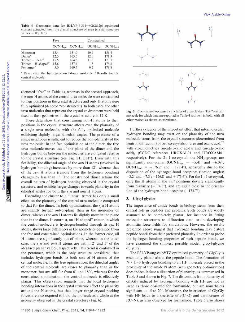
These data show that constraining non-H atoms to their
positions in the crystal structure affects even the planarity of
a single urea molecule, with the fully optimised molecule
exhibiting slightly larger dihedral angles. The presence of a
single neighbour is sufficient to reduce the non-planarity of the
urea molecule. In the free optimisation of the dimer, the free
urea molecule moves out of the plane of the dimer and the
hydrogen bonds between the molecules are elongated relative
to the crystal structure (see Fig. S1, ESIw). Even with this
flexibility, the dihedral angle of the anti H atoms (involved in
hydrogen bonding) increases by more than 121, whereas that
of the syn H atoms (remote from the hydrogen bonding)
changes by less than 11. The constrained dimer retains the
overall pattern of hydrogen bonding observed in the crystal
structure, and exhibits larger changes towards planarity in the
dihedral angles for both the syn and anti H atoms.
Extending the cluster to a ‘‘linear’’ trimer has only a small
effect on the planarity of the central urea molecule compared
to that for the dimer. In both optimisations, the syn H atoms
are slightly further out-of-plane than in the monomer or
dimer, whereas the anti H atoms lie slightly more in the plane
than in the dimer. In contrast, an ‘‘H-shaped’’ trimer, in which
the central molecule is hydrogen-bonded through its syn H
atoms, shows large differences in the geometries obtained from
the free and constrained optimisations. In the former case, all
H atoms are significantly out-of-plane, whereas in the latter
case, the syn and anti H atoms are within 21 and 51 of the
idealised planar values, respectively. This trend is continued in
the pentamer, which is the only structure considered that
includes hydrogen bonds to both sets of H atoms of the
central molecule. In the free optimisation, the dihedral angles
of the central molecule are closer to planarity than in the
monomer, but are still far from 01 and 1801, whereas for the
constrained optimization, the central molecule is effectively
planar. This observation suggests that the local hydrogen-
bonding interactions in the crystal structure affect the planarity
around the N atoms, but that longer range crystal packing
forces are also required to hold the molecule as a whole at the
geometry observed in the crystal structure (Fig. 6).
Further evidence of the important effect that intermolecular
hydrogen bonding may exert on the planarity of the urea
molecule stems from the crystal structures (determined from
neutron diffraction) of two co-crystals of urea and oxalic acid,20
with stoichiometries (urea)2(oxalic acid)1 and (urea)1(oxalic
acid)1 (CCDC references UROXAL01 and UROXAM01
respectively). For the 2 : 1 co-crystal, the NH2 groups are
significantly non-planar (OCNHsyn = �5.411 and �6.081;OCNHanti = �176.21 and +178.41), apparently due to the
disposition of the hydrogen-bond acceptors (torsion angles:
�3.21 and�7.31;�176.81 and+173.61). For the 1 : 1 co-crystal,
only the H atoms in the anti positions deviate significantly
from planarity (�174.31), and are again close to the orienta-
tion of the hydrogen-bond acceptor (�173.71).
3. Glycyl-glycine
The importance of amide bonds in biology stems from their
central role in peptides and proteins. Such bonds are widely
assumed to be completely planar, for instance in fitting
molecular structures to diffraction data or in developing
atomistic force fields for simulations. However, the results
presented above suggest that hydrogen bonding may distort
peptide bonds from their preferred planarity. In order to probe
the hydrogen bonding properties of such peptide bonds, we
have examined the simplest possible model, glycyl-glycine
(GlyGly).
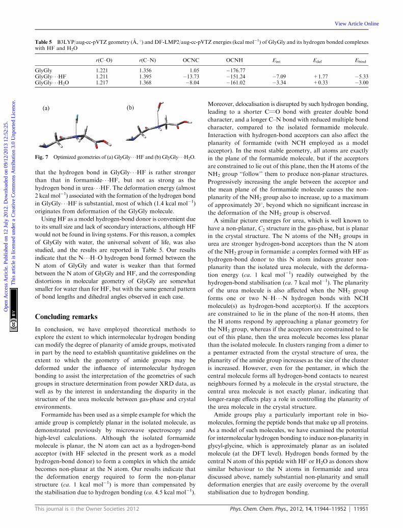
The B3LYP/aug-cc-pVTZ optimized geometry of GlyGly is
essentially planar about the peptide bond. The formation of
N� � �H–F hydrogen bonding to an HF molecule placed in the
proximity of the amide N atom (with geometry optimization)
does indeed induce a distortion of planarity, as summarized in
Table 5 and shown in Fig. 7. The distortions from planarity of
GlyGly induced by hydrogen bonding with HF are not as
large as those observed for formamide, but are nonetheless
significant at 15 to 201. Moreover, the interaction of GlyGly
with HF leads to a decrease of r(C–O) and an increase of
r(C–N), as also observed for formamide. Table 5 also shows
Table 4 Geometric data for B3LYP/6-311++G(2d,2p) optimizedclusters extracted from the crystal structure of urea (crystal structurevalues = 01/1801)
Free Constrained
OCNHsyn OCNHanti OCNHsyn OCNHanti
Monomer 13.4 151.0 10.9 156.4Dimera 12.5 163.5 12.0 171.3Trimer – linearb 15.5 164.6 11.3 173.7Trimer – H-shapedb 15.6 157.4 1.5 175.8Pentamerb 5.0 169.7 0.2 179.8
a Results for the hydrogen-bond donor molecule. b Results for the
central molecule.
Fig. 6 Constrained optimised structures of urea clusters. The ‘‘central’’
molecule for which data are reported in Table 4 is shown in bold, with all
other molecules shown as wireframe.
Ope
n A
cces
s A
rtic
le. P
ublis
hed
on 1
2 Ju
ly 2
012.
Dow
nloa
ded
on 0
9/12
/201
3 12
:52:
25.
Thi
s ar
ticle
is li
cens
ed u
nder
a C
reat
ive
Com
mon
s A
ttrib
utio
n 3.
0 U
npor
ted
Lic
ence
.
View Article Online
This journal is c the Owner Societies 2012 Phys. Chem. Chem. Phys., 2012, 14, 11944–11952 11951
that the hydrogen bond in GlyGly� � �HF is rather stronger
than that in formamide� � �HF, but not as strong as the
hydrogen bond in urea� � �HF. The deformation energy (almost
2 kcal mol�1) associated with the formation of the hydrogen bond
in GlyGly� � �HF is substantial, most of which (1.4 kcal mol�1)
originates from deformation of the GlyGly molecule.
Using HF as a model hydrogen-bond donor is convenient due
to its small size and lack of secondary interactions, although HF
would not be found in living systems. For this reason, a complex
of GlyGly with water, the universal solvent of life, was also
studied, and the results are reported in Table 5. Our results
indicate that the N� � �H–O hydrogen bond formed between the
N atom of GlyGly and water is weaker than that formed
between the N atom of GlyGly and HF, and the corresponding
distortions in molecular geometry of GlyGly are somewhat
smaller for water than for HF, but with the same general pattern
of bond lengths and dihedral angles observed in each case.
Concluding remarks
In conclusion, we have employed theoretical methods to
explore the extent to which intermolecular hydrogen bonding
can modify the degree of planarity of amide groups, motivated
in part by the need to establish quantitative guidelines on the
extent to which the geometry of amide groups may be
deformed under the influence of intermolecular hydrogen
bonding to assist the interpretation of the geometries of such
groups in structure determination from powder XRD data, as
well as by the interest in understanding the disparity in the
structure of the urea molecule between gas-phase and crystal
environments.
Formamide has been used as a simple example for which the
amide group is completely planar in the isolated molecule, as
demonstrated previously by microwave spectroscopy and
high-level calculations. Although the isolated formamide
molecule is planar, the N atom can act as a hydrogen-bond
acceptor (with HF selected in the present work as a model
hydrogen-bond donor) to form a complex in which the amide
becomes non-planar at the N atom. Our results indicate that
the deformation energy required to form the non-planar
structure (ca. 1 kcal mol�1) is more than compensated by
the stabilisation due to hydrogen bonding (ca. 4.5 kcal mol�1).
Moreover, delocalisation is disrupted by such hydrogen bonding,
leading to a shorter CQO bond with greater double bond
character, and a longer C–N bond with reduced multiple bond
character, compared to the isolated formamide molecule.
Interaction with hydrogen-bond acceptors can also affect the
planarity of formamide (with NCH employed as a model
acceptor). In the most stable geometry, all atoms are exactly
in the plane of the formamide molecule, but if the acceptors
are constrained to lie out of this plane, then the H atoms of the
NH2 group ‘‘follow’’ them to produce non-planar structures.
Progressively increasing the angle between the acceptor and
the mean plane of the formamide molecule causes the non-
planarity of the NH2 group also to increase, up to a maximum
of approximately 201, beyond which no significant increase in
the deformation of the NH2 group is observed.
A similar picture emerges for urea, which is well known to
have a non-planar, C2 structure in the gas-phase, but is planar
in the crystal structure. The N atoms of the NH2 groups in
urea are stronger hydrogen-bond acceptors than the N atom
of the NH2 group in formamide: a complex formed with HF as
hydrogen-bond donor to this N atom induces greater non-
planarity than the isolated urea molecule, with the deforma-
tion energy (ca. 1 kcal mol�1) readily outweighed by the
hydrogen-bond stabilisation (ca. 7 kcal mol�1). The planarity
of the urea molecule is also affected when the NH2 group
forms one or two N–H� � �N hydrogen bonds with NCH
molecule(s) as hydrogen-bond acceptor(s). If the acceptors
are constrained to lie in the plane of the non-H atoms, then
the H atoms respond by approaching a planar geometry for
the NH2 group, whereas if the acceptors are constrained to lie
out of this plane, then the urea molecule becomes less planar
than the isolated molecule. In clusters ranging from a dimer to
a pentamer extracted from the crystal structure of urea, the
planarity of the amide group increases as the size of the cluster
is increased. However, even for the pentamer, in which the
central molecule forms all hydrogen-bond contacts to nearest
neighbours formed by a molecule in the crystal structure, the
central urea molecule is not exactly planar, indicating that
longer-range effects play a role in controlling the planarity of
the urea molecule in the crystal structure.
Amide groups play a particularly important role in bio-
molecules, forming the peptide bonds that make up all proteins.
As a model of such molecules, we have examined the potential
for intermolecular hydrogen bonding to induce non-planarity in
glycyl-glycine, which is approximately planar as an isolated
molecule (at the DFT level). Hydrogen bonds formed by the
central N atom of this peptide with HF or H2O as donors show
similar behaviour to the N atoms in formamide and urea
discussed above, namely substantial non-planarity and small
deformation energies that are easily overcome by the overall
stabilisation due to hydrogen bonding.
Table 5 B3LYP/aug-cc-pVTZ geometry (A, 1) and DF-LMP2/aug-cc-pVTZ energies (kcal mol�1) of GlyGly and its hydrogen bonded complexeswith HF and H2O
r(C–O) r(C–N) OCNC OCNH Eint Edef Ebind
GlyGly 1.221 1.356 1.05 �176.77GlyGly� � �HF 1.211 1.395 �13.73 �151.24 �7.09 +1.77 �5.33GlyGly� � �H2O 1.217 1.368 �8.04 �161.02 �3.34 +0.33 �3.00
Fig. 7 Optimized geometries of (a) GlyGly� � �HF and (b) GlyGly� � �H2O.
Ope
n A
cces
s A
rtic
le. P
ublis
hed
on 1
2 Ju
ly 2
012.
Dow
nloa
ded
on 0
9/12
/201
3 12
:52:
25.
Thi
s ar
ticle
is li
cens
ed u
nder
a C
reat
ive
Com
mon
s A
ttrib
utio
n 3.
0 U
npor
ted
Lic
ence
.
View Article Online
11952 Phys. Chem. Chem. Phys., 2012, 14, 11944–11952 This journal is c the Owner Societies 2012
Acknowledgements
JAP is grateful to the Leverhulme Trust for a Research
Fellowship. GKL and HM are grateful to the Government
of Malaysia for studentships.
References
1 (a) J. Demaison, A. G. Csazar, I. Kleiner and H. Møllendal,J. Phys. Chem. A, 2007, 111, 2574; (b) B. E. Mannfors,N. G. Mirkin, K. Palmo and S. Krimm, J. Phys. Chem. A, 2003,107, 1825, and references cited therein; (c) K. B. Wiberg andK. E. Laidig, J. Am. Chem. Soc., 1987, 109, 5935;(d) J. I. Mujika, J. M. Matxain, L. A. Eriksson and X. Lopez,Chem.–Eur. J., 2006, 12, 7215; (e) Y. R. Mo, P. V. Schleyer,W. Wu, M. H. Lin, Q. Zhang and J. L. Gao, J. Phys. Chem. A,2003, 107, 10011; (f) H. Basch and S. Hoz, Chem. Phys. Lett., 1998,294, 117; (g) G. Fogarasi and P. G. Szalay, J. Phys. Chem. A, 1997,101, 1400.
2 S. Swaminathan, B. M. Craven and R. K. McMullan, ActaCrystallogr., Sect. B: Struct. Sci., 1984, 40, 300.
3 (a) K. D. M. Harris and J. M. Thomas, J. Chem. Soc., FaradayTrans., 1990, 86, 2985; (b) K. D. M. Harris, Supramol. Chem.,2007, 19, 47.
4 (a) R. L. T. Parreira, G. F. Caramori, N. H. Morgon andS. E. Galembeck, Int. J. Quantum. Chem., 2012, 112, 1401;(b) M. Nagaraju and G. N. Sastry, Int. J. Quantum. Chem.,2010, 110, 1994; (c) A. A. Samchenko, A. V. Kabanov andV. M. Komarov, Biofizika, 2010, 55, 197; (d) R. L. T. Parreira,H. Valdes and S. E. Galembeck, Chem. Phys., 2006, 331, 96;(e) J. Binoy, N. B. Prathima, C. M. Krishna, C. Santhosh,I. H. Joe and V. S. Jayakumar, Laser Phys., 2006, 16, 1253;(f) S. Chalmet and M. F. Ruiz-Lopez, J. Chem. Phys., 1999,111, 1117; (g) T. Ishida, P. J. Rossky and E. W. Castner,J. Phys. Chem. B, 2004, 108, 17483.
5 A. J. Cruz Cabeza, G. M. Day, W. D. S. Motherwell andW. Jones,Cryst. Growth Des., 2006, 6, 1858.
6 (a) J. D. Dunitz, X-ray Analysis and the Structures ofOrganic Molecules, Verlag Helvetica Chimica Acta, Basel, 1995;
(b) J. P. Glusker and K. N. Trueblood, Crystal Structure Analysis –A Primer, Oxford University Press, Oxford, 1985.
7 (a) K. D. M. Harris and M. Tremayne, Chem. Mater., 1996,8, 2554; (b) ed. W. I. F. David, K. Shankland, L. B. McCuskerand C. Baerlocher, Structure Determination from Powder Diffrac-tion Data, OUP/IUCr, 2002; (c) K. D. M. Harris, Cryst. GrowthDes., 2003, 3, 887.
8 (a) A. D. Becke, J. Chem. Phys., 1993, 98, 5648; (b) C. T. Lee,W. T. Yang and R. G. Parr, Phys. Rev. B: Condens. Matter Mater.Phys., 1988, 37, 785.
9 R. A. Kendall, T. H. Dunning Jr. and R. J. Harrison, J. Chem.Phys., 1992, 96, 6796.
10 M. J. Frisch, et al.,Gaussian03 Rev. E.01, Gaussian Inc, WallingfordCT, 2004.
11 See for example (a) M. Lozynski, D. Rusinska-Roszak andH.-G. Mack, J. Phys. Chem. A, 1998, 102, 2899; (b) I. V. Alabugin,M. Manoharan, S. Peabody and F. Weinhold, J. Am. Chem. Soc.,2003, 125, 5973; (c) A. D. Rabuck and G. E. Scuseria, Theor. Chem.Acc., 2000, 104, 439.
12 H.-J. Werner, F. R. Manby and P. J. Knowles, J. Chem. Phys.,2003, 118, 8149.
13 (a) M. Schutz, G. Rauhut and H.-J. Werner, J. Phys. Chem. A,1998, 102, 5997; (b) J. G. Hill, J. A. Platts and H.-J. Werner, Phys.Chem. Chem. Phys., 2006, 8, 4072.
14 F. Weigend, A. Kohn and C. Hattig, J. Chem. Phys., 2002,116, 3175.
15 J. Pipek and P. G. Mezey, J. Chem. Phys., 1989, 90, 4916.16 J. W. Boughton and P. J. Pulay, J. Comput. Chem., 1993, 14,
736.17 H.-J. Werner, P. J. Knowles, R. Lindh, F. R. Manby and
M. Schutz,Molpro, version, 2010.1, a package of ab initio programs;see: http://www.molpro.net.
18 Bond lengths differ from B3LYP values by less than 0.01 A anddihedral angles by less than 11 with four different DFT methods.See Table S2 (ESIw) for more information.
19 (a) A. E. Reed, R. B. Weinstock and F. Weinhold, J. Chem. Phys.,1985, 83, 735.
20 (a) G. J. van Hummel and R. B. Helmholdt, Acta Crystallogr.,Sect. C: Cryst. Struct. Commun., 1991, 47, 213; (b) S. Harkema,J. H. ter Brake and R. B. Helmholdt, Acta Crystallogr., Sect. C:Cryst. Struct. Commun., 1984, 40, 1733.
Ope
n A
cces
s A
rtic
le. P
ublis
hed
on 1
2 Ju
ly 2
012.
Dow
nloa
ded
on 0
9/12
/201
3 12
:52:
25.
Thi
s ar
ticle
is li
cens
ed u
nder
a C
reat
ive
Com
mon
s A
ttrib
utio
n 3.
0 U
npor
ted
Lic
ence
.
View Article Online