Embed Size (px)
Citation preview

Citect for Windows
Driver Specification
Bailey Driver
Revision Date Author Comments
1.0 23/1/98 Simon Frost Original, W. A. Cromarty Pty Ltd
1.1 2/11/01 Graeme Sutton Updated driver error list

Driver Design Specification
BAILEY.DOC 2
Contents
1. QA 4
1.1 Introduction 4
1.2 Procedure for generating a new driver 4
2. TARGET DEVICE(S) AND PROTOCOL 5
2.1 Introduction 5
2.2 Device Manufacturer 5
2.3 Device Definition 5
2.4 Communications Method 12
2.5 Communications/Hardware Configuration 12
2.6 Special Requirements 14
2.7 Maximum Request Length 14
2.8 Contacts 15
3. PROTOCOL REQUIREMENTS 16
3.1 Introduction 16
3.2 Initialising the Board 16
3.3 Initialising the Port 16
3.4 Initialising the IO Device 16
3.5 IO Device Online Test 16
3.6 State Flow Description 16
3.7 Message Structure 17
3.8 Data Format 22
3.9 Check Sum 22
3.10 Error Handling 22
4. USER INTERFACE 23
4.1 Introduction 23
4.2 Driver Name 23
4.3 Boards Form 23
4.4 Ports Form 23
4.5 IO Devices Form 24
4.6 Pulldown lists Help 24
Driver Design Specification
BAILEY.DOC 3
4.7 IO Device Variable Types 24
4.8 PROTDIR.DBF 30
4.9 Parameters and INI options 30
4.10 Driver Specific Errors 33
4.11 Driver Error Help 37
4.12 Debug Messages 41
4.13 Stats Special Counters 42
4.14 Hints and Tips 43
5. BASIC TESTING 46
5.1 Introduction 46
5.2 Procedure 46
6. PERFORMANCE TESTING 47
6.1 Introduction 47
6.2 Calculating the Blocking Constant 47
7. REFERENCES 48
7.1 References 48
8. APPENDIX 49
Appendix A Initialization flow chart 49
Appendix B Configuration flowchart 50
Appendix C Bailey Driver Execution flowchart 51

Driver Design Specification
BAILEY.DOC 4
1. QA
1.1 Introduction
This document follows the development of the Bailey driver. It serves as a functional specification, design specification and test specification.
1.2 Procedure for generating a new driver
The following check list defines the QA steps for generating a new driver. This procedure must be followed for drivers to be integrated into Citect.
Description Person Date
1 This specification document is written. SF 3/09/98
2 Specification reviewed and accepted by R&D department.
3 Driver coded. PW, SF
18/11/92
4 Code and specification reviewed and accepted by R&D department.
5 Testing with connection project, and performance test.
6 Driver integrated into Citect source and built.
7 Documentation is written (HLP or MVB files)
At this checkpoint coding is done and the driver is available as a beta.
8a Full testing is carried out.
8b Performance testing is carried out.
8c Specification and documentation updated from testing/performance tests
At this checkpoint the testing is complete.
9a Review for completeness by developer, tester, documenter and R&D staff
9b Add driver to install disks
9c Add driver to protocols database
9d Support notified of new driver for training purposes
10 Sales notified of new driver
The driver is now finished.
The hand over of a driver requires that all the above steps are completed and checked off.

Driver Design Specification
BAILEY.DOC 5
2. Target Device(s) and Protocol
2.1 Introduction
There are many devices made by Elsag Bailey to enable communication between host computers and their DCS equipment. A simple binary serial protocol is employed via a RS232C connection to interface between host computer and DCS. The interface provides connectivity to the DCS internal network protocol enabling transfer of messages to and from host computers and modules distrib-uted through out the network.
The DCS uses a variety of internal protocols such as Module Bus, Control way, INFI-NET and Plant loop to communicate between module, PCU and OIS. Elsag Bailey provides hardware interfaces, which use the common serial protocol to interface host computers to these protocols.
The Elsag Bailey DCS comes in two varieties, Network 90 and INFI 90. The names distinguish be-tween the type of communication being used within a PCU and between PCUs. The Network 90 DCS is the older systems which uses Module bus and Plant loop. While INFI90 is the newer sys-tem, which uses Module bus, plant loop, Control way and INFI-NET. The two types of Elsag Bailey DCS equipment can be linked together using specialised hardware interface units, meaning that Network 90 and INFI90 systems can coexist in the same, plant, system or PCU.
2.2 Device Manufacturer
Bailey Controls Australia Pty Ltd., Regent Park, NSW Australia. A Babcock & Wilcox Company.
2.3 Device Definition
There are two distinct hardware interface unit types used by Elsag Bailey to provide connectivity between host computers and their DCS system:
2.3.1 INFI-NET and Plant Loop Interfaces.
These interfaces are generally called Computer Interface Units CIU. CIU are combinations of hard-ware, which provide the following functionality:
1) Host interface (RS232C communication and termination)
2) Process control unit (PCU) interface (INFI-NET or Plant Loop communication)
3) Data storage and data transfer control.
The data storage and data transfer control module holds the exception report routing database and directs the operations of both process control unit interface and the host interface. It acts as the translator between the INFI-NET/Plant loop, host computer and the control way/module bus. It communicates directly with the PCU interface hardware and monitors the local control way/module bus. It polls each local PCU module on the control way/module bus for exception reports using the following criteria:
i) A points changes by a significant amount
ii) The maximum exception report time expires

Driver Design Specification
BAILEY.DOC 6
iii) An alarm condition changes
The exception reports are packed together with other exception reports having a common node des-tination and transferred to the PCU interface for transmission. The PCU interface receives all incom-ing messages from other PCU interfaces on the loop and retransmits a new stream of messages in a store and forward fashion to the next node. When there are no messages to transmit the module transmit null packets to keep the loop synchronized.
The host interface is generally a termination unit, which provides level conversion and isolation be-tween the host computer and the DCS equipment.
CIU Host interfaces PCU interface Data storage and control
CIC01 CIC01 None CIC01
NCIU01 or INPCI01
TCU (Computer inter-face termination unit)
LIM (Loop inter-face module)
SIM (Serial inter-face module) & PTM (Point table module)
NCIU02 TPL(Plant loop termina-tion unit)
LIM(Loop inter-face module)
BTM(Bus transfer module) & LSM(Loop stor-age module)
NCIU03 or INPCI02
TMF(Multi function Con-troller Termination unit)
LIM (Loop inter-face module)
PCT ( Plant loop to Computer Transfer module) & BTM Bus transfer module)
NCIU04 or INICI01
ICL (Communication Termination unit)
NIS (Network interface slave)
ICT(Computer transfer module)
INICI03 TPM (Multi function processor termination unit)
NIS (Network interface slave)
ICT(Computer transfer module) & MPI (Multifunc-tion Processor interface)

Driver Design Specification
BAILEY.DOC 7
2.3.1.1 Diagram NCIU01/INPCI01

Driver Design Specification
BAILEY.DOC 8
2.3.1.2 Diagram NCIU03/INPCI02
2.3.1.3 Diagram NCIU04/INICI01 and INICI03

Driver Design Specification
BAILEY.DOC 9
2.3.2 Control way and Modules Bus interfaces.
These interfaces are generally called serial port modules (SPM) or Communication Port modules (CPM). These are single slot units, which occupy one slot in a Module Mounting Unit (MMU) within a PCU. They provide:
1) Host interface (RS232C communication and termination)
2) Module interface (Control way or Modules bus communication)
SPM and CPM are designed to provide local (within PCU) system configuration, tuning and diagnos-tics. They enable the host to configure, tune and monitor the master modules and their function blocks. They do not provide the exception reporting facility offered by a CIU, instead to monitor a point the host must poll it directly.
The diagrams below use the acronyms defined in this diagram. Host computer may be substituted for EWS.

Driver Design Specification
BAILEY.DOC 10
2.3.2.1 Diagram IMCPM 01
2.3.2.2 Diagram IMCPM02
Driver Design Specification
BAILEY.DOC 11
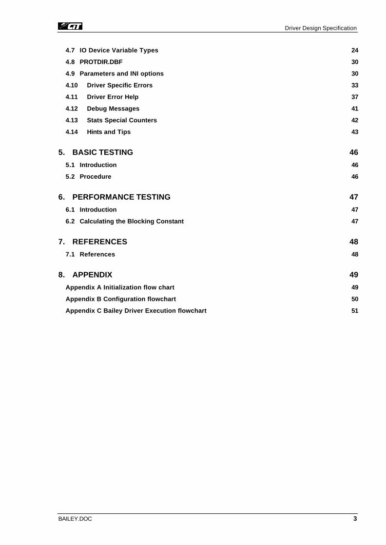
2.3.2.3 Diagram IMCPM03
Driver Design Specification
BAILEY.DOC 12
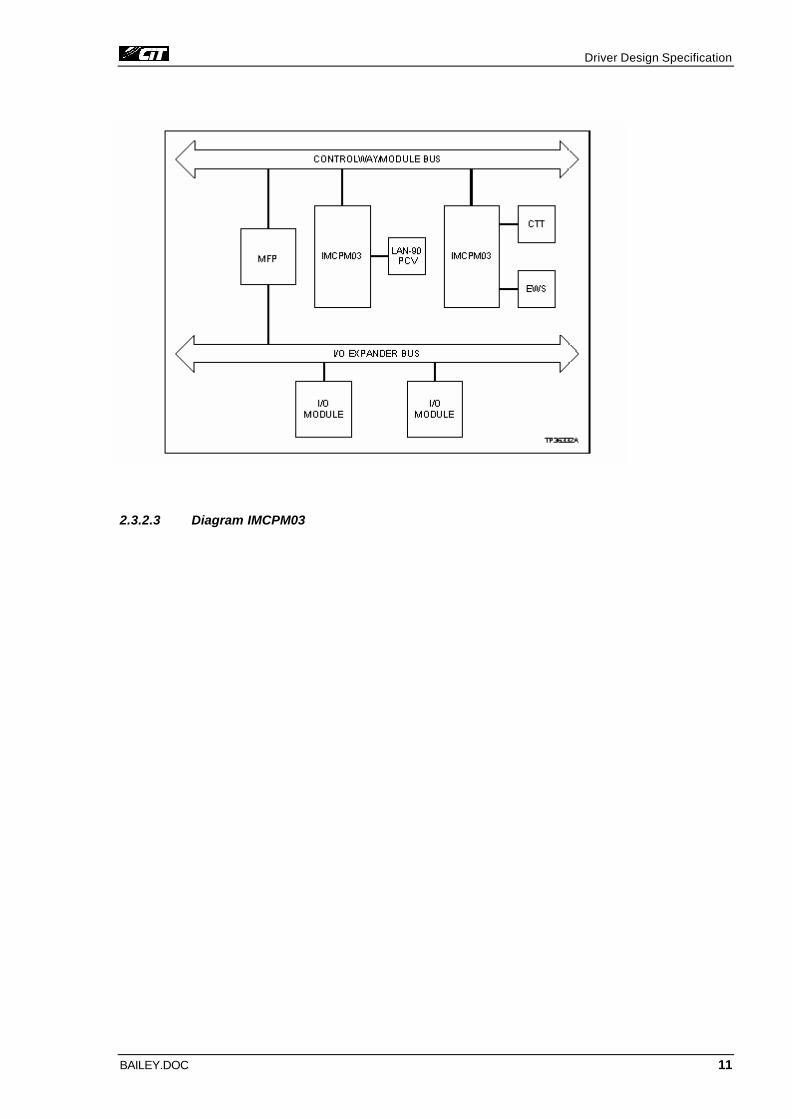
2.3.2.4 Diagram IMSPMO1 or NSPM01
2.4 Communications Method
CITECT communicates to each style of device via a RS232C connection.
2.5 Communications/Hardware Configuration
2.5.1 Wiring Diagrams
The NSPM01 is designed to function as DCE through a type Z interchange. This is a non-specified optional interchange, which allows equipment manufactures to define what signals will be used. To minimize the chance of confusion, a detailed description of each signal line of the NSPM01’s serial port is given below. Please note that the RS-232C specification identifies pin names and functions with respect to DTE. The pin numbers below refer to the front panel connector on the NSPM01. Ku-dos
Pin 1 - GROUND/SHEILD A protective ground line, which is electrically connected to the equipment frame.
Pin 2 - TRANSMITTED DATA (TX DATA). Signals on this pin are the input of serial data to the module
Pin 3 - RECEIVED DATA (RX DATA). Signals on this pin are the serial data output from the module
Pin 4 - REQUEST TO SEND (RTS). This signal is an input to the DCE that signals a request from the DTE to begin a transfer of data. This signal is not used on the by default in most modules but can be selected using jumpers on the boards.
Driver Design Specification
BAILEY.DOC 13
Pin 5 - CLEAR TO SEND (CTS). This signal is an output from the DCE in response to receiving a RTS signal. Since the RTS signal is disabled by default, the module generates the CTS signal as long as the Machine Fault Timer is in its normal state.
Pin 6 - DATA SET READY (DSR). This signal is also an output from the DCE to the DTE. Be-cause of the overlap of signal definition with respect to the modules, this signal is synony-mous with the CTS signal. Both signals are generated at a common point.
Pin 7 - SIGNAL GROUND. This is the common for all signals. Pin 8 - RECEIVED LINE SIGNAL DETECT (RLSD). This signal is generated to indicate that a
valid communication link has been established. For the NSPM01 module, this signal is used to indicate when access to the Module Bus is possible. Again, as with Pins 5 and 6, if the Machine Fault Timer is normal, the communication link is considered to be present. This signal is synonymous with the CTS and DSR signals on the NSPM01 but is provided to al-low interfacing with other data equipment.
Pin 20 - DATA TERMINAL READY (DTR). This is an input to the DCE. It is to confirm that the DTE is there and that the communication link is to be maintained. If the signal is not gen-erated by the DTE, jumpers are provided on the modules so that the need for this input can be eliminated.
All other pin assignments of the RS232C interchange are grouped into a “don’t care” classification.
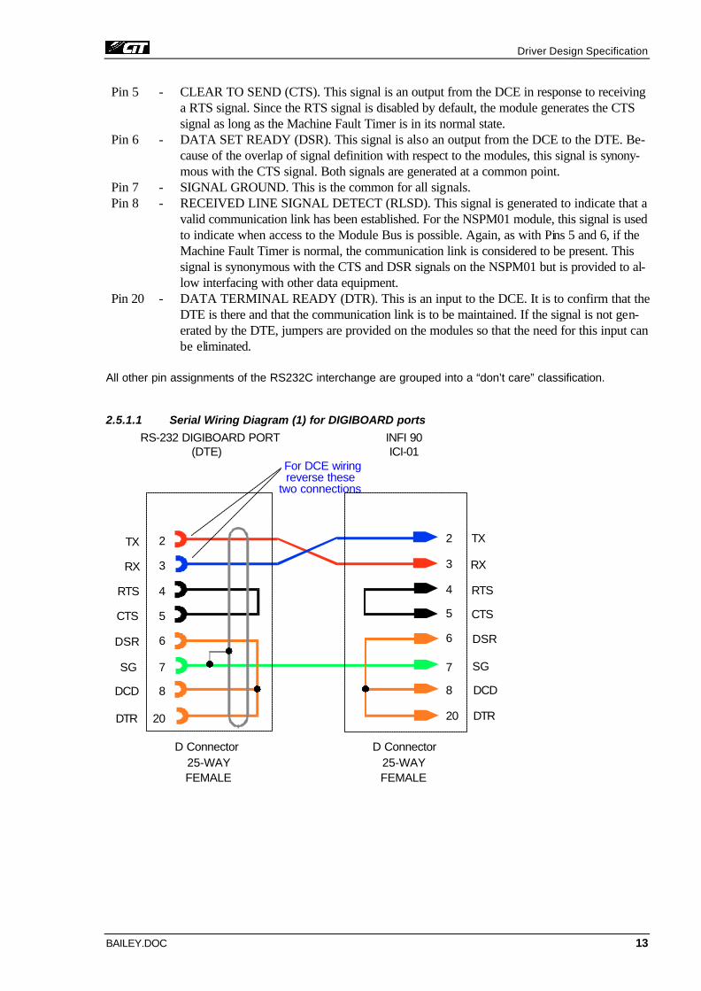
2.5.1.1 Serial Wiring Diagram (1) for DIGIBOARD ports
2
3
4
5
6
8
20
7
TX
RX
RTS
CTS
DSR
DCD
DTR
SG
2 TX
3 RX
4 RTS
5 CTS
6 DSR
8 DCD
20 DTR
7 SG
RS-232 DIGIBOARD PORT(DTE)
D Connector25-WAYFEMALE
For DCE wiring
D Connector25-WAYFEMALE
reverse thesetwo connections
ICI-01INFI 90
Driver Design Specification
BAILEY.DOC 14
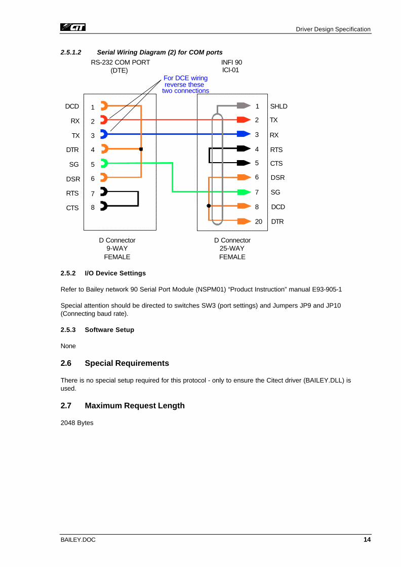
2.5.1.2 Serial Wiring Diagram (2) for COM ports
2
3
4
5
6
8
1
7
TX
RX
RTS
CTS
DSR
DCD
DTR
SG
2 TX
3 RX
4 RTS
5 CTS
6 DSR
8 DCD
20 DTR
7 SG
RS-232 COM PORT(DTE)
D Connector9-WAY
FEMALE
D Connector25-WAYFEMALE
1 SHLD
For DCE wiringreverse these
two connections
ICI-01INFI 90
2.5.2 I/O Device Settings
Refer to Bailey network 90 Serial Port Module (NSPM01) “Product Instruction” manual E93-905-1
Special attention should be directed to switches SW3 (port settings) and Jumpers JP9 and JP10 (Connecting baud rate).
2.5.3 Software Setup
None
2.6 Special Requirements
There is no special setup required for this protocol - only to ensure the Citect driver (BAILEY.DLL) is used.
2.7 Maximum Request Length
2048 Bytes

Driver Design Specification
BAILEY.DOC 15
2.8 Contacts
Simon Frost
W.A. Cromarty Pty Ltd
79 Howick Street,
South Launceston,
Tasmania 7249
Tel 03 63449110
Fax 03 63441221
Bruce Kinchin
Ci Technologies Pty Limited
10-12 West Street
PO Box 174
Pymble NSW 2073
Australia
Tel: (02) 855 1000
Fax: (02) 488 9164
Driver Design Specification
BAILEY.DOC 16
3. Protocol Requirements
3.1 Introduction
This section outlines the protocol and execution flow of the Bailey driver. The protocol is not covered in depth here as an adequate description is given in [1].
3.2 Initialising the Board
The driver uses standard RS232 communication. Therefore only the normal board initialization car-ried out by CITECT is required.
3.3 Initialising the Port
The port is opened using the COMSetVector function and reset using the COMReset each time the driver is restarted.
3.4 Initialising the IO Device
The CIU device requires extensive initialization while the SPM and CPM modules require only to be restarted. See Appendix A Initialization flow chart and Appendix B Configuration flow chart
3.5 IO Device Online Test
The device is considered to be online after the initialization has been completed. See Appendix A Initialization flow chart. There exists a special condition where the unit does not go on line until both the initialization and configuration (See Appendix B Configuration flow chart) have been completed. This special case has been included to make swapping from a secondary server back to a primary server seamless. This will only occur if CIU > 0 BackGroundInit = 1 and the device has been initial-ized successfully by the driver prior to the current initialization attempt.
3.6 State Flow Description
This driver is based on the front-end back-end model. The front end services all requests from the IOSERVER. All requests are handled through the READDCB and WRITEDCB calls. Read requests are separated into tag types, TUNE BLOCK (TR, TI, TD), READ BLOCK OUTPUT (BR, BI, BD) and point tags (PV, SP, RI etc). The back end of the driver maintains a image of the CIU point table and all requests for point tag data are serviced from the in\mage. Read requests for READ BLOCK OUTPUT tags and TUNE BLOCK tags are handled by the back-end. See 3.7.3 Read commands and 3.7.5 Tune commands for respective descriptions.
Write request are also separated into point tags and TUNE BLOCK tags. As with the read requests the write tags are handled by the back-end of the driver. To facilitate continuity of the back-end poll-ing strategy all requests that cannot be handled directly by the front end are placed in the IN queue. The IN queue is then serviced during the polling operations of the back-end. Commands generated from the IN queue OUT queue or polling cycle are transmitted and placed in the OUT queue. Re-sponses from the Bailey host communication equipment are matched to an item in the OUT queue. The driver replied to the IOSERVER immediately with write responses. Read responses may be replied directly or placed in the RETURN queue. The RETURN queue uses a timer to delay the read responses to the IOSERVER.
Driver Design Specification
BAILEY.DOC 17
The OUT queue is given the highest priority during the operation of the back-end. The IN queue is serviced next and finally exception reports are polled. The responses to polled commands are de-coded and used to update the internal point table image. See Appendix C Bailey Driver Execution flowchart for further details
3.7 Message Structure
The Bailey host communication equipment uses binary COMANDS and REPLIES to send mes-sages back and forth between host and DCS. Each information transfer is a command from the host followed by a reply from the bailey equipment. The message structures are:
Command: <COMMAND CODE><COMMAND STRUCTURE><CHECKSUM>0D
Reply: <REPLY CODE><REPLY STRUCTURE><CHECKSUM>0D
The message structure of both the commands and replies are outlined in Sections 2 of [1]. Com-mands and relies are terminated by the 0D (HEX). To avoid 0D as a character within a message, the driver must translate both 0D and 1B into 1B0E and 1B1B receptively for commands and visa versa for replies. Section 3 of [1] covers this topic.
The driver communicates with a CIU uses the following messages. To communicate with a CPM or SPM unit only the CIU RESTART, ENVIRONMENT, READ BLOCK, READ BLOCK OUTPUT, TUNE BLOCK and DEMAND MODULE STATUS messages are uses as these units have a reduced command set. (See CIU parameter below 4.9.2.4)
The driver used 26 IO Device Variable Types (see 4.7) to perform all its IO with the Bailey host communication equipment. Each IO Device Variable type is associated with one or more of the messages below.
Message/Command CODE Description
CIU RESTART 19 Clears the CIU points table and give the CIU its executive con-trol parameters.
ENVIRONMENT 69 This command returns the CIU environment data. The data identifies the CIU module type and operation mode
ESTABLISH POINT 1 Enters a point in the CIU points table and establishes exception report receiving.
DISESTABLISH POINT 23 Removes a point from the points table
ESTABLISH AND CONNECT POINT 49 Enters a point in the CIU points table, and establishes and con-nects a route so the index re-ceives exception reports
ESTABLISH REPORT 2 Enters a report point into the CIU table

Driver Design Specification
BAILEY.DOC 18
CONNECT POINT LIST 4 Connects already established input routes
DISCONNECT POINT LIST 5 Disconnects points to keep un-needed traffic of the loop.
READ EXCEPTION REPORT SPECS 24 Provides the host with point specification information. The points module returns this in-formation after the CIU estab-lishes and exception report route
READ EXCEPTION 8 Returns the current status and value of each station variable to be read, or an analog, digital or RMSC point for which the CIU has received an exception re-port. In order to receive excep-tion reports for a point, the point must have been established.
READ MISC STATUS EXCEPTION 22 Read Miscellaneous Status Ex-ceptions returns the current status of each station, RCM, and module for which the CIU has received an exception re-port. In order to receive excep-tion reports for station status, RCM, and module status, the status must have been estab-lished.
READ VALUE LIST 6 Returns the values of the station variable, analog, and digital points in the requested list.
READ MISC STATUS LIST 21 Read miscellaneous status list returns the status of station, RCMs, and modules for the re-quested list.
OUTPUT VALUE 10 Sends an analog or digital ex-ception report, or sets a station variable or RMSC. The point have been established
OUTPUT STATUS 11 Sends a digital point report, set station mode, or set/reset an RCM function block or com-mand a device driver.
READ BLOCK 13 Reads the configuration of a block configured in a module. While the module is in configure

Driver Design Specification
BAILEY.DOC 19
or execution mode.
READ BLOCK OUTPUT 20 Allows the host to read the out-put of a block in a module, even though the block does not gen-erate exception reports. The block does not need to be es-tablished in the CIU point table
TUNE BLOCK 17 Changes the tune parameters of a block.
DEMAND MODULE STATUS 27 Allows the host to read the status of any module, even if the module’s status is not estab-lished in the point list.
Note: The byte structure of each of the above commands and their respective replies can be found in section 2of [1].
Several of these commands require the address of a specific block location within the DCS system. Bailey uses a propriety addressing system, which does not map well into that, used by CITECT. The system refers to a specific block within the DCS using:
Name Range Description
Ring 0 – 7 The loop that the PCU is on
Node 0 – 255 The PCU number
Module 0 – 31 The module within the PCU
Block 0 – 16383 The block within the module.
For exception reporting purposes. Route which map a block within the DCS into a CIU point data-base are referred to by:
Name Range Description
Index 0 – 10000 The point number in the CIU database
To facilitate this in the code the DATAPOINT structure has been mapped into the MAPPOINT struc-ture. Therefore UnitAddress and UnitType fields are assigned as follows at compile time.
UnitAddress Bits
Description
Bit 31 Write flag
Bit 30 Read flag
Bit 29 – 24 Point type (PV, SP, CO, RI, A, SS, D, SM, MS, RCM, RMSC etc)

Driver Design Specification
BAILEY.DOC 20
Bit 23 – 16 This byte will be put into UnitAddress when 0 is entered as an index
Bit 15 – 0 Index
UnitType Bits Description
Bit 29 – 16 Block
Bit 15 – 11 Module
Bit 10 – 3 Node
Bit 2 – 0 Ring
3.7.1 Initialization Commands
Initialization is a function performed by the back end of the driver. The driver performs initialization functions with the following commands. CIU RESTART, ENVIRONMENT, CONNECT POINT LIST and DISCONNECT POINT LIST. The initialization takes two forms. If the CIU = 0 or the MapPath = NULL then a CIU RESTART command is issued followed by an ENVIRONMENT. Otherwise the driver uses DISCONNECT POINT LIST to remove all of the existing CIU point routes and then re-connects them using CONNECT POINT LIST. This forces the CIU to refresh its point table and pro-vide a fresh exception reports for each point.
3.7.2 Configuration Commands
Configuration is a function performed by the back-end of the driver. The driver performs configuration functions with the following commands. ESTABLISH POINT, DISESTABLISH POINT, ESTABLISH AND CONNECT POINT, CONNECT POINT LIST and ESTABLISH REPORT. Configuration only oc-curs if CIU > 0. Configuration is the process of building the CIU internal point table. Each point in the table must be first established using one of the establishment commands and then connected with a connect command. These two commands enter a point into the CIU database and link that point to a block within the DCS.
Configuration may occur in the background, or as each point is accessed by CITECT. If Back-GroundInit = 0 the driver tries to establish and connect each point as it is accessed by CITECT. Otherwise the driver tries to establish and connect all points which are not being accessed by CITECT in the background during normal polling for exception reports.
The majority of IO device variable tag listed in 4.7 can be associated with a point in the CIU. The driver uses the index field when establishing a point in the CIU. The index is a unique number asso-ciated with one block in the DCS. All IO device variables addressing the same block within the DCS should have the same index number, making transfer of data more efficient and reducing network overheads.
When the MapPath <> NULL the DISESTABLISH POINT command many be used to remove a point in the CIU database if that point (index) has been removed from the CITECT project or the in-dex has been assigned to a different block.
The following table shows the IO variable tag types, which are established and removed by the vari-ous commands.

Driver Design Specification
BAILEY.DOC 21
ESTABLISH POINT MS, WSP, WCO, WRI, SM
DISESTABLISH POINT All
ESTABLISH AND CONNECT POINT PV, SP, CO, RI, A, SS, EMS, D, RCM, RMSC
ESTABLISH REPORT WD, WA
3.7.3 Read Commands
The driver performs read functions with the following commands. READ EX-CEPTION REPORT SPECS READ EXCEP-TION, READ MISC STATUS EXCEP-TION, READ VALUE LIST, READ MISC STATUS LIST, READ BLOCK OUT-PUT and DEMAND MODULE STATUS.
This driver is primarily based on the front-end back-end model however the READ BLOCK OUTPUT and DEMAND STATUS commands fall under the Request based model. When CITECT services tags, which uses these messages the driver issues the commands directly and waits for a reply. All other tags except those associated with tunable parameters (see below 3.7.5) are serviced from the driver’s internal image of the point table. This image is maintained by continuously polling the CIU for exception reports. Using exception reporting tags is preferable as READ BLOCK OUTPUT commands are slow and reduce the efficiency of both the driver and DCS network.
The following table shows the IO variable tag types, which are read by the various read commands.
READ EXCEPTION REPORT SPECS PV, SP
READ EXCEPTION PV, SP, CO, RI, A, D, RCM, RMSC
READ MISC STATUS EXCEPTION SS, RCM, MS, EMS
READ VALUE LIST PV, SP, CO, RI, A, D, RCM, RMSC
READ MISC STATUS LIST SS, MS, RCM, EMS
READ BLOCK OUTPUT BR, BI, BD
DEMAND MODULE STATUS MS
3.7.4 Write Commands
The driver performs write functions with the following commands OUTPUT VALUE and OUTPUT STATUS. Write commands from CITECT are immediately formatted and transmitted.
The following table shows the IO variable tag types, which are written by the various write com-mands
OUTPUT VALUE WSP, WCO, WRI, WA, WD, RMSC
OUTPUT STATUS RMC, SM

Driver Design Specification
BAILEY.DOC 22
3.7.5 Tune Commands
Tunable blocks within a DCS are both read and written to by CITECT. However they are treated dif-ferently by the driver because the function of reading and writing them is slower than exception re-porting. Tunable blocks are read using READ BLOCK the resulting reply is cached by the driver and used to service further requests until the data has been cached for a period greater than Watch-Time. At which time the following access to that tune block will cause the driver to issue another READ BLOCK command.
When CITECT writes to a tune block the block is first read using READ BLOCK and then written to using TUNE BLOCK. The driver needs to read the block first to establish all the parameter of the block before changing any of them and writing the block back into the DCS.
Tunable parameters can be cached because they are not modified very often. However it is possible that two people could tune the same block within the WatchTime causing one person to have invalid data on that particular block.
The following table shows the IO variable tag types, which are written and read by the various tune commands
READ BLOCK
TR, TI, TD
TUNE BLOCK
TR, TI, TD
3.8 Data Format
The data formats used by the Bailey Host Communication Equipment is clearly defined in “FIELDS” Section 3 Pages 5 – 8 and Section 6 Page 1 Point 7of [1].
3.9 Check Sum
The byte wise sums of all bytes in the command, except for the checksum byte itself and the command terminator. This single byte quantity is the next to last byte transmitted in the command. Only the command terminator follows it. Commands issued by the host must have checksums. Command replies may have checksums if the checksum option is switched on. The bailey diver expects to see checksums on all replies.
3.10 Error Handling
All reply codes, other than NO ERROR (0) and those mentioned below, received by the driver have 0x100 added to them and assigned to the ErrDriver field of the DCB in the reply to IOSERVER. Data encapsulated in a message with a non 0 reply code is ignored.
Certain reply codes can be masked from CITECT using the ErrorMask parameter below (4.9.2.4). In this case the driver uses the error codes to inhibit operations but returns NO ERROR (0) to the IO-SERVER.
The driver does not return error codes encountered during the polling of exceptions and background establishing of points. Message with non 0 reply codes received during polling are ignored.

Driver Design Specification
BAILEY.DOC 23
4. User Interface
4.1 Introduction
This section defines how the user will see the driver. This relates directly to how the Citect forms need to be filled out and any special INI options. For the kernel, the debugs trace messages and the Stats.Special counters are documented.
4.2 Driver Name
Bailey
4.3 Boards Form
Typically you would use a serial board or COM port for this communication. Refer to the instruc-tions for setting up and using COM ports or serial boards, or complete the Boards form as in-structed, but with the following specific information.
4.3.1.1 Board Type
If using a serial board or COM port, you should enter COMx .
4.3.1.2 Address
If using a serial board or COM port, you should enter 0.
4.3.1.3 I/O Port
Leave this field blank.
4.3.1.4 Interrupt
Leave this field blank.
4.3.1.5 Special Options
If using a serial board or COM port, you should enter 0.
4.4 Ports Form
You should complete the Ports form as instructed, but with the following specific information.
4.4.1.1 Port Number
This value should match the COM port number. This number is defined in the Ports section of the Control Panel.
4.4.1.2 Baud Rate
This value should match the setting of the ICI-01 - 19200 is recommended.

Driver Design Specification
BAILEY.DOC 24
4.4.1.3 Data Bits
You must enter 8.
4.4.1.4 Stop Bits
You must enter 1.
4.4.1.5 Parity
This value should match the setting of the ICI-01 - NONE is recommended.
4.4.1.6 Special Options
Leave this field blank.
4.5 IO Devices Form
You should complete the I/O Devices form as instructed, but with the following specific information.
4.5.1.1 I/O Device Address
No address is specified on the ICI-01. Leave this field blank.
4.5.1.2 I/O Device Protocol
You must enter Bailey.
4.6 Pulldown lists Help
The following entries should be included in the Citect Help.DBF spec file.
TYPE DATA FILTER
PROTOCOL BAILEY
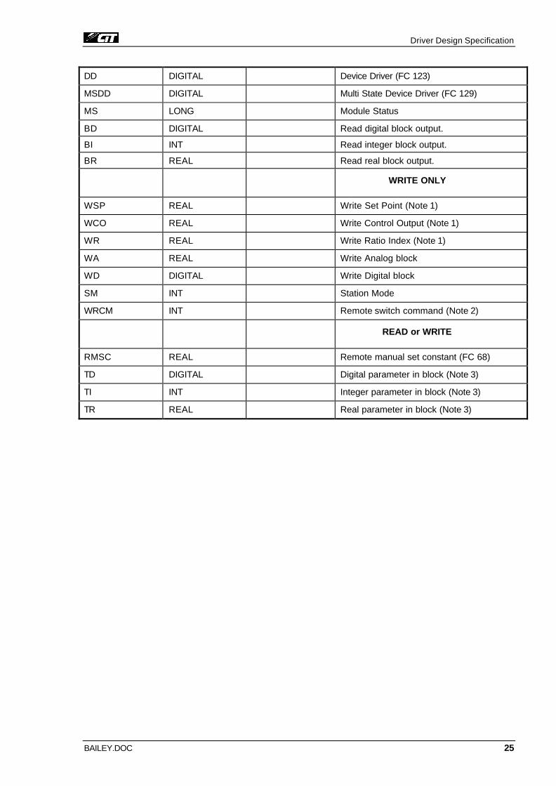
4.7 IO Device Variable Types
IO Device Type Citect data type Address range Description/Special Usage/Limitations
READ ONLY
PV REAL Note 4 Process variable
SP REAL Set Point
CO REAL Control Output
R REAL Ratio Index
A REAL Analog block (FC 30)
D DIGITAL Digital block (FC 45)
SS DIGITAL Station Status (FC 21, 22, 23 or 80)
RCM DIGITAL Remote switch (RCM, FC62) status
Driver Design Specification
BAILEY.DOC 25
DD DIGITAL Device Driver (FC 123)
MSDD DIGITAL Multi State Device Driver (FC 129)
MS LONG Module Status
BD DIGITAL Read digital block output.
BI INT Read integer block output.
BR REAL Read real block output.
WRITE ONLY
WSP REAL Write Set Point (Note 1)
WCO REAL Write Control Output (Note 1)
WR REAL Write Ratio Index (Note 1)
WA REAL Write Analog block
WD DIGITAL Write Digital block
SM INT Station Mode
WRCM INT Remote switch command (Note 2)
READ or WRITE
RMSC REAL Remote manual set constant (FC 68)
TD DIGITAL Digital parameter in block (Note 3)
TI INT Integer parameter in block (Note 3)
TR REAL Real parameter in block (Note 3)

Driver Design Specification
BAILEY.DOC 26
Note 1. To Use WSP, WCO, or WR, you must put the appropriate Station (FC 21, 22, 23, 80) into the correct mode. This is done with the Station Mode (SM) Command.
Station must be set to Computer OK.
SM<Index>,<Ring>,<Node>,<Module>,<Block> = 9
SM<Index>,<Ring>,<Node>,<Module>,<Block>=7
SM<Index>,<Ring>,<Node>,<Module>,<Block>=3
This allows the writing to Set Points and Control Outputs (WSP & WCO).
When SM = 4 You can then write to Set Points Only (WSP).
When SM = 5 You can then write to Ratio Indexes only (WR).
Note 2. The WRCM Command writes to Remote Switches, Device Drivers and Multi-State Device Drivers. Referencing the same Index as the DD or MSDD tag enables the WRCM to write to the point.
e.g. DD02,0,12,5,100.Q
WRCM02,0,12,5,100
MSDD03,0,12,5,120.Q
WRCM03,0,12,5,120
Note 3. You can only write to the tunable parameters of a block.
Note 4. The Address range has been left blank as the Bailey DCS address system has five fields <Index (1-10000 *)>, <Ring (0-7)>, <Node (0-255)>, <Module (0-31)>, <Block (0-16383**)> each with its own specific range.
* See specific CIU for maximum point index.
** See specific Module for maximum block number.
Analog status (PV, SP, CO, R, A) data types have the format PVxxxxx.qqq, SPxxxxx.qqq, COxxxxx.qqq, Rxxxxx.qqq, and Axxxxx.qqq, where "xxxxx" is in the format <Index>, <Ring>, <Node>, <Module>, <Block> and "qqq" is an optional qualifier as detailed below:
.BAD Bad Quality
.HL High Limit Alarm
.LL Low Limit Alarm
.HD High Deviation Alarm
.LD Low Deviation Alarm
.RTG One or more red tags

Driver Design Specification
BAILEY.DOC 27
.SPT Set Point tracking
Digital values (D) have the format Dxxxxx.qqq, where "xxxxx" is in the format <Index> , <Ring> , <Node> , <Module> , <Block> and "qqq" is the mandatory qualifier as detailed below:
.BAD Bad Quality
.ALM Limit Alarm
.VAL Value
Station status (SS) data types have the format SSxxxxx.qqq, where "xxxxx" is in the format <Index>, <Ring>, <Node>, <Module>, <Block> and "qqq" is the mandatory qualifier as detailed below:
.BYP Bypassed, bad analog output
.MI Manual Interlock
.OT Output Tracking
.DSF Digital Station failure
.COK Computer OK
.LEV Computer
.CRN Cascade/ratio
.A Auto
Remote switch (RCM) status has the format RCMxxxxx.qqq, where "xxxxx" is in the format <Index>, <Ring>, <Node>, <Module>, <Block> and "qqq" is the mandatory qualifier as detailed below:
.Q Bad quality (all other indication are undefined)
.ALM Alarm
.TAG Block is tagged
.OV Output value of block
.SI Logic set input is 1
.SP Set permissive input is 1
.RI Logic reset input value is 1
.OR Override is 1
.FB Feedback value is 1
.SC Set command is 1
.RC Reset command is 1
Device Driver (FC 123) status has the format DDxxxxx.qqq, where "xxxxx" is in the format <Index>, <Ring>, <Node>, <Module>, <Block> and "qqq" is the mandatory qualifier as detailed below:
.Q Bad quality (all other indication are undefined)
.ALM Alarm
.TAG Block is tagged
.V Output value of block
.F1 Input 1 feedback state is 1
.F2 Input 2 feedback state is 1
.FS Feedback status value bad is 1

Driver Design Specification
BAILEY.DOC 28
.SO Override is 1
.M1 Mode bit 1
.M0 Mode bit 0
Multi-State Device Driver (FC 129) status has the format MSDDxxxxx.qqq, where "xxxxx" is in the format <Index>, <Ring>, <Node>, <Module>, <Block> and "qqq" is the mandatory qualifier as de-tailed below:
.Q Bad quality (all other indication are undefined)
.ALM Alarm
.SO Status override is 1
.CO Control override is 1
.M Auto mode
.TAG Block is tagged
.V Output value of block
.F1 Input 1 feedback state is 1
.F2 Input 2 feedback state is 1
.F3 Input 3 feedback state is 1
.F4 Input 4 feedback state is 1
.GS1 Good state bit 1
.GS0 Good state bit 0
.RS1 Request state bit 1
.RS0 Request state bit 0
Station Mode command
Value Meaning
0 Go to local-manual (console/station-manual)
1 Go to local-auto (console/station-auto)
2 Go to local-cascade/ratio (console/station-cascade/ratio)
3 Go to computer-manual
4 Go to computer-auto
5 Go to computer cascade/ratio
6 Go to local level (console/station level)
7 Go to computer level
8 Go to computer back-up state
9 Computer OK
10 Go to previous state
Remote Switch (WRCM) command
Value Meaning
1 Sustain reset
2 Sustain set

Driver Design Specification
BAILEY.DOC 29
5 Pulse reset
6 Pulse set
Device Driver (FC 123) command (WRCM)
Value Meaning
1 Reset control output
2 Set control output
4 Request manual mode
8 Request automatic mode
Multi-State Device Driver (FC 129)) command (WRCM)
Value Meaning
0-3 Request device driver state (value 0-3)
4 Request manual mode
8 Request automatic mode
Tune block (T) has the format Txxxxx.Sn, where "xxxxx" is in the format <Index>, <Ring>, <Node>, <Module>, <Block> and "n" is the mandatory Specification Number (1 to 128) applied to the speci-fied block. Refer to the Bailey Function Code Manual for details on the Specification Numbers that you can use. Note that not all of the Specification Numbers (parameters) are tunable.
Bailey does not use Exception Reporting for tuning parameters, so take care not to slow down the system when using tuning parameters. To improve the performance of tuning parameters, Citect will read tuning parameters every 5 seconds.
To reduce the traffic on the Network 90 when reading tune blocks, CITECT reads tune blocks every 15 seconds (3 * [Bailey]Timeout). Writes to tune blocks are performed immediately.
Module Status has the format MS.qqq, where "qqq" is the mandatory qualifier as detailed below:
.MODE0 see below
.MODE1 MODE0 = 0 & MODE1 = 0 Configure
MODE0 = 1 & MODE1 = 0 Failed
MODE0 = 0 & MODE1 = 1 Error
MODE0 = 1 & MODE1 = 1 Execute
.ES Errors exist
.STA Summary station status (1bad)
.EAI EEROM contains default configuration (1yes)
.AIE Auto initialisation input status (1set)
.CAL Calibration quality status for defined ports (1bad)
.LIO Summary local IO status (1bad)
.RIO Summary remote IO status (1bad)
.MSC for MFC (1backup bad), for LMM (1memory filled)
.FTX First time in Execute (1yes)
.RING One or more rings are off-line (NCIU04 only)

Driver Design Specification
BAILEY.DOC 30
.NODE Failure in node environment (NCIU02/03 only)
.MEM Memory full
.PCU One or more PCUs are off-line
.LT0 Loop transmit error channel 0
.LT1 Loop transmit error channel 1
.LR0 Loop receive error channel 0
.LR1 Loop receive error channel 1
.LIM LIM internal problem (NCIU02/03 only) or Failure in node environment (NCIU04 only)
4.8 PROTDIR.DBF
TAG FILE BIT_BLOCK MAX_LENGTH OPTIONS
Bailey Bailey 1024 2048 0x4044b
4.9 Parameters and INI options
4.9.1 Standard Parameters
4.9.1.1 [BAILEY]Block
The blocking constant is a trade-off between the time taken to make multiple data requests and the time taken to read more data in a single request.
Allowable Values 1 to 256
Default Value 2
4.9.1.2 [BAILEY]Delay
The period (in milliseconds) to wait between receiving a response and sending the next command.
Allowable Values 0 to 300 (milliseconds)
Default Value 0
4.9.1.3 [BAILEY]MaxPending
The maximum number parameter determines number of pending commands that the driver holds ready for immediate execution.
Allowable Values 1 to 32
Default Value 1
Driver Design Specification
BAILEY.DOC 31
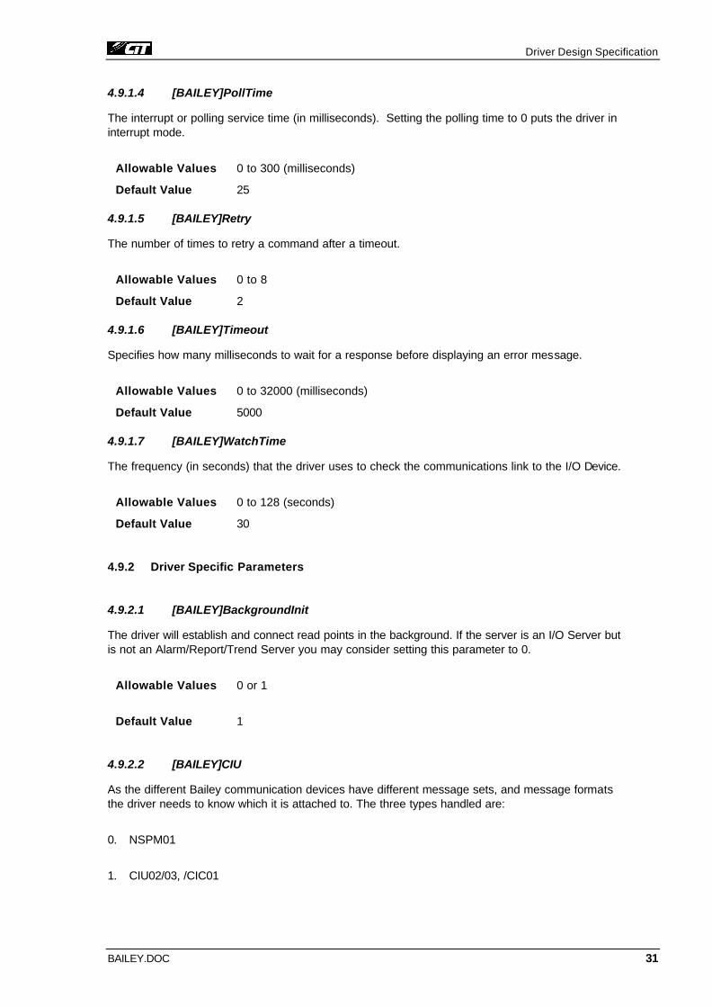
4.9.1.4 [BAILEY]PollTime
The interrupt or polling service time (in milliseconds). Setting the polling time to 0 puts the driver in interrupt mode.
Allowable Values 0 to 300 (milliseconds)
Default Value 25
4.9.1.5 [BAILEY]Retry
The number of times to retry a command after a timeout.
Allowable Values 0 to 8
Default Value 2
4.9.1.6 [BAILEY]Timeout
Specifies how many milliseconds to wait for a response before displaying an error message.
Allowable Values 0 to 32000 (milliseconds)
Default Value 5000
4.9.1.7 [BAILEY]WatchTime
The frequency (in seconds) that the driver uses to check the communications link to the I/O Device.
Allowable Values 0 to 128 (seconds)
Default Value 30
4.9.2 Driver Specific Parameters
4.9.2.1 [BAILEY]BackgroundInit
The driver will establish and connect read points in the background. If the server is an I/O Server but is not an Alarm/Report/Trend Server you may consider setting this parameter to 0.
Allowable Values 0 or 1
Default Value 1
4.9.2.2 [BAILEY]CIU
As the different Bailey communication devices have different message sets, and message formats the driver needs to know which it is attached to. The three types handled are:
0. NSPM01
1. CIU02/03, /CIC01

Driver Design Specification
BAILEY.DOC 32
2. CIU04 and higher
Allowable Values 0 - 2
Default Value 2
4.9.2.3 [BAILEY]Debug
Developers track down a CIU configuration problem using the debug parameter. It has four levels:
0. Ignore debug info
1. Check for BAD QUAILTY data
2. Enable trace info exception reports
3. Check for DRIVER BAD DATA
Allowable Values 0 - 3
Default Value 0
4.9.2.4 [BAILEY]ErrorMask
On occasions reply codes may be returned by the Bailey equipment, which effect the performance of the driver but are not critical to the operation of CITECT. One particular code 101 Busy- cannot respond at this time is the most common cause. This code maps to driver error 357 and it can be ignored by the driver using the ErrorMask. ErrorMask can be filled with 5 driver error codes sepa-rated by TAB, COMMA or SPACE, which the driver will ignore.
Allowable Values 0 - 400
Default Value 0,0,0,0,0
4.9.2.5 [BAILEY]FastInit
The driver will give higher priority to establishing and connecting analog points. This will result in pages displaying data faster (~12 seconds) the first time the page is displayed. But if you want digi-tal data (For example alarm data) to have equal priority, set this parameter to 0. If you set the value to 0, then you should also set [Lan]WatchTime to at least 120 seconds to stop request timeout errors. In this case the first page may take a moment to update.
Allowable Values 0 or 1
Default Value 1
4.9.2.6 [BAILEY]MapPath
If the project being developed has many alarms, trends and points (> 2000) it may take the driver several minutes each time the IO server is started to establish a point table on the CIU. As only a few points are added or deleted each time the server is started a delay of several minutes while the whole point table is reestablished, can be difficult. This parameter enables CITECT to keep a copy of the last CIU point table on disk. Provided the CIU has not been restarted since the last time the server was communicating with it, the point table in the CIU and on the disk should be identical. The

Driver Design Specification
BAILEY.DOC 33
driver can therefore read the disk version and set up its index table to mirror the CIU and go straight on line. The driver notes any differences between the disk copy and the new “variable.dbf”; different points are either established or deleted in the background to update the CIU point table
Allowable Values any directory or directory plus filename. If a filename is not includes then a default name Bailey_<channel number>. MAP will be used
Default Value c:\temp\Bailey_<channel number>. MAP
4.9.2.7 [BAILEY]Primary
When using redundant CIU pairs, a #COM error can occur and exist for some time when a primary CIU is taken offline and then put back online again (for example during services or swaps). The de-lay is caused by the primary reestablishing its point table after it has gone online. The primary pa-rameter tells CITECT to continue using the secondary CIU until the primary has established its point table. Note: BackgroundInit must be 1 and CIU must be > 0 for this function to work.
Allowable Values 0 or 1
Default Value 0 go online immediately
4.9.2.8 [BAILEY]Options
The CIU restart option. Refer to [1] page 2-6 point 2.
Suggested setting: NCIU04 = 11, NCIU02/03 = 11 and NSPM01 = 10
Default Value 11
4.9.2.9 [BAILEY]ReqDelay
The millisecond delay for each read request.
Default Value 60 (milliseconds
4.9.2.10 [BAILEY]Ring
Allows mapping of the ring numbers. Each of the ring numbers must be unique.
Allowable Values 0 to 255, 0 to 255, 0 to 255, 0 to255, 0 to 255, 0 to 255, 0 to 255, 0 to255
Default Value 0, 1, 2, 3, 4, 5, 6, 7
4.9.2.11 [BAILEY]WatchDog
The Watchdog time-out period = 2.5 seconds x Watchdog.
Default Value 0 (seconds)
4.10 Driver Specific Errors
The following errors, listed in (hexadecimal) sequence, are specific to this protocol. Citect displays the error number and description for common protocol-specific errors. Uncommon errors are not contained in the Citect error database, in which case Citect will only display the error number.

Driver Design Specification
BAILEY.DOC 34
You may require additional information to enable you to rectify an error. This information should be detailed in the documentation that accompanied the I/O Device (or network). Refer to [1] "Reply Codes" and "Module Bus Reply Codes". Ref: Bailey Network 90, E93-905-2, pages 9-1 to 9-7, page A-4
The driver offsets all errors generated by the Bailey module. The offset is 0x100 hexadecimal or 256 decimal –
eg. Driver Error 0x115 is error 0x15 = Bailey Error # 21 (decimal)
DRIVER ERRORS
Driver Error Code Mapped to Citect Error
Meaning of Error Code
40 (0x28) 40 (0x28) Tune block specification number is out of Range in Block
41 (0x29) 41 (0x29) Incompatible Data Type The data type is not specified correctly (e.g. reading TI as real)
42 (0x2A) 42 (0x2A) Tune block specification number is Not Tunable
43 (0x2B) 43 (0x2B) Status of point indicates Bad Quality.
BAILEY STANDARD REPLY CODES
Driver Error Codes
(256 – 297 decimal)
Bailey Error Code
(Decimal)
Meaning of Error Code
0x100 0 No Error
0x101 1 Waiting for Loop The command was started successfully. The NCIU is now waiting for a reply from the remote PCU used in the command.
0x102 2 Improper Format The Command to the NCIU was not properly constructed. This usually indicates that the command contains too few or too many bytes.
0x103 3 Illegal command
0x104 4 Index already established
0x105 5 Block already established for another point This point has already been established by the computer using another index

Driver Design Specification
BAILEY.DOC 35
0x106 6 Command too long
0x107 7 Bad reply from BTM
0x108 8 Export used As Import
0x109 9 Repeat CIU restart command
0x10A 10 Undefined index
0x10B 11 Memory full
0x10C 12 Host communication error
0x10D 13 BTM not responding
0x10E 14 Import used as export
0x10F 15 Time-out of plant loop response
0x110 16 Number out of range
0x111 17 Illegal key
0x112 18 Need a restart command
0x113 19 Module status used as import
0x114 20 Message active on loop
0x115 21 Import or export used as module status
0x116 22 Exception report specification list
0x117 23 No message queued/dequeue received
0x118 24 Reply too large
0x119 25 Illegal station mode command
0x11A 26 Illegal Module number in command
0x11B 27 Time-out between bytes in command
0x11C 28 Index already established (by another computer)
0x11D 29 Point type incompatible with command
0x11E 30 Watchdog time-out
0x11F 31 Checksum compare error
0x120 32 Destination node off-line

Driver Design Specification
BAILEY.DOC 36
0x121 33 Callup command required
0x122 34 CIU error
0x123 35 CIU busy
0x124 36 BTM off-line
0x125 37 Conflict with monitor mode
0x126 38 Point type
0x127 39 Destination ring off-line
0x128 40 Destination node busy
0x129 41 Destination ring busy
BAILEY MODULE BUS REPLY CODES
Driver Error Codes
(356 – 366 decimal)
Bailey Error Code
(Decimal)
Meaning of Error Code
0x164 100 Busy - The unit cannot respond at this time
0x165 101 Mode for command does not agree with current module mode
0x166 102 Mode for command incompatible with module mode
0x167 103 Message data out of legal range
0x168 104 Invalid block number
0x169 105 Unconfigured block number
0x16A 106 Unreadable block
0x16B 107 Invalid function code for target module
0x16C 108 Incompatible function code and block number
0x16D 109 Insufficient memory to write block
0x16E 110 Module not responding

Driver Design Specification
BAILEY.DOC 37
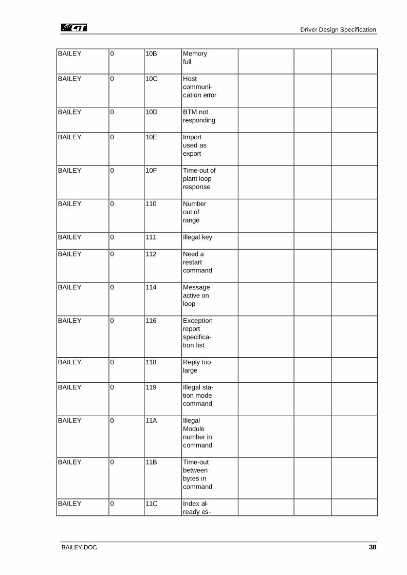
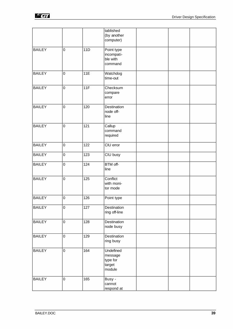
4.11 Driver Error Help
The following entries should be included in the Citect ProtErr.DBF spec file.
PROTOCOL MASK ERROR MESSAGE REFERENCE ACTION COMMENT
BAILEY 0 28 Spec out of range
BAILEY 0 29 Incompati-ble type
BAILEY 0 2A Spec not tunable
BAILEY 0 2B Bad quality warning
BAILEY 0 101 Waiting for loop
BAILEY 0 102 Improper format
BAILEY 0 103 Illegal command
BAILEY 0 104 Index al-ready estab-lished
BAILEY 0 105 Block al-ready es-tablished another point
BAILEY 0 106 Command too long
BAILEY 0 107 Bad reply from BTM
BAILEY 0 108 Export used As Import
BAILEY 0 109 Repeat CIU restart command
BAILEY 0 10A Undefined index
Driver Design Specification
BAILEY.DOC 38
BAILEY 0 10B Memory full
BAILEY 0 10C Host communi-cation error
BAILEY 0 10D BTM not responding
BAILEY 0 10E Import used as export
BAILEY 0 10F Time-out of plant loop response
BAILEY 0 110 Number out of range
BAILEY 0 111 Illegal key
BAILEY 0 112 Need a restart command
BAILEY 0 114 Message active on loop
BAILEY 0 116 Exception report specifica-tion list
BAILEY 0 118 Reply too large
BAILEY 0 119 Illegal sta-tion mode command
BAILEY 0 11A Illegal Module number in command
BAILEY 0 11B Time-out between bytes in command
BAILEY 0 11C Index al-ready es-
Driver Design Specification
BAILEY.DOC 39
tablished (by another computer)
BAILEY 0 11D Point type incompati-ble with command
BAILEY 0 11E Watchdog time-out
BAILEY 0 11F Checksum compare error
BAILEY 0 120 Destination node off-line
BAILEY 0 121 Callup command required
BAILEY 0 122 CIU error
BAILEY 0 123 CIU busy
BAILEY 0 124 BTM off-line
BAILEY 0 125 Conflict with moni-tor mode
BAILEY 0 126 Point type
BAILEY 0 127 Destination ring off-line
BAILEY 0 128 Destination node busy
BAILEY 0 129 Destination ring busy
BAILEY 0 164 Undefined message type for target module
BAILEY 0 165 Busy - cannot respond at

Driver Design Specification
BAILEY.DOC 40
this time
BAILEY 0 166 Mode for command incompati-ble with module mode
BAILEY 0 167 Message data out of legal range
BAILEY 0 168 Invalid block number
BAILEY 0 169 Unconfig-ured block number
BAILEY 0 16A Unreadable block
BAILEY 0 16B Invalid function code for target module
BAILEY 0 16C Incompati-ble func-tion code and block number
BAILEY 0 16D Insufficient memory to write block
BAILEY 0 16E Module not responding
BAILEY FF 100 *BAILEY error code
Bailey Network 90, E93-905-2, pages 9-1 to 9-7, page A-4

Driver Design Specification
BAILEY.DOC 41
4.12 Debug Messages
The driver uses two forms of debug messages. The Bailey "Reply Codes" and "Module Bus Reply Codes" which are returned in the driver specific error code field of the device error message incre-mented by 0x100 hexadecimal and the trace messages. The trace messages has two forms. Trace of the transmitted message, which has the form:
<CITECT time stamp> <Tag address> <Hexadecimal message transmitted><checksum>
And a trace of the message received from the Bailey equipment in the form:
<CITECT time stamp> <Tag address> <Hexadecimal message received>
Note: the received message has had the checksum removed since the message has passed the checksum test.
The <Tag address> has the form:
<Type><Index>, <Ring>, <Node>, <Module>, <Block.[.Sub]>
The <Hexadecimal message transmitted> has the form:
Byte No Data type Description
1 Code Command Code
2 Byte Key
3…END Depend on format of Command Code refer to [1] Chapter 2 Commands, COMMAND
The <Hexadecimal message received> has the form:
Byte No Data type Description
1 Reply Code Reply from Bailey equipment. 0 = ON ERROR
2…END Depend on format of Command Code refer to [1] Chapter 2 Commands, REPLY

Driver Design Specification
BAILEY.DOC 42
4.13 Stats Special Counters
Number Label Purpose/Meaning of this counter
0 TRANSMIT The number of messages sent to the Bailey Equipment
1 RECEIVED The number of messages received from the Bailey Equip-ment
2 RX_INT The number of time the receiver timer has expired
3 POLL The number of background poll messages sent to the Bai-ley Equipment
4 READ_EXCEPTIONS The number of exception messages received from the Bai-ley Equipment
5 BAD_QUALITY The number of exception messages received from the Bai-ley Equipment who’s status was bad
6 MAX_INDEX The highest index number used in the point table
7 INIT_UNIT The number of times the serial port has been reset
8 GET_CACHE The number of messages retrieved from the tune block cache
9 PUT_CACHE The number of messages added to the tune block cache
10 INITIALISING The number of initialising requests sent to the Bailey equipment
11 POINTS_DEFINED The number of read points defined
12 POINTS_ESTABLISHED The number of read points established
13 READ_ERROR The number of read points which could not be established
14 POINTS_NODATA The number of read points which could be established but have not returned any data
15 WRITE_DEFINED The number of write points defined
16 WRITE_ERROR The number of write points which could not be established
17 DCB The number of messages received from the IO server
18 POINTS_WRITE This count is divided into three groups:
1. write points established (count in 1’s)
2. write points establishing (count in 1000’s)
3. write points written to (count in 100000’s)
19 BAD_INDEX Number of bad indexes returned in exception reports

Driver Design Specification
BAILEY.DOC 43
4.14 Hints and Tips
4.14.1 Improving System Performance
4.14.1.1 Screen Update
In communicating with the Bailey, Citect creates a Point Table identical to the Point Table in the Bailey. When the Bailey gets any change, it reports the change to Citect and Citect updates its Point Table, so data updates should be nearly instant. However, read and write points are only es-tablished when requested the first time. When accessing pages for the first time the update will be slow some improvements may be possible if the following are considered.
4.14.1.1.1 Request Delay The default delay time between read requests is 60 milliseconds. If the screen update times are too high, reduce the delay in the [BAILEY]ReqDelay parameter. You can also increase the [BAI-LEY]Block parameter to allow Citect to read more data in each read operation. Remember for sys-tems that are using Display Clients talking to an IO Server over the network. Reducing the ReqDe-lay to 0 on a Display Client will increase network traffic as the Display Client is requesting data from the I/O Server continuously. A ReqDelay of 0 is not recommended for networks.
4.14.1.1.2 Blocking Blocking of similar data types also increases performance. If you block each data type (e.g. Digital, Real, etc.) together in your Variables Definitions, then the variables of each type are read faster. To block them together, you should try to keep Index numbers running in order (for each type). For example:
PV1,0,5,6,199
PV2,0,5,6,728
SP3,0,5,6,199
(REAL, Read Only data types blocked together)
WSP201,0,5,6,199
WPV202,0,5,6,728
WPV203,0,5,6,199
(REAL, Write Only data types blocked together)
D401,0,5,6,236.BAD
D402,0,5,6,173.VAL
SS403,0,5,6,328.A
(DIGITAL, Read Only data types blocked together)
PV601,0,5,6,199.BAD
Driver Design Specification
BAILEY.DOC 44
PV602,0,5,6,199.HL
SP603,0,5,6,199.SPT
(DIGITAL, Status values from REAL points)
n By blocking data types together, you can keep ReqDelay at 60 and Block at 2, but you should still experiment to determine the optimum settings for your installation (if the response times of the system are inadequate).
n The CPU Usage value should be monitored (shown on the Page General display of the Citect Ker-nel). If this value rises to unacceptably high levels, then increase the ReqDelay parameter.
4.14.1.2 Using multiple CIUs
If you are using two ICT modules to improve performance on the system, be careful not to interlace tags in each ICT (e.g. don't have ICT1 talking to blocks 555, 559 and 580, while ICT2 is talking to 556, 560 and 577). While it won't actually stall the driver, it may affect the scan time of the proces-sor, depending on how badly you interlace everything. Only use more than one ICT if you need to access more than 10000 indexes (not necessarily the same thing as tags) from the system, or pro-vide redundancy. Also note that Citect prefers to have similar tag types grouped into indexes (e.g. all the RCM reads in index range say 5000-5999), so bear this in mind when trying to split things across two or more modules.
4.14.2 Using BR, BI and BD tags
The BR, BI and BD tags use the READ BLOCK OUTPUT command to retrieve data from the Bailey DCS. This command is inefficient for the driver since it has to issue a command and wait for a reply from the DCS for each tag read. This command also increases the traffic on the DCS internal net-work, as the actual module in which the block resides must be asked for the output value. The tags were implemented to enable limited monitoring of a DCS using equipment, which is not capable of exception reporting such as a SPM or CPM.
With the above in mind these tags can be used to read any output from any block using either a SPM or CIU type unit. One of the most common uses is to read the output of FC 129 the MSDD function code. The outputs for this FC reside in block N, N+1, N+2 and N+3. N is the block the FC is configured in. There is two ways to read these blocks. The preferred way is to configure several block in the control module with FC30 and FC45 to generate exception reports for blocks N, N+1 etc. and then include D and A tags in the project to read exception reports from the FC30 and FC45 blocks. The other way is to configure BR and BD tags in the project to read the N, N+1, N+2 and N+3 blocks directly.
When using large numbers of BR, BI and BD tags it is important to consider the effect of the index field. The index field is used as an address by CITECT. Since the granularity of CITECT is meas-ured in blocks which relates to16 digital tags The blocking parameter equates to Block *16 indexes. So the minimum number of indexes the driver will read during each request is 16 if Block = 1. This can be a problem when using the serial port module. The serial port module does not use an index table or exception reporting therefore each request is sent over the Bailey communication network to the module denoted in the address. This is a much slower operation than exception reporting so reading more tags than is necessary for the current page and associated trend or alarms can cause screen update delays. To over come this problem tags BR, BI and BD can be indexed at intervals of 16 therefore only one slow READ BLOCK OUTPUT operation will be performed per request. Alterna-tively all the BR, BI and BD tags per page can be grouped together, so that all the tags on the one page are updated in one or two requests.

Driver Design Specification
BAILEY.DOC 45
4.14.3 Function Codes
A function code is a function, which resides in the control module firmware. Blocks that are asso-ciated with a FC during configuration of a control module are data storage areas for each instantia-tion of the FC. This storage area is broken up into several sections, specifications, status and out-put. The driver is capable of reading each of these sections. It can write to the status section and tuning parts of the specification section. The driver therefore operates independently of the FCs assigned to the blocks.
Its only function is to read and write the bytes within the blocks. The format of these bytes is differ-ent for each FC and some tags have been included to help decode the status section of blocks as-sociated with these FCs, for example MSDD (FC 129 Multi State Device Driver). If there is not a tag for the FC you wish to use and its status field (RCM) is different to the standard one either add an-other record into the Bailey.dbf file to handle the status section or use RCM to read in the status and decode it with cicode.
4.14.4 Indexing Tags
The majority of tags listed above can be associated with a point in the CIU points database. The driver uses the index field when establishing a point in the CIU. This index is a unique number as-sociated with one block in the DCS. All tags addressing the same block within the DCS should have the same index number. This will make the transfer of data more efficient and reduce network overheads
4.14.5 Troubleshooting
4.14.5.1 "Unknown Data Type"
If the "Unknown Data Type" error (protocol generic error 3) occurs when you try to connect to an I/O Device, first check that the CTCMP.EXE and BAILEY.DLL files on the PC running Citect are the current version. Then check that your variables are properly addressed. This error can also be caused when two different variable tags try to read the same Bailey block.
4.14.5.2 "Driver is Not Responding"
If the "Driver is Not Responding" error (protocol generic error 19) occurs, check that you have given each CIU on the loop a unique I/O Device Address. If no addresses are duplicated, try resetting the CIU and the Bus Transfer Module. Pull the modules out of the backplane to cause a power down reset. If the driver still does not respond, contact Bailey customer support.
4.14.5.3 General Error"
n If a general error (protocol generic error 8) occurs during run time, Citect may be trying to read from a block that does not exist in the computer.
4.14.5.4 "Incompatible Types"
n If the "Incompatible Types" error occurs during compilation, you could have allocated a sin-gle index number more than once in the database.
4.14.5.5 "Bad I/O Device Variable"
n If the "Bad I/O Device Variable" error occurs during compilation, you could be using an out-of-date compiler. Check the version/release of the compiler and contact Citect Technical Support

Driver Design Specification
BAILEY.DOC 46
5. Basic Testing
5.1 Introduction
As this specification is written for a driver, which has been in service for may years this section is considered unnecessary. All modifications to the driver in the recent release have been field tested during commissioning of the driver at least three separate sites.
5.2 Procedure
Not applicable

Driver Design Specification
BAILEY.DOC 47
6. Performance Testing
6.1 Introduction
Limited performance testing has been carried out on this driver following recent modifications. Per-formance testing was not considered necessary as P Wong performed these during initial testing in 1992.
6.2 Calculating the Blocking Constant
The Block constant is 2.

Driver Design Specification
BAILEY.DOC 48
7. References
7.1 References
[1] Bailey Product Instruction E93-905-9, "Enhanced Computer Interface Unit Programmer's Reference Manual", Bailey Controls, Wickliffe, Ohio 44092.
[2] Bailey Product Instruction E93-905-1 “Serial Port Module (NSPM01)”, Bailey Controls, Wickliffe, Ohio 44092
[3] Electronic Documentation INFI 90®, Elsag Bailey Process Automation.

Driver Design Specification
BAILEY.DOC 49
8. Appendix
Appendix A Initialization flow chart
START
READ PARMAETERS
LOAD MAPPOINTS
ENVIRONMENT
CIU RESTART
LOAD AND COMPARE
PREVIOUS MAP
MAPPATH = NULL AND
INITSTATE <> RESTART
DISCONNECT POINT LIST
CONNECT POINT LIST
ERROR
ERROR ERROR
ERROR
ONLINE
INITSTATE = RESTART
N
N
N
N N

Driver Design Specification
BAILEY.DOC 50
Appendix B Configuration flowchart
The following flow chart applies to each point whose index number is > 0 Configuration of a point in the CIU can occur: Once every cycle of the polling loop, During a read or write request from CITECT or During initialization (special redundancy case only)
START
ESTABLISH AND CONNECT POINT
CHANGED
DEFINED
REMOVED
DISESTABLISH POINT
PV, SP, CO, RI, A, SS, EMS, D,
RCM, RMSC
ESTABLISH POINT MS, WSP, WCO, WRI,
SM
WA, WD
DISESTABLISH POINT END
DEFINED
ESTABLISH REPORT
ERROR ESTABLISHED
END
Y
Y
Y
Y Y
Y
Y

Driver Design Specification
BAILEY.DOC 51
Appendix C Bailey Driver Execution flowchart
Front-end READ
START
TR, TI, TD IN QUEUE
NOT ESTABLISHED
CONFIGURE
REPLY
BR, BI, BD IN QUEUE
END
Front-end WRITE
START
IN QUEUE

Driver Design Specification
BAILEY.DOC 52
BACK-END TRANSMITT
START
OUT QUEUE
BUILD COMMAND
BUILD COMMAND IN QUEUE
COUNT%4=0
COUNT%4=1
COUNT%4=2
COUNT%4=3
COUNT++
CONFIGURE
READ EXCEPTION
READ MISC STATUS EXCEPTION
READ EXCEPTION REPORT SPECS

Driver Design Specification
BAILEY.DOC 53
BACK-END CPU
START
OUT QUEUE CACHE
EXCEPTION
BR, BI, BD, MS
TR, TI, TD READ
UPDATE POINT TABLE IMAGE
WRITE
ERROR
CACHE
CONFIGURATION
TUNE
END
REPLY


![Citect SCADA 6[1].10 Modbus Driver Help](https://img.pdfslide.us/doc/110x75/553578924a795956188b45fe/citect-scada-6110-modbus-driver-help.jpg)