Embed Size (px)
Citation preview

Citabria ProAerobatic Parkflyer
byJoel Dirnberger
Revision C: December 21, 2004

Page 2 of 24 © Copyright 2004 Joel Dirnberger. All rights reserved.
Citabria Pro Building Instructions
Length: 19 in.
Wingspan: 30.5 in.
Wing Area: 146 sq. in.
Flying Weight: 7.5 ~ 9.0 oz.
Wing Loading: 7.4 ~ 8.9 oz/sq. ft.
Functions: Aileron, Elevator, Rudder, Throttle
Specifications:
Aileron Servo: 4.4gr. or smaller
Other Servos: 6.0 gr. or smaller
Motor: GoBrushless, LensRC 15, or AXI 2204/56
Battery Pack: 7.4 or 11.1, 800mAh or larger Lithium Polymer
Suggested Equipment:
Parts required to complete the Citabria Pro kit (1) Micro Brushless Motor (1) Electronic Speed Control (to suit motor) (1) 4 Channel Receiver (1) 4.4 gr. Servo (or smaller) (2) 6.0 gr. Servo (or smaller) (1) Roll of Solite covering (or equivalent)
qqqqqq
Tools and Supplies required to complete the Citabria Pro kit
Fine & Medium Sanding Papers Thin & Medium Thickness CA Glues Masking Tape Wax Paper or Plan Protection Plastic Hobby Knife & Blades Needle Nose Pliers Ruler Covering Iron 3/32 in. Drill Bit 1/16 in. Drill Bit 1/32 in. Drill Bit 2-56 Machine Screw Tap 4-40 Machine Screw Tap
qqqqqqqqqqqqq

10B
2F
8F
2B
3B
1B
4B5B
5F6B
ST
q Using the holes in both parts for alignment, glue 8F to 2F. Glue 10B into the notches in 2F.
q If you will be using the IPS style stick mount, cut the hole in the firewall to the size required for the desired mount. Assemble parts 1F, 3F and 4F to 2F as shown. Do not glue at this time.
q To simplify installation, you want to attach the rudder and elevator servos to part ST at this time. Add parts ST, 4B, 5B, 5F and 6B to the fuselage assembly. Pull the tail of the fuselage together and glue the added parts in place.
q Add parts 1B, 2B and 3B to 2F as shown. Glue the bottom of the fuselage assembly at this point.
Page 3 of 24
Citabria Pro Building Instructions - Fuselage
© Copyright 2004 Joel Dirnberger. All rights reserved.
4F3F
3F1F
IPS Dual
IPS Single

6F
9B
8B
7B
6F
q Glue parts 7B, 8B and 9B into the slots in part 6F.
q Glue the parts assembled in the previous step to the bottom of the bottom of the fuselage assembly. Glue the joints along the top of the fuselage at this point.
q Glue parts 11B to the bottom of the fuselage assembly.
q Attach the aluminum landing gear to the bottom of the fuselage assembly using a pair of steel 4-40 screws. Use washers under the screw heads.
Page 4 of 24
11B
Citabria Pro Building Instructions - Fuselage
© Copyright 2004 Joel Dirnberger. All rights reserved.

q Bevel the edges of parts 1L as required so that they fit tightly around the aluminum landing gear legs. Glue parts 1L in place.
Page 5 of 24
1L
1L
1H
6T
1T
13T12T
11T10T
9T8T
7T
q Glue parts 1T, 6T and 1H to the top of the fuselage assembly. Bevel the edges of parts 1H to match 1T and 6T.
q Glue parts 7T, 8T, 9T, 10T, 11T, 12T and 13T to the top of the fuselage assembly.
Citabria Pro Building Instructions - Fuselage
© Copyright 2004 Joel Dirnberger. All rights reserved.

Page 6 of 24
7F q Bevel the top and bottom edges of parts 7F to match the angle of part 13T. Glue parts 7F to the fuselage assembly. Parts 7F must be twisted to meet 13T (see the illustration in the next step).
10F
9F
8F
q Glue parts 8F, 9F and 10F into the notches in the formers on top of the fuselage assembly.
q From 1/16” diameter carbon fiber rod, cut two 4” lengths and insert them into the forward cabin strut holes in the fuselage assembly. Cut two 3.9” lengths of carbon rod and insert them into the rear cabin strut holes in the fuselage assembly. Do not glue the rods in place at this time.
Citabria Pro Building Instructions - Fuselage
© Copyright 2004 Joel Dirnberger. All rights reserved.

2MX2
X1
X3
1M
q Assemble the wing incidence jig from parts X1, X2 and X3. Use the jig as shown to position the wing mounts 1M and 2M on the upper ends of the cabin struts. Cut two 3.1” lengths of carbon rod and fit them into the strut brace holes in the fuselage and parts 1M. When you are satisfied that the mounts and rods are properly aligned, glue the rods and mounts in place. Be careful not to glue parts X1, X2 or X3 to the fuselage assembly. When the glue is dry, remove parts X1, X2 and X3.
Page 7 of 24
3C(or 6C)
5C (or 8C)
4C(or 7C)
2C
1C
2C
q Assemble the motor stick mount from parts 3C, 4C and 5C (or 6C, 7C and 8C if using IPS Dual mount) and fit them into the firewall. Insert motor stick fits into the hole formed by the motor mount parts to check for proper fit. Remove the motor stick and glue the mount parts to the fuselage firewall.
q Glue parts 1C to the front of the fuselage assembly. Glue parts 2C to 1C using the holes for alignment. After the glue dries, drill out the holes in 1C and 2C using a 1/16” diameter drill bit. Tap the holes for 2-56 machine screws.
Citabria Pro Building Instructions - Fuselage
© Copyright 2004 Joel Dirnberger. All rights reserved.

Page 8 of 24
Citabria Pro Building Instructions - Fuselage & Hatch
© Copyright 2004 Joel Dirnberger. All rights reserved.
q Assemble the hatch from parts 2T, 3T, 4T, 5T, and 2H. Trial fit the hatch in the fuselage opening before gluing.
q Cut a 1.4” length of 1/16” carbon rod. Round one end of the rod with sandpaper. Glue the rod into the holes in parts 2T and 3T so that the rounded end of the rod protrudes 1/8” of an inch from the forward end of the hatch.
5T
2H
2H
2T
2H
3T
4T
q Trial fit the assembled hatch in the fuselage opening again. Sand the hatch and opening if required. Cut a 1.4” length of 1/16” carbon rod to use as the hatch retaining pin. Round one end of the rod with sandpaper. The rounded end of the rod slides through the holes in fuselage parts 6T and 7T and into the hole in hatch part 5T to retain the hatch.
RetainingPin
q If you did not install the rudder and elevator servos earlier, do so now. Cut the pushrod tubing into two pieces 7 inches long and sand the outside of the tubing ends lightly. Fit the tubing into the holes in former 9T and the slots in the fuselage sides (parts 3F). Glue the tubing in place. After the glue has dried, trim pushrod tubing flush with the fuselage sides.

Page 9 of 24
q Reinforce the firewall by gluing 4 gussets (parts GU) between the firewall and the fuselage sides. The gussets should be locate 1/4” below the fuselage top (part 4F) and 1/4” above the fuselage bottom (part 2F).
q Reinforce the landing gear by gluing 2 gussets (parts GU) between the fuselage bottom and the fuselage sides. The gussets should be locate in line with part 3B.
© Copyright 2004 Joel Dirnberger. All rights reserved.
GU
GU
Citabria Pro Building Instructions - Fuselage
q Remove the hatch. Using the templates on the plans, cut 1/32” balsa sheet for the top of the fuselage to size. Dry fit the sheet to the fuselage and trim to fit. Glue the sheet in place. After the glue has dried, trim the sheeting to fit the hatch opening as required. Sand the sides of the fuselage to create a smooth transition into the top sheeting.

FiberglassCloth
Page 10 of 24
q Cut the 1/16” O.D. brass tubing to 0.7” in length. Cut a piece of 1/32” dia. piano wire to 3.2” in length. Bend the wire as shown on the plans to create the tail wheel assembly. Slip the brass tube over the wire before making the final bend. The tailwheel may be installed at this time, or it may be installed during final assembly.
q Carve a groove in the tail of the fuselage so that the brass pivot tube of the tail wheel assembly will fit almost flush with the end of the fuselage. Glue the pivot tube in place taking care that the wire still pivots freely. Reinforce the joint by gluing a couple of layers of fiberglass cloth over the brass tube.
Citabria Pro Building Instructions - Hatch & Tail Wheel
Make thisbend last
© Copyright 2004 Joel Dirnberger. All rights reserved.
q Using the template on the plans, cut 1/32” balsa sheet for the top of the hatch to size. Glue the sheet in place. After the glue has dried, trim the sheet and sand the hatch as required so that the hatch will fit the opening in the fuselage. Be sure to leave enough clearance so the hatch will open easily once the hatch and fuselage are covered.

q Assemble the vertical stabilizer and rudder over the appropriate section of the plans.
Page 11 of 24
Citabria Pro Building Instructions - Tail Surfaces
© Copyright 2004 Joel Dirnberger. All rights reserved.
q Sand the tail surfaces to their final shape. Round the leading edges and taper the trailing edges. Test fit the horizontal stabilizer and the vertical stabilizer to the tail of the fuselage. Determine where the tail wheel wire will intersect the rudder and drill a 1/32 in. diameter hole into the rudder such that the rudder will slide over the wire into the proper position.
q Assemble the horizontal stabilizer and elevators over the appropriate section of the plans.
q Join the elevator halves with a a 1” length of 1/16” diameter carbon rod.

S8
S8
S7
S7
T9
T9
R2
R3
R3
S1
S2S3
S6
S4
R1
Page 12 of 24
Construction Supports
q Locate the wing spar parts S1, S2, S4 and S5. When you remove them from the parts sheet, do not remove the construction supports from the spars.
q Assemble the wing spars from parts S1, S2, S3, S4, S5 and S6. Make sure the construction supports for the spars all rest flat on the building surface when you glue the spars together.
q Tap the wing mounting holes in parts S7 and S8 for 4-40 machine screws. Apply thin CA to the threads and allow them to dry. Dry assemble the wing center section from parts R2, R3, S7, S8 and T9. Do not glue at this time.
q Fit the sub-assemblies from the previous step to the wing spars. Add part R1 to the wing assembly. The wing assembly should now stand nicely on the construction supports. Position the wing over the plans to insure it is square. You may now glue the center section at this time.
Citabria Pro Building Instructions - Wing
© Copyright 2004 Joel Dirnberger. All rights reserved.

T2
T3
T1
1/8 x 1/4
T10
Page 13 of 24
q Cut a piece of 1/8 x 1/4 balsa to 3.4” in length, and glue it into the leading edge of the wing center section. Fit parts T1 and T10 to the wing center section and glue them in place.
q Fit parts T2 to the wing center section and glue them in place.
q Fit parts T3 to the wing center section and glue them in place.
Citabria Pro Building Instructions - Wing
© Copyright 2004 Joel Dirnberger. All rights reserved.

A8
A6
R4
R5
A6/A8
T4
R6
R7
T5
R9R8
Page 14 of 24
q Fit ribs R4 and R5 to one side of the wing assembly. Repeat for the other side of the wing. Do not glue them in place at this time.
q Assemble the bellcrank support by gluing part A8 into the square hole in part A6. Repeat for the other pair of parts.
q Fit part T4, rib R6 and the assembled parts A6/A8 to one side of the wing assembly. Repeat for the other side of the wing. Do not glue them in place at this time.
q Fit part T5 and ribs R7, R8 and R9 to one side of the wing assembly. Repeat for the other side of the wing. Do not glue them in place at this time.
Citabria Pro Building Instructions - Wing
© Copyright 2004 Joel Dirnberger. All rights reserved.

S11
R11
S11
1/8 x 1/4
T6
T8
S9
S9
S6
R10
A10
A9
Page 15 of 24
q Glue parts A9 and A19 to the bottom of the wing to create an exit hole for the aileron pushrods. Do this for both ends of the wing.
q Fit rib R11 to both ends of the wing assembly. Check the entire wing for squareness a and fit. Glue the entire wing at this time. Parts S11 are optional hinge supports. Add them if you do not plan to use tape hinges on the ailerons.
q Fit parts S6, S9 and rib R10 to one side of the wing assembly. Repeat for the other side of the wing. Do not glue them in place at this time.
q Cut a strip of 1/8 x 1/4 balsa to 13” in length. Dry fit the strip into the leading edge on one side of the wing and trim to fit if necessary. Fit parts T6 and T8 to this side of the wing. Repeat for the other side of the wing.
Citabria Pro Building Instructions - Wing
© Copyright 2004 Joel Dirnberger. All rights reserved.

A2
A2
A2
Page 16 of 24
A4
A2
A1
A6
A5
q Sand the wing leading and trailing edges to shape. If parts S11 were used, sand them flush to the top of the wing.
q Laminate parts A1 and A6. Glue parts A1/A6 and A2 to part A4.
q Glue the remaining A2 parts to the previous aileron assembly.
q Glue the part A5 to the aileron assembly.
Citabria Pro Building Instructions - Wing & Ailerons
© Copyright 2004 Joel Dirnberger. All rights reserved.

A3
A7
A7
Page 17 of 24
q Glue the part A3 to the aileron assembly. Sand the aileron trailing edge to shape.
q Parts A7 are optional hinge supports. Add them if you do not plan to use tape hinges on the ailerons. If used, sand parts A7 flush with the top of the ailerons.
Citabria Pro Building Instructions - Ailerons & Linkage
© Copyright 2004 Joel Dirnberger. All rights reserved.
q Using the templates on the plans and 0.032” diameter piano wire, fabricate the aileron pushrods and the wing pushrod ends.
q Assemble the aileron servo hatch using Parts S10 and R12.
S10
S10R12
Aileron Pushrods
Wing Pushrod Ends

Page 18 of 24
Citabria Pro Building Instructions - Aileron Linkage
© Copyright 2004 Joel Dirnberger. All rights reserved.
q Connect the wing pushrod bellcrank end to the DuBro Micro Bellcrank. Screw the Micro Bellcrank to the bellcrank support. Do this for both halves of the wing.
q Connect the wing pushrod servo ends to the aileron servo. Either glue the aileron servo directly to part T10 or screw the servo to mounting blocks made from scrap balsa and glue the mounting blocks to part T10. Be sure to position the servo such that the servo horn and the pushrod ends do not bind or rub.
q Using masking tape, temporarily hinge the ailerons to the wing. Tape the trailing edges to prevent the ailerons from moving. Connect the aileron pushrods the bellcranks and the ailerons. Lock the pushrods in place using Mini E/Z Connectors.
q Cut the main wing pushrod segments to length from 0.040 in. diameter carbon fiber rod. The ends of the rods and the wire pushrod ends should overlap by ½ inch. With fine sandpaper, lightly sand the ends of the rods and wires where they overlap. Connect the rods and pushrods using heat shrink tubing over the joints.
Carbon Fiber RodApproximate Lengths
Left: 6.1 inchesRight: 6.9 inches
Heat Shrink Tubing

q Test fit the wing to the fuselage. Slide the wing over the cabin strut mount plates and attach the wing using four nylon 4-40 x 3/8 machine screws.
Apply thin CA glue at these joints
Page 19 of 24© Copyright 2004 Joel Dirnberger. All rights reserved.
q Remove the tape from the aileron trailing edges. Cycle the servo and check that the ailerons move freely and the linkage does not bind or rub. The ailerons should have about1/2 in. up travel and about 3/8 in. down travel. Once the linkage has been adjusted and is operating properly, lock the heat shrink in place with thin CA glue. Be sure the CA penetrates under the heat shrink.
q Test fit the servo bay hatch. Trim and sand the hatch as required to obtain a flush fit. Cut a small notch in the corner of the hatch to provide clearance for the servo leads.
Citabria Pro Building Instructions - Aileron Linkage & Wing Struts
1.00 in.
1.00 in.
1.25 in.
q Using the templates on the plans, fabricate the wing strut end wires from 0.032” diameter piano wire. At the dimensions shown, drill three holes 1/8 in. deep and 1/32 in. diameter in the leading edges of both wing struts (part Z1).

Page 20 of 24© Copyright 2004 Joel Dirnberger. All rights reserved.
Citabria Pro Building Instructions - Wing Struts & Ailerons
FiberglassCloth
q Glue the strut end wires into the holes in the strut. Reinforce the joints by wrapping a couple of layers of fiberglass cloth over joints as shown. Glue with medium CA. Make sure the wire at the fuselage end of the strut will flex enough for the strut to slide onto the fuselage mount.
q To test fit the wing struts, first insert the Z-bends at the upper end of the struts into the holes in the mount plates (parts S9). Next, rotate the struts into position and slide the lower wire into the fuselage mounts (part 10B) flexing the wire slightly until the strut is in position.
q Remove the struts and disconnect the wing from the fuselage. Remove the ailerons and servo bay hatch from the wing. cover the wing, ailerons and servo bay hatch. Reinstall the servo bay hatch. Hold the hatch in place using transparent adhesive tape.
q Reinstall the ailerons. You may hinge the ailerons using your favorite method, or using 3/4 inch transparent tape. Leave about a 1/32 inch gap to allow the for rotation of the ailerons. Center the ailerons in the openings and make sure they do not bind through the entire range of travel. Reattach the aileron pushrods.
Tape
Tape
Tape Hinge

Page 21 of 24© Copyright 2004 Joel Dirnberger. All rights reserved.
Citabria Pro Building Instructions- Fuselage & Tail
q Cover the fuselage and hatch. Do not cover the mounting surface for the horizontal or vertical stabilizers. Cut openings for the pushrod exits.
q Cut the windscreen from the supplied sheet of clear plastic using the template on page 2 of the plans. Using the windscreen location template, cut the four slots for the windscreen mounting tabs into the fuselage. Glue the windscreen in place using odorless CA or epoxy.
q Cover the tail surfaces. Do not cover the mounting surfaces for the vertical or horizontal stabilizers.
Pushrod ExitOpening
Do Not Cover
Cut Slots HereTemplate
Do Not Cover
Do Not Cover (Bottom)
Do Not Cover (Top)
Page 22 of 24© Copyright 2004 Joel Dirnberger. All rights reserved.
Citabria Pro Building Instructions - Tail
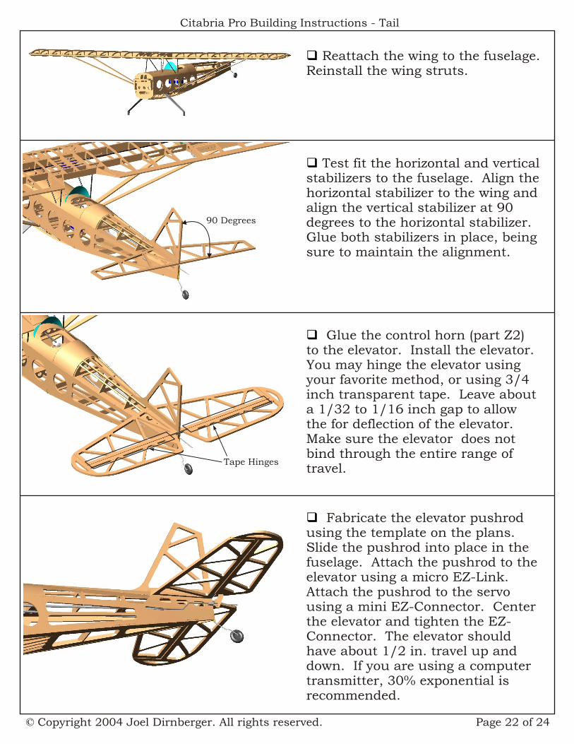
q Test fit the horizontal and vertical stabilizers to the fuselage. Align the horizontal stabilizer to the wing and align the vertical stabilizer at 90 degrees to the horizontal stabilizer. Glue both stabilizers in place, being sure to maintain the alignment.
q Glue the control horn (part Z2) to the elevator. Install the elevator. You may hinge the elevator using your favorite method, or using 3/4 inch transparent tape. Leave about a 1/32 to 1/16 inch gap to allow the for deflection of the elevator. Make sure the elevator does not bind through the entire range of travel.
q Fabricate the elevator pushrod using the template on the plans. Slide the pushrod into place in the fuselage. Attach the pushrod to the elevator using a micro EZ-Link. Attach the pushrod to the servo using a mini EZ-Connector. Center the elevator and tighten the EZ-Connector. The elevator should have about 1/2 in. travel up and down. If you are using a computer transmitter, 30% exponential is recommended.
q Reattach the wing to the fuselage. Reinstall the wing struts.
90 Degrees
Tape Hinges

Page 23 of 24© Copyright 2004 Joel Dirnberger. All rights reserved.
Citabria Pro Building Instructions - Tail, Motor & Cowl
q Glue the control horn (part Z2) to the rudder. Install the rudder. You may hinge the elevator using your favorite method, or using 3/4 inch transparent tape. Leave about a 1/32 to 1/16 inch gap to allow the for deflection of the rudder. Make sure the rudder does not bind through the entire range of travel.
q Fabricate the rudder pushrod using the template on the plans. Slide the pushrod into place in the fuselage. Attach the pushrod to the rudder using a micro EZ-Link. Attach the pushrod to the servo using a mini EZ-Connector. Center the rudder and tighten the EZ-Connector. The rudder should have about 1/2 in. travel to each side.
Tape Hinge
2” or less
2.3” or more
q Attach your motor to the motor stick. Position the motor and stick in the firewall mount so that the face of the motor is not more than 2 inches from the firewall and so that the back of the prop will be at least 2.3 inches from the firewall. Fasten the motor stick in place with a small self tapping screw.
q Trim the trailing edge of the cowl to shape. Open the prop shaft and cooling holes in the cowl. Tape a small piece of paper to each side of the fuselage so that they overlay the cowl mounting holes, but can still be folded out of the way to position the cowl. Mark each mounting hole location by using a pin or awl to poke holes in the paper. Do not remove the paper at this time.
Trim away excess
Open prop shaft and cooling holes
Poke holesthrough paper
TapePaper

Page 24 of 24© Copyright 2004 Joel Dirnberger. All rights reserved.
Citabria Pro Building Instructions - Cowl and Wheels
q Trim the bottom edges of vacuum formed wheel pants to match the outline shown on the plans. Drill a 3/32 in. diameter axle hole in one side of each pant. Using the hole for alignment, glue the reinforcement plates (parts xx)
3L
q Enlarge the axle holes in the wheels with a 3/32 in. diameter drill bit. Use 3/4 in. long 2-56 screws as axles. On each axle, slide a #2 washer, a wheel and another #2 washer, then thread on a 2-56 nut. Gently spread the wheel pants enough to fit the wheel/axle assemblies inside pants with the axles protruding through the holes. Thread the axle of the pant/wheel assemblies onto the gear legs.Use a 2-56 nut to lock the axles to the gear legs. Tighten the nuts inside the pants enough to hold the wheel pants in position.
q Tape the cowl into position on the fuselage centering the prop hole on the prop shaft and keeping the face of the cowl midway between the face of the motor and the back of the prop. Mark the mounting hole locations on the cowl using the paper templates you just made. Untape the templates and the cowl. Drill four 3/32 inch mounting holes in the cowl. Attach the cowl to the fuselage us four nylon 2-56 machine screws.