Embed Size (px)
Citation preview
Proceedings of PVP2006-ICPVT-112006 ASME Pressure Vessels and Piping Division Conference
July 23-27, 2006, Vancouver BC, CANADA
PVP2006-ICPVT11-93670
STRUCTURAL RESPONSE OF PIPING TO INTERNAL GAS DETONATION
Joseph E. ShepherdGraduate Aeronautical Laboratories
California Institute of TechnologyPasadena, CA 91125
Email: [email protected]
ABSTRACTDetonation waves in gas-filled piping or tubing pose special
challenges in analysis and prediction of structural response. Thechallenges arise due the nature of the detonation process andthe role of fluid-structure interaction in determining the prop-agation and arrest of fractures. Over the past ten years, ourlaboratory has been engaged in studying this problem and devel-oping methodologies for estimating structural response. A briefoverview of detonation waves and some key issues relevant tostructural waves is presented first. This is followed by a sum-mary of our work on the elastic response of tubes and pipes toideal detonation loading, highlighting the importance of detona-tion wave speed in determining flexural wave excitation and pos-sibility of resonant response leading to large deformations. Someissues in measurement technique and validation testing are thenpresented. The importance of wave reflection from bends, valvesand dead ends is discussed, as well as the differences betweendetonation, shock wave, and uniform internal pressure loading.Following this, we summarize our experimental findings on thefracture threshold of thin-walled tubes with pre-existing flaws. Aparticularly important issue for hazard analysis is the estimationof loads associated with flame acceleration and deflagration-to-detonation transition. We give some recent results on pressureand elastic strain measurements in the transition regime for athick-wall piping, and some remarks about plastic deformation.
INTRODUCTIONThe goal of this paper is to summarize the state of knowl-
edge about gaseous detonation loading of piping and indicate
some of the more important issues that have to be considered inanalyzing these problems. Detonation of gaseous mixtures insideof piping systems is of interest to the practicing engineer and as asubject of scientific investigation. It is a hazard that is occasion-ally encountered in the chemical [1, 2], nuclear [3–6], and trans-portation industries [2]. In some technologies like pulse detona-tion engines [7], detonations are deliberately created. The cou-pling between detonations and structures like pipes are a modelfor fluid-structure interaction, which has been extensively exam-ined in the closely related subject of shock (blast wave) or impactloading of structures [8, 9].
The response of pipes to detonations is part of the broaderproblem of designing or analyzing the ability of pressure vesselsto contain internal gaseous explosions. Broadly speaking, gasexplosions can be characterized into two categories, low-speedflames or deflagrations and high-speed coupled shock and reac-tion waves known as detonations [10]. Deflagrations are sub-sonic, usually turbulent, flames that cause slow pressurizationthat is treated as a quasi-static, spatially non-uniform structuralload. Detonations are supersonic waves that result in dynamicstructural loading that is spatially nonuniform. The peak pres-sures in detonations are usually about twice as high as for a de-flagration and in exceptional cases, may be as much as 10 timeshigher.
There is some guidance on structural design for deflagra-tions contained in NFPA 69 [11] which refers to the ASMEBoiler and Pressure Vessel Code Section VIII - Division 1, PartH. It is quite clear that detonations are excluded from these con-siderations since the pressure loading of a deflagration is re-stricted to the quasi-static regime. At present, there is no pro-
1 Copyright c© 2006 by ASME
vision within the ASME Boiler and Pressure Vessel or PipingCodes for designing pressure vessels or piping to withstand det-onations.
Currently, a standard is under consideration for designinghigh-explosive containment vessels based on extensive work byLos Alamos [12, 13] to formulate ductile failure criteria. Al-though focused on high explosives, the material response aspectof the Los Alamos work is quite relevant to the present study. Akey idea is the reliance on modern fracture mechanics [14] to de-sign vessels that will plastically deform but not catastrophicallyfail under extreme impulsive loading. Many of these ideas are di-rectly applicable to the situation of gaseous detonation but thereare some crucial distinctions. High explosives are usually ap-proximated as impulsive loads and the standoff between the ves-sel and the explosive is a significant aspect of the loading magni-tude. Gaseous explosions usually result in a combination of stepand impulse loading and the gas is often assumed to completelyfill the vessel or pipe. Deliberate high explosive detonations in-side containment vessels are controlled events while gaseous det-onations often are the result of an uncontrolled ignition processthat can result in very high localized pressures if the deflagrationaccelerates to detonation (deflagration to detonation transition orDDT). In addition, the propagation of the explosion wave in thegas adjacent to the vessel or tube may result in a strong couplingbetween the pressure wave and the structural response.
Detonation WavesA detonation wave [15] consists of a shock wave closely
followed by a chemical reaction zone in which the fuel and ox-idizer rapidly react to produce hot (temperatures of 2000-3000K) combustion products. An ideal detonation travels at a nearlyconstant speed close to (usually within 90% of) the theoreticalor Chapman-Jouguet (CJ) velocity UCJ , which is between 1500and 3000 m/s in gases depending on the fuel-oxidizer combi-nation, see Table 1. The reaction zone in a detonation is usu-ally very thin, less than 10 mm for most stoichiometric fuel-airmixtures and less than 100 µm for stoichiometric fuel-oxygenmixtures. Due to reaction zone instability, the effective widthof the reaction zone (characterized by the detonation cell widthS) is typically 10-100 times larger than the idealized reactionzone [16–18]. Within this reaction zone, temperature, pressureand other properties change rapidly while just downstream of thereaction zone, a much slower variation occurs due to the gas dy-namics of the wave propagation process. The pressure just be-hind the detonation can be as high as 20 to 30 times the ambientpressure, depending on the fuel-oxidizer mixture, see Table 1.The computations were carried out with standard thermochemi-cal equilibrium methods [19, 20].
The values in the table are only representative of detonationparameters, all values will depend strongly on composition andthe results in the table are for stoichiometric mixtures only. Det-
Table 1. Measured and computed detonation parameters for stoichio-metric mixtures at standard initial conditions (25 ◦C, 1 atm).
Fuel % (vol) UCJ PCJ S
(m/s) (bar) (mm)
Fuel-air mixtures
hydrogen H2 29.6 1971 15.6 6–10
acetylene C2H2 7.75 1867 19.1 10–15
ethylene C2H4 6.54 1825 18.4 24–26
ethane C2H6 5.66 1825 18.0 50–59
propane C3H8 4.03 1801 18.3 40–60
methane CH4 9.48 1804 17.2 250–350
Fuel-oxygen mixtures
hydrogen H2 66.7 2841 19.0 1–2
acetylene C2H2 28.6 2425 34.0 0.1–0.2
ethylene C2H4 25.0 2376 33.7 2-3
ethane C2H6 22.2 2372 34.3 1–2
propane C3H8 16.7 2360 36.5 0.5-1
methane CH4 33.3 2393 29.6 2-4
onation velocities, pressures and cell widths will all depend onthe ratio of fuel to oxygen, and the amount and type of additionalgas components such as nitrogen. Detonation properties will alsodepend on initial pressure and temperature. To evaluate the haz-ard for a specific mixture and initial conditions, computations ormeasurements for that particular situation should be carried out.
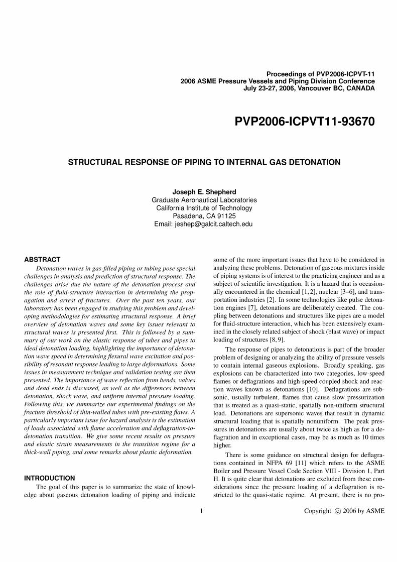
A typical experimental pressure-time trace for a detonationpropagating longitudinally from the closed end of a tube is shownin Figure 1. The almost instantaneous jump in pressure at time t= 0 corresponds to the passage of the detonation wave across themeasuring station. The rapid decrease in pressure in the first .01ms is associated with the reaction zone. The more gradual de-crease in pressure out to t = 0.25 ms and plateau for longer timesis associated with the gas dynamics of the flow behind the wave.Superimposed on the general trend are pressure fluctuations dueto the unstable nature of the coupling between chemical kinet-ics and the leading shock front [15]. This instability consists of
2 Copyright c© 2006 by ASME
00.5
11.5
22.5
33.5
-0.1 0 0.1 0.2 0.3 0.4 0.5time (ms)
pressu
re (M
Pa)
(a)
Figure 1. Measured pressure vs time for detonation loading [21].
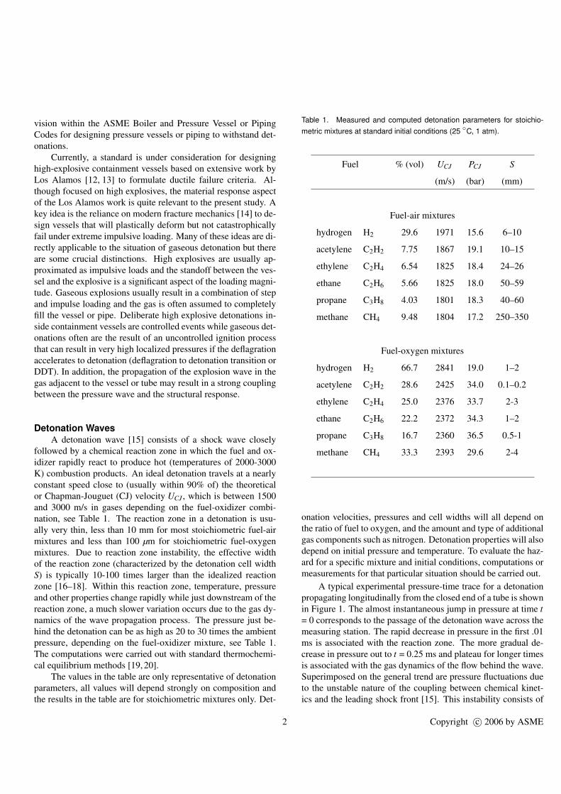
weaker shock waves propagating transversely to the main frontand organized in a quasi-periodic structure that creates a cellularstructure on sooted foils placed with the detonation tube [22], seeFig. 2.
The spacing S of the transverse waves (detonation cellwidth) observed on sooted foils (see Table 1) has been mea-sured [26] for many mixtures and can be used as a measure ofthe sensitivity of a mixture to detonation. The smaller the cellsize, the easier it is to initiate and propagate detonations. Asshown in Table 1, mixtures of fuel and oxygen have cells that aremuch smaller than fuel and air, in agreement with the observedease of detonation [27].
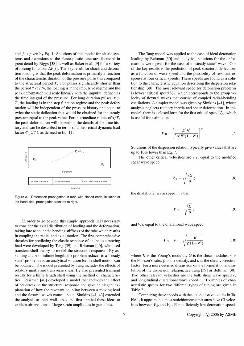
The fluctuating pressure is usually ignored in structuralmodels and only the average pressure is considered computingthe force (loading) on the tube wall. In terms of a structural load,the net effect of a detonation is to produce a spatially nonuni-form propagating load as shown in Figure 3. Experimental pres-sure traces and gas dynamic models can be used to define anidealized loading profile. For a tube with a closed end, the situ-ation can be characterized by three regions (see Figure 3). First,there is the initial mixture ahead of the detonation front. Sincethe detonation wave propagating supersonically, there is no load-ing produced ahead of the detonation front and the pressure at afixed location jumps up suddenly when the detonation front ar-rives there. The detonation front consists of the shock wave andreaction zone, which is not resolved in the loading model. Thepeak pressure just behind the front P2 can be approximated by theCJ value, computed with the same thermochemical equilibriumcodes that are used to obtain the detonation velocities. The det-onation is followed by an expansion wave which extends to ap-proximately mid-way between the wave front and the initiationend of the tube. Behind the expansion wave the gas is stationaryand the pressure P3 in this region is approximately 0.4PCJ .
The ideal pressure distribution in such a tube can bedescribed with an analytical solution known as the Taylor-Zel’dovich model [28, 29]. The expansion wave region stretchesas the wave propagates and the profile evolves in a self-similarfashion with the similarity parameter x/UCJt) and the leading
pressure wave propagating at the Chapman-Jouguet detonationvelocity UCJ . This ideal solution is commonly used as a basefor modeling the pressure distribution required from structuralloading computations; a simple approximation in terms of an ex-ponentially decaying solution can also be used as discussed inAppendix B of Beltman [30].
For long tubes and high temperature mixtures, significantheat transfer and frictional effects will modify the pressure pro-file [31]. As thermal energy is transferred into the tube, the tem-perature and pressure of the gas will drop more rapidly than dueto the isentropic expansion of the ideal Taylor-Zel’dovich modeland the tube will heat up. Edwards [32] found that after the det-onation had propagated about 70 tube diameters, the pressureprofile actually became steady relative to the detonation front it-self, in other words, the expansion wave reaches a fixed extentonce the wave has propagated sufficiently far. A second conse-quence is that the thermal energy that is deposited into the tubewill set up thermal stresses [33], increasing the strain within thetube in addition to the mechanical strain induced by the internalpressure load. In general, for detonations the thermal stresses aremuch lower than the peak stresses that occur due to the mechan-ical load. Since the heat transfer into the pipe is relatively slow,the peak thermal stresses occur at long times compared to thedetonation loading duration. As a consequence, thermal stressis a much more significant issue for deflagration-type explosionsthan detonations, and, may result in strains much larger than themechanical strain alone.
In addition to the main pressure loading shown in Figure 3,idealized models [34] predict the existence of a pressure peak(Von Neumann spike) at the front of the reaction zone with avalue approximately double that of the Chapman-Jouguet pres-sure. This pressure spike is usually not resolved in experimentsbecause of its localized nature and short duration. Since the re-action zone is of such a short length compared to a typical tubelength, the influence on the structural response is small in com-parison with the effects of the main loading produced by theTaylor-Zeldovich pressure profile behind the detonation front.For these reasons, the influence of the Von Neumann pressurespike on the structural response is usually neglected.
Elastic ResponseFrom a structural point of view, the tube experiences a trav-
eling internal load that produces transient deformation of thetube. This situation is similar to the case of a gaseous shockwave propagating in a tube [21] but with a slightly more com-plex temporal (Figure 1) and spatial (Figure 2) variation of in-ternal pressure than the simple step function that can be used torepresent a shock wave. For an ideal wave, the pressure initiallyjumps to the CJ value PCJ and then decays to the plateau value P3after the Taylor wave has passed and the fluid has come to rest.If the CJ pressure is sufficiently small (defined subsequently),
3 Copyright c© 2006 by ASME
(a) (b)
Figure 2. (a) Shadow image of a detonation front in 2H2-O2+3N2 at 20 kPa, propagation is left to right. The instability of the front is manifested by thecurved and kinked leading shock, the fine-scale density fluctuations behind the front and the secondary shock waves extending into the products at the leftof the wave. (b) Cellular pattern on sooted foil created by a detonation in 2H2-O2+2N2 at 20 kPa. The cell size for this mixture is approximately 43 mm andthe soot foil is about 150 mm wide [23–25].
then the motions of the tube wall will be elastic and no perma-nent deformation will occur when the detonation passes throughthe tube. On the other hand, for sufficiently large values of theCJ pressure the yield strength of the tube will be exceeded andplastic deformation will ensue. In this section we will review theelastic case and we will consider the problem of plastic responsein a subsequent section.
Extensive results [30] in the form of measurements, analyt-ical theories based on shell models, and numerical simulationsare available for the case of elastic motion created by propa-gating detonations or shock waves. The key results are that thewave acts as a traveling load which produces progressive flexuralwaves having a phase speed equal to the load speed. The modeand peak amplitudes of the deformations depend on the speed ofthe wave as compared to the characteristic group velocities of thevarious elastic modes of tube oscillations.
ModelingThe simplest approach [35], often used in hazard analyses
for quick estimates of peak deflection, ignores the axial distrib-ution of pressure (or equivalently, the bending resistance of thetube), and assumes that the transient pressure load at a location(Fig. 1) can be used as the forcing function for a single-degree-of-freedom (radial motion only) of the tube structure. The axi-symmetric radial vibrations [36] of a long (axially unconfined)cylinder have a fundamental frequency of
f =1
2πR
√E
ρ(1−ν2), (1)
corresponding to an oscillation period of
T = 1/ f (2)
The time required for elastic wave transit time through the thick-ness h is
τwave = h/cl , (3)
where the longitudinal sound speed cl typically between 5500-6000 m/s for metals, so that
τwave ¿ T . (4)
Therefore, even under gaseous detonation loading it is not neces-sary to consider [37] elastic wave motion through the thicknessbut only the structural modes that involve the bulk radial motionof the pipe wall. The single degree of freedom model describesthe radial deflections as simple forced harmonic motions
∂2x∂t2 +ω2x =
∆P(t)ρh
, (5)
where the oscillator natural frequency (radian/s) is
ω = 2π f (6)
4 Copyright c© 2006 by ASME
and f is given by Eq. 1. Solutions of this model for elastic sys-tems and extensions to the elasto-plastic case are discussed ingreat detail by Biggs [38] as well as Baker et al. [9] for a varietyof forcing functions ∆P(t). The key result for shock and detona-tion loading is that the peak deformation is primarily a functionof the characteristic duration of the pressure pulse τ as comparedto the structural period T . For pulses significantly shorter thanthe period τ < T /4, the loading is in the impulsive regime and thepeak deformation will scale linearly with the impulse, defined asthe time integral of the pressure. For long duration pulses, τ >T , the loading is in the step function regime and the peak defor-mation will be independent of the pressure history and equal totwice the static deflection that would be obtained for the steadypressure equal to the peak value. For intermediate values of τ/T ,the peak deformation will depend on the details of the time his-tory and can be described in terms of a theoretical dynamic loadfactor Φ(τ/T ), as defined in Eq. 11.
0
0.2
0.4
0.6
0.8
1
1.2
0 0.2 0.4 0.6 0.8 1 1.2 1.4 1.6 1.8distance
pres
sure
P2 = P
P3
P1
stationary reactantsexpansion wavestationary products
detonation
UCJ
CJ
Figure 3. Detonation propagation in tube with closed ends, initiation atleft-hand side, propagation from left to right.
In order to go beyond this simple approach, it is necessaryto consider the axial distribution of loading and the deformation,taking into account the bending stiffness of the tube which resultsin coupling the radial and axial motion. The first comprehensivetheories for predicting the elastic response of a tube to a movingload were developed by Tang [39] and Reisman [40], who usedtransient shell theory to model the structural response. By as-suming a tube of infinite length, the problem reduces to a “steadystate” problem and an analytical solution for the shell motion canbe obtained. The model presented by Tang includes the effects ofrotatory inertia and transverse shear. He also presented transientresults for a finite length shell using the method of characteris-tics. Reisman [40] developed a model that includes the effectof pre-stress on the structural response and gave an elegant ex-planation of how the resonant coupling between a moving loadand the flexural waves comes about. Simkins [41–43] extendedthe analysis to thick-wall tubes and first applied these ideas toexplain observations of large strain amplitudes in gun tubes.
The Tang model was applied to the case of ideal detonationloading by Beltman [30] and analytical solutions for the defor-mations were given for the case of a “steady state” wave. Oneof the key results is the prediction of peak structural deflectionsas a function of wave speed and the possibility of resonant re-sponse at four critical speeds. These speeds are found as a solu-tion to the characteristic equation describing the dispersion rela-tionship [39]. The most relevant speed for detonation problemsis lowest critical speed Vc0, which corresponds to the group ve-locity of flexural waves that consist of coupled radial-bendingoscillations. A simpler model was given by Simkins [41], whoseanalysis neglects rotatory inertia and shear deformation. In thismodel, there is a closed form for the first critical speed Vc0, whichis useful for estimation
Vc0 =[
E2h2
3ρ2R2(1−ν2)
] 14
. (7)
Solutions of the dispersion relation typically give values that areup to 10% lower than Eq. 7.
The other critical velocities are vc1, equal to the modifiedshear wave speed
Vc1 =
√κGρ
; (8)
the dilatational wave speed in a bar,
Vc2 =
√Eρ
; (9)
and Vc3, equal to the dilatational wave speed
Vc3 = vd =
√E
ρ(1−ν2)(10)
where E is the Young’s modulus, G is the shear modulus, ν isthe Poisson’s ratio, ρ is the density, and κ is the shear correctionfactor. For a more detailed discussion on the formulation and so-lution of the dispersion relation, see Tang [39] or Beltman [30].Two other relevant velocities are the bulk shear wave speed csand longitudinal dilatational wave speed cs. Examples of char-acteristic speeds for two different types of tubing are given inTable 2.
Comparing these speeds with the detonation velocities in Ta-ble 1, it appears that most stoichiometric mixtures have CJ veloc-ities between Vc0 and Vc1. For sufficiently low detonation speeds
5 Copyright c© 2006 by ASME
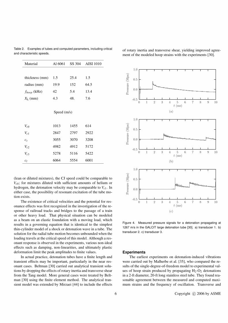
Table 2. Examples of tubes and computed parameters, including criticaland characteristic speeds.
Material Al 6061 SS 304 AISI 1010
thickness (mm) 1.5 25.4 1.5
radius (mm) 19.9 152 64.5
fhoop (kHz) 42 5.4 13.4
Xλ (mm) 4.3 48. 7.6
Speed (m/s)
Vc0 1013 1455 614
Vc1 2847 2797 2922
cs 3055 3070 3208
Vc2 4982 4912 5172
Vc3 5278 5116 5422
cl 6064 5554 6001
(lean or diluted mixtures), the CJ speed could be comparable toVc0; for mixtures diluted with sufficient amounts of helium orhydrogen, the detonation velocity may be comparable to Vc1. Ineither case, the possibility of resonant excitation of the tube mo-tion exists.
The existence of critical velocities and the potential for res-onance effects was first recognized in the investigation of the re-sponse of railroad tracks and bridges to the passage of a trainor other heavy load. That physical situation can be modeledas a beam on an elastic foundation with a moving load, whichresults in a governing equation that is identical to the simplestthin-cylinder model of a shock or detonation wave in a tube. Thesolution for the radial tube motion becomes unbounded when theloading travels at the critical speed of this model. Although a res-onant response is observed in the experiments, various non-idealeffects such as damping, non-linearities, and ultimately plasticdeformation limit the peak amplitudes to finite values.
In actual practice, detonation tubes have a finite length andtransient effects may be important, particularly in the near res-onant cases. Beltman [30] carried out analytical transient solu-tions by dropping the effects of rotary inertia and transverse shearfrom the Tang model. More general cases were treated by Belt-man [30] using the finite element method. The analytical tran-sient model was extended by Mirzaei [44] to include the effects
of rotary inertia and transverse shear, yielding improved agree-ment of the modeled hoop strains with the experiments [30].
t (ms)
Pre
ssure
(Mpa)
109876543210
1.0
0.5
0.0
-0.5
(a)
t (ms)
Pre
ssure
(Mpa)
109876543210
1.0
0.5
0.0
-0.5
(b)
t (ms)
Pre
ssure
(Mpa)
109876543210
1.0
0.5
0.0
-0.5
(c)
Figure 4. Measured pressure signals for a detonation propagating at1267 m/s in the GALCIT large detonation tube [30]. a) transducer 1. b)transducer 2. c) transducer 3.
ExperimentsThe earliest experiments on detonation-induced vibrations
were carried out by Malherbe et al. [35], who compared the re-sults of the single-degree-of-freedom model to experimental val-ues of hoop strain produced by propagating H2-O2 detonationsin a 2-ft diameter, 20-ft long stainless steel tube. They found rea-sonable agreement between the measured and computed maxi-mum strains and the frequency of oscillation. Transverse and
6 Copyright c© 2006 by ASME
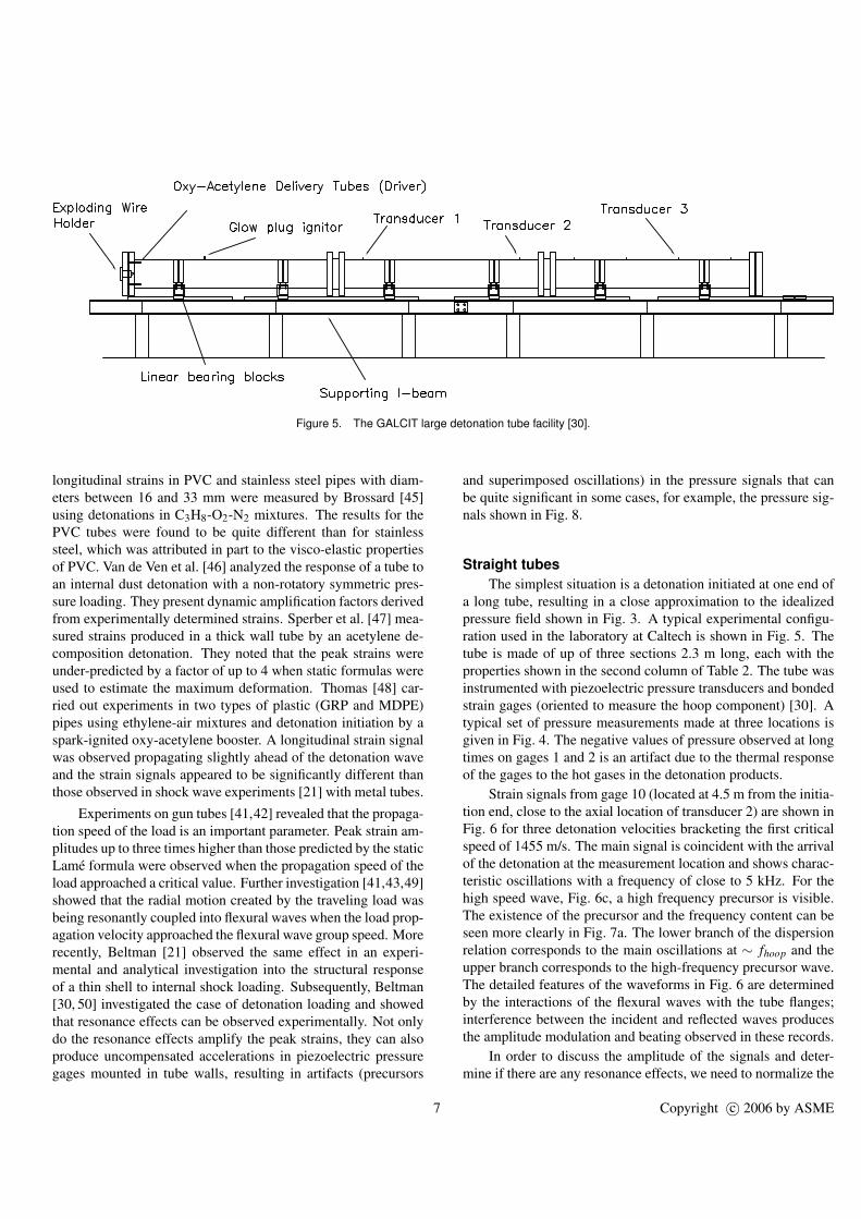
Figure 5. The GALCIT large detonation tube facility [30].
longitudinal strains in PVC and stainless steel pipes with diam-eters between 16 and 33 mm were measured by Brossard [45]using detonations in C3H8-O2-N2 mixtures. The results for thePVC tubes were found to be quite different than for stainlesssteel, which was attributed in part to the visco-elastic propertiesof PVC. Van de Ven et al. [46] analyzed the response of a tube toan internal dust detonation with a non-rotatory symmetric pres-sure loading. They present dynamic amplification factors derivedfrom experimentally determined strains. Sperber et al. [47] mea-sured strains produced in a thick wall tube by an acetylene de-composition detonation. They noted that the peak strains wereunder-predicted by a factor of up to 4 when static formulas wereused to estimate the maximum deformation. Thomas [48] car-ried out experiments in two types of plastic (GRP and MDPE)pipes using ethylene-air mixtures and detonation initiation by aspark-ignited oxy-acetylene booster. A longitudinal strain signalwas observed propagating slightly ahead of the detonation waveand the strain signals appeared to be significantly different thanthose observed in shock wave experiments [21] with metal tubes.
Experiments on gun tubes [41,42] revealed that the propaga-tion speed of the load is an important parameter. Peak strain am-plitudes up to three times higher than those predicted by the staticLame formula were observed when the propagation speed of theload approached a critical value. Further investigation [41,43,49]showed that the radial motion created by the traveling load wasbeing resonantly coupled into flexural waves when the load prop-agation velocity approached the flexural wave group speed. Morerecently, Beltman [21] observed the same effect in an experi-mental and analytical investigation into the structural responseof a thin shell to internal shock loading. Subsequently, Beltman[30, 50] investigated the case of detonation loading and showedthat resonance effects can be observed experimentally. Not onlydo the resonance effects amplify the peak strains, they can alsoproduce uncompensated accelerations in piezoelectric pressuregages mounted in tube walls, resulting in artifacts (precursors
and superimposed oscillations) in the pressure signals that canbe quite significant in some cases, for example, the pressure sig-nals shown in Fig. 8.
Straight tubesThe simplest situation is a detonation initiated at one end of
a long tube, resulting in a close approximation to the idealizedpressure field shown in Fig. 3. A typical experimental configu-ration used in the laboratory at Caltech is shown in Fig. 5. Thetube is made of up of three sections 2.3 m long, each with theproperties shown in the second column of Table 2. The tube wasinstrumented with piezoelectric pressure transducers and bondedstrain gages (oriented to measure the hoop component) [30]. Atypical set of pressure measurements made at three locations isgiven in Fig. 4. The negative values of pressure observed at longtimes on gages 1 and 2 is an artifact due to the thermal responseof the gages to the hot gases in the detonation products.
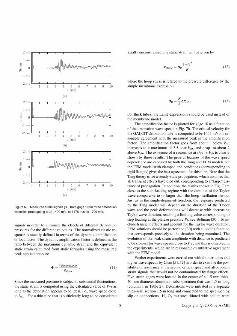
Strain signals from gage 10 (located at 4.5 m from the initia-tion end, close to the axial location of transducer 2) are shown inFig. 6 for three detonation velocities bracketing the first criticalspeed of 1455 m/s. The main signal is coincident with the arrivalof the detonation at the measurement location and shows charac-teristic oscillations with a frequency of close to 5 kHz. For thehigh speed wave, Fig. 6c, a high frequency precursor is visible.The existence of the precursor and the frequency content can beseen more clearly in Fig. 7a. The lower branch of the dispersionrelation corresponds to the main oscillations at ∼ fhoop and theupper branch corresponds to the high-frequency precursor wave.The detailed features of the waveforms in Fig. 6 are determinedby the interactions of the flexural waves with the tube flanges;interference between the incident and reflected waves producesthe amplitude modulation and beating observed in these records.
In order to discuss the amplitude of the signals and deter-mine if there are any resonance effects, we need to normalize the
7 Copyright c© 2006 by ASME
t (ms)
Str
ain
109876543210
2.e-4
1.e-4
0
-1.e-4
-2.e-4
(a)
t (ms)
Str
ain
109876543210
2.e-4
1.e-4
0
-1.e-4
-2.e-4
(b)
t (ms)
Str
ain
109876543210
2.e-4
1.e-4
0
-1.e-4
-2.e-4
(c)
Figure 6. Measured strain signals [30] from gage 10 for three detonationvelocities propagating at a) 1400 m/s, b) 1478 m/s, c) 1700 m/s.
signals in order to eliminate the effects of different detonationpressures for the different velocities. The normalized elastic re-sponse is usually defined in terms of the dynamic amplificationor load factor. The dynamic amplification factor is defined as theratio between the maximum dynamic strain and the equivalentstatic strain calculated from static formulas using the measuredpeak applied pressure
Φ =εdynamic max
εstatic. (11)
Since the measured pressure is subject to substantial fluctuations,the static strain is computed using the calculated value of PCJ aslong as the detonation appears to be ideal, i.e., wave speed closeto UCJ . For a thin tube that is sufficiently long to be considered
axially unconstrained, the static strain will be given by
εstatic = σθ1−ν2
E(12)
where the hoop stress is related to the pressure difference by thesimple membrane expression
σθ =Rh
∆PCJ , (13)
For thick tubes, the Lame expressions should be used instead ofthe membrane model.
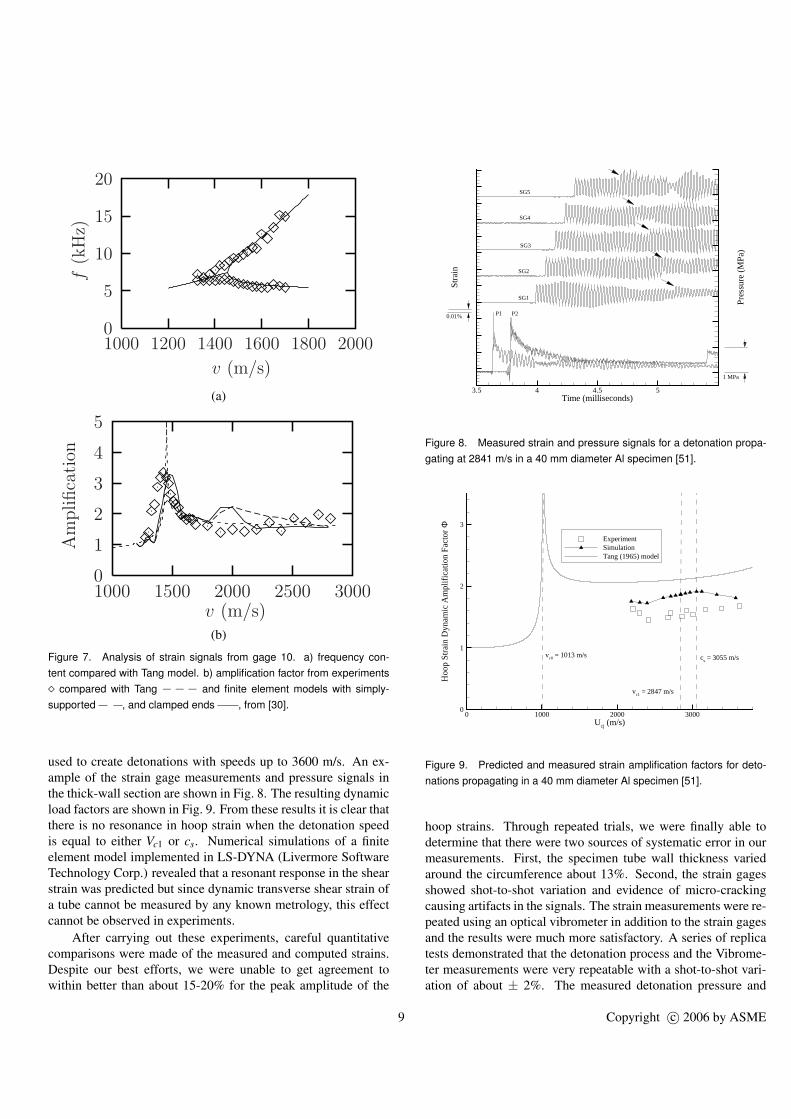
The amplification factor is plotted for gage 10 as a functionof the detonation wave speed in Fig. 7b. The critical velocity forthe GALCIT detonation tube is computed to be 1455 m/s in rea-sonable agreement with the measured peak in the amplificationfactor. The amplification factor goes from about 1 below Vc0,increases to a maximum of 3.5 near Vc0, and drops to about 2above Vc0. The existence of a resonance at UCJ ≈ Vc0 is clearlyshown by these results. The general features of the wave speeddependence are captured by both the Tang and FEM models butthe FEM model with clamped end conditions (corresponding torigid flanges) gives the best agreement for this tube. Note that theTang theory is for a steady-state propagation, which assumes thatall transient effects have died out, corresponding to a “large” dis-tance of propagation. In addition, the results shown in Fig. 7 areclose to the step-loading regime with the duration of the Taylorwave comparable to or larger than the hoop oscillation period.Just as in the single-degree-of-freedom, the response predictedby the Tang model will depend on the duration of the Taylorwave and the peak deformations will decrease with decreasingTaylor wave duration, reaching a limiting value corresponding tostep loading at the plateau pressure P3, see Beltman [30]. To in-clude transient effects and account for the Taylor wave duration,FEM solutions should be performed [30] with a loading functionthat corresponds precisely to the situation being examined. Theevolution of the peak strain amplitude with distance is predictedto be slowest for wave speeds close to Vc0, and this is observed inthe experiments, which are in reasonable quantitative agreementwith the FEM model.
Further experiments were carried out with thinner tubes andhigher wave speeds by Chao [51,52] in order to examine the pos-sibility of resonance at the second critical speed and also, obtainstrain signals that would not be contaminated by flange effects.Five strain gages were located in the center of a 1.5 mm thick,40 mm diameter aluminum tube specimen that was 1.5 m long(column 1 in Table 2). Detonations were initiated in a separatethick-wall section 1.5 m long and connected to the specimen byslip-on connections. H2-O2 mixtures diluted with helium were
8 Copyright c© 2006 by ASME
v (m/s)
f(k
Hz)
200018001600140012001000
20
15
10
5
0
(a)
3000v (m/s)
Am
plifica
tion
30002500200015001000
5
4
3
2
1
0
(b)
Figure 7. Analysis of strain signals from gage 10. a) frequency con-tent compared with Tang model. b) amplification factor from experiments¦ compared with Tang −−− and finite element models with simply-supported , and clamped ends , from [30].
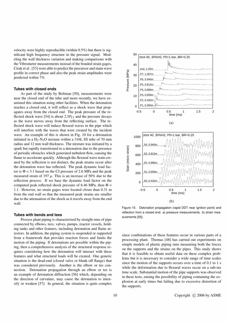
used to create detonations with speeds up to 3600 m/s. An ex-ample of the strain gage measurements and pressure signals inthe thick-wall section are shown in Fig. 8. The resulting dynamicload factors are shown in Fig. 9. From these results it is clear thatthere is no resonance in hoop strain when the detonation speedis equal to either Vc1 or cs. Numerical simulations of a finiteelement model implemented in LS-DYNA (Livermore SoftwareTechnology Corp.) revealed that a resonant response in the shearstrain was predicted but since dynamic transverse shear strain ofa tube cannot be measured by any known metrology, this effectcannot be observed in experiments.
After carrying out these experiments, careful quantitativecomparisons were made of the measured and computed strains.Despite our best efforts, we were unable to get agreement towithin better than about 15-20% for the peak amplitude of the
Time (milliseconds)
Str
ain
Pre
ssur
e(M
Pa)
3.5 4 4.5 5
P1 P2
SG1
SG2
SG3
SG4
SG5
1 MPa
0.01%
Figure 8. Measured strain and pressure signals for a detonation propa-gating at 2841 m/s in a 40 mm diameter Al specimen [51].
Ucj (m/s)
Hoo
pS
trai
nD
ynam
icA
mpl
ific
atio
nF
acto
rΦ
0 1000 2000 30000
1
2
3
ExperimentSimulationTang (1965) model
vc0 = 1013 m/s cs = 3055 m/s
vc1 = 2847 m/s
Figure 9. Predicted and measured strain amplification factors for deto-nations propagating in a 40 mm diameter Al specimen [51].
hoop strains. Through repeated trials, we were finally able todetermine that there were two sources of systematic error in ourmeasurements. First, the specimen tube wall thickness variedaround the circumference about 13%. Second, the strain gagesshowed shot-to-shot variation and evidence of micro-crackingcausing artifacts in the signals. The strain measurements were re-peated using an optical vibrometer in addition to the strain gagesand the results were much more satisfactory. A series of replicatests demonstrated that the detonation process and the Vibrome-ter measurements were very repeatable with a shot-to-shot vari-ation of about ± 2%. The measured detonation pressure and
9 Copyright c© 2006 by ASME
velocity were highly reproducible (within 0.5%) but there is sig-nificant high frequency structure in the pressure signal. Mod-eling the wall thickness variation and making comparisons withthe Vibrometer measurements instead of the bonded strain gages,Cirak et al . [53] were able to predict the precursor and main waveprofile in correct phase and also the peak strain amplitudes werepredicted within 7%.
Tubes with closed endsAs part of the study by Beltman [50], measurements were
near the closed end of the tube and more recently, we have ex-amined this situation using other facilities. When the detonationreaches a closed end, it will reflect as a shock wave that prop-agates away from the closed end. The peak pressure of the re-flected shock wave [54] is about 2.5PCJ and the pressure decaysas the wave moves away from the reflecting surface. The re-flected shock wave will induce flexural waves in the pipe whichwill interfere with the waves that were created by the incidentwave. An example of this is shown in Fig. 10 for a detonationinitiated in a H2-N2O mixture within a 316L SS tube of 70 mmradius and 12 mm wall thickness. The mixture was initiated by aspark but rapidly transitioned to a detonation due to the presenceof periodic obstacles which generated turbulent flow, causing theflame to accelerate quickly. Although the flexural wave train cre-ated by the reflection is not distinct, the peak strains occur afterthe detonation wave has reflected. The peak dynamic load fac-tor is Φ = 3.1 based on the CJ pressure of 2.6 MPa and the peakmeasured strain of 197 µ. This is an increase of 50% due to thereflection process. If we base the dynamic load factor on thecomputed peak reflected shock pressure of 6.46 MPa, then Φ =1.1. However, no strain gages were located closer than 0.31 mfrom the end wall so that the measured peak strains are smallerdue to the attenuation of the shock as it travels away from the endwall.
Tubes with bends and teesProcess plant piping is characterized by straight runs of pipe
connected by elbows, tees, valves, pumps, reactor vessels, hold-ing tanks and other features, including detonation and flame ar-restors. In addition, the piping system is suspended or supportedfrom a framework that provides reaction forces and limits themotion of the piping. If detonations are possible within the pip-ing, then a comprehensive analysis of the structural response re-quires considering how the detonation will interact with thesefeatures and what structural loads will be created. One genericsituation is the dead-end (closed valve or blank-off flange) thatwas considered previously. Another is the elbow or tee con-nection. Detonation propagation through an elbow or tee isan example of detonation diffraction [56] which, depending onthe direction of curvature, may cause the detonation to inten-sify or weaken [57]. In general, the situation is quite complex
0
10
20
30
40
50
-0.5 0 0.5 1 1.5 2
Pre
ssur
e (M
Pa)
time (ms)
shot 40, 30%H2, P0=1 bar, BR=0.25
P1, 0.305m
P2, 0.432m
P3, 0.559m
P4, 0.686m
P5, 0.813m
P6, 0.940m
P7, 1.067m
end, 1.25m
(a)
0
200
400
600
800
1000
-0.5 0 0.5 1 1.5 2
Sta
in (
mic
ro s
trai
n)
time (ms)
shot 40, 30%H2, P0=1 bar, BR=0.25
S0, 0.432m
S1, 0.559m
S2, 0.686m
S3, 0.813m
S4, 0.940m
(b)
Figure 10. Detonation propagation (rapid DDT near ignition point) andreflection from a closed end. a) pressure measurements. b) strain mea-surements [55].
since combinations of these features occur in various parts of aprocessing plant. Thomas [48] has carried out experiments onsimple models of plastic piping runs measuring both the forceson the supports and the strains on the pipes. This study showsthat it is feasible to obtain useful data on these complex prob-lems but it is necessary to consider a wide range of time scalessince the motion of the supports occurs over a time of 0.1 to 1 swhile the deformation due to flexural waves occur on a sub-mstime scale. Substantial motion of the pipe supports was observedin these tests, raising the possibility of piping containing the ex-plosion at early times but failing due to excessive distortion ofthe supports.
10 Copyright c© 2006 by ASME
Rupture of TubesRecently, two failures occurred in piping systems in nuclear
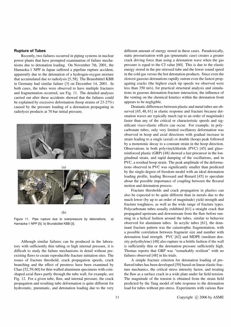
power plants that have prompted examination of failure mecha-nisms due to detonation loading. On November 7th, 2001, theHamaoka-1 NPP in Japan suffered a pipeline rupture accident,apparently due to the detonation of a hydrogen-oxygen mixturethat accumulated due to radiolysis [5,58]. The Brunsbuttel KBBin Germany had similar failure [3] on December 14, 2001. Inboth cases, the tubes were observed to have multiple fracturesand fragmentation occurred, see Fig. 11. The detailed analysescarried out after these accidents showed that the failures couldbe explained by excessive deformation (hoop strains of 23-27%)caused by the pressure loading of a detonation propagating inradiolysis products at 70 bar initial pressure.
(a)
(b)
Figure 11. Pipe rupture due to overpressure by detonations. a)Hamaoka-1 NPP [5]. b) Brunsbuttel KBB [3].
Although similar failures can be produced in the labora-tory with sufficiently thin tubing or high internal pressure, it isdifficult to study the failure mechanisms in detail without pre-existing flaws to create reproducible fracture initiation sites. Theissues of fracture threshold, crack propagation speeds, crackbranching and the effect of prestress have been examined byChao [52,59,60] for thin-walled aluminum specimens with coin-shaped axial flaws partly through the tube wall, for example, seeFig. 12. For a given tube, flaw, and internal pressure, the crackpropagation and resulting tube deformation is quite different forhydrostatic, pneumatic, and detonation loading due to the very
different amount of energy stored in these cases. Paradoxically,static pressurization with gas (pneumatic case) creates a greatercrack driving force than using a detonation wave when the gaspressure is equal to the CJ value [60]. This is due to the elasticenergy stored in the pre-stressed tube and the lower sound speedin the cold gas versus the hot detonation products. Since even theslowest gaseous detonations rapidly outrun even the fastest prop-agating cracks (the highest crack tip speeds we observed wereless than 350 m/s), for practical structural analysis and simula-tions in gaseous detonation-fracture interaction, the influence ofthe venting on the chemical kinetics within the detonation frontappears to be negligible.
Dramatic differences between plastic and metal tubes are ob-served [45, 48, 61] in elastic response and fracture because det-onation waves are typically much (up to an order of magnitude)faster than any of the critical or characteristic speeds and sig-nificant visco-elastic effects can occur. For example, in poly-carbonate tubes, only very limited oscillatory deformation wasobserved in hoop and axial directions with gradual increase instrain leading to a single (axial) or double (hoop) peak followedby a monotonic decay to a constant strain in the hoop direction.Observations in both polyvinylchloride (PVC) [45] and glass-reinforced plastic (GRP) [48] showed a fast precursor in the lon-gitudinal strain, and rapid damping of the oscillations, and inPVC, a residual hoop strain. The peak amplitude of the deforma-tions observed in PVC was significantly smaller than predictedby the single-degree-of-freedom model with an ideal detonationloading profile, leading Brossard and Renard [45] to speculateabout the possible importance of coupling between the flexuralmotion and detonation process.
Fracture thresholds and crack propagation in plastics canalso be expected to be quite different than in metals due to themuch lower (by up to an order of magnitude) yield strength andfracture toughness, as well as the wide range of fracture types.Polycarbonate tubes usually exhibited [61] a straight crack thatpropagated upstream and downstream from the flaw before run-ning in a helical fashion around the tubes, similar to behaviorobserved for aluminum tubes. In acrylic tubes [61], the dom-inant fracture pattern was the catastrophic fragmentation, witha possible correlation between fragment size and number withdetonation load strength. PVC [62] and MDPE (medium den-sity polyethylene) [48] also rupture in a brittle fashion if the wallis sufficiently thin or the detonation pressure sufficiently high.Thomas reports that GRP was “remarkably resilient” with nofailures observed [48] in his trials.
A simple fracture criterion for detonation loading of pre-flawed tubes has been developed [59] based on linear elastic frac-ture mechanics, the critical stress intensity factor, and treatingthe flaw as a surface crack in a wide plate under far field tension.The magnitude of the tension is obtained from the strain fieldpredicted by the Tang model of tube response to the detonationload for tubes without pre-stress. Experiments with various flaw
11 Copyright c© 2006 by ASME
(a)
(b)
(c)
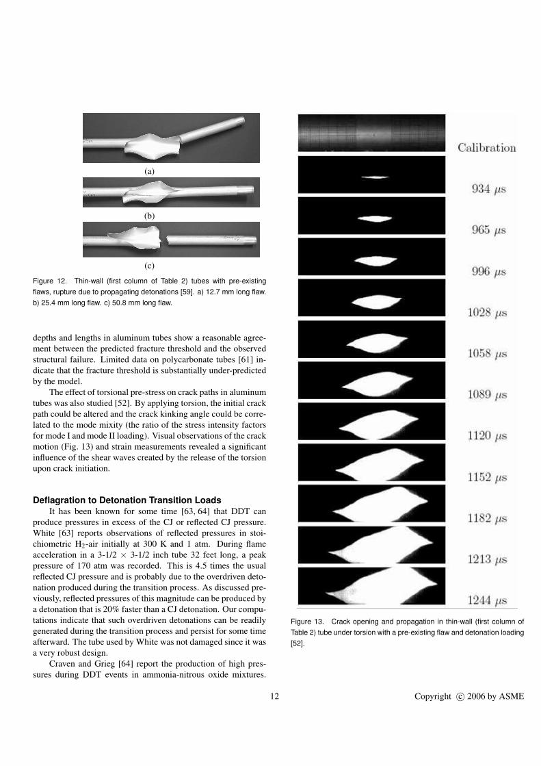
Figure 12. Thin-wall (first column of Table 2) tubes with pre-existingflaws, rupture due to propagating detonations [59]. a) 12.7 mm long flaw.b) 25.4 mm long flaw. c) 50.8 mm long flaw.
depths and lengths in aluminum tubes show a reasonable agree-ment between the predicted fracture threshold and the observedstructural failure. Limited data on polycarbonate tubes [61] in-dicate that the fracture threshold is substantially under-predictedby the model.
The effect of torsional pre-stress on crack paths in aluminumtubes was also studied [52]. By applying torsion, the initial crackpath could be altered and the crack kinking angle could be corre-lated to the mode mixity (the ratio of the stress intensity factorsfor mode I and mode II loading). Visual observations of the crackmotion (Fig. 13) and strain measurements revealed a significantinfluence of the shear waves created by the release of the torsionupon crack initiation.
Deflagration to Detonation Transition LoadsIt has been known for some time [63, 64] that DDT can
produce pressures in excess of the CJ or reflected CJ pressure.White [63] reports observations of reflected pressures in stoi-chiometric H2-air initially at 300 K and 1 atm. During flameacceleration in a 3-1/2 × 3-1/2 inch tube 32 feet long, a peakpressure of 170 atm was recorded. This is 4.5 times the usualreflected CJ pressure and is probably due to the overdriven deto-nation produced during the transition process. As discussed pre-viously, reflected pressures of this magnitude can be produced bya detonation that is 20% faster than a CJ detonation. Our compu-tations indicate that such overdriven detonations can be readilygenerated during the transition process and persist for some timeafterward. The tube used by White was not damaged since it wasa very robust design.
Craven and Grieg [64] report the production of high pres-sures during DDT events in ammonia-nitrous oxide mixtures.
Figure 13. Crack opening and propagation in thin-wall (first column ofTable 2) tube under torsion with a pre-existing flaw and detonation loading[52].
12 Copyright c© 2006 by ASME
Static pressures up to 70 atm in the transition region (the idealCJ pressure PCJ = 30 atm for this mixture) were recorded. Moresignificant, reflected pressures up to 340 atm were inferred (theideal reflected CJ pressure PR = 71 atm for this mixture) fromthe deformation of the endplate. These pressures were not ac-tually measured. Moreover, the velocities reported by Cravenand Grieg were recorded in separate experiments without an endplate. The relation between inferred pressure and wave velocityplays a key role in their conclusions but appears suspect.
The very high pressures were only obtained when the transi-tion was arranged to occur near the closed end of the tube. How-ever, it is not clear if the dynamic load factor was properly ac-counted for in these tests. Craven and Grieg do not give anydiscussion of the structural dynamics. This is a serious problemsince pressures were determined from deformation of a sacrifi-cial end plate rather than pressure transducers. Despite the rela-tive weakness of the tube used by Craven and Grieg, no failureof the tube itself was noted.
Craven and Greig speculated that these pressures were cre-ated when the detonation occurred within the shocked gas aheadof the flame. They proposed a “double discontinuity” model con-sisting of a detonation behind a shock. Their shock interactioncalculations suggested that this model could easily account forthe magnitude of the pressure waves produced in detonation re-flection. They obtained calculated peak reflected pressures be-tween 340 and 880 atm. However, these extreme values werebased on an idealized interaction for the detonation and shockmerging just as the end of the tube was reached. These pres-sures represent extreme upper bounds that may only be achievedin exceptional cases.
Unsteady gas dynamic computations [65] indicate that thepressures observed by Craven and Greig could in fact be pro-duced by some variation on multiple detonation–shock interac-tions. Thermochemical computations and simulations [65] yieldsimilar bounds on the peak pressures of 350 to 540 Po for the caseof H2-air mixtures. However, a very special set of circumstancesis required to produce these pressures. Values in the range of150Po, as observed by White and computed in the simulations,appear to be more likely.
The experimental evidence that DDT can result in pressuresmuch higher than direct initiation of detonation is reviewed byThibault et al. [1]. The basic notion, as discussed above, is thatthe flame pre-compresses the mixture prior to the onset of deto-nation. This is sometimes referred to as “pressure piling” in theprocess industry. Transition to detonation in this pre-compressedmixture results in much higher detonation pressures, and conse-quently pressures created by the detonation reflection, than if CJdetonation has simply reflected from the end of the tube. Theworst case situation that was identified by Craven and Greig in-volves transition to detonation within the gas processed by thereflected shock produced by a fast flame. Numerical simula-tions [65, 66] indicate that the peak pressure created by such an
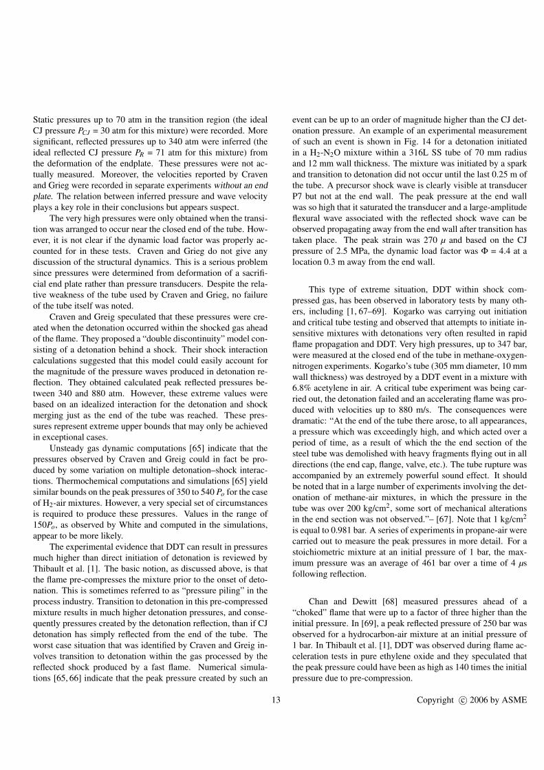
event can be up to an order of magnitude higher than the CJ det-onation pressure. An example of an experimental measurementof such an event is shown in Fig. 14 for a detonation initiatedin a H2-N2O mixture within a 316L SS tube of 70 mm radiusand 12 mm wall thickness. The mixture was initiated by a sparkand transition to detonation did not occur until the last 0.25 m ofthe tube. A precursor shock wave is clearly visible at transducerP7 but not at the end wall. The peak pressure at the end wallwas so high that it saturated the transducer and a large-amplitudeflexural wave associated with the reflected shock wave can beobserved propagating away from the end wall after transition hastaken place. The peak strain was 270 µ and based on the CJpressure of 2.5 MPa, the dynamic load factor was Φ = 4.4 at alocation 0.3 m away from the end wall.
This type of extreme situation, DDT within shock com-pressed gas, has been observed in laboratory tests by many oth-ers, including [1, 67–69]. Kogarko was carrying out initiationand critical tube testing and observed that attempts to initiate in-sensitive mixtures with detonations very often resulted in rapidflame propagation and DDT. Very high pressures, up to 347 bar,were measured at the closed end of the tube in methane-oxygen-nitrogen experiments. Kogarko’s tube (305 mm diameter, 10 mmwall thickness) was destroyed by a DDT event in a mixture with6.8% acetylene in air. A critical tube experiment was being car-ried out, the detonation failed and an accelerating flame was pro-duced with velocities up to 880 m/s. The consequences weredramatic: “At the end of the tube there arose, to all appearances,a pressure which was exceedingly high, and which acted over aperiod of time, as a result of which the the end section of thesteel tube was demolished with heavy fragments flying out in alldirections (the end cap, flange, valve, etc.). The tube rupture wasaccompanied by an extremely powerful sound effect. It shouldbe noted that in a large number of experiments involving the det-onation of methane-air mixtures, in which the pressure in thetube was over 200 kg/cm2, some sort of mechanical alterationsin the end section was not observed.”– [67]. Note that 1 kg/cm2
is equal to 0.981 bar. A series of experiments in propane-air werecarried out to measure the peak pressures in more detail. For astoichiometric mixture at an initial pressure of 1 bar, the max-imum pressure was an average of 461 bar over a time of 4 µsfollowing reflection.
Chan and Dewitt [68] measured pressures ahead of a“choked” flame that were up to a factor of three higher than theinitial pressure. In [69], a peak reflected pressure of 250 bar wasobserved for a hydrocarbon-air mixture at an initial pressure of1 bar. In Thibault et al. [1], DDT was observed during flame ac-celeration tests in pure ethylene oxide and they speculated thatthe peak pressure could have been as high as 140 times the initialpressure due to pre-compression.
13 Copyright c© 2006 by ASME
0
10
20
30
40
50
0 0.5 1 1.5 2
Pre
ssur
e (M
Pa)
time (ms)
shot 52, 17%H2, P0=1 bar, BR=0.25
P1, 0.305m
P2, 0.432m
P3, 0.559m
P4, 0.686m
P5, 0.813m
P6, 0.940m
P7, 1.067m
end, 1.25m
(a)
0
200
400
600
800
1000
0 0.5 1 1.5 2
Sta
in (
mic
ro s
trai
n)
time (ms)
shot 52, 17%H2, P0=1 bar, BR=0.25
S0, 0.432m
S1, 0.559m
S2, 0.686m
S3, 0.813m
S4, 0.940m
(b)
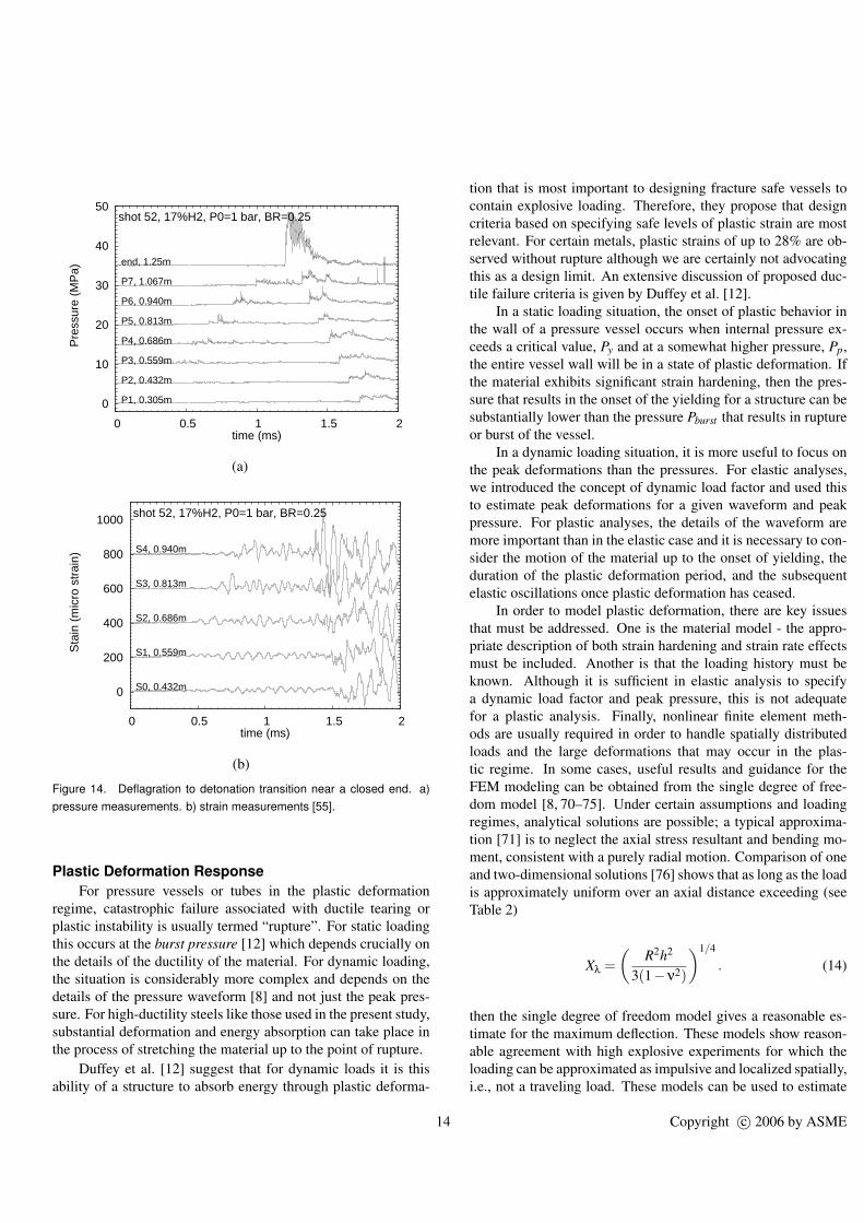
Figure 14. Deflagration to detonation transition near a closed end. a)pressure measurements. b) strain measurements [55].
Plastic Deformation ResponseFor pressure vessels or tubes in the plastic deformation
regime, catastrophic failure associated with ductile tearing orplastic instability is usually termed “rupture”. For static loadingthis occurs at the burst pressure [12] which depends crucially onthe details of the ductility of the material. For dynamic loading,the situation is considerably more complex and depends on thedetails of the pressure waveform [8] and not just the peak pres-sure. For high-ductility steels like those used in the present study,substantial deformation and energy absorption can take place inthe process of stretching the material up to the point of rupture.
Duffey et al. [12] suggest that for dynamic loads it is thisability of a structure to absorb energy through plastic deforma-
tion that is most important to designing fracture safe vessels tocontain explosive loading. Therefore, they propose that designcriteria based on specifying safe levels of plastic strain are mostrelevant. For certain metals, plastic strains of up to 28% are ob-served without rupture although we are certainly not advocatingthis as a design limit. An extensive discussion of proposed duc-tile failure criteria is given by Duffey et al. [12].
In a static loading situation, the onset of plastic behavior inthe wall of a pressure vessel occurs when internal pressure ex-ceeds a critical value, Py and at a somewhat higher pressure, Pp,the entire vessel wall will be in a state of plastic deformation. Ifthe material exhibits significant strain hardening, then the pres-sure that results in the onset of the yielding for a structure can besubstantially lower than the pressure Pburst that results in ruptureor burst of the vessel.
In a dynamic loading situation, it is more useful to focus onthe peak deformations than the pressures. For elastic analyses,we introduced the concept of dynamic load factor and used thisto estimate peak deformations for a given waveform and peakpressure. For plastic analyses, the details of the waveform aremore important than in the elastic case and it is necessary to con-sider the motion of the material up to the onset of yielding, theduration of the plastic deformation period, and the subsequentelastic oscillations once plastic deformation has ceased.
In order to model plastic deformation, there are key issuesthat must be addressed. One is the material model - the appro-priate description of both strain hardening and strain rate effectsmust be included. Another is that the loading history must beknown. Although it is sufficient in elastic analysis to specifya dynamic load factor and peak pressure, this is not adequatefor a plastic analysis. Finally, nonlinear finite element meth-ods are usually required in order to handle spatially distributedloads and the large deformations that may occur in the plas-tic regime. In some cases, useful results and guidance for theFEM modeling can be obtained from the single degree of free-dom model [8, 70–75]. Under certain assumptions and loadingregimes, analytical solutions are possible; a typical approxima-tion [71] is to neglect the axial stress resultant and bending mo-ment, consistent with a purely radial motion. Comparison of oneand two-dimensional solutions [76] shows that as long as the loadis approximately uniform over an axial distance exceeding (seeTable 2)
Xλ =(
R2h2
3(1−ν2)
)1/4
. (14)
then the single degree of freedom model gives a reasonable es-timate for the maximum deflection. These models show reason-able agreement with high explosive experiments for which theloading can be approximated as impulsive and localized spatially,i.e., not a traveling load. These models can be used to estimate
14 Copyright c© 2006 by ASME
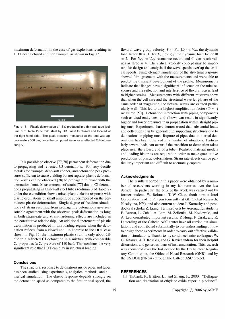
maximum deformation in the case of gas explosions resulting inDDT near a closed end, for example, as shown in Fig. 15.
Figure 15. Plastic deformation of 15% produced in a thin-wall tube (col-umn 3 of Table 2) of mild steel by DDT next to closed end located atthe right-hand side. The peak pressure measured at the end was ap-proximately 500 bar, twice the computed value for a reflected CJ detona-tion [77].
It is possible to observe [77,78] permanent deformation dueto propagating and reflected CJ detonations. For very ductilemetals (for example, dead-soft copper) and detonation peak pres-sures sufficient to cause yielding but not rupture, plastic deforma-tion waves can be observed [78] to propagate in phase with thedetonation front. Measurements of strain [77] due to CJ detona-tions propagating in thin-wall steel tubes (column 3 of Table 2)under these condition show a mixed plastic-elastic response withelastic oscillations of small amplitude superimposed on the per-manent plastic deformation. Single-degree-of-freedom simula-tions of strain resulting from propagating detonations give rea-sonable agreement with the observed peak deformation as longas both strain-rate and strain-hardening effects are included inthe constitutive relationship. An additional increment of plasticdeformation is produced in this loading regime when the deto-nation reflects from a closed end. In contrast to the DDT caseshown in Fig. 15, the maximum plastic strain is only about 2%due to a reflected CJ detonation in a mixture with comparableCJ properties (a CJ pressure of 110 bar). This confirms the verysignificant role that DDT can play in structural loading.
ConclusionsThe structural response to detonations inside pipes and tubes
has been studied using experiments, analytical methods, and nu-merical simulation. The elastic response depends strongly onthe detonation speed as compared to the first critical speed, the
flexural wave group velocity, Vc0. For UCJ < Vc0, the dynamicload factor Φ ≈ 1; for UCJ > Vc0, the dynamic load factor Φ≈ 2. For UCJ ≈ Vc0, resonance occurs and Φ can reach val-ues as large as 4. The critical velocity concept may be impor-tant for design and analysis if the wave speeds overlap the criti-cal speeds. Finite element simulations of the structural responseshowed fair agreement with the measurements and were able topredict the transient development of the profile. Measurementsindicate that flanges have a significant influence on the tube re-sponse and the reflection and interference of flexural waves leadto higher strains. Measurements with different mixtures showthat when the cell size and the structural wave length are of thesame order of magnitude, the flexural waves are excited partic-ularly well. This led to the highest amplification factor (Φ = 4)measured [50]. Detonation interaction with piping componentssuch as dead ends, tees, and elbows can result in significantlyhigher and lower pressures than propagation within straight pip-ing runs. Experiments have demonstrated that substantial loadsand deflections can be generated in supporting structures due todetonations in piping runs. Rupture of pipes due to internal det-onations has been observed in a number of situations. Particu-larly severe loads can occur if the transition to detonation takesplace near the closed end of a tube. Realistic material modelsand loading histories are required in order to make quantitativepredictions of plastic deformation. Strain rate effects can be par-ticularly important and difficult to accurately capture.
AcknowledgmentsThe results reported in this paper were obtained by a num-
ber of researchers working in my laboratories over the lastdecade. In particular, the bulk of the work was carried out byformer students W. Beltman, T.-W. Chao, (both now at IntelCorporation) and F. Pintgen (currently at GE Global Research,Nisakyuna, NY), and also current student J. Karnesky and post-doctoral scholar Z. Liang. Term projects by Aeronautics studentsE. Burcsu, L. Zuhal, A. Lam, M. Zeilonka, M. Kozlowski, andA. Lew contributed important results. P. Hung, F. Cirak, and R.Dieterding of the Caltech ASC center have all carried out simu-lations and contributed substantially to our understanding of howto design these experiments in order to carry out effective valida-tion of simulations. Thanks to my solid mechanics colleagues W.G. Knauss, A. J. Rosakis, and G. Ravichandran for their helpfuldiscussions and generous loans of instrumentation. This researchwas sponsored over the last decade by the US Nuclear Regula-tory Commission, the Office of Naval Research (ONR), and bythe US DOE (NNSA) through the Caltech ASC project.
REFERENCES[1] Thibault, P., Britton, L., and Zhang, F., 2000. “Deflagra-
tion and detonation of ethylene oxide vapor in pipelines”.
15 Copyright c© 2006 by ASME
Process Safety Progress, 19(3), pp. 125–139.[2] Grossel, S. S., 2002. Deflagration and Detonation Flame
Arresters. Wiley.[3] Kuznetsov, M., Breitung, W., Grune, J., and Singh, R. K.,
2005. “Structural response of DN15-tubes under radioly-sis gas detonation loads for BWR safety applications”. In18th International Conference on Structural Mechanics inReactor Technology, no. SMiRT 18-J09-1.
[4] Krieg, R., Dolensky, B., Goller, B., Breitung, W.,Redlinger, R., and Royl, P., 2003. “Assessment of the load-carrying capacities of a spherical pressurized water reactorsteel containment under a postulated hydrogen detonation”.Nuclear Technology, 141(2), February, pp. 109–121.
[5] Naitoh, M., Kasahara, F., Kubota, R., and Ohshima, I.,2003. “Analysis of pipe rupture of steam condensationline at Hamoaka-1, (I) Accumulation of noncondensablegas in a pipe”. Journal of Nuclear Science and Technol-ogy, 40(12), p. 1032.
[6] OECD, 2000. Flame acceleration and deflagration todetonation transition in nuclear safety. Tech. Rep.NEA/CSNI/R(2000)7, OECD Nuclear Energy Agency.State-of-the-Art Report by a Group of Experts, http://www.galcit.caltech.edu/∼jeshep/SOAR/index.html.
[7] Roy, G. D., Frolov, S. M., Borisov, A. A., and Netzer,D. W., 2004. “Pulse detonation propulsion: challenges, cur-rent status, and future perspective”. Prog. Energy Combust.Sci., 30, pp. 545–672.
[8] Florek, J. R., and Benaroya, H., 2005. “Pulse-pressureloading effects on aviation and general engineering struc-tures”. Journal of Sound and Vibration, 284, pp. 421–453.
[9] Baker, W. E., Cox, P. A., Westine, P. S., Kulesz, J. J., andStrehlow, R. A., 1983. Explosion Hazards and Evaluation.Elsevier.
[10] Bjerketvedt, D., Bakke, J. R., and van Wingerden, K., 1997.“Gas explosion handbook”. J. Hazardous Materials, pp. 1–150.
[11] NFPA. Standard on explosion protection systems. Tech.Rep. NFPA 69, National Fire Protection Association.
[12] Duffey, T., Rodriguez, E., and Romero, C., 2002. Design ofpressure vessels for high-strain rate loading: dynamic pres-sure and failure criteria. Bulletin 477, Welding ResearchCouncil, P.O. Box 1942, New York, NY.
[13] Rodriguez, E., and Duffey, T., 2004. Fracture-safe and fa-tigue design criteria for detonation-induced pressure load-ing in containment vessels. Bulletin 494, Welding ResearchCouncil, P.O. Box 1942, New York, NY.
[14] Pellini, W., 1973. Design options for selection of frac-ture control procedures in the modernization of codes, rulesand standards. Analytical design procedures for metals ofelastic-plastic and plastic fracture properties. Bulletin 186,Welding Research Council, P.O. Box 1942, New York, NY.
[15] Fickett, W., and Davis, W. C., 2001. Detonation Theory
and Experiment. Dover Publications Inc.[16] Tieszen, S. R., Stamps, D. W., Westbrook, C. K., and Pitz,
W. J., 1991. “Gaseous hydrocarbon-air detonations”. Com-bust. Flame, 84(3), pp. 376–390.
[17] Shepherd, J. E., 1986. “Chemical kinetics of hydrogen–air–diluent detonations”. Prog. Astronaut. Aeronaut., 106,pp. 263–293.
[18] Westbrook, C. K., and Urtiew, P. A., 1982. “Chemical ki-netic prediction of critical parameters in gaseous detona-tion”. In 19th Symp. Int. Combust. Proc., pp. 615–623.
[19] Reynolds, W., 1986. The element potential method forchemical equilibrium analysis: implementation in the in-teractive program STANJAN. Tech. rep., Mechanical En-gineering Department, Stanford University.
[20] McBride, B., and Gordon, S., 1996. Computer program forcalculation of complex chemical equilibrium compositionsand applications: II. Users manual and program descrip-tion. NASA Reference Publication 1311, June.
[21] Beltman, W., Burcsu, E., Shepherd, J., and Zuhal, L., 1999.“The structural response of tubes to internal shock load-ing”. Journal of Pressure Vessel Technology, 121, pp. 315–322.
[22] Stamps, D. W., Slezak, S. E., and Tieszen, S. R., 2006. “Ob-servations of the cellular structure of fuel–air detonations”.Combust. Flame, 144(1-2), pp. 289–298.
[23] Pintgen, F., Austin, J. M., and Shepherd, J. E., 2003.“Detonation front structure: Variety and characterization”.In Confined Detonations and Pulse Detonation Engines,G. Roy, S. Frolov, R. Santoro, and S. Tsyganov, eds., TorusPress, Moscow, pp. 105–116.
[24] Austin, J., 2003. “The role of instability in gaseous det-onation”. PhD thesis, California Institute of Technology,Pasadena, California, June.
[25] Pintgen, F., 2004. “Detonation diffraction in mixtures withvarious degrees of instability”. PhD thesis, California Insti-tute of Technology, Pasadena, California, December.
[26] Kaneshige, M., and Shepherd, J., 1997. Det-onation database. Tech. Rep. FM97-8, GALCIT,July. See also the electronic hypertext version athttp://www.galcit.caltech.edu/detn db/html/.
[27] Dorofeev, S., Sidorov, V., Kuznetsov, M., Matsukov, I., andAlekseev, V., 2000. “Effect of scale on the onset of detona-tions”. Shock Waves, 10(2), pp. 137–149.
[28] Taylor, G., 1950. “The dynamics of combustion fronts be-hind plane and spherical detonations”. Proc. Roy. Soc. Lon-don, A200, pp. 235–247.
[29] Zeldovich, Y. B., 1942. “On the distribution of pressure andvelocity in the products of a detonation explosion, specifi-cally in the case of spherical propagation of the detonationwave”. Journal Experimental Theoretical Physics, 12(1),p. 389.
[30] Beltman, W., and Shepherd, J., 2002. “Linear elastic re-
16 Copyright c© 2006 by ASME

sponse of tubes to internal detonation loading”. Journal ofSound and Vibration, 252(4), pp. 617–655.
[31] Radulescu, M., and Hanson, R., 2005. “Effect of heat losson pulse detonation engine flow fields and pefromance”. J.Propulsion Power, 21(2), pp. 274–285.
[32] Edwards, D., Brown, D., Hooper, G., and Jones, A., 1970.“Influence of wall heat transfer on expansion following a C-J detonation wave”. Journal of Physics. D, Applied Physics,3(3), pp. 365–376.
[33] Noda, N., Hetnarski, R., and Tanigawa, Y., 2002. ThermalStresses. Taylor and Francis.
[34] Fickett, W., and Davis, W., 1979. Detonation. Universityof California Press, Berkeley, CA.
[35] de Malherbe, M., Wing, R., Laderman, A., and Oppen-heim, A., 1966. “Response of a cylindrical shell to internalblast loading”. Journal of Mechanical Engineering Science,8(1), pp. 91–98.
[36] Blevins, R. D., 1979. Formulas for natural frequency andmode shape. van Nostrand Reinhold Company.
[37] Auslender, F., and Combescure, A., 2000. “Sphericalelastic-plastic structures under internal explosion. approx-imate analytical solutions and applications.”. EngineeringStructures, 22, pp. 984–992.
[38] Biggs, J., 1964. Introduction to structural dynamics.McGraw-Hill, Inc.
[39] Tang, S., 1965. “Dynamic response of a tube under mov-ing pressure”. In Proceedings of the American Society ofCivil Engineers, Vol. 5, Engineering Mechanics Division,pp. 97–122.
[40] Reismann, H., 1965. “Response of a pre-stressed cylin-drical shell to moving pressure load”. In Eighth MidwestMechanics Conference, S. Ostrach and R. Scanlon, eds.,Pergamon Press, pp. 349–363.
[41] Simkins, T., 1987. Resonance of flexural waves in guntubes. Tech. Rep. ARCCB–TR–87008, US Army Arma-ment Research, Development and Engineering Center, Wa-tervliet, N.Y. 12189–4050, July.
[42] Simkins, T., Pflegl, G., and Stilson, E., 1993. “Dynamicstrains in a 60mm gun tube - an experimental-study”. Jour-nal of Sound and Vibration, 168(3), pp. 549–557.
[43] Simkins, T., 1994. “Amplification of flexural waves in guntubes”. Journal of Sound and Vibration, 172(2), pp. 145–154.
[44] Mirzaei, A., Mazaheri, K., and Biglari, H., 2005. “Ana-lytical modeling of the elastic structural response of tubesto internal detonation loading”. International Journal OfPressure Vessels And Piping, 82(12), December, pp. 883–895.
[45] Brossard, J., and Renard, J., 1979. “Mechanical effectsof gaseous detonations on a flexible confinement”. InGasdynamics of detonations and explosions: technical pa-pers from the seventh International Colloquium on Gasdy-
namics of Explosions and Reactive Systems, J. R. Bowen,ed., Progress in astronautics and aeronautics, v.75, AIAA,pp. 108–121.
[46] Van de Ven, A., Olivier, H., and Gronig, H., 1996. “Dy-namic structural response of a dust detonation tube”. In 7thInternational Colloquium on Dust Explosions, pp. 4.22–4.32.
[47] Sperber, A., Schildber, H., and Schlehlein, S., 1999. “Dy-namic load on a pipe caused by acetylene detonations - ex-periments and theoretical approaches”. Shock and Vibra-tion, 6, pp. 29–43.
[48] Thomas, G., 2002. “The response of pipes and supportsgenerated by gaseous detonations”. Journal of PressureVessel Technology, 124, pp. 66–73.
[49] Simkins, T., 1995. “The influence of transient flexuralwaves on dynamic strains in cylinders”. Journal of AppliedMechanics-Transactions of the ASME, 62(1), pp. 262–265.
[50] Beltman, W. M., and Shepherd, J. E., 1998. Structural re-sponse of shells to detonation and shock loading. Tech.Rep. FM98-3, Graduate Aeronautical Laboratories, Cali-fornia Insititute of Technology.
[51] Chao, T., and Shepherd, J., 2005. “Detonation loading oftubes in the modified shear wave regime”. In Proceed-ings of the 24th International Symposium on Shock Waves,Z. Jiang, ed., Vol. 2, Springer, pp. 865–870.
[52] Chao, T. W., 2004. “Gaseous detonation-driven fracture oftubes”. PhD thesis, California Institute of Technology.
[53] Cirak, F., Pintgen, F., and Shepherd, J. E., 2006. Validationof shell dynamics computation for detonation loading. Inpreparation.
[54] Shepherd, J. E., Teodorcyzk, A., Knystautas, R., and Lee,J. H., 1991. “Shock waves produced by reflected det-onations”. In Progress in Astronautics and Aeronautics,Vol. 134. pp. 244–264.
[55] Liang, Z., Karnesky, J., and Shepherd, J. E., 2006. DDTand structural response in hydrogen-nitrous oxide mixtures.Tech. rep., Explosion Dynamics Laboratory, California In-stitute of Technology. in preparation.
[56] Shepherd, J., Schultz, E., and Akbar, R., 2000. “Deto-nation diffraction”. In Proceedings of the 22nd Interna-tional Symposium on Shock Waves, G. Ball, R. Hillier, andG. Roberts, eds., Vol. 1, pp. 41–48.
[57] Thomas, G. O., and Williams, R. L., 2002. “Detonationinteractions with wedges and bends”. Shock Waves, 11,pp. 481–491.
[58] Naitoh, M., Kasahara, F., Kubota, R., and Ohshima, I.,2003. “Analysis of pipe rupture of steam condensationline at Hamoaka-1, (II) Hydrogen combustion and genera-tion”. Journal of Nuclear Science and Technology, 40(12),pp. 1041–1051.
[59] Chao, T.-W., and Shepherd, J. E., 2005. “Fracture responseof externally flawed aluminum cylindrical shells under in-
17 Copyright c© 2006 by ASME
ternal gaseous detonation loading”. International Journalof Fracture, 134(1), July, pp. 59–90.
[60] Chao, T. W., and Shepherd, J. E., 2004. “Comparison offracture response of preflawed tubes under internal staticand detonation loading”. Journal of Pressure Vessel Tech-nology, 126(3), pp. 345–353.
[61] Lam, A., and Zielonka, M., 2002. Fracture response ofexternally flawed thin-walled plastic tubes to gaseous det-onation loading. Ae104c Report, Graduate AeronauticalLaboratories, California Institute of Technology, Pasadena,California 91125.
[62] Brossard, J., and Charpentier de Coysevox, N., 1976.“Effects d’un confinement souple sur la detonation desmelanges gazeux”. Acta Astronautica, 3, pp. 971–981.
[63] White, D. A., 1957. “On the existence of higher than nor-mal detonation pressures”. Journal of Fluid Mechanics, 2,pp. 513–514.
[64] Craven, A. D., and Grieg, T. R., 1968. “The developmentof detonation over–pressures in pipelines”. I. Chem. Eng.Symposium Series, 25, pp. 41–50.
[65] Shepherd, J., 1992. Pressure loads and structural responseof the BNL high-temperature detonation tube. Tech. Rep.A-3991, Brookhaven National Laboratory, Upton, NewYork 11973, September.
[66] Boyack, K., Tieszen, S., and Stamps, D., 1993. “Internal-pressure loads due to gaseous detonations”. Proceedings OfThe Royal Society Of London Series A-Mathematical Phys-ical And Engineering Sciences, 443 (1918), November 8,pp. 343–366.
[67] Kogarko, S. M., 1958. “Invetigation of pressure at the endof a tube in connection with rapid nonstationary combus-tion”. Soviet Physics - Technical Physics, 38(9), p. 1875.
[68] Chan, C. K., and Dewitt, W. A., 1996. “DDT in end gases”.In 27th Symposium (International on Combustion, Vol. 2,p. 2679.
[69] Zhang, F., Thibault, P. A., and Murray, S. B., 1998. “Tran-sition from deflagration to detonation in multi-phase slug”.Combustion and Flame, 114, pp. 13–24.
[70] Duffey, T., and Mitchell, D., 1973. “Containment of explo-sions in cylindrical shells”. Int. J. Mech. Sci., 15, pp. 237–249.
[71] Benham, R. A., and Duffey, T., 1974. “Experimental-theoretical correlation on the containment of explosions incylindrical vessels”. Int. J. Mech. Sci., 16, pp. 549–558.
[72] Hodge, P. G., 1956. “The influence of blast characteristicson final deformation of circular cylindrical shells”. Journalof Applied Mechanics, 284, December, pp. 617–624.
[73] Duffey, T., 1971. “Approximate solutions of an impulsivelyloaded long cylinder governed by an elastic-plastic materiallaw”. Acta Mechanica., 11, pp. 45–57.
[74] Duffey, T., and Krieg, R., 1969. “Effects of strain harden-ing and strain rate sensitivity on the transient response of
elastic-plastic rings and cylinders”. Int. J. Mech. Sci., 11,pp. 825–844.
[75] Fanous, F., and Greiman, L., 1988. “Simplified analysis forimpulsively loaded shells”. Journal of Structural Engineer-ing, 114, April, pp. 885–899.
[76] Young, W., and Budynas, R., 2002. Roark’s formulas forstress and strain. McGraw-Hill. Seventh Edition.
[77] Pintgen, F., and Shepherd, J. E., 2006. unpublished data,Explosion Dynamics Laboratory, California Institute ofTechnology.
[78] Koslowksi, M., and Lew, A., 1999. Plastic response of thintubes to gaseous detonation waves. Ae104c Report, Gradu-ate Aeronautical Laboratories, California Institute of Tech-nology, Pasadena, California 91125.
18 Copyright c© 2006 by ASME