Embed Size (px)
Citation preview

© 2005 Cisco Systems, Inc. All rights reserved.
Introduction 1-1DFM v2.0 Tutorial
(DFM) v2.0 Tutorial(DFM) v2.0 Tutorial
CiscoWorksCiscoWorksDevice Fault Manager Device Fault Manager

© 2005 Cisco Systems, Inc. All rights reserved.
Introduction 1-2DFM v2.0 Tutorial
Introduction 1-2© 2005 Cisco Systems, Inc. All rights reserved.DFM v2.0 Tutorial
About This Tutorial
• Identify the need for real-time fault management & analysis
• Describe the industry standard and Cisco tools for device fault analysis
• Provide several important scenarios for using DFM to manage device faults
• Provide helpful install and maintenance guidelines for system administrators
• Provide links to helpful reference documents on CiscoWorks, DFM, and fault analysis
About This TutorialThe CiscoWorks Device Fault Manager (DFM) tutorial provides self-paced training focused on using DFM for viewing device faults occurring in Cisco devices. DFM is available with the purchase of the CiscoWorks LAN Management Solution (LMS) bundle. The LMS bundle is a suite of network management applications used for configuring, administering, monitoring, and troubleshooting a Cisco-based network. It enables network administrators to effectively manage their LAN and campus networks.This tutorial will focus on how to use and administer DFM. More information on other CiscoWorks products can be found in separate tutorials and is highlighted later in this chapter.The tutorial is structured as a series of self-paced modules, or chapters, that conclude with self-administered exercises. Also included as part of the tutorial is a helpful reference section containing links to technical documents on component products, concepts, and terminology. The tutorial material is presented through text, illustrations, hypertext links, and typical scenarios.This tutorial is not intended to teach you how to manage or analyze faults in a network, but rather to introduce you DFM, which will help you achieve these tasks.

© 2005 Cisco Systems, Inc. All rights reserved.
Introduction 1-3DFM v2.0 Tutorial
Introduction 1-3© 2005 Cisco Systems, Inc. All rights reserved.DFM v2.0 Tutorial
How the Tutorial Is Organized
Chapter 1Managing Device Faults in a
Cisco Network
Chapter 2DFM Features for Cisco
Device Fault Management
Chapter 3Scenarios
Chapter 4System Administration
Guidelines
Chapter 5Helpful Links to Reference
Material
Review the importance of network management, the tools, and the data available
Learn how DFM can help a user to detect and analysis faults in a Cisco network
Using an example, learn how DFM can help manage Cisco device faults
Review important system requirements, installation guidelines, and system troubleshooting tools
A comprehensive set of links to information on CiscoWorks and DFM
How This Tutorial Is OrganizedThe tutorial is divided into five chapters. Each chapter outlines its specific learning objectives, and concludes with a series of self-assessment exercises based on the chapter objectives. The multiple-choice exercises provide a means for you to assess your understanding of the material presented in a given chapter. A summary of each chapter is listed below.
Chapter 1: Managing Device Faults in a Cisco NetworkThis chapter identifies the need for fault management and the many challenges related to managing and analyzing the faults when they do occur. This chapter will first identify the need for fault management and next formalize its definition before describing the challenges that make this area of network management so difficult. Finally, the chapter will introduce DFM, the main CiscoWorks application used for fault management.
Chapter 2: Using DFM for Cisco Device Fault ManagementThis chapter discusses the key features of DFM in a manner that allows you to understand not only the product as a whole, but any reason for the individual tasks necessary for using DFM. Before getting into the specifics on how to use the various functions of DFM, the chapter discusses DFM architecture, to provide an understanding of how all the components work together and interface with other tools. The roadmap to using DFM is presented in a logical workflow showing how you would begin and continue to use DFM.

© 2005 Cisco Systems, Inc. All rights reserved.
Introduction 1-4DFM v2.0 Tutorial
Chapter 3: ScenariosThis chapter walks you through several scenarios to provide hands-on experience using DFM. The scenarios begin with steps on how to get started, followed by day-to-day monitoring activities and customized configurations. These scenarios will help to reinforce the information learned in Chapter 2.
Chapter 4: System Administration GuidelinesThis chapter provides information about client and server requirements, software installation guidelines, and tips for troubleshooting and avoiding common problems when using DFM. Detailed instructions on installing the software can be found in the various product installation guides. A link to these installation guides can be found in the references section (Chapter 5).
Chapter 5: ReferencesThis chapter contains a comprehensive list of additional product information, such as links to white papers and documentation.
Chapter Questions and AnswersThis section contains the answers to the questions that conclude each chapter.

© 2005 Cisco Systems, Inc. All rights reserved.
Introduction 1-5DFM v2.0 Tutorial
Chapter 1Chapter 1
Managing Device Managing Device Faults in a Cisco Faults in a Cisco NetworkNetwork

© 2005 Cisco Systems, Inc. All rights reserved.
Introduction 1-6DFM v2.0 Tutorial
Introduction 1-6© 2005 Cisco Systems, Inc. All rights reserved.DFM v2.0 Tutorial
Chapter 1 Outline
• The Importance of Device Fault Management
• What is Fault Management?
• Challenges to Managing Device Faults
• Introduction to CiscoWorks Device Fault Manager
Chapter 1 Outline When asked to describe what network management is, many are quick to indicate that it is the ability to find faults in the network. Though this is just one of the many faucets of network management, its importance is obvious based on the response to the network management query. This chapter will first identify the need for fault management and then formalize its definition before describing the challenges that can make this area of network management so difficult. Finally, the chapter will introduce Cisco’s primary CiscoWorks application used for managing faults in the network, Device Fault Manager or DFM.

© 2005 Cisco Systems, Inc. All rights reserved.
Introduction 1-7DFM v2.0 Tutorial
Introduction 1-7© 2005 Cisco Systems, Inc. All rights reserved.DFM v2.0 Tutorial
The Importance of Device Fault Management
Why can’t I attach to the
corporate server?
Why can’t I attach to the
corporate server?
I can’t get my e-mailI can’t get my e-mail
The network is slow!!
The network is slow!!
I can’t get to the partner’s
web site
I can’t get to the partner’s
web site
How would you begin to solve their problems? Where do you start to look? How could tools help in this situation?
How would you begin to solve their problems? Where do you start to look? How could tools help in this situation?
Help
The Importance of Device Fault ManagementLooking at a typical day in the life of a network administrator readily highlights the need for fault management. Although the server or other resource outside the management scope of the network administrator can cause many of the issues that are blamed on the network, to the user it is always the network’s fault.Unfortunately, many of the complaints are real network problems, and finding the cause of them can be a real challenge. Most notable among the challenges are where to start looking for the cause, and what to look for.

© 2005 Cisco Systems, Inc. All rights reserved.
Introduction 1-8DFM v2.0 Tutorial
Introduction 1-8© 2005 Cisco Systems, Inc. All rights reserved.DFM v2.0 Tutorial
What is Fault Management?
The ability to:• Quickly and easily detect, isolate,
and correct network faults:– Monitor not only up and down status,
but also potential problems
– Provide valuable insight into the relative health of a device and the network
– Address problems before network service degradation impacts users
• Minimize downtime and service degradation!
What is Fault Management? With the need for fault management so easily recognized, it can be defined as the ability to quickly and easily isolate, detect, and correct the conditions leading to undesirable network behavior. Typically, network managers perform fault management activities after the problem has already occurred. Unfortunately, as will be discussed in more detail later in this chapter, the presence of a problem doesn’t always indicate what the actual cause is, resulting in a tremendous amount of effort and time on the part of the network administrator to hunt down the culprit. A better solution would be to employ fault management tools that proactively monitor the network for indicators that the device or network is beginning to degrade. The network administrator would now know exactly what to fix, avoiding costly network service degradation.This sounds easy enough, so why is it so hard in practice? Before answering this question, let’s first define what a fault is.

© 2005 Cisco Systems, Inc. All rights reserved.
Introduction 1-9DFM v2.0 Tutorial
Introduction 1-9© 2005 Cisco Systems, Inc. All rights reserved.DFM v2.0 Tutorial
What Constitutes a Fault?
FAULTAny condition that leads to unexpected or undesirable behavior
FAULTAny condition that leads to unexpected or undesirable behavior
Root CauseRoot Cause
Goal: Early fault detection. The earlier the symptoms are detected,the sooner the fault condition can be isolated and corrected,
minimizing the impact to network service.
Goal: Early fault detection. The earlier the symptoms are detected,the sooner the fault condition can be isolated and corrected,
minimizing the impact to network service.
SymptomSymptomSymptomSymptom
SymptomSymptomSymptomSymptom
Characterized/detected by:
Need to determine in order to correct:
Easier
More difficult
Detection/IsolationDetection/Isolation
What Constitutes a Fault? In simple terms, a fault is any condition that leads to unexpected or undesirable behavior. Typically, the altered behavior is fairly easy to detect (for example, poor response time). The resulting behavior of the fault condition can be seen as a symptom of the fault, but may not directly point to the actual condition that caused the fault. The real challenge of fault management is to isolate the root cause of the condition that leads to the altered behavior. Like a doctor making a diagnosis, you look at the symptoms to try to locate the problem, but unfortunately, many faults may exhibit the same symptoms (for example, long latency is a symptom that may be caused by many different faults).A primary goal of any fault management system is to detect the symptoms and isolate the condition early, to allow for correction before network service degradation starts. We now begin to see one of the reasons why fault management is so difficult; next, we will look at an example that further highlights the difficulties of implementing a fault management solution.

© 2005 Cisco Systems, Inc. All rights reserved.
Introduction 1-10DFM v2.0 Tutorial
Introduction 1-10© 2005 Cisco Systems, Inc. All rights reserved.DFM v2.0 Tutorial
Challenges to Managing Device Faults
DetectionDetection • Response time tests• SNMP trap from device indicating problem or error condition• Syslog message from device indicating problem or error condition• Irate user!
PossibleRoot CausePossible
Root Cause• Router port going up and down• Too many ACLs in router (slow processing)• Buffer allocation problems• High bandwidth due to backup
SymptomSymptom • The XYZ application is exhibiting poor response time
• The real challenge!– Where to start looking?– What fault could be causing the slow response?– What MIB variable(s) must be polled to detect this fault?– What is an acceptable range for the MIB variable(s)?– What other conditions must also be occurring?– How often to poll for this information?
IsolationIsolation
Challenges to Managing Device FaultsThe following example is used to illustrate the challenges of performing fault management:The XYZ application is experiencing poor response time. This is the symptom of the fault condition. The symptom may have been discovered in many ways, including through periodic response time tests; through SNMP trap or Syslog messages from a device in the path to the server, indicating some kind of problem; or as in many cases, through a report from an upset user.The network administrator now knows there is a problem, but does not know the cause. Possibilities the network administrator might consider include a router port going up and down; too many ACLs in a router, slowing down packet forwarding; buffer allocation problems; high bandwidth due to the backup application running; or possibly a defective device.So a problem has been detected, but not yet isolated. To isolate the problem, the network administrator must answer some difficult questions, including:
• Where to start looking?• What fault could be causing the slow response?• What MIB variable(s) must be polled to detect this fault?• What is an acceptable range for the MIB variable(s)?• What other conditions must also be occurring?• How often to poll for this information?
This example should highlight the need for tools to assist in fault management. Many fault management tools allow the network administrator to write rules to find various faults. However, the writing of these rules is subject to the same questions the network administrator must answer when finding a fault in a reactive manner. To write the rules, the network administrator would potentially need to have a design engineer’s knowledge about the devices on the network. Clearly, fault management is a difficult task.

© 2005 Cisco Systems, Inc. All rights reserved.
Introduction 1-11DFM v2.0 Tutorial
Introduction 1-11© 2005 Cisco Systems, Inc. All rights reserved.DFM v2.0 Tutorial
Introduction to CiscoWorks DFM
DFM detects the symptoms or unexpected conditions on a Cisco device
DFM automatically looks for a range of common problems at the device and VLAN level without requiring users to write rules or set polling or threshold values
DFM reports these conditions as Alerts and can notify network administrators of these conditions
Summary of all faults detected for the Cisco
devices managed using DFM
Summary of all faults detected for the Cisco
devices managed using DFM
Introduction to CiscoWorks DFMTraditionally, fault management applications have simply determined whether a device was up or down. With the complexity of network infrastructure equipment in networks today, a device can be up but performing badly, resulting in network performance degradation. Most fault managers therefore allow the network administrator to selectively poll specific MIB variables to determine the overall health of a device. Doing so, however, requires a great deal of knowledge to determine what constitutes a healthy device, and what MIB variables to poll to determine its health. Further, many times a single MIB variable does not tell the whole story; multiple variables in conjunction with events are required determine a particular health index.DFM addresses these issues head-on by providing device-specific fault management out of the box. You don’t have to write complex rules or spend vast amounts of time performing difficult configurations.

© 2005 Cisco Systems, Inc. All rights reserved.
Introduction 1-12DFM v2.0 Tutorial
Introduction 1-12© 2005 Cisco Systems, Inc. All rights reserved.DFM v2.0 Tutorial
Introduction to CiscoWorks DFMA Quick Look at DFM Alerts
DFM comes pre-configured with built-in intelligence to determine the proper operation of Cisco Devices and automatically provide actionable information
Summary of all faultsSummary of all faults
Problem-focused analysis, including chassis, fan, memory, network adapters, power supplies, processors, and system
Problem-focused analysis, including chassis, fan, memory, network adapters, power supplies, processors, and system
Drill-downs to events causing the alert
Drill-downs to events causing the alert
A Quick Look at DFM AlertsDFM has the built-in intelligence to determine what variables and events to look for to determine the health of a Cisco device, without user intervention, for true fault management. DFM correlates events and determines their importance so that the event viewer is not flooded with useless information. The events for a device is aggregated together and the user can view the alerts easily for all devices in the DFM Alerts and Activities window. For example, rather than reporting that all of the ports on a card are down, DFM reports only one alert that there is a interface problem with the device. The user can then drill down into the alert and see the events that the card is down. Chapter 2 of this tutorial will provide a lot more details on the alerts, events, and notification methods provided by DFM.

© 2005 Cisco Systems, Inc. All rights reserved.
Introduction 1-13DFM v2.0 Tutorial
Introduction 1-13© 2005 Cisco Systems, Inc. All rights reserved.DFM v2.0 Tutorial
Introduction to CiscoWorks DFM Where to Find DFM
InternetworkPerformance Monitor
Device FaultManager
Campus Manager
Resource ManagerEssentials
CiscoView
LAN Management Solution(LMS)
• DFM is available in the CiscoWorks LMS solution bundle
• LMS contains other CiscoWorks applications for Cisco device configuration and performance management
CiscoWorks Common Services
Where to Find Device Fault Manager (DFM)DFM is available as one of several applications in the CiscoWorks LAN Management Solutions (LMS) bundle. It cannot be purchased separately. To run DFM as a standalone application on a server would require that you first install CiscoWorks Common Services. Common Services provides the web server, security authentication, and GUI desktop interface for DFM and other CiscoWorks applications. The other applications in the LMS bundle include:
• CiscoView—Graphical device management application; provides managers with browser access to real-time device status and operational and configuration functions.
• Resource Manager Essentials (RME)—Provides network inventory, device change management, network configuration, software image management, network availability, and Syslog analysis tools.
• Campus Manager (Campus)—Designed for managing Cisco powered switched networks, this application includes Layer 2 device and connectivity discovery, workflow application server discovery and management, detailed topology views, end-station tracking, Layer 2 and 3 path analysis tools, IP phone location, and phone call tracing.
• Internetwork Performance Monitor (IPM) )—Configures and gathers performance statistics for IP SLAs (Service Level Agreements) agents embedded in Cisco IOS devices. IP SLAs send synthetics test traffic from the Cisco IOS devices to a target device. The test traffic is measured for network latencies, errors, and jitter (voice and video traffic). IPM gathers these statistics for historical reports. Test operations are available for upper layer protocols as well as voice and video.

© 2005 Cisco Systems, Inc. All rights reserved.
Introduction 1-14DFM v2.0 Tutorial
Introduction 1-14© 2005 Cisco Systems, Inc. All rights reserved.DFM v2.0 Tutorial
Introduction to CiscoWorks DFM Devices Supported By DFM
• Support for numerous Cisco devices: – Broadband Cable – Content Networking – DSL and LRE – Interfaces and Modules – Optical – Routers – Security and VPN – Storage Networking – Switches and Hubs – Universal Gateways and Access Servers – Voice and Telephony – Wireless – Third Party Servers
Go to URL: http://www.cisco.com/univercd/cc/td/doc/product/rtrmgmt/cw2000/dfm/dev_sup/dfm2_0.htm
to view the complete supported device table for DFM 2.0
Go to URL: http://www.cisco.com/univercd/cc/td/doc/product/rtrmgmt/cw2000/dfm/dev_sup/dfm2_0.htm
to view the complete supported device table for DFM 2.0
Devices Supported by DFMThere are too many devices supported by DFM to list all of them here in this tutorial. To find out if a particular device is supported by DFM, refer to the supported device table for DFM 2.0 found at:http://www.cisco.com/univercd/cc/td/doc/product/rtrmgmt/cw2000/dfm/dev_sup/dfm2_0.htm If the device is supported and DFM fails to display the device, then check one of the following:
• The SNMP server may not be set in the device. • The SNMP credentials are incorrect. Verify that the device attributes are correct in the CiscoWorks
Device and Credential Repository (DCR). See User Guide for CiscoWorks Common Services for more information.
• The management station cannot reach and successfully ping the device.

© 2005 Cisco Systems, Inc. All rights reserved.
Introduction 1-15DFM v2.0 Tutorial
15
Continue on to Chapter 2 to learn about the features of DFM for device fault management.

© 2005 Cisco Systems, Inc. All rights reserved.
Introduction 1-16DFM v2.0 Tutorial
<Intentionally left blank>

© 2005 Cisco Systems, Inc. All rights reserved.
DFM Features 2-1DFM v2.0 Tutorial
Chapter 2Chapter 2
DFM Features For DFM Features For Cisco Device Fault Cisco Device Fault ManagementManagement

© 2005 Cisco Systems, Inc. All rights reserved.
DFM Features 2-2DFM v2.0 Tutorial
DFM Features 2-2© 2005 Cisco Systems, Inc. All rights reserved.DFM v2.0 Tutorial
Chapter 2 Outline
• DFM Overview– What is DFM?– Functional Overview
• Fault Management Using DFM– Alerts & Activities– Event Details– Fault History– Event Notification– Polling & Threshold Customization
• Understanding How DFM Works
Chapter 2 OutlineHopefully Chapter 1 has excited you to the possibilities of performing fault management using DFM. This chapter discusses the key features of DFM by first reintroducing DFM and providing a functional flow, followed up with more details about the features of DFM. The final section of this chapter briefly explains how DFM works – what to poll, what threshold to use, etc.By the conclusion of this chapter, the reader should have a good understanding of the components of DFM and what is possible with them. Chapter 3 will then provide the jump start to using DFM through a series of scenarios that takes you from getting started through customization.

© 2005 Cisco Systems, Inc. All rights reserved.
DFM Features 2-3DFM v2.0 Tutorial
DFM OverviewDFM Overview
DFM Overview• Fault Management Using DFM• Understanding How DFM Works

© 2005 Cisco Systems, Inc. All rights reserved.
DFM Features 2-4DFM v2.0 Tutorial
DFM Features 2-4© 2005 Cisco Systems, Inc. All rights reserved.DFM v2.0 Tutorial
• Out of the Box Analysis– Looks for a wide range of faults– Thresholds and polling pre-set based on testing and experience
– This can also be manually adjusted
– Intelligently correlates information to minimize flooding event screen– Highest severity problem shown per device - drill down to see all alerts
detected for device
• Fully Integrated with CiscoWorks– DFM automatically populated from CiscoWorks shared device inventory– Uses CiscoWorks or Access Control Server security roles– DFM data displayed on Common Services Device Center application
(after DFM is registered with CiscoWorks home page)
What is Device Fault Manager?
Problem Focused Fault Analysis for Cisco DevicesProblem Focused Fault Analysis for Cisco Devices
What is Device Fault Manager?The CiscoWorks Device Fault Manager (DFM) application provides a fault analysis tool for Cisco-specific network devices. The application is designed to provide insight and information about the operational health of the Cisco devices in the network. The key distinction and differentiating value is that, in addition to identifying whether devices are up or down (the so-called "green/red" management), DFM considers potential problems by polling the devices for specific information and then correlating this information to diagnose the problem. Perhaps the best part of DFM is that there are no rules to write to detect and diagnose these potential problems - DFM comes ready to use right out of the box. DFM is fully integrated with CiscoWorks and therefore automatically is populated with devices from the Device and Credentials Repository (DCR) and immediately begins monitoring for faults.From an end-user perspective, DFM provides network management operators with early insight into potential problems within the network infrastructure without any cumbersome configuration (though customization is possible). Using this proactive management method, problem areas can be addressed before they escalate to cause service degradation within the network.

© 2005 Cisco Systems, Inc. All rights reserved.
DFM Features 2-5DFM v2.0 Tutorial
DFM Features 2-5© 2005 Cisco Systems, Inc. All rights reserved.DFM v2.0 Tutorial
DFM Engine
DFM Functional Architecture
SNMP Queries
Per Polling Settings
ThresholdSettings
ThresholdSettings
SNMPPort
TrapReceiving
Port
TrapForwarding
Port
Notification Services
Notify based on user criteria
Notify based on user criteria
EmailEmail
TrapTrap
SyslogSyslog
Users
DFM Alerts & Activities
Display
Third PartyNMS or Event
Notification System
Raw Traps
DFM Server
Traps
Fault History DB(Stores 31 days of
data)
Fault History Display
DFM Functional ArchitectureAs previously mentioned, the monitoring “rules” come preloaded in DFM, meaning DFM knows the exact MIB variables to poll for and the rules for determining the devices overall health based on the retrieved values. DFM additionally uses various traps to determine the overall health of a device.Although DFM can and does collect SNMP traps from the managed devices, the main purpose of this feature is to provide diagnostics. Generic MIB-II traps (such as Link Up and Link Down) are used to expedite the port and interface operational diagnostics and pinpoint unstable conditions (such as interface flapping). DFM is not considered a general trap receiver and therefore does not display details about many traps. Therefore, it is important to forward these traps onto a trap collection system like HP OpenView. A handful of traps, however, are presented to reflect some important operational and performance changes that otherwise cannot be diagnosed by DFM (for example, Loss Of Signal in the optical switches).When DFM detects certain events, an Alert is generated and displayed on the Alert and Activities console. Alert notification customization is also available by creating Notification Groups consisting of a set of events and alerts on a set of devices. Alerts fitting the parameters detailed in a Notification Group can then be sent out as E-Mail, SNMP Trap, or a Syslog Message allowing for flexible notification of detected conditions.DFM also stores 31 days of fault history to help in the analysis of devices on a device.
© 2005 Cisco Systems, Inc. All rights reserved.
DFM Features 2-6DFM v2.0 Tutorial
Fault Management Using Fault Management Using DFMDFM
• DFM OverviewFault Management Using DFM
• Understanding How DFM Works

© 2005 Cisco Systems, Inc. All rights reserved.
DFM Features 2-7DFM v2.0 Tutorial
DFM Features 2-7© 2005 Cisco Systems, Inc. All rights reserved.DFM v2.0 Tutorial
Fault Management Using DFMAlerts & Activities
Consolidated real-time view of the operational status of the network
Consolidated real-time view of the operational status of the network
Drill-down to Alerts and Activities DetailsDrill-down to Alerts
and Activities DetailsDrill-down to
Detailed Device ViewDrill-down to
Detailed Device View
User Alert
Views
User Alert
Views
DFM Tools(see next page)DFM Tools
(see next page)
Severity of Alert(see next page)
Severity of Alert(see next page)
Alerts & ActivitiesThe Alerts and Activities display is the main DFM task used on a day-to-day basis. It provides a consolidated real-time (updated every 30 seconds) view of the operational status of the network. The display is designed to leave up and running, providing an ongoing monitoring tool. When a fault occurs on the network, DFM generates an event or events that are rolled up into an alert and is shown on the Alerts and Activities display. To minimize device alerts displayed or to focus monitoring efforts, Alert Views are employed to show a subset of the devices being monitored by DFM. Additionally, filtering by alert or event severity and status is also available.The Alert and Activities display is just the starting point for viewing network fault activity. From this display, numerous drill downs are available to see more information about alerts, events, and device details.

© 2005 Cisco Systems, Inc. All rights reserved.
DFM Features 2-8DFM v2.0 Tutorial
DFM Features 2-8© 2005 Cisco Systems, Inc. All rights reserved.DFM v2.0 Tutorial
Fault Management Using DFM Alerts & Activities Legend
Severity of Alert
- Critical
- Warning
- Informational Unidentified Trap
- InformationalNo Icon
LastChange
- Alert updated within last 15 minutes
- Alert updated within last 16 - 30 minutes
- Alert updated within last 31 - 45 minutes
No Diamonds
- Alert was updated over 46 minutes ago
- Export current tabular display to a PDF file
- Opens the filter page for refining the alerts displayed
- Opens printer friendly version of display
- Opens DFM tools window with link to Fault History
- Opens DFM help window
Alerts and Activities LegendAs shown in the graphic above, the Alerts and Activities display uses icons as a means of quick glance status (severity and Last Change), and as launch points for additional tools.
© 2005 Cisco Systems, Inc. All rights reserved.
DFM Features 2-9DFM v2.0 Tutorial
DFM Features 2-9© 2005 Cisco Systems, Inc. All rights reserved.DFM v2.0 Tutorial
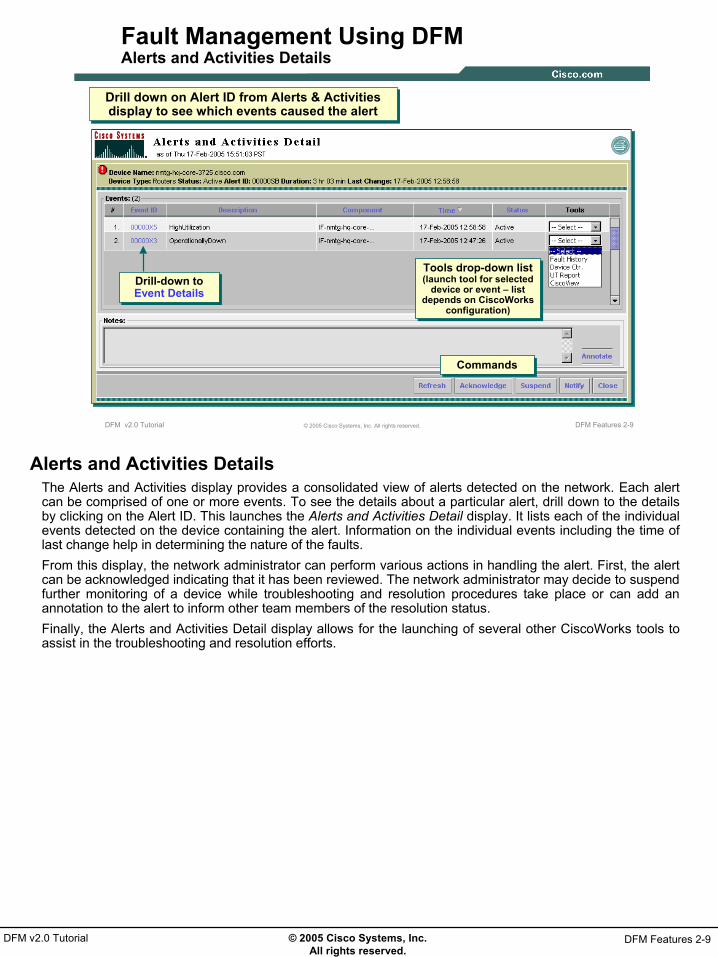
Fault Management Using DFM Alerts and Activities Details
Drill down on Alert ID from Alerts & Activities display to see which events caused the alert
Drill down on Alert ID from Alerts & Activities display to see which events caused the alert
Tools drop-down list (launch tool for selected
device or event – list depends on CiscoWorks
configuration)
Tools drop-down list (launch tool for selected
device or event – list depends on CiscoWorks
configuration)
CommandsCommands
Drill-down to Event DetailsDrill-down to Event Details
Alerts and Activities DetailsThe Alerts and Activities display provides a consolidated view of alerts detected on the network. Each alert can be comprised of one or more events. To see the details about a particular alert, drill down to the details by clicking on the Alert ID. This launches the Alerts and Activities Detail display. It lists each of the individual events detected on the device containing the alert. Information on the individual events including the time of last change help in determining the nature of the faults. From this display, the network administrator can perform various actions in handling the alert. First, the alert can be acknowledged indicating that it has been reviewed. The network administrator may decide to suspend further monitoring of a device while troubleshooting and resolution procedures take place or can add an annotation to the alert to inform other team members of the resolution status.Finally, the Alerts and Activities Detail display allows for the launching of several other CiscoWorks tools to assist in the troubleshooting and resolution efforts.

© 2005 Cisco Systems, Inc. All rights reserved.
DFM Features 2-10DFM v2.0 Tutorial
DFM Features 2-10© 2005 Cisco Systems, Inc. All rights reserved.DFM v2.0 Tutorial
Fault Management Using DFM Event Details
Drill down on Event ID from Alerts & Activities Detail display to see the MIB attribute values for the Event
Drill down on Event ID from Alerts & Activities Detail display to see the MIB attribute values for the Event
Reason for Event(Actual MIB value and configured threshold)
Reason for Event(Actual MIB value and configured threshold)
Relevant Event Information
Relevant Event Information
Event DetailsLike the Alerts and Activities display, the Alerts and Activities Detail display shows a summary of information. To see actual values from the device that triggered the event, click on the Event Id to launch Event Details. This display list actual variables and their value during the last polling cycle and any associated threshold helping the network administrator determine the extent of the condition.

© 2005 Cisco Systems, Inc. All rights reserved.
DFM Features 2-11DFM v2.0 Tutorial
DFM Features 2-11© 2005 Cisco Systems, Inc. All rights reserved.DFM v2.0 Tutorial
Fault Management Using DFM Detailed Device View
Suspend or resume monitoring of any
component
Suspend or resume monitoring of any
component
Drill down on Device Name link from Alerts & Activities display to display Detailed Device View
Drill down on Device Name link from Alerts & Activities display to display Detailed Device View
Detailed Device View
Memory components
For aggregated devices, (i.e. with MSFC), user can launch a separate Detailed Device View on the MSFC)
For aggregated devices, (i.e. with MSFC), user can launch a separate Detailed Device View on the MSFC)
Examine monitored components of a device and
current MIB values
Examine monitored components of a device and
current MIB values
Detailed Device ViewAs will be detailed in the next section of this chapter, DFM discovers the different components of a device to further define how it is to be managed. The Detailed Device View provides information on the devices and device components that DFM is managing. The Detailed Device View (DDV) can be launched by clicking on the device name within the Alerts and Activities display or using a separate task under the Device Management tab. The Detailed Device View display can not only be used to view current values retrieved by DFM for the different managed components, but to also choose to un-manage (suspend polling) specific components.Aggregated DevicesThe illustration above shows a DDV for a Cisco Catalyst 6500 switch. This switch contains an MSFC card (a contained device). If you select the MSFC card, the DDV displays the managed state of the subcomponent on the right side of the display and a new DDV launch point is provided. To display a DDV for the MSFC card, click Launch New DDV For This Device. The new DDV appears,

© 2005 Cisco Systems, Inc. All rights reserved.
DFM Features 2-12DFM v2.0 Tutorial
DFM Features 2-12© 2005 Cisco Systems, Inc. All rights reserved.DFM v2.0 Tutorial
Fault Management Using DFM Fault History
Can be launched from:- Fault History Tab (search by Device, Group, Alert, Event)- Alerts & Activities Tools (24 hour history for all current view alerts)- Alerts & Activities Details (launched for selected event)
Can be launched from:- Fault History Tab (search by Device, Group, Alert, Event)- Alerts & Activities Tools (24 hour history for all current view alerts)- Alerts & Activities Details (launched for selected event)
Fault History saves up to 31 days of dataFault History saves
up to 31 days of data
Fault HistoryFault History stores and allows you to view the history of DFM events and alerts for the past 31 days. The stored history includes alert information and annotations, and event information and properties (for example, the values of MIB attributes at the time of the event, polling and threshold information, and utilization information). Fault History can be launched in a variety of ways:
• From the Alerts and Activities display (icon in upper right-hand corner) – provides fault history for the last 24 hours for all alerts within the current view.
• From the Alerts and Activities Detail display (pull down menu tool list) – provides fault history for last 24 hours for the selected event.
• From the tasks within the Fault History tab – allows for granular searching of the database.• From the Common Services Device Center – fault history for device displayed in device center for
either the last 24 hours or 31 days.

© 2005 Cisco Systems, Inc. All rights reserved.
DFM Features 2-13DFM v2.0 Tutorial
DFM Features 2-13© 2005 Cisco Systems, Inc. All rights reserved.DFM v2.0 Tutorial
Fault Management Using DFM Device Center Integration
DFM information can be found on Device
Center report(launched from
CiscoWorks Home page or from tools drop down
list on Alerts and Activities Detail screen)
DFM information can be found on Device
Center report(launched from
CiscoWorks Home page or from tools drop down
list on Alerts and Activities Detail screen)
Summary fault information for selected device
Summary fault information for selected device
Quick link to Fault History for selected device
Quick link to Fault History for selected device
Device CenterThe CiscoWorks Device Center application provides information for a single device that includes both data and links to all CiscoWorks applications registered to Common Services. Device Center provides a central point from where you can see a summary and reports for the selected device, invoke various tools on the selected device, and perform the tasks that can be performed on the selected device.After launching device center, you can perform device-centric activities, such as changing device attributes, updating inventory, Telnet etc. depending on the applications which are installed on the Common Services Server. You can also launch Element Management tools, reports, and management tasks from the Device Center.The Device Center has a launch point from CiscoWorks Homepage, but is discussed here because it can be launched for a device from the DFM Alerts and Activities Detail pull down tools list. The Device Center summary shows information regarding any current alert for the device and also includes a link to the Fault History report.

© 2005 Cisco Systems, Inc. All rights reserved.
DFM Features 2-14DFM v2.0 Tutorial
DFM Features 2-14© 2005 Cisco Systems, Inc. All rights reserved.DFM v2.0 Tutorial
Fault Management Using DFM Notification Services
Alerts/Events matching Notification Group parameters can be forwarded as:
• Email• Syslog• Trap
Alerts/Events matching Notification Group parameters can be forwarded as:
• Email• Syslog• Trap
Notification Group consists of:• Alert Severity/Status• Event Type/Severity/Status• Set of Devices
Notification Group consists of:• Alert Severity/Status• Event Type/Severity/Status• Set of Devices
Notification ServicesThe Alerts and Activities display is one of the main ways to use DFM on a day-to-day basis but would require constant visual contact to be alerted to changes in the fault state of the network. To free the network administrators from 24/7 visual contact with the Alerts and Activities display, DFM allows for alternate means to notify personnel – E-mail, SNMP traps, and Syslog message. Each of these notification mechanisms would provide a summary of the alert/event. The receiver of the notification could then return to DFM for more details.Notifications are sent based on subscriptions to notification groups. Basically a notification group is a set of events and alerts occurring on a set of devices. This allows for different recipients or notification mechanisms for different devices and alerts for ultimate notification flexibility.

© 2005 Cisco Systems, Inc. All rights reserved.
DFM Features 2-15DFM v2.0 Tutorial
DFM Features 2-15© 2005 Cisco Systems, Inc. All rights reserved.DFM v2.0 Tutorial
Fault Management Using DFM Polling & Threshold Customization
DFM comes pre-configured with polling and threshold values. These values can
also be modified
DFM comes pre-configured with polling and threshold values. These values can
also be modified
Custom polling and threshold groups can also
be created to support troubleshooting and/or finer
granularity monitoring
Custom polling and threshold groups can also
be created to support troubleshooting and/or finer
granularity monitoring
Polling and ThresholdsThough DFM comes pre-configured with polling and threshold parameters, DFM can be customized to modify these parameters for all members of a class or to create custom classes or groups and define specific polling and threshold values for them. What can’t be created is the ability to poll variables not currently polled by DFM.

© 2005 Cisco Systems, Inc. All rights reserved.
DFM Features 2-16DFM v2.0 Tutorial
How DFM WorksHow DFM Works
• DFM Overview• Fault Management Using DFM
Understanding How DFM Works

© 2005 Cisco Systems, Inc. All rights reserved.
DFM Features 2-17DFM v2.0 Tutorial
DFM Features 2-17© 2005 Cisco Systems, Inc. All rights reserved.DFM v2.0 Tutorial
Understanding How DFM Works
Periodically query (poll) Cisco devicefor specific values used to determine
status and health of the device
Compare retrieved valuesagainst threshold values to help proactively determineif an undesired condition is
about to occur or is occurring
Compare retrieved valuesagainst threshold values to help proactively determineif an undesired condition is
about to occur or is occurring
DFM
How does DFM determine what to poll for each device type?
How does DFM determine what to poll for each device type?
What is your CPU utilization?
My CPU utilization is 91%
CPU threshold for device type voice gateway is 90%;91% > 90%, so generate an event to inform user
How DFM WorksDFM leverages device status and health information, which is stored locally on the device in a Management Information Base (MIB). Each variable in a MIB has a unique “address” known as an Object Identifier (OID). These OIDs are the same on each like device. DFM leverages this structured information to perform its analysis. DFM knows which MIB variables it needs from each type of device to perform its analysis.DFM asks each device for this information using a Simple Network Management Protocol (SNMP) query. The SNMP packet contains the OID of the MIB variable it wants to receive. When the SNMP agent on the device receives this query, it retrieves the requested variable (using the OID) and returns the value to the requester.Upon receipt of the requested value, DFM must make a judgment on this value to determine if it indicates a potential fault condition. Many variables are simply true or false values, simplifying this judgment. Others are a numerical indication about some aspect of the device. For this type of value, DFM must compare it against some predefined threshold to determine the health of this aspect of the device. As mentioned previously in this tutorial, DFM already knows which MIB variables to poll for each device to determine the health and status of the device. The necessary threshold values have also been predefined based on extensive testing. This allows DFM to begin fault and performance monitoring nearly right out of the box after the devices are added to the DFM inventory. The upcoming pages will explain how DFM determines what to monitor for each device type and how to modify thresholds and polling periods, if needed.

© 2005 Cisco Systems, Inc. All rights reserved.
DFM Features 2-18DFM v2.0 Tutorial
DFM Features 2-18© 2005 Cisco Systems, Inc. All rights reserved.DFM v2.0 Tutorial
Understanding How DFM WorksDFM System Defined Groups
DevicesDevices DCRDCR
DFMDFM
CS Device GroupsCS Device GroupsPolling defined
per Device Group
Polling definedper
Device Group
Thresholds defined per Grouping
Thresholds defined per Grouping
Added to
CS Creates
DFM Creates
DFM System Defined GroupsDFM System Defined Groups
DFM System Defined GroupsDFM comes with built-in knowledge to determine how to group the device components for the devices added to DFM, what to poll for, and how often to poll each component. For example, all routers are polled and managed at the system level identically, and all 1 GB interfaces (variables and thresholds) are grouped together; thus, they are all managed exactly the same. Thus, for polling and analysis to take place by DFM, DFM must first place its devices and their components into its proper set of System Defined Groups. Each of these groups have been created by DFM. The concept of grouping devices is used throughout all CiscoWorks products, in fact, as devices are added to the DCR, there are placed into a group based on their device type. These system defined device groups are the same groups that DFM has rules written for.As the devices are brought into DFM from the DCR, DFM performs a discovery of the device to determine its manageable components and places each of the components into one of the DFM system defined groups that already exist and have polling and threshold setting already defined.At this point all the manageable components in DFM have been grouped into appropriate bins so that DFM knows what to poll for and how to determine the health based on the value of the variables polled for. Since each device should only be polled once during a cycle, the polling frequency is determined by device type and DFM polls for all variables for all managed components detected for that class of variables.Thresholds are a little different and threshold exist not only for the device group, but also for each managed component group. So a router will be polled using the polling parameters for the router group and the returned values will be compared against the threshold group for routers, and the threshold groups for each managed component (i.e. I GB interface).The graphic above shows the group hierarchy – device groups are located under Common Services (devices put into groups when added to DCR) and the component groups are located under the system defined groups for DFM. DFM system defined groups cannot be added, modified, or deleted.The next few pages will show how to determine membership of groups, how to create new groups, and how to change priority so devices belonging to two groups know which parameters to use.

© 2005 Cisco Systems, Inc. All rights reserved.
DFM Features 2-19DFM v2.0 Tutorial
DFM Features 2-19© 2005 Cisco Systems, Inc. All rights reserved.DFM v2.0 Tutorial
Understanding How DFM WorksPorts & Interfaces Managed
Routers
By default,Trunk ports are in a Managed state
and Access ports are in an Unmanaged state
By default,Trunk ports are in a Managed state
and Access ports are in an Unmanaged state
By default,all Interfaces in the
MIB are in a Managedstate
By default,all Interfaces in the
MIB are in a Managedstate
Access Ports
Switches
Trunks
Ports & Interfaces ManagedAs just previously mentioned, when a device is added to DFM, DFM assigns the device interfaces and ports to DFM system defined groups depending on their type.Every device, device port, and device interface belongs to at least one system-defined group; in fact, they can belong to several. When a device belongs to several groups, DFM uses the settings of the overriding group, discussed later in the tutorial. The overriding group is the highest priority device group to which the device belongs.Thus, all interfaces belong to a system defined group and can be placed in a Managed or Unmanaged state. By default, DFM uses the following rules to place device ports and interfaces in a Managed state:
• Ports on switches - By default, DFM manages trunk ports but does not manage access ports. A trunk port is a port that is connected to another Layer 2 device (such as a switch, bridge, or hub). An access port is a port that is either not connected to any device, or is connected to a non-Layer 2 device (such as a router).
• Interfaces on routers - By default, DFM manages all interfaces listed in a device ifTable.

© 2005 Cisco Systems, Inc. All rights reserved.
DFM Features 2-20DFM v2.0 Tutorial
DFM Features 2-20© 2005 Cisco Systems, Inc. All rights reserved.DFM v2.0 Tutorial
Understanding How DFM WorksPolling Group Membership
DFM > Configuration > Polling and Thresholds > Polling Parameters
List of devices belonging to
Routers Polling Group
List of devices belonging to
Routers Polling Group
Parameters Polledand current valuesParameters Polledand current values
Routers
Polling Group MembershipA polling group determines the frequency in which a device is polled to retrieve the necessary MIB values for DFM to perform its analysis. Launching the Polling Parameters task will present a list of device groups (remember polling is for device groups only). Select a group and then select View. A table will be displayed showing all devices that are members of that group. Also displayed are the current polling parameters (both default and current) for each managed component type.Again, in the event a device belongs to two polling groups, the Overriding Group will list the polling parameters used by DFM for this device.

© 2005 Cisco Systems, Inc. All rights reserved.
DFM Features 2-21DFM v2.0 Tutorial
DFM Features 2-21© 2005 Cisco Systems, Inc. All rights reserved.DFM v2.0 Tutorial
Understanding How DFM WorksModifying Polling
DFM > Configuration > Polling and Thresholds > Polling Parameters
Click Edit to view/change the polling interval or enable/
disable actual polling
Click Edit to view/change the polling interval or enable/
disable actual polling
ROUTERS
Before these changes take effect, the user must run the
Apply Changes task
Before these changes take effect, the user must run the
Apply Changes task
Routers
Modify PollingIf the network administrator determines that the polling for a particular group is not adequate for whatever reason, simply select the group from the Polling Parameters task and click Edit. Change the values as necessary and save them. Note(s):
• Before these changes take effect, the user must run the Apply Changes task (refer to Chapter 3, Scenario for an example).
• Notice that the Polling Parameters task also has a Factory Setting button to return polling settings to their original value.

© 2005 Cisco Systems, Inc. All rights reserved.
DFM Features 2-22DFM v2.0 Tutorial
DFM Features 2-22© 2005 Cisco Systems, Inc. All rights reserved.DFM v2.0 Tutorial
Understanding How DFM WorksThreshold Device Group Membership
DFM > Configuration > Polling and Thresholds > Managing Thresholds
List of devices belonging to
Routers Device Threshold Group
List of devices belonging to
Routers Device Threshold Group
• Threshold categories assigned to Routers Device Group
• Parameters within category and current value
• Threshold categories assigned to Routers Device Group
• Parameters within category and current value
ROUTERS
Routers
Threshold Device Group MembershipThreshold group membership is a little more tricky and must be looked at by device thresholds and component group thresholds. Though the concept is the same, the component threshold membership viewing has an additional step.To view threshold membership, use the Managing Thresholds task. The group selector appears slightly different than the polling group selector. The device groups under the Common Services application are the same, but the thresholds group selector also has the component groups found under the DFM heading. To view membership in a threshold device group, select the group and click View.Like the polling group membership view, the threshold device group view lists the members in the selected device group along with the threshold category and the default and current threshold settings. Note:
• If the device belongs to more than one group, the Overriding Group column lists the threshold group that DFM will use to analyze this device.
© 2005 Cisco Systems, Inc. All rights reserved.
DFM Features 2-23DFM v2.0 Tutorial
DFM Features 2-23© 2005 Cisco Systems, Inc. All rights reserved.DFM v2.0 Tutorial
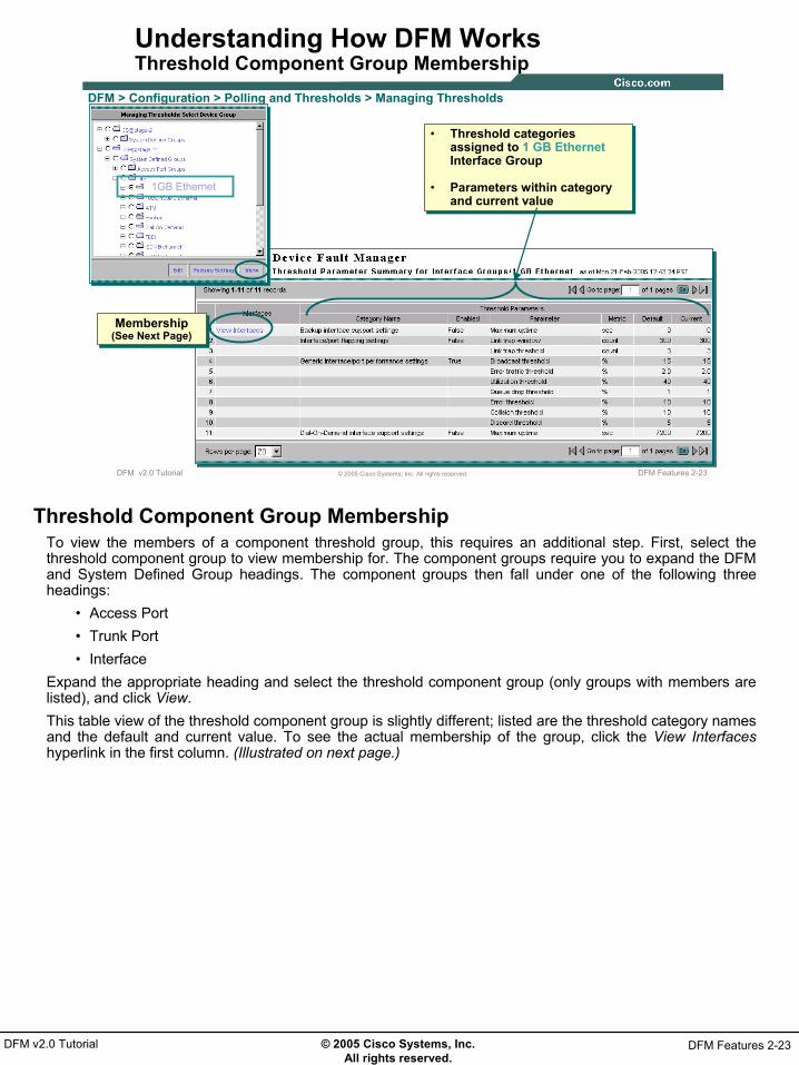
Understanding How DFM WorksThreshold Component Group Membership
DFM > Configuration > Polling and Thresholds > Managing Thresholds
Membership(See Next Page)Membership
(See Next Page)
• Threshold categories assigned to 1 GB EthernetInterface Group
• Parameters within category and current value
• Threshold categories assigned to 1 GB EthernetInterface Group
• Parameters within category and current value
1GB Ethernet
Threshold Component Group MembershipTo view the members of a component threshold group, this requires an additional step. First, select the threshold component group to view membership for. The component groups require you to expand the DFM and System Defined Group headings. The component groups then fall under one of the following three headings:
• Access Port• Trunk Port• Interface
Expand the appropriate heading and select the threshold component group (only groups with members are listed), and click View.This table view of the threshold component group is slightly different; listed are the threshold category names and the default and current value. To see the actual membership of the group, click the View Interfaceshyperlink in the first column. (Illustrated on next page.)

© 2005 Cisco Systems, Inc. All rights reserved.
DFM Features 2-24DFM v2.0 Tutorial
DFM Features 2-24© 2005 Cisco Systems, Inc. All rights reserved.DFM v2.0 Tutorial
Understanding How DFM WorksThreshold Component Group Membership Continue …
Interfaces in the 1 GB EthernetInterface Threshold Group
Interfaces in the 1 GB EthernetInterface Threshold Group
Threshold Component Group Membership(Cont)Selecting the View hyperlink causes a new window to be displayed listing the devices and their interfaces or ports that are members of this threshold component group.

© 2005 Cisco Systems, Inc. All rights reserved.
DFM Features 2-25DFM v2.0 Tutorial
DFM Features 2-25© 2005 Cisco Systems, Inc. All rights reserved.DFM v2.0 Tutorial
Understanding How DFM WorksModifying Thresholds
DFM > Configuration > Polling and Thresholds > Managing Thresholds
Threshold Category
Parameters
Threshold Category
Parameters
Enable/Disable Threshold Categories assigned to
selected Group
Enable/Disable Threshold Categories assigned to
selected Group
After modifying values changes must be applied using the Configuration > Polling
and Thresholds > Apply Changes task
After modifying values changes must be applied using the Configuration > Polling
and Thresholds > Apply Changes task
1GB Ethernet
Modifying ThresholdsLike the modification of the polling parameters there may come a time when the network administrator deems it necessary to modify the threshold parameters for one of the threshold groups. Using the Managing Thresholds task, select the threshold group to modify and click Edit. Change the values as necessary and save them. Before these changes take effect, the user must run the Apply Changes task. Notice that the Managing Thresholds task also has a Factory Setting button to return threshold settings to their original value.

© 2005 Cisco Systems, Inc. All rights reserved.
DFM Features 2-26DFM v2.0 Tutorial
DFM Features 2-26© 2005 Cisco Systems, Inc. All rights reserved.DFM v2.0 Tutorial
Understanding How DFM WorksCreating Custom Groups
What if you want to poll/threshold routers differently (i.e. critical vs. normal)?What if you want to poll/threshold routers differently (i.e. critical vs. normal)?
User-defined Customizable
Groups
User-defined Customizable
Groups
DeviceDevice Trunk PortTrunk PortInterfaceInterfaceAccess PortAccess Port
Customizable Group 1Customizable Group 2Customizable Group 3Customizable Group 4Customizable Group ACustomizable Group BCustomizable Group C
Customizable Group 1Customizable Group 2Customizable Group 3Customizable Group 4Customizable Group ACustomizable Group BCustomizable Group C
Customizable Group 1Customizable Group 2Customizable Group 3Customizable Group 4Customizable Group ACustomizable Group BCustomizable Group C
Customizable Group 1Customizable Group 2Customizable Group 3Customizable Group 4Customizable Group ACustomizable Group BCustomizable Group C
Polling & ThresholdsPolling & Thresholds ThresholdsThresholds ThresholdsThresholds ThresholdsThresholds
For each Group Type, DFM provides 7 customizable groups
Creating Custom GroupsThe basic scheme for managing device works fine in a network where all devices are considered equally as important, but what happens if you need to troubleshoot a device or want to manage one set of routers differently. DFM provides for this case through the use of Customizable Groups. Basically, the devices and/or components that you wish to manage differently are put into there own custom group and then the polling and threshold parameters for the custom group can be modified to meet the management needs.Customizable groups are the only user-defined groups for which you can set polling and threshold parameters. They are provided so you can create groups that fit your needs. DFM provides 28 customizable groups, which are divided into four categories:
• Device• Access port• Interface• Trunk port
DFM includes 7 customizable groups for each of these groups. 3 customizable groups (A, B, and C) are for troubleshooting single devices or components, and 4 of them (1, 2, 3, and 4) are for customizing polling and thresholds for multiple devices and/or components. These groups are found under the User-Defined Group heading of a group selector. These groups cannot be deleted or cannot have their names changed.To create and use custom groups, follow these steps and the upcoming pages in this chapter:
1. Select a customization group name2. Populate the group with devices and/or components3. Modify the polling and/or thresholds for the group4. Finally, change the priority of the customizable group to be higher than the member devices system
defined (or default) group

© 2005 Cisco Systems, Inc. All rights reserved.
DFM Features 2-27DFM v2.0 Tutorial
DFM Features 2-27© 2005 Cisco Systems, Inc. All rights reserved.DFM v2.0 Tutorial
Understanding How DFM WorksSelect a Customizable Group and Add Devices
DFM > Configuration > Other Configurations > Group Administration
Launches wizard to create membership in a Custom Group
Launches wizard to create membership in a Custom Group
Select a Customizable Group and Add DevicesWhen using the Group Administration task (see Chapter 3 for a usage example), the group selector includes a User-Defined Group heading. Under this heading will be the 4 basic group types and 7 customizable groups under it. Select the Customizable Group to populate and follow the wizard to populate with members. Since these groups cannot be created or deleted, use the Edit button to populate the group.

© 2005 Cisco Systems, Inc. All rights reserved.
DFM Features 2-28DFM v2.0 Tutorial
DFM Features 2-28© 2005 Cisco Systems, Inc. All rights reserved.DFM v2.0 Tutorial
Understanding How DFM WorksModify Polling/Threshold Parameters for Custom Group
Use appropriate task to modify polling and/or
thresholds for customizable group
Use appropriate task to modify polling and/or
thresholds for customizable group
DFM > Configuration > Polling and Thresholds > Polling Parameters
Select Factory Settings to reset values back to the original DFM values
Select Factory Settings to reset values back to the original DFM values
DFM > Configuration > Polling and Thresholds > Managing Thresholds
Modify Polling/Threshold Parameters for Custom GroupAfter populating the customizable group, the next step is to modify the polling and threshold values. This is done as explained earlier, but instead of selecting one of the System Defined Groups, select the appropriate Customizable Group. Note(s):
• The Customizable Groups are displayed in the group selector once they have at least one member in the group.
• Factory Settings will reset the values back to the original DFM settings.

© 2005 Cisco Systems, Inc. All rights reserved.
DFM Features 2-29DFM v2.0 Tutorial
DFM Features 2-29© 2005 Cisco Systems, Inc. All rights reserved.DFM v2.0 Tutorial
Understanding How DFM WorksSet Priority for Custom Group
Since members can now belong to more than one group, which values are used?
Since members can now belong to more than one group, which values are used?
DFM > Configuration > Polling and Thresholds > Setting Priorities
Move groups up or down to determine
priority (higher up in list equals
higher priority)
Move groups up or down to determine
priority (higher up in list equals
higher priority)
Select group type to change priority for
Select group type to change priority for
After modifying values changes must be applied using the Configuration > Polling
and Thresholds > Apply Changes task
After modifying values changes must be applied using the Configuration > Polling
and Thresholds > Apply Changes task
Setting Priority for Custom GroupThe astute reader will realize that the device or component in the customizable group will now be a member of at least two groups, so how does DFM determine to use the new polling/threshold settings for the devices in the Customizable Group instead of the polling/threshold settings for the devices original System Defined Group? DFM achieves this by assigning priority to each of the groups. So by making the priority of the Customizable Group higher than the priority of the devices original System Defined Group, DFM will manage the devices using the parameters for the Customizable Group instead.

© 2005 Cisco Systems, Inc. All rights reserved.
DFM Features 2-30DFM v2.0 Tutorial
DFM Features 2-30© 2005 Cisco Systems, Inc. All rights reserved.DFM v2.0 Tutorial
Understanding How DFM WorksPriority Verification
nmtg-hq-core-3725.cisco.com is a member of the Routers device group and Customizable Group 1, but DFM will use settings found in Customizable
Group 1 since it is a higher priority group
nmtg-hq-core-3725.cisco.com is a member of the Routers device group and Customizable Group 1, but DFM will use settings found in Customizable
Group 1 since it is a higher priority group
View Overriding Group
Priority VerificationTo verify this fact, once the priority has been altered and the changes have been applied, go back to the membership for the original system group. Since the devices placed in the Customizable Group are still members of this system group they will be listed as members. However, since they belong to two groups and the Customizable Group has higher priority, the Overriding Group for these devices will be the Customizable Group. Meaning that even though these devices are members of the displayed system group, the will be analyzed by DFM using the parameters of the Customizable Group.
© 2005 Cisco Systems, Inc. All rights reserved.
DFM Features 2-31DFM v2.0 Tutorial
Thank You!
This completes a quick look at the features of DFM. Continue on to Chapter 3 where most of these features can be seen in the context of real world examples.

© 2005 Cisco Systems, Inc. All rights reserved.
DFM Features 2-32DFM v2.0 Tutorial
<Intentionally left blank>

© 2005 Cisco Systems, Inc. All rights reserved.
Scenarios 3-1DFM v2.0 Tutorial
Chapter 3Chapter 3
DFM ScenariosDFM Scenarios

© 2005 Cisco Systems, Inc. All rights reserved.
Scenarios 3-2DFM v2.0 Tutorial
Scenarios 3-2© 2005 Cisco Systems, Inc. All rights reserved.DFM v2.0 Tutorial
DFM Scenarios
• Getting Started• Preparing DFM for Use• Customization
– Custom Group– Custom Polling– Alert View– Notification
• Alerts & Activities
DFM ScenariosAs Chapters 1 and 2 demonstrated, DFM monitors network faults right out of the box - no rules to create. Once the Device and Credentials Repository (DCR) is populated, DFM by default, will begin monitoring all DCR devices. In this Chapter, the use of DFM will be demonstrated through a series of simple scenarios. The first two scenarios are directed at the administrative user in charge of getting DFM ready. The remaining scenarios will look at how to customize DFM for more targeted fault monitoring.To enhance the effectiveness of the chapter as a learning resource, the reader is encouraged to follow along on an operational system, and to explore the other function options not covered in detail by this tutorial. It would also be wise to view the help screens associated with all functions to better understand the many different options available for most tasks. Launch the content sensitive help by selecting the Help link in the upper right-hand corner of the DFM desktop.

© 2005 Cisco Systems, Inc. All rights reserved.
Scenarios 3-3DFM v2.0 Tutorial
Getting StartedGetting Started
Getting Started
• Preparing DFM for Use
• Customization
• Alerts & Activities

© 2005 Cisco Systems, Inc. All rights reserved.
Scenarios 3-4DFM v2.0 Tutorial
Scenarios 3-4© 2005 Cisco Systems, Inc. All rights reserved.DFM v2.0 Tutorial
Getting Started
• Server Access
• Permissions Review
• Navigation
• Device Management– Adding Devices
Getting StartedIn this first scenario, the user will first learn how to access the server. This will be followed by a review on CiscoWorks user permissions and how they effect the look and use of DFM. Note: More information on user permissions and security in general can be found in the Common Services user guide. Before actually beginning to use DFM, the navigation and layout of DFM will be discussed. Finally, this section will show the reader how to add devices from the Device Central Repository (DCR) to the DFM list of devices to be managed.

© 2005 Cisco Systems, Inc. All rights reserved.
Scenarios 3-5DFM v2.0 Tutorial
Scenarios 3-5© 2005 Cisco Systems, Inc. All rights reserved.DFM v2.0 Tutorial
Getting StartedServer Access
http://<server-name or IP address>:1741
Launch DFM main window or
directly to a DFM task
Launch DFM main window or
directly to a DFM task
CiscoWorks Homepage
CiscoWorks Homepage
Applications registered with
CiscoWorks home page
Applications registered with
CiscoWorks home page
Login
usernamepassword
Server AccessAccessing the CiscoWorks server is easy, simply enter the server’s DNS name or IP address followed by the http port being used (port 1741 is used by default during installation) as a URL in a standard browser (see Chapter 4 for complete client requirements):
http://<server-name or IP address>:1741The CiscoWorks login banner will be displayed. The left-hand side of the banner will display the results of a requirements check against the browser being used.To access the CiscoWorks home-page, enter your User ID and password provided by the CiscoWorksadministrator and select Login. The CiscoWorks home-page will be displayed. The home-page will display the different CiscoWorks applications registered for use. Find the DFM listing and click on the DFM header to take you to DFM in general, or selected one of the DFM tasks listed to launch DFM to the screen for the selected task. Before looking at the DFM desktop, lets briefly review CiscoWorks user permissions.Note: For more information on the CiscoWorks homepage layout and configuration see the “Common Services” user guide.

© 2005 Cisco Systems, Inc. All rights reserved.
Scenarios 3-6DFM v2.0 Tutorial
Scenarios 3-6© 2005 Cisco Systems, Inc. All rights reserved.DFM v2.0 Tutorial
Getting StartedPermissions Review – User Roles
• User Roles determine tasks that can be performed by user
• User can be assigned more than 1 user role
System All DFM TasksAdministrator
Network All DFM tasks except configuring SNMP,Administrator Rediscovery, Polling & Thresholds, and Trap
Forwarding and Receiving
Network All DFM tasks except configuring SNMP,Operator Rediscovery, Polling & Thresholds, Groups, and
Trap Forwarding and Receiving
Approver View Alerts and Activities and Fault History
Help Desk View Alerts and Activities and Fault History
• Tasks displayed change depending on users assigned roles
Permissions Review - User RolesMany DFM tasks are used to modify the behavior of DFM and can have an impact on the amount of network traffic and load placed on a device. Therefore, it would not be wise to allow all types of users access to thesecritical functions, but at the same time it would be beneficial to allow all types of users access to all the basic information. To allow for proper access to all types of users, CiscoWorks employs the concept of User Roles (also known as user privileges or permissions). Use of the various functions or tasks within all CiscoWorks applications is based upon the “roles” assigned to a user account. In fact, if a task is not permitted to the user role assigned to the logged in user, then that task will not even be displayed in the navigation tree of the application.CiscoWorks uses five basic User Roles; users can be assigned more than one user role, and all are assigned the basic user role – Help Desk. The five user roles and their basic access ability for DFM are:System Administrator – All DFM applicationsNetwork Administrator – All DFM applications except for tasks used to configure SNMP, polling and thresholds, device rediscovery, and trap forwarding.Network Operator – Same as Network Administrator except the Network Operator also can not configure groups.Approver – View onlyHelp Desk – View only

© 2005 Cisco Systems, Inc. All rights reserved.
Scenarios 3-7DFM v2.0 Tutorial
Scenarios 3-7© 2005 Cisco Systems, Inc. All rights reserved.DFM v2.0 Tutorial
Getting StartedPermissions Review – Permissions Report
User RolesUser Roles
Permission to perform tasks are based on
CiscoWorks or ACS user roles
Permission to perform tasks are based on
CiscoWorks or ACS user roles
Launch Permission Report from:Common Services > Server > Reports > Permission ReportLaunch Permission Report from:Common Services > Server > Reports > Permission Report
Permissions ReportTo view the details of which DFM tasks (as well as all other CiscoWorks applications) are available to each user role type, view the Permissions Report. To launch the Permissions Report:
1. From the CiscoWorks Home Page, Click on the Common Services applicationThe Common Services Desktop is displayed
2. Click on the Server tab3. From the listed options for the tab, click on the Reports option4. From the displayed dialog box select Permissions Report and then click Generate Report
The Permissions Report lists every CiscoWorks application and the tasks for that application and indicates which user role is capable of executing it. To determine the user role(s) assigned to your user account, review your account by selecting Common Services > Server > Security > Single Server Management >Local User Setup.Note: Consult the “Common Services User Guide” for more information on creating CiscoWorks users and limiting their scope of use.

© 2005 Cisco Systems, Inc. All rights reserved.
Scenarios 3-8DFM v2.0 Tutorial
Scenarios 3-8© 2005 Cisco Systems, Inc. All rights reserved.DFM v2.0 Tutorial
Getting StartedNavigation – DFM Layout
Each tab represents a different DFM function and contains numerous tasksEach tab represents a different DFM
function and contains numerous tasks
The available options for the
selected tab
The available options for the
selected tab
Table of Contents
(TOC) displays submenu for
selected option
(Note: not all options have a
TOC)
Table of Contents
(TOC) displays submenu for
selected option
(Note: not all options have a
TOC)
Navigation bar lists the
current task
Navigation bar lists the
current task
Content for selected task(Note task may
open in separate window)
Content for selected task(Note task may
open in separate window)
Note: listed tasks depend on the users privileges
Note: listed tasks depend on the users privileges
Navigation – DFM LayoutPrior to the brief tangent to discuss user roles and privileges, the DFM desktop was launched from the CiscoWorks Home Page. Before actually using DFM, it would be beneficial to discuss the basic layout to help you understand how to navigate through DFM.All CiscoWorks applications employ identical user interfaces and layouts to minimize the burden of learning a different interface for each application within the suite of tools. The DFM desktop appears as a series of folders representing the major task categories within DFM. The contents of these folders are accessible by selecting the appropriate folder tab. The currently selected folder is identifiable by the different color of the tab and it’s text. Immediately under the tabs are the options associated with the selected major task category. Notice that this bar is the same color as the selected tab helping to further identify which tab is selected. To select one of these options, simply click on it. The selected option will be in bold text. At this point, the selected option may have a dialog box associated with it, which will be displayed in the content area. The selected option may also have sub-tasks associated with it. These will be listed in a table of content dialog on the left-hand side of the screen. Again, to select one of the sub tasks, simply click it and it’s text will now become bold to identify it as the selected task.When the selected task has no further sub-tasks, a dialog box with further instruction or simply displaying the requested information will be shown in the content display area. To determine where the user currently is, the display line (appropriately titled “You Are Here”) under the tab options indicates the path currently selected.Note: Review the section tilted “How does DFM Work” in Chapter 2 to understand how various devices are grouped and selected for various tasks.Note: To help reduce the number of pages in this tutorial, the entire desktop is not always shown. To facilitate the user in understanding what task is being displayed, the following notation is used to represent the options clicked: application > option > task > sub-task. For example to access the Alerts and Activities display, the user would be in the DFM application, click the Alerts and Activities tab and then click the Alerts and Activities option or DFM > Alerts and Activities > Alerts and Activities.
© 2005 Cisco Systems, Inc. All rights reserved.
Scenarios 3-9DFM v2.0 Tutorial
Scenarios 3-9© 2005 Cisco Systems, Inc. All rights reserved.DFM v2.0 Tutorial
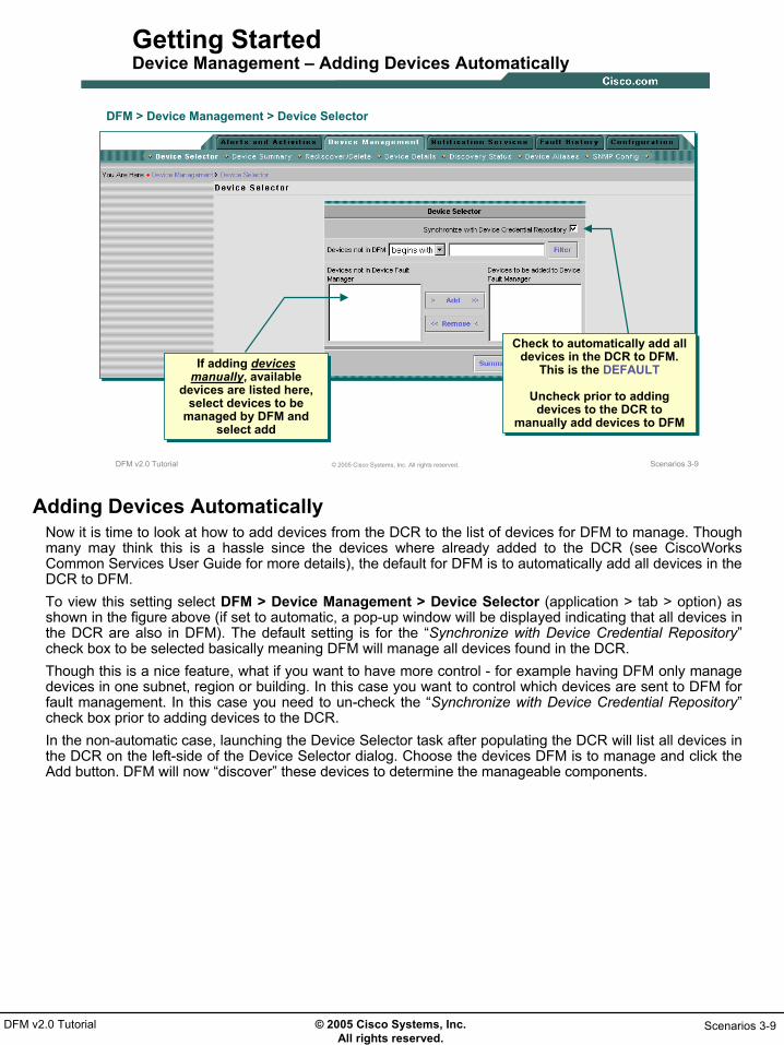
Getting StartedDevice Management – Adding Devices Automatically
Check to automatically add all devices in the DCR to DFM.
This is the DEFAULT
Uncheck prior to adding devices to the DCR to
manually add devices to DFM
Check to automatically add all devices in the DCR to DFM.
This is the DEFAULT
Uncheck prior to adding devices to the DCR to
manually add devices to DFM
If adding devices manually, available
devices are listed here, select devices to be
managed by DFM and select add
If adding devices manually, available
devices are listed here, select devices to be
managed by DFM and select add
DFM > Device Management > Device Selector
Adding Devices AutomaticallyNow it is time to look at how to add devices from the DCR to the list of devices for DFM to manage. Though many may think this is a hassle since the devices where already added to the DCR (see CiscoWorks Common Services User Guide for more details), the default for DFM is to automatically add all devices in the DCR to DFM. To view this setting select DFM > Device Management > Device Selector (application > tab > option) as shown in the figure above (if set to automatic, a pop-up window will be displayed indicating that all devices in the DCR are also in DFM). The default setting is for the “Synchronize with Device Credential Repository” check box to be selected basically meaning DFM will manage all devices found in the DCR.Though this is a nice feature, what if you want to have more control - for example having DFM only manage devices in one subnet, region or building. In this case you want to control which devices are sent to DFM for fault management. In this case you need to un-check the “Synchronize with Device Credential Repository” check box prior to adding devices to the DCR. In the non-automatic case, launching the Device Selector task after populating the DCR will list all devices in the DCR on the left-side of the Device Selector dialog. Choose the devices DFM is to manage and click the Add button. DFM will now “discover” these devices to determine the manageable components.

© 2005 Cisco Systems, Inc. All rights reserved.
Scenarios 3-10DFM v2.0 Tutorial
Scenarios 3-10© 2005 Cisco Systems, Inc. All rights reserved.DFM v2.0 Tutorial
Getting StartedDevice Management – Result of Adding Devices
DFM > Device Management > Device Summary
DFM > Device Management > Discovery Status
List current state of added devices
List current state of added devices
List status of added devices and last discovery time
List status of added devices and last discovery time
Result of Adding DevicesTo see the results of the device adding operation whether the devices are automatically or manually added use one of the following tasks:
1. Select DFM > Device Management > Device SummaryThe Device Summary is displayed indicating the current state of all devices. Ideally all devices should eventually be in the Known State meaning DFM was at least able to contact them using an SNMP read operation. The Learning State would indicate the add operation is still in progress.
or1. Select DFM > Device Management > Discovery Status
The Discovery Status is displayed indicating the current state of all devices, current processing of device, and the time the device was last discovered.
Device States: Known -The device has been successfully imported, and is fully managed by DFM. Learning - DFM is discovering the device. This is the beginning state, when the device is first added or is being rediscovered. Some of the data collectors may still be gathering device information. Questioned - DFM cannot manage the device. Pending - The device is being deleted. (DFM is waiting for confirmation from all of its data collectors before purging the device and its details.) Unknown - The device is not supported by DFM.

© 2005 Cisco Systems, Inc. All rights reserved.
Scenarios 3-11DFM v2.0 Tutorial
Preparing DFM for UsePreparing DFM for Use
• Getting Started
Preparing DFM for Use
• Customization
• Alerts & Activities
© 2005 Cisco Systems, Inc. All rights reserved.
Scenarios 3-12DFM v2.0 Tutorial
Scenarios 3-12© 2005 Cisco Systems, Inc. All rights reserved.DFM v2.0 Tutorial
Preparing DFM for Use
• Rediscovery Schedule
• SNMP Settings
• Trap Receiving
• Trap Forwarding
Preparing DFM for UseEven though DFM was ready for use pretty much right after devices were added to the DCR, this scenario looks at additional administration type functions to perform to both help keep DFM up-to-date and to make it more effective to use.The first portion of the scenario will look at keeping DFM processing up-to-date by ensuring DFM is made aware of any changes to the devices it is managing. This is followed by some other basic configurations for retrieving and forwarding data.

© 2005 Cisco Systems, Inc. All rights reserved.
Scenarios 3-13DFM v2.0 Tutorial
Scenarios 3-13© 2005 Cisco Systems, Inc. All rights reserved.DFM v2.0 Tutorial
Preparing DFM for Use Rediscovery Schedule
DFM > Configuration > Other Configurations > Rediscovery Schedule
Default discovery schedule performs
weekly rediscovery that cannot be modified but
can be suspended
Default discovery schedule performs
weekly rediscovery that cannot be modified but
can be suspended
Rediscovery probes devices to discover their configuration and verify
their manageable elements
Rediscovery probes devices to discover their configuration and verify
their manageable elements
Add additional rediscovery schedules if desired
Add additional rediscovery schedules if desired
Rediscovery ScheduleAs discussed in Chapter 2 - How does DFM Work, DFM “discovers” each device to determine themanageable components it contains. DFM can then assign appropriate polling and threshold parameters. In order to ensure DFM monitoring of a device is up-to-date, the device needs to be “re-discovered” on a periodic basis. DFM comes pre-configured with a weekly task to perform a re-discovery. This task can not be changed or deleted but can be suspended. If the administrator feels it necessary to perform this at a different time or more often, additional re-discovery tasks can be created using the following steps:
1. Select DFM > Configuration > Other Configurations > Rediscovery Schedule2. The Rediscovery Schedule dialog is displayed and shows the default schedule. Select Add to create
a new scheduled re-discovery.3. The Rediscovery Schedule: Add dialog is displayed. Enter a Schedule Name, Frequency, and Start
Date and Time.4. Click the Next> button at the bottom of the display.5. A summary of the newly configured schedule is displayed, click Finish to have it take effect.
An on-demand rediscovery can also be performed for selected devices by using the DFM > Device Management > Rediscover/Delete Devices task.
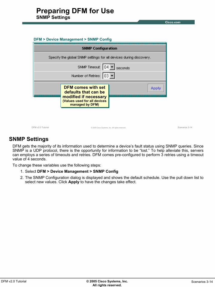
© 2005 Cisco Systems, Inc. All rights reserved.
Scenarios 3-14DFM v2.0 Tutorial
Scenarios 3-14© 2005 Cisco Systems, Inc. All rights reserved.DFM v2.0 Tutorial
Preparing DFM for Use SNMP Settings
DFM > Device Management > SNMP Config
DFM comes with set defaults that can be
modified if necessary(Values used for all devices
managed by DFM)
DFM comes with set defaults that can be
modified if necessary(Values used for all devices
managed by DFM)
SNMP SettingsDFM gets the majority of its information used to determine a device’s fault status using SNMP queries. Since SNMP is a UDP protocol, there is the opportunity for information to be “lost.” To help alleviate this, servers can employs a series of timeouts and retries. DFM comes pre-configured to perform 3 retries using a timeout value of 4 seconds.To change these variables use the following steps:
1. Select DFM > Device Management > SNMP Config2. The SNMP Configuration dialog is displayed and shows the default schedule. Use the pull down list to
select new values. Click Apply to have the changes take effect.

© 2005 Cisco Systems, Inc. All rights reserved.
Scenarios 3-15DFM v2.0 Tutorial
Scenarios 3-15© 2005 Cisco Systems, Inc. All rights reserved.DFM v2.0 Tutorial
Preparing DFM for Use Trap Receiving
DFM > Configuration > Other Configurations > SNMP Trap Receiving
Enable Trapsand Send to DFM
Enable Trapsand Send to DFM
DFMTRAPS
SNMP traps use UDP port 162 by default. If another app is already using the
port, DFM can be modified to listen on another port
SNMP traps use UDP port 162 by default. If another app is already using the
port, DFM can be modified to listen on another port
Use this task to modify the trap port DFM listens to if
necessary
Use this task to modify the trap port DFM listens to if
necessary
Trap ReceivingAnother major source of information DFM uses to determine faults is SNMP traps. The standard SNMP trap port is UDP 162. Unfortunately, only one application on a server can be set up to listen and retrieve information from this port. Therefore, if the server has multiple trap receivers installed, they must each use a different port for trap receiving. During installation DFM will detect if any other application is using port 162. If so, DFM will use port 9000 as the trap port. Devices must be configured accordingly to forward traps to that port; else port 162 is used.The DFM > Configuration > Other Configuration > SNMP Trap Receiving task can be used to change the trap receiving port if necessary. Simply enter the new port number and click Apply to have it take effect.

© 2005 Cisco Systems, Inc. All rights reserved.
Scenarios 3-16DFM v2.0 Tutorial
Scenarios 3-16© 2005 Cisco Systems, Inc. All rights reserved.DFM v2.0 Tutorial
Preparing DFM for Use Trap Forwarding
DFM > Configuration > Other Configurations > SNMP Trap Forwarding
By default, DFM does not forward
unprocessed (pass-through) SNMP traps.
By default, DFM does not forward
unprocessed (pass-through) SNMP traps.
Use this task to configure DFM to
forward unprocessed traps. All traps are
forwarded in V1 format.
Use this task to configure DFM to
forward unprocessed traps. All traps are
forwarded in V1 format.
Trap ForwardingDFM is not considered a general trap receiver, in fact, it is very specific in the types of traps it will process. If devices are configured to send traps to DFM only, DFM must be configured to forward the traps on to a general trap receiver like HP OpenView. DFM will inform the user that an unidentified trap was received by displaying an Alert on the Alerts and Activities display, but will not provide any additional information.To forward “pass-through” and “unidentified” traps use the following steps:
1. Select DFM > Configuration > Other Configurations > SNMP Trap Forwarding2. The SNMP Trap Forwarding dialog is displayed. Enter the DNS host name or IP address of the
server to forward the traps to and the port to be used. Click Apply to have the changes take effect.Note: This task is not to be confused with the Trap Notification Service which forwards DFM Alerts as traps.As shown in these two scenarios, DFM set-up is a snap. In fact, other than adding devices to the DCR, DFMis already monitoring devices for faults without any administrative effort. The next scenario will show how to customize DFM for more specific monitoring.

© 2005 Cisco Systems, Inc. All rights reserved.
Scenarios 3-17DFM v2.0 Tutorial
CustomizationCustomization
• Getting Started
• Preparing DFM for Use
Customization
• Alerts & Activities

© 2005 Cisco Systems, Inc. All rights reserved.
Scenarios 3-18DFM v2.0 Tutorial
Scenarios 3-18© 2005 Cisco Systems, Inc. All rights reserved.DFM v2.0 Tutorial
Customization
• Custom Group– Polling
– Thresholds
– Priority
• Alert View
• Notification
CustomizationIn its most basic form, use of DFM is simply looking at the discovered alerts and their details. This section will look at how to customize DFM so that devices of the same type are polled and/or evaluated (thresholds) differently from similar devices. Also, DFM will be customized to allow for the viewing and automatic notification based on alerts and/or events from specific devices.

© 2005 Cisco Systems, Inc. All rights reserved.
Scenarios 3-19DFM v2.0 Tutorial
Scenarios 3-19© 2005 Cisco Systems, Inc. All rights reserved.DFM v2.0 Tutorial
Customization Create Custom Device Group
We need to monitor the core
routers more frequently the the
other routers
Let’s start by creating a
new device group
Select Customizable Group 1 to create a new
device group(Remember polling is done
by device group)
Select Customizable Group 1 to create a new
device group(Remember polling is done
by device group)
DFM > Configuration > Other Configurations > Group Administration
Customizable Groups can only be edited and not created or deleted
Customizable Groups can only be edited and not created or deleted
Create Custom Device GroupFor the remained of this chapter, we introduce Ted, the IT manager for east coast operations of a large firm and one of his brightest engineers Sally. The company was always in a reactive mode when it came to management of the network and Sally convinced Ted to purchase and install CiscoWorks to help them work more efficiently. As part of the CiscoWorks roll out, Ted wants to test the features of DFM against the core routers as they are the most critical in the network by increasing the polling frequency and lowering the thresholds on numerous utilization based variables. Sally has previously populated the DCR with a number of devices.The first order of business is to make a new group to contain the core routers. Remember, polling of devices is based upon device groups. The system default group, Routers, will poll all routers the same, therefore, a new device group must be created in order to change polling behavior for the core routers.Sally uses the following steps to create a new device group containing the core routers:
1. Select DFM > Configuration > Other Configurations > Group Administration. The Group Administration and Configuration dialog is displayed.
2. The dialog contains a Group Selector used to determine the parent of a new group or to select an existing group to edit. In this case, Sally is actually going to edit an existing group (new device groups are actually just an edit of one of the 7 customizable device groups). Sally expands the DFM, User Defined, and Customizable Groups entries and selects Customizable Group 1. Information about this group is displayed on the right side of the dialog.
3. Click Edit to perform the next step.

© 2005 Cisco Systems, Inc. All rights reserved.
Scenarios 3-20DFM v2.0 Tutorial
Scenarios 3-20© 2005 Cisco Systems, Inc. All rights reserved.DFM v2.0 Tutorial
Customization Create Custom Device Group (Continue …)
Enter description, membership rules, and
visibility
Enter description, membership rules, and
visibility
Enter the rule(s) to determine membership
in the group
Enter the rule(s) to determine membership
in the group
Use pull down lists for all possible object
types, variables, and operators
Use pull down lists for all possible object
types, variables, and operators
Create Custom Device Group (Continue …)4. Step 1 of the Edit Group 4 step wizard is displayed. Use the first step to define properties of the
group. The name of the group can not be changed, therefore it is beneficial to add a meaningful description as to the contents and use of this group. Also determine how the membership of the group will be updated: automatically (device meets membership rules) or manually (user adds or deletes all members). Finally, determine the visibility scope of the group: All users versus currently logged in user only. Click Next > when finished editing the properties.
5. The second step of the wizard is used to enter the rules for membership (skipping this step will allow user to add members manually). Use the various drop down boxes to create the rule(s) that determine group membership. In this case, Sally selects the Object Type to be Routers, the Variableto be Name, the operator to be contains and the value to be core. Note that the variable depends on the object and not all variables require a value.
6. Click Add Rule Expression to add the rule. Click Next > when finished creating the membership rules.

© 2005 Cisco Systems, Inc. All rights reserved.
Scenarios 3-21DFM v2.0 Tutorial
Scenarios 3-21© 2005 Cisco Systems, Inc. All rights reserved.DFM v2.0 Tutorial
Customization Create Custom Device Group (Continue …)
Devices meeting rulesDevices meeting rules
Add or delete devices if necessary
Add or delete devices if necessary
Summary information for new group
Summary information for new group
Create Custom Device Group (Continue …)7. Step 3 of the wizard displays the devices meeting the rule criteria on the right side of the dialog. The
left side includes all the non matching devices. Devices can be added or deleted to the membership if desired and DFM will automatically create the appropriate rules. (If no rules where added during step 2 of the wizard, the right side of the dialog will be blank and the user can simple select the desired membership from the left hand side.) When membership is correct, click Next >.
8. Step 4 of the wizard displays a summary of the group. If all appears correctly, click Finish.Customizable Group 1 now contains the two core routers.

© 2005 Cisco Systems, Inc. All rights reserved.
Scenarios 3-22DFM v2.0 Tutorial
Scenarios 3-22© 2005 Cisco Systems, Inc. All rights reserved.DFM v2.0 Tutorial
Customization Create User-Defined Group
Next I need a group to use for the Alerts & Activities
display
Select User Defined Groups(User-defined miscellaneous group has no effect on polling and thresholds – used for alert viewing and
notifications only)
Select User Defined Groups(User-defined miscellaneous group has no effect on polling and thresholds – used for alert viewing and
notifications only)
DFM > Configuration > Other Configurations > Group Administration
Enter description, membership rules, and
visibility
Enter description, membership rules, and
visibility
Remaining steps exactly the same as
Creating the new group (rules, membership,
summary)
Remaining steps exactly the same as
Creating the new group (rules, membership,
summary)
Create User-Defined GroupBefore moving on to modify polling and threshold values for the Customizable Group 1, Sally wants to create an identical group containing the core routers as a miscellaneous user group which can then be used later on to create a new Alert view. The steps are identical as before except for the selection of the parent group –User-Defined and the group is to be created not edited.
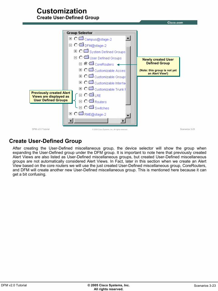
© 2005 Cisco Systems, Inc. All rights reserved.
Scenarios 3-23DFM v2.0 Tutorial
Scenarios 3-23© 2005 Cisco Systems, Inc. All rights reserved.DFM v2.0 Tutorial
Customization Create User-Defined Group
Previously created Alert Views are displayed as User Defined Groups
Previously created Alert Views are displayed as User Defined Groups
Newly created User Defined Group
(Note: this group is not yet an Alert View!)
Newly created User Defined Group
(Note: this group is not yet an Alert View!)
Create User-Defined GroupAfter creating the User-Defined miscellaneous group, the device selector will show the group when expanding the User-Defined group under the DFM group. It is important to note here that previously created Alert Views are also listed as User-Defined miscellaneous groups, but created User-Defined miscellaneous groups are not automatically considered Alert Views. In Fact, later in this section when we create an Alert View based on the core routers we will use the just created User-Defined miscellaneous group, CoreRouters, and DFM will create another new User-Defined miscellaneous group. This is mentioned here because it can get a bit confusing.

© 2005 Cisco Systems, Inc. All rights reserved.
Scenarios 3-24DFM v2.0 Tutorial
Scenarios 3-24© 2005 Cisco Systems, Inc. All rights reserved.DFM v2.0 Tutorial
Customization Edit Polling for Customizable Group
Next I need to modify the
polling parameters for the new
group
DFM > Configuration > Polling and Thresholds > Polling Parameters
Make them twice as often as
regular routers
Select group to edit(Note only customizable
groups with members are displayed)
Select group to edit(Note only customizable
groups with members are displayed)
Save and closeSave and close
Edit Polling for Customizable GroupNow that Customizable Group 1 has been populated with the core routers, the polling parameters associated with the group can be modified using the following steps:
1. Select DFM > Configuration > Polling and Thresholds > Polling Parameters. The Polling Parameters: Select Device Group dialog is displayed.
2. Only Device groups are displayed since polling parameters are associated with device groups. Sally expands the DFM, User-Defined, and Customizable Group entries to revel the entry for Customizable Group 1. Note that only Groups (Customizable or System Defined) with members are displayed. Select Customizable Group 1 and click Edit.
3. The Polling Parameters: Edit dialog is displayed. Ted wants Sally to change the polling of the core routers to be twice as often as the default. Sally simply enters the new interval for each parameter and clicks OK.
A pop-up window is displayed indicating that the new values have been saved but will not take effect until applied. Sally will wait to apply the changes until all changes have been made.

© 2005 Cisco Systems, Inc. All rights reserved.
Scenarios 3-25DFM v2.0 Tutorial
Scenarios 3-25© 2005 Cisco Systems, Inc. All rights reserved.DFM v2.0 Tutorial
Customization Edit Thresholds for Customizable Group
Next I need to modify the Threshold parameters for the new
group
Lower the CPU and memory
utilization thresholds
DFM > Configuration > Polling and Thresholds > Managing Thresholds
Select group to edit(Note only customizable
groups with members are displayed)
Select group to edit(Note only customizable
groups with members are displayed)
Save and closeSave and close
Saving does not Apply Changes
(Apply Changes when all are made)
Saving does not Apply Changes
(Apply Changes when all are made)
Edit Thresholds for Customizable GroupThresholds are configurable for each type of DFM group: Device, Access Port, Trunk Port, and Interface Port. In this case, a customizable group was only made for the core router devices, so the thresholds to edit will be device related. Customizable groups for the interfaces of the core routers could also be created and thresholds modified in the same basic manner. Sally uses the following steps to modify the thresholds associated with Customizable Group 1:1. Select DFM > Configuration > Polling and Thresholds > Managing Thresholds. The Managing
Thresholds: Select Device Group dialog is displayed.2. Only groups containing members are displayed. Sally expands the DFM, User-Defined, and
Customizable Group entries to revel the entry for Customizable Group 1. Select Customizable Group 1 and click Edit.
3. The Managing Thresholds: Edit dialog is displayed. Ted wants Sally to lower the thresholds for the utilization based parameters. From the Threshold Categories pull down menu, Sally one by one selects the different entries and modifies the appropriate threshold values. Before selecting the next Threshold Category, click Save. When all appropriate parameters have been modified, click OK.
A pop-up window is again displayed indicating that the new values have been saved but will not take effect until applied. Sally will wait to apply the changes until all changes have been made.

© 2005 Cisco Systems, Inc. All rights reserved.
Scenarios 3-26DFM v2.0 Tutorial
Scenarios 3-26© 2005 Cisco Systems, Inc. All rights reserved.DFM v2.0 Tutorial
Customization Modify Priority
DFM > Configuration > Polling and Thresholds > Setting Priorities
Next I need to change the polling
and threshold priority of the new group to be greater
than the router group
Move the Customizable group up above the
Router Group(Core Routers also belong
to this group)
Move the Customizable group up above the
Router Group(Core Routers also belong
to this group)
Save after each change
Save after each change
Modify PriorityDFM determines how to poll and apply threshold based on groups of the device and its components. A problem arises when a device or component belongs to more than one group. DFM handles this case by defining a priority hierarchy. A device or components will receive the polling/threshold parameters of the highest priority group it belongs to.Since the core routers now belong to two groups, Routers and Customizable Group 1, group priority will determine how DFM will process them. To determine and set group priorities use the following steps:
1. Select DFM > Configuration > Polling and Thresholds > Setting Priorities. The Setting Priorities: Queue dialog is displayed.
2. Select the Device Polling Group radio button to display the polling priorities. Note that the Routers group has higher priority than the Customizable Group 1 group. Therefore the core routers will be polled by DFM using the Router group polling parameters – not what Ted wants. Sally highlights the Customizable Group 1 entry and clicks the Up button until it is higher on the list than the Routers group. The core routers will now be polled using the polling parameters for the Customizable Group 1 instead of the Router group’s. All other routers will still use the Router groups polling parameters. Click Save to save the changes.
3. Select the Device Threshold Groups radio button to display the device threshold priorities. Again Routers is higher than Customizable Group 1. Highlight the Customizable Group 1 entry and click the Up button until it is higher on the list than the Routers group. The core routers will now use the threshold parameters for the Customizable Group 1 instead of the Router group’s. All other routers will still use the Router groups threshold parameters. Click Save to save the changes.
4. When finished modifying the priorities, click OK.A pop-up window is again displayed indicating that the new values have been saved but will not take effect until applied – the next step.

© 2005 Cisco Systems, Inc. All rights reserved.
Scenarios 3-27DFM v2.0 Tutorial
Scenarios 3-27© 2005 Cisco Systems, Inc. All rights reserved.DFM v2.0 Tutorial
Customization Apply Changes
Now I need to run the Apply Changes task to make then
take effect
DFM > Configuration > Polling and Thresholds > Apply Changes
Apply ChangesNow that Sally has made all the changes to DFM that will allow for the Core routers to be processed differently from other routers it is time to apply the changes using the following steps:
1. Select DFM > Configuration > Polling and Thresholds > Apply Changes. The Apply Changes dialog is displayed.
2. Select Yes to apply the changes.DFM is now processing the core routers according to the parameters associated with the Customizable Group 1.The following explains the difference between saving changes and applying changes: When you save changes, DFM performs the following tasks:
• Sets the polling and threshold settings of devices in the selected device group. • Sets the overriding group, based on the priorities of the groups to which devices belong.
When you apply changes, DFM performs the following tasks: • Recalculates group membership, based on group priority. • Uses the new polling and threshold settings to gather information from the devices.
Also use Apply Changes after changing the managed state of a device from False to True, so that DFM will begin polling the device using the appropriate settings.

© 2005 Cisco Systems, Inc. All rights reserved.
Scenarios 3-28DFM v2.0 Tutorial
Scenarios 3-28© 2005 Cisco Systems, Inc. All rights reserved.DFM v2.0 Tutorial
Customization Create New Alert View
DFM > Configuration > Other Configurations > Alert and Activities Defaults
Now I need to create an Alert View
to highlight these devices in the
Alerts & Activities display
Previously created viewsPreviously
created views
Select Core Routers User Defined Group created earlier
Select Core Routers User Defined Group created earlier
Create New Alert ViewEarlier Sally created a User-Defined group with the core routers as members. Sally can now use this group to create an Alert View that will allow viewers to only see Alerts associated with these devices from the Alert and Activities display. Sally uses the following steps to create a new Alert View for the core routers:
1. Select DFM > Configuration > Other Configurations > Alert and Activities Defaults. The Alert and Activities Views; View Management dialog is displayed listing any user-defined alert views and their status.
2. Select Create. The View Properties: Create dialog is displayed. Enter a Name (must be different from any current user-defined group’s name since this activity actually creates a new user-defined group), a Description, and a device group (CoreRouters created earlier) to determine Alert View membership (note that individual devices cannot be selected only groups, hence the reason for creating the user-defined view earlier). Click Next > when done entering properties.
3. The View Summary: Create dialog is displayed showing the details of the Alert View. Click Finish.

© 2005 Cisco Systems, Inc. All rights reserved.
Scenarios 3-29DFM v2.0 Tutorial
Scenarios 3-29© 2005 Cisco Systems, Inc. All rights reserved.DFM v2.0 Tutorial
Customization Create New Alert View (Continue …)
DFM > Configuration > Other Configurations > Alert & Activities Defaults
Now I need to Activate the new
view
Select view to Activate
Select view to Activate
Create New Alert View (Continue …)4. The Alert and Activities Views; View Management dialog is again displayed this time listing the newly
created Alert View with a status of Inactive. Highlight the new Alert View and click Activate to change the Alert View’s status. Select Yes to the Confirm window pop-up.

© 2005 Cisco Systems, Inc. All rights reserved.
Scenarios 3-30DFM v2.0 Tutorial
Scenarios 3-30© 2005 Cisco Systems, Inc. All rights reserved.DFM v2.0 Tutorial
Customization Notification – Create Event Set
First let me define the
Email server, then
create an Event Set
Let’s inform Jack and Sam by email whenever
utilization events are detected on these
devices
DFM > Configuration > Other Configurations > SMTP Default Server
DFM > Notification Services > Event Sets
9 possible Event Sets, select desired events to be included in each set
9 possible Event Sets, select desired events to be included in each set
Notification – Create Event SetThe core routers are now being processed by DFM using the new polling and threshold parameters for Customizable Group 1. Ted wants DMF to inform Jack and Sam via e-mail whenever DFM detects a utilization event on the core routers.Sally will configure the DFM Notification Services to meet Ted’s demand. She decides to first configure the default E-mail server:
1. Select DFM > Configuration > Other Configurations > SMTP Default Server. The Default SMTP Server dialog is displayed.
2. Enter the Email server DNS name or IP address and click Apply.Notifications are issued based on a set of events and alert status for a given set of devices. In this case, a user-define group already exists containing the core routers. The next step is to then create an Event Set that contains the utilization based events:
1. Select DFM > Notification Services > Event Sets. The Event Sets dialog is displayed.2. Up to 9 Event Sets can be created. An Event Set consists of one or more Events. Sally configures
Event Set A by checking the various utilization based events according to Ted’s wishes.3. Click Apply when done configuring Event Sets.

© 2005 Cisco Systems, Inc. All rights reserved.
Scenarios 3-31DFM v2.0 Tutorial
Scenarios 3-31© 2005 Cisco Systems, Inc. All rights reserved.DFM v2.0 Tutorial
Customization Notification – Create Notification Group
Next I create the
Notification Group
DFM > Notification Services > Notification Groups
Select devices using previously created group
Select devices using previously created group
Select previously created Event Set
Select previously created Event Set
Notification – Create Notification GroupNow that both a device group and event set exist that meet Ted’s directive, the next step is to create a Notification Group that ties all the components together. Again, Ted wants Jack and Sam informed whenever an utilization based event is detected by DFM on one of the core routers. Sally uses the following steps to create the desired Notification Group:
1. Select DFM > Notification Services > Notification Groups. The Notification Group(s) dialog is displayed listing any existing Notification Groups.
2. Select Add to create a new Notification Group. The Notification Group Save: Add 3 step dialog is displayed. Use this dialog to configure the three components of a notification group: Devices, Alert Severity/Status, and Events.
3. Sally expands the DFM and User Define groups in the Group Selector on the left side of the dialog and selects the CoreRouters device group. Next she selects any Critical and Active Alerts, selects Event Set A (previously configured to contain the utilization based events) with severity Critical or Warning, and wants notification to occur whenever these events go active or are cleared.
4. Click Next > to continue.

© 2005 Cisco Systems, Inc. All rights reserved.
Scenarios 3-32DFM v2.0 Tutorial
Scenarios 3-32© 2005 Cisco Systems, Inc. All rights reserved.DFM v2.0 Tutorial
Customization Notification – Create Notification Group (Continue …)
Enter a name for the notification group and additional identifying information if desired
Enter a name for the notification group and additional identifying information if desired
Details of the Notification Group
Details of the Notification Group
Notification – Create Notification Group (Continue …)5. The second step of the Add Notification wizard is used to enter a Name and other identifying
information for the group. Both the Customer identification and Customer Revision fields values are passed along in the notification. Click Next >.
6. The third and final step of the Add Notification wizard displays a summary of the Notification group about to be created. Click Finish to create the Group.
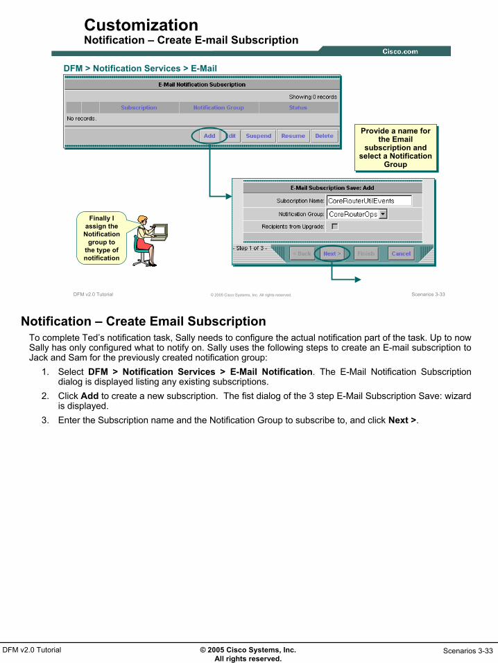
© 2005 Cisco Systems, Inc. All rights reserved.
Scenarios 3-33DFM v2.0 Tutorial
Scenarios 3-33© 2005 Cisco Systems, Inc. All rights reserved.DFM v2.0 Tutorial
Customization Notification – Create E-mail Subscription
Finally I assign the
Notification group to
the type of notification
DFM > Notification Services > E-Mail Notification
Provide a name for the Email
subscription and select a Notification
Group
Provide a name for the Email
subscription and select a Notification
Group
Notification – Create Email SubscriptionTo complete Ted’s notification task, Sally needs to configure the actual notification part of the task. Up to now Sally has only configured what to notify on. Sally uses the following steps to create an E-mail subscription to Jack and Sam for the previously created notification group:
1. Select DFM > Notification Services > E-Mail Notification. The E-Mail Notification Subscription dialog is displayed listing any existing subscriptions.
2. Click Add to create a new subscription. The fist dialog of the 3 step E-Mail Subscription Save: wizard is displayed.
3. Enter the Subscription name and the Notification Group to subscribe to, and click Next >.

© 2005 Cisco Systems, Inc. All rights reserved.
Scenarios 3-34DFM v2.0 Tutorial
Scenarios 3-34© 2005 Cisco Systems, Inc. All rights reserved.DFM v2.0 Tutorial
Customization Notification – Create E-mail Subscription (Continue …)
Enter necessary information
Enter necessary information
Details of the E-Mail Subscription
Details of the E-Mail Subscription
Notification – Create Email Subscription4. The second step of the wizard is used to enter the E-mail information. The SMTP Server field will be
populated with the server configured earlier or can be changed if desired. Enter the senders and recipients addresses and click Next >.
5. The final step of the wizard displays the details of the subscription to be created. Click Finish to create the subscription.
When DFM detects an event included in the parameters of the Notification Group just created, Jack and Sam will receive an E-mail containing text similar to the following:
ALERT ID = 00000SBTIME = Tue 22-Feb-2005 15:28:33 PSTSTATUS = ActiveSEVERITY = CriticalMANAGED OBJECT = nmtg-hq-core-3725.cisco.comMANAGED OBJECT TYPE = RoutersEVENT DESCRIPTION = IF-nmtg-hq-core-3725.cisco.com/2 [Se0/0] [CONNECTION TO NMTG-SP-FR-7500]:HighUtilization; IF-nmtg-hq-core-3725.cisco.com/5 [Fa1/0]:OperationallyDown; CUSTOMER IDENTIFICATION = Jack/SamCUSTOMER REVISION = 1.0

© 2005 Cisco Systems, Inc. All rights reserved.
Scenarios 3-35DFM v2.0 Tutorial
Alerts & ActivitiesAlerts & Activities
• Getting Started
• Preparing DFM for Use
• Customization
Alerts & Activities

© 2005 Cisco Systems, Inc. All rights reserved.
Scenarios 3-36DFM v2.0 Tutorial
Scenarios 3-36© 2005 Cisco Systems, Inc. All rights reserved.DFM v2.0 Tutorial
Alerts & Activities
• Alerts & Activities Display
• Alert Drill Down
• Event Drill Down
• Annotate
• Notification
• Resolution
Alerts and ActivitiesThis section will focus on using DFM to monitor the core routers. The Alerts and Activities display will use the Core Routers alert view and the various drill downs will be shown. The alerts detected will be handled by un-managing an interface and using CiscoView to “fix” the other as an example of fault resolution possibilities.

© 2005 Cisco Systems, Inc. All rights reserved.
Scenarios 3-37DFM v2.0 Tutorial
Scenarios 3-37© 2005 Cisco Systems, Inc. All rights reserved.DFM v2.0 Tutorial
Alerts & ActivitiesAlerts and Activities Display
DFM > Alerts and Activities > Alerts and Activities
Alert Views, select Core Routers to see Alerts for members of Core Router
Group only
Alert Views, select Core Routers to see Alerts for members of Core Router
Group only
Alert and Activities Detail Drill Down
Alert and Activities Detail Drill Down
Detailed Device View Drill Down
Detailed Device View Drill Down
Alerts and Activities DisplayDFM can be used to monitor faults in two ways: through notification services as was seen in the previous section when Jack and Sam received an E-mail detailing the event, or by using the Alerts and Activities display that will provide access to more information about the alerts, events, and device. In this section we focus on using the Alerts and Activities display and other DFM tasks to monitor the core routers.
1. Select DFM > Alerts And Activities > Alerts and Activities. The Alerts and Activities console is displayed in a new window.
2. Select the Core Routers Alert View from the Views menu on the left side of the window. Any Alert associated with any of the core routers will now be the only alerts displayed. Each line gives a summary for the Alert (note one alert per device, but each alert may include many events.) Two hyperlinks exist in the summary line: the Alert ID which drills down into the Alert details and the Device name which drills down into the details about the managed components of the device.
When an alert is generated, it remains in the Alerts and Activities display until it expires. DFM sets an alert state to Expired when DFM performs its normal polling and determines that the alarm has been in the Cleared state for 30 minutes or longer (from the time of polling). While the alert is in the display, if any of its events recur, the alert is updated. If an expired alert recurs, a new alert with a new ID is shown.

© 2005 Cisco Systems, Inc. All rights reserved.
Scenarios 3-38DFM v2.0 Tutorial
Scenarios 3-38© 2005 Cisco Systems, Inc. All rights reserved.DFM v2.0 Tutorial
Alerts & ActivitiesAlerts Drill Down
All events reported for selected device
All events reported for selected device
Event Drill DownEvent Drill DownDFM ToolsDFM Tools
Alert Tasks(Refer to notes below on these tasks)
Alert Tasks(Refer to notes below on these tasks)
or
Note: When resuming monitoring from a Suspended state, select Configuration > Polling and Thresholds > Apply
Changes for polling to resume
Note: When resuming monitoring from a Suspended state, select Configuration > Polling and Thresholds > Apply
Changes for polling to resume
Alerts Drill DownThe Alerts and Activities Detail console can be used to drill down on individual events to get actual MIB variable values that were used to determine the event by clicking on the Event ID hyper link. To bring up the Alerts and Activities Detail window to view the events, suspend the device, or acknowledge the alert, follow these steps.
1. From the Alerts and Activities console, click on the Alert ID to drill down into the Alert details. The Alerts and Activities Detail console is displayed in a new window listing a summary of the events detected by DFM for the selected device.
2. A number of tools can also be launched for each event to assist in the troubleshooting and resolution process.
3. Finally a user can annotate or comment on the alert to provide information to other users or can choose an alert action, such as one of the following:
• Suspend the device from further monitoring. DFM will no longer polls any device components, nor will it process any traps. All alerts and activities change to the Cleared state, and the device is moved to the Suspended Devices view
• Resume the device. DFM resumes polling and trap processing on the device. If you resumed any devices (and you are finished making all of your monitoring status changes), select Configuration > Polling and Thresholds > Apply Changes from the DFM home page so that DFM will resume polling according to the polling and threshold settings for the device.
• Acknowledge the alert. This signals other users that you are aware of the alert and the status change is populated to all Alerts and Activities displays.
• Notify another user. Most of these options will be explored in the next few pages. First, let’s view the individual events rolled up into the device alert.

© 2005 Cisco Systems, Inc. All rights reserved.
Scenarios 3-39DFM v2.0 Tutorial
Scenarios 3-39© 2005 Cisco Systems, Inc. All rights reserved.DFM v2.0 Tutorial
Alerts & ActivitiesEvents Drill Down
Event DetailsEvent Details
Reason for Event(Actual MIB value and configured threshold)
Reason for Event(Actual MIB value and configured threshold)
Events Drill Down1. From the Alerts and Activities Detail console, click on the Event ID to drill down into the Event details.
A pop-up window will be displayed showing MIB values and other details related to the event. This information can be used to better understand the reason for the event, and assist in the troubleshooting and resolution processes.

© 2005 Cisco Systems, Inc. All rights reserved.
Scenarios 3-40DFM v2.0 Tutorial
Scenarios 3-40© 2005 Cisco Systems, Inc. All rights reserved.DFM v2.0 Tutorial
Alerts & ActivitiesAnnotation
Add notes to the device alert
Add notes to the device alert
AnnotationOften times the troubleshooting and resolution of a detected fault is a time consuming process involving many people. The Alerts and Activities Detail console provides a space to provide notes about the alert detailing progress or thoughts about the fault and its resolution.
1. From the Alerts and Activities Detail console select the Annotate button. A pop-up window is displayed allowing the user to enter pertinent information. Click OK when finished entering information. The message is displayed in the Annotate box of the Alerts and Activities Detail console with a time stamp when it was added.

© 2005 Cisco Systems, Inc. All rights reserved.
Scenarios 3-41DFM v2.0 Tutorial
Scenarios 3-41© 2005 Cisco Systems, Inc. All rights reserved.DFM v2.0 Tutorial
Alerts & ActivitiesNotification
Send Email from Alerts & Activities
Detail display
Send Email from Alerts & Activities
Detail display
NotificationThe annotation is only useful if the other people working to resolve the issue are currently using DFM. As an alternative, the Notify feature allows one to send an E-mail directly from the Alerts and Activities Detail console.
1. From the Alerts and Activities Detail console select the Notify button. A pop-up window is displayed allowing the user to generate an E-mail message.
2. Enter all appropriate information and click Send.

© 2005 Cisco Systems, Inc. All rights reserved.
Scenarios 3-42DFM v2.0 Tutorial
Scenarios 3-42© 2005 Cisco Systems, Inc. All rights reserved.DFM v2.0 Tutorial
Alerts & ActivitiesResolution – Unmanage Se0/0
Launch Detailed Device View
Launch Detailed Device View
Select appropriate interface
Select appropriate interface
Set managed state for interface to falseSet managed state
for interface to false
Note: When resuming monitoring (from False to True) select Configuration > Polling and
Thresholds > Apply Changes for polling to resume
Note: When resuming monitoring (from False to True) select Configuration > Polling and
Thresholds > Apply Changes for polling to resume
Resolution – Unmanage Se0/0The event details of the high utilization event showed that it was interface Se0/0 experiencing this anomaly. The tiger team has determine that this is not really a condition to be concerned about since it is a test link that they are using to explore alternate configurations to achieve the desired behavior. Hence, rather than alarm people that there is an issue in the network, they decide to inform DFM to no longer manage this interface, and hence no further events will be generated on it. Once the testing is complete, the interface can be re-managed.
1. From the Alert and Activities console, select the <Device Name> link to display the Device Detail console in a separate window.
2. The left side of the console consists of a structured hierarchy of the managed components of the device. Expand the Interface Status heading and select the Interface radio button. The content area of the console now displays a list of all interfaces on the device and their status as of the last polling cycle by DFM.
3. The final column shows whether or not DFM is managing the interface (by default DFM does not manage access ports). Locate interface Se0/0 and change the manage state from True to Falseand click Submit.
DFM will now no longer poll this interface.Note(s):
• When you apply changes as stated in the above illustration, DFM performs the following tasks: Recalculates group membership, based on group priority. Uses the new polling and threshold settings to gather information from the devices.
• You must also apply changes after resuming a device, so that DFM will begin polling the device depending on the appropriate settings.

© 2005 Cisco Systems, Inc. All rights reserved.
Scenarios 3-43DFM v2.0 Tutorial
Scenarios 3-43© 2005 Cisco Systems, Inc. All rights reserved.DFM v2.0 Tutorial
Alerts & ActivitiesResolution – Change Port Status
Use tools to launch CiscoView
Use tools to launch CiscoView
Resolution – Change Port StatusThe Event details of the operationally down event shows that interface Fa1/0 is operationally down, but administratively up. The tiger team has determine that this is due to a connection being removed without performing a shutdown on the interface. They decide to simply change the administrative state of this port to down to resolve the event.
1. From the Alert and Activities Detail console, use the pull down tools menu to select CiscoView(assumes CiscoView is installed).
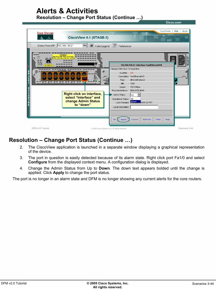
© 2005 Cisco Systems, Inc. All rights reserved.
Scenarios 3-44DFM v2.0 Tutorial
Scenarios 3-44© 2005 Cisco Systems, Inc. All rights reserved.DFM v2.0 Tutorial
Alerts & ActivitiesResolution – Change Port Status (Continue …)
Right click on interface, select “Interface” and change Admin Status
to “down”
Right click on interface, select “Interface” and change Admin Status
to “down”
Resolution – Change Port Status (Continue …)2. The CiscoView application is launched in a separate window displaying a graphical representation
of the device. 3. The port in question is easily detected because of its alarm state. Right click port Fa1/0 and select
Configure from the displayed context menu. A configuration dialog is displayed.4. Change the Admin Status from Up to Down. The down text appears bolded until the change is
applied. Click Apply to change the port status.The port is no longer in an alarm state and DFM is no longer showing any current alerts for the core routers.

© 2005 Cisco Systems, Inc. All rights reserved.
Scenarios 3-45DFM v2.0 Tutorial
Thank You!
This chapter has discussed methods of configuring DFM to assist in fault monitoring activities tailored to a specific environment. Chapter 4 will show a few additional administrative DFM tasks not covered in either
chapter 2 or 3 to further enhance the use of DFM for fault monitoring.

© 2005 Cisco Systems, Inc. All rights reserved.
Scenarios 3-46DFM v2.0 Tutorial
Intentionally Blank

© 2005 Cisco Systems, Inc. All rights reserved.
System Admin 4-1DFM v2.0 Tutorial
Chapter 4Chapter 4
DFM System DFM System AdministrationAdministration

© 2005 Cisco Systems, Inc. All rights reserved.
System Admin 4-2DFM v2.0 Tutorial
System Admin 4-2© 2005 Cisco Systems, Inc. All rights reserved.DFM v2.0 Tutorial
Chapter 4 Outline
• System Requirements- Server
- Client
- Installation
• DFM Administration• Task Reference
Chapter 4 OutlineThis chapter starts out by covering some basic requirements for both the CiscoWorks Server with Common Services and DFM installed, and the client used to access the server. Following that is a section that briefly covers some remaining administrative maintenance tasks that are not necessary to get started using the product, but complete the overall configuration of DFM.For detailed installation steps or information on upgrading from previous versions of DFM, refer to the DFM Installation Guide.

© 2005 Cisco Systems, Inc. All rights reserved.
System Admin 4-3DFM v2.0 Tutorial
System RequirementsSystem Requirements
System Requirements
• DFM Administration
• Task Reference

© 2005 Cisco Systems, Inc. All rights reserved.
System Admin 4-4DFM v2.0 Tutorial
System Admin 4-4© 2005 Cisco Systems, Inc. All rights reserved.DFM v2.0 Tutorial
RequirementsWindows Server
* DFM requires Common Services to be installed before installing DFM. Additional CiscoWorks applications would require additional server resources
Common Services v3.x and DFM v2.x*Requirement Type
System Hardware
Minimum Requirements
• 1.6 GHz or faster Pentium IBM PC-compatible dual CPU system
• ODBC Driver Manager 3.5.10. • Windows Server 2003 Standard and Enterprise Editions or
Windows 2000 (Professional, Server, and Advanced Server) with SP 3 or 4Note Windows terminal services is supported in remote administrationmode only. Note DFM supports only US-English and Japanese language versions.
• 2 GB
System Software
Available RAM
Available Drive Space • 4 GB. • Swap space equal to double the amount of memory (RAM)
Note NTFS file system required for secure operation
Windows Server RequirementsThe above chart provides minimum system requirements for a Windows server running Common Services (required for all CiscoWorks applications) and DFM. Installing additional CiscoWorks applications would require additional resources. Refer to the Common Services User Guide for more on CiscoWorks deployment.Note: It is always a good idea to check the latest CiscoWorks release notes for up-to-date information regarding system requirements.

© 2005 Cisco Systems, Inc. All rights reserved.
System Admin 4-5DFM v2.0 Tutorial
System Admin 4-5© 2005 Cisco Systems, Inc. All rights reserved.DFM v2.0 Tutorial
RequirementsSolaris Server
* DFM requires Common Services to be installed before installing DFM. Additional CiscoWorks applications would require additional server resources
Common Services v3.x and DFM v2.x*Requirement Type
System Hardware
Minimum Requirements
• Sun UltraSPARC IIIi with two1-GHz CPUs
• Solaris 2.8 or Solaris 2.9Note DFM supports only US-English and Japanese language versions.
• 2 GB
System Software
Available RAM
Available Drive Space • 4 GB on the install partition (default is /opt)• Swap space equal to double the amount of memory (RAM).
Solaris Server RequirementsThe above chart provides minimum system requirements for a Solaris server running Common Services (required for all CiscoWorks applications) and DFM. Installing additional CiscoWorks applications would require additional resources. Refer to the Common Services User Guide for more on CiscoWorks deployment.Note: It is always a good idea to check the latest CiscoWorks release notes for up-to-date information regarding system requirements.

© 2005 Cisco Systems, Inc. All rights reserved.
System Admin 4-6DFM v2.0 Tutorial
System Admin 4-6© 2005 Cisco Systems, Inc. All rights reserved.DFM v2.0 Tutorial
RequirementsClient
Requirement Type
System Hardware and Software
Minimum Requirements
• 1 GHz Pentium IBM PC-compatible system • Windows 2000 (Professional and Server) with SP 3 or 4 • Windows XP with SP 1 or 2 • Windows Server 2003 Standard or Enterprise Edition without
terminal services. • Sun SPARC Ultra 10 running Solaris 2.8 or 2.9.
Note DFM supports only US-English and Japanese versions of Windows Operating System (OS) and Solaris OS.
• Color monitor with video card set to 24 bits color depth.
• 512 MB
Browser
Available RAM
Available Drive Space • Swap space equal to double the amount of memory (RAM)
• On Windows clients: • Microsoft Internet Explorer 6.0 with SPK 1, Java Virtual Machine
(JVM) 5.0.0.3802 and later, and (optional) Java Plug-in version 1.4.2_04.
• Netscape Navigator 7.1 for Windows. • Mozilla 1.7.1.
• On Solaris clients: • Netscape Navigator 7.0 for Solaris 2.8 and 2.9. • Mozilla 1.7 for Solaris 2.8 and 2.9.
Client RequirementsAccess to a CiscoWorks server and all installed applications is achieved using a standard web browser. On Windows based platforms, CiscoWorks has been tested and certified using Microsoft Internet Explorer 6.0 with Service Pack 1 Java Virtual Machine (JVM) 5.0.0.3802 and later, and (optional) Java Plug-in version 1.4.2_04; Netscape Navigator 7.1, and Mozilla 1.7.1. Solaris based platforms running US-English or Japanese versions of Solaris 2.8 or 2.9 can use Netscape Navigator 7.0 or Mozilla 1.7. Client systems should have at least 512MB of memory.Note: It is always a good idea to check the latest CiscoWorks release notes for up-to-date information regarding system requirements.Note: Clients not conforming to the above requirements may also work but have not been tested and certified by Cisco and therefore will not be supported should problems arise.To verify the JVM: From Internet Explorer, select View > Java Console. From Netscape Navigator, select Tools > Server > Java Console.

© 2005 Cisco Systems, Inc. All rights reserved.
System Admin 4-7DFM v2.0 Tutorial
System Admin 4-7© 2005 Cisco Systems, Inc. All rights reserved.DFM v2.0 Tutorial
RequirementsInstallation Notes
• Install CiscoWorks Common Services v3.0 First- Reboot Machine (Windows Only)
• Use Administrator (Windows) or Root (Solaris) accounts
• DFM installed in same directory as Common Services
• Migration from DFM 1.2.x (requires Common Services upgrade to v3.0 first)
• Review Install Guide and Release notes for install steps- License Required
• If installing LMS 2.5, Review the Quick Start Guide
Installation NotesInstallation of DFM should be performed according to the steps detailed in the installation guide. It should be noted, however, that DFM is not a stand-alone application. Like all CiscoWorks applications, DFM dependson services supplied by the Common Services application. Therefore, prior to installing DFM, Common Services should first be installed and the machine rebooted. DFM will be installed to the same directory selected for Common Services. All CiscoWorks applications should be installed using the root account on Solaris platforms and the Administrator (not a cloned account) account on a Windows platform.Note: You can determine the status of your license from the CiscoWorks home page, by selecting Common Services > Server > Admin > Licensing

© 2005 Cisco Systems, Inc. All rights reserved.
System Admin 4-8DFM v2.0 Tutorial
System Admin 4-8© 2005 Cisco Systems, Inc. All rights reserved.DFM v2.0 Tutorial
RequirementsSoftware Updates
Additional ways to retrieve software
updates and Incremental Device
Updates (IDUs)
Additional ways to retrieve software
updates and Incremental Device
Updates (IDUs)
Software UpdatesFrom time to time, updates to all CiscoWorks applications are made available. Typically, Incremental Device Updates are made available every 3 months. The CiscoWorks Home Page provides numerous ways to retrieve these updates:
• The lower right hand corner of the home page presents CiscoWorks Product Update notes with a link to all available updates.
• The Resource section of the home page (upper right-hand corner) contains a link to all CiscoWorks Software including updates.
• The Common Services Software Center contains a Software Update task. Selecting this task will display the currently installed CiscoWorks applications and a mechanism to retrieve updates.

© 2005 Cisco Systems, Inc. All rights reserved.
System Admin 4-9DFM v2.0 Tutorial
DFM AdministrationDFM Administration
• System Requirements
DFM Administration
• Task Reference

© 2005 Cisco Systems, Inc. All rights reserved.
System Admin 4-10DFM v2.0 Tutorial
System Admin 4-10© 2005 Cisco Systems, Inc. All rights reserved.DFM v2.0 Tutorial
DFM AdministrationSteps
• Common Services – Register applications (See Common Services User Guide)
– Add devices to DCR (See Common Services User Guide)
– Create users and assign user roles (See Common Services User Guide)
• DFM– Enable Device to forward traps to DFM (see Chapter 3)
– Add devices (See Chapter 3)
– Schedule updates, trap receiving, and trap forwarding (See Chapter 3)
– Miscellaneous configuration• Customizing event names • Fault History purge job• Logging
DFM Administration StepsThe first two scenarios in Chapter 3 are enough to get DFM up and running. This section of Chapter 4 briefly discusses some remaining administrative tasks mainly used for maintenance and troubleshooting of the application. With the exception of the Miscellaneous Configuration bullet, the above list provides the basic steps to get DFM up, running, and usable. Many of these steps were detailed in the first two scenarios of Chapter 3, however, there are three important configuration steps associated to Common Services tasks that are pre-requisites to any DFM tasks. Please review the Common Services user guide for assistance in performing these steps. Again this section will focus on the ‘Miscellaneous Configuration’ steps mainly used for maintenance and troubleshooting purposes.

© 2005 Cisco Systems, Inc. All rights reserved.
System Admin 4-11DFM v2.0 Tutorial
System Admin 4-11© 2005 Cisco Systems, Inc. All rights reserved.DFM v2.0 Tutorial
DFM AdministrationCustomizing Event Names
DFM > Notification Services > Notification Customization
Enter your new names in the New Event Description
fields
Enter your new names in the New Event Description
fields
Customized event names are displayed in all notifications within
DFM, in the Alerts and Activities display and Fault History
Customized event names are displayed in all notifications within
DFM, in the Alerts and Activities display and Fault History
Customizing Event NamesDFM comes pre-configured with names for each event. Notification Services allows you to customize these names. When an event name is customized, it is reflected in all notifications, on the Alerts and Activities display, and in Fault History. The new event name is used for all instances of an event, regardless of the component on which the event occurs. It is also easy to revert to the default event names as needed. The Notification Customization page also lists the new name and default name to easily check which names have been changed.
.

© 2005 Cisco Systems, Inc. All rights reserved.
System Admin 4-12DFM v2.0 Tutorial
System Admin 4-12© 2005 Cisco Systems, Inc. All rights reserved.DFM v2.0 Tutorial
DFM AdministrationFault History Purge Job
DFM > Configuration > Other Configurations > Daily Purging Schedule
Change the schedule for trimming the Fault History
database(Midnight is default time)
Change the schedule for trimming the Fault History
database(Midnight is default time)
Make sure new scheduled time doesn’t interfere with
other task schedules(i.e. Rediscovery Schedule)
Make sure new scheduled time doesn’t interfere with
other task schedules(i.e. Rediscovery Schedule)
Fault History stores 31 days of data
Fault History stores 31 days of data
Fault History Purge JobData for Fault History remains in the DFM database for 31 days. By default, purging of data older than 31 days occurs every day at midnight. Use the Daily Purging Schedule task to change this time if desired. To ensure proper processing, DFM tasks should be scheduled in such a way as to not run at the same time.

© 2005 Cisco Systems, Inc. All rights reserved.
System Admin 4-13DFM v2.0 Tutorial
System Admin 4-13© 2005 Cisco Systems, Inc. All rights reserved.DFM v2.0 Tutorial
DFM AdministrationLogging
DFM > Configuration > Other Configurations > Logging
Collect additional information by increasing the logging levels
Collect additional information by increasing the logging levels
LoggingDFM writes application log files for all major functional modules. By default, DFM writes only error and fatal messages to these log files. Logging cannot be disabled, but using the Logging task additional data can be collected by increasing the logging level.Each DFM module writes log files to its own folder within the NMSROOT/log/dfmLogs folder. When a log file reaches its maximum size, the module backs up the file and starts writing to a new log file. DFM saves the previous three logs as backups.

© 2005 Cisco Systems, Inc. All rights reserved.
System Admin 4-14DFM v2.0 Tutorial
System Admin 4-14© 2005 Cisco Systems, Inc. All rights reserved.DFM v2.0 Tutorial
DFM AdministrationProcess Management
Common Services > Server > Admin > Processes
View status of all CiscoWorks processes
and start and stop if necessary
View status of all CiscoWorks processes
and start and stop if necessary
Process ManagementThe final administrative piece to be talked about isn’t a DFM task, but a Common Services task used to manage all CiscoWorks processes. In the event something doesn’t quite seem right with DFM, the administrator should first check the processes to ensure they are running. If not, they can be restarted, or stopped and restarted, in an attempt to fix the problem. The processes can be viewed by running the Common Services > Server > Admin > Processes task. The Admin task under the Server tab in Common Services also has tasks to run self-tests and collect server information.

© 2005 Cisco Systems, Inc. All rights reserved.
System Admin 4-15DFM v2.0 Tutorial
Task ReferenceTask Reference
• System Requirements
• DFM Administration
Task Reference
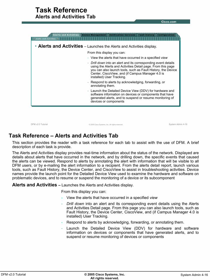
© 2005 Cisco Systems, Inc. All rights reserved.
System Admin 4-16DFM v2.0 Tutorial
System Admin 4-16© 2005 Cisco Systems, Inc. All rights reserved.DFM v2.0 Tutorial
Task ReferenceAlerts and Activities Tab
• Alerts and Activities – Launches the Alerts and Activities display.From this display you can:- View the alerts that have occurred in a specified view- Drill down into an alert and its corresponding event details
using the Alerts and Activities Detail page. From this page you can also launch tools, such as Fault History, the Device Center, CiscoView, and (if Campus Manager 4.0 is installed) User Tracking.
- Respond to alerts by acknowledging, forwarding, or annotating them.
- Launch the Detailed Device View (DDV) for hardware and software information on devices or components that have generated alerts, and to suspend or resume monitoring of devices or components
Task Reference – Alerts and Activities TabThis section provides the reader with a task reference for each tab to assist with the use of DFM. A brief description of each task is provide. The Alerts and Activities display provides real-time information about the status of the network. Displayed are details about alerts that have occurred in the network, and by drilling down, the specific events that caused the alerts can be viewed. Respond to alerts by annotating the alert with information that will be visible to all DFM users, or by e-mailing the alert information to a recipient. From the alerts detail report, launch various tools, such as Fault History, the Device Center, and CiscoView to assist in troubleshooting activities. Device names provide the launch point for the Detailed Device View used to examine the hardware and software on problematic devices, and to resume or suspend the monitoring of a device or its subcomponent
Alerts and Activities – Launches the Alerts and Activities display.
From this display you can:- View the alerts that have occurred in a specified view- Drill down into an alert and its corresponding event details using the Alerts
and Activities Detail page. From this page you can also launch tools, such as Fault History, the Device Center, CiscoView, and (if Campus Manager 4.0 is installed) User Tracking.
- Respond to alerts by acknowledging, forwarding, or annotating them.- Launch the Detailed Device View (DDV) for hardware and software
information on devices or components that have generated alerts, and to suspend or resume monitoring of devices or components

© 2005 Cisco Systems, Inc. All rights reserved.
System Admin 4-17DFM v2.0 Tutorial
System Admin 4-17© 2005 Cisco Systems, Inc. All rights reserved.DFM v2.0 Tutorial
Task ReferenceDevice Management Tab
• Device Selector - Controls automatic or manual addition of devices from DCR
• Device Summary - Summarizes the state of all devices in the DFM inventory
• Rediscover/Delete - Rediscovers devices, and (when using manual DCR synchronization) deletes devices from the DFM inventory
• Device Details - Displays basic information about devices in the DFM inventory. Launch point for Detailed Device View
• Discovery Status - Displays discovery information
• Device Aliases - Displays devices that have the same IP address as devices already in the DFM inventory
• SNMP Config - Modifies DFM SNMP timeouts and retries
Task Reference – Device Management TabTasks included in this tab are used to perform device management tasks including: synchronizing and comparing the DFM inventory with the Device Credential Repository (DCR), adding and deleting devices, suspending and resuming the management of devices (or their subcomponents), checking device states and discovery status, rediscovering devices, and configuring DFM SNMP settings.
Device Selector - Controls automatic or manual addition of devices from DCR
Device Summary - Summarizes the state of all devices in the DFM inventory
Rediscover/Delete - Rediscovers devices, and (when using manual DCR synchronization) deletes devices from the DFM inventory
Device Details - Displays basic information about devices in the DFM inventory. Launch point for Detailed Device View
Discovery Status - Displays discovery information
Device Aliases - Displays devices that have the same IP address as devices already in the DFM inventory
SNMP Config - Modifies DFM SNMP timeouts and retries

© 2005 Cisco Systems, Inc. All rights reserved.
System Admin 4-18DFM v2.0 Tutorial
System Admin 4-18© 2005 Cisco Systems, Inc. All rights reserved.DFM v2.0 Tutorial
Task ReferenceNotification Services Tab
• Notification Customization – Modify event names throughout DFM
• Event Sets – Create sets of events to monitor for notifications
• Notification Groups - Define notification groups. Groups can consist of devices, alerts, and events (determined by a chosen event set). Alerts and events can be grouped according to severity and status
• SNMP Trap Notification - Forward alerts and events as SNMP traps, to specified trap recipients. Forwarded traps are based on notification groups
• E-Mail Notification - Forward alerts and events as e-mail, to specified e-mail recipients. Forwarded traps are based on notification groups
• Syslog Notification - Forward alerts and events as syslog messages, to specified recipients. Forwarded traps are based on notification groups
Task Reference – Notification Services TabThe tasks found under the Notification Services tab can be used to customize event names and manage DFM notifications. The Notification Customization tasks is used to change system-defined event names to other names that are more meaningful. DFM will then use the new names throughout its system, including in its notifications. The other tasks allow fir the configuration of DFM to send notifications when specific alerts or events occur on specific device groups. Notifications can be sent as e-mail to a list of recipients, traps to network management systems, and/or as syslog messages for systems that do not accept SNMP traps.
Notification Customization – Modify event names throughout DFM
Event Sets – Create sets of events to monitor for notifications
Notification Groups - Define notification groups. Groups can consist of devices, alerts, and events (determined by a chosen event set). Alerts and events can be grouped according to severity and status
SNMP Trap Notification - Forward alerts and events as SNMP traps, to specified trap recipients. Forwarded traps are based on notification groups
E-Mail Notification - Forward alerts and events as e-mail, to specified e-mail recipients. Forwarded traps are based on notification groups
Syslog Notification - Forward alerts and events as syslog messages, to specified recipients. Forwarded traps are based on notification groups

© 2005 Cisco Systems, Inc. All rights reserved.
System Admin 4-19DFM v2.0 Tutorial
System Admin 4-19© 2005 Cisco Systems, Inc. All rights reserved.DFM v2.0 Tutorial
Task ReferenceFault History Tab
• Alert Filtering– Search by Alert ID - Search for a specific alert using its ID
– Search by Device - Search for alerts that occurred on specific devices
– Search by Group - Search for alerts that occurred on devices in any system-defined or user-defined group
• Event Filtering– Search by Event ID - Search for a specific event using its ID.
– Search by Device - Search for events that occurred on specific devices.
– Search by Alert ID - Search for events associated with a specific alert ID.
– Search by Group - Search for events that occurred on devices in any system-defined or user-defined group.
Task Reference – Fault History TabFault History displays stored information on past alerts and events. This information is stored in a Fault History database, and searches can be customized according to what you are looking for, such as alerts and events that occurred on certain devices, in a certain time period, or in a certain group.
Alert Filtering- Search by Alert ID - Search for a specific alert using its ID- Search by Device - Search for alerts that occurred on specific devices- Search by Group - Search for alerts that occurred on devices in any system-defined or user-defined
group
Event Filtering- Search by Event ID - Search for a specific event using its ID.- Search by Device - Search for events that occurred on specific devices.- Search by Alert ID - Search for events associated with a specific alert ID.- Search by Group - Search for events that occurred on devices in any system-defined or user-defined
group.

© 2005 Cisco Systems, Inc. All rights reserved.
System Admin 4-20DFM v2.0 Tutorial
System Admin 4-20© 2005 Cisco Systems, Inc. All rights reserved.DFM v2.0 Tutorial
Task ReferenceConfigurations Tab
• Polling and Thresholds– Polling Parameters - Change the scheduled interval at which DFM polls
devices and their ports/interfaces for data.
– Managing Thresholds - Modify the values for the threshold settings that DFM polls.
– Setting Priorities - Specify which polling and threshold parameters to use when a device, port, or interface belongs to multiple groups.
– Apply Changes - Apply polling and threshold changes to DFM
Task Reference – Configurations TabTasks found under this tab are used to perform DFM-specific configuration and administration tasks. Polling and threshold administrative tasks are separated from basic system configuration tasks. From Polling and Thresholds configuration, you can change the polling parameters and threshold settings, and specify priorities when a component belongs to multiple groups. The Other Configuration tasks include setting up SNMP trap forwarding and receiving, creating views for the Alerts and Activities display, creating and editing device groups, setting up schedules for rediscovering the managed inventory and trimming the Fault History database, specifying an SMTP server for e-mail notifications, and adjusting logging levels.
Polling and Thresholds- Polling Parameters - Change the scheduled interval at which DFM polls devices and their
ports/interfaces for data. - Managing Thresholds - Modify the values for the threshold settings that DFM polls. - Setting Priorities - Specify which polling and threshold parameters to use when a device, port, or
interface belongs to multiple groups. - Apply Changes - Apply polling and threshold changes to DFM

© 2005 Cisco Systems, Inc. All rights reserved.
System Admin 4-21DFM v2.0 Tutorial
System Admin 4-21© 2005 Cisco Systems, Inc. All rights reserved.DFM v2.0 Tutorial
Task ReferenceConfigurations Tab (Cont.)
• Other Configurations– Rediscovery Schedule - Change the time at which DFM probes the
devices in its inventory, or suspend and resume device rediscovery.
– Group Administration - Create new or modify existing User Defined Groups (including Customizable Groups).
– Daily Purging Schedule - Change the schedule for trimming the Fault History database.
– Alerts and Activities Defaults - Create views for the Alerts and Activities display.
– Logging - Increase logging levels or return to default logging levels.
– SNMP Trap Forwarding - Set a host and port number to receive pass-through traps.
– SNMP Trap Receiving - Set the port on which DFM will listen for SNMP traps (normally port 162).
– SMTP Default Server - Add or change the default server to use for e-mail notifications.
Task Reference – Configurations Tab (Cont.)Other Configurations
- Rediscovery Schedule - Change the time at which DFM probes the devices in its inventory, or suspend and resume device rediscovery.
- Group Administration - Create new or modify existing User Defined Groups (including Customizable Groups).
- Daily Purging Schedule - Change the schedule for trimming the Fault History database. - Alerts and Activities Defaults - Create views for the Alerts and Activities display. - Logging - Increase logging levels or return to default logging levels. - SNMP Trap Forwarding - Set a host and port number to receive pass-through traps. - SNMP Trap Receiving - Set the port on which DFM will listen for SNMP traps (normally port 162). - SMTP Default Server - Add or change the default server to use for e-mail notifications.

© 2005 Cisco Systems, Inc. All rights reserved.
System Admin 4-22DFM v2.0 Tutorial
Thank You!
We hope that you have enjoyed using Device Fault Manager and have found its features to be an important part of your network-management toolkit.
Cisco Systems

CChhaapptteerr 55
DDFFMM vv22..00 RReeffeerreenncceess


DFM v2.0 © 2005 Cisco Systems, Inc References 5-1
Reference Materials Many Cisco reference documents have been created to help users understand the use of the CiscoWorks application, Device Fault Manager (DFM). However, finding help and documentation can often be a challenge. This reference chapter has been created to assist you in your pursuit of additional product information. Below are links to documents and Web pages that provide further details on the DFM product.
• Device Fault Manager (DFM) v2.0 Product Information ♦ Data Sheet (URL)
www.cisco.com/en/US/products/sw/cscowork/ps2421/products_data_sheet0900aecd8021ccbe.html
♦ User Guide (URL)
www.cisco.com/univercd/cc/td/doc/product/rtrmgmt/cw2000/dfm/dfm20/ug/index.htm
♦ Installation Guide (URL)
www.cisco.com/univercd/cc/td/doc/product/rtrmgmt/cw2000/dfm/dfm20/install/index.htm
♦ Release Notes (URL)
www.cisco.com/univercd/cc/td/doc/product/rtrmgmt/cw2000/dfm/dfm20/rel_note/index.htm
♦ Devices Supported (URL)
www.cisco.com/univercd/cc/td/doc/product/rtrmgmt/cw2000/dfm/dev_sup/dfm2_0.htm
♦ DFM IDU (Software download available to registered Cisco.com users with a Cisco Service Agreement) (URL)
www.cisco.com/pcgi-bin/tablebuild.pl/cw2000-dfm
• Related Material
♦ CiscoWorks LAN Management Solution (LMS) (URL)
Learn more about CiscoWorks solutions bundled in LMS: www.cisco.com/go/lms/
♦ CiscoWorks Common Service v3.0 (URL)
Required for all CiscoWorks applications: www.cisco.com/univercd/cc/td/doc/product/rtrmgmt/cw2000/cw2000_d/comser30/index.htm
♦ Cisco’s SNMP Object Navigator (URL)
tools.cisco.com/Support/SNMP/do/BrowseOID.do?local=en

DFM v2.0 © 2005 Cisco Systems, Inc Reference 5-2
♦ Solaris Patches (URL)
To obtain the patches, contact your Sun Microsystems representative or download them from the Sun web site: sunsolve.sun.com/
♦ LMS Documentation (URL) www.cisco.com/univercd/cc/td/doc/product/rtrmgmt/cw2000/cw2000_b/lms/lms25/index.htm
♦ Quick Start Guide
♦ Data Migration Guidelines
♦ Online Bug Tracker (On Line URL) Search for known problems on the Cisco bug tracking system tool, called Bug Toolkit. To access Bug Toolkit, perform the following steps:
♦ Click on the link above (www.cisco.com/cgi-bin/Support/Bugtool/launch_bugtool.pl) ♦ Login to Cisco.com ♦ Click Launch Bug Toolkit. ♦ Locate CiscoWorks Device Fault Manager from the list of Cisco Software
Products ♦ Then click Next.
Technical Notes / White Papers
♦ Network Management Systems: Best Practices White Paper (URL)
http://www.cisco.com/en/US/tech/tk869/tk769/technologies_white_paper09186a00800aea9c.shtml
The objective of this paper is to provide some deployment guidelines for all areas of network management: Fault, Configuration, Accounting, Performance, and Security (FCAPS).
♦ CiscoWorks LAN Management Solution White Papers (URL) www.cisco.com/en/US/products/sw/cscowork/ps2425/prod_white_papers_list.html
♦ LMS Deployment Guide
The objective of this paper is to review the steps to properly deploying the LMS suite of applications.
♦ Cost Analysis Using CiscoWorks LAN Management Solution
The CiscoWorks product family can provide a quantifiable financial and IT benefit to an organization, through the automation of routine labor, as well as helping to mitigate network degradation due to device failures. While it is difficult to derive an exact figure of the true and potential cost savings for every customer situation, the Cost Analysis Tool can provide an understanding of the scale of savings involved. At this point, the question that needs to be asked is not "What is the cost of the product?" but "What is the cost of NOT using CiscoWorks?"

Chapter Questions
AAsssseessssmmeenntt QQuueessttiioonnss
DDeevviiccee FFaauulltt MMaannaaggeerr((DDFFMM)) vv22..00 TTuuttoorriiaall

DFM v2.0 Tutorial
Assessment - 2 © 2005 Cisco System Inc. DFM v2.0 Tutorial

DFM v2.0 Tutorial
DFM v2.0 Tutorial © 2005 Cisco Systems, Inc Assessment - 3
Based on the information in the DFM product tutorial, please answer the following questions.
Q1) Based on the tutorial, what are the three key tasks defining fault management? Choose three.
A) Poll
B) Detect
C) Isolate
D) Categorize
E) Correct
Q2) By default, what does DFM require the user to do to get started using the tool? Choose all that apply.
A) Write rules to determine device status
B) Determine polling rates and threshold values
C) Manually populate the DFM inventory with devices from the CiscoWorks Device & Credentials Repository (DCR)
D) Nothing, as long as the devices are in the DCR and DFM has factory settings
E) All of the above
Q3) DFM is available only in the CiscoWorks LAN Management Solution bundle. Choose one.
A) True
B) False

DFM v2.0 Tutorial
Assessment - 4 © 2005 Cisco System Inc. DFM v2.0 Tutorial
Q4) Which of the following best describes DFM? Choose one.
A) DFM is an intelligent, real-time, detailed, device fault detection and analysis tool, designed specifically for Cisco devices.
B) DFM is a tool that automatically correlates device fault conditions and automatically updates the codebook when the device inventory changes for all types of SNMP devices.
C) DFM is a general-purpose data and trap collection tool.
D) DFM is an asset/inventory management tool that can be used to collect and report on all devices and their components.
Q5) Which of the following are true statements? Choose all that apply.
A) DFM uses a combination of SNMP polling and ICMP pinging to collect valuable diagnostic data for automated root-cause analysis.
B) DFM requires SNMP traps to provide diagnostic results.
C) DFM requires the devices to be managed to have the SNMP read-write community string configured and defined in DFM.
D) All of the above are true statements
Q6) What are the primary functions of the DFM Alerts and Activities window? Choose all that apply.
A) Provides an ongoing monitoring tool that displays an alert entry when a fault condition has been detected on a monitored device
B) Displays every event detected on the monitored device
C) Provides the ability to drill down to look each event detail
D) Configures polling intervals and thresholds
E) For each event detected, the events are rolled up into a single alert and displayed

DFM v2.0 Tutorial
DFM v2.0 Tutorial © 2005 Cisco Systems, Inc Assessment - 5
Q7) Which Cisco device ports and interfaces are managed by default when added to the DFM inventory? Choose one.
A) All ports and interfaces on switches and routers.
B) Only the router interfaces.
C) Only ports and interfaces that are connected to other managed devices in the DFM inventory (for example, trunk ports).
D) Only truck ports on switches and all interfaces on routers
E) No interfaces are monitored by default.
Q8) Which of the following is not true? Choose one.
A) DFM displays monitoring results in the Alerts and Activities window.
B) DFM sends diagnostic results to third-party network management systems via SNMP traps.
C) DFM can log diagnostic results into a file.
D) DFM forwards diagnostics results to Resource Manager Essentials for viewing.
Q9) What are the functions of the Polling and Thresholds task? Choose all that apply.
A) Adjust polling intervals and thresholds for collected diagnostics.
B) Group devices using matching criteria to assign individual thresholds and polling intervals.
C) Control how often to rediscover the inventory.

DFM v2.0 Tutorial
Assessment - 6 © 2005 Cisco System Inc. DFM v2.0 Tutorial
Q10) Based on the CiscoWorks permission report, which of the following user roles permit the CiscoWorks user to make changes to the Polling & Threshold settings and Trap Forwarding settings using the Configuration task menu? Choose all that apply.
A) System Administrator
B) Network Administrator
C) Network Operator
D) Approver
E) Help Desk
F) All of the above
Q11) Based on the CiscoWorks permission report, which of the following user roles permit the CiscoWorks user to view events or device faults using the DFM Alerts and Activities window? Choose all that apply.
A) System Administrator
B) Network Administrator
C) Network Operator
D) Approver
E) Help Desk
F) All of the above
Q12) CiscoWorks DFM can be used to monitor the SNMP variables of third-party devices, such as my NT or UNIX system-based application servers. Choose one.
A) True
B) False

DFM v2.0 Tutorial
DFM v2.0 Tutorial © 2005 Cisco Systems, Inc Assessment - 7
Q13) DFM is integrated with the entire CiscoWorks family of products in which of the following ways? Choose all that apply.
A) Links to DFM tasks on the CiscoWorks desktop
B) Uses CiscoWorks security roles
C) Uses CiscoWorks background server process and backup services
D) Imports devices to manage from the CiscoWorks Device & Credentials Repository (DCR)
E) All of the above
Q14) Fill in the blanks. To change the polling and threshold settings for a specific group of devices, the user should define a new __________ ________ in the Polling and Thresholds settings.
Q15) If CiscoWorks users want to view alerts in the DFM Alerts and Activities window only in a specific subnet, or if they want to view only specific types of events, they must perform which of the following tasks? Choose one.
A) Use the Alert Filter to manipulate the Alerts and Activities display to show alerts based on their severity, status, and originating device type
B) Create a specific device view in the RME inventory that contains those devices of interest and import that view into DFM
C) Write a command line script to query the DFM database
D) The Alerts and Activities window always shows all the alerts

DFM v2.0 Tutorial
Assessment - 8 © 2005 Cisco System Inc. DFM v2.0 Tutorial
Q16) LMS v2.5 (including DFM v2.0) can be installed on which of the following operating systems? Choose all that apply.
A) Windows NT 4.0 Workstation
B) Windows NT 4.0 Server
C) Windows 2000 Professional, Server, and Advanced Server
D) Windows Server 2003 Standard and Enterprise Editions
E) Windows XP Professional
F) Solaris 2.8, 2.9
G) AIX 4.3.3
H) HP-UX 11.x
Q17) Which of the following CiscoWorks applications must be installed prior to installing DFM v2.0? Choose one.
A) CiscoWorks Common Services v3.0
B) Resource Manager Essentials (RME) v4.0
C) HP OpenView Network Node Manager v7.x
D) All of the above

Chapter Questions
AAnnsswweerrss ttoo AAsssseessssmmeenntt QQuueessttiioonnss
DDeevviiccee FFaauulltt MMaannaaggeerr((DDFFMM)) vv22..00 TTuuttoorriiaall

DFM v2.0 Tutorial
Answers - 2 © 2005 Cisco System Inc. DFM v2.0 Tutorial

DFM v2.0 Tutorial
DFM v2.0 Tutorial © 2005 Cisco Systems, Inc Answers - 3
Based on the information in the DFM product tutorial, please answer the following questions.
Q1) Based on the tutorial, what are the three key tasks defining fault management? Choose three.
A) Poll
B) Detect
C) Isolate
D) Categorize
E) Correct
Q2) By default, what does DFM require the user to do to get started using the tool? Choose all that apply.
A) Write rules to determine device status
B) Determine polling rates and threshold values
C) Manually populate the DFM inventory with devices from the CiscoWorks Device & Credentials Repository (DCR)
D) Nothing, as long as the devices are in the DCR and DFM has factory settings
E) All of the above
Q3) DFM is available only in the CiscoWorks LAN Management Solution bundle. Choose one.
A) True
B) False

DFM v2.0 Tutorial
Answers - 4 © 2005 Cisco System Inc. DFM v2.0 Tutorial
Q4) Which of the following best describes DFM? Choose one.
A) DFM is an intelligent, real-time, detailed, device fault detection and analysis tool, designed specifically for Cisco devices.
B) DFM is a tool that automatically correlates device fault conditions and automatically updates the codebook when the device inventory changes for all types of SNMP devices.
C) DFM is a general-purpose data and trap collection tool.
D) DFM is an asset/inventory management tool that can be used to collect and report on all devices and their components.
Q5) Which of the following are true statements? Choose all that apply.
A) DFM uses a combination of SNMP polling and ICMP pinging to collect valuable diagnostic data for automated root-cause analysis.
B) DFM requires SNMP traps to provide diagnostic results.
C) DFM requires the devices to be managed to have the SNMP read-write community string configured and defined in DFM.
D) All of the above are true statements
Q6) What are the primary functions of the DFM Alerts and Activities window? Choose all that apply.
A) Provides an ongoing monitoring tool that displays an alert entry when a fault condition has been detected on a monitored device
B) Displays every event detected on the monitored device
C) Provides the ability to drill down to look each event detail
D) Configures polling intervals and thresholds
E) For each event detected, the events are rolled up into a single alert and displayed
DFM v2.0 Tutorial
DFM v2.0 Tutorial © 2005 Cisco Systems, Inc Answers - 5
Q7) Which Cisco device ports and interfaces are managed by default when added to the DFM inventory? Choose one.
A) All ports and interfaces on switches and routers.
B) Only the router interfaces.
C) Only ports and interfaces that are connected to other managed devices in the DFM inventory (for example, trunk ports).
D) Only truck ports on switches and all interfaces on routers
E) No interfaces are monitored by default.
Q8) Which of the following is not true? Choose one.
A) DFM displays monitoring results in the Alerts and Activities window.
B) DFM sends diagnostic results to third-party network management systems via SNMP traps.
C) DFM can log diagnostic results into a file.
D) DFM forwards diagnostics results to Resource Manager Essentials for viewing.
Q9) What are the functions of the Polling and Thresholds task? Choose all that apply.
A) Adjust polling intervals and thresholds for collected diagnostics.
B) Group devices using matching criteria to assign individual thresholds and polling intervals.
C) Control how often to rediscover the inventory.

DFM v2.0 Tutorial
Answers - 6 © 2005 Cisco System Inc. DFM v2.0 Tutorial
Q10) Based on the CiscoWorks permission report, which of the following user roles permit the CiscoWorks user to make changes to the Polling & Threshold settings and Trap Forwarding settings using the Configuration task menu? Choose all that apply.
A) System Administrator
B) Network Administrator
C) Network Operator
D) Approver
E) Help Desk
F) All of the above
Q11) Based on the CiscoWorks permission report, which of the following user roles permit the CiscoWorks user to view events or device faults using the DFM Alerts and Activities window? Choose all that apply.
A) System Administrator
B) Network Administrator
C) Network Operator
D) Approver
E) Help Desk
F) All of the above
Q12) CiscoWorks DFM can be used to monitor the SNMP variables of third-party devices, such as my NT or UNIX system-based application servers. Choose one.
A) True
B) False

DFM v2.0 Tutorial
DFM v2.0 Tutorial © 2005 Cisco Systems, Inc Answers - 7
Q13) DFM is integrated with the entire CiscoWorks family of products in which of the following ways? Choose all that apply.
A) Links to DFM tasks on the CiscoWorks desktop
B) Uses CiscoWorks security roles
C) Uses CiscoWorks background server process and backup services
D) Imports devices to manage from the CiscoWorks Device & Credentials Repository (DCR)
E) All of the above
Q14) Fill in the blanks. To change the polling and threshold settings for a specific group of devices, the user should define a new ___POLLING GROUP_ in the Polling and Thresholds settings.
Q15) If CiscoWorks users want to view alerts in the DFM Alerts and Activities window only in a specific subnet, or if they want to view only specific types of events, they must perform which of the following tasks? Choose one.
A) Use the Alert Filter to manipulate the Alerts and Activities display to show alerts based on their severity, status, and originating device type
B) Create a specific device view in the RME inventory that contains those devices of interest and import that view into DFM
C) Write a command line script to query the DFM database
D) The Alerts and Activities window always shows all the alerts

DFM v2.0 Tutorial
Answers - 8 © 2005 Cisco System Inc. DFM v2.0 Tutorial
Q16) LMS v2.5 (including DFM v2.0) can be installed on which of the following operating systems? Choose all that apply.
A) Windows NT 4.0 Workstation
B) Windows NT 4.0 Server
C) Windows 2000 Professional, Server, and Advanced Server
D) Windows Server 2003 Standard and Enterprise Editions
E) Windows XP Professional
F) Solaris 2.8, 2.9
G) AIX 4.3.3
H) HP-UX 11.x
Q17) Which of the following CiscoWorks applications must be installed prior to installing DFM v2.0? Choose one.
A) CiscoWorks Common Services v3.0
B) Resource Manager Essentials (RME) v4.0
C) HP OpenView Network Node Manager v7.x
D) All of the above


![Guided drives DFM/DFM-B · Guided drives DFM/DFM-B Product range overview Function Version Type Piston Stroke Variable stroke [mm] [mm] [mm] Double-acting DFM basic version with recirculating](https://img.pdfslide.us/doc/110x75/60075e4355302d48df775d82/guided-drives-dfmdfm-b-guided-drives-dfmdfm-b-product-range-overview-function.jpg)