Embed Size (px)
Citation preview

Cisco Videoscape Distribution Suite Transparent Caching Software Blade Server Cluster Installation GuideRelease 5.1.1 March 2014
Americas HeadquartersCisco Systems, Inc.170 West Tasman DriveSan Jose, CA 95134-1706 USAhttp://www.cisco.comTel: 408 526-4000
800 553-NETS (6387)Fax: 408 527-0883
Text Part Number: OL-31422-01

THE SPECIFICATIONS AND INFORMATION REGARDING THE PRODUCTS IN THIS MANUAL ARE SUBJECT TO CHANGE WITHOUT NOTICE. ALL STATEMENTS, INFORMATION, AND RECOMMENDATIONS IN THIS MANUAL ARE BELIEVED TO BE ACCURATE BUT ARE PRESENTED WITHOUT WARRANTY OF ANY KIND, EXPRESS OR IMPLIED. USERS MUST TAKE FULL RESPONSIBILITY FOR THEIR APPLICATION OF ANY PRODUCTS.
THE SOFTWARE LICENSE AND LIMITED WARRANTY FOR THE ACCOMPANYING PRODUCT ARE SET FORTH IN THE INFORMATION PACKET THAT SHIPPED WITH THE PRODUCT AND ARE INCORPORATED HEREIN BY THIS REFERENCE. IF YOU ARE UNABLE TO LOCATE THE SOFTWARE LICENSE OR LIMITED WARRANTY, CONTACT YOUR CISCO REPRESENTATIVE FOR A COPY.
The Cisco implementation of TCP header compression is an adaptation of a program developed by the University of California, Berkeley (UCB) as part of UCB’s public domain version of the UNIX operating system. All rights reserved. Copyright © 1981, Regents of the University of California.
NOTWITHSTANDING ANY OTHER WARRANTY HEREIN, ALL DOCUMENT FILES AND SOFTWARE OF THESE SUPPLIERS ARE PROVIDED “AS IS” WITH ALL FAULTS. CISCO AND THE ABOVE-NAMED SUPPLIERS DISCLAIM ALL WARRANTIES, EXPRESSED OR IMPLIED, INCLUDING, WITHOUT LIMITATION, THOSE OF MERCHANTABILITY, FITNESS FOR A PARTICULAR PURPOSE AND NONINFRINGEMENT OR ARISING FROM A COURSE OF DEALING, USAGE, OR TRADE PRACTICE.
IN NO EVENT SHALL CISCO OR ITS SUPPLIERS BE LIABLE FOR ANY INDIRECT, SPECIAL, CONSEQUENTIAL, OR INCIDENTAL DAMAGES, INCLUDING, WITHOUT LIMITATION, LOST PROFITS OR LOSS OR DAMAGE TO DATA ARISING OUT OF THE USE OR INABILITY TO USE THIS MANUAL, EVEN IF CISCO OR ITS SUPPLIERS HAVE BEEN ADVISED OF THE POSSIBILITY OF SUCH DAMAGES.
Cisco and the Cisco logo are trademarks or registered trademarks of Cisco and/or its affiliates in the U.S. and other countries. To view a list of Cisco trademarks, go to this URL: www.cisco.com/go/trademarks. Third-party trademarks mentioned are the property of their respective owners. The use of the word partner does not imply a partnership relationship between Cisco and any other company. (1110R)
Any Internet Protocol (IP) addresses and phone numbers used in this document are not intended to be actual addresses and phone numbers. Any examples, command display output, network topology diagrams, and other figures included in the document are shown for illustrative purposes only. Any use of actual IP addresses or phone numbers in illustrative content is unintentional and coincidental.
Cisco Videoscape Distribution Suite Transparent Caching Software Blade Server Cluster Installation Guide © 2014 Cisco Systems, Inc. All rights reserved.

OL-31422-01
C O N T E N T S
Preface vii
Cluster Installation Overview vii
Blade Server Cluster Models vii
Obtaining Documentation and Submitting a Service Request viii
C H A P T E R 1 Prerequisites and Blade Server Cluster Physical Installation 1-1
Prerequisites 1-1
Required Software 1-1
Firmware Versions 1-1
Rack Mounting 1-2
Power Cabling 1-3
Network Cabling 1-3
Cache Engines 1-3
Fabric Interconnects 1-3
Management Server 1-3
Storage Enclosures 1-4
Additional Steps 1-6
C H A P T E R 2 Configuring the Switches in a Blade Server Cluster Installation 2-1
Initial Setup of the Cluster Switches 2-7
Preparing for the Configuration 2-7
VDS TC Management and Data Switch Configuration 2-8
Cisco Nexus 7000 Series Switch Configuration 2-8
C H A P T E R 3 Management Server Installation 3-1
Configuring the BIOS and Operating System with CIMC for a Management Server that is not PID TCE-1300MGR-K9 3-1
Configuring the Management IP Address and Password for a PID TCE-1300MGR-K9 Management Server 3-11
Configuring the Boot Image 3-13
Copying the ISO to the VDS TC Management Server 3-21
Starting the VNC Server on the Management Server 3-22
iiiBook Title

Contents
C H A P T E R 4 Cache Engine Servers Installation 4-1
Configuring the BIOS and Operating System Using Cisco UCS Manager 4-1
Configuring the Boot Image 4-9
Running the Post Installation Scripts 4-25
C H A P T E R 5 Configuring the Cache Storage 5-1
Installing the Storage Manager on the Management Server 5-1
Configuring the First Storage Array 5-5
Configuring the Remaining Storage Arrays 5-15
Configuring the Storage and Formatting Storage Disks 5-17
C H A P T E R 6 Installing and Configuring the Cisco VDS TC Cluster Software 6-1
Installing the Management Environment and Software 6-1
Post Installation Steps 6-3
Installing the License 6-5
A P P E N D I X A Cisco VDS TC Blade Server Cabling Guides A-1
VDS-TC-4B Non-Redundant Cabling Scheme A-2
Cisco Nexus 7004 or 7010 Switch Cabling (VDS-TC-4B Non-Redundant) A-2
Cisco 2248TP Fabric Extender Cabling (VDS-TC-4B Non-Redundant) For 1 Gb Connections to the IBM Storage Enclosure A-3
Cisco 2232TM Fabric Extender Cabling (VDS-TC-4B Non-Redundant) For 10 Gb Connections to the IBM Storage Enclosure A-4
Cisco UCS 6248 UP Fabric Interconnect Cabling (VDS-TC-4B Non-Redundant) A-5
VDS-TC-4B Redundant Cabling Scheme A-6
Cisco Nexus 7004 or 7010 Switch Cabling (VDS-TC-4B Redundant) A-6
Cisco 2248TP Fabric Extender 1 (FEX-1) Cabling (VDS-TC-4B Redundant) For 1 Gb Connections to the IBM Storage Enclosure A-8
Cisco 2248TP Fabric Extender 2 (FEX-2) Cabling (VDS-TC-4B Redundant) For 1 Gb Connections to the IBM Storage Enclosure A-9
Cisco 2232TM Fabric Extender 1 (FEX-1) Cabling (VDS-TC-4B Redundant) For 10 Gb Connections to the IBM Storage Enclosure A-10
Cisco 2232TM Fabric Extender 2 (FEX-2) Cabling (VDS-TC-4B Redundant) For 10 Gb Connections to the IBM Storage Enclosure A-11
Cisco UCS 6248 UP Fabric Interconnect 1 (FI-1) Cabling (VDS-TC-4B Redundant) A-12
Cisco UCS 6248 UP Fabric Interconnect 2 (FI-2) Cabling (VDS-TC-4B Redundant) A-13
VDS-TC-8B Non-Redundant Cabling Scheme A-14
Cisco Nexus 7004 or 7010 Switch Cabling (VDS-TC-8B Non-Redundant) A-14
ivBook Title
OL-31422-01

Contents
Cisco 2248TP Fabric Extender Cabling (VDS-TC-8B Non-Redundant) For 1 Gb Connections to the IBM Storage Enclosure A-15
Cisco 2232TM Fabric Extender Cabling (VDS-TC-8B Non-Redundant) For 10 Gb Connections to the IBM Storage Enclosure A-17
Cisco UCS 6248 UP Fabric Interconnect Cabling (VDS-TC-8B Non-Redundant) A-18
VDS-TC-8B Redundant Cabling Scheme A-19
Cisco Nexus 7004 Switch Cabling (VDS-TC-8B Redundant) A-19
Cisco 2248TP Fabric Extender 1 (FEX-1) Cabling (VDS-TC-8B Redundant) For 1 Gb Connections to the IBM Storage Enclosure A-21
Cisco 2248TP Fabric Extender 2 (FEX-2) Cabling (VDS-TC-8B Redundant) For 1 Gb Connections to the IBM Storage Enclosure A-22
Cisco 2232TM Fabric Extender 1 (FEX-1) Cabling (VDS-TC-8B Redundant) For 10 Gb Connections to the IBM Storage Enclosure A-23
Cisco 2232TM Fabric Extender 2 (FEX-2) Cabling (VDS-TC-8B Redundant) For 10 Gb Connections to the IBM Storage Enclosure A-24
Cisco UCS 6248 UP Fabric Interconnect 1 (FI-1) Cabling (VDS-TC-8B Redundant) A-25
Cisco UCS 6248 UP Fabric Interconnect 2 (FI-2) Cabling (VDS-TC-8B Redundant) A-26
VDS-TC-16B Non-Redundant Cabling Scheme A-27
Cisco Nexus 7004 or 7010 Switch Cabling (VDS-TC-16B Non-Redundant) A-27
Cisco 2248TP Fabric Extender 1 (FEX-1) Cabling (VDS-TC-16B Non-Redundant) For 1 Gb Connections to the IBM Storage Enclosure A-29
Cisco 2232TM Fabric Extender Cabling (VDS-TC-16B Non-Redundant) For 10 Gb Connections to the IBM Storage Enclosure A-33
Cisco UCS 6248 UP Fabric Interconnect Cabling (VDS-TC-16B Non-Redundant) A-34
VDS-TC-16B Redundant Cabling Scheme A-35
Cisco Nexus 7004 Switch Cabling (VDS-TC-16B Redundant) A-35
Cisco 2248TP Fabric Extender 1 (FEX-1) Cabling (VDS-TC-16B Redundant) For 1 Gb Connections to the IBM Storage Enclosure A-37
Cisco 2248TP Fabric Extender 2 (FEX-2) Cabling (VDS-TC-16B Redundant) For 1 Gb Connections to the IBM Storage Enclosure A-39
Cisco 2232TM Fabric Extender 1 (FEX-1) Cabling (VDS-TC-16B Redundant) For 10 Gb Connections to the IBM Storage Enclosure A-41
Cisco 2232TM Fabric Extender 2 (FEX-2) Cabling (VDS-TC-16B Redundant) For 10 Gb Connections to the IBM Storage Enclosure A-42
Cisco UCS 6248 UP Fabric Interconnect 1 (FI-1) Cabling (VDS-TC-16B Redundant) A-43
Cisco UCS 6248 UP Fabric Interconnect 2 (FI-2) Cabling (VDS-TC-16B Redundant) A-45
A P P E N D I X B Cisco VDS TC Specific UCS Blade Server Values B-1
Values for the Equipment Tab B-1
Values for the LAN Tab B-1
Values for the Server Tab B-11
vBook Title
OL-31422-01

Contents
viBook Title
OL-31422-01

Preface
Revised: March 2014, OL-31422-01
The Cisco Videoscape Distribution Suite Transparent Caching (VDS TC) solution is focused on reducing costs and improving the quality of user experience in delivering unmanaged Internet-based content, including Internet video, file sharing, software distribution, mobile application downloads, and web browsing. VDS TC integrates highly scalable caching software with high-performance Cisco Unified Computing System™ (UCS) C-Series Rack Servers and B-Series Blade Servers, Cisco switches, and SAN storage. The VDS TC solution, combined with other Videoscape products, such as Cisco Videoscape Distribution Suite for Internet Streaming (VDS IS), provides a complete platform for optimizing managed and unmanaged content delivery.
Cluster Installation OverviewThe Cisco VDS TC Cluster platform is a multi-server scalable system that is intended for the efficient serving of P2P and HTTP user requests. A Cisco VDS-TC Cluster installation can optimize P2P and HTTP object downloading traffic across ISP networks through high-performance caching.
Because of its flexible size, a Cisco VDS TC Cluster installation can meet both low-end and high-end requirements, and can also grow in parallel with the customer network.
In a VDS TC Cluster configuration, the VDS TC software can run on the Cisco UCS C220 C- Series Rack Servers or on the Cisco UCS B200 M3 B-Series Blade Servers. The cached objects for both solutions are stored on an IBM SAN storage device, and Cisco switches are used for data, storage, and management connectivity. A VDS TC Cluster configuration that uses the Cisco UCS B200 Blade Servers can contain up to 16 Cisco UCS B200 cache engine blade servers and up to 5 IBM DS3524 SAN storage enclosures. A separate Cisco UCS C220 is used as the VDS TC Management Server.
This installation guide provides instructions for installing VDS TC on a Cisco Blade Server Cluster platform, including installing and configuring the VDS TC Management Server, the VDS TC Cache Engines, and the storage enclosures. This installation guide also discusses configuring the data and management switches used by the VDS TC Blade Server Cluster installation.
Blade Server Cluster ModelsThere are three VDS TC Server cluster models that use the Cisco UCS B200 Blade Servers:
• Cisco VDS-TC-4B: The Cisco VDS-TC-4B model contains four Cisco UCS B200 Blade Servers, one UCS 5108 Blade Chassis, one Cisco UCS C220 Management Server, and two IBM DS3524 SAN storage enclosures.
viiCisco Videoscape Distribution Suite Transparent Caching Software Blade Server Cluster Installation Guide
OL-31422-01

Preface
• Cisco VDS-TC-8B: The Cisco VDS-TC-8B model contains eight Cisco UCS B200 Blade Servers, one UCS 5108 Blade Chassis, one Cisco UCS C220 Management Server, and three IBM DS3524 SAN storage enclosures.
• Cisco VDS-TC-16B: The Cisco VDS-TC-16B model contains 16 Cisco UCS B200 Blade Servers, two UCS 5108 Blade Chassis, one Cisco UCS C220 Management Server, and five IBM DS3524 SAN storage enclosures.
Each model can be installed in a redundant and a non-redundant configuration. Each Blade Server Cluster model also uses one Cisco UCS 6248UP Fabric Interconnect, or two Cisco UCS 6248UP Fabric Interconnects for redundant installations.
Obtaining Documentation and Submitting a Service RequestFor information on obtaining documentation, submitting a service request, and gathering additional information, see the monthly What’s New in Cisco Product Documentation, which also lists all new and revised Cisco technical documentation, at:
http://www.cisco.com/en/US/docs/general/whatsnew/whatsnew.html
Subscribe to the What’s New in Cisco Product Documentation as an RSS feed and set content to be delivered directly to your desktop using a reader application. The RSS feeds are a free service. Cisco currently supports RSS Version 2.0.
viiiCisco Videoscape Distribution Suite Transparent Caching Software Blade Server Cluster Installation Guide
OL-31422-01

Cisco Videoscape Distribution Suite Transparent CachinOL-31422-01
C H A P T E R 1
Prerequisites and Blade Server Cluster Physical InstallationThis chapter outlines the preliminary requirements for installing a VDS TC Blade Server Cluster platform and describes how to connect both the power cables to the storage enclosure PDUs and the rack PDU, and the network cabling scheme for the VDS TC Cache Engines, the VDS TC Management Server, and the storage enclosures. This chapter contains the following sections:
• Prerequisites
• Rack Mounting
• Power Cabling
• Network Cabling
• Additional Steps
Prerequisites
Required SoftwareBefore installing the VDS TC Blade Server Cluster system, you must obtain the VDS TC ISO disk image from Cisco.
Firmware VersionsThe following table describes the supported hardware and firmware for a VDS TC Blade Server Cluster installation:
Note Always refer to the Release Notes for your product to confirm the required firmware and image files.
1-1g Software Blade Server Cluster Installation Guide

Chapter 1 Prerequisites and Blade Server Cluster Physical Installation Rack Mounting
To check firmware version on the Cisco UCS C-Series Management Server, use the CIMC. To check the version of firmware on the Cisco Blade Server and the Cisco Fabric Interconnect, use the Cisco UCS Manager.
Tip For instructions on how to perform a firmware upgrade, for the Cisco UCS C-Series Servers see the Cisco UCS C-Series Rack-Mount Server BIOS Upgrade Guide document available at http://www.cisco.com/en/US/docs/unified_computing/ucs/c/sw/bios/b_Upgrading_BIOS_Firmware.html, and for the UCS Blade Server and the Cisco UCS 6248 UP Fabric Interconnect, see the Cisco UCS Manager Install and Upgrade Guides page available at www.cisco.com/en/US/products/ps10281/prod_installation_guides_list.html.
Rack MountingTo mount the VDS TC Blade Servers in a chassis, see the Cisco UCS 5108 Server Chassis Installation Guide available at http://www.cisco.com/en/US/docs/unified_computing/ucs/hw/chassis/install/ucs5108_install.html.
Hardware Component Model Required Firmware Version and Image File
Management Server Cisco UCS-C220-M3S Cisco UCS-C220-M3S:
• Firmware version: 1.5.4.3
• Image file: ucs-c220-huu-1.5.4-3.iso
Cache Engine Cisco UCS 5108 Blade Chassis
Cisco UCS-B200-M3
Cisco UCS 6248 UP Fabric Interconnect
Cisco UCS-B200-M3:
• Firmware version: 2.2.1b
• Image file: ucs-k9-bundle-b-series.2.2.1b.B.bin
Cisco UCS 6248 UP Fabric Interconnect:
• Firmware version: 2.2.1.b
• Image file: ucs-k9-bundle-infra.2.2.1b.A.bin
IBM DS3524 storage enclosure
Any IBM DS3500 storage models
• BIOS version: 07.86.32.00
• Controller image files: ibm_fw_ds3k_07863200_anyos_anycpu.zip
• HDD BIOS version: 4.17
• HDD image file: ibm_fw_ds3khdd_4.17_anyos_anycpu.zip
• IBM Storage Manager version: 10.86 (SM10.86_Linux_64bit_x86-64_SMIA-10.86.x5.43.tgz)
1-2Cisco Videoscape Distribution Suite Transparent Caching Software Blade Server Cluster Installation Guide
OL-31422-01

Chapter 1 Prerequisites and Blade Server Cluster Physical Installation Power Cabling
Power CablingUsing standard power cables, connect the power cables to both of the storage enclosure PSUs and the rack PDU. For connecting power to the Blade Series servers, see the Cisco UCS 5108 Server Chassis Installation Guide available at http://www.cisco.com/en/US/docs/unified_computing/ucs/hw/chassis/install/ucs5108_install.html.
Network CablingThere are six different configurations available for a VDS TC Blade Server Cluster installation:
• VDS-TC-4B non-redundant
• VDS-TC-4B redundant
• VDS-TC-8B non-redundant
• VDS-TC-8B redundant
• VDS-TC-16B non-redundant
• VDS-TC-16B redundant
This section provides an overview of cabling the connections for the cache engines, the management server, and the storage enclosures. For a complete cabling guide for one of these VDS TC configurations, see Appendix A, “Cisco VDS TC Blade Server Cabling Guides”.
Cache EnginesFor a complete cabling diagram for one of these VDS TC configurations, see Appendix A, “Cisco VDS TC Blade Server Cabling Guides”.
Fabric InterconnectsThe Cisco UCS 6248 Fabric Interconnect connects to the Cisco UCS I/O Modules in the Cisco 5108 Server Chassis and to the data switch. For specific cabling schemes, see Appendix A, “Cisco VDS TC Blade Server Cabling Guides”.
Management ServerMake the following connections on the management server to the management switch.
1-3Cisco Videoscape Distribution Suite Transparent Caching Software Blade Server Cluster Installation Guide
OL-31422-01

Chapter 1 Prerequisites and Blade Server Cluster Physical Installation Network Cabling
Figure 1-1 Management Server Connections
Note See Appendix A, “Cisco VDS TC Blade Server Cabling Guides”for a full cabling scheme.
Storage EnclosuresMake the following connections on each storage enclosure.
Figure 1-2 Storage Connections
Table 1-1 Management Server Connections
Port # Description Wire Connection Notes
1 Power supply 1 PDU A
2 Power supply 2 PDU B
3 Interface 1 (eth0) Eth0 management Connects to first Fabric Extender, FEX 2248TP or 2232TM
4 Interface 2 (eth1) Eth1 redundant management
Connects to second Fabric Extender FEX 2248TP or 2232TM
1-4Cisco Videoscape Distribution Suite Transparent Caching Software Blade Server Cluster Installation Guide
OL-31422-01

Chapter 1 Prerequisites and Blade Server Cluster Physical Installation Network Cabling
Note The storage enclosure has two controllers.
Note See Appendix A, “Cisco VDS TC Blade Server Cabling Guides”for a full cabling diagram.
Follow these steps to wire the storage server:
Table 1-2 Storage Connections
Port # Description Wire Connection Notes
1 iSCSI connection Connects to first Fabric Extender, FEX 2248TP or 2232TM for either 1 Gb or 10Gb connections
For 10Gb connections, use 10GBASE-T CAT6 or CAT7 cables.
2 iSCSI connection Connects to first Fabric Extender, FEX 2248TP or 2232TM
Used only for 1Gb connections
3 iSCSI connection Connects to first Fabric Extender, FEX 2248TP or 2232TM
Used only for 1Gb connections
4 iSCSI connection Connects to first Fabric Extender, FEX 2248TP or 2232TM
Used only for 1Gb connections
5 iSCSI connection Connects to first Fabric Extender, FEX 2248TP or 2232TM
For 10Gb connections use 10GBASE-T CAT6 or CAT7 cables.
6 iSCSI connection Connects to first Fabric Extender, FEX 2248TP or 2232TM
Used only for 1Gb connections
7 iSCSI connection Connects to first Fabric Extender, FEX 2248TP or 2232TM
Used only for 1Gb connections
8 iSCSI connection Connects to first Fabric Extender, FEX 2248TP or 2232TM
Used only for 1Gb connections
9 Management 1 controller A
Man1 StoX Connects to the first management switch
10 Management 2 controller B
Man2 StoX Connects to the second management switch if present, or to the first management switch if not
11 Power supply 1 PDU A
12 Power supply 2 PDU B
1-5Cisco Videoscape Distribution Suite Transparent Caching Software Blade Server Cluster Installation Guide
OL-31422-01

Chapter 1 Prerequisites and Blade Server Cluster Physical Installation Additional Steps
Step 1 Connect the two management cables between the two management ports on the storage server and the ports on the management switches.
Step 2 Connect the iSCSI storage data cables between the storage server iSCSI in controller A and the management switch. Connect the iSCSI storage data cables between the storage server iSCSI in controller B and the management switch.
Additional StepsYou must also complete a proper installation and initial configuration of the Cisco UCS C220, the Cisco UCS Blade Servers, and the Cisco UCS 6248 UP Fabric Interconnects. For more information see the following documents and web pages on www.cisco.com:
• Cisco UCS C-Series Rack Servers Install and Upgrade Guides web page, available at http://www.cisco.com/en/US/products/ps10493/prod_installation_guides_list.html
• Cisco UCS C-Series Rack Servers Configuration Guides web page, available at http://www.cisco.com/en/US/products/ps10493/products_installation_and_configuration_guides_list.html
• Cisco UCS B200 Blade Server Installation and Service Note document available at http://www.cisco.com/en/US/docs/unified_computing/ucs/hw/chassis/install/blade.html
• Cisco UCS B-Series Blade Servers Configuration Guides web page, available at http://www.cisco.com/en/US/products/ps10280/products_installation_and_configuration_guides_list.html
Next you will configure the switches in a Blade Server cluster installation. This configuration is covered in the next chapter, Chapter 2, “Configuring the Switches in a Blade Server Cluster Installation”.
1-6Cisco Videoscape Distribution Suite Transparent Caching Software Blade Server Cluster Installation Guide
OL-31422-01

Cisco Videoscape Distribution Suite Transparent CachinOL-31422-01
C H A P T E R 2
Configuring the Switches in a Blade Server Cluster InstallationThe VDS TC Blade Server Cluster installation has switches that provide two different functions:
• Data switch: The Cisco UCS 6248 Fabric Interconnects connect to the data switch. The Cisco Blade Server cache engines communicate with the data switch through the Fabric Interconnects. A Cisco Nexus 7000 Series Switch is used for the VDS TC data switch, to which the Fabric Interconnect is connected. In a redundant configuration there is one Cisco Nexus 7000 Series Switch, but it will have two supervisor modules, two line cards, and redundant power supplies. There will also be two Cisco UCS 6248 Fabric Interconnects that will connect to the Cisco Nexus 7000 Series Switch.
• Management switch: The VDS TC Management Server, the storage chassis, and the management ports of the Cisco Fabric Interconnect connect to the management switch. The Nexus 7000 Series Switch is used as the management switch, as well as the data switch, using the Cisco Nexus 2232TM Fabric Extender if using 10Gb connections to the SAN storage devices, or Cisco Nexus 2248TP Fabric Extender is using 1Gb connections to the SAN storage devices. In a VDS-TC-4B and VDS-TC-8B non-redundant installation, there will be only one Cisco Nexus 2232TM or Cisco Nexus 2248TP Fabric Extender. For a non-redundant VDS-TC-16B installation and all redundant installations, there will be two Cisco Nexus 2232TM or Cisco Nexus 2248TP Fabric Extenders.
2-1g Software Blade Server Cluster Installation Guide

Chapter 2 Configuring the Switches in a Blade Server Cluster Installation
Figure 2-1 Redundant 16 Blade Server (VDST-TC-16B) Cluster Configuration with 1Gb
Connections to the Storage Enclosure
2-2Cisco Videoscape Distribution Suite Transparent Caching Software Blade Server Cluster Installation Guide
OL-31422-01

Chapter 2 Configuring the Switches in a Blade Server Cluster Installation
Figure 2-2 Redundant 16 Blade Server (VDST-TC-16B) Cluster Configuration with 10Gb
Connections to the Storage Enclosure
2-3Cisco Videoscape Distribution Suite Transparent Caching Software Blade Server Cluster Installation Guide
OL-31422-01

Chapter 2 Configuring the Switches in a Blade Server Cluster Installation
Figure 2-3 Redundant 8 Blade Server (VDST-TC-8B) Cluster Configuration with 1Gb Connections
to the Storage Enclosure
2-4Cisco Videoscape Distribution Suite Transparent Caching Software Blade Server Cluster Installation Guide
OL-31422-01

Chapter 2 Configuring the Switches in a Blade Server Cluster Installation
Figure 2-4 Redundant 8 Blade Server (VDST-TC-8B) Cluster Configuration with 10Gb
Connections to the Storage Enclosure
2-5Cisco Videoscape Distribution Suite Transparent Caching Software Blade Server Cluster Installation Guide
OL-31422-01

Chapter 2 Configuring the Switches in a Blade Server Cluster Installation
Figure 2-5 Redundant 4 Blade Server (VDST-TC-4B) Cluster Configuration with 1Gb Connections
to the Storage Enclosure
2-6Cisco Videoscape Distribution Suite Transparent Caching Software Blade Server Cluster Installation Guide
OL-31422-01

Chapter 2 Configuring the Switches in a Blade Server Cluster Installation Initial Setup of the Cluster Switches
Figure 2-6 Redundant 4 Blade Server (VDST-TC-4B) Cluster Configuration with 10Gb
Connections to the Storage Enclosure
After initially installing the Cisco switches and configuring them with a management IP address and password, you must perform an initial setup on the switch for the VDS TC connections. You must install and configure the switches before you install the Cisco VDS TC Management Server.
Initial Setup of the Cluster Switches
Preparing for the ConfigurationBefore you can configure the switches to support the VDS TC installation, you must obtain a copy of the switch configuration files. The configuration files are available in a .tgz file that is available from the same location as the VDS TC ISO image file on www.cisco.com.
Caution The example switch configuration files are just examples. Please make sure to edit these files as appropriate for the network environment of your company.
2-7Cisco Videoscape Distribution Suite Transparent Caching Software Blade Server Cluster Installation Guide
OL-31422-01

Chapter 2 Configuring the Switches in a Blade Server Cluster Installation Initial Setup of the Cluster Switches
VDS TC Management and Data Switch ConfigurationThe Cisco Nexus 7000 Series Switch for the VDS TC installation should run Cisco NX-OS Release 6.2(6) or later with a K9 feature set. You can use the show version command to see the version and features information of the switch.
Note If you need to upgrade the Cisco NX-OS release that is installed on the Cisco Nexus 7000 Series switch, please refer to “Cisco Nexus 7000 Series NX-OS Software Upgrade and Downgrade Guide, Release 6.x” available at http://www.cisco.com/en/US/docs/switches/datacenter/sw/6_x/nx-os/upgrade/guide/b_Cisco_Nexus_7000_Series_NX-OS_Software_Upgrade_and_Downgrade_Guide_Release_6.x.html.
You must apply a configuration to the VDS TC switch. The configuration files are provided in a .tgz file that is available from the same location as the VDS TC ISO image file on www.cisco.com.
Cisco Nexus 7000 Series Switch Configuration
You will need multiple configuration files to configure the Cisco Nexus 7000 Series Switch. All of these files are available in the configuration .tgz file that is available from the same location as the VDS TC ISO image file on www.cisco.com. Follow this procedure to apply the appropriate configurations to a Cisco Nexus 7000 series Switch that is being used in a Blade Server cluster configuration:
Procedure
Step 1 Gather the following information to configure the Cisco Nexus 7000 Series Switch:
• IP address and subnet mask for the Cisco Nexus 7000 Series Switch management interface.
• Nexus management IP default gateway
Step 2 Using a text editor, such as Notepad, open the main VDC configuration file for your switch and review the switch configuration file. The configuration files are available in a .tgz file that is available from the same location as the VDS TC ISO image file on www.cisco.com.
Note Make sure you use the appropriate VDC configuration file based on whether you have a redundant or non-redundant installation.
Step 3 Ensure that the configuration file will not overwrite any necessary settings in your current switch configuration. Make any necessary changes to the switch configuration file that are appropriate for your installation and save the changes, including the following:
• Look for the following commands in the main VDC configuration file and edit the management IP address and subnet mask of the main vdc and set it to the values documented in Step 1:
interface mgmt0
ip address mgmt_IP_address/length
• Look for the following commands in the configuration file and edit the next_hop_gateway parameter. Set this parameter to the value documented for the Nexus management IP default gateway in Step 1:
vrf context management
ip route 0.0.0.0/0 next_hop_gateway
2-8Cisco Videoscape Distribution Suite Transparent Caching Software Blade Server Cluster Installation Guide
OL-31422-01

Chapter 2 Configuring the Switches in a Blade Server Cluster Installation Initial Setup of the Cluster Switches
Step 4 Log into the CLI of the switch. You will need the username and password to access the CLI.
Step 5 You should make a backup copy of the current switch configuration before you apply the VDS TC switch configuration file. To save a copy of the current switch configuration, use the copy command.
Step 6 After you have backed up your current running configuration, enter the config t command to enter global configuration mode. The global configuration mode prompt, switch(config)#, appears.
Step 7 Copy all of the configuration lines from the switch configuration file that you opened in Step 2 and paste them into the global configuration mode prompt.
Step 8 Enter exit to return to Enable mode.
Step 9 To save the configuration to nvram, enter the command write or copy run start.
Step 10 Next you will apply a configuration to the data VDC. The data VDC configuration files are contained in the configuration .tgz file that is available from the same location as the VDS TC ISO image file on www.cisco.com.
Step 11 Using a text editor, such as Notepad, open the appropriate data VDC configuration file and review the switch configuration file.
Note Which data VDC configuration file you should use depends on how many Blade Servers you have in your installation, if you have a redundant installation, and if you are installing a multicluster configuration. For example, if you have 16 Blade Servers in an installation that is not multicluster, you would use the file named VDS-TC-16B-DATA-VDC.txt. If you have 16 Blade Servers in a multicluster installation, you would use the files named TC-16B-DATA-01_vdc.txt and TC-16B-DATA-02_vdc.txt. If you are unsure of which files to use, contact your Cisco representative.
Step 12 Make sure that the configuration file will not overwrite any necessary settings in your current switch configuration. Make any necessary changes to the switch configuration file that are appropriate for your installation and save the changes.
Step 13 To switch to the data VDC, enter the command switchto vdc TC-XB-DATA, where X is the number of Blade Servers you have installed.
Step 14 Enter the config t command to enter global configuration mode. The global configuration mode prompt, switch(config)#, appears.
Step 15 Copy all of the configuration lines from the data VDC switch configuration file that you opened in Step 16 and paste them into the global configuration mode prompt.
Step 16 Enter exit to return to Enable mode.
Step 17 Enter the command write or copy run start to save the configuration to nvram.
Step 18 Enter the switchback command to switchback to the main (default) VDC.
Step 19 Enter the reload command to reload the Cisco Nexus 7000 Series Switch.
Caution The reload command disrupts traffic on the device.
Next you will install the VDS TC Management Server. This configuration is covered in the next chapter, Chapter 3, “Management Server Installation”.
2-9Cisco Videoscape Distribution Suite Transparent Caching Software Blade Server Cluster Installation Guide
OL-31422-01

Chapter 2 Configuring the Switches in a Blade Server Cluster Installation Initial Setup of the Cluster Switches
2-10Cisco Videoscape Distribution Suite Transparent Caching Software Blade Server Cluster Installation Guide
OL-31422-01

Cisco Videoscape Distribution Suite Transparent CachinOL-31422-01
C H A P T E R 3
Management Server InstallationThis chapter describes how to configure the VDS TC Management server, including configuring the BIOS and operating system, internal system disk, and boot image. This chapter contains these sections:
• Configuring the BIOS and Operating System with CIMC for a Management Server that is not PID TCE-1300MGR-K9
• Configuring the Management IP Address and Password for a PID TCE-1300MGR-K9 Management Server
• Configuring the Boot Image
• Copying the ISO to the VDS TC Management Server
• Starting the VNC Server on the Management Server
Configuring the BIOS and Operating System with CIMC for a Management Server that is not PID TCE-1300MGR-K9
Note Perform the steps in this section only if you are not using a VDS TC Management server that was purchased using PID TCE-1300MGR-K9. If you are using a VDS TC Management server that was purchased using PID TCE-1300MGR-K9, go to the Configuring the Management IP Address and Password for a PID TCE-1300MGR-K9 Management Server section.
You will use the Cisco Integrated Management Controller (CIMC) to configure the VDS TC management server.
Note Do not perform these steps until you have completed the proper installation and initial configuration of the Cisco UCS C220. For more information, see the Cisco UCS C-Series Rack Servers Install and Upgrade Guides web page available at http://www.cisco.com/en/US/products/ps10493/prod_installation_guides_list.html and the Cisco UCS C-Series Rack Servers Configuration Guides web page available at http://www.cisco.com/en/US/products/ps10493/products_installation_and_configuration_guides_list.html.
Use this procedure to configure the BIOS and Operating System using the CIMC.
3-1g Software Blade Server Cluster Installation Guide

Chapter 3 Management Server Installation Configuring the BIOS and Operating System with CIMC for a Management Server that is not PID TCE-1300MGR-K9
Procedure
Caution Before you begin these configuration steps, confirm that the VDS TC management server is using the correct version of BIOS firmware. The BIOS firmware of the Cisco UCS C220 M3S should be Release 1.5.4.3. For instructions on how to perform a firmware upgrade see the Cisco UCS C-Series Rack-Mount Server BIOS Upgrade Guide available http://www.cisco.com/en/US/docs/unified_computing/ucs/c/sw/bios/b_Upgrading_BIOS_Firmware.html.
Step 1 Connect to the VDS TC management server. You can use either a KVM cable and the KVM connector, or the CIMC to connect to the VDS TC management server.
Note For more information on how to connect to the VDS TC management server, refer to the Cisco UCS C-Series Rack Servers Install and Upgrade Guides web page available at http://www.cisco.com/en/US/products/ps10493/prod_installation_guides_list.html.
Step 2 Boot up the VDS TC management server. From the Cisco BIOS screen press F8 when prompted. The CIMC Configuration Utility window appears.
Step 3 From the CIMC Configuration Utility window, configure the following:
• NIC Mode: Choose Shared LOM.
• IPV4 (Basic):
– Clear the DHCP Enabled option. This is enabled by default.
– Enter the IP address and subnet mask to use for CIMC.
– Enter the default gateway for the CIMC to use.
Note For a multicluster installation, each cluster should have its own VDS TC management server, and the CIMC IP address for each management server should be in a different subnet.
• NIC Redundancy: Choose Active-active.
• Default User (Basic): Enter and re-enter the password for the CIMC user. The default password is password.
Step 4 Press F10 to save the configuration and F5 to refresh.
3-2Cisco Videoscape Distribution Suite Transparent Caching Software Blade Server Cluster Installation Guide
OL-31422-01

Chapter 3 Management Server Installation Configuring the BIOS and Operating System with CIMC for a Management Server that is not PID TCE-1300MGR-K9
Figure 3-1 CIMC Configuration Utility Screen
Step 5 Open a web browser and enter the IP address that you configured to access CIMC in Step 2. The CIMC login window appears.
Step 6 Enter the username admin and the password that you configured in Step 2 and click Login. The default password is password.
Step 7 The Cisco Integrated Management Controller: Server Summary window appears.
3-3Cisco Videoscape Distribution Suite Transparent Caching Software Blade Server Cluster Installation Guide
OL-31422-01

Chapter 3 Management Server Installation Configuring the BIOS and Operating System with CIMC for a Management Server that is not PID TCE-1300MGR-K9
Figure 3-2 CIMC: Server Summary Window
Step 8 From the Server tab, choose Remote Presence. The Remote Presence window appears.
Step 9 Click the Serial Over LAN tab and check the Enabled check box.
Step 10 From the Baud Rate drop-down list choose 115.2 kbps and from the Com Port drop-down list choose com0.
Step 11 Click the Save Changes button.
3-4Cisco Videoscape Distribution Suite Transparent Caching Software Blade Server Cluster Installation Guide
OL-31422-01

Chapter 3 Management Server Installation Configuring the BIOS and Operating System with CIMC for a Management Server that is not PID TCE-1300MGR-K9
Figure 3-3 Serial Over LAN Window
Step 12 From the Server tab, choose BIOS.
Step 13 In the BIOS window, click Configure BIOS. The Configure BIOS Parameters window appears.
Step 14 Click the Advanced tab.
3-5Cisco Videoscape Distribution Suite Transparent Caching Software Blade Server Cluster Installation Guide
OL-31422-01

Chapter 3 Management Server Installation Configuring the BIOS and Operating System with CIMC for a Management Server that is not PID TCE-1300MGR-K9
Figure 3-4 Configure BIOS Parameters Window: Advanced Tab
Step 15 Use the Advanced BIOS Parameters table to configure the settings on the Advanced tab.
Note Parameters that are not listed in the following table should be left set to their default value.
Table 3-1 Advanced BIOS Parameters
Processor Configuration State
Hyper - Threading Technology Disabled
Number Of Enabled Cores All
Execute Disable Enabled
Intel VT Disabled
Intel VT-d Disabled
Intel VT-d Coherency Support Disabled
Intel VT-d ATS Support Disabled
CPU Performance High Throughput
Hardware Prefetcher Disabled
3-6Cisco Videoscape Distribution Suite Transparent Caching Software Blade Server Cluster Installation Guide
OL-31422-01

Chapter 3 Management Server Installation Configuring the BIOS and Operating System with CIMC for a Management Server that is not PID TCE-1300MGR-K9
Adjacent Cache Line Prefetch Disabled
DCU Streamer Prefetch Disabled
DCU IP Prefetcher Enabled
Direct Cache Access Support Enabled
Power Technology Disabled
Enhanced Intel Speedstep Technology Enabled
Intel Turbo Boost Technology Disabled
Processor Power State C6 Disabled
Processor Power State C1 Enhanced Disabled
Frequency Floor Override Disabled
P-STATE Coordination HW ALL
Energy Performance Performance
Memory Configuration Status
Select Memory RAS Maximum Performance
DRAM Clock Throttling Performance
NUMA Enabled
Low Voltage DDR Mode Performance Mode
Channel Interleaving Auto
Rank Interleaving Auto
Patrol Scrub Enabled
Demand Scrub Enabled
Altitude 300 M
QPI Configuration Status
QPI Link Frequency Select Auto
Onboard Storage Status
Onboard SCU Storage Support Disabled
USB Configuration Status
USB Port:SD Card Disabled
PCI Configuration Status
MIMO above 4GB Disabled
ASPM Support Disabled
3-7Cisco Videoscape Distribution Suite Transparent Caching Software Blade Server Cluster Installation Guide
OL-31422-01

Chapter 3 Management Server Installation Configuring the BIOS and Operating System with CIMC for a Management Server that is not PID TCE-1300MGR-K9
Step 16 Click Save Changes.
Step 17 From the Server tab, choose Power Policies. The Power Policies window appears.
Step 18 In the Power Policies window configure the following settings:
• From the Power Restore Policy drop-down list, choose Power On.
• From the Power Delay Type drop-down list, choose Fixed.
• In the Power Delay Value text box, enter 0.
• From the Fan Policy drop-down list, choose Maximum Power.
Step 19 Click Save Changes.
VGA Priority Onboard
Serial Configuration Status
Out-of-Band Mgmt Port Disabled
Console Redirection Disabled
Terminal Type VT100+
Bits per Second 115200
Flow Control None
LOM and PCIe Slots Configuration Status
LOM Port 0 Legacy OptionROM Enabled
LOM Port 1 Legacy OptionROM Enabled
LOM Port 2 Legacy OptionROM Enabled
LOM Port 3 Legacy OptionROM Enabled
All PCIe Slots OptionROM Enabled
PCIe Slot:1 OptionROM Enabled
PCIe Slot:2 OptionROM Enabled
PCIe Slot:3 OptionROM Enabled
PCIe Slot:4 OptionROM Enabled
PCIe Mezzanine OptionROM Enabled
PCIe Slot:1 Link Speed GEN3
PCIe Slot:2 Link Speed GEN3
3-8Cisco Videoscape Distribution Suite Transparent Caching Software Blade Server Cluster Installation Guide
OL-31422-01

Chapter 3 Management Server Installation Configuring the BIOS and Operating System with CIMC for a Management Server that is not PID TCE-1300MGR-K9
Figure 3-5 Power Policies Screen
Step 20 From the Server tab choose BIOS.
Step 21 From the BIOS window, click Configure Boot Order.
Step 22 Click OK to close the Manage Boot Order dialog box. The Configure Boot Order dialog box appears.
Step 23 Add the following Device Types to the Boot Order list:
• HDD
• CDROM
Step 24 Click Apply.
3-9Cisco Videoscape Distribution Suite Transparent Caching Software Blade Server Cluster Installation Guide
OL-31422-01

Chapter 3 Management Server Installation Configuring the BIOS and Operating System with CIMC for a Management Server that is not PID TCE-1300MGR-K9
Figure 3-6 Configure Boot Order Window
Step 25 The BIOS is now configured.
Step 26 From the Server tab, choose Summary.
Step 27 In the Actions pane, click Launch KVM Console. This will launch the KVM Console window for this server. You will use the KVM Console to configure the boot image in the next section.
Note If you do not have Java™ installed on your computer, or your version is older than that required by the KVM Console, a dialog box will appear. Install or update Java ™ and continue with the installation procedure.
Step 28 In the Actions pane, click Hard Reset Server.
3-10Cisco Videoscape Distribution Suite Transparent Caching Software Blade Server Cluster Installation Guide
OL-31422-01

Chapter 3 Management Server Installation Configuring the Management IP Address and Password for a PID TCE-1300MGR-K9 Management Server
Figure 3-7 Server Summary Window
Step 29 From the Hard Reset Server popup window, click OK to reset the server.
Note This will drop your connection to the CIMC UI momentarily and you will have to log back into the system.
Step 30 Continue to the Configuring the Boot Image section.
Configuring the Management IP Address and Password for a PID TCE-1300MGR-K9 Management Server
Note Perform the steps in this section only if you purchased a VDS TC management server using PID TCE-1300MGR-K9.
The PID TCE-1300MGR-K9 ships with a default management IP address (10.11.12.253) and password that you should change before installing VDS TC. Follow these steps to changes these settings:
3-11Cisco Videoscape Distribution Suite Transparent Caching Software Blade Server Cluster Installation Guide
OL-31422-01

Chapter 3 Management Server Installation Configuring the Management IP Address and Password for a PID TCE-1300MGR-K9 Management Server
Procedure
Step 1 Connect to the VDS TC management server. You can use either a KVM cable and the KVM connector, or you can use a web browser and the default IP address of 10.11.12.253 that is preconfigured on the TCE-1300MGR-K9 VDS TC management server to connect to the CIMC. The default password is preset by Cisco specifically for VDS-TC. Please contact your Cisco account system engineer if you need this password.
Note For more information on how to connect to the VDS TC management server, refer to the Cisco UCS C-Series Rack Servers Install and Upgrade Guides web page available at http://www.cisco.com/en/US/products/ps10493/prod_installation_guides_list.html.
Step 2 Boot up the VDS TC management server. From the Cisco BIOS screen press F8 when prompted. The CIMC Configuration Utility window appears.
Step 3 From the CIMC Configuration Utility window, configure the following:
• IPV4 (Basic):
– Enter the IP address and subnet mask to use for CIMC. This should be an IP address on your network.
– Enter the default gateway for the CIMC to use.
Note For a multicluster installation, each cluster should have its own VDS TC management server, and the CIMC IP address for each management server should be in a different subnet.
• Default User (Basic): Enter and re-enter a new password for the CIMC user. The default password has been preconfigured by Cisco specifically for VDS TC. Please contact your Cisco account system engineer for details.
Step 4 Press F10 to save the configuration and F5 to refresh.
Step 5 Open a web browser and enter the IP address that you configured in Step 3. The CIMC login window appears.
Step 6 Enter the username admin and the password that you configured in Step 3 and click Login. The default password has been preconfigured by Cisco specifically for VDS TC. Please contact your Cisco account system engineer for details.
Step 7 The Cisco Integrated Management Controller: Server Summary window appears.
3-12Cisco Videoscape Distribution Suite Transparent Caching Software Blade Server Cluster Installation Guide
OL-31422-01
Chapter 3 Management Server Installation Configuring the Boot Image
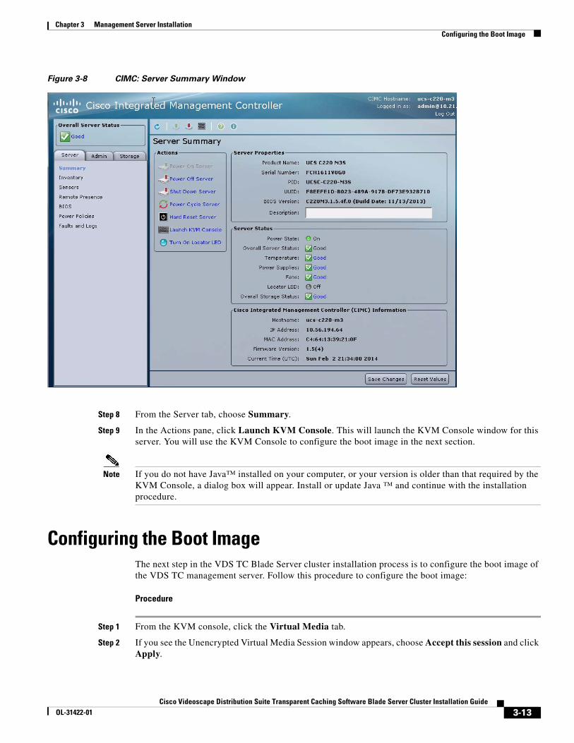
Figure 3-8 CIMC: Server Summary Window
Step 8 From the Server tab, choose Summary.
Step 9 In the Actions pane, click Launch KVM Console. This will launch the KVM Console window for this server. You will use the KVM Console to configure the boot image in the next section.
Note If you do not have Java™ installed on your computer, or your version is older than that required by the KVM Console, a dialog box will appear. Install or update Java ™ and continue with the installation procedure.
Configuring the Boot ImageThe next step in the VDS TC Blade Server cluster installation process is to configure the boot image of the VDS TC management server. Follow this procedure to configure the boot image:
Procedure
Step 1 From the KVM console, click the Virtual Media tab.
Step 2 If you see the Unencrypted Virtual Media Session window appears, choose Accept this session and click Apply.
3-13Cisco Videoscape Distribution Suite Transparent Caching Software Blade Server Cluster Installation Guide
OL-31422-01

Chapter 3 Management Server Installation Configuring the Boot Image
Figure 3-9 Unencrypted Virtual Media Session
Step 3 Click Add Image.
Figure 3-10 Virtual Media Tab
Step 4 Browse for and select the ISO installer image and click Open.
3-14Cisco Videoscape Distribution Suite Transparent Caching Software Blade Server Cluster Installation Guide
OL-31422-01

Chapter 3 Management Server Installation Configuring the Boot Image
Figure 3-11 Browse for Image
Step 5 Check the Mapped check box for the newly added ISO image file.
Figure 3-12 Mapped ISO File
Step 6 Reboot the system by choosing Macros > Static Macros > Ctrl-Alt-Del from the KVM console, or from the CIMC user interface choose Server > Summary and click Hard Reset Server.
Step 7 As the system reboots, switch back to the KVM console and click the KVM tab.
Step 8 When you see the prompt that says to press F6 to enter the boot menu, press F6. The Please Select Boot Device dialog box appears.
3-15Cisco Videoscape Distribution Suite Transparent Caching Software Blade Server Cluster Installation Guide
OL-31422-01

Chapter 3 Management Server Installation Configuring the Boot Image
Figure 3-13 System Reboot Window
Step 9 Using the up and down arrows, choose vKVM-Mapped vDVD1.22. The system will reboot from the virtual ISO image.
Step 10 When the VDS-TC Installer environment displays in the KVM console window, choose Installer - No Serial.
Figure 3-14 VDS TC Installer Window
Step 11 When the Welcome screen appears, enter Y to continue the installation process.
3-16Cisco Videoscape Distribution Suite Transparent Caching Software Blade Server Cluster Installation Guide
OL-31422-01

Chapter 3 Management Server Installation Configuring the Boot Image
Figure 3-15 Welcome Screen
Step 12 When you see the Choose the Appliance Deployment window, choose Management and select OK.
Figure 3-16 Choose the Appliance Deployment Window
Step 13 When prompted, enter a management IP address for the VDS TC management server and choose OK. You will use this IP address to connect to the CLI of the VDS TC management server using SSH and to connect to the VDS TC management server using VDS TC Manager.
Note For a multicluster installation, each cluster should have its own VDS TC management server, and the management IP address for each management server should be in a different subnet.
3-17Cisco Videoscape Distribution Suite Transparent Caching Software Blade Server Cluster Installation Guide
OL-31422-01

Chapter 3 Management Server Installation Configuring the Boot Image
Figure 3-17 Enter IP Address Window
Step 14 When prompted, enter the subnet mask for the management IP address and choose OK.
Figure 3-18 Enter Subnet Mask Window
Step 15 When prompted, enter the default gateway for the VDS TC management server to use and choose OK.
3-18Cisco Videoscape Distribution Suite Transparent Caching Software Blade Server Cluster Installation Guide
OL-31422-01

Chapter 3 Management Server Installation Configuring the Boot Image
Figure 3-19 Enter Default Gateway Window
Step 16 Confirm the system configuration. If everything is correct, choose Yes. If there is a mistake, choose No and repeat Step 11 through Step 15.
Figure 3-20 Confirm Configuration
3-19Cisco Videoscape Distribution Suite Transparent Caching Software Blade Server Cluster Installation Guide
OL-31422-01

Chapter 3 Management Server Installation Configuring the Boot Image
Step 17 From the KVM window you will see the installation begin.
Figure 3-21 VDS TC Installation Process: System Image Dumping Screen
Step 18 When the installation completes, you must unmap the ISO image file. When the “Installation completed. Press <Enter> to reboot.” message appears, press Enter.
Note Wait for the system to reboot and display the BIOS splash screen, as shown in Figure 3-13 “System Reboot Window”, before proceeding to the next step.
Figure 3-22 Installation Completed Window
Step 19 From the KVM console window, click the Virtual Media tab and uncheck the Mapped check box next to the ISO image file.
3-20Cisco Videoscape Distribution Suite Transparent Caching Software Blade Server Cluster Installation Guide
OL-31422-01

Chapter 3 Management Server Installation Copying the ISO to the VDS TC Management Server
Step 20 In the Unmap Drive Requested dialog box, click Yes to confirm the unmapping the image file. This unmounts the ISO image.
Figure 3-23 Unmap Drive Requested Window
Step 21 Reboot the system by choosing Macros > Static Macros > Ctrl-Alt-Del from the KVM console, or by using the CIMC user interface.
Note The first time you reboot the system after the installation can take up to 10 minutes because of the initial disk checkup.
Copying the ISO to the VDS TC Management ServerNext you must copy the ISO image to the management server. Follow this procedure to copy the ISO image to the VDS TC Management Server.
Procedure
Step 1 Using SFTP software, such as WinSCP, connect to the VDS TC Management Server using the IP address that you assigned during the “Configuring the Boot Image” process. Log in using the user name padmin and the password that was provided by Cisco.
Step 2 Create the folder /opt/pang/iso. Copy the ISO file that you received from Cisco into this folder.
3-21Cisco Videoscape Distribution Suite Transparent Caching Software Blade Server Cluster Installation Guide
OL-31422-01

Chapter 3 Management Server Installation Starting the VNC Server on the Management Server
Note You must copy the ISO image to the VDS TC Management Server because it is the only system that has access to the management interfaces of the cache engines and the CIMC.
Starting the VNC Server on the Management ServerFollow this procedure to start the VNC server on the VDS TC Management Server:
Procedure
Step 1 Using SSH software, such as Putty, open an SSH connection to the IP address that was assigned to the VDS TC Management Server.
Step 2 Log into the system using the username padmin and the password provided by Cisco.
Step 3 Enter the command su root to change to the root user. Enter the password for the root user when prompted. This password is provided by Cisco.
Step 4 Enter the command vncserver :1 to start the VNC Server.
Step 5 Use VNC to connect from your local computer to the VDS TC Management Server, using the IP address that you configured.
Figure 3-24 VNC Viewer
Next you will install the VDS TC Cache Engine. This configuration is covered in the next chapter, Chapter 4, “Cache Engine Servers Installation”.
3-22Cisco Videoscape Distribution Suite Transparent Caching Software Blade Server Cluster Installation Guide
OL-31422-01

Cisco Videoscape Distribution Suite Transparent CachinOL-31422-01
C H A P T E R 4
Cache Engine Servers InstallationThis chapter describes how to configure the VDS TC Cache Engine servers in a Cisco Blade Server cluster installation including configuring the BIOS and operating system. This chapter includes the following sections:
• Configuring the BIOS and Operating System Using Cisco UCS Manager
• Configuring the Boot Image
• Running the Post Installation Scripts
Configuring the BIOS and Operating System Using Cisco UCS Manager
You will import an XML file using the Cisco UCS Manager to configure the VDS TC Cache Engine servers. Use the following procedure to configure the BIOS and Operating System using Cisco UCS Manager.
Note Do not perform these steps until you have completed the proper installation and initial configuration of the Fabric Interconnects and the Cisco UCS Blade Servers. In a multicluster installation, make sure that the IP addresses that you assign to the Fabric Interconnects are in the same subnet as their respective VDS TC Management Server. For more information, see the Cisco UCS Manager GUI Configuration Guide, Release 2.1 document available at http://www.cisco.com/en/US/docs/unified_computing/ucs/sw/gui/config/guide/2.1/b_UCSM_GUI_Configuration_Guide_2_1.html.
Procedure
Caution Before you begin these configuration steps, confirm that the Cisco B200 M3 cache engine and the Cisco UCS 6248 UP Fabric Interconnect are using the correct version of BIOS firmware. The BIOS firmware of the Cisco B200 M3 should be Release 2.2.1.b and the BIOS firmware of the Cisco UCS 6248 UP Fabric Interconnect should be Release 2.2.1.b. For instructions on how to perform a firmware upgrade see the Cisco UCS Manager Install and Upgrade Guides web page available at http://www.cisco.com/en/US/products/ps10281/prod_installation_guides_list.html.
4-1g Software Blade Server Cluster Installation Guide

Chapter 4 Cache Engine Servers Installation Configuring the BIOS and Operating System Using Cisco UCS Manager
Step 1 To configure the BIOS for the VDS TC cache engines, you must obtain a copy of the XML configuration file that configures the BIOS. The XML configuration file is provided in a .tgz file that is available from the same location as the VDS TC ISO image file on www.cisco.com. Download the .tgz file to the machine from which you will perform the following configuration steps and extract the files. You will need to browse to the location of the files in a later step.
Step 2 Open a web browser and enter the IP address of the management port for the Fabric Interconnect. In a redundant installation, enter the Cluster (virtual) IP address. These addresses were configured as part of the initial installation and configuration of the Cisco UCS 6248 UP Fabric Interconnect. The Cisco UCS Manager window appears.
Figure 4-1 Cisco UCS Manager Window
Step 3 Click Launch UCS Manager. Click OK to open the .jnlp file with Java(TM) Web Start Launcher.
Step 4 In the Cisco UCS Manager Login window that appears, enter the username admin and the password that was configured during the initial system setup of the fabric interconnect, and then click Login.
4-2Cisco Videoscape Distribution Suite Transparent Caching Software Blade Server Cluster Installation Guide
OL-31422-01

Chapter 4 Cache Engine Servers Installation Configuring the BIOS and Operating System Using Cisco UCS Manager
Figure 4-2 Cisco UCS Manager Login Window
Step 5 From the Cisco Unified Computing System Manager window, click the Admin tab in the left pane, click the General tab in the work pane, and then in the Actions area click Import Configuration.
Figure 4-3 Admin Tab Window
Step 6 The Import Configuration window appears. In this window, click Create Import Operation.
4-3Cisco Videoscape Distribution Suite Transparent Caching Software Blade Server Cluster Installation Guide
OL-31422-01

Chapter 4 Cache Engine Servers Installation Configuring the BIOS and Operating System Using Cisco UCS Manager
Figure 4-4 Import Configuration Window
Step 7 The Create Import Operation Window appears. Set the Admin State to Enabled, the Action to Replace, and the Location of the Import File to Local File System, and then click Browse.
Figure 4-5 Create Import Operation Window
4-4Cisco Videoscape Distribution Suite Transparent Caching Software Blade Server Cluster Installation Guide
OL-31422-01

Chapter 4 Cache Engine Servers Installation Configuring the BIOS and Operating System Using Cisco UCS Manager
Step 8 From the Select File window, browse to the folder that you downloaded the XML file to in Step 1. Choose the correct file to import based on the number of blade servers you have in your VDS TC configuration and click Select.
Caution Importing the wrong configuration file could cause problems with the VDS TC installation and cause problems with the VDS TC cache engines. If you are unsure of which file to use, contact your Cisco representative.
Figure 4-6 Select File Window
Step 9 The file you selected will now appear in the Browse field of the Create Import Operation window. Click OK to begin importing the file from your computer.
4-5Cisco Videoscape Distribution Suite Transparent Caching Software Blade Server Cluster Installation Guide
OL-31422-01

Chapter 4 Cache Engine Servers Installation Configuring the BIOS and Operating System Using Cisco UCS Manager
Figure 4-7 Create Import Operation Window
Step 10 After the file has finished importing to the system, you will be returned to the Import Configuration window.
4-6Cisco Videoscape Distribution Suite Transparent Caching Software Blade Server Cluster Installation Guide
OL-31422-01

Chapter 4 Cache Engine Servers Installation Configuring the BIOS and Operating System Using Cisco UCS Manager
Figure 4-8 Import Configuration Window
Caution Before performing the next step, make sure that the file that appears in the Filename text box in the Properties section of the Import Configuration window is the correct file for your VDS TC Blade Server installation. Applying the wrong configuration file to your system could cause problems with the VDS TC installation and cause problems with the VDS TC cache engines. If you are unsure of which file to use, contact your Cisco representative.
Step 11 Click Apply in the Import Configuration window. To view the status of the import, click FSM Details to expand the FSM details section of the Import Configuration window.
4-7Cisco Videoscape Distribution Suite Transparent Caching Software Blade Server Cluster Installation Guide
OL-31422-01

Chapter 4 Cache Engine Servers Installation Configuring the BIOS and Operating System Using Cisco UCS Manager
Figure 4-9 FSM Details Section
Step 12 When the XML file is finished importing, click OK to close the Import Configuration window.
Note Some configuration changes may cause the server to reboot automatically.
Note After you import the XML configuration file to configure the VDS TC Cache Engine servers, you may need to Acknowledge the chassis or re-acknowledge a specific server.
After you are finished configuring the BIOS and operating system of the VDS TC cache engines, the following vNICs will be created for each cache engine:
Table 4-1 vNIC to VLAN Mapping
vNIC VLAN
eth0 50
eth1 1
eth2 1
eth3 1
eth4 70
eth5 201
4-8Cisco Videoscape Distribution Suite Transparent Caching Software Blade Server Cluster Installation Guide
OL-31422-01

Chapter 4 Cache Engine Servers Installation Configuring the Boot Image
Step 13 Proceed to the next section, Configuring the Boot Image.
Configuring the Boot ImageThe next step in the VDS TC Blade Server Cluster installation process is to configure the boot image on the VDS TC Cache Engines. Use this procedure to configure the boot image:
Note This procedure must be completed on all cache engines.
Procedure
Step 1 Use VNC to connect from your local computer to the VDS TC Management Server using the IP address that you configured, adding :1 to the end, for example 10.56.194.65:1. When prompted to enter a password, enter the root password that was provided by Cisco. If you encounter problems opening a VNC client connection to the VDS TC Management Server, you may need to restart VNC Server 1 on the VDS TC Management Server. Follow these steps to restart this server:
a. From an SSH connection to the VDS TC Management server where you are logged in with root permissions, enter the command rm /tmp/.X11-unix/X1.
b. Enter the command vncserver :1 to start the VNC Server.
Figure 4-10 VNC Viewer
eth6 202
eth7 203
eth8 204
eth9 301
eth10 302
eth11 303
eth12 304
Table 4-1 vNIC to VLAN Mapping
vNIC VLAN
4-9Cisco Videoscape Distribution Suite Transparent Caching Software Blade Server Cluster Installation Guide
OL-31422-01

Chapter 4 Cache Engine Servers Installation Configuring the Boot Image
Note If you have problems restarting the VNC Server 1 instance, you can also start another VNC Server instance by entering the command vncserver :2.
Step 2 From the VNC console, enter the command firefox &.
Figure 4-11 VNC Console
Step 3 In the Firefox window that opens, enter the Management port IP address for the fabric interconnect. In a redundant installation, enter the Cluster (virtual) IP address.
Step 4 The Cisco UCS Manager window appears. From this window, click Launch KVM Manager.
4-10Cisco Videoscape Distribution Suite Transparent Caching Software Blade Server Cluster Installation Guide
OL-31422-01
Chapter 4 Cache Engine Servers Installation Configuring the Boot Image
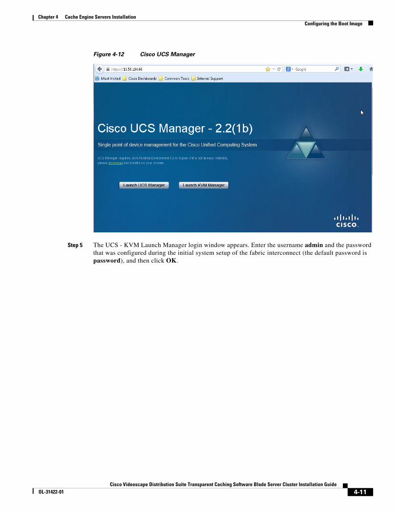
Figure 4-12 Cisco UCS Manager
Step 5 The UCS - KVM Launch Manager login window appears. Enter the username admin and the password that was configured during the initial system setup of the fabric interconnect (the default password is password), and then click OK.
4-11Cisco Videoscape Distribution Suite Transparent Caching Software Blade Server Cluster Installation Guide
OL-31422-01

Chapter 4 Cache Engine Servers Installation Configuring the Boot Image
Figure 4-13 UCS KVM Launch Manager Login Window
Step 6 The Service Profiles window appears, listing all of the cache engine profiles. From this window, in the row for the cache engine you are configuring, in the Launch KVM column click Launch to launch the KVM console.
4-12Cisco Videoscape Distribution Suite Transparent Caching Software Blade Server Cluster Installation Guide
OL-31422-01

Chapter 4 Cache Engine Servers Installation Configuring the Boot Image
Figure 4-14 Service Profiles Window
Step 7 Click OK to open the .jnlp file with Java(TM) Web Start Launcher.
Step 8 From the KVM Console window, click the KVM Console tab, click the Virtual Media tab.
Step 9 If you see the Unencrypted Virtual Media Session window, choose Accept this session and click Apply.
Figure 4-15 Unencrypted Virtual Media Session
Step 10 Click Add Image.
4-13Cisco Videoscape Distribution Suite Transparent Caching Software Blade Server Cluster Installation Guide
OL-31422-01

Chapter 4 Cache Engine Servers Installation Configuring the Boot Image
Figure 4-16 Add Image
Step 11 Browse to the /opt/pang/iso/ folder to find the ISO installer image and click Open.
Figure 4-17 Browse for Image
Step 12 Check the Mapped check box for the newly added ISO image file.
4-14Cisco Videoscape Distribution Suite Transparent Caching Software Blade Server Cluster Installation Guide
OL-31422-01

Chapter 4 Cache Engine Servers Installation Configuring the Boot Image
Figure 4-18 Map ISO Image
Step 13 Click Reset under the menu bar to reboot the cache engine.
Figure 4-19 Reset the Cache Engine
4-15Cisco Videoscape Distribution Suite Transparent Caching Software Blade Server Cluster Installation Guide
OL-31422-01

Chapter 4 Cache Engine Servers Installation Configuring the Boot Image
Step 14 From the Reset Server Warning window that appears, click OK to reset the server.
Figure 4-20 Reset Server Warning Window
Step 15 From the Reset Server Service window that appears, choose Power Cycle and click OK.
4-16Cisco Videoscape Distribution Suite Transparent Caching Software Blade Server Cluster Installation Guide
OL-31422-01

Chapter 4 Cache Engine Servers Installation Configuring the Boot Image
Figure 4-21 Reset Server Service
Step 16 From the KVM Console window you will see the VDS TC Cache Engine reboot. When you see the prompt to press F6 to enter the boot menu, click the KVM Console window to make sure it has focus and press F6. The Please Select Boot Device dialog box appears.
Note You may need to press F6 several times to see the Please Select Boot Device dialog box.
4-17Cisco Videoscape Distribution Suite Transparent Caching Software Blade Server Cluster Installation Guide
OL-31422-01

Chapter 4 Cache Engine Servers Installation Configuring the Boot Image
Figure 4-22 System Reboot Window
Step 17 Using the up and down arrows, choose Cisco Virtual CD/DVD. The system will reboot from the virtual ISO image.
4-18Cisco Videoscape Distribution Suite Transparent Caching Software Blade Server Cluster Installation Guide
OL-31422-01

Chapter 4 Cache Engine Servers Installation Configuring the Boot Image
Figure 4-23 Select Boot Device Window
Step 18 When the VDS-TC Installer environment displays in the KVM console window, choose Installer - No Serial.
Figure 4-24 VDS TC Installer Window
Step 19 When the Welcome screen appears, enter Y to continue the installation process.
4-19Cisco Videoscape Distribution Suite Transparent Caching Software Blade Server Cluster Installation Guide
OL-31422-01

Chapter 4 Cache Engine Servers Installation Configuring the Boot Image
Figure 4-25 Welcome Screen
Step 20 When the Choose the Appliance Deployment window appears, choose Cache Engine and select OK.
Figure 4-26 Choose the Appliance Deployment Window
Step 21 When prompted, enter the cache engine number and choose OK.
4-20Cisco Videoscape Distribution Suite Transparent Caching Software Blade Server Cluster Installation Guide
OL-31422-01

Chapter 4 Cache Engine Servers Installation Configuring the Boot Image
Figure 4-27 Enter Cache Engine Number
Step 22 Confirm the Cache Engine configuration. If everything is correct, choose Yes. If there is a mistake, choose No and repeat Step 20 through Step 22.
Figure 4-28 Configuration Confirmation
Step 23 From the KVM window you will see the installation begin. You must wait for this installation process to complete before you continue.
Note Please be aware that the installation may take more than an hour.
4-21Cisco Videoscape Distribution Suite Transparent Caching Software Blade Server Cluster Installation Guide
OL-31422-01

Chapter 4 Cache Engine Servers Installation Configuring the Boot Image
Figure 4-29 Cache Engine Installation Process
Step 24 When the installation completes, you must unmap the ISO image file. When the “Installation completed. Press <Enter> to reboot.” message appears, press Enter.
Note Wait for the system to reboot and display the BIOS splash screen, as shown in Figure 4-22 “System Reboot Window”, before proceeding to the next step.
Figure 4-30 Installation Completed Window
Step 25 After the system reboots, from the KVM Console window, click the Virtual Media tab and uncheck the Mapped check box next to the ISO image file.
Step 26 In the Unmap Drive Requested dialog box, click Yes to confirm the unmapping the image file. This unmounts the ISO image.
4-22Cisco Videoscape Distribution Suite Transparent Caching Software Blade Server Cluster Installation Guide
OL-31422-01
Chapter 4 Cache Engine Servers Installation Configuring the Boot Image
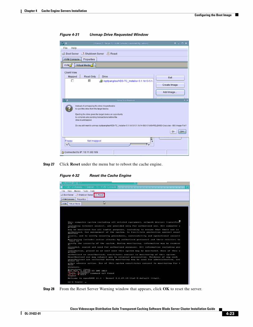
Figure 4-31 Unmap Drive Requested Window
Step 27 Click Reset under the menu bar to reboot the cache engine.
Figure 4-32 Reset the Cache Engine
Step 28 From the Reset Server Warning window that appears, click OK to reset the server.
4-23Cisco Videoscape Distribution Suite Transparent Caching Software Blade Server Cluster Installation Guide
OL-31422-01
Chapter 4 Cache Engine Servers Installation Configuring the Boot Image
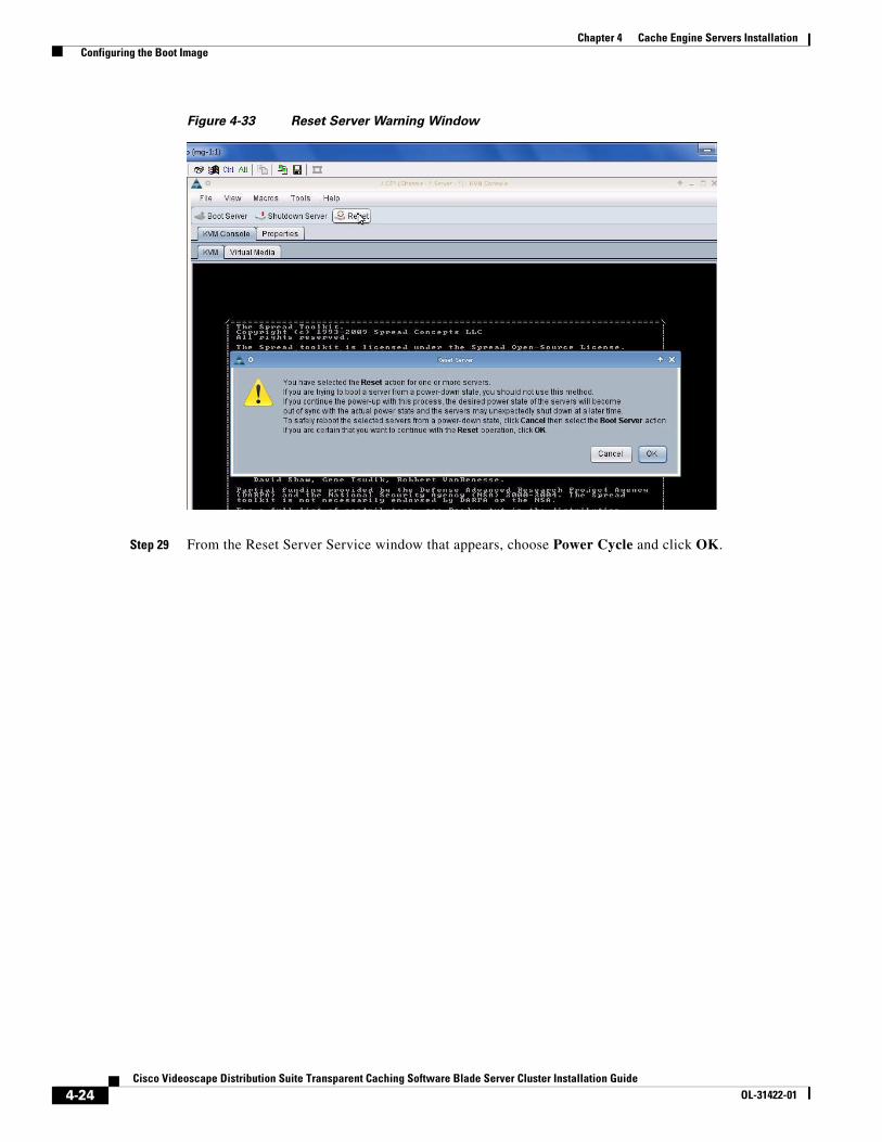
Figure 4-33 Reset Server Warning Window
Step 29 From the Reset Server Service window that appears, choose Power Cycle and click OK.
4-24Cisco Videoscape Distribution Suite Transparent Caching Software Blade Server Cluster Installation Guide
OL-31422-01

Chapter 4 Cache Engine Servers Installation Running the Post Installation Scripts
Figure 4-34 Reset Server Service
Running the Post Installation ScriptsAfter rebooting the VDS TC Cache Engine, you must run a post installation script. Use this procedure to run this script:
Note This procedure needs to be completed on all Cache Engines.
Procedure
Step 1 From the KVM Console window, on the KVM tab, log in using the root user and the password that was provided by Cisco.
Step 2 Enter the command cd /opt/pang/utilities/DS/
Step 3 Enter the command tar -zxvf rdac-LINUX-09.03.0C05.0652-source.tar.gz.
Step 4 Enter the command cd linuxrdac-09.03.0C05.0652.
Step 5 Enter the command make clean.
Step 6 Enter the command make.
Step 7 Enter the command make install.
4-25Cisco Videoscape Distribution Suite Transparent Caching Software Blade Server Cluster Installation Guide
OL-31422-01

Chapter 4 Cache Engine Servers Installation Running the Post Installation Scripts
Step 8 If you are prompted about whether the new MPP driver should manage the iSCSI storages, answer yes to continue.
Step 9 Enter the command reboot to reboot the cache engine.
Step 10 After the cache engine reboots, log back into the KVM console as the root user, using the password that was provided by Cisco.
Step 11 To verify that the installation of the multipath driver was successful, enter the command chkconfig mpp. If the installation was successful, this command should return the following output:
mpp on
Next you will configure the storage for the cache engines. This configuration is covered in the next chapter, Chapter 5, “Configuring the Cache Storage”.
4-26Cisco Videoscape Distribution Suite Transparent Caching Software Blade Server Cluster Installation Guide
OL-31422-01

Cisco Videoscape Distribution Suite Transparent CachinOL-31422-01
C H A P T E R 5
Configuring the Cache StorageThis chapter includes information about configuring the storage, installing Storage Manager, connecting to the storage using Storage Manager software, and integrating the VDS TC Cache Engines with the storage.
Ensure that you have installed the operating system on your VDS TC Management Server and the VDS TC Cache Engines before starting the configuration in this chapter.
This chapter contains the following sections:
• Installing the Storage Manager on the Management Server
• Configuring the First Storage Array
• Configuring the Remaining Storage Arrays
• Configuring the Storage and Formatting Storage Disks
Installing the Storage Manager on the Management ServerUse this procedure to install the Storage Manager software on the VDS TC Management Server:
Procedure
Step 1 If you do not already have a VNC client connection open to the VDS TC Management Server, open one now. If you encounter problems opening a VNC client connection to the VDS TC Management Server, you may need to restart VNC Server 1 on the VDS TC Management Server. Follow these steps to restart this server:
a. From an SSH connection to the VDS TC Management server where you are logged in with root permissions, enter the command rm /tmp/.X11-unix/X1.
b. Enter the command vncserver :1 to start the VNC Server.
Note If you have problems restarting the VNC Server 1 instance, you can also start another VNC Server instance by entering the command vncserver :2.
Step 2 From the VNC console window, if you are prompted to log in, enter the root user with the password that was provided by Cisco. If you are not prompted to log in, enter the whoami command to determine the username of the current session. Make sure that you are logged in as root. If you are not logged in as root, enter the su root command to switch to the root user. Enter the password that was provided by Cisco for the root account.
5-1g Software Blade Server Cluster Installation Guide

Chapter 5 Configuring the Cache Storage Installing the Storage Manager on the Management Server
Step 3 From the VNC console, enter the command cd /opt/pang/utilities/DS/DS3500_FW86 to change folders.
Step 4 Enter the command tar -zxvf SM10.86_Linux_64bit_x86-64_SMIA-10.86.x5.43.tgz.
Step 5 After the files are extracted, enter the command cd ./Linux_x64_10p86/Linux_x86-64/ to change folders.
Step 6 Enter the command chmod 777 SMIA-LINUXX64-10.86.0A05.0043.bin to set permissions on the file.
Step 7 Next, to start the Management Station installation enter the command ./SMIA-LINUXX64-10.86.0A05.0043.bin.
Step 8 The IBM System Storage™ DS Storage Manager installation window appears. From the initial screen, click OK to continue in English.
Figure 5-1 IBM DS Storage Manager Initial Screen
Step 9 The Introduction window appears. Click Next.
5-2Cisco Videoscape Distribution Suite Transparent Caching Software Blade Server Cluster Installation Guide
OL-31422-01

Chapter 5 Configuring the Cache Storage Installing the Storage Manager on the Management Server
Figure 5-2 IBM DS Storage Manager Introduction Window
Step 10 The Copyright Window appears. Click Next.
Figure 5-3 IBM DS Storage Manager Copyright Window
Step 11 Choose I accept the terms of the License Agreement and click Next.
5-3Cisco Videoscape Distribution Suite Transparent Caching Software Blade Server Cluster Installation Guide
OL-31422-01

Chapter 5 Configuring the Cache Storage Installing the Storage Manager on the Management Server
Figure 5-4 IBM DS Storage Manager License Agreement
Step 12 From the Select Installation Type window, click Management Station and click Next.
Figure 5-5 Installation Type Window
Step 13 You will see the installation begin.
5-4Cisco Videoscape Distribution Suite Transparent Caching Software Blade Server Cluster Installation Guide
OL-31422-01

Chapter 5 Configuring the Cache Storage Configuring the First Storage Array
Figure 5-6 IBM DS Storage Manager Installation
Step 14 When the installation completes, click Done.
Figure 5-7 IBM DS Manager Installation Complete
Configuring the First Storage ArrayAfter the Management Station installation completes, you must configure the first storage array. Use this procedure to configure the first storage array:
5-5Cisco Videoscape Distribution Suite Transparent Caching Software Blade Server Cluster Installation Guide
OL-31422-01

Chapter 5 Configuring the Cache Storage Configuring the First Storage Array
Procedure
Step 1 After the Management Station installation completes, in the xterm window enter the command cd /opt/IBM_DS/client to change folders.
Step 2 Enter the command ./SMclient to start the The IBM System Storage™ DS Storage Manager software.
Step 3 Power down all storage arrays that you are not currently configuring or that are not already configured. For example, if you are configuring storage array 1, it should be the only storage array powered up. When powering up a storage array, wait at least 5 minutes before you proceed.
Caution Verify, physically, that only one none-configured storage array is powered-up.
Step 4 From the Storage Manager client, click the Setup tab.
Step 5 From the Initial Setup Tasks window, click Add Storage Subsystem.
Figure 5-8 Initial Setup Tasks
Step 6 From the Select Addition Method window, click Manual.
5-6Cisco Videoscape Distribution Suite Transparent Caching Software Blade Server Cluster Installation Guide
OL-31422-01

Chapter 5 Configuring the Cache Storage Configuring the First Storage Array
Figure 5-9 Select Addition Method
Step 7 From the Add New Storage Subsystem window, in the first Controller field under Out-of-band Management, enter 192.168.128.101.
Step 8 In the second Controller field under Out-of-Band Management, enter 192.168.128.102.
Note Ensure that a single IP address is entered in each controller field.
Step 9 Click Add.
Figure 5-10 Add New Storage Subsystem Window
Step 10 From the Add Additional Devices window, click No.
5-7Cisco Videoscape Distribution Suite Transparent Caching Software Blade Server Cluster Installation Guide
OL-31422-01

Chapter 5 Configuring the Cache Storage Configuring the First Storage Array
Step 11 From the Devices tab, click Storage Subsystem Unnamed.
Figure 5-11 Storage Subsystem
5-8Cisco Videoscape Distribution Suite Transparent Caching Software Blade Server Cluster Installation Guide
OL-31422-01

Chapter 5 Configuring the Cache Storage Configuring the First Storage Array
Step 12 From the Unnamed Disk Pool Automatic Configuration window, click No.
Figure 5-12 Unamed Disk Pool Automatic Configuration
Step 13 In the Storage Subsystem Password dialog box, click No.
Figure 5-13 Storage Subsystem Password Dialog Box
Step 14 In the Initial Setup Tasks window, click the Setup tab and click Configure Ethernet Management Ports.
5-9Cisco Videoscape Distribution Suite Transparent Caching Software Blade Server Cluster Installation Guide
OL-31422-01

Chapter 5 Configuring the Cache Storage Configuring the First Storage Array
Figure 5-14 Configure Ethernet Management Ports
Step 15 From the window that appears, from the Ethernet Port drop-down list ensure Controller A, Port 1 is selected.
Step 16 From the Speed and Duplex Mode drop-down list, choose 1Gbps, Full Duplex.
Step 17 From the IPv4 Settings tab, click the Specify Configuration radio button.
Step 18 In the IP address field, enter 10.11.18.200.
Step 19 In the Subnet Mask field, enter 255.255.255.0.
Step 20 From the Ethernet Port drop-down list, choose Controller B, Port 1.
Step 21 From the Speed and Duplex Mode drop-down list, choose 1Gbps, Full Duplex.
Step 22 From the IPv4 Settings tab, click the Specify Configuration radio button.
Step 23 In the IP address field, enter 10.11.18.201.
Step 24 In the Subnet Mask field, enter 255.255.255.0.
Step 25 Click OK. The storage array disconnects.
5-10Cisco Videoscape Distribution Suite Transparent Caching Software Blade Server Cluster Installation Guide
OL-31422-01

Chapter 5 Configuring the Cache Storage Configuring the First Storage Array
Figure 5-15 Controller Configuration
Step 26 Close the subsystem management window.
Step 27 From the Enterprise Management window, remove the system that was previously added using the default factory IPs (The system is highlighted in red when the IP addresses change.)
Step 28 Click the Setup tab and click Add Storage Subsystem to re-add the system with the new IP addresses.
Step 29 From the Add New Storage Subsystem window, in the IP address fields under Out-of-band Management, enter 10.11.18.200 and 10.11.18.201. These are the IP addresses that were assigned to Controller A, port 1 and Controller B, port1.
Step 30 Click Add.
5-11Cisco Videoscape Distribution Suite Transparent Caching Software Blade Server Cluster Installation Guide
OL-31422-01

Chapter 5 Configuring the Cache Storage Configuring the First Storage Array
Figure 5-16 Add New Storage Subsystem Window
Step 31 In the Automatic Configuration window, click No.
Step 32 In the Storage Subsystem Password window, click No.
Figure 5-17 Password Not Set Window
Step 33 From the Initial Setup Tasks window, click the Setup tab.
Step 34 Click Configure iSCSI Host Ports.
Caution If the user-interface does not show the Configure iSCSI Host Ports link, you should STOP here and contact the storage vendor, because this storage array is not running the correct firmware version that supports iSCSI configuration. You must update the storage firmware to version 07.86.32.
5-12Cisco Videoscape Distribution Suite Transparent Caching Software Blade Server Cluster Installation Guide
OL-31422-01

Chapter 5 Configuring the Cache Storage Configuring the First Storage Array
Figure 5-18 Configure iSCSI Host Ports
Step 35 From the window that appears, from the Ethernet Port drop-down list choose Controller A, HIC 1, Port 3.
Step 36 Ensure that the Enable IPv4 check box is checked and that the IPv6 check box is not checked.
Step 37 From the IPv4 Settings tab, click the Specify Configuration radio button.
Step 38 In the IP address field, enter 10.11.14.100.
Step 39 In the Subnet Mask field, enter 255.255.255.0.
5-13Cisco Videoscape Distribution Suite Transparent Caching Software Blade Server Cluster Installation Guide
OL-31422-01

Chapter 5 Configuring the Cache Storage Configuring the First Storage Array
Figure 5-19 Configure IP Address
Step 40 Click Advanced Port Settings.
Step 41 From the window that appears, check the Enable Jumbo Frames check box and enter 9000 in the MTU Size field.
Figure 5-20 Enable Jumbo Frames
Step 42 If you are using 10Gb iSCSI ports on the storage subsystem to connect to the cache engines, perform the following substeps:
5-14Cisco Videoscape Distribution Suite Transparent Caching Software Blade Server Cluster Installation Guide
OL-31422-01

Chapter 5 Configuring the Cache Storage Configuring the Remaining Storage Arrays
Note These substeps are only for installations that use 10Gb Ethernet connections from the cache engines to the iSCSI ports of the storage subsystem.
a. Repeat Steps 35 through 40 for Controller B port 3. Assign this port an IP address of 10.11.14.101.
b. Confirm that the Enable IPv4 or the Enable IPv6 check boxes for Controller A port 4 and Controller B port 4 are not checked.
Step 43 If you are using 1Gb Ethernet ports to connect from the cache engines to the iSCSI ports of the storage subsystem, repeat Steps 35 through 40 for the following ports and click OK when finished:
Note The following IP address information is only for installation that use 1Gb Ethernet connections from the cache engines to the iSCSI ports of the storage subsystem.
• Controller A port 4: 10.11.15.100
• Controller A port 5: 10.11.16.100
• Controller A port 6: 10.11.17.100
• Controller B port 3: 10.11.14.101
• Controller B port 4: 10.11.15.101
• Controller B port 5: 10.11.16.101
• Controller B port 6: 10.11.17.101
Configuring the Remaining Storage ArraysNext you must configure the remaining storage enclosures. To do this, power up the next storage enclosure to be configured. Wait five minutes to make sure the unit is powered up and then repeat Steps 4 through 43 in the Configuring the First Storage Array section. Use the Storage Enclosure Management IP Addresses table to determine the management IP addresses to assign to the different enclosures. For installations that use 10Gb connections to the storage enclosure, use the 10Gb installation iSCSI Port Addresses table to determine the IP addresses to assign to the ports en each enclosure and for installations that use 1Gb connections to the storage enclosure use the 1 Gb installation iSCSI Port Addresses table to determine the IP addresses to assign to the ports en each enclosure.
Table 5-1 Storage Enclosure Management IP Addresses
Enclosure Management IP Addresses
Enclosure 2 10.11.18.202, 10.11.18.203
Enclosure 3 10.11.18.204, 10.11.18.205
Enclosure 4 10.11.18.206, 10.11.18.207
Enclosure 5 10.11.18.208, 10.11.18.209
5-15Cisco Videoscape Distribution Suite Transparent Caching Software Blade Server Cluster Installation Guide
OL-31422-01
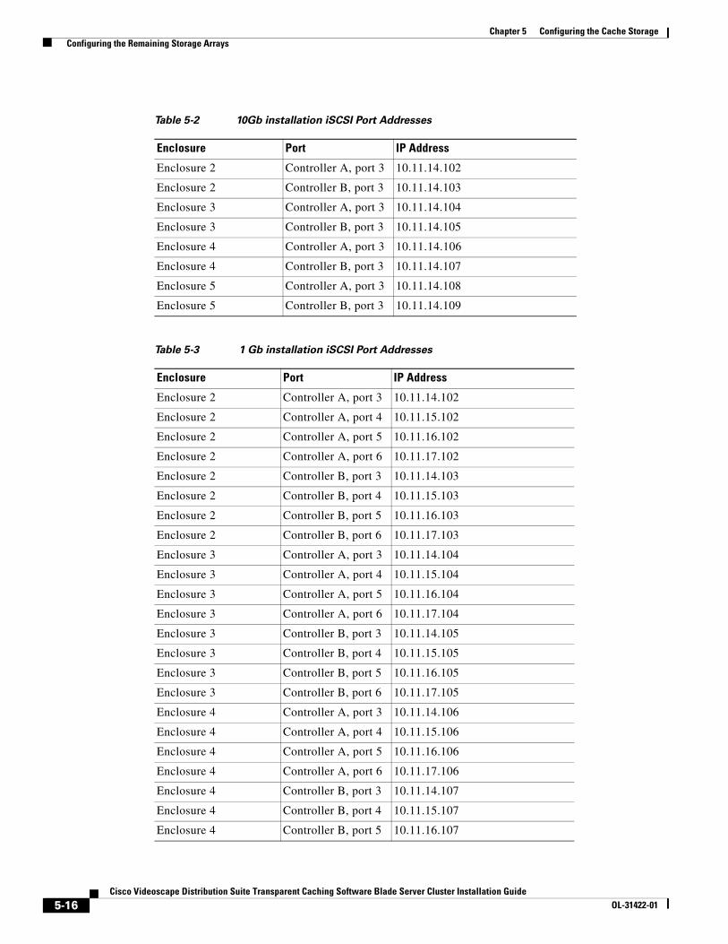
Chapter 5 Configuring the Cache Storage Configuring the Remaining Storage Arrays
Table 5-2 10Gb installation iSCSI Port Addresses
Enclosure Port IP Address
Enclosure 2 Controller A, port 3 10.11.14.102
Enclosure 2 Controller B, port 3 10.11.14.103
Enclosure 3 Controller A, port 3 10.11.14.104
Enclosure 3 Controller B, port 3 10.11.14.105
Enclosure 4 Controller A, port 3 10.11.14.106
Enclosure 4 Controller B, port 3 10.11.14.107
Enclosure 5 Controller A, port 3 10.11.14.108
Enclosure 5 Controller B, port 3 10.11.14.109
Table 5-3 1 Gb installation iSCSI Port Addresses
Enclosure Port IP Address
Enclosure 2 Controller A, port 3 10.11.14.102
Enclosure 2 Controller A, port 4 10.11.15.102
Enclosure 2 Controller A, port 5 10.11.16.102
Enclosure 2 Controller A, port 6 10.11.17.102
Enclosure 2 Controller B, port 3 10.11.14.103
Enclosure 2 Controller B, port 4 10.11.15.103
Enclosure 2 Controller B, port 5 10.11.16.103
Enclosure 2 Controller B, port 6 10.11.17.103
Enclosure 3 Controller A, port 3 10.11.14.104
Enclosure 3 Controller A, port 4 10.11.15.104
Enclosure 3 Controller A, port 5 10.11.16.104
Enclosure 3 Controller A, port 6 10.11.17.104
Enclosure 3 Controller B, port 3 10.11.14.105
Enclosure 3 Controller B, port 4 10.11.15.105
Enclosure 3 Controller B, port 5 10.11.16.105
Enclosure 3 Controller B, port 6 10.11.17.105
Enclosure 4 Controller A, port 3 10.11.14.106
Enclosure 4 Controller A, port 4 10.11.15.106
Enclosure 4 Controller A, port 5 10.11.16.106
Enclosure 4 Controller A, port 6 10.11.17.106
Enclosure 4 Controller B, port 3 10.11.14.107
Enclosure 4 Controller B, port 4 10.11.15.107
Enclosure 4 Controller B, port 5 10.11.16.107
5-16Cisco Videoscape Distribution Suite Transparent Caching Software Blade Server Cluster Installation Guide
OL-31422-01

Chapter 5 Configuring the Cache Storage Configuring the Storage and Formatting Storage Disks
Configuring the Storage and Formatting Storage DisksUse this procedure to configure the storage:
Procedure
Step 1 Before you configure the storage devices, you must verify that the Enclosure ID is 99 for each storage subsystem. Follow these steps to confirm the Enclosure ID and change if necessary:
Note Perform these steps on all of the storage subsystems:
a. From the IBM DS Storage Manager, click the Devices tab.
b. Right-click the storage subsystem and choose Manage Storage Subsystem.
c. Click the Hardware tab.
d. From the Hardware tab, verify that the Enclosure ID is 99. You can verify this information in multiple places on the Hardware tab, as shown in the following figure.
Enclosure 4 Controller B, port 6 10.11.17.107
Enclosure 5 Controller A, port 3 10.11.14.108
Enclosure 5 Controller A, port 4 10.11.15.108
Enclosure 5 Controller A, port 5 10.11.16.108
Enclosure 5 Controller A, port 6 10.11.17.108
Enclosure 5 Controller B, port 3 10.11.14.109
Enclosure 5 Controller B, port 4 10.11.15.109
Enclosure 5 Controller B, port 5 10.11.16.109
Enclosure 5 Controller B, port 6 10.11.17.109
Table 5-3 1 Gb installation iSCSI Port Addresses
Enclosure Port IP Address
5-17Cisco Videoscape Distribution Suite Transparent Caching Software Blade Server Cluster Installation Guide
OL-31422-01

Chapter 5 Configuring the Cache Storage Configuring the Storage and Formatting Storage Disks
Figure 5-21 Storage Subsystem Enclosure ID
e. If the Enclosure ID is 99, go to step j. If the Enclosure ID is not 99, click View Enclosure Components, located above the front view of the enclosure.
f. From the Enclosure Component Information window, click Change Enclosure ID.
Figure 5-22 Enclosure Component Information
5-18Cisco Videoscape Distribution Suite Transparent Caching Software Blade Server Cluster Installation Guide
OL-31422-01

Chapter 5 Configuring the Cache Storage Configuring the Storage and Formatting Storage Disks
g. The Change Enclosure ID window appears. From this window, choose 99 from the “Change Enclosure ID to” drop-down list and click OK.
Figure 5-23 Change Enclosure ID
h. Click Close to close the Enclosure Component Information window.
i. Choose Storage Subsystem > Exit to close the Subsystem Management window.
j. Repeat these steps for the rest of the storage subsystems.
Step 2 From the VNC console connection to the VDS TC Management Server, enter the command cd /opt/pang/useful/configure_storages/ to change folders.
Step 3 Next, enter the command ./configure_storages.py -s [no_of_storage_enclosures] -b [no_of_blades].
Step 4 The following warning message regarding the disk formatting will appear:
*********** WARNING! **********All storages are about to be reconfigured. All data on the data disks will be lost.
Do you want to continue? (y/n)
Step 5 To continue the storages configuration and formatting of the their disks, enter y.
Step 6 Follow the on screen instructions. If prompted, enter the password for the root user that was provided by Cisco.
Note You may be prompted to enter the password several times.
Step 7 If you see the message “MegaCLI is not installed, so SSD disks will not be detected and formatted. Do you wish to continue anyway?”, enter Y.
Step 8 After running this script, the storage arrays should be configured and formatted and all of the VDS TC Cache Engines will connect to the storage enclosures.
Step 9 From the VDS TC Management Server, open the IBM DS Storage Manager.
5-19Cisco Videoscape Distribution Suite Transparent Caching Software Blade Server Cluster Installation Guide
OL-31422-01
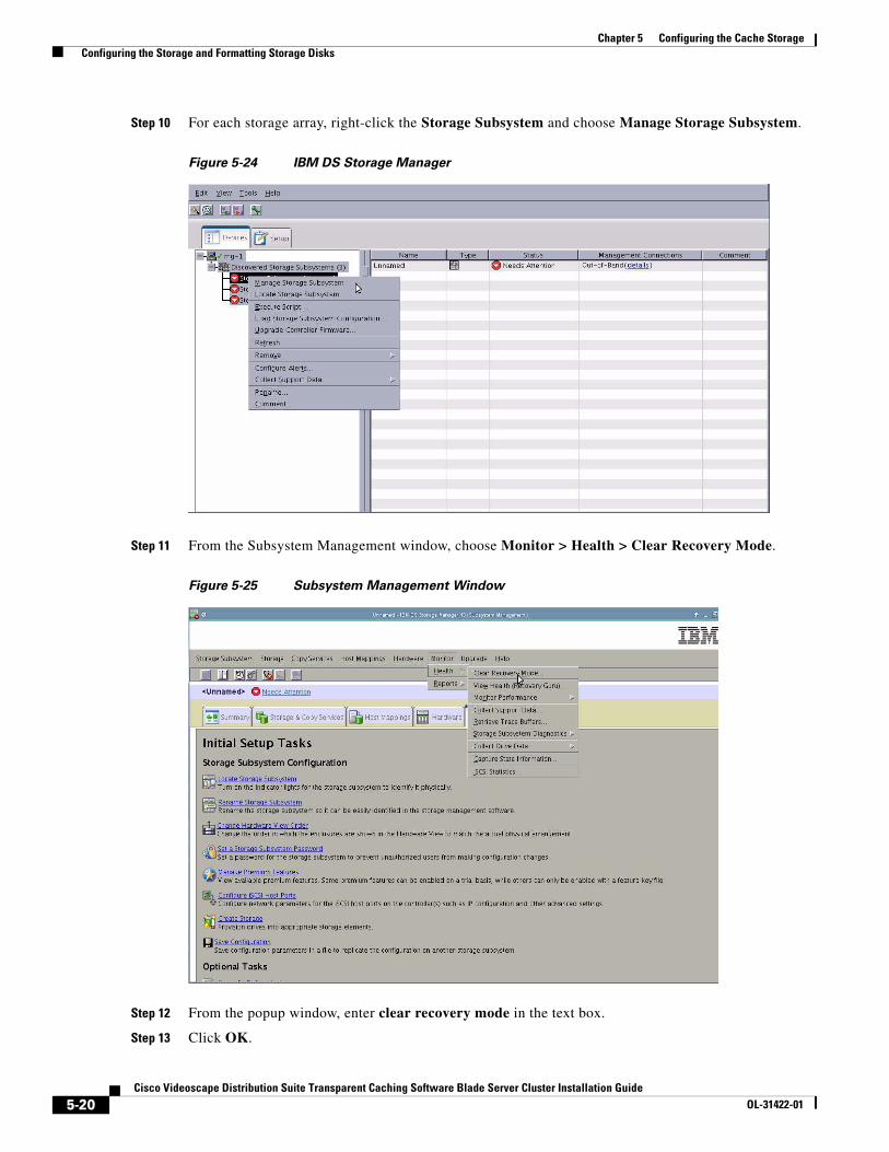
Chapter 5 Configuring the Cache Storage Configuring the Storage and Formatting Storage Disks
Step 10 For each storage array, right-click the Storage Subsystem and choose Manage Storage Subsystem.
Figure 5-24 IBM DS Storage Manager
Step 11 From the Subsystem Management window, choose Monitor > Health > Clear Recovery Mode.
Figure 5-25 Subsystem Management Window
Step 12 From the popup window, enter clear recovery mode in the text box.
Step 13 Click OK.
5-20Cisco Videoscape Distribution Suite Transparent Caching Software Blade Server Cluster Installation Guide
OL-31422-01

Chapter 5 Configuring the Cache Storage Configuring the Storage and Formatting Storage Disks
Figure 5-26 Clear Recovery Mode
Next you will install and configure the Cisco VDS TC Cluster Software. This configuration is covered in the next chapter, Chapter 6, “Installing and Configuring the Cisco VDS TC Cluster Software”.
5-21Cisco Videoscape Distribution Suite Transparent Caching Software Blade Server Cluster Installation Guide
OL-31422-01
Chapter 5 Configuring the Cache Storage Configuring the Storage and Formatting Storage Disks
5-22Cisco Videoscape Distribution Suite Transparent Caching Software Blade Server Cluster Installation Guide
OL-31422-01

Cisco Videoscape Distribution Suite Transparent CachinOL-31422-01
C H A P T E R 6
Installing and Configuring the Cisco VDS TC Cluster SoftwareThis chapter includes information for installing the VDS TC Cluster platform software, including pre-installation and post-installation steps.
The VDS TC Cluster software installation script installs the VDS TC caching software and installs management tools, such as the VDS TC Management software, SNMP MIBs, and the CLI environment. Upon completion, the installer performs some verification tests, such as verifying the directory structure accessibility and the reachability of IP addresses.
Note The steps in this chapter should only be run on the VDS TC Management Server. The procedures in this chapter will distribute the Cisco software packages to all of the servers.
This chapter contains the following sections:
• Installing the Management Environment and Software
• Post Installation Steps
Installing the Management Environment and SoftwareUse this procedure to install the management environment and software:
Procedure
Step 1 Using an SSH session that is connected to the VDS TC Management server, enter the command su root to login as the root user.
Step 2 Enter the command cd /tftpboot to change folders.
Step 3 Enter the ls command to see the name of the archive file. The file you are looking for will start with VDS-TC_FI and will include Server_Cluster in the filename. Record the name of this file because you will need it in a later step. The numbers in the archive file represent the version of the VDS TC caching software. For example, the file named VDS-TC_FI_5.1.1b28_Server_Cluster.tar.gz would be for a VDS TC Cluster installation and the version number of the software is 5.1.1b28.
Step 4 Enter the command mkdir version, where version is the version number in the archive file you discovered in Step 3. For example, if the file you discovered in Step 3 was VDS-TC_FI_5.1.1b28_Server_Cluster.tar.gz, enter the command mkdir 5.1.1b28.
6-1g Software Blade Server Cluster Installation Guide

Chapter 6 Installing and Configuring the Cisco VDS TC Cluster Software Installing the Management Environment and Software
Step 5 Use the cd command to change to the directory you created in Step 4, for example cd 5.1.1b28.
Step 6 You must extract the VDS-TC software from the packed archive, located in the /tftpboot folder. Enter the command tar -zxvf ../archive_name, where archive_name is the name of the file you discovered in Step 3. For example, enter the command tar -zxvf ../VDS-TC_FI_5.1.1b28_Server_Cluster.tar.gz.
Step 7 Enter the command cd /opt/pang/useful.
Step 8 Enter the command ./replace_server_keys.sh –servers XX, where XX is the number of cache engines in your installation. For example, in a VDS TC 16B installation, enter the command ./replace_server_keys.sh –servers 16.
Step 9 Next you must edit the GA_installer.rc file to reflect the number of cache engine servers to be installed in the Cluster. Use the command vi GA_installer.rc to edit this file. The following is an example of what that file should look like for the first time install of four servers and the management server.
#MANAGEMENT_SOFTWARE {no, yes}MANAGEMENT_SOFTWARE=yes
#UPGRADEL_CACHE_SOFTWARE {all, none, space separated list(ce-1 ce-2 ce-3 ce-4 ce-5 ce-6 ce-7 ce-8 ce-9 ce-10 ce-11 ce-12 ce-13 ce-14 ce-15 ce-16)}UPGRADEL_CACHE_SOFTWARE=ce-1 ce-2 ce-3 ce-4
UPGRADE_TAR_BALL=<filename>.tar.gzMANAGEMENT_ENVIRONMENT=yesGRACE_UPGRADE=yesFIRST_INSTALL=yes
Step 10 To adjust the number of cache engine servers being installed, edit the line UPGRADEL_CACHE_SOFTWARE=ce-1 ce-2 ce-3 ce-4, listing the cache engines that you are installing.
Step 11 When you are finished editing the GA_installer.rc file, in the vi editor enter :x and press Enter to save and exit the file.
Step 12 Enter the command ./GA_installer.sh to run the first installation script.
Step 13 At the Enter primary name server IP prompt, enter the IP address of your primary DNS server.
Note If a DNS server is unavailable, enter 0.0.0.0 as the IP address of the DNS server to prevent system functionality from being negatively affected.
Step 14 Enter y to confirm the entry.
Step 15 At the Enter secondary name server IP prompt, enter the IP address of your secondary DNS server.
Note If no secondary DNS server is unavailable, leave this entry blank.
Step 16 Enter y to confirm the entry.
Step 17 The GA Installer script displays a summary of the configuration. Review this configuration. If the configuration is correct, press Y to proceed. If the configuration is not correct, press N to exit the installation and start over.
Step 18 When asked if you want to change the management IPv4 settings, enter N unless you need to change the IP address information that was configured during the original VDS TC Management Server installation. If you enter Y, enter information at the following prompts:
• Management IPv4 address ():
6-2Cisco Videoscape Distribution Suite Transparent Caching Software Blade Server Cluster Installation Guide
OL-31422-01

Chapter 6 Installing and Configuring the Cisco VDS TC Cluster Software Post Installation Steps
• Management IPv4 netmask ():
• Default IPv4 gateway ():
Note To accept the current setting, press Enter.
Step 19 When asked if you want to change the management IPv6 settings, enter N.
Note While the VDS TC software contains the infrastructure to configure IPv6 on the management server, this functionality is not currently supported.
Step 20 Wait for the installation script to finish before continuing on to the next step.
Post Installation StepsUse the following procedure after installing the management environment and software to perform the post installation steps. Part of the post installation steps is to copy a configuration file to the VDS TC Management Server. The configuration file sets the environment variables and configuration for the VDS TC application. A sample configuration file is provided in a .tgz file that is available from the same location as the VDS TC ISO image file on www.cisco.com. In this section you will copy an example configuration file, edit this file, and import the new configuration file to the VDS TC Management Server.For more information about editing the configuration files in this section, see the Cisco Videoscape Distribution Suite Transparent Caching Software Configuration Guide (part number OL-28016-03).
Procedure
Step 1 Download the .tgz file that is available from the same location as the VDS TC ISO image file on www.cisco.com. In this .tgz file, locate the sample configuration file that matches the number of VDS TC Cache Engines that are installed in your VDS TC Blade Server installation.
Step 2 Edit the sample configuration file and make the required changes in the following sections. For more information editing the required parameters in the cluster_conf.xml file, see the Cisco Videoscape Distribution Suite Transparent Caching Software Configuration Guide (part number OL-28016-02).
• The <mgmt-config> controls the management IP environment section.
• The <network> section controls the data network addresses.
• The <service> section controls the cache out port configuration.
Step 3 Save your changes and rename the file cluster_conf.xml.
Step 4 Using SFTP software, such as WinSCP, connect to the management IP address that you assigned to the VDS TC Management Server. Log in using the user name padmin and the password that was provided by Cisco.
Step 5 Copy the example configuration file that you saved in Step 3 into the /tftpboot folder on the VDS TC Management Server.
Step 6 From the CE prompt, enter the command su admin. The Regular mode prompt, console>, appears.
6-3Cisco Videoscape Distribution Suite Transparent Caching Software Blade Server Cluster Installation Guide
OL-31422-01

Chapter 6 Installing and Configuring the Cisco VDS TC Cluster Software Post Installation Steps
Note If you need to open a new SSH window to the VDS TC cache engine, enter the management IP address of the VDS TC cache engine and log in using the username padmin and the password that was provided by Cisco. Enter the command su root to change to the root user and when prompted, enter the password for the root user that was provided by Cisco.
Step 7 To log into the Enable mode, you need the system ID to use for the password. Enter the command show systemid to determine the system ID.
Step 8 Enter the command enable to switch to Enable mode. Enter the system ID discovered in Step 7 for the password, excluding the leading *. The prompt changes to console#.
Step 9 To be able to import and apply the new configuration, enter the command config to switch to Configuration mode.
Step 10 To import the edited configuration file, enter the command import 127.0.0.1 cluster_conf.xml.
Step 11 To confirm your changes to the configuration file, enter the command diff. The new configuration parameters are indicated by a plus (+) sign as the first character on the line, while the current configuration parameters are indicated by a minus (-) sign as the first character on the line. If there are no proposed configuration changes to display, the command returns the message “Configurations are identical”.
Step 12 To apply the imported configuration file, enter the command apply.
Caution If you have configured the timezone of the VDS TC management server or cache engines, or if you have configured the VDS TC management server to use an external NTP time server, you must repeat the NTP configuration after importing a cluster_conf file.
Step 13 Enter the command show cluster-bus-ip to check if the spread communication among cluster members is set to broadcast.
console# show cluster-bus-ip Processing...MG-1: [Broadcast]CE-1: [Broadcast]CE-2: [Broadcast]CE-3: [Broadcast]CE-4: [Broadcast]CE-5: [Broadcast]CE-6: [Broadcast]CE-7: [Broadcast]CE-8: [Broadcast]OK. All the CEs are configured to work with Broadcast IP.
Step 14 If the communication is set to broadcast, continue on to the Installing the License section. If the communication is set to multicast instead of broadcast, enter the command cluster-bus-ip broadcast. For example:
configuration# cluster-bus-ip broadcastProcessing...All the CEs are configured to work with Broadcast IP.
Step 15 Enter the command exit to exit the Configuration mode.
Step 16 Enter the command show cluster-bus-ip to confirm that the management server and all cache engines are configured to use broadcast. For example:
console# show cluster-bus-ip Processing...
6-4Cisco Videoscape Distribution Suite Transparent Caching Software Blade Server Cluster Installation Guide
OL-31422-01

Chapter 6 Installing and Configuring the Cisco VDS TC Cluster Software Post Installation Steps
MG-1: [Broadcast]CE-1: [Broadcast]CE-2: [Broadcast]CE-3: [Broadcast]CE-4: [Broadcast]CE-5: [Broadcast]CE-6: [Broadcast]CE-7: [Broadcast]CE-8: [Broadcast]OK. All the CEs are configured to work with Broadcast IP.
Installing the LicenseAfter importing the configuration file you need to install a valid license. After you obtain a valid VDS TC license from Cisco use this procedure to install the VDS TC license:
Procedure
Step 1 Copy the license file to the /tftpboot/ folder on the VDS TC Management Server using SFTP software, such as WinSCP.
Step 2 To import the license file to the system from the VDS TC Enable mode CLI, enter the command license import 127.0.0.1 filename, where filename is the license file name. When you enter this command, the details of the license will be displayed. Verify the features of the license and the expiration date.
Step 3 To activate the imported license, enter the command license activate. Enter Y when prompted to confirm the activation.
Step 4 Enter the command oper service start to start the VDS TC service.
Step 5 To confirm that the VDS TC service has successfully started, enter the command show system and look for a device state of “started”.
6-5Cisco Videoscape Distribution Suite Transparent Caching Software Blade Server Cluster Installation Guide
OL-31422-01

Chapter 6 Installing and Configuring the Cisco VDS TC Cluster Software Post Installation Steps
6-6Cisco Videoscape Distribution Suite Transparent Caching Software Blade Server Cluster Installation Guide
OL-31422-01

Cisco Videoscape Distribution Suite TranOL-31422-01
A
P P E N D I X A Cisco VDS TC Blade Server Cabling GuidesRevised: March 2014, OL-31422-01
This appendix provides cabling guidelines for cabling a VDS TC Cluster solution that uses Cisco Blade Servers and a Cisco Nexus 7004 or 7010 switch for the data and management switch.
There are six different configurations available for a VDS TC Blade Server Cluster installation that use the Cisco Nexus 7004 or 7010 switch for the data and management switch. This appendix provides a separate set of tables for each one of these configurations:
• VDS-TC-4B Non-Redundant Cabling Scheme
• VDS-TC-4B Redundant Cabling Scheme
• VDS-TC-8B Non-Redundant Cabling Scheme
• VDS-TC-8B Redundant Cabling Scheme
• VDS-TC-16B Non-Redundant Cabling Scheme
• VDS-TC-16B Redundant Cabling Scheme
A-1sparent Caching Software Installation Guide

Appendix A Cisco VDS TC Blade Server Cabling Guides VDS-TC-4B Non-Redundant Cabling Scheme
VDS-TC-4B Non-Redundant Cabling SchemeThis section provides the cabling scheme for the VDS-TC-4B non-redundant solution.
Cisco Nexus 7004 or 7010 Switch Cabling (VDS-TC-4B Non-Redundant)
Note All connections from the Cisco Nexus 7004 or 7010 switch use a 10GBASE-CU SFP+ 3 meter twinax cable. If a cable longer than 3 meters is required, please refer to the specific product documentation to verify which longer cables are supported.
Local Device Local Port Remote Device Remote Port Notes
Nexus 7004 or 7010 with Line Card in Slot 3
Eth 3/1 Mgmt Uplink To customer environment
Eht3/5 FEX-1 Fex Fabric 10Gb Uplink port 1
Eth3/6 FEX-1 Fex Fabric 10Gb Uplink port 2
Eth3/7 FEX-1 Fex Fabric 10Gb Uplink port 3
Eth3/8 FEX-1 Fex Fabric 10Gb Uplink port 4
Eth3/13 UCS-FI-6248UP (FI 1) Eth1/29
Eth3/14 UCS-FI-6248UP (FI 1) Eth1/30
Eth3/15 UCS-FI-6248UP (FI 1) Eth1/31
Eth3/16 UCS-FI-6248UP (FI 1) Eth1/32
Eth3/29 PBR Router To customer environment
Eth3/30 PBR Router To customer environment
Eth3/31 PBR Router To customer environment
Eth3/32 PBR Router To customer environment
Eth3/37 PBR Router To customer environment
Eth3/38 PBR Router To customer environment
Eth3/39 PBR Router To customer environment
Eth3/40 PBR Router To customer environment
A-2Cisco Videoscape Distribution Suite Transparent Caching Software Installation Guide
OL-31422-01

Appendix A Cisco VDS TC Blade Server Cabling Guides VDS-TC-4B Non-Redundant Cabling Scheme
Cisco 2248TP Fabric Extender Cabling (VDS-TC-4B Non-Redundant) For 1 Gb Connections to the IBM Storage Enclosure
Note Only use this cabling table if you are connecting to the IBM storage enclosure using 1 Gb connections.
Note All connections from the Cisco 2248TP Fabric Extender use a 1000Base-T CAT5 or CAT6 cable except for the connections to the Cisco Nexus 7004 or 7010 switch. The connections from the Cisco 2248TP Fabric Extender to the Cisco Nexus 7004 or 7010 switch use a 10GBASE-CU SFP+ 3 meter twinax cable. If a cable longer than 3 meters is required, please refer to the specific product documentation to verify which longer cables are supported.
Local Device Local PortReference on Nexus 7004/7010 Remote Device Remote Port Notes
Fabric Extender
1 Ethernet101/1/1 IBM Storage 1 Controller1 Mgmt port 1
2 Ethernet101/1/2 IBM Storage 2 Controller1 Mgmt port 1
3 Ethernet101/1/3 IBM Storage 1 Controller2 Mgmt port 1
4 Ethernet101/1/4 IBM Storage 2 Controller2 Mgmt port 1
13 Ethernet101/1/13 IBM Storage 1 Controller1 port 3
14 Ethernet101/1/14 IBM Storage 1 Controller1 port 4
15 Ethernet101/1/15 IBM Storage 1 Controller2 port 3
16 Ethernet101/1/16 IBM Storage 1 Controller2 port 4
17 Ethernet101/1/17 IBM Storage 2 Controller1 port 3
18 Ethernet101/1/18 IBM Storage 2 Controller1 port 4
19 Ethernet101/1/19 IBM Storage 2 Controller2 port 3
20 Ethernet101/1/20 IBM Storage 2 Controller2 port 4
21 Ethernet101/1/21 IBM Storage 1 Controller1 port 5
22 Ethernet101/1/22 IBM Storage 1 Controller1 port 6
23 Ethernet101/1/23 IBM Storage 1 Controller2 port 5
24 Ethernet101/1/24 IBM Storage 1 Controller2 port 6
25 Ethernet101/1/25 IBM Storage 2 Controller1 port 5
26 Ethernet101/1/26 IBM Storage 2 Controller1 port 6
27 Ethernet101/1/27 IBM Storage 2 Controller2 port 5
28 Ethernet101/1/28 IBM Storage 2 Controller2 port 6
37 Ethernet101/1/37 Management Server port 1
38 Ethernet101/1/38 UCS-FI-6248UP (FI 1) MGMT0
10Gb Uplink port 1 Nexus 7004 or 7010 Eth3/5
10Gb Uplink port 2 Nexus 7004 or 7010 Eth3/6
10Gb Uplink port 3 Nexus 7004 or 7010 Eth3/7
10Gb Uplink port 4 Nexus 7004 or 7010 Eth3/8
A-3Cisco Videoscape Distribution Suite Transparent Caching Software Installation Guide
OL-31422-01
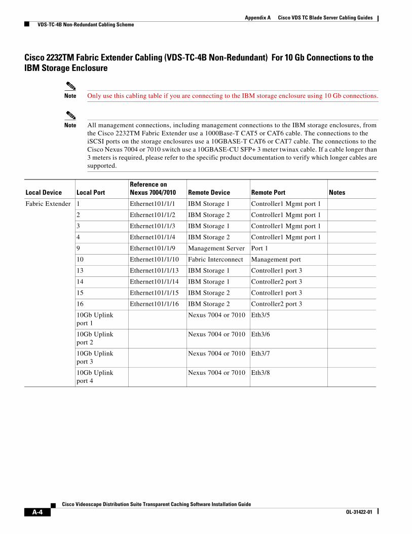
Appendix A Cisco VDS TC Blade Server Cabling Guides VDS-TC-4B Non-Redundant Cabling Scheme
Cisco 2232TM Fabric Extender Cabling (VDS-TC-4B Non-Redundant) For 10 Gb Connections to the IBM Storage Enclosure
Note Only use this cabling table if you are connecting to the IBM storage enclosure using 10 Gb connections.
Note All management connections, including management connections to the IBM storage enclosures, from the Cisco 2232TM Fabric Extender use a 1000Base-T CAT5 or CAT6 cable. The connections to the iSCSI ports on the storage enclosures use a 10GBASE-T CAT6 or CAT7 cable. The connections to the Cisco Nexus 7004 or 7010 switch use a 10GBASE-CU SFP+ 3 meter twinax cable. If a cable longer than 3 meters is required, please refer to the specific product documentation to verify which longer cables are supported.
Local Device Local PortReference onNexus 7004/7010 Remote Device Remote Port Notes
Fabric Extender 1 Ethernet101/1/1 IBM Storage 1 Controller1 Mgmt port 1
2 Ethernet101/1/2 IBM Storage 2 Controller1 Mgmt port 1
3 Ethernet101/1/3 IBM Storage 1 Controller1 Mgmt port 1
4 Ethernet101/1/4 IBM Storage 2 Controller1 Mgmt port 1
9 Ethernet101/1/9 Management Server Port 1
10 Ethernet101/1/10 Fabric Interconnect Management port
13 Ethernet101/1/13 IBM Storage 1 Controller1 port 3
14 Ethernet101/1/14 IBM Storage 1 Controller2 port 3
15 Ethernet101/1/15 IBM Storage 2 Controller1 port 3
16 Ethernet101/1/16 IBM Storage 2 Controller2 port 3
10Gb Uplink port 1
Nexus 7004 or 7010 Eth3/5
10Gb Uplink port 2
Nexus 7004 or 7010 Eth3/6
10Gb Uplink port 3
Nexus 7004 or 7010 Eth3/7
10Gb Uplink port 4
Nexus 7004 or 7010 Eth3/8
A-4Cisco Videoscape Distribution Suite Transparent Caching Software Installation Guide
OL-31422-01

Appendix A Cisco VDS TC Blade Server Cabling Guides VDS-TC-4B Non-Redundant Cabling Scheme
Cisco UCS 6248 UP Fabric Interconnect Cabling (VDS-TC-4B Non-Redundant)
Note All connections from the Cisco UCS 6248 UP Fabric Interconnect use a 10GBASE-CU SFP+ 3 meter twinax cable. If a cable longer than 3 meters is required, please refer to the specific product documentation to verify which longer cables are supported.
Local Device Local Port Remote Device Remote Port Notes
Fabric Interconnect Eth port 1/1 Chassis 1 Fabric port 1/1
Eth port 1/2 Chassis 1 Fabric port 1/2
Eth port 1/3 Chassis 1 Fabric port 1/3
Eth port 1/4 Chassis 1 Fabric port 1/4
Eth1/29 Nexus 7004 or 7010 Eth3/13
Eth1/30 Nexus 7004 or 7010 Eth3/14
A-5Cisco Videoscape Distribution Suite Transparent Caching Software Installation Guide
OL-31422-01

Appendix A Cisco VDS TC Blade Server Cabling Guides VDS-TC-4B Redundant Cabling Scheme
VDS-TC-4B Redundant Cabling SchemeThis section provides the cabling scheme for the VDS-TC-4B redundant solution.
Cisco Nexus 7004 or 7010 Switch Cabling (VDS-TC-4B Redundant)
Note All connections from the Cisco Nexus 7004 or 7010 switch use a 10GBASE-CU SFP+ 3 meter twinax cable. If a cable longer than 3 meters is required, please refer to the specific product documentation to verify which longer cables are supported.
Local Device Local Port Remote Device Remote Port Notes
Nexus 7004 or 7010 with Line Card in Slot 3
Eth 3/1 Mgmt Uplink To customer environment
Eth3/5 FEX-2 Fex Fabric 10Gb Uplink port 2
Eth3/6 FEX-2 Fex Fabric 10Gb Uplink port 4
Eth3/7 FEX-1 Fex Fabric 10Gb Uplink port 2
Eth3/8 FEX-1 Fex Fabric 10Gb Uplink port 4
Eth3/13 UCS-FI-6248UP (FI 1) Eth1/29
Eth3/14 UCS-FI-6248UP (FI 1) Eth1/30
Eth3/15 UCS-FI-6248UP (FI 1) Eth1/31
Eth3/16 UCS-FI-6248UP (FI 1) Eth1/32
Eth3/29 PBR Router To customer environment
Eth3/30 PBR Router To customer environment
Eth3/31 PBR Router To customer environment
Eth3/32 PBR Router To customer environment
Eth3/37 PBR Router To customer environment
Eth3/38 PBR Router To customer environment
Eth3/39 PBR Router To customer environment
Eth3/40 PBR Router To customer environment
A-6Cisco Videoscape Distribution Suite Transparent Caching Software Installation Guide
OL-31422-01

Appendix A Cisco VDS TC Blade Server Cabling Guides VDS-TC-4B Redundant Cabling Scheme
Nexus 7004 with Line Card in Slot 4 or
Nexus 7010 with Line Card in Slot 8
Eth4/5 or Eth8/5
FEX-2 Fex Fabric 10Gb Uplink port 1
Eth4/6 or Eth8/6
FEX-2 Fex Fabric 10Gb Uplink port 3
Eth4/7 or Eth8/7
FEX-1 Fex Fabric 10Gb Uplink port 1
Eth4/8 or Eth8/8
FEX-1 Fex Fabric 10Gb Uplink port 3
Eth4/13 or Eth8/13
UCS-FI-6248UP (FI 2) Eth1/29
Eth4/14 or Eth8/14
UCS-FI-6248UP (FI 2) Eth1/30
Eth4/29 or Eth8/29
PBR Router To customer environment
Eth4/30 or Eth8/30
PBR Router To customer environment
Eth4/31 or Eth8/31
PBR Router To customer environment
Eth4/32 or Eth8/32
PBR Router To customer environment
Eth4/37 or Eth8/37
PBR Router To customer environment
Eth4/38 or Eth8/38
PBR Router To customer environment
Eth4/39 or Eth8/39
PBR Router To customer environment
Eth4/40 or Eth8/40
PBR Router To customer environment
Cisco Nexus 7004 or 7010 Switch Cabling (VDS-TC-4B Redundant) (continued)
Note All connections from the Cisco Nexus 7004 or 7010 switch use a 10GBASE-CU SFP+ 3 meter twinax cable. If a cable longer than 3 meters is required, please refer to the specific product documentation to verify which longer cables are supported.
Local Device Local Port Remote Device Remote Port Notes
A-7Cisco Videoscape Distribution Suite Transparent Caching Software Installation Guide
OL-31422-01

Appendix A Cisco VDS TC Blade Server Cabling Guides VDS-TC-4B Redundant Cabling Scheme
Cisco 2248TP Fabric Extender 1 (FEX-1) Cabling (VDS-TC-4B Redundant) For 1 Gb Connections to the IBM Storage Enclosure
Note Only use this cabling table if you are connecting to the IBM storage enclosure using 1 Gb connections.
Note All connections from the Cisco 2248TP Fabric Extender use a 1000Base-T CAT5 or CAT6 cable except for the connections to the Cisco Nexus 7004 or 7010 switch. The connections from the Cisco 2248TP Fabric Extender to the Cisco Nexus 7004 or 7010 switch use a 10GBASE-CU SFP+ 3 meter twinax cable. If a cable longer than 3 meters is required, please refer to the specific product documentation to verify which longer cables are supported.
Local Device Local PortReference on Nexus 7004/7010 Remote Device Remote Port Notes
Fabric Extender 1
1 Ethernet101/1/1 IBM Storage 1 Controller1 Mgmt port 1
2 Ethernet101/1/2 IBM Storage 2 Controller1 Mgmt port 1
13 Ethernet101/1/13 IBM Storage 1 Controller1 port 3
14 Ethernet101/1/14 IBM Storage 1 Controller1 port 4
15 Ethernet101/1/15 IBM Storage 1 Controller2 port 3
16 Ethernet101/1/16 IBM Storage 1 Controller2 port 4
17 Ethernet101/1/17 IBM Storage 2 Controller1 port 3
18 Ethernet101/1/18 IBM Storage 2 Controller1 port 4
19 Ethernet101/1/19 IBM Storage 2 Controller2 port 3
20 Ethernet101/1/20 IBM Storage 2 Controller2 port 4
37 Ethernet101/1/37 Management Server
port 1
38 Ethernet101/1/38 UCS-FI-6248UP (FI 1)
MGMT0
10Gb Uplink port 2 Nexus 7004 or 7010 Eth3/7
10Gb Uplink port 4 Nexus 7004 or 7010 Eth3/8
10Gb Uplink port 1 Nexus 7004 or 7010 Eth4/7
10Gb Uplink port 3 Nexus 7004 or 7010 Eth4/8
A-8Cisco Videoscape Distribution Suite Transparent Caching Software Installation Guide
OL-31422-01

Appendix A Cisco VDS TC Blade Server Cabling Guides VDS-TC-4B Redundant Cabling Scheme
Cisco 2248TP Fabric Extender 2 (FEX-2) Cabling (VDS-TC-4B Redundant) For 1 Gb Connections to the IBM Storage Enclosure
Note Only use this cabling table if you are connecting to the IBM storage enclosure using 1 Gb connections.
Note All connections from the Cisco 2248TP Fabric Extender use a 1000Base-T CAT5 or CAT6 cable except for the connections to the Cisco Nexus 7004 or 7010 switch. The connections from the Cisco 2248TP Fabric Extender to the Cisco Nexus 7004 or 7010 switch use a 10GBASE-CU SFP+ 3 meter twinax cable If a cable longer than 3 meters is required, please refer to the specific product documentation to verify which longer cables are supported.
Local Device Local PortReference on Nexus 7004/7010 Remote Device Remote Port Notes
Fabric Extender 2
1 Ethernet102/1/1 IBM Storage 1 Controller2 Mgmt port 1
2 Ethernet102/1/2 IBM Storage 2 Controller2 Mgmt port 1
13 Ethernet102/1/13 IBM Storage 1 Controller1 port 5
14 Ethernet102/1/14 IBM Storage 1 Controller1 port 6
15 Ethernet102/1/15 IBM Storage 1 Controller2 port 5
16 Ethernet102/1/16 IBM Storage 1 Controller2 port 6
17 Ethernet102/1/17 IBM Storage 2 Controller1 port 5
18 Ethernet102/1/18 IBM Storage 2 Controller1 port 6
19 Ethernet102/1/19 IBM Storage 2 Controller2 port 5
20 Ethernet102/1/20 IBM Storage 2 Controller2 port 6
37 Ethernet102/1/37 Management Server
port 2
38 Ethernet102/1/38 UCS-FI-6248UP (FI 2)
MGMT0
10Gb Uplink port 2 Nexus 7004 or 7010 Eth3/5
10Gb Uplink port 4 Nexus 7004 or 7010 Eth3/6
10Gb Uplink port 1 Nexus 7004 or 7010 Eth4/5
10Gb Uplink port 3 Nexus 7004 or 7010 Eth4/6
A-9Cisco Videoscape Distribution Suite Transparent Caching Software Installation Guide
OL-31422-01
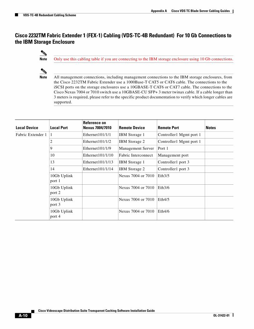
Appendix A Cisco VDS TC Blade Server Cabling Guides VDS-TC-4B Redundant Cabling Scheme
Cisco 2232TM Fabric Extender 1 (FEX-1) Cabling (VDS-TC-4B Redundant) For 10 Gb Connections to the IBM Storage Enclosure
Note Only use this cabling table if you are connecting to the IBM storage enclosure using 10 Gb connections.
Note All management connections, including management connections to the IBM storage enclosures, from the Cisco 2232TM Fabric Extender use a 1000Base-T CAT5 or CAT6 cable. The connections to the iSCSI ports on the storage enclosures use a 10GBASE-T CAT6 or CAT7 cable. The connections to the Cisco Nexus 7004 or 7010 switch use a 10GBASE-CU SFP+ 3 meter twinax cable. If a cable longer than 3 meters is required, please refer to the specific product documentation to verify which longer cables are supported.
Local Device Local PortReference onNexus 7004/7010 Remote Device Remote Port Notes
Fabric Extender 1 1 Ethernet101/1/1 IBM Storage 1 Controller1 Mgmt port 1
2 Ethernet101/1/2 IBM Storage 2 Controller1 Mgmt port 1
9 Ethernet101/1/9 Management Server Port 1
10 Ethernet101/1/10 Fabric Interconnect Management port
13 Ethernet101/1/13 IBM Storage 1 Controller1 port 3
14 Ethernet101/1/14 IBM Storage 2 Controller1 port 3
10Gb Uplink port 1
Nexus 7004 or 7010 Eth3/5
10Gb Uplink port 2
Nexus 7004 or 7010 Eth3/6
10Gb Uplink port 3
Nexus 7004 or 7010 Eth4/5
10Gb Uplink port 4
Nexus 7004 or 7010 Eth4/6
A-10Cisco Videoscape Distribution Suite Transparent Caching Software Installation Guide
OL-31422-01

Appendix A Cisco VDS TC Blade Server Cabling Guides VDS-TC-4B Redundant Cabling Scheme
Cisco 2232TM Fabric Extender 2 (FEX-2) Cabling (VDS-TC-4B Redundant) For 10 Gb Connections to the IBM Storage Enclosure
Note Only use this cabling table if you are connecting to the IBM storage enclosure using 10 Gb connections.
Note All management connections, including management connections to the IBM storage enclosures, from the Cisco 2232TM Fabric Extender use a 1000Base-T CAT5 or CAT6 cable. The connections to the iSCSI ports on the storage enclosures use a 10GBASE-T CAT6 or CAT7 cable. The connections to the Cisco Nexus 7004 or 7010 switch use a 10GBASE-CU SFP+ 3 meter twinax cable. If a cable longer than 3 meters is required, please refer to the specific product documentation to verify which longer cables are supported.
Local Device Local PortReference onNexus 7004/7010 Remote Device Remote Port Notes
Fabric Extender 2 1 Ethernet102/1/1 IBM Storage 1 Controller2 Mgmt port 1
2 Ethernet102/1/2 IBM Storage 2 Controller2 Mgmt port 1
9 Ethernet102/1/9 Management Server Port 1
10 Ethernet102/1/10 Fabric Interconnect Management port
13 Ethernet102/1/13 IBM Storage 1 Controller1 port 3
14 Ethernet102/1/14 IBM Storage 2 Controller1 port 3
10Gb Uplink port 1
Nexus 7004 or 7010 Eth3/7
10Gb Uplink port 2
Nexus 7004 or 7010 Eth3/8
10Gb Uplink port 3
Nexus 7004 or 7010 Eth4/7
10Gb Uplink port 4
Nexus 7004 or 7010 Eth4/8
A-11Cisco Videoscape Distribution Suite Transparent Caching Software Installation Guide
OL-31422-01
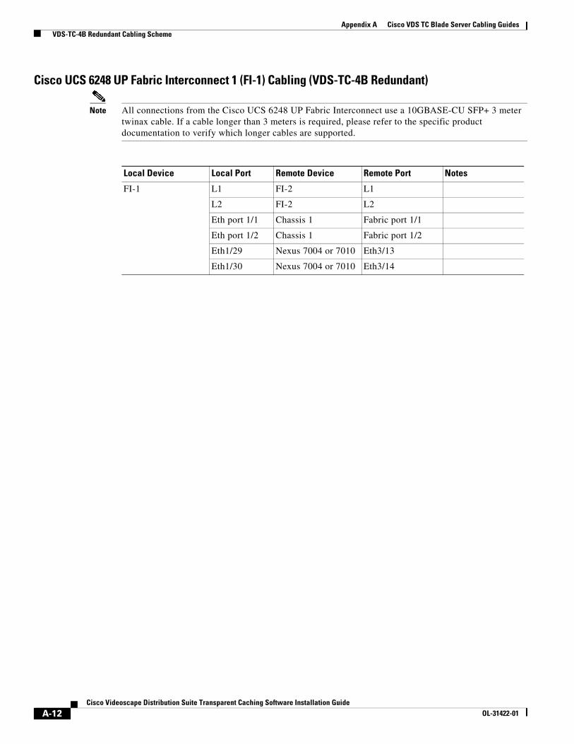
Appendix A Cisco VDS TC Blade Server Cabling Guides VDS-TC-4B Redundant Cabling Scheme
Cisco UCS 6248 UP Fabric Interconnect 1 (FI-1) Cabling (VDS-TC-4B Redundant)
Note All connections from the Cisco UCS 6248 UP Fabric Interconnect use a 10GBASE-CU SFP+ 3 meter twinax cable. If a cable longer than 3 meters is required, please refer to the specific product documentation to verify which longer cables are supported.
Local Device Local Port Remote Device Remote Port Notes
FI-1 L1 FI-2 L1
L2 FI-2 L2
Eth port 1/1 Chassis 1 Fabric port 1/1
Eth port 1/2 Chassis 1 Fabric port 1/2
Eth1/29 Nexus 7004 or 7010 Eth3/13
Eth1/30 Nexus 7004 or 7010 Eth3/14
A-12Cisco Videoscape Distribution Suite Transparent Caching Software Installation Guide
OL-31422-01
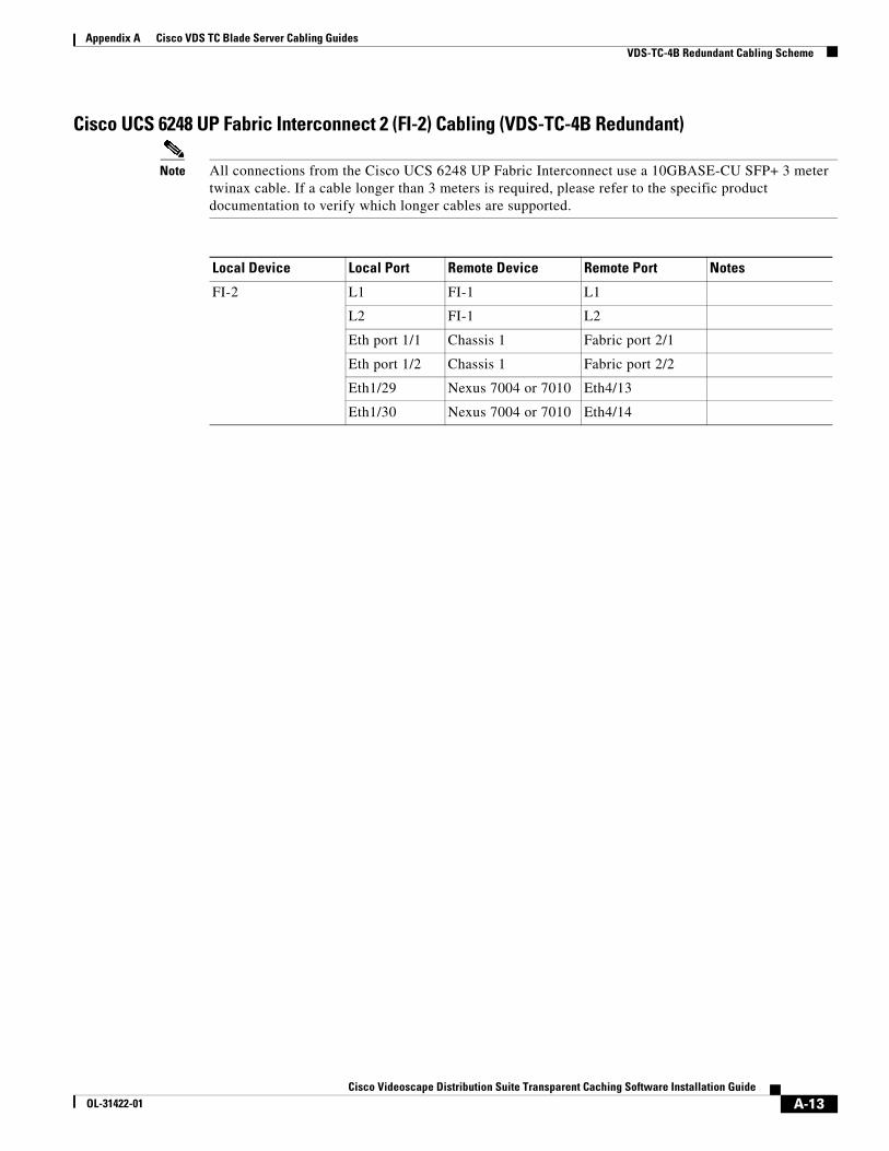
Appendix A Cisco VDS TC Blade Server Cabling Guides VDS-TC-4B Redundant Cabling Scheme
Cisco UCS 6248 UP Fabric Interconnect 2 (FI-2) Cabling (VDS-TC-4B Redundant)
Note All connections from the Cisco UCS 6248 UP Fabric Interconnect use a 10GBASE-CU SFP+ 3 meter twinax cable. If a cable longer than 3 meters is required, please refer to the specific product documentation to verify which longer cables are supported.
Local Device Local Port Remote Device Remote Port Notes
FI-2 L1 FI-1 L1
L2 FI-1 L2
Eth port 1/1 Chassis 1 Fabric port 2/1
Eth port 1/2 Chassis 1 Fabric port 2/2
Eth1/29 Nexus 7004 or 7010 Eth4/13
Eth1/30 Nexus 7004 or 7010 Eth4/14
A-13Cisco Videoscape Distribution Suite Transparent Caching Software Installation Guide
OL-31422-01

Appendix A Cisco VDS TC Blade Server Cabling Guides VDS-TC-8B Non-Redundant Cabling Scheme
VDS-TC-8B Non-Redundant Cabling SchemeThis section provides the cabling scheme for the VDS-TC-8B non-redundant solution.
Cisco Nexus 7004 or 7010 Switch Cabling (VDS-TC-8B Non-Redundant)
Note All connections from the Cisco Nexus 7004 or 7010 switch use a 10GBASE-CU SFP+ 3 meter twinax cable. If a cable longer than 3 meters is required, please refer to the specific product documentation to verify which longer cables are supported.
Local Device Local Port Remote Device Remote Port Notes
Nexus 7004 or 7010 with Line Card in Slot 3
Eth 3/1 Mgmt Uplink To customer environment
Eht3/5 FEX-1 Fex Fabric 10Gb Uplink port 1
Eth3/6 FEX-1 Fex Fabric 10Gb Uplink port 2
Eth3/7 FEX-1 Fex Fabric 10Gb Uplink port 3
Eth3/8 FEX-1 Fex Fabric 10Gb Uplink port 4
Eth3/13 UCS-FI-6248UP (FI 1) Eth1/29
Eth3/14 UCS-FI-6248UP (FI 1) Eth1/30
Eth3/15 UCS-FI-6248UP (FI 1) Eth1/31
Eth3/16 UCS-FI-6248UP (FI 1) Eth1/32
Eth3/29 PBR Router To customer environment
Eth3/30 PBR Router To customer environment
Eth3/31 PBR Router To customer environment
Eth3/32 PBR Router To customer environment
Eth3/37 PBR Router To customer environment
Eth3/38 PBR Router To customer environment
Eth3/39 PBR Router To customer environment
Eth3/40 PBR Router To customer environment
A-14Cisco Videoscape Distribution Suite Transparent Caching Software Installation Guide
OL-31422-01

Appendix A Cisco VDS TC Blade Server Cabling Guides VDS-TC-8B Non-Redundant Cabling Scheme
Cisco 2248TP Fabric Extender Cabling (VDS-TC-8B Non-Redundant) For 1 Gb Connections to the IBM Storage Enclosure
Note Only use this cabling table if you are connecting to the IBM storage enclosure using 1 Gb connections.
Note All connections from the Cisco 2248TP Fabric Extender use a 1000Base-T CAT5 or CAT6 cable except for the connections to the Cisco Nexus 7004 or 7010 switch. The connections from the Cisco 2248TP Fabric Extender to the Cisco Nexus 7004 or 7010 switch use a 10GBASE-CU SFP+ 3 meter twinax cable. If a cable longer than 3 meters is required, please refer to the specific product documentation to verify which longer cables are supported.
Local Device Local PortReference on Nexus 7004/7010 Remote Device Remote Port Notes
Fabric Extender
1 Ethernet101/1/1 IBM Storage 1 Controller1 Mgmt port 1
2 Ethernet101/1/2 IBM Storage 2 Controller1 Mgmt port 1
3 Ethernet101/1/3 IBM Storage 3 Controller1 Mgmt port 1
4 Ethernet101/1/4 IBM Storage 1 Controller2 Mgmt port 1
5 Ethernet101/1/5 IBM Storage 2 Controller2 Mgmt port 1
6 Ethernet101/1/6 IBM Storage 3 Controller2 Mgmt port 1
13 Ethernet101/1/13 IBM Storage 1 Controller1 port 3
14 Ethernet101/1/14 IBM Storage 1 Controller1 port 4
15 Ethernet101/1/15 IBM Storage 1 Controller2 port 3
16 Ethernet101/1/16 IBM Storage 1 Controller2 port 4
17 Ethernet101/1/17 IBM Storage 2 Controller1 port 3
18 Ethernet101/1/18 IBM Storage 2 Controller1 port 4
19 Ethernet101/1/19 IBM Storage 2 Controller2 port 3
20 Ethernet101/1/20 IBM Storage 2 Controller2 port 4
21 Ethernet101/1/21 IBM Storage 3 Controller1 port 3
22 Ethernet101/1/22 IBM Storage 3 Controller1 port 4
23 Ethernet101/1/23 IBM Storage 3 Controller2 port 3
24 Ethernet101/1/24 IBM Storage 3 Controller2 port 4
25 Ethernet101/1/25 IBM Storage 1 Controller1 port 5
26 Ethernet101/1/26 IBM Storage 1 Controller1 port 6
27 Ethernet101/1/27 IBM Storage 1 Controller2 port 5
28 Ethernet101/1/28 IBM Storage 1 Controller2 port 6
29 Ethernet101/1/29 IBM Storage 2 Controller1 port 5
30 Ethernet101/1/30 IBM Storage 2 Controller1 port 6
31 Ethernet101/1/31 IBM Storage 2 Controller2 port 5
32 Ethernet101/1/32 IBM Storage 2 Controller2 port 6
33 Ethernet101/1/33 IBM Storage 3 Controller1 port 5
34 Ethernet101/1/34 IBM Storage 3 Controller1 port 6
A-15Cisco Videoscape Distribution Suite Transparent Caching Software Installation Guide
OL-31422-01
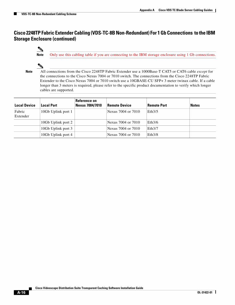
Appendix A Cisco VDS TC Blade Server Cabling Guides VDS-TC-8B Non-Redundant Cabling Scheme
Fabric Extender
10Gb Uplink port 1 Nexus 7004 or 7010 Eth3/5
10Gb Uplink port 2 Nexus 7004 or 7010 Eth3/6
10Gb Uplink port 3 Nexus 7004 or 7010 Eth3/7
10Gb Uplink port 4 Nexus 7004 or 7010 Eth3/8
Cisco 2248TP Fabric Extender Cabling (VDS-TC-8B Non-Redundant) For 1 Gb Connections to the IBM Storage Enclosure (continued)
Note Only use this cabling table if you are connecting to the IBM storage enclosure using 1 Gb connections.
Note All connections from the Cisco 2248TP Fabric Extender use a 1000Base-T CAT5 or CAT6 cable except for the connections to the Cisco Nexus 7004 or 7010 switch. The connections from the Cisco 2248TP Fabric Extender to the Cisco Nexus 7004 or 7010 switch use a 10GBASE-CU SFP+ 3 meter twinax cable. If a cable longer than 3 meters is required, please refer to the specific product documentation to verify which longer cables are supported.
Local Device Local PortReference on Nexus 7004/7010 Remote Device Remote Port Notes
A-16Cisco Videoscape Distribution Suite Transparent Caching Software Installation Guide
OL-31422-01

Appendix A Cisco VDS TC Blade Server Cabling Guides VDS-TC-8B Non-Redundant Cabling Scheme
Cisco 2232TM Fabric Extender Cabling (VDS-TC-8B Non-Redundant) For 10 Gb Connections to the IBM Storage Enclosure
Note Only use this cabling table if you are connecting to the IBM storage enclosure using 10 Gb connections.
Note All management connections, including management connections to the IBM storage enclosures, from the Cisco 2232TM Fabric Extender use a 1000Base-T CAT5 or CAT6 cable. The connections to the iSCSI ports on the storage enclosures use a 10GBASE-T CAT6 or CAT7 cable. The connections to the Cisco Nexus 7004 or 7010 switch use a 10GBASE-CU SFP+ 3 meter twinax cable. If a cable longer than 3 meters is required, please refer to the specific product documentation to verify which longer cables are supported.
Local Device Local PortReference onNexus 7004/7010 Remote Device Remote Port Notes
Fabric Extender 1 Ethernet101/1/1 IBM Storage 1 Controller1 Mgmt port 1
2 Ethernet101/1/2 IBM Storage 2 Controller1 Mgmt port 1
3 Ethernet101/1/3 IBM Storage 3 Controller1 Mgmt port 1
4 Ethernet101/1/4 IBM Storage 1 Controller2 Mgmt port 1
5 Ethernet101/1/5 IBM Storage 2 Controller2 Mgmt port 1
6 Ethernet101/1/6 IBM Storage 3 Controller2 Mgmt port 1
9 Ethernet101/1/9 Management Server Port 1
10 Ethernet101/1/10 Fabric Interconnect Management port
13 Ethernet101/1/13 IBM Storage 1 Controller1 port 3
14 Ethernet101/1/14 IBM Storage 1 Controller2 port 3
15 Ethernet101/1/15 IBM Storage 2 Controller1 port 3
16 Ethernet101/1/16 IBM Storage 2 Controller2 port 3
17 Ethernet101/1/17 IBM Storage 3 Controller1 port 3
18 Ethernet101/1/18 IBM Storage 3 Controller2 port 3
10Gb Uplink port 1
Nexus 7004 or 7010 Eth3/5
10Gb Uplink port 2
Nexus 7004 or 7010 Eth3/6
10Gb Uplink port 3
Nexus 7004 or 7010 Eth3/7
10Gb Uplink port 4
Nexus 7004 or 7010 Eth3/8
A-17Cisco Videoscape Distribution Suite Transparent Caching Software Installation Guide
OL-31422-01
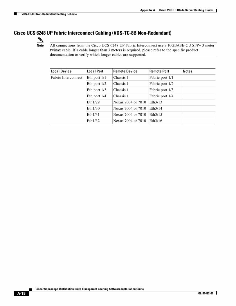
Appendix A Cisco VDS TC Blade Server Cabling Guides VDS-TC-8B Non-Redundant Cabling Scheme
Cisco UCS 6248 UP Fabric Interconnect Cabling (VDS-TC-8B Non-Redundant)
Note All connections from the Cisco UCS 6248 UP Fabric Interconnect use a 10GBASE-CU SFP+ 3 meter twinax cable. If a cable longer than 3 meters is required, please refer to the specific product documentation to verify which longer cables are supported.
Local Device Local Port Remote Device Remote Port Notes
Fabric Interconnect Eth port 1/1 Chassis 1 Fabric port 1/1
Eth port 1/2 Chassis 1 Fabric port 1/2
Eth port 1/3 Chassis 1 Fabric port 1/3
Eth port 1/4 Chassis 1 Fabric port 1/4
Eth1/29 Nexus 7004 or 7010 Eth3/13
Eth1/30 Nexus 7004 or 7010 Eth3/14
Eth1/31 Nexus 7004 or 7010 Eth3/15
Eth1/32 Nexus 7004 or 7010 Eth3/16
A-18Cisco Videoscape Distribution Suite Transparent Caching Software Installation Guide
OL-31422-01

Appendix A Cisco VDS TC Blade Server Cabling Guides VDS-TC-8B Redundant Cabling Scheme
VDS-TC-8B Redundant Cabling SchemeThis section provides the cabling scheme for the VDS-TC-8B redundant solution.
Cisco Nexus 7004 Switch Cabling (VDS-TC-8B Redundant)
Note All connections from the Cisco Nexus 7004 or 7010 switch use a 10GBASE-CU SFP+ 3 meter twinax cable. If a cable longer than 3 meters is required, please refer to the specific product documentation to verify which longer cables are supported.
Local Device Local Port Remote Device Remote Port Notes
Nexus 7004 or 7010 with Line Card in Slot 3
Eth 3/1 Mgmt Uplink To customer environment
Eth3/5 FEX-2 Fex Fabric 10Gb Uplink port 2
Eth3/6 FEX-2 Fex Fabric 10Gb Uplink port 4
Eth3/7 FEX-1 Fex Fabric 10Gb Uplink port 2
Eth3/8 FEX-1 Fex Fabric 10Gb Uplink port 4
Eth3/13 UCS-FI-6248UP (FI 1) Eth1/29
Eth3/14 UCS-FI-6248UP (FI 1) Eth1/30
Eth3/15 UCS-FI-6248UP (FI 1) Eth1/31
Eth3/16 UCS-FI-6248UP (FI 1) Eth1/32
Eth3/29 PBR Router To customer environment
Eth3/30 PBR Router To customer environment
Eth3/31 PBR Router To customer environment
Eth3/32 PBR Router To customer environment
Eth3/37 PBR Router To customer environment
Eth3/38 PBR Router To customer environment
Eth3/39 PBR Router To customer environment
Eth3/40 PBR Router To customer environment
A-19Cisco Videoscape Distribution Suite Transparent Caching Software Installation Guide
OL-31422-01

Appendix A Cisco VDS TC Blade Server Cabling Guides VDS-TC-8B Redundant Cabling Scheme
Nexus 7004 with Line Card in Slot 4
or
Nexus 7010 with Line Card in Slot 8
Eth4/5 or Eth8/5
FEX-2 Fex Fabric 10Gb Uplink port 1
Eth4/6 or Eth8/6
FEX-2 Fex Fabric 10Gb Uplink port 3
Eth4/7 or Eth8/7
FEX-1 Fex Fabric 10Gb Uplink port 1
Eth4/8 or Eth8/8
FEX-1 Fex Fabric 10Gb Uplink port 3
Eth4/13 or Eth8/13
UCS-FI-6248UP (FI 2) Eth1/29
Eth4/14 or Eth8/14
UCS-FI-6248UP (FI 2) Eth1/30
Eth4/15 or Eth8/15
UCS-FI-6248UP (FI 2) Eth1/31
Eth4/16 or Eth8/16
UCS-FI-6248UP (FI 2) Eth1/32
Eth4/29 or Eth8/29
PBR Router To customer environment
Eth4/30 or Eth8/30
PBR Router To customer environment
Eth4/31 or Eth8/31
PBR Router To customer environment
Eth4/32 or Eth8/32
PBR Router To customer environment
Eth4/37 or Eth8/37
PBR Router To customer environment
Eth4/38 or Eth8/38
PBR Router To customer environment
Eth4/39 or Eth8/39
PBR Router To customer environment
Eth4/40 or Eth8/40
PBR Router To customer environment
Cisco Nexus 7004 Switch Cabling (VDS-TC-8B Redundant) (continued)
Note All connections from the Cisco Nexus 7004 or 7010 switch use a 10GBASE-CU SFP+ 3 meter twinax cable. If a cable longer than 3 meters is required, please refer to the specific product documentation to verify which longer cables are supported.
Local Device Local Port Remote Device Remote Port Notes
A-20Cisco Videoscape Distribution Suite Transparent Caching Software Installation Guide
OL-31422-01

Appendix A Cisco VDS TC Blade Server Cabling Guides VDS-TC-8B Redundant Cabling Scheme
Cisco 2248TP Fabric Extender 1 (FEX-1) Cabling (VDS-TC-8B Redundant) For 1 Gb Connections to the IBM Storage Enclosure
Note Only use this cabling table if you are connecting to the IBM storage enclosure using 1 Gb connections.
Note All connections from the Cisco 2248TP Fabric Extender use a 1000Base-T CAT5 or CAT6 cable except for the connections to the Cisco Nexus 7004 or 7010 switch. The connections from the Cisco 2248TP Fabric Extender to the Cisco Nexus 7004 or 7010 switch use a 10GBASE-CU SFP+ 3 meter twinax cable. If a cable longer than 3 meters is required, please refer to the specific product documentation to verify which longer cables are supported.
Local Device Local PortReference on Nexus 7004/7010 Remote Device Remote Port Notes
Fabric Extender 1 1 Ethernet101/1/1 IBM Storage 1 Controller1 Mgmt port 1
2 Ethernet101/1/2 IBM Storage 2 Controller1 Mgmt port 1
3 Ethernet101/1/3 IBM Storage 3 Controller1 Mgmt port 1
13 Ethernet101/1/13 IBM Storage 1 Controller1 port 3
14 Ethernet101/1/14 IBM Storage 1 Controller1 port 4
15 Ethernet101/1/15 IBM Storage 1 Controller2 port 3
16 Ethernet101/1/16 IBM Storage 1 Controller2 port 4
17 Ethernet101/1/17 IBM Storage 2 Controller1 port 3
18 Ethernet101/1/18 IBM Storage 2 Controller1 port 4
19 Ethernet101/1/19 IBM Storage 2 Controller2 port 3
20 Ethernet101/1/20 IBM Storage 2 Controller2 port 4
21 Ethernet101/1/21 IBM Storage 3 Controller1 port 3
22 Ethernet101/1/22 IBM Storage 3 Controller1 port 4
23 Ethernet101/1/23 IBM Storage 3 Controller2 port 3
24 Ethernet101/1/24 IBM Storage 3 Controller2 port 4
37 Ethernet101/1/37 Management Server port 1
38 Ethernet101/1/38 UCS-FI-6248UP (FI 1) MGMT0
10Gb Uplink port 2
Nexus 7004 or 7010 Eth3/7
10Gb Uplink port 4
Nexus 7004 or 7010 Eth3/8
10Gb Uplink port 1
Nexus 7004 or 7010 Eth4/7
10Gb Uplink port 3
Nexus 7004 or 7010 Eth4/8
A-21Cisco Videoscape Distribution Suite Transparent Caching Software Installation Guide
OL-31422-01

Appendix A Cisco VDS TC Blade Server Cabling Guides VDS-TC-8B Redundant Cabling Scheme
Cisco 2248TP Fabric Extender 2 (FEX-2) Cabling (VDS-TC-8B Redundant) For 1 Gb Connections to the IBM Storage Enclosure
Note Only use this cabling table if you are connecting to the IBM storage enclosure using 1 Gb connections.
Note All connections from the Cisco 2248TP Fabric Extender use a 1000Base-T CAT5 or CAT6 cable except for the connections to the Cisco Nexus 7004 or 7010 switch. The connections from the Cisco 2248TP Fabric Extender to the Cisco Nexus 7004 or 7010 switch use a 10GBASE-CU SFP+ 3 meter twinax cable. If a cable longer than 3 meters is required, please refer to the specific product documentation to verify which longer cables are supported.
Local Device Local PortReference on Nexus 7004/7010 Remote Device Remote Port Notes
Fabric Extender 2 1 Ethernet102/1/1 IBM Storage 1 Controller2 Mgmt port 1
2 Ethernet102/1/2 IBM Storage 2 Controller2 Mgmt port 1
3 Ethernet102/1/3 IBM Storage 3 Controller2 Mgmt port 1
13 Ethernet102/1/13 IBM Storage 1 Controller1 port 5
14 Ethernet102/1/14 IBM Storage 1 Controller1 port 6
15 Ethernet102/1/15 IBM Storage 1 Controller2 port 5
16 Ethernet102/1/16 IBM Storage 1 Controller2 port 6
17 Ethernet102/1/17 IBM Storage 2 Controller1 port 5
18 Ethernet102/1/18 IBM Storage 2 Controller1 port 6
19 Ethernet102/1/19 IBM Storage 2 Controller2 port 5
20 Ethernet102/1/20 IBM Storage 2 Controller2 port 6
21 Ethernet102/1/21 IBM Storage 3 Controller1 port 5
22 Ethernet102/1/22 IBM Storage 3 Controller1 port 6
23 Ethernet102/1/23 IBM Storage 3 Controller2 port 5
24 Ethernet102/1/24 IBM Storage 3 Controller2 port 6
37 Ethernet102/1/37 Management Server port 2
38 Ethernet102/1/38 UCS-FI-6248UP (FI 2) MGMT0
10Gb Uplink port 2
Nexus 7004 or 7010 Eth3/5
10Gb Uplink port 4
Nexus 7004 or 7010 Eth3/6
10Gb Uplink port 1
Nexus 7004 or 7010 Eth4/5
10Gb Uplink port 3
Nexus 7004 or 7010 Eth4/6
A-22Cisco Videoscape Distribution Suite Transparent Caching Software Installation Guide
OL-31422-01
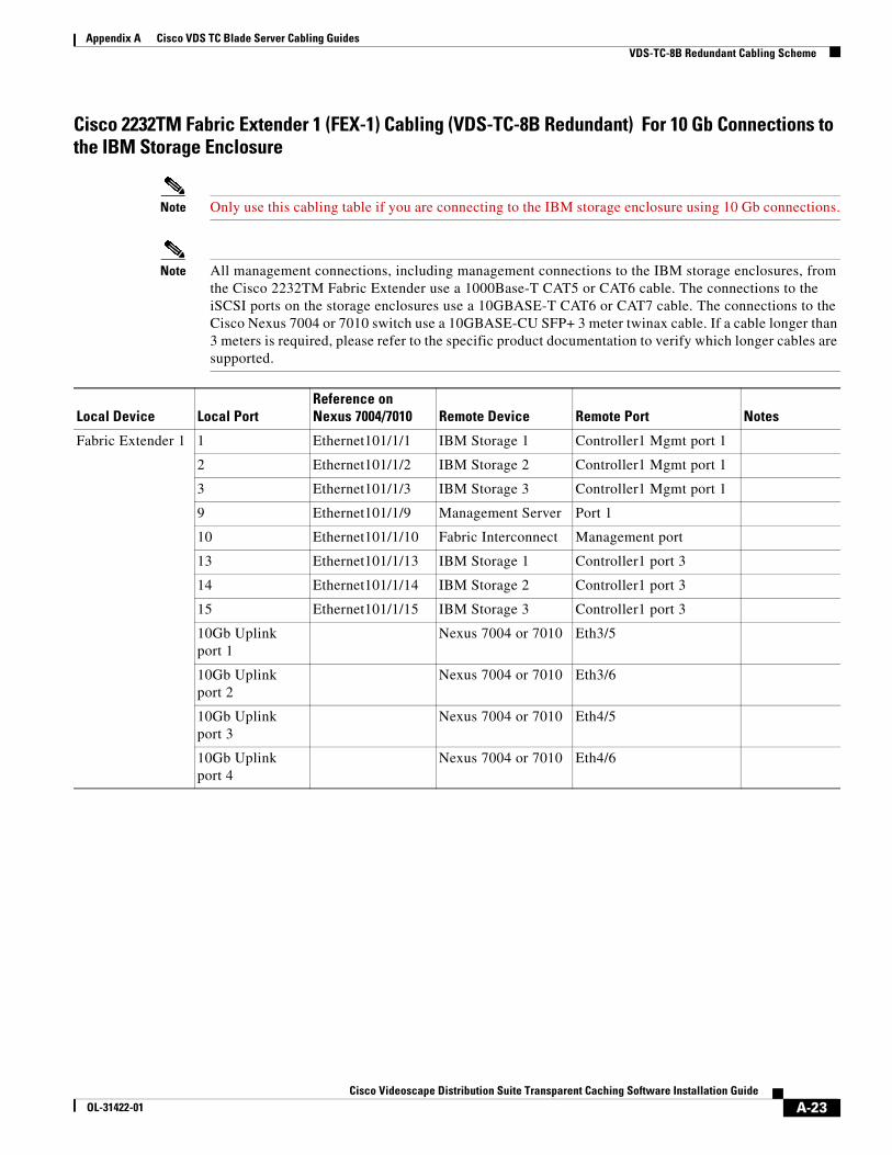
Appendix A Cisco VDS TC Blade Server Cabling Guides VDS-TC-8B Redundant Cabling Scheme
Cisco 2232TM Fabric Extender 1 (FEX-1) Cabling (VDS-TC-8B Redundant) For 10 Gb Connections to the IBM Storage Enclosure
Note Only use this cabling table if you are connecting to the IBM storage enclosure using 10 Gb connections.
Note All management connections, including management connections to the IBM storage enclosures, from the Cisco 2232TM Fabric Extender use a 1000Base-T CAT5 or CAT6 cable. The connections to the iSCSI ports on the storage enclosures use a 10GBASE-T CAT6 or CAT7 cable. The connections to the Cisco Nexus 7004 or 7010 switch use a 10GBASE-CU SFP+ 3 meter twinax cable. If a cable longer than 3 meters is required, please refer to the specific product documentation to verify which longer cables are supported.
Local Device Local PortReference onNexus 7004/7010 Remote Device Remote Port Notes
Fabric Extender 1 1 Ethernet101/1/1 IBM Storage 1 Controller1 Mgmt port 1
2 Ethernet101/1/2 IBM Storage 2 Controller1 Mgmt port 1
3 Ethernet101/1/3 IBM Storage 3 Controller1 Mgmt port 1
9 Ethernet101/1/9 Management Server Port 1
10 Ethernet101/1/10 Fabric Interconnect Management port
13 Ethernet101/1/13 IBM Storage 1 Controller1 port 3
14 Ethernet101/1/14 IBM Storage 2 Controller1 port 3
15 Ethernet101/1/15 IBM Storage 3 Controller1 port 3
10Gb Uplink port 1
Nexus 7004 or 7010 Eth3/5
10Gb Uplink port 2
Nexus 7004 or 7010 Eth3/6
10Gb Uplink port 3
Nexus 7004 or 7010 Eth4/5
10Gb Uplink port 4
Nexus 7004 or 7010 Eth4/6
A-23Cisco Videoscape Distribution Suite Transparent Caching Software Installation Guide
OL-31422-01

Appendix A Cisco VDS TC Blade Server Cabling Guides VDS-TC-8B Redundant Cabling Scheme
Cisco 2232TM Fabric Extender 2 (FEX-2) Cabling (VDS-TC-8B Redundant) For 10 Gb Connections to the IBM Storage Enclosure
Note Only use this cabling table if you are connecting to the IBM storage enclosure using 10 Gb connections.
Note All management connections, including management connections to the IBM storage enclosures, from the Cisco 2232TM Fabric Extender use a 1000Base-T CAT5 or CAT6 cable. The connections to the iSCSI ports on the storage enclosures use a 10GBASE-T CAT6 or CAT7 cable. The connections to the Cisco Nexus 7004 or 7010 switch use a 10GBASE-CU SFP+ 3 meter twinax cable. If a cable longer than 3 meters is required, please refer to the specific product documentation to verify which longer cables are supported.
Local Device Local PortReference onNexus 7004/7010 Remote Device Remote Port Notes
Fabric Extender 2 1 Ethernet102/1/1 IBM Storage 1 Controller2 Mgmt port 1
2 Ethernet102/1/2 IBM Storage 2 Controller2 Mgmt port 1
3 Ethernet102/1/3 IBM Storage 3 Controller2 Mgmt port 1
9 Ethernet102/1/9 Management Server Port 1
10 Ethernet102/1/10 Fabric Interconnect Management port
13 Ethernet102/1/13 IBM Storage 1 Controller2 port 3
14 Ethernet102/1/14 IBM Storage 2 Controller2 port 3
15 Ethernet102/1/15 IBM Storage 3 Controller2 port 3
10Gb Uplink port 1
Nexus 7004 or 7010 Eth3/7
10Gb Uplink port 2
Nexus 7004 or 7010 Eth3/8
10Gb Uplink port 3
Nexus 7004 or 7010 Eth4/7
10Gb Uplink port 4
Nexus 7004 or 7010 Eth4/8
A-24Cisco Videoscape Distribution Suite Transparent Caching Software Installation Guide
OL-31422-01
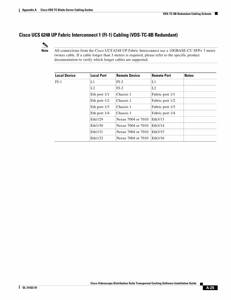
Appendix A Cisco VDS TC Blade Server Cabling Guides VDS-TC-8B Redundant Cabling Scheme
Cisco UCS 6248 UP Fabric Interconnect 1 (FI-1) Cabling (VDS-TC-8B Redundant)
Note All connections from the Cisco UCS 6248 UP Fabric Interconnect use a 10GBASE-CU SFP+ 3 meter twinax cable. If a cable longer than 3 meters is required, please refer to the specific product documentation to verify which longer cables are supported.
Local Device Local Port Remote Device Remote Port Notes
FI-1 L1 FI-2 L1
L2 FI-2 L2
Eth port 1/1 Chassis 1 Fabric port 1/1
Eth port 1/2 Chassis 1 Fabric port 1/2
Eth port 1/3 Chassis 1 Fabric port 1/3
Eth port 1/4 Chassis 1 Fabric port 1/4
Eth1/29 Nexus 7004 or 7010 Eth3/13
Eth1/30 Nexus 7004 or 7010 Eth3/14
Eth1/31 Nexus 7004 or 7010 Eth3/15
Eth1/32 Nexus 7004 or 7010 Eth3/16
A-25Cisco Videoscape Distribution Suite Transparent Caching Software Installation Guide
OL-31422-01

Appendix A Cisco VDS TC Blade Server Cabling Guides VDS-TC-8B Redundant Cabling Scheme
Cisco UCS 6248 UP Fabric Interconnect 2 (FI-2) Cabling (VDS-TC-8B Redundant)
Note All connections from the Cisco UCS 6248 UP Fabric Interconnect use a 10GBASE-CU SFP+ 3 meter twinax cable. If a cable longer than 3 meters is required, please refer to the specific product documentation to verify which longer cables are supported.
Local Device Local Port Remote Device Remote Port Notes
FI-2 L1 FI-1 L1
L2 FI-1 L2
Eth port 1/1 Chassis 1 Fabric port 2/1
Eth port 1/2 Chassis 1 Fabric port 2/2
Eth port 1/3 Chassis 1 Fabric port 2/3
Eth port 1/4 Chassis 1 Fabric port 2/4
Eth1/29 Nexus 7004 or 7010 Eth4/13
Eth1/30 Nexus 7004 or 7010 Eth4/14
Eth1/31 Nexus 7004 or 7010 Eth4/15
Eth1/32 Nexus 7004 or 7010 Eth4/16
A-26Cisco Videoscape Distribution Suite Transparent Caching Software Installation Guide
OL-31422-01

Appendix A Cisco VDS TC Blade Server Cabling Guides VDS-TC-16B Non-Redundant Cabling Scheme
VDS-TC-16B Non-Redundant Cabling SchemeThis section provides the cabling scheme for the VDS-TC-16B non-redundant solution.
Cisco Nexus 7004 or 7010 Switch Cabling (VDS-TC-16B Non-Redundant)
Note All connections from the Cisco Nexus 7004 or 7010 switch use a 10GBASE-CU SFP+ 3 meter twinax cable. If a cable longer than 3 meters is required, please refer to the specific product documentation to verify which longer cables are supported.
Local Device Local Port Remote Device Remote Port Notes
Nexus 7004 or 70101 with Line Card in Slot 3
Eth 3/1 Mgmt Uplink To customer environment
Eth3/5 FEX-2 Fex Fabric 10Gb Uplink 2
Eth3/6 FEX-2 Fex Fabric 10Gb Uplink 4
Eth3/7 FEX-1 Fex Fabric 10Gb Uplink 2
Eth3/8 FEX-1 Fex Fabric 10Gb Uplink 4
Eth3/9 FEX-2 Fex Fabric 10GB Uplink 1
Eth3/10 FEX-2 Fex Fabric 10GB Uplink 3
Eth3/11 FEX-1 Fex Fabric 10GB Uplink 1
Eth3/12 FEX-1 Fex Fabric 10GB Uplink 3
Eth3/13 UCS-FI-6248UP (FI 1) Eth1/29
Eth3/14 UCS-FI-6248UP (FI 1) Eth1/30
Eth3/15 UCS-FI-6248UP (FI 1) Eth1/31
Eth3/16 UCS-FI-6248UP (FI 1) Eth1/32
Eth3/17 UCS-FI-6248UP (FI 1) Eth1/25
Eth3/18 UCS-FI-6248UP (FI 1) Eth1/26
Eth3/19 UCS-FI-6248UP (FI 1) Eth1/27
Eth3/20 UCS-FI-6248UP (FI 1) Eth1/28
Eth3/29 PBR Router To customer environment
Eth3/30 PBR Router To customer environment
Eth3/31 PBR Router To customer environment
Eth3/32 PBR Router To customer environment
Eth3/37 PBR Router To customer environment
Eth3/38 PBR Router To customer environment
Eth3/39 PBR Router To customer environment
Eth3/40 PBR Router To customer environment
A-27Cisco Videoscape Distribution Suite Transparent Caching Software Installation Guide
OL-31422-01
Appendix A Cisco VDS TC Blade Server Cabling Guides VDS-TC-16B Non-Redundant Cabling Scheme
A-28Cisco Videoscape Distribution Suite Transparent Caching Software Installation Guide
OL-31422-01

Appendix A Cisco VDS TC Blade Server Cabling Guides VDS-TC-16B Non-Redundant Cabling Scheme
Cisco 2248TP Fabric Extender 1 (FEX-1) Cabling (VDS-TC-16B Non-Redundant) For 1 Gb Connections to the IBM Storage Enclosure
Note Only use this cabling table if you are connecting to the IBM storage enclosure using 1 Gb connections.
Note All connections from the Cisco 2248TP Fabric Extender use a 1000Base-T CAT5 or CAT6 cable except for the connections to the Cisco Nexus 7004 or 7010 switch. The connections from the Cisco 2248TP Fabric Extender to the Cisco Nexus 7004 or 7010 switch use a 10GBASE-CU SFP+ 3 meter twinax cable. If a cable longer than 3 meters is required, please refer to the specific product documentation to verify which longer cables are supported.
Local Device Local PortReference on Nexus 7004/7010 Remote Device Remote Port Notes
Fabric Extender 1
1 Ethernet101/1/1 IBM Storage 1 Controller1 Mgmt port 1
2 Ethernet101/1/2 IBM Storage 2 Controller1 Mgmt port 1
3 Ethernet101/1/3 IBM Storage 3 Controller1 Mgmt port 1
4 Ethernet101/1/4 IBM Storage 4 Controller1 Mgmt port 1
5 Ethernet101/1/5 IBM Storage 5 Controller1 Mgmt port 1
13 Ethernet101/1/13 IBM Storage 1 Controller1 port 3
14 Ethernet101/1/14 IBM Storage 1 Controller1 port 4
15 Ethernet101/1/15 IBM Storage 1 Controller2 port 3
16 Ethernet101/1/16 IBM Storage 1 Controller2 port 4
17 Ethernet101/1/17 IBM Storage 2 Controller1 port 3
18 Ethernet101/1/18 IBM Storage 2 Controller1 port 4
19 Ethernet101/1/19 IBM Storage 2 Controller2 port 3
20 Ethernet101/1/20 IBM Storage 2 Controller2 port 4
21 Ethernet101/1/21 IBM Storage 3 Controller1 port 3
22 Ethernet101/1/22 IBM Storage 3 Controller1 port 4
23 Ethernet101/1/23 IBM Storage 3 Controller2 port 3
24 Ethernet101/1/24 IBM Storage 3 Controller2 port 4
25 Ethernet101/1/25 IBM Storage 4 Controller1 port 3
26 Ethernet101/1/26 IBM Storage 4 Controller1 port 4
27 Ethernet101/1/27 IBM Storage 4 Controller2 port 3
28 Ethernet101/1/28 IBM Storage 4 Controller2 port 4
29 Ethernet101/1/29 IBM Storage 5 Controller1 port 3
30 Ethernet101/1/30 IBM Storage 5 Controller1 port 4
31 Ethernet101/1/31 IBM Storage 5 Controller2 port 3
32 Ethernet101/1/32 IBM Storage 5 Controller2 port 4
37 Ethernet101/1/37 Management Server port 1
38 Ethernet101/1/38 UCS-FI-6248UP (FI 1) MGMT0
A-29Cisco Videoscape Distribution Suite Transparent Caching Software Installation Guide
OL-31422-01

Appendix A Cisco VDS TC Blade Server Cabling Guides VDS-TC-16B Non-Redundant Cabling Scheme
Fabric Extender 1
10Gb Uplink port 2 Nexus 7004 or 7010 Eth3/7
10Gb Uplink port 4 Nexus 7004 or 7010 Eth3/8
10Gb Uplink port 1 Nexus 7004 or 7010 Eth3/11
10Gb Uplink port 3 Nexus 7004 or 7010 Eth3/12
Cisco 2248TP Fabric Extender 1 (FEX-1) Cabling (VDS-TC-16B Non-Redundant) For 1 Gb Connections to the IBM Storage Enclosure (continued)
Note Only use this cabling table if you are connecting to the IBM storage enclosure using 1 Gb connections.
Note All connections from the Cisco 2248TP Fabric Extender use a 1000Base-T CAT5 or CAT6 cable except for the connections to the Cisco Nexus 7004 or 7010 switch. The connections from the Cisco 2248TP Fabric Extender to the Cisco Nexus 7004 or 7010 switch use a 10GBASE-CU SFP+ 3 meter twinax cable. If a cable longer than 3 meters is required, please refer to the specific product documentation to verify which longer cables are supported.
Local Device Local PortReference on Nexus 7004/7010 Remote Device Remote Port Notes
A-30Cisco Videoscape Distribution Suite Transparent Caching Software Installation Guide
OL-31422-01

Appendix A Cisco VDS TC Blade Server Cabling Guides VDS-TC-16B Non-Redundant Cabling Scheme
Cisco 2248TP Fabric Extender 2 (FEX-2) Cabling (VDS-TC-16B Non-Redundant) For 1 Gb Connections to the IBM Storage Enclosure
Note Only use this cabling table if you are connecting to the IBM storage enclosure using 1 Gb connections.
Note All connections from the Cisco 2248TP Fabric Extender use a 1000Base-T CAT5 or CAT6 cable except for the connections to the Cisco Nexus 7004 or 7010 switch. The connections from the Cisco 2248TP Fabric Extender to the Cisco Nexus 7004 or 7010 switch use a 10GBASE-CU SFP+ 3 meter twinax cable. If a cable longer than 3 meters is required, please refer to the specific product documentation to verify which longer cables are supported.
Local Device Local PortReference on Nexus 7004/7010 Remote Device Remote Port Notes
Fabric Extender 2
1 Ethernet102/1/1 IBM Storage 1 Controller2 Mgmt port 1
2 Ethernet102/1/2 IBM Storage 2 Controller2 Mgmt port 1
3 Ethernet102/1/3 IBM Storage 3 Controller2 Mgmt port 1
4 Ethernet102/1/4 IBM Storage 4 Controller2 Mgmt port 1
5 Ethernet102/1/5 IBM Storage 5 Controller2 Mgmt port 1
13 Ethernet102/1/13 IBM Storage 1 Controller1 port 5
14 Ethernet102/1/14 IBM Storage 1 Controller1 port 6
15 Ethernet102/1/15 IBM Storage 1 Controller2 port 5
16 Ethernet102/1/16 IBM Storage 1 Controller2 port 6
17 Ethernet102/1/17 IBM Storage 2 Controller1 port 5
18 Ethernet102/1/18 IBM Storage 2 Controller1 port 6
19 Ethernet102/1/19 IBM Storage 2 Controller2 port 5
20 Ethernet102/1/20 IBM Storage 2 Controller2 port 6
21 Ethernet102/1/21 IBM Storage 3 Controller1 port 5
22 Ethernet102/1/22 IBM Storage 3 Controller1 port 6
23 Ethernet102/1/23 IBM Storage 3 Controller2 port 5
24 Ethernet102/1/24 IBM Storage 3 Controller2 port 6
25 Ethernet102/1/25 IBM Storage 4 Controller1 port 5
26 Ethernet102/1/26 IBM Storage 4 Controller1 port 6
27 Ethernet102/1/27 IBM Storage 4 Controller2 port 5
28 Ethernet102/1/28 IBM Storage 4 Controller2 port 6
29 Ethernet102/1/29 IBM Storage 5 Controller1 port 5
30 Ethernet102/1/30 IBM Storage 5 Controller1 port 6
31 Ethernet102/1/31 IBM Storage 5 Controller2 port 5
32 Ethernet102/1/32 IBM Storage 5 Controller2 port 6
A-31Cisco Videoscape Distribution Suite Transparent Caching Software Installation Guide
OL-31422-01

Appendix A Cisco VDS TC Blade Server Cabling Guides VDS-TC-16B Non-Redundant Cabling Scheme
Fabric Extender 2
10Gb Uplink port 2 Nexus 7004 or 7010 Eth3/5
10Gb Uplink port 4 Nexus 7004 or 7010 Eth3/6
10Gb Uplink port 1 Nexus 7004 or 7010 Eth3/9
10Gb Uplink port 3 Nexus 7004 or 7010 Eth3/10
Cisco 2248TP Fabric Extender 2 (FEX-2) Cabling (VDS-TC-16B Non-Redundant) For 1 Gb Connections to the IBM Storage Enclosure (continued)
Note Only use this cabling table if you are connecting to the IBM storage enclosure using 1 Gb connections.
Note All connections from the Cisco 2248TP Fabric Extender use a 1000Base-T CAT5 or CAT6 cable except for the connections to the Cisco Nexus 7004 or 7010 switch. The connections from the Cisco 2248TP Fabric Extender to the Cisco Nexus 7004 or 7010 switch use a 10GBASE-CU SFP+ 3 meter twinax cable. If a cable longer than 3 meters is required, please refer to the specific product documentation to verify which longer cables are supported.
Local Device Local PortReference on Nexus 7004/7010 Remote Device Remote Port Notes
A-32Cisco Videoscape Distribution Suite Transparent Caching Software Installation Guide
OL-31422-01

Appendix A Cisco VDS TC Blade Server Cabling Guides VDS-TC-16B Non-Redundant Cabling Scheme
Cisco 2232TM Fabric Extender Cabling (VDS-TC-16B Non-Redundant) For 10 Gb Connections to the IBM Storage Enclosure
Note Only use this cabling table if you are connecting to the IBM storage enclosure using 10 Gb connections.
Note All management connections, including management connections to the IBM storage enclosures, from the Cisco 2232TM Fabric Extender use a 1000Base-T CAT5 or CAT6 cable. The connections to the iSCSI ports on the storage enclosures use a 10GBASE-T CAT6 or CAT7 cable. The connections to the Cisco Nexus 7004 or 7010 switch use a 10GBASE-CU SFP+ 3 meter twinax cable. If a cable longer than 3 meters is required, please refer to the specific product documentation to verify which longer cables are supported.
Local Device Local PortReference onNexus 7004/7010 Remote Device Remote Port Notes
Fabric Extender
1 Ethernet101/1/1 IBM Storage 1 Controller1 Mgmt port 1
2 Ethernet101/1/2 IBM Storage 2 Controller1 Mgmt port 1
3 Ethernet101/1/3 IBM Storage 3 Controller1 Mgmt port 1
4 Ethernet101/1/4 IBM Storage 4 Controller1 Mgmt port 1
5 Ethernet101/1/5 IBM Storage 5 Controller1 Mgmt port 1
6 Ethernet101/1/6 IBM Storage 1 Controller2 Mgmt port 1
7 Ethernet101/1/7 IBM Storage 2 Controller2 Mgmt port 1
8 Ethernet101/1/8 IBM Storage 3 Controller2 Mgmt port 1
9 Ethernet101/1/9 IBM Storage 4 Controller2 Mgmt port 1
10 Ethernet101/1/10 IBM Storage 5 Controller2 Mgmt port 1
11 Ethernet101/1/11 Management Server Port 1
12 Ethernet101/1/12 Fabric Interconnect Management port
13 Ethernet101/1/13 IBM Storage 1 Controller1 port 3
14 Ethernet101/1/14 IBM Storage 1 Controller2 port 3
15 Ethernet101/1/15 IBM Storage 2 Controller1 port 3
16 Ethernet101/1/16 IBM Storage 2 Controller2 port 3
17 Ethernet101/1/17 IBM Storage 3 Controller1 port 3
18 Ethernet101/1/18 IBM Storage 3 Controller2 port 3
19 Ethernet101/1/19 IBM Storage 4 Controller1 port 3
20 Ethernet101/1/20 IBM Storage 4 Controller2 port 3
21 Ethernet101/1/21 IBM Storage 4 Controller1 port 3
22 Ethernet101/1/22 IBM Storage 5 Controller2 port 3
10Gb Uplink port 1 Nexus 7004 or 7010 Eth3/5
10Gb Uplink port 2 Nexus 7004 or 7010 Eth3/6
10Gb Uplink port 3 Nexus 7004 or 7010 Eth3/7
10Gb Uplink port 4 Nexus 7004 or 7010 Eth3/8
A-33Cisco Videoscape Distribution Suite Transparent Caching Software Installation Guide
OL-31422-01

Appendix A Cisco VDS TC Blade Server Cabling Guides VDS-TC-16B Non-Redundant Cabling Scheme
Cisco UCS 6248 UP Fabric Interconnect Cabling (VDS-TC-16B Non-Redundant)
Note All connections from the Cisco UCS 6248 UP Fabric Interconnect use a 10GBASE-CU SFP+ 3 meter twinax cable. If a cable longer than 3 meters is required, please refer to the specific product documentation to verify which longer cables are supported.
Local Device Local Port Remote Device Remote Port Notes
Fabric Interconnect Eth port 1/1 Chassis 1 Fabric port 1/1
Eth port 1/2 Chassis 1 Fabric port 1/2
Eth port 1/3 Chassis 1 Fabric port 1/3
Eth port 1/4 Chassis 1 Fabric port 1/4
Eth port 1/9 Chassis 2 Fabric port 1/1
Eth port 1/10 Chassis 2 Fabric port 1/2
Eth port 1/11 Chassis 2 Fabric port 1/3
Eth port 1/12 Chassis 2 Fabric port 1/4
Eth1/25 Nexus 7004 or 7010 Eth3/17
Eth1/26 Nexus 7004 or 7010 Eth3/18
Eth1/27 Nexus 7004 or 7010 Eth3/19
Eth1/28 Nexus 7004 or 7010 Eth3/20
Eth1/29 Nexus 7004 or 7010 Eth3/13
Eth1/30 Nexus 7004 or 7010 Eth3/14
Eth1/31 Nexus 7004 or 7010 Eth3/15
Eth1/32 Nexus 7004 or 7010 Eth3/16
A-34Cisco Videoscape Distribution Suite Transparent Caching Software Installation Guide
OL-31422-01
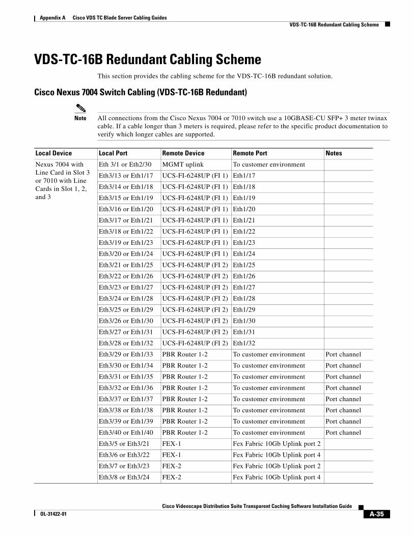
Appendix A Cisco VDS TC Blade Server Cabling Guides VDS-TC-16B Redundant Cabling Scheme
VDS-TC-16B Redundant Cabling SchemeThis section provides the cabling scheme for the VDS-TC-16B redundant solution.
Cisco Nexus 7004 Switch Cabling (VDS-TC-16B Redundant)
Note All connections from the Cisco Nexus 7004 or 7010 switch use a 10GBASE-CU SFP+ 3 meter twinax cable. If a cable longer than 3 meters is required, please refer to the specific product documentation to verify which longer cables are supported.
Local Device Local Port Remote Device Remote Port Notes
Nexus 7004 with Line Card in Slot 3 or 7010 with Line Cards in Slot 1, 2, and 3
Eth 3/1 or Eth2/30 MGMT uplink To customer environment
Eth3/13 or Eth1/17 UCS-FI-6248UP (FI 1) Eth1/17
Eth3/14 or Eth1/18 UCS-FI-6248UP (FI 1) Eth1/18
Eth3/15 or Eth1/19 UCS-FI-6248UP (FI 1) Eth1/19
Eth3/16 or Eth1/20 UCS-FI-6248UP (FI 1) Eth1/20
Eth3/17 or Eth1/21 UCS-FI-6248UP (FI 1) Eth1/21
Eth3/18 or Eth1/22 UCS-FI-6248UP (FI 1) Eth1/22
Eth3/19 or Eth1/23 UCS-FI-6248UP (FI 1) Eth1/23
Eth3/20 or Eth1/24 UCS-FI-6248UP (FI 1) Eth1/24
Eth3/21 or Eth1/25 UCS-FI-6248UP (FI 2) Eth1/25
Eth3/22 or Eth1/26 UCS-FI-6248UP (FI 2) Eth1/26
Eth3/23 or Eth1/27 UCS-FI-6248UP (FI 2) Eth1/27
Eth3/24 or Eth1/28 UCS-FI-6248UP (FI 2) Eth1/28
Eth3/25 or Eth1/29 UCS-FI-6248UP (FI 2) Eth1/29
Eth3/26 or Eth1/30 UCS-FI-6248UP (FI 2) Eth1/30
Eth3/27 or Eth1/31 UCS-FI-6248UP (FI 2) Eth1/31
Eth3/28 or Eth1/32 UCS-FI-6248UP (FI 2) Eth1/32
Eth3/29 or Eth1/33 PBR Router 1-2 To customer environment Port channel
Eth3/30 or Eth1/34 PBR Router 1-2 To customer environment Port channel
Eth3/31 or Eth1/35 PBR Router 1-2 To customer environment Port channel
Eth3/32 or Eth1/36 PBR Router 1-2 To customer environment Port channel
Eth3/37 or Eth1/37 PBR Router 1-2 To customer environment Port channel
Eth3/38 or Eth1/38 PBR Router 1-2 To customer environment Port channel
Eth3/39 or Eth1/39 PBR Router 1-2 To customer environment Port channel
Eth3/40 or Eth1/40 PBR Router 1-2 To customer environment Port channel
Eth3/5 or Eth3/21 FEX-1 Fex Fabric 10Gb Uplink port 2
Eth3/6 or Eth3/22 FEX-1 Fex Fabric 10Gb Uplink port 4
Eth3/7 or Eth3/23 FEX-2 Fex Fabric 10Gb Uplink port 2
Eth3/8 or Eth3/24 FEX-2 Fex Fabric 10Gb Uplink port 4
A-35Cisco Videoscape Distribution Suite Transparent Caching Software Installation Guide
OL-31422-01

Appendix A Cisco VDS TC Blade Server Cabling Guides VDS-TC-16B Redundant Cabling Scheme
Nexus 7004 with Line Card in Slot 4
or
Nexus 7010 with Line Card in Slot 8, 9, and 10
Eth4/1 or Eth9/30 MGMT uplink To customer environment
Eth4/13 or Eth10/17 UCS-FI-6248UP (FI 2) Eth1/17
Eth4/14 or Eth10/14 UCS-FI-6248UP (FI 2) Eth1/18
Eth4/15 or Eth10/15 UCS-FI-6248UP (FI 2) Eth1/19
Eth4/16 or Eth10/16 UCS-FI-6248UP (FI 2) Eth1/20
Eth4/17 or Eth10/17 UCS-FI-6248UP (FI 2) Eth1/21
Eth4/18 or Eth10/18 UCS-FI-6248UP (FI 2) Eth1/22
Eth4/19 or Eth10/19 UCS-FI-6248UP (FI 2) Eth1/23
Eth4/20 or Eth10/20 UCS-FI-6248UP (FI 2) Eth1/24
Eth4/21 or Eth10/25 UCS-FI-6248UP (FI 1) Eth1/25
Eth4/22 or Eth10/26 UCS-FI-6248UP (FI 1) Eth1/26
Eth4/23 or Eth10/27 UCS-FI-6248UP (FI 1) Eth1/27
Eth4/24 or Eth10/28 UCS-FI-6248UP (FI 1) Eth1/28
Eth4/25 or Eth10/29 UCS-FI-6248UP (FI 1) Eth1/29
Eth4/26 or Eth10/30 UCS-FI-6248UP (FI 1) Eth1/30
Eth4/27 or Eth10/31 UCS-FI-6248UP (FI 1) Eth1/31
Eth4/28 or Eth10/32 UCS-FI-6248UP (FI 1) Eth1/32
Eth4/29 or Eth10/33 PBR Router 3-4 To customer environment Port channel
Eth4/30 or Eth10/34 PBR Router 3-4 To customer environment Port channel
Eth4/31 or Eth10/35 PBR Router 3-4 To customer environment Port channel
Eth4/32 or Eth10/36 PBR Router 3-4 To customer environment Port channel
Eth4/37 or Eth10/37 PBR Router 3-4 To customer environment Port channel
Eth4/38 or Eth10/38 PBR Router 3-4 To customer environment Port channel
Eth4/39 or Eth10/39 PBR Router 3-4 To customer environment Port channel
Eth4/40 or Eth10/40 PBR Router 3-4 To customer environment Port channel
Eth4/5 or Eth8/23 FEX-2 Fex Fabric 10Gb Uplink port 2
Eth4/6 or Eth8/24 FEX-2 Fex Fabric 10Gb Uplink port 4
Eth4/7 or Eth8/21 FEX-1 Fex Fabric 10Gb Uplink port 2
Eth4/8 or Eth8/22 FEX-1 Fex Fabric 10Gb Uplink port 4
Cisco Nexus 7004 Switch Cabling (VDS-TC-16B Redundant) (continued)
Note All connections from the Cisco Nexus 7004 or 7010 switch use a 10GBASE-CU SFP+ 3 meter twinax cable. If a cable longer than 3 meters is required, please refer to the specific product documentation to verify which longer cables are supported.
Local Device Local Port Remote Device Remote Port Notes
A-36Cisco Videoscape Distribution Suite Transparent Caching Software Installation Guide
OL-31422-01
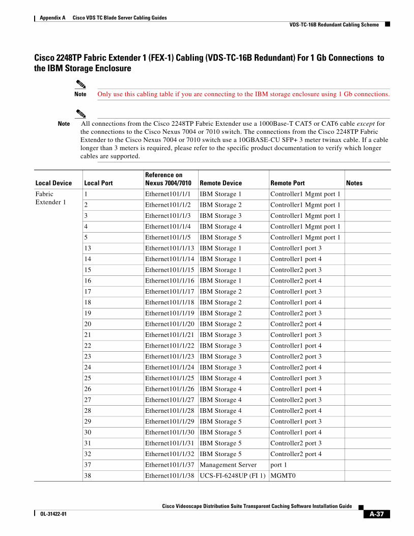
Appendix A Cisco VDS TC Blade Server Cabling Guides VDS-TC-16B Redundant Cabling Scheme
Cisco 2248TP Fabric Extender 1 (FEX-1) Cabling (VDS-TC-16B Redundant) For 1 Gb Connections to the IBM Storage Enclosure
Note Only use this cabling table if you are connecting to the IBM storage enclosure using 1 Gb connections.
Note All connections from the Cisco 2248TP Fabric Extender use a 1000Base-T CAT5 or CAT6 cable except for the connections to the Cisco Nexus 7004 or 7010 switch. The connections from the Cisco 2248TP Fabric Extender to the Cisco Nexus 7004 or 7010 switch use a 10GBASE-CU SFP+ 3 meter twinax cable. If a cable longer than 3 meters is required, please refer to the specific product documentation to verify which longer cables are supported.
Local Device Local PortReference on Nexus 7004/7010 Remote Device Remote Port Notes
Fabric Extender 1
1 Ethernet101/1/1 IBM Storage 1 Controller1 Mgmt port 1
2 Ethernet101/1/2 IBM Storage 2 Controller1 Mgmt port 1
3 Ethernet101/1/3 IBM Storage 3 Controller1 Mgmt port 1
4 Ethernet101/1/4 IBM Storage 4 Controller1 Mgmt port 1
5 Ethernet101/1/5 IBM Storage 5 Controller1 Mgmt port 1
13 Ethernet101/1/13 IBM Storage 1 Controller1 port 3
14 Ethernet101/1/14 IBM Storage 1 Controller1 port 4
15 Ethernet101/1/15 IBM Storage 1 Controller2 port 3
16 Ethernet101/1/16 IBM Storage 1 Controller2 port 4
17 Ethernet101/1/17 IBM Storage 2 Controller1 port 3
18 Ethernet101/1/18 IBM Storage 2 Controller1 port 4
19 Ethernet101/1/19 IBM Storage 2 Controller2 port 3
20 Ethernet101/1/20 IBM Storage 2 Controller2 port 4
21 Ethernet101/1/21 IBM Storage 3 Controller1 port 3
22 Ethernet101/1/22 IBM Storage 3 Controller1 port 4
23 Ethernet101/1/23 IBM Storage 3 Controller2 port 3
24 Ethernet101/1/24 IBM Storage 3 Controller2 port 4
25 Ethernet101/1/25 IBM Storage 4 Controller1 port 3
26 Ethernet101/1/26 IBM Storage 4 Controller1 port 4
27 Ethernet101/1/27 IBM Storage 4 Controller2 port 3
28 Ethernet101/1/28 IBM Storage 4 Controller2 port 4
29 Ethernet101/1/29 IBM Storage 5 Controller1 port 3
30 Ethernet101/1/30 IBM Storage 5 Controller1 port 4
31 Ethernet101/1/31 IBM Storage 5 Controller2 port 3
32 Ethernet101/1/32 IBM Storage 5 Controller2 port 4
37 Ethernet101/1/37 Management Server port 1
38 Ethernet101/1/38 UCS-FI-6248UP (FI 1) MGMT0
A-37Cisco Videoscape Distribution Suite Transparent Caching Software Installation Guide
OL-31422-01

Appendix A Cisco VDS TC Blade Server Cabling Guides VDS-TC-16B Redundant Cabling Scheme
Fabric Extender 1
10Gb Uplink port 2 Nexus 7004 or 7010 Eth3/7
10Gb Uplink port 4 Nexus 7004 or 7010 Eth3/8
10Gb Uplink port 1 Nexus 7004 or 7010 Eth4/7
10Gb Uplink port 3 Nexus 7004 or 7010 Eth4/8
Cisco 2248TP Fabric Extender 1 (FEX-1) Cabling (VDS-TC-16B Redundant) For 1 Gb Connections to the IBM Storage Enclosure (continued)
Note Only use this cabling table if you are connecting to the IBM storage enclosure using 1 Gb connections.
Note All connections from the Cisco 2248TP Fabric Extender use a 1000Base-T CAT5 or CAT6 cable except for the connections to the Cisco Nexus 7004 or 7010 switch. The connections from the Cisco 2248TP Fabric Extender to the Cisco Nexus 7004 or 7010 switch use a 10GBASE-CU SFP+ 3 meter twinax cable. If a cable longer than 3 meters is required, please refer to the specific product documentation to verify which longer cables are supported.
Local Device Local PortReference on Nexus 7004/7010 Remote Device Remote Port Notes
A-38Cisco Videoscape Distribution Suite Transparent Caching Software Installation Guide
OL-31422-01
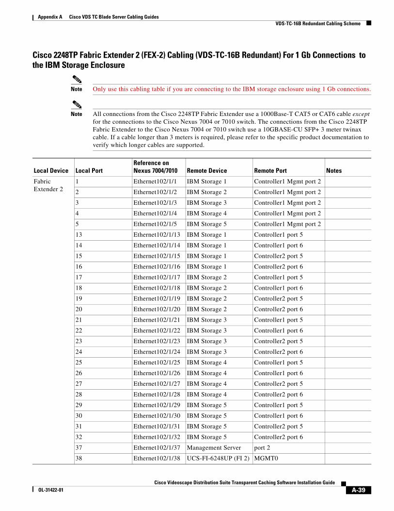
Appendix A Cisco VDS TC Blade Server Cabling Guides VDS-TC-16B Redundant Cabling Scheme
Cisco 2248TP Fabric Extender 2 (FEX-2) Cabling (VDS-TC-16B Redundant) For 1 Gb Connections to the IBM Storage Enclosure
Note Only use this cabling table if you are connecting to the IBM storage enclosure using 1 Gb connections.
Note All connections from the Cisco 2248TP Fabric Extender use a 1000Base-T CAT5 or CAT6 cable except for the connections to the Cisco Nexus 7004 or 7010 switch. The connections from the Cisco 2248TP Fabric Extender to the Cisco Nexus 7004 or 7010 switch use a 10GBASE-CU SFP+ 3 meter twinax cable. If a cable longer than 3 meters is required, please refer to the specific product documentation to verify which longer cables are supported.
Local Device Local PortReference onNexus 7004/7010 Remote Device Remote Port Notes
Fabric Extender 2
1 Ethernet102/1/1 IBM Storage 1 Controller1 Mgmt port 2
2 Ethernet102/1/2 IBM Storage 2 Controller1 Mgmt port 2
3 Ethernet102/1/3 IBM Storage 3 Controller1 Mgmt port 2
4 Ethernet102/1/4 IBM Storage 4 Controller1 Mgmt port 2
5 Ethernet102/1/5 IBM Storage 5 Controller1 Mgmt port 2
13 Ethernet102/1/13 IBM Storage 1 Controller1 port 5
14 Ethernet102/1/14 IBM Storage 1 Controller1 port 6
15 Ethernet102/1/15 IBM Storage 1 Controller2 port 5
16 Ethernet102/1/16 IBM Storage 1 Controller2 port 6
17 Ethernet102/1/17 IBM Storage 2 Controller1 port 5
18 Ethernet102/1/18 IBM Storage 2 Controller1 port 6
19 Ethernet102/1/19 IBM Storage 2 Controller2 port 5
20 Ethernet102/1/20 IBM Storage 2 Controller2 port 6
21 Ethernet102/1/21 IBM Storage 3 Controller1 port 5
22 Ethernet102/1/22 IBM Storage 3 Controller1 port 6
23 Ethernet102/1/23 IBM Storage 3 Controller2 port 5
24 Ethernet102/1/24 IBM Storage 3 Controller2 port 6
25 Ethernet102/1/25 IBM Storage 4 Controller1 port 5
26 Ethernet102/1/26 IBM Storage 4 Controller1 port 6
27 Ethernet102/1/27 IBM Storage 4 Controller2 port 5
28 Ethernet102/1/28 IBM Storage 4 Controller2 port 6
29 Ethernet102/1/29 IBM Storage 5 Controller1 port 5
30 Ethernet102/1/30 IBM Storage 5 Controller1 port 6
31 Ethernet102/1/31 IBM Storage 5 Controller2 port 5
32 Ethernet102/1/32 IBM Storage 5 Controller2 port 6
37 Ethernet102/1/37 Management Server port 2
38 Ethernet102/1/38 UCS-FI-6248UP (FI 2) MGMT0
A-39Cisco Videoscape Distribution Suite Transparent Caching Software Installation Guide
OL-31422-01

Appendix A Cisco VDS TC Blade Server Cabling Guides VDS-TC-16B Redundant Cabling Scheme
Fabric Extender 2
10Gb Uplink port 2 Nexus 7004 or 7010 Eth3/5
10Gb Uplink port 4 Nexus 7004 or 7010 Eth3/6
10Gb Uplink port 1 Nexus 7004 or 7010 Eth4/5
10Gb Uplink port 3 Nexus 7004 or 7010 Eth4/6
Local Device Local PortReference onNexus 7004/7010 Remote Device Remote Port Notes
A-40Cisco Videoscape Distribution Suite Transparent Caching Software Installation Guide
OL-31422-01

Appendix A Cisco VDS TC Blade Server Cabling Guides VDS-TC-16B Redundant Cabling Scheme
Cisco 2232TM Fabric Extender 1 (FEX-1) Cabling (VDS-TC-16B Redundant) For 10 Gb Connections to the IBM Storage Enclosure
Note Only use this cabling table if you are connecting to the IBM storage enclosure using 10 Gb connections.
Note All management connections, including management connections to the IBM storage enclosures, from the Cisco 2232TM Fabric Extender use a 1000Base-T CAT5 or CAT6 cable. The connections to the iSCSI ports on the storage enclosures use a 10GBASE-T CAT6 or CAT7 cable. The connections to the Cisco Nexus 7004 or 7010 switch use a 10GBASE-CU SFP+ 3 meter twinax cable. If a cable longer than 3 meters is required, please refer to the specific product documentation to verify which longer cables are supported
Local Device Local PortReference onNexus 7004/7010 Remote Device Remote Port Notes
Fabric Extender 1
1 Ethernet101/1/1 IBM Storage 1 Controller1 Mgmt port 1
2 Ethernet101/1/2 IBM Storage 2 Controller1 Mgmt port 1
3 Ethernet101/1/3 IBM Storage 3 Controller1 Mgmt port 1
4 Ethernet101/1/4 IBM Storage 4 Controller1 Mgmt port 1
5 Ethernet101/1/5 IBM Storage 5 Controller1 Mgmt port 1
9 Ethernet101/1/9 Management Server port 1
10 Ethernet101/1/10 Fabric Interconnect Management port
13 Ethernet101/1/13 IBM Storage 1 Controller1 port 3
14 Ethernet101/1/14 IBM Storage 2 Controller1 port 3
15 Ethernet101/1/15 IBM Storage 3 Controller1 port 3
16 Ethernet101/1/16 IBM Storage 4 Controller1 port 3
17 Ethernet101/1/17 IBM Storage 5 Controller1 port 3
10Gb Uplink port 1
Nexus 7004 or 7010 Eth3/5
10Gb Uplink port 2
Nexus 7004 or 7010 Eth3/6
10Gb Uplink port 3
Nexus 7004 or 7010 Eth4/5
10Gb Uplink port 4
Nexus 7004 or 7010 Eth4/6
A-41Cisco Videoscape Distribution Suite Transparent Caching Software Installation Guide
OL-31422-01

Appendix A Cisco VDS TC Blade Server Cabling Guides VDS-TC-16B Redundant Cabling Scheme
Cisco 2232TM Fabric Extender 2 (FEX-2) Cabling (VDS-TC-16B Redundant) For 10 Gb Connections to the IBM Storage Enclosure
Note Only use this cabling table if you are connecting to the IBM storage enclosure using 10 Gb connections.
Note All management connections, including management connections to the IBM storage enclosures, from the Cisco 2232TM Fabric Extender use a 1000Base-T CAT5 or CAT6 cable. The connections to the iSCSI ports on the storage enclosures use a 10GBASE-T CAT6 or CAT7 cable. The connections to the Cisco Nexus 7004 or 7010 switch use a 10GBASE-CU SFP+ 3 meter twinax cable. If a cable longer than 3 meters is required, please refer to the specific product documentation to verify which longer cables are supported.
Local Device Local PortReference onNexus 7004/7010 Remote Device Remote Port Notes
Fabric Extender 2
1 Ethernet102/1/1 IBM Storage 1 Controller2 Mgmt port 1
2 Ethernet102/1/2 IBM Storage 2 Controller2 Mgmt port 1
3 Ethernet102/1/3 IBM Storage 3 Controller2 Mgmt port 1
4 Ethernet102/1/4 IBM Storage 4 Controller2 Mgmt port 1
5 Ethernet102/1/5 IBM Storage 5 Controller2 Mgmt port 1
9 Ethernet102/1/9 Management Server port 1
10 Ethernet102/1/10 Fabric Interconnect Management port
13 Ethernet102/1/13 IBM Storage 1 Controller2 port 3
14 Ethernet102/1/14 IBM Storage 2 Controller2 port 3
15 Ethernet102/1/15 IBM Storage 3 Controller2 port 3
16 Ethernet102/1/16 IBM Storage 4 Controller2 port 3
17 Ethernet102/1/17 IBM Storage 5 Controller2 port 3
10Gb Uplink port 1
Nexus 7004 or 7010 Eth3/7
10Gb Uplink port 2
Nexus 7004 or 7010 Eth3/8
10Gb Uplink port 3
Nexus 7004 or 7010 Eth4/7
10Gb Uplink port 4
Nexus 7004 or 7010 Eth4/8
A-42Cisco Videoscape Distribution Suite Transparent Caching Software Installation Guide
OL-31422-01

Appendix A Cisco VDS TC Blade Server Cabling Guides VDS-TC-16B Redundant Cabling Scheme
Cisco UCS 6248 UP Fabric Interconnect 1 (FI-1) Cabling (VDS-TC-16B Redundant)
Note All connections from the Cisco UCS 6248 UP Fabric Interconnect use a 10GBASE-CU SFP+ 3 meter twinax cable. If a cable longer than 3 meters is required, please refer to the specific product
A-43Cisco Videoscape Distribution Suite Transparent Caching Software Installation Guide
OL-31422-01

Appendix A Cisco VDS TC Blade Server Cabling Guides VDS-TC-16B Redundant Cabling Scheme
documentation to verify which longer cables are supported.
Local Device Local Port Remote Device Remote Port Notes
FI-1 L1 FI-2 L1
L2 FI-2 L2
Eth port 1/1 Chassis 1 Fabric port 1/1
Eth port 1/2 Chassis 1 Fabric port 1/2
Eth port 1/3 Chassis 1 Fabric port 1/3
Eth port 1/4 Chassis 1 Fabric port 1/4
Eth port 1/5 Chassis 1 Fabric port 1/5
Eth port 1/6 Chassis 1 Fabric port 1/6
Eth port 1/7 Chassis 1 Fabric port 1/7
Eth port 1/8 Chassis 1 Fabric port 1/8
Eth port 1/9 Chassis 2 Fabric port 1/1
Eth port 1/10 Chassis 2 Fabric port 1/2
Eth port 1/11 Chassis 2 Fabric port 1/3
Eth port 1/12 Chassis 2 Fabric port 1/4
Eth port 1/13 Chassis 2 Fabric port 1/5
Eth port 1/14 Chassis 2 Fabric port 1/6
Eth port 1/15 Chassis 2 Fabric port 1/7
Eth port 1/16 Chassis 2 Fabric port 1/8
Eth1/17 Nexus 7004 or 7010 Eth 3/17 or Eth1/17
Eth1/18 Nexus 7004 or 7010 Eth 3/18 or Eth1/18
Eth1/19 Nexus 7004 or 7010 Eth 3/19 or Eth1/19
Eth1/20 Nexus 7004 or 7010 Eth 3/20 or Eth1/20
Eth1/21 Nexus 7004 or 7010 Eth 3/13 or Eth1/21
Eth1/22 Nexus 7004 or 7010 Eth 3/14 or Eth1/22
Eth1/23 Nexus 7004 or 7010 Eth 3/15 or Eth1/23
Eth1/24 Nexus 7004 or 7010 Eth 3/16 or Eth1/24
Eth1/25 Nexus 7004 or 7010 Eth4/21 or Eth10/25
Eth1/26 Nexus 7004 or 7010 Eth4/22 or Eth10/26
Eth1/27 Nexus 7004 or 7010 Eth4/23 or Eth10/27
Eth1/28 Nexus 7004 or 7010 Eth4/24 or Eth10/28
Eth1/29 Nexus 7004 or 7010 Eth4/25 or Eth10/29
Eth1/30 Nexus 7004 or 7010 Eth4/26 or Eth10/30
Eth1/31 Nexus 7004 or 7010 Eth4/27 or Eth10/31
Eth1/32 Nexus 7004 or 7010 Eth4/28 or Eth10/32
A-44Cisco Videoscape Distribution Suite Transparent Caching Software Installation Guide
OL-31422-01

Appendix A Cisco VDS TC Blade Server Cabling Guides VDS-TC-16B Redundant Cabling Scheme
Cisco UCS 6248 UP Fabric Interconnect 2 (FI-2) Cabling (VDS-TC-16B Redundant)
Note All connections from the Cisco UCS 6248 UP Fabric Interconnect use a 10GBASE-CU SFP+ 3 meter twinax cable. If a cable longer than 3 meters is required, please refer to the specific product documentation to verify which longer cables are supported.
A-45Cisco Videoscape Distribution Suite Transparent Caching Software Installation Guide
OL-31422-01

Appendix A Cisco VDS TC Blade Server Cabling Guides VDS-TC-16B Redundant Cabling Scheme
Local Device Local Port Remote Device Remote Port Notes
FI-2 L1 FI-1 L1
L2 FI-1 L2
Eth port 1/1 Chassis 1 Fabric port 2/1
Eth port 1/2 Chassis 1 Fabric port 2/2
Eth port 1/3 Chassis 1 Fabric port 2/3
Eth port 1/4 Chassis 1 Fabric port 2/4
Eth port 1/5 Chassis 1 Fabric port 2/5
Eth port 1/6 Chassis 1 Fabric port 2/6
Eth port 1/7 Chassis 1 Fabric port 2/7
Eth port 1/8 Chassis 1 Fabric port 2/8
Eth port 1/9 Chassis 2 Fabric port 2/1
Eth port 1/10 Chassis 2 Fabric port 2/2
Eth port 1/11 Chassis 2 Fabric port 2/3
Eth port 1/12 Chassis 2 Fabric port 2/4
Eth port 1/13 Chassis 2 Fabric port 2/5
Eth port 1/14 Chassis 2 Fabric port 2/6
Eth port 1/15 Chassis 2 Fabric port 2/7
Eth port 1/16 Chassis 2 Fabric port 2/8
Eth1/17 Nexus 7004 or 7010 Eth4/17 or Eth10/17
Eth1/18 Nexus 7004 or 7010 Eth4/18 or Eth10/18
Eth1/19 Nexus 7004 or 7010 Eth4/19 or Eth10/19
Eth1/20 Nexus 7004 or 7010 Eth4/20 or Eth10/20
Eth1/21 Nexus 7004 or 7010 Eth4/13 or Eth10/21
Eth1/22 Nexus 7004 or 7010 Eth4/14 or Eth10/22
Eth1/23 Nexus 7004 or 7010 Eth4/15 or Eth10/23
Eth1/24 Nexus 7004 or 7010 Eth4/16 or Eth10/24
Eth1/25 Nexus 7004 or 7010 Eth3/21 or Eth1/25
Eth1/26 Nexus 7004 or 7010 Eth3/22 or Eth1/26
Eth1/27 Nexus 7004 or 7010 Eth3/23 or Eth1/27
Eth1/28 Nexus 7004 or 7010 Eth3/24 or Eth1/28
Eth1/29 Nexus 7004 or 7010 Eth3/25 or Eth1/29
Eth1/30 Nexus 7004 or 7010 Eth3/26 or Eth1/30
Eth1/31 Nexus 7004 or 7010 Eth3/27 or Eth1/31
Eth1/32 Nexus 7004 or 7010 Eth3/28 or Eth1/32
A-46Cisco Videoscape Distribution Suite Transparent Caching Software Installation Guide
OL-31422-01

Cisco Videoscape Distribution Suite TranOL-31422-01
A
P P E N D I X B Cisco VDS TC Specific UCS Blade Server ValuesRevised: March 2014, OL-31422-01
This appendix provides information on the Cisco UCS Blade Server values that are specific for a Cisco VDS TC Blade Server installation.
Note Make sure to click Save Changes if you make any changes to the Blade Server BIOS settings.
Note All Cache Engine servers will require to go through a reboot at the end of the configuration to apply all of the changes.
Values for the Equipment Tab
Path Parameter Value
Policies Tab > Global Policies Tab Chassis/FEX Discovery Policy Section > Link Group Preference
Port Channel
Rack Server Discovery Policy Section > Scrub Policy
default
Values for the LAN Tab
Path Parameter Value
LAN Cloud > Fabric A > Port Channels > Port-Channel 1
Port Channel Name To-N7K-PO1
Admin Speed 10 Gbps
Ports • VDS-TC-16B: 1/25 - 1/32
• VDS-TC-8B: 1/29 - 1/32
• VDS-TC-4B: 1/29 & 1/30
B-1sparent Caching Software Installation Guide

Appendix B Cisco VDS TC Specific UCS Blade Server Values
LAN Cloud > Fabric B > Port Channels > Port-Channel 1
Port Channel Name To-N7K-PO1
Admin Speed 10 Gbps
Ports • VDS-TC-16B: 1/25 - 1/32
• VDS-TC-8B: 1/29 - 1/32
• VDS-TC-4B: 1/29 & 1/30
LAN Cloud > QoS System Class > Platinum
Enabled Checked
CoS 5
Packet Drop Checked
Weight 10
MTU 9120
Multicast Optimized Checked
LAN Cloud > QoS System Class > Gold
Enabled Checked
CoS 4
Packet Drop Unchecked
Weight 9
MTU 9120
Multicast Optimized Unchecked
LAN Cloud > QoS System Class > Silver
Enabled Unchecked
CoS 2
Packet Drop Checked
Weight 8
MTU 9120
Multicast Optimized Unchecked
LAN Cloud > QoS System Class > Bronze
Enabled Unchecked
CoS 1
Packet Drop Checked
Weight 7
MTU 9120
Multicast Optimized Unchecked
LAN Cloud > QoS System Class > Best Effort
Enabled Checked
CoS Any
Packet Drop Checked
Weight 5
MTU 9120
Multicast Optimized Unchecked
Values for the LAN Tab (continued)
Path Parameter Value
B-2Cisco Videoscape Distribution Suite Transparent Caching Software Installation Guide
OL-31422-01

Appendix B Cisco VDS TC Specific UCS Blade Server Values
LAN Cloud > QoS System Class > Fibre Channel
Enabled Checked
CoS 3
Packet Drop Unchecked
Weight 5
MTU fc
Multicast Optimized N/A
Policies > root > QoS Policies Name DATA
Policies > root > QoS Policies > QoS Policy Data
Priority Gold
Burst(Bytes) 10240
Rate(Kbps) line-rate
Host Control None
Policies > root > QoS Policies Name Mgmt
Policies > root > QoS Policies > QOS Policy Mgmt
Priority Platinum
Burst(Bytes) 20480
Rate(Kbps) line-rate
Host Control None
Policies > root > QoS Policies Name iSCSI
Policies > root > QoS Policies > QOS Policy iSCSI
Priority Platinum
Burst(Bytes) 10240
Rate(Kbps) line-rate
Host Control None
Policies > Appliances > Network Control Policies > default
CDP Disabled
MAC Register Mode Only Native VLAN
Action on Uplink Fail Link Down
MAC Security Allow
Policies > root > Network Control Policies > default
CDP Enabled
MAC Register Mode Only Native VLAN
Action on Uplink Fail Link Down
MAC Security Allow
Policies > root > Flow Control Policies > default
Priority Auto
Receive Off
Send Off
Values for the LAN Tab (continued)
Path Parameter Value
B-3Cisco Videoscape Distribution Suite Transparent Caching Software Installation Guide
OL-31422-01

Appendix B Cisco VDS TC Specific UCS Blade Server Values
LAN Cloud > VLANs > VLAN default (1)
VLAN ID 1
Native VLAN Yes
Multicast Policy Name <not set>
Fabric ID DUAL
If Type Virtual
Transport Type Ether
Locale External
Sharing Type None
LAN Cloud > VLANs > VLAN Mgmt (50)
VLAN ID 50
Native VLAN No
Multicast Policy Name <not set>
Fabric ID DUAL
If Type Virtual
Transport Type Ether
Locale External
Sharing Type None
LAN Cloud > VLANs > VLAN iSCSI_DATA (70)
VLAN ID 70
Native VLAN No
Multicast Policy Name <not set>
Fabric ID DUAL
If Type Virtual
Transport Type Ether
Locale External
Sharing Type None
LAN Cloud > VLANs > VLAN DATA_201 (201)
VLAN ID 201
Native VLAN No
Multicast Policy Name <not set>
Fabric ID DUAL
If Type Virtual
Transport Type Ether
Locale External
Sharing Type None
Values for the LAN Tab (continued)
Path Parameter Value
B-4Cisco Videoscape Distribution Suite Transparent Caching Software Installation Guide
OL-31422-01

Appendix B Cisco VDS TC Specific UCS Blade Server Values
LAN Cloud > VLANs > VLAN DATA_202 (202)
VLAN ID 202
Native VLAN No
Multicast Policy Name <not set>
Fabric ID DUAL
If Type Virtual
Transport Type Ether
Locale External
Sharing Type None
LAN Cloud > VLANs > VLAN DATA_203 (203)
VLAN ID 203
Native VLAN No
Multicast Policy Name <not set>
Fabric ID DUAL
If Type Virtual
Transport Type Ether
Locale External
Sharing Type None
LAN Cloud > VLANs > VLAN DATA_204 (204)
VLAN ID 204
Native VLAN No
Multicast Policy Name <not set>
Fabric ID DUAL
If Type Virtual
Transport Type Ether
Locale External
Sharing Type None
LAN Cloud > VLANs > VLAN DATA_301 (301)
VLAN ID 301
Native VLAN No
Multicast Policy Name <not set>
Fabric ID DUAL
If Type Virtual
Transport Type Ether
Locale External
Sharing Type None
Values for the LAN Tab (continued)
Path Parameter Value
B-5Cisco Videoscape Distribution Suite Transparent Caching Software Installation Guide
OL-31422-01

Appendix B Cisco VDS TC Specific UCS Blade Server Values
LAN Cloud > VLANs > VLAN DATA_302 (302)
VLAN ID 302
Native VLAN No
Multicast Policy Name <not set>
Fabric ID DUAL
If Type Virtual
Transport Type Ether
Locale External
Sharing Type None
LAN Cloud > VLANs > VLAN DATA_303 (303)
VLAN ID 303
Native VLAN No
Multicast Policy Name <not set>
Fabric ID DUAL
If Type Virtual
Transport Type Ether
Locale External
Sharing Type None
LAN Cloud > VLANs > VLAN DATA_304 (304)
VLAN ID 304
Native VLAN No
Multicast Policy Name <not set>
Fabric ID DUAL
If Type Virtual
Transport Type Ether
Locale External
Sharing Type None
Pools > root > IP Pools > IP Pool ext-mgmt
Size 150
IP Addresses 10.11.80.100 - 10.11.80.249
Pools > root > MAC Pools > MAC Pool Eth0
First MAC 00:25:B5:00:01:00
Size 256
Pools > root > MAC Pools > MAC Pool Eth1
First MAC 00:25:B5:00:02:00
Size 256
Pools > root > MAC Pools > MAC Pool Eth2
First MAC 00:25:B5:00:03:00
Size 256
Pools > root > MAC Pools > MAC Pool Eth3
First MAC 00:25:B5:00:04:00
Size 256
Pools > root > MAC Pools > MAC Pool Eth4
First MAC 00:25:B5:00:05:00
Size 256
Values for the LAN Tab (continued)
Path Parameter Value
B-6Cisco Videoscape Distribution Suite Transparent Caching Software Installation Guide
OL-31422-01

Appendix B Cisco VDS TC Specific UCS Blade Server Values
Pools > root > MAC Pools > MAC Pool Eth5
First MAC 00:25:B5:00:06:00
Size 256
Pools > root > MAC Pools > MAC Pool Eth6
First MAC 00:25:B5:00:07:00
Size 256
Pools > root > MAC Pools > MAC Pool Eth7
First MAC 00:25:B5:00:08:00
Size 256
Pools > root > MAC Pools > MAC Pool Eth8
First MAC 00:25:B5:00:09:00
Size 256
Pools > root > MAC Pools > MAC Pool Eth9
First MAC 00:25:B5:00:0A:00
Size 256
Pools > root > MAC Pools > MAC Pool Eth10
First MAC 00:25:B5:00:0B:00
Size 256
Pools > root > MAC Pools > MAC Pool Eth11
First MAC 00:25:B5:00:0C:00
Size 256
Pools > root > MAC Pools > MAC Pool Eth12
First MAC 00:25:B5:00:0D:00
Size 256
Policies > root > vNIC Templates > CE_ETH0
Fabric A
Enable Failover Checked
VM Unchecked
VLAN Mgmt
Native VLAN Yes
Template Type Updating Template
MTU 9000
MAC Pool Eth0
Network Control Policy default
QOS Policy Mgmt
Policies > root > vNIC Templates > CE_ETH1
Fabric A
Enable Failover Checked
VM Unchecked
VLAN default
Native VLAN No
Template Type Updating Template
MTU 9000
MAC Pool Eth1
Network Control Policy default
QOS Policy iSCSI
Values for the LAN Tab (continued)
Path Parameter Value
B-7Cisco Videoscape Distribution Suite Transparent Caching Software Installation Guide
OL-31422-01

Appendix B Cisco VDS TC Specific UCS Blade Server Values
Policies > root > vNIC Templates > CE_ETH2
Fabric A
Enable Failover Checked
VM Unchecked
VLAN None
Native VLAN N/A
Template Type Updating Template
MTU 9000
MAC Pool Eth2
Network Control Policy default
QOS Policy DATA
Policies > root > vNIC Templates > CE_ETH3
Fabric A
Enable Failover Checked
VM Unchecked
VLAN None
Native VLAN N/A
Template Type Updating Template
MTU 9000
MAC Pool Eth3
Network Control Policy default
QOS Policy DATA
Policies > root > vNIC Templates > CE_ETH4
Fabric A
Enable Failover Checked
VM Unchecked
VLAN iSCSI_DATA
Native VLAN Yes
Template Type Updating Template
MTU 9000
MAC Pool Eth4
Network Control Policy default
QOS Policy iSCSI
Values for the LAN Tab (continued)
Path Parameter Value
B-8Cisco Videoscape Distribution Suite Transparent Caching Software Installation Guide
OL-31422-01
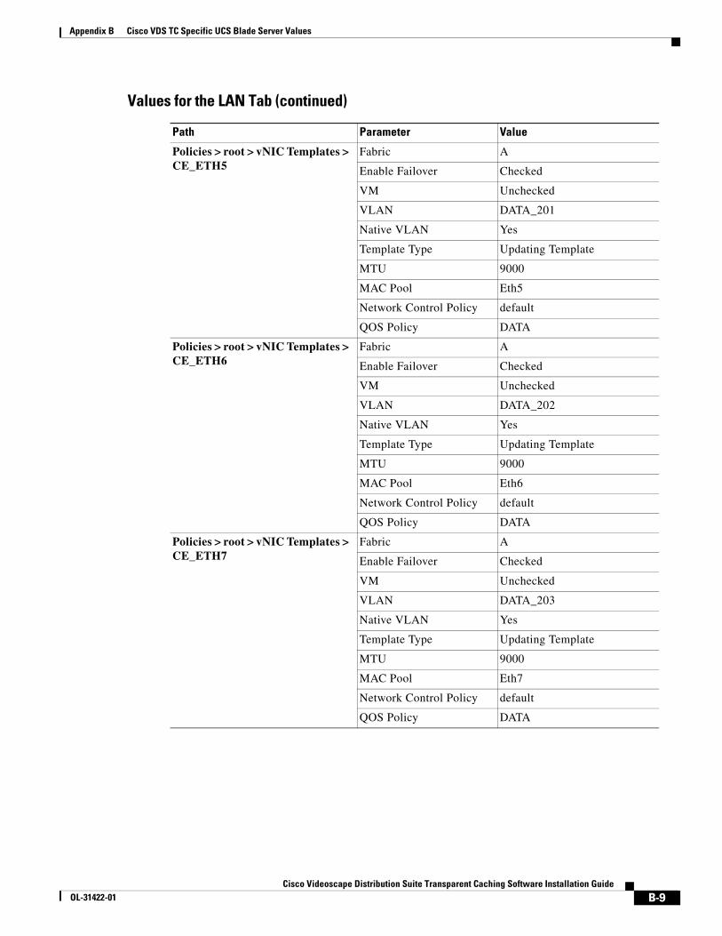
Appendix B Cisco VDS TC Specific UCS Blade Server Values
Policies > root > vNIC Templates > CE_ETH5
Fabric A
Enable Failover Checked
VM Unchecked
VLAN DATA_201
Native VLAN Yes
Template Type Updating Template
MTU 9000
MAC Pool Eth5
Network Control Policy default
QOS Policy DATA
Policies > root > vNIC Templates > CE_ETH6
Fabric A
Enable Failover Checked
VM Unchecked
VLAN DATA_202
Native VLAN Yes
Template Type Updating Template
MTU 9000
MAC Pool Eth6
Network Control Policy default
QOS Policy DATA
Policies > root > vNIC Templates > CE_ETH7
Fabric A
Enable Failover Checked
VM Unchecked
VLAN DATA_203
Native VLAN Yes
Template Type Updating Template
MTU 9000
MAC Pool Eth7
Network Control Policy default
QOS Policy DATA
Values for the LAN Tab (continued)
Path Parameter Value
B-9Cisco Videoscape Distribution Suite Transparent Caching Software Installation Guide
OL-31422-01

Appendix B Cisco VDS TC Specific UCS Blade Server Values
Policies > root > vNIC Templates > CE_ETH8
Fabric A
Enable Failover Checked
VM Unchecked
VLAN DATA_204
Native VLAN Yes
Template Type Updating Template
MTU 9000
MAC Pool Eth8
Network Control Policy default
QOS Policy DATA
Policies > root > vNIC Templates > CE_ETH9
Fabric A
Enable Failover Checked
VM Unchecked
VLAN DATA_301
Native VLAN Yes
Template Type Updating Template
MTU 9000
MAC Pool Eth9
Network Control Policy default
QOS Policy DATA
Policies > root > vNIC Templates > CE_ETH10
Fabric A
Enable Failover Checked
VM Unchecked
VLAN DATA_302
Native VLAN Yes
Template Type Updating Template
MTU 9000
MAC Pool Eth10
Network Control Policy default
QOS Policy DATA
Values for the LAN Tab (continued)
Path Parameter Value
B-10Cisco Videoscape Distribution Suite Transparent Caching Software Installation Guide
OL-31422-01
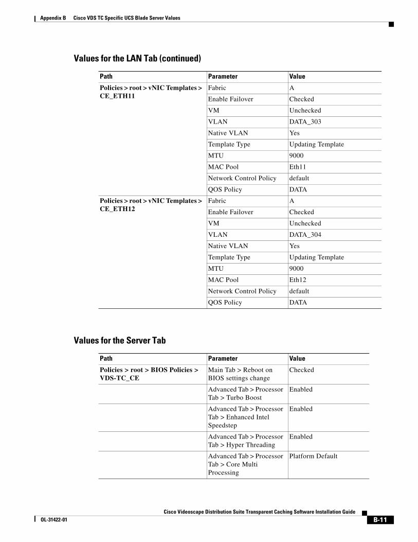
Appendix B Cisco VDS TC Specific UCS Blade Server Values
Policies > root > vNIC Templates > CE_ETH11
Fabric A
Enable Failover Checked
VM Unchecked
VLAN DATA_303
Native VLAN Yes
Template Type Updating Template
MTU 9000
MAC Pool Eth11
Network Control Policy default
QOS Policy DATA
Policies > root > vNIC Templates > CE_ETH12
Fabric A
Enable Failover Checked
VM Unchecked
VLAN DATA_304
Native VLAN Yes
Template Type Updating Template
MTU 9000
MAC Pool Eth12
Network Control Policy default
QOS Policy DATA
Values for the LAN Tab (continued)
Path Parameter Value
Values for the Server Tab
Path Parameter Value
Policies > root > BIOS Policies > VDS-TC_CE
Main Tab > Reboot on BIOS settings change
Checked
Advanced Tab > Processor Tab > Turbo Boost
Enabled
Advanced Tab > Processor Tab > Enhanced Intel Speedstep
Enabled
Advanced Tab > Processor Tab > Hyper Threading
Enabled
Advanced Tab > Processor Tab > Core Multi Processing
Platform Default
B-11Cisco Videoscape Distribution Suite Transparent Caching Software Installation Guide
OL-31422-01
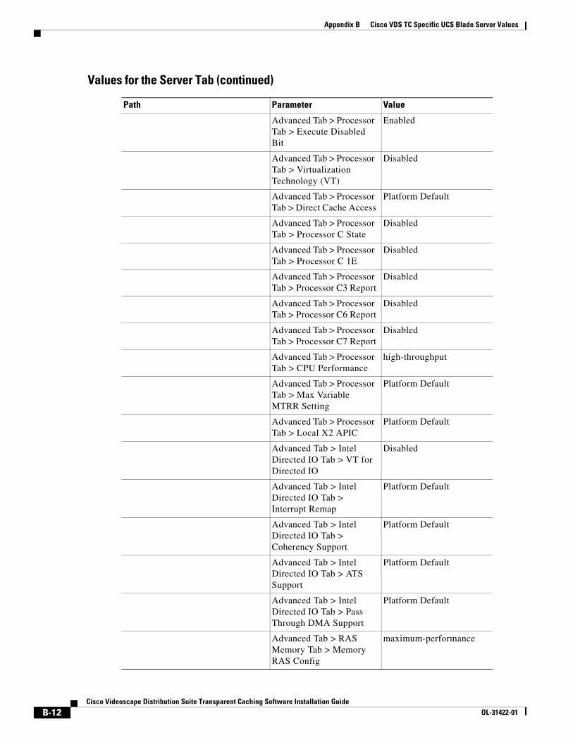
Appendix B Cisco VDS TC Specific UCS Blade Server Values
Advanced Tab > Processor Tab > Execute Disabled Bit
Enabled
Advanced Tab > Processor Tab > Virtualization Technology (VT)
Disabled
Advanced Tab > Processor Tab > Direct Cache Access
Platform Default
Advanced Tab > Processor Tab > Processor C State
Disabled
Advanced Tab > Processor Tab > Processor C 1E
Disabled
Advanced Tab > Processor Tab > Processor C3 Report
Disabled
Advanced Tab > Processor Tab > Processor C6 Report
Disabled
Advanced Tab > Processor Tab > Processor C7 Report
Disabled
Advanced Tab > Processor Tab > CPU Performance
high-throughput
Advanced Tab > Processor Tab > Max Variable MTRR Setting
Platform Default
Advanced Tab > Processor Tab > Local X2 APIC
Platform Default
Advanced Tab > Intel Directed IO Tab > VT for Directed IO
Disabled
Advanced Tab > Intel Directed IO Tab > Interrupt Remap
Platform Default
Advanced Tab > Intel Directed IO Tab > Coherency Support
Platform Default
Advanced Tab > Intel Directed IO Tab > ATS Support
Platform Default
Advanced Tab > Intel Directed IO Tab > Pass Through DMA Support
Platform Default
Advanced Tab > RAS Memory Tab > Memory RAS Config
maximum-performance
Values for the Server Tab (continued)
Path Parameter Value
B-12Cisco Videoscape Distribution Suite Transparent Caching Software Installation Guide
OL-31422-01

Appendix B Cisco VDS TC Specific UCS Blade Server Values
Advanced Tab > RAS Memory Tab > NUMA
Disabled
Advanced Tab > RAS Memory Tab > LV DDR Mode
performance-mode
Advanced Tab > RAS Memory Tab > DRAM Refresh Rate
Platform Default
Advanced Tab > Serial Port Tab > Serial Port A
Platform Default
Advanced Tab > USB Tab > Make Device Non Bootable
Platform Default
Advanced Tab > USB Tab > Legacy USB Support
Platform Default
Advanced Tab > USB Tab > USB System Idle Power Optimizing Setting
Platform Default
Advanced Tab > USB Tab > USB Front Panel Access Lock
Platform Default
Advanced Tab > PCI Configuration Tab > Max Memory Below 4G
Platform Default
Advanced Tab > PCI Configuration Tab > Memory Mapped IO Above 4Gb Config
Platform Default
Boot Options Tab > Boot Option Retry
Platform Default
Boot Options Tab > Intel Entry SAS RAID
Platform Default
Boot Options Tab > Intel Entry SAS RAID Module
Platform Default
Boot Options Tab > Onboard SCU Storage Support
Platform Default
Server Management Tab > Assert Nmi on Serr
Platform Default
Server Management Tab > Assert Nmi on Perr
Platform Default
Server Management Tab > OS Boot Watchdog Timer
Platform Default
Values for the Server Tab (continued)
Path Parameter Value
B-13Cisco Videoscape Distribution Suite Transparent Caching Software Installation Guide
OL-31422-01

Appendix B Cisco VDS TC Specific UCS Blade Server Values
Server Management Tab > Console Redirection
Platform Default
Server Management Tab > Flow Control
Platform Default
Server Management Tab > BAUD Rate
Platform Default
Server Management Tab > Terminal Type
Platform Default
Server Management Tab > Legacy OS Redirect
Platform Default
Service Profile Templates > root > Service Template CE_Unit > vNICs
vNICs ETH0, ETH1, ETH2, ETH3, ETH4, ETH5, ETH6, ETH7, ETH8, ETH9, ETH10, ETH11, ETH12
Fabric ID A/B for all vNICs
Desired Placement Any for all vNICs
Service Profile Templates > root > Service Template CE_Unit > vNICS > vNIC#
Adapter Policy VDS_TC_CE
Service Profile Templates > root > Service Template CE_Unit
Boot Order Tab • CD-ROM • Storage (Local Disk) • LAN (ETH0)
Policies Tab > BIOS Policy
VDS-TC_CE
Policies Tab > Firmware Policies > Host Firmware
b200-2.1
Policies Tab > IPMI Access Profile Policy
admin
Service Profiles > root > CE1 Associated Server sys/chassis-1/blade-1
Service Profile Template CE_Unit
Service Profiles > root > CE2 Associated Server sys/chassis-1/blade-2
Service Profile Template CE_Unit
Service Profiles > root > CE3 Associated Server sys/chassis-1/blade-3
Service Profile Template CE_Unit
Service Profiles > root > CE4 Associated Server sys/chassis-1/blade-4
Service Profile Template CE_Unit
Values for the Server Tab (continued)
Path Parameter Value
B-14Cisco Videoscape Distribution Suite Transparent Caching Software Installation Guide
OL-31422-01

Appendix B Cisco VDS TC Specific UCS Blade Server Values
Service Profiles > root > CE5(In VDS-TC-8B and VDS-TC-16B)
Associated Server sys/chassis-1/blade-5
Service Profile Template CE_Unit
Service Profiles > root > CE6(In VDS-TC-8B and VDS-TC-16B)
Associated Server sys/chassis-1/blade-6
Service Profile Template CE_Unit
Service Profiles > root > CE7(In VDS-TC-8B and VDS-TC-16B)
Associated Server sys/chassis-1/blade-7
Service Profile Template CE_Unit
Service Profiles > root > CE8(In VDS-TC-8B and VDS-TC-16B)
Associated Server sys/chassis-1/blade-8
Service Profile Template CE_Unit
Service Profiles > root > CE9(In VDS-TC-16B)
Associated Server sys/chassis-2/blade-1
Service Profile Template CE_Unit
Service Profiles > root > CE10(In VDS-TC-16B)
Associated Server sys/chassis-2/blade-2
Service Profile Template CE_Unit
Service Profiles > root > CE11(In VDS-TC-16B)
Associated Server sys/chassis-2/blade-3
Service Profile Template CE_Unit
Service Profiles > root > CE12(In VDS-TC-16B)
Associated Server sys/chassis-2/blade-4
Service Profile Template CE_Unit
Service Profiles > root > CE13(In VDS-TC-16B)
Associated Server sys/chassis-2/blade-5
Service Profile Template CE_Unit
Service Profiles > root > CE14(In VDS-TC-16B)
Associated Server sys/chassis-2/blade-6
Service Profile Template CE_Unit
Service Profiles > root > CE15(In VDS-TC-16B)
Associated Server sys/chassis-2/blade-7
Service Profile Template CE_Unit
Service Profiles > root > CE16(In VDS-TC-16B)
Associated Server sys/chassis-2/blade-8
Service Profile Template CE_Unit
Pools > root > UUID Suffix Pools > Pool default
Prefix CB984AB8-23FA-11E2
Size 512
Assignment order Default
Values for the Server Tab (continued)
Path Parameter Value
B-15Cisco Videoscape Distribution Suite Transparent Caching Software Installation Guide
OL-31422-01

Appendix B Cisco VDS TC Specific UCS Blade Server Values
B-16Cisco Videoscape Distribution Suite Transparent Caching Software Installation Guide
OL-31422-01