Embed Size (px)
Citation preview
Cisco UCS Configuration Guide for vSphere Server Profile Cisco UCS Configuration Guide, covering the creation of Cisco UCS Server policies.
Seven part series, describing how to configure a Cisco UCS from start to finish for a vSphere deployment:
The UCS Manager Server configuration has four areas: Server Profiles, Server Profiles Templates, Policies
and Pools. The diagram below shows the breakdown of those areas.
Server Policies
The previous parts of this configuration guide focused upon equipment, network and storage. This is the final
step of configuring the server policies required to build a Server Profile Template and then bring the server
hardware into service.
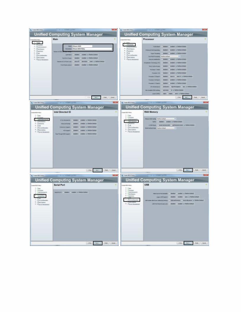
1. In the “Policies” section of the “Server” tab, select the “BIOS Policies” object, right mouse click and select
“Create BIOS Policy”.
2. In the “Create BIOS Policy” wizard, enter the “Name” and “Description” and then press the “Finish” button
to leave the “Processor”, “Intel Directed IO”, “RAS Memory”, “Serial Port”, “USB”, “PCI Configuration”,
“Boot Options” and “Server Management” settings at the “Platform Default” values. Each policy screen is
displayed below for completeness.
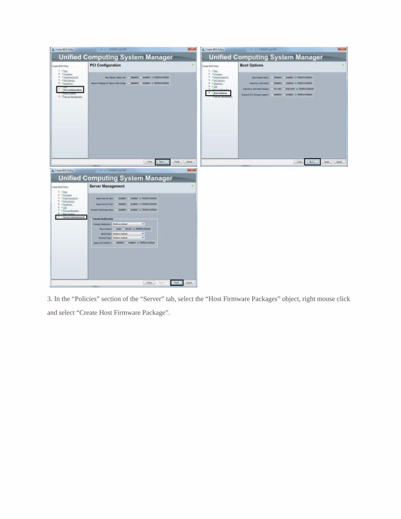
3. In the “Policies” section of the “Server” tab, select the “Host Firmware Packages” object, right mouse click
and select “Create Host Firmware Package”.
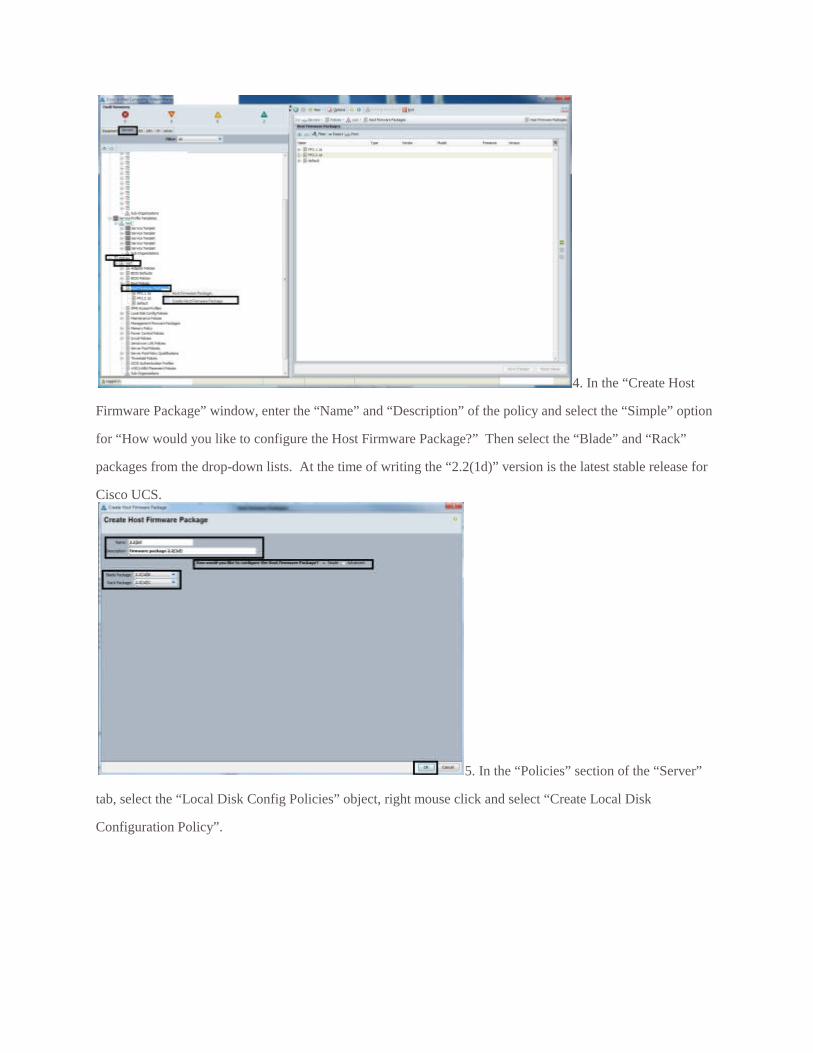
4. In the “Create Host
Firmware Package” window, enter the “Name” and “Description” of the policy and select the “Simple” option
for “How would you like to configure the Host Firmware Package?” Then select the “Blade” and “Rack”
packages from the drop-down lists. At the time of writing the “2.2(1d)” version is the latest stable release for
Cisco UCS.
5. In the “Policies” section of the “Server”
tab, select the “Local Disk Config Policies” object, right mouse click and select “Create Local Disk
Configuration Policy”.
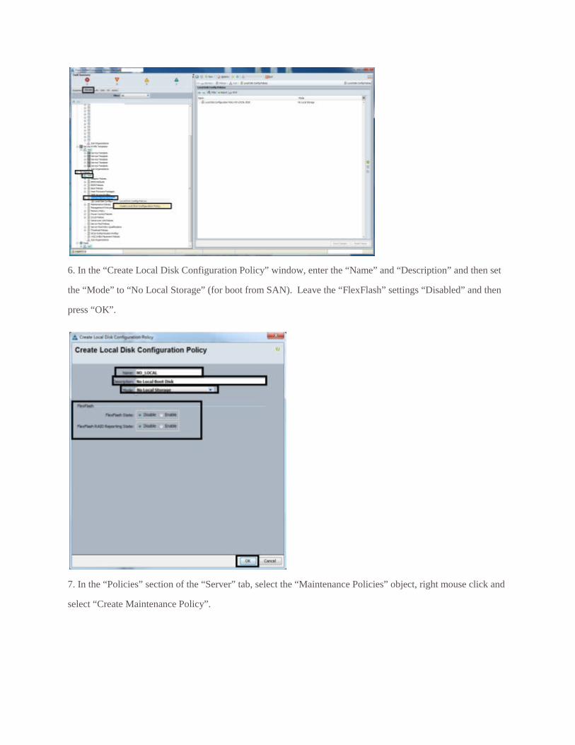
6. In the “Create Local Disk Configuration Policy” window, enter the “Name” and “Description” and then set
the “Mode” to “No Local Storage” (for boot from SAN). Leave the “FlexFlash” settings “Disabled” and then
press “OK”.
7. In the “Policies” section of the “Server” tab, select the “Maintenance Policies” object, right mouse click and
select “Create Maintenance Policy”.
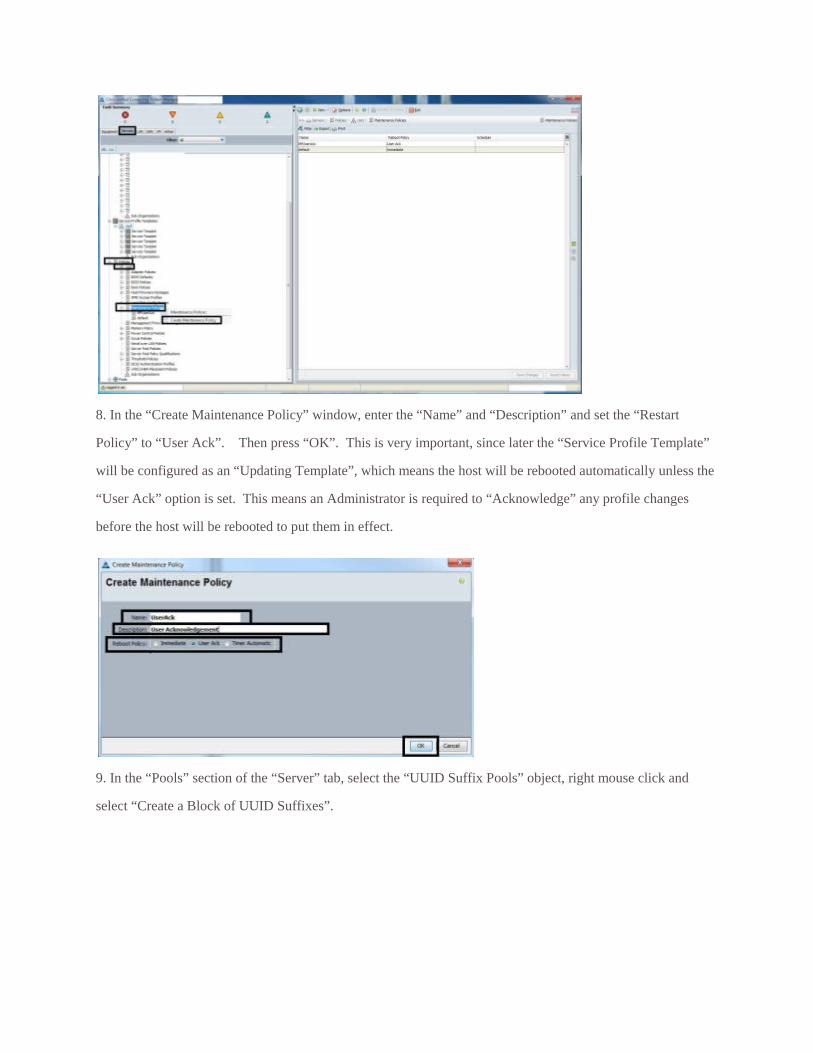
8. In the “Create Maintenance Policy” window, enter the “Name” and “Description” and set the “Restart
Policy” to “User Ack”. Then press “OK”. This is very important, since later the “Service Profile Template”
will be configured as an “Updating Template”, which means the host will be rebooted automatically unless the
“User Ack” option is set. This means an Administrator is required to “Acknowledge” any profile changes
before the host will be rebooted to put them in effect.
9. In the “Pools” section of the “Server” tab, select the “UUID Suffix Pools” object, right mouse click and
select “Create a Block of UUID Suffixes”.
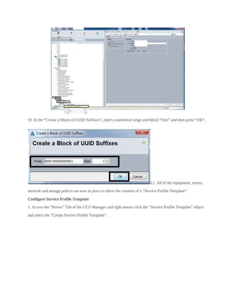
10. In the “Create a Block of UUID Suffixes”, enter a numerical range and block “Size” and then press “OK”.
11. All of the equipment, server,
network and storage polices are now in place to allow the creation of a “Service Profile Template”.
Configure Service Profile Template
1. Access the “Server” Tab of the UCS Manager and right mouse click the “Service Profile Template” object
and select the “Create Service Profile Template”.
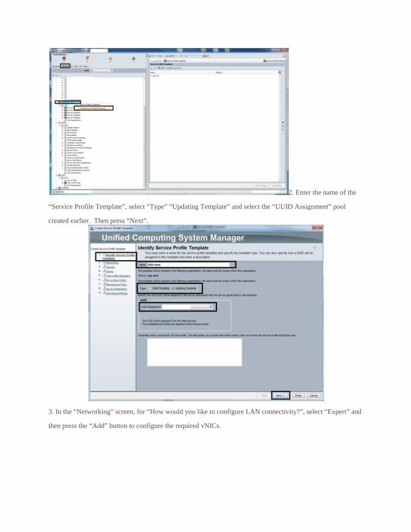
2. Enter the name of the
“Service Profile Template”, select “Type” “Updating Template” and select the “UUID Assignment” pool
created earlier. Then press “Next”.
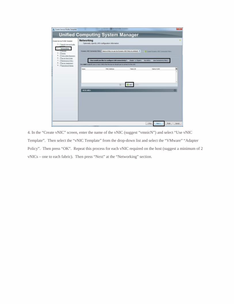
3. In the “Networking” screen, for “How would you like to configure LAN connectivity?”, select “Expert” and
then press the “Add” button to configure the required vNICs.
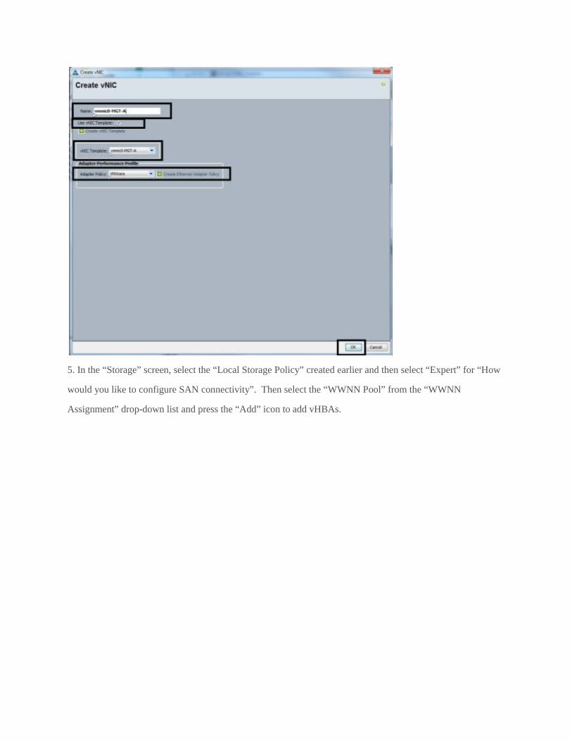
4. In the “Create vNIC” screen, enter the name of the vNIC (suggest “vmnicN”) and select “Use vNIC
Template”. Then select the “vNIC Template” from the drop-down list and select the “VMware” “Adapter
Policy”. Then press “OK”. Repeat this process for each vNIC required on the host (suggest a minimum of 2
vNICs – one to each fabric). Then press “Next” at the “Networking” section.
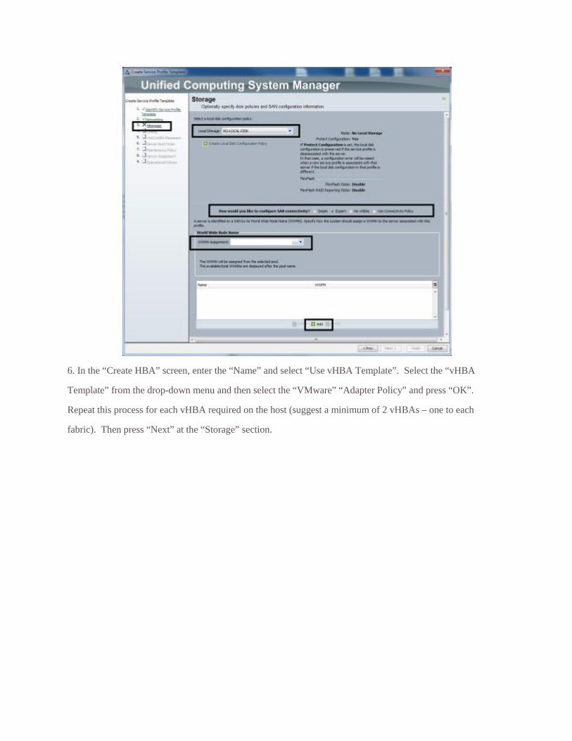
5. In the “Storage” screen, select the “Local Storage Policy” created earlier and then select “Expert” for “How
would you like to configure SAN connectivity”. Then select the “WWNN Pool” from the “WWNN
Assignment” drop-down list and press the “Add” icon to add vHBAs.
6. In the “Create HBA” screen, enter the “Name” and select “Use vHBA Template”. Select the “vHBA
Template” from the drop-down menu and then select the “VMware” “Adapter Policy” and press “OK”.
Repeat this process for each vHBA required on the host (suggest a minimum of 2 vHBAs – one to each
fabric). Then press “Next” at the “Storage” section.
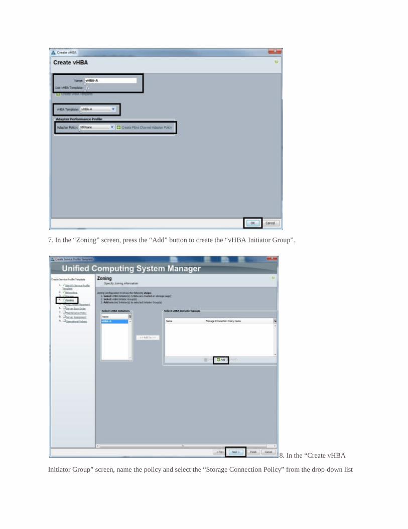
7. In the “Zoning” screen, press the “Add” button to create the “vHBA Initiator Group”.
8. In the “Create vHBA
Initiator Group” screen, name the policy and select the “Storage Connection Policy” from the drop-down list
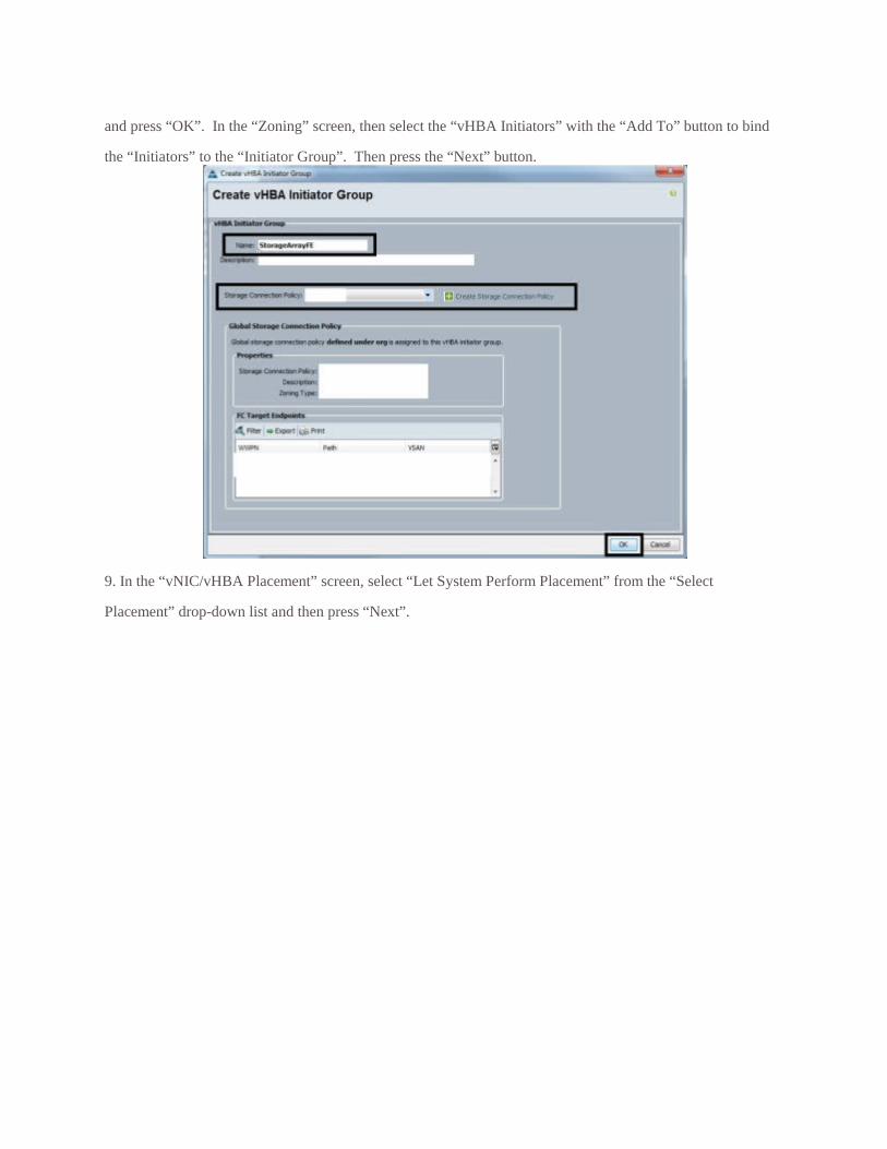
and press “OK”. In the “Zoning” screen, then select the “vHBA Initiators” with the “Add To” button to bind
the “Initiators” to the “Initiator Group”. Then press the “Next” button.
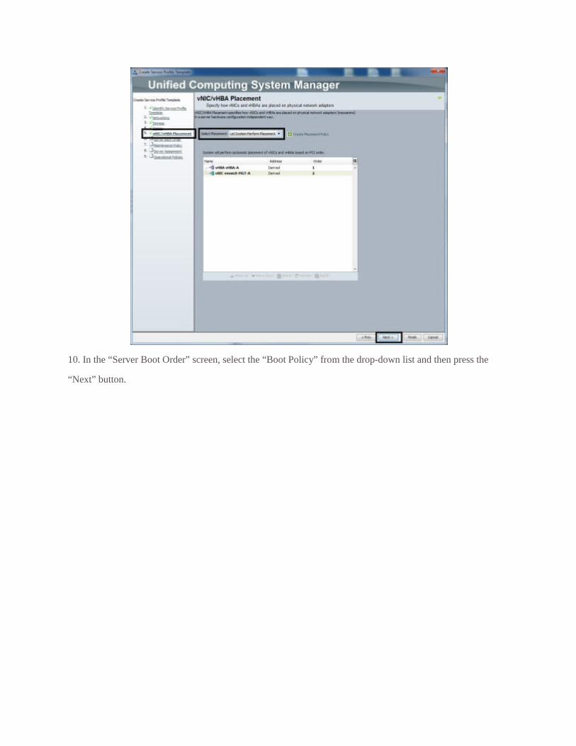
9. In the “vNIC/vHBA Placement” screen, select “Let System Perform Placement” from the “Select
Placement” drop-down list and then press “Next”.
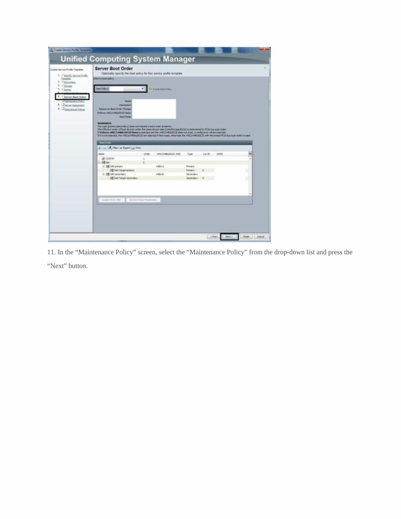
10. In the “Server Boot Order” screen, select the “Boot Policy” from the drop-down list and then press the
“Next” button.
11. In the “Maintenance Policy” screen, select the “Maintenance Policy” from the drop-down list and press the
“Next” button.
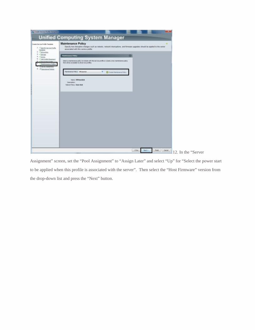
12. In the “Server
Assignment” screen, set the “Pool Assignment” to “Assign Later” and select “Up” for “Select the power start
to be applied when this profile is associated with the server”. Then select the “Host Firmware” version from
the drop-down list and press the “Next” button.
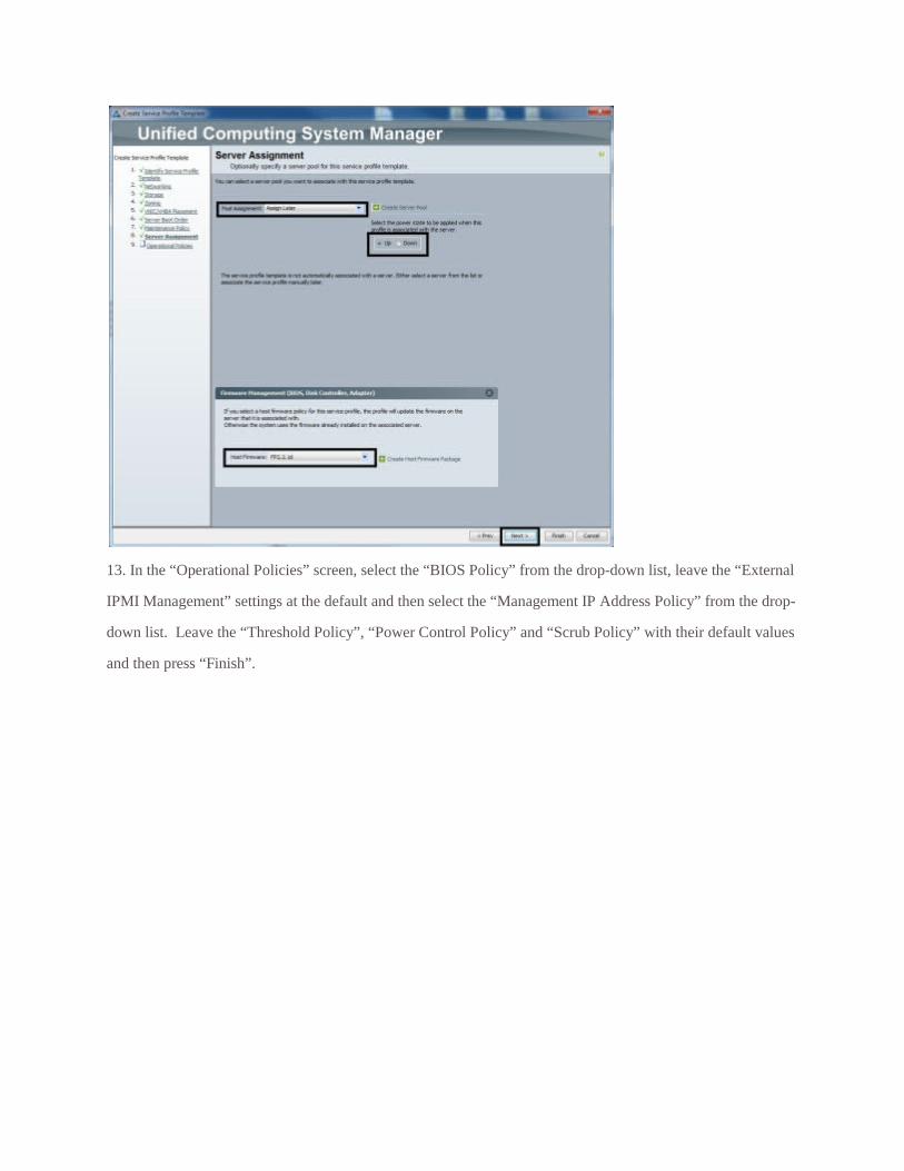
13. In the “Operational Policies” screen, select the “BIOS Policy” from the drop-down list, leave the “External
IPMI Management” settings at the default and then select the “Management IP Address Policy” from the drop-
down list. Leave the “Threshold Policy”, “Power Control Policy” and “Scrub Policy” with their default values
and then press “Finish”.
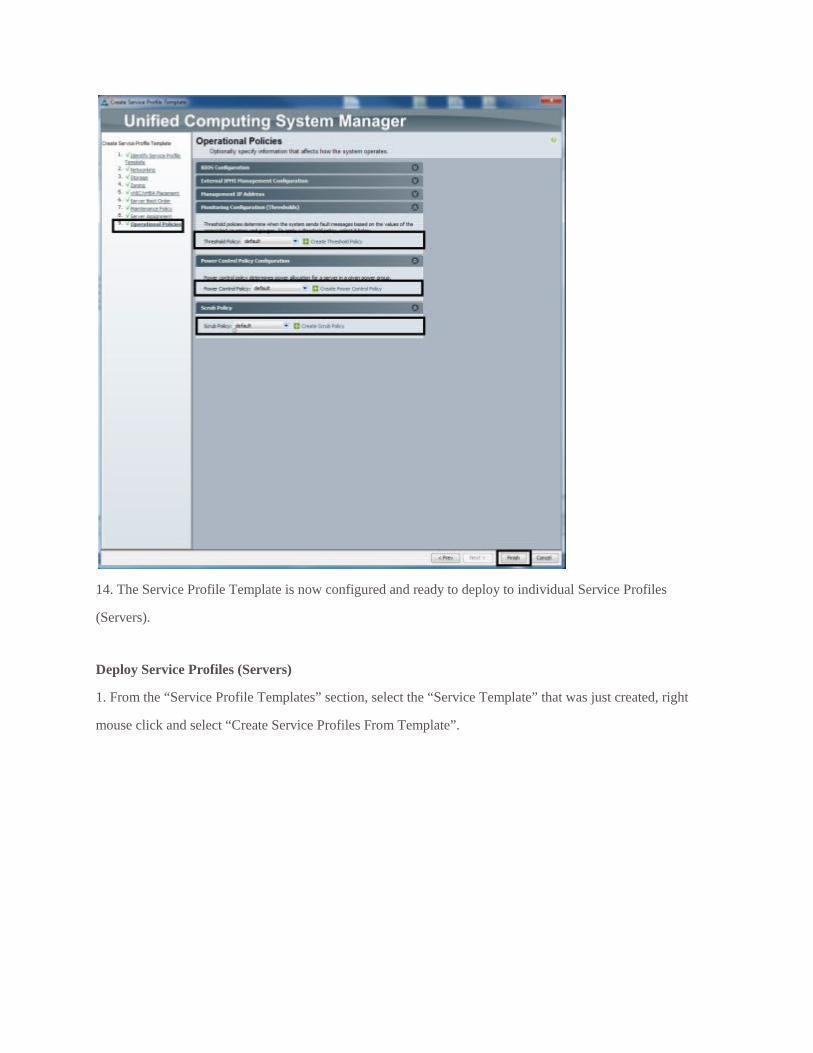
14. The Service Profile Template is now configured and ready to deploy to individual Service Profiles
(Servers).
Deploy Service Profiles (Servers)
1. From the “Service Profile Templates” section, select the “Service Template” that was just created, right
mouse click and select “Create Service Profiles From Template”.
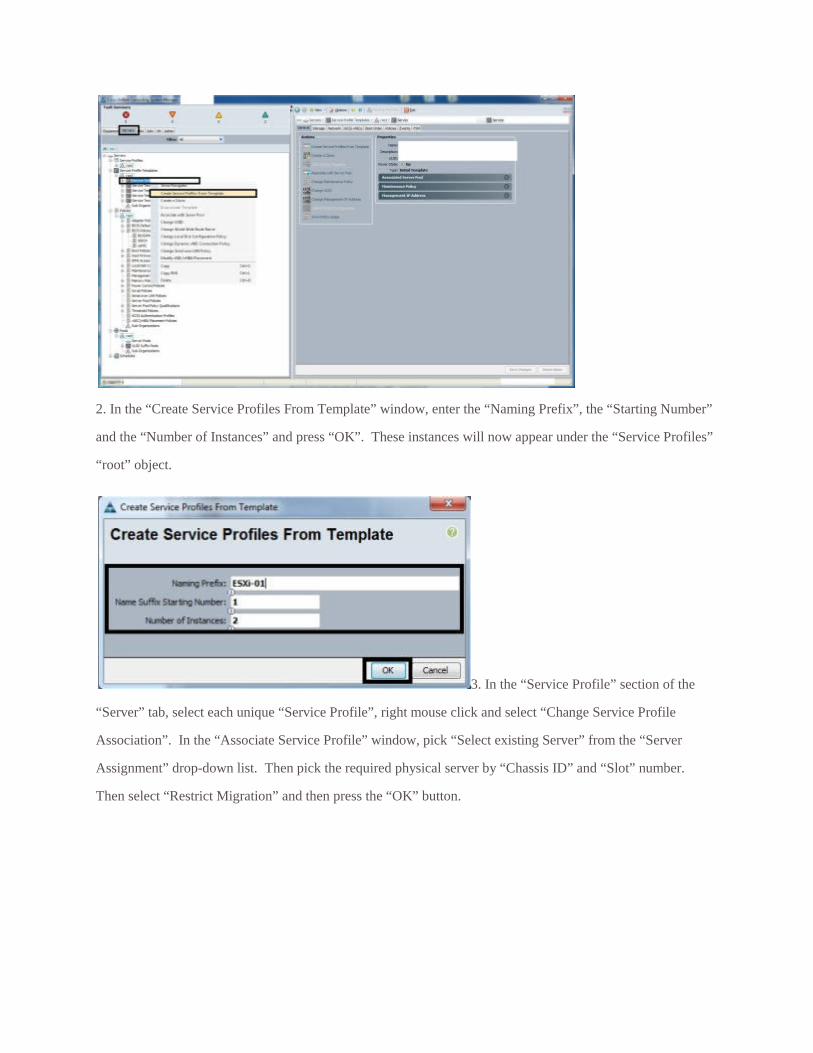
2. In the “Create Service Profiles From Template” window, enter the “Naming Prefix”, the “Starting Number”
and the “Number of Instances” and press “OK”. These instances will now appear under the “Service Profiles”
“root” object.
3. In the “Service Profile” section of the
“Server” tab, select each unique “Service Profile”, right mouse click and select “Change Service Profile
Association”. In the “Associate Service Profile” window, pick “Select existing Server” from the “Server
Assignment” drop-down list. Then pick the required physical server by “Chassis ID” and “Slot” number.
Then select “Restrict Migration” and then press the “OK” button.
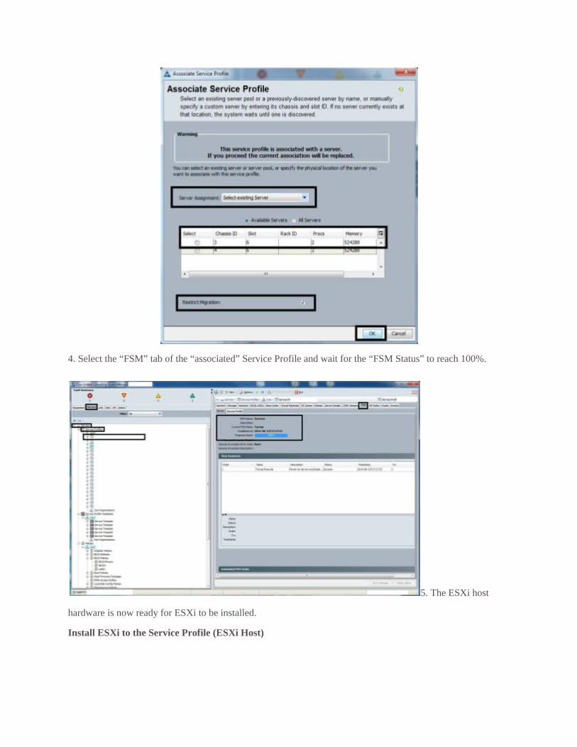
4. Select the “FSM” tab of the “associated” Service Profile and wait for the “FSM Status” to reach 100%.
5. The ESXi host
hardware is now ready for ESXi to be installed.
Install ESXi to the Service Profile (ESXi Host)
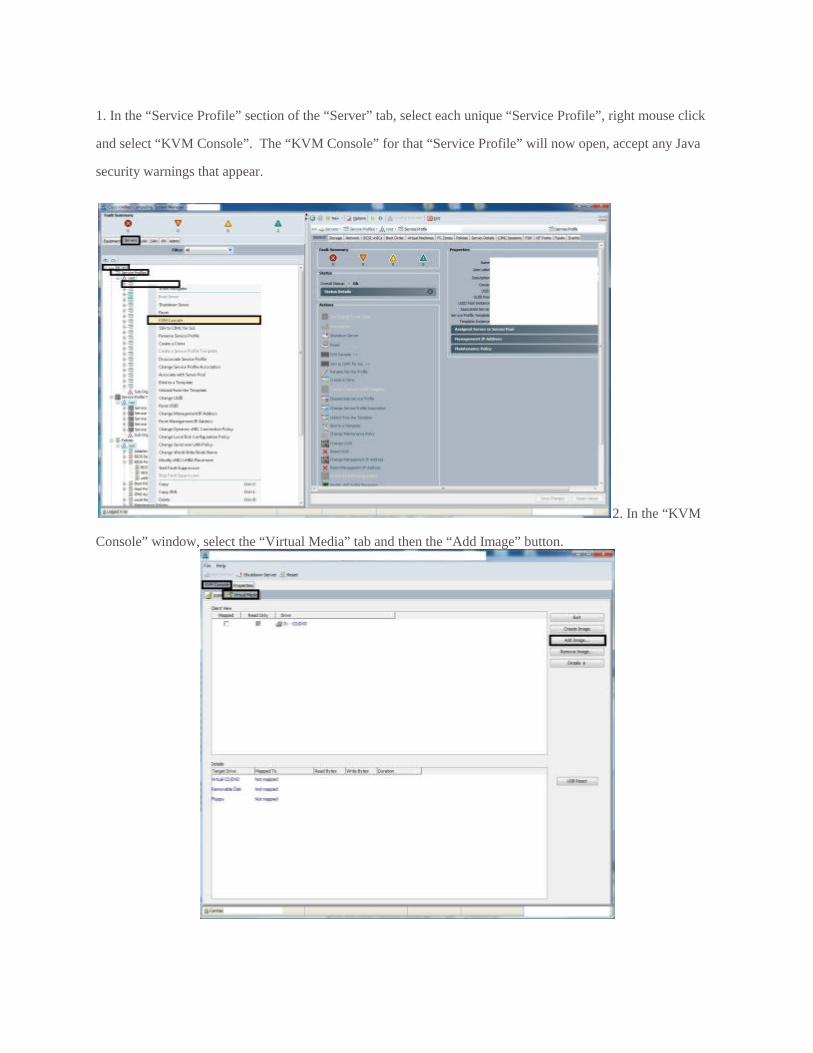
1. In the “Service Profile” section of the “Server” tab, select each unique “Service Profile”, right mouse click
and select “KVM Console”. The “KVM Console” for that “Service Profile” will now open, accept any Java
security warnings that appear.
2. In the “KVM
Console” window, select the “Virtual Media” tab and then the “Add Image” button.
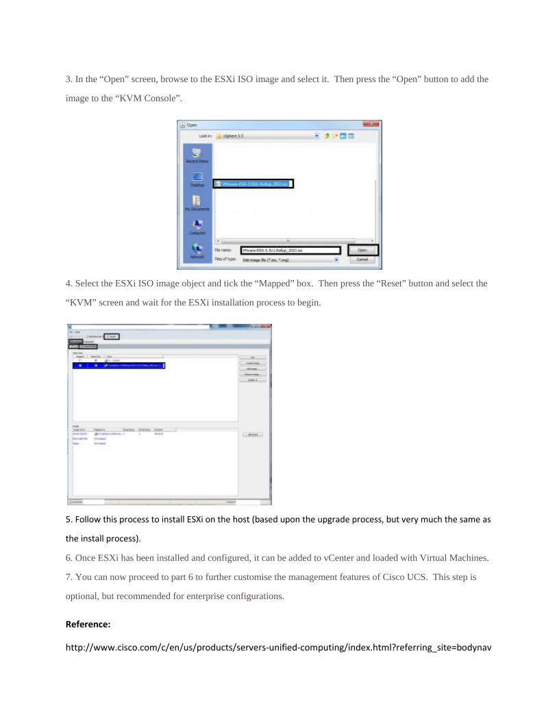
3. In the “Open” screen, browse to the ESXi ISO image and select it. Then press the “Open” button to add the
image to the “KVM Console”.
4. Select the ESXi ISO image object and tick the “Mapped” box. Then press the “Reset” button and select the
“KVM” screen and wait for the ESXi installation process to begin.
5. Follow this process to install ESXi on the host (based upon the upgrade process, but very much the same as
the install process).
6. Once ESXi has been installed and configured, it can be added to vCenter and loaded with Virtual Machines.
7. You can now proceed to part 6 to further customise the management features of Cisco UCS. This step is
optional, but recommended for enterprise configurations.
Reference:
http://www.cisco.com/c/en/us/products/servers-unified-computing/index.html?referring_site=bodynav