Embed Size (px)
Citation preview
CISCO SYSTEMS PUBLICATION HISTORY 170 WEST TASMAN DR. SAN JOSE, CA, 95134 REV A.3 DECEMBER 2, 2011 WWW.CISCO.COM
Spec Sheet
Cisco UCS C210 M2General-Purpose Rack-Mount Server
Cisco UCS C210 M2 General-Purpose Rack-Mount Server 2
CONTENTS
OVERVIEW . . . . . . . . . . . . . . . . . . . . . . . . . . . . . . . . . . . . . . . . . . . . . . . 3DETAILED VIEWS . . . . . . . . . . . . . . . . . . . . . . . . . . . . . . . . . . . . . . . . . . . 4
Chassis Front View . . . . . . . . . . . . . . . . . . . . . . . . . . . . . . . . . . . . . . . . . . . . . . . . . . .4Chassis Rear View . . . . . . . . . . . . . . . . . . . . . . . . . . . . . . . . . . . . . . . . . . . . . . . . . . .5
BASE SERVER STANDARD CAPABILITIES and FEATURES . . . . . . . . . . . . . . . . . 6CONFIGURING the SERVER . . . . . . . . . . . . . . . . . . . . . . . . . . . . . . . . . . . . 8
STEP 1 VERIFY BASE SKU . . . . . . . . . . . . . . . . . . . . . . . . . . . . . . . . . . . . . . . . . . . . . .9STEP 2 CHOOSE CPU(S) . . . . . . . . . . . . . . . . . . . . . . . . . . . . . . . . . . . . . . . . . . . . . 10STEP 3 CHOOSE MEMORY . . . . . . . . . . . . . . . . . . . . . . . . . . . . . . . . . . . . . . . . . . . . 13STEP 4 CHOOSE RAID CONFIGURATION . . . . . . . . . . . . . . . . . . . . . . . . . . . . . . . . . . . 17STEP 5 ORDER SAS EXPANDER AS NEEDED . . . . . . . . . . . . . . . . . . . . . . . . . . . . . . . . . 20STEP 6 CHOOSE HARD DISK DRIVES or SOLID STATE DRIVES . . . . . . . . . . . . . . . . . . . . . . 21STEP 7 CHOOSE PCIe OPTION CARD(S) . . . . . . . . . . . . . . . . . . . . . . . . . . . . . . . . . . . 23STEP 8 CHOOSE OPTIONAL DVD-RW DRIVE . . . . . . . . . . . . . . . . . . . . . . . . . . . . . . . . . 25STEP 9 ORDER OPTIONAL REDUNDANT POWER SUPPLY . . . . . . . . . . . . . . . . . . . . . . . . . 26STEP 10 CHOOSE AC POWER CORDS . . . . . . . . . . . . . . . . . . . . . . . . . . . . . . . . . . . . . 27STEP 11 ORDER OPTIONAL RAIL KIT . . . . . . . . . . . . . . . . . . . . . . . . . . . . . . . . . . . . . 30STEP 12 ORDER OPTIONAL CABLE MANAGEMENT ARM . . . . . . . . . . . . . . . . . . . . . . . . . . 31STEP 13 ORDER A TRUSTED PLATFORM MODULE . . . . . . . . . . . . . . . . . . . . . . . . . . . . . 32STEP 14 CHOOSE OPERATING SYSTEM . . . . . . . . . . . . . . . . . . . . . . . . . . . . . . . . . . . . 33STEP 15 CHOOSE OPERATING SYSTEM MEDIA KIT . . . . . . . . . . . . . . . . . . . . . . . . . . . . . 35STEP 16 CHOOSE OPTIONAL VALUE-ADDED SOFTWARE . . . . . . . . . . . . . . . . . . . . . . . . . 36STEP 17 CHOOSE SERVICE and SUPPORT LEVEL . . . . . . . . . . . . . . . . . . . . . . . . . . . . . . 37
OPTIONAL STEP - ORDER RACK(s) . . . . . . . . . . . . . . . . . . . . . . . . . . . . . . 41OPTIONAL STEP - ORDER PDU . . . . . . . . . . . . . . . . . . . . . . . . . . . . . . . . . 42SUPPLEMENTAL MATERIAL . . . . . . . . . . . . . . . . . . . . . . . . . . . . . . . . . . . 43
CHASSIS . . . . . . . . . . . . . . . . . . . . . . . . . . . . . . . . . . . . . . . . . . . . . . . . . . . . . . . . . 43CPUs and DIMMs . . . . . . . . . . . . . . . . . . . . . . . . . . . . . . . . . . . . . . . . . . . . . . . . . . . . 44
Physical Layout . . . . . . . . . . . . . . . . . . . . . . . . . . . . . . . . . . . . . . . . . . . . . . . . 44Memory Population Rules . . . . . . . . . . . . . . . . . . . . . . . . . . . . . . . . . . . . . . . . . 45Low-Voltage DIMM Considerations . . . . . . . . . . . . . . . . . . . . . . . . . . . . . . . . . . . . 45Recommended Configurations . . . . . . . . . . . . . . . . . . . . . . . . . . . . . . . . . . . . . . 46Configuration Samples . . . . . . . . . . . . . . . . . . . . . . . . . . . . . . . . . . . . . . . . . . . 47
SAS EXTENDER and SAS EXPANDER . . . . . . . . . . . . . . . . . . . . . . . . . . . . . . . . . . . . . . . . 49SAS Extender . . . . . . . . . . . . . . . . . . . . . . . . . . . . . . . . . . . . . . . . . . . . . . . . . 49SAS Expander . . . . . . . . . . . . . . . . . . . . . . . . . . . . . . . . . . . . . . . . . . . . . . . . . 49
RACKS . . . . . . . . . . . . . . . . . . . . . . . . . . . . . . . . . . . . . . . . . . . . . . . . . . . . . . . . . . 50PDUs . . . . . . . . . . . . . . . . . . . . . . . . . . . . . . . . . . . . . . . . . . . . . . . . . . . . . . . . . . . 52POWER SUPPLIES . . . . . . . . . . . . . . . . . . . . . . . . . . . . . . . . . . . . . . . . . . . . . . . . . . . 53KVM CABLE . . . . . . . . . . . . . . . . . . . . . . . . . . . . . . . . . . . . . . . . . . . . . . . . . . . . . . . 54Motherboard USB Port . . . . . . . . . . . . . . . . . . . . . . . . . . . . . . . . . . . . . . . . . . . . . . . 55
TECHNICAL SPECIFICATIONS . . . . . . . . . . . . . . . . . . . . . . . . . . . . . . . . . . 56Dimensions and Weight . . . . . . . . . . . . . . . . . . . . . . . . . . . . . . . . . . . . . . . . . . . . . . . 56Power Specifications . . . . . . . . . . . . . . . . . . . . . . . . . . . . . . . . . . . . . . . . . . . . . . . . 56Environmental Specifications . . . . . . . . . . . . . . . . . . . . . . . . . . . . . . . . . . . . . . . . . . . 58Compliance Requirements . . . . . . . . . . . . . . . . . . . . . . . . . . . . . . . . . . . . . . . . . . . . . 59
OVERVIEW
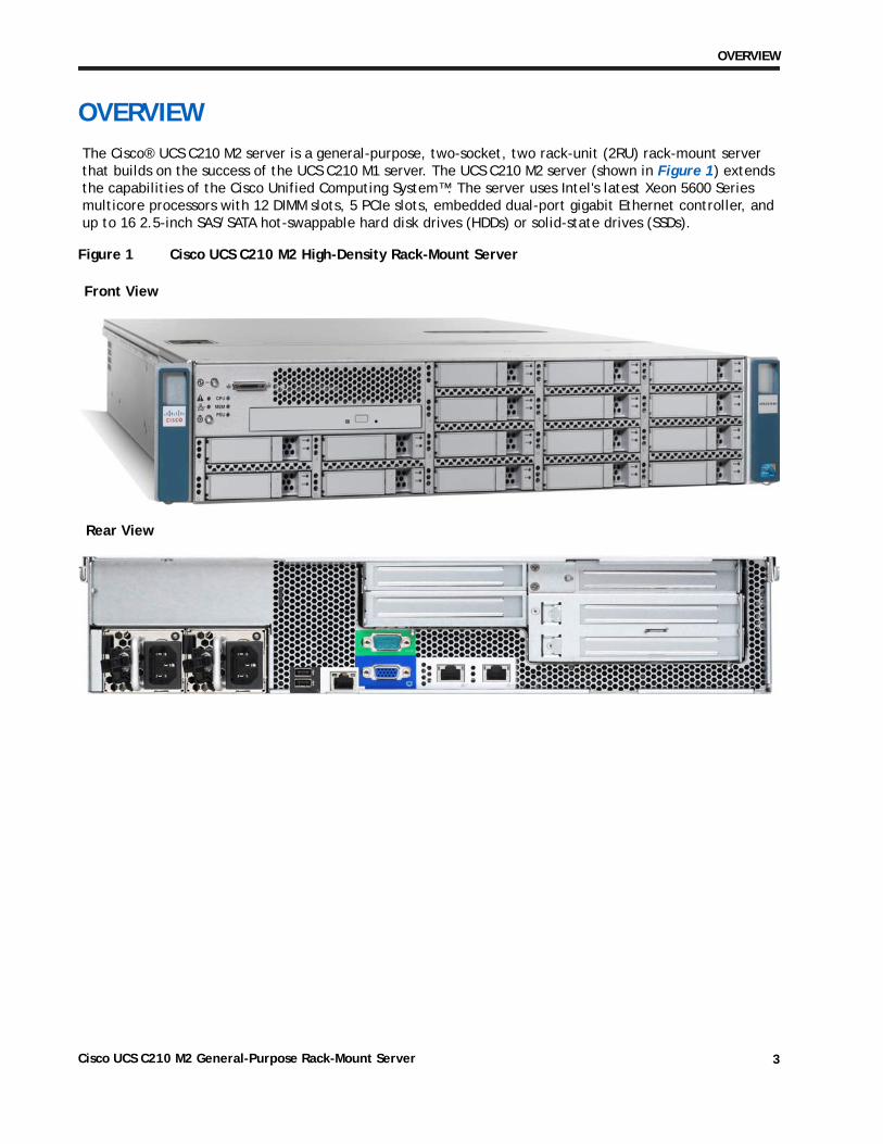
OVERVIEWThe Cisco® UCS C210 M2 server is a general-purpose, two-socket, two rack-unit (2RU) rack-mount server that builds on the success of the UCS C210 M1 server. The UCS C210 M2 server (shown in Figure 1) extends the capabilities of the Cisco Unified Computing System™. The server uses Intel's latest Xeon 5600 Series multicore processors with 12 DIMM slots, 5 PCIe slots, embedded dual-port gigabit Ethernet controller, and up to 16 2.5-inch SAS/SATA hot-swappable hard disk drives (HDDs) or solid-state drives (SSDs).
Figure 1 Cisco UCS C210 M2 High-Density Rack-Mount Server
Front View
Rear View
Cisco UCS C210 M2 General-Purpose Rack-Mount Server 3
DETAILED VIEWS
DETAILED VIEWS
Chassis Front View
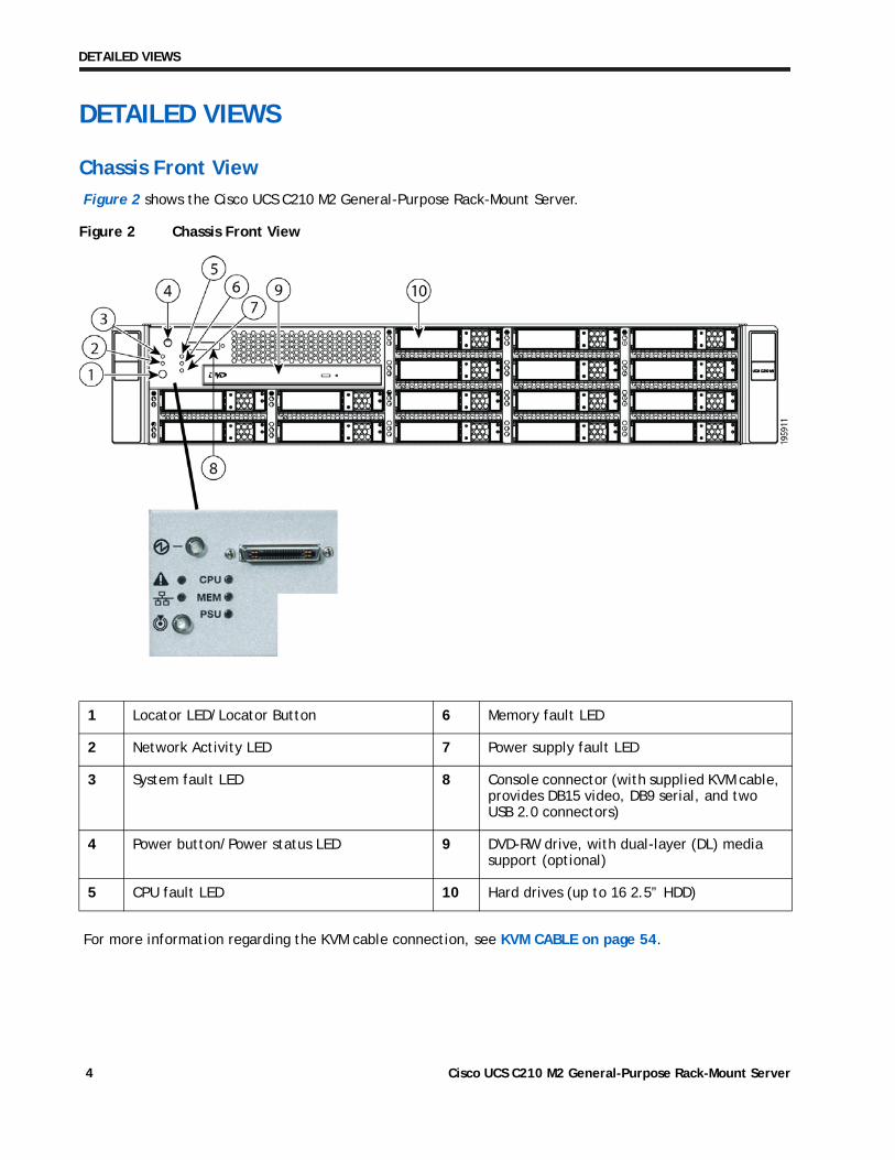
Figure 2 shows the Cisco UCS C210 M2 General-Purpose Rack-Mount Server.
Figure 2 Chassis Front View
For more information regarding the KVM cable connection, see KVM CABLE on page 54.
1 Locator LED/Locator Button 6 Memory fault LED
2 Network Activity LED 7 Power supply fault LED
3 System fault LED 8 Console connector (with supplied KVM cable, provides DB15 video, DB9 serial, and two USB 2.0 connectors)
4 Power button/Power status LED 9 DVD-RW drive, with dual-layer (DL) media support (optional)
5 CPU fault LED 10 Hard drives (up to 16 2.5” HDD)
Cisco UCS C210 M2 General-Purpose Rack-Mount Server4
DETAILED VIEWS
Chassis Rear View
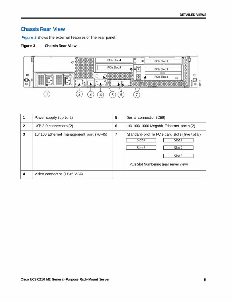
Figure 3 shows the external features of the rear panel.
Figure 3 Chassis Rear View
1 Power supply (up to 2) 5 Serial connector (DB9)
2 USB 2.0 connectors (2) 6 10/100/1000 Megabit Ethernet ports (2)
3 10/100 Ethernet management port (RJ-45) 7 Standard-profile PCIe card slots (five total)
4 Video connector (DB15 VGA)
Cisco UCS C210 M2 General-Purpose Rack-Mount Server 5
BASE SERVER STANDARD CAPABILITIES and FEATURES
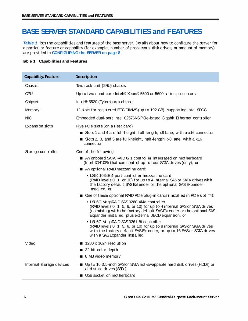
BASE SERVER STANDARD CAPABILITIES and FEATURESTable 1 lists the capabilities and features of the base server. Details about how to configure the server for a particular feature or capability (for example, number of processors, disk drives, or amount of memory) are provided in CONFIGURING the SERVER on page 8.
Table 1 Capabilities and Features
Capability/Feature Description
Chassis Two rack unit (2RU) chassis
CPU Up to two quad-core Intel® Xeon® 5500 or 5600 series processors
Chipset Intel® 5520 (Tylersburg) chipset
Memory 12 slots for registered ECC DIMMS (up to 192 GB), supporting Intel SDDC
NIC Embedded dual-port Intel 82576NS PCIe-based Gigabit Ethernet controller
Expansion slots Five PCIe slots (on a riser card)
■ Slots 1 and 4 are full-height, full length, x8 lane, with a x16 connector
■ Slots 2, 3, and 5 are full-height, half-length, x8 lane, with a x16 connector
Storage controller One of the following:
■ An onboard SATA RAID 0/1 controller integrated on motherboard (Intel ICH10R) that can control up to four SATA drives (only), or
■ An optional RAID mezzanine card:
• LSI® 1064E 4-port controller mezzanine card (RAID levels 0, 1, or 1E) for up to 4 internal SAS or SATA drives with the factory default SAS Extender or the optional SAS Expander installed, or
■ One of these optional RAID PCIe plug-in cards (installed in PCIe slot #4):
• LSI 6G MegaRAID SAS 9280-4i4e controller (RAID levels 0, 1, 5, 6, or 10) for up to 4 internal SAS or SATA drives (no mixing) with the factory default SAS Extender or the optional SAS Expander installed, plus external JBOD expansion, or
• LSI 6G MegaRAID SAS 9261-8i controller (RAID levels 0, 1, 5, 6, or 10) for up to 8 internal SAS or SATA drives with the factory default SAS Extender, or up to 16 SAS or SATA drives with a SAS Expander installed
Video ■ 1280 x 1024 resolution
■ 32-bit color depth
■ 8 MB video memory
Internal storage devices ■ Up to 16 3.5-inch SAS or SATA hot-swappable hard disk drives (HDDs) or solid state drives (SSDs)
■ USB socket on motherboard
Cisco UCS C210 M2 General-Purpose Rack-Mount Server6
BASE SERVER STANDARD CAPABILITIES and FEATURES
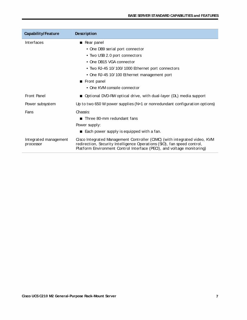
Interfaces ■ Rear panel
• One DB9 serial port connector
• Two USB 2.0 port connectors
• One DB15 VGA connector
• Two RJ-45 10/100/1000 Ethernet port connectors
• One RJ-45 10/100 Ethernet management port
■ Front panel
• One KVM console connector
Front Panel ■ Optional DVD-RW optical drive, with dual-layer (DL) media support
Power subsystem Up to two 650 W power supplies (N+1 or nonredundant configuration options)
Fans Chassis:
■ Three 80-mm redundant fans
Power supply:
■ Each power supply is equipped with a fan.
Integrated management processor
Cisco Integrated Management Controller (CIMC) (with integrated video, KVM redirection, Security Intelligence Operations (SIO), fan speed control, Platform Environment Control Interface (PECI), and voltage monitoring)
Capability/Feature Description
Cisco UCS C210 M2 General-Purpose Rack-Mount Server 7
CONFIGURING the SERVER
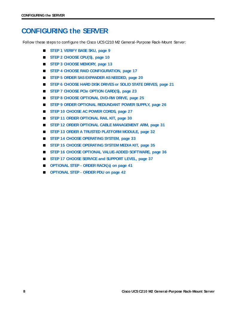
CONFIGURING the SERVERFollow these steps to configure the Cisco UCS C210 M2 General-Purpose Rack-Mount Server:
■ STEP 1 VERIFY BASE SKU, page 9
■ STEP 2 CHOOSE CPU(S), page 10
■ STEP 3 CHOOSE MEMORY, page 13
■ STEP 4 CHOOSE RAID CONFIGURATION, page 17
■ STEP 5 ORDER SAS EXPANDER AS NEEDED, page 20
■ STEP 6 CHOOSE HARD DISK DRIVES or SOLID STATE DRIVES, page 21
■ STEP 7 CHOOSE PCIe OPTION CARD(S), page 23
■ STEP 8 CHOOSE OPTIONAL DVD-RW DRIVE, page 25
■ STEP 9 ORDER OPTIONAL REDUNDANT POWER SUPPLY, page 26
■ STEP 10 CHOOSE AC POWER CORDS, page 27
■ STEP 11 ORDER OPTIONAL RAIL KIT, page 30
■ STEP 12 ORDER OPTIONAL CABLE MANAGEMENT ARM, page 31
■ STEP 13 ORDER A TRUSTED PLATFORM MODULE, page 32
■ STEP 14 CHOOSE OPERATING SYSTEM, page 33
■ STEP 15 CHOOSE OPERATING SYSTEM MEDIA KIT, page 35
■ STEP 16 CHOOSE OPTIONAL VALUE-ADDED SOFTWARE, page 36
■ STEP 17 CHOOSE SERVICE and SUPPORT LEVEL, page 37
■ OPTIONAL STEP - ORDER RACK(s) on page 41
■ OPTIONAL STEP - ORDER PDU on page 42
Cisco UCS C210 M2 General-Purpose Rack-Mount Server8
CONFIGURING the SERVER
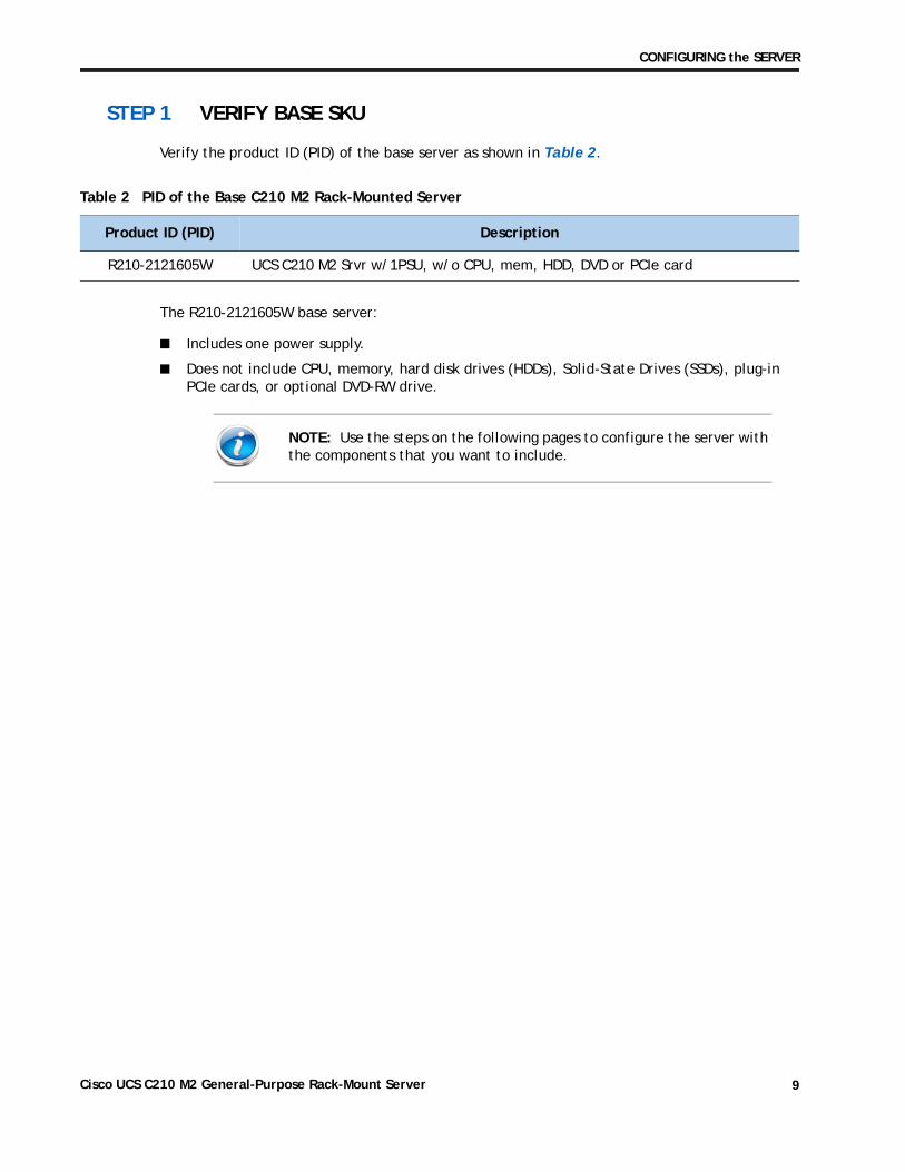
STEP 1 VERIFY BASE SKU
Verify the product ID (PID) of the base server as shown in Table 2.
The R210-2121605W base server:
■ Includes one power supply.
■ Does not include CPU, memory, hard disk drives (HDDs), Solid-State Drives (SSDs), plug-in PCIe cards, or optional DVD-RW drive.
Table 2 PID of the Base C210 M2 Rack-Mounted Server
Product ID (PID) Description
R210-2121605W UCS C210 M2 Srvr w/1PSU, w/o CPU, mem, HDD, DVD or PCIe card
NOTE: Use the steps on the following pages to configure the server with the components that you want to include.
Cisco UCS C210 M2 General-Purpose Rack-Mount Server 9
CONFIGURING the SERVER
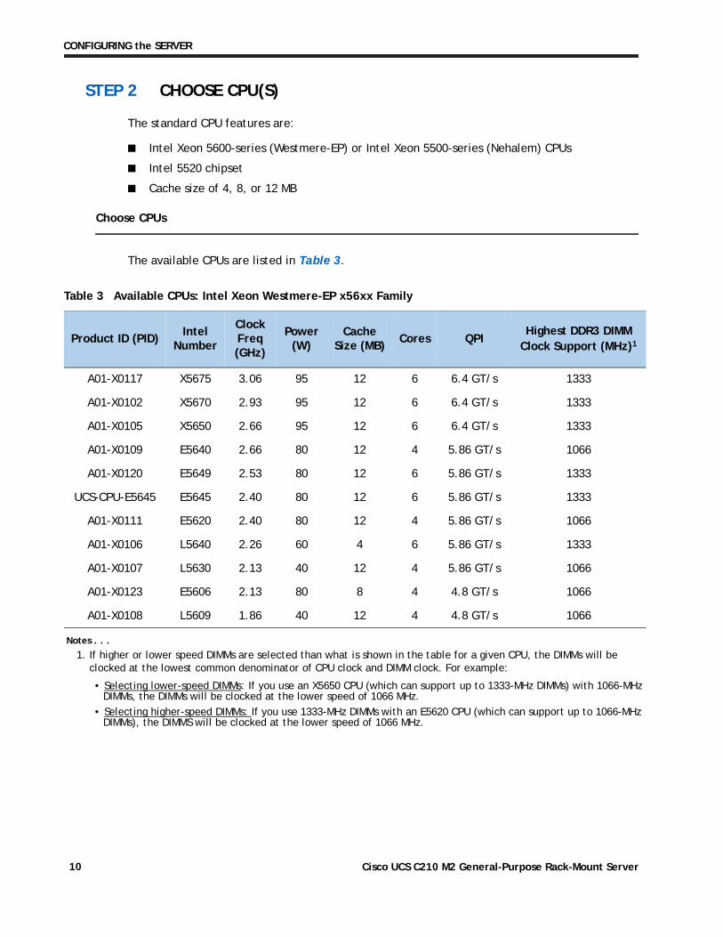
STEP 2 CHOOSE CPU(S)
The standard CPU features are:
■ Intel Xeon 5600-series (Westmere-EP) or Intel Xeon 5500-series (Nehalem) CPUs
■ Intel 5520 chipset
■ Cache size of 4, 8, or 12 MB
Choose CPUs
The available CPUs are listed in Table 3.
Table 3 Available CPUs: Intel Xeon Westmere-EP x56xx Family
Product ID (PID)Intel
Number
Clock Freq(GHz)
Power (W)
Cache Size (MB)
Cores QPIHighest DDR3 DIMM
Clock Support (MHz)1
Notes . . .
1. If higher or lower speed DIMMs are selected than what is shown in the table for a given CPU, the DIMMs will be clocked at the lowest common denominator of CPU clock and DIMM clock. For example:
• Selecting lower-speed DIMMs: If you use an X5650 CPU (which can support up to 1333-MHz DIMMs) with 1066-MHz DIMMs, the DIMMs will be clocked at the lower speed of 1066 MHz.
• Selecting higher-speed DIMMs: If you use 1333-MHz DIMMs with an E5620 CPU (which can support up to 1066-MHz DIMMs), the DIMMS will be clocked at the lower speed of 1066 MHz.
A01-X0117 X5675 3.06 95 12 6 6.4 GT/s 1333
A01-X0102 X5670 2.93 95 12 6 6.4 GT/s 1333
A01-X0105 X5650 2.66 95 12 6 6.4 GT/s 1333
A01-X0109 E5640 2.66 80 12 4 5.86 GT/s 1066
A01-X0120 E5649 2.53 80 12 6 5.86 GT/s 1333
UCS-CPU-E5645 E5645 2.40 80 12 6 5.86 GT/s 1333
A01-X0111 E5620 2.40 80 12 4 5.86 GT/s 1066
A01-X0106 L5640 2.26 60 4 6 5.86 GT/s 1333
A01-X0107 L5630 2.13 40 12 4 5.86 GT/s 1066
A01-X0123 E5606 2.13 80 8 4 4.8 GT/s 1066
A01-X0108 L5609 1.86 40 12 4 4.8 GT/s 1066
Cisco UCS C210 M2 General-Purpose Rack-Mount Server10
CONFIGURING the SERVER
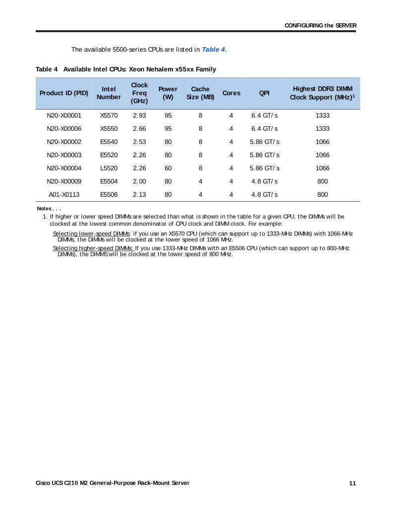
The available 5500-series CPUs are listed in Table 4.
Table 4 Available Intel CPUs: Xeon Nehalem x55xx Family
Product ID (PID)Intel
Number
Clock Freq(GHz)
Power (W)
Cache Size (MB)
Cores QPIHighest DDR3 DIMM
Clock Support (MHz)1
Notes . . .
1. If higher or lower speed DIMMs are selected than what is shown in the table for a given CPU, the DIMMs will be clocked at the lowest common denominator of CPU clock and DIMM clock. For example:
Selecting lower-speed DIMMs: if you use an X5570 CPU (which can support up to 1333-MHz DIMMs) with 1066-MHz DIMMs, the DIMMs will be clocked at the lower speed of 1066 MHz.
Selecting higher-speed DIMMs: If you use 1333-MHz DIMMs with an E5506 CPU (which can support up to 800-MHz DIMMs), the DIMMS will be clocked at the lower speed of 800 MHz.
N20-X00001 X5570 2.93 95 8 4 6.4 GT/s 1333
N20-X00006 X5550 2.66 95 8 4 6.4 GT/s 1333
N20-X00002 E5540 2.53 80 8 4 5.86 GT/s 1066
N20-X00003 E5520 2.26 80 8 4 5.86 GT/s 1066
N20-X00004 L5520 2.26 60 8 4 5.86 GT/s 1066
N20-X00009 E5504 2.00 80 4 4 4.8 GT/s 800
A01-X0113 E5506 2.13 80 4 4 4.8 GT/s 800
Cisco UCS C210 M2 General-Purpose Rack-Mount Server 11
CONFIGURING the SERVER
Approved Configurations
(1) Single-CPU configurations:
■ Choose any one CPU listed in Table 3 on page 10 or Table 4 on page 11.
(2) Two-CPU Configurations:
■ Choose two identical CPUs from any one of the rows of Table 3 on page 10 or Table 4 on page 11.
Caveats
■ You can select either one processor or two identical processors.
■ For optimal performance, select DIMMs with the highest clock speed for a given processor (see Table 5 on page 14). If you select DIMMs whose speeds are lower or higher than that shown in the tables, suboptimal performance will result.
Cisco UCS C210 M2 General-Purpose Rack-Mount Server12
CONFIGURING the SERVER
STEP 3 CHOOSE MEMORY
The standard memory features are:
■ DIMMs
— Clock speed: 800 MHz, 1066 MHz, or 1333 MHz
— Ranks per DIMM: 1, 2, or 4
— Operational voltage: single voltage (1.5 V) or dual voltage (1.35 V/1.5 V)
— Registered
■ DDR3 ECC registered DIMMs (RDIMMs), supporting Intel SDDC
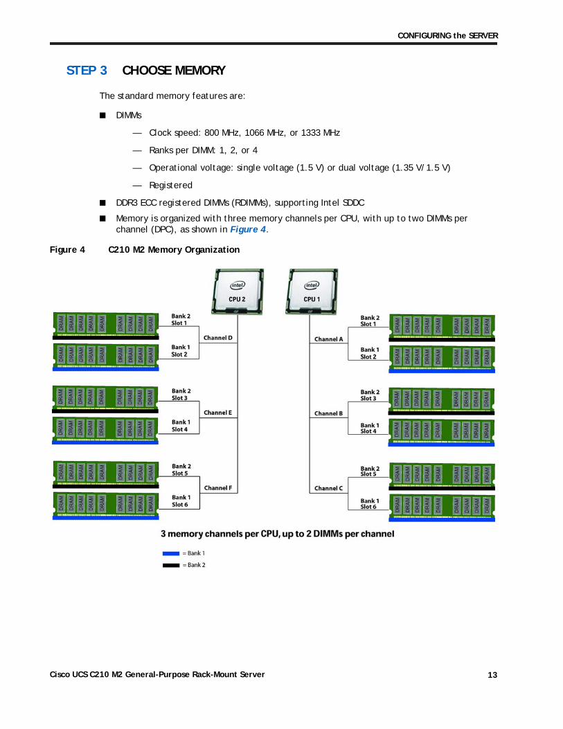
■ Memory is organized with three memory channels per CPU, with up to two DIMMs per channel (DPC), as shown in Figure 4.
Figure 4 C210 M2 Memory Organization
Cisco UCS C210 M2 General-Purpose Rack-Mount Server 13
CONFIGURING the SERVER
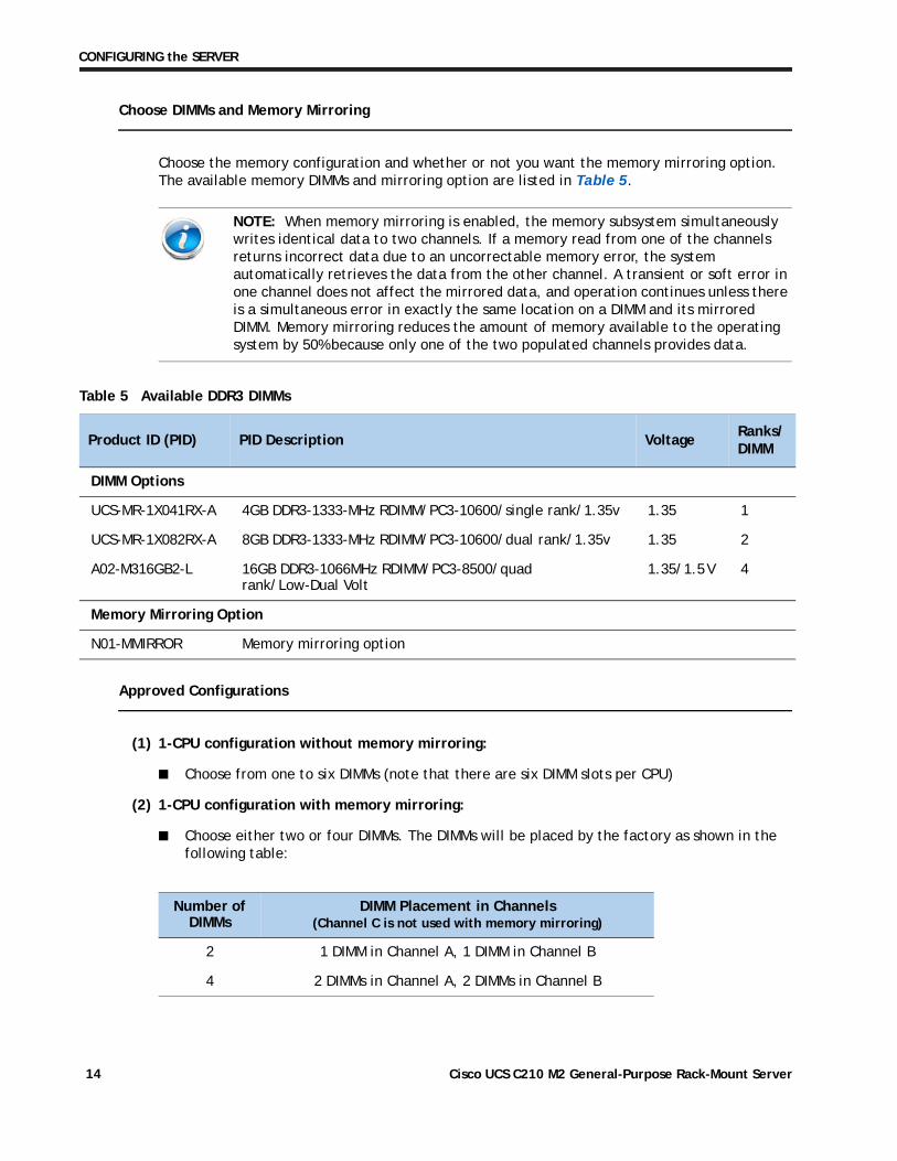
Choose DIMMs and Memory Mirroring
Choose the memory configuration and whether or not you want the memory mirroring option. The available memory DIMMs and mirroring option are listed in Table 5.
Approved Configurations
(1) 1-CPU configuration without memory mirroring:
■ Choose from one to six DIMMs (note that there are six DIMM slots per CPU)
(2) 1-CPU configuration with memory mirroring:
■ Choose either two or four DIMMs. The DIMMs will be placed by the factory as shown in the following table:
NOTE: When memory mirroring is enabled, the memory subsystem simultaneously writes identical data to two channels. If a memory read from one of the channels returns incorrect data due to an uncorrectable memory error, the system automatically retrieves the data from the other channel. A transient or soft error in one channel does not affect the mirrored data, and operation continues unless there is a simultaneous error in exactly the same location on a DIMM and its mirrored DIMM. Memory mirroring reduces the amount of memory available to the operating system by 50% because only one of the two populated channels provides data.
Table 5 Available DDR3 DIMMs
Product ID (PID) PID Description VoltageRanks/DIMM
DIMM Options
UCS-MR-1X041RX-A 4GB DDR3-1333-MHz RDIMM/PC3-10600/single rank/1.35v 1.35 1
UCS-MR-1X082RX-A 8GB DDR3-1333-MHz RDIMM/PC3-10600/dual rank/1.35v 1.35 2
A02-M316GB2-L 16GB DDR3-1066MHz RDIMM/PC3-8500/quad rank/Low-Dual Volt
1.35/1.5 V 4
Memory Mirroring Option
N01-MMIRROR Memory mirroring option
Number of DIMMs
DIMM Placement in Channels(Channel C is not used with memory mirroring)
2 1 DIMM in Channel A, 1 DIMM in Channel B
4 2 DIMMs in Channel A, 2 DIMMs in Channel B
Cisco UCS C210 M2 General-Purpose Rack-Mount Server14
CONFIGURING the SERVER
■ Choose the memory mirroring option (N01-MMIRROR) as shown in Table 5 on page 14.
(3) 2-CPU configuration without memory mirroring:
■ Choose from 1 to 6 DIMMs per CPU (from 2 to 12 total DIMMs)
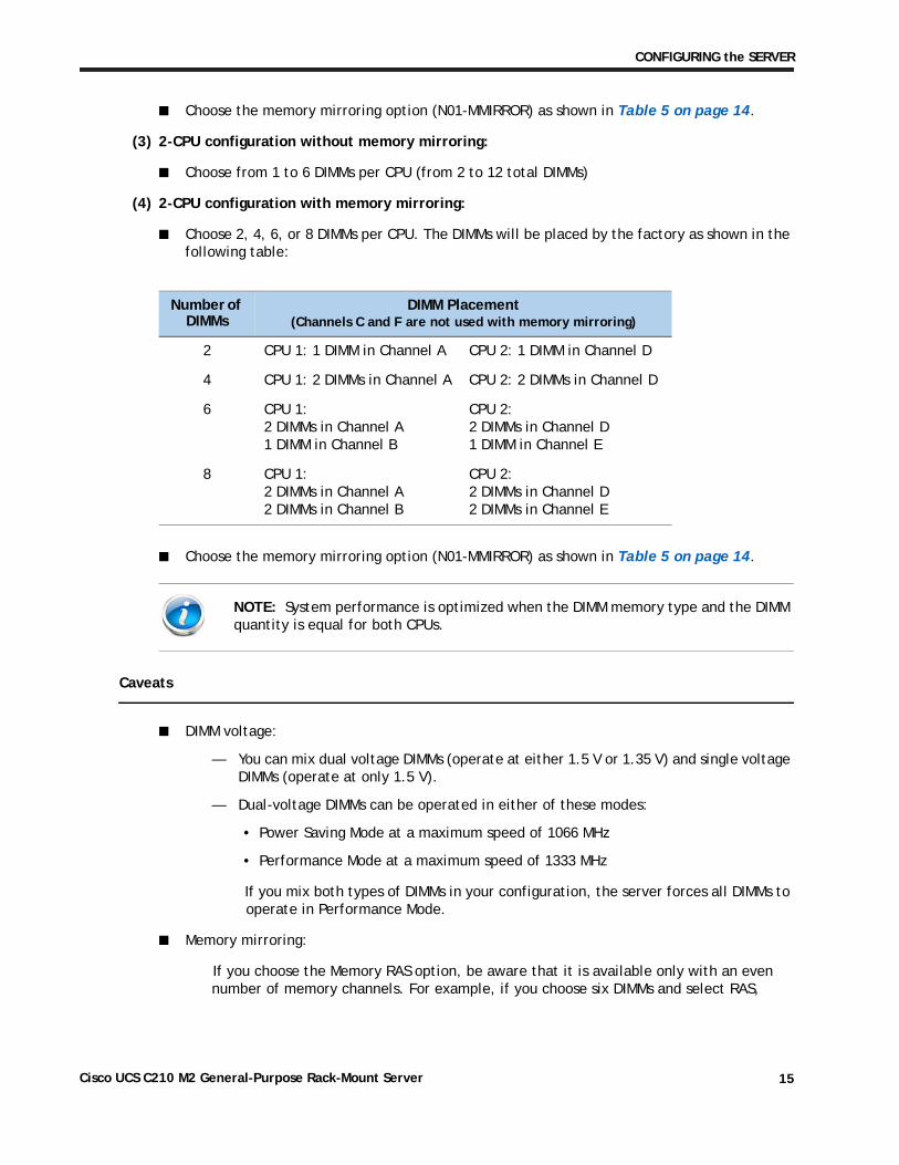
(4) 2-CPU configuration with memory mirroring:
■ Choose 2, 4, 6, or 8 DIMMs per CPU. The DIMMs will be placed by the factory as shown in the following table:
■ Choose the memory mirroring option (N01-MMIRROR) as shown in Table 5 on page 14.
Caveats
■ DIMM voltage:
— You can mix dual voltage DIMMs (operate at either 1.5 V or 1.35 V) and single voltage DIMMs (operate at only 1.5 V).
— Dual-voltage DIMMs can be operated in either of these modes:
• Power Saving Mode at a maximum speed of 1066 MHz
• Performance Mode at a maximum speed of 1333 MHz
If you mix both types of DIMMs in your configuration, the server forces all DIMMs to operate in Performance Mode.
■ Memory mirroring:
If you choose the Memory RAS option, be aware that it is available only with an even number of memory channels. For example, if you choose six DIMMs and select RAS,
Number of DIMMs
DIMM Placement(Channels C and F are not used with memory mirroring)
2 CPU 1: 1 DIMM in Channel A CPU 2: 1 DIMM in Channel D
4 CPU 1: 2 DIMMs in Channel A CPU 2: 2 DIMMs in Channel D
6 CPU 1: 2 DIMMs in Channel A 1 DIMM in Channel B
CPU 2: 2 DIMMs in Channel D 1 DIMM in Channel E
8 CPU 1:2 DIMMs in Channel A 2 DIMMs in Channel B
CPU 2: 2 DIMMs in Channel D 2 DIMMs in Channel E
NOTE: System performance is optimized when the DIMM memory type and the DIMM quantity is equal for both CPUs.
Cisco UCS C210 M2 General-Purpose Rack-Mount Server 15
CONFIGURING the SERVER
mirroring will go into effect on only two channels with two DIMMS per channel (you cannot implement RAS on three channels). In this case, two DIMMS would go unused.
For more information regarding memory, see CPUs and DIMMs on page 44.
NOTE: For memory mirroring, DIMM pairing across buses must be identical. If you only have two DIMMs, they need to be the same PID because you have one DIMM on each of two buses. If you have four DIMMs in a 2-CPU system, for example, you can have two 4-GB and two 8-GB DIMMs. One 4-GB/8-GB DIMM pair would located on Channel A of CPU 1, and one 4-GB/8-GB DIMM pair would be located on Channel D of CPU 2. If you have four DIMMs in a 1-CPU system, for example, you can have two 4-GB and two 8-GB DIMMs. One 4-GB/8-GB DIMM pair would located on Channel A of CPU 1, and one 4-GB/8-GB DIMM pair would be located on Channel B of CPU 1.
Cisco UCS C210 M2 General-Purpose Rack-Mount Server16
CONFIGURING the SERVER
STEP 4 CHOOSE RAID CONFIGURATION
The base server motherboard comes with an integrated SATA RAID 0/1 controller, which supports up to 4 SATA drives only (the integrated controller does not support SAS drives). Therefore, a separate plug-in PCIe controller card is not required when ordering SATA drives and a RAID 0 or 1 configuration is desired.
You can use the built-in SATA RAID 0/1 controller as described in the preceding paragraph or you can instead choose to implement a RAID configuration by using the optional mezzanine card on the server motherboard or by using an optional plug-in PCIe RAID controller card.
Cisco can provide factory-configured RAID 0, 1, 1E, 5, 6, and 10 systems depending on the RAID implementation chosen and the number of drives ordered. Factory-configured RAID options are listed at the end of Table 6.
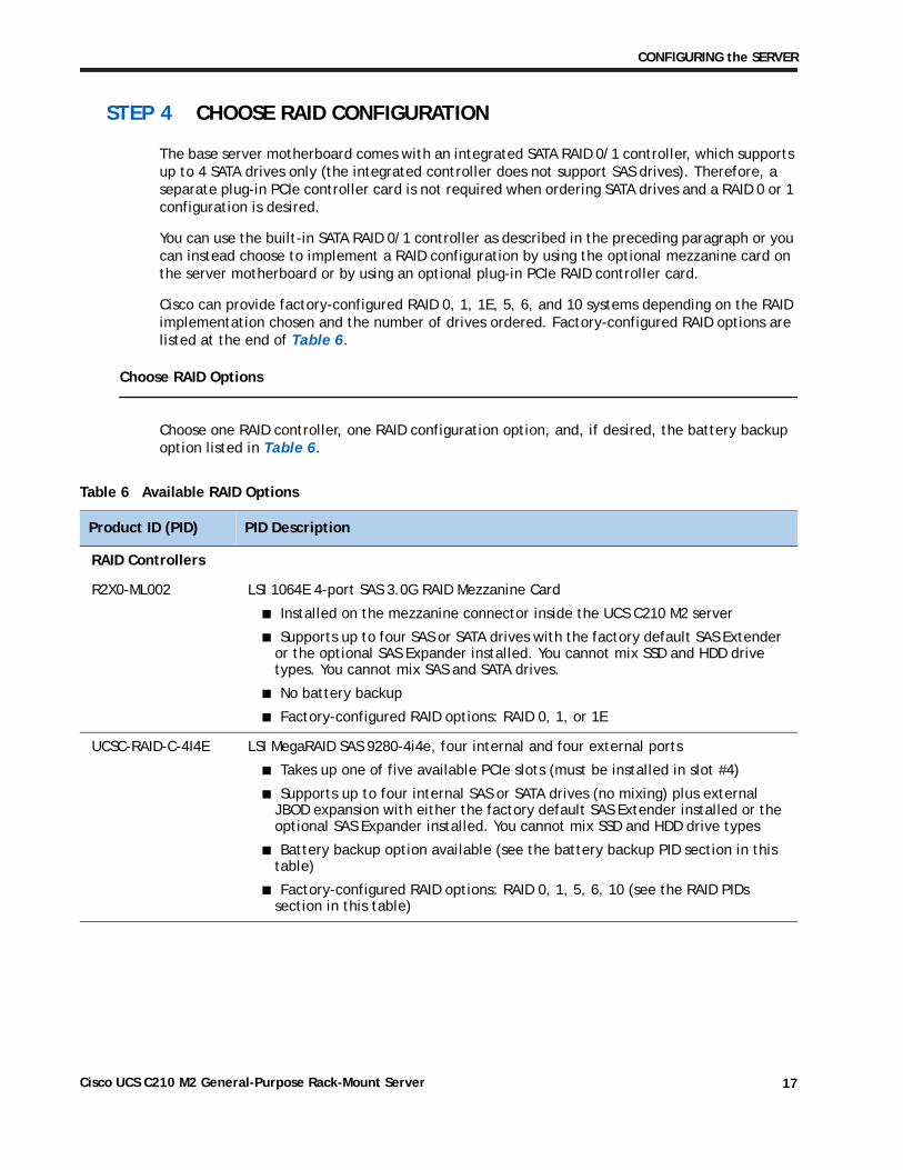
Choose RAID Options
Choose one RAID controller, one RAID configuration option, and, if desired, the battery backup option listed in Table 6.
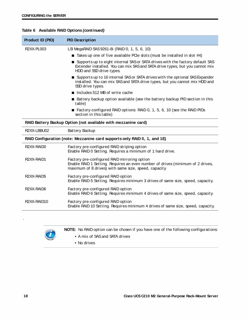
Table 6 Available RAID Options
Product ID (PID) PID Description
RAID Controllers
R2X0-ML002 LSI 1064E 4-port SAS 3.0G RAID Mezzanine Card
■ Installed on the mezzanine connector inside the UCS C210 M2 server
■ Supports up to four SAS or SATA drives with the factory default SAS Extender or the optional SAS Expander installed. You cannot mix SSD and HDD drive types. You cannot mix SAS and SATA drives.
■ No battery backup
■ Factory-configured RAID options: RAID 0, 1, or 1E
UCSC-RAID-C-4I4E LSI MegaRAID SAS 9280-4i4e, four internal and four external ports
■ Takes up one of five available PCIe slots (must be installed in slot #4)
■ Supports up to four internal SAS or SATA drives (no mixing) plus external JBOD expansion with either the factory default SAS Extender installed or the optional SAS Expander installed. You cannot mix SSD and HDD drive types
■ Battery backup option available (see the battery backup PID section in this table)
■ Factory-configured RAID options: RAID 0, 1, 5, 6, 10 (see the RAID PIDs section in this table)
Cisco UCS C210 M2 General-Purpose Rack-Mount Server 17
CONFIGURING the SERVER
.
R2XX-PL003 LSI MegaRAID SAS 9261-8i (RAID 0, 1, 5, 6, 10)
■ Takes up one of five available PCIe slots (must be installed in slot #4)
■ Supports up to eight internal SAS or SATA drives with the factory default SAS Extender installed. You can mix SAS and SATA drive types, but you cannot mix HDD and SSD drive types.
■ Supports up to 16 internal SAS or SATA drives with the optional SAS Expander installed. You can mix SAS and SATA drive types, but you cannot mix HDD and SSD drive types.
■ Includes 512 MB of write cache
■ Battery backup option available (see the battery backup PID section in this table)
■ Factory-configured RAID options: RAID 0, 1, 5, 6, 10 (see the RAID PIDs section in this table)
RAID Battery Backup Option (not available with mezzanine card)
R2XX-LBBU02 Battery Backup
RAID Configuration (note: Mezzanine card supports only RAID 0, 1, and 1E)
R2XX-RAID0 Factory pre-configured RAID striping option Enable RAID 0 Setting. Requires a minimum of 1 hard drive.
R2XX-RAID1 Factory pre-configured RAID mirroring option Enable RAID 1 Setting. Requires an even number of drives (minimum of 2 drives, maximum of 8 drives) with same size, speed, capacity.
R2XX-RAID5 Factory pre-configured RAID option Enable RAID 5 Setting. Requires minimum 3 drives of same size, speed, capacity.
R2XX-RAID6 Factory pre-configured RAID option Enable RAID 6 Setting. Requires minimum 4 drives of same size, speed, capacity.
R2XX-RAID10 Factory pre-configured RAID option Enable RAID 10 Setting. Requires minimum 4 drives of same size, speed, capacity.
NOTE: No RAID option can be chosen if you have one of the following configurations:
• A mix of SAS and SATA drives
• No drives
Table 6 Available RAID Options (continued)
Product ID (PID) PID Description
Cisco UCS C210 M2 General-Purpose Rack-Mount Server18
CONFIGURING the SERVER
Approved Configurations
(1) Integrated SATA RAID 0/1 controller
■ Choose none of the options listed in Table 6. In this case, the integrated RAID 0/1 controller will be used.
(2) Optional RAID controller
■ Choose one of the RAID controllers options (with or without battery backup) listed in Table 6.
(3) Optional RAID configuration
■ Choose one of the RAID configuration options listed in Table 6.
Caveats
■ The MegaRAID cards (LSI MegaRAID SAS 9280-4i4e and LSI MegaRAID SAS 9261-8i) must be installed in PCIe slot #4. Refer to Figure 3 on page 5 for PCIe slot numbering.
■ If you choose the mezzanine RAID controller card, you will still have all five PCIe slots available for adding optional cards.
■ The two optional plug-in RAID controllers are each half-height PCIe cards. If you choose one of these optional cards, you will still have four slots available for adding optional PCIe cards.
■ You can choose only one RAID controller (integrated controller, mezzanine card controller, or one plug-in PCIe controller).
■ You can choose an optional RAID configuration (RAID 0, 1, 5, 6, or 10), which is pre-configured at the factory. If you do not choose a RAID configuration, the disks will be configured as a JBOD.
NOTE: If an optional RAID configuration is not chosen, the disks will be configured as a JBOD.
Cisco UCS C210 M2 General-Purpose Rack-Mount Server 19
CONFIGURING the SERVER
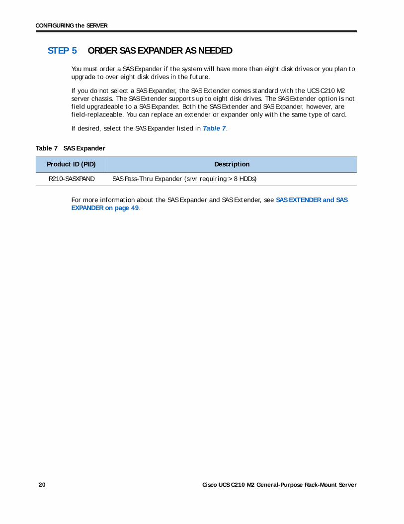
STEP 5 ORDER SAS EXPANDER AS NEEDED
You must order a SAS Expander if the system will have more than eight disk drives or you plan to upgrade to over eight disk drives in the future.
If you do not select a SAS Expander, the SAS Extender comes standard with the UCS C210 M2 server chassis. The SAS Extender supports up to eight disk drives. The SAS Extender option is not field upgradeable to a SAS Expander. Both the SAS Extender and SAS Expander, however, are field-replaceable. You can replace an extender or expander only with the same type of card.
If desired, select the SAS Expander listed in Table 7.
For more information about the SAS Expander and SAS Extender, see SAS EXTENDER and SAS EXPANDER on page 49.
Table 7 SAS Expander
Product ID (PID) Description
R210-SASXPAND SAS Pass-Thru Expander (srvr requiring > 8 HDDs)
Cisco UCS C210 M2 General-Purpose Rack-Mount Server20
CONFIGURING the SERVER
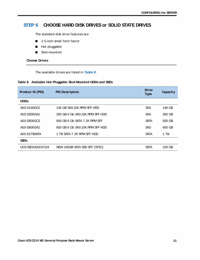
STEP 6 CHOOSE HARD DISK DRIVES or SOLID STATE DRIVES
The standard disk drive features are:
■ 2.5-inch small form factor
■ Hot-pluggable
■ Sled-mounted
Choose Drives
The available drives are listed in Table 8.
Table 8 Available Hot-Pluggable Sled-Mounted HDDs and SSDs
Product ID (PID) PID DescriptionDrive Type
Capacity
HDDs
A03-D146GC2 146 GB SAS 15K RPM SFF HDD SAS 146 GB
A03-D300GA2 300 GB 6 Gb SAS 10K RPM SFF HDD SAS 300 GB
A03-D500GC3 500 GB 6 Gb SATA 7.2K RPM SFF SATA 500 GB
A03-D600GA2 600 GB 6 Gb SAS 10K RPM SFF HDD SAS 600 GB
A03-D1TBSATA 1 TB SATA 7.2K RPM SFF HDD SATA 1 TB
SSDs
UCS-SSD100GI1F104 NEW 100GB SATA SSD SFF (STEC) SATA 100 GB
Cisco UCS C210 M2 General-Purpose Rack-Mount Server 21
CONFIGURING the SERVER
Approved Configurations
(1) Integrated SATA RAID 0/1 controller
■ Select up to 4 SATA (only) drives listed in Table 8. You cannot mix HDD and SDD SATA drive types.
(2) LSI 1064E 4-port SAS 6.0G RAID Mezzanine card RAID controller
■ Select up to four SAS or SATA drives listed in Table 8. You cannot mix HDD and SSD drives. You cannot mix SAS and SATA drive types.
(3) LSI MegaRAID SAS 9280-4i4e RAID controller
■ Select up to four SAS or SATA internal drives listed in Table 8. You cannot mix HDD and SSD drive types or SAS and SATA drives.
(4) LSI MegaRAID SAS 9261-8i RAID controller
■ Select up to eight internal SAS or SATA drives listed in Table 8. You can mix SAS and SATA drives but you cannot mix HDD and SSD drive types. If you order the optional SAS Expander, the controller can support up to 16 internal drives.
Caveats
■ If the integrated RAID controller on the server motherboard is used (no PCIe or mezzanine card controller selected), all the drives must be SATA.
A SAS Extender is not field-upgradable to a SAS Expander, so if you are configuring a system with eight or more drives or anticipate the system will implement more than eight drives in the future, make sure you order a SAS Expander. You can replace an extender or expander only with the same type of card.
Cisco UCS C210 M2 General-Purpose Rack-Mount Server22
CONFIGURING the SERVER
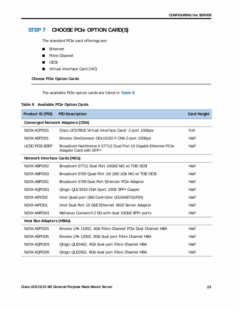
STEP 7 CHOOSE PCIe OPTION CARD(S)
The standard PCIe card offerings are:
■ Ethernet
■ Fibre Channel
■ iSCSI
■ Virtual Interface Card (VIC)
Choose PCIe Option Cards
The available PCIe option cards are listed in Table 9.
Table 9 Available PCIe Option Cards
Product ID (PID) PID Description Card Height
Converged Network Adapters (CNA)
N2XX-ACPCI01 Cisco UCS P81E Virtual Interface Card/ 2-port 10Gbps Full
N2XX-AEPCI01 Emulex OneConnect OCe10102-F CNA 2-port 10Gbps Half
UCSC-PCIE-BSFP Broadcom NetXtreme II 57712 Dual Port 10 Gigabit Ethernet PCIe Adapter Card with SFP+
Half
Network Interface Cards (NICs)
N2XX-ABPCI02 Broadcom 57711 Dual Port 10GbE NIC w/TOE iSCSI Half
N2XX-ABPCI03 Broadcom 5709 Quad Port 10/100/1Gb NIC w/TOE iSCSI Half
N2XX-ABPCI01 Broadcom 5709 Dual-Port Ethernet PCIe Adapter Half
N2XX-AQPCI01 Qlogic QLE 8152-CNA 2port 10Gb SFP+ Copper Half
N2XX-AIPCI02 Intel Quad port GbE Controller (E1G44ETG1P20) Half
N2XX-AIPCI01 Intel Dual Port 10 GbE Ethernet X520 Server Adapter Half
N2XX-AMPCI01 Mellanox ConnectX-2 EN with dual 10GbE SFP+ ports Half
Host Bus Adapters (HBAs)
N2XX-AEPCI03 Emulex LPe 11002, 4Gb Fibre Channel PCIe Dual Channel HBA Half
N2XX-AEPCI05 Emulex LPe 12002, 8Gb dual port Fibre Channel HBA Half
N2XX-AQPCI03 Qlogic QLE2462, 4Gb dual port Fibre Channel HBA Half
N2XX-AQPCI05 Qlogic QLE2562, 8Gb dual port Fibre Channel HBA Half
Cisco UCS C210 M2 General-Purpose Rack-Mount Server 23
CONFIGURING the SERVER
Approved Configurations
(1) No RAID controller plug-in card
■ If you did not choose a plug-in RAID controller (for example, you are using the mezzanine card or the interated RAID controller on the motherboard), you can select up to five PCIe option cards listed in Table 9.
(2) One RAID controller plug-in card
■ If you selected a plug-in RAID controller, you can select up to four of the optional PCIe cards listed in Table 9.
Caveats
■ There are five PCIe slots. All are full-height. All of the PCIe adapter cards are half-height, with the exception of the Virtual Interface Card (VIC) (N2XX-ACPCI01), which is a full-height card.
— If you selected a plug-in RAID controller in STEP 4 CHOOSE RAID CONFIGURATION, four slots remain available.
— Only a single VIC card may be installed and it must be installed in either slot 1 or slot 2 (see Figure 3 on page 5 for slot numbering).
— All cards will fit in any slot.
■ The MegaRAID cards (LSI MegaRAID SAS 9280-4i4e and LSI MegaRAID SAS 9261-8i) must be installed in PCIe slot #4. Refer to Figure 3 on page 5 for PCIe slot numbering.
■ To help ensure that your operating system is compatible with the card you have selected, please check the Hardware Compatibility List at this URL:
http://www.cisco.com/en/US/products/ps10477/prod_technical_reference_list.html
NOTE: If a plug-in RAID controller card is installed, any optional PCIe card you select will be installed in one of the remaining four PCIe slots. You can install a maximum of one plug-in PCIe RAID controller card.
Cisco UCS C210 M2 General-Purpose Rack-Mount Server24
CONFIGURING the SERVER
STEP 8 CHOOSE OPTIONAL DVD-RW DRIVE
An optional DVD-RW optical drive, with dual-layer (DL) media support, may be ordered. The drive is listed in Table 10.
Table 10 Available DVD-RW Drive
Product ID (PID) PID Description
R210-ODVDRW DVD-RW Drive for UCS C210 M2 Rack Servers
Cisco UCS C210 M2 General-Purpose Rack-Mount Server 25
CONFIGURING the SERVER
STEP 9 ORDER OPTIONAL REDUNDANT POWER SUPPLY
The C210 M2 server can accommodate two power supplies. Only one power supply is required. One 650 W power supply ships with the base server chassis. You can order an optional redundant power supply listed in Table 11s.
Table 11 Redundant Power Supply
Product ID (PID) PID Description
R2X0-PSU2-650W-SB 650 W power supply, w/added 5A Standby for UCS C200 or C210
Cisco UCS C210 M2 General-Purpose Rack-Mount Server26
CONFIGURING the SERVER
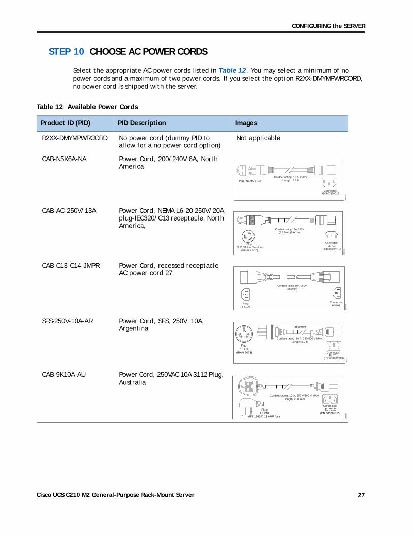
STEP 10 CHOOSE AC POWER CORDS
Select the appropriate AC power cords listed in Table 12. You may select a minimum of no power cords and a maximum of two power cords. If you select the option R2XX-DMYMPWRCORD, no power cord is shipped with the server.
Table 12 Available Power Cords
Product ID (PID) PID Description Images
R2XX-DMYMPWRCORD No power cord (dummy PID to allow for a no power cord option)
Not applicable
CAB-N5K6A-NA Power Cord, 200/240V 6A, North America
CAB-AC-250V/13A Power Cord, NEMA L6-20 250V/20A plug-IEC320/C13 receptacle, North America,
CAB-C13-C14-JMPR Power Cord, recessed receptacle AC power cord 27
SFS-250V-10A-AR Power Cord, SFS, 250V, 10A, Argentina
CAB-9K10A-AU Power Cord, 250VAC 10A 3112 Plug, Australia
Cordset rating: 10 A, 250 VLength: 8.2 ft
1865
70
Plug: NEMA 6-15P
Connector:IEC60320/C13
Cordset rating 13A, 250V(6.6 feet) (79±2m)
Plug:EL312MoldedTwistlock
(NEMA L6-20)
1865
68
Connector:EL 701
(IEC60320/C13)
Cordset rating 10A, 250V(686mm)
Plug:SS10A
1865
69
Connector:HS10S
1865
71
2500 mm
Cordset rating: 10 A, 250/500 V MAXLength: 8.2 ft
Plug:EL 219
(IRAM 2073) Connector:EL 701
(IEC60320/C13)
Plug:
Cordset rating: 10 A, 250 V/500 V MAXLength: 2500mm
1865
80
Connector:EL 701C
(EN 60320/C15)EL 210(BS 1363A) 13 AMP fuse
Cisco UCS C210 M2 General-Purpose Rack-Mount Server 27
CONFIGURING the SERVER
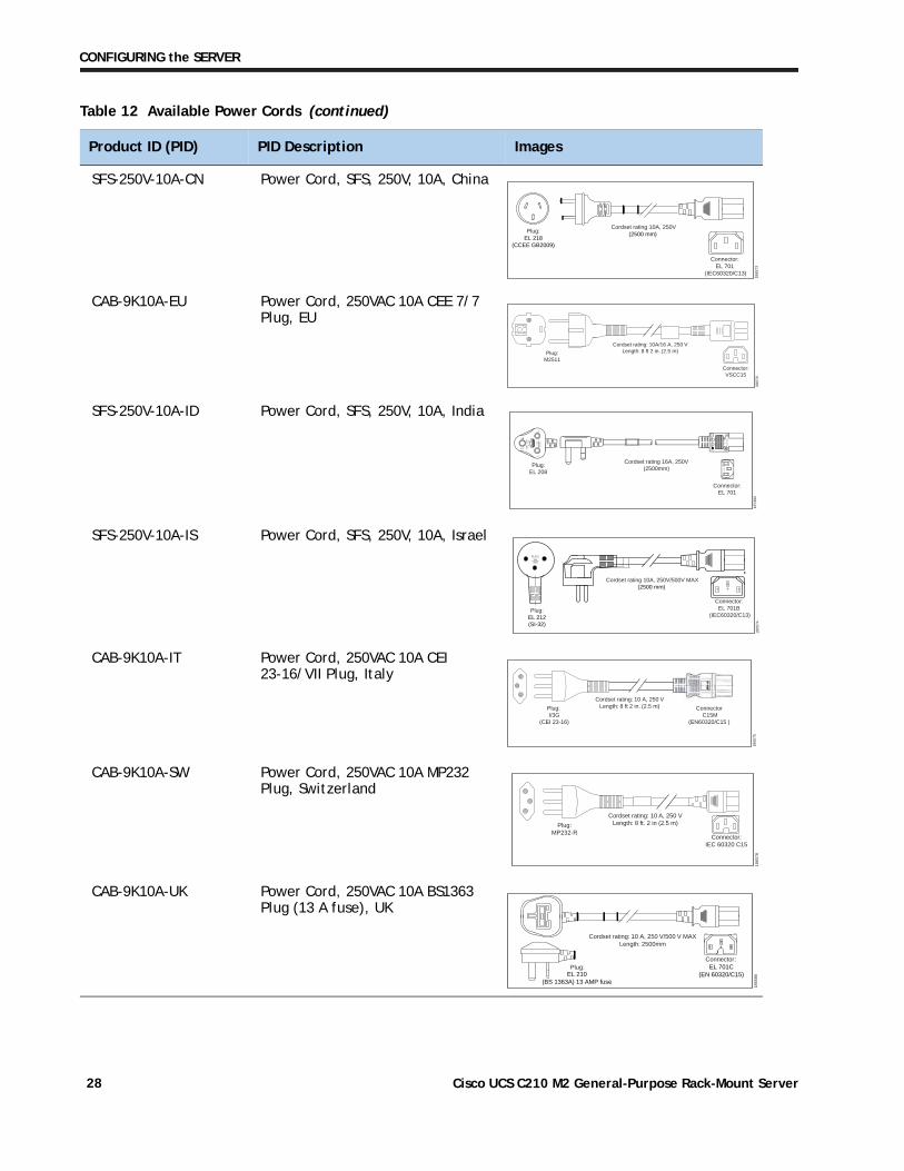
SFS-250V-10A-CN Power Cord, SFS, 250V, 10A, China
CAB-9K10A-EU Power Cord, 250VAC 10A CEE 7/7 Plug, EU
SFS-250V-10A-ID Power Cord, SFS, 250V, 10A, India
SFS-250V-10A-IS Power Cord, SFS, 250V, 10A, Israel
CAB-9K10A-IT Power Cord, 250VAC 10A CEI 23-16/VII Plug, Italy
CAB-9K10A-SW Power Cord, 250VAC 10A MP232 Plug, Switzerland
CAB-9K10A-UK Power Cord, 250VAC 10A BS1363 Plug (13 A fuse), UK
Table 12 Available Power Cords (continued)
Product ID (PID) PID Description Images
Cordset rating 10A, 250V(2500 mm)
Plug:EL 218
(CCEE GB2009)
1865
73
Connector:EL 701
(IEC60320/C13)
Connector:VSCC15
Cordset rating: 10A/16 A, 250 VLength: 8 ft 2 in. (2.5 m)Plug:
M2511
1865
76
OVE
Cordset rating 16A, 250V(2500mm)
Plug:EL 208
1874
90
Connector:EL 701
Cordset rating 10A, 250V/500V MAX(2500 mm)
Plug:EL 212(SI-32)
1865
74
Connector:EL 701B
(IEC60320/C13)
EL-21216A250V
Plug: I/3G
(CEI 23-16)
Connector C15M
(EN60320/C15 )
Cordset rating: 10 A, 250 VLength: 8 ft 2 in. (2.5 m)
1865
75
Plug:MP232-R
Cordset rating: 10 A, 250 VLength: 8 ft. 2 in (2.5 m)
1865
78
Connector:IEC 60320 C15
Plug:
Cordset rating: 10 A, 250 V/500 V MAXLength: 2500mm
1865
80
Connector:EL 701C
(EN 60320/C15)EL 210(BS 1363A) 13 AMP fuse
Cisco UCS C210 M2 General-Purpose Rack-Mount Server28
CONFIGURING the SERVER
CAB-9K12A-NA Power Cord, 125VAC 13A NEMA 5-15 Plug, North America
Image not available
CAB-JPN-3PIN Power Cord 3PIN, Japan Image not available
Table 12 Available Power Cords (continued)
Product ID (PID) PID Description Images
Cisco UCS C210 M2 General-Purpose Rack-Mount Server 29
CONFIGURING the SERVER
STEP 11 ORDER OPTIONAL RAIL KIT
A rail kit is not included with the Cisco UCS C210 M2 base server chassis, but you can order the rail kit listed in Table 13).
See the section titled OPTIONAL STEP - ORDER RACK(s) on page 41 for information about racks and rack equipment.
Table 13 Rail Kit
Product ID (PID) PID Description
R2XX-G31032RAIL Rail Kit for UCS 200, 210 Rack Servers
NOTE: This third-generation rail kit works in racks with square holes or 10-32 round holes and is shorter than the previous generation rail kit. The new R2XX-G31032RAIL measures 23.5 inches to 36 inches in length. By comparison, the previous version, R250-SLDRAIL, measured 27 inches to 37 inches in length.
Cisco UCS C210 M2 General-Purpose Rack-Mount Server30
CONFIGURING the SERVER
STEP 12 ORDER OPTIONAL CABLE MANAGEMENT ARM
The cable management arm hooks onto the right and left slide rails at the rear of the server and is used for cable management. You can order the cable management arm listed in Table 14.
For more information about the cable management arm, see the Cisco UCS C210 Installation and Service Guide at this URL:
http://www.cisco.com/en/US/docs/unified_computing/ucs/c/hw/C210M1/install/C210M1.html
Table 14 Cable Management Arm
Product ID (PID) PID Description
R2XX-CMAG3-1032 Cable Mgmt Arm for R2XX-G31032RAIL for C200/C210
Cisco UCS C210 M2 General-Purpose Rack-Mount Server 31
CONFIGURING the SERVER
STEP 13 ORDER A TRUSTED PLATFORM MODULE
Trusted Platform Module (TPM) is a computer chip (microcontroller) that can securely store artifacts used to authenticate the platform (server). These artifacts can include passwords, certificates, or encryption keys. A TPM can also be used to store platform measurements that help ensure that the platform remains trustworthy. Authentication (ensuring that the platform can prove that it is what it claims to be) and attestation (a process helping to prove that a platform is trustworthy and has not been breached) are necessary steps to ensure safer computing in all environments.
The TPM ordering information is listed in Table 15.
Table 15 Trusted Platform Module
Product ID (PID) PID Description
R200-TPM1 Trusted Platform Module
Cisco UCS C210 M2 General-Purpose Rack-Mount Server32
CONFIGURING the SERVER
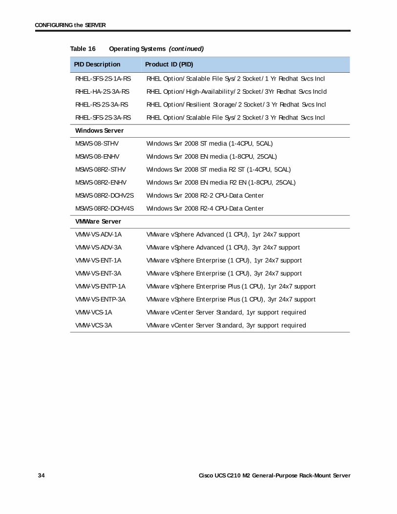
STEP 14 CHOOSE OPERATING SYSTEM
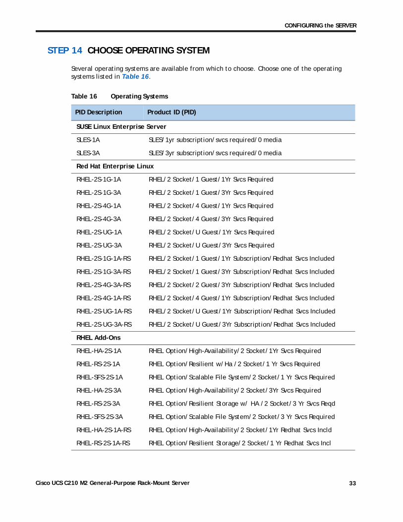
Several operating systems are available from which to choose. Choose one of the operating systems listed in Table 16.
Table 16 Operating Systems
PID Description Product ID (PID)
SUSE Linux Enterprise Server
SLES-1A SLES/1yr subscription/svcs required/0 media
SLES-3A SLES/3yr subscription/svcs required/0 media
Red Hat Enterprise Linux
RHEL-2S-1G-1A RHEL/2 Socket/1 Guest/1Yr Svcs Required
RHEL-2S-1G-3A RHEL/2 Socket/1 Guest/3Yr Svcs Required
RHEL-2S-4G-1A RHEL/2 Socket/4 Guest/1Yr Svcs Required
RHEL-2S-4G-3A RHEL/2 Socket/4 Guest/3Yr Svcs Required
RHEL-2S-UG-1A RHEL/2 Socket/U Guest/1Yr Svcs Required
RHEL-2S-UG-3A RHEL/2 Socket/U Guest/3Yr Svcs Required
RHEL-2S-1G-1A-RS RHEL/2 Socket/1 Guest/1Yr Subscription/Redhat Svcs Included
RHEL-2S-1G-3A-RS RHEL/2 Socket/1 Guest/3Yr Subscription/Redhat Svcs Included
RHEL-2S-4G-3A-RS RHEL/2 Socket/2 Guest/3Yr Subscription/Redhat Svcs Included
RHEL-2S-4G-1A-RS RHEL/2 Socket/4 Guest/1Yr Subscription/Redhat Svcs Included
RHEL-2S-UG-1A-RS RHEL/2 Socket/U Guest/1Yr Subscription/Redhat Svcs Included
RHEL-2S-UG-3A-RS RHEL/2 Socket/U Guest/3Yr Subscription/Redhat Svcs Included
RHEL Add-Ons
RHEL-HA-2S-1A RHEL Option/High-Availability/2 Socket/1Yr Svcs Required
RHEL-RS-2S-1A RHEL Option/Resilient w/Ha /2 Socket/1 Yr Svcs Required
RHEL-SFS-2S-1A RHEL Option/Scalable File System/2 Socket/1 Yr Svcs Required
RHEL-HA-2S-3A RHEL Option/High-Availability/2 Socket/3Yr Svcs Required
RHEL-RS-2S-3A RHEL Option/Resilient Storage w/ HA /2 Socket/3 Yr Svcs Reqd
RHEL-SFS-2S-3A RHEL Option/Scalable File System/2 Socket/3 Yr Svcs Required
RHEL-HA-2S-1A-RS RHEL Option/High-Availability/2 Socket/1Yr Redhat Svcs Incld
RHEL-RS-2S-1A-RS RHEL Option/Resilient Storage/2 Socket/1 Yr Redhat Svcs Incl
Cisco UCS C210 M2 General-Purpose Rack-Mount Server 33
CONFIGURING the SERVER
RHEL-SFS-2S-1A-RS RHEL Option/Scalable File Sys/2 Socket/1 Yr Redhat Svcs Incl
RHEL-HA-2S-3A-RS RHEL Option/High-Availability/2 Socket/3Yr Redhat Svcs Incld
RHEL-RS-2S-3A-RS RHEL Option/Resilient Storage/2 Socket/3 Yr Redhat Svcs Incl
RHEL-SFS-2S-3A-RS RHEL Option/Scalable File Sys/2 Socket/3 Yr Redhat Svcs Incl
Windows Server
MSWS-08-STHV Windows Svr 2008 ST media (1-4CPU, 5CAL)
MSWS-08-ENHV Windows Svr 2008 EN media (1-8CPU, 25CAL)
MSWS-08R2-STHV Windows Svr 2008 ST media R2 ST (1-4CPU, 5CAL)
MSWS-08R2-ENHV Windows Svr 2008 EN media R2 EN (1-8CPU, 25CAL)
MSWS-08R2-DCHV2S Windows Svr 2008 R2-2 CPU-Data Center
MSWS-08R2-DCHV4S Windows Svr 2008 R2-4 CPU-Data Center
VMWare Server
VMW-VS-ADV-1A VMware vSphere Advanced (1 CPU), 1yr 24x7 support
VMW-VS-ADV-3A VMware vSphere Advanced (1 CPU), 3yr 24x7 support
VMW-VS-ENT-1A VMware vSphere Enterprise (1 CPU), 1yr 24x7 support
VMW-VS-ENT-3A VMware vSphere Enterprise (1 CPU), 3yr 24x7 support
VMW-VS-ENTP-1A VMware vSphere Enterprise Plus (1 CPU), 1yr 24x7 support
VMW-VS-ENTP-3A VMware vSphere Enterprise Plus (1 CPU), 3yr 24x7 support
VMW-VCS-1A VMware vCenter Server Standard, 1yr support required
VMW-VCS-3A VMware vCenter Server Standard, 3yr support required
Table 16 Operating Systems (continued)
PID Description Product ID (PID)
Cisco UCS C210 M2 General-Purpose Rack-Mount Server34
CONFIGURING the SERVER
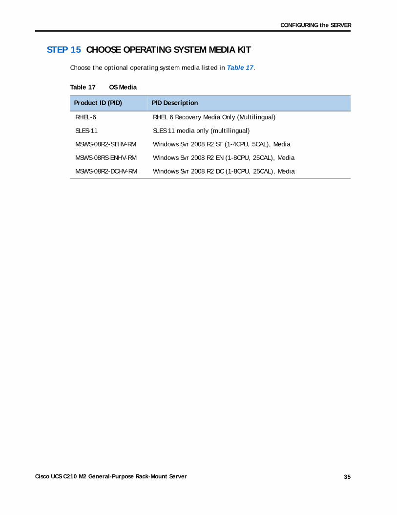
STEP 15 CHOOSE OPERATING SYSTEM MEDIA KIT
Choose the optional operating system media listed in Table 17.
Table 17 OS Media
Product ID (PID) PID Description
RHEL-6 RHEL 6 Recovery Media Only (Multilingual)
SLES-11 SLES 11 media only (multilingual)
MSWS-08R2-STHV-RM Windows Svr 2008 R2 ST (1-4CPU, 5CAL), Media
MSWS-08RS-ENHV-RM Windows Svr 2008 R2 EN (1-8CPU, 25CAL), Media
MSWS-08R2-DCHV-RM Windows Svr 2008 R2 DC (1-8CPU, 25CAL), Media
Cisco UCS C210 M2 General-Purpose Rack-Mount Server 35
CONFIGURING the SERVER
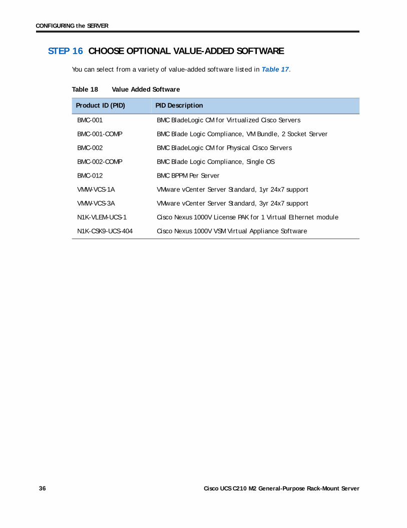
STEP 16 CHOOSE OPTIONAL VALUE-ADDED SOFTWARE
You can select from a variety of value-added software listed in Table 17.
Table 18 Value Added Software
Product ID (PID) PID Description
BMC-001 BMC BladeLogic CM for Virtualized Cisco Servers
BMC-001-COMP BMC Blade Logic Compliance, VM Bundle, 2 Socket Server
BMC-002 BMC BladeLogic CM for Physical Cisco Servers
BMC-002-COMP BMC Blade Logic Compliance, Single OS
BMC-012 BMC BPPM Per Server
VMW-VCS-1A VMware vCenter Server Standard, 1yr 24x7 support
VMW-VCS-3A VMware vCenter Server Standard, 3yr 24x7 support
N1K-VLEM-UCS-1 Cisco Nexus 1000V License PAK for 1 Virtual Ethernet module
N1K-CSK9-UCS-404 Cisco Nexus 1000V VSM Virtual Appliance Software
Cisco UCS C210 M2 General-Purpose Rack-Mount Server36
CONFIGURING the SERVER
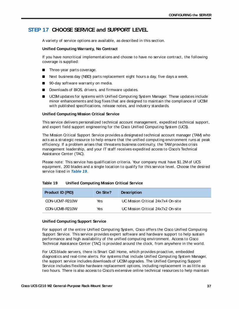
STEP 17 CHOOSE SERVICE and SUPPORT LEVEL
A variety of service options are available, as described in this section.
Unified Computing Warranty, No Contract
If you have noncritical implementations and choose to have no service contract, the following coverage is supplied:
■ Three-year parts coverage.
■ Next business day (NBD) parts replacement eight hours a day, five days a week.
■ 90-day software warranty on media.
■ Downloads of BIOS, drivers, and firmware updates.
■ UCSM updates for systems with Unified Computing System Manager. These updates include minor enhancements and bug fixes that are designed to maintain the compliance of UCSM with published specifications, release notes, and industry standards.
Unified Computing Mission Critical Service
This service delivers personalized technical account management, expedited technical support, and expert field support engineering for the Cisco Unified Computing System (UCS).
The Mission Critical Support Service provides a designated technical account manager (TAM) who acts as a strategic resource to help ensure that the unified computing environment runs at peak efficiency. If a problem arises that threatens business continuity, the TAM provides crisis management leadership, and your IT staff receives expedited access to Cisco's Technical Assistance Center (TAC).
Please note: This service has qualification criteria. Your company must have $1.2M of UCS equipment, 200 blades and a single location to qualify for this service level. Choose the desired service listed in Table 19.
Unified Computing Support Service
For support of the entire Unified Computing System, Cisco offers the Cisco Unified Computing Support Service. This service provides expert software and hardware support to help sustain performance and high availability of the unified computing environment. Access to Cisco Technical Assistance Center (TAC) is provided around the clock, from anywhere in the world.
For UCS blade servers, there is Smart Call Home, which provides proactive, embedded diagnostics and real-time alerts. For systems that include Unified Computing System Manager, the support service includes downloads of UCSM upgrades. The Unified Computing Support Service includes flexible hardware replacement options, including replacement in as little as two hours. There is also access to Cisco's extensive online technical resources to help maintain
Table 19 Unified Computing Mission Critical Service
Product ID (PID) On Site? Description
CON-UCM7-R210W Yes UC Mission Critical 24x7x4 On-site
CON-UCM8-R210W Yes UC Mission Critical 24x7x2 On-site
Cisco UCS C210 M2 General-Purpose Rack-Mount Server 37
CONFIGURING the SERVER
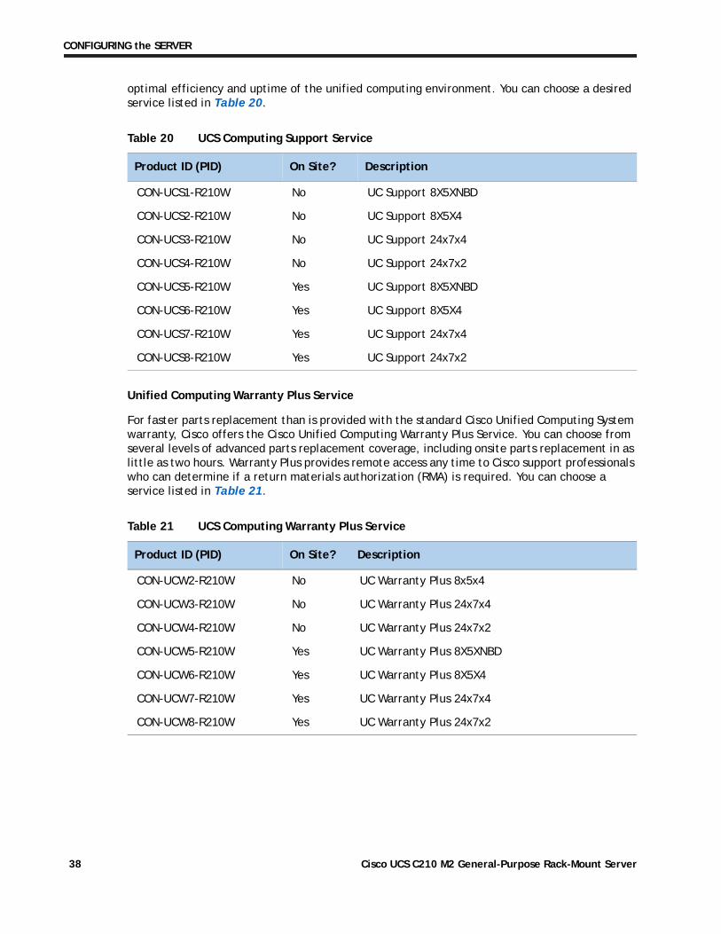
optimal efficiency and uptime of the unified computing environment. You can choose a desired service listed in Table 20.
Unified Computing Warranty Plus Service
For faster parts replacement than is provided with the standard Cisco Unified Computing System warranty, Cisco offers the Cisco Unified Computing Warranty Plus Service. You can choose from several levels of advanced parts replacement coverage, including onsite parts replacement in as little as two hours. Warranty Plus provides remote access any time to Cisco support professionals who can determine if a return materials authorization (RMA) is required. You can choose a service listed in Table 21.
Table 20 UCS Computing Support Service
Product ID (PID) On Site? Description
CON-UCS1-R210W No UC Support 8X5XNBD
CON-UCS2-R210W No UC Support 8X5X4
CON-UCS3-R210W No UC Support 24x7x4
CON-UCS4-R210W No UC Support 24x7x2
CON-UCS5-R210W Yes UC Support 8X5XNBD
CON-UCS6-R210W Yes UC Support 8X5X4
CON-UCS7-R210W Yes UC Support 24x7x4
CON-UCS8-R210W Yes UC Support 24x7x2
Table 21 UCS Computing Warranty Plus Service
Product ID (PID) On Site? Description
CON-UCW2-R210W No UC Warranty Plus 8x5x4
CON-UCW3-R210W No UC Warranty Plus 24x7x4
CON-UCW4-R210W No UC Warranty Plus 24x7x2
CON-UCW5-R210W Yes UC Warranty Plus 8X5XNBD
CON-UCW6-R210W Yes UC Warranty Plus 8X5X4
CON-UCW7-R210W Yes UC Warranty Plus 24x7x4
CON-UCW8-R210W Yes UC Warranty Plus 24x7x2
Cisco UCS C210 M2 General-Purpose Rack-Mount Server38
CONFIGURING the SERVER
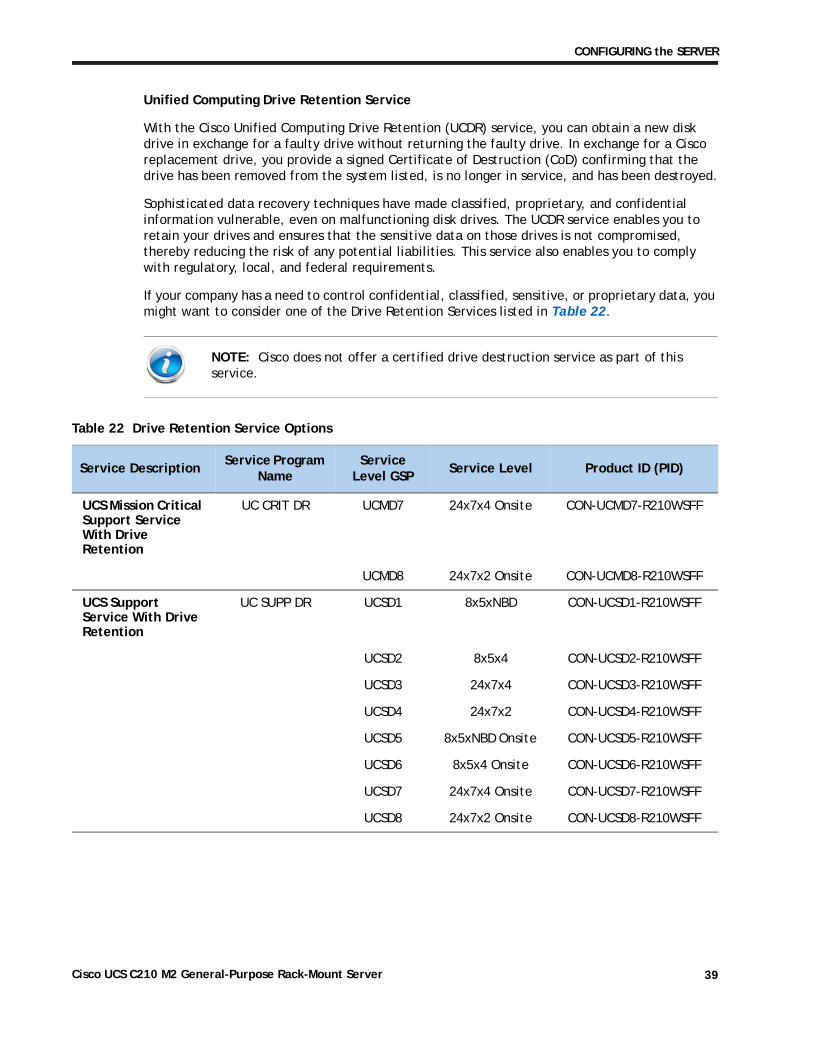
Unified Computing Drive Retention Service
With the Cisco Unified Computing Drive Retention (UCDR) service, you can obtain a new disk drive in exchange for a faulty drive without returning the faulty drive. In exchange for a Cisco replacement drive, you provide a signed Certificate of Destruction (CoD) confirming that the drive has been removed from the system listed, is no longer in service, and has been destroyed.
Sophisticated data recovery techniques have made classified, proprietary, and confidential information vulnerable, even on malfunctioning disk drives. The UCDR service enables you to retain your drives and ensures that the sensitive data on those drives is not compromised, thereby reducing the risk of any potential liabilities. This service also enables you to comply with regulatory, local, and federal requirements.
If your company has a need to control confidential, classified, sensitive, or proprietary data, you might want to consider one of the Drive Retention Services listed in Table 22.
NOTE: Cisco does not offer a certified drive destruction service as part of this service.
Table 22 Drive Retention Service Options
Service DescriptionService Program
NameService
Level GSPService Level Product ID (PID)
UCS Mission Critical Support Service With Drive Retention
UC CRIT DR UCMD7 24x7x4 Onsite CON-UCMD7-R210WSFF
UCMD8 24x7x2 Onsite CON-UCMD8-R210WSFF
UCS Support Service With Drive Retention
UC SUPP DR UCSD1 8x5xNBD CON-UCSD1-R210WSFF
UCSD2 8x5x4 CON-UCSD2-R210WSFF
UCSD3 24x7x4 CON-UCSD3-R210WSFF
UCSD4 24x7x2 CON-UCSD4-R210WSFF
UCSD5 8x5xNBD Onsite CON-UCSD5-R210WSFF
UCSD6 8x5x4 Onsite CON-UCSD6-R210WSFF
UCSD7 24x7x4 Onsite CON-UCSD7-R210WSFF
UCSD8 24x7x2 Onsite CON-UCSD8-R210WSFF
Cisco UCS C210 M2 General-Purpose Rack-Mount Server 39
CONFIGURING the SERVER
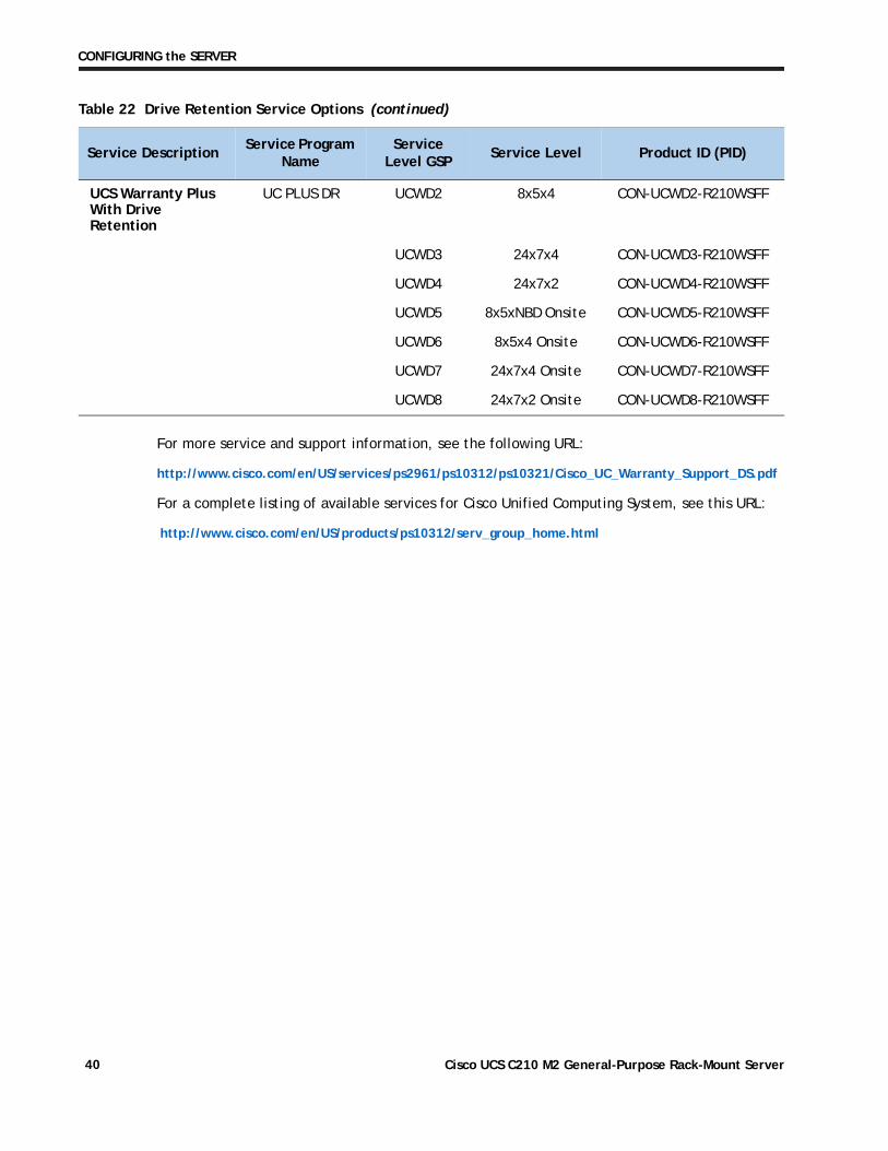
For more service and support information, see the following URL:
http://www.cisco.com/en/US/services/ps2961/ps10312/ps10321/Cisco_UC_Warranty_Support_DS.pdf
For a complete listing of available services for Cisco Unified Computing System, see this URL:
http://www.cisco.com/en/US/products/ps10312/serv_group_home.html
UCS Warranty Plus With Drive Retention
UC PLUS DR UCWD2 8x5x4 CON-UCWD2-R210WSFF
UCWD3 24x7x4 CON-UCWD3-R210WSFF
UCWD4 24x7x2 CON-UCWD4-R210WSFF
UCWD5 8x5xNBD Onsite CON-UCWD5-R210WSFF
UCWD6 8x5x4 Onsite CON-UCWD6-R210WSFF
UCWD7 24x7x4 Onsite CON-UCWD7-R210WSFF
UCWD8 24x7x2 Onsite CON-UCWD8-R210WSFF
Table 22 Drive Retention Service Options (continued)
Service DescriptionService Program
NameService
Level GSPService Level Product ID (PID)
Cisco UCS C210 M2 General-Purpose Rack-Mount Server40
OPTIONAL STEP - ORDER RACK(s)
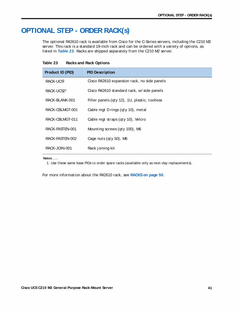
OPTIONAL STEP - ORDER RACK(s)The optional R42610 rack is available from Cisco for the C-Series servers, including the C210 M2 server. This rack is a standard 19-inch rack and can be ordered with a variety of options, as listed in Table 23. Racks are shipped separately from the C210 M2 server.
For more information about the R42610 rack, see RACKS on page 50.
Table 23 Racks and Rack Options
Product ID (PID) PID Description
RACK-UCS1
Notes . . .
1. Use these same base PIDs to order spare racks (available only as next-day replacements).
Cisco R42610 expansion rack, no side panels
RACK-UCS21 Cisco R42610 standard rack, w/side panels
RACK-BLANK-001 Filler panels (qty 12), 1U, plastic, toolless
RACK-CBLMGT-001 Cable mgt D rings (qty 10), metal
RACK-CBLMGT-011 Cable mgt straps (qty 10), Velcro
RACK-FASTEN-001 Mounting screws (qty 100), M6
RACK-FASTEN-002 Cage nuts (qty 50), M6
RACK-JOIN-001 Rack joining kit
Cisco UCS C210 M2 General-Purpose Rack-Mount Server 41
OPTIONAL STEP - ORDER PDU
OPTIONAL STEP - ORDER PDUAn optional power distribution unit (PDU) is available from Cisco for the C-Series rack servers, including theC210 M2 server. This PDU is available in a zero rack unit (RU) style (see Table 23).
For more information about the PDU, see PDUs on page 52.
Table 24 PDU Options
Product ID (PID) PID Description
RP208-30-2P-U-2 Zero RU PDU
Cisco UCS C210 M2 General-Purpose Rack-Mount Server42
SUPPLEMENTAL MATERIAL
SUPPLEMENTAL MATERIAL
CHASSIS
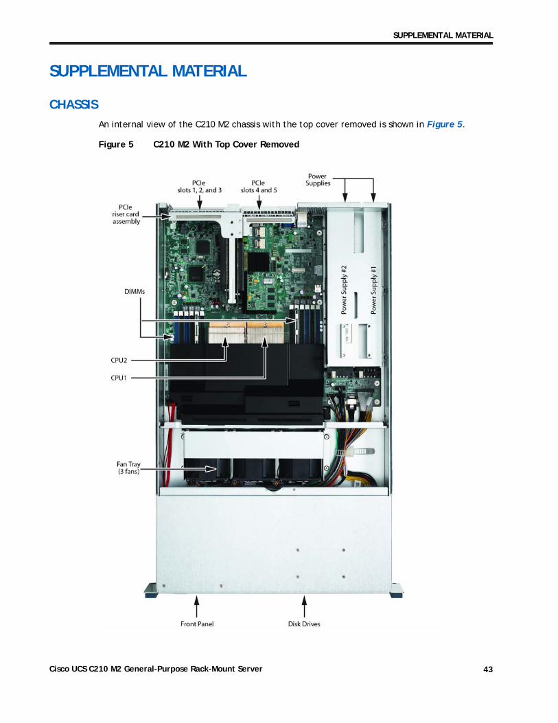
An internal view of the C210 M2 chassis with the top cover removed is shown in Figure 5.
Figure 5 C210 M2 With Top Cover Removed
Cisco UCS C210 M2 General-Purpose Rack-Mount Server 43
SUPPLEMENTAL MATERIAL
CPUs and DIMMs
Physical Layout
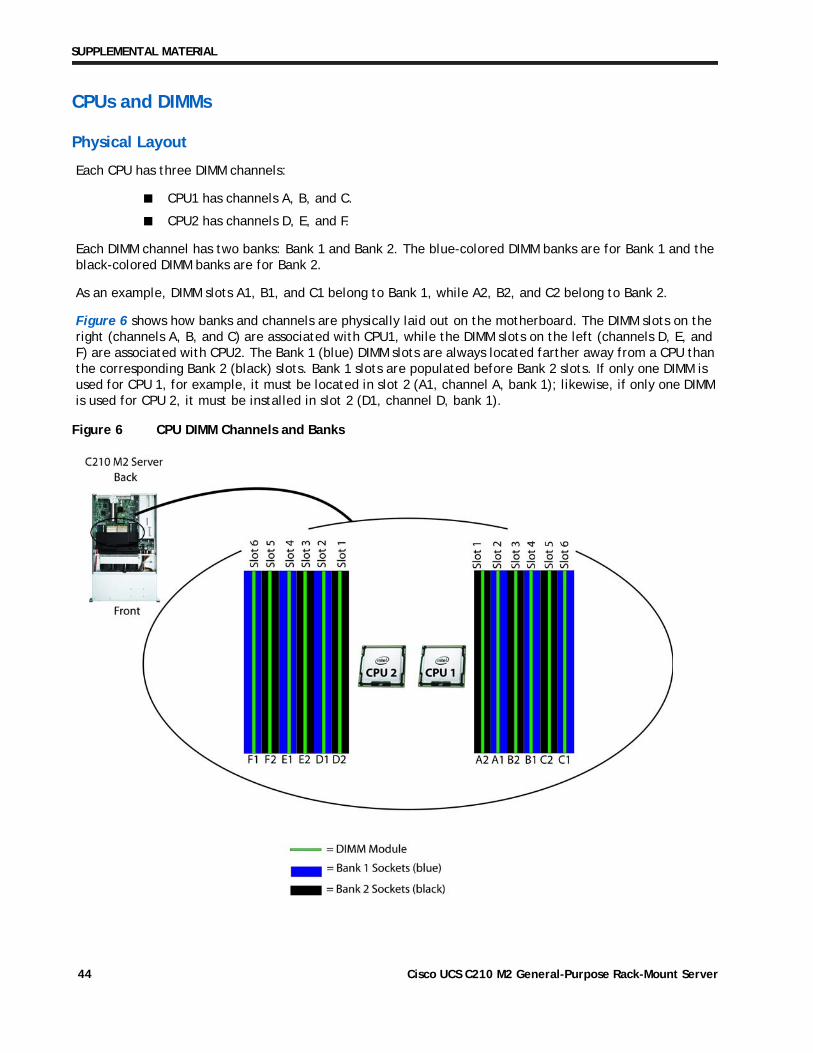
Each CPU has three DIMM channels:
■ CPU1 has channels A, B, and C.
■ CPU2 has channels D, E, and F.
Each DIMM channel has two banks: Bank 1 and Bank 2. The blue-colored DIMM banks are for Bank 1 and the black-colored DIMM banks are for Bank 2.
As an example, DIMM slots A1, B1, and C1 belong to Bank 1, while A2, B2, and C2 belong to Bank 2.
Figure 6 shows how banks and channels are physically laid out on the motherboard. The DIMM slots on the right (channels A, B, and C) are associated with CPU1, while the DIMM slots on the left (channels D, E, and F) are associated with CPU2. The Bank 1 (blue) DIMM slots are always located farther away from a CPU than the corresponding Bank 2 (black) slots. Bank 1 slots are populated before Bank 2 slots. If only one DIMM is used for CPU 1, for example, it must be located in slot 2 (A1, channel A, bank 1); likewise, if only one DIMM is used for CPU 2, it must be installed in slot 2 (D1, channel D, bank 1).
Figure 6 CPU DIMM Channels and Banks
Cisco UCS C210 M2 General-Purpose Rack-Mount Server44
SUPPLEMENTAL MATERIAL
Memory Population Rules
When considering the memory configuration of your server, you should consider the following items:
■ DIMMs within the server should all be the same type and speed. If you mix different DIMM types or DIMMs with different clock rates in the same server, such configurations are supported; however, these configurations may cause the system to operate at less than optimum levels. See Table 25 on page 46 for recommended DIMM combinations.
■ DIMMs can be used either in a one DIMM per Channel (1DPC) configuration or in a two DIMMs per Channel (2DPC) configuration.
■ There are blue and black DIMM slots. Populate blue slots in a bank first.
■ Low-voltage (1.35 V) DIMM and standard-voltage DIMM (1.5 V) can be mixed in the same server. Note that this causes the system BIOS to default to standard-voltage operation (Performance Mode). See Low-Voltage DIMM Considerations.
Low-Voltage DIMM Considerations
The C210 M2 server can be ordered with low-voltage (1.35 V) DIMMs or standard-voltage (1.5 V) DIMMs. Note the following considerations:
■ Low-voltage DIMMs within the server must have the identical manufacturer, type, speed, and size.
■ Low-voltage DIMMs and standard-voltage DIMMs can be mixed in the same server. Note that this causes the system BIOS to default to standard-voltage operation (Performance Mode). That is, the server cannot operate in Power Saving Mode unless all DIMMs are low-voltage DIMMs.
■ CPUs that have a maximum memory frequency less than 1333 MHz support low-voltage DIMMs operating in Power Saving Mode only, and do not support Performance Mode.
Cisco UCS C210 M2 General-Purpose Rack-Mount Server 45
SUPPLEMENTAL MATERIAL
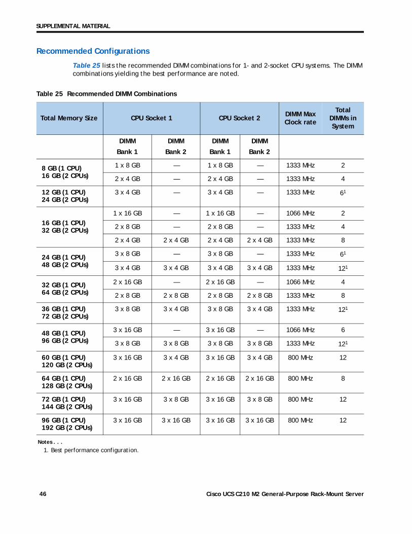
Recommended Configurations
Table 25 lists the recommended DIMM combinations for 1- and 2-socket CPU systems. The DIMM combinations yielding the best performance are noted.
Table 25 Recommended DIMM Combinations
Total Memory Size CPU Socket 1 CPU Socket 2DIMM Max Clock rate
Total DIMMs in System
DIMM
Bank 1
DIMM
Bank 2
DIMM
Bank 1
DIMM
Bank 2
8 GB (1 CPU) 16 GB (2 CPUs)
1 x 8 GB — 1 x 8 GB — 1333 MHz 2
2 x 4 GB — 2 x 4 GB — 1333 MHz 4
12 GB (1 CPU) 24 GB (2 CPUs)
3 x 4 GB — 3 x 4 GB — 1333 MHz 61
Notes . . .
1. Best performance configuration.
16 GB (1 CPU) 32 GB (2 CPUs)
1 x 16 GB — 1 x 16 GB — 1066 MHz 2
2 x 8 GB — 2 x 8 GB — 1333 MHz 4
2 x 4 GB 2 x 4 GB 2 x 4 GB 2 x 4 GB 1333 MHz 8
24 GB (1 CPU) 48 GB (2 CPUs)
3 x 8 GB — 3 x 8 GB — 1333 MHz 61
3 x 4 GB 3 x 4 GB 3 x 4 GB 3 x 4 GB 1333 MHz 121
32 GB (1 CPU) 64 GB (2 CPUs)
2 x 16 GB — 2 x 16 GB — 1066 MHz 4
2 x 8 GB 2 x 8 GB 2 x 8 GB 2 x 8 GB 1333 MHz 8
36 GB (1 CPU) 72 GB (2 CPUs)
3 x 8 GB 3 x 4 GB 3 x 8 GB 3 x 4 GB 1333 MHz 121
48 GB (1 CPU) 96 GB (2 CPUs)
3 x 16 GB — 3 x 16 GB — 1066 MHz 6
3 x 8 GB 3 x 8 GB 3 x 8 GB 3 x 8 GB 1333 MHz 121
60 GB (1 CPU) 120 GB (2 CPUs)
3 x 16 GB 3 x 4 GB 3 x 16 GB 3 x 4 GB 800 MHz 12
64 GB (1 CPU) 128 GB (2 CPUs)
2 x 16 GB 2 x 16 GB 2 x 16 GB 2 x 16 GB 800 MHz 8
72 GB (1 CPU) 144 GB (2 CPUs)
3 x 16 GB 3 x 8 GB 3 x 16 GB 3 x 8 GB 800 MHz 12
96 GB (1 CPU) 192 GB (2 CPUs)
3 x 16 GB 3 x 16 GB 3 x 16 GB 3 x 16 GB 800 MHz 12
Cisco UCS C210 M2 General-Purpose Rack-Mount Server46
SUPPLEMENTAL MATERIAL
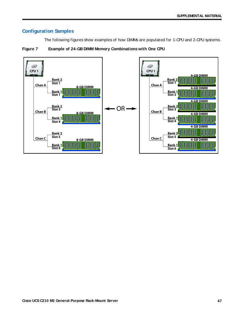
Configuration Samples
The following figures show examples of how DIMMs are populated for 1-CPU and 2-CPU systems.
Figure 7 Example of 24-GB DIMM Memory Combinations with One CPU
Cisco UCS C210 M2 General-Purpose Rack-Mount Server 47
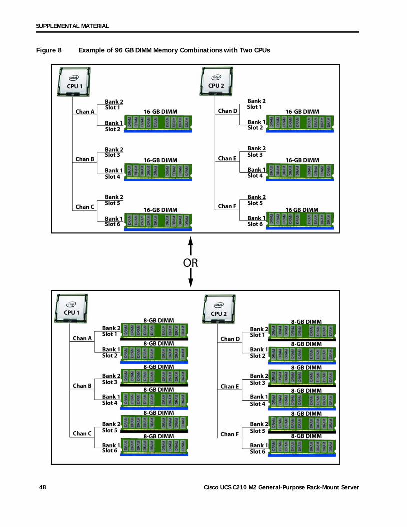
SUPPLEMENTAL MATERIAL
Figure 8 Example of 96 GB DIMM Memory Combinations with Two CPUs
Cisco UCS C210 M2 General-Purpose Rack-Mount Server48
SUPPLEMENTAL MATERIAL
SAS EXTENDER and SAS EXPANDER
This server has two factory-configurable options for the hard drive backplane connection:
■ Standard SAS extender, or
■ Optional SAS expander
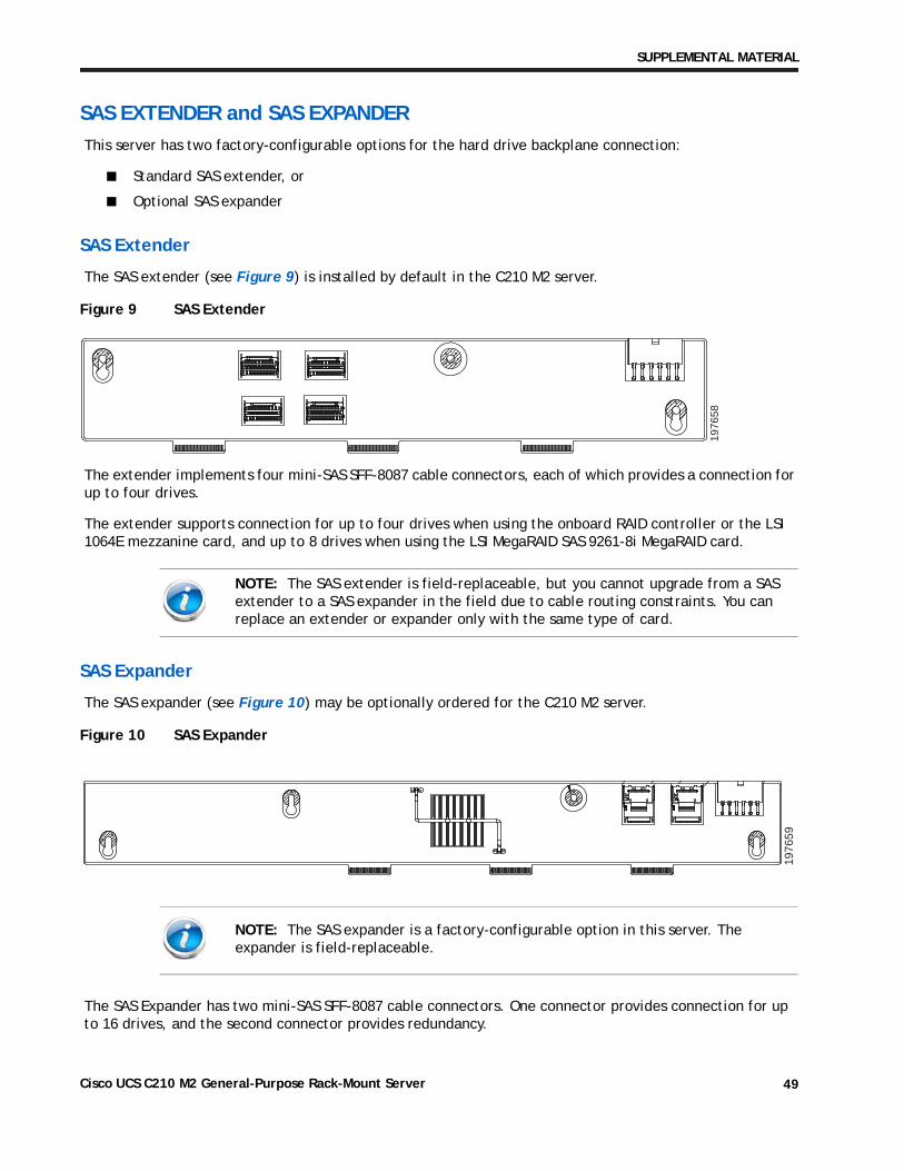
SAS Extender
The SAS extender (see Figure 9) is installed by default in the C210 M2 server.
Figure 9 SAS Extender
The extender implements four mini-SAS SFF-8087 cable connectors, each of which provides a connection for up to four drives.
The extender supports connection for up to four drives when using the onboard RAID controller or the LSI 1064E mezzanine card, and up to 8 drives when using the LSI MegaRAID SAS 9261-8i MegaRAID card.
SAS Expander
The SAS expander (see Figure 10) may be optionally ordered for the C210 M2 server.
Figure 10 SAS Expander
The SAS Expander has two mini-SAS SFF-8087 cable connectors. One connector provides connection for up to 16 drives, and the second connector provides redundancy.
NOTE: The SAS extender is field-replaceable, but you cannot upgrade from a SAS extender to a SAS expander in the field due to cable routing constraints. You can replace an extender or expander only with the same type of card.
NOTE: The SAS expander is a factory-configurable option in this server. The expander is field-replaceable.
1976
58
1976
59
Cisco UCS C210 M2 General-Purpose Rack-Mount Server 49
SUPPLEMENTAL MATERIAL
RACKS
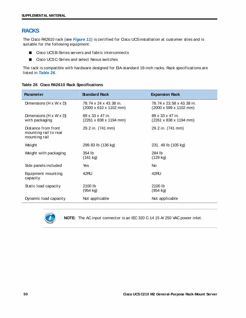
The Cisco R42610 rack (see Figure 11) is certified for Cisco UCS installation at customer sites and is suitable for the following equipment:
■ Cisco UCS B-Series servers and fabric interconnects
■ Cisco UCS C-Series and select Nexus switches
The rack is compatible with hardware designed for EIA-standard 19-inch racks. Rack specifications are listed in Table 26.
Table 26 Cisco R42610 Rack Specifications
Parameter Standard Rack Expansion Rack
Dimensions (H x W x D) 78.74 x 24 x 43.38 in. (2000 x 610 x 1102 mm)
78.74 x 23.58 x 43.38 in. (2000 x 599 x 1102 mm)
Dimensions (H x W x D) with packaging
89 x 33 x 47 in. (2261 x 838 x 1194 mm)
89 x 33 x 47 in. (2261 x 838 x 1194 mm)
Distance from front mounting rail to rear mounting rail
29.2 in. (741 mm) 29.2 in. (741 mm)
Weight 299.83 lb (136 kg) 231. 49 lb (105 kg)
Weight with packaging 354 lb (161 kg)
284 lb (129 kg)
Side panels included Yes No
Equipment mounting capacity
42RU 42RU
Static load capacity 2100 lb (954 kg)
2100 lb (954 kg)
Dynamic load capacity Not applicable Not applicable
NOTE: The AC input connector is an IEC 320 C-14 15 A/250 VAC power inlet.
Cisco UCS C210 M2 General-Purpose Rack-Mount Server50
SUPPLEMENTAL MATERIAL
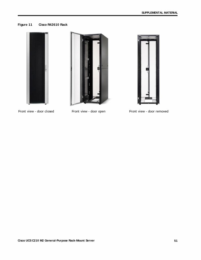
Figure 11 Cisco R42610 Rack
Front view - door closed Front view - door open Front view - door removed
Cisco UCS C210 M2 General-Purpose Rack-Mount Server 51
SUPPLEMENTAL MATERIAL
PDUs
Cisco RP Series Power Distribution Units (PDUs) offer power distribution with branch circuit protection.
Cisco RP Series PDU models distribute power to up to 24 outlets. The architecture organizes power distribution, simplifies cable management, and enables you to move, add, and change rack equipment without an electrician.
With a Cisco RP Series PDU in the rack, you can replace up to two dozen input power cords with just one. The fixed input cord connects to the power source from overhead or under-floor distribution. Your IT equipment is then powered by PDU outlets in the rack using short, easy-to-manage power cords.
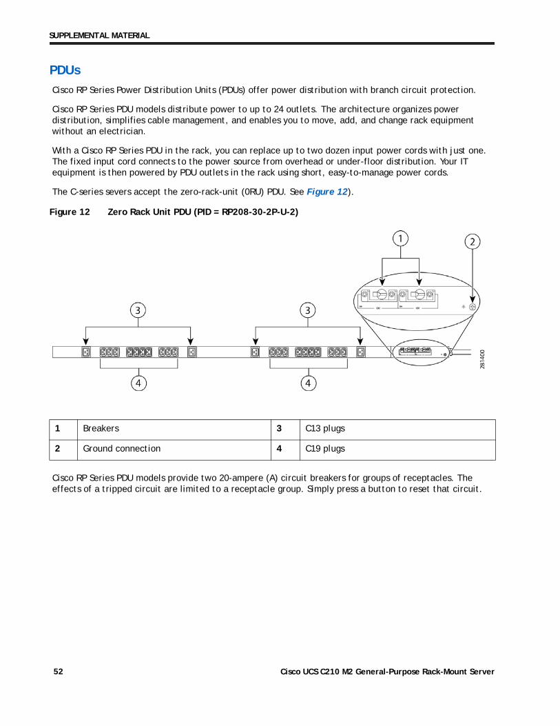
The C-series severs accept the zero-rack-unit (0RU) PDU. See Figure 12).
Figure 12 Zero Rack Unit PDU (PID = RP208-30-2P-U-2)
Cisco RP Series PDU models provide two 20-ampere (A) circuit breakers for groups of receptacles. The effects of a tripped circuit are limited to a receptacle group. Simply press a button to reset that circuit.
1 Breakers 3 C13 plugs
2 Ground connection 4 C19 plugs
Cisco UCS C210 M2 General-Purpose Rack-Mount Server52
SUPPLEMENTAL MATERIAL
POWER SUPPLIES
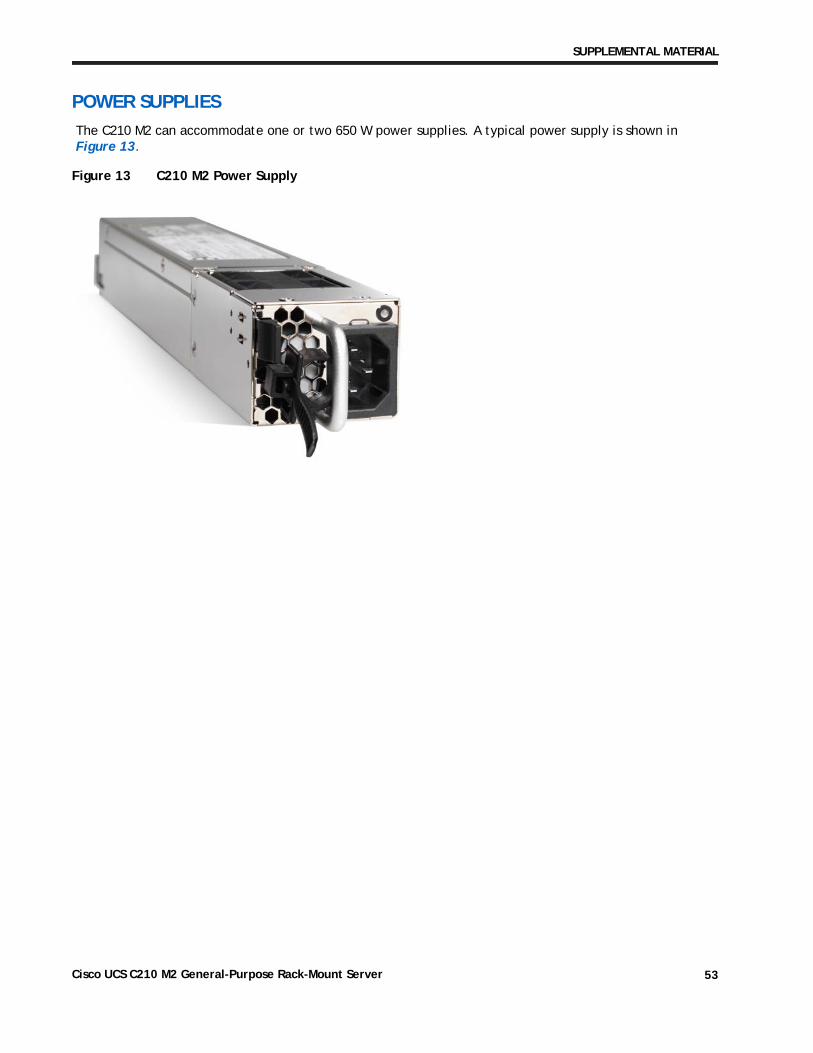
The C210 M2 can accommodate one or two 650 W power supplies. A typical power supply is shown in Figure 13.
Figure 13 C210 M2 Power Supply
Cisco UCS C210 M2 General-Purpose Rack-Mount Server 53
SUPPLEMENTAL MATERIAL
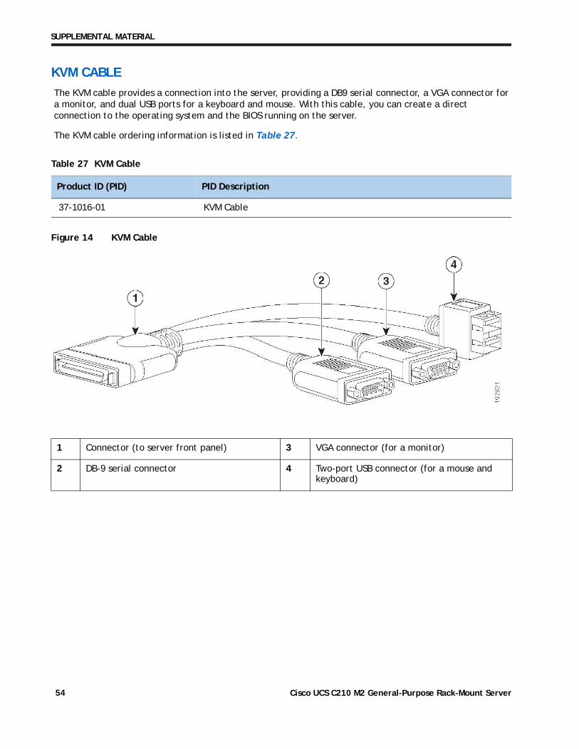
KVM CABLE
The KVM cable provides a connection into the server, providing a DB9 serial connector, a VGA connector for a monitor, and dual USB ports for a keyboard and mouse. With this cable, you can create a direct connection to the operating system and the BIOS running on the server.
The KVM cable ordering information is listed in Table 27.
Figure 14 KVM Cable
Table 27 KVM Cable
Product ID (PID) PID Description
37-1016-01 KVM Cable
1 Connector (to server front panel) 3 VGA connector (for a monitor)
2 DB-9 serial connector 4 Two-port USB connector (for a mouse and keyboard)
Cisco UCS C210 M2 General-Purpose Rack-Mount Server54
SUPPLEMENTAL MATERIAL
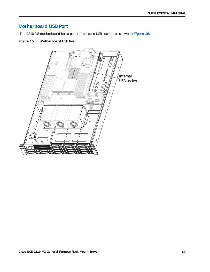
Motherboard USB Port
The C210 M2 motherboard has a general-purpose USB socket, as shown in Figure 15.
Figure 15 Motherboard USB Port
Cisco UCS C210 M2 General-Purpose Rack-Mount Server 55
TECHNICAL SPECIFICATIONS
TECHNICAL SPECIFICATIONS
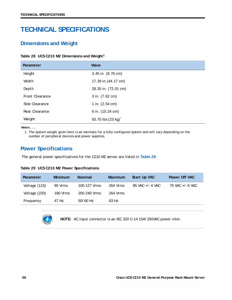
Dimensions and Weight
Power Specifications
The general power specifications for the C210 M2 server are listed in Table 29.
Table 28 UCS C210 M2 Dimensions and Weight1
Notes . . .
1. The system weight given here is an estimate for a fully configured system and will vary depending on the number of peripheral devices and power supplies.
Parameter Value
Height 3.45 in. (8.76 cm)
Width 17.39 in.(44.17 cm)
Depth 28.35 in. (72.01 cm)
Front Clearance 3 in. (7.62 cm)
Side Clearance 1 in. (2.54 cm)
Rear Clearance 6 in. (15.24 cm)
Weight 50.70 lbs (23 kg)*
Table 29 UCS C210 M2 Power Specifications
Parameter Minimum Nominal Maximum Start Up VAC Power Off VAC
Voltage (115) 90 Vrms 100-127 Vrms 264 Vrms 85 VAC +/-4 VAC 75 VAC +/-5 VAC
Voltage (220) 180 Vrms 200-240 Vrms 264 Vrms
Frequency 47 Hz 50/60 Hz 63 Hz
NOTE: AC input connector is an IEC 320 C-14 15A/250VAC power inlet.
Cisco UCS C210 M2 General-Purpose Rack-Mount Server56
TECHNICAL SPECIFICATIONS
For configuration-specific power specifications, use the Cisco UCS Power Calculator at this URL: http://www.cisco.com/assets/cdc_content_elements/flash/dataCenter/cisco_ucs_power_calculator/.
As an example, using the calculator, we can determine the approximate power for the following C210 M2 server configuration:
■ Voltage = 115 VAC
■ Power Supplies = 2
■ Processors = 2 CPUs (Intel Xeon 2.93 GHz X5670)
■ Memory DIMMs = 6 x 16 GB
■ Disk Drives = 16 x 1 TB
■ PCIe Cards = 4
■ PCIe RAID Card = 1
The resulting power calculations are:
■ Idle Power = 263 W
■ 50% Load Power = 419 W
■ Max Power = 574 W
Cisco UCS C210 M2 General-Purpose Rack-Mount Server 57
TECHNICAL SPECIFICATIONS
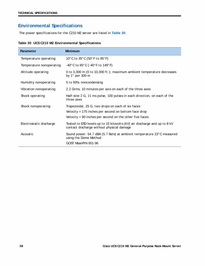
Environmental Specifications
The power specifications for the C210 M2 server are listed in Table 30.
Table 30 UCS C210 M2 Environmental Specifications
Parameter Minimum
Temperature operating 10°C to 35°C (50°F to 95°F)
Temperature nonoperating -40°C to 65°C (-40°F to 149°F)
Altitude operating 0 to 3,000 m (0 to 10,000 ft.); maximum ambient temperature decreases by 1° per 300 m
Humidity nonoperating 5 to 93%, noncondensing
Vibration nonoperating 2.2 Grms, 10 minutes per axis on each of the three axes
Shock operating Half-sine 2 G, 11 ms pulse, 100 pulses in each direction, on each of the three axes
Shock nonoperating Trapezoidal, 25 G, two drops on each of six faces
Velocity = 175 inches per second on bottom face drop
Velocity = 90 inches per second on the other five faces
Electrostatic discharge Tested to ESD levels up to 15 kilovolts (kV) air discharge and up to 8 kV contact discharge without physical damage
Acoustic Sound power: 54.7 dBA (5.7 Bels) at ambient temperature 23°C measured using the Dome Method
GOST MsanPiN 001-96
Cisco UCS C210 M2 General-Purpose Rack-Mount Server58
TECHNICAL SPECIFICATIONS
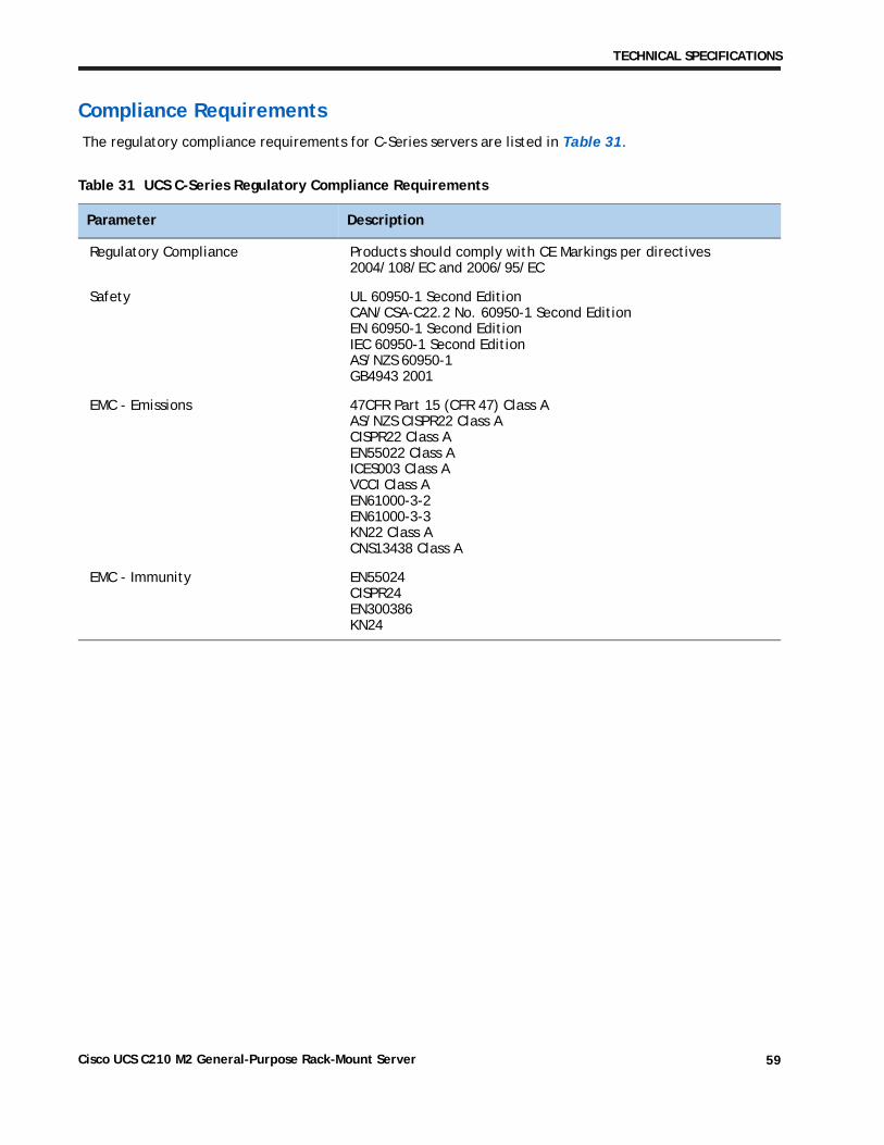
Compliance Requirements
The regulatory compliance requirements for C-Series servers are listed in Table 31.
Table 31 UCS C-Series Regulatory Compliance Requirements
Parameter Description
Regulatory Compliance Products should comply with CE Markings per directives 2004/108/EC and 2006/95/EC
Safety UL 60950-1 Second Edition CAN/CSA-C22.2 No. 60950-1 Second Edition EN 60950-1 Second Edition IEC 60950-1 Second Edition AS/NZS 60950-1 GB4943 2001
EMC - Emissions 47CFR Part 15 (CFR 47) Class A AS/NZS CISPR22 Class A CISPR22 Class A EN55022 Class A ICES003 Class A VCCI Class A EN61000-3-2 EN61000-3-3 KN22 Class A CNS13438 Class A
EMC - Immunity EN55024 CISPR24 EN300386 KN24
Cisco UCS C210 M2 General-Purpose Rack-Mount Server 59
TECHNICAL SPECIFICATIONS
Cisco UCS C210 M2 General-Purpose Rack-Mount Server60