Embed Size (px)
Citation preview

D14850.02 MX Series Administrator Guide (TC5.0) | 2011 NOVEMBER | © 2011 Cisco Systems, Inc. All rights reserved. www.cisco.com
1
Cisco TelePresence MX Series
AdministrAtor guide
• MX300• MX200
Software version TC5.0 NOVEMBER 2011
D14850.02 MX Series Administrator Guide (TC5.0) | 2011 NOVEMBER | © 2011 Cisco Systems, Inc. All rights reserved. www.cisco.com
2
Cisco TelePresence MX SeriesAdministrAtor guide
Tableofcontents
Introduction........................................................................3Intellectual property rights ...................................................4User documentation ............................................................5Software ..............................................................................5Cisco contacts ....................................................................5What’s new in this version ...................................................6Cisco TelePresence MX Series at a glance .........................8
Thewebinterface.............................................................10Starting the web interface .................................................11Changing the system/codec password .............................12The interactive menu .........................................................13The system information page ............................................14Log files .............................................................................15XML files ...........................................................................16Advanced configuration .....................................................17Selecting a wallpaper ........................................................18Sign in banner ...................................................................19Placing calls ......................................................................20Controlling and monitoring a call .......................................21Local layout control ...........................................................22Taking snapshots ...............................................................23Upgrading the system software.........................................24Certificate management ....................................................25The audit certificate list .....................................................26User administration ...........................................................27Restarting the system ........................................................29
Theadvancedsettings.....................................................30Overview of the advanced settings ...................................31The Audio settings ............................................................34The Cameras settings .......................................................35The Conference settings ...................................................36The H323 settings .............................................................39The Network settings ........................................................41The NetworkServices settings ...........................................45The Phonebook settings ....................................................48The Provisioning settings...................................................49The RTP settings ...............................................................50The Security settings .........................................................51The SerialPort settings ......................................................52The SIP settings ................................................................52The Standby settings .........................................................54The SystemUnit settings....................................................55The Time settings ..............................................................56The UserInterface settings ................................................57The Video settings ............................................................57The Experimental settings .................................................62
Appendices......................................................................65Setting the system password ............................................66Setting the Administrator settings menu password ..........66Setting a root password ....................................................66Cisco VCS provisioning .....................................................67Optimal definition profiles ..................................................68ClearPath — Packet loss resilience ....................................69Technical specification for MX300/MX200 ........................70User documentation on the Cisco web site .......................73
Thank you for choosing Cisco!
Your Cisco product has been designed to give you many years of safe, reliable operation.
This part of the product documentation is aimed at administrators working with the setup of the MX200.
Our main objective with this Administrator guide is to address your goals and needs. Please let us know how well we succeeded!
May we recommend that you visit the Cisco web site regularly for updated versions of this guide.
The user documentation can be found on http://www.cisco.com/go/telepresence/docs.
HowtousethisguideThe top menu bar and the entries in the Table of contents are all hyperlinks. You can click on them to go to the topic.

D14850.02 MX Series Administrator Guide (TC5.0) | 2011 NOVEMBER | © 2011 Cisco Systems, Inc. All rights reserved. www.cisco.com
3
Cisco TelePresence MX SeriesAdministrAtor guide
Chapter 1
Introduction
D14850.02 MX Series Administrator Guide (TC5.0) | 2011 NOVEMBER | © 2011 Cisco Systems, Inc. All rights reserved. www.cisco.com
4
Cisco TelePresence MX SeriesAdministrAtor guide
IntellectualpropertyrightsTHE SPECIFICATIONS AND INFORMATION REGARDING THE PRODUCTS IN THIS MANUAL ARE SUBJECT TO CHANGE WITHOUT NOTICE. ALL STATEMENTS, INFORMATION, AND RECOMMENDATIONS IN THIS MANUAL ARE BELIEVED TO BE ACCURATE BUT ARE PRESENTED WITHOUT WARRANTY OF ANY KIND, EXPRESS OR IMPLIED. USERS MUST TAKE FULL RESPONSIBILITY FOR THEIR APPLICATION OF ANY PRODUCTS.
THE SOFTWARE LICENSE AND LIMITED WARRANTY FOR THE ACCOMPANYING PRODUCT ARE SET FORTH IN THE INFORMATION PACKET THAT SHIPPED WITH THE PRODUCT AND ARE INCORPORATED HEREIN BY THIS REFERENCE. IF YOU ARE UNABLE TO LOCATE THE SOFTWARE LICENSE OR LIMITED WARRANTY, CONTACT YOUR CISCO REPRESENTATIVE FOR A COPY.
The Cisco implementation of TCP header compression is an adaptation of a program developed by the University of California, Berkeley (UCB) as part of UCB’s public domain version of the UNIX operating system. All rights reserved. Copyright © 1981, Regents of the University of California.
NOTWITHSTANDING ANY OTHER WARRANTY HEREIN, ALL DOCUMENT FILES AND SOFTWARE OF THESE SUPPLIERS ARE PROVIDED “AS IS” WITH ALL FAULTS. CISCO AND THE ABOVE-NAMED SUPPLIERS DISCLAIM ALL WARRANTIES, EXPRESSED OR IMPLIED, INCLUDING, WITHOUT LIMITATION, THOSE OF MERCHANTABILITY, FITNESS FOR A PARTICULAR PURPOSE AND NONINFRINGEMENT OR ARISING FROM A COURSE OF DEALING, USAGE, OR TRADE PRACTICE.
IN NO EVENT SHALL CISCO OR ITS SUPPLIERS BE LIABLE FOR ANY INDIRECT, SPECIAL, CONSEQUENTIAL, OR INCIDENTAL DAMAGES, INCLUDING, WITHOUT LIMITATION, LOST PROFITS OR LOSS OR DAMAGE TO DATA ARISING OUT OF THE USE OR INABILITY TO USE THIS MANUAL, EVEN IF CISCO OR ITS SUPPLIERS HAVE BEEN ADVISED OF THE POSSIBILITY OF SUCH DAMAGES.
Cisco and the Cisco Logo are trademarks of Cisco Systems, Inc. and/or its affiliates in the U.S. and other countries. A listing of Cisco’s trademarks can be found at www.cisco.com/go/trademarks. Third party trademarks mentioned are the property of their respective owners. The use of the word partner does not imply a partnership relationship between Cisco and any other company. (1005R)
Any Internet Protocol (IP) addresses and phone numbers used in this document are not intended to be actual addresses and phone numbers. Any examples, command display output, network topology diagrams, and other figures included in the document are shown for illustrative purposes only. Any use of actual IP addresses or phone numbers in illustrative content is unintentional and coincidental.
TANDBERG is now a part of Cisco. TANDBERG® is a registered trademark belonging to Tandberg ASA.
D14850.02 MX Series Administrator Guide (TC5.0) | 2011 NOVEMBER | © 2011 Cisco Systems, Inc. All rights reserved. www.cisco.com
5
Cisco TelePresence MX SeriesAdministrAtor guide
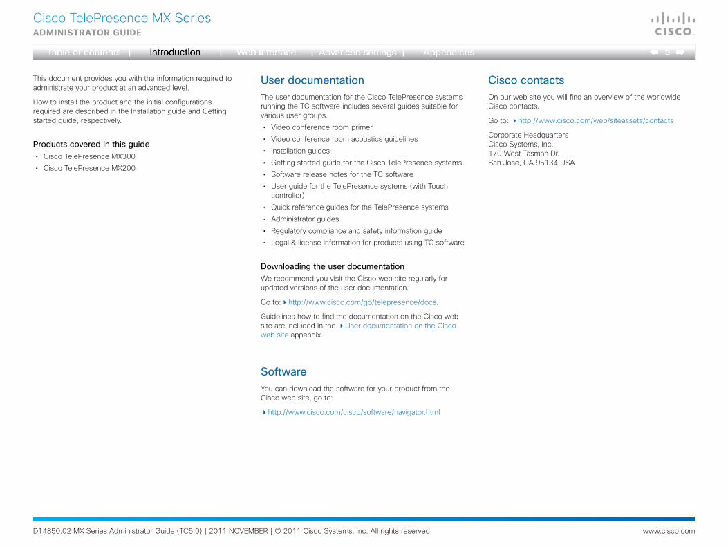
This document provides you with the information required to administrate your product at an advanced level.
How to install the product and the initial configurations required are described in the Installation guide and Getting started guide, respectively.
Productscoveredinthisguide• Cisco TelePresence MX300
• Cisco TelePresence MX200
UserdocumentationThe user documentation for the Cisco TelePresence systems running the TC software includes several guides suitable for various user groups.
• Video conference room primer
• Video conference room acoustics guidelines
• Installation guides
• Getting started guide for the Cisco TelePresence systems
• Software release notes for the TC software
• User guide for the TelePresence systems (with Touch controller)
• Quick reference guides for the TelePresence systems
• Administrator guides
• Regulatory compliance and safety information guide
• Legal & license information for products using TC software
DownloadingtheuserdocumentationWe recommend you visit the Cisco web site regularly for updated versions of the user documentation.
Go to:http://www.cisco.com/go/telepresence/docs.
Guidelines how to find the documentation on the Cisco web site are included in the User documentation on the Cisco web site appendix.
SoftwareYou can download the software for your product from the Cisco web site, go to:
http://www.cisco.com/cisco/software/navigator.html
CiscocontactsOn our web site you will find an overview of the worldwide Cisco contacts.
Go to: http://www.cisco.com/web/siteassets/contacts
Corporate HeadquartersCisco Systems, Inc.170 West Tasman Dr.San Jose, CA 95134 USA

D14850.02 MX Series Administrator Guide (TC5.0) | 2011 NOVEMBER | © 2011 Cisco Systems, Inc. All rights reserved. www.cisco.com
6
Cisco TelePresence MX SeriesAdministrAtor guide
What’snewinthisversionThis section provides an overview of the new and changed advanced settings and new features in the TC5.0 software version.
SoftwarereleasenotesFor a complete overview of the news and changes, we recommend reading the Software Release Notes (TC5).
Go to: http://www.cisco.com/en/US/products/ps11776/tsd_products_support_series_home.html
SoftwaredownloadFor software download go to: http://www.cisco.com/cisco/software/navigator.html
Newfeaturesandimprovements
Support for native Cisco UCM registrationWith TC5 the video systems are able to register to the Cisco Unified Communications Manager (UCM) version 8.6 as a native Cisco device. Supported features are:
• Basic telephony features like call, hold/resume, transfer
• Cisco UCM provisioning
• Cisco UCM phonebook
• Software upgrade
Encrypted calls are not supported.
Support for Cisco TelePresence Multipoint Switch (CTMS)In TC5 interoperability with CTMS version 1.8 is achieved. The following features are supported:
• Multipoint conferences hosted on CTMS
• Unrestricted 720p/1080p conferences (unrestricted 1080p is not available when there is a CTS system in the conference)
• H.264 GDR (Gradual Decoder Refresh)
• Legacy stream (CIF/360p) to WebEX and MXE
• Informational Black Screen Codes
Encryption is not supported. CTMS calls must be SIP only.
Support for One Button To Push (OBTP) meetingsBoth the Touch controller and the OSD (On Screen Display) menu will display scheduled OBTP meetings from CTS-MAN (version 1.8 or later) or TelePresence Management Suite (TMS, version 13.1 or later). Supported features are:
• A reminder for scheduled meetings will appear on screen. Press one button to start the meeting
• Press the Meetings button to see a list of all scheduled meetings
• WebEx indication
• Meeting extension if the meeting is booked using CTS-MAN
Web interface enhancementsNew call application with support for:
• Making calls and start/stop presentation
• Selecting source for both main source and presentation
• Volume control
• Microphone mute
• Local camera control including preset selection
• Layout control
• Diagnostics information
• Web snapshots of any local source
Cisco Touch enhancementsThe user interface has been changed:
• Call rate button. If changed from default, the new call rate is displayed on the button
• Meetings button on the main menu
• Possibility to enable/disable web snapshots.
• Local camera control, including preset selection
New languages supported:
• Finnish
• French
• German
• Japanese
• Russian
• Simplified Chinese
• Swedish
Software upgrade from TMS Agent/Cisco VCSWhen using large scale provisioning, the TMS Agent (requires TMS 13.1) now supports software upgrade. The upgrade is initiated from the TMS GUI, but the upgrade itself will be done by the TMS Agent running on a Cisco VCS.
D14850.02 MX Series Administrator Guide (TC5.0) | 2011 NOVEMBER | © 2011 Cisco Systems, Inc. All rights reserved. www.cisco.com
7
Cisco TelePresence MX SeriesAdministrAtor guide
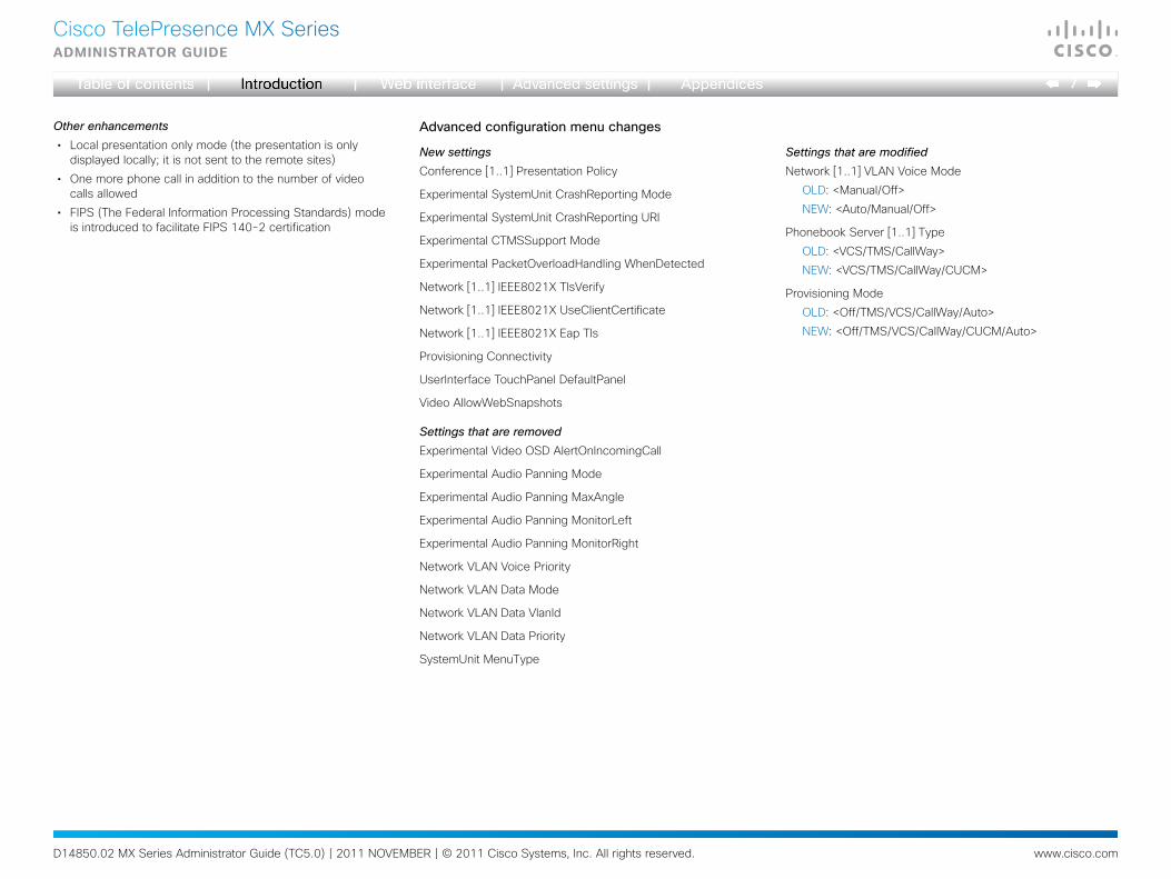
Other enhancements• Local presentation only mode (the presentation is only
displayed locally; it is not sent to the remote sites)
• One more phone call in addition to the number of video calls allowed
• FIPS (The Federal Information Processing Standards) mode is introduced to facilitate FIPS 140-2 certification
Advancedconfigurationmenuchanges
New settingsConference [1..1] Presentation Policy
Experimental SystemUnit CrashReporting Mode
Experimental SystemUnit CrashReporting URI
Experimental CTMSSupport Mode
Experimental PacketOverloadHandling WhenDetected
Network [1..1] IEEE8021X TlsVerify
Network [1..1] IEEE8021X UseClientCertificate
Network [1..1] IEEE8021X Eap Tls
Provisioning Connectivity
UserInterface TouchPanel DefaultPanel
Video AllowWebSnapshots
Settings that are removedExperimental Video OSD AlertOnIncomingCall
Experimental Audio Panning Mode
Experimental Audio Panning MaxAngle
Experimental Audio Panning MonitorLeft
Experimental Audio Panning MonitorRight
Network VLAN Voice Priority
Network VLAN Data Mode
Network VLAN Data VlanId
Network VLAN Data Priority
SystemUnit MenuType
Settings that are modifiedNetwork [1..1] VLAN Voice Mode
OLD: <Manual/Off>
NEW: <Auto/Manual/Off>
Phonebook Server [1..1] Type
OLD: <VCS/TMS/CallWay>
NEW: <VCS/TMS/CallWay/CUCM>
Provisioning Mode
OLD: <Off/TMS/VCS/CallWay/Auto>
NEW: <Off/TMS/VCS/CallWay/CUCM/Auto>
D14850.02 MX Series Administrator Guide (TC5.0) | 2011 NOVEMBER | © 2011 Cisco Systems, Inc. All rights reserved. www.cisco.com
8
Cisco TelePresence MX SeriesAdministrAtor guide
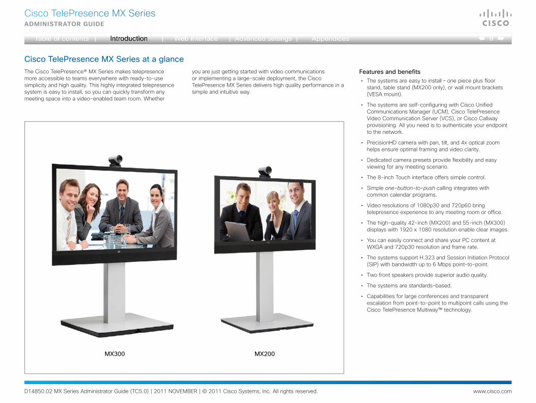
CiscoTelePresenceMXSeriesataglanceThe Cisco TelePresence® MX Series makes telepresence more accessible to teams everywhere with ready-to-use simplicity and high quality. This highly integrated telepresence system is easy to install, so you can quickly transform any meeting space into a video-enabled team room. Whether
you are just getting started with video communications or implementing a large-scale deployment, the Cisco TelePresence MX Series delivers high quality performance in a simple and intuitive way.
Featuresandbenefits• The systems are easy to install – one piece plus floor
stand, table stand (MX200 only), or wall mount brackets (VESA mount).
• The systems are self-configuring with Cisco Unified Communications Manager (UCM), Cisco TelePresence Video Communication Server (VCS), or Cisco Callway provisioning. All you need is to authenticate your endpoint to the network.
• PrecisionHD camera with pan, tilt, and 4x optical zoom helps ensure optimal framing and video clarity.
• Dedicated camera presets provide flexibility and easy viewing for any meeting scenario.
• The 8-inch Touch interface offers simple control.
• Simple one-button-to-push calling integrates with common calendar programs.
• Video resolutions of 1080p30 and 720p60 bring telepresence experience to any meeting room or office.
• The high-quality 42-inch (MX200) and 55-inch (MX300) displays with 1920 x 1080 resolution enable clear images.
• You can easily connect and share your PC content at WXGA and 720p30 resolution and frame rate.
• The systems support H.323 and Session Initiation Protocol (SIP) with bandwidth up to 6 Mbps point-to-point.
• Two front speakers provide superior audio quality.
• The systems are standards-based.
• Capabilities for large conferences and transparent escalation from point-to-point to multipoint calls using the Cisco TelePresence Multiway™ technology.
MX300 MX200

D14850.02 MX Series Administrator Guide (TC5.0) | 2011 NOVEMBER | © 2011 Cisco Systems, Inc. All rights reserved. www.cisco.com
9
Cisco TelePresence MX SeriesAdministrAtor guide
MX200: 1 external microphone (+ 1 optional) MX300: 2 external microphones
Touch controller
Precision HD camera
MX200: 42” LCD monitor MX300: 55” LCD monitor
Frontview
MX200
Internal microphone
Codec embedded in video unit
Loudspeakers
MX300mountingoptions (floor stand, wall mount)
MX200mountingoptions (floor stand, table stand, wall mount)
CiscoTelePresenceMXSeriesataglance(continued)
MX300
Rearview

D14850.02 MX Series Administrator Guide (TC5.0) | 2011 NOVEMBER | © 2011 Cisco Systems, Inc. All rights reserved. www.cisco.com
10
Cisco TelePresence MX SeriesAdministrAtor guide
Chapter 2
Thewebinterface
D14850.02 MX Series Administrator Guide (TC5.0) | 2011 NOVEMBER | © 2011 Cisco Systems, Inc. All rights reserved. www.cisco.com
11
Cisco TelePresence MX SeriesAdministrAtor guide
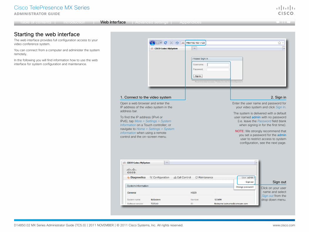
StartingthewebinterfaceThe web interface provides full configuration access to your video conference system.
You can connect from a computer and administer the system remotely.
In the following you will find information how to use the web interface for system configuration and maintenance.
1.Connecttothevideosystem
Open a web browser and enter the IP address of the video system in the address bar.
To find the IP address (IPv4 or IPv6), tap More > Settings > System Information on a Touch controller; or navigate to Home > Settings > System information when using a remote control and the on-screen menu.
2.Signin
Enter the user name and password for your video system and click Sign In.
The system is delivered with a default user named admin with no password
(i.e. leave the Password field blank when signing in for the first time).
NOTE: We strongly recommend that you set a password for the admin user to restrict access to system configuration, see the next page.
Signout
Click on your user name and select
Sign out from the drop down menu.
D14850.02 MX Series Administrator Guide (TC5.0) | 2011 NOVEMBER | © 2011 Cisco Systems, Inc. All rights reserved. www.cisco.com
12
Cisco TelePresence MX SeriesAdministrAtor guide
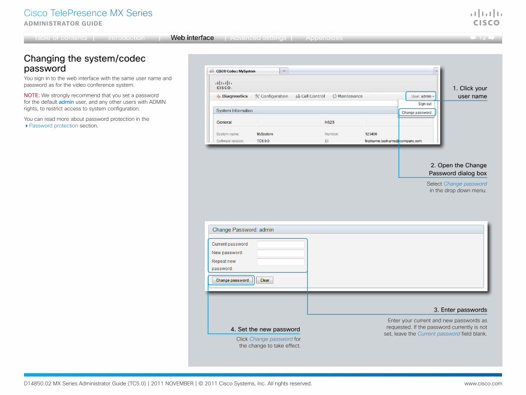
Changingthesystem/codecpasswordYou sign in to the web interface with the same user name and password as for the video conference system.
NOTE: We strongly recommend that you set a password for the default admin user, and any other users with ADMIN rights, to restrict access to system configuration.
You can read more about password protection in the Password protection section.
1.Clickyourusername
2.OpentheChangePassworddialogbox
4.Setthenewpassword
3.Enterpasswords
Enter your current and new passwords as requested. If the password currently is not
set, leave the Current password field blank.Click Change password for the change to take effect.
Select Change password in the drop down menu.
D14850.02 MX Series Administrator Guide (TC5.0) | 2011 NOVEMBER | © 2011 Cisco Systems, Inc. All rights reserved. www.cisco.com
13
Cisco TelePresence MX SeriesAdministrAtor guide
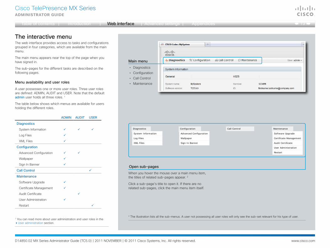
TheinteractivemenuThe web interface provides access to tasks and configurations grouped in four categories, which are available from the main menu.
The main menu appears near the top of the page when you have signed in.
The sub-pages for the different tasks are described on the following pages.
Menuavailabilityanduserroles
A user possesses one or more user roles. Three user roles are defined: ADMIN, AUDIT and USER. Note that the default admin user holds all three roles. 1
The table below shows which menus are available for users holding the different roles.
Mainmenu
• Diagnostics
• Configuration
• Call Control
• Maintenance
2 The illustration lists all the sub-menus. A user not possessing all user roles will only see the sub-set relevant for his type of user.1 You can read more about user administration and user roles in the User administration section.
ADMIN AUDIT USER
Diagnostics
System Information
Log Files
XML Files
Configuration
Advanced Configuration
Wallpaper
Sign In Banner
CallControl
Maintenance
Software Upgrade
Certificate Management
Audit Certificate
User Administration
Restart
Configuration
Advanced Configuration
Wallpaper
Sign In Banner
Call ControlDiagnostics
System Information
Log Files
XML Files
Maintenance
Software Upgrade
Certificate Management
Audit Certificate
User Administration
Restart
Opensub-pages
When you hover the mouse over a main menu item, the titles of related sub-pages appear. 2
Click a sub-page’s title to open it. If there are no related sub-pages, click the main menu item itself.
D14850.02 MX Series Administrator Guide (TC5.0) | 2011 NOVEMBER | © 2011 Cisco Systems, Inc. All rights reserved. www.cisco.com
14
Cisco TelePresence MX SeriesAdministrAtor guide
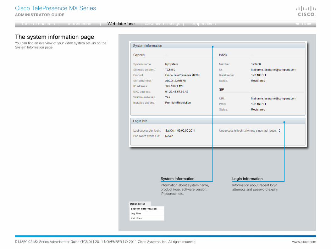
ThesysteminformationpageYou can find an overview of your video system set-up on the System Information page.
LogininformationSysteminformation
Information about recent login attempts and password expiry.
Information about system name, product type, software version, IP address, etc.
Diagnostics
System Information
Log Files
XML Files
D14850.02 MX Series Administrator Guide (TC5.0) | 2011 NOVEMBER | © 2011 Cisco Systems, Inc. All rights reserved. www.cisco.com
15
Cisco TelePresence MX SeriesAdministrAtor guide
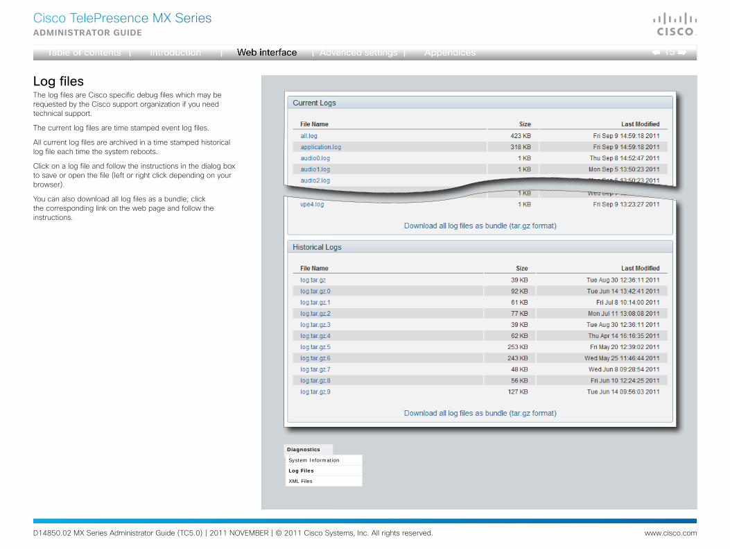
LogfilesThe log files are Cisco specific debug files which may be requested by the Cisco support organization if you need technical support.
The current log files are time stamped event log files.
All current log files are archived in a time stamped historical log file each time the system reboots.
Click on a log file and follow the instructions in the dialog box to save or open the file (left or right click depending on your browser).
You can also download all log files as a bundle; click the corresponding link on the web page and follow the instructions.
Diagnostics
System Information
Log Files
XML Files
D14850.02 MX Series Administrator Guide (TC5.0) | 2011 NOVEMBER | © 2011 Cisco Systems, Inc. All rights reserved. www.cisco.com
16
Cisco TelePresence MX SeriesAdministrAtor guide
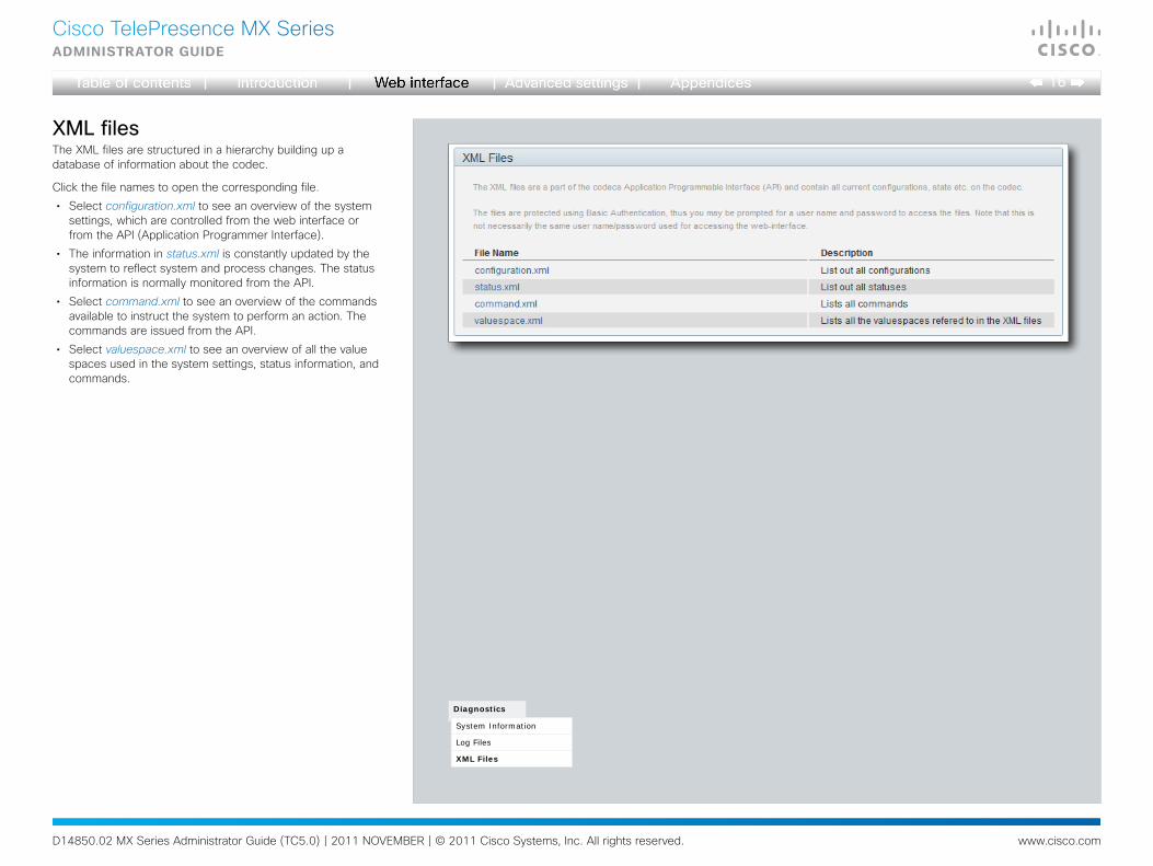
XMLfilesThe XML files are structured in a hierarchy building up a database of information about the codec.
Click the file names to open the corresponding file.
• Select configuration.xml to see an overview of the system settings, which are controlled from the web interface or from the API (Application Programmer Interface).
• The information in status.xml is constantly updated by the system to reflect system and process changes. The status information is normally monitored from the API.
• Select command.xml to see an overview of the commands available to instruct the system to perform an action. The commands are issued from the API.
• Select valuespace.xml to see an overview of all the value spaces used in the system settings, status information, and commands.
Diagnostics
System Information
Log Files
XML Files
D14850.02 MX Series Administrator Guide (TC5.0) | 2011 NOVEMBER | © 2011 Cisco Systems, Inc. All rights reserved. www.cisco.com
17
Cisco TelePresence MX SeriesAdministrAtor guide
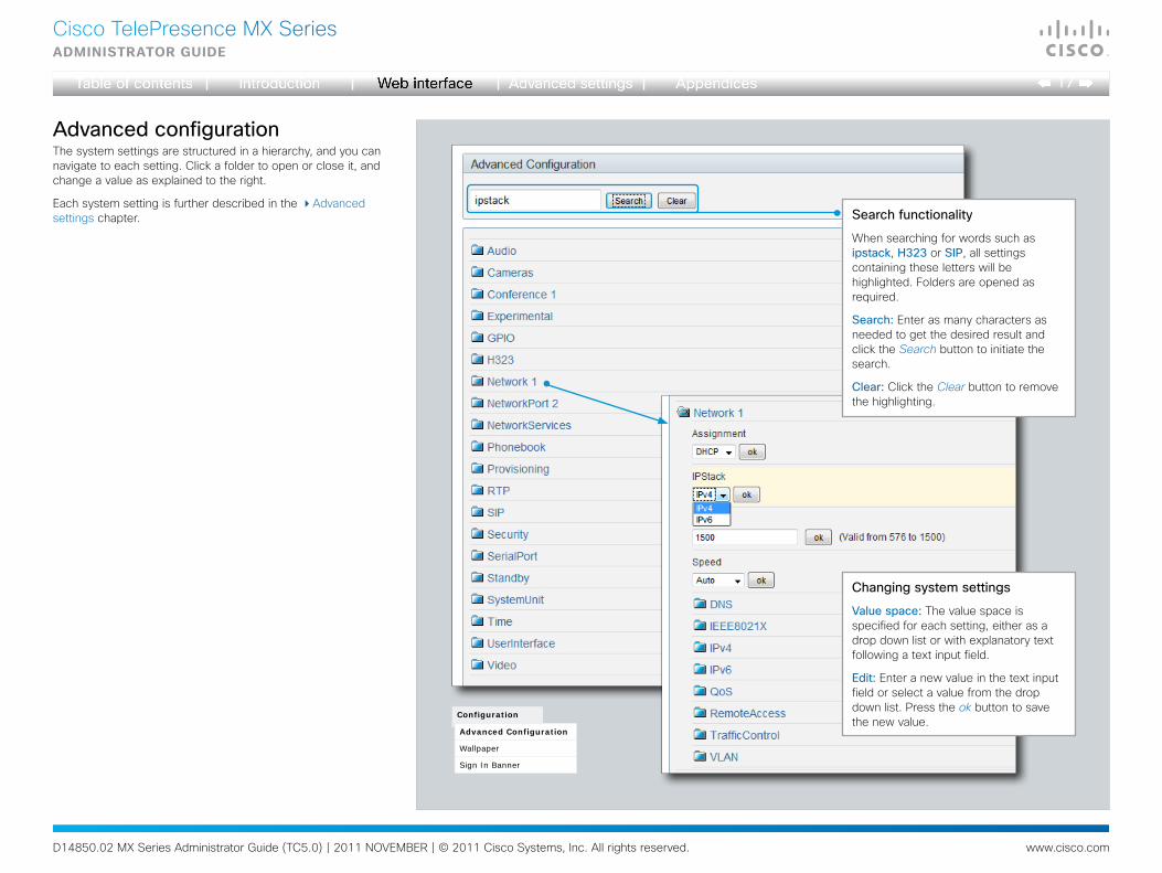
AdvancedconfigurationThe system settings are structured in a hierarchy, and you can navigate to each setting. Click a folder to open or close it, and change a value as explained to the right.
Each system setting is further described in the Advanced settings chapter.
Changingsystemsettings
Valuespace: The value space is specified for each setting, either as a drop down list or with explanatory text following a text input field.
Edit: Enter a new value in the text input field or select a value from the drop down list. Press the ok button to save the new value.
Searchfunctionality
When searching for words such as ipstack, H323 or SIP, all settings containing these letters will be highlighted. Folders are opened as required.
Search: Enter as many characters as needed to get the desired result and click the Search button to initiate the search.
Clear: Click the Clear button to remove the highlighting.
Configuration
Advanced Configuration
Wallpaper
Sign In Banner
D14850.02 MX Series Administrator Guide (TC5.0) | 2011 NOVEMBER | © 2011 Cisco Systems, Inc. All rights reserved. www.cisco.com
18
Cisco TelePresence MX SeriesAdministrAtor guide
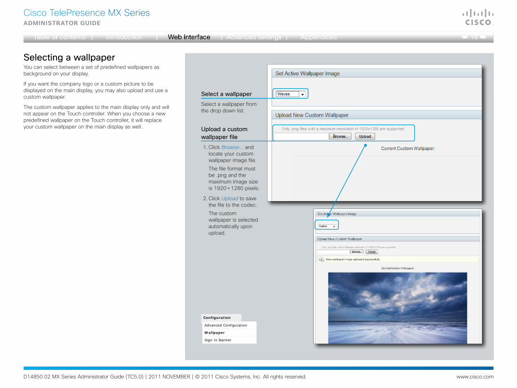
SelectingawallpaperYou can select between a set of predefined wallpapers as background on your display.
If you want the company logo or a custom picture to be displayed on the main display, you may also upload and use a custom wallpaper.
The custom wallpaper applies to the main display only and will not appear on the Touch controller. When you choose a new predefined wallpaper on the Touch controller, it will replace your custom wallpaper on the main display as well.
Selectawallpaper
Uploadacustomwallpaperfile
Select a wallpaper from the drop down list.
Configuration
Advanced Configuration
Wallpaper
Sign In Banner
1. Click Browse... and locate your custom wallpaper image file.
The file format must be .png and the maximum image size is 1920 × 1280 pixels.
2. Click Upload to save the file to the codec.
The custom wallpaper is selected automatically upon upload.
D14850.02 MX Series Administrator Guide (TC5.0) | 2011 NOVEMBER | © 2011 Cisco Systems, Inc. All rights reserved. www.cisco.com
19
Cisco TelePresence MX SeriesAdministrAtor guide
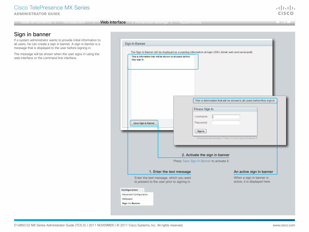
SigninbannerIf a system administrator wants to provide initial information to all users, he can create a sign in banner. A sign in banner is a message that is displayed to the user before signing in.
The message will be shown when the user signs in using the web interface or the command line interface.
Configuration
Advanced Configuration
Wallpaper
Sign In Banner
2.Activatethesigninbanner
Press Save Sign In Banner to activate it.
1.Enterthetextmessage
Enter the text message, which you want to present to the user prior to signing in.
When a sign in banner is active, it is displayed here.
Anactivesigninbanner
D14850.02 MX Series Administrator Guide (TC5.0) | 2011 NOVEMBER | © 2011 Cisco Systems, Inc. All rights reserved. www.cisco.com
20
Cisco TelePresence MX SeriesAdministrAtor guide
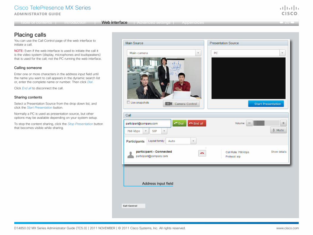
Addressinputfield
Call Control
PlacingcallsYou can use the Call Control page of the web interface to initiate a call.
NOTE: Even if the web interface is used to initiate the call it is the video system (display, microphones and loudspeakers) that is used for the call; not the PC running the web interface.
Callingsomeone
Enter one or more characters in the address input field until the name you want to call appears in the dynamic search list or, enter the complete name or number. Then click Dial.
Click End all to disconnect the call.
Sharingcontents
Select a Presentation Source from the drop down list, and click the Start Presentation button.
Normally a PC is used as presentation source, but other options may be available depending on your system setup.
To stop the content sharing, click the Stop Presentation button that becomes visible while sharing.
D14850.02 MX Series Administrator Guide (TC5.0) | 2011 NOVEMBER | © 2011 Cisco Systems, Inc. All rights reserved. www.cisco.com
21
Cisco TelePresence MX SeriesAdministrAtor guide
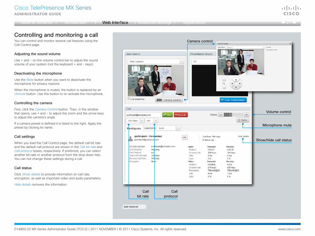
ControllingandmonitoringacallYou can control and monitor several call features using the Call Control page.
Adjustingthesoundvolume
Use + and - on the volume control bar to adjust the sound volume of your system (not the keyboard + and - keys).
Deactivatingthemicrophone
Use the Mute button when you want to deactivate the microphone for privacy reasons.
When the microphone is muted, the button is replaced by an Unmute button. Use this button to re-activate the microphone.
Controllingthecamera
First, click the Camera Control button. Then, in the window that opens, use + and - to adjust the zoom and the arrow keys to adjust the camera’s angle.
If a camera preset is defined it is listed to the right. Apply the preset by clicking its name.
Callsettings
When you load the Call Control page, the default call bit rate and the default call protocol are shown in the Call bit rate and Call protocol boxes, respectively. If preferred, you can select another bit rate or another protocol from the drop down lists. You can not change these settings during a call.
Callstatus
Click Show details to provide information on call rate, encryption, as well as important video and audio parameters.
Hide details removes the information.
Volumecontrol
Microphonemute
Show/hidecallstatus
Call Control
Cameracontrol
Callprotocol
Callbitrate
D14850.02 MX Series Administrator Guide (TC5.0) | 2011 NOVEMBER | © 2011 Cisco Systems, Inc. All rights reserved. www.cisco.com
22
Cisco TelePresence MX SeriesAdministrAtor guide
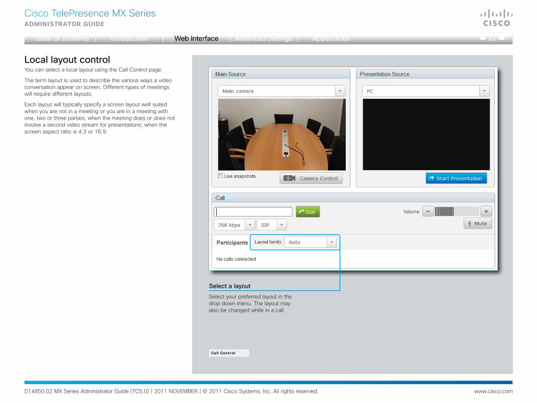
LocallayoutcontrolYou can select a local layout using the Call Control page.
The term layout is used to describe the various ways a video conversation appear on screen. Different types of meetings will require different layouts.
Each layout will typically specify a screen layout well suited when you are not in a meeting or you are in a meeting with one, two or three parties; when the meeting does or does not involve a second video stream for presentations; when the screen aspect ratio is 4:3 or 16:9.
Selectalayout
Select your preferred layout in the drop down menu. The layout may also be changed while in a call.
Call Control

D14850.02 MX Series Administrator Guide (TC5.0) | 2011 NOVEMBER | © 2011 Cisco Systems, Inc. All rights reserved. www.cisco.com
23
Cisco TelePresence MX SeriesAdministrAtor guide
Call Control
TakingsnapshotsSnapshots of what the video system’s camera captures can be obtained from the Call Control page, provided that the feature has been enabled on the video system.
This feature might come in handy when administering the video system from a remote location, e.g. to check the camera view.
To use web snapshots you have to sign in with ADMIN credentials.
Enablingthelivesnapshotfeature
NOTE: The live snapshot feature is disabled by default.
The live snapshot feature can be enabled using the Touch controller.
• Tap More > Settings > Administrator Settings > Web Snapshots and select On.
Takelivesnapshots
While the Live snapshots box is checked, a snapshot is taken approximately every
two seconds. The snapshots are displayed in the Main source display area.
Mainsourcedisplayarea
Snapshots are displayed here.
D14850.02 MX Series Administrator Guide (TC5.0) | 2011 NOVEMBER | © 2011 Cisco Systems, Inc. All rights reserved. www.cisco.com
24
Cisco TelePresence MX SeriesAdministrAtor guide
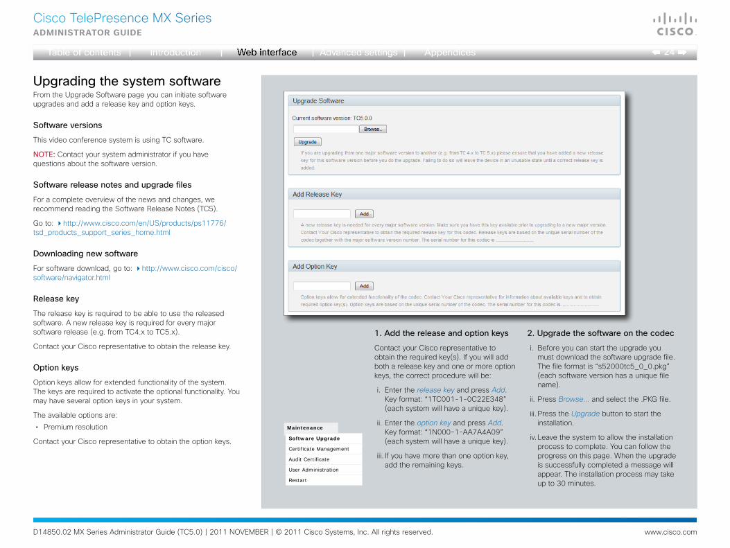
UpgradingthesystemsoftwareFrom the Upgrade Software page you can initiate software upgrades and add a release key and option keys.
Softwareversions
This video conference system is using TC software.
NOTE: Contact your system administrator if you have questions about the software version.
Softwarereleasenotesandupgradefiles
For a complete overview of the news and changes, we recommend reading the Software Release Notes (TC5).
Go to: http://www.cisco.com/en/US/products/ps11776/tsd_products_support_series_home.html
Downloadingnewsoftware
For software download, go to: http://www.cisco.com/cisco/software/navigator.html
Releasekey
The release key is required to be able to use the released software. A new release key is required for every major software release (e.g. from TC4.x to TC5.x).
Contact your Cisco representative to obtain the release key.
Optionkeys
Option keys allow for extended functionality of the system. The keys are required to activate the optional functionality. You may have several option keys in your system.
The available options are:
• Premium resolution
Contact your Cisco representative to obtain the option keys.
1.Addthereleaseandoptionkeys
Contact your Cisco representative to obtain the required key(s). If you will add both a release key and one or more option keys, the correct procedure will be:
i. Enter the release key and press Add. Key format: “1TC001-1-0C22E348” (each system will have a unique key).
ii. Enter the option key and press Add. Key format: “1N000-1-AA7A4A09” (each system will have a unique key).
iii. If you have more than one option key, add the remaining keys.
Maintenance
Software Upgrade
Certificate Management
Audit Certificate
User Administration
Restart
2.Upgradethesoftwareonthecodec
i. Before you can start the upgrade you must download the software upgrade file. The file format is “s52000tc5_0_0.pkg” (each software version has a unique file name).
ii. Press Browse... and select the .PKG file.
iii. Press the Upgrade button to start the installation.
iv. Leave the system to allow the installation process to complete. You can follow the progress on this page. When the upgrade is successfully completed a message will appear. The installation process may take up to 30 minutes.
D14850.02 MX Series Administrator Guide (TC5.0) | 2011 NOVEMBER | © 2011 Cisco Systems, Inc. All rights reserved. www.cisco.com
25
Cisco TelePresence MX SeriesAdministrAtor guide
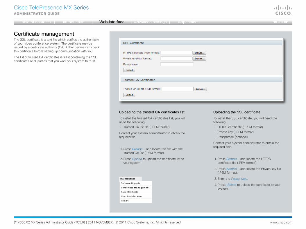
CertificatemanagementThe SSL certificate is a text file which verifies the authenticity of your video conference system. The certificate may be issued by a certificate authority (CA). Other parties can check this certificate before setting up communication with you.
The list of trusted CA certificates is a list containing the SSL certificates of all parties that you want your system to trust.
Maintenance
Software Upgrade
Certificate Management
Audit Certificate
User Administration
Restart
UploadingtheSSLcertificate
To install the SSL certificate, you will need the following:
• HTTPS certificate ( .PEM format)
• Private key ( .PEM format)
• Passphrase (optional)
Contact your system administrator to obtain the required files.
1. Press Browse... and locate the HTTPS certificate file (.PEM format).
2. Press Browse... and locate the Private key file (.PEM format).
3. Enter the Passphrase.
4. Press Upload to upload the certificate to your system.
UploadingthetrustedCAcertificateslist
To install the trusted CA certificates list, you will need the following:
• Trusted CA list file ( .PEM format).
Contact your system administrator to obtain the required file.
1. Press Browse... and locate the file with the Trusted CA list (.PEM format).
2. Press Upload to upload the certificate list to your system.
D14850.02 MX Series Administrator Guide (TC5.0) | 2011 NOVEMBER | © 2011 Cisco Systems, Inc. All rights reserved. www.cisco.com
26
Cisco TelePresence MX SeriesAdministrAtor guide
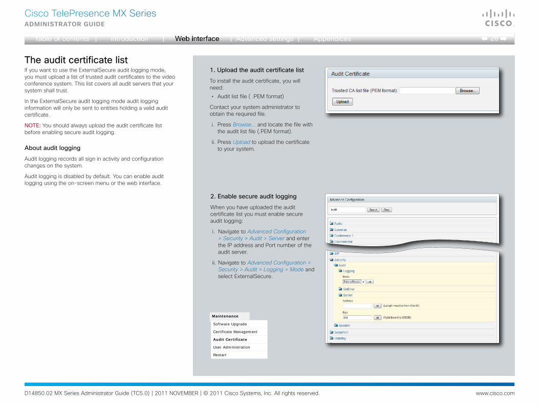
TheauditcertificatelistIf you want to use the ExternalSecure audit logging mode, you must upload a list of trusted audit certificates to the video conference system. This list covers all audit servers that your system shall trust.
In the ExternalSecure audit logging mode audit logging information will only be sent to entities holding a valid audit certificate.
NOTE: You should always upload the audit certificate list before enabling secure audit logging.
Aboutauditlogging
Audit logging records all sign in activity and configuration changes on the system.
Audit logging is disabled by default. You can enable audit logging using the on-screen menu or the web interface.
Maintenance
Software Upgrade
Certificate Management
Audit Certificate
User Administration
Restart
1.Uploadtheauditcertificatelist
To install the audit certificate, you will need:
• Audit list file ( .PEM format)
Contact your system administrator to obtain the required file.
i. Press Browse... and locate the file with the audit list file (.PEM format).
ii. Press Upload to upload the certificate to your system.
2.Enablesecureauditlogging
When you have uploaded the audit certificate list you must enable secure audit logging:
i. Navigate to Advanced Configuration > Security > Audit > Server and enter the IP address and Port number of the audit server.
ii. Navigate to Advanced Configuration > Security > Audit > Logging > Mode and select ExternalSecure.

D14850.02 MX Series Administrator Guide (TC5.0) | 2011 NOVEMBER | © 2011 Cisco Systems, Inc. All rights reserved. www.cisco.com
27
Cisco TelePresence MX SeriesAdministrAtor guide
UseradministrationFrom this page you can manage the user accounts of your video conference system. You can create new user accounts, edit the details of existing users, and delete users.
Thedefaultuseraccount
The system comes with a default administrator user account with username admin and no password set. The admin user has full access rights, and itishighlyrecommendedtosetapasswordforthisuser.
Read more about passwords in the Password protection chapter.
Aboutuserroles
A user account must hold one or a combination of several userroles. Three user roles exist, representing different rights:
• ADMIN: A user holding this role can create new users and change all settings, except the security audit settings. He cannot upload audit certificates.
• USER: A user holding this role can make calls and search the phonebook.
• AUDIT: A user holding this role can change the security audit configurations and upload audit certificates.
It is important to note that these three roles have non-overlappingrights.
An administrator user account with full access rights, like the default admin user, must possess all the three roles.
Securitymode
You can enable/disable the strong security mode from this page.
Strong security mode sets very strict password requirements, and requires all users to change their password on next sign in.
Software upload from TMS, web snapshots and making calls from the web interface are prohibited in strong security mode.
The system comes with admin as the default
user account. This user has full access rights.
Defaultuseraccount
Maintenance
Software Upgrade
Certificate Management
Audit Certificate
User Administration
Restart
D14850.02 MX Series Administrator Guide (TC5.0) | 2011 NOVEMBER | © 2011 Cisco Systems, Inc. All rights reserved. www.cisco.com
28
Cisco TelePresence MX SeriesAdministrAtor guide
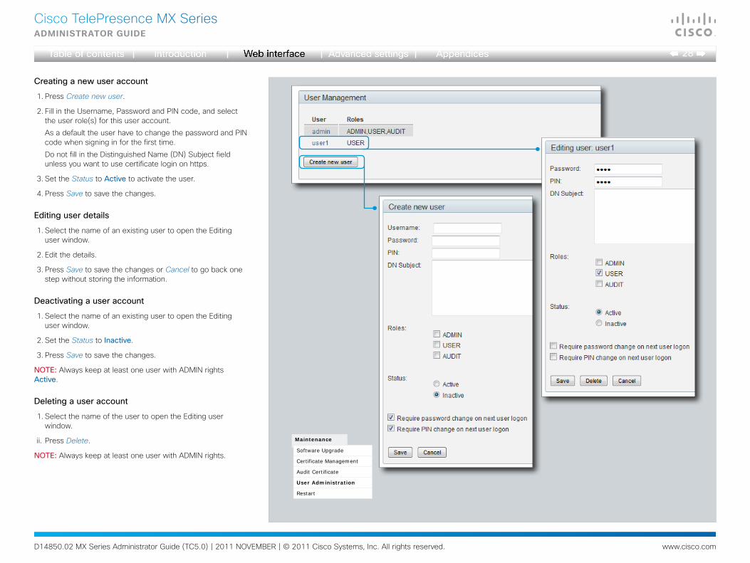
Creatinganewuseraccount
1. Press Create new user.
2. Fill in the Username, Password and PIN code, and select the user role(s) for this user account.
As a default the user have to change the password and PIN code when signing in for the first time.
Do not fill in the Distinguished Name (DN) Subject field unless you want to use certificate login on https.
3. Set the Status to Active to activate the user.
4. Press Save to save the changes.
Editinguserdetails
1. Select the name of an existing user to open the Editing user window.
2. Edit the details.
3. Press Save to save the changes or Cancel to go back one step without storing the information.
Deactivatingauseraccount
1. Select the name of an existing user to open the Editing user window.
2. Set the Status to Inactive.
3. Press Save to save the changes.
NOTE: Always keep at least one user with ADMIN rights Active.
Deletingauseraccount
1. Select the name of the user to open the Editing user window.
ii. Press Delete.
NOTE: Always keep at least one user with ADMIN rights.
Maintenance
Software Upgrade
Certificate Management
Audit Certificate
User Administration
Restart
D14850.02 MX Series Administrator Guide (TC5.0) | 2011 NOVEMBER | © 2011 Cisco Systems, Inc. All rights reserved. www.cisco.com
29
Cisco TelePresence MX SeriesAdministrAtor guide
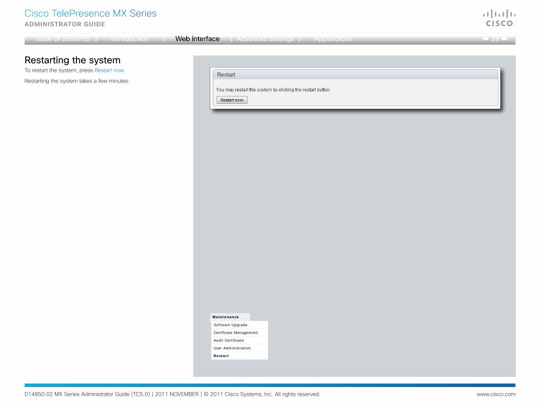
RestartingthesystemTo restart the system, press Restart now.
Restarting the system takes a few minutes.
Maintenance
Software Upgrade
Certificate Management
Audit Certificate
User Administration
Restart
D14850.02 MX Series Administrator Guide (TC5.0) | 2011 NOVEMBER | © 2011 Cisco Systems, Inc. All rights reserved. www.cisco.com
30
Cisco TelePresence MX SeriesAdministrAtor guide
Chapter 3
Theadvancedsettings

D14850.02 MX Series Administrator Guide (TC5.0) | 2011 NOVEMBER | © 2011 Cisco Systems, Inc. All rights reserved. www.cisco.com
31
Cisco TelePresence MX SeriesAdministrAtor guide
OverviewoftheadvancedsettingsIn the following pages you will find a complete list of the system settings which are configured from the Advanced Configuration page on the web interface.
The examples show either the default value or an example of a value.
FindtheIPaddressofyoursystemTap More > Settings on the Touch controller, select System Information and find the IPv4 Address or IPv6 Address of your system.
OpenthewebinterfaceOpen a web browser and enter your video conference system’s IP address in the address bar; then sign in.
TheAudiosettings..............................................................................................................34Audio InternalSpeaker Mode .................................................................................................. 34Audio Microphones Mute Enabled .......................................................................................... 34Audio PreferredOutputConnector ........................................................................................... 34Audio SoundsAndAlerts KeyTones Mode ............................................................................... 34Audio SoundsAndAlerts RingTone .......................................................................................... 34Audio SoundsAndAlerts RingVolume ...................................................................................... 34Audio Volume ......................................................................................................................... 34Audio VolumeHandset ............................................................................................................ 34Audio VolumeHeadset ............................................................................................................ 34
TheCamerassettings..........................................................................................................35Cameras Camera [1..1] Backlight ........................................................................................... 35Cameras Camera [1..1] Brightness Level ............................................................................... 35Cameras Camera [1..1] Brightness Mode .............................................................................. 35Cameras Camera [1..1] Flip .................................................................................................... 35Cameras Camera [1..1] Focus Mode...................................................................................... 35Cameras Camera [1..1] FrameRate ........................................................................................ 35Cameras Camera [1..1] Gamma Level ................................................................................... 35Cameras Camera [1..1] Gamma Mode ................................................................................... 35Cameras Camera [1..1] IrSensor ............................................................................................ 35Cameras Camera [1..1] Mirror ................................................................................................ 36Cameras Camera [1..1] Whitebalance Level .......................................................................... 36Cameras Camera [1..1] Whitebalance Mode .......................................................................... 36Cameras PowerLine Frequency ............................................................................................. 35
TheConferencesettings.....................................................................................................36Conference [1..1] AutoAnswer Delay ..................................................................................... 36Conference [1..1] AutoAnswer Mode ..................................................................................... 36Conference [1..1] AutoAnswer Mute ...................................................................................... 36Conference [1..1] DefaultCall Protocol ................................................................................... 37Conference [1..1] DefaultCall Rate ......................................................................................... 37Conference [1..1] DoNotDisturb Mode ................................................................................... 37Conference [1..1] Encryption Mode........................................................................................ 37Conference [1..1] FarEndControl Mode .................................................................................. 37Conference [1..1] FarEndControl SignalCapability .................................................................. 37
Conference [1..1] IncomingMultisiteCall Mode ....................................................................... 38Conference [1..1] MaxReceiveCallRate .................................................................................. 38Conference [1..1] MaxTransmitCallRate ................................................................................. 37Conference [1..1] MicUnmuteOnDisconnect Mode ................................................................ 37Conference [1..1] PacketLossResilience Mode ...................................................................... 38Conference [1..1] Presentation Policy ....................................................................................38Conference [1..1] TelephonyPrefix ......................................................................................... 36Conference [1..1] VideoBandwidth MainChannel Weight ....................................................... 38Conference [1..1] VideoBandwidth Mode ............................................................................... 38Conference [1..1] VideoBandwidth PresentationChannel Weight ........................................... 38
TheH323settings...............................................................................................................39H323 NAT Address ................................................................................................................39H323 NAT Mode ....................................................................................................................39H323 Profile [1..1] Authentication LoginName........................................................................ 39H323 Profile [1..1] Authentication Mode ................................................................................ 39H323 Profile [1..1] Authentication Password .......................................................................... 39H323 Profile [1..1] CallSetup Mode ........................................................................................40H323 Profile [1..1] Gatekeeper Address ................................................................................. 40H323 Profile [1..1] Gatekeeper Discovery .............................................................................. 40H323 Profile [1..1] H323Alias E164 ........................................................................................40H323 Profile [1..1] H323Alias ID .............................................................................................40H323 Profile [1..1] PortAllocation ...........................................................................................40
TheNetworksettings...........................................................................................................41Network [1..1] Assignment .....................................................................................................41Network [1..1] DNS Domain Name ......................................................................................... 41Network [1..1] DNS Server [1..5] Address .............................................................................. 41Network [1..1] IEEE8021X AnonymousIdentity ....................................................................... 43Network [1..1] IEEE8021X Eap Md5 .......................................................................................44Network [1..1] IEEE8021X Eap Peap ......................................................................................44Network [1..1] IEEE8021X Eap Tls ..........................................................................................44Network [1..1] IEEE8021X Eap Ttls .........................................................................................44Network [1..1] IEEE8021X Identity ..........................................................................................43Network [1..1] IEEE8021X Mode ............................................................................................43Network [1..1] IEEE8021X Password ......................................................................................43
D14850.02 MX Series Administrator Guide (TC5.0) | 2011 NOVEMBER | © 2011 Cisco Systems, Inc. All rights reserved. www.cisco.com
32
Cisco TelePresence MX SeriesAdministrAtor guide
Network [1..1] IEEE8021X TlsVerify ........................................................................................ 43Network [1..1] IEEE8021X UseClientCertificate ...................................................................... 43Network [1..1] IPStack ............................................................................................................ 41Network [1..1] IPv4 Address ................................................................................................... 41Network [1..1] IPv4 Gateway .................................................................................................. 41Network [1..1] IPv4 SubnetMask ............................................................................................ 41Network [1..1] IPv6 Address ................................................................................................... 41Network [1..1] IPv6 Assignment ............................................................................................. 42Network [1..1] IPv6 DHCPOptions .......................................................................................... 42Network [1..1] IPv6 Gateway .................................................................................................. 42Network [1..1] MTU ................................................................................................................ 44Network [1..1] QoS Diffserv Audio .......................................................................................... 42Network [1..1] QoS Diffserv Data ........................................................................................... 42Network [1..1] QoS Diffserv Signalling .................................................................................... 42Network [1..1] QoS Diffserv Video .......................................................................................... 43Network [1..1] QoS Mode....................................................................................................... 42Network [1..1] RemoteAccess Allow ...................................................................................... 44Network [1..1] Speed ............................................................................................................. 44Network [1..1] TrafficControl Mode ........................................................................................ 44Network [1..1] VLAN Voice Mode ........................................................................................... 45Network [1..1] VLAN Voice VlanId .......................................................................................... 45
TheNetworkServicessettings.............................................................................................45NetworkServices H323 Mode ................................................................................................ 45NetworkServices HTTP Mode ................................................................................................ 46NetworkServices HTTPS Mode .............................................................................................. 46NetworkServices HTTPS OCSP Mode ................................................................................... 46NetworkServices HTTPS OCSP URL ...................................................................................... 46NetworkServices HTTPS VerifyClientCertificate ..................................................................... 46NetworkServices HTTPS VerifyServerCertificate .................................................................... 46NetworkServices Multiway Address ....................................................................................... 45NetworkServices Multiway Protocol ....................................................................................... 45NetworkServices NTP Address .............................................................................................. 47NetworkServices NTP Mode .................................................................................................. 46NetworkServices SIP Mode .................................................................................................... 47NetworkServices SNMP CommunityName ............................................................................. 47NetworkServices SNMP Host [1..3] Address .......................................................................... 47NetworkServices SNMP Mode ............................................................................................... 47NetworkServices SNMP SystemContact ................................................................................ 47NetworkServices SNMP SystemLocation ............................................................................... 47NetworkServices SSH AllowPublicKey ................................................................................... 48NetworkServices SSH Mode .................................................................................................. 47NetworkServices Telnet Mode................................................................................................ 48
ThePhonebooksettings......................................................................................................48Phonebook Server [1..1] ID .................................................................................................... 48
Phonebook Server [1..1] Type ................................................................................................48Phonebook Server [1..1] URL .................................................................................................48
TheProvisioningsettings.....................................................................................................49Provisioning Connectivity .......................................................................................................49Provisioning ExternalManager Address .................................................................................. 49Provisioning ExternalManager Domain ...................................................................................50Provisioning ExternalManager Path ........................................................................................ 50Provisioning ExternalManager Protocol .................................................................................. 50Provisioning HttpMethod ........................................................................................................49Provisioning LoginName .........................................................................................................49Provisioning Mode ..................................................................................................................49Provisioning Password............................................................................................................ 49
TheRTPsettings.................................................................................................................50RTP Ports Range Start ............................................................................................................50RTP Ports Range Stop ............................................................................................................50
TheSecuritysettings...........................................................................................................51Security Audit Logging Mode .................................................................................................51Security Audit OnError Action .................................................................................................51Security Audit Server Address ...............................................................................................51Security Audit Server Port ......................................................................................................51Security Session InactivityTimeout ......................................................................................... 51Security Session ShowLastLogon .......................................................................................... 51
TheSerialPortsettings.........................................................................................................52SerialPort BaudRate ...............................................................................................................52SerialPort LoginRequired ........................................................................................................52SerialPort Mode ......................................................................................................................52
TheSIPsettings..................................................................................................................52SIP Profile [1..1] Authentication [1..1] LoginName .................................................................. 52SIP Profile [1..1] Authentication [1..1] Password..................................................................... 52SIP Profile [1..1] DefaultTransport ...........................................................................................53SIP Profile [1..1] DisplayName ................................................................................................52SIP Profile [1..1] Outbound .....................................................................................................53SIP Profile [1..1] Proxy [1..4] Address..................................................................................... 53SIP Profile [1..1] Proxy [1..4] Discovery ..................................................................................53SIP Profile [1..1] TlsVerify .......................................................................................................53SIP Profile [1..1] Type .............................................................................................................53SIP Profile [1..1] URI ...............................................................................................................52

D14850.02 MX Series Administrator Guide (TC5.0) | 2011 NOVEMBER | © 2011 Cisco Systems, Inc. All rights reserved. www.cisco.com
33
Cisco TelePresence MX SeriesAdministrAtor guide
TheStandbysettings...........................................................................................................54Standby BootAction ................................................................................................................ 54Standby Control ..................................................................................................................... 54Standby Delay ........................................................................................................................ 54Standby StandbyAction .......................................................................................................... 54Standby WakeupAction .......................................................................................................... 54
TheSystemUnitsettings......................................................................................................55SystemUnit CallLogging Mode ............................................................................................... 55SystemUnit ContactInfo Type ................................................................................................. 55SystemUnit IrSensor ............................................................................................................... 55SystemUnit MenuLanguage ................................................................................................... 55SystemUnit Name .................................................................................................................. 55SystemUnit Type .................................................................................................................... 55
TheTimesettings................................................................................................................56Time DateFormat .................................................................................................................... 56Time TimeFormat ................................................................................................................... 56Time Zone .............................................................................................................................. 56
TheUserInterfacesettings...................................................................................................57UserInterface TouchPanel DefaultPanel .................................................................................. 57
TheVideosettings...............................................................................................................57Video AllowWebSnapshots .................................................................................................... 61Video ControlPanel Brightness ............................................................................................... 59Video DefaultPresentationSource ........................................................................................... 59Video Input DVI [1] Type ......................................................................................................... 59Video Input Source [1..2] CameraControl CameraId .............................................................. 58Video Input Source [1..2] CameraControl Mode ..................................................................... 58Video Input Source [1..2] Name ............................................................................................. 57Video Input Source [1..2] OptimalDefinition Profile ................................................................. 58Video Input Source [1..2] OptimalDefinition Threshold60fps .................................................. 58Video Input Source [1..2] Quality ............................................................................................ 59Video Input Source [1..2] Type ............................................................................................... 57Video Input Source [1] Connector .......................................................................................... 57Video Input Source [2] Connector .......................................................................................... 57Video Layout LocalLayoutFamily ............................................................................................. 60Video Layout RemoteLayoutFamily ......................................................................................... 60Video Layout ScaleToFrame ................................................................................................... 59Video Layout ScaleToFrameThreshold ................................................................................... 59Video Layout Scaling .............................................................................................................. 59Video MainVideoSource ......................................................................................................... 60Video Monitors ....................................................................................................................... 60Video OSD AutoSelectPresentationSource ............................................................................ 60
Video OSD InputMethod Cyrillic .............................................................................................60Video OSD InputMethod InputLanguage ................................................................................ 60Video OSD LoginRequired ......................................................................................................60Video OSD Mode ...................................................................................................................60Video OSD MyContactsExpanded .......................................................................................... 60Video OSD Output ..................................................................................................................60Video OSD TodaysBookings ................................................................................................... 60Video Output Internal [2] MonitorRole .....................................................................................61Video Output LCD [1] Blue .....................................................................................................61Video Output LCD [1] Brightness ............................................................................................61Video Output LCD [1] Green ...................................................................................................61Video Output LCD [1] MonitorRole.......................................................................................... 61Video Output LCD [1] Red ......................................................................................................61Video Output LCD [1] Resolution ............................................................................................61Video Selfview ........................................................................................................................61Video WallPaper .....................................................................................................................62
TheExperimentalsettings...................................................................................................62Experimental CapsetFilter .......................................................................................................62Experimental CapsetReduction ..............................................................................................62Experimental Conference [1..1] PacketLossResilience ForwardErrorCorrection ..................... 62Experimental Conference [1..1] PacketLossResilience RateAdaption ..................................... 63Experimental Conference [1..1] ReceiverBasedDownspeeding .............................................. 63Experimental CTMSSupport Mode ......................................................................................... 63Experimental NetworkServices UPnP Mode ........................................................................... 63Experimental NetworkServices UPnP Timeout ....................................................................... 63Experimental PacketOverloadHandling WhenDetected .......................................................... 63Experimental SystemUnit CrashReporting Mode .................................................................... 64Experimental SystemUnit CrashReporting URI ........................................................................ 64Experimental SystemUnit MenuType ...................................................................................... 63Experimental SystemUnit SoftwareUpgrade RequireAuthentication ....................................... 63
D14850.02 MX Series Administrator Guide (TC5.0) | 2011 NOVEMBER | © 2011 Cisco Systems, Inc. All rights reserved. www.cisco.com
34
Cisco TelePresence MX SeriesAdministrAtor guide
TheAudiosettings
AudioPreferredOutputConnectorSelect the preferred connector for the audio out. When the handset is in use the audio out goes to the handset, and when hanged up the audio out goes to the preferred output connector.
Requiresuserrole: ADMIN
Valuespace: <None/Internal>None: The default audio output is the internal speaker.Internal: The audio out goes to the internal loudspeaker. NOTE: Requires the "Audio InternalSpeaker Mode" to be enabled.
Example: Audio PreferredOutputConnector: Internal
AudioInternalSpeakerModeSet the internal loudspeaker mode.
Requiresuserrole: ADMIN
Valuespace: <On/Off>On: The internal speakers are enabled.Off: The internal speakers are disabled.
Example: Audio InternalSpeaker Mode: On
AudioMicrophonesMuteEnabledDetermine whether audio-mute is allowed or not. The default value is True.
Requiresuserrole: ADMIN
Valuespace: <True/InCallOnly>True: Muting of audio is always available.InCallOnly: Muting of audio is only available when the device is in a call. When Idle it is not possible to mute the microphone. This is useful when an external telephone service/audio system is connected via the codec and is to be available when the codec is not in a call. When set to InCallOnly this will prevent the audio-system from being muted by mistake.
Example: Audio Microphones Mute Enabled: True
AudioSoundsAndAlertsKeyTonesModeNot applicable in this version.
AudioSoundsAndAlertsRingToneSelect the ring tone for incoming calls.
Requiresuserrole: USER
Valuespace: <Marbles/IceCrystals/Polaris/Alert/Discreet/Fantasy/Jazz/Nordic/Echo/Rhythmic>
Range: Select a tone from the list of ring tones.
Example: Audio SoundsAndAlerts RingTone: Jazz
AudioSoundsAndAlertsRingVolumeSets the ring tone volume for an incoming call.
Requiresuserrole: USER
Valuespace: <0..100>Range: The value goes in steps of 5 from 0 to 100 (from -34.5 dB to 15 dB). Volume 0 = Off.
Example: Audio SoundsAndAlerts RingVolume: 50
AudioVolumeHandsetSet the volume on the handset.
Requiresuserrole: ADMIN
Valuespace: <0..100>Range: The value goes in steps of 5 from 0 to 100 (from -34.5 dB to 15 dB). Value 0 = Off.
Example: Audio VolumeHandset: 70
AudioVolumeHeadsetSet the volume on the headset.
Requiresuserrole: ADMIN
Valuespace: <0..100>Range: The value goes in steps of 5 from 0 to 100 (from -34.5 dB to 15 dB). Value 0 = Off.
Example: Audio VolumeHeadset: 70
AudioVolumeSet the volume on the loudspeaker.
Requiresuserrole: USER
Valuespace: <0..100>Range: The value goes in steps of 5 from 0 to 100 (from -34.5 dB to 15 dB). Value 0 = Off.
Example: Audio Volume: 70
D14850.02 MX Series Administrator Guide (TC5.0) | 2011 NOVEMBER | © 2011 Cisco Systems, Inc. All rights reserved. www.cisco.com
35
Cisco TelePresence MX SeriesAdministrAtor guide
TheCamerassettings
CamerasPowerLineFrequencyApplies to cameras supporting PowerLine frequency anti-flickering, i.e PrecisionHD 1080p cameras.
Requiresuserrole: ADMIN
Valuespace: <Auto/50Hz/60Hz>Auto: Set to Auto to enable power frequency auto detection in the camera.50Hz: Set to 50 Hz.60Hz: Set to 60 Hz.
Example: Cameras PowerLine Frequency: Auto
CamerasCamera[1..1]BacklightThe backlight functionality compensates for light shining directly at the camera (usually the sun entering the window) to avoid a too dark image from the room.
Requiresuserrole: ADMIN
Valuespace: <On/Off>On: Turn on the camera backlight.Off: Turn off the camera backlight.
Example: Cameras Camera 1 Backlight: Off
CamerasCamera[1..1]BrightnessModeSet the camera brightness mode.
Requiresuserrole: ADMIN
Valuespace: <Auto/Manual>Auto: The camera brightness is automatically set by the system.Manual: Enable manual control of the camera brightness, e.g. the level of the brightness level setting will be used for the camera.
Example: Cameras Camera 1 Brightness Mode: Auto
CamerasCamera[1..1]BrightnessLevelSet the brightness level. NOTE: Requires the Camera Brightness Mode to be set to Manual.
Requiresuserrole: ADMIN
Valuespace: <1..31>Range: Select a value from 1 to 31.
Example: Cameras Camera 1 Brightness Level: 1
CamerasCamera[1..1]FlipNot applicable in this version.
CamerasCamera[1..1]FocusModeSet the camera focus mode.
Requiresuserrole: ADMIN
Valuespace: <Auto/Manual>Auto: When set to Auto the focus will be updated throughout the call. When moving the camera, the system will use auto focus for a few seconds to set the right focus of the new camera position. After a few seconds auto focus is turned off to prevent continuous focus adjustments of the camera.Manual: Turn the autofocus off and adjust the camera focus manually.
Example: Cameras Camera 1 Focus Mode: Auto
CamerasCamera[1..1]FrameRateSet the frame rate frequency.
Requiresuserrole: ADMIN
Valuespace: <60Hz/30Hz>60Hz: Set the frame rate to 60 Hz.30Hz: Set the frame rate to 30 Hz.
Example: Cameras Camera 1 FrameRate: 30Hz
CamerasCamera[1..1]GammaModeThe Gamma Mode setting enables for gamma corrections. Gamma describes the nonlinear relationship between image pixels and monitor brightness.
Requiresuserrole: ADMIN
Valuespace: <Auto/Manual>Auto: Auto is the default and the recommended setting.Manual: In severe light conditions, you may switch mode to manual and specify explicitly which gamma table to use by setting the Gamma Level.
Example: Cameras Camera 1 Gamma Mode: Auto
CamerasCamera[1..1]GammaLevelBy setting the Gamma Level you can select which gamma correction table to use. This setting may be useful in difficult lighting conditions, where changes to the brightness setting does not provide satisfactory results. NOTE: Requires the Gamma Mode to be set to Manual.
Requiresuserrole: ADMIN
Valuespace: <0..7>Range: Select a value from 0 to 7.
Example: Cameras Camera 1 Gamma Level: 0
CamerasCamera[1..1]IrSensorNot applicable in this version.

D14850.02 MX Series Administrator Guide (TC5.0) | 2011 NOVEMBER | © 2011 Cisco Systems, Inc. All rights reserved. www.cisco.com
36
Cisco TelePresence MX SeriesAdministrAtor guide
CamerasCamera[1..1]MirrorNot applicable in this version.
CamerasCamera[1..1]WhitebalanceModeSet the camera whitebalance mode.
Requiresuserrole: ADMIN
Valuespace: <Auto/Manual>Auto: The camera will continuously adjust the whitebalance depending on the camera view.Manual: Enables manual control of the camera whitebalance, e.g. the level of the whitebalance level setting will be used for the camera.
Example: Cameras Camera 1 Whitebalance Mode: Auto
CamerasCamera[1..1]WhitebalanceLevelSet the whitebalance level. NOTE: Requires the Camera Whitebalance Mode to be set to manual.
Requiresuserrole: ADMIN
Valuespace: <1..16>Range: Select a value from 1 to 16.
Example: Cameras Camera 1 Whitebalance Level: 1
TheConferencesettings
Conference[1..1]TelephonyPrefixEnter the prefix to be used for telephony calls.
Requiresuserrole: ADMIN
Valuespace: <S: 0, 80>Format: String with a maximum of 80 characters.
Example: Conference 1 TelephonyPrefix: "520"
Conference[1..1]AutoAnswerModeSet the AutoAnswer mode.
Requiresuserrole: ADMIN
Valuespace: <On/Off>On: Enable AutoAnswer to let the system automatically answer all incoming calls.Off: The incoming calls must be answered manually by pressing the green Accept key on the touch controller.
Example: Conference 1 AutoAnswer Mode: Off
Conference[1..1]AutoAnswerMuteDetermine if the microphone shall be muted when an incoming call is automatically answered. NOTE: Requires the AutoAnswer Mode to be enabled.
Requiresuserrole: ADMIN
Valuespace: <On/Off>On: The incoming call will be muted when automatically answered.Off: The incoming call will not be muted.
Example: Conference 1 AutoAnswer Mute: Off
Conference[1..1]AutoAnswerDelayDefine how long (in seconds) an incoming call has to wait before it is answered automatically by the system. NOTE: Requires the AutoAnswer Mode to be enabled.
Requiresuserrole: ADMIN
Valuespace: <0..50>Range: Select a value from 0 to 50 seconds.
Example: Conference 1 AutoAnswer Delay: 0
D14850.02 MX Series Administrator Guide (TC5.0) | 2011 NOVEMBER | © 2011 Cisco Systems, Inc. All rights reserved. www.cisco.com
37
Cisco TelePresence MX SeriesAdministrAtor guide
Conference[1..1]MicUnmuteOnDisconnectModeDetermine if the microphones shall be unmuted automatically when all calls are disconnected. In a meeting room or other shared resources this could be done to prepare the system for the next user.
Requiresuserrole: ADMIN
Valuespace: <On/Off>On: Un-mute the microphones after the call is disconnected.Off: If muted, let the microphones remain muted after the call is disconnected.
Example: Conference 1 MicUnmuteOnDisconnect Mode: On
Conference[1..1]DoNotDisturbModeDetermine if there should be an alert on incoming calls.
Requiresuserrole: USER
Valuespace: <On/Off>On: All incoming calls will be rejected, with no alert. The calling side will receive a busy signal when trying to call the codec. A message will display on screen, telling that Do not disturb is turned on, together with an option to turn off the Do not disturb. When turning off the Do not disturb mode you will see a list of the calls that have been rejected. Off: The incoming calls will be alerted.
Example: DoNotDisturb Mode: Off
Conference[1..1]FarEndControlModeLets you decide if the remote side (far end) should be allowed to select your video sources and control your local camera (pan, tilt, zoom).
Requiresuserrole: ADMIN
Valuespace: <On/Off>On: Allows the far end to be able to select your video sources and control your local camera (pan, tilt, zoom). You will still be able to control your camera and select your video sources as normal.Off: The far end is not allowed to select your video sources or to control your local camera (pan, tilt, zoom).
Example: Conference 1 FarEndControl Mode: On
Conference[1..1]FarEndControlSignalCapabilitySet the far end control (H.224) signal capability mode.
Requiresuserrole: ADMIN
Valuespace: <On/Off>On: Enable the far end control signal capability.Off: Disable the far end control signal capability.
Example: Conference 1 FarEndControl SignalCapability: On
Conference[1..1]EncryptionModeSet the conference encryption mode. A padlock with the text "Encryption On" or "Encryption Off" displays on screen for a few seconds when the conference starts.
Requiresuserrole: ADMIN
Valuespace: <BestEffort/On/Off>BestEffort: The system will use encryption whenever possible. > In Point to point calls: If the far end system supports encryption (AES-128), the call will be encrypted. If not, the call will proceed without encryption. > In MultiSite calls: In order to have encrypted MultiSite conferences, all sites must support encryption. If not, the conference will be unencrypted.On: The system will only allow calls that are encrypted.Off: The system will not use encryption.
Example: Conference 1 Encryption Mode: BestEffort
Conference[1..1]DefaultCallProtocolSet the Default Call Protocol to be used when placing calls from the system.
Requiresuserrole: ADMIN
Valuespace: <H323/Sip>H.323: Select H.323 to ensure that calls are set up as H.323 calls.Sip: Select SIP to ensure that calls are set up as SIP calls.
Example: Conference 1 DefaultCall Protocol: H323
Conference[1..1]DefaultCallRateSet the Default Call Rate to be used when placing calls from the system.
Requiresuserrole: ADMIN
Valuespace: <64..6000>Range: Select a value between 64 and 6000 kbps
Example: Conference 1 DefaultCall Rate: 768
Conference[1..1]MaxTransmitCallRateSpecify the maximum transmit call rate to be used when placing or receiving calls.
Requiresuserrole: ADMIN
Valuespace: <64..6000>Range: Select a value between 64 and 6000 kbps.
Example: Conference 1 MaxTransmitCallRate: 6000

D14850.02 MX Series Administrator Guide (TC5.0) | 2011 NOVEMBER | © 2011 Cisco Systems, Inc. All rights reserved. www.cisco.com
38
Cisco TelePresence MX SeriesAdministrAtor guide
Conference[1..1]MaxReceiveCallRateSpecify the maximum receive call rate to be used when placing or receiving calls.
Requiresuserrole: ADMIN
Valuespace: <64..6000>Range: Select a value between 64 and 6000 kbps.
Example: Conference 1 MaxReceiveCallRate: 6000
Conference[1..1]VideoBandwidthModeSet the conference video bandwidth mode.
Requiresuserrole: ADMIN
Valuespace: <Dynamic/Static>Dynamic: The available transmit bandwidth for the video channels are distributed among the currently active channels. If there is no presentation, the main video channels will use the bandwidth of the presentation channel.Static: The available transmit bandwidth is assigned to each video channel, even if it is not active.
Example: Conference 1 VideoBandwidth Mode: Dynamic
Conference[1..1]VideoBandwidthMainChannelWeightThe available transmit video bandwidth is distributed on the main channel and presentation channel according to "MainChannel Weight" and "PresentationChannel Weight". If the main channel weight is 2 and the presentation channel weight is 1, then the main channel will use twice as much bandwidth as the presentation channel.
Requiresuserrole: ADMIN
Valuespace: <1..10>Range: 1 to 10.
Example: Conference 1 VideoBandwidth MainChannel Weight: 5
Conference[1..1]VideoBandwidthPresentationChannelWeightThe available transmit video bandwidth is distributed on the main channel and presentation channel according to "MainChannel Weight" and "PresentationChannel Weight". If the main channel weight is 2 and the presentation channel weight is 1, then the main channel will use twice as much bandwidth as the presentation channel.
Requiresuserrole: ADMIN
Valuespace: <1..10>Range: 1 to 10.
Example: Conference 1 VideoBandwidth PresentationChannel Weight: 5
Conference[1..1]PacketLossResilienceModeSet the packetloss resilience mode. This configuration will only take effect for calls initiated after the configuration is set.
Requiresuserrole: ADMIN
Valuespace: <On/Off>On: Enable the packetloss resilience.Off: Disable the packetloss resilience.
Example: Conference 1 PacketLossResilience Mode: On
Conference[1..1]PresentationPolicyControl how the presentation service is to be performed.
Requiresuserrole: ADMIN
Valuespace: <LocalRemote/LocalOnly>LocalRemote: The presentation will be shown locally and sent to remote side.LocalOnly: The presentation will only be shown locally.
Example: Conference 1 Presentation Policy: LocalRemote
Conference[1..1]IncomingMultisiteCallModeSet the incoming Multisite call mode. The MultiSite feature allows participants from more than two locations to join a meeting — by video and/or telephone.
Requiresuserrole: ADMIN
Valuespace: <Allow/Deny>Allow: Accept incoming calls to an already active call/conference. The incoming call will be added to the MCU conference. Deny: The system will not accept incoming calls when you are in a call. The calling side will receive a busy signal.
Example: Conference 1 IncomingMultisiteCall Mode: Allow
D14850.02 MX Series Administrator Guide (TC5.0) | 2011 NOVEMBER | © 2011 Cisco Systems, Inc. All rights reserved. www.cisco.com
39
Cisco TelePresence MX SeriesAdministrAtor guide
TheH323settings
H323NATModeThe firewall traversal technology creates a secure path through the firewall barrier, and enables proper exchange of audio/video data when connected to an external video conferencing system (when the IP traffic goes through a NAT router). NOTE: NAT does not work in conjunction with gatekeepers.
Requiresuserrole: ADMIN
Valuespace: <Auto/On/Off>Auto: The system will determine if the "NAT Address" or the real IP-address should be used within signalling. This is done to make it possible to place calls to endpoints on the LAN as well as endpoints on the WAN.On: The system will signal the configured "NAT Address" in place of its own IP-address within Q.931 and H.245. The NAT Server Address will be shown in the startup-menu as: "My IP Address: 10.0.2.1".Off: The system will signal the real IP Address.
Example: H323 NAT Mode: Off
H323NATAddressEnter the external/global IP-address to the router with NAT support. Packets sent to the router will then be routed to the system.
In the router, the following ports must be routed to the system's IP-address:
* Port 1720
* Port 5555-5574
* Port 2326-2485
Requiresuserrole: ADMIN
Valuespace: <S: 0, 64>Format: String with a maximum of 64 characters.
Example: H323 NAT Address: ""
H323Profile[1..1]AuthenticationModeSet the authenticatin mode for the H.323 profile.
Requiresuserrole: ADMIN
Valuespace: <On/Off>On: If the H.323 Gatekeeper Authentication Mode is set to On and a H.323 Gatekeeper indicates that it requires authentication, the system will try to authenticate itself to the gatekeeper. NOTE: Requires the Authentication LoginName and Authentication Password to be defined on both the codec and the Gatekeeper.Off: If the H.323 Gatekeeper Authentication Mode is set to Off the system will not try to authenticate itself to a H.323 Gatekeeper, but will still try a normal registration.
Example: H323 Profile 1 Authentication Mode: Off
H323Profile[1..1]AuthenticationLoginNameThe system sends the Authentication Login Name and the Authentication Password to a H.323 Gatekeeper for authentication. The authentication is a one way authentication from the codec to the H.323 Gatekeeper, i.e. the system is authenticated to the gatekeeper. If the H.323 Gatekeeper indicates that no authentication is required, the system will still try to register. NOTE: Requires the H.323 Gatekeeper Authentication Mode to be enabled.
Requiresuserrole: ADMIN
Valuespace: <S: 0, 50>Format: String with a maximum of 50 characters.
Example: H323 Profile 1 Authentication LoginName: ""
H323Profile[1..1]AuthenticationPasswordThe system sends the Authentication Login Name and the Authentication Password to a H.323 Gatekeeper for authentication. The authentication is a one way authentication from the codec to the H.323 Gatekeeper, i.e. the system is authenticated to the gatekeeper. If the H.323 Gatekeeper indicates that no authentication is required, the system will still try to register. NOTE: Requires the H.323 Gatekeeper Authentication Mode to be enabled.
Requiresuserrole: ADMIN
Valuespace: <S: 0, 50>Format: String with a maximum of 50 characters.
Example: H323 Profile 1 Authentication Password:
D14850.02 MX Series Administrator Guide (TC5.0) | 2011 NOVEMBER | © 2011 Cisco Systems, Inc. All rights reserved. www.cisco.com
40
Cisco TelePresence MX SeriesAdministrAtor guide
H323Profile[1..1]CallSetupModeThe H.323 Call Setup Mode defines whether to use a Gatekeeper or Direct calling when establishing H323 calls.
NOTE: Direct H.323 calls can be made even though the H.323 Call Setup Mode is set to Gatekeeper.
Requiresuserrole: ADMIN
Valuespace: <Direct/Gatekeeper>Direct: An IP-address must be used when dialling in order to make the H323 call.Gatekeeper: The system will use a Gatekeeper to make a H.323 call. When selecting this option the H323 Profile Gatekeeper Address and H323 Profile Gatekeeper Discovery settings must also be configured.
Example: H323 Profile 1 CallSetup Mode: Gatekeeper
H323Profile[1..1]GatekeeperDiscoveryDetermine how the system shall register to a H.323 Gatekeeper.
Requiresuserrole: ADMIN
Valuespace: <Manual/Auto>Manual: The system will use a specific Gatekeeper identified by the Gatekeeper's IP-address.Auto: The system will automatically try to register to any available Gatekeeper. If a Gatekeeper responds to the request sent from the codec within 30 seconds this specific Gatekeeper will be used. This requires that the Gatekeeper is in auto discovery mode as well. If no Gatekeeper responds, the system will not use a Gatekeeper for making H.323 calls and hence an IP-address must be specified manually.
Example: H323 Profile 1 Gatekeeper Discovery: Manual
H323Profile[1..1]GatekeeperAddressEnter the IP address of the Gatekeeper. NOTE: Requires the H.323 Call Setup Mode to be set to Gatekeeper and the Gatekeeper Discovery to be set to Manual.
Requiresuserrole: ADMIN
Valuespace: <S: 0, 255>Format: Only the valid IP address format is accepted. An IP address that contains letters (192.a.2.0) or unvalid IP addresses (192.0.1234.0) will be rejected.
Example: H323 Profile 1 Gatekeeper Address: "192.0.2.0"
H323Profile[1..1]H323AliasE164The H.323 Alias E.164 defines the address of the system, according to the numbering plan implemented in the H.323 Gatekeeper. The E.164 alias is equivalent to a telephone number, sometimes combined with access codes.
Requiresuserrole: ADMIN
Valuespace: <S: 0, 30>Format: Compact string with a maximum of 30 characters. Valid characters are 0-9, * and #.
Example: H323 Profile 1 H323Alias E164: "90550092"
H323Profile[1..1]H323AliasIDLets you specify the H.323 Alias ID which is used to address the system on a H.323 Gatekeeper and will be displayed in the call lists. Example: "[email protected]", "My H.323 Alias ID"
Requiresuserrole: ADMIN
Valuespace: <S: 0, 49>Format: String with a maximum of 49 characters
Example: H323 Profile 1 H323Alias ID: "[email protected]"
H323Profile[1..1]PortAllocationThe H.323 Port Allocation setting affects the H.245 port numbers used for H.323 call signalling.
Requiresuserrole: ADMIN
Valuespace: <Dynamic/Static>Dynamic: The system will allocate which ports to use when opening a TCP connection. The reason for doing this is to avoid using the same ports for subsequent calls, as some firewalls consider this as a sign of attack. When Dynamic is selected, the H.323 ports used are from 11000 to 20999. Once 20999 is reached they restart again at 11000. For RTP and RTCP media data, the system is using UDP ports in the range 2326 to 2487. Each media channel is using two adjacent ports, ie 2330 and 2331 for RTP and RTCP respectively. The ports are automatically selected by the system within the given range. Firewall administrators should not try to deduce which ports are used when, as the allocation schema within the mentioned range may change without any further notice.Static: When set to Static the ports are given within a static predefined range [5555-6555].
Example: H323 Profile 1 PortAllocation: Dynamic

D14850.02 MX Series Administrator Guide (TC5.0) | 2011 NOVEMBER | © 2011 Cisco Systems, Inc. All rights reserved. www.cisco.com
41
Cisco TelePresence MX SeriesAdministrAtor guide
TheNetworksettings
Network[1..1]AssignmentDefine whether to use DHCP or Static IPv4 assignment.
Requiresuserrole: ADMIN
Valuespace: <Static/DHCP>Static: Set the network assignment to Static and configure the static IPv4 settings (IP Address, SubnetMask and Gateway).DHCP: The system addresses are automatically assigned by the DHCP server.
Example: Network 1 Assignment: DHCP
Network[1..1]DNSDomainNameDNS Domain Name is the default domain name suffix which is added to unqualified names.
Example: If the DNS Domain Name is "company.com" and the name to lookup is "MyVideoSystem", this will result in the DNS lookup "MyVideoSystem.company.com".
Requiresuserrole: ADMIN
Valuespace: <S: 0, 64>Format: String with a maximum of 64 characters.
Example: Network 1 DNS Domain Name: ""
Network[1..1]DNSServer[1..5]AddressDefine the network addresses for DNS servers. Up to 5 addresses may be specified. If the network addresses are unknown, contact your administrator or Internet Service Provider.
Requiresuserrole: ADMIN
Valuespace: <S: 0, 64>Format: String with a maximum of 64 characters.
Example: Network 1 DNS Server 1 Address: ""
Network[1..1]IPStackSelect which internet protocols the system will support.
Requiresuserrole: ADMIN
Valuespace: <IPv4/IPv6>IPv4: IP version 4 is supported.IPv6: IP version 6 is supported. The IPv4 settings (IP Address, IP Subnet Mask and Gateway) will be disabled.
Example: Network 1 IPStack: IPv4
Network[1..1]IPv4AddressEnter the static IPv4 network address for the system. Only applicable if the Network Assignment is set to Static.
Requiresuserrole: ADMIN
Valuespace: <S: 0, 64>Format: Only the valid IP address format is accepted. An IP address that contains letters (192.a.2.0) or unvalid IP addresses (192.0.1234.0) will be rejected.
Example: Network 1 IPv4 Address: "192.0.2.0"
Network[1..1]IPv4GatewayDefine the IPv4 network gateway. Only applicable if the Network Assignment is set to Static.
Requiresuserrole: ADMIN
Valuespace: <S: 0, 64>Format: Compact string with a maximum of 64 characters.
Example: Network 1 IPv4 Gateway: "192.0.2.0"
Network[1..1]IPv4SubnetMaskDefine the IPv4 network subnet mask. Only applicable if the Network Assignment is set to Static.
Requiresuserrole: ADMIN
Valuespace: <S: 0, 64>Format: Compact string with a maximum of 64 characters.
Example: Network 1 IPv4 SubnetMask: "255.255.255.0"
Network[1..1]IPv6AddressEnter the static IPv6 network address for the system. Only applicable if the Network IPv6 Assignment is set to Static.
Requiresuserrole: ADMIN
Valuespace: <S: 0, 64>Format: The IPv6 address of host name.
Example: Network 1 IPv6 Address: "ffff:ffff:ffff:ffff:ffff:ffff:ffff:ffff"
D14850.02 MX Series Administrator Guide (TC5.0) | 2011 NOVEMBER | © 2011 Cisco Systems, Inc. All rights reserved. www.cisco.com
42
Cisco TelePresence MX SeriesAdministrAtor guide
Network[1..1]IPv6GatewayDefine the IPv6 network gateway address. Only applicable if the Network IPv6 Assignment is set to Static.
Requiresuserrole: ADMIN
Valuespace: <S: 0, 64>Format: The IPv6 address of host name.
Example: Network 1 IPv6 Gateway: "ffff:ffff:ffff:ffff:ffff:ffff:ffff:ffff"
Network[1..1]IPv6AssignmentDefine whether to use Autoconf or Static IPv6 assignment.
Requiresuserrole: ADMIN
Valuespace: <Static/Autoconf>Static: Set the network assignment to Static and configure the static IPv6 settings (IP Address and Gateway).Autoconf: Enable IPv6 stateless autoconfiguration of the IPv6 network interface. See RFC4862 for a detailed description.
Example: Network 1 IPv6 Assignment: Autoconf
Network[1..1]IPv6DHCPOptionsRetrieves a set of DHCP options from a DHCPv6 server.
Requiresuserrole: ADMIN
Valuespace: <On/Off>On: Enable the retrieval of a selected set of DHCP options from a DHCPv6 server.Off: Set to Off when IPv6 Assignment is set to Static.
Example: Network 1 IPv6 Gateway: On
Network[1..1]QoSModeThe QoS (Quality of Service) is a method which handles the priority of audio, video and data in the network. The QoS settings must be supported by the infrastructure. Diffserv (Differentiated Services) is a computer networking architecture that specifies a simple, scalable and coarse-grained mechanism for classifying, managing network traffic and providing QoS priorities on modern IP networks.
Requiresuserrole: ADMIN
Valuespace: <Off/Diffserv>Off: No QoS method is used. Diffserv: When you set the QoS Mode to Diffserv you must configure the Diffserv sub menu settings (Audio, Data, Signalling and Video).
Example: Network 1 QoS Mode: diffserv
Network[1..1]QoSDiffservAudioThe Diffserv Audio defines which priority Audio packets should have in an IP network. Enter a priority, which ranges from 0 to 63 for the packets. The higher the number, the higher the priority. These priorities might be overridden when packets are leaving the network controlled by the local network administrator. NOTE: Requires the Network QoS Mode to be set to Diffserv.
Requiresuserrole: ADMIN
Valuespace: <0..63>Audio: A recommended value is Diffserv Code Point (DSCP) AF41, which equals the value 34. If in doubt, contact your network administrator.Range: Select a value from 0 to 63.
Example: Network 1 QoS Diffserv Audio: 0
Network[1..1]QoSDiffservDataThe Diffserv Data defines which priority Data packets should have in an IP network. Enter a priority, which ranges from 0 to 63 for the packets. The higher the number, the higher the priority. These priorities might be overridden when packets are leaving the network controlled by the local network administrator. NOTE: Requires the Network QoS Mode to be set to Diffserv.
Requiresuserrole: ADMIN
Valuespace: <0..63>Data: A recommended value is Diffserv Code Point (DSCP) AF23, which equals the value 22. If in doubt, contact your network administrator.Range: Select a value from 0 to 63.
Example: Network 1 QoS Diffserv Data: 0
Network[1..1]QoSDiffservSignallingThe Diffserv Signalling defines which priority Signalling packets should have in an IP network. Enter a priority, which ranges from 0 to 63 for the packets. The higher the number, the higher the priority. These priorities might be overridden when packets are leaving the network controlled by the local network administrator. NOTE: Requires the Network QoS Mode to be set to Diffserv.
Requiresuserrole: ADMIN
Valuespace: <0..63>Signalling: A recommended value is Diffserv Code Point (DSCP) AF31, which equals the value 26. If in doubt, contact your network administrator.Range: Select a value from 0 to 63.
Example: Network 1 QoS Diffserv Signalling: 0
D14850.02 MX Series Administrator Guide (TC5.0) | 2011 NOVEMBER | © 2011 Cisco Systems, Inc. All rights reserved. www.cisco.com
43
Cisco TelePresence MX SeriesAdministrAtor guide
Network[1..1]QoSDiffservVideoThe Diffserv Video defines which priority Video packets should have in an IP network. Enter a priority, which ranges from 0 to 63 for the packets. The higher the number, the higher the priority. These priorities might be overridden when packets are leaving the network controlled by the local network administrator. NOTE: Requires the Network QoS Mode to be set to Diffserv.
Requiresuserrole: ADMIN
Valuespace: <0..63>Video: A recommended value is Diffserv Code Point (DSCP) AF41, which equals the value 34. If in doubt, contact your network administrator.Range: Select a value from 0 to 63.
Example: Network 1 QoS Diffserv Video: 0
Network[1..1]IEEE8021XModeThe system can be connected to an IEEE 802.1X LAN network, with a port-based network access control that is used to provide authenticated network access for Ethernet networks.
Requiresuserrole: ADMIN
Valuespace: <On/Off>On: The 802.1X authentication is enabled.Off: The 802.1X authentication is disabled (default).
Example: Network 1 IEEE8021X Mode: Off
Network[1..1]IEEE8021XTlsVerifyVerification of the server-side certificate of an IEEE802.1x connection against the certificates in the local CA-list when TLS is used. The CA-list must be uploaded to the video system / codec.
This setting takes effect only when Network [1..1] IEEE8021X Eap Tls is enabled (On).
Requiresuserrole: ADMIN
Valuespace: <Off/On>Off: When set to Off, TLS connections are allowed without verifying the server-side X.509 certificate against the local CA-list. This should typically be selected if no CA-list has been uploaded to the codec.On: When set to On, the server-side X.509 certificate will be validated against the local CA-list for all TLS connections. Only servers with a valid certificate will be allowed.
Example: xConfiguration Network 1 IEEE8021X TlsVerify: Off
Network[1..1]IEEE8021XUseClientCertificateAuthentication using a private key/certificate pair during an IEEE802.1x connection. The authentication X.509 certificate must be uploaded to the video system / codec.
Requiresuserrole: ADMIN
Valuespace: <Off/On>Off: When set to Off client-side authentication is not used (only server-side).On: When set to On the client (codec) will perform a mutual authentication TLS handshake with the server.
Example: Network 1 IEEE8021X UseClientCertificate: Off
Network[1..1]IEEE8021XIdentityThe 802.1X Identity is the user name needed for 802.1X authentication.
Requiresuserrole: ADMIN
Valuespace: <S: 0, 64>Format: String with a maximum of 64 characters.
Example: Network 1 IEEE8021X Identity: ""
Network[1..1]IEEE8021XPasswordThe 802.1X Password is the password needed for 802.1X authentication.
Requiresuserrole: ADMIN
Valuespace: <S: 0, 32>Format: String with a maximum of 32 characters.
Example: Network 1 IEEE8021X Password: "***"
Network[1..1]IEEE8021XAnonymousIdentityThe 802.1X Anonymous ID string is to be used as unencrypted identity with EAP (Extensible Authentication Protocol) types that support different tunneled identity, like EAP-PEAP and EAP-TTLS. If set, the anonymous ID will be used for the initial (unencrypted) EAP Identity Request.
Requiresuserrole: ADMIN
Valuespace: <S: 0, 64>Format: String with a maximum of 64 characters.
Example: Network 1 IEEE8021X AnonymousIdentity: ""
D14850.02 MX Series Administrator Guide (TC5.0) | 2011 NOVEMBER | © 2011 Cisco Systems, Inc. All rights reserved. www.cisco.com
44
Cisco TelePresence MX SeriesAdministrAtor guide
Network[1..1]IEEE8021XEapMd5Set the Md5 (Message-Digest Algorithm 5) mode. This is a Challenge Handshake Authentication Protocol that relies on a shared secret. Md5 is a Weak security.
Requiresuserrole: ADMIN
Valuespace: <On/Off>On: The EAP-MD5 protocol is enabled (default).Off: The EAP-MD5 protocol is disabled.
Example: Network 1 IEEE8021X Eap Md5: On
Network[1..1]IEEE8021XEapTtlsSet the TTLS (Tunneled Transport Layer Security) mode. Authenticates LAN clients without the need for client certificates. Developed by Funk Software and Certicom. Usually supported by Agere Systems, Proxim and Avaya.
Requiresuserrole: ADMIN
Valuespace: <On/Off>On: The EAP-TTLS protocol is enabled (default).Off: The EAP-TTLS protocol is disabled.
Example: Network 1 IEEE8021X Eap Ttls: On
Network[1..1]IEEE8021XEapTlsEnable or disable the use of EAP-TLS (Transport Layer Security) for IEEE802.1x connections. The EAP-TLS protocol, defined in RFC5216, is considered one of the most secure EAP standards. LAN clients are authenticated using client certificates.
Requiresuserrole: ADMIN
Valuespace: <Off/On>Off: The EAP-TLS protocol is disabled.On: The EAP-TLS protocol is enabled (default).
Example: Network 1 IEEE8021X Eap Tls: On
Network[1..1]IEEE8021XEapPeapSet the Peap (Protected Extensible Authentication Protocol) mode. Authenticates LAN clients without the need for client certificates. Developed by Microsoft, Cisco and RSA Security.
Requiresuserrole: ADMIN
Valuespace: <On/Off>On: The EAP-PEAP protocol is enabled (default).Off: The EAP-PEAP protocol is disabled.
Example: Network 1 IEEE8021X Eap Peap: On
Network[1..1]MTUSet the Ethernet MTU (Maximum Transmission Unit).
Requiresuserrole: ADMIN
Valuespace: <576..1500>Range: Select a value from 576 to 1500 bytes.
Example: Network 1 MTU: 1500
Network[1..1]SpeedSet the Ethernet link speed.
Requiresuserrole: ADMIN
Valuespace: <Auto/10half/10full/100half/100full/1000full>Auto: Autonegotiate link speed.10half: Force link to 10 Mbps half-duplex.10full: Force link to 10 Mbps full-duplex.100half: Force link to 100 Mbps half-duplex.100full: Force link to 100 Mbps full-duplex.1000full: Force link to 1 Gbps full-duplex.
Example: Network 1 Speed: Auto
Network[1..1]TrafficControlModeSet the network traffic control mode to decide how to control the video packets transmission speed.
Requiresuserrole: ADMIN
Valuespace: <On/Off>On: Transmit video packets at maximum 20 Mbps. Can be used to smooth out bursts in the outgoing network traffic.Off: Transmit video packets at link speed.
Example: Network 1 TrafficControl: On
Network[1..1]RemoteAccessAllowFilter IP addresses for access to ssh/telnet/HTTP/HTTPS.
Requiresuserrole: ADMIN
Valuespace: <S: 0, 255>Format: String with a maximum of 255 characters, comma separated IP adresses or IP range.
Example: Network 1 RemoteAccess Allow: "192.168.1.231, 192.168.1.182"
D14850.02 MX Series Administrator Guide (TC5.0) | 2011 NOVEMBER | © 2011 Cisco Systems, Inc. All rights reserved. www.cisco.com
45
Cisco TelePresence MX SeriesAdministrAtor guide
Network[1..1]VLANVoiceModeSet the VLAN voice mode.
Requiresuserrole: ADMIN
Valuespace: <Auto/Manual/Off>Auto: The Cisco Discovery Protocol (CDP), if available, assigns an id to the voice VLAN. If CDP is not available, VLAN is not enabled. The VLAN Voice Mode automatically will be set to Auto when the GUI is used to set the Provisioning Mode to CUCM. Manual: The VLAN id is set manually using the Network VLAN Voice VlanId setting. If CDP is available, the manually set value will be overruled by the value assigned by CDP.Off: VLAN is not enabled.
Example: Network 1 VLAN Voice Mode: Off
Network[1..1]VLANVoiceVlanIdSet the VLAN voice ID. This setting will only take effect if VLAN Voice Mode is set to Manual.
Requiresuserrole: ADMIN
Valuespace: <1..4094>Range: Select a value from 1 to 4094.
Example: Network 1 VLAN Voice VlanId: 1
TheNetworkServicessettings
NetworkServicesMultiwayAddressThe Multiway address must be equal to the Conference Factory Alias, as configured on the Video Communication Server. The Multiway™ conferencing enables video endpoint users to introduce a 3rd party into an existing call.
Multiway™ can be used in the following situations:
1) When you want to add someone else in to your existing call.
2) When you are called by a 3rd party while already in a call and you want to include that person in the call.
Requirements: The Codec C20 must be running TC3.0 (or later), Codec C90/C60/C40 must be running TC4.0 (or later), EX90/EX60/MX200/MX300 must be running TC4.2 (or later), Video Communication Server (VCS) version X5 (or later) and Codian MCU version 3.1 (or later). Endpoints invited to join the Multiway™ conference must support the H.323 routeToMC facility message if in an H.323 call, or SIP REFER message if in a SIP call.
Requiresuserrole: ADMIN
Valuespace: <S: 0, 255>Format: String with a maximum of 255 characters.
Example: NetworkServices Multiway Address: "h323:[email protected]"
NetworkServicesMultiwayProtocolDetermine the protocol to be used for Multiway calls. NOTE: Requires a restart of the codec.
Requiresuserrole: ADMIN
Valuespace: <Auto/H323/Sip>Auto: The system will select the protocol for Multiway calls.H323: The H323 protocol will be used for Multiway calls.Sip: The SIP protocol will be used for Multiway calls.
Example: NetworkServices Multiway Protocol: Auto
NetworkServicesH323ModeDetermine whether the system should be able to place and receive H.323 calls or not. NOTE: Requires a restart of the codec.
Requiresuserrole: ADMIN
Valuespace: <On/Off>On: Enable the possibility to place and receive H.323 calls (default).Off: Disable the possibility to place and receive H.323 calls.
Example: NetworkServices H323 Mode: On
D14850.02 MX Series Administrator Guide (TC5.0) | 2011 NOVEMBER | © 2011 Cisco Systems, Inc. All rights reserved. www.cisco.com
46
Cisco TelePresence MX SeriesAdministrAtor guide
NetworkServicesHTTPModeSet the HTTP mode to enable/disable access to the system through a web browser. The web interface is used for system management, call management such as call transfer, diagnostics and software uploads.
Requiresuserrole: ADMIN
Valuespace: <On/Off>On: The HTTP protocol is enabled.Off: The HTTP protocol is disabled.
Example: NetworkServices HTTP Mode: On
NetworkServicesHTTPSModeHTTPS is a web protocol that encrypts and decrypts user page requests as well as the pages that are returned by the web server.
Requiresuserrole: ADMIN
Valuespace: <On/Off>On: The HTTPS protocol is enabled.Off: The HTTPS protocol is disabled.
Example: NetworkServices HTTPS Mode: On
NetworkServicesHTTPSVerifyServerCertificateWhen the system connects to an external HTTPS server (like a phonebook server or an external manager), this server will present a certificate to the system to identify itself.
Requiresuserrole: ADMIN
Valuespace: <On/Off>On: Requires the system to verify that the server certificate is signed by a trusted Certificate Authority (CA). This requires that a list of trusted CAs are uploaded to the system in advance.Off: Do not verify server certificates.
Example: NetworkServices HTTPS VerifyServerCertificate: Off
NetworkServicesHTTPSVerifyClientCertificateWhen the system connects to a HTTPS client (like a web browser), the client can be asked to present a certificate to the system to identify itself.
Requiresuserrole: ADMIN
Valuespace: <On/Off>On: Requires the client to present a certificate that is signed by a trusted Certificate Authority (CA). This requires that a list of trusted CAs are uploaded to the system in advance.Off: Do not verify client certificates.
Example: NetworkServices HTTPS VerifyClientCertificate: Off
NetworkServicesHTTPSOCSPModeDefine the support for OCSP (Online Certificate Status Protocol) responder services. The OCSP feature allows users to enable OCSP instead of certificate revocation lists (CRLs) to check certificate status.
Requiresuserrole: ADMIN
Valuespace: <On/Off>On: Enable OCSP support.Off: Disable OCSP support.
Example: NetworkServices HTTPS OCSP Mode: Off
NetworkServicesHTTPSOCSPURLSpecify the URL of an OCSP server.
Requiresuserrole: ADMIN
Valuespace: <S: 0, 255>Format: String with a maximum of 255 characters.
Example: NetworkServices HTTPS OCSP URL: "http://ocspserver.company.com:81"
NetworkServicesNTPModeThe Network Time Protocol (NTP) is used to synchronize the time of the system to a reference time server. The time server will subsequently be queried every 24th hour for time updates. The time will be displayed on the top of the screen. The system will use the time to timestamp messages transmitted to Gatekeepers or Border Controllers requiring H.235 authentication. The system will use the time to timestamp messages transmitted to Gatekeepers or Border Controllers that requires H.235 authentication. It is also used for timestamping Placed Calls, Missed Calls and Received Calls.
Requiresuserrole: ADMIN
Valuespace: <Off/Auto/Manual>Off: The system will not use an NTP server.Auto: The system will use the NTP server, by which address is supplied from the DHCP server in the network. If no DHCP server is used, or the DHCP server does not provide the system with a NTP server address, the system will use the static defined NTP server address specified by the user.Manual: The system will always use the static defined NTP server address specified by the user.
Example: NetworkServices NTP Mode: Manual
D14850.02 MX Series Administrator Guide (TC5.0) | 2011 NOVEMBER | © 2011 Cisco Systems, Inc. All rights reserved. www.cisco.com
47
Cisco TelePresence MX SeriesAdministrAtor guide
NetworkServicesNTPAddressEnter the NTP Address to define the network time protocol server address. This address will be used if NTP Mode is set to Manual, or if set to Auto and no address is supplied by a DHCP server.
Requiresuserrole: ADMIN
Valuespace: <S: 0, 64>Format: String with a maximum of 64 characters.
Example: NetworkServices NTP Address: "1.ntp.tandberg.com"
NetworkServicesSIPModeDetermine whether the system should be able to place and receive SIP calls or not. NOTE: Requires a restart of the codec.
Requiresuserrole: ADMIN
Valuespace: <On/Off>On: Enable the possibility to place and receive SIP calls (default).Off: Disable the possibility to place and receive SIP calls.
Example: NetworkServices SIP Mode: On
NetworkServicesSNMPModeSNMP (Simple Network Management Protocol) is used in network management systems to monitor network-attached devices (routers, servers, switches, projectors, etc) for conditions that warrant administrative attention. SNMP exposes management data in the form of variables on the managed systems, which describe the system configuration. These variables can then be queried (set to ReadOnly) and sometimes set (set to ReadWrite) by managing applications.
Requiresuserrole: ADMIN
Valuespace: <Off/ReadOnly/ReadWrite>Off: Disable the SNMP network service.ReadOnly: Enable the SNMP network service for queries only.ReadWrite: Enable the SNMP network service for both queries and commands.
Example: NetworkServices SNMP Mode: ReadWrite
NetworkServicesSNMPHost[1..3]AddressEnter the address of up to three SNMP Managers.
The system's SNMP Agent (in the codec) responds to requests from SNMP Managers (a PC program etc.), e.g. about system location and system contact. SNMP traps are not supported.
Requiresuserrole: ADMIN
Valuespace: <S: 0, 64>Format: String with a maximum of 64 characters.
Example: NetworkServices SNMP Host 1 Address: ""
NetworkServicesSNMPCommunityNameEnter the name of the Network Services SNMP Community. SNMP Community names are used to authenticate SNMP requests. SNMP requests must have a password (case sensitive) in order to receive a response from the SNMP Agent in the codec. The default password is "public". If you have the Cisco TelePresence Management Suite (TMS) you must make sure the same SNMP Community is configured there too. NOTE: The SNMP Community password is case sensitive.
Requiresuserrole: ADMIN
Valuespace: <S: 0, 50>Format: String with a maximum of 50 characters.
Example: NetworkServices SNMP CommunityName: "public"
NetworkServicesSNMPSystemContactEnter the name of the Network Services SNMP System Contact.
Requiresuserrole: ADMIN
Valuespace: <S: 0, 50>Format: String with a maximum of 50 characters.
Example: NetworkServices SNMP SystemContact: ""
NetworkServicesSNMPSystemLocationEnter the name of the Network Services SNMP System Location.
Requiresuserrole: ADMIN
Valuespace: <S: 0, 50>Format: String with a maximum of 50 characters.
Example: NetworkServices SNMP SystemLocation: ""
NetworkServicesSSHModeSSH (or Secure Shell) protocol can provide secure encrypted communication between the codec and your local computer.
Requiresuserrole: ADMIN
Valuespace: <On/Off>On: The SSH protocol is enabled.Off: The SSH protocol is disabled.
Example: NetworkServices SSH Mode: On
D14850.02 MX Series Administrator Guide (TC5.0) | 2011 NOVEMBER | © 2011 Cisco Systems, Inc. All rights reserved. www.cisco.com
48
Cisco TelePresence MX SeriesAdministrAtor guide
NetworkServicesSSHAllowPublicKeySecure Shell (SSH) public key authentication can be used to access the codec.
Requiresuserrole: ADMIN
Valuespace: <On/Off>On: The SSH public key is allowed.Off: The SSH public key is not allowed.
Example: NetworkServices SSH AllowPublicKey: On
NetworkServicesTelnetModeTelnet is a network protocol used on the Internet or Local Area Network (LAN) connections.
Requiresuserrole: ADMIN
Valuespace: <On/Off>On: The Telnet protocol is enabled.Off: The Telnet protocol is disabled. This is the factory setting.
Example: NetworkServices Telnet Mode: Off
ThePhonebooksettings
PhonebookServer[1..1]IDEnter a name for the external phonebook.
Requiresuserrole: ADMIN
Valuespace: <S: 0, 64>Format: String with a maximum of 64 characters.
Example: Phonebook Server 1 ID: ""
PhonebookServer[1..1]TypeSelect the phonebook server type.
Requiresuserrole: ADMIN
Valuespace: <VCS/TMS/Callway/CUCM>VCS: Select VCS if the phonebook is located on the Cisco TelePresence Video Communication Server.TMS: Select TMS if the phonebook is located on the Cisco TelePresence Management Suite server.Callway: Select Callway if the phonebook is to be provided by the Callway subscription service. Contact your Callway provider for more information.CUCM: Select CUCM if the phonebook is located on the Cisco Unified Communications Manager.
Example: Phonebook Server 1 Type: TMS
PhonebookServer[1..1]URLEnter the address (URL) to the external phonebook server.
Requiresuserrole: ADMIN
Valuespace: <S: 0, 255>Format: String with a maximum of 255 characters.
Example: Phonebook Server 1 URL: "http://tms.company.com/tms/public/external/phonebook/phonebookservice.asmx"
D14850.02 MX Series Administrator Guide (TC5.0) | 2011 NOVEMBER | © 2011 Cisco Systems, Inc. All rights reserved. www.cisco.com
49
Cisco TelePresence MX SeriesAdministrAtor guide
TheProvisioningsettings
ProvisioningConnectivityThis setting controls how the device discovers whether it should request an internal or external configuration from the provisioning server.
Requiresuserrole: ADMIN
Valuespace: <Internal/External/Auto>Internal: Request internal configuration.External: Request external configuration.Auto: Automatically discover using NAPTR queries whether internal or external configurations should be requested. If the NAPTR responses have the "e" flag, external configurations will be requested. Otherwise internal configurations will be requested.
Example: Provisioning Connectivity: Auto
ProvisioningModeIt is possible to configure the codec (video system) using a provisioning system / an external manager. This allows video conferencing network administrators to manage many video systems simultaneously.
With this setting you choose which type of provisioning system to use. Provisioning can also be switched off. Contact your provisioning system provider/representative for more information.
Requiresuserrole: ADMIN
Valuespace: <Off/TMS/VCS/CallWay/CUCM/Auto>Off: The video system will not be configured by a provisioning system.TMS: The video system will be configured using TMS (Cisco TelePresence Management System).VCS: The video system will be configured using VCS (Cisco TelePresence Video Communication Server).Callway: The video system will be configured using Callway (subscription service).CUCM: The video system will be configured using CUCM (Cisco Unified Communications Manager).Auto: The provisioning server will automatically be selected by the video system.
Example: Provisioning Mode: TMS
ProvisioningLoginNameThis is the user name part of the credentials used to authenticate the video system with the provisioning server. This setting must be used when required by the provisioning server. If Provisioning Mode is Callway, enter the video number.
Requiresuserrole: ADMIN
Valuespace: <S: 0, 80>Format: String with a maximum of 80 characters.
Example: Provisioning LoginName: ""
ProvisioningPasswordThis is the password part of the credentials used to authenticate the video system with the provisioning server. This setting must be used when required by the provisioning server. If Provisioning Mode is Callway, enter the activation code.
Requiresuserrole: ADMIN
Valuespace: <S: 0, 64>Format: String with a maximum of 64 characters.
Example: Provisioning Password: ""
ProvisioningHttpMethodSelect the HTTP method to be used for the provisioning.
Requiresuserrole: ADMIN
Valuespace: <GET/POST>GET: Select GET when the provisiong server supports GET.POST: Select POST when the provisiong server supports POST.
Example: Provisioning HttpMethod: POST
ProvisioningExternalManagerAddressEnter the IP Address or DNS name of the external manager / provisioning system.
If an External Manager Address (and Path) is configured, the system will send a message to this address when starting up. When receiving this message the external manager / provisioning system can return configurations/commands to the unit as a result.
When using CUCM or TMS provisioning, the DHCP server can be set up to provide the external manager address automatically (DHCP Option 242 for TMS, and DHCP Option 150 for CUCM). An address set in the Provisioning ExternalManager Address setting will override the address provided by DHCP.
Requiresuserrole: ADMIN
Valuespace: <S: 0, 64>Format: A valid IP address format or DNS name; a compact string with a maximum of 64 characters.
Example: Provisioning ExternalManager Address: ""
D14850.02 MX Series Administrator Guide (TC5.0) | 2011 NOVEMBER | © 2011 Cisco Systems, Inc. All rights reserved. www.cisco.com
50
Cisco TelePresence MX SeriesAdministrAtor guide
ProvisioningExternalManagerProtocolDetermine whether to use secure management or not.
Requiresuserrole: ADMIN
Valuespace: <HTTP/HTTPS>HTTP: Set to HTTP to disable secure management. Requires HTTP to be enabled in the xConfiguration NetworkServices HTTP Mode setting.HTTPS: Set to HTTPS to enable secure management. Requires HTTPS to be enabled in the xConfiguration NetworkServices HTTPS Mode setting.
Example: Provisioning ExternalManager Protocol: HTTP
ProvisioningExternalManagerPathSet the Path to the external manager / provisioning system. This setting is required when several management services reside on the same server, i.e. share the same External Manager address.
Requiresuserrole: ADMIN
Valuespace: <S: 0, 255>Format: String with a maximum of 255 characters.
Example: Provisioning ExternalManager Path: "tms/public/external/management/SystemManagementService.asmx"
ProvisioningExternalManagerDomainEnter the SIP domain for the VCS provisioning server.
Requiresuserrole: ADMIN
Valuespace: <S: 0, 64>Format: String with a maximum of 64 characters.
Example: Provisioning ExternalManager Domain: "any.domain.com"
TheRTPsettings
RTPPortsRangeStartSpecify the first port in the range of RTP ports. See also the "H323 Profile [1..1] PortAllocation" command.
Requiresuserrole: USER
Valuespace: <1024..65502>Range: Select a value from 1024 to 65502.
Example: RTP Ports Range Start: 2326
RTPPortsRangeStopSpecify the last RTP port in the range. See also the "H323 Profile [1..1] PortAllocation" command.
Requiresuserrole: USER
Valuespace: <1056..65535>Range: Select a value from 1056 to 65535.
Example: RTP Ports Range Stop: 2486
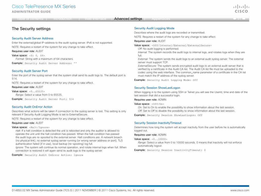
D14850.02 MX Series Administrator Guide (TC5.0) | 2011 NOVEMBER | © 2011 Cisco Systems, Inc. All rights reserved. www.cisco.com
51
Cisco TelePresence MX SeriesAdministrAtor guide
TheSecuritysettings
SecurityAuditServerAddressEnter the external/global IP-address to the audit syslog server. IPv6 is not supported.
NOTE: Requires a restart of the system for any change to take effect.
Requiresuserrole: AUDIT
Valuespace: <S: 0, 64>Format: String with a maximum of 64 characters.
Example: Security Audit Server Address: ""
SecurityAuditServerPortEnter the port of the syslog server that the system shall send its audit logs to. The default port is 514.
NOTE: Requires a restart of the system for any change to take effect.
Requiresuserrole: AUDIT
Valuespace: <0..65535>Range: Select a value from 0 to 65535.
Example: Security Audit Server Port: 514
SecurityAuditOnErrorActionDescribes what actions will be taken if connection to the syslog server is lost. This setting is only relevant if Security Audit Logging Mode is set to ExternalSecure.
NOTE: Requires a restart of the system for any change to take effect.
Requiresuserrole: AUDIT
Valuespace: <Halt/Ignore>Halt: If a halt condition is detected the unit is rebooted and only the auditor is allowed to operate the unit until the halt condition has passed. When the halt condition has passed the audit logs are re-spooled to the external server. Halt conditions are: A network breach (no physical link), no external syslog server running (or wrong server address or port), TLS authentication failed (if in use), local backup (re-spooling) log full.Ignore: The system will continue its normal operation, and rotate internal logs when full. When connection is restored it will again send its audit logs to the syslog server.
Example: Security Audit OnError Action: Ignore
SecurityAuditLoggingModeDescribes where the audit logs are recorded or transmitted.
NOTE: Requires a restart of the system for any change to take effect.
Requiresuserrole: AUDIT
Valuespace: <Off/Internal/External/ExternalSecure>Off: No audit logging is performed.Internal: The system records the audit logs to internal logs, and rotates logs when they are full.External: The system sends the audit logs to an external audit syslog server. The external server must support TCP.ExternalSecure: The system sends encrypted audit logs to an external audit server that is verified by a certificate in the Audit CA list. The Audit CA list file must be uploaded to the codec using the web interface. The common_name parameter of a certificate in the CA list must match the IP address of the syslog server.
Example: Security Audit Logging Mode: Off
SecuritySessionShowLastLogonWhen logging in to the system using SSH or Telnet you will see the UserId, time and date of the last session that did a successful login.
Requiresuserrole: ADMIN
Valuespace: <Off/On>On: Set to On to enable the possibility to show information about the last session.Off: Set to Off to disable the possibility to show information about the last session.
Example: Security Session ShowLastLogon: Off
SecuritySessionInactivityTimeoutDetermines how long the system will accept inactivity from the user before he is automatically logged out.
Requiresuserrole: ADMIN
Valuespace: <0..10000>Range: Select a value from 0 to 10000 seconds. 0 means that inactivity will not enforce automatically logout.
Example: Security Session InactivityTimeout: 0
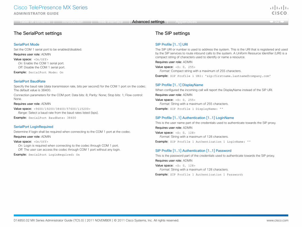
D14850.02 MX Series Administrator Guide (TC5.0) | 2011 NOVEMBER | © 2011 Cisco Systems, Inc. All rights reserved. www.cisco.com
52
Cisco TelePresence MX SeriesAdministrAtor guide
TheSerialPortsettings
SerialPortModeSet the COM 1 serial port to be enabled/disabled.
Requiresuserrole: ADMIN
Valuespace: <On/Off>On: Enable the COM 1 serial port.Off: Disable the COM 1 serial port.
Example: SerialPort Mode: On
SerialPortBaudRateSpecify the baud rate (data transmission rate, bits per second) for the COM 1 port on the codec. The default value is 38400.
Connection parameters for the COM port: Data bits: 8; Parity: None; Stop bits: 1; Flow control: None.
Requiresuserrole: ADMIN
Valuespace: <9600/19200/38400/57600/115200>Range: Select a baud rate from the baud rates listed (bps).
Example: SerialPort BaudRate: 38400
SerialPortLoginRequiredDetermine if login shall be required when connecting to the COM 1 port at the codec.
Requiresuserrole: ADMIN
Valuespace: <On/Off>On: Login is required when connecting to the codec through COM 1 port.Off: The user can access the codec through COM 1 port without any login.
Example: SerialPort LoginRequired: On
TheSIPsettings
SIPProfile[1..1]URIThe SIP URI or number is used to address the system. This is the URI that is registered and used by the SIP services to route inbound calls to the system. A Uniform Resource Identifier (URI) is a compact string of characters used to identify or name a resource.
Requiresuserrole: ADMIN
Valuespace: <S: 0, 255>Format: Compact string with a maximum of 255 characters.
Example: SIP Profile 1 URI: "sip:[email protected]"
SIPProfile[1..1]DisplayNameWhen configured the incoming call will report the DisplayName instead of the SIP URI.
Requiresuserrole: ADMIN
Valuespace: <S: 0, 255>Format: String with a maximum of 255 characters.
Example: SIP Profile 1 DisplayName: ""
SIPProfile[1..1]Authentication[1..1]LoginNameThis is the user name part of the credentials used to authenticate towards the SIP proxy.
Requiresuserrole: ADMIN
Valuespace: <S: 0, 128>Format: String with a maximum of 128 characters.
Example: SIP Profile 1 Authentication 1 LoginName: ""
SIPProfile[1..1]Authentication[1..1]PasswordThis is the password part of the credentials used to authenticate towards the SIP proxy.
Requiresuserrole: ADMIN
Valuespace: <S: 0, 128>Format: String with a maximum of 128 characters.
Example: SIP Profile 1 Authentication 1 Password:
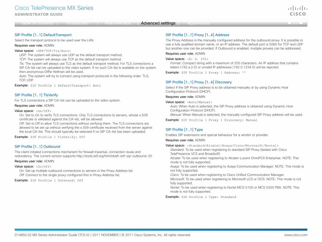
D14850.02 MX Series Administrator Guide (TC5.0) | 2011 NOVEMBER | © 2011 Cisco Systems, Inc. All rights reserved. www.cisco.com
53
Cisco TelePresence MX SeriesAdministrAtor guide
SIPProfile[1..1]DefaultTransportSelect the transport protocol to be used over the LAN.
Requiresuserrole: ADMIN
Valuespace: <UDP/TCP/Tls/Auto>UDP: The system will always use UDP as the default transport method.TCP: The system will always use TCP as the default transport method.Tls: The system will always use TLS as the default transport method. For TLS connections a SIP CA-list can be uploaded to the video system. If no such CA-list is available on the system then anonymous Diffie Hellman will be used.Auto: The system will try to connect using transport protocols in the following order: TLS, TCP, UDP.
Example: SIP Profile 1 DefaultTransport: Auto
SIPProfile[1..1]TlsVerifyFor TLS connections a SIP CA-list can be uploaded to the video system.
Requiresuserrole: ADMIN
Valuespace: <On/Off>On: Set to On to verify TLS connections. Only TLS connections to servers, whose x.509 certificate is validated against the CA-list, will be allowed.Off: Set to Off to allow TLS connections without verifying them. The TLS connections are allowed to be set up without verifying the x.509 certificate received from the server against the local CA-list. This should typically be selected if no SIP CA-list has been uploaded.
Example: SIP Profile 1 TlsVerify: Off
SIPProfile[1..1]OutboundThe client initiated connections mechanism for firewall traversal, connection reuse and redundancy. The current version supports http://tools.ietf.org/html/draft-ietf-sip-outbound-20.
Requiresuserrole: ADMIN
Valuespace: <On/Off>On: Set up multiple outbound connections to servers in the Proxy Address list.Off: Connect to the single proxy configured first in Proxy Address list.
Example: SIP Profile 1 Outbound: Off
SIPProfile[1..1]Proxy[1..4]AddressThe Proxy Address is the manually configured address for the outbound proxy. It is possible to use a fully qualified domain name, or an IP address. The default port is 5060 for TCP and UDP but another one can be provided. If Outbound is enabled, multiple proxies can be addressed.
Requiresuserrole: ADMIN
Valuespace: <S: 0, 255>Format: Compact string with a maximum of 255 characters. An IP address that contains letters (192.a.2.0) or unvalid IP addresses (192.0.1234.0) will be rejected.
Example: SIP Profile 1 Proxy 1 Address: ""
SIPProfile[1..1]Proxy[1..4]DiscoverySelect if the SIP Proxy address is to be obtained manually or by using Dynamic Host Configuration Protocol (DHCP).
Requiresuserrole: ADMIN
Valuespace: <Auto/Manual>Auto: When Auto is selected, the SIP Proxy address is obtained using Dynamic Host Configuration Protocol (DHCP).Manual: When Manual is selected, the manually configured SIP Proxy address will be used.
Example: SIP Profile 1 Proxy 1 Discovery: Manual
SIPProfile[1..1]TypeEnables SIP extensions and special behaviour for a vendor or provider.
Requiresuserrole: ADMIN
Valuespace: <Standard/Alcatel/Avaya/Cisco/Microsoft/Nortel>Standard: To be used when registering to standard SIP Proxy (tested with Cisco TelePresence VCS and Broadsoft)Alcatel: To be used when registering to Alcatel-Lucent OmniPCX Enterprise. NOTE: This mode is not fully supported.Avaya: To be used when registering to Avaya Communication Manager. NOTE: This mode is not fully supported.Cisco: To be used when registering to Cisco Unified Communication Manager.Microsoft: To be used when registering to Microsoft LCS or OCS. NOTE: This mode is not fully supported.Nortel: To be used when registering to Nortel MCS 5100 or MCS 5200 PBX. NOTE: This mode is not fully supported.
Example: SIP Profile 1 Type: Standard
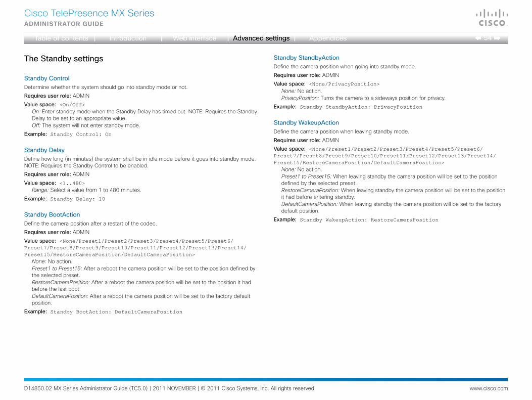
D14850.02 MX Series Administrator Guide (TC5.0) | 2011 NOVEMBER | © 2011 Cisco Systems, Inc. All rights reserved. www.cisco.com
54
Cisco TelePresence MX SeriesAdministrAtor guide
TheStandbysettings
StandbyControlDetermine whether the system should go into standby mode or not.
Requiresuserrole: ADMIN
Valuespace: <On/Off>On: Enter standby mode when the Standby Delay has timed out. NOTE: Requires the Standby Delay to be set to an appropriate value.Off: The system will not enter standby mode.
Example: Standby Control: On
StandbyDelayDefine how long (in minutes) the system shall be in idle mode before it goes into standby mode. NOTE: Requires the Standby Control to be enabled.
Requiresuserrole: ADMIN
Valuespace: <1..480>Range: Select a value from 1 to 480 minutes.
Example: Standby Delay: 10
StandbyBootActionDefine the camera position after a restart of the codec.
Requiresuserrole: ADMIN
Valuespace: <None/Preset1/Preset2/Preset3/Preset4/Preset5/Preset6/Preset7/Preset8/Preset9/Preset10/Preset11/Preset12/Preset13/Preset14/Preset15/RestoreCameraPosition/DefaultCameraPosition>
None: No action.Preset1 to Preset15: After a reboot the camera position will be set to the position defined by the selected preset.RestoreCameraPosition: After a reboot the camera position will be set to the position it had before the last boot.DefaultCameraPosition: After a reboot the camera position will be set to the factory default position.
Example: Standby BootAction: DefaultCameraPosition
StandbyStandbyActionDefine the camera position when going into standby mode.
Requiresuserrole: ADMIN
Valuespace: <None/PrivacyPosition>None: No action.PrivacyPosition: Turns the camera to a sideways position for privacy.
Example: Standby StandbyAction: PrivacyPosition
StandbyWakeupActionDefine the camera position when leaving standby mode.
Requiresuserrole: ADMIN
Valuespace: <None/Preset1/Preset2/Preset3/Preset4/Preset5/Preset6/Preset7/Preset8/Preset9/Preset10/Preset11/Preset12/Preset13/Preset14/Preset15/RestoreCameraPosition/DefaultCameraPosition>
None: No action.Preset1 to Preset15: When leaving standby the camera position will be set to the position defined by the selected preset.RestoreCameraPosition: When leaving standby the camera position will be set to the position it had before entering standby.DefaultCameraPosition: When leaving standby the camera position will be set to the factory default position.
Example: Standby WakeupAction: RestoreCameraPosition

D14850.02 MX Series Administrator Guide (TC5.0) | 2011 NOVEMBER | © 2011 Cisco Systems, Inc. All rights reserved. www.cisco.com
55
Cisco TelePresence MX SeriesAdministrAtor guide
TheSystemUnitsettings
SystemUnitNameEnter a System Name to define a name of the system unit. If the H.323 Alias ID is configured on the system then this ID will be used instead of the system name. The system name will be displayed:
1) When the codec is acting as an SNMP Agent.
2) Towards a DHCP server.
Requiresuserrole: ADMIN
Valuespace: <S: 0, 50>Format: String with a maximum of 50 characters.
Example: SystemUnit Name: "Meeting Room"
SystemUnitMenuLanguageSelect the language to be used in the menus on screen.
Requiresuserrole: USER
Valuespace: <English/ChineseSimplified/Finnish/French/German/Japanese/Russian/Swedish>
Example: SystemUnit MenuLanguage: English
SystemUnitContactInfoTypeNot applicable in this version.
SystemUnitTypeSelect whether the video system is for personal use or to be used in a multiuser environment. It is highly recommended not to use the default setting.
Requiresuserrole: ADMIN
Valuespace: <Personal/Shared>Personal: Set to Personal when the system is for personal use.Shared: Set to Shared when the system is used in a multiuser environment.
Example: SystemUnit Type: Personal
SystemUnitCallLoggingModeSet the call logging mode for calls that are received or placed by the system. The call logs may then be viewed via the web interface or using the xHistory command.
Requiresuserrole: ADMIN
Valuespace: <On/Off>On: Enable logging.Off: Disable logging.
Example: SystemUnit CallLogging Mode: On
SystemUnitIrSensorNot applicable in this version.
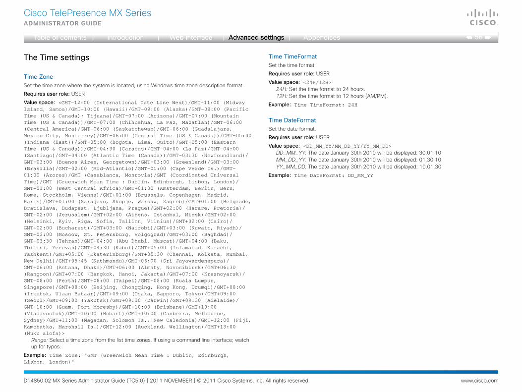
D14850.02 MX Series Administrator Guide (TC5.0) | 2011 NOVEMBER | © 2011 Cisco Systems, Inc. All rights reserved. www.cisco.com
56
Cisco TelePresence MX SeriesAdministrAtor guide
TheTimesettings
TimeZoneSet the time zone where the system is located, using Windows time zone description format.
Requiresuserrole: USER
Valuespace: <GMT-12:00 (International Date Line West)/GMT-11:00 (Midway Island, Samoa)/GMT-10:00 (Hawaii)/GMT-09:00 (Alaska)/GMT-08:00 (Pacific Time (US & Canada); Tijuana)/GMT-07:00 (Arizona)/GMT-07:00 (Mountain Time (US & Canada))/GMT-07:00 (Chihuahua, La Paz, Mazatlan)/GMT-06:00 (Central America)/GMT-06:00 (Saskatchewan)/GMT-06:00 (Guadalajara, Mexico City, Monterrey)/GMT-06:00 (Central Time (US & Canada))/GMT-05:00 (Indiana (East))/GMT-05:00 (Bogota, Lima, Quito)/GMT-05:00 (Eastern Time (US & Canada))/GMT-04:30 (Caracas)/GMT-04:00 (La Paz)/GMT-04:00 (Santiago)/GMT-04:00 (Atlantic Time (Canada))/GMT-03:30 (Newfoundland)/GMT-03:00 (Buenos Aires, Georgetown)/GMT-03:00 (Greenland)/GMT-03:00 (Brasilia)/GMT-02:00 (Mid-Atlantic)/GMT-01:00 (Cape Verde Is.)/GMT-01:00 (Azores)/GMT (Casablanca, Monrovia)/GMT (Coordinated Universal Time)/GMT (Greenwich Mean Time : Dublin, Edinburgh, Lisbon, London)/GMT+01:00 (West Central Africa)/GMT+01:00 (Amsterdam, Berlin, Bern, Rome, Stockholm, Vienna)/GMT+01:00 (Brussels, Copenhagen, Madrid, Paris)/GMT+01:00 (Sarajevo, Skopje, Warsaw, Zagreb)/GMT+01:00 (Belgrade, Bratislava, Budapest, Ljubljana, Prague)/GMT+02:00 (Harare, Pretoria)/GMT+02:00 (Jerusalem)/GMT+02:00 (Athens, Istanbul, Minsk)/GMT+02:00 (Helsinki, Kyiv, Riga, Sofia, Tallinn, Vilnius)/GMT+02:00 (Cairo)/GMT+02:00 (Bucharest)/GMT+03:00 (Nairobi)/GMT+03:00 (Kuwait, Riyadh)/GMT+03:00 (Moscow, St. Petersburg, Volgograd)/GMT+03:00 (Baghdad)/GMT+03:30 (Tehran)/GMT+04:00 (Abu Dhabi, Muscat)/GMT+04:00 (Baku, Tbilisi, Yerevan)/GMT+04:30 (Kabul)/GMT+05:00 (Islamabad, Karachi, Tashkent)/GMT+05:00 (Ekaterinburg)/GMT+05:30 (Chennai, Kolkata, Mumbai, New Delhi)/GMT+05:45 (Kathmandu)/GMT+06:00 (Sri Jayawardenepura)/GMT+06:00 (Astana, Dhaka)/GMT+06:00 (Almaty, Novosibirsk)/GMT+06:30 (Rangoon)/GMT+07:00 (Bangkok, Hanoi, Jakarta)/GMT+07:00 (Krasnoyarsk)/GMT+08:00 (Perth)/GMT+08:00 (Taipei)/GMT+08:00 (Kuala Lumpur, Singapore)/GMT+08:00 (Beijing, Chongqing, Hong Kong, Urumqi)/GMT+08:00 (Irkutsk, Ulaan Bataar)/GMT+09:00 (Osaka, Sapporo, Tokyo)/GMT+09:00 (Seoul)/GMT+09:00 (Yakutsk)/GMT+09:30 (Darwin)/GMT+09:30 (Adelaide)/GMT+10:00 (Guam, Port Moresby)/GMT+10:00 (Brisbane)/GMT+10:00 (Vladivostok)/GMT+10:00 (Hobart)/GMT+10:00 (Canberra, Melbourne, Sydney)/GMT+11:00 (Magadan, Solomon Is., New Caledonia)/GMT+12:00 (Fiji, Kamchatka, Marshall Is.)/GMT+12:00 (Auckland, Wellington)/GMT+13:00 (Nuku alofa)>
Range: Select a time zone from the list time zones. If using a command line interface; watch up for typos.
Example: Time Zone: "GMT (Greenwich Mean Time : Dublin, Edinburgh, Lisbon, London)"
TimeTimeFormatSet the time format.
Requiresuserrole: USER
Valuespace: <24H/12H>24H: Set the time format to 24 hours.12H: Set the time format to 12 hours (AM/PM).
Example: Time TimeFormat: 24H
TimeDateFormatSet the date format.
Requiresuserrole: USER
Valuespace: <DD_MM_YY/MM_DD_YY/YY_MM_DD>DD_MM_YY: The date January 30th 2010 will be displayed: 30.01.10MM_DD_YY: The date January 30th 2010 will be displayed: 01.30.10YY_MM_DD: The date January 30th 2010 will be displayed: 10.01.30
Example: Time DateFormat: DD_MM_YY
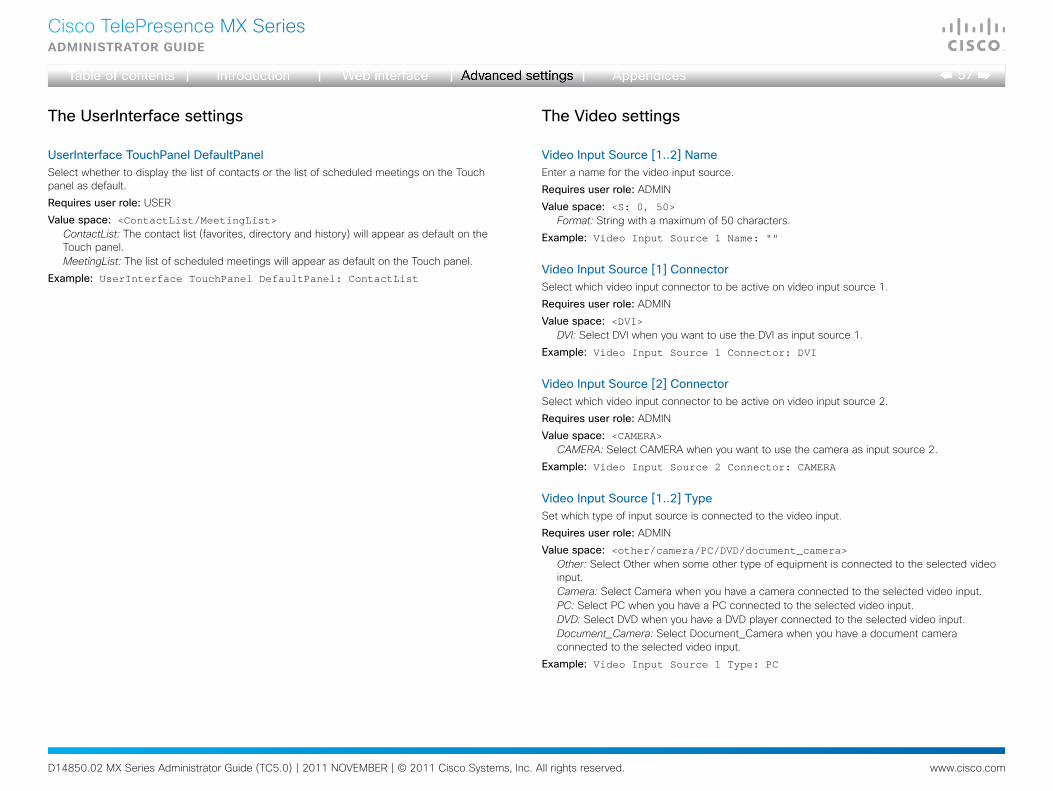
D14850.02 MX Series Administrator Guide (TC5.0) | 2011 NOVEMBER | © 2011 Cisco Systems, Inc. All rights reserved. www.cisco.com
57
Cisco TelePresence MX SeriesAdministrAtor guide
TheUserInterfacesettings
UserInterfaceTouchPanelDefaultPanelSelect whether to display the list of contacts or the list of scheduled meetings on the Touch panel as default.
Requiresuserrole: USER
Valuespace: <ContactList/MeetingList>ContactList: The contact list (favorites, directory and history) will appear as default on the Touch panel. MeetingList: The list of scheduled meetings will appear as default on the Touch panel.
Example: UserInterface TouchPanel DefaultPanel: ContactList
TheVideosettings
VideoInputSource[1..2]NameEnter a name for the video input source.
Requiresuserrole: ADMIN
Valuespace: <S: 0, 50>Format: String with a maximum of 50 characters.
Example: Video Input Source 1 Name: ""
VideoInputSource[1]ConnectorSelect which video input connector to be active on video input source 1.
Requiresuserrole: ADMIN
Valuespace: <DVI>DVI: Select DVI when you want to use the DVI as input source 1.
Example: Video Input Source 1 Connector: DVI
VideoInputSource[2]ConnectorSelect which video input connector to be active on video input source 2.
Requiresuserrole: ADMIN
Valuespace: <CAMERA>CAMERA: Select CAMERA when you want to use the camera as input source 2.
Example: Video Input Source 2 Connector: CAMERA
VideoInputSource[1..2]TypeSet which type of input source is connected to the video input.
Requiresuserrole: ADMIN
Valuespace: <other/camera/PC/DVD/document_camera>Other: Select Other when some other type of equipment is connected to the selected video input.Camera: Select Camera when you have a camera connected to the selected video input.PC: Select PC when you have a PC connected to the selected video input.DVD: Select DVD when you have a DVD player connected to the selected video input.Document_Camera: Select Document_Camera when you have a document camera connected to the selected video input.
Example: Video Input Source 1 Type: PC
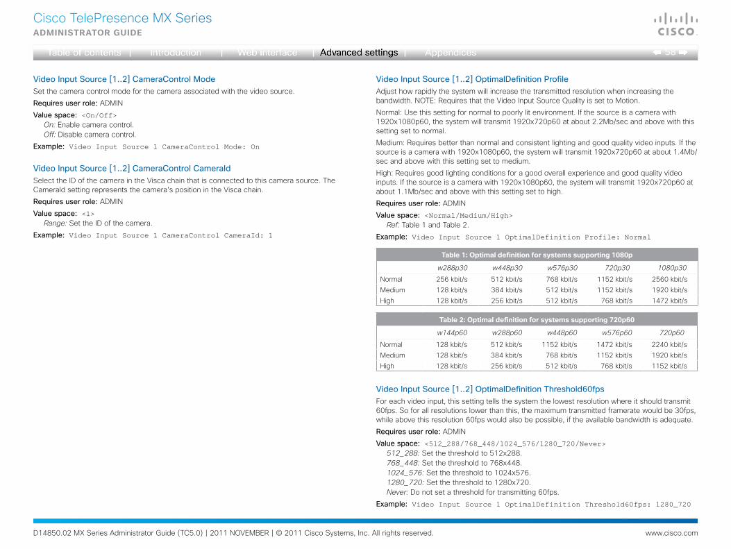
D14850.02 MX Series Administrator Guide (TC5.0) | 2011 NOVEMBER | © 2011 Cisco Systems, Inc. All rights reserved. www.cisco.com
58
Cisco TelePresence MX SeriesAdministrAtor guide
VideoInputSource[1..2]CameraControlModeSet the camera control mode for the camera associated with the video source.
Requiresuserrole: ADMIN
Valuespace: <On/Off>On: Enable camera control.Off: Disable camera control.
Example: Video Input Source 1 CameraControl Mode: On
VideoInputSource[1..2]CameraControlCameraIdSelect the ID of the camera in the Visca chain that is connected to this camera source. The CameraId setting represents the camera's position in the Visca chain.
Requiresuserrole: ADMIN
Valuespace: <1>Range: Set the ID of the camera.
Example: Video Input Source 1 CameraControl CameraId: 1
VideoInputSource[1..2]OptimalDefinitionProfileAdjust how rapidly the system will increase the transmitted resolution when increasing the bandwidth. NOTE: Requires that the Video Input Source Quality is set to Motion.
Normal: Use this setting for normal to poorly lit environment. If the source is a camera with 1920x1080p60, the system will transmit 1920x720p60 at about 2.2Mb/sec and above with this setting set to normal.
Medium: Requires better than normal and consistent lighting and good quality video inputs. If the source is a camera with 1920x1080p60, the system will transmit 1920x720p60 at about 1.4Mb/sec and above with this setting set to medium.
High: Requires good lighting conditions for a good overall experience and good quality video inputs. If the source is a camera with 1920x1080p60, the system will transmit 1920x720p60 at about 1.1Mb/sec and above with this setting set to high.
Requiresuserrole: ADMIN
Valuespace: <Normal/Medium/High>Ref: Table 1 and Table 2.
Example: Video Input Source 1 OptimalDefinition Profile: Normal
.
VideoInputSource[1..2]OptimalDefinitionThreshold60fpsFor each video input, this setting tells the system the lowest resolution where it should transmit 60fps. So for all resolutions lower than this, the maximum transmitted framerate would be 30fps, while above this resolution 60fps would also be possible, if the available bandwidth is adequate.
Requiresuserrole: ADMIN
Valuespace: <512_288/768_448/1024_576/1280_720/Never>512_288: Set the threshold to 512x288.768_448: Set the threshold to 768x448.1024_576: Set the threshold to 1024x576.1280_720: Set the threshold to 1280x720.Never: Do not set a threshold for transmitting 60fps.
Example: Video Input Source 1 OptimalDefinition Threshold60fps: 1280_720
table 1: optimal definition for systems supporting 1080p
w288p30 w448p30 w576p30 720p30 1080p30
Normal 256 kbit/s 512 kbit/s 768 kbit/s 1152 kbit/s 2560 kbit/sMedium 128 kbit/s 384 kbit/s 512 kbit/s 1152 kbit/s 1920 kbit/sHigh 128 kbit/s 256 kbit/s 512 kbit/s 768 kbit/s 1472 kbit/s
table 2: optimal definition for systems supporting 720p60
w144p60 w288p60 w448p60 w576p60 720p60
Normal 128 kbit/s 512 kbit/s 1152 kbit/s 1472 kbit/s 2240 kbit/sMedium 128 kbit/s 384 kbit/s 768 kbit/s 1152 kbit/s 1920 kbit/sHigh 128 kbit/s 256 kbit/s 512 kbit/s 768 kbit/s 1152 kbit/s
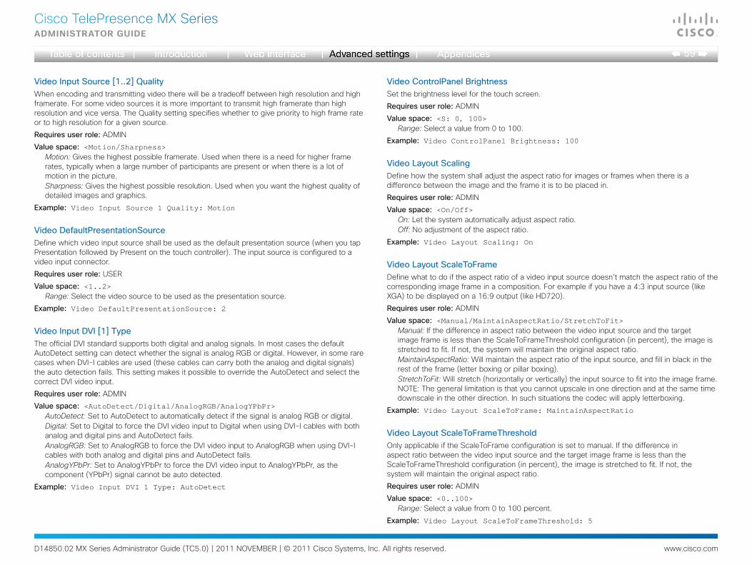
D14850.02 MX Series Administrator Guide (TC5.0) | 2011 NOVEMBER | © 2011 Cisco Systems, Inc. All rights reserved. www.cisco.com
59
Cisco TelePresence MX SeriesAdministrAtor guide
VideoInputSource[1..2]QualityWhen encoding and transmitting video there will be a tradeoff between high resolution and high framerate. For some video sources it is more important to transmit high framerate than high resolution and vice versa. The Quality setting specifies whether to give priority to high frame rate or to high resolution for a given source.
Requiresuserrole: ADMIN
Valuespace: <Motion/Sharpness>Motion: Gives the highest possible framerate. Used when there is a need for higher frame rates, typically when a large number of participants are present or when there is a lot of motion in the picture.Sharpness: Gives the highest possible resolution. Used when you want the highest quality of detailed images and graphics.
Example: Video Input Source 1 Quality: Motion
VideoDefaultPresentationSourceDefine which video input source shall be used as the default presentation source (when you tap Presentation followed by Present on the touch controller). The input source is configured to a video input connector.
Requiresuserrole: USER
Valuespace: <1..2>Range: Select the video source to be used as the presentation source.
Example: Video DefaultPresentationSource: 2
VideoInputDVI[1]TypeThe official DVI standard supports both digital and analog signals. In most cases the default AutoDetect setting can detect whether the signal is analog RGB or digital. However, in some rare cases when DVI-I cables are used (these cables can carry both the analog and digital signals) the auto detection fails. This setting makes it possible to override the AutoDetect and select the correct DVI video input.
Requiresuserrole: ADMIN
Valuespace: <AutoDetect/Digital/AnalogRGB/AnalogYPbPr>AutoDetect: Set to AutoDetect to automatically detect if the signal is analog RGB or digital. Digital: Set to Digital to force the DVI video input to Digital when using DVI-I cables with both analog and digital pins and AutoDetect fails. AnalogRGB: Set to AnalogRGB to force the DVI video input to AnalogRGB when using DVI-I cables with both analog and digital pins and AutoDetect fails. AnalogYPbPr: Set to AnalogYPbPr to force the DVI video input to AnalogYPbPr, as the component (YPbPr) signal cannot be auto detected.
Example: Video Input DVI 1 Type: AutoDetect
VideoControlPanelBrightnessSet the brightness level for the touch screen.
Requiresuserrole: ADMIN
Valuespace: <S: 0, 100>Range: Select a value from 0 to 100.
Example: Video ControlPanel Brightness: 100
VideoLayoutScalingDefine how the system shall adjust the aspect ratio for images or frames when there is a difference between the image and the frame it is to be placed in.
Requiresuserrole: ADMIN
Valuespace: <On/Off>On: Let the system automatically adjust aspect ratio.Off: No adjustment of the aspect ratio.
Example: Video Layout Scaling: On
VideoLayoutScaleToFrameDefine what to do if the aspect ratio of a video input source doesn't match the aspect ratio of the corresponding image frame in a composition. For example if you have a 4:3 input source (like XGA) to be displayed on a 16:9 output (like HD720).
Requiresuserrole: ADMIN
Valuespace: <Manual/MaintainAspectRatio/StretchToFit>Manual: If the difference in aspect ratio between the video input source and the target image frame is less than the ScaleToFrameThreshold configuration (in percent), the image is stretched to fit. If not, the system will maintain the original aspect ratio.MaintainAspectRatio: Will maintain the aspect ratio of the input source, and fill in black in the rest of the frame (letter boxing or pillar boxing).StretchToFit: Will stretch (horizontally or vertically) the input source to fit into the image frame. NOTE: The general limitation is that you cannot upscale in one direction and at the same time downscale in the other direction. In such situations the codec will apply letterboxing.
Example: Video Layout ScaleToFrame: MaintainAspectRatio
VideoLayoutScaleToFrameThresholdOnly applicable if the ScaleToFrame configuration is set to manual. If the difference in aspect ratio between the video input source and the target image frame is less than the ScaleToFrameThreshold configuration (in percent), the image is stretched to fit. If not, the system will maintain the original aspect ratio.
Requiresuserrole: ADMIN
Valuespace: <0..100>Range: Select a value from 0 to 100 percent.
Example: Video Layout ScaleToFrameThreshold: 5
D14850.02 MX Series Administrator Guide (TC5.0) | 2011 NOVEMBER | © 2011 Cisco Systems, Inc. All rights reserved. www.cisco.com
60
Cisco TelePresence MX SeriesAdministrAtor guide
VideoLayoutLocalLayoutFamilySelect which video layout family to be used locally.
Requiresuserrole: ADMIN
Valuespace: <Auto/FullScreen/Equal/PresentationSmallSpeaker/PresentationLargeSpeaker>
Auto: The default layout family, as given by the layout database, will be used as the local layout. For more information about the layout database, see the command: xCommand Video Layout LoadDb.FullScreen: The FullScreen layout family will be used as the local layout.Equal: The Equal layout family will be used as the local layout.PresentationSmallSpeaker: The PresentationSmallSpeaker layout family will be used as the local layout.PresentationLargeSpeaker: The PresentationLargeSpeaker layout family will be used as the local layout.
Example: Video Layout LocalLayoutFamily: Auto
VideoLayoutRemoteLayoutFamilySelect which video layout family to be used for the remote participants.
Requiresuserrole: ADMIN
Valuespace: <Auto/FullScreen/Equal/PresentationSmallSpeaker/PresentationLargeSpeaker>
Auto: The default layout family, as given by the local layout database, will be used as the remote layout. For more information about the layout database, see the command: xCommand Video Layout LoadDb.FullScreen: The FullScreen layout family will be used as the remote layout.Equal: The Equal layout family will be used as the remote layout.PresentationSmallSpeaker: The PresentationSmallSpeaker layout family will be used as the remote layout.PresentationLargeSpeaker: The PresentationLargeSpeaker layout family will be used as the remote layout.
Example: Video Layout RemoteLayoutFamily: Auto
VideoMainVideoSourceDefine which video input source shall be used as the main video source. The video input source is configured with the "Video Input Source [1..2] Connector" setting.
Requiresuserrole: USER
Valuespace: <1..2>Range: Select the source to be used as the main video source.
Example: Video MainVideoSource: 1
VideoMonitorsSet the monitor layout mode.
Requiresuserrole: ADMIN
Valuespace: <Single/Dual/DualPresentationOnly>Single: The same layout is shown on all monitors.Dual: The layout is distributed on two monitors.DualPresentationOnly: All participants in the call will be shown on the first monitor, while the presentation (if any) will be shown on the second monitor.
Example: Video Monitors: Single
VideoOSDModeNot applicable in this version.
VideoOSDAutoSelectPresentationSourceNot applicable in this version.
VideoOSDTodaysBookingsNot applicable in this version.
VideoOSDMyContactsExpandedNot applicable in this version.
VideoOSDOutputNot applicable in this version.
VideoOSDInputMethodInputLanguageNot applicable in this version.
VideoOSDInputMethodCyrillicNot applicable in this version.
VideoOSDLoginRequiredNot applicable in this version.
D14850.02 MX Series Administrator Guide (TC5.0) | 2011 NOVEMBER | © 2011 Cisco Systems, Inc. All rights reserved. www.cisco.com
61
Cisco TelePresence MX SeriesAdministrAtor guide
VideoAllowWebSnapshotsAllow or disallow that snapshots captured by the video input main source can be displayed in the web interface Call Control page.
NOTE: This feature is disabled by default, and must be enabled from the Touch controller.
Requiresuserrole: ADMIN
Valuespace: <On/Off>On: If set to on, a web snapshot can be generated and displayed on the web interface.Off: The generation of web snapshots is not allowed.
Example: Video AllowWebSnapshots: Off
VideoOutputLCD[1]ResolutionSet the screen resolution.
Requiresuserrole: ADMIN
Valuespace: <1920_1080_60>Range: The screen resolution is 1920 x 1080 60 Hz.
Example: Video Output LCD 1 Resolution: 1920_1080_60
VideoOutputLCD[1]MonitorRoleSet the LCD monitor role.
It is highly recommended to use the default setting. NOTE: The settings made here will be overruled by the touch controller.
Requiresuserrole: ADMIN
Valuespace: <First/Second/PresentationOnly/InternalSetup>First: Show main video stream.Second: Show presentation video stream if active, or other participants.PresentationOnly: Show presentation video stream if active, and nothing else.InternalSetup: Internal setup from the touch controller will be used.
Example: Video Output LCD 1 MonitorRole: InternalSetup
VideoOutputLCD[1]BrightnessSet the brightness level for the monitor.
Requiresuserrole: ADMIN
Valuespace: <S: 0, 100>Range: Select a value from 0 to 100.
Example: Video Output LCD 1 Brightness: 50
VideoOutputLCD[1]RedSet the Red color level for the monitor.
Requiresuserrole: ADMIN
Valuespace: <S: 0, 100>Range: Select a value from 0 to 100.
Example: Video Output LCD 1 Red: 50
VideoOutputLCD[1]GreenSet the Green color level for the monitor.
Requiresuserrole: ADMIN
Valuespace: <S: 0, 100>Range: Select a value from 0 to 100.
Example: Video Output LCD 1 Green: 50
VideoOutputLCD[1]BlueSet the Blue color level for the monitor.
Requiresuserrole: ADMIN
Valuespace: <S: 0, 100>Range: Select a value from 0 to 100.
Example: Video Output LCD 1 Blue: 50
VideoOutputInternal[2]MonitorRoleDetermine the role of the internal monitor and select where to show the video stream and presentation.
It is highly recommended to use the default setting.
Requiresuserrole: ADMIN
Valuespace: <First/Second/PresentationOnly>First: Show the main video stream.Second: Show presentation video stream if active, or other participants.PresentationOnly: Show presentation video stream if active, and nothing else.
Example: Video Output Internal 2: First
VideoSelfviewDetermine if the main video source (selfview) shall be displayed on screen.
Requiresuserrole: USER
Valuespace: <On/Off>On: Display selfview on screen.Off: Do not display selfview on screen.
Example: Video Selfview: On
D14850.02 MX Series Administrator Guide (TC5.0) | 2011 NOVEMBER | © 2011 Cisco Systems, Inc. All rights reserved. www.cisco.com
62
Cisco TelePresence MX SeriesAdministrAtor guide
VideoWallPaperDetermine which background picture to show on the touch screen and main screen when idle. It is recommended to use Wallpaper01 to Wallpaper12.
Requiresuserrole: USER
Valuespace: <None/Growing/Summersky/Custom/Wallpaper01/Wallpaper02/Wallpaper03/Wallpaper04/Wallpaper05/Wallpaper06/Wallpaper07/Wallpaper08/Wallpaper09/Wallpaper10/Wallpaper11/Wallpaper12>
Wallpaper01 to Wallpaper12: Select one of the predefined wallpapers to be displayed on the main screen and touch screen. The wallpaper will be shown on both screens. None: No wallpaper will be displayed on the main screen. NOTE: When you change the wallpaper on the touch screen, it will also set the wallpaper for the main screen.Summersky, Growing: Select one of the predefined wallpapers to be displayed on the main screen. It will not be displayed on the touch screen. NOTE: When you change the wallpaper on the touch screen, it will also change the wallpaper for the main screen.Custom: The custom wallpaper will only show on the main screen, not the touch screen. It must be uploaded to the codec from the web interface before selecting Custom. The maximum supported resolution is 1920x1280. 1) On the video system: Find the IP address of the codec. Open the menu on screen and go to Home > Settings > System information to find the IP Address. 2) On your computer: Open a web browser and enter the IP address of the codec. Select "Wallpaper" from the menu, browse for the file, and press the "Upload" button. 3) On the web interface: Log in and go to Advanced Configuration > Video > Wallpaper and select Custom. Give it a few seconds to display the new picture. If the picture does not show, toggle once between "None" and "Custom" wallpaper to make the change take effect. NOTE: When you change the wallpaper on the touch screen, it will also change the wallpaper for the main screen.
Example: Video Wallpaper: Wallpaper01
TheExperimentalsettingsThe Experimental settings are beta preview features and can be used 'as is'. They are not fully documented.
NOTE: The Experimental settings are likely to change without further notice.
ExperimentalCapsetFilterNOTE: This Experimental command can be used 'as is' and will not be further documented. The Experimental settings WILL change.
Requiresuserrole: ADMIN
Valuespace: <S: 0, 100>Example: Experimental CapsetFilter: ""
ExperimentalCapsetReductionNOTE: This Experimental command can be used 'as is' and will not be further documented. The Experimental settings WILL change.
Requiresuserrole: ADMIN
Valuespace: <Auto/Reduced>Example: Experimental CapsetReduction: Auto
ExperimentalConference[1..1]PacketLossResilienceForwardErrorCorrectionNOTE: This Experimental command can be used 'as is' and will not be further documented. The Experimental settings WILL change.
Will enable ForwardErrorCorrection (RFC5109) mechanism as part of the PacketLossResilience mechanism. Default value is On.
On: Forward error correction will be used as part of the PacketLossResilience mechanism.
Off: Forward error correction will NOT be used as part of the PacketLossResilience mechanism.
Requiresuserrole: ADMIN
Valuespace: <On/Off>Example: Experimental Conference 1 PacketLossResilience ForwardErrorCorrection: On

D14850.02 MX Series Administrator Guide (TC5.0) | 2011 NOVEMBER | © 2011 Cisco Systems, Inc. All rights reserved. www.cisco.com
63
Cisco TelePresence MX SeriesAdministrAtor guide
ExperimentalConference[1..1]PacketLossResilienceRateAdaptionNOTE: This Experimental command can be used 'as is' and will not be further documented. The Experimental settings WILL change.
Will use the a RateAdaption algorithm adapted to the PacketLossResilience mechanism. Default value is On.
Requiresuserrole: ADMIN
Valuespace: <On/Off>On: RateAdaption will be used as part of the PacketLossResilience mechanism.Off: RateAdaption will NOT be used as part of the PacketLossResilience mechanism.
Example: Experimental Conference 1 PacketLossResilience RateAdaption: On
ExperimentalConference[1..1]ReceiverBasedDownspeedingNOTE: This Experimental command can be used 'as is' and will not be further documented. The Experimental settings WILL change.
Requiresuserrole: ADMIN
Valuespace: <On/Off>Example: Experimental Conference 1 ReceiverBasedDownspeeding: Off
ExperimentalNetworkServicesUPnPModeNOTE: This Experimental command can be used 'as is' and will not be further documented. The Experimental settings WILL change.
Requiresuserrole: ADMIN
Valuespace: <On/Off>Example: Experimental NetworkServices UPnP Mode: Off
ExperimentalNetworkServicesUPnPTimeoutNOTE: This Experimental command can be used 'as is' and will not be further documented. The Experimental settings WILL change.
Requiresuserrole: ADMIN
Valuespace: <0..3600>Example: Experimental NetworkServices UPnP Timeout: 0
ExperimentalCTMSSupportModeNOTE: This Experimental command can be used 'as is' and will not be further documented. The Experimental settings WILL change.
This configuration tells whether CTMS (Cisco TelePresence Multipoint Switch) is supported or not.
Requiresuserrole: ADMIN
Valuespace: <Off/On>Off: CTMS is not supported.On: CTMS is supported.
Example: Experimental CTMSSupport Mode: On
ExperimentalPacketOverloadHandlingWhenDetectedNOTE: This Experimental command can be used 'as is' and will not be further documented. The Experimental settings WILL change.
Requiresuserrole: ADMIN
Valuespace: <Off/CallRate2256/CallRate768/ReduceTo576p/ReduceTo360p/Unencrypted/Disconnect>
Example: Experimental PacketOverloadHandling WhenDetected: Off
ExperimentalSystemUnitMenuTypeNOTE: This Experimental command can be used 'as is' and will not be further documented. The Experimental settings WILL change.
Requiresuserrole: ADMIN
Valuespace: <Indicators/Full>Example: Experimental SystemUnit MenuType: Full
ExperimentalSystemUnitSoftwareUpgradeRequireAuthenticationNOTE: This Experimental command can be used 'as is' and will not be further documented. The Experimental settings WILL change.
Requiresuserrole: ADMIN
Valuespace: <On/Off>Example: Experimental SystemUnit SoftwareUpgrade RequireAuthentication: Off
D14850.02 MX Series Administrator Guide (TC5.0) | 2011 NOVEMBER | © 2011 Cisco Systems, Inc. All rights reserved. www.cisco.com
64
Cisco TelePresence MX SeriesAdministrAtor guide
ExperimentalSystemUnitCrashReportingModeNOTE: This Experimental command can be used 'as is' and will not be further documented. The Experimental settings WILL change.
Requiresuserrole: ADMIN
Valuespace: <Off/On>Example: Experimental SystemUnit CrashReporting Mode: Off
ExperimentalSystemUnitCrashReportingURINOTE: This Experimental command can be used 'as is' and will not be further documented. The Experimental settings WILL change.
Requiresuserrole: ADMIN
Valuespace: <S: 0, 255>Example: Experimental SystemUnit CrashReporting URI: ""
D14850.02 MX Series Administrator Guide (TC5.0) | 2011 NOVEMBER | © 2011 Cisco Systems, Inc. All rights reserved. www.cisco.com
65
Cisco TelePresence MX SeriesAdministrAtor guide
Appendices
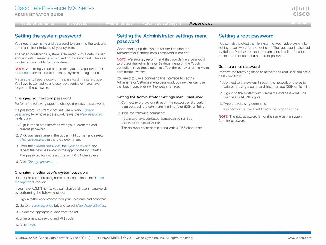
D14850.02 MX Series Administrator Guide (TC5.0) | 2011 NOVEMBER | © 2011 Cisco Systems, Inc. All rights reserved. www.cisco.com
66
Cisco TelePresence MX SeriesAdministrAtor guide
SettingthesystempasswordYou need a username and password to sign in to the web and command line interfaces of your system.
The video conference system is delivered with a default user account with username admin and no password set. This user has full access rights to the system.
NOTE: We strongly recommend that you set a password for the admin user to restrict access to system configuration.
Make sure to keep a copy of the password in a safe place. You have to contact your Cisco representative if you have forgotten the password.
ChangingyoursystempasswordPerform the following steps to change the system password.
If a password is currently not set, use a blank Current password; to remove a password, leave the New password fields blank.
1. Sign in to the web interface with your username and current password.
2. Click your username in the upper right corner and select Change password in the drop down menu.
3. Enter the Current password, the New password, and repeat the new password in the appropriate input fields.
The password format is a string with 0–64 characters.
4. Click Change password.
Changinganotheruser’ssystempasswordRead more about creating more user accounts in the User management section.
If you have ADMIN rights, you can change all users’ passwords by performing the following steps:
1. Sign in to the web interface with your username and password.
2. Go to the Maintenance tab and select User Administration.
3. Select the appropriate user from the list.
4. Enter a new password and PIN code.
5. Click Save.
SettingtheAdministratorsettingsmenupasswordWhen starting up the system for the first time the Administrator Settings menu password is not set.
NOTE: We strongly recommend that you define a password to protect the Administrator Settings menu on the Touch controller, since these settings affect the behavior of the video conference system.
You need to use a command line interface to set the Administrator Settings menu password; you neither can use the Touch controller nor the web interface.
SettingtheAdministratorSettingsmenupassword1. Connect to the system through the network or the serial
data port, using a command line interface (SSH or Telnet).
2. Type the following command:
xCommand SystemUnit MenuPassword Set Password: <password>
The password format is a string with 0–255 characters.
SettingarootpasswordYou can also protect the file system of your video system by setting a password for the root user. The root user is disabled by default. You have to use the command line interface to enable the root user and set a root password.
SettingarootpasswordPerform the following steps to activate the root user and set a password for it:
1. Connect to the system through the network or the serial data port, using a command line interface (SSH or Telnet).
2. Sign in to the system with username and password. The user needs ADMIN rights.
3. Type the following command:
systemtools rootsettings on <password>
NOTE:The root password is not the same as the system (admin) password.
D14850.02 MX Series Administrator Guide (TC5.0) | 2011 NOVEMBER | © 2011 Cisco Systems, Inc. All rights reserved. www.cisco.com
67
Cisco TelePresence MX SeriesAdministrAtor guide
CiscoVCSprovisioningWhen using Cisco VCS (Video Communication Server)provisioning, a template containing all the settings that can be provisioned must be uploaded to Cisco TMS (TelePresence Management System). This is called the Cisco TMS provisioning configuration template.
All the Advanced Settings for your video system are included in this template. All settings except SystemUnit Name and SIP Profile [1..1] URI can be automatically provisioned to the video system.
The settings are described in the Advanced settings chapter in this guide. Examples showing either the default value or an example value are included.
DownloadingtheprovisioningconfigurationtemplateYou can download the templates here:
http://www.cisco.com/en/US/products/ps11776/prod_release_notes_list.html
For each software release there is one provisioning configuration template for every video system model. Take care to download the correct file.
Read the Cisco TMS Provisioning Deployment Guide to find how to upload the file to Cisco TMS, and how to set the desired values for the parameters to be provisioned. If not set by Cisco TMS, the default values will be used.

D14850.02 MX Series Administrator Guide (TC5.0) | 2011 NOVEMBER | © 2011 Cisco Systems, Inc. All rights reserved. www.cisco.com
68
Cisco TelePresence MX SeriesAdministrAtor guide
OptimaldefinitionprofilesUnder ideal lighting conditions the bandwidth requirements can be substantially reduced with the optimal definitions profiles.
Generally, we recommend the Optimal Definition set at Normal.
If lighting conditions are good we recommend that you test the endpoint on the various Optimal Definition settings before deciding on a profile.
Go to Advanced Configuration on the web interface and navigate to Video > Input > Source [1..n] > OptimalDefinition > Profile and select the optimal definition profile.
You can set a resolution threshold below which the maximum frame rate will be 30 fps.
Go to Advanced Configuration on the web interface and navigate to Video > Input > Source [1..n] > OptimalDefinition > Threshold60fps and select a threshold.
The video input quality settings must be set to Motion for the Optimal Definition to work. With the video input quality set to Sharpness, the endpoint will transmit the highest resolution possible, regardless of frame rate.
Go to Advanced Configuration on the web interface and navigate to Video > Input > Source [1..n] > Quality and set the video quality parameter.
You can read more about the video settings in the Advanced settings chapter.
table 1: optimal definition for systems supporting 1080p
w288p30 w448p30 w576p30 720p30 1080p30
Normal 256 kbit/s 512 kbit/s 768 kbit/s 1152 kbit/s 2560 kbit/s
Medium 128 kbit/s 384 kbit/s 512 kbit/s 1152 kbit/s 1920 kbit/s
High 128 kbit/s 256 kbit/s 512 kbit/s 768 kbit/s 1472 kbit/s
table 2: optimal definition for systems supporting 720p60
w144p60 w288p60 w448p60 w576p60 720p60
Normal 128 kbit/s 512 kbit/s 1152 kbit/s 1472 kbit/s 2240 kbit/s
Medium 128 kbit/s 384 kbit/s 768 kbit/s 1152 kbit/s 1920 kbit/s
High 128 kbit/s 256 kbit/s 512 kbit/s 768 kbit/s 1152 kbit/s
High(720p60)
Typically used in dedicated video conferencing rooms. Requires good lighting conditions for a good overall experience.
Under ideal conditions the bandwidth requirements can be reduced by up to 50%.
Medium(w576p60)
Typically used in rooms with better than normal, and consistent lighting.
The bandwidth requirements can be reduced by up to 25%.
Normal(w448p60)
This setting is typically used in office environments where the environment is normal to poorly lit.
Generally, we recommend the Optimal Definition set at Normal.
D14850.02 MX Series Administrator Guide (TC5.0) | 2011 NOVEMBER | © 2011 Cisco Systems, Inc. All rights reserved. www.cisco.com
69
Cisco TelePresence MX SeriesAdministrAtor guide
ClearPath—PacketlossresilienceClearPath introduces advanced packet loss resilience mechanisms that increase the experienced quality when you use your video system in an error prone environment.
To configure ClearPath select Advanced Configuration on the web interface and navigate to Conference 1 > PacketLossResilience > Mode. Select Off to disable ClearPath and select On to enable ClearPath.
We recommend that you keep ClearPath enabled on your video system.

D14850.02 MX Series Administrator Guide (TC5.0) | 2011 NOVEMBER | © 2011 Cisco Systems, Inc. All rights reserved. www.cisco.com
70
Cisco TelePresence MX SeriesAdministrAtor guide
TechnicalspecificationforMX300/MX200
PRODUCTSPECIFICATION
Productcompatibility
Fully compatible with standards-compliant telepresence and video systems
Softwarecompatibility
MX200: Cisco TelePresence Software Version TC4.2 or later
MX300: Cisco TelePresence Software Version TC5.0 or later
Components
Fully integrated unit including:• Codec• Display• Camera• Integrated microphone and loudspeakers
Cisco TelePresence Table Mic 20 microphone (MX200 comes standard with one microphone; MX300 comes standard with two microphones)
Cables: VGA-to-DVI-I cable, 3.5 mm jack audio cable, LAN cable, and power cable
Display
• LCD monitor: 42” (MX200), 55” (MX300)
• Resolution: 1920 x 1200 (16:9)• Contrast ratio: 2500:1• Viewing angle: 178° • Response time:
8 ms (MX200), 10 ms (MX300) • Brightness: 550 cd/m2
PCandsecond-sourcevideoinput
DVI-I
SupportedPCinputresolutions
SVGA (800 x 600) to 1080p (1920 x 1080)
Camera
• PrecisionHD camera: 1080p 4x zoom• Resolutions: 1080p30 and 720p60 • Auto-focus• Wide-angle 72-degree horizontal field of
view• 4x optical zoom• Pan +/–100 degrees• Tilt +/–25 degrees
Audiosystem
• Integrated full-range speaker and woofer• Integrated full-range microphone• Bluetooth-ready • Support for two Cisco TelePresence Table
Mic 20 microphones • RCA PC audio input• RCA audio output
Userinterface
Cisco TelePresence Touch• Eight-inch projected capacitive touch screen• Resolution: 800 x 480
Languagesupport
• English• Finnish• French• German• Japanese• Russian• Simplified Chinese• Swedish
Physicaldimensions
MX200 with floor stand:Height: 1429 mm / 56.3 in.Width: 1026 mm / 40.4 in.Depth: 602 mm / 23.7 in.Weight: 40.2 kg / 89 lb
MX200 with table stand:Height: 781 mm / 30.7 in.Width: 1026 mm / 40.4 in.Depth: 259 mm /10.2 in.Weight: 31.5 kg / 69 lb
MX200 with wall mount:Height: 757 mm / 29.8 in.Width: 1026 mm / 40.4 in.Depth: 169 mm / 6.7 in.Weight: 30 kg / 66 lb
MX300 with floor stand:Height: 1523 mm / 60.0 in.Width: 1280 mm / 50.4 in.Depth: 671 mm / 26.4 in.Weight: 51.3 kg / 113 lb
MX300 with wall mount:Height: 942 mm / 37.1 in.Width: 1280 mm / 50.4 in.Depth: 217 mm / 8.5 in.Weight: 34.4 kg / 76 lb
Power
• Autosensing power supply• 100–240 VAC, 50/60 Hz• 75 watts maximum
Temperaturerange
Operating temperature and humidity:• Ambient temperature: 32 to 95°F
(0 to 35°C)• Relative humidity (RH): 10 to 90%• Storage and transport temperature at RH
10–90% (noncondensing): –4 to 140°F (–20 to 60°C)
Approvalsandcompliance
EU/EECDirective 2006/95/EC (Low Voltage Directive) - Standard EN 60950-1
Directive 2004/108/EC (EMC Directive) - Standard EN 55022, Class A - Standard EN 55024 - Standard EN 61000-3-2/-3-3
Warning: This is a class A product. In a domestic environment this product may cause radio interference in which case the user may be required to take adequate measures.
USAApproved according to UL 60950-1
Complies with FCC15B Class A
Note: This equipment has been tested and found to comply with the limits for a Class A digital device, pursuant to part 15 of the FCC Rules. These limits are designed to provide reasonable protection against harmful interference when the equipment is operated in a commercial environment. This equipment generates, uses, and can radiate radio frequency energy and, if not installed and used in accordance with the instruction manual, may cause harmful interference to radio communications. Operation of this equipment in a residential area is likely to cause harmful interference in which case the user will be required to correct the interference at his own expense.
CanadaApproved according to CAN/CSA C22.2 No. 60950-1
This Class A digital apparatus complies with Canadian ICES-003.
Cet appareil numérique de la classe A est conforme à la norme NMB-003 du Canada

D14850.02 MX Series Administrator Guide (TC5.0) | 2011 NOVEMBER | © 2011 Cisco Systems, Inc. All rights reserved. www.cisco.com
71
Cisco TelePresence MX SeriesAdministrAtor guide
VIDEOANDAUDIOSPECIFICATIONS
Bandwidth
H.323 and SIP up to 6 Mbps point-to-point
Videostandards
• H.261• H.263• H.263+• H.264
Videofeatures
• Widescreen: 16:9• Advanced screen layouts• Intelligent video management• Local auto-layout
Livevideoresolutions(encode/decode)
• 176 x 144 @ 30 fps (QCIF)• 352 x 288 @ 30 fps (CIF)• 512 x 288 @ 30 fps (w288p)• 576 x 448 @ 30 fps (448p)• 768 x 448 @ 30 fps (w448p)• 704 x 576 @ 30 fps (4CIF)• 1024 x 576 @ 30 fps (w576p)• 640 x 480 @ 30 fps (VGA)• 800 x 600 @ 30 fps (SVGA)• 1024 x 768 @ 30 fps (XGA)• 1280 x 1024 @ 30 fps (SXGA)• 1280 x 720 @ 30 fps (720p30)• 1280 x 768 @ 30 fps (WXGA)• 1920 x 1080 @ 30 fps (1080p30)*• 1440 x 900 @ 30 fps (WXGA+)*• 1680 x 1050 @ 30 fps (WSXGA+)*• 1600 x 1200 @ 30 fps (UXGA)*• 512 x 288 @ 60 fps (w288p60)*• 768 x 448 @ 60 fps (w448p60)*• 1024 x 576 @ 60 fps (w576p60)*• 1280 x 720 @ 60 fps (720p60)
* Requires premium resolution option
Audiostandards
• G.711• G.722• G.722.1• 64/128 kbps MPEG-4 AAC-LD• AAC-LD stereo
Audiofeatures
• CD-quality 20 kHz stereo• Acoustic echo canceling• Automatic gain control• Automatic noise reduction• Active lip synchronization
Dualstream
• H.239 (H.323) dual stream• BFCP (SIP) dual stream• Support for resolutions up to 720p30 in both
main stream and dual stream simultaneously
NETWORK,SECURITyANDMANAGEMENTSPECIFICATIONS
Protocols
• H.323• SIP
Networkinterfaces
• One LAN or Ethernet (RJ-45) 10/100/1000 Mbps for LAN
Otherinterfaces
• Bluetooth for future applications• RJ-45 for maintenance
IPnetworkfeatures
• Domain Name System (DNS) lookup for service configuration
• Differentiated Services (quality of service (QoS))
• IP adaptive bandwidth management (including flow control)
• Auto-gatekeeper discovery• Dynamic playout and lip-sync buffering• H.245 dual-tone multifrequency (DTMF)
tones in H.323• Date and time support with Network Time
Protocol (NTP)• Packet loss based downspeeding• DNS based URI dialing• TCP/IP• Dynamic Host Configuration Protocol (DHCP)• IEEE 802.1x network authentication• IEEE 802.1q VLAN• IEEE 802.1p QoS and class of service
IPv6networksupport
• Single call stack support for both H323 and SIP
• Dual-stack IPv4 and IPv6 for DHCP, SSH, HTTP, HTTPS, DNS, DiffServ
• Support for both static and autoconfiguration (stateless address autoconfiguration)
Firewalltraversal
• Cisco TelePresence Expressway technology• H.460.18 and H.460.19 firewall traversal
Embeddedencryption
• H.323 and SIP point-to-point• Standards-based: H.235v3 and Advanced
Encryption Standard (AES)• Automatic key generation and exchange• Support in dual stream
Securityfeatures
• Management through Secure HTTP (HTTPS) and Secure Shell (SSH) Protocol
• IP administration password• Menu administration password• Disable IP services• Network settings protection
Multipointsupport
• Cisco TelePresence Multiway support (requires Cisco TelePresence Video Communication Server [Cisco VCS] and Cisco TelePresence MCU)
• Ability to natively join multipoint conferences hosted on Cisco Telepresence Multipoint Switch (CTMS)
Ciscounifiedcommunicationsmanager(requires Cisco UCM version 8.6 or later)
• Native registration with Cisco Unified Communications Manager
• Basic Cisco Unified Communications Manager provisioning
• Firmware upgrade from Cisco Unified Communications Manager
• Cisco Discovery Protocol and DHCP option 150 support
• Basic telephony features such as hold, resume, transfer, and corporate directory lookup
D14850.02 MX Series Administrator Guide (TC5.0) | 2011 NOVEMBER | © 2011 Cisco Systems, Inc. All rights reserved. www.cisco.com
72
Cisco TelePresence MX SeriesAdministrAtor guide
Systemmanagement
• Support for the Cisco TelePresence Management Suite (Cisco TMS)
• Total management through embedded Simple Network Management Protocol (SNMP), Telnet, SSH, XML, and Simple Object Access Protocol (SOAP)
• Remote software upload: Through web server, Secure Copy Protocol, HTTP, and HTTPS
Directoryservices
• Support for local directories (My Contacts)• Corporate directory• Unlimited entries using server directory supporting• Lightweight Directory Access Protocol (LDAP) and H.350• Unlimited number for corporate directory (available with Cisco
TelePresence Management Suite)• Local directory: 200 numbers• Received calls with date and time• Placed calls with date and time• Missed calls with date and time
All specifications are subject to change without notice, system specifics may vary.All images in these materials are for representational purposes only, actual products may differ.Cisco and the Cisco Logo are trademarks of Cisco Systems, Inc. and/or its affiliates in the U.S. and other countries. A listing of Cisco’s trademarks can be found at www.cisco.com/go/trademarks. Third party trademarks mentioned are the property of their respective owners. The use of the word partner does not imply a partnership relationship between Cisco and any other company.
November 2011

D14850.02 MX Series Administrator Guide (TC5.0) | 2011 NOVEMBER | © 2011 Cisco Systems, Inc. All rights reserved. www.cisco.com
73
Cisco TelePresence MX SeriesAdministrAtor guide
UserdocumentationontheCiscowebsiteUser documentation for Cisco TelePresence products can be found on http://www.cisco.com/go/telepresence/docs.
Depending on which product you have got, select the following in the right pane:
MXSeries:TelePresence Endpoints - Multipurpose
> Cisco TelePresence MX Series
ProfileSeries: TelePresence Endpoints - Multipurpose
> Cisco TelePresence System Profile Series
EXSeries:TelePresence Endpoints - Personal
> TelePresence Desktop > Cisco TelePresence System EX Series
CodecCSeries: TelePresence Solutions Platform
> TelePresence Integrator Products > Cisco TelePresence System Integrator C Series
QuickSetC20: TelePresence Solutions Platform
> TelePresence Quick Set > Cisco TelePresence Quick Set Series
DocumentcategoriesFor each product you will find the documents under the following categories:
Userguides:Maintain and Operate | End-User Guides
Quickreferenceguides:Maintain and Operate | End-User Guides
Installationguides:Install and Upgrade | Install and Upgrade Guides
Gettingstartedguide:Install and Upgrade | Install and Upgrade Guides
Administratorguides:Maintain and Operate | Maintain and Operate Guides
APIreferenceguides:Reference Guides | Command references
Physicalinterfaceguides:Maintain and Operate | End-User Guides
Regulatorycomplianceandsafetyinformation:Install and Upgrade | Install and Upgrade Guides
TCsoftwarereleasenotes:Release and General Information | Release Notes
TCsoftwarelicensinginformation:Release and General Information | Licensing Information
Videoconferencingroomguidelines:Design | Design Guides
NOTE:All products do not have all types of user documentation.