Embed Size (px)
Citation preview
Cisco Sx250 Series Managed Switches, Firmware Release 2.4.x, ver. 0.4
ADMINISTRATION GUIDE
Cisco Sx250 Series Managed Switches, Firmware Release 2.4.x, ver. 0.4 1
Contents
Table of Contents
Chapter 1: Table of Contents 1
Chapter 1: Quick Getting Started 9
Before You Begin 9
Rack Mounting Switch 10
Power over Ethernet Considerations 11
Configuring Switches 13
Configuring Your Switch Using the Console Port 15
USB Port 16
Switch Features 16
Chapter 2: General Information 22
Basic or Advanced Display Mode 22
Quick Start Device Configuration 24
Interface Naming Conventions 25
Window Navigation 26
Search Facility 29
Chapter 3: Dashboard 30
Grid Management 30
System Health 32
Resource Utilization 33
Identification 34
Port Utilization 35
PoE Utilization 36
Latest Logs 37
Suspended Interfaces 37
Cisco Sx250 Series Managed Switches, Firmware Release 2.4.x, ver. 0.4 2
Contents
Traffic Errors 39
Chapter 4: Configuration Wizards 40
Getting Started Wizard 40
VLAN Configuration Wizard 42
ACL Wizard 43
Chapter 5: Status and Statistics 46
System Summary 47
CPU Utilization 49
Interface 49
Etherlike 51
Port Utilization 52
GVRP 52
802.1X EAP 53
ACL 55
Hardware Resource Utilization 55
Health and Power 56
Switched Port Analyzer (SPAN) 60
Diagnostics 61
RMON 65
View Logs 73
Chapter 6: Administration 76
System Settings 77
User Accounts 78
Idle Session Timeout 79
Time Settings 79
System Log 79
File Management 83
Cisco Sx250 Series Managed Switches, Firmware Release 2.4.x, ver. 0.4 3
Contents
Plug-n-Play (PNP) 83
Reboot 87
Discovery - Bonjour 88
Discovery - LLDP 88
Discovery - CDP 88
Locate Device 89
Ping 89
Traceroute 91
Chapter 7: Administration: File Management 92
System Files 92
Firmware Operations 94
File Operations 98
File Directory 105
DHCP Auto Configuration/Image Update 106
Chapter 8: Administration: Time Settings 115
System Time Configuration 116
SNTP Modes 117
System Time 118
SNTP Unicast 120
SNTP Multicast/Anycast 123
SNTP Authentication 123
Time Range 124
Recurring Time Range 126
Chapter 9: Administration: Discovery 127
Bonjour 127
LLDP and CDP 128
Discover - LLDP 130
Cisco Sx250 Series Managed Switches, Firmware Release 2.4.x, ver. 0.4 4
Contents
Discovery - CDP 151
Chapter 10: Port Management 160
Workflow 160
Port Settings 161
Error Recovery Settings 164
Loopback Detection Settings 165
Link Aggregation 168
PoE 176
Green Ethernet 185
Chapter 11: Smartport 193
Overview 193
How the Smartport Feature Works 198
Auto Smartport 198
Error Handling 202
Default Configuration 202
Relationships with Other Features 203
Common Smartport Tasks 203
Configuring Smartport Using The Web-based Interface 205
Built-in Smartport Macros 210
Chapter 12: VLAN Management 221
Regular VLANs 223
GVRP Settings 230
Voice VLAN 231
Chapter 13: Spanning Tree 244
STP Flavors 244
STP Status and Global Settings 245
Cisco Sx250 Series Managed Switches, Firmware Release 2.4.x, ver. 0.4 5
Contents
STP Interface Settings 247
RSTP Interface Settings 249
Multiple Spanning Tree Overview 251
MSTP Properties 251
VLANs to a MSTP Instance 252
MSTP Instance Settings 253
MSTP Interface Settings 254
Chapter 14: Managing MAC Address Tables 257
Static Addresses 258
Dynamic Addresses 259
Chapter 15: Multicast 260
Multicast Forwarding Overview 260
Properties 266
MAC Group Address 267
IP Multicast Group Address 268
IPv4 Multicast Configuration 270
IPv6 Multicast Configuration 274
IGMP/MLD Snooping IP Multicast Group 277
Multicast Router Port 278
Forward All 278
Unregistered Multicast 279
Chapter 16: IP Configuration 281
Overview 281
Loopback Interface 283
IPv4 Management and Interfaces 283
IPv6 Management and Interfaces 292
Domain Name System 311
Cisco Sx250 Series Managed Switches, Firmware Release 2.4.x, ver. 0.4 6
Contents
Chapter 17: Security 317
RADIUS 318
Password Strength 321
Management Access Method 323
Management Access Authentication 328
SSL Server 329
SSH Client 332
TCP/UDP Services 332
Storm Control 334
Port Security 337
802.1X Authentication 339
Denial of Service Prevention 339
Chapter 18: Security: 802.1X Authentication 348
Overview 348
Properties 356
Port Authentication 358
Host and Session Authentication 360
Authenticated Hosts 361
Chapter 19: Security: Secure Sensitive Data Management 362
Introduction 362
SSD Management 363
SSD Rules 363
SSD Properties 368
Configuration Files 371
SSD Management Channels 375
Menu CLI and Password Recovery 376
Configuring SSD 376
Cisco Sx250 Series Managed Switches, Firmware Release 2.4.x, ver. 0.4 7
Contents
Chapter 20: Security: SSH Server 380
Overview 380
Common Tasks 381
SSH User Authentication 382
SSH Server Authentication 383
Chapter 21: Security: SSH Client 385
Overview 385
SSH User Authentication 391
SSH Server Authentication 392
Change User Password on the SSH Server 394
Chapter 22: Access Control 395
Overview 395
MAC-Based ACLs Creation 399
IPv4-based ACL Creation 401
IPv6-Based ACL Creation 406
ACL Binding 409
Chapter 23: Quality of Service 412
QoS Features and Components 413
General 417
QoS Basic Mode 427
QoS Advanced Mode 429
QoS Statistics 440
Chapter 24: SNMP 444
Overview 444
Engine ID 448
Views 450
Cisco Sx250 Series Managed Switches, Firmware Release 2.4.x, ver. 0.4 8
Contents
Groups 451
Users 453
Communities 455
Trap Settings 457
Notification Recipients 457
Notification Filter 462
Chapter 25: Smart Network Application (SNA) 463
SNA Sessions 464
SNA Graphics 465
Top Right-Hand Menu 467
Topology View 468
Right-Hand Information Panel 477
Operations 491
Overlays 496
Tags 499
Search 503
Dashboard 505
Notifications 507
Device Authorization Control (DAC) 510
DAC Workflow 510
Services 516
Saving SNA Settings 534
Technical Details 535
1
Cisco Sx250 Series Managed Switches, Firmware Release 2.4.x, ver. 0.4 9
Quick Getting Started
This section covers the following topics:
Before You Begin
Rack Mounting Switch
Power over Ethernet Considerations
Configuring98DX4203, 98DX4204, 98DX4210, 98DX4211, and 98DX4212Switches
Configuring Your Switch Using the Console Port
Out-Of-Band Port
USB Port
98DX4203, 98DX4204, 98DX4210, 98DX4211, and 98DX4212Switch Features
Before You Begin
Before you begin installing your device, ensure that the following items are available:
• RJ-45 Ethernet cables for connecting network devices. A category 6a and higher cable is required for 10G ports; a category 5e and higher cable is required for all other ports.
• Console cable for using the console port to manage your switch.
• Tools for installing the hardware. The rack-mount kit packed with the switch contains four rubber feet for desktop placement, and two brackets and twelve screws for rack-mounting. If the supplied screws are lost, use replacement screws in the following size:
- Diameter of the screw head: 6.9 mm
- Length of face of screw head to base of screw: 5.9 mm
- Shaft diameter: 3.94 mm
Quick Getting StartedRack Mounting Switch
10 Cisco Sx250 Series Managed Switches, Firmware Release 2.4.x, ver. 0.4
1
• Computer with Internet Explorer (version 9.0, 10.0, 11.0), or Firefox (version 36.0, 37.0 or higher), or Chrome (version 40,41,42 or higher) for using the web-based interface or the console port to manage your switch.
Rack Mounting Switch
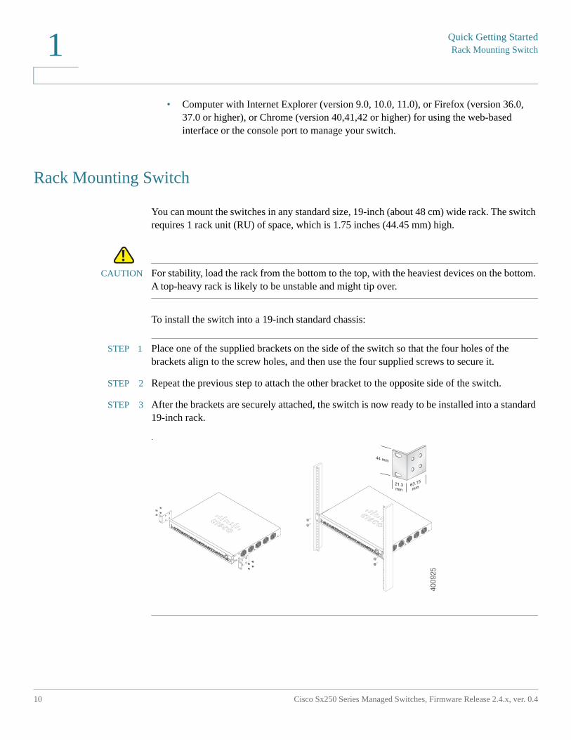
You can mount the switches in any standard size, 19-inch (about 48 cm) wide rack. The switch requires 1 rack unit (RU) of space, which is 1.75 inches (44.45 mm) high.
!CAUTION For stability, load the rack from the bottom to the top, with the heaviest devices on the bottom.
A top-heavy rack is likely to be unstable and might tip over.
To install the switch into a 19-inch standard chassis:
STEP 1 Place one of the supplied brackets on the side of the switch so that the four holes of the brackets align to the screw holes, and then use the four supplied screws to secure it.
STEP 2 Repeat the previous step to attach the other bracket to the opposite side of the switch.
STEP 3 After the brackets are securely attached, the switch is now ready to be installed into a standard 19-inch rack.
.40
0925
Quick Getting Started
Power over Ethernet Considerations
Cisco Sx250 Series Managed Switches, Firmware Release 2.4.x, ver. 0.4 11
1
Power over Ethernet Considerations
WARNING The switch is to be connected only to PoE networks without routing to the outside plant.
Some devices support PoE while others do not. Models that support PoE have a P at the end of the model number, such as: SF250-48HP.
PoE fields are described on all relevant pages although they are only supported on devices that support PoE.
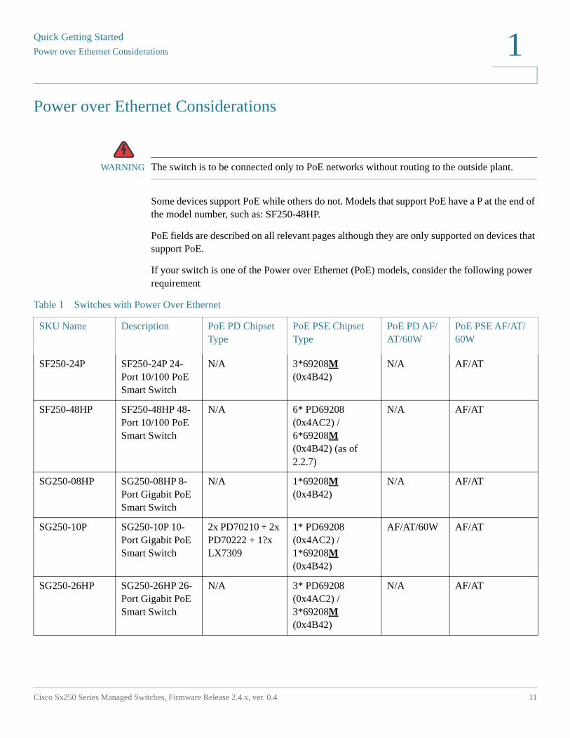
If your switch is one of the Power over Ethernet (PoE) models, consider the following power requirement
Table 1 Switches with Power Over Ethernet
SKU Name Description PoE PD Chipset Type
PoE PSE Chipset Type
PoE PD AF/AT/60W
PoE PSE AF/AT/60W
SF250-24P SF250-24P 24-Port 10/100 PoE Smart Switch
N/A 3*69208M (0x4B42)
N/A AF/AT
SF250-48HP SF250-48HP 48-Port 10/100 PoE Smart Switch
N/A 6* PD69208 (0x4AC2) /6*69208M (0x4B42) (as of 2.2.7)
N/A AF/AT
SG250-08HP SG250-08HP 8-Port Gigabit PoE Smart Switch
N/A 1*69208M (0x4B42)
N/A AF/AT
SG250-10P SG250-10P 10-Port Gigabit PoE Smart Switch
2x PD70210 + 2x PD70222 + 1?x LX7309
1* PD69208 (0x4AC2) /1*69208M (0x4B42)
AF/AT/60W AF/AT
SG250-26HP SG250-26HP 26-Port Gigabit PoE Smart Switch
N/A 3* PD69208 (0x4AC2) /3*69208M (0x4B42)
N/A AF/AT
Quick Getting StartedPower over Ethernet Considerations
12 Cisco Sx250 Series Managed Switches, Firmware Release 2.4.x, ver. 0.4
1
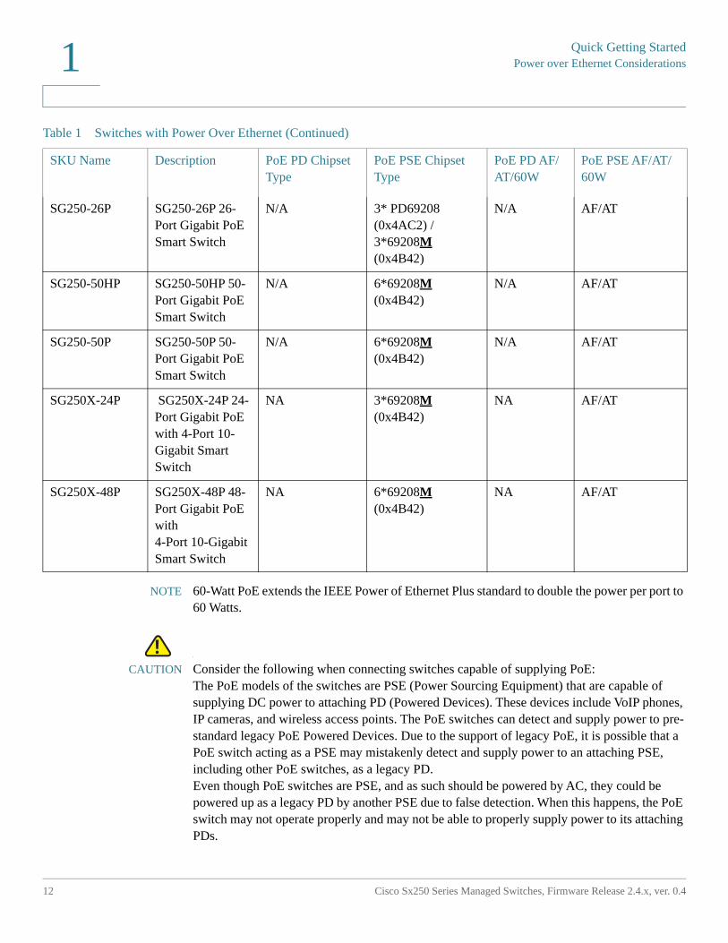
NOTE 60-Watt PoE extends the IEEE Power of Ethernet Plus standard to double the power per port to 60 Watts.
!CAUTION Consider the following when connecting switches capable of supplying PoE:
The PoE models of the switches are PSE (Power Sourcing Equipment) that are capable of supplying DC power to attaching PD (Powered Devices). These devices include VoIP phones, IP cameras, and wireless access points. The PoE switches can detect and supply power to pre-standard legacy PoE Powered Devices. Due to the support of legacy PoE, it is possible that a PoE switch acting as a PSE may mistakenly detect and supply power to an attaching PSE, including other PoE switches, as a legacy PD. Even though PoE switches are PSE, and as such should be powered by AC, they could be powered up as a legacy PD by another PSE due to false detection. When this happens, the PoE switch may not operate properly and may not be able to properly supply power to its attaching PDs.
SG250-26P SG250-26P 26-Port Gigabit PoE Smart Switch
N/A 3* PD69208 (0x4AC2) /3*69208M (0x4B42)
N/A AF/AT
SG250-50HP SG250-50HP 50-Port Gigabit PoE Smart Switch
N/A 6*69208M (0x4B42)
N/A AF/AT
SG250-50P SG250-50P 50-Port Gigabit PoE Smart Switch
N/A 6*69208M (0x4B42)
N/A AF/AT
SG250X-24P SG250X-24P 24-Port Gigabit PoE with 4-Port 10-Gigabit Smart Switch
NA 3*69208M (0x4B42)
NA AF/AT
SG250X-48P SG250X-48P 48-Port Gigabit PoE with 4-Port 10-Gigabit Smart Switch
NA 6*69208M (0x4B42)
NA AF/AT
Table 1 Switches with Power Over Ethernet (Continued)
SKU Name Description PoE PD Chipset Type
PoE PSE Chipset Type
PoE PD AF/AT/60W
PoE PSE AF/AT/60W
Quick Getting Started
Configuring98DX4203, 98DX4204, 98DX4210, 98DX4211, and 98DX4212 Switches
Cisco Sx250 Series Managed Switches, Firmware Release 2.4.x, ver. 0.4 13
1
To prevent false detection, you should disable PoE on the ports on the PoE switches that are used to connect to PSEs. You should also first power up a PSE device before connecting it to a PoE switch. When a device is being falsely detected as a PD, you should disconnect the device from the PoE port and power recycle the device with AC power before reconnecting its PoE ports.
Configuring98DX4203, 98DX4204, 98DX4210, 98DX4211, and 98DX4212 Switches
Before You Begin
The switch can be accessed and managed by two different methods; over your IP network using the web-based interface, or by using the switch’s command-line interface through the console port. Using the console port requires advanced user skills.
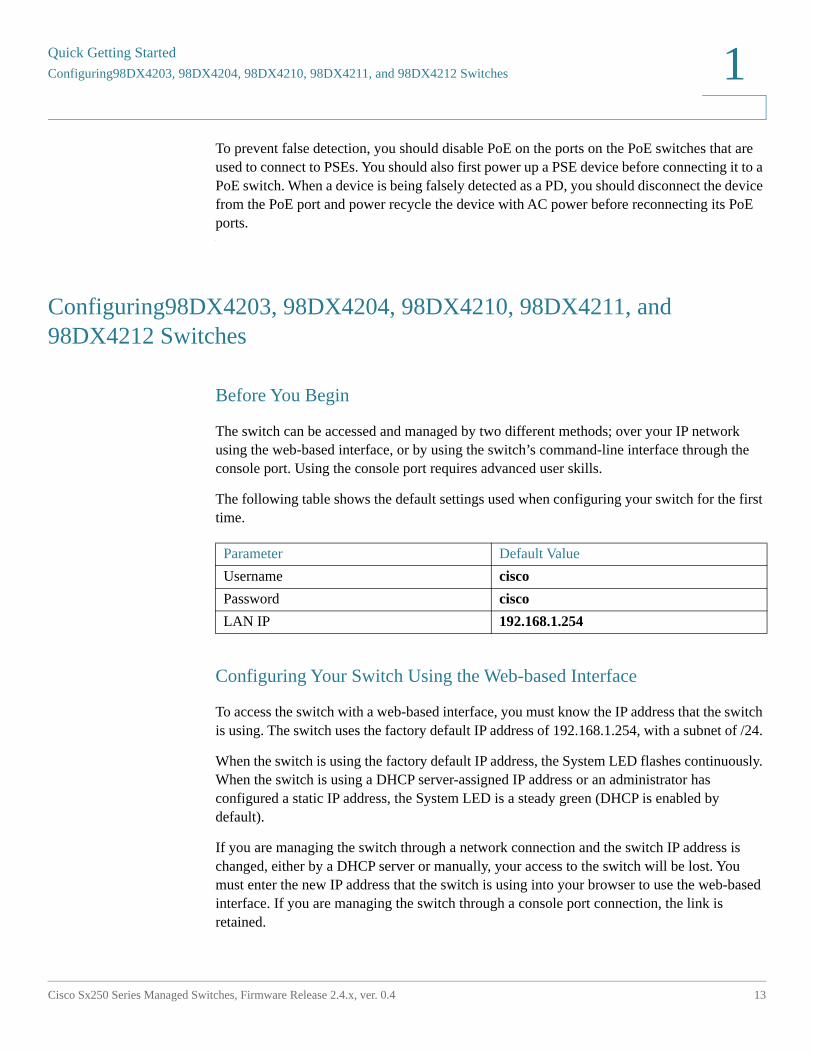
The following table shows the default settings used when configuring your switch for the first time.
Configuring Your Switch Using the Web-based Interface
To access the switch with a web-based interface, you must know the IP address that the switch is using. The switch uses the factory default IP address of 192.168.1.254, with a subnet of /24.
When the switch is using the factory default IP address, the System LED flashes continuously. When the switch is using a DHCP server-assigned IP address or an administrator has configured a static IP address, the System LED is a steady green (DHCP is enabled by default).
If you are managing the switch through a network connection and the switch IP address is changed, either by a DHCP server or manually, your access to the switch will be lost. You must enter the new IP address that the switch is using into your browser to use the web-based interface. If you are managing the switch through a console port connection, the link is retained.
Parameter Default Value
Username cisco
Password cisco
LAN IP 192.168.1.254
Quick Getting StartedConfiguring98DX4203, 98DX4204, 98DX4210, 98DX4211, and 98DX4212 Switches
14 Cisco Sx250 Series Managed Switches, Firmware Release 2.4.x, ver. 0.4
1
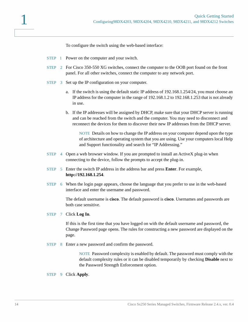
To configure the switch using the web-based interface:
STEP 1 Power on the computer and your switch.
STEP 2 For Cisco 350-550 XG switches, connect the computer to the OOB port found on the front panel. For all other switches, connect the computer to any network port.
STEP 3 Set up the IP configuration on your computer.
a. If the switch is using the default static IP address of 192.168.1.254/24, you must choose an IP address for the computer in the range of 192.168.1.2 to 192.168.1.253 that is not already in use.
b. If the IP addresses will be assigned by DHCP, make sure that your DHCP server is running and can be reached from the switch and the computer. You may need to disconnect and reconnect the devices for them to discover their new IP addresses from the DHCP server.
NOTE Details on how to change the IP address on your computer depend upon the type of architecture and operating system that you are using. Use your computers local Help and Support functionality and search for “IP Addressing.”
STEP 4 Open a web browser window. If you are prompted to install an ActiveX plug-in when connecting to the device, follow the prompts to accept the plug-in.
STEP 5 Enter the switch IP address in the address bar and press Enter. For example,http://192.168.1.254.
STEP 6 When the login page appears, choose the language that you prefer to use in the web-based interface and enter the username and password.
The default username is cisco. The default password is cisco. Usernames and passwords are both case sensitive.
STEP 7 Click Log In.
If this is the first time that you have logged on with the default username and password, the Change Password page opens. The rules for constructing a new password are displayed on the page.
STEP 8 Enter a new password and confirm the password.
NOTE Password complexity is enabled by default. The password must comply with the default complexity rules or it can be disabled temporarily by checking Disable next to the Password Strength Enforcement option.
STEP 9 Click Apply.
Quick Getting Started
Configuring Your Switch Using the Console Port
Cisco Sx250 Series Managed Switches, Firmware Release 2.4.x, ver. 0.4 15
1
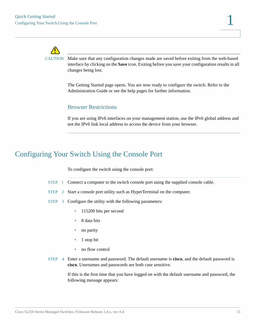
!CAUTION Make sure that any configuration changes made are saved before exiting from the web-based
interface by clicking on the Save icon. Exiting before you save your configuration results in all changes being lost.
The Getting Started page opens. You are now ready to configure the switch. Refer to the Administration Guide or see the help pages for further information.
Browser Restrictions
If you are using IPv6 interfaces on your management station, use the IPv6 global address and not the IPv6 link local address to access the device from your browser.
Configuring Your Switch Using the Console Port
To configure the switch using the console port:
STEP 1 Connect a computer to the switch console port using the supplied console cable.
STEP 2 Start a console port utility such as HyperTerminal on the computer.
STEP 3 Configure the utility with the following parameters:
• 115200 bits per second
• 8 data bits
• no parity
• 1 stop bit
• no flow control
STEP 4 Enter a username and password. The default username is cisco, and the default password is cisco. Usernames and passwords are both case sensitive.
If this is the first time that you have logged on with the default username and password, the following message appears:
Quick Getting StartedUSB Port
16 Cisco Sx250 Series Managed Switches, Firmware Release 2.4.x, ver. 0.4
1
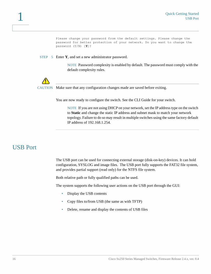
Please change your password from the default settings. Please change the password for better protection of your network. Do you want to change the password (Y/N) [Y]?
STEP 5 Enter Y, and set a new administrator password.
NOTE Password complexity is enabled by default. The password must comply with the default complexity rules.
!CAUTION Make sure that any configuration changes made are saved before exiting.
You are now ready to configure the switch. See the CLI Guide for your switch.
NOTE If you are not using DHCP on your network, set the IP address type on the switch to Static and change the static IP address and subnet mask to match your network topology. Failure to do so may result in multiple switches using the same factory default IP address of 192.168.1.254.
USB Port
The USB port can be used for connecting external storage (disk-on-key) devices. It can hold configuration, SYSLOG and image files. The USB port fully supports the FAT32 file system, and provides partial support (read only) for the NTFS file system.
Both relative path or fully qualified paths can be used.
The system supports the following user actions on the USB port through the GUI:
• Display the USB contents
• Copy files to/from USB (the same as with TFTP)
• Delete, rename and display the contents of USB files
Quick Getting Started
98DX4203, 98DX4204, 98DX4210, 98DX4211, and 98DX4212Switch Features
Cisco Sx250 Series Managed Switches, Firmware Release 2.4.x, ver. 0.4 17
1
98DX4203, 98DX4204, 98DX4210, 98DX4211, and 98DX4212Switch Features
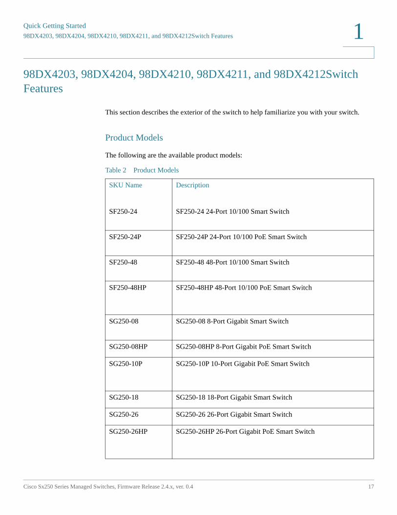
This section describes the exterior of the switch to help familiarize you with your switch.
Product Models
The following are the available product models:
Table 2 Product Models
SKU Name Description
SF250-24 SF250-24 24-Port 10/100 Smart Switch
SF250-24P SF250-24P 24-Port 10/100 PoE Smart Switch
SF250-48 SF250-48 48-Port 10/100 Smart Switch
SF250-48HP SF250-48HP 48-Port 10/100 PoE Smart Switch
SG250-08 SG250-08 8-Port Gigabit Smart Switch
SG250-08HP SG250-08HP 8-Port Gigabit PoE Smart Switch
SG250-10P SG250-10P 10-Port Gigabit PoE Smart Switch
SG250-18 SG250-18 18-Port Gigabit Smart Switch
SG250-26 SG250-26 26-Port Gigabit Smart Switch
SG250-26HP SG250-26HP 26-Port Gigabit PoE Smart Switch
Quick Getting Started98DX4203, 98DX4204, 98DX4210, 98DX4211, and 98DX4212Switch Features
18 Cisco Sx250 Series Managed Switches, Firmware Release 2.4.x, ver. 0.4
1
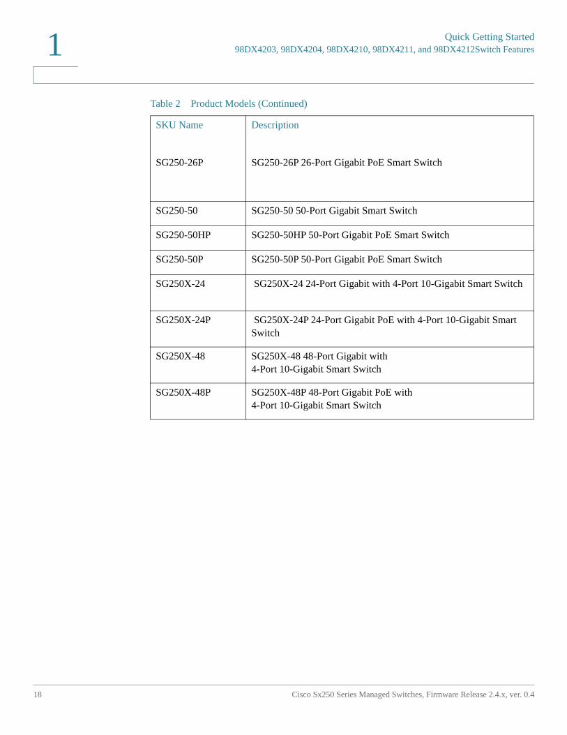
SG250-26P SG250-26P 26-Port Gigabit PoE Smart Switch
SG250-50 SG250-50 50-Port Gigabit Smart Switch
SG250-50HP SG250-50HP 50-Port Gigabit PoE Smart Switch
SG250-50P SG250-50P 50-Port Gigabit PoE Smart Switch
SG250X-24 SG250X-24 24-Port Gigabit with 4-Port 10-Gigabit Smart Switch
SG250X-24P SG250X-24P 24-Port Gigabit PoE with 4-Port 10-Gigabit Smart Switch
SG250X-48 SG250X-48 48-Port Gigabit with 4-Port 10-Gigabit Smart Switch
SG250X-48P SG250X-48P 48-Port Gigabit PoE with 4-Port 10-Gigabit Smart Switch
Table 2 Product Models (Continued)
SKU Name Description
Quick Getting Started
98DX4203, 98DX4204, 98DX4210, 98DX4211, and 98DX4212Switch Features
Cisco Sx250 Series Managed Switches, Firmware Release 2.4.x, ver. 0.4 19
1
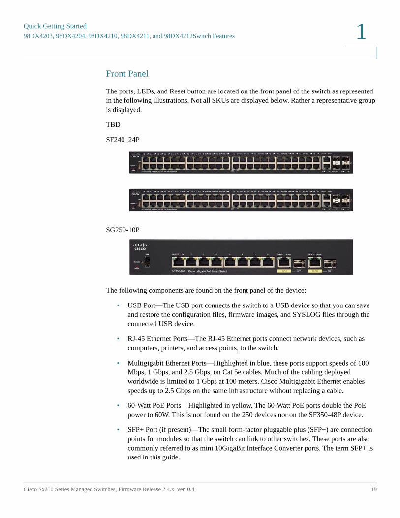
Front Panel
The ports, LEDs, and Reset button are located on the front panel of the switch as represented in the following illustrations. Not all SKUs are displayed below. Rather a representative group is displayed.
TBD
SF240_24P
SG250-10P
The following components are found on the front panel of the device:
• USB Port—The USB port connects the switch to a USB device so that you can save and restore the configuration files, firmware images, and SYSLOG files through the connected USB device.
• RJ-45 Ethernet Ports—The RJ-45 Ethernet ports connect network devices, such as computers, printers, and access points, to the switch.
• Multigigabit Ethernet Ports—Highlighted in blue, these ports support speeds of 100 Mbps, 1 Gbps, and 2.5 Gbps, on Cat 5e cables. Much of the cabling deployed worldwide is limited to 1 Gbps at 100 meters. Cisco Multigigabit Ethernet enables speeds up to 2.5 Gbps on the same infrastructure without replacing a cable.
• 60-Watt PoE Ports—Highlighted in yellow. The 60-Watt PoE ports double the PoE power to 60W. This is not found on the 250 devices nor on the SF350-48P device.
• SFP+ Port (if present)—The small form-factor pluggable plus (SFP+) are connection points for modules so that the switch can link to other switches. These ports are also commonly referred to as mini 10GigaBit Interface Converter ports. The term SFP+ is used in this guide.
Quick Getting Started98DX4203, 98DX4204, 98DX4210, 98DX4211, and 98DX4212Switch Features
20 Cisco Sx250 Series Managed Switches, Firmware Release 2.4.x, ver. 0.4
1
• The SFP+ ports are compatible with the following Cisco SFP 1G optical modules MGBSX1, MGBLH1, MGBT1, as well as other brands.
• The Cisco SFP+ 10G optical modules that are supported in the Cisco switches are: SFP-10G-SR, SFP-10G-LR, SFP-10G-SR-S, andSFP-10G-LR-S.
• The Cisco SFP+ Copper Cable modules that are supported in the Cisco switches are: SFP-H10GB-CU1M, SFP-H10GB-CU3M, and SFP-H10GB-CU5M.
• The SFP+ port is a combination port, shared with one other RJ-45 port. When the SFP+ is active, the adjacent RJ-45 port is disabled.
• Some SFP interfaces are shared with one other RJ-45 port, called a combo port. When the SFP is active, the adjacent RJ-45 port is disabled.
• The LEDs of the corresponding RJ-45 port flash green to respond to the SFP interface traffic.
• OOB Port (if present)—The Out of Band (OOB) port is a CPU Ethernet port that can be used only as a management interface. Bridging between the OOB port and the in-band Layer 2 interface is not supported. This does not appear on 250 devices.
Front Panel LEDs
The following are the global LEDs found on the devices:
• System—(Green) The LED lights steady when the switch is powered on, and flashes when booting, performing self-tests, or acquiring an IP address. If the LED flashes Green, the switch has detected a hardware failure, a firmware failure, and/or a configuration file error.
The following are per port LEDs:
• LINK/ACT—(Green) Located on the left of each port. The LED lights steady when a link between the corresponding port and another device is detected, and flashes when the port is passing traffic.
• XG—(Green) Located on the right of a 10G port. The LED lights steady when another device is connected to the port, is powered on, and a 10 Gbps link is established between the devices. When the LED is off, the connection speed is under 10 Gbps or nothing is cabled to the port.
• Gigabit—(Green) Located on the right of the OOB port. The LED lights steady when another device is connected to the port, is powered on, and a 1000 Mbps link is established between the devices. When the LED is off, the connection speed is under 1000 Mbps or nothing is cabled to the port.
Quick Getting Started
98DX4203, 98DX4204, 98DX4210, 98DX4211, and 98DX4212Switch Features
Cisco Sx250 Series Managed Switches, Firmware Release 2.4.x, ver. 0.4 21
1
• SFP+ (if present)—(Green) Located on the right of a 10G port. The LED lights steady when a connection is made through the shared port, and flashes when the port is passing traffic.
• PoE (if present)—(Amber) Located on the right of the port. The LED lights steady when power is being supplied to a device attached to the corresponding port.
Reset Button
The switch can be reset by inserting a pin or paper clip into the Reset button opening on the front panel of the switch. To use the Reset button to reboot or reset the switch, do the following:
• To reboot the switch, press and hold the Reset button for less than ten seconds.
• To restore the switch to its factory default settings:
- Disconnect the switch from the network or disable all DHCP servers on your network.
- With the power on, press and hold the Reset button for more than ten seconds.
Back Panel
The following buttons are found on the back panels:
• Power—Connects the switch to AC power.
• Console—Connects a serial cable to a computer serial port so that it can be configured by using a terminal emulation program.
2
Cisco Sx250 Series Managed Switches, Firmware Release 2.4.x, ver. 0.4 22
General Information
This section covers the following topics:
• Basic or Advanced Display Mode
• Quick Start Device Configuration
• Interface Naming Conventions
• Window Navigation
• Search Facility
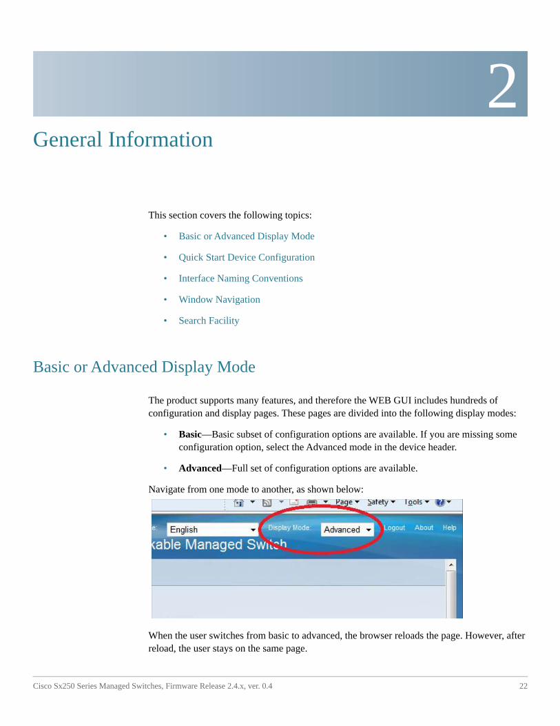
Basic or Advanced Display Mode
The product supports many features, and therefore the WEB GUI includes hundreds of configuration and display pages. These pages are divided into the following display modes:
• Basic—Basic subset of configuration options are available. If you are missing some configuration option, select the Advanced mode in the device header.
• Advanced—Full set of configuration options are available.
Navigate from one mode to another, as shown below:
When the user switches from basic to advanced, the browser reloads the page. However, after reload, the user stays on the same page.
General Information
Basic or Advanced Display Mode
Cisco Sx250 Series Managed Switches, Firmware Release 2.4.x, ver. 0.4 23
2
When the user switches from advanced to basic, the browser reloads the page. If the page exists also on the basic mode, the user stays on the same page. If the page does not exist in the basic mode, the browser will load the first page of the folder which was used by the user. If the folder does not exist, the Getting Started page will be displayed.
If there is advanced configuration, and the page is loaded in basic mode, a page-level message will be displayed to the user (e.g. there are 2 radius server configured but in basic mode only a single server can be displayed, or there is 802.1X port authentication with time range configured but time range is not visible in basic mode).
When switching from one mode to another, any configuration which was made on the page (without Apply) is deleted.
General InformationQuick Start Device Configuration2
Cisco Sx250 Series Managed Switches, Firmware Release 2.4.x, ver. 0.4 24
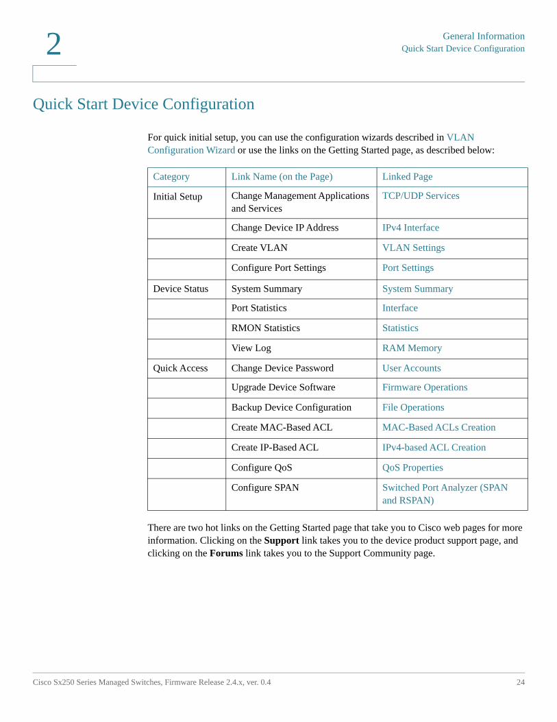
Quick Start Device Configuration
For quick initial setup, you can use the configuration wizards described in VLAN Configuration Wizard or use the links on the Getting Started page, as described below:
There are two hot links on the Getting Started page that take you to Cisco web pages for more information. Clicking on the Support link takes you to the device product support page, and clicking on the Forums link takes you to the Support Community page.
Category Link Name (on the Page) Linked Page
Initial Setup Change Management Applications and Services
TCP/UDP Services
Change Device IP Address IPv4 Interface
Create VLAN VLAN Settings
Configure Port Settings Port Settings
Device Status System Summary System Summary
Port Statistics Interface
RMON Statistics Statistics
View Log RAM Memory
Quick Access Change Device Password User Accounts
Upgrade Device Software Firmware Operations
Backup Device Configuration File Operations
Create MAC-Based ACL MAC-Based ACLs Creation
Create IP-Based ACL IPv4-based ACL Creation
Configure QoS QoS Properties
Configure SPAN Switched Port Analyzer (SPAN and RSPAN)
General Information
Interface Naming Conventions
Cisco Sx250 Series Managed Switches, Firmware Release 2.4.x, ver. 0.4 25
2
Interface Naming Conventions
Within the GUI, interfaces are denoted by concatenating the following elements:
• Type of interface: The following types of interfaces are found on the various types of devices:
- Fast Ethernet (10/100 bits)—These are displayed as FE.
- Gigabit Ethernet ports (10/100/1000 bits)—These are displayed as GE.
- Out-of-Band Port—This is displayed as OOB.
- LAG (Port Channel)—These are displayed as LAG.
- VLAN—These are displayed as VLAN.
- Tunnel —These are displayed as Tunnel.
• Interface Number: Port, LAG, Tunnel, or VLAN ID.
General InformationWindow Navigation2
Cisco Sx250 Series Managed Switches, Firmware Release 2.4.x, ver. 0.4 26
Window Navigation
This section describes the features of the web-based switch configuration utility.
Application Header
The Application Header appears on every page. It provides the following application links:
Application Link Name
Description
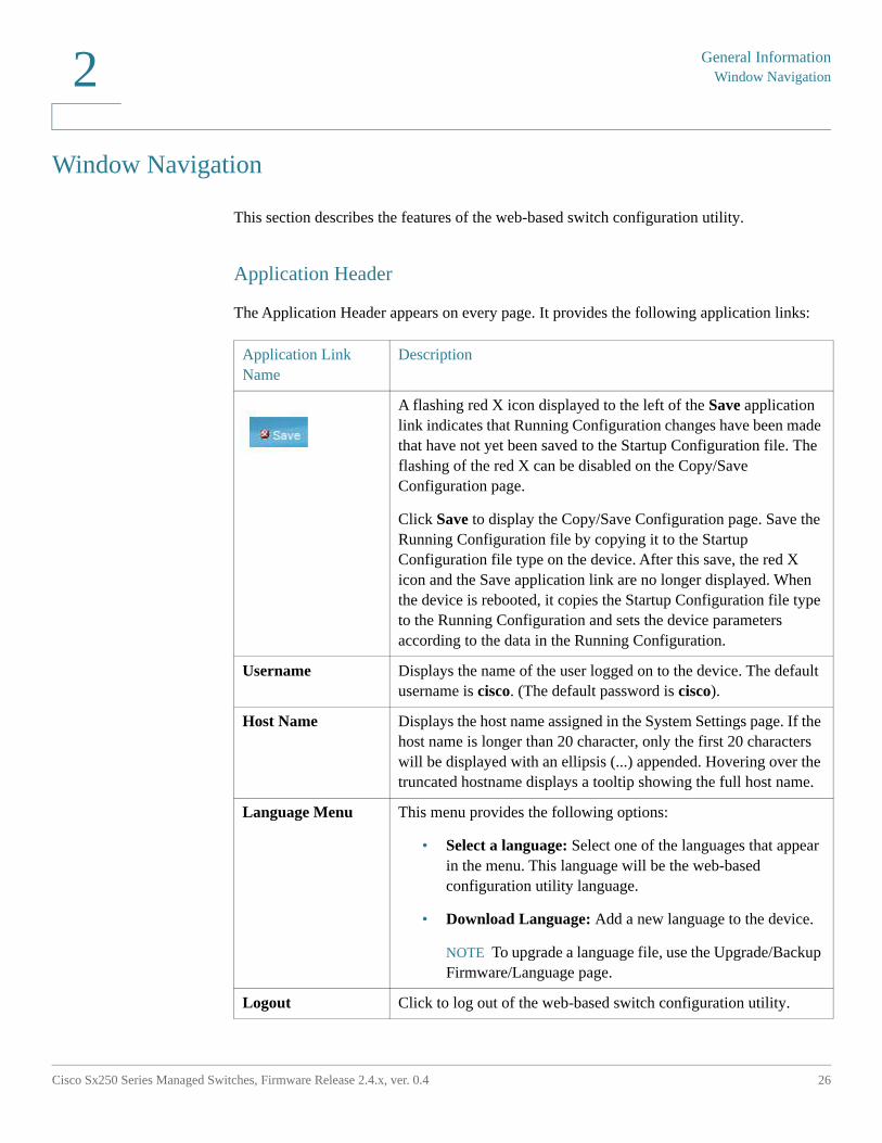
A flashing red X icon displayed to the left of the Save application link indicates that Running Configuration changes have been made that have not yet been saved to the Startup Configuration file. The flashing of the red X can be disabled on the Copy/Save Configuration page.
Click Save to display the Copy/Save Configuration page. Save the Running Configuration file by copying it to the Startup Configuration file type on the device. After this save, the red X icon and the Save application link are no longer displayed. When the device is rebooted, it copies the Startup Configuration file type to the Running Configuration and sets the device parameters according to the data in the Running Configuration.
Username Displays the name of the user logged on to the device. The default username is cisco. (The default password is cisco).
Host Name Displays the host name assigned in the System Settings page. If the host name is longer than 20 character, only the first 20 characters will be displayed with an ellipsis (...) appended. Hovering over the truncated hostname displays a tooltip showing the full host name.
Language Menu This menu provides the following options:
• Select a language: Select one of the languages that appear in the menu. This language will be the web-based configuration utility language.
• Download Language: Add a new language to the device.
NOTE To upgrade a language file, use the Upgrade/Backup Firmware/Language page.
Logout Click to log out of the web-based switch configuration utility.
General Information
Window Navigation
Cisco Sx250 Series Managed Switches, Firmware Release 2.4.x, ver. 0.4 27
2
Management Buttons
The following table describes the commonly-used buttons that appear on various pages in the system.
About Click to display the device name and device version number.
Help Click to display the online help.
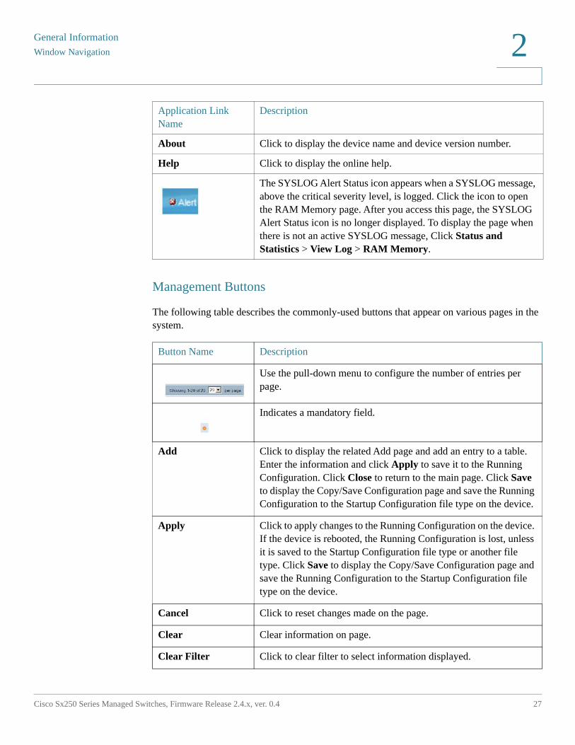
The SYSLOG Alert Status icon appears when a SYSLOG message, above the critical severity level, is logged. Click the icon to open the RAM Memory page. After you access this page, the SYSLOG Alert Status icon is no longer displayed. To display the page when there is not an active SYSLOG message, Click Status and Statistics > View Log > RAM Memory.
Button Name Description
Use the pull-down menu to configure the number of entries per page.
Indicates a mandatory field.
Add Click to display the related Add page and add an entry to a table. Enter the information and click Apply to save it to the Running Configuration. Click Close to return to the main page. Click Save to display the Copy/Save Configuration page and save the Running Configuration to the Startup Configuration file type on the device.
Apply Click to apply changes to the Running Configuration on the device. If the device is rebooted, the Running Configuration is lost, unless it is saved to the Startup Configuration file type or another file type. Click Save to display the Copy/Save Configuration page and save the Running Configuration to the Startup Configuration file type on the device.
Cancel Click to reset changes made on the page.
Clear Clear information on page.
Clear Filter Click to clear filter to select information displayed.
Application Link Name
Description
General InformationWindow Navigation2
Cisco Sx250 Series Managed Switches, Firmware Release 2.4.x, ver. 0.4 28
Clear All Interfaces Counters
Click to clear the statistic counters for all interfaces.
Clear Interface Counters
Click to clear the statistic counters for the selected interface.
Clear Logs Clears log files.
Clear Table Clears table entries.
Close Returns to main page. If any changes were not applied to the Running Configuration, a message appears.
Copy Settings A table typically contains one or more entries containing configuration settings. Instead of modifying each entry individually, it is possible to modify one entry and then copy the selected entry to multiple entries, as described below:
1. Select the entry to be copied. Click Copy Settings to display the popup.
2. Enter the destination entry numbers in the to field.
3. Click Apply to save the changes and click Close to return to the main page.
Delete After selecting an entry in the table, click Delete to remove.
Details Click to display the details associated with the entry selected.
Edit Select the entry and click Edit. The Edit page appears, and the entry can be modified.
1. Click Apply to save the changes to the Running Configuration.
2. Click Close to return to the main page.
Go Enter the query filtering criteria and click Go. The results are displayed on the page.
Refresh Click Refresh to refresh the counter values.
Test Click Test to perform the related tests.
Restore Defaults Click Restore Defaults to restore factory defaults.
Cancel Defaults Click Cancel Defaults to restore factory defaults.
Button Name Description
General Information
Search Facility
Cisco Sx250 Series Managed Switches, Firmware Release 2.4.x, ver. 0.4 29
2
Search Facility
The search function helps the user to locate relevant GUI pages.
The search result for a keyword includes links to the relevant pages, and also links to the relevant help pages.
To access the search function, enter a key word and click on the magnifying glass icon.
3
Cisco Sx250 Series Managed Switches, Firmware Release 2.4.x, ver. 0.4 30
Dashboard
The dashboard is a collection of 8 squares, initially empty, that can be populated by various types of information
You can select a number of modules from the available modules and place them in this grid. You can also customize settings of the currently-displayed modules.
When the dashboard loads, the modules you selected for the dashboard are loaded in their locations in the grid. The data in the modules is updated periodically, in intervals depending on the module type. These intervals are configurable for some modules.
This following topics are covered in this chapter:
• Grid Management
• System Health
• Resource Utilization
• Identification
• Port Utilization
• PoE Utilization
• Latest Logs
• Suspended Interfaces
• Traffic Errors
Grid Management
The dashboard consists of multiple modules, but only a subset of the modules can be viewed at the same time.
Dashboard
Grid Management
Cisco Sx250 Series Managed Switches, Firmware Release 2.4.x, ver. 0.4 31
3
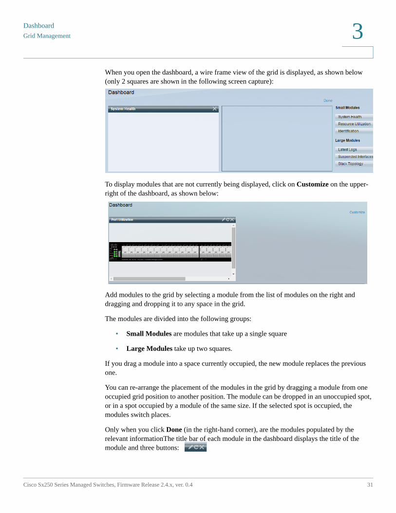
When you open the dashboard, a wire frame view of the grid is displayed, as shown below (only 2 squares are shown in the following screen capture):
To display modules that are not currently being displayed, click on Customize on the upper-right of the dashboard, as shown below:
Add modules to the grid by selecting a module from the list of modules on the right and dragging and dropping it to any space in the grid.
The modules are divided into the following groups:
• Small Modules are modules that take up a single square
• Large Modules take up two squares.
If you drag a module into a space currently occupied, the new module replaces the previous one.
You can re-arrange the placement of the modules in the grid by dragging a module from one occupied grid position to another position. The module can be dropped in an unoccupied spot, or in a spot occupied by a module of the same size. If the selected spot is occupied, the modules switch places.
Only when you click Done (in the right-hand corner), are the modules populated by the relevant informationThe title bar of each module in the dashboard displays the title of the module and three buttons:
DashboardSystem Health
32 Cisco Sx250 Series Managed Switches, Firmware Release 2.4.x, ver. 0.4
3
These button perform the following:
• Pencil — Opens configuration options (depending on the module).
• Refresh — Refreshes the information.
• X — Removes the module from the dashboard.
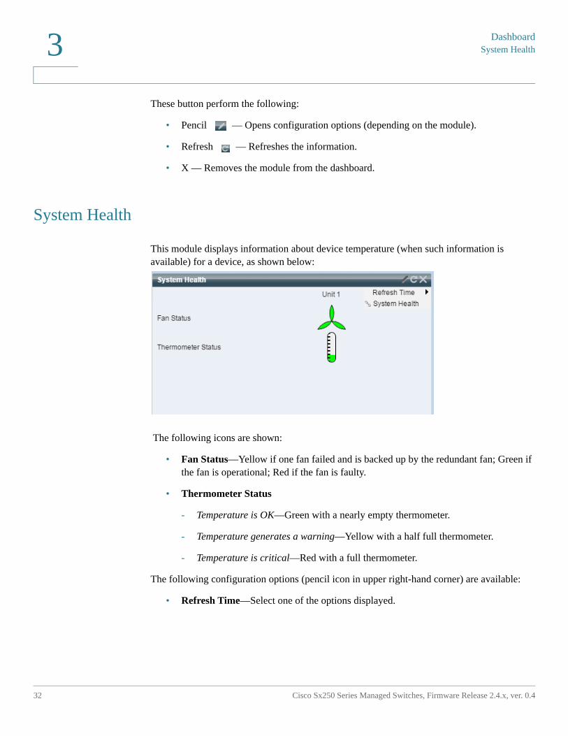
System Health
This module displays information about device temperature (when such information is available) for a device, as shown below:
The following icons are shown:
• Fan Status—Yellow if one fan failed and is backed up by the redundant fan; Green if the fan is operational; Red if the fan is faulty.
• Thermometer Status
- Temperature is OK—Green with a nearly empty thermometer.
- Temperature generates a warning—Yellow with a half full thermometer.
- Temperature is critical—Red with a full thermometer.
The following configuration options (pencil icon in upper right-hand corner) are available:
• Refresh Time—Select one of the options displayed.
Dashboard
Resource Utilization
Cisco Sx250 Series Managed Switches, Firmware Release 2.4.x, ver. 0.4 33
3
Resource Utilization
This module displays the utilization status in terms of a percentage of the various system resources as a bar chart, The resources monitored are:
• Multicast Groups—Percentage of Multicast groups that exist out of the maximum possible number that are permitted to be defined.
• MAC Address Table—Percentage of MAC Address table in use.
• TCAM—Percentage of TCAM used by QoS and ACL entries.
• CPU—Percentage of CPU being used.
Each bar becomes red if the resource utilization is higher than 80 percent.
Hovering over a bar displays a tooltip displaying the numeric utilization information (used resources/max available).
The following configuration options (right-hand corner) are available:
• Refresh Time—Select one of the options displayed.
• Multicast Groups—Click to open MAC Group Address
• MAC Address Table—Click to open Dynamic Addresses.
DashboardIdentification
34 Cisco Sx250 Series Managed Switches, Firmware Release 2.4.x, ver. 0.4
3
• TCAM Utilization Information—Click to open Hardware Resource Utilization.
• CPU Utilization Information—Click to open CPU Utilization.
Identification
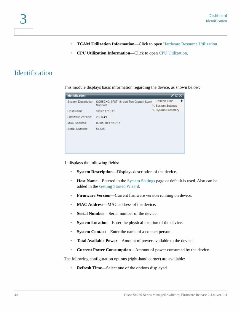
This module displays basic information regarding the device, as shown below:
It displays the following fields:
• System Description—Displays description of the device.
• Host Name—Entered in the System Settings page or default is used. Also can be added in the Getting Started Wizard.
• Firmware Version—Current firmware version running on device.
• MAC Address—MAC address of the device.
• Serial Number—Serial number of the device.
• System Location—Enter the physical location of the device.
• System Contact—Enter the name of a contact person.
• Total Available Power—Amount of power available to the device.
• Current Power Consumption—Amount of power consumed by the device.
The following configuration options (right-hand corner) are available:
• Refresh Time—Select one of the options displayed.
Dashboard
Port Utilization
Cisco Sx250 Series Managed Switches, Firmware Release 2.4.x, ver. 0.4 35
3
• System Settings—Click to open System Settings.
• System Summary—Click to open System Summary.
Port Utilization
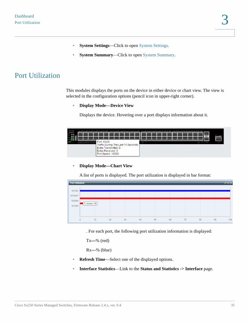
This modules displays the ports on the device in either device or chart view. The view is selected in the configuration options (pencil icon in upper-right corner).
• Display Mode—Device View
Displays the device. Hovering over a port displays information about it.
• Display Mode—Chart View
A list of ports is displayed. The port utilization is displayed in bar format:
. For each port, the following port utilization information is displayed:
Tx—% (red)
Rx—% (blue)
• Refresh Time—Select one of the displayed options.
• Interface Statistics—Link to the Status and Statistics -> Interface page.
DashboardPoE Utilization
36 Cisco Sx250 Series Managed Switches, Firmware Release 2.4.x, ver. 0.4
3
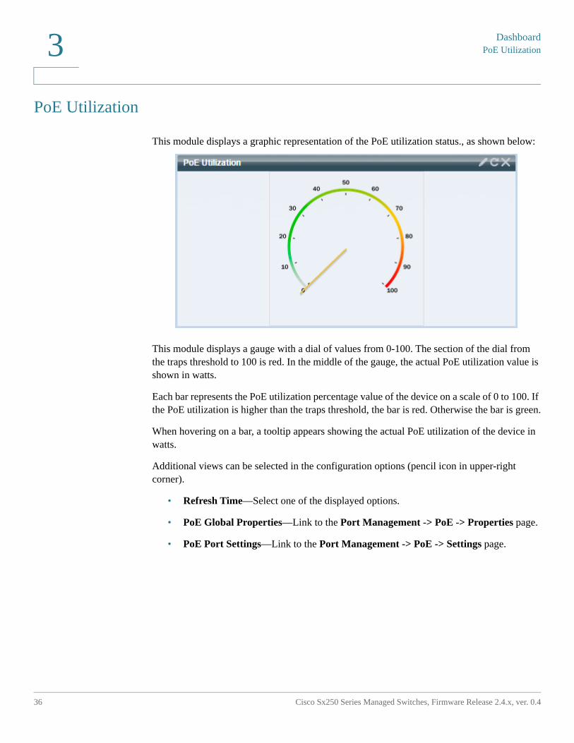
PoE Utilization
This module displays a graphic representation of the PoE utilization status., as shown below:
This module displays a gauge with a dial of values from 0-100. The section of the dial from the traps threshold to 100 is red. In the middle of the gauge, the actual PoE utilization value is shown in watts.
Each bar represents the PoE utilization percentage value of the device on a scale of 0 to 100. If the PoE utilization is higher than the traps threshold, the bar is red. Otherwise the bar is green.
When hovering on a bar, a tooltip appears showing the actual PoE utilization of the device in watts.
Additional views can be selected in the configuration options (pencil icon in upper-right corner).
• Refresh Time—Select one of the displayed options.
• PoE Global Properties—Link to the Port Management -> PoE -> Properties page.
• PoE Port Settings—Link to the Port Management -> PoE -> Settings page.
Dashboard
Latest Logs
Cisco Sx250 Series Managed Switches, Firmware Release 2.4.x, ver. 0.4 37
3
Latest Logs
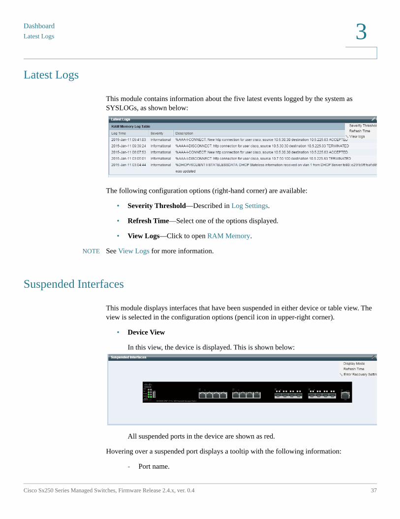
This module contains information about the five latest events logged by the system as SYSLOGs, as shown below:
The following configuration options (right-hand corner) are available:
• Severity Threshold—Described in Log Settings.
• Refresh Time—Select one of the options displayed.
• View Logs—Click to open RAM Memory.
NOTE See View Logs for more information.
Suspended Interfaces
This module displays interfaces that have been suspended in either device or table view. The view is selected in the configuration options (pencil icon in upper-right corner).
• Device View
In this view, the device is displayed. This is shown below:
All suspended ports in the device are shown as red.
Hovering over a suspended port displays a tooltip with the following information:
- Port name.
DashboardSuspended Interfaces
38 Cisco Sx250 Series Managed Switches, Firmware Release 2.4.x, ver. 0.4
3
- If the port is a member of a LAG, the LAG identity of the port.
- The suspension reason if it is suspended.
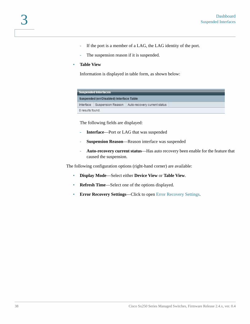
• Table View
Information is displayed in table form, as shown below:
The following fields are displayed:
- Interface—Port or LAG that was suspended
- Suspension Reason—Reason interface was suspended
- Auto-recovery current status—Has auto recovery been enable for the feature that caused the suspension.
The following configuration options (right-hand corner) are available:
• Display Mode—Select either Device View or Table View.
• Refresh Time—Select one of the options displayed.
• Error Recovery Settings—Click to open Error Recovery Settings.
Dashboard
Traffic Errors
Cisco Sx250 Series Managed Switches, Firmware Release 2.4.x, ver. 0.4 39
3
Traffic Errors
This modules displays the number of error packets of various types that are counted on the RMON statistics. The view is selected in the configuration options (pencil icon in upper-right corner).
The following can be selected in from the pencil icon:
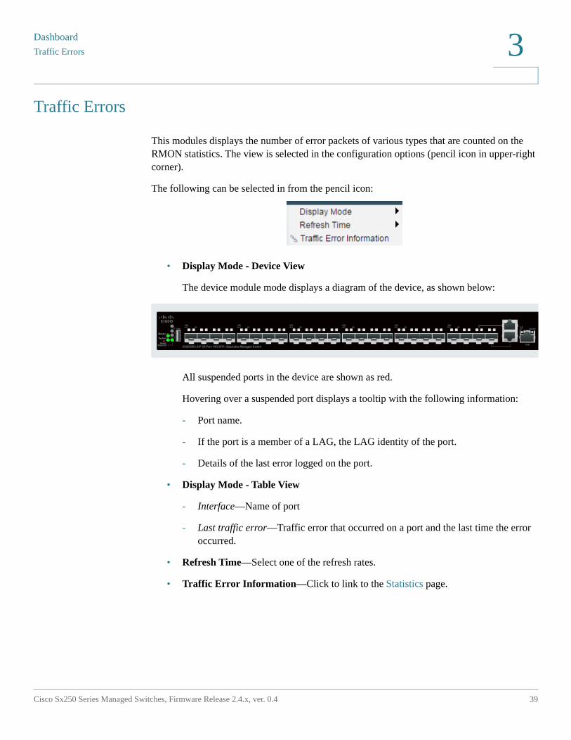
• Display Mode - Device View
The device module mode displays a diagram of the device, as shown below:
All suspended ports in the device are shown as red.
Hovering over a suspended port displays a tooltip with the following information:
- Port name.
- If the port is a member of a LAG, the LAG identity of the port.
- Details of the last error logged on the port.
• Display Mode - Table View
- Interface—Name of port
- Last traffic error—Traffic error that occurred on a port and the last time the error occurred.
• Refresh Time—Select one of the refresh rates.
• Traffic Error Information—Click to link to the Statistics page.
4
Cisco Sx250 Series Managed Switches, Firmware Release 2.4.x, ver. 0.4 40
Configuration Wizards
This section describes the following configuration wizards:
It covers the following topics:
• Getting Started Wizard
• VLAN Configuration Wizard
• ACL Wizard
Getting Started Wizard
This wizard assists in the initial configuration of the device.
STEP 1 Click Configuration Wizards > Getting Started Wizard.
STEP 2 Click Launch Wizard and Next.
STEP 3 Enter the fields:
• System Location—Enter the physical location of the device.
• System Contact—Enter the name of a contact person.
• Host Name—Select the host name of this device. This is used in the prompt of CLI commands:
- Use Default—The default hostname (System Name) of these switches is: switch123456, where 123456 represents the last three bytes of the device MAC address in hex format.
- User Defined—Enter the hostname. Use only letters, digits, and hyphens. Host names cannot begin or end with a hyphen. No other symbols, punctuation characters, or blank spaces are permitted (as specified in RFC1033, 1034, 1035).
STEP 4 Click Next.
Configuration Wizards
Getting Started Wizard
Cisco Sx250 Series Managed Switches, Firmware Release 2.4.x, ver. 0.4 41
4
STEP 5 Enter the fields:
• Interface—Select the IP interface for the system.
• IP Interface Source—Select one of the following options:
- DHCP—Select for the device to receive its IP address from a DHCP server.
- Static—Select to enter the IP address of the device manually.
If you selected Static as the IP interface source, enter the following fields:
• IP Address—IP address of the interface.
• Network Mask—IP mask for this address.
• Administrative Default Gateway—Enter the default gateway IP address.
• DNS Server—Enter the IP address of the DNS server.
STEP 6 Click Next
STEP 7 Enter the fields:
• Username—Enter a new user name between 0 and 20 characters. UTF-8 characters are not permitted.
• Password—Enter a password (UTF-8 characters are not permitted). If the password strength and complexity is defined, the user password must comply with the policy configured in Password Strength.
• Confirm Password—Enter the password again.
• Password Strength—Displays the strength of password. The policy for password strength and complexity are configured in the Password Strength page.
• Keep current username and password—Select to keep current username and password.
STEP 8 Click Next
STEP 9 Enter the fields:
• Clock Source—Select one of the following:
- Manual Settings—Select to enter the device system time. If this is selected, enter the Date and Time.
- Default SNTP Servers—Select to use the default SNTP servers.
Configuration WizardsVLAN Configuration Wizard
42 Cisco Sx250 Series Managed Switches, Firmware Release 2.4.x, ver. 0.4
4
NOTE The default SNTP servers are defined by name, thus DNS must be configured and operational (DNS server configured and reachable). This is done in DNS Settings.
- Manual SNTP Server—Select and enter the IP address of an SNTP server.
STEP 10 Click Next to view a summary of configuration that you entered.
STEP 11 Click Apply to save the configuration data.
VLAN Configuration Wizard
This wizard assists in configuring VLANs. Each time you run this wizard, you can configure ports membership in a single VLAN. The first steps are for Trunk port mode (where you configure trunk ports tagged and untagged ports), and then you configure Access port mode.
STEP 1 Click Configuration Wizards > VLAN Configuration Wizard.
STEP 2 Click Launch Wizard and Next.
STEP 3 Select the ports that are to be configured as trunk port (by clicking with mouse on the required ports in the graphical display). Ports that are already configured as Trunk ports are pre-selected.
STEP 4 Click Next.
STEP 5 Enter the fields:
• VLAN ID—Select the VLAN you want to configure. You can select either an existing VLAN or New VLAN.
• New VLAN ID—Enter the VLAN ID of a new VLAN.
• VLAN Name—Optionally, enter VLAN name.
STEP 6 Select the trunk ports that are to be configured as untagged members of the VLAN (by clicking with mouse on the required ports in the graphical display). The trunk ports that are not selected in this step becomes tagged members of the VLAN.
STEP 7 Click Next.
STEP 8 Select the ports are that to be the access ports of the VLAN. Access ports of a VLAN is untagged member of the VLAN. (by clicking with mouse on the required ports in the graphical display).
Configuration Wizards
ACL Wizard
Cisco Sx250 Series Managed Switches, Firmware Release 2.4.x, ver. 0.4 43
4
STEP 9 Click Next to see the summary of the information that you entered.
STEP 10 Click Apply.
ACL Wizard
To create a new ACL.
STEP 1 Click Configuration Wizards > ACL Wizard.
STEP 2 Click Next.
STEP 3 Enter the fields:
• ACL Name—Enter the name of a new ACL.
• ACL Type—Select the type of ACL: IPv4 or MAC.
STEP 4 Click Next.
STEP 5 Enter the fields:
• Action on match—Select one of the options:
- Permit Traffic—Forward packets that meet the ACL criteria.
- Deny Traffic—Drop packets that meet the ACL criteria.
- Shutdown Interface—Drop packets that meet the ACL criteria, and disable the port from where the packets received. Such ports can be reactivated from the Error Recovery Settings page.
STEP 6 For a MAC-based ACL, enter the fields:
• Source MAC Address—Select Any if all source address are acceptable or User defined to enter a source address or range of source addresses.
• Source MAC Value—Enter the MAC address to which the source MAC address is to be matched and its mask (if relevant).
• Source MAC Wildcard Mask—Enter the mask to define a range of MAC addresses.
• Destination MAC Address—Select Any if all destination addresses are acceptable or User defined to enter a destination address or a range of destination addresses.
• Destination MAC Value—Enter the MAC address to which the destination MAC address is to be matched and its mask (if relevant).
Configuration WizardsACL Wizard
44 Cisco Sx250 Series Managed Switches, Firmware Release 2.4.x, ver. 0.4
4
• Destination MAC Wildcard Mask—Enter the mask to define a range of MAC addresses. Note that this mask is different than in other uses, such as subnet mask. Here, setting a bit as 1 indicates don't care and 0 indicates to mask that value.
NOTE Given a mask of 0000 0000 0000 0000 0000 0000 1111 1111 (which means that you match on the bits where there is 0 and don't match on the bits where there are 1's). You need to translate the 1's to a decimal integer and you write 0 for each four zeros. In this example since 1111 1111 = 255, the mask would be written: as 0.0.0.255.
• Time Range Name—If Time Range is selected, select the time range to be used. Time ranges are defined in the System Time Configuration section. This field is only displayed if a Time Range was previously created.
STEP 7 For a IPv4-based ACL, enter the fields:
• Protocol—Select one of the following options to create an ACL based on a specific protocol:
- Any (IP)—Accept all IP protocols packets
- TCP—Accept Transmission Control Protocols packets
- UDP—Accept User Datagram Protocols packets
- ICMP—Accept ICMP Protocols packets
- IGMP—Accept IGMP Protocols packets
• Source Port for TCP/UDP—Select a port from the drop-down list.
• Destination Port for TCP/UDP—Select a port from the drop-down list.
• Source IP Address—Select Any if all source address are acceptable or User defined to enter a source address or range of source addresses.
• Source IP Value—Enter the IP address to which the source IP address is to be matched
• Source IP Wildcard Mask—Enter the mask to define a range of IP addresses. Note that this mask is different than in other uses, such as subnet mask. Here, setting a bit as 1 indicates don't care and 0 indicates to mask that value.
• Destination IP Address—Select Any if all source address are acceptable or User defined to enter a source address or range of source addresses.
• Destination IP Value—Enter the IP address to which the source IP address is to be matched.
• Destination IP Wildcard Mask—Enter the mask to define a range of IP addresses. Note that this mask is different than in other uses, such as subnet mask. Here, setting a bit as 1 indicates don't care and 0 indicates to mask that value.
Configuration Wizards
ACL Wizard
Cisco Sx250 Series Managed Switches, Firmware Release 2.4.x, ver. 0.4 45
4
• Time Range Name—If Time Range is selected, select the time range to be used. Time ranges are defined in the System Time Configuration section. This field is only displayed if a Time Range was previously created.
STEP 8 Click Next.
STEP 9 Confirm that you want the ACL and ACE to be created.
The details of the ACL rule are displayed. You can click Add another rule to this ACL to add another rule.
STEP 10 Click Next and enter the ACL Binding information:
• Binding Type—Select one of the following options to bind the ACL:
- Physical interfaces only—Bind the ACL to a port. In this case, click a port or ports on which to bind the ACL.
- VLANs only—Bind the ACL to a VLAN. Enter the list of VLANs in the Enter the list of VLANs you want to bind the ACL to field.
- No binding—Do not bind the ACL.
Click Apply.
5
Cisco Sx250 Series Managed Switches, Firmware Release 2.4.x, ver. 0.4 46
Status and Statistics
This section describes how to view device statistics.
It covers the following topics:
• System Summary
• CPU Utilization
• Interface
• Etherlike
• Port Utilization
• GVRP
• 802.1X EAP
• ACL
• Hardware Resource Utilization
• Health and Power
• Switched Port Analyzer (SPAN and RSPAN)
• Diagnostics
• RMON
• View Logs
Status and Statistics
System Summary
Cisco Sx250 Series Managed Switches, Firmware Release 2.4.x, ver. 0.4 47
5
System Summary
The System Summary page provides a graphic view of the device, and displays device status, hardware information, firmware version information, general PoE status, and other items.
To view system information, click Status and Statistics > System Summary.
System Information:
• System Description—A description of the system.
• System Location—Physical location of the device. Click Edit to go the System Settings page to enter this value.
• System Contact—Name of a contact person. Click Edit to go the System Settings page to enter this value.
• Host Name—Name of the device. Click Edit to go the System Settings page to enter this value. By default, the device host name is composed of the word switch concatenated with the three least significant bytes of the device MAC address (the six furthest right hexadecimal digits).
• System Object ID—Unique vendor identification of the network management subsystem contained in the entity (used in SNMP).
• System Uptime—Time that has elapsed since the last reboot.
• Current Time—Current system time.
• Base MAC Address—Device MAC address.
• Jumbo Frames—Jumbo frame support status. This support can be enabled or disabled by using the Port Settings page.
NOTE Jumbo frames support takes effect only after it is enabled, and after the device is rebooted.
Software Information:
• Firmware Version—Firmware version number of the active image.
• Firmware MD5 Checksum—MD5 checksum of the active image.
NOTE The following three fields can appear twice - once for each language on the device.
• Locale—Locale of the first language. (This is always English.)
Status and StatisticsSystem Summary
48 Cisco Sx250 Series Managed Switches, Firmware Release 2.4.x, ver. 0.4
5
• Language Version—Language package version of the first or English language.
• Language MD5 Checksum—MD5 checksum of the language file.
TCP/UDP Services Status:
To reset the following fields, click Edit to open the TCP/UDP Services page.
• HTTP Service—Whether HTTP is enabled/disabled.
• HTTPS Service—Whether HTTPS is enabled/disabled.
• SNMP Service—Whether SNMP is enabled/disabled.
• Telnet Service—Whether Telnet is enabled/disabled.
• SSH Service—Whether SSH is enabled/disabled.
PoE Power Information: (on devices supporting PoE)
• PoE Power Information—Click on Detail to link you directly to the PoE Properties page. This page shows the PoE power information.
• Maximum Available PoE Power (W)—Maximum available power that can be delivered by the switch.
• Total PoE Power Consumption (W)—Total PoE power delivered to connected PoE devices.
• PoE Power Mode—Port Limit or Class Limit.
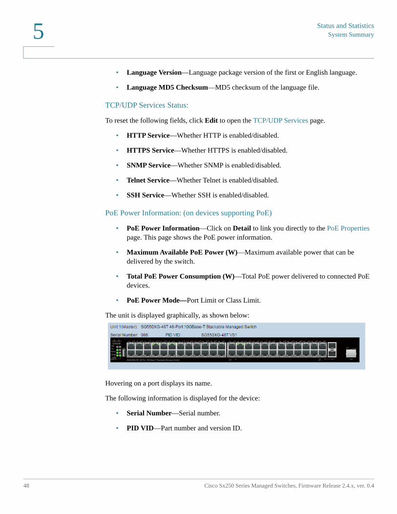
The unit is displayed graphically, as shown below:
Hovering on a port displays its name.
The following information is displayed for the device:
• Serial Number—Serial number.
• PID VID—Part number and version ID.
Status and Statistics
CPU Utilization
Cisco Sx250 Series Managed Switches, Firmware Release 2.4.x, ver. 0.4 49
5
CPU Utilization
The device CPU handles the following types of traffic, in addition to end-user traffic handling the management interface:
• Management traffic
• Protocol traffic
• Snooping traffic
Excessive traffic burdens the CPU, and might prevent normal device operation. The device uses the Secure Core Technology (SCT) feature to ensure that the device receives and processes management and protocol traffic, no matter how much total traffic is received. SCT is enabled by default on the device and cannot be disabled.
There are no interactions with other features.
To display CPU utilization:
STEP 1 Click Status and Statistics > CPU Utilization.
The CPU Input Rate field displays the rate of input frames to the CPU per second.
The window contains a graph displaying CPU utilization on the device. The Y axis is percentage of usage, and the X axis is the sample number.
STEP 2 Ensure that the CPU Utilization check box is enabled.
STEP 3 Select the Refresh Rate (time period in seconds) that passes before the statistics are refreshed. A new sample is created for each time period.
The window containing a graph displaying CPU utilization on the device is displayed.
Interface
The Interface page displays traffic statistics per port. The refresh rate of the information can be selected.
This page is useful for analyzing the amount of traffic that is both sent and received and its dispersion (Unicast, Multicast, and Broadcast).
Status and StatisticsInterface
50 Cisco Sx250 Series Managed Switches, Firmware Release 2.4.x, ver. 0.4
5
To display Ethernet statistics and/or set the refresh rate:
STEP 1 Click Status and Statistics > Interface.
STEP 2 Enter the parameters.
• Interface—Select the interface for which Ethernet statistics are to be displayed.
• Refresh Rate—Select the time period that passes before the interface Ethernet statistics are refreshed.
The Receive Statistics area displays information about incoming packets.
• Total Bytes (Octets)—Octets received, including bad packets and FCS octets, but excluding framing bits.
• Unicast Packets—Good Unicast packets received.
• Multicast Packets—Good Multicast packets received.
• Broadcast Packets—Good Broadcast packets received.
• Packets with Errors—Packets with errors received.
The Transmit Statistics area displays information about outgoing packets.
• Total Bytes (Octets)—Octets transmitted, including bad packets and FCS octets, but excluding framing bits.
• Unicast Packets—Good Unicast packets transmitted.
• Multicast Packets—Good Multicast packets transmitted.
• Broadcast Packets—Good Broadcast packets transmitted.
STEP 3 To view statistics counters in table view or graphic view:
• Click View All Interfaces Statistics to see all ports in table view.
• Click View Interface History Graph to display these results in graphic form. In this view, you can select the Time Span for which the results will be displayed and the type of statistic to be displayed. For example, if you select Last 5 Minutes and Unicast Packets, you will see how many Unicast packets received in the last 5 minutes.
Status and Statistics
Etherlike
Cisco Sx250 Series Managed Switches, Firmware Release 2.4.x, ver. 0.4 51
5
Etherlike
The Etherlike page displays statistics per port according to the Etherlike MIB standard definition. The refresh rate of the information can be selected. This page provides more detailed information regarding errors in the physical layer (Layer 1) that might disrupt traffic.
To view Etherlike Statistics and/or set the refresh rate:
STEP 1 Click Status and Statistics > Etherlike.
STEP 2 Enter the parameters.
• Interface—Select the specific interface for which Ethernet statistics are to be displayed.
• Refresh Rate—Select the amount of time that passes before the Etherlike statistics are refreshed.
The fields are displayed for the selected interface.
NOTE If one of the following fields shows a number of errors (not 0), a Last Update time is displayed.
• Frame Check Sequence (FCS) Errors—Received frames that failed the CRC (cyclic redundancy checks).
• Single Collision Frames—Frames that involved in a single collision, but successfully transmitted.
• Late Collisions—Collisions that have been detected after the first 512 bits of data.
• Excessive Collisions—Transmissions rejected due to excessive collisions.
• Oversize Packets—Packets greater than 2000 octets received.
• Internal MAC Receive Errors—Frames rejected because of receiver errors.
• Pause Frames Received—Received flow control pause frames. This field is only supported for XG ports. When the port speed is 1G, the received pause frames counter is not operational.
• Pause Frames Transmitted—Flow control pause frames transmitted from the selected interface.
STEP 3 To view statistics counters in table view, click View All Interfaces Statistics to see all ports in table view.
Status and StatisticsPort Utilization
52 Cisco Sx250 Series Managed Switches, Firmware Release 2.4.x, ver. 0.4
5
Port Utilization
The Port Utilization page displays utilization of broadband (both incoming and outgoing) per port.
To display port utilization:
STEP 1 Click Status and Statistics > Port Utilization.
STEP 2 Enter the Refresh Rate, which is the time period that passes before the interface Ethernet statistics are refreshed.
The following fields are displayed for each port:
• Interface—Name of port.
• Tx Utilization—Amount of bandwidth used by outgoing packets.
• Rx Utilization—Amount of bandwidth used by incoming packets.
To view a graph of historical utilization over time on the port, select a port and click View Interface History Graph. In addition to the above, the following field is displayed:
• Time Span—Select a unit of time. The graph displays the port utilization over this unit of time.
GVRP
The GVRP page displays information regarding GARP VLAN Registration Protocol (GVRP) frames that sent or received from a port. GVRP is a standards-based Layer 2 network protocol, for automatic configuration of VLAN information on switches. It is defined in the 802.1ak amendment to 802.1Q-2005.
GVRP statistics for a port are only displayed if GVRP is enabled globally and on the port. See the GVRP Settings page.
To view GVRP statistics and/or set the refresh rate:
STEP 1 Click Status and Statistics > GVRP.
STEP 2 Enter the parameters.
• Interface—Select the specific interface for which GVRP statistics are to be displayed.
Status and Statistics
802.1X EAP
Cisco Sx250 Series Managed Switches, Firmware Release 2.4.x, ver. 0.4 53
5
• Refresh Rate—Select the time period that passes before the GVRP page is refreshed.
The Attribute Counter block displays the counters for various types of packets per interface. These are displayed for Received and Transmitted packets.
• Join Empty—GVRP Join Empty packets received/transmitted.
• Empty—GVRP empty packets received/transmitted.
• Leave Empty—GVRP Leave Empty packets received/transmitted.
• Join In—GVRP Join In packets received/transmitted.
• Leave In—GVRP Leave In packets received/transmitted.
• Leave All—GVRP Leave All packets received/transmitted.
The GVRP Error Statistics section displays the GVRP error counters.
• Invalid Protocol ID—Invalid protocol ID errors.
• Invalid Attribute Type—Invalid attribute ID errors.
• Invalid Attribute Value—Invalid attribute value errors.
• Invalid Attribute Length—Invalid attribute length errors.
• Invalid Event—Invalid events.
STEP 3 To clear statistics counters, click View All Interfaces Statistics to see all ports on a single page.
802.1X EAP
The 802.1x EAP page displays detailed information regarding the EAP (Extensible Authentication Protocol) frames that were sent or received. To configure the 802.1X feature, see the (Security > 802.1x) Properties page.
To view the EAP Statistics and/or set the refresh rate:
STEP 1 Click Status and Statistics > 802.1x EAP.
STEP 2 Select the Interface that is polled for statistics.
STEP 3 Select the Refresh Rate (time period) that passes before the EAP statistics are refreshed.
Status and Statistics802.1X EAP
54 Cisco Sx250 Series Managed Switches, Firmware Release 2.4.x, ver. 0.4
5
The values are displayed for the selected interface.
• EAPOL EAP Frames Received—Valid EAPOL frames received on the port.
• EAPOL Start Frames Received—Valid EAPOL start frames received on the port.
• EAPOL Logoff Frames Received—EAPOL Logoff frames received on the port.
• EAPOL Announcement Frames Received—EAPOL Announcement frames received on the port.
• EAPOL Announcement Request Frames Received—EAPOL Announcement Request frames received on the port.
• EAPOL Invalid Frames Received—EAPOL invalid frames received on the port.
• EAPOL EAP Length Error Frames Received—EAPOL frames with an invalid Packet Body Length received on this port.
• MKPDU Frames with unrecognized CKN Received—EAP frames with unrecognized CKN received on this port.
• MKPDU Invalid Frames Received—MKPDU invalid frames received on the port.
• Last EAPOL Frame Version—Protocol version number attached to the most recently received EAPOL frame.
• Last EAPOL Frame Source—Source MAC address attached to the most recently received EAPOL frame.
• EAPOL EAP Supplicant Frames Transmitted—EAPOL EAP Supplicant frames transmitted on the port.
• EAPOL Start Frames Transmitted—EAPOL Start frames transmitted on the port.
• EAPOL Logoff Frames Transmitted—EAPOL Logoff frames transmitted on the port.
• EAPOL Announcement Frames Transmitted—EAPOL Announcement frames transmitted on the port.
• EAPOL Announcement Request Frames Transmitted—EAPOL Announcement Request frames transmitted on the port.
• EAPOL EAP Authenticator Frames Transmitted—EAP Authenticator frames transmitted on the port.
• EAPOL MKA Frames with No CKN Transmitted—MKA frames with no CKN transmitted on the port.
Status and Statistics
ACL
Cisco Sx250 Series Managed Switches, Firmware Release 2.4.x, ver. 0.4 55
5
STEP 4 To clear statistics counters:
• Click View All Interfaces Statistics to view the counters of all interfaces.
• Click Clear Interface Counters to clear the counters of all interfaces.
ACL
When the ACL logging feature is enabled, an informational SYSLOG message is generated for packets that match ACL rules.
To view the interfaces on which packets forward or rejected based on ACLs:
STEP 1 Click Status and Statistics > ACL.
STEP 2 Select the Refresh Rate (time period in seconds) that passes before the page is refreshed. A new group of interfaces is created for each time period.
The following information is displayed:
• Global Trapped Packet Counter—Number of packets trapped globally due to lack of resources.
• Trapped Packets—Port/LAG Based—The interfaces on which packets forwarded or rejected based on ACL rules.
• Trapped Packets—VLAN Based—The VLANs on which packets forwarded or rejected based on ACL rules.
STEP 3 To manage statistics counters, click Clear Counters to clear the counters of all interfaces.
Hardware Resource Utilization
This page displays resources used by the system, such as ACLs (Access Control Lists) and Quality of Service (QoS).
Some applications allocate rules upon their initiation. Additionally, processes that initialize during system boot use some of their rules during the startup process.
Status and StatisticsHealth and Power
56 Cisco Sx250 Series Managed Switches, Firmware Release 2.4.x, ver. 0.4
5
To view hardware resource utilization, click Status and Statistics > Hardware Resource Utilization.
The following fields are displayed:
• IP Entries
- In Use—Number of TCAM entries used for IP rules.
- Maximum—Number of available TCAM entries that can be used for IP rules.
• ACL and QoS Rules
- In Use—Number of TCAM entries used for ACL and QoS rules.
- Maximum—Number of available TCAM entries that can be used for ACL and QoS rules.
To view how the allocation among various processes can be changed, see the Hardware Resources section.
Health and Power
The Health and Power page monitors the temperature status, power supply status and fan status on all relevant devices. Depending on the model, there are one or more fans on a device. Some models have no fans at all.
Fans
In some devices the fans are mandatory for the device operation since without them the device becomes too hot and automatically shut-down. Since a fan is a moving part, it is subject to failures. A redundant fan is installed on the system. This fan is not operational unless one or more of the system fans fails. In this case, the redundant fan becomes part of the environment monitoring of the device.
It is recommended to let the redundant fan work for at least 1 minute once a day.
Status and Statistics
Health and Power
Cisco Sx250 Series Managed Switches, Firmware Release 2.4.x, ver. 0.4 57
5
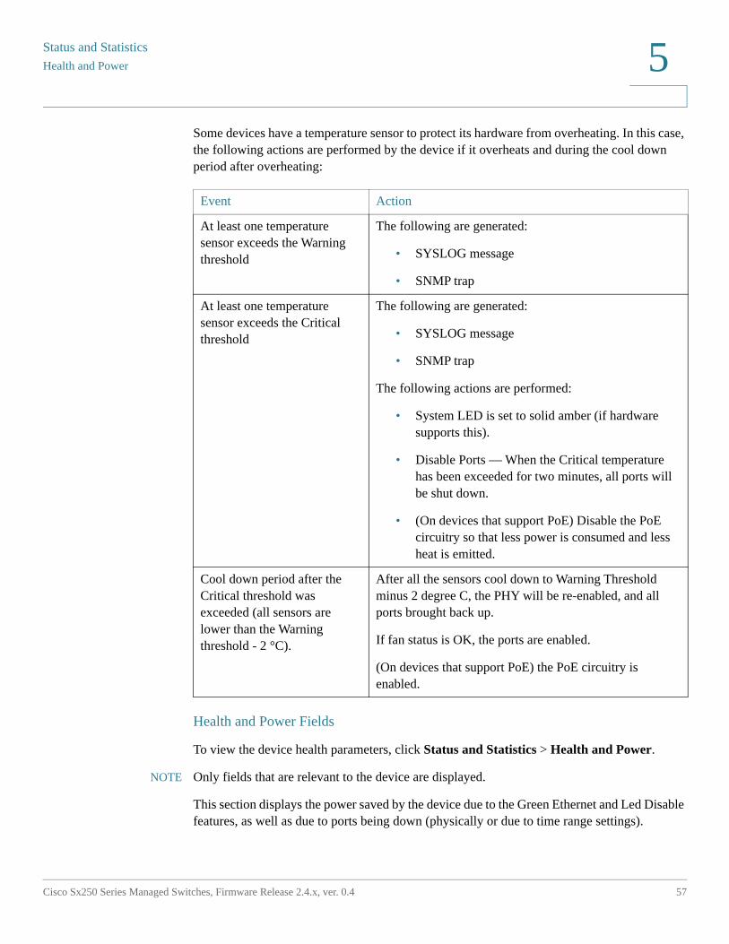
Some devices have a temperature sensor to protect its hardware from overheating. In this case, the following actions are performed by the device if it overheats and during the cool down period after overheating:
Health and Power Fields
To view the device health parameters, click Status and Statistics > Health and Power.
NOTE Only fields that are relevant to the device are displayed.
This section displays the power saved by the device due to the Green Ethernet and Led Disable features, as well as due to ports being down (physically or due to time range settings).
Event Action
At least one temperature sensor exceeds the Warning threshold
The following are generated:
• SYSLOG message
• SNMP trap
At least one temperature sensor exceeds the Critical threshold
The following are generated:
• SYSLOG message
• SNMP trap
The following actions are performed:
• System LED is set to solid amber (if hardware supports this).
• Disable Ports — When the Critical temperature has been exceeded for two minutes, all ports will be shut down.
• (On devices that support PoE) Disable the PoE circuitry so that less power is consumed and less heat is emitted.
Cool down period after the Critical threshold was exceeded (all sensors are lower than the Warning threshold - 2 °C).
After all the sensors cool down to Warning Threshold minus 2 degree C, the PHY will be re-enabled, and all ports brought back up.
If fan status is OK, the ports are enabled.
(On devices that support PoE) the PoE circuitry is enabled.
Status and StatisticsHealth and Power
58 Cisco Sx250 Series Managed Switches, Firmware Release 2.4.x, ver. 0.4
5
The PoE savings displays the total power saved by using the PoE time range feature that shuts down PoE to ports at specific times (usually when the PoE network element is not in use).
The following information is displayed (the order of the fields may be different depending on the device):
Environmental Savings
• Fan Status—The following values are possible:
- OK—Fan is operating normally.
- Failure—Fan is not operating correctly.
- N/A—Fan ID is not applicable for the specific model.
• Sensor Status—The following values are possible:
- OK—Sensor is operating normally.
- Failure—Sensor is not operating correctly.
- N/A—Sensor ID is not applicable for the specific model.
• Temperature—The options are:
- OK—The temperature is below the warning threshold.
- Warning—The temperature is between the warning threshold to the critical threshold.
- Critical—Temperature is above the critical threshold.
- N/A—Not relevant.
- Main Power Supply Status—Displays one of the following for the main power supply:
Active—Power supply is being used.
Failure—Main power has failed.
Power Savings
• Current Green Ethernet and Port Power Savings—Current amount of the power savings on all the ports.
• Cumulative Green Ethernet and Port Power Savings—Accumulative amount of the power savings on all the ports since the device was powered up.

Status and Statistics
Health and Power
Cisco Sx250 Series Managed Switches, Firmware Release 2.4.x, ver. 0.4 59
5
• Projected Annual Green Ethernet and Port Power Savings—Projection of the amount of the power that will be saved on the device during one week. This value is calculated based on the savings that occurred during the previous week.
• Current PoE Power Savings—Current amount of the PoE power saved on ports that have PDs connected to them and on which PoE is not operational due to the Time Range feature.
• Cumulative PoE Power Savings—Cumulative amount of the PoE power, since the device was powered up, saved on ports which have PDs connected to them and to which PoE is not operational due to the Time Range feature.
• Projected Annual PoE Power Savings—Yearly projected amount of PoE power, since device was powered up, saved on ports that have PDs connected to them and to which PoE is not operational due to the Time Range feature. The projection is based on the savings during the previous week.
Ethernet Power Supply Table (displayed only if the device supports PD ports). The following fields are displayed:
• Port Name—Number of port.
• PD Status—Displays one of the following values:
- Connected—The PD port is connected to a PSE device that is providing power.
- Not Connected—The PD port is not connected to a PSE device.
• Negotiation Mode—One of the following values.
- Auto—CDP or LLDP negotiation is used to determine power level.
- Force 802.3AF—Both sides use the AF power standard.
- Force 802.3AT—Both sides use the AT power standard.
- Force 60W—Both sides use the 60W power.
• Power Budget—Amount of power actually allocated to the port.
Status and StatisticsSwitched Port Analyzer (SPAN)
60 Cisco Sx250 Series Managed Switches, Firmware Release 2.4.x, ver. 0.4
5
Switched Port Analyzer (SPAN)
The SPAN feature, which is sometimes called port mirroring or port monitoring, selects network traffic for analysis by a network analyzer. The network analyzer can be a Cisco SwitchProbe device or other Remote Monitoring (RMON) probes.
Port mirroring is used on a network device to send a copy of network packets, seen on a single device port, multiple device ports, or an entire VLAN, to a network monitoring connection on another port on the device. This is commonly used when monitoring of network traffic, such as for an intrusion-detection system, is required. A network analyzer, connected to the monitoring port, processes the data packets.
The device can mirror up to four interfaces per session.
A packet, which is received on a network port and assigned to a VLAN that is subject to mirroring, is mirrored to the analyzer port even if the packet was eventually trapped or discarded. Packets sent by the device are mirrored when Transmit (Tx) mirroring is activated.
Mirroring does not guarantee that all traffic from the source port(s) is received on the analyzer (destination) port. If more data is sent to the analyzer port than it can support, some data might be lost.
SPAN Session Destinations
A monitoring session consists of one or more source ports and a single destination ports.
To add a destination port:
STEP 1 Click Status and Statistics > SPAN > Session Destinations.
The previously-defined destinations are displayed.
STEP 2 Click Add.
STEP 3 Enter the following fields:
• Session ID—Select a session ID. This must match the session IDs of the source ports.
• Port—Select the port number to which traffic is to be copied.
This is the analyzer port. A network analyzer, such as a PC running Wireshark, is connected to this port.
Status and Statistics
Diagnostics
Cisco Sx250 Series Managed Switches, Firmware Release 2.4.x, ver. 0.4 61
5
• Network Traffic—Select to enable that traffic other than monitored traffic is possible on the port.
STEP 4 Click Apply.
SPAN Session Sources
One or more SPAN sources must be configured on the device.
To configure the source ports to be mirrored:
STEP 1 Click Status and Statistics > SPAN > Session Sources.
STEP 2 Click Add.
STEP 3 Select the session number from Session ID. This must be the same for all source ports and the destination port.
STEP 4 Select the port or VLAN from which traffic is sent to the analyzer port (Source Interface)
STEP 5 In the Monitor Type field, select whether incoming, outgoing, or both types of traffic are mirrored.
• Rx and Tx—Port mirroring on both incoming and outgoing packets.
• Rx—Port mirroring on incoming packets.
• Tx—Port mirroring on outgoing packets.
STEP 6 Click Apply. The source interface for the mirroring is configured.
Diagnostics
This section contains information for configuring port mirroring, running cable tests, and viewing device operational information.
It covers the following topics:
• Copper Ports Tests
• Optical Module Status
• Tech-Support Information
Status and StatisticsDiagnostics
62 Cisco Sx250 Series Managed Switches, Firmware Release 2.4.x, ver. 0.4
5
Copper Ports Tests
The Copper Test page displays the results of integrated cable tests performed on copper cables by the Virtual Cable Tester (VCT).
VCT performs two types of tests:
• Time Domain Reflectometry (TDR) technology tests the quality and characteristics of a copper cable attached to a port. Cables of up to 140 meters long can be tested. These results are displayed in the Test Results block of the Copper Test page.
• DSP-based tests are performed on active XG links to measure cable length. These results are displayed in the Advanced Information block of the Copper Test page. This test can run only when the link speed is 10G.
Preconditions to Running the Copper Port Test
Before running the test, do the following:
• (Mandatory) Disable Short Reach mode (see the Properties page)
• (Optional) Disable EEE (see the Properties page)
Use a CAT6a data cable when testing cables using (VCT).
The test results have an accuracy within an error range of +/- 10 for advanced Testing and +/- 2 for basic testing.
CAUTION When a port is tested, it is set to the Down state and communications are interrupted. After the test, the port returns to the Up state. It is not recommended that you run the copper port test on a port you are using to run the web-based switch configuration utility, because communications with that device are disrupted.
To test copper cables attached to ports:
STEP 1 Click Status and Statistics > Diagnostics > Copper Test.
STEP 2 Select the port on which to run the test.
STEP 3 Click Copper Test.
STEP 4 When the message appears, click OK to confirm that the link can go down or Cancel to abort the test.
The following fields are displayed in the Test Results block:
• Last Update—Time of the last test conducted on the port.
Status and Statistics
Diagnostics
Cisco Sx250 Series Managed Switches, Firmware Release 2.4.x, ver. 0.4 63
5
• Test Results—Cable test results. Possible values are:
- OK—Cable passed the test.
- No Cable—Cable is not connected to the port.
- Open Cable—Cable is connected on only one side.
- Short Cable—Short circuit has occurred in the cable.
- Unknown Test Result—Error has occurred.
• Distance to Fault—Distance from the port to the location on the cable where the fault was discovered.
• Operational Port Status—Displays whether port is up or down.
The Advanced Information block contains the following information, which is refreshed each time you enter the page:
• Cable Length—Provides an estimate for the length.
• Pair—Cable wire pair being tested.
• Status—Wire pair status. Red indicates fault and Green indicates status OK.
• Channel—Cable channel indicating whether the wires are straight or cross-over.
• Polarity—Indicates if automatic polarity detection and correction has been activated for the wire pair.
• Pair Skew—Difference in delay between wire pairs.
Optical Module Status
The Optical Module Status page displays the operating conditions reported by the SFP (Small Form-factor Pluggable) transceiver.
The following GE SFP (1000Mbps) transceivers are supported:
• MGBBX1: 1000BASE-BX-20U SFP transceiver, for single-mode fiber, 1310 nm wavelength, supports up to 40 km.
• MGBLH1: 1000BASE-LH SFP transceiver, for single-mode fiber, 1310 nm wavelength, supports up to 40 km.
• MGBLX1: 1000BASE-LX SFP transceiver, for single-mode fiber, 1310 nm wavelength, supports up to 10 km.
Status and StatisticsDiagnostics
64 Cisco Sx250 Series Managed Switches, Firmware Release 2.4.x, ver. 0.4
5
• MGBSX1:1000BASE-SX SFP transceiver, for multimode fiber, 850 nm wavelength, supports up to 550 m.
• MGBT1: 1000BASE-T SFP transceiver for category 5 copper wire, supports up to 100 m.
The following XG SFP+ (10,000Mbps) transceivers are supported:
• Cisco SFP-10GSR
• Cisco SFP-10GLRM
• Cisco SFP-10GLR
The following XG passive cables (Twinax/DAC) are supported:
• Cisco SFP-H10GCU1m
• Cisco SFP-H10GCU3m
• Cisco SFP-H10GCU5m
To view the results of optical tests, click Status and Statistics > Diagnostics > Optical Module Status.
This page displays the following fields:
• Port—Port number on which the SFP is connected.
• Description—Description of optical transceiver.
• Serial Number—Serial number of optical transceiver.
• PID—VLAN ID.
• VID—ID of optical transceiver.
• Temperature—Temperature (Celsius) at which the SFP is operating.
• Voltage—SFPs operating voltage.
• Current—SFPs current consumption.
• Output Power—Transmitted optical power.
• Input Power—Received optical power.
• Transmitter Fault—Remote SFP reports signal loss. Values are True, False, and No Signal (N/S).
• Loss of Signal—Local SFP reports signal loss. Values are True and False.
Status and Statistics
RMON
Cisco Sx250 Series Managed Switches, Firmware Release 2.4.x, ver. 0.4 65
5
• Data Ready—SFP is operational. Values are True and False.
Tech-Support Information
This page provides a detailed log of the device status. This is valuable when the technical support are trying to help a user with a problem, since it gives the output of many show commands (including debug command) in a single command.
To view technical support information useful for debugging purposes:
STEP 1 Click Status and Statistics > Diagnostics > Tech-Support Information.
STEP 2 Click Generate.
Information from a variety of show CLI commands is displayed.
NOTE Generation of output from this command may take some time. When the information is generated, you can copy it from the text box in the screen by clicking on Select tech-support data.
RMON
RMON (Remote Networking Monitoring) enables an SNMP agent in the device to proactively monitor traffic statistics over a given period and send traps to an SNMP manager. The local SNMP agent compares actual, real-time counters against predefined thresholds and generates alarms, without the need for polling by a central SNMP management platform. This is an effective mechanism for proactive management, provided that you have set the correct thresholds relative to your network’s base line.
RMON decreases the traffic between the manager and the device since the SNMP manager does not have to poll the device frequently for information, and enables the manager to get timely status reports, since the device reports events as they occur.
With this feature, you can perform the following actions:
• View the current statistics (from the time that the counter values cleared). You can also collect the values of these counters over a period of time, and then view the table of collected data, where each collected set is a single line of the History tab.
• Define interesting changes in counter values, such as “reached a certain number of late collisions” (defines the alarm), and then specify what action to perform when this event occurs (log, trap, or log and trap).
Status and StatisticsRMON
66 Cisco Sx250 Series Managed Switches, Firmware Release 2.4.x, ver. 0.4
5
Statistics
The Statistics page displays detailed information regarding packet sizes and information regarding physical layer errors. The information is displayed according to the RMON standard. An oversized packet is defined as an Ethernet frame with the following criteria:
• Packet length is greater than MRU byte size.
• Collision event has not been detected.
• Late collision event has not been detected.
• Received (Rx) error event has not been detected.
• Packet has a valid CRC.
To view RMON statistics and/or set the refresh rate:
STEP 1 Click Status and Statistics > RMON > Statistics.
STEP 2 Select the Interface for which Ethernet statistics are to be displayed.
STEP 3 Select the Refresh Rate, which is the time period that passes before the interface statistics are refreshed.
The following statistics are displayed for the selected interface.
NOTE If one of the following fields shows a number of errors (not 0), a Last Update time is displayed.
• Bytes Received—Octets received, including bad packets and FCS octets, but excluding framing bits.
• Drop Events—Packets dropped.
• Packets Received—Good packets received, including Multicast and Broadcast packets.
• Broadcast Packets Received—Good Broadcast packets received. This number does not include Multicast packets.
• Multicast Packets Received—Good Multicast packets received.
• CRC & Align Errors—CRC and Align errors that have occurred.
• Undersize Packets—Undersized packets (less than 64 octets) received.
• Oversize Packets—Oversized packets (over 2000 octets) received.
• Fragments—Fragments (packets with less than 64 octets, excluding framing bits, but including FCS octets) received.
Status and Statistics
RMON
Cisco Sx250 Series Managed Switches, Firmware Release 2.4.x, ver. 0.4 67
5
• Jabbers—Received packets that longer than 1632 octets. This number excludes frame bits, but includes FCS octets that had either a bad FCS (Frame Check Sequence) with an integral number of octets (FCS Error) or a bad FCS with a non-integral octet (Alignment Error) number. A Jabber packet is defined as an Ethernet frame that satisfies the following criteria:
- Packet data length is greater than MRU.
- Packet has an invalid CRC.
- Received (Rx) Error Event has not been detected.
• Collisions—Collisions received. If Jumbo frames are enabled, the threshold of Jabber frames is raised to the maximum size of Jumbo frames.
• Frames of 64 Bytes—Frames, containing 64 bytes that were sent or received.
• Frames of 65 to 127 Bytes—Frames, containing 65-127 bytes that were sent or received.
• Frames of 128 to 255 Bytes—Frames, containing 128-255 bytes that were sent or received.
• Frames of 256 to 511 Bytes—Frames, containing 256-511 bytes that were sent or received.
• Frames of 512 to 1023 Bytes—Frames, containing 512-1023 bytes that were sent or received.
• Frames of 1024 Bytes or More—Frames, containing 1024-2000 bytes, and Jumbo Frames, that were sent or received.
STEP 4 To view counters in table view or graphic view:
• Click View All Interfaces Statistics to see all ports in table view.
• Click Graphic View to display these results in graphic form. In this view, you can select the Time Span for which the results will be displayed and the type of statistic to be displayed.
RMON History
The RMON feature enables monitoring statistics per interface.
The History page defines the sampling frequency, amount of samples to store and the port from which to gather the data.
Status and StatisticsRMON
68 Cisco Sx250 Series Managed Switches, Firmware Release 2.4.x, ver. 0.4
5
After the data is sampled and stored, it appears in the History Table page that can be viewed by clicking History Table.
To enter RMON control information:
STEP 1 Click Status and Statistics > RMON > History. The fields displayed on this page are defined in the Add RMON History page, below. The only field is that is on this page and not defined in the Add page is:
• Current Number of Samples—RMON is allowed by the standard to not grant all requested samples, but rather to limit the number of samples per request. Therefore, this field represents the sample number actually granted to the request that is equal or less than the requested value.
STEP 2 Click Add.
STEP 3 Enter the parameters.
• New History Entry—Displays the number of the new History table entry.
• Source Interface—Select the type of interface from which the history samples are to be taken.
• Max No. of Samples to Keep—Enter the number of samples to store.
• Sampling Interval—Enter the time in seconds that samples are collected from the ports. The field range is 1-3600.
• Owner—Enter the RMON station or user that requested the RMON information.
STEP 4 Click Apply. The entry is added to the History Control Table page, and the Running Configuration file is updated.
STEP 5 Click History Table (described below) to view the actual statistics.
RMON History Table
The History page displays interface-specific statistical network samplings. The samples configured in the History Control table described above.
To view RMON history statistics:
STEP 1 Click Status and Statistics > RMON > History.
STEP 2 Click History Table.
Status and Statistics
RMON
Cisco Sx250 Series Managed Switches, Firmware Release 2.4.x, ver. 0.4 69
5
STEP 3 From the History Entry No. drop down menu, optionally select the entry number of the sample to display.
The fields are displayed for the selected sample.
• Owner—History table entry owner.
• Sample No.—Statistics taken from this sample.
• Drop Events—Dropped packets due to lack of network resources during the sampling interval. This may not represent the exact number of dropped packets, but rather the number of times dropped packets detected.
• Bytes Received—Octets received including bad packets and FCS octets, but excluding framing bits.
• Packets Received—Packets received, including bad packets, Multicast, and Broadcast packets.
• Broadcast Packets—Good Broadcast packets excluding Multicast packets.
• Multicast Packets—Good Multicast packets received.
• CRC Align Errors—CRC and Align errors that have occurred.
• Undersize Packets—Undersized packets (less than 64 octets) received.
• Oversize Packets—Oversized packets (over 2000 octets) received.
• Fragments—Fragments (packets with less than 64 octets) received, excluding framing bits, but including FCS octets.
• Jabbers—Total number of received packets that longer than 2000 octets. This number excludes frame bits, but includes FCS octets that had either a bad FCS (Frame Check Sequence) with an integral number of octets (FCS Error) or a bad FCS with a non-integral octet (Alignment Error) number.
• Collisions—Collisions received.
• Utilization—Percentage of current interface traffic compared to maximum traffic that the interface can handle.
Status and StatisticsRMON
70 Cisco Sx250 Series Managed Switches, Firmware Release 2.4.x, ver. 0.4
5
RMON Events Control
You can control the occurrences that trigger an alarm and the type of notification that occurs. This is performed as follows:
• Events Page—Configures what happens when an alarm is triggered. This can be any combination of logs and traps.
• Alarms Page—Configures the occurrences that trigger an alarm.
To define RMON events:
STEP 1 Click Status and Statistics > RMON > Events.
This page displays previously defined events.
The fields on this page are defined by the Add RMON Events dialog box except for the Time field.
• Time—Displays the time of the event. (This is a read-only table in the parent window and cannot be defined).
STEP 2 Click Add.
STEP 3 Enter the parameters.
• Event Entry—Displays the event entry index number for the new entry.
• Community—Enter the SNMP community string to be included when traps are sent (optional). Note that the community must be defined using the Notification Recipients pages for the trap to reach the Network Management Station.
• Description—Enter a name for the event. This name is used in the Add RMON Alarm page to attach an alarm to an event.
• Notification Type—Select the type of action that results from this event. Values are:
- None—No action occurs when the alarm goes off.
- Log (Event Log Table)—Add a log entry to the Event Log table when the alarm is triggered.
- Trap (SNMP Manager and Syslog Server)—Send a trap to the remote log server when the alarm goes off.
- Log and Trap—Add a log entry to the Event Log table and send a trap to the remote log server when the alarm goes off.
• Owner—Enter the device or user that defined the event.
Status and Statistics
RMON
Cisco Sx250 Series Managed Switches, Firmware Release 2.4.x, ver. 0.4 71
5
STEP 4 Click Apply. The RMON event is saved to the Running Configuration file.
STEP 5 Click Event Log Table to display the log of alarms that have occurred and that have been logged (see description below).
RMON Events Logs
The Events page displays the log of events (actions) that occurred. Two types of events can be logged: Log or Log and Trap. The action in the event is performed when the event is bound to an alarm (see the RMON Alarms page) and the conditions of the alarm have occurred.
STEP 1 Click Status and Statistics > RMON > Events.
STEP 2 Click Event Log Table.
You can select an interface in the filter to view events on a specific interface.
This page displays the following fields:
• Event Entry No.—Event’s log entry number.
• Log No.—Log number (within the event).
• Log Time—Time that the log entry was entered.
• Description—Description of event that triggered the alarm.
RMON Alarms
RMON alarms provide a mechanism for setting thresholds and sampling intervals to generate exception events on counters or any other SNMP object counter maintained by the agent. Both the rising and falling thresholds must be configured in the alarm. After a rising threshold is crossed, no rising events are generated until the companion falling threshold is crossed. After a falling alarm is issued, the next alarm is issued when a rising threshold is crossed.
One or more alarms are bound to an event, which indicates the action to be taken when the alarm occurs.
Alarm counters can be monitored by either absolute values or changes (delta) in the counter values.
Status and StatisticsRMON
72 Cisco Sx250 Series Managed Switches, Firmware Release 2.4.x, ver. 0.4
5
To enter RMON alarms:
STEP 1 Click Status and Statistics > RMON > Alarms.
All previously-defined alarms are displayed. The fields are described in the Add RMON Alarm page below. In addition to those fields, the following field appears:
• Counter Value—Displays the value of the statistic during the last sampling period.
STEP 2 Click Add.
STEP 3 Enter the parameters.
• Alarm Entry—Displays the alarm entry number.
• Interface—Select the type of interface for which RMON statistics are displayed.
• Counter Name—Select the MIB variable that indicates the type of occurrence measured.
• Sample Type—Select the sampling method to generate an alarm. The options are:
- Absolute—If the threshold is crossed, an alarm is generated.
- Delta—Subtracts the last sampled value from the current value. The difference in the values is compared to the threshold. If the threshold was crossed, an alarm is generated.
• Rising Threshold—Enter the value that triggers the rising threshold alarm.
• Rising Event—Select an event to be performed when a rising event is triggered. Events are configured in the RMON Events Control page.
• Falling Threshold—Enter the value that triggers the falling threshold alarm.
• Falling Event—Select an event to be performed when a falling event is triggered.
• Startup Alarm—Select the first event from which to start generation of alarms. Rising is defined by crossing the threshold from a low-value threshold to a higher-value threshold.
- Rising Alarm—A rising value triggers the rising threshold alarm.
- Falling Alarm—A falling value triggers the falling threshold alarm.
- Rising and Falling—Both rising and falling values trigger the alarm.
• Interval—Enter the alarm interval time in seconds.
Status and Statistics
View Logs
Cisco Sx250 Series Managed Switches, Firmware Release 2.4.x, ver. 0.4 73
5
• Owner—Enter the name of the user or network management system that receives the alarm.
STEP 4 Click Apply. The RMON alarm is saved to the Running Configuration file.
View Logs
The device can write to the following logs:
• Log in RAM (cleared during reboot).
• Log in Flash memory (cleared only upon user command).
You can configure the messages that are written to each log by severity, and a message can go to more than one log, including logs that reside on external SYSLOG servers.
RAM Memory
The RAM Memory page displays all messages that saved in the RAM (cache) in chronological order. Entries are stored in the RAM log according to the configuration in the Log Settings page.
Pop-Up SYSLOG Notifications
When a new SYSLOG message is written to the RAM log file, a notification is displayed in the web GUI showing its contents.
The web GUI will poll the RAM log every 10 seconds. Notifications pop-ups for all SYSLOGs created in the last 10 seconds will appear at the bottom right of the screen.
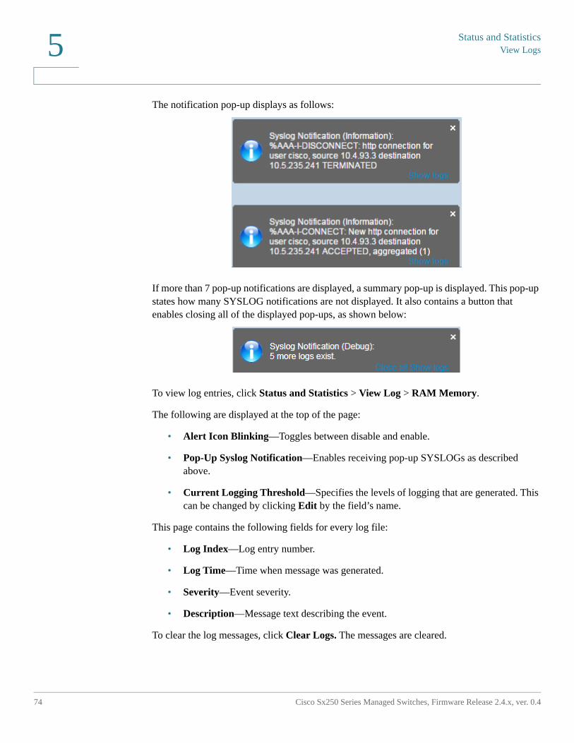
Status and StatisticsView Logs
74 Cisco Sx250 Series Managed Switches, Firmware Release 2.4.x, ver. 0.4
5
The notification pop-up displays as follows:
If more than 7 pop-up notifications are displayed, a summary pop-up is displayed. This pop-up states how many SYSLOG notifications are not displayed. It also contains a button that enables closing all of the displayed pop-ups, as shown below:
To view log entries, click Status and Statistics > View Log > RAM Memory.
The following are displayed at the top of the page:
• Alert Icon Blinking—Toggles between disable and enable.
• Pop-Up Syslog Notification—Enables receiving pop-up SYSLOGs as described above.
• Current Logging Threshold—Specifies the levels of logging that are generated. This can be changed by clicking Edit by the field’s name.
This page contains the following fields for every log file:
• Log Index—Log entry number.
• Log Time—Time when message was generated.
• Severity—Event severity.
• Description—Message text describing the event.
To clear the log messages, click Clear Logs. The messages are cleared.
Status and Statistics
View Logs
Cisco Sx250 Series Managed Switches, Firmware Release 2.4.x, ver. 0.4 75
5
Flash Memory
The Flash Memory page displays the messages that stored in the Flash memory, in chronological order. The minimum severity for logging is configured in the Log Settings page. Flash logs remain when the device is rebooted. You can clear the logs manually.
To view the Flash logs, click Status and Statistics > View Log > Flash Memory.
The Current Logging Threshold specifies the levels of logging that are generated. This can be changed by clicking Edit by the field’s name.
This page contains the following fields for each log file:
• Log Index—Log entry number.
• Log Time—Time when message was generated.
• Severity—Event severity.
• Description—Message text describing the event.
To clear the messages, click Clear Logs. The messages are cleared.
6
Cisco Sx250 Series Managed Switches, Firmware Release 2.4.x, ver. 0.4 76
Administration
This section describes how to view system information and configure various options on the device.
It covers the following topics:
• System Settings
• User Accounts
• Idle Session Timeout
• Time Settings
• System Log
• File Management
• Plug-n-Play (PNP)
• Reboot
• Discovery - Bonjour
• Discovery - LLDP
• Discovery - CDP
• Locate Device
• Ping
• Traceroute
Administration
System Settings
Cisco Sx250 Series Managed Switches, Firmware Release 2.4.x, ver. 0.4 77
6
System Settings
To enter system settings:
STEP 1 Click Administration > System Settings.
STEP 2 View or modify the system settings.
• System Description—Displays a description of the device.
• System Location—Enter the physical location of the device.
• System Contact—Enter the name of a contact person.
• Host Name—Select the host name of this device. This is used in the prompt of CLI commands:
- Use Default—The default hostname (System Name) of these switches is: switch123456, where 123456 represents the last three bytes of the device MAC address in hex format.
- User Defined—Enter the hostname. Use only letters, digits, and hyphens. Host names cannot begin or end with a hyphen. No other symbols, punctuation characters, or blank spaces are permitted (as specified in RFC1033, 1034, 1035).
• Custom Banner Settings—The following banners can be set:
- Login Banner—Enter text to display on the Login page before login. Click Preview to view the results.
- Welcome Banner—Enter text to display on the Login page after login. Click Preview to view the results.
NOTE When you define a login banner from the web-based configuration utility, it also activates the banner for the CLI interfaces (Console, Telnet, and SSH).
The banner can contain up to 1000 characters. After 510 characters, press <Enter> to continue.
STEP 3 Click Apply to save the values in the Running Configuration file.
AdministrationUser Accounts
78 Cisco Sx250 Series Managed Switches, Firmware Release 2.4.x, ver. 0.4
6
User Accounts
The User Accounts page enables entering additional users that are permitted to access to the device (read-only or read-write) or changing the passwords of existing users.
After adding a level 15 user (as described below), the default user is removed from the system.
NOTE For information on password recover, see Menu CLI and Password Recovery.
To add a new user:
STEP 1 Click Administration > User Accounts.
This page displays the users defined in the system and their user privilege level.
STEP 2 Click Add to add a new user or click Edit to modify a user.
STEP 3 Enter the parameters.
• User Name—Enter a new username between 0 and 20 characters. UTF-8 characters are not permitted.
• Password—Enter a password (UTF-8 characters are not permitted). If the password strength and complexity is defined, the user password must comply with the policy configured in Password Strength.
• Confirm Password—Enter the password again.
• Password Strength Meter—Displays the strength of password. The policy for password strength and complexity are configured in the Password Strength page.
• User Level—Select the privilege level of the user being added/edited.
- Read-Only CLI Access (1)—User cannot access the GUI, and can only access CLI commands that do not change the device configuration.
- Read/Limited Write CLI Access (7)—User cannot access the GUI, and can only access some CLI commands that change the device configuration. See the CLI Reference Guide for more information.
- Read/Write Management Access (15)—User can access the GUI, and can configure the device.
STEP 4 Click Apply. The user is added to the Running Configuration file of the device.
Administration
Idle Session Timeout
Cisco Sx250 Series Managed Switches, Firmware Release 2.4.x, ver. 0.4 79
6
Idle Session Timeout
The Idle Session Timeout configures the time intervals that the management sessions can remain idle before they timeout and you must log in again to reestablish one of the following sessions:
• HTTP Session Timeout
• HTTPS Session Timeout
• Telnet Session Timeout
• SSH Session Timeout
To set the idle session timeout for various types of sessions:
STEP 1 Click Administration > Idle Session Timeout.
STEP 2 Select the timeout for the each type of session from the corresponding list. The default timeout value is 10 minutes.
STEP 3 Click Apply to set the configuration settings on the device.
Time Settings
See Administration: Time Settings.
System Log
This section describes the system logging, which enables the device to generate multiple independent logs. Each log is a set of messages describing system events.
The device generates the following local logs:
• Log sent to the console interface.
• Log written into a cyclical list of logged events in the RAM and erased when the device reboots.
AdministrationSystem Log
80 Cisco Sx250 Series Managed Switches, Firmware Release 2.4.x, ver. 0.4
6
• Log written to a cyclical log-file saved to the Flash memory and persists across reboots.
In addition, you can send messages to remote SYSLOG servers in the form of SNMP traps and SYSLOG messages.
This section covers the following sections:
• Log Settings
• Remote Logging Settings
Log Settings
You can select the events to be logged by severity level. Each log message has a severity level marked with the first letter of the severity level concatenated with a dash (-) on each side (except for Emergency that is indicated by the letter F). For example, the log message "%INIT-I-InitCompleted: … " has a severity level of I, meaning Informational.
The event severity levels are listed from the highest severity to the lowest severity, as follows:
• Emergency—System is not usable.
• Alert—Action is needed.
• Critical—System is in a critical condition.
• Error—System is in error condition.
• Warning—System warning has occurred.
• Notice—System is functioning properly, but a system notice has occurred.
• Informational—Device information.
• Debug—Detailed information about an event.
You can select different severity levels for RAM and Flash logs. These logs are displayed in the RAM Memory page and Flash Memory page, respectively.
Selecting a severity level to be stored in a log causes all of the higher severity events to be automatically stored in the log. Lower severity events are not stored in the log.
For example, if Warning is selected, all severity levels that are Warning and higher are stored in the log (Emergency, Alert, Critical, Error, and Warning). No events with severity level below Warning are stored (Notice, Informational, and Debug).
Administration
System Log
Cisco Sx250 Series Managed Switches, Firmware Release 2.4.x, ver. 0.4 81
6
To set global log parameters:
STEP 1 Click Administration > System Log > Log Settings.
STEP 2 Enter the parameters.
• Logging—Select to enable message logging.
• Syslog Aggregator—Select to enable the aggregation of SYSLOG messages and traps. If enabled, identical and contiguous SYSLOG messages and traps are aggregated over the specified Max. Aggregation Time and sent in a single message. The aggregated messages are sent in the order of their arrival. Each message states the number of times it was aggregated.
• Max. Aggregation Time—Enter the interval of time that SYSLOG messages are aggregated.
• Originator Identifier—Enables adding an origin identifier to SYSLOG messages. The options are:
- None—Do not include the origin identifier in SYSLOG messages.
- Hostname—Include the system host name in SYSLOG messages.
- IPv4 Address—Include the IPv4 address of the sending interface in SYSLOG messages.
- IPv6 Address—Include the IPv6 address of the sending interface in SYSLOG messages.
- User Defined—Enter a description to be included in SYSLOG messages.
• RAM Memory Logging—Select the severity levels of the messages to be logged to the RAM.
• Flash Memory Logging—Select the severity levels of the messages to be logged to the Flash memory.
• Click Apply. The Running Configuration file is updated.
Remote Logging Settings
The Remote Log Servers page enables defining remote SYSLOG servers to which log messages are sent. For each server, you can configure the severity of the messages that it receives.
AdministrationSystem Log
82 Cisco Sx250 Series Managed Switches, Firmware Release 2.4.x, ver. 0.4
6
To define SYSLOG servers:
STEP 1 Click Administration > System Log > Remote Log Servers.
STEP 2 Enter the following fields:
• IPv4 Source Interface—Select the source interface whose IPv4 address will be used as the source IPv4 address of SYSLOG messages sent to SYSLOG servers.
• IPv6 Source Interface—Select the source interface whose IPv6 address will be used as the source IPv6 address of SYSLOG messages sent to SYSLOG servers.
NOTE If the Auto option is selected, the system takes the source IP address from the IP address defined on the outgoing interface.
Information is described for each previously-configured log server. The fields are described below in the Add page.
STEP 3 Click Add.
STEP 4 Enter the parameters.
• Server Definition—Select whether to identify the remote log server by IP address or name.
• IP Version—Select the supported IP format.
• IPv6 Address Type—Select the IPv6 address type (if IPv6 is used). The options are:
- Link Local—The IPv6 address uniquely identifies hosts on a single network link. A link local address has a prefix of FE80::/10, is not routable, and can be used for communication only on the local network. Only one link local address is supported. If a link local address exists on the interface, this entry replaces the address in the configuration.
- Global—The IPv6 address is a global Unicast IPV6 type that is visible and reachable from other networks.
• Link Local Interface—Select the link local interface (if IPv6 Address Type Link Local is selected) from the list.
• Log Server IP Address/Name—Enter the IP address or domain name of the log server.
• UDP Port—Enter the UDP port to which the log messages are sent.
• Facility—Select a facility value from which system logs are sent to the remote server. Only one facility value can be assigned to a server. If a second facility code is assigned, the first facility value is overridden.
Administration
File Management
Cisco Sx250 Series Managed Switches, Firmware Release 2.4.x, ver. 0.4 83
6
• Description—Enter a server description.
• Minimum Severity—Select the minimum level of system log messages to be sent to the server.
STEP 5 Click Apply. The Add Remote Log Server page closes, the SYSLOG server is added, and the Running Configuration file is updated.
File Management
See Administration: File Management.
Plug-n-Play (PNP)
Installation of new networking devices or replacement of devices can be expensive, time-consuming and error-prone when performed manually. Typically, new devices are first sent to a central staging facility where the devices are unboxed, connected to a staging network, updated with the right licenses, configurations and images; then packaged and shipped to the actual installation location. After these processes are completed, experts must travel to the installation locations to perform the installation. Even in scenarios where the devices are installed in the NOC/Data Center itself, there may not be enough experts for the sheer number of devices. All these issues contribute to delays in deployment and add to the operational costs.
The Cisco Plug-n-Play solution reduces the costs associated with deployment/installation of network devices, increase the speed of their installation and reduce the complexity of deployments without compromising the security. Using the Cisco Plug-n-Play solution, you can perform Zero Touch Installs of the switches in various deployment scenarios and deployment locations.
AdministrationPlug-n-Play (PNP)
84 Cisco Sx250 Series Managed Switches, Firmware Release 2.4.x, ver. 0.4
6
PNP Settings
To configure PNP settings:
NOTE The feature is enabled by default.
STEP 1 Click Administration > PNP > PNP Settings.
STEP 2 Configure PNP by entering information in the following fields:
• PNP State—Enabled by default.
PNP Transport – Define PNP agent session information and parameters.
• Settings Definition—Select one of the following options for locating configuration information, regarding the transport protocol to use, the PNP server address and the TCP port to use:
- Default Settings—If this option is selected, the PNP settings are then taken from DHCP option 43. If some or all of the settings are not received from DHCP option 43, the following default values are used: default transport protocol HTTP, DNS name "pnpserver" for PNP server and the port related to HTTP.
When selecting the Default Settings option, all fields in PNP Transport section are grayed out.
- Manual Settings— Manually set the TCP port and server settings to use for PNP transport.
• TCP Port—Number of the TCP port. This is entered automatically by the system: 80 for HTTP.
• Server Definition—Select whether to specify the PNP server By IP address or By name.
• IP Version—Select the supported IP format.
• Server IPv6 Address Type—Select one of the following options, if the IP version type is IPv6:
- Link Local—The IPv6 address uniquely identifies hosts on a single network link. A link local address has a prefix of FE80, is not routable, and can be used for communication only on the local network. Only one link local address is supported. If a link local address exists on the interface, this entry replaces the address in the configuration.
- Global—The IPv6 address is a global Unicast IPV6 type that is visible and reachable from other networks.
Administration
Plug-n-Play (PNP)
Cisco Sx250 Series Managed Switches, Firmware Release 2.4.x, ver. 0.4 85
6
• Link Local Interface—If the source IPv6 address type is Link Local, select from where it is received.
• Server IP Address/Name—Enter the IP address or domain name of the PNP server.
PNP User
• User Definition—User information to be sent in PNP packets sent to the server. Select one of the following options:
- Default Value—When selecting this option, the PNP username and password settings are taken from DHCP option 43. If this option is selected the username and password fields are grayed out.
- Manual Settings—Select to manually configure PNP username and password.
• Username—Username to be entered in the PNP packets.
• Password—Password in either Encrypted or Plaintext form.
PNP Behavior Settings—Enter the following parameters:
• Reconnection Interval—Interval in seconds before attempting to reconnect the session after the connection is lost.
• Discovery Timeout—Specifies the time to wait, in seconds, before attempting discovery again after a discovery of the PNP server failed.
• Timeout Exponential Factor—Value that triggers the discovery attempt exponentially. by multiplying the previous timeout value by an exponential value and applying the result as timeout (if value is smaller than max timeout value).
• Max Discovery Timeout—.Maximum value of timeout. Must be greater than the Discovery Timeout value.
• Watchdog Timeout—Interval of time to wait for a reply from a PnP or file server during an active PNP session (for example during a file download process).
STEP 3 Click Apply. The parameters are copied to the Running Configuration file.
Click Display Sensitive Data as Plaintext to display the password if it is encrypted.
AdministrationPlug-n-Play (PNP)
86 Cisco Sx250 Series Managed Switches, Firmware Release 2.4.x, ver. 0.4
6
PNP Session
This screen displays the value of the PNP parameters currently in effect. The source of the parameter is displayed in parenthesis where relevant.
To display information about PNP parameters:
STEP 1 Click Administration > PNP > PNP Session.
The following fields are displayed:
• Administrative Status—Whether PNP is enabled or not.
• Operational Status—Is PNP operational.
• PNP Agent State—Indicates whether there is an active PNP session. The possible values are Discovery Wait; Discovery; Not Ready; Disabled; Session; Session Wait.
• Transport Protocol– Displays the PNP agent session information.
• TCP Port—TCP port of the PNP session
• Server IP Address—IP address of PNP server
• Username—Username to be sent in PNP packets
• Password MD5—Password to be sent in PNP packets
• Discovery Timeout—Discovery timeout configured
• Session Interval Timeout—Session Interval timeout configured (appears only when PNP Agent State is Waiting)
• Remaining Timeout—Value of remaining timeout.
NOTE Click the Resume button to immediately take the PnP agent out of the waiting state, in the following way:
• If the agent is in the Discovery Waiting state, it is set to the Discovery state.
• If the agent is in the PnP Session Waiting state, it is set to the PnP Session state.
Administration
Reboot
Cisco Sx250 Series Managed Switches, Firmware Release 2.4.x, ver. 0.4 87
6
Reboot
Some configuration changes, such as enabling jumbo frame support, require the system to be rebooted before they take effect. However, rebooting the device deletes the Running Configuration, so it is critical that the Running Configuration is saved to the Startup Configuration before the device is rebooted. Clicking Apply does not save the configuration to the Startup Configuration. For more information on files and file types, see the System Files section.
You can back up the device configuration by using the File Operations page or clicking Save at the top of the window. You can also upload the configuration from a remote device in the same page.
You might want to set the time of the reboot for some time in the future. This could happen, for example, in one of the following cases:
• You are performing actions on a remote device, and a mistake in these actions might create loss of connectivity to the remote device. Pre-scheduling a reboot restores the working configuration and enables restoring the connectivity to the remote device after the specified time expires. If these actions are successful, the delayed reboot can be manually canceled.
• Reloading the device cause loss of connectivity in the network, thus by using delayed reboot, you can schedule the reboot to a time that is more convenient for the users (e.g. late night).
To reboot the device:
STEP 1 Click Administration > Reboot.
STEP 2 Click the Reboot button to reboot the device.
• Reboot—Reboots the device. Since any unsaved information in the Running Configuration is discarded when the device is rebooted, you must click Save in the upper-right corner of any window to preserve current configuration across the boot process. If the Save option is not displayed, the Running Configuration matches the Startup Configuration and no action is necessary.
The following options are available:
- Immediate—Reboot immediately.
- Date—Enter the date (month/day) and time (hour and minutes) of the schedule reboot. This schedules a reload of the software to take place at the specified time (using a 24-hour clock). If you specify the month and day, the reload is scheduled to take place at the specified time and date. If you do not specify the month and day,
AdministrationDiscovery - Bonjour
88 Cisco Sx250 Series Managed Switches, Firmware Release 2.4.x, ver. 0.4
6
the reload takes place at the specified time on the current day (if the specified time is later than the current time) or on the next day (if the specified time is earlier than the current time). Specifying 00:00 schedules the reload for midnight. The reload must take place within 24 days.
NOTE This option can only be used if the system time has either been set manually or by SNTP.
NOTE If a reboot is scheduled, click Cancel Reboot to cancel the scheduled reboot.
- In—Reboot within the specified number of hours and minutes. The maximum amount of time that can pass is 24 days.
• Restore to Factory Defaults—Reboots the device by using the factory default configuration. This process erases all except for the Active Image, Mirror configuration, and Localization files.
• Clear Startup Configuration File—Check to clear the startup configuration on the device for the next time it boots up.
Discovery - Bonjour
See Bonjour.
Discovery - LLDP
See Discover - LLDP.
Discovery - CDP
See Discovery - CDP.
Administration
Locate Device
Cisco Sx250 Series Managed Switches, Firmware Release 2.4.x, ver. 0.4 89
6
Locate Device
This feature enables flashing all network port LEDs on a specific device in the network to locate the device physically. This feature is useful for locating a device within a room with many interconnected devices. When this feature is activated, all network port LEDs on the device flash for a configured duration (one minute by default).
STEP 1 Click Administration > Locate Device.
STEP 2 Enter values in the following fields:
• Duration—Enter for how long (in seconds) the port’s LEDs will flash.
• Remaining Time—This field is only displayed if the feature is currently activated. It displays the remaining time during which the LED will flash.
STEP 3 Click Start to activate the feature.
When the feature is activated the Start button is replaced by the Stop button, which allows you to stop the LED blinking before the defined timer expires.
Ping
The Ping utility tests if a remote host can be reached and measures the round-trip time for packets sent from the device to a destination device.
Ping operates by sending Internet Control Message Protocol (ICMP) echo request packets to the target host and waiting for an ICMP response, sometimes called a pong. It measures the round-trip time and records any packet loss.
To ping a host:
STEP 1 Click Administration > Ping.
STEP 2 Configure ping by entering the fields:
• Host Definition—Select whether to specify the source interface by its IP address or name. This field influences the interfaces that are displayed in the Source IP field, as described below.
• IP Version—If the source interface is identified by its IP address, select either IPv4 or IPv6 to indicate that it will be entered in the selected format.
AdministrationPing
90 Cisco Sx250 Series Managed Switches, Firmware Release 2.4.x, ver. 0.4
6
• Source IP—Select the source interface whose IPv4 address will be used as the source IPv4 address for communication with the destination. If the Host Definition field was By Name, all IPv4 and IPv6 addresses will be displayed in this drop-down field. If the Host Definition field was By IP Address, only the existing IP addresses of the type specified in the IP Version field will be displayed.
NOTE If the Auto option is selected, the system computes the source address based on the destination address.
• Destination IPv6 Address Type—Select one of the following options:.
- Link Local—The IPv6 address uniquely identifies hosts on a single network link. A link local address has a prefix of FE80, is not routable, and can be used for communication only on the local network. Only one link local address is supported. If a link local address exists on the interface, this entry replaces the address in the configuration.
- Global—The IPv6 address is a global Unicast IPV6 type that is visible and reachable from other networks.
• Link Local Interface—If the IPv6 address type is Link Local, select from where it is received.
• Destination IP Address/Name—Address or host name of the device to be pinged. Whether this is an IP address or host name depends on the Host Definition.
• Ping Interval—Length of time the system waits between ping packets. Ping is repeated the number of times configured in the Number of Pings field, whether the ping succeeds or not. Select to use the default interval or specify your own value.
• Number of Pings—The number of times the ping operation is performed. Select to use the default or specify your own value.
• Status—Displays whether the ping succeeded or failed.
STEP 3 Click Activate Ping to ping the host. The ping status appears and a message is added to the list of messages, indicating the result of the ping operation.
STEP 4 View the results of ping in the Ping Counters and Status section of the page:
• Number of Sent Packets—Number of packets sent by ping
• Number of Received Packets—Number of packets received by ping
• Packet Lost—Percentage of packets lost in ping process
• Minimum Round Trip Time—Shortest time for packet to return
• Maximum Round Trip Time—Longest time for packet to return
Administration
Traceroute
Cisco Sx250 Series Managed Switches, Firmware Release 2.4.x, ver. 0.4 91
6
• Average Round Trip Time—Average time for packet to return
• Status—Fail or succeed
Traceroute
Traceroute discovers the IP routes along which packets forwarded by sending an IP packet to the target host and back to the device. The Traceroute page shows each hop between the device and a target host, and the round-trip time to each such hop.
STEP 1 Click Administration > Traceroute.
STEP 2 Configure Traceroute by entering information in the following fields:
• Host Definition—Select whether hosts are identified by their IP address or name.
• IP Version—If the host is identified by its IP address, select either IPv4 or IPv6 to indicate that it will be entered in the selected format.
• Source IP—Select the source interface whose IPv4 address will be used as the source IPv4 address for communication messages. If the Host Definition field was By Name, all IPv4 and IPv6 addresses will be displayed in this drop-down field. If the Host Definition field was By IP Address, only the existing IP addresses of the type specified in the IP Version field will be displayed.
• Host IP Address/Name—Enter the host address or name.
• TTL—Enter the maximum number of hops that Traceroute permits. This is used to prevent a case where the sent frame gets into an endless loop. The Traceroute command terminates when the destination is reached or when this value is reached. To use the default value (30), select Use Default.
• Timeout—Enter the length of time that the system waits for a frame to return before declaring it lost, or select Use Default.
STEP 3 Click Activate Traceroute. The operation is performed.
A page appears showing the Round Trip Time (RTT) and status for each trip in the fields:
• Index—Displays the number of the hop.
• Host—Displays a stop along the route to the destination.
Round Trip Time (1-3)—Displays the round trip Time in (ms) for the first through third frame and the Status of the first through third operation.
7
Cisco Sx250 Series Managed Switches, Firmware Release 2.4.x, ver. 0.4 92
Administration: File Management
This section describes how system files are managed.
The following topics are covered:
• System Files
• Firmware Operations
• File Operations
• File Directory
• DHCP Auto Configuration/Image Update
System Files
System files are files that contain information, such as: configuration information or firmware images.
Generally, every file under the flash://system/ folder is a system file.
Various actions can be performed with these files, such as: selecting the firmware file from which the device boots, copying various types of configuration files internally on the device, or copying files to or from an external device, such as an external server.
Configuration files on the device are defined by their type, and contain the settings and parameter values for the device.
Other files on the device include firmware and log files, and are referred to as operational files.
The configuration files are text files and can be edited in a text editor, such as Notepad after they are copied to an external device, such as a PC.
Administration: File Management
System Files
Cisco Sx250 Series Managed Switches, Firmware Release 2.4.x, ver. 0.4 93
7
Files and File Types
The following are some of the types of files are found on the device:
• Running Configuration—Contains the parameters currently being used by the device to operate. This file is modified when you change parameter values on the device.
If the device is rebooted, the Running Configuration is lost.
To preserve any changes you made to the device, you must save the Running Configuration to the Startup Configuration, or another file type.
• Startup Configuration—The parameter values that saved by copying another configuration (usually the Running Configuration) to the Startup Configuration.
The Startup Configuration is retained in Flash and is preserved when the device is rebooted. At this time, the Startup Configuration is copied to RAM and identified as the Running Configuration.
• Mirror Configuration—A copy of the Startup Configuration, created by the device when the following conditions exist:
- The device has been operating continuously for 24 hours.
- No configuration changes have been made to the Running Configuration in the previous 24 hours.
- The Startup Configuration is identical to the Running Configuration.
Only the system can copy the Startup Configuration to the Mirror Configuration. However, you can copy from the Mirror Configuration to other file types or to another device.
The option of automatically copying the Running Configuration to the mirror configuration can be disabled in the File Directory page.
• Backup Files—Manual copies of a files used for protection against system shutdown or for the maintenance of a specific operating state. For instance, you can copy the Mirror Configuration, Startup Configuration, or Running Configuration to a Backup file. The Backup exists in Flash or on a PC or USB drive and is preserved if the device is rebooted.
• Firmware—The program that controls the operations and functionality of the device. More commonly referred to as the image.
• Language File—The dictionary that enables the web-based configuration utility windows to be displayed in the selected language.
• Logging File—SYSLOG messages stored in Flash memory.
Administration: File ManagementFirmware Operations
94 Cisco Sx250 Series Managed Switches, Firmware Release 2.4.x, ver. 0.4
7
Firmware Operations
The Firmware Operations page can be used to:
• Update or backup the firmware image
• Swap the active image
The following methods for transferring files are supported:
• HTTP/HTTPS that uses the facilities provided by the browser
• USB
• TFTP that requires a TFTP server
• Secure Copy Protocol (SCP) that requires an SCP server
There are two firmware images stored on the device. One of the images is identified as the active image and other image is identified as the inactive image.
When updating the device's firmware, the new firmware is always overwriting the inactive image. After uploading new firmware on the device, the next boot uses the new version. The old version becomes the inactive version after reboot.
To update or backup firmware using HTTP/HTTPS or USB:
STEP 1 Click Administration > File Management > Firmware Operations.
The following fields are displayed:
• Active Firmware File—Displays the current, active firmware file.
• Active Firmware Version—Displays the version of the current, active firmware file.
STEP 2 Enter the following fields:
• Operation Type—Select Update Firmware or Backup Firmware.
• Copy Method—Select HTTP/HTTPS or USB.
• File Name—Enter the name of the file to be updated (not relevant for Backup by HTTP/HTTPS).
STEP 3 Click Apply.
STEP 4 Click Reboot.
Administration: File Management
Firmware Operations
Cisco Sx250 Series Managed Switches, Firmware Release 2.4.x, ver. 0.4 95
7
To update or backup firmware using TFTP:
STEP 1 Click Administration > File Management > Firmware Operations.
The following fields are displayed:
• Active Firmware File—Displays the current, active firmware file.
• Active Firmware Version—Displays the version of the current, active firmware file.
STEP 2 Enter the following fields:
• Operation Type—Select Update Firmware or Backup Firmware.
• Copy Method—Select TFTP.
• Server Definition—Select whether to specify the TFTP server By IP address or By name.
If Server Definition is By Address:
• IP Version—(If Server Definition is By Address) Select whether an IPv4 or an IPv6 address for the server is used.
• IPv6 Address Type—Select the IPv6 address type (if IPv6 is used). The options are:
- Link Local—The IPv6 address uniquely identifies hosts on a single network link. A link local address has a prefix of FE80, is not routable, and can be used for communication only on the local network. Only one link local address is supported. If a link local address exists on the interface, this entry replaces the address in the configuration.
- Global—The IPv6 address is a global Unicast IPV6 type that is visible and reachable from other networks.
• Link Local Interface—Select the link local interface (if IPv6 is used) from the list.
• Server IP Address/Name—Enter the IP address or the name of the TFTP server, whichever is relevant.
• (Update) Source—Enter the name of the source file.
• (Backup) Destination—Enter the name of the backup file.
STEP 3 Click Apply to begin the operation.
Administration: File ManagementFirmware Operations
96 Cisco Sx250 Series Managed Switches, Firmware Release 2.4.x, ver. 0.4
7
To update/backup firmware using SCP:
STEP 1 Click Administration > File Management > Firmware Operations.
The following fields are displayed:
• Active Firmware File—Displays the current, active firmware file.
• Active Firmware Version—Displays the version of the current, active firmware file.
STEP 2 Enter the following fields:
• Operation Type—Select Update Firmware or Backup Firmware.
• Copy Method—Select SCP.
STEP 3 To enable SSH server authentication (which is disabled by default), click Edit by Remote SSH Server Authentication. This takes you to the SSH Server Authentication page to configure the SSH server
STEP 4 Return to this page.
STEP 5 Select one of the following methods to perform SSH Client Authentication:
• Use SSH Client System Credentials—Sets permanent SSH user credentials. Click System Credentials to go to the SSH User Authentication page where the user/password can be set once for all future use.
• Use SSH Client One-Time Credentials—Enter the following:
- Username—Enter a username for this copy action.
- Password—Enter a password for this copy.
NOTE The username and password for one-time credential will not saved in configuration file.
STEP 6 Enter the following fields:
• Server Definition—Select whether to specify the SCP server by IP address or by domain name.
If Server Definition is By Address:
- IP Version—Select whether an IPv4 or an IPv6 address is used.
Administration: File Management
Firmware Operations
Cisco Sx250 Series Managed Switches, Firmware Release 2.4.x, ver. 0.4 97
7
- IPv6 Address Type—Select the IPv6 address type (if used). The options are:
Link Local—The IPv6 address uniquely identifies hosts on a single network link. A link local address has a prefix of FE80, is not routable, and can be used for communication only on the local network. Only one link local address is supported. If a link local address exists on the interface, this entry replaces the address in the configuration.
Global—The IPv6 address is a global Unicast IPv6 type that is visible and reachable from other networks.
- Link Local Interface—Select the link local interface from the list.
• Server IP Address/Name—Enter the IP address or domain name of the SCP server, whichever is relevant.
• (Update) Source—Enter the name of the source file.
• (Backup) Destination—Enter the name of the backup file.
STEP 7 Click Apply. If the files, passwords and server addresses are correct, one of the following may happen:
• If SSH server authentication is enabled (in the SSH Server Authentication page), and the SCP server is trusted, the operation succeeds. If the SCP server is not trusted, the operation fails and an error is displayed.
• If SSH server authentication is not enabled, the operation succeeds for any SCP server.
To swap an image file:
STEP 1 Click Administration > File Management > Firmware Operations.
The following fields are displayed:
• Active Firmware File—Displays the current, active firmware file.
• Active Firmware Version—Displays the version of the current, active firmware file.
STEP 2 Enter the following fields are displayed:
• Operation Type—Select Swap Image.
• Active Image After Reboot—Select the firmware file that you want to be active after reboot.
Administration: File ManagementFile Operations
98 Cisco Sx250 Series Managed Switches, Firmware Release 2.4.x, ver. 0.4
7
• Active Image Version Number After Reboot—Displays the version of the firmware file after reboot.
STEP 3 Click Apply, and after a success message is displayed, click Reboot if you want to immediately reload with the new firmware.
File Operations
The File Operations page enables:
• Backing up configuration files or logs from the device to an external device.
• Restoring configuration files from an external device to the device.
• Duplicating a configuration file.
When restoring a configuration file to the Running Configuration, the imported file adds any configuration commands that did not exist in the old file and overwrites any parameter values in the existing configuration commands.
When restoring a configuration file to the Startup Configuration, the new file replaces the previous file.
When restoring to Startup Configuration, the device must be rebooted for the restored Startup Configuration to be used as the Running Configuration. You can reboot the device by using the process described in the Reboot section.
When you click Apply on any window, changes that you made to the device configuration settings are stored only in the Running Configuration.
!CAUTION Unless the Running Configuration is copied to the Startup Configuration or another
configuration file, all changes made since the last time the file was copied are lost when the device is rebooted.
The following combinations of copying internal file types are allowed:
• From the Running Configuration to the Startup Configuration or other backup file.
• From the Startup Configuration to the Running Configuration or other backup file.
• From a backup file to the Running Configuration or Startup Configuration.
Administration: File Management
File Operations
Cisco Sx250 Series Managed Switches, Firmware Release 2.4.x, ver. 0.4 99
7
• From the Mirror Configuration to the Running Configuration, Startup Configuration or a backup file.
The following sections describe these operations.
To update a system configuration file using HTTP/HTTPS, USB or Internal Flash:
STEP 1 Click Administration > File Management > File Operations.
STEP 2 Enter the following fields:
• Operation Type—Select Update File.
• Destination File Type—Select one of the configuration file types to update.
• Copy Method—Select HTTP/HTTPS, USB or Internal Flash.
• File Name—Enter name of file to be updated from (source file).
STEP 3 Click Apply to begin the operation.
To update a system configuration file using TFTP:
STEP 1 Click Administration > File Management > File Operations.
STEP 2 Enter the following fields:
• Operation Type—Select Update File.
• Destination File Type—Select one of the configuration file types to update.
• Copy Method—Select TFTP.
• Server Definition—Select whether to specify the TFTP server by IP address or by domain name.
If Server Definition is By Address:
- IP Version—Select whether an IPv4 or an IPv6 address is used.
If the server is selected by name in the Server Definition, there is no need to select the IP Version related options.
Administration: File ManagementFile Operations
100 Cisco Sx250 Series Managed Switches, Firmware Release 2.4.x, ver. 0.4
7
- IPv6 Address Type—Select the IPv6 address type (if used). The options are:
Link Local—The IPv6 address uniquely identifies hosts on a single network link. A link local address has a prefix of FE80, is not routable, and can be used for communication only on the local network. Only one link local address is supported. If a link local address exists on the interface, this entry replaces the address in the configuration.
Global—The IPv6 address is a global Unicast IPV6 type that is visible and reachable from other networks.
- Link Local Interface—Select the link local interface from the list.
• Server IP Address/Name—Enter the IP address or name of the TFTP server.
• Source—Enter the update file name.
STEP 3 Click Apply to begin the operation.
To update a system configuration file using SCP:
STEP 1 Click Administration > File Management > File Operations.
STEP 2 Enter the following fields:
• Operation Type—Select Update File.
• Destination File Type—Select one of the configuration file types to update.
• Copy Method—Select SCP.
STEP 3 To enable SSH server authentication (which is disabled by default), click Edit by Remote SSH Server Authentication. This takes you to the SSH Server Authentication page to configure the SSH server
STEP 4 Return to this page.
STEP 5 Select one of the following methods to perform SSH Client Authentication:
• Use SSH Client System Credentials—Sets permanent SSH user credentials. Click System Credentials to go to the SSH User Authentication page where the user/password can be set once for all future use.
• Use SSH Client One-Time Credentials—Enter the following:
- Username—Enter a username for this copy action.
- Password—Enter a password for this copy.
Administration: File Management
File Operations
Cisco Sx250 Series Managed Switches, Firmware Release 2.4.x, ver. 0.4 101
7
NOTE The username and password for one-time credential will not saved in configuration file.
• Server Definition—Select whether to specify the SCP server by IP address or by domain name.
If Server Definition is By Address:
- IP Version—Select whether an IPv4 or an IPv6 address is used.
- IPv6 Address Type—Select the IPv6 address type (if used). The options are:
Link Local—The IPv6 address uniquely identifies hosts on a single network link. A link local address has a prefix of FE80, is not routable, and can be used for communication only on the local network. Only one link local address is supported. If a link local address exists on the interface, this entry replaces the address in the configuration.
Global—The IPv6 address is a global Unicast IPV6 type that is visible and reachable from other networks.
- Link Local Interface—Select the link local interface from the list.
• Server IP Address/Name—Enter the IP address or name of the SCP server.
• Source—Enter the name of the source file.
STEP 6 Click Apply to begin the operation.
To backup a system configuration file using HTTP/HTTPS:
STEP 1 Click Administration > File Management > File Operations.
STEP 2 Enter the following fields:
• Operation Type—Select Backup File.
• Source File Type—Select one of the configuration file types to backup.
• Copy Method—Select HTTP/HTTPS.
• Sensitive Data Handling—Select how sensitive data should be included in the backup file. The following options are available:
- Exclude—Do not include sensitive data in the backup.
- Encrypt—Include sensitive data in the backup in its encrypted form.
Administration: File ManagementFile Operations
102 Cisco Sx250 Series Managed Switches, Firmware Release 2.4.x, ver. 0.4
7
- Plaintext—Include sensitive data in the backup in its plaintext form.
NOTE The available sensitive data options are determined by the current user SSD rules. For details, refer to the SSD Rules page.
STEP 3 Click Apply to begin the operation.
To backup a system configuration file using USB or Internal Flash:
STEP 1 Click Administration > File Management > File Operations.
STEP 2 Enter the following fields:
• Operation Type—Select Backup File.
• Source File Type—Select one of the configuration file types to backup.
• Copy Method—Select USB or Internal Flash.
• File Name—Enter name of destination backup file.
• Sensitive Data Handling—Select how sensitive data should be included in the backup file. The following options are available:
- Exclude—Do not include sensitive data in the backup.
- Encrypt—Include sensitive data in the backup in its encrypted form.
- Plaintext—Include sensitive data in the backup in its plaintext form.
NOTE The available sensitive data options are determined by the current user SSD rules. For details, refer to the SSD Rules page.
STEP 3 Click Apply to begin the operation.
To backup a system configuration file using TFTP:
STEP 1 Click Administration > File Management > File Operations.
STEP 2 Enter the following fields:
• Operation Type—Select Backup File.
• Source File Type—Select the type of file to be backed up.
• Copy Method—Select TFTP.
Administration: File Management
File Operations
Cisco Sx250 Series Managed Switches, Firmware Release 2.4.x, ver. 0.4 103
7
• Server Definition—Select whether to specify the TFTP server by IP address or by domain name.
If Server Definition is By Address:
- IP Version—Select whether an IPv4 or an IPv6 address is used.
If the server is selected by name in the Server Definition, there is no need to select the IP Version related options.
- IPv6 Address Type—Select the IPv6 address type (if used). The options are:
Link Local—The IPv6 address uniquely identifies hosts on a single network link. A link local address has a prefix of FE80, is not routable, and can be used for communication only on the local network. Only one link local address is supported. If a link local address exists on the interface, this entry replaces the address in the configuration.
Global—The IPv6 address is a global Unicast IPV6 type that is visible and reachable from other networks.
- Link Local Interface—Select the link local interface from the list.
• Server IP Address/Name—Enter the IP address or name of the TFTP server.
• Destination—Enter the backup file name.
• Sensitive Data Handling—Select how sensitive data should be included in the backup file. The following options are available:
- Exclude—Do not include sensitive data in the backup.
- Encrypt—Include sensitive data in the backup in its encrypted form.
- Plaintext—Include sensitive data in the backup in its plaintext form.
NOTE The available sensitive data options are determined by the current user SSD rules. For details, refer to Secure Sensitive Data Management > SSD Rules page.
STEP 3 Click Apply to begin the operation.
To backup a system configuration file using SCP:
STEP 1 Click Administration > File Management > File Operations.
STEP 2 Enter the following fields:
• Operation Type—Select Backup File.
Administration: File ManagementFile Operations
104 Cisco Sx250 Series Managed Switches, Firmware Release 2.4.x, ver. 0.4
7
• Source File Type—Select the type of file to be backed up.
• Copy Method—Select SCP.
• Remote SSH Server Authentication—The current state of the remote SSH server authentication. Click Edit to go to SSH Server Authentication and change the setting.
SSH Client Authentication—Client authentication can be done in one of the following ways:
• Use SSH Client System Credentials—Sets permanent SSH user credentials. Click System Credentials to go to the SSH User Authentication page where the user/password can be set once for all future use.
• Use SSH Client One-Time Credentials—Enter the following:
- Username—Enter a username for this copy action.
- Password—Enter a password for this copy.
• Server Definition—Select whether to specify the SCP server by IP address or by domain name.
• IP Version—Select whether an IPv4 or an IPv6 address is used.
• IPv6 Address Type—Select the IPv6 address type (if used). The options are:
- Link Local—The IPv6 address uniquely identifies hosts on a single network link. A link local address has a prefix of FE80, is not routable, and can be used for communication only on the local network. Only one link local address is supported. If a link local address exists on the interface, this entry replaces the address in the configuration.
- Global—The IPv6 address is a global Unicast IPV6 type that is visible and reachable from other networks.
• Link Local Interface—Select the link local interface from the list.
• Server IP Address/Name—Enter the IP address or name of the SCP server.
• Destination—Enter the name of the backup file.
• Sensitive Data Handling—Select how sensitive data should be included in the backup file. The following options are available:
- Exclude—Do not include sensitive data in the backup.
- Encrypt—Include sensitive data in the backup in its encrypted form.
- Plaintext—Include sensitive data in the backup in its plaintext form.
Administration: File Management
File Directory
Cisco Sx250 Series Managed Switches, Firmware Release 2.4.x, ver. 0.4 105
7
NOTE The available sensitive data options are determined by the current user SSD rules. For details, refer to Secure Sensitive Data Management > SSD Rules page.
STEP 3 Click Apply to begin the operation.
To copy a system configuration file to another type of configuration file:
STEP 1 Click Administration > File Management > File Operations.
STEP 2 Enter the following fields:
• Operation Type—Select Duplicate.
• Source File Name—Select one of the configuration file types to copy.
• Destination File Name—Enter name of the destination configuration file.
STEP 3 Click Apply to begin the operation.
File Directory
The File Directory page displays the system files existing in the system.
STEP 1 Click Administration > File Management > File Directory.
STEP 2 If required, enable Auto Mirror Configuration. This enables the automatic creation of mirror configuration files. When disabling this feature, the mirror configuration file, if it exists, is deleted. See System Files for a description of mirror files and why you might not want to automatically create mirror configuration files.
STEP 3 Select the drive from which you want to display the files and directories. The following options are available:
• Flash—Display all files in the root directory of the management station.
• USB—Display files on the USB drive.
STEP 4 Click Go to display the following fields:
• File Name—Type of system file or actual name of file depending on the file type.
• Permissions—Read/write permissions of the user for the file.
Administration: File ManagementDHCP Auto Configuration/Image Update
106 Cisco Sx250 Series Managed Switches, Firmware Release 2.4.x, ver. 0.4
7
• Size—Size of file.
• Last Modified—Date and time that file was modified.
• Full Path—Path of file.
DHCP Auto Configuration/Image Update
The Auto Configuration/Image Update feature provides a convenient method to automatically configure switches in a network and upgrade their firmware. This process enables the administrator to remotely ensure that the configuration and firmware of these devices in the network are up-to-date.
This feature is comprised of the following parts:
• Auto Image Update—Automatic downloading a firmware image from a remote TFTP/SCP server. At the end of the Auto Configuration/Image Update process, the device reboots itself to the firmware image.
• Auto Configuration—Automatic downloading a configuration file from a remote TFTP/SCP server. At the end of the Auto Configuration/Image process, the device reboots itself to the configuration file.
NOTE If both Auto Image Update and Auto Configuration are requested, Auto Image Update is performed first, then after reboot, Auto Configuration is performed and then a final reboot is performed.
To use this feature, configure a DHCP server in the network with the locations and names of the configuration file and firmware image of your devices. The devices in the network are configured as DHCP clients by default. When the devices are assigned their IP addresses by the DHCP server, they also receive information about the configuration file and firmware image. If the configuration file and/or firmware image are different from the ones currently used on the device, the device reboots itself after downloading the file and/or image. This section describes these processes.
In addition to the ability to keep the devices in the network updated with the latest configuration files and firmware image, Auto-Update/Configuration enables quick installation of new devices on the network, since an out-of-the-box device is configured to retrieve its configuration file and software image from the network without any manual intervention by the system administrator. The first time that it applies for its IP address from the DHCP server, the device downloads and reboots itself with the configuration file and/or image specified by the DHCP server.
Administration: File Management
DHCP Auto Configuration/Image Update
Cisco Sx250 Series Managed Switches, Firmware Release 2.4.x, ver. 0.4 107
7
The Auto Configuration process supports downloading a configuration file that includes sensitive information, such as RADIUS server keys and SSH/SSL keys, by using the Secured Copy Protocol (SCP) and the Secure Sensitive Data (SSD) feature (See SSH Client Authentication and Security: Secure Sensitive Data Management).
Download Protocols (TFTP or SCP)
Configuration files and firmware images can be downloaded from either a TFTP or an SCP server.
The user configures the protocol to be used, as follows:
• Auto By File Extension—(Default) If this option is selected, a user-defined file extension indicates that files with this extension are downloaded using SCP (over SSH), while files with other extensions are downloaded using TFTP. For example, if the file extension specified is.xyz, files with the xyz extension are downloaded using SCP, and files with the other extensions are downloaded using TFTP. The default extension is .scp.
• TFTP Only—The download is done through TFTP, regardless of the file extension of the configuration file name.
• SCP Only—The download is done through SCP (over SSH), regardless of the file extension of the configuration file name.
SSH Client Authentication
SCP is SSH based. By default, remote SSH server authentication is disabled, so that the device accepts any remote SSH server out of the box. You can enable remote SSH server authentication so that only servers found in the trusted server list can be used.
SSH client authentication parameters are required to access the SSH server by the client (which is the device). The default SSH client authentication parameters are:
• SSH authentication method: by username/password
• SSH username: anonymous
• SSH password: anonymous
NOTE The SSH client authentication parameters can also be used when downloading a file manually (meaning, a download that is not performed through the DHCP Auto Configuration/Image Update feature).
Administration: File ManagementDHCP Auto Configuration/Image Update
108 Cisco Sx250 Series Managed Switches, Firmware Release 2.4.x, ver. 0.4
7
Auto Configuration/Image Update Process
DHCP Auto Configuration uses the configuration server name/address and configuration file name/path from the DHCP messages received (if any). In addition, DHCP Image Update uses the indirect file name of the firmware, if any, in the messages. This information is specified as DHCP options in the Offer message coming from the DHCPv4 servers and in the Information Reply messages coming from DHCPv6 servers.
If this information is not found in the DHCP server messages, backup information that has been configured in the DHCP Auto Configuration/Image Update page is used.
When the Auto Configuration/Image Update process is triggered (see Auto Configuration/Image Update Trigger), the sequence of events described below occurs.
Auto Image Update Starts:
• The switch uses the indirect file name from option 125 (DHCPv4) and option 60 (DHCPv6) if any, from the DHCP message received.
• If the DHCP server did not send the indirect file name of the firmware image file, the Backup Indirect Image File Name (from the DHCP Auto Configuration/Image Update page) is used.
• The switch downloads the Indirect Image File and extracts from it the name of the image file on the TFTP/SCP server.
• The switch compares the version of the TFTP server's image file with the version of the switch active image.
• If the two versions are different, the new version is loaded into the non-active image, a reboot is performed and the non-active image becomes the active image.
• When using the SCP protocol, a SYSLOG message is generated informing that reboot is about to start.
• When using the SCP protocol, a SYSLOG message is generated acknowledging that the Auto Update process is completed.
• When using the TFTP protocol, SYSLOG messages are generated by the copy process.
Auto Configuration Starts
• The device uses the TFTP/SCP server name/address and configuration file name/path (DHCPv4 options: 66,150, and 67, DHCPv6 options: 59 and 60), if any, from the DHCP message received.
Administration: File Management
DHCP Auto Configuration/Image Update
Cisco Sx250 Series Managed Switches, Firmware Release 2.4.x, ver. 0.4 109
7
• If the information is not sent by the DHCP server, the Backup Server IP Address/Name and the Backup Configuration File Name (from the DHCP Auto Configuration/Image Update) is used.
• The new configuration file is used if its name is different than the name of the configuration file previously used on the device or if the device has never been configured.
• The device is rebooted with the new configuration file, at the end of the Auto Configuration/Image Update Process.
• SYSLOG messages are generated by the copy process.
Missing Options
• If the DHCP server did not send the TFTP/SCP server address in a DHCP option and the backup TFTP/SCP server address parameter has not been configured, then:
- SCP—The Auto Configuration process is halted.
- TFTP—The device sends TFTP Request messages to a limited Broadcast address (for IPv4) or ALL NODES address (for IPv6) on its IP interfaces and continues the process of Auto Configuration/Image Update with the first answering TFTP server.
Download Protocol Selection
• The copy protocol (SCP/TFTP) is selected, as described in Download Protocols (TFTP or SCP).
SCP
• When downloading using SCP, the device accepts any specified SCP/SSH server (without authentication) if either of the following is true:
- The SSH server authentication process is disabled. By default the SSH server authentication is disabled in order to allow downloading configuration file for devices with factory default configuration (for example out-of-box devices).
- The SSH Server is configured in the SSH Trusted Servers list.
If the SSH server authentication process is enabled, and the SSH server is not found in the SSH Trusted Servers list, the Auto Configuration process is halted.
• If the information is available, the SCP server is accessed to download the configuration file or image from it.
Administration: File ManagementDHCP Auto Configuration/Image Update
110 Cisco Sx250 Series Managed Switches, Firmware Release 2.4.x, ver. 0.4
7
Auto Configuration/Image Update Trigger
Auto Configuration/Image Update via DHCPv4 is triggered when the following conditions are fulfilled:
• The IP address of the device is dynamically assigned/renewed at reboot, or explicitly renewed by administrative action, or automatically renewed due to an expiring lease. Explicit renewal can be activated in the IPv4 Interface page.
• If Auto Image Update is enabled, the Auto Image Update process is triggered when an indirect image file name is received from a DHCP server or a backup indirect image file name has been configured. Indirect means that this is not the image itself, but rather a file that holds the path name to the image.
• If Auto Configuration is enabled, the Auto Configuration process is triggered when the configuration file name is received from a DHCP server or a backup configuration file name has been configured.
Auto Configuration/Image Update via DHCPv6 is triggered when the following conditions are fulfilled:
• When a DHCPv6 server sends information to the device. This occurs in the following cases:
- When an IPv6-enabled interface is defined as a DHCPv6 stateless configuration client.
- When DHCPv6 messages are received from the server (for example, when you press the Restart button on IPv6 Interfaces page,
- When DHCPv6 information is refreshed by the device.
- After rebooting the device when stateless DHCPv6 client is enabled.
• When the DHCPv6 server packets contain the configuration filename option.
• The Auto Image Update process is triggered when an indirect image file name is provided by the DHCP server or a backup indirect image file name has been configured. Indirect means that this is not the image itself, but rather a file that holds the path name to the image.
Administration: File Management
DHCP Auto Configuration/Image Update
Cisco Sx250 Series Managed Switches, Firmware Release 2.4.x, ver. 0.4 111
7
DHCP Auto Configuration/Image Update
The DHCP Auto Configuration/Image Update page is used to configure the device as a DHCP client.
The following defaults exist on the system:
• Auto Configuration is disabled.
• Auto Image Update is disabled.
• The device is enabled as a DHCP client.
• Remote SSH server authentication is disabled.
Before You Start
To use this feature, the device must either be configured as a DHCPv4 or DHCPv6 client. The type of DHCP client defined on the device is in correlation with the type of interfaces defined on the device.
Auto Configuration Preparations
To prepare the DHCP and TFTP/SCP servers, do the following:
TFTP/SCP Server
• Place a configuration file in the working directory. This file can be created by copying a configuration file from a device. When the device is booted, this becomes the Running Configuration file.
DHCP Server
Configure the DHCP server with the following options:
• DHCPv4:
- 66 (single server address) or 150 (list of server addresses)
- 67 (name of configuration file)
• DHCPv6
- Option 59 (server address)
- Options 60 (name of configuration file plus indirect image file name, separated by a comma)
Administration: File ManagementDHCP Auto Configuration/Image Update
112 Cisco Sx250 Series Managed Switches, Firmware Release 2.4.x, ver. 0.4
7
Auto Image Update Preparations
To prepare the DHCP and TFTP/SCP servers do the following:
TFTP/SCP Server
1. Create a sub directory in the main directory. Place a software image file in it.
2. Create an indirect file that contains a path and the name of the firmware version (for example indirect-cisco.txt that contains cisco\cisco-version.ros).
3. Copy this indirect file to the TFTP/SCP server’s main directory
DHCP Server
Configure the DHCP server with the following options
• DHCPv4—Option 125 (indirect file name)
• DHCPv6—Options 60 (name of configuration file plus indirect image file name, separated by a comma)
DHCP Client Work Flow
STEP 1 Configure Auto Configuration and/or Auto Image Update parameters in the DHCP Auto Configuration/Image Update page.
STEP 2 Set the IP Address Type to Dynamic in the IP Configuration > IPv4 Interface page.Set the IP Address Type to Dynamic in the IPv4 Interface pages, and/or define the device as a stateless DHCPv6 client in the IPv6 Interfaces page.
Web Configuration
To configure Auto Configuration and/or Auto Update:
STEP 1 Click Administration > File Management > DHCP Auto Configuration/Image Update.
STEP 2 Enter the values.
• Auto Configuration Via DHCP—Select this field to enable DHCP Auto Configuration. This feature is disabled by default, but can be enabled here.
Administration: File Management
DHCP Auto Configuration/Image Update
Cisco Sx250 Series Managed Switches, Firmware Release 2.4.x, ver. 0.4 113
7
• Download Protocol—Select one of the following options:
- Auto by File Extension—Select to indicate that Auto Configuration uses the TFTP or SCP protocol depending on the extension of the configuration file. If this option is selected, the extension of the configuration file does not necessarily have to be given. If it is not given, the default extension is used (as indicated below).
- File Extension for SCP—If Auto By File Extension is selected, you can indicate a file extension here. Any file with this extension is downloaded using SCP. If no extension is entered, the default file extension .scp is used.
- TFTP Only—Select to indicate that only the TFTP protocol is to be used for auto configuration.
- SCP Only—Select to indicate that only the SCP protocol is to be used for auto configuration.
• Image Auto Update Via DHCP—Select this field to enable update of the firmware image from the DHCP server. This feature is disabled by default, but can be enabled here.
• Download Protocol—Select one of the following options:
- Auto By File Extension—Select to indicate that auto update uses the TFTP or SCP protocol depending on the extension of the image file. If this option is selected, the extension of the image file does not necessarily have to be given. If it is not given, the default extension is used (as indicated below).
- File Extension for SCP—If Auto By File Extension is selected, you can indicate a file extension here. Any file with this extension is downloaded using SCP. If no extension is entered, the default file extension .scp is used.
- TFTP Only—Select to indicate that only the TFTP protocol is to be used for auto update.
- SCP Only—Select to indicate that only the SCP protocol is to be used for auto update.
• SSH Settings for SCP—When using SCP for downloading the configuration files, select one of the following options:
• Remote SSH Server Authentication—Click on the Enable/Disable link to navigate to the SSH Server Authentication page. There you can enable authentication of the SSH server to be used for the download and enter the trusted SSH server if required.
• SSH Client Authentication—Click on the System Credentials link to enter user credentials in the SSH User Authentication page.
Administration: File ManagementDHCP Auto Configuration/Image Update
114 Cisco Sx250 Series Managed Switches, Firmware Release 2.4.x, ver. 0.4
7
• Backup Server Definition—Select whether the backup server will be configured By IP address or By name.
STEP 3 If Server Definition is By Address:
• IP Version—Select whether an IPv4 or an IPv6 address is used.
• IPv6 Address Type—Select the IPv6 address type (if IPv6 is used). The options are:
- Link Local—The IPv6 address uniquely identifies hosts on a single network link. A link local address has a prefix of FE80, is not routable, and can be used for communication only on the local network. Only one link local address is supported. If a link local address exists on the interface, this entry replaces the address in the configuration.
- Global—The IPv6 address is a global Unicast IPV6 type that is visible and reachable from other networks.
• Link Local Interface—Select the link local interface (if IPv6 is used) from the list.
STEP 4 Enter the following optional information that is used if the DHCP server did not provide the required information.
• Backup Server IP Address/Name—Enter either the backup server IP address or name.
• Backup Configuration File Name—Enter the backup configuration file name.
• Backup Indirect Image File Name—Enter the indirect image file name to be used. This is a file that holds the path to the image. An example of an indirect image file name is: indirect-cisco.scp. This file contains the path and name of the firmware image.
The following fields are displayed:
• Last Auto Configuration/Image Server IP Address—Address of the last backup server.
• Last Auto Configuration File Name—Name of the last configuration file name.
STEP 5 Click Apply. The parameters are copied to the Running Configuration file.
8
Cisco Sx250 Series Managed Switches, Firmware Release 2.4.x, ver. 0.4 115
Administration: Time Settings
Synchronized system clocks provide a frame of reference between all devices on the network. Network time synchronization is critical because every aspect of managing, securing, planning, and debugging a network involves determining when events occur. Without synchronized clocks, accurately correlating log files between devices when tracking security breaches or network usage is impossible.
Synchronized time also reduces confusion in shared file systems, as it is important for the modification times to be consistent, regardless of the machine on which the file systems reside.
For these reasons, it is important that the time configured on all of the devices on the network is accurate.
NOTE The device supports Simple Network Time Protocol (SNTP) and when enabled, the device dynamically synchronizes the device time with time from an SNTP server. The device operates only as an SNTP client, and cannot provide time services to other devices.
This section describes the options for configuring the system time, time zone, and Daylight Savings Time (DST). It covers the following topics:
• System Time Configuration
• SNTP Modes
• System Time
• SNTP Unicast
• SNTP Multicast/Anycast
• SNTP Authentication
• Time Range
• Recurring Time Range
Administration: Time SettingsSystem Time Configuration
116 Cisco Sx250 Series Managed Switches, Firmware Release 2.4.x, ver. 0.4
8
System Time Configuration
System time can be set manually by the user, dynamically from an SNTP server, or synchronized from the PC running the GUI. If an SNTP server is chosen, the manual time settings are overwritten when communications with the server are established.
As part of the boot process, the device always configures the time, time zone, and DST. These parameters are obtained from the PC running the GUI, SNTP, values set manually, or if all else fails, from the factory defaults.
Time
The following methods are available for setting the system time on the device:
• Manual—User must manually set the time.
• From PC—Time can be received from the PC by using browser information.
The configuration of time from the computer is saved to the Running Configuration file. You must copy the Running Configuration to the Startup Configuration to enable the device to use the time from the computer after reboot. The time after reboot is set during the first WEB login to the device.
When you configure this feature for the first time, if the time was not already set, the device sets the time from the PC.
This method of setting time works with both HTTP and HTTPS connections.
• SNTP—Time can be received from SNTP time servers. SNTP ensures accurate network time synchronization of the device up to the millisecond by using an SNTP server for the clock source. When specifying an SNTP server, if choosing to identify it by hostname, three suggestions are given in the GUI:
- time-a.timefreq.bldrdoc.gov
- time-b.timefreq.bldrdoc.gov
- time-c.timefreq.bldrdoc.gov
After the time has been set by any of the above sources, it is not set again by the browser.
NOTE SNTP is the recommended method for time setting.
Administration: Time Settings
SNTP Modes
Cisco Sx250 Series Managed Switches, Firmware Release 2.4.x, ver. 0.4 117
8
Time Zone and Daylight Savings Time (DST)
The Time Zone and DST can be set on the device in the following ways:
• Dynamic configuration of the device through a DHCP server, where:
- Dynamic DST, when enabled and available, always takes precedence over the manual configuration of DST.
- If the server supplying the source parameters fails, or dynamic configuration is disabled by the user, the manual settings are used.
- Dynamic configuration of the time zone and DST continues after the IP address lease time has expired.
• Manual configuration of the time zone and DST becomes the Operational time zone and DST, only if the dynamic configuration is disabled or fails.
NOTE The DHCP server must supply DHCP option 100 in order for dynamic time zone configuration to take place.
SNTP Modes
The device can receive system time from an SNTP server in one of the following ways:
• Client Broadcast Reception (passive mode)—SNTP servers broadcast the time, and the device listens to these broadcasts. When the device is in this mode, there is no need to define a Unicast SNTP server.
• Client Broadcast Transmission (active mode)—The device, as an SNTP client, periodically requests SNTP time updates. This mode works in either of the following ways:
- SNTP Anycast Client Mode—The device broadcasts time request packets to all SNTP servers in the subnet, and waits for a response.
- Unicast SNTP Server Mode—The device sends Unicast queries to a list of manually-configured SNTP servers, and waits for a response.
The device supports having all of the above modes active at the same time and selects the best system time received from an SNTP server, according to an algorithm based on the closest stratum (distance from the reference clock).
Administration: Time SettingsSystem Time
118 Cisco Sx250 Series Managed Switches, Firmware Release 2.4.x, ver. 0.4
8
System Time
Use the System Time page to select the system time source. If the source is manual, you can enter the time here.
!CAUTION If the system time is set manually and the device is rebooted, the manual time settings must be
reentered.
To define system time:
STEP 1 Click Administration > Time Settings > System Time.
The following fields are displayed:
• Actual Time (Source of System Time)—System time on the device. This shows the DHCP time zone or the acronym for the user-defined time zone if these defined.
• Last Synchronized Server—Address, stratum and type of the SNTP server from which system time was last taken.
STEP 2 Enter the following parameters:
• Clock Source Settings—Select the source used to set the system clock.
- Main Clock Source (SNTP Servers)—If this is enabled, the system time is obtained from an SNTP server. To use this feature, you must also configure a connection to an SNTP server in the SNTP Multicast/Anycast page. Optionally, enforce authentication of the SNTP sessions by using the SNTP Authentication page.
- Alternate Clock Source (PC via active HTTP/HTTPS sessions)—Select to set the date and time from the configuring computer using the HTTP protocol.
NOTE The Clock Source Setting needs to be set to either of the above in order for RIP MD5 authentication to work.
• Manual Settings—Set the date and time manually. The local time is used when there is no alternate source of time, such as an SNTP server:
- Date—Enter the system date.
- Local Time—Enter the system time.
• Time Zone Settings—The local time is used via the DHCP server or Time Zone offset.
Administration: Time Settings
System Time
Cisco Sx250 Series Managed Switches, Firmware Release 2.4.x, ver. 0.4 119
8
- Get Time Zone from DHCP—Select to enable dynamic configuration of the time zone and the DST from the DHCP server. Whether one or both of these parameters can be configured depends on the information found in the DHCP packet. If this option is enabled, DHCP client must be enabled on the device.
NOTE The DHCP Client supports Option 100 providing dynamic time zone setting.
- Time Zone from DHCP—Displays the acronym of the time zone configured from the DHCP server. This acronym appears in the Actual Time field
- Time Zone Offset—Select the difference in hours between Greenwich Mean Time (GMT) and the local time. For example, the Time Zone Offset for Paris is GMT +1, while the Time Zone Offset for New York is GMT – 5.
- Time Zone Acronym—Enter a name that will represent this time zone. This acronym appears in the Actual Time field.
• Daylight Savings Settings—Select how DST is defined:
- Daylight Savings—Select to enable Daylight Saving Time.
- Time Set Offset—Enter the number of minutes offset from GMT ranging from 1—1440. The default is 60.
- Daylight Savings Type—Click one of the following:
USA—DST is set according to the dates used in the USA.
European—DST is set according to the dates used by the European Union and other countries that use this standard.
By dates—DST is set manually, typically for a country other than the USA or a European country. Enter the parameters described below.
Recurring—DST occurs on the same date every year.
Selecting By Dates allows customization of the start and stop of DST:
• From—Day and time that DST starts.
• To—Day and time that DST ends.
STEP 3 Selecting Recurring allows different customization of the start and stop of DST:
• From—Date when DST begins each year.
- Day—Day of the week on which DST begins every year.
- Week—Week within the month from which DST begins every year.
- Month—Month of the year in which DST begins every year.
Administration: Time SettingsSNTP Unicast
120 Cisco Sx250 Series Managed Switches, Firmware Release 2.4.x, ver. 0.4
8
- Time—The time at which DST begins every year.
• To—Date when DST ends each year. For example, DST ends locally every fourth Friday in October at 5:00 am. The parameters are:
- Day—Day of the week on which DST ends every year.
- Week—Week within the month from which DST ends every year.
- Month—Month of the year in which DST ends every year.
- Time—The time at which DST ends every year.
STEP 4 Click Apply. The system time values are written to the Running Configuration file.
SNTP Unicast
Up to 16 Unicast SNTP servers can be configured.
NOTE To specify a Unicast SNTP server by name, you must first configure DNS server(s) on the device (see DNS Settings).
To add a Unicast SNTP server:
STEP 1 Click Administration > Time Settings > SNTP Unicast.
STEP 2 Enter the following fields:
• SNTP Client Unicast—Select to enable the device to use SNTP-predefined Unicast clients with Unicast SNTP servers.
• IPv4 Source Interface—Select the IPv4 interface whose IPv4 address will be used as the source IPv4 address in messages used for communication with the SNTP server.
• IPv6 Source Interface—Select the IPv6 interface whose IPv6 address will be used as the source IPv6 address in messages used for communication with the SNTP server.
NOTE If the Auto option is selected, the system takes the source IP address from the IP address defined on the outgoing interface.
This page displays the following information for each Unicast SNTP server:
• SNTP Server—SNTP server IP address. The preferred server, or hostname, is chosen according to its stratum level.
Administration: Time Settings
SNTP Unicast
Cisco Sx250 Series Managed Switches, Firmware Release 2.4.x, ver. 0.4 121
8
• Poll Interval—Displays whether polling is enabled or disabled.
• Authentication Key ID—Key Identification used to communicate between the SNTP server and device.
• Stratum Level—Distance from the reference clock expressed as a numerical value. An SNTP server cannot be the primary server (stratum level 1) unless polling interval is enabled.
• Status—SNTP server status. The possible values are:
- Up—SNTP server is currently operating normally.
- Down—SNTP server is currently not available.
- Unknown—SNTP server status is unknown.
- In Process—Connection to SNTP server currently in process.
• Last Response—Last date and time a response was received from this SNTP server.
• Offset—Estimated offset of the server's clock relative to the local clock, in milliseconds. The host determines the value of this offset using the algorithm described in RFC 2030.
• Delay—Estimated round-trip delay of the server's clock relative to the local clock over the network path between them, in milliseconds. The host determines the value of this delay using the algorithm described in RFC 2030.
• Source—How the SNTP server was defined, for example: manually or from DHCPv6 server.
• Interface—Interface on which packets are received.
STEP 3 To add a Unicast SNTP server, enable SNTP Client Unicast.
STEP 4 Click Add.
NOTE To remove all user-defined SNTP servers, click Restore Default Servers.
STEP 5 Enter the following parameters:
• Server Definition—Select if the SNTP server is going to be identified by its IP address or if you are going to select a well-known SNTP server by name from the list.
NOTE To specify a well-known SNTP server, the device must be connected to the internet and configured with a DNS server or configured so that a DNS server is identified by using DHCP. (See DNS Settings)
• IP Version—Select the version of the IP address: Version 6 or Version 4.
Administration: Time SettingsSNTP Unicast
122 Cisco Sx250 Series Managed Switches, Firmware Release 2.4.x, ver. 0.4
8
• IPv6 Address Type—Select the IPv6 address type (if IPv6 is used). The options are
- Link Local—The IPv6 address uniquely identifies hosts on a single network link. A link local address has a prefix of FE80, is not routable, and can be used for communication only on the local network. Only one link local address is supported. If a link local address exists on the interface, this entry replaces the address in the configuration.
- Global—The IPv6 address is a global Unicast IPV6 type that is visible and reachable from other networks.
• Link Local Interface—Select the link local interface (if IPv6 Address Type Link Local is selected) from the list.
• SNTP Server IP Address/Name—Enter the SNTP server IP addressor name. The format depends on which address type was selected.
• Poll Interval—Select to enable polling of the SNTP server for system time information. All NTP servers that are registered for polling are polled, and the clock is selected from the server with the lowest stratum level (distance from the reference clock) that is reachable. The server with the lowest stratum is considered to be the primary server. The server with the next lowest stratum is a secondary server, and so forth. If the primary server is down, the device polls all servers with the polling setting enabled, and selects a new primary server with the lowest stratum.
• Authentication—Select the check box to enable authentication.
• Authentication Key ID—If authentication is enabled, select the value of the key ID. (Create the authentication keys using the SNTP Authentication page.)
STEP 6 Click Apply. The STNP server is added, and you are returned to the main page.
Administration: Time Settings
SNTP Multicast/Anycast
Cisco Sx250 Series Managed Switches, Firmware Release 2.4.x, ver. 0.4 123
8
SNTP Multicast/Anycast
The device can be in active and/or passive mode (see SNTP Modes for more information).
To enable receiving SNTP packets from all servers on the subnet and/or to enable transmitting time requests to SNTP servers:
STEP 1 Click Administration > Time Settings > SNTP Multicast/Anycast.
Select from the following options:
• SNTP IPv4 Multicast Client Mode (Client Broadcast Reception)—Select to receive system time IPv4 Multicast transmissions from any SNTP server on the subnet.
• SNTP IPv6 Multicast Client Mode (Client Broadcast Reception)—Select to receive system time IPv6 Multicast transmissions from any SNTP server on the subnet.
• SNTP IPv4 Anycast Client Mode (Client Broadcast Transmission)—Select to transmit SNTP IPv4 synchronization packets requesting system time information. The packets are transmitted to all SNTP servers on the subnet.
• SNTP IPv6 Anycast Client Mode (Client Broadcast Transmission)—Select to transmit SNTP IPv6 synchronization packets requesting system time information. The packets are transmitted to all SNTP servers on the subnet.
STEP 2 Click Apply to save the settings to the Running Configuration file.
SNTP Authentication
SNTP clients can authenticate responses by using HMAC-MD5. An SNTP server is associated with a key, which is used as input together with the response itself to the MD5 function; the result of the MD5 is also included in the response packet.
The SNTP Authentication page enables configuration of the authentication keys that are used when communicating with an SNTP server that requires authentication.
The authentication key is created on the SNTP server in a separate process that depends on the type of SNTP server you are using. Consult with the SNTP server system administrator for more information.
Administration: Time SettingsTime Range
124 Cisco Sx250 Series Managed Switches, Firmware Release 2.4.x, ver. 0.4
8
Workflow
STEP 1 Enable authentication in the SNTP Authentication page below.
STEP 2 Create a key in the SNTP Authentication page below.
STEP 3 Associate this key with an SNTP server in the SNTP Unicast page.
To enable SNTP authentication and define keys:
STEP 1 Click Administration > Time Settings > SNTP Authentication.
STEP 2 Select SNTP Authentication to support authentication of an SNTP session between the device and an SNTP server.
STEP 3 Click Apply to update the device.
STEP 4 Click Add.
STEP 5 Enter the following parameters:
• Authentication Key ID—Enter the number used to identify this SNTP authentication key internally.
• Authentication Key (Encrypted)—Enter the key used for authentication (up to eight characters) in encrypted format. The SNTP server must send this key for the device to synchronize to it.
• Authentication Key (Plaintext)—Enter the key used for authentication (up to eight characters) in plaintext format. The SNTP server must send this key for the device to synchronize to it.
• Trusted Key—Select to enable the device to receive synchronization information only from a SNTP server by using this authentication key.
STEP 6 Click Apply. The SNTP Authentication parameters are written to the Running Configuration file.
Time Range
Time ranges can be defined and associated with the following types of commands, so that they are applied only during that time range:
• ACLs
Administration: Time Settings
Time Range
Cisco Sx250 Series Managed Switches, Firmware Release 2.4.x, ver. 0.4 125
8
• 8021X Port Authentication
• Port Settings
• Time-Based PoE
There are two types of time ranges:
• Absolute —This type of time range begins on a specific date or immediately and ends on a specific date or extends infinitely. It is created in the Time Range pages. A recurring element can be added to it.
• Recurring — This type of time range contains a time range element that is added to an absolute range, and begins and ends on a recurring basis. It is defined in the Recurring Range pages.
If a time range includes both absolute and recurring ranges, the operations of the associated commands are active only if both absolute start time and the recurring time range have been reached. Operations of the associated commands are inactive when either of the time ranges are reached.
The device supports a maximum of 10 absolute time ranges.
All time specifications are interpreted as local time (Daylight Saving Time does not affect this).To ensure that the time range entries take effect at the desired times, the system time must be set.
The time-range feature can be used for the following:
• Limit access of computers to the network during business hours (for example), after which the network ports are locked, and access to the rest of the network is blocked (see Port Settings and Link Aggregation)
• Limit PoE operation to a specified period.
Absolute Time Range
To define an absolute time range:
STEP 1 Click Administration > Time Settings > Time Range.
The existing time ranges are displayed.
STEP 2 To add a new time range, click Add.
STEP 3 Enter the following fields:
• Time Range Name—Enter a new time range name.
Administration: Time SettingsRecurring Time Range
126 Cisco Sx250 Series Managed Switches, Firmware Release 2.4.x, ver. 0.4
8
• Absolute Starting Time—To define the start time, enter the following:
- Immediate—Select for the time range to start immediately.
- Date, Time—Enter the date and time that the Time Range begins.
• Absolute Ending Time—To define the start time, enter the following:
- Infinite—Select for the time range to never end.
- Date, Time—Enter the date and time that the Time Range ends.
STEP 4 Click Apply.
STEP 5 To add a recurring time range, click Recurring Range.
Recurring Time Range
A recurring time element can be added to an absolute time range. This limits the operation to certain time periods within the absolute range.
To add a recurring time range element to an absolute time range:
STEP 1 Click Administration > Time Settings > Recurring Range.
The existing recurring time ranges are displayed (filtered per a specific, absolute time range.)
STEP 2 Select the absolute time range to which to add the recurring range.
STEP 3 To add a new recurring time range, click Add.
STEP 4 Enter the following fields:
• Recurring Starting Time—Enter the date and time that the Time Range begins on a recurring basis.
• Recurring Ending Time—Enter the date and time that the Time Range ends on a recurring basis.
STEP 5 Click Apply.
STEP 6 Click Time Range to access the Absolute Time Range page.
9
Cisco Sx250 Series Managed Switches, Firmware Release 2.4.x, ver. 0.4 127
Administration: Discovery
This section provides information for configuring Discovery.
It covers the following topics:
• Bonjour
• LLDP and CDP
• Discover - LLDP
• Discovery - CDP
Bonjour
As a Bonjour client, the device periodically broadcasts Bonjour Discovery protocol packets to directly-connected IP subnet(s), advertising its existence and the services that it provides, for example; HTTP or HTTPS. (Use the Security > TCP/UDP Services page to enable or disable the device services.) The device can be discovered by a network management system or other third-party applications. By default, Bonjour is enabled and runs on the Management VLAN.
When the device is in Layer 2 system mode, Bonjour Discovery is enabled globally; which sends out Bonjour advertisements to the management VLAN. The device advertises all of the services that have been turned on by the administrator based on the configuration on the Services page.
When Bonjour Discovery and IGMP are both enabled, the IP Multicast address of Bonjour appears on the Adding IP Multicast Group Address page.
When Bonjour Discovery is disabled, the device stops any service type advertisements and does not respond to requests for service from network management applications.
Bonjour Discovery can only be enabled globally, and not on a per-port or per-VLAN basis. The device advertises the services enabled by the administrator.
When Bonjour Discovery and IGMP are both enabled, the IP Multicast address of Bonjour appears on the Adding IP Multicast Group Addresses page.
Administration: DiscoveryLLDP and CDP
128 Cisco Sx250 Series Managed Switches, Firmware Release 2.4.x, ver. 0.4
9
When Bonjour Discovery is disabled, the device stops service type advertisements and does not respond to requests for service from network management applications.
By default, Bonjour is enabled on all interfaces that are members of the Management VLAN.
To configure Bonjour:
STEP 1 Click Administration > Discovery - Bonjour.
STEP 2 Select Enable to enable Bonjour Discovery globally.
STEP 3 To enable Bonjour on a specific interface, click Add.
STEP 4 Select the interface. If the interface has an IP address assigned to it, the address is displayed.
STEP 5 Click Apply to update the Running Configuration file.
NOTE Click Delete to disable Bonjour on an interface (this performs the delete operation without any additional operation, such as Apply).
LLDP and CDP
LLDP (Link Layer Discovery Protocol) and CDP (Cisco Discovery Protocol) are link layer protocols for directly-connected LLDP and CDP-capable neighbors to advertise themselves and their capabilities. By default, the device sends an LLDP/CDP advertisement periodically to all its interfaces and processes incoming LLDP and CDP packets as required by the protocols. In LLDP and CDP, advertisements are encoded as TLV (Type, Length, Value) in the packet.
The following CDP/LLDP configuration notes apply:
• CDP/LLDP can be enabled or disabled globally or per port. The CDP/LLDP capability of a port is relevant only if CDP/LLDP is globally enabled.
• If CDP/LLDP is globally enabled, the device filters out incoming CDP/LLDP packets from ports that are CDP/LLDP-disabled.
• If CDP/LLDP is globally disabled, the device can be configured to discard, VLAN-aware flooding, or VLAN-unaware flooding of all incoming CDP/LLDP packets. VLAN-aware flooding floods an incoming CDP/LLDP packet to the VLAN where the packet is received excluding the ingress port. VLAN-unaware flooding floods an incoming CDP/LLDP packet to all the ports excluding the ingress port. The default is
Administration: Discovery
LLDP and CDP
Cisco Sx250 Series Managed Switches, Firmware Release 2.4.x, ver. 0.4 129
9
to discard CDP/LLDP packets when CDP/LLDP is globally disabled. You can configure the discard/flooding of incoming CDP and LLDP packets from the CDP Properties page and the LLDP Properties page, respectively.
• Auto Smartport requires CDP and/or LLDP to be enabled. Auto Smartport automatically configures an interface based on the CDP/LLDP advertisement received from the interface.
• CDP and LLDP end devices, such as IP phones, learn the voice VLAN configuration from CDP and LLDP advertisements. By default, the device is enabled to send out CDP and LLDP advertisement based on the voice VLAN configured at the device. Refer to the Voice VLAN for details.
NOTE CDP/LLDP does not distinguish if a port is in a LAG. If there are multiple ports in a LAG, CDP/LLDP transmit packets on each port without taking into account the fact that the ports are in a LAG.
The operation of CDP/LLDP is independent of the STP status of an interface.
If 802.1x port access control is enabled at an interface, the device transmits and receives CDP/LLDP packets to and from the interface only if the interface is authenticated and authorized.
If a port is the target of mirroring, then CDP/LLDP considers it down.
NOTE CDP and LLDP are link layer protocols for directly-connected CDP/LLDP capable devices to advertise themselves and their capabilities. In deployments where the CDP/LLDP-capable devices are not directly connected and are separated with CDP/LLDP-incapable devices, the CDP/LLDP-capable devices may be able to receive the advertisement from other device(s) only if the CDP/LLDP-incapable devices flood the CDP/LLDP packets they receive. If the CDP/LLDP-incapable devices perform VLAN-aware flooding, then CDP/LLDP-capable devices can hear each other only if they are in the same VLAN. A CDP/LLDP-capable device may receive advertisements from more than one device if the CDP/LLDP-incapable devices flood the CDP/LLDP packets.
Administration: DiscoveryDiscover - LLDP
130 Cisco Sx250 Series Managed Switches, Firmware Release 2.4.x, ver. 0.4
9
Discover - LLDP
This section describes how to configure LLDP. It covers the following topics:
• LLDP Overview
• LLDP Configuration Workflow
• LLDP Properties
• Port Settings
• LLDP MED Network Policy
• LLDP MED Port Settings
• LLDP Port Status
• LLDP Local Information
• LLDP Neighbor Information
• LLDP Statistics
• LLDP Overloading
LLDP Overview
LLDP is a protocol that enables network managers to troubleshoot and enhance network management in multi-vendor environments. LLDP standardizes methods for network devices to advertise themselves to other systems, and to store discovered information.
LLDP enables a device to advertise its identification, configuration, and capabilities to neighboring devices that then store the data in a Management Information Base (MIB). The network management system models the topology of the network by querying these MIB databases.
LLDP is a link layer protocol. By default, the device terminates and processes all incoming LLDP packets as required by the protocol.
The LLDP protocol has an extension called LLDP Media Endpoint Discovery (LLDP-MED) that provides and accepts information from media endpoint devices such as VoIP phones and video phones. For further information about LLDP-MED, see LLDP MED Network Policy.
Administration: Discovery
Discover - LLDP
Cisco Sx250 Series Managed Switches, Firmware Release 2.4.x, ver. 0.4 131
9
LLDP Configuration Workflow
Following are examples of actions that can be performed with the LLDP feature and in a suggested order. You can refer to the LLDP/CDP section for additional guidelines on LLDP configuration. LLDP configuration pages are accessible under the LLDP and CDP section.
1. Enter LLDP global parameters, such as the time interval for sending LLDP updates using the LLDP Properties page.
2. Configure LLDP per port by using the Port Settings page. On this page, interfaces can be configured to receive/transmit LLDP PDUs, send SNMP notifications, specify which TLVs to advertise, and advertise the device's management address.
3. Create LLDP MED network policies by using the LLDP MED Network Policy page.
4. Associate LLDP MED network policies and the optional LLDP-MED TLVs to the desired interfaces by using the LLDP MED Port Settings page.
5. If Auto Smartport is to detect the capabilities of LLDP devices, enable LLDP in the Properties page.
6. Display overloading information by using the LLDP Overloading page.
LLDP Properties
The Properties page enables entering LLDP general parameters, such as enabling/disabling the feature globally and setting timers.
To enter LLDP properties:
STEP 1 Click Administration > Discovery - LLDP > Properties.
STEP 2 Enter the parameters.
• LLDP Status—Select to enable LLDP on the device (enabled by default).
• LLDP Frames Handling—If LLDP is not enabled, select the action to be taken if a packet that matches the selected criteria is received:
- Filtering—Delete the packet.
- Flooding—Forward the packet to all VLAN members.
• TLV Advertise Interval—Enter the rate in seconds at which LLDP advertisement updates are sent, or use the default.
• Topology Change SNMP Notification Interval—Enter the minimum time interval between SNMP notifications.
Administration: DiscoveryDiscover - LLDP
132 Cisco Sx250 Series Managed Switches, Firmware Release 2.4.x, ver. 0.4
9
• Hold Multiplier—Enter the amount of time that LLDP packets are held before the packets are discarded, measured in multiples of the TLV Advertise Interval. For example, if the TLV Advertise Interval is 30 seconds, and the Hold Multiplier is 4, then the LLDP packets are discarded after 120 seconds.
• Reinitializing Delay—Enter the time interval in seconds that passes between disabling and reinitializing LLDP, following an LLDP enable/disable cycle.
• Transmit Delay—Enter the amount of time in seconds that passes between successive LLDP frame transmissions, due to changes in the LLDP local systems MIB.
• Chassis ID Advertisement—Select one of the following options for advertisement in the LLDP messages:
- MAC Address—Advertise the MAC address of the device.
- Host Name—Advertise the host name of the device.
STEP 3 In the LED-MED Properties Fast Start Repeat Count field, enter the number of times LLDP packets are sent when the LLDP-MED Fast Start mechanism is initialized. This occurs when a new endpoint device links to the device. For a description of LLDP MED, refer to the LLDP MED Network Policy section.
STEP 4 Click Apply. The LLDP properties are added to the Running Configuration file.
Port Settings
The LLDP Port Settings page enables activating LLDP and SNMP notification per port, and entering the TLVs that are sent in the LLDP PDU.
The LLDP-MED TLVs to be advertised can be selected in the LLDP MED Port Settings page, and the management address TLV of the device may be configured.
To define the LLDP port settings:
STEP 1 Click Administration > Discovery - LLDP > Port Settings.
This page contains the port LLDP information.
STEP 2 Select a port and click Edit.
This page provides the following fields:
• Interface—Select the port to edit .
Administration: Discovery
Discover - LLDP
Cisco Sx250 Series Managed Switches, Firmware Release 2.4.x, ver. 0.4 133
9
• Administrative Status—Select the LLDP publishing option for the port. The values are:
- Tx Only—Publishes but does not discover.
- Rx Only—Discovers but does not publish.
- Tx & Rx—Publishes and discovers.
- Disable—Indicates that LLDP is disabled on the port.
• SNMP Notification—Select Enable to send notifications to SNMP notification recipients; for example, an SNMP managing system, when there is a topology change.
The time interval between notifications is entered in the Topology Change SNMP Notification Interval field in the LLDP Properties page. Define SNMP Notification Recipients by using the SNMPv1.2 Notification Recipients.
• Selected Optional TLVs—Select the information to be published by the device by moving the TLV from the Available Optional TLVs list. The available TLVs contain the following information:
- Port Description—Information about the port, including manufacturer, product name and hardware/software version.
- System Name—System's assigned name (in alpha-numeric format). The value equals the sysName object.
- System Description—Description of the network entity (in alpha-numeric format). This includes the system's name and versions of the hardware, operating system, and networking software supported by the device. The value equals the sysDescr object.
- System Capabilities—Primary functions of the device, and whether or not these functions are enabled on the device. The capabilities are indicated by two octets. Bits 0 through 7 indicate Other, Repeater, Bridge, WLAN AP, Router, Telephone, DOCSIS cable device, and station respectively. Bits 8 through 15 are reserved.
- 802.3 MAC-PHY—Duplex and bit rate capability and the current duplex and bit rate settings of the sending device. It also indicates whether the current settings are due to auto-negotiation or manual configuration.
- 802.3 power via MDI—Maximum power transmitted via MDI.
- 802.3 Link Aggregation—Whether the link (associated with the port on which the LLDP PDU is transmitted) can be aggregated. It also indicates whether the link is currently aggregated, and if so, provides the aggregated port identifier.
- 802.3 Maximum Frame Size—Maximum frame size capability of the MAC/PHY implementation.
Administration: DiscoveryDiscover - LLDP
134 Cisco Sx250 Series Managed Switches, Firmware Release 2.4.x, ver. 0.4
9
- 4-Wire Power via MDI—(relevant to PoE ports supporting 60W PoE) Proprietary Cisco TLV defined to support power over Ethernet that allow for 60 watts power (standard support is up to 30 watts).
Management Address Optional TLV
• Advertisement Mode—Select one of the following ways to advertise the IP management address of the device:
- Auto Advertise—Specifies that the software automatically chooses a management address to advertise from all the IP addresses of the device. In case of multiple IP addresses, the software chooses the lowest IP address among the dynamic IP addresses. If there are no dynamic addresses, the software chooses the lowest IP address among the static IP addresses.
- None—Do not advertise the management IP address.
- Manual Advertise—Select this option and the management IP address to be advertised.
• IP Address—If Manual Advertise was selected, select the Management IP address from the addresses provided.
802.1 VLAN and Protocol
• PVID—Select to advertise the PVID in the TLV.
• Port and Protocol VLAN ID—Enter the protocol-based VLANs enabled on the port.
• VLAN ID—Select which VLANs will be advertised.
• Protocol IDs—Select which protocols will be advertised.
• Selected Protocol IDs—Select the protocols to be used in the Protocols IDs box and move them to the Selected Protocols ID box.
STEP 3 Enter the relevant information, and click Apply. The port settings are written to the Running Configuration file.
LLDP MED Network Policy
LLDP Media Endpoint Discovery (LLDP-MED) is an extension of LLDP that provides the following additional capabilities to support media endpoint devices:
• Enables the advertisement and discovery of network polices for real-time applications such as voice and/or video.
Administration: Discovery
Discover - LLDP
Cisco Sx250 Series Managed Switches, Firmware Release 2.4.x, ver. 0.4 135
9
• Device location discovery to allow creation of location databases and, in the case of Voice over Internet Protocol (VoIP), Emergency Call Service (E-911) by using IP Phone location information.
• Troubleshooting information. LLDP MED sends alerts to network managers upon:
- Port speed and duplex mode conflicts
- QoS policy misconfigurations
Setting LLDP MED Network Policy
An LLDP-MED network policy is a related set of configuration settings for a specific real-time application such as voice, or video. A network policy, if configured, can be included in the outgoing LLDP packets to the attached LLDP media endpoint device. The media endpoint device must send its traffic as specified in the network policy it receives. For example, a policy can be created for VoIP traffic that instructs VoIP phone to:
• Send voice traffic on VLAN 10 as tagged packet and with 802.1p priority 5.
• Send voice traffic with DSCP 46.
Network policies are associated with ports by using the LLDP MED Port Settings page. An administrator can manually configure one or more network policies and the interfaces where the policies are to be sent. It is the administrator's responsibility to manually create the VLANs and their port memberships according to the network policies and their associated interfaces.
In addition, an administrator can instruct the device to automatically generate and advertise a network policy for voice application based on the voice VLAN maintained by the device. Refer the Auto Voice VLAN section for details on how the device maintains its voice VLAN.
To define an LLDP MED network policy:
STEP 1 Click Administration > Discovery - LLDP > LLDP MED Network Policy.
This page contains previously-created network policies.
STEP 2 Select Auto for LLDP-MED Network Policy for Voice Application if the device is to automatically generate and advertise a network policy for voice application based on the voice VLAN maintained by the device.
NOTE When this box is checked, you may not manually configure a voice network policy.
STEP 3 Click Apply to add this setting to the Running Configuration file.
STEP 4 To define a new policy, click Add.
Administration: DiscoveryDiscover - LLDP
136 Cisco Sx250 Series Managed Switches, Firmware Release 2.4.x, ver. 0.4
9
STEP 5 Enter the values:
• Network Policy Number—Select the number of the policy to be created.
• Application—Select the type of application (type of traffic) for which the network policy is being defined.
• VLAN ID—Enter the VLAN ID to which the traffic must be sent.
• VLAN Type—Select whether the traffic is Tagged or Untagged.
• User Priority—Select the traffic priority applied to traffic defined by this network policy. This is the CoS value.
• DSCP Value—Select the DSCP value to associate with application data sent by neighbors. This value informs them how they must mark the application traffic they send to the device.
STEP 6 Click Apply. The network policy is defined.
NOTE You must manually configure the interfaces to include the desired manually-defined network policies for the outgoing LLDP packets using the LLDP MED Port Settings.
LLDP MED Port Settings
The LLDP MED Port Settings page enables the selection of the LLDP-MED TLVs and/or the network policies to be included in the outgoing LLDP advertisement for the desired interfaces. Network policies are configured using the LLDP MED Network Policy page.
NOTE If LLDP-MED Network Policy for Voice Application (LLDP MED Network Policy Page) is Auto and Auto Voice VLAN is in operation, then the device automatically generates an LLDP-MED Network Policy for Voice Application for all the ports that are LLDP-MED enabled and are members of the voice VLAN.
Administration: Discovery
Discover - LLDP
Cisco Sx250 Series Managed Switches, Firmware Release 2.4.x, ver. 0.4 137
9
To configure LLDP MED on each port:
STEP 1 Click Administration > Discovery - LLDP > LLDP MED Port Settings.
This page displays the following LLDP MED settings for all ports (only fields not described in the Edit page are listed):
• User Defined Network Policy—Policies are defined for types of traffic (called application). This is defined in the LLDP MED Network Policy. In this case, the following information is displayed for the policy on the port:
- Active—Is the type of traffic active on the port.
- Application—Type of traffic for which the policy is defined.
• Location—Whether Location TLV is transmitted.
• PoE—Whether PoE-PSE TLV is transmitted.
• Inventory—Whether Inventory TLV is transmitted.
STEP 2 The message at the top of the page indicates whether the generation of the LLDP MED Network Policy for the voice application is automatic or not (see LLDP Overview). Click on the link to change the mode.
STEP 3 To associate additional LLDP MED TLV and/or one or more user-defined LLDP MED Network Policies to a port, select it, and click Edit.
STEP 4 Enter the parameters:
• Interface—Select the interface to configure.
• LLDP MED Status—Enable/disable LLDP MED on this port.
• SNMP Notification—Select whether SNMP notification is sent on a per-port basis when an end station that supports MED is discovered; for example a SNMP managing system, when there is a topology change.
• Selected Optional TLVs—Select the TLVs that can be published by the device by moving them from the Available Optional TLVs list to the Selected Optional TLVs list.
• Selected Network Policies—Select the LLDP MED policies to be published by LLDP by moving them from the Available Network Policies list to the Selected Network Policies list. These were created in the LLDP MED Network Policy page. To include one or more user-defined network polices in the advertisement, you must also select Network Policy from the Available Optional TLVs.
Administration: DiscoveryDiscover - LLDP
138 Cisco Sx250 Series Managed Switches, Firmware Release 2.4.x, ver. 0.4
9
NOTE The following fields must be entered in hexadecimal characters in the exact data format that is defined in the LLDP-MED standard (ANSI-TIA-1057_final_for_publication.pdf):
- Location Coordinate—Enter the coordinate location to be published by LLDP.
- Location Civic Address—Enter the civic address to be published by LLDP.
- Location ECS ELIN—Enter the Emergency Call Service (ECS) ELIN location to be published by LLDP.
STEP 5 Click Apply. The LLDP MED port settings are written to the Running Configuration file.
LLDP Port Status
The LLDP Port Status page contains the LLDP global information for every port.
STEP 1 To view the LLDP port status, click Administration > Discovery - LLDP > LLDP Port Status.
Information for all ports is displayed.
STEP 2 Select a specific port and click LLDP Local Information Detail to see the details of the LLDP and LLDP-MED TLVs sent out to the port.
STEP 3 Select a specific port and click LLDP Neighbor Information Detail to see the details of the LLDP and LLDP-MED TLVs received from the port.
• LLDP Port Status Global Information
• Chassis ID Subtype—Type of chassis ID (for example, MAC address).
• Chassis ID—Identifier of chassis. Where the chassis ID subtype is a MAC address, the MAC address of the device appears.
• System Name—Name of device.
• System Description—Description of the device (in alpha-numeric format).
• Supported System Capabilities—Primary functions of the device, such as Bridge, WLAN AP, or Router.
• Enabled System Capabilities—Primary enabled function(s) of the device.
• Port ID Subtype—Type of the port identifier that is shown.
• LLDP Port Status Table
Administration: Discovery
Discover - LLDP
Cisco Sx250 Series Managed Switches, Firmware Release 2.4.x, ver. 0.4 139
9
• Interface—Port identifier.
• LLDP Status—LLDP publishing option.
• LLDP MED Status—Enabled or disabled.
• Local PoE ((Power Type, Power Source, Power Priority, Power Value)—Local PoE information advertised.
• Remote PoE (Power Type, Power Source, Power Priority, Power Value)—PoE information advertised by the neighbor.
• # of neighbors—Number of neighbors discovered.
• Neighbor capability of 1st device—Displays the primary functions of the neighbor; for example: Bridge or Router.
LLDP Local Information
To view the LLDP local port status advertised on a port:
STEP 1 Click Administration > Discovery - LLDP > LLDP Local Information.
STEP 2 Select the interface for which LLDP local information is to be displayed.
This page displays the following fields for the selected interface :
Global
• Chassis ID Subtype—Type of chassis ID. (For example, the MAC address.)
• Chassis ID—Identifier of chassis. Where the chassis ID subtype is a MAC address, the MAC address of the device appears.
• System Name—Name of device.
• System Description—Description of the device (in alpha-numeric format).
• Supported System Capabilities—Primary functions of the device, such as Bridge, WLAN AP, or Router.
• Enabled System Capabilities—Primary enabled function(s) of the device.
• Port ID Subtype—Type of the port identifier that is shown.
• Port ID—Identifier of port.
Administration: DiscoveryDiscover - LLDP
140 Cisco Sx250 Series Managed Switches, Firmware Release 2.4.x, ver. 0.4
9
• Port Description—Information about the port, including manufacturer, product name and hardware/software version.
Management Address
Displays the table of addresses of the local LLDP agent. Other remote managers can use this address to obtain information related to the local device. The address consists of the following elements:
• IPv4 Address—IPv4 returned address most appropriate for management use.
• IPv6 Global Address—IPv6 returned global address most appropriate for management use.
• IPv6 Link Local Address—IPv6 returned link local address most appropriate for management use.
MAC/PHY Details
• Auto-Negotiation Supported—Port speed auto-negotiation support status.
• Auto-Negotiation Enabled—Port speed auto-negotiation active status.
• Auto-Negotiation Advertised Capabilities—Port speed auto-negotiation capabilities; for example, 1000BASE-T half duplex mode, 100BASE-TX full duplex mode.
• Operational MAU Type—Medium Attachment Unit (MAU) type. The MAU performs physical layer functions, including digital data conversion from the Ethernet interfaces' collision detection and bit injection into the network; for example, 100BASE-TX full duplex mode.
802.3 Details
• 802.3 Maximum Frame Size—The maximum supported IEEE 802.3 frame size.
802.3 Link Aggregation
• Aggregation Capability—Indicates whether the interface can be aggregated.
• Aggregation Status—Indicates whether the interface is aggregated.
• Aggregation Port ID—Advertised aggregated interface ID.
802.3 Power via MDI
• MDI Power Support Port Class—Advertised power support port class.
• PSE MDI Power Support—Indicates if MDI power is supported on the port.
Administration: Discovery
Discover - LLDP
Cisco Sx250 Series Managed Switches, Firmware Release 2.4.x, ver. 0.4 141
9
• PSE MDI Power State—Indicates if MDI power is enabled on the port.
• PSE Power Pair Control Ability—Indicates if power pair control is supported on the port.
• PSE Power Pair—Power pair control type supported on the port.
• PSE Power Class—Advertised power class of the port.
• Power Type—Type of pod device connected to the port.
• Power Source—Port power source.
• Power Priority—Port power priority.
• PD Requested Power Value—Amount of power allocated by the PSE to the PD.
• PSE Allocated Power Value—Amount of power allocated to the sourcing equipment (PSE).
802.3 Energy Efficient Ethernet (EEE) (If device supports EEE)
• Local Tx—Indicates the time (in micro seconds) that the transmitting link partner waits before it starts transmitting data after leaving Low Power Idle (LPI mode).
• Local Rx—Indicates the time (in micro seconds) that the receiving link partner requests that the transmitting link partner waits before transmission of data following Low Power Idle (LPI mode).
• Remote Tx Echo—Indicates the local link partner’s reflection of the remote link partner’s Tx value.
• Remote Rx Echo—Indicates the local link partner’s reflection of the remote link partner’s Rx value.
4-Wire Power via MDI
• 4-Pair PoE Supported—Indicates system and port support enabling the 4-pair wire (true only for specific ports that have this HW ability).
• Spare Pair Detection/Classification Required—Indicates that the 4-pair wire is needed.
• PD Spare Pair Desired State—Indicates a pod device requesting to enable the 4-pair ability.
• PD Spare Pair Operational State—Indicates whether the 4-pair ability is enabled or disabled.
Administration: DiscoveryDiscover - LLDP
142 Cisco Sx250 Series Managed Switches, Firmware Release 2.4.x, ver. 0.4
9
MED Details
• Capabilities Supported—MED capabilities supported on the port.
• Current Capabilities—MED capabilities enabled on the port.
• Device Class—LLDP-MED endpoint device class. The possible device classes are:
- Endpoint Class 1—Generic endpoint class, offering basic LLDP services.
- Endpoint Class 2—Media endpoint class, offering media streaming capabilities, as well as all Class 1 features.
- Endpoint Class 3—Communications device class, offering all Class 1 and Class 2 features plus location, 911, Layer 2 device support, and device information management capabilities.
• PoE Device Type—Port PoE type; for example, PD.
• PoE Power Source—Port power source.
• PoE Power Priority—Port power priority.
• PoE Power Value—Port power value.
• Hardware Revision—Hardware version.
• Firmware Revision—Firmware version.
• Software Revision—Software version.
• Serial Number—Device serial number.
• Manufacturer Name—Device manufacturer name.
• Model Name—Device model name.
• Asset ID—Asset ID.
Location Information
• Civic—Street address.
• Coordinates—Map coordinates: latitude, longitude, and altitude.
• ECS ELIN—Emergency Call Service (ECS) Emergency Location Identification Number (ELIN).
Network Policy Table
• Application Type—Network policy application type; for example, Voice.
Administration: Discovery
Discover - LLDP
Cisco Sx250 Series Managed Switches, Firmware Release 2.4.x, ver. 0.4 143
9
• VLAN ID—VLAN ID for which the network policy is defined.
• VLAN Type—VLAN type for which the network policy is defined. The possible field values are:
- Tagged—Indicates the network policy is defined for tagged VLANs.
- Untagged—Indicates the network policy is defined for untagged VLANs.
• User Priority—Network policy user priority.
• DSCP—Network policy DSCP.
STEP 3 On the bottom of the page, click LLDP Port Status Table to see the details in the LLDP Port Status Table (see Port Settings).
LLDP Neighbor Information
The LLDP Neighbor Information page contains information that was received from neighboring devices.
After timeout (based on the value received from the neighbor Time To Live TLV during which no LLDP PDU was received from a neighbor), the information is deleted.
To view the LLDP neighbors information:
STEP 1 Click Administration > Discovery - LLDP > LLDP Neighbor Information.
STEP 2 Select the interface for which LLDP neighbor information is to be displayed.
This page displays the following fields for the selected interface:
• Local Port—Number of the local port to which the neighbor is connected.
• Chassis ID Subtype—Type of chassis ID (for example, MAC address).
• Chassis ID—Identifier of the 802 LAN neighboring device's chassis.
• Port ID Subtype—Type of the port identifier that is shown.
• Port ID—Identifier of port.
• System Name—Published name of the device.
• Time to Live—Time interval (in seconds) after which the information for this neighbor is deleted.
Administration: DiscoveryDiscover - LLDP
144 Cisco Sx250 Series Managed Switches, Firmware Release 2.4.x, ver. 0.4
9
STEP 3 Select a local port, and click Details.
The LLDP Neighbor Information page contains the following fields:
Port Details
• Local Port—Port number.
• MSAP Entry—Device Media Service Access Point (MSAP) entry number.
Basic Details
• Chassis ID Subtype—Type of chassis ID (for example, MAC address).
• Chassis ID—Identifier of the 802 LAN neighboring device chassis.
• Port ID Subtype—Type of the port identifier that is shown.
• Port ID—Identifier of port.
• Port Description—Information about the port, including manufacturer, product name and hardware/software version.
• System Name—Name of system that is published.
• System Description—Description of the network entity (in alpha-numeric format). This includes the system name and versions of the hardware, operating system, and networking software supported by the device. The value equals the sysDescr object.
• Supported System Capabilities—Primary functions of the device. The capabilities are indicated by two octets. Bits 0 through 7 indicate Other, Repeater, Bridge, WLAN AP, Router, Telephone, DOCSIS cable device, and station, respectively. Bits 8 through 15 are reserved.
• Enabled System Capabilities—Primary enabled function(s) of the device.
Management Address Table
• Address Subtype—Managed address subtype; for example, MAC or IPv4.
• Address—Managed address.
• Interface Subtype—Port subtype.
• Interface Number—Port number.
MAC/PHY Details
• Auto-Negotiation Supported—Port speed auto-negotiation support status. The possible values are True and False.
Administration: Discovery
Discover - LLDP
Cisco Sx250 Series Managed Switches, Firmware Release 2.4.x, ver. 0.4 145
9
• Auto-Negotiation Enabled—Port speed auto-negotiation active status. The possible values are True and False.
• Auto-Negotiation Advertised Capabilities—Port speed auto-negotiation capabilities, for example, 1000BASE-T half duplex mode, 100BASE-TX full duplex mode.
• Operational MAU Type—Medium Attachment Unit (MAU) type. The MAU performs physical layer functions, including digital data conversion from the Ethernet interfaces’ collision detection and bit injection into the network; for example, 100BASE-TX full duplex mode.
802.3 Power via MDI
• MDI Power Support Port Class—Advertised power support port class.
• PSE MDI Power Support—Indicates if MDI power is supported on the port.
• PSE MDI Power State—Indicates if MDI power is enabled on the port.
• PSE Power Pair Control Ability—Indicates if power pair control is supported on the port.
• PSE Power Pair—Power pair control type supported on the port.
• PSE Power Class—Advertised power class of the port.
• Power Type—Type of pod device connected to the port.
• Power Source— Port power source.
• Power Priority—Port power priority.
• PD Requested Power Value—Amount of power requested by the pod device.
• PSE Allocated Power Value—Amount of power allocated by the PSE to the PD.
4-Wire Power via MDI
• 4-Pair PoE Supported—Indicates system and port support enabling the 4-pair wire (true only for specific ports that have this HW ability).
• Spare Pair Detection/Classification Required—Indicates that the 4-pair wire is needed.
• PD Spare Pair Desired State—Indicates a pod device requesting to enable the 4-pair ability.
• PD Spare Pair Operational State—Indicates if the 4-pair ability is enabled or disabled.
Administration: DiscoveryDiscover - LLDP
146 Cisco Sx250 Series Managed Switches, Firmware Release 2.4.x, ver. 0.4
9
802.3 Details
• 802.3 Maximum Frame Size—Advertised maximum frame size that is supported on the port.
802.3 Link Aggregation
• Aggregation Capability—Indicates if the port can be aggregated.
• Aggregation Status—Indicates if the port is currently aggregated.
• Aggregation Port ID—Advertised aggregated port ID.
802.3 Energy Efficient Ethernet (EEE)
• Remote Tx—Indicates the time (in micro seconds) that the transmitting link partner waits before it starts transmitting data after leaving Low Power Idle (LPI mode).
• Remote Rx—Indicates the time (in micro seconds) that the receiving link partner requests that the transmitting link partner waits before transmission of data following Low Power Idle (LPI mode).
• Local Tx Echo—Indicates the local link partner’s reflection of the remote link partner’s Tx value.
• Local Rx Echo—Indicates the local link partner’s reflection of the remote link partner’s Rx value.
MED Details
• Capabilities Supported—MED capabilities enabled on the port.
• Current Capabilities—MED TLVs advertised by the port.
• Device Class—LLDP-MED endpoint device class. The possible device classes are:
- Endpoint Class 1—Indicates a generic endpoint class, offering basic LLDP services.
- Endpoint Class 2—Indicates a media endpoint class, offering media streaming capabilities as well as all Class 1 features.
- Endpoint Class 3—Indicates a communications device class, offering all Class 1 and Class 2 features plus location, 911, Layer 2 switch support and device information management capabilities.
• PoE Device Type—Port PoE type, for example, PD/PSE.
• PoE Power Source—Port’s power source.
Administration: Discovery
Discover - LLDP
Cisco Sx250 Series Managed Switches, Firmware Release 2.4.x, ver. 0.4 147
9
• PoE Power Priority—Port’s power priority.
• PoE Power Value—Port’s power value.
• Hardware Revision –Hardware version.
• Firmware Revision—Firmware version.
• Software Revision—Software version.
• Serial Number—Device serial number.
• Manufacturer Name—Device manufacturer name.
• Model Name—Device model name.
• Asset ID—Asset ID.
802.1 VLAN and Protocol
• PVID—Advertised port VLAN ID.
PPVIDs
PPVID Table
• VID—Protocol VLAN ID.
• Supported—Supported Port and Protocol VLAN IDs.
• Enabled—Enabled Port and Protocol VLAN IDs.
VLAN IDs
VLAN ID Table
• VID—Port and Protocol VLAN ID.
• VLAN Name—Advertised VLAN names.
Protocol ID Table
• Protocol ID—Advertised protocol IDs.
Location Information
Enter the following data structures in hexadecimal as described in section 10.2.4 of the ANSI-TIA-1057 standard:
• Civic—Civic or street address.
Administration: DiscoveryDiscover - LLDP
148 Cisco Sx250 Series Managed Switches, Firmware Release 2.4.x, ver. 0.4
9
• Coordinates—Location map coordinates—latitude, longitude, and altitude.
• ECS ELIN—Device’s Emergency Call Service (ECS) Emergency Location Identification Number (ELIN).
• Unknown—Unknown location information.
Network Policy Table
• Application Type—Network policy application type, for example, Voice.
• VLAN ID—VLAN ID for which the network policy is defined.
• VLAN Type—VLAN type, Tagged or Untagged, for which the network policy is defined.
• User Priority—Network policy user priority.
• DSCP—Network policy DSCP.
STEP 4 Select a port and click LLDP Port Status Table to see the details in the LLDP Port Status Table.
LLDP Statistics
The LLDP Statistics page displays LLDP statistical information per port.
To view the LLDP statistics:
STEP 1 Click Administration > Discovery - LLDP > LLDP Statistics.
For each port, the fields are displayed:
• Interface—Identifier of interface.
• Tx Frames (Total)—Number of transmitted frames.
• Rx Frames
- Total—Number of received frames.
- Discarded—Total number of received frames that discarded.
- Errors—Total number of received frames with errors.
• Rx TLVs
Administration: Discovery
Discover - LLDP
Cisco Sx250 Series Managed Switches, Firmware Release 2.4.x, ver. 0.4 149
9
- Discarded—Total number of received TLVs that discarded.
- Unrecognized—Total number of received TLVs that unrecognized.
• Neighbor's Information Deletion Count—Number of neighbor ageouts on the interface.
STEP 2 Click Refresh to view the latest statistics.
LLDP Overloading
LLDP adds information as LLDP and LLDP-MED TLVs into the LLDP packets. LLDP overload occurs when the total amount of information to be included in a LLDP packet exceed the maximum PDU size supported by an interface.
The LLDP Overloading page displays the number of bytes of LLDP/LLDP-MED information, the number of available bytes for additional LLDP information, and the overloading status of every interface.
To view LLDP overloading information:
STEP 1 Click Administration > Discovery - LLDP > LLDP Overloading.
This page contains the following fields for each port:
• Interface—Port identifier.
• Total Bytes In-Use—Total number of bytes of LLDP information in each packet
• Available Bytes Left—Total number of available bytes left for additional LLDP information in each packet.
• Status—Whether TLVs are being transmitted or if they are overloaded.
STEP 2 To view the overloading details for a port, select it and click Details.
This page contains the following information for each TLV sent on the port:
• LLDP Mandatory TLVs
- Size (Bytes)—Total mandatory TLV byte size.
- Status—If the mandatory TLV group is being transmitted, or if the TLV group was overloaded.
• LLDP MED Capabilities
Administration: DiscoveryDiscover - LLDP
150 Cisco Sx250 Series Managed Switches, Firmware Release 2.4.x, ver. 0.4
9
- Size (Bytes)—Total LLDP MED capabilities packets byte size.
- Status—If the LLDP MED capabilities packets sent, or if they overloaded.
• LLDP MED Location
- Size (Bytes)—Total LLDP MED location packets byte size.
- Status—If the LLDP MED locations packets sent, or if they overloaded.
• LLDP MED Network Policy
- Size (Bytes)—Total LLDP MED network policies packets byte size.
- Status—If the LLDP MED network policies packets sent, or if they overloaded.
• LLDP MED Extended Power via MDI
- Size (Bytes)—Total LLDP MED extended power via MDI packets byte size.
- Status—If the LLDP MED extended power via MDI packets sent, or if they overloaded.
• 802.3 TLVs
- Size (Bytes)—Total LLDP MED 802.3 TLVs packets byte size.
- Status—If the LLDP MED 802.3 TLVs packets sent, or if they overloaded.
• LLDP Optional TLVs
- Size (Bytes)—Total LLDP MED optional TLVs packets byte size.
- Status—If the LLDP MED optional TLVs packets sent, or if they overloaded.
• LLDP MED Inventory
- Size (Bytes)—Total LLDP MED inventory TLVs packets byte size.
- Status—If the LLDP MED inventory packets sent, or if they overloaded.
• Total
- Total (Bytes)—Total number of bytes of LLDP information in each packet
- Available Bytes Left—Total number of available bytes left to send for additional LLDP information in each packet.
Administration: Discovery
Discovery - CDP
Cisco Sx250 Series Managed Switches, Firmware Release 2.4.x, ver. 0.4 151
9
Discovery - CDP
This section describes how to configure CDP.
It covers the following topics:
• CDP Properties
• CDP Interface Settings
• CDP Local Information
• CDP Neighbors Information
• CDP Statistics
CDP Properties
Similar to LLDP, the Cisco Discovery Protocol (CDP) is a link layer protocol for directly-connected neighbors to advertise themselves and their capabilities to each other. Unlike LLDP, CDP is a Cisco proprietary protocol.
CDP Configuration Workflow
The followings is sample workflow for configuring CDP on the device. You can also find additional CDP configuration guidelines in the LLDP/CDP section.
STEP 1 Enter the CDP global parameters using the CDP Properties page
STEP 2 Configure CDP per interface using the CDP Interface Settings page
STEP 3 If Auto Smartport is used to detect the capabilities of CDP devices, enable CDP in the Properties page.
See Smartport Types for a description of how CDP is used to identify devices for the Smartport feature.
To enter CDP general parameters:
STEP 1 Click Administration > Discovery - CDP > Properties.
STEP 2 Enter the parameters.
• CDP Status—Select to enable CDP on the device.
Administration: DiscoveryDiscovery - CDP
152 Cisco Sx250 Series Managed Switches, Firmware Release 2.4.x, ver. 0.4
9
• CDP Frames Handling—If CDP is not enabled, select the action to be taken if a packet that matches the selected criteria is received:
- Bridging—Forward the packet based on the VLAN.
- Filtering—Delete the packet.
- Flooding—VLAN unaware flooding that forwards incoming CDP packets to all the ports excluding the ingress ports.
• CDP Voice VLAN Advertisement—Select to enable the device to advertise the voice VLAN in CDP on all of the ports that are CDP enabled, and are member of the voice VLAN. The voice VLAN is configured in the Voice VLAN Properties page.
• CDP Mandatory TLVs Validation—If selected, incoming CDP packets not containing the mandatory TLVs are discarded and the invalid error counter is incremented.
• CDP Version—Select the version of CDP to use.
• CDP Hold Time—Amount of time that CDP packets are held before the packets are discarded, measured in multiples of the TLV Advertise Interval. For example, if the TLV Advertise Interval is 30 seconds, and the Hold Multiplier is 4, then the LLDP packets are discarded after 120 seconds. The following options are possible:
- Use Default—Use the default time (180 seconds)
- User Defined—Enter the time in seconds.
• CDP Transmission Rate—The rate in seconds at which CDP advertisement updates are sent. The following options are possible:
- Use Default—Use the default rate (60 seconds)
- User Defined—Enter the rate in seconds.
• Device ID Format—Select the format of the device ID (MAC address or serial number). The following options are possible:
- MAC Address—Use the MAC address of the device as the device ID.
- Serial Number—Use the serial number of the device as the device ID.
- Hostname—Use the host name of the device as the device ID.
• Source Interface—IP address to be used in the TLV of the frames. The following options are possible:
- Use Default—Use the IP address of the outgoing interface.
Administration: Discovery
Discovery - CDP
Cisco Sx250 Series Managed Switches, Firmware Release 2.4.x, ver. 0.4 153
9
- User Defined—Use the IP address of the interface (in the Interface field) in the address TLV.
• Interface—IF User Defined was selected for Source Interface, select the interface.
• Syslog Voice VLAN Mismatch—Check to send a SYSLOG message when a voice VLAN mismatch is detected. This means that the voice VLAN information in the incoming frame does not match what the local device is advertising.
• Syslog Native VLAN Mismatch—Check to send a SYSLOG message when a native VLAN mismatch is detected. This means that the native VLAN information in the incoming frame does not match what the local device is advertising.
• Syslog Duplex Mismatch—Check to send a SYSLOG message when duplex information is mismatched. This means that the duplex information in the incoming frame does not match what the local device is advertising.
STEP 3 Click Apply. The LLDP properties are defined.
CDP Interface Settings
Use the Interface Settings page to activate CDP and remote log server notification per port, and to select the TLVs included in LLDP PDUs.
By setting these properties it is possible to select the types of information to be provided to devices that support the LLDP protocol.
The LLDP-MED TLVs to be advertised can be selected in the LLDP MED Port Settings page.
To define the CDP interface settings:
STEP 1 Click Administration > Discovery - CDP > Interface Settings.
This page displays the following CDP information for each interface.
• CDP Status—CDP publishing option for the port.
• Reporting Conflicts with CDP Neighbors—Status of the reporting options that are enabled/disabled in the Edit page (Voice VLAN/Native VLAN/Duplex).
• No. of Neighbors—Number of neighbors detected.
The bottom of the page has four buttons:
• Copy Settings—Select to copy a configuration from one port to another.
Administration: DiscoveryDiscovery - CDP
154 Cisco Sx250 Series Managed Switches, Firmware Release 2.4.x, ver. 0.4
9
• Edit—Fields explained in Step 2 below.
• CDP Local Information Details—Takes you to the CDP Local Information page.
• CDP Neighbor Information Details—Takes you to the CDP Neighbors Information page.
STEP 2 Select a port and click Edit.
This page provides the following fields:
• Interface—Select the interface to be defined.
• CDP Status—Select to enable/disable the CDP publishing option for the port.
NOTE The next three fields are operational when the device has been set up to send traps to the management station.
• Syslog Voice VLAN Mismatch—Select to enable sending a SYSLOG message when a voice VLAN mismatch is detected. This means that the voice VLAN information in the incoming frame does not match what the local device is advertising.
• Syslog Native VLAN Mismatch—Select to enable sending a SYSLOG message when a native VLAN mismatch is detected. This means that the native VLAN information in the incoming frame does not match what the local device is advertising.
• Syslog Duplex Mismatch—Select to enable sending a SYSLOG message when duplex information mismatch is detected. This means that the duplex information in the incoming frame does not match what the local device is advertising.
STEP 3 Enter the relevant information, and click Apply. The port settings are written to the Running Configuration.
CDP Local Information
To view information that is advertised by the CDP protocol about the local device:
STEP 1 Click Administration > Discovery - CDP > CDP Local Information.
STEP 2 Select a local port, and the following fields are displayed:
• Interface—Number of the local port.
• CDP State—Displays whether CDP is enabled or not.
• Device ID TLV
Administration: Discovery
Discovery - CDP
Cisco Sx250 Series Managed Switches, Firmware Release 2.4.x, ver. 0.4 155
9
- Device ID Type—Type of the device ID advertised in the device ID TLV.
- Device ID—Device ID advertised in the device ID TLV.
• System Name TLV
- System Name—System name of the device.
• Address TLV
- Address1-3—IP addresses (advertised in the device address TLV).
• Port TLV
- Port ID—Identifier of port advertised in the port TLV.
• Capabilities TLV
- Capabilities—Capabilities advertised in the port TLV)
• Version TLV
- Version—Information about the software release on which the device is running.
• Platform TLV
- Platform—Identifier of platform advertised in the platform TLV.
• Native VLAN TLV
- Native VLAN—The native VLAN identifier advertised in the native VLAN TLV.
• Full/Half Duplex TLV
- Duplex—Whether port is half or full duplex advertised in the full/half duplex TLV.
• Appliance TLV
- Appliance ID—Type of device attached to port advertised in the appliance TLV.
- Appliance VLAN ID—VLAN on the device used by the appliance, for instance if the appliance is an IP phone, this is the voice VLAN.
• Extended Trust TLV
- Extended Trust—Enabled indicates that the port is trusted, meaning that the host/server from which the packet is received is trusted to mark the packets itself. In this case, packets received on such a port are not re-marked. Disabled indicates that the port is not trusted in which case, the following field is relevant.
• CoS for Untrusted Ports TLV
Administration: DiscoveryDiscovery - CDP
156 Cisco Sx250 Series Managed Switches, Firmware Release 2.4.x, ver. 0.4
9
- CoS for Untrusted Ports—If Extended Trust is disabled on the port, this fields displays the Layer 2 CoS value, meaning, an 802.1D/802.1p priority value. This is the COS value with which all packets received on an untrusted port are remarked by the device.
• Power Available TLV
- Request ID—Last power request ID received echoes the Request-ID field last received in a Power Requested TLV. It is 0 if no Power Requested TLV was received since the interface last transitioned to Up.
- Power Management ID—Value incremented by 1 (or 2, to avoid 0) each time any one of the following events occur:
Available-Power or Management Power Level change
A Power Requested TLV is received with a Request-ID field that is different from the last-received set (or when the first value is received)
The interface transitions to Down
- Available Power—Amount of power consumed by port.
- Management Power Level—Displays the supplier's request to the pod device for its Power Consumption TLV. The device always displays “No Preference” in this field.
• 4-Wire Power via MDI (UPOE) TLV
Displays whether this TLV is supported.
- 4-Pair PoE Supported—Displays whether PoE is supported.
- Spare Pair Detection/Classification Required—Displays whether this classification is required.
- PD Spare Pair Desired State—Displays the PD spare pair desired state.
- PD Spare Pair Operational State—Displays the PSE spare pair state.
CDP Neighbors Information
The CDP Neighbors Information page displays CDP information received from neighboring devices.
After timeout (based on the value received from the neighbor Time To Live TLV during which no CDP PDU was received from a neighbor), the information is deleted.
Administration: Discovery
Discovery - CDP
Cisco Sx250 Series Managed Switches, Firmware Release 2.4.x, ver. 0.4 157
9
To view the CDP neighbors information:
STEP 1 Click Administration > Discovery - CDP > CDP Neighbor Information.
STEP 2 To select a filter, check the Filter checkbox, select a Local interface, and click Go.
The filter is triggered, and Clear Filter is activated.
STEP 3 Click Clear Filter to stop the filter.
The CDP Neighbor Information page contains the following fields for the link partner (neighbor):
• Device ID—Neighbors device ID.
• System Name—Neighbors system name.
• Local Interface—Number of the local port to which the neighbor is connected.
• Advertisement Version—CDP protocol version.
• Time to Live (sec)—Time interval (in seconds) after which the information for this neighbor is deleted.
• Capabilities—Capabilities advertised by neighbor.
• Platform—Information from Platform TLV of neighbor.
• Neighbor Interface—Outgoing interface of the neighbor.
STEP 4 Select a device, and click Details.
This page contains the following fields about the neighbor:
• Device ID—Identifier of the neighboring device ID.
• System Name—Name of the neighboring device ID.
• Local Interface—Interface number of port through which frame arrived.
• Advertisement Version—Version of CDP.
• Time to Live—Time interval (in seconds) after which the information for this neighbor is deleted.
• Capabilities—Primary functions of the device. The capabilities are indicated by two octets. Bits 0 through 7 indicate Other, Repeater, Bridge, WLAN AP, Router, Telephone, DOCSIS cable device, and station respectively. Bits 8 through 15 are reserved.
• Platform—Identifier of the neighbors platform.

Administration: DiscoveryDiscovery - CDP
158 Cisco Sx250 Series Managed Switches, Firmware Release 2.4.x, ver. 0.4
9
• Neighbor Interface—Interface number of the neighbor through which frame arrived.
• Native VLAN—Neighbors native VLAN.
• Application—Name of application running on the neighbor.
• Duplex—Whether neighbors interface is half or full duplex.
• Addresses—Neighbors addresses.
• Power Drawn—Amount of power consumed by neighbor on the interface.
• Version—Neighbors software version.
• Power Request—Power requested by PD that is connected to the port.
• Power Request List—Each PD may send a list (up to 3) of supported power levels.
• Power Available
- Request ID—Last power request ID received echoes the Request-ID field last received in a Power Requested TLV. It is 0 if no Power Requested TLV was received since the interface last transitioned to Up.
- Power Management ID—Value incremented by 1 (or 2, to avoid 0) each time any one of the following events occur:
Available-Power or Management Power Level fields change value
A Power Requested TLV is received with a Request-ID field that is different from the last-received set (or when the first value is received)
The interface transitions to Down
- Available Power—Amount of power consumed by port.
- Management Power Level—Displays the supplier's request to the pod device for its Power Consumption TLV. The device always displays “No Preference” in this field.
• 4-Wire Power via MDI
- 4-Pair PoE Supported—Indicates system and port support enabling the 4-pair wire (true only for specific ports that have this HW ability).
- Spare Pair Detection/Classification Required—Indicates that the 4-pair wire is needed.
- PD Spare Pair Desired State—Indicates a pod device requesting to enable the 4-pair ability.
Administration: Discovery
Discovery - CDP
Cisco Sx250 Series Managed Switches, Firmware Release 2.4.x, ver. 0.4 159
9
- PD Spare Pair Operational State—Indicates whether the 4-pair ability is enabled or disabled.
NOTE Clicking on the Clear Table button disconnect all connected devices if from CDP, and if Auto Smartport is enabled change all port types to default.
CDP Statistics
The CDP Statistics page displays information regarding CDP frames that sent or received from a port. CDP packets are received from devices attached to the switches interfaces, and are used for the Smartport feature. See Discovery - CDP for more information.
CDP statistics for a port are only displayed if CDP is enabled globally and on the port. This is done in the CDP Properties page and the CDP Interface Settings page.
To view CDP statistics:
STEP 1 Click Administration > Discovery - CDP > CDP Statistics.
The following fields are displayed for every interface :
Packets Received/Transmitted:
• Version 1—Number of CDP version 1 packets received/transmitted.
• Version 2—Number of CDP version 2 packets received/transmitted.
• Total—Total number of CDP packets received/transmitted.
The CDP Error Statistics section displays the CDP error counters.
• Illegal Checksum—Number of packets received with illegal checksum value.
• Other Errors—Number of packets received with errors other than illegal checksums.
• Neighbors Over Maximum—Number of times that packet information could not be stored in cache because of lack of room.
STEP 2 To clear all counters on all interfaces, click Clear All Interface Counters. To clear all counters on an interface, select it and click Clear Interface Counters.
10
Cisco Sx250 Series Managed Switches, Firmware Release 2.4.x, ver. 0.4 160
Port Management
This section describes port configuration, link aggregation, and the Green Ethernet feature.
It covers the following topics:
• Workflow
• Port Settings
• Error Recovery Settings
• Loopback Detection Settings
• Link Aggregation
• PoE
• Green Ethernet
Workflow
To configure ports, perform the following actions:
1. Configure port by using the Port Settings page.
2. Enable/disable the Link Aggregation Control (LAG) protocol, and configure the potential member ports to the desired LAGs by using the LAG Management page. By default, all LAGs are empty.
3. Configure the Ethernet parameters, such as speed and auto-negotiation for the LAGs by using the LAG Settings page.
4. Configure the LACP parameters for the ports that are members or candidates of a dynamic LAG by using the LACP page.
5. Configure Green Ethernet and 802.3 Energy Efficient Ethernet by using the Properties page.
6. Configure Green Ethernet energy mode and 802.3 Energy Efficient Ethernet per port by using the Port Settings page.
Port Management
Port Settings
Cisco Sx250 Series Managed Switches, Firmware Release 2.4.x, ver. 0.4 161
10
7. If PoE is supported and enabled for the device, configure the device as described in Port Management: PoE.
Port Settings
The Port Settings page displays the global and per port setting of all the ports. This page enables you to select and configure the desired ports from the Edit Port Settings page.
To configure port settings:
STEP 1 Click Port Management > Port Settings.
The port settings are displayed for all ports.
STEP 2 Enter the following fields:
• Link Flap Prevention—Select to minimize the disruption to your network. Enabled, this command automatically disables ports that experience link-flap events.
• Jumbo Frames—Check to support packets of up to 9 KB in size. If Jumbo Frames is not enabled (default), the system supports packet size up to 2,000 bytes. Note that receiving packets bigger than 9 KB might cause the receiving port to shutdown. Also, sending packets bigger than 10 KB bytes might cause the receiving port to shutdown.
For jumbo frames to take effect, the device must be rebooted after the feature is enabled..
STEP 3 Click Apply to update the global setting.
Jumbo frames configuration changes take effect only after the Running Configuration is explicitly saved to the Startup Configuration File using the File Operations page, and the device is rebooted.
STEP 4 To update the port settings, select the desired port, and click Edit.
STEP 5 Modify the following parameters:
• Interface—Select the port number.
• Port Description—Enter the port user-defined name or comment.
NOTE: The Interface and Port Description are displayed on the main page in the Port column.
Port ManagementPort Settings
162 Cisco Sx250 Series Managed Switches, Firmware Release 2.4.x, ver. 0.4
10
• Port Type—Displays the port type and speed. The possible options are:
- Copper Ports—Regular, not Combo, support the following values: 10M, 100M, 1000M (type: Copper) and 10G.
- Combo Ports —Combo port connected with either copper CAT6a cable or SFP Fiber Gigabit Interface.
- /SX550X/SX350X
NOTE SFP Fiber takes precedence in Combo ports when both ports are being used.
• Administrative Status—Select whether the port must be Up or Down when the device is rebooted.
• Operational Status—Displays whether the port is currently Up or Down. If the port is down because of an error, the description of the error is displayed.
• Link Status SNMP Traps—Select to enable generation of SNMP traps that notify of changes to the link status of the port.
• Time Range—Select to enable the time range during which the port is in Up state. When the time range is not active, the port is in shutdown. If a time range is configured, it is effective only when the port is administratively Up.
• Time Range Name—Select the profile that specifies the time range. Not relevant for the OOB port. If a time range is not yet defined, click Edit to go to the Time Range page. Not relevant for the OOB port.
• Operational Time-Range State—Displays whether the time range is currently active or inactive.
• Auto Negotiation—Select to enable auto-negotiation on the port. Auto-negotiation enables a port to advertise its transmission speed, duplex mode, and Flow Control abilities to the port link partner.
• Operational Auto Negotiation—Displays the current auto-negotiation status on the port.
• Administrative Port Speed—Select the speed of the port. The port type determines the available speeds. You can designate Administrative Speed only when port auto-negotiation is disabled.
• Operational Port Speed—Displays the current port speed that is the result of negotiation.
Port Management
Port Settings
Cisco Sx250 Series Managed Switches, Firmware Release 2.4.x, ver. 0.4 163
10
• Administrative Duplex Mode—(Only displayed on non-XG ports) Select the port duplex mode. This field is configurable only when auto-negotiation is disabled, and the port speed is set to 10M or 100M. At port speed of 1G, the mode is always full duplex. The possible options are:
- Half—The interface supports transmission between the device and the client in only one direction at a time.
- Full—The interface supports transmission between the device and the client in both directions simultaneously.
• Operational Duplex Mode—(Only displayed on non-XG ports) Displays the ports current duplex mode.
• Auto Advertisement—Select the capabilities advertised by auto-negotiation when it is enabled.
NOTE Not all options are relevant for all devices.
The options are:
- Max Capability—All port speeds and duplex mode settings can be accepted.
- 10 Half—10 Mbps speed and Half Duplex mode (does not appear on XG devices)
- 10 Full—10 Mbps speed and Full Duplex mode (does not appear on XG devices)
- 100 Half—100 Mbps speed and Half Duplex mode (does not appear on XG devices)
- 100 Full—100 Mbps speed and Full Duplex mode.
- 1000 Full—1000 Mbps speed and Full Duplex mode.
• Operational Advertisement—Displays the capabilities currently published to the ports neighbor. The possible options are those specified in the Administrative Advertisement field.
• Preference Mode—Available only if auto-negotiation is enabled. Select the master-slave mode of the interface for the auto-negotiation operation. Select one of the following options:
- Slave—Begin negotiation with the preference that the device port is the slave in the auto-negotiation process.
- Master—Begin negotiation with the preference that the device port is the master in the auto-negotiation process.
• Neighbor Advertisement—Displays the capabilities advertised by the neighboring device (link partner).
Port ManagementError Recovery Settings
164 Cisco Sx250 Series Managed Switches, Firmware Release 2.4.x, ver. 0.4
10
• Back Pressure—(Only supported on non-XG ports) Select the Back Pressure mode on the port (used with Half Duplex mode) to slow down the packet reception speed when the device is congested. Selecting this option disables the remote port, preventing it from sending packets by jamming the signal.
• Flow Control—Enable or disable 802.3x Flow Control, or enable the auto-negotiation of Flow Control on the port (only when in Full Duplex mode). Flow control auto-negotiation cannot be enabled on combo ports.
• MDI/MDIX—Media Dependent Interface (MDI)/Media Dependent Interface with Crossover (MDIX) status on the port.
The options are:
- MDIX—Select to swap the port's transmit and receive pairs.
- MDI—Select to connect this device to a station by using a straight through cable.
- Auto—Select to configure this device to automatically detect the correct pinouts for connection to another device.
• Operational MDI/MDIX—Displays the current MDI/MDIX setting.
• Member in LAG—If the port is a member of a LAG, the LAG number appears; otherwise this field is left blank.
STEP 6 Click Apply. The Port Settings are written to the Running Configuration file.
Error Recovery Settings
This page enables automatically reactivating a port that has been shutdown because of an error condition after the Automatic Recovery Interval has passed.
To configure error recovery settings:
STEP 1 Click Port Management > Error Recovery Settings.
STEP 2 Enter the following fields:
• Automatic Recovery Interval—Specify the time delay for automatic error recovery, if enabled, after a port is shutdown.
• Automatic ErrDisable Recovery
Port Management
Loopback Detection Settings
Cisco Sx250 Series Managed Switches, Firmware Release 2.4.x, ver. 0.4 165
10
- Port Security—Select to enable automatic error recovery when the port has been shut down for port security violations
- 802.1x Single Host Violation—Select to enable automatic error recovery when the port has been shut down by 802.1x.
- ACL Deny—Select to enable automatic error recovery mechanism by an ACL action.
- STP Loopback Guard— Enable automatic recovery when the port has been shut down by STP Loopback Guard.
- Loopback Detection—Select to enable error recovery mechanism for ports shut down by loopback detection.
- Storm Control—Select to enable error recovery mechanism for ports shut down by storm control.
- Link Flap Prevention—Select to minimize the disruption to your network. Enabled, this command automatically disables ports that experience link-flap events.
STEP 3 Click Apply to update the global setting.
To manually reactivate a port:
STEP 1 Click Port Management > Error Recovery Settings.
The list of inactivated interfaces along with their Suspension Reason is displayed.
STEP 2 Select the interface to be reactivated.
STEP 3 Click Reactivate.
Loopback Detection Settings
Loopback Detection (LBD) provides protection against loops by transmitting loop protocol packets out of ports on which loop protection has been enabled. When the switch sends out a loop protocol packet, and then receives the same packet, it shuts down the port that received the packet.
Port ManagementLoopback Detection Settings
166 Cisco Sx250 Series Managed Switches, Firmware Release 2.4.x, ver. 0.4
10
Loopback Detection operates independently of STP. After a loop is discovered, the port that received the loops is placed in the Shut Down state. A trap is sent and the event is logged. Network managers can define a Detection Interval that sets the time interval between LBD packets.
The following loop cases can be detected by the Loopback Detection protocol:
• Shorted wire—Port that loop backs all receiving traffic.
• Direct multi-ports loop—Switch is connected to another switch with more than one port and STP is disabled.
• LAN segment loop—Switch is connected with one or more ports to a LAN segment that has loops.
How LBD Works
LBD protocol periodically broadcast loopback detection packets. A switch detects a loop when it receives its own LBD packets.
The following conditions must be true for a port to be LBD active:
• LBD is globally enabled.
• LBD is enabled on the port.
• Port operational status is up.
• Port is in STP forwarding/disable state (MSTP instance forwarding state, instance 0).
LBD frames are transmitted on the highest priority queue on LBD active ports (in case of LAGs, the LBD is transmitted on every active port member in LAG).
When a loop is detected, the switch performs the following actions:
• Sets the receiving ports or LAGs to Error Disable state.
• Issues an appropriate SNMP trap.
• Generates an appropriate SYSLOG message.
Default Settings and Configuration
Loopback detection is not enabled by default.
Port Management
Loopback Detection Settings
Cisco Sx250 Series Managed Switches, Firmware Release 2.4.x, ver. 0.4 167
10
Interactions with Other Features
If STP is enabled on a port on which Loopback Detection is enabled, the port must be in STP forwarding state.
Configuring LBD
To enable and configure LBD:
STEP 1 Enable Loopback Detection system-wide in the Loopback Detection Settings page (below).
STEP 2 Enable Loopback Detection on access ports in the Loopback Detection Settings page (below).
STEP 3 Enable Auto-Recovery for Loopback Detection in the Error Recovery Settings page.
To configure Loopback Detection:
STEP 1 Click Port Management > Loopback Detection Settings.
STEP 2 Select Enable in the Loopback Detection global field to enable the feature.
STEP 3 Enter the Detection Interval. This is the interval between transmission of LBD packets.
STEP 4 Click Apply to save the configuration to the Running Configuration file.
The following fields are displayed for each interface, regarding the Loopback Detection State:
• Administrative—Loopback detection is enabled.
• Operational—Loopback detection is enabled but not active on the interface.
STEP 5 Select whether to enable LBD on ports or LAGS in the Interface Type equals field in the filter.
STEP 6 Select the ports or LAGs on which LBD is to be enabled and click Edit.
STEP 7 Select Enable in the Loopback Detection State field for the port or LAG selected.
STEP 8 Click Apply to save the configuration to the Running Configuration file.
Port ManagementLink Aggregation
168 Cisco Sx250 Series Managed Switches, Firmware Release 2.4.x, ver. 0.4
10
Link Aggregation
This section describes how to configure LAGs. It covers the following topics:
• Link Aggregation Overview
• Default Settings and Configuration
• Static and Dynamic LAG Workflow
• LAG Management
• LAG Settings
• LACP
Link Aggregation Overview
Link Aggregation Control Protocol (LACP) is part of the IEEE specification (802.3az) that enables you to bundle several physical ports together to form a single logical channel (LAG). LAGs multiply the bandwidth, increase port flexibility, and provide link redundancy between two devices.
Two types of LAGs are supported:
• Static—The ports in the LAG are manually configured. A LAG is static if LACP is disabled on it. The group of ports assigned to a static LAG are always active members. After a LAG is manually created, the LACP option cannot be added or removed, until the LAG is edited and a member is removed (which can be added back prior to applying); the LACP button then become available for editing.
• Dynamic—A LAG is dynamic if LACP is enabled on it. The group of ports assigned to dynamic LAG are candidate ports. LACP determines which candidate ports are active member ports. The non-active candidate ports are standby ports ready to replace any failing active member ports.
Load Balancing
Traffic forwarded to a LAG is load-balanced across the active member ports, thus achieving an effective bandwidth close to the aggregate bandwidth of all the active member ports of the LAG.
Traffic load balancing over the active member ports of a LAG is managed by a hash-based distribution function that distributes Unicast and Multicast traffic based on Layer 2 or Layer 3 packet header information.

Port Management
Link Aggregation
Cisco Sx250 Series Managed Switches, Firmware Release 2.4.x, ver. 0.4 169
10
The device supports two modes of load balancing:
• By MAC Addresses—Based on the destination and source MAC addresses of all packets.
• By IP and MAC Addresses—Based on the destination and source IP addresses for IP packets, and destination and source MAC addresses for non-IP packets.
LAG Management
In general, a LAG is treated by the system as a single logical port. In particular, the LAG has port attributes similar to a regular port, such as state and speed.
The family of
The device supports eight LAGs with up to eight ports in a LAG.
Every LAG has the following characteristics:
• All ports in a LAG must be of the same media type.
• Ports in a LAG must not be assigned to another LAG.
• No more than eight ports are assigned to a static LAG and no more than 16 ports can be candidates for a dynamic LAG.
• When a port is added to a LAG, the configuration of the LAG is applied to the port. When the port is removed from the LAG, its original configuration is reapplied.
• Protocols, such as Spanning Tree, consider all the ports in the LAG to be one port.
Default Settings and Configuration
By default, ports are not members of a LAG and are not candidates to become part of a LAG.
Port ManagementLink Aggregation
170 Cisco Sx250 Series Managed Switches, Firmware Release 2.4.x, ver. 0.4
10
Static and Dynamic LAG Workflow
After a LAG has been manually created, LACP cannot be added or removed until the LAG is edited and a member is removed. Only then the LACP button become available for editing.
To configure a static LAG, perform the following actions:
1. Disable LACP on the LAG to make it static. Assign up to eight member ports to the static LAG by selecting and moving the ports from the Port List to the LAG Members list. Select the load balancing algorithm for the LAG. Perform these actions in the LAG Management page.
2. Configure various aspects of the LAG, such as speed and flow control by using the LAG Settings page.
To configure a dynamic LAG, perform the following actions:
1. Enable LACP on the LAG. Assign up to 16 candidates ports to the dynamic LAG by selecting and moving the ports from the Port List to the LAG Members List by using the LAG Management page.
2. Configure various aspects of the LAG, such as speed and flow control by using the LAG Settings page.
3. Set the LACP priority and timeout of the ports in the LAG by using the LACP page.
LAG Management
The LAG Management page displays the global and per LAG settings. The page also enables you to configure the global setting and to select and edit the desired LAG on the Edit LAG Membership page.
To select the load balancing algorithm of the LAG:
STEP 1 Click Port Management > Link Aggregation > LAG Management.
STEP 2 Select one of the following Load Balance Algorithm:
• MAC Address—Perform load balancing by source and destination MAC addresses on all packets.
• IP/MAC Address—Perform load balancing by the source and destination IP addresses on IP packets, and by the source and destination MAC addresses on non-IP packets
STEP 3 Click Apply. The Load Balance Algorithm is saved to the Running Configuration file.
Port Management
Link Aggregation
Cisco Sx250 Series Managed Switches, Firmware Release 2.4.x, ver. 0.4 171
10
To define the member or candidate ports in a LAG.
STEP 1 Select the LAG to be configured, and click Edit.
The following fields are displayed for each LAG (only fields not on the Edit page are described):
• Link State—Whether port is up or down.
• Active Member—Active ports in the LAG.
• Standby Member—Candidate ports for this LAG.
STEP 2 Enter the values for the following fields:
• LAG—Select the LAG number.
• LAG Name—Enter the LAG name or a comment.
• LACP—Select to enable LACP on the selected LAG. This makes it a dynamic LAG. This field can only be enabled after moving a port to the LAG in the next field.
• Port List—Move those ports that are to be assigned to the LAG from the Port List to the LAG Members list. Up to eight ports per static LAG can be assigned, and 16 ports can be assigned to a dynamic LAG These are candidate ports.
STEP 3 Click Apply. LAG membership is saved to the Running Configuration file.
LAG Settings
The LAG Settings page displays a table of current settings for all LAGs. You can configure the settings of selected LAGs, and reactivate suspended LAGs by launching the Edit LAG Settings page.
To configure the LAG settings or reactivate a suspended LAG:
STEP 1 Click Port Management > Link Aggregation > LAG Settings.
The LAGs in the system are displayed.
STEP 2 Select a LAG, and click Edit.
STEP 3 Enter the values for the following fields:
• LAG—Select the LAG ID number.
Port ManagementLink Aggregation
172 Cisco Sx250 Series Managed Switches, Firmware Release 2.4.x, ver. 0.4
10
• LAG Type—Displays the port type that comprises the LAG.
• Description—Enter the LAG name or a comment.
• Administrative Status—Set the selected LAG to be Up or Down.
• Operational Status—Displays whether the LAG is currently operating.
• Link Status SNMP Traps—Select to enable generation of SNMP traps notifying of changes to the link status of the ports in the LAG.
• Time Range—Select to enable the time range during which the port is in Up state. When the time range is not active, the port is in shutdown. If a time range is configured, it is effective only when the port is administratively Up.
• Time Range Name—Select the profile that specifies the time range. If a time range is not yet defined, click Edit to go to the Time Range page.
• Operational Time-Range State—Displays whether the time range is currently active or inactive.
• Administrative Auto Negotiation—Enables or disable auto-negotiation on the LAG. Auto-negotiation is a protocol between two link partners that enables a LAG to advertise its transmission speed and flow control to its partner (the Flow Control default is disabled). It is recommended to keep auto-negotiation enabled on both sides of an aggregate link, or disabled on both sides, while ensuring that link speeds are identical.
• Operational Auto Negotiation—Displays the auto-negotiation setting.
• Administrative Speed—Select the speed of the ports in the LAG.
• Operational LAG Speed—Displays the current speed at which the LAG is operating.
• Administrative Advertisement—Select the capabilities to be advertised by the LAG. The options are:
- Max Capability—All LAG speeds and both duplex modes are available.
- 10 Full—The LAG advertises a 10 Mbps speed and the mode is full duplex.
- 100 Full—The LAG advertises a 100 Mbps speed and the mode is full duplex.
- 1000 Full—The LAG advertises a 1000 Mbps speed and the mode is full duplex.
• Operational Advertisement—Displays the Administrative Advertisement status. The LAG advertises its capabilities to its neighbor LAG to start the negotiation process. The possible values are those specified in the Administrative Advertisement field.
• Administrative Flow Control—Set Flow Control to either Enable or Disable or enable the Auto-Negotiation of Flow Control on the LAG.
Port Management
Link Aggregation
Cisco Sx250 Series Managed Switches, Firmware Release 2.4.x, ver. 0.4 173
10
• Operational Flow Control—Displays the current Flow Control setting.
STEP 4 Click Apply. The Running Configuration file is updated.
LACP
A dynamic LAG is LACP-enabled, and LACP is run on every candidate port defined in the LAG.
LACP Priority and Rules
LACP system priority and LACP port priority are both used to determine which of the candidate ports become active member ports in a dynamic LAG configured with more than eight candidate ports.
The selected candidate ports of the LAG are all connected to the same remote device. Both the local and remote switches have a LACP system priority.
The following algorithm is used to determine whether LACP port priorities are taken from the local or remote device: the local LACP System Priority is compared to the remote LACP System Priority. The device with the lowest priority controls candidate port selection to the LAG. If both priorities are the same, the local and remote MAC addresses are compared. The priority of the device with the lowest MAC address controls candidate port selection to the LAG.
A dynamic LAG can have up to 16 Ethernet ports of the same type. Up to eight ports can be active, and up to eight ports can be in standby mode. When there are more than eight ports in the dynamic LAG, the device on the controlling end of the link uses port priorities to determine which ports are bundled into the LAG and which ports are put in hot-standby mode. Port priorities on the other device (the non-controlling end of the link) are ignored.
The following are additional rules used to select the active or standby ports in a dynamic LACP:
• Any link operating at a different speed from the highest-speed active member or operating at half-duplex is made standby. All the active ports in a dynamic LAG operate at the same baud rate.
• If the port LACP priority of the link is lower than that of the currently-active link members, and the number of active members is already at the maximum number, the link is made inactive, and placed in standby mode.
Port ManagementLink Aggregation
174 Cisco Sx250 Series Managed Switches, Firmware Release 2.4.x, ver. 0.4
10
LACP With No Link Partner
In order for LACP to create a LAG, the ports on both link ends should be configured for LACP, meaning that the ports send LACP PDUs and handle received PDUs.
However, there are cases when one link partner is temporarily not configured for LACP. One example for such case is when the link partner is on a device, which is in the process of receiving its configuration using the auto-config protocol. This device's ports are not yet configured to LACP. If the LAG link cannot come up, the device cannot ever become configured. A similar case occurs with dual-NIC network-boot computers (e.g. PXE), which receive their LAG configuration only after they bootup.
When several LACP-configured ports are configured, and the link comes up in one or more ports but there are no LACP responses from the link partner for those ports, the first port that had link up is added to the LACP LAG and becomes active (the other ports become non-candidates). In this way, the neighbor device can, for example, get its IP Address using DHCP and get its configuration using auto-configuration.
LACP Settings
Use the LACP page to configure the candidate ports for the LAG and to configure the LACP parameters per port.
With all factors equal, when the LAG is configured with more candidate ports than the maximum number of active ports allowed (8), the device selects ports as active from the dynamic LAG on the device that has the highest priority.
NOTE The LACP setting is irrelevant on ports that are not members of a dynamic LAG.
To define the LACP settings:
STEP 1 Click Port Management > Link Aggregation > LACP.
STEP 2 Enter the LACP System Priority.
STEP 3 Select a port, and click Edit.
STEP 4 Enter the values for the following fields:
• Port—Select the port number to which timeout and priority values are assigned.
• LACP Port Priority—Enter the LACP priority value for the port.
• LACP Timeout—Time interval between the sending and receiving of consecutive LACP PDUs. Select the periodic transmissions of LACP PDUs, which occur at either a Long or Short transmission speed, depending upon the expressed LACP timeout preference.
Port Management
Link Aggregation
Cisco Sx250 Series Managed Switches, Firmware Release 2.4.x, ver. 0.4 175
10
STEP 5 Click Apply. The Running Configuration file is updated.
Port ManagementPoE
176 Cisco Sx250 Series Managed Switches, Firmware Release 2.4.x, ver. 0.4
10
PoE
This section describes how to use the PoE feature.
It covers the following topics:
• Overview
• PoE Properties
• Settings
• Statistics
• Green Ethernet Overview
Overview
A PoE device is Power Sourcing Equipment (PSE) that delivers electrical power to a connected Pod Devices (PD) over existing copper cables without interfering with the network traffic, updating the physical network or modifying the network infrastructure.
Features
PoE provides the following features:
• Eliminates the need to run 110/220 V AC power to all devices on a wired LAN.
• Removes the necessity for placing all network devices next to power sources.
• Eliminates the need to deploy double cabling systems in an enterprise significantly decreasing installation costs.
Power over Ethernet can be used in any enterprise network that deploys relatively low-pod devices connected to the Ethernet LAN, such as:
• IP phones
• Wireless access points
• IP gateways
• Audio and video remote monitoring devices
Port Management
PoE
Cisco Sx250 Series Managed Switches, Firmware Release 2.4.x, ver. 0.4 177
10
Operation
PoE implements in the following stages:
• Detection—Sends special pulses on the copper cable. When a PoE device is located at the other end, that device responds to these pulses.
• Classification—Negotiation between the Power Sourcing Equipment (PSE) and the Pod Device (PD) commences after the Detection stage. During negotiation, the PD specifies its class, which indicates maximum amount of power that the PD consumes.
• Power Consumption—After the classification stage completes, the PSE provides power to the PD. If the PD supports PoE, but without classification, it is assumed to be class 0 (the maximum). If a PD tries to consume more power than permitted by the standard, the PSE stops supplying power to the port.
PoE supports two modes:
• Port Limit—The maximum power the device agrees to supply is limited to the value the system administrator configures, regardless of the Classification result.
• Class Power Limit—The maximum power the device agrees to supply is determined by the results of the Classification stage. This means that it is set as per the Client's request.
PoE Devices
Uplink ports may function as a Powered Device (PD), with 1 or 2 PD ports. On 8-port devices, the highest port will be the PD (PD ports do not have Power Sourcing Equipment (PSE) functionality). If there are 2 PD ports, it is recommended to connect them to a single PSE. Both PD ports are functional, if they are powered with the same power standard (both AF, both AT or both 60W PoE).
For more information on the various SKUs and their PoE information, see Switches with Power Over Ethernet
PoE Configuration Considerations
Consider the following when configuring PoE:
• The amount of power that the PSE can supply
• The amount of power that the PD is actually attempting to consume
Port ManagementPoE
178 Cisco Sx250 Series Managed Switches, Firmware Release 2.4.x, ver. 0.4
10
The following can be configured:
• Maximum power a PSE is allowed to supply to a PD.
• During device operation, to change the mode from Class Power Limit to Port Limit and vice versa. The power values per port that configured for the Port Limit mode are retained.
NOTE Changing the mode from Class Limit to Port limit and vice versa when the device is operational forces the PD to reboot.
• Maximum port limit allowed as a per-port numerical limit in mW (Port Limit mode).
• To generate a trap when a PD tries to consume too much and at what percent of the maximum power this trap is generated.
The PoE-specific hardware automatically detects the PD class and its power limit according to the class of the device connected to each specific port (Class Limit mode).
If at any time during the connectivity, an attached PD requires more power from the device than the configured allocation allows (no matter if the device is in Class Limit or Port Limit mode), the device does the following:
• Maintains the up/down status of the PoE port link
• Turns off power delivery to the PoE port
• Logs the reason for turning off power
• Generates an SNMP trap
PoE Properties
NOTE This section is only relevant for devices supporting PoE.
The PoE Properties page enables selecting either the Port Limit or Class Limit PoE mode and specifying the PoE traps to be generated.
These settings are entered in advance. When the PD actually connects and is consuming power, it might consume much less than the maximum power allowed.
Output power is disabled during power-on reboot, initialization, and system configuration to ensure that PDs are not damaged.
Port Management
PoE
Cisco Sx250 Series Managed Switches, Firmware Release 2.4.x, ver. 0.4 179
10
To configure PoE on the device and monitor current power usage:
STEP 1 Click Port Management > PoE > Properties.
STEP 2 Enter the values for the following fields:
• Power Mode—Select one of the following options:
- Class Limit—Maximum power limit per port is determined by the class of the device, which results from the Classification stage.
- Port Limit—Maximum power limit per each port is configured by the user.
NOTE When you change from Port Limit to Class Limit or vice versa, you must disable PoE ports, and enable them after changing the power configuration.
• Traps—Enable or disable traps. If traps are enabled, you must also enable SNMP and configure at least one SNMP Notification Recipient.
• Power Trap Threshold—Enter the usage threshold that is a percentage of the power limit. An alarm is initiated if the power exceeds this value.
• Software Version—Displays the software version of the PoE chip.
The following counters are displayed for the device:
• Nominal Power—Total amount of power the device can supply to all the connected PDs.
• Consumed Power—Amount of power currently being consumed by the PoE ports.
• Available Power—Nominal power minus the amount of consumed power.
• PSE Chipset & Hardware Revision—PoE chipset and hardware revision number.
STEP 3 Click Apply to save the PoE properties.
Port ManagementPoE
180 Cisco Sx250 Series Managed Switches, Firmware Release 2.4.x, ver. 0.4
10
Settings
The Settings page displays system PoE information for enabling PoE on the interfaces and monitoring the current power usage and maximum power limit per port when the PoE mode is Port Limit.
NOTE PoE can be configured on the device for a specific period. This feature enables you to define, per port, the days in the week and the hours that PoE is enabled. When the time range is not active, PoE is disabled. To use this feature, a time range must first be defined in the Time Range page.
This page limits the power per port to a specified wattage. For these settings to be active, the system must be in PoE Port Limit mode. That mode is configured in the PoE Properties page.
When the power consumed on the port exceeds the port limit, the port power is turned off.
PoE Priority Example:
Given: A 48 port device is supplying a total of 375 watts.
The administrator configures all ports to allocate up to 30 watts. This results in 48 times 30 ports equaling 1440 watts, which is too much. The device cannot provide enough power to each port, so it provides power according to the priority.
The administrator sets the priority for each port, allocating how much power it can be given.
These priorities are entered in the PoE Settings page.
See System Settings for a description of the device models that support PoE and the maximum power that can be allocated to PoE ports.
To configure PoE port limit settings:
STEP 1 Click Port Management > PoE > Settings.
Ports are displayed with relevant PoE information. These fields are described in the Edit page except for the following fields:
• Administrative Power Allocation (mW)—Enter the amount of power that can be allocated.
• Operational Status—Displays whether PoE is currently active on the port.
• PoE Standard—Displays the type of PoE supported, such as 60W PoE and 802.3 AT PoE).
STEP 2 Select a port and click Edit.
Port Management
PoE
Cisco Sx250 Series Managed Switches, Firmware Release 2.4.x, ver. 0.4 181
10
STEP 3 Enter the following fields:
• Interface—Select the port to configure.
• Administrative Status—Enable or disable PoE on the port.
• Time Range—Select to enabled PoE on the port.
• Time Range Name—If Time Range has been enabled, select the time range to be used. Time ranges are defined in the Time Range page. To define a new time range, click Edit.
• Priority Level—Select the port priority: low, high, or critical, for use when the power supply is low. For example, if the power supply is running at 99% usage and port 1 is prioritized as high, but port 3 is prioritized as low, port 1 receives power and port 3 might be denied power.
• Administrative Power Allocation—This field appears only if the Power Mode set in the PoE Properties page is Port Limit. If the Power mode is Port Limit, enter the power in milliwatts allocated to the port.
• Force Four Pair—Select to force the spare pair to supply power. This allows the usage of 60 Watts PoE to PDs that do not support CDP/LLDP PoE negotiation.
• Max Power Allocation—This field appears only if the Power Mode set in the PoE Properties page is Power Limit. Displays the maximum amount of power permitted on this port.
• Negotiated Power—Power allocated to device.
• Power Negotiation Protocol—Protocol determining the negotiated power.
• Power Consumption—Displays the amount of power in milliwatts assigned in the Settings (Class Limit).
• Class—Displays class of power generated.
The (Class Limit) Settings page displays system PoE information for enabling PoE on the interfaces and monitoring the current power usage and maximum power limit per port.
NOTE PoE can be configured on the device for a specific period. This feature enables you to define, per port, the days in the week and the hours that PoE is enabled. When the time range is not active, PoE is disabled. To use this feature, a time range must first be defined in the Time Range page.
Port ManagementPoE
182 Cisco Sx250 Series Managed Switches, Firmware Release 2.4.x, ver. 0.4
10
This page limits the power per port based on the class of the connected PD. For these settings to be active, the system must be in PoE Class Limit mode. That mode is configured in the PoE Properties page.
When the power consumed on the port exceeds the class limit, the port power is turned off.
PoE Priority Example
See System Settings for a description of the device models that support PoE and the maximum power that can be allocated to PoE ports.
To configure PoE class limit settings:
STEP 1 Click Port Management > PoE > Settings (Class Limit).
Ports are displayed with relevant PoE information. These fields are described in the Edit page except for the following fields:
• PoE Standard—Displays the type of PoE supported, such as 60W PoE and 802.3 AT PoE).
• Operational Status—Displays whether PoE is currently active on the port.
STEP 2 Select a port and click Edit.
STEP 3 Enter the value for the following field:
• Interface—Select the port to configure.
• Administrative Status—Enable or disable PoE on the port.
• Priority Level—Select the port priority: low, high, or critical, for use when the power supply is low. For example, if the power supply is running at 99% usage and port 1 is prioritized as high, but port 3 is prioritized as low, port 1 receives power and port 3 might be denied power.
• Force Four Pair—Enable this feature to provide enhanced power supply.
• Power Consumption—Displays the amount of power in milliwatts assigned Settings (Class Limit)
• Class—Displays the class of the device, which indicates the maximum power level of the device:
Class Maximum Power Delivered by Device Port
0 30.0 watt
Port Management
PoE
Cisco Sx250 Series Managed Switches, Firmware Release 2.4.x, ver. 0.4 183
10
• Max Power Allocation—This field appears only if the Power Mode set in the PoE Properties page is Power Limit. Displays the maximum amount of power permitted on this port.
• Negotiated Power—Power allocated to device.
• Power Negotiation Protocol—Protocol determining the negotiated power.
STEP 4 Click Apply. The PoE settings for the port are written to the Running Configuration file.
Statistics
This page displays the power consumption trend, which is the average power consumption over time. This is useful for monitoring and debugging of PoE behavior.
The device stores PoE port consumption values (in units of watts) over time. This enables calculating and displaying the average PoE consumption over specified time of day/week/month, and enables detecting trends. Information is provided for each interface and for the device as a whole.
PoE consumption readings are taken every 1 minute. The daily, weekly and monthly statistics are saved in flash memory, so that they are still available after reboot.
A sample's average PoE consumption per port/device is as follows:
Sum of all PoE consumption readings in a period / Number of minutes in the sampling period.
To view the PoE consumption trend on the device and define settings for the view:
STEP 1 Click Port Management > PoE > Statistics.
STEP 2 Select the port in the Interface field.
STEP 3 Select the Refresh Rate.
1 4.0 watt
2 7.0 watt
3 15.4 watt
4 30.0 watt
Class Maximum Power Delivered by Device Port
Port ManagementPoE
184 Cisco Sx250 Series Managed Switches, Firmware Release 2.4.x, ver. 0.4
10
STEP 4 The following fields are displayed for the selected interface:
Consumption History
• Average Consumption over Last Hour—Average of all PoE consumption readings in the last hour.
• Average Consumption over Last Day—Average of all PoE consumption readings in the last day.
• Average Consumption over Last Week—Average of all PoE consumption readings in the last week.
PoE Event Counters
• Overload Counter—Number of overload conditions detected.
• Short Counter—Number of short conditions detected
• Denied Counter—Number of denied conditions detected
• Absent Counter—Number of absent conditions detected
• Invalid Signature Counter—Number of invalid signature conditions detected
The following operations can be performed in the main page:
• Clear Event Counters—Clear the displayed event counters.
• View All Interfaces Statistics—Display the above statistics for all interfaces
• View Interface History Graph—Display the counters in graph format.
• Refresh—Refresh the displayed counters.
The following operations can be performed by clicking View All Interfaces Statistics:
• Clear Event Counters—Clear the displayed event counters.
• View Interfaces Statistics—Display the above statistics for a selected interface
• View Interface History Graph—Display the counters in graph format for a selected interface
• Refresh—Refresh the displayed counters.
The following operations can be performed by clicking View Interface History Graph:
• View Interfaces Statistics—Display the graph statistics for a selected interface in table form. Enter the Time Span in hours, days, weeks or years.

Port Management
Green Ethernet
Cisco Sx250 Series Managed Switches, Firmware Release 2.4.x, ver. 0.4 185
10
• View All Interfaces Statistics—Display the above statistics for all interfaces in table format. Enter the Time Span in hours, days, weeks or years.
• Clear Event Counters—Clear the counters.
Green Ethernet
This section describes the Green Ethernet feature that is designed to save power on the device.
It contains the following sections:
• Green Ethernet Overview
• Properties
• Port Settings
Green Ethernet Overview
Green Ethernet is a common name for a set of features that is designed to be environmentally friendly, and to reduce the power consumption of a device. Green Ethernet is different from EEE in that Green Ethernet energy-detect is enabled on all devices whereas only Gigabyte ports are enable with EEE.
The Green Ethernet feature can reduce overall power usage in the following ways:
• Energy-Detect Mode—On an inactive link, the port moves into inactive mode, saving power while keeping the Administrative status of the port Up. Recovery from this mode to full operational mode is fast, transparent, and no frames are lost. This mode is supported on both GE and FE ports. This mode is disabled by default.
• Short-Reach Mode—This feature provides for power savings on a short length of cable. After cable length is analyzed, the power usage is adjusted for various cable lengths. If the cable is shorter than 30 meter for Tengigabit ports and 50 meter for other type of ports, the device uses less power to send frames over the cable, thus saving energy. This mode is only supported on RJ45 ports; it does not apply to Combo ports. This mode is disabled by default.
In addition to the above Green Ethernet features, the 802.3az Energy Efficient Ethernet (EEE) is found on devices supporting GE ports. EEE reduces power consumption when there is no traffic on the port. See 802.3az Energy Efficient Ethernet Feature for more information (available on GE models only).

Port ManagementGreen Ethernet
186 Cisco Sx250 Series Managed Switches, Firmware Release 2.4.x, ver. 0.4
10
EEE is enabled globally by default. On a given GE or FE port, if EEE is enabled, the short reach mode must disabled. Similarly, the user must disable EEE before enabling short reach mode. On XG interfaces, short reach is always enabled and there is no restriction on EEE settings.
These modes are configured per port, without taking into account the LAG membership of the ports.
The device LEDs are power consumers. Since most of the time the devices are in an unoccupied room, having these LEDs lit is a waste of energy. The Green Ethernet feature enables you to disable the port LEDs (for link, speed, and PoE) when they are not required, and to enable the LEDs if they are needed (debugging, connecting additional devices etc.).
On the System Summary page, the LEDs that are displayed on the device board pictures are not affected by disabling the LEDs.
Power savings, current power consumption and cumulative energy saved can be monitored. The total amount of saved energy can be viewed as a percentage of the power that would have been consumed by the physical interfaces had they not been running in Green Ethernet mode.
The saved energy displayed is only related to Green Ethernet. The amount of energy saved by EEE is not displayed.
Power Saving by Disabling Port LEDs
The Disable Port LEDs feature saves power consumed by device LEDs. Since the devices are often in an unoccupied room, having these LEDs lit is a waste of energy. The Green Ethernet feature enables you to disable the port LEDs (for link, speed, and PoE) when they are not required, and to enable the LEDs if they are needed (debugging, connecting additional devices etc.).
On the System Summary page, the LEDs that are displayed on the device board pictures are not affected by disabling the LEDs.
Port LEDs can be disabled on the Properties page.
802.3az Energy Efficient Ethernet Feature
This section describes the 802.3az Energy Efficient Ethernet (EEE) feature.
It covers the following topics:
• 802.3az EEE Overview
• Advertise Capabilities Negotiation
Port Management
Green Ethernet
Cisco Sx250 Series Managed Switches, Firmware Release 2.4.x, ver. 0.4 187
10
• Link Level Discovery for 802.3az EEE
• Availability of 802.3az EEE
• Default Configuration
• Interactions Between Features
• 802.3az EEE Configuration Workflow
802.3az EEE Overview
802.3az EEE is designed to save power when there is no traffic on the link. In Green Ethernet, power is reduced when the port is down. With 802.3az EEE, power is reduced when the port is up, but there is no traffic on it.
802.3az EEE is not supported on the Out Of Band port.
NOTE The remote link partner status can be displayed only when the link speed is 1G or 10G.
When using 802.3az EEE, systems on both sides of the link can disable portions of their functionality and save power during periods of no traffic.
802.3az EEE supports IEEE 802.3 MAC operation at 100 Mbps and 1000 Mbps:
LLDP is used to select the optimal set of parameters for both devices. If LLDP is not supported by the link partner, or is disabled, 802.3az EEE still be operational, but it might not be in the optimal operational mode.
The 802.3az EEE feature is implemented using a port mode called Low Power Idle (LPI) mode. When there is no traffic and this feature is enabled on the port, the port is placed in the LPI mode, which reduces power consumption dramatically.
Both sides of a connection (device port and connecting device) must support 802.3az EEE for it to work. When traffic is absent, both sides send signals indicating that power is about to be reduced. When signals from both sides are received, the Keep Alive signal indicates that the ports are in LPI status (and not in Down status), and power is reduced.
For ports to stay in LPI mode, the Keep Alive signal must be received continuously from both sides.
Port ManagementGreen Ethernet
188 Cisco Sx250 Series Managed Switches, Firmware Release 2.4.x, ver. 0.4
10
Advertise Capabilities Negotiation
802.3az EEE support is advertised during the Auto-Negotiation stage. Auto-Negotiation provides a linked device with the capability to detect the abilities (modes of operation) supported by the device at the other end of the link, determine common abilities, and configure itself for joint operation. Auto-Negotiation is performed at the time of link-up, on command from management, or upon detection of a link error. During the link establishment process, both link partners to exchange their 802.3az EEE capabilities. Auto-Negotiation functions automatically without user interaction when it is enabled on the device.
NOTE If Auto-Negotiation is not enabled on a port, the EEE is disabled. The only exception is if the link speed is 1GB or 10G, then EEE still e enabled even though Auto-Negotiation is disabled.
Link Level Discovery for 802.3az EEE
In addition to the capabilities described above, 802.3az EEE capabilities and settings are also advertised using frames based on the organizationally-specific TLVs defined in Annex G of IEEE Std 802.1AB protocol (LLDP). LLDP is used to further optimize 802.3az EEE operation after auto-negotiation is completed. The 802.3az EEE TLV is used to fine tune system wake-up and refresh durations.
Availability of 802.3az EEE
Please see the release notes for a complete listing of products that support EEE.
Default Configuration
By default, 802.3az EEE and EEE LLDP are enabled globally and per port.
Interactions Between Features
The following describe 802.3az EEE interactions with other features:
• If auto-negotiation is not enabled on the port, the 802.3az EEE operational status is disabled. The exception to this rule is that if the link speed is 1 gigabyte, EEE still be enabled even though Auto-Negotiation is disabled.
• If 802.3az EEE is enabled and the port is going Up, it commences to work immediately in accordance with the maximum wake time value of the port.
• If the port speed on the GE port is changed to 10Mbit, 802.3az EEE is disabled. This is supported in GE models only.
Port Management
Green Ethernet
Cisco Sx250 Series Managed Switches, Firmware Release 2.4.x, ver. 0.4 189
10
802.3az EEE Configuration Workflow
This section describes how to configure the 802.3az EEE feature and view its counters.
STEP 1 Ensure that auto-negotiation is enabled on the port by opening the Port Management > Port Settings page.
a. Select a port and open the Edit Port Setting page.
b. Select Auto Negotiation field to ensure that it is Enabled.
STEP 2 Ensure that 802.3 Energy Efficient Ethernet (EEE) is globally enabled in the Properties page (it is enabled by default). This page also displays how much energy has been saved.
STEP 3 Ensure that 802.3az EEE is enabled on a port by opening the Port Settings page.
a. Select a port, open the Edit Port Setting page.
b. Check the 802.3 Energy Efficient Ethernet (EEE) mode on the port (it is enabled by default).
c. Select whether to enable or disable advertisement of 802.3az EEE capabilities through LLDP in 802.3 Energy Efficient Ethernet (EEE) LLDP (it is enabled by default).
STEP 4 To see 802.3 EEE-related information on the local device, open the LLDP Local Information page, and view the information in the 802.3 Energy Efficient Ethernet (EEE) block.
STEP 5 To display 802.3az EEE information on the remote device, open the LLDP Neighbor Information pages, and view the information in the 802.3 Energy Efficient Ethernet (EEE) block.
Properties
The Properties page displays and enables configuration of the Green Ethernet mode for the device. It also displays the current power savings.
To enable Green Ethernet and EEE and view power savings:
STEP 1 Click Port Management > Green Ethernet > Properties.
STEP 2 Enter the values for the following fields:
• Energy Detect Mode— Click the checkbox to enable this mode. This setting is not supported for some of the XG devices.
• Short Reach—(For non-XG devices) Click the checkbox to enable this feature.
Port ManagementGreen Ethernet
190 Cisco Sx250 Series Managed Switches, Firmware Release 2.4.x, ver. 0.4
10
• Port LEDs—Select to enable the port LEDs. When these are disabled, they do not display link status, activity, etc.
• 802.3 Energy Efficient Ethernet (EEE)— Globally enable or disable EEE mode.
STEP 3 Click Reset Energy Saving Counter—To reset the Cumulative Energy Saved information.
STEP 4 Click Apply. The Green Ethernet Properties are written to the Running Configuration file.
Port Settings
The Port Settings page displays the current Green Ethernet and EEE modes per port, and enables configuring Green Ethernet on a port using the Edit Port Setting page. For the Green Ethernet modes to operate on a port, the corresponding modes must be activated globally in the Properties page.
EEE settings are only displayed for devices that have GE ports. EEE works only when ports are set to Auto negotiation. The exception is that EEE is still functional even when Auto Negotiation is disabled, but the port is at 1GB or higher.
The Short reach and Energy Detect features are always enabled on XG devices and cannot be disabled. On devices with FE or GE ports these features can be enabled or disabled.
To define per port Green Ethernet settings:
STEP 1 Click Port Management > Green Ethernet > Port Settings.
The Port Settings page displays the following:
• Global Parameter Status—Displays following:
- Energy Detect Mode—Whether this mode is enabled or not.
- Short Reach Mode—Whether this mode is enabled.
- 802.3 Energy Efficient Ethernet (EEE) Mode—Whether this mode is enabled.
For each port the following fields are described:
NOTE Some fields may not be displayed on some SKUs.
• Port—The port number.
• Energy Detect—State of the port regarding the Energy Detect feature:
- Administrative—Displays whether Energy Detect is enabled.
Port Management
Green Ethernet
Cisco Sx250 Series Managed Switches, Firmware Release 2.4.x, ver. 0.4 191
10
- Operational—Displays whether Energy Detect is currently operating on the local port. This is a function of whether it has been enabled (Administrative Status), whether it has been enabled on the local port and whether it is operational on the local port.
- Reason—Displays the reason that Energy Detect is not operational even if it is enabled.
• Short Reach—State of the port regarding the Short Reach feature:
- Administrative—Displays whether Short Reach is enabled.
- Operational—Displays whether Short Reach is currently operating on the local port. This is a function of whether it has been enabled (Administrative Status), whether it has been enabled on the local port and whether it is operational on the local port.
- Reason—Displays the reason that Short Reach is not operational even if it is enabled.
- Cable Length—Length of cable.
• 802.3 Energy Efficient Ethernet (EEE)—State of the port regarding the EEE feature:
- Administrative—Displays whether EEE was enabled.
- Operational—Displays whether EEE is currently operating on the local port. This is a function of whether it has been enabled (Administrative Status), whether it has been enabled on the local port and whether it is operational on the local port.
- LLDP Administrative—Displays whether advertising EEE counters through LLDP was enabled.
- LLDP Operational—Displays whether advertising EEE counters through LLDP is currently operating.
- EEE Support on Remote—Displays whether EEE is supported on the link partner. EEE must be supported on both the local and remote link partners.
STEP 2 Select a Port and click Edit.
STEP 3 (For non-XG devices only) Select to enable or disable Energy Detect mode on the port.
STEP 4 (For non-XG devices only) Select to enable or disable Short Reach mode on the port if there are GE ports on the device.
STEP 5 Select to enable or disable 802.3 Energy Efficient Ethernet (EEE) mode on the port.
STEP 6 Select to enable or disable 802.3 Energy Efficient Ethernet (EEE) LLDP mode on the port (advertisement of EEE capabilities through LLDP).

Port ManagementGreen Ethernet
192 Cisco Sx250 Series Managed Switches, Firmware Release 2.4.x, ver. 0.4
10
STEP 7 Click Apply. The Green Ethernet port settings are written to the Running Configuration file.
11
Cisco Sx250 Series Managed Switches, Firmware Release 2.4.x, ver. 0.4 193
Smartport
This document describes the Smartports feature.
It contains the following topics:
• Overview
• How the Smartport Feature Works
• Auto Smartport
• Error Handling
• Default Configuration
• Relationships with Other Features
• Common Smartport Tasks
• Configuring Smartport Using The Web-based Interface
• Built-in Smartport Macros
Overview
The Smartport feature is designed to provide a means of quickly configuring network devices, such as IP phones, printers, routers and Access Points (APs).
Using this feature, you create a “Smartport” macro, which is simply a script containing CLI commands. These CLI commands specify the device configuration. Smartport macro, it is applied to one or more devices. The result is that these devices share a common configuration.
The Smartport feature works in conjunction with other features such as:
• Voice VLAN and Smartport, described in the Voice VLAN section.
• LLDP/CDP for Smartport, described in the Discover - LLDP and Discovery - CDP sections, respectively.
SmartportOverview
194 Cisco Sx250 Series Managed Switches, Firmware Release 2.4.x, ver. 0.4
11
Additionally, typical work flows are described in the Common Smartport Tasks section.
What is a Smartport
A Smartport is an interface (port, VLAN or LAG) to which a built-in macro may be applied. Smartport types refers to the types of devices, which can be attached to Smartports.
The MTS device supports the following Smartport types (named to describe the type of device that is attached to the interface):
• Printer
• Desktop
• Guest
• Server
• Host
• IP Camera
• IP phone
• IP Phone+Desktop
• Switch
• Router
• Wireless Access Point
Each Smartport type is associated with two Smartport macros.
• The “macro” serves to apply the desired configuration
• The “anti-macro” serves to undo all configuration performed by the macro when an interface is attached to a different Smartport type.
A Smartport macro can be applied to a device in one of the following ways:
• By macro name–
By Smartport type–Every Smartport macro has a type, such as: printer or IP phone. The Smartport macro for a particular type of device is applied to all the devices in the network.There are two ways to apply a Smartport macro by Smartport type to an interface:
• Static Smartport—Manually assign a Smartport type to an interface. The result is the corresponding Smartport macro is applied to the interface.
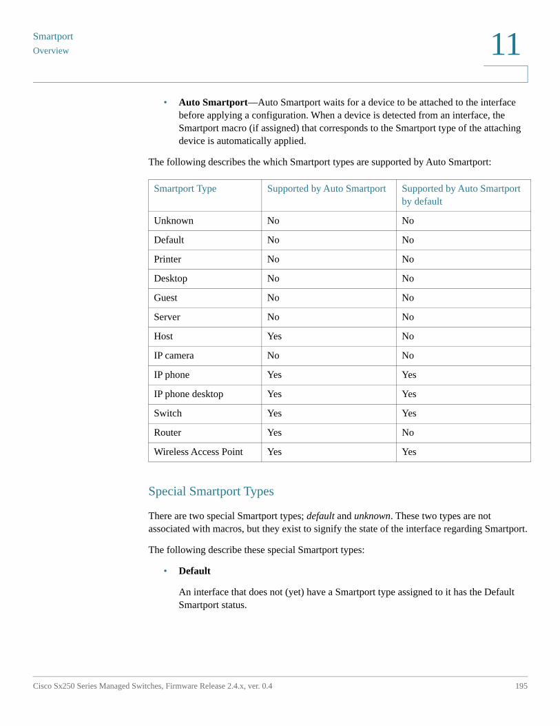
Smartport
Overview
Cisco Sx250 Series Managed Switches, Firmware Release 2.4.x, ver. 0.4 195
11
• Auto Smartport—Auto Smartport waits for a device to be attached to the interface before applying a configuration. When a device is detected from an interface, the Smartport macro (if assigned) that corresponds to the Smartport type of the attaching device is automatically applied.
The following describes the which Smartport types are supported by Auto Smartport:
Special Smartport Types
There are two special Smartport types; default and unknown. These two types are not associated with macros, but they exist to signify the state of the interface regarding Smartport.
The following describe these special Smartport types:
• Default
An interface that does not (yet) have a Smartport type assigned to it has the Default Smartport status.
Smartport Type Supported by Auto Smartport Supported by Auto Smartport by default
Unknown No No
Default No No
Printer No No
Desktop No No
Guest No No
Server No No
Host Yes No
IP camera No No
IP phone Yes Yes
IP phone desktop Yes Yes
Switch Yes Yes
Router Yes No
Wireless Access Point Yes Yes
SmartportOverview
196 Cisco Sx250 Series Managed Switches, Firmware Release 2.4.x, ver. 0.4
11
If Auto Smartport assigns a Smartport type to an interface and the interface is not configured to be Auto Smartport Persistent, then its Smartport type is re-initialized to Default in the following cases:
- A link down/up operation is performed on the interface.
- The device is restarted.
- All devices attached to the interface have aged out, which is defined as the absence of CDP and/or LLDP advertisement from the device for a specified time period.
• Unknown
If a Smartport macro is applied to an interface and an error occurs, the interface is assigned the Unknown status. In this case, the Smartport and Auto Smartport features do not function on the interface until you correct the error and applies the Reset action (performed in the Interface Settings) that resets the Smartport status.
See the workflow area in Common Smartport Tasks section for troubleshooting tips.
NOTE Throughout this section, the term “aged out” is used to describe the LLDP and CDP messages via their TTL. If Auto Smartport is enabled, and persistent status is disabled, and no more CDP or LLDP messages are received on the interface before both TTLs of the most recent CDP and LLDP packets decrease to 0, then the anti-macro is run, and the Smartport type returns to default.
Smartport Macros
A Smartport macro is a script that configure an interface appropriately for a particular network device.
Smartport macros should not be confused with global macros. Global macros configure the device globally, however, the scope of a Smartport macro is limited to the interface on which it is applied.
The macro source may be found by clicking the View Macro Source button on the Type Settings page.
A macro and the corresponding anti-macro are paired together in association with each Smartport type. The macro applies the configuration and the anti-macro removes it.
Two Smartport macros are paired by their names as follows:
• macro_name (for example: printer)
• no_macro_name (for example: no_printer, the anti Smartport macro of Smartport macro printer)
Smartport
Overview
Cisco Sx250 Series Managed Switches, Firmware Release 2.4.x, ver. 0.4 197
11
See Built-in Smartport Macros for a listing of the built-in Smartport macros for each device type.
Applying a Smartport Type to an Interface
When Smartport types are applied to interfaces, the Smartport types and configuration in the associated Smartport macros are saved in the Running Configuration File. If the administrator saves the Running Configuration File into the Startup Configuration File, the device applies the Smartport types and the Smartport macros to the interfaces after reboot as follows:
• If the Startup Configuration File does not specify a Smartport type for an interface, its Smartport type is set to Default.
• If the Startup Configuration File specifies a static Smartport type, the Smartport type of the interface is set to this static type.
• If the Startup Configuration File specifies a Smartport type that was dynamically assigned by Auto Smartport:
- If the Auto Smartport Global Operational state, the interface Auto Smartport state, and the Persistent Status are all Enable, the Smartport type is set to this dynamic type.
- Else the corresponding anti-macro is applied and the interfaces status is set to Default.
Macro Failure and the Reset Operation
A Smartport macro might fail if there is a conflict between the existing configuration of the interface and a Smartport macro.
When a Smartport macro fails, a SYSLOG message containing the following parameters is sent:
• Port number
• Smartport type
• The line number of the failed CLI command in the macro
When a Smartport macro fails on an interface, the status of the interface is set to Unknown. The reason for the failure can be displayed in the Interface Settings page, Show Diagnostics popup.
SmartportHow the Smartport Feature Works
198 Cisco Sx250 Series Managed Switches, Firmware Release 2.4.x, ver. 0.4
11
After the source of the problem is determined and the existing configuration or Smartport macro is corrected, you must perform a reset operation to reset the interface before it can be reapplied with a Smartport type (in the Interface Settings pages). See the workflow area in Common Smartport Tasks section for troubleshooting tips.
How the Smartport Feature Works
You can apply a Smartport macro to an interface by the Smartport type associated with the macro.
Because support is provided for Smartport types which correspond to devices that do not allow themselves to be discovered via CDP and/or LLDP, these Smartport types must be statically assigned to the desired interfaces. This can be done by navigating to the Interface Settings page, selecting the radio button of the desired interface, and clicking Edit. Then, select the Smartport type you want to assign and adjust the parameters as necessary before clicking Apply.
There are two ways to apply a Smartport macro by Smartport type to an interface:
• Static Smartport
You manually assign a Smartport type to an interface. The corresponding Smartport macro is applied to the interface. You can manually assign a Smartport type to an interface from the Interface Settings page.
• Auto Smartport
When a device is detected from an interface, the Smartport macro, if any, that corresponds to the Smartport type of the attaching device is automatically applied. Auto Smartport is enabled by default globally, and at the interface level.
In both cases, the associated anti-macro is run when the Smartport type is removed from the interface, and the anti-macro runs in exactly the same manner, removing all of the interface configuration.
Auto Smartport
In order for Auto Smartport to automatically assign Smartport types to interfaces, the Auto Smartport feature must be enabled globally and on the relevant interfaces which Auto Smartport should be allowed to configure. By default, Auto Smartport is enabled and allowed to configure all interfaces. The Smartport type assigned to each interface is determined by the CDP and LLDP packets received on the each interface respectively.
Smartport
Auto Smartport
Cisco Sx250 Series Managed Switches, Firmware Release 2.4.x, ver. 0.4 199
11
• If multiple devices are attached to an interface, a configuration profile that is appropriate for all of the devices is applied to the interface if possible.
• If a device is aged out (no longer receiving advertisements from other devices), the interface configuration is changed according to its Persistent Status. If the Persistent Status is enabled, the interface configuration is retained. If not, the Smartport Type reverts to Default.
Enabling Auto Smartport
Auto Smartport can be enabled globally in the Properties page in the following ways:
• Enabled—This manually enables Auto Smartport and places it into operation immediately.
• Enable by Auto Voice VLAN—This enables Auto Smartport to operate if Auto Voice VLAN is enabled and in operation. Enable by Auto Voice VLAN is the default.
NOTE In addition to enabling Auto Smartport globally, you must enable Auto Smartport at the desired interface as well. By default, Auto Smartport is enabled at all the interfaces.
See Voice VLAN for more information on enabling Auto Voice VLAN
Identifying Smartport Type
If Auto Smartport is globally enabled (in the Properties page), and at an interface (in the Interface Settings page), the device applies a Smartport macro to the interface based on the Smartport type of the attaching device. Auto Smartport derives the Smartport types of attaching devices based on the CDP and/or LLDP the devices advertise.
If, for example, an IP phone is attached to a port, it transmits CDP or LLDP packets that advertise its capabilities. After reception of these CDP and/or LLDP packets, the device derives the appropriate Smartport type for phone and applies the corresponding Smartport macro to the interface where the IP phone attaches.
Unless Persistent Auto Smartport is enabled on an interface, the Smartport type and resulting configuration applied by Auto Smartport is removed if the attaching device(s) ages out, links down, reboots, or if the attached device receives conflicting capabilities. Aging out times are determined by the absence of CDP and/or LLDP advertisements from the device for a specified time period.
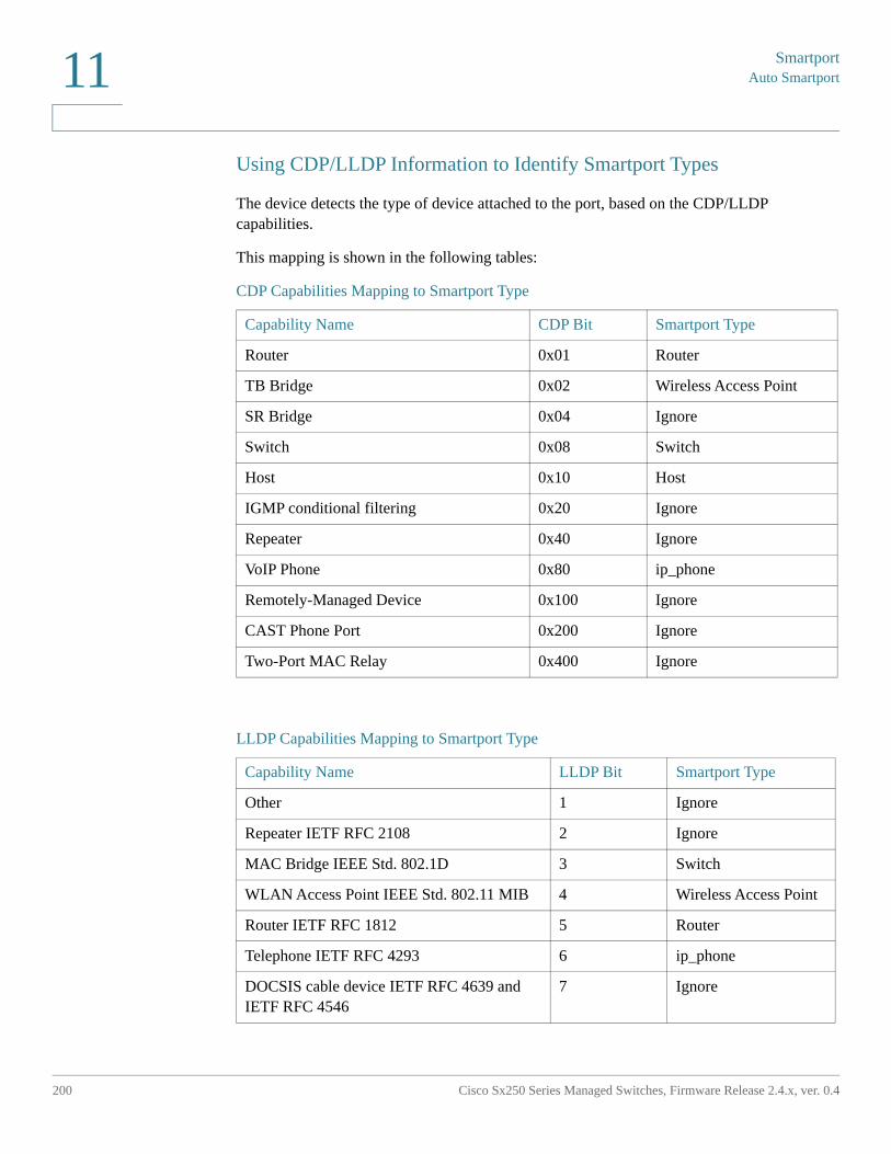
SmartportAuto Smartport
200 Cisco Sx250 Series Managed Switches, Firmware Release 2.4.x, ver. 0.4
11
Using CDP/LLDP Information to Identify Smartport Types
The device detects the type of device attached to the port, based on the CDP/LLDP capabilities.
This mapping is shown in the following tables:
CDP Capabilities Mapping to Smartport Type
Capability Name CDP Bit Smartport Type
Router 0x01 Router
TB Bridge 0x02 Wireless Access Point
SR Bridge 0x04 Ignore
Switch 0x08 Switch
Host 0x10 Host
IGMP conditional filtering 0x20 Ignore
Repeater 0x40 Ignore
VoIP Phone 0x80 ip_phone
Remotely-Managed Device 0x100 Ignore
CAST Phone Port 0x200 Ignore
Two-Port MAC Relay 0x400 Ignore
LLDP Capabilities Mapping to Smartport Type
Capability Name LLDP Bit Smartport Type
Other 1 Ignore
Repeater IETF RFC 2108 2 Ignore
MAC Bridge IEEE Std. 802.1D 3 Switch
WLAN Access Point IEEE Std. 802.11 MIB 4 Wireless Access Point
Router IETF RFC 1812 5 Router
Telephone IETF RFC 4293 6 ip_phone
DOCSIS cable device IETF RFC 4639 and IETF RFC 4546
7 Ignore
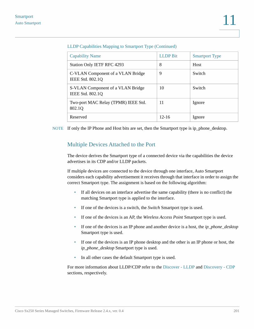
Smartport
Auto Smartport
Cisco Sx250 Series Managed Switches, Firmware Release 2.4.x, ver. 0.4 201
11
NOTE If only the IP Phone and Host bits are set, then the Smartport type is ip_phone_desktop.
Multiple Devices Attached to the Port
The device derives the Smartport type of a connected device via the capabilities the device advertises in its CDP and/or LLDP packets.
If multiple devices are connected to the device through one interface, Auto Smartport considers each capability advertisement it receives through that interface in order to assign the correct Smartport type. The assignment is based on the following algorithm:
• If all devices on an interface advertise the same capability (there is no conflict) the matching Smartport type is applied to the interface.
• If one of the devices is a switch, the Switch Smartport type is used.
• If one of the devices is an AP, the Wireless Access Point Smartport type is used.
• If one of the devices is an IP phone and another device is a host, the ip_phone_desktop Smartport type is used.
• If one of the devices is an IP phone desktop and the other is an IP phone or host, the ip_phone_desktop Smartport type is used.
• In all other cases the default Smartport type is used.
For more information about LLDP/CDP refer to the Discover - LLDP and Discovery - CDP sections, respectively.
Station Only IETF RFC 4293 8 Host
C-VLAN Component of a VLAN Bridge IEEE Std. 802.1Q
9 Switch
S-VLAN Component of a VLAN Bridge IEEE Std. 802.1Q
10 Switch
Two-port MAC Relay (TPMR) IEEE Std. 802.1Q
11 Ignore
Reserved 12-16 Ignore
LLDP Capabilities Mapping to Smartport Type (Continued)
Capability Name LLDP Bit Smartport Type
SmartportError Handling
202 Cisco Sx250 Series Managed Switches, Firmware Release 2.4.x, ver. 0.4
11
Persistent Auto Smartport Interface
If the Persistent status of an interface is enabled, its Smartport type and the configuration that is already applied dynamically by Auto Smartport remains on the interface even after the attaching device ages out, the interface goes down, and the device is rebooted (assuming the configuration was saved). The Smartport type and the configuration of the interface are not changed unless Auto Smartport detects an attaching device with a different Smartport type. If the Persistent status of an interface is disabled, the interface reverts to the default Smartport type when the attaching device to it ages out, the interface goes down, or the device is rebooted. Enabling Persistent status on an interface eliminates the device detection delay that otherwise occurs.
NOTE The persistence of the Smartport types applied to the interfaces are effective between reboots only if the running configuration with the Smartport type applied at the interfaces is saved to the startup configuration file.
Error Handling
When a smart port macro fails to apply to an interface, you can examine the point of the failure in the Interface Settings page and reset the port and reapply the macro after the error is corrected from the Interface Settings page.
Default Configuration
Smartport is always available. By default, Auto Smartport is enabled by Auto Voice VLAN, relies on both CDP and LLDP to detect attaching device's Smartport type, and detects Smartport type IP phone, IP phone + Desktop, Switch, and Wireless Access Point.
See Voice VLAN for a description of the voice factory defaults.
Smartport
Relationships with Other Features
Cisco Sx250 Series Managed Switches, Firmware Release 2.4.x, ver. 0.4 203
11
Relationships with Other Features
Auto Smartport is enabled by default and may be disabled. Telephony OUI cannot function concurrently with Auto Smartport, and Auto Voice VLAN. Auto Smartport must be disabled before enabling Telephony OUI.
Common Smartport Tasks
This section describes some common tasks to setup Smartport and Auto Smartport.
Workflow1: To globally enable Auto Smartport on the device, and to configure a port with Auto Smartport, perform the following steps:
STEP 1 To enable the Auto Smartport feature on the device, open the Properties page. Set Administrative Auto Smartport to Enable or Enable by Voice VLAN.
STEP 2 Select whether the device is to process CDP and/or LLDP advertisements from connected devices.
STEP 3 Select which type of devices are to be detected in the Auto Smartport Device Detection field.
STEP 4 Click Apply
STEP 5 To enable the Auto Smartport feature on one or more interfaces, open the Interface Settings page.
STEP 6 Select the interface, and click Edit.
STEP 7 Select Auto Smartport in the Smartport Application field.
STEP 8 Check or uncheck Persistent Status if desired.
STEP 9 Click Apply.
Workflow2: To configure an interface as a static Smartport, perform the following steps:
STEP 1 To enable the Smartport feature on the interface, open the Interface Settings page.
STEP 2 Select the interface, and click Edit.
STEP 3 Select the Smartport type that is to be assigned to the interface in the Smartport Application field.
SmartportCommon Smartport Tasks
204 Cisco Sx250 Series Managed Switches, Firmware Release 2.4.x, ver. 0.4
11
STEP 4 Set the macro parameters as required.
STEP 5 Click Apply.
Workflow3: To adjust Smartport macro parameter defaults, perform the following steps:
Through this procedure you can accomplish the following:
• View the macro source.
• Change parameter defaults.
• Restore the parameter defaults to the factory settings.
STEP 1 Open the Type Settings page.
STEP 2 Select the Smartport Type.
STEP 3 Click View Macro Source to view the current Smartport macro that is associated with the selected Smartport Type.
STEP 4 Click Edit to open a new window in which you can modify the default values of the parameters in the macros bound to that Smartport type. These parameter default values are used when Auto Smartport applies the selected Smartport type (if applicable) to an interface.
STEP 5 In the Edit page, modify the fields.
STEP 6 Click Apply to return the macro if the parameters changed.
Workflow4: To rerun a Smartport macro after it has failed, perform the following steps:
STEP 1 In the Interface Settings page, select an interface with Smartport type Unknown.
STEP 2 Click Show Diagnostics to see the problem.
STEP 3 Troubleshoot, then correct the problem. Consider the troubleshooting tip below.
STEP 4 Click Edit. A new window appears in which you can click Reset to reset the interface.
STEP 5 Return to the main page and reapply the macro using either Reapply (for devices that are not switches, routers or APs) or Reapply Smartport Macro (for switches, routers or APs) to run the Smartport Macro on the interface.
Smartport
Configuring Smartport Using The Web-based Interface
Cisco Sx250 Series Managed Switches, Firmware Release 2.4.x, ver. 0.4 205
11
A second method of resetting single or multiple unknown interfaces is:
STEP 1 In the Interface Settings page, select the Port Type equals to checkbox.
STEP 2 Select Unknown and click Go.
STEP 3 Click Reset All Unknown Smartports. Then reapply the macro as described above.
TIP The reason that the macro failed might be a conflict with a configuration on the interface made prior to applying the macro (most often encountered with security and storm-control settings), a wrong port type, a typo or an incorrect command within the user-defined macro, or an invalid parameter setting. Parameters are checked for neither type nor boundary prior to the attempt to apply the macro, therefore, an incorrect or invalid input to a parameter value will almost assuredly cause failure when applying the macro.
Configuring Smartport Using The Web-based Interface
The Smartport feature is configured in the Smartport > Properties, Smartport Type Settings and Interface Settings pages.
For Voice VLAN configuration, see Voice VLAN.
For LLDP/CDP configuration, see the Discover - LLDP and Discovery - CDP sections, respectively.
Properties
To configure the Smartport feature globally:
STEP 1 Click Smartport > Properties.
STEP 2 Enter the parameters.
• Administrative Auto Smartport—Select to globally enable or disable Auto Smartport. The following options are available:
- Disable—Select to disable Auto Smartport on the device.
- Enable—Select to enable Auto Smartport on the device.
SmartportConfiguring Smartport Using The Web-based Interface
206 Cisco Sx250 Series Managed Switches, Firmware Release 2.4.x, ver. 0.4
11
- Enable by Auto Voice VLAN—This enables Auto Smartport, but puts it in operation only when Auto Voice VLAN is also enabled and in operation. Enable by Auto Voice VLAN is the default.
• Operational Auto Smartport—Displays the Auto Smartport status.
• Auto Smartport Device Detection Method—Select whether incoming CDP, LLDP, or both types of packets are used to detect the Smartport type of the attaching device(s). At least one must be checked in order for Auto Smartport to identify devices.
• Operational CDP Status—Displays the operational status of CDP. Enable CDP if Auto Smartport is to detect the Smartport type based on CDP advertisement.
• Operational LLDP Status—Displays the operational status of LLDP. Enable LLDP if Auto Smartport is to detect the Smartport type based on LLDP/LLDP-MED advertisement.
• Auto Smartport Device Detection—Select each type of device for which Auto Smartport can assign Smartport types to interfaces. If unchecked, Auto Smartport does not assign that Smartport type to any interface.
STEP 3 Click Apply. This sets the global Smartport parameters on the device.
Type Settings
Use the Smartport Type Settings page to edit the Smartport Type settings and view the Macro Source.
By default, each Smartport type is associated with a pair of built-in Smartport macros. See A Smartport is an interface (port, VLAN or LAG) to which a built-in (or user-defined) macro may be applied. Smartport types refers to the types of devices, which can be attached to Smartports. for further information on macro versus anti-macro. Built-in or user-defined macros can have parameters. The built-in macros have up to three parameters.
Editing these parameters for the Smartport types applied by Auto Smartport from the Smartport Type Settings page configures the default values for these parameters. These defaults are used by Auto Smartport.
NOTE Changes to Auto Smartport types cause the new settings to be applied to interfaces which have already been assigned that type by Auto Smartport. In this case, binding an invalid macro or setting an invalid default parameter value causes all ports of this Smartport type to become unknown.
Smartport
Configuring Smartport Using The Web-based Interface
Cisco Sx250 Series Managed Switches, Firmware Release 2.4.x, ver. 0.4 207
11
STEP 1 Click Smartport > Smartport Type Settings.
STEP 2 To view the Smartport macro associated with a Smartport type, select a Smartport type and click View Macro Source.
STEP 3 To modify the parameters of a macro, select a Smartport type and click Edit.
STEP 4 Enter the fields.
• Port Type—Select a Smartport type.
• Macro Name—Displays the name of the Smartport macro currently associated with the Smartport type.
• Macro Parameters—Displays the following fields for three parameters in the macro:
- Parameter Name—Name of parameter in macro.
- Parameter Value—Current value of parameter in macro. This can be changed here.
- Parameter Description—Description of parameter.
STEP 5 Click Apply to save the changes to the running configuration. If the Smartport macro and/or its parameter values associated with the Smartport type are modified, Auto Smartport automatically reapplies the macro to the interfaces currently assigned with the Smartport type by Auto Smartport. Auto Smartport does not apply the changes to interfaces that statically assigned a Smartport type.
NOTE There is no method to validate macro parameters because they do not have a type association. Therefore, any entry is valid at this point. However, invalid parameter values may cause errors to occur when the Smartport type is assigned to an interface, applying the associated macro.
Interface Settings
Use the Interface Settings page to perform the following tasks:
• Statically apply a specific Smartport type to an interface with interface-specific values for the macro parameters.
• Enable Auto Smartport on an interface.
• Diagnose a Smartport macro that failed upon application, and caused the Smartport type to become Unknown.
• Reapply a Smartport macro after it fails for all interfaces or for one of the following types of interfaces: switch, router and AP. It is expected that the necessary corrections
SmartportConfiguring Smartport Using The Web-based Interface
208 Cisco Sx250 Series Managed Switches, Firmware Release 2.4.x, ver. 0.4
11
have been made prior to clicking Apply. See the workflow area in Common Smartport Tasks section for troubleshooting tips.
• Reapply a Smartport macro to an interface. In some circumstances, you may want to reapply a Smartport macro so that the configuration at an interface is up to date. For instance, reapplying a switch Smartport macro at a device interface makes the interface a member of the VLANs created since the last macro application. You have to be familiar with the current configurations on the device and the definition of the macro to determine if a reapplication has any impact on the interface.
• Reset unknown interfaces. This sets the mode of Unknown interfaces to Default.
To apply a Smartport macro:
STEP 1 Click Smartport > Interface Settings.
To reapply the last Smartport macros that was associated with a group of interfaces, click one of the following options:
• All Switches, Routers and Wireless Access Points—Reapplies the macros to all interfaces.
• All Switches—Reapplies the macros to all interfaces defined as switches.
• All Routers —Reapplies the macros to all interfaces defined as routers.
• All Wireless Access Points—Reapplies the macros to all interfaces defined as access points.
To reapply the Smartport macros associated with a specific interface, select that interface (it must be UP) and click Reapply to reapply the last macro that was applied to the interface.
The Reapply action also adds the interface to all newly-created VLANs.
STEP 2 Smartport Diagnostic.
If a Smartport macro fails, the Smartport Type of the interface is Unknown. Select an interface which is of unknown type and click Show Diagnostic. This displays the command at which application of the macro failed. See the workflow area in Common Smartport Tasks section for troubleshooting tips. Proceed to reapply the macro after correcting the problem.
STEP 3 Resetting all Unknown interfaces to Default type.
• Select the Smartport Type equals to checkbox.
• Select Unknown.
• Click Go.
Smartport
Configuring Smartport Using The Web-based Interface
Cisco Sx250 Series Managed Switches, Firmware Release 2.4.x, ver. 0.4 209
11
• Click Reset All Unknown Smartports. Then reapply the macro as described above. This performs a reset on all interfaces with type Unknown, meaning that all interfaces are returned to the Default type. After correcting the error in the macro or on the current interface configuration or both, a new macro may be applied.
NOTE Resetting the interface of unknown type does not reset the configuration performed by the macro that failed. This clean up must be done manually.
To assign a Smartport type to an interface or activate Auto Smartport on the interface:
STEP 1 Select an interface and click Edit.
STEP 2 Enter the fields.
• Interface—Select the port or LAG.
• Smartport Type—Displays the Smartport type currently assigned to the port/LAG.
• Smartport Application—Select the Smartport type from the Smartport Application pull-down.
• Smartport Application Method— If Auto Smartport is selected, Auto Smartport automatically assigns the Smartport type based on the CDP and/or LLDP advertisement received from the connecting devices as well as applying the corresponding Smartport macro. To statically assign a Smartport type and apply the corresponding Smartport macro to the interface, select the desired Smartport type.
• Persistent Status—Select to enable the Persistent status. If enabled, the association of a Smartport type to an interface remains even if the interface goes down, or the device is rebooted. Persistent is applicable only if the Smartport Application of the interface is Auto Smartport. Enabling Persistent at an interface eliminates the device detection delay that otherwise occurs.
• Macro Parameters—Displays the following fields for up to three parameters in the macro:
- Parameter Name—Name of parameter in macro.
- Parameter Value—Current value of parameter in macro. This can be changed here.
- Parameter Description—Description of parameter.
STEP 3 Click Reset to set an interface to Default if it is in Unknown status (as a result of an unsuccessful macro application). The macro can be reapplied on the main page.
STEP 4 Click Apply to update the changes and assign the Smartport type to the interface.
SmartportBuilt-in Smartport Macros
210 Cisco Sx250 Series Managed Switches, Firmware Release 2.4.x, ver. 0.4
11
Built-in Smartport Macros
The following describes the pair of built-in macros for each Smartport type. For each Smartport type there is a macro to configure the interface and an anti macro to remove the configuration.
Macro code for the following Smartport types are provided:
• desktop
• printer
• guest
• server
• host
• ip_camera
• ip_phone
• ip_phone_desktop
• switch
• router
• ap
desktop
[desktop]#interface configuration, for increased network security and reliability when connecting a desktop device, such as a PC, to a switch port.#macro description Desktop#macro keywords $native_vlan $max_hosts##macro key description: $native_vlan: The untag VLAN which will be configured on the port# $max_hosts: The maximum number of allowed devices on the port#Default Values are#$native_vlan = Default VLAN#$max_hosts = 10##the port type cannot be detected automatically##the default mode is trunksmartport switchport trunk native vlan $native_vlan#port security max $max_hosts
Smartport
Built-in Smartport Macros
Cisco Sx250 Series Managed Switches, Firmware Release 2.4.x, ver. 0.4 211
11
port security mode max-addressesport security discard trap 60#smartport storm-control broadcast level 10smartport storm-control include-multicastsmartport storm-control broadcast enable#spanning-tree portfast#@
no_desktop
[no_desktop]#macro description No Desktop#no smartport switchport trunk native vlansmartport switchport trunk allowed vlan remove all#no port security no port security modeno port security max #no smartport storm-control broadcast enableno smartport storm-control broadcast levelno smartport storm-control include-multicast#spanning-tree portfast auto#@
printer
[printer]#macro description printer#macro keywords $native_vlan##macro key description: $native_vlan: The untag VLAN which will be configured on the port#Default Values are#$native_vlan = Default VLAN##the port type cannot be detected automatically#switchport mode accessswitchport access vlan $native_vlan##single hostport security max 1port security mode max-addressesport security discard trap 60
SmartportBuilt-in Smartport Macros
212 Cisco Sx250 Series Managed Switches, Firmware Release 2.4.x, ver. 0.4
11
#smartport storm-control broadcast level 10smartport storm-control include-multicastsmartport storm-control broadcast enable#spanning-tree portfast#@
no_printer
[no_printer]#macro description No printer#no switchport access vlanno switchport mode#no port security no port security mode#no smartport storm-control broadcast enableno smartport storm-control broadcast levelno smartport storm-control include-multicast#spanning-tree portfast auto#@
guest
[guest]#macro description guest#macro keywords $native_vlan##macro key description: $native_vlan: The untag VLAN which will be configured on the port#Default Values are#$native_vlan = Default VLAN##the port type cannot be detected automatically#switchport mode accessswitchport access vlan $native_vlan##single hostport security max 1port security mode max-addressesport security discard trap 60#smartport storm-control broadcast level 10smartport storm-control include-multicast
Smartport
Built-in Smartport Macros
Cisco Sx250 Series Managed Switches, Firmware Release 2.4.x, ver. 0.4 213
11
smartport storm-control broadcast enable#spanning-tree portfast#@
no_guest]]
[no_guest]#macro description No guest#no switchport access vlanno switchport mode#no port security no port security mode#no smartport storm-control broadcast enableno smartport storm-control broadcast levelno smartport storm-control include-multicast#spanning-tree portfast auto#@
server
[server]#macro description server#macro keywords $native_vlan $max_hosts##macro key description: $native_vlan: The untag VLAN which will be configured on the port# $max_hosts: The maximum number of allowed devices on the port#Default Values are#$native_vlan = Default VLAN#$max_hosts = 10##the port type cannot be detected automatically##the default mode is trunksmartport switchport trunk native vlan $native_vlan#port security max $max_hostsport security mode max-addressesport security discard trap 60#smartport storm-control broadcast level 10smartport storm-control broadcast enable#
SmartportBuilt-in Smartport Macros
214 Cisco Sx250 Series Managed Switches, Firmware Release 2.4.x, ver. 0.4
11
spanning-tree portfast#@
no_server
[no_server]#macro description No server#no smartport switchport trunk native vlansmartport switchport trunk allowed vlan remove all#no port security no port security modeno port security max #no smartport storm-control broadcast enableno smartport storm-control broadcast level#spanning-tree portfast auto#@
host
[host]#macro description host#macro keywords $native_vlan $max_hosts##macro key description: $native_vlan: The untag VLAN which will be configured on the port# $max_hosts: The maximum number of allowed devices on the port#Default Values are#$native_vlan = Default VLAN#$max_hosts = 10##the port type cannot be detected automatically##the default mode is trunksmartport switchport trunk native vlan $native_vlan#port security max $max_hostsport security mode max-addressesport security discard trap 60#smartport storm-control broadcast level 10smartport storm-control include-multicastsmartport storm-control broadcast enable#spanning-tree portfast
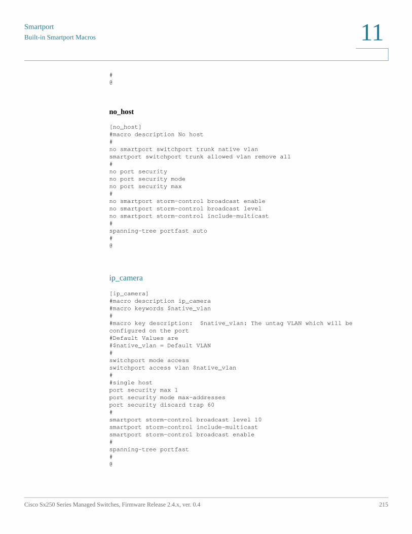
Smartport
Built-in Smartport Macros
Cisco Sx250 Series Managed Switches, Firmware Release 2.4.x, ver. 0.4 215
11
#@
no_host
[no_host]#macro description No host#no smartport switchport trunk native vlansmartport switchport trunk allowed vlan remove all#no port security no port security modeno port security max #no smartport storm-control broadcast enableno smartport storm-control broadcast levelno smartport storm-control include-multicast#spanning-tree portfast auto#@
ip_camera
[ip_camera]#macro description ip_camera#macro keywords $native_vlan##macro key description: $native_vlan: The untag VLAN which will be configured on the port#Default Values are#$native_vlan = Default VLAN#switchport mode accessswitchport access vlan $native_vlan##single hostport security max 1port security mode max-addressesport security discard trap 60#smartport storm-control broadcast level 10smartport storm-control include-multicastsmartport storm-control broadcast enable#spanning-tree portfast#@
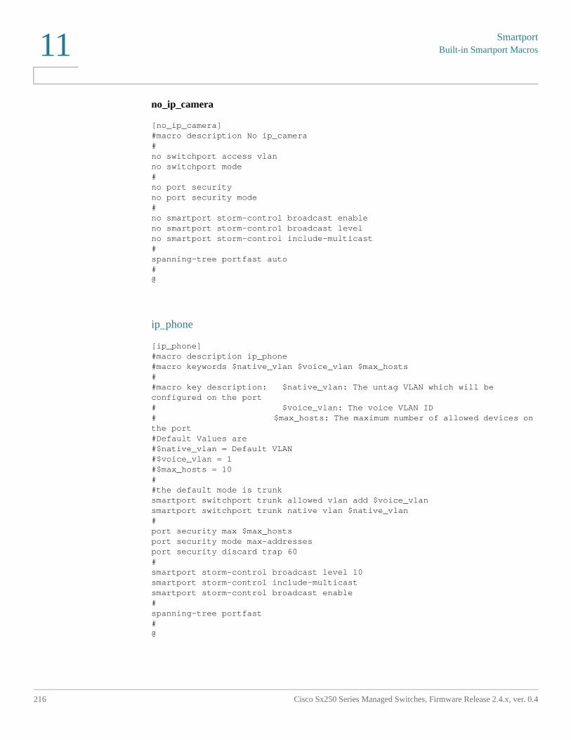
SmartportBuilt-in Smartport Macros
216 Cisco Sx250 Series Managed Switches, Firmware Release 2.4.x, ver. 0.4
11
no_ip_camera
[no_ip_camera]#macro description No ip_camera#no switchport access vlanno switchport mode#no port security no port security mode#no smartport storm-control broadcast enableno smartport storm-control broadcast levelno smartport storm-control include-multicast#spanning-tree portfast auto#@
ip_phone
[ip_phone]#macro description ip_phone#macro keywords $native_vlan $voice_vlan $max_hosts##macro key description: $native_vlan: The untag VLAN which will be configured on the port# $voice_vlan: The voice VLAN ID# $max_hosts: The maximum number of allowed devices on the port#Default Values are#$native_vlan = Default VLAN#$voice_vlan = 1#$max_hosts = 10##the default mode is trunksmartport switchport trunk allowed vlan add $voice_vlansmartport switchport trunk native vlan $native_vlan#port security max $max_hostsport security mode max-addressesport security discard trap 60#smartport storm-control broadcast level 10smartport storm-control include-multicastsmartport storm-control broadcast enable#spanning-tree portfast#@
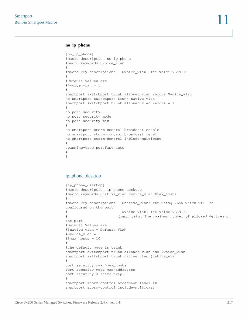
Smartport
Built-in Smartport Macros
Cisco Sx250 Series Managed Switches, Firmware Release 2.4.x, ver. 0.4 217
11
no_ip_phone
[no_ip_phone]#macro description no ip_phone#macro keywords $voice_vlan##macro key description: $voice_vlan: The voice VLAN ID##Default Values are#$voice_vlan = 1#smartport switchport trunk allowed vlan remove $voice_vlanno smartport switchport trunk native vlansmartport switchport trunk allowed vlan remove all#no port security no port security modeno port security max #no smartport storm-control broadcast enableno smartport storm-control broadcast levelno smartport storm-control include-multicast#spanning-tree portfast auto#@
ip_phone_desktop
[ip_phone_desktop]#macro description ip_phone_desktop#macro keywords $native_vlan $voice_vlan $max_hosts##macro key description: $native_vlan: The untag VLAN which will be configured on the port# $voice_vlan: The voice VLAN ID# $max_hosts: The maximum number of allowed devices on the port#Default Values are#$native_vlan = Default VLAN#$voice_vlan = 1#$max_hosts = 10##the default mode is trunksmartport switchport trunk allowed vlan add $voice_vlansmartport switchport trunk native vlan $native_vlan#port security max $max_hostsport security mode max-addressesport security discard trap 60#smartport storm-control broadcast level 10smartport storm-control include-multicast
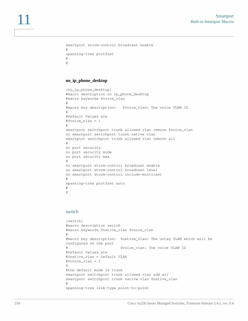
SmartportBuilt-in Smartport Macros
218 Cisco Sx250 Series Managed Switches, Firmware Release 2.4.x, ver. 0.4
11
smartport storm-control broadcast enable#spanning-tree portfast#@
no_ip_phone_desktop
[no_ip_phone_desktop]#macro description no ip_phone_desktop#macro keywords $voice_vlan##macro key description: $voice_vlan: The voice VLAN ID##Default Values are#$voice_vlan = 1#smartport switchport trunk allowed vlan remove $voice_vlanno smartport switchport trunk native vlansmartport switchport trunk allowed vlan remove all#no port security no port security modeno port security max #no smartport storm-control broadcast enableno smartport storm-control broadcast levelno smartport storm-control include-multicast#spanning-tree portfast auto#@
switch
[switch]#macro description switch#macro keywords $native_vlan $voice_vlan##macro key description: $native_vlan: The untag VLAN which will be configured on the port# $voice_vlan: The voice VLAN ID#Default Values are#$native_vlan = Default VLAN#$voice_vlan = 1##the default mode is trunksmartport switchport trunk allowed vlan add allsmartport switchport trunk native vlan $native_vlan#spanning-tree link-type point-to-point
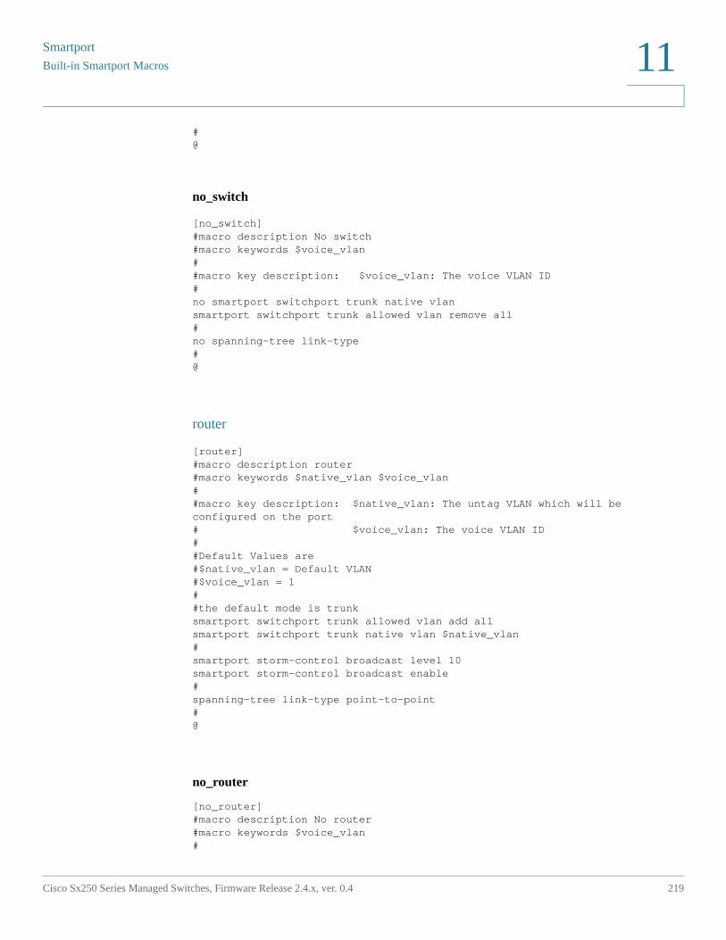
Smartport
Built-in Smartport Macros
Cisco Sx250 Series Managed Switches, Firmware Release 2.4.x, ver. 0.4 219
11
#@
no_switch
[no_switch]#macro description No switch#macro keywords $voice_vlan##macro key description: $voice_vlan: The voice VLAN ID#no smartport switchport trunk native vlansmartport switchport trunk allowed vlan remove all#no spanning-tree link-type #@
router
[router]#macro description router#macro keywords $native_vlan $voice_vlan##macro key description: $native_vlan: The untag VLAN which will be configured on the port# $voice_vlan: The voice VLAN ID##Default Values are#$native_vlan = Default VLAN#$voice_vlan = 1##the default mode is trunksmartport switchport trunk allowed vlan add allsmartport switchport trunk native vlan $native_vlan#smartport storm-control broadcast level 10smartport storm-control broadcast enable#spanning-tree link-type point-to-point#@
no_router
[no_router]#macro description No router#macro keywords $voice_vlan#
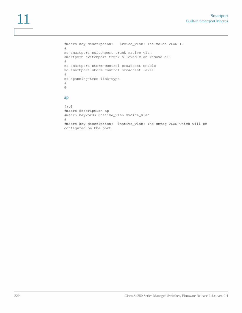
SmartportBuilt-in Smartport Macros
220 Cisco Sx250 Series Managed Switches, Firmware Release 2.4.x, ver. 0.4
11
#macro key description: $voice_vlan: The voice VLAN ID#no smartport switchport trunk native vlansmartport switchport trunk allowed vlan remove all#no smartport storm-control broadcast enableno smartport storm-control broadcast level#no spanning-tree link-type #@
ap
[ap]#macro description ap#macro keywords $native_vlan $voice_vlan##macro key description: $native_vlan: The untag VLAN which will be configured on the port
12
Cisco Sx250 Series Managed Switches, Firmware Release 2.4.x, ver. 0.4 221
VLAN Management
This section covers the following topics:
• Regular VLANs
• GVRP Settings
• Voice VLAN
A VLAN is a logical group of ports that enables devices associated with it to communicate with each other over the Ethernet MAC layer, regardless of the physical LAN segment of the bridged network to which they are connected.
VLAN Description
Each VLAN is configured with a unique VLAN ID (VID) with a value from 1 to 4094. A port on a device in a bridged network is a member of a VLAN if it can send data to and receive data from the VLAN. A port is an untagged member of a VLAN if all packets destined for that port into the VLAN have no VLAN tag. A port is a tagged member of a VLAN if all packets destined for that port into the VLAN have a VLAN tag. A port can be a member of only one untagged VLAN but can be a member of multiple tagged VLANs.
A port in VLAN Access mode can be part of only one VLAN. If it is in General or Trunk mode, the port can be part of one or more VLANs.
VLANs address security and scalability issues. Traffic from a VLAN stays within the VLAN, and terminates at devices in the VLAN. It also eases network configuration by logically connecting devices without physically relocating those devices.
If a frame is VLAN-tagged, a four-byte VLAN tag is added to each Ethernet frame. The tag contains a VLAN ID between 1 and 4094, and a VLAN Priority Tag (VPT) between 0 and 7. See Quality of Service for details about VPT.
When a frame enters a VLAN-aware device, it is classified as belonging to a VLAN, based on the four-byte VLAN tag in the frame.
VLAN Management
222 Cisco Sx250 Series Managed Switches, Firmware Release 2.4.x, ver. 0.4
12
If there is no VLAN tag in the frame or the frame is priority-tagged only, the frame is classified to the VLAN based on the PVID (Port VLAN Identifier) configured at the ingress port where the frame is received.
The frame is discarded at the ingress port if Ingress Filtering is enabled and the ingress port is not a member of the VLAN to which the packet belongs. A frame is regarded as priority-tagged only if the VID in its VLAN tag is 0.
Frames belonging to a VLAN remain within the VLAN. This is achieved by sending or forwarding a frame only to egress ports that are members of the target VLAN. An egress port may be a tagged or untagged member of a VLAN.
The egress port:
• Adds a VLAN tag to the frame if the egress port is a tagged member of the target VLAN, and the original frame does not have a VLAN tag.
• Removes the VLAN tag from the frame if the egress port is an untagged member of the target VLAN, and the original frame has a VLAN tag.
VLAN Roles
Device VLANs can only be created statically.
Some VLANs can have additional roles, including:
• Voice VLAN: For more information refer to the Voice VLAN section.
• Guest VLAN: Set in the Properties page.
• Default VLAN: VLAN1.
• Management VLAN: For more information refer to the Configuring IP Information section.
QinQ
QinQ provides isolation between service provider networks and customers' networks. The device is a provider bridge that supports port-based c-tagged service interface.
With QinQ, the device adds an ID tag known as Service Tag (S-tag) to forward packets into the provider network. The S-tag is used to segregate traffic between various customers, while preserving the customer VLAN tags.
VLAN Management
Regular VLANs
Cisco Sx250 Series Managed Switches, Firmware Release 2.4.x, ver. 0.4 223
12
Customer traffic is encapsulated with an S-tag with TPID 0x8100, regardless of whether it was originally c-tagged or untagged. The S-tag enables this traffic to be treated as an aggregate within a provider bridge network, where the bridging is based on the S-tag VID (S-VID) only.
The S-Tag is preserved while traffic is forwarded through the network service provider's infrastructure, and is later removed by an egress device.
An additional benefit of QinQ is that there is no need to configure customers' edge devices.
QinQ is enabled in the Interface Settings page.
Regular VLANs
This section describes the GUI pages used to configure various types of VLANs. This section describes:
• Regular VLAN Overview
• VLAN Settings
• Interface Settings
• Port to VLAN
• Port VLAN Membership
Regular VLAN Overview
VLAN Configuration Workflow
To configure VLANs:
STEP 1 Create the required VLANs as described in the VLAN Settings section.
STEP 2 Set the desired VLAN-related configuration for ports and enable QinQ on an interface as described in the Interface Settings section.
STEP 3 Assign interfaces to VLANs as described in the Port to VLAN section or the Port VLAN Membership section.
STEP 4 View the current VLAN port membership for all the interfaces as described in the Port VLAN Membership section.
VLAN ManagementRegular VLANs
224 Cisco Sx250 Series Managed Switches, Firmware Release 2.4.x, ver. 0.4
12
Default VLAN Settings
The device automatically creates VLAN 1 as the default VLAN, the default interface status of all ports is Access, and all ports are configured as untagged members of the default VLAN.
The default VLAN has the following characteristics:
• It is distinct, non-static/non-dynamic, and all ports are untagged members by default.
• It cannot be deleted.
• It cannot be given a label.
• It is automatically used as the voice VLAN for OUI-enabled voice VLAN.
• If a port is no longer a member of any VLAN, the device automatically configures the port as an untagged member of the default VLAN. A port is no longer a member of a VLAN if the VLAN is deleted or the port is removed from the VLAN.
VLAN Settings
You can create a VLAN, but this has no effect until the VLAN is attached to at least one port, either manually or dynamically. Ports must always belong to one or more VLANs.
The 250 Series device supports up to 256 VLANs, including the default VLAN.
Each VLAN must be configured with a unique VID with a value from 1 to 4094. The device reserves VID 4095 as the Discard VLAN. All packets classified to the Discard VLAN are discarded at ingress, and are not forwarded to a port.
To create a VLAN:
STEP 1 Click VLAN Management > VLAN Settings.
Information is displayed for all defined VLANs. The fields are defined below under the Add page. The following field is not on the Add page.
• Originators—How the VLAN was created
- Static—VLAN is user-defined.
- Default—VLAN is the default VLAN.
STEP 2 Click Add to add one or more new VLANs.
The page enables the creation of either a single VLAN or a range of VLANs.
STEP 3 To create a single VLAN, select the VLAN radio button, enter the VLAN ID, and optionally the VLAN Name.
VLAN Management
Regular VLANs
Cisco Sx250 Series Managed Switches, Firmware Release 2.4.x, ver. 0.4 225
12
To create a range of VLANs, select the Range radio button, and specify the range of VLANs to be created by entering the Starting VID and Ending VID, inclusive. When using the Range function, the maximum number of VLANs you can create at one time is 100.
NOTE Some VLANs are required by the system for internal system usage, and therefore cannot be created or configured by the user. The system requires the following VLANs for internal usage:
• One VLAN for each IP interface that is defined directly on an Ethernet port or on a port channel (LAGs).
• One VLAN for each IPv6 tunnel
• One VLAN for 802.1x
The VLANs for IPv6 tunnels and 802.1x are pre-assigned, while the VLANs for IP configuration for Ethernet ports/port channels are assigned when the IP configuration is applied. Internal VLANs are allocated beginning from the highest free VLAN (by default VLAN 4094).
STEP 4 Add the following fields for the new VLANs.
• VLAN Interface State—Select to shutdown the VLAN. In this state, the VLAN does not transmit/receive messages from/to higher levels. For example, if you shut down a VLAN, on which an IP interface is configured, bridging into the VLAN continues, but the switch cannot transmit and receive IP traffic on the VLAN
• Link Status SNMP Traps—Select to enable link-status generation of SNMP traps.
STEP 5 Click Apply to create the VLAN(s).
Interface Settings
The Interface Settings page displays and enables configuration of VLAN-related parameters for all interfaces.
To configure the VLAN settings:
STEP 1 Click VLAN Management > Interface Settings.
STEP 2 Select an interface type (Port or LAG), and click Go. Ports or LAGs and their VLAN parameters are displayed.
STEP 3 To configure a Port or LAG, select it and click Edit.
VLAN ManagementRegular VLANs
226 Cisco Sx250 Series Managed Switches, Firmware Release 2.4.x, ver. 0.4
12
STEP 4 Enter the values for the following fields:
• Interface—Select a Port/LAG.
• Switchport Mode—Select either Layer 2 or Layer 3.
• Interface VLAN Mode—Select the interface mode for the VLAN. The options are:
- General—The interface can support all functions as defined in the IEEE 802.1q specification. The interface can be a tagged or untagged member of one or more VLANs.
- Access—The interface is an untagged member of a single VLAN. A port configured in this mode is known as an access port.
- Trunk—The interface is an untagged member of one VLAN at most, and is a tagged member of zero or more VLANs. A port configured in this mode is known as a trunk port.
- Customer—Selecting this option places the interface in QinQ mode. This enables you to use your own VLAN arrangements (PVID) across the provider network. The device is in Q-in-Q mode when it has one or more customer ports. See QinQ.
• Frame Type—(Available only in General mode) Select the type of frame that the interface can receive. Frames that are not of the configured frame type are discarded at ingress. Possible values are:
- Admit All—The interface accepts all types of frames: untagged frames, tagged frames, and priority tagged frames.
- Admit Tagged Only—The interface accepts only tagged frames.
- Admit Untagged Only—The interface accepts only untagged and priority frames.
• Ingress Filtering—(Available only in General mode) Select to enable ingress filtering. When an interface is ingress filtering enabled, the interface discards all incoming frames that are classified as VLANs of which the interface is not a member. Ingress filtering can be disabled or enabled on general ports. It is always enabled on access ports and trunk ports.
STEP 5 Click Apply. The parameters are written to the Running Configuration file.
VLAN Management
Regular VLANs
Cisco Sx250 Series Managed Switches, Firmware Release 2.4.x, ver. 0.4 227
12
Port to VLAN
The Port to VLAN and Port VLAN Membership pages display the VLAN memberships of the ports in various presentations. You can use them to add or remove memberships to or from the VLANs.
When a port is forbidden default VLAN membership, that port is not allowed membership in any other VLAN. An internal VID of 4095 is assigned to the port.
To forward packets properly, intermediate VLAN-aware devices that carry VLAN traffic along the path between end nodes must be manually configured.
Untagged port membership between two VLAN-aware devices with no intervening VLAN-aware devices, must be to the same VLAN. In other words, the PVID on the ports between the two devices must be the same if the ports are to send and receive untagged packets to and from the VLAN. Otherwise, traffic might leak from one VLAN to another.
Frames that are VLAN-tagged can pass through other network devices that are VLAN-aware or VLAN-unaware. If a destination end node is VLAN-unaware, but is to receive traffic from a VLAN, then the last VLAN-aware device (if there is one), must send frames of the destination VLAN to the end node untagged.
Use the Port to VLAN page to display and configure the ports within a specific VLAN.
To map ports or LAGs to a VLAN:
STEP 1 Click VLAN Management > Port to VLAN.
STEP 2 Select a VLAN and the interface type (Port or LAG), and click Go to display or to change the port characteristic with respect to the VLAN.
The port mode for each port or LAG appears with its current port mode (Access, Trunk, General, Private-Host, Private-Promiscuous or Customer) configured from the Interface Settings page.
Each port or LAG appears with its current registration to the VLAN.
The following fields are displayed:
• VLAN Mode—Displays port type of ports in the VLAN.
• Membership Type: Select one of the following options:
- Forbidden—The interface is not allowed to join the VLAN even from GVRP registration. When a port is not a member of any other VLAN, enabling this option on the port makes the port part of internal VLAN 4095 (a reserved VID).
VLAN ManagementRegular VLANs
228 Cisco Sx250 Series Managed Switches, Firmware Release 2.4.x, ver. 0.4
12
- Excluded—The interface is currently not a member of the VLAN. This is the default for all the ports and LAGs when the VLAN is newly created.
- Tagged—The interface is a tagged member of the VLAN.
- Untagged—The interface is an untagged member of the VLAN. Frames of the VLAN are sent untagged to the interface VLAN.
• PVID—Select to set the PVID of the interface to the VID of the VLAN. PVID is a per-port setting.
STEP 3 Click Apply. The interfaces are assigned to the VLAN, and written to the Running Configuration file.
You can continue to display and/or configure port membership of another VLAN by selecting another VLAN ID.
Port VLAN Membership
The Port VLAN Membership page displays all ports on the device along with a list of VLANs to which each port belongs.
If the port-based authentication method for an interface is 802.1x and the Administrative Port Control is Auto, then:
• Until the port is authenticated, it is excluded from all VLANs, except guest and unauthenticated ones. In the VLAN to Port page, the port is marked with an upper case P.
• When the port is authenticated, it receives membership in the VLAN in which it was configured.
NOTE VLAN IS mode is supported. This means that port VLAN membership can be configured ahead of time for various VLAN modes. When the port is put into the specific VLAN mode, the configuration becomes active. When changing to a different mode the settings for the mode changed from are saved, and will be re-applied if the mode is reactivated on the interface.
To assign a port to one or more VLANs:
STEP 1 Click VLAN Management > Port VLAN Membership.
STEP 2 Select interface type (Port or LAG), and click Go. The following fields are displayed for all interfaces of the selected type:
• Interface—Port/LAG ID.
VLAN Management
Regular VLANs
Cisco Sx250 Series Managed Switches, Firmware Release 2.4.x, ver. 0.4 229
12
• Mode—Interface VLAN mode that was selected in the Interface Settings page.
• Administrative VLANs—Drop-down list that displays all VLANs of which the interface might be a member.
• Operational VLANs—Drop-down list that displays all VLANs of which the interface is currently a member.
• LAG—If interface selected is Port, displays the LAG in which it is a member.
STEP 3 Select a port, and click the Join VLAN button.
STEP 4 Enter the values for the following fields:
• Interface—Select a Port or LAG.
• Current VLAN Mode—Displays the port VLAN mode that was selected in the Interface Settings page.
• Access Mode Membership (Active)
- Access VLAN ID—When the port is in Access mode, it will be a member of this VLAN.
• Trunk Mode Membership
- Native VLAN ID—When the port is in Trunk mode, it will be a member of this VLAN.
- Tagged VLANs—When the port is in Trunk mode, it will be a member of these VLANs. The following options are possible:
All VLANs—When the port is in Trunk mode, it will be a member of all VLANs.
User Defined—When the port is in Trunk mode, it will be a member of the VLANs that are entered here.
• General Mode Membership
- Untagged VLANs—When the port is in General mode, it will be an untagged member of this VLAN.
- Tagged VLANs—When the port is in General mode, it will be a tagged member of these VLAN
- Forbidden VLANs—When the port is in General mode, the interface is not allowed to join the VLAN even from GVRP registration. When a port is not a member of any other VLAN, enabling this option on the port makes the port part of internal VLAN 4095 (a reserved VID)
VLAN ManagementGVRP Settings
230 Cisco Sx250 Series Managed Switches, Firmware Release 2.4.x, ver. 0.4
12
- General PVID—When the port is in General mode, it will be a member of these VLANs.
• Customer Mode Membership
- Customer VLAN ID—When the port is in Customer mode, it will be a member of this VLANs.
STEP 5 Select a port and click Details to view the following fields:
• Administrative VLANs—Port is configured for these VLANs.
• Operational VLANs—Port is currently a member of these VLANs.
STEP 6 Click Apply (for Join VLAN). The settings are modified and written to the Running Configuration file.
GVRP Settings
Adjacent VLAN-aware devices can exchange VLAN information with each other by using the Generic VLAN Registration Protocol (GVRP). GVRP is based on the Generic Attribute Registration Protocol (GARP) and propagates VLAN information throughout a bridged network.
To enable GVRP on an interface, it must be configured in General mode.
When a port joins a VLAN by using GVRP, it is added to the VLAN as a tagged dynamic member, unless this was expressly forbidden in the Port VLAN Membership page. If the VLAN does not exist, it is dynamically created when Dynamic VLAN creation is enabled for this port (in the GVRP Settings page).
GVRP must be activated globally as well as on each port. When it is activated, it transmits and receives GARP Packet Data Units (GPDUs). VLANs that are defined but not active are not propagated. To propagate the VLAN, it must be up on at least one port.
By default, GVRP is disabled globally and on ports.
GVRP Settings
To define GVRP settings for an interface:
STEP 1 Click VLAN Management > GVRP Settings.
STEP 2 Select GVRP Global Status to enable GVRP globally.
VLAN Management
Voice VLAN
Cisco Sx250 Series Managed Switches, Firmware Release 2.4.x, ver. 0.4 231
12
STEP 3 Click Apply to set the global GVRP status.
STEP 4 Select an interface type (Port or LAG), and click Go to display all interfaces of that type.
STEP 5 To define GVRP settings for a port, select it, and click Edit.
STEP 6 Enter the values for the following fields:
• Interface—Select the interface (Port or LAG) to be edited.
• GVRP State—Select to enable GVRP on this interface.
• Dynamic VLAN Creation—Select to enable Dynamic VLAN Creation on this interface.
• GVRP Registration—Select to enable VLAN Registration using GVRP on this interface.
STEP 7 Click Apply. GVRP settings are modified, and written to the Running Configuration file..
Voice VLAN
In a LAN, voice devices, such as IP phones, VoIP endpoints, and voice systems are placed into the same VLAN. This VLAN is referred as the voice VLAN. If the voice devices are in different voice VLANs, IP (Layer 3) routers are needed to provide communication.
This section covers the following topics:
• Voice VLAN Overview
• Voice VLAN Configuration
• Telephony OUI
Voice VLAN Overview
This section covers the following topics:
• Dynamic Voice VLAN Modes
• Auto Voice VLAN, Auto Smartports, CDP, and LLDP
• Voice VLAN QoS
• Voice VLAN Constraints
• Voice VLAN Workflows
VLAN ManagementVoice VLAN
232 Cisco Sx250 Series Managed Switches, Firmware Release 2.4.x, ver. 0.4
12
The following are typical voice deployment scenarios with appropriate configurations:
• UC3xx/UC5xx hosted: All Cisco phones and VoIP endpoints support this deployment model. For this model, the UC3xx/UC5xx, Cisco phones and VoIP endpoints reside in the same voice VLAN. The voice VLAN of UC3xx/UC5xx defaults to VLAN 100.
• Third-party IP PBX-hosted: Cisco SBTG CP-79xx, SPA5xx phones and SPA8800 endpoints support this deployment model. In this model, the VLAN used by the phones is determined by the network configuration. There may or may not be separate voice and data VLANs. The phones and VoIP endpoints register with an on-premise IP PBX.
• IP Centrex/ITSP hosted: Cisco CP-79xx, SPA5xx phones and SPA8800 endpoints support this deployment model. For this model, the VLAN used by the phones is determined by the network configuration. There may or may not be separate voice and data VLANs. The phones and VoIP endpoints register with an off-premise SIP proxy in “the cloud”.
From a VLAN perspective, the above models operate in both VLAN-aware and VLAN-unaware environments. In the VLAN-aware environment, the voice VLAN is one of the many VLANs configured in an installation. The VLAN-unaware scenario is equivalent to a VLAN-aware environment with only one VLAN.
The device always operates as a VLAN-aware switch.
The device supports a single voice VLAN. By default, the voice VLAN is VLAN 1. The voice VLAN is defaulted to VLAN 1. A different voice VLAN can be manually configured. It can also be dynamically learned when Auto Voice VLAN is enabled.
Ports can be manually added to the voice VLAN by using basic VLAN configuration described in the Configuring VLAN Interface Setting section, or by manually applying voice-related Smartport macro to the ports. Alternatively, they can be added dynamically if the device is in Telephony OUI mode, or has Auto Smartports enabled.
Dynamic Voice VLAN Modes
The device supports two dynamic voice VLAN modes: Telephony OUI (Organization Unique Identifier) mode and Auto Voice VLAN mode. The two modes affect how voice VLAN and/or voice VLAN port memberships are configured. The two modes are mutually exclusive to each other.
• Telephony OUI
In Telephony OUI mode, the voice VLAN must be a manually-configured VLAN, and cannot be the default VLAN.
VLAN Management
Voice VLAN
Cisco Sx250 Series Managed Switches, Firmware Release 2.4.x, ver. 0.4 233
12
When the device is in Telephony OUI mode and a port is manually configured as a candidate to join the voice VLAN, the device dynamically adds the port to the voice VLAN if it receives a packet with a source MAC address matching to one of the configured telephony OUIs. An OUI is the first three bytes of an Ethernet MAC address. For more information about Telephony OUI, see Telephony OUI.
• Auto Voice VLAN
In Auto Voice VLAN mode, the voice VLAN can be either the default voice VLAN, manually configured, or learned from external devices such as UC3xx/5xx and from switches that advertise voice VLAN in CDP or VSDP. VSDP is a Cisco defined protocol for voice service discovery.
Unlike Telephony OUI mode that detects voice devices based on telephony OUI, Auto Voice VLAN mode depends on Auto Smartport to dynamically add the ports to the voice VLAN. Auto Smartport, if enabled, adds a port to the voice VLAN if it detects an attaching device to the port that advertises itself as a phone or media end points through CDP and/or LLDP-MED.
Voice End-Points
To have a voice VLAN work properly, the voice devices, such as Cisco phones and VoIP endpoints, must be assigned to the voice VLAN where it sends and receives its voice traffic. Some of the possible scenarios are as follows:
• A phone/endpoint may be statically configured with the voice VLAN.
• A phone/endpoint may obtain the voice VLAN in the boot file it downloads from a TFTP server. A DHCP server may specify the boot file and the TFTP server when it assigns an IP address to the phone.
• A phone/endpoint may obtain the voice VLAN information from CDP and LLDP-MED advertisements it receives from their neighbor voice systems and switches.
The device expects the attaching voice devices to send voice VLAN, tagged packets. On ports where the voice VLAN is also the native VLAN, voice VLAN untagged packets are possible.
Auto Voice VLAN, Auto Smartports, CDP, and LLDP
Defaults
By factory defaults, CDP, LLDP, LLDP-MED, auto Smartport mode, and Basic QoS with trusted DSCP is enabled. All ports are members of default VLAN 1, which is the default Voice VLAN.
VLAN ManagementVoice VLAN
234 Cisco Sx250 Series Managed Switches, Firmware Release 2.4.x, ver. 0.4
12
Voice VLAN Triggers
When the Dynamic Voice VLAN mode is Enable Auto Voice VLAN, Auto Voice VLAN becomes operational only if one or more triggers occur. Possible triggers are static voice VLAN configuration, voice VLAN information received in neighbor CDP advertisement, and voice VLAN information received in the Voice VLAN Discovery Protocol (VSDP). If desired, you can activate Auto Voice VLAN immediately without waiting for a trigger.
When Auto Smartport is enabled, depending on Auto Voice VLAN mode, Auto Smartport is enabled when Auto Voice VLAN becomes operational. If desired, you can make Auto Smartport independent of Auto Voice VLAN.
NOTE The default configuration list here applies to switches whose firmware version supports Auto Voice VLAN out of the box. It also applies to unconfigured switches that have been upgraded to the firmware version that supports Auto Voice VLAN.
NOTE The defaults and the voice VLAN triggers are designed to have no effect on installations without a voice VLAN or on switches that have already been configured. You may manually disable and enable Auto Voice VLAN and/or Auto Smartport to fit your deployment if needed.
Auto Voice VLAN
Auto Voice VLAN is responsible to maintain the voice VLAN, but depends on Auto Smartport to maintain the voice VLAN port memberships. Auto Voice VLAN performs the following functions when it is in operation:
• It discovers voice VLAN information in CDP advertisements from directly connected neighbor devices.
• If multiple neighbor switches and/or routers, such as Cisco Unified Communication (UC) devices, are advertising their voice VLAN, the voice VLAN from the device with the lowest MAC address is used.
NOTE If connecting the device to a Cisco UC device, you may need to configure the port on the UC device using the switchport voice vlan command to ensure the UC device advertises its voice VLAN in CDP at the port.
• It synchronizes the voice VLAN-related parameters with other Auto Voice VLAN-enabled switches, using Voice Service Discovery Protocol (VSDP). The device always configures itself with the voice VLAN from the highest priority source it is aware of. The priority is based on the source type and MAC address of the source providing the voice VLAN information. Source type priority from high to low are static VLAN configuration, CDP advertisement, and default configuration based on changed default VLAN, and default voice VLAN. A numeric low MAC address is of higher priority than a numeric high MAC address.
VLAN Management
Voice VLAN
Cisco Sx250 Series Managed Switches, Firmware Release 2.4.x, ver. 0.4 235
12
• It maintains the voice VLAN until a new voice VLAN from a higher priority source is discovered or until the Auto Voice VLAN is restarted by the user. When restarted, the device resets the voice VLAN to the default voice VLAN and restarts the Auto Voice VLAN discovery.
• When a new voice VLAN is configured/discovered, the device automatically creates it, and replaces all the port memberships of the existing voice VLAN to the new voice VLAN. This may interrupt or terminate existing voice sessions, which is expected when network topology is altered.
Auto Smartport works with CDP/LLDP to maintain the port memberships of the voice VLAN when voice end-points are detected from the ports:
• When CDP and LLDP are enabled, the device sends out CDP and LLDP packets periodically to advertise the voice VLAN to the voice endpoints to use.
• When a device attaching to a port advertises itself as a voice endpoint through CDP and/or LLDP, the Auto Smartport automatically adds the port to the voice VLAN by applying the corresponding Smartport macro to the port (if there is no other devices from the port advertising a conflicting or superior capability). If a device advertises itself as a phone, the default Smartport macro is phone. If a device advertises itself as a phone and host or phone and bridge, the default Smartport macro is phone+desktop.
Voice VLAN QoS
Voice VLAN can propagate the CoS/802.1p and DSCP settings by using LLDP-MED Network policies. The LLDP-MED is set by default to response with the Voice QoS setting if an appliance sends LLDP-MED packets. MED-supported devices must send their voice traffic with the same CoS/802.1p and DSCP values, as received with the LLDP-MED response.
You can disable the automatic update between Voice VLAN and LLDP-MED and use your own network policies.
Working with the OUI mode, the device can additionally configure the mapping and remarking (CoS/802.1p) of the voice traffic based on the OUI.
By default, all interfaces are CoS/802.1p trusted. The device applies the quality of service based on the CoS/802.1p value found in the voice stream. For Telephony OUI voice streams, you can override the quality of service and optionally remark the 802.1p of the voice streams by specifying the desired CoS/802.1p values and using the remarking option under Telephony OUI.
Voice VLAN Constraints
The following constraints exist:
• Only one Voice VLAN is supported.
VLAN ManagementVoice VLAN
236 Cisco Sx250 Series Managed Switches, Firmware Release 2.4.x, ver. 0.4
12
• A VLAN that is defined as a Voice VLAN cannot be removed
In addition the following constraints are applicable for Telephony OUI:
• The Voice VLAN cannot be Smartport enabled.
• The Voice VLAN QoS decision has priority over any other QoS decision, except for the Policy decision.
• A new VLAN ID can be configured for the Voice VLAN only if the current Voice VLAN does not have candidate ports.
• The interface VLAN of a candidate port must be in General or Trunk mode.
• The Voice VLAN QoS is applied to candidate ports that have joined the Voice VLAN, and to static ports.
• The voice flow is accepted if the MAC address can be learned by the Forwarding Database (FDB). (If there is no free space in FDB, no action occurs).
Voice VLAN Workflows
The device default configuration on Auto Voice VLAN, Auto Smartports, CDP, and LLDP cover most common voice deployment scenarios. This section describes how to deploy voice VLAN when the default configuration does not apply.
Workflow1: To configure Auto Voice VLAN:
STEP 1 Open the Voice VLAN Properties page.
STEP 2 Select the Voice VLAN ID. It cannot be set to VLAN ID 1 (this step is not required for dynamic Voice VLAN).
STEP 3 Set Dynamic Voice VLAN to Enable Auto Voice VLAN.
STEP 4 Select the Auto Voice VLAN Activation method.
NOTE If the device is currently in Telephony OUI mode, you must disable it before you can configure Auto Voice Vlan
STEP 5 Click Apply.
STEP 6 Configure Smartports as described in the Common Smartport Tasks section.
STEP 7 Configure LLDP/CDP as described in the Discover - LLDP and Discovery - CDP sections, respectively.
STEP 8 Enable the Smartport feature on the relevant ports using the Interface Settings page.
VLAN Management
Voice VLAN
Cisco Sx250 Series Managed Switches, Firmware Release 2.4.x, ver. 0.4 237
12
NOTE Step 7 and Step 8 are optional as they are enabled by default.
Workflow2: To configure the Telephony OUI Method
STEP 1 Open the VLAN Management > Voice VLAN > Properties page. Set Dynamic Voice VLAN to Enable Telephony OUI.
NOTE If the device is currently in Auto Voice VLAN mode, you must disable it before you can enable Telephony OUI.
STEP 2 Configure Telephony OUI in the Telephony OUI Table page.
STEP 3 Configure Telephony OUI VLAN membership for ports in the Telephone OUI Interface page.
Voice VLAN Configuration
This section describes how to configure voice VLAN. It covers the following topics:
• Voice VLAN Properties
• Auto Voice VLAN Settings
• Telephony OUI
Voice VLAN Properties
Use the Voice VLAN Properties page for the following:
• View how voice VLAN is currently configured.
• Configure the VLAN ID of the Voice VLAN.
• Configure voice VLAN QoS settings.
• Configure the voice VLAN mode (Telephony OUI or Auto Voice VLAN).
• Configure how Auto Voice VLAN is triggered.
To view and configure Voice VLAN properties:
STEP 1 Click VLAN Management > Voice VLAN > Properties.
• The voice VLAN settings configured on the device are displayed in the Voice VLAN Settings (Administrative Status) block.
VLAN ManagementVoice VLAN
238 Cisco Sx250 Series Managed Switches, Firmware Release 2.4.x, ver. 0.4
12
• The voice VLAN settings that are actually being applied to the voice VLAN deployment are displayed in the Voice VLAN Settings (Operational Status) block.
STEP 2 Enter values for the following Administrative Status fields:
• Voice VLAN ID—Enter the VLAN that is to be the Voice VLAN.
NOTE Changes in the voice VLAN ID, CoS/802.1p, and/or DSCP cause the device to advertise the administrative voice VLAN as a static voice VLAN. If the option Auto Voice VLAN Activation triggered by external Voice VLAN is selected, then the default values need to be maintained.
• CoS/802.1p —Select a CoS/802.1p value that to be used by LLDP-MED as a voice network policy. Refer to Administration > Discovery > LLDP > LLDP MED Network Policy for additional details.
• DSCP—Selection of DSCP values that to be used by the LLDP-MED as a voice network policy. Refer to Administration > Discovery > LLDP > LLDP MED Network Policy for additional details.
The following Operational Status fields are displayed:
• Voice VLAN ID—Voice VLAN.
• CoS/802.1p —Value being used by LLDP-MED as a voice network policy. Refer to Administration > Discovery > LLDP > LLDP MED Network Policy for additional details.
• DSCP—Value being used by the LLDP-MED as a voice network policy.
The following Dynamic Voice VLAN Settings fields are displayed:
• Dynamic Voice VLAN—Select this field to disable or enable voice VLAN feature in one of the following ways:
- Enable Auto Voice VLAN—Enable Dynamic Voice VLAN in Auto Voice VLAN mode.
- Enable Telephony OUI—Enable Dynamic Voice VLAN in Telephony OUI mode.
- Disable—Disable Auto Voice Vlan or Telephony OUI.
• Auto Voice VLAN Activation—If Auto Voice VLAN was enabled, select one of the following options to activate Auto Voice VLAN:
- Immediate—Auto Voice VLAN on the device is to be activated and put into operation immediately if enabled.
- By External Voice VLAN Trigger—Auto Voice VLAN on the device is activated and put into operation only if the device detects a device advertising the voice VLAN.
VLAN Management
Voice VLAN
Cisco Sx250 Series Managed Switches, Firmware Release 2.4.x, ver. 0.4 239
12
NOTE Manually re-configuring the voice VLAN ID, CoS/802.1p, and/or DSCP from their default values results in a static voice VLAN, which has higher priority than auto voice VLAN that was learned from external sources.
STEP 3 Click Apply. The VLAN properties are written to the Running Configuration file.
Auto Voice VLAN Settings
If Auto Voice VLAN mode is enabled, use the Auto Voice VLAN page to view the relevant global and interface parameters.
You can also use this page to manually restart Auto Voice VLAN, by clicking Restart Auto Voice VLAN. After a short delay, this resets the voice VLAN to the default voice VLAN and restarts the Auto Voice VLAN discovery and synchronization process on all the switches in the LAN that are Auto Voice VLAN enabled.
NOTE This only resets the voice VLAN to the default voice vlan if the Source Type is in the Inactive state.
To view Auto Voice VLAN parameters:
STEP 1 Click VLAN Management > Voice VLAN > Auto Voice VLAN.
The Operation Status block on this page shows the information about the current voice VLAN and its source:
• Auto Voice VLAN Status—Displays whether Auto Voice VLAN is enabled.
• Voice VLAN ID—The identifier of the current voice VLAN
• Source Type—Displays the type of source where the voice VLAN is discovered by the root device.
• CoS/802.1p—Displays CoS/802.1p values to be used by the LLDP-MED as a voice network policy.
• DSCP—Displays DSCP values to be used by the LLDP-MED as a voice network policy.
• Root Switch MAC Address—The MAC address of the Auto Voice VLAN root device that discovers or is configured with the voice VLAN from which the voice VLAN is learned.
• Switch MAC Address—Base MAC address of the device. If the device's Switch MAC address is the Root Switch MAC Address, the device is the Auto Voice VLAN root device.
VLAN ManagementVoice VLAN
240 Cisco Sx250 Series Managed Switches, Firmware Release 2.4.x, ver. 0.4
12
• Voice VLAN ID Change Time—Last time that voice VLAN was updated.
STEP 2 Click Restart Auto Voice VLAN to reset the voice VLAN to the default voice VLAN and restart Auto Voice VLAN discovery on all the Auto-Voice-VLAN-enabled switches in the LAN.
The Voice VLAN Local Source Table displays voice VLAN configured on the device, as well as any voice VLAN configuration advertised by directly-connected neighbor devices. It contains the following fields:
• Interface—Displays the interface on which voice VLAN configuration was received or configured. If N/A appears, the configuration was done on the device itself. If an interface appears, a voice configuration was received from a neighbor.
• Source MAC Address— MAC address of a UC from which the voice configuration was received.
• Source Type— Type of UC from which voice configuration was received. The following options are available:
- Default—Default voice VLAN configuration on the device
- Static—User-defined voice VLAN configuration defined on the device.
- CDP—UC that advertised voice VLAN configuration is running CDP.
- LLDP—UC that advertised voice VLAN configuration is running LLDP.
- Voice VLAN ID—The identifier of the advertised or configured voice VLAN
• Voice VLAN ID—The identifier of the current voice VLAN.
• CoS/802.1p—The advertised or configured CoS/802.1p values that are used by the LLDP-MED as a voice network policy.
• DSCP—The advertised or configured DSCP values that are used by the LLDP-MED as a voice network policy.
• Best Local Source—Displays whether this voice VLAN was used by the device. The following options are available:
- Yes—The device uses this voice VLAN to synchronize with other Auto Voice VLAN-enabled switches. This voice VLAN is the voice VLAN for the network unless a voice VLAN from a higher priority source is discovered. Only one local source is the best local source.
- No—This is not the best local source.
VLAN Management
Voice VLAN
Cisco Sx250 Series Managed Switches, Firmware Release 2.4.x, ver. 0.4 241
12
STEP 3 Click Refresh to refresh the information on the page
Telephony OUI
OUIs are assigned by the Institute of Electrical and Electronics Engineers, Incorporated (IEEE) Registration Authority. Since the number of IP phone manufacturers is limited and well-known, the known OUI values cause the relevant frames, and the port on which they are seen, to be automatically assigned to a Voice VLAN.
The OUI Global table can hold up to 128 OUIs.
This section covers the following topics:
• Telephony OUI Table
• Telephone OUI Interface
Telephony OUI Table
Use the Telephony OUI page to configure Telephony OUI QoS properties. In addition, the Auto Membership Aging time can be configured. If the specified time period passes with no telephony activity, the port is removed from the Voice VLAN.
Use the Telephony OUI page to view existing OUIs, and add new OUIs.
To configure Telephony OUI and/or add a new Voice VLAN OUI:
STEP 1 Click VLAN Management > Voice VLAN > Telephony OUI.
The Telephony OUI page contains the following fields:
• Telephony OUI Operational Status—Displays whether OUIs are used to identify voice traffic.
• CoS/802.1p—Select the CoS queue to be assigned to voice traffic.
• Remark CoS/802.1p—Select whether to remark egress traffic.
• Auto Membership Aging Time—Enter the time delay to remove a port from the voice VLAN after all of the MAC addresses of the phones detected on the ports have aged out.
STEP 2 Click Apply to update the Running Configuration of the device with these values.
The Telephony OUI table appears:
• Telephony OUI—First six digits of the MAC address that are reserved for OUIs.
VLAN ManagementVoice VLAN
242 Cisco Sx250 Series Managed Switches, Firmware Release 2.4.x, ver. 0.4
12
• Description—User-assigned OUI description.
STEP 3 Click Restore Default OUIs to delete all of the user-created OUIs, and leave only the default OUIs in the table. The OUI information may not be accurate until the restoration is completed. This may take several seconds. After several seconds have passed, refresh the page by exiting it and reentering it.
To delete all the OUIs, select the top checkbox. All the OUIs are selected and can be deleted by clicking Delete. If you then click Restore Default OUIs, the system recovers the known OUIs.
STEP 4 To add a new OUI, click Add.
STEP 5 Enter the values for the following fields:
• Telephony OUI—Enter a new OUI.
• Description—Enter an OUI name.
STEP 6 Click Apply. The OUI is added to the Telephony OUI Table.
Telephone OUI Interface
The QoS attributes can be assigned per port to the voice packets in one of the following modes:
• All—Quality of Service (QoS) values configured to the Voice VLAN are applied to all of the incoming frames that are received on the interface and are classified to the Voice VLAN.
• Telephony Source MAC Address (SRC)—The QoS values configured for the Voice VLAN are applied to any incoming frame that is classified to the Voice VLAN and contains an OUI in the source MAC address that matches a configured telephony OUI.
Use the Telephony OUI Interface page to add an interface to the voice VLAN on the basis of the OUI identifier and to configure the OUI QoS mode of voice VLAN.
To configure Telephony OUI on an interface:
STEP 1 Click VLAN Management > Voice VLAN > Telephony OUI Interface.
The Telephony OUI Interface page contains voice VLAN OUI parameters for all interfaces.
STEP 2 To configure an interface to be a candidate port of the telephony OUI-based voice VLAN, click Edit.
VLAN Management
Voice VLAN
Cisco Sx250 Series Managed Switches, Firmware Release 2.4.x, ver. 0.4 243
12
STEP 3 Enter the values for the following fields:
• Interface—Select an interface.
• Telephony OUI VLAN Membership—If enabled, the interface is a candidate port of the telephony OUI based voice VLAN. When packets that match one of the configured telephony OUI are received, the port is added to the voice VLAN.
• Voice VLAN QoS Mode (Telephone OUI QoS Mode in main page)—Select one of the following options:
- All—QoS attributes are applied on all packets that are classified to the Voice VLAN.
- Telephony Source MAC Address—QoS attributes are applied only on packets from IP phones.
STEP 4 Click Apply. The OUI is added.
13
Cisco Sx250 Series Managed Switches, Firmware Release 2.4.x, ver. 0.4 244
Spanning Tree
This section describes the Spanning Tree Protocol (STP) (IEEE802.1D and IEEE802.1Q) and covers the following topics:
• STP Flavors
• STP Status and Global Settings
• STP Interface Settings
• RSTP Interface Settings
• Multiple Spanning Tree Overview
• MSTP Properties
• VLANs to a MSTP Instance
• MSTP Instance Settings
• MSTP Interface Settings
STP Flavors
STP protects a Layer 2 Broadcast domain from Broadcast storms by selectively setting links to standby mode to prevent loops. In standby mode, these links temporarily stop transferring user data. After the topology changes so that the data transfer is made possible, the links are automatically re-activated.
Loops occur when alternate paths exist between hosts. Loops can cause switches to relay the same packets indefinitely, resulting packets not arriving at their destination, Broadcast/Multicast storms and reduced network efficiency.
STP provides a tree topology for any arrangement of switches and interconnecting links, by creating a unique path between end stations on a network, and thereby eliminating loops.
Spanning Tree
STP Status and Global Settings
Cisco Sx250 Series Managed Switches, Firmware Release 2.4.x, ver. 0.4 245
13
The device supports the following Spanning Tree Protocol versions:
• Classic STP – Provides a single path between any two end stations, avoiding and eliminating loops.
• Rapid STP (RSTP) – Detects network topologies to provide faster convergence of the spanning tree. This is most effective when the network topology is naturally tree-structured, and therefore faster convergence might be possible. RSTP is enabled by default.
• Multiple STP (MSTP) – MSTP is based on RSTP. It detects Layer 2 loops, and attempts to mitigate them by preventing the involved port from transmitting traffic. Since loops exist on a per-Layer 2-domain basis, a situation can occur when a port is blocked to eliminate a STP loop. Traffic will be forwarded to the port that is not blocked, and no traffic will be forwarded to the port that is blocked. This is not an efficient usage of bandwidth as the blocked port will always be unused.
• MSTP solves this problem by enabling several STP instances, so that it is possible to detect and mitigate loops separately in each instance. This enables a port to be blocked for one or more STP instances but non blocked for other STP instances. If different VLANs are associated with different STP instances, then their traffic will be relayed based on the STP port state of their associated MST instances. Better bandwidth utilization results.
STP Status and Global Settings
The STP Status and Global Settings page contains parameters for enabling STP, RSTP, or MSTP.
Use the STP Interface Settings page, RSTP Interface Settings page, and MSTP Properties page to configure each mode, respectively.
To set the STP status and global settings:
STEP 1 Click Spanning Tree > STP Status & Global Settings.
STEP 2 Enter the parameters.
Global Settings:
• Spanning Tree State—Select to enable on the device.
• STP Loopback Guard—Select to enable Loopback Guard on the device.
• STP Operation Mode—Select an STP mode.
Spanning TreeSTP Status and Global Settings
246 Cisco Sx250 Series Managed Switches, Firmware Release 2.4.x, ver. 0.4
13
• BPDU Handling—Select how Bridge Protocol Data Unit (BPDU) packets are managed when STP is disabled on the port or the device. BPDUs are used to transmit spanning tree information.
- Filtering—Filters BPDU packets when Spanning Tree is disabled on an interface.
- Flooding—Floods BPDU packets when Spanning Tree is disabled on an interface.
• Path Cost Default Values—Selects the method used to assign default path costs to the STP ports. The default path cost assigned to an interface varies according to the selected method.
- Short—Specifies the range 1 through 65,535 for port path costs.
- Long—Specifies the range 1 through 200,000,000 for port path costs.
Bridge Settings:
• Priority—Sets the bridge priority value. After exchanging BPDUs, the device with the lowest priority becomes the Root Bridge. In the case that all bridges use the same priority, then their MAC addresses are used to determine the Root Bridge. The bridge priority value is provided in increments of 4096. For example, 4096, 8192, 12288, and so on.
• Hello Time—Set the interval (in seconds) that a Root Bridge waits between configuration messages.
• Max Age—Set the interval (in seconds) that the device can wait without receiving a configuration message, before attempting to redefine its own configuration.
• Forward Delay—Set the interval (in seconds) that a bridge remains in a learning state before forwarding packets. For more information, refer to STP Interface Settings.
Designated Root:
• Bridge ID—The bridge priority concatenated with the MAC address of the device.
• Root Bridge ID—The Root Bridge priority concatenated with the MAC address of the Root Bridge.
• Root Port—The port that offers the lowest cost path from this bridge to the Root Bridge. (This is significant when the bridge is not the root.)
• Root Path Cost—The cost of the path from this bridge to the root.
• Topology Changes Counts—The total number of STP topology changes that have occurred.
• Last Topology Change—The time interval that elapsed since the last topology change occurred. The time appears in a days/hours/minutes/seconds format.
Spanning Tree
STP Interface Settings
Cisco Sx250 Series Managed Switches, Firmware Release 2.4.x, ver. 0.4 247
13
STEP 3 Click Apply. The STP Global settings are written to the Running Configuration file.
STP Interface Settings
The STP Interface Settings page enables you to configure STP on a per-port basis, and to view the information learned by the protocol, such as the designated bridge.
The defined configuration entered is valid for all flavors of the STP protocol.
To configure STP on an interface:
STEP 1 Click Spanning Tree > STP Interface Settings.
STEP 2 Select an interface and click Edit.
STEP 3 Enter the parameters
• Interface—Select the Port or LAG on which Spanning Tree is configured.
• STP—Enables or disables STP on the port.
• Edge Port—Enables or disables Fast Link on the port. If Fast Link mode is enabled on a port, the port is automatically set to Forwarding state when the port link is up. Fast Link optimizes the STP protocol convergence. The options are:
- Enable—Enables Fast Link immediately.
- Auto—Enables Fast Link a few seconds after the interface becomes active. This allows STP to resolve loops before enabling Fast Link.
- Disable—Disables Fast Link.
NOTE It is recommended to set the value to Auto so that the device sets the port to fast link mode if a host is connected to it, or sets it as a regular STP port if connected to another device. This helps avoid loops.
Edge Port is not operational in MSTP mode.
• BPDU Handling—Select how BPDU packets are managed when STP is disabled on the port or the device. BPDUs are used to transmit spanning tree information.
- Use Global Settings—Select to use the settings defined in the STP Status and Global Settings page.
- Filtering—Filters BPDU packets when Spanning Tree is disabled on an interface.
Spanning TreeSTP Interface Settings
248 Cisco Sx250 Series Managed Switches, Firmware Release 2.4.x, ver. 0.4
13
- Flooding—Floods BPDU packets when Spanning Tree is disabled on an interface.
• Path Cost—Set the port contribution to the root path cost or use the default cost generated by the system.
• Priority—Set the priority value of the port. The priority value influences the port choice when a bridge has two ports connected in a loop. The priority is a value from 0 to 240, and must be a multiple of 16.
• Port State—Displays the current STP state of a port.
- Disabled—STP is currently disabled on the port. The port forwards traffic while learning MAC addresses.
- Blocking—The port is currently blocked, and cannot forward traffic (with the exception of BPDU data) or learn MAC addresses.
- Listening—The port is in Listening mode. The port cannot forward traffic, and cannot learn MAC addresses.
- Learning—The port is in Learning mode. The port cannot forward traffic, but it can learn new MAC addresses.
- Forwarding—The port is in Forwarding mode. The port can forward traffic and learn new MAC addresses.
• Designated Bridge ID—Displays the bridge priority and the MAC address of the designated bridge.
• Designated Port ID—Displays the priority and interface of the selected port.
• Designated Cost—Displays the cost of the port participating in the STP topology. Ports with a lower cost are less likely to be blocked if STP detects loops.
• Forward Transitions—Displays the number of times the port has changed from the Blocking state to Forwarding state.
• Speed—Displays the speed of the port.
• LAG—Displays the LAG to which the port belongs. If a port is a member of a LAG, the LAG settings override the port settings.
STEP 4 Click Apply. The interface settings are written to the Running Configuration file.
Spanning Tree
RSTP Interface Settings
Cisco Sx250 Series Managed Switches, Firmware Release 2.4.x, ver. 0.4 249
13
RSTP Interface Settings
Rapid Spanning Tree Protocol (RSTP) enables a faster STP convergence without creating forwarding loops.
The RSTP Interface Settings page enables you to configure RSTP per port. Any configuration that is done on this page is active when the global STP mode is set to RSTP .
To enter RSTP settings:
STEP 1 Click Spanning Tree > STP Status and Global Settings.
STEP 2 Enable RSTP.
STEP 3 Click Spanning Tree > RSTP Interface Settings. The RSTP Interface Settings page appears.
STEP 4 Select a port.
NOTE Activate Protocol Migration is only available after selecting the port that is connected to the bridge partner being tested.
STEP 5 If a link partner is discovered by using STP, click Activate Protocol Migration to run a Protocol Migration test. This discovers whether the link partner using STP still exists, and if so whether it has migrated to RSTP or MSTP. If it still exists as an STP link, the device continues to communicate with it by using STP. Otherwise, if it has been migrated to RSTP or MSTP, the device communicates with it using RSTP or MSTP, respectively.
STEP 6 Select an interface, and click Edit.
STEP 7 Enter the parameters:
• Interface—Set the interface, and specify the port or LAG where RSTP is to be configured.
• Point to Point Administrative Status—Define the point-to-point link status. Ports defined as Full Duplex are considered Point-to-Point port links.
- Enabled—This port is an RSTP edge port when this feature is enabled, and is brought to Forwarding mode quickly (usually within 2 seconds).
- Disabled—The port is not considered point-to-point for RSTP purposes, which means that STP works on it at regular speed, as opposed to high speed.
- Auto—Automatically determines the device status by using RSTP BPDUs.
• Point to Point Operational Status—Displays the Point-to-Point operational status if the Point to Point Administrative Status is set to Auto.
Spanning TreeRSTP Interface Settings
250 Cisco Sx250 Series Managed Switches, Firmware Release 2.4.x, ver. 0.4
13
• Role—Displays the role of the port that was assigned by STP to provide STP paths. The possible roles are:
- Root—Lowest cost path to forward packets to the Root Bridge.
- Designated—The interface through which the bridge is connected to the LAN, which provides the lowest cost path from the LAN to the Root Bridge.
- Alternate—Provides an alternate path to the Root Bridge from the root port.
- Backup—Provides a backup path to the designated port path toward the Spanning Tree leaves. This provides a configuration in which two ports are connected in a loop by a point-to-point link. Backup ports are also used when a LAN has two or more established connections to a shared segment.
- Disabled—The port is not participating in Spanning Tree.
• Mode—Displays the current Spanning Tree mode: Classic STP or RSTP.
• Fast Link Operational Status—Displays whether the Fast Link (Edge Port) is enabled, disabled, or automatic for the interface. The values are:
- Enabled—Fast Link is enabled.
- Disabled—Fast Link is disabled.
- Auto—Fast Link mode is enabled a few seconds after the interface becomes active.
• Port Status—Displays the RSTP status on the specific port.
- Disabled—STP is currently disabled on the port.
- Discarding—The port is currently discarding/blocked, and it cannot forward traffic or learn MAC addresses.
- Listening—The port is in Listening mode. The port cannot forward traffic, and cannot learn MAC addresses.
- Learning—The port is in Learning mode. The port cannot forward traffic, however it can learn new MAC addresses.
- Forwarding—The port is in Forwarding mode. The port can forward traffic and learn new MAC addresses.
STEP 8 Click Apply. The Running Configuration file is updated.
Spanning Tree
Multiple Spanning Tree Overview
Cisco Sx250 Series Managed Switches, Firmware Release 2.4.x, ver. 0.4 251
13
Multiple Spanning Tree Overview
Multiple Spanning Tree Protocol (MSTP) is used to separate the STP port state between various domains (on different VLANs). For example, while port A is blocked in one STP instance due to a loop on VLAN A, the same port can be placed in the Forwarding State in another STP instance. The MSTP Properties page enables you to define the global MSTP settings.
To configure MSTP:
STEP 1 Set the STP Operation Mode to MSTP as described in the STP Status and Global Settings page.
STEP 2 Define MSTP instances. Each MSTP instance calculates and builds a loop free topology to bridge packets from the VLANs that map to the instance. Refer to the VLANs to a MSTP Instance section.
STEP 3 Decide which MSTP instance be active in what VLAN, and associate these MSTP instances to VLAN(s) accordingly.
STEP 4 Configure the MSTP attributes by:
• MSTP Properties
• MSTP Instance Settings
• VLANs to a MSTP Instance
MSTP Properties
The global MSTP configures a separate Spanning Tree for each VLAN group and blocks all but one of the possible alternate paths within each spanning tree instance. MSTP enables formation of MST regions that can run multiple MST instances (MSTI). Multiple regions and other STP bridges are interconnected using one single common spanning tree (CST).
MSTP is fully compatible with RSTP bridges, in that an MSTP BPDU can be interpreted by an RSTP bridge as an RSTP BPDU. This not only enables compatibility with RSTP bridges without configuration changes, but also causes any RSTP bridges outside of an MSTP region to see the region as a single RSTP bridge, regardless of the number of MSTP bridges inside the region itself.
For two or more switches to be in the same MST region, they must have the same VLANs to MST instance mapping, the same configuration revision number, and the same region name.
Spanning TreeVLANs to a MSTP Instance
252 Cisco Sx250 Series Managed Switches, Firmware Release 2.4.x, ver. 0.4
13
Switches intended to be in the same MST region are never separated by switches from another MST region. If they are separated, the region becomes two separate regions.
This mapping can be done in theVLANs to a MSTP Instance page.
Use this page if the system operates in MSTP mode.
To define MSTP:
STEP 1 Click Spanning Tree > STP Status and Global Settings.
STEP 2 Enable MSTP.
STEP 3 Click Spanning Tree > MSTP Properties.
STEP 4 Enter the parameters.
• Region Name—Define an MSTP region name.
• Revision—Define an unsigned 16-bit number that identifies the revision of the current MST configuration. The field range is from 0 to 65535.
• Max Hops—Set the total number of hops that occur in a specific region before the BPDU is discarded. Once the BPDU is discarded, the port information is aged out. The field range is from 1 to 40.
• IST Master—Displays the regions master.
STEP 5 Click Apply. The MSTP properties are defined, and the Running Configuration file is updated.
VLANs to a MSTP Instance
The VLAN to MSTP Instance page enables you to map each VLAN to a Multiple Spanning Tree Instance (MSTI). For devices to be in the same region, they must have the same mapping of VLANs to MSTIs.
NOTE The same MSTI can be mapped to more than one VLAN, but each VLAN can only have one MST Instance attached to it.
Configuration on this page (and all of the MSTP pages) applies if the system STP mode is MSTP.
Up to 16 MST instances can be defined in addition to instance zero.
Spanning Tree
MSTP Instance Settings
Cisco Sx250 Series Managed Switches, Firmware Release 2.4.x, ver. 0.4 253
13
For those VLANs that are not explicitly mapped to one of the MST instances, the device automatically maps them to the CIST (Core and Internal Spanning Tree) instance. The CIST instance is MST instance 0.
To map VLANs to MST Instances:
STEP 1 Click Spanning Tree > VLAN to MSTP Instance.
The VLAN to MSTP Instance page contains the following fields:
• MSTP Instance ID—All MST instances are displayed.
• VLANs—All VLANs belonging to the MST instance are displayed.
STEP 2 To add a VLAN to an MSTP instance, select the MST instance, and click Edit.
STEP 3 Enter the parameters:
• MSTP Instance ID—Select the MST instance.
• VLANs—Define the VLANs being mapped to this MST instance.
• Action—Define whether to Add (map) the VLAN to the MST instance or Remove it.
STEP 4 Click Apply. The MSTP VLAN mappings are defined, and the Running Configuration file is updated.
MSTP Instance Settings
The MSTP Instance Settings page enables you to configure and view parameters per MST instance. This is the per-instance equivalent to the Configuring STP Status and Global Settings.
To enter MSTP instance settings:
STEP 1 Click Spanning Tree > MSTP Instance Settings.
STEP 2 Enter the parameters.
• Instance ID—Select an MST instance to be displayed and defined.
• Included VLAN—Displays the VLANs mapped to the selected instance. The default mapping is that all VLANs are mapped to the common and internal spanning tree (CIST) instance 0).
Spanning TreeMSTP Interface Settings
254 Cisco Sx250 Series Managed Switches, Firmware Release 2.4.x, ver. 0.4
13
• Bridge Priority—Set the priority of this bridge for the selected MST instance.
• Designated Root Bridge ID—Displays the priority and MAC address of the Root Bridge for the MST instance.
• Root Port—Displays the root port of the selected instance.
• Root Path Cost—Displays the root path cost of the selected instance.
• Bridge ID—Displays the bridge priority and the MAC address of this device for the selected instance.
• Remaining Hops—Displays the number of hops remaining to the next destination.
STEP 3 Click Apply. The MST Instance configuration is defined, and the Running Configuration file is updated.
MSTP Interface Settings
The MSTP Interface Settings page enables you to configure the port MSTP settings for every MST instance, and to view information that has currently been learned by the protocol, such as the designated bridge per MST instance.
To configure the ports in an MST instance:
STEP 1 Click Spanning Tree > MSTP Interface Settings.
STEP 2 Enter the parameters.
• Instance equals To—Select the MSTP instance to be configured.
• Interface Type equals to—Select whether to display the list of ports or LAGs.
STEP 3 Click Go. The MSTP parameters for the interfaces on the instance are displayed.
STEP 4 Select an interface, and click Edit.
STEP 5 Enter the parameters.
• Instance ID—Select the MST instance to be configured.
• Interface—Select the interface for which the MSTI settings are to be defined.
• Interface Priority—Set the port priority for the specified interface and MST instance.
Spanning Tree
MSTP Interface Settings
Cisco Sx250 Series Managed Switches, Firmware Release 2.4.x, ver. 0.4 255
13
• Path Cost—Enter the port contribution to the root path cost in the User Defined textbox or select Use Default to use the default value.
• Port State—Displays the MSTP status of the specific port on a specific MST instance. The parameters are defined as:
- Disabled—STP is currently disabled.
- Discarding—The port on this instance is currently discarding/blocked, and cannot forward traffic (with the exception of BPDU data) or learn MAC addresses.
- Listening—The port on this instance is in Listening mode. The port cannot forward traffic, and cannot learn MAC addresses.
- Learning—The port on this instance is in Learning mode. The port cannot forward traffic, but it can learn new MAC addresses.
- Forwarding—The port on this instance is in Forwarding mode. The port can forward traffic and learn new MAC addresses.
- Boundary—The port on this instance is a boundary port. It inherits its state from instance 0 and can be viewed on the STP Interface Settings page.
• Port Role—Displays the port or LAG role, per port or LAG per instance, assigned by the MSTP algorithm to provide STP paths:
- Root—Forwarding packets through this interface provides the lowest cost path for forwarding packets to the root device.
- Designated Port—The interface through which the bridge is connected to the LAN, which provides the lowest root path cost from the LAN to the Root Bridge for the MST instance.
- Alternate—The interface provides an alternate path to the Root Bridge from the root port.
- Backup—The interface provides a backup path to the designated port path toward the Spanning Tree leaves. Backup ports occur when two ports are connected in a loop by a point-to-point link. Backup ports also occur when a LAN has two or more established connections to a shared segment.
- Disabled—The interface does not participate in the Spanning Tree.
- Boundary—The port on this instance is a boundary port. It inherits its state from instance 0 and can be viewed on the STP Interface Settings page.
• Mode—Displays the current interface Spanning Tree mode.
- If the link partner is using MSTP or RSTP, the displayed port mode is RSTP.
Spanning TreeMSTP Interface Settings
256 Cisco Sx250 Series Managed Switches, Firmware Release 2.4.x, ver. 0.4
13
- If the link partner is using STP, the displayed port mode is STP.
• Type—Displays the MST type of the port.
- Boundary—A Boundary port attaches MST bridges to a LAN in a remote region. If the port is a boundary port, it also indicates whether the device on the other side of the link is working in RSTP or STP mode.
- Internal—The port is an internal port.
• Designated Bridge ID—Displays the ID number of the bridge that connects the link or shared LAN to the root.
• Designated Port ID—Displays the Port ID number on the designated bridge that connects the link or the shared LAN to the root.
• Designated Cost—Displays the cost of the port participating in the STP topology. Ports with a lower cost are less likely to be blocked if STP detects loops.
• Remain Hops—Displays the hops remaining to the next destination.
• Forward Transitions—Displays the number of times the port has changed from the Forwarding state to the Discarding state.
STEP 6 Click Apply. The Running Configuration file is updated.
14
Cisco Sx250 Series Managed Switches, Firmware Release 2.4.x, ver. 0.4 257
Managing MAC Address Tables
This section describe how to add MAC addresses to the system. It covers the following topics:
• Static Addresses
• Dynamic Addresses
There are two types of MAC addresses—static and dynamic. Depending on their type, MAC addresses are either stored in the Static Address table or in the Dynamic Address table, along with VLAN and port information.
Static addresses are configured by the user, and therefore, they do not expire.
A new source MAC address that appears in a frame arriving at the device is added to the Dynamic Address table. This MAC address is retained for a configurable period of time. If another frame with the same source MAC address does not arrive at the device before that time period expires, the MAC entry is aged (deleted) from the table.
When a frame arrives at the device, the device searches for a corresponding/matching destination MAC address entry in the static or dynamic table. If a match is found, the frame is marked for egress on a the port specified in the table. If frames are sent to a MAC address that is not found in the tables, they are transmitted/broadcasted to all the ports on the relevant VLAN. Such frames are referred to as unknown Unicast frames.
The device supports a maximum of 8K static and dynamic MAC addresses.
Managing MAC Address TablesStatic Addresses
258 Cisco Sx250 Series Managed Switches, Firmware Release 2.4.x, ver. 0.4
14
Static Addresses
Static MAC addresses are assigned to a specific physical interface and VLAN on the device. If that address is detected on another interface, it is ignored, and is not written to the address table.
To define a static address:
STEP 1 Click MAC Address Tables > Static Addresses.
The Static Addresses page contains the currently defined static addresses.
STEP 2 Click Add.
STEP 3 Enter the parameters.
• VLAN ID—Select the VLAN ID for the port.
• MAC Address—Enter the interface MAC address.
• Interface—Select an interface (port, or LAG) for the entry.
• Status—Select how the entry is treated. The options are:
- Permanent—The system never removes this MAC address. If the static MAC address is saved in the Startup Configuration, it is retained after rebooting.
- Delete on reset—The static MAC address is deleted when the device is reset.
- Delete on timeout—The MAC address is deleted when aging occurs.
- Secure—The MAC address is secure when the interface is in classic locked mode (see Port Security).
STEP 4 Click Apply. A new entry appears in the table.
Managing MAC Address Tables
Dynamic Addresses
Cisco Sx250 Series Managed Switches, Firmware Release 2.4.x, ver. 0.4 259
14
Dynamic Addresses
The Dynamic Address Table (bridging table) contains the MAC addresses acquired by monitoring the source addresses of frames entering the device.
To prevent this table from overflowing and to make room for new MAC addresses, an address is deleted if no corresponding traffic is received for a certain period of time known as the aging time.
Dynamic Address Settings
To configure the aging time for dynamic addresses:
STEP 1 Click MAC Address Tables > Dynamic Address Settings.
STEP 2 Enter Aging Time. The aging time is a value between the user-configured value and twice that value minus 1. For example, if you entered 300 seconds, the aging time is between 300 and 599 seconds.
STEP 3 Click Apply. The aging time is updated.
Dynamic Addresses
To query dynamic addresses:
STEP 1 Click MAC Address Tables > Dynamic Addresses.
STEP 2 In the Filter block, you can enter the following query criteria:
• VLAN ID—Enter the VLAN ID for which the table is queried.
• MAC Address—Enter the MAC address for which the table is queried.
• Interface—Select the interface for which the table is queried. The query can search for specific ports, or LAGs.
STEP 3 Click Go. The Dynamic MAC Address Table is queried and the results are displayed.
STEP 4 To delete all of the dynamic MAC addresses. click Clear Table.
15
Cisco Sx250 Series Managed Switches, Firmware Release 2.4.x, ver. 0.4 260
Multicast
This section describes the Multicast Forwarding feature, and covers the following topics:
• Multicast Forwarding Overview
• Properties
• MAC Group Address
• IP Multicast Group Address
• IPv4 Multicast Configuration
• IPv6 Multicast Configuration
• IGMP/MLD Snooping IP Multicast Group
• Multicast Router Port
• Forward All
• Unregistered Multicast
Multicast Forwarding Overview
Multicast forwarding enables one-to-many information dissemination. Multicast applications are useful for dissemination of information to multiple clients, where clients do not require reception of the entire content. A typical application is a cable-TV-like service, where clients can join a channel in the middle of a transmission, and leave before it ends.
The data is sent only to relevant ports. Forwarding the data only to the relevant ports conserves bandwidth and host resources on links.
By default, all Multicast frames are flooded to all ports of the VLAN. It is possible to selectively forward only to relevant ports and filter (drop) the Multicast on the rest of the ports by enabling the Bridge Multicast filtering status in the Properties page.
Multicast
Multicast Forwarding Overview
Cisco Sx250 Series Managed Switches, Firmware Release 2.4.x, ver. 0.4 261
15
If filtering is enabled, Multicast frames are forwarded to a subset of the ports in the relevant VLAN as defined in the Multicast Forwarding Data Base (MFDB). Multicast filtering is enforced on all traffic.
A common way of representing Multicast membership is the (S,G) notation where S is the (single) source sending a Multicast stream of data, and G is the IPv4 or IPv6 group address. If a Multicast client can receive Multicast traffic from any source of a specific Multicast group, this is saved as (*,G).
You can configure one of the following ways of forwarding Multicast frames:
• MAC Group Address—Based on the destination MAC address in the Ethernet frame.
NOTE One or more IP Multicast group addresses can be mapped to a MAC group address. Forwarding, based on the MAC group address, can result in an IP Multicast stream being forwarded to ports that have no receiver for the stream.
• IP Group Address—Based on the destination IP address of the IP packet (*,G).
• Source Specific IP Group Address—Based on both the destination IP address and the source IP address of the IP packet (S,G).
(S,G) is supported by IGMPv3 and MLDv2, while IGMPv1/2 and MLDv1 support only (*.G), which is just the group ID.
The device supports a maximum of 256 static and dynamic Multicast group addresses.
Only one of filtering options can be configured per VLAN.
MulticastMulticast Forwarding Overview
262 Cisco Sx250 Series Managed Switches, Firmware Release 2.4.x, ver. 0.4
15
Typical Multicast Setup
While Multicast routers route Multicast packets between IP subnets, Multicast-capable Layer 2 switches forward Multicast packets to registered nodes within a LAN or VLAN.
A typical setup involves a router that forwards the Multicast streams between private and/or public IP networks, a device with IGMP/MLD snooping capabilities, and a Multicast client that wants to receive a Multicast stream. In this setup, the router sends IGMP/MLD queries periodically.
Multicast Operation
In a Layer 2 Multicast service, a Layer 2 switch receives a single frame addressed to a specific Multicast address. It creates copies of the frame to be transmitted on each relevant port.
When the device is IGMP/MLD-snooping-enabled and receives a frame for a Multicast stream, it forwards the Multicast frame to all the ports that have registered to receive the Multicast stream using IGMP/MLD Join messages.
The system maintains lists of Multicast groups for each VLAN, and these lists manage the Multicast information that each port should receive. The Multicast groups and their receiving ports can be configured statically or learned dynamically using IGMP or MLD protocols snooping.
Multicast Registration (IGMP/MLD Snooping)
Multicast registration is the process of listening and responding to Multicast registration protocols. The available protocols are IGMP for IPv4 and MLD for IPv6.
When IGMP/MLD snooping is enabled in a device on a VLAN, the device analyzes the IGMP/MLD packets it receives from the VLAN connected to the device and Multicast routers in the network.
When a device learns that a host is using IGMP/MLD messages to register to receive a Multicast stream, optionally from a specific source, the device adds the registration to the MFDB.
The following versions are supported:
• IGMP v1/v2/ v3
• MLD v1/v2
NOTE The device supports IGMP/MLD Snooping only on static VLANs. It does not support IGMP/MLD Snooping on dynamic VLANs.
Multicast
Multicast Forwarding Overview
Cisco Sx250 Series Managed Switches, Firmware Release 2.4.x, ver. 0.4 263
15
When IGMP/MLD Snooping is enabled globally or on a VLAN, all IGMP/MLD packets are forwarded to the CPU. The CPU analyzes the incoming packets, and determines the following:
• Which ports are asking to join which Multicast groups on what VLAN.
• Which ports are connected to Multicast routers (Mrouters) that are generating IGMP/MLD queries.
• Which ports are receiving PIM, DVMRP, or IGMP/MLD query protocols.
These VLANs are displayed on the IGMP/MLD Snooping IP Multicast Group page.
Ports, asking to join a specific Multicast group, issue an IGMP/MLD report that specifies which group(s) the host wants to join. This results in the creation of a forwarding entry in the Multicast Forwarding Data Base.
IGMP Snooping Querier
The IGMP/MLD Snooping Querier is used to support a Layer 2 Multicast domain of snooping switches in the absence of a Multicast router. For example, where Multicast content is provided by a local server, but the router (if one exists) on that network does not support Multicast.
The device can be configured to be an IGMP Querier as a backup querier, or in situation where a regular IGMP Querier does not exist. The device is not a full capability IGMP Querier.
If the device is enabled as an IGMP Querier, it starts after 60 seconds have passed with no IGMP traffic (queries) detected from a Multicast router. In the presence of other IGMP Queriers, the device might (or might not) stop sending queries, based on the results of the standard querier selection process.
The speed of IGMP/MLD querier activity must be aligned with the IGMP/MLD-snooping-enabled switches. Queries must be sent at a rate that is aligned to the snooping table aging time. If queries are sent at a rate lower than the aging time, the subscriber cannot receive the Multicast packets. This is performed in the IGMP/MLD Snooping IP Multicast Group page.
If the IGMP/MLD querier election mechanism is disabled, then the IGMP/MLD Snooping Querier delays sending general query messages after its enabling for 60 seconds. If there is no other querier, it starts to send general query messages. It stops sending general query messages if it detects another querier.
MulticastMulticast Forwarding Overview
264 Cisco Sx250 Series Managed Switches, Firmware Release 2.4.x, ver. 0.4
15
The IGMP/MLD Snooping querier resumes sending general query messages if it does hear another querier for the following interval:
Query passive interval = Robustness * Query Interval + 0.5*Query Response Interval.
NOTE It is recommended to disable IGMP/MLD Querier election mechanism if there is an IPM Multicast router on the VLAN.
Multicast Address Properties
Multicast addresses have the following properties:
• Each IPv4 Multicast address is in the address range 224.0.0.0 to 239.255.255.255.
• The IPv6 Multicast address is FF00:/8.
• To map an IP Multicast group address to an Layer 2 Multicast address:
- For IPv4, this is mapped by taking the 23 low-order bits from the IPv4 address, and adding them to the 01:00:5e prefix. By standard, the upper nine bits of the IP address are ignored, and any IP addresses that only differ in the value of these upper bits are mapped to the same Layer 2 address, since the lower 23 bits that are used are identical. For example, 234.129.2.3 is mapped to a MAC Multicast group address 01:00:5e:01:02:03. Up to 32 IP Multicast group addresses can be mapped to the same Layer 2 address.
- For IPv6, this is mapped by taking the 32 low-order bits of the Multicast address, and adding the prefix of 33:33. For example, the IPv6 Multicast address FF00:1122:3344 is mapped to Layer 2 Multicast 33:33:11:22:33:44.
IGMP/MLD Proxy
IGMP/MLD Proxy is a simple IP Multicast protocol.
Using IGMP/MLD Proxy to replicate Multicast traffic on devices, such as the edge boxes, can greatly simplify the design and implementation of these devices. By not supporting more complicated Multicast routing protocols, such as Protocol Independent Multicast (PIM) or Distance Vector Multicast Routing Protocol (DVMRP), it reduces not only the cost of the devices, but also the operational overhead. Another advantage is that it makes the proxy devices independent of the Multicast routing protocol used by the core network routers. Hence, proxy devices can be easily deployed in any Multicast network.
Multicast
Multicast Forwarding Overview
Cisco Sx250 Series Managed Switches, Firmware Release 2.4.x, ver. 0.4 265
15
IGMP/MLD Proxy Tree
IGMP/MLD Proxy works in a simple tree topology in which it is not necessary to run a robust Multicast routing protocol (for example, PIM). It is sufficient to use a simple IPM Routing protocol based on learning group membership information and proxy group membership information and forward Multicast packets based upon that information.
The tree must be manually configured by designating upstream and downstream interfaces on each proxy device. In addition, the IP addressing scheme applied to the proxying tree topology should be configured to ensure that a proxy device can win the IGMP/MLD Querier election to be able to forward Multicast traffic. There should be no other Multicast routers except the proxy devices within the tree, and the root of the tree is expected to be connected to a wider Multicast infrastructure.
A proxy device performing IGMP/MLD-based forwarding has a single upstream interface and one or more downstream interfaces. These designations are explicitly configured; there is no protocol to determine what type each interface is. A proxy device performs the router portion of IGMP/MLD on its downstream interfaces, and the host portion of IGMP/MLD on its upstream interface.
Only one tree is supported.
Forwarding Rules and Querier
The following rules are applied:
• A Multicast packet received on the upstream interface is forwarded
- On the upstream interface
- On all downstream interfaces requesting the packet only if the proxy device is the querier on the interfaces
• A proxy device drops Multicast packets received on a downstream interface if it is not the querier on the interface.
• A Multicast packet received on a downstream interface on which the proxy device is the querier is forwarded on the upstream interface and on all downstream interfaces requesting the packet only if the proxy device is the querier on the interfaces.
Downstream Interface Protection
By default, IP Multicast traffic arriving on an interface of the IGMP/MLD tree is forwarded. You can disable of IP Multicast traffic forwarding arriving on downstream interfaces. It can be done globally and on a given downstream interface.
MulticastProperties
266 Cisco Sx250 Series Managed Switches, Firmware Release 2.4.x, ver. 0.4
15
Properties
To enable Multicast filtering, and select the forwarding method:
STEP 1 Click Multicast > Properties.
STEP 2 Enter the parameters.
• Bridge Multicast Filtering Status—Select to enable filtering.
• VLAN ID—Select the VLAN ID to set its forwarding method.
• Forwarding Method for IPv6—Set one of the following forwarding methods for IPv6 addresses:
- MAC Group Address—Forward packets according to the MAC Multicast group address
- IP Group Address—Forward packets according to the IPv6 Multicast group address
- Source Specific IP Group Address—Forward packets according to the source IPv6 address and IPv6 Multicast group address. If an IPv6 address is configured on the VLAN, the operational forwarding method for IPv6 Multicast will be IP Group Address.
NOTE For IPv6 IP Group Address and Source Specific IP Group Address modes, the device checks a match only for 4 bytes of the destination Multicast address and for the source address. For the destination Multicast address, the last 4 bytes of group ID are matched. For the source address, the last 3 bytes + the 5th from the last byte are matched.
• Forwarding Method for IPv4—Set one of the following forwarding methods for IPv4 addresses:
- MAC Group Address—Forward packets according to the MAC Multicast group address
- IP Group Address—Forward packets according to the IPv4 Multicast group address
- Source Specific IP Group Address—Forward packets according to the source IPv4 address and IPv4 Multicast group address. If an IPv4 address is configured on the VLAN, the operational forwarding method for IPv4 Multicast will be IP Group Address.
Multicast
MAC Group Address
Cisco Sx250 Series Managed Switches, Firmware Release 2.4.x, ver. 0.4 267
15
STEP 3 Click Apply. The Running Configuration file is updated.
MAC Group Address
The MAC Group Address page has the following functions:
• Query and view information from the Multicast Forwarding Data Base (MFDB), relating to a specific VLAN ID or a specific MAC address group. This data is acquired either dynamically through IGMP/MLD snooping or statically by manual entry.
• Add or delete static entries to the MFDB that provide static forwarding information, based on MAC destination addresses.
• Display a list of all ports/LAGs that are a member of each VLAN ID and MAC address group, and enter whether traffic is forwarded to it or not.
To define and view MAC Multicast groups:
STEP 1 Click Multicast > MAC Group Address.
STEP 2 Enter the Filter parameters.
• VLAN ID Equals To—Set the VLAN ID of the group to be displayed.
• MAC Group Address Equals To—Set the MAC address of the Multicast group to be displayed. If no MAC Group Address is specified, the page contains all the MAC Group Addresses from the selected VLAN.
STEP 3 Click Go, and the MAC Multicast group addresses are displayed in the lower block.
Entries that created both in this page and in the IP Multicast Group Address page are displayed. For those created in the IP Multicast Group Address page, the IP addresses are converted to MAC addresses.
STEP 4 Click Add to add a static MAC Group Address.
STEP 5 Enter the parameters.
• VLAN ID—Defines the VLAN ID of the new Multicast group.
• MAC Group Address—Defines the MAC address of the new Multicast group.
STEP 6 Click Apply, the MAC Multicast group is saved to the Running Configuration file.
MulticastIP Multicast Group Address
268 Cisco Sx250 Series Managed Switches, Firmware Release 2.4.x, ver. 0.4
15
To configure and display the registration for the interfaces within the group, select an address, and click Details.
The page displays:
• VLAN ID—The VLAN ID of the Multicast group.
• MAC Group Address—The MAC address of the group.
STEP 7 Select either port or LAG from the Filter: Interface Type menu.
STEP 8 Click Go to display the port or LAG membership of the VLAN.
STEP 9 Select the way that each interface is associated with the Multicast group:
• Static—Attaches the interface to the Multicast group as a static member.
• Dynamic—Indicates that the interface was added to the Multicast group as a result of IGMP/MLD snooping.
• Forbidden—Specifies that this port is not allowed to join this Multicast group on this VLAN.
• None—Specifies that the port is not currently a member of this Multicast group on this VLAN.
STEP 10 Click Apply, and the Running Configuration file is updated.
NOTE Entries that created in the IP Multicast Group Address page cannot be deleted in this page (even if they are selected).
IP Multicast Group Address
The IP Multicast Group Address page is similar to the MAC Group Address page except that Multicast groups are identified by IP addresses.
The IP Multicast Group Address page enables querying and adding IP Multicast groups.
Multicast
IP Multicast Group Address
Cisco Sx250 Series Managed Switches, Firmware Release 2.4.x, ver. 0.4 269
15
To define and view IP Multicast groups:
STEP 1 Click Multicast > IP Multicast Group Address.
The page contains all of the IP Multicast group addresses learned by snooping.
STEP 2 Enter the parameters required for filtering.
• VLAN ID equals to—Define the VLAN ID of the group to be displayed.
• IP Version equals to—Select IPv6 or IPv4.
• IP Multicast Group Address equals to—Define the IP address of the Multicast group to be displayed. This is only relevant when the Forwarding mode is (S,G).
• Source IP Address equals to—Define the source IP address of the sending device. If mode is (S,G), enter the sender S. This together with the IP Group Address is the Multicast group ID (S,G) to be displayed. If mode is (*.G), enter an * to indicate that the Multicast group is only defined by destination.
STEP 3 Click Go. The results are displayed in the lower block.
STEP 4 Click Add to add a static IP Multicast Group Address.
STEP 5 Enter the parameters.
• VLAN ID—Defines the VLAN ID of the group to be added.
• IP Version—Select the IP address type.
• IP Multicast Group Address—Define the IP address of the new Multicast group.
• Source Specific—Indicates that the entry contains a specific source, and adds the address in the IP Source Address field. If not, the entry is added as a (*,G) entry, an IP group address from any IP source.
• Source IP Address—Defines the source address to be included.
STEP 6 Click Apply. The IP Multicast group is added, and the device is updated.
STEP 7 To configure and display the registration of an IP group address, select an address and click Details.
The VLAN ID, IP Version, IP Multicast Group Address, and Source IP Address selected are displayed as read-only in the top of the window. You can select the filter type:
• Interface Type equals to—Select whether to display ports or LAGs.
MulticastIPv4 Multicast Configuration
270 Cisco Sx250 Series Managed Switches, Firmware Release 2.4.x, ver. 0.4
15
STEP 8 For each interface, select its association type. The options are as follows:
• Static—Attaches the interface to the Multicast group as a static member.
• Dynamic—Attaches the interface to the Multicast group as a dynamic member.
• Forbidden—Specifies that this port is forbidden from joining this group on this VLAN.
• None—Indicates that the port is not currently a member of this Multicast group on this VLAN. This is selected by default until Static or Forbidden is selected.
STEP 9 Click Apply. The Running Configuration file is updated.
IPv4 Multicast Configuration
The following pages configure IPv4 Multicast Configuration:
• IGMP Snooping
• IGMP VLAN Settings
IGMP Snooping
To support selective IPv4 Multicast forwarding, bridge Multicast filtering must be enabled (in the Properties page), and IGMP Snooping must be enabled globally and for each relevant VLAN in the IGMP Snooping page.
To enable IGMP Snooping and identify the device as an IGMP Snooping Querier on a VLAN:
STEP 1 Click Multicast > IPv4 Multicast Configuration > IGMP Snooping.
When IGMP Snooping is globally enabled, the device monitoring network traffic can determine which hosts have requested to receive Multicast traffic. The device performs IGMP Snooping only if both IGMP snooping and Bridge Multicast filtering are enabled.
The IGMP Snooping Table is displayed. The fields displayed are described in the Edit page below. In addition the following fields are displayed:
• IGMP Snooping Status—Displays whether IGMP Snooping was enabled (Administrative) and whether it is actually running on the VLAN (Operational).
• IGMP Querier Status—Displays whether IGMP Querier was enabled (Administrative) and whether it is actually running on the VLAN (Operational).
Multicast
IPv4 Multicast Configuration
Cisco Sx250 Series Managed Switches, Firmware Release 2.4.x, ver. 0.4 271
15
Enable or disable the following features:
• IGMP Snooping Status—Select to enable IGMP snooping globally on all interfaces.
• IGMP Querier Status—Select to enable IGMP querier globally on all interfaces.
STEP 2 To configure IGMP on an interface, select a static VLAN and click Edit. Enter the following fields:
• IGMP Snooping Status—Select to enable IGMP Snooping on the VLAN. The device monitors network traffic to determine which hosts have asked to be sent Multicast traffic. The device performs IGMP snooping only when IGMP snooping and Bridge Multicast filtering are both enabled.
• MRouter Ports Auto Learn—Select to enable Auto Learn of the Multicast router.
• Immediate Leave—Select to enable the switch to remove an interface that sends a leave message from the forwarding table without first sending out MAC-based general queries to the interface. When an IGMP Leave Group message is received from a host, the system removes the host port from the table entry. After it relays the IGMP queries from the Multicast router, it deletes entries periodically if it does not receive any IGMP membership reports from the Multicast clients. When enabled, this feature reduces the time it takes to block unnecessary IGMP traffic sent to a device port.
• Last Member Query Counter—Number of MLD group-specific queries sent before the device assumes there are no more members for the group, if the device is the elected querier.
- Use Query Robustness (x)—This value is set in MLD Interface Settings page. The number in parentheses is the current query robustness value.
- User Defined—Enter a user-defined value.
• IGMP Querier Status—Select to enable this feature. This feature is required if there is no Multicast router.
• IGMP Querier Election—Whether the IGMP querier election is enabled or disabled. If the IGMP Querier election mechanism is enabled, the IGMP Snooping querier supports the standard IGMP Querier election mechanism specified in RFC3810.
If the IGMP Querier election mechanism is disabled, the IGMP Snooping querier delays sending General Query messages for 60 seconds after it was enabled, and if there is no other querier, it starts sending General Query messages. It stops sending General Query messages when it detects another querier. The IGMP Snooping Querier resumes sending General Query messages if it does hear another querier for a Query Passive interval that equals: Robustness * (Query Interval) + 0.5 * Query Response Interval.
MulticastIPv4 Multicast Configuration
272 Cisco Sx250 Series Managed Switches, Firmware Release 2.4.x, ver. 0.4
15
• IGMP Querier Version— Select the IGMP version to be used if the device becomes the elected querier. Select IGMPv3 if there are switches and/or Multicast routers in the VLAN that perform source-specific IP Multicast forwarding. Otherwise, select IGMPv2.
• Querier Source IP Address—Select the device source interface to be used in messages sent. In MLD this address is selected automatically by the system.
NOTE If the Auto option is selected, the system takes the source IP address from the IP address defined on the outgoing interface.
STEP 3 Click Apply. The Running Configuration file is updated.
NOTE Changes in IGMP Snooping timers configuration, such as: Query Robustness, Query Interval etc. do not take effect on timers which already created.
IGMP VLAN Settings
To configure IGMP on a specific VLAN:
STEP 1 Click Multicast > IPv4 Multicast Configuration > IGMP VLAN Settings.
The following fields are displayed for each VLAN on which IGMP is enabled:
• Query Robustness—Enter the number of expected packet losses on a link.
• Query Interval (sec)—Interval between the General Queries to be used if this device is the elected querier.
• Query Max Response Interval (sec)—Delay used to calculate the Maximum Response Code inserted into the periodic General Queries.
• Last Member Query Interval (msec)—Enter the Maximum Response Delay to be used if the device cannot read Max Response Time value from group-specific queries sent by the elected querier.
Multicast packets with a TTL value less than the threshold are not forwarded on the interface.
The default value of 0 means all Multicast packets are forwarded on the interface.
A value of 256 means that no Multicast packets are forwarded on the interface.
Configure the TTL threshold only on border routers. Conversely, routers on which you configure a TTL threshold value automatically become border routers.
STEP 2 Select an interface, and click Edit. Enter the values of the fields described above.
Multicast
IPv4 Multicast Configuration
Cisco Sx250 Series Managed Switches, Firmware Release 2.4.x, ver. 0.4 273
15
STEP 3 Click Apply. The Running Configuration file is updated.
MulticastIPv6 Multicast Configuration
274 Cisco Sx250 Series Managed Switches, Firmware Release 2.4.x, ver. 0.4
15
IPv6 Multicast Configuration
The following pages configure IPv6 Multicast Configuration:
• MLD Snooping
• MLD VLAN Settings
MLD Snooping
To support selective IPv6 Multicast forwarding, bridge Multicast filtering must be enabled (in the Properties page), and MLD Snooping must be enabled globally and for each relevant VLAN in the MLD Snooping pages.
To enable MLD Snooping and configure it on a VLAN:
STEP 1 Click Multicast > IPv6 Multicast Configuration > MLD Snooping.
When MLD Snooping is globally enabled, the device monitoring network traffic can determine which hosts have requested to receive Multicast traffic. The device performs MLD Snooping only if both MLD snooping and Bridge Multicast filtering are enabled.
The MLD Snooping Table is displayed. The fields displayed are described in the Edit page below. In addition the following fields are displayed:
• MLD Snooping Status—Displays whether MLD Snooping was enabled (Administrative) and whether it is actually running on the VLAN (Operational).
• MLD Querier Status—Displays whether MLD Querier was enabled (Administrative) and whether it is actually running on the VLAN (Operational).
STEP 2 Enable or disable the following features:
• MLD Snooping Status—Select to enable MLD snooping globally on all interfaces.
• MLD Querier Status—Select to enable MLD querier globally on all interfaces.
STEP 3 To configure MLD proxy on an interface, select a static VLAN and click Edit. Enter the following fields:
• MLD Snooping Status—Select to enable MLD Snooping on the VLAN. The device monitors network traffic to determine which hosts have asked to be sent Multicast traffic. The device performs MLD snooping only when MLD snooping and Bridge Multicast filtering are both enabled.
• MRouter Ports Auto Learn—Select to enable Auto Learn of the Multicast router.
Multicast
IPv6 Multicast Configuration
Cisco Sx250 Series Managed Switches, Firmware Release 2.4.x, ver. 0.4 275
15
• Immediate Leave—Select to enable the switch to remove an interface that sends a leave message from the forwarding table without first sending out MAC-based general queries to the interface. When an MLD Leave Group message is received from a host, the system removes the host port from the table entry. After it relays the MLD queries from the Multicast router, it deletes entries periodically if it does not receive any MLD membership reports from the Multicast clients. When enabled, this feature reduces the time it takes to block unnecessary MLD traffic sent to a device port.
• Last Member Query Counter—Number of MLD group-specific queries sent before the device assumes there are no more members for the group, if the device is the elected querier.
- Use Query Robustness (x)—This value is set in MLD Interface Settings page. The number in parentheses is the current query robustness value.
- User Defined—Enter a user-defined value.
• MLD Querier Status—Select to enable this feature. This feature is required if there is no Multicast router.
• MLD Querier Election—Whether the MLD querier election is enabled or disabled. If the MLD Querier election mechanism is enabled, the MLD Snooping querier supports the standard MLD Querier election mechanism specified in RFC3810.
If the MLD Querier election mechanism is disabled, the MLD Snooping querier delays sending General Query messages for 60 seconds after it was enabled, and if there is no other querier, it starts sending General Query messages. It stops sending General Query messages when it detects another querier. The MLD Snooping Querier resumes sending General Query messages if it does hear another querier for a Query Passive interval that equals: Robustness * (Query Interval) + 0.5 * Query Response Interval.
• MLD Querier Version— Select the MLD version to be used if the device becomes the elected querier. Select MLDv2 if there are switches and/or Multicast routers in the VLAN that perform source-specific IP Multicast forwarding. Otherwise, select MLDv1.
STEP 4 Click Apply. The Running Configuration file is updated.
NOTE Changes in MLD Snooping timers configuration, such as: Query Robustness, Query Interval etc. do not take effect on timers which already created.
MulticastIPv6 Multicast Configuration
276 Cisco Sx250 Series Managed Switches, Firmware Release 2.4.x, ver. 0.4
15
MLD VLAN Settings
To configure MLD on a specific VLAN:
STEP 1 Click Multicast > IPv6 Multicast Configuration > MLD VLAN Settings.
The following fields are displayed for each VLAN on which MLD is enabled:
• Interface Name—VLAN for which MLD information is being displayed.
• Query Robustness—Enter the number of expected packet losses on a link
• Query Interval (sec)—Interval between the General Queries to be used if this device is the elected querier.
• Query Max Response Interval (sec)—Delay used to calculate the Maximum Response Code inserted into the periodic General Queries.
• Last Member Query Interval (msec)—Enter the Maximum Response Delay to be used if the device cannot read Max Response Time value from group-specific queries sent by the elected querier.
STEP 2 To configure a VLAN, select it and click Edit. Enter the fields described above.
STEP 3 Click Apply. The Running Configuration file is updated.
Multicast
IGMP/MLD Snooping IP Multicast Group
Cisco Sx250 Series Managed Switches, Firmware Release 2.4.x, ver. 0.4 277
15
IGMP/MLD Snooping IP Multicast Group
The IGMP/MLD Snooping IP Multicast Group page displays the IPv4 and IPv6 group addresses learned from IGMP/MLD messages.
There might be a difference between information on this page and information on the MAC Group Address page. The following is an example: assume that the system filters according to MAC-based groups and a port requested to join the following Multicast groups 224.1.1.1 and 225.1.1.1, and both are mapped to the same MAC Multicast address 01:00:5e:01:01:01. In this case, there is a single entry in the MAC Multicast page, but two entries on this page.
To query for a IP Multicast group:
STEP 1 Click Multicast > IGMP/MLD Snooping IP Multicast Group.
STEP 2 Set the type of snooping group for which to search: IGMP or MLD.
STEP 3 Enter some or all of following query filter criteria:
• Group Address equals to—Defines the Multicast group MAC address or IP address to query.
• Source Address equals to—Defines the sender address to query.
• VLAN ID equals to—Defines the VLAN ID to query.
STEP 4 Click Go. The following fields are displayed for each Multicast group:
• VLAN—The VLAN ID.
• Group Address—The Multicast group MAC address or IP address.
• Source Address—The sender address for all of the specified group ports.
• Included Ports—The list of destination ports for the Multicast stream.
• Excluded Ports—The list of ports not included in the group.
• Compatibility Mode—The oldest IGMP/MLD version of registration from the hosts the device receives on the IP group address.
MulticastMulticast Router Port
278 Cisco Sx250 Series Managed Switches, Firmware Release 2.4.x, ver. 0.4
15
Multicast Router Port
A Multicast router (Mrouter) port is a port that connects to a Multicast router. The device includes the Multicast router port(s) numbers when it forwards the Multicast streams and IGMP/MLD registration messages. This is required so that the Multicast routers can, in turn, forward the Multicast streams and propagate the registration messages to other subnets.
To statically configure or see dynamically-detected ports connected to the Multicast router:
STEP 1 Click Multicast > Multicast Router Port.
STEP 2 Enter some or all of following query filter criteria:
• VLAN ID equals to—Select the VLAN ID for the router ports that are described.
• IP Version equals to—Select the IP version that the Multicast router supports.
• Interface Type equals to—Select whether to display ports or LAGs.
STEP 3 Click Go. The interfaces matching the query criteria are displayed.
STEP 4 For each port or LAG, select its association type. The options are as follows:
• Static—The port is statically configured as a Multicast router port.
• Dynamic—(Display only) The port is dynamically configured as a Multicast router port by a MLD/IGMP query. To enable the dynamic learning of Multicast router ports, go to the IGMP Snooping page or the MLD Snooping page
• Forbidden—This port is not to be configured as a Multicast router port, even if IGMP or MLD queries are received on this port. If Forbidden is enabled on a port, Mrouter is not learned on this port (i.e. MRouter Ports Auto-Learn is not enabled on this port).
• None—The port is not currently a Multicast router port.
STEP 5 Click Apply to update the device.
Forward All
When Bridge Multicast Filtering is enabled, Multicast packets to registered Multicast groups are forwarded to ports based on IGMP Snooping and MLD snooping. If Bridge Multicast Filtering is disabled, all Multicast packets are flooded to the corresponding VLAN
Multicast
Unregistered Multicast
Cisco Sx250 Series Managed Switches, Firmware Release 2.4.x, ver. 0.4 279
15
The Forward All page configures the ports and/or LAGs that are to receive Multicast streams from a specific VLAN. This feature requires that Bridge Multicast filtering in the Multicast Address Properties page be enabled. If it is disabled, then all Multicast traffic is flooded to ports in the device.
You can statically (manually) configure a port to Forward All, if the devices connecting to the port do not support IGMP and/or MLD.
Multicast packets, excluding IGMP and MLD messages, are always forwarded to ports that are defined as Forward All. The configuration affects only the ports that are members of the selected VLAN.
To define Forward All Multicast:
STEP 1 Click Multicast > Forward All.
STEP 2 Define the following:
• VLAN ID equals to—The VLAN ID the ports/LAGs are to be displayed.
• Interface Type equals to—Define whether to display ports or LAGs.
STEP 3 Click Go. The status of all ports/LAGs are displayed.
STEP 4 Select the port/LAG that is to be defined as Forward All by using the following methods:
• Static—The port receives all Multicast streams.
• Forbidden—Ports cannot receive any Multicast streams, even if IGMP/MLD snooping designated the port to join a Multicast group.
• None—The port is not currently a Forward All port.
STEP 5 Click Apply. The Running Configuration file is updated.
Unregistered Multicast
This feature can be used to ensure that the customer receives only the Multicast groups requested (registered) and not others that may be transmitted in the network (unregistered).
Unregistered Multicast frames are usually forwarded to all ports on the VLAN.
You can select a port to receive or reject (filter) unregistered Multicast streams. The configuration is valid for any VLAN of which the port is a member (or will be a member).
MulticastUnregistered Multicast
280 Cisco Sx250 Series Managed Switches, Firmware Release 2.4.x, ver. 0.4
15
To define unregistered Multicast settings:
STEP 1 Click Multicast > Unregistered Multicast.
STEP 2 Select the Interface Type equals to— To view either ports or LAGs.
STEP 3 Click Go.
STEP 4 Define the following:
• Port/LAG—Displays the port or LAG ID.
• Displays the forwarding status of the selected interface. The possible values are:
- Forwarding—Enables forwarding of unregistered Multicast frames to the selected interface.
- Filtering—Enables filtering (rejecting) of unregistered Multicast frames to the selected interface.
STEP 5 Click Apply. The settings are saved, and the Running Configuration file is updated.
16
Cisco Sx250 Series Managed Switches, Firmware Release 2.4.x, ver. 0.4 281
IP Configuration
IP interface addresses can be configured manually by the user, or automatically configured by a DHCP server. This section provides information for defining the device IP addresses, either manually or by making the device a DHCP client.
This section covers the following topics:
• Overview
• Loopback Interface
• IPv4 Management and Interfaces
• IPv6 Management and Interfaces
• Domain Name System
Overview
If jumbo frames are disabled, the L3 traffic MTU for traffic is limited to 1518 bytes.
If jumbo frames are enabled, the L3 traffic MTU for traffic is limited to 9000 bytes.
The factory default IPv4 interface setting of the default VLAN is DHCPv4. This means that the device acts as a DHCPv4 client, and sends out a DHCPv4 request during boot up.
If the device receives a DHCPv4 response from the DHCPv4 server with an IPv4 address, it sends Address Resolution Protocol (ARP) packets to confirm that the IP address is unique. If the ARP response shows that the IPv4 address is in use, the device sends a DHCPDECLINE message to the offering DHCP server, and sends another DHCPDISCOVER packet that restarts the process.
If the device does not receive a DHCPv4 response in 60 seconds, it continues to send DHCPDISCOVER queries, and adopts the default IPv4 address: 192.168.1.254/24.
IP ConfigurationOverview
282 Cisco Sx250 Series Managed Switches, Firmware Release 2.4.x, ver. 0.4
16
IP address collisions occur when the same IP address is used in the same IP subnet by more than one device. Address collisions require administrative actions on the DHCP server and/or the devices that collide with the device.
The IP address assignment rules for the default VLAN are as follows:
• Unless the device is configured with a static IPv4 address, it issues DHCPv4 queries until a response is received from a DHCPv4 server.
• If the IP address on the device is changed, the device issues gratuitous ARP packets to the corresponding VLAN to check IP address collisions. This rule also applies when the device reverts to the default IP address.
• The system status LED changes to solid green when a new unique IP address is received from the DHCP server. If a static IP address has been set, the system status LED also changes to solid green. The LED flashes when the device is acquiring an IP address and is currently using the factory default IP address 192.168.1.254.
• The same rules apply when a client must renew the lease, prior to its expiration date through a DHCPREQUEST message.
• With factory default settings, when no statically-defined or DHCP-acquired IP address is available, the default IP address is used. When the other IP addresses become available, the addresses are automatically used. The default IP address is always on the management VLAN.
The device can have multiple IP addresses. Each IP address can be assigned to specified ports, LAGs, or VLANs. These IP addresses are configured in the IPv4 Interface and IPv6 Interfaces pages. The device can be reached at all its IP addresses from the corresponding interfaces.
A predefined, default route is not provided. To remotely manage the device, a default route must be defined. All DHCP-assigned default gateways are stored as default routes. In addition, you can manually define default routes. This is defined in the IPv4 Static Routes and IPv6 Routes pages.
All the IP addresses configured or assigned to the device are referred to as Management IP addresses in this guide.
IP Configuration
Loopback Interface
Cisco Sx250 Series Managed Switches, Firmware Release 2.4.x, ver. 0.4 283
16
Loopback Interface
Overview
The loopback interface is a virtual interface whose operational state is always up. If the IP address that is configured on this virtual interface is used as the local address when communicating with remote IP applications, the communication will not be aborted even if the actual route to the remote application was changed.
The operational state of a loopback interface is always up. You define an IP address (either IPv4 or IPv6) on it and use this IP address as the local IP address for IP communication with remote IP applications. Communication remains intact as long as the remote applications can be reached from any one of the switch's active (non-loopback) IP interfaces. On the other hand, if the IP address of an IP interface is used in communicating with remote applications, the communication will be terminated when the IP interface is down.
A loopback interface does not support bridging; it cannot be a member of any VLAN, and no layer 2 protocol can be enabled on it.
The IPv6 link-local interface identifier is 1.
Configuring a Loopback Interface
To configure an IPv4 loopback interface, add a loopback interface in IPv4 Interface.
To configure an IPv6 loopback interface, add a loopback interface in the IPv6 Addresses.
IPv4 Management and Interfaces
This section covers the following topics:
• IPv4 Interface
• IPv4 Static Routes
• IPv4 Forwarding Table
• RIPv2
•
• ARP
• ARP Proxy
IP ConfigurationIPv4 Management and Interfaces
284 Cisco Sx250 Series Managed Switches, Firmware Release 2.4.x, ver. 0.4
16
• UDP Relay/IP Helper
• DHCP Snooping/Relay
IPv4 Interface
To manage the device by using the web-based configuration utility, the IPv4 device management IP address must be defined and known. The device IP address can be manually configured or automatically received from a DHCP server.
The IPv4 Interface page is used to configure IP addresses for device management. This IP address can be configured on a port, a LAG, VLAN, loopback interface or out-of-band interface.
You can configure multiple IP addresses (interfaces) on the device. It then supports traffic routing between these various interfaces and also to remote networks. By default and typically, the routing functionality is performed by the hardware. If hardware resources are exhausted or there is a routing table overflow in the hardware, IP routing is performed by the software.
Hardware routing provides wire-speed Layer 3 traffic forwarding and software routing is limited by CPU capabilities and other tasks being performed by the software.
NOTE The device software consumes one VLAN ID (VID) for every IP address configured on a port or LAG. The device takes the first VID that is not used starting from 4094.
To configure the IPv4 addresses:
STEP 1 Click IP Configuration > IPv4 Management and Interfaces > IPv4 Interface.
Enter the following fields:
• IPv4 Routing—Check the Enable box to enable IPv4 routing (enabled by default).
• Hardware Based Routing—Displays whether hardware-based routing is currently active or whether software-based routing has been activated.
If hardware-based routing is not active, click the Reactivate Hardware Based Routing button to enable it. Activation of hardware-based routing depends on the hardware resources that are available to support the current routing configuration.
STEP 2 Click Apply. The parameter is saved to the Running Configuration file.
The following fields are displayed in the IPv4 Interface Table:
• Interface—Interface for which the IP address is defined. This can also be the out-of-band port.
IP Configuration
IPv4 Management and Interfaces
Cisco Sx250 Series Managed Switches, Firmware Release 2.4.x, ver. 0.4 285
16
• IP Address Type—The available options are:
- DHCP—Received from DHCP server.
- Static—Entered manually. Static interfaces are non-DHCP interfaces that created by the user.
- Default—The default address that exists on the device by default, before any configurations have been made.
• IP Address—Configured IP address for the interface.
• Mask—Configured IP address mask.
• Status—Results of the IP address duplication check.
- Tentative—There is no final result for the IP address duplication check.
- Valid—The IP address collision check was completed, and no IP address collision was detected.
- Valid-Duplicated—The IP address duplication check was completed, and a duplicate IP address was detected.
- Duplicated—A duplicated IP address was detected for the default IP address.
- Delayed—The assignment of the IP address is delayed for 60 second if DHCP Client is enabled on startup in order to give time to discover DHCP address.
- Not Received—Relevant for DHCP Address. When a DCHP Client starts a discovery process, it assigns a dummy IP address 0.0.0.0 before the real address is obtained. This dummy address has the status of “Not Received”.
STEP 3 Click Add.
STEP 4 Select one of the following fields:
• Interface—Select the port, LAG, Loopback or VLAN as the interface associated with this IP configuration, and select an interface from the list.
• IP Address Type—Select one of the following options:
- Dynamic IP Address—Receive the IP address from a DHCP server.
- Static IP Address—Enter the IP address.
STEP 5 If Static IP Address was selected, enter the following fields:
• IP Address—Enter the IP address of the interface.
• Mask
IP ConfigurationIPv4 Management and Interfaces
286 Cisco Sx250 Series Managed Switches, Firmware Release 2.4.x, ver. 0.4
16
- Network Mask—IP mask for this address.
- Prefix Length—Length of the IPv4 prefix.
STEP 6 Click Apply. The IPv4 address settings are written to the Running Configuration file.
IPv4 Static Routes
This page enables configuring and viewing IPv4 static routes on the device. When routing traffic, the next hop is decided on according to the longest prefix match (LPM algorithm). A destination IPv4 address may match multiple routes in the IPv4 Static Route Table. The device uses the matched route with the highest subnet mask, that is, the longest prefix match. If more than one default gateway is defined with the same metric value, the lowest IPv4 address from among all the configured default gateways is used.
To define an IP static route:
STEP 1 Click IP Configuration > IPv4 Management and Interfaces > IPv4 Static Routes.
The IPv4 Static Routes Table is displayed. The following fields are displayed for each entry:
• Destination IP Prefix—Destination IP address prefix.
• Prefix Length— IP route prefix for the destination IP.
• Route Type—Whether the route is a reject or remote route.
• Next Hop Router IP Address—The next hop IP address or IP alias on the route.
• Metric—Cost of this hop (a lower value is preferred).
• Outgoing Interface—Outgoing interface for this route.
STEP 2 Click Add.
STEP 3 Enter values for the following fields:
• Destination IP Prefix—Enter the destination IP address prefix.
• Mask—Select and enter:
- Network Mask—IP route prefix for the destination IP, in the format of a mask (number of bits in of route network address).
- Prefix Length—IP route prefix for the destination IP in IP address format.
IP Configuration
IPv4 Management and Interfaces
Cisco Sx250 Series Managed Switches, Firmware Release 2.4.x, ver. 0.4 287
16
• Route Type—Select the route type.
- Reject—Rejects the route and stops routing to the destination network via all gateways. This ensures that if a frame arrives with the destination IP of this route, it is dropped. Selecting this value disables the following controls: Next Hop IP Address, Metric and IP SLA Track.
- Remote—Indicates that the route is a remote path.
• Next Hop Router IP Address—Enter the next hop IP address or IP alias on the route.
NOTE You cannot configure a static route through a directly-connected IP subnet where the device gets its IP address from a DHCP server.
• Metric—Enter the administrative distance to the next hop. The range is 1–255.
STEP 4 Click Apply. The IP Static route is saved to the Running Configuration file.
IPv4 Forwarding Table
To view the IPv4 Forwarding Table:
STEP 1 Click IP Configuration > IPv4 Management and Interfaces > IPv4 Forwarding Table.
The IPv4 Forwarding Table is displayed. The following fields are displayed for each entry:
• Destination IP Prefix—Destination IP address prefix.
• Prefix Length— IP route prefix for the length of the destination IP.
• Route Type—Whether the route is a local, reject or remote route.
• Next Hop Router IP Address—The next hop IP address.
• Route Owner—This can be one of the following options:
- Default—Route was configured by default system configuration.
- Static—Route was manually created.
- Dynamic—Route was created by an IP routing protocol.
- DHCP—Route was received from a DHCP server.
- Directly Connected—Route is a subnet to which the device is connected.
• Metric—Cost of this hop (a lower value is preferred).
IP ConfigurationIPv4 Management and Interfaces
288 Cisco Sx250 Series Managed Switches, Firmware Release 2.4.x, ver. 0.4
16
• Administrative Distance—The administrative distance to the next hop (a lower value is preferred). This is not relevant for static routes.
• Outgoing Interface—Outgoing interface for this route.
ARP
The device maintains an ARP (Address Resolution Protocol) table for all known devices that reside in the IP subnets directly connected to it. A directly-connected IP subnet is the subnet to which an IPv4 interface of the device is connected. When the device is required to send/route a packet to a local device, it searches the ARP table to obtain the MAC address of the device. The ARP table contains both static and dynamic addresses. Static addresses are manually configured and do not age out. The device creates dynamic addresses from the ARP packets it receives. Dynamic addresses age out after a configured time.
NOTE The mapping information is used for routing as well as to forward generated traffic.
To define the ARP tables:
STEP 1 Click IP Configuration > IPv4 Management and Interfaces > ARP.
STEP 2 Enter the parameters.
• ARP Entry Age Out—Enter the number of seconds that dynamic addresses can remain in the ARP table. A dynamic address ages out after the time it is in the table exceeds the ARP Entry Age Out time. When a dynamic address ages out, it is deleted from the table, and only returns when it is relearned.
• Clear ARP Table Entries—Select the type of ARP entries to be cleared from the system.
- All—Deletes all of the static and dynamic addresses immediately.
- Dynamic—Deletes all of the dynamic addresses immediately.
- Static—Deletes all of the static addresses immediately.
- Normal Age Out—Deletes dynamic addresses based on the configured ARP Entry Age Out time.
STEP 3 Click Apply. The ARP global settings are written to the Running Configuration file.
The ARP table displays the following fields:
• Interface—The IPv4 Interface of the directly-connected IP subnet where the IP device resides.
• IP Address—The IP address of the IP device.
IP Configuration
IPv4 Management and Interfaces
Cisco Sx250 Series Managed Switches, Firmware Release 2.4.x, ver. 0.4 289
16
• MAC Address—The MAC address of the IP device.
• Status—Whether the entry was manually entered or dynamically learned.
STEP 4 Click Add.
STEP 5 Enter the parameters:
• IP Version—The IP address format supported by the host. Only IPv4 is supported.
• Interface—An IPv4 interface can be configured on a port, LAG or VLAN. Select the desired interface from the list of configured IPv4 interfaces on the device.
• IP Address—Enter the IP address of the local device.
• MAC Address—Enter the MAC address of the local device.
STEP 6 Click Apply. The ARP entry is saved to the Running Configuration file.
ARP Proxy
The Proxy ARP technique is used by the device on a given IP subnet to answer ARP queries for a network address that is not on that network.
NOTE The ARP proxy feature is only available when the device is in L3 mode.
The ARP Proxy is aware of the destination of traffic, and offers another MAC address in reply. Serving as an ARP Proxy for another host effectively directs LAN traffic destination to the host. The captured traffic is then typically routed by the Proxy to the intended destination by using another interface, or by using a tunnel.
The process in which an ARP-query-request for a different IP address, for proxy purposes, results in the node responding with its own MAC address is sometimes referred to as publishing.
To enable ARP Proxy on all IP interfaces:
STEP 1 Click IP Configuration > IPv4 Management and Interfaces > ARP Proxy.
STEP 2 Select ARP Proxy to enable the device to respond to ARP requests for remotely-located nodes with the device MAC address.
STEP 3 Click Apply. The ARP proxy is enabled, and the Running Configuration file is updated.
IP ConfigurationIPv4 Management and Interfaces
290 Cisco Sx250 Series Managed Switches, Firmware Release 2.4.x, ver. 0.4
16
UDP Relay/IP Helper
Switches do not typically route IP Broadcast packets between IP subnets. However, this feature enables the device to relay specific UDP Broadcast packets, received from its IPv4 interfaces, to specific destination IP addresses.
To configure the relaying of UDP packets received from a specific IPv4 interface with a specific destination UDP port, add a UDP Relay:
STEP 1 Click IP Configuration > IPv4 Management and Interfaces > UDP Relay/IP Helper.
STEP 2 Click Add.
STEP 3 Select the Source IP Interface to where the device is to relay UDP Broadcast packets based on a configured UDP destination port. The interface must be one of the IPv4 interfaces configured on the device.
STEP 4 Enter the UDP Destination Port number for the packets that the device is to relay. Select a well-known port from the drop-down list, or click the port radio button to enter the number manually.
STEP 5 Enter the Destination IP Address that receives the UDP packet relays. If this field is 0.0.0.0, UDP packets are discarded. If this field is 255.255.255.255, UDP packets are flooded to all IP interfaces.
STEP 6 Click Apply. The UDP relay settings are written to the Running Configuration file.
DHCP Relay
This section covers the following topics:
• Overview
• Properties
DHCPv4 Relay Overview
DHCP Relay relays DHCP packets to the DHCP server.
The device can relay DHCP messages received from VLANs that do not have IP addresses. Whenever DHCP Relay is enabled on a VLAN without an IP address, Option 82 is inserted automatically. This insertion is in the specific VLAN and does not influence the global administration state of Option 82 insertion.
IP Configuration
IPv4 Management and Interfaces
Cisco Sx250 Series Managed Switches, Firmware Release 2.4.x, ver. 0.4 291
16
For regular DHCP Relay:
• Enable DHCP Relay.
Properties
To configure DHCP Relay:
STEP 1 Click IP Configuration > IPv4 Management and Interfaces >DHCP Snooping/Relay > Properties.
Enter the following fields:
• DHCP Relay—Select to enable DHCP Relay.
STEP 2 Click Apply. The settings are written to the Running Configuration file.
STEP 3 To define a DHCP server, click Add.
STEP 4 Enter the IP address of the DHCP server and click Apply. The settings are written to the Running Configuration file.
Interface Settings
DHCP Relay can be enabled on any interface or VLAN. For DHCP relay to be functional, an IP address must be configured on the VLAN or interface.
To enable DHCP Relay on specific interfaces:
STEP 1 Click IP Configuration > IPv4 Management and Interfaces > DHCP Relay > Interface Settings.
STEP 2 To enable DHCP Relay on an interface, click ADD.
STEP 3 Select the interface and the features to be enabled: DHCP Relay.
STEP 4 Click Apply. The settings are written to the Running Configuration file.
IP ConfigurationIPv6 Management and Interfaces
292 Cisco Sx250 Series Managed Switches, Firmware Release 2.4.x, ver. 0.4
16
IPv6 Management and Interfaces
This section covers the following topics:
• Overview
• IPv6 Global Configuration
• IPv6 Interfaces
• IPv6 Tunnel
• IPv6 Addresses
• IPv6 Router Configuration
• IPv6 Default Router List
• IPv6 Neighbors
• IPv6 Prefix List
• IPv6 Routes
• DHCPv6 Relay
Overview
The Internet Protocol version 6 (IPv6) is a network-layer protocol for packet-switched internetworks. IPv6 was designed to replace IPv4, the predominantly deployed Internet protocol.
IPv6 introduces greater flexibility in assigning IP addresses, because the address size increases from 32-bit to 128-bit addresses. IPv6 addresses are written as eight groups of four hexadecimal digits, for example FE80:0000:0000:0000:0000:9C00:876A:130B. The abbreviated form, in which a group of zeroes can be left out, and replaced with '::', is also acceptable, for example, FE80::9C00:876A:130B.
IPv6 nodes require an intermediary mapping mechanism to communicate with other IPv6 nodes over an IPv4-only network. This mechanism, called a tunnel, enables IPv6-only hosts to reach IPv4 services, and enables isolated IPv6 hosts and networks to reach an IPv6 node over the IPv4 infrastructure.
Tunneling uses either an ISATAP or manual mechanism (see IPv6 Tunnel). Tunneling treats the IPv4 network as a virtual IPv6 local link, with mappings from each IPv4 address to a link local IPv6 address.
IP Configuration
IPv6 Management and Interfaces
Cisco Sx250 Series Managed Switches, Firmware Release 2.4.x, ver. 0.4 293
16
The device detects IPv6 frames by the IPv6 Ethertype.
In the same way as occurs in IPv4 routing, frames addressed to the devices's MAC address, but to an IPv6 address that is not known to the device, are forwarded to a next-hop device. This device may be the target end-station, or a router nearer the destination. The forwarding mechanism entails re-building a L2 frame around the (essentially) unchanged L3 packet received, with the next-hop device’s MAC address as the destination MAC address.
The system uses Static Routing and Neighbor Discovery messages (similar to IPv4 ARP messages) to build the appropriate forwarding tables and next-hop addresses.
A route defines the path between two network devices. Routing entries added by the user are static, and are used by the system until explicitly removed by the user. They are not changed by routing protocols. When static routes must be updated, this must be done explicitly by the user. It is the user's responsibility to prevent routing loops in the network.
Static IPv6 routes are either:
• Directly-attached, meaning that the destination is directly-attached to an interface on the device, so that the packet destination (which is the interface) is used as the next-hop address.
• Recursive, where only the next-hop is specified, and the outgoing interface is derived from the next-hop.
In the same manner, the MAC address of the next-hop devices (including directly-attached end-systems) are automatically derived using Network Discovery. However, the user may override and supplement this by adding manually entries to the Neighbors table.
IPv6 Global Configuration
To define IPv6 global parameters and DHCPv6 client settings:
STEP 1 Click IP Configuration > IPv6 Management and Interfaces > IPv6 Global Configuration.
STEP 2 Enter values for the following fields:
• IPv6 Routing—Select to enable IPv6 routing. If this is not enabled, the device acts as a host (not a router) and can receive management packets, but cannot forward packets. If routing is enabled, the device can forward the IPv6 packets.
Enabling IPv6 routing will remove any address previously assigned to the device interface, via the auto-config operation, from an RA sent by a Router in the network.
• ICMPv6 Rate Limit Interval—Enter how often the ICMP error messages are generated.
IP ConfigurationIPv6 Management and Interfaces
294 Cisco Sx250 Series Managed Switches, Firmware Release 2.4.x, ver. 0.4
16
• ICMPv6 Rate Limit Bucket Size—Enter the maximum number of ICMP error messages that can be sent by the device per interval.
• IPv6 Hop Limit—Enter the maximum number of intermediate routers on its way to the final destination to which a packet can pass. Each time a packet is forwarded to another router, the hop limit is reduced. When the hop limit becomes zero, the packet is discarded. This prevents packets from being transferred endlessly.
• DHCPv6 Client Settings
- Unique Identifier (DUID) Format—This is the identifier of the DHCP client that is used by the DHCP server to locate the client. It can be in one of the following formats:
Link-Layer—(Default). If you select this option, the MAC address of the device is used.
Enterprise Number—If you select this option, enter the following fields.
- Enterprise Number—The vendors registered Private Enterprise number as maintained by IANA.
- Identifier—The vendor-defined hex string (up to 64 hex characters). If the number of the character is not even, a zero is added at the right. Each 2 hex characters can be separated by a period or colon.
• DHCPv6 Unique Identifier (DUID)—Displays the identifier selected.
STEP 3 Click Apply. The IPv6 global parameters and DHCPv6 client settings are updated.
IPv6 Interfaces
An IPv6 interface can be configured on a port, LAG, VLAN, loopback interface or tunnel.
As opposed to other types of interfaces, a tunnel interface is first created in the IPv6 Tunnel page and then IPv6 interface is configured on the tunnel in this page.
To define an IPv6 interface:
STEP 1 Click IP Configuration > IPv6 Management and Interfaces > IPv6 Interfaces.
STEP 2 Enter the parameters.
• IPv6 Link Local Default Zone—Select to enable defining a default zone. This is an interface to be used to egress a link-local packet arriving without a specified interface or with its default zone 0.
IP Configuration
IPv6 Management and Interfaces
Cisco Sx250 Series Managed Switches, Firmware Release 2.4.x, ver. 0.4 295
16
• IPv6 Link Local Default Zone Interface—Select an interface to be used as a default zone. This can be a previously-defined tunnel or other interface.
STEP 3 Click Apply to configure default zone.
The IPv6 Interface Table is displayed along with the following field:
• Tunnel Type—Manual, 6 to 4 and ISATAP.
STEP 4 Click Add to add a new interface on which interface IPv6 is enabled.
STEP 5 Enter the fields:
• IPv6 Interface—Select a specific port, LAG, loopback interface or VLAN for the IPv6 address.
STEP 6 To configure the interface as a DHCPv6 client, meaning to enable the interface to receive information from the DHCPv6 server, such as: SNTP configuration and DNS information, enter the DHCPv6 Client fields:
• DHCPv6 Client—Select to enable DHCPv6 Client (stateless and statefull) on the interface.
• Rapid Comment—Select to enable the use of the two-message exchange for address allocation and other configuration. If it is enabled, the client includes the rapid-commit option in a solicit message.
• Minimum Information Refresh Time—This value is used to put a floor on the refresh time value. If the server sends a refresh time option that is less than this value, this value is used instead. Select either Infinite (no refresh unless the server sends this option) or User Defined to set a value.
• Information Refresh Time—This value indicates how often the device will refresh information received from the DHCPv6 server. If this option is not received from the server, the value entered here is used. Select either Infinite (no refresh unless the server sends this option) or User Defined to set a value.
STEP 7 To configure additional IPv6 parameters, enter the following fields:
• IPv6 Address Auto Configuration—Select to enable automatic address configuration from router advertisements sent by neighbors.
• Number of DAD Attempts—Enter the number of consecutive neighbor solicitation messages that are sent while Duplicate Address Detection (DAD) is performed on the interface’s Unicast IPv6 addresses. DAD verifies the uniqueness of a new Unicast IPv6 address before it is assigned. New addresses remain in a tentative state during DAD
IP ConfigurationIPv6 Management and Interfaces
296 Cisco Sx250 Series Managed Switches, Firmware Release 2.4.x, ver. 0.4
16
verification. Entering 0 in this field disables duplicate address detection processing on the specified interface. Entering 1 in this field indicates a single transmission without follow-up transmissions.
• Send ICMPv6 Messages—Enable generating unreachable destination messages.
• IPv6 Redirects—Select to enable sending ICMP IPv6 redirect messages. These messages inform other devices not to send traffic to the device, but rather to another device.
STEP 8 Click Apply to enable IPv6 processing on the selected interface. Regular IPv6 interfaces have the following addresses automatically configured:
• Link local address using EUI-64 format interface ID based on a device’s MAC address
• All node link local Multicast addresses (FF02::1)
• Solicited-Node Multicast address (format FF02::1:FFXX:X)
STEP 9 Press the Restart button to initiate refresh of the stateless information received from the DHCPv6 server.
STEP 10 Click IPv6 Address Table to manually assign IPv6 addresses to the interface, if required. This page is described in the IPv6 Addresses section.
STEP 11 To add a tunnel, select an interface (which was defined as a tunnel in the IPv6 Interfaces page) in the IPv6 Tunnel Table and click IPv6 Tunnel . See IPv6 Tunnel.
DHCPv6 Client Details
The Details button displays information received on the interface from a DHCPv6 server.
It is active when the interface selected is defined as a DHCPv6 stateless client.
When the button is pressed, it displays the following fields (for the information that was received from the DHCP server):
• DHCP Operational Mode—This displays Enabled if the following conditions are fulfilled:
- The interface is Up.
- IPv6 is enabled on it.
- DHCPv6 client is enabled on it.
• Stateful Service State—Does the client receive stateful configuration information from a DHCP server.
IP Configuration
IPv6 Management and Interfaces
Cisco Sx250 Series Managed Switches, Firmware Release 2.4.x, ver. 0.4 297
16
• Stateless Service State—Does the client receive stateless configuration information from a DHCP server.
• IPv6 Address IA NA—IA ID has a value of tag C/IANAID, T1-C/T1, T2, - C/T2,. T1 and T2 are available when at least one address is received on the interface.
• DHCP Server Address—Address of DHCPv6 server.
• DHCP Server DUID—Unique identifier of the DHCPv6 server.
• DHCP Server Preference—Priority of this DHCPv6 server.
• Information Minimum Refresh Time— See above.
• Information Refresh Time—See above.
• Received Information Refresh Time—Refresh time received from DHCPv6 server.
• Remaining Information Refresh Time—Remaining time until next refresh.
• DNS Servers—List of DNS servers received from the DHCPv6 server.
• DNS Domain Search List—List of domains received from the DHCPv6 server.
• SNTP Servers—List of SNTP servers received from the DHCPv6 server.
• POSIX Timezone String—Timezone received from the DHCPv6 server.
• Configuration Server—Server containing configuration file received from the DHCPv6 server.
• Configuration Path Name—Path to configuration file on the configuration server received from the DHCPv6 server.
IPv6 Tunnel
Tunnels enable transmission of IPv6 packets over IPv4 networks. Each tunnel has a source IPv4 address and if it is a manual tunnel it also has a destination IPv4 address. The IPv6 packet is encapsulated between these addresses.
ISATAP Tunnels
The device supports a single Intra-Site Automatic Tunnel Addressing Protocol (ISATAP) tunnel.
An ISATAP tunnel is a point-to-multi-point tunnel. The source address is the IPv4 address (or one of the IPv4 addresses) of the device.
IP ConfigurationIPv6 Management and Interfaces
298 Cisco Sx250 Series Managed Switches, Firmware Release 2.4.x, ver. 0.4
16
When configuring an ISATAP tunnel, the destination IPv4 address is provided by the router. Note that:
• An IPv6 link local address is assigned to the ISATAP interface. The initial IP address is assigned to the interface, which is then activated.
• If an ISATAP interface is active, the ISATAP router IPv4 address is resolved via DNS by using ISATAP-to-IPv4 mapping. If the ISATAP DNS record is not resolved, ISATAP host name-to-address mapping is searched in the host mapping table.
• When the ISATAP router IPv4 address is not resolved via the DNS process, the ISATAP IP interface remains active. The system does not have a default router for ISATAP traffic until the DNS process is resolved.
Configuring Tunnels
To configure an IPv6 tunnel:
STEP 1 Click IP Configuration > IPv6 Management and Interfaces > IPv6 Tunnel.
STEP 2 Click Create ISATAP Tunnel.
STEP 3 The Tunnel Number and its Tunnel Type - 1 and ISATAP are displayed.
STEP 4 Enter the fields:
• Source IPv4 Address—Set the local (source) IPv4 address of a tunnel interface. The IPv4 address of the selected IPv4 interface is used to form part of the IPv6 address over the ISATAP tunnel interface. The IPv6 address has a 64-bit network prefix of fe80::, with the rest of the 64-bit formed by concatenating 0000:5EFE and the IPv4 address.
- Auto—Automatically selects the lowest IPv4 address from among all of its configured IPv4 interfaces as the source address for packets sent on the tunnel interface.
- Manual—Specifies the IPv4 address to use as the source address for packets sent on the tunnel interface. The local address of the tunnel interface is not changed when the IPv4 address is moved to another interface.
NOTE If the device IPv4 address is changed, the local address of the tunnel interface is also changed.
- Interface—Select the source interface.
• ISATAP Router Name— Select one of the following options to configure a global string that represents a specific automatic tunnel router domain name.
IP Configuration
IPv6 Management and Interfaces
Cisco Sx250 Series Managed Switches, Firmware Release 2.4.x, ver. 0.4 299
16
- Use Default—This is always ISATAP.
- User Defined—Enter the router’s domain name.
STEP 5 Enter the parameters.
• ISATAP Solicitation Interval—The number of seconds between ISATAP router solicitations messages, when no active ISATAP router is discovered. The interval can be the Default Value or a User Defined interval.
• ISATAP Robustness—Used to calculate the interval for router solicitation queries. The bigger the number, the more frequent the queries. The interval can be the Default Value or a User Defined interval
NOTE The ISATAP tunnel is not operational if the underlying IPv4 interface is not in operation.
STEP 6 Click Apply to save the ISATAP parameters to the Running Configuration file.
STEP 7 To remove the ISATAP tunnel click the Delete ISATAP Tunnel button
/SX350X.
IPv6 Addresses
To assign an IPv6 address to an IPv6 Interface:
STEP 1 Click IP Configuration > IPv6 Management and Interfaces > IPv6 Addresses.
STEP 2 To filter the table, select an interface name, and click Go. The interface appears in the IPv6 Address Table. These fields are described in the Add page except for the following fields:
• Address Source—Displays one of the address source types: DHCP, System or Static.
• DAD Status—Displays whether Duplicate Access Detection is active or not and the DAD state.
• Preferred Lifetime— Displays the entry preferred lifetime.
• Valid Lifetime—Displays the entry valid lifetime.
• Expiry Time—Displays the expiry time.
STEP 3 Click Add.
STEP 4 Enter values for the fields.
IP ConfigurationIPv6 Management and Interfaces
300 Cisco Sx250 Series Managed Switches, Firmware Release 2.4.x, ver. 0.4
16
• IPv6 Interface—Displays the interface on which the IPv6 address is to be defined. If an * is displayed, this means that the IPv6 interface is not enabled but has been configured.
• IPv6 Address Type—Select the type of the IPv6 address to add.
- Link Local—An IPv6 address that uniquely identifies hosts on a single network link. A link local address has a prefix of FE80, is not routable, and can be used for communication only on the local network. Only one link local address is supported. If a link local address exists on the interface, this entry replaces the address in the configuration.
- Global—An IPv6 address that is a global Unicast IPV6 type that is visible and reachable from other networks.
- Anycast—The IPv6 address is an Anycast address. This is an address that is assigned to a set of interfaces that typically belong to different nodes. A packet sent to an Anycast address is delivered to the closest interface—as defined by the routing protocols in use—identified by the Anycast address.
NOTE Anycast cannot be used, if the IPv6 address is on an ISATAP interface.
• IPv6 Address—In Layer 2, the device supports a single IPv6 interface. In addition to the default link local and Multicast addresses, the device also automatically adds global addresses to the interface based on the router advertisements it receives. The device supports a maximum of 128 addresses at the interface. Each address must be a valid IPv6 address that is specified in hexadecimal format by using 16-bit values separated by colons.
The following types of addresses can be added to various types of tunnels:
- To manual tunnels—Global or Anycast address
- To ISATAP tunnels—Global address with EUI-6
- 6 to 4 tunnels—None
• Prefix Length—The length of the Global IPv6 prefix is a value from 0-128 indicating the number of the high-order contiguous bits of the address comprise the prefix (the network portion of the address).
• EUI-64—Select to use the EUI-64 parameter to identify the interface ID portion of the Global IPv6 address by using the EUI-64 format based on a device MAC address.
STEP 5 Click Apply. The Running Configuration file is updated.
IP Configuration
IPv6 Management and Interfaces
Cisco Sx250 Series Managed Switches, Firmware Release 2.4.x, ver. 0.4 301
16
IPv6 Router Configuration
The following sections describe how to configure IPv6 routers. It covers the following topics:
• Router Advertisement
• IPv6 Prefixes
Router Advertisement
IPv6 routers are able to advertise their prefixes to neighboring devices. This feature can be enabled or suppressed per interface, as follows:
STEP 1 Click IP Configuration > IPv6 Management and Interfaces > IPv6 Router Configuration > Router Advertisement.
STEP 2 To configure an interface listed in the Router Advertisement Table, select it and click Edit.
STEP 3 Enter the following fields:
• Suppress Router Advertisement—Select Yes to suppress IPv6 router advertisement transmissions on the interface. If this feature is not suppressed, enter the following fields.
• Router Preference—Select either Low, Medium or High preference for the router. Router advertisement messages are sent with the preference configured in this field. If no preference is configured, they are sent with a medium preference.
Associating a preference with a router is useful when, for example, two routers on a link provide equivalent, but not equal-cost, routing, and policy may dictate that hosts should prefer one of the routers.
• Include Advertisement Interval Option—Select to indicate that an advertisement option will be used by the system. This option indicates to a visiting mobile node the interval at which that node may expect to receive router advertisements. The node may use this information in its movement detection algorithm.
• Hop Limit—This is the value that the router advertises. If it is not zero, it is used as the hop limit by the host.
• Managed Address Configuration Flag—Select this flag to indicate to attached hosts that they should use stateful auto configuration to obtain addresses. Hosts may use stateful and stateless address auto configuration simultaneously.
• Other Stateful Configuration Flag—Select this flag to indicate to attached hosts that they should use stateful auto configuration to obtain other (non address) information.
IP ConfigurationIPv6 Management and Interfaces
302 Cisco Sx250 Series Managed Switches, Firmware Release 2.4.x, ver. 0.4
16
NOTE If the Managed Address Configuration flag is set, an attached host can use stateful auto configuration to obtain the other (non address) information regardless of the setting of this flag.
• Neighbor Solicitation Retransmissions Interval—Set the interval to determine the time between retransmissions of neighbor solicitation messages to a neighbor when resolving the address or when probing the reachability of a neighbor.
• Maximum Router Advertisement Interval—Enter the maximum amount of time that can pass between router advertisements.
The interval between transmissions should be less than or equal to the IPv6 router advertisement lifetime if you configure the route as a default router by using this command. To prevent synchronization with other IPv6 nodes, the actual interval used is randomly selected from a value between the minimum and maximum values.
• Minimum Router Advertisement Interval—Enter the minimum amount of time that can pass between router advertisements (User Defined) or select Use Default to user the system default.
NOTE The minimum RA interval may never be more than 75% of the maximum RA interval and never less than 3 seconds.
• Router Advertisement Lifetime—Enter the remaining length of time, in seconds, that this router will continue to be useful as a default router. A value of zero indicates that it is no longer useful as a default router.
• Reachable Time—Enter the amount of time that a remote IPv6 node is considered reachable (in milliseconds) (User Defined) or select the Use Default option to use the system default.
STEP 4 Click Apply to save the configuration to the Running Configuration file.
IPv6 Prefixes
To define prefixes to be advertised on the interfaces of the device:
STEP 1 Click IP Configuration > IPv6 Management and Interfaces > IPv6 Router Configuration > IPv6 Prefixes.
STEP 2 If required, enable the Filter field and click Go. The group of interfaces matching the filter are displayed.
STEP 3 To add an interface, click Add.
STEP 4 Select the required IPv6 Interface on which a prefix is to be added.
IP Configuration
IPv6 Management and Interfaces
Cisco Sx250 Series Managed Switches, Firmware Release 2.4.x, ver. 0.4 303
16
STEP 5 Enter the following fields:
• Prefix Address—The IPv6 network. This argument must be in the form documented in RFC 4293 where the address is specified in hexadecimal—using 16-bit values between colons.
• Prefix Length—The length of the IPv6 prefix. A decimal value that indicates how many of the high-order contiguous bits of the address comprise the prefix (the network portion of the address). A slash mark must precede the decimal value
• Prefix Advertisement—Select to advertise this prefix.
• Valid Lifetime—Remaining length of time, in seconds, that this prefix will continue to be valid, i.e., time until invalidation. The address generated from an invalidated prefix should not appear as the destination or source address of a packet.
- Infinite—Select this value to set the field to 4,294,967,295, which represents infinity.
- User Defined—Enter a value.
• Preferred Lifetime—The remaining length of time, in seconds, that this prefix will continue to be preferred. After this time has passed, the prefix should no longer be used as a source address in new communications, but packets received on such an interface are processed as expected. The preferred-lifetime must not be larger than the valid-lifetime.
- Infinite—Select this value to set the field to 4,294,967,295, which represents infinity.
- User Defined—Enter a value.
• Auto Configuration—Enable automatic configuration of IPv6 addresses using stateless auto configuration on an interface and enable IPv6 processing on the interface. Addresses are configured depending on the prefixes received in Router Advertisement messages
• Prefix Status—Select one of the following options:
- Onlink—Configures the specified prefix as on-link. Nodes sending traffic to addresses that contain the specified prefix consider the destination to be locally reachable on the link. An onlink prefix is inserted into the routing table as a connected prefix (L-bit set).
- No-Onlink—Configures the specified prefix as not onlink. A no onlink prefix is inserted into the routing table as a connected prefix but advertised with a L-bit clear.
IP ConfigurationIPv6 Management and Interfaces
304 Cisco Sx250 Series Managed Switches, Firmware Release 2.4.x, ver. 0.4
16
- Offlink—Configures the specified prefix as offlink. The prefix will be advertised with the L-bit clear. The prefix will not be inserted into the routing table as a connected prefix. If the prefix is already present in the routing table as a connected prefix (for example, because the prefix was also configured by adding an IPv6 address), it will be removed.
STEP 6 Click Apply to save the configuration to the Running Configuration file.
IPv6 Default Router List
The IPv6 Default Router List page enables configuring and viewing the default IPv6 router addresses. This list contains the routers that are candidates to become the device default router for non-local traffic (it may be empty). The device randomly selects a router from the list. The device supports one static IPv6 default router. Dynamic default routers are routers that have sent router advertisements to the device IPv6 interface.
When adding or deleting IP addresses, the following events occur:
• When removing an IP interface, all the default router IP addresses are removed. Dynamic IP addresses cannot be removed.
• An alert message appears after an attempt is made to insert more than a single user-defined address.
• An alert message appears when attempting to insert a non-link local type address, meaning 'fe80:'.
To define a default router:
STEP 1 Click IP Configuration > IPv6 Management and Interfaces > IPv6 Default Router List.
This page displays the following fields for each default router:
• Outgoing Interface—Outgoing IPv6 interface where the default router resides.
• Default Router IPv6 Address—Link local IP address of the default router.
• Type—The default router configuration that includes the following options:
- Static—The default router was manually added to this table through the Add button.
- Dynamic—The default router was dynamically configured.
• Metric—Cost of this hop.
STEP 2 Click Add to add a static default router.
IP Configuration
IPv6 Management and Interfaces
Cisco Sx250 Series Managed Switches, Firmware Release 2.4.x, ver. 0.4 305
16
STEP 3 Enter the following fields:
• Next Hop Type—The IP address of the next destination to which the packet is sent. This is composed of the following:
- Global—An IPv6 address that is a global Unicast IPV6 type that is visible and reachable from other networks.
- Link Local—An IPv6 interface and IPv6 address that uniquely identifies hosts on a single network link. A link local address has a prefix of FE80, is not routable, and can be used for communication only on the local network. Only one link local address is supported. If a link local address exists on the interface, this entry replaces the address in the configuration.
• Outgoing Interface—Displays the outgoing Link Local interface.
• Default Router IPv6 Address—The IP address of the static default router
• Metric—Enter the cost of this hop.
STEP 4 Click Apply. The default router is saved to the Running Configuration file.
IPv6 Neighbors
The IPv6 Neighbors page enables configuring and viewing the list of IPv6 neighbors on the IPv6 interface. The IPv6 Neighbor Table (also known as IPv6 Neighbor Discovery Cache) displays the MAC addresses of the IPv6 neighbors that are in the same IPv6 subnet as the device. This is the IPv6 equivalent of the IPv4 ARP Table. When the device needs to communicate with its neighbors, the device uses the IPv6 Neighbor Table to determine the MAC addresses based on their IPv6 addresses.
This page displays the neighbors that automatically detected or manually configured entries. Each entry displays to which interface the neighbor is connected, the neighbor’s IPv6 and MAC addresses, the entry type (static or dynamic), and the state of the neighbor.
To define IPv6 neighbors:
STEP 1 Click IP Configuration > IPv6 Management and Interfaces > IPv6 Neighbors.
You can select a Clear Table option to clear some or all of IPv6 addresses in the IPv6 Neighbors Table.
• Static Only—Deletes the static IPv6 address entries.
• Dynamic Only—Deletes the dynamic IPv6 address entries.
IP ConfigurationIPv6 Management and Interfaces
306 Cisco Sx250 Series Managed Switches, Firmware Release 2.4.x, ver. 0.4
16
• All Dynamic & Static—Deletes the static and dynamic address entries IPv6 address entries.
The following fields are displayed for the neighboring interfaces:
• Interface—Neighboring IPv6 interface type.
• IPv6 Address—IPv6 address of a neighbor.
• MAC Address—MAC address mapped to the specified IPv6 address.
• Type—Neighbor discovery cache information entry type (static or dynamic).
• State—Specifies the IPv6 neighbor status. The values are:
- Incomplete—Address resolution is working. The neighbor has not yet responded.
- Reachable—Neighbor is known to be reachable.
- Stale—Previously-known neighbor is unreachable. No action is taken to verify its reachability until traffic must be sent.
- Delay—Previously-known neighbor is unreachable. The interface is in Delay state for a predefined Delay Time. If no reachability confirmation is received, the state changes to Probe.
- Probe—Neighbor is no longer known to be reachable, and Unicast Neighbor Solicitation probes are being sent to verify the reachability.
• Router—Specifies whether the neighbor is a router (Yes or No).
STEP 2 To add a neighbor to the table, click Add.
STEP 3 The following fields are displayed:
• Interface—Displays the neighboring IPv6 interface to be added.
• IPv6 Address—Enter the IPv6 network address assigned to the interface. The address must be a valid IPv6 address.
• MAC Address—Enter the MAC address mapped to the specified IPv6 address.
STEP 4 Click Apply. The Running Configuration file is updated.
STEP 5 To change the type of an IP address from Static to Dynamic, select the address, click Edit and use the Edit IPv6 Neighbors page.
IP Configuration
IPv6 Management and Interfaces
Cisco Sx250 Series Managed Switches, Firmware Release 2.4.x, ver. 0.4 307
16
IPv6 Prefix List
When First Hop Security is configured, it is possible to define rules for filtering based on IPv6 prefixes. These lists can be defined in the IPv6 Prefix List page.
Prefix lists are configured with permit or deny keywords to either permit or deny a prefix based on a matching condition. An implicit deny is applied to traffic that does not match any prefix-list entry.
A prefix-list entry consists of an IP address and a bit mask. The IP address can be for a classful network, a subnet, or a single host route. The bit mask is a number from 1 to 32.
Prefix lists are configured to filter traffic based on a match of an exact prefix length or a match within a range when the ge and le keywords are used.
The Greater Than and Lower Than parameters are used to specify a range of prefix lengths and provide more flexible configuration than using only the network/length argument. A prefix list is processed using an exact match when neither the Greater Than nor Lower Than parameter is specified. If only the Greater Than parameter is specified, the range is the value entered for Greater Than to a full 32-bit length. If only Lower Than is specified, the range is from the value entered for the network/length argument to the Lower Than. If both the Greater Than and Lower Than arguments are entered, the range is between the values used for Greater Than and Lower Than.
To create a prefix list:
STEP 1 Click IP Configuration > IPv6 Management Interfaces > IPv6 Prefix List.
STEP 2 Click Add.
STEP 3 Enter the following fields:
• List Name—Select one of the following options:
- Use Existing List—Select a previously-defined list to add a prefix to it.
- Create New List—Enter a name to create a new list.
• Sequence Number—Specifies the place of the prefix within the prefix list. Select one of the following options:
- Auto Numbering—Puts the new IPV6 prefix after the last entry of the prefix list. The sequence number equals the last sequence number plus 5. If the list is empty the first prefix-list entry is assigned the number 5 and subsequent prefix list entries increment by 5.
- User Defined—Puts the new IPV6 prefix into the place specified by the parameter. If an entry with the number exists, it is replaced by the new one.
IP ConfigurationIPv6 Management and Interfaces
308 Cisco Sx250 Series Managed Switches, Firmware Release 2.4.x, ver. 0.4
16
• Rule Type—Enter the rule for the prefix list:
- Permit—Permits networks that matches the condition.
- Deny—Denies networks that matches the condition.
- Description—Text.
• IPv6 Prefix—IP route prefix.
• Prefix Length—IP route prefix length.
• Greater Than—Minimum prefix length to be used for matching. Select one of the following options:
- No Limit—No minimum prefix length to be used for matching.
- User Defined—Minimum prefix length to be matched.
• Lower Than—Maximum prefix length to be used for matching. Select one of the following options:
- No Limit—No maximum prefix length to be used for matching.
- User Defined—Maximum prefix length to be matched.
• Description—Enter a description of the prefix list.
STEP 4 Click Apply to save the configuration to the Running Configuration file.
IPv6 Routes
The IPv6 Forwarding Table contains the various routes that have been configured. One of these routes is a default route (IPv6 address:0) that uses the default router selected from the IPv6 Default Router List to send packets to destination devices that are not in the same IPv6 subnet as the device. In addition to the default route, the table also contains dynamic routes that are ICMP redirect routes received from IPv6 routers by using ICMP redirect messages. This could happen when the default router the device uses is not the router for traffic to which the IPv6 subnets that the device wants to communicate.
To view IPv6 routes:
Click IP Configuration > IPv6 Management and Interfaces > IPv6 Routes.
This page displays the following fields:
• IPv6 Prefix—IP route address prefix for the destination IPv6 subnet address.
IP Configuration
IPv6 Management and Interfaces
Cisco Sx250 Series Managed Switches, Firmware Release 2.4.x, ver. 0.4 309
16
• Prefix Length—IP route prefix length for the destination IPv6 subnet address. It is preceded by a forward slash.
• Outgoing Interface—Interface used to forward the packet.
• Next Hop—Type of address to which the packet is forwarded. Typically, this is the address of a neighboring router. It can be one of the following types.
- Link Local—An IPv6 interface and IPv6 address that uniquely identifies hosts on a single network link. A link local address has a prefix of FE80, is not routable, and can be used for communication only on the local network. Only one link local address is supported. If a link local address exists on the interface, this entry replaces the address in the configuration.
- Global—An IPv6 address that is a global Unicast IPV6 type that is visible and reachable from other networks.
- Point-to-Point—A Point-to-point tunnel.
• Metric—Value used for comparing this route to other routes with the same destination in the IPv6 router table. All default routes have the same value.
• Lifetime—Time period during which the packet can be sent, and resent, before being deleted.
• Route Type—How the destination is attached, and the method used to obtain the entry. The following values are:
- S (Static) —Entry was manually configured by a user.
- I (ICMP Redirect)—Entry is an ICMP redirect dynamic route received from an IPv6 router by using ICMP redirect messages.
- ND (Router Advertisement)—Entry is taken from a router advertisement message.
STEP 1 To add a new route, click Add and enter the fields described above. In addition, enter the following field:
• IPv6 Address—Add the IPv6 address of the new route.
STEP 2 Click Apply to save the changes.
DHCPv6 Relay
This section covers the following topics:
• Global Destinations
IP ConfigurationIPv6 Management and Interfaces
310 Cisco Sx250 Series Managed Switches, Firmware Release 2.4.x, ver. 0.4
16
• Interface Settings
DHCPv6 Relay is used for relaying DHCPv6 messages to DHCPv6 servers. It is defined in RFC 3315.
When the DHCPv6 client is not directly connected to the DHCPv6 server, a DHCPv6 relay agent (the device) to which this DHCPv6 client is directly-connected encapsulates the received messages from the directly-connected DHCPv6 client, and forwards them to the DHCPv6 server.
In the opposite direction, the relay agent decapsulates packets received from the DHCPv6 server and forwards them, towards the DHCPv6 client.
The user must configure the list DHCP servers to which packets are forwarded. Two sets of DHCPv6 servers can be configured:
• Global Destinations—Packets are always relayed to these DHCPv6 servers.
• Interface List—This is a per-interface list of DHCPv6 servers. When a DHCPv6 packet is received on an interface, the packet is relayed both to the servers on the interface list (if it exists) and to the servers on the global destination list.
Dependencies with Other Features
The DHCPv6 client and DHCPv6 relay functions are mutually exclusive on an interface.
Global Destinations
To configure a list of DHCPv6 servers to which all DHCPv6 packets are relayed:
STEP 1 Click IP Configuration > IPv6 Management and Interfaces > DHCPv6 Relay > Global Destinations.
STEP 2 To add a default DHCPv6 server, click Add.
STEP 3 Enter the fields:
• IPv6 Address Type—Enter the type of the destination address to which client messages are forwarded. The address type can be Link Local, Global or Multicast (All_DHCP_Relay_Agents_and_Servers).
• DHCPv6 Server IP Address—Enter the address of the DHCPv6 server to which packets are forwarded.
• IPv6 Interface—Enter the destination interface on which packets are transmitted when the address type of the DHCPv6 server is Link Local or Multicast. The interface can be a VLAN, LAG or tunnel.
IP Configuration
Domain Name System
Cisco Sx250 Series Managed Switches, Firmware Release 2.4.x, ver. 0.4 311
16
STEP 4 Click Apply. The Running Configuration file is updated.
Interface Settings
To enable the DHCPv6 Relay feature on an interface and to configure a list of DHCPv6 servers to which DHCPv6 packets are relayed when they are received on this interface.
STEP 1 Click IP Configuration > IPv6 Management and Interfaces > DHCPv6 Relay > Interface Settings.
STEP 2 To enable DHCPv6 on an interface and optionally add a DHCPv6 server for an interface, click Add.
Enter the fields:
• Source Interface—Select the interface (port, LAG, VLAN or tunnel) for which DHCPv6 Relay is enabled.
• Use Global Destinations Only—Select to forward packets to the DHCPv6 global destination servers only.
• IPv6 Address Type—Enter the type of the destination address to which client messages are forwarded. The address type can be Link Local, Global or Multicast (All_DHCP_Relay_Agents_and_Servers).
• DHCPv6 Server IP Address—Enter the address of the DHCPv6 server to which packets are forwarded.
• Destination IPv6 Interface—Enter the interface on which packets are transmitted when the address type of the DHCPv6 server is Link Local or Multicast.
STEP 3 Click Apply. The Running Configuration file is updated.
Domain Name System
The Domain Name System (DNS) translates domain names into IP addresses for the purpose of locating and addressing hosts.
As a DNS client, the device resolves domain names to IP addresses through the use of one or more configured DNS servers.
IP ConfigurationDomain Name System
312 Cisco Sx250 Series Managed Switches, Firmware Release 2.4.x, ver. 0.4
16
DNS Settings
Use the DNS Settings page to enable the DNS feature, configure the DNS servers and set the default domain used by the device.
STEP 1 Click IP Configuration > DNS > DNS Settings.
STEP 2 In Basic Mode, enter the parameters:
• Server Definition—Select one of the following options for defining the DNS server:
- By IP Address—IP Address will be entered for DNS server.
- Disabled—No DNS server will be defined.
• Server IP Address—If you selected By IP Address above, enter the IP address of the DNS server.
• Default Domain Name—Enter the DNS domain name used to complete unqualified host names. The device appends this to all non-fully qualified domain names (NFQDNs) turning them into FQDNs.
NOTE Do not include the initial period that separates an unqualified name from the domain name (like cisco.com).
STEP 3 In Advanced Mode, enter the parameters.
• DNS—Select to designate the device as a DNS client, which can resolve DNS names into IP addresses through one or more configured DNS servers.
• Polling Retries—Enter the number of times to send a DNS query to a DNS server until the device decides that the DNS server does not exist.
• Polling Timeout—Enter the number of seconds that the device will wait for a response to a DNS query.
• Polling Interval—Enter how often (in seconds) the device sends DNS query packets after the number of retries has been exhausted.
- Use Default—Select to use the default value.
This value = 2*(Polling Retries + 1)* Polling Timeout
- User Defined—Select to enter a user-defined value.
IP Configuration
Domain Name System
Cisco Sx250 Series Managed Switches, Firmware Release 2.4.x, ver. 0.4 313
16
• Default Parameters—Enter the following default parameters:
- Default Domain Name—Enter the DNS domain name used to complete unqualified host names. The device appends this to all non-fully qualified domain names (NFQDNs) turning them into FQDNs.
NOTE Do not include the initial period that separates an unqualified name from the domain name (like cisco.com).
- DHCP Domain Search List—Click Details to view the list of DNS servers configured on the device.
STEP 4 Click Apply. The Running Configuration file is updated.
The DNS Server Table displays the following information for each DNS server configured:
• DNS Server—The IP address of the DNS server.
• Preference—Each server has a preference value, a lower value means a higher chance of being used.
• Source—Source of the server’s IP address (static or DHCPv4 or DHCPv6)
• Interface—Interface of the server’s IP address.
STEP 5 Up to eight DNS servers can be defined. To add a DNS server, click Add.
STEP 6 Enter the parameters.
• IP Version—Select Version 6 for IPv6 or Version 4 for IPv4.
• IPv6 Address Type—Select the IPv6 address type (if IPv6 is used). The options are:
- Link Local—The IPv6 address uniquely identifies hosts on a single network link. A link local address has a prefix of FE80, is not routable, and can be used for communication only on the local network. Only one link local address is supported. If a link local address exists on the interface, this entry replaces the address in the configuration.
- Global—The IPv6 address is a global Unicast IPV6 type that is visible and reachable from other networks.
• Link Local Interface—If the IPv6 address type is Link Local, select the interface through which it is received.
• DNS Server IP Address—Enter the DNS server IP address.
• Preference—Select a value that determines the order in which the domains are used (from low to high). This effectively determines the order in which unqualified names are completed during DNS queries.
IP ConfigurationDomain Name System
314 Cisco Sx250 Series Managed Switches, Firmware Release 2.4.x, ver. 0.4
16
STEP 7 Click Apply. The DNS server is saved to the Running Configuration file.
Search List
The search list can contain one static entry defined by the user in the DNS Settings page and dynamic entries received from DHCPv4 and DHCPv6 servers.
To view the domain names that have been configured on the device, click IP Configuration > DNS > Search List.
The following fields are displayed for each DNS server configured on the device.
• Domain Name—Name of domain that can be used on the device.
• Source—Source of the server’s IP address (static or DHCPv4 or DHCPv6) for this domain.
• Interface—Interface of the server’s IP address for this domain.
• Preference—This is the order in which the domains are used (from low to high). This effectively determines the order in which unqualified names are completed during DNS queries.
Host Mapping
Host name/IP address mappings are stored in the Host Mapping Table (DNS cache).
This cache can contain the following type of entries:
• Static Entries—These are mapping pairs that manually added to the cache. There can be up to 64 static entries.
• Dynamic Entries—These are mapping pairs that either added by the system as a result of being used by the user, or and an entry for each IP address configured on the device by DHCP. There can be 256 dynamic entries.
Name resolution always begins by checking static entries, continues by checking the dynamic entries, and ends by sending requests to the external DNS server.
Eight IP addresses are supported per DNS server per host name.
IP Configuration
Domain Name System
Cisco Sx250 Series Managed Switches, Firmware Release 2.4.x, ver. 0.4 315
16
To add a host name and its IP address:
STEP 1 Click IP Configuration > DNS > Host Mapping.
STEP 2 If required, select the Clear Table option to clear some or all of the entries in the Host Mapping Table.
• Static Only—Deletes the static hosts.
• Dynamic Only—Deletes the dynamic hosts.
• All Dynamic & Static—Deletes the static and dynamic hosts.
The Host Mapping Table displays the following fields:
• Host Name—User-defined host name or fully-qualified name.
• IP Address—The host IP address.
• IP Version—IP version of the host IP address.
• Type—Is this a Dynamic or Static entry to the cache.
• Status— Displays the results of attempts to access the host
- OK—Attempt succeeded.
- Negative Cache—Attempt failed, do not try again.
- No Response—There was no response, but system can try again in future.
• TTL (Sec)— If this is a dynamic entry, how long will it remain in the cache.
• Remaining TTL (Sec)— If this is a dynamic entry, how much longer will it remain in the cache.
STEP 3 To add a host mapping, click Add.
STEP 4 Enter the parameters.
• IP Version—Select Version 6 for IPv6 or Version 4 for IPv4.
• IPv6 Address Type—Select the IPv6 address type (if IPv6 is used). The options are:
- Link Local—The IPv6 address uniquely identifies hosts on a single network link. A link local address has a prefix of FE80, is not routable, and can be used for communication only on the local network. Only one link local address is supported. If a link local address exists on the interface, this entry replaces the address in the configuration.
IP ConfigurationDomain Name System
316 Cisco Sx250 Series Managed Switches, Firmware Release 2.4.x, ver. 0.4
16
- Global—The IPv6 address is a global Unicast IPV6 type that is visible and reachable from other networks.
• Link Local Interface—If the IPv6 address type is Link Local, select the interface through which it is received.
• Host Name—Enter a user-defined host name or fully-qualified name. Host names are restricted to the ASCII letters A through Z (case-insensitive), the digits 0 through 9, the underscore and the hyphen. A period (.) is used to separate labels.
• IP Address—Enter a single address or up to eight associated IP addresses (IPv4 or IPv6).
STEP 5 Click Apply. The settings are saved to the Running Configuration file.
17
Cisco Sx250 Series Managed Switches, Firmware Release 2.4.x, ver. 0.4 317
Security
This section describes device security and access control. The system handles various types of security.
The following list of topics describes the various types of security features described in this section. Some features are used for more than a single type of security or control, and so they appear twice in the list of topics below.
Permission to administer the device is described in the following sections:
• Password Strength
• Management Access Method
• Management Access Authentication
• SSL Server
Protection from attacks directed at the device CPU is described in the following sections:
• TCP/UDP Services
• Storm Control
• Access Control
Access control of end-users to the network through the device is described in the following sections:
• Management Access Method
• RADIUS
• Port Security
Protection from other network users is described in the following sections. These are attacks that pass through, but are not directed at, the device.
• Denial of Service Prevention
• SSL Server
SecurityRADIUS
318 Cisco Sx250 Series Managed Switches, Firmware Release 2.4.x, ver. 0.4
17
• Storm Control
• Port Security
• Access Control
RADIUS
Remote Authorization Dial-In User Service (RADIUS) servers provide a centralized 802.1X or MAC-based network access control.
The device can be configured to be a RADIUS client that can use a RADIUS server to provide centralized security, and as a RADIUS server.
RADIUS Client
An organization can use the device as establish a Remote Authorization Dial-In User Service (RADIUS) server to provide centralized 802.1X or MAC-based network access control for all of its devices. In this way, authentication and authorization can be handled on a single server for all devices in the organization.
When the device is configured as a RADIUS client, it can use the RADIUS server for the following services:
• Authentication—Provides authentication of regular and 802.1X users logging onto the device by using usernames and user-defined passwords.
• Authorization—Performed at login. After the authentication session is completed, an authorization session starts using the authenticated username. The RADIUS server then checks user privileges.
Accounting—Enable accounting of login sessions using the RADIUS server. This enables a system administrator to generate accounting reports from the RADIUS server. The user-configurable, TCP port used for RADIUS server accounting is the same TCP port that is used for RADIUS server authentication and authorization.
Defaults
The following defaults are relevant to this feature:
• No default RADIUS server is defined by default.
• If you configure a RADIUS server, the accounting feature is disabled by default.
Security
RADIUS
Cisco Sx250 Series Managed Switches, Firmware Release 2.4.x, ver. 0.4 319
17
Radius Workflow
To use a RADIUS server, do the following:
STEP 1 Open an account for the device on the RADIUS server.
STEP 2 Configure that server along with the other parameters in the RADIUS and ADD RADIUS Server pages.
NOTE If more than one RADIUS server has been configured, the device uses the configured priorities of the available RADIUS servers to select the RADIUS server to be used by the device.
To set the RADIUS server parameters:
STEP 1 Click Security > RADIUS Client.
STEP 2 Enter the default RADIUS parameters if required. Values entered in the Default Parameters are applied to all servers. If a value is not entered for a specific server (in the Add RADIUS Server page) the device uses the values in these fields.
• Retries—Enter the number of transmitted requests that are sent to the RADIUS server before a failure is considered to have occurred.
• Timeout for Reply—Enter the number of seconds that the device waits for an answer from the RADIUS server before retrying the query, or switching to the next server.
• Dead Time—Enter the number of minutes that elapse before a non-responsive RADIUS server is bypassed for service requests. If the value is 0, the server is not bypassed.
• Key String—Enter the default key string used for authenticating and encrypting between the device and the RADIUS server. This key must match the key configured on the RADIUS server. A key string is used to encrypt communications by using MD5. The key can be entered in Encrypted or Plaintext form. If you do not have an encrypted key string (from another device), enter the key string in plaintext mode and click Apply. The encrypted key string is generated and displayed.
This overrides the default key string if one has been defined.
• Source IPv4 Interface—Select the device IPv4 source interface to be used in messages for communication with the RADIUS server.
• Source IPv6 Interface—Select the device IPv6 source interface to be used in messages for communication with the RADIUS server.
NOTE If the Auto option is selected, the system takes the source IP address from the IP address defined on the outgoing interface.
SecurityRADIUS
320 Cisco Sx250 Series Managed Switches, Firmware Release 2.4.x, ver. 0.4
17
STEP 3 Click Apply. The RADIUS default settings for the device are updated in the Running Configuration file.
To add a RADIUS server, click Add.
STEP 4 Enter the values in the fields for each RADIUS server. To use the default values entered in the RADIUS page, select Use Default.
• Server Definition—Select whether to specify the RADIUS server by IP address or name.
• IP Version—Select the version of the IP address of the RADIUS server.
• IPv6 Address Type—Select the IPv6 address type (if IPv6 is used). The options are:
- Link Local—The IPv6 address uniquely identifies hosts on a single network link. A link local address has a prefix of FE80, is not routable, and can be used for communication only on the local network. Only one link local address is supported. If a link local address exists on the interface, this entry replaces the address in the configuration.
- Global—The IPv6 address is a global Unicast IPV6 type that is visible and reachable from other networks.
• Link Local Interface—Select the link local interface (if IPv6 Address Type Link Local is selected) from the list.
• Server IP Address/Name—Enter the RADIUS server by IP address or name.
• Priority—Enter the priority of the server. The priority determines the order the device attempts to contact the servers to authenticate a user. The device starts with the highest priority RADIUS server first. Zero is the highest priority.
• Key String—Enter the key string used for authenticating and encrypting communication between the device and the RADIUS server. This key must match the key configured on the RADIUS server. It can be entered in Encrypted or Plaintext format. If Use Default is selected, the device attempts to authenticate to the RADIUS server by using the default Key String.
• Timeout for Reply—Select User Defined and enter the number of seconds the device waits for an answer from the RADIUS server before retrying the query, or switching to the next server if the maximum number of retries made. If Use Default is selected, the device uses the default timeout value.
• Authentication Port—Enter the UDP port number of the RADIUS server port for authentication requests.
Security
Password Strength
Cisco Sx250 Series Managed Switches, Firmware Release 2.4.x, ver. 0.4 321
17
• Retries—Select User Defined and enter the number of requests that are sent to the RADIUS server before a failure is considered to have occurred. If Use Default is selected, the device uses the default value for the number of retries.
• Dead Time—Select User Defined and enter the number of minutes that must pass before a non-responsive RADIUS server is bypassed for service requests. If Use Default is selected, the device uses the default value for the dead time. If you enter 0 minutes, there is no dead time.
• Usage Type—Enter the RADIUS server authentication type. The options are:
- Login—RADIUS server is used for authenticating users that ask to administer the device.
- 802.1X—RADIUS server is used for 802.1x authentication.
- All—RADIUS server is used for authenticating user that ask to administer the device and for 802.1X authentication.
STEP 5 Click Apply. The RADIUS server definition is added to the Running Configuration file of the device.
STEP 6 To display sensitive data in plaintext form on the page, click Display Sensitive Data As Plaintext.
Password Strength
The default username/password is cisco/cisco. The first time that you log in with the default username and password, you are required to enter a new password. Password complexity is enabled by default. If the password that you choose is not complex enough (Password Complexity Settings are enabled in the Password Strength page), you are prompted to create another password.
See User Accounts on how to create a user account.
Since passwords are used to authenticate users accessing the device, simple passwords are potential security hazards. Therefore, password complexity requirements are enforced by default and may be configured as necessary.
SecurityPassword Strength
322 Cisco Sx250 Series Managed Switches, Firmware Release 2.4.x, ver. 0.4
17
To define password complexity rules:
STEP 1 Click Security > Password Strength.
STEP 2 Enter the following aging parameters for passwords:
• Password Aging—If selected, the user is prompted to change the password when the Password Aging Time expires.
• Password Aging Time—Enter the number of days that can elapse before the user is prompted to change the password.
NOTE Password aging also applies to zero-length passwords (no password).
STEP 3 Select Password Complexity Settings to enable complexity rules for passwords.
If password complexity is enabled, new passwords must conform to the following default settings:
• Have a minimum length of eight characters.
• Contain characters from at least three character classes (uppercase letters, lowercase letters, numbers, and special characters available on a standard keyboard).
• Are different from the current password.
• Contain no character that is repeated more than three times consecutively.
• Do not repeat or reverse the users name or any variant reached by changing the case of the characters.
• Do not repeat or reverse the manufacturers name or any variant reached by changing the case of the characters.
STEP 4 If the Password Complexity Settings are enabled, the following parameters may be configured:
• Minimal Password Length—Enter the minimal number of characters required for passwords.
NOTE A zero-length password (no password) is allowed, and can still have password aging assigned to it.
• Allowed Character Repetition—Enter the number of times that a character can be repeated.
• Minimal Number of Character Classes—Enter the number of character classes which must be present in a password. Character classes are lower case (1), upper case (2), digits (3), and symbols or special characters (4).
Security
Management Access Method
Cisco Sx250 Series Managed Switches, Firmware Release 2.4.x, ver. 0.4 323
17
• The New Password Must Be Different than the Current One—If selected, the new password cannot be the same as the current password upon a password change.
STEP 5 Click Apply. The password settings are written to the Running Configuration file.
NOTE Configuring the username-password equivalence, and manufacturer-password equivalence may be done through the CLI. See the CLI Reference Guide for further instruction.
Management Access Method
This section describes access rules for various management methods.
It covers the following topics:
• Access Profile
• Profile Rules
Access profiles determine how to authenticate and authorize users accessing the device through various access methods. Access Profiles can limit management access from specific sources.
Only users who pass both the active access profile and the management access authentication methods are given management access to the device.
There can only be a single access profile active on the device at one time.
Access profiles consist of one or more rules. The rules are executed in order of their priority within the access profile (top to bottom).
Rules are composed of filters that include the following elements:
• Access Methods—Methods for accessing and managing the device:
- Telnet
- Secure Telnet (SSH)
- Hypertext Transfer Protocol (HTTP)
- Secure HTTP (HTTPS)
- Simple Network Management Protocol (SNMP)
- All of the above
SecurityManagement Access Method
324 Cisco Sx250 Series Managed Switches, Firmware Release 2.4.x, ver. 0.4
17
• Action—Permit or deny access to an interface or source address.
• Interface—Which ports, LAGs, or VLANs are permitted to access or are denied access to the web-based configuration utility.
• Source IP Address—IP addresses or subnets. Access to management methods might differ among user groups. For example, one user group might be able to access the device module only by using an HTTPS session, while another user group might be able to access the device module by using both HTTPS and Telnet sessions.
Access Profile
The Access Profiles page displays the access profiles that are defined and enables selecting one access profile to be the active one.
When a user attempts to access the device through an access method, the device looks to see if the active access profile explicitly permits management access to the device through this method. If no match is found, access is denied.
When an attempt to access the device is in violation of the active access profile, the device generates a SYSLOG message to alert the system administrator of the attempt.
For more information see Profile Rules.
Use the Access Profiles page to create an access profile and to add its first rule. If the access profile only contains a single rule, you are finished. To add additional rules to the profile, use the Profile Rules page.
STEP 1 Click Security > Mgmt Access Method > Access Profiles.
This page displays all of the access profiles, active and inactive.
STEP 2 To change the active access profile, select a profile from the Active Access Profile drop down menu and click Apply. This makes the chosen profile the active access profile.
A caution message displays if you selected any other access profile, warning you that, depending on the selected access profile, you might be disconnected from the web-based configuration utility.
STEP 3 Click OK to select the active access profile or click Cancel to discontinue the action.
STEP 4 Click Add to open the Add Access Profile page. The page allows you to configure a new profile and one rule.
STEP 5 Enter the Access Profile Name. This name can contain up to 32 characters.
STEP 6 Enter the parameters.
Security
Management Access Method
Cisco Sx250 Series Managed Switches, Firmware Release 2.4.x, ver. 0.4 325
17
• Rule Priority—Enter the rule priority. When the packet is matched to a rule, user groups are either granted or denied access to the device. The rule priority is essential to matching packets to rules, as packets are matched on a first-match basis. The highest priority is ‘1’.
• Management Method—Select the management method for which the rule is defined. The options are:
- All—Assigns all management methods to the rule.
- Telnet—Users requesting access to the device that meets the Telnet access profile criteria are permitted or denied access.
- Secure Telnet (SSH)—Users requesting access to the device that meets the SSH access profile criteria, are permitted or denied access.
- HTTP— Users requesting access to the device that meets the HTTP access profile criteria, are permitted or denied.
- Secure HTTP (HTTPS)—Users requesting access to the device that meets the HTTPS access profile criteria, are permitted or denied.
- SNMP—Users requesting access to the device that meets the SNMP access profile criteria are permitted or denied.
• Action—Select the action attached to the rule. The options are:
- Permit—Permits access to the device if the user matches the settings in the profile.
- Deny—Denies access to the device if the user matches the settings in the profile.
• Applies to Interface—Select the interface attached to the rule. The options are:
- All—Applies to all ports, VLANs, and LAGs.
- User Defined—Applies to selected interface.
• Interface—Enter the interface number if User Defined was selected.
• Applies to Source IP Address—Select the type of source IP address to which the access profile applies. The Source IP Address field is valid for a subnetwork. Select one of the following values:
- All—Applies to all types of IP addresses.
- User Defined—Applies to only those types of IP addresses defined in the fields.
• IP Version—Enter the version of the source IP address: Version 6 or Version 4.
• IP Address—Enter the source IP address.
SecurityManagement Access Method
326 Cisco Sx250 Series Managed Switches, Firmware Release 2.4.x, ver. 0.4
17
• Mask—Select the format for the subnet mask for the source IP address, and enter a value in one of the fields:
- Network Mask—Select the subnet to which the source IP address belongs and enter the subnet mask in dotted decimal format.
- Prefix Length—Select the Prefix Length and enter the number of bits that comprise the source IP address prefix.
STEP 7 Click Apply. The access profile is written to the Running Configuration file. You can now select this access profile as the active access profile.
Profile Rules
Access profiles can contain up to 128 rules to determine who is permitted to manage and access the device, and the access methods that may be used.
Each rule in an access profile contains an action and criteria (one or more parameters) to match. Each rule has a priority; rules with the lowest priority are checked first. If the incoming packet matches a rule, the action associated with the rule is performed. If no matching rule is found within the active access profile, the packet is dropped.
For example, you can limit access to the device from all IP addresses except IP addresses that are allocated to the IT management center. In this way, the device can still be managed and has gained another layer of security.
To add profile rules to an access profile:
STEP 1 Click Security > Mgmt Access Method > Profile Rules.
STEP 2 Select the Filter field, and an access profile. Click Go.
The selected access profile appears in the Profile Rule Table.
STEP 3 Click Add to add a rule.
STEP 4 Enter the parameters.
• Access Profile Name—Select an access profile.
• Rule Priority—Enter the rule priority. When the packet is matched to a rule, user groups are either granted or denied access to the device. The rule priority is essential to matching packets to rules, as packets are matched on a first-fit basis.
Security
Management Access Method
Cisco Sx250 Series Managed Switches, Firmware Release 2.4.x, ver. 0.4 327
17
• Management Method—Select the management method for which the rule is defined. The options are:
- All—Assigns all management methods to the rule.
- Telnet—Users requesting access to the device that meets the Telnet access profile criteria are permitted or denied access.
- Secure Telnet (SSH)—Users requesting access to the device that meets the Telnet access profile criteria, are permitted or denied access.
- HTTP—Assigns HTTP access to the rule. Users requesting access to the device that meets the HTTP access profile criteria, are permitted or denied.
- Secure HTTP (HTTPS)—Users requesting access to the device that meets the HTTPS access profile criteria, are permitted or denied.
- SNMP—Users requesting access to the device that meets the SNMP access profile criteria are permitted or denied.
• Action—Select one of the following options.
- Permit—Allow device access to users coming from the interface and IP source defined in this rule.
- Deny—Deny device access to users coming from the interface and IP source defined in this rule.
• Applies to Interface—Select the interface attached to the rule. The options are:
- All—Applies to all ports, VLANs, and LAGs.
- User Defined—Applies only to the port, VLAN, or LAG selected.
• Interface—Enter the interface number. .
• Applies to Source IP Address—Select the type of source IP address to which the access profile applies. The Source IP Address field is valid for a subnetwork. Select one of the following values:
- All—Applies to all types of IP addresses.
- User Defined—Applies to only those types of IP addresses defined in the fields.
• IP Version—Select the supported IP version of the source address: IPv6 or IPv4.
• IP Address—Enter the source IP address.
SecurityManagement Access Authentication
328 Cisco Sx250 Series Managed Switches, Firmware Release 2.4.x, ver. 0.4
17
• Mask—Select the format for the subnet mask for the source IP address, and enter a value in one of the field:
- Network Mask—Select the subnet to which the source IP address belongs and enter the subnet mask in dotted decimal format.
- Prefix Length—Select the Prefix Length and enter the number of bits that comprise the source IP address prefix.
STEP 5 Click Apply, and the rule is added to the access profile.
Management Access Authentication
You can assign authentication methods to the various management access methods, such as SSH, Telnet, HTTP, and HTTPS. The authentication can be performed locally or on a RADIUS server.
If authorization is enabled, both the identity and read/write privileges of the user are verified. If authorization is not enabled, only the identity of the user is verified.
The authorization/authentication method used is determined by the order that the authentication methods are selected. If the first authentication method is not available, the next selected method is used. For example, if the selected authentication methods are RADIUS and Local, and all configured RADIUS servers are queried in priority order and do not reply, the user is authorized/authenticated locally.
If authorization is enabled, and an authentication method fails or the user has insufficient privilege level, the user is denied access to the device. In other words, if authentication fails for an authentication method, the device stops the authentication attempt; it does not continue and does not attempt to use the next authentication method.
Similarly, if authorization is not enabled, and authentication fails for a method, the device stops the authentication attempt.
To define authentication methods for an access method:
STEP 1 Click Security > Management Access Authentication.
STEP 2 Enter the Application (type) of the management access method.
STEP 3 Select Authorization to enable both authentication and authorization of the user by the list of methods described below. If the field is not selected, only authentication is performed. If
Security
SSL Server
Cisco Sx250 Series Managed Switches, Firmware Release 2.4.x, ver. 0.4 329
17
Authorization is enabled, the read/write privileges of users are checked. This privilege level is set in the User Accounts page.
STEP 4 Use the arrows to move the authentication method between the Optional Methods column and the Selected Methods column. The first method selected is the first method that is used.
• RADIUS—User is authorized/authenticated on a RADIUS server. You must have configured one or more RADIUS servers. For the RADIUS server to grant access to the web-based configuration utility, the RADIUS server must return cisco-avpair = shell:priv-lvl=15.
• None—User is allowed to access the device without authorization/authentication.
• Local—Username and password are checked against the data stored on the local device. These username and password pairs are defined in the User Accounts page.
NOTE The Local or None authentication method must always be selected last. All authentication methods selected after Local or None are ignored.
STEP 5 Click Apply. The selected authentication methods are associated with the access method.
SSL Server
This section describes the Secure Socket Layer (SSL) feature.
It covers the following topics:
• SSL Overview
• SSL Server Authentication Settings
SSL Overview
The Secure Socket Layer (SSL) feature is used to open an HTTPS session to the device.
An HTTPS session may be opened with the default certificate that exists on the device.
Some browsers generate warnings when using a default certificate, since this certificate is not signed by a Certification Authority (CA). It is best practice to have a certificate signed by a trusted CA.
SecuritySSL Server
330 Cisco Sx250 Series Managed Switches, Firmware Release 2.4.x, ver. 0.4
17
To open an HTTPS session with a user-created certificate, perform the following actions:
1. Generate a certificate.
2. Request that the certificate be certified by a CA.
3. Import the signed certificate into the device.
By default, the device contains a certificate that can be modified.
HTTPS is enabled by default.
SSL Server Authentication Settings
It may be required to generate a new certificate to replace the default certificate found on the device.
To create a new certificate:
STEP 1 Click Security > SSL Server > SSL Server Authentication Settings.
Information appears for SSL Active Certificate Number 1 and 2 in the SSL Server Key Table. Select one of these fields.
These fields are defined in the Edit page except for the following fields:
• Valid From—Specifies the date from which the certificate is valid.
• Valid To—Specifies the date up to which the certificate is valid.
• Certificate Source—Specifies whether the certificate was generated by the system (Auto Generated) or the user (User Defined).
STEP 2 Select an active certificate.
STEP 3 Click Generate Certificate Request.
STEP 4 Enter the following fields:
• Certificate ID—Select the active certificate.
• Common Name—Specifies the fully-qualified device URL or IP address. If unspecified, defaults to the lowest IP address of the device (when the certificate is generated).
• Organization Unit—Specifies the organization-unit or department name.
• Organization Name—Specifies the organization name.
• Location—Specifies the location or city name.
Security
SSL Server
Cisco Sx250 Series Managed Switches, Firmware Release 2.4.x, ver. 0.4 331
17
• State—Specifies the state or province name.
• Country—Specifies the country name.
• Certificate Request—Displays the key created when the Generate Certificate Request button is pressed.
STEP 5 Click Generate Certificate Request. This creates a key that must be entered on the Certification Authority (CA). Copy it from the Certificate Request field.
To import a certificate:
STEP 1 Click Security > SSL Server > SSL Server Authentication Settings.
STEP 2 Click Import Certificate.
STEP 3 Enter the following fields:
• Certificate ID—Select the active certificate.
• Certificate Source—Displays that the certificate is user-defined.
• Certificate—Copy in the received certificate.
• Import RSA Key-Pair—Select to enable copying in the new RSA key-pair.
• Public Key—Copy in the RSA public key.
• Private Key (Encrypted)—Select and copy in the RSA private key in encrypted form.
• Private Key (Plaintext)—Select and copy in the RSA private key in plain text form.
STEP 4 Click Apply to apply the changes to the Running Configuration.
STEP 5 Click Display Sensitive Data as Encrypted to display this key as encrypted. When this button is clicked, the private keys are written to the configuration file in encrypted form (when Apply is clicked). When the text is displayed in encrypted form, the button becomes Display Sensitive Data as Plaintext enabling you to view the text in plaintext again.
The Details button displays the certificate and RSA key pair. This is used to copy the certificate and RSA key-pair to another device (using copy/paste). When you click Display Sensitive Data as Encrypted, the private keys are displayed in encrypted form.
To create a new self-generated certificate on the device:
STEP 1 Click Security > SSL Server > SSL Server Authentication Settings.
STEP 2 Select a certificate and click Edit.
SecuritySSH Client
332 Cisco Sx250 Series Managed Switches, Firmware Release 2.4.x, ver. 0.4
17
STEP 3 Enter the following fields as required:
• Regenerate RSA Key—Select to regenerate the RSA key.
• Key Length—Select the required key length from the options.
• Common Name—Enter a common name.
• Organization Unit—Enter the name of the organization unit for the certificate.
• Location—Enter the location of the organization unit for the certificate.
• State—Enter the state of the organization unit for the certificate.
• County—Enter the county of the organization unit for the certificate.
• Duration—Enter the length of time that the certificate will be valid.
STEP 4 Click Apply to apply the changes to the Running Configuration.
SSH Client
See Security: SSH Client.
TCP/UDP Services
The TCP/UDP Services page enables TCP or UDP-based services on the device, usually for security reasons.
The device offers the following TCP/UDP services:
• HTTP—Enabled by factory default
• HTTPS—Enabled by factory default
• SNMP—Disabled by factory default
• Telnet—Disabled by factory default
• SSH—Disabled by factory default
The active TCP connections are also displayed in this window.
Security
TCP/UDP Services
Cisco Sx250 Series Managed Switches, Firmware Release 2.4.x, ver. 0.4 333
17
To configure TCP/UDP services:
STEP 1 Click Security > TCP/UDP Services.
STEP 2 Enable or disable the following TCP/UDP services on the displayed services.
• HTTP Service—Indicates whether the HTTP service is enabled or disabled.
• HTTPS Service—Indicates whether the HTTPS service is enabled or disabled.
• SNMP Service—Indicates whether the SNMP service is enabled or disabled.
• Telnet Service—Indicates whether the Telnet service is enabled or disabled.
• SSH Service—Indicates whether the SSH server service is enabled or disabled.
STEP 3 Click Apply. The services are written to the Running Configuration file.
The TCP Service Table displays the following fields for each service:
• Service Name—Access method through which the device is offering the TCP service.
• Type—IP protocol the service uses.
• Local IP Address—Local IP address through which the device is offering the service.
• Local Port—Local TCP port through which the device is offering the service.
• Remote IP Address—IP address of the remote device that is requesting the service.
• Remote Port—TCP port of the remote device that is requesting the service.
• State—Status of the service.
The UDP Service table displays the following information:
• Service Name—Access method through which the device is offering the UDP service.
• Type—IP protocol the service uses.
• Local IP Address—Local IP address through which the device is offering the service.
• Local Port—Local UDP port through which the device is offering the service.
• Application Instance—The service instance of the UDP service. (For example, when two senders send data to the same destination.)
SecurityStorm Control
334 Cisco Sx250 Series Managed Switches, Firmware Release 2.4.x, ver. 0.4
17
Storm Control
This section describes storm control. It covers the following topics:
• Storm Control
• Storm Control Statistics
When Broadcast, Multicast, or Unknown Unicast frames are received, they are duplicated, and a copy is sent to all possible egress ports. This means that in practice they are sent to all ports belonging to the relevant VLAN. In this way, one ingress frame is turned into many, creating the potential for a traffic storm.
Storm protection enables you to limit the number of frames entering the device and to define the types of frames that are counted towards this limit.
When the rate of Broadcast, Multicast, or Unknown Unicast frames is higher than the user-defined threshold, frames received beyond the threshold are discarded.
Storm Control
To define Storm Control:
STEP 1 Click Security > Storm Control > Storm Control Settings.
STEP 2 Select a port and click Edit.
STEP 3 Enter the parameters.
• Interface—Select the port for which storm control is enabled.
Unknown Unicast Storm Control
• Storm Control State—Select to enable Storm Control for Unicast packets.
• Rate Threshold—Enter the maximum rate at which unknown packets can be forwarded. This value can be entered by Kbits/sec or By percentage of the total available bandwidth.
• Trap on Storm—Select to send a trap when a storm occurs on a port. If this is not selected, the trap is not sent.
• Shutdown on Storm—Select to shutdown a port when a storm occurs on the port. If this is not selected extra traffic is discarded.
Multicast Storm Control
Security
Storm Control
Cisco Sx250 Series Managed Switches, Firmware Release 2.4.x, ver. 0.4 335
17
• Storm Control State—Select to enable Storm Control for Multicast packets.
• Multicast Type—Select one of the following types of Multicast packets on which to implement storm control:
- All—Enables storm control on all Multicast packets on the port.
- Registered Multicast—Enables storm control only on registered Multicast addresses on the port.
- Unregistered Multicast—Enables only unregistered Multicast storm control on the port.
• Rate Threshold—Enter the maximum rate at which unknown packets can be forwarded. This value can be entered by Kbits/sec or By percentage of the total available bandwidth.
• Trap on Storm—Select to send a trap when a storm occurs on a port. If this is not selected, the trap is not sent.
• Shutdown on Storm—Select to shutdown a port when a storm occurs on the port. If this is not selected extra traffic is discarded.
Broadcast Storm Control
• Storm Control State—Select to enable Storm Control for Broadcast packets.
• Rate Threshold—Enter the maximum rate at which unknown packets can be forwarded. This value can be entered by Kbits/sec or By percentage of the total available bandwidth.
• Trap on Storm—Select to send a trap when a storm occurs on a port. If this is not selected, the trap is not sent.
• Shutdown on Storm—Select to shutdown a port when a storm occurs on the port. If this is not selected extra traffic is discarded.
STEP 4 Click Apply. Storm control is modified, and the Running Configuration file is updated.
Storm Control Statistics
To view Storm Control statistics:
STEP 1 Click Security > Storm Control > Storm Control Statistics.
STEP 2 Select an interface.
SecurityStorm Control
336 Cisco Sx250 Series Managed Switches, Firmware Release 2.4.x, ver. 0.4
17
STEP 3 Enter the Refresh Rate—Select the how often the statistics should be refreshed. The available options are:
• No Refresh—Statistics are not refreshed.
• 15 Sec—Statistics are refreshed every 15 seconds.
• 30 Sec—Statistics are refreshed every 30 seconds.
• 60 Sec—Statistics are refreshed every 60 seconds.
The following statistics are displayed for Unknown Unicast, Multicast and Broadcast storm control:
• Multicast Traffic Type—(Only for Multicast traffic) Registered or Unregistered.
• Bytes Passed—Number of bytes received.
• Bytes Dropped—Number of bytes dropped because of storm control.
• Last Drop Time—Time that the last byte was dropped.
STEP 4 To clear all counters on all interfaces, click Clear All Interfaces Counters. To clear all counters on an interface, select it and click Clear Interface Counters.
Security
Port Security
Cisco Sx250 Series Managed Switches, Firmware Release 2.4.x, ver. 0.4 337
17
Port Security
NOTE Port security cannot be enabled on ports on which 802.1X is enabled or on ports that defined as SPAN destination.
Network security can be increased by limiting access on a port to users with specific MAC addresses. The MAC addresses can be either dynamically learned or statically configured.
Port security monitors received and learned packets. Access to locked ports is limited to users with specific MAC addresses.
Port Security has four modes:
• Classic Lock—All learned MAC addresses on the port are locked, and the port does not learn any new MAC addresses. The learned addresses are not subject to aging or re-learning.
• Limited Dynamic Lock—The device learns MAC addresses up to the configured limit of allowed addresses. After the limit is reached, the device does not learn additional addresses. In this mode, the addresses are subject to aging and re-learning.
• Secure Permanent—Keeps the current dynamic MAC addresses associated with the port (as long as the configuration was saved to the Start configuration file). New MAC addresses can be learned as Permanent Secure ones up to the maximum addresses allowed on the port. Relearning and aging are disabled.
• Secure Delete on Reset—Deletes the current dynamic MAC addresses associated with the port after reset. New MAC addresses can be learned as Delete-On-Reset ones up to the maximum addresses allowed on the port. Relearning and aging are disabled.
When a frame from a new MAC address is detected on a port where it is not authorized (the port is classically locked, and there is a new MAC address, or the port is dynamically locked, and the maximum number of allowed addresses has been exceeded), the protection mechanism is invoked, and one of the following actions can take place:
• Frame is discarded
• Frame is forwarded
• Port is shut down
When the secure MAC address is seen on another port, the frame is forwarded, but the MAC address is not learned on that port.
In addition to one of these actions, you can also generate traps, and limit their frequency and number to avoid overloading the devices.
SecurityPort Security
338 Cisco Sx250 Series Managed Switches, Firmware Release 2.4.x, ver. 0.4
17
To configure port security:
STEP 1 Click Security > Port Security.
STEP 2 Select an interface to be modified, and click Edit.
STEP 3 Enter the parameters.
• Interface—Select the interface name.
• Interface Status—Select to lock the port.
• Learning Mode—Select the type of port locking. To configure this field, the Interface Status must be unlocked. The Learning Mode field is enabled only if the Interface Status field is locked. To change the Learning Mode, the Lock Interface must be cleared. After the mode is changed, the Lock Interface can be reinstated. The options are:
- Classic Lock—Locks the port immediately, regardless of the number of addresses that have already been learned.
- Limited Dynamic Lock—Locks the port by deleting the current dynamic MAC addresses associated with the port. The port learns up to the maximum addresses allowed on the port. Both re-learning and aging of MAC addresses are enabled.
- Secure Permanent—Keeps the current dynamic MAC addresses associated with the port and learns up to the maximum number of addresses allowed on the port (set by Max No. of Addresses Allowed). Relearning and aging are disabled.
- Secure Delete on Reset—Deletes the current dynamic MAC addresses associated with the port after reset. New MAC addresses can be learned as Delete-On-Reset ones up to the maximum addresses allowed on the port. Relearning and aging are disabled.
• Max No. of Addresses Allowed—Enter the maximum number of MAC addresses that can be learned on the port if Limited Dynamic Lock learning mode is selected. The number 0 indicates that only static addresses are supported on the interface.
• Action on Violation—Select an action to be applied to packets arriving on a locked port. The options are:
- Discard—Discards packets from any unlearned source.
- Forward—Forwards packets from an unknown source without learning the MAC address.
- Shutdown—Discards packets from any unlearned source, and shuts down the port. The port remains shut down until reactivated, or until the device is rebooted.
Security
802.1X Authentication
Cisco Sx250 Series Managed Switches, Firmware Release 2.4.x, ver. 0.4 339
17
• Trap—Select to enable traps when a packet is received on a locked port. This is relevant for lock violations. For Classic Lock, this is any new address received. For Limited Dynamic Lock, this is any new address that exceeds the number of allowed addresses.
• Trap Frequency—Enter minimum time (in seconds) that elapses between traps.
STEP 4 Click Apply. Port security is modified, and the Running Configuration file is updated.
802.1X Authentication
See the Security: 802.1X Authentication chapter for information about 802.1X authentication.
Denial of Service Prevention
A Denial of Service (DoS) attack is a hacker attempt to make a device unavailable to its users.
DoS attacks saturate the device with external communication requests, so that it cannot respond to legitimate traffic. These attacks usually lead to a device CPU overload.
• Martian Addresses
• SYN Filtering
• SYN Rate Protection
• ICMP Filtering
• IIP Fragments Filtering
Secure Core Technology (SCT)
One method of resisting DoS attacks employed by the device is the use of SCT. SCT is enabled by default on the device and cannot be disabled.
The Cisco device is an advanced device that handles management traffic, protocol traffic and snooping traffic, in addition to end-user (TCP) traffic.
SCT ensures that the device receives and processes management and protocol traffic, no matter how much total traffic is received. This is done by rate-limiting TCP traffic to the CPU.
There are no interactions with other features.
SecurityDenial of Service Prevention
340 Cisco Sx250 Series Managed Switches, Firmware Release 2.4.x, ver. 0.4
17
SCT can be monitored in the Security Suite Settings page (Details button).
Types of DoS Attacks
A Denial of Service attack can be caused in the following ways (among others):
• TCP SYN Packets—A flood of TCP SYN packets, often with a false sender address, can signify an attack. Each of these packets causes the device to spawn a half-open connection, by sending back a TCP/SYN-ACK packet (Acknowledge), and waiting for a packet in response from the sender address (response to the ACK Packet). However, because the sender address is false, the response never comes. These half-open connections saturate the number of available connections the device is able to make, keeping it from responding to legitimate requests. In addition, the potential number of packets to the CPU is limited and the attack traffic might consume this number of packets.
These packets can be blocked in the SYN Protection page.
• TCP SYN-FIN Packets— SYN packets are sent to create a new TCP connection. TCP FIN packets are sent to close a connection. A packet in which both SYN and FIN flags are set should never exist. Therefore these packets might signify an attack on the device and should be blocked.
A definition of what constitutes a SYN attack can be set in the SYN Protection page. When the device identifies such an attack on an interface, it is reported in this page.
Defense Against DoS Attacks
The Denial of Service (DoS) Prevention feature assists the system administrator in resisting DoS attacks in the following ways:
• Enable TCP SYN protection. If this feature is enabled, reports are issued when a SYN packet attack is identified. A SYN attack is identified if the number of SYN packets per second exceeds a user-configured threshold.
• SYN-FIN packets can be blocked.
Dependencies Between Features
There is no dependency between this feature and other features.
Security
Denial of Service Prevention
Cisco Sx250 Series Managed Switches, Firmware Release 2.4.x, ver. 0.4 341
17
Default Configuration
The DoS Prevention feature has the following defaults:
• The DoS Prevention feature is disabled by default.
• SYN-FIN protection is enabled by default (even if DoS Prevention is disabled).
• If SYN protection is enabled, the default is Report.The default threshold is 30 SYN packets per second.
• All other DoS Prevention features are disabled by default.
Security Suite Settings
NOTE Before activating DoS Prevention, you must unbind all Access Control Lists (ACLs) or advanced QoS policies that are bound to a port. ACL and advanced QoS policies are not active when a port has DoS Protection enabled on it.
To configure DoS Prevention global settings and monitor SCT:
STEP 1 Click Security > Denial of Service Prevention > Security Suite Settings.
CPU Protection Mechanism: Enabled indicates that SCT is enabled.
STEP 2 Click Details beside CPU Utilization to go to the CPU Utilization page and view CPU resource utilization information.
STEP 3 Click Edit beside TCP SYN Protection to set the feature.
STEP 4 Select DoS Prevention to enable the feature.
• Disable—Disable the feature.
• System-Level Prevention—Enable that part of the feature that prevents attacks from Stacheldraht Distribution, Invasor Trojan, and Back Orifice Trojan.
• System-Level and Interface-Level Prevention—Enable that part of the feature that prevents attacks from Stacheldraht Distribution, Invasor Trojan, and Back Orifice Trojan.
STEP 5 If System-Level Prevention or System-Level and Interface-Level Prevention is selected, enable one or more of the following DoS Prevention options:
• Stacheldraht Distribution—Discards TCP packets with source TCP port equal to 16660.
SecurityDenial of Service Prevention
342 Cisco Sx250 Series Managed Switches, Firmware Release 2.4.x, ver. 0.4
17
• Invasor Trojan—Discards TCP packets with destination TCP port equal to 2140 and source TCP port equal to 1024.
• Back Orifice Trojan—Discards UDP packets with destination UDP port equal to 31337 and source UDP port equal to 1024.
STEP 6 Click the following as required:
• Martian Addresses—Click Edit to go to the Martian Addresses page.
• SYN Filtering—Click Edit to go to the SYN Filtering page.
• SYN Rate Protection—(In Layer 2 only) Click Edit to go to the SYN Rate Protection page.
• ICMP Filtering—Click Edit to go to the ICMP Filtering page.
• IP Fragmented—Click Edit to go to the IIP Fragments Filtering page.
STEP 7 Click Apply. The Denial of Service prevention Security Suite settings are written to the Running Configuration file.
SYN Protection
The network ports might be used by hackers to attack the device in a SYN attack, which consumes TCP resources (buffers) and CPU power.
Since the CPU is protected using SCT, TCP traffic to the CPU is limited. However, if one or more ports are attacked with a high rate of SYN packets, the CPU receives only the attacker packets, thus creating Denial-of-Service.
When using the SYN protection feature, the CPU counts the SYN packets ingressing from each network port to the CPU per second.
If the number is higher than the threshold, a SYSLOG message is generated, but the packets are not blocked.
To configure SYN protection:
STEP 1 Click Security > Denial of Service Prevention > SYN Protection.
STEP 2 Enter the parameters.
• Block SYN-FIN Packets—Select to enable the feature. All TCP packets with both SYN and FIN flags are dropped on all ports.
Security
Denial of Service Prevention
Cisco Sx250 Series Managed Switches, Firmware Release 2.4.x, ver. 0.4 343
17
• SYN Protection Mode—Select between three modes:
- Disable—The feature is disabled on a specific interface.
- Report—Generates a SYSLOG message.The status of the port is changed to Attacked when the threshold is passed.
- Block and Report—When a TCP SYN attack is identified, TCP SYN packets destined for the system are dropped and the status of the port is changed to Blocked.
• SYN Protection Threshold—Number of SYN packets per second before SYN packets will be blocked (deny SYN with MAC-to-me rule will be applied on the port).
• SYN Protection Period—Time in seconds before unblocking the SYN packets (the deny SYN with MAC-to-me rule is unbound from the port).
STEP 3 Click Apply. SYN protection is defined, and the Running Configuration file is updated.
The SYN Protection Interface Table displays the following fields for every port or LAG (as requested by the user).
• Current Status—Interface status. The possible values are:
- Normal—No attack was identified on this interface.
- Attacked—Attack was identified on this interface.
• Last Attack—Date of last SYN-FIN attack identified by the system and the system action (Reported).
Martian Addresses
The Martian Addresses page enables entering IP addresses that indicate an attack if they are seen on the network. Packets from these addresses are discarded.
The device supports a set of reserved Martian addresses that are illegal from the point of view of the IP protocol. The supported reserved Martian addresses are:
• Addresses defined to be illegal in the Martian Addresses page.
• Addresses that are illegal from the point of view of the protocol, such as loopback addresses, including addresses within the following ranges:
- 0.0.0.0/8 (Except 0.0.0.0/32 as a Source Address)—Addresses in this block refer to source hosts on this network.
- 127.0.0.0/8—Used as the Internet host loopback address.
- 192.0.2.0/24—Used as the TEST-NET in documentation and example codes.
SecurityDenial of Service Prevention
344 Cisco Sx250 Series Managed Switches, Firmware Release 2.4.x, ver. 0.4
17
- 224.0.0.0/4 (As a Source IP Address)—Used in IPv4 Multicast address assignments, and was formerly known as Class D Address Space.
- 240.0.0.0/4 (Except 255.255.255.255/32 as a Destination Address)—Reserved address range, and was formerly known as Class E Address Space.
You can also add new Martian Addresses for DoS prevention. Packets that have a Martian addresses are discarded.
To define Martian addresses:
STEP 1 Click Security > Denial of Service Prevention > Martian Addresses.
STEP 2 Select Reserved Martian Addresses and click Apply to include the reserved Martian Addresses in the System Level Prevention list.
STEP 3 To add a Martian address click Add.
STEP 4 Enter the parameters.
• IP Version—Indicates the supported IP version. Currently, support is only offered for IPv4.
• IP Address—Enter an IP addresses to reject. The possible values are:
- From Reserved List—Select a well-known IP address from the reserved list.
- New IP Address—Enter an IP address.
• Mask—Enter the mask of the IP address to define a range of IP addresses to reject. The values are:
- Network Mask—Network mask in dotted decimal format.
- Prefix Length—Enter the prefix of the IP address to define the range of IP addresses for which Denial of Service prevention is enabled.
STEP 5 Click Apply. The Martian addresses are written to the Running Configuration file.
SYN Filtering
The SYN Filtering page enables filtering TCP packets that contain a SYN flag, and are destined for one or more ports.
Security
Denial of Service Prevention
Cisco Sx250 Series Managed Switches, Firmware Release 2.4.x, ver. 0.4 345
17
To define a SYN filter:
STEP 1 Click Security > Denial of Service Prevention > SYN Filtering.
STEP 2 Click Add.
STEP 3 Enter the parameters.
• Interface—Select the interface on which the filter is defined.
• IPv4 Address—Enter the IP address for which the filter is defined, or select All Addresses.
• Network Mask—Enter the network mask for which the filter is enabled in IP address format. Enter one of the following:
- Mask—Network mask in dotted decimal format.
- Prefix Length—Enter the prefix of the IP address to define the range of IP addresses for which Denial of Service prevention is enabled.
• TCP Port—Select the destination TCP port being filtered:
- Known ports—Select a port from the list.
- User Defined—Enter a port number.
- All ports—Select to indicate that all ports are filtered.
STEP 4 Click Apply. The SYN filter is defined, and the Running Configuration file is updated.
SYN Rate Protection
The SYN Rate Protection page enables limiting the number of SYN packets received on the ingress port. This can mitigate the effect of a SYN flood against servers, by rate limiting the number of new connections opened to handle packets.
To define SYN rate protection:
STEP 1 Click Security > Denial of Service Prevention > SYN Rate Protection.
This page appears the SYN rate protection currently defined per interface.
STEP 2 Click Add.
SecurityDenial of Service Prevention
346 Cisco Sx250 Series Managed Switches, Firmware Release 2.4.x, ver. 0.4
17
STEP 3 Enter the parameters.
• Interface—Select the interface on which the rate protection is being defined.
• IP Address—Enter the IP address for which the SYN rate protection is defined or select All Addresses. If you enter the IP address, enter either the mask or prefix length.
• Network Mask—Select the format for the subnet mask for the source IP address, and enter a value in one of the field:
- Mask—Select the subnet to which the source IP address belongs and enter the subnet mask in dotted decimal format.
- Prefix Length—Select the Prefix Length and enter the number of bits that comprise the source IP address prefix.
• SYN Rate Limit—Enter the number of SYN packets that be received.
STEP 4 Click Apply. The SYN rate protection is defined, and the Running Configuration is updated.
ICMP Filtering
The ICMP Filtering page enables the blocking of ICMP packets from certain sources. This can reduce the load on the network in case of an ICMP attack.
To define ICMP filtering:
STEP 1 Click Security > Denial of Service Prevention > ICMP Filtering.
STEP 2 Click Add.
STEP 3 Enter the parameters.
• Interface—Select the interface on which the ICMP filtering is being defined.
• IP Address—Enter the IPv4 address for which the ICMP packet filtering is activated or select All Addresses to block ICMP packets from all source addresses. If you enter the IP address, enter either the mask or prefix length.
• Network Mask—Select the format for the subnet mask for the source IP address, and enter a value in one of the field:
- Mask—Select the subnet to which the source IP address belongs and enter the subnet mask in dotted decimal format.
Security
Denial of Service Prevention
Cisco Sx250 Series Managed Switches, Firmware Release 2.4.x, ver. 0.4 347
17
- Prefix Length—Select the Prefix Length and enter the number of bits that comprise the source IP address prefix.
STEP 4 Click Apply. The ICMP filtering is defined, and the Running Configuration is updated.
IP Fragments Filtering
The IP Fragmented page enables blocking fragmented IP packets.
To configure fragmented IP blocking:
STEP 1 Click Security > Denial of Service Prevention > IP Fragments Filtering.
STEP 2 Click Add.
STEP 3 Enter the parameters.
• Interface—Select the interface on which the IP fragmentation is being defined.
• IP Address—Enter an IP network from which the fragmented IP packets is filtered or select All Addresses to block IP fragmented packets from all addresses. If you enter the IP address, enter either the mask or prefix length.
• Network Mask—Select the format for the subnet mask for the source IP address, and enter a value in one of the field:
- Mask—Select the subnet to which the source IP address belongs and enter the subnet mask in dotted decimal format.
- Prefix Length—Select the Prefix Length and enter the number of bits that comprise the source IP address prefix.
STEP 4 Click Apply. The IP fragmentation is defined, and the Running Configuration file is updated.
18
Cisco Sx250 Series Managed Switches, Firmware Release 2.4.x, ver. 0.4 348
Security: 802.1X Authentication
This section describes 802.1X authentication.
It covers the following topics:
• Overview
• Properties
• Port Authentication
• Host and Session Authentication
• Authenticated Hosts
Overview
802.1x authentication restricts unauthorized clients from connecting to a LAN through publicity-accessible ports. 802.1x authentication is a client-server model. In this model, network devices have the following specific roles.
• Client or supplicant
• Authenticator
• Authentication server
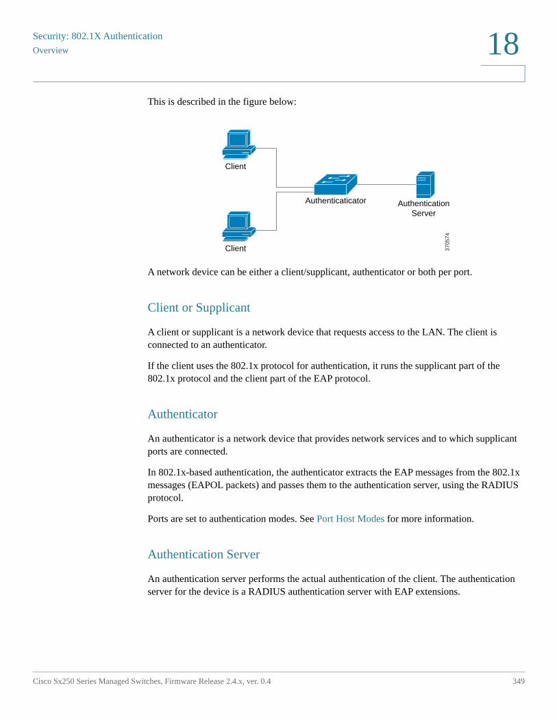
Security: 802.1X Authentication
Overview
Cisco Sx250 Series Managed Switches, Firmware Release 2.4.x, ver. 0.4 349
18
This is described in the figure below:
A network device can be either a client/supplicant, authenticator or both per port.
Client or Supplicant
A client or supplicant is a network device that requests access to the LAN. The client is connected to an authenticator.
If the client uses the 802.1x protocol for authentication, it runs the supplicant part of the 802.1x protocol and the client part of the EAP protocol.
Authenticator
An authenticator is a network device that provides network services and to which supplicant ports are connected.
In 802.1x-based authentication, the authenticator extracts the EAP messages from the 802.1x messages (EAPOL packets) and passes them to the authentication server, using the RADIUS protocol.
Ports are set to authentication modes. See Port Host Modes for more information.
Authentication Server
An authentication server performs the actual authentication of the client. The authentication server for the device is a RADIUS authentication server with EAP extensions.
Client
Client
Authenticaticator AuthenticationServer
3705
74
Security: 802.1X AuthenticationOverview
350 Cisco Sx250 Series Managed Switches, Firmware Release 2.4.x, ver. 0.4
18
Open Access
The Open (Monitoring) Access feature aids in separating real authentication failures from failures caused by mis-configuration and/or lack of resources, in an 802.1x environment.
Open Access helps system administrators understand the configuration problems of hosts connecting to the network, monitors bad situations and enables these problems to be fixed.
When Open Access is enabled on an interface, the switch treats all failures received from a RADIUS server as successes and allows access to the network for stations connected to interfaces regardless of authentication results.
Open Access changes the normal behavior of blocking traffic on a authentication-enabled port until authentication and authorization are successfully performed. The default behavior of authentication is still to block all traffic except Extensible Authentication Protocol over LAN (EAPoL). However, Open Access provides the administrator with the option of providing unrestricted access to all traffic, even though authentication (802.1X-Based, MAC-Based, and/or WEB-Based) is enabled.
When RADIUS accounting is enabled, you can log authentication attempts and gain visibility of who and what is connecting to your network with an audit trail.
All of this is accomplished with no impact on end users or on network-attached hosts. Open Access can be activated in the Port Authentication page.
Port Authentication States
The port authentication state determines whether the client is granted access to the network.
The port administrative state can be configured in the Port Authentication page.
The following values are available:
• force-authorized
Port authentication is disabled and the port transmits all traffic in accordance with its static configuration without requiring any authentication. The switch sends the 802.1x EAP-packet with the EAP success message inside when it receives the 802.1x EAPOL-start message.
This is the default state.
Security: 802.1X Authentication
Overview
Cisco Sx250 Series Managed Switches, Firmware Release 2.4.x, ver. 0.4 351
18
• force-unauthorized
Port authentication is disabled and the port transmits all traffic via the guest VLAN and unauthenticated VLANs. For more information see Host and Session Authentication. The switch sends 802.1x EAP packets with EAP failure messages inside when it receives 802.1x EAPOL-Start messages.
• auto
Enables port authentications in accordance with the configured port host mode and authentication methods configured on the port.
Port Host Modes
Ports can be placed in the following port host modes (configured in the Host and Session Authentication page):
• Single-Host Mode
A port is authorized if there is an authorized client. Only one host can be authorized on a port.
When a port is unauthorized and the guest VLAN is enabled, untagged traffic is remapped to the guest VLAN. Tagged traffic is dropped unless it belongs to the guest VLAN or to an unauthenticated VLAN. If a guest VLAN is not enabled on the port, only tagged traffic belonging to the unauthenticated VLANs is bridged.
When a port is authorized, untagged and tagged traffic from the authorized host is bridged based on the static VLAN membership port configuration. Traffic from other hosts is dropped.
A user can specify that untagged traffic from the authorized host will be remapped to a VLAN that is assigned by a RADIUS server during the authentication process. Tagged traffic is dropped unless it belongs to the RADIUS-assigned VLAN or the unauthenticated VLANs. Radius VLAN assignment on a port is set in the Port Authentication page.
• Multi-Host Mode
A port is authorized if there is if there is at least one authorized client.
When a port is unauthorized and a guest VLAN is enabled, untagged traffic is remapped to the guest VLAN. Tagged traffic is dropped unless it belongs to the guest VLAN or to an unauthenticated VLAN. If guest VLAN is not enabled on a port, only tagged traffic belonging to unauthenticated VLANs is bridged.
Security: 802.1X AuthenticationOverview
352 Cisco Sx250 Series Managed Switches, Firmware Release 2.4.x, ver. 0.4
18
When a port is authorized, untagged and tagged traffic from all hosts connected to the port is bridged, based on the static VLAN membership port configuration.
You can specify that untagged traffic from the authorized port will be remapped to a VLAN that is assigned by a RADIUS server during the authentication process. Tagged traffic is dropped unless it belongs to the RADIUS-assigned VLAN or to the unauthenticated VLANs. Radius VLAN assignment on a port is set in the Port Authentication page.
• Multi-Sessions Mode
Unlike the single-host and multi-host modes, a port in the multi-session mode does not have an authentication status. This status is assigned to each client connected to the port.
Tagged traffic belonging to an unauthenticated VLAN is always bridged regardless of whether the host is authorized or not.
Tagged and untagged traffic from unauthorized hosts not belonging to an unauthenticated VLAN is remapped to the guest VLAN if it is defined and enabled on the VLAN, or is dropped if the guest VLAN is not enabled on the port.
You can specify that untagged traffic from the authorized port will be remapped to a VLAN that is assigned by a RADIUS server during the authentication process. Tagged traffic is dropped unless it belongs to the RADIUS-assigned VLAN or to the unauthenticated VLANs. Radius VLAN assignment on a port is set in the Port Authentication page.
802.1x-Based Authentication
The 802.1x-based authenticator relays transparent EAP messages between 802.1x supplicants and authentication servers. The EAP messages between supplicants and the authenticator are encapsulated into the 802.1x messages, and the EAP messages between the authenticator and authentication servers are encapsulated into the RADIUS messages.
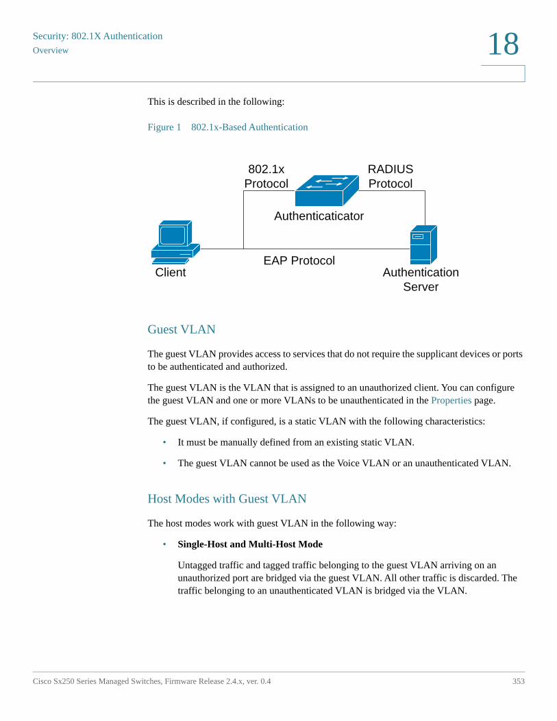
Security: 802.1X Authentication
Overview
Cisco Sx250 Series Managed Switches, Firmware Release 2.4.x, ver. 0.4 353
18
This is described in the following:
Figure 1 802.1x-Based Authentication
Guest VLAN
The guest VLAN provides access to services that do not require the supplicant devices or ports to be authenticated and authorized.
The guest VLAN is the VLAN that is assigned to an unauthorized client. You can configure the guest VLAN and one or more VLANs to be unauthenticated in the Properties page.
The guest VLAN, if configured, is a static VLAN with the following characteristics:
• It must be manually defined from an existing static VLAN.
• The guest VLAN cannot be used as the Voice VLAN or an unauthenticated VLAN.
Host Modes with Guest VLAN
The host modes work with guest VLAN in the following way:
• Single-Host and Multi-Host Mode
Untagged traffic and tagged traffic belonging to the guest VLAN arriving on an unauthorized port are bridged via the guest VLAN. All other traffic is discarded. The traffic belonging to an unauthenticated VLAN is bridged via the VLAN.
Client
Authenticaticator
RADIUSProtocol
802.1xProtocol
AuthenticationServer
EAP Protocol
Security: 802.1X AuthenticationOverview
354 Cisco Sx250 Series Managed Switches, Firmware Release 2.4.x, ver. 0.4
18
• Multi-Sessions Mode
Untagged traffic and tagged traffic, which does not belong to the unauthenticated VLANs and that arrives from unauthorized clients, are assigned to the guest VLAN using the TCAM rule and are bridged via the guest VLAN. The tagged traffic belonging to an unauthenticated VLAN is bridged via the VLAN.
This mode cannot be configured on the same interface with policy-based VLANs.
If the tunnel-private-group ID attribute is provided as a VLAN name, the VLAN with this name most be statically configured on the device. If a VLAN ID (2-4094) is used in this attribute, after a supplicant is authenticated, the VLAN will be created dynamically.
The device supports the 802.1x authentication mechanism, as described in the standard, to authenticate and authorize 802.1x supplicants.
Violation Mode
In single-host mode you can configure the action to be taken when an unauthorized host on authorized port attempts to access the interface. This is done in the Host and Session Authentication page.
The following options are available:
• restrict—Generates a trap when a station, whose MAC address is not the supplicant MAC address, attempts to access the interface. The minimum time between the traps is 1 second. These frames are forwarded, but their source addresses are not learned.
• protect—Discard frames with source addresses that are not the supplicant address.
• shutdown—Discard frames with source addresses that are not the supplicant address and shutdown the port.
You can also configure the device to send SNMP traps, with a configurable minimum time between consecutive traps. If seconds = 0, traps are disabled. If minimum time is not specified, it defaults to 1 second for the restrict mode and 0 for the other modes.
Quiet Period
The Quiet period is a period when the port (single-host or multi-host modes) or the client (multi-sessions mode) cannot attempt authentication, following a failed authentication exchange. In single-host or multi-host mode, the period is defined per port, and in the multi-sessions mode the period is defined per client. During the quiet period, the switch does not accept or initiate authentication requests.
Security: 802.1X Authentication
Overview
Cisco Sx250 Series Managed Switches, Firmware Release 2.4.x, ver. 0.4 355
18
You can also specify the maximum number of login attempts before the quiet period is started. A value of 0 specifies the unlimited number of login attempts.
The duration of the quiet period and the maximum number of login attempts can be set in the Port Authentication page.
Common Tasks
Workflow 1: To enable 802.1x authentication on a port:
STEP 1 Click Security > 802.1X Authentication > Properties to globally enable 802.1x authentication.
STEP 2 Enable Port-based Authentication.
STEP 3 Select the Authentication Method.
STEP 4 Click Apply, and the Running Configuration file is updated.
STEP 5 Click Security > 802.1X Authentication > Host and Session.
STEP 6 Select the required port and click Edit.
STEP 7 Set the Host Authentication mode.
STEP 8 Click Apply, and the Running Configuration file is updated.
STEP 9 Click Security > 802.1X Authentication > Port Authentication.
STEP 10 Select a port, and click Edit.
STEP 11 Set the Administrative Port Control field to Auto.
STEP 12 Define the authentication methods.
STEP 13 Click Apply, and the Running Configuration file is updated.
Workflow 2: To configure traps
STEP 1 Click Security > 802.1X Authentication > Properties.
STEP 2 Select the required traps.
STEP 3 Click Apply, and the Running Configuration file is updated.
Security: 802.1X AuthenticationProperties
356 Cisco Sx250 Series Managed Switches, Firmware Release 2.4.x, ver. 0.4
18
Workflow 3: To configure 802.1x-based,
STEP 1 Click Security > 802.1X Authentication > Port Authentication.
STEP 2 Select the required port and click Edit.
STEP 3 Enter the fields required for the port.
The fields in this page are described in Port Authentication.
STEP 4 Click Apply, and the Running Configuration file is updated.
Use the Copy Settings button to copy settings from one port to another.
Workflow 4: To configure the quiet period
STEP 1 Click Security > 802.1X Authentication > Port Authentication.
STEP 2 Select a port, and click Edit.
STEP 3 Enter the quiet period in the Quiet Period field.
STEP 4 Click Apply, and the Running Configuration file is updated.
Workflow 5: To configure the guest VLAN:
STEP 1 Click Security > 802.1X Authentication > Properties.
STEP 2 Select Enable in the Guest VLAN field.
STEP 3 Select the guest VLAN in the Guest VLAN ID field.
STEP 4 Configure the Guest VLAN Timeout to be either Immediate or enter a value in the User defined field.
STEP 5 Click Apply, and the Running Configuration file is updated.
Properties
The Properties page is used to globally enable port/device authentication. For authentication to function, it must be activated both globally and individually on each port.
Security: 802.1X Authentication
Properties
Cisco Sx250 Series Managed Switches, Firmware Release 2.4.x, ver. 0.4 357
18
To define port-based authentication:
STEP 1 Click Security > 802.1X Authentication > Properties.
STEP 2 Enter the parameters.
• Port-Based Authentication—Enable or disable port-based authentication.
If this is disabled 802.1X is disabled.
• Authentication Method—Select the user authentication methods. The options are:
- RADIUS, None—Perform port authentication first by using the RADIUS server. If no response is received from RADIUS (for example, if the server is down), then no authentication is performed, and the session is permitted.
- RADIUS—Authenticate the user on the RADIUS server. If no authentication is performed, the session is not permitted.
- None—Do not authenticate the user. Permit the session.
• Guest VLAN—Select to enable the use of a guest VLAN for unauthorized ports. If a guest VLAN is enabled, all unauthorized ports automatically join the VLAN selected in the Guest VLAN ID field. If a port is later authorized, it is removed from the guest VLAN.
The guest VLAN can be defined as a layer 3 interface (assigned an IP address) like any other VLAN. However, device management is not available via the guest VLAN IP address.
• Guest VLAN ID—Select the guest VLAN from the list of VLANs.
• Guest VLAN Timeout—Define a time period as either Immediate or enter a value in User Defined. This value is used as follows:
After linkup, if the software does not detect the 802.1X supplicant, or the authentication has failed, the port is added to the guest VLAN, only after the Guest VLAN timeout period has expired.
If the port state changes from Authorized to Not Authorized, the port is added to the guest VLAN only after the Guest VLAN timeout has expired.
• Trap Settings—To enable traps, select one of more of the following options:
- 802.1x Authentication Failure Traps—Select to generate a trap if 802.1x authentication fails.
- 802.1x Authentication Success Traps—Select to generate a trap if 802.1x authentication succeeds.
Security: 802.1X AuthenticationPort Authentication
358 Cisco Sx250 Series Managed Switches, Firmware Release 2.4.x, ver. 0.4
18
STEP 3 Click Apply. The 802.1X properties are written to the Running Configuration file.
Port Authentication
The Port Authentication page enables configuration of parameters for each port. Since some of the configuration changes are only possible while the port is in Force Authorized state, such as host authentication, it is recommended that you change the port control to Force Authorized before making changes. When the configuration is complete, return the port control to its previous state.
NOTE A port with 802.1x defined on it cannot become a member of a LAG.802.1x and Port Security cannot be enabled on same port at same time. If you enable port security on an interface, the Administrative Port Control cannot be changed to Auto mode.
To define 802.1X authentication:
STEP 1 Click Security > 802.1X Authentication > Port Authentication.
STEP 2 This page displays authentication settings for all ports. Select a port, and click Edit.
STEP 3 Enter the parameters.
• Interface—Select a port .
• Current Port Control—Displays the current port authorization state. If the state is Authorized, the port is either authenticated or the Administrative Port Control is Force Authorized. Conversely, if the state is Unauthorized, then the port is either not authenticated or the Administrative Port Control is Force Unauthorized. If supplicant is enabled on an interface, the current port control will be Supplicant.
• Administrative Port Control—Select the Administrative Port Authorization state. The options are:
- Force Unauthorized—Denies the interface access by moving the interface into the unauthorized state. The device does not provide authentication services to the client through the interface.
- Auto—Enables port-based authentication and authorization on the device. The interface moves between an authorized or unauthorized state based on the authentication exchange between the device and the client.
- Force Authorized—Authorizes the interface without authentication.
Security: 802.1X Authentication
Port Authentication
Cisco Sx250 Series Managed Switches, Firmware Release 2.4.x, ver. 0.4 359
18
• Guest VLAN—Select to enable using a guest VLAN for unauthorized ports. If a guest VLAN is enabled, the unauthorized port automatically joins the VLAN selected in the Guest VLAN ID field in the Port Authentication page. After an authentication failure, and if guest VLAN is activated globally on a given port, the guest VLAN is automatically assigned to the unauthorized ports as an Untagged VLAN.
• Periodic Reauthentication—Select to enable port re-authentication attempts after the specified Reauthentication Period.
• Reauthentication Period—Enter the number of seconds after which the selected port is reauthenticated.
• Reauthenticate Now—Select to enable immediate port re-authentication.
• Authenticator State—Displays the defined port authorization state. The options are:
- Initialize—In process of coming up.
- Force-Authorized—Controlled port state is set to Force-Authorized (forward traffic).
- Force-Unauthorized—Controlled port state is set to Force-Unauthorized (discard traffic).
NOTE If the port is not in Force-Authorized or Force-Unauthorized, it is in Auto Mode and the authenticator displays the state of the authentication in progress. After the port is authenticated, the state is shown as Authenticated.
• Time Range—Select to enable limiting authentication to a specific time range.
• Time Range Name—If Time Range is selected, select the time range to be used. Time ranges are defined in the System Time Configuration section.
• Max Hosts—Enter the maximum number of authorized hosts allowed on the interface. Select either Infinite for no limit or User Defined to set a limit.
• Quiet Period—Enter the length of the quiet period.
• Resending EAP—Enter the number of seconds that the device waits for a response to an Extensible Authentication Protocol (EAP) request/identity frame from the supplicant (client) before resending the request.
• Max EAP Requests—Enter the maximum number of EAP requests that will be sent. If a response is not received after the defined period (supplicant timeout), the authentication process is restarted.
• Supplicant Timeout—Enter the number of seconds that lapses before EAP requests are resent to the supplicant.
Security: 802.1X AuthenticationHost and Session Authentication
360 Cisco Sx250 Series Managed Switches, Firmware Release 2.4.x, ver. 0.4
18
• Server Timeout—Enter the number of seconds that lapses before the device resends a request to the authentication server.
STEP 4 Click Apply. The port settings are written to the Running Configuration file.
Host and Session Authentication
The Host and Session Authentication page enables defining the mode in which 802.1X operates on the port and the action to perform if a violation has been detected.
See Port Host Modes for an explanation of these modes.
To define 802.1X advanced settings for ports:
STEP 1 Click Security > 802.1X Authentication > Host and Session Authentication.
The authentication parameters are described for all ports. All fields except the following are described in the Edit page.
• Number of Violations—Displays the number of packets that arrive on the interface in single-host mode, from a host whose MAC address is not the supplicant MAC address.
STEP 2 Select a port, and click Edit.
STEP 3 Enter the parameters.
• Interface—Enter a port number for which host authentication is enabled.
• Host Authentication—Select one of the modes. These modes are described above in Port Host Modes.
Single Host Violation Settings (only displayed if host authentication is Single Host):
• Action on Violation—Select the action to be applied to packets arriving in Single Session/Single Host mode, from a host whose MAC address is not the supplicant MAC address. The options are:
- Protect (Discard)—Discards the packets.
- Restrict (Forward)—Forwards the packets.
- Shutdown—Discards the packets and shuts down the port. The ports remains shut down until reactivated, or until the device is rebooted.
• Traps—Select to enable traps.
Security: 802.1X Authentication
Authenticated Hosts
Cisco Sx250 Series Managed Switches, Firmware Release 2.4.x, ver. 0.4 361
18
• Trap Frequency—Defines how often traps are sent to the host. This field can be defined only if multiple hosts are disabled.
STEP 4 Click Apply. The settings are written to the Running Configuration file.
Authenticated Hosts
To view details about authenticated users, click Security > 802.1X Authentication > Authenticated Hosts.
This page displays the following fields:
• User Name—Supplicant names that authenticated on each port.
• Port—Number of the port.
• Session Time (DD:HH:MM:SS)—Amount of time that the supplicant was authenticated and authorized access at the port.
• Authentication Server—RADIUS server.
• MAC Address—Displays the supplicant MAC address.
,
19
Cisco Sx250 Series Managed Switches, Firmware Release 2.4.x, ver. 0.4 362
Security: Secure Sensitive Data Management
Secure Sensitive Data (SSD) is an architecture that facilitates the protection of sensitive data on a device, such as passwords and keys. The facility makes use of passphrases, encryption, access control, and user authentication to provide a secure solution to managing sensitive data.
The facility is extended to protect the integrity of configuration files, to secure the configuration process, and to support SSD zero-touch auto configuration.
• Introduction
• SSD Management
• SSD Rules
• SSD Properties
• Configuration Files
• SSD Management Channels
• Menu CLI and Password Recovery
• Configuring SSD
Introduction
SSD protects sensitive data on a device, such as passwords and keys, permits and denies access to sensitive data encrypted and in plain text based on user credentials and SSD rules, and protects configuration files containing sensitive data from being tampered with.
In addition, SSD enables the secure backup and sharing of configuration files containing sensitive data.
SSD provides users with the flexibility to configure the desired level of protection on their sensitive data; from no protection with sensitive data in plaintext, minimum protection with encryption based on the default passphrase, and better protection with encryption based on user-defined passphrase.
Security: Secure Sensitive Data Management
SSD Management
Cisco Sx250 Series Managed Switches, Firmware Release 2.4.x, ver. 0.4 363
19
SSD grants read permission to sensitive data only to authenticated and authorized users, and according to SSD rules. A device authenticates and authorizes management access to users through the user authentication process.
Whether or not SSD is used, it is recommended that the administrator secure the authentication process by using the local authentication database, and/or secure the communication to the external authentication servers used in the user authentication process.
In summary, SSD protects sensitive data on a device with SSD rules, SSD properties, and user authentication. And SSD rules, SSD properties, and user authentication configurations of the device are themselves sensitive data protected by SSD.
SSD Management
SSD management includes a collection of configuration parameters that define the handling and security of sensitive data. The SSD configuration parameters themselves are sensitive data and are protected under SSD.
All configuration of SSD is performed through the SSD pages that are only available to users with the correct permissions (see SSD Rules).
SSD Rules
SSD rules define the read permissions and default read mode given to a user session on a management channel.
An SSD rule is uniquely identified by its user and SSD management channel. Different SSD rules might exist for the same user but for different channels, and conversely, different rules might exist for the same channel but for different users.
Read permissions determine how sensitive data can be viewed: in only encrypted form, in only plaintext form, in both encrypted or plaintext, or no permission to view sensitive data. The SSD rules themselves are protected as sensitive data.
A device can support a total of 32 SSD rules.
A device grants a user the SSD read permission of the SSD rule that best matches the user identity/credential and the type of management channel from which the user is/will access the sensitive data.
A device comes with a set of default SSD rules. An administrator can add, delete, and change SSD rules as desired.
Security: Secure Sensitive Data ManagementSSD Rules
364 Cisco Sx250 Series Managed Switches, Firmware Release 2.4.x, ver. 0.4
19
NOTE A device may not support all the channels defined by SSD.
Elements of an SSD Rule
An SSD rule includes the following elements:
• User type—The user types supported in order of most preference to least preference are as follows: (If a user matches multiple SSD rules, the rule with the most preference User Type will be applied).
- Specific—The rule applies to a specific user.
- Default User (cisco)—The rule applies to the default user (cisco).
- Level 15—The rule applies to users with privilege level 15.
- All—The rule applies to all users.
• User Name—If user type is Specific, a user name is required.
• Channel—Type of SSD management channel to which the rule is applied. The channel types supported are:
- Secure—Specifies the rule applies only to secure channels. Depending on the device, it may support some or all of the following secure channels:Console port interface, SCP, SSH, and HTTPS.
- Insecure—Specifies that this rule applies only to insecure channels. Depending on the device, it may support some or all of the following insecure channels:Telnet, TFTP, and HTTP.
- Secure XML SNMP—Specifies that this rule applies only to XML over HTTPS or SNMPv3 with privacy. A device may or may not support all of the secure XML and SNMP channels.
- Insecure XML SNMP—Specifies that this rule applies only to XML over HTTP or SNMPv1/v2 and SNMPv3 without privacy. A device may or may not support all of the secure XML and SNMP channels.
• Read Permission—The read permissions associate with the rules. These can be the following:
- (Lowest) Exclude—Users are not permitted to access sensitive data in any form.
- (Middle) Encrypted Only—Users are permitted to access sensitive data as encrypted only.
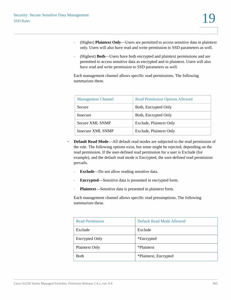
Security: Secure Sensitive Data Management
SSD Rules
Cisco Sx250 Series Managed Switches, Firmware Release 2.4.x, ver. 0.4 365
19
- (Higher) Plaintext Only—Users are permitted to access sensitive data in plaintext only. Users will also have read and write permission to SSD parameters as well.
- (Highest) Both—Users have both encrypted and plaintext permissions and are permitted to access sensitive data as encrypted and in plaintext. Users will also have read and write permission to SSD parameters as well.
Each management channel allows specific read permissions. The following summarizes these.
• Default Read Mode—All default read modes are subjected to the read permission of the rule. The following options exist, but some might be rejected, depending on the read permission. If the user-defined read permission for a user is Exclude (for example), and the default read mode is Encrypted, the user-defined read permission prevails.
- Exclude—Do not allow reading sensitive data.
- Encrypted—Sensitive data is presented in encrypted form.
- Plaintext—Sensitive data is presented in plaintext form.
Each management channel allows specific read presumptions. The following summarizes these.
Management Channel Read Permission Options Allowed
Secure Both, Encrypted Only
Insecure Both, Encrypted Only
Secure XML SNMP Exclude, Plaintext Only
Insecure XML SNMP Exclude, Plaintext Only
Read Permission Default Read Mode Allowed
Exclude Exclude
Encrypted Only *Encrypted
Plaintext Only *Plaintext
Both *Plaintext, Encrypted
Security: Secure Sensitive Data ManagementSSD Rules
366 Cisco Sx250 Series Managed Switches, Firmware Release 2.4.x, ver. 0.4
19
* The Read mode of a session can be temporarily changed in the SSD Properties page if the new read mode does not violate the read permission.
NOTE Note the following:
• The default Read mode for the Secure XML SNMP and Insecure XML SNMP management channels must be identical to their read permission.
• Read permission Exclude is allowed only for Secure XML SNMP and Insecure XML SNMP management channels; Exclude is not allowed for regular secure and insecure channels.
• Exclude sensitive data in secure and Insecure XML-SNMP management channels means that the sensitive data is presented as a 0 (meaning null string or numeric 0). If the user wants to view sensitive data, the rule must be changed to plaintext.
• By default, an SNMPv3 user with privacy and XML-over-secure channels permissions is considered to be a level-15 user.
• SNMP users on Insecure XML and SNMP (SNMPv1,v2, and v3 with no privacy) channel are considered as All users.
• SNMP community names are not used as user names to match SSD rules.
• Access by a specific SNMPv3 user can be controlled by configuring an SSD rule with a user name matching the SNMPv3 user name.
• There must always be at least one rule with read permission: Plaintext Only or Both, because only users with those permissions are able to access the SSD pages.
• Changes in the default read mode and read permissions of a rule will become effective, and will be applied to the affected user(s) and channel of all active management sessions immediately, excluding the session making the changes even if the rule is applicable. When a rule is changed (add, delete, edit), a system will update all the affected CLI/GUI sessions.
NOTE When the SSD rule applied upon the session login is changed from within that session, the user must log out and back in to see the change.
NOTE When doing a file transfer initiated by an XML or SNMP command, the underlying protocol used is TFTP. Therefore, the SSD rule for insecure channel will apply.
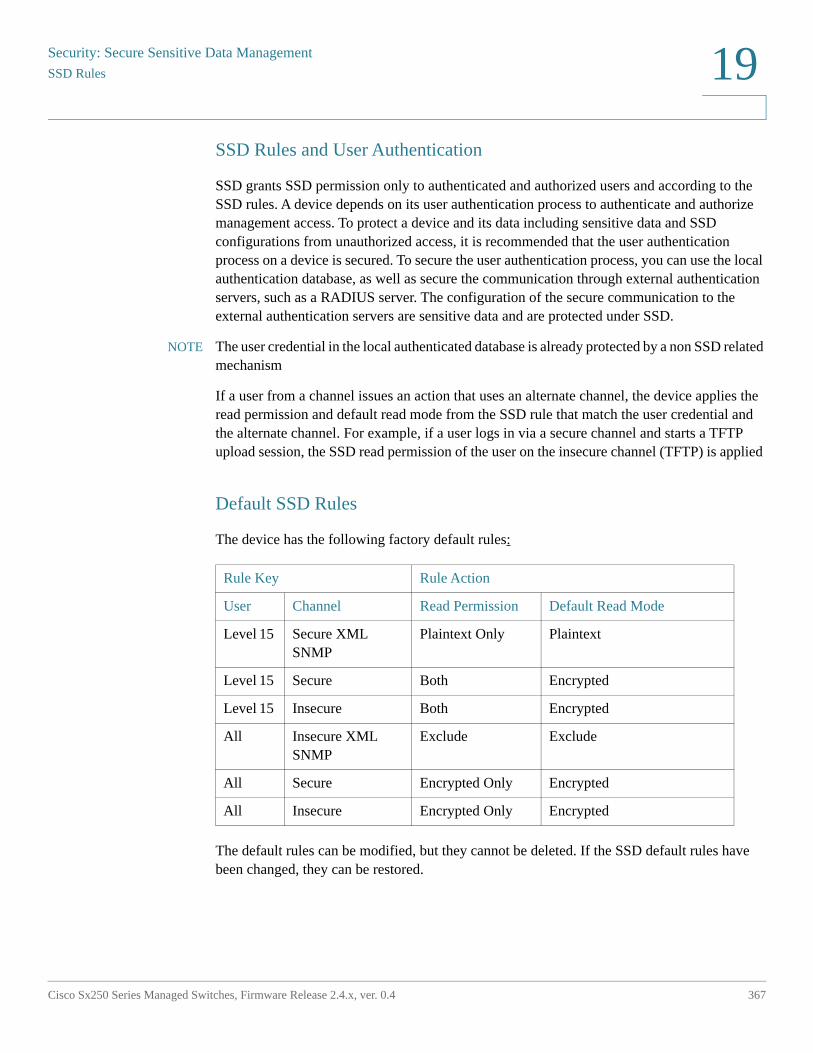
Security: Secure Sensitive Data Management
SSD Rules
Cisco Sx250 Series Managed Switches, Firmware Release 2.4.x, ver. 0.4 367
19
SSD Rules and User Authentication
SSD grants SSD permission only to authenticated and authorized users and according to the SSD rules. A device depends on its user authentication process to authenticate and authorize management access. To protect a device and its data including sensitive data and SSD configurations from unauthorized access, it is recommended that the user authentication process on a device is secured. To secure the user authentication process, you can use the local authentication database, as well as secure the communication through external authentication servers, such as a RADIUS server. The configuration of the secure communication to the external authentication servers are sensitive data and are protected under SSD.
NOTE The user credential in the local authenticated database is already protected by a non SSD related mechanism
If a user from a channel issues an action that uses an alternate channel, the device applies the read permission and default read mode from the SSD rule that match the user credential and the alternate channel. For example, if a user logs in via a secure channel and starts a TFTP upload session, the SSD read permission of the user on the insecure channel (TFTP) is applied
Default SSD Rules
The device has the following factory default rules:
The default rules can be modified, but they cannot be deleted. If the SSD default rules have been changed, they can be restored.
Rule Key Rule Action
User Channel Read Permission Default Read Mode
Level 15 Secure XML SNMP
Plaintext Only Plaintext
Level 15 Secure Both Encrypted
Level 15 Insecure Both Encrypted
All Insecure XML SNMP
Exclude Exclude
All Secure Encrypted Only Encrypted
All Insecure Encrypted Only Encrypted
Security: Secure Sensitive Data ManagementSSD Properties
368 Cisco Sx250 Series Managed Switches, Firmware Release 2.4.x, ver. 0.4
19
SSD Default Read Mode Session Override
The system contains sensitive data in a session, as either encrypted or plaintext, based on the read permission and the default read mode of the user.
The default read mode can be temporarily overridden as long it does not conflict with the SSD read permission of the session. This change is effective immediately in the current session, until one of the following occurs:
• User changes it again.
• Session is terminated.
• The read permission of the SSD rule that is applied to the session user is changed and is no longer compatible with the current read mode of the session. In this case, the session read mode returns to the default read mode of the SSD rule.
SSD Properties
SSD properties are a set of parameters that, in conjunction with the SSD rules, define and control the SSD environment of a device. The SSD environment consists of these properties:
• Controlling how the sensitive data is encrypted.
• Controlling the strength of security on configuration files.
• Controlling how the sensitive data is viewed within the current session.
Passphrase
A passphrase is the basis of the security mechanism in the SSD feature, and is used to generate the key for the encryption and decryption of sensitive data. Devices that have the same passphrase are able to decrypt each other's sensitive data encrypted with the key generated from the passphrase.
A passphrase must comply with the following rules:
• Length—Between 8-16 characters, inclusive.
• Character Classes—The passphrase must have at least one upper case character, one lower case character, one numeric character, and one special character e.g. #,$.
Security: Secure Sensitive Data Management
SSD Properties
Cisco Sx250 Series Managed Switches, Firmware Release 2.4.x, ver. 0.4 369
19
Default and User-defined Passphrases
All devices come with a default, out-of-the box passphrase that is transparent to users. The default passphrase is never displayed in the configuration file or in the CLI/GUI.
If better security and protection are desired, an administrator should configure SSD on a device to use a user-defined passphrase instead of the default passphrase. A user-defined passphrase should be treated as a well-guard secret, so that the security of the sensitive data on the device is not compromised.
A user-defined passphrase can be configured manually in plain text. It can also be derived from a configuration file. (See Sensitive Data Zero-Touch Auto Configuration). A device always displays user-defined passphrases encrypted.
Local Passphrase
A device maintains a local passphrase that is the passphrase of its Running Configuration. SSD normally performs encryption and decryption of sensitive data with the key generated from the local passphrase.
The local passphrase can be configured to be either the default passphrase or a user-defined passphrase. By default, the local passphrase and default passphrase are identical. It can be changed by administrative actions from either the Command Line Interface (if available) or the web-based interface. It is automatically changed to the passphrase in the startup configuration file, when the startup configuration becomes the running configuration of the device. When a device is reset to factory default, the local passphrase is reset to the default passphrase.
Configuration File Passphrase Control
File passphrase control provides additional protection for a user-defined passphrase, and the sensitive data that are encrypted with the key generated from the user-defined passphrase, in text-based configuration files.
The following are the existing passphrase control modes:
• Unrestricted (default)—The device includes its passphrase when creating a configuration file. This enables any device accepting the configuration file to learn the passphrase from the file.
• Restricted—The device restricts its passphrase from being exported into a configuration file. Restricted mode protects the encrypted sensitive data in a configuration file from devices that do not have the passphrase. This mode should be used when a user does not want to expose the passphrase in a configuration file.
Security: Secure Sensitive Data ManagementSSD Properties
370 Cisco Sx250 Series Managed Switches, Firmware Release 2.4.x, ver. 0.4
19
After a device is reset to the factory default, its local passphrase is reset to the default passphrase. As a result, the device will be not able to decrypt any sensitive data encrypted based on a user-defined passphrase entered from a management session (GUI/CLI), or in any configuration file with restricted mode, including the files created by the device itself before it is reset to factory default. This remains until the device is manually reconfigured with the user-defined passphrase, or learns the user-defined passphrase from a configuration file.
Configuration File Integrity Control
A user can protect a configuration file from being tampered or modified by creating the configuration file with Configuration File Integrity Control. It is recommended that Configuration File Integrity Control be enabled when a device uses a user-defined passphrase with Unrestricted Configuration File Passprhase Control.
!CAUTION Any modification made to a configuration file that is integrity protected is considered
tampering.
A device determines whether the integrity of a configuration file is protected by examining the File Integrity Control command in the file's SSD Control block. If a file is integrity protected but a device finds the integrity of the file is not intact, the device rejects the file. Otherwise, the file is accepted for further processing.
A device checks for the integrity of a text-based configuration file when the file is downloaded or copied to the Startup Configuration file.
Read Mode
Each session has a Read mode. This determines how sensitive data appears. The Read mode can be either Plaintext, in which case sensitive data appears as regular text, or Encrypted, in which sensitive data appears in its encrypted form.
Security: Secure Sensitive Data Management
Configuration Files
Cisco Sx250 Series Managed Switches, Firmware Release 2.4.x, ver. 0.4 371
19
Configuration Files
A configuration file contains the configuration of a device. A device has a Running Configuration file, a Startup Configuration file, a Mirror Configuration file (optionally), and a Backup Configuration file. A user can manually upload and download a configuration file to and from a remote file-server. A device can automatically download its Startup Configuration from a remote file server during the auto configuration stage using DHCP. Configuration files stored on remote file servers are referred to as remote configuration files.
A Running Configuration file contains the configuration currently being used by a device. The configuration in a Startup Configuration file becomes the Running Configuration after reboot. Running and Startup Configuration files are formatted in internal format. Mirror, Backup, and the remote configuration files are text-based files usually kept for archive, records, or recovery. During copying, uploading, and downloading a source configuration file, a device automatically transforms the source content to the format of the destination file if the two files are of different formats.
File SSD Indicator
When copying the Running or Startup Configuration file into a text-based configuration file, the device generates and places the file SSD indicator in the text-based configuration file to indicate whether the file contains encrypted sensitive data, plaintext sensitive data or excludes sensitive data.
• The SSD indicator, if it exists, must be in the configuration header file.
• A text-based configuration that does not include an SSD indicator is considered not to contain sensitive data.
• The SSD indicator is used to enforce SSD read permissions on text-based configuration files, but is ignored when copying the configuration files to the Running or Startup Configuration file.
The SSD indicator in a file is set according to the user’s instruction, during copy, to include encrypted, plaintext or exclude sensitive data from a file.
SSD Control Block
When a device creates a text-based configuration file from its Startup or Running Configuration file, it inserts an SSD control block into the file if a user requests the file is to include sensitive data. The SSD control block, which is protected from tampering, contains SSD rules and SSD properties of the device creating the file. A SSD control block starts and ends with "ssd-control-start" and "ssd-control-end" respectively.
Security: Secure Sensitive Data ManagementConfiguration Files
372 Cisco Sx250 Series Managed Switches, Firmware Release 2.4.x, ver. 0.4
19
Startup Configuration File
The device currently supports copying from the Running, Backup, Mirror, and Remote Configuration files to a Startup Configuration file. The configurations in the Startup Configuration are effective and become the Running Configuration after reboot. A user can retrieve the sensitive data encrypted or in plaintext from a startup configuration file, subject to the SSD read permission and the current SSD read mode of the management session.
Read access of sensitive data in the startup configuration in any forms is excluded if the passphrase in the Startup Configuration file and the local passphrase are different.
SSD adds the following rules when copying the Backup, Mirror, and Remote Configuration files to the Startup Configuration file:
• After a device is reset to factory default, all of its configurations, including the SSD rules and properties are reset to default.
• If a source configuration file contains encrypted sensitive data, but is missing an SSD control block, the device rejects the source file and the copy fails.
• If there is no SSD control block in the source configuration file, the SSD configuration in the Startup Configuration file is reset to default.
• If there is a passphrase in the SSD control block of the source configuration file, the device will reject the source file, and the copy fails if there is encrypted sensitive data in the file not encrypted by the key generated from the passphrase in the SSD control block.
• If there is an SSD control block in the source configuration file and the file fails the SSD integrity check, and/or file integrity check, the device rejects the source file and fails the copy.
• If there is no passphrase in the SSD control block of the source configuration file, all the encrypted sensitive data in the file must be encrypted by either the key generated from the local passphrase, or the key generated from the default passphrase, but not both. Otherwise, the source file is rejected and the copy fails.
• The device configures the passphrase, passphrase control, and file integrity, if any, from the SSD Control Block in the source configuration file to the Startup Configuration file. It configures the Startup Configuration file with the passphrase that is used to generate the key to decrypt the sensitive data in the source configuration file. Any SSD configurations that are not found are reset to the default.
• If there is an SSD control block in the source configuration file and the file contains plaintext, sensitive data excluding the SSD configurations in the SSD control block, the file is accepted.
Security: Secure Sensitive Data Management
Configuration Files
Cisco Sx250 Series Managed Switches, Firmware Release 2.4.x, ver. 0.4 373
19
Running Configuration File
A Running Configuration file contains the configuration currently being used by the device. A user can retrieve the sensitive data encrypted or in plaintext from a running configuration file, subject to the SSD read permission and the current SSD read mode of the management session. The user can change the Running Configuration by copying the Backup or Mirror Configuration files through other management actions via CLI, XML,SNMP, and so on.
A device applies the following rules when a user directly changes the SSD configuration in the Running Configuration:
• If the user that opened the management session does not have SSD permissions (meaning read permissions of either Both or Plaintext Only), the device rejects all SSD commands.
• When copied from a source file, File SSD indicator, SSD Control Block Integrity, and SSD File Integrity are neither verified nor enforced.
• When copied from a source file, the copy will fail if the passphrase in the source file is in plaintext. If the passphrase is encrypted, it is ignored.
• When directly configuring the passphrase, (non file copy), in the Running Configuration, the passphrase in the command must be entered in plaintext. Otherwise, the command is rejected.
• Configuration commands with encrypted sensitive data, that are encrypted with the key generated from the local passphrase, are configured into the Running Configuration. Otherwise, the configuration command is in error, and is not incorporated into the Running Configuration file.
Backup and Mirror Configuration File
A device periodically generates its Mirror Configuration file from the Startup Configuration file if auto mirror configuration service is enabled. A device always generates a Mirror Configuration file with encrypted sensitive data. Therefore, the File SSD Indicator in a Mirror Configuration file always indicates that the file contains encrypted sensitive data.
By default, auto mirror configuration service is enabled. To configure auto mirror configuration to be enabled or disabled, click Administration > File Management > Firmware Operations.
Security: Secure Sensitive Data ManagementConfiguration Files
374 Cisco Sx250 Series Managed Switches, Firmware Release 2.4.x, ver. 0.4
19
A user can display, copy, and upload the complete mirror and backup configuration files, subject to SSD read permission, the current read mode in the session, and the file SSD indicator in the source file as follows:
• If there is no file SSD indicator in a mirror or backup configuration file, all users are allowed to access the file.
• A user with Both read permission can access all mirror and backup configuration files. However, if the current read mode of the session is different than the file SSD indicator, the user is presented with a prompt indicating that this action is not allowed.
• A user with Plaintext Only permission can access mirror and backup configuration files if their file SSD Indicator shows Exclude or Plaintext Only sensitive data.
• A user with Encrypted Only permission can access mirror and backup configuration files with their file SSD Indicator showing Exclude or Encrypted sensitive data.
• A user with Exclude permission cannot access mirror and backup configuration files with their file SSD indicator showing either encrypted or plaintext sensitive data.
The user should not manually change the file SSD indicator that conflicts with the sensitive data, if any, in the file. Otherwise, plaintext sensitive data may be unexpectedly exposed.
Sensitive Data Zero-Touch Auto Configuration
SSD Zero-touch Auto Configuration is the auto configuration of target devices with encrypted sensitive data, without the need to manually pre-configure the target devices with the passphrase whose key is used to encrypted the sensitive data.
The device currently supports Auto Configuration, which is enabled by default. When Auto Configuration is enabled on a device and the device receives DHCP options that specify a file server and a boot file, the device downloads the boot file (remote configuration file) into the Startup Configuration file from a file server, and then reboots.
NOTE The file server may be specified by the bootp siaddr and sname fields, as well as DHCP option 150 and statically configured on the device.
The user can safely auto configure target devices with encrypted sensitive data, by first creating the configuration file that is to be used in the auto configuration from a device that contains the configurations. The device must be configured and instructed to:
• Encrypt the sensitive data in the file
• Enforce the integrity of the file content
• Include the secure, authentication configuration commands and SSD rules that properly control and secure the access to devices and the sensitive data
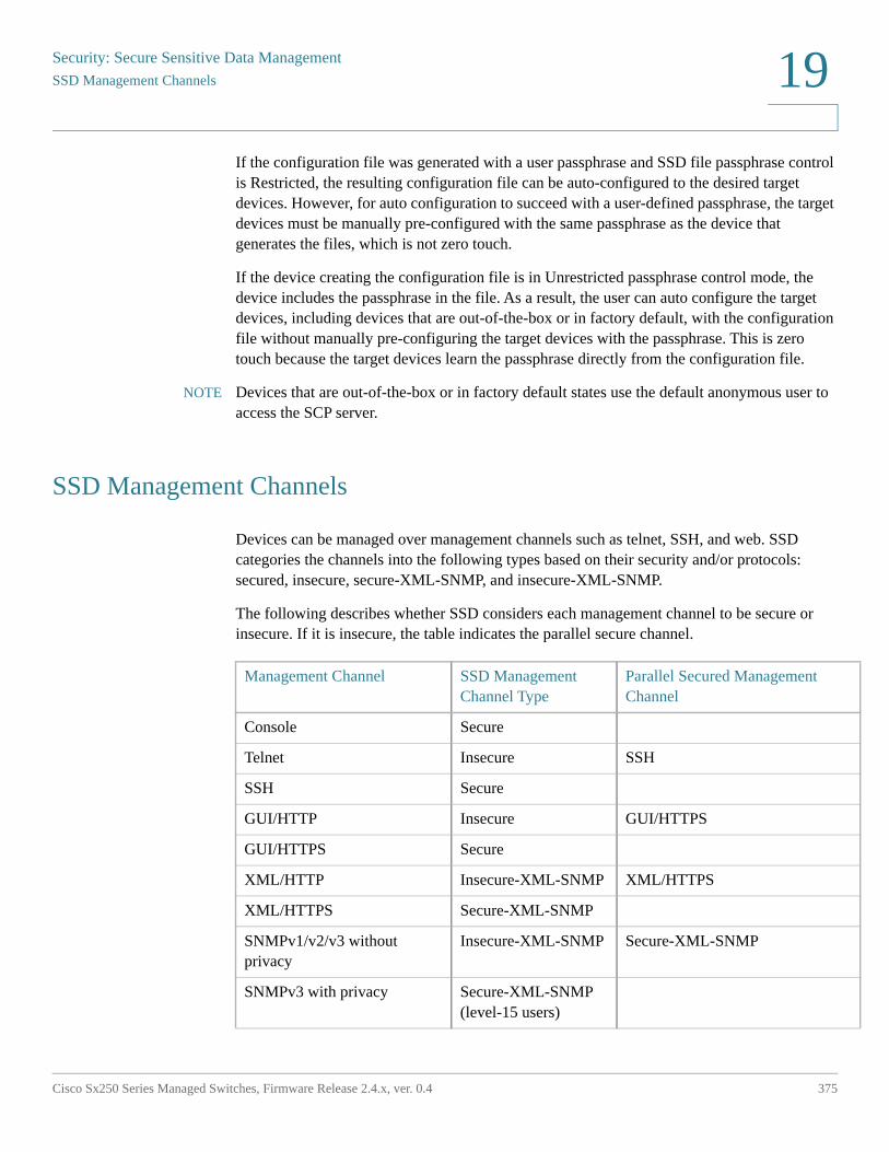
Security: Secure Sensitive Data Management
SSD Management Channels
Cisco Sx250 Series Managed Switches, Firmware Release 2.4.x, ver. 0.4 375
19
If the configuration file was generated with a user passphrase and SSD file passphrase control is Restricted, the resulting configuration file can be auto-configured to the desired target devices. However, for auto configuration to succeed with a user-defined passphrase, the target devices must be manually pre-configured with the same passphrase as the device that generates the files, which is not zero touch.
If the device creating the configuration file is in Unrestricted passphrase control mode, the device includes the passphrase in the file. As a result, the user can auto configure the target devices, including devices that are out-of-the-box or in factory default, with the configuration file without manually pre-configuring the target devices with the passphrase. This is zero touch because the target devices learn the passphrase directly from the configuration file.
NOTE Devices that are out-of-the-box or in factory default states use the default anonymous user to access the SCP server.
SSD Management Channels
Devices can be managed over management channels such as telnet, SSH, and web. SSD categories the channels into the following types based on their security and/or protocols: secured, insecure, secure-XML-SNMP, and insecure-XML-SNMP.
The following describes whether SSD considers each management channel to be secure or insecure. If it is insecure, the table indicates the parallel secure channel.
Management Channel SSD Management Channel Type
Parallel Secured Management Channel
Console Secure
Telnet Insecure SSH
SSH Secure
GUI/HTTP Insecure GUI/HTTPS
GUI/HTTPS Secure
XML/HTTP Insecure-XML-SNMP XML/HTTPS
XML/HTTPS Secure-XML-SNMP
SNMPv1/v2/v3 without privacy
Insecure-XML-SNMP Secure-XML-SNMP
SNMPv3 with privacy Secure-XML-SNMP (level-15 users)
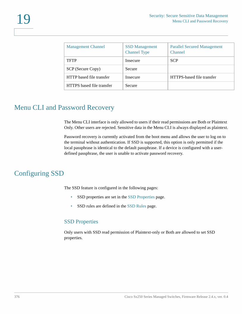
Security: Secure Sensitive Data ManagementMenu CLI and Password Recovery
376 Cisco Sx250 Series Managed Switches, Firmware Release 2.4.x, ver. 0.4
19
Menu CLI and Password Recovery
The Menu CLI interface is only allowed to users if their read permissions are Both or Plaintext Only. Other users are rejected. Sensitive data in the Menu CLI is always displayed as plaintext.
Password recovery is currently activated from the boot menu and allows the user to log on to the terminal without authentication. If SSD is supported, this option is only permitted if the local passphrase is identical to the default passphrase. If a device is configured with a user-defined passphrase, the user is unable to activate password recovery.
Configuring SSD
The SSD feature is configured in the following pages:
• SSD properties are set in the SSD Properties page.
• SSD rules are defined in the SSD Rules page.
SSD Properties
Only users with SSD read permission of Plaintext-only or Both are allowed to set SSD properties.
TFTP Insecure SCP
SCP (Secure Copy) Secure
HTTP based file transfer Insecure HTTPS-based file transfer
HTTPS based file transfer Secure
Management Channel SSD Management Channel Type
Parallel Secured Management Channel
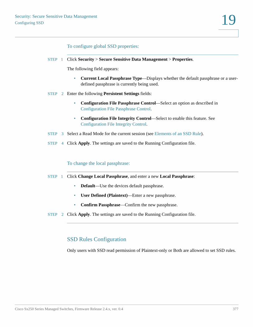
Security: Secure Sensitive Data Management
Configuring SSD
Cisco Sx250 Series Managed Switches, Firmware Release 2.4.x, ver. 0.4 377
19
To configure global SSD properties:
STEP 1 Click Security > Secure Sensitive Data Management > Properties.
The following field appears:
• Current Local Passphrase Type—Displays whether the default passphrase or a user-defined passphrase is currently being used.
STEP 2 Enter the following Persistent Settings fields:
• Configuration File Passphrase Control—Select an option as described in Configuration File Passphrase Control.
• Configuration File Integrity Control—Select to enable this feature. See Configuration File Integrity Control.
STEP 3 Select a Read Mode for the current session (see Elements of an SSD Rule).
STEP 4 Click Apply. The settings are saved to the Running Configuration file.
To change the local passphrase:
STEP 1 Click Change Local Passphrase, and enter a new Local Passphrase:
• Default—Use the devices default passphrase.
• User Defined (Plaintext)—Enter a new passphrase.
• Confirm Passphrase—Confirm the new passphrase.
STEP 2 Click Apply. The settings are saved to the Running Configuration file.
SSD Rules Configuration
Only users with SSD read permission of Plaintext-only or Both are allowed to set SSD rules.
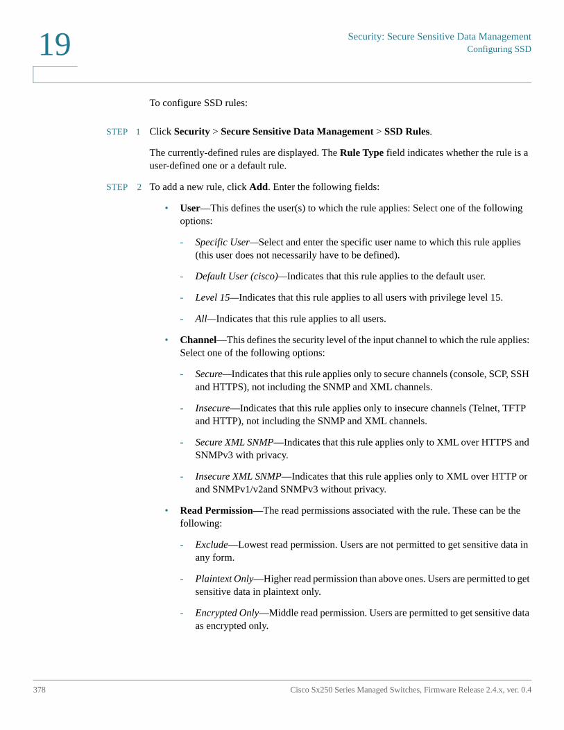
Security: Secure Sensitive Data ManagementConfiguring SSD
378 Cisco Sx250 Series Managed Switches, Firmware Release 2.4.x, ver. 0.4
19
To configure SSD rules:
STEP 1 Click Security > Secure Sensitive Data Management > SSD Rules.
The currently-defined rules are displayed. The Rule Type field indicates whether the rule is a user-defined one or a default rule.
STEP 2 To add a new rule, click Add. Enter the following fields:
• User—This defines the user(s) to which the rule applies: Select one of the following options:
- Specific User—Select and enter the specific user name to which this rule applies (this user does not necessarily have to be defined).
- Default User (cisco)—Indicates that this rule applies to the default user.
- Level 15—Indicates that this rule applies to all users with privilege level 15.
- All—Indicates that this rule applies to all users.
• Channel—This defines the security level of the input channel to which the rule applies: Select one of the following options:
- Secure—Indicates that this rule applies only to secure channels (console, SCP, SSH and HTTPS), not including the SNMP and XML channels.
- Insecure—Indicates that this rule applies only to insecure channels (Telnet, TFTP and HTTP), not including the SNMP and XML channels.
- Secure XML SNMP—Indicates that this rule applies only to XML over HTTPS and SNMPv3 with privacy.
- Insecure XML SNMP—Indicates that this rule applies only to XML over HTTP or and SNMPv1/v2and SNMPv3 without privacy.
• Read Permission—The read permissions associated with the rule. These can be the following:
- Exclude—Lowest read permission. Users are not permitted to get sensitive data in any form.
- Plaintext Only—Higher read permission than above ones. Users are permitted to get sensitive data in plaintext only.
- Encrypted Only—Middle read permission. Users are permitted to get sensitive data as encrypted only.
Security: Secure Sensitive Data Management
Configuring SSD
Cisco Sx250 Series Managed Switches, Firmware Release 2.4.x, ver. 0.4 379
19
- Both (Plaintext and Encrypted)—Highest read permission. Users have both encrypted and plaintext permissions and are permitted to get sensitive data as encrypted and in plaintext
• Default Read Mode—All default read modes are subjected to the read permission of the rule. The following options exist, but some might be rejected, depending on the rule’s read permission.
- Exclude—Do not allow reading the sensitive data.
- Encrypted—Sensitive data is presented encrypted.
- Plaintext—Sensitive data is presented as plaintext.
STEP 3 Click Apply. The settings are saved to the Running Configuration file.
STEP 4 The following actions can be performed on selected rules:
• Add, Edit or Delete rules or Restore to Default.
• Restore All Rules to Default—Restore a user-modified default rule to the default rule.
20
Cisco Sx250 Series Managed Switches, Firmware Release 2.4.x, ver. 0.4 380
Security: SSH Server
This section describes how to establish an SSH session on the device.
It covers the following topics:
• Overview
• Common Tasks
• SSH User Authentication
• SSH Server Authentication
Overview
The SSH Server feature enables a remote users to establish SSH sessions to the device. This is similar to establishing a telnet session, except the session is secured.
The device, as a SSH server, supports SSH User Authentication which authenticates a remote user either by password, or by public key. At the same time, the remote user as a SSH client can perform SSH Server Authentication to authenticate the device using the device public key (fingerprint).
SSH Server can operate in the following modes:
• By Internally-generated RSA/DSA Keys (Default Setting)—An RSA and a DSA key are generated. Users log on the SSH Server application and are automatically authenticated to open a session on the device when they supply the IP address of the device.
• Public Key Mode—Users are defined on the device. Their RSA/DSA keys are generated in an external SSH server application, such as PuTTY. The public keys are entered in the device. The users can then open an SSH session on the device through the external SSH server application.
Security: SSH Server
Common Tasks
Cisco Sx250 Series Managed Switches, Firmware Release 2.4.x, ver. 0.4 381
20
Common Tasks
This section describes some common tasks performed using the SSH Server feature.
Workflow1: Create an SSH session with no SSH user authentication, perform the following:
STEP 1 Enable SSH server in the TCP/UDP Services page.
STEP 2 Disable SSH user authentication by password and by public key in the SSH User Authentication page.
STEP 3 Establish SSH sessions to the device from a SSH client application such as PUTTY.
Workflow2: To create an SSH session with SSH user authentication by password, perform the following steps:
STEP 1 Enable SSH server in the TCP/UDP Services page.
STEP 2 Enable SSH User authentication by password in the SSH User Authentication page.
STEP 3 Establish SSH sessions to the device from a SSH client application such as PUTTY.
Workflow3: Create an SSH session with SSH user authentication by public key with/without bypassing management authentication, perform the following steps:
STEP 1 Enable SSH server in the TCP/UDP Services page.
STEP 2 Enable SSH User authentication by public key in the SSH User Authentication page. The public key must have already been created at the SSH client and will be used by the SSH client to establish a SSH session to the SSH server on the device.
STEP 3 Enable Automatic Login by passing management authentication if required in the SSH User Authentication page.
STEP 4 Add the users and their public key into to SSH User Authentication Table in the SSH User Authentication page.
STEP 5 Establish SSH sessions to the device from a SSH client application such as PUTTY.
Security: SSH ServerSSH User Authentication
382 Cisco Sx250 Series Managed Switches, Firmware Release 2.4.x, ver. 0.4
20
SSH User Authentication
Use the SSH User Authentication page to enable SSH user authentication by public key and/or password. For a user using public key to establish an SSH server, its user name and public key must be entered into the SSH User Authentication Table. For a user using password to establish a SSH session, the user name and password must be that of a user that has management access.
Before you can add a user, you must generate an RSA or DSA key for the user in the external SSH key generation/client application (such as PuTTY).
Automatic Login
If you use the SSH User Authentication page to create an SSH username for a user who is already configured in the local user database. You can prevent additional authentication by configuring the Automatic Login feature, which works as follows:
• Enabled—If a user is defined in the local database, and this user passed SSH Authentication using a public-key, the authentication by the local database username and password is skipped.
NOTE The configured authentication method for this specific management method (console, Telnet, SSH and so on) must be Local (i.e. not RADIUS or TACACS+). See Management Access Method for more details).
• Not Enabled—After successful authentication by SSH public key, even if the username is configured in the local user database, the user is authenticated again, as per the configured authentication methods, configured on the Management Access Authentication page.
This page is optional. You do not have to work with user authentication in SSH.
To enable authentication and add a user.
STEP 1 Click Security > SSH Server > SSH User Authentication.
STEP 2 Select the following fields:
• SSH User Authentication by Password—Select to perform authentication of the SSH client user using the username/password configured in the local database (see User Accounts).
• SSH User Authentication by Public Key—Select to perform authentication of the SSH client user using the public key.
Security: SSH Server
SSH Server Authentication
Cisco Sx250 Series Managed Switches, Firmware Release 2.4.x, ver. 0.4 383
20
• Automatic Login—This field can be enabled if the SSH User Authentication by Public Key feature was selected.
STEP 3 Click Apply. The settings are saved to the Running Configuration file.
The following fields are displayed for the configured users:
• SSH User Name—User name of user.
• Key Type—Whether this is an RSA or DSA key.
• Fingerprint—Fingerprint generated from the public keys.
STEP 4 Click Add to add a new user and enter the fields:
• SSH User Name—Enter a user name.
• Key Type—Select either RSA or DSA.
• Public Key—Copy the public key generated by an external SSH client application (like PuTTY) into this text box.
STEP 5 Click Apply to save the new user.
The following fields are displayed for all active users:
• IP Address—IP address of the active user.
• SSH User Name—User name of the active user.
• SSH Version—Version of SSH used by the active user.
• Cipher—Cipher of the active user.
• Authentication Code—Authentication code of the active user.
SSH Server Authentication
A remote SSH client can perform SSH Server Authentication to ensure it is establishing a SSH session to the expected SSH driver. To perform SSH Server Authentication, the remote SSH client must have a copy of the SSH server public key (or fingerprint) of the target SSH server
Security: SSH ServerSSH Server Authentication
384 Cisco Sx250 Series Managed Switches, Firmware Release 2.4.x, ver. 0.4
20
The SSH Server Authentication Page generates/imports the private/public key for the device as a SSH server. A user should copy the SSH server public key (or fingerprint) of this device to the application if it is to perform SSH Server Authentication on its SSH sessions. A public and private RSA and DSA key are automatically generated when the device is booted from factory defaults. Each key is also automatically created when the appropriate user-configured key is deleted by the user.
To regenerate an RSA or DSA key or to copy in an RSA/DSA key generated on another device:
STEP 1 Click Security > SSH Server > SSH Server Authentication.
The following fields are displayed for each key:
• Key Type—RSA or DSA.
• Key Source—Auto Generated or User Defined.
• Fingerprint—Fingerprint generated from the key.
STEP 2 Select either an RSA or DSA key.
STEP 3 You can perform any of the following actions:
• Generate—Generates a key of the selected type.
• Edit—Enables you to copy in a key from another device. Enter the following fields:
- Key Type—As described above.
- Public Key—Enter the public key.
- Private Key—Select either Encrypted or Plaintext and enter the private key.
Clicking Display Sensitive Data as Encrypted or Display Sensitive Data as Plaintext sets how sensitive data will be displayed.
• Delete—Enables you to delete a key.
• Details—Enables you to view the generated key. The Details window also enables you to click Display Sensitive Data as Plaintext. If this is clicked, the keys are displayed as plaintext and not in encrypted form. If the key is already being displayed as plaintext, you can click Display Sensitive Data as Encrypted. to display the text in encrypted form.
21
Cisco Sx250 Series Managed Switches, Firmware Release 2.4.x, ver. 0.4 385
Security: SSH Client
This section describes the device when it functions as an SSH client.
It covers the following topics:
• Overview
• SSH User Authentication
• SSH Server Authentication
• Change User Password on the SSH Server
Overview
Secure Copy (SCP) and SSH
Secure Shell or SSH is a network protocol that enables data to be exchanged on a secure channel between an SSH client (in this case, the device) and an SSH server.
SSH client helps the user manage a network composed of one or more switches in which various system files are stored on a central SSH server. When configuration files are transferred over a network, Secure Copy (SCP), which is an application that utilizes the SSH protocol, ensures that sensitive data, such as username/password cannot be intercepted.
Secure Copy (SCP) is used to securely transfer firmware, boot image, configuration files, language files, and log files from a central SCP server to a device.
With respect to SSH, the SCP running on the device is an SSH client application and the SCP server is a SSH server application.
When files are downloaded via TFTP or HTTP, the data transfer is unsecured.
When files are downloaded via SCP, the information is downloaded from the SCP server to the device via a secure channel. The creation of this secure channel is preceded by authentication, which ensures that the user is permitted to perform the operation.
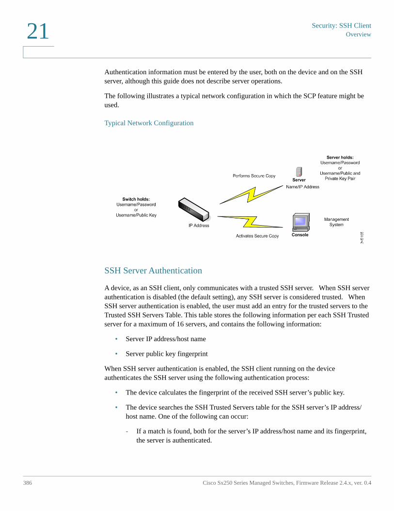
Security: SSH ClientOverview
386 Cisco Sx250 Series Managed Switches, Firmware Release 2.4.x, ver. 0.4
21
Authentication information must be entered by the user, both on the device and on the SSH server, although this guide does not describe server operations.
The following illustrates a typical network configuration in which the SCP feature might be used.
Typical Network Configuration
SSH Server Authentication
A device, as an SSH client, only communicates with a trusted SSH server. When SSH server authentication is disabled (the default setting), any SSH server is considered trusted. When SSH server authentication is enabled, the user must add an entry for the trusted servers to the Trusted SSH Servers Table. This table stores the following information per each SSH Trusted server for a maximum of 16 servers, and contains the following information:
• Server IP address/host name
• Server public key fingerprint
When SSH server authentication is enabled, the SSH client running on the device authenticates the SSH server using the following authentication process:
• The device calculates the fingerprint of the received SSH server’s public key.
• The device searches the SSH Trusted Servers table for the SSH server’s IP address/host name. One of the following can occur:
- If a match is found, both for the server’s IP address/host name and its fingerprint, the server is authenticated.
Security: SSH Client
Overview
Cisco Sx250 Series Managed Switches, Firmware Release 2.4.x, ver. 0.4 387
21
- If a matching IP address/host name is found, but there is no matching fingerprint, the search continues. If no matching fingerprint is found, the search is completed and authentication fails.
- If no matching IP address/host name is found, the search is completed and authentication fails.
• If the entry for the SSH server is not found in the list of trusted servers, the process fails.
In order to support auto configuration of an out-of-box device (device with factory default configuration), SSH server authentication is disabled by default.
SSH User Authentication
When a device (SSH client) attempts to establish a SSH session to a SSH server, the SSH server uses various methods for client authentication. These are described below.
Passwords
To use the password method, first ensure that a username/password has been established on the SSH server. This is not done through the device’s management system, although, after a username has been established on the server, the server password can be changed through the device’s management system.
The username/password must then be created on the device. When the device tries to establish a SSH session to a SSH server, the username/password supplied by the device must match the username/password on the server.
Data can be encrypted using a one-time symmetric key negotiated during the session.
Each device being managed must have its own username/password, although the same username/password can be used for multiple switches.
The password method is the default method on the device.
Public/Private Keys
To use the public/private key method for client authentication by a SSH server, create a user and generate/import a public/private key pair on the device which is a SSH client. Then create the same user at the SSH server and copy the public key (or fingerprint) generated/entered at the SSH client to the SSH server. The action of creating the user and copy the public key (or fingerprint) to the SSH server is beyond the scope of this guide.
Security: SSH ClientOverview
388 Cisco Sx250 Series Managed Switches, Firmware Release 2.4.x, ver. 0.4
21
RSA and DSA default key pairs are generated for the device when it is booted. One of these keys is used to encrypt the data being downloaded from the SSH server. The RSA key is used by default.
If the user deletes one or both of these keys, they are regenerated.
The public/private keys are encrypted and stored in the device memory. The keys are part of the device configuration file, and the private key can be displayed to the user, in encrypted or plaintext form.
Since the private key cannot be copied directly to the private key of another device, an import method exists that enables copying private keys from device to device (described in Import Keys).
Import Keys
In the key method, individual public/private keys must be created for each individual device, and these private keys cannot be copied directly from one device to another because of security considerations.
If there are multiple switches in the network, the process of creating public/private keys for all the switches might be time-consuming, because each public/private key must be created and then loaded onto the SSH server.
To facilitate this process, an additional feature enables secure transfer of the encrypted private key to all switches in the system.
When a private key is created on a device, it is also possible to create an associated passphrase. This passphrase is used to encrypt the private key and to import it into the remaining switches. In this way, all the switches can use the same public/private key.
Default Password
SSH user authentication by password is enabled by default, with the username/password being “anonymous”.
The user must configure the following information for authentication:
• The authentication method to be used.
• The username/password or public/private key pair.
Supported Algorithms
When the connection between a device (as an SSH client) and an SSH server is established, the client and SSH server exchange data in order to determine the algorithms to use in the SSH transport layer.
Security: SSH Client
Overview
Cisco Sx250 Series Managed Switches, Firmware Release 2.4.x, ver. 0.4 389
21
The following algorithms are supported on the client side:
• Key Exchange Algorithm-diffie-hellman
• Encryption Algorithms
- aes128-ctr
- aes192-ctr
- aes256-ctr
- Chacha
- Poly1305
• Message Authentication Code Algorithms
- hmac-sha1
NOTE Compression algorithms are not supported.
Before You Begin
The following actions must be performed before using the SCP feature:
• When using the password authentication method, a username/password must be set up on the SSH server.
• When using public/private keys authentication method, the public key must be stored on the SSH server.
Common Tasks
This section describes some common tasks performed by the device as a SSH client. All pages referenced are pages found under the SSH Client branch of the menu tree.
Security: SSH ClientOverview
390 Cisco Sx250 Series Managed Switches, Firmware Release 2.4.x, ver. 0.4
21
Workflow1: To configure SSH client and transfer data to/from a remote SSH server, perform the following steps:
STEP 1 Decide which method is to be used: password or public/private key. Use the SSH User Authentication page.
STEP 2 If the password method was selected, perform the following steps:
a. Create a global password in the SSH User Authentication page, or create a temporary one in the Firmware Operations or File Operations pages, when you actually activate the secure data transfer.
b. Upgrade the firmware, boot image or language file, using SCP, by selecting the SCP option in the Firmware Operations page. The password can be entered in this page directly, or the password entered in the SSH User Authentication page can be used.
c. Download/backup the configuration file, using SCP, by selecting the via SCP (over SSH) option in the File Operations page. The password can be entered in this page directly, or the password entered in the SSH User Authentication page can be used.
STEP 3 Set up a username/password or modify the password on the remote SSH server. This activity depends on the server and is not described here.
STEP 4 If the public/private key method is being used, perform the following steps:
a. Select whether to use an RSA or DSA key, create a username and then generate the public/private keys.
b. View the generated key by clicking the Details button, and transfer the username and public key to the SSH server. This action depends on the server and is not described in this guide.
c. Upgrade/backup the firmware, using SCP, by selecting the SCP option in the Firmware Operations page.
d. Download/backup the configuration file, using SCP, by selecting the SCP option in the File Operations page.
Workflow2: To import the public/private keys from one device to another:
STEP 1 Generate a public/private key in theSSH User Authentication page.
STEP 2 Set the SSD properties and create a new local passphrase in the SSD Properties page.
STEP 3 Click Details to view the generated, encrypted keys, and copy them (including the Begin and End footers) from the Details page to an external device. Copy the public and private keys separately.
Security: SSH Client
SSH User Authentication
Cisco Sx250 Series Managed Switches, Firmware Release 2.4.x, ver. 0.4 391
21
STEP 4 Log on to another device and open the SSH User Authentication page. Select the type of key required and click Edit. Paste in the public/private keys.
STEP 5 Click Apply to copy the public/private keys onto the second device.
Workflow3: To change your password on an SSH server:
STEP 1 Identify the server in the Change User Password on the SSH Server page.
STEP 2 Enter the new password.
STEP 3 Click Apply.
SSH User Authentication
Use this page to select an SSH user authentication method, set a username and password on the device, if the password method is selected or generate an RSA or DSA key, if the public/private key method is selected.
To select an authentication method, and set the username/password/keys.
STEP 1 Click Security > SSH Client > SSH User Authentication.
STEP 2 Select an SSH User Authentication Method. This is the global method defined for the secure copy (SCP). Select one of the options:
• By Password—This is the default setting. If this is selected, enter a password or retain the default one.
• By RSA Public Key—If this is selected, create an RSA public and Private key in the SSH User Key Table block.
• By DSA Public Key—If this is selected, create a DSA public/private key in the SSH User Key Table block.
STEP 3 Enter the Username (no matter what method was selected) or user the default username. This must match the username defined on the SSH server.
STEP 4 If the By Password method was selected, enter a password (Encrypted or Plaintext) or leave the default encrypted password.
STEP 5 Perform one of the following actions:
• Apply—The selected authentication methods are associated with the access method.
Security: SSH ClientSSH Server Authentication
392 Cisco Sx250 Series Managed Switches, Firmware Release 2.4.x, ver. 0.4
21
• Restore Default Credentials—The default username and password (anonymous) are restored.
• Display Sensitive Data As Plaintext—Sensitive data for the current page appears as plaintext.
The SSH User Key Table contains the following fields for each key:
• Key Type—RSA or DSA.
• Key Source—Auto Generated or User Defined.
• Fingerprint—Fingerprint generated from the key.
STEP 6 To handle an RSA or DSA key, select either RSA or DSA and perform one of the following actions:
• Generate—Generate a new key.
• Edit—Display the keys for copying/pasting to another device.
• Delete—Delete the key.
• Details—Display the keys.
SSH Server Authentication
To enable SSH server authentication and define the trusted servers:
STEP 1 Click Security > SSH Client > SSH Server Authentication.
STEP 2 Select Enable to enable SSH server authentication.
• IPv4 Source Interface—Select the source interface whose IPv4 address will be used as the source IPv4 address for messages used in communication with IPv4 SSH servers.
• IPv6 Source Interface—Select the source interface whose IPv6 address will be used as the source IPv6 address for messages used in communication with IPv6 SSH servers.
NOTE If the Auto option is selected, the system takes the source IP address from the IP address defined on the outgoing interface.
STEP 3 Click Apply.
Security: SSH Client
SSH Server Authentication
Cisco Sx250 Series Managed Switches, Firmware Release 2.4.x, ver. 0.4 393
21
STEP 4 Click Add and enter the following fields for the SSH trusted server:
• Server Definition—Select one of the following ways to identify the SSH server:
- By IP address—If this is selected enter the IP address of the server in the fields below.
- By name—If this is selected enter the name of the server in the Server IP Address/Name field.
• IP Version—If you selected to specify the SSH server by IP address, select whether that IP address is an IPv4 or IPv6 address.
• IPv6 Address Type—If the SSH server IP address is an IPv6 address, select the IPv6 address type. The options are:
- Link Local—The IPv6 address uniquely identifies hosts on a single network link. A link local address has a prefix of FE80, is not routable, and can be used for communication only on the local network. Only one link local address is supported. If a link local address exists on the interface, this entry replaces the address in the configuration.
- Global—The IPv6 address is a global Unicast IPV6 type that is visible and reachable from other networks.
• Link Local Interface—Select the link local interface from the list of interfaces.
• Server IP Address/Name—Enter either the IP address of the SSH server or its name, depending on what was selected in Server Definition.
• Fingerprint—Enter the fingerprint of the SSH server (copied from that server).
STEP 5 Click Apply. The trusted server definition is stored in the Running Configuration file.
Security: SSH ClientChange User Password on the SSH Server
394 Cisco Sx250 Series Managed Switches, Firmware Release 2.4.x, ver. 0.4
21
Change User Password on the SSH Server
To change the password on the SSH server:
STEP 1 Click Security > SSH Client > Change User Password on SSH Server.
STEP 2 Enter the following fields:
• Server Definition—Define the SSH server by selecting either By IP Address or By Name. Enter the server name or IP address of the server in the Server IP Address/Name field.
• IP Version—If you selected to specify the SSH server by IP address, select whether that IP address is an IPv4 or IPv6 address.
• IPv6 Address Type—If the SSH server IP address is an IPv6 address, select the IPv6 address type. The options are:
- Link Local—The IPv6 address uniquely identifies hosts on a single network link. A link local address has a prefix of FE80, is not routable, and can be used for communication only on the local network. Only one link local address is supported. If a link local address exists on the interface, this entry replaces the address in the configuration.
- Global—The IPv6 address is a global Unicast IPV6 type that is visible and reachable from other networks.
• Link Local Interface—Select the link local interface from the list of interfaces.
• Server IP Address/Name—Enter either the IP address of the SSH server or its name, depending on what was selected in Server Definition.
• Username—This must match the username on the server.
• Old Password—This must match the password on the server.
• New Password—Enter the new password and confirm it in the Confirm Password field.
STEP 3 Click Apply. The password on the SSH server is modified.
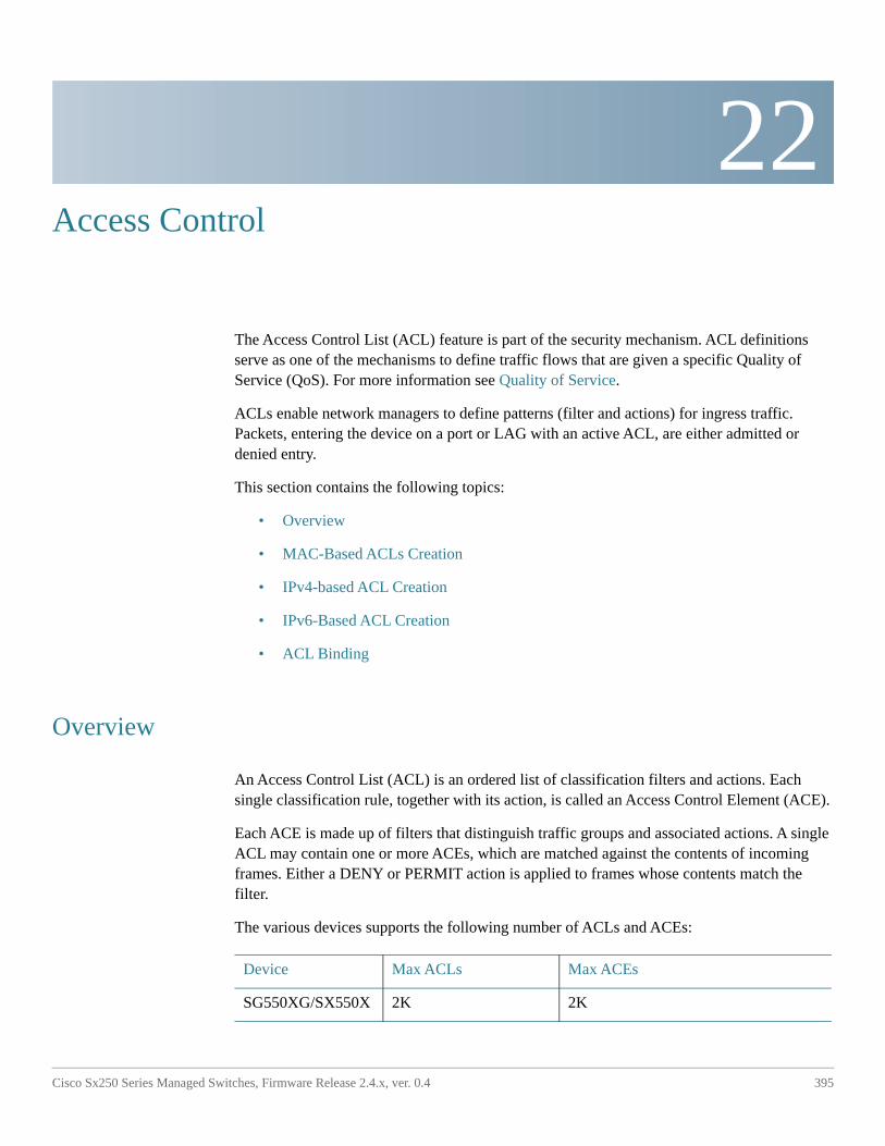
22
Cisco Sx250 Series Managed Switches, Firmware Release 2.4.x, ver. 0.4 395
Access Control
The Access Control List (ACL) feature is part of the security mechanism. ACL definitions serve as one of the mechanisms to define traffic flows that are given a specific Quality of Service (QoS). For more information see Quality of Service.
ACLs enable network managers to define patterns (filter and actions) for ingress traffic. Packets, entering the device on a port or LAG with an active ACL, are either admitted or denied entry.
This section contains the following topics:
• Overview
• MAC-Based ACLs Creation
• IPv4-based ACL Creation
• IPv6-Based ACL Creation
• ACL Binding
Overview
An Access Control List (ACL) is an ordered list of classification filters and actions. Each single classification rule, together with its action, is called an Access Control Element (ACE).
Each ACE is made up of filters that distinguish traffic groups and associated actions. A single ACL may contain one or more ACEs, which are matched against the contents of incoming frames. Either a DENY or PERMIT action is applied to frames whose contents match the filter.
The various devices supports the following number of ACLs and ACEs:
Device Max ACLs Max ACEs
SG550XG/SX550X 2K 2K
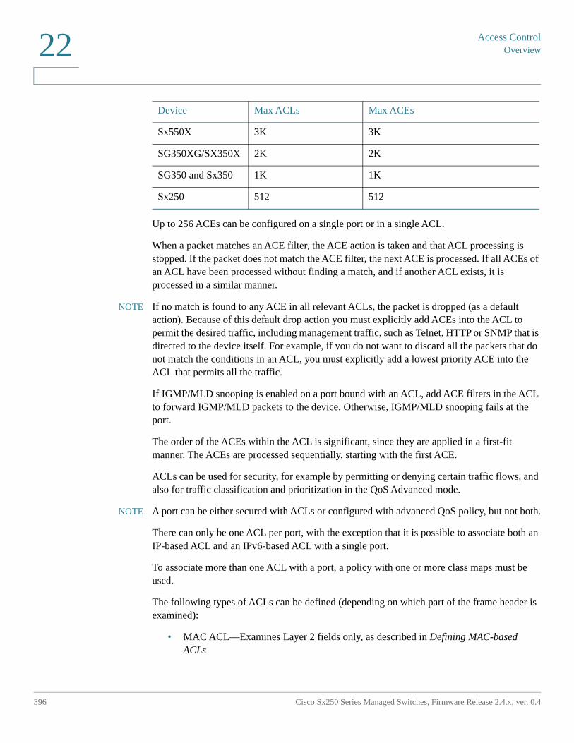
Access ControlOverview
396 Cisco Sx250 Series Managed Switches, Firmware Release 2.4.x, ver. 0.4
22
Up to 256 ACEs can be configured on a single port or in a single ACL.
When a packet matches an ACE filter, the ACE action is taken and that ACL processing is stopped. If the packet does not match the ACE filter, the next ACE is processed. If all ACEs of an ACL have been processed without finding a match, and if another ACL exists, it is processed in a similar manner.
NOTE If no match is found to any ACE in all relevant ACLs, the packet is dropped (as a default action). Because of this default drop action you must explicitly add ACEs into the ACL to permit the desired traffic, including management traffic, such as Telnet, HTTP or SNMP that is directed to the device itself. For example, if you do not want to discard all the packets that do not match the conditions in an ACL, you must explicitly add a lowest priority ACE into the ACL that permits all the traffic.
If IGMP/MLD snooping is enabled on a port bound with an ACL, add ACE filters in the ACL to forward IGMP/MLD packets to the device. Otherwise, IGMP/MLD snooping fails at the port.
The order of the ACEs within the ACL is significant, since they are applied in a first-fit manner. The ACEs are processed sequentially, starting with the first ACE.
ACLs can be used for security, for example by permitting or denying certain traffic flows, and also for traffic classification and prioritization in the QoS Advanced mode.
NOTE A port can be either secured with ACLs or configured with advanced QoS policy, but not both.
There can only be one ACL per port, with the exception that it is possible to associate both an IP-based ACL and an IPv6-based ACL with a single port.
To associate more than one ACL with a port, a policy with one or more class maps must be used.
The following types of ACLs can be defined (depending on which part of the frame header is examined):
• MAC ACL—Examines Layer 2 fields only, as described in Defining MAC-based ACLs
Sx550X 3K 3K
SG350XG/SX350X 2K 2K
SG350 and Sx350 1K 1K
Sx250 512 512
Device Max ACLs Max ACEs
Access Control
Overview
Cisco Sx250 Series Managed Switches, Firmware Release 2.4.x, ver. 0.4 397
22
• IP ACL—Examines the Layer 3 layer of IP frames, as described in IPv4-based ACLs
• IPv6 ACL—Examines the Layer 3 layer of IPv4 frames as described in Defining IPv6-Based ACL
If a frame matches the filter in an ACL, it is defined as a flow with the name of that ACL. In advanced QoS, these frames can be referred to using this Flow name, and QoS can be applied to these frames.
ACL Logging
This feature enables adding a logging option to ACEs. When the feature is enabled, any packet that was permitted or denied by the ACE, generates an informational SYSLOG message related to it.
If ACL logging is enabled, it can be specified per interface by binding the ACL to an interface. In this case, SYSLOGs are generated for packets that matched the permit or deny ACEs associated with the interface.
A flow is defined as a stream of packets with identical characteristics, as follows:
• Layer 2 Packets—Identical source and destination MAC addresses
• Layer 3 Packets—Identical source and destination IP addresses
• Layer 4 Packets—Identical source and destination IP and L4 port
For any new flow, the first packet that is trapped from a specific interface causes the generation of an informational SYSLOG message. Additional packets from the same flow are trapped to the CPU, but SYSLOG messages for this flow are limited to one message every 5 minutes. This SYSLOG informs that at least one packet was trapped in the last 5 minutes.
After handling the trapped packet, the packets are forwarded in case of permit and discarded in case of deny.
The number of supported flows is 150 flows per unit:
SYSLOGs
The SYSLOG messages are in Informational severity, and state if the packet matched a deny rule or a permit rule.
• For layer 2 packets, the SYSLOG includes the information (if applicable): source MAC, destination MAC, Ethertype, VLAN-ID, and CoS queue.
• For Layer 3 packets, the SYSLOG includes the information (if applicable): source IP, destination IP address, protocol, DSCP value, ICMP type, ICMP code, and IGMP type.
Access ControlOverview
398 Cisco Sx250 Series Managed Switches, Firmware Release 2.4.x, ver. 0.4
22
• For Layer 4 packets the SYSLOG includes the information (if applicable): source port, destination port, and TCP flag.
The following are examples of possible SYSLOGs:
• For a non-IP packet:
- 06-Jun-2013 09:49:56 %3SWCOS-I-LOGDENYMAC: gi0/1: deny ACE 00:00:00:00:00:01 -> ff:ff:ff:ff:ff:ff, Ethertype-2054, VLAN-20, CoS-4, trapped
• For an IP packet (v4 and v6):
- 06-Jun-2013 12:38:53 %3SWCOS-I-LOGDENYINET: gi0/1: deny ACE IPv4(255) 1.1.1.1 -> 1.1.1.10, protocol-1, DSCP-54, ICMP Type-Echo Reply, ICMP code-5 , trapped
• For an L4 packet:
- 06-Jun-2013 09:53:46 %3SWCOS-I-LOGDENYINETPORTS: gi0/1: deny ACE IPv4(TCP) 1.1.1.1(55) -> 1.1.1.10(66), trapped
Configuring ACLs
This section describes how to create ACLs and add rules (ACEs) to them.
Creating ACLs Workflow
To create ACLs and associate them with an interface, perform the following:
1. Create one or more of the following types of ACLs:
a. MAC-based ACL by using the MAC-Based ACL page and the MAC-based ACE page
b. IP-based ACL by using the IPv4-based ACL page and the IPv4-Based ACE page
c. IPv6-based ACL by using the IPv6-Based ACL page and the IPv6-Based ACE page
2. Associate the ACL with interfaces by using the ACL Binding (VLAN) or ACL Binding (Port) page.
Access Control
MAC-Based ACLs Creation
Cisco Sx250 Series Managed Switches, Firmware Release 2.4.x, ver. 0.4 399
22
Modifying ACLs Workflow
An ACL can only be modified if it is not in use. The following describes the process of unbinding an ACL in order to modify it:
1. If the ACL does not belong to a QoS Advanced Mode class map, but it has been associated with an interface, unbind it from the interface using the ACL Binding (VLAN) or ACL Binding (Port) page.
2. If the ACL is part of the class map and not bound to an interface, then it can be modified.
3. If the ACL is part of a class map contained in a policy bound to an interface, you must perform the chain of unbinding as follows:
• Unbind the policy containing the class map from the interface by using Policy Binding.
• Delete the class map containing the ACL from the policy using the Configuring a Policy (Edit).
• Delete the class map containing the ACL, by using Defining Class Mapping.
Only then can the ACL be modified, as described in this section.
MAC-Based ACLs Creation
MAC-based ACLs are used to filter traffic based on Layer 2 fields. MAC-based ACLs check all frames for a match.
MAC-based ACLs are defined in the MAC-Based ACL page. The rules are defined in the MAC-based ACE page.
MAC-Based ACL
To define a MAC-based ACL:
STEP 1 Click Access Control > MAC-Based ACL.
This page contains a list of all currently-defined MAC-based ACLs.
STEP 2 Click Add.
STEP 3 Enter the name of the new ACL in the ACL Name field. ACL names are case-sensitive.
STEP 4 Click Apply. The MAC-based ACL is saved to the Running Configuration file.
Access ControlMAC-Based ACLs Creation
400 Cisco Sx250 Series Managed Switches, Firmware Release 2.4.x, ver. 0.4
22
MAC-based ACE
NOTE Each MAC-based rule consumes one TCAM rule. Note that the TCAM allocation is performed in couples, such that, for the first ACE, 2 TCAM rules are allocated and the second TCAM rule is allocated to the next ACE, and so forth.
To add rules (ACEs) to an ACL:
STEP 1 Click Access Control > Mac-Based ACE.
STEP 2 Select an ACL, and click Go. The ACEs in the ACL are listed.
STEP 3 Click Add.
STEP 4 Enter the parameters.
• ACL Name—Displays the name of the ACL to which an ACE is being added.
• Priority—Enter the priority of the ACE. ACEs with higher priority are processed first. One is the highest priority.
• Action—Select the action taken upon a match. The options are:
- Permit—Forward packets that meet the ACE criteria.
- Deny—Drop packets that meet the ACE criteria.
- Shutdown—Drop packets that meet the ACE criteria, and disable the port from where the packets received. Such ports can be reactivated from the Error Recovery Settings page.
• Logging—Select to enable logging ACL flows that match the ACL rule.
• Time Range—Select to enable limiting the use of the ACL to a specific time range.
• Time Range Name—If Time Range is selected, select the time range to be used. Time ranges are defined in the System Time Configuration section.
• Destination MAC Address—Select Any if all destination addresses are acceptable or User defined to enter a destination address or a range of destination addresses.
• Destination MAC Address Value—Enter the MAC address to which the destination MAC address is to be matched and its mask (if relevant).
• Destination MAC Wildcard Mask—Enter the mask to define a range of MAC addresses. Note that this mask is different than in other uses, such as subnet mask. Here, setting a bit as 1 indicates don't care and 0 indicates to mask that value.
Access Control
IPv4-based ACL Creation
Cisco Sx250 Series Managed Switches, Firmware Release 2.4.x, ver. 0.4 401
22
NOTE Given a mask of 0000 0000 0000 0000 0000 0000 1111 1111 (which means that you match on the bits where there is 0 and don't match on the bits where there are 1's). You need to translate the 1's to a decimal integer and you write 0 for each four zeros. In this example since 1111 1111 = 255, the mask would be written: as 0.0.0.255.
• Source MAC Address—Select Any if all source address are acceptable or User defined to enter a source address or range of source addresses.
• Source MAC Address Value—Enter the MAC address to which the source MAC address is to be matched and its mask (if relevant).
• Source MAC Wildcard Mask—Enter the mask to define a range of MAC addresses.
• VLAN ID—Enter the VLAN ID section of the VLAN tag to match.
• 802.1p—Select Include to use 802.1p.
• 802.1p Value—Enter the 802.1p value to be added to the VPT tag.
• 802.1p Mask—Enter the wildcard mask to be applied to the VPT tag.
• Ethertype—Enter the frame Ethertype to be matched.
STEP 5 Click Apply. The MAC-based ACE is saved to the Running Configuration file.
IPv4-based ACL Creation
IPv4-based ACLs are used to check IPv4 packets, while other types of frames, such as ARPs, are not checked.
The following fields can be matched:
• IP protocol (by name for well-known protocols, or directly by value)
• Source/destination ports for TCP/UDP traffic
• Flag values for TCP frames
• ICMP and IGMP type and code
• Source/destination IP addresses (including wildcards)
• DSCP/IP-precedence value
NOTE ACLs are also used as the building elements of flow definitions for per-flow QoS handling.
Access ControlIPv4-based ACL Creation
402 Cisco Sx250 Series Managed Switches, Firmware Release 2.4.x, ver. 0.4
22
The IPv4-based ACL page enables adding ACLs to the system. The rules are defined in the IPv4-Based ACE page.
IPv6 ACLs are defined in the IPv6 Based ACL page.
IPv4-based ACL
To define an IPv4-based ACL:
STEP 1 Click Access Control > IPv4-Based ACL.
This page contains all currently defined IPv4-based ACLs.
STEP 2 Click Add.
STEP 3 Enter the name of the new ACL in the ACL Name field. The names are case-sensitive.
STEP 4 Click Apply. The IPv4-based ACL is saved to the Running Configuration file.
IPv4-Based ACE
NOTE Each IPv4-based rule consumes one TCAM rule. Note that the TCAM allocation is performed in couples, such that, for the first ACE, 2 TCAM rules are allocated and the second TCAM rule is allocated to the next ACE, and so forth.
To add rules (ACEs) to an IPv4-based ACL:
STEP 1 Click Access Control > IPv4-Based ACE.
STEP 2 Select an ACL, and click Go. All currently-defined IP ACEs for the selected ACL are displayed.
STEP 3 Click Add.
STEP 4 Enter the parameters.
• ACL Name—Displays the name of the ACL.
• Priority—Enter the priority. ACEs with higher priority are processed first.
• Action—Select the action assigned to the packet matching the ACE. The options are as follows:
- Permit—Forward packets that meet the ACE criteria.
Access Control
IPv4-based ACL Creation
Cisco Sx250 Series Managed Switches, Firmware Release 2.4.x, ver. 0.4 403
22
- Deny—Drop packets that meet the ACE criteria.
- Shutdown—Drop packet that meets the ACE criteria and disable the port to which the packet was addressed. Ports are reactivated from the Error Recovery Settings page.
• Logging—Select to enable logging ACL flows that match the ACL rule.
• Time Range—Select to enable limiting the use of the ACL to a specific time range.
• Time Range Name—If Time Range is selected, select the time range to be used. Time ranges are defined in the System Time Configuration section.
• Protocol—Select to create an ACE based on a specific protocol or protocol ID. Select Any (IPv4) to accept all IP protocols. Otherwise select one of the following protocols from the drop-down list Selected from list:
- ICMP—Internet Control Message Protocol
- IGMP—Internet Group Management Protocol
- IP in IP—IP in IP encapsulation
- TCP—Transmission Control Protocol
- EGP—Exterior Gateway Protocol
- IGP—Interior Gateway Protocol
- UDP—User Datagram Protocol
- HMP—Host Mapping Protocol
- RDP—Reliable Datagram Protocol.
- IDPR—Inter-Domain Policy Routing Protocol
- IPV6—IPv6 over IPv4 tunneling
- IPV6:ROUT—Matches packets belonging to the IPv6 over IPv4 route through a gateway
- IPV6:FRAG—Matches packets belonging to the IPv6 over IPv4 Fragment Header
- IDRP—Inter-Domain Routing Protocol
- RSVP—ReSerVation Protocol
- AH—Authentication Header
- IPV6:ICMP—Internet Control Message Protocol
Access ControlIPv4-based ACL Creation
404 Cisco Sx250 Series Managed Switches, Firmware Release 2.4.x, ver. 0.4
22
- EIGRP—Enhanced Interior Gateway Routing Protocol
- OSPF—Open Shortest Path First
- IPIP—IP in IP
- PIM—Protocol Independent Multicast
- L2TP—Layer 2 Tunneling Protocol
- ISIS—IGP-specific protocol
- Protocol ID to Match—Instead of selecting the name, enter the protocol ID.
• Source IP Address—Select Any if all source address are acceptable or User defined to enter a source address or range of source addresses.
• Source IP Address Value—Enter the IP address to which the source IP address is to be matched.
• Source IP Wildcard Mask—Enter the mask to define a range of IP addresses. Note that this mask is different than in other uses, such as subnet mask. Here, setting a bit as 1 indicates don't care and 0 indicates to mask that value.
NOTE Given a mask of 0000 0000 0000 0000 0000 0000 1111 1111 (which means that you match on the bits where there is 0 and don't match on the bits where there are 1's). You need to translate the 1's to a decimal integer and you write 0 for each four zeros. In this example since 1111 1111 = 255, the mask would be written: as 0.0.0.255.
• Destination IP Address—Select Any if all destination address are acceptable or User defined to enter a destination address or range of destination addresses.
• Destination IP Address Value—Enter the IP address to which the destination IP address is to be matched.
• Destination IP Wildcard Mask—Enter the mask to define a range of IP addresses.
• Source Port—Select one of the following:
- Any—Match to all source ports.
- Single from list—Select a single TCP/UDP source port to which packets are matched. This field is active only if 800/6-TCP or 800/17-UDP is selected in the Select from List drop-down menu.
- Single by number—Enter a single TCP/UDP source port to which packets are matched. This field is active only if 800/6-TCP or 800/17-UDP is selected in the Select from List drop-down menu.
Access Control
IPv4-based ACL Creation
Cisco Sx250 Series Managed Switches, Firmware Release 2.4.x, ver. 0.4 405
22
- Range—Select a range of TCP/UDP source ports to which the packet is matched. There are eight different port ranges that can be configured (shared between source and destination ports). TCP and UDP protocols each have eight port ranges.
• Destination Port—Select one of the available values. These are the same as the Source Port field described above.
NOTE You must specify the IP protocol for the ACE before you can enter the source and/or destination port.
• TCP Flags—Select one or more TCP flags with which to filter packets. Filtered packets are either forwarded or dropped. Filtering packets by TCP flags increases packet control, which increases network security.
• Type of Service—The service type of the IP packet.
- Any—Any service type
- DSCP to Match—Differentiated Serves Code Point (DSCP) to match
- IP Precedence to match—IP precedence is a model of TOS (type of service) that the network uses to help provide the appropriate QoS commitments. This model uses the 3 most significant bits of the service type byte in the IP header, as described in RFC 791 and RFC 1349.
• ICMP—If the IP protocol of the ACL is ICMP, select the ICMP message type used for filtering purposes. Either select the message type by name or enter the message type number:
- Any—All message types are accepted.
- Select from list—Select message type by name.
- ICMP Type to match—Number of message type to be used for filtering purposes.
• ICMP Code—The ICMP messages can have a code field that indicates how to handle the message. Select one of the following options to configure whether to filter on this code:
- Any—Accept all codes.
- User Defined—Enter an ICMP code for filtering purposes.
• IGMP—If the ACL is based on IGMP, select the IGMP message type to be used for filtering purposes. Either select the message type by name or enter the message type number:
- Any—All message types are accepted.
- Select from list—Select message type by name.
Access ControlIPv6-Based ACL Creation
406 Cisco Sx250 Series Managed Switches, Firmware Release 2.4.x, ver. 0.4
22
- IGMP Type to match—Number of message type that is to be used for filtering purposes.
STEP 5 Click Apply. The IPv4-based ACE is saved to the Running Configuration file.
IPv6-Based ACL Creation
The IPv6-Based ACL page displays and enables the creation of IPv6 ACLs, which check pure IPv6-based traffic. IPv6 ACLs do not check IPv6-over-IPv4 or ARP packets.
NOTE ACLs are also used as the building elements of flow definitions for per-flow QoS handling.
IPv6-Based ACL
To define an IPv6-based ACL:
STEP 1 Click Access Control > IPv6-Based ACL.
This window contains the list of defined ACLs and their contents
STEP 2 Click Add.
STEP 3 Enter the name of a new ACL in the ACL Name field. The names are case-sensitive.
STEP 4 Click Apply. The IPv6-based ACL is saved to the Running Configuration file.
IPv6-Based ACE
NOTE Each IPv6-based rule consumes two TCAM rules.
STEP 1 Click Access Control > IPv6-Based ACE.
This window contains the ACE (rules) for a specified ACL (group of rules).
STEP 2 Select an ACL, and click Go. All currently-defined IP ACEs for the selected ACL are displayed.
STEP 3 Click Add.
Access Control
IPv6-Based ACL Creation
Cisco Sx250 Series Managed Switches, Firmware Release 2.4.x, ver. 0.4 407
22
STEP 4 Enter the parameters.
• ACL Name—Displays the name of the ACL to which an ACE is being added.
• Priority—Enter the priority. ACEs with higher priority are processed first.
• Action—Select the action assigned to the packet matching the ACE. The options are as follows:
- Permit—Forward packets that meet the ACE criteria.
- Deny—Drop packets that meet the ACE criteria.
- Shutdown—Drop packets that meet the ACE criteria, and disable the port to which the packets addressed. Ports are reactivated from the Error Recovery Settings page.
• Logging—Select to enable logging ACL flows that match the ACL rule.
• Time Range—Select to enable limiting the use of the ACL to a specific time range.
• Time Range Name—If Time Range is selected, select the time range to be used. Time ranges are described in the System Time section.
• Protocol—Select to create an ACE based on a specific protocol. Select Any (IPv6) to accept all IP protocols.
Otherwise select one of the following protocols:
- TCP—Transmission Control Protocol. Enables two hosts to communicate and exchange data streams. TCP guarantees packet delivery, and guarantees that packets are transmitted and received in the order they sent.
- UDP—User Datagram Protocol. Transmits packets but does not guarantee their delivery.
- ICMP—Matches packets to the Internet Control Message Protocol (ICMP).
or
- Protocol ID to Match—Enter the ID of the protocol to be matched.
• Source IP Address—Select Any if all source address are acceptable or User defined to enter a source address or range of source addresses.
• Source IP Address Value—Enter the IP address to which the source IP address is to be matched and its mask (if relevant).
• Source IP Prefix Length—Enter the prefix length of the source IP address.
• Destination IP Address—Select Any if all destination address are acceptable or User defined to enter a destination address or a range of destination addresses.
Access ControlIPv6-Based ACL Creation
408 Cisco Sx250 Series Managed Switches, Firmware Release 2.4.x, ver. 0.4
22
• Destination IP Address Value—Enter the IP address to which the destination MAC address is matched and its mask (if relevant).
• Destination IP Prefix Length—Enter the prefix length of the IP address.
• Source Port—Select one of the following:
- Any—Match to all source ports.
- Select from list—Select a single TCP/UDP source port to which packets are matched. This field is active only if 800/6-TCP or 800/17-UDP is selected in the IP Protocol drop-down menu.
- By number—Enter a single TCP/UDP source port to which packets are matched. This field is active only if 800/6-TCP or 800/17-UDP is selected in the IP Protocol drop-down menu.
• Destination Port—Select one of the available values. They are the same as for the Source Port field described above.
NOTE You must specify the IPv6 protocol for the ACL before you can configure the source and/or destination port.
• Flow Label—Classifies IPv6 traffic based on a IPv6 Flow label field. This is a 20-bit field that is part of the IPv6 packet header. An IPv6 flow label can be used by a source station to label a set of packets belonging to the same flow. Select Any if all flow labels are acceptable or select User defined and then enter a specific flow label to be accepted by the ACL.
• TCP Flags—Select one or more TCP flags with which to filter packets. Filtered packets are either forwarded or dropped. Filtering packets by TCP flags increases packet control, which increases network security. For each type of flag, select one of the following options:
- Set—Match if the flag is SET.
- Unset—Match if the flag is Not SET.
- Don’t care—Ignore the TCP flag.
• Type of Service—The service type of the IP packet.
- Any—Any service type
- DSCP to Match—Differentiated Serves Code Point (DSCP) to match
Access Control
ACL Binding
Cisco Sx250 Series Managed Switches, Firmware Release 2.4.x, ver. 0.4 409
22
- IP Precedence to match—IP precedence is a model of TOS (type of service) that the network uses to help provide the appropriate QoS commitments. This model uses the 3 most significant bits of the service type byte in the IP header, as described in RFC 791 and RFC 1349.
• ICMP—If the ACL is based on ICMP, select the ICMP message type that is used for filtering purposes. Either select the message type by name or enter the message type number. If all message types are accepted, select Any.
- Any—All message types are accepted.
- Select from list—Select message type by name from the drop-down list.
- ICMP Type to Match—Number of message type that is to be used for filtering purposes.
• ICMP Code—The ICMP messages may have a code field that indicates how to handle the message. Select one of the following options, to configure whether to filter on this code:
- Any—Accept all codes.
- User Defined—Enter an ICMP code for filtering purposes.
STEP 5 Click Apply.
ACL Binding
When an ACL is bound to an interface (port, LAG or VLAN), its ACE rules are applied to packets arriving at that interface. Packets that do not match any of the ACEs in the ACL are matched to a default rule, whose action is to drop unmatched packets.
Although each interface can be bound to only one ACL, multiple interfaces can be bound to the same ACL by grouping them into a policy-map, and binding that policy-map to the interface.
After an ACL is bound to an interface, it cannot be edited, modified, or deleted until it is removed from all the ports to which it is bound or in use.
NOTE It is possible to bind an interface (port, LAG or VLAN) to a policy or to an ACL, but they cannot be bound to both a policy and an ACL.
NOTE In the same class map, a MAC ACL cannot be used with an IPv6 ACE that has a Destination IPv6 address as a filtering condition.
Access ControlACL Binding
410 Cisco Sx250 Series Managed Switches, Firmware Release 2.4.x, ver. 0.4
22
ACL Binding (VLAN)
To bind an ACL to a VLAN:
STEP 1 Click Access Control > ACL Binding (VLAN).
STEP 2 Select a VLAN and click Edit.
If the VLAN you require is not displayed, add a new one.
STEP 3 Select one of the following:
• MAC-Based ACL—Select a MAC-based ACL to be bound to the interface.
• IPv4-Based ACL—Select an IPv4-based ACL to be bound to the interface.
• IPv6-Based ACL—Select an IPv6-based ACL to be bound to the interface.
• Default Action—Select one of the following options:
- Deny Any—If packet does not match an ACL, it is denied (dropped).
- Permit Any—If packet does not match an ACL, it is permitted (forwarded).
NOTE Default Action can be defined only if IP Source Guard is not activated on the interface.
STEP 4 Click Apply. The ACL binding is modified, and the Running Configuration file is updated.
NOTE If no ACL is selected, the ACL(s) that is previously bound to the VLAN are unbound.
ACL Binding (Port)
To bind an ACL to a port or LAG:
STEP 1 Click Access Control > ACL Binding (Port).
STEP 2 Select an interface type Ports/LAGs (Port or LAG).
STEP 3 Click Go. For each type of interface selected, all interfaces of that type are displayed with a list of their current ACLs (for Input ACLs and Output ACLs):
• Interface—Identifier of interface on which ACL is defined.
• MAC ACL—ACLs of type MAC that are bound to the interface (if any).
• IPv4 ACL—ACLs of type IPv4 that are bound to the interface (if any).
Access Control
ACL Binding
Cisco Sx250 Series Managed Switches, Firmware Release 2.4.x, ver. 0.4 411
22
• IPv6 ACL—ACLs of type IPv6 that are bound to the interface (if any).
• Default Action—Action of the ACL’s rules (drop any/permit any).
NOTE To unbind all ACLs from an interface, select the interface, and click Clear.
STEP 4 Select an interface, and click Edit.
STEP 5 Enter the following for input and output ACLs:
Input ACL
• MAC-Based ACL—Select a MAC-based ACL to be bound to the interface.
• IPv4-Based ACL—Select an IPv4-based ACL to be bound to the interface.
• IPv6-Based ACL—Select an IPv6-based ACL to be bound to the interface.
• Default Action—Select one of the following options:
- Deny Any—If packet does not match an ACL, it is denied (dropped).
- Permit Any—If packet does not match an ACL, it is permitted (forwarded).
NOTE Default Action can be defined only if IP Source Guard is not activated on the interface.
Output ACL
• MAC-Based ACL—Select a MAC-based ACL to be bound to the interface.
• IPv4-Based ACL—Select an IPv4-based ACL to be bound to the interface.
• IPv6-Based ACL—Select an IPv6-based ACL to be bound to the interface.
• Default Action—Select one of the following options:
- Deny Any—If packet does not match an ACL, it is denied (dropped).
- Permit Any—If packet does not match an ACL, it is permitted (forwarded).
NOTE Default Action can be defined only if IP Source Guard is not activated on the interface.
STEP 6 Click Apply. The ACL binding is modified, and the Running Configuration file is updated.
NOTE If no ACL is selected, the ACL(s) that is previously bound to the interface are unbound.
23
Cisco Sx250 Series Managed Switches, Firmware Release 2.4.x, ver. 0.4 412
Quality of Service
The Quality of Service feature is applied throughout the network to ensure that network traffic is prioritized according to required criteria and the desired traffic receives preferential treatment.
This section covers the following topics:
• QoS Features and Components
• General
• QoS Basic Mode
• QoS Advanced Mode
• QoS Statistics
Quality of Service
QoS Features and Components
Cisco Sx250 Series Managed Switches, Firmware Release 2.4.x, ver. 0.4 413
23
QoS Features and Components
The QoS feature is used to optimize network performance.
QoS provides the following:
• Classification of incoming traffic to traffic classes, based on attributes, including:
- Device Configuration
- Ingress interface
- Packet content
- Combination of these attributes
QoS includes the following:
• Traffic Classification—Classifies each incoming packet as belonging to a specific traffic flow, based on the packet contents and/or the port. The classification is done by ACL (Access Control List), and only traffic that meets the ACL criteria is subject to CoS or QoS classification.
• Assignment to Software Queues—Assigns incoming packets to forwarding queues. Packets are sent to a particular queue for handling as a function of the traffic class to which they belong. See Queue.
• Other Traffic Class-Handling Attribute—Applies QoS mechanisms to various classes, including bandwidth management.
QoS Operation
The type of header field to be trusted is entered in the Global Settings page. For every value of that field, an egress queue is assigned, indicating through which queue the frame is sent, in the CoS/802.1p to a Queue page or the DSCP to Queue page (depending on whether the trust mode is CoS/802.1p or DSCP, respectively).
Quality of ServiceQoS Features and Components
414 Cisco Sx250 Series Managed Switches, Firmware Release 2.4.x, ver. 0.4
23
QoS Modes
The QoS mode that is selected applies to all interfaces in the system.
• Basic Mode—Class of Service (CoS).
All traffic of the same class receives the same treatment, which is the single QoS action of determining the egress queue on the egress port, based on the indicated QoS value in the incoming frame. This can be the VLAN Priority Tag (VPT) 802.1p value in Layer 2 and the Differentiated Service Code Point (DSCP) value for IPv4 or Traffic Class (TC) value for IPv6 in Layer 3. When operating in Basic Mode, the device trusts this external assigned QoS value. The external assigned QoS value of a packet determines its traffic class and QoS.
The header field to be trusted is entered in the Global Settings page. For every value of that field, an egress queue is assigned where the frame is sent in the CoS/802.1p to a Queue or the DSCP to Queue page (depending on whether the trust mode is CoS/802.1p or DSCP, respectively).
• Advanced Mode—Per-flow Quality of Service (QoS).
In advanced mode, a per flow QoS consists of a class map and/or a policer:
- A class map defines the kind of traffic in a flow, and contains one or more ACLs. Packets that match the ACLs belong to the flow.
- A policer applies the configured QoS to a flow. The QoS configuration of a flow may consist of egress queue, the DSCP or CoS/802.1p value, and actions on out of profile (excess) traffic.
• Disable Mode—In this mode all traffic is mapped to a single best effort queue, so that no type of traffic is prioritized over another.
Only a single mode can be active at a time. When the system is configured to work in QoS Advanced mode, settings for QoS Basic mode are not active and vice versa.
When the mode is changed, the following occurs:
• When changing from QoS Advanced mode to any other mode, policy profile definitions and class maps are deleted. ACLs bonded directly to interfaces remain bonded.
• When changing from QoS Basic mode to Advanced mode, the QoS Trust mode configuration in Basic mode is not retained.
• When disabling QoS, the shaper and queue setting (WRR/SP bandwidth setting) are reset to default values.
Quality of Service
QoS Features and Components
Cisco Sx250 Series Managed Switches, Firmware Release 2.4.x, ver. 0.4 415
23
All other user configurations remain intact.
QoS Workflow
To configure general QoS parameters, perform the following:
STEP 1 Choose the QoS mode (Basic, Advanced, or Disabled, as described in the “QoS Modes” section) for the system by using the QoS Properties page. The following steps in the workflow, assume that you have chosen to enable QoS.
STEP 2 Assign each interface a default CoS priority by using the QoS Properties page.
STEP 3 Assign the schedule method (Strict Priority or WRR) and bandwidth allocation for WRR to the egress queues by using the Queue page.
STEP 4 Designate an egress queue to each IP DSCP/TC value with the DSCP to Queue page. If the device is in DSCP trusted mode, incoming packets are put into the egress queues based on the their DSCP/TC value.
STEP 5 Designate an egress queue to each CoS/802.1p priority. If the device is in CoS/802.1 trusted mode, all incoming packets are put into the designated egress queues according to the CoS/802.1p priority in the packets. This is done by using the CoS/802.1p to a Queue page.
STEP 6 If required for Layer 3 traffic only, assign a queue to each DSCP/TC value, by using the DSCP to Queue page.
STEP 7 Enter bandwidth and rate limits in the following pages:
a. Set egress shaping per queue by using the Egress Shaping per Queue page.
b. Set ingress rate limit and egress shaping rate per port by using the Bandwidth page.
STEP 8 Configure the selected mode by performing one of the following:
a. Configure Basic mode, as described in Workflow to Configure Basic QoS Mode
b. Configure Advanced mode, as described in Workflow to Configure Advanced QoS Mode.
Quality of ServiceQoS Features and Components
416 Cisco Sx250 Series Managed Switches, Firmware Release 2.4.x, ver. 0.4
23
QoS Workflow
To configure general QoS parameters, perform the following:
STEP 1 Enable QoS by using the QoS Properties page to select the trust mode. Then enable QoS on ports by using the Interface Settings page.
STEP 2 Assign each interface a default CoS or DSCP priority by using the QoS Properties page.
STEP 3 Assign the schedule method (Strict Priority or WRR) and bandwidth allocation for WRR to the egress queues by using the Queue page.
STEP 4 Designate an egress queue to each IP DSCP/TC value with the DSCP to Queue page. If the device is in DSCP trusted mode, incoming packets are put into the egress queues based on the their DSCP/TC value.
STEP 5 Designate an egress queue to each CoS/802.1p priority. If the device is in CoS/802.1 trusted mode, all incoming packets are put into the designated egress queues according to the CoS/802.1p priority in the packets. This is done by using the CoS/802.1p to Queue page.
STEP 6 Enter bandwidth and rate limits in the following pages:
a. Set egress shaping per queue by using the Egress Shaping Per Queue page.
b. Set ingress rate limit and egress shaping rate per port by using the Bandwidth page.
Quality of Service
General
Cisco Sx250 Series Managed Switches, Firmware Release 2.4.x, ver. 0.4 417
23
General
This section covers the following topics:
• QoS Properties
• Queue
• CoS/802.1p to a Queue
• DSCP to Queue
• Bandwidth
• Egress Shaping per Queue
• VLAN Ingress Rate Limit
• TCP Congestion Avoidance
QoS Properties
The QoS Properties Page contains fields for setting the QoS mode for the system (Basic, Advanced, or Disabled, as described in the “QoS Modes” section).
To enable QoS and select the QoS mode:
STEP 1 Click Quality of Service > General > QoS Properties.
STEP 2 Set the QoS mode. The following options are available:
• Disable—QoS is disabled on the device.
• Basic—QoS is enabled on the device in Basic mode.
• Advanced—QoS is enabled on the device in Advanced mode.
STEP 3 Select Port/LAG and click GO to display/modify all ports/LAGs on the device and their CoS information.
The following fields are displayed for all ports/LAGs:
• Interface—Type of interface.
• Default CoS—Default VPT value for incoming packets that do not have a VLAN Tag. The default CoS is 0. The default is only relevant for untagged frames and only if the system is in Basic mode and Trust CoS is selected in the Global Settings page.
Quality of ServiceGeneral
418 Cisco Sx250 Series Managed Switches, Firmware Release 2.4.x, ver. 0.4
23
STEP 4 Click Apply. The Running Configuration file is updated.
To set QoS on an interface, select it, and click Edit.
STEP 1 Enter the parameters.
• Interface—Select the port or LAG.
• Default CoS—Select the default CoS (Class-of-Service) value to be assigned for incoming packets (that do not have a VLAN tag).
STEP 2 Click Apply. The interface default CoS value is saved to Running Configuration file.
To restore the default CoS values, click Restore CoS Defaults.
Queue
The device supports 8 queues for each interface. Queue number eight is the highest priority queue. Queue number one is the lowest priority queue.
There are two ways of determining how traffic in queues is handled, Strict Priority and Weighted Round Robin (WRR).
• Strict Priority—Egress traffic from the highest-priority queue is transmitted first. Traffic from the lower queues is processed only after the highest queue has been transmitted, thus providing the highest level of priority of traffic to the highest numbered queue.
• Weighted Round Robin (WRR)—In WRR mode the number of packets sent from the queue is proportional to the weight of the queue (the higher the weight the more frames are sent). For example, if there are a maximum of four queues possible and all four queues are WRR and the default weights are used, queue 1 receives 1/15 of the bandwidth (assuming all queues are saturated and there is congestion), queue 2 receives 2/15, queue 3 receives 4/15 and queue 4 receives 8 /15 of the bandwidth. The type of WRR algorithm used in the device is not the standard Deficit WRR (DWRR), but rather Shaped Deficit WRR (SDWRR).
The queuing modes can be selected in the Queue page. When the queuing mode is by strict priority, the priority sets the order in which queues are serviced, starting with the highest priority queue and going to the next lower queue when each queue is completed.
Quality of Service
General
Cisco Sx250 Series Managed Switches, Firmware Release 2.4.x, ver. 0.4 419
23
When the queuing mode is Weighted Round Robin, queues are serviced until their quota has been used up and then another queue is serviced.
It is also possible to assign some of the lower queues to WRR, while keeping some of the higher queues in strict priority. In this case traffic for the strict priority queues is always sent before traffic from the WRR queues. Only after the strict priority queues have been emptied is traffic from the WRR queues forwarded. (The relative portion from each WRR queue depends on its weight).
To select the priority method and enter WRR data.
STEP 1 Click Quality of Service > General > Queue.
STEP 2 Enter the parameters.
• Queue—Displays the queue number.
• Scheduling Method—Select one of the following options:
- Strict Priority—Traffic scheduling for the selected queue and all higher queues is based strictly on the queue priority.
- WRR—Traffic scheduling for the selected queue is based on WRR. The period time is divided between the WRR queues that are not empty, meaning they have descriptors to egress. This division happens only if the strict priority queues are empty.
- WRR Weight—If WRR is selected, enter the WRR weight assigned to the queue.
- % of WRR Bandwidth—Displays the amount of bandwidth assigned to the queue. These values represent the percent of the WRR weight.
STEP 3 Click Apply. The queues are configured, and the Running Configuration file is updated.
Quality of ServiceGeneral
420 Cisco Sx250 Series Managed Switches, Firmware Release 2.4.x, ver. 0.4
23
CoS/802.1p to a Queue
The CoS/802.1p to Queue page maps 802.1p priorities to egress queues. The CoS/802.1p to Queue Table determines the egress queues of the incoming packets based on the 802.1p priority in their VLAN Tags. For incoming untagged packets, the 802.1p priority is the default CoS/802.1p priority assigned to the ingress ports.
The following table describes the default mapping when there are 8 queues:
By changing the CoS/802.1p to Queue mapping (CoS/802.1p to Queue) and the Queue schedule method and bandwidth allocation (Queue page), it is possible to achieve the desired quality of service in a network.
The CoS/802.1p to Queue mapping is applicable only if one of the following exists:
• The device is in QoS Basic mode and CoS/802.1p trusted mode
• The device is in QoS Advanced mode and the packets belong to flows that are CoS/802.1p trusted
Queue 1 has the lowest priority, queue 8 in the 350 and 550 families have the highest priority.
To map CoS values to egress queues:
STEP 1 Click Quality of Service > General > CoS/802.1p to Queue.
STEP 2 Enter the parameters.
• 802.1p—Displays the 802.1p priority tag values to be assigned to an egress queue, where 0 is the lowest and 7 is the highest priority.
• Output Queue—Select the egress queue to which the 802.1p priority is mapped. Either four or eight egress queues are supported, where Queue 4 or Queue 8 is the highest priority egress queue and Queue 1 is the lowest priority.
STEP 3 For each 802.1p priority, select the Output Queue to which it is mapped.
STEP 4 Click Apply, Cancel or Restore Defaults. 801.1p priority values to queues are mapped, and the Running Configuration file is updated, the changes that entered are canceled, or previously defined values are restored.
Quality of Service
General
Cisco Sx250 Series Managed Switches, Firmware Release 2.4.x, ver. 0.4 421
23
DSCP to Queue
The DSCP (IP Differentiated Services Code Point) to Queue page maps DSCP values to egress queues. The DSCP to Queue Table determines the egress queues of the incoming IP packets based on their DSCP values. The original VPT (VLAN Priority Tag) of the packet is unchanged.
By simply changing the DSCP to Queue mapping and the Queue schedule method and bandwidth allocation, it is possible to achieve the desired quality of services in a network.
The DSCP to Queue mapping is applicable to IP packets if:
• The device is in QoS Basic mode and DSCP is the trusted mode, or
• The device is in QoS Advanced mode and the packets belongs to flows that is DSCP trusted
Non-IP packets are always classified to the best-effort queue.
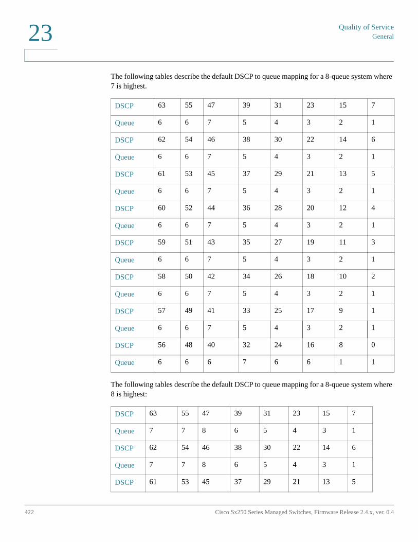
Quality of ServiceGeneral
422 Cisco Sx250 Series Managed Switches, Firmware Release 2.4.x, ver. 0.4
23
The following tables describe the default DSCP to queue mapping for a 8-queue system where 7 is highest.
The following tables describe the default DSCP to queue mapping for a 8-queue system where 8 is highest:
DSCP 63 55 47 39 31 23 15 7
Queue 6 6 7 5 4 3 2 1
DSCP 62 54 46 38 30 22 14 6
Queue 6 6 7 5 4 3 2 1
DSCP 61 53 45 37 29 21 13 5
Queue 6 6 7 5 4 3 2 1
DSCP 60 52 44 36 28 20 12 4
Queue 6 6 7 5 4 3 2 1
DSCP 59 51 43 35 27 19 11 3
Queue 6 6 7 5 4 3 2 1
DSCP 58 50 42 34 26 18 10 2
Queue 6 6 7 5 4 3 2 1
DSCP 57 49 41 33 25 17 9 1
Queue 6 6 7 5 4 3 2 1
DSCP 56 48 40 32 24 16 8 0
Queue 6 6 6 7 6 6 1 1
DSCP 63 55 47 39 31 23 15 7
Queue 7 7 8 6 5 4 3 1
DSCP 62 54 46 38 30 22 14 6
Queue 7 7 8 6 5 4 3 1
DSCP 61 53 45 37 29 21 13 5
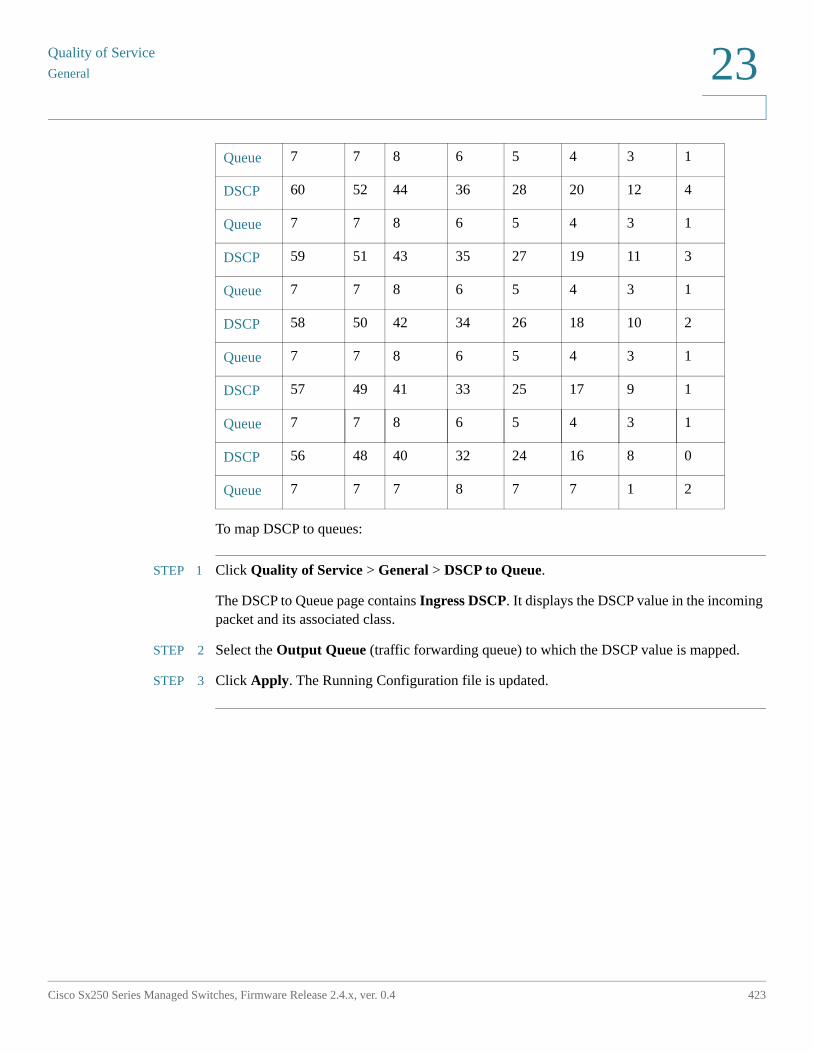
Quality of Service
General
Cisco Sx250 Series Managed Switches, Firmware Release 2.4.x, ver. 0.4 423
23
To map DSCP to queues:
STEP 1 Click Quality of Service > General > DSCP to Queue.
The DSCP to Queue page contains Ingress DSCP. It displays the DSCP value in the incoming packet and its associated class.
STEP 2 Select the Output Queue (traffic forwarding queue) to which the DSCP value is mapped.
STEP 3 Click Apply. The Running Configuration file is updated.
Queue 7 7 8 6 5 4 3 1
DSCP 60 52 44 36 28 20 12 4
Queue 7 7 8 6 5 4 3 1
DSCP 59 51 43 35 27 19 11 3
Queue 7 7 8 6 5 4 3 1
DSCP 58 50 42 34 26 18 10 2
Queue 7 7 8 6 5 4 3 1
DSCP 57 49 41 33 25 17 9 1
Queue 7 7 8 6 5 4 3 1
DSCP 56 48 40 32 24 16 8 0
Queue 7 7 7 8 7 7 1 2
Quality of ServiceGeneral
424 Cisco Sx250 Series Managed Switches, Firmware Release 2.4.x, ver. 0.4
23
Bandwidth
The Bandwidth page displays bandwidth information for each interface.
To view the bandwidth information:
STEP 1 Click Quality of Service > General > Bandwidth.
The fields in this page are described in the Edit page below, except for the following fields:
• Ingress Rate Limit:
- Status—Displays whether Ingress Rate Limit is enabled.
- Rate Limit (KBits/sec)— Displays the ingress rate limit for the port.
- %— Displays the ingress rate limit for the port divided by the total port bandwidth.
- CBS (Bytes)—Maximum burst size of data for the ingress interface in bytes of data.
• Egress Shaping Rates:
- Status—Displays whether Egress Shaping Rates is enabled.
- CIR (KBits/sec)—Displays the maximum bandwidth for the egress interface.
- CBS (Bytes)—Maximum burst size of data for the egress interface in bytes of data.
STEP 2 Select an interface, and click Edit.
STEP 3 Select the Port or LAG interface.
STEP 4 Enter the fields for the selected interface:
• Ingress Rate Limit—Select to enable the ingress rate limit, which is defined in the field below. (Not relevant for LAGs)
• Ingress Rate Limit (Kbits per sec)—Enter the maximum amount of bandwidth allowed on the interface. (Not relevant for LAGs)
• Ingress Committed Burst Size (CBS)—Enter the maximum burst size of data for the ingress interface in bytes of data. This amount can be sent even if it temporarily increases the bandwidth beyond the allowed limit. This field is only available if the interface is a port. (Not relevant for LAGs)
• Egress Shaping Rate—Select to enable egress shaping on the interface.
• Committed Information Rate (CIR)—Enter the maximum bandwidth for the egress interface.
Quality of Service
General
Cisco Sx250 Series Managed Switches, Firmware Release 2.4.x, ver. 0.4 425
23
• Egress Committed Burst Size (CBS)—Enter the maximum burst size of data for the egress interface in bytes of data. This amount can be sent even if it temporarily increases the bandwidth beyond the allowed limit.
STEP 5 Click Apply. The bandwidth settings are written to the Running Configuration file.
Egress Shaping per Queue
In addition to limiting transmission rate per port, which is done in the Bandwidth page, the device can limit the transmission rate of selected egressing frames on a per-queue per-port basis. Egress rate limiting is performed by shaping the output load.
The device limits all frames except for management frames. Any frames that are not limited are ignored in the rate calculations, meaning that their size is not included in the limit total.
Per-queue Egress rate shaping can be disabled.
To define egress shaping per queue:
STEP 1 Click Quality of Service > General > Egress Shaping per Queue.
The Egress Shaping Per Queue page displays the rate limit and burst size for each queue.
STEP 2 Select an interface type (Port or LAG), and click Go.
STEP 3 Select a Port/LAG, and click Edit.
This page enables shaping the egress for up to eight queues on each interface.
STEP 4 Select the Interface.
STEP 5 For each queue that is required, enter the following fields:
• Enable Shaping—Select to enable egress shaping on this queue.
• Committed Information Rate (CIR)—Enter the maximum rate (CIR) in Kbits per second (Kbps). CIR is the average maximum amount of data that can be sent.
• Committed Burst Size (CBS)—Enter the maximum burst size (CBS) in bytes. CBS is the maximum burst of data allowed to be sent even if a burst exceeds CIR.
STEP 6 Click Apply. The bandwidth settings are written to the Running Configuration file.
Quality of ServiceGeneral
426 Cisco Sx250 Series Managed Switches, Firmware Release 2.4.x, ver. 0.4
23
VLAN Ingress Rate Limit
Rate limiting per VLAN, performed in the VLAN Ingress Rate Limit page, enables traffic limiting on VLANs. When VLAN ingress rate limiting is configured, it limits aggregate traffic from all the ports on the device.
The following constraints apply to rate limiting per VLAN:
• It has lower precedence than any other traffic policing defined in the system. For example, if a packet is subject to QoS rate limits but is also subject to VLAN rate limiting, and the rate limits conflict, the QoS rate limits take precedence.
• It is applied at the device level and within the device at the packet processor level. If there is more than one packet processor on the device, the configured VLAN rate limit value is applied to each of the packet processors, independently. Devices with up to 24 ports have a single packet processor, while devices of 48 ports or more have two packet processors.
Rate limiting is calculated separately for each packet processor in a unit.
To define the VLAN ingress rate limit:
STEP 1 Click Quality of Service > General > VLAN Ingress Rate Limit.
This page displays the VLAN Ingress Rate Limit Table.
STEP 2 Click Add.
STEP 3 Enter the parameters.
• VLAN ID—Select a VLAN.
• Committed Information Rate (CIR)—Enter the average maximum amount of data that can be accepted into the VLAN in Kilobits per second.
• Committed Burst Size (CBS)—Enter the maximum burst size of data for the egress interface in bytes of data. This amount can be sent even if it temporarily increases the bandwidth beyond the allowed limit. Cannot be entered for LAGs.
STEP 4 Click Apply. The VLAN rate limit is added, and the Running Configuration file is updated.
Quality of Service
QoS Basic Mode
Cisco Sx250 Series Managed Switches, Firmware Release 2.4.x, ver. 0.4 427
23
TCP Congestion Avoidance
The TCP Congestion Avoidance page enables activating a TCP congestion avoidance algorithm. The algorithm breaks up or avoids TCP global synchronization in a congested node, where the congestion is due to various sources sending packets with the same byte count.
To configure TCP congestion avoidance:
STEP 1 Click Quality of Service > General > TCP Congestion Avoidance.
STEP 2 Click Enable to enable TCP congestion avoidance, and click Apply.
QoS Basic Mode
This section covers the following topics:
• Overview
• Global Settings
• Interface Settings
Overview
In QoS Basic mode, a specific domain in the network can be defined as trusted. Within that domain, packets are marked with 802.1p priority and/or DSCP to signal the type of service they require. Nodes within the domain use these fields to assign the packet to a specific output queue. The initial packet classification and marking of these fields is done in the ingress of the trusted domain.
Workflow to Configure Basic QoS Mode
To configure Basic QoS mode, perform the following:
1. Select Basic mode for the system by using the QoS Properties page.
2. Select the trust-behavior using the Global Setting page. The device supports CoS/802.1p trusted mode and DSCP trusted mode. CoS/802.1p trusted mode uses the 802.1p priority in the VLAN tag. DSCP trusted mode use the DSCP value in the IP header.
Quality of ServiceQoS Basic Mode
428 Cisco Sx250 Series Managed Switches, Firmware Release 2.4.x, ver. 0.4
23
If there is any port that, as an exception, should not trust the incoming CoS mark, disable the QoS state on that port using the Interface Settings page.
Enable or disable the global selected trusted mode at the ports by using the Interface Settings page. If a port is disabled without trusted mode, all its ingress packets are forward in best effort. It is recommended that you disable the trusted mode at the ports where the CoS/802.1p and/or DSCP values in the incoming packets are not trustworthy. Otherwise, it might negatively affect the performance of your network
Global Settings
The Global Settings page contains information for enabling Trust on the device (see the Trust Mode field below). This configuration is active when the QoS mode is Basic mode. Packets entering a QoS domain are classified at the edge of the QoS domain.
To define the Trust configuration:
STEP 1 Click Quality of Service > QoS Basic Mode > Global Settings.
STEP 2 Select the Trust Mode while the device is in Basic mode. If a packet CoS level and DSCP tag are mapped to separate queues, the Trust mode determines the queue to which the packet is assigned:
• CoS/802.1p—Traffic is mapped to queues based on the VPT field in the VLAN tag, or based on the per-port default CoS/802.1p value (if there is no VLAN tag on the incoming packet), the actual mapping of the VPT to queue can be configured in the mapping CoS/802.1p to Queue page.
• DSCP—All IP traffic is mapped to queues based on the DSCP field in the IP header. The actual mapping of the DSCP to queue can be configured in the DSCP to Queue page. If traffic is not IP traffic, it is mapped to the best effort queue.
• CoS/802.1p-DSCP—Either CoS/802.1p or DSCP whichever has been set.
STEP 3 Select Override Ingress DSCP to override the original DSCP values in the incoming packets with the new values entered in the DSCP Override table. When Override Ingress DSCP is enabled, the device uses the new DSCP values for egress queuing. It also replaces the original DSCP values in the packets with the new DSCP values.
NOTE The frame is mapped to an egress queue using the new, rewritten value, and not by the original DSCP value.
STEP 4 If Override Ingress DSCP was enabled, click DSCP Override Table to reconfigure DSCP. (See DSCP Override Table).
Quality of Service
QoS Advanced Mode
Cisco Sx250 Series Managed Switches, Firmware Release 2.4.x, ver. 0.4 429
23
STEP 5 DSCP In displays the DSCP value of the incoming packet that needs to be re-marked to an alternative value. Select the DSCP Out value to indicate the outgoing value is mapped.
STEP 6 Click Apply. The Running Configuration file is updated with the new DSCP values.
Interface Settings
The Interface Settings page enables configuring QoS on each port of the device, as follows:
• QoS State Disabled on an Interface—All inbound traffic on the port is mapped to the best effort queue and no classification/prioritization takes place.
• QoS State of the Port is Enabled—Port prioritize traffic on ingress is based on the system wide configured trusted mode, which is either CoS/802.1p trusted mode or DSCP trusted mode.
To enter QoS settings per interface:
STEP 1 Click Quality of Service > QoS Basic Mode > Interface Settings.
STEP 2 Select Port or LAG to display the list of ports or LAGs.
QoS State displays whether QoS is enabled on the interface.
STEP 3 Select an interface, and click Edit.
STEP 4 Select the Port or LAG interface.
STEP 5 Click to enable or disable QoS State for this interface.
STEP 6 Click Apply. The Running Configuration file is updated.
QoS Advanced Mode
This section covers the following topics:
• Overview
• Workflow to Configure Advanced QoS Mode
• Global Settings
Quality of ServiceQoS Advanced Mode
430 Cisco Sx250 Series Managed Switches, Firmware Release 2.4.x, ver. 0.4
23
• Out-of-Profile DSCP Remarking
• Class Mapping
• Aggregate Policer
• Policy Table
• Policy Class Maps
• Policy Binding
Overview
Frames that match an ACL and permitted entrance are implicitly labeled with the name of the ACL that permitted their entrance. Advanced mode QoS actions can then be applied to these flows.
In QoS advanced mode, the device uses policies to support per flow QoS. A policy and its components have the following characteristics and relationships:
• A policy contains one or more class maps.
• A class map defines a flow with one or more associating ACLs. Packets that match only ACL rules (ACE) in a class map with Permit (forward) action are considered belonging to the same flow, and are subjected to the same quality of services. Thus, a policy contains one or more flows, each with a user defined QoS.
• The QoS of a class map (flow) is enforced by the associating policer. There are two type of policers, single policer and aggregate policer. Each policer is configured with a QoS specification. A single policer applies the QoS to a single class map, and thus to a single flow, based on the policer QoS specification. An aggregate policer applies the QoS to one or more class maps, and thus one or more flows. An aggregate policer can support class maps from different policies.
• Per flow QoS are applied to flows by binding the policies to the desired ports. A policy and its class maps can be bound to one or more ports, but each port is bound with at most one policy.
Notes:
• Single policer and aggregation policer are available when the device is in Layer 2 mode.
• An ACL can be configured to one or more class maps regardless of policies.
• A class map can belong to only one policy.
Quality of Service
QoS Advanced Mode
Cisco Sx250 Series Managed Switches, Firmware Release 2.4.x, ver. 0.4 431
23
• When a class map using single policer is bound to multiple ports, each port has its own instance of single policer; each applying the QoS on the class map (flow) at a port independent of each other.
• An aggregate policer applies the QoS to all its flow(s) in aggregation regardless of policies and ports.
Advanced QoS settings consist of three parts:
• Definitions of the rules to match. All frames matching a single group of rules are considered to be a flow.
• Definition of the actions to be applied to frames in each flow that match the rules.
• Binding the combinations of rules and action to one or more interfaces.
Workflow to Configure Advanced QoS Mode
To configure Advanced QoS mode, perform the following:
1. Select Advanced mode for the system by using the QoS Properties page. Select the Trust Mode using the Global Settings page. If a packet CoS level and DSCP tag are mapped to separate queues, the Trust mode determines the queue to which the packet is assigned:
• If internal DSCP values are different from those used on incoming packets, map the external values to internal values by using the Out-of-Profile DSCP Remarking page. This in turn opens the DSCP Remarking page.
2. Create ACLs, as described in Create ACL Workflow.
3. If ACLs defined, create class maps and associate the ACLs with them by using the Class Mapping page.
4. Create a policy using the Policy Table page, and associate the policy with one or more class maps using the Policy Class Map page. You can also specify the QoS, if needed, by assigning a policer to a class map when you associate the class map to the policy.
• Single Policer—Create a policy that associates a class map with a single policer by using the Policy Table page and the Class Mapping page. Within the policy, define the single policer.
• Aggregate Policer—Create a QoS action for each flow that sends all matching frames to the same policer (aggregate policer) by using the Aggregate Policer page. Create a policy that associates a class map with the aggregate policer by using the Policy Table page.
5. Bind the policy to an interface by using the Policy Binding page.
Quality of ServiceQoS Advanced Mode
432 Cisco Sx250 Series Managed Switches, Firmware Release 2.4.x, ver. 0.4
23
Global Settings
The Global Settings page contains information for enabling Trust on the device. Packets entering a QoS domain are classified at the edge of the QoS domain.
To define the Trust configuration:
STEP 1 Click Quality of Service > QoS Advanced Mode > Global Settings.
STEP 2 Select the Trust Mode while the device is in Advanced mode. If a packet CoS level and DSCP tag are mapped to separate queues, the Trust mode determines the queue to which the packet is assigned:
• CoS/802.1p—Traffic is mapped to queues based on the VPT field in the VLAN tag, or based on the per-port default CoS/802.1p value (if there is no VLAN tag on the incoming packet), the actual mapping of the VPT to queue can be configured in the mapping CoS/802.1p to Queue page.
• DSCP—All IP traffic is mapped to queues based on the DSCP field in the IP header. The actual mapping of the DSCP to queue can be configured in the DSCP to Queue page. If traffic is not IP traffic, it is mapped to the best effort queue.
• CoS/802.1p-DSCP—Select to use Trust CoS mode for non-IP traffic and Trust DSCP for IP traffic.
STEP 3 Select the default Advanced mode QoS trust mode (either trusted or untrusted) for interfaces in the Default Mode Status field. This provides basic QoS functionality on Advanced QoS, so that you can trust CoS/DSCP on Advanced QoS by default (without having to create a policy).
In QoS Advanced Mode, when the Default Mode Status is set to Not Trusted, the default CoS values configured on the interface is ignored and all the traffic goes to queue 1. See the Quality of Service > QoS Advanced Mode > Global Settings page for details.
If you have a policy on an interface then the Default Mode is irrelevant, the action is according to the policy configuration and unmatched traffic is dropped.
STEP 4 Select Override Ingress DSCP to override the original DSCP values in the incoming packets with the new values according to the DSCP Override Table. When Override Ingress DSCP is enabled, the device uses the new DSCP values for egress queuing. It also replaces the original DSCP values in the packets with the new DSCP values.
NOTE The frame is mapped to an egress queue using the new, rewritten value, and not by the original DSCP value.
STEP 5 If Override Ingress DSCP was enabled, click DSCP Override Table to reconfigure DSCP.
Quality of Service
QoS Advanced Mode
Cisco Sx250 Series Managed Switches, Firmware Release 2.4.x, ver. 0.4 433
23
DSCP Override Table
STEP 1 Enter the following fields:
• DSCP In—Displays the DSCP value of the incoming packet that needs to be remarked to an alternative value.
• DSCP Out—Select the DSCP Out value to indicate the outgoing value is mapped.
STEP 2 Click Apply.
Out-of-Profile DSCP Remarking
When a policer is assigned to a class maps (flows), you can specify the action to take when the amount of traffic in the flow(s) exceeds the QoS-specified limits. The portion of the traffic that causes the flow to exceed its QoS limit is referred to as out-of-profile packets.
If the exceed/violate action is Out of Profile DSCP, the device remaps the original DSCP value of the out-of-profile IP packets with a new value based on the Out of Profile DSCP Remarking Table. The device uses the new values to assign resources and the egress queues to these packets. The device also physically replaces the original DSCP value in the out of profile packets with the new DSCP value.
To use the out-of-profile DSCP exceed action, remap the DSCP value in the Out Of Profile DSCP Remarking Table. Otherwise the action is null, because the DSCP value in the table remaps the packets to itself by factory default.
This feature changes the DSCP tags for incoming traffic switched between trusted QoS domains. Changing the DSCP values used in one domain, sets the priority of that type of traffic to the DSCP value used in the other domain to identify the same type of traffic.
These settings are active when the system is in the QoS Advance mode, and once activated they are active globally.
For example: Assume that there are three levels of service: Silver, Gold, and Platinum and the DSCP incoming values used to mark these levels are 10, 20, and 30 respectively. If this traffic is forwarded to another service provider that has the same three levels of service, but uses DSCP values 16, 24, and 48, Out of Profile DSCP Remarking changes the incoming values as they are mapped to the outgoing values.
Quality of ServiceQoS Advanced Mode
434 Cisco Sx250 Series Managed Switches, Firmware Release 2.4.x, ver. 0.4
23
To map DSCP values:
STEP 1 Click Quality of Service > QoS Advanced Mode > Out of Profile DSCP Remarking. This page enables setting the DSCP-value of traffic entering or leaving the device.
DSCP In displays the DSCP value of the incoming packet that needs to be re-marked to an alternative value.
STEP 2 Select the DSCP Out value to where the incoming value is mapped.
STEP 3 Click Apply. The Running Configuration file is updated with the new DSCP Remarking table.
STEP 4 Click Restore Defaults to restore the factory CoS default setting for this interface.
Class Mapping
A Class Map defines a traffic flow with ACLs (Access Control Lists) defined on it. A MAC ACL, IP ACL, and IPv6 ACL can be combined into a class map. Class maps are configured to match packet criteria on a match-all or match-any basis. They are matched to packets on a first-fit basis, meaning that the action associated with the first-matched class map is the action performed by the system. Packets that matches the same class map are considered to belong to the same flow.
NOTE Defining class maps does not have any effect on QoS; it is an interim step, enabling the class maps to be used later.
If more complex sets of rules are needed, several class maps can be grouped into a super-group called a policy (see Policy Table).
NOTE In the same class map, a MAC ACL cannot be used with an IPv6 ACE that has a Destination IPv6 address as a filtering condition.
The Class Mapping page shows the list of defined class maps and the ACLs comprising each, and enables you to add/delete class maps.
To define a Class Map:
STEP 1 Click Quality of Service > QoS Advanced Mode > Class Mapping.
For each class map, the ACLs defined on it are displayed along with the relationship between them. Up to three ACLs can be displayed along with their Match, which can be either And or Or. This indicates the relationship between the ACLs. The Class Map is then the result of the three ACLs combined with either And or Or.
STEP 2 Click Add.
Quality of Service
QoS Advanced Mode
Cisco Sx250 Series Managed Switches, Firmware Release 2.4.x, ver. 0.4 435
23
A new class map is added by selecting one or two ACLs and giving the class map a name. If a class map has two ACLs, you can specify that a frame must match both ACLs, or that it must match either one or both of the ACLs selected.
STEP 3 Enter the parameters.
• Class Map Name—Enter the name of a new class map.
• Match ACL Type—The criteria that a packet must match in order to be considered to belong to the flow defined in the class map. The options are:
- IP—A packet must match either of the IP based ACLs in the class map.
- MAC—A packet must match the MAC based ACL in the class map.
- IP and MAC—A packet must match the IP based ACL and the MAC based ACL in the class map.
- IP or MAC—A packet must match either the IP based ACL or the MAC based ACL in the class map.
• IP—Select the IPv4 based ACL or the IPv6 based ACL for the class map.
• MAC—Select the MAC based ACL for the class map.
• Preferred ACL—Select whether packets are first matched to an IP-based ACL or a MAC-based ACL.
STEP 4 Click Apply. The Running Configuration file is updated.
Aggregate Policer
You can measure the rate of traffic that matches a pre-defined set of rules, and to enforce limits, such as limiting the rate of file-transfer traffic that is allowed on a port.
This can be done by using the ACLs in the class map(s) to match the desired traffic, and by using a policer to apply the QoS on the matching traffic.
A policer is configured with a QoS specification. There are two kinds of policers:
• Single (Regular) Policer—A single policer applies the QoS to a single class map, and to a single flow based on the policer's QoS specification. When a class map using single policer is bound to multiple ports, each port has its own instance of single policer; each applying the QoS on the class map (flow) at ports that are otherwise independent of each other. A single policer is created in the Policy Table page.
Quality of ServiceQoS Advanced Mode
436 Cisco Sx250 Series Managed Switches, Firmware Release 2.4.x, ver. 0.4
23
• Aggregate Policer—An aggregate policer applies the QoS to one or more class maps, and one or more flows. An aggregation policer can support class maps from different policies. An aggregate policer applies QoS to all its flow(s) in aggregation regardless of policies and ports. An aggregate policer is created in the Aggregate Policer page.
An aggregate policer is defined if the policer is to be shared with more than one class. Policers on a port cannot be shared with other policers in another device.
Each policer is defined with its own QoS specification with a combination of the following parameters:
• A maximum allowed rate, called a Committed Information Rate (CIR), measured in Kbps.
• An amount of traffic, measured in bytes, called a Committed Burst Size (CBS). This is traffic that is allowed to pass as a temporary burst even if it is above the defined maximum rate.
• An action to be applied to frames that are over the limits (called out-of-profile traffic), where such frames can be passed as is, dropped, or passed, but remapped to a new DSCP value that marks them as lower-priority frames for all subsequent handling within the device.
• Configures traffic policing on the basis of the specified rates and optional actions. Enter the CIR and these optional values and actions.
Assigning a policer to a class map is done when a class map is added to a policy. If the policer is an aggregate policer, you must create it using the Aggregate Policer page.
To define an aggregate policer:
STEP 1 Click Quality of Service > QoS Advanced Mode > Aggregate Policer.
This page displays the existing aggregate policers.
STEP 2 Click Add.
STEP 3 Enter the parameters.
• Aggregate Policer Name—Enter the name of the Aggregate Policer.
• Ingress Committed Information Rate (CIR)—Enter the maximum bandwidth allowed in bits per second. See the description of this in the Bandwidth page.
• Ingress Committed Burst Size (CBS)—Enter the maximum burst size (even if it goes beyond the CIR) in bytes. See the description of this in the Bandwidth page.
Quality of Service
QoS Advanced Mode
Cisco Sx250 Series Managed Switches, Firmware Release 2.4.x, ver. 0.4 437
23
• Exceed Action—Select the action to be performed on incoming packets that exceed the CIR. Possible values are:
- Drop—Packets exceeding the defined CIR value are dropped.
- Out of Profile DSCP—The DSCP values of packets exceeding the defined CIR value are remapped to a value based on the Out Of Profile DSCP Remarking Table.
STEP 4 Click Apply. The Running Configuration file is updated.
Policy Table
The Policy Table Map page displays the list of advanced QoS polices defined in the system. The page also allows you to create and delete polices. Only those policies that are bound to an interface are active (see Policy Binding page).
Each policy consists of:
• One or more class maps of ACLs which define the traffic flows in the policy.
• One or more aggregates that applies the QoS to the traffic flows in the policy.
After a policy has been added, class maps can be added by using the Policy Table page.
To add a QoS policy:
STEP 1 Click Quality of Service > QoS Advanced Mode > Policy Table.
This page displays the list of defined policies.
STEP 2 Click Policy Class Map Table to display the Policy Class Maps page.-orClick Add to open the Add Policy Table page.
STEP 3 Enter the name of the new policy in the New Policy Name field.
STEP 4 Click Apply. The QoS policy profile is added, and the Running Configuration file is updated.
Policy Class Maps
One or more class maps can be added to a policy. A class map defines the type of packets that are considered to belong to the same traffic flow.
Quality of ServiceQoS Advanced Mode
438 Cisco Sx250 Series Managed Switches, Firmware Release 2.4.x, ver. 0.4
23
To add a class map to a policy:
STEP 1 Click Quality of Service > QoS Advanced Mode > Policy Class Maps.
STEP 2 Select a policy in the Filter, and click Go. All class maps in that policy are displayed.
STEP 3 To add a new class map, click Add.
STEP 4 Enter the parameters.
• Policy Name—Displays the policy to which the class map is being added.
• Class Map Name—Select an existing class map to be associated with the policy. Class maps are created in the Class Mapping page.
• Action Type—Select the action regarding the ingress CoS/802.1p and/or DSCP value of all the matching packets.
- Use default trust mode—If this options is selected, use the default mode status in Global Trust mode. If the default mode status is “Not Trusted”, ignore the ingress CoS/802.1p and/or DSCP value and the matching packets are sent as best effort.
- Always Trust—If this options is selected, the device trusts the matching packet based on the Global Trust mode (selected in the Global Settings page). It ignores the Default Mode status (selected in the Global Settings page).
- Set—If this option is selected, use the value entered in the New Value box to determine the egress queue of the matching packets as follows:
If the new value (0..7) is a CoS/802.1p priority, use the priority value and the CoS/802.1p to Queue Table to determine the egress queue of all the matching packets.
If the new value (0..63) is a DSCP, use the new DSCP and the DSCP to Queue Table to determine the egress queue of the matching IP packets.
Otherwise, use the new value (1..8) as the egress queue number for all the matching packets.
• Police Type—Select the policer type for the policy. The options are:
- None—No policy is used.
- Single—The policer for the policy is a single policer.
- Aggregate—The policer for the policy is an aggregate policer.
STEP 5 If Police Type is Aggregate, select the Aggregate Policer.
Quality of Service
QoS Advanced Mode
Cisco Sx250 Series Managed Switches, Firmware Release 2.4.x, ver. 0.4 439
23
STEP 6 If Police Type is Single, enter the following QoS parameters:
• Ingress Committed Information Rate (CIR)—Enter the CIR in Kbps. See a description of this in the Bandwidth page.
• Ingress Committed Burst Size (CBS)—Enter the CBS in bytes. See a description of this in the Bandwidth page.
• Exceed Action—Select the action assigned to incoming packets exceeding the CIR. The options are:
- Drop—Packets exceeding the defined CIR value are dropped.
- Out of Profile DSCP—IP packets exceeding the defined CIR are forwarding with a new DSCP derived from the Out Of Profile DSCP Remarking Table.
STEP 7 Click Apply.
Policy Binding
The Policy Binding page shows which policy profile is bound and to which port. A policy can be bound to an interface as an ingress (input) policy or as an egress (output) policy. When a policy profile is bound to a specific port, it is active on that port. Only one policy profile can be configured per port, per direction, but a single policy can be bound to more than one port.
When a policy is bound to a port, it filters and applies QoS to traffic that belongs to the flows defined in the policy.
To edit a policy, it must first be removed (unbound) from all those ports to which it is bound.
NOTE It is possible to either bind a port to a policy or to an ACL but both cannot be bound.
To define policy binding:
STEP 1 Click Quality of Service > QoS Advanced Mode > Policy Binding.
STEP 2 Select an Interface Type if required.
STEP 3 Click Go. The policies for that interface are displayed.
STEP 4 Click Edit.
STEP 5 Select the following for the input policy/interface:
• Input Policy Binding—Select to bind the input policy to the interface.
• Policy Name—Select the input policy being bound.
Quality of ServiceQoS Statistics
440 Cisco Sx250 Series Managed Switches, Firmware Release 2.4.x, ver. 0.4
23
• Default Action—Select action if packet matches policy:
- Deny Any—Select to forward packets on the interface if they match any policy.
- Permit Any—Select to forward packets on the interface if they do not match any policy.
NOTE Permit Any can be defined only if IP Source Guard is not activated on the interface.
STEP 6 Select the following for the output policy/interface:
• Output Policy Binding—Select to bind the output policy to the interface.
• Policy Name—Select the output policy being bound.
• Default Action—Select action if packet matches policy:
- Deny Any—Select to forward packets on the interface if they match any policy.
- Permit Any—Select to forward packets on the interface if they do not match any policy.
NOTE Permit Any can be defined only if IP Source Guard is not activated on the interface.
STEP 7 Click Apply. The QoS policy binding is defined, and the Running Configuration file is updated.
QoS Statistics
From these pages you can manage the Single Policer, Aggregated Policer, and view queues statistics.
Policer Statistics
A Single Policer is bound to a class map from a single policy. An Aggregate Policer is bound to one or more class maps from one or more policies.
Quality of Service
QoS Statistics
Cisco Sx250 Series Managed Switches, Firmware Release 2.4.x, ver. 0.4 441
23
Viewing Single Policer Statistics
The Single Policer Statistics page indicates the number of in-profile and out-of-profile packets that are received from an interface that meet the conditions defined in the class map of a policy.
NOTE This page is not displayed when the device is in Layer 3 mode.
To view policer statistics:
STEP 1 Click Quality of Service > QoS Statistics > Single Policer Statistics.
This page displays the following fields:
• Interface—Statistics are displayed for this interface.
• Policy—Statistics are displayed for this policy.
• Class Map—Statistics are displayed for this class map.
• In-Profile Bytes—Number of in-profile bytes received.
• Out-of-Profile Bytes—Number of out-profile bytes received.
STEP 2 Click Add.
STEP 3 Enter the parameters.
• Interface—Select the interface for which statistics are accumulated.
• Policy Name—Select the policy name.
• Class Map Name—Select the class name.
STEP 4 Click Apply. An additional request for statistics is created and the Running Configuration file is updated.
Viewing Aggregated Policer Statistics
To view aggregated policer statistics:
STEP 1 Click Quality of Service > QoS Statistics > Aggregate Policer Statistics.
This page displays the following fields:
• Aggregate Policer Name—Policer on which statistics are based.
Quality of ServiceQoS Statistics
442 Cisco Sx250 Series Managed Switches, Firmware Release 2.4.x, ver. 0.4
23
• In-Profile Bytes—Number of in-profile packets that received.
• Out-of-Profile Bytes—Number of out-of-profile packets that received.
STEP 2 Click Add.
STEP 3 Select an Aggregate Policer Name, one of the previously-created Aggregate Policers for which statistics are displayed.
STEP 4 Click Apply. An additional request for statistics is created, and the Running Configuration file is updated.
Queues Statistics
The Queues Statistics page displays queue statistics, including statistics of forwarded and dropped packets, based on interface, queue, and drop precedence.
To view Queues Statistics and define what statistics to display (Counter Set):
STEP 1 Click Quality of Service > QoS Statistics > Queues Statistics.
This page displays the following fields:
• Refresh Rate—Select the time period that passes before the interface Ethernet statistics are refreshed. The available options are:
- No Refresh—Statistics are not refreshed.
- 15 Sec—Statistics are refreshed every 15 seconds.
- 30 Sec—Statistics are refreshed every 30 seconds.
- 60 Sec—Statistics are refreshed every 60 seconds.
To view a specific unit and interface, select the unit/interface in the filter and click Go.
To view a specific interface, select the interface in the filter and click Go.
The Queues Statistics Table displays the following fields for each queue:
• Queue—Packets forwarded or tail dropped from this queue.
• Transmitted Packets—Number of packets that were transmitted.
• Tail Dropped Packets—Percentage of packets that were tail dropped.
• Transmitted Bytes—Number of bytes that were transmitted.

Quality of Service
QoS Statistics
Cisco Sx250 Series Managed Switches, Firmware Release 2.4.x, ver. 0.4 443
23
• Tail Dropped Bytes—Percentage of bytes that were tail dropped.
24
Cisco Sx250 Series Managed Switches, Firmware Release 2.4.x, ver. 0.4 444
SNMP
This section describes the Simple Network Management Protocol (SNMP) feature that provides a method for managing network devices.
It covers the following topics:
• Overview
• Engine ID
• Views
• Groups
• Users
• Communities
• Trap Settings
• Notification Recipients
• Notification Filter
Overview
SNMP Versions and Workflow
The device functions as SNMP agent and supports SNMPv1, v2, and v3. It also reports system events to trap receivers using the traps defined in the supported MIBs (Management Information Base).
SNMPv1 and v2
To control access to the system, a list of community entries is defined. Each community entry consists of a community string and its access privilege. The system responds only to SNMP messages specifying the community which has the correct permissions and correct operation.
SNMP
Overview
Cisco Sx250 Series Managed Switches, Firmware Release 2.4.x, ver. 0.4 445
24
SNMP agents maintain a list of variables that are used to manage the device. These variables are defined in the Management Information Base (MIB).
NOTE Due to the security vulnerabilities of other versions, it is recommended to use SNMPv3.
SNMPv3
In addition to the functionality provided by SNMPv1 and v2, SNMPv3 applies access control and new trap mechanisms to SNMPv1 and SNMPv2 PDUs. SNMPv3 also defines a User Security Model (USM) that includes:
• Authentication—Provides data integrity and data origin authentication.
• Privacy—Protects against disclosure message content. Cipher Block-Chaining (CBC-DES) is used for encryption. Either authentication alone can be enabled on an SNMP message, or both authentication and privacy can be enabled on an SNMP message. However, privacy cannot be enabled without authentication.
• Timeliness—Protects against message delay or playback attacks. The SNMP agent compares the incoming message time stamp to the message arrival time.
SNMP Workflow
NOTE For security reasons, SNMP is disabled by default. Before you can manage the device via SNMP, you must enable SNMP on the TCP/UDP Services page.
The following is the recommended series of actions for configuring SNMP:
If you decide to use SNMPv1 or v2:
STEP 1 Navigate to the Communities page and click Add. The community can be associated with access rights and a view in Basic mode or with a group in Advanced mode. There are two ways to define access rights of a community:
• Basic mode—The access rights of a community can configure with Read Only, Read Write, or SNMP Admin. In addition, you can restrict the access to the community to only certain MIB objects by selecting a view (defined in the Views page).
• Advanced Mode—The access rights of a community are defined by a group (defined in the Groups page). You can configure the group with a specific security model. The access rights of a group are Read, Write, and Notify.
STEP 2 Choose whether to restrict the SNMP management station to one address or allow SNMP management from all addresses. If you choose to restrict SNMP management to one address, then input the address of your SNMP Management PC in the IP Address field.
SNMPOverview
446 Cisco Sx250 Series Managed Switches, Firmware Release 2.4.x, ver. 0.4
24
STEP 3 Input the unique community string in the Community String field.
STEP 4 Optionally, enable traps by using the Trap Settings page.
STEP 5 Optionally, define a notification filter(s) by using the Notification Filter page.
STEP 6 Configure the notification recipients on the SNMPv1.2 Notification Recipients pages.
If you decide to use SNMPv3:
STEP 1 Define the SNMP engine by using the Engine ID page. Either create a unique Engine ID or use the default Engine ID. Applying an Engine ID configuration clears the SNMP database.
STEP 2 Optionally, define SNMP view(s) by using the Views page. This limits the range of OIDs available to a community or group.
STEP 3 Define groups by using the Groups page.
STEP 4 Define users by using the Users page, where they can be associated with a group. If the SNMP Engine ID is not set, then users may not be created.
STEP 5 Optionally, enable or disable traps by using the Trap Settings page.
STEP 6 Optionally, define a notification filter(s) by using the Notification Filter page.
STEP 7 Define a notification recipient(s) by using the SNMPv3 Notification Recipients page.
Supported MIBs
For a list of supported MIBs, visit the following URL and navigate to the download area listed as Cisco MIBS:
www.cisco.com/cisco/software/navigator.html
SNMP
Overview
Cisco Sx250 Series Managed Switches, Firmware Release 2.4.x, ver. 0.4 447
24
Model OIDs
The following are the OIDs for the 250 family.
SKU Name Description System Object ID
F250-24 SF250-24 24-Port 10/100 Smart Switch 9.6.1.98.24.1
SF250-24P SF250-24P 24-Port 10/100 PoE Smart Switch 9.6.1.98.24.5
SF250-48 SF250-48 48-Port 10/100 Smart Switch 9.6.1.98.24.1
SF250-48HP SF250-48HP 48-Port 10/100 PoE Smart Switch
9.6.1.98.24.4
SG250-08 SG250-08 8-Port Gigabit Smart Switch 9.6.1.97.8.3
SG250-08HP SG250-08HP 8-Port Gigabit PoE Smart Switch
9.6.1.97.8.4S
SG250-10P SG250-10P 10-Port Gigabit PoE Smart Switch
9.6.1.97.10.5
SG250-18 SG250-18 18-Port Gigabit Smart Switch 9.6.1.97.18.1
SG250-26 SG250-26 26-Port Gigabit Smart Switch 9.6.1.97.26.1
SG250-26HP SG250-26HP 26-Port Gigabit PoE Smart Switch
9.6.1.97.26.4
SG250-26P SG250-26P 26-Port Gigabit PoE Smart Switch
9.6.1.97.26.5
SG250-50 SG250-50 50-Port Gigabit Smart Switch 9.6.1.97.50.1
SG250-50HP SG250-50HP 50-Port Gigabit PoE Smart Switch
9.6.1.97.50.4
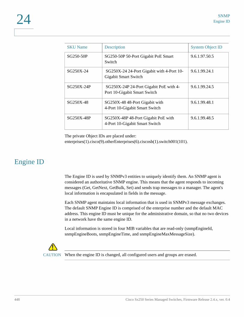
SNMPEngine ID
448 Cisco Sx250 Series Managed Switches, Firmware Release 2.4.x, ver. 0.4
24
The private Object IDs are placed under: enterprises(1).cisco(9).otherEnterprises(6).ciscosb(1).switch001(101).
Engine ID
The Engine ID is used by SNMPv3 entities to uniquely identify them. An SNMP agent is considered an authoritative SNMP engine. This means that the agent responds to incoming messages (Get, GetNext, GetBulk, Set) and sends trap messages to a manager. The agent's local information is encapsulated in fields in the message.
Each SNMP agent maintains local information that is used in SNMPv3 message exchanges. The default SNMP Engine ID is comprised of the enterprise number and the default MAC address. This engine ID must be unique for the administrative domain, so that no two devices in a network have the same engine ID.
Local information is stored in four MIB variables that are read-only (snmpEngineId, snmpEngineBoots, snmpEngineTime, and snmpEngineMaxMessageSize).
!CAUTION When the engine ID is changed, all configured users and groups are erased.
SG250-50P SG250-50P 50-Port Gigabit PoE Smart Switch
9.6.1.97.50.5
SG250X-24 SG250X-24 24-Port Gigabit with 4-Port 10-Gigabit Smart Switch
9.6.1.99.24.1
SG250X-24P SG250X-24P 24-Port Gigabit PoE with 4-Port 10-Gigabit Smart Switch
9.6.1.99.24.5
SG250X-48 SG250X-48 48-Port Gigabit with 4-Port 10-Gigabit Smart Switch
9.6.1.99.48.1
SG250X-48P SG250X-48P 48-Port Gigabit PoE with 4-Port 10-Gigabit Smart Switch
9.6.1.99.48.5
SKU Name Description System Object ID
SNMP
Engine ID
Cisco Sx250 Series Managed Switches, Firmware Release 2.4.x, ver. 0.4 449
24
To define the SNMP engine ID:
STEP 1 Click SNMP > Engine ID.
STEP 2 Choose which to use for Local Engine ID.
• Use Default—Select to use the device-generated engine ID. The default engine ID is based on the device MAC address, and is defined per standard as:
- First 4 octets—First bit = 1, the rest is the IANA enterprise number.
- Fifth octet—Set to 3 to indicate the MAC address that follows.
- Last 6 octets—MAC address of the device.
• None—No engine ID is used.
• User Defined—Enter the local device engine ID. The field value is a hexadecimal string (range: 10 - 64). Each byte in the hexadecimal character strings is represented by two hexadecimal digits.
All remote engine IDs and their IP addresses are displayed in the Remote Engine ID table.
STEP 3 Click Apply. The Running Configuration file is updated.
The Remote Engine ID table shows the mapping between IP addresses of the engine and Engine ID.
To add the IP address of an engine ID:
STEP 4 Click Add. Enter the following fields:
• Server Definition—Select whether to specify the Engine ID server by IP address or name.
• IP Version—Select the supported IP format.
• IPv6 Address Type—Select the IPv6 address type (if IPv6 is used). The options are:
- Link Local—The IPv6 address uniquely identifies hosts on a single network link. A link local address has a prefix of FE80, is not routable, and can be used for communication on the local network only. Only one link local address is supported. If a link local address exists on the interface, this entry replaces the address in the configuration.
- Global—The IPv6 address is a global Unicast IPV6 type that is visible and reachable from other networks.
• Link Local Interface—Select the link local interface (if IPv6 Address Type Link Local is selected) from the list.
SNMPViews
450 Cisco Sx250 Series Managed Switches, Firmware Release 2.4.x, ver. 0.4
24
• Server IP Address/Name—Enter the IP address or domain name of the log server.
• Engine ID—Enter the Engine ID.
STEP 5 Click Apply. The Running Configuration file is updated.
Views
A view is a user-defined label for a collection of MIB subtrees. Each subtree ID is defined by the Object ID (OID) of the root of the relevant subtrees. Either well-known names can be used to specify the root of the desired subtree or an OID can be entered (see Model OIDs).
Each subtree is either included or excluded in the view being defined.
The Views page enables creating and editing SNMP views. The default views (Default, DefaultSuper) cannot be changed.
Views can be attached to groups in the Groups page or to a community which employs basic access mode through the Communities page.
To define SNMP views:
STEP 1 Click SNMP > Views.
The following fields are displayed for each view:
• Object ID Subtree—Node in the MIB tree that is included or excluded in the view.
• Object ID Subtree View—Whether the node is Included or Excluded.
STEP 2 Click Add to define new views.
STEP 3 Enter the parameters.
• View Name—Enter a view name between 0-30 characters.
• Object ID Subtree—Select the node in the MIB tree that is included or excluded in the selected SNMP view. The options to select the object are as follows:
- Select from list—Enables you to navigate the MIB tree. Press the Up arrow to go to the level of the selected node's parent and siblings; press the Down arrow to descend to the level of the selected node's children. Click nodes in the view to pass from one node to its sibling. Use the scrollbar to bring siblings in view.
- User Defined—Enter an OID not offered in the Select from list option.
SNMP
Groups
Cisco Sx250 Series Managed Switches, Firmware Release 2.4.x, ver. 0.4 451
24
STEP 4 Select or deselect Include in view. If this is selected, the selected MIBs are included in the view, otherwise they are excluded.
STEP 5 Click Apply.
STEP 6 In order to verify your view configuration, select the user-defined views from the Filter: View Name list. The following views exist by default:
• Default—Default SNMP view for read and read/write views.
• DefaultSuper—Default SNMP view for administrator views.
Groups
In SNMPv1 and SNMPv2, a community string is sent along with the SNMP frames. The community string acts as a password to gain access to an SNMP agent. However, neither the frames nor the community string are encrypted. Therefore, SNMPv1 and SNMPv2 are not secure.
In SNMPv3, the following security mechanisms can be configured.
• Authentication—The device checks that the SNMP user is an authorized system administrator. This is done for each frame.
• Privacy—SNMP frames can carry encrypted data.
Thus, in SNMPv3, there are three levels of security:
• No security (No authentication and no privacy)
• Authentication (Authentication and no privacy)
• Authentication and privacy
SNMPv3 provides a means of controlling the content each user can read or write and the notifications they receive. A group defines read/write privileges and a level of security. It becomes operational when it is associated with an SNMP user or community.
NOTE To associate a non-default view with a group, first create the view in the Views page.
SNMPGroups
452 Cisco Sx250 Series Managed Switches, Firmware Release 2.4.x, ver. 0.4
24
To create an SNMP group:
STEP 1 Click SNMP > Groups.
This page contains the existing SNMP groups and their security levels.
STEP 2 Click Add.
STEP 3 Enter the parameters.
• Group Name—Enter a new group name.
• Security Model—Select the SNMP version attached to the group, SNMPv1, v2, or v3.
Three types of views with various security levels can be defined. For each security level, select the views for Read, Write and Notify by entering the following fields:
• Enable—Select this field to enable the Security Level.
• Security Level—Define the security level attached to the group. SNMPv1 and SNMPv2 support neither authentication nor privacy. If SNMPv3 is selected, choose one of the following:
- No Authentication and No Privacy—Neither the Authentication nor the Privacy security levels are assigned to the group.
- Authentication and No Privacy—Authenticates SNMP messages, and ensures the SNMP message origin is authenticated but does not encrypt them.
- Authentication and Privacy—Authenticates SNMP messages, and encrypts them.
• View—Select to associate a view with either read, write, and/or notify access privileges of the group limits the scope of the MIB tree to which the group has read, write, and notify access.
- Read—Management access is read-only for the selected view. Otherwise, a user or a community associated with this group is able to read all MIBs except those that control SNMP itself.
- Write—Management access is write for the selected view. Otherwise, a user or a community associated with this group is able to write all MIBs except those that control SNMP itself.
- Notify—Limits the available content of the traps to those included in the selected view. Otherwise, there is no restriction on the contents of the traps. This can only be selected for SNMPv3.
SNMP
Users
Cisco Sx250 Series Managed Switches, Firmware Release 2.4.x, ver. 0.4 453
24
STEP 4 Click Apply. The SNMP group is saved to the Running Configuration file.
Users
An SNMP user is defined by the login credentials (username, passwords, and authentication method) and by the context and scope in which it operates by association with a group and an Engine ID.
The configured user have the attributes of its group, having the access privileges configured within the associated view.
Groups enable network managers to assign access rights to a group of users instead of to a single user.
A user can only belong to a single group.
To create an SNMPv3 user, the following must first exist:
• An engine ID must first be configured on the device. This is done in the Engine ID page.
• An SNMPv3 group must be available. An SNMPv3 group is defined in the Groups page.
To display SNMP users and define new ones:
STEP 1 Click SNMP > Users.
This page displays existing users. The fields in this page are described in the Add page except for the following field:
• IP Address—Displays the IP address of the engine.
STEP 2 Click Add.
This page provides information for assigning SNMP access control privileges to SNMP users.
STEP 3 Enter the parameters.
• User Name—Enter a name for the user.
SNMPUsers
454 Cisco Sx250 Series Managed Switches, Firmware Release 2.4.x, ver. 0.4
24
• Engine ID—Select either the local or remote SNMP entity to which the user is connected. Changing or removing the local SNMP Engine ID deletes the SNMPv3 User Database. To receive inform messages and request information, you must define both a local and remote user.
- Local—User is connected to the local device.
- Remote IP Address—User is connected to a different SNMP entity in addition to the local device. If the remote Engine ID is defined, remote devices receive inform messages, but cannot make requests for information.
Enter the remote engine ID.
• Group Name—Select the SNMP group to which the SNMP user belongs. SNMP groups are defined in the Add Group page.
NOTE Users, who belong to groups which have been deleted, remain, but they are inactive.
• Authentication Method—Select the Authentication method that varies according to the Group Name assigned. If the group does not require authentication, then the user cannot configure any authentication. The options are:
- None—No user authentication is used.
- MD5—A password that is used for generating a key by the MD5 authentication method.
- SHA—A password that is used for generating a key by the SHA (Secure Hash Algorithm) authentication method.
• Authentication Password—If authentication is accomplished by either a MD5 or a SHA password, enter the local user password in either Encrypted or Plaintext. Local user passwords are compared to the local database. and can contain up to 32 ASCII characters.
• Privacy Method—Select one of the following options:
- None—Privacy password is not encrypted.
- DES—Privacy password is encrypted according to the Data Encryption Standard (DES).
• Privacy Password—16 bytes are required (DES encryption key) if the DES privacy method was selected. This field must be exactly 32 hexadecimal characters. The Encrypted or Plaintext mode can be selected.
SNMP
Communities
Cisco Sx250 Series Managed Switches, Firmware Release 2.4.x, ver. 0.4 455
24
STEP 4 Click Apply to save the settings.
Communities
Access rights in SNMPv1 and SNMPv2 are managed by defining communities in the Communities page. The community name is a type of shared password between the SNMP management station and the device. It is used to authenticate the SNMP management station.
Communities are only defined in SNMPv1 and v2 because SNMPv3 works with users instead of communities. The users belong to groups that have access rights assigned to them.
The Communities page associates communities with access rights, either directly (Basic mode) or through groups (Advanced mode):
• Basic mode—The access rights of a community can configure with Read Only, Read Write, or SNMP Admin. In addition, you can restrict the access to the community to only certain MIB objects by selecting a view (defined in the Views page).
• Advanced Mode—The access rights of a community are defined by a group (defined in the Groups page). You can configure the group with a specific security model. The access rights of a group are Read, Write, and Notify.
To define SNMP communities:
STEP 1 Click SNMP > Communities.
This page contains a table of configured SNMP communities and their properties. The fields in this page are described in the Add page except for the following field:
• Community Type—Displays the mode of the community (Basic or Advanced).
STEP 2 Click Add.
This page enables network managers to define and configure new SNMP communities.
STEP 3 SNMP Management Station—Click User Defined to enter the management station IP address that can access the SNMP community. Click All to indicate that any IP device can access the SNMP community.
• IP Version—Select either IPv4 or IPv6.
SNMPCommunities
456 Cisco Sx250 Series Managed Switches, Firmware Release 2.4.x, ver. 0.4
24
• IPv6 Address Type—Select the supported IPv6 address type if IPv6 is used. The options are:
- Link Local—The IPv6 address uniquely identifies hosts on a single network link. A link local address has a prefix of FE80, is not routable, and can be used for communication on the local network only. Only one link local address is supported. If a link local address exists on the interface, this entry replaces the address in the configuration.
- Global—The IPv6 address is a global Unicast IPV6 type that is visible and reachable from other networks.
• Link Local Interface—If the IPv6 address type is Link Local, select whether it is received through a VLAN or ISATAP.
• IP Address—Enter the SNMP management station IP address.
• Community String—Enter the community name used to authenticate the management station to the device.
• (Community Type) Basic—In this community type, there is no connection to any group. You can only choose the community access level (Read Only, Read Write, or SNMP Admin) and, optionally, further qualify it for a specific view. By default, it applies to the entire MIB. If this is selected, enter the following fields:
- Access Mode—Select the access rights of the community. The options are:
Read Only—Management access is restricted to read-only. Changes cannot be made to the community.
Read Write—Management access is read-write. Changes can be made to the device configuration, but not to the community.
SNMP Admin—User has access to all device configuration options, as well as permissions to modify the community. SNMP Admin is equivalent to Read Write for all MIBs except for the SNMP MIBs. SNMP Admin is required for access to the SNMP MIBs.
- View Name—Select an SNMP view (a collection of MIB subtrees to which access is granted).
• (Community Type) Advanced—Select this type for a selected community.
- Group Name—Select an SNMP group that determines the access rights.
STEP 4 Click Apply. The SNMP Community is defined, and the Running Configuration is updated.
SNMP
Trap Settings
Cisco Sx250 Series Managed Switches, Firmware Release 2.4.x, ver. 0.4 457
24
Trap Settings
The Trap Settings page enables configuring whether SNMP notifications are sent from the device, and for which cases. The recipients of the SNMP notifications can be configured in the SNMPv1.2 Notification Recipients page, or the SNMPv3 Notification Recipients page.
To define trap settings:
STEP 1 Click SNMP > Trap Settings.
STEP 2 Select Enable for SNMP Notifications to specify that the device can send SNMP notifications.
STEP 3 Select Enable for Authentication Notifications to enable SNMP authentication failure notification.
STEP 4 Click Apply. The SNMP Trap settings are written to the Running Configuration file.
Notification Recipients
Trap messages are generated to report system events, as defined in RFC 1215. The system can generate traps defined in the MIB that it supports.
Trap receivers (Notification Recipients) are network nodes to which trap messages are sent by the device. A list of notification recipients can be defined.
A trap receiver entry contains the IP address of the node and the SNMP credentials corresponding to the version that is included in the trap message. When an event arises that requires a trap message to be sent, it is sent to every node listed in the Notification Recipient Table.
The SNMPv1.2 Notification Recipients page and the SNMPv3 Notification Recipientspage enable configuring the destination to which SNMP notifications are sent, and the types of SNMP notifications that are sent to each destination (traps or informs). The Add/Edit pop-ups enable configuring the attributes of the notifications.
An SNMP notification is a message sent from the device to the SNMP management station indicating that a certain event has occurred, such as a link up/down.
SNMPNotification Recipients
458 Cisco Sx250 Series Managed Switches, Firmware Release 2.4.x, ver. 0.4
24
It is also possible to filter certain notifications. This can be done by creating a filter in the Notification Filter page and attaching it to an SNMP notification recipient. The notification filter enables filtering the type of SNMP notifications that are sent to the management station based on the OID of the notification that is about to be sent.
SNMPv1.2 Notification Recipients
To define a recipient in SNMPv1,2:
STEP 1 Click SNMP > Notification Recipients SNMPv1,2.
This page displays recipients for SNMPv1,2.
STEP 2 Enter the following fields:
• Informs IPv4 Source Interface—Select the source interface whose IPv4 address will be used as the source IPv4 address in inform messages for communication with IPv4 SNMP servers.
• Traps IPv4 Source Interface—Select the source interface whose IPv6 address will be used as the source IPv6 address in trap messages for communication with IPv6 SNMP servers.
• Informs IPv6 Source Interface—Select the source interface whose IPv4 address will be used as the source IPv4 address in inform messages for communication with IPv4 SNMP servers.
• Traps IPv6 Source Interface—Select the source interface whose IPv6 address will be used as the source IPv6 address in trap messages for communication with IPv6 SNMP servers.
NOTE If the Auto option is selected, the system takes the source IP address from the IP address defined on the outgoing interface.
STEP 3 Click Add.
STEP 4 Enter the parameters.
• Server Definition—Select whether to specify the remote log server by IP address or name.
• IP Version—Select either IPv4 or IPv6.
• IPv6 Address Type—Select either Link Local or Global.
SNMP
Notification Recipients
Cisco Sx250 Series Managed Switches, Firmware Release 2.4.x, ver. 0.4 459
24
- Link Local—The IPv6 address uniquely identifies hosts on a single network link. A link local address has a prefix of FE80, is not routable, and can be used for communication on the local network only. Only one link local address is supported. If a link local address exists on the interface, this entry replaces the address in the configuration.
- Global—The IPv6 address is a global Unicast IPV6 type that is visible and reachable from other networks.
• Link Local Interface—If the IPv6 address type is Link Local, select whether it is received through a VLAN or ISATAP.
• Recipient IP Address/Name—Enter the IP address or server name of where the traps are sent.
• UDP Port—Enter the UDP port used for notifications on the recipient device.
• Notification Type—Select whether to send Traps or Informs. If both are required, two recipients must be created.
• Timeout—Enter the number of seconds the device waits before re-sending informs.
• Retries—Enter the number of times that the device resends an inform request.
• Community String—Select from the pull-down the community string of the trap manager. Community String names are generated from those listed in the Communities page.
• Notification Version—Select the trap SNMP version. Either SNMPv1 or SNMPv2 may be used as the version of traps, with only a single version enabled at a time.
• Notification Filter—Select to enable filtering the type of SNMP notifications sent to the management station. The filters are created in the Notification Filter page.
• Filter Name—Select the SNMP filter that defines the information contained in traps (defined in the Notification Filterpage).
STEP 5 Click Apply. The SNMP Notification Recipient settings are written to the Running Configuration file.
SNMPNotification Recipients
460 Cisco Sx250 Series Managed Switches, Firmware Release 2.4.x, ver. 0.4
24
SNMPv3 Notification Recipients
To define a recipient in SNMPv3:
STEP 1 Click SNMP > Notification Recipients SNMPv3.
This page displays recipients for SNMPv3.
• Informs IPv4 Source Interface—Select the source interface whose IPv4 address will be used as the source IPv4 address in inform messages for communication with IPv4 SNMP servers.
• Traps IPv4 Source Interface—Select the source interface whose IPv6 address will be used as the source IPv6 address in trap messages for communication with IPv6 SNMP servers.
• Informs IPv6 Source Interface—Select the source interface whose IPv4 address will be used as the source IPv4 address in inform messages for communication with IPv4 SNMP servers.
• Traps IPv6 Source Interface—Select the source interface whose IPv6 address will be used as the source IPv6 address in trap messages for communication with IPv6 SNMP servers.
STEP 2 Click Add.
STEP 3 Enter the parameters.
• Server Definition—Select whether to specify the remote log server by IP address or name.
• IP Version—Select either IPv4 or IPv6.
• IPv6 Address Type—Select the IPv6 address type (if IPv6 is used). The options are:
- Link Local—The IPv6 address uniquely identifies hosts on a single network link. A link local address has a prefix of FE80, is not routable, and can be used for communication on the local network only. Only one link local address is supported. If a link local address exists on the interface, this entry replaces the address in the configuration.
- Global—The IPv6 address is a global Unicast IPV6 type that is visible and reachable from other networks.
• Link Local Interface—Select the link local interface (if IPv6 Address Type Link Local is selected) from the pull-down list.
SNMP
Notification Recipients
Cisco Sx250 Series Managed Switches, Firmware Release 2.4.x, ver. 0.4 461
24
• Recipient IP Address/Name—Enter the IP address or server name of where the traps are sent.
• UDP Port—Enter the UDP port used to for notifications on the recipient device.
• Notification Type—Select whether to send traps or informs. If both are required, two recipients must be created.
• Timeout—Enter the amount of time (seconds) the device waits before re-sending informs/traps. Timeout: Range 1-300, default 15
• Retries—Enter the number of times that the device resends an inform request. Retries: Range 1-255, default 3
• User Name—Select from the drop-down list the user to whom SNMP notifications are sent. In order to receive notifications, this user must be defined on the Users page, and its engine ID must be remote.
• Security Level—Select how much authentication is applied to the packet.
NOTE The Security Level here depends on which User Name was selected. If this User Name was configured as No Authentication, the Security Level is No Authentication only. However, if this User Name has assigned Authentication and Privacy on the Users page, the security level on this screen can be either No Authentication, or Authentication Only, or Authentication and Privacy.
The options are:
- No Authentication—Indicates the packet is neither authenticated nor encrypted.
- Authentication—Indicates the packet is authenticated but not encrypted.
- Privacy—Indicates the packet is both authenticated and encrypted.
• Notification Filter—Select to enable filtering the type of SNMP notifications sent to the management station. The filters are created in the Notification Filter page.
• Filter Name—Select the SNMP filter that defines the information contained in traps (defined in the Notification Filter page).
STEP 4 Click Apply. The SNMP Notification Recipient settings are written to the Running Configuration file.
SNMPNotification Filter
462 Cisco Sx250 Series Managed Switches, Firmware Release 2.4.x, ver. 0.4
24
Notification Filter
The Notification Filter page enables configuring SNMP notification filters and Object IDs (OIDs) that are checked. After creating a notification filter, it is possible to attach it to a notification recipient in the SNMPv1.2 Notification Recipients page, and SNMPv3 Notification Recipientspage.
The notification filter enables filtering the type of SNMP notifications that are sent to the management station based on the OID of the notification to be sent.
To define a notification filter:
STEP 1 Click SNMP > Notification Filter.
The Notification Filter page contains notification information for each filter. The table is able to filter notification entries by Filter Name.
STEP 2 Click Add.
STEP 3 Enter the parameters.
• Filter Name—Enter a name between 0-30 characters.
• Object ID Subtree—Select the node in the MIB tree that is included or excluded in the selected SNMP filter. The options to select the object are as follows:
- Select from list—Enables you to navigate the MIB tree. Press the Up arrow to go to the level of the selected node's parent and siblings; press the Down arrow to descend to the level of the selected node's children. Click nodes in the view to pass from one node to its sibling. Use the scrollbar to bring siblings in view.
- If Object ID is used, the entered object identifier is included in the view if the Include in filter option is selected.
STEP 4 Select or deselect Include in filter. If this is selected, the selected MIBs are included in the filter, otherwise they are excluded.
STEP 5 Click Apply. The SNMP views are defined and the running configuration is updated.
25
Cisco Sx250 Series Managed Switches, Firmware Release 2.4.x, ver. 0.4 463
Smart Network Application (SNA)
This section describes the Smart Network Application (SNA) system, which displays an overview of network topology, including detailed monitoring information for devices and traffic. It enables viewing and modifying of configurations globally, on all supported devices in the network.
The following topics are covered in this chapter:
• SNA Sessions
• SNA Graphics
• Topology View
• Right-Hand Information Panel
• Operations
• Overlays
• Tags
• Search
• Notifications
• Device Authorization Control (DAC)
• Services
• Saving SNA Settings
• Technical Details
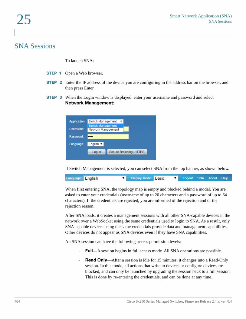
Smart Network Application (SNA)SNA Sessions
464 Cisco Sx250 Series Managed Switches, Firmware Release 2.4.x, ver. 0.4
25
SNA Sessions
To launch SNA:
STEP 1 Open a Web browser.
STEP 2 Enter the IP address of the device you are configuring in the address bar on the browser, and then press Enter.
STEP 3 When the Login window is displayed, enter your username and password and select Network Management:
If Switch Management is selected, you can select SNA from the top banner, as shown below.
When first entering SNA, the topology map is empty and blocked behind a modal. You are asked to enter your credentials (username of up to 20 characters and a password of up to 64 characters). If the credentials are rejected, you are informed of the rejection and of the rejection reason.
After SNA loads, it creates a management sessions with all other SNA-capable devices in the network over a WebSocket using the same credentials used to login to SNA. As a result, only SNA-capable devices using the same credentials provide data and management capabilities. Other devices do not appear as SNA devices even if they have SNA capabilities.
An SNA session can have the following access permission levels:
- Full—A session begins in full access mode. All SNA operations are possible.
- Read Only—After a session is idle for 15 minutes, it changes into a Read-Only session. In this mode, all actions that write to devices or configure devices are blocked, and can only be launched by upgrading the session back to a full session. This is done by re-entering the credentials, and can be done at any time.
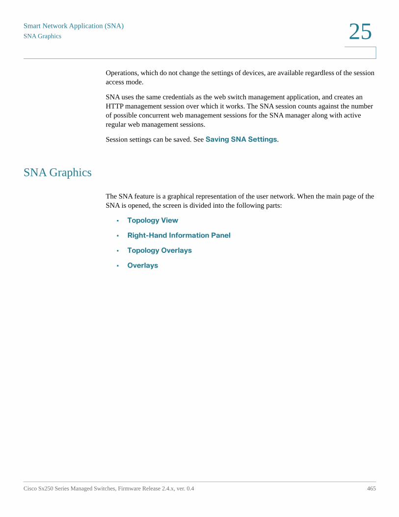
Smart Network Application (SNA)
SNA Graphics
Cisco Sx250 Series Managed Switches, Firmware Release 2.4.x, ver. 0.4 465
25
Operations, which do not change the settings of devices, are available regardless of the session access mode.
SNA uses the same credentials as the web switch management application, and creates an HTTP management session over which it works. The SNA session counts against the number of possible concurrent web management sessions for the SNA manager along with active regular web management sessions.
Session settings can be saved. See Saving SNA Settings.
SNA Graphics
The SNA feature is a graphical representation of the user network. When the main page of the SNA is opened, the screen is divided into the following parts:
• Topology View
• Right-Hand Information Panel
• Topology Overlays
• Overlays
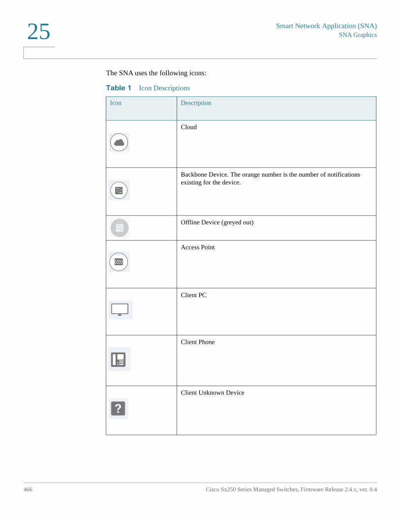
Smart Network Application (SNA)SNA Graphics
466 Cisco Sx250 Series Managed Switches, Firmware Release 2.4.x, ver. 0.4
25
The SNA uses the following icons:
Table 1 Icon Descriptions
Icon Description
Cloud
Backbone Device. The orange number is the number of notifications existing for the device.
Offline Device (greyed out)
Access Point
Client PC
Client Phone
Client Unknown Device
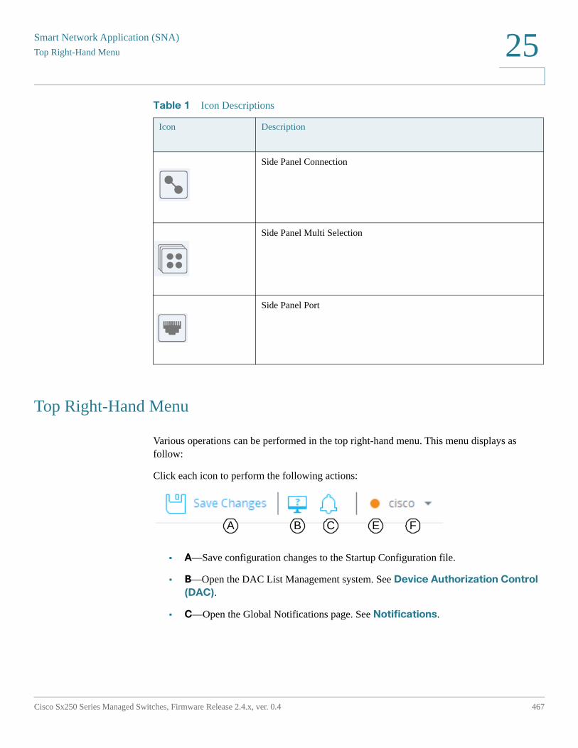
Smart Network Application (SNA)
Top Right-Hand Menu
Cisco Sx250 Series Managed Switches, Firmware Release 2.4.x, ver. 0.4 467
25
Top Right-Hand Menu
Various operations can be performed in the top right-hand menu. This menu displays as follow:
Click each icon to perform the following actions:
• A—Save configuration changes to the Startup Configuration file.
• B—Open the DAC List Management system. See Device Authorization Control
(DAC).
• C—Open the Global Notifications page. See Notifications.
Side Panel Connection
Side Panel Multi Selection
Side Panel Port
Table 1 Icon Descriptions
Icon Description
A B C E F
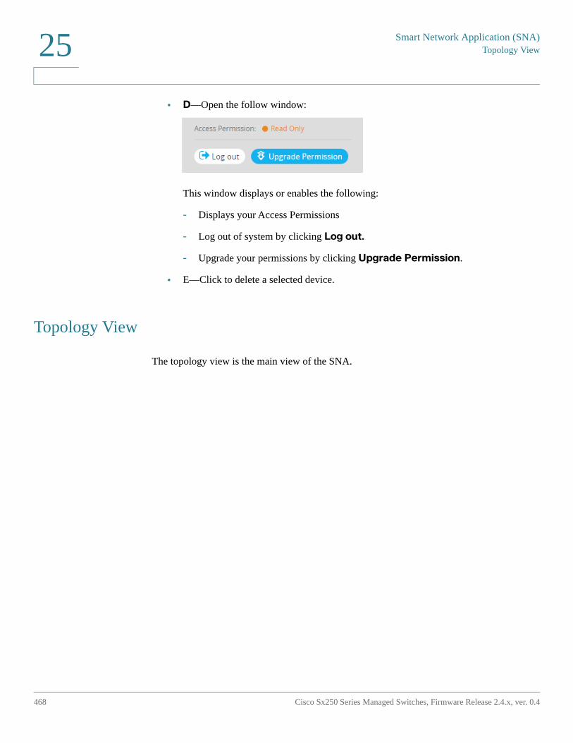
Smart Network Application (SNA)Topology View
468 Cisco Sx250 Series Managed Switches, Firmware Release 2.4.x, ver. 0.4
25
• D—Open the follow window:
This window displays or enables the following:
- Displays your Access Permissions
- Log out of system by clicking Log out.
- Upgrade your permissions by clicking Upgrade Permission.
• E—Click to delete a selected device.
Topology View
The topology view is the main view of the SNA.
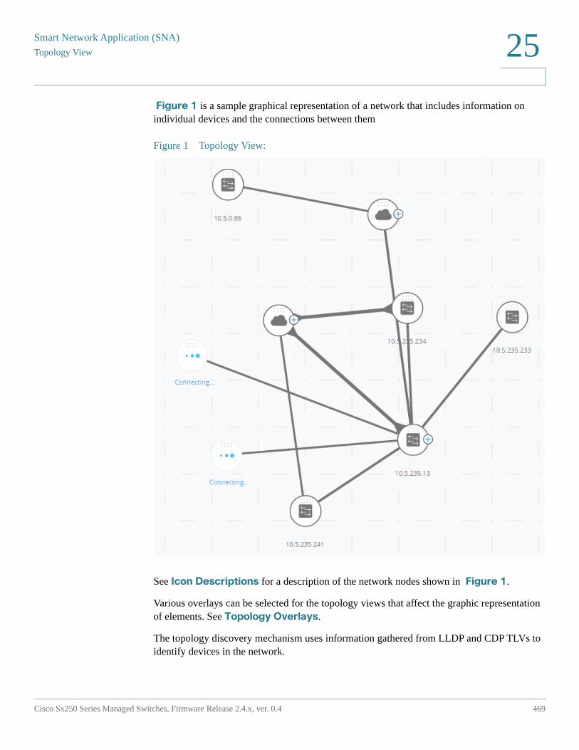
Smart Network Application (SNA)
Topology View
Cisco Sx250 Series Managed Switches, Firmware Release 2.4.x, ver. 0.4 469
25
Figure 1 is a sample graphical representation of a network that includes information on individual devices and the connections between them
Figure 1 Topology View:
See Icon Descriptions for a description of the network nodes shown in Figure 1.
Various overlays can be selected for the topology views that affect the graphic representation of elements. See Topology Overlays.
The topology discovery mechanism uses information gathered from LLDP and CDP TLVs to identify devices in the network.
Smart Network Application (SNA)Topology View
470 Cisco Sx250 Series Managed Switches, Firmware Release 2.4.x, ver. 0.4
25
To maximize information provided in the topology, all devices in the network, which support these protocols, must have them enabled.
Since the topology is created by creating management sessions with the participating SNA devices, when using the HTTPS protocol to launch the SNA, all SNA switches in the network must be authorized or added to the certificate exception list on the web client (browser) used for SNA.
Topology Overlays
Various overlays of the topology view are supported that determine the contents of the graphic representation of elements in the topology view. Supported overlays include: VLAN membership, Spanning Tree, PoE, and Link Utilization. If you select the VLAN Membership overlay, for example, VLAN information is added to the topological view. See Overlays for a complete description.
Topology Elements
The Topology view displays the following types of entities:
• Devices
• Ports
• Connections Between Devices
• Clouds
Devices
Detected devices are represented as nodes in the topology view, as shown in the Figure 1.
Click on a device to display the following information in the right-hand information (if the information is available):
• Device type—The icon shape indicates the device type. Device types include: switch, access point, PC, or IP phone. If the device type is not pre-defined, or if the type is not detected properly for some reason, the device type is shown as Unknown.
Switches discovered on the network are labeled as one of the following types:
- SNA Switch— Switch (running version 2.2.5 or higher) with the full SNA feature set.
Smart Network Application (SNA)
Topology View
Cisco Sx250 Series Managed Switches, Firmware Release 2.4.x, ver. 0.4 471
25
- Partial SNA Switch—Switch that can be accessed remotely by starting a management session through an SNA switch. This does not provide discovery, services explorers or the full SNA feature set.
- Unmanaged Switch— A switch that cannot be accessed through SNA.
• Device Name
• IP Address (A list if more than one is discovered)
• MAC Address (A list if more than one is discovered)
• Number of Notifications–The number of notifications is indicated by a number in orange on the device icon. The actual notifications are displayed in the right-hand information panel.
• SNA Support
• Manufacturer
Some devices (particularly SNA-capable devices) have additional information, such as individual port information. This information can be viewed by clicking on their icon and displaying a device explorer screen for the device.
Devices in the network are separated into the following categories:
• Backbone devices – Basic skeleton of the network. By default, all switches, routers and access points detected on the network are designated automatically as backbone devices.
After a backbone device is detected, it remains on the topology map until it is manually removed. If the device is disconnected from the network, it still appears on the topology map as an offline device.
An SNA-capable device or a managed device remains detected as long as it is connected to the network by the same IP address it used previously.
• Offline devices – Backbone devices that were previously added to the topology (either by the topology detection mechanisms or manually). These devices are now no longer detected by SNA.
Offline devices have the following characteristics:
- Distinct visual appearance from online devices on the topology map (see “Topology View:”).
- Can be moved on the topology, and its placement can be saved. You can also add tags to the device (see Tags).
Smart Network Application (SNA)Topology View
472 Cisco Sx250 Series Managed Switches, Firmware Release 2.4.x, ver. 0.4
25
- Selectable and detectable by the search functionality. When an offline device is selected, the information panel displays the device’s basic identifying information and tags, but no services, notifications, or general information beyond the basic identifiers.
- Unable to launch the device explorer or the device management GUI of offline devices.
- Can be manually removed. After a device is removed, it no longer appears on the topology map until it is detected or added manually. All tags associated with this device are lost, and is not restored even if the device is detected again in the future.
SNA periodically attempts to connect to offline devices to verify if a managed or an SNA switch has come back online. During these attempts, an indication is displayed on the device.
• Client devices – End-point clients of the network (for example, PCs, IP phones) usually connected to a backbone device. In the topology map, these devices are displayed grouped with other devices of the same type that are connected to the same backbone device. These grouping of devices are called client groups, and individual clients comprising a client group can be viewed by clicking and entering its explorer (see Explorers).
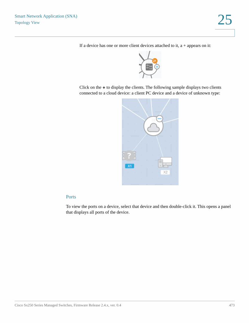
Smart Network Application (SNA)
Topology View
Cisco Sx250 Series Managed Switches, Firmware Release 2.4.x, ver. 0.4 473
25
If a device has one or more client devices attached to it, a + appears on it:
Click on the + to display the clients. The following sample displays two clients connected to a cloud device: a client PC device and a device of unknown type:
Ports
To view the ports on a device, select that device and then double-click it. This opens a panel that displays all ports of the device.
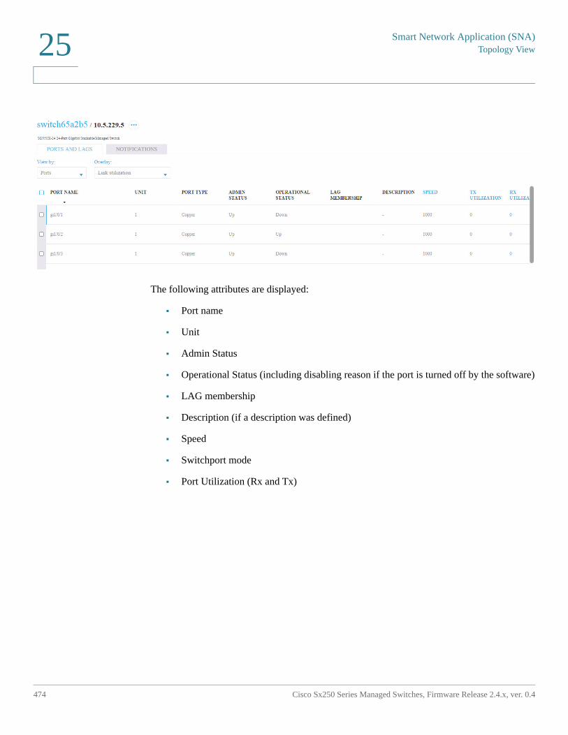
Smart Network Application (SNA)Topology View
474 Cisco Sx250 Series Managed Switches, Firmware Release 2.4.x, ver. 0.4
25
The following attributes are displayed:
• Port name
• Unit
• Admin Status
• Operational Status (including disabling reason if the port is turned off by the software)
• LAG membership
• Description (if a description was defined)
• Speed
• Switchport mode
• Port Utilization (Rx and Tx)
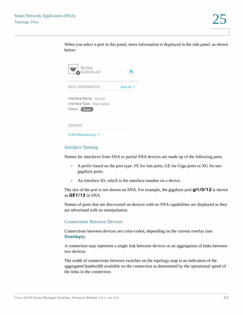
Smart Network Application (SNA)
Topology View
Cisco Sx250 Series Managed Switches, Firmware Release 2.4.x, ver. 0.4 475
25
When you select a port in this panel, more information is displayed in the side panel, as shown below:
Interface Naming
Names for interfaces from SNA or partial SNA devices are made up of the following parts.
• A prefix based on the port type: FE for fast ports, GE for Giga ports or XG for ten-gigabyte ports.
• An interface ID, which is the interface number on a device.
The slot of the port is not shown on SNA. For example, the gigabyte port gi1/0/12 is shown as GE1/12 in SNA.
Names of ports that are discovered on devices with no SNA capabilities are displayed as they are advertised with no manipulation.
Connections Between Devices
Connections between devices are color-coded, depending on the current overlay (see Overlays).
A connection may represent a single link between devices or an aggregation of links between two devices.
The width of connections between switches on the topology map is an indication of the aggregated bandwidth available on the connection as determined by the operational speed of the links in the connection.
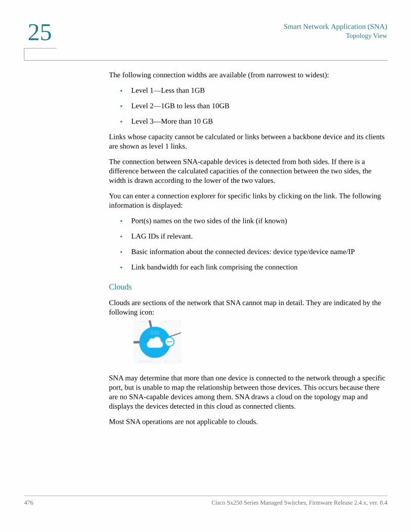
Smart Network Application (SNA)Topology View
476 Cisco Sx250 Series Managed Switches, Firmware Release 2.4.x, ver. 0.4
25
The following connection widths are available (from narrowest to widest):
• Level 1—Less than 1GB
• Level 2—1GB to less than 10GB
• Level 3—More than 10 GB
Links whose capacity cannot be calculated or links between a backbone device and its clients are shown as level 1 links.
The connection between SNA-capable devices is detected from both sides. If there is a difference between the calculated capacities of the connection between the two sides, the width is drawn according to the lower of the two values.
You can enter a connection explorer for specific links by clicking on the link. The following information is displayed:
• Port(s) names on the two sides of the link (if known)
• LAG IDs if relevant.
• Basic information about the connected devices: device type/device name/IP
• Link bandwidth for each link comprising the connection
Clouds
Clouds are sections of the network that SNA cannot map in detail. They are indicated by the following icon:
SNA may determine that more than one device is connected to the network through a specific port, but is unable to map the relationship between those devices. This occurs because there are no SNA-capable devices among them. SNA draws a cloud on the topology map and displays the devices detected in this cloud as connected clients.
Most SNA operations are not applicable to clouds.
Smart Network Application (SNA)
Right-Hand Information Panel
Cisco Sx250 Series Managed Switches, Firmware Release 2.4.x, ver. 0.4 477
25
Right-Hand Information Panel
The area to the right of the topology view displays an information panel, which displays attributes of the selected elements and enables performing actions on them.
The right-hand information panel contains the following blocks:
• Header Block
• Right-Hand Information Panel Cogwheel
• Basic Information Block
• Notifications Block
• Services Block
• Tags
• Statistics
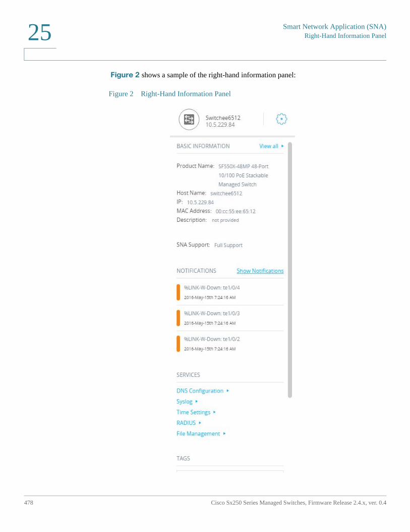
Smart Network Application (SNA)Right-Hand Information Panel
478 Cisco Sx250 Series Managed Switches, Firmware Release 2.4.x, ver. 0.4
25
Figure 2 shows a sample of the right-hand information panel:
Figure 2 Right-Hand Information Panel
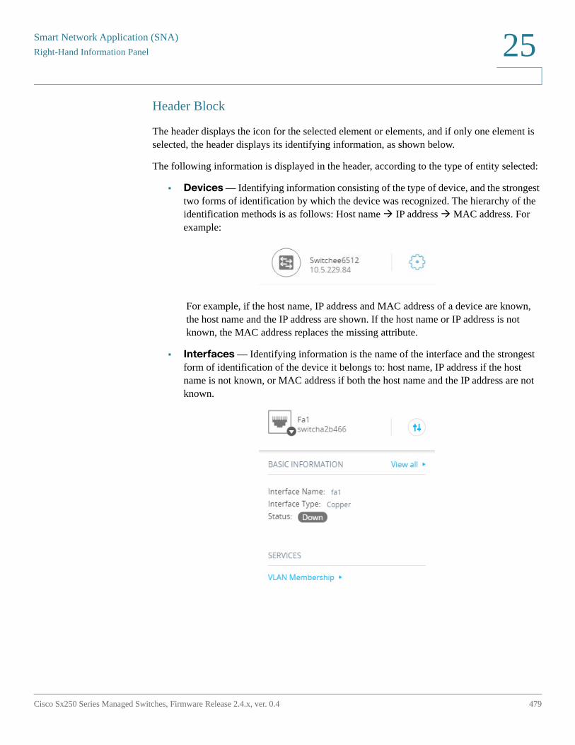
Smart Network Application (SNA)
Right-Hand Information Panel
Cisco Sx250 Series Managed Switches, Firmware Release 2.4.x, ver. 0.4 479
25
Header Block
The header displays the icon for the selected element or elements, and if only one element is selected, the header displays its identifying information, as shown below.
The following information is displayed in the header, according to the type of entity selected:
• Devices — Identifying information consisting of the type of device, and the strongest two forms of identification by which the device was recognized. The hierarchy of the identification methods is as follows: Host name IP address MAC address. For example:
For example, if the host name, IP address and MAC address of a device are known, the host name and the IP address are shown. If the host name or IP address is not known, the MAC address replaces the missing attribute.
• Interfaces — Identifying information is the name of the interface and the strongest form of identification of the device it belongs to: host name, IP address if the host name is not known, or MAC address if both the host name and the IP address are not known.
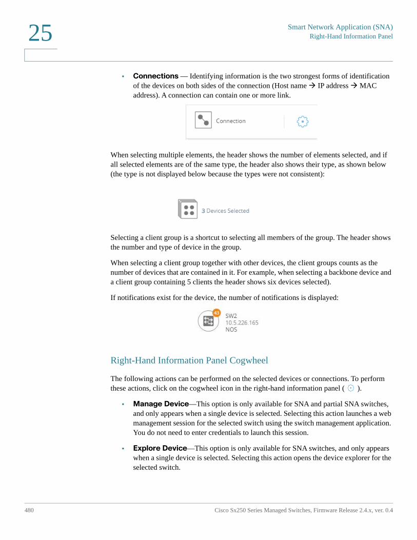
Smart Network Application (SNA)Right-Hand Information Panel
480 Cisco Sx250 Series Managed Switches, Firmware Release 2.4.x, ver. 0.4
25
• Connections — Identifying information is the two strongest forms of identification of the devices on both sides of the connection (Host name IP address MAC address). A connection can contain one or more link.
When selecting multiple elements, the header shows the number of elements selected, and if all selected elements are of the same type, the header also shows their type, as shown below (the type is not displayed below because the types were not consistent):
Selecting a client group is a shortcut to selecting all members of the group. The header shows the number and type of device in the group.
When selecting a client group together with other devices, the client groups counts as the number of devices that are contained in it. For example, when selecting a backbone device and a client group containing 5 clients the header shows six devices selected).
If notifications exist for the device, the number of notifications is displayed:
Right-Hand Information Panel Cogwheel
The following actions can be performed on the selected devices or connections. To perform these actions, click on the cogwheel icon in the right-hand information panel ( ).
• Manage Device—This option is only available for SNA and partial SNA switches, and only appears when a single device is selected. Selecting this action launches a web management session for the selected switch using the switch management application. You do not need to enter credentials to launch this session.
• Explore Device—This option is only available for SNA switches, and only appears when a single device is selected. Selecting this action opens the device explorer for the selected switch.
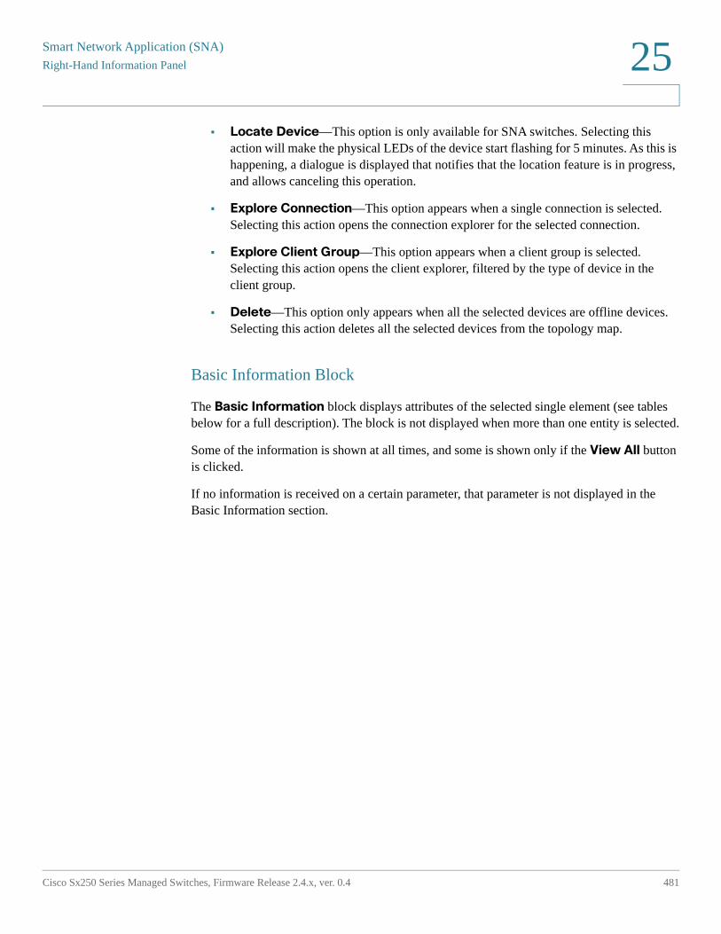
Smart Network Application (SNA)
Right-Hand Information Panel
Cisco Sx250 Series Managed Switches, Firmware Release 2.4.x, ver. 0.4 481
25
• Locate Device—This option is only available for SNA switches. Selecting this action will make the physical LEDs of the device start flashing for 5 minutes. As this is happening, a dialogue is displayed that notifies that the location feature is in progress, and allows canceling this operation.
• Explore Connection—This option appears when a single connection is selected. Selecting this action opens the connection explorer for the selected connection.
• Explore Client Group—This option appears when a client group is selected. Selecting this action opens the client explorer, filtered by the type of device in the client group.
• Delete—This option only appears when all the selected devices are offline devices. Selecting this action deletes all the selected devices from the topology map.
Basic Information Block
The Basic Information block displays attributes of the selected single element (see tables below for a full description). The block is not displayed when more than one entity is selected.
Some of the information is shown at all times, and some is shown only if the View All button is clicked.
If no information is received on a certain parameter, that parameter is not displayed in the Basic Information section.
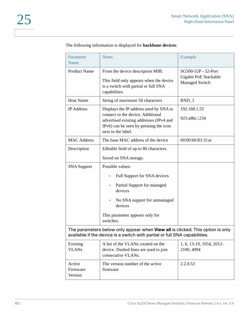
Smart Network Application (SNA)Right-Hand Information Panel
482 Cisco Sx250 Series Managed Switches, Firmware Release 2.4.x, ver. 0.4
25
The following information is displayed for backbone devices:
Parameter Name
Notes Example
Product Name From the device description MIB.
This field only appears when the device is a switch with partial or full SNA capabilities.
SG500-52P - 52-Port Gigabit PoE Stackable Managed Switch
Host Name String of maximum 58 characters RND_1
IP Address Displays the IP address used by SNA to connect to the device. Additional advertised existing addresses (IPv4 and IPv6) can be seen by pressing the icon next to the label.
192.168.1.55
923:a8bc::234
MAC Address The base MAC address of the device 00:00:b0:83:1f:ac
Description Editable field of up to 80 characters.
Saved on SNA storage.
SNA Support Possible values:
• Full Support for SNA devices
• Partial Support for managed devices
• No SNA support for unmanaged devices
This parameter appears only for switches.
The parameters below only appear when View all is clicked. This option is only available if the device is a switch with partial or full SNA capabilities.
Existing VLANs
A list of the VLANs created on the device. Dashed lines are used to join consecutive VLANs.
1, 6, 13-19, 1054, 2012-2100, 4094
Active Firmware Version
The version number of the active firmware
2.2.0.53
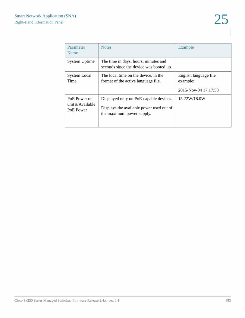
Smart Network Application (SNA)
Right-Hand Information Panel
Cisco Sx250 Series Managed Switches, Firmware Release 2.4.x, ver. 0.4 483
25
System Uptime The time in days, hours, minutes and seconds since the device was booted up.
System Local Time
The local time on the device, in the format of the active language file.
English language file example:
2015-Nov-04 17:17:53
PoE Power on unit #/Available PoE Power
Displayed only on PoE-capable devices.
Displays the available power used out of the maximum power supply.
15.22W/18.0W
Parameter Name
Notes Example
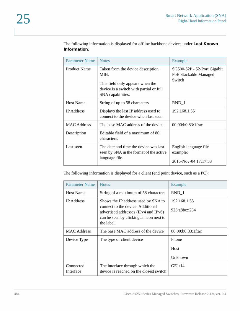
Smart Network Application (SNA)Right-Hand Information Panel
484 Cisco Sx250 Series Managed Switches, Firmware Release 2.4.x, ver. 0.4
25
The following information is displayed for offline backbone devices under Last Known
Information:
The following information is displayed for a client (end point device, such as a PC):
Parameter Name Notes Example
Product Name Taken from the device description MIB.
This field only appears when the device is a switch with partial or full SNA capabilities.
SG500-52P - 52-Port Gigabit PoE Stackable Managed Switch
Host Name String of up to 58 characters RND_1
IP Address Displays the last IP address used to connect to the device when last seen.
192.168.1.55
MAC Address The base MAC address of the device 00:00:b0:83:1f:ac
Description Editable field of a maximum of 80 characters.
Last seen The date and time the device was last seen by SNA in the format of the active language file.
English language file example:
2015-Nov-04 17:17:53
Parameter Name Notes Example
Host Name String of a maximum of 58 characters RND_1
IP Address Shows the IP address used by SNA to connect to the device. Additional advertised addresses (IPv4 and IPv6) can be seen by clicking an icon next to the label.
192.168.1.55
923:a8bc::234
MAC Address The base MAC address of the device 00:00:b0:83:1f:ac
Device Type The type of client device Phone
Host
Unknown
Connected Interface
The interface through which the device is reached on the closest switch
GE1/14
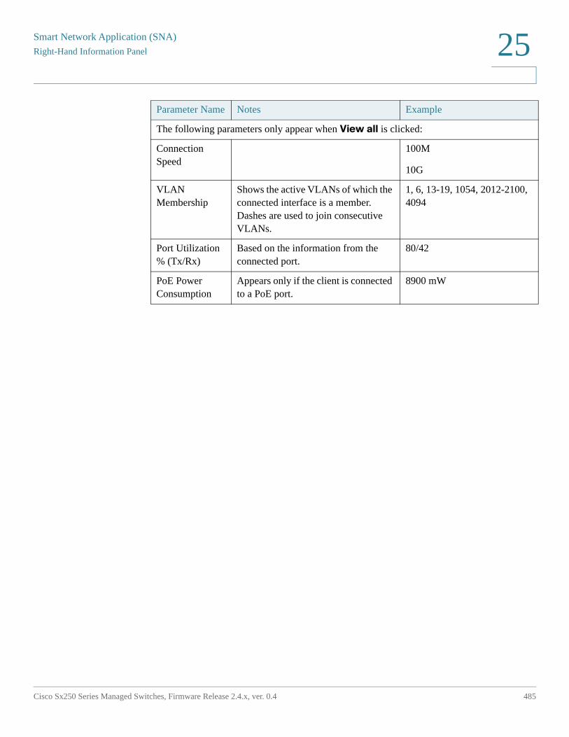
Smart Network Application (SNA)
Right-Hand Information Panel
Cisco Sx250 Series Managed Switches, Firmware Release 2.4.x, ver. 0.4 485
25
The following parameters only appear when View all is clicked:
Connection Speed
100M
10G
VLAN Membership
Shows the active VLANs of which the connected interface is a member. Dashes are used to join consecutive VLANs.
1, 6, 13-19, 1054, 2012-2100, 4094
Port Utilization % (Tx/Rx)
Based on the information from the connected port.
80/42
PoE Power Consumption
Appears only if the client is connected to a PoE port.
8900 mW
Parameter Name Notes Example
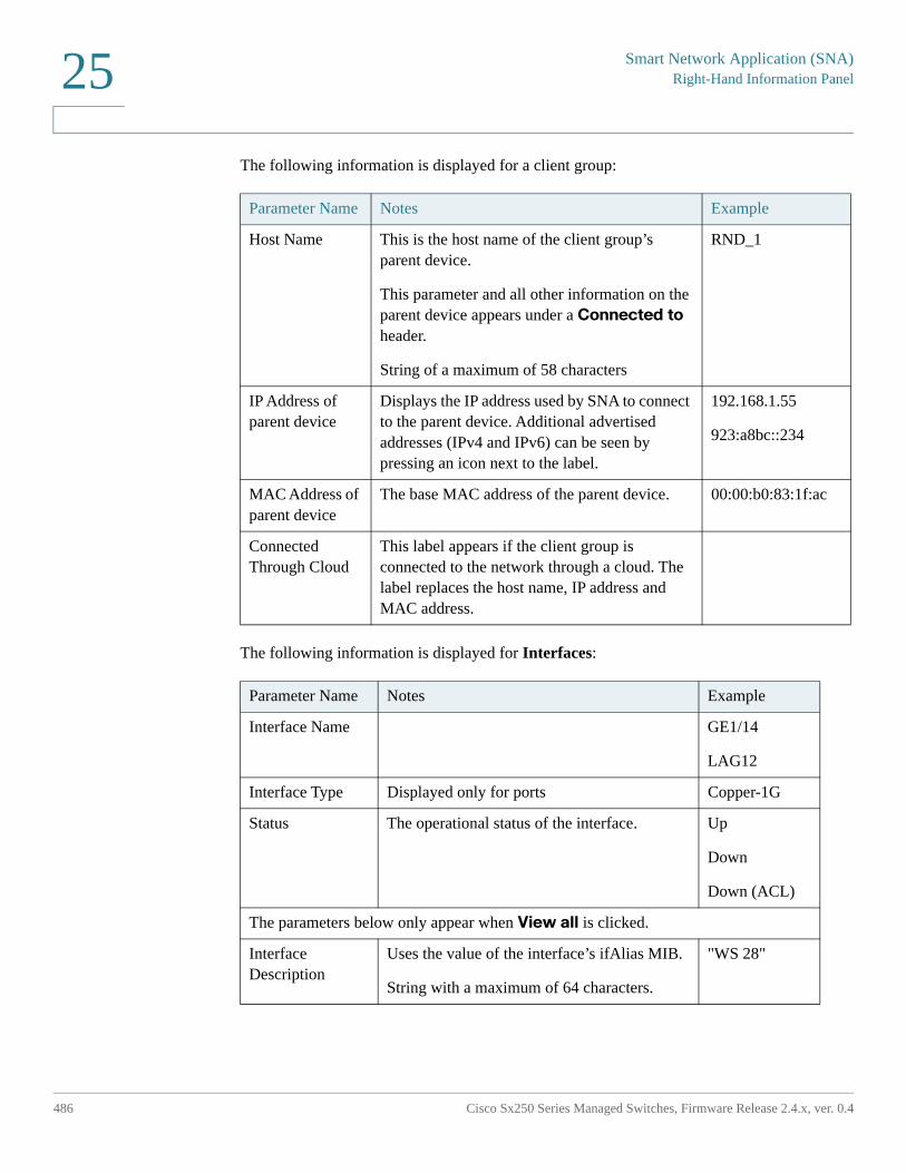
Smart Network Application (SNA)Right-Hand Information Panel
486 Cisco Sx250 Series Managed Switches, Firmware Release 2.4.x, ver. 0.4
25
The following information is displayed for a client group:
The following information is displayed for Interfaces:
Parameter Name Notes Example
Host Name This is the host name of the client group’s parent device.
This parameter and all other information on the parent device appears under a Connected to header.
String of a maximum of 58 characters
RND_1
IP Address of parent device
Displays the IP address used by SNA to connect to the parent device. Additional advertised addresses (IPv4 and IPv6) can be seen by pressing an icon next to the label.
192.168.1.55
923:a8bc::234
MAC Address of parent device
The base MAC address of the parent device. 00:00:b0:83:1f:ac
Connected Through Cloud
This label appears if the client group is connected to the network through a cloud. The label replaces the host name, IP address and MAC address.
Parameter Name Notes Example
Interface Name GE1/14
LAG12
Interface Type Displayed only for ports Copper-1G
Status The operational status of the interface. Up
Down
Down (ACL)
The parameters below only appear when View all is clicked.
Interface Description
Uses the value of the interface’s ifAlias MIB.
String with a maximum of 64 characters.
"WS 28"
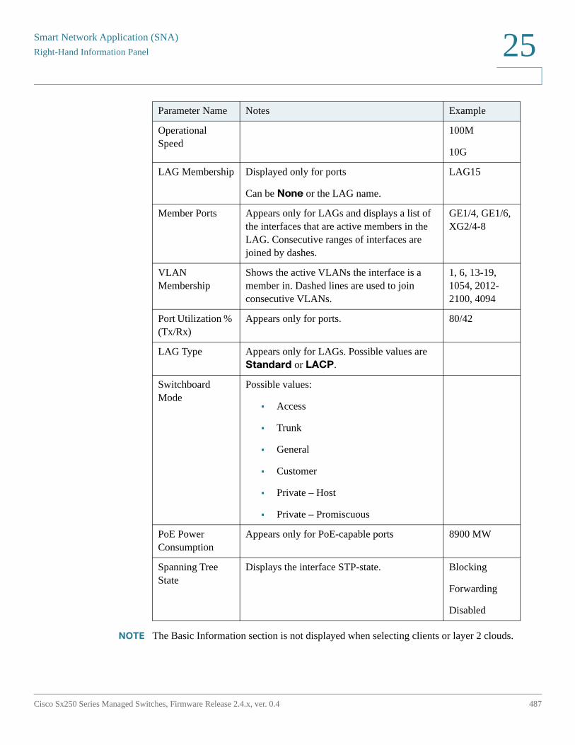
Smart Network Application (SNA)
Right-Hand Information Panel
Cisco Sx250 Series Managed Switches, Firmware Release 2.4.x, ver. 0.4 487
25
NOTE The Basic Information section is not displayed when selecting clients or layer 2 clouds.
Operational Speed
100M
10G
LAG Membership Displayed only for ports
Can be None or the LAG name.
LAG15
Member Ports Appears only for LAGs and displays a list of the interfaces that are active members in the LAG. Consecutive ranges of interfaces are joined by dashes.
GE1/4, GE1/6, XG2/4-8
VLAN Membership
Shows the active VLANs the interface is a member in. Dashed lines are used to join consecutive VLANs.
1, 6, 13-19, 1054, 2012-2100, 4094
Port Utilization % (Tx/Rx)
Appears only for ports. 80/42
LAG Type Appears only for LAGs. Possible values are Standard or LACP.
Switchboard Mode
Possible values:
• Access
• Trunk
• General
• Customer
• Private – Host
• Private – Promiscuous
PoE Power Consumption
Appears only for PoE-capable ports 8900 MW
Spanning Tree State
Displays the interface STP-state. Blocking
Forwarding
Disabled
Parameter Name Notes Example
Smart Network Application (SNA)Right-Hand Information Panel
488 Cisco Sx250 Series Managed Switches, Firmware Release 2.4.x, ver. 0.4
25
Notifications Block
The notification block displays the latest notifications (SYSLOGs) recorded on the selected device.
The notifications section only appears when selecting a single SNA device.
See Notifications for additional details.
Services Block
This section of the information panel displays available services for the current selection of elements. Only services that are relevant for all selected elements are displayed. This section is not displayed if elements, which do not support services, are a part of the selection, or when devices and interfaces are selected together.
See Services for additional information.
Tags
Tags are used to identify elements in the topology by attributes (see Tags). The Tag block of the right-hand information displays all the tags assigned to the element, either automatically or by the user. You can also manage the tags of the selected elements from this part of the panel. See Tags for additional information.
Statistics
When viewing an SNA-capable device, or the interfaces on an SNA-capable device, you can select to view historical statistics information on that interface or device.
The Statistics view is accessed from the right-hand information panel.
To view historical statistics on an interface or device, select a specific parameter to view from a list of available parameters, according to the parameters supported by the embedded counters history feature. You can then view the status of this parameter on the selected interface for the previous year.
Smart Network Application (SNA)
Right-Hand Information Panel
Cisco Sx250 Series Managed Switches, Firmware Release 2.4.x, ver. 0.4 489
25
The following graphs can be viewed:
• Port Utilization Graph
• PoE Consumption Graph (Port)
• PoE Consumption Graph (Device)
• Traffic Graph (Bytes)
• Traffic Graph (Packets)
Port Utilization Graph
This graph is a port-level graph that shows the port utilization percentage of the port over time. It is available for all ports of devices with full SNA support.
You can select a number of ports to run a side-by-side comparison.
The data is shown as a percentage (0-100) with number and frequency of samples depending on the displayed time scale:
• Last five minutes—20 samples (one every 15 seconds).
• Last hour—60 samples (one every minute)
• Last day—24 samples (one every hour)
• Last week—7 samples (one every day)
• Last 3 months—12 samples (one every week)
PoE Consumption Graph (Port)
This graph is a port-level graph that shows the PoE utilization of the port over time. It is available for all PoE ports of devices with full SNA support.
You can select a number of ports to run a side-by-side comparison.
The data is shown as a number of watts (0 - 30/60 depending on whether the port has PoE+ capability) with number and frequency of samples depending on the displayed time scale:
• Last hour—60 samples (one every minute)
• Last day—24 samples (one every hour)
• Last week—7 samples (one every day)
• Last year—52 samples (one every week)
Smart Network Application (SNA)Right-Hand Information Panel
490 Cisco Sx250 Series Managed Switches, Firmware Release 2.4.x, ver. 0.4
25
PoE Consumption Graph (Device)
This graph is a device-level graph that shows the PoE utilization of the device over time. The graph is available for all PoE devices with full SNA support.
The graph is represented per unit, and you can select a number of units to view simultaneously.
The data is shown as a number of watts (0 - the PoE capacity of the selected unit with the highest capacity) with numbers and frequency of samples depending on the displayed time scale:
• Last hour—60 samples (one every minute)
• Last day—24 samples (one every hour)
• Last week—7 samples (one every day)
• Last year—52 samples (one every week)
Traffic Graph (Bytes)
This graph is an interface-level graph that shows the total traffic on an interface in bytes over time. The graph is available for all interfaces of devices with full SNA support and has separate lines for Tx and for Rx traffic.
You can select a number of ports and types of traffic to run a side-by-side comparison.
The data is shown as a number of octets (0 - highest sample in selected interfaces/time period) with number and frequency of samples depending on the displayed time scale:
• Last five minutes—20 samples (one every 15 seconds).
• Last hour—60 samples (one every minute)
• Last day—24 samples (one every hour)
• Last week—7 samples (one every day)
• Last 3 months—12 samples (one every week)
Traffic Graph (Packets)
This graph is an interface-level graph that shows the total traffic on an interface in packets over time. The graph is available for all interfaces (ports or LAGs) of devices with full SNA support.
The data in both versions is shown as a number of packets (0 being the highest value in sampled range) with number and frequency of samples depending on the displayed time scale:
• Last five minutes—20 samples (one every 15 seconds).
Smart Network Application (SNA)
Operations
Cisco Sx250 Series Managed Switches, Firmware Release 2.4.x, ver. 0.4 491
25
• Last hour—60 samples (one every minute)
• Last day—24 samples (one every hour)
• Last week—7 samples (one every day)
• Last 3 months—12 samples (one every week)
Operations
The topology view displays the elements and their connections in the network. Operations can be performed on elements displayed in the topology view.
When you select an element in the topology, it is possible to perform the following actions:
• View information regarding the element—See Explorers
• Configure an element—See Services
• Add a device or switch to the Topology View—See Manually Adding a Device or
Switch to the Topology View
NOTE When selecting multiple elements, only actions that are available for all the selected elements are available.
You can perform more operations on SNA-capable devices than other devices in the topology.
The following actions can be performed for SNA-capable devices:
• Zoom into a more detailed view of its interfaces.
• Launch web management sessions on other SNA-capable devices and on managed devices through SNA (bypassing the login screen) if the managed device/SNA device allows management sessions using the same credentials used to log in to SNA.
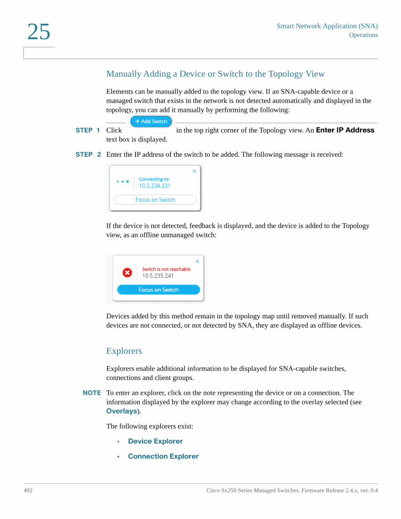
Smart Network Application (SNA)Operations
492 Cisco Sx250 Series Managed Switches, Firmware Release 2.4.x, ver. 0.4
25
Manually Adding a Device or Switch to the Topology View
Elements can be manually added to the topology view. If an SNA-capable device or a managed switch that exists in the network is not detected automatically and displayed in the topology, you can add it manually by performing the following:
STEP 1 Click in the top right corner of the Topology view. An Enter IP Address text box is displayed.
STEP 2 Enter the IP address of the switch to be added. The following message is received:
If the device is not detected, feedback is displayed, and the device is added to the Topology view, as an offline unmanaged switch:
Devices added by this method remain in the topology map until removed manually. If such devices are not connected, or not detected by SNA, they are displayed as offline devices.
Explorers
Explorers enable additional information to be displayed for SNA-capable switches, connections and client groups.
NOTE To enter an explorer, click on the note representing the device or on a connection. The information displayed by the explorer may change according to the overlay selected (see Overlays).
The following explorers exist:
• Device Explorer
• Connection Explorer
Smart Network Application (SNA)
Operations
Cisco Sx250 Series Managed Switches, Firmware Release 2.4.x, ver. 0.4 493
25
• Client Explorer
Device Explorer
This explorer provides additional information on full SNA devices and their interfaces.
It displays a table view of the ports and existing LAGs in the switch. Every entry in the table has several basic columns, and a small number of additional columns that appear only when the relevant overlay is active.
From here, you can also edit and save the device's host name.
The following columns are displayed in the Device Explorer table:
• Port/LAG Name — Full interface name.
• Port Type — Displays only in the port table. Physical type of the port.
• Admin Status — The interface’s administrative status.
• Operational Status — The interface’s operational state. If the interface is suspended, the suspension reason appears in parenthesis.
• LAG Membership — Displays only in the port table. If the port is a member of a LAG, this column shows the LAG ID.
• Port Members — Displays only in the LAG table. Displays a list of the ports that are members in this LAG. This field may contain a long list of ports. If the complete list does not fit in the table, it may be viewed on the right-hand information.
• Description — Description of the interface. Uses the MIB ifAlias.
• When the Link Utilization overlay is selected, the following columns are displayed:
- Current Speed — Current speed of the interface (10M, 100M, 1G…).
- Tx Utilization — Tx utilization of the interface as a percentage of the current speed. This column is not displayed for LAGs.
- Rx Utilization — Rx utilization of the interface as a percentage of the current speed. This column is not displayed for LAGs
• When the PoE overlay is selected, the following columns are displayed:
- Maximum Power Allocation — Displays only in the port table. Displays the maximum power allocation in MW. If a port does not support PoE, shows N/A.
- Power Consumption — Appears only in the port table. Displays the actual power consumption in MW. If a port does not support PoE, displays N/A.
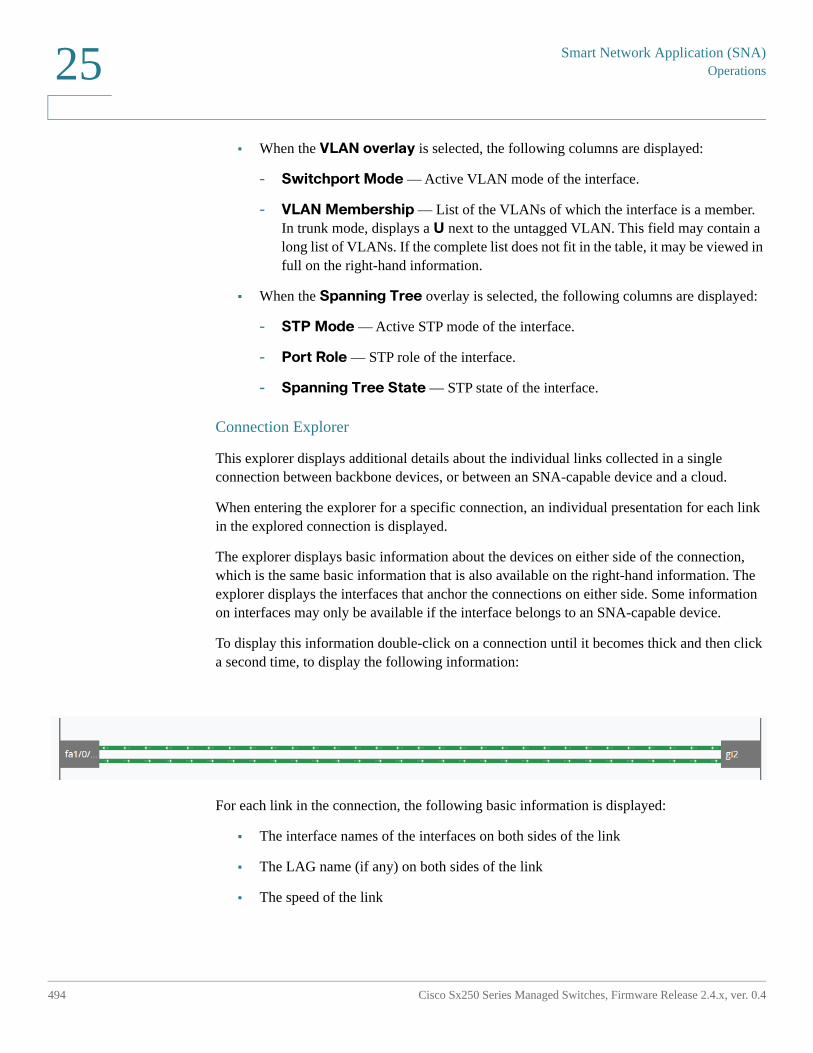
Smart Network Application (SNA)Operations
494 Cisco Sx250 Series Managed Switches, Firmware Release 2.4.x, ver. 0.4
25
• When the VLAN overlay is selected, the following columns are displayed:
- Switchport Mode — Active VLAN mode of the interface.
- VLAN Membership — List of the VLANs of which the interface is a member. In trunk mode, displays a U next to the untagged VLAN. This field may contain a long list of VLANs. If the complete list does not fit in the table, it may be viewed in full on the right-hand information.
• When the Spanning Tree overlay is selected, the following columns are displayed:
- STP Mode — Active STP mode of the interface.
- Port Role — STP role of the interface.
- Spanning Tree State — STP state of the interface.
Connection Explorer
This explorer displays additional details about the individual links collected in a single connection between backbone devices, or between an SNA-capable device and a cloud.
When entering the explorer for a specific connection, an individual presentation for each link in the explored connection is displayed.
The explorer displays basic information about the devices on either side of the connection, which is the same basic information that is also available on the right-hand information. The explorer displays the interfaces that anchor the connections on either side. Some information on interfaces may only be available if the interface belongs to an SNA-capable device.
To display this information double-click on a connection until it becomes thick and then click a second time, to display the following information:
For each link in the connection, the following basic information is displayed:
• The interface names of the interfaces on both sides of the link
• The LAG name (if any) on both sides of the link
• The speed of the link
Smart Network Application (SNA)
Operations
Cisco Sx250 Series Managed Switches, Firmware Release 2.4.x, ver. 0.4 495
25
This information about interface names and LAG membership is only available on the sides of the connection that belong to SNA-capable devices. If one of the sides of the connection is not a switch, its ports are not displayed.
The specific links in the explorer are also affected by the active overlay, changing the visual display of the link according to its status relevant to the selected overlay. See Overlays.
When selecting a link in the connection explorer, the interfaces anchoring the link on both sides are selected.
Client Explorer
This explorer enables viewing information about selected clients in a client group, such as a group of IP phones.
This explorer is comprised of a table with a row for each device in the client group. Some columns in this table are only displayed when specific overlays are active.
The client explorer is not supported for client groups that are connected to the network through a cloud.
The following information is displayed in the Client Explorer table:
• Device ID—Known information about the device: its host name, the IP address it uses to connect to its parent switch and the device’s MAC address. Only the available information is displayed here. There are no placeholders for non-available information.
• Device Type—Type of client device.
• Connected port—The port on the parent switch to which this client is
connected.
• Link Utilization Overlay Columns
- Connection speed—Shows the speed of the connection to the parent
switch (10M, 100M, 1G).
- Tx Utilization—The Tx utilization of the device (Rx of the connected
port) as a percentage of the current speed.
- Rx Utilization—The Rx utilization of the device (Tx of the connected
port) as a percentage of the current speed.
• PoE Overlay column
- Power Consumption—Shows the power consumed by the device in
MW. If the connected port does not support PoE, shows N/A.
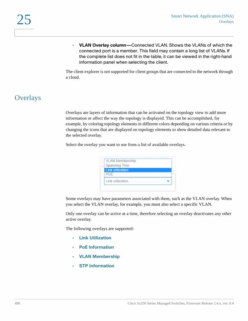
Smart Network Application (SNA)Overlays
496 Cisco Sx250 Series Managed Switches, Firmware Release 2.4.x, ver. 0.4
25
• VLAN Overlay column—Connected VLAN. Shows the VLANs of which the
connected port is a member. This field may contain a long list of VLANs. If
the complete list does not fit in the table, it can be viewed in the right-hand
information panel when selecting the client.
The client explorer is not supported for client groups that are connected to the network through a cloud.
Overlays
Overlays are layers of information that can be activated on the topology view to add more information or affect the way the topology is displayed. This can be accomplished, for example, by coloring topology elements in different colors depending on various criteria or by changing the icons that are displayed on topology elements to show detailed data relevant to the selected overlay.
Select the overlay you want to use from a list of available overlays.
Some overlays may have parameters associated with them, such as the VLAN overlay. When you select the VLAN overlay, for example, you must also select a specific VLAN.
Only one overlay can be active at a time, therefore selecting an overlay deactivates any other active overlay.
The following overlays are supported:
• Link Utilization
• PoE Information
• VLAN Membership
• STP Information
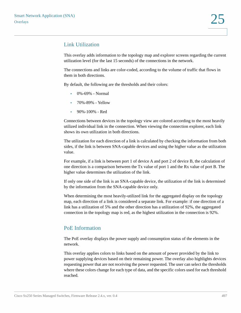
Smart Network Application (SNA)
Overlays
Cisco Sx250 Series Managed Switches, Firmware Release 2.4.x, ver. 0.4 497
25
Link Utilization
This overlay adds information to the topology map and explorer screens regarding the current utilization level (for the last 15 seconds) of the connections in the network.
The connections and links are color-coded, according to the volume of traffic that flows in them in both directions.
By default, the following are the thresholds and their colors:
• 0%-69% - Normal
• 70%-89% - Yellow
• 90%-100% - Red
Connections between devices in the topology view are colored according to the most heavily utilized individual link in the connection. When viewing the connection explorer, each link shows its own utilization in both directions.
The utilization for each direction of a link is calculated by checking the information from both sides, if the link is between SNA-capable devices and using the higher value as the utilization value.
For example, if a link is between port 1 of device A and port 2 of device B, the calculation of one direction is a comparison between the Tx value of port 1 and the Rx value of port B. The higher value determines the utilization of the link.
If only one side of the link is an SNA-capable device, the utilization of the link is determined by the information from the SNA-capable device only.
When determining the most heavily-utilized link for the aggregated display on the topology map, each direction of a link is considered a separate link. For example: if one direction of a link has a utilization of 5% and the other direction has a utilization of 92%, the aggregated connection in the topology map is red, as the highest utilization in the connection is 92%.
PoE Information
The PoE overlay displays the power supply and consumption status of the elements in the network.
This overlay applies colors to links based on the amount of power provided by the link to power supplying devices based on their remaining power. The overlay also highlights devices requesting power that are not receiving the power requested. The user can select the thresholds where these colors change for each type of data, and the specific colors used for each threshold reached.
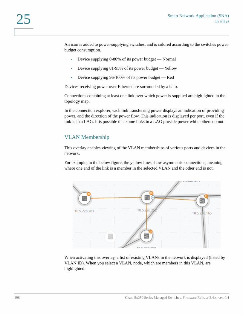
Smart Network Application (SNA)Overlays
498 Cisco Sx250 Series Managed Switches, Firmware Release 2.4.x, ver. 0.4
25
An icon is added to power-supplying switches, and is colored according to the switches power budget consumption.
• Device supplying 0-80% of its power budget — Normal
• Device supplying 81-95% of its power budget — Yellow
• Device supplying 96-100% of its power budget — Red
Devices receiving power over Ethernet are surrounded by a halo.
Connections containing at least one link over which power is supplied are highlighted in the topology map.
In the connection explorer, each link transferring power displays an indication of providing power, and the direction of the power flow. This indication is displayed per port, even if the link is in a LAG. It is possible that some links in a LAG provide power while others do not.
VLAN Membership
This overlay enables viewing of the VLAN memberships of various ports and devices in the network.
For example, in the below figure, the yellow lines show asymmetric connections, meaning where one end of the link is a member in the selected VLAN and the other end is not.
When activating this overlay, a list of existing VLANs in the network is displayed (listed by VLAN ID). When you select a VLAN, node, which are members in this VLAN, are highlighted.
Smart Network Application (SNA)
Tags
Cisco Sx250 Series Managed Switches, Firmware Release 2.4.x, ver. 0.4 499
25
Links between devices are displayed in one of the following states:
• A link between SNA devices, where neither of the connected interfaces on either device is a member of the VLAN, is unmarked.
• A link between an SNA device and a non-SNA device, whose interface on the SNA device is not in the VLAN, is unmarked.
• A link between SNA devices where the connected interfaces in both devices are members of the VLAN is highlighted as a member of the VLAN.
• A link between an SNA device and a non-SNA device whose interface on the SNA device is a member of the VLAN is highlighted.
• An asymmetric link between SNA devices where one of the connected interfaces is a member of the VLAN and the other one is not is marked in yellow.
The connection between an aggregation of links (LAGs) between devices in the topology map is marked according to the following rules:
• If at least one link is highlighted, the connection is highlighted.
• If at least one link has an asymmetric connection, the connection is yellow.
In the Connection Explorer, every link can be viewed individually. When a link is has an asymmetric configuration, in addition to being colored yellow, the connection explorer displays which side of the link is not a member of the VLAN.
STP Information
This overlay displays the active topology of the network. When this overlay is activated, an indication is added to the spanning tree root device and all connections. This indication highlights the links that are blocked by the common spanning tree.
When viewing a connection explorer, all blocked links are highlighted.
When a link is blocked, the connection explorer specifies which end of the link is the actual blocked interface.
Tags
Tags are used to identify devices in the Topology view by attributes or by user-defined names. Tags are used to quickly select multiple elements by searching for a specific tag. For example, you can search for all network nodes labelled with the IP Phone tag.
Smart Network Application (SNA)Tags
500 Cisco Sx250 Series Managed Switches, Firmware Release 2.4.x, ver. 0.4
25
Tags can be built-in or user-defined.
• Built-in tags—Applied automatically to nodes based on information gathered by Discovery protocols. See Built-In Tags.
• User-defined tags—Added manually and assigned to nodes in the topology map. See User-Defined Tags.
Built-in and user-defined tags are visually distinct from each other.
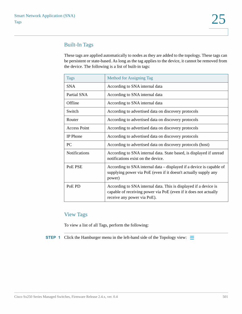
Smart Network Application (SNA)
Tags
Cisco Sx250 Series Managed Switches, Firmware Release 2.4.x, ver. 0.4 501
25
Built-In Tags
These tags are applied automatically to nodes as they are added to the topology. These tags can be persistent or state-based. As long as the tag applies to the device, it cannot be removed from the device. The following is a list of built-in tags:
View Tags
To view a list of all Tags, perform the following:
STEP 1 Click the Hamburger menu in the left-hand side of the Topology view:
Tags Method for Assigning Tag
SNA According to SNA internal data
Partial SNA According to SNA internal data
Offline According to SNA internal data
Switch According to advertised data on discovery protocols
Router According to advertised data on discovery protocols
Access Point According to advertised data on discovery protocols
IP Phone According to advertised data on discovery protocols
PC According to advertised data on discovery protocols (host)
Notifications According to SNA internal data. State based, is displayed if unread notifications exist on the device.
PoE PSE According to SNA internal data – displayed if a device is capable of supplying power via PoE (even if it doesn't actually supply any power)
PoE PD According to SNA internal data. This is displayed if a device is capable of receiving power via PoE (even if it does not actually receive any power via PoE).
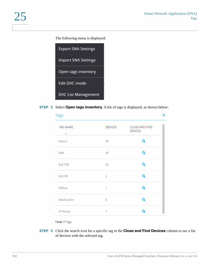
Smart Network Application (SNA)Tags
502 Cisco Sx250 Series Managed Switches, Firmware Release 2.4.x, ver. 0.4
25
The following menu is displayed:
STEP 2 Select Open tags inventory. A list of tags is displayed, as shown below:
STEP 3 Click the search icon for a specific tag in the Close and Find Devices column to see a list of devices with the selected tag.
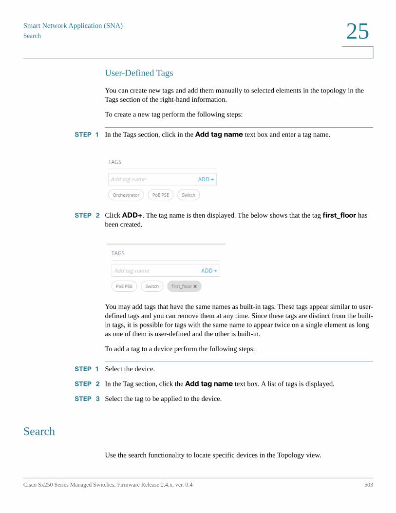
Smart Network Application (SNA)
Search
Cisco Sx250 Series Managed Switches, Firmware Release 2.4.x, ver. 0.4 503
25
User-Defined Tags
You can create new tags and add them manually to selected elements in the topology in the Tags section of the right-hand information.
To create a new tag perform the following steps:
STEP 1 In the Tags section, click in the Add tag name text box and enter a tag name.
STEP 2 Click ADD+. The tag name is then displayed. The below shows that the tag first_floor has been created.
You may add tags that have the same names as built-in tags. These tags appear similar to user-defined tags and you can remove them at any time. Since these tags are distinct from the built-in tags, it is possible for tags with the same name to appear twice on a single element as long as one of them is user-defined and the other is built-in.
To add a tag to a device perform the following steps:
STEP 1 Select the device.
STEP 2 In the Tag section, click the Add tag name text box. A list of tags is displayed.
STEP 3 Select the tag to be applied to the device.
Search
Use the search functionality to locate specific devices in the Topology view.
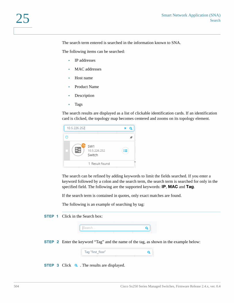
Smart Network Application (SNA)Search
504 Cisco Sx250 Series Managed Switches, Firmware Release 2.4.x, ver. 0.4
25
The search term entered is searched in the information known to SNA.
The following items can be searched:
• IP addresses
• MAC addresses
• Host name
• Product Name
• Description
• Tags
The search results are displayed as a list of clickable identification cards. If an identification card is clicked, the topology map becomes centered and zooms on its topology element.
The search can be refined by adding keywords to limit the fields searched. If you enter a keyword followed by a colon and the search term, the search term is searched for only in the specified field. The following are the supported keywords: IP, MAC and Tag.
If the search term is contained in quotes, only exact matches are found.
The following is an example of searching by tag:
STEP 1 Click in the Search box:
STEP 2 Enter the keyword “Tag” and the name of the tag, as shown in the example below:
STEP 3 Click . The results are displayed.
Smart Network Application (SNA)
Dashboard
Cisco Sx250 Series Managed Switches, Firmware Release 2.4.x, ver. 0.4 505
25
Dashboard
The network dashboard is a separate screen from the topology that displays general information about the status of the network.
The dashboard contains the following sections:
Network Overview
This section displays general information about the network. All the information displayed here is provided by the SNA and partial SNA devices on the network.
The following information is displayed:
• PoE power supplied by PoE devices on the network – Displayed in Watts.
• Current power saved by green Ethernet – Displayed as a percentage and Watts value (for example: 20%; 5 Watts).
• Cumulative power saved by green Ethernet – Displayed as Watts * Hours.
• Projected annual power savings by green Ethernet – Displayed as Watts * Hours.
• Current power saved by power management policy – Displayed as Watts.
• Cumulative power saved by power management policy – Displayed as Watts * Hours.
• Projected annual power savings by power management policy – Displayed as Watt s* Hours.
Alerts
This section displays the ten most recent alerts on the network. The alerts are notifications of severity rank 1 (see Notifications Block).
These alerts are displayed in a table with the following columns:
• Originating device
This appears only in the aggregated notifications display. The originating device is identified by the strongest available form of identification according to the following priority: Host name > IP address > MAC address.
Smart Network Application (SNA)Dashboard
506 Cisco Sx250 Series Managed Switches, Firmware Release 2.4.x, ver. 0.4
25
• Timestamp.
• Severity
• Syslog text.
The list can be sorted by device, time or severity and can be filtered by device or severity.
By default, the list is sorted by timestamp, with the most recent notification appearing first.
Network Health
This section displays alerts if a health problem is detected on any SNA device in the network.
Alerts display the device or connection that they happened in, provide a link to the appropriate device or connection explorer and the nature of the problem.
They are displayed for the following events
• A fan fails.
• A temperature sensor detects dangerously high temperature.
• PoE is overloaded (a request for PoE cannot be supplied because the budget is surpassed).
• A connection's traffic utilization reaches 70%/90% or higher.
• A device's CPU utilization reaches 96% or higher.
This section does not appear if there are no health problems in the network.
Suspended Interfaces
This section display information on all suspended ports in the network.
The following information is displayed for each suspended interface:
• Device ID
• Interface Name
• Suspension Reason (string of up to 20 characters)
• Auto Recovery Status (Enabled/Disabled)
• A button to attempt to re-activate the interface (this button requires the SNA to be in full permission mode).
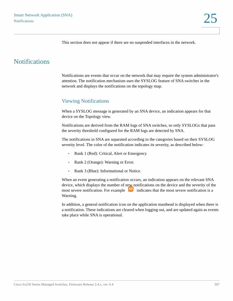
Smart Network Application (SNA)
Notifications
Cisco Sx250 Series Managed Switches, Firmware Release 2.4.x, ver. 0.4 507
25
This section does not appear if there are no suspended interfaces in the network.
Notifications
Notifications are events that occur on the network that may require the system administrator's attention. The notification mechanism uses the SYSLOG feature of SNA switches in the network and displays the notifications on the topology map.
Viewing Notifications
When a SYSLOG message is generated by an SNA device, an indication appears for that device on the Topology view.
Notifications are derived from the RAM logs of SNA switches, so only SYSLOGs that pass the severity threshold configured for the RAM logs are detected by SNA.
The notifications in SNA are separated according to the categories based on their SYSLOG severity level. The color of the notification indicates its severity, as described below:
• Rank 1 (Red): Critical, Alert or Emergency
• Rank 2 (Orange): Warning or Error.
• Rank 3 (Blue): Informational or Notice.
When an event generating a notification occurs, an indication appears on the relevant SNA device, which displays the number of new notifications on the device and the severity of the most severe notification. For example indicates that the most severe notification is a Warning.
In addition, a general notification icon on the application masthead is displayed when there is a notification. These indications are cleared when logging out, and are updated again as events take place while SNA is operational.
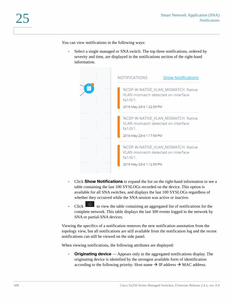
Smart Network Application (SNA)Notifications
508 Cisco Sx250 Series Managed Switches, Firmware Release 2.4.x, ver. 0.4
25
You can view notifications in the following ways:
• Select a single managed or SNA switch. The top three notifications, ordered by severity and time, are displayed in the notifications section of the right-hand information.
• Click Show Notifications to expand the list on the right-hand information to see a table containing the last 100 SYSLOGs recorded on the device. This option is available for all SNA switches, and displays the last 100 SYSLOGs regardless of whether they occurred while the SNA session was active or inactive.
• Click to view the table containing an aggregated list of notifications for the complete network. This table displays the last 300 events logged in the network by SNA or partial-SNA devices.
Viewing the specifics of a notification removes the new notification annotation from the topology view, but all notifications are still available from the notification log and the recent notifications can still be viewed on the side panel.
When viewing notifications, the following attributes are displayed:
• Originating device — Appears only in the aggregated notifications display. The originating device is identified by the strongest available form of identification according to the following priority: Host name IP address MAC address.
Smart Network Application (SNA)
Notifications
Cisco Sx250 Series Managed Switches, Firmware Release 2.4.x, ver. 0.4 509
25
• Timestamp
• Severity
• SYSLOG text
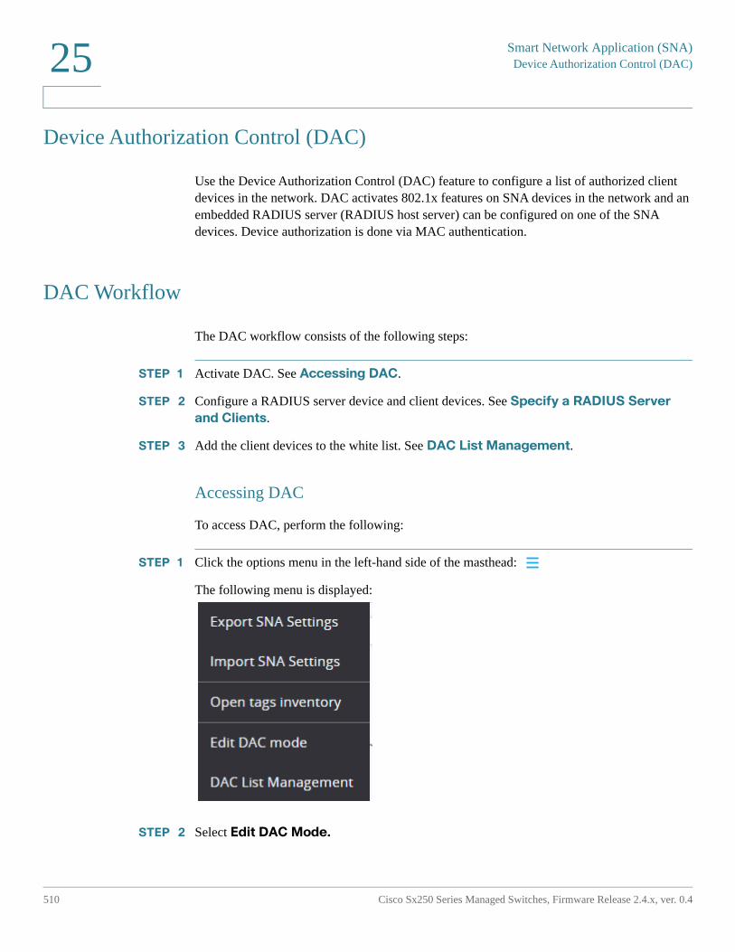
Smart Network Application (SNA)Device Authorization Control (DAC)
510 Cisco Sx250 Series Managed Switches, Firmware Release 2.4.x, ver. 0.4
25
Device Authorization Control (DAC)
Use the Device Authorization Control (DAC) feature to configure a list of authorized client devices in the network. DAC activates 802.1x features on SNA devices in the network and an embedded RADIUS server (RADIUS host server) can be configured on one of the SNA devices. Device authorization is done via MAC authentication.
DAC Workflow
The DAC workflow consists of the following steps:
STEP 1 Activate DAC. See Accessing DAC.
STEP 2 Configure a RADIUS server device and client devices. See Specify a RADIUS Server
and Clients.
STEP 3 Add the client devices to the white list. See DAC List Management.
Accessing DAC
To access DAC, perform the following:
STEP 1 Click the options menu in the left-hand side of the masthead:
The following menu is displayed:
STEP 2 Select Edit DAC Mode.
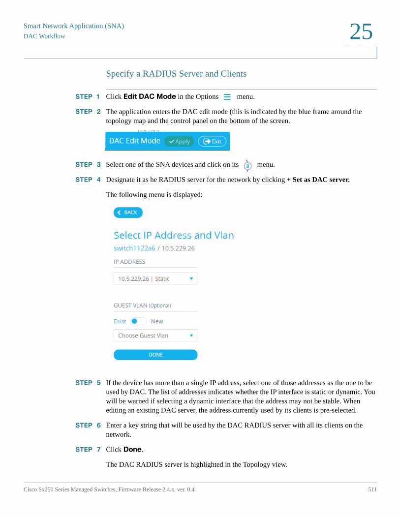
Smart Network Application (SNA)
DAC Workflow
Cisco Sx250 Series Managed Switches, Firmware Release 2.4.x, ver. 0.4 511
25
Specify a RADIUS Server and Clients
STEP 1 Click Edit DAC Mode in the Options menu.
STEP 2 The application enters the DAC edit mode (this is indicated by the blue frame around the topology map and the control panel on the bottom of the screen.
STEP 3 Select one of the SNA devices and click on its menu.
STEP 4 Designate it as he RADIUS server for the network by clicking + Set as DAC server.
The following menu is displayed:
STEP 5 If the device has more than a single IP address, select one of those addresses as the one to be used by DAC. The list of addresses indicates whether the IP interface is static or dynamic. You will be warned if selecting a dynamic interface that the address may not be stable. When editing an existing DAC server, the address currently used by its clients is pre-selected.
STEP 6 Enter a key string that will be used by the DAC RADIUS server with all its clients on the network.
STEP 7 Click Done.
The DAC RADIUS server is highlighted in the Topology view.
Smart Network Application (SNA)DAC Workflow
512 Cisco Sx250 Series Managed Switches, Firmware Release 2.4.x, ver. 0.4
25
STEP 8 Stand on the server and then click the menu of the device that you want to add as a client. Click +Set as client.
- If a switch is already a client of the DAC RADIUS server (its IP address is in the NAS table of the RADIUS server and the RADIUS server is configured in its RADIUS server table with usage type 802.1x or all in priority 0), the switch is pre-selected.
- If a client is selected, which already has a RADIUS server configured for 802.1x (other than the previously-selected server), you will be notified that the proceedings will interrupt the existing RADIUS server operation.
- If a client is selected, which has a RADIUS server configured for 802.1x in priority 0 (other than the previously-selected server), an error message is displayed and DAC is not configured on this client.
- Select at least one client for the DAC RADIUS server. If no clients are selected, you will be unable to apply the settings.
STEP 9 When a switch is selected as a client, a window with its ports is displayed. Select the ports from the client switch on which to apply 802.1 x authentications.
The SNA recommends a list of all edge ports (all the ports that are not known to be connected to other switches or clouds). You can select these recommended ports by clicking on:
You can add or remove ports to this selection. At this stage, all ports that have the full DAC configuration (see Table 2) appear as pre-selected.
STEP 10 Click Done.
STEP 11 Click Apply in the
After the DAC is configured, an alert is displayed whenever a new non-blacklisted device is rejected on the network through a DAC-enabled RADIUS server. You are asked whether to add this device to the white-list of authorized devices, or send it into a blacklist so that you are not alerted again.
When informing the user of the new device, SNA provides the MAC address of the device and the device and port through which the device attempted to access the network.
Smart Network Application (SNA)
DAC Workflow
Cisco Sx250 Series Managed Switches, Firmware Release 2.4.x, ver. 0.4 513
25
If a rejection event is received from a device that is not a DAC RADIUS server, the message is ignored, and all further messages from this device for the next 20 minutes are ignored. After 20 minutes, SNA checks again if the device is a DAC RADIUS server. If a user is added to the whitelist, the device is added to the DAC group of all DAC servers. When this configuration is saved, you can decide whether to save this setting immediately to the server's startup-configuration (this option is selected by default).
Until a device is added to the white-list, it is not allowed access to the network.
You can view and change the white and black lists at any time, as long as a DAC RADIUS server is defined and reachable.
When applying the DAC settings, you are presented with a report listing actions that will be applied to the participating devices. After you approve the changes, you can decide if the settings should additionally be copied to the startup configuration file of the configured devices (this option is selected by default). Finally, apply the configurations.
The report displays warnings if some steps of the DAC configuration process are missed, along with the status of the actions as handled by the devices.
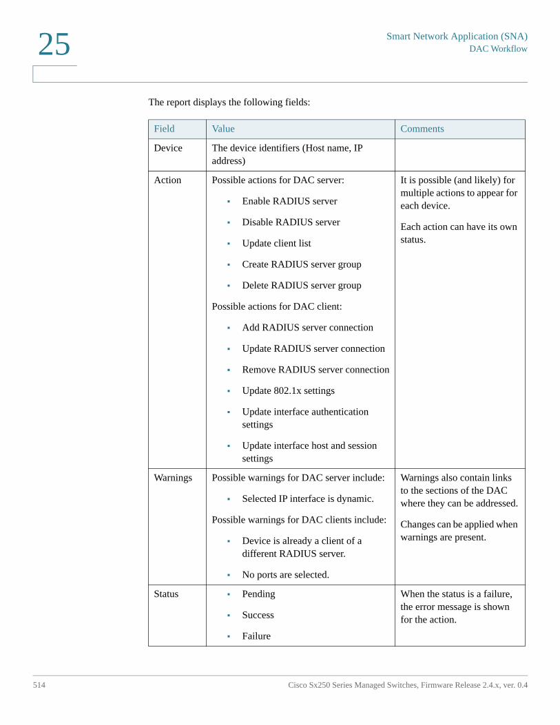
Smart Network Application (SNA)DAC Workflow
514 Cisco Sx250 Series Managed Switches, Firmware Release 2.4.x, ver. 0.4
25
The report displays the following fields:
Field Value Comments
Device The device identifiers (Host name, IP address)
Action Possible actions for DAC server:
• Enable RADIUS server
• Disable RADIUS server
• Update client list
• Create RADIUS server group
• Delete RADIUS server group
Possible actions for DAC client:
• Add RADIUS server connection
• Update RADIUS server connection
• Remove RADIUS server connection
• Update 802.1x settings
• Update interface authentication settings
• Update interface host and session settings
It is possible (and likely) for multiple actions to appear for each device.
Each action can have its own status.
Warnings Possible warnings for DAC server include:
• Selected IP interface is dynamic.
Possible warnings for DAC clients include:
• Device is already a client of a different RADIUS server.
• No ports are selected.
Warnings also contain links to the sections of the DAC where they can be addressed.
Changes can be applied when warnings are present.
Status • Pending
• Success
• Failure
When the status is a failure, the error message is shown for the action.
Smart Network Application (SNA)
DAC Workflow
Cisco Sx250 Series Managed Switches, Firmware Release 2.4.x, ver. 0.4 515
25
DAC List Management
After you have added client devices and selected which of their ports are to be authenticated, all unauthenticated devices detected on those ports are added to the List of Unauthenticated Devices.
DAC supports the following lists of devices:
• White List—List of all servers that can be authenticated
• Black List—List of servers that must never be authenticated
If you want devices and their ports to be authenticated, they must be added to the white lists. If you do not want them to be authenticated, not action is required - they are added to the black list by default.
To add these devices to the white list or remove them from the black list:
STEP 1 Click the Unauthenticated device icon
The DAC List Management page is displayed with the list of unauthenticated devices.
STEP 2 Select the devices you want to add to the white list and click Add to Whitelist.
STEP 3 Select the devices you want to add to the black list and click Add to Blacklist.
STEP 4 Click Apply. Packets entering on the ports on the device are authenticated on the RADIUS server.
To manage the white or black lists, click the Whitelist or Blacklist tab, respectively
You can perform the following tasks in these pages:
• Remove from list—Removes selected devices from the list.
• Move to Black List or Move to White List—Moves selected devices to the specified list.
• Add Device—Add a device to either the black or white list by entering its MAC address and pressing Add+.
• Search for device with MAC address—Enter a MAC address and click search. The system returns the date and time that traffic from this devices was encountered (Last Seen) and through which port/device it attempted to access the network (Seen At).
Smart Network Application (SNA)Services
516 Cisco Sx250 Series Managed Switches, Firmware Release 2.4.x, ver. 0.4
25
Services
Services are configurations that can be activated on multiple SNA-capable devices or interfaces, simultaneously. These are only available for devices with full SNA support or for interfaces for those devices.
Services are selected from the right-hand information panel.
To apply a service, select one or more devices or interfaces from the Topology view, either manually from the map or by selecting them from the search results. You can activate any service that is appropriate to all selected elements.
After a service is selected, a dedicated GUI for the service is displayed. The current settings for the relevant feature from all selected elements are displayed. The specific parameters displayed for each service are described below. You can then update the settings on selected devices or interfaces or select an entry from one device and copy the entry to other devices.
You can also use the settings from one of the devices or interfaces as the settings for all other devices or interfaces in the selection.
For most services, a GUI page is displayed where specific parameters can be defined for the service. After you enter the parameters in the GUI page, and all possible client side validations are performed on them, the settings are submitted to the selected devices or interfaces. A report then is displayed showing the results of the service as they are received. For every recipient of the service, a status is displayed (submitting, success, fail) and if an error was received the error message details are displayed for that recipient.
If a configuration failed due to a communication error between SNA and the configured device, an option is displayed to retry the configuration.
By default, all services copy the running configuration file to the startup configuration file automatically after the configuration is performed. You can disable this option.
Smart Network Application (SNA)
Services
Cisco Sx250 Series Managed Switches, Firmware Release 2.4.x, ver. 0.4 517
25
Device-Level Services
The following services are available for switches:
• RADIUS Client Configuration
• DNS Client Configuration
• SYSLOG Server Configuration
• Time Settings Configuration
• File Management
• Power Management Policy (Device Level)
• VLAN Membership (Device Level)
For each of these device-level services, the tickets showing the current configurations of the selected devices show the following identifying information in addition to service specific parameters:
• Device host name
• IP address—If more than one IP address exists for the device, the one used by SNA to access the device is displayed.
• Device model—The alphanumeric string representing the device model. For example: SG350XG-2F10.
RADIUS Client Configuration
This service enables you to configure one or more devices as RADIUS clients by defining the RADIUS server they are using for login.
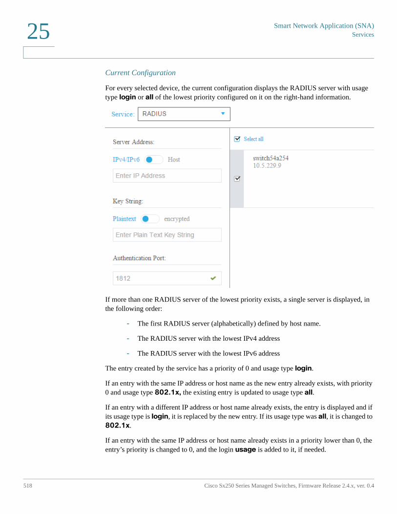
Smart Network Application (SNA)Services
518 Cisco Sx250 Series Managed Switches, Firmware Release 2.4.x, ver. 0.4
25
Current Configuration
For every selected device, the current configuration displays the RADIUS server with usage type login or all of the lowest priority configured on it on the right-hand information.
If more than one RADIUS server of the lowest priority exists, a single server is displayed, in the following order:
- The first RADIUS server (alphabetically) defined by host name.
- The RADIUS server with the lowest IPv4 address
- The RADIUS server with the lowest IPv6 address
The entry created by the service has a priority of 0 and usage type login.
If an entry with the same IP address or host name as the new entry already exists, with priority 0 and usage type 802.1x, the existing entry is updated to usage type all.
If an entry with a different IP address or host name already exists, the entry is displayed and if its usage type is login, it is replaced by the new entry. If its usage type was all, it is changed to 802.1x.
If an entry with the same IP address or host name already exists in a priority lower than 0, the entry’s priority is changed to 0, and the login usage is added to it, if needed.
Smart Network Application (SNA)
Services
Cisco Sx250 Series Managed Switches, Firmware Release 2.4.x, ver. 0.4 519
25
Displayed/Editable Parameters
To configure selected devices as clients to a different RADIUS server than the currently-configured RADIUS server, enter the following fields:
• Server Address—IPv4 address or IPv6 address of the RADIUS server.
• Key string—Key string used for the RADIUS server (up to 128 characters).
When displayed, this parameter is displayed in the encrypted format. You can elect to enter the key string in encrypted or plaintext format.
• Authentication Port—Number of the authentication port.
• Authentication Methods—List of the authentication methods used for each device by the channel currently used on SNA (HTTP or HTTPS). The common values for this parameter are Local or RADIUS, Local. If the current value for a device is any other value, the copy option is not available for this device. When copying settings, the value RADIUS, Local is mapped to the RADIUS Primary Authentication Method radio button.
• Primary Authentication Method—Write-only parameter that appears in the configuration section. It is a selection between two values: Local Database, RADIUS. If RADIUS is selected, the actual value configured for all channels is RADIUS, Local.
DNS Client Configuration
The DNS Client Configuration service enables defining the DNS server that the selected devices use.
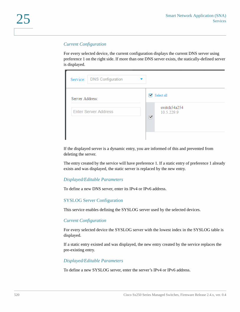
Smart Network Application (SNA)Services
520 Cisco Sx250 Series Managed Switches, Firmware Release 2.4.x, ver. 0.4
25
Current Configuration
For every selected device, the current configuration displays the current DNS server using preference 1 on the right side. If more than one DNS server exists, the statically-defined server is displayed.
If the displayed server is a dynamic entry, you are informed of this and prevented from deleting the server.
The entry created by the service will have preference 1. If a static entry of preference 1 already exists and was displayed, the static server is replaced by the new entry.
Displayed/Editable Parameters
To define a new DNS server, enter its IPv4 or IPv6 address.
SYSLOG Server Configuration
This service enables defining the SYSLOG server used by the selected devices.
Current Configuration
For every selected device the SYSLOG server with the lowest index in the SYSLOG table is displayed.
If a static entry existed and was displayed, the new entry created by the service replaces the pre-existing entry.
Displayed/Editable Parameters
To define a new SYSLOG server, enter the server’s IPv4 or IPv6 address.
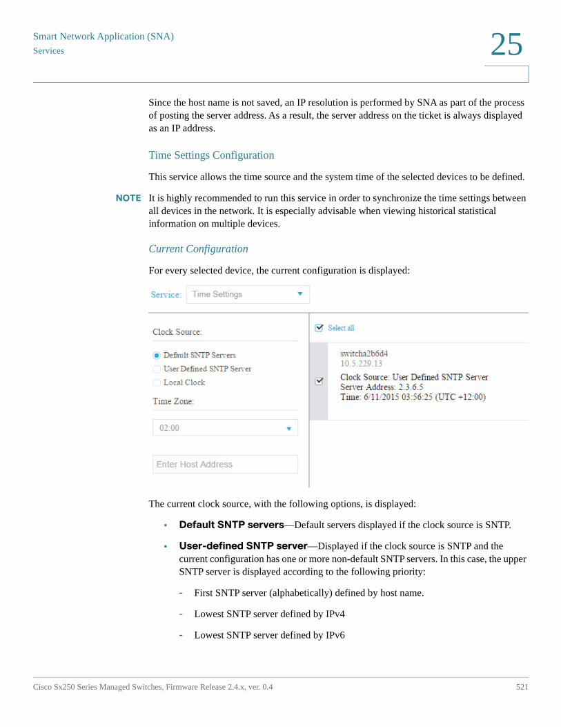
Smart Network Application (SNA)
Services
Cisco Sx250 Series Managed Switches, Firmware Release 2.4.x, ver. 0.4 521
25
Since the host name is not saved, an IP resolution is performed by SNA as part of the process of posting the server address. As a result, the server address on the ticket is always displayed as an IP address.
Time Settings Configuration
This service allows the time source and the system time of the selected devices to be defined.
NOTE It is highly recommended to run this service in order to synchronize the time settings between all devices in the network. It is especially advisable when viewing historical statistical information on multiple devices.
Current Configuration
For every selected device, the current configuration is displayed:
The current clock source, with the following options, is displayed:
• Default SNTP servers—Default servers displayed if the clock source is SNTP.
• User-defined SNTP server—Displayed if the clock source is SNTP and the current configuration has one or more non-default SNTP servers. In this case, the upper SNTP server is displayed according to the following priority:
- First SNTP server (alphabetically) defined by host name.
- Lowest SNTP server defined by IPv4
- Lowest SNTP server defined by IPv6
Smart Network Application (SNA)Services
522 Cisco Sx250 Series Managed Switches, Firmware Release 2.4.x, ver. 0.4
25
• Local Clock—Displayed if the clock source is local.
• Current time—Display of the current time and time zone offset.
Editable Parameters
To change the clock source select one of the following options:
• Default SNTP Servers—Deletes all configured SNTP servers and re-creates three default servers.
• User Defined SNTP Server—Add the address of the SNTP server by entering either host name, IPv4 or IPv6. When applying the server, all current configured servers are deleted, and the server one is added. Time Zone must be configured with this option.
• Local Clock—Changes the device clock source to local clock. The date, time and time zone must be configured.
• Set Date and Time—Date and time if local clock is configured.
• Time Zone—Time zone offset if a user-defined SNTP server or local time is configured.
File Management
Unlike the services previously mentioned, the File Management service does not change the configuration of the selected devices directly. Instead, it performs an operation on all selected devices. Use this service to download new firmware versions or configuration files to the selected devices or reboot them.

Smart Network Application (SNA)
Services
Cisco Sx250 Series Managed Switches, Firmware Release 2.4.x, ver. 0.4 523
25
Current Configuration
The current configuration displays the Active Firmware version, as follows:
Operations
The following operations are available from the service:
• Download firmware via HTTP
Used to download a new firmware file. In the local file system, browse to the new firmware file and select it. This file is then downloaded to all devices participating in the service.
After downloading the new firmware, the device also automatically makes it the active firmware version.
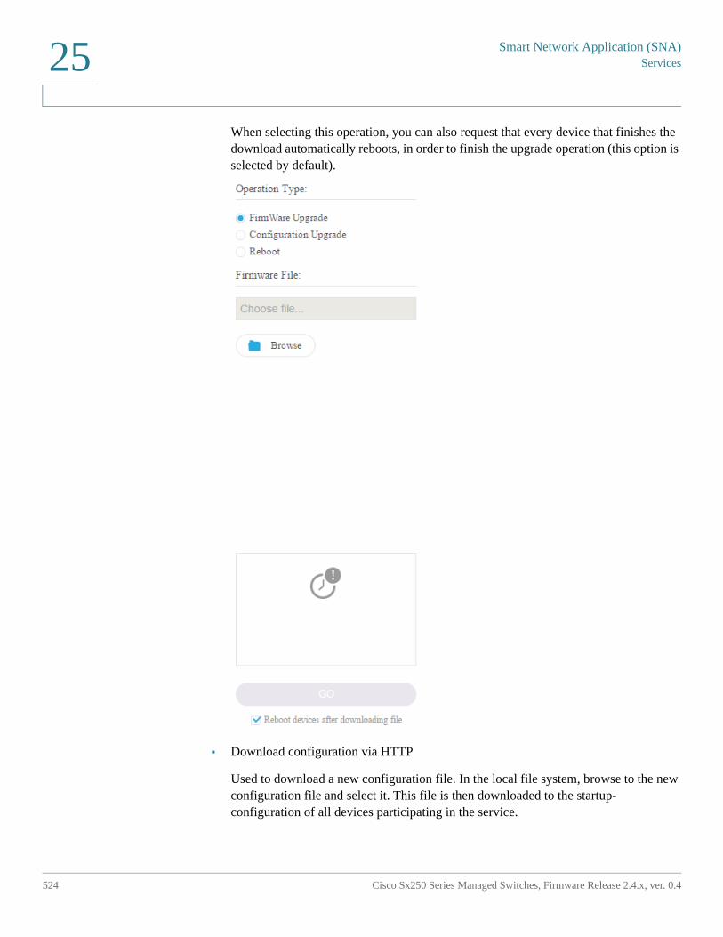
Smart Network Application (SNA)Services
524 Cisco Sx250 Series Managed Switches, Firmware Release 2.4.x, ver. 0.4
25
When selecting this operation, you can also request that every device that finishes the download automatically reboots, in order to finish the upgrade operation (this option is selected by default).
• Download configuration via HTTP
Used to download a new configuration file. In the local file system, browse to the new configuration file and select it. This file is then downloaded to the startup-configuration of all devices participating in the service.
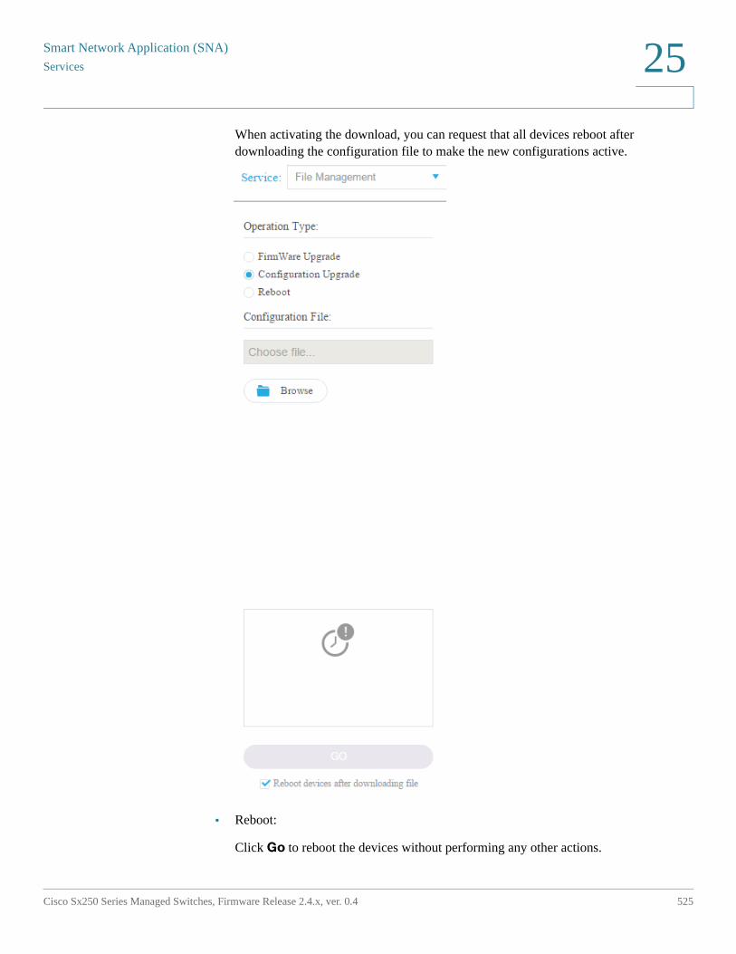
Smart Network Application (SNA)
Services
Cisco Sx250 Series Managed Switches, Firmware Release 2.4.x, ver. 0.4 525
25
When activating the download, you can request that all devices reboot after downloading the configuration file to make the new configurations active.
• Reboot:
Click Go to reboot the devices without performing any other actions.
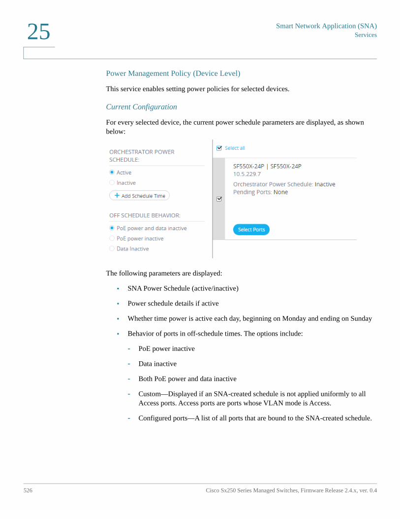
Smart Network Application (SNA)Services
526 Cisco Sx250 Series Managed Switches, Firmware Release 2.4.x, ver. 0.4
25
Power Management Policy (Device Level)
This service enables setting power policies for selected devices.
Current Configuration
For every selected device, the current power schedule parameters are displayed, as shown below:
The following parameters are displayed:
• SNA Power Schedule (active/inactive)
• Power schedule details if active
• Whether time power is active each day, beginning on Monday and ending on Sunday
• Behavior of ports in off-schedule times. The options include:
- PoE power inactive
- Data inactive
- Both PoE power and data inactive
- Custom—Displayed if an SNA-created schedule is not applied uniformly to all Access ports. Access ports are ports whose VLAN mode is Access.
- Configured ports—A list of all ports that are bound to the SNA-created schedule.
Smart Network Application (SNA)
Services
Cisco Sx250 Series Managed Switches, Firmware Release 2.4.x, ver. 0.4 527
25
Editable Parameters
You can create a power schedule (see Setting up a Power Management Policy) and apply it to the devices. To perform this action, select the start time and end time of activity for every day of the week and then select one of the following behaviors for off times.
• PoE power inactive
• Data inactive
• PoE power and data inactive (default)
To properly activate the schedule on the devices, at least one port must be selected in each device.
You can only select a behavior if at least one PoE device is selected. Otherwise, the schedule can only be created or deleted.
The schedule created by this service uses a reserved name (orch_power_sched). Time ranges with other names are ignored by SNA.
When applying the settings, the applied behavior is bound to all selected ports. All ports that are not selected are unbound from the schedule if they were previously bound.
Non-PoE ports are only affected if one of the behaviors, which shut down data is selected. If a selected port is not affected by the selected behavior, a note is added to the success message. This note notifies the user that some ports were not bound because the selected behavior did not apply to them.
Setting up a Power Management Policy
To set up a power management policy:
STEP 1 Select a device in the Topology view.
STEP 2 Select the Power Management service in the right-hand information.
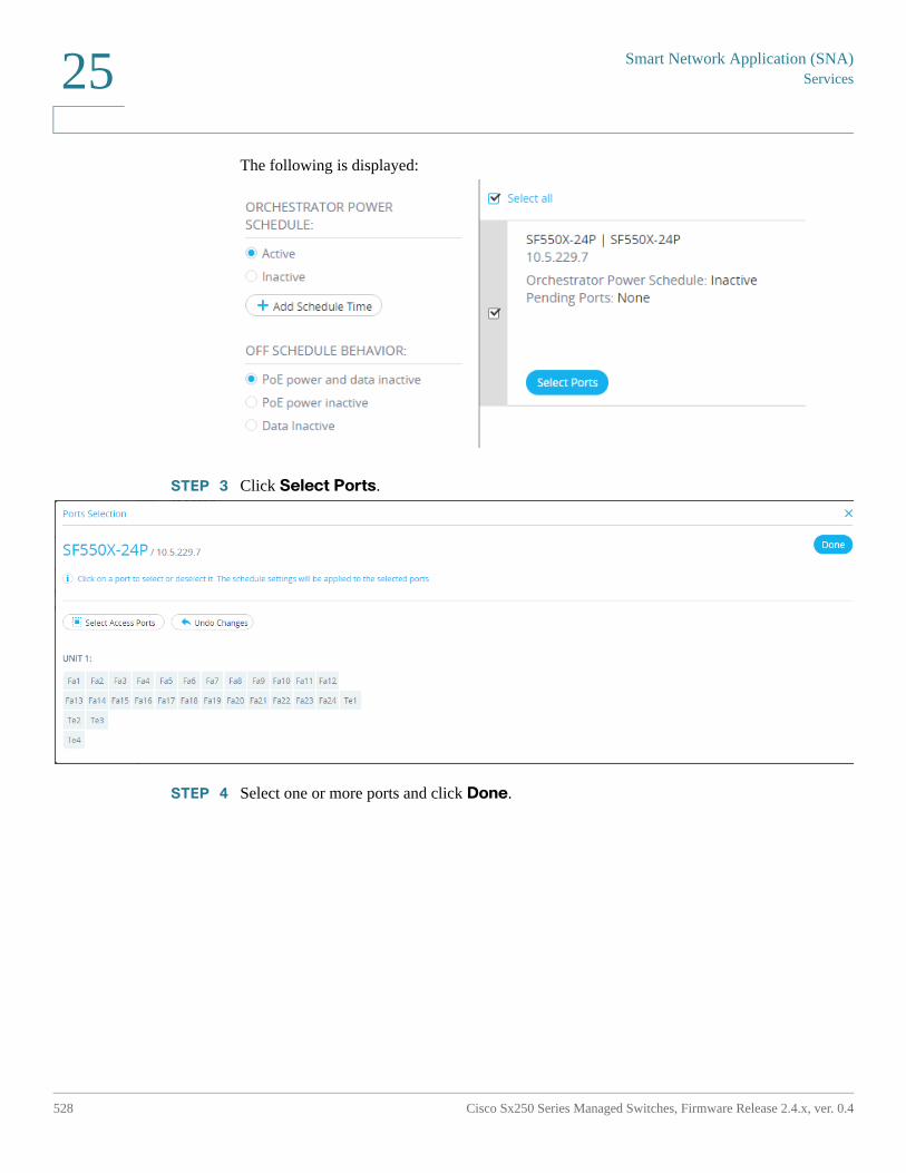
Smart Network Application (SNA)Services
528 Cisco Sx250 Series Managed Switches, Firmware Release 2.4.x, ver. 0.4
25
The following is displayed:
STEP 3 Click Select Ports.
STEP 4 Select one or more ports and click Done.
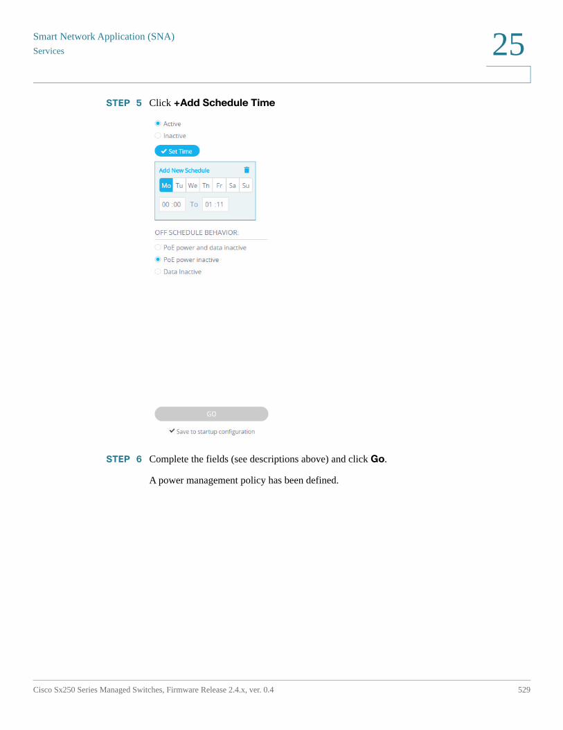
Smart Network Application (SNA)
Services
Cisco Sx250 Series Managed Switches, Firmware Release 2.4.x, ver. 0.4 529
25
STEP 5 Click +Add Schedule Time
STEP 6 Complete the fields (see descriptions above) and click Go.
A power management policy has been defined.
Smart Network Application (SNA)Services
530 Cisco Sx250 Series Managed Switches, Firmware Release 2.4.x, ver. 0.4
25
VLAN Membership (Device Level)
This service configures the VLAN membership of interfaces across multiple devices.
Current Configuration
For every device, the following parameters are displayed:
• Access ports—A list of the ports in access VLAN mode. This list is grouped by the access VLANs the ports belong to. Consecutive ranges of ports are shortened using dashes.
• Trunk ports—A list of the ports in trunk VLAN mode. This list is grouped by the native VLANs the ports belong to. Consecutive ranges of ports are shortened using dashes.
Editable Parameters
When editing the VLAN membership, first select a VLAN to operate on. This VLAN selection offers a selection of all existing VLANs in the network, and an option to create a new VLAN.
After a VLAN is selected, open a port selection panel that is connected to each device's card.
In this panel, all ports that are members of the selected VLAN are marked according to their membership type:
• A—For access ports that are untagged members in the VLAN.
• U—For trunk ports that are untagged (native) members in the VLAN.
• "*"—For any other state, whether it's not a member of the VLAN or is a member under a different VLAN mode.
Clicking a port toggles between the A and U states (and the "*" state if the port was originally in that state).
Ports that are LAG members display the marking based on their LAG, and when such a port is clicked, all the members of the same LAG toggle with it.
After editing the membership and applying, the VLAN will be created on all devices that will now have ports belonging to it (if that VLAN did not exist in them before).
Smart Network Application (SNA)
Services
Cisco Sx250 Series Managed Switches, Firmware Release 2.4.x, ver. 0.4 531
25
Interface-Level Services
Some services are relevant to interfaces rather than devices. When activating these services, select one or more interfaces and then select a service from the list of services available.
The following services are available for interfaces:
• Power Management Settings (Port)—PoE priority and applying schedule behavior. See Power Management Settings (Interface Level)
• VLAN Membership (port/LAG) — Switchport type (Access and Trunk), membership for Access and Trunk. See VLAN Membership (Interface Level)
For each of these services, the tickets showing the current configurations for the selected interfaces display the following identifying information in addition to service specific parameters:
• Interface name
• Device host name (of the parent device of the interface)
• IP address (of the parent device of the interface)—If more than one IP address exists for the device, the IP address used by SNA to access the device is displayed.
• Device model (of the parent device of the interface)—The alphanumeric string representing the device model. For example: SG350XG-2F10.
Power Management Settings (Interface Level)
This service configures the Power settings on specific ports. This service can only be run when all selected ports belong to the same device.
Displayed Parameters
• PoE Administrative Status (Enabled/Disabled)—This parameter only appears for PoE ports.
• Port Power Priority (Low/High/Critical)—This parameter only appears for PoE ports.
• SNA Power Schedule (Applied/Not Applied)—This parameter appears only if the device has a power schedule created by SNA.
• Schedule behavior—This information appears only if the port has an applied SNA-defined power schedule. The possible values are:
- PoE power inactive
- Data inactive
Smart Network Application (SNA)Services
532 Cisco Sx250 Series Managed Switches, Firmware Release 2.4.x, ver. 0.4
25
- PoE power and data inactive
Editable Parameters
• PoE Administrative Status (Enabled/Disabled)—This control only appears if at least one PoE ports is selected for the service, and is only applied to the PoE ports.
• Port Power Priority (Low/High/Critical)—This control only appears if at least one PoE ports is selected for the service, and is only applied to the PoE ports.
• SNA Power Schedule (Applied/Not Applied—This control appears only if the device has a power schedule created by SNA.
• Schedule behavior—This control appears only if the user chooses to apply the schedule. Possible values include:
- PoE power inactive
- Data inactive
- PoE power and data inactive
If no PoE ports are selected, the schedule can only be applied or removed from the port, and no behavior can be selected. Applying the schedule to the ports has the same behavior as selecting the Data inactive option.
If a combination of PoE and non-PoE ports is selected, when applying the settings to the PoE ports, the option PoE power and data inactive is treated as if it were Data inactive, and the option PoE power inactive is treated as if the schedule was not activated on the non-PoE port.
VLAN Membership (Interface Level)
This service configures the VLAN membership of the selected interfaces.
Displayed/Editable Parameters
• Interface Name (Read-Only)
• Switchport Mode—For display, can be Access, Trunk, General, Customer, Private - Host, Private - Promiscious. When configuring, the user can choose Access or Trunk.
• Access VLAN—Appears only in Access mode. When displayed shows the Access VLAN ID, and when configuring allows selection of the access VLAN.
• Native VLAN (SNA version 2.3)—Appears only in Trunk mode. When displayed it shows the Native VLAN ID, and when configuring allows selection of the native VLAN.
Smart Network Application (SNA)
Services
Cisco Sx250 Series Managed Switches, Firmware Release 2.4.x, ver. 0.4 533
25
The selection of VLANs is from a list where all present VLANs on the network can be selected. If the VLAN does not exist on a device to which a selected interface belongs, this VLAN will be created as part of the service operation.
The user can also select an option to add a VLAN (1-4094). This VLAN will be added to all switches that have interfaces that were selected for the service.
Interface Settings
This service configures basic interface settings for ports or LAGs.
Display Parameters
• Administrative Status—Up/Down.
• Current Status—Up/Down/Suspended. If the port is suspended, the suspension reason is shown in parenthesis. For example: "Suspended (ACL)".
• Auto Negotiation—Enabled/Disabled
• Administrative Speed—This parameter is only displayed if Auto Negotiation is disabled.
The values can be 10M, 100M, 1000M, 2500M, 5G, or 10G.
• Current Speed—10M, 100M, 1000M, 2500M, 5G, or 10G.
• Administrative Duplex Mode—This parameter is only displayed if Auto Negotiation is disabled.
The values can be Half or Full.
• Current Duplex Mode—Half or Full.
Editable Parameters
• Administrative Status—Up/Down.
• Auto Negotiation—Enabled/Disabled.
• Speed—This parameter is only available for editing if Auto Negotiation is disabled. The possible values for speed are: 10M, 100M, 1000M, 2500M, 5G, or 10G. Different types of ports are capable of different subsets of these values, and the options displayed in the service depend on the types of ports currently selected.
• Duplex Mode—This parameter is only available if Auto Negotiation is disabled and if the selected speed is 10M or 100M.
Smart Network Application (SNA)Saving SNA Settings
534 Cisco Sx250 Series Managed Switches, Firmware Release 2.4.x, ver. 0.4
25
Saving SNA Settings
All changes made in the SNA system itself (not using services) can be saved. These settings are then available to the next SNA session launched on the network. This saved information is also available the next time you access the network from any SNA-device connected to the same network, and from any browser, as long as you use the same username for the next login.
When saving the settings, SNA attempts to save the changes in all detected online SNA devices (in a special SNA folder on the flash). If no copy of the settings can be saved, you are alerted of the failure.
If the save operation failed on any or all of the devices, you can request a report showing the devices on which the settings were not saved. Each device in the report displays its ID and the error that was recorded on it.
While operating SNA, if a newer version of the SNA settings is detected on any device in the network, you are alerted that a newer version was detected (including the time it was created and the device it was detected on), and prompted to select the version of settings that SNA should use.
The following settings can be saved:
• Positions of all backbone devices in the network.
• Any client device designated as a backbone device retains this status.
• Any tag manually added to elements in the network.
• Any device manually added to the network.
• A description string for backbone devices.
• The blacklist used by the DAC.
In addition to saving SNA settings to the network, you can also export and import settings to an external file for an additional backup.
Importing a file or accepting a newer file that was detected on the network overrides the current SNA settings with the ones from the new file. After the file is imported and the topology is updated to the new parameters, you are prompted to keep the changes or revert back to the previous settings.
If you choose to keep the changes, the new settings are saved to all devices in the network. If you choose to revert to the previous settings, the topology returns to the previous settings.
If you manually save the settings after importing a new file, the option to revert is no longer available
Smart Network Application (SNA)
Technical Details
Cisco Sx250 Series Managed Switches, Firmware Release 2.4.x, ver. 0.4 535
25
Technical Details
The following are technical details of the SNA feature:
• Supported browsers: IE10 and above, Chrome, FireFox.
• Safari on MAC OS: 6.1.2-7.0.2
• Supported OS: Win 7, Win 8, Win 8.1, Linux 2.6, 3.11, MAC OSX version 10.7 and up

© 2017 Cisco Systems, Inc. All rights reserved.
Cisco and the Cisco logo are trademarks or registered trademarks of Cisco and/or its affiliates in the U.S. and other countries. To view a list of Cisco trademarks, go to this URL: www.cisco.com/go/trademarks. Third-party trademarks mentioned are the property of their respective owners. The use of the word partner does not imply a partnership relationship between Cisco and any other company. (1110R)