Embed Size (px)
Citation preview
QUICK START GUIDE
Cisco SCE8000 10 GBE QUICK START GUIDE, RELEASE 5.1.X
1 Preparing for Installation
2 Rack-Mounting the SCE8000 Chassis
3 Connecting Power Supply Units
4 Connecting Management Interfaces and Performing Initial System Configuration
5 Cabling Line Ports
6 Completing the Installation
7 Troubleshooting
8 Obtaining Documentation and Submitting a Service Request
Revised: March 12, 2015
Note This document supports all 5.1.x releases.
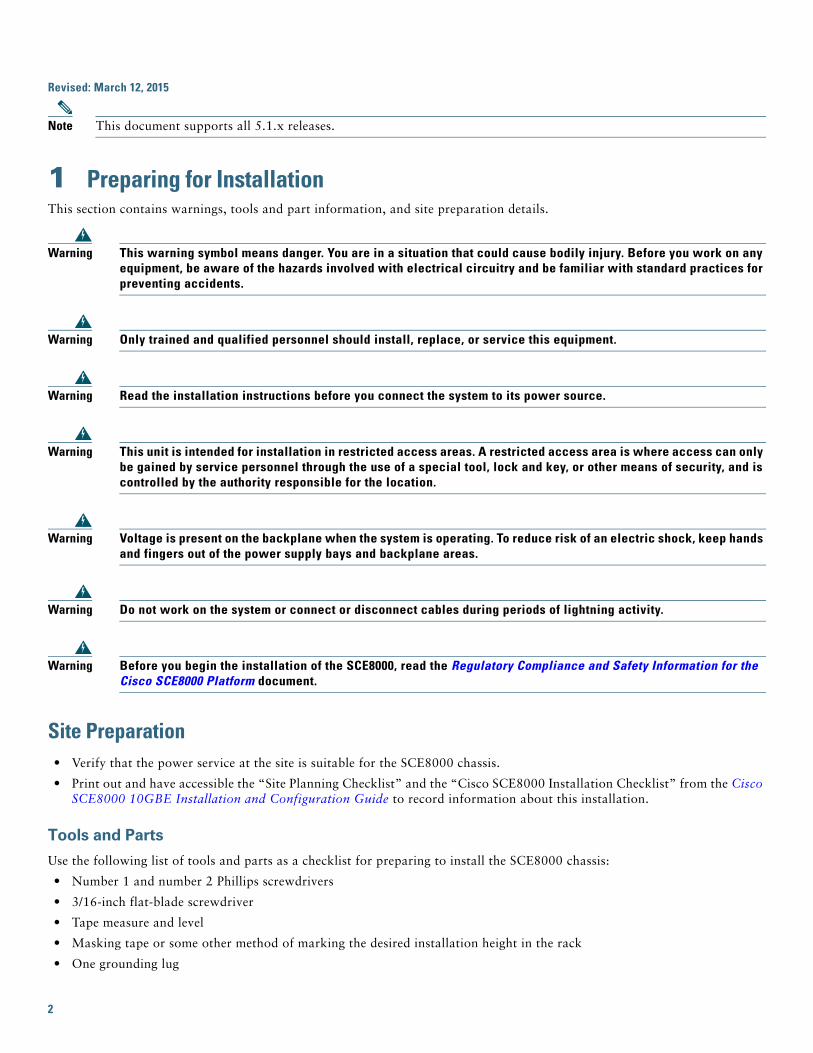
1 Preparing for InstallationThis section contains warnings, tools and part information, and site preparation details.
Warning This warning symbol means danger. You are in a situation that could cause bodily injury. Before you work on any equipment, be aware of the hazards involved with electrical circuitry and be familiar with standard practices for preventing accidents.
Warning Only trained and qualified personnel should install, replace, or service this equipment.
Warning Read the installation instructions before you connect the system to its power source.
Warning This unit is intended for installation in restricted access areas. A restricted access area is where access can only be gained by service personnel through the use of a special tool, lock and key, or other means of security, and is controlled by the authority responsible for the location.
Warning Voltage is present on the backplane when the system is operating. To reduce risk of an electric shock, keep hands and fingers out of the power supply bays and backplane areas.
Warning Do not work on the system or connect or disconnect cables during periods of lightning activity.
Warning Before you begin the installation of the SCE8000, read the Regulatory Compliance and Safety Information for the Cisco SCE8000 Platform document.
Site Preparation• Verify that the power service at the site is suitable for the SCE8000 chassis.
• Print out and have accessible the “Site Planning Checklist” and the “Cisco SCE8000 Installation Checklist” from the Cisco SCE8000 10GBE Installation and Configuration Guide to record information about this installation.
Tools and Parts
Use the following list of tools and parts as a checklist for preparing to install the SCE8000 chassis:
• Number 1 and number 2 Phillips screwdrivers
• 3/16-inch flat-blade screwdriver
• Tape measure and level
• Masking tape or some other method of marking the desired installation height in the rack
• One grounding lug
2
• Two M4 (metric) hex-head screws with locking washers
Note The grounding lug and M4 hex-head screws with locking washers are provided in kit 69-0815-01
• One grounding wire—Must be sized according to local and national installation requirements. Depending on the power supply and system, a 12 AWG conductor or larger size wire is required for U.S. installations.
• Crimping tool—Must be large enough to accommodate the girth of the grounding lug when crimping the grounding cable into the lug.
• Wire-stripping tool
• Appropriate cables to connect the SCE8000 to the network and console terminal
Unpacking the Cisco SCE8000 Chassis
Tip When you unpack the Cisco SCE8000, do not discard the shipping container. Flatten the shipping cartons and store them with the pallet. You may need these containers if you move or ship the Cisco SCE8000 in the future.
Check the contents of the shipping container:
• Check the contents of the accessories kit against the list of accessories in the “Cisco SCE8000 Component List” in the Cisco SCE8000 10GBE Installation and Configuration Guide and the packing slip. Verify that you received all listed equipment, which should include the following:
– Hardware and software documentation, if ordered
– Optional equipment that you ordered, such as network interface cables, transceivers, or special connectors
Check the modules in each slot. Ensure that the configuration matches the packing list and that all the specified interfaces are included.
2 Rack-Mounting the SCE8000 ChassisThis chapter provides information for rack-mounting the SCE8000 chassis.
Warning Before you install, operate, or service the system, read the Regulatory Compliance and Safety Information for the Cisco SCE8000 Platform. This guide contains important safety information you should know before working with the system.
Note Before you start the installation described in this chapter, see the “Site Planning Checklist” in the Cisco SCE8000 10GBE Installation and Configuration Guide to verify that all site planning activities are complete.
Installation GuidelinesTable 1 lists rack dimensions. Carefully check the contents of the shipping container, the accessories kit, and optional equipment.
Table 1 Rack Dimensions
Width 17.75 inches (45.09 cm)
Depth • Minimum: 19.25 inches (48.9 cm)
• Maximum 32 inches (81.3 cm)
Minimum vertical clearance 8.7 inches (22.09 cm) (5 RU)
3
Caution If the rack is on wheels, ensure that the brakes are engaged or that the rack is otherwise stabilized.
Note We recommend that you maintain a minimum air space of 6 inches (15 cm) between walls and the chassis air vents and a minimum horizontal separation of 12 inches (30.5 cm) between two chassis to prevent overheating.
The installation hardware is not suitable for use with racks with obstructions (such as a power strip) that could impair access to field-replaceable units (FRUs).
Warning To prevent bodily injury when mounting or servicing this unit in a rack, you must take special precautions to ensure that the system remains stable. The following guidelines are provided to ensure your safety:>If it is the only unit in the rack, this unit must be mounted at the bottom of the rack.>When mounting this unit in a partially-filled rack, load the rack from the bottom to the top with the heaviest component at the bottom of the rack.>If the rack is provided with stabilizing devices, install the stabilizers before mounting or servicing the unit in the rack.
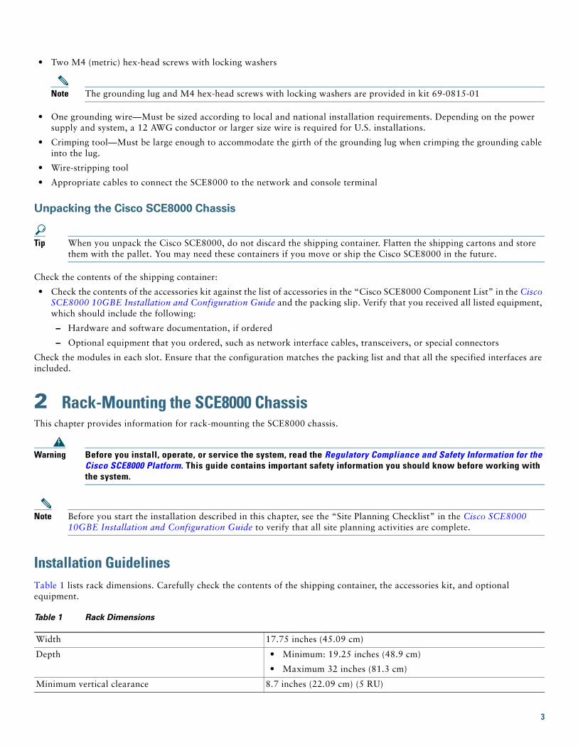
The chassis is shipped with the mounting brackets installed on the front of the chassis. You can remove these brackets and install them on the rear of the chassis, using the holes provided in the rear side of the chassis (Figure 1).
Figure 1 Cisco SCE8000 Chassis Brackets
Step 1 Position the chassis in the rack as follows. If the:
• Front of the chassis (front panel) is at the front of the rack, insert the rear of the chassis between the mounting posts.
• Rear of the chassis is at the front of the rack, insert the front of the chassis between the mounting posts.
Step 2 Align the mounting holes in the bracket (and optional cable guide) with the mounting holes in the equipment rack.
Step 3 Use a tape measure and level to choose and mark the position that the chassis is to be installed in the rack. Make a mark at equal height on both sides of the rack. This helps ensure that the chassis is installed straight and level (Figure 2).
FAN STATUS
SCM 1
SCM 2
SIP 3
4SCE8000-FAN
SYSTEM POWER
OPTICAL BYPASS
STATUS
AUXPORT 2
LINKACTIVE MASTER
SCE8000 EXTENDED SERVICE CONTROL MODULE
OPTICALBYPASS
OPTICALBYPASS
CONSOLE
10 1001000
LINKACTIVE
PORT 1
A C
A BC D
B D
STATUS
CTRL
OPB-SCE8K-MM
OPTICAL BYPASS1
TX
RX
TX
RX
TX
RX
TX
RX
A C
A BC D
B D
STATUS
CTRL
OPB-SCE8K-MM
OPTICAL BYPASS2
TX
RX
TX
RX
TX
RX
TX
RX
SYSTEM POWER
OPTICAL BYPASS
STATUS
AUXPORT 2
10 1001000
LINKACTIVE MASTER
SCE8000 EXTENDED SERVICE CONTROL MODULE
SCE8000-SCM-E
SCE8000-SCM-E
SCE8000-SIP
CONSOLE
10 1001000
LINKACTIVE
PORT 1
OPTICALBYPASS
OPTICALBYPASS
STATUS
ACTIVE/LINK
SPA-1X10GE-L-V2
STATUS
ACTIVE/LINK
SPA-1X10GE-L-V2STATUS
ACTIVE/LINK
SPA-1X10GE-L-V2
STATUS
ACTIVE/LINK
SPA-1X10GE-L-V2
10 1001000
2708
90
4
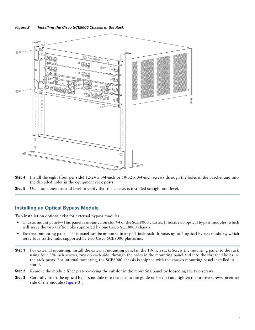
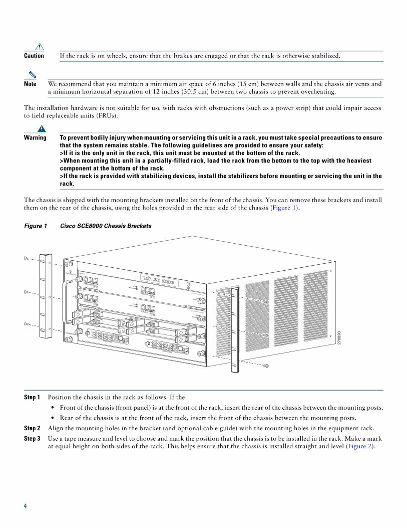
Figure 2 Installing the Cisco SCE8000 Chassis in the Rack
Step 4 Install the eight (four per side) 12-24 x 3/4-inch or 10-32 x 3/4-inch screws through the holes in the bracket and into the threaded holes in the equipment rack posts.
Step 5 Use a tape measure and level to verify that the chassis is installed straight and level.
Installing an Optical Bypass Module
Two installation options exist for external bypass modules:
• Chassis mount panel—This panel is mounted on slot #4 of the SCE8000 chassis. It hosts two optical bypass modules, which will serve the two traffic links supported by one Cisco SCE8000 chassis.
• External mounting panel—This panel can be mounted in any 19-inch rack. It hosts up to 4 optical bypass modules, which serve four traffic links supported by two Cisco SCE8000 platforms.
Step 1 For external mounting, install the external mounting panel in the 19-inch rack. Screw the mounting panel to the rack using four 3/4-inch screws, two on each side, through the holes in the mounting panel and into the threaded holes in the rack posts. For internal mounting, the SCE8000 chassis is shipped with the chassis mounting panel installed in slot 4.
Step 2 Remove the module filler plate covering the subslot in the mounting panel by loosening the two screws.
Step 3 Carefully insert the optical bypass module into the subslot (no guide rails exist) and tighten the captive screws on either side of the module (Figure 3).
2708
91
FAN STATUS
SCM 1
SCM 2
SIP 3
4SCE8000-FAN
SYSTEM POWER
OPTICAL BYPASS
STATUS
AUXPORT 2
LINKACTIVE MASTER
SCE8000 EXTENDED SERVICE CONTROL MODULE
OPTICALBYPASS
OPTICALBYPASS
CONSOLE
10 1001000
LINKACTIVE
PORT 1
A C
A BC D
B D
STATUS
CTRL
OPB-SCE8K-MM
OPTICAL BYPASS1
TX
RX
TX
RX
TX
RX
TX
RX
A C
A BC D
B D
STATUS
CTRL
OPB-SCE8K-MM
OPTICAL BYPASS2
TX
RX
TX
RX
TX
RX
TX
RX
SYSTEM POWER
OPTICAL BYPASS
STATUS
AUXPORT 2
10 1001000
LINKACTIVE MASTER
SCE8000 EXTENDED SERVICE CONTROL MODULE
SCE8000-SCM-E
SCE8000-SCM-E
SCE8000-SIP
CONSOLE
10 1001000
LINKACTIVE
PORT 1
OPTICALBYPASS
OPTICALBYPASS
STATUS
ACTIVE/LINK
SPA-1X10GE-L-V2
STATUS
ACTIVE/LINK
SPA-1X10GE-L-V2STATUS
ACTIVE/LINK
SPA-1X10GE-L-V2
STATUS
ACTIVE/LINK
SPA-1X10GE-L-V2
10 1001000
5
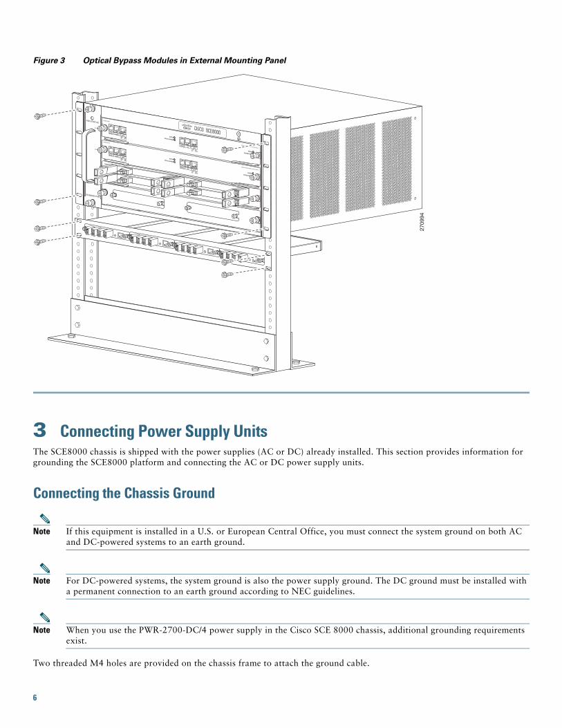
Figure 3 Optical Bypass Modules in External Mounting Panel
3 Connecting Power Supply UnitsThe SCE8000 chassis is shipped with the power supplies (AC or DC) already installed. This section provides information for grounding the SCE8000 platform and connecting the AC or DC power supply units.
Connecting the Chassis Ground
Note If this equipment is installed in a U.S. or European Central Office, you must connect the system ground on both AC and DC-powered systems to an earth ground.
Note For DC-powered systems, the system ground is also the power supply ground. The DC ground must be installed with a permanent connection to an earth ground according to NEC guidelines.
Note When you use the PWR-2700-DC/4 power supply in the Cisco SCE 8000 chassis, additional grounding requirements exist.
Two threaded M4 holes are provided on the chassis frame to attach the ground cable.
2709
94
FAN STATUS
SCM 1
SCM 2
SIP 3
4SCE8000-FAN
SYSTEM POWER
OPTICAL BYPASS
STATUS
AUXPORT 2
LINKACTIVE MASTER
SCE8000 EXTENDED SERVICE CONTROL MODULE
OPTICALBYPASS
OPTICALBYPASS
CONSOLE
10 1001000
LINKACTIVE
PORT 1
SYSTEM POWER
OPTICAL BYPASS
STATUS
AUXPORT 2
10 1001000
LINKACTIVE MASTER
SCE8000 EXTENDED SERVICE CONTROL MODULE
SCE8000-SCM-E
SCE8000-SCM-E
SCE8000-SIP
CONSOLE
10 1001000
LINKACTIVE
PORT 1
OPTICALBYPASS
OPTICALBYPASS
STATUS
ACTIVE/LINK
SPA-1X10GE-L-V2
STATUS
ACTIVE/LINK
SPA-1X10GE-L-V2STATUS
ACTIVE/LINK
SPA-1X10GE-L-V2
STATUS
ACTIVE/LINK
SPA-1X10GE-L-V2
10 1001000
6

Before you connect system power or turn on the Cisco SCE 8000 chassis, you must complete this procedure:
Step 1 Remove approximately 0.75 inch (19 mm) of the covering from the end of the grounding wire using a wire-stripping tool.
Step 2 Insert the stripped end of the grounding wire into the open end of the grounding lug.
Step 3 To secure the grounding wire in place in the grounding lug, use the manufacturer recommended crimping tool.
Step 4 Locate and remove the adhesive label from the system grounding pad on the chassis (Figure 4).
Figure 4 Installing the System Ground
Step 5 Place the grounding wire lug against the grounding pad, making sure that solid metal-to-metal contact exists.
Step 6 Secure the grounding lug to the chassis using two M4 screws. Ensure that the grounding lug does not interfere with other hardware or rack equipment.
Step 7 To ensure adequate earth ground for the Cisco SCE8000 chassis, prepare the other end of the grounding wire, and connect it to an appropriate grounding point at your site.
Connecting PowerThe following sections describe how to reconnect the AC or DC power.
Installing a DC-Input Power Supply
Note The DC return must remain isolated from the system frame and chassis (DC-I).
Warning Before you perform any of the following procedures, ensure that power is removed from the DC circuit.
FAN STATUS
SCM 1
SCM 2
SIP 3
4SCE8000-FAN
SYSTEM POWER
OPTICAL BYPASS
STATUS
AUXPORT 2
LINKACTIVE MASTER
SCE8000 EXTENDED SERVICE CONTROL MODULE
OPTICALBYPASS
OPTICALBYPASS
CONSOLE
10 1001000
LINKACTIVE
PORT 1
A C
A BC D
B D
STATUS
CTRL
OPB-SCE8K-MM
OPTICAL BYPASS1
TX
RX
TX
RX
TX
RX
TX
RX
A C
A BC D
B D
STATUS
CTRL
OPB-SCE8K-MM
OPTICAL BYPASS2
TX
RX
TX
RX
TX
RX
TX
RX
SYSTEM POWER
OPTICAL BYPASS
STATUS
AUXPORT 2
10 1001000
LINKACTIVE MASTER
SCE8000 EXTENDED SERVICE CONTROL MODULE
SCE8000-SCM-E
SCE8000-SCM-E
SCE8000-SIP
CONSOLE
10 1001000
LINKACTIVE
PORT 1
OPTICALBYPASS
OPTICALBYPASS
STATUS
ACTIVE/LINK
SPA-1X10GE-L-V2
STATUS
ACTIVE/LINK
SPA-1X10GE-L-V2STATUS
ACTIVE/LINK
SPA-1X10GE-L-V2
STATUS
ACTIVE/LINK
SPA-1X10GE-L-V2
10 1001000
2708
92
System groundconnector
System groundconnectorGrounding
lug
Wire
7
Note For multiple DC input power supplies, each DC input must be protected by a dedicated circuit breaker or fuse. The circuit breaker or fuse should be sized according to the power supply input rating and local or national electrical code requirements.
Step 1 Power supply ground is required. Install the PWR-2700-DC/4 power supply ground as described in this procedure.
Note The system ground connection with the PWR-2700-DC/4 power supply in a Cisco SCE8000 is provided by the PWR-2700-DC/4 power supply ground. Additionally, you can connect a system (earth) ground.
Note You must always connect the PWR-2700-DC/4 power supply ground.
Note You must always connect the PWR-2700-DC/4 power supply ground for both power supplies.
Note If you intend to use an additional system (earth ground), ensure that the system ground connection is made. For ground connection installation instructions, see the “Connecting the Chassis Ground” section on page 6.
Step 2 Remove the plastic bag attached to the front panel and put aside. This bag contains two plastic terminal block barriers, two cable ties, and two cable holder covers.
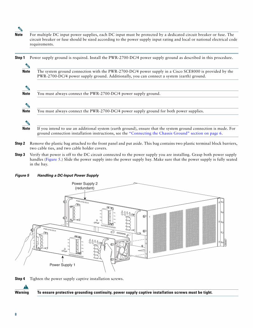
Step 3 Verify that power is off to the DC circuit connected to the power supply you are installing. Grasp both power supply handles (Figure 5.) Slide the power supply into the power supply bay. Make sure that the power supply is fully seated in the bay.
Figure 5 Handling a DC-Input Power Supply
Step 4 Tighten the power supply captive installation screws.
Warning To ensure protective grounding continuity, power supply captive installation screws must be tight.
1265
67PWR-2700-DC/4
ALL FASTENERS MUST BE FULLY ENGAGED
PRIOR TO OPERATING THE POWER SUPPLY
INPUT1OK
48V-60V=40A
INPUT2OK
48V-60V=40A
FANOK
OUTPUTFAIL
+VE-1
-VE-1
+VE-2
-VE-2
ALL FASTENERS MUST BE FULLY ENGAGED
PRIOR TO OPERATING THE POWER SUPPLY
INPUT1OK
48V-60V=40A
INPUT2OK
48V-60V=40A
FANOK
OUTPUTFAIL
PWR-2700-DC/4
+VE-1
-VE-1
+VE-2
-VE-2
+VE-1
-VE-1
+VE-2
-VE-2
+VE-1
-VE-1
+VE-2
-VE-2
Power Supply 2(redundant)
Power Supply 1
8
Note Because the power requirement of the SCE8000 does not exceed 1350 W, it is not necessary to connect two pairs of input wires to each power supply. If you want to connect two pairs of input wires, both pairs of input wires for one 2700 W DC-input power supply must come from the same battery system (A feed); and both pairs of input wires for the other power supply must come from another battery system (B feed).
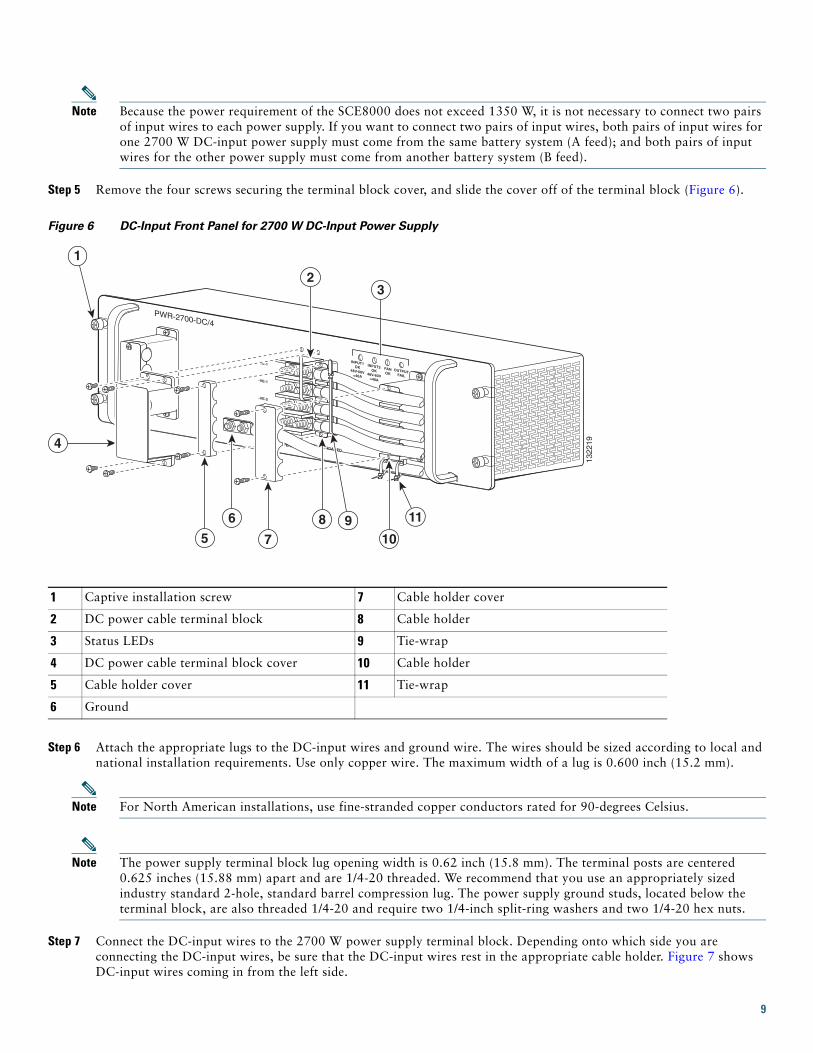
Step 5 Remove the four screws securing the terminal block cover, and slide the cover off of the terminal block (Figure 6).
Figure 6 DC-Input Front Panel for 2700 W DC-Input Power Supply
Step 6 Attach the appropriate lugs to the DC-input wires and ground wire. The wires should be sized according to local and national installation requirements. Use only copper wire. The maximum width of a lug is 0.600 inch (15.2 mm).
Note For North American installations, use fine-stranded copper conductors rated for 90-degrees Celsius.
Note The power supply terminal block lug opening width is 0.62 inch (15.8 mm). The terminal posts are centered 0.625 inches (15.88 mm) apart and are 1/4-20 threaded. We recommend that you use an appropriately sized industry standard 2-hole, standard barrel compression lug. The power supply ground studs, located below the terminal block, are also threaded 1/4-20 and require two 1/4-inch split-ring washers and two 1/4-20 hex nuts.
Step 7 Connect the DC-input wires to the 2700 W power supply terminal block. Depending onto which side you are connecting the DC-input wires, be sure that the DC-input wires rest in the appropriate cable holder. Figure 7 shows DC-input wires coming in from the left side.
1 Captive installation screw 7 Cable holder cover
2 DC power cable terminal block 8 Cable holder
3 Status LEDs 9 Tie-wrap
4 DC power cable terminal block cover 10 Cable holder
5 Cable holder cover 11 Tie-wrap
6 Ground
1322
19
PWR-2700-DC/4
-VE-1
-VE-1
-VE-2
-VE-2
INPUT1OK
48V-60V=40A
INPUT2OK
48V-60V=40A
FANOK
OUTPUTFAIL
ALL FASTENERS MUST BE FULLY ENGAGED
PRIOR TO OPERATING THE POWER SUPPLY
32
6
4
10
1
85 7
119
9
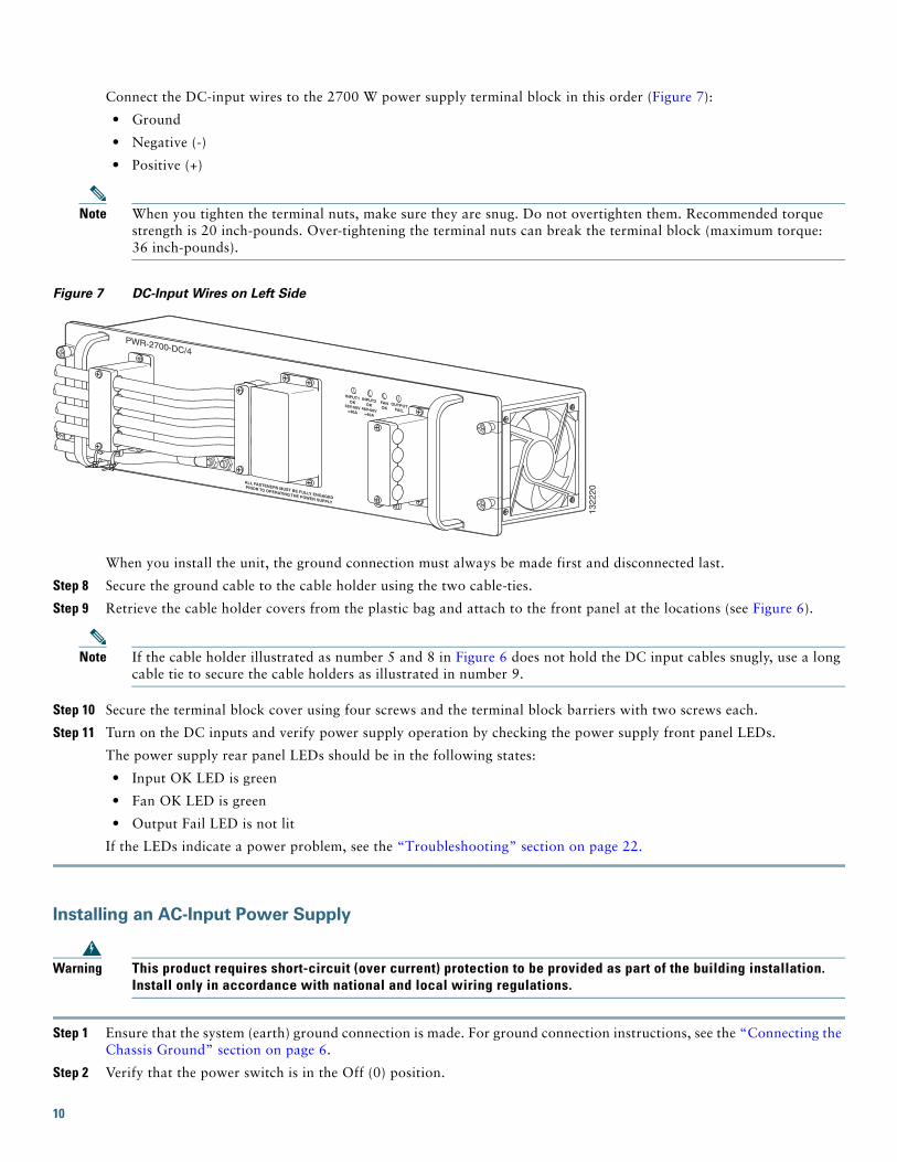
Connect the DC-input wires to the 2700 W power supply terminal block in this order (Figure 7):
• Ground
• Negative (-)
• Positive (+)
Note When you tighten the terminal nuts, make sure they are snug. Do not overtighten them. Recommended torque strength is 20 inch-pounds. Over-tightening the terminal nuts can break the terminal block (maximum torque: 36 inch-pounds).
Figure 7 DC-Input Wires on Left Side
When you install the unit, the ground connection must always be made first and disconnected last.
Step 8 Secure the ground cable to the cable holder using the two cable-ties.
Step 9 Retrieve the cable holder covers from the plastic bag and attach to the front panel at the locations (see Figure 6).
Note If the cable holder illustrated as number 5 and 8 in Figure 6 does not hold the DC input cables snugly, use a long cable tie to secure the cable holders as illustrated in number 9.
Step 10 Secure the terminal block cover using four screws and the terminal block barriers with two screws each.
Step 11 Turn on the DC inputs and verify power supply operation by checking the power supply front panel LEDs.
The power supply rear panel LEDs should be in the following states:
• Input OK LED is green
• Fan OK LED is green
• Output Fail LED is not lit
If the LEDs indicate a power problem, see the “Troubleshooting” section on page 22.
Installing an AC-Input Power Supply
Warning This product requires short-circuit (over current) protection to be provided as part of the building installation. Install only in accordance with national and local wiring regulations.
Step 1 Ensure that the system (earth) ground connection is made. For ground connection instructions, see the “Connecting the Chassis Ground” section on page 6.
Step 2 Verify that the power switch is in the Off (0) position.
1322
20
INPUT1OK
48V-60V=40A
INPUT2OK
48V-60V=40A
FANOK
OUTPUTFAIL
ALL FASTENERS MUST BE FULLY ENGAGED
PRIOR TO OPERATING THE POWER SUPPLY
PWR-2700-DC/4
10
Step 3 Plug the power cord into the power supply.
Step 4 Connect the other end of the power cord to an AC-input power source.
Caution In a system with dual power supplies, connect each power supply to a separate input source. In case of a power source failure, the second source will most likely still be available.
Step 5 Turn the switch on the power supply to the On (|) position.
Step 6 Verify power supply operation by checking the power supply LEDs. The power supply LEDs should be in the following states:
• Input OK LED is green
• Fan OK LED is green
• Output Failed LED is not lit
If the LEDs indicate a power issue, see the “Identifying Startup Issues” section on page 23.
4 Connecting Management Interfaces and Performing Initial System ConfigurationThis section explains how to connect the Cisco SCE 8000 platform to a local console and how to cable the 10/100/1000 Ethernet management interfaces.
Note If two SCE8000-SCM modules are installed, use the console and management ports on the module in slot 1 only.
Connecting the Local ConsoleYou must first connect the unit to a local console and configure the initial settings for the SCE8000 to support remote management.
Make sure that the terminal configuration is as follows:
• 9600 baud
• 8 data bits
• No Parity
• 1 stop bits
• No flow control
The above Cisco SCE8000 port parameters are fixed and are not configurable.
Step 1 Plug the RS-232 serial cable provided with the Cisco SCE8000 into the Con port on the front panel of the SCE8000-SCM-E (item #2 in Figure 8).
11
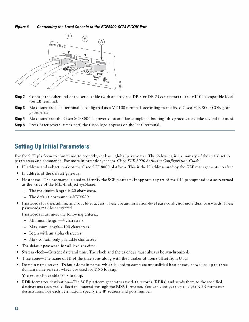
Figure 8 Connecting the Local Console to the SCE8000-SCM-E CON Port
Step 2 Connect the other end of the serial cable (with an attached DB-9 or DB-25 connector) to the VT100 compatible local (serial) terminal.
Step 3 Make sure the local terminal is configured as a VT-100 terminal, according to the fixed Cisco SCE 8000 CON port parameters.
Step 4 Make sure that the Cisco SCE8000 is powered on and has completed booting (this process may take several minutes).
Step 5 Press Enter several times until the Cisco logo appears on the local terminal.
Setting Up Initial ParametersFor the SCE platform to communicate properly, set basic global parameters. The following is a summary of the initial setup parameters and commands. For more information, see the Cisco SCE 8000 Software Configuration Guide.
• IP address and subnet mask of the Cisco SCE 8000 platform. This is the IP address used by the GBE management interface.
• IP address of the default gateway.
• Hostname—The hostname is used to identify the SCE platform. It appears as part of the CLI prompt and is also returned as the value of the MIB-II object sysName.
– The maximum length is 20 characters.
– The default hostname is SCE8000.
• Passwords for user, admin, and root level access. These are authorization-level passwords, not individual passwords. These passwords may be encrypted.
Passwords must meet the following criteria:
– Minimum length—4 characters
– Maximum length—100 characters
– Begin with an alpha character
– May contain only printable characters
• The default password for all levels is cisco.
• System clock—Current date and time. The clock and the calendar must always be synchronized.
• Time zone—The name or ID of the time zone along with the number of hours offset from UTC.
• Domain name server—Default domain name, which is used to complete unqualified host names, as well as up to three domain name servers, which are used for DNS lookup.
You must also enable DNS lookup.
• RDR formatter destination—The SCE platform generates raw data records (RDRs) and sends them to the specified destinations (external collection systems) through the RDR formatter. You can configure up to eight RDR formatter destinations. For each destination, specify the IP address and port number.
2709
76
SCE8000-SCM-E
10/100/1000 LINK/
ACTIVE
OPTICALBYPASS1 CONSOLEPORT1
12
3
12
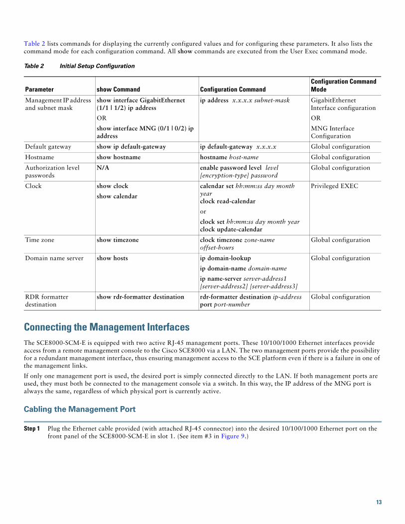
Table 2 lists commands for displaying the currently configured values and for configuring these parameters. It also lists the command mode for each configuration command. All show commands are executed from the User Exec command mode.
Connecting the Management InterfacesThe SCE8000-SCM-E is equipped with two active RJ-45 management ports. These 10/100/1000 Ethernet interfaces provide access from a remote management console to the Cisco SCE8000 via a LAN. The two management ports provide the possibility for a redundant management interface, thus ensuring management access to the SCE platform even if there is a failure in one of the management links.
If only one management port is used, the desired port is simply connected directly to the LAN. If both management ports are used, they must both be connected to the management console via a switch. In this way, the IP address of the MNG port is always the same, regardless of which physical port is currently active.
Cabling the Management Port
Step 1 Plug the Ethernet cable provided (with attached RJ-45 connector) into the desired 10/100/1000 Ethernet port on the front panel of the SCE8000-SCM-E in slot 1. (See item #3 in Figure 9.)
Table 2 Initial Setup Configuration
Parameter show Command Configuration CommandConfiguration Command Mode
Management IP address and subnet mask
show interface GigabitEthernet (1/1 | 1/2) ip address
OR
show interface MNG (0/1 | 0/2) ip address
ip address x.x.x.x subnet-mask GigabitEthernet Interface configuration
OR
MNG Interface Configuration
Default gateway show ip default-gateway ip default-gateway x.x.x.x Global configuration
Hostname show hostname hostname host-name Global configuration
Authorization level passwords
N/A enable password level level [encryption-type] password
Global configuration
Clock show clock
show calendar
calendar set hh:mm:ss day month yearclock read-calendar
or
clock set hh:mm:ss day month yearclock update-calendar
Privileged EXEC
Time zone show timezone clock timezone zone-name offset-hours
Global configuration
Domain name server show hosts ip domain-lookup
ip domain-name domain-name
ip name-server server-address1 [server-address2] [server-address3]
Global configuration
RDR formatter destination
show rdr-formatter destination rdr-formatter destination ip-address port port-number
Global configuration
13

Figure 9 Cabling the Management Port
Step 2 Connect the other end of the Ethernet cable into your management network.
• If only one management port is used — connect the port directly to the LAN.
• If both management ports are used — connect both ports to the LAN via a switch.
The Link LED on the SCE8000 management port lights.
Step 3 Test connectivity. From the host that you intend to use for remote management, ping to the Cisco SCE8000 by typing ping and the Cisco SCE8000 IP address, and pressing Enter.
This verifies that an active connection exists between the specified station and the management port.
5 Cabling Line PortsThis chapter describes cabling the Cisco SCE 8000 10 Gigabit Ethernet ports for single, cascaded, and multigigabit service control platforms (MGSCP) topologies.
The 10 Gigabit Ethernet ports are located on the 10 G SPA modules, which are installed in the SCE8000-SIP module in slot #3 of the Cisco SCE 8000 chassis.
Warning Class 1 laser. Avoid exposure to radiation and do not stare into open aperture.
SCE8000 Connectivity SummaryTable 3 through Table 7 summarize Cisco SCE 8000 connectivity for basic topologies. Receive-only topologies use only receive fibers.
Note You can implement receive-only topologies using either an optical splitter or a switch. If you use a switch, it must support SPAN functionality that includes separation between ingress and egress traffic and multiple SPAN-port destinations.
Table 3 Single Link Connectivity
Port Link Side
3/0/0 Link 0 Subscribers
3/1/0 Link 0 Network
2709
76
SCE8000-SCM-E
10/100/1000 LINK/
ACTIVE
OPTICALBYPASS1 CONSOLEPORT1
12
3
14
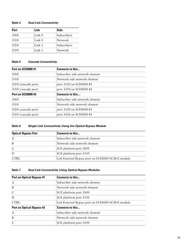
Table 4 Dual Link Connectivity
Port Link Side
3/0/0 Link 0 Subscribers
3/1/0 Link 0 Network
3/2/0 Link 1 Subscribers
3/3/0 Link 1 Network
Table 5 Cascade Connectivity
Port on SCE8000 #1 Connects to this...
3/0/0 Subscriber side network element
3/1/0 Network side network element
3/2/0 (cascade port) port 3/3/0 on SCE8000 #2
3/3/0 (cascade port) port 3/2/0 on SCE8000 #2
Port on SCE8000 #2 Connects to this....
3/0/0 Subscriber side network element
3/1/0 Network side network element
3/2/0 (cascade port) port 3/3/0 on SCE8000 #1
3/3/0 (cascade port) port 3/2/0 on SCE8000 #1
Table 6 Single Link Connectivity Using the Optical Bypass Module
Optical Bypass Port Connects to this...
A Subscriber side network element
B Network side network element
C SCE platform port 3/0/0
D SCE platform port 3/1/0
CTRL Left External Bypass port on SCE8000-SCM-E module
Table 7 Dual Link Connectivity Using Optical Bypass Modules
Port on Optical Bypass #1 Connects to this...
A Subscriber side network element
B Network side network element
C SCE platform port 3/0/0
D SCE platform port 3/1/0
CTRL Left External Bypass port on SCE8000-SCM-E module.
Port on Optical Bypass #2 Connects to this...
A Subscriber side network element
B Network side network element
C SCE platform port 3/2/0
15

Deploying a Multigigabit Service Control Platform Topology
In a Multigigabit Service Control Platform (MGSCP) deployment, the cabling scheme depends on the number and arrangement of ports in the EtherChannel in the Cisco 7600 series router. It is therefore not possible to detail exact cabling schemes. When designing the cabling scheme, refer to the following general guidelines.
General guidelines for MGSCP topologies:
• Because two links exist per Cisco SCE8000 platform, the minimum number of platforms required is half the number of links used.
• Each link corresponds to one port on the EtherChannel (EC) on the Cisco 7600 series router. Each EC supports a maximum of eight ports. Therefore, if all eight EC ports are configured, four Cisco SCE 8000 platforms are required.
• For N+1 redundancy, two ports (connected to the standby platform) must be configured as standby ports on both ECs. Therefore, for N+1 redundancy, one router and five Cisco SCE 8000 platforms are used to support eight links.
• If two Cisco 7600 series routers are used (for network redundancy), one link on each Cisco SCE8000 platform is connected to each router. This requires twice the number of Cisco SCE 8000 platforms, one platform for each link.
– A minimum of eight Cisco SCE8000 platforms are required to support eight ports.
– For N+1 redundancy, nine Cisco SCE8000 platforms are used to support eight active links.
When cabling to the EC, follow these guidelines:
• The Cisco SCE platform ports must be connected to the EC ports in the same order on both sides.
• The EC ports should be sorted in an ascending order by their physical interface numbers.
• In a topology with two Cisco 7600 series routers, the order of connection to the EC ports must be the same on both routers. For both routers to send the traffic of a given subscriber to the same SCE platform, the SCE platforms must be connected to both routers in exactly the same order (one SCE platform connected to the first link on both routers, another SCE platform connected to the second link on both routers, and so on).
Cabling 10 GBE Line Interface Ports
Note When you install an external optical bypass module, the Cisco SCE8000 line ports are connected to the module. See Table 6 and Table 7 for connectivity.
Warning Class 1 laser. Avoid exposure to radiation and do not stare into open aperture.
Step 1 Obtain the appropriate fiber optic cable.
Step 2 Plus the fiber optic cable into the appropriate port on the 10 GBE interface on the SPA module in slot #3 of the Cisco SCE 8000 (Figure 10).
D SCE platform port 3/3/0
CTRL Right External Bypass port on SCE8000-SCM-E module
Table 7 Dual Link Connectivity Using Optical Bypass Modules (continued)
Port on Optical Bypass #1 Connects to this...
16
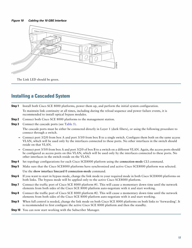
Figure 10 Cabling the 10 GBE Interface
The Link LED should be green.
Installing a Cascaded System
Step 1 Install both Cisco SCE 8000 platforms, power them up, and perform the initial system configuration.
To maintain link continuity at all times, including during the reload sequence and power failure events, it is recommended to install optical bypass modules.
Step 2 Connect both Cisco SCE 8000 platforms to the management station.
Step 3 Connect the cascade ports (see Table 5).
The cascade ports must be either be connected directly in Layer 1 (dark fibers), or using the following procedure to connect through a switch.
– Connect port 3/2/0 from box A and port 3/3/0 from box B to a single switch. Configure them both on the same access VLAN, which will be used only by the interfaces connected to these ports. No other interfaces in the switch should reside on that VLAN.
– Connect port 3/3/0 from box A and port 3/2/0 of box B to a switch on a different VLAN. Again, the access ports should be configured as access ports on this VLAN, which will be used only by the interfaces connected to these ports. No other interfaces in the switch reside on the VLAN.
Step 4 Set topology configurations for each Cisco SCE8000 platform using the connection-mode CLI command.
Step 5 Make sure that the Cisco SCE8000 platforms have synchronized and active Cisco SCE8000 platform was selected.
Use the show interface linecard 0 connection-mode command.
Step 6 If you want to start in bypass mode, change the link mode to your required mode in both Cisco SCE8000 platforms on both links. The bypass mode will be applied only to the active Cisco SCE8000 platform.
Step 7 Connect the traffic port of Cisco SCE 8000 platform #1. This will cause a momentary down time until the network elements from both sides of the Cisco SCE 8000 platform auto-negotiate with it and start working.
Step 8 Connect the traffic port of Cisco SCE 8000 platform #2. This will cause a momentary down time until the network elements from both sides of the Cisco SCE 8000 platform auto-negotiate with it and start working.
Step 9 When full control is needed, change the link mode on both Cisco SCE 8000 platforms on both links to ‘forwarding’. It is recommended to first configure the active Cisco SCE 8000 platform and then the standby.
Step 10 You can now start working with the Subscriber Manager.
2709
79
SCE8000-SIP
STATUS
ACTIVE/LINK
SPA-1X10GE-L-V2
STATUS
ACTIVE/LINK
SPA-1X10GE-L-V2
17
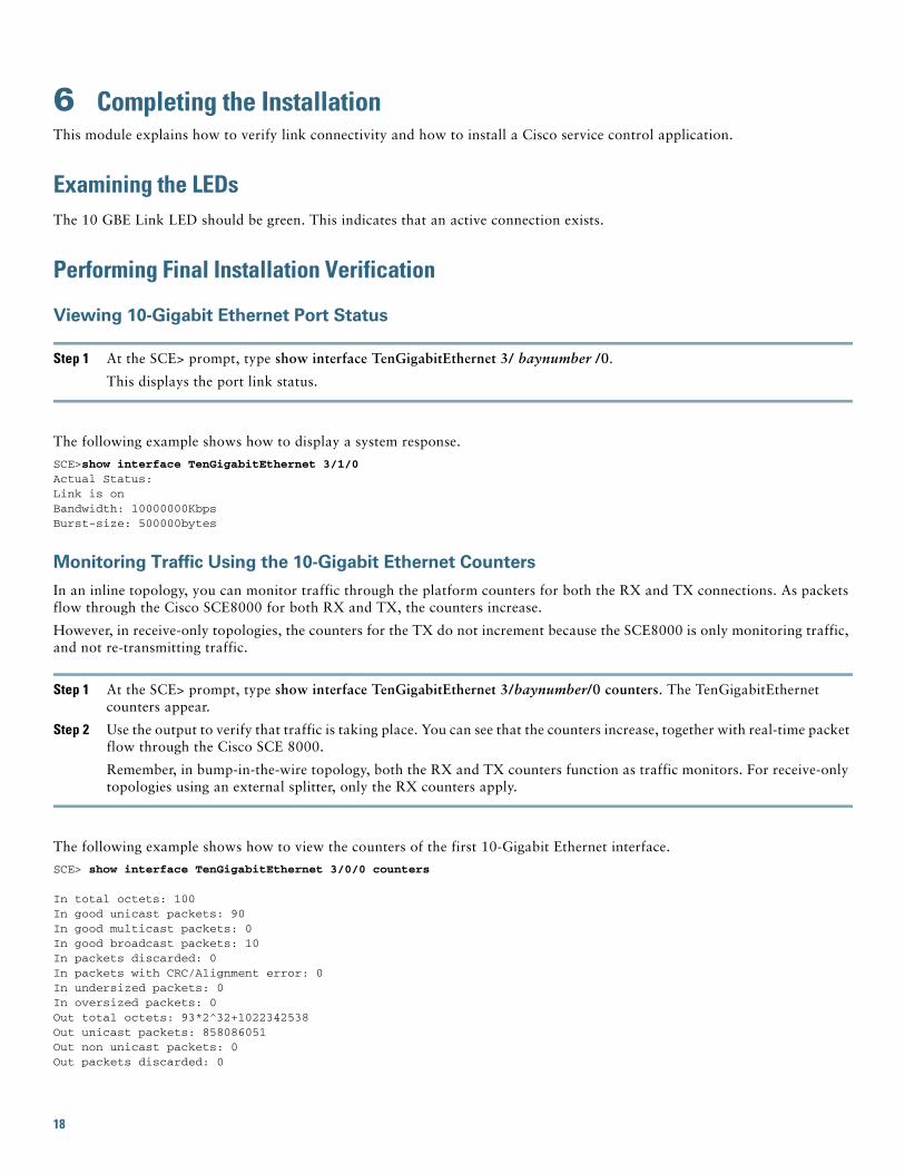
6 Completing the InstallationThis module explains how to verify link connectivity and how to install a Cisco service control application.
Examining the LEDsThe 10 GBE Link LED should be green. This indicates that an active connection exists.
Performing Final Installation Verification
Viewing 10-Gigabit Ethernet Port Status
Step 1 At the SCE> prompt, type show interface TenGigabitEthernet 3/ baynumber /0.
This displays the port link status.
The following example shows how to display a system response.
SCE>show interface TenGigabitEthernet 3/1/0 Actual Status: Link is onBandwidth: 10000000KbpsBurst-size: 500000bytes
Monitoring Traffic Using the 10-Gigabit Ethernet Counters
In an inline topology, you can monitor traffic through the platform counters for both the RX and TX connections. As packets flow through the Cisco SCE8000 for both RX and TX, the counters increase.
However, in receive-only topologies, the counters for the TX do not increment because the SCE8000 is only monitoring traffic, and not re-transmitting traffic.
Step 1 At the SCE> prompt, type show interface TenGigabitEthernet 3/baynumber/0 counters. The TenGigabitEthernet counters appear.
Step 2 Use the output to verify that traffic is taking place. You can see that the counters increase, together with real-time packet flow through the Cisco SCE 8000.
Remember, in bump-in-the-wire topology, both the RX and TX counters function as traffic monitors. For receive-only topologies using an external splitter, only the RX counters apply.
The following example shows how to view the counters of the first 10-Gigabit Ethernet interface.
SCE> show interface TenGigabitEthernet 3/0/0 counters
In total octets: 100In good unicast packets: 90In good multicast packets: 0In good broadcast packets: 10In packets discarded: 0In packets with CRC/Alignment error: 0In undersized packets: 0In oversized packets: 0Out total octets: 93*2^32+1022342538Out unicast packets: 858086051Out non unicast packets: 0Out packets discarded: 0
18
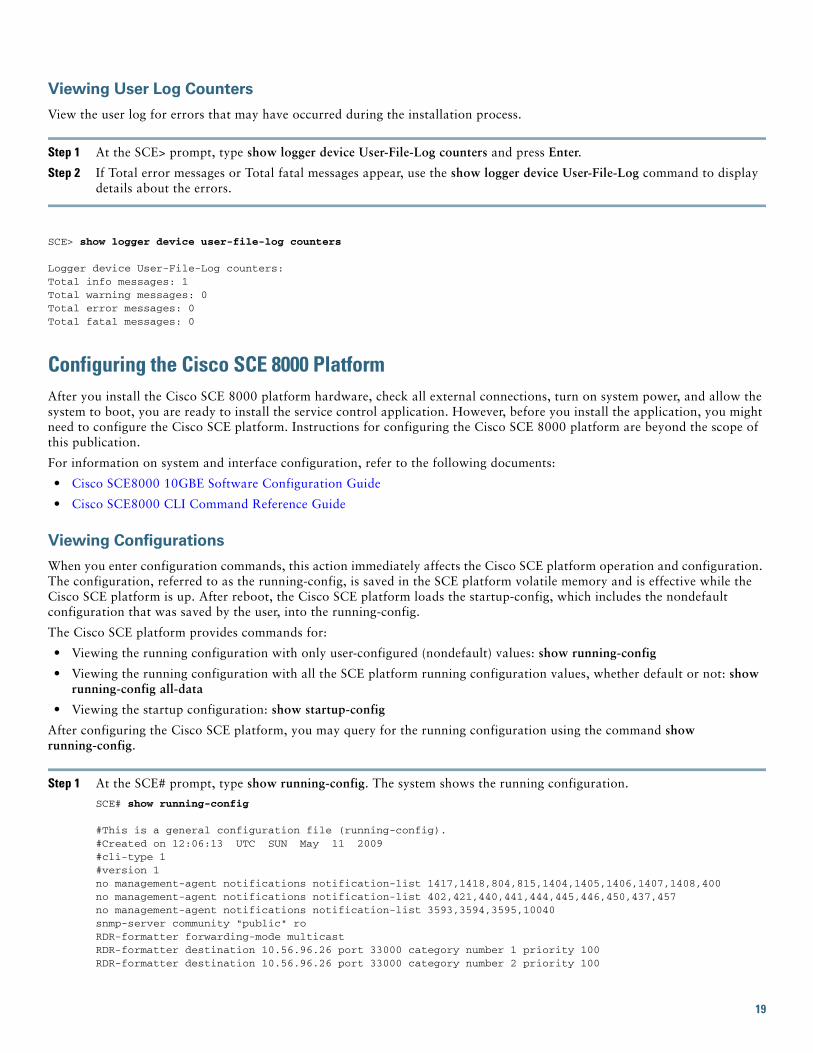
Viewing User Log Counters
View the user log for errors that may have occurred during the installation process.
Step 1 At the SCE> prompt, type show logger device User-File-Log counters and press Enter.
Step 2 If Total error messages or Total fatal messages appear, use the show logger device User-File-Log command to display details about the errors.
SCE> show logger device user-file-log counters
Logger device User-File-Log counters:Total info messages: 1Total warning messages: 0Total error messages: 0Total fatal messages: 0
Configuring the Cisco SCE 8000 PlatformAfter you install the Cisco SCE 8000 platform hardware, check all external connections, turn on system power, and allow the system to boot, you are ready to install the service control application. However, before you install the application, you might need to configure the Cisco SCE platform. Instructions for configuring the Cisco SCE 8000 platform are beyond the scope of this publication.
For information on system and interface configuration, refer to the following documents:
• Cisco SCE8000 10GBE Software Configuration Guide
• Cisco SCE8000 CLI Command Reference Guide
Viewing Configurations
When you enter configuration commands, this action immediately affects the Cisco SCE platform operation and configuration. The configuration, referred to as the running-config, is saved in the SCE platform volatile memory and is effective while the Cisco SCE platform is up. After reboot, the Cisco SCE platform loads the startup-config, which includes the nondefault configuration that was saved by the user, into the running-config.
The Cisco SCE platform provides commands for:
• Viewing the running configuration with only user-configured (nondefault) values: show running-config
• Viewing the running configuration with all the SCE platform running configuration values, whether default or not: show running-config all-data
• Viewing the startup configuration: show startup-config
After configuring the Cisco SCE platform, you may query for the running configuration using the command show running-config.
Step 1 At the SCE# prompt, type show running-config. The system shows the running configuration.
SCE# show running-config
#This is a general configuration file (running-config).#Created on 12:06:13 UTC SUN May 11 2009#cli-type 1#version 1no management-agent notifications notification-list 1417,1418,804,815,1404,1405,1406,1407,1408,400no management-agent notifications notification-list 402,421,440,441,444,445,446,450,437,457no management-agent notifications notification-list 3593,3594,3595,10040snmp-server community "public" ro RDR-formatter forwarding-mode multicastRDR-formatter destination 10.56.96.26 port 33000 category number 1 priority 100 RDR-formatter destination 10.56.96.26 port 33000 category number 2 priority 100
19
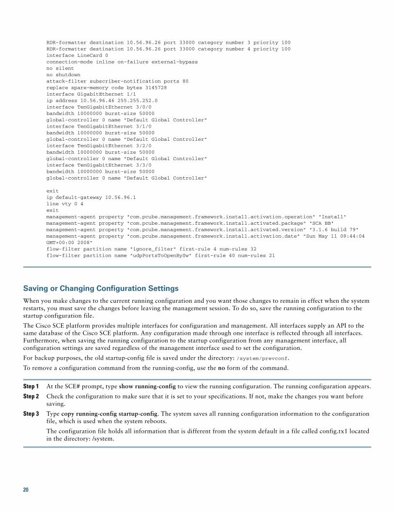
RDR-formatter destination 10.56.96.26 port 33000 category number 3 priority 100 RDR-formatter destination 10.56.96.26 port 33000 category number 4 priority 100 interface LineCard 0connection-mode inline on-failure external-bypassno silentno shutdownattack-filter subscriber-notification ports 80replace spare-memory code bytes 3145728interface GigabitEthernet 1/1ip address 10.56.96.46 255.255.252.0 interface TenGigabitEthernet 3/0/0bandwidth 10000000 burst-size 50000global-controller 0 name "Default Global Controller"interface TenGigabitEthernet 3/1/0bandwidth 10000000 burst-size 50000global-controller 0 name "Default Global Controller"interface TenGigabitEthernet 3/2/0bandwidth 10000000 burst-size 50000global-controller 0 name "Default Global Controller"interface TenGigabitEthernet 3/3/0bandwidth 10000000 burst-size 50000global-controller 0 name "Default Global Controller"
exitip default-gateway 10.56.96.1line vty 0 4exitmanagement-agent property "com.pcube.management.framework.install.activation.operation" "Install"management-agent property "com.pcube.management.framework.install.activated.package" "SCA BB"management-agent property "com.pcube.management.framework.install.activated.version" "3.1.6 build 79"management-agent property "com.pcube.management.framework.install.activation.date" "Sun May 11 08:44:04 GMT+00:00 2008"flow-filter partition name "ignore_filter" first-rule 4 num-rules 32flow-filter partition name "udpPortsToOpenBySw" first-rule 40 num-rules 21
Saving or Changing Configuration Settings
When you make changes to the current running configuration and you want those changes to remain in effect when the system restarts, you must save the changes before leaving the management session. To do so, save the running configuration to the startup configuration file.
The Cisco SCE platform provides multiple interfaces for configuration and management. All interfaces supply an API to the same database of the Cisco SCE platform. Any configuration made through one interface is reflected through all interfaces. Furthermore, when saving the running configuration to the startup configuration from any management interface, all configuration settings are saved regardless of the management interface used to set the configuration.
For backup purposes, the old startup-config file is saved under the directory: /system/prevconf.
To remove a configuration command from the running-config, use the no form of the command.
Step 1 At the SCE# prompt, type show running-config to view the running configuration. The running configuration appears.
Step 2 Check the configuration to make sure that it is set to your specifications. If not, make the changes you want before saving.
Step 3 Type copy running-config startup-config. The system saves all running configuration information to the configuration file, which is used when the system reboots.
The configuration file holds all information that is different from the system default in a file called config.tx1 located in the directory: /system.
20
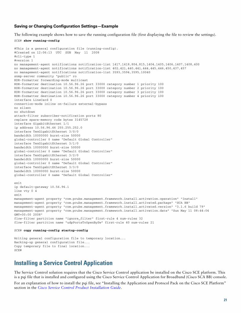
Saving or Changing Configuration Settings—Example
The following example shows how to save the running configuration file (first displaying the file to review the settings).
SCE# show running-config
#This is a general configuration file (running-config).#Created on 12:06:13 UTC SUN May 11 2008#cli-type 1#version 1no management-agent notifications notification-list 1417,1418,804,815,1404,1405,1406,1407,1408,400no management-agent notifications notification-list 402,421,440,441,444,445,446,450,437,457no management-agent notifications notification-list 3593,3594,3595,10040snmp-server community "public" ro RDR-formatter forwarding-mode multicastRDR-formatter destination 10.56.96.26 port 33000 category number 1 priority 100 RDR-formatter destination 10.56.96.26 port 33000 category number 2 priority 100 RDR-formatter destination 10.56.96.26 port 33000 category number 3 priority 100 RDR-formatter destination 10.56.96.26 port 33000 category number 4 priority 100 interface LineCard 0connection-mode inline on-failure external-bypassno silentno shutdownattack-filter subscriber-notification ports 80replace spare-memory code bytes 3145728interface GigabitEthernet 1/1ip address 10.56.96.46 255.255.252.0 interface TenGigabitEthernet 3/0/0bandwidth 10000000 burst-size 50000global-controller 0 name "Default Global Controller"interface TenGigabitEthernet 3/1/0bandwidth 10000000 burst-size 50000global-controller 0 name "Default Global Controller"interface TenGigabitEthernet 3/2/0bandwidth 10000000 burst-size 50000global-controller 0 name "Default Global Controller"interface TenGigabitEthernet 3/3/0bandwidth 10000000 burst-size 50000global-controller 0 name "Default Global Controller"
exitip default-gateway 10.56.96.1line vty 0 4exitmanagement-agent property "com.pcube.management.framework.install.activation.operation" "Install"management-agent property "com.pcube.management.framework.install.activated.package" "SCA BB"management-agent property "com.pcube.management.framework.install.activated.version" "3.1.6 build 79"management-agent property "com.pcube.management.framework.install.activation.date" "Sun May 11 08:44:04 GMT+00:00 2008"flow-filter partition name "ignore_filter" first-rule 4 num-rules 32flow-filter partition name "udpPortsToOpenBySw" first-rule 40 num-rules 21
SCE# copy running-config startup-config
Writing general configuration file to temporary location...Backing-up general configuration file...Copy temporary file to final location...SCE#
Installing a Service Control ApplicationThe Service Control solution requires that the Cisco Service Control application be installed on the Cisco SCE platform. This is a pqi file that is installed and configured using the Cisco Service Control Application for Broadband (Cisco SCA BB) console.
For an explanation of how to install the pqi file, see “Installing the Application and Protocol Pack on the Cisco SCE Platform” section in the Cisco Service Control Product Installation Guide.
21
For information on initial configuration of the application, see the “Initial Cisco SCA BB Configuration” section in the Cisco Service Control Product Installation Guide.
For complete instructions on how to install and configure the Cisco SCA BB application, see the Cisco Service Control Application for Broadband User Guide.
7 Troubleshooting
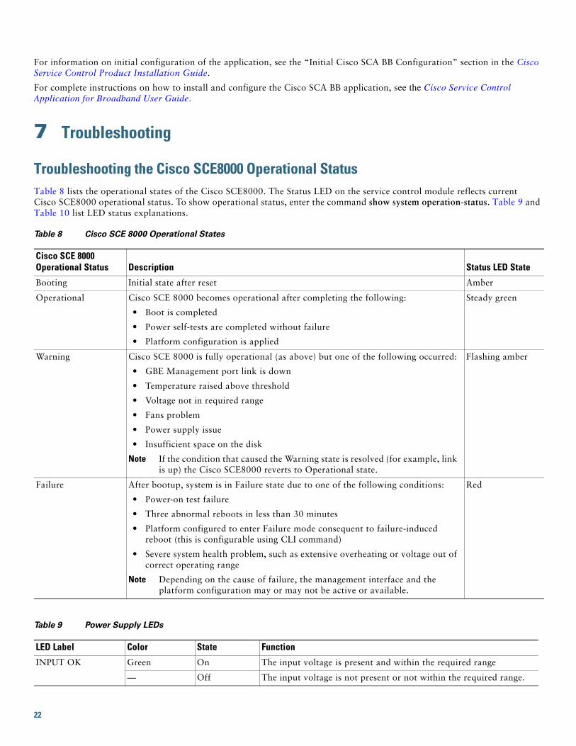
Troubleshooting the Cisco SCE8000 Operational StatusTable 8 lists the operational states of the Cisco SCE8000. The Status LED on the service control module reflects current Cisco SCE8000 operational status. To show operational status, enter the command show system operation-status. Table 9 and Table 10 list LED status explanations.
Table 8 Cisco SCE 8000 Operational States
Cisco SCE 8000 Operational Status Description Status LED State
Booting Initial state after reset Amber
Operational Cisco SCE 8000 becomes operational after completing the following:
• Boot is completed
• Power self-tests are completed without failure
• Platform configuration is applied
Steady green
Warning Cisco SCE 8000 is fully operational (as above) but one of the following occurred:
• GBE Management port link is down
• Temperature raised above threshold
• Voltage not in required range
• Fans problem
• Power supply issue
• Insufficient space on the disk
Note If the condition that caused the Warning state is resolved (for example, link is up) the Cisco SCE8000 reverts to Operational state.
Flashing amber
Failure After bootup, system is in Failure state due to one of the following conditions:
• Power-on test failure
• Three abnormal reboots in less than 30 minutes
• Platform configured to enter Failure mode consequent to failure-induced reboot (this is configurable using CLI command)
• Severe system health problem, such as extensive overheating or voltage out of correct operating range
Note Depending on the cause of failure, the management interface and the platform configuration may or may not be active or available.
Red
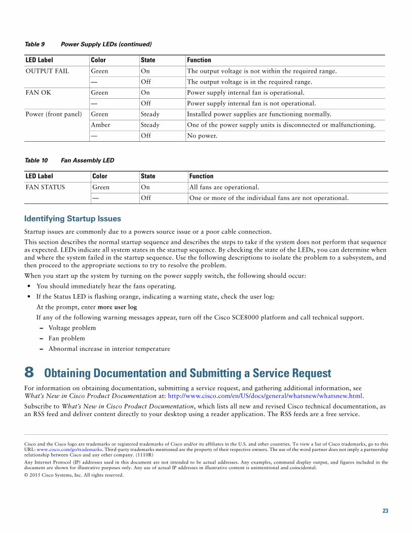
Table 9 Power Supply LEDs
LED Label Color State Function
INPUT OK Green On The input voltage is present and within the required range
— Off The input voltage is not present or not within the required range.
22
Identifying Startup Issues
Startup issues are commonly due to a powers source issue or a poor cable connection.
This section describes the normal startup sequence and describes the steps to take if the system does not perform that sequence as expected. LEDs indicate all system states in the startup sequence. By checking the state of the LEDs, you can determine when and where the system failed in the startup sequence. Use the following descriptions to isolate the problem to a subsystem, and then proceed to the appropriate sections to try to resolve the problem.
When you start up the system by turning on the power supply switch, the following should occur:
• You should immediately hear the fans operating.
• If the Status LED is flashing orange, indicating a warning state, check the user log:
At the prompt, enter more user log
If any of the following warning messages appear, turn off the Cisco SCE8000 platform and call technical support.
– Voltage problem
– Fan problem
– Abnormal increase in interior temperature
8 Obtaining Documentation and Submitting a Service RequestFor information on obtaining documentation, submitting a service request, and gathering additional information, see What’s New in Cisco Product Documentation at: http://www.cisco.com/en/US/docs/general/whatsnew/whatsnew.html.
Subscribe to What’s New in Cisco Product Documentation, which lists all new and revised Cisco technical documentation, as an RSS feed and deliver content directly to your desktop using a reader application. The RSS feeds are a free service.
Cisco and the Cisco logo are trademarks or registered trademarks of Cisco and/or its affiliates in the U.S. and other countries. To view a list of Cisco trademarks, go to thisURL: www.cisco.com/go/trademarks. Third-party trademarks mentioned are the property of their respective owners. The use of the word partner does not imply a partnershiprelationship between Cisco and any other company. (1110R)
Any Internet Protocol (IP) addresses used in this document are not intended to be actual addresses. Any examples, command display output, and figures included in thedocument are shown for illustrative purposes only. Any use of actual IP addresses in illustrative content is unintentional and coincidental.
© 2015 Cisco Systems, Inc. All rights reserved.
OUTPUT FAIL Green On The output voltage is not within the required range.
— Off The output voltage is in the required range.
FAN OK Green On Power supply internal fan is operational.
— Off Power supply internal fan is not operational.
Power (front panel) Green Steady Installed power supplies are functioning normally.
Amber Steady One of the power supply units is disconnected or malfunctioning.
— Off No power.
Table 10 Fan Assembly LED
LED Label Color State Function
FAN STATUS Green On All fans are operational.
— Off One or more of the individual fans are not operational.
Table 9 Power Supply LEDs (continued)
LED Label Color State Function
23

Americas HeadquartersCisco Systems, Inc.San Jose, CA
Asia Pacific HeadquartersCisco Systems (USA) Pte. Ltd.Singapore
Europe HeadquartersCisco Systems International BV Amsterdam, The Netherlands
Cisco has more than 200 offices worldwide. Addresses, phone numbers, and fax numbers are listed on the Cisco Website at www.cisco.com/go/offices.