Embed Size (px)
Citation preview

Cisco Remote Expert ManagerInstallation GuideRelease 1.9.6
September 28, 2015
Cisco Systems, Inc.www.cisco.com
Cisco has more than 200 offices worldwide. Addresses, phone numbers, and fax numbers are listed on the Cisco website at www.cisco.com/go/offices.

THE SPECIFICATIONS AND INFORMATION REGARDING THE PRODUCTS IN THIS MANUAL ARE SUBJECT TO CHANGE WITHOUT NOTICE. ALL STATEMENTS, INFORMATION, AND RECOMMENDATIONS IN THIS MANUAL ARE BELIEVED TO BE ACCURATE BUT ARE PRESENTED WITHOUT WARRANTY OF ANY KIND, EXPRESS OR IMPLIED. USERS MUST TAKE FULL RESPONSIBILITY FOR THEIR APPLICATION OF ANY PRODUCTS.
THE SOFTWARE LICENSE AND LIMITED WARRANTY FOR THE ACCOMPANYING PRODUCT ARE SET FORTH IN THE INFORMATION PACKET THAT SHIPPED WITH THE PRODUCT AND ARE INCORPORATED HEREIN BY THIS REFERENCE. IF YOU ARE UNABLE TO LOCATE THE SOFTWARE LICENSE OR LIMITED WARRANTY, CONTACT YOUR CISCO REPRESENTATIVE FOR A COPY.
The Cisco implementation of TCP header compression is an adaptation of a program developed by the University of California, Berkeley (UCB) as part of UCB’s public domain version of the UNIX operating system. All rights reserved. Copyright © 1981, Regents of the University of California.
NOTWITHSTANDING ANY OTHER WARRANTY HEREIN, ALL DOCUMENT FILES AND SOFTWARE OF THESE SUPPLIERS ARE PROVIDED “AS IS” WITH ALL FAULTS. CISCO AND THE ABOVE-NAMED SUPPLIERS DISCLAIM ALL WARRANTIES, EXPRESSED OR IMPLIED, INCLUDING, WITHOUT LIMITATION, THOSE OF MERCHANTABILITY, FITNESS FOR A PARTICULAR PURPOSE AND NONINFRINGEMENT OR ARISING FROM A COURSE OF DEALING, USAGE, OR TRADE PRACTICE.
IN NO EVENT SHALL CISCO OR ITS SUPPLIERS BE LIABLE FOR ANY INDIRECT, SPECIAL, CONSEQUENTIAL, OR INCIDENTAL DAMAGES, INCLUDING, WITHOUT LIMITATION, LOST PROFITS OR LOSS OR DAMAGE TO DATA ARISING OUT OF THE USE OR INABILITY TO USE THIS MANUAL, EVEN IF CISCO OR ITS SUPPLIERS HAVE BEEN ADVISED OF THE POSSIBILITY OF SUCH DAMAGES.
CCDE, CCENT, Cisco Eos, Cisco HealthPresence, the Cisco logo, Cisco Lumin, Cisco Nexus, Cisco StadiumVision, Cisco TelePresence, Cisco WebEx, DCE, and Welcome to the Human Network are trademarks; Changing the Way We Work, Live, Play, and Learn and Cisco Store are service marks; and Access Registrar, Aironet, AsyncOS, Bringing the Meeting To You, Catalyst, CCDA, CCDP, CCIE, CCIP, CCNA, CCNP, CCSP, CCVP, Cisco, the Cisco Certified Internetwork Expert logo, Cisco IOS, Cisco Press, Cisco Systems, Cisco Systems Capital, the Cisco Systems logo, Cisco Unity, Collaboration Without Limitation, EtherFast, EtherSwitch, Event Center, Fast Step, Follow Me Browsing, FormShare, GigaDrive, HomeLink, Internet Quotient, IOS, iPhone, iQuick Study, IronPort, the IronPort logo, LightStream, Linksys, MediaTone, MeetingPlace, MeetingPlace Chime Sound, MGX, Networkers, Networking Academy, Network Registrar, PCNow, PIX, PowerPanels, ProConnect, ScriptShare, SenderBase, SMARTnet, Spectrum Expert, StackWise, The Fastest Way to Increase Your Internet Quotient, TransPath, WebEx, and the WebEx logo are registered trademarks of Cisco Systems, Inc. and/or its affiliates in the United States and certain other countries.
All other trademarks mentioned in this document or website are the property of their respective owners. The use of the word partner does not imply a partnership relationship between Cisco and any other company. (1110R)
© 2015 Cisco Systems, Inc. All rights reserved.
C O N T E N T S
Preface 5
Overview 5
Audience 5
Purpose 5
Organization 6
Related Documentation 6
7
C H A P T E R 1 Remote Expert Manager (REM) ISO Deployment 1-1
Chapter Overview 1-1
REM ISO Deployment 1-2
Upload the REM ISO Image into the Datastore 1-2
Create the Virtual Machine 1-2
Turn on the VM 1-4
Start the REM ISO Installation 1-4
Configure the REM’s Virtual Machine 1-4
Activate Master and Slave Nodes for REM HA 1-6
Configure the NTP Server 1-7
Configure the Time Zone 1-7
Configure the SSH Banner (Optional) 1-8
Install VMware Tools (Optional) 1-8
Install the Skin Package 1-8
Modify the REM Properties File 1-9
Enable Video for Wait and On Hold Pages 1-13
Execute IAS 1-13
REM ISO Installation Verification 1-14
C H A P T E R 2 REM High Availability 2-1
Chapter Overview 2-1
Use of Private and Public Addresses for REM HA 2-1
Activate Master and Slave Nodes for REM HA 2-1
Configuring a Virtual Switch in the ESX Server 2-2
1Cisco Remote Expert Interactive Controller SDK Developer
Contents
C H A P T E R 3 Media Server Installation 3-1
Chapter Overview 3-1
Identify and Locate Media Server 3-1
C H A P T E R 4 IEM Policy Configuration 4-1
Chapter Overview 4-1
Create and Apply a Policy for REM in the IEM 4-1
C H A P T E R 5 Connected Justice 5-1
Chapter Overview 5-1
Connected Justice Overview 5-1
Extension Mobility Setup 5-1
Click To Connect (CTC) 5-1
Next Available Interpreter (NAI) 5-2
Hardware Required 5-2
Cisco Extension Mobility Setup on CUCM 5-2
Connected Justice Configuration 5-4
A P P E N D I X A Frequently Asked Questions (FAQs) A-1
Appendix Overview A-1
General Questions A-1
Remote Expert Manager (REM) Installation Questions A-2
Remote Expert Admin Console (REAC) Questions A-2
Remote Expert Session Control (RESC) Questions A-5
Remote Expert Interactive Console (REIC) Questions A-6
Direct Connect Questions A-9
A-11
A P P E N D I X B Document Camera Configuration B-1
Appendix Overview B-1
Configure the Document Camera B-1
Connect and Configure the Hardware B-3
Create Policies in the IEM for Each Document Camera B-9
Reboot IEC from REAC B-12
B-12
2Cisco Remote Expert Interactive Controller SDK Developer
Contents
A P P E N D I X C RE-on-IServices C-1
Appendix Overview C-1
RE-on-IServices Overview C-1
Hardware Required C-2
Cisco IEC Setup on the CUCM C-2
Configuring a SIP Policy in the IEM C-3
RE-on-IServices Configuration C-4
Set Up the RE-on-IServices Environment C-5
miniREIC Supporting Files C-8
Integrating miniREIC into the I-Services Template C-9
SIP and DC Call Flow C-10
HA Proxy Server C-11
C-13
A P P E N D I X D Mobile Advisor D-1
Appendix Overview D-1
Mobile Advisor Integration Overview D-1
Mobile Session Type and mREAD D-2
Live Assist Configuration D-4
D-4
3Cisco Remote Expert Interactive Controller SDK Developer

Contents
4Cisco Remote Expert Interactive Controller SDK Developer
Preface
Note All advertising materials mentioning features or use of this software must display the following acknowledgement: “This product includes software developed by the University of California, Berkeley and its contributors.”
OverviewThis preface describes the audience, organization, and conventions of the Cisco Remote Expert Manager Installation Guide for release 1.9.6. It also provides information on related documentation. This preface includes the following sections:
• “Audience”
• “Purpose”
• “Organization”
• “Related Documentation”
AudienceThis guide is intended for Partners and the Advanced Services team who will install the hardware and software at the data center, contact center, and branches. This guide is not intended for Administrators of the solution.
PurposeThis guide provides the information that you need to install and configure the components of the Cisco Remote Expert solution.
Note REAC configuration is not included in this guide.
5Cisco Remote Expert Manager Installation Guide
PrefaceOrganization
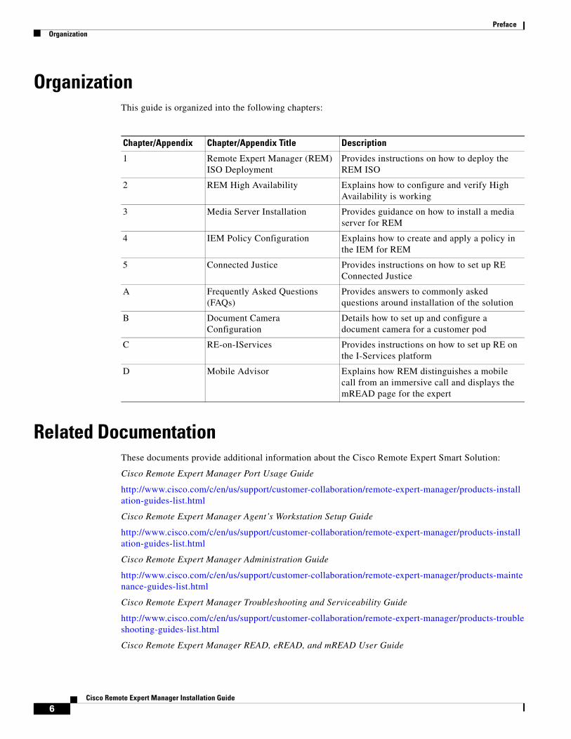
OrganizationThis guide is organized into the following chapters:
Related DocumentationThese documents provide additional information about the Cisco Remote Expert Smart Solution:
Cisco Remote Expert Manager Port Usage Guide
http://www.cisco.com/c/en/us/support/customer-collaboration/remote-expert-manager/products-installation-guides-list.html
Cisco Remote Expert Manager Agent’s Workstation Setup Guide
http://www.cisco.com/c/en/us/support/customer-collaboration/remote-expert-manager/products-installation-guides-list.html
Cisco Remote Expert Manager Administration Guide
http://www.cisco.com/c/en/us/support/customer-collaboration/remote-expert-manager/products-maintenance-guides-list.html
Cisco Remote Expert Manager Troubleshooting and Serviceability Guide
http://www.cisco.com/c/en/us/support/customer-collaboration/remote-expert-manager/products-troubleshooting-guides-list.html
Cisco Remote Expert Manager READ, eREAD, and mREAD User Guide
Chapter/Appendix Chapter/Appendix Title Description
1 Remote Expert Manager (REM) ISO Deployment
Provides instructions on how to deploy the REM ISO
2 REM High Availability Explains how to configure and verify High Availability is working
3 Media Server Installation Provides guidance on how to install a media server for REM
4 IEM Policy Configuration Explains how to create and apply a policy in the IEM for REM
5 Connected Justice Provides instructions on how to set up RE Connected Justice
A Frequently Asked Questions (FAQs)
Provides answers to commonly asked questions around installation of the solution
B Document Camera Configuration
Details how to set up and configure a document camera for a customer pod
C RE-on-IServices Provides instructions on how to set up RE on the I-Services platform
D Mobile Advisor Explains how REM distinguishes a mobile call from an immersive call and displays the mREAD page for the expert
6Cisco Remote Expert Manager Installation Guide
Preface
http://www.cisco.com/c/en/us/support/customer-collaboration/remote-expert-manager/products-user-guide-list.html
Cisco Remote Expert Manager Release Notes
http://www.cisco.com/c/en/us/support/customer-collaboration/remote-expert-manager/products-release-notes-list.html
Cisco Remote Expert Smart Solution Migration Guide
http://www.cisco.com/c/en/us/support/customer-collaboration/remote-expert-manager/products-installation-guides-list.html
7Cisco Remote Expert Manager Installation Guide

Preface
8Cisco Remote Expert Manager Installation Guide
C H A P T E R 1
Remote Expert Manager (REM) ISO DeploymentSeptember 28, 2015
Chapter OverviewThis chapter contains the procedure for deploying the Remote Expert Manager (REM) ISO.
Topics in this chapter include:
• “REM ISO Deployment”
– “Upload the REM ISO Image into the Datastore”
– “Create the Virtual Machine”
– “Turn on the VM”
– “Start the REM ISO Installation”
– “Configure the REM’s Virtual Machine”
– “Activate Master and Slave Nodes for REM HA”
– “Configure the NTP Server”
– “Configure the Time Zone”
– “Configure the SSH Banner (Optional)”
– “Install VMware Tools (Optional)”
– “Install the Skin Package”
– “Modify the REM Properties File”
– “Enable Video for Wait and On Hold Pages”
– “Execute IAS”
– “REM ISO Installation Verification”
Note Please refer to the Cisco Remote Expert Manager Port Usage Guide for information on ports assignment: http://www.cisco.com/c/en/us/support/customer-collaboration/remote-expert-manager/products-installation-guides-list.html
1-1Cisco Remote Expert Manager Installation Guide
Chapter 1 Remote Expert Manager (REM) ISO Deployment REM ISO Deployment
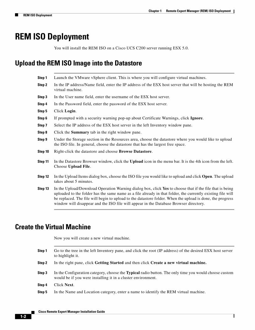
REM ISO DeploymentYou will install the REM ISO on a Cisco UCS C200 server running ESX 5.0.
Upload the REM ISO Image into the Datastore
Step 1 Launch the VMware vSphere client. This is where you will configure virtual machines.
Step 2 In the IP address/Name field, enter the IP address of the ESX host server that will be hosting the REM virtual machine.
Step 3 In the User name field, enter the username of the ESX host server.
Step 4 In the Password field, enter the password of the ESX host server.
Step 5 Click Login.
Step 6 If prompted with a security warning pop-up about Certificate Warnings, click Ignore.
Step 7 Select the IP address of the ESX host server in the left Inventory window pane.
Step 8 Click the Summary tab in the right window pane.
Step 9 Under the Storage section in the Resources area, choose the datastore where you would like to upload the ISO file. In general, choose the datastore that has the largest free space.
Step 10 Right-click the datastore and choose Browse Datastore.
Step 11 In the Datastore Browser window, click the Upload icon in the menu bar. It is the 4th icon from the left. Choose Upload File.
Step 12 In the Upload Items dialog box, choose the ISO file you would like to upload and click Open. The upload takes about 5 minutes.
Step 13 In the Upload/Download Operation Warning dialog box, click Yes to choose that if the file that is being uploaded to the folder has the same name as a file already in that folder, the currently existing file will be replaced. The file will begin to upload to the datastore folder. When the upload is done, the progress window will disappear and the ISO file will appear in the Database Browser directory.
Create the Virtual MachineNow you will create a new virtual machine.
Step 1 Go to the tree in the left Inventory pane, and click the root (IP address) of the desired ESX host server to highlight it.
Step 2 In the right pane, click Getting Started and then click Create a new virtual machine.
Step 3 In the Configuration category, choose the Typical radio button. The only time you would choose custom would be if you were installing it in a cluster environment.
Step 4 Click Next.
Step 5 In the Name and Location category, enter a name to identify the REM virtual machine.
1-2Cisco Remote Expert Manager Installation Guide
Chapter 1 Remote Expert Manager (REM) ISO Deployment REM ISO Deployment
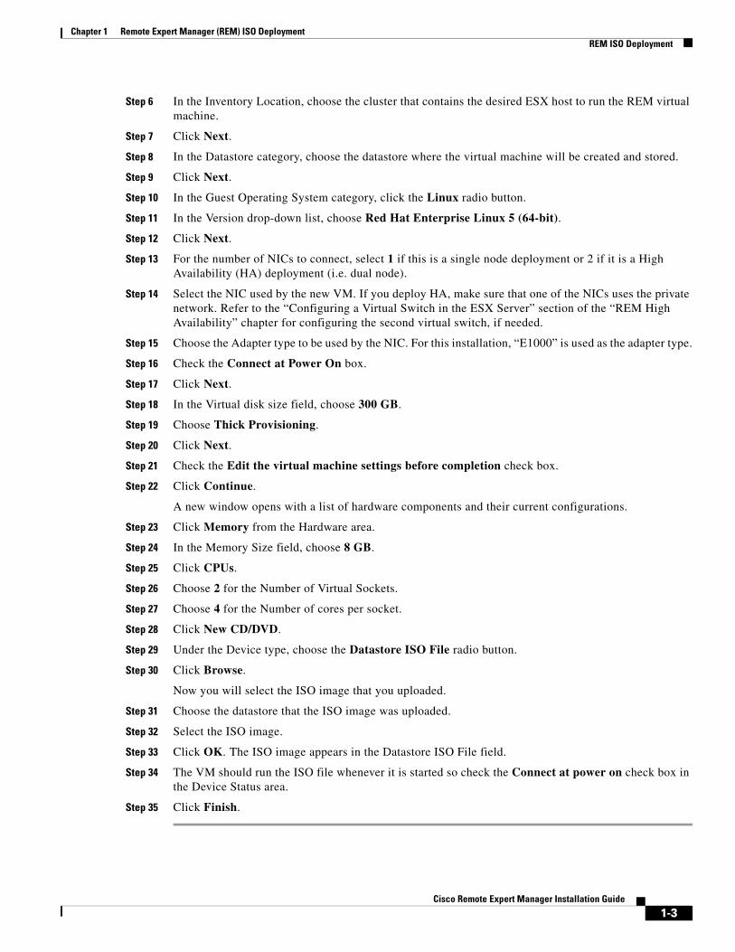
Step 6 In the Inventory Location, choose the cluster that contains the desired ESX host to run the REM virtual machine.
Step 7 Click Next.
Step 8 In the Datastore category, choose the datastore where the virtual machine will be created and stored.
Step 9 Click Next.
Step 10 In the Guest Operating System category, click the Linux radio button.
Step 11 In the Version drop-down list, choose Red Hat Enterprise Linux 5 (64-bit).
Step 12 Click Next.
Step 13 For the number of NICs to connect, select 1 if this is a single node deployment or 2 if it is a High Availability (HA) deployment (i.e. dual node).
Step 14 Select the NIC used by the new VM. If you deploy HA, make sure that one of the NICs uses the private network. Refer to the “Configuring a Virtual Switch in the ESX Server” section of the “REM High Availability” chapter for configuring the second virtual switch, if needed.
Step 15 Choose the Adapter type to be used by the NIC. For this installation, “E1000” is used as the adapter type.
Step 16 Check the Connect at Power On box.
Step 17 Click Next.
Step 18 In the Virtual disk size field, choose 300 GB.
Step 19 Choose Thick Provisioning.
Step 20 Click Next.
Step 21 Check the Edit the virtual machine settings before completion check box.
Step 22 Click Continue.
A new window opens with a list of hardware components and their current configurations.
Step 23 Click Memory from the Hardware area.
Step 24 In the Memory Size field, choose 8 GB.
Step 25 Click CPUs.
Step 26 Choose 2 for the Number of Virtual Sockets.
Step 27 Choose 4 for the Number of cores per socket.
Step 28 Click New CD/DVD.
Step 29 Under the Device type, choose the Datastore ISO File radio button.
Step 30 Click Browse.
Now you will select the ISO image that you uploaded.
Step 31 Choose the datastore that the ISO image was uploaded.
Step 32 Select the ISO image.
Step 33 Click OK. The ISO image appears in the Datastore ISO File field.
Step 34 The VM should run the ISO file whenever it is started so check the Connect at power on check box in the Device Status area.
Step 35 Click Finish.
1-3Cisco Remote Expert Manager Installation Guide
Chapter 1 Remote Expert Manager (REM) ISO Deployment REM ISO Deployment
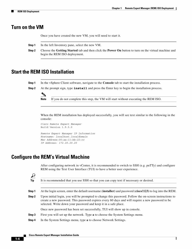
Turn on the VMOnce you have created the new VM, you will need to start it.
Step 1 In the left Inventory pane, select the new VM.
Step 2 Choose the Getting Started tab and then click the Power On button to turn on the virtual machine and begin the REM ISO deployment.
Start the REM ISO Installation
Step 1 In the vSphere Client software, navigate to the Console tab to start the installation process.
Step 2 At the prompt sign, type install and press the Enter key to begin the installation process.
Note If you do not complete this step, the VM will start without executing the REM ISO.
When the REM installation has deployed successfully, you will see text similar to the following in the console:
Cisco Remote Expert ManagerBuild Version 1.9.5.0
Remote Expert Manager IP InformationHostname: localhost.localdomainMac Address:00:aa:11:bb:22:ccIP Address: 172.20.20.20
Configure the REM’s Virtual MachineAfter configuring network in vCenter, it is recommended to switch to SSH (e.g. puTTy) and configure REM using the Text User Interface (TUI) to have a better user experience.
Tip It is recommended that you use SSH so that you can copy text if necessary or desired.
Step 1 At the login screen, enter the default username (installer) and password (cisco!123) to log into the REM.
Step 2 Upon initial login, you will be prompted to change this password. Follow the on-screen instructions to create a new password. This password expires every 60 days and will require a new password to be selected. Write down your password and keep it in a safe place.
Once new password has been set successfully, TUI will show up in console.
Step 3 First you will set up the network. Type a to choose the System Settings menu.
Step 4 In the System Settings menu, type a to choose Network Settings.
1-4Cisco Remote Expert Manager Installation Guide

Chapter 1 Remote Expert Manager (REM) ISO Deployment REM ISO Deployment
Step 5 In the Network Settings menu, type a to choose Setup Network Information.
Step 6 In the Setup Network Information screen, press any key to continue.
Step 7 Configure for either Single Node or REM HA setup.
a. Single Node:
1. Within the Select Action screen, choose Edit Devices.
2. Select eth0 to configure. Press the Enter key.
3. Uncheck the Use DHCP check box.
4. Enter the desired IP addresses for the Static IP address, Netmask IP address, and Default gateway IP address fields. Select Ok.
5. Choose Save and press the Enter key.
6. Choose Edit DNS Configuration.
7. Enter the Hostname, Primary DNS, Secondary DNS, Tertiary DNS, and Search fields. Select Ok.
8. Select Save and Quit.
9. Go back to the Main Menu.
10. To restart network service, select c) Services Control in the Main Menu. Then choose a) Networking in the Services Control menu. Finally, choose a) Restart networking in the Networking menu.
If network is set up properly, you should see a message similar to “Updating REM DB with IP Address: 172.20.20.20”.
b. REM HA (Dual Node):
1. Choose Edit Devices.
2. Select eth0 to configure. Press the Enter key.
3. Uncheck the Use DHCP check box.
4. Enter a public IP address in the Static IP address, Netmask IP address, and Default gateway IP address fields. Select Ok.
5. Select eth1 to configure. Press the Enter key.
6. Uncheck the Use DHCP check box.
7. Enter a private IP address (e.g. 192.168.10.100) in the Static IP address field. In the Netmask IP address field, enter 255.255.255.0. Leave the Default gateway IP address field empty. Select Ok.
8. Choose Save and press the Enter key.
9. Choose Edit DNS Configuration and enter the values for the Hostname, Primary DNS, Secondary DNS, Tertiary DNS, and Search fields. Select Ok.
Note Each node should be given a unique hostname.
Note If you have FQDN for REM HA, use Virtual IP for DNS server.
1-5Cisco Remote Expert Manager Installation Guide
Chapter 1 Remote Expert Manager (REM) ISO Deployment REM ISO Deployment
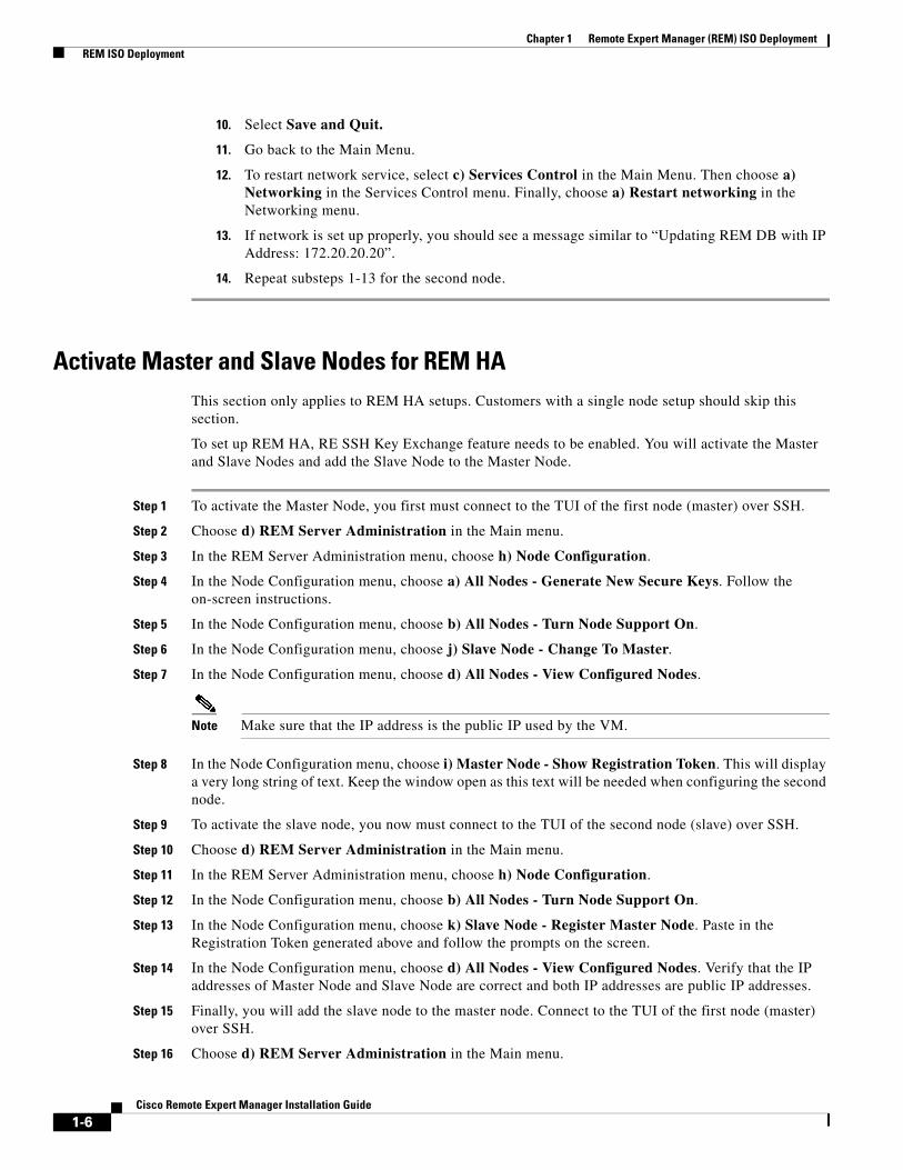
10. Select Save and Quit.
11. Go back to the Main Menu.
12. To restart network service, select c) Services Control in the Main Menu. Then choose a) Networking in the Services Control menu. Finally, choose a) Restart networking in the Networking menu.
13. If network is set up properly, you should see a message similar to “Updating REM DB with IP Address: 172.20.20.20”.
14. Repeat substeps 1-13 for the second node.
Activate Master and Slave Nodes for REM HAThis section only applies to REM HA setups. Customers with a single node setup should skip this section.
To set up REM HA, RE SSH Key Exchange feature needs to be enabled. You will activate the Master and Slave Nodes and add the Slave Node to the Master Node.
Step 1 To activate the Master Node, you first must connect to the TUI of the first node (master) over SSH.
Step 2 Choose d) REM Server Administration in the Main menu.
Step 3 In the REM Server Administration menu, choose h) Node Configuration.
Step 4 In the Node Configuration menu, choose a) All Nodes - Generate New Secure Keys. Follow the on-screen instructions.
Step 5 In the Node Configuration menu, choose b) All Nodes - Turn Node Support On.
Step 6 In the Node Configuration menu, choose j) Slave Node - Change To Master.
Step 7 In the Node Configuration menu, choose d) All Nodes - View Configured Nodes.
Note Make sure that the IP address is the public IP used by the VM.
Step 8 In the Node Configuration menu, choose i) Master Node - Show Registration Token. This will display a very long string of text. Keep the window open as this text will be needed when configuring the second node.
Step 9 To activate the slave node, you now must connect to the TUI of the second node (slave) over SSH.
Step 10 Choose d) REM Server Administration in the Main menu.
Step 11 In the REM Server Administration menu, choose h) Node Configuration.
Step 12 In the Node Configuration menu, choose b) All Nodes - Turn Node Support On.
Step 13 In the Node Configuration menu, choose k) Slave Node - Register Master Node. Paste in the Registration Token generated above and follow the prompts on the screen.
Step 14 In the Node Configuration menu, choose d) All Nodes - View Configured Nodes. Verify that the IP addresses of Master Node and Slave Node are correct and both IP addresses are public IP addresses.
Step 15 Finally, you will add the slave node to the master node. Connect to the TUI of the first node (master) over SSH.
Step 16 Choose d) REM Server Administration in the Main menu.
1-6Cisco Remote Expert Manager Installation Guide
Chapter 1 Remote Expert Manager (REM) ISO Deployment REM ISO Deployment
Step 17 In the REM Server Administration menu, choose h) Node Configuration.
Step 18 In the Node Configuration menu, choose e) Master Node - Add Slave Node. At the prompt, enter the public IP address of the second node (slave). Depending on the network configuration, this step may take some time as the master node is verifying SSH connectivity with the slave node.
Step 19 In the Node Configuration menu, choose d) All Nodes - View Configured Nodes. Verify that the slave node has been added.
Step 20 In the Node Configuration menu, choose g) Master Node - Key Synchronization Across Nodes. This step may take some time depending on the network configuration.
Configure the NTP ServerThe REM ISO has pre-configured NTP servers, which require the REM servers to have external Internet access. If you plan to use internal NTP servers, follow the steps below. Otherwise, you may skip this step set.
Step 1 Choose a) System Settings in the Main Menu.
Step 2 In the System Settings menu, choose b) Date and Time Settings.
Step 3 In the Date and Time Settings, choose a) Setup NTP Source.
Step 4 A VI window will open. Replace the IPs or hostname of your NTP servers in the following entries. If you only use one or two NTP servers, comment out the unused entries by adding # at the beginning of lines.
server 0.rhel.pool.ntp.org
server 1.rhel.pool.ntp.org
#server 2.rhel.pool.ntp.org
Step 5 Save and exit the VI.
Step 6 If you have a REM HA setup, repeat the steps above on the second node.
Configure the Time ZoneNetwork Time Protocol (NTP) setup is part of the REM ISO installation. NTP synchronizes the clock of the local server with the NTP server. This is required for synchronization of files with timestamp.
Follow these steps to configure the NTP server:
Step 1 In the TUI, choose a) System Settings in the Main Menu.
Step 2 In the System Settings menu, choose b) Date and Time Settings.
Step 3 In the Date and Time Settings, choose b) Change timezone.
Step 4 Follow the on-screen instructions to set up time zone.
Step 5 If you have a REM HA setup, repeat the steps above on the second node.
1-7Cisco Remote Expert Manager Installation Guide
Chapter 1 Remote Expert Manager (REM) ISO Deployment REM ISO Deployment
Configure the SSH Banner (Optional)The SSH banner appears at the top of the TUI. Adding a message to the SSH banner is not a requirement.
Step 1 Choose a) System Settings in the Main Menu.
Step 2 In the System Settings menu, choose c) SSH Banner Settings.
Step 3 A VI window will open. Add the desired messages to display in SSH login window.
Step 4 Save and exit the VI.
Step 5 If you have a REM HA setup, repeat the steps above on the second node.
Install VMware Tools (Optional)Installing VMware Tools is optional. VMware Tools provide a better user experience and improved management of the VM. To install VMware Tools, follow these steps:
Step 1 In the vSphere Client inventory, right-click the VM and choose Guest > Install/Upgrade VMware Tools.
Step 2 Go to the VM Console in vSphere Client (or SSH into the VM) to access TUI.
Step 3 In the Main Menu, choose a) System Settings.
Step 4 In the System Settings menu, choose e) Install VMware Tools.
Step 5 Follow the on-screen instructions to install the tools.
Install the Skin PackageRemote Expert has a default skin that will appear on the customer pod’s touchscreen. This default skin is known as the Francisco Skin Package. Once the Francisco Skin Package is installed, it can be modified with customized background and button images. See the Cisco Remote Expert Manager Administration Guide for instructions on how to customize the REIC User Interface.
Two additional skins are available. The REM skin with the sequence “rem-skin-cj” is for Cisco Remote Expert Connected Justice. The REM skin with the sequence “rem-skin-regs” is for Cisco Remote Expert Government Services.
Follow these steps to install the appropriate skin:
Step 1 Use a terminal emulator such as PuTTY to SSH into the REM server.
Step 2 In the Main Menu, type d to choose the REM Server Administration menu.
Step 3 In the REM Server Administration menu, type f to choose the Install REM Skin menu.
Step 4 Choose the desired skin.
• The Connected Justice skin file contains the acronym “cj”.
1-8Cisco Remote Expert Manager Installation Guide
Chapter 1 Remote Expert Manager (REM) ISO Deployment REM ISO Deployment
• The skin file name for Government Services contains the acronym “regs”.
• The default REM skin, known as the Francisco skin, is the file without an acronym between “rem-skin-” and the release number.
Step 5 When asked if you want to continue with the skin that you selected, type C.
The skin will install.
Step 6 Once you see a “Complete!” message, press any key to return to the menu.
Note Records installed by default skin package (such as locale, expert type, and content) can be changed using REAC.
Step 7 If you have a REM HA setup, repeat the steps above on the second node.
Modify the REM Properties FileThe rem.properties file must now be configured. Follow the steps below to configure the properties within that file.
Warning Do not modify or delete any encrypted text with the rem.properties file. Encryption is taken care of by the Installation Automation Script (IAS).
Step 1 Use a terminal emulator such as PuTTY to SSH into the REM server.
Step 2 In the Main Menu, type d to choose the REM Server Administration menu.
Step 3 In the REM Server Administration menu, type b to choose Edit REM Properties.
Step 4 Within the REM Core Properties section:
a. Set the WEB_PROTOCOL property value to https.
b. For the REM_VIRTUAL_IP property, enter the IP address to that of the REM server if you are using a single node setup. If you are using dual node setup for High Availability (HA), enter the Virtual IP address which is assigned in ACE.
c. Change the RESC_PORT number to 8443.
d. For the RESC_IP property, enter the internal RESC component IP address if you are using a single node setup. If you are using HA, enter the private address.
Warning Do not modify or delete the encrypted text for the RESC_SERVER_USER and RESC_SERVER_PASSW properties.
Step 5 Within the CCX Deployment section, the default setting for IS_CCX property is false. If you are using Cisco Contact Center Enterprise (CCE), keep the default value (i.e. false). If you are using Cisco Contact Center Express (CCX), change the value to true.
1-9Cisco Remote Expert Manager Installation Guide

Chapter 1 Remote Expert Manager (REM) ISO Deployment REM ISO Deployment
Step 6 Within the CVP Deployment section, the default setting for IS_CvP property is false. If you are using Cisco Contact Center Express (CCX), you will not use Cisco Unified Customer Voice Portal (CVP) so keep the default value (i.e. false). If you are using Cisco Contact Center Enterprise (CCE), you will use CVP so change the value to true.
Step 7 Within the CUCM Credentials section, enter the IP address of the CUCM if you have just a single CUCM. If you have a cluster of CUCM servers, enter the IP address of the publisher followed by a comma and then the IP address of the subscriber(s) (e.g. 172.57.1.181,172.57.4.194). Up to three CUCM IP addresses are supported - one publisher and two subscribers.
Note Do not change the CUCM_PORT number; port 8443 is the default listening port for the CUCM.
Warning Do not modify or delete the encrypted text for the CUCM_USER, CUCM_PASSWORD, CUCM_SERVICE_USER, and CUCM_SERVICE_PASSWORD properties.
Step 8 Within the IEM Credentials section, enter the IP address of the IEM server.
Warning Do not modify or delete the encrypted text for the IEM_ACCOUNT, IEM_USER, and IEM_PASSWORD properties.
Step 9 Within the HA Properties section:
a. The default setting of Total_Nodes_In_Cluster is 1, which indicates that there is only a single node and hence high availability will not be supported. If you have set up high availability, change this setting to 2.
Note Do not change the PORT number for HA; port 22 is the default port.
b. For the NODE_IP_1 property, enter the IP address of the REM if the setup is for a single node. If this is a dual node setup, enter the private IP address of the first node.
Warning Do not modify or delete the encrypted text for the NODE_1_USER, NODE_1_PASSWORD, NODE_1_DB_USER, and NODE_1_DB_PASSWORD properties.
c. If this is a dual node setup, enter the private IP address of the second node in the NODE_IP_2 property.
d. If this is a dual node setup, change the RSYNC_ENABLED property to true.
Step 10 For the MEDIA_SENSE_VERSION property, enter 9 if MediaSense 9.x is used or 10 if MediaSense 10.x is used.
Step 11 Enter the IP address for the primary and secondary MediaSense servers.
Note Do not change the PORT numbers for either the primary or secondary server.
1-10Cisco Remote Expert Manager Installation Guide

Chapter 1 Remote Expert Manager (REM) ISO Deployment REM ISO Deployment
Warning Do not modify or delete the encrypted text for the PRIMARY_MEDIA_SENSE_USER, PRIMARY_MEDIA_SENSE_PASSWORD, SECONDARY_MEDIA_SENSE_USER, and SECONDARY_MEDIA_SENSE_PASSWORD properties.
Step 12 If you are using LongPen, enter the IP address of the LongPen server.
Step 13 The JMX_PORT and JMX_RMI_PORT ports are those that REAC uses to make a JMX over RMI call to fetch the database cluster information on both of the REM servers. If you do not have preferences and restrictions from your network’s firewall, you can use the default values. However, if you have some concerns or issues, specify the port numbers configured in their firewall.
Step 14 Within the REIC/Kiosk Properties section:
a. The REIC_SCREEN_MODULE property enables a keypad or magnetic card reader attached to the IEC to initiate a call by entering the customer’s ID number or swiping the customer’s card.
– By default, the property is set to null, which indicates that the customer needs to initiate the call using the touchscreen.
– If customers will use a USB keypad to initiate a call, change the value to keyboard.
– If customers will use a USB card reader to initiate a call, change the value to magstripe.
Note Even if REM is configured to use either a keypad or card reader to initiate a call, customers can still initiate a call using the touchscreen by clicking the Cancel button in the pop-up window, which triggers the REIC to initiate a call.
b. If configuring for Connected Justice, change the IS_CJ property to true. Otherwise, it should remain false.
Step 15 If you have a HD Webplayer license, enter the license in the HDWEBPLAYER_LICENSE property. If you do not have a license, videos will show a HD Webplayer Free watermark.
Caution The gadget properties (READ_GADGET_WIDTH and READ_GADGET_HEIGHT) should not be modified. The default values are width = ‘100%’ and height = ‘790px’.
Step 16 Disable the document camera and disable multicasting:
a. The DOCUMENT_CAMERA_ENABLED property is set to false by default. Since the document camera application is accessed on the agent’s workstation, the “Document Camera” button is not needed.
b. Unicast is the default stream type for the document camera. In the rem.properties file, the IS_MULTICAST property should be set to false.
Step 17 Under the Hide or show Utility buttons section, find the feature(s) that you want shown on eREAD and READ and change their values to true.
LONGPEN_ENABLED=true (for the LongPen button)
SCAN_ENABLED=true (for the Scanner button)
SESSION_RESULT_ENABLED=true (for the Session Result button)
SIGNATURE_CAPTURE_ENABLED=true (for the Signature Capture button)
VNC_COSHARE_ENABLED=true (for the VNC co-browsing button)
1-11Cisco Remote Expert Manager Installation Guide

Chapter 1 Remote Expert Manager (REM) ISO Deployment REM ISO Deployment
Caution The DOCUMENT_CAMERA_ENABLED property should NOT be set to “true”. The document camera is accessed on the agent’s workstation rather than from a button within READ or eREAD. Therefore the DOCUMENT_CAMERA_ENABLED property should be set to false.
Caution The HYPERLINK_BUTTON_CONFIG property should not be changed. By default the value should be set to ‘false’.
Step 18 Change the Backup and Restore Properties:
a. If you want to enable backup and restore, change the FEATURE_ENABLE property to true.
b. In the ARCHIVE_IDENTIFIER property, enter the IP address or hostname of the server from where the file will be backed up. This value will be appended to the backup file name so its origins can be easily identified by the administrator. The name contains the word “rem”, the system-generated date and time of the backup, and the IP address of the server from where the backup was taken.
c. SSH is the only mode currently supported so enter ssh for the MODE property.
d. In the SERVER_ADDRESS property, enter the IP address of the remote archiving server where the backup file will be sent.
Note In the next substep, you will enter the directory path as to where the backup files should be stored on the remote archiving server. The directory must be created in the remote server before executing the backup operation as REM will NOT create any directory on the remote server.
e. For the SERVER_BACKUP_PATH property, enter the path of the directory that you created in the remote server.
f. Configure the frequency of backups by entering the time and day that the backup should occur. This will create a Cron job inside the system. See the “Serviceability Administration” chapter in the Cisco Remote Expert Manager Troubleshooting and Serviceability Guide for more information.
You can modify the backup frequency by changing the values of the property.
The default is every day at 6:30 p.m. which is configured as follows:
– MIN=30
– HOUR=18
– DAY=*
– MONTH=*
– WEEKDAY=*
Note The * is used to indicate “every”.
If you want to backup on the 15th of every month instead, for example, enter 15 for the DAY property. If you want to backup on Fridays only, enter 5 for the WEEKDAY property.
g. If you want e-mail alerts for status of backups, change the MAIL_ENABLED property to true and then populate the SMTP server name, sender’s mail ID, and recipients mail ID.
Step 19 If you will use Mobile Advisor, scroll to the LIVEASSIST DETAILS section. Enter the IP address of the Live Assist server for the LIVEASSIST_SERVER property.
1-12Cisco Remote Expert Manager Installation Guide

Chapter 1 Remote Expert Manager (REM) ISO Deployment REM ISO Deployment
Step 20 Change the value of the LIVEASSIST_PORT property to 8443.
Warning Do not change the value of the LIVEASSIST_AUDIT_ENABLE property. The LIVEASSIST_AUDIT_ENABLE property enables the Mobile Advisor login capability and is enabled by default (i.e. the property is set to “true”).
Step 21 The VNC Port is the port that is used for VNC co-browsing. By default, the property is set to “5980”. If you wish to use a different port, enter the desired port number
Step 22 After you make all the changes to the rem.properties file, you need to save it by pressing SHIFT : and then entering wq.
Enable Video for Wait and On Hold PagesWait and On Hold pages display text by default. Follow the steps below to configure the REIC properties to enable video streaming when the customer sees the Wait and On Hold pages.
Step 1 In the REM Server Administration menu, type c to choose Edit REM Templates.
Step 2 In the Edit REM Templates menu, type e to choose REIC Properties.
Step 3 Find call.connecting.content=null and change the value to video.
Step 4 Find call.onhold.view=text and change text to REM.
Step 5 Save the file.
Step 6 If you have a REM HA setup, repeat the steps above on the second node.
Execute IASThe IAS should be executed now. In REM HA setups, the IAS only needs to be executed on the master node.
Step 1 In the REM Server Administration menu, type d to choose the Run Configuration Tool.
Step 2 In the Run Configuration Tool, press any key to begin.
Step 3 When prompted to update JTAPI username and password, type y.
Step 4 Type the JTAPI username and password.
Step 5 When prompted to update the CUCM Weblogin username and password, type y.
Step 6 Type the root username and password for the CUCM. You cannot use a regular account username and password.
Step 7 When prompted to update the IEM account name, type y.
Step 8 Type the account name.
Step 9 When prompted to update the IEM username and password, type y.
Step 10 Type the username and password for the IEM.
1-13Cisco Remote Expert Manager Installation Guide
Chapter 1 Remote Expert Manager (REM) ISO Deployment REM ISO Deployment
Step 11 When prompted to update the primary and secondary media servers’ username and password, type y.
Step 12 Type their usernames and passwords.
Step 13 When prompted to update the backup and restore username and password, type y.
Step 14 Type the remote server’s username and password.
Step 15 The process is complete when you see the “Press any key to return to the menu” message. Press any key.
REM ISO Installation VerificationAfter installing REM, use the following steps to check if the REM has been configured properly.
Step 1 In your browser, enter https://<REM_IP>:8443/ to verify that Tomcat is running.
Step 2 Check if necessary session control service is activated by entering the following URL in a web browser: https://<REM_IP>:8443/resc
Step 3 Once the Axis welcome page is displayed, choose Services.
Step 4 Verify that all the services are active. The Service Status for each should read “Active”.
Step 5 Check if REAC works properly by opening a web browser and entering the REAC’s URL: https://<REM_IP>:8443/reac
Refer to Chapter 1 “Remote Expert Administration Console (REAC)” of the Cisco Remote Expert Manager Administration Guide for instructions on how to log in as the administrator and add data.
1-14Cisco Remote Expert Manager Installation Guide
C H A P T E R 2
REM High AvailabilitySeptember 28, 2015
Chapter OverviewThis chapter contains the procedure for deploying High Availability (HA) for the Remote Expert Manager (REM).
Topics in this chapter include:
• “Use of Private and Public Addresses for REM HA”
• “Activate Master and Slave Nodes for REM HA”
• “Configuring a Virtual Switch in the ESX Server”
Use of Private and Public Addresses for REM HAWhen configuring REM HA, you will need a private and a public address.
The public address is needed for:
• Node 1 VM: The public IP address is entered into the Static IP address field within the TUI’s Setup Network Information screen.
• Node 2 VM: The public IP address is entered into the Static IP address field within the TUI’s Setup Network Information screen.
The private address is needed for:
• RESC_IP property in the rem.properties file
• NODE_IP_1 property in the rem.properties file
• NODE_IP_2 property in the rem.properties file
Activate Master and Slave Nodes for REM HATo set up REM HA, the RE SSH Key Exchange feature must be enabled. You need to activate the Master and Slave Nodes and then add the Slave Node to the Master Node. Refer to the “Activate Master and Slave Nodes for REM HA” section of Chapter 1 for instructions on how to configure the master and slave nodes for REM HA.
2-1Cisco Remote Expert Manager Installation Guide
Chapter 2 REM High Availability Configuring a Virtual Switch in the ESX Server
Configuring a Virtual Switch in the ESX Server
Step 1 Choose the ESX server that will host the VMs from the left Inventory pane.
Step 2 In the right pane, click the Configuration tab.
Step 3 In the Hardware box, find the Networking selection. Click Add Networking… at the upper right corner.
The Add Network Wizard dialog box opens.
Step 4 Choose Virtual Machine as the Connection Type.
Step 5 Click the Next button.
Step 6 Choose the Create a vSphere standard switch radio button.
Step 7 Check the check box for the NIC which is currently not in use.
Step 8 Click the Next button.
Step 9 In the Port Group Properties box, provide the proper Network Label. Use the default value for VLAN ID.
Step 10 Click the Next button.
Step 11 Click the Finish button to complete the configuration.
Tip If the configuration is not correct, go to NIC #2 in each REM node and set the second NIC card to use the network of the virtual switch that you just created.
2-2Cisco Remote Expert Manager Installation Guide
C H A P T E R 3
Media Server InstallationSeptember 28, 2015
Chapter OverviewThis chapter explains how to identify and locate the media server.
Topics in this chapter include:
• “Identify and Locate Media Server”
Identify and Locate Media Server
Note The media server cannot be installed on REM 1.9.x VM. You must set up a dedicated server.
REM requires a RTMP compliant media server. It is recommended that it is a dedicated media server. In this section, you will identify and locate the RTMP compliant media server for video streaming. The instructions are specifically for the Adobe Media Server (AMS).
If using AMS, note the following:
1. Install AMS on a dedicated server if possible. It is not recommended to use the same VM as REM.
2. If customers use the default setting in Linux system, then all the video files should be uploaded to the /opt/adobe/ams/webroot/vod folder.
3. Make sure that extensions of video files are in lower case.
4. Due to limitation of software, file names of video clips should only include alphanumeric characters, underscores (_) and hyphens (-). Currently, special characters such as # and % are not supported in REM.
3-1Cisco Remote Expert Manager Installation Guide
Chapter 3 Media Server Installation Identify and Locate Media Server
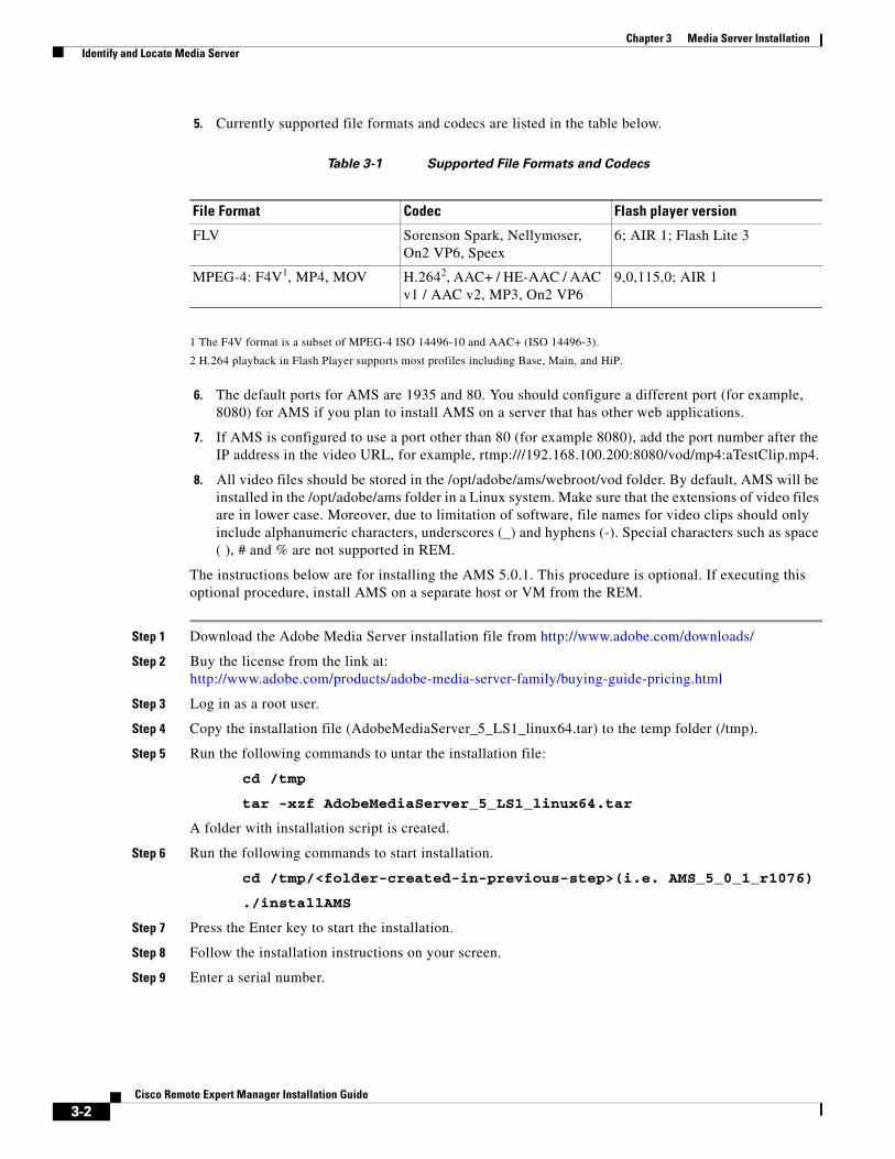
5. Currently supported file formats and codecs are listed in the table below.
Table 3-1 Supported File Formats and Codecs
1 The F4V format is a subset of MPEG-4 ISO 14496-10 and AAC+ (ISO 14496-3).
2 H.264 playback in Flash Player supports most profiles including Base, Main, and HiP.
6. The default ports for AMS are 1935 and 80. You should configure a different port (for example, 8080) for AMS if you plan to install AMS on a server that has other web applications.
7. If AMS is configured to use a port other than 80 (for example 8080), add the port number after the IP address in the video URL, for example, rtmp:///192.168.100.200:8080/vod/mp4:aTestClip.mp4.
8. All video files should be stored in the /opt/adobe/ams/webroot/vod folder. By default, AMS will be installed in the /opt/adobe/ams folder in a Linux system. Make sure that the extensions of video files are in lower case. Moreover, due to limitation of software, file names for video clips should only include alphanumeric characters, underscores (_) and hyphens (-). Special characters such as space ( ), # and % are not supported in REM.
The instructions below are for installing the AMS 5.0.1. This procedure is optional. If executing this optional procedure, install AMS on a separate host or VM from the REM.
Step 1 Download the Adobe Media Server installation file from http://www.adobe.com/downloads/
Step 2 Buy the license from the link at: http://www.adobe.com/products/adobe-media-server-family/buying-guide-pricing.html
Step 3 Log in as a root user.
Step 4 Copy the installation file (AdobeMediaServer_5_LS1_linux64.tar) to the temp folder (/tmp).
Step 5 Run the following commands to untar the installation file:
cd /tmp
tar -xzf AdobeMediaServer_5_LS1_linux64.tar
A folder with installation script is created.
Step 6 Run the following commands to start installation.
cd /tmp/<folder-created-in-previous-step>(i.e. AMS_5_0_1_r1076)
./installAMS
Step 7 Press the Enter key to start the installation.
Step 8 Follow the installation instructions on your screen.
Step 9 Enter a serial number.
File Format Codec Flash player version
FLV Sorenson Spark, Nellymoser, On2 VP6, Speex
6; AIR 1; Flash Lite 3
MPEG-4: F4V1, MP4, MOV H.2642, AAC+ / HE-AAC / AAC v1 / AAC v2, MP3, On2 VP6
9,0,115,0; AIR 1
3-2Cisco Remote Expert Manager Installation Guide
Chapter 3 Media Server Installation Identify and Locate Media Server
Note If you do not enter a serial number or if you enter an invalid serial number, the AMS 5.0.1 Starter version will be installed.
Step 10 Enter a user and group for AMS processes to run as. The default user is “ams”. The default group is “ams”.
Note If you install AMS on the REM server, make sure that you do NOT install the Apache server included in the installation package.
Step 11 The default ports for AMS are 1935 and 80. Configure AMS to use a different port (e.g. 8080) if you installed AMS on a server that has other web applications.
Step 12 Review the summary of the installation options you have chosen, which are displayed on screen by the installer.
Step 13 When installation is complete, the AMS service should start if you configured it to start automatically. To start the server manually, go to the folder where AMS is installed and enter the command ./server start.
Note By default, AMS is installed to the /opt/adobe/ams folder.
3-3Cisco Remote Expert Manager Installation Guide

Chapter 3 Media Server Installation Identify and Locate Media Server
3-4Cisco Remote Expert Manager Installation Guide
C H A P T E R 4
IEM Policy ConfigurationSeptember 28, 2015
Chapter Overview
This chapter explains how to create and apply a policy for REM in the IEM.
Topics in this chapter include:
• “Create and Apply a Policy for REM in the IEM”
Create and Apply a Policy for REM in the IEMThe Interactive Experience Manager (IEM) manages the Interactive Experience Clients (IECs) at the customer pods using policies that are applied to the IEC devices.
Note Each IEC 4600 Series has its own local set of configuration settings, known as a ‘Device Profile’. The device profile is useful in some applications where an IEC 4600 Series device is not managed by an IEM. In the Remote Expert Smart Solution, the IEC 4600 Series devices are always controlled by the IEM. Therefore the device policy assigned to the IEC 4600 Series device by the IEM takes precedence over any local profile information.
Refer to the Cisco Interactive Experience Manager (IEM) Installation Guide and the Cisco Interactive Experience Manager (IEM) Administration Guide to perform the following tasks:
Step 1 Install the IEM software on the VM.
Step 2 Configure the IEM server settings.
Note For the IECs to work properly, the “Device gateway”, “AMF gateway”, and “XML gateway” must be enabled in the IEM.
Step 3 Add an account on the IEM that will be used to manage the IECs for REM.
4-1Cisco Remote Expert Manager Installation Guide
Chapter 4 IEM Policy Configuration Create and Apply a Policy for REM in the IEM
Step 4 Add the IEC devices to the IEM so that they can be managed by it.
Step 5 Create a new policy in the IEM for the IECs and configure the following properties in that policy to set the startup URL as well as enable or disable network failure and timeout, watchdog features, and the IEC web cache features:
• browser > startup URL = https://<REM_IP>:8443/reic
• browser > network > failover > enabled = true
• browser > network > timeout > enabled = false
• browser > watchdog > enabled = false
• browser > cache > web > enabled = true
• clock > NTP = NTP server IP addresses
• clock > timezone = the server’s time zone
Note If the customer pods in this Remote Expert Smart Solution deployment span multiple time zones, then multiple device policies need to be created (e.g. Francisco-EST and Francisco-PST) and assigned to the appropriate IEC 4600 Series device located in those time zones.
Step 6 Apply the policy to the IECs.
Step 7 Reboot the IECs so that the settings will be enforced on the IECs.
4-2Cisco Remote Expert Manager Installation Guide
C H A P T E R 5
Connected JusticeSeptember 28, 2015
Chapter OverviewThis chapter explains how to setup and configure Connected Justice for Cisco Remote Expert Manager (REM).
Topics in this chapter include:
• “Connected Justice Overview”
• “Extension Mobility Setup”
• “Connected Justice Configuration”
Connected Justice OverviewConnected Justice (CJ) is an extension of Remote Expert Manager (REM). It includes two primary features, namely Click to Connect (CTC) and Next Available Interpreter (NAI). CJ utilizes the Cisco Extension Mobility to provide extra functionality for REM. Cisco Extension Mobility allows users to temporarily access their Cisco IP Phone configuration such as line appearances, services, and speed dials from other Cisco IP Phones.
Extension Mobility Setup
Click To Connect (CTC)The CTC feature provides an easy-to-use user interface to communicate between the court rooms and the remote interpreters using the Remote Expert (RE) solution.
In CTC, the hierarchy starts at the top with the Segment (e.g. The 9th Circuit), and then the Group (e.g. Orange County), followed by the Room (e.g. Court Room 1).
CTC works in the following manner: Once interpreters select a desired court house and court room on the CTC web page, the CTC initiates a RE call between the court room and the interpreter. The RE call connects the interpreter to the court room via TelePresence endpoints, such as the EX90. At the same
5-1Cisco Remote Expert Manager Installation Guide
Chapter 5 Connected Justice Extension Mobility Setup
time, the CTC loads the phone dialing extensions of that court room into the desk phone of the interpreter via the Extension Mobility API provided by the Cisco Unified Communications Manager (CUCM). This allows the interpreter to call the court room directly and speak to the judge or other court personnel if the interpreter has a question about what he or she is being asked to translate.
Next Available Interpreter (NAI)The NAI feature is a RE solution with a specially designed user interface for the judicial authority. Court officials, such as judges, are able to use a Remote Expert Interactive Console (REIC) in the courtroom to initiate an interpretation session with the next available language interpreter. The REIC will display up to six languages queues with each language having its own button.
When an interpreter has a CTC session, she/he is moved to the “Not Ready” state in CAD; this prevents the interpreter from being selected if a court official initiates a NAI request. When the REM detects a call established between the court room and the interpreter, the NAI loads the phone dialing extensions of that court room into the desk phone of the interpreter via the Extension Mobility API.
Hardware Required• Interpreter Side:
– PC / laptop with CAD installed
– Cisco IP phone (7975 or 9971 is preferred)
– EX90 TelePresence Endpoint
• Court Room Side:
– C40 TelePresence Endpoint
– Cisco Interactive Experience Client (IEC)
– Touchscreen
Cisco Extension Mobility Setup on CUCMEach court room requires a device profile created in the CUCM. Follow these steps to setup Extension Mobility for each court room.
Step 1 Activate the Cisco Extension Mobility service. Log into your CUCM and choose Cisco Unified Serviceability from the drop-down menu in the upper right corner.
Step 2 Choose Tools > Service Activation. Check the Cisco Extension Mobility check box. Click the Save button at the upper left corner.
Step 3 Choose Cisco Unified CM Administration from the drop-down menu in the upper right corner to complete the rest of configuration.
Step 4 Create the user device profile for a court room by choosing Device > Device Settings > Device Profile. Click the Add New button.
Step 5 From the Device Profile Type drop-down menu, select the phone type (e.g. Cisco 7975 or Cisco 9971). Click Next to go to the next page.
Step 6 Select SIP for the Device Protocol. Click Next to go to the next page.
5-2Cisco Remote Expert Manager Installation Guide
Chapter 5 Connected Justice Extension Mobility Setup
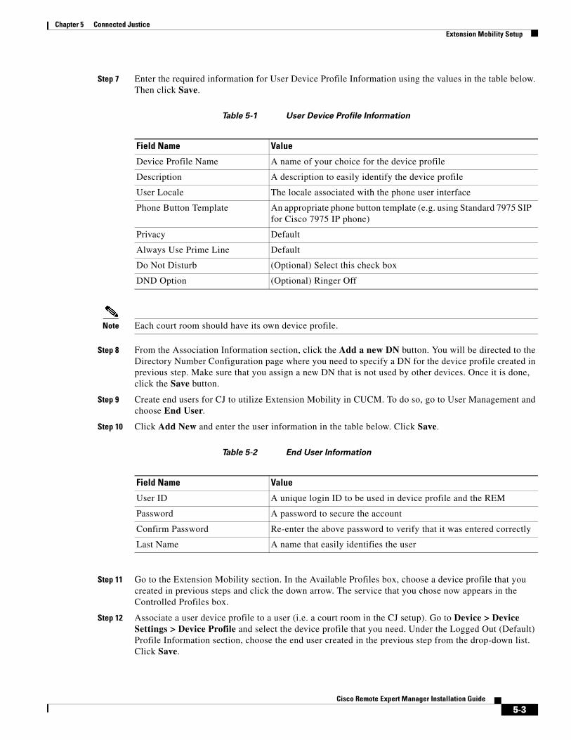
Step 7 Enter the required information for User Device Profile Information using the values in the table below. Then click Save.
Table 5-1 User Device Profile Information
Note Each court room should have its own device profile.
Step 8 From the Association Information section, click the Add a new DN button. You will be directed to the Directory Number Configuration page where you need to specify a DN for the device profile created in previous step. Make sure that you assign a new DN that is not used by other devices. Once it is done, click the Save button.
Step 9 Create end users for CJ to utilize Extension Mobility in CUCM. To do so, go to User Management and choose End User.
Step 10 Click Add New and enter the user information in the table below. Click Save.
Table 5-2 End User Information
Step 11 Go to the Extension Mobility section. In the Available Profiles box, choose a device profile that you created in previous steps and click the down arrow. The service that you chose now appears in the Controlled Profiles box.
Step 12 Associate a user device profile to a user (i.e. a court room in the CJ setup). Go to Device > Device Settings > Device Profile and select the device profile that you need. Under the Logged Out (Default) Profile Information section, choose the end user created in the previous step from the drop-down list. Click Save.
Field Name Value
Device Profile Name A name of your choice for the device profile
Description A description to easily identify the device profile
User Locale The locale associated with the phone user interface
Phone Button Template An appropriate phone button template (e.g. using Standard 7975 SIP for Cisco 7975 IP phone)
Privacy Default
Always Use Prime Line Default
Do Not Disturb (Optional) Select this check box
DND Option (Optional) Ringer Off
Field Name Value
User ID A unique login ID to be used in device profile and the REM
Password A password to secure the account
Confirm Password Re-enter the above password to verify that it was entered correctly
Last Name A name that easily identifies the user
5-3Cisco Remote Expert Manager Installation Guide
Chapter 5 Connected Justice Connected Justice Configuration
Step 13 Enable Extension Mobility for a physical IP phone. Go to Device > Phone, and choose the IP phone used by an interpreter. Under the Extension Information section, check the Enable Extension Mobility check box.
Step 14 Click Save, then click Apply Config, and finally Reset to complete configuration.
Connected Justice Configuration The configuration procedure for CJ includes three parts to set up CJ in REM server:
1. Installation of REM with the CJ feature enabled
2. Installation of CJ skin
3. Configuration of CJ-related properties
The following steps detail the information:
Step 1 Create a VM in vCenter and deploy the REM ISO. Refer to Chapter 1 for instructions.
Note CJ currently supports Cisco C series endpoints for kiosks and EX 90 endpoints for agents. For Extension Mobility, Cisco IP phone 7975 or 9971 is recommended.
Step 2 Remote Expert has a default Connected Justice skin that will appear on the court room’s touchscreen. Install the CJ skin package and CJ-related components:
a. In the Main Menu, type d to choose the REM Server Administration menu.
b. In the REM Server Administration menu, type f to choose the Install REM Skin menu.
c. Choose the REM skin that contains the sequence “rem-skin-cj”.
Note The REM skin with the sequence “rem-skin-regs” is for Cisco Remote Expert Government Services. The REM skin with the sequence “rem-skin” is for the default REM skin, known as the Francisco skin.
d. When asked if you want to continue with the skin that you selected, type C.
e. The Connected Justice skin will install. Once, you see a “Complete!” message, press any key to return to the menu.
Step 3 Now you will enable the CJ feature in REM:
a. In the Main Menu, type d to choose the REM Server Administration menu.
b. In the REM Server Administration menu, type b to choose Edit REM Properties.
c. In the VI editor, enter the necessary information in the rem.properties file.
d. Enable extension mobility. Within the REIC/Kiosk Properties section, change the IS_CJ property to true.
5-4Cisco Remote Expert Manager Installation Guide
Chapter 5 Connected Justice Connected Justice Configuration
Note The IS_CJ property by default is set to false, which disables CJ. You must change this property to true to enable CJ.
e. Save and exit the VI.
Step 4 Provide CUCM information to the CJ component:
a. In the Main Menu, choose d) REM Server Administration.
b. In the REM Server Administration menu, choose g) Connected Justice.
c. In the Connected Justice menu, choose b) Configure Connected Justice.
d. In the Configure Connected Justice menu, choose a) Connected Justice Properties.
e. A VI window will open. Update the CUCM IP address ([cucm_host]) and https port ([cucm_port]). Ensure that the port number is 8443.Since CUCM uses port 8443 by default, normally you do not need to update CUCM port information. If you have a CUCM cluster setup, use the IP address of the publisher in the “cucm_host” property.
f. Save and exit the VI.
Step 5 Map the interpreter’s Cisco IP phone to enable Extension Mobility for that phone:
a. In the Main Menu, choose d) REM Server Administration.
b. In the REM Server Administration menu, choose g) Connected Justice.
c. In the Connected Justice menu, choose b) Configure Connected Justice.
d. In the Configure Connected Justice menu, choose b) Interpreter Properties.
e. A VI window will open. Update the interpreter’s video endpoint DN (for regular RE agent) and the device name of her / his Cisco IP phone (for Extension Mobility). The device name can be found in CUCM. For example, the EX 90 endpoint used by interpreter has DN 1000, and the device name of interpreter’s Cisco IP phone is SEPAA11BB22CC33 (listed in CUCM). You should put the mapping syntax as “1000: SEPAA11BB22CC33”.
f. Save and exit the VI.
Step 6 Execute IAS.
a. In the Main Menu, choose d) REM Server Administration.
b. In the REM Server Administration menu, type d to choose the Run Configuration Tool.
c. In the Run Configuration Tool, press any key to begin.
d. When prompted to update JTAPI username and password, type y.
e. Type the JTAPI username and password.
f. When prompted to update the CUCM Weblogin username and password, type y.
g. Type the root username and password for the CUCM. You cannot use a regular account username and password.
h. When prompted to update the IEM account name, type y.
i. Type the account name.
j. When prompted to update the IEM username and password, type y.
k. Type the username and password for the IEM.
l. When prompted to update the primary and secondary media servers’ username and password, type y.
m. Type their usernames and passwords.
5-5Cisco Remote Expert Manager Installation Guide
Chapter 5 Connected Justice Connected Justice Configuration
n. When prompted to update the backup and restore username and password, type y.
o. Type the remote server’s username and password.
p. The process is complete when you see the “Press any key to return to the menu” message. Press any key.
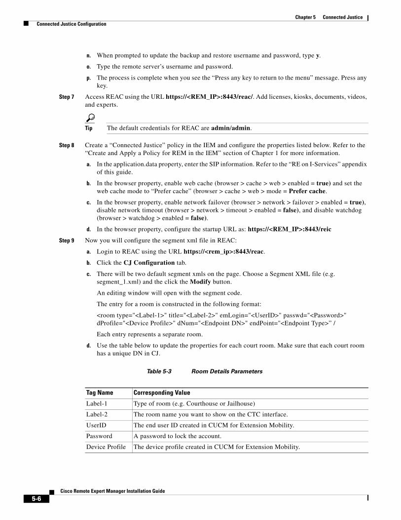
Step 7 Access REAC using the URL https://<REM_IP>:8443/reac/. Add licenses, kiosks, documents, videos, and experts.
Tip The default credentials for REAC are admin/admin.
Step 8 Create a “Connected Justice” policy in the IEM and configure the properties listed below. Refer to the “Create and Apply a Policy for REM in the IEM” section of Chapter 1 for more information.
a. In the application.data property, enter the SIP information. Refer to the “RE on I-Services” appendix of this guide.
b. In the browser property, enable web cache (browser > cache > web > enabled = true) and set the web cache mode to “Prefer cache” (browser > cache > web > mode = Prefer cache.
c. In the browser property, enable network failover (browser > network > failover > enabled = true), disable network timeout (browser > network > timeout > enabled = false), and disable watchdog (browser > watchdog > enabled = false).
d. In the browser property, configure the startup URL as: https://<REM_IP>:8443/reic
Step 9 Now you will configure the segment xml file in REAC:
a. Login to REAC using the URL https://<rem_ip>:8443/reac.
b. Click the CJ Configuration tab.
c. There will be two default segment xmls on the page. Choose a Segment XML file (e.g. segment_1.xml) and the click the Modify button.
An editing window will open with the segment code.
The entry for a room is constructed in the following format:
<room type="<Label-1>" title="<Label-2>" emLogin="<UserID>" passwd="<Password>" dProfile="<Device Profile>" dNum="<Endpoint DN>" endPoint="<Endpoint Type>” /
Each entry represents a separate room.
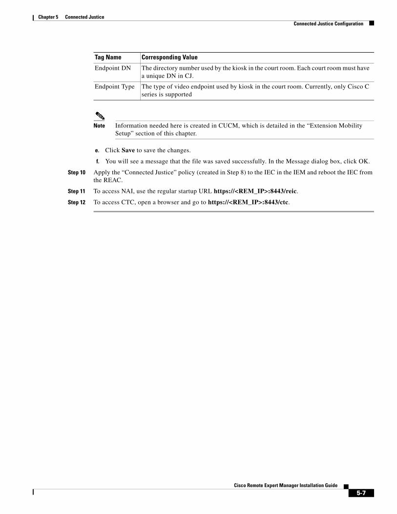
d. Use the table below to update the properties for each court room. Make sure that each court room has a unique DN in CJ.
Table 5-3 Room Details Parameters
Tag Name Corresponding Value
Label-1 Type of room (e.g. Courthouse or Jailhouse)
Label-2 The room name you want to show on the CTC interface.
UserID The end user ID created in CUCM for Extension Mobility.
Password A password to lock the account.
Device Profile The device profile created in CUCM for Extension Mobility.
5-6Cisco Remote Expert Manager Installation Guide
Chapter 5 Connected Justice Connected Justice Configuration
Note Information needed here is created in CUCM, which is detailed in the “Extension Mobility Setup” section of this chapter.
e. Click Save to save the changes.
f. You will see a message that the file was saved successfully. In the Message dialog box, click OK.
Step 10 Apply the “Connected Justice” policy (created in Step 8) to the IEC in the IEM and reboot the IEC from the REAC.
Step 11 To access NAI, use the regular startup URL https://<REM_IP>:8443/reic.
Step 12 To access CTC, open a browser and go to https://<REM_IP>:8443/ctc.
Endpoint DN The directory number used by the kiosk in the court room. Each court room must have a unique DN in CJ.
Endpoint Type The type of video endpoint used by kiosk in the court room. Currently, only Cisco C series is supported
Tag Name Corresponding Value
5-7Cisco Remote Expert Manager Installation Guide

Chapter 5 Connected Justice Connected Justice Configuration
5-8Cisco Remote Expert Manager Installation Guide

Cisc
A
P P E N D I X A Frequently Asked Questions (FAQs)September 28, 2015
Appendix OverviewThis appendix provides answers to the frequently asked questions.
Topics in this appendix include:
• “General Questions”
• “Remote Expert Manager (REM) Installation Questions”
• “Remote Expert Admin Console (REAC) Questions”
• “Remote Expert Session Control (RESC) Questions”
• “Remote Expert Interactive Console (REIC) Questions”
• “Direct Connect Questions”
General QuestionsQ. Why does the NTP server need to be configured separately?
A. NTP servers are used to synchronize the timestamp of the recording file in MediaSense with the timestamp of a session in REM.
Q. The Remote Expert system seems to take a long time to perform an operation. What can I do to improve speed?
A. Make sure that REM server’s network is adequate and works fine. Since REM is a complicated platform with several sub-systems running in the background, ensure that the server has enough resources to operate. Consult the “Create the Virtual Machine” section of Chapter 1 to configure the virtual machine with the necessary resources (at least 8 GB RAM, 300 GB hard drive, and 2 CPU sockets with 4 cores on each socket).
A-1o Remote Expert Manager Installation Guide

Appendix A Frequently Asked Questions (FAQs) Remote Expert Manager (REM) Installation Questions
Remote Expert Manager (REM) Installation QuestionsQ. After restarting the network service, the REM indicates that the “Network is unreachable”. What
should I do?
A. This issue is caused by an incorrectly configured static or gateway IP address. Refer to the “Configure the REM’s Virtual Machine” section of Chapter 1 to reconfigure the network settings.
Q. After restarting the network service, the IP updating script indicates “unary operator expected”. What should I do?
A. This issue is caused by an incorrectly configured static or gateway IP address. Refer to the “Configure the REM’s Virtual Machine” section of Chapter 1 to reconfigure the network settings
Q. After restarting the network service, PostgresSQL throws the error message “value too long for type character varying (15)”. What should I do?
A. This issue is caused by an incorrectly configured static or gateway IP address. Refer to the “Configure the REM’s Virtual Machine” section of Chapter 1 to reconfigure the network settings.
Q. After restarting the network service, the system shows that one of the Nameservers is down. What should I do?
A. Make sure DNS is up and running. If DNS works fine, the DNS may have been configured incorrectly. Refer to the “Configure the REM’s Virtual Machine” section of Chapter 1 to reconfigure the network settings.
Q. While running the main.sh script, the system becomes non-responsive for a period of time and throws error messages and exceptions. What should I do?
A. During the initial setup process, the script will keep trying to make a connection to the database. If the system is non-responsive, it is most likely due to an incorrect IP address. Check the rem.properties file and verify that the following entries have the correct IP addresses: [REM_VIRTUAL_IP], [RESC_IP], and [NODE_IP_1]. Refer to the “Modify the REM Properties File” section of Chapter 1 for instructions on configuring the rem.properties file.
Q. While running the main.sh script, the system throws the error message “Connection timed out”. What should I do?
A. Ensure that the system’s network connection works properly. If the network connection works fine, the problem is most likely due to an incorrect IP address. Check the rem.properties file and verify that the following entries have the correct IP addresses: [REM_VIRTUAL_IP], [RESC_IP], and [NODE_IP_1]. Refer to the “Modify the REM Properties File” section of Chapter 1 for instructions on configuring the rem.properties file.
Remote Expert Admin Console (REAC) QuestionsQ. After adding an agent in the Expert tab of the REAC, the agent’s registration status is red instead of
green. What should I do?
A-2Cisco Remote Expert Manager Installation Guide
Appendix A Frequently Asked Questions (FAQs) Remote Expert Admin Console (REAC) Questions
A. The registration status indicates the communication status between Cisco Unified Communications Manager (CUCM) and REM. There are two possible reasons for the agent being shown as not registered in the REM:
1. The directory number (DN) for that agent has not been registered with the CUCM successfully: Use the keypad of the agent’s endpoint to dial any DN managed by the same CUCM. If a phone call can be made, the problem is most likely in the entries within the CUCM Credentials section of the rem.properties file. Refer to the “Modify the REM Properties File” section of Chapter 1 for instructions on configuring the rem.properties file. After updating the information in the rem.properties file, remember to execute the script main.sh again.
2. The Agent Observer is not registered in Remote Expert Session Controller (RESC): In this case, the DN or endpoint could be registered with CUCM but the Agent Observer is not registered in the RESC. Check that the endpoint is part of the JTAPI application account.
Q. After changing the endpoint’s partition in CUCM, the agent’s registration status becomes red under the Expert tab in REAC. What should I do?
A. A possible cause of this issue is that one of the REM’s internal services does not publish the required JTAPI event properly when the partition of endpoint is changed. To resolve this issue, delete the problematic agent and then add the agent back to the REAC.
Q. When trying to upload a document file in the Document tab of the REAC, a pop-up window appears with the error message “The server encountered an error”. What should I do?
A. Verify that both PostgresSQL and Tomcat are running (use the ps command to verify). If both processes are up and running, the issue is most likely that the default Francisco skin package is not installed properly. In order for REM’s database to function properly, the default Francisco skin package must be installed. Refer to the “Install the Default Francisco Skin Package” section of Chapter 1 for instructions on how to reinstall the skin package.
Q. After adding a new customer pod to the Kiosk tab of the REAC, the customer pod’s screen shows the error message “Kiosk is not registered”. What should I do?
A. Follow these steps to troubleshoot the issue:
Step 1 Ensure that the Interactive Experience Client (IEC) in the customer pod has a network connection.
Step 2 In the Interactive Experience Manager (IEM), verify that the IEC has been registered in the IEM.
Step 3 In the IEM, verify that the REM policy has been applied to the IEC.
Step 4 In the CUCM, verify that the endpoint (i.e. EX 60 & 90) has been created and configured properly.
Step 5 In the REAC, verify that all settings are correct, in particular, check the entries in the TP IP Address and IEC Serial Number fields.
Q. According to the DB Cluster tab of the REAC, one of DB Cluster Nodes is down. What should I do?
A. When a database does not function properly in REM, the REAC will show red boxes in the DB Cluster Nodes column.
Use TUI to restart Postgres by performing these steps:
Step 1 Using TUI, go to the Main Menu and choose c) Services Control.
Step 2 In the Services Control menu, choose c) Database Server.
A-3Cisco Remote Expert Manager Installation Guide
Appendix A Frequently Asked Questions (FAQs) Remote Expert Admin Console (REAC) Questions
Step 3 In the Database Server menu, choose c) Stop Service.
Step 4 After the service has stopped, go back to the Database Server menu and choose b) Start Service.
Step 5 Log back in REAC, go to the DB Cluster tab, select the database with the red box, and click Activate.
Q. According to the DB Cluster tab of the REAC, one of DB Cluster Managers is down. What should I do?
A. When Apache Tomcat does not function properly in REM, the REAC will show a red box in the DB Cluster Manager column.
Use TUI to restart Tomcat by performing these steps:
Step 1 Using TUI, go to the Main Menu and choose c) Services Control.
Step 2 In the Services Control menu, choose b) Application Server.
Step 3 In the Application Server menu, choose c) Stop Service.
Step 4 After the service has stopped, go back to the Application Server menu and choose b) Start Service.
Step 5 Log back in REAC, go to the DB Cluster tab, select the cluster manager with the red box, and click Activate.
Q. Where can video files be placed in the Adobe Media Server?
A. Video files can be placed in the /opt/adobe/ams/webroot/vod directory.
Q. What format should be used for the video URL is using Adobe Media Server (AMS)?
A. Using RTMP as an example, the following format should be used for the video URL: rtmp://<AMS IP>/vod/mp4:aTestClip.ext
– The extensions could be flv, f4v, mov, or mp4.
– Upper case extensions, such as FLV files running on rtmp, are not currently supported.
– Special characters, such as space ( ) and #, are not supported in video file names.
– If AMS is configured to use a port other than 80 (for example, 8080), add the port number after the IP address, for example, rtmp://192.168.100.200:8080/vod/mp4:aTestClip.mp4.
Q. A MediaSense recording populates intermittently in the Session tab of the REAC?
A. First, ensure that the timestamps of MediaSense and REM servers are synchronized. Refer to the “Configure Network Time Protocol” section of Chapter 1 for instructions on how to configure the NTP server.
If the servers’ timestamps are synchronized and you still have issues, try to increase REM and MediaSense responding time.
Step 1 Using TUI, go to the Main Menu and choose d) REM Server Administration.
Step 2 In the REM Server Administration menu, choose c) Edit REM Templates.
Step 3 In the Edit REM Templates menu, choose a) REAC Properties.
Step 4 Find the entry “media_sense_time_offset=5000”, which is the default responding time in milliseconds.
A-4Cisco Remote Expert Manager Installation Guide
Appendix A Frequently Asked Questions (FAQs) Remote Expert Session Control (RESC) Questions
Step 5 Change the value of milliseconds to either “15000” or “20000”.
Step 6 Save the file and go back to the REM Server Administration menu.
Step 7 Choose d) Run Configuration Tool and follow on screen instructions.
Q. Is it possible to modify the maximum file size that can be uploaded into REAC?
A. The default maximum file size that can be uploaded into REAC is 50Mb. However, that size can be increased to allow larger files to be uploaded. To modify the maximum size value, follow these steps:
Step 1 Using TUI, go to the Main Menu and choose d) REM Server Administration.
Step 2 In the REM Server Administration menu, choose c) Edit REM Templates.
Step 3 In the Edit REM Templates menu, choose a) REAC Properties.
Step 4 Find the entry “maximum_file_upload_size=50000000”, which is the default file size in bytes.
Step 5 Change the value.
Note The value is limited to the browser’s capability.
Step 6 Save the file and go back to the REM Server Administration menu.
Step 7 Choose d) Run Configuration Tool and follow on screen instructions.
Remote Expert Session Control (RESC) Questions Q. How do I view session results?
A. Reports are generated in REAC. Refer to the “Generating Session Reports” section of the Cisco Remote Expert Manager Administration Guide for instructions on how to generate reports.
Q. If the REM’s session questions and answers are in languages other than English, strange characters are present in the CSV files. What should I do?
A. Open the file using a text editor program in your OS.
If you have Microsoft Windows, for example, you could use Microsoft Excel to import the CSV file since REM uses UTF-8 to encode the data. If you want to use Microsoft Windows, follow these steps:
Step 1 Open Microsoft Excel.
Step 2 Click the Data menu bar option.
Step 3 Click the From Text icon.
Step 4 Navigate to the location of the file that you want to import. Click the filename and then click the Import button.
Step 5 In the Text Import Wizard, choose Delimited in the Original data type section.
Step 6 Choose 65001: Unicode (UTF-8) from the drop-down list that appears next to File origin.
A-5Cisco Remote Expert Manager Installation Guide
Appendix A Frequently Asked Questions (FAQs) Remote Expert Interactive Console (REIC) Questions
Step 7 Click the Next button.
Step 8 Place a checkmark in the delimiter - comma check box (only leave Comma checked).
Step 9 Click the Finish button to finish importing the data into Microsoft Excel.
If you have an Apple Macintosh OS, there is an issue with importing UTF-8 file to MS Excel. Review this post of a Microsoft Support Engineer: http://answers.microsoft.com/en-us/mac/forum/macoffice2011-macexcel/mac-excel-converts-utf-8-characters-to-underlines/7c4cdaa7-bfa3-41a2-8482-554ae235227b?msgId=49d349d7-35d4-4cc0-b8ba-cd8abb5bff8c
If you want to use an Apple Macintosh to open the file, try the following two options:
1. Use TextEdit to open the CSV file as a text file.
2. Use OpenOffice to open the CSV file if you want to have a spreadsheet-type presentation.
Remote Expert Interactive Console (REIC) QuestionsQ. The expert icons do not display properly on the customer pod screens or the icons for document and
video files do not display properly in the READ windows of CAD. What should I do?
A. These scenarios may be caused by an incorrect installation of the web application package.
Step 1 Go to Locale tab of REAC, find a valid image file name in a local bundle you select (i.e. english_220_80.png under the English locale).
Step 2 Open your browser and enter the following URL: https://[REM_server_ip]:8443/images/english_220_80.png, for example.
Step 3 If the English is not displayed properly, the default REM skin package did not install properly.
Step 4 Refer to the “Install the Skin Package” section of Chapter 1 for instructions on how to reinstall the skin package.
Q. The screen at the customer pod displays the “Server is down” message. What should I do?
A. When an IEC loses its network connectivity or the Tomcat service in REM is down, the screen at the customer pod will show the “Server is down” message.
Step 1 Step 1 Using TUI, go to the Main Menu and choose c) Service Control
Step 2 Step 2 in the Service Control menu, choose b) Application Server
Step 3 Step 3 Choose a) Show Status
Step 4 Step 4 If Tomcat is not running is displayed, go back and choose b) Start Service
Q. The screen at the customer pod displays the “Expert not Available” message. What should I do?
A-6Cisco Remote Expert Manager Installation Guide
Appendix A Frequently Asked Questions (FAQs) Remote Expert Interactive Console (REIC) Questions
A. When an IEC or REM loses communications with the TelePresence (TP) endpoint (i.e. EX), or the codec for TP is incorrect in REAC, the screen at the customer pod will show the “Designer not Available” message.
Step 1 Check if the codec is correct for the TP endpoint in the Kiosk tab of the REAC.
Step 2 Check if the TP endpoint still has its network connectivity. To verify, either make a call to another TP endpoint by using the dial pad or ping the TP endpoint from REM. If you could not get responses from the TP endpoint, contact your system administrator.
Q. The screen at the customer pod displays the “Startup URL not found” message. What should I do?
A. This behavior is usually caused by incorrect configurations of the IEC. If the IEC does not have a proper policy (initial configuration that includes startup URL) in the IEM, the IEC will not load the proper REIC application. Verify that the IEC has the correct policy applied.
Another possibility is that the IEC is not registered with the IEM. Verify that the IEC is shown in the main window of IEM. Also make sure that the IEM’s gateway is turned on.
Q. The REIC static image on the TP endpoint in the customer pod disappears after 10 minutes. However, the image appears again after making a call. What should I do?
A. Most likely, the screen is going into sleep mode. Check the configuration in CUCM for the TP endpoint by performing the following steps:
Step 1 Log into the CUCM.
Step 2 Go to Device and choose Phone.
Step 3 Choose the endpoint in the customer pod.
Step 4 In the User Preferences dialog box, set the Display On Duration to 10:30 so that the monitor will stay on for 10 hours and 30 minutes.
Step 5 If you still have issue, contact your system administrator.
Q. How can I limit the phone at the customer pod to accept only one call at a time?
A. To limit the number of calls, change the phone’s configuration in the CUCM by following these steps:
Step 1 Log into the CUCM.
Step 2 In the Device menu, choose Phone.
Step 3 Find the phone and choose it.
Step 4 Choose the line number under the Association Information section in the left panel.
Step 5 In the subsequent page, enter 1 into the Maximum Number of Calls and Busy Trigger fields to limit the number of incoming call to one.
Q. In the UCCX environment, there are no call events detected by REM. How is this issue resolved?
A-7Cisco Remote Expert Manager Installation Guide
Appendix A Frequently Asked Questions (FAQs) Remote Expert Interactive Console (REIC) Questions
A. Verify that the value of [IS_CCX] within the CCX Credentials section of the rem.properties file is set to “true” and the value of the [IS_CVP] within the CVP Credential section is set to “false”. If you make any changes to the rem.properties file, run the main.sh command again.
Q. If the video endpoint at the customer pod goes down after the agent accepts the call (i.e. the session is in progress), what should the agent do?
A. Due to technical limitations of TelePresence, it could take a period of time (more than seven minutes) to reflect the status of the customer pod’s video endpoint at the agent side (including CAD). The agent should not wait for the call to disconnect. Instead, the agent should disconnect the call from CAD manually.
Q. If the video endpoint at the customer pod goes down after the agent makes an outbound call to the customer pod (i.e. the session is in progress), what should I do?
A. Due to technical limitation of TelePresence, it could take more than three minutes for the agent’s CAD to reflect the status. As a result, CAD will be in a hung state. The agent should not wait for the call to disconnect. To recover from this situation, the call has to be disconnected from the customer pod side. Since CAD is in a hung state, the call cannot be disconnected by the agent using CAD.
Q. How do I change the volume on the IEC?
A. An IEC’s volume can be changed by creating a new policy in the IEM. Follow these steps to create a volume policy:
Step 1 Log into the IEM, and create a new policy.
Step 2 Within the policy, go to the volume > master property.
Step 3 Enter a numeric value (0 is minimum; 100 is maximum).
Step 4 Go to the volume > master > muted property and make sure that the value is set to false.
Step 5 Click the Apply button.
Step 6 Add this policy to the IEC in the IEM.
Step 7 Reboot the IEC.
Q. The customer pod touch screen does not display the correct resolution that is configured in the IEM. How can I fix the issue?
A. Make sure that the video cable is connected securely. Although a regular VGA cable may be used with a variety of supported VGA resolutions, higher-quality cables typically produce better results. Shorter VGA cables are less likely to introduce significant degradation. Moreover, the VGA port used by the IEC is Display Data Channel (DDC) enabled. To take a full advantage of the REIC, a VGA cable with the presence of pins 9 and 15 is required to operate correctly. Make sure that the VGA cable you use has pins 9 and 15. If you still have issues, contact your system administrator.
Q. The touch screen has a resolution of less than 1024 in height. What should be done to ensure that the REIC main page is displayed fully?
A. In REM, the standard resolution supported is 1280 x1024 (aspect ratio 5:4). The REIC main page may not display properly if the screen has a resolution that is less than 1024 in height. You can adjust the IEC display resolution to fit within the REM default resolution using the policy in the IEM.
Step 1 Create a new policy.
A-8Cisco Remote Expert Manager Installation Guide
Appendix A Frequently Asked Questions (FAQs) Direct Connect Questions
Step 2 In the policy, go to the Display > Resolution > Custom property.
Step 3 Change the height and width values as necessary.
Direct Connect QuestionsQ. What should I do if the “Pureweb 503 error” message displays on the customer pod screen when the
agent starts a Direct Connect (DC) sharing session during a call?
A. If the “Pureweb 503 error” message is seen for just a short period of time (less than 3 seconds) during a sharing session, restart the DC server on the agent’s desktop by clicking the Restart DC Server icon.
This issue may also be caused by IEC’s Watchdog, which is a daemon program monitoring Cobra browser’s activity. When there is any resource issue, the Watchdog restarts or terminates incompatible processes. Sometimes, it may terminate DC unexpectedly. If you see the “Pureweb 503” message, make sure that Watchdog related functionalities are turned off in the IEM policy that is applied to the IEC. Refer to the “Create a Policy in the IEM” section of Chapter 1 for instructions.
If you still have problem with Direct Connect, contact your System Administrator for further assistance.
Q. What should I do if when trying to connect DC the message “Waiting (Cancel)” is displayed and DC never connects?
A. There are two possibilities why Direct Connect does not connect:
1. The REM IP is incorrect or the URL contains “https” instead of “http”. Perform these steps to correct the REM IP:
Step 1 Navigate to C:\CSI\DirectConnect\bin\DirectConnect.
Step 2 Open the DirectConnect.exe.config file.
Step 3 Edit the value of cv_service_url to the correct REM IP address and correct protocol (http).
<ArrestedDevelopment.Properties.Settings>
<setting name="cv_service_url" serializeAs="String">
<value>http://REM_IP/resc/services/VirtualAgentServices.VirtualAgentServicesHttpSoap11Endpoint/</value>
</setting>
Step 4 Save the file before closing.
Step 5 Click Restart DC Server on the agent’s desktop.
2. The Cisco Security Agent is turned on. Perform these steps to turn off the Cisco Security Agent:
Step 1 Click the Show Hidden Icons button in the notification area of Windows taskbar.
Step 2 Right-click the Cisco Security Agent icon.
A-9Cisco Remote Expert Manager Installation Guide
Appendix A Frequently Asked Questions (FAQs) Direct Connect Questions
Step 3 Select Off as the Security Level.
If neither of the above two resolutions solve the issue, please contact your System Administrator.
Q. Is it possible to reduce bandwidth utilization of Direct Connect?
A. You can modify the RemotingService.exe.config file in the C:\CSI\DirectConnect\bin\DirectConnect\ directory to reduce bandwidth utilization of DC. You can get the bandwidth utilization down to around 450Kbps and still provide a good user experience. Use the following suggested configuration and change the values in the red lines of code.
<userSettings>
<RemotingService.Properties.Settings>
<setting name="FilterClientInput" serializeAs="String">
<value>True</value>
</setting>
<setting name="ShowApplicationWaitInterval" serializeAs="String">
<value>200</value>
</setting> 11
<setting name="ShowApplicationTimeout" serializeAs="String">
<value>10000</value>
</setting>
<setting name="ThumbnailAcquisitionInterval" serializeAs="String">
<value>1000</value>
</setting>
<setting name="ImageFormatIsJpeg" serializeAs="String">
<value>True</value>
</setting>
<setting name="ImageMaxQuality" serializeAs="String">
<value>85</value>
</setting>
<setting name="ImageLowBandwidthWidth" serializeAs="String">
<value>1280</value>
</setting>
<setting name="ImageAcquisitionIntervalMillis" serializeAs="String">
<value>1000</value>
</setting>
<setting name="ClientDisplayStatus" serializeAs="String">
<value>False</value>
</setting>
A-10Cisco Remote Expert Manager Installation Guide
Appendix A Frequently Asked Questions (FAQs)
<setting name="ImageMinQuality" serializeAs="String">
<value>30</value>
</setting>
<setting name="ImageDynamicQuality" serializeAs="String">
<value>True</value>
</setting>
<setting name="ImageMaxBitrate" serializeAs="String">
<value>0.4</value>
</setting>
<setting name="ImageLowBandwidthHeight" serializeAs="String">
<value>1024</value>
</setting>
<setting name="BitrateBufferFactor" serializeAs="String">
<value>4</value>
</setting>
<setting name="WindowRestorationDelay" serializeAs="String">
<value>750</value>
</setting>
</RemotingService.Properties.Settings>
</userSettings>
A-11Cisco Remote Expert Manager Installation Guide

Appendix A Frequently Asked Questions (FAQs)
A-12Cisco Remote Expert Manager Installation Guide
Cisc
A
P P E N D I X B Document Camera ConfigurationSeptember 28, 2015
Appendix OverviewThis appendix explains how to configure document cameras at the branches.
Topics in this appendix include:
• “Configure the Document Camera”
– “Connect and Configure the Hardware”
– “Create Policies in the IEM for Each Document Camera”
– “Reboot IEC from REAC”
Configure the Document CameraA ceiling-mounted document camera can be used in the customer pod to allow customers to share documents with the expert. It is recommended to use the Vaddio CellingVIEW™ HD-18 DocCAM with Quick-Connect DVI/HDMI SR Interface. The REM may support different document cameras with configurable RS-232 commands. Please contact the RE team for more details if you plan to use a different document camera.
The Vaddio CeilingVIEW™ HD-18 DOCCAM camera is designed for use with high definition video conferencing codecs, HD monitors, and HD presentation applications where image quality and resolution are critical. The camera features an 18X optical zoom lens and is built around a 1/3”, 1.3 Megapixel CCD image sensors for precise HD video image acquisition even in low light applications. The camera supports HD resolution such as 1080p60, 1080p30, 720p30 and RGB resolution such as 1024x768.
The document camera system is composed of two units: the camera itself that is mounted to the ceiling (Figure B-1) and a control unit called the DocCam SR module (Figure B-2).
B-1o Remote Expert Manager Installation Guide
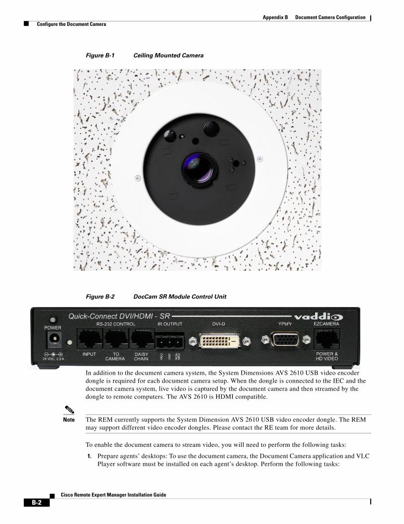
Appendix B Document Camera Configuration Configure the Document Camera
Figure B-1 Ceiling Mounted Camera
Figure B-2 DocCam SR Module Control Unit
In addition to the document camera system, the System Dimensions AVS 2610 USB video encoder dongle is required for each document camera setup. When the dongle is connected to the IEC and the document camera system, live video is captured by the document camera and then streamed by the dongle to remote computers. The AVS 2610 is HDMI compatible.
Note The REM currently supports the System Dimension AVS 2610 USB video encoder dongle. The REM may support different video encoder dongles. Please contact the RE team for more details.
To enable the document camera to stream video, you will need to perform the following tasks:
1. Prepare agents’ desktops: To use the document camera, the Document Camera application and VLC Player software must be installed on each agent’s desktop. Perform the following tasks:
B-2Cisco Remote Expert Manager Installation Guide

Appendix B Document Camera Configuration Configure the Document Camera
a. Install Java Runtime Environment (JRE) version 7 on each agent’s desktop.
b. Download the snapshotapp-dist.zip file from REAC and install it on each agent’s desktop. Refer to Appendix D: “Document Camera Application Installation and Configuration” of the Cisco Remote Expert Manager READ and eREAD User Guide for instructions.
c. Install a VLC Player on each agent’s desktop.
Note The snapshot application works only if both the JRE and VLC player are of same bit size, i.e., 64bit JRE and 64bit VLC or 32bit JRE and 32bit VLC.
2. Connect the document camera system to the IEC and the video encoder dongle
3. Create a policy in the IEM for the document camera
4. Reboot the IEC from REAC
Connect and Configure the HardwareTo connect the document camera system, follow these steps:
Step 1 Connect the EZCamera Power & HD Video port of the control unit to the camera using a Cat-5e cable with a maximum distance of 100’ (30.5 m). This port supplies power to the camera and returns HD video from the camera.
Step 2 Connect the RS-232 Control To Camera port on the control unit to the camera.
Step 3 Connect the RS-232 Control Input port on the control unit to the RS232 port on the IEC.
Step 4 Connect the DVI-D port to the HDMI input of the dongle.
Step 5 Connect the HDMI output of the dongle to a USB port of the IEC. If necessary, use an USB extension cable.
B-3Cisco Remote Expert Manager Installation Guide
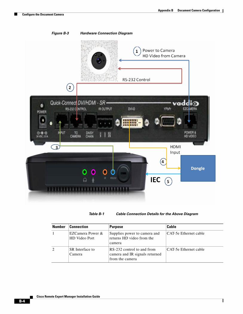
Appendix B Document Camera Configuration Configure the Document Camera
Figure B-3 Hardware Connection Diagram
Table B-1 Cable Connection Details for the Above Diagram
Number Connection Purpose Cable
1 EZCamera Power & HD Video Port
Supplies power to camera and returns HD video from the camera
CAT-5e Ethernet cable
2 SR Interface to Camera
RS-232 control to and from camera and IR signals returned from the camera
CAT-5e Ethernet cable
B-4Cisco Remote Expert Manager Installation Guide
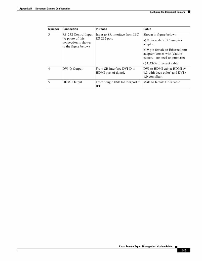
Appendix B Document Camera Configuration Configure the Document Camera
3 RS-232 Control Input (A photo of this connection is shown in the figure below)
Input to SR interface from IEC RS-232 port
Shown in figure below:
a) 9 pin male to 3.5mm jack adapter
b) 9 pin female to Ethernet port adapter (comes with Vaddio camera - no need to purchase)
c) CAT-5e Ethernet cable
4 DVI-D Output From SR interface DVI-D to HDMI port of dongle
DVI to HDMI cable: HDMI (v 1.3 with deep color) and DVI v 1.0 compliant
5 HDMI Output From dongle USB to USB port of IEC
Male to female USB cable
Number Connection Purpose Cable
B-5Cisco Remote Expert Manager Installation Guide
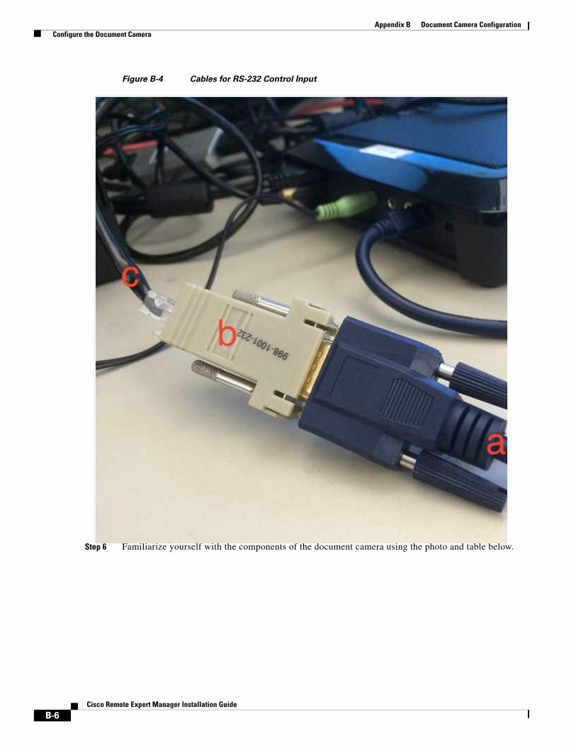
Appendix B Document Camera Configuration Configure the Document Camera
Figure B-4 Cables for RS-232 Control Input
Step 6 Familiarize yourself with the components of the document camera using the photo and table below.
B-6Cisco Remote Expert Manager Installation Guide
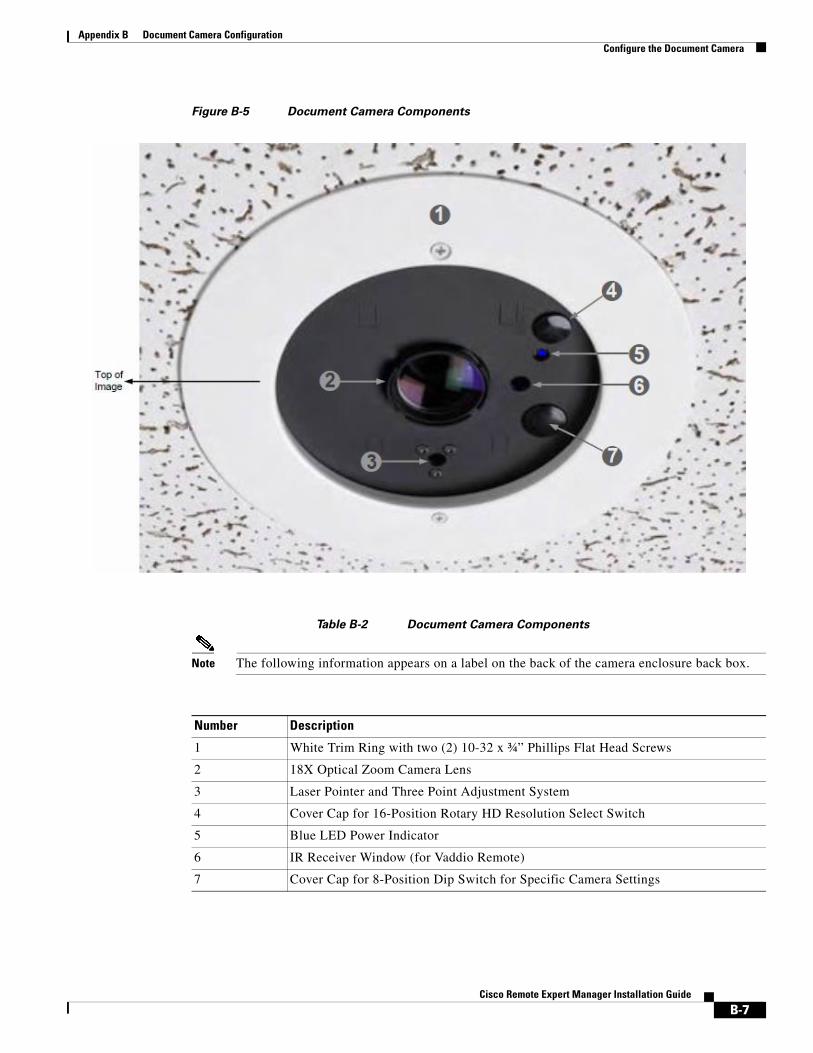
Appendix B Document Camera Configuration Configure the Document Camera
Figure B-5 Document Camera Components
Table B-2 Document Camera Components
Note The following information appears on a label on the back of the camera enclosure back box.
Number Description
1 White Trim Ring with two (2) 10-32 x ¾” Phillips Flat Head Screws
2 18X Optical Zoom Camera Lens
3 Laser Pointer and Three Point Adjustment System
4 Cover Cap for 16-Position Rotary HD Resolution Select Switch
5 Blue LED Power Indicator
6 IR Receiver Window (for Vaddio Remote)
7 Cover Cap for 8-Position Dip Switch for Specific Camera Settings
B-7Cisco Remote Expert Manager Installation Guide
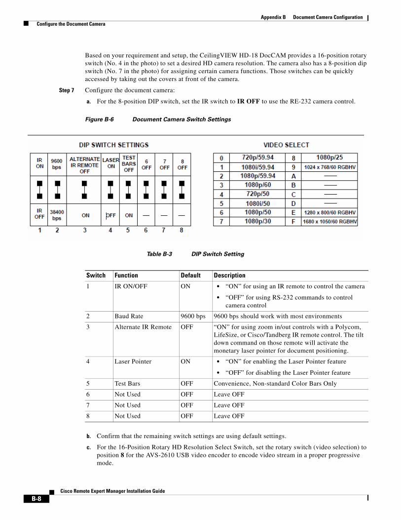
Appendix B Document Camera Configuration Configure the Document Camera
Based on your requirement and setup, the CeilingVIEW HD-18 DocCAM provides a 16-position rotary switch (No. 4 in the photo) to set a desired HD camera resolution. The camera also has a 8-position dip switch (No. 7 in the photo) for assigning certain camera functions. Those switches can be quickly accessed by taking out the covers at front of the camera.
Step 7 Configure the document camera:
a. For the 8-position DIP switch, set the IR switch to IR OFF to use the RE-232 camera control.
Figure B-6 Document Camera Switch Settings
Table B-3 DIP Switch Setting
b. Confirm that the remaining switch settings are using default settings.
c. For the 16-Position Rotary HD Resolution Select Switch, set the rotary switch (video selection) to position 8 for the AVS-2610 USB video encoder to encode video stream in a proper progressive mode.
Switch Function Default Description
1 IR ON/OFF ON • “ON” for using an IR remote to control the camera
• “OFF” for using RS-232 commands to control camera control
2 Baud Rate 9600 bps 9600 bps should work with most environments
3 Alternate IR Remote OFF “ON” for using zoom in/out controls with a Polycom, LifeSize, or Cisco/Tandberg IR remote control. The tilt down command on those remote will activate the monetary laser pointer for document positioning.
4 Laser Pointer ON • “ON” for enabling the Laser Pointer feature
• “OFF” for disabling the Laser Pointer feature
5 Test Bars OFF Convenience, Non-standard Color Bars Only
6 Not Used OFF Leave OFF
7 Not Used OFF Leave OFF
8 Not Used OFF Leave OFF
B-8Cisco Remote Expert Manager Installation Guide
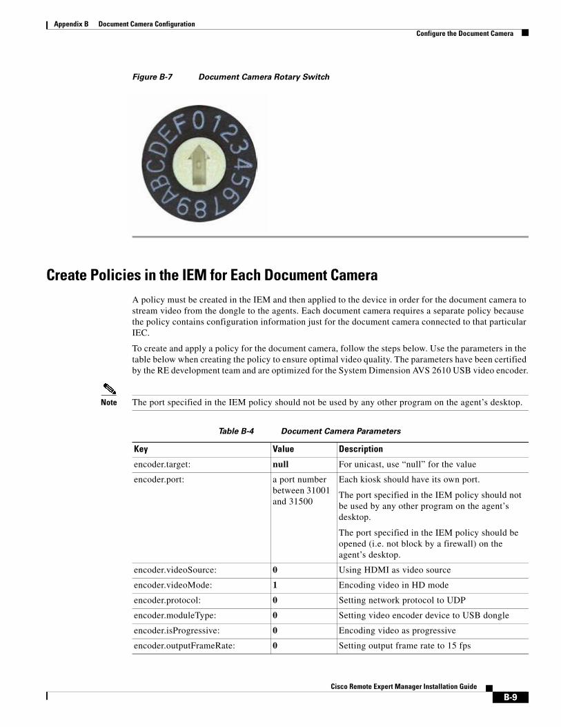
Appendix B Document Camera Configuration Configure the Document Camera
Figure B-7 Document Camera Rotary Switch
Create Policies in the IEM for Each Document CameraA policy must be created in the IEM and then applied to the device in order for the document camera to stream video from the dongle to the agents. Each document camera requires a separate policy because the policy contains configuration information just for the document camera connected to that particular IEC.
To create and apply a policy for the document camera, follow the steps below. Use the parameters in the table below when creating the policy to ensure optimal video quality. The parameters have been certified by the RE development team and are optimized for the System Dimension AVS 2610 USB video encoder.
Note The port specified in the IEM policy should not be used by any other program on the agent’s desktop.
Table B-4 Document Camera Parameters
Key Value Description
encoder.target: null For unicast, use “null” for the value
encoder.port: a port number between 31001 and 31500
Each kiosk should have its own port.
The port specified in the IEM policy should not be used by any other program on the agent’s desktop.
The port specified in the IEM policy should be opened (i.e. not block by a firewall) on the agent’s desktop.
encoder.videoSource: 0 Using HDMI as video source
encoder.videoMode: 1 Encoding video in HD mode
encoder.protocol: 0 Setting network protocol to UDP
encoder.moduleType: 0 Setting video encoder device to USB dongle
encoder.isProgressive: 0 Encoding video as progressive
encoder.outputFrameRate: 0 Setting output frame rate to 15 fps
B-9Cisco Remote Expert Manager Installation Guide
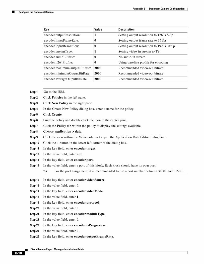
Appendix B Document Camera Configuration Configure the Document Camera
Step 1 Go to the IEM.
Step 2 Click Policies in the left pane.
Step 3 Click New Policy in the right pane.
Step 4 In the Create New Policy dialog box, enter a name for the policy.
Step 5 Click Create.
Step 6 Find the policy and double-click the icon in the center pane.
Step 7 Click the Policy tab within the policy to display the settings available.
Step 8 Choose application > data.
Step 9 Click the icon within the Value column to open the Application Data Editor dialog box.
Step 10 Click the + button in the lower left corner of the dialog box.
Step 11 In the key field, enter encoder.target.
Step 12 In the value field, enter null.
Step 13 In the key field, enter encoder.port.
Step 14 In the value field, enter a port of this kiosk. Each kiosk should have its own port.
Tip For the port assignment, it is recommended to use a port number between 31001 and 31500.
Step 15 In the key field, enter encoder.videoSource.
Step 16 In the value field, enter 0.
Step 17 In the key field, enter encoder.videoMode.
Step 18 In the value field, enter 1.
Step 19 In the key field, enter encoder.protocol.
Step 20 In the value field, enter 0.
Step 21 In the key field, enter encoder.moduleType.
Step 22 In the value field, enter 0.
Step 23 In the key field, enter encoder.isProgressive.
Step 24 In the value field, enter 0.
Step 25 In the key field, enter encoder.outputFrameRate.
encoder.outputResolution: 1 Setting output resolution to 1280x720p
encoder.inputFrameRate: 0 Setting output frame rate to 15 fps
encoder.inputResolution: 0 Setting output resolution to 1920x1080p
encoder.streamType: 1 Setting video-in stream to TS
encoder.audioBitRate: 0 No audio-in stream
encoder.h264Profile: 0 Using baseline profile for encoding
encoder.maximumOutputBitRate: 2000 Recommended video-out bitrate
encoder.minimumOutputBitRate: 2000 Recommended video-out bitrate
encoder.averageOutputBitRate: 2000 Recommended video-out bitrate
Key Value Description
B-10Cisco Remote Expert Manager Installation Guide
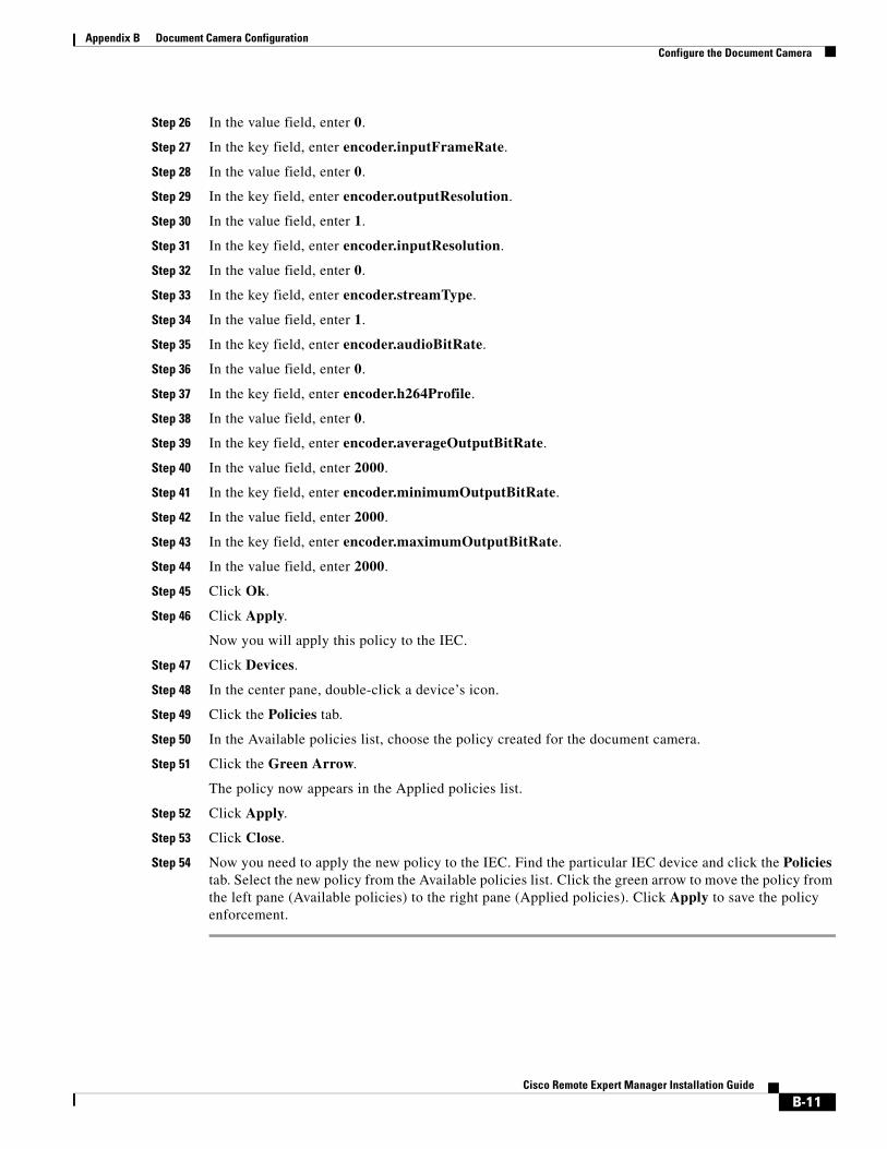
Appendix B Document Camera Configuration Configure the Document Camera
Step 26 In the value field, enter 0.
Step 27 In the key field, enter encoder.inputFrameRate.
Step 28 In the value field, enter 0.
Step 29 In the key field, enter encoder.outputResolution.
Step 30 In the value field, enter 1.
Step 31 In the key field, enter encoder.inputResolution.
Step 32 In the value field, enter 0.
Step 33 In the key field, enter encoder.streamType.
Step 34 In the value field, enter 1.
Step 35 In the key field, enter encoder.audioBitRate.
Step 36 In the value field, enter 0.
Step 37 In the key field, enter encoder.h264Profile.
Step 38 In the value field, enter 0.
Step 39 In the key field, enter encoder.averageOutputBitRate.
Step 40 In the value field, enter 2000.
Step 41 In the key field, enter encoder.minimumOutputBitRate.
Step 42 In the value field, enter 2000.
Step 43 In the key field, enter encoder.maximumOutputBitRate.
Step 44 In the value field, enter 2000.
Step 45 Click Ok.
Step 46 Click Apply.
Now you will apply this policy to the IEC.
Step 47 Click Devices.
Step 48 In the center pane, double-click a device’s icon.
Step 49 Click the Policies tab.
Step 50 In the Available policies list, choose the policy created for the document camera.
Step 51 Click the Green Arrow.
The policy now appears in the Applied policies list.
Step 52 Click Apply.
Step 53 Click Close.
Step 54 Now you need to apply the new policy to the IEC. Find the particular IEC device and click the Policies tab. Select the new policy from the Available policies list. Click the green arrow to move the policy from the left pane (Available policies) to the right pane (Applied policies). Click Apply to save the policy enforcement.
B-11Cisco Remote Expert Manager Installation Guide

Appendix B Document Camera Configuration
Reboot IEC from REACAfter you set up the document camera and configure it in the IEM, you need to reboot the IEC that is connected to that document camera. In REAC, choose the kiosk for that IEC in the Kiosk tab and click the Restart button.
B-12Cisco Remote Expert Manager Installation Guide
Cisc
A
P P E N D I X C RE-on-IServicesSeptember 28, 2015
Appendix OverviewThis appendix explains how to set up RE-on-IServices. RE-on-IServices is an extension of Remote Expert that uses the I-Services platform. RE-on-IServices uses the Interactive Experience Client (IEC) as a video endpoint to make Session Initiation Protocol (SIP) calls from a kiosk.
Topics in this appendix include:
• “RE-on-IServices Overview”
– “Hardware Required”
• “Cisco IEC Setup on the CUCM”
• “Configuring a SIP Policy in the IEM”
• “RE-on-IServices Configuration”
– “Set Up the RE-on-IServices Environment”
– “miniREIC Supporting Files”
– “Integrating miniREIC into the I-Services Template”
– “SIP and DC Call Flow”
– “HA Proxy Server”
RE-on-IServices OverviewRE-on-IServices is an extended feature provided by the Remote Expert Manager (REM) that will enable a customer to interact with a remote agent via Cisco Contact Center on the I-Services platform. RE-on-IServices consists of the RE-Kiosk template and miniREIC.
1. RE-Kiosk template: A sample HTML web application, which provides interactive contents.
2. miniREIC: A JavaScript library that can be used by any HTML-based web application to utilize the capabilities of Remote Expert. This library currently supports Direct Connect (DC), which can be initiated in READ or manually started if using eREAD after a SIP call is established via REM.
In order for the SIP client to work, the IEC will need to be configured in the Cisco Unified Communication Manager (CUCM) and then configured on the REM.
C-1o Remote Expert Manager Installation Guide
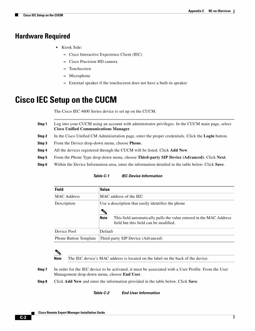
Appendix C RE-on-IServices Cisco IEC Setup on the CUCM
Hardware Required• Kiosk Side:
– Cisco Interactive Experience Client (IEC)
– Cisco Precision HD camera
– Touchscreen
– Microphone
– External speaker if the touchscreen does not have a built-in speaker
Cisco IEC Setup on the CUCMThe Cisco IEC 4600 Series device is set up on the CUCM.
Step 1 Log into your CUCM using an account with administrator privileges. In the CUCM main page, select Cisco Unified Communications Manager.
Step 2 In the Cisco Unified CM Administration page, enter the proper credentials. Click the Login button.
Step 3 From the Device drop-down menu, choose Phone.
Step 4 All the devices registered through the CUCM will be listed. Click Add New.
Step 5 From the Phone Type drop-down menu, choose Third-party SIP Device (Advanced). Click Next.
Step 6 Within the Device Information area, enter the information detailed in the table below. Click Save.
Table C-1 IEC Device Information
Note The IEC device’s MAC address is located on the label on the back of the device.
Step 7 In order for the IEC device to be activated, it must be associated with a User Profile. From the User Management drop-down menu, choose End User.
Step 8 Click Add New and enter the information provided in the table below. Click Save.
Table C-2 End User Information
Field Value
MAC Address MAC address of the IEC
Description Use a description that easily identifies the phone
Note This field automatically pulls the value entered in the MAC Address field but this field can be modified.
Device Pool Default
Phone Button Template Third-party SIP Device (Advanced)
C-2Cisco Remote Expert Manager Installation Guide
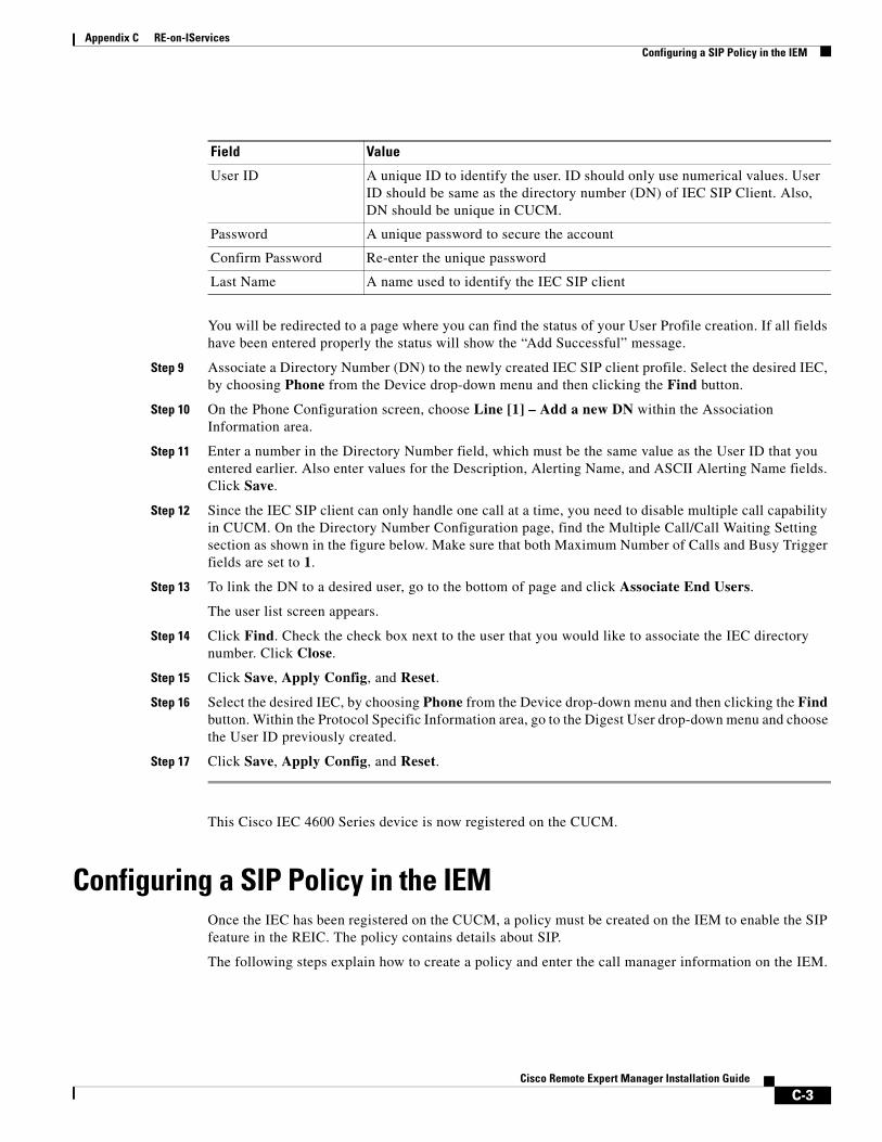
Appendix C RE-on-IServices Configuring a SIP Policy in the IEM
You will be redirected to a page where you can find the status of your User Profile creation. If all fields have been entered properly the status will show the “Add Successful” message.
Step 9 Associate a Directory Number (DN) to the newly created IEC SIP client profile. Select the desired IEC, by choosing Phone from the Device drop-down menu and then clicking the Find button.
Step 10 On the Phone Configuration screen, choose Line [1] – Add a new DN within the Association Information area.
Step 11 Enter a number in the Directory Number field, which must be the same value as the User ID that you entered earlier. Also enter values for the Description, Alerting Name, and ASCII Alerting Name fields. Click Save.
Step 12 Since the IEC SIP client can only handle one call at a time, you need to disable multiple call capability in CUCM. On the Directory Number Configuration page, find the Multiple Call/Call Waiting Setting section as shown in the figure below. Make sure that both Maximum Number of Calls and Busy Trigger fields are set to 1.
Step 13 To link the DN to a desired user, go to the bottom of page and click Associate End Users.
The user list screen appears.
Step 14 Click Find. Check the check box next to the user that you would like to associate the IEC directory number. Click Close.
Step 15 Click Save, Apply Config, and Reset.
Step 16 Select the desired IEC, by choosing Phone from the Device drop-down menu and then clicking the Find button. Within the Protocol Specific Information area, go to the Digest User drop-down menu and choose the User ID previously created.
Step 17 Click Save, Apply Config, and Reset.
This Cisco IEC 4600 Series device is now registered on the CUCM.
Configuring a SIP Policy in the IEMOnce the IEC has been registered on the CUCM, a policy must be created on the IEM to enable the SIP feature in the REIC. The policy contains details about SIP.
The following steps explain how to create a policy and enter the call manager information on the IEM.
Field Value
User ID A unique ID to identify the user. ID should only use numerical values. User ID should be same as the directory number (DN) of IEC SIP Client. Also, DN should be unique in CUCM.
Password A unique password to secure the account
Confirm Password Re-enter the unique password
Last Name A name used to identify the IEC SIP client
C-3Cisco Remote Expert Manager Installation Guide
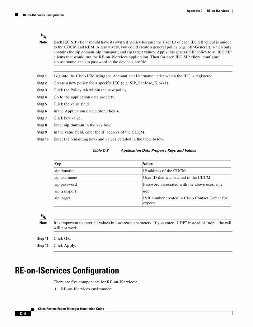
Appendix C RE-on-IServices RE-on-IServices Configuration
Note Each IEC SIP client should have its own SIP policy because the User ID of each IEC SIP client is unique to the CUCM and REM. Alternatively, you could create a general policy (e.g. SIP-General), which only contains the sip.domain, sip.transport, and sip.target values. Apply this general SIP policy to all IEC SIP clients that would run the RE-on-IServices application. Then for each IEC SIP client, configure sip.username and sip.password in the device’s profile.
Step 1 Log into the Cisco IEM using the Account and Username under which the IEC is registered.
Step 2 Create a new policy for a specific IEC (e.g. SIP_SanJose_Kiosk1).
Step 3 Click the Policy tab within the new policy.
Step 4 Go to the application data property.
Step 5 Click the value field.
Step 6 In the Application data editor, click +.
Step 7 Click key:value.
Step 8 Enter sip.domain in the key field.
Step 9 In the value field, enter the IP address of the CUCM.
Step 10 Enter the remaining keys and values detailed in the table below.
Table C-3 Application Data Property Keys and Values
Note It is important to enter all values in lowercase characters. If you enter “UDP” instead of “udp”, the call will not work.
Step 11 Click Ok.
Step 12 Click Apply.
RE-on-IServices ConfigurationThere are five components for RE-on-IServices:
1. RE-on-IServices environment
Key Value
sip.domain IP address of the CUCM
sip.username User ID that was created in the CUCM
sip.password Password associated with the above username
sip.transport udp
sip.target IVR number created in Cisco Contact Center for experts
C-4Cisco Remote Expert Manager Installation Guide
Appendix C RE-on-IServices RE-on-IServices Configuration
2. miniREIC supporting files
3. I-Services template
4. SIP and DC call flow
5. HA proxy server
Set Up the RE-on-IServices EnvironmentTo set up the RE-on-IServices environment, you will need the following:
• Three (3) servers to be fully functional, namely the REM server, a Reverse Proxy server, and a Content server.
• The IEC with firmware 5.48.62 or above.
• An application that is developed to be used as a “RE-on-IServices” template. This application is based on the I-Services platform template. This application should include the following features:
– SIP widget
– Direct Connect widget
– Navigation buttons that each have a unique URL with self-contained images
– Video playback
Note Video playback is NOT the same feature as video streaming from the agent’s CAD. The video streaming functionality in CAD is NOT available with RE-on-IServices.
– Accessibility option
Note This will be implemented in the next release.
– RSS feed
Note This feature is partially supported in this release.
Server Deployment
As mentioned above, RE-on-IServices requires three servers to be fully functional: the REM server, a Reverse Proxy server, and a Content server.
Although there are many ways to set up those three servers to enable RE-on-IServices to work, it is better to have the Reverse Proxy and Content servers on the same host server for system performance. The REM could be either a single node or HA setup. If this recommended deployment model is used, the work flow should look like the figure below.
C-5Cisco Remote Expert Manager Installation Guide
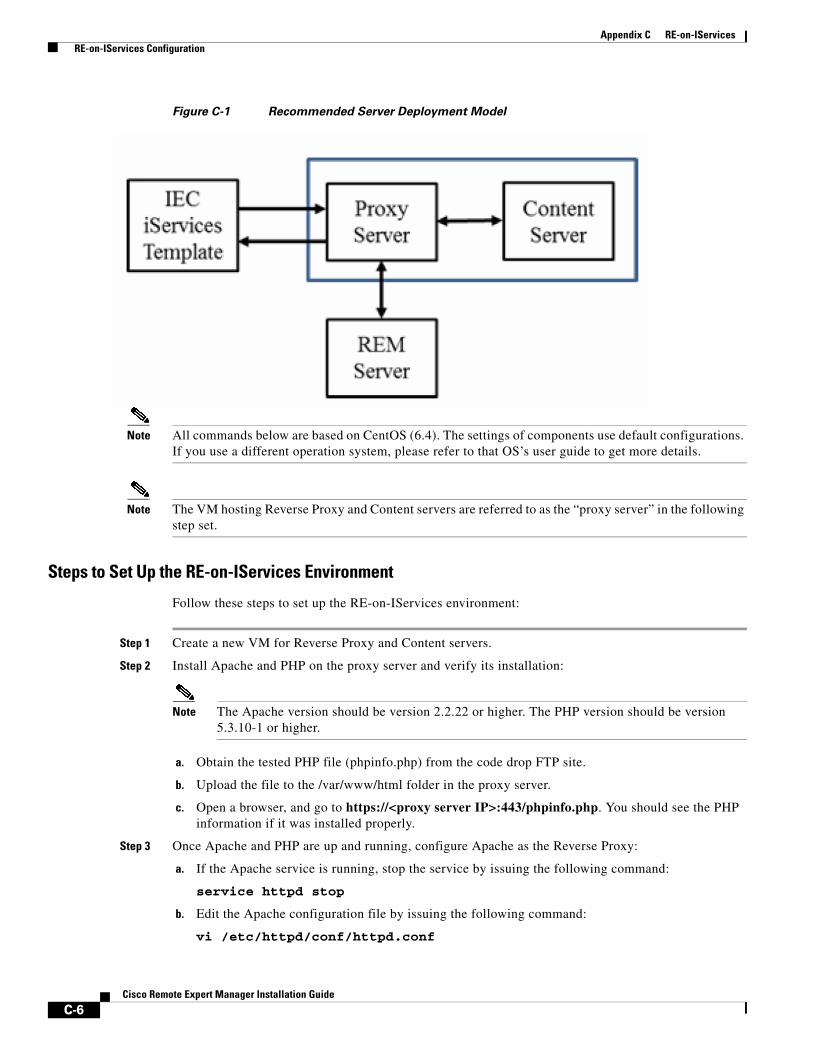
Appendix C RE-on-IServices RE-on-IServices Configuration
Figure C-1 Recommended Server Deployment Model
Note All commands below are based on CentOS (6.4). The settings of components use default configurations. If you use a different operation system, please refer to that OS’s user guide to get more details.
Note The VM hosting Reverse Proxy and Content servers are referred to as the “proxy server” in the following step set.
Steps to Set Up the RE-on-IServices Environment
Follow these steps to set up the RE-on-IServices environment:
Step 1 Create a new VM for Reverse Proxy and Content servers.
Step 2 Install Apache and PHP on the proxy server and verify its installation:
Note The Apache version should be version 2.2.22 or higher. The PHP version should be version 5.3.10-1 or higher.
a. Obtain the tested PHP file (phpinfo.php) from the code drop FTP site.
b. Upload the file to the /var/www/html folder in the proxy server.
c. Open a browser, and go to https://<proxy server IP>:443/phpinfo.php. You should see the PHP information if it was installed properly.
Step 3 Once Apache and PHP are up and running, configure Apache as the Reverse Proxy:
a. If the Apache service is running, stop the service by issuing the following command:
service httpd stop
b. Edit the Apache configuration file by issuing the following command:
vi /etc/httpd/conf/httpd.conf
C-6Cisco Remote Expert Manager Installation Guide
Appendix C RE-on-IServices RE-on-IServices Configuration
c. Uncomment the following lines in the file to enable proxy modules:
LoadModule proxy_module modules/mod_proxy.so
LoadModule proxy_http_module modules/mod_proxy_http.so
d. Change the port for Reverse Proxy by finding the Listen line and changing its value to 81.
e. Add the following lines to the bottom of file:
#For RE on iServices
SSLProxyEngine on
ProxyRequests Off
ProxyPass /resc https://172.25.26.141:8443/resc
ProxyPassReverse /resc https://172.25.26.141:8443/resc
<Location "/resc">
Order allow,deny
Allow from all
</Location>
f. Save the file and exit the vi editor.
Step 4 Create a new folder called “reOnIservices” under the /var/www/html directory to host the RE-on-IServices application.
Step 5 Unzip the RE-on-Iservices.zip file to the /var/www/html/reOnIservices directory. It should create a sub-folders called “v1”.
Step 6 Edit the RE-on-IServices application configuration by issuing the following command:
vi /var/www/html/reOnIservices/v1/reic/js/reic.json
The content of the reic.json file is:
{
"poolingInterval" : "3000",
“sessionPoolingInterval”: "1000",
"isDCEnable": "true",
"rescURL" : "<proxy server IP>: <Port>"
}
Step 7 Restart Apache by issuing the following command:
service httpd start
Step 8 Create a policy for RE-on-IServices in the IEM. Refer to the “Create and Apply a Policy for REM in the IEM” section in Chapter 1 for instructions. Ensure the following has been completed:
a. Provide proper SIP information in the application data property of the policy applied to the IEC.
b. In the browser property, disable web cache (browser > cache > web > enabled = false) and set the web cache mode to “Prefer network” (browser > cache > web > mode = Prefer network).
C-7Cisco Remote Expert Manager Installation Guide
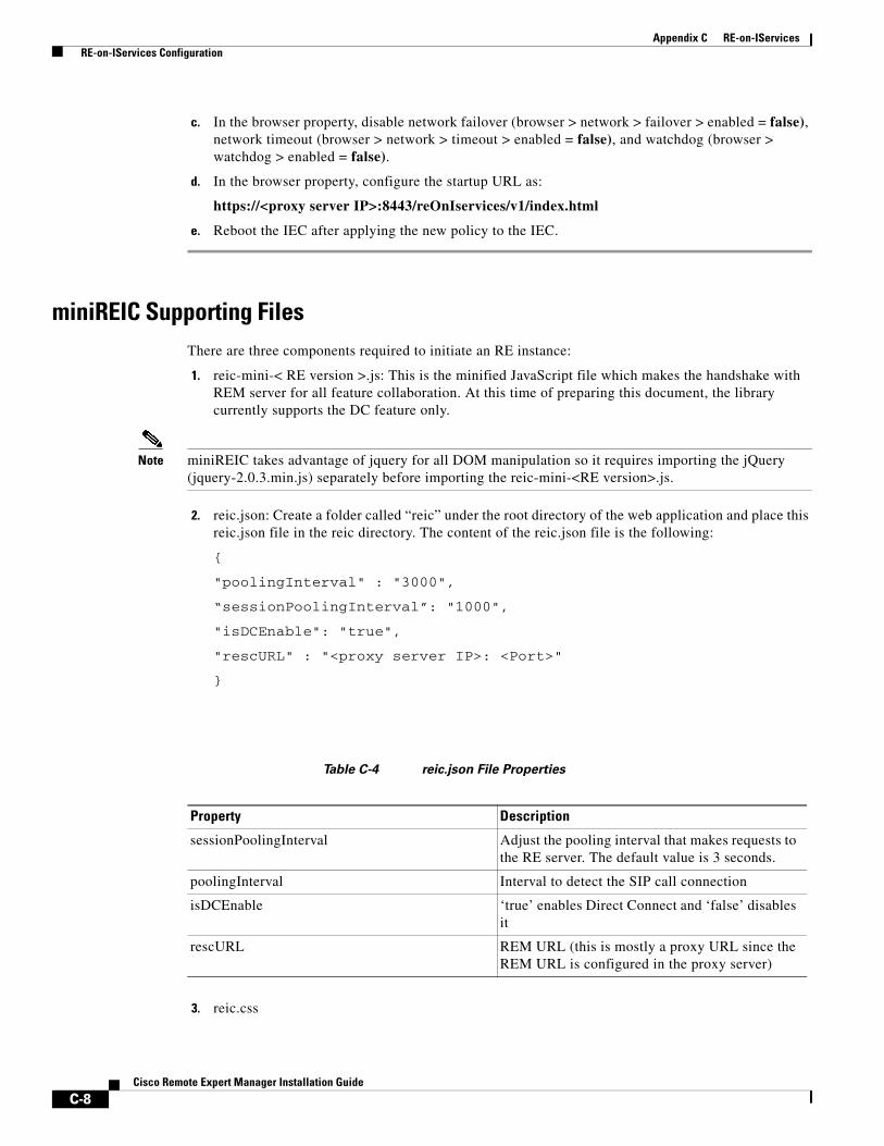
Appendix C RE-on-IServices RE-on-IServices Configuration
c. In the browser property, disable network failover (browser > network > failover > enabled = false), network timeout (browser > network > timeout > enabled = false), and watchdog (browser > watchdog > enabled = false).
d. In the browser property, configure the startup URL as:
https://<proxy server IP>:8443/reOnIservices/v1/index.html
e. Reboot the IEC after applying the new policy to the IEC.
miniREIC Supporting FilesThere are three components required to initiate an RE instance:
1. reic-mini-< RE version >.js: This is the minified JavaScript file which makes the handshake with REM server for all feature collaboration. At this time of preparing this document, the library currently supports the DC feature only.
Note miniREIC takes advantage of jquery for all DOM manipulation so it requires importing the jQuery (jquery-2.0.3.min.js) separately before importing the reic-mini-<RE version>.js.
2. reic.json: Create a folder called “reic” under the root directory of the web application and place this reic.json file in the reic directory. The content of the reic.json file is the following:
{
"poolingInterval" : "3000",
“sessionPoolingInterval”: "1000",
"isDCEnable": "true",
"rescURL" : "<proxy server IP>: <Port>"
}
Table C-4 reic.json File Properties
3. reic.css
Property Description
sessionPoolingInterval Adjust the pooling interval that makes requests to the RE server. The default value is 3 seconds.
poolingInterval Interval to detect the SIP call connection
isDCEnable ‘true’ enables Direct Connect and ‘false’ disables it
rescURL REM URL (this is mostly a proxy URL since the REM URL is configured in the proxy server)
C-8Cisco Remote Expert Manager Installation Guide
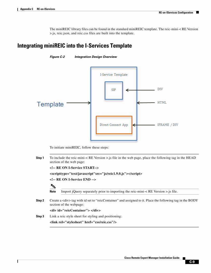
Appendix C RE-on-IServices RE-on-IServices Configuration
The miniREIC library files can be found in the standard miniREIC template. The reic-mini-< RE Version >.js, reic.json, and reic.css files are built into the template.
Integrating miniREIC into the I-Services Template
Figure C-2 Integration Design Overview
To initiate miniREIC, follow these steps:
Step 1 To include the reic-mini-< RE Version >.js file in the web page, place the following tag in the HEAD section of the web page:
<!-- RE ON I-Service START-->
<scripttype="text/javascript"src="js/reic1.9.0.js"></script>
<!-- RE ON I-Service END -->
Note Import jQuery separately prior to importing the reic-mini-< RE Version >.js file.
Step 2 Create a <div> tag with id set to “reicContainer” and assigned to it. Place the following tag in the BODY section of the webpage:
<div id="reicContainer"> </div>
Step 3 Link a reic style sheet for styling and positioning:
<link rel="stylesheet" href="css/reic.css"/>
C-9Cisco Remote Expert Manager Installation Guide
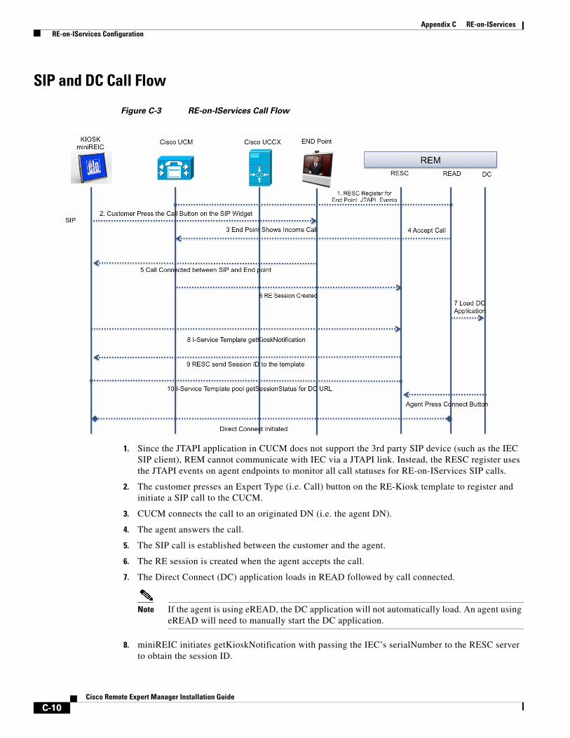
Appendix C RE-on-IServices RE-on-IServices Configuration
SIP and DC Call Flow
Figure C-3 RE-on-IServices Call Flow
1. Since the JTAPI application in CUCM does not support the 3rd party SIP device (such as the IEC SIP client), REM cannot communicate with IEC via a JTAPI link. Instead, the RESC register uses the JTAPI events on agent endpoints to monitor all call statuses for RE-on-IServices SIP calls.
2. The customer presses an Expert Type (i.e. Call) button on the RE-Kiosk template to register and initiate a SIP call to the CUCM.
3. CUCM connects the call to an originated DN (i.e. the agent DN).
4. The agent answers the call.
5. The SIP call is established between the customer and the agent.
6. The RE session is created when the agent accepts the call.
7. The Direct Connect (DC) application loads in READ followed by call connected.
Note If the agent is using eREAD, the DC application will not automatically load. An agent using eREAD will need to manually start the DC application.
8. miniREIC initiates getKioskNotification with passing the IEC’s serialNumber to the RESC server to obtain the session ID.
C-10Cisco Remote Expert Manager Installation Guide
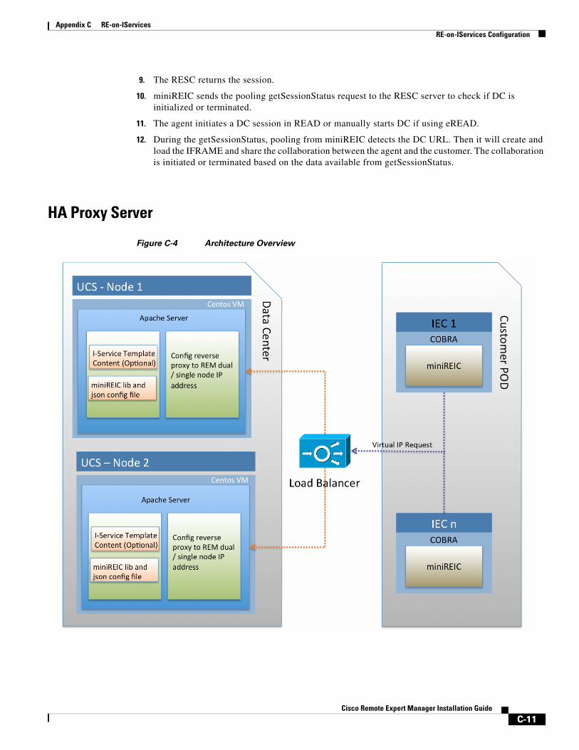
Appendix C RE-on-IServices RE-on-IServices Configuration
9. The RESC returns the session.
10. miniREIC sends the pooling getSessionStatus request to the RESC server to check if DC is initialized or terminated.
11. The agent initiates a DC session in READ or manually starts DC if using eREAD.
12. During the getSessionStatus, pooling from miniREIC detects the DC URL. Then it will create and load the IFRAME and share the collaboration between the agent and the customer. The collaboration is initiated or terminated based on the data available from getSessionStatus.
HA Proxy Server
Figure C-4 Architecture Overview
C-11Cisco Remote Expert Manager Installation Guide
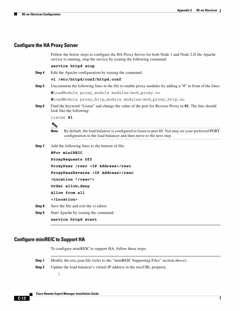
Appendix C RE-on-IServices RE-on-IServices Configuration
Configure the HA Proxy Server
Follow the below steps to configure the HA Proxy Server for both Node 1 and Node 2.If the Apache service is running, stop the service by issuing the following command:
service httpd stop
Step 4 Edit the Apache configuration by issuing the command:
vi /etc/httpd/conf/httpd.conf
Step 5 Uncomment the following lines in the file to enable proxy modules by adding a “#” in front of the lines:
#LoadModule proxy_module modules/mod_proxy.so
#LoadModule proxy_http_module modules/mod_proxy_http.so
Step 6 Find the keyword “Listen” and change the value of the port for Reverse Proxy to 81. The line should look like the following:
Listen 81
Note By default, the load balancer is configured to listen to port 80. You may set your preferred PORT configuration in the load balancer and then move to the next step.
Step 7 Add the following lines to the bottom of file:
#For miniREIC
ProxyRequests Off
ProxyPass /resc <IP Address>/resc
ProxyPassReverse <IP Address>/resc
<Location "/resc">
Order allow,deny
Allow from all
</Location>
Step 8 Save the file and exit the vi editor.
Step 9 Start Apache by issuing the command:
service httpd start
Configure miniREIC to Support HA
To configure miniREIC to support HA, follow these steps:
Step 1 Modify the reic.json file (refer to the “miniREIC Supporting Files” section above).
Step 2 Update the load balancer’s virtual IP address in the rescURL property.
{
C-12Cisco Remote Expert Manager Installation Guide

Appendix C RE-on-IServices
"poolingInterval" : "3000",
"sessionPoolingInterval" : "1000",
"isDCEnable": "true",
"rescURL" : "<Load Balancer Virtual IP>:<Port>"
}
C-13Cisco Remote Expert Manager Installation Guide

Appendix C RE-on-IServices
C-14Cisco Remote Expert Manager Installation Guide
Cisc
A
P P E N D I X D Mobile AdvisorSeptember 28, 2015
Appendix OverviewThis appendix provides an overview of the integration with Mobile Advisor, an explanation of how a mobile call is detected by REM and the mREAD page is displayed to the expert, and instructions on how to configure the Live Assist server’s IP address in the REM Properties file.
Topics in this appendix include:
• “Mobile Advisor Integration Overview”
• “Mobile Session Type and mREAD”
• “Live Assist Configuration”
Mobile Advisor Integration OverviewThe integration of Cisco Mobile Advisor with REM enables organizations to conduct video sessions with customers who are using mobile devices or PCs. Since Cisco Mobile Advisor gives customers the freedom to conduct business with experts anywhere, anytime, and on any device, its integration with REM will allow customers to easily move from branch to mobile interactions as they wish. As a result, it will strengthen existing customer relationships with a consistent video-enabled mobile experience and create a long-lasting loyal customer base.
The following are key features of the REM integration with Mobile Advisor:
– Customers can connect with an expert using either an iPad or Google Chrome on a mobile device or PC.
– Customers do not install or configure an application on their mobile device or PC - they simply press a button on the organization’s website to initiate the video call.
– Experts do not need to open a separate application to communicate with mobile customers. Experts log into Cisco Finesse and when a call is determined to be mobile rather than immersive (i.e. from a kiosk), the mREAD page appears.
– Experts can share documents and web links, annotate on the screen, and control the web page that the customer is viewing using mREAD.
– REM provides the API to mobile applications to share the DN/URI along with CafeX session token.
D-1o Remote Expert Manager Installation Guide
Appendix D Mobile Advisor Mobile Session Type and mREAD
– RESC detects a Mobile Advisor call and creates a RESC session via JTAPI.
– REAC changes to handle query changes and support to configure document and URLs.
Mobile Session Type and mREADExperts will use Cisco Finesse to conduct the video sessions with mobile customers. When a video call is initiated by the mobile customer, REM detects that it is a “mobile” session rather than an “immersive” session (i.e. a call from a kiosk). The mREAD page will then be displayed in Cisco Finesse so that the expert can begin collaborating with the mobile customer.
The diagram below shows how after the agent logs in and chooses the Ready state, an incoming call is analyzed for its session type (immersive or mobile) and then when answered, the appropriate page is displayed (eREAD for immersive or mREAD for mobile).
D-2Cisco Remote Expert Manager Installation Guide
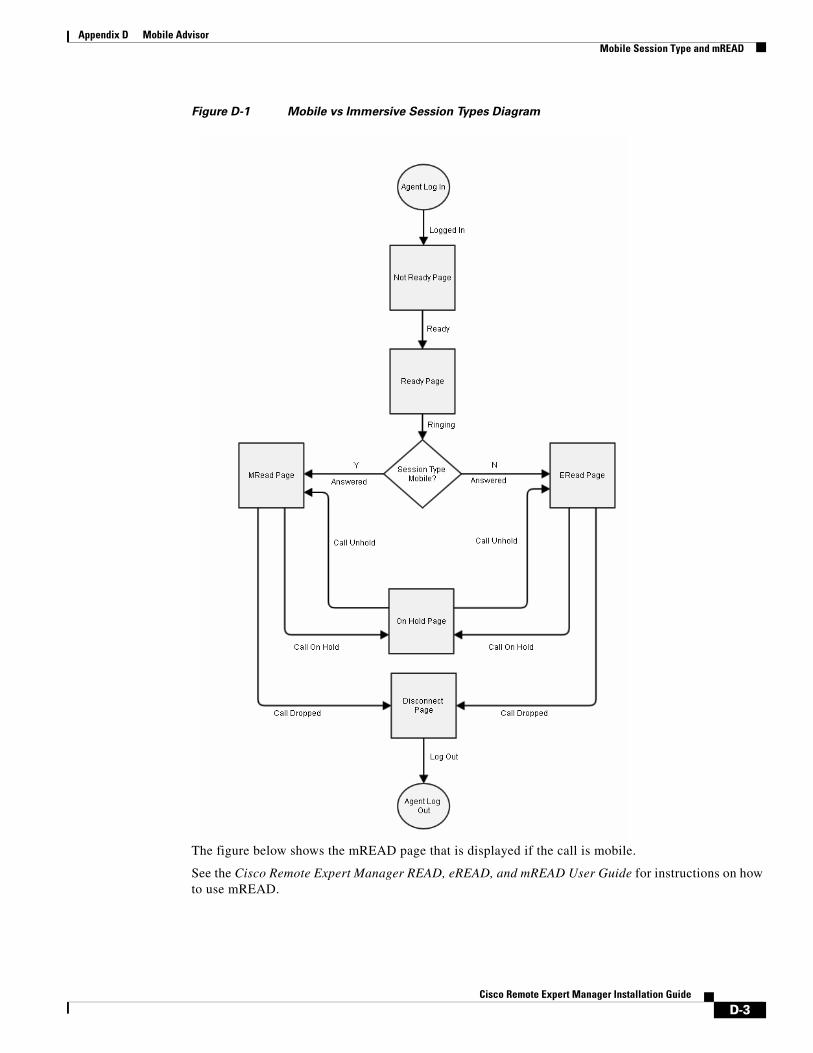
Appendix D Mobile Advisor Mobile Session Type and mREAD
Figure D-1 Mobile vs Immersive Session Types Diagram
The figure below shows the mREAD page that is displayed if the call is mobile.
See the Cisco Remote Expert Manager READ, eREAD, and mREAD User Guide for instructions on how to use mREAD.
D-3Cisco Remote Expert Manager Installation Guide
Appendix D Mobile Advisor Live Assist Configuration
Live Assist ConfigurationMobile Advisor’s Live Assist is enabled by default in the REM Properties file. You only need to configure the IP address and port of the Live Assist server. Follow the steps below to configure the IP address.
Step 1 Use a terminal emulator such as PuTTY to SSH into the REM server.
Step 2 In the Main Menu, type d to choose the REM Server Administration menu.
Step 3 In the REM Server Administration menu, type b to choose Edit REM Properties.
Step 4 Scroll to the LIVEASSIST DETAILS section.
Step 5 Enter the IP address of the Live Assist server for the LIVEASSIST_SERVER property.
Step 6 Change the LIVEASSIST_PORT property value to 8443.
Warning Do not change the value of the LIVEASSIST_AUDIT_ENABLE property. The LIVEASSIST_AUDIT_ENABLE property enables the Mobile Advisor login capability and is enabled by default (i.e. the property is set to “true”).
Step 7 After you make changes to the rem.properties file, you need to save it by pressing SHIFT : and then entering wq.
D-4Cisco Remote Expert Manager Installation Guide