Embed Size (px)
Citation preview

Cisco Prime Network 4.3.1 Gateway High Availability GuideRevised: February, 2017
Cisco Systems, Inc.www.cisco.com
Cisco has more than 200 offices worldwide. Addresses, phone numbers, and fax numbers are listed on the Cisco website at www.cisco.com/go/offices.

THE SPECIFICATIONS AND INFORMATION REGARDING THE PRODUCTS IN THIS MANUAL ARE SUBJECT TO CHANGE WITHOUT NOTICE. ALL STATEMENTS, INFORMATION, AND RECOMMENDATIONS IN THIS MANUAL ARE BELIEVED TO BE ACCURATE BUT ARE PRESENTED WITHOUT WARRANTY OF ANY KIND, EXPRESS OR IMPLIED. USERS MUST TAKE FULL RESPONSIBILITY FOR THEIR APPLICATION OF ANY PRODUCTS.
THE SOFTWARE LICENSE AND LIMITED WARRANTY FOR THE ACCOMPANYING PRODUCT ARE SET FORTH IN THE INFORMATION PACKET THAT SHIPPED WITH THE PRODUCT AND ARE INCORPORATED HEREIN BY THIS REFERENCE. IF YOU ARE UNABLE TO LOCATE THE SOFTWARE LICENSE OR LIMITED WARRANTY, CONTACT YOUR CISCO REPRESENTATIVE FOR A COPY.
The Cisco implementation of TCP header compression is an adaptation of a program developed by the University of California, Berkeley (UCB) as part of UCB’s public domain version of the UNIX operating system. All rights reserved. Copyright © 1981, Regents of the University of California.
NOTWITHSTANDING ANY OTHER WARRANTY HEREIN, ALL DOCUMENT FILES AND SOFTWARE OF THESE SUPPLIERS ARE PROVIDED “AS IS” WITH ALL FAULTS. CISCO AND THE ABOVE-NAMED SUPPLIERS DISCLAIM ALL WARRANTIES, EXPRESSED OR IMPLIED, INCLUDING, WITHOUT LIMITATION, THOSE OF MERCHANTABILITY, FITNESS FOR A PARTICULAR PURPOSE AND NONINFRINGEMENT OR ARISING FROM A COURSE OF DEALING, USAGE, OR TRADE PRACTICE.
IN NO EVENT SHALL CISCO OR ITS SUPPLIERS BE LIABLE FOR ANY INDIRECT, SPECIAL, CONSEQUENTIAL, OR INCIDENTAL DAMAGES, INCLUDING, WITHOUT LIMITATION, LOST PROFITS OR LOSS OR DAMAGE TO DATA ARISING OUT OF THE USE OR INABILITY TO USE THIS MANUAL, EVEN IF CISCO OR ITS SUPPLIERS HAVE BEEN ADVISED OF THE POSSIBILITY OF SUCH DAMAGES.
Cisco and the Cisco logo are trademarks or registered trademarks of Cisco and/or its affiliates in the U.S. and other countries. To view a list of Cisco trademarks, go to this URL: www.cisco.com/go/trademarks. Third-party trademarks mentioned are the property of their respective owners. The use of the word partner does not imply a partnership relationship between Cisco and any other company. (1110R)
Any Internet Protocol (IP) addresses and phone numbers used in this document are not intended to be actual addresses and phone numbers. Any examples, command display output, network topology diagrams, and other figures included in the document are shown for illustrative purposes only. Any use of actual IP addresses or phone numbers in illustrative content is unintentional and coincidental.
© 2017 Cisco Systems, Inc. All rights reserved.

C O N T E N T S
Installation Overview 1-1
Assumptions in This Document 1-1
Installation DVDs 1-1
Installation Flow 1-3
Using Gateway High Availability with Cisco Prime Central and Other Prime Network Components 1-7
Licenses 1-8
Functional Overview of Gateway Local Redundancy and Geographical Redundancy 2-1
Local Redundancy Functional Overview 2-1
Configuration Details for Local Redundancy 2-2
Geographical Redundancy Functional Overview 2-5
Oracle ADG Replication Process 2-7
Gateway Sync (GWSync) Replication Process 2-8
Infobright Database Replication Process (Operations Reports) 2-9
ESXi Testing Details 2-9
Installing and Maintaining Gateway Local Redundancy 3-1
Steps for Installing the Gateway Local Redundancy Solution 3-1
Installation Requirements for Local Redundancy 3-4
Hardware and Software Requirements for Local Redundancy 3-4
Port Usage for Local Redundancy 3-6
Preparing to Install the Local Redundancy Solution 3-6
Configuring Hardware and External Storage for Red Hat Cluster Site 3-7
Installing RHEL and Verifying the Version 3-8
Installing RPMs Required on Red Hat for Prime Network 3-8
Required RPMs for Red Hat 5.8 3-8
Required RPMs for Red Hat 6.5 3-9
Required RPMs for Oracle Database 12c 3-10
Configuring Disk Group and Volumes 3-11
Verify That All Servers Are Ready for Installation 3-12
Creating the Mount Points for Installation 3-12
Configure the Services for Automatic Start After Reboot 3-13
Stopping the RHCS Services 3-13
Installing the Prime Network Gateway Local Redundancy Software 3-14
Troubleshooting the Local Redundancy Installation 3-19
1Cisco Prime Network 4.3.1 Gateway High Availability Guide

Contents
Verifying the Local Redundancy Setup 3-20
Post-Installation Tasks for Local Redundancy 3-22
Updating the Database Host in the Registry (Only for NAT) 3-22
Configuring the RHCS Web Interface (Optional) 3-23
Maintaining Local Redundancy 3-24
Monitoring Log Messages 3-25
Monitoring Cluster Status Using the CLI 3-25
Monitoring Cluster Status Using the GUI 3-26
Managing the Local Redundancy Cluster 3-26
Manually Fencing 3-27
Uninstalling Local Redundancy 3-28
Installing and Configuring PN-IL with Local Redundancy 3-29
Installation DVD 3-29
Steps for Installing PN-IL with Local Redundancy 3-29
Installing PN-IL on a Prime Network Server (Local Redundancy) 3-30
Configuring PN-IL on a Prime Network Gateway (Local Redundancy) 3-31
Configuring PN-IL with Prime Network (Standalone Mode with Local Redundancy) 3-31
Configuring PN-IL with Prime Central (Suite Mode with Local Redundancy) 3-32
Disabling the PN-IL Health Monitor 3-34
Installing and Maintaining Gateway Geographical Redundancy 4-1
Steps for Installing the Geographical Redundancy Solution 4-1
Installation Requirements for Geographical Redundancy 4-4
Hardware and Software Requirements for Geographical Redundancy 4-4
Ports Usage for Geographical Redundancy 4-5
Preparing to Install Geographical Redundancy 4-6
Installing the Prime Network Gateway Geographical Redundancy Software 4-6
Verifying the Geographical Redundancy Setup 4-14
Maintaining Geographical Redundancy 4-16
Checking Log Messages 4-16
Monitoring Overall Status 4-17
Uninstalling the Geographical Redundancy Software 4-18
Installing and Configuring PN-IL for Local + Geographical Redundancy 4-18
Installation DVD 4-19
Steps for Installing PN-IL with Local + Geographical Redundancy 4-19
Installing PN-IL on a Prime Network Server (Local + Geographical Redundancy) 4-20
Configuring PN-IL on a Prime Network Gateway (Local + Geographical Redundancy) 4-22
Configuring PN-IL with Prime Network (Standalone Mode with Local + Geographical Redundancy) 4-22
2Cisco Prime Network 4.3.1 Gateway High Availability Guide

Contents
Configuring and Migrating PN-IL with Prime Central (Suite Mode with Local + Geographical Redundancy) 4-23
Disabling the PN-IL Health Monitor 4-26
Installing and Configuring PN-IL for Geographical Redundancy Only 4-27
Steps for Installing PN-IL with Geographical Redundancy Only 4-27
Installing PN-IL on a Prime Network Server (Geographical Redundancy Only) 4-28
Configuring PN-IL on a Prime Network Gateway (Geographical Redundancy Only) 4-30
Configuring PN-IL with Prime Network (Standalone Mode with Geographical Redundancy Only) 4-30
Configuring and Migrating PN-IL with Prime Central (Suite Mode with Geographical Redundancy Only) 4-31
Installing Prime Network Operations Report with Gateway High Availability 5-1
Installation DVD 5-1
Steps for Installing Operations Reports 5-2
Installing the Operations Reports Software 5-2
Verifying the Operations Reports Setup 5-4
Performing Switchovers and Failovers 6-1
Performing a Scheduled Site Move 6-1
Performing Switchover on Systems with Prime Network Integration Layer Installed on Prime Network 6-3
Failing Over to the Standby Site for Disaster Recovery 6-4
Restoring the Failed Site (Hot Backup) 6-6
Restoring Redundancy Configuration After a Catastrophic Failure 6-8
Restoring Redundancy Configuration After a Non-Catastrophic Failure 6-10
Stopping and Restarting Data Replication 6-11
Changing IP Addresses after a Failover or Switchover 6-14
Changing the Gateway IP Address on a Gateway and All Units (changeSite.pl) 6-14
Changing the Gateway IP Address on a Single Unit (switchUnit.pl) 6-16
3Cisco Prime Network 4.3.1 Gateway High Availability Guide

Contents
4Cisco Prime Network 4.3.1 Gateway High Availability Guide

Cisco Pr
C H A P T E R 1
Installation OverviewThis chapter provides an overview of the Prime Network gateway high availability installation process and includes these installation-related topics:
• Assumptions in This Document, page 1-1
• Installation DVDs, page 1-1
• Installation Flow, page 1-3
• Using Gateway High Availability with Cisco Prime Central and Other Prime Network Components, page 1-7
• Licenses, page 1-8
Assumptions in This DocumentThe procedures described in this guide assume the following:
• Your deployment uses a Prime Network embedded database, not an external database.
• Your deployment does not have an IPv6 gateway or database.
If your gateway high availability deployment differs from the previous requirements, please contact your Cisco account representative for assistance with planning and installation of the solution.
Installation DVDsThe gateway high availability files are provided on the Prime Network installation DVDs listed in Table 1-1.
Note If you are upgrading an existing gateway high availability deployment to Prime Network 4.3.1, follow the upgrade procedure described in the Cisco Prime Network 4.3.1 Installation Guide.
1-1ime Network 4.3.1 Gateway High Availability Guide

Chapter 1 Installation Overview Installation DVDs
Table 1-1 Gateway High Availability Installation Scripts
Scripts Description Local RedundancyGeographical Redundancy
Disk 1—RH_ha.zip Contents
install_Prime_HA.pl Local redundancy—Is run from locally mounted node that has primary database. Installs gateway and embedded database on primary node, and sets up a limited number of elements on secondary node (such as cron jobs, users, groups, SSH keys, and so forth).
In case of geographical redundancy only or geogrpahical + local redundancy, this script will install Prime Network gateway and embedded database on the remote site.
Server P1 (primary
database)
Server P2
Server S1
x — —
setup_Prime_DR.pl Geographical redundancy—Is run from node that is running the primary database. Stops the gateway, installs Oracle ADG, and sets up cron jobs for gateway synchronization (GWSync) and ADG monitoring. Also triggers the initial Gateway Sync.
x — —
Disk 2—sil-esb-1.2.0.tar.gz Contents (Integration Layer)
installAndConfigureEsb.sh Installs local redundancy alone or local + geographical redundancy elements for PN-IL.
Note PN-IL supports local redundancy alone, or local + geographical redundancy. It does not support geographical redundancy alone.
x — —
itgctl Configures PN-IL. x — x
il-watch-dog.sh Controls the PN-IL health monitor. x — x
DMSwitchToSuite.sh Migrates a standalone PN-IL to suite mode. x — x
Disk 6—infobright_integ.zip Contents (Operations Reports)
primenw_integration.pl Installs Operations Reports. x — —
1-2Cisco Prime Network 4.3.1 Gateway High Availability Guide
Chapter 1 Installation Overview Installation Flow
Installation FlowGateway high availability is provided in three configurations:
• Local redundancy alone, which uses two active local servers for automatic failover.
• Geographical redundancy alone, which uses a server at a remote geographical site for a full disaster recovery.
• Local + geographical redundancy, which uses both of the above.
Note For all gateway HA configurations, the Prime Network gateway software, the embedded Oracle database, and (if installed) the Infobright database must all be installed on the same gateway server.
Table 1-2 shows the high availability deployments that are supported, depending on your Prime Network installation.
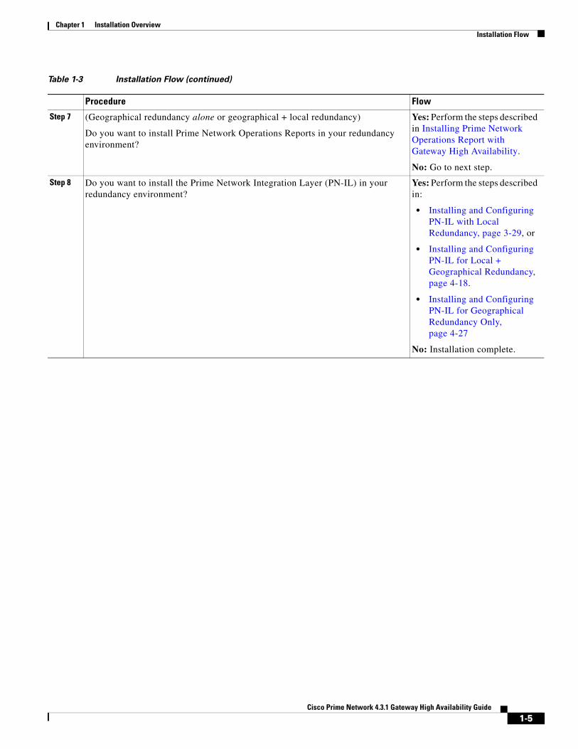
Table 1-3 and Figure 1-1 provide the general flow for installing and setting up gateway high availability. For detailed instructions on each, see the topics referenced in Table 1-3.
Note If you are upgrading an existing gateway high availability deployment to Prime Network 4.3.1, follow the upgrade procedure described in the Cisco Prime Network 4.3.1 Installation Guide. If you are upgrading Prime Network in a HA setup, you should always start the upgrade from the Primary gateway as active gateway. The active gateway should not be the secondary gateway when starting the upgrade process.
Table 1-2 Supported HA Deployments Available for Prime Network Installations
Installation
Supported Gateway High Availability Deployments
Local Geographical Local + Geographical
Prime Network x x x
Prime Network with Operations Reports
x x x
Prime Network with PN-IL x x x1
1. If you want to integrate a PN-IL deployment with Prime Central, Prime Central must have the same configuration.
Prime Network with Operations Reports and PN-IL
x x x1
1-3Cisco Prime Network 4.3.1 Gateway High Availability Guide

Chapter 1 Installation Overview Installation Flow
Table 1-3 Installation Flow
Procedure Flow
Step 1 If you are you going to install gateway high availability with Operations Reports or PN-IL, or integrate with Prime Central, have you read these topics?
• Operations Reports and Gateway High Availability, page 1-7
• Gateway High Availability and the Prime Network Integration Layer (PN-IL), page 1-7
• Gateway High Availability and Prime Central, page 1-8
Yes: Go to next step.
No: Do not continue until you have read those sections. They contain information on supported configurations.
Step 2 Have you familiarized yourself with the high availability solutions by reading these topics?
• Local Redundancy Functional Overview, page 2-1
• Geographical Redundancy Functional Overview, page 2-5
Yes: Go to next step.
No: Do not continue until you have read those sections. They contain information on supported configurations.
Step 3 Does the gateway where you will install gateway high availability meet the requirements?
• For local redundancy alone (with or without Operations Reports and PN-IL), see Installation Requirements for Local Redundancy, page 3-4.
• For geographical redundancy alone (with or without Operations Reports), see Installation Requirements for Geographical Redundancy, page 4-4.
• For local + geographical redundancy (with or without Operations Reports and PN-IL), see Installation Requirements for Local Redundancy, page 3-4 and Installation Requirements for Geographical Redundancy, page 4-4.
Yes: Go to next step.
No: Do not continue until all specified requirements are met.
Step 4 Have you performed the tasks in these sections?
• For local redundancy alone (with or without Operations Reports and PN-IL), see Preparing to Install the Local Redundancy Solution, page 3-7.
• For geographical redundancy alone (with or without Operations Reports), see Preparing to Install Geographical Redundancy, page 4-6.
• For local + geographical redundancy (with or without Operations Reports and PN-IL), see Preparing to Install the Local Redundancy Solution, page 3-7 and Preparing to Install Geographical Redundancy, page 4-6.
Yes: Go to next step.
No: Do not continue until all preinstallation tasks are completed.
Step 5 (Local redundancy) When the installation is complete, have you verified the installation according to Verifying the Local Redundancy Setup, page 3-20?
Yes: Go to next step.
No: Do not continue until you have verified the installation,
Step 6 (Local redundancy) Have you completed all post-installation tasks according to Post-Installation Tasks for Local Redundancy, page 3-22?
Yes: Go to next step.
No: Do not continue until you have finished the post-installation tasks.
1-4Cisco Prime Network 4.3.1 Gateway High Availability Guide
Chapter 1 Installation Overview Installation Flow
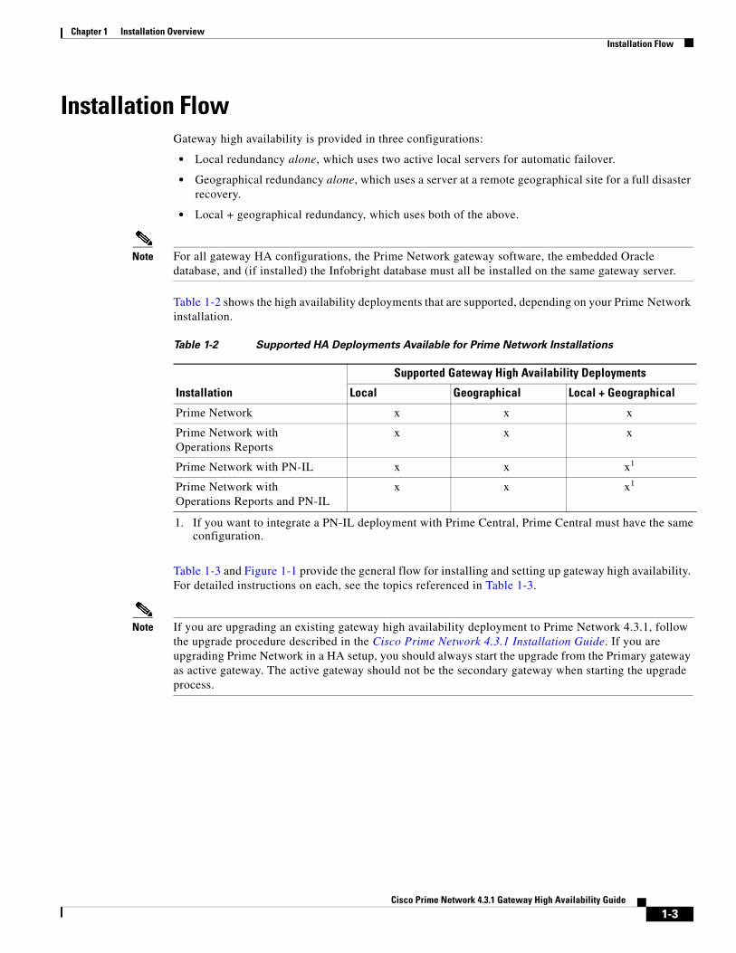
Step 7 (Geographical redundancy alone or geographical + local redundancy)
Do you want to install Prime Network Operations Reports in your redundancy environment?
Yes: Perform the steps described in Installing Prime Network Operations Report with Gateway High Availability.
No: Go to next step.
Step 8 Do you want to install the Prime Network Integration Layer (PN-IL) in your redundancy environment?
Yes: Perform the steps described in:
• Installing and Configuring PN-IL with Local Redundancy, page 3-29, or
• Installing and Configuring PN-IL for Local + Geographical Redundancy, page 4-18.
• Installing and Configuring PN-IL for Geographical Redundancy Only, page 4-27
No: Installation complete.
Table 1-3 Installation Flow (continued)
Procedure Flow
1-5Cisco Prime Network 4.3.1 Gateway High Availability Guide
Chapter 1 Installation Overview Installation Flow
Figure 1-1 Installation Flow for Prime Network Gateway High Availability
End
(Optional)Install PN-IL
(Optional)Install Operations Reports
Setup and Configure the Remote Site
Verify the installation
(Optional)Update the database host in theCisco Prime Network registry
Install the units
3618
21
LocalRedundancy
Geographical Redundancy
Start
Identify the type ofinstallation:• Local Redundancy• Geographical Redundancy
Configure the Embedded DatabaseRun add_embd_storage.pl -ha
Setup the Remote SiteRun install_Prime_HA.pl (HA=No, DR=Yes)
Configure the Remote SiteRun setup_Prime_DR.pl
Configure the Embedded DatabaseRun add_embd_storage.pl
Install Red Hat Enterprise for Linux 5.5with Clustering Suite and the
relevant RPMs
Synchronize Cisco Prime Networkgateways and units time
Configure the Operating Systemand disk partitions
Setup high availability in the primary siteRun install_Prime_HA.pl (HA=yes, R=No)
Configure the server hardware
1-6Cisco Prime Network 4.3.1 Gateway High Availability Guide
Chapter 1 Installation Overview Using Gateway High Availability with Cisco Prime Central and Other Prime Network Components
Using Gateway High Availability with Cisco Prime Central and Other Prime Network ComponentsUnit High Availability and Gateway High Availability
Gateway high availability is compatible with unit server high availability. However, unit server high availability must be configured separately as described in the Cisco Prime Network 4.3.1 Administrator Guide. Designating active and standby units is not included in the procedures described in this guide.
Operations Reports and Gateway High Availability
The gateway high availability solution also protects Operations Reports data that is stored on the gateway and the Infobright database.
You should install Operations Reports after you have installed the base gateway redundancy solution. Installing gateway high availability for Operations Reports is described in Installing Prime Network Operations Report with Gateway High Availability. When Operations Reports is installed, Prime Network will start the processes required to protect your Operations Reports data. This includes the folders, system files, registry data on the gateway, and event data that is stored in the Infobright database. These are monitored using:
• The RHCS Infobright database service, ifb:
In case of local redundancy only and local + geographical redundancy configurations, if a hardware or software failure occurs, the RHCS automatically restarts the failed node's services on the functional node. See Table 2-1 on page 2-3 for more information.
• The GWSync process:
Replicates data between the local and remote servers in a geographical redundancy configuration.
• AVM 45:
AVM 45 runs on the active server and constantly loads data to the backup site in a geographical redundancy configuration. If there is a failover event, archived event data and standard event data from the previous 80 minutes is lost. This is due to the time required to load and validate the data that is saved on the secondary Infobright database.
Inventory data is retrieved from memory (from the inventory snapshot) and is therefore not affected by any high availability events.
Gateway High Availability and the Prime Network Integration Layer (PN-IL)
PN-IL supports all the redundancy configurations as supported by Prime Network, i.e, local only, local + geographical, and geographical only. The RHCS ana service will monitor the PN-IL resources.
Note PN-IL supports all the redundancy configurations as that of the Prime Network. Therefore, if you want to integrate a PN-IL deployment with Prime Central, Prime Central also must have the same configuration.
If you want to use PN-IL, install it after you have installed Prime Network in following HA configurations. See:
• Installing and Configuring PN-IL with Local Redundancy, page 3-29
• Installing and Configuring PN-IL for Local + Geographical Redundancy, page 4-18
1-7Cisco Prime Network 4.3.1 Gateway High Availability Guide
Chapter 1 Installation Overview Licenses
• Installing and Configuring PN-IL for Geographical Redundancy Only, page 4-27
Gateway High Availability and Prime Central
Deployments of Prime Network gateway high availability (with or without Operations Reports and PN-IL) can be integrated with Prime Central. Therefore, if you want to integrate a PN-IL deployment with Prime Central, Prime Central also must have the same configuration.
See these documents and topics for more information.
Licenses In addition to the gateway high availability license, you must purchase a license for each redundant gateway server and a standby license.
Table 1-4 Where to Get Information on Integration with Prime Central
To integrate Prime Central with: See
Prime Network with or without Operations Reports
Cisco Prime Central High Availability Quick Start Guide
Prime Network plus PN-IL Configuring PN-IL with Prime Central (Suite Mode with Local Redundancy), page 3-32
Configuring and Migrating PN-IL with Prime Central (Suite Mode with Local + Geographical Redundancy), page 4-23 and Configuring and Migrating PN-IL with Prime Central (Suite Mode with Geographical Redundancy Only), page 4-31
1-8Cisco Prime Network 4.3.1 Gateway High Availability Guide

Cisco Pr
C H A P T E R 2
Functional Overview of Gateway Local Redundancy and Geographical RedundancyThese topics provide a functional overview of the Prime Network gateway high availability solutions:
• Local Redundancy Functional Overview, page 2-1
• Geographical Redundancy Functional Overview, page 2-5
Note Gateway high availability is supported only when the gateway software, Oracle database, and Infobright database (applicable for Operations Report) are installed on the same server.
Local Redundancy Functional OverviewGateway local redundancy configuration uses one active and one standby node to provide an automatic failover solution for local hardware faults, without the need to reconfigure IP addresses. The solution uses the Red Hat Cluster Suite (RHCS). The nodes are monitored by RHCS and if the node managing the services fails, the services are seamlessly moved to the other node. In case of a single service failure, the cluster will attempt to restart the service. If the retries fail, the service will be relocated to the second node and started on that node. This does not impact the other service in the cluster.
When this solution is initially installed, the gateway and database services are installed on and managed by one node in the cluster from where the installation script is run.
Figure 2-1 shows a basic dual-node cluster local redundancy configuration, where the Prime Network gateway service is on Server P1, the Oracle database service is on Server P2, and both servers are connected to a server for external storage. Both servers use an embedded database.
The RHCS local redundancy solution requires a fencing device, which is a hardware unit that disconnects a node from shared storage to ensure data integrity. For more information on fencing options, see Fencing Options, page 2-3.
2-1ime Network 4.3.1 Gateway High Availability Guide
Chapter 2 Functional Overview of Gateway Local Redundancy and Geographical Redundancy Local Redundancy Functional Overview
Figure 2-1 Architecture for Gateway Local Redundancy
Configuration Details for Local RedundancyLocal redundancy requires that RHCS be installed on both nodes. Out of the box, both services run on the node from which the installation script is run. This configuration can be changed, if desired, using RHCS web GUI or CLI (clusvcadm utility). For details on the required system configuration for local redundancy, see Installation Requirements for Local Redundancy, page 3-4
The local redundancy setup has the following:
• Dual Node Cluster, page 2-2
• RHCS Installed on Both Nodes, page 2-2
• External Shared Storage, page 2-3
• Fencing Options, page 2-3
• Security, page 2-5
Dual Node Cluster
The Prime Network gateway and embedded database are installed in a dual-node cluster. Each node has the platform to run both Prime Network gateway, database services, and operations reports (optional).
RHCS Installed on Both Nodes
RHCS manages the local redundancy by monitoring cluster configured services: ana and oracle_db. If you have installed Operations Reports, RHCS also manages the Infobright database service, ifb. If a hardware or software failure occurs, the RHCS automatically restarts the failed node's services on the functional node.
Cisco Prime Networkgateways
External storage
Heartbeat
3023
98
Server P1 Server P2
2-2Cisco Prime Network 4.3.1 Gateway High Availability Guide
Chapter 2 Functional Overview of Gateway Local Redundancy and Geographical Redundancy Local Redundancy Functional Overview
Table 2-1 lists the services that are monitored by RHCS.
The floating IP address is different from either node’s physical IP address. The floating IP address is associated with a service rather than a particular machine in the cluster. Therefore, the cluster IP address is the floating IP address of the management port of the cluster. It floats because it always points the parent device (for example, it would change from P1 to P2 in case of a switchover or failover).
The Oracle listener should be running before Prime Network, which allows the Prime Network gateway process (AVM 11) to connect to the database. If the listener is not running, the Prime Network agent contains logic to enable it to delay startup of the Prime Network processes while it waits for the listener to start. If the listener does not start up on time, the Prime Network gateway agent will abort the startup, resulting in a Prime Network resource failure.
Alternatively, you can also bring the service groups online in serial sequence, starting with the Oracle and the Infobright service groups, then the Prime Network service group. (RHCS does not enforce this behavior.)
External Shared Storage
RHCS requires an external shared storage that is mountable from both nodes. The external shared storage contain the Prime Network, Oracle, and (if Operations Reports is installed) Infobright files.
Fencing Options
Each node in the cluster must use a fencing method. Local redundancy configuration uses a fencing hardware unit for cutting a node off from the shared storage. This is to ensure data integrity and to prevents a split brain scenario by preventing the problematic node from writing to the shared storage. If any problem with cluster node occurs, RHCS invokes the fencing device with the peer and waits for the success signal. If a failure occurs, the cut off can be accomplished by powering off the node with a remote power switch, disabling a switch channel, or revoking a host's SCSI 3 reservations.
The supported fencing options are:
• fence_ipmilan—Intelligent Platform Management Interface (IPMI) v1.5 or higher compliant devices over a LAN.
Table 2-1 Cluster Configured Services Monitored by RHCS
RHCS Service Description
ana Monitors Prime Network (AVM 99), the Prime Network Integration Layer (if installed), and Prime Network Operations Reports (if installed). It consists of the following resources.
IP address ana_service_floating_IP
Scripts ana.sh (Prime Network)pcil.sh (Prime Network Integration Layer)
oracle_db Monitors Oracle processes and listener and consists of the following resources.
IP address oracle_db_floating_IP
Scripts oracles.sh, lsnr.sh
ifb Monitors Infobright processes and XXX and consists of the following resources:
IP address infobright_db_floating_IP
Scripts infobright.sh
2-3Cisco Prime Network 4.3.1 Gateway High Availability Guide
Chapter 2 Functional Overview of Gateway Local Redundancy and Geographical Redundancy Local Redundancy Functional Overview
• fence_ilo—Hewlett Packard Integrated Lights Out (HP iLO).
• fence_vmware_soap—VMware with SOAP API. This agent communicates with the VMware vCenter server that is managing the VM that will be fenced. If you choose this fencing method, you will be prompted for the vCenter user login and password, the vCenter IP address, and the vCenter hostname. Not all RHEL versions support this option; see Hardware and Software Requirements for Local Redundancy, page 3-4 and the Red Hat site.
• fence_manual—This option allows you to add a a Red Hat-supported fencing device not listed above. If you choose Manual, the fence-manual-fencing agent is assigned. This fencing agent is temporary and should not be used in production because it does not perform automated actions. If a cluster problem occurs, the node and storage must be manually disconnected, or another fencing agent must be used to disconnect them. If you choose this option during the installation because you want to add a different Red Hat-supported fencing device, provision the device after installation using the RHCS GUI. When you add it, be sure to add it as the main fencing method, and move the manual fencing agent to the backup method, as shown in Figure 2-2.
General information about the RHCS web GUI is provided in Configuring the RHCS Web Interface (Optional), page 3-23. However, see the Red Hat Conga documentation for complete information about using the RHCS web GUI application. Additionally, you need the RHCS user documentation to provision and manage cluster fencing devices. See the Red Hat site for more information.
Note Keep these items in mind:
• To prevent fencing loops, the cluster interconnect and power fencing (for example, HP-iLO) should use the same network, such as bond0.
• If the main fencing device is a remote power switch, define all ports that supply power to the node simultaneously.
• If manual fencing is used, before disconnecting the node, remove the cman and rgmanager services from the automatic startup sequence. For more information on the command to remove these services, see Manually Fencing, page 3-27.
2-4Cisco Prime Network 4.3.1 Gateway High Availability Guide

Chapter 2 Functional Overview of Gateway Local Redundancy and Geographical Redundancy Geographical Redundancy Functional Overview
Figure 2-2 RHCS GUI Fencing Method Window
Security
When the RHCS local redundancy solution is installed, SSL keys are generated and copied to the other node in the cluster.
Geographical Redundancy Functional OverviewGateway geographical redundancy is implemented using Oracle Active Data Guard (ADG). The ADG geographical redundancy solution uses a remote site containing a single server that provides failover in case of a failure at the primary site. The remote site, which is running but has no active applications, provides redundancy for the server (or servers) at the primary site, which contain the gateway and the database services. The remote node is called the Disaster Recovery (DR) node.
Geographical redundancy can be installed alone (geographical redundancy only) or with local redundancy (local + geographical redundancy), depending on your configuration; see Table 1-2 on page 1-3. In both cases, the remote site (S1) contains its own server, database, and storage—all located at another geographical location. The DR node at the remote site is the backup to the node primary site. Figure 2-3 illustrates a deployment with geographical redundancy alone. It includes a single node with external storage in the primary site (P1), and a single node with external storage in the remote site (S1).
1 Backup fencing method: Move the manual fencing agent to the backup method.
2 Main fencing method: Add a different Red Hat-supported fencing device.
2466
67
1 2
192.168.1.10
2-5Cisco Prime Network 4.3.1 Gateway High Availability Guide
Chapter 2 Functional Overview of Gateway Local Redundancy and Geographical Redundancy Geographical Redundancy Functional Overview
Figure 2-3 Architecture for Gateway with Geographical Redundancy Alone
Figure 2-4 illustrates a deployment with both local + geographical redundancy. It includes a dual-node cluster with external shared storage in the primary site (P1 and P2), and a single node with external storage in the remote site (S1).
Figure 2-4 Architecture for Gateway with Local Redundancy and Geographical Redundancy
Note Geographical redundancy does not allow the Prime Network service (ana) to be brought online on the local side while the Oracle service is online on the remote site (or vice versa).
The data stored in the server and Oracle database is continuously replicated between the two sites. The primary and standby Oracle database are monitored and synchronized using ADG. If Operations Reports is installed, AVM 45 performs the synchronization between the two Infobright databases and Oracle database.
The Prime Network server files (registry and system files) are synchronized using the GWSync utility. Prime Network periodically monitors and validates the replication process and issues a System event in case of a problem. Figure 2-5 shows the data replication process between the primary site and remote site. To secure the channel used for data replication, an SSH key exchange is performed during the Prime Network installation.
Replication
3618
12
Cisco Prime Networkgateway
External storage
Server S1
Remote site single-node
Cisco Prime Networkgateway
External storage
Server P1
Primary site single-node
Replication
3023
99
Cisco Prime Networkgateways
External storage
Server P1 Server P2
Cisco Prime Networkgateway
External storage
Server S1
Primary site/local clusterdual-node cluster
Remote site single-node
2-6Cisco Prime Network 4.3.1 Gateway High Availability Guide
Chapter 2 Functional Overview of Gateway Local Redundancy and Geographical Redundancy Geographical Redundancy Functional Overview
Figure 2-5 Replication Configuration for Geographical Redundancy
For disaster recovery (if the primary site becomes unavailable), a manual failover can be triggered from the remote site. The utilities for managing the manual failover are described in Maintaining Geographical Redundancy, page 4-16.
The geographical redundancy solution uses the following replication processes.
• Oracle ADG Replication Process, page 2-7
• Gateway Sync (GWSync) Replication Process, page 2-8
• Infobright Database Replication Process (Operations Reports), page 2-9
Oracle ADG Replication Process When the ADG solution is installed, a standby database is created at the remote site to replicate Prime Network database information. The remote site database is a standby (read-only) Oracle instance. The primary site database, which operates in archive log mode, sends copies of the redo logs to the remote site database for archiving. Data is synchronized using Redo-apply.
When the high availability solution is installed, it sets up the cron jobs that will monitor the synchronization process.
Note ADG uses port 1521 for communication between the servers. This port must be open.
Figure 2-6 illustrates how data is replicated between the primary site database and the remote site.
TCP/IP WAN
Local ActiveServer
Local ActiveDB
Local BackupDB
RemoteStandby
Server
GW Sync for Prime Network GW files
Oracle Active Data Guard for DB files
RemoteSite
PrimarySite
3618
52
AVM 45 for Operations ReportsInfobright DB files*
* Gateway, Oracle DB, and Infobright DB are on same server
RAID RAID
2-7Cisco Prime Network 4.3.1 Gateway High Availability Guide
Chapter 2 Functional Overview of Gateway Local Redundancy and Geographical Redundancy Geographical Redundancy Functional Overview
Figure 2-6 ADG Database Replication Process (ADG Geographical Redundancy)
Note The databases must have identical disk capacities and mount points.
To troubleshoot problems with the replication process, see the Verifying the Geographical Redundancy Setup, page 4-14.
Note When the emdbctl --restore command is used with Oracle ADG, reconfigure the Oracle database replication after restoring the primary database.
Gateway Sync (GWSync) Replication ProcessGateway Sync (GWSync) is a RHEL rsync utility that replicates the Prime Network home directory (and any file system data that is required for disaster recovery) from the primary gateway to the remote site. The GWSync process replicates the gateway data between servers. If Operations Reports is installed, GWSync replicates the folders, system files, and registry data used by Operations Reports.
Cron jobs trigger synchronization at both the primary and remote sites. Data is exchanged using SSH across secure channels. GWSync only sends data that has changed.
The initial GWSync is triggered when the geographical redundancy solution is installed; after that, the data is synchronized every 60 seconds. The installation process also sets up the cron jobs that trigger the synchronization process
Prime Network monitors and validates the replication processes (ADG and Gateway Sync) and issues a system event if replication problems occur. To troubleshoot problems with the replication process, see Verifying the Geographical Redundancy Setup, page 4-14.
TCP/IP WAN
Local ActiveServer
RemoteStandbyServer
Redo ApplySync ARCH file Writing
Async ARCH file Writing
LOG_ARCHIVE_DEST_1=LOCALLOG_ARCHIVE_DEST_2=REMOTE
3100
13
2-8Cisco Prime Network 4.3.1 Gateway High Availability Guide
Chapter 2 Functional Overview of Gateway Local Redundancy and Geographical Redundancy Geographical Redundancy Functional Overview
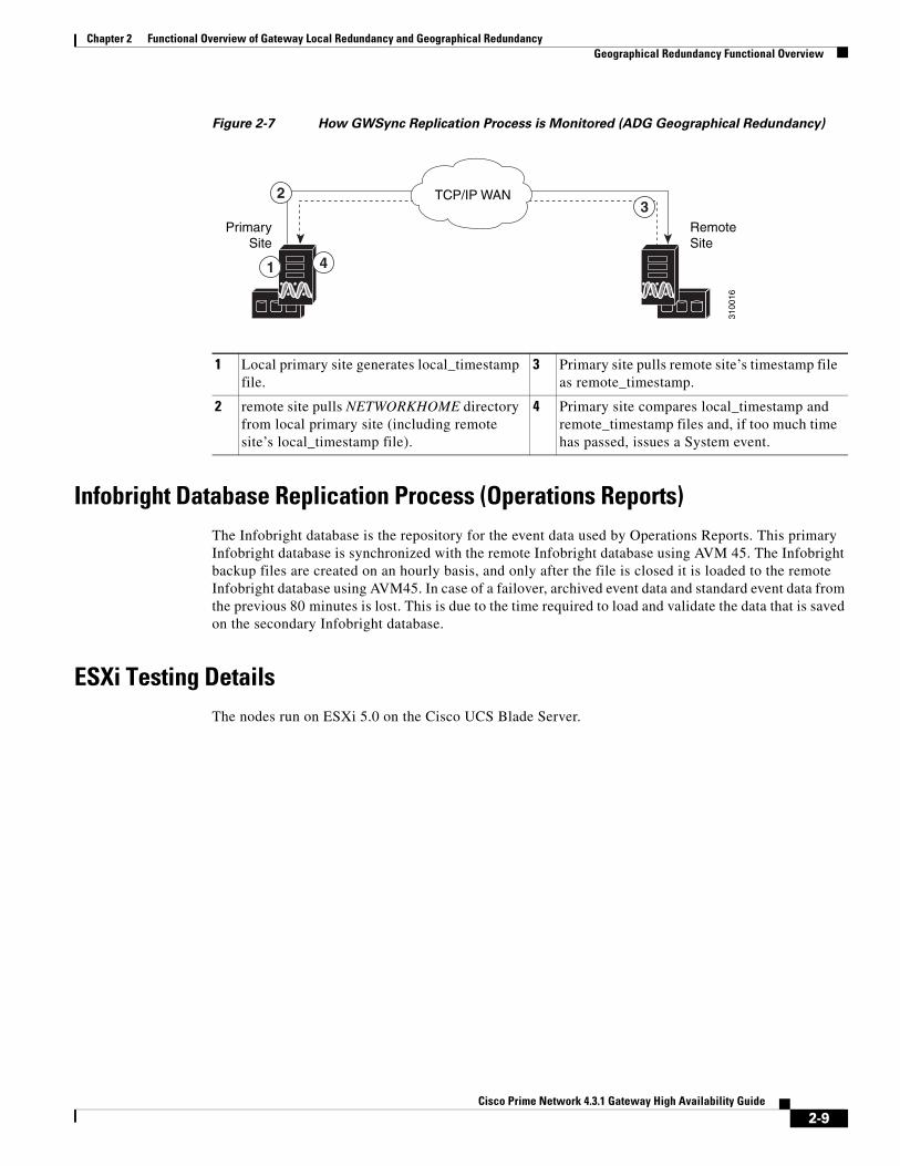
Figure 2-7 How GWSync Replication Process is Monitored (ADG Geographical Redundancy)
Infobright Database Replication Process (Operations Reports)The Infobright database is the repository for the event data used by Operations Reports. This primary Infobright database is synchronized with the remote Infobright database using AVM 45. The Infobright backup files are created on an hourly basis, and only after the file is closed it is loaded to the remote Infobright database using AVM45. In case of a failover, archived event data and standard event data from the previous 80 minutes is lost. This is due to the time required to load and validate the data that is saved on the secondary Infobright database.
ESXi Testing DetailsThe nodes run on ESXi 5.0 on the Cisco UCS Blade Server.
1 Local primary site generates local_timestamp file.
3 Primary site pulls remote site’s timestamp file as remote_timestamp.
2 remote site pulls NETWORKHOME directory from local primary site (including remote site’s local_timestamp file).
4 Primary site compares local_timestamp and remote_timestamp files and, if too much time has passed, issues a System event.
TCP/IP WAN
RemoteSite
PrimarySite
3100
16
1
2
4
3
2-9Cisco Prime Network 4.3.1 Gateway High Availability Guide

Chapter 2 Functional Overview of Gateway Local Redundancy and Geographical Redundancy Geographical Redundancy Functional Overview
2-10Cisco Prime Network 4.3.1 Gateway High Availability Guide
Cisco Pr
C H A P T E R 3
Installing and Maintaining Gateway Local RedundancyThe following topics provide procedures for setting up, installing, and maintaining the gateway local redundancy solution. Local redundancy is configured and monitored using the Red Hat Cluster Server (RHCS) for local redundancy. This chapter also explains how to install Prime Network Operations Reports and the Prime Network Integration Layer (PN-IL) with gateway local redundancy.
Note Gateway high availability is supported only when the gateway software, Oracle database, and Infobright database (applicable for Operations Reports) are installed on the same server.
• Steps for Installing the Gateway Local Redundancy Solution, page 3-1
• Installation Requirements for Local Redundancy, page 3-4
• Preparing to Install the Local Redundancy Solution, page 3-7
• Installing the Prime Network Gateway Local Redundancy Software, page 3-14
• Verifying the Local Redundancy Setup, page 3-20
• Post-Installation Tasks for Local Redundancy, page 3-22
• Maintaining Local Redundancy, page 3-24
• Uninstalling Local Redundancy, page 3-28
• Installing and Configuring PN-IL with Local Redundancy, page 3-29
Before proceeding with this chapter, make sure you have read Local Redundancy Functional Overview, page 2-1.
Steps for Installing the Gateway Local Redundancy SolutionTable 3-1 lists the steps you must follow to prepare for an installation, perform an installation, and verify an installation of the Prime Network gateway local redundancy solution. The table includes steps for working in a deployment that also has local redundancy. For local redundancy, the steps assume the primary database is on cluster node P1. An x means you must perform the step on that server.
Note If you also have local redundancy installed, this procedure assumes the primary database is on the primary cluster server (P1).
3-1ime Network 4.3.1 Gateway High Availability Guide
Chapter 3 Installing and Maintaining Gateway Local Redundancy Steps for Installing the Gateway Local Redundancy Solution
Table 3-1 Steps for Setting Up and Installing Local Redundancy
Task Topic/Action RequiredPrimary
Node P11Standby Node P2
Step 1 Collect server details, so that you have all information handy prior to installation.
• Prime Network Virtual IP address
• Oracle Virtual IP address
• Node 1, Node 2 Hostname and IP addresses
x x
Step 2 Verify that the Prime Network servers meets the prerequisites.
Installation Requirements for Local Redundancy, page 3-4
x x
Step 3 Configure the dual-node cluster server hardware including configuring the external storage.
Configuring Hardware and External Storage for Red Hat Cluster Site, page 3-7
x x
Step 4 Install RHEL and all recommended patches on both servers in the cluster.
Installing RHEL and Verifying the Version, page 3-8
x x
Step 5 Install the RPMs required for Red Hat and Oracle.
If you are installing Operations Reports, be sure to check this section.
Installing RPMs Required on Red Hat for Prime Network, page 3-8
x x
Step 6 Configure disk groups, volumes, and partitions.
If you are installing Operations Reports, be sure to check the required volume sizes.
Configuring Disk Group and Volumes, page 3-11
x x
Step 7 Verify that all nodes are ready for installation by checking disk access, Linux versions, and NTP synchronization.
Verify That All Servers Are Ready for Installation, page 3-12
x x
Step 8 Mount the external shared storage, Oracle and Prime Network mount points on the relevant directories.
Creating the Mount Points for Installation, page 3-12
x x
3-2Cisco Prime Network 4.3.1 Gateway High Availability Guide
Chapter 3 Installing and Maintaining Gateway Local Redundancy Steps for Installing the Gateway Local Redundancy Solution
Step 9 Make sure the format of the /etc/hosts file is correct.
Make sure the /etc/hosts file lists the hostname before the fully qualified domain name (FQDN).
Bad /etc/hosts file:
127.0.0.1 localhost.localdomain localhost::1 localhost6.localdomain6 localhost610.128.14.247 spin
172.16.17.127 cvldprimegate1.cscdev.com cvldprimegate1
Good /etc/hosts file:
127.0.0.1 localhost.localdomain localhost::1 localhost6.localdomain6 localhost610.128.14.247 spin
172.16.17.127 cvldprimegate1 cvldprimegate1.cscdev.com
Also make sure the hostname is not mapped to the loopback address (localhost / 127.0.0.1).
x x
Step10 Back up the /etc/host and root cron jobs files (the installation software will modify them).
— x x
Step11 For cluster node makes sure the specified services are configured to start automatically each time the machine is rebooted.
Configure the Services for Automatic Start After Reboot, page 3-13
x x
Step12 Stop the RHCS services in the order specified in Stopping the RHCS Services, page 3-14.
Stopping the RHCS Services, page 3-14 x x
Step13 Install the gateway and Oracle database using install_prime_HA.pl.
Installing the Prime Network Gateway Local Redundancy Software, page 3-14
x —
Step14 Configure the embedded database (using the add_emdb_storage.pl -ha script).
Step15 If desired, install any new device packages so that you have the latest device support.
Cisco Prime Network 4.3.1 Administrator Guide
x x
Step16 Verify the installation of the gateway and database.
Verifying the Local Redundancy Setup, page 3-20
x x
Step17 (Only for NAT) Update the database host. Updating the Database Host in the Registry (Only for NAT), page 3-22
x —
Step18 (Optional) Install Operations Reports. Installing Prime Network Operations Report with Gateway High Availability
x —
Table 3-1 Steps for Setting Up and Installing Local Redundancy (continued)
Task Topic/Action RequiredPrimary
Node P11Standby Node P2
3-3Cisco Prime Network 4.3.1 Gateway High Availability Guide
Chapter 3 Installing and Maintaining Gateway Local Redundancy Installation Requirements for Local Redundancy
Installation Requirements for Local RedundancyThese topics list the prerequisites for installing gateway geographical redundancy:
• Hardware and Software Requirements for Local Redundancy, page 3-4
• Port Usage for Local Redundancy, page 3-6
Hardware and Software Requirements for Local RedundancyTable 3-2 shows the core system requirements for local redundancy. Local redundancy requires a Prime Network embedded database and does not support IPv6 gateways or databases. If your high availability deployment differs from these requirements, please contact your Cisco account representative for assistance with the planning and installation of high availability.
.
Step19 (Optional) Install PN-IL. Installing and Configuring PN-IL with Local Redundancy, page 3-29
x —
Step20 (Optional) Setup RHCS Web GUI if it is not configured during installation.
Configuring the RHCS Web Interface (Optional), page 3-23
x —
1. P1 is the primary cluster node and has the primary database.
Table 3-1 Steps for Setting Up and Installing Local Redundancy (continued)
Task Topic/Action RequiredPrimary
Node P11Standby Node P2
Table 3-2 Prerequisites for Local Redundancy 1
Area Requirements
Operating System
Red Hat 5.8, Red Hat 6.5 64-bit Server Edition (English language). Red Hat can run in a virtual environment and supports VMware ESXi version 5.5,and 6.0, and also on the Openstack kernel-based virtual machine (KVM) hypervisor version 2.6.
Note Both nodes in the cluster must have identical RHCS versions and packages.
Required Red Hat services and components:
• /usr/bin/expect—Tool to automate interactive applications
• /usr/bin/ksh—Korn shell
• /usr/bin/scp—Secure copy tool
• /usr/sbin/sshd—SSH daemon
• /usr/bin/ssh—SSH
• /usr/bin/ssh-keygen—Tool to generate, manage, and convert authentication keys.
For more information on installing operating system and RPMs required on Red Hat, see Installing RHEL and Verifying the Version, page 3-8 and Installing RPMs Required on Red Hat for Prime Network, page 3-8.
Oracle 12c.
Note Oracle 12c is included in the Prime Network embedded database installation.
3-4Cisco Prime Network 4.3.1 Gateway High Availability Guide
Chapter 3 Installing and Maintaining Gateway Local Redundancy Installation Requirements for Local Redundancy
Hardware RHEL 5.8 and RHEL 6.5 certified platform with fencing capabilities.
Note RHEL supports the fence_vmware_soap fencing method on RHEL 5.7 or higher (with the High Availability and Resilient Storage Add Ons). For more information, see the Red Hat site. It is recommended for virtual machines, the RHCS must run with fence_vmware_soap fencing method.
Note Hardware installation with no single point of failure is recommended. See Configuring Hardware and External Storage for Red Hat Cluster Site, page 3-7.
While using fencing, ensure the following:
– Each node in the cluster uses a fencing method.
– If you choose manual fencing option during the local redundancy installation to add a different Red Hat-supported fencing device, provision the device after installation using the RHCS GUI. When you add it, be sure to add it as the main fencing method, and move the manual fencing agent to the backup method.
– To prevent fencing loops, the cluster interconnect and power fencing (for example, HP-iLO) should use the same network, such as bond0.
– If the main fencing device is a remote power switch, define all ports that supply power to the node simultaneously.
Fencing options are listed in Fencing Options, page 2-3. For the recommended hardware for small, medium, and large networks, see the Cisco Prime Network 4.3.1 Installation Guide.
Network • Virtual IP Address
– Reserve two floating IP addresses for ana and oracle_db services. These IP addresses are entered while executing the installation scripts.
– Ensure that the IP addresses are on the same subnet and are not attached to any server. RHCS will manage them, that is, add and remove them from the server running the service.
• Multicast Addresses
– Cluster nodes must be able to communicate with each other using multicast.
– Each network switch and associated networking equipment in a Red Hat cluster must be configured to enable multicast addresses and support IGMP. Without multicast and IGMP, not all nodes can participate in a cluster, causing the cluster to fail.
– Refer to the appropriate vendor documentation or other information about configuring network switches, and associated networking equipment, to enable multicast addresses and IGMP
– Multicast address should meet RHCS requirements and should not blocked by a firewall. If there is a firewall, disable it; see the Red Hat site for more information.
– If you are using SELinux, it must be disabled (or in permissive mode). See the Red Hat site.
• Network Timing Protocol (NTP) must be configured. For more details on procedures, see the Cisco Prime Network 4.3.1 Installation Guide.
Table 3-2 Prerequisites for Local Redundancy (continued)1
Area Requirements
3-5Cisco Prime Network 4.3.1 Gateway High Availability Guide
Chapter 3 Installing and Maintaining Gateway Local Redundancy Installation Requirements for Local Redundancy
Port Usage for Local RedundancyIn addition to the ports listed in the Cisco Prime Network 4.3.1 Installation Guide, the following ports must be free.
You can check the status of the listed ports by executing the following command:
# netstat -tulnap | grep port-number
To free any ports, contact your system administrator.
Storage RHCS requires a shared storage accessible from all cluster nodes. When using external storage, ensure the following:
– All of the shared storage should have an ext3 file system installed.
– Shared storage must be accessible and mountable from both nodes. The number of HDD, HDD types, HDD capacity, and RAID level, should be based on recommendations provided by the Prime Network Capacity Planning Guide.
– Shared storage can be configured in several ways, it depends on your hardware. If there is only one link for the storage to the node, LABEL must be configured on each disk device. If the node is connected to the storage with more than 1 connection (recommended) multipath should be configured.
– Each cluster service should use one partition. If the partitions are on the same disk, use a single partition for each service. If partitions are spread across disks, use a single disk for each service. Each disk must be labeled.
Note Labels used by any cluster service to name a distinct block device on any node in the cluster must be unique across all block devices. Also, a label used in a cluster service may not be reused by any block device with a different UUID, which is listed by command 'blkid', run the command on all nodes of the cluster, and cross check across all results, before configuring local HA cluster.
If you are using Operations Reports, 1-4 additional partitions should be created for the Infobright database data, cache, backup, and DLP storage.
File system ext3
Disk space 5 GB under /tmp is required for installation
1. Virtual machine and bare metal requirements for hard disk, memory, and processor are same. Refer to the Cisco Prime Network 4.3.1 Installation Guide for memory and processor requirements.
Table 3-2 Prerequisites for Local Redundancy (continued)1
Area Requirements
Table 3-3 Additional Ports Required for Local Redundancy
Port No. Used for:
9096 Operations Reports
3-6Cisco Prime Network 4.3.1 Gateway High Availability Guide
Chapter 3 Installing and Maintaining Gateway Local Redundancy Preparing to Install the Local Redundancy Solution
Preparing to Install the Local Redundancy SolutionThese topics describe the setup tasks you may need to perform before installing the local redundancy software:
• Configuring Hardware and External Storage for Red Hat Cluster Site, page 3-7
• Installing RHEL and Verifying the Version, page 3-8
• Installing RPMs Required on Red Hat for Prime Network, page 3-8
• Configuring Disk Group and Volumes, page 3-11
• Verify That All Servers Are Ready for Installation, page 3-12
• Creating the Mount Points for Installation, page 3-12
• Stopping the RHCS Services, page 3-14
• Updating the Database Host in the Registry (Only for NAT), page 3-22
• Configuring the RHCS Web Interface (Optional), page 3-23
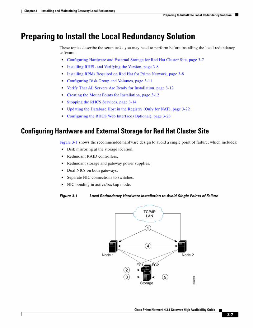
Configuring Hardware and External Storage for Red Hat Cluster SiteFigure 3-1 shows the recommended hardware design to avoid a single point of failure, which includes:
• Disk mirroring at the storage location.
• Redundant RAID controllers.
• Redundant storage and gateway power supplies.
• Dual NICs on both gateways.
• Separate NIC connections to switches.
• NIC bonding in active/backup mode.
Figure 3-1 Local Redundancy Hardware Installation to Avoid Single Points of Failure
1
3
2
5
2465
99
TCP/IPLAN
FC1 FC2
Node 1 Node 2
Storage
4
3-7Cisco Prime Network 4.3.1 Gateway High Availability Guide
Chapter 3 Installing and Maintaining Gateway Local Redundancy Preparing to Install the Local Redundancy Solution
Configure the external storage so all disks and logical unit numbers (LUNs) are accessible from both servers in the cluster. The disk and LUN configuration depends on the storage type:
• If you are using JBOD disks, provide enough physical disks to create the volumes shown in Table 3-4 to satisfy the Oracle performance requirements.
• If you are using storage that supports hardware RAID, divide the physical disks into LUNs so that the volumes listed in Table 3-4 can be created and configured to satisfy the Oracle performance requirements and protected with RAID5, RAID1, or RAID10. The Oracle volumes can be created on a single LUN.
• The number of HDD, HDD types, HDD capacity, and RAID level, should be based on recommendations provided by the Prime Network Capacity Planning Guide. Obtain the Capacity Planning Guide from your Cisco account representative.
Installing RHEL and Verifying the VersionInstall the RHEL with the Red Hat Cluster Suite using the procedures in the Red Hat user documentation.
To verify that you have the required Linux version, use the following command:
cat /etc/redhat-release
RHEL installation version should be identical on all the servers.
Note RHCS is included in the Red Hat Advanced Platform option. If Red Hat Clustering Service was not installed as part of RHEL, install the Red Hat Clustering Service using the procedures in the Red Hat user documentation.
Installing RPMs Required on Red Hat for Prime Network These sections list the additional RPMs required for Red Hat and Oracle:
• Required RPMs for Red Hat 5.8, page 3-8
• Required RPMs for Red Hat 6.5, page 3-9
• Required RPMs for Oracle Database 12c, page 3-10
Required RPMs for Red Hat 5.8
If you plan to run Prime Network on gateways or units running Red Hat 5.8, you must download and install several RPM files from the Red Hat website. For more information, see the Red Hat openssh bug fix and enhancement update, Advisory RHRA-2011:0018-1 at:
https://rhn.redhat.com/errata/RHBA-2011-0018.html
To download and install the Red Hat RPMs:
1 Dual NICs on both gateways 4 Redundant gateway power supplies
2 Disk mirroring 5 Redundant storage power supplies
3 Redundant RAID controllers
3-8Cisco Prime Network 4.3.1 Gateway High Availability Guide
Chapter 3 Installing and Maintaining Gateway Local Redundancy Preparing to Install the Local Redundancy Solution
Step 1 Download the following Red Hat openssh bug fix and enhancement update RPM files from the Red Hat website to the gateway or unit installation directory:
• openssh-4.3.1p2-72.el5.x86_64.rpm
• openssh-clients-4.3.1p2-72.el5.x86_64.rpm
• openssh-server-4.3.1p2-72.el5.x86_64.rpm
• compat-libstdc++-33.x86_64
• dos2unix-3.1-37.el6.x86_64
Step 2 As the root user, enter the following commands:
rpm -Uhv openssh-4.3.1p2-72.el5.x86_64.rpmrpm -Uhv openssh-clients-4.3.1p2-72.el5.x86_64.rpmrpm -Uhv openssh-server-4.3.1p2-72.el5.x86_64.rpm/etc/init/sshd stop/etc/init/sshd start
Step 3 Repeat these steps for each gateway and unit running Red Hat 5.8.
Required RPMs for Red Hat 6.5
The following RPMs must be downloaded from the Red Hat website and installed on the gateway and unit servers.
Required 32-bit packages
• compat-libstdc++-33-3.2.3-69.el6.i686
• glibc-2.12-1.132.el6.i686
• libgcc-4.4.7-4.el6.i686
• libstdc++-devel-4.4.7-4.el6.i686
• libaio-devel-0.3.107-10.el6.i686
• libXtst-1.2.1-2.el6.i686(Required for GUI installation)
• libgcj-4.4.7-4.1.el6_5.i686(Required for GUI installation)
• libXext.i686
Minimum Required 64-bit packages
• binutils-2.20.51.0.2-5.36.el6.x86_64
• libXtst-1.2.1-2.el6.x86_64 (Required for GUI installation)
• libgcj-4.4.7-4.1.el6_5.x86_64(Required for GUI installation)
• compat-libcap1-1.10-1.x86_64
• compat-libstdc++-33-3.2.3-69.el6.x86_64
• openssl098e-0.9.8e-17.el6_2.2.x86_64 (Required for installing Operations Reports)
• gcc-c++-4.4.7-4.el6.x86_64
• glibc-devel-2.12-1.132.el6_5.4.x86_64
• numactl-2.0.7-8.el6.x86_64
• ksh-20120801-10.el6.x86_64
• libgcc-4.4.7-4.el6.x86_64
3-9Cisco Prime Network 4.3.1 Gateway High Availability Guide

Chapter 3 Installing and Maintaining Gateway Local Redundancy Preparing to Install the Local Redundancy Solution
• libstdc++-devel-4.4.7-4.el6.x86_64
• libaio-devel-0.3.107-10.el6.x86_64
• make-3.81-20.el6.x86_64
• sysstat-9.0.4-22.el6.x86_64
• expect-5.44.1.15-5.el6_4.x86_64
• openssh-server-5.3p1-94.el6.x86_64
• openssh-5.3p1-94.el6.x86_64
• telnet-0.17-47.el6_3.1.x86_64
• dos2unix-3.1-37.el6.x86_64
Required RPMs for Oracle Database 12c
The following packages, or later versions of them, are required for the Oracle 12c database on Red Hat.
• binutils-2.20.51.0.2-5.11.el6 (x86_64)
• glibc-2.12-1.7.el6 (x86_64)
• libgcc-4.4.4-13.el6 (x86_64)
• libstdc++-4.4.4-13.el6 (x86_64)
• libaio-0.3.107-10.el6 (x86_64)
• libXext-1.1 (x86_64)
• libXtst-1.0.99.2 (x86_64)
• libX11-1.3 (x86_64)
• libXau-1.0.5 (x86_64)
• libxcb-1.5 (x86_64)
• libXi-1.3 (x86_64)
• make-3.81-19.el6
• sysstat-9.0.4-11.el6 (x86_64)
• compat-libcap1-1.10-1 (x86_64)
• compat-libstdc++-33-3.2.3-69.el6 (x86_64)
• gcc-4.4.4-13.el6 (x86_64)
• gcc-c++-4.4.4-13.el6 (x86_64)
• glibc-devel-2.12-1.7.el6 (x86_64)
• ksh (any version of ksh)
• libstdc++-devel-4.4.4-13.el6 (x86_64)
• libaio-devel-0.3.107-10.el6 (x86_64)
Note If any of the preceding packages are missing, the installation fails.
To verify all required RPMs are installed, execute the following command as root:
3-10Cisco Prime Network 4.3.1 Gateway High Availability Guide

Chapter 3 Installing and Maintaining Gateway Local Redundancy Preparing to Install the Local Redundancy Solution
• rpm -q binutils compat-libcap compat-libstdc++ expect gcc gcc-c++ glibc glibc-devel ksh
libgcc libstdc++ libstdc++-devel libaio libaio-devel make numactl numactl-devel sysstat
--qf'%{name}.%{arch}\n'|sort
Configuring Disk Group and VolumesTable 3-4 and Table 3-5 show the disk partitions required for the dual-node cluster at the primary site.
When you set up the RHCS disk groups and volumes, keep the following in mind:
• All of the shared storage should have an ext3 file system installed.
• Shared storage must be accessible from all cluster nodes. For recommendations on the number of HDD, HDD types, HDD capacity, and RAID level contact your Cisco representative.
• Placing the individual directories in separate partitions is recommended, though not required.
Table 3-4 Prime Network Local Redundancy Cluster Volume Sizes
Volume Minimum Size (GB) Comments
Prime Network 50 —
Oracle application + data files 10 —
Oracle redo logs 12.8 —
Oracle archives 20 See the Prime Network Capacity Planning Guide. Contact your Cisco account representative for information.
Oracle additional data files (if used)
— Based on Prime Network alarm history needs. See the Prime Network Capacity Planning Guide.
Oracle backup 50 See the Prime Network Capacity Planning Guide.
If Operations Reports is installed:
• Infobright data directory
• Infobright cache directory
• Infobright backup directory
• Infobright DLP directory
— See the Prime Network Capacity Planning Guide and Memory Assessment Tool.
Table 3-5 Disk Groups
Partition Space (in MB)
swap Twice the size of the physical memory, up to 96 GB.
For example, if your server has 16 GB RAM, the recommended swap space is 32 GB.
If your server has 64 GB RAM, the recommended swap space is 96 GB.
/tmp Standard amount of space + 5120
/ Standard amount of space + 6144
3-11Cisco Prime Network 4.3.1 Gateway High Availability Guide
Chapter 3 Installing and Maintaining Gateway Local Redundancy Preparing to Install the Local Redundancy Solution
Note Prime Network installation normally requires 1024 MB additional free space on the root partition. For HA, a temporary copy of Prime Network is installed under the root partition. Therefore, an additional 5120 MB free space is required, for a total of 6144 MB required free space. The HA files are installed under /usr/local/bin, /var, /etc., which requires a minimum of 1224 MB. You can add this amount to the root partition instead of creating a separate partition for each.
Verify That All Servers Are Ready for InstallationVerify the following on all servers: disk access, Linux versions, and NTP sync on all servers:
• Access to all external disks is available.
• The same version of Linux is deployed on all servers. To check the version:
cat /etc/redhat-release
• Verify that the time is synchronized on both servers using NTP. For information on configuring NTP, see the Cisco Prime Network 4.3.1 Installation Guide.
Creating the Mount Points for InstallationUse this procedure to create mount points before setting up high availability.
Note All servers in the local redundancy setup should have same mount points.
Step 1 Log in as root user, and create the following directories:
• Prime Network home directory and Oracle directories.
mkdir -p /pn41mkdir -p /opt/oramkdir -p /redomkdir -p /data
• Operations Reports directories (applicable for Operations Reports).
mkdir -p /Idatamkdir -p /Icachemkdir -p /Ibackupmkdir -p /Idlp
Step 2 Mount the external shared storage on the relevant directories of the node from where you will run the installation. Mount it manually and do not add it to the fstab file. Comment out any corresponding entry to the shared storage in /etc/fstab for both cluster nodes.
/var Standard amount of space + 1024 for HA utilities
/usr/local/bin Standard amount of space + 200 for cluster utilities
/etc Standard amount of space + 200 for cluster conf
Table 3-5 Disk Groups (continued)
Partition Space (in MB)
3-12Cisco Prime Network 4.3.1 Gateway High Availability Guide
Chapter 3 Installing and Maintaining Gateway Local Redundancy Preparing to Install the Local Redundancy Solution
Step 3 If the embedded database mount points contained in networkdata/archive logs and control files are set outside the local disks, for example, on a SAN, make corresponding entries in /etc/fstab so the mount points are available during a reboot.
Step 4 Mount all of the Oracle, Prime Network, Operations Reports mount points on the server where you will run the installation.
In this example, PRIMENETWORK and ORACLE are the sample label names:
mount -L PRIMENETWORK/pn41mount -L ORACLE/opt/ora mount -L PRIMENETWORK/redomount -L PRIMENETWORK/data
mount /dev/sda1 /Idatamount /dev/sda2 /Icachemount /dev/sda3 /Ibackupmount /dev/sda4 /Idlp
Configure the Services for Automatic Start After RebootFor every cluster node, make sure the following services are configured to start automatically each time the server is rebooted.
• modclusterd
• ricci
• rgmanager
• cman
For automatically starting these services, run the following command:
chkconfig modclusterd on chkconfig ricci on chkconfig rgmanager on chkconfig cman on
Check that status of these services using the following command:
chkconfig --list ricciricci 0:off 1:off 2:off 3:off 4:off 5:off 6:off
The above output indicate the ricci service is disabled
chkconfig --list riccisshd 0:off 1:off 2:on 3:on 4:on 5:on 6:off
The above output indicate the ricci service is enabled
3-13Cisco Prime Network 4.3.1 Gateway High Availability Guide
Chapter 3 Installing and Maintaining Gateway Local Redundancy Installing the Prime Network Gateway Local Redundancy Software
Stopping the RHCS ServicesMake sure that the Red Hat Cluster Suite rgmanager and cman services are turned off before installing Prime Network high availability on the gateway.
To turn off the RHCS services:
Step 1 On P1, stop the rgmanager service using the following command:
service rgmanager stop
Step 2 On P2, stop the rgmanager service using the following command:
service rgmanager stop
Step 3 On P1, stop the cman service using the following command:
service cman stop
Step 4 On P2, stop the cman service using the following command:
service cman stop
Step 5 Enter the following command on all cluster nodes to verify the service status:
service rgmanager status service cman status
Step 6 The services are stopped.
For rgmanager stopped services the output is displayed as clurgmgrd is stopped and for cman as ccsd is stopped.
Installing the Prime Network Gateway Local Redundancy Software
The local redundancy solution for dual-node cluster is installed using install_prime_HA.pl script that is available in RH_ha.zip file in the installation DVD as described in Installation DVDs, page 1-1.
You can run the installation in interactive or in non-interactive mode. Interactive mode installation prompts you to enter the gateway HA data values one at a time. The Prime Network installer then updates the auto_install_RH.ini file template, which populates the install_Prime_HA.pl script.
Alternatively, you can enter all the installation values in the auto_install_RH.ini template, located in the RH_ha directory, then run the installation in non-interactive mode. The installation mode is determined by the presence or absence of the -autoconf flag.
Note It is recommended you run the installation in interactive mode first to populate the auto_install_RH.ini template with the user input. This gives you the ability to verify the input and run the installation again in non-interactive mode, if needed.
3-14Cisco Prime Network 4.3.1 Gateway High Availability Guide

Chapter 3 Installing and Maintaining Gateway Local Redundancy Installing the Prime Network Gateway Local Redundancy Software
This procedure installs gateway high availability for local redundancy.
Step 1 Change to the root user, then unzip the RH_ha.zip located on the installation DVD. Unzipping RH_ha.zip creates the /tmp/RH_ha directory.
Note If you are running the Korn shell (/bin/ksh) and the prompt is the hash tag (#), the installation will fail. Run the installation script using bash.
Step 2 From the /tmp/RH_ha directory run the install_Prime_HA.pl in interactive or non-interactive mode. For information on the install_Prime_HA.pl script, see Installation DVDs, page 1-1.
Step 3 For local redundancy alone, enter local HA= yes, DR= no, when prompted. See Table 3-6 for the prompts that appears while installing local redundancy configuration.
Step 4 Execute the install_Prime_HA.pl script in interactive or non-interactive method.
• Interactive Installation:
For interactive installation, execute the following commands:
cd /tmp/RH_haperl install_Prime_HA.pl
See Table 3-6 for descriptions of other parameters you will be asked to enter at various stages of the interactive installation.
• Non-Interactive Installation (Automatic):
a. Edit the auto_install_RH.ini file template found under the RH_ha directory with all of the installation details.
b. Run the following command:
cd /tmp/RH_ha perl install_Prime_HA.pl -autoconf <full-path-of-auto_install_RH.ini-file>
Note To prevent any security violation, it is highly recommended to remove the password in auto_install_RH.ini file after the successful installation.
After the install_Prime_HA.pl script is completed:
• Prime Network and embedded database will be installed on the setup node. The cluster standby node will have only the users and home directory.
• RHCS will be up and running the Prime Network (ana) and Oracle (oracle_db) services.
Table 3-6 describes the prompts that you need to enter during the local redundancy installation.
Note If you experience problems, see Troubleshooting the Local Redundancy Installation, page 3-19.
3-15Cisco Prime Network 4.3.1 Gateway High Availability Guide

Chapter 3 Installing and Maintaining Gateway Local Redundancy Installing the Prime Network Gateway Local Redundancy Software
Table 3-6 Installation Prompts for Local Redundancy Alone
Prompt for Enter... Notes
Configure local HA? yes —
Configure DR? no Enter no; this procedure is for local redundancy alone.
To install local + geographical redundancy, see Installing the Prime Network Gateway Geographical Redundancy Software, page 4-6.
Configure NTP on 2 gateways?
yes yes or no depending on whether NTP should be configured on two gateways. If not configured, first configure NTP and then continue with the installation. For more details on procedures, see configuring NTP in the Cisco Prime Network 4.3.1 Installation Guide.
OS user of the database oracledb Oracle installation owner (default is oracle).
Prime Network OS user pnuser User-defined Prime Network OS user (pnuser). Username must start with a letter and contain only the following characters: [A-Z a-z 0-9].
Oracle user home directory
Home directory of user oracle Location of the mount point given for the oracle-home/oracle-user. Default is /opt/ora/oracle.
Home directory of the Prime Network user
Example: /export/home/ana/pn41
Directory should be located under Prime Network file system mount point but not the mount point itself.
Prime Network user password
password User-defined password for the pnuser.
Location of the Prime Network installation file
Example: /dvd/Server Mount point of the Prime Network installation. Should be the same for all relevant nodes. Example: For install.pl the path will be /dvd/Server.
Oracle mount point Example: /opt/ora Location of Oracle mount points, separated by ",". First is the mount point for the Oracle home directory, for example, /opt/ora,/opt/dbf.
Note For interactive installations: Installer asks you for a mount, then asks if you want to add another one. For non-interactive installations, enter all Oracle mount data in the input file.
Configure another oracle file system mount
no yes or no value indicating whether you want to use the default Oracle mount point or not
Prime Network mount point
Example: /export/home Location of Prime Network mount point.
Directory for the Oracle zip files
Example: /opt/ora/oracle_zip Directory containing embedded Oracle zip files. Can be a temporary location where the files were copied from the installation DVDs; or directly specify the location on DVD.
Node one name node 1 hostname Hostname for node running the installation. For local redundancy dual-node clusters, node must be one of the cluster nodes. This is the value returned by the system call hostname.
Node two name node 2 hostname hostname for the second cluster node for local redundancy dual-node clusters. This is the value returned by the system call hostname.
3-16Cisco Prime Network 4.3.1 Gateway High Availability Guide
Chapter 3 Installing and Maintaining Gateway Local Redundancy Installing the Prime Network Gateway Local Redundancy Software
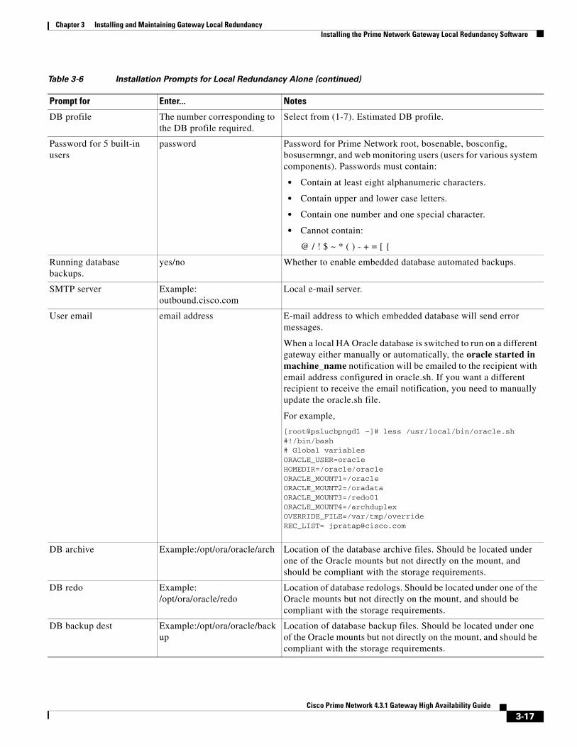
DB profile The number corresponding to the DB profile required.
Select from (1-7). Estimated DB profile.
Password for 5 built-in users
password Password for Prime Network root, bosenable, bosconfig, bosusermngr, and web monitoring users (users for various system components). Passwords must contain:
• Contain at least eight alphanumeric characters.
• Contain upper and lower case letters.
• Contain one number and one special character.
• Cannot contain:
@ / ! $ ~ * ( ) - + = [ {
Running database backups.
yes/no Whether to enable embedded database automated backups.
SMTP server Example: outbound.cisco.com
Local e-mail server.
User email email address E-mail address to which embedded database will send error messages.
When a local HA Oracle database is switched to run on a different gateway either manually or automatically, the oracle started in machine_name notification will be emailed to the recipient with email address configured in oracle.sh. If you want a different recipient to receive the email notification, you need to manually update the oracle.sh file.
For example,
[root@pslucbpngd1 ~]# less /usr/local/bin/oracle.sh#!/bin/bash# Global variablesORACLE_USER=oracleHOMEDIR=/oracle/oracleORACLE_MOUNT1=/oracleORACLE_MOUNT2=/oradataORACLE_MOUNT3=/redo01ORACLE_MOUNT4=/archduplexOVERRIDE_FILE=/var/tmp/overrideREC_LIST= [email protected]
DB archive Example:/opt/ora/oracle/arch Location of the database archive files. Should be located under one of the Oracle mounts but not directly on the mount, and should be compliant with the storage requirements.
DB redo Example: /opt/ora/oracle/redo
Location of database redologs. Should be located under one of the Oracle mounts but not directly on the mount, and should be compliant with the storage requirements.
DB backup dest Example:/opt/ora/oracle/backup
Location of database backup files. Should be located under one of the Oracle mounts but not directly on the mount, and should be compliant with the storage requirements.
Table 3-6 Installation Prompts for Local Redundancy Alone (continued)
Prompt for Enter... Notes
3-17Cisco Prime Network 4.3.1 Gateway High Availability Guide

Chapter 3 Installing and Maintaining Gateway Local Redundancy Installing the Prime Network Gateway Local Redundancy Software
Step 5 Configure the embedded database by running the add_emdb_storage.pl utility. In the following, NETWORKHOME is the Prime Network installation directory (/export/home/pnuser by default).
a. Log in as pnuser.
DB datafiles Example:/opt/ora/oracle/data Location of database data files. Should be located under one of the Oracle mounts but not directly on the mount, and should be compliant with the storage requirements.
Oracle service IP address IP address Virtual IP of local cluster Oracle service group.
Prime Network service IP address
IP address Virtual IP of local cluster Prime Network service group.
Multicast address IP address An available multicast address accessible and configured for both cluster nodes.
Prime Network cluster name
username User-defined cluster name. The cluster name cannot be more than 15 non-NUL (ASCII 0) characters. For local HA, the cluster name must be unique within the LAN.
Node one fence agent The number corresponding to the fencing agent required
Type of fencing device configured for node running the installation. (For information about supported fencing devices and information you may need to provide to the installation script, see supported fencing methods in Fencing Options, page 2-3.)
Node one fence hostname hostname Hostname of fencing device configured for the node running the installation (for some fencing devices, can be an IP address).
Node one fence login login name Login name for fencing device configured for node running the installation.
Node one fence passwd password Password for fencing device configured for node running the installation.
Node two fence agent The number corresponding to the fencing agent required
Type of fencing device configured for second cluster node. (For information about supported fencing devices and information you may need to provide to the installation script, see supported fencing methods in Fencing Options, page 2-3.)
Node two fence hostname hostname Hostname of fencing device configured for second cluster node (for some fencing devices, can be an IP address ).
Node two fence login login name Login name for fencing device configured for second cluster node.
Node two fence passwd password Password for fencing device configured for second cluster node.
Prime Network cluster web interface password
port number and password ort and the password for cluster web interface.
LUCI_PORT must be available and should not be in Prime Network debug range:
60000 <= x < 61000
or in Prime Network AVM port range:
2000 <= x < 3000 or 8000 <= x < 9000)
Password must contain at least 6 characters.
Prime Network cluster web interface port
Table 3-6 Installation Prompts for Local Redundancy Alone (continued)
Prompt for Enter... Notes
3-18Cisco Prime Network 4.3.1 Gateway High Availability Guide
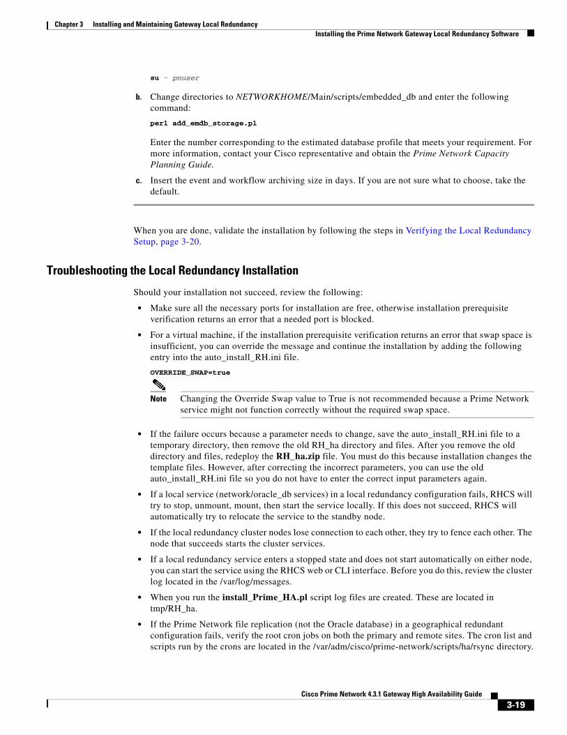
Chapter 3 Installing and Maintaining Gateway Local Redundancy Installing the Prime Network Gateway Local Redundancy Software
su - pnuser
b. Change directories to NETWORKHOME/Main/scripts/embedded_db and enter the following command:
perl add_emdb_storage.pl
Enter the number corresponding to the estimated database profile that meets your requirement. For more information, contact your Cisco representative and obtain the Prime Network Capacity Planning Guide.
c. Insert the event and workflow archiving size in days. If you are not sure what to choose, take the default.
When you are done, validate the installation by following the steps in Verifying the Local Redundancy Setup, page 3-20.
Troubleshooting the Local Redundancy Installation
Should your installation not succeed, review the following:
• Make sure all the necessary ports for installation are free, otherwise installation prerequisite verification returns an error that a needed port is blocked.
• For a virtual machine, if the installation prerequisite verification returns an error that swap space is insufficient, you can override the message and continue the installation by adding the following entry into the auto_install_RH.ini file.
OVERRIDE_SWAP=true
Note Changing the Override Swap value to True is not recommended because a Prime Network service might not function correctly without the required swap space.
• If the failure occurs because a parameter needs to change, save the auto_install_RH.ini file to a temporary directory, then remove the old RH_ha directory and files. After you remove the old directory and files, redeploy the RH_ha.zip file. You must do this because installation changes the template files. However, after correcting the incorrect parameters, you can use the old auto_install_RH.ini file so you do not have to enter the correct input parameters again.
• If a local service (network/oracle_db services) in a local redundancy configuration fails, RHCS will try to stop, unmount, mount, then start the service locally. If this does not succeed, RHCS will automatically try to relocate the service to the standby node.
• If the local redundancy cluster nodes lose connection to each other, they try to fence each other. The node that succeeds starts the cluster services.
• If a local redundancy service enters a stopped state and does not start automatically on either node, you can start the service using the RHCS web or CLI interface. Before you do this, review the cluster log located in the /var/log/messages.
• When you run the install_Prime_HA.pl script log files are created. These are located in tmp/RH_ha.
• If the Prime Network file replication (not the Oracle database) in a geographical redundant configuration fails, verify the root cron jobs on both the primary and remote sites. The cron list and scripts run by the crons are located in the /var/adm/cisco/prime-network/scripts/ha/rsync directory.
3-19Cisco Prime Network 4.3.1 Gateway High Availability Guide
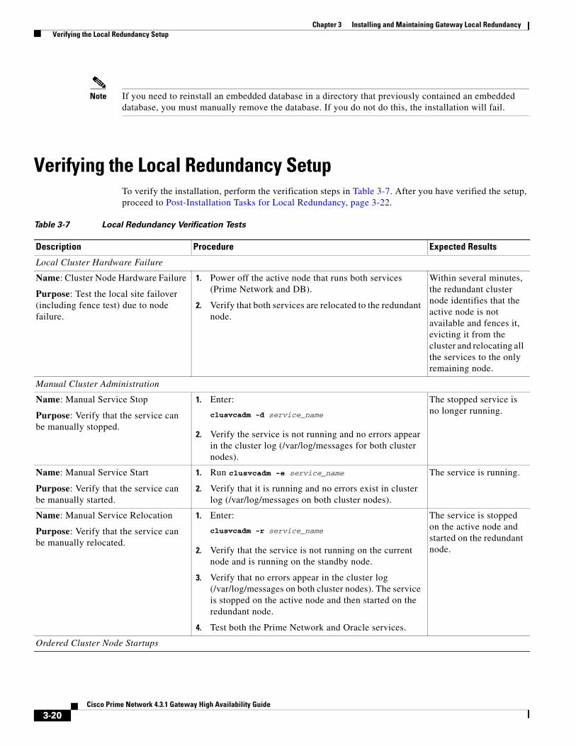
Chapter 3 Installing and Maintaining Gateway Local Redundancy Verifying the Local Redundancy Setup
Note If you need to reinstall an embedded database in a directory that previously contained an embedded database, you must manually remove the database. If you do not do this, the installation will fail.
Verifying the Local Redundancy SetupTo verify the installation, perform the verification steps in Table 3-7. After you have verified the setup, proceed to Post-Installation Tasks for Local Redundancy, page 3-22.
Table 3-7 Local Redundancy Verification Tests
Description Procedure Expected Results
Local Cluster Hardware Failure
Name: Cluster Node Hardware Failure
Purpose: Test the local site failover (including fence test) due to node failure.
1. Power off the active node that runs both services (Prime Network and DB).
2. Verify that both services are relocated to the redundant node.
Within several minutes, the redundant cluster node identifies that the active node is not available and fences it, evicting it from the cluster and relocating all the services to the only remaining node.
Manual Cluster Administration
Name: Manual Service Stop
Purpose: Verify that the service can be manually stopped.
1. Enter:
clusvcadm -d service_name
2. Verify the service is not running and no errors appear in the cluster log (/var/log/messages for both cluster nodes).
The stopped service is no longer running.
Name: Manual Service Start
Purpose: Verify that the service can be manually started.
1. Run clusvcadm -e service_name
2. Verify that it is running and no errors exist in cluster log (/var/log/messages on both cluster nodes).
The service is running.
Name: Manual Service Relocation
Purpose: Verify that the service can be manually relocated.
1. Enter:
clusvcadm -r service_name
2. Verify that the service is not running on the current node and is running on the standby node.
3. Verify that no errors appear in the cluster log (/var/log/messages on both cluster nodes). The service is stopped on the active node and then started on the redundant node.
4. Test both the Prime Network and Oracle services.
The service is stopped on the active node and started on the redundant node.
Ordered Cluster Node Startups
3-20Cisco Prime Network 4.3.1 Gateway High Availability Guide

Chapter 3 Installing and Maintaining Gateway Local Redundancy Verifying the Local Redundancy Setup
Name: Node Startup in Existing Cluster
Purpose: Verify that a cluster node starts up and rejoins a cluster after it is restarted.
1. Restart one of the cluster nodes.
2. Verify that the node joins the cluster after the reboot.
3. Relocate one of the services to the rebooted node and verify that it is running.
4. Check the log for errors.
The rebooted node joins the cluster and runs the services.
Name: Simultaneous Node Startup
Purpose: Verify that the cluster is set up correctly when both nodes start simultaneously.
1. Start both nodes from the power off state.
2. Verify that both nodes appear in the cluster after they are up with both services are running on the cluster.
3. Check the log for errors.
Both cluster nodes join the cluster; both services are running.
Name: Single Node Startup
Purpose: Test the cluster functionality when only one is node running.
1. Power down both nodes, then start one of them.
The running node will fence the other node and run the services. The fenced node joins the cluster to create the dual node cluster.
2. Check log for errors.
Both cluster nodes join the cluster; both services are running.
Local Cluster Service Failure
Name: Service Failure
Purpose: Test the service startup after a failure occurs.
1. Simulate a service failure by stopping its processes or shutting down the Oracle listener.
2. Verify that the service restarts on the same node it was running.
3. Check the log for errors.
4. Test both the Prime Network and Oracle services.
The service is restarted on the same node.
Local Cluster HW Failure
Name: Stop Node with Fencing Off
Purpose: Verify the node requires manual fencing after the other node, including its fencing agent, is removed.
1. Disconnect the fencing agent to one of the nodes, then power it off unexpectedly.
2. Observe the other node behavior.
3. Check the log for errors and the request for manual fencing.
The fence_ack_manual required notification appears in the logs. A message is printed to /var/log/messages advising you to run the fence_ack_manual command on the gateway server.
The cluster is running with one node and all services running on it.
Name: Single Node Cluster
Purpose: Checks that the cluster can function when the other node does not exist at all, or have no power at all
1. Power down both nodes,
2. Disconnect the fencing agent to one of the nodes.
3. Start the other node. It will attempt to fence the other node, but fail with the regular fencing agent. Manual fencing is required.
4. Acknowledge the manual fencing.
The cluster does not start the services (and does not show in the clustat command) before acknowledging that manual fencing is performed.
Table 3-7 Local Redundancy Verification Tests (continued)
Description Procedure Expected Results
3-21Cisco Prime Network 4.3.1 Gateway High Availability Guide
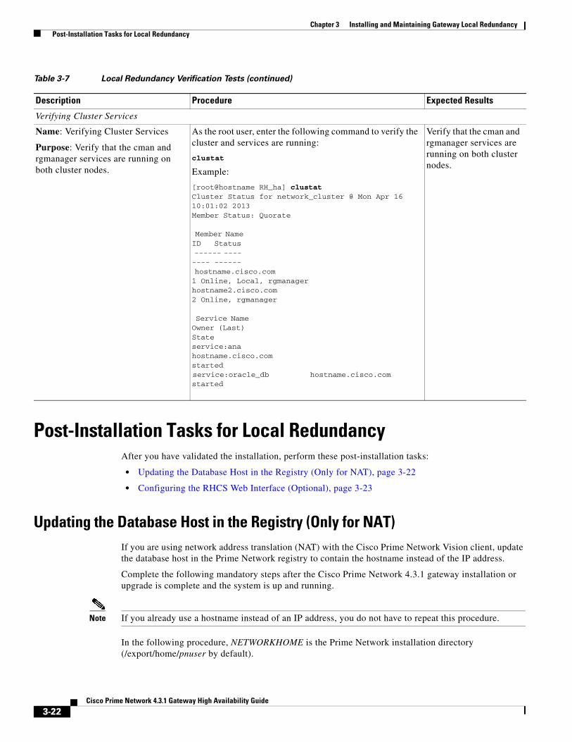
Chapter 3 Installing and Maintaining Gateway Local Redundancy Post-Installation Tasks for Local Redundancy
Post-Installation Tasks for Local RedundancyAfter you have validated the installation, perform these post-installation tasks:
• Updating the Database Host in the Registry (Only for NAT), page 3-22
• Configuring the RHCS Web Interface (Optional), page 3-23
Updating the Database Host in the Registry (Only for NAT)If you are using network address translation (NAT) with the Cisco Prime Network Vision client, update the database host in the Prime Network registry to contain the hostname instead of the IP address.
Complete the following mandatory steps after the Cisco Prime Network 4.3.1 gateway installation or upgrade is complete and the system is up and running.
Note If you already use a hostname instead of an IP address, you do not have to repeat this procedure.
In the following procedure, NETWORKHOME is the Prime Network installation directory (/export/home/pnuser by default).
Verifying Cluster Services
Name: Verifying Cluster Services
Purpose: Verify that the cman and rgmanager services are running on both cluster nodes.
As the root user, enter the following command to verify the cluster and services are running:
clustat
Example:
[root@hostname RH_ha] clustatCluster Status for network_cluster @ Mon Apr 16 10:01:02 2013Member Status: Quorate
Member Name ID Status ------ ---- ---- ------ hostname.cisco.com 1 Online, Local, rgmanagerhostname2.cisco.com 2 Online, rgmanager
Service Name Owner (Last) State service:ana hostname.cisco.com started service:oracle_db hostname.cisco.com started
Verify that the cman and rgmanager services are running on both cluster nodes.
Table 3-7 Local Redundancy Verification Tests (continued)
Description Procedure Expected Results
3-22Cisco Prime Network 4.3.1 Gateway High Availability Guide
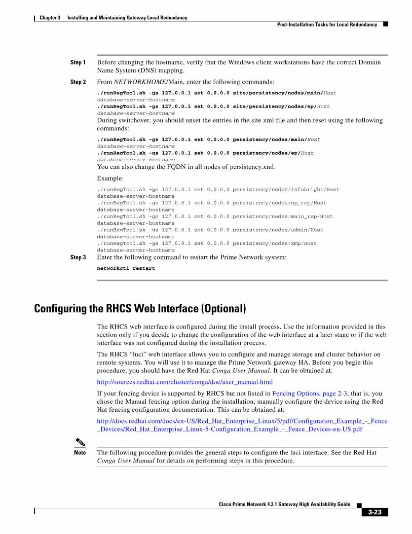
Chapter 3 Installing and Maintaining Gateway Local Redundancy Post-Installation Tasks for Local Redundancy
Step 1 Before changing the hostname, verify that the Windows client workstations have the correct Domain Name System (DNS) mapping.
Step 2 From NETWORKHOME/Main, enter the following commands:
./runRegTool.sh -gs 127.0.0.1 set 0.0.0.0 site/persistency/nodes/main/Host database-server-hostname./runRegTool.sh -gs 127.0.0.1 set 0.0.0.0 site/persistency/nodes/ep/Host database-server-hostname
During switchover, you should unset the entries in the site.xml file and then reset using the following commands:
./runRegTool.sh -gs 127.0.0.1 set 0.0.0.0 persistency/nodes/main/Host database-server-hostname./runRegTool.sh -gs 127.0.0.1 set 0.0.0.0 persistency/nodes/ep/Host database-server-hostname
You can also change the FQDN in all nodes of persistency.xml.
Example:
./runRegTool.sh -gs 127.0.0.1 set 0.0.0.0 persistency/nodes/infobright/Host database-server-hostname./runRegTool.sh -gs 127.0.0.1 set 0.0.0.0 persistency/nodes/ep_rep/Host database-server-hostname./runRegTool.sh -gs 127.0.0.1 set 0.0.0.0 persistency/nodes/main_rep/Host database-server-hostname./runRegTool.sh -gs 127.0.0.1 set 0.0.0.0 persistency/nodes/admin/Host database-server-hostname./runRegTool.sh -gs 127.0.0.1 set 0.0.0.0 persistency/nodes/xmp/Host database-server-hostname
Step 3 Enter the following command to restart the Prime Network system:
networkctl restart
Configuring the RHCS Web Interface (Optional) The RHCS web interface is configured during the install process. Use the information provided in this section only if you decide to change the configuration of the web interface at a later stage or if the web interface was not configured during the installation process.
The RHCS “luci” web interface allows you to configure and manage storage and cluster behavior on remote systems. You will use it to manage the Prime Network gateway HA. Before you begin this procedure, you should have the Red Hat Conga User Manual. It can be obtained at:
http://sources.redhat.com/cluster/conga/doc/user_manual.html
If your fencing device is supported by RHCS but not listed in Fencing Options, page 2-3, that is, you chose the Manual fencing option during the installation, manually configure the device using the Red Hat fencing configuration documentation. This can be obtained at:
http://docs.redhat.com/docs/en-US/Red_Hat_Enterprise_Linux/5/pdf/Configuration_Example_-_Fence_Devices/Red_Hat_Enterprise_Linux-5-Configuration_Example_-_Fence_Devices-en-US.pdf
Note The following procedure provides the general steps to configure the luci interface. See the Red Hat Conga User Manual for details on performing steps in this procedure.
3-23Cisco Prime Network 4.3.1 Gateway High Availability Guide
Chapter 3 Installing and Maintaining Gateway Local Redundancy Maintaining Local Redundancy
Note The RHCS web interface must be configured for both servers in the local redundant dual-node cluster.
Step 1 As root user, run the following command and enter the needed details:
luci_admin init
Step 2 Edit /etc/sysconfig/luci to change the default port to an available port. (The default 8084 port is used by Prime Network.) For example:
defaults for luci,web UI fronted for remote cluster and storage management
LUCI_HTTPS_PORT=8085
Note The ports must be available and should not be in Prime Network debug range (60000 <= X < 61000) or in Prime Network avm port range (2000 <= X < 3000 or 8000 <= X < 9000)
Step 3 As the root user, enter:
service luci restart
Step 4 Enter the web interface using the following link:
https://node host name:port
From the RHCS web interface you can stop, start, and relocate the Prime Network and oracle_db services managed by the cluster.
Step 5 In the luci web interface, add the cluster that was configured by the Prime Network installation. See the Red Hat Conga User Manual for details on performing the following:
• Add a system.
• Add an existing cluster.
• Add a user.
Step 6 If your fencing device is supported by RHCS but not listed in Fencing Options, page 2-3, use the Red Hat fencing configuration guide to configure the device.
Note If you provision a new fencing device, set it as the primary fencing method. The manual fencing agent should be kept as the backup fencing method.
Maintaining Local RedundancyAfter the local redundancy cluster is deployed, failovers are automatic. In case of a single service failure, the cluster will attempt to restart the service. If the retries fail, the service will be relocated to the second node and started on that node. This does not impact the other service in the cluster.
3-24Cisco Prime Network 4.3.1 Gateway High Availability Guide
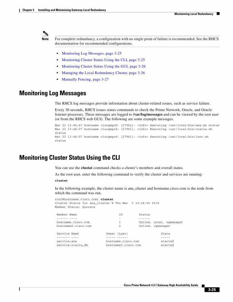
Chapter 3 Installing and Maintaining Gateway Local Redundancy Maintaining Local Redundancy
Note For complete redundancy, a configuration with no single point of failure is recommended. See the RHCS documentation for recommended configurations.
• Monitoring Log Messages, page 3-25
• Monitoring Cluster Status Using the CLI, page 3-25
• Monitoring Cluster Status Using the GUI, page 3-26
• Managing the Local Redundancy Cluster, page 3-26
• Manually Fencing, page 3-27
Monitoring Log MessagesThe RHCS log messages provide information about cluster-related issues, such as service failure.
Every 30 seconds, RHCS issues status commands to check the Prime Network, Oracle, and Oracle listener processes. These messages are logged to /var/log/messages and can be viewed by the root user (or from the RHCS web GUI). The following are some example messages.
Mar 23 13:45:47 hostname clurgmgrd: [27961]: <info> Executing /usr/local/bin/ana.sh statusMar 23 13:46:07 hostname clurgmgrd: [27961]: <info> Executing /usr/local/bin/oracle.sh statusMar 23 13:46:07 hostname clurgmgrd: [27961]: <info> Executing /usr/local/bin/lsnr.sh status
Monitoring Cluster Status Using the CLIYou can use the clustat command checks a cluster’s members and overall status.
As the root user, enter the following command to verify the cluster and services are running:
clustat
In the following example, the cluster name is ana_cluster and hostname.cisco.com is the node from which the command was run.
[email protected]] clustatCluster Status for ana_cluster @ Thu Mar 3 10:24:50 2014Member Status: Quorate
Member Name ID Status------ ---- - ------hostname.cisco.com 1 Online, Local, rgmanagerhostname2.cisco.com 2 Online, rgmanager
Service Name Owner (Last) State------- ---- ----- ------ -----service:ana hostname.cisco.com startedservice:oracle_db hostname2.cisco.com started
3-25Cisco Prime Network 4.3.1 Gateway High Availability Guide
Chapter 3 Installing and Maintaining Gateway Local Redundancy Maintaining Local Redundancy
Monitoring Cluster Status Using the GUIThe RHCS web interface is automatically configured by the Prime Network installation script. If the interface was not configured during the installation process, use the procedure in Configuring the RHCS Web Interface (Optional) section to configure RHCS Web GUI. For details on how to use the web GUI, see the appropriate RHCS documentation.
Web GUI is used to:
• Check the cluster status, including the status of each service and the node each service is running on.
• Initiate a switchover of a service to the other node (relocate the service from the Services area of the GUI).
You can connect to the RHCS web interface by entering the following in the address field of your browser: https://cluster-node-hostname:port/luci.
Managing the Local Redundancy Cluster You can use clusvcadm command to check the version of the RHCS used on the cluster, stop, restart the cluster services and so on. To manage the cluster from the CLI, enter:
[root@hostname RH_ha] clusvcadm
Table 3-8 shows the RHCS clusvcadm command options to manage the cluster.
To restart Prime Network, Oracle, or (if installed) Operations Reports application processes, use the following procedure.
Step 1 Place the Prime Network and database RHCS services in maintenance mode (also called freezing) using the following command, where service is ana, oracle_db, or ifb.
clusvcadm -Z service
Table 3-8 RHCS CLI Commands
clusvcadm + Description
-v Display version and exit
-d group Disable group
-e group Enable group
-e group -F Enable group according to failover domain rules
-e group -m member Enable group on member
-r group -m member Relocate group to member
-M group -m member Migrate group to member (e.g. for live migration of VMs)
-R group Restart a group in place
-s group Stop group
-Z Freeze group in place
-U Unfreeze/thaw group
3-26Cisco Prime Network 4.3.1 Gateway High Availability Guide

Chapter 3 Installing and Maintaining Gateway Local Redundancy Maintaining Local Redundancy
Step 2 Confirm that the services are in maintenance mode. Run clustat and verify that the output shows the service followed by a [Z], which indicates the service is in maintenance mode (frozen). When the services are frozen, the cluster does not monitor them.
[email protected]] clustatCluster Status for ana_cluster @ Thu Mar 3 12:31:55 2013Member Status: Quorate
Member Name ID Status------ ---- -- ------hostname.cisco.com 1 Online, rgmanagerhostname.cisco.com 2 Online, Local, rgmanager
Service Name Owner (Last) State------- ---- ----- ------ -----service:ana hostname.cisco.com started [Z]service:oracle_db hostname.cisco.com started [Z]
Note If you attempt to restart either the Prime Network, Oracle, or Infobright applications without freezing the RHCS process, the cluster may detect that the services are down and attempt to restart them.
Step 3 After confirming that the ana, oracle_db, and ifb cluster configured services are frozen, use the normal application commands to stop Prime Network and Oracle.
clusvcadm -s group
Step 4 After restarting the Prime Network, Oracle, and Infobright applications, move the RHCS services out of freeze mode and reinitiate the cluster’s monitoring of the ana and oracle services:
clusvcadm -U group
Manually FencingDuring the installation of the RHCS solution, you are prompted to select one of three fencing options. You can reconfigure the fencing choice at any time using the RHCS web interface or other RHCS tools. If you choose manual fencing, you must disconnect the node and storage when a problem occurs (either by disconnecting the node and storage by hand or by using another fencing agent).
Note We recommend that manual fencing only be used on a temporary basis. If you use manual fencing, it is your responsibility to make sure that when an error occurs, the node and the storage are disconnected during the cluster workflow. We recommend that manual fencing only be used on a temporary basis and as a backup for your chosen fencing agent.
If you are using manual fencing and an error occurs that requires fencing intervention, a message is printed to /var/log/messages advising you to run the fence_ack_manual command on the gateway server.
Note (Only for Red Hat 6.x)
3-27Cisco Prime Network 4.3.1 Gateway High Availability Guide
Chapter 3 Installing and Maintaining Gateway Local Redundancy Uninstalling Local Redundancy
• Before disconnecting the faulty node, remove the cman and rgmanager services from the automatic startup sequence. This is to avoid the failure when the restored node joins the cluster. You can remove these services by using the commands,
chkconfig –del cmanan chkconfig –del rgmanager
• Start these services after the servers are restored using the following command:
service cman startservice rgmanager start
Use the procedure below to disconnect the faulty node.
Step 1 Log into the gateway server as root and enter the command using the following syntax.
fence_ack_manual -n nodename
where n nodename indicates the node that has been disconnected from storage.
Note For Red Hat 6.x, use only fence_ack_manual nodename.
Step 2 Continue with the confirmation message to disconnect the faulty node from the storage.
Uninstalling Local RedundancyTo uninstall local redundancy setup, follow the procedure provided below. The procedure also removes the operations reports if installed.
Step 1 Determine the active and standby cluster nodes using the following command:
clustat
Step 2 Stop cluster services on the standby nodes using the following command:
service regmanager stop
service cman stop
Step 3 Uninstall the Prime Network on the standby nodes by choosing Yes to all the prompts. The process uninstalls the Prime Network even if the disks are not mounted on the secondary nodes.
/var/adm/cisco/prime-network/reg/current/uninstall.pl
Step 4 Verify if the configuration file (cluster.conf) located at /etc/cluster/cluster.conf is either deleted or rolled back to the state before the Prime Network is installed.
Step 5 Stop the cluster services on the active node using the following commands:
service regmanager stop
service cman stop
3-28Cisco Prime Network 4.3.1 Gateway High Availability Guide
Chapter 3 Installing and Maintaining Gateway Local Redundancy Installing and Configuring PN-IL with Local Redundancy
Note Verify if ana/oracle disks are not mounted by using the command df -h
Step 6 Manually remount the filesystems used by the cluster on the correct mounting points. This is because shutting down the cluster results in dismounting of all filesystems related to the cluster services.
Step 7 Uninstall Prime Network on the active node using the following command.
/var/adm/cisco/prime-network/reg/current/uninstall.pl
Step 8 Verify if the configuration file (cluster.conf) located at /etc/cluster/cluster.conf is either deleted or rolled back to the state before the Prime Network is installed.
Installing and Configuring PN-IL with Local RedundancyThis section explains how to install and configure the Prime Network Integration Layer (PN-IL) 1.2 with a Prime Network gateway local redundancy deployment. It also explains how to integrate the deployment with Cisco Prime Central. For information on the Prime Central releases with which you can install PN-IL 1.2, see the Cisco Prime Network 4.3.1 Release Notes.
These topics provide the information you will need to install and configure PN-IL local redundancy:
• Installation DVD, page 3-29
• Steps for Installing PN-IL with Local Redundancy, page 3-29
• Installing PN-IL on a Prime Network Server (Local Redundancy), page 3-30
• Configuring PN-IL on a Prime Network Gateway (Local Redundancy), page 3-31
• Disabling the PN-IL Health Monitor, page 3-34
If you want to migrate an existing standalone installation of PN-IL (with local redundancy) to suite mode, you can use the procedure in Configuring PN-IL with Prime Central (Suite Mode with Local Redundancy), page 3-32.
Installation DVDThe PN-IL high availability files are provided on the Prime Network installation DVD named Disk 1: New Install DVD. Disk 2 contains the tar file sil-esb-1.2.0.tar.gz, which contains the PN-IL installation files and scripts, including:
• installAndConfigureESB.sh—PN-IL installation script
• itgctl—PN-IL configuration script
• il-watch-dog.sh—PN-IL health monitor control script
• DMSwitchToSuite.sh—Script to migrate to suite
Steps for Installing PN-IL with Local RedundancyTable 3-9 provides the basic steps you must follow to set up local redundancy for PN-IL.
3-29Cisco Prime Network 4.3.1 Gateway High Availability Guide
Chapter 3 Installing and Maintaining Gateway Local Redundancy Installing and Configuring PN-IL with Local Redundancy
Note Install PN-IL only on the primary server.
If you want to migrate an existing standalone installations of PN-IL (with local redundancy) to suite mode, see the procedure in Configuring PN-IL with Prime Central (Suite Mode with Local Redundancy), page 3-32.
Installing PN-IL on a Prime Network Server (Local Redundancy)
Before You Begin:
Make sure Prime Network is installed and running on the cluster.
In the following procedure, $ANAHOME is the pnuser environment variable for the Prime Network installation directory (/export/home/pnuser by default). To install PN-IL on a server running Prime Network local redundancy software:
Step 1 On the primary cluster node (P1), log in as root and freeze the ana service.
Note The cluster server should be the active node where the ana service is running.
ssh root@active-cluster-nodeclusvcadm -Z ana
Table 3-9 Steps for Installing PN-IL Local Redundancy
Task Topic/Action Required
Server (P1) (has Primary database) Server (P2)
Step 1 Collect server details, so that you have all information handy prior to installation.
• Virtual IP address of P1
• Prime Network application root username and password for P1
• URL for authenticating Prime Network calls on P1 (normally https://localhost:6081/ana/services/userman
• (Suite mode) For the Prime Central server where Oracle is installed: Hostname, database service name, database username and password, and database port.
x —
Step 2 Verify the server meets the prerequisites.
Installation Requirements for Local Redundancy, page 3-4
x —
Step 3 Freeze RHCS and install PN-IL. Installing PN-IL on a Prime Network Server (Local Redundancy), page 3-30
x —
Step 4 Configure PN-IL (in standalone or suite mode) and unfreeze RHCS.
Configuring PN-IL on a Prime Network Gateway (Local Redundancy), page 3-31
x —
Step 5 Disable the PN-IL Health Monitor Disabling the PN-IL Health Monitor, page 3-34 x —
3-30Cisco Prime Network 4.3.1 Gateway High Availability Guide

Chapter 3 Installing and Maintaining Gateway Local Redundancy Installing and Configuring PN-IL with Local Redundancy
Step 2 As pnuser (the operating system user for the Prime Network application), log into the active node where you froze the ana service.
su - pnuser
For example:
su - pn41
Step 3 Create an installation directory for PN-IL.
mkdir -p $ANAHOME/new-pnil-dir
For example, if the Prime Network installation directory was /export/home/pn41, you would run this command to create an installation directory called pnil:
mkdir -p $ANAHOME/pnil
Step 4 Copy the installation files from the installation DVD, extract them, and start the installation script. These examples use the PN-IL installation directory named pnil.
a. Copy the PN-IL installation tar file from Disk 2 to the directory you created in Step 3.
cp /tmp/sil-esb-1.2.0.tar.gz $ANAHOME/pnil
b. Change to the directory you created in Step 3 and extract the PN-IL installation tar:
cd $ANAHOME/pniltar -zxf sil-esb-1.2.0.tar.gz
c. Change to directory where the installation tar files were extracted and run the installation script:
cd sil-esb-1.2.0/install/packages./installAndConfigureEsb.sh
Step 5 Reload the user profile using the following command:
source $ANAHOME/.cshrc
Next, perform the necessary configuration steps that are described in Configuring PN-IL on a Prime Network Gateway (Local Redundancy), page 3-31.
Configuring PN-IL on a Prime Network Gateway (Local Redundancy)If you are using Prime Network in standalone mode—that is, without Prime Central—configure PN-IL using the instructions in Configuring PN-IL with Prime Network (Standalone Mode with Local Redundancy), page 3-31.
If you are using Prime Network with Prime Central, configure PN-IL as described in Configuring PN-IL with Prime Central (Suite Mode with Local Redundancy), page 3-32.
Configuring PN-IL with Prime Network (Standalone Mode with Local Redundancy)
In standalone mode, Prime Network is not integrated with Prime Central and can independently expose MTOSI and 3GPP web services to other OSS/applications. In the following procedure, $PRIMEHOME is the pnuser environment variable for the PN-IL installation directory you created in Installing PN-IL on a Prime Network Server (Local Redundancy), page 3-30.
3-31Cisco Prime Network 4.3.1 Gateway High Availability Guide
Chapter 3 Installing and Maintaining Gateway Local Redundancy Installing and Configuring PN-IL with Local Redundancy
Step 1 As pnuser, configure PN-IL in standalone mode using the following command:
itgctl config 1 --anaPtpServer ana-cluster-ip --anaPtpUser pn-root-user --anaPtpPw pn-root-user-password --authURL network-authentication-URL
itgctl uses these arguments.
For example:
itgctl config 1 --anaPtpServer 192.0.2.22 --anaPtpUser root --anaPtpPw myrootpassword --authURL https://192.0.2.22:6081/ana/services/userman
Step 2 Start PN-IL by using the following command:
$PRIMEHOME/bin/itgctl start
Step 3 Log out as pnuser and log back in as the operating system root user.
Step 4 Unfreeze the ana service.
clusvcadm -U ana
Step 5 Enable NBI:
cd $PRIMEHOME/install/scripts ./accessconfig.sh nbi enable
Next, disable the PN-IL health monitor as described in Disabling the PN-IL Health Monitor, page 3-34.
Configuring PN-IL with Prime Central (Suite Mode with Local Redundancy)
Note Use this procedure only after installing the PN-IL as described in Installing and Configuring PN-IL with Local Redundancy, page 3-29.
When Prime Network is in suite mode, it is integrated with Prime Central. This procedure explains how to integrate PN-IL with a deployment of Prime Central that is using gateway local redundancy. You can use this procedure for:
• New installations of PN-IL with local redundancy.
Options and Arguments Description
--anaPtpServer ana-cluster-ip Specifies the IP address of the Prime Network primary cluster server
--anaPtpUser pn-root-user Specifies the name of Prime Network application root user (usually root)
--anaPtpPw pn-root-user-password Specifies the password for Prime Network application root user
--authURL network-authentication-URL Specifies the URL used to authenticate Prime Network calls (usually https://localhost:6081/ana/services/userman)
3-32Cisco Prime Network 4.3.1 Gateway High Availability Guide
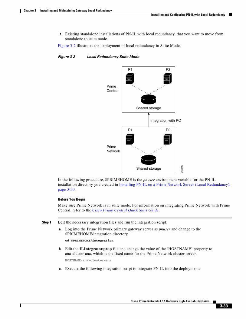
Chapter 3 Installing and Maintaining Gateway Local Redundancy Installing and Configuring PN-IL with Local Redundancy
• Existing standalone installations of PN-IL with local redundancy, that you want to move from standalone to suite mode.
Figure 3-2 illustrates the deployment of local redundancy in Suite Mode.
Figure 3-2 Local Redundancy Suite Mode
In the following procedure, $PRIMEHOME is the pnuser environment variable for the PN-IL installation directory you created in Installing PN-IL on a Prime Network Server (Local Redundancy), page 3-30.
Before You Begin
Make sure Prime Network is in suite mode. For information on integrating Prime Network with Prime Central, refer to the Cisco Prime Central Quick Start Guide.
Step 1 Edit the necessary integration files and run the integration script:
a. Log into the Prime Network primary gateway server as pnuser and change to the $PRIMEHOME/integration directory.
cd $PRIMEHOME/integration
b. Edit the ILIntegrator.prop file and change the value of the ‘HOSTNAME’ property to ana-cluster-ana, which is the fixed name for the Prime Network cluster server.
HOSTNAME=ana-cluster-ana
c. Execute the following integration script to integrate PN-IL into the deployment:
P1
Shared storage
Integration with PC
3639
89
PrimeCentral
PrimeNetwork
P2
P1
Shared storage
P2
3-33Cisco Prime Network 4.3.1 Gateway High Availability Guide

Chapter 3 Installing and Maintaining Gateway Local Redundancy Installing and Configuring PN-IL with Local Redundancy
Note When you run DMIntegrator.sh, you must exactly follow the format below or the script will fail.
./DMIntegrator.sh -a ILIntegrator.prop prime-central-db-hostname prime-central-db-service-name prime-central-db-user prime-central-db-user-password prime-central-port-number
DMIntegrators.sh uses these variables. You must enter them in this exact order.
Example:
./DMIntegrator.sh -a ILIntegrator.prop 10.10.10.10 primedb primedba mypassword 1521
Step 2 Reload the user profile:
source $PRIMEHOME/.cshrc
Step 3 Start PN-IL:
$PRIMEHOME/bin/itgctl start
Step 4 Log out as pnuser and log back in as the operating system root user.
Step 5 Unfreeze the ana service.
clusvcadm -U ana
Step 6 Enable NBI:
cd $PRIMEHOME/install/scripts ./accessconfig.sh nbi enable
Next, disable the PN-IL health monitor as described in Disabling the PN-IL Health Monitor, page 3-34.
Disabling the PN-IL Health MonitorWhen PN-IL is installed in a local redundancy deployment, the RHCS cluster service monitors PN-IL’s status. Therefore, you should disable the PN-IL health monitor.
To disable the PN-IL health monitor, log in as pnuser and execute the following command:
$PRIMEHOME/local/scripts/il-watch-dog.sh disable
DMIntegrator.sh Variable Description
prime-central-db-hostname Specifies the IP address of the Prime Central database server
prime-central-db-service-name Specifies the name of Prime Central database service
prime-central-db-user Specifies the name of Prime Central database user (usually primedba)
prime-central-db-user-password Specifies the password for Prime Central database user
prime-central-db-port Specifies the port for Prime Central database (usually 1521)
3-34Cisco Prime Network 4.3.1 Gateway High Availability Guide

Cisco Pr
C H A P T E R 4
Installing and Maintaining Gateway Geographical RedundancyThe following topics provide procedures for setting up, installing, and maintaining the gateway geographical redundancy solution. Geographical redundancy is configured and monitored using Oracle Active Data Guard (ADG) for geographical redundancy. This chapter also explains how to install Prime Network Operations Reports and the Prime Network Integration Layer (PN-IL) with gateway geographical redundancy.
Note Gateway high availability is supported only when the gateway software, Oracle database, and Infobright database (applicable for Operations Reports) are installed on the same server.
This chapter covers the following topics:
• Steps for Installing the Geographical Redundancy Solution, page 4-1
• Installation Requirements for Geographical Redundancy, page 4-4
• Preparing to Install Geographical Redundancy, page 4-6
• Installing the Prime Network Gateway Geographical Redundancy Software, page 4-6
• Verifying the Geographical Redundancy Setup, page 4-14
• Maintaining Geographical Redundancy, page 4-16
• Uninstalling the Geographical Redundancy Software, page 4-18
• Installing and Configuring PN-IL for Local + Geographical Redundancy, page 4-18
• Installing and Configuring PN-IL for Geographical Redundancy Only, page 4-27
Before proceeding with this chapter, make sure you have read Geographical Redundancy Functional Overview, page 2-5.
Steps for Installing the Geographical Redundancy SolutionTable 4-1 lists the steps you must follow to prepare for an installation, perform an installation and verify an installation of the Prime Network gateway geographical redundancy solution. The standby P2 node is only relevant if you are installing geographical + local redundancy. An x means you must perform the step on that server.
4-1ime Network 4.3.1 Gateway High Availability Guide
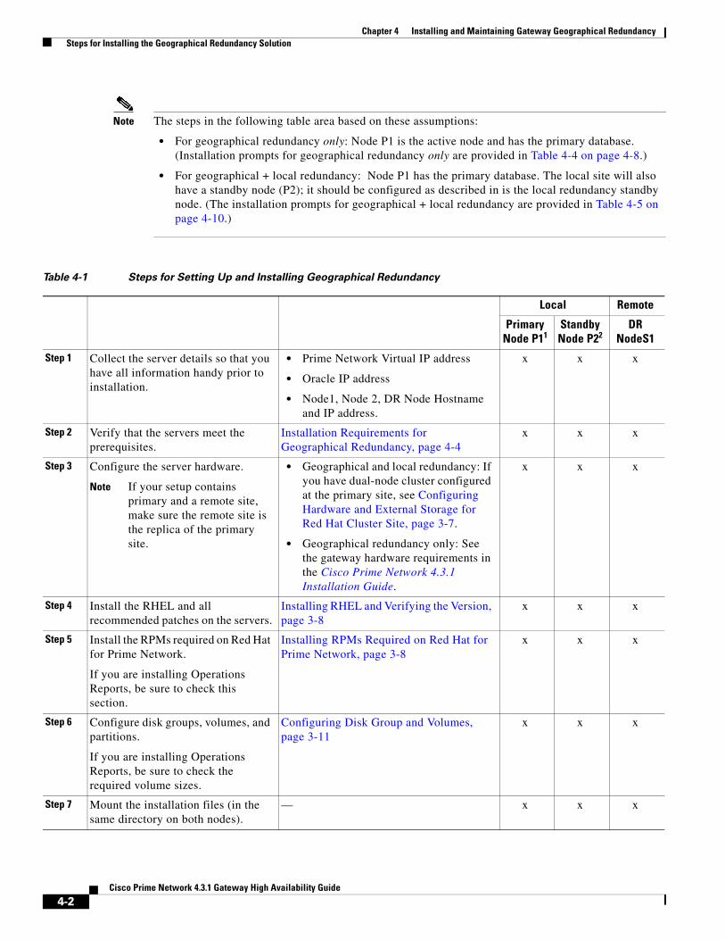
Chapter 4 Installing and Maintaining Gateway Geographical Redundancy Steps for Installing the Geographical Redundancy Solution
Note The steps in the following table area based on these assumptions:
• For geographical redundancy only: Node P1 is the active node and has the primary database. (Installation prompts for geographical redundancy only are provided in Table 4-4 on page 4-8.)
• For geographical + local redundancy: Node P1 has the primary database. The local site will also have a standby node (P2); it should be configured as described in is the local redundancy standby node. (The installation prompts for geographical + local redundancy are provided in Table 4-5 on page 4-10.)
Table 4-1 Steps for Setting Up and Installing Geographical Redundancy
Local Remote
Primary Node P11
Standby Node P22
DR NodeS1
Step 1 Collect the server details so that you have all information handy prior to installation.
• Prime Network Virtual IP address
• Oracle IP address
• Node1, Node 2, DR Node Hostname and IP address.
x x x
Step 2 Verify that the servers meet the prerequisites.
Installation Requirements for Geographical Redundancy, page 4-4
x x x
Step 3 Configure the server hardware.
Note If your setup contains primary and a remote site, make sure the remote site is the replica of the primary site.
• Geographical and local redundancy: If you have dual-node cluster configured at the primary site, see Configuring Hardware and External Storage for Red Hat Cluster Site, page 3-7.
• Geographical redundancy only: See the gateway hardware requirements in the Cisco Prime Network 4.3.1 Installation Guide.
x x x
Step 4 Install the RHEL and all recommended patches on the servers.
Installing RHEL and Verifying the Version, page 3-8
x x x
Step 5 Install the RPMs required on Red Hat for Prime Network.
If you are installing Operations Reports, be sure to check this section.
Installing RPMs Required on Red Hat for Prime Network, page 3-8
x x x
Step 6 Configure disk groups, volumes, and partitions.
If you are installing Operations Reports, be sure to check the required volume sizes.
Configuring Disk Group and Volumes, page 3-11
x x x
Step 7 Mount the installation files (in the same directory on both nodes).
— x x x
4-2Cisco Prime Network 4.3.1 Gateway High Availability Guide

Chapter 4 Installing and Maintaining Gateway Geographical Redundancy Steps for Installing the Geographical Redundancy Solution
Step 8 Verify that all nodes are ready for installation by checking disk access, Linux versions, and NTP synchronization.
Verify That All Servers Are Ready for Installation, page 3-12
x x x
Step 9 Configure the disk partitions. Configuring Disk Group and Volumes, page 3-11
x x x
Step 10 Mount the external shared storage, Oracle, and Prime Network mount points on the relevant directories.
Creating the Mount Points for Installation, page 3-12
x x —
Step 11 Back up the /etc/host and root cron jobs files (the installation software will modify them).
— x x x
Step 12 (Local + geographical) For cluster node makes sure the specified services are configured to start automatically each time the machine is rebooted.
Configure the Services for Automatic Start After Reboot, page 3-13
x x —
Step 13 (Local + geographical) Stop the RHCS services.
Stopping the RHCS Services, page 3-14 x x x
Step 14 Install the server and Oracle database using install_prime_HA.pl.
Installing the Prime Network Gateway Geographical Redundancy Software, page 4-6
x — —
Step 15 Configure the embedded database (using the add_emdb_storage.pl -ha script).
x — —
Step 16 Configure the remote site (S1) (execute setup_prime_DR.pl)
x — x
Step 17 If desired, install any new device packages so that you have the latest device support.
Cisco Prime Network 4.3 Release Notes x x —
Step 18 Verify the installation. Verifying the Geographical Redundancy Setup, page 4-14
x x x
Step 19 (Optional) Install PN-IL Installing and Configuring PN-IL for Local + Geographical Redundancy, page 4-18
x — x
Step 20 (Optional) Setup RHCS Web GUI if it is not configured during installation.
Configuring the RHCS Web Interface (Optional), page 3-23
x — —
Step 21 (Only for NAT) Update the database host.
Updating the Database Host in the Registry (Only for NAT), page 3-22
x x x
Step 22 (Local + geographical HA only) (Optional) Setup RHCS Web GUI if it is not configured during installation.
Configuring the RHCS Web Interface (Optional), page 3-23
x —
Table 4-1 Steps for Setting Up and Installing Geographical Redundancy (continued)
Local Remote
Primary Node P11
Standby Node P22
DR NodeS1
4-3Cisco Prime Network 4.3.1 Gateway High Availability Guide

Chapter 4 Installing and Maintaining Gateway Geographical Redundancy Installation Requirements for Geographical Redundancy
Installation Requirements for Geographical RedundancyThese topics list the prerequisites for installing gateway geographical redundancy:
• Hardware and Software Requirements for Geographical Redundancy, page 4-4
• Ports Usage for Geographical Redundancy, page 4-5
Hardware and Software Requirements for Geographical RedundancyTable 4-2 shows the core system requirements for geographical redundancy. All the hardware and software requirements are also applicable for virtual machines. Geographical redundancy requires a Prime Network embedded database and does not support IPv6 gateways or databases. If your high availability deployment differs from these requirements, please contact your Cisco account representative for assistance with the planning and installation of high availability.
Note Geographical redundancy for PN-IL is only supported if the local redundancy solution is also installed.
If you are installing both local and geographical redundancy, for the local redundancy site, refer to the requirements in Hardware and Software Requirements for Local Redundancy, page 3-4.
1. P1 node has primary database (geographical redundancy only, or geographical + local redundancy).
2. P2 node is only relevant if local redundancy is also installed.
Table 4-2 System Requirements for Geographical Redundancy1
Area Requirements
Operating System Red Hat 5.8, Red Hat 6.5 64-bit Server Edition (English language).
Oracle 12c.
Oracle 12c is included in the Prime Network embedded database installation.
Hardware RHEL 5.8 and RHEL 6.5 certified platform.
For recommended hardware for small, medium and large networks, see the Cisco Prime Network 4.3 Installation Guide.
4-4Cisco Prime Network 4.3.1 Gateway High Availability Guide
Chapter 4 Installing and Maintaining Gateway Geographical Redundancy Installation Requirements for Geographical Redundancy
Ports Usage for Geographical RedundancyIn addition to the ports listed in the Cisco Prime Network 4.3 Installation Guide, the following ports must be free.
You can check the status of the listed ports by executing the following command:
# netstat -tulnap | grep port-number
Network • Gateway and database should use logical IP addresses which are different between two sites (the sites can be on different subnets).
Note If you are using the network-conf script, when you are prompted for the IP address of units, use the floating IP address of the gateway.
• A SSH connection between all nodes is required.
• Port 1521 must be open between all nodes to allow ADG data to transfer between the primary and standby database.
• IP reachability to the primary site.
• SSL connectivity to primary site. For SSL, generate SSL keys and copy to all nodes in primary site.
• If you use LDAP authentication in a geographical redundancy configuration, the gateway servers must be configured to communicate with two different LDAP servers, one at the local site and one at the remote site. For this reason the switchover and failover utilities will prompt you for the relevant LDAP parameters. The LDAP parameters are set once using Prime Network Administration.
If for some reason the necessary IP addresses are not updated after a switchover or failover, you can set them manually (which includes setting the necessary LDAP parameters). See Changing the Gateway IP Address on a Gateway and All Units (changeSite.pl), page 6-14.
For more information on using LDAP for user authentication, see Using an External LDAP Server for Password Authentication in the Cisco Prime Network 4.3 Administrator Guide.
Storage Based on requirements determined by the Cisco Prime Network Capacity Planning Guide.
To obtain a copy of Capacity Planning Guide, contact your Cisco representative.
Geographical redundant storage should have the same capacity and mount points as the local site.
File system ext3
Disk space 5 GB under /tmp is required for installation
rsync The rsync utility must be installed on all servers that are part of the geographical redundant solution.
scp The scp program must be installed on all servers that are part of the geographical redundant solution.
1. Virtual machine and bare metal requirements for hard disk, memory, and processor are same. Refer to the Cisco Prime Network 4.3 Installation Guide for memory and processor requirements.
Table 4-2 System Requirements for Geographical Redundancy1 (continued)
Area Requirements
4-5Cisco Prime Network 4.3.1 Gateway High Availability Guide

Chapter 4 Installing and Maintaining Gateway Geographical Redundancy Preparing to Install Geographical Redundancy
To free any ports, contact your system administrator.
Preparing to Install Geographical RedundancyThere are a number of pre installation steps you need to perform before you install the geographical redundancy solution. These steps are similar to those for local redundancy, except that you are performing them on the primary server (P1) and the remote DR server (S2). These steps include the following:
• Configuring the server hardware, disk groups, volumes, and partitions
• Installing RHEL and the recommended patches and RPMs
• Mounting the installation files, and creating the mount points for the external shared storage, Oracle, and Prime Network
• Backing up your deployment
Extra steps are included if you are using both geographical and local redundancy. The preparation procedures are in Table 4-1 on page 4-2, starting with Step 3. Some procedures will refer you to the instructions for local redundancy; this is because the steps are identical but are performed on the primary node (P1) and the remote DR node (S1) instead of the primary and secondary cluster nodes (P1 and P2).
Installing the Prime Network Gateway Geographical Redundancy Software
The geographical redundancy solution uses a remote site that contains a single server that provides failover in case of a failure at the primary site. It is installed using install_prime_HA.pl script that is available in RH_ha.zip file in the installation DVD as described in Installation DVDs, page 1-1.
You can use this procedure to:
• Install the geographical redundancy software only on a remote server (S1 in Figure 2-4 on page 2-6)
• Install the geographical redundancy software on a deployment that is also using local redundancy (P1, P2, S1 in Figure 2-4 on page 2-6)
You can run the installation in interactive or in non-interactive mode. Interactive mode installation prompts you to enter the gateway HA data values one at a time. The Prime Network installer then updates the auto_install_RH.ini file template, which populates the install_Prime_HA.pl script.
Note It is recommended you run the installation in interactive mode first to populate the auto_install_RH.ini template with the user input. This gives you the ability to verify the input and run the installation again in non-interactive mode, if needed.
Alternatively, you can enter all the installation values in the auto_install_RH.ini template, located in the RH_ha directory, then run the installation in non-interactive mode. The installation mode is determined by the presence or absence of the -autoconf flag.
Table 4-3 Additional Ports Required for Local Redundancy
Port No. Used for:
9096 Prime Network cluster web interface
4-6Cisco Prime Network 4.3.1 Gateway High Availability Guide

Chapter 4 Installing and Maintaining Gateway Geographical Redundancy Installing the Prime Network Gateway Geographical Redundancy Software
Note The geographic redundancy configuration takes time. Depending on the speed of the local and remote site connection and size of the database, the configuration can take several hours.
To set up and configure the geographical redundancy site:
Step 1 Change to root user, then unzip the RH_ha.zip file located on the installation DVD in the /tmp path.This is a mandatory process to unzip the RH_ha file in the /tmp/RH_ha directory.
Note If you are running the Korn shell (/bin/ksh) and the prompt is the hash tag (#), the installation will fail. Run the installation script using bash.
Step 2 From the /tmp/RH_ha directory, run the install_Prime_HA.pl in interactive or non-interactive mode.
Step 3 Depending on whether you want to configure geographical + local redundancy or geographical redundancy only, do one of the following for the prompts shown in Table 4-4 or Table 4-5:
• For geographical redundancy only, enter:
local HA= no, DR= yes.
• For local + geographical redundancy, enter:
local HA= yes, DR= yes.
Step 4 Execute the install_Prime_HA.pl script in interactive or non-interactive method.
• For Interactive Installation:
For interactive installation, execute the following commands:
cd /tmp/RH_ha perl install_Prime_HA.pl
See Table 4-4 or Table 4-5 for descriptions of parameters you will be asked to enter at various stages of the interactive installation.
• For Non-Interactive Installation (Automatic):
a. Edit the auto_install_RH.ini file template found under the RH_ha directory with all of the installation details.
b. Run the following command:
cd /tmp/RH_ha perl install_Prime_HA.pl -autoconf auto_install_RH.ini full path
Note To prevent a security violation, it is highly recommended to remove the password in auto_install_RH.ini file after the successful installation.
After the install_Prime_HA.pl script is completed, Prime Network gateway and embedded database are installed on the remote site.
The following tables describe the installation prompts, depending on your deployment:
• Table 4-4, Installation Prompts for Geographical Redundancy Only (this deployment is not supported for PN-IL)
• Table 4-5, Installation Prompts for Local and Geographical Redundancy
4-7Cisco Prime Network 4.3.1 Gateway High Availability Guide
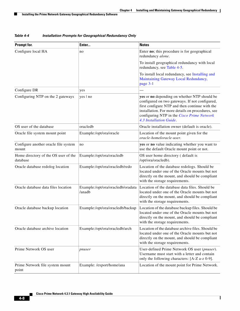
Chapter 4 Installing and Maintaining Gateway Geographical Redundancy Installing the Prime Network Gateway Geographical Redundancy Software
Table 4-4 Installation Prompts for Geographical Redundancy Only
Prompt for. Enter... Notes
Configure local HA no Enter no; this procedure is for geographical redundancy alone.
To install geographical redundancy with local redundancy, see Table 4-5.
To install local redundancy, see Installing and Maintaining Gateway Local Redundancy, page 3-1
Configure DR yes —
Configuring NTP on the 2 gateways yes | no yes or no depending on whether NTP should be configured on two gateways. If not configured, first configure NTP and then continue with the installation. For more details on procedures, see configuring NTP in the Cisco Prime Network 4.3 Installation Guide.
OS user of the database oracledb Oracle installation owner (default is oracle).
Oracle file system mount point Example:/opt/ora/oracle Location of the mount point given for the oracle-home/oracle-user.
Configure another oracle file system mount
no yes or no value indicating whether you want to use the default Oracle mount point or not.
Home directory of the OS user of the database
Example:/opt/ora/oracledb OS user home directory ( default is /opt/ora/oracledb).
Oracle database redolog location Example:/opt/ora/oracledb/redo Location of the database redologs. Should be located under one of the Oracle mounts but not directly on the mount, and should be compliant with the storage requirements.
Oracle database data files location Example:/opt/ora/oracledb/oradata/anadb
Location of the database data files. Should be located under one of the Oracle mounts but not directly on the mount, and should be compliant with the storage requirements.
Oracle database backup location Example:/opt/ora/oracledb/backup Location of the database backup files. Should be located under one of the Oracle mounts but not directly on the mount, and should be compliant with the storage requirements.
Oracle database archive location Example:/opt/ora/oracledb/arch Location of the database archive files. Should be located under one of the Oracle mounts but not directly on the mount, and should be compliant with the storage requirements.
Prime Network OS user pnuser User-defined Prime Network OS user (pnuser). Username must start with a letter and contain only the following characters: [A-Z a-z 0-9].
Prime Network file system mount point
Example: /export/home/ana Location of the mount point for Prime Network.
4-8Cisco Prime Network 4.3.1 Gateway High Availability Guide
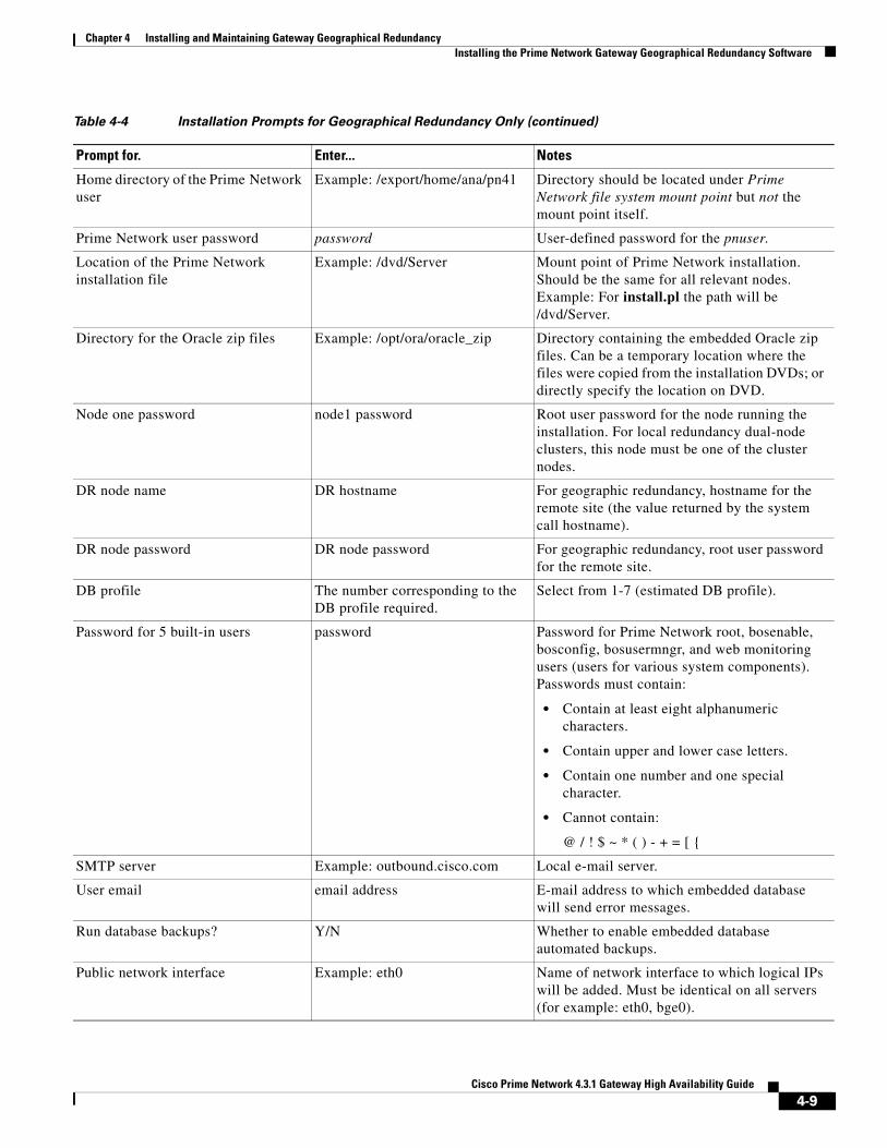
Chapter 4 Installing and Maintaining Gateway Geographical Redundancy Installing the Prime Network Gateway Geographical Redundancy Software
Home directory of the Prime Network user
Example: /export/home/ana/pn41 Directory should be located under Prime Network file system mount point but not the mount point itself.
Prime Network user password password User-defined password for the pnuser.
Location of the Prime Network installation file
Example: /dvd/Server Mount point of Prime Network installation. Should be the same for all relevant nodes. Example: For install.pl the path will be /dvd/Server.
Directory for the Oracle zip files Example: /opt/ora/oracle_zip Directory containing the embedded Oracle zip files. Can be a temporary location where the files were copied from the installation DVDs; or directly specify the location on DVD.
Node one password node1 password Root user password for the node running the installation. For local redundancy dual-node clusters, this node must be one of the cluster nodes.
DR node name DR hostname For geographic redundancy, hostname for the remote site (the value returned by the system call hostname).
DR node password DR node password For geographic redundancy, root user password for the remote site.
DB profile The number corresponding to the DB profile required.
Select from 1-7 (estimated DB profile).
Password for 5 built-in users password Password for Prime Network root, bosenable, bosconfig, bosusermngr, and web monitoring users (users for various system components). Passwords must contain:
• Contain at least eight alphanumeric characters.
• Contain upper and lower case letters.
• Contain one number and one special character.
• Cannot contain:
@ / ! $ ~ * ( ) - + = [ {
SMTP server Example: outbound.cisco.com Local e-mail server.
User email email address E-mail address to which embedded database will send error messages.
Run database backups? Y/N Whether to enable embedded database automated backups.
Public network interface Example: eth0 Name of network interface to which logical IPs will be added. Must be identical on all servers (for example: eth0, bge0).
Table 4-4 Installation Prompts for Geographical Redundancy Only (continued)
Prompt for. Enter... Notes
4-9Cisco Prime Network 4.3.1 Gateway High Availability Guide

Chapter 4 Installing and Maintaining Gateway Geographical Redundancy Installing the Prime Network Gateway Geographical Redundancy Software
Table 4-5 shows the installation prompts when setting up local and geographical redundancy.
Table 4-5 Installation Prompts for Local and Geographical Redundancy
Prompt for. Enter... Notes
Configure local HA? yes Enter yes; this procedure is for geographical redundancy + local redundancy.
To install geographical only, see Table 4-4.
To install local redundancy, see Installing and Maintaining Gateway Local Redundancy, page 3-1
Configure DR? yes —
Is NTP configured on the 3 gateways (local and remote)?
yes yes or no depending on whether NTP should be configured on three gateways. If not configured, first configure NTP and then continue with the installation. For more details on procedures, see configuring NTP in the Cisco Prime Network 4.3 Installation Guide.
OS user of the database oracledb Oracle installation owner (default is oracle).
Configuring multipath no Answer yes if the node is connected to storage with more than one connection (recommended).
Oracle file system mount point Example:/opt/ora/oracle Location of the mount point given for the oracle-home/oracle-user.
Configure another oracle file system mount
no yes or no value indicating whether you want to use the default Oracle mount point or not.
Home directory of the OS user of the database
Example:/opt/ora/oracledb OS user home directory ( default is /opt/ora/oracledb).
Oracle database redolog location Example:/opt/ora/oracledb/redo Location of the database redologs. Should be located under one of the Oracle mounts but not directly on the mount, and should be compliant with the storage requirements.
Oracle database data files location Example:/opt/ora/oracledb/oradata/anadb
Location of the database data files. Should be located under one of the Oracle mounts but not directly on the mount, and should be compliant with the storage requirements.
Oracle database backup location Example:/opt/ora/oracledb/backup Location of the database backup files. Should be located under one of the Oracle mounts but not directly on the mount, and should be compliant with the storage requirements.
Oracle database archive location Example:/opt/ora/oracledb/arch Location of the database archive files. Should be located under one of the Oracle mounts but not directly on the mount, and should be compliant with the storage requirements.
Prime Network OS user pnuser User-defined Prime Network OS user (pnuser). Username must start with a letter and contain only the following characters: [A-Z a-z 0-9].
4-10Cisco Prime Network 4.3.1 Gateway High Availability Guide
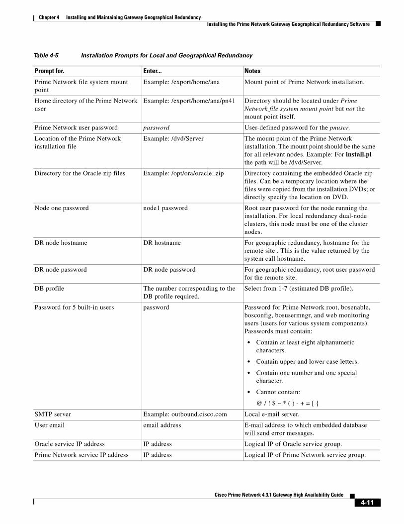
Chapter 4 Installing and Maintaining Gateway Geographical Redundancy Installing the Prime Network Gateway Geographical Redundancy Software
Prime Network file system mount point
Example: /export/home/ana Mount point of Prime Network installation.
Home directory of the Prime Network user
Example: /export/home/ana/pn41 Directory should be located under Prime Network file system mount point but not the mount point itself.
Prime Network user password password User-defined password for the pnuser.
Location of the Prime Network installation file
Example: /dvd/Server The mount point of the Prime Network installation. The mount point should be the same for all relevant nodes. Example: For install.pl the path will be /dvd/Server.
Directory for the Oracle zip files Example: /opt/ora/oracle_zip Directory containing the embedded Oracle zip files. Can be a temporary location where the files were copied from the installation DVDs; or directly specify the location on DVD.
Node one password node1 password Root user password for the node running the installation. For local redundancy dual-node clusters, this node must be one of the cluster nodes.
DR node hostname DR hostname For geographic redundancy, hostname for the remote site . This is the value returned by the system call hostname.
DR node password DR node password For geographic redundancy, root user password for the remote site.
DB profile The number corresponding to the DB profile required.
Select from 1-7 (estimated DB profile).
Password for 5 built-in users password Password for Prime Network root, bosenable, bosconfig, bosusermngr, and web monitoring users (users for various system components). Passwords must contain:
• Contain at least eight alphanumeric characters.
• Contain upper and lower case letters.
• Contain one number and one special character.
• Cannot contain:
@ / ! $ ~ * ( ) - + = [ {
SMTP server Example: outbound.cisco.com Local e-mail server.
User email email address E-mail address to which embedded database will send error messages.
Oracle service IP address IP address Logical IP of Oracle service group.
Prime Network service IP address IP address Logical IP of Prime Network service group.
Table 4-5 Installation Prompts for Local and Geographical Redundancy
Prompt for. Enter... Notes
4-11Cisco Prime Network 4.3.1 Gateway High Availability Guide

Chapter 4 Installing and Maintaining Gateway Geographical Redundancy Installing the Prime Network Gateway Geographical Redundancy Software
Multicast address for the cluster nodes
IP address An available multicast address accessible and configured for both cluster nodes.
Prime Network cluster name username User-defined cluster name. Cannot be more than 15 non-NUL (ASCII 0) characters. For local redundancy, cluster name must be unique within the LAN.
Node one fence agent The number corresponding to the fencing agent required
Type of fencing device configured for the node running the installation. (See Fencing Options, page 2-3.)
Node two fence agent The number corresponding to the fencing agent required
Type of fencing device configured for the second cluster running the installation. (See Fencing Options, page 2-3.)
Prime Network cluster web interface password
port number and password Port and the password for cluster web interface.
LUCI_PORT must be available and should not be in Prime Network debug range:
60000 <= x < 61000
or in Prime Network AVM port range:
2000 <= x < 3000 or 8000 <= x < 9000)
Password must contain at least 6 characters.
Prime Network cluster web interface port
Node one IP node1 IP address IP address of the node running the installation. Local redundancy dual-node clusters: Must be one of the cluster nodes.
DR node IP DR node IP address IP address of DR node at remote site (geographical redundancy).
Run database backups? Y/N Whether to enable embedded database automated backups.
Public network interface Example: eth0 Name of network interface to which logical IPs will be added. Must be identical on all servers (for example: eth0, bge0).
Node one fence hostname hostname Hostname of fencing device configured for node running the installation (for some fencing devices, this can be an IP address).
Node one fence login login name Login name for fencing device configured for node running the installation.
Node one fence passwd password Password for fencing device configured for node running the installation.
Node two fence hostname hostname Hostname of fencing device configured for second cluster node (for some fencing devices, this can be an IP address).
Table 4-5 Installation Prompts for Local and Geographical Redundancy
Prompt for. Enter... Notes
4-12Cisco Prime Network 4.3.1 Gateway High Availability Guide
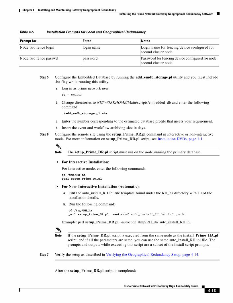
Chapter 4 Installing and Maintaining Gateway Geographical Redundancy Installing the Prime Network Gateway Geographical Redundancy Software
Step 5 Configure the Embedded Database by running the add_emdb_storage.pl utility and you must include -ha flag while running this utility.
a. Log in as prime network user
su - pnuser
b. Change directories to NETWORKHOME/Main/scripts/embedded_db and enter the following command:
./add_emdb_storage.pl -ha
c. Enter the number corresponding to the estimated database profile that meets your requirement.
d. Insert the event and workflow archiving size in days.
Step 6 Configure the remote site using the setup_Prime_DR.pl command in interactive or non-interactive mode. For more information on setup_Prime_DR.pl script, see Installation DVDs, page 1-1.
Note The setup_Prime_DR.pl script must run on the node running the primary database.
• For Interactive Installation:
For interactive mode, enter the following commands:
cd /tmp/RH_ha perl setup_Prime_DR.pl
• For Non- Interactive Installation (Automatic):
a. Edit the auto_install_RH.ini file template found under the RH_ha directory with all of the installation details.
b. Run the following command:
cd /tmp/RH_ha perl setup_Prime_DR.pl -autoconf auto_install_RH.ini full path
Example: perl setup_Prime_DR.pl -autoconf /tmp/RH_dr/ auto_install_RH.ini
Note If the setup_Prime_DR.pl script is executed from the same node as the install_Prime_HA.pl script, and if all the parameters are same, you can use the same auto_install_RH.ini file. The prompts and outputs while executing this script are a subset of the install script prompts.
Step 7 Verify the setup as described in Verifying the Geographical Redundancy Setup, page 4-14.
After the setup_Prime_DR.pl script is completed:
Node two fence login login name Login name for fencing device configured for second cluster node.
Node two fence passwd password Password for fencing device configured for node second cluster node.
Table 4-5 Installation Prompts for Local and Geographical Redundancy
Prompt for. Enter... Notes
4-13Cisco Prime Network 4.3.1 Gateway High Availability Guide

Chapter 4 Installing and Maintaining Gateway Geographical Redundancy Verifying the Geographical Redundancy Setup
• The Prime Network and embedded database files are replicated to the remote site.
• All utility scripts are located under /var/adm/cisco/prime-network/scripts/ha/util/.
Verifying the Geographical Redundancy SetupTable 4-6 shows the geographical redundancy verification tests.
Note The geographical redundancy verification tests are for the embedded database and must be performed by Cisco personnel only.
Table 4-6 Geographical Redundancy Verification Tests
Description Procedure Expected Results
Database Replication
Name: tnsping Test: Primary to remote site
Purpose: Verify tnsping from the primary to the remote site.
From the primary DB server enter the following as the OS Oracle UNIX user:
tnsping anadbtnsping anadb_sb
Verify that the TNS connection on port 1521 is available between the two database servers.
Name: tnsping Test: remote site to Primary
Purpose: Verify tnsping from the remote site to the primary site.
From the standby database server enter the following as the as Oracle UNIX user:
tnsping anadb tnsping anadb_sb
Verify that the TNS connection on port 1521 is available between the two database servers.
Name: Get the pnuser_admin Password
Purpose: Get the pnuser_admin login password from the registry for later tests.
As the Prime Network UNIX user, enter:
cd NETWORKHOME/Main ./runRegTool.sh localhost get persistency/nodes/admin/PASS
Derive the password for pnuser_admin database user from the registry for creating db_links.
Name: Replication Test
Purpose: Verify the object and data replication.
1. On the primary database server, connect to sqlplus as pnuser_admin, then enter the following:
CREATE TABLE NETWORK_TEST_REP (NUM NUMBER);INSERT INTO NETWORK_TEST_REP VALUES(1);COMMIT;ALTER SYSTEM SWITCH LOGFILE;
2. On the standby database server, connect to sqlplus as pnuser_admin and query this table:
SELECT * FROM NETWORK_TEST_REP;
The table and data are replicated
4-14Cisco Prime Network 4.3.1 Gateway High Availability Guide

Chapter 4 Installing and Maintaining Gateway Geographical Redundancy Verifying the Geographical Redundancy Setup
Name and Purpose: Create Database Links on the Primary Database
Note Perform this step once, after installing RHEL. Do not repeat this step when verifying the setup after a switchover or failover.
Connect to sqlplus as the pnuser_admin, then enter the following:
CREATE DATABASE LINK TO_anadb_sb CONNECT TO pnuser_ADMINIDENTIFIED BY pnuser_admin_password USING 'anadb_sb';CREATE DATABASE LINK TO_anadb CONNECT TO pnuser_ADMIN IDENTIFIED BY pnuser_admin password USING 'anadb';
The database link is created.
Name: Query Replication SCN Gap.
Purpose: Verify that an SCN gap is not growing between the two databases.
1. Connect to sqlplus as pnuser_admin.
2. Run the following query several times to verify gap is not growing:
with v1 as (select current_scn anadb_sb_SCN from v$database@TO_anadb_sb), v2 as (select current_scn anadb_SCN from v$database@TO_anadb) select v1.anadb_sb_SCN anadb_sb_SCN,v2.anadb_SCN anadb_SCN,v1.anadb_sb_SCN-v2.anadb_SCN "SCN GAP" from v1,v2;
Run the query several times to verify the gap is not growing The SCN gap should be less than 100,000.
Name: Replication is running
Purpose: Verify the file replication process is running correctly by checking the monitoring log files under the Prime Network home directory.
Check the following log files under NETWORKHOME.
• NETWORKHOME/.replication—A time stamp file is created on the primary Prime Network node.
• NETWORKHOME/.replication_remote—A time stamp file is created on the primary Prime Network node and replicated to the remote Prime Network node and back again. This will hold the time stamp of the last Prime Network file replication.
• NETWORKHOME/.replication_log—Log file created by the Prime Network replication monitoring. It will be empty if all is considered OK (the difference between the time stamp files is within range).
• NETWORKHOME/oracle_monitor.log—Remote database monitoring log.
The replication is running correctly.
File Replication
Name: File replication
Purpose: Verify the file replication process.
1. Create a file under NETWORKHOME by entering:
touch filename
2. Verify that the file is created on the geographical remote node.
3. Remove the file and verify that the file is removed on the remote node.
The file is created and removed.
Note File replication from primary to geographical remote node takes some time.
Table 4-6 Geographical Redundancy Verification Tests (continued)
Description Procedure Expected Results
4-15Cisco Prime Network 4.3.1 Gateway High Availability Guide
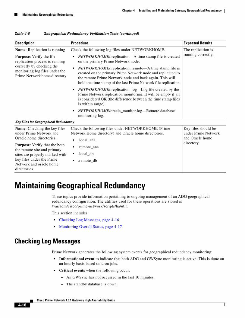
Chapter 4 Installing and Maintaining Gateway Geographical Redundancy Maintaining Geographical Redundancy
Maintaining Geographical RedundancyThese topics provide information pertaining to ongoing management of an ADG geographical redundancy configuration. The utilities used for these operations are stored in /var/adm/cisco/prime-network/scripts/ha/util.
This section includes:
• Checking Log Messages, page 4-16
• Monitoring Overall Status, page 4-17
Checking Log MessagesPrime Network generates the following system events for geographical redundancy monitoring:
• Informational event to indicate that both ADG and GWSync monitoring is active. This is done on an hourly basis based on cron jobs.
• Critical events when the following occur:
– An GWSync has not occurred in the last 10 minutes.
– The standby database is down.
Name: Replication is running
Purpose: Verify the file replication process is running correctly by checking the monitoring log files under the Prime Network home directory.
Check the following log files under NETWORKHOME.
• NETWORKHOME/.replication—A time stamp file is created on the primary Prime Network node.
• NETWORKHOME/.replication_remote—A time stamp file is created on the primary Prime Network node and replicated to the remote Prime Network node and back again. This will hold the time stamp of the last Prime Network file replication.
• NETWORKHOME/.replication_log—Log file created by the Prime Network replication monitoring. It will be empty if all is considered OK (the difference between the time stamp files is within range).
• NETWORKHOME/oracle_monitor.log—Remote database monitoring log.
The replication is running correctly.
Key Files for Geographical Redundancy
Name: Checking the key files under Prime Network and Oracle home directories.
Purpose: Verify that the both the remote site and primary sites are properly marked with key files under the Prime Network and oracle home directories.
Check the following files under NETWORKHOME (Prime Network Home directory) and Oracle home directories.
• .local_ana
• .remote_ana
• .local_db
• .remote_db
Key files should be under Prime Network and Oracle home directory.
Table 4-6 Geographical Redundancy Verification Tests (continued)
Description Procedure Expected Results
4-16Cisco Prime Network 4.3.1 Gateway High Availability Guide

Chapter 4 Installing and Maintaining Gateway Geographical Redundancy Maintaining Geographical Redundancy
– The standby database is up but has been out of sync for 60 minutes.
The log files for data replication are described in the following table. To troubleshoot problems with the replication process, see Verifying the Geographical Redundancy Setup, page 4-14.
Monitoring Overall StatusThe primeha command is a central utility for checking the status of the high availability nodes, performing switchovers and failovers, and stopping and resuming data replication.
Use the following command to view the status of the cluster:
perl primeha -status
The below output is an example for a network that has both local and geographical redundancy.
• The first portion of the output as shown below, shows the status of the geographical redundancy configuration. The server hostname1.cisco.com is the remote gateway and database server. The server hostname2.cisco.com is the other node in the local redundancy cluster and is not running any service.
- Installing Perl-5.16.0-x86_64-linux-thread-multi Log can be found at /var/adm/cisco/prime-network/scripts/ha/util/perlForHA/installPerlForHA-1365070277.log
HOST ANA SERVICE ORACLE SERVICEhostname.cisco.com Active Prime Network Active oracle localhostname1.cisco.com Standby Prime Network Standby oracle
Log File Description
NETWORKHOME/.replicationNETWORKHOME/.replication_remote
Contains the local and remote timestamps used by GWSync.
NETWORKHOME/.replication_log This log is only populated if the GWSync local and remote timestamps are more than 10 minutes apart (and a System event is generated), as in the following example:
Replication failed since: date
NETWORKHOME/oracle_monitoring.log Information on the Redo-apply log from the standby server.
+ Testing the replication state on the remote database
- Redo transport lag:NAME VALUE TIME_COMPLETED-----------------------------------------------------------transport lag +00 00:00:00 04/14/2013 10:30:34
- Redo apply lag:NAME VALUE TIME_COMPLETED-----------------------------------------------------------apply lag +00 00:00:00 04/14/2013 10:30:35
- Active apply rate:ITEM UNITS SO FAR----------------------------------Active Apply Rate KB/sec 286
- Data base role: PHYSICAL STANDBY
4-17Cisco Prime Network 4.3.1 Gateway High Availability Guide

Chapter 4 Installing and Maintaining Gateway Geographical Redundancy Uninstalling the Geographical Redundancy Software
hostname2.cisco.com Prime Network not running on this node oracle not running on this node
• The second portion of the output as shown below (that begins with Cluster Status) shows the status of the local redundancy configuration. (This is displayed because this setup also contains a local redundancy configuration.)
Cluster Status for ana_cluster @ Mon Aug 1 12:34:40 2013Member Status: Quorate
Member Name ID Status ------ ---- ---- ------ hostname.cisco.com 1 Online, Local, rgmanager hostname2.cisco.com 2 Online, rgmanager
Service Name Owner (Last) State ------- ---- ----- ------ ----- service:ana hostname.cisco.com started service:oracle_db hostname.cisco.com started
Uninstalling the Geographical Redundancy SoftwareTo uninstall geographical redundancy, use this procedure. If Operations Reports was also installed, this procedure will remove it.
If your deployment also has local redundancy, uninstall the software on the primary cluster server (P1) first using the procedure in Uninstalling Local Redundancy, page 3-28.
Step 1 If any RHCS services are running, log into the primary cluster server and freeze the relevant services (service can be ana, oracle, and, if Operations Reports is installed, ifb).
clusvcadm -Z service
Step 2 Log in as the root user and change to the following directory:
cd /var/adm/cisco/prime-network/reg/pnuser
Step 3 Enter the following command:
perl uninstall.pl
Installing and Configuring PN-IL for Local + Geographical Redundancy
This section explains how to install the Prime Network Integration Layer (PN-IL) 1.2 for a local + geographical redundancy deployment. It also explains how to integrate the deployment with Cisco Prime Central. For information on the Prime Central releases with which you can integrate PN-IL 1.2, see the Cisco Prime Network 4.3 Release Notes.
These topics provide the information you will need to install and configure PN-IL geographical, and local redundancy:
• Installation DVD, page 4-19
4-18Cisco Prime Network 4.3.1 Gateway High Availability Guide

Chapter 4 Installing and Maintaining Gateway Geographical Redundancy Installing and Configuring PN-IL for Local + Geographical Redundancy
• Steps for Installing PN-IL with Local + Geographical Redundancy, page 4-19
• Installing PN-IL on a Prime Network Server (Local + Geographical Redundancy), page 4-20
• Configuring PN-IL on a Prime Network Gateway (Local + Geographical Redundancy), page 4-22
• Disabling the PN-IL Health Monitor, page 4-26
If you want to migrate an existing standalone installations of PN-IL (local + geographical) to suite mode, you can use the procedure in Configuring and Migrating PN-IL with Prime Central (Suite Mode with Local + Geographical Redundancy), page 4-23.
Installation DVDThe PN-IL high availability files are provided on the Prime Network installation DVD named Disk 1: New Install DVD. Disk 2 contains the tar file sil-esb-1.2.0.tar.gz, which contains the PN-IL installation files and scripts, including:
• installAndConfigureESB.sh—PN-IL installation script
• itgctl—PN-IL configuration script
• il-watch-dog.sh—PN-IL health monitor control script
• DMSwitchToSuite.sh—Script to migrate to suite
Steps for Installing PN-IL with Local + Geographical RedundancyTable 4-7 provides the basic steps you must follow to set up local + geographical redundancy for PN-IL. If you want to migrate an existing standalone installations of PN-IL (local + geographical) to suite mode, you can use the procedure in Configuring and Migrating PN-IL with Prime Central (Suite Mode with Local + Geographical Redundancy), page 4-23.
Note that you only have to install PN-IL on the primary cluster server (P1), not on the remote (DR) server (S2). However, you will have to do some configuration tasks on the remote server.
4-19Cisco Prime Network 4.3.1 Gateway High Availability Guide

Chapter 4 Installing and Maintaining Gateway Geographical Redundancy Installing and Configuring PN-IL for Local + Geographical Redundancy
Installing PN-IL on a Prime Network Server (Local + Geographical Redundancy)
Use this procedure to install PN-IL with local + geographical redundancy on the primary cluster server (P1). The primary cluster node will copy the necessary files to the remote DR node (S1). For the remote DR node, you only have to perform some minor configurations.
Before You Begin:
Make sure Prime Network is installed and is up and running on the both the primary cluster node (P1) and the remote DR node (S2). In the following procedure, $ANAHOME is the pnuser environment variable for the Prime Network installation directory (/export/home/pnuser by default).
Step 1 On the primary cluster node (P1), log in as root and freeze the ana service.
Table 4-7 Steps for Setting Up PN-IL Local + Geographical Redundancy
Task Topic/Action Required
Local ClusterRemote (DR)
Server
Server (P1) (has Primary database) Server (P2)
Remote Server (S1)
Step 1 Collect server details, so that you have all information handy prior to installation.
• Virtual IP address of P1
• IP Address of remote DR server S1
• Prime Network application root username and password for primary cluster and remote DR servers (P1 and S1)
• URL for authenticating Prime Network calls for P1 and S1 (normally https://localhost:6081/ana/services/userman)
• ((Suite mode) For the Prime Central server where Oracle is installed: Hostname, database service name, database username and password, and database port.
x — —
Step 2 Verify the server meets the prerequisites.
Installation Requirements for Geographical Redundancy, page 4-4
x — —
Step 3 Freeze RHCS and install PN-IL.
Installing PN-IL on a Prime Network Server (Local + Geographical Redundancy), page 4-20
x — —
Step 4 Configure PN-IL (in standalone or suite mode) on both nodes, and unfreeze RHCS.
Configuring PN-IL on a Prime Network Gateway (Local + Geographical Redundancy), page 4-22
x — x
Step 5 Disable the PN-IL Health Monitor.
Disabling the PN-IL Health Monitor, page 4-26 x — x
4-20Cisco Prime Network 4.3.1 Gateway High Availability Guide
Chapter 4 Installing and Maintaining Gateway Geographical Redundancy Installing and Configuring PN-IL for Local + Geographical Redundancy
Note The cluster server should be the active node where the ana service is running.
ssh root@active-cluster-nodeclusvcadm -Z ana
Step 2 On the remote DR node (S1), log in as root and save your rsync settings so they are not overwritten during the PN-IL installation process.
ssh root@remote-DR-node-namecd /var/adm/cisco/prime-network/scripts/ha/rsyncmv rsync_exclude_pnil.txt rsync_exclude_pnil.txt.orgmv rsync_exclude_pnil_cfg.txt rsync_exclude_pnil_cfg.txt.org
Step 3 On the primary cluster node (P1), log in as pnuser.
su - pnuser
For example:
su - pn41
Step 4 On the primary cluster node, create an installation directory for PN-IL.
mkdir -p $ANAHOME/new-pnil-dir
For example, if the Prime Network installation directory was /export/home/pn41, you would run this command to create an installation directory called pnil:
mkdir -p $ANAHOME/pnil
Step 5 On the primary cluster node (P1), copy the installation files from the installation DVD, extract them, and start the installation script. These examples use the PN-IL installation directory /pnil.
a. Copy the PN-IL installation tar file from Disk 2 to the directory you created in Step 4. In the following example, the installation directory is named pnil.
cp /tmp/sil-esb-1.2.0.tar.gz $ANAHOME/pnil
b. Change to the directory you created in Step 4 and extract the files from the PN-IL installation tar:
cd $ANAHOME/pniltar -zxf sil-esb-1.2.0.tar.gz
c. Change to directory where the installation tar files were extracted and run the installation script:
cd sil-esb-1.2.0/install/packages./installAndConfigureEsb.sh
Step 6 On the primary cluster node (P1), reload the user profile.
source $ANAHOME/.cshrc
Step 7 Log into the remote DR server (S1) as root and move the original rsync exclude file (that you moved in Step 2) back to its proper place.
ssh root@remote-DR-servercd /var/adm/cisco/prime-network/scripts/ha/rsyncmv rsync_exclude_pnil.txt.org rsync_exclude_pnil.txt mv rsync_exclude_pnil_cfg.txt.org rsync_exclude_pnil_cfg.txt
Step 8 Configure PN-IL as described in Configuring PN-IL on a Prime Network Gateway (Local + Geographical Redundancy), page 4-22.
4-21Cisco Prime Network 4.3.1 Gateway High Availability Guide
Chapter 4 Installing and Maintaining Gateway Geographical Redundancy Installing and Configuring PN-IL for Local + Geographical Redundancy
Note Do not unfreeze the ana service until PN-IL has been configured.
Note You do not have to install the geographical redundancy files on the remote server (S1); the necessary files will be copied to the remote DR server by the primary cluster node.
Configuring PN-IL on a Prime Network Gateway (Local + Geographical Redundancy)
Configuration tasks must be performed on both the primary cluster node (P1) and the remote DR node (S1).
• For standalone mode (that is, Prime Network is not integrated with Prime Central), follow the instructions in Configuring PN-IL with Prime Network (Standalone Mode with Local + Geographical Redundancy), page 4-22.
• For suite mode (Prime Network is integrated with Prime Central), follow the instructions in Configuring and Migrating PN-IL with Prime Central (Suite Mode with Local + Geographical Redundancy), page 4-23.
Configuring PN-IL with Prime Network (Standalone Mode with Local + Geographical Redundancy)
In standalone mode, Prime Network is not integrated with Prime Central and can independently expose MTOSI and 3GPP web services to other OSS/applications. In the following procedure:
• $PRIMEHOME is the pnuser environment variable for the PN-IL installation directory you created in Installing PN-IL on a Prime Network Server (Local + Geographical Redundancy), page 4-20.
• $ANAHOME is the pnuser environment variable for the Prime Network installation directory (/export/home/pnuser by default).
Step 1 From the primary cluster node (P1), log in as pnuser.
Step 2 On the primary cluster node (P1), configure PN-IL in standalone mode.
itgctl config 1 --anaPtpServer ana-cluster-ip --anaPtpUser pn-root-user --anaPtpPw pn-root-user-password --authURL network-authentication-URL
itgctl uses these arguments.
Argument Description
ana-cluster-ip • When run on the primary cluster node (P1), this is the IP address of the primary cluster server.
• When run on the remote DR node, this is the IP address of the remote DR server.
pn-root-user Name of Prime Network root user (usually root)
4-22Cisco Prime Network 4.3.1 Gateway High Availability Guide
Chapter 4 Installing and Maintaining Gateway Geographical Redundancy Installing and Configuring PN-IL for Local + Geographical Redundancy
For example:
itgctl config 1 --anaPtpServer 192.0.2.22 --anaPtpUser root --anaPtpPw myrootpassword --authURL https://192.0.2.22:6081/ana/services/userman
Step 3 On the primary cluster node (P1), start PN-IL.
$PRIMEHOME/bin/itgctl start
Step 4 Open a new session on the remote DR server (S1) and log in as pnuser.
Step 5 On the remote DR server (S1), configure PN-IL in standalone mode but use the remote DR server’s IP address (--anaPtpServer remote-DR-ip).
itgctl config 1 --anaPtpServer remote-DR-server-ip --anaPtpUser pn-root-user --anaPtpPw pn-root-user-password --authURL network-authentication-URL
Step 6 On the primary cluster node (P1), start PN-IL.
$PRIMEHOME/bin/itgctl start
Note To avoid the automatic start of PN-IL on the DR server, disable the PN-IL Health monitor, and stop the PN-IL service on that server, using the following command: $PRIMEHOME/local/scripts/il-watch-dog.sh disableandstop.
Step 7 On the primary cluster node, log in as the operating system root user and unfreeze the ana service.
clusvcadm -U ana
Step 8 To enable NBI, contact Cisco representative.
Next, perform the necessary configuration steps that are described in Configuring PN-IL on a Prime Network Gateway (Local + Geographical Redundancy), page 4-22.
Configuring and Migrating PN-IL with Prime Central (Suite Mode with Local + Geographical Redundancy)
When Prime Network and PN-IL are running in suite mode, that means they are integrated with Prime Central. This procedure explains how to integrate PN-IL with a deployment of Prime Central that uses geographical redundancy. You can use this procedure for:
• New installations of PN-IL with geographical redundancy.
• Existing standalone installations of PN-IL with geographical redundancy, that you want to move from standalone to suite mode.
Figure 4-1 illustrates the deployment of both local and geographical redundancy in Suite Mode.
pn-root-user-password Password for Prime Network root user
network-authentication-URL URL used to authenticate Prime Network calls (usually https://localhost:6081/ana/services/userman)
Argument Description
4-23Cisco Prime Network 4.3.1 Gateway High Availability Guide
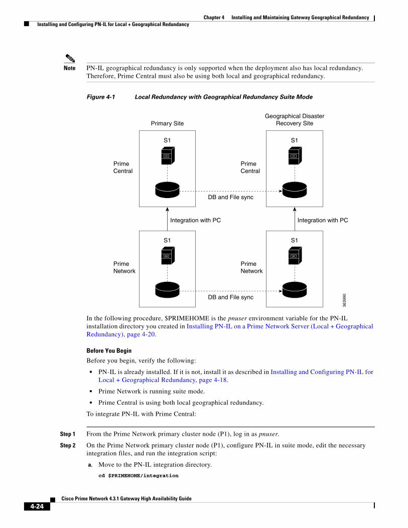
Chapter 4 Installing and Maintaining Gateway Geographical Redundancy Installing and Configuring PN-IL for Local + Geographical Redundancy
Note PN-IL geographical redundancy is only supported when the deployment also has local redundancy. Therefore, Prime Central must also be using both local and geographical redundancy.
Figure 4-1 Local Redundancy with Geographical Redundancy Suite Mode
In the following procedure, $PRIMEHOME is the pnuser environment variable for the PN-IL installation directory you created in Installing PN-IL on a Prime Network Server (Local + Geographical Redundancy), page 4-20.
Before You Begin
Before you begin, verify the following:
• PN-IL is already installed. If it is not, install it as described in Installing and Configuring PN-IL for Local + Geographical Redundancy, page 4-18.
• Prime Network is running suite mode.
• Prime Central is using both local geographical redundancy.
To integrate PN-IL with Prime Central:
Step 1 From the Prime Network primary cluster node (P1), log in as pnuser.
Step 2 On the Prime Network primary cluster node (P1), configure PN-IL in suite mode, edit the necessary integration files, and run the integration script:
a. Move to the PN-IL integration directory.
cd $PRIMEHOME/integration
S1
Integration with PC
DB and File sync
3639
90
PrimeCentral
Primary SiteGeographical Disaster
Recovery Site
PrimeNetwork
S1
PrimeCentral
PrimeNetwork
S1
Integration with PC
S1
DB and File sync
4-24Cisco Prime Network 4.3.1 Gateway High Availability Guide

Chapter 4 Installing and Maintaining Gateway Geographical Redundancy Installing and Configuring PN-IL for Local + Geographical Redundancy
b. Edit the ILIntegrator.prop file and change the value of the ‘HOSTNAME’ property to ana-cluster-ana, which is the fixed name for the Prime Network cluster server.
HOSTNAME=ana-cluster-ana
c. Execute the following integration script to integrate PN-IL with Prime Central. Prime Central will assign an ID number to PN-IL. Note the ID number because you will need it later to integrate the remote DR server (S1) with Prime Central.
Note When you run DMIntegrator.sh, you must exactly follow the format below or the script will fail.
./DMIntegrator.sh -a ILIntegrator.prop prime-central-db-hostname prime-central-db-service-name prime-central-db-user prime-central-db-user-password prime-central-port-number
DMIntegrator uses these variables. You must enter them in this exact order.
Example:
./DMIntegrator.sh -a ILIntegrator.prop 10.10.10.10 primedb primedba mypassword 1521
Step 3 On the Prime Network primary cluster node (P1), reload the user profile:
source $PRIMEHOME/.cshrc
Step 4 On the Prime Network primary cluster node (P1), retrieve the ID that Prime Central assigned to Prime Network using itgctl list. You will need it in a future step.
$PRIMEHOME/bin/itgctl list
Step 5 Open a new session to the Prime Network remote DR server (S1) as a root user and rename file as shown below.
cd /var/adm/cisco/prime-network/scripts/ha/rsyncmv rsync_exclude_pnil.txt rsync_exclude_pnil.txt.orgmv rsync_exclude_pnil_cfg.txt rsync_exclude_pnil_cfg.txt.org
Step 6 On the Prime Network remote DR server (S1), configure PN-IL in suite mode as pnuser. Edit the necessary integration files, and run the integration script.
a. su - pnuser
b. Move to the PN-IL integration directory.
cd $PRIMEHOME/integration
DMIntegrator.sh Variable Description
prime-central-server-hostname Specifies the IP address of the Prime Central database server
prime-central-db-service-name Specifies the name of Prime Central database service
prime-central db-user Specifies the name of Prime Central database user (usually primedba)
prime-central-db-user-password Specifies the password for Prime Central database user
prime-central-db-port Specifies the port for Prime Central database (usually 1521)
4-25Cisco Prime Network 4.3.1 Gateway High Availability Guide

Chapter 4 Installing and Maintaining Gateway Geographical Redundancy Installing and Configuring PN-IL for Local + Geographical Redundancy
c. Edit the ILIntegrator.prop file and change the value of the ‘HOSTNAME’ property to the Prime Network remote DR server (S1) hostname. For example:
HOSTNAME=remote-pn-DR-server
d. Execute the following integration script to integrate PN-IL into the deployment:
./DMIntegrator.sh -a ILIntegrator.prop prime-DR-db-server-hostname db-service-name db-user db-user-password db-port pn-id
DMIntegrator uses these variables. You must enter them in this exact order.
Example:
./DMIntegrator.sh -a ILIntegrator.prop 10.10.1.11 primedb primedba mypassword 1521 10
Step 7 On the remote DR node (S1), reload the user profile:
source $ANAHOME/.cshrc
Step 8 Log out from Prime Network application user and as root user change the following file name
cd /var/adm/cisco/prime-network/scripts/ha/rsyncmv rsync_exclude_pnil.txt.org rsync_exclude_pnil.txtmv rsync_exclude_pnil_cfg.txt.org rsync_exclude_pnil_cfg.txt
Step 9 As the operating system root user, on the primary cluster node (P1), unfreeze the ana service.
clusvcadm -U ana
Next, disable the PN-IL health monitor as described in Disabling the PN-IL Health Monitor, page 4-26.
Disabling the PN-IL Health Monitor When PN-IL is installed in a geographical redundancy deployment, the RHCS cluster service monitors PN-IL’s status. Therefore, you should disable the PN-IL health monitor.
To disable the PN-IL health monitor, execute the following command as pnuser:
$ANAHOME/local/scripts/il-watch-dog.sh disable
DMIntegrator.sh Variable Description
prime-DR-db-server-hostname IP address of the Prime Central DR database server
db-service-name Name of Prime Central database service
db-user Name of Prime Central database user (usually primedba)
db-user-password Password for Prime Central database user
db-port Port for Prime Central database (usually 1521)
prime-pn-id Prime Network ID number assigned by Prime Central
4-26Cisco Prime Network 4.3.1 Gateway High Availability Guide

Chapter 4 Installing and Maintaining Gateway Geographical Redundancy Installing and Configuring PN-IL for Geographical Redundancy Only
Installing and Configuring PN-IL for Geographical Redundancy Only
This section explains how to install the Prime Network Integration Layer (PN-IL) 1.2 for a geographical redundancy only deployment. It also explains how to integrate the deployment with Cisco Prime Central. For information on the Prime Central releases with which you can integrate PN-IL 1.2, see the Cisco Prime Network 4.3 Release Notes.
Note PN-IL geographical redundancy only has a primary server (P1) at the local site and remote server (S1) at a remote geographical site for a full disaster recovery.
These topics provide the information you will need to install and configure PN-IL geographical only deployments:
• Installation DVD, page 4-19
• Steps for Installing PN-IL with Geographical Redundancy Only, page 4-27
• Installing PN-IL on a Prime Network Server (Geographical Redundancy Only), page 4-28
• Configuring PN-IL on a Prime Network Gateway (Geographical Redundancy Only), page 4-30
• Disabling the PN-IL Health Monitor, page 4-26
If you want to migrate an existing standalone installations of PN-IL (with geographical redundancy) to suite mode, you can use the procedure in Configuring and Migrating PN-IL with Prime Central (Suite Mode with Local + Geographical Redundancy), page 4-23.
Steps for Installing PN-IL with Geographical Redundancy OnlyTable 4-7 provides the basic steps you must follow to set up geographical redundancy only for PN-IL. If you want to migrate an existing standalone installations of PN-IL (with geographical redundancy only) to suite mode, you can use the procedure in Configuring and Migrating PN-IL with Prime Central (Suite Mode with Local + Geographical Redundancy), page 4-23.
Note that you only have to install PN-IL on the primary server (P1), not on the remote (DR) server (S2). However, you will have to do some configuration tasks on the remote server.
4-27Cisco Prime Network 4.3.1 Gateway High Availability Guide
Chapter 4 Installing and Maintaining Gateway Geographical Redundancy Installing and Configuring PN-IL for Geographical Redundancy Only
Installing PN-IL on a Prime Network Server (Geographical Redundancy Only)Use this procedure to install PN-IL with geographical redundancy on the primary server (P1). The primary node will copy the necessary files to the remote DR node (S1). For the remote DR node, you only have to perform some minor configurations.
Before You Begin:
Make sure Prime Network is installed and is up and running on the both the primary node (P1) and the remote DR node (S1). In the following procedure, $ANAHOME is the pnuser environment variable for the Prime Network installation directory (/export/home/pnuser by default).
Step 1 On the remote DR node (S1), log in as root and save your rsync settings so they are not overwritten during the PN-IL installation process.
ssh root@remote-DR-node-namecd /var/adm/cisco/prime-network/scripts/ha/rsyncmv rsync_exclude_pnil.txt rsync_exclude_pnil.txt.orgmv rsync_exclude_pnil_cfg.txt rsync_exclude_pnil_cfg.txt.org
Step 2 On the primary node (P1), log in as pnuser.
Table 4-8 Steps for Setting Up PN-IL Geographical Redundancy
Task Topic/Action Required
Local ClusterRemote (DR)
Server
Server (P1) (has Primary database) Server (P2)
Remote Server (S1)
Step 1 Collect server details, so that you have all information handy prior to installation.
• IP address of P1
• IP Address of remote DR server S1
• Prime Network application root username and password for primary and remote DR servers (P1 and S1)
• URL for authenticating Prime Network calls for P1 and S1 (normally https://localhost:6081/ana/services/userman)
• ((Suite mode) For the Prime Central server where Oracle is installed: Hostname, database service name, database username and password, and database port.
x — x
Step 2 Verify the server meets the prerequisites.
Installation Requirements for Geographical Redundancy, page 4-4
x — —
Step 3 Configure PN-IL (in standalone or suite mode) on both nodes.
Configuring PN-IL on a Prime Network Gateway (Local + Geographical Redundancy), page 4-22
x — x
Step 4 Disable the PN-IL Health Monitor.
Disabling the PN-IL Health Monitor, page 4-26 x — x
4-28Cisco Prime Network 4.3.1 Gateway High Availability Guide

Chapter 4 Installing and Maintaining Gateway Geographical Redundancy Installing and Configuring PN-IL for Geographical Redundancy Only
su - pnuser
For example:
su - pn41
Step 3 On the primary node, create an installation directory for PN-IL.
mkdir -p $ANAHOME/new-pnil-dir
For example, if the Prime Network installation directory was /export/home/pn41, you would run this command to create an installation directory called pnil:
mkdir -p $ANAHOME/pnil
Step 4 On the primary cluster node (P1), copy the installation files from the installation DVD, extract them, and start the installation script. These examples use the PN-IL installation directory /pnil.
a. Copy the PN-IL installation tar file from Disk 2 to the directory you created in Step 4. In the following example, the installation directory is named pnil.
cp /tmp/sil-esb-1.2.0.tar.gz $ANAHOME/pnil
b. Change to the directory you created in Step 4 and extract the files from the PN-IL installation tar:
cd $ANAHOME/pniltar -zxf sil-esb-1.2.0.tar.gz
c. Change to directory where the installation tar files were extracted and run the installation script:
cd sil-esb-1.2.0/install/packages./installAndConfigureEsb.sh
Step 5 On the primary node (P1), reload the user profile.
source $ANAHOME/.cshrc
Step 6 Log into the remote DR server (S1) as root and move the original rsync exclude file (that you moved in Step 1) back to its proper place.
ssh root@remote-DR-servercd /var/adm/cisco/prime-network/scripts/ha/rsyncmv rsync_exclude_pnil.txt.org rsync_exclude_pnil.txtmv rsync_exclude_pnil_cfg.txt.org rsync_exclude_pnil_cfg.txt
Step 7 Configure PN-IL as described in Configuring PN-IL on a Prime Network Gateway (Local + Geographical Redundancy), page 4-22.
Note Do not unfreeze the ana service until PN-IL has been configured.
Note You do not have to install the geographical redundancy files on the remote server (S1); the necessary files will be copied to the remote DR server by the primary node.
4-29Cisco Prime Network 4.3.1 Gateway High Availability Guide
Chapter 4 Installing and Maintaining Gateway Geographical Redundancy Installing and Configuring PN-IL for Geographical Redundancy Only
Configuring PN-IL on a Prime Network Gateway (Geographical Redundancy Only)
Configuration tasks must be performed on both the primary node (P1) and the remote DR node (S1).
• For standalone mode (that is, Prime Network is not integrated with Prime Central), follow the instructions in Configuring PN-IL with Prime Network (Standalone Mode with Local + Geographical Redundancy), page 4-22.
• For suite mode (Prime Network is integrated with Prime Central), follow the instructions in Configuring and Migrating PN-IL with Prime Central (Suite Mode with Local + Geographical Redundancy), page 4-23.
Configuring PN-IL with Prime Network (Standalone Mode with Geographical Redundancy Only)
In standalone mode, Prime Network is not integrated with Prime Central and can independently expose MTOSI and 3GPP web services to other OSS/applications. In the following procedure:
• $PRIMEHOME is the pnuser environment variable for the PN-IL installation directory you created in Installing PN-IL on a Prime Network Server (Local + Geographical Redundancy), page 4-20.
• $ANAHOME is the pnuser environment variable for the Prime Network installation directory (/export/home/pnuser by default).
Step 1 From the primary node (P1), log in as pnuser.
Step 2 On the primary node (P1), configure PN-IL in standalone mode.
itgctl config 1 --anaPtpServer ana-primary-ip --anaPtpUser pn-root-user --anaPtpPw pn-root-user-password --authURL network-authentication-URL
itgctl uses these arguments.
For example:
itgctl config 1 --anaPtpServer 192.0.2.22 --anaPtpUser root --anaPtpPw myrootpassword --authURL https://192.0.2.22:6081/ana/services/userman
Step 3 On the primary node (P1), start PN-IL.
$PRIMEHOME/bin/itgctl start
Step 4 Open a new session on the remote DR server (S1) and log in as pnuser.
Argument Description
ana-primary-ip • When run on the primary cluster node (P1), this is the IP address of the primary server.
• When run on the remote DR node, this is the IP address of the remote DR server.
pn-root-user Name of Prime Network root user (usually root)
pn-root-user-password Password for Prime Network root user
network-authentication-URL URL used to authenticate Prime Network calls (usually https://localhost:6081/ana/services/userman)
4-30Cisco Prime Network 4.3.1 Gateway High Availability Guide

Chapter 4 Installing and Maintaining Gateway Geographical Redundancy Installing and Configuring PN-IL for Geographical Redundancy Only
Step 5 On the remote DR server (S1), configure PN-IL in standalone mode but use the remote DR server’s IP address (--anaPtpServer remote-DR-ip).
itgctl config 1 --anaPtpServer remote-DR-server-ip --anaPtpUser pn-root-user --anaPtpPw pn-root-user-password --authURL network-authentication-URL
Step 6 On the primary cluster node (P1), start PN-IL.
$PRIMEHOME/bin/itgctl start
Step 7 Enable NBI:
cd $PRIMEHOME/install/scripts ./accessconfig.sh nbi enable
Next, perform the necessary configuration steps that are described in Configuring PN-IL on a Prime Network Gateway (Local + Geographical Redundancy), page 4-22.
Configuring and Migrating PN-IL with Prime Central (Suite Mode with Geographical Redundancy Only)
When Prime Network and PN-IL are running in suite mode, that means they are integrated with Prime Central. This procedure explains how to integrate PN-IL with a deployment of Prime Central that uses geographical redundancy only. You can use this procedure for:
• New installations of PN-IL with geographical redundancy.
• Existing standalone installations of PN-IL with geographical redundancy, that you want to move from standalone to suite mode.
In the following procedure, $PRIMEHOME is the pnuser environment variable for the PN-IL installation directory you created in Installing PN-IL on a Prime Network Server (Local + Geographical Redundancy), page 4-20.
Before You Begin
Before you begin, verify the following:
• PN-IL is already installed. If it is not, install it as described in Installing and Configuring PN-IL for Local + Geographical Redundancy, page 4-18.
• Prime Network is running suite mode. For information on integrating Prime Network with Prime Central, see Cisco Prime Central Quick Start Guide, 1.3.
• Prime Central is using both local geographical redundancy.
To integrate PN-IL with Prime Central:
Step 1 From the Prime Network primary node (P1), log in as pnuser and stop prime network integration layer.
su - pnuser$PRIMEHOME/itgctl stop
Step 2 On the Prime Network primary node (P1), configure PN-IL in suite mode, edit the necessary integration files, and run the integration script:
a. Move to the PN-IL integration directory.
cd $PRIMEHOME/integration
4-31Cisco Prime Network 4.3.1 Gateway High Availability Guide

Chapter 4 Installing and Maintaining Gateway Geographical Redundancy Installing and Configuring PN-IL for Geographical Redundancy Only
b. Execute the following integration script to integrate PN-IL with Prime Central. Prime Central will assign an ID number to PN-IL. Note the ID number because you will need it later to integrate the remote DR server (S1) with Prime Central.
Note When you run DMIntegrator.sh, you must exactly follow the format below or the script will fail.
./DMIntegrator.sh -a ILIntegrator.prop prime-central-db-hostname prime-central-db-service-name prime-central-db-user prime-central-db-user-password prime-central-port-number
DMIntegrator uses these variables. You must enter them in this exact order.
Example:
./DMIntegrator.sh -a ILIntegrator.prop 10.10.10.10 primedb primedba mypassword 1521
Step 3 On the Prime Network primary cluster node (P1), reload the user profile:
source $PRIMEHOME/.cshrc
Step 4 On the Prime Network primary node (P1), retrieve the ID that Prime Central assigned to Prime Network using itgctl list. You will need it in a future step.
$PRIMEHOME/bin/itgctl list
Step 5 Open a new session to the Prime Network remote DR server (S1) as a root user and rename file as shown below.
cd /var/adm/cisco/prime-network/scripts/ha/rsyncmv rsync_exclude_pnil.txt rsync_exclude_pnil.txt.orgmv rsync_exclude_pnil_cfg.txt rsync_exclude_pnil_cfg.txt.org
Step 6 On the Prime Network remote DR server (S1), configure PN-IL in suite mode as pnuser. Edit the necessary integration files, and run the integration script.
a. su - pnuser
b. Move to the PN-IL integration directory.
cd $PRIMEHOME/integration
c. Edit the ILIntegrator.prop file and change the value of the ‘HOSTNAME’ property to the Prime Network remote DR server (S1) hostname. For example:
HOSTNAME=remote-pn-DR-server
d. Execute the following integration script to integrate PN-IL into the deployment:
DMIntegrator.sh Variable Description
prime-central-server-hostname Specifies the IP address of the Prime Central database server
prime-central-db-service-name Specifies the name of Prime Central database service
prime-central db-user Specifies the name of Prime Central database user (usually primedba)
prime-central-db-user-password Specifies the password for Prime Central database user
prime-central-db-port Specifies the port for Prime Central database (usually 1521)
4-32Cisco Prime Network 4.3.1 Gateway High Availability Guide
Chapter 4 Installing and Maintaining Gateway Geographical Redundancy Installing and Configuring PN-IL for Geographical Redundancy Only
./DMIntegrator.sh -a ILIntegrator.prop prime-DR-db-server-hostname db-service-name db-user db-user-password db-port pn-id
DMIntegrator uses these variables. You must enter them in this exact order.
Example:
./DMIntegrator.sh -a ILIntegrator.prop 10.10.1.11 primedb primedba mypassword 1521 10
Step 7 On the remote DR node (S1), reload the user profile:
source $ANAHOME/.cshrc
Step 8 Log out from Prime Network application user and as root user change the following file name
cd /var/adm/cisco/prime-network/scripts/ha/rsyncmv rsync_exclude_pnil.txt.org rsync_exclude_pnil.txtmv rsync_exclude_pnil_cfg.txt.org rsync_exclude_pnil_cfg.txt
Next, disable the PN-IL health monitor as described in Disabling the PN-IL Health Monitor, page 4-26.
DMIntegrator.sh Variable Description
prime-DR-db-server-hostname IP address of the Prime Central DR database server
db-service-name Name of Prime Central database service
db-user Name of Prime Central database user (usually primedba)
db-user-password Password for Prime Central database user
db-port Port for Prime Central database (usually 1521)
prime-PNIL-DMID Prime Network Integration Layer Domain ID number assigned by Prime Central
4-33Cisco Prime Network 4.3.1 Gateway High Availability Guide

Chapter 4 Installing and Maintaining Gateway Geographical Redundancy Installing and Configuring PN-IL for Geographical Redundancy Only
4-34Cisco Prime Network 4.3.1 Gateway High Availability Guide
Cisco Pr
C H A P T E R 5
Installing Prime Network Operations Report with Gateway High AvailabilityThis chapter explains how to install Prime Network Operations Reports with gateway high availability. For details about how to use Operations Report and its database, see the Cisco Prime Network 4.3.1 Operations Reports User Guide.
Note You cannot install Operations Reports on an IPv6-only server. You can install it on an IPv4-only server or on a dual stack server (IPv4 and IPv6) but only IPv4 address can be used for communicating with the report server.
Operations Reports uses data from the Oracle database and its own Infobright database. The Infobright database is installed as part of the Operations Reports installation.
These sections includes the following details:
• Installation DVD, page 5-1
• Steps for Installing Operations Reports, page 5-2
• Installing the Operations Reports Software, page 5-2
• Verifying the Operations Reports Setup, page 5-4
Installation DVDThe Operations Reports high availability files are provided on the Prime Network installation DVD named Disk 5: Prime Network Operations Reports. That DVD contains the tar file infobright_integ.zip, which contains the Operations Reports installation files and the rpm’s required for Operations Reports installation.
5-1ime Network 4.3.1 Gateway High Availability Guide
Chapter 5 Installing Prime Network Operations Report with Gateway High Availability Steps for Installing Operations Reports
Steps for Installing Operations ReportsTable 5-1 provides the basic steps you must follow to set up Operations Reports.
Installing the Operations Reports SoftwareTo install Operations Reports and the Infobright database on the gateway:
Step 1 On the primary cluster node (P1), log in as root, and make sure the cluster is in the working state.
clustatCluster Status for nw_clus @ Sun Jan 12 18:56:08 2014Member Status: Quorate
Member Name ID Status------ ---- ---- ------local-01 1 Online, Local, rgmanagerlocal-02 2 Online, rgmanager
Service Name Owner (Last) State------- ---- ----- ------ -----service:ana local-01 startedservice:oracle_db local-01 started
Step 2 Insert Disk 5: Prime Network Operations Reports in the DVD drive.
Step 3 Mount the inserted DVD using the mount command and change to the mount location.
Step 4 Locate the infobright_integ.zip file under the mount location and change to its parent directory.
Step 5 Extract the Operations Reports installation files:
Note Do not extract the files to a private folder such as /root.
unzip infobright_integ.zip –d extract-directory
Step 6 Change to directory where the installation files were extracted and run the installation script:
cd extract-directory/infobright_integperl primenw_integration.pl
Table 5-1 Steps for Installing Operations Reports
Task Topic/Action Required
Step 1 Collect server details, so that you have all information handy prior to installation.
• IP address of local Infobright database service
Note This should be floating IP in case of local redundancy.
• Full path for folders that contain data, cache, backup, and DLP files (P1)
Step 2 Depending on your setup, verify the server meets the prerequisites.
Installation Requirements for Local Redundancy, page 3-4 and Installation Requirements for Geographical Redundancy, page 4-4
Step 3 Verify the cluster is in working state. Step 1 in Installing the Operations Reports Software, page 5-2
5-2Cisco Prime Network 4.3.1 Gateway High Availability Guide

Chapter 5 Installing Prime Network Operations Report with Gateway High Availability Installing the Operations Reports Software
Step 7 Enter the required information at the prompts.
Step 8 On the primary cluster node (P1), log in as root, and run clustat again to verify that the ifb service was created and is running.
clustatCluster Status for nw_clus @ Sun Jan 12 18:56:08 2014Member Status: Quorate
Member Name ID Status------ ---- ---- ------local-01 1 Online, Local, rgmanagerlocal-02 2 Online, rgmanager
Service Name Owner (Last) State------- ---- ----- ------ -----service:ana local-01 startedservice:oracle_db local-01 startedservice:ifb local-01 started
Step 9 Restart the gateway and unit to complete the installation (enter yes).
Step 10 Launch Operations Reports using this URL (in this example, gateway-IP would be the IP address for local-01.
https://gateway-IP:8445/prime-network-reports/Login
Table 5-2 Installation Prompts for Infobright and Operations Reports
Prompt for... Notes
Database Installation Prompts
Choosing database profiles Select from 1-7 based on the actionable events per second.
Archive history size Set a value in days (180 days by default).
Backup history size
Infobright database server's IP address
Provide the floating IPv4 IP address for the local gateway (P1) with the Oracle database.
Full path to data directory Set location for storing the Infobright data, cache, and backup.
The data directory will contain the Infobright database files and cache directory that will be used for runtime queries.
Full path to cache directory
Infobright database backup data location
Enabling backup files creation Enter yes to enable Infobright backups
Full path to Infobright Distributed Load Processor (DLP) staging area on gateway and units
Enter a location for text files generated by Operations Reports processes for archiving purposes. These files are continually shifted to the Infobright database server.
5-3Cisco Prime Network 4.3.1 Gateway High Availability Guide

Chapter 5 Installing Prime Network Operations Report with Gateway High Availability Verifying the Operations Reports Setup
Verifying the Operations Reports SetupTable 5-3 shows the Operations Reports verification tests.
Table 5-3 Operations Report Verification Tests
Description Procedure Expected Results
Name: Checking AVM 45.
Purpose: Verify that AVM 45 has loaded and is running on the primary server.
From the primary server, enter networkctl and check the output for a line similar to the following:
- Checking for AVM45's status [OK 0/xx]
AVM 45 should be running on the primary server.
Name: Checking Infobright backup directory.
Purpose: Verify that Infobright is being backed up on the primary server.
The Infobright backup files are created on an hourly basis, and only after the file is closed it is loaded to the remote Infobright database using AVM45.
To check wheter the files are being backed up, verify the files are reaching the backup directory. The infobright backup directory is specified in the persistency.xml file.
runRegTool.sh localhost get persistency/nodes/infobright/ibbackup
Backup directory should exist on the primary server and contain at least one backup file (files are backed up every hour).
5-4Cisco Prime Network 4.3.1 Gateway High Availability Guide

Cisco Pr
C H A P T E R 6
Performing Switchovers and FailoversThese topics describe how to use the high availability scripts to perform a switchover between two active sites, perform a failover when a primary site fails, restore the configuration of a failed site, and other high availability operations.
• Performing a Scheduled Site Move, page 6-1
• Failing Over to the Standby Site for Disaster Recovery, page 6-4
• Restoring the Failed Site (Hot Backup), page 6-6
• Stopping and Restarting Data Replication, page 6-11
• Changing IP Addresses after a Failover or Switchover, page 6-14
Performing a Scheduled Site MoveUse the primeha -switch command to perform a scheduled move from a primary site to a remote site, when both sites are available. This is called a switchover. This is used for planned switches initiated by administrators.
The primeha -switch command will use the inputs you provided when you installed the gateway server high availability solution but will also give you an opportunity to modify those settings before performing the switchover. The switchover process consists of the following:
• Switch the roles between the primary and standby sites.
• Switch the data replication sides (ADG and GWSync). In other words, the new primary site will be replicated to the new standby site.
• For Operations Reports, start AVM 45 on the standby site.
You can also use the switchover command to fallback to the primary site when a failed server is brought back online. The switchover will again reverse the replication directions. After performing a manual switchover, move any AVMs from unreachable units at the primary site to reachable units at the remote site.
Note primeha -switch command must be run from the server with the primary active database.
6-1ime Network 4.3.1 Gateway High Availability Guide
Chapter 6 Performing Switchovers and Failovers Performing a Scheduled Site Move
To perform a switchover:
Step 1 Log into the server that contains the primary active database. (You can validate this by running primeha -status.)
Step 2 Move to the proper directory and start the script. The script will use the inputs you provided when you installed the gateway server high availability solution but will also give you an opportunity to modify those settings before performing the switchover.
cd /var/adm/cisco/prime-network/scripts/ha/utilperl primeha -switch
Make sure:
• If switching to a dual-node cluster, when you are prompted for the gateway and database IP addresses, use the floating IP addresses for the Prime Network, Oracle, and Infobright (if installed) services.
• You are only prompted for the “remote node” if the utility is invoked from a server that is part of a local redundancy setup. You should enter the IP address of the remote node—that is, the node the script is not being run from.
+ Switching over to remote node+ These are the parameters for the switchover process
you will switch over to :gateway : 1.1.1.1database : 1.1.1.1remote node :1.1.1.2Prime Network user : pn41Prime Network user home : /export/home/pn41oracle user : oracleoracle user home : /opt/ora/oracle
Step 3 Approve or edit the default choices that appear based on the inputs you provided when you installed the gateway server high availability:
Do you approve? (yes/no)
• If you enter yes and the system is using external authentication (LDAP), provide the necessary information at the following prompt. For details on these LDAP prompt, see Configuring Prime Network to Communicate with the External LDAP Server in the Cisco Prime Network 4.3 Administrator Guide.
Does this setup have an LDAP configured? (yes/no)
Otherwise, proceed to Step 4.
• If you enter no, you are prompted for the following information:
Field Description
IP address of the remote gateway server on which Prime Network will run.
IP address of the standby gateway.
Root password for the remote node on which Prime Network will run.
For the remote site gateway server, the root password for the operating system (required for SSH).
IP address of the remote server\service on which Oracle database will run
IP address of the standby database.
Root password of the remote server on which Oracle database will run
For the remote database, the root password for the operating system (required for SSH).
6-2Cisco Prime Network 4.3.1 Gateway High Availability Guide
Chapter 6 Performing Switchovers and Failovers Performing a Scheduled Site Move
Step 4 Confirm that you want to continue with the switchover. Prime Network proceeds and displays text similar to the following.
- Checking if Prime Network is mounted on local node [MOUNTED]- Verifying local oracle status- Verifying remote oracle status- Changing local Prime Network flag to remote [OK]- Stopping Prime Network on local side.. [OK]- Switching local server to remote- Copying scripts to remote database- Running pre-switchover script on remote database- Changing local oracle flag to remote- Copying scripts to remote database- Running switchover script on remote database- Copying scripts to remote gateway- Running switchover script on remote gateway- Switching local server to recover mode- Set db to read only mode
Step 5 If required, manually move the AVMs from the unreachable units at the primary site to the reachable units at the remote site. For moving and deleting AVMs information see the Cisco Prime Network 4.3 Administrator Guide. (This is not required if the local units were not affected by a failure; the script will reconfigure the units to use the relevant gateway and database.)
Step 6 Verify that the new gateway IP address and database IP addresses are correct. If needed, switch the IP address manually using one of the following procedures:
• Changing the Gateway IP Address on a Gateway and All Units (changeSite.pl), page 6-14
• Changing the Gateway IP Address on a Single Unit (switchUnit.pl), page 6-16
Step 7 To verify the setup, perform all of the tests (not including the step for creating database links) that are described in Verifying the Geographical Redundancy Setup, page 4-14.
Note To make cross-launch work on the upgrade setup, de-register and register the Prime Network, after the Prime Central and Prime Network switchover.
Performing Switchover on Systems with Prime Network Integration Layer Installed on Prime Network
Use the below procedure to perform switch over from local node (also local cluster node) to remote (DR) server (S2) with Prime Network Integration Layer installed.
Name for the OS user of the database Example: Oracle
Home directory of the user Example: /opt/ora/oracle
Name for the OS user for Prime Network Example: pn41
Home directory of the user Example: /export/home/pn41
Whether the setup has LDAP configured If system users LDAP (external authentication) for user authentication (see the Cisco Prime Network 4.3 Administrator Guide).
Field Description
6-3Cisco Prime Network 4.3.1 Gateway High Availability Guide
Chapter 6 Performing Switchovers and Failovers Failing Over to the Standby Site for Disaster Recovery
To perform a switchover on systems that has PN-IL installed on top of Prime Network.
Step 1 As root user, log in to Prime Network primary server and perform switch over to DR node, using the procedure in Performing a Scheduled Site Move, page 6-1.
Step 2 After switchover, login to the DR node as the Prime Network user.
su - pnuser
Step 3 Enable PN-IL Health monitor. [Health monitor will bring up PN-IL service if it is down.]
$PRIMEHOME/local/scripts/il-watch-dog.sh enable
Step 4 After the primary server is up, login as a root user to the Prime Network DR node and again perform the switch over to primary node, using the procedure in Performing a Scheduled Site Move, page 6-1.
Step 5 After switchover, log in to the DR node as the Prime Network user and disable the PN-IL health monitor
$PRIMEHOME/local/scripts/il-watch-dog.sh disableandstop
Failing Over to the Standby Site for Disaster Recovery
Note A manual failover should only be performed when the primary site has failed.
Use the primeha -fail command to perform a site failover for disaster recovery. A site failover is a manual move from the failed primary site to the standby site at remote location. The script will use the inputs you provided when you installed the gateway server high availability solution but will also give you an opportunity to modify those settings before performing the failover. When you invoke primeha -fail, the command does the following:
• Disconnects the primary site from the remote site.
• Stops the GWSync and ADG replication processes.
• Start the standby server as standalone node without geographical redundancy.
After performing a manual failover, move any AVMs from unreachable units at the primary site to reachable units at the remote site.
If you are using Operations Reports, the data from the past 1 hour and 20 minutes will be lost.
Note The failover must be run from the node that contains the standby database. If the system is using external authentication (LDAP), you will have to provide the LDAP URL, distinguished name prefix and suffix, and the protocol (see Configuring Prime Network to Communicate with the External LDAP Server in the Cisco Prime Network 4.3 Administrator Guide).
To perform a failover:
Step 1 As a root user, log into the active node that contains the standby database. (You can validate this by running primeha -status.)
6-4Cisco Prime Network 4.3.1 Gateway High Availability Guide
Chapter 6 Performing Switchovers and Failovers Failing Over to the Standby Site for Disaster Recovery
Move to the proper directory and start the script. The script will use the inputs you provided when you installed the gateway server high availability solution but will also give you an opportunity to modify those settings before performing the failover.
cd /var/adm/cisco/prime-network/scripts/ha/util
perl primeha -fail
Make sure:
• If the setup includes a dual-node cluster, when you are prompted for the gateway and database IP addresses, use the floating IP addresses for the Prime Network and Oracle services.
• You are only prompted for the “remote node” if the utility is invoked from a server that is part of a local redundancy setup. You should enter the IP address of the remote node—that is, the node the script is not being run from.
+ Failing over to remote node+ These are the parameters for the fail over process
you will fail over to :gateway : 1.1.1.1database : 1.1.1.2
from :gateway : 1.1.1.1database : 1.1.1.1remote node : 1.1.1.3Prime Network user : pn41Prime Net work user home : /export/home/pn1oracle user : oracleoracle user home : /opt/ora/oracle
Step 2 Approve or edit the default choices that appear based on the inputs you provided when you installed the gateway server high availability:
Do you approve? (yes/no)
• If you enter yes and the system is using external authentication (LDAP), provide the necessary information at the following prompt. For details on these LDAP prompt, see Configuring Prime Network to Communicate with the External LDAP Server in the Cisco Prime Network 4.3 Administrator Guide:
Does this setup have an LDAP configured?
If you enter yes and the system is not using external authentication, proceed to Step 3.
• If you enter no, you are prompted for the following information:
Field Description
IP address of the server to which the gateway should fail over
IP address of the standby gateway. If the remote site is a member of a dual-node cluster, use the floating IP address (of the management port of the cluster).
IP address of the server to which the database should fail over
IP address of the standby database. If the remote site is a member of a dual-node cluster, use the floating IP address.
IP address of the current gateway server
Root password for the node that has the gateway mounted
For the remote gateway server, the root password for the operating system (required for SSH).
IP address of the current database server
Root password for the node that has the database mounted
For the remote database, the root password for the operating system (required for SSH).
6-5Cisco Prime Network 4.3.1 Gateway High Availability Guide
Chapter 6 Performing Switchovers and Failovers Restoring the Failed Site (Hot Backup)
Step 3 Confirm that you want to continue with the failover. Prime Network proceeds and displays text similar to the following.
- Checking if Prime Network is mounted on local node [MOUNTED] - Verifying local oracle status - Copying scripts to remote gateway - Running failover script on remote gateway - Copying scripts to remote database - Running failover script on remote database - Switching local db to active mode - Changing remote oracle flag to local - Starting replication monitoring cron [OK] - Changing remote Prime Network flag to local [OK] - Copying scripts to sub - Running script on cluster standby node
Step 4 Move any AVMs from unreachable units at the primary site to reachable units at the remote site. For moving and deleting AVMs information see the Cisco Prime Network 4.3 Administrator Guide.
Step 5 Verify that the new gateway IP address and database IP addresses are correct. If needed, switch the IP address manually using one of the following procedures:
• Changing the Gateway IP Address on a Gateway and All Units (changeSite.pl), page 6-14
• Changing the Gateway IP Address on a Single Unit (switchUnit.pl), page 6-16
Note To restore the configuration after a disaster, see Restoring the Failed Site (Hot Backup), page 6-6.
Step 6 To verify the setup, perform all of the tests (not including the step for creating database links) that are described in Verifying the Geographical Redundancy Setup, page 4-14.
Step 7 Log into Prime Network using the new IP address.
Restoring the Failed Site (Hot Backup)
Note In this section, failed site refers to the non-active site. This could be:
• A cluster (Server P1 and Server P2 in a local or geographic redundancy setup), or
OS user of the database Name of database OS user.
Home directory of the user (oracle) Example: /opt/ora/oracle
OS user for Prime Network Example: pn41
Home directory of the user (pn41) Example: /export/home/pn41
Whether the setup has LDAP configured (yes/no)
If system users LDAP (external authentication) for user authentication (For details on LDAP, see Configuring Prime Network to Communicate with the External LDAP Server in the Cisco Prime Network 4.3 Administrator Guide).
Field Description
6-6Cisco Prime Network 4.3.1 Gateway High Availability Guide
Chapter 6 Performing Switchovers and Failovers Restoring the Failed Site (Hot Backup)
• A single node (Server P1 in a geographical redundancy (only) setup).
After the servers are up and running on the failed site, use the procedures in this section to restore the redundancy configuration on the failed site. For information about how to failover to a standby site after a disaster, see Failing Over to the Standby Site for Disaster Recovery, page 6-4.
While restoring the redundancy configuration on the failed site, you do not have to take down the active site. Both sites are up while the failed site resumes, and you can switch back to the active site, without any down time. Restoring the redundancy configuration on the failed site depends on whether the servers on the failed site were down due to a catastrophic or non-catastrophic failure.
• A catastrophic failure is when the servers becomes unoperative and unreachable, for example, unexpected breakdown on the server side due to disk crash, or sudden power surge. In this case, the existing setup or configuration is completely lost.
• A non-catastrophic failure is when the server may be unoperative for some time but the setup is still intact, for example, in case of a reboot.
The resumeFromFailOver.pl script is used for restoring the redundancy configuration and has the following format:
perl resumeFromFailOver.pl -setup_replication [-daemonize] | -reconfigure_setup | [-autoconf dir] -reinstall_setup
Table 6-1 describes the arguments and option and also indicates the node from where the commands should be executed.
Table 6-1 Options/Arguments for resumeFromFailOver.pl
Arguments/Options DescriptionFailed Site1
Active Site
[-autoconf dir] -reinstall_setup
Reinstalls the gateway on the failed site1 that can be either a dual node cluster or a single node server.
The -autoconf dir option runs the operation in non-interactive mode using input from the rf_auto_install_RH.ini file located in dir (dir must be a full pathname).
1. The site which had failed. This could be a Cluster (Server P1 and Server P2 in a local or geographic redundancy setup) or only a single node (Server P1 in a geographical redundancy (only) setup)
x -
-setup_replication [-daemonize]
Restores the replication between the failed site and remote site. The daemonize option runs the replication process in background without any user interaction.
- x
-reconfigure_setup Reconfigures the failed2 site1 after a failover. Use this flag only when the setup still exists on the failed site.
If for some reason, the --setup_replication fails, then use this flag on the failed site first, and then run --setup_replication again (from the active site).
2. Failed server still operates and Prime Network installation exists. Redundancy setup can be reconfigured without reinstalling.
x -
6-7Cisco Prime Network 4.3.1 Gateway High Availability Guide

Chapter 6 Performing Switchovers and Failovers Restoring the Failed Site (Hot Backup)
Depending on the type of failure on the failed site, do one of the following to restore the redundancy configuration on the failed site:
• Restoring Redundancy Configuration After a Catastrophic Failure, page 6-8
• Restoring Redundancy Configuration After a Non-Catastrophic Failure, page 6-10
Restoring Redundancy Configuration After a Catastrophic Failure
Before You Begin:
Make sure all the installation and high availability requirements are met. See Installation Requirements for Geographical Redundancy, page 4-4.
Note Ensure that you have already performed the failover procedure before proceeding to the restore redundancy configuration on the failed site. For information about how to failover to a standby site after a disaster, see Failing Over to the Standby Site for Disaster Recovery, page 6-4.
To restore the redundancy configuration on the failed site after a catastrophic failure, do the following:
Step 1 As a root user, log into the failed site and unzip the RH_ha.zip located on the “Disk 1 New Install” DVD. Unzipping RH_ha.zip creates the /tmp/RH_ha directory. Also, unzip the RH_ha.zip in the primary location.
Step 2 From the /tmp/RH_ha directory, run the perl resumeFromFailOver.pl -reinstall_setup for reinstalling the failed site. For information about other options or arguments used with resumeFromFailOver.pl script, see Table 6-1.
cd /tmp/RH_haperl resumeFromFailOver.pl -reinstall_setup
Step 3 Enter y at the prompt to continue with the Prime Network installation.
Would you like to continue? (y/n)
Step 4 Enter the server details as shown in Table 6-2 or Table 6-3, depending on whether it is local and geographical redundancy configuration or a geographical redundancy only.
Table 6-2 Prompts that Appear While Restoring Local and Geographical Redundancy
Configuration
Field Description
Hostname of the primary node Hostname of the active site, i.e, the site that is currently running both the cluster services (ana, oracle_db).
Password for the primary node root user Password of the active site, i.e, the site that is currently running both the cluster services (ana, oracle_db).
Whether NTP is configured on the 2 gateways (local)
NTP should be configured on two gateways. If not configured, first configure NTP and then continue with the installation. For more details on procedures, see configuring NTP in the Cisco Prime Network 4.3 Installation Guide.
Checking whether multipath is configured Check whether multipath is enabled.
6-8Cisco Prime Network 4.3.1 Gateway High Availability Guide

Chapter 6 Performing Switchovers and Failovers Restoring the Failed Site (Hot Backup)
Checking whether to run automated backup for embedded database backup
Indicates whether to run the embedded database automated backups, yes or no.
Password for pnuser User-defined password for the pnuser.
Location of the Prime Network build image
Enter full path to the installation image version that was first installed.
For example, if you had installed 3.8 first, then upgraded to 3.10, then upgraded to 4.1, and then upgraded to 4.2, 4.2.3, or 4.3 provide the path of the 3.8 image.
Directory for the oracle zip files The directory containing the embedded Oracle zip files.
Password for NODE_ONE_HOSTNAME root user
The root user password for the node running the installation. For local redundancy dual-node clusters, this node must be one of the cluster nodes.
Hostname for the cluster second node Hostname of the second node in the cluster
Password for NODE_TWO_HOSTNAME root user
Password of the second node in the cluster
SMTP server The local mail server
User email address The email address to which error messages will be sent from the embedded database if problems occur.
IP address for the ORACLE service Floating or Virtual IP of the Oracle service group.
IP address for the Prime Network service Floating or Virtual IP of the Prime Network service.
Valid multicast address for the cluster nodes
An available multicast address accessible and configured for both cluster nodes.
Name for the Prime Network cluster User-defined cluster name. The cluster name cannot be more than 15 non-NUL (ASCII 0) characters. For local redundancy, the cluster name must be unique within the LAN.
NODE_ONE_HOSTNAME fencing agent The hostname of the fencing device configured for the node running the installation. This can be an IP address for some fencing devices.
NODE_TWO_HOSTNAME fencing agent The hostname of the fencing device configured for the second cluster node. For some fencing devices, this can be an IP address.
Password for the Prime Network cluster web interface admin user
Indicates the port and the password for the cluster web interface. The LUCI_PORT must be available and should not be in the Prime Network debug range (60000 <= X < 61000) or in the Prime Network avm port range (2000 <= X < 3000) OR (8000 <= X < 9000). The password must contain at least 6 characters.
Port for the Prime Network cluster web interface
Table 6-2 Prompts that Appear While Restoring Local and Geographical Redundancy
Configuration (continued)
Field Description
6-9Cisco Prime Network 4.3.1 Gateway High Availability Guide
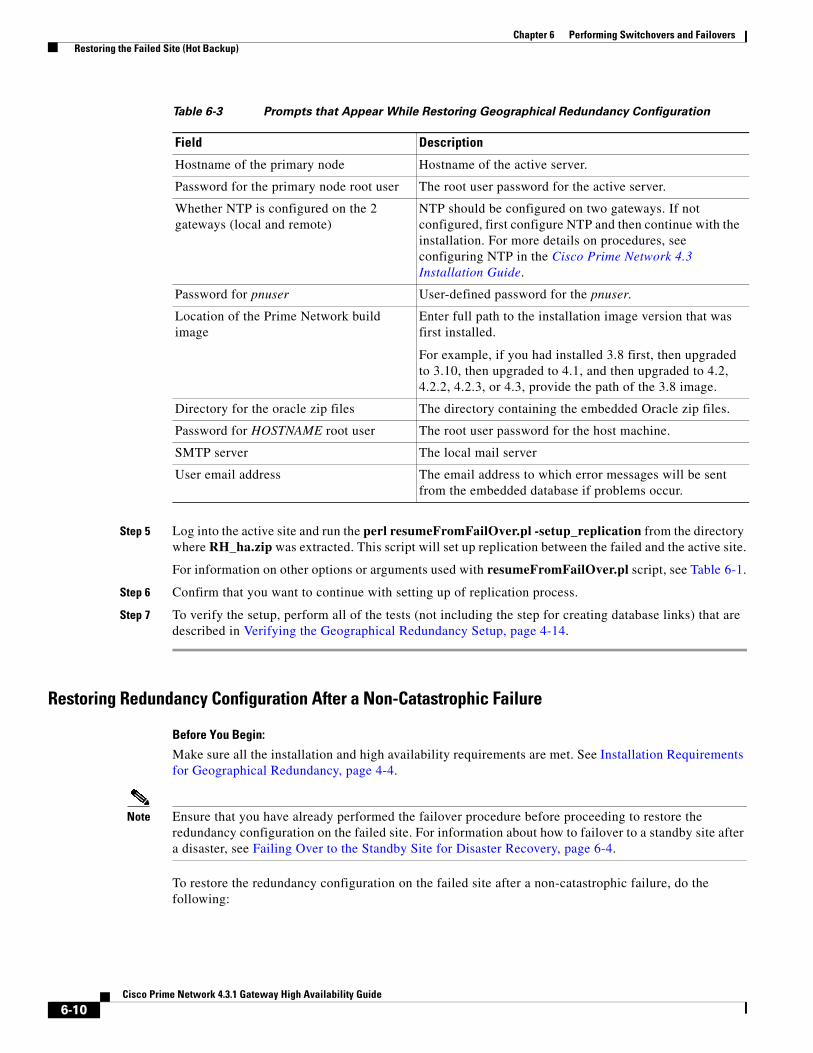
Chapter 6 Performing Switchovers and Failovers Restoring the Failed Site (Hot Backup)
Step 5 Log into the active site and run the perl resumeFromFailOver.pl -setup_replication from the directory where RH_ha.zip was extracted. This script will set up replication between the failed and the active site.
For information on other options or arguments used with resumeFromFailOver.pl script, see Table 6-1.
Step 6 Confirm that you want to continue with setting up of replication process.
Step 7 To verify the setup, perform all of the tests (not including the step for creating database links) that are described in Verifying the Geographical Redundancy Setup, page 4-14.
Restoring Redundancy Configuration After a Non-Catastrophic Failure
Before You Begin:
Make sure all the installation and high availability requirements are met. See Installation Requirements for Geographical Redundancy, page 4-4.
Note Ensure that you have already performed the failover procedure before proceeding to restore the redundancy configuration on the failed site. For information about how to failover to a standby site after a disaster, see Failing Over to the Standby Site for Disaster Recovery, page 6-4.
To restore the redundancy configuration on the failed site after a non-catastrophic failure, do the following:
Table 6-3 Prompts that Appear While Restoring Geographical Redundancy Configuration
Field Description
Hostname of the primary node Hostname of the active server.
Password for the primary node root user The root user password for the active server.
Whether NTP is configured on the 2 gateways (local and remote)
NTP should be configured on two gateways. If not configured, first configure NTP and then continue with the installation. For more details on procedures, see configuring NTP in the Cisco Prime Network 4.3 Installation Guide.
Password for pnuser User-defined password for the pnuser.
Location of the Prime Network build image
Enter full path to the installation image version that was first installed.
For example, if you had installed 3.8 first, then upgraded to 3.10, then upgraded to 4.1, and then upgraded to 4.2, 4.2.2, 4.2.3, or 4.3, provide the path of the 3.8 image.
Directory for the oracle zip files The directory containing the embedded Oracle zip files.
Password for HOSTNAME root user The root user password for the host machine.
SMTP server The local mail server
User email address The email address to which error messages will be sent from the embedded database if problems occur.
6-10Cisco Prime Network 4.3.1 Gateway High Availability Guide
Chapter 6 Performing Switchovers and Failovers Stopping and Restarting Data Replication
Step 1 As a root user, log into the failed site and unzip the RH_ha.zip located on the “Disk 1 New Install” DVD. Unzipping RH_ha.zip creates the /tmp/RH_ha directory. Also, unzip the RH_ha.zip in the primary location.
Step 2 From the /tmp/RH_ha directory, run the perl resumeFromFailOver.pl -reconfigure_setup for restoring the replication between the failed and the active site.
For information on options or arguments used with resumeFromFailOver.pl script, see Table 6-1.
cd /tmp/RH_ha perl resumeFromFailOver.pl -reconfigure_setup
Step 3 Log into the active site and run the perl resumeFromFailOver.pl -setup_replication from the /tmp/RH_ha directory for setting up replication between the failed and the active site.
For information on other options or arguments used with resumeFromFailOver.pl script, see Table 6-1
Step 4 Confirm to continue with setting up of replication process.
Step 5 To verify the setup, perform all of the tests (not including the step for creating database links) that are described in Verifying the Geographical Redundancy Setup, page 4-14.
Stopping and Restarting Data ReplicationThese topics explain how to stop and restart the data replication process:
• Stopping Data Replication, page 6-11
• Resuming Data Replication, page 6-13
Stopping Data Replication
Use the stop replication command primeha -stop when you need to perform scheduled work on a server in the remote site. It stops the replication process to the remote site and shuts down the standby database. Then resume replication when maintenance is complete as described in Resuming Data Replication, page 6-13.
The following includes an example of a stop replication session. In the example:
• The local active gateway is P1with the IP address 10.33.150.66.
• The remote standby gateway is S1.
This example stops data replication from P1 to S1.
Note This command must be run from the server that contains the standby database (S1 in this example). You can validate which server is the standby by running primeha -status.
Step 1 Move to the correct directory.
# cd /var/adm/cisco/prime-network/scripts/ha/util
Step 2 Verify the status of the active and backup servers using primeha -status:
# primeha -status
6-11Cisco Prime Network 4.3.1 Gateway High Availability Guide

Chapter 6 Performing Switchovers and Failovers Stopping and Restarting Data Replication
+ Perl for HA already installed
HOST Prime Network SERVICE ORACLE SERVICES1 Standby Prime Network Standby oracle localP1 Active Prime Network Active oracle
Step 3 Log into the server with the remote database (S1) and enter the following command. This will stop replicating data and will shut down the remote site database.
# ./primeha -stop
Step 4 Enter the server details as shown in the following table.
# ./primeha -stop
+ Perl for HA already installed
+ Stopping replication to remote node- Enter the remote server's gateway IP address:10.33.150.66- Enter the root password for the node that has the gateway mounted:pwd- Enter the remote data base IP address: 10.33.150.66 - Enter the root password for the node that has the data base mounted:pwd- Enter a name for the OS user of the databaseoracle
Table 6-4 Prompts for primeha -stop and -start
Prompt for Description
Remote server's gateway IP address IP address for the primary gateway (P1). If the primary site has a local redundancy setup, enter the floating IP address for the Prime Network service.
(Because the script is run from S1, P1 is the remote server.)
Root password for the node that has the gateway mounted
The root password for the operating system (required for SSH). (This would be the password for the P1 node.)
Remote database IP address IP address for the primary database. If the primary site has a local redundancy setup, enter the floating IP address of the Oracle service.
(Because the script is run from S1, P1 is the remote database.)
Root password for the node that has the database mounted
The root password for the operating system (required for SSH). (Again, this would be the password for the P1 node.)
Cluster sub server's IP address (Displayed if standby database is part of a cluster) Enter the physical IP address of the remote node. (This would be the physical IP address for P1.)
Name for the OS user of the database Example: oracle
Home directory of the user Example: /opt/ora/oracle
Name for the OS user for Prime Network Example: pn41
Home directory of the user Prime Network OS user
Example: /export/home/pn41
6-12Cisco Prime Network 4.3.1 Gateway High Availability Guide

Chapter 6 Performing Switchovers and Failovers Stopping and Restarting Data Replication
- Enter the home directory of the user (oracle)/opt/ora/oracle- Enter a name for the OS user for Prime Networkpn41- Enter the home directory of the user (pn41)/export/home/pn41- Checking if Prime Network is mounted on local node [MOUNTED]- Removing local node Prime Network flag- Stopping local db replication - Removing local node data base flag- Stopping replication on remote gateway- Copying scripts to remote database- Running stop replication script on remote database
Step 5 Verify the status of the active and backup servers using primeha -status:
# primeha -status
+ Perl for HA already installed
HOST Prime Network SERVICE ORACLE SERVICES1 Prime Network not running on this node Oracle not running on this nodeP1 Prime Network not running on this node Oracle not running on this node
Step 6 Verify that all applications on the standby server (S1) are stopped by running fsuser -c /export/home. If any processes are still running (such as the Apache webserver), boot the standby server in single-user mode.
Step 7 Perform any necessary maintenance.
Resuming Data Replication
Note This command can only be used if (1) the remote database was stopped using primeha -stop, and (2) the remote database has not been down for more than 7 days. If the remote database has been down for more than seven days, you must recreate the remote database by using the setup_Prime_DR.pl script. See Installing the Prime Network Gateway Geographical Redundancy Software, page 4-6 for information on using setup_Prime_DR.pl script.
Use the resume replication utility primeha -start to start the database at the remote site (in open, read-only mode) and restart the replication process. Run this command after all work is completed on the remote site.
The following includes an example of a start replication session. In this example:
• The local active gateway P1with IP address 10.33.150.66.
• The remote standby gateway is S1.
This example starts data replication from the local active gateway (P1) to the remote standby gateway (S1).
Note This command must be run from the server that contains the remote database.
Step 1 Verify the following on the server with the remote database (S1):
6-13Cisco Prime Network 4.3.1 Gateway High Availability Guide
Chapter 6 Performing Switchovers and Failovers Changing IP Addresses after a Failover or Switchover
• The database has not been down for more than seven days. If it has, you must recreate the remote database using setup_Prime_DR.pl script (see Installing the Prime Network Gateway Geographical Redundancy Software, page 4-6).
• Maintenance on the server is complete.
• Whether the server is in single-user mode. If it is, reboot it in multi-user mode.
Step 2 Log into the server with the remote database (S1) and move to the correct directory.
# cd /var/adm/cisco/prime-network/scripts/ha/util
Step 3 Verify the status of the active and backup servers using primeha -status. If any services are running, stop them using primeha -stop.
Step 4 Enter the following command. This will start replicating data and will shut down the remote site database.
# ./primeha -start
Step 5 Enter the server details (see Table 6-4).
Note If the process aborts, run primeha -stop again. (The script most likely aborted because a process is not shut down.) Then verify that no services are running with primeha -status.
Step 6 When the process completes, verify the status of the active and backup servers using primeha -status:
# primeha -status
+ Perl for HA already installed
HOST Prime Network SERVICE ORACLE SERVICES1 Standby Prime Network Standby oracle localP1 Active Prime Network Active oracle
Changing IP Addresses after a Failover or SwitchoverIf all IP addresses are not automatically changed after a failover or switchover, use the following procedures, as appropriate.
• Changing the Gateway IP Address on a Gateway and All Units (changeSite.pl), page 6-14
• Changing the Gateway IP Address on a Single Unit (switchUnit.pl), page 6-16
Changing the Gateway IP Address on a Gateway and All Units (changeSite.pl)
If the gateway IP address is not updated on any of the units (or on the gateway) during a site-to-site failover or switchover, use the changeSite.pl utility to do so manually. This procedure will change the address on the gateway and all reachable units.
Note If a dual-node cluster is part of a local redundancy setup, use the logical IP addresses.
6-14Cisco Prime Network 4.3.1 Gateway High Availability Guide

Chapter 6 Performing Switchovers and Failovers Changing IP Addresses after a Failover or Switchover
The following table describes the options or arguments to the changeSite.pl utility. If you are using an external LDAP server for user authentication, you must also set the necessary LDAP parameters, as described below. For more details on these parameters, see Configuring Prime Network to Communicate with the External LDAP Server in the Cisco Prime Network 4.3 Administrator Guide.
Step 1 If you will reset LDAP information, reconfigure them first from the Prime Network Administration GUI client. For details on LDAP, see Configuring Prime Network to Communicate with the External LDAP Server in the Cisco Prime Network 4.3 Administrator Guide.
Step 2 Log into the primary gateway server as pnuser.
Option/Arguments Description
-force Allow manual change to registry settings. (Because this script runs as part of a failover or switchover, the -force option is required when running the script from the command line.)
-newgwip new-gateway-ip IP address of the gateway that is running after the failover or switchover.
-newdbip new-database-ip IP address of the database that running after the failover or switchover.
-oldgwip old-gateway-ip IP address of the gateway that was running prior to the failover or switchover.
-oldbip old-database-ip IP address of the database that was running prior to the failover or switchover.
[ -newldapurl new-ldap-url -oldldapurl old-ldap-url ]
(LDAP only) URL for the LDAP server that will be used by the running gateway (new-ldap-url), and the URL that was used by the gateway that was running prior to the failover or switchover (old-ldap-url). Use the following format:
ldap://host.company.com:port
[ -newldapprefix new-ldap-prefix -oldldapprefix old-ldap-prefix ]
(LDAP only) First part of the LDAP DN (which is used to uniquely identify users) for the new and old LDAP server. Both new-ldap-prefix and old-ldap-prefix should be entered exactly as shown below:
CN
(The actual format is CN=Value, which specifies the common name for specific users. =Value will be automatically populated with Prime Network usernames.)
[ -newldapsuffix new-ldap-suffix -oldldapsuffix old-ldap-suffix ]
(LDAP only) Second part of the LDAP distinguished name, which specifies the location in the directory for both the new and old LDAP servers. Both new-ldap-suffix and old-ldap-suffix should use the following format
,CN=Users,DC=LDAP_server,DC=company,DC=com
[ -newldapisssl new-ldap-is-ssl -oldldapisssl old-ldap-is-ssl ]
(LDAP only) Encryption protocol to be used for communication between the running Prime Network gateway server and the new LDAP server (new-ldap-is-ssl), and the protocol that was used between the old gateway and LDAP servers (old-ldap-is-ssl).
6-15Cisco Prime Network 4.3.1 Gateway High Availability Guide
Chapter 6 Performing Switchovers and Failovers Changing IP Addresses after a Failover or Switchover
Step 3 Change to the correct directory:
cd $ANAHOME/Main/ha
Step 4 Run the following command:
perl changeSite.pl -force -newgwip new-gw-ip -newdbip new-db-ip -oldgwip old-gw-ip -olddbip old-db-ip[-newldapurl new-ldap-url -oldldapurl old-ldap-url][-newldapprefix new-ldap-prefix -oldldapprefix old-ldap-prefix][-newldapsuffix new-ldap-suffix -oldldapsuffix old-ldap-suffix][-newldapisssl new-ldap-is-ssl -oldldapisssl old-ldap-is-ssl]
The following is an example of a changeSite.pl session. In this example the following is being changed:
• The original gateway and database IP address was 1.1.1.1.
• The site was switched over to the standby gateway (1.1.1.2) and database (1.1.1.3).
For some reason, the IP addresses were not correctly changed to reflect the new addresses. The utility forces the IP addresses to be changed to 1.1.1.2 for the gateway and 1.1.1.3 for the database. In this example the system is not using LDAP, so those parameters are not included.
hostname% cd $ANAHOME/Main/hahostname% perl changeSite.pl -force -newgwip 1.1.1.2 -newdbip 1.1.1.3 -oldgwip 1.1.1.1 -olddbip 1.1.1.1
Thu Apr 14 16:08:22 2013 --[INFO]: '-Forced change of gw address from 1.1.1.1 to 1.1.1.2.... 'Thu Apr 14 16:08:22 2013 --[INFO]: '--changing uplinks for gw AVM0'Thu Apr 14 16:08:22 2013 --[INFO]: '--changing uplinks for unit AVM0s'Thu Apr 14 16:08:22 2013 --[INFO]: '--changing gw ip and haservice for unit AVM99s'Thu Apr 14 16:08:22 2013 --[INFO]: '--changing registry on units'Thu Apr 14 16:08:37 2013 --[INFO]: '--changing localhost entry for gw AVM99'Thu Apr 14 16:08:37 2013 --[INFO]: '-Forced change of db server address from 1.1.1.1 to 1.1.1.3.... 'Thu Apr 14 16:08:37 2013 --[INFO]: '--changing db server ip for gw AVM66'Thu Apr 14 16:08:38 2013 --[INFO]: '--changing db server ip for gw persistency.xml'Thu Apr 14 16:08:38 2013 --[INFO]: '--changing db server ip for template persistency.xml'Thu Apr 14 16:08:38 2013 --[INFO]: '--changing db server ip for unit persistency.xml'Thu Apr 14 16:08:38 2013 --[INFO]: '-Forced change of NCCM address from 1.1.1.1 to 1.1.1.3.... 'new IP address is: 1.1.1.3jdbc.properties file has been updated to change to new IP addressThu Apr 14 16:08:39 2013 --[INFO]: '->Done'
Changing the Gateway IP Address on a Single Unit (switchUnit.pl)
If any of the units do not reflect the updated gateway and database IP address after a site-to-site failover or switchover, use the switchUnit.pl utility to do so manually. This procedure will change the address only on the unit from which it is run.
Note If a dual-node cluster is part of a local redundancy setup, use the logical IP addresses.
6-16Cisco Prime Network 4.3.1 Gateway High Availability Guide

Chapter 6 Performing Switchovers and Failovers Changing IP Addresses after a Failover or Switchover
For any unit that does not reflect the updated gateway and database IP addresses:
Step 1 Log into the unit as pnuser.
Step 2 Change to the correct directory:
cd $ANAHOME/Main/ha
Step 3 Run the following command:
perl switchUnit.pl new-gw-ip old-gw-ip new-db-ip old-db-ip
6-17Cisco Prime Network 4.3.1 Gateway High Availability Guide

Chapter 6 Performing Switchovers and Failovers Changing IP Addresses after a Failover or Switchover
6-18Cisco Prime Network 4.3.1 Gateway High Availability Guide