Embed Size (px)
DESCRIPTION
how to use DSL based access solutions.
Citation preview

Mr. Bad Example
Evaluation notes were added to the output document. To get rid of these notes, please order your copy of ePrint IV now.

Mr. Bad Example
Design and Implementation of DSL-Based Access
Solutions
Design and Implementation of DSL-Based Access Solutions addresses various architectures for DSL-based networks. It focuses on how to design and implement an end-to-end solution for service providers, considering various business models such as retail, wholesale, VPN, etc.
This book depicts the different architectures, and helps you understand the key design principles in deploying them. It covers both access encapsulations such as bridging, PPPoA, PPPoE, and routing, as well as core architectures such as IP, L2TP, MPLS/VPN, and ATM. Because it focuses on end-to-end solutions, Design and Implementation of DSL-Based Access Solutions talks about how to do mass provisioning of subscribers and how to manage networks in the most efficient way. It also includes discussions of real-life deployments, their design-related issues, and their implementation.
Evaluation notes were added to the output document. To get rid of these notes, please order your copy of ePrint IV now.

Mr. Bad Example
About the Authors Sanjeev Mervana, CCIE #4006, has over 10 years of experience in networking and has been with Cisco Systems since 1998. A CCIE since 1998, Sanjeev was the Technical Leader in the Customer Support Organization at Cisco for resolving complex networking issues before moving to the Technical Marketing Group. Since joining the Technical Marketing Group, Sanjeev has established a lead in defining broadband architectures for customers and has published several service architecture papers internally to Cisco as well as for customers. His primary job involves him in architectural discussions with leading service providers to offer various value-add services. Sanjeev has been a key contributor and instrumental in defining some of the requirements for next-generation products at the edge of the network.
Chris Le, CCIE #5235, is a Technical Marketing Engineer for the Service Provider Line of Business for Cisco Systems. Chris has provided DSL internetworking design, implementation, and performance engineering to several service providers. He has worked extensively on design and implementation in the IP aggregation space and has provided training to engineers on leased-line and broadband aggregation.
Evaluation notes were added to the output document. To get rid of these notes, please order your copy of ePrint IV now.

Mr. Bad Example
About the Technical Reviewers Kumar Reddy is Manager of Technical Marketing at Cisco Systems. Kumar has authored a number of technical papers and presentations for both internal and customer audiences in the area of broadband aggregation and is a regular technical presenter and trainer at Cisco events. He works extensively with Cisco customers and pre-sales teams on service architectures and deployments for IP access networks. Prior to joining Cisco, Kumar worked in Paris, teaching and developing network protocols and software.
Jay Thontakudi is a Technical Marketing Engineer with Cisco, working in the field on architectural design, network migration, and issues related to DSL. He has been with Cisco since 1999. Jay's prior experience includes nine years in the oil and natural gas industry with job functions in project engineering, process control networks, and enterprise networking. Jay holds a masters degrees in computer science and mechanical engineering.
Brian Melzer, CCIE #3981, is an Internetwork Solutions Engineer for ThruPoint, Inc., out of its Raleigh office. He has worked as a consultant for ThruPoint since September 2000. Thrupoint is a global networking services firm and one of the few companies selected as a Cisco System Strategic Partner. Before working for Thrupoint he spent five years working for AT&T Solutions on the design and management of outsourcing deals involving Fortune 500 clients. As a member of the Wolfpack, Brian received his undergraduate degree in electrical engineering and his masters degree in management at North Carolina State University.
Evaluation notes were added to the output document. To get rid of these notes, please order your copy of ePrint IV now.

Mr. Bad Example
Acknowledgments We would like to thank Stephane Lamarre first for encouraging us with writing DSL architecture white papers that were the basis and inspiration for this book. Thanks to Charles Ford with his expertise in DSL and to Jay Thontakudi for his expertise in IP DSL switching. Special thanks to Kumar Reddy and Jay for their dedication in reviewing the book, for their constructive suggestions and criticisms, and for keeping us honest.
Our thanks also go to John Kane and Christopher Cleveland from Cisco Press who assisted us with producing this book and believed in our ideas.
Last but not least, we'd like to thank our Technical Marketing Engineer colleagues whom we learned so much from and made our work much more enjoyable.
Evaluation notes were added to the output document. To get rid of these notes, please order your copy of ePrint IV now.

Mr. Bad Example
Introduction This book is aimed at network engineers who need to have an understanding of DSL technology and how it is deployed in real networks today. Some background information is provided so that readers can appreciate the problems that DSL can solve and understand some of the challenges still ahead. Readers need to know basic IP operation in order to easily grasp the concept of different ATM encapsulations often used in this book. Although not required, knowledge of dial-up networks may help readers breeze through the encapsulation portion of this book because the same technology used in dial-up networks is also used in DSL aggregation.
Not only network engineers can benefit from this book. Network designers can also enjoy reading the case studies and the pros and cons of each of the encapsulation methods. Case studies are provided with in-depth discussion of several implementation options, from a small DSL network to a large network supporting millions of subscribers.
Motivation for the Book
There are many books available in the market today that explain how DSL works at Layer 1, its modulation techniques, and so forth. There are also certain books that cover some of the access encapsulations briefly. What we couldn't find when we started working on this book was clear understanding of various architectures, when to deploy a certain architecture, and what the implications were if we deployed those architectures. There are several service providers out there today with DSL networks ranging from very small ones to ones that support millions of customers. The lessons learned from those deployments in addition to various proof-of-concept labs and performance tests done in-house will help readers understand and implement those architectures.
Goals of the Book
The purpose of this book is to get the readers more familiar with various DSL access and core architectures and how they are implemented. By presenting readers with real-life deployment scenarios and case studies, the book helps readers understand the pitfalls and benefits of DSL architecture and apply those principles when designing and deploying their own DSL networks. The in-depth sections on DSL architectures will also help you to understand different encapsulation methods used in networks today.
How This Book Is Organized
Chapter 1 takes you back to the time when 300-baud modem was the only access technology available to consumers. It covers the progress in access networks for the last 15 to 20 years and gets you to appreciate how far along we've come in bringing high-speed access home to consumers.
Evaluation notes were added to the output document. To get rid of these notes, please order your copy of ePrint IV now.

Mr. Bad Example
This chapter also discusses the basic building block for telephone networks, which is a DS-0, and the frequency it operates on. Other follow-on access technologies such as ISDN still did not solve the problem of overloading the Public Switched Telephone Network (PSTN), leading to the adoption of DSL as the access technology of choice for phone companies.
Chapter 2 introduces the different flavors of DSL along with the advantages and disadvantages of each flavor. This chapter looks at Layer 1 design considerations, such as copper loop issues, noise margin, and reach, and what can be done in the DSLAMs and in the Central Office (CO) to resolve those problems. This chapter also addresses the protocols running over DSL—ATM and Frame Relay—showing why ATM dominates most, if not all, ADSL deployments today.
Chapter 3 covers DSL functional segments and responsibilities and where the demarcations end. Companies that own the copper loop are traditionally the sole provider for both voice and data running over that same copper loop, but because of government deregulation, other companies can move in and lease those lines from the phone companies and offer data to their customers. This is followed by the services offered by wholesale and retail ISPs.
Chapter 4 focuses on the encapsulation methods of subscriber ATM VCs. PPPoA, PPPoE, RFC 1483 bridge, RFC 1483 routed, and RBE are some of the encapsulations discussed in detail. The chapter addresses the advantages, disadvantages, and design considerations for customer premises equipment (CPE), aggregation devices, and ATM switches for each encapsulation method. Coverage also includes the different methods of carrying subscribers data to the ISP and corporate home gateways, such as L2TP, Service Selection Gateway (SSG), and MPLS.
Chapter 5 is an exciting chapter that presents you with real-life DSL deployment scenarios. This chapter includes four case studies, ranging from a few hundred thousand subscribers to millions of subscribers with download speeds ranging from 384 kbps to 4 Mbps. All elements of DSL are considered and calculated including the number of subscribers per DSLAMs, the number of DSLAMs per CO, the number of ATM switches, and the number of aggregation devices. When scaling the network, these and other elements need to be closely examined. In addition to the wealth of practical information in these case studies, you will also have a chance to look at the migration path and scaling up of networks to support a much larger number of subscribers.
Chapter 6 provides an overview of the provisioning model today, which involves a lot of manual steps in order to roll out a new DSL line. To achieve the goal of installing one million DSL lines that some service providers have set, there has to be a better way to automatically provision these lines quickly.
This chapter provides an overview of the flowthrough provisioning concept and Cisco Element Manager Framework, and how each Element Manager ties into the framework that integrates into the existing service provisioning applications. With the right tools, a line can be tested and provisioned automatically, and the CPE will have its images and configurations downloaded, and other elements in the network will also have the appropriate configurations downloaded to it automatically.
Evaluation notes were added to the output document. To get rid of these notes, please order your copy of ePrint IV now.

Mr. Bad Example
Icons Used in This Book
Command Syntax Conventions
The conventions used to present command syntax in this book are the same conventions used in the IOS Command Reference. The Command Reference describes these conventions as follows:
Vertical bars (|) separate alternative, mutually exclusive elements. Square brackets [ ] indicate optional elements. Braces { } indicate a required choice. Braces within brackets [{ }] indicate a required choice within an optional
element. Boldface indicates commands and keywords that are entered literally as
shown. In actual configuration examples and output (not general command syntax), boldface indicates commands that are manually input by the user (such as a show command).
Italics indicate arguments for which you supply actual values
Evaluation notes were added to the output document. To get rid of these notes, please order your copy of ePrint IV now.

Mr. Bad Example
Chapter 1. History of Remote Access Technology This chapter covers the following key topics:
History of Remote Access Technology — A brief history of the remote access technology and its evolution from analog to digital.
The World of Analog — Earlier applications that used analog modems were mainly text-based, but with the explosion of the Internet and its graphical applications, analog modem has put a tremendous burden on the Public Switched Telephone Network (PSTN).
ISDN — ISDN was supposed to be the next big thing, replacing analog modems; however, because telcos failed to push the technology and invest more upfront for a long-term, rather than a short-term financial gain, the technology failed to take off.
ADSL Comes of Age — A brief history of ADSL and its adoption by different phone companies. Each phone company chose a different ADSL vendor, while a few ganged up to form a Joint Procurement Contract and together chose one vendor to supply them with ADSL equipment.
ADSL Benefits — ADSL offered some of the benefits that analog modems and ISDN were never able to offer. High-speed access, always-on, offload data from the voice network, and so much more, are the main reasons every phone company today is pushing the technology.
Applications That Drive High-Speed Access — High-speed access applications such as Voice over IP (VoIP) and video on demand (VoD) enable phone companies the possiblity for additional revenues over their existing copper wire infrastructure.
Remember back when a 300 baud modem was the fastest access technology that you could get your hands on. And when 2400 baud came out, you thought modem speed could not get any faster? As encoding algorithms continue to improve and telephone lines have become cleaner of electrical interference, analog modem speed has improved greatly with the latest V.90 standard capable of 56 kbps of data transfer.
In today's digital age, inexpensive cameras that are available in a neighborhood electronic store can store images in a digital format, music we listen to is stored digitally on CDs, and movies are encoded into digital format and stored on DVDs.
The recent MP3 format for music and MPEG-2 for movies have ignited a series of lawsuits from recording and movie studios. Music can be encoded in a digital format small enough to be shared among friends. It doesn't matter how many times the song has been copied, the quality of the song doesn't decrease. What worries the recording studios and music labels even more is that these songs are easily accessible by anyone that has a connection to the Internet.
When it comes to remote access, we are still using decade old technology to transmit these digital files over analog phone lines. We spent so much time and energy
Evaluation notes were added to the output document. To get rid of these notes, please order your copy of ePrint IV now.

Mr. Bad Example
building faster computers and digitizing everything from music, voice, and movies, that there has not been much improvement when it comes to access technology.
There have been attempts to bring faster access speed to consumers in the past, each with various degree of success. The most popular broadband access technologies today are cable modems and digital subscriber lines (DSL), with wireless gaining more popularity. Although each technology has its advantages and drawbacks, DSL seems promising because it is backed by virtually all phone companies, plus the technology has room to grow.
This chapter will cover the history of remote access including analog modem and Integrated Services Digital Network (ISDN), and the problems that led to the adoption of DSL by major telephone companies as the next method of remote access.
The World of Analog
Earlier applications that used analog modem involved text-based applications. These applications were mainly used by corporations who had a need for employees or vendors to access and use a corporate database. Digital bits and bytes from the PC applications are converted into analog waves by analog modems. Those analog waves then are transmitted through a Public Switched Telephone Network (PSTN). These waves are received by another modem, which in turn converts these signals into digital bits and bytes that the far-end (receiving) computer can understand. Figure 1-1 illustrates how the signals are converted from one PC to another from digital to analog and then back again to digital.
Figure 1-1. Signal Conversion Between Two Computers Using Analog Modems
Because early applications were mainly text-based and early computers were relatively slow, low-speed modems were not a big issue. A person from their home would dial in to a computer, and once a session was established, users would send a couple of keystrokes to the mainframe asking it to do a series of computations. After some time, the mainframe would then display the result of the operation back to the user, one screen of text at a time. As you can see, there's not much need for a high-speed connection because the majority of the time is spent waiting for the mainframe to finish its jobs. Remote access was limited to a very small group of scientists and engineers involved with number crunching and other mathematical applications, and only the final result of the computations were of any interest to the end user.
Evaluation notes were added to the output document. To get rid of these notes, please order your copy of ePrint IV now.

Mr. Bad Example
When multimedia intensive applications, such as the World Wide Web, began to take off, there was an obvious need for remote access speed to improve. Over time, modem speed has become faster with better modulation/demodulation algorithms and cleaner copper wires from the Central Office (CO) to your residence. Modem speed has been able to improve from 300 bps to 1200 bps to 9600 bps. With clever engineering, modem speed has achieved 56 kbps. But as with most technologies, there is an upper limit of how fast modem speed can go. With the 56-kbps modem technology, we are hitting the upper limit of analog technology, and 56 kbps is the highest analog speed that we will be able to achieve over the existing copper wires used to carry voice. Due to the modem limitation, alternative technologies, such as broadband access technologies, are needed that allow subscribers to access the Internet at a much higher speed.
Telephone companies had been converting their analog switches to digital for decades. That along with digital phone switches comes Integrated Services Digital Network (ISDN), which is supposed to solve the digital to analog back to digital conversion problem. ISDN enables much faster access speeds. With ISDN, voice and data can be offered simultaneously over the same pair of copper wiring. A channel is available for voice and another channel for data. When the voice channel is not in use, ISDN equipment can use both channels to achieve speeds up to 128 kbps. ISDN was offered around the time when modem speed was at 9600 bps, making it attractive to users who demanded high-speed access. Figure 1-2 illustrates the concept of 2 B channels used in both voice and data.
Figure 1-2. Voice and Data Over the Same ISDN Line
ISDN
ISDN brings some relief to the speed limitations of analog modems by offering speed up to 1.5 Mbps for Primary Rate Interface (PRI), or a more commonly used rate that is offered by most phone companies, the Basic Rate Interface (BRI). BRI offers speed up to 128 kbps, significantly faster than traditional analog speed.
Evaluation notes were added to the output document. To get rid of these notes, please order your copy of ePrint IV now.

Mr. Bad Example
So what makes ISDN able to achieve such high speeds that analog modems can't? To fully understand the difference between analog modems and ISDN, we need to take a look at how voice is encoded into a digital signal level 0 (DS-0) channel.
To convert an analog voice into digital signal, the required sampling rate is 8000 samples per second; therefore, 8 bits are needed to represent each sample. Therefore, the bandwidth needed is 8000 * 8 = 64,000 bits per second, which is called a DS-0 channel. A traditional analog line runs over a DS-0 channel and has 64 kbps of total bandwidth. Out of this total bandwidth, 8 kbps is taken out for telephone signaling, leaving 56 kbps for voice calls. The services that are run over the 8-kbps channel are necessary for your phone to ring. That's where caller ID information is sent, plus other maintenance services so that the telephone switch knows when you have hung up your call and to stop billing you. This method is called in-band signaling, or robbed bit signaling, because an 8 kb chunk is taken out, or robbed out of the original 64 kbps for signaling. If digital signals are converted into analog and back to digital again, only 56 kbps worth of bandwidth is available to do it in, so this is where the 56-kbps limitation in analog modems comes in. Figure 1-3 illustrates the breakdown in robbed bit signaling.
Figure 1-3. Robbed Bit Signaling
ISDN, on the other hand, carries three logical channels over the same pair of copper, two B, or Bearer, channels and one D, or Delta, channel. Each B channel has a bandwidth of 64 kbps and is capable of carrying voice or data. Instead of the 8 kbps in-band signaling channel from the POTS (plain old telephone system) case, there is now a separate signaling channel called a D channel that has 16 kbps and can support signaling for both B channels. The two B channels can then be combined yielding up to 128 kbps of speed. The attractive feature of ISDN is integrated voice and data running over the same copper wire. A computer can have both B channels connected to the Internet, but when a person needs to make a phone call, he can simply pick up the phone using one of the B channels. The ISDN equipment will automatically detect that there is a phone call and will drop one B channel from the computer automatically.
You can choose from many variations of ISDN configurations. You can choose one B channel to carry voice alone and one D channel for signaling, or you can choose only one B channel for voice, one B channel for data, and one D channel for signaling. The most popular method is called 2B+D BRI. Figure 1-4 shows a BRI line has three logical channels: two B channels and one D channel.
Figure 1-4. Logical Channels Over a BRI Interface
Evaluation notes were added to the output document. To get rid of these notes, please order your copy of ePrint IV now.
Mr. Bad Example
Besides the voice capability, ISDN also offers other attractive features such as quick call setup and teardown. In the analog world when a modem needs to call the Internet, your modem has to train with the modem on the other end, meaning the modems need to negotiate the connecting speed that both computers can send and receive data reliably. Because each B channel always operates at 64 kbps and there's a separate dedicated D channel for signaling, the setup time for ISDN is in seconds, negligible to the end user. Because ISDN is entirely digital, this effectively makes communication between two ISDN devices all digital without converting signals to analog and back to digital again. Figure 1-5 shows ISDN communication between two PCs.
Figure 1-5. ISDN Communication Between Two Computers
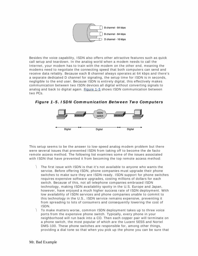
This setup seems to be the answer to low-speed analog modem problem but there were several issues that prevented ISDN from taking off to become the de facto remote access method. The following list examines some of the issues associated with ISDN that have prevented it from becoming the top remote access method:
The first issue with ISDN is that it's not available to anyone who wants the service. Before offering ISDN, phone companies must upgrade their phone switches to make sure they are ISDN-ready. ISDN support for phone switches requires expensive software upgrades, costing millions of dollars for each switch. Because of this, not all telephone companies embraced ISDN technology, making ISDN availability spotty in the U.S. Europe and Japan, however, have enjoyed a much higher success rate of ISDN deployment. With low availability of ISDN services and phone companies unable to commit to this technology in the U.S., ISDN service remains expensive, preventing it from spreading to lots of consumers and consequently lowering the cost of ISDN.
To make matters worse, common ISDN deployment takes up to three voice ports from the expensive phone switch. Typically, every phone in your neighborhood will run back into a CO. Then each copper pair will terminate on a phone switch, the most popular of which are the Lucent 5ESS and Nortel DMS-100. These phone switches are responsible for, among other things, providing a dial tone so that when you pick up the phone you can be sure that
Evaluation notes were added to the output document. To get rid of these notes, please order your copy of ePrint IV now.
Mr. Bad Example
it's ready for you to dial. Phone ports on these switches are expensive and often take years of service to recover the initial investment cost. With three voice ports taken just for ISDN, it becomes too expensive to offer to the masses and, therefore, each phone company has a different view on offering ISDN. Some charge hundreds of dollars for installing ISDN, not including monthly service and usage charges.
To the phone switch, an ISDN call looks the same as a voice call, tying up the same 56-kbps channel on the switch. Telephone companies design their phone network for voice calls that typically last on the average of five to six minutes per call. Internet users who use analog or ISDN modems typically stay connected for a much longer period of time, usually from 30 to 35 minutes, tying up phone lines for other people to use. This results in the phone switch getting congested and unable to serve other customers. This problem is similar to the Mother's Day problem where the phone switch runs out of capacity resulting in a busy signal. With everybody rushing to connect to their Internet at 6:00 p.m. after dinner, this Mother's Day problem now happens almost every night, prompting the phone companies to find other ways to offer remote access methods to their customers.
Besides spotty availability and expensive monthly charges, ISDN doesn't attract a lot of customers because the most affordable and commonly used form of ISDN (BRI) has a limitation of 128 kbps, making it unattractive for subscribers who use bandwidth-hungry applications.
As you can see, ISDN offered faster speed access to customers but presented another set of problems to phone companies. Some phone companies are uncommitted to the technology because of the cost of equipment upgrade and longer return on their investment, although ISDN has enjoyed a much higher deployment in Europe and Japan. The best method for phone companies to solve remote access is to get data off the voice network without running another pair of copper wiring to every house. The next few sections examine how DSL can help relieve the voice network and at the same time see why DSL technology does not run into the same 56-kbps limitation like the analog modem does.
ADSL Comes of Age
Asymmetric digital subscriber line (ADSL) is a technology invented by BellCore in the mid-1980s as a method to offer video and voice over the same copper loop. The intent was to offer VoD to their customers when they wanted it. When the technology fizzled out because VoD failed to take off and typical deployment of ADSL was too slow to run any real-time video over it; however, the technology seems to have been forgotten for almost a decade.
ADSL had a renewed interest from phone companies again after their voice network became overloaded with data. ADSL was being looked at again, but this time the main application that was driving it was data—not video like it was originally designed for. In the early 1990s, phone companies wanted to offer DSL as a method to prevent data from overtaking their voice network but there was a problem. There's no DSL standard, and phone companies don't make the equipment themselves. Southwestern Bell, Bell Atlantic, and BellSouth got together to form the Joint Procurement Contract (JPC) to search for an ADSL equipment maker. They picked Alcatel as the main supplier of their Digital Subscriber Line Access Multiplexers (DSLAMs) and customer premises equipment (CPE). US West chose not
Evaluation notes were added to the output document. To get rid of these notes, please order your copy of ePrint IV now.

Mr. Bad Example
to participate in the consortium and instead picked a startup company called NetSpeed (later acquired by Cisco). Bell Atlantic went with Westell as the main supplier for their DSL equipment. Other competitive local exchange carriers (CLECs) such as Northpoint Kovad, Rhythms, and Cincinnati Bell all offered DSL services later on— each choosing ADSL equipment from different vendors.
Unlike ISDN, the announcements by major U.S. telcos are a big boost to ADSL technology, signaling that ADSL is at the forefront of new remote access technology. Most importantly with ADSL, voice and data are separated into two different networks preventing data from overloading the voice infrastructure. Figure 1-6 shows data offloaded from the PSTN resulting in two networks: data network and voice network.
Figure 1-6. Offloading Data from PSTN Network
Though offering tremendous benefits, ADSL, like most new technologies, has some problems inherited from the current cable wiring for phone services and mass deployments. In the next chapter, we'll look at these benefits and problems that earlier ADSL deployments have run into.
ADSL Benefits
In May 2001, 2,914,003 ADSL lines were recorded in service (Telechoice DSL Deployment Summary, www.xdsl.com/content/resources/deployment_info.aspwww.xdsl.com/content/resources/deployment_info.asp). This tremendous growth in DSL technology was the result of major telcos pushing this technology. So far, DSL has been the most promising technology that enables telcos to get incremental revenues by offering voice, video, and data over the same copper wire. Telephone companies embraced the technology because of the following benefits:
High-speed access— For an affordable price of around $40 a month, customers now can get speeds of up to 1 Mbps, which is necessary to download web pages that are loaded with graphics. Sharing pictures on the
Evaluation notes were added to the output document. To get rid of these notes, please order your copy of ePrint IV now.

Mr. Bad Example
web is now more practical and downloading large MP3 music files from the web is more attractive largely due to advances in DSL technology.
Always-on— If you have ever used a modem before, you know how long it takes to boot up your computer, turn on the modem, dial a number, and listen to a barrage of noise from the modem training. If you get lucky, you will connect on the first try and then you have to make sure everybody in the house does not pick up the phone while you are online. With DSL, it is a service that's always on, meaning you are always connected to the Internet. You no longer have to dial your service provider or fear that someone will pick up the phone while you are on the Internet. The fact that DSL is always on makes people come up with great ideas of utilizing the service from putting up their own web server in the garage to monitoring their homes remotely through a web camera set up inside their house.
Low maintenance— For phone companies deploying hundreds of thousands of DSL lines, low maintenance is a big requirement. The phone lines between the CO and your house are usually underground and protected, barring construction nearby that results in a cable cut. Once DSL is installed, your phone line is left alone—no maintenance needed.
Security— Because every house has its own copper pair running back to the CO, the voice or data traffic traversing the line does not have to mix with any other traffic until it gets to the CO, meaning no one else can listen to your phone message or sniff your data from their computer. Cable technology relies on a shared network, similar to a LAN where everybody on the LAN can listen to all the traffic on that LAN. With some clever hacking or spoofing, a computer might be hacked into. The implication here is that hacking is harder on a dedicated line like DSL. The nature of a dedicated line to the CO makes things a little harder for hackers to compromise your home PC.
ADSL provides a tremendous opportunity for telephone companies to offer new services such as data and voice over their existing copper infrastructure. Newer DSL standards, such as very-high-data-rate DSL (VDSL), provides an extremely fast pipe to the consumer, enabling services such as video over DSL, VoD, video conferencing, and VoIP, all on top of the regular POTS line. The next few sections examine how DSL will enable new service offerings and how high-speed access plays an important role in the future.
Applications That Drive High-Speed Access
Having a big data pipe to the house opens up a new world of applications that were not possible before with analog modems or even ISDN. Applications such as the World Wide Web and e-mail can be run on top of IP. Plus now with plenty of bandwidth that DSL provides, other bandwidth hungry applications can also run on top of IP as well. With a theoretical speed of 8-Mbps download for ADSL and 52 Mbps for VDSL, data, voice, and video can be run concurrently over the same copper wire. The following sections discuss applications that are bandwidth intensive, including
Video over DSL VoIP Residential Gateway High-speed Internet Access and Virtual Private Network (VPN)
Evaluation notes were added to the output document. To get rid of these notes, please order your copy of ePrint IV now.

Mr. Bad Example
Video over DSL
With over 827 million copper lines installed worldwide, phone companies have a massive customer base and they also want to offer new services to their customers. Right now, phone companies would love to have recurrent revenue of about $40 from each resident. But running cable to every neighborhood proves to be expensive. Due to their existing infrastructure, phone companies find it very attractive to offer new services utilizing the existing copper pair. With ADSL, they have been able to offer voice and affordable high-speed data over the same wire and without clogging up their expensive voice network.
As mentioned previously, ADSL was invented by BellCore to offer VoD over existing copper pair. Using MPEG-2 compression, each video stream takes about 3 Mbps to achieve 30 frames per second, a standard rate at which broadcast television operates.
Although ADSL was initially designed to operate at 7 Mbps of download speed, distance limitation has cut down the typical ADSL deployment to about 1.5 Mbps peak download.
As DSLAMs are pushed closer to the neighborhood, copper length is becoming shorter, allowing ADSL to operate at a much higher speed. It also allows other high speed technologies, such as VDSL, to operate at a maximum theoretical 52 Mbps of download speed. This availability of high bandwidth allows phone companies to offer multiple real-time feeds of TV channels to their subscribers over VDSL or a single feed of real-time or VoD channels over ADSL.
Customers now can use multiple VoIP phone lines, surf the Internet, and watch TV at the same time—all over the same copper wire. Because there isn't a need to run additional wiring to your home, the cost savings as a customer is significant. This news is great for the telephone companies because the more bandwidth they can offer to their customers, resulting in the capability to offer more robust services (a greater amount of digital TV channels, for example). Figure 1-7 shows a Video over DSL setup.
Figure 1-7. Video over DSL Application
Evaluation notes were added to the output document. To get rid of these notes, please order your copy of ePrint IV now.

Mr. Bad Example
In the Figure 1-7, a multicast server gets its programming either from a videotaped classroom or from a satellite feed. A content manager such as an IPTV content server will broadcast its programming information to any multicast clients that request for one. The ISP point of presence (POP) will pull down a multicast stream only if there's a client that requests that programming. The beauty of multicast is that even if there's a hundred clients wanting the same programming, the ISP POP will have to pull down only one stream and replicate that stream a hundred times on an aggregation device, pushing those streams down the DSL lines to the clients. In the case of an IP DSL switch, the replication will be done on the switch itself, pushing the content closer to the subscriber.
Voice over IP
Corporations have long known that running two networks, one for voice and one for data, is very expensive both to deploy and to maintain. Separate pieces of equipment have to be bought and maintained, while renting leased lines from telcos incurs on-going monthly expenses. As the phone and data networks begin to converge, corporations are increasingly running voice over their fast data networks. Figure 1-8 shows a typical VoIP application, sometimes called toll bypass.
Figure 1-8. VoIP Application
Let's say a large corporation has four regional offices across the U.S. with high-speed Internet connections. Voice calls outside the company go out of the PSTN, while data calls go out of the public Internet connection. Because all four regional offices have high-speed Internet connections, voice calls placed to the other regional offices use VoIP (over the public Internet). Special Premium Quality of Service (QoS) is applied to these calls to ensure there's minimal delay. This is sometimes referred to as a toll bypass: a remote office or a regional office can dial the headquarters using the four- or five-digit extension, essentially bypassing the CO.
Evaluation notes were added to the output document. To get rid of these notes, please order your copy of ePrint IV now.

Mr. Bad Example
There's no reason why this technology will not work for telecommuters using DSL as a data connection to the corporation. Instead of running one phone line for voice and one phone line for data, both voice and data can be run over the same high-speed DSL connection.
Residential Gateway
Phone companies are already invested heavily in the voice infrastructure, including phone switches and copper runs to the neighborhood. Besides offering DSL over the same set of copper, phone companies also would like to offer voice for incremental revenue. Running an additional pair of copper lines to the home for a second phone line is expensive, and voice over the same pair enables the phone companies to provision a second line without the expensive cable run.
CLECs, unlike phone companies, have no voice infrastructure but would like to offer voice service to their data customers. Imagine when you finally give in and agree to let your teenage daughter add another phone line to your house. Instead of waiting for the phone companies to run another pair of copper to your house, these CLECs can simply enter a couple of keystrokes to activate another phone line for your house.
All that is needed here is a residential gateway. This is a gateway that will sit in your home, terminating the DSL line from your provider and, in turn, provide your house with different services, such as high-speed Internet access, multiple phone lines, and video feeds. Figure 1-9 shows how a residential gateway might look.
Figure 1-9. Typical Residential Gateway
The residential gateway has several important features built into the box:
Evaluation notes were added to the output document. To get rid of these notes, please order your copy of ePrint IV now.

Mr. Bad Example
On the PC side, a Dynamic Host Configuration Protocol (DHCP) server, network address translation (NAT), and an Ethernet switch allow multiple PCs to obtain IP addresses from the residential gateway by way of a traditional Ethernet cable. A wireless base station might be built into the gateway instead of an Ethernet hub for wireless 802.11 users. The ideal gateway should also include VPN and encryption software that enable telecommuters to connect to their office securely.
Several voice ports are also built into this box that enable regular phones to plug into these ports. As mentioned earlier, when a new phone line is needed, the phone provider can configure their switch and the gateway for a new phone number. There is no need to run an additional pair of copper from the CO to the house.
Last but not least, a coax port should be available for future VoD over DSL programming. VoD can be achieved easily, even today, when the entire movie is downloaded into the high capacity internal hard drive in the gateway, enabling later playback at any convenient time.
Some manufacturers have come out with residential gateways, although not all of them have a lot of the rich features. Cisco, 2Wire, and 3COM have all come out with their own version of residential gateway, but you can bet that the functionality of these boxes will be a lot richer once they become more popular.
High-Speed Internet Access and VPN
The main application of DSL today is still web and e-mail traffic, which does not need guaranteed bandwidth and delay. One or two seconds delay will not affect your sending or receiving e-mail. As we move to more time-sensitive traffic such as voice, a different level of service must be implemented by service providers to distinguish time-sensitive traffic over the rest of the non–time-sensitive applications.
Corporations can take advantage of high-speed Internet access by allowing employees to access their corporation from home by various techniques. Figure 1-10 shows a typical DSL deployment where a subscriber is connected to the Internet via an ISP POP. Later chapters will discuss different techniques of building a VPN.
Figure 1-10. High-Speed Internet Access over DSL
Evaluation notes were added to the output document. To get rid of these notes, please order your copy of ePrint IV now.
Mr. Bad Example
Looking Ahead
In this chapter, we've looked at how the access technology has evolved from the traditional analog modems to ISDN and finally DSL. We've also discussed the exciting new applications that can be offered at a low cost to DSL subscribers such as high-speed Internet access, voice service, VPN, and video over DSL.
We'll take a closer look at different xDSL flavors in the next chapter. Different encoding algorithms such as Carrierless Amplitude and Phase Modulation (CAP) and discrete multitone (DMT) will be discussed, as well as a more in-depth discussion of the frequencies in which voice and data operates.
References
xDSL.com, which provides an analysis of DSL technologies, can be found at: www.xdsl.com/content/resources/deployment_info.aspwww.xdsl.com/content/resources/deployment_info.asp
Evaluation notes were added to the output document. To get rid of these notes, please order your copy of ePrint IV now.
Mr. Bad Example
Chapter 2. xDSL Flavors and Considerations at the Physical and Data Link Layers This chapter provides an overview of following xDSL technologies:
ADSL — Asymmetric DSL (ADSL) is the most widely deployed DSL technology today with a theoretical download speed of up to 8 Mbps and 1 Mbps for upload speed. This section discusses different modulation techniques, such as Carrierless Amplitude and Phase Modulation (CAP) and discrete multitone (DMT) along with a lower rate version of ADSL called G.Lite.
VDSL — VDSL is an emerging technology that plans to deliver data rates as high as 52 Mbps in the downstream direction for subscribers that have shorter loops to the Central Office (CO). Both ANSI and ETSI are standardizing this technology.
IDSL — IDSL closely resembles the ISDN technology, including the use of the ISDN 2B1Q encoding algorithm and offers 144 kbps for both uploading and downloading.
SDSL — SDSL was an attractive option for small businesses looking to replace their expensive T1 lines. SDSL, however, never became a standard, making SDSL services spotty and resulting in incompatibility between different vendors.
G.shdsl — The highly anticipated G.shdsl standard from the ITU was developed to replace or enhance many previous DSL standards, making DSL roll out much easier and addressing the interoperability issues at the same time.
Comparing xDSL Flavors — This section provides an overview of positioning each flavor of xDSL in various market segments, depending on what services the service provider offers.
Design Considerations at the Physical Layer (Layer 1) — When deploying DSL in Layer 1, this section addresses such challenges as loop quality, noise, reach versus bandwidth, and how to deal with those issues.
Considerations at the Data Link Layer (Layer 2) — Asynchronous Transfer Mode (ATM) is the widely used data link layer for ADSL-based solution. In this chapter, you will find some basics on ATM and why ATM was chosen as the data link layer.
The objective of this chapter is to familiarize readers of various flavors of xDSL technologies and how they differ from each other. Service providers can choose one technology over the other based on the services they want to offer, how far the subscriber is from the CO, and so forth. This chapter is not intended for readers who are looking for the actual operation of various xDSL flavors. Instead, we will try to explain to you in simplistic terms what the different flavors of xDSL are, which service models they fit in, and what some of the design considerations you need to be aware of at Layer 1.
All xDSL flavors, such as ADSL, SDSL, and IDSL, sit at the physical layer of the OSI reference model. xDSL technology is simply a transmission technology, much like
Evaluation notes were added to the output document. To get rid of these notes, please order your copy of ePrint IV now.

Mr. Bad Example
T1/E1, which we are familiar with. DSL technology in its simplest form is nothing but a modem technology. Data from the subscriber gets modulated by the subscriber-end DSL modem before being put on the physical copper loop. The CO equipment at the other end— comprised of banks of modems—demodulates the signals and makes necessary switching decisions based on the transport layer used. For example, in the case of ADSL, the most widely and commonly used data link layer is ATM. Other vendors, however, also use Frame Relay as the data link layer.
To understand any DSL connectivity, you must understand the components of the entire DSL network, as shown in Figure 2-1. This diagram is also a graphical representation of the ADSL Forum reference model.
Figure 2-1. ADSL Forum Reference Model
As Figure 2-1 illustrates for any DSL connectivity, you have a DSL modem at the subscriber end at a minimum, noted in the diagram as an ATU-R (ADSL termination unit-remote) and more commonly known as customer premises equipment (CPE). At the CO, a corresponding DSL modem demodulates the signals modulated by the subscriber modem. The CO is equipped with a digital subscriber line access multiplexer (DSLAM), which consists of banks of ATU-Cs (ADSL termination unit-central). Depending on the region that CO is serving, the DSLAM should have a corresponding ATU-C for each ATU-R at the subscriber end. Because we are depicting ADSL in the diagram, we made reference to ADSL termination units. If the flavor of DSL is SDSL, the subscriber-end modem then would be called STU-R and so forth.
The splitters shown in Figure 2-1 reflect a device that differentiates DSL data from the regular analog voice. It is important to note here that any DSL flavor usually makes use of the frequency spectrum, which is higher than that used by regular analog voice (typically 4 kHz). In simplistic terms, the job of the splitter is to identify whether the signal is below 4 kHz or higher. This is achieved using a simple low-pass filter technology. By making use of this splitter technology and by DSL using the upper frequency spectrum, utilizing the same pair of copper for both regular analog voice as well as DSL data is possible. If a single pair of copper is used for both the analog voice and DSL data, a splitter will be used at both the subscriber end as well as one in the CO.
Evaluation notes were added to the output document. To get rid of these notes, please order your copy of ePrint IV now.

Mr. Bad Example
In the CO, when a signal is received from the subscriber end, the POTS splitter sends the voice spectrum to a regular phone switch in the CO. Additionally, it sends the data spectrum to the ATU-C in the DSLAM. The ATU-C in turn demodulates the signal. Depending on which transport layer the CPE and DSLAM agreed on using (whether it is ATM or Frame Relay), the DSLAM makes the necessary switching decision to forward the subscriber traffic to its final destination. We will discuss about the data link layer in the later section, "Considerations at the Data Link Layer (Layer 2)."
One other important aspect worth noting on the reference model in Figure 2-1 is upstream and downstream:
Upstream is always referred to as the direction from the subscriber towards the CO.
Downstream is referred to as the direction towards the subscriber.
Table 2-1 depicts the most commonly used xDSL flavors with their corresponding distance limitations and bandwidth.
Table 2-1. DSL Flavor Characteristics
Upstream Bit Rate Downstream Bit Rate Reach
ADSL Up to 800 kbps Up to 8 Mbps Up to 17,000 feet
G.Lite Up to 176 kbps Up to 1.5 Mbps Up to 18,000 feet
SDSL Up to 768 kbps Up to 768 Kbps Up to 10,000 feet
VDSL Up to 20 Mbps Up to 52 Mbps Up to 3000 feet
G.shdsl Up to 2.3 Mbps Up to 2.3 Mbps Up to 22,000 feet
The distance or reach specified in Table 2-1 reflects the distance from the CPE to the CO. Depending on which modulation technology you use or which flavor of xDSL you select, you can achieve different bandwidth in both upstream and downstream direction. The key point that needs to be noted here is that a tradeoff between reach and bandwidth always occurs. The further down the CPE is from the CO, the lesser the bandwidth it gets. A number of factors can play a big role in determining the exact bandwidth at a certain distance, and they will be discussed briefly in the section, "Design Considerations at the Physical Layer (Layer 1)."
ADSL
ADSL, as explained in the first chapter, is the most widely deployed flavor of xDSL today. The reason for this is simple: ADSL provides the right suite of bandwidth both in upstream and downstream directions, required by the most consumers today. ADSL has gained popularity in today's consumer space, not only as the always-on technology but also as a cheaper and more suitable alternative to the common dial modem technology. In addition, ADSL is being offered and gaining popularity as a
Evaluation notes were added to the output document. To get rid of these notes, please order your copy of ePrint IV now.

Mr. Bad Example
cheaper alternative to the traditional T1/Frame Relay circuits for small offices, home offices, and business customer space.
ADSL has become a relatively mature technology having already been through several years of development and physical deployment by many service providers. ADSL can offer rates of 8 Mbps in the downstream direction and approximately 1 Mbps in the upstream direction.
ADSL uses CAP or DMT to encode the data traffic on copper loop. Both CAP and DMT are quite different in how they encode. CAP is not standardized; however, DMT was initially standardized as ANSI T1.413 and was then forwarded to ITU as G.992.1. Since then, the DMT standard has gone through various versions (or issues). Issue One provides the basic framework, while Issue Two provides better interoperability and includes references to ATM and rate adaptation.
Although both CAP and DMT are frequency domain techniques, CAP relies more heavily on the time domain than does DMT. CAP sends high bandwidth symbols across a wider spectrum for a shorter period of time. On the other hand, DMT relies on smaller bandwidth channels sending longer duration symbols at a narrower frequency.
As shown in Figure 2-2, CAP relies on single downstream and upstream band occupying a larger proportion of the available bandwidth. As shown in the diagram, the spectrum is divided into two single carriers—the upstream starts at f1 and the downstream starts at f2. CAP modems can accept ATM, packet, and bit synchronous traffic. As seen with most ADSL deployments, however, ATM predominates across the loop. CAP defines a number of downstream and upstream baud rates (number of symbols per second), which then derive the actual bandwidth.
Figure 2-2. CAP Spectrum for ADSL
CAP was used as the initial choice of encoding method for most initial ADSL deployments, but with the standardization of DMT and the availability of Issue Two, most vendors started adopting the DMT encoding method to achieve the interoperability with other vendors. Another reason for vendors to standardize on
Evaluation notes were added to the output document. To get rid of these notes, please order your copy of ePrint IV now.
Mr. Bad Example
DMT is the fact that DMT is more susceptible to noise and therefore offers a better rate adapting technique.
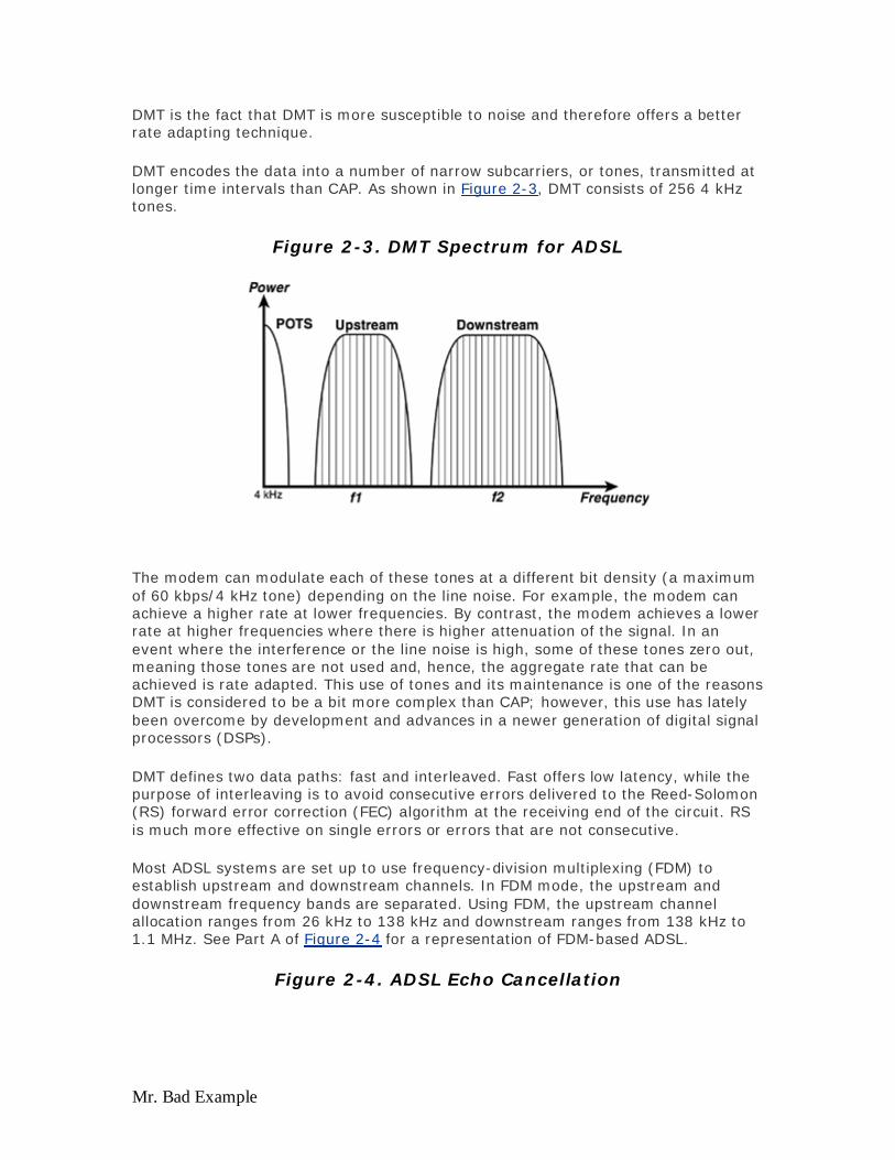
DMT encodes the data into a number of narrow subcarriers, or tones, transmitted at longer time intervals than CAP. As shown in Figure 2-3, DMT consists of 256 4 kHz tones.
Figure 2-3. DMT Spectrum for ADSL
The modem can modulate each of these tones at a different bit density (a maximum of 60 kbps/4 kHz tone) depending on the line noise. For example, the modem can achieve a higher rate at lower frequencies. By contrast, the modem achieves a lower rate at higher frequencies where there is higher attenuation of the signal. In an event where the interference or the line noise is high, some of these tones zero out, meaning those tones are not used and, hence, the aggregate rate that can be achieved is rate adapted. This use of tones and its maintenance is one of the reasons DMT is considered to be a bit more complex than CAP; however, this use has lately been overcome by development and advances in a newer generation of digital signal processors (DSPs).
DMT defines two data paths: fast and interleaved. Fast offers low latency, while the purpose of interleaving is to avoid consecutive errors delivered to the Reed-Solomon (RS) forward error correction (FEC) algorithm at the receiving end of the circuit. RS is much more effective on single errors or errors that are not consecutive.
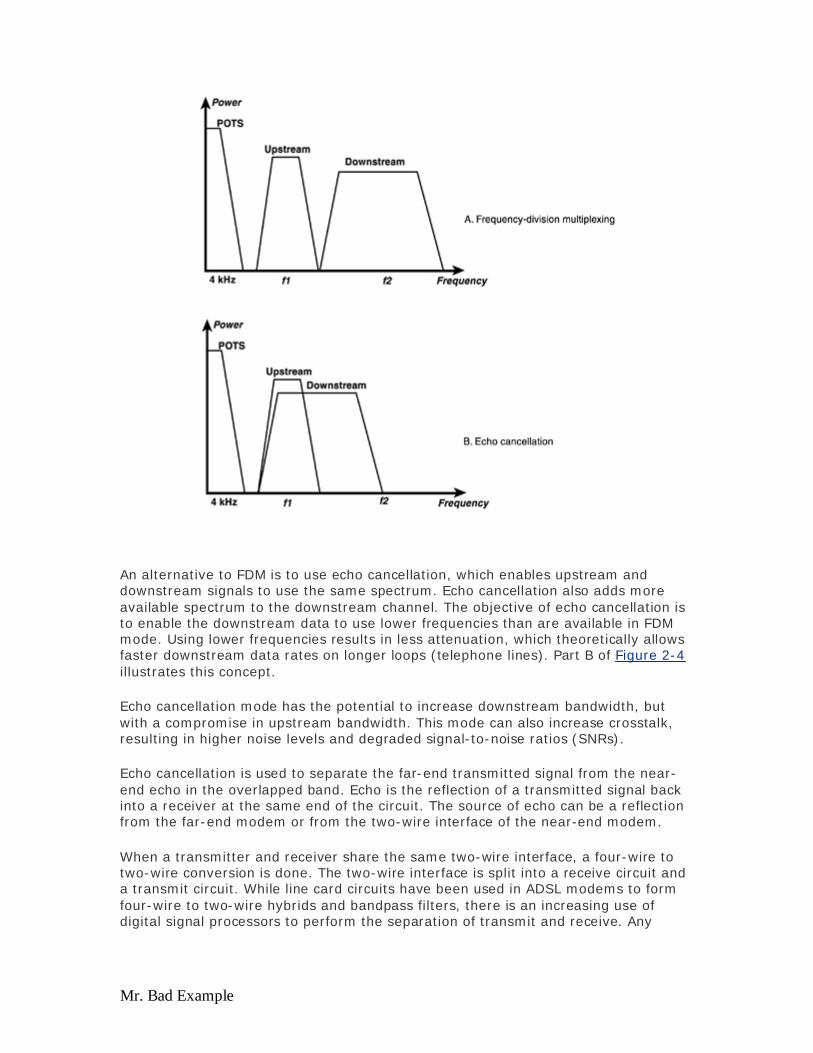
Most ADSL systems are set up to use frequency-division multiplexing (FDM) to establish upstream and downstream channels. In FDM mode, the upstream and downstream frequency bands are separated. Using FDM, the upstream channel allocation ranges from 26 kHz to 138 kHz and downstream ranges from 138 kHz to 1.1 MHz. See Part A of Figure 2-4 for a representation of FDM-based ADSL.
Figure 2-4. ADSL Echo Cancellation
Evaluation notes were added to the output document. To get rid of these notes, please order your copy of ePrint IV now.
Mr. Bad Example
An alternative to FDM is to use echo cancellation, which enables upstream and downstream signals to use the same spectrum. Echo cancellation also adds more available spectrum to the downstream channel. The objective of echo cancellation is to enable the downstream data to use lower frequencies than are available in FDM mode. Using lower frequencies results in less attenuation, which theoretically allows faster downstream data rates on longer loops (telephone lines). Part B of Figure 2-4 illustrates this concept.
Echo cancellation mode has the potential to increase downstream bandwidth, but with a compromise in upstream bandwidth. This mode can also increase crosstalk, resulting in higher noise levels and degraded signal-to-noise ratios (SNRs).
Echo cancellation is used to separate the far-end transmitted signal from the near-end echo in the overlapped band. Echo is the reflection of a transmitted signal back into a receiver at the same end of the circuit. The source of echo can be a reflection from the far-end modem or from the two-wire interface of the near-end modem.
When a transmitter and receiver share the same two-wire interface, a four-wire to two-wire conversion is done. The two-wire interface is split into a receive circuit and a transmit circuit. While line card circuits have been used in ADSL modems to form four-wire to two-wire hybrids and bandpass filters, there is an increasing use of digital signal processors to perform the separation of transmit and receive. Any
Evaluation notes were added to the output document. To get rid of these notes, please order your copy of ePrint IV now.

Mr. Bad Example
phase errors in an analog circuit can cause a received signal to be coupled into the transmit path, or vice versa.
A lower data rate version ADSL has also been proposed as an extension to ANSI standard T1.413 by the Universal ADSL Working Group (UAWG) led by Microsoft, Intel, and Compaq. This is known as G.Lite in the ITU standards committee. The standard calls for reducing the maximum transmit power, thus reducing the download speed of up to 1.5 Mbps and upload speed of up to 512 kbps. G.Lite operates at a lower frequency than ADSL, allowing for a longer distance between a CO and its subscribers and, therefore, reaching more subscribers than ADSL. G.Lite uses the same DMT modulation scheme as ADSL but eliminates the POTS splitter at the customer premises. As a result, the ADSL signal is carried over all the house wiring, resulting in lower available bandwidth due to greater noise impairments.
VDSL
VDSL is an emerging technology that plans to deliver data rates as high as 52 Mbps in the downstream direction to the subscriber at a shorter loop. VDSL is not yet standardized, however both American (ANSI) and European (ETSI) standards bodies are working actively in standardizing this technology.
With downstream speeds of up to a blazing 52 Mbps, VDSL is the next step up the speed ladder beyond ADSL. The price paid for VDSL's increased speed, however, is a shorter distance range. This means that VDSL can be a promising technology for applications requiring a very high bandwidth in the downstream direction towards to subscriber, especially in the Multi Dwelling Unit/Multi Tenant Unit (MDU/MTU) space. This also applies for hospitality suites like hotels and so forth that would like to offer voice, video, and data on a common pair of copper. A typical VDSL-based architecture is shown in Figure 2-5.
Figure 2-5. MDU/MTU Architecture
VDSL comes in two variants: a symmetrical version and an asymmetrical version, which is one of the key differences from ADSL. Over short ranges (1000 feet), VDSL
Evaluation notes were added to the output document. To get rid of these notes, please order your copy of ePrint IV now.
Mr. Bad Example
can offer up to 52 Mbps downstream capacity compared to the ADSL capacity of up to 8 Mbps; upstream, the asymmetrical version of VDSL offers a slower data rate of approximately 1.5 Mbps to 2.3 Mbps. Over short distances, VDSL offers a speed increase of approximately three to five times over ADSL. Over longer distances, VDSL will offer a speed increase of two to three times but VDSL's distance range will always be less than that for ADSL.
To provide high bandwidth to the subscriber, the copper loop to the subscriber should be as short as possible, which means that the DSLAMS consisting of VDSL cards might mainly be located in basements of the buildings for MDU/MTU applications as well as the hospitality suites. Plus, they are likely to be fed by a high capacity fiber optic link from a central site but occasionally directly from a CO or switch.
The asymmetrical version of VDSL works well in the consumer space and would be used mainly to offer various applications to the consumers. Some of the ideal applications for VDSL include providing video over the copper loop, provisioning multiple TV channels, video conferencing, streaming video, and so on. On the other hand, the symmetrical version of VDSL can be a suitable option for business class services. The bandwidth offered by VDSL today is far more than most people need. This would change, however, with the growing demand of video applications on xDSL.
IDSL
IDSL makes use of the ISDN 2B1Q encoding method but for permanent (or always-on) connectivity, unlike ISDN that enables dynamically initiating/terminating the connection. IDSL allows for the use of the D channel along with the 2 B channels of ISDN and, hence, can achieve the bandwidth of 144 kbps.
The maximum achievable bandwidth for IDSL is 144 kbps in both directions, and it is symmetric. IDSL is repeatable (which implies that you can have a repeater in the loop to amplify the signal), so it can be offered at longer distances where ADSL usually cannot be offered. Because of this distance advantage over ADSL, IDSL has become an attractive option for regions where ADSL can't be offered and the subscribers want to take advantage of high-speed access instead of the slower analog modem connection. One good question everyone asks at this juncture is, "Why not use plain ISDN, which also provides 128 kbps using two B channels?" The main difference between ISDN and IDSL is that, with ISDN, the D channel is usually not used to carry data—although some real applications utilize the D channel to carry data, like X.25 over D Channel, fewer companies in Europe adopted it— consequently sacrificing 16 kbps. In the case of IDSL, the D channel is used along with two B channels for carrying data. The other major difference between IDSL and ISDN is that ISDN is typically not an always-on technology and can initiate the call as and when required. However, IDSL is always on—you cannot tear down any of the B or D channels if they are idle.
Because a majority of the telephone systems in Europe makes use of ISDN technology, ADSL over ISDN is gaining popularity in Europe. ADSL over ISDN is accomplished by overlaying the DMT encapsulation over the 2B1Q encoding, consequently separating the frequency spectrum of DMT and 2B1Q so that they both
Evaluation notes were added to the output document. To get rid of these notes, please order your copy of ePrint IV now.

Mr. Bad Example
can coexist and DMT can be carried over 2B1Q. Because in countries, such as Germany, where there is a widespread deployment of ISDN, the coexistence of ADSL and ISDN on the same copper loop is a requirement. Therefore, the ADSL spectrum in this case can only start at 140 kHz because ISDN occupies a much larger spectrum in the baseband. You need the splitters the same way as discussed in the ADSL section, but in this case, the splitter is used to separate ISDN from DMT.
SDSL
SDSL is symmetric in nature, which in simple language means you get the same bandwidth in both upstream and downstream direction. With SDSL, the maximum bandwidth that can be achieved is 2.3 Mbps. The typical maximum reach for SDSL is approximately 4 km, or 12,000 feet.
SDSL, like IDSL, makes use of 2B1Q encoding. SDSL, however, is not repeatable, meaning that you cannot connect repeaters to boost the signal. The inability to use repeaters with SDSL results in the same distance limitation approach as that of ADSL. SDSL, unlike ADSL, is not rate adaptive, implying that once the two modems are trained up they will not rate adapt to a lower rate in case of noise interference or other factors.
SDSL because of its symmetric nature becomes an attractive option for small offices, home offices, or business customer spaces that are looking for cheaper alternative for traditional time-division multiplexing (TDM) lines. SDSL has been a means of entry for CLECs to take the leased line business and has been quite successful in that space. However, SDSL implementation is not based on any standard, and it is proprietary with each vendor based on the chipsets they use. For this reason, vendor compatibility with SDSL is a big issue and, therefore, has not become the ultimate choice of technology for leased line replacement. Most of the CLECs and incumbent local exchange carriers (ILECs) are awaiting the arrival of standards-based G.shdsl, which is presumed will ultimately dominate the Leased Line Replacements and will be the preferred choice of most DSL providers for business class users.
G.shdsl
Recently, International Telecommunications Union (ITU) determined the highly anticipated G.shdsl standard. This new standard was developed to replace or enhance many older or existing DSL technologies and other transport options such as HDSL, DSL, HDSL2, ISDN, T1, E1, and IDSL. Until now, telecommunication equipment vendors were required to develop several different line cards to accommodate each of the services that were offered by the technologies listed above. The new G.shdsl Draft Standard will enable equipment manufacturers to develop CO loop access equipment and CPE around a single standard, enabling them to address the interoperability issues faced by other xDSL implementations as discussed earlier.
G.shdsl is a technology that encompasses all functions which are currently provided by the European SDSL standard and HDSL2 including Overlapped Phase Trellis-coded Interlocking Spectrum (OPTIS) spectral shaping. G.shdsl is multirate, multiservice, extended-reach, and repeatable.
Evaluation notes were added to the output document. To get rid of these notes, please order your copy of ePrint IV now.

Mr. Bad Example
It is multirate because it supports data rates from 192 kbps to 2.3 Mbps. G.shdsl uses G.hs (handshake) to negotiate the framing protocol. Protocols supported include ATM, T1, E1, ISDN, and IP. The flexibility of G.shdsl enables the transport of virtually any type of service. It makes use of Trellis Coded Pulse Amplitude Modulation (TC-PAM) line coding that enables interoperation due to the low complexity level of the transceivers. G.shdsl is suppose to deliver approximately 30 percent greater reach than currently deployed transport technologies. G.shdsl is expected to rapidly replace the proprietary SDSL implementations of today and is mainly used for business-class users.
Comparing xDSL Flavors
Table 2-2 summarizes the various features of each xDSL flavor we discussed and which segment of market they fit in.
Table 2-2.
ADSL IDSL SDSL G.shdsl
Standard Yes, ANSI T1.413, ITU G.992.1 No No Yes (ITU)
Rate Adaptive Yes No No Yes
Repeatable No Yes No Yes
ATM Framing Yes No No Yes
T1 Framing No No No Yes
E1 Framing No No No Yes
Design Considerations at the Physical Layer (Layer 1)
The purpose of this section is to make you aware of some of the challenges faced at Layer 1 while deploying DSL. Additionally, because this book focus mainly on ADSL, we will discuss some important issues related with DMT and its various options.
Copper Loop Issues
One of the major challenges to next-generation data networking over PSTN is the copper pair itself. The nature of copper windings and the traditional cabling practices used in local loops creates huge barriers to technologies, such as ADSL. This influenced a requirement for rate adaptive and resilient signaling techniques to compensate for the issues that are inherent in a twisted-pair local loop.
The following issues are all potential hindrances to a voice or DSL network:
Since the early days of telephony, load coils have been applied to long loops to boost and flatten the frequency response of the line at the upper edge of
Evaluation notes were added to the output document. To get rid of these notes, please order your copy of ePrint IV now.

Mr. Bad Example
the voice band. These load coils increase attenuation greatly at frequencies above the voice band; therefore, load coils must be removed for DSL to function on a local loop.
In multicarrier systems, inter-carrier interference can occur. This happens as a result of frequency dependent attenuation and dispersion, which can vary between carriers. With the infringement of a variety of carriers into the CO, this becomes a serious concern for DSL deployments.
In the process of connecting and disconnecting portions of a loop cabling, portions of open-circuit wiring can sometimes be left connected to a working twisted pair. The presence of these bridge taps can affect the frequency response of the loop and cause distortion and interference.
Reflections and distortions can also be caused by loops made up of wires of differing diameter. This is a frequent problem in older wiring that has been modified over time.
Impulse noise (a brief, high amplitude jolt of noise introduced into the cabling from outside sources) is a major problem in copper wiring. Lightning and switching equipment transients are common causes of impulse noise. This is common in older COs, which are not properly insulated and older network equipment that has not been properly maintained.
Radio frequency (RF) interference is very common in twisted pairs, especially with the cabling techniques common in the U.S. Various radio sources can impair with a copper transmission medium, the foremost of which is the amateur radio transmitter. Ham radio operators can disrupt telephone communication in a large area around their transmitters if the local loops are extremely long or vertical. RF interference becomes a bigger problem as frequency increases, making DSL applications more susceptible.
The impact of these points can vary widely depending on particular network topologies and the specifics of the local loop cabling plant. Both voice and DSL switching systems have designed solutions for dealing with each of these issues to some degree.
Reach Versus Bandwidth
One of the challenges faced by the DSL providers today is that they would like to offer DSL services to as many subscribers as possible, but that is not easily achievable because of the distance limitations seen in various DSL technology. Also the further the subscriber is from the CO the less bandwidth the subscriber can get. The next couple of sections discuss some of the factors that affect the rate that can be offered to subscribers.
Noise Margin
It is important to note that higher DSL rates result in lower SNRs and lower DSL rates result in higher SNRs. Therefore, the noise margin becomes lower at longer cable lengths and at higher DSL rates. When a bit error rate (BER) of 10–7 can no longer be maintained, an automatic reduction in DSL rate normally occurs in DSL flavors that are rate adaptive, such as ADSL and G.shdsl.
Evaluation notes were added to the output document. To get rid of these notes, please order your copy of ePrint IV now.

Mr. Bad Example
RADSL (rate adaptive DSL) is a technique that automatically adjusts the DSL transmission speed to a rate where the appropriate noise margin can be maintained and enables a 10–7 BER to be maintained.
When DSL service is provisioned in a DSLAM, the minimum acceptable noise margin is usually specified. CAP DSL service is typically provisioned with a downstream margin of 3 dB and an upstream margin of 6 dB. Research has shown that the optimum margins for DMT service are 6 dB downstream and 6 dB upstream.
Avoiding configuring a DSL service with more noise margin than appropriate is important because the system will train to an unnecessarily low DSL rate to provide the specified margin. It is also important to avoid specifying an exceptionally low margin, such as 1 dB downstream and 1 dB upstream because a small increase in noise level on the transmission line would probably result in excessive errors and a subsequent retraining to a lower DSL rate.
If a DSL line is at maximum reach (maximum cable length) and the modems will not train, the margins may be set to zero for troubleshooting purposes only. For example, if a DSL line trains with the margins set to 0 but will not train when the margins are set to 6 dB, the line length is probably at maximum reach (typically 18 kft of 24-gauge wire). If providing service at any cost is necessary, a compromise margin between 0 and 6 dB can be selected. In such cases, determining whether the source of the problem is in the downstream spectrum or in the upstream spectrum is important, and make adjustments accordingly. For example, a margin setting of 3 dB in the downstream spectrum can be necessary to provide a preferred DSL rate at 18 feet of cable.
Increasing the transmit power levels will also improve the noise margin but at the cost of interfering with other services in the same cable.
Most DSLAMs and CPE report both the provisioned and actual noise margins for each DSL line. If the actual margin is higher than the provisioned margin, the line should provide an acceptable error rate at the present DSL line rate. As the actual margin drops below the provisioned margin, there is a high probability of an excessive error rate and subsequent retrain to a lower DSL rate.
The general indicator of acceptable DSL performance is when the actual margin is better than an appropriately set minimum margin, and the DSL line is running at the desired data rate.
Forward Error Correction
FEC refers to the process of correcting errors mathematically at the receiving end of a transmission path, rather than calling for a retransmit of the erred data. Retransmitting data to correct errors uses the available bandwidth to repeatedly send the same information, and the user perceives very slow throughput. FEC results in greater effective throughput of user data because valuable bandwidth is not being used to retransmit erred data.
When errors can be corrected without retransmitting the data, the errors are reported as corrected errors. When errors can't be corrected by the algorithm, they
Evaluation notes were added to the output document. To get rid of these notes, please order your copy of ePrint IV now.
Mr. Bad Example
are reported as uncorrected errors. The ratio of corrected to uncorrected errors shows the relative effectiveness of the error correction algorithm, or the relative intensity of the errors.
FEC Bytes
Also called check bytes or redundancy bytes, FEC bytes are added to the user data stream to produce a means of calculating the presence of erred data and generating a corrected frame. The appropriate number of FEC bytes provisioned generally depends on the type of errors being detected and corrected. It is important to note that the more FEC bytes that are added to the data stream the more bandwidth the users' data shares with the FEC bytes.
The tradeoff is being able to correct errors without retransmission versus displacement of user data. It is generally observed that much better throughput, however, is achieved by increased efficiency in FEC rather than by retransmitting erred data.
In many systems, the selectable number of FEC bytes is 0 (none), 2, 4, 8, 12, or 16. As a very basic and general rule, the more FEC bytes used the more effective is the error correction. But in error-free transmission paths, an unnecessary number of FEC bytes serves only to displace user data in the available bandwidth. For example, 16 FEC bytes per frame displaces much more user data at a transmission rate of 256 kbps that the same number of FEC bytes displaces at a transmission rate of 8 Mbps. That is the presence and number of FEC bytes at 256 kbps is more apparent to the user as reduced throughput than the same number of FEC bytes at 8 Mbps.
Note that some chipsets optimize the number of FEC bytes versus the requested ATM transmission rate. For example if a downstream rate of 8.032 Mbps and 16 FEC bytes is specified in the line configuration but the error rate is within the 10–7 BER limit, the chipset may set the number of FEC bytes to a lower number to create the requested user bandwidth. When DMT performance statistics are reviewed, the chipset reports a fewer number of FEC bytes than what was specified in the configuration.
Before specifying the most efficient number of FEC bytes and the most efficient interleave delay, we must determine the pattern of errors occurring on the transmission path. Errors occur in two general patterns: bursty or dribbling.
Interleaving
Interleaving is the process of scrambling user data in a very precise sequence. The purpose of interleaving is to avoid having consecutive errors delivered to the RS FEC algorithm at the receiving end of the circuit. RS is much more effective on single errors or errors that are more spaced in time (not consecutive).
If a noise burst occurs on the copper transmission line, several consecutive data bits can be affected resulting in consecutive bit errors. Because the data was interleaved at the transmitter, de-interleaving at the receiver produces not only the original bit sequence, but separates the erred bits over time. (The erred bits appear in separate
Evaluation notes were added to the output document. To get rid of these notes, please order your copy of ePrint IV now.

Mr. Bad Example
bytes.) Therefore, the erred bits are no longer consecutive and the RS FEC process is much more effective.
Latency
In many systems, interleaving can be set to 0 (off, none), 1, 2, 4, 8, or 16 milliseconds of interleave delay or interleave depth. The more milliseconds of time allocated to interleaving, the more data can be interleaved. But increasing interleaving delay will cause additional latency or delay in the time the data is transmitted and the time it is available to the receiving user.
As a general rule, the more interleaving delay that is used the better the RS algorithm can correct consecutive errors. The increased latency normally causes no problems for general data transmission but digitized voice over a high-latency path results in extremely unpleasant echo. For this reason, a minimum interleave delay (or no interleaving) is always used on data channels carrying voice traffic. As delay is added to voice transmissions, the problem of echo increases radically and requires additional treatment. Two-way video conferencing can also experience some undesirable effects from excessive latency in the data stream.
A relatively high error rate can usually be tolerated during voice conversations, and a human ear might not even detect the errors. Additional consideration of minimized latency versus error correction may be required, however, when analog data or fax is also running on the voice channel. Conversely, greater latency (delay) is not particularly detrimental to data transmission. Increasing latency does not usually reduce the transmission speed (throughput). Effective FEC, partially resulting from increased interleaving, can contribute significantly to achieving maximum throughput in a noisy environment.
Bursty Errors
Bursty errors are multiple errors that occur in very short timeframes. For example, in a one-minute timeframe, there might have been a total of 100 errors. The 100 errors, however, might have occurred in bursts of 10 errors at a time, spaced several seconds apart.
To determine if errors are bursty, inspect the total DSL trained-up time and erred-seconds counters. If a unit has been trained for one hour and has reported 100 errors and one erred second, the errors are bursty. By contrast, if the unit has been trained for one hour and has reported 1000 errors and 1000 erred seconds, the errors are dribbling. (Dribbling errors are covered in the following section.)
Noting the ratio of corrected errors to uncorrected errors is important. If all reported errors are corrected (no uncorrected errors), no further action is required.
For treating uncorrected bursty errors, increase the interleave delay (interleave depth). In most systems, interleave delay can be set as low as 1000 microseconds (one millisecond) and as high as 16,000 microseconds (16 milliseconds). If very few erred seconds are detected over a period of several hours, additional corrective measures might not be necessary.
Evaluation notes were added to the output document. To get rid of these notes, please order your copy of ePrint IV now.

Mr. Bad Example
Dribbling Errors
Dribbling errors occur usually one at a time (spaced by milliseconds to seconds) and continue to occur over any given timeframe.
To treat a steady stream of uncorrected dribbling errors, increase the number of FEC bytes. Increasing the number of FEC bytes adds baggage to the datastream. This results in a tradeoff between correcting errors and reducing the bandwidth available to the user. The effect of increasing FEC bytes depends on the data rate: Slower data rates demonstrate more bandwidth loss. As a general guideline, do not add more FEC bytes than what is required to correct the errors.
Coding Gain
When using FEC, typically RS encoding, errors might be corrected at the receiver without having to use TCP for block retransmits. When errors are corrected in this way, it has the same effect of using higher noise margins without the related reduction in DSL trained rates. This effect is called coding gain and is expressed in dB (the equivalent dB of margin).
Without coding gain, we need a specific SNR to achieve and maintain an ATM data error rate of 10–7 or better. With coding gain, we can achieve and maintain a 10–7 error rate with a lower SNR. Errors might still be occurring on the transmission line but are being corrected by the RS algorithm. The resulting error-free (corrected) data rate is the same as if a higher noise margin was used.
DSL Modem Train-Up
The initialization sequence conducted between two modems is referred to as training, or train-up.
During train-up, DSL modems start with no data interleaving and no line coding. (Interleaving and line coding must be negotiated between the two modems.) The signal-to-noise level is calculated across the DSL spectrum, and a DSL line rate is established based on three essential factors:
Provisioning— The DSL modems cannot establish a faster DSL rate than what is specified (provisioned) in the DSLAM. The DSL trained rate is typically specified in terms of available user bandwidth rather than actual DSL spectrum used.
DMT options— An unnecessarily high noise margin setting results in an unnecessarily low DSL trained rate. The recommended noise margin settings for DMT are 6 dB downstream and 6 dB upstream. (The recommendation for CAP systems is traditionally 3 dB downstream and 6 dB upstream.)
Line conditions— This includes several factors, but primarily two: attenuation and noise levels. It is important to note that more than one noise source might be contributing to the total noise spectrum on the line, thus producing multiple noise frequencies with related noise (power) levels. Some noise sources are more detrimental to DSL performance than others, again depending on the spectrum and power level of the noise induced into the DSL circuit.
Evaluation notes were added to the output document. To get rid of these notes, please order your copy of ePrint IV now.

Mr. Bad Example
Train-Up Mode Options
In DSLAMs options are available sometimes for specifying the training procedure. For example, in Cisco DSLAMs, you might encounter the options standard train and quick train, or standard train and fast train. Standard train relates to a training procedure specified in ANSI standards document T1.413, which is considered the standards reference for DMT ADSL. (Any manufacturer offering the option standard train should ensure the option is T1.413 compliant.) Quick train, fast train, and so forth can be more proprietary and perform best when used with the same manufacturer's modems (and usually the same DSL chipset) on both ends of the telephone line. Furthermore, quick train might not always result in a faster train-up by the modems.
Train-Up Problems
If a DSL modem cannot train to the ATU-C in the DSLAM, any of the following is a possible problem:
Excessive line length, or exceeding the maximum reach— An ILEC knows how long any given cable pair is, but testing cable length dynamically requires expensive test equipment. It's also important to note the difference between 24- and 26-gauge wire. Without getting into pages of calculations, we can say that 26-gauge wire is significantly more attenuative at all frequencies than 24-gauge wire. This becomes especially apparent at DSL frequencies, where 18,000 feet of 24-gauge cable is roughly equivalent to 15,000 feet of 26-gauge wire.
Bridge taps and half taps— A bridge tap and half tap are the same thing. A bridge tap occurs when a section of cable is connected to a telephone line at some midpoint between the CO and the CPE, usually done to prepare for a cable reroute. Bridge taps can significantly alter the impedance of a telephone line, especially at DSL frequencies. Impedance mismatches cause a wide variety of symptoms, typically reflection of data bits from the tap-point back to the point of transmission, causing bit errors. A tapped-in stub can even become a tuned filter at DSL frequencies, causing excessive attenuation of DSL signals. Figure 2-6 illustrates the concept of a bridge tap.
Figure 2-6. Bridge Tap
Evaluation notes were added to the output document. To get rid of these notes, please order your copy of ePrint IV now.
Mr. Bad Example
Interfering signals— This can become extremely complicated and difficult to diagnose without spectrum analysis. If a single DSL line is activated in a 25-pair binder (a group of pairs), we can measure a specific noise margin. If DSL is activated on 10 more pairs in the 25-pair binder, the margin degrades noticeably.
AM radio stations have been known to cause a degradation of DSL service but should not cause a no-train condition unless the modems are already at maximum reach. The DSL spectrum is roughly from 25 kHz to 1.1 MHz, and the AM radio band (in North America) is roughly from 550 kHz to 1.7 MHz. The overlap in the two spectrums enables powerful radio stations to interfere with highly attenuated DSL signals on longer cable lengths.
DMT interferes with CAP more than other CAP signals. SDSL interferes with DMT. ISDN interferes with CAP. Basically, everything interferes with everything else. The important thing is that an acceptable noise margin be maintained, and this is controlled by attenuation (cable length and wire gauge), bridge taps on the line, and the spectrum and power level of interfering signals.
Finally, note that a small amount of noise is also produced by the digital signal processors and DMT modulation subsystems. The term channel noise is used to identify noise on the transmission path rather than internal noise in a modem.
Load coils— Load coils are typically 88 millihenry (mH) chokes placed in the tip and ring lead of the cable pair at specific intervals to add more inductance than can be produced by twisting the wire pairs. The added inductance counteracts the effect of capacitance between thousands of feet of a wire pair by creating a very effective bandpass filter that is optimized for a flat response between 300 and 3000 Hz.
Without load coils on cables of 15,000 feet or longer, excessive capacitance will begin to radically attenuate the higher frequencies of the voice band. Analog modem and fax performance begins to degrade as well as voice quality.
Load coils must be removed from cable pairs when DSL service is provided. What makes the job somewhat difficult and expensive is that, when load coils are placed in a cable, they are installed 3 kft from each end and at 6 kft intervals between each end. Fortunately for DSL service, many telephone companies do not load cables shorter than 10 kft, so fewer cable pairs have to be unloaded for DSL service.
Other communication devices connected to the phone line— A telephone or fax machine connected to the phone line without a microfilter or DSL splitter will cause excessive loading on the line when off the hook. On longer cable lengths, a DSL modem cannot train when a phone is off the hook unless a microfilter is used at the telephone or a splitter is placed between the phone and DSL modem.
Evaluation notes were added to the output document. To get rid of these notes, please order your copy of ePrint IV now.

Mr. Bad Example
On shorter cable lengths, taking a phone off the hook without a filter or splitter causes the DSL modem to untrain and then retrain at a lower DSL rate. But things can get tricky. If a cordless phone base unit is connected to the phone line without a microfilter, the RF pi-filter in the base unit is much more reactive (lower resistance) across the wire pair at lower DSL frequencies than at higher frequencies. The DSL downstream rate appears normal, but the upstream rate is lower than normal. Fortunately, installing a microfilter in the phone line to the base unit corrects the problem.
Radio interference (RFI) filters on the phone line— RFI filters are installed in many areas where AM radio stations can be heard on telephones during conversations. The most basic RFI filters are simply capacitors placed across the phone line. More sophisticated RF filters also include inductors placed in the tip and ring. When capacitors are placed across the phone line (parallel) and inductors are inserted into the phone line (series), DSL frequencies can be removed completely. RFI filters have no affect at voice frequencies but appear as a short circuit at radio (and DSL) frequencies. RFI filters can cause degradation of DSL performance on shorter cable lengths and can prevent DSL modems from training on longer cable lengths.
Power Levels In DSL Services
DSL power levels are much higher than used in voice, fax, or analog data services. This is simply because of the much greater attenuation of signals at DSL frequencies caused by the electrical characteristics of telephone lines.
DSL Power Levels
Because the attenuation of a phone line is much greater at ADSL frequencies than at voice frequencies, the phone line is much more attenuative to DSL than to voice, fax, or analog modems. To recover a usable signal at the end of 18 kft of cable, ADSL is usually transmitted at +15 to +20 dBm. This is an exceptionally high amount of power to be transmitted on a telephone line, but it is necessary to attain DSL rates at maximum reach.
The standard unit of measure for telephone system power levels is dBm, or dB relative to one milliwatt of power dissipated across 600 Ohms. Zero dBm is often called milliwatt. Three dBm refers to a Level 3 dB higher than milliwatt, and –3 dBm refers to a Level 3 dB less than milliwatt.
Broad spectrum power levels are usually measured in dBm per Hertz rather than dBm, often shown as dBm/Hz. This is sometimes referred to as power spectral density (PSD). Most ADSL DMT is transmitted at –39 to –41 dBm/Hz, and this falls in the range of +15 to +20 dBm.
Power Cutback
Power can be reduced during the train-up sequence when DSL modems calculate and exchange information regarding attenuation. Although it is possible to increase power above a nominal level, this commonly is not done because of the interference
Evaluation notes were added to the output document. To get rid of these notes, please order your copy of ePrint IV now.

Mr. Bad Example
imposed on other services in the same cable. This is referred to as crosstalk between cable pairs and results in a degraded SNR.
Crosstalk is generally categorized as near-end crosstalk (NEXT) or far-end crosstalk (FEXT). NEXT is sometimes caused by part of the transmitted signal being coupled back into the receiver of the same unit. FEXT usually refers to interfering signals at the far end of the data path.
It is best to allow rate adaptive ADSL to compute and apply the appropriate power level unless a particular troubleshooting procedure is in progress. (On rare occasions, power levels are manually adjusted to compensate for the presence of half-taps on the DSL line.)
The amount of automatic cutback or the manually provisioned transmit level is sometimes reported in DSL performance statistics.
The capability to change the default transmit power level becomes very important when comparing different DSL vendors or DSL chipsets. If a system is set to transmit at an abnormally high DSL power level, it might offer exceptionally good reach and noise margin while inducing excessive noise in adjacent cable pairs. During competitive evaluations, some equipment manufacturers will increase power to improve reach and noise (bit error) performance. The same transmit levels, however, could not be deployed in a production telco environment.
Bit Swapping
Bit swapping is the process of moving data bits from low signal-to-noise parts of the spectrum to higher signal-to-noise parts of the spectrum. It is negotiated between the two modems via the ADSL overhead control (AOC) channel.
Bit swapping is an attempt at maximizing the efficiency (throughput) of a channel by sending different numbers of bits on different subchannels. The number of bits on each subchannel depends on the SNR of the subchannel. As bits are added to a subchannel, a lower SNR automatically results.
With the exception of the DMT carriers used for timing, each carrier is capable of carrying data. However, only carriers with sufficient SNR are allocated payload for transmission. Each transmitting carrier is allocated a bit count based on the characteristics of the specific subchannel. This results in an optimized data transfer rate for the current line conditions.
A classic example of bit swapping is shown by the presence of an AM radio station carrier interfering with a specific frequency within the DMT downstream channel. In this situation, the carriers with reduced SNR will transmit fewer databits, while the carriers with a higher SNR may be able to transmit more bits. The bits were moved, or swapped, from one carrier assignment to another, resulting in the fastest data rate possible under the circumstances.
Evaluation notes were added to the output document. To get rid of these notes, please order your copy of ePrint IV now.

Mr. Bad Example
Trellis Coding
Trellis coding is a process of altering the Quadrature Amplitude Modulation (QAM) constellation to provide better performance in a noisy environment. Trellis uses a coding algorithm that enables modems to compensate for minor phase or amplitude variations caused by noise on the transmission path. The combination of modulation technique and code enables operation at a higher data rate for a given SNR than could be accomplished without the Trellis code. The net coding gain (equivalent improvement in noise margin) from Trellis encoding is usually estimated to be about 3 dB, although theoretically, it could be slightly higher.
Trellis coding is less effective when noise is random, such as erratic impulse spikes or when a high level of white noise (random noise) is present. Trellis coding can differentiate between correct and incorrect symbols by establishing a pattern, or history, of the effects of an interfering noise source. Therefore, Trellis coding is more effective when noise has recurring, predictable patterns.
A significant advantage of Trellis coding is that it does not expand bandwidth requirements or increase transmit power requirements to maintain acceptable error rates. Trellis coding requires more complex transceivers, however, and Trellis-capable chipsets may have a slightly higher internal power requirement.
Whether Trellis adds a significant amount of latency to the transmission path is often debated. The general view is that while a small amount of data buffering is required for the coding/decoding process, the newer hardware designs have fast processing speeds that minimize the latency. The added latency, while theoretically present, is considered negligible in present designs.
The end result of using Trellis coding/decoding is to be able to transmit at faster line rates with lower error rates, thus providing a faster overall throughput in a moderately noisy environment. Trellis coding offers no advantage in a noise-free environment, however. The benefit or liability of turning on Trellis coding would have to be compared to the achieved coding gain and whether improved transmission quality is needed in a particular situation. DSL transmission on longer telephone company loops generally is improved by using Trellis coding.
Note that when RS FEC and Trellis coding are both used at the same time, the coding gain is not simply an additive. That is if 3 dB is gained by using RS alone and 3 dB is gained by using Trellis alone, the combined coding gain is not 6 dB. Using both systems is ultimately more effective than using only RS or Trellis, however, so it is generally recommended that both be used in DSL service when supported by the system hardware and software.
Considerations at the Data Link Layer (Layer 2)
The previous section covered how subscriber traffic is put on the wire and how it is modulated into signals. We also talked about the issues related to Layer 1. Moving up one layer in the OSI model, we will now discuss some of the key components of Layer 2, or the data link layer for xDSL deployments. Because this book focuses more on ADSL, the most common and widely deployed data link layer for ADSL deployments today, we will use ATM as the model for our examples.
Evaluation notes were added to the output document. To get rid of these notes, please order your copy of ePrint IV now.

Mr. Bad Example
Even though ATM is the most common and widely deployed data link layer protocol for ADSL, other technologies exist. Other vendors use Frame Relay as the data link layer for ADSL, while some use HDLC as the data link layer protocol for IDSL. This protocol choice for Layer 2 takes a great deal of part in the flexibility of how services are ultimately delivered to the subscriber.
We touched on some of the bandwidth hungry applications and services briefly in the introduction, and we will cover a bit more about them in later chapters. If a service provider decides to offer multiple services over the same copper wire, there will be contention from different applications for a finite resource—bandwidth. Service providers have to ensure that for those customers who paid more money for a premium service that their traffic has more precedence over the lower-priced traffic.
Picking the right data link layer protocol to ensure QoS is important so that service providers have a means to differentiate or classify various services and charge their customers accordingly. Not only that but also with certain applications, such as voice and video, we require reasonably low absolute delay from source to destination with very little variation in delay from packet to packet. In choosing a Layer 2 protocol, we want to find one that gives us the flexibility to efficiently support the classical higher layer protocols like TCP/IP, but at the same time can handle the low delay and delay variation requirements of voice and video applications using entirely different higher layer protocols. In effect, we need a way to inform the network on what kind of traffic we are dealing with and how to handle it. Because of these requirements, ATM becomes an obvious choice.
ATM was developed specifically to enable a single network to simultaneously handle large frames bursted by data applications and still provide the low delay requirements of real-time processes. A data link layer using ATM is divided into two sublayers: the ATM Layer and ATM Adaptation Layer. The ATM layer is concerned with forming the basic unit of transport, which is the cell, switching cells through the network, establishing and tearing down connections, and providing QoS guarantee to the user.
ATM Technology Basics
ATM is asynchronous in nature. Because of that, ATM is more efficient than synchronous technologies like time-division multiplexing (TDM). With TDM, each station or user is preassigned some time slots, and no other station can send in that time slot. If a station or user has more data than it can send during its allotted time slot, it can send only the information during its allotted timeslot even though other time slots are empty. On the other hand, if a user or station has nothing to send when its turn or time slot comes up, that time slot goes empty, which is a waste of bandwidth. With ATM being asynchronous in nature, however, time slots are available on demand with information identifying the source of the transmission contained in the header of each ATM cell.
ATM makes use of fixed size units called cells, to transfer information. Each cell consists of 53 bytes. The first 5 bytes contain cell header information, and the remaining 48 bytes contain the user information. Because of the small fixed-length size, ATM cells become very suitable for applications such as voice and video, which are intolerant of delays resulting from waiting for large packets to be transmitted (as is the case in non-ATM networks).
Evaluation notes were added to the output document. To get rid of these notes, please order your copy of ePrint IV now.

Mr. Bad Example
Figure 2-7 shows the basic format of an ATM cell.
Figure 2-7. ATM Cell Format
In simplistic terms, an ATM network consists of two main components—an ATM switch and an ATM endpoint.
The main purpose of an ATM switch is to switch the ATM cells through the network. An ATM switch in a network first accepts the incoming cells from an ATM endpoint or a neighbor ATM switch, reads the cell header information and makes the necessary switching decision for those cells through the outbound interface towards the cell's final destination.
An ATM endpoint is the component that initiates those ATM cells. Some examples of ATM endpoints include workstations, routers, and other devices, which have an ATM network adapter. Figure 2-8 illustrates a basic ATM network.
Figure 2-8. Example of an ATM Network
A typical ATM network consists of multiple ATM switches, which are connected via point-to-point ATM interfaces or links. The ATM switches support two types of interfaces:
User-Network Interfaces (UNIs)— UNIs connect ATM end-systems (hosts, routers) to an ATM switch.
Network-to-Network Interfaces (NNIs)— NNIs connect two ATM switches.
Evaluation notes were added to the output document. To get rid of these notes, please order your copy of ePrint IV now.

Mr. Bad Example
ATM Cell Header
Figure 2-9 shows the basic ATM cell format including the UNI and NNI cell header formats. The UNI header is for communication between endpoints and the switches, while the NNI header is used to communicate between switches.
Figure 2-9. ATM Cell Header
As Figure 2-9 illustrates, the NNI header does not include the Generic Flow Control (GFC) field. Additionally, this header has a Virtual Path Identifier (VPI) field that occupies the first 12 bits allowing for larger trunks between public ATM switches.
The following is a brief description of each field in the cell header:
Generic Flow Control (GFC)— This field is typically not used. However, it can provide some local functions as in the case of subtending (discussed later in the section, "Subtending") to identify multiple DSLAMs that share a single outbound ATM trunk interface.
Virtual Path Identifier (VPI)— Used in conjunction with the VCI to identify the next destination of a cell as it passes through a series of ATM switches on its way to its destination.
Virtual Channel Identifier (VCI)— Used in conjunction with the VPI to identify the next destination of a cell as it passes through a series of ATM switches on its way to its destination.
Payload Type (PT)— The first bit of PT indicates whether the cell contains user or control data. In the event that the first bit represents user data, the second bit then indicates congestion. The third bit indicates whether the cell is the last in the series of cells that represent an entire single AAL5 frame.
Congestion Loss Priority (CLP)— Indicates whether the cell should be discarded if it encounters extreme congestion as it moves through the network. If the CLP bit equals 1, the cell should be discarded in preference to cells with the CLP bit equal to 0.
Header Error Control (HEC)— HEC is an algorithm for checking and correcting error in ATM cell. ATM equipment checks for errors and corrects the content of the header.
Evaluation notes were added to the output document. To get rid of these notes, please order your copy of ePrint IV now.

Mr. Bad Example
ATM Reference Model
We will now briefly discuss the ATM reference model in comparison to the OSI reference model.
The ATM reference model consists of three main layers: Physical, ATM, and ATM adaptation layer (AAL). The physical layer is similar to the physical layer of the OSI reference model. The ATM physical layer manages the medium-dependent transmission. The ATM physical layer is responsible for converting bits into ATM cells, controlling the transmission and receipt of bits on the physical medium, keeping track of cell boundaries, and packaging the ATM cells into appropriate type of frame for the physical media being used. The example of some of the physical media is SONET, DS-3/E3, and so forth.
The ATM layer along with ATM adaptation layer is more or less like the data link layer of OSI reference model. The ATM layer establishes connections and passes the cells through the ATM network; it achieves this by using the information in the headers of each ATM cell.
The AAL is responsible for isolating the upper-layer protocols like IP, IPX, and so forth from the details of the ATM processes. AAL mainly receives packets from upper-level protocols and breaks them into the 48-byte segments that form the Payload field of ATM cell. Several AALs support a various range of traffic requirements.
Table 2-3 depicts the different type of AALs and their applications.
Table 2-3. ATM Adaptation Layers and Their Applications
Characteristics AAL1 AAL2 AAL3/AAL4 AAL5
Requires Timing between Source & Destination
Yes Yes No No
Bit Rate Constant Variable Available Available
Connection Mode Connection Oriented
Connection Oriented
Connection oriented or Connectionless
Connection Oriented
Application Voice and Circuit Emulation
Packet Voice and Video
Data Data
The AAL is further divided into two sublayers:
Convergence sublayer (CS)— Adapts information into multiples of octets and padding can be added to achieve this purpose.
Evaluation notes were added to the output document. To get rid of these notes, please order your copy of ePrint IV now.

Mr. Bad Example
Segmentation and reassembly sublayer (SAR)— Segments information into 48 octet units at the source and reassembles them at the destination.
ATM Virtual Connections and How They Are Used in ADSL Deployments
ATM networks, by nature, are connection-oriented. This means that a VC or a virtual circuit needs to be set up across the ATM network prior to any data transfer.
Two types of connections exist: virtual paths, which are identified by virtual path identifiers (VPI); and virtual channels, which are identified by the using VPI; and a virtual channel identifier (VCI). These are the two main components that help in identifying the path for the data transfer. Figure 2-10 illustrates the ATM components for data transfer.
Figure 2-10. Virtual Paths and Virtual Circuits
A virtual path basically consists of multiple virtual channels, all of which are being switched through the network on the basis of a common VPI. All VPIs and VCIs have only local significance on a particular link and are remapped at each switch.
ATM virtual connections can be established in many different ways. We will be discussing those methods, keeping in mind the deployment scenarios of DSL. The basic methods are using permanent virtual circuits (PVCs), switched virtual circuits (SVCs), and Soft PVCs (SPVCs).
PVCs
Most ADSL deployments today use ATM as the data link layer, using PVC to establish the connection. Each subscriber is typically allocated one PVC, which is then switched by various ATM switches or DSLAMs before it reaches its final destination, as shown in Figure 2-11.
Figure 2-11. PVC Definition for Each Hop
Evaluation notes were added to the output document. To get rid of these notes, please order your copy of ePrint IV now.

Mr. Bad Example
As Figure 2-11 illustrates, whenever a subscriber is provisioned using a PVC method, you need to manually set the VPI/VCI value for each hop, which is time consuming and labor intensive. In today's implementation where ADSL is being deployed mainly to provide data services, only one PVC is provisioned for each subscriber. Once voice and video start getting deployed (there are some early field trials going on), however, you might start seeing one PVC for each of those applications, resulting in at least two to three PVCs for one subscriber. Just imagine how much of a provisioning task it would be if you need to provision one million subscribers.
SVCs
SVCs are an alternative to PVCs. They can solve many provisioning hassles as observed with the PVC model. But the issue with SVC is that telcos need to support the SVC model in their ATM core, which might not belong to only them but could be spanning among multiple service providers. This scenario would mean that, if the ATM switches deployed today cannot handle SVCs, they need to be upgraded. This results in an additional cost for the service provider, which might not be that much of a problem compared to that of the CPE. The CPE is deployed at subscriber's premises and needs to initiate SVCs. To support a SVC from the CPE itself could mean that the CPE now is no longer a cheap dumb device. Most service providers would like to reduce the maintenance cost at the subscriber's premise and would like to have the cost of the CPE under $50, which becomes challenging when they want to initiate SVCs. Some CPE vendors have come out with SVC support, but the service providers are not keen in deploying SVC-based solutions because of some of the reasons mentioned above. Apart from the reason of cost for the service provider, the other reason for service providers not using SVCs is the matter of control. If the service providers started using SVCs in their network, then for them to predict the amount of usage for certain circuit becomes difficult especially when the network spans across multiple service providers. The service providers definitely understand that SVCs can easily reduce their provisioning cost. However, SVC implementation brings up a number of issues. Some of these issues are listed here for a deployment perspective.
SPVCs
Evaluation notes were added to the output document. To get rid of these notes, please order your copy of ePrint IV now.

Mr. Bad Example
To get the best of both worlds—the simplicity of PVCs and faster provisioning through SVCs—service providers are opting for SPVCs. An SPVC is sort of a hybrid between PVCs and SVCs. Using an SPVC, the subscriber CPE maintains the PVC model. After that reaches the DSLAM, however, the DSLAM using an SPVC can provision that subscriber directly to the final destination device based on that device's NSAP address and the ATM Private Network-Network Interface (PNNI) routing. Figure 2-12 depicts how the subscribers are provisioned using SPVC.
Figure 2-12. Soft PVC
Example 2-1 shows the configurations for the DSLAM, the 6400 NSP, and the 6400 NRP (aggregation router) depicted in Figure 2-12.
Example 2-1 Configuring the Soft PVC for the Network in Figure 2-12 DSLAM Config : 6260(config)#int atm1/1 6260(config-int)#atm soft-vc 1 32 dest-address NSAP address 10 32 6260(config)#int atm0/1 6260(config-int)#atm signalling enable NSP ( ATM Switch) Config : 6400NSP#show atm address 6400NSP(config)#int atm1/0/0 6400NSP(config-int)#atm signalling enable NRP ( Aggregation Router) Config 6400NRP#int atm0/0/0.132 6400NRP(config-int)#atm pvc 10 32
As Figure 2-12 and Example 2-1 illustrate, a PVC is provisioned for the subscriber from the subscriber CPE to the DSLAM, but the DSLAM is configured with SPVC. This subscriber is supposed to be terminated on a router whose NSAP address is specified. This eliminated the entire process of provisioning PVCs in the middle hops or the switches. Because SPVCs use ATM routing, the DSLAMs and ATM switches in the intermediate hops should support signaling and PNNI.
As mentioned, SPVC greatly helps the service provider in provisioning the subscribers, not only through the ATM core but also if the DSLAMs are subtended.
Subtending
Evaluation notes were added to the output document. To get rid of these notes, please order your copy of ePrint IV now.
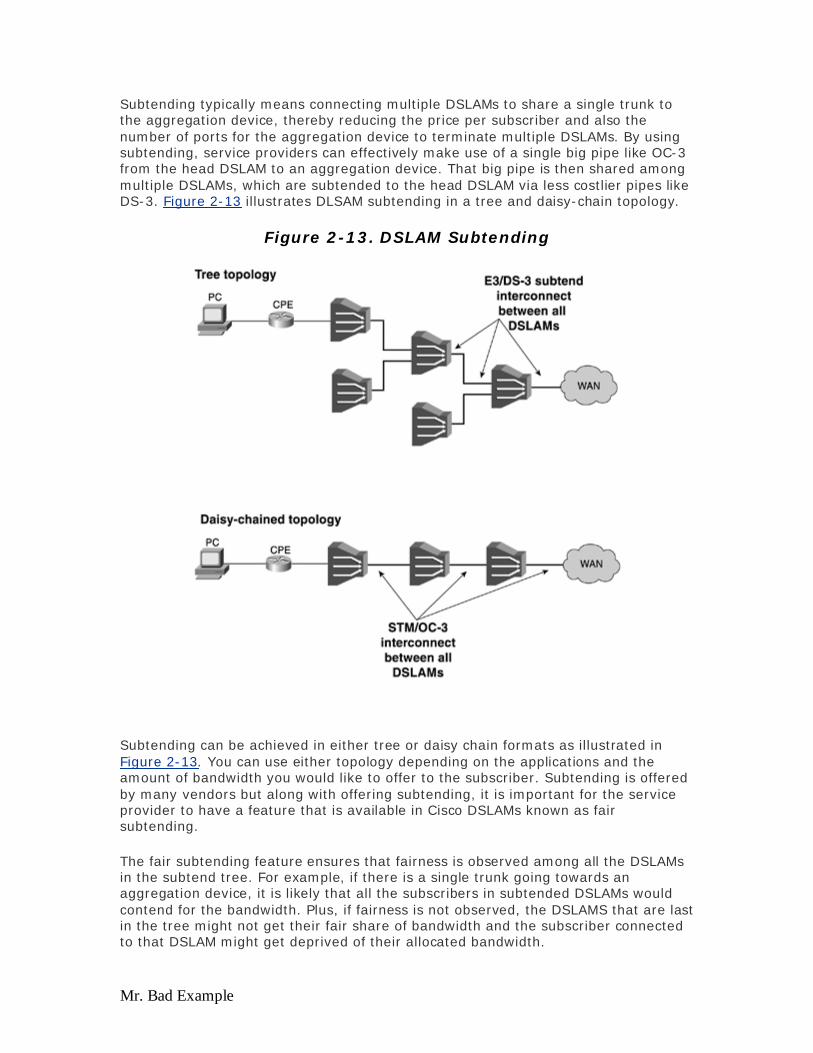
Mr. Bad Example
Subtending typically means connecting multiple DSLAMs to share a single trunk to the aggregation device, thereby reducing the price per subscriber and also the number of ports for the aggregation device to terminate multiple DSLAMs. By using subtending, service providers can effectively make use of a single big pipe like OC-3 from the head DSLAM to an aggregation device. That big pipe is then shared among multiple DSLAMs, which are subtended to the head DSLAM via less costlier pipes like DS-3. Figure 2-13 illustrates DLSAM subtending in a tree and daisy-chain topology.
Figure 2-13. DSLAM Subtending
Subtending can be achieved in either tree or daisy chain formats as illustrated in Figure 2-13. You can use either topology depending on the applications and the amount of bandwidth you would like to offer to the subscriber. Subtending is offered by many vendors but along with offering subtending, it is important for the service provider to have a feature that is available in Cisco DSLAMs known as fair subtending.
The fair subtending feature ensures that fairness is observed among all the DSLAMs in the subtend tree. For example, if there is a single trunk going towards an aggregation device, it is likely that all the subscribers in subtended DSLAMs would contend for the bandwidth. Plus, if fairness is not observed, the DSLAMS that are last in the tree might not get their fair share of bandwidth and the subscriber connected to that DSLAM might get deprived of their allocated bandwidth.
Evaluation notes were added to the output document. To get rid of these notes, please order your copy of ePrint IV now.
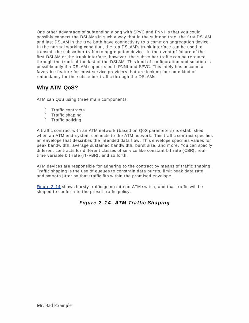
Mr. Bad Example
One other advantage of subtending along with SPVC and PNNI is that you could possibly connect the DSLAMs in such a way that in the subtend tree, the first DSLAM and last DSLAM in the tree both have connectivity to a common aggregation device. In the normal working condition, the top DSLAM's trunk interface can be used to transmit the subscriber traffic to aggregation device. In the event of failure of the first DSLAM or the trunk interface, however, the subscriber traffic can be rerouted through the trunk of the last of the DSLAM. This kind of configuration and solution is possible only if a DSLAM supports both PNNI and SPVC. This lately has become a favorable feature for most service providers that are looking for some kind of redundancy for the subscriber traffic through the DSLAMs.
Why ATM QoS?
ATM can QoS using three main components:
Traffic contracts Traffic shaping Traffic policing
A traffic contract with an ATM network (based on QoS parameters) is established when an ATM end-system connects to the ATM network. This traffic contract specifies an envelope that describes the intended data flow. This envelope specifies values for peak bandwidth, average sustained bandwidth, burst size, and more. You can specify different contracts for different classes of service like constant bit rate (CBR), real-time variable bit rate (rt-VBR), and so forth.
ATM devices are responsible for adhering to the contract by means of traffic shaping. Traffic shaping is the use of queues to constrain data bursts, limit peak data rate, and smooth jitter so that traffic fits within the promised envelope.
Figure 2-14 shows bursty traffic going into an ATM switch, and that traffic will be shaped to conform to the preset traffic policy.
Figure 2-14. ATM Traffic Shaping
Evaluation notes were added to the output document. To get rid of these notes, please order your copy of ePrint IV now.
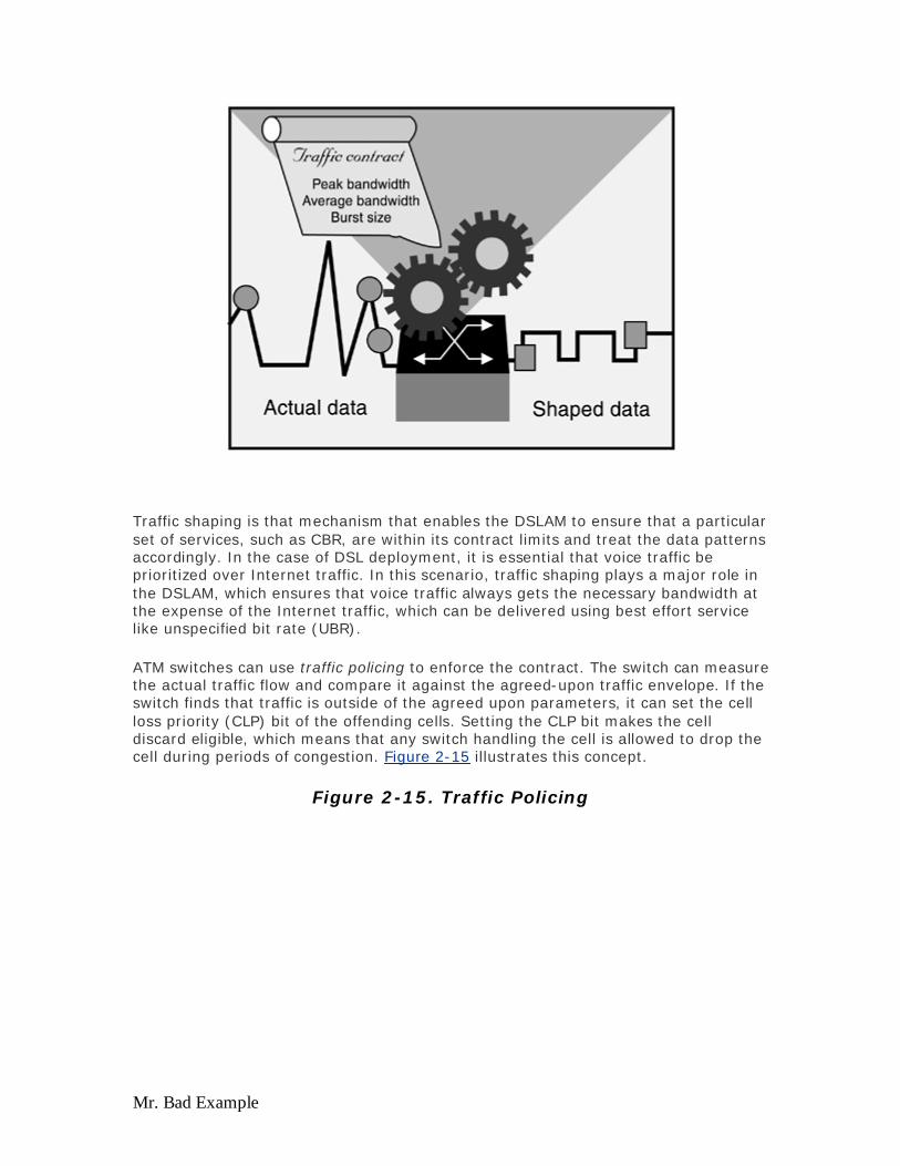
Mr. Bad Example
Traffic shaping is that mechanism that enables the DSLAM to ensure that a particular set of services, such as CBR, are within its contract limits and treat the data patterns accordingly. In the case of DSL deployment, it is essential that voice traffic be prioritized over Internet traffic. In this scenario, traffic shaping plays a major role in the DSLAM, which ensures that voice traffic always gets the necessary bandwidth at the expense of the Internet traffic, which can be delivered using best effort service like unspecified bit rate (UBR).
ATM switches can use traffic policing to enforce the contract. The switch can measure the actual traffic flow and compare it against the agreed-upon traffic envelope. If the switch finds that traffic is outside of the agreed upon parameters, it can set the cell loss priority (CLP) bit of the offending cells. Setting the CLP bit makes the cell discard eligible, which means that any switch handling the cell is allowed to drop the cell during periods of congestion. Figure 2-15 illustrates this concept.
Figure 2-15. Traffic Policing
Evaluation notes were added to the output document. To get rid of these notes, please order your copy of ePrint IV now.
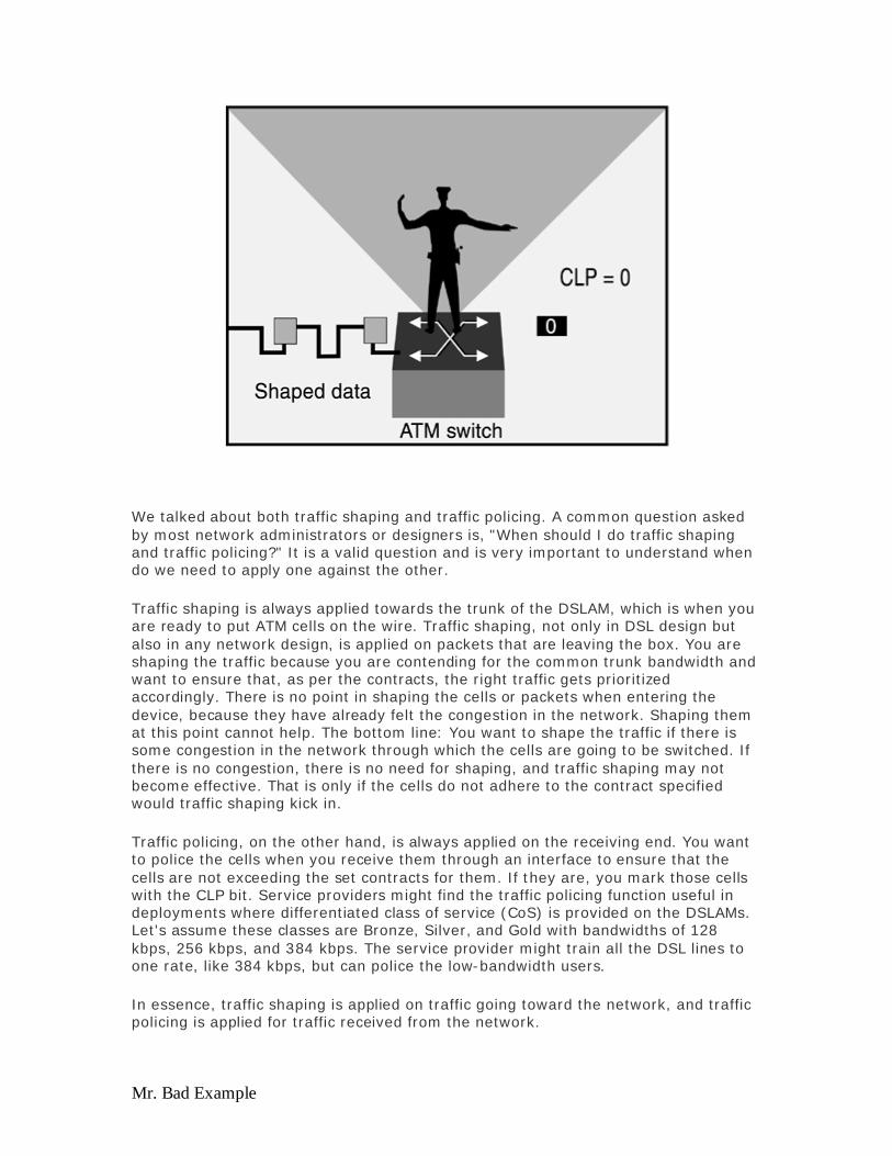
Mr. Bad Example
We talked about both traffic shaping and traffic policing. A common question asked by most network administrators or designers is, "When should I do traffic shaping and traffic policing?" It is a valid question and is very important to understand when do we need to apply one against the other.
Traffic shaping is always applied towards the trunk of the DSLAM, which is when you are ready to put ATM cells on the wire. Traffic shaping, not only in DSL design but also in any network design, is applied on packets that are leaving the box. You are shaping the traffic because you are contending for the common trunk bandwidth and want to ensure that, as per the contracts, the right traffic gets prioritized accordingly. There is no point in shaping the cells or packets when entering the device, because they have already felt the congestion in the network. Shaping them at this point cannot help. The bottom line: You want to shape the traffic if there is some congestion in the network through which the cells are going to be switched. If there is no congestion, there is no need for shaping, and traffic shaping may not become effective. That is only if the cells do not adhere to the contract specified would traffic shaping kick in.
Traffic policing, on the other hand, is always applied on the receiving end. You want to police the cells when you receive them through an interface to ensure that the cells are not exceeding the set contracts for them. If they are, you mark those cells with the CLP bit. Service providers might find the traffic policing function useful in deployments where differentiated class of service (CoS) is provided on the DSLAMs. Let's assume these classes are Bronze, Silver, and Gold with bandwidths of 128 kbps, 256 kbps, and 384 kbps. The service provider might train all the DSL lines to one rate, like 384 kbps, but can police the low-bandwidth users.
In essence, traffic shaping is applied on traffic going toward the network, and traffic policing is applied for traffic received from the network.
Evaluation notes were added to the output document. To get rid of these notes, please order your copy of ePrint IV now.

Mr. Bad Example
Looking Ahead
As we have now covered some of the basic xDSL flavors and the importance of ATM as a Layer 2 transport, in Chapter 3, "Service Offerings," we will introduce how different service providers make use of these technologies in their respective segments, offer different kind of services, and provide an introduction to service architectures.
References
http://wwwin.cisco.com/cct/data/itm/bs/atm/bsataal.htmhttp://wwwin.cisco.com/cct/data/itm/bs/atm/bsataal.htm (internal Cisco document)
http://wwwin.cisco.com/Mkt/cmc/cc/pd/rt/7200/prodlit/bba_wi.htmhttp://wwwin.cisco.com/Mkt/cmc/cc/pd/rt/7200/prodlit/bba_wi.htm (internal Cisco document)
http://dsl.cisco.com/training/DSL_Layer_1/basicdmt.pdfhttp://dsl.cisco.com/training/DSL_Layer_1/basicdmt.pdf (internal Cisco document)
http://www.planetee.com/planetee/servlet/DisplayDocument?ArticleIhttp://www.planetee.com/planetee/servlet/DisplayDocument?ArticleID=2861
Evaluation notes were added to the output document. To get rid of these notes, please order your copy of ePrint IV now.
Mr. Bad Example
Chapter 3. Service Offerings This chapter covers the following key topics:
The ADSL Functional Segment — The ADSL model is segmented into three segments: customer premises equipment (CPE), network access provider (NAP), and network service provider (NSP). To understand the different service architectures discussed in the next chapter, it is necessary to have the background of how each segment works.
CLECs and ILECs — Competitive local exchange carriers (CLECs) came into existence when the FCC passed laws mandating phone companies to share the last mile copper loops with other companies. The companies that lease these copper lines are called CLECs and can offer DSL at a faster pace than the traditional telephone companies.
Wholesale Service Providers — Wholesale service providers resell the high-speed pipes from the subscriber to the ISPs or corporations. ATM virtual circuits (VCs) are aggregated at the wholesale service provider and switched to other ISPs either by end-to-end VC architecture or by aggregating the multiple VCs into fewer VCs.
Retail Service Providers — The retail service provider acts as both a DSL provider and an ISP. These are companies who have access to the copper loops and are therefore able to offer DSL service and access to the Internet or to the subscriber's corporation. Apart from offering DSL access infrastructure, the retail service provider also takes part in offering the services used by the end user.
Centralized Versus Distributed Architecture — DSL is probably the only last mile access technology where the subscriber traffic is not terminated or provided IP functionality from the access multiplexer. With the introduction of the IP DSL switch where DSLAMs perform IP aggregation service providers now have an option of terminating ATM into IP on the DSLAMs, as opposed to terminating on the centrally located aggregating device.
Points to Consider Before Deploying Any Architecture — This section offers some points to consider before deciding on which ADSL functional segment to play, which can help in designing a network architecture.
Up until now we have discussed how DSL works, what the different flavors of DSL are, and what some of the design considerations related to DSL are. In this chapter, we discuss how the various services are being offered by service providers (SPs) and take a closer look at some of their operating and architectural models. Understanding the operation model and the way SPs offer various services to the end consumers is important for you to design any DSL-based solution. Both the access and core architecture for an SP depend on what services the SP wants to offer. The access architecture defines how the subscriber traffic is carried to the network access provider's end; whereas, the core architecture defines how that traffic is carried over to the SP where the service resides. Both of these architectures are covered in detail later in this chapter and in Chapter 4, "Access and Core Architectures."
Evaluation notes were added to the output document. To get rid of these notes, please order your copy of ePrint IV now.

Mr. Bad Example
The ADSL Functional Segments
For you to understand any operation model, you must understand the functional segments of DSL-based solutions, as shown in Figure 3-1. The segments are based on the ADSL Forum reference model.
Figure 3-1. ADSL Functional Segment Diagram
As Figure 3-1 shows, a DSL network has distinct segments:
Customer premises equipment (CPE) Network access provider (NAP) Network service provider (NSP)
A different company might own each of these segments or sometimes one company might be both an NAP and NSP. The following sections discuss the functions of each segment in detail. You will see the terms CPE, NAP, and NSP used to explain various architectures throughout this book; therefore, it is essential for you to understand the significance of each functional segment.
CPE Segment
CPE refers generically to the equipment required on the customer premise and includes an ADSL transmission unit-remote (ATU-R), functioning either by itself with a network interface card or inside a bridge or router.
The main job of the CPE is to encapsulate the subscriber IP traffic over the DSL loop. Different methods exist to encapsulate the subscriber traffic from the CPE. As discussed earlier, the most common transport method for the data link layer used in
Evaluation notes were added to the output document. To get rid of these notes, please order your copy of ePrint IV now.
Mr. Bad Example
ADSL today is ATM. We will concentrate only on those encapsulation methods that can encapsulate the subscriber IP traffic into ATM, which is than carried over the various flavors of DSL discussed in earlier chapters.
The most common methods of carrying subscriber traffic are the following:
Multiprotocol Encapsulation over ATM Adaptation Layer 5 as defined by RFC 1483 (now RFC 2684)
PPP over ATM Adaptation Layer 5 (PPPoA) as defined by RFC 2364 PPP over Ethernet (PPPoE) as defined by RFC 2516 Classical IP and ARP over ATM defined by RFC 1577
All of these access encapsulation methods are explained at length in Chapter 4.
For the most part, all SPs offering DSL services today see this product as a component that is a commodity sold in computer stores. Generally, a lot of choices are available for DSL CPEs, but consumers are limited to the CPE supported by SPs. To minimize costs on supporting and training their technicians with various CPEs, SPs will use only one or two types of CPEs within their network.
If you are an NAP or NSP, you have a large choice of CPEs to deploy in your network. The complexity of CPEs ranges from simple bridge devices to full-fledged routers that can run most routing protocols today. Some CPEs support all available protocols including bridging, PPPoA, and PPPoE, and all are available quite cheaply.
NAP and NSP CPE Requirements
The type of encapsulation configured on the CPE is governed by an access method implemented by the NSP. As an NAP, you might want to ensure that the CPE you are offering is capable of offering the services that the NSP (to whom you will be wholesaling to) wants to offer.
On the other hand if you are in the NSP space, you want to ensure that the NAP through which you are reaching your end consumers is offering the right CPE for you to offer your services. If the NAP is providing the CPE, depending on what encapsulation method the NSP is going to use, the NAP either preprovisions the CPE or uses the auto-provisioning tool (explained in detail in Chapter 6, "Network Management and Service Provisioning") in the DSLAMs to configure the CPE.
In addition to the different encapsulations supported by the CPE, some other features are available that are essential to have on the CPE. The NAT feature should be available in case the customer wants to hook up more computers to the CPE and conserve IP addresses. The firewall feature set should also be available to protect the consumers from attacks coming from the Internet. The DHCP server feature should also be built in to the CPE. These are nice features to have in a CPE so that future services can be offered to the consumers without swapping out the CPE.
In essence, no matter who is providing the CPE, the choice of the specific CPE and the feature set supported is purely based on the services the NSP wants to offer. For a residential subscriber, if the final service to be offered is high-speed Internet access, the CPE might need to support basic functionality and might not require
Evaluation notes were added to the output document. To get rid of these notes, please order your copy of ePrint IV now.

Mr. Bad Example
additional features such as the firewall feature set. But if the subscriber is a small to medium business (SMB), features such as NAT, routing, firewall, and so on, become essential.
Network Access Provider (NAP)
The NAP has been the primary focus of most initial ADSL services. The NAP portion of the network is composed of at least three components:
The DSLAM A core network for transport An aggregation component
The NAP is where end customers connect their CPEs to the DSLAM. Therefore, any company that owns copper to the house can offer DSL services. Traditional telephone companies have all offered DSL services over their copper wire, as well as new CLECs who lease those lines from the phone companies and, therefore, can become a NAP.
DSLAMs
The DSLAM is the most important part in the NAP because it is the component that connects subscribers to the NAP. DSLAMs are most likely subtended in a CO, depending on the ratio of subscribers to the number of DSLAMs per CO. Subtending is also conditional to the number of DSLAMs that exist in a CO. Subtending means taking a trunk output of a DSLAM and, instead of feeding that trunk to the ATM cloud, feeding it into another DSLAM. This enables the NAP to aggregate the DSLAM trunks within a CO to a single WAN link feeding the ATM cloud. This design is a big cost savings for the NAP because buying a WAN connection for each DSLAM is too expensive and impractical.
When several DSLAMs are subtended, each DSLAM will have to share one common trunk connected to the ATM cloud. The capacity of all the DSLAMs' trunks will exceed the trunk feeding the ATM cloud, creating over-subscription. In an over-subscription case, one or more DSLAMs can hog the bandwidth of the trunk making other DSLAMs unable to access the ATM network. Cisco has solved this problem by using a separate queue for each subtended DSLAM in the subtended network. Each queue has equal access to the trunk interface; this is called subtending fairness.
The Cisco DSLAMs can allow you to subtend up to 13 chassis, which can be subtended in either a daisy chain or star topology. Figure 3-2 shows subtended DSLAMs in a daisy chain topology.
Figure 3-2. DSLAM in Daisy Chain Subtending
Evaluation notes were added to the output document. To get rid of these notes, please order your copy of ePrint IV now.

Mr. Bad Example
Most DSLAMs will have one or two high-speed uplinks, such as OC-3 or DS-3. Therefore, subtending several DSLAMs to one central DSLAM by using a high-speed uplink is not feasible. In smaller DSLAMs where the uplink speed is N * E1/T1, these uplinks can be fed into one central DSLAM as a star configuration, as shown in Figure 3-3.
Figure 3-3. DSLAM in Star Subtending
Whenever you have a heavy concentration of DSLAMs and PVCs, it is easy to provision the subscriber PVCs by using soft permanent virtual circuits (SPVCs) and Private Network-to-Network Interface (PNNI) as offered by Cisco DSLAMs. Provisioning the subscriber PVCs by using SPVCs is easy. This requires signaling the PNNI between two directly connected devices. Depending on what type of services are being offered by the NSP, you can then set the appropriate upstream and downstream rates for the subscribers.
As part of the service offerings, it becomes the role of the NAP to also ensure that if a customer is paying higher for certain services, they get those kind of rates. For example, a customer might be paying $19 for basic services and there might be another customer who is paying $29 for premium services. To classify these kind of
Evaluation notes were added to the output document. To get rid of these notes, please order your copy of ePrint IV now.

Mr. Bad Example
subscribers, the NAP needs to implement the right kind of quality of service (QoS) and classification, which can be achieved using various traffic management and congestion techniques of ATM in a DSLAM, as explained in Chapter 2, "xDSL Flavors and Considerations at the Physical and Data Link Layers."
Aggregation and Core: ATM Switches
As explained in the introduction, the NAP is responsible for receiving subscriber traffic and then handing it over to the NSP, which then offers the services to the end user. For the NAP to transport the subscribers' data to the NSP, the typical NAP core is built with ATM switches and one or more aggregation devices. Many of the DSL NAPs are migrating to using an IP core either by running IP over the existing ATM infrastructure or by building a new IP core that uses Gigabit Ethernet as the transport. For the purpose of this section, we are assuming that the NAP already has an existing ATM core that can be used to transport PVCs or IP over it.
For a NAP that is transporting only PVCs, the core consists mainly of ATM switches, and the type and kind of ATM switches depend on the amount of VCs you want to switch. Having some of the key features such as VP switching, PNNI, traffic management, and QoS built into the switch is essential. These features will typically help the NAP provision subscribers faster, offer differentiated services, and ease the operation and maintenance associated with subscriber. For example, by using SPVCs and PNNI, the NAP basically eliminates the need to provision or map the PVCs between each ATM device. Using VP switching in the core reduces the burden on the NAP to provision too many PVCs through the core and also eliminates the effect of VC depletion in the core by switching VPs in the core. The ATM switches play a key role in identifying how the subscriber traffic is delivered from the NAP end to the NSP end.
Being a wholesaler, the NAP wants to ensure that it provides the minimum interface possible to the NSP, and it is also capable of providing the effective throughput to the end subscriber as desired by the services and applications offered by the NSP. To provide minimum interface to the NSP, the NAP has to perform some sort of aggregation by aggregating VCs, aggregating the trunk interfaces from different ATM switches, or both before delivering it to NSP. To deliver the effective throughput to the end user in any of these scenarios, the NAP might need to implement certain traffic engineering mechanisms by using QoS to achieve this. For example, if an NAP is purely switching the ATM PVCs and delivering PVCs to the NSP, the NAP needs to implement the QoS mechanisms based on individual PVCs to ensure each end subscriber gets the guaranteed rate. However, if the NAP is using VP switching to deliver the traffic, it needs to implement QoS mechanisms at the VP level.
For example, if an NSP would just like to offer a best effort service of high-speed Internet access, the NAP can pre-arrange with the NSP the effective rate they would provide on the dedicated VP to the NSP. The NAP needs to worry only about the rate at which they deliver the subscriber traffic on the VP to the NSP and maintain the train rates for the subscriber; whereas, the NSP has to actually cater to the effective throughput per subscriber. This would be based on the rate the NSP can switch the traffic toward the NAP and the subscriber. If the NSP requires the capability to offer different sets of services to different customers by using the same NAP, the NAP (by using VP shaping) needs to also be in a position to do some sort of per subscriber VC shaping, as well as offer hierarchical VP shaping if different classes of service exist.
Evaluation notes were added to the output document. To get rid of these notes, please order your copy of ePrint IV now.

Mr. Bad Example
Assuming the NAP is only doing VC switching or VP switching through the core and using those mechanisms to deliver the subscriber traffic to NSP, the purpose of aggregation in this architecture is to aggregate the physical trunks. For example, in one of the architectures you might possibly have the subscriber PVCs being switched by the DSLAMs by DS-3 trunks that further get switched by an aggregator device by using an OC-3 to the final destination, which can be an ISP. If such an aggregation was not performed, the NAP might need to connect the DS-3 from each of its COs to the ISP. In turn, the ISP might need to terminate a higher number of DS-3s. To reduce the number of interfaces to the NSP, some physical trunk level aggregation must be done.
Network Service Provider (NSP)
The NSP is responsible for offering services to the residential or business subscriber end users. Some NSPs offer network services such as e-mail, Internet access, and newsgroup access; whereas, others provide access to corporations via IP VPN, VoD, and VoIP and content servers.
Aggregation devices at the NSP are used to terminate VCs coming from the NAP. Once those VCs are terminated and the Layer 3 information is retrieved (in our case IP), they are switched or forwarded to their destination (most likely the Internet). The aggregation device at the NSP can be configured to terminate different encapsulation methods, which is carrying subscriber IP information. Each of these methods and implementations have their own advantages and disadvantages. The choice of one versus the other is based on many factors. These encapsulation methods are discussed in greater detail in Chapter 4.
Along with this functional segment, further division and segmentation exists in the industry because of certain regulations and who owns the last mile of copper to the end subscriber or the consumer. Even though similar regulatory rules exist outside the United States in Europe and Asia, the terms of CLECs and ILECs do not come into play.
CLECs and ILECs
Without going into many regulatory details, the ILEC owns the last mile of copper to the end subscriber (in the simplest terms). Some of the examples of ILECs in the U.S. include companies like SBC, Qwest, and Bell South. These ILECs, or Regional Bell Operating Companies (RBOCs), due to the regulatory aspects, have structured their models to be both in the regulatory arms and out of the regulatory arms. In essence, the regulatory arm is responsible for providing the transport; whereas, the unregulated arm provides the actual services. For example, Qwest (regulated arm) acting as an ILEC is responsible for providing equal access to different ISPs, while Qwest.net (the unregulated arm) acts as an ISP. CLECs, however, lease the last mile of copper from ILECs and offer services on those copper loops. Most of the CLECs were formed in late 1997 or early 1998 to take advantage of the Telecommuncations Act of 1996, which lets anyone compete against existing communications businesses.
Most CLECs came into existence because of regulations passed by the FCC mandating that ILECs share that last mile of copper loop with other companies. This broke up the monopoly of traditional ILEC companies. Because of these rulings, we
Evaluation notes were added to the output document. To get rid of these notes, please order your copy of ePrint IV now.

Mr. Bad Example
saw many companies (small CLECs) starting to take advantage by offering DSL services to end consumers.
Challenges Faced by CLECs
When the small CLECs first started offering various DSL services, they offered the services at a rapid rate because they were like small startups and can afford to build their infrastructure to meet their business models' requirement, unlike ILECs. One of the major challenges faced by the CLECs is the prequalification of the copper loop. Because the copper loop is owned by the ILECs, the CLECs are required to put in a request to ensure that they can offer DSL service through that copper loop and that the ILEC had prequalified that copper loop to offer DSL services. The prequalification process involves checking the loop to ensure the least possible interference to offering DSL services. Typically, this process involves confirming that no bridge taps or loading coils exist on the loop. This process is lengthy and can delay the actual deployment of the service.
The other challenge faced by a majority of DSL SPs, and not only CLECs, is the actual provisioning time for a subscriber. The provisioning time includes the day the order was placed until the day the actual service is being turned on and the subscriber starts using the service. The steps involved during this time include the following:
The loop prequalification process as discussed previously Truck roll (sending a technician to the customer to install the CPE and
possibly verify the home wiring) to the subscriber Actual provisioning of the subscriber PVC all the way to the final destination
Currently, the provisioning time varies between 18 and 22 days for turning on the service, which shows that a lot of things still need to be streamlined for offering DSL services to end consumers.
Another issue that most CLECs have to deal with is sharing the CO locations with the ILECs. The ILECs who are leasing the copper to CLECs have to also allocate some space in the COs where the CLEC can locate their equipment. This space in the CO is often called a cage. Having the space built in the CO and running enough power and copper loop to the cage takes some time to finish, effecting the DSL rollout for CLECs.
The Competition
Meanwhile, the ILECs were not sitting idle watching the CLECs at work. They started offering services at a much cheaper price by using their unregulated arm, in part, because they also own the copper loop, and they also own all the space in their CO. Besides fierce competition from ILECs, CLECs started to see the increased competition from various cable operators and satellite companies, which started offering the same services on various broadband media. However, the ILECs had a slight advantage on time to market their DSL services compared to cable companies because the ILECs already had their copper loops installed. It took them less time to build the right infrastructure to offer DSL services; whereas, cable companies need
Evaluation notes were added to the output document. To get rid of these notes, please order your copy of ePrint IV now.

Mr. Bad Example
to go through rehauling their cable plant to ensure the possibility of two-way communication between end consumers and the cable plant possible.
When the SPs (both CLECs and ILECs) started offering DSL services, their first and main objective was to get as many subscribers as possible in the least amount of time and provide them an alternative to the traditional dialup connection for Internet access. Market share is important because it will stay ahead of the competitors in offering services to consumers at a cheaper price. And like the competitors in cable and wireless space, most SPs are both an NAP and NSP, offering a one-stop shop for their consumers.
Wholesale Service Providers
The wholesale SP offering DSL services acts as an NAP and does not usually get involved in offering different services, such as high-speed Internet access, voice, or video. The main customers for the wholesale SPs are the various ISPs or corporations. These ISPs and corporations sell their services to their end consumer by outsourcing the DSL services from the wholesale DSL SP. The wholesale SP in turn sells the high-speed pipes from the subscriber to the ISPs or corporations. As mentioned before, the frontier companies of DSL access services adopted a business model of selling fat pipes to the end consumer without really concentrating on the actual services.
In essence, the wholesaler SP wholesales its infrastructure for providing DSL access services to the ISPs or corporations, who actually own the end consumers. In order for the wholesaler to sell its infrastructure to an ISP, they need to ensure that its architecture is capable of offering the services that the ISP wants to offer to the end consumers. On the other hand, the ISP would look for a wholesaler who has large geographical presence so that they can reach as many subscribers as possible. The ISP also considers how the wholesaler's architecture can scale to those many subscribers and how it can support the services the ISP would like to offer to their subscribers.
Wholesale with End-to-End VC Architecture
Initially, the majority of the DSL SPs who started with wholesaling DSL services adopted the end-to-end VC model. In this model, the subscriber PVC is switched all the way to the ISP or the corporation (the wholesaler SP in this model) who then transports the subscriber traffic to the NSP by simply switching the incoming PVC from each subscriber to a corresponding PVC towards the NSP. The NSP, ISP, or the corporation then goes ahead and terminates the subscriber PVCs, retrieves the Layer 3 (IP) information, and provides the necessary IP addresses for the end subscriber. Figure 3-4 shows the end-to-end VC architecture.
Figure 3-4. End-to-End VC Architecture
Evaluation notes were added to the output document. To get rid of these notes, please order your copy of ePrint IV now.

Mr. Bad Example
One reason for the adoption and deployment of this kind of architecture is due to regulations prohibiting telephone companies from switching the data traffic from one subscriber to another. Therefore, this has to be done at the ISP router where IP address allocation and switching traffic from one subscriber to another can occur.
As shown in Figure 3-4 in an end-to-end VC architecture, individual PVC mapping for each subscriber occurs. In this model, the NAP or wholesale DSL SP needs to ensure that each and every subscriber's PVC is mapped all the way from their cloud on the left-hand side to the NSP or ISP on the right-hand side. The ATM cloud shown in Figure 3-4 consists of multiple ATM switches and might belong to the NAP or they might lease part of the infrastructure from different SP that wholesale leases lines to address different geographical regions.
Advantages and Disadvantages of End-to-End VC Architecture
The end-to-end VC architecture was the most common with most of the CLECs who were in wholesale business. It is still being deployed by many of the ILECs. The advantage of this model is that the CLECs or the NAP do not have to deal with the challenging issue of IP address management. Plus they don't have to worry about the various design challenges of access encapsulation methods, as discussed in Chapter 4. The biggest challenge they face is the amount of PVCs through the core, and the time it takes to provision a subscriber and service being deployed.
In this model, the moment the NSP starts getting a higher number of subscribers or if the subscriber starts selecting more than one ISP, they will start running into the most common issue of VC depletion—meaning they will start running out of VCs in the core. NAPs now need bigger ATM switches that can enable switching of hundreds
Evaluation notes were added to the output document. To get rid of these notes, please order your copy of ePrint IV now.

Mr. Bad Example
of thousands of PVCs. However, the ISPs or the NSPs also started feeling the crunch because they had to terminate more number of PVCs, which increased their cost. It became apparent that this kind of architecture cannot scale well and a better design needed to be developed for DSL wholesaling.
The second issue pertains to the NAPs (especially the CLECs) who must rely on or lease some of the infrastructure of the bigger players that provide metro connectivity between states and cities to serve out of regional NSPs. To alleviate traffic congestion resulting from adding subscribers to their network, the NAPs need to perform some sort of traffic management. But because NAPs do not have control over the entire network (for transporting the subscriber traffic to the NSP), it might be difficult for them to control the bandwidth making it much harder for them to offer service level agreements with the ISPs. On the other hand, SPs who have regional and out-of-region presence (major ILECs or RBOCs) took advantage of various traffic management and congestion mechanisms, such as traffic shaping and traffic policing, as well as varying the over-subscription ratio of subscriber-to-trunk bandwidth to overcome such issues.
Wholesale with VC Aggregation
To overcome the issue of VC depletion, the SPs need to start aggregating the ATM PVCs on the aggregation device rather than switching the PVCs all the way to the NSP, as shown in Figure 3-5
Figure 3-5. VC Aggregation Architecture
Evaluation notes were added to the output document. To get rid of these notes, please order your copy of ePrint IV now.

Mr. Bad Example
VC aggregation allows the SP to aggregate the PVCs coming in from DSLAMs from multiple COs to be aggregated into one or more devices. Aggregating the PVCs means performing the segmentation, assembly, and re-assembly (SAR) functions on the incoming ATM cells from the subscriber end and retrieving the upper layer (IP, PPP, and so forth) information, such as username and final destination. By aggregating those incoming PVCs from all the subscribers, the wholesaler now has access to some Layer 3 information that was not available when the wholesaler did only PVC switching.
Based on this information, the wholesaler can now forward subscriber traffic to the NSP on one or more PVCs. By doing this, not only does the SP reduce the number of PVCs to be terminated at the ISPs, but it also reduces the number of PVCs required to switch across the core. In short, this is achieved by either terminating the PVCs at the aggregation device in the NAP's space or using some kind of tunnel mechanism to transport the subscriber traffic from the NAP's end to the NSP. This concept will be discussed in detail in subsequent chapters.
The decision of where the actual VC aggregation occurs depends on a number of factors, such as effective throughput per subscriber, centralized or distributed architecture, applications, IP address management, and services. We will discuss this situation in detail in the section, "Centralized Versus Distributed Architecture for xDSL Networks."
The overall architecture really does not change based on where the aggregation occurs, although there can be some implementation challenges. It is important to understand the advantages of aggregating it to a wholesale NAP and some issues associated with it.
VC aggregation not only eliminates the issue of VC depletion for the NAP in the core, but it also opens more avenues for the NAP to offer various differentiated services in a much more scalable and manageable way.
As Chapter 4 discusses, different methods are available in which the NAP aggregates the subscriber PVCs and then delivers them to the NSP. As explained earlier, the main reason for aggregating PVCs are twofold:
It reduces the number of PVCs required in the core, avoids the issue of VC depletion, eases provisioning, and makes the network more scalable for a higher number of subscribers.
It provides access to Layer 3 information and, therefore, the capability for the SPs acting as an NAP to provide more differentiated services as requested by the NSP.
Retail Service Provider
In the last section, we discussed that wholesale SPs do not offer any services. In the case of retail SPs, now the DSL SP not only offers the DSL services by being in the NAP's space but it also offers value-add services by being in the NSP's space as well (via its unregulated arm in case of ILECs).
Evaluation notes were added to the output document. To get rid of these notes, please order your copy of ePrint IV now.

Mr. Bad Example
Quite a few CLECs and a majority of ILECs (via their unregulated arm) adopted this kind of operating model to offer some value-added services and some differentiated services to the end consumer. Figure 3-6 shows a typical retail SP's architecture.
Figure 3-6. Retail Service Provider Architecture
Because the retail SPs are now offering various services, the NAP needs to start thinking of various issues, including the following:
IP address management The services reached from the NAP's end The kinds of access encapsulation methods to use Bandwidth and performance issues for offering different services
Various SPs use this kind of model to attract both residential and business subscribers. For the residential subscribers, this kind of model is capable of offering all the essential services such as voice, video, and data bundled on a single pair of copper. However, for business customers, the retailers can offer various VPN services such as lease-line replacement, connection back to the corporate office, and so forth. This architecture does not stop the retail SP from offering the wholesale services as well, plus different methods exist that can achieved these results (discussed later in Chapter 4.)
Centralized Versus Distributed Architecture for xDSL Networks
The first generation DSLAMs are considered ATM multiplexers that aggregate ATM VCs coming from subscribers into a bigger trunk feeding into an ATM cloud. As more and more DSL lines get deployed, a need exists for DSLAMs to get smarter and distinguish different levels of service that the end user subscribed to. These second generation DSLAMs support different ATM QoS, PNNI, and SVCs and a full ATM switch in their entirety.
Evaluation notes were added to the output document. To get rid of these notes, please order your copy of ePrint IV now.

Mr. Bad Example
The third generation of DSLAMs incorporate Layer 3 functionality making DSLAMs routers with full routing capabilities and able to aggregate various access encapsulation methods. DSLAMs now suddenly become more intelligent pushing Layer 3 services down to the edge of the DSL network. This makes the DSL network a distributed network instead of the older centralized network model.
Centralized Architecture
This section discusses where aggregation occurs. Traditionally, aggregation of subscribers or subscriber VCs occurs in a centralized location where it can terminate tens of thousands of subscribers. Some of the companies that build products to meet these requirements include Cisco, Redback, Nortel, Alcatel, and Lucent. This architecture requires that subscribers or subscriber VCs from various COs of the SP get aggregated in various centralized PoPs before the subscribers or subscriber traffic is handed over to the NSP. Figure 3-7 illustrates the concept of centralized architecture.
Figure 3-7. Centralized Architecture
In the existing xDSL-based access architectures, the role of a DSLAM, as the name suggests, is to act as a multiplexer for a number of subscriber modems—ATU-R—and switch the subscriber data over a common trunk.
As illustrated in Figure 3-8, each subscriber has a fixed PVC Virtual Path Identifier/Virtual Channel Identifier (VPI/VCI) allocated. The upper layer protocol, such as IP, is encapsulated in LLC SNAP or VC Muxing, which is encapsulated in AAL5. The AAL5 frame is then segmented into an ATM cell and sent out on a VPI/VCI. Upon receiving this information, the DSLAM, like any Cisco ATM switch, performs a VPI/VCI lookup, makes a switching decision, and forwards the subscriber traffic to its final destination on the ATM network (which can be an aggregation device or a high-end router). The most common method implemented today is a PVC-based model where the NAP's DSLAM switches individual incoming subscriber PVCs to a corresponding PVC through the ATM core to the aggregation device either
Evaluation notes were added to the output document. To get rid of these notes, please order your copy of ePrint IV now.

Mr. Bad Example
in the NAP or NSP. Using this method, the subscriber traffic, after leaving the DSLAM, might hop across a number of ATM switches before it reaches its final destination. The DSLAM provides feature rich ATM QoS functionality and implements all the necessary congestion control mechanisms to allocate the necessary amount of bandwidth to the subscriber.
Figure 3-8. PVC and Centralized Architecture
The aggregation device will then aggregate all PVCs from all subscribers via the DSLAMs. The subscriber traffic is carried over to the final destination on fewer ATM PVCs. Alternatively, the subscriber traffic is terminated at the aggregation device where the Layer 3 information is retrieved, a routing decision is made, and the subscriber traffic is delivered to the final destination. The data link layer from the aggregation point to the ISP can be ATM, Frame Relay, or HDLC.
The primary function of the aggregation device is to aggregate subscriber traffic coming from multiple DSLAMs to the subscriber's final destination end point (ISP or a corporate network) after performing the Layer 3 processing as indicated earlier. This model is well suited for most SPs who have an existing ATM infrastructure and skilled personnel. This architecture addresses the issue of delivering multiple PVCs through the SP's core to the ISPs but still requires as many PVCs as the number of subscribers in the SP's access core. This can pose a big challenge to the SPs who would like to get as many subscribers as possible in the shortest possible time and have ease of provisioning. With this model, SPs need to provision the subscriber at different places (at least in the DSLAM and aggregation device) before they can offer
Evaluation notes were added to the output document. To get rid of these notes, please order your copy of ePrint IV now.

Mr. Bad Example
services. This can result in provisioning delays, which happens to be one of the biggest challenges facing DSL SPs today.
Most networks today are using the end-to-end PVC model resulting in VC depletion in the ATM core. To make the network more scalable and offload some of the processing of the core devices at the edge and the ATM core itself, Cisco took the lead in introducing the Cisco 6000 series IP DSL switches, which introduce the functionality of IP in traditionally Layer 2 DSLAMs. This will also reduce capital expenditures and operating costs for the SP. Other companies followed suit and also announced their plan to implement IP in their DSLAMs. Throughout the book, whenever we refer to an IP DSL switch, we mean IP-enabled DSLAMs.
Distributed Architecture—A New Paradigm
The introduction of the IP DSL switch enables the SPs to address some of the challenges faced in today's architectures. The distributed architecture concept is not new to Cisco. Consider the dial model as an example. Initially during the evolution of the dial market, routers with external modem banks were used. As this model became popular, the first generation remote access server, the AS5300, was introduced. It combined both dial modem banks and routing functionality.
The IP DSL switch is an outcome of combining the DSLAM and aggregation functionality into the same device. By doing this, Cisco has expanded the number of options SPs can consider when defining their network architecture. Additionally, Cisco has empowered the SP to bring IP functionality to the edge of the DSL network. As in the case of dial, T1, and Frame Relay, xDSL is a transport mechanism only for carrying subscriber traffic to the SP's core network. As soon as it reaches the SP's network, we can apply the same architectures as in the case of dial. Figure 3-9 shows a typical distributed architecture.
Figure 3-9. Distributed Architecture
Evaluation notes were added to the output document. To get rid of these notes, please order your copy of ePrint IV now.

Mr. Bad Example
The IP DSL switch, as shown in Figure 3-9, acts as an aggregation device and has the capability to aggregate the subscriber VCs by using common access encapsulation methods. In addition, the IP DSL switch can also act as a Provider Edge (PE) device for MPLS cores and can offer VPN services. An IP DSLAM acting as a PE router can associate the incoming subscriber traffic to their corresponding VPNs. A PE usually sits at the edge of the SP's network and communicates with various CE routers in customers' networks. Performing these functions (which were previously performed by an external device other than the DSLAMs) not only results in fewer PVCs in the access core of the SP network, but also reduces the number of additional elements required in the network to perform those functionality. It also saves capital expenditures for the SP. In addition, it also helps SPs who perform the following:
Migrating their ATM-based core infrastructure to IP Moving from centralized to distributed architecture Adding IP to their existing ATM infrastructure to make it more scalable
The device can aggregate the subscriber VCs and also switch them. This is a great help in the case of migration, where you can switch the existing subscribers to your centralized aggregation device while the newer subscribers can be aggregated. This architecture also provides relief to the SPs in terms of PVC provisioning delays because they can provision a subscriber on the same network object, the IP DSL switch.
Evaluation notes were added to the output document. To get rid of these notes, please order your copy of ePrint IV now.
Mr. Bad Example
The introduction of the IP DSL switch empowers the SP with an option to aggregate the subscribers at the edge. SPs who do not wish to take advantage of the IP functionality in DSLAM can continue using the current robust ATM architecture, in which case the DSLAM will act as a traditional ATM switch. If the SP wants to use both IP functionality and ATM though, they can do that, too, to help the SP in different migration scenarios.
With the aforementioned advantages, the implementation of this architecture needs to be considered with existing architectures in the SP network and are discussed in detail in the next section. The section also highlights some of the advantages and challenges faced in deploying IP DSL switches.
Comparing Centralized Versus Distributed Architecture
This section compares the centralized architectures with the new distributed architecture by using either IP DSL switches or performing VC aggregation in an external aggregation device in the CO. Distributed architecture is always represented by IP DSL switching or by performing VC Aggregation in an external aggregation device in the CO.
The architecture in Figure 3-8 is referred to as centralized architecture where the aggregation device terminates subscriber traffic from different DSLAMs serving different regions. The aggregation device in this case would support and terminate a higher number of subscribers.
The architecture in Figure 3-9 employs the IP DSL switches and is considered a distributed architecture. The IP DSL switches aggregate subscriber traffic from each region and then forward the traffic to their final destination by using MPLS VPN, IP routing, or tunneling. Compared to the centralized architecture, the IP DSL switches aggregate a smaller number of subscribers, but more importantly, they aggregate customers at the DSLAMs (IP DSL switches) themselves, not at a separate aggregation device.
A few points to contrast the differences between the two architectures follow:
It is easier to implement and manage the subscribers for a particular ISP in case of a centralized architecture. Because the bigger aggregation device can serve as many as 100,000 subscribers, it is easier to manage those subscribers per ISP and to deliver the subscriber traffic to the ISP from a single device rather than have subscriber traffic delivered to an ISP from an IP DSL switch distributed across different locations. Of course, it does not make sense to deliver the subscriber IP traffic from each IP DSL switch to the ISP. IP traffic, however, needs to be aggregated via routers before delivering to the ISP. In the case of IP DSL switches, the IP core needs to be designed properly in order to accommodate and manage more nodes compared to an external aggregation device. It can be argued that with the centralized architecture the DSLAMs would still be managed devices in addition to the aggregation devices.
In the centralized architecture, a service outage affects a large number of subscribers. In the case of a distributed system, the impact is applicable to
Evaluation notes were added to the output document. To get rid of these notes, please order your copy of ePrint IV now.

Mr. Bad Example
only to those number of subscribers served by the affected IP DSL switch, which is comparatively low.
Because the number of subscribers is high in the external aggregation device in a centralized architecture, the requirement for having high throughput increases. Usually, it is a challenge to switch that many packets at an acceptable rate and honor the bandwidth offered to subscriber. This in turn imposes a high CPU memory requirement on the aggregation device. The same throughput can be achieved if the number of subscribers is comparatively lower with a powerful CPU and sufficient memory, as in case of a distributed IP DSL switch.
For certain applications that use IP multicast, it is more beneficial to do replication at the edge (distributed architecture) rather than doing it in the core. If the replication occurs in the core, as in the case of centralized architecture, it will unnecessarily use up more bandwidth for transmitting those packets to the subscriber. It also can be extremely expensive in terms of bandwidth as well as the CPU power required to do replication in the core. For example, a lot of SPs like to offer video services to their subscribers. If the multicast replication occurs in the core in case of centralized architecture model, the SP might be required to carry multiple large video streams across its core network, which does not make sense. Therefore, distributed architecture is the most-suitable architecture for multicast-based applications such as video.
For MDU/MTU applications like a hotel complex or apartments, the IP DSL switch in a basement can be connected to interactive video gaming servers and movie servers. This allows tenants to view these applications on demand. A professional park with small office applications can now offer server backups, web hosting, video training and other IT-based services, thus off-loading the IT over heads.
With the routing functionality enabled in the DSLAMs (IP DSL switches) and the distributed architecture, it is possible to bring the web caching to the edge of the access network. This setup substantially reduces the Internet traffic traversing the invaluable trunk link and speeds up content delivery.
Last but not the least, the advantage of tagging the packet at the edge (as in a distributed architecture) is more beneficial than doing it in the core (as in a centralized architecture). If the packets are tagged at the IP DSL switch, the delivery of those packets across the MPLS core is more controlled, allows better traffic engineering, and can apply QoS right at the edge. By tagging the packets at the IP DSL switch, we can now make use of optimal routing and route the packets to the same or different destination on more than one path. This is unlike fixed PVCs where the subscriber information for the same destination must travel on the same set of fixed VCs.
One of the challenges of implementing PE functionality in a distributed architecture is that as the number of PE nodes increases this, in turn, increases the number of IBGP peers. This challenge, however, can be addressed by making use of Route Reflectors, which reduce the number of peers.
The issue of IP address summarization (faced also—though less pertinent—with external aggregation devices) can cause a design challenge in case of IP DSL switches. It also can be addressed in the same way as in the case of the dial model.
Evaluation notes were added to the output document. To get rid of these notes, please order your copy of ePrint IV now.

Mr. Bad Example
Taking Advantage of the IP DSL Switch
With the introduction of IP DSL switches, the SPs now have an additional option to aggregate subscriber traffic at the edge. As stated earlier, aggregating subscribers at the edge has its own advantages and challenges.
The current deployment of DSL services evolves around two of the most common business models: retail and wholesale. The most common service offerings today are to provide Internet connectivity and e-mail services.
The SPs in the retail model have realized that providing Internet connectivity and e-mail at a lower rate is enough to get many subscribers fast but is not enough for generating revenue. They need to provide value-added services like voice and video along with data.
The SPs who are in the wholesale model realized that just by wholesaling the subscribers to various ISPs might not be enough for them to make enough revenue. They, too, need a more scalable model that can help retain the subscriber base without directly competing with the ISPs.
In order to keep the monthly subscription service low, SPs need to cut costs and overcome some concerns and challenges they are facing today. By keeping the operation costs low, SPs will be able to pass the savings to consumers. By using IP DSL switches, SPs can eliminate a lot of the following problems:
By terminating the subscriber PVCs in the IP DSL switch, making VC depletion a nonissue is possible. SPs no longer need to upgrade their expensive ATM switch to accommodate more VCs for their ATM network.
The IP DSL switch can provide IP multicast, making it possible to offer high bandwidth video or streaming video applications to the subscribers either in the residential environment or the MDU/MTU applications. Video is one more service that SPs can charge their customers for.
By tagging the IP packets at the edge, utilizing the optimal routing necessary to provide VPN services to businesses or corporations who are looking for a cheaper alternative to traditional T1/Frame Relay services is possible.
Aggregating the subscribers in the IP DSL switch can potentially reduce some network elements, which can save some real estate space in the collocation environment.
Ease of provisioning can be realized by provisioning the subscriber only once in the IP DSL switch.
By applying IP at the edge on DSLAMs, the SPs can now start offering services like firewalls.
The SP can save bandwidth in the core by using local web caching and content.
IP DSL Switch Deployment Case Study
This section discusses the possible architectures that can be deployed using IP DSL switches in the retail or wholesale model and how the SPs might possibly evolve their network to gain some of the advantages of IP DSL switches.
Evaluation notes were added to the output document. To get rid of these notes, please order your copy of ePrint IV now.

Mr. Bad Example
The architecture in Figure 3-10 depicts the use of an IP DSL switch as a PE device offering VPN services to two corporate networks.
Figure 3-10. IP DSL Switch Used as PE in MPLS VPN
The access encapsulation in this architecture is shown as either 1483 routed or 1483 bridged traffic. In the case of 1483 bridged traffic, you need to implement routed bridge encapsulation (RBE) at the PE IP DSL switch. It is also possible to use PPPoA or PPPoE as the encapsulation method. The challenge with those encapsulation methods is finding the effective way to summarize the possible scattered IP addresses assigned among different Point of Presence (PoP) locations, and (especially with the IP DSL switch) the capability to support a fewer number of subscribers can potentially amplify the problem.
In this architecture, the IP address to hosts behind the CPE can be assigned using a DHCP server, which can be located either locally or at the corporate headquarters. To wholesale residential customers and consumers, the IP DSL switch might need to support more than one access encapsulation method such as 1483 bridging, PPPoA, and PPPoE. It also supports the tunneling mechanisms like Layer 2 Tunneling Protocol (L2TP).
If the access encapsulation is either PPPoA or PPPoE, the IP DSL switch must have enough memory and CPU in order to terminate a large number of PPPoX sessions as well as maintaining them. An alternative method is if the IP DSL switch is constrained by memory or the CPU, it can be used in an architecture as shown later, where the IP DSL switch acts as a Local Access Concentrator (LAC).
With the support of those encapsulation methods, one of the ways the SP can possibly wholesale the consumer subscribers via L2TP method is illustrated in Figure 3-11. If the subscribers are in bridged mode, the IP DSL switch might need to implement RBE and take the subscriber traffic to the final destination via a Layer 3 core or preferably a MPLS VPN as mentioned earlier.
Figure 3-11. IP DSL Switch for Wholesale Service Providers
Evaluation notes were added to the output document. To get rid of these notes, please order your copy of ePrint IV now.

Mr. Bad Example
As shown in the architecture in Figure 3-11, the IP DSL switch can take the entire subscriber PPP sessions and transport them to a tunnel switch by using a single tunnel for all the domains by using the tunnel share feature (explained in detail in Chapters 4 and 5). The tunnel switch then can create the appropriate tunnel to each final destination. The advantage of this architecture is two-fold:
The IP DSL switch does not have to initiate as many tunnels as the number of domains—reducing the actual number of tunnels being initiated.
Because the NAP architecture makes use of the L2TP tunnels to carry the PPP traffic, the NSP provides the IP addresses to the subscriber. The NAP might not need to deal with the IP address management issue.
This architecture and when to use tunnel switch option is explained in detail in Chapter 4 and Chapter 5.
In the case of the retail model, for PPPoX traffic, we can use the architecture illustrated in Figure 3-11. Rather than terminating the tunnels at the final destination and using a tunnel switch, we can initiate a tunnel to an access concentrator that terminates the tunnels and can provide the service selection capabilities. For bridged subscribers, the subscriber traffic can be routed across the Layer 3 core after implementing RBE at the IP DSL switch. Other architectures are possible using the IP DSL switch. We will talk more about them as we discuss the service architectures in detail in Chapter 4.
Points to Consider Before Deploying Any Architecture
Some of the basic points you need to consider before defining any architecture for offering various services are as follows:
You need to first identify the business model. The first step is to probably define which space the SP is going to be in—whether it is going to be an NAP, NSP, or both.
Evaluation notes were added to the output document. To get rid of these notes, please order your copy of ePrint IV now.

Mr. Bad Example
Determine who will own the IP address space. Whoever is going to provide IP addresses usually controls the subscriber and all the services that are being offered using IP. In the wholesale scenario, the ISP usually provides the IP address because it can have better management of the subscriber, as well as the services offered to them. The IP address assignment varies based on various service architectures (discussed in Chapter 4).
Does the IP address overlap between subscribers? Because of shortage of public IPv4 addresses, at times SPs find that they need to service certain end consumers who might be using the same set of private addressing schemes. This typically occurs for the business class end consumers.
How is the NSP accessible from the NAP's network? The answer to this question defines how the subscribers are handled over the NAP's network. The answer to this question basically identifies what kind of core the NAP has and how it needs to scale based on the number of subscribers that it needs to transport to various NSPs in the case of wholesale model.
Is NAT acceptable? NAT can be implemented either at the CPE, NAP, or NSP space, but the key is that NAT breaks certain applications that embeds IP address info in the payload (one example is Microsoft's NetMeeting). Cisco IOS Software, however, has implemented NAT in such a way that many of the applications work if we implement Cisco IOS Software NAT, including NetMeeting, H.323, and other applications. Because some of the applications do not work with NAT, the DSL SP generally prefers to stay away from NAT, but because of the scarcity of IP addresses, they do not have any choice in certain architectures.
Is host-based software acceptable? Host-based software typically gets installed on PCs that are connected to the DSL CPE. The implication of installing host-based software is that the DSL SP needs to deal with subscriber's PC in addition to the CPE. PPPoE is one of the common encapsulation types where host based software needs to be installed (explained in detail in Chapter 4).
Network management, billing, and provisioning become an integral part of any architecture or service offering.
Traffic engineering and service level agreements are also important. Traffic engineering is essential for designing any scalable network and plays an important role in a DSL-based network because the bandwidth offered by the SP on the access side is quite high while the core is congested. Based on various mechanisms, the DSL SP can ensure certain effective throughput for certain subscribers or NSPs and, therefore, can offer service level agreements.
What is the over-subscription ratio? This is the ratio of bandwidth for subscribers to the actual bandwidth available in the access and core. The last mile of DSL bandwidth removes the current bottleneck (modem speed), but after a certain point, servers, international links, and so forth become the bottleneck. The concept is not new to any DSL SP, as they usually congest either the bandwidth or the trunk. Sometimes they might even over-subscribe the actual physical interface itself. In either case, each SP utilizes some kind of over-subscription ratio.
Geographical distribution of PoPs is important because that decides various levels of aggregation, issues of IP address management, tunnel (L2TP/L2F) grooming, and so forth.
Evaluation notes were added to the output document. To get rid of these notes, please order your copy of ePrint IV now.

Mr. Bad Example
Looking Ahead
This chapter deals with different functional segments in the ADSL model including CPE, NAP, and NSP. Each segment is unique and has different requirements and serves a different purpose in the overall DSL architecture. We discussed the wholesale and retail model with the end-to-end VC and VC aggregation model.
The next chapter discusses different encapsulation methods when ATM VCs are terminated into IP packets. The advantages and disadvantages of each method will be discussed in detail, allowing you to deploy your DSL services with the method that fits best.
Evaluation notes were added to the output document. To get rid of these notes, please order your copy of ePrint IV now.

Mr. Bad Example
Chapter 4. Access and Core Architectures This chapter covers the following key topics:
The Access Network — The Access network deals with how the subscriber traffic (Layer 3 and above) is carried over to the NAP's network. Different methods exist for encapsulation for carrying this traffic: RFC 1483 bridging, RFC 1483 routing, PPP over ATM (PPPoA), PPP over Ethernet (PPPoE), and variation of RFC 1483 bridging encapsulation, such as Routed Bridge Encapsulation. Each of these encapsulation methods is discussed in detail along with implementation considerations.
The Core Network — After the subscriber traffic has reached the NAP, it needs to be delivered to its final destination at NSP. Layer 2 Tunnel Protocol (L2TP) and Multiprotocol Label Switching (MPLS) Virtual Private Networks (VPNs) are some of the methods that allow ISPs to effectively hand off the subscriber traffic to either a corporation or an ISP. The traditional L2TP method that is used heavily in dialup is discussed along with the newer and more scalable architecture: MPLS VPN.
Service Selection Gateway — L2TP and MPLS VPN are great if subscribers need to connect only to either an ISP or a corporation. With PPPoE, users can change their PPPoE usernames and select a different service. Service Selection Gateway (SSG) is another option that offers a scalable way to select different services based on their L2 or L3 connectivity to the service providers (SPs).
The previous chapter discussed various architectures customers can deploy based on whether they are in a wholesale business or retail business model. We also mentioned the need to understand the access encapsulation methods used on the access side and type of core used to transport the subscriber traffic from the network access provider (NAP) space to the network service provider (NSP) space. Referring back to the functional segment introduced in Chapter 3, "Service Offerings," you can easily create points of demarcation on how the subscriber traffic is carried to its final destination where services are offered. The first point of demarcation is from the CPE to the NAP; this is dependent on what kind of encapsulation method is implemented at the CPE to carry the upper layer protocol, such as IP. Some of the examples of this access encapsulation method are RFC 1483 bridging, PPPoA, and so forth. The second point of demarcation is where the subscriber traffic reaches the NAP space, and how it is aggregated and handed to the ISP.
Various ways exist by which the subscriber traffic can be carried over to the NAP. After being aggregated, various means are available for the traffic to be transported from the NAP space to the NSP space. These different permutations and combinations result in various service architectures. This chapter tackles each of these architectures separately by explaining how they work, weighing the advantages and disadvantages, and discussing some of their design considerations. Figure 4-1 provides an example of the various architectures.
Figure 4-1. Aggregation Models
Evaluation notes were added to the output document. To get rid of these notes, please order your copy of ePrint IV now.
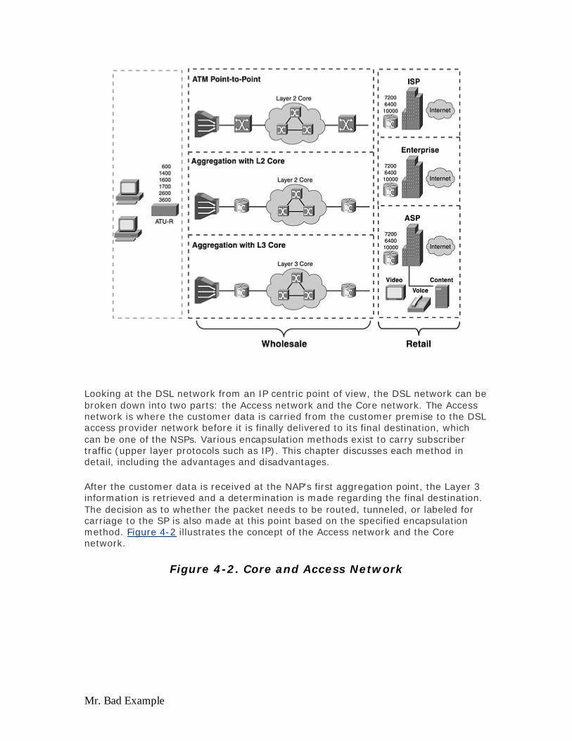
Mr. Bad Example
Looking at the DSL network from an IP centric point of view, the DSL network can be broken down into two parts: the Access network and the Core network. The Access network is where the customer data is carried from the customer premise to the DSL access provider network before it is finally delivered to its final destination, which can be one of the NSPs. Various encapsulation methods exist to carry subscriber traffic (upper layer protocols such as IP). This chapter discusses each method in detail, including the advantages and disadvantages.
After the customer data is received at the NAP's first aggregation point, the Layer 3 information is retrieved and a determination is made regarding the final destination. The decision as to whether the packet needs to be routed, tunneled, or labeled for carriage to the SP is also made at this point based on the specified encapsulation method. Figure 4-2 illustrates the concept of the Access network and the Core network.
Figure 4-2. Core and Access Network
Evaluation notes were added to the output document. To get rid of these notes, please order your copy of ePrint IV now.

Mr. Bad Example
As you can see from Figure 4-2, the access concentrator has three main functions:
Taking data from different subscribers coming into the DSLAMs and retrieving the Layer 3 information—IP. When the traffic from the Internet is addressed to the CPE, the access concentrator, based on the Layer 3 information (Destination IP address) of the CPE, transports that traffic in form of ATM cells.
Forwarding these IP packets based on their destination, IP addresses, or tunneling the subscriber sessions to their respective SP.
Aggregating individual VCs from thousands of subscribers into a few VCs to hand off to the ISP.
Because most DSLAMs today use ATM for uplink, ATM is used as a Layer 2 transport throughout the examples in this book. Note that the access concentrator provides the functionality of an aggregation device for aggregating subscriber permanent virtual circuits (PVCs) and retrieving Layer 3 information of the subscriber traffic and then making the necessary forwarding or switching decision for those packets. This aggregation can take place anywhere—in the DSLAM by using IP DSL switches, before and after the ATM core of NAP, and at the NSP in the case of an end-to-end VC model.
On the connectivity side, the two most important areas are the Access layer and Core. The access side handles the DSL and the ATM layer where subscriber traffic converts into ATM cells and is transported to the DSLAMs through DSL lines. The DSLAMs, in turn, send these cells to the aggregation device so that the aggregation device can convert these ATM cells back to IP. It is the process of converting IP into ATM and back to IP that is of interest. Although many different ways exist for doing this, each method comes with a standard. Each standard has its advantages and disadvantages, and depending on what you want to accomplish, one of these methods will fit your needs. RFC 1483 bridging, Route Bridged Encapsulation (RBE), RFC 1483 routing, PPPoA, and PPPoE are some of the encapsulation methods on the access side.
Evaluation notes were added to the output document. To get rid of these notes, please order your copy of ePrint IV now.

Mr. Bad Example
After the ATM cells are converted to IP on the aggregation device, it looks like you are set because you know how to route IP from this point on. If a NAP is also an ISP, this is definitely the case. The subscriber traffic needs to be routed to the Internet and back, and your job in DSL implementation is done. If the NAP has to transport the subscriber traffic to different ISPs or corporations, standards are available for doing this. L2TP and MPLS VPN are a few ways of transporting subscriber traffic to the ISP, and these methods will also be discussed later in this chapter.
As the price continues to go down for Internet bandwidth, SPs continue to find ways to offer additional services to their subscriber base to increase their revenue. In homes with multiple computers, each computer can connect to different destinations over the same DSL line, much like the dial model. In the dial world, whenever a user wants to connect to his ISP, he simply dials one number to reach his ISP. If he wants to connect to his corporation, he simply dials another number. With the point-to-point nature of DSL, no number needs to be dialed. In order to get around this, people have created several ways to reach different destinations by PPPoE through the SSG, which will be discussed later in the chapter as well.
The Access Network
The access concentrator has several thousand VCs coming in to its ATM interface through the ATM cloud. It has several options to convert these VCs into the IP packet, and each of these methods has a standard associated with it. Some of the methods are as follows:
RFC 1483 bridging RFC 1483 bridging with RBE RFC 1483 routing PPPoA PPPoE
For each of the service architectures, one access encapsulation method will be selected and explained. Each service architecture basically covers the following:
Basic architecture— Provides a brief overview of the encapsulation method and problems this architecture will solve.
Operational description— Provides a technology overview of the access encapsulation method
Advantages and disadvantages— Provides an overview of the advantages and disadvantages of the particular access encapsulation and the architecture
Implementation and design considerations— Covers several design and implementation aspects of the access encap method and its application to this architecture and what the SP or the Consulting/Design Engineer needs to know
CPE options— Covers various aspects of CPE, including installation, configuration, and maintenance of the CPE installed at the subscribers' premises
IP address management and routing— Covers how the IP addresses are allocated to the subscribers, who allocates the IP addresses, how they are managed, and the ramifications of routing those IP addresses through the core
Evaluation notes were added to the output document. To get rid of these notes, please order your copy of ePrint IV now.

Mr. Bad Example
RFC 1483 Bridging
RFC 1483 describes two different methods for carrying connectionless network interconnect traffic over an ATM network: routed protocol data units (PDUs) and bridged PDUs. Routing allows multiplexing of multiple protocols over a single ATM virtual circuit (VC). The protocol of a carried PDU is identified by prefixing the PDU with an IEEE 802.2 Logical Link Control (LLC) header. Bridging performs higher-layer protocol multiplexing implicitly by ATM VCs. For more information, refer to RFC 1483 at www.isi.edu/inwww.isi.edu/in-notes/rfc1483.txt.
This section refers only to bridged PDUs.
RFC 1483 Bridging Operational Description
The list that follows Figure 4-3 outlines the various stages of data encapsulation by using RFC 1483 bridging.
Figure 4-3. RFC 1483 Bridging Data Encapsulation Through Various Stages
1. The user's IP data is encapsulated in IEEE 802.3 (Ethernet) from the PC and enters the Cisco 6xx CPE.
2. It is then encapsulated into a Logical Link Control/Subnetwork Access Protocol (LLC/SNAP) header, which in turn is encapsulated in ATM Adaptation Layer 5 (AAL5) and handed over to the ATM layer.
3. The ATM cells are then modulated by the ADSL transmission technology, Carrierless Amplitude and Phase (CAP) modulation, or discrete multitone (DMT) and sent over the wire to the DSLAM.
Evaluation notes were added to the output document. To get rid of these notes, please order your copy of ePrint IV now.

Mr. Bad Example
4. At the DSLAM, these modulated signals are first received by the POTS splitter if one exists. The POTS splitter splits the signal on the phone wire into two: the signal below 4 kHz is a voice signal and, therefore, is sent to the POTS line; whereas, the signal above 4 kHz is a data signal and, therefore, is sent to the data side.
5. After the POTS splitter identifies the signals as above 4 kHz, it passes them to the ADSL transmission unit – central office (ATU-C) in the DSLAM.
6. The ATU-C demodulates the signal and retrieves the ATM cells, which are then passed to the network interface card (NIC) in the multiplexing device (MUX).
7. The NIC looks at the subscriber side VPI/VCI information in the ATM header and makes the switching decision to another VPI/VCI that will be forwarded to the service destination router.
8. After the service destination router receives these cells on a particular ATM interface, it re-assembles them, looks at the upper layer, and passes the information to a Bridge-Group Virtual Interface (BVI), which is a virtual interface created in the software that can route as well as bridge IP packets.
9. After the BVI interface receives the information from one of the interfaces, it makes the necessary decision on whether to route or bridge the packet, looking at both the Layer 2 and Layer 3 information of the received packet.
After customer data is decapsulated into an IP packet, it is the responsibility of the aggregator to route this packet according to its destination. A BVI with an IP address is defined on the aggregator, and this interface receives all the packets in the bridge and decides whether to forward that packet to other ports in the same group or to route to other destinations.
All subscriber interfaces in the same bridge group share the broadcast domain because of the way bridging works, and for hundreds of subscribers in the same bridge group, broadcasts can have a significant impact on network performance overall. A subscriber might have two computers connected to the same bridge group and connected to each other, consequently creating a loop in the bridge network, as shown in Figure 4-4. For this reason, most RFC 1483 bridging networks also turn on Spanning-Tree Protocol for loop avoidance.
Figure 4-4. RFC 1483 Bridge Loop
Evaluation notes were added to the output document. To get rid of these notes, please order your copy of ePrint IV now.

Mr. Bad Example
Example 4-1 shows a sample configuration for the terminating RFC 1483 bridged packets by using integrated routing and bridging (IRB).
Example 4-1 Terminating RFC 1483 Bridging Packets by Using IRB ! bridge irb bridge 1 protocol ieee bridge 1 route ip !
The configuration in Example 4-1 allows a user to implement IRB on a Cisco router to terminate 1483 bridging traffic. With this configuration, the router routes the bridged IP packets received from bridge group 1.
The configuration in Example 4-2 represents the ATM subinterface facing the subscriber. Notice that an IP address is not assigned to this interface because both the CPE and this interface are in one bridge domain. The encapsulation aal5snap under the pvc command represents that the incoming bridge protocol data units (BPDUs) will be using LLC/SNAP to encapsulate upper layer protocols such as IP. The bridge-group command represents that the interface belongs to a bridge domain 1. Each subscriber has one ATM subinterface on the aggregation device with the configuration similar to Example 4-2.
Example 4-2 ATM Subinterface Configuration interface ATM0/0/0.132 multipoint description PC6, RFC-1483 Bridging no ip directed-broadcast pvc 1/32 encapsulation aal5snap ! bridge-group 1 !
Evaluation notes were added to the output document. To get rid of these notes, please order your copy of ePrint IV now.

Mr. Bad Example
The configuration in Example 4-3 represents and defines a BVI, which makes the necessary decision to route or bridge the packet received from the subscriber side or from the Core network toward the subscriber.
Example 4-3 Defining a BVI interface BVI1 ip address 192.168.1.1 255.255.255.0 ip helper-address 192.168.2.1
The 1 after BVI signifies that this is a BVI interface for bridge group 1 and it represents all the subscribers in that domain. The IP address on the BVI interface applied must be on the same subnet as that of all the subscribers' IP addresses in that bridge group. The helper-address command signifies that all the DHCP broadcast requests coming from subscribers in bridge group 1 are forwarded to a common DHCP server located at 192.168.2.1.
Putting it together, Example 4-4 lists the RFC 1483 bridging configuration for one subscriber.
Example 4-4 Sample RFC 1483 Bridging Configuration bridge irb bridge 1 protocol ieee bridge 1 route ip ! interface ATM0/0/0.132 multipoint description RFC1483 Bridging no ip directed-broadcast pvc 1/32 encapsulation aal5snap ! bridge-group 1 ! interface BVI1 ip address 192.168.1.1 255.255.255.0 ip helper-address 192.168.2.1
Whereas RFC 1483 bridging offers so much in ease of deployment and configuration, it also have disadvantages. Some of the disadvantages are inherent in the bridging model, but some of the disadvantages were also found during ADSL deployment. The following sections discuss many of the advantages and disadvantages of the RFC 1483 model.
Advantages of RFC 1483 Bridging
The advantages of RFC 1483 bridging are as follows:
RFC 1483 bridging is simple to understand— Bridging is simple to understand and implement because no complex issues exist, such as routing or authentication requirements for users.
Evaluation notes were added to the output document. To get rid of these notes, please order your copy of ePrint IV now.
Mr. Bad Example
CPE configuration is minimal and the same configuration is required for all subscribers— Early CPE is bridge-only CPE; therefore, no configuration is required. Even when CPE is capable of both bridging and routing, bridging is the default configuration. The SP considers this important because it no longer requires a large number of truck rolls and no longer needs to invest heavily in personnel for the support of higher-level protocols. The CPE in bridge mode acts as a simple device. Minimal troubleshooting is involved at the CPE because everything that comes in from the Ethernet passes directly to the WAN side.
Easy to install— Bridging architecture is easy to install because of its simplistic nature. After end-to-end PVCs are established, activities such as IP at the upper layer protocols become transparent.
Multiprotocol support for the subscriber— When the CPE is in bridging mode, it is not concerned with which upper layer protocol is being encapsulated.
Ideal for Internet access in a single user environment— Complex troubleshooting is not required for upper layer protocols because the CPE acts as a set-top box. The end PCs do not require additional client installation.
Disadvantages of RFC 1483 Bridging
Several disadvantages exist when you use the RFC 1483 model. As mentioned previously, some of these disadvantages are inherent to the bridging model.
Bridging depends heavily on broadcasts to establish connectivity— When a station in the bridge group broadcasts, everybody in the bridge group is interrupted. These broadcasts also consume bandwidth across the users' xDSL loop, and the broadcasts require resources at the head-end router to replicate packets for the broadcast over point-to-point (ATM PVC) media. Broadcasts between thousands of users are inherently not scalable and can bring a router's performance down because of the processor's time spent on processing broadcasts.
Bridging is inherently insecure and requires a trusted environment— The Address Resolution Protocol (ARP) replies can be spoofed and a network address hijacked. Additionally, broadcast attacks can be initiated on the local subnet, thereby denying service to all members of the local subnet. Within a Windows environment where most people use WORKGROUP as a default workgroup when setting up file sharing, clicking Network Neighborhood can often show other computers in the bridge group as well, often without the end-user aware that he is sharing his hard drive with everyone in the group.
IP address hijacking is possible— With a typical DSL deployment, each PC is assigned one IP address; if the subscriber wants more than one, he must pay more to get a second IP address. The subscriber can pick an IP address from the subnet and use it as his second IP address, and SPs cannot stop this. What's worse is the hijacker can assign the IP address of the default router to one of his computers, which results in a duplicate IP address between the default router and another PC on the subnet, and no one on the subnet can get outside his bridge group.
Implementation Considerations
Ask the following questions before implementing the RFC 1483 bridging architecture:
Evaluation notes were added to the output document. To get rid of these notes, please order your copy of ePrint IV now.

Mr. Bad Example
What are the current and planned numbers of subscribers to be serviced?— As mentioned in the disadvantages section, this model will not scale to a large number of subscribers because of broadcasts that each end station will generate. When the network is overloaded with broadcasts, DSL bandwidth is taken away for user data, and the user PC spends all its time processing these broadcast packets.
Do the subscribers need to communicate with each other?— In homes with more than one PC connected to the Internet, those PCs need to turn on NetBIOS for file and printer sharing to work. Because NetBIOS relies on broadcasts to find its neighbor and other computers in the same network; all the PCs that need to communicate through NetBIOS must be in the same broadcast domain. You can solve this in several ways, including RBE and PPPoA, but often bridging is the easiest way to get this to work.
Do the subscribers in the same bridge domain need to communicate with each other?— If this is required, the NAP must configure point-to-point interfaces for those subscribers because they might not be able to communicate if they are configured under a multipoint interface for the same bridge group. The communication between subscribers fails because of how bridging works—it does not broadcast packets it receives from an interface again out on the same interface. For a point-to-point interface, this behavior is expected. In a multiport bridge, if the bridge receives a broadcast from port 1, the bridge then takes this broadcast and sends it to the rest of its interfaces, except port 1. It does not send the same broadcast to the person who broadcast.
Are these subscribers single-user residential customers?— Do you service small office, home office (SOHO) customers who might have a small LAN behind the CPE? If the customer has a private LAN behind the CPE in the case of SOHO or small business customer, they will not want their traffic on the same bridge group as other subscribers, so the SP must provision a separate bridge group for that customer. Having several bridge groups on the aggregation device is not scalable; therefore, provisioning SOHO customers with RFC 1483 bridging is not a good idea.
What is the deployment and provisioning of CPEs, DSLAMs, and Point of Presence (POP)?— RFC 1483 bridging is simple to provision on the aggregation device. A bridge group and a BVI interface with an IP address is created once, and IP address assignment to PCs are maintained on a DHCP server. Every new subscriber is added with the addition a PVC and a subinterface. No provisioning is needed on CPE if RFC 1483 bridging is deployed. For this reason, if a POP does not have a provisioning system that can handle subscriber provisioning, RFC 1483 is the easiest way to roll out a DSL deployment.
Are the NAP and the NSP the same entity?— Does the business model for the NAP also involve selling wholesale services, such as secured corporate access, and value-added services, such as voice and video? Using RFC 1483 bridging is challenging for the NAP to wholesale the subscriber traffic because the Layer 3 traffic belonging to various ISPs must be separated. The only way the NAP can hand off the subscriber traffic to the NSP is by forwarding IP.
How can the accounting and billing be achieved?— Is it per usage, per bandwidth, or per service? With RFC 1483 bridging, no easy way exists to capture the statistics for traffic sent and received on a VC. If an SP uses the dial model where billing is achieved by the amount of time online and the packets sent/received, RFC 1483 poses a great challenge when it comes to billing.
Evaluation notes were added to the output document. To get rid of these notes, please order your copy of ePrint IV now.

Mr. Bad Example
Design Considerations
As previously mentioned, some inherent problems exist with the RFC 1483 bridging architecture, such as ARP spoofing, IP hijacking, and the basic, general security concern of a bridged model having different subscribers on a single broadcast domain. Cisco IOS Software has a feature known as Subscriber Bridging that addresses some of these problems. Selective application of subscriber policies to a bridge group will control the flooding of ARPs, unknown packets, and others down each ADSL loop. For example, by preventing ARPs from broadcasting across different VCs, a hostile user cannot discover the IP address of another user.
Another solution is to put all subscribers into a single subinterface. Normal bridging behavior will not forward frames to the port on which the frame was received. In essence, this enforces a type of subscriber bridging in which all packets between subscribers are filtered. This approach, however, has the following flaws:
Subscriber policy is only applied between subinterfaces. To apply subscriber policies between two different users, each user must be in a different ATM subinterface.
Hostile users can still hijack the connection of other users because the Layer 2-to-Layer 3 address mapping is learned (via ARP). This is done by generating ARP traffic with another user's IP address and using a different MAC address.
The second scenario is more serious for the carrier or ISP. In this situation, any user can assign the wrong address to a PC or Ethernet-attached device such as a printer and cause connection problems for another user. Such errors or attacks are hard to pinpoint and correct because the offender can be tracked only by tracing the MAC address of the offender.
Example 4-5 shows a sample configuration for a subscriber bridge-group. In this example, subscriber-policy 3 is applied to bridge-group 1. Members of this bridge-group cannot broadcast for ARP or multicast within the same bridge-group, as specified by the subscriber policy. This does not mean that the subscribers within the bridge group cannot communicate with each other; it just means that they cannot broadcast for the ARP within the same bridge group. If a subscriber knows the MAC address of the neighbor's PC, the subscriber can have a static ARP entry in his PC, allowing him to communicate with his neighbor.
Example 4-5 Configure a Subscriber Bridge Group bridge 1 protocol ieee bridge 1 subscriber-policy 3 subscriber-policy 3 arp deny subscriber-policy 3 multicast deny
Some carriers try to work around this problem by segregating users across bridge groups and by implementing subscriber bridging across subinterfaces. In this case when IRB is required, each user is assigned a unique bridge group and BVI. This approach uses two interfaces per subscriber and can be challenging to manage. These issues are addressed and resolved by the RBE feature in Cisco IOS Software.
Evaluation notes were added to the output document. To get rid of these notes, please order your copy of ePrint IV now.
Mr. Bad Example
Considering some of the disadvantages of bridging, you might wonder why the bridging architecture is ever implemented. The answer is simple. Most of the earlier ADSL CPEs installed in the field are capable only of forwarding bridged frames. In these cases, the NSP must implement bridging.
Today, CPE can do PPPoA, RFC 1483 bridging, and RFC 1483 routing. The NSP determines whether to do bridging or PPP. The decision is based on the implementation considerations mentioned earlier, in addition to the advantages and disadvantages of each architecture.
Even with the disadvantages of bridging architecture, it might be suitable for a small ISP (that might not be the NAP) or an NAP/NSP serving a smaller number of subscribers. In these scenarios, the NAP usually forwards all subscriber traffic to the ISP/NSP, which terminates those subscribers. The NAP can choose to provide subscriber traffic by using ATM or Frame Relay as the Layer 2 protocol.
The NAPs using current generation DSLAMs can transport subscriber traffic only by using ATM. In this case, the ISP needs to terminate ATM PVCs to a router. If the ISP/NSP does not have the ATM interface, a regular serial interface with encapsulation ATM Data Exchange Interface (DXI), possibly on an additional device, can be used to accept the incoming bridged PDUs. In both scenarios, the NSP/ISP might need to configure IRB on the router (except when using encapsulation ATM DXI or in the case of transparent bridging). Some of the SP implemented IRB to terminate bridged subscribers. It is expected that SPs will gradually migrate to RBE (discussed later in the section, "Routed Bridge Encapsulation (RBE) Baseline Architecture") or implement PPPoE.
The NSP/ISP might opt to configure separate bridge groups for each set of subscribers or to configure all the subscribers in one bridge group because of some of the limitations previously mentioned. The common practice is to configure a few bridge groups and then configure all the subscribers under separate multipoint interfaces. As mentioned earlier, the subscribers under the same multipoint interface might not communicate with each other. If certain users need to communicate, configure those subscribers under different interfaces. (They can still be in the same bridge group.)
For a small ISP/NSP, the most common routers used to terminate bridged subscribers are the Cisco 3810, Cisco 3600, and Cisco 7200. For an ISP/NSP with a large subscriber base, the Cisco 7400 or 6400 is preferred. Before calculating the memory requirements for these routers, consider the same factors as for any other environment: number of users, bandwidth, and router resources.
CPE Options
Cisco offers various CPE that operate with Cisco and non-Cisco DSLAMs. The configuration for each of the CPE devices is problem free and requires no input from the subscriber. The primary requirement is that the CPE define an ATM VPI/VCI. This allows the CPE to train up with the DSLAM and start passing traffic. In most instances, the NAP opts to configure the same VPI/VCI for all subscribers. The NAP usually preprovisions the CPE before deploying it at the subscriber's location.
Evaluation notes were added to the output document. To get rid of these notes, please order your copy of ePrint IV now.

Mr. Bad Example
In bridging architecture, the main consideration for the CPE and its deployment is how the NAP manages the CPE after it is installed in the field. This is a concern because bridging does not require an IP address for the CPE. However, Cisco CPE can be provisioned with an IP address in bridging mode. The NAP might use this feature to telnet to the CPE to collect statistics or to help the subscriber with troubleshooting. To allow CPE to be managed through the DSLAMs, new proxy element functionality is added that allows the NAP to access the CPE by using Layer 2.
In bridging mode, if no management IP address is assigned to the CPE, the operator can manage the CPE only through the CPE management port. If a management IP address is assigned, the operator can use a Web browser to manage the device; however, this option is generally not available.
When the CPE is in bridging mode, the service destination (which can be the NSP/ISP) needs to provide an IP address to be used as the default gateway for the PCs behind the CPE. These PCs must be set to the correct default gateway. Otherwise, even if the modem is trained (which means that the physical layer is good between the CPE and the DSLAM), the subscriber might not be able to pass traffic. This is not an issue if Dynamic Host Configuration Protocol (DHCP) is used to assign subscriber DHCP addresses because the default router is returned by the DHCP server.
IP Management
In a bridged environment, the IP addresses are allocated to the end stations by a DHCP server located at the service destination, which is usually in the NSP/ISP network. This is the most common approach and is implemented by most NSPs/ISPs by using this model, as shown in Figure 4-5.
Figure 4-5. RFC 1483 Bridge IP Management
Another approach is to provide static IP addresses to the subscribers. In this case, either a subnet of IP addresses or a single IP address is allocated per subscriber, depending on the subscribers' requirements. For example, subscribers wanting to host a Web server or an e-mail server need a set of IP addresses rather than a single IP address. The problem with this is that the NSP/ISP has to provide public IP addresses and might quickly run out of them. Another bigger problem is that subscribers might use the wrong address that does not belong to them, therefore creating IP address conflict within the bridge group.
Evaluation notes were added to the output document. To get rid of these notes, please order your copy of ePrint IV now.

Mr. Bad Example
Some NSPs/ISPs provide private IP addresses to their subscribers and then perform network address translation (NAT) at the service destination router. NAT works by translating several private IP addresses assigned to subscribers to a few registered IP addresses. Some inherent issues exist involving NAT for those who want to put a personal server on their DSL line, but NAT works well for subscribers that need to access only the Internet. NSPs/ISPs that provide a full subnet for one bridge group (with more than one subscriber) need to know that one user can assign the wrong address to a PC or Ethernet-attached device, such as a printer, and cause connection problems for another user. No easy way exists to avoid this problem, except to implement RBE.
An NSP/ISP can restrict the number of PCs that can access the service at one time by configuring the maximum users on the Ethernet interface on the CPE. More specifically, the CPE allows only the maximum number of ARP entries on the Ethernet wire, in effect limiting the number of PCs connected to the CPE.
However, this method has the following flaw. If three PCs are configured to use the service and one of the subscribers adds a network printer (which has its own MAC address) during a time when one of the PCs is idle, the idle PC's MAC address disappears from the ARP entry of the CPE.
If the printer becomes active while a PC is idle, the printer's MAC address is entered in the ARP entry. When a user decides to use this PC to access the Internet, it is unavailable because the CPE already has allowed three MAC entries. The SP can use the strategy of limiting users on the CPE but must take care in fixing the numbers. The best option to restrict the actual number of users is to make use of the DHCP Option 82 feature that restricts the amount of IP addresses to be allocated by a DHCP server, as configured and allowed by the SP, which restricts the actual number of hosts. DHCP Option 82 is convenient for SPs because they can control the number of clients on a centrally located DHCP server versus having to program every CPE every time a new PC is added or removed.
How a Service Destination Is Reached
In an end-to-end PVC architecture with bridging, the service destination is reached by the creation of PVCs between each hop as illustrated in Figure 4-6.
Figure 4-6. RFC 1483 Bridging: End-to-End PVC
Evaluation notes were added to the output document. To get rid of these notes, please order your copy of ePrint IV now.

Mr. Bad Example
Management of these PVCs, however, can be challenging for the NAP/NSP. Additionally, the number of PVCs that can be defined through the ATM cloud is limited. This limitation affects many of the NAPs/NSPs who adopt an end-to-end PVC model. For each subscriber, there must be a fixed, unique set of VPIs/VCIs along the entire path. We have also seen many access providers are migrating to IP-enabled Core networks to solve the problem of VC exhaustion. The NSP/ISP also has the option to use the SSG functionality (discussed at the end of the chapter) to provide different services to subscribers.
In this architecture, secured access to a corporate gateway is achieved by terminating the subscriber traffic PVC directly into the corporate router at Layer 2. The PVC-based architectures are inherently secure when sharing data with other service destinations.
If the NAP does not use end-to-end VC model, it terminates those bridged subscribers and then routes out of its core, so the subscriber traffic is delivered to its final destination. The routing is typically 1483 routing because the core is usually ATM.
Conclusion
The RFC 1483 bridging model is more suitable for smaller ISPs or corporate access for which scalability does not become an issue. RFC 1483 bridging has become the choice of many smaller ISPs because it is simple to understand and implement. As a result of some security and scalability issues, however, the bridging architecture is losing its popularity. NSPs/ISPs are opting for RBE or moving toward PPPoA or
Evaluation notes were added to the output document. To get rid of these notes, please order your copy of ePrint IV now.

Mr. Bad Example
PPPoE, which are highly scalable and secure, but more complex and difficult to implement.
Routed Bridge Encapsulation (RBE) Baseline Architecture
The previous section explains the RFC 1483 bridging architecture and discusses the advantages and disadvantages of this model. RBE was developed to address the known RFC 1483 bridging issues, including broadcast storms, scalability, and security. RBE features function identically to half-bridging, except it operates exclusively over ATM. Half-bridging works by allowing certain IP address to go over a certain VC; therefore, use Layer 3 addresses instead of ARP to forward to different VCs. By eliminating Layer 2 connectivity between subscribers, RBE can scale well, provide greater performance, and provide better security that RFC 1483 bridging (using IRB) failed to provide.
The RBE baseline architecture is designed using the ADSL Forum Reference Architecture Model. The architecture covers different service offerings by the NAP and different scenarios of how the subscriber traffic is forwarded to the SP NSP. The content of this section is based on existing deployments, as well as some in-house tests performed on the architecture.
RBE Operational Description
From the network point of view, the ATM connection looks like a routed connection. Data traffic is received as RFC 1483 packets but are RFC 1483 Ethernet or IEEE 802.3 frames. Instead of bridging the Ethernet or IEEE 802.3 frame, such as in the case of regular RFC 1483 bridging, the router routes on the Layer 3 header. With the exception of some cursory checks (checking the entire frame), the bridge header is ignored.
From an operational point of view, the router operates as if the routed bridge interface were connected to an Ethernet LAN. The operation is described in two ways:
Packets originating from the customer premises— The Ethernet header is skipped and the destination IP address is examined. If the destination IP address is in the route cache or the Forwarding Information Base (FIB) table, the packet is fast switched to the outbound interface. If the destination IP address is not in the route cache, the packet is queued for process switching. In the process switch mode, the outbound interface through which the packet must be routed is found by looking in the routing table. After the outbound interface is identified, the packet is routed through that interface. This occurs without the requirement for a bridge group or BVI.
Packets destined for the customer premises— The destination IP address of the packet is examined first. The destination interface is determined from the IP routing table. Next, the router checks the ARP table associated with that interface for a destination MAC address to place in the Ethernet header. If none is found, the router generates an ARP request for the destination IP address. The ARP request is forwarded only to the destination interface. This
Evaluation notes were added to the output document. To get rid of these notes, please order your copy of ePrint IV now.

Mr. Bad Example
is in contrast to bridging, in which the ARP request is sent to all interfaces in the bridge group.
Figure 4-7 summarizes the Layer 2 and Layer 3 operations in RBE mode.
Figure 4-7. RBE Operation
For a scenario using unnumbered interfaces (where you might find two subscribers on the same subnet), the routed bridge interface uses proxy ARP. Numbered and unnumbered interfaces are discussed in the RBE's sample configuration section later in this chapter. Figure 4-8 provides an example of unnumbered interface. In this figure, 192.168.1.2 (Host A) wants to communicate with 192.168.1.3 (Host B). However, Host A is on the same subnet as Host B.
Figure 4-8. IP Unnumbered Operation
Host A must learn the Host B MAC address by sending out an ARP broadcast to Host B. When the routed bridge interface at the aggregation device receives this broadcast, it will send out a proxy ARP response with the MAC address of 192.168.1.1, Host A. It will take that MAC address, place it in its Ethernet header,
Evaluation notes were added to the output document. To get rid of these notes, please order your copy of ePrint IV now.

Mr. Bad Example
and send the packet. When the router receives the packet, it discards the header, looks at the destination IP address, and then routes it on the correct interface.
Advantages of RBE
RBE was developed with the intention of addressing some of the issues faced by the RFC 1483 bridging architecture. RBE retains the major advantages of RFC 1483 bridging architecture, while eliminating most of its drawbacks. Some of the advantages RBE offers are the following:
Minimal configuration at the CPE— Like RFC 1483 bridging, minimal configuration is necessary on the CPE, and all of the CPE uses the same configuration, eliminating the need to keep track of one unique configuration per subscriber.
Easy to migrate from RFC 1483 bridging architectures to RBE— No change is required at the subscriber end, including CPE and PCs. The only change that needs to happen is on the access concentrator side.
RBE avoids the IP hijacking and ARP spoofing challenges faced in typical pure bridging architectures— RBE also prevents broadcast storms by using point-to-point connections. RBE is preferred over RFC 1483 bridging implementation using IRB by most customers because security is the major disadvantage in pure bridging architectures.
Compared to IRB architectures, RBE provides superior performance because of the routing implementation at the aggregation device— RBE is also more scalable because it does not have bridge group limitations, unlike IRB. Performance for RBE is a big win. Today's standard bridging code has the inherent problem of requiring two separate classifications for a packet before a forwarding decision can be made. A classification is defined as the process of examining (on the upstream) and modifying (on the downstream) the packet header for forwarding information, which is relatively expensive. A Layer 2 lookup is needed to determine whether the packet needs to be routed or bridged. Then, at Layer 3, a lookup is needed to identify the location to which the packet must be routed. This classification is done in the upstream as well as downstream directions, which has an impact on performance. For RBE, it is predetermined by configuration that the packet is to be routed in the upstream direction. As a result, it is not necessary to go through the bridging forwarding path, which was necessary in the case of standard bridging.
Disadvantages of RBE
Although RBE was developed to address the majority of the issues in traditional RFC 1483 bridged architecture using IRB, if RBE is not implemented properly, you can encounter some of the following issues:
IP addresses exhaustion— If the unnumbered option is not used on the RBE interfaces, wastage of IP addresses occur because each interface might need to be assigned a subnet. If you imagine a residence with one host doing RBE, this setup might require a subnet of at least four addresses at a minimum; therefore, RBE needs to be implemented only with unnumbered interfaces.
Evaluation notes were added to the output document. To get rid of these notes, please order your copy of ePrint IV now.

Mr. Bad Example
IP unnumbered without DHCP— If RBE is implemented with unnumbered interfaces without using DHCP to assign IP addresses, you must enter the static host routes for each host, which can result in provisioning delays and large configurations.
Large configuration and bootup time— Because RBE is implemented with only point-to-point interfaces, this results in many interfaces on the aggregation device, which results in a big configuration file stored in NVRAM. During the bootup time when the router tries to load the configuration, it needs to go through each configuration parameter, which might result in some delay during the bootup time.
Implementation Considerations
Some of the key points to consider before implementing the RBE architecture are the same as mentioned for RFC 1483 bridging. RBE is recommended in the following situations:
The scenarios are the same as in existing bridging architectures— For example, when CPE can do RFC 1483 bridging only, ease of CPE provisioning, and so forth.
The NAP wants to perform only minimal management of CPE— The concept of a simple CPE requires minimal or no configuration after the CPE is deployed at the subscriber's location.
The NAP does not want to install and maintain host clients on the hosts behind the bridged CPE— These installation and maintenance tasks increase deployment costs and maintenance, including the provision of help desk personnel with knowledge of the client software and the operating system on which the client is running.
The NAP wants to deploy a scalable and secured bridged network by using existing CPE (which can operate only in RFC 1483 bridging model)— For example, the NAP already has an installed base of bridged CPE, does not like to change any configuration on those CPE, and likes to scale its network to add the additional subscribers within the same network, minus the security related issues associated with traditional RFC 1483 bridging architecture.
Design Considerations for RBE Architecture
This section explains some of the key points that must be considered before designing RBE architecture. For the subscriber side, the design principles remain the same as in the RFC 1483 bridging architecture. On the network side, RBE eliminates the major security risks involved with RFC 1483 bridging using IRB. Additionally, RBE provides better performance and is more scalable because the subinterfaces are being treated as routed interfaces.
In RBE, a single VC is allocated a single route, a set of routes, or a classless interdomain routing (CIDR) subnet. Therefore, the trusted environment is reduced to only the single customer premises represented by either the IP addresses in the set of routes or the CIDR block. The ISP also controls the addresses assigned to the user by configuring a subnet on the subinterface to that user. If a user misconfigures equipment with an IP address outside the allocated address range (possibly causing
Evaluation notes were added to the output document. To get rid of these notes, please order your copy of ePrint IV now.

Mr. Bad Example
ARP packets to flow up to the router), the router generates a wrong-cable error and refuses to enter the erroneous IP-to-MAC address mapping into its ARP table.
ATM Point-to-Point Subinterfaces
RBE can be deployed using only point-to-point ATM subinterfaces. It cannot be deployed on multipoint subinterfaces. Even though the subscriber side is bridged, you do not need to define bridge groups or BVI interfaces because the subinterfaces are treated as routed interfaces.
The ATM point-to-point subinterfaces can be numbered interfaces or unnumbered interfaces to some other interfaces. By definition, a numbered interface is an interface that has a specific IP address assigned to it with a fixed subnet mask. Example 4-6 shows a configuration for a numbered interface.
Example 4-6 Configuring a Numbered Interface interface atm0/0/0.132 point-to-point ip address 192.168.1.1 255.255.255.252
As Example 4-6 shows, when RBE is deployed with a numbered interface, you need a separate subnet for each subscriber. The host at the subscriber end must be configured for 192.168.1.2. Only one host is at the subscriber end. If the requirement is to support more than one host, the subnet mask chosen must accommodate more hosts.
ATM Numbered and Unnumbered Interfaces
Numbered interfaces give the NAP control over the number of hosts the subscriber has connected behind the CPE. As explained previously, this lack of control was a major problem in RFC 1483 bridging using IRB. However, this methodology consumes too many IP addresses. You need to allocate one subnet per subscriber, use one IP address for the ATM subinterface, and leave the broadcast address and all zero addresses unused. To have one host behind the CPE, you at least need to define a subnet mask of 255.255.255.252. Considering the scarcity of IP addresses, this might not be a feasible option unless the NAP/ NSP is using private address space and performing NAT to reach the outside world.
To conserve IP addresses, using unnumbered interfaces is an alternative. By definition, an unnumbered interface is an interface that uses another interface's IP address by using the ip unnumbered command, as demonstrated in Example 4-7.
Example 4-7 Configuring Unnumbered Interfaces ! interface loopback 0 ip address 192.168.1.1 255.255.255.0 ! interface atm0/0/0.132 point-to-point ip unnumbered loopback 0 ! interface atm0/0/0.133 point-to-point
Evaluation notes were added to the output document. To get rid of these notes, please order your copy of ePrint IV now.

Mr. Bad Example
ip unnumbered loopback 0
As Example 4-7 shows, an IP address and subnet are applied only to the loopback interface. All ATM subinterfaces need to be unnumbered to that loopback interface. In this scenario, all the subscribers terminated on ATM subinterfaces (unnumbered to loopback 0) must be on the same subnet as that of loopback 0. This implies that subscribers need to be on the same subnet but would be coming in through different routed interfaces. In this situation, it becomes a problem for the router to identify which subscriber is behind which ATM subinterface. Assume that 192.168.1.0 is directly connected through interface loopback 0, and it is never going to send traffic destined to any of the host addresses on that subnet through any other interface. To resolve this issue, you need to explicitly configure static host routes, as in Example 4-8.
Example 4-8 Configuring Static Host Routes ip route 192.168.1.2 255.255.255.255 atm0/0/0.132 ip route 192.168.1.3 255.255.255.255 atm0/0/0.133
As specified in Example 4-8, when the router needs to make a routing decision and needs to forward the traffic destined for 192.168.1.2, it chooses ATM 0/0/0.132 as the outgoing interface, and so on. Without specifying those static host routes, the router chooses the outgoing interface as loopback 0 and drops the packet.
Even though the unnumbered interface conserves IP addresses, it requires the additional task of configuring static host routes on the aggregation device for each subscriber, if the unnumbered interface option is not used along with DHCP, as explained in the "RBE and DHCP" section. Note that if a subscriber has, for example, 14 hosts behind the CPE, it is not required to have static host routes for each host. A summarized route can be defined for the ATM subinterface as follows:
ip route 192.168.1.0 255.255.255.0 atm0/0/0.132
The preceding static route summarizes host routes for the whole network of 192.168.1.0 with the address ranging from 192.168.1.1 to 192.168.1.254. You can vary the subnet mask to define the actual number of hosts in a network.
Example 4-9 puts together the RBE configuration for unnumbered interfaces.
Example 4-9 RBE Configuration for Unnumbered Interfaces interface Loopback0 ip address 192.168.1.1 255.255.255.0 no ip directed-broadcast ! interface ATM0/0/0.132 point-to-point ip unnumbered Loopback0 no ip directed-broadcast atm route-bridged ip
Evaluation notes were added to the output document. To get rid of these notes, please order your copy of ePrint IV now.

Mr. Bad Example
pvc 1/32 encapsulation aal5snap ! ip route 192.168.1.2 255.255.255.255 ATM0/0/0.132
For each new subscriber, the ATM interface section and the static IP route needs to be added to the configuration.
RBE and DHCP
So far, this explanation has assumed that the hosts behind the CPE are configured for static IP addresses. This assumption is not true in real-life designs. In the practical world, the NAP wants to perform minimal configuration and maintenance for the CPE and the hosts attached to it. To achieve that, the hosts must get their addresses dynamically using a DHCP server.
To get their IP addresses dynamically, hosts must be configured to get IP addresses from a DHCP server. When the host boots up, it sends out DHCP requests. These requests are then relayed to the appropriate DHCP server, which assigns an IP address to the host from one in its previously defined scopes.
To forward the initial DHCP requests from the host to the appropriate DHCP server, you need to apply the ip helper-address command to the interface that is receiving the broadcasts. After the broadcasts are received, Cisco IOS Software looks at the configuration of the IP helper address for that interface and forwards those requests in a unicast packet to the appropriate DHCP server whose IP address is specified by the ip helper-address command. After the DHCP server replies with the IP address, it sends the response to the interface on the router that originally forwarded the request. This is used as the outbound interface to send the DHCP server response to the host that originally requested the service. The router also automatically installs a host route for this address.
If RBE is enabled on a subinterface and is an IEEE 802.3 BPDU, the Ethernet encapsulation is examined after ATM bridge encapsulation. If it is an IP/ARP packet, it is handled like any other IP/ARP packet. The IP packet is fast or CEF switched. If it fails, it is queued for process switching.
IP Management
While deploying the numbered interfaces for RBE, the IP address allocation to the host behind the bridged CPE is usually handled through a DHCP server. As mentioned earlier, the DHCP server can reside in the NAP or in the NSP. For either case, the numbered ATM subinterface must be configured with the ip helper-address command. If the DHCP server is located at the NSP, the NAP aggregation device must have a route to reach that server. The only scenario in which a NAP uses its own DHCP server and IP address range is when it wants to offer service selection capabilities to the subscribers, and those subscribers are LAN-attached to the NAP.
If the NAP wants to use the IP address space of the NSP, one of the IP addresses for each subnet must be allocated to the ATM subinterface. Also, there needs to be some
Evaluation notes were added to the output document. To get rid of these notes, please order your copy of ePrint IV now.
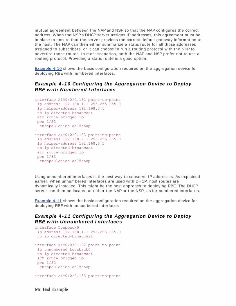
Mr. Bad Example
mutual agreement between the NAP and NSP so that the NAP configures the correct address. When the NSP's DHCP server assigns IP addresses, this agreement must be in place to ensure that the server provides the correct default gateway information to the host. The NAP can then either summarize a static route for all those addresses assigned to subscribers, or it can choose to run a routing protocol with the NSP to advertise those routes. In most scenarios, both the NAP and NSP prefer not to use a routing protocol. Providing a static route is a good option.
Example 4-10 shows the basic configuration required on the aggregation device for deploying RBE with numbered interfaces.
Example 4-10 Configuring the Aggregation Device to Deploy RBE with Numbered Interfaces ! interface ATM0/0/0.132 point-to-point ip address 192.168.1.1 255.255.255.0 ip helper-address 192.168.3.1 no ip directed-broadcast atm route-bridged ip pvc 1/32 encapsulation aal5snap ! interface ATM0/0/0.133 point-to-point ip address 192.168.2.1 255.255.255.0 ip helper-address 192.168.3.1 no ip directed-broadcast atm route-bridged ip pvc 1/33 encapsulation aal5snap
Using unnumbered interfaces is the best way to conserve IP addresses. As explained earlier, when unnumbered interfaces are used with DHCP, host routes are dynamically installed. This might be the best approach to deploying RBE. The DHCP server can then be located at either the NAP or the NSP, as for numbered interfaces.
Example 4-11 shows the basic configuration required on the aggregation device for deploying RBE with unnumbered interfaces.
Example 4-11 Configuring the Aggregation Device to Deploy RBE with Unnumbered Interfaces interface Loopback0 ip address 192.168.1.1 255.255.255.0 no ip directed-broadcast ! interface ATM0/0/0.132 point-to-point ip unnumbered Loopback0 no ip directed-broadcast ATM route-bridged ip pvc 1/32 encapsulation aal5snap ! interface ATM0/0/0.133 point-to-point
Evaluation notes were added to the output document. To get rid of these notes, please order your copy of ePrint IV now.

Mr. Bad Example
ip unnumbered Loopback0 no ip directed-broadcast ATM route-bridged ip pvc 1/33 encapsulation aal5snap
How a Service Destination Is Reached
Up to this point, the basic access technology by using RBE as the encapsulation method has been discussed. However, using this architecture enables the NAP/NSP to offer various services and different options where the NAP can forward the subscriber traffic to the NSP. You can use different ways to get subscriber traffic to the NSP (sometimes called service selection). As illustrated in Figure 4-9, a service can be Internet access, access to the corporation, or a Voice over IP (VoIP).
Figure 4-9. Service Selection
Service Selection by Policy Routing
In the case of RBE, because the subscribers' PVCs are terminated at the aggregation device in the NAP, the subscribers' data is transported to the SP NSP by routing IP traffic. SPs who have a legacy ATM core in their network and have migrated from and end-to-end VC model to RBE might route IP over ATM by using RFC 1483 routing. The SPs who do not have an existing core infrastructure might opt to build up a Layer 3-based core and utilize it optimally to route the subscriber traffic in case of RBE.
One important aspect that must be noted while deploying RBE, especially in a wholesale scenario, is how to separate the traffic from subscribers from different ISPs. In a wholesale model, as discussed in Chapter 3, the NAP might be servicing more than one NSP. The wholesaler can overcome this kind of situation in a couple of
Evaluation notes were added to the output document. To get rid of these notes, please order your copy of ePrint IV now.

Mr. Bad Example
ways. One way is by implementing Cisco IOS Software-based policy routing, and the other is by using Cisco IOS Software-based SSG. This ensures that subscriber traffic belonging to xyz.com is routed to only xyz.com and not abc.com. However, any approach that requires a policy to be defined per subscriber has some performance implications on the device. The performance impact is important because each and every IP packet from each subscriber needs to be checked against the policy defined to make the necessary routing decision. The scalability concern is determined by how many policies can be defined, which in turn determines how the subscribers can be allowed to select more than one NSP. The best way to approach this issue is as mentioned earlier, by using an MPLS-based VPN or SSG. MPLS-based VPNs and SSG are explained in detail later in this chapter in the core section.
Providing Internet Access
In this scenario, the primary function for the NSP is to provide high-speed Internet access to the end subscribers. IP address management becomes the responsibility of the NSP because the NSP is going to provide the final service. The NSP can assign public IP addresses to its end subscribers by using a DHCP server, or it can opt to provide private IP addresses to the subscribers and then perform NAT to reach the outside world.
Wholesale Services
If the NAP wants to offer wholesale services to other ISPs, it can do so. In this scenario, the NAP usually does not prefer to handle IP addresses for all the subscribers for different NSPs. The NAP makes an arrangement with the ISP to provide IP addresses to those subscribers. This can be achieved by the NAP forwarding the DHCP requests coming from the subscribers to the DHCP servers at the NSPs. The NAP has to configure its ATM subinterfaces with one of the IP addresses from that range, and it needs to advertise those routes to the NSP. The route advertisement can be in the form of either a static route or some routing protocol between the NAP and NSP. Static route assignment is the preferable method for the NAP, as well as the NSP. Because of some of these concerns and issues, RBE does not become an obvious choice for a wholesaler unless it is used along with MPLS VPN or SSG, as explained earlier.
Corporate Access
Corporate access usually requires VPN services. This means that the corporation does not provide any IP addresses to the NAP and does not allow the NAP to advertise the corporate IP address space in the NAP's IP core because it can result in a security breach. Corporations usually prefer to apply their own IP addresses to their clients, or they will allow access through some secured means, such as MPLS VPN or L2TP.
The other approach to providing secured corporate access is where the NAP provides the initial IP addresses to those subscribers. After the subscribers have initial IP addresses, they can initiate a tunnel to the corporation through L2TP client software running on the host. In turn, the corporation authenticates this subscriber and provides an IP address from its IP address space. This IP address is used by the L2TP VPN adapter. This way, the subscribers have the option to either connect to their ISP
Evaluation notes were added to the output document. To get rid of these notes, please order your copy of ePrint IV now.

Mr. Bad Example
for Internet connection or gain access to their corporation through a secured L2TP tunnel access. However, this requires the corporation to provide the tunnel destination IP address to the subscriber, which can be routable through the NAP's IP core.
Service Selection Capabilities
The NAP can offer various service selection capabilities by using Cisco's SSG functionality. The SSG offers two methods for providing service selection: through Layer 2 (which is known as PTA-MD) and Layer 3 Web selection. With RBE, only the Layer 3 Web selection method can be used. This requires the NAP to provide the initial IP address to the subscriber and provides access to the Cisco Service Selection Dashboard (SSD). SSG and SSD are explained in detail later in the chapter.
In the case of the RBE architecture, the Cisco SSG Web selection method is a good way to account for subscriber traffic.
Conclusion
RBE provides better performance and more scalability, and overcomes most of the security issues in standard bridging. RBE eliminates the broadcast storm problems of standard bridging. RBE provides a robust architecture for the NAP that wants to avoid the maintenance of client host software and bridging-related issues and wants lower deployment costs. With RBE, this can all be achieved using the existing bridging architecture.
PPP over ATM
Although most earlier deployments were based on the bridging architecture, PPPoA is popular today, and because of the tremendous advantages it offers, PPPoA might be the chosen access encapsulation method for many SPs serving business customers.
The PPPoA baseline architecture is designed with an assumption of providing high-speed Internet access and corporate access to the end subscriber by using PPPoA and ATM as the core backbone. This architecture is discussed mainly based on PVCs because that is what the majority of the current deployments are using. The content of the section is based on existing deployments, as well as some in-house tests done on this architecture.
Technology Brief
Point-to-Point Protocol (PPP), described in RFC 1331 (www.isi.edu/inwww.isi.edu/in-notes/rfc1331.txt), provides a standard method of encapsulating higher layer protocols across point-to-point connections. It extends the HDLC packet structure with a 16-bit protocol identifier, which contains information of content of the packet. This packet contain three types of information:
Link Control Protocol (LCP) Network Control Protocol (NCP) IP Control Protocol (IPCP)
Evaluation notes were added to the output document. To get rid of these notes, please order your copy of ePrint IV now.

Mr. Bad Example
LCP phase negotiates the link parameters, packet size, or type of authentication. The NCP phase has information about higher layer protocols, such as IP, IPX, and their control protocols (which is IPCP for IP). The final piece of the protocol identifier contains the actual data. PPP over AAL5 (RFC 2364) uses AAL5 as the framed protocol, which supports both PVCs and SVCs. PPPoA was primarily implemented as part of ADSL. It relies on RFC 1483 and operates in either LLC-SNAP or VC-Mux mode. A CPE encapsulates PPP sessions based on this RFC for transport across the ADSL loop and the DSLAM.
PPPoA Operational Description
When the CPE is first powered on, it starts sending an LCP config request toward the aggregation device. The aggregation device, with the PVCs configured, also sends out the LCP config request on a Virtual Access Interface associated with the PVC as soon as the VC comes up. When both the CPE and aggregation device see each other's config request, they acknowledge them. After the CPE receives acknowledgment from the aggregation server and vice versa, the LCP state is then open.
The next stage, authentication, occurs when the CPE sends the authentication request to the aggregation device. Depending on the aggregation device's configuration, authentication is either achieved by looking at the domain name, if supplied, or the username, using its local database or Remote Access Dial-In User Service (RADIUS) server. If the request from the subscriber is in the form of username@domainname, the aggregation device tries to create a tunnel to the username@domainname, the aggregation device tries to create a tunnel to the destination, if one is not already there. After the tunnel is created, the aggregation server forwards the PPP requests from the subscriber to the destination, which in turn authenticates the user and assigns an IP address. If the request from the subscriber is without the domain name, the user is authenticated by the local database. If SSG is configured on the aggregation device, the user can access the default network as specified and can get an option to select different services.
Besides the VC configuration on the aggregation device, the username and password for each subscriber usually are stored in a RADIUS server. On the aggregation router, some additional commands need to be turned on in order for the aggregation router to communicate with the RADIUS server, as shown in Example 4-12.
Example 4-12 RADIUS Server Configuration on the Aggregation Device aaa new-model aaa authentication login default none aaa authentication ppp default local group radius aaa authorization network default local group radius none aaa accounting network default wait-start group radius radius-server host 192.168.2.20 auth-port 1645 acct-port 1646 radius-server key cisco
IP address assignment can either be assigned by the RADIUS server or by the local IP pool stored on the aggregation device. The command ip local pool local-pppoa
Evaluation notes were added to the output document. To get rid of these notes, please order your copy of ePrint IV now.

Mr. Bad Example
192.168.40.20 192.168.40.50 defines a local pool called local-pppoa that has 10 IP addresses from 192.168.40.20 to 192.168.40.50.
Finally, you need to create an interface on the aggregation device for each subscriber. You can statically define each interface or define a virtual-template interface. Each interface that uses this template inherits all the characteristics under the template. Example 4-13 shows a virtual template that uses CHAP as an authentication method and assigns the CPE IP addresses from the pool called local-pppoa. The PVC 1/32 is encapsulated by aal5mux method and uses virtual-template 1 for creating its interface.
Example 4-13 Virual Template Definition with ATM Subinterface interface ATM0/0/0.1 point-to-point no ip directed-broadcast pvc 1/32 encapsulation aal5mux ppp Virtual-Template1 ! interface Virtual-Template1 description PPPoATM ip unnumbered FastEthernet0/0/0 peer default ip address pool local-pppoa ppp authentication chap
Upon configuring the RADIUS server and defining the virtual template and local pool, every new subscriber needs one ATM subinterface with the corresponding PVC defined, and the username and password is added to the RADIUS authentication database.
Advantages of PPPoA
The PPPoA architecture inherits most of the advantages of PPP used in the dial model. Some of the key points are as follows:
Per session authentication based on PAP or CHAP— This is the most advantageous point of PPPoA that overcomes the security hole in the bridging architecture. The SP assigns an individual IP username and password making it much harder for intruders to access the network. IP address assignment happens only after authentication between the CPE and aggregation device passed. Furthermore, the authentication mechanism used in CHAP uses the MD5 algorithm to send keys to each other for authentication; the password is never sent across the wire, making security harder to compromise.
Per session accounting is possible— This allows the SP to charge the subscriber based on the session time for various services offered. This is also useful if the SP opts to offer a minimum charge for access and than charges the subscriber based on the services used.
IP address conservation at the CPE— The SP needs to assign only one IP address for CPE, and the CPE can be configured for NAT. This allows all the users behind one CPE to use one IP address to reach different destinations and, therefore, reduces the overhead of IP management for NAP/NSP for each individual user behind the CPE and at the same time conserve IP addresses. Additionally, the SP also has an option to provide a small subnet of IP
Evaluation notes were added to the output document. To get rid of these notes, please order your copy of ePrint IV now.

Mr. Bad Example
addresses that can overcome the limitation of PAT/NAT. The feature called IPCP Subnet Negotiation allows the CPE to download a block of IP addresses from the aggregation device, use the first address out of the block for its Ethernet IP address, and put the rest of the IP addresses into the DHCP server. This feature is convenient when deploying CPEs for small businesses.
The NAP/NSP can provide secured access to the corporate gateway without managing an end-to-end PVC and making use of Layer 3 routing and L2F/L2TP tunnels— As a result, the NAP/NSP can scale their business model of selling wholesale services.
Easy to troubleshoot individual subscribers— The NSP can easily identify which subscriber is on or off based on active PPP sessions, rather than troubleshooting the entire group of subscribers as in the case of a bridging architecture. PPPoA goes through different stages, and by turning on debugs on PPP, technicians can see exactly where the problem is when PPP is set up.
Oversubscribing is possible— The NSP can afford to oversubscribe by deploying idle and session timeouts by using industry standard RADIUS server for each subscriber.
Highly scalable— You can terminate a high number of PPP sessions on an aggregation device. In addition, authentication, authorization, and accounting can be handled on a per user basis by using an external RADIUS server.
Disadvantages of PPPoA
PPPoA offers only single session per CPE on one VC— Because the username and password are configured on the CPE, only one set of services is accessible for all the users behind the CPE for that particular VC; the users do not have option to select a different set of services. Using multiple VCs and establishing different PPP sessions on different VCs, though, is possible.
Increased complexity of the CPE setup— Help Desk personnel at the SP need to be more knowledgeable. The username and password are set on the CPE, so if that needs to be changed, it requires configuration on the part of the subscriber or the vendor. When multiple VCs are used, it increases the complexity.
SPs need to maintain a database of username and password for each subscriber— If tunnels or proxy services are used, the authentication can be done on the basis of the domain name, and the user authentication is done at the corporate gateway, which reduces the size of the database the SP has to maintain.
If a single IP address is provided to CPE and NAT/PAT is implemented, certain applications that embed IP information in the payload cannot work— Additionally, even if the IP subnet feature is used, an IP address must be reserved for the CPE as well.
Implementation Considerations
Various aspects need to be considered while implementing PPPoA architecture, some of which include the following:
Planned number of subscribers to be serviced current and future, meaning the number of PPP sessions.
Are the PPP sessions terminated at the SP's aggregation router or are they forwarded to other corporate gateways or ISPs?
Evaluation notes were added to the output document. To get rid of these notes, please order your copy of ePrint IV now.

Mr. Bad Example
Who is providing the IP address to the CPE—the SP or the final service destination?
Are the IP addresses provided public or private? Is CPE going to be NAT/PAT, or is NAT done at the aggregation device?
What is the end subscriber's profile? Is the subscriber a residential user, a SOHO customer, or is it one or more telecommuters?
In case of more than one user on the same CPE, do all the users need to reach the same final destination or do they all have different service destinations?
Is the SP providing any value-add services such as voice and video? Does the SP require all the subscribers to go to a particular network first before reaching any final destination? When using SSG, are they going to use passthrough services, PTA MD, or proxy. PTA MD and passthrough services are discussed in detail in the SSG section of this chapter; the reason you need to ask this question when deciding to deploy PPPoA is explained in the SSG section.
How does the SP want to bill the subscriber: flat rate, per session usage, or by services used? If the SP wants to bill subscribers by connection time or by packets, PPPoA is a good choice versus RFC 1483 bridging or RBE. The bridging models cannot keep track of accounting for subscriber sessions.
Deployment and provisioning of CPE, DSLAMs, and aggregation POPs. PPPoA is a robust architecture with different stages of negotiation and authentication; therefore, the provisioning system needs to support these parameters. This means the provisioning system needs to keep track of individual CPE's configuration as each customer's configuration is unique.
For SPs, are the NAP and NSP the same entity or does the business model for the NAP also involve selling wholesale services, such as secured corporate access and value-add services, such as voice and video?
Is the business model of the company an ILEC, CLEC, or ISP?
Keeping some of these key points in mind, how the PPPoA architecture fits and scales to different business models for SPs and how they can benefit using this architecture is discussed next.
Design Considerations for PPPoA
Remember several key points when deploying a PPPoA network. If you sell different levels of access speed to the subscribers, quality of service (QoS) is something you need to deploy, either on the ATM level or at the IP level. The intention to scale the network to support tens of thousands of PPPoA subscribers needs some additional considerations. Because each CPE requires a unique configuration, such as username and password, some considerations have to be taken into account on the CPE side. Authentication of subscriber sessions can be a problem if the server is not scaled correctly to the number of subscribers in the network. Underpowered RADIUS servers or insufficient bandwidth to the RADIUS servers can leave some sessions unable to authenticate, leaving subscribers unable to connect to their aggregation device.
Other issues that might come into play are performance of the aggregation device and accounting records for individual subscribers. Segment assembly and reassembly of ATM cells, retrieving IP, and producing accounting records to send to the RADIUS
Evaluation notes were added to the output document. To get rid of these notes, please order your copy of ePrint IV now.

Mr. Bad Example
servers takes some cycles on the CPU of the aggregation device. These issues are address in the following sections.
Quality of Service
One major consideration in the previous scenarios is how the SP can offer different levels of QoS for different services and how they calculate the bandwidth allocation. Currently, most SPs deploy this architecture so that different levels of QoS are offered on different PVCs. The SP might have a separate PVC on the core for residential customers and a separate PVC for the business customers. Using different PVCs allows the SP to specify different levels of QoS for different services. As already mentioned, QoS can be applied on separate PVCs, or the SP might opt to provide different levels of QoS at Layer 3. For more information on IP QoS, refer to the Cisco Press book, IP Quality of Service, by Srinivas Vegesna (published by Cisco Press).
Applying QoS at Layer 3 requires that the SP knows the final destination, which can be a limiting factor; however, if Layer 3 QoS is used in combination with Layer 2 QoS (by applying it on different VCs), this can be useful for the SP. The only limitation with this model is that it is fixed, and the SP needs to provision for those levels of QoS in advance— QoS does not get applied dynamically on the selection of service. Currently, a user has no option to select different bandwidths for different services with a click of the mouse; however, a lot of engineering effort is put in to realize this feature.
CPE Deployment and Provisioning
Deployment, management, and provisioning of CPE can be challenging in the PPPoA architecture because the CPE needs to be configured for username and passwords. For simplicity, some SPs use the same username and password for all CPE, but this can be a big security glitch. Additionally, if the CPE needs to open different sessions simultaneously, additional VCs need to be provisioned at the CPE, NAP, and NSP. Provisioning at the NSP for so many subscribers by using PVCs is a major limiting factor because they need to manage all those different PVCs. Currently, no simple way exists to provision 2000 PVCs on a single aggregation device by clicking a couple of buttons with a mouse or entering a few keystrokes.
RADIUS Servers
Another important thing that most designers forget to consider before undertaking a large ADSL deployment using this architecture is communication from the aggregation router to the RADIUS server. When you have thousands of PPP sessions terminated on a router, if that router fails, all those PPP sessions must be re-established. This means all those subscribers need to be authenticated and their accounting record has to be stopped and restarted after the connection is established. When so many subscribers try to become authenticated at the same time, and if the pipe to the RADIUS server becomes a bottleneck, some of the subscribers might not become authenticated, which can create a problem for the SP.
It is important to have a link to the RADIUS server that has enough bandwidth and power to accommodate and grant permissions to all these subscribers at the same
Evaluation notes were added to the output document. To get rid of these notes, please order your copy of ePrint IV now.

Mr. Bad Example
time. In the case of thousands of subscribers, the SP must consider an option to load balance between the multiple RADIUS servers.
Performance of the Aggregation Router
With so many PPP sessions, performance of the aggregation device can play an important role. Consider the same traffic engineering principles that are used for other implementations. Previously for PPPoA, the user had to configure PVCs for PPPoA on point-to-point subinterfaces. Today, PPPoA allows the user to configure multiple PVCs on multipoint subinterfaces as well as point-to-point.
The maximum number of PPPoA sessions supported on a platform depends on available system resources, such as memory and CPU speed. Each virtual access interface consists of a hardware interface description block/software interface description block (hwidb/ swidb) pair that takes approximately 7.5 KB of memory. These hwidb/swidb pairs are needed to create an interface in IOS. To support more number of sessions, the router needs to have higher IDBs for PPPoA deployment. Today, IDB limits in IOS are high and the memory required per hwidb/swidb is reducing rapidly.
User Authentication and Billing
In the case of high-speed Internet access, in an environment where the NSP and the NAP are the same, you will have to terminate the PPP sessions from subscribers in the aggregation device deployed. In this kind of scenario, the NSP/NAP needs to consider how many PPP sessions can be terminated on a single router, how the users are going to be authenticated, how they are going to perform accounting, and what the path to the Internet is after user sessions are terminated on the aggregation device.
The user authentication and accounting in this scenario is best handled by using the industry standard RADIUS server, which can authenticate users on the basis of their username. You can also authenticate based on the VPI/VCI from which the users are coming. For high-speed Internet access, usually the NSP bills customers for a flat rate— this is how most of the current deployments are being implemented. In the case where the NSP and NAP are the same entity, the billing model consists of a fixed rate for Internet access. This model changes when the SP starts offering value-add services; the SP can offer to charge the customers based on the service they use and the amount of time they used the service.
CPE Options
SPs have an option to charge end users for more IP addresses or more PCs connected to their network. Additionally, SPs prefer to provide subscribers with additional IP addresses for a fee. Some choose to sell bandwidth to the users instead and do not care how many PCs are hooked up to the CPE. In this scenerio, in order to conserve IP addresses, SPs can choose to have Port Address Translation (PAT) running on the CPE. PAT works by translating a block of private IP address ranges to one single registered IP address by mapping the private IP address to the port address and registered IP address pair.
Evaluation notes were added to the output document. To get rid of these notes, please order your copy of ePrint IV now.

Mr. Bad Example
Certain applications that embed IP information in the payload will not work because of the nature of PAT, such as Netmeeting. If the SP decides that PAT is the service they want to sell, they need to inform customers about which applications will not work.
In the PPPoA architecture, because an IP address is assigned to the CPE, it becomes easier for the NAP/NSP to telnet into the CPE and configure, as well as troubleshoot.
Different options for the CPE can be used depending on the subscriber's profile. For example, for a residential user, CPE might be configured without PAT/DHCP, and for a subscriber with more than one PC, CPE can be either configured for PAT/DHCP or can be configured the same way as that of a residential user. If an IP phone connects at the back of the CPE, the CPE might be configured for more than one PVC.
IP Management
In the PPPoA architecture, the IP address allocation for the subscriber CPE is based on the same principle of PPP in the dial model, that is, through IPCP negotiation. The IP address allocated to the CPE depends on the type of service to which the subscriber subscribes.
If the subscriber has subscribed to only Internet access from the NSP, the NSP will terminate those PPP sessions from the subscriber and will assign an IP address. The IP address pool is allocated from either a locally defined pool, DHCP server, or can be applied from the IP address pool on the RADIUS server. However, if the subscriber wants to tunnel his session to a corporation, the NSP will tunnel the PPP session to the corporation without assigning IP addresses to this session.
There can also be certain cases where the ISP might have provided a set of static IP addresses to the subscriber and might not assign IP addresses dynamically when the subscriber initiates the PPP session. In this scenario, the SP might not use its local pool; the SP only uses the RADIUS server to authenticate the user.
IP Addressing
In an event where the subscriber prefers to have multiple services available, the NSP might need to implement SSG. In this scenario, a couple of possibilities exist to assign an IP address to the end subscriber. In first scenario, the SP might provide an IP address to the subscriber through its local pool of IP addresses (which are defined on the access concentrator) or RADIUS server; then after the user selects a particular service, SSG forwards user traffic to that destination. If the SSG is configured in proxy mode, the final destination might provide an IP address, which the SSG uses to NAT. SSG and its modes are discussed in detail later in this chapter.
In the second scenario, the PPP sessions do not terminate on the SP's aggregation router, and they are either tunneled or forwarded to the final destination/home gateway that will eventually terminate the PPP sessions and negotiate IPCP with the subscriber and, therefore, provide an IP address dynamically. In the second scenario, using static addresses is also possible as long as the final destination has allocated those IP addresses and has a route to them.
Evaluation notes were added to the output document. To get rid of these notes, please order your copy of ePrint IV now.

Mr. Bad Example
IPCP Subnet Negotiation
In the past, when an SP assigned a subnet of IP addresses, an SP technician had to make a static route in a router for that subnet and advertise it to other routers in the network. On the CPE side, a technician also needed to take one IP address, assign it to the Ethernet side of the CPE, and use the other IP addresses for the remaining devices on the network. The network administrator for the subscriber must be quite knowledgeable in configuring CPE and needs to spend some time configuring the CPE.
In a large scale roll out, and especially dealing with the consumer, it is important that SPs can offer this IP subnet to their customers without involving the customer configuring their CPE. Fortunately, Cisco IOS Software provides a feature called IPCP Subnet Negotiation that allows a way for the SP to provide a subnet of an IP address to the subscriber, out of which the first IP address is used by the CPE, and the remaining IP addresses are put in a DHCP pool. These IP addresses are, in turn, assigned to individual PCs. Because of the availability of this feature, CPE does not need to be configured for PAT, which did not work with some of the applications.
Figure 4-10 illustrates how IPCP Subnet negotiation works. The DHCP server assigns a block of IP addresses from 192.168.1.1 to 192.168.1.6 to the CPE. The CPE gets the IP address pool assigned to it during IPCP negotiation, takes the first IP address out of the pool, which is 192.168.1.1, and assigns it to its own Ethernet interface. The rest of the IP addresses in the pool, from 192.168.1.2 to 192.168.1.6, are put into the CPE's DHCP server to be handed out to the CPE.
Figure 4-10. IPCP Subnet Negotiation
Evaluation notes were added to the output document. To get rid of these notes, please order your copy of ePrint IV now.

Mr. Bad Example
How Service Destination Is Reached
In the case of PPPoA architecture, as explained earlier, the service destination can be reached in different ways. Some of the most common ones that are deployed in large scale today are as follows:
Terminating PPP sessions at the SP L2TP tunneling Using SSG
In all three scenarios, a fixed set of PVCs are defined from the CPE to DSLAM that switch to a fixed set of PVCs on the aggregation router. The way the PVCs are mapped from DSLAM to aggregation router might be through an ATM cloud.
Apart from these three scenarios, the service destination can be reached in other ways, including PPPoA with SVCs and MPLS VPNs. Later sections of this chapter will discuss these implementations.
Terminating PPP at Aggregation Device
The PPP sessions initiated by the subscriber are terminated at the SP that authenticates users either using a local database on the router or through a RADIUS server. When the user is authenticated, IPCP negotiation takes place and the IP address gets assigned to the CPE.
After the IP address has been assigned, a host route is established both on the CPE and the aggregation router. The IP addresses that are allocated to the subscriber, if registered, are advertised to the edge router that is the gateway to the Internet and the subscriber can access the Internet. If the IP addresses are registered, the SP translates them before advertising them to the edge router. Figure 4-11 shows how a VC is terminated at the aggregation device and then routed to the Internet.
Figure 4-11. Terminating PPP at Aggregation Device
Evaluation notes were added to the output document. To get rid of these notes, please order your copy of ePrint IV now.
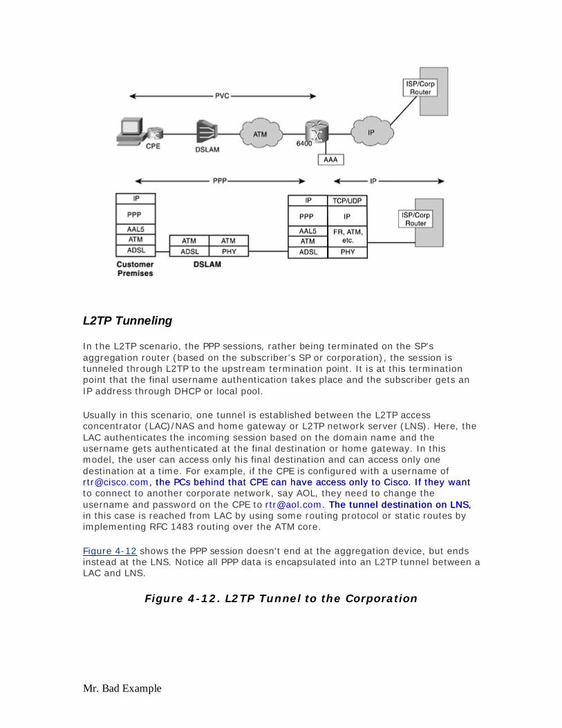
Mr. Bad Example
L2TP Tunneling
In the L2TP scenario, the PPP sessions, rather being terminated on the SP's aggregation router (based on the subscriber's SP or corporation), the session is tunneled through L2TP to the upstream termination point. It is at this termination point that the final username authentication takes place and the subscriber gets an IP address through DHCP or local pool.
Usually in this scenario, one tunnel is established between the L2TP access concentrator (LAC)/NAS and home gateway or L2TP network server (LNS). Here, the LAC authenticates the incoming session based on the domain name and the username gets authenticated at the final destination or home gateway. In this model, the user can access only his final destination and can access only one destination at a time. For example, if the CPE is configured with a username of [email protected], the PCs behind that CPE can have access only to Cisco. If they want [email protected], the PCs behind that CPE can have access only to Cisco. If they want to connect to another corporate network, say AOL, they need to change the username and password on the CPE to [email protected]. The tunnel destination on LNS, [email protected]. The tunnel destination on LNS, in this case is reached from LAC by using some routing protocol or static routes by implementing RFC 1483 routing over the ATM core.
Figure 4-12 shows the PPP session doesn't end at the aggregation device, but ends instead at the LNS. Notice all PPP data is encapsulated into an L2TP tunnel between a LAC and LNS.
Figure 4-12. L2TP Tunnel to the Corporation
Evaluation notes were added to the output document. To get rid of these notes, please order your copy of ePrint IV now.

Mr. Bad Example
Using SSG
The main advantage of using SSG over tunneling is that SSG provides mapping of one-to-many services as opposed to one-to-one mapping in tunneling. This becomes useful where a single user might require access to multiple services at any given time, or multiple users at a single location each require access to a unique service. SSG makes use of the Web-based SSD which is accessible to the user and which consists of different services. The user can select to access one service or multiple services at a time. One other advantage of using SSG is that the SP can bill the user based on the services used and the session time. The user has the ability to turn services on and off through the SSD. SSG and its modes will be explained in detail later in the chapter in the SSG section.
Conclusion
PPPoA is a suitable architecture for most SPs because it is highly scalable, especially for business customers, and it mirrors the PPP model used in dial that a lot of people understand well. PPPoA becomes useful for SOHO or business applications in a centralized fashion when all the hosts behind the CPE need to go to only one destination, such as a corporation. With the SSG functionality running on top of PPPoA, users can easily choose different services with a few mouse clicks.
PPP over Ethernet Architecture (PPPoE)
In the current world of access technologies, it is highly desirable to connect multiple hosts at a remote site through the same customer premises access device. It is also essential to provide access control and billing functionality in a manner similar to
Evaluation notes were added to the output document. To get rid of these notes, please order your copy of ePrint IV now.
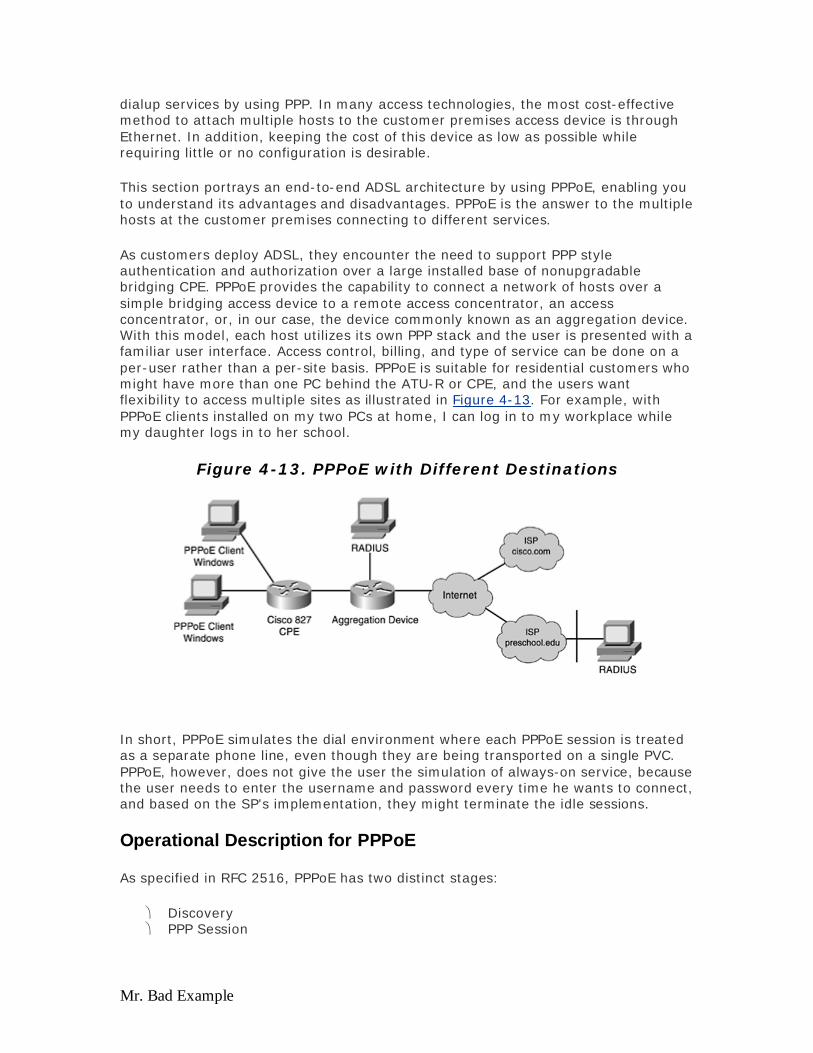
Mr. Bad Example
dialup services by using PPP. In many access technologies, the most cost-effective method to attach multiple hosts to the customer premises access device is through Ethernet. In addition, keeping the cost of this device as low as possible while requiring little or no configuration is desirable.
This section portrays an end-to-end ADSL architecture by using PPPoE, enabling you to understand its advantages and disadvantages. PPPoE is the answer to the multiple hosts at the customer premises connecting to different services.
As customers deploy ADSL, they encounter the need to support PPP style authentication and authorization over a large installed base of nonupgradable bridging CPE. PPPoE provides the capability to connect a network of hosts over a simple bridging access device to a remote access concentrator, an access concentrator, or, in our case, the device commonly known as an aggregation device. With this model, each host utilizes its own PPP stack and the user is presented with a familiar user interface. Access control, billing, and type of service can be done on a per-user rather than a per-site basis. PPPoE is suitable for residential customers who might have more than one PC behind the ATU-R or CPE, and the users want flexibility to access multiple sites as illustrated in Figure 4-13. For example, with PPPoE clients installed on my two PCs at home, I can log in to my workplace while my daughter logs in to her school.
Figure 4-13. PPPoE with Different Destinations
In short, PPPoE simulates the dial environment where each PPPoE session is treated as a separate phone line, even though they are being transported on a single PVC. PPPoE, however, does not give the user the simulation of always-on service, because the user needs to enter the username and password every time he wants to connect, and based on the SP's implementation, they might terminate the idle sessions.
Operational Description for PPPoE
As specified in RFC 2516, PPPoE has two distinct stages:
Discovery PPP Session
Evaluation notes were added to the output document. To get rid of these notes, please order your copy of ePrint IV now.

Mr. Bad Example
The four steps to the Discovery stage follow:
Step 1. The host broadcasts an Initiation packet.
Step 2. One or more access concentrators send Offer packets.
Step 3. The host sends a unicast Session Request packet.
Step 4. The selected access concentrator sends a Confirmation packet.
When these four steps are completed, both peers know the PPPoE SESSION_ID and the peer's Ethernet address, which together define the PPPoE session uniquely. When the host receives the Confirmation packet, it can proceed to the PPP Session stage. When the access concentrator sends the Confirmation packet, it can proceed to the PPP Session Stage in the following steps:
Step 1. LCP negotiation between the two end-point connections (that is, the host and the access concentrator).
Step 2. Authentication Phase (where the access concentrator actually authenticates the user).
Step 3. This is the final stage, where IPCP negotiation takes place and the host is assigned with an IP address.
The detailed description of the Discovery Stage for PPPoE follows:
Step 1. The host sends The PPPoE Active Discovery Initiation (PADI) packet with the DESTINATION_ADDR set to the broadcast address. The PADI consists of one tag indicating what service type it is requesting.
Step 2. When the access concentrator or the router receives a PADI that it can serve, it replies by sending a PPPoE Active Discovery Offer (PADO) packet. The PADO packet is a unicast packet where the DESTINATION_ADDR is the unicast address of the host that initiated the PADI. If the access concentrator cannot serve the PADI, in an event where it cannot service the tag as requested in PADI, it MUST NOT respond with a PADO.
Step 3. Because the PADI was broadcast, the host might receive more than one PADO. The host looks through the PADO packets it receives and chooses one. The choice can be based on the services offered by each access concentrator.
Step 4. The host then sends one PPPoE Active Discovery Request (PADR) packet to the access concentrator that it has chosen. The DESTINATION_ADDR field is set to the unicast address of the access concentrator or the router that sent the PADO.
Step 5. When the access concentrator receives a PADR packet, it prepares to begin a PPP session. It generates a unique SESSION_ID for the PPPoE session and replies to the host with a PPPoE Active Discovery Session-confirmation
Evaluation notes were added to the output document. To get rid of these notes, please order your copy of ePrint IV now.

Mr. Bad Example
(PADS) packet. The DESTINATION_ADDR field is the unicast Ethernet address of the host that sent the PADR.
After the PPPoE session begins, PPP data is sent as in any other PPP encapsulation. All Ethernet packets are unicast. Figure 4-14 shows the PPPoE operation.
Figure 4-14. PPPoE Operation
The PPPoE Active Discovery Terminate (PADT) packet might be sent anytime after a session is established to indicate that a PPPoE session terminated. It might be sent by either the host or the access concentrator. The DESTINATION_ADDR field is a unicast Ethernet address. For more detailed explanation please refer to RFC 2516 (www.isi.edu/inwww.isi.edu/in-notes/rfc2516.txt).
Configuration for PPPoE on the access concentrator is more or less similar to PPPoA, as far as configuring the virtual template goes. It uses the same local-pool concept to assign IP addresses to the PPPoE clients or can use an external AAA server to do accounting and authentication and also to provide IP addresses. The difference is the VPDN configurations, as shown in Example 4-14. Notice the ATM encapsulation is aal5snap, and the definition of vpdn-group that specifies pppoe as a protocol.
Example 4-14 Configuration for PPPoE ! vpdn enable ! vpdn-group 1 accept-dialin protocol pppoe virtual-template 1 ! interface ATM0/0/0.132 point-to-point pvc 1/32
Evaluation notes were added to the output document. To get rid of these notes, please order your copy of ePrint IV now.

Mr. Bad Example
encapsulation aal5snap protocol pppoe ! interface Virtual-Template1 ip unnumbered FastEthernet0/0/0 peer default ip address pool pppoe-pool ppp authentication pap ! ip local pool pppoe-pool 192.168.1.10 192.168.1.50
After the virtual template, IP local pool, and VPDN-group are defined, the only thing needed for a new subscriber is to create an ATM subinterface with the right PVC and add the username and password to the RADIUS database.
Advantages of PPPoE
The PPPoE architecture inherits most of the advantages of PPP used in the dial model and PPPoA architecture. Some of the advantages follow:
Per session authentication based on PAP or CHAP— The most advantageous point of PPPoA and PPPoE that overcomes the security hole in bridging architecture.
Per session accounting is possible— Enables the SP to charge the subscriber based on the session time for various services offered. This can also be useful if the SP opts to offer minimal charge for access and then charges the subscriber based on the service he used.
PPPoE can be used on existing CPE (which cannot be upgraded to PPP or which does not have capability to run PPPoA)— Extends the PPP session over the bridged Ethernet LAN to the PC.
PPPoE preserves the point-to-point session used by ISPs in the current dialup model— PPPoE is the only protocol capable of running point-to-point over Ethernet without requiring an intermediate IP stack. This is a powerful point for the SP deploying PPPoE, as an IP address is not required to communicate with the end device to advertise services.
The NAP/NSP can provide secured access to corporate gateway without managing end-to-end PVC and making use of Layer 3 routing and L2TP tunnels— Allows the NAP/NSP to scale their business model for selling wholesale services and VPN.
PPPoE can provide a host (PC) access to multiple destinations at a given time— You can have multiple PPPoE sessions per PVC. This can translate to multiple sessions per PVC; therefore, with a household of one or more PCs, each PC can access a different service while still being on the same PVC.
NSP can afford to oversubscribe— This is possible by deploying idle and session timeouts by using an industry standard RADIUS server for each subscriber, as available with PPPoA.
Disadvantages of PPPoE
PPPoE has the following disadvantages:
Evaluation notes were added to the output document. To get rid of these notes, please order your copy of ePrint IV now.

Mr. Bad Example
Not all access concentrators support PPPoEoE (PPPoE over Ethernet)— Most support only PPPoE over ATM.
PPPoE client software needs to be installed on all hosts (PCs) connected on the Ethernet segment— This increases an added complexity to the access providers because they not only have to maintain the CPE but also need to maintain the client software on the PC, requiring additional understanding, troubleshooting of the client operating system, and the additional cost associated for maintaining it. Many CPE vendors have a PPPoE client built in to prevent cumbersome maintenance of client software on PCs.
PPPoE implementation makes use of RFC 1483 bridging— As a result, PPPoE can potentially be susceptible to broadcast storms and possible denial of service attacks.
Implementation Considerations
Various aspects need to be considered while implementing PPPoE architecture. Some of the key points that you should consider before implementing this kind of architecture follow:
Number of planned and future PPPoE sessions on an access concentrator. This might influence the number of access concentrator devices you need to purchase.
Are the PPP sessions terminated at the SP's aggregation router or are they forwarded to other corporate gateways or ISPs?
Who is providing the IP address? Is it the SP or the final service destination? In case of more than one user, do all the users needs to reach the same final
destination or service, or do they all have different service destinations? Does the end subscriber require simultaneous access to multiple destinations?
Which PPPoE client software does the access provider plan to use, and has it has been tested? What is the PC's operating system, and is it capable of making an intelligent routing decision?
How does the SP want to bill the subscriber; is it based on flat rate, per session usage, or services used?
Deployment and provisioning of CPE, DSLAMs, and aggregation POPs. What network management platform provisions and manages these devices?
Are the NAP and NSP the same entity or does the business model for the NAP also involve selling wholesale services, such as secured corporate access or value-add services such as voice and video.
Is the business model of the company an ILEC, CLEC, or ISP? What kind of applications does the NSP want to offer to the end subscriber? What is the volume of data flow in each direction (upstream and
downstream)?
Keeping some of these points in mind, consider how the PPPoE architecture fits and scales to different business models for SPs and how they can benefit using this architecture.
Design Consideration for PPPoE Architecture
As expressed in the previous section on implementation considerations, it is highly recommended that you read the section on PPPoA because a majority of the design
Evaluation notes were added to the output document. To get rid of these notes, please order your copy of ePrint IV now.

Mr. Bad Example
considerations for both the PPPoA and PPPoE architectures remains the same. Most of the PPPoA architecture design considerations also apply PPPoE and are not repeated here. Instead, the issues that specifically apply to PPPoE and that are not covered under PPPoA architecture are discussed. We also discuss design considerations that do not apply to PPPoE architecture that are specified under PPPoA architecture.
Before deploying any architecture, you must understand the SP's business model and determine the different services the SP offers. The SP might opt to provide one service such as high-speed Internet access to his end subscribers, or might select to sell wholesale services to different ISPs and provide value-add services to those subscribers. The SP might opt to provide all of these services. The section on PPPoA covers a majority of these options and, therefore, is not repeated.
It is important in the case of PPPoE to choose which client software will be installed on the PC. The market offers a variety of different client software, but the most common one is from Routerware. Because the client software is going to be installed on a PC, this increases further complexity as the SP technician needs to have a good understanding of the PC and the operating system running on that PC.
Note that for PPPoE as per RFC 2516, the Maximum-Receive-Unit (MRU) option must not be negotiated to a larger size than 1492 because Ethernet has a maximum payload size of 1500 octets. The PPPoE header is 6 octets and the PPP protocol ID is 2 octets, so the PPP MTU must not be greater than 1492. This can be achieved by configuring ip mtu 1492 for PPPoE virtual-template interfaces. Example 4-15 shows a sample configuration for changing the MTU under a virtual-template interface.
Example 4-15 Changing MTU Under a Virtual-Template Interface interface Virtual-Template1 ip unnumbered FastEthernet0/0/0 no ip directed-broadcast peer default ip address pool pppoe-pool ppp authentication pap ip mtu 1493
To protect the router against denial of service attacks, the PPPoE implementation of Cisco IOS Software by default allows only 100 sessions to be sourced from a MAC address or 100 sessions to be established over a VC. Users can change the defaults by using pppoe session-limit per-mac and pppoe session-limit per-vc commands, as shown in Example 4-16.
Example 4-16 Setting MAC and Session Limits Under vpdn-group vpdn-group 1 accept dialin pppoe virtual-template 1 pppoe limit per-mac 2 pppoe limit per-vc 2
Evaluation notes were added to the output document. To get rid of these notes, please order your copy of ePrint IV now.
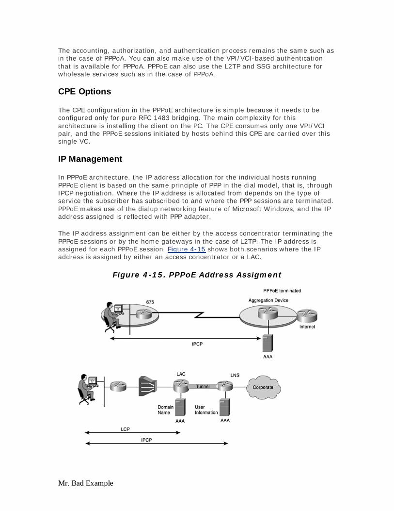
Mr. Bad Example
The accounting, authorization, and authentication process remains the same such as in the case of PPPoA. You can also make use of the VPI/VCI-based authentication that is available for PPPoA. PPPoE can also use the L2TP and SSG architecture for wholesale services such as in the case of PPPoA.
CPE Options
The CPE configuration in the PPPoE architecture is simple because it needs to be configured only for pure RFC 1483 bridging. The main complexity for this architecture is installing the client on the PC. The CPE consumes only one VPI/VCI pair, and the PPPoE sessions initiated by hosts behind this CPE are carried over this single VC.
IP Management
In PPPoE architecture, the IP address allocation for the individual hosts running PPPoE client is based on the same principle of PPP in the dial model, that is, through IPCP negotiation. Where the IP address is allocated from depends on the type of service the subscriber has subscribed to and where the PPP sessions are terminated. PPPoE makes use of the dialup networking feature of Microsoft Windows, and the IP address assigned is reflected with PPP adapter.
The IP address assignment can be either by the access concentrator terminating the PPPoE sessions or by the home gateways in the case of L2TP. The IP address is assigned for each PPPoE session. Figure 4-15 shows both scenarios where the IP address is assigned by either an access concentrator or a LAC.
Figure 4-15. PPPoE Address Assigment
Evaluation notes were added to the output document. To get rid of these notes, please order your copy of ePrint IV now.

Mr. Bad Example
Because in PPPoE the CPE is bridged, no IP address is allocated to it. Being in bridged mode, the CPE cannot do NAT/DHCP as in PPPoA and, therefore, conserve public IP addresses, as we saw in PPPoA. There only the CPE was assigned a public IP address, while the hosts behind the CPE received private IP addresses and were translated to the one assigned to CPE, before reaching any outside services.
How Service Destination Is Reached
In the case of PPPoE, the service destination can be reached in the following ways as explained with PPPoA:
Terminating PPP sessions at the SP L2TP tunneling Using SSG
Conclusion
PPPoE is gaining in popularity in the ADSL world. PPPoE has become a popular choice for SPs that provide high-speed Internet access service to residential customers, although it still needs to establish its advantages for business customers.
References
RFC 2516, "A Method for Transmitting PPP over Ethernet (PPPoE)"
RFC 1483, "Multiprotocol Encapsulation over ATM Adaptation Layer 5"
RFC 2364, "Point-to-Point over AAL5"
RFC 1483 Routing
RFC 1483 routing, as the name suggests, is also based on RFC 1483 as explained in the RFC 1483 bridged architecture. The only difference is that the CPE in this case is in 1483 routing mode and sends routed PDUs instead of bridged PDUs. The upper layer protocols, such as IP, are again encapsulated into LLC SNAP, just the way they became encapsulated in bridged mode.
Operational Description of RFC 1483 Routing
As Figure 4-16 shows, the CPE or the ATU-R is now configured in the RFC 1483 routing mode, and the Ethernet frame from the subscriber PC is not passed over to the aggregation device. This is the main difference in the stack compared to that of RFC 1483 bridging where the CPE or ATU-R was configured in bridged mode and allowed the Ethernet frame to pass over all the way to the aggregation device. After the aggregation device terminates the subscriber PVC, it can make the forwarding decision of that packet by looking at the destination address of the IP packet it retrieved and then looking in the routing table. Like any router, the CPE and the aggregation device can exchange each other's routing information by using various routing protocols.
Evaluation notes were added to the output document. To get rid of these notes, please order your copy of ePrint IV now.

Mr. Bad Example
Figure 4-16. Protocol Stack for RFC 1483 Routing
Figure 4-16 shows the protocol stack for RFC 1483 routing.
The RFC 1483 routing architecture is popular with business customers with existing routers who currently use Frame Relay or T1/E1 as leased lines to connect to their remote offices or branches and are now considering replacing those with xDSL lines. The architecture is suitable for wholesalers who want to offer various VPN services to their business customers and corporate accounts. The core in this type of architecture is typically a Layer 3 core or IP core, which can be either over ATM or a completely packet-based core by using trunk interfaces such as Gigabit Ethernet from the aggregation devices.
Configuration for RFC 1483 routing is similar to that of RFC 1483 bridging: each ATM subinterface is specified with a PVC and aal5snap encapsulation method. A static route for each subnet is entered for each customer, as shown in Example 4-17.
Example 4-17 RFC 1483 Routing Configuration ! interface ATM0/0/0.132 point-to-point ip unnumbered fastethernet 0/0/0 no ip directed-broadcast pvc 1/32 encapsulation aal5snap ! ip route 192.168.1.0 255.255.255.0 interface atm 0/0/0.132
Evaluation notes were added to the output document. To get rid of these notes, please order your copy of ePrint IV now.
Mr. Bad Example
Advantages of RFC 1483 Routing
Some of the advantages of the RFC 1483 routing architecture are as follows:
Probably the best approach for enterprise or business customers who already have routers in place and are currently looking at xDSL as a replacement to their traditional leased line circuits— This approach might enable the SP to seamlessly adopt their existing infrastructure by either putting in an external ATU-R or an internal xDSL WAN Interface Card (WIC) in their router and offering their customers VPN services.
The CPE becomes manageable— Being in 1483 routing mode, the CPE or the ATU-R now is acting as a router and has an IP address assigned to it and, therefore, can be managed remotely by either Telnet or sending images through TFTP. This is advantageous for the SPs who were earlier using bridged CPE and had to either waste IP addresses to manage those CPEs or needed a truck roll to do any image upgrades.
Being in 1483 routing mode, the CPE or ATU-R can have more than one PVC configured— This is advantageous if the SP wants to offer different services or class of services on separate PVCs. For example, the SP might prefer to offer data service on one PVC and voice service on a separate PVC, which then allows them to do a proper classification of the traffic and prioritize it accordingly.
The CPE, in routed mode and acting as a router, can implement NAT or PAT— The advantage of this implementation is the conservation of IP addresses. The SP might allocate only one legal IP address for the subscriber CPE or ATU-R, and the rest of the devices behind that CPE use an illegal IP address and NAT or PAT to that address while going out of their local network. Conservation of IP addresses is advantageous to various SPs who do not have enough legal IP addresses to give to their subscribers.
By using Cisco IOS Software, the subscribers can implement firewall features on their CPE— This helps avoid any denial of service attacks to their sites or possible intervention to their network.
The SOHO business owners now have the ability to implement some sort of encryption and tunneling between their branch offices by using this implementation, while getting DSL Services from different DSL SPs— This is useful when xDSL is considered as a replacement to traditional T1 or Frame Relay connectivity between corporations and branch offices. By using encryption between the branch office and corporate headquarters, even though the corporate headquarters uses the SP's network infrastructure, data is secure.
Disadvantages of RFC 1483 Routing
Some disadvantages of this model that make it unpopular with SPs targeting residential customers follows:
Lack of accounting method for subscriber traffic— As mentioned in the case of bridging, no good way exists to do accounting for subscriber traffic if the SP wants to bill the subscribers based on certain service usage. If the SP is offering always-on service, accounting is not needed and this implementation is suitable.
Evaluation notes were added to the output document. To get rid of these notes, please order your copy of ePrint IV now.
Mr. Bad Example
This implementation does not allow any means to authenticate the subscribers— This can be highly disadvantageous to SPs who want to offer a different set of services to different users based on what the subscribers have subscribed or paid for.
Complex routing configurations necessary on the CPE— Because the CPE is acting as a router and might typically have more than one IP subnet behind it, the configurations usually become complex and routing knowledge is essential as the routes between the subscriber CPE and the SP might be exchanged using some routing protocols. This definitely calls for truck rolls and also requires a higher level of routing expertise at the help desk of SPs. Additionally, if the SP is managing the CPE, additional costs involved in maintaining the CPE and its complex configurations must be considered.
Implementation Considerations for RFC 1483 Routing
As explained earlier, RFC 1483 routing is suitable for SMB or corporations connecting to its other small branches through T1 or Frame Relay today and should consider using xDSL as a replacement to T1 or Frame Relay connectivity.
While implementing RFC 1483 routing architecture, you need to consider the following issues:
Routing protocols between CPE and NAP edge router— This can help you to identify what routing protocols you might need to run (as an SP) in your network or redistribute. If in your implementation you have a small LAN behind the CPE that uses the contiguous IP addresses, you might define a static route for that subnet, which is easier to handle. However, for certain branch offices that have multiple LANs, you might need to run a routing protocol, such as OSPF, EIGRP, or RIP, to update your NAP edge router's routing table.
Who is providing the IP addresses?— In the corporate environment, usually depending on the size of the branch office, a central DHCP server is located at the corporate headquarters, providing addresses to the hosts at branch offices. In this scenario, the SP needs to be aware of this address range and, therefore, update its routing table accordingly. If the DHCP server is located at the branch office, that network needs to be advertised by the CPE by using one of the routing protocol or static routes. In either case, typically in this architecture, the IP addresses are allocated using a DHCP server, and the SP usually does not allocate those IP addresses.
In a wholesale scenario, how to separate the traffic— This is basically the same issue mentioned during RFC 1483 bridging or RBE architecture. The best way to achieve this is by using MPLS-based VPN (explained in detail, later in the chapter).
Design Considerations for RFC 1483 Routing Architecture and Key Points
1483 Routed architecture is in no way different than any enterprise routed model wherein the different remote sites might be connected to the corporate site by using some set of routing protocols that are overlayed on some sort of Layer 2 transport, such as Frame Relay. In the case of DSL, implementing this architecture requires the
Evaluation notes were added to the output document. To get rid of these notes, please order your copy of ePrint IV now.
Mr. Bad Example
SP to also take part in the Layer 3 or routing process, which might be questioned by some customers as far as the security goes and how far they trust routing their traffic through the SP's network. The SPs adopting this model specifically for business customers make use of MPLS-based VPN services—the security for which can easily be compared with the security of providing Frame Relay access.
As mentioned earlier, this architecture is similar to any routed architectures, that is, routing or internetworking between different routers. Therefore, all the design considerations you might use in the routed model can apply to this. The SP might need to consider the appropriate routing protocol to be used in both the core and access layer. Typically, on the access side, if the CPE or ATU-R belongs to the SP and is a managed service provided by the SP, it is appropriate to run a dynamic routing protocol between the CPE and SP's router. However, if it is not a managed service and the ATU-R or CPE does not belong to the SP, use of a static route might be one of the options, especially if the subscriber does not have more than one network behind its CPE. This way, the SP has better control of the subscriber routes and can manage them appropriately. The only issue with a static route is that it increases the configuration efforts on the SP's end every time the subscriber adds a new network behind its CPE.
Depending on the number of subscribers it needs to service, the SP might need to calculate the appropriate amount of memory to hold those routes and also ensure that forwarding of the subscriber traffic takes place by using mechanisms such as Cisco Express Forwarding (CEF) to reduce the impact on the processor and speed up the switching time. The topology of the SP's core and the decision to use an appropriate routing protocol is a key in this kind of implementation, as it addresses the scalability of the architecture.
If the SP is a wholesaler and is servicing subscribers of multiple corporate networks and ISPs, one of the challenges using this model is how to keep the subscriber traffic belonging to different corporate networks and ISPs separate from each other, as discussed in the section on RBE. The solutions are similar to those used for RBE—either implement policy-based routing or MPLS-based VPNs. No matter which method is implemented, the subscriber traffic handed over to the corporate network or ISP uses IP. Therefore, the architecture is not common with SPs who are in wholesale business to residential and consumer subscribers of different ISPs because the ISPs would not like anyone (even the wholesaler SP) touching their subscriber's traffic beyond Layer 2.
IP Address Management
IP addresses to the subscribers in this model are assigned in the same way used for RBE— by using a DHCP server. The location of the DHCP server varies based on different factors. For example, if the SP serves a corporation with various geographical locations, each with approximately more than one hundred subscribers, it is likely that the corporation might have installed a local DHCP server at each site, the local subscribers get their IP addresses by using the local server, and the CPE is preconfigured with a static address. In a scenario where the corporation might have fewer subscribers at each site, and it prefers that all those subscribers get their addresses through a common shared DHCP server at the central site, the CPEs at the subscribers' end and the SP's routers need to act as a DHCP relay agent and forward the subscribers' DHCP request to a centralized server. If the SP offers MPLS-based
Evaluation notes were added to the output document. To get rid of these notes, please order your copy of ePrint IV now.

Mr. Bad Example
VPNs and the SP is holding the IP addresses for various corporations or ISPs, the SP might need to implement mechanisms to ensure that when an IP address is assigned to a subscriber of Corporation A, it also is associated with the VPN for Corporation A. If the SP offers MPLS-based VPNs and the DHCP servers are located at various ISPs or corporations, the SP might need to implement VPN-based DHCP relay agents to ensure that the requests from subscribers of Corporation A are handed over to the DHCP server located centrally at Corporation A and are not broadcast to all the other corporations or ISPs.
CPE Options
CPE devices in this architecture are configured to do RFC 1483 routing and are actually full-blown routers running Cisco IOS Software. Being a router, the CPE configuration at times can become complex, especially when it has multiple networks running behind it. Depending on the application and usage, the CPE could be running routing protocols like E-BGP, OSPF, RIP, or EIGRP between itself and the NAP edge router (aggregation device) or can simply be advertising the networks connected behind it by using static routes. CPE devices in this architecture are usually managed through SNMP.
How Service Destination Is Reached
The service destination in an RFC 1483 routing environment is reached in the same way as discussed in the case of the RBE implementation. This is because RBE implementation uses RFC 1483 routing implementation after the subscriber's traffic on the access side reaches the aggregation device in the NAP.
Conclusion
The RFC 1483 routing architecture is not popular today, but as soon as business customers begin migrating to xDSL as a replacement to Frame Relay and T1/E1 lines, this will probably be the most common architecture for them.
The Core Network
On the core side, after an ATM cell has gone through the segment assembly and reassembly (SAR) process, and Layer 3 (IP) information is retrieved, the access concentrator must decide what to do with that packet. If the access concentrator belongs to the NAP, it routes that packet according to the destination of the packet. However, if this access concentrator is only a transit point for other NSPs, the access concentrator forwards that packet to the appropriate SPs by using one of the following methods:
ATM IP MPLS L2TP
The sections that follow discuss the methods not covered so far—L2TP and MPLS.
Evaluation notes were added to the output document. To get rid of these notes, please order your copy of ePrint IV now.

Mr. Bad Example
As discussed in the sections on access architectures, if the core is ATM-based and if the access concentrator in the NAP is terminating the subscribers, the subscriber IP traffic is routed over that ATM core by using RFC 1483 routing or RFC 1577. This is a common scenario for retail SPs; however, because of the overhead of ATM and the expense associated with maintaining an ATM core, most of the retail SPs now are either migrating to or thinking about migrating to an IP core. This makes sense for a retailer who controls the subscriber and offers various value-add services to its subscribers. The connectionless nature of IP allows their core to scale to serve millions of subscribers.
Layer 2 Tunneling Protocol (L2TP)
L2TP was first introduced in traditional dialup models, specifically to offer VPN services. Traditional dialup networking services support only registered IP addresses, which limits the types of applications that are implemented over VPNs. L2TP supports multiple protocols and unregistered and privately administered IP addresses over the Internet. This allows the existing access infrastructure, such as the Internet, modems, access servers, and ISDN terminal adapters (TAs), to be used. It also allows enterprise customers to outsource dialout support, thereby reducing overhead for hardware maintenance costs and 800 number fees, and allows them to concentrate on corporate gateway resources.
L2TP, an extension to the PPP, is an important component for VPNs, which allow users and telecommuters to connect to their corporate intranets or extranets. VPN is cost-effective because users can connect to the Internet locally and tunnel back to connect to corporate resources. This not only reduces overhead costs associated with traditional remote access methods but also improves flexibility and scalability.
The wholesale DSL SP also uses the same model to provide wholesale services to various ISPs and corporations. Corporations looking for VPN services adhered to this model as a replacement to traditional dialup VPNs. ISPs looking for outsourcing the access infrastructure to different SPs to serve their subscribers also adopted this model because it does not require the access provider to provide any IP addresses to the subscribers, and the access provider does not look at the subscriber traffic beyond Layer 2 after the session is up. The access provider, however, also can bill the ISP or the subscriber by the amount of usage of certain services because the architecture requires PPP as the access encapsulation and, therefore, the availability of accounting records.
The main components of this architecture follows:
The L2TP Access Concentrator (LAC) that initiates the L2TP tunnels and is located in the NAP.
The L2TP Network Server (LNS) that terminates the tunnels and is typically located at the network SP. (An exception is when it is also located at NAP.)
Authentication, Authorization, and Accounting (AAA) servers also play a key role in this architecture. Figure 4-17 shows the L2TP architecture and components.
Figure 4-17. L2TP Architecture
Evaluation notes were added to the output document. To get rid of these notes, please order your copy of ePrint IV now.

Mr. Bad Example
The LAC has the following characteristics:
A device attached to a switched network fabric, such as PSTN or ISDN, or colocated with a PPP end system capable of handling the L2TP protocol.
The capability to tunnel any protocol carried within PPP The initiator of incoming calls and the receiver of outgoing calls Also known as NAS in Layer 2 Forwarding (L2F) terminology
The LNS has the following characteristics:
A termination point for L2TP tunnel and access point where PPP frames are processed and passed to higher layer protocols.
Operates on any platform capable of PPP termination. Handles the server side of the L2TP protocol. L2TP relies only on the single
media over which L2TP tunnels arrive. Might have a single LAN or WAN interface, yet still can terminate calls arriving
at any of the LACs full range of PPP. The initiator of outgoing calls and the receiver of incoming calls, analogous to
the L2F's home gateway (HGW).
The L2TP architecture supports any PPP-based encapsulations such as PPPoA and PPPoE. As previously discussed, L2TP is an extension of PPP and can be used only if the access encapsulation is PPP-based. One of the reasons for that is with any PPP-based encapsulation, you send out the information regarding the username, which in turn is used by L2TP to initiate a tunnel or get a tunnel information. Without this information, L2TP cannot be used. Because in this architecture the user specifies exactly what his final destination is going to be, it provides some sort of Layer 2 service selection method, as discussed in the section on the PPPoE architecture.
Operational Description of L2TP
L2TP is an extension of the PPP protocol; therefore, the remote user first initiates a PPP session. For PPPoA, a PPP session is initiated from the CPE. For PPPoE, the PPP session is initiated from either a PC or a CPE that supports a PPPoE client stack. Several steps take place for L2TP to work, and those steps are illustrated in Figure 4-18.
Figure 4-18. Operational Description of L2TP
Evaluation notes were added to the output document. To get rid of these notes, please order your copy of ePrint IV now.

Mr. Bad Example
For L2TP to work properly, follow these steps:
Step 1 The CPE initiates a PPP session with the LAC in the NAP.
Step 2 The NAP accepts these PPP frames and starts the initial LCP negotiations. After establishing the initial LCP negotiations, the LCP state appears, which brings in the authentication phase.
Steps 3 and 4 During the authentication phase, the LAC partially authenticates the user by using either CHAP or PAP. In this phase, both sides challenge each other with the prearranged authentication protocol, such as CHAP or PAP, and provide their responses. Based on the responses received and the configuration, the LAC uses the domain name (and saves the username portion) to identify if the user is a Virtual Private Dialup Network (VPDN) client. VPDN is a Cisco IOS implementation that is a system that permits dial-in networks to connect remotely to home networks while giving the appearance of being directly connected. VPDN use L2TP and L2F to terminate the Layer 2 and higher parts of the network connection at the LNS, instead of the LAC. If the remote user is not a VPDN client, the authentication phase continues and the user gains access to the contacted service.
Step 5 If the remote user is a VPDN client and the LAC is configured for an external AAA server, it will request tunnel information.
Evaluation notes were added to the output document. To get rid of these notes, please order your copy of ePrint IV now.

Mr. Bad Example
Step 6 Upon receiving the request of tunnel information, AAA server replies with all the necessary tunnel information so that the LAC initiates a tunnel to LNS. The AAA response includes AV (attribute value) Pairs consisting of the LNS IP address (where the tunnel needs to terminate), information about Tunnel Password, Tunnel Name, Local Name, and Tunnel Type. If the tunnel is already set up between the end points (LAC and LNS), the Remote Users PPP frames are forwarded within this tunnel to the LNS, which then terminates the PPP sessions from the user and provides an IP address by using IPCP. Note that the LAC performs only a partial authentication of the username, specifically if the user is a VPDN Client. The partial authentication checks the domain name portion of the username and does not authenticate the actual username. For example, [email protected] is a VPDN Client; therefore, the LAC [email protected] is a VPDN Client; therefore, the LAC checks only for cisco.com before forwarding it to the LNS, which then authenticates the user [email protected]@cisco.com.
Step 7 If the Tunnel is not set up between the endpoints, LAC uses the information it received from AAA server (Step 6) to initiate a tunnel setup (Step 7). During the tunnel setup procedure, both end points exchange information such as tunnel type, local names, and so forth.
Steps 8-13 One part of Tunnel Setup and establishment is that both the LAC and LNS challenges each other with passwords to ensure some sort of security (Steps 8–13). After successfully getting the right response, both send a Pass message to the other end.
Step 14 After the LAC receives the Pass from LNS, for its response to the tunnel authentication, the tunnel is set up; then the LAC forwards the User Password response (which it received earlier during partial authentication), the Response Identifier (which specifies which tunnel and against which response and so on), and other PPP negotiating parameters through the tunnel to the LNS.
Steps 15 and 16 The LNS, now authenticates the user. The LNS can use a local RADIUS Database or an external AAA server to authenticate the user.
Step 17 After the Authentication phase passes, LNS sends a Pass to the Remote User directly. On passing that authentication, the LNS starts the process of IPCP negotiation with the Remote User. Based on LNS's config (it has an option to assign the IP address locally from the pool or can use an external AAA server to allocate an IP address), the LNS allocates an appropriate IP address or subnet to the user.
Steps 18-22 On receiving the initial user password response (forwarded by the LAC), the LNS has an option to challenge the user again.
L2TP Tunnel Steps Using Cisco IOS Debugs
The L2TP operation can also be seen in Cisco IOS Software debug output. For example, a client at home initiates a PPP session to the NAP's LAC, called Sanjeev. Then Sanjeev challenges the remote user by using CHAP. For an example, this user is called [email protected]. The debugs in the following sections are from [email protected]. The debugs in the following sections are from the LAC, as shown in Example 4-18.
PPP Challenge and Response on the LAC
Evaluation notes were added to the output document. To get rid of these notes, please order your copy of ePrint IV now.

Mr. Bad Example
Example 4-18 debug Output: PPP Challenge and Response on the LAC Sanjeev>debug ppp nego PPP: Treating connection as a dedicated line PPP: Phase is ESTABLISHING, Active Open LCP: O CONFREQ [REQsent] id 2 len 25 LCP: I CONFACK [REQsent] id 2 len 25 LCP: I CONFREQ [ACKrcvd] id 3 len 20 LCP: O CONFACK [ACKrcvd] id 3 len 20 LCP: State is Open PPP: Phase is AUTHENTICATING, by this end CHAP: O CHALLENGE id 1 len 27 from "Sanjeev" CHAP: I RESPONSE id 1 len 35 from "[email protected]"[email protected]" PPP: Phase is FORWARDING
You need to note a couple of things about the debug output in Example 4-18. The LCP state is open between the LAC and the remote user. Notice also the CHAP challenge from Sanjeev and the CHAP response from [email protected]. This is like any [email protected]. This is like any other PPP negotiation, and the domain name indicates to the LAC if the user is a VPDN client. Assuming that the user is a VPDN client, at this point, the LAC now starts searching for a tunnel to forward the user [email protected], and you notice the [email protected], and you notice the following in the debug:
VPDN: Looking for tunnel -- cisco.com -
The output in Example 4-18 indicates that the LAC is searching for a tunnel to cisco.com. If no tunnel is built to cisco.com, the LAC now has to initiate a sequence to build one.
Tunnel Creation
Example 4-19 shows the first thing you notice at the LAC and LNS.
Example 4-19 debug Output: Tunnel Creation LAC Debug: VPDN: Bind interface direction=1 (VPDN starts) Tnl/Cl 1/1 L2TP: Session FS enabled Tnl/Cl 1/1 L2TP: Session state change from idle to wait-for-tunnel LNS Debug: L2TP: I SCCRQ from lac tnl 1 Tnl 4 L2TP: New tunnel created for remote sanjeev, address 172.22.66.23
Tunnel Authentication
Tunnel authentication between LAC and LNS begins, regardless of whether you use local or AAA configurations. Example 4-20 shows what occurs at the LAC.
Evaluation notes were added to the output document. To get rid of these notes, please order your copy of ePrint IV now.

Mr. Bad Example
Example 4-20 debug Output: Tunnel Authentication at LAC Tnl/Cl 2/1 L2TP: Session FS enabled Tnl/Cl 2/1 L2TP: Session state change from idle to wait-for-tunnel As3 2/1 L2TP: Create session Tnl 2 L2TP: SM State idle Tnl 2 L2TP: O SCCRQ Tnl 2 L2TP: Tunnel state change from idle to wait-ctl-reply Tnl 2 L2TP: SM State wait-ctl-reply As3 VPDN: [email protected] is forwarded [email protected] is forwarded Tnl 2 L2TP: I SCCRP from lns Tnl 2 L2TP: Got a challenge from remote peer, lns Tnl 2 L2TP: Got a response from remote peer, lns Tnl 2 L2TP: Tunnel Authentication success Tnl 2 L2TP: Tunnel state change from wait-ctl-reply to established Tnl 2 L2TP: O SCCCN to lns tnlid 5 Tnl 2 L2TP: SM State established
Session FS enabled means that fast switching is in use and is on by default to improve performance. L2TP uses the well-known UDP port 1701. The entire L2TP packet is encapsulated in a UDP datagram.
Example 4-20 shows the process and exchange of start control messages between the LAC and LNS. During this process, both the LAC and LNS mainly exchange information about themselves, such as identity and password.
From the LAC perspective, note that the LAC first sent out a Start Control Connect Request (SCCRQ) that was than responded to by a Start Control Connect Response (SCCRP) from the LNS.
Now you need to see what occurs at the LNS end to have a clear picture and to close the loop on the authentication process.
The first line in Example 4-21 is the incoming SCCRQ from LAC. The second line indicates that a new tunnel was created from remote LAC Sanjeev, and its IP address is provided. The LNS debug output in Example 4-21 shows the tunnel authentication process.
Example 4-21 debug Output: Tunnel Authentication, LNS L2TP: I SCCRQ from lac tnl 1 Tnl 4 L2TP: New tunnel created for remote sanjeev, address 172.22.66.23 Tnl 4 L2TP: Got a challenge in SCCRQ, sanjeev Tnl 4 L2TP: O SCCRP to sanjeev tnlid 1 Tnl 4 L2TP: Tunnel state change from idle to wait-ctl-reply Tnl 4 L2TP: I SCCCN from sanjeev tnl 1 Tnl 4 L2TP: Got a Challenge Response in SCCCN from lac Tnl 4 L2TP: Tunnel Authentication success Tnl 4 L2TP: Tunnel state change from wait-ctl-reply to established Tnl 4 L2TP: SM State established Tnl 4 L2TP: I ICRQ from sanjeev tnl 1 Tnl/Cl 4/1 L2TP: Session FS enabled Tnl/Cl 4/1 L2TP: Session state change from idle to wait-for-tunnel Tnl/Cl 4/1 L2TP: New session created
Evaluation notes were added to the output document. To get rid of these notes, please order your copy of ePrint IV now.
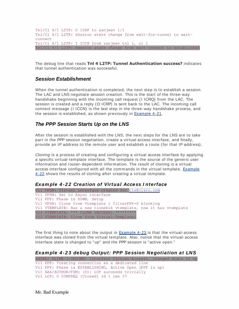
Mr. Bad Example
Tnl/Cl 4/1 L2TP: O ICRP to sanjeev 1/1 Tnl/Cl 4/1 L2TP: Session state change from wait-for-tunnel to wait-connect Tnl/Cl 4/1 L2TP: I ICCN from sanjeev tnl 1, cl 1 Tnl/Cl 4/1 L2TP: Session state change from wait-connect to established
The debug line that reads Tnl 4 L2TP: Tunnel Authentication success? indicates that tunnel authentication was successful.
Session Establishment
When the tunnel authentication is completed, the next step is to establish a session. The LAC and LNS negotiate session creation. This is the start of the three-way handshake beginning with the incoming call request (I ICRQ) from the LAC. The session is created and a reply (O ICRP) is sent back to the LAC. The incoming call connect message (I ICCN) is the last step in the three-way handshake process, and the session is established, as shown previously in Example 4-21.
The PPP Session Starts Up on the LNS
After the session is established with the LNS, the next steps for the LNS are to take part in the PPP session negotiation, create a virtual access interface, and finally, provide an IP address to the remote user and establish a route (for that IP address).
Cloning is a process of creating and configuring a virtual access interface by applying a specific virtual-template interface. The template is the source of the generic user information and router-dependent information. The result of cloning is a virtual access interface configured with all the commands in the virtual template. Example 4-22 shows the results of cloning after creating a virtual template.
Example 4-22 Creation of Virtual Access Interface Vi1 VPDN: Virtual interface created for [email protected]@cisco.com Vi1 VPDN: Set to Async interface Vi1 PPP: Phase is DOWN, Setup Vi1 VPDN: Clone from Vtemplate 1 filterPPP=0 blocking Vi1 VTEMPLATE: Has a new cloneblk vtemplate, now it has vtemplate Vi1 VTEMPLATE: *** CLONE VACCESS1 ********* Vi1 VTEMPLATE: Clone from Virtual-Template1
The first thing to note about the output in Example 4-23 is that the virtual-access interface was cloned from the virtual template. Also, notice that the virtual-access interface state is changed to "up" and the PPP session is "active open."
Example 4-23 debug Output: PPP Session Negotiation at LNS 4d08h: %LINK-3-UPDOWN: Interface Virtual-Access1, changed state to up Vi1 PPP: Treating connection as a dedicated line Vi1 PPP: Phase is ESTABLISHING, Active Open (PPP is up) Vi1 AAA/AUTHOR/FSM: (0): LCP succeeds trivially Vi1 LCP: O CONFREQ [Closed] id 1 len 37
Evaluation notes were added to the output document. To get rid of these notes, please order your copy of ePrint IV now.
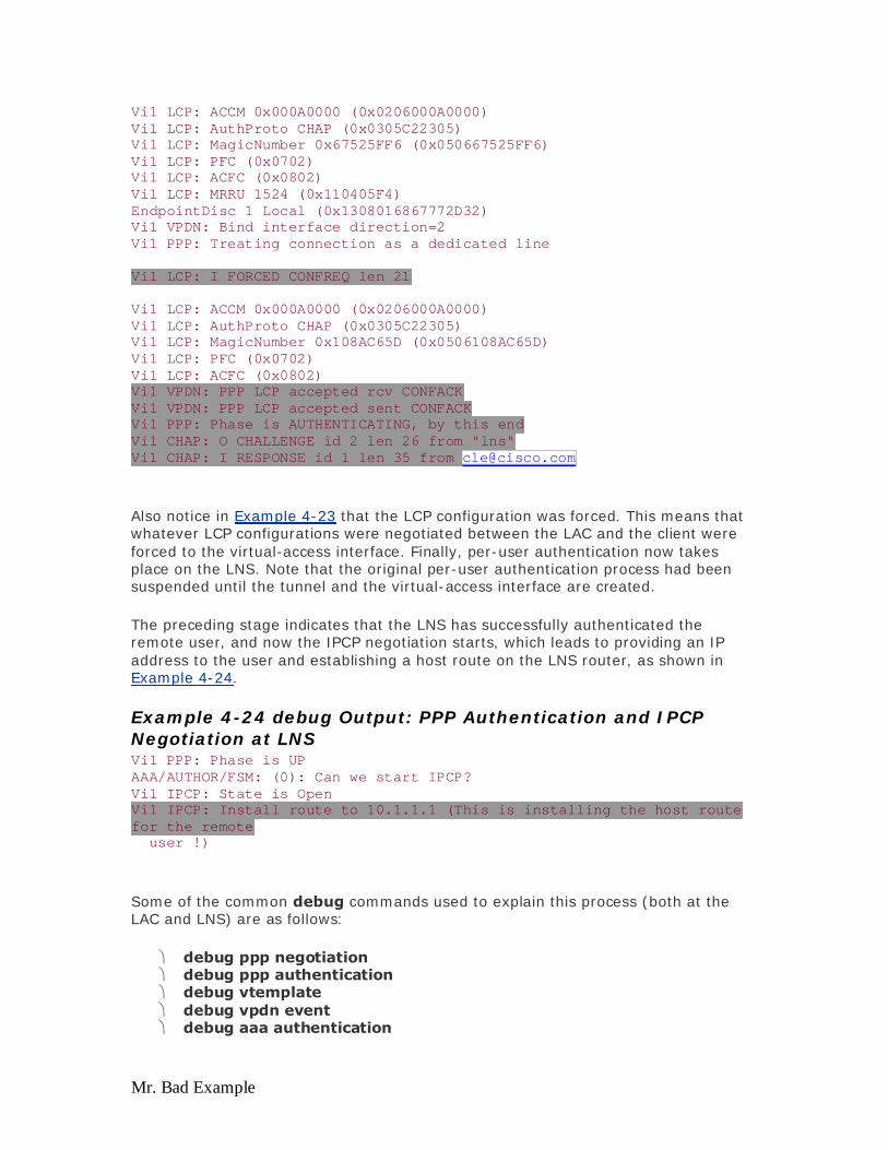
Mr. Bad Example
Vi1 LCP: ACCM 0x000A0000 (0x0206000A0000) Vi1 LCP: AuthProto CHAP (0x0305C22305) Vi1 LCP: MagicNumber 0x67525FF6 (0x050667525FF6) Vi1 LCP: PFC (0x0702) Vi1 LCP: ACFC (0x0802) Vi1 LCP: MRRU 1524 (0x110405F4) EndpointDisc 1 Local (0x1308016867772D32) Vi1 VPDN: Bind interface direction=2 Vi1 PPP: Treating connection as a dedicated line Vi1 LCP: I FORCED CONFREQ len 21 Vi1 LCP: ACCM 0x000A0000 (0x0206000A0000) Vi1 LCP: AuthProto CHAP (0x0305C22305) Vi1 LCP: MagicNumber 0x108AC65D (0x0506108AC65D) Vi1 LCP: PFC (0x0702) Vi1 LCP: ACFC (0x0802) Vi1 VPDN: PPP LCP accepted rcv CONFACK Vi1 VPDN: PPP LCP accepted sent CONFACK Vi1 PPP: Phase is AUTHENTICATING, by this end Vi1 CHAP: O CHALLENGE id 2 len 26 from "lns" Vi1 CHAP: I RESPONSE id 1 len 35 from [email protected]@cisco.com
Also notice in Example 4-23 that the LCP configuration was forced. This means that whatever LCP configurations were negotiated between the LAC and the client were forced to the virtual-access interface. Finally, per-user authentication now takes place on the LNS. Note that the original per-user authentication process had been suspended until the tunnel and the virtual-access interface are created.
The preceding stage indicates that the LNS has successfully authenticated the remote user, and now the IPCP negotiation starts, which leads to providing an IP address to the user and establishing a host route on the LNS router, as shown in Example 4-24.
Example 4-24 debug Output: PPP Authentication and IPCP Negotiation at LNS Vi1 PPP: Phase is UP AAA/AUTHOR/FSM: (0): Can we start IPCP? Vi1 IPCP: State is Open Vi1 IPCP: Install route to 10.1.1.1 (This is installing the host route for the remote user !)
Some of the common debug commands used to explain this process (both at the LAC and LNS) are as follows:
debug ppp negotiation debug ppp authentication debug vtemplate debug vpdn event debug aaa authentication
Evaluation notes were added to the output document. To get rid of these notes, please order your copy of ePrint IV now.

Mr. Bad Example
debug aaa authorization
Configuration for L2TP also uses the vpdn-group command. An additional step is necessary to set up the tunnels on both the LAC and LNS. Example 4-25 shows a sample LAC configuration with the initiate-to ip 192.168.1.27 command signaling the LAC to establish a tunnel to the LNS with IP address 192.168.1.27.
Example 4-25 L2TP Configurations on the LAC ! aaa authentication login default none aaa authentication ppp default local group radius aaa authorization network default local group radius none aaa accounting network default wait-start group radius ! vpdn-group 4 request-dialin protocol l2tp domain aol.com initiate-to ip 192.168.1.27 priority 1 local name aol-tunnel ! interface ATM0/0/0.1 point-to-point no ip directed-broadcast pvc 1/32 encapsulation aal5mux ppp Virtual-Template1 ! interface Virtual-Template1 description PPPoATM ppp authentication pap ! radius-server host 192.168.2.20 auth-port 1645 acct-port 1646 radius-server key cisco
On the LNS side, under the vpdn-group command, the command terminate-from hostname aol.com terminates the tunnel from aol.com. The RADIUS server holds the tunnel name and password for tunnel authentication. Example 4-26 shows a sample configuration for LNS.
Example 4-26 L2TP LNS Configuration ! aaa new-model aaa authentication login default none aaa authentication ppp default local group radius aaa authorization network default local group radius none aaa accounting network default wait-start group radius ! vpdn-group 1 accept-dialin protocol any virtual-template 1 terminate-from hostname aol-tunnel local name tunnel10-gate !
Evaluation notes were added to the output document. To get rid of these notes, please order your copy of ePrint IV now.

Mr. Bad Example
radius-server host 192.168.3.20 auth-port 1645 acct-port 1646 radius-server key aol
Design Considerations: Advantages of L2TP
L2TP is a common core architecture deployed today by many of the wholesale DSL SPs. Some of the key advantages of using L2TP in the core to deliver the subscriber traffic are as follows:
The NAP does not have to deal with IP address management issues because the ISP or the corporation that is terminating the tunnels can assign addresses. This overcomes the challenge of the NAP keeping the data traffic of different subscribers belonging to different ISPs.
The NAP can still offer some sort of accounting because the access encapsulation is always PPP-based. Because of this, the NAP can now start charging the ISPs based on the usage by each subscriber.
This is a suitable model for the NSP because the NAP is not aware of subscriber traffic at Layer 3 and higher. As a result, the NSP can control the subscriber.
Through eliminating the necessity of IP address management, the model can eliminate the usage of legal IP addresses and, therefore, can enhance the security by usage of private address space.
Design Considerations: Disadvantages of L2TP
The usage of the L2TP architecture also has some scalability and design challenges that include the following:
The number of PPP sessions that can be carried over a single tunnel has a limit and can impose a scalability problem on how many tunnels might need to be created for a single ISP. For example, if an LAC device has a capacity of carrying 2000 PPP sessions in a single L2TP tunnel and the NAP requires transporting about 20,000 subscribers to the same ISP, the NAP might have to create about 10 tunnels to carry 20,000 PPP sessions. Therefore, as the number of PPP sessions increases, the number to tunnels through the core to carry those PPP sessions also increases, which results in additional hardware to initiate the tunnels in the NAP space and additional hardware on the NSP's end to terminate those tunnels and PPP sessions.
Remember that a tunnel is created between two end points (between the LAC and LNS). A single LNS can have multiple tunnels coming from multiple LAC devices. When the number of tunnels starts increasing in the core, the LNS needs to know the IP addresses of the LACs that are initiating the tunnels. This results in a nightmare if proper planning has not been done in designing the network. Just imagine that you have laid a network with approximately 50 LACs going into one LNS. The LNS needs to have a route to reach each one of the 50 LACs. Realistically, you might not have all those 50 LACs on same subnet as that of LNS, so you might need to run some routing protocols. Assuming that the LNS belongs to the ISP, and the LACs are in the NAP, the ISP can never allow running any routing protocol between itself and the NAP. Even if the ISP allowed running routing protocols between itself and the NAP, this would expose the core network of the NAP because the ISP can easily
Evaluation notes were added to the output document. To get rid of these notes, please order your copy of ePrint IV now.

Mr. Bad Example
know the topology of NAP's network because it knows how to reach those 50 LACs.
The way to resolve this issue is by making use of some sort of tunnel grooming before handing over the tunnels to the ISP by using a tunnel switch (TS). This not only hides the NAP's core network behind the TS but also reduces the number of interfaces to be handed over to the ISP. Figure 4-19 shows a TS with one LAC and two LNSs. The LAC and TS share tunnels for l2tp.com and ts.com over one IP interface. Data for either l2tp.com or ts.com originating from the 677 CPE travels from the LAC to the TS through the shared tunnel, and then it switches to the appropriate LNS at the TS.
Figure 4-19. L2TP Tunnel Switch
Examples 4-27 – 4-29 show the configurations for the TS, LAC, and LNS.
Example 4-27 Tunnel Switch Configuration for the LAC vpdn-group LAC request-dialin protocol l2tp domain ts.com domain l2tp.com initiate-to ip 12.0.0.1 local name ts.com tunnel share
Example 4-28 Tunnel Switch Configuration for the Tunnel Switch vpdn search-order multihop-hostname domain ! vpdn-group Tunnel-in accept-dialin virtual-template 1 terminate-from hostname ts.com local name Tunnel-in ! -vpdn-group Tunnel-out request-dialin
Evaluation notes were added to the output document. To get rid of these notes, please order your copy of ePrint IV now.
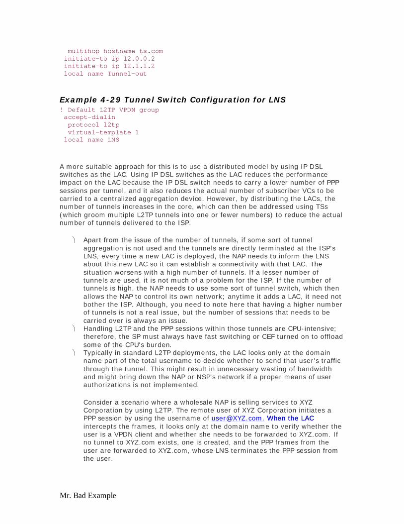
Mr. Bad Example
multihop hostname ts.com initiate-to ip 12.0.0.2 initiate-to ip 12.1.1.2 local name Tunnel-out
Example 4-29 Tunnel Switch Configuration for LNS ! Default L2TP VPDN group accept-dialin protocol l2tp virtual-template 1 local name LNS
A more suitable approach for this is to use a distributed model by using IP DSL switches as the LAC. Using IP DSL switches as the LAC reduces the performance impact on the LAC because the IP DSL switch needs to carry a lower number of PPP sessions per tunnel, and it also reduces the actual number of subscriber VCs to be carried to a centralized aggregation device. However, by distributing the LACs, the number of tunnels increases in the core, which can then be addressed using TSs (which groom multiple L2TP tunnels into one or fewer numbers) to reduce the actual number of tunnels delivered to the ISP.
Apart from the issue of the number of tunnels, if some sort of tunnel aggregation is not used and the tunnels are directly terminated at the ISP's LNS, every time a new LAC is deployed, the NAP needs to inform the LNS about this new LAC so it can establish a connectivity with that LAC. The situation worsens with a high number of tunnels. If a lesser number of tunnels are used, it is not much of a problem for the ISP. If the number of tunnels is high, the NAP needs to use some sort of tunnel switch, which then allows the NAP to control its own network; anytime it adds a LAC, it need not bother the ISP. Although, you need to note here that having a higher number of tunnels is not a real issue, but the number of sessions that needs to be carried over is always an issue.
Handling L2TP and the PPP sessions within those tunnels are CPU-intensive; therefore, the SP must always have fast switching or CEF turned on to offload some of the CPU's burden.
Typically in standard L2TP deployments, the LAC looks only at the domain name part of the total username to decide whether to send that user's traffic through the tunnel. This might result in unnecessary wasting of bandwidth and might bring down the NAP or NSP's network if a proper means of user authorizations is not implemented.
Consider a scenario where a wholesale NAP is selling services to XYZ Corporation by using L2TP. The remote user of XYZ Corporation initiates a PPP session by using the username of [email protected]. When the LAC [email protected]. When the LAC intercepts the frames, it looks only at the domain name to verify whether the user is a VPDN client and whether she needs to be forwarded to XYZ.com. If no tunnel to XYZ.com exists, one is created, and the PPP frames from the user are forwarded to XYZ.com, whose LNS terminates the PPP session from the user.
Evaluation notes were added to the output document. To get rid of these notes, please order your copy of ePrint IV now.

Mr. Bad Example
Assume now that a mischievous user who actually does not belong to XYZ.com initiates a fictitious PPP session by using [email protected]. The LAC [email protected]. The LAC again looks at just the domain name XYZ.com and forwards the user to XYZ.com, which in turn fails the authentication process for [email protected] [email protected] because abc does not belong to XYZ.com. As you notice from this example, even though the user was unable to enter the XYZ.com, the transaction utilized the NAP's bandwidth and XYZ.com's LNS CPU power to authenticate and reject it, which if done on a large-scale basis can waste a lot of bandwidth for the NAP and the processing power of LNS. This is a common situation in most L2TP-based networks. In order to avoid this, you need to use the Cisco IOS Software feature called Service Authorization that eliminates the unnecessary forwarding of all the users that do not belong to a certain domain name.
In order to have acceptable performance, you must also consider limiting the number of sessions per tunnels. Cisco IOS Software allows you to limit the actual number of PPP sessions that can be carried on any one tunnel. After the configured number is reached and a new PPP session appears belonging to the same domain name, a new tunnel is initiated. By doing this, not only can you control the total number of sessions per tunnel, but you can also have a better performance from the router by reducing the number of sessions per tunnel.
When using the distributed architecture and using DSLAMs as the LAC, you might want to consider using the Tunnel Share option, which allows the router to create only one tunnel for all the domain names, and forwarding all the PPP sessions to the same LAC/LNS device (tunnel switch), which in turn, retrieves the correct information and creates separate tunnels for each domain name. This option allows the distributed architecture model to reduce the number of tunnels in the NAP's core. However, note that this option becomes most useful after considering the actual limitation of sessions within a tunnel limit. If the number of sessions carried in tunnels is more sparsely distributed than the actual limit (that is, if a device has a limit of carrying 1000 sessions in a tunnel), it is acting as a TS. The incoming tunnels coming in (by using the tunnel share option) are carrying 100 sessions each; therefore, it makes sense to use this option. However, if the incoming tunnels are carrying 1000 sessions, the TS basically cannot groom at all.
When you have multiple LACs going into one LNS, that makes the LNS a point of failure; therefore, it is always a good idea to have LNS redundancy. You can achieve this redundancy in different ways, one of which is to use a RADIUS server that can restrict the number of tunnels per LNS. If a tunnel limit is reached, the RADIUS server points out another LNS server's IP address. The other method is to associate the PPP sessions in different tunnels to two or more LNS servers on a round robin basis; therefore, you equally distribute the load among different LNS servers. Similarly, you can also use the backup LNS or LNSs to respond if the primary servers go down or do not respond.
IP Address Management by Using L2TP
IP addresses in the L2TP architecture are applied by the LNS, which terminates the PPP sessions initiated by the remote user. As explained in the PPPoA and PPPoE
Evaluation notes were added to the output document. To get rid of these notes, please order your copy of ePrint IV now.

Mr. Bad Example
sections, the LNS can choose multiple ways on how to assign the IP address to the end remote user; it can use a local pool or a local RADIUS server.
References
http://wwwin.cisco.com/cmc/cc/pd/iosw/tech/l2pro_tc.htmhttp://wwwin.cisco.com/cmc/cc/pd/iosw/tech/l2pro_tc.htm (internal Cisco document)
http://www.cisco.com/univercd/cc/td/doc/product/software/ios113ed/113aa/113aa_http://www.cisco.com/univercd/cc/td/doc/product/software/ios113ed/113aa/113aa_5/l2tp.htm
MPLS-Based VPNs
This is a broad section; however, it discusses MPLS-based VPNs with respect to the way they are applied to DSL and specifically to the newly introduced IP DSL switch, which brings the IP functionality into SmartDSLAM as offered by Cisco. Even though this section emphasizes the design and implementation aspect of deploying MPLS-based VPNs with the IP DSL switch, the concept does not change and can be applied to any device that is acting as a PE device. Also discussed are the different architectures used with MPLS-based VPNs along with the advantages and limitations of each. The remainder of this section references an IP DSL switch as a DSLAM with IP functionality. Coverage of MPLS-based VPNs is limited to the scope of this book. For more detailed information, refer to the Cisco Press book, MPLS and VPN Architectures, by Ivan Pepelnjak and Jim Guichard (published by Cisco Press).
MPLS VPN Operational Description
An IP packet generated at a customer edge (CE) device (any CE router connecting to an SP's edge router; in this context, it will be the DSL CPE) is encapsulated into ATM and transported over DSL to the IP DSL switch, PE 1, as depicted in Figure 4-20. Provider edge (PE) is the SP's edge router that connects to one or more CE routers. In a DSL environment, the CPE becomes the CE, and the IP DSL switch becomes the PE. Based on the routing configuration set up on the inbound subscriber modem port, this packet is switched to the SAR port to strip off the ATM header and queued for the CPU to perform the forwarding table lookup and make a forwarding decision. The CPU performs this lookup in the VPN forwarding table if the packet belongs to a specific VPN. This lookup determines the egress PE router for the packet. If this lookup fails, the packet is dropped. The switch now does a lookup in the global routing table to determine the next hop (the Label Switch Router (LSR) in Figure 4-20) to the egress PE router. Based on this lookup, the switch tags the packet (with the underlying transport being ATM), binds it to a specific VC, and ships it on the ATM trunk port.
Figure 4-20. Packet Flow through an IP DSL Switch
Evaluation notes were added to the output document. To get rid of these notes, please order your copy of ePrint IV now.

Mr. Bad Example
The egress PE router, upon receipt of the packet, first strips off the label imposed by the penultimate hop LSR. Next, the egress PE removes the label assigned by the ingress PE at the point of entry into the MPLS VPN network. Note at this point that some routers in the network might negotiate in Penultimate Hop Popping (PHP). In this scheme, the penultimate hop LSR at the egress side might not assign a label based on the next hop global routing. This allows the egress PE to strip only one label, the one assigned by the ingress PE. A VPN SP has traditionally designed and operated a virtual backbone for each of its customers. The SP uses an overlay model to service each VPN, wherein adequate point connectivities are established between different nodes in a VPN to ensure reliability. With this approach, the SP must design and operate a VPN backbone for each customer, which becomes an operational challenge, not withstanding the cost of operation, when the number of VPNs increase. Also, the mesh intersite connectivity increases with the number of customer sites, forcing IGP protocols to become impaired as a result of scaling problems.
With MPLS VPNs, the benefit to the SPs is that they can build the BGP/MPLS VPN network once and simply add VPNs for new customers to include them in the already established network. The BGP version used here is the Multiprotocol BGP (mBGP). mBGP support includes provision to carry information on VPN-IPv4 addresses, extended communities, and labels. This approach to build once and sell many VPNs is economically beneficial to the SP compared to the build-once, sell-once approach as stated earlier. Figure 4-21 shows the difference between the traditional VPN SP's network and the new MPLS VPN SP's network.
Figure 4-21. (a)Traditional VPN SP (b)MPLS VPN SP
Evaluation notes were added to the output document. To get rid of these notes, please order your copy of ePrint IV now.

Mr. Bad Example
A SP can position a MPLS VPN as a service for small and medium businesses, SOHOs, telecommuters, or enterprise customers with remote sites. Traditional remote access to corporate networks has been through leased lines. With a VPN service, an enterprise can reduce the leased line costs while enjoying the benefits of secure corporate connectivity at potentially higher bandwidth.
Another offering for the SP is in the MDU/MTU space where offices that span multiple floors of a high-rise building or multiple locations on a campus can route traffic between each other without crossing the IP DSL switch trunk boundary. The traffic can be routed between subscribers on the same switch, thus saving valuable bandwidth on the link.
Full-Mesh and Hub-and-Spoke MPLS VPN
This section reviews various components of BGP and MPLS along with different deployment scenarios. To begin, consider a BGP/MPLS VPN, as shown in Figure 4-22.
Figure 4-22. Route Distribution in a BGP/MPLS VPN Network
Evaluation notes were added to the output document. To get rid of these notes, please order your copy of ePrint IV now.

Mr. Bad Example
The distribution of routing information is described as follows:
1. The routing information is propagated from a CE (any CPE device) router to a PE router to which the CE is directly connected. The CPE uses an IGP protocol such as RIP to propagate site reachability information.
2. The ingress PE assigns itself as the next hop to reach the CE route. This PE creates a label specific to the VRF and/or interface.
3. The information exported into the provider's BGP table is distributed among other PE routers in the network by using mBGP.
4. The routing information is imported from the BGP table at the egress PE. The VPN route is inserted into the route targets identified in the mBGP packet. All packets destined to the CE are also imposed with the label information received from the PE in Step 2.
5. Optionally, based on the configuration, the egress PE sends the routing information to the CE that is directly connected using a protocol such as RIP.
Full-Mesh MPLS VPN Architecture
In the full-mesh MPLS VPN architecture, each PE router has full knowledge of routes to all other sites in the VPN. This routing knowledge enables each route to have its BGP next hop closest to the destination, thus providing a key advantage of optimal routing. A full-mesh architecture also allows the P routers (they are the SP routers that are not at the edge— ingress or egress—and do not take part in assigning VPN information or have any knowledge of CE routers, unlike PE routers, but they only switch the labels) to focus purely on label switching. Figure 4-23 shows a logical full mesh between PE routers.
Evaluation notes were added to the output document. To get rid of these notes, please order your copy of ePrint IV now.
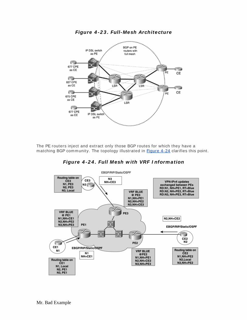
Mr. Bad Example
Figure 4-23. Full-Mesh Architecture
The PE routers inject and extract only those BGP routes for which they have a matching BGP community. The topology illustrated in Figure 4-24 clarifies this point.
Figure 4-24. Full Mesh with VRF Information
Evaluation notes were added to the output document. To get rid of these notes, please order your copy of ePrint IV now.

Mr. Bad Example
PE1 exports the route N1 into BGP, which is distributed to PE routers PE2 and PE3. PE2 and PE3 import the information about N1 because they have route targets with an import policy defined to match the export policy of PE1. This allows all the PE routers to agree on the next hop to each customer network.
When compared to a hub-and-spoke architecture described in the following section, note that in a full-mesh topology no site is used as a central point for connectivity, thus avoiding single point of failure. The disadvantages of this architecture include the following:
Memory consumption on PE routers as the number of routes per VPN increases (see Example 4-30).
The operational cost can increase with the size of the mesh because troubleshooting a mesh can be cumbersome.
The IP DSL switch can potentially hit a limit with the total number of routes. At presstime, the switch is capable of holding up to approximately 3500 IGP routes.
Hub-and-Spoke MPLS VPN
The hub-and-spoke architecture overcomes the limitation on PE routers that can hold only a smaller number of routes because of memory restraints. As the name suggests, a group of PE routers can form the spokes of this architecture. The central hub can be a PE that holds routes to the spokes. Traffic between the spokes travels across the hub, which can be considered suboptimal because the next hop for the spokes is the hub. Although this method overcomes one limitation held by the full-mesh architecture, it exposes the hub as a single point of failure. Figures 4-25 and Figure 4-26 highlight this type of deployment scenario.
Figure 4-25. Hub-and-Spoke Architecture
Evaluation notes were added to the output document. To get rid of these notes, please order your copy of ePrint IV now.

Mr. Bad Example
Figure 4-26. Hub-and-Spoke Architecture with VRF Information
Figure 4-26 shows the general scheme of VPN routing/forwarding VRF) updates shared by the hub-and-spoke architecture. In a MPLS-based VPN network, each PE router must maintain a separate forwarding table for each customer (C) network to which it is attached. These forwarding tables are known as VPN Routing and Forwarding Tables (VRFs). This forwarding table is populated with routing information that pertains only to the C network. One advantage when all packets flow through the hub is that it can be configured as a firewall if certain traffic must not be allowed to cross over from one site to another.
Example 4-30 shows the difference in memory usage with three PEs on a network. The output for show ip route vrf RED summary illustrates the memory for a full-mesh topology; whereas, the output for sh ip route vrf black summary shows two PEs as spokes and one PE as a hub.
Example 4-30 show ip route vrf summary for Full Mesh with Three PEs for Hub-and-Spoke MPLS VPN PE-1#show ip route vrf RED summary IP routing table name is RED(2) Route Source Networks Subnets Overhead Memory (bytes) connected 0 1 64 144 static 0 0 0 0 ospf 100 0 0 0 0 Intra-area: 0 Inter-area: 0 External-1: 0 External-2: 0 NSSA External-1: 0 NSSA External-2: 0 bgp 101 1 4 320 720 External: 0 Internal: 5 Local: 0 internal 3 3492 Total 4 5 384 4356 PE-1#show ip route vrf black summary IP routing table name is black(3) Route Source Networks Subnets Overhead Memory (bytes) connected 0 1 64 144 static 1 0 64 144
Evaluation notes were added to the output document. To get rid of these notes, please order your copy of ePrint IV now.

Mr. Bad Example
ospf 100 0 0 0 0 Intra-area: 0 Inter-area: 0 External-1: 0 External-2: 0 NSSA External-1: 0 NSSA External-2: 0 rip 0 0 0 0 bgp 101 0 1 64 144 External: 0 Internal: 1 Local: 0 internal 1 1164 Total 2 2 192 1596
MPLS VPN Network Elements
The biggest advantage for an SP offering MPLS-based VPNs is the build-once and sell-many VPN model. The sections that follow describe the key elements to the VPN infrastructure that an SP should keep in mind.
Core Provisioning
A major part of the provisioning effort is in the careful design and management of the core MPLS-based VPN network, including the P and PE routers. The list that follows explains the key elements of this design; the management aspects are covered under a separate section, "VPN Management."
The construction of an MPLS-based VPN network involves the following network building process:
Step 1. In an IGP process such as OSPF, IS-IS is used to set up reachability among all the PE and P routers in the network.
Step 2. The routing table established in Step 1 is used to distribute tag binding information by PE and P routers in the MPLS cloud. This tag binding information is distributed using Tag Distribution Protocol (TDP) or Label Distribution Protocol (LDP). When ATM is used as the Layer 2 transport, the tag binding process also involves an ATM-TDP/LDP tag binding, wherein the VPI/VCIs between interconnecting nodes are used to switch traffic instead of labels.
Step 3. BGP is the protocol to build VPN routing and forwarding information. BGP locates the next hop closest to a destination. To do that, BGP establishes a peer relation to its neighbor by using TCP. Because the protocol is IBGP, the neighbor does not need to be directly connected to the BGP speaker. As a result of this nonrequirement, the TCP connectivity requests must be routed to the neighbor by using predefined routes in the routing table. The IGP used in Step 1 provides that facility.
Loopback Interfaces
The loopback interface is a key element of the MPLS VPN building block. Loopback interfaces allow tag switching to use these loopback interface IP addresses as endpoints of a specific path. The initial reachability information is also exchanged between PE and P routers by using loopback addresses. Loopback addresses can be assigned in a way to identify the device in terms of its location in the MPLS cloud.
Evaluation notes were added to the output document. To get rid of these notes, please order your copy of ePrint IV now.

Mr. Bad Example
Loopback interfaces are never shut down unless the device is powered down. These addresses can be used to check device status as opposed to using physical addresses.
Loopback interfaces are also ideal in deployment scenarios where staging is done prior to deployment. This interface becomes functional when the router is powered on. If a physical interface address is used as the router ID for tag/label switching, a deployed PE or P router can participate in the MPLS network establishment phase only after the interface becomes active. Also, the IP addresses might need a change after the configuration is tested during staging.
Loopback interfaces can be defined on PE routers for a specific VPN. VPN reachability can be checked after the PE router is installed at the site. The advantage with this approach is that VPN reachability on the PE in question can be verified before customers go live on that VPN.
Route Reflectors
In a full-mesh architecture using iBGP, the iBGP routers maintain a full peering relationship with each other in order to ensure reachability among various nodes. This occurs because when a BGP speaker receives an update from another BGP speaker within the same AS, the receiving BGP speaker will not redistribute that information to a third BGP speaker in the same AS—therefore, the need to configure a full mesh.
A full mesh containing four nodes as indicated in Example 4-30 requires six peering relationships. A mesh with N nodes needs a total of N * (N-1)/2 peering neighbors for full reachability. Route reflectors (RRs) reduce the explosion of iBGP peers, shown in Figure 4-27, which includes exchanging full BGP routing table between these peering neighbors and then sending BGP updates.
Figure 4-27. PE Routers with Peer Relation Without RR
Evaluation notes were added to the output document. To get rid of these notes, please order your copy of ePrint IV now.

Mr. Bad Example
The choice of route reflectors needs to include the following factors:
RR should not become the bottleneck while establishing the peering relationship.
An off-path router can be chosen as a route reflector so that the functions of packet forwarding and route reflection functionality can be separated. This way, the core routers forward packets while the RR maintains a peer relationship and sends routing updates to the peering clients.
RR must have the CPU necessary to handle neighbor information while functioning as an LSR in the MPLS cloud.
Multiple RRs can be chosen for redundancy. RRs can be selected on a per VPN basis.
Figure 4-28. PE Routers with Peer Relation Through RR
Route Distinguishers (RDs) and Route Targets (RTs)
When a PE router knows the set of addresses that are reachable through a particular CE device in a particular VPN, it needs to distribute this information to other PE routers that attach to CE devices that are in that same VPN. Before the PE router does this, it must translate the IP address prefixes into VPN-IP address prefixes so that the different VPNs can have overlapping address spaces without causing a conflict in the routing of the P network. To do this, the PE router must be configured with a route distinguisher (RD) value that it applies to addresses that are reachable through a particular CE device. It might be convenient to use the same RD for all addresses that are in the same network, but this is not required or mandatory. An RD is concatenated to IP addresses by the ingress PE and are kept unique per VPN. Note that this RD value is stripped by the egress PE, and the CE router, as well as the P router, are unaware of its existence in the VPN network. RD values for a given VPN might vary if multiple SPs are involved because each SP might have used different RDs to address the same VPN.
Evaluation notes were added to the output document. To get rid of these notes, please order your copy of ePrint IV now.

Mr. Bad Example
Routing information that is exported into BGP from an ingress PE and imported by an egress PE needs to be constrained to prevent route leaks between VPNs. This is done using filtering based on Route Targets (RTs). RTs define the route import and export policy that is carried by the BGP community attribute. This allows only those PEs that have matching RDs and RTs to import or export VPN routes. As a result, PEs carry VRF information for only those VPNs they service. It is important that the SP defines the import and export policies to use for VPNs based on the type of function expected.
Subscriber Provisioning
Subscriber provisioning focuses on CE router configuration, a good portion of which is staged. The advantage is the ease of deployment and use of standard configuration templates to activate the CE network. Key aspects of this activity follow:
Knowing which VPN the CE belongs to and incorporating the necessary configuration on the IP DSL switch interface or the interface of any other PE device.
Choosing the appropriate IP addressing scheme that fits the CE. Deciding on a static route or IGP protocol to run between the CE and PE. Deciding whether the SP wants to redistribute routes from BGP into the IGP
running between the PE and CE. Most remote sites do not need to know about all the available routes. In such cases, the SP can specify a default route on the CE that points to the PE.
Design Considerations for MPLS-Based VPNs
For an MPLS-based VPN, the SP must choose an IGP protocol to use in the MPLS cloud. In addition, an appropriate addressing scheme needs to be used for loopback addresses so that these are unique through the SP cloud and can provide an indication of the location of routers with those addresses.
The IGP protocol, such as EBGP, RIP, and OSPF, and a static route running between the PE and CE, will, in part, depend on the routing protocols that the CE routers support. The SP must decide whether a CE site needs to know about the routes to all destinations in the VPN. For example, a small branch of a corporation needs to know only the corporate headquarter's network and does not need to know the network for all other small branches. By adding default route statements on the CE and not including a BGP redistribution into the IGP protocol running between PE and CE, the CE does not need to learn all the routes.
IP addressing per VPN CE can be done with static assignment or by the use of DHCP. For fewer subscribers attached to the CE, the SP might choose static addressing; whereas, a large number of subscribers can be better managed with DHCP. The helper address feature of Cisco IOS Software is needed to support DHCP requests from subscribers when a particular VPN is available, which allows the DHCP broadcast to be relayed only to a particular DHCP server in that VPN.
The choice of full-mesh or hub-and-spoke architecture must be made remembering that a full mesh provides optimal intra-VPN routing; whereas, the hub-and-spoke
Evaluation notes were added to the output document. To get rid of these notes, please order your copy of ePrint IV now.

Mr. Bad Example
architecture can substantially reduce the number of routes the PE device can handle. Deciding which architecture to deploy depends on the amount of memory available on the PE device; however, as mentioned earlier, a full-mesh architecture provides optimal routing.
The SP has to decide on the location of route reflectors. The device chosen to reflect neighbor peering information needs to handle multiple TCP sessions without experiencing processing delays. It should be located in the interior of the MPLS cloud, preferably on an LSR, and close to the PE where frequent route changes occur such as the PE at the ISP side. RRs can be configured per VPN. Redundancy between RRs is important to maintain reliability; however, an overdose of RRs might defeat the purpose they are meant to serve. A good approach is to start with a couple of RRs for a manageable geographical area and expand with the growth of the network.
Route targets (RTs) must have import and export policies defined for route filtering; Example 4-31 later in this section provides a detailed configuration. Note that these policies vary between hub-and-spoke VPNs and full-mesh VPNs. Each PE needs to be configured to match the requirements of the site to which they connect and the role each VPN plays in the MPLS cloud, as illustrated in Figures 4-29 and 4-30.
Figure 4-29. RD and RT Values for a Hub-and-Spoke Architecture
Figure 4-30. RD and RT Values for Full-Mesh Architecture
Evaluation notes were added to the output document. To get rid of these notes, please order your copy of ePrint IV now.

Mr. Bad Example
After a P and PE network are provisioned, adding a new PE or extending the MPLS VPN network reach involves fewer changes to the established set up. A PE router addition involves configuration of VPN and BGP information. Care should be taken to choose a VP tunnel that is not in use at the P router. Route convergence for a newly added PE varies depending on the number of nodes in the IGP network, the number of VPNs it supports, and the number of PEs in each VPN. Provisioning new subscribers or adding new subscribers to an existing network might involve a small degree of latency based on the factors listed in the earlier section, "Subscriber Provisioning."
Tag switching information is carried in a VP tunnel. Subscriber traffic routed through the VPN is terminated on the SAR port, which is atm0/0, in case of an IP DSL switch (or some other interfaces in case of a router). These VCs are automatically switched to the SAR port by using 0/VCI circuit identifiers. Also, every route that is tag-switched has a VCI associated with it that also terminates on atm0/0.
Service Providers with Existing MPLS VPN Networks
In the scenario where MPLS are implemented with the an aggregation device such as a 6400 or 7200 as the PE, the MPLS edge functionality may need to be transferred to the IP DSL switch. This migration requires careful planning to minimize service interruption.
Figure 4-31 shows how to migrate the PE functionality to an IP DSL switch with an existing MPLS VPN network.
Figure 4-31. Design Consideration in Extending MPLS to IP DSL Switch
Factors to bear in mind, for migrating the PE functionality to the IP DSL switch, include the following:
Evaluation notes were added to the output document. To get rid of these notes, please order your copy of ePrint IV now.
Mr. Bad Example
The choice of loopback addresses and IGP protocol with which to communicate.
The aggregation device capabilities. PE interfaces need to be configured with IP helper address functionality for
those CEs that use this feature. CEs that are supported by NAT must be converted to a valid IP address.
Establishing IGP routes to the new PE and ensuring that tag switching is functional.
Defining VPN with the appropriate RD and RT policies and extending the BGP routes to the new edge.
After you carefully map these aspects, a complete migration over to the IP DSL switch can be created.
As previously indicated, the IP DSL switch uses Cisco's MPLS implementation of TDP. If non-Cisco equipment exists in the cloud, it might not work with the IP DSL switch because at presstime it did not have LDP support—although it is planned for the near future. Check the latest capabilities and supported features on CCO.
The workflow to add an IP DSL switch to an existing MPLS cloud is as follows:
Step 1. Configure a loopback interface for normal routing, turn on CEF switching, and configure the router ID for TDP protocol to use.
Step 2. Configure the IGP used in the MPLS cloud and include the loopback address in the previous step.
Step 3. Ensure this address is propagated through the MPLS cloud.
Step 4. Define the VP tunnel for tag switching.
Step 5. Determine the VPNs the PE services.
Step 6. Configure VPNs and define a loopback interface for each VPN by setting it to VRF forwarding.
Step 7. Define the RD and RT with import and export policies that match the hub-and-spoke topology.
Step 8. Configure BGP routing with the AS number to match the existing network and incorporate the VPNs defined on the PE. Configure the full-mesh or hub-and-spoke topology as needed.
Step 9. Test reachability to loopback interfaces defined from other parts of the VPN network.
Step 10. Add subscribers as needed.
The sample configuration in Example 4-31 is a quick reference to the work flow involved in adding a PE.
Evaluation notes were added to the output document. To get rid of these notes, please order your copy of ePrint IV now.

Mr. Bad Example
Example 4-31 Adding an IP DSL Switch as a PE to an Existing MPLS Cloud Step 1 int loopback 0 ip address 192.150.10.25 255.255.255.255 ip cef tag-swtiching tdp router-id loopback0 Step 2 router ospf 100 network 192.150.10.0 0.0.0.255 area 30 Step 3 show ip route Step 4 int atm0/1 atm pvp 2 int atm0/1.2 point-to-point ip unnumbered loopback0 tag-switching IP Steps 5,6,7 ip vrf VPN_A rd 2501:1 route-target export 2501:1 route-target import 2501:1 ip vrf VPN_B rd 2501:11 route-target export 2511:1 route-target import 2511:1 int loopback 1 ip vrf forwarding VPN_A ip address 14.0.0.1 255.255.255.255 int loopback 2 ip vrf forwarding VPN_B ip address 15.0.0.1 255.255.255.255 Step 8 router bgp 100 redistribute rip neighbor 192.150.254.1 remote-as 100 neighbor 192.150.254.1 update-source loopback 0 address-family ipv4 vrf VPN_A redistribute connected redistribute static no auto-summary Nn synchronization Exit-address-family address-family ipv4 vrf VPN_A redistribute connected redistribute static
Evaluation notes were added to the output document. To get rid of these notes, please order your copy of ePrint IV now.

Mr. Bad Example
no auto-summary no synchronization exit-address-family address-family vpnv4 neighbor 192.150.254.1 activate neighbor 192.150.254.1 send-community-extended exit-address-family Step 9 From a remote PE in VPN_A check reachability with the command: ping vrf VPN_A ip 14.0.0.1 From a remote PE in VPN_B check reachability with the command: ping vrf VPN_B ip 15.0.0.1 Step 10 int atm1/1 ip vrf forwarding VPN_A ip unnumbered loopback 1 pvc 1/32 encap aal5snap
VPN Management
This section provides a brief introduction to some of the tools that are in existence or in a state of pre-eminence for VPN configuration and management. VPN configuration and management can be performed using a VPN Solution Center (SC), which allows users to set up a CE and PE for VPN provisioning. A user can define the VPN on the PE and configure an IP address range. IP addresses from this range can be assigned to the interface that links the PE and CE.
References
Davie, Bruce Yakov Rekhter . MPLS Technology and Applications. San Francisco: Morgan Kaufmann Publishers, 2000.
Service Selection Gateway
When we discussed various access encapsulation methods such as PPPoA, PPPoE, and RBE, at times we made reference to the SSG. This section covers the SSG in detail and explains what it does, how it works, its design considerations, how an SP can benefit by using this feature, and what kind of user experience the end customer sees if their DSL SP is using SSG. SSG functionality was first introduced in Cisco IOS Software for the Cisco 6400 platform, and soon it will be available for other platforms.
In order to have a better grasp of SSG, you need to understand it. You can find various definitions of SSG, depending with whom you speak. Here are a couple for your reference:
Evaluation notes were added to the output document. To get rid of these notes, please order your copy of ePrint IV now.

Mr. Bad Example
Service Selection Gateway is a Cisco IOS Feature that enables subscribers to selectively access different services (IP Destination Networks) based on their L2 or L3 connectivity to the SPs.
Service Selection Gateway is a L2 & L3 solution for the xDSL market that provides RADIUS Authentication and Accounting for User interactive policy routing to different IP destinations (services).
SSG is a mechanism that allows the SPs to offer different services to the user, concurrently or sequentially, by creating a user-friendly user experience for the end consumer. This mechanism can be used irrespective of the access technology. It can be used with xDSL, cable, wireless, or traditional dialup. This section focuses mainly on SSG mechanism details and its design considerations.
You need to go back in history to understand why a feature or mechanism such as SSG became necessary, especially for the retail SP who wanted to lure the end consumers by offering various value-add services.
Before SSG was available, the retail SPs supported only one service at a time. If the user wanted to access another service, he had to disconnect from the service to which he was connected and reconnect to the other service, as shown in Figure 4-32.
Figure 4-32. Before SSG Service Selection
As Figure 4-32 demonstrates, if the user connects to ISP-A and accesses the Internet, he cannot simultaneously access his corporate intranet. In order to access his corporate intranet, the user first needs to disconnect from ISP-A and then reinitiate the connection back to the corporate intranet. Does this model ring a bell?
Evaluation notes were added to the output document. To get rid of these notes, please order your copy of ePrint IV now.
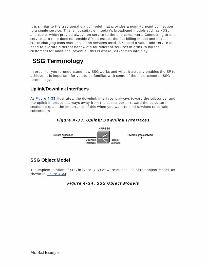
Mr. Bad Example
It is similar to the traditional dialup model that provides a point-to-point connection to a single service. This is not suitable in today's broadband models such as xDSL and cable, which provide always-on service to the end consumers. Connecting to one service at a time does not enable SPs to escape the flat billing model and instead starts charging consumers based on services used. SPs need a value-add service and need to allocate different bandwidth for different services in order to bill the customers for additional revenue—this is where SSG comes into play.
SSG Terminology
In order for you to understand how SSG works and what it actually enables the SP to achieve, it is important for you to be familiar with some of the most common SSG terminology.
Uplink/Downlink Interfaces
As Figure 4-33 illustrates, the downlink interface is always toward the subscriber and the uplink interface is always away from the subscriber or toward the core. Later sections explain the importance of this when you want to bind services to certain subscribers.
Figure 4-33. Uplink/Downlink Interfaces
SSG Object Model
The implementation of SSG in Cisco IOS Software makes use of the object model, as shown in Figure 4-34.
Figure 4-34. SSG Object Models
Evaluation notes were added to the output document. To get rid of these notes, please order your copy of ePrint IV now.
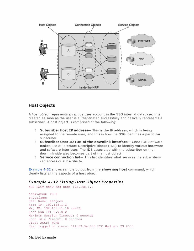
Mr. Bad Example
Host Objects
A host object represents an active user account in the SSG internal database. It is created as soon as the user is authenticated successfully and basically represents a subscriber. A host object is comprised of the following:
Subscriber host IP address— This is the IP address, which is being assigned to the remote user, and this is how the SSG identifies a particular subscriber.
Subscriber User ID IDB of the downlink interface— Cisco IOS Software makes use of Interface Descriptive Blocks (IDB) to identify various hardware and software interfaces. The IDB associated with the subscriber on the downlink side also becomes part of the host object.
Service connection list— This list identifies what services the subscribers can access or subscribe to.
Example 4-32 shows sample output from the show ssg host command, which clearly lists all the aspects of a host object.
Example 4-32 Listing Host Object Properties NRP-SSG# show ssg host 192.168.1.2 Activated: TRUE Interface: User Name: sanjeev Host IP: 192.168.1.2 Msg IP: 192.168.11.10 (9902) Host DNS IP: 0.0.0.0 Maximum Session Timeout: 0 seconds Host Idle Timeout: 0 seconds Class Attr: NONE User logged on since: *14:59:34.000 UTC Wed Nov 29 2000
Evaluation notes were added to the output document. To get rid of these notes, please order your copy of ePrint IV now.

Mr. Bad Example
User last activity at: *12:07:21.000 UTC Thu Nov 30 2000 Default Service: NONE DNS Default Service: NONE Active Services: cisco; AutoService: NONE Subscribed Services: aol; cisco; hbo;
The output of the show ssg host command shows all the properties of a host identified by its IP address, which in this case is 192.168.1.2. The username of this host is sanjeev, and the user is subscribed to services called aol, cisco, and hbo, while the current active service the user uses is cisco.
Connection Object
A connection object represents an active connection to a service (destination network). The connection object is created when a subscriber logs on to a service and is destroyed when she logs off the service. A host object can be associated with one or more connection objects. The connection object is composed of following:
Service user ID— The logon ID used by the subscriber to access this service. This is typically the same as the user ID noted in the host object, and a particular user can use the same user ID for accessing different services.
IP address— The IP address assigned to the subscriber. Pointer— The pointer to the host object that owns this connection object. Service object— The service to which this connection object refers.
The connection object attaches the host object to a service object (which identifies a particular service). Example 4-33 provides sample output from the show ssg connection command, which shows the status of the connection object, which is referring to the service of cisco.
Example 4-33 Listing Connection Object Properties NRP-SSG# show ssg connection 192.168.1.2 cisco User Name: sanjeev Owner Host: 192.168.1.2 Associated Service: cisco Connection State: 0 (UP) Connection Started since: *14:59:40.000 UTC Wed Nov 29 2000 User last activity at: *12:07:21.000 UTC Thu Nov 30 2000 Connection Traffic Statistics: Input Bytes = 0 (HI = 0), Input packets = 0 Output Bytes = 666331 (HI = 0), Output packets = 16492
Evaluation notes were added to the output document. To get rid of these notes, please order your copy of ePrint IV now.

Mr. Bad Example
Service Object
A service object contains all the relevant information about a service (destination network). A service object is created from a service profile, which is obtained from local configuration or from a AAA server. A service object is composed of following:
Service name— This is the name of the service itself. During the discussion of host object, you learned that it lists the services the user subscribes to, and the example showed the services as aol, cisco, and hbo.
Domain name— This provides the list of domain names associated with this service. This is used for the purpose of redirecting the DNS requests from the subscribers. If more than one connection to the Internet service through SSG exists, SSG using this DNS Redirection feature first matches a DNS request to a logged on service. If no match is found, it sends to any one of those Internet services. If a match still is not found, SSG forwards that request, unmodified through the routing table.
Service types— This defines that what kind of service this is, whether it is a passthrough, tunnel, or a proxy service (all these services are explained later).
Destination network— This is basically an Access Control List (ACL), which on applying identifies and checks on who is allowed or not allowed to access which part of the network.
Next hop address— It is used to determine the next hop for routing upstream traffic.
Remote RADIUS server information— This information is used in cases where a proxy (explained later on) kind of service is used that makes use of the remote RADIUS server. This property identifies the resources on how to reach that RADIUS server.
Example 4-34 provides sample output from the show ssg service command, which shows the properties of the service object—which in this case is cisco.
Example 4-34 Listing Service Object Properties NRP-SSG# show ssg service cisco Uplink IDB: Name: cisco Type: PASS-THROUGH Mode: CONCURRENT Service Session Timeout: 0 seconds Service Idle Timeout: 0 seconds Class Attr: NONE Authentication Type: CHAP Reference Count: 1 DNS Server(s): Included Network Segments: 192.168.5.3/255.255.255.255 Excluded Network Segments: Domain List: Active Connections: 1 : Virtual=0.0.0.0, Subscriber=192.168.13.2
Evaluation notes were added to the output document. To get rid of these notes, please order your copy of ePrint IV now.

Mr. Bad Example
Default Network
A default network is a segment of the SP IP network that subscribers can access without authentication. As Figure 4-35 shows, the default network for the end user is where the local AAA server and the Web server is located, and the users do not require any sort of authentication or permission to access that network. If the user wants to access service ISP A or service ISP B, she requires a proper means of authentication and possible access rights to those services.
Figure 4-35. SSG Default Network
SSG Service Models
SSG can provide two flavors of implementation or service models: Layer 2 Service Selection or Layer 3 Service Selection, both of which are discussed in detail in this section.
The main difference between a Layer 3 Service Selection and a Layer 2 Service Selection is that in the case of Layer 2 Service Selection, the user has already identified his final destination before he initiates a PPP session, and that final destination remains the same until that PPP session is active. In the Layer 3 Service Selection model, the user has multiple choices of services (final destinations) that he can select from after he lands into the walled garden (local network) of the NAP or NSP. The user can then select what service he actually connects to, without actually disconnecting (which happens in Layer 2 Service Selection) the PPP session.
Layer 2 Service Selection
Layer 2 Service Selection of SSG is also known as PPP Termination and Aggregation for Multiple Domain (PTA-MD). As the name suggests, PTA-MD can be used only if the subscribers' access encapsulation is PPP-based. If the subscribers use any other encapsulation but PPP, you cannot implement PTA-MD.
This feature allows the SP to support multiple domains on the same aggregation device, such as the Node Route Processor (NRP) of the Cisco 6400, although the service model is similar to that of the dial model. This model allows the subscriber to
Evaluation notes were added to the output document. To get rid of these notes, please order your copy of ePrint IV now.

Mr. Bad Example
connect to only one service or domain at a time; if he needs to connect to a separate service or domain, he needs to disconnect the service he is connected to. If that is the case, you must be wondering why an SP would elect to use PTA-MD. The answer to that question becomes clear in the following section that explains how PTA-MD works and how it supports overlapping IP addresses, therefore explaining its usefulness for the wholesale providers.
How Layer 2 Service Selection (PTA-MD) Works
As mentioned earlier, in PTA-MD, the access encapsulation is always PPP-based, so it can be either PPPoA or PPPoE. The way in which Layer 2 Service Selection happens is based on the domain name provided by the user, in the form of a username when a PPP session is negotiated between the NAP (who is performing the Layer 2 Service Selection) and the remote user. As explained earlier, with Layer 2 Service Selection, the user has already identified where she wants to go or what her final destination is.
Consider the illustration in Figure 4-36. If the remote user wants to go to the intranet, she puts her username as [email protected]@intranet.com. During the authentication phase, the NRP of the Cisco 6400, which is running the SSG code and is configured for PTA-MD, would typically send the entire username to an external RADIUS server (if the NRP is not configured for local profiles). After the RADIUS server receives the username, it looks at the domain name portion of that username in its database, and returns a few attribute value (AV) pairs back to the NRP, based on its configuration of where the service (intranet, in this case) can be reached.
Figure 4-36. PTA-MD Operation
The key here is the response of the RADIUS server to the NRP on how to forward [email protected] to [email protected] to intranet (the service). The AV pair actually specifies the Layer 2 information on how the subscriber traffic can be forwarded to the service or the final destination. That Layer 2 information, in the case of the Cisco 6400, happens to
Evaluation notes were added to the output document. To get rid of these notes, please order your copy of ePrint IV now.

Mr. Bad Example
be the outbound ATM PVC on that NRP, through which it can reach the service intranet. So, the key point to note here is that while using PTA-MD on a Cisco 6400 NRP, you can bind only one service at a time to one ATM PVC in the uplink direction, unless autosubscription is turned on. By turning on autosubscription, an SP can basically list a set of services to be offered, instead of just one service as explained earlier, to a subscriber, so when the subscriber logs in, they are connected and has access to all the services defined at the same time.
Upon receiving the Layer 2 information from the RADIUS server of where the service intranet is connected, the NRP terminates the PPP session from the remote user, provides an IP address, and then forwards all the data traffic from that user to the service intranet. The data traffic is forwarded through the subinterface that uses the ATM PVC specified by the RADIUS server, and the interface is configured for 1483 routing to route the IP traffic over that PVC. Note that in Layer 2 Service Selection, the PPP sessions terminate at the NAP's end (if the NAP uses PTA-MD to wholesale the services to various NSPs).
You must be wondering that if the NAP is terminating the PPP sessions and then using 1483 Routed to route the subscriber's traffic, why is it called Layer 2 Service Selection, even though it is using IP to route the traffic out of the NRP? The key point to remember is that the NRP is not routing the subscriber traffic, but it is actually forwarding all the subscriber traffic through that interface, as explained in Figure 4-37.
Figure 4-37. SSG Object Model
The bottom portion of Figure 4-37 illustrates, using the SSG's Object Model, what occurs in the NRP when it is configured for PTA-MD. The first thing that happens
Evaluation notes were added to the output document. To get rid of these notes, please order your copy of ePrint IV now.

Mr. Bad Example
when the user is authenticated is the creation of the host object. That host object is associated to the intranet service through a connection object. The service object is represented by the AV pair returned by the RADIUS server, which carries the information of the outbound interface or the ATM PVC, and which, in turn, informs the SSG how the service intranet can be reached.
After these three objects are populated, anytime some data traffic comes from the established host object, SSG looks at the corresponding connection object and the service object and forwards all the traffic through that, without actually looking into the global routing table. Remember that when PTA-MD is used and a user connects to a particular service, with all the objects being populated, the NRP does not look into the destination IP address field of the incoming IP packet from that host to make a forwarding decision. Instead, after SSG identifies the host by looking at the source IP address of the IP packet, it forwards the information based on the designated outbound or uplink interface and does not make use of the global routing table to help it make its necessary forwarding or switching decision. When the PPP session is terminated, the corresponding host, connection, and service objects are also removed. When the user initiates a new connection to the same or different service, a new set of host, connection, and service objects is established.
IP Address Management
Because the PPP sessions are terminated by the NRP, which is running SSG and configured for PTA-MD, NRP provides the IP addresses to the subscriber and establishes host routes for each address assigned to various subscribers. The NRP can provide these IP addresses in different ways, which again depends on where this NRP is located.
If the NAP is a wholesale provider and uses PTA-MD to deliver subscriber traffic to various NSPs, it is likely that all those NSPs want their subscribers to use their NSP's IP address, rather than use that of NAPs. In such situations, even though the NAP terminates the PPP sessions, it can use the RADIUS Proxy to get an IP address from different NSPs. The other options make use of local IP pools or local RADIUS servers, as discussed during PPPoA and PPPoE access architectures.
As noted earlier, because the Cisco 6400's NRP is running SSG PTA-MD and terminates the PPP sessions, it also establishes the host routes for each assigned IP address. In this case, how can you separate the user traffic of one NSP from the other if all of them have a route to reach each other in the global routing table on the same NRP? That challenge is addressed swiftly by the SSG's PTA-MD service model, which does not actually look at the destination IP address of an incoming IP packet from an established host. SSG uses the source IP address to identify the host and then simply forwards on a fixed outbound or uplink interface. The outbound interface is always fixed for a particular service, and you cannot have more than one outbound or uplink interface for the same service.
You can use SSG PTA-MD to also support overlapping IP addresses because SSG does not look at the destination IP address to make the forwarding decision. The advantage of that is if you wholesale to various corporations, it is likely that those corporations use the same private addressing scheme. If you cannot offer MPLS-based VPNs, SSG's PTA-MD can do your job, and you might not have to ask one of
Evaluation notes were added to the output document. To get rid of these notes, please order your copy of ePrint IV now.

Mr. Bad Example
the corporations to change their addressing scheme. Figure 4-38 illustrates how using PTA-MD can achieve the overlapping IP address.
Figure 4-38. PTA-MD and Overlapping IP Addresses
Figure 4-38 illustrates how the Cisco IOS-based SSG software supports service selection at Layer 2 by using PPPoE or PPPoA and supports overlapping IP addresses. In this example, three destinations exist: an ISP assigning public addresses from subnet 134.1.x.x, Company A assigning addresses from a private address space of 10.0.X.X, and Company B assigning addresses from the same private address space as Company A.
User 1 initiates a PPP session with a username of [email protected]. SSG software [email protected]. SSG software examines the username of the PPP session and indexes on ISPA.com. These profiles (service) might be stored locally in the memory of the hardware platform or stored remotely on an AAA server. The ISPA.com profile indicates that this service is PTA-MD and that proxy RADIUS authentication is required. The ISPA.com profile contains the address and secret of ISPA's RADIUS server. SSG software sends the RADIUS request to ISPA's RADIUS server and receives an Access-Accept reply with an IP address assignment. If no IP address is received in the RADIUS Reply packet, an IP Pool attribute can be used to assign the IP address. User 1 is assigned an IP address of 134.1.1.1 and is bound to ISPA.
User 2 initiates a PPP session with a username of [email protected]. A similar [email protected]. A similar process takes place; however, User 3 is assigned the same private address as User 2. Because SSG software supports overlapping IP addresses, this is not a problem. Multidomain support allows the wholesale SP to be liberated from IP address issues.
Evaluation notes were added to the output document. To get rid of these notes, please order your copy of ePrint IV now.

Mr. Bad Example
Layer 3 Service Selection
Layer 3 Service Selection makes SSG a must-have feature for any kind of retail SP, irrespective of whether the access type is xDSL, cable, or wireless. Layer 3 Service Selection is also commonly known as Web-Based Service Selection. Web-Based Service Selection, unlike Layer 2 Service Selection, can be implemented with any kind of access encapsulation methods, such as RBE, 1483 Routing, PPPoA, PPPoE, or incoming L2TP tunnels, as long as it can identify the host or subscriber by a unique IP address.
Web-Based Service Selection uses an HTTP server or a Web server called a Service Selection Dashboard (SSD). The SSD is a Web server that operates on a PC running a Microsoft OS or Sun Station running Solaris and interacts with the SSG software running on the NRP of a Cisco 6400. By using Web-Based Service Selection with SSD, the SP can offer a set of Web-based menus (discussed in the "User Experience with Web-Based Service Selection" section) to the subscribers, which list various services the user has or can subscribe to. The user sees the menus after logging in using a unique username and password. After the user is logged in, he can select any service he has subscribed to and access it. Figure 4-39 lists the major components of Web-Based Service Selection.
Figure 4-39. Major Components of Web-Based Service Selection
One of the major advantages of the Layer 3 or Web-Based Service Selection is that users can now connect to one or more services at the same time, unlike the PTA-MD or dialup model where the user needed to disconnect from one service to connect to the second service. This is a huge advantage and appealing to the retail SPs who want to offer various value-added services to its subscribers. The way SSG is implemented today allows a user to concurrently support up to 20 services. Along with the capability to support concurrent services, Web-Based Service Selection also allows for sequential access if an SP requires it.
Evaluation notes were added to the output document. To get rid of these notes, please order your copy of ePrint IV now.

Mr. Bad Example
By providing concurrent access to multiple services, Web-Based SSG solves the major concern of SPs for ease of usability for its subscribers, but the question is how can the SP turn this service into a business model to bring in more revenue? One answer is to charge subscribers based on the amount of time they use a particular service. This can be achieved by using a feature called Interim RADIUS Accounting that keeps track of all the activity of the user and the services she uses and for how much time, which can be utilized to create necessary billing information. However, the same information can also be retrieved using Accounting-stop records.
The summarized advantages of using this approach are as follows:
Service can be advertised and a price can be placed next to services. Web browsers are ubiquitous. Services can be turned on and off without having to disconnect. Users can select multiple destinations simultaneously. Users can get personalized services. Internet or corporate access can be made a separate selectable service.
How Web-Based Service Selection Works
Web-Based Service Selection is independent of Layers 1 and 2 and can be used over a bridged Layer 2, a PPP Layer 2, or a routed Layer 2. When a Layer 2 connection is established, the user brings up the dashboard, sending an HTML request to the SSD server. The SSD server has two types of URLs: one where a guest URL doesn't require a username and password, and another where a user URL requires a username and password.
Assuming the URL is the guest, when the SSD server receives the guest HTML request, it triggers a RADIUS request sent to the authentication, authorization, and accounting (AAA) server. The username in the RADIUS request is "guest" and the password is moot, because the AAA server has a guest profile in it that doesn't require a password. The AAA server sends back to the SSD server a RADIUS access-accept packet with a list of services for "guest." The SSD server then replies back to the user's Web browser with a Web page that lists the services.
In order to better understand the actual interaction in a step-by-step format between the SSG (running on NRP in Cisco 6400), an SSD server, and an external RADIUS server, look at Figure 4-40 and the corresponding list.
Figure 4-40. Interactions between SSG Components
Evaluation notes were added to the output document. To get rid of these notes, please order your copy of ePrint IV now.

Mr. Bad Example
Step 1. The first step indicates that the host accesses the predefined URL or IP address of the SSD by using a browser such as Netscape or Microsoft Explorer. This occurs only after the user has been allocated some IP address, and the only access the user can get is to the default network that is predefined while configuring SSG. The SSD server and the AAA server are always part of the default network.
Step 2. After the user gets access to the first screen of the dashboard, she is asked to enter a unique username and password. After that information is entered, the SSD translates that username/password received through HTTP into a RADIUS Authentication packet and sends it to the NRP, which is running SSG.
Step 3. Upon receiving that request, the SSG in NRP forwards that request to the AAA server.
Step 4. The AAA server authenticates the user and sends a reply back to the NRP SSG. Two replies can occur: If the user is successfully authenticated, AAA sends a Pass; if the user fails authentication, AAA sends a Fail.
Step 5. No matter what the reply from AAA, NRP SSG forwards that response to the SSD. If the response is a Pass (access-accept) from the AAA server, the NRP creates a host object for that userid before passing on the message to the SSD Server; if a Fail is received, no host object is created.
Step 6. After SSD receives the response of Pass or Fail of the user's authentication, it actually requests the service profiles from the AAA server directly. This is the only time the SSD server talks directly to the AAA server; otherwise, all the communication is through the SSG in NRP. The service profile in the AAA server is basically a list of services this user is allowed to see.
Step 7. The AAA server replies to the request of the SSD server directly and provides the list of services the user can see after going through its database.
Step 8. After that response is received by the SSD server, it launches a new page for the user, which lists all the services that user is allowed to see. At this point, a host, but no service objects, exists in SSG.
Evaluation notes were added to the output document. To get rid of these notes, please order your copy of ePrint IV now.
Mr. Bad Example
The SSG uses a different model in a RADIUS server than dial to authenticate, authorize, and account for a user. In the dial model, a user has RADIUS attributes in his profile that represent a single service. If the SP wants to offer multiple services, a profile must be created for each individual service, and the user needs to use a different username for each unique service. By using the SSG model, each user's profile lists the service to which a user has access.
After the user gets access to multiple services, he can access one or the other service without actually disconnecting his initial logged-in session. The ways in which the user is connected to different services is discussed in the section, "SSG Service Types." After the user logs out of the SSD server, even though his session is up, the host object from the NRP is removed, and he needs to log in again if he needs access to any service again. Currently, a lot of effort is directed toward ensuring the ease of usability for the user and reducing the duplication of multiple logins for the SSD user.
IP Address Management for Web-Based Service Selection
Because Layer 3 or Web-Based Service Selection does not care about the access encapsulation (RBE, 1483 Routed, PPPoA, or PPPoE), it can make use of the IP address management scheme of any of those encapsulation methods to assign IP addresses to the end subscriber. However, the subscriber is terminated on the router that runs SSG and is assigned with an IP address in such a way that the end user can only access the default network as defined. The default network consists of network elements such as an AAA server and the SSD server.
This typically implies that when an end user initiates a bridge, IP, or PPP session and is connected, he lands into the walled garden of that SP who is running the Web-Based Service Selection. The walled garden implies that the SP's core network, which can consist of local contents, intranets, links to extranets, exit paths to various ISPs, and contents, is accessible to only certain subscribers. Before accessing any of those services, the user must first get into the SP's network or SP's walled garden. The combination of getting in the SP's walled garden and the SSD makes an appealing proposition for those retail and wholesale SPs who want all the users to go through their web site and then go to their respective services or destinations. This way, the SP can now start advertising various services it offers and the different portals.
The tricky part occurs when the SP is retailing using SSG's Web-Based Service Selection method and also wants to wholesale the services offered by various NSPs. In a situation where the NSP does not mind if their subscribers use the NAP's given IP addresses, it is okay, and the NAP can route the subscriber traffic through its core to the NSP—although this is not a common deployment scenario. In an actual deployment and business model, the NSP does not allow the NAP to provide its (NSP's) subscriber IP address that belongs to them (the NAP). If you follow that logic, the subscribers must terminate at the NSP, who then provides the IP address. If the NAP is terminating the subscribers, it should use some sort of proxy service to get the IP address from the NSP to be applied. The issue with the latter scenario is that in case of Web-Based Service Selection SSG, the subscriber does not specify her final destinations when she initiates the session. Therefore, it becomes difficult for the NAP to identify which NSP this subscriber belongs to and cannot use proxy RADIUS.
Evaluation notes were added to the output document. To get rid of these notes, please order your copy of ePrint IV now.

Mr. Bad Example
So the big question is, how can you assign an IP address that belongs to NSP to a subscriber who does not know which NSP he is going to use. The answer to this question is making use of SSG NAT, which is the same as Cisco IOS Software NAT.
By using NAT, the access provider who is offering Web-Based Service Selection does not have to disconnect the session or change the IP address it has already allocated to the subscriber. After the subscriber selects an NSP who also provides its IP address, SSG would NAT the subscriber traffic to that IP address before forwarding any subscriber traffic to the NSP. So, as far as NSP is concerned, he sees the traffic coming from the IP address it allocated.
Although the NAT feature resolves such issues, realistically many SPs would rather not use NAT simply because some of the applications do not work with NAT.
User Experience with Web-Based Service Selection
This section includes some screen shots of the SSG's Web-Based Service Selection as seen by the end user. When the user connects to the SP and brings up her browser, the first thing she sees is something like Figure 4-41.
Figure 4-41. Web-Based Service Selection Login Screen
Figure 4-41 shows the first screen the user sees from the SSD. The user enters her username and password as indicated, after which she sees the screen in Figure 4-42, which lists the set of services the user can select from (shown on the leftside of the screen).
Evaluation notes were added to the output document. To get rid of these notes, please order your copy of ePrint IV now.
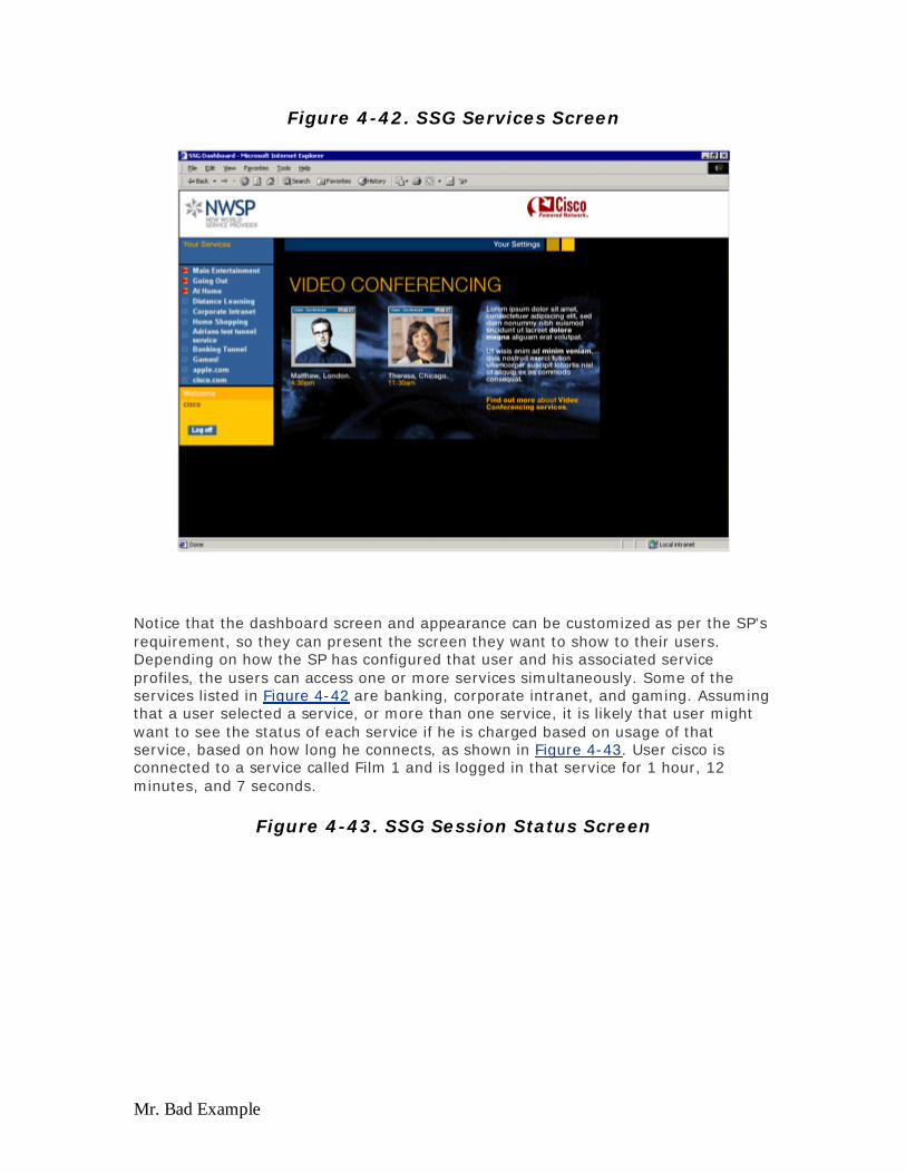
Mr. Bad Example
Figure 4-42. SSG Services Screen
Notice that the dashboard screen and appearance can be customized as per the SP's requirement, so they can present the screen they want to show to their users. Depending on how the SP has configured that user and his associated service profiles, the users can access one or more services simultaneously. Some of the services listed in Figure 4-42 are banking, corporate intranet, and gaming. Assuming that a user selected a service, or more than one service, it is likely that user might want to see the status of each service if he is charged based on usage of that service, based on how long he connects, as shown in Figure 4-43. User cisco is connected to a service called Film 1 and is logged in that service for 1 hour, 12 minutes, and 7 seconds.
Figure 4-43. SSG Session Status Screen
Evaluation notes were added to the output document. To get rid of these notes, please order your copy of ePrint IV now.
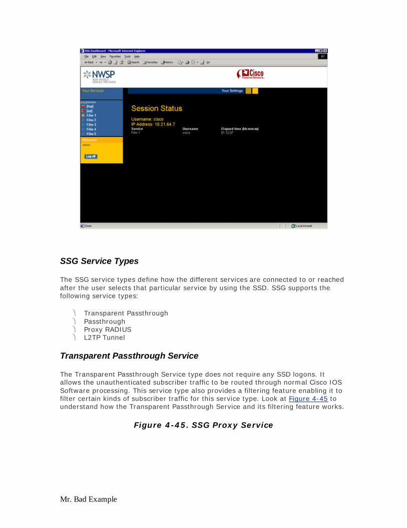
Mr. Bad Example
SSG Service Types
The SSG service types define how the different services are connected to or reached after the user selects that particular service by using the SSD. SSG supports the following service types:
Transparent Passthrough Passthrough Proxy RADIUS L2TP Tunnel
Transparent Passthrough Service
The Transparent Passthrough Service type does not require any SSD logons. It allows the unauthenticated subscriber traffic to be routed through normal Cisco IOS Software processing. This service type also provides a filtering feature enabling it to filter certain kinds of subscriber traffic for this service type. Look at Figure 4-45 to understand how the Transparent Passthrough Service and its filtering feature works.
Figure 4-45. SSG Proxy Service
Evaluation notes were added to the output document. To get rid of these notes, please order your copy of ePrint IV now.

Mr. Bad Example
Figure 4-44. Transparent Passthrough Service
A transparent passthrough filter is defined in the AAA, which is then applied to SSG running on the NRP by using the ssg pass-through filter download profile-name profile-name profile-password command, as shown in the previous diagram. When that is done, any unauthenticated traffic can transparently reach the Network B but not Network A.
Example 4-35 provides a sample filter profile.
Example 4-35 A Sample Transparent Passthrough Filter Network-B Password="cisco" Service-Type=Outbound Av-pair="ip:inacl#110 deny ip any 192.168.5.0 0.0.0.255" Av-pair="ip:inacl#110 permit ip any any"
Evaluation notes were added to the output document. To get rid of these notes, please order your copy of ePrint IV now.

Mr. Bad Example
Passthrough Service
With the Passthrough Service, the NRP SSG can forward subscriber traffic through any interface by using normal SSG forwarding rules or with the help of the next hop table. This type of service does not do any NAT and, therefore, reduces overhead. This type of service is suitable for basic Internet access.
Example 4-36 provides a sample service profile of the Passthrough Service.
Example 4-36 A Sample Passthrough Service Service Profile Intranet Password="cisco" Service-Type=Outbound Service-Info="IIntranet" Service-Info="R192.168.2.0;255.255.255.0" Service-Info="TP"
As seen from the sample service profile in Example 4-36, the service name is Intranet, the route to reach that service is defined by the Service-Info with "R" and the type of service is Passthrough, represented by "TP" (T =Type, P= Passthrough).
Proxy RADIUS Service
When a subscriber requests a service defined as a Proxy RADIUS Service, the SSG proxies the access request to a remote AAA server. Upon receiving the accept or reject message from the remote AAA server, the NRP SSG responds to the subscriber accordingly. To the remote AAA server, NRP SSG is its client. The concept becomes clearer with the help of the Figure 4-45.
With the Proxy RADIUS Service, the remote RADIUS server (after authentication) can optionally provide an IP address for that subscriber. If an IP address is allocated, SSG performs NAT, and if no address is assigned, it does not perform NAT and routes the subscriber data traffic to the service. When a user selects a Proxy RADIUS Service type, another prompt appears for the user to enter a username and password again to access that particular service. After the user is authenticated, the service is connected until the user disconnects, logs out of SSD, or gets timed out by the Remote Service.
As Figure 4-45 shows, when the subscriber logs into the dashboard and then requests the service of the intranet, the user is prompted to enter the username and password for the service intranet. The username and password are then forwarded by the NRP SSG in the form of an Access Request to the RADIUS server connected to the intranet service. This in turn authenticates the user and sends back an access-accept or access-reject message to the NRP SSG. If the message from the RADIUS server is access-accept and configured, it might opt to provide an IP address for that subscriber. If it does provide that IP address, NRP SSG performs NAT; otherwise, no NAT is performed.
Example 4-37 provides a sample service profile of a Proxy RADIUS Service.
Example 4-37 A Sample Proxy RADIUS Service Service Profile
Evaluation notes were added to the output document. To get rid of these notes, please order your copy of ePrint IV now.
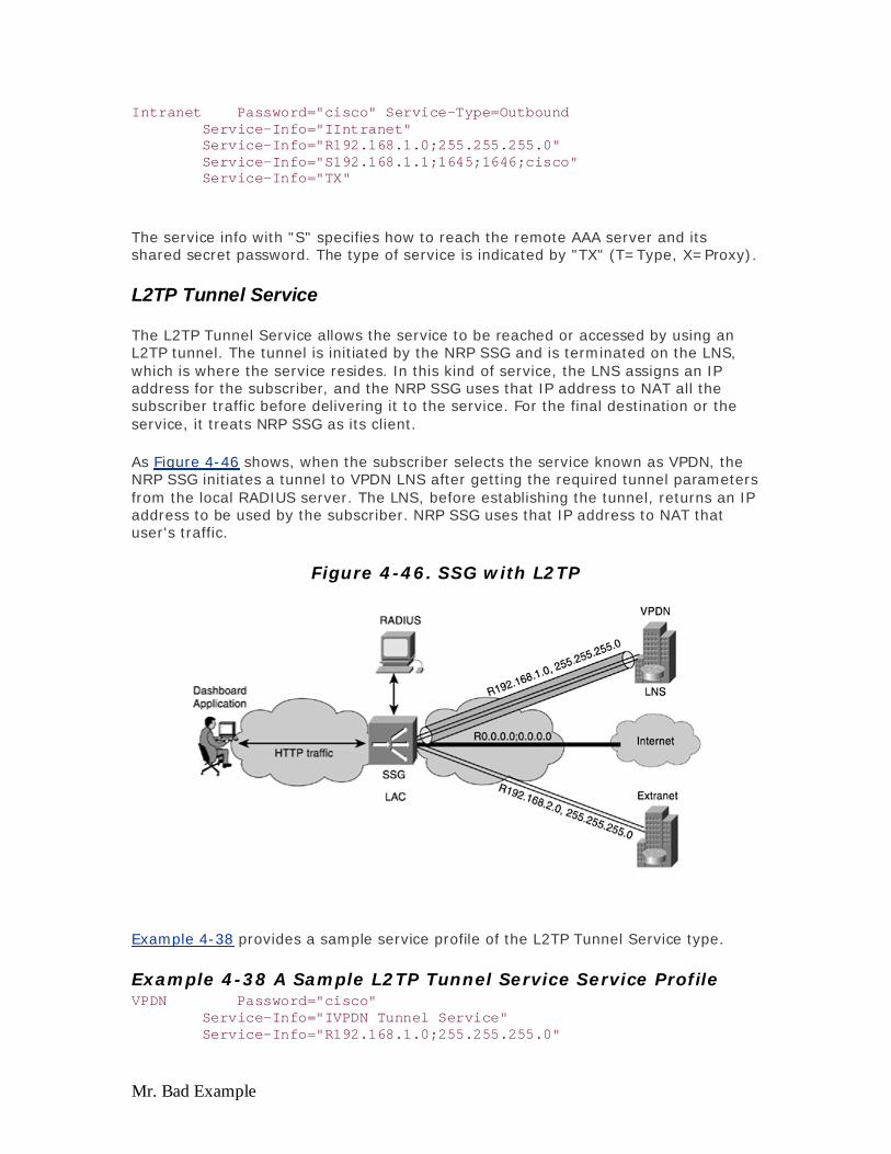
Mr. Bad Example
Intranet Password="cisco" Service-Type=Outbound Service-Info="IIntranet" Service-Info="R192.168.1.0;255.255.255.0" Service-Info="S192.168.1.1;1645;1646;cisco" Service-Info="TX"
The service info with "S" specifies how to reach the remote AAA server and its shared secret password. The type of service is indicated by "TX" (T=Type, X=Proxy).
L2TP Tunnel Service
The L2TP Tunnel Service allows the service to be reached or accessed by using an L2TP tunnel. The tunnel is initiated by the NRP SSG and is terminated on the LNS, which is where the service resides. In this kind of service, the LNS assigns an IP address for the subscriber, and the NRP SSG uses that IP address to NAT all the subscriber traffic before delivering it to the service. For the final destination or the service, it treats NRP SSG as its client.
As Figure 4-46 shows, when the subscriber selects the service known as VPDN, the NRP SSG initiates a tunnel to VPDN LNS after getting the required tunnel parameters from the local RADIUS server. The LNS, before establishing the tunnel, returns an IP address to be used by the subscriber. NRP SSG uses that IP address to NAT that user's traffic.
Figure 4-46. SSG with L2TP
Example 4-38 provides a sample service profile of the L2TP Tunnel Service type.
Example 4-38 A Sample L2TP Tunnel Service Service Profile VPDN Password="cisco" Service-Info="IVPDN Tunnel Service" Service-Info="R192.168.1.0;255.255.255.0"
Evaluation notes were added to the output document. To get rid of these notes, please order your copy of ePrint IV now.

Mr. Bad Example
Service-Info="vpdn:l2tp-tunnel-password=cisco" Service-Info="vpdn:ip-address=192.168.1.1" Service-Info="vpdn:tunnel-id=tunnelxyz" Service-Info="TT"
Example 4-38 shows that all the tunnel-related information is specified by the VPDN-related service information, and the type of service is defined by "TT"(T=Type, T=Tunnel). The L2TP option is particularly suited for connecting to legacy services; ISPs are accustomed to terminating PPP/L2TP, but this usually precludes the NAP from doing any form of service selection, unless they use this (L2TP) option.
SSG Service Access Modes
The service access modes of SSG define how a particular service is accessible. SSG supports two types of access modes:
Sequential— Allows the user to access only one service at a time, so if a user has selected a sequential service, he can use that service only.
Concurrent— Allows the service to be used along with other concurrent services that the user has logged onto. The user can simultaneously use different services at the same time without actually logging off from one service to access the other service.
The concurrent mode of service is on by default for all services. When a concurrent mode of service is selected, it is likely that more than one service can let the user access the Internet. The question becomes which service is used to route the subscriber traffic for the Internet? For such situations, SSG makes use of a feature known as service access order to determine the order in which the user's service connections are checked for forwarding packets and checking the DNS domain. The algorithm for such selection is the smallest network first, then the larger network, and in case of a tie, the recently assessed service is first.
SSG Auto Logon Feature
The SSG auto logon feature allows the SP to bundle different services in one group for one user or a set of users so that, for example, when a user logs in once on the SSD, she is automatically logged on to all the services that she subscribed to. This feature is useful for those SPs who are bundling different services to its users and would not like its users to log on more than once for all sets of services.
SSG DNS Redirection
If SSG receives a DNS request from a user and can match the domain with one of the service domain attributes for one of the user's active service connections, the SSG forwards the DNS request through the user's active connection for the service that matched. If SSG receives a DNS request that it cannot match to any of the service domain attributes for any of the user's active connections and the user is logged on to a service that has Internet connectivity, the SSG forwards the DNS request through the user's first active service connection that has Internet connectivity, as illustrated in Figure 4-47.
Evaluation notes were added to the output document. To get rid of these notes, please order your copy of ePrint IV now.

Mr. Bad Example
Figure 4-47. SSG DNS Redirection
With SSG DNS redirection, in a scenario where SSG receives a DNS request that it cannot match to any of the service domain attributes for any of its user's active connection and the user is not logged on to a service that has Internet connectivity, then the SSG forwards those DNS requests unmodified through the routing table based on IP destination. A service is defined to have Internet connectivity if its service profile contains a service route information of 0.0.0.0;0.0.0.0.
Looking Ahead
This chapter covered most of the access service architectures and their design considerations in great detail. The next chapter applies all of this information in the form of case studies, explains how they are deployed in production networks, explores some issues that might determine the best service architecture to use, and determines some of the implications of having one type of core versus another.
Evaluation notes were added to the output document. To get rid of these notes, please order your copy of ePrint IV now.
Mr. Bad Example
Chapter 5. Case Studies This chapter covers the following key topics:
Case Study 1: Small to Medium Wholesale SP — This section discusses what happens when you are a wholesale service provider selling DSL infrastructure to ISPs. The number of subscribers involved is up to 100,000.
Case Study 2: Large Wholesale SP — This is a case study of a larger wholesale SP who wants to accommodate up to 500,000 subscribers. Some are residential subscribers while others are business customers with SLA requirements.
Case Study 3: Very Large Wholesale SP — This case study is for a very large wholesale provider who not only wholesales its DSL infrastructure to ISPs but also is an ISP. This network needs to handle up to one million subscribers and up to two million VCs.
Case Study 4: MPLS VPN Services — This case study discusses the new MPLS VPN architecture. The scaling issues encountered in the L2TP-based models are addressed with this MPLS VPN model.
In the preceding chapters, various aspects of xDSL, various methods to carry subscriber traffic to the NAP network by using different access encapsulation methods, and various methods to deliver the subscriber traffic from the NAP to the NSP by using different core technologies were discussed. This chapter concentrates on putting all these elements together to see how customers deploy these elements in real-life scenarios. The rationale behind selecting one architecture versus another and some of the influencing factors in selecting some of the currently deployed architectures are considered. Design issues, a customer's target market, and how these networks evolve when they start supporting a large subscriber base are discussed.
This chapter lists some of the basic requirements as seen by certain DSL service providers in the form of case studies, and then discusses, based on those requirements, how an SP probably defines an architecture to meet those requirements. Based on some of the existing deployments and scalability tests performed in-house, some of the design issues—including the CPE, NAP's network, and scalability—and the core's scalability are addressed.
Case Study 1: Small to Medium Wholesale SP
Requirements: The service provider is a small- to medium-sized DSL wholesale provider. The service provider does not want to offer any services to end consumers. Instead, this wholesale service provider wants to wholesale its DSL infrastructure to various ISPs. Some of the basic requirements of this DSL wholesale provider are as follows:
CPE— Provided by the wholesale DSL provider to the end consumer, and the ISPs expect the wholesaler to manage those CPE devices for the basic configuration, image upgrade, and so on.
Number of subscribers— The number of subscribers that are served by this wholesale provider ranges from 50,000 to 100,000.
Evaluation notes were added to the output document. To get rid of these notes, please order your copy of ePrint IV now.
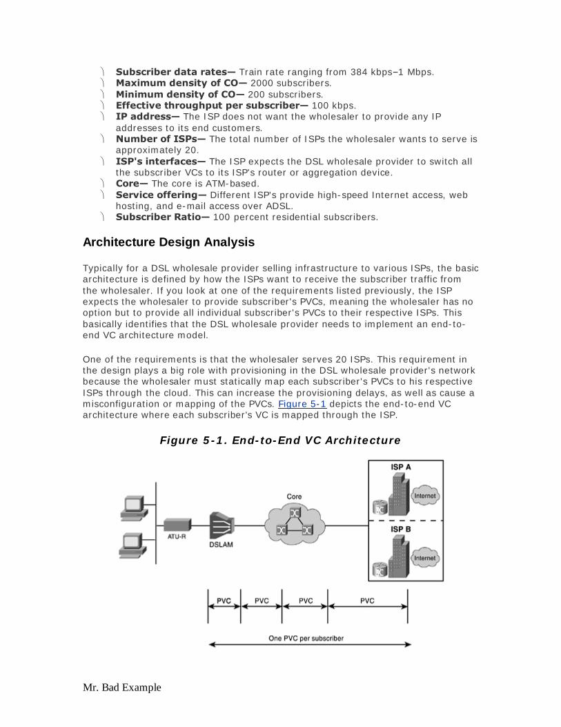
Mr. Bad Example
Subscriber data rates— Train rate ranging from 384 kbps–1 Mbps. Maximum density of CO— 2000 subscribers. Minimum density of CO— 200 subscribers. Effective throughput per subscriber— 100 kbps. IP address— The ISP does not want the wholesaler to provide any IP
addresses to its end customers. Number of ISPs— The total number of ISPs the wholesaler wants to serve is
approximately 20. ISP's interfaces— The ISP expects the DSL wholesale provider to switch all
the subscriber VCs to its ISP's router or aggregation device. Core— The core is ATM-based. Service offering— Different ISP's provide high-speed Internet access, web
hosting, and e-mail access over ADSL. Subscriber Ratio— 100 percent residential subscribers.
Architecture Design Analysis
Typically for a DSL wholesale provider selling infrastructure to various ISPs, the basic architecture is defined by how the ISPs want to receive the subscriber traffic from the wholesaler. If you look at one of the requirements listed previously, the ISP expects the wholesaler to provide subscriber's PVCs, meaning the wholesaler has no option but to provide all individual subscriber's PVCs to their respective ISPs. This basically identifies that the DSL wholesale provider needs to implement an end-to-end VC architecture model.
One of the requirements is that the wholesaler serves 20 ISPs. This requirement in the design plays a big role with provisioning in the DSL wholesale provider's network because the wholesaler must statically map each subscriber's PVCs to his respective ISPs through the cloud. This can increase the provisioning delays, as well as cause a misconfiguration or mapping of the PVCs. Figure 5-1 depicts the end-to-end VC architecture where each subscriber's VC is mapped through the ISP.
Figure 5-1. End-to-End VC Architecture
Evaluation notes were added to the output document. To get rid of these notes, please order your copy of ePrint IV now.

Mr. Bad Example
ATM VC Considerations
The biggest problem with this design is the provisioning delays for mapping various subscribers' PVCs to various ISPs. The second big challenge of this design as discussed earlier in Chapter 3, "Service Offerings": during different access and core architectures is the issue of VC depletion.
Consider how big the effect of VC depletion is in this design. One of the design requirements for this architecture is for the DSL wholesale provider to support from 50,000 to 100,000 subscribers. If all the subscribers go to one ISP, the DSL wholesale provider needs to ensure that its ATM core is scalable to support 100,000 VCs.
Consider that out of 100,000 subscribers, 20,000 subscribers select more than one ISP; the number of VCs the ATM core needs to handle increases by that number. For example if 20,000 subscribers select two ISPs, the ATM core needs to support 120,000 total VCs. Although, some of the VC depletion issues can be tackled if the SP implements VP switching as explained later in the section.
The problem escalates when the ISP wants to start offering more than high-speed Internet access, such as voice and video along with data. To be appropriately classified and prioritized, those services might require separate VCs for each class of traffic, which can further increase the number of VCs the ATM core needs to handle. In this design, that is not the case because the only service offered is high-speed Internet access, which is typically a best-effort service.
The SP can use one of the following methods to transport the subscriber VC through the core and then to the ISP:
PVC end-to-end— Similar to previous explanation where the SP manually provisions each subscriber PVC, through each of the hops through the ATM core. This can result in long provisioning delays and VC depletion.
SPVC and PNNI— Using SPVC and PNNI, the SP can get away with most of the provisioning delays it faces in the PVC -end-to-end implementation. However, this requires the ATM core to support PNNI and cannot address the VC depletion issue because the SP still needs to switch those many VCs through the ATM core.
VP switching— Associates multiple VCs into one or more VPs through the DSLAM and the ATM core, and then switches only the VP. Because the ATM core switches only the VP, it does not have any knowledge of the subscriber VC and can avoid the individual VC mapping, as well as avoid the VC depletion issue. The drawback, however, is that the SP cannot perform any OAM functionality or troubleshoot on an individual subscriber VC.
DSLAM Considerations
The design requires that the maximum concentration of subscribers at one particular CO not exceed 2000; the minimum concentration is 200. Assume a ratio of 95 percent with maximum concentration and 5 percent with minimum concentration.
Evaluation notes were added to the output document. To get rid of these notes, please order your copy of ePrint IV now.
Mr. Bad Example
With these numbers, the DSL wholesale provider needs to have a presence in approximately 73 COs. The number of 73 is determined as follows:
95% of 100,000 = 95,000, divided by a maximum concentration of 2000 = 47.5
5% of 100,000 = 5000, divided by a minimum concentration of 200 = 25
Total = 47.5 + 25 = 72.5 COs
As shown in the preceding calculations, you have approximately 48 COs with approximately 2000 subscribers and 25 COs with around 200 subscribers.
For this case, you should consider Cisco's 6000 DSLAMs with 8-port line cards, with each chassis supporting up to 256 subscribers. To support 2000 subscribers, you need a total of approximately eight DSLAMs. If the subscriber loops are not line-shared, you probably do not need the POTS splitter, and if you are not too stringent about the power dissipation, you can get away with 3 * 6000 Cisco IP DSL switches in a 7-foot rack. This gives you approximately 750 ports per rack. However, this is not realistic. To be within Network Equipment Building Systems (NEBS) limits of power dissipation of 1375 Watts per 7-foot rack, you need to incorporate two chassis with POTS splitters giving you approximately 368 ports. If you are not too stringent about staying within NEBs limit, you can fill up the chassis with both 8-port cards and a POTS splitter, which gives you 512 ports per 7-foot rack.
With this design, consider some real life deployment scenarios, which deploys two Cisco 6160 chassis along with a POTS splitter in a 7-foot rack. In some of the deployments, the service provider has a mixture of 4- and 8-port cards to stay within the NEBS limit and have approximately 368 ports per rack.
If you work around 368 ports per 7-foot rack for your design purposes, the total number of racks required to serve 2000 subscribers is equal to approximately five and a half or six 7-foot units of rack space.
Over-Subscription Ratio
The number of DSLAMs required to serve the 2000 subscribers (as previously discussed) is eight, and by using the same calculations, approximately one DSLAM is needed for the CO that has a maximum of 200 subscribers. For a less populated CO, the wholesaler can install one chassis and keep on adding the ports as required. The next thing to consider is how to connect those DSLAMs—do we subtend them or have trunk interfaces from each DSLAM go directly into the ATM cloud?
Obviously the answer to that question is dependent on the kind of bandwidth you want to give to the subscriber and the over-subscription ratio. Here, the over-subscription ratio refers to the over-subscription of the trunk or the upstream interface of the DSLAM toward the ATM core. The following paragraphs explain this concept in greater detail.
One of the requirements is to train the subscribers between 384 kbps to 1 Mbps. Of course training the CPE devices at this rate depends on many factors, such as the distance from the CO and the quality of the loop (as discussed in Chapter 2, "xDSL
Evaluation notes were added to the output document. To get rid of these notes, please order your copy of ePrint IV now.
Mr. Bad Example
Flavors and Considerations at the Physical and Data Link Layers"). Assuming that all those physical layer conditions are met and the CPE devices are trained at those rates, the associated requirement is to provide effective throughput of approximately 100 kbps. When the service is high-speed Internet access as specified as the requirement, it can become difficult to maintain the effective throughput because the bottlenecks can be somewhere else and not in the DSL wholesaler's network. For the purpose of this design guide, assume that it is the DSL wholesaler's charter to provide an effective throughput of 100 kbps per subscriber.
By using that number for the worst-case scenario when all 2000 subscribers are using the service, that particular CO needs to provide 100 kbps * 2000 = 200 Mbps in the downstream direction toward the subscriber. If you go with the number of 200 Mbps and consider the worst-case scenario as mentioned earlier, you need something bigger than OC-3 (155 Mbps) because you're serving all subscribers in one CO. OC-12 would fall into this category, but it is not realistic and cost effective for the wholesale provider. It is not realistic because more than likely not all 2000 subscribers are online and are effectively using 100 kbps. Plus, it isn't cost effective to deploy OC-12 just to provide high-speed Internet access service to the subscriber. First of all, the service is a best effort. Secondly, it is for residential customers who are usually charged from $39.95–$49.95 a month. No additional incremental revenue is generated for the DSL provider for its OC-12. Unless the SP starts bundling high-bandwidth applications, such as video, and offers other value-added services, such as voice and data, it DSL providers have no incentive to deploy OC-12.
The DSL wholesale provider, therefore, is actually going to over-subscribe. Because the requirement does not give any indication of the over-subscription ratio, you can assume a ratio of 15:1, which is a common ratio used by many of the DSL providers for residential customers and services such as best-effort, high-speed Internet access. The ratio indicates that out of every 15 subscribers at any point in time, only one subscriber is actually using an effective throughput of 100 kbps.
With the over-subscription ratio of 15:1, the entire picture of trunk requirements for a CO changes. Considering the densely populated CO with 2000 subscribers, the requirement provides 100 kbps for 300 (2000/15) subscribers only. This amounts to 30 Mbps. This brings down the need of the trunk from OC-12 to DS-3, which is what most DSL providers deploy. If DSL providers have any plans to provide some other value added service at a later date or if the over-subscription ratio is lower, they might invest in OC-3 but surely not OC-12 with these kinds of requirements.
DSLAM Subtending
Assuming that your DSL service provider is investing in an OC-3 trunk for 2000 subscribers per CO to best serve all the subscribers and share the same trunk, the DSLAMs are subtended as illustrated in Figure 5-2.
Figure 5-2. End-to-End VC Architecture with Subtended DSLAM in a CO
Evaluation notes were added to the output document. To get rid of these notes, please order your copy of ePrint IV now.

Mr. Bad Example
As shown in Figure 5-2, the subtended DSLAMs connect to each other and to the subtending DSLAM (or Head Node) through DS-3. The trunk on the subtending DSLAM toward the ATM core is OC-3.
One question that pops up when you talk about subtending is if the trunk fails or if the subtended node fails, what happens to the subscriber traffic on the lower DSLAM? The answer is simple. If you do not implement the Ring Redundancy-based architecture, that traffic can't go anywhere. Instead, if you implement Ring Redundancy-based architecture by using Soft-PVC and PNNI, you can reroute the traffic through another trunk. Referring to Figure 5-2, you can implement the Ring Redundancy-based architecture by connecting the subtend-port of the last DSLAM to the ATM cloud. By doing this, all subscriber VCs route through the subtend port of the last DSLAM if the subtended node fails or the trunk fails. Figure 5-3 shows how the DSLAM can be used in the Ring Redundancy-based architecture.
Figure 5-3. DSLAM Subtending and Ring Redundancy-Based Architecture
Evaluation notes were added to the output document. To get rid of these notes, please order your copy of ePrint IV now.

Mr. Bad Example
The SP can decide that it does not want to have one tree of subtended DSLAMs or it does not want to go more than four levels deep in a subtended architecture. In such a case, each of the subtended trees can use DS-3 lines as trunks because the number of subscribers are now distributed among two trees. Therefore, the reduction in required bandwidth needed to serve those subscribers per single subtended tree occurs. The reason why the SP might not go with one tree or restrict a subtended tree from more than four levels deep is based on the applications and its tolerance for latency and capability to maintain fairness in subtending.
ATM Aggregation
Consider that one OC-3 trunk comes out of each densely populated CO with 2000 subscribers; approximately 48 such COs exist, and a T1 IMA or DS-3 trunk comes out of 25 smaller COs. The trunk interfaces need to be physically aggregated in the DSL provider's ATM core network before the subscriber's VCs are delivered to various ISPs, which in this case is 20.
When you have a large number of COs and a smaller number of ISPs, the numbering scheme for subscriber VCs and VPIs, plays a big role for the DSL wholesale provider for ease of provisioning. To identify each ISP separately, the DSL provider in a typical deployment has separate VPIs associated with each ISP. If the number of ISPs is small or only one, then he can also opt to identify each CO by a separate VPI.
The ATM core, along with handling a number of VCs, needs to cater to a number of VPs carrying those VCs. The ATM core must be in a position to apply the proper QoS on those VPs because of contention for bandwidth in the ATM core. The DSL wholesale provider might want to prioritize traffic for a specific ISP or have more subscribers on one VP than the other and want to control the bandwidth on that VP
Evaluation notes were added to the output document. To get rid of these notes, please order your copy of ePrint IV now.

Mr. Bad Example
based on different CoS. In this case, the number of ISPs is 20, and the ATM core needs to aggregate the VCs coming from different COs into 20 VPs, which are then handed over to the respective ISPs. Therefore, each ISP will receive a VP, or more than one VP (depending on how many VCs can be carried on one VP), from the DSL wholesale provider. The number of physical interfaces to the ISP though can be one.
Layer 3 Considerations
Having covered the issues of Layer 1 and Layer 2, now focus on some of the Layer 3 aspects and service architecture as a whole. The decision as to which access encapsulation method to use with this architecture depends on each ISP because the DSL wholesale provider is not involved at Layer 3 and hands off the subscriber PVCs to the ISPs.
Each ISP might have different criteria in selecting different encapsulation methods. Chapter 4, "Access and Core Architectures," explains the advantages and disadvantages of various criteria. Mostly with this kind of architecture, the ISPs prefer to use a bridging architecture using RBE, even though some ISPs implement the PPP model. The reasoning for selecting RBE is the simplicity of the CPE and its management and the flat rate billing model. PPPoX is selected by certain ISPs because of the need to authenticate users and implement the model of charging subscribers based on different service usage. Figure 5-4 shows one example of how RBE and PPPoX are used.
Figure 5-4. Solution by Using RBE and PPPoX
If the bridging solution is used, the ISP implements RBE at its end. Keeping the CPE in bridged mode reduces many configuration hassles for the DSL wholesale provider and also reduces the truck rolls. If PPPoX is the preferred access encapsulation method for the ISP and the DSL wholesaler has to manage the CPE, it might create additional burdens for the wholesaler to manage those CPE configurations and any
Evaluation notes were added to the output document. To get rid of these notes, please order your copy of ePrint IV now.

Mr. Bad Example
associated client software along with them. The bottom line is that the DSL provider does not need to worry about what access encapsulation is used.
The DSL wholesaler does not take part in providing IP addresses to the subscribers because the DSL wholesaler is not aggregating or terminating any of the subscriber sessions. The IP addresses to the end consumer are applied by the respective ISP that terminates the sessions by using one of their preferred methods. The ISP can opt to provide legal public addresses or provide private IP addresses to its subscribers and then perform NAT before the subscriber leaves the ISP's domain.
One of the challenges for the DSL provider in this model is how the SPs manage the CPE because the SP is not aware of the IP address assigned to the subscriber's CPE. If this is the case, how can the DSL wholesaler ensure that the CPE devices are running the right image and have the right configurations with respect to their ISPs? This is a crucial and tough question faced by many of the DSL wholesalers who have adopted this model. Some SPs manually maintain a common image and common configuration task. Whenever they need to make some changes to those images or configurations, they either need to ship a new CPE device to the subscriber or send a truck roll if problems occur. This is fine as long as the number of subscribers is small. Imagine if you need to upgrade or change the configurations of 100,000 subscribers—this would be a nightmare! Cisco developed an initiative known as Open DSL, which addresses this problem by using Auto Provisioning mechanisms for CPE. Under this initiative, you do not require access to Layer 3 information to manage the CPE because the CPE can be managed using Layer 2 information. Every time the CPE comes up, it checks with the connected DSLAM to determine whether it is running the right image and configuration. If not, the DSLAM upgrades the image or corrects the configuration without actually having a truck roll or shipping a CPE.
Conclusion
A few main points about the solution for this case study follow:
This architecture can run into a VC depletion issue and face provisioning delays.
The access encapsulation method is defined by the ISP. The ISP might need to terminate a high number of ATM PVCs. The DSL wholesaler does not handle any kind of IP address management. The DSL wholesaler can't offer per subscriber accounting; a flat billing model
is more suitable. This architecture is suitable for a low volume of subscribers per ISP.
Case Study 2: Large Wholesale SP
Requirements: Most of the requirements are similar to Case Study 1. However, some of the parameters change:
Subscriber base— The DSL wholesale provider expects a substantial increase in the subscriber base in the range of 300,000–500,000.
ISP's interfaces— The ISP expects minimal interface from the wholesale provider. The ISP expects the SP to hand off subscribers aggregated on fewer VCs, instead of one VC per subscriber.
Evaluation notes were added to the output document. To get rid of these notes, please order your copy of ePrint IV now.

Mr. Bad Example
Subscriber ratio— Based on different ISP's requirements, the residential subscribers are approximately 70 percent, and small to medium business subscribers are approximately 30 percent.
Service offering— Along with providing high-speed Internet access, web hosting, and e-mail access, the ISPs want to offer service level agreements (SLAs) to their business customers as well.
Over-subscription ratio for residential— This remains at 15:1; whereas, for business, it is 4:1
Remaining requirements— The remaining requirements are identical to Case Study 1.
Architecture Design Analysis
Three major differentiators separate this case from Case Study 1. In this scenario, the number of subscribers is almost three to five times that of Case Study 1. The subscriber ratio now includes both residential as well as business customers, and the services include offering an SLA of guaranteed bandwidth for its business customers. The sections that follow show how changing these parameters changes the architecture.
ATM VC Considerations
Because the subscriber base ranges from 300,000–500,000, using an end-to-end VC model is impractical because the ATM core runs into VC depletion. In addition, the provisioning causes confusion. For these reasons, aggregating those VCs from subscribers into an aggregation device before handing it over to the ISP is essential. The aggregation device aggregates those VCs into fewer VCs before handing it over to ISP, which in turn is inline with the requirement of the ISP to have as few interfaces as possible and minimal VCs compared to the actual number of subscribers, as shown in Figure 5-5.
Figure 5-5. Aggregated ATM VCs
Evaluation notes were added to the output document. To get rid of these notes, please order your copy of ePrint IV now.

Mr. Bad Example
Now the subscriber VCs aggregate into an aggregation device and then delivers on fewer VCs to their final destinations of ISP. The methods by which VCs are handed over to an aggregation device match those mentioned in Case Study 1, by using PVC-end to end, SPVC, and PNNI or VP switching.
DSLAM Considerations
The number of DSLAMs at a particular CO remain the same if the concentration ratio of the subscribers remains the same. This implies that, how those DSLAMs are connected, what their trunk interfaces are, and so forth, as long as the effective throughput for the subscribers remains the same. A slight change in the over-subscription ratio for the business customers exists, which needs to be accounted for. The math, however, remains the same as in Case Study 1 in "DSLAM Considerations," "Over-Subscription Ratio," and "DSLAM Subtending."
The other change requiring some configuration modifications in the DSLAM is that the ISP wants to offer SLAs for its business customers to ensure that business class subscriber traffic gets prioritized over that of residential subscribers. This is possible only by using the CoS feature in the DSLAM, which enables classifying different classes of traffic. The classes of traffic can be prioritized accordingly, and the necessary bandwidth can be allocated per the SLA.
When this type of feature is enabled and the DSLAMs are connected in a subtended architecture, it is extremely important for the DSLAM to support the fairness in subtending. Otherwise, the DSLAMs that are lower in the tree can be starved of the bandwidth on the trunk, and the DSL wholesaler might not adhere to the SLA for subscribers who connect on the DSLAM lower in the tree. This was not required in Case Study 1 because it was besteffort service, and all subscribers were basically using the same kind of service.
Soft PVC Considerations
To ease provisioning a little (because the number of PVCs is high in this case) and not to provision the subscriber PVC through each of the nodes, the DSL wholesaler can use Soft PVCs. Soft PVCs enable SPs to specify the NSAP address for the aggregation device terminating those PVCs and eliminate a need to provision the PVC through every node. Figure 5-6 depicts the usage of SPVCs, and Example 5-1 shows the associated configurations by using the Cisco 6260 DSLAM and Cisco 6400 as the aggregation device.
Figure 5-6. Soft PVC Usage
Evaluation notes were added to the output document. To get rid of these notes, please order your copy of ePrint IV now.

Mr. Bad Example
Example 5-1 SPVC Configurations 6260(config)#int atm1/1 6260(config-int)#atm soft-vc 1 32 dest-address nsap address 10 32 6260(config)#int atm0/1 6260(config-int)#atm signalling enable 6400NSP#show atm address 6400NSP(config)#int atm1/0/0 6400NSP(config-int)#atm signalling enable 6400NRP#int atm0/0/0.132 6400NRP(config-int)#atm pvc 10 32
The DSL provider needs to make use of Soft PVCs to reduce the provisioning delays. Along with using Soft PVCs, DSL providers also need to use the highly recommended Ring Redundancy-based architecture, as explained in Case Study 1.
Wholesale SP and Encapsulation Methods
The basic difference at Layer 1 and Layer 2 between Case Study 1 and this case study and the additional changes required in the architecture to support the additional requirements were discussed previously. The major shift in architecture is by the means of aggregating subscriber PVCs. Because the DSL wholesaler is now aggregating the subscriber PVCs, it is involved in which access encapsulation method to use, the handling of IP addresses, and the delivery of subscriber traffic to the ISP by using Layer 3.
The choice of access encapsulation depends on a couple of factors for the DSL wholesaler: ease of management and provisioning of subscriber CPEs and who is allocating the IP addresses (DSL wholesaler or ISPs). Another important point is how the subscriber traffic is delivered to the ISP, whether the ISP wants only a certain kind of traffic, such as L2TP or IP traffic, from the wholesaler.
Taking a closer look at the requirements for the DSL wholesaler in this case study, the ISP does not want the SP to provide the IP addresses to the end subscribers, but the ISP has not specified whether it is ready to accept only L2TP tunnels or IP traffic. Therefore, consider both the options in this case study, even though typically with these requirements, L2TP is the most common way to deliver subscriber traffic. The reason is because the ISP does not want the DSL wholesaler to do anything with IP address allocation to the subscriber by that ISP.
Evaluation notes were added to the output document. To get rid of these notes, please order your copy of ePrint IV now.

Mr. Bad Example
Using RBE as the Encapsulation Method
Consider first that the DSL wholesaler is leaning toward a bridging solution because it does not need to worry about complex configurations at the CPE nor does the ISP want to send PPPoE host clients to the subscribers. If that is the case, the DSL wholesaler needs to implement RBE in the aggregation device. With RBE implemented in the aggregation device and the requirement of the ISP to provide the IP address, the aggregation device can be configured as a DHCP Relay agent by using the ip helper-address command, as explained in Chapter 4, "Access and Core Architectures."
The incoming DHCP requests from the subscribers can be forwarded to appropriate DHCP servers located at different ISPs. When the ISP's DHCP server responds to those requests, the aggregation device, in turn, installs those routes in its global routing table. Then, the DSL wholesaler's aggregation device can run RFC 1483 Routing and route the subscriber traffic to different ISPs by using either static routes for a smaller number of interfaces or putting the subscriber traffic into an MPLS-based VPN or running some sort of routing protocols with the ISP. Running routing protocols is not a realistic scenario because the ISP risks exposing some of its networks if it allowed running some sort of routing protocol with a DSL wholesaler.
This method takes care of the requirement of the ISP providing the IP addresses; however, it imposes a challenge for the DSL wholesaler on how to keep the subscriber traffic for different ISPs separate, without actually running MPLS-based VPNs. The DSL wholesaler can probably implement policy-based routing, but that is not a scalable method for many subscribers. Because of some of the design challenges mentioned, RBE implementation might not be a suitable option for a DSL wholesale provider.
Using PPPo X as the Encapsulation Method
Consider a PPPoX model as the access encapsulation method for the DSL wholesaler. PPPoX in this case means either PPPoE or PPPoA. First consider the scenario where the DSL wholesale provider terminates those PPPoX sessions coming in from the subscriber. If the sessions are terminated by the wholesale provider, the subscriber traffic needs to be routed out to the ISP; therefore, the subscriber traffic is delivered to the respective ISP by using IP. Terminating any kind of session on an aggregation device that is serving more than one ISP raises the challenge of how to separate the subscriber traffic of different ISPs. This challenge is addressed later in this section.
If the PPPoX sessions terminate on the aggregation device of the DSL wholesaler, it looks to the end user like the DSL wholesaler is assigning the IP addresses to the subscribers. That is true in some sense. The DSL provider actually provides those IP addresses to the end subscribers and establishes 32-bit host routes on its aggregation device, but actually those IP addresses belong to the ISPs. The mechanism through which this can be achieved is using Proxy RADIUS. Proxy RADIUS allows the DSL wholesaler's RADIUS server to act as a proxy server for the subscriber, and it instead contacts the ISP's RADIUS server to get the subscriber-related information, such as the IP address. At this instance, the local RADIUS server acts as a client to the remote RADIUS server at the ISP.
Evaluation notes were added to the output document. To get rid of these notes, please order your copy of ePrint IV now.

Mr. Bad Example
The big question most DSL wholesale providers ask is should they terminate the PPPoX sessions? When the DSL wholesaler selects to terminate the PPP sessions, it can assign IP addresses that belong to the ISP to the subscribers by using a local pool, local RADIUS server, or Proxy RADIUS. If the wholesaler selects to assign using a local pool, it needs to arrange with the ISP to release its addresses so that wholesale providers can keep those addresses in its local pool.
If the ISP agrees to release its addresses (which is not realistic), the wholesaler needs to come up with a mechanism to properly allocate the IP address for a local pool of each aggregation device, located at geographically distributed Points of Presence (PoPs). This is a difficult thing to do because it is likely that one of the aggregation devices runs out of IP addresses; whereas, the other aggregation device has plenty of spare IP addresses to be allocated to the subscribers. The same issue is true if a local RADIUS server is used, which identifies which pool to use or can potentially hold the pool of addresses.
Proxy RADIUS Server Considerations
If a Proxy RADIUS server is used, this problem can potentially be avoided because the RADIUS server that is actually allocating the IP addresses belongs to the ISP, and the local RADIUS server of all geographically distributed aggregation devices points to this same RADIUS server at the ISP. However, this leads to another problem. Assume that the wholesaler has three different PoPs (in San Jose, London, and Mumbai) that serve ISP A by using Proxy RADIUS. A subscriber in San Jose logs in and receives an address of 192.168.1.1, and the aggregation device in San Jose establishes a 32-bit route. A subscriber in Mumbai logs in and is allocated an address of 192.168.1.2 by the ISP's RADIUS server, and the aggregation device in Mumbai establishes a 32-bit host route for that address. A subscriber in London logs in after them and is allocated an address of 192.168.1.3, and the aggregation device in London establishes a host route for that. After the subscriber in London logged in, another subscriber from San Jose came online and received a 192.168.1.4 address, and this keeps going on.
What you notice from this example is that it becomes difficult for the DSL wholesale provider to summarize those routes in a minimal amount of routes to route to the ISP. Instead of receiving summarized routes from the DSL wholesaler, the ISP starts receiving advertisements of all these distributed host routes, which can become an issue for ISPs to maintain and manage. This effect, known as IP address management, is alleviated if the aggregation devices are densely distributed with a lower number of subscribers.
Because of some of these challenges, termination of PPPoX session and routing out using IP is not a popular architecture and is used by only a few SPs. The other challenge to keep subscriber traffic of different ISPs separate is addressed using policy-based routing, which can impact performance with a high number of subscribers and is recommended only for fewer subscribers.
Another method that can address the challenge of separating traffic from different ISPs is to use SSG's PTA-MD feature. PTA-MD does not make use of the global routing table to make the forwarding decision for a packet, but instead forwards it based on the Layer 2 information and, therefore, can be useful in keeping the traffic of different ISPs separate by allocating a fixed subinterface for each ISP.
Evaluation notes were added to the output document. To get rid of these notes, please order your copy of ePrint IV now.

Mr. Bad Example
Some of the issues mentioned are mainly related to how the subscriber traffic, after it is aggregated at the DSL wholesaler, is carried over to a different ISP by using IP as a handoff mechanism. In both the cases of RBE and PPPoX, notice that the DSL wholesaler faces some major architectural challenges to route that traffic out and deliver IP to the ISP. These challenges are addressed when discussing MPLS in the core. Here it is assumed that no MPLS exists in the core.
Using PPPo X -L2TP as the Encapsulation Method
An alternative and suitable approach to using IP (without MPLS is explained later in Case Study 4) as a handoff mechanism to ISP is to use L2TP and tunnel the subscriber traffic directly to the ISP, which in turn terminates the sessions. This approach dictates that the access encapsulation is PPPoX. Figure 5-7 illustrates the L2TP and PPPoX approach.
Figure 5-7. L2TP-PPPoX as Encapsulation Method
SPs targeting residential customers and wanting to have per session accounting and billing are embracing PPPoE for residential subscribers and PPPoA for business customers. This mimics the dial model where residential subscribers enter their username and passwords every time they want to connect when using PPPoE; whereas, the model used for business customers requires PPPoA. Even though PPPoE is also an always-on service, it basically duplicates the dial model and requires the subscriber to enter their username and password every time they want to connect.
The PPPoX-L2TP architecture eliminates the issue of IP address management and how to keep the subscriber traffic separate for the DSL wholesale provider and, therefore, is one of the most popular architectures and is becoming widely deployed. Again, using PPPoX as the access encapsulation method allows the DSL wholesaler to have accounting records for the subscriber connection time, and SPs have the option to bill based on usage if they want.
Some of the things that need to be considered and analyzed to design this kind of architecture are as follows:
Number of tunnels that can be initiated by the aggregation device acting as an L2TP access concentrator (LAC)
Number of tunnels that can be terminated on the router at the ISP that is acting as an L2TP network server (LNS)
Evaluation notes were added to the output document. To get rid of these notes, please order your copy of ePrint IV now.

Mr. Bad Example
Number of PPP sessions that can be carried within these tunnels Maximum number of PPP sessions supported on an aggregation device Throughput of aggregation device
The Number Game: Determining the Number of Sessions and Tunnels
To serve 300,000 subscribers with a maximum number of subscribers per CO at 2000, the DSL wholesaler needs to serve 150 COs. Assuming that a subscriber from every 10 COs is aggregated at a centralized PoP, you need 15 such PoPs consisting of aggregation devices. To aggregate 10 COs at each PoP requires the aggregation device in each PoP to terminate or aggregate 20,000 VCs (each CO with 2000 subscribers * 10 COs) and 20,000 PPPoX sessions. The aggregation device might need to support a higher number of PPP sessions than the number of VCs, especially if PPPoE is used (which is used in your case for residential subscribers). For this design, consider one PPPoE session per single VC. Table 5-1 summarizes the numbers needed in this case study.
Table 5-1. Subscriber Concentration Table
Subscribers Subscribers per CO No. of COs No. of PoPs VCs/PoPs
300,000 2000 150 15 20,000
Assume that the aggregation device can support 4000 sessions in a single L2TP tunnel. It can also support up to 30,000 sessions; out of 20 ISPs, the DSL wholesaler needs to support two of the ISP accounts for 200,000 subscribers (two-thirds of the subscriber base). The remaining 100,000 subscribers are distributed among 18 different ISPs. The LNS at the ISP is capable of handling 1000 tunnels and a total of 8000 PPP sessions.
Keeping these assumptions in mind, each PoP would have 20,000 subscribers coming in, with traffic destined to 20 different ISPs. Assuming the 2:3 ratio between two major ISPs and 18 smaller ISPs, 13,334 subscribers go to two major ISPs (6667 subcribers each) and the remaining 6666 subscribers go to 18 separate ISPs. Each of the major ISPs get 6667 subscribers from each PoP. Now based on your assumption, the aggregation device (LAC) in the PoP cannot carry more then 4000 sessions in a single tunnel, so in order to carry 6667 sessions, it needs to initiate more then one tunnel to the major ISP. Therefore, in order to carry 13,334 subscribers to two major ISPs, the PoP needs to initiate at least four tunnels (two to each major ISP), and then an additional 18 tunnels are needed to the other 18 ISPs. The total number of L2TP tunnels initiated by a single aggregation device from a PoP is 22. Table 5-2 shows the number of tunnels needed by the ISPs.
Table 5-2. Number of Tunnels
ISPs Number of Subscribers Total Number of Tunnels
Evaluation notes were added to the output document. To get rid of these notes, please order your copy of ePrint IV now.

Mr. Bad Example
Table 5-2. Number of Tunnels
ISPs Number of Subscribers Total Number of Tunnels
Two major ISPs 13,334 4
18 smaller ISPs 6666 18
The total number of tunnels carried through the core of the DSL provider is 22 (tunnels per PoP) * 15 (number of PoPs) = 330 tunnels, which equals to the number of VCs required to carry this many tunnels. If you do a comparison with Case Study 1, to carry 100,000 subscribers, that architecture required 100,000 VCs to be switched through the core of the wholesaler before being delivered to the ISP. In this architecture, to serve 300,000 subscribers, the number of VCs required to switch before those subscribers reach the ISP is reduced to only 330.
The number of tunnels the two major ISPs need to terminate equals 2 * 15 = 30 tunnels each. The number of tunnels the smaller ISP needs to terminate is 15 each. These numbers are within the limit of the number of tunnels the LNS can support in your case (although depending on which device is used as the LNS, it can have different sets of limits on session limitations); however, the number of sessions exceeds the limit that might require the ISP to have more LNSs. For example, in your case, one of the major ISPs needs to terminate 100,005 (15 * 6667) subscribers; whereas, the LNS supports only 8000 sessions, so the ISP needs at least 13 (100,005/8000) of these devices, or a device that can terminate a higher number of sessions. Because in your case the major ISP has more than one LNS deployed to support thousands of subscribers, the load must be equally distributed among those LNSs, and some sort of resiliency needs to be implemented at the ISP end. The way the LAC can distribute the sessions among different LNSs is to have more than one IP address specified for LNS, so the sessions distribute evenly among the LNSs.
So far, your calculations are based on the number of tunnels and sessions supported by the LAC and LNS. Even though the number of sessions plays an important role, it should not be the only deciding factor when choosing an aggregation device. Along with looking at the number of sessions, the performance and throughput of the aggregation device plays a crucial role in providing effective throughput per subscriber.
Throughput of the Aggregation Device
The effective throughput requirement per subscriber is 100 kbps. You already calculated that an aggregation device per PoP can support 20,000 subscribers. Out of these 20,000 subscribers, as per the requirement, 14,000 (70 percent of 20,000) are residential subscribers and 6000 are business subscribers. The over-subscription ratio for residential subscribers is 15:1 and for the business customers is 4:1, which leads to 934 (14,000/15) residential subscribers and 1500 (6000/4) business subscribers. So a total of 2434 (934 +1500) subscribers require the effective throughput of 100 kbps at any given time, with the given over-subscription ratio.
Evaluation notes were added to the output document. To get rid of these notes, please order your copy of ePrint IV now.

Mr. Bad Example
Table 5-3 shows the actual distribution of the number of subscribers requiring 100 kbps at any given time.
Table 5-3. Number of Subscribers Active at Any Given Time Per PoP
Number of Subscribers
Over-subscription
Ratio
Total Subscribers Requiring Access
Subscribers per PoP 20,000
Residential Subscribers per PoP
14,000 15:1 934
Business Subscribers per PoP
6000 4:1 1500
This requires the aggregation device to have minimum throughput of 243 Mbps (2434 * 100 kbps) toward the subscribers. This throughput is with the given over-subscription ratio. If the ratio is lower, the throughput requirement goes even higher, and the same is true if the requirement is to support higher bandwidth applications such as video. This number also identifies what kind of trunk the aggregation device can use. Looking at the throughput rate, GE or OC-12 is an obvious choice depending on the core. Because in your case the core is ATM, OC-12 is the obvious choice, even though it might not be utilized to its full capacity and can turn out to be not cost effective. Unless the wholesaler has some concrete plans to offer higher bandwidth applications, a substitute option is to distribute the processing on the aggregation and have multiple smaller trunks such as OC-3, which is more cost effective than to aggregate OC-12 in the core.
Managed LNS Considerations
You now have the actual number of tunnels going through the core of DSL wholesaler. The numbers are both reasonable and manageable. One of the issues with a high number of tunnels is that every time a new LAC is built, the ISP needs to be told about it and the ISP needs to establish a route to the LAC. One other design challenge, especially for the DSL wholesaler, is that its network is potentially exposed to ISPs (because ISPs terminate tunnels from every PoP), which must be carefully considered during the design plan to avoid any security breach.
One way to avoid this issue is to use a managed LNS approach where the LNS belongs to the DSL wholesaler, and it terminates all the tunnels through various PoPs. One single interface goes to the ISP that delivers subscriber traffic through the IP. This concept of managed LNS not only reduces the number of actual interfaces to the ISP, but it also eases provisioning for the ISP. Now, the ISP no longer needs to know the IP address of a new LAC that was just added to the DSL wholesaler's network, as all those things are hidden from the ISP. The ISP is aware of only the managed LNS router. With this approach, however, the DSL wholesaler now becomes
Evaluation notes were added to the output document. To get rid of these notes, please order your copy of ePrint IV now.

Mr. Bad Example
responsible for IP address management for the subscribers, as the wholesaler now owns the LNS, instead of the ISP.
SLA Considerations
An important factor that needs to be considered in this PPPoX-L2TP architecture is how to apply proper traffic management, especially for SLA service for business customers. As long as the service is best-effort, high-speed Internet access, the traffic type is all UBR and does not create a big impact on the design for QoS. When you talk about SLA, QoS and CoS play a big role. This requirement not only dictates various traffic management features at the DSLAM and the ATM cloud for Layer 2, but it also imposes a requirement on the aggregation device that is terminating the Layer 2 VCs to support some sort of mapping between Layer 2 CoS to Layer 3. This needs to be carefully designed to meet the requirements.
You can probably do policing for upstream traffic at the DSLAM for different classes of service and also shape the appropriate VP tunnels going to the aggregation device through the ATM cloud. From the aggregation device to the ISP, you can do shaping as well, but the key here is where you are facing contention. Usually the contention is faced in the core and from the aggregation device toward the ISP if the traffic is going through a public ATM cloud. As a DSL wholesaler, you cannot control the subscriber traffic after it leaves its boundary, therefore, you need to consider those factors and try to manage it within its boundary. In doing so, one rule of thumb is you always want to police the traffic that is coming inbound to the DSLAM, and you shape traffic outbound to the ISP.
RADIUS Server Considerations
The other design aspect for this kind of architecture is the RADIUS servers, which carry all the user databases, service profiles, and so forth. Most service providers make use of some sort of RADIUS functionality to identify which tunnels the subscriber traffic would go into, restrict the number of sessions per tunnel, restrict the number of tunnels, and define the IP pools at the LNS end. Most of the service providers deploy a centralized RADIUS farm per region. Each LAC in the DSL wholesaler's network accesses that RADIUS server to get the tunnel information. Some of the service providers that did not implement redundancy on their farms actually face the problem of a user unable to log in. You must carefully plan implementing a RADIUS server before deploying the PPPoX-L2TP architecture. Although, some service providers do not use external RADIUS servers and rely on the routers to provide the necessary RADIUS functionality.
Typically, the user enters username@domainnameusername@domainname and the local RADIUS server at the LAC identifies the right tunnel to which the subscriber traffic needs to be forwarded based on the domain name. The RADIUS servers are typically located along with a separate wholesaler's management network.
Depending on the number of access requests coming from subscribers, the bandwidth on that local interface needs to be calculated. The bottleneck becomes apparent if careful planning is not done when many users try to log in simultaneously. Most RADIUS servers have certain limitations on how many access requests or responses they can generate in a given amount of time, measured as
Evaluation notes were added to the output document. To get rid of these notes, please order your copy of ePrint IV now.

Mr. Bad Example
transactions per second (tps). Based on those numbers and the number of subscribers, you can get an idea of what kind of bandwidth on the local trunk you need to provision, how many RADIUS servers you need, and the kind of resiliency feature you need to implement if the primary RADIUS server goes down.
Apart from providing user and service profiles, most of the common RADIUS servers in the industry today keep track of the accounting records for subscribers. It is always a good idea to have some sort of hook to your billing system (if the charges are not flat-rate) to keep track of the accounting for the subscribers. The accounting activity also adds to the tps.
Most of the service providers (who have presence in different geographical locations) provide the same look and feel for their subscribers no matter where they log in. In order to achieve this, it is highly recommended to implement a directory-based RADIUS server that makes use of shared centralized databases for the subscribers.
User Authentication Considerations
We mentioned how the subscriber traffic gets into a particular tunnel by using username and domain name. This is okay if PPPoE is used because the user has to enter the username and password, plus multiple sessions are over a single VC. In the case of PPPoA, however, the DSL wholesaler needs to preprovision all the CPE devices to reflect the right username and password, which can sometime take a lot of time for the wholesaler. Instead, if you identify the subscriber based on their incoming VPI/VCI on the aggregation device (available with Cisco IOS Software), it can practically eliminate the time required to put a separate username and password on all the CPE devices.
Some SPs have already adopted this model. Apart from resolving the CPE configuration issue, you can use this feature to do domain pre-authorization, which results in both saving core bandwidth for the DSL wholesaler and resources for the ISP. As mentioned previously, the local RADIUS server at the LAC looks only at the domain name in the username to identify which tunnel the subscriber traffic needs to go into—the actual user authentication happens at the LNS. Assume that a user [email protected]@cisco.com (who is actually not a valid user at Cisco) gets in the LAC, which is serving subscribers for Cisco. After the user hits the LAC, his request would be forwarded to the local RADIUS server, which looks at the domain name of cisco.com and identifies the right tunnel for that subscriber. The user traffic is put in that tunnel and forwarded to the LNS at Cisco, which in turn fails the authentication because jo is not a valid user at Cisco, and the session would be dropped. Imagine you have many such users resulting in a major bandwidth crunch for the DSL wholesaler, as well as the resources required for the ISP.
As mentioned previously, as the requirement for the effective throughput per subscriber increases along with the number of subscribers, the centralized aggregation model might not scale well. The DSL wholesaler might need to adopt the distributed model by using IP DSL switches or by performing VC aggregation in an external aggregation device in the CO. By distributing the number of subscribers across several IP DSL DSLAMs (or smaller aggregation devices in the CO), it can provide higher effective throughput per subscriber and additionally save immense bandwidth in the core by doing multicast replication at the edge for high bandwidth applications. This is discussed in detail in Case Study 3.
Evaluation notes were added to the output document. To get rid of these notes, please order your copy of ePrint IV now.

Mr. Bad Example
Conclusion
A few main points about the solution for this case study follow:
The PPPoX-L2TP architecture is suitable for a DSL wholesaler that does not want to become involved with IP address management but still wants to offer the service of maintaining accounting records for the subscribers of different ISPs, to whom it (wholesaler) is wholesaling the service.
The DSL wholesaler addresses the VC depletion issue by aggregating the subscriber PVC into fewer VCs before delivering to different ISPs.
The aggregation device might require terminating a high number of subscriber's sessions that can result in lower throughput per subscriber if proper design considerations are not used.
Factors deciding the selection of the aggregation device are throughput of the aggregation device and the total number of sessions it can support. They both go hand in hand; none of them is valid without the other. That is, if an aggregation device can support 50,000 subscribers but cannot provide the effective throughput per subscriber, it is not acceptable.
The DSL provider might opt to use the concept of managed LNS to ease the provisioning and also to have one interface to the ISP.
Case Study 3: Very Large Wholesale SP
Requirements: All the basic requirements match Case Study 2 by using PPPoX-L2TP architecture, with the following modifications:
Number of Subscribers— The architecture must scale to support one million subscribers with the assumption of two sessions per VC, which amounts to two million sessions.
Effective Throughput— The effective throughput per subscriber, at a minimum, needs to be 384 kbps, with the capability to increase to 1 Mbps.
Existing Deployment— The DSL wholesaler is already equipped with a PPPoX-L2TP architecture by using centralized aggregation. The architecture uses PPPoE as encapsulations and has a minimum of two sessions per single VC; the subscriber base is strictly residential. no plan exists to change this architecture.
Number of ISPs— The DSL wholesaler is expected to serve 100 ISPs.
Architecture Design Analysis
Based on the requirements for this DSL wholesaler, before you design the architecture, you need to understand that the wholesaler already has an existing network, and the architecture is based on PPPoE-L2TP. The main thing the DSL wholesaler looks for is to scale its network to provide the effective throughput of 384 kbps to subscribers, have the capability to handle a subscriber base of one million, and serve a maximum of 100 ISPs.
Assume that the existing deployment for this DSL wholesaler is the same as defined in Case Study 2 for residential subscribers only. The rest of the variables, such as over-subscription, CO concentration, service offering, and so forth remain the same.
Evaluation notes were added to the output document. To get rid of these notes, please order your copy of ePrint IV now.

Mr. Bad Example
Now analyze whether the architecture defined in Case Study 2 meets the requirements and whether it is realistic and cost effective.
In Case Study 2, you calculated that for a wholesaler to support 300,000 subscribers, based on the assumptions such as subscriber concentration per CO, over-subscription ratio, and so forth, the wholesaler needs a certain number of COs, a certain number of VCs to be switched, and so on. For clarity and better understanding, use the same assumptions for Case Study 3 as an existing infrastructure for the wholesaler, which is listed as follows:
150 COs with each CO supporting a maximum of 2000 VCs, not sessions. 15 centralized PoPs with a single aggregation device that can support up to
30,000 sessions. Each aggregation device can put 4000 sessions in a single L2TP tunnel. LNS can support 8000 sessions and 1000 tunnels total. To provide effective throughput of 100 kbps with the specified over-
subscription ratio (15:1 residential), the aggregation device needs to support the aggregate throughput of 133 Mbps (20,000/15 =1334, to provide 100 kbps to all 1334 subscribers)
With these numbers, if the DSL wholesaler wants to scale the network for one million subscribers VCs and two million sessions and offer a minimum of 384-kbps throughput, the following is required:
1. Number of COs increases to 500.
2. Assume each CO with 2000 VCs and each PoP with one aggregation device is capable of handling 30,000 sessions. This yields that one aggregation device can handle approximately 7 COs (2000 VCs = 4000 sessions, hence 4000 * 7 = 28,000 sessions).
3. If the number of PoPs remains the same, that is 15, each PoP needs to handle approximately 33 COs (500/15) and have the capability to terminate 66,000 VCs (2000 * 33), which results in a requirement for each PoP to populate with approximately five aggregation devices (132,000/30,000 supported per aggregation device).
4. Total number of aggregation devices required = 15 * 5 = 75 (each supporting 30,000 PPPoE sessions).
5. The ATM core between CO (consisting of DSLAM) and PoP (consisting the aggregation device) needs to switch one million PVCs.
6. The calculations for an effective throughput per subscriber of 384 kbps for the subscribers, with the specified over-subscription ratio, per single aggregation device is 30,000/15 = 2000 subscribers * 384 kbps each = 768 Mbps.
7. To support 100 ISPs from each PoP consisting of five aggregation devices, each leads to 500 tunnels from each PoP, as long as the number of sessions within those tunnels does not exceed 4000 each. Realistically, the number of sessions is spread over multiple tunnels and fewer ISPs (who have a majority
Evaluation notes were added to the output document. To get rid of these notes, please order your copy of ePrint IV now.

Mr. Bad Example
of subscriber density) have more tunnels going to them than the others that have fewer sessions being carried in their respective tunnels. For your design consideration, assume 500 tunnels per PoP, which is realistic considering the number of subscribers.
8. The total number of tunnels flowing through the core from 15 PoPs = 15 * 500 = 7500 = number of VCs required to carry those tunnels from LAC to LNS through the ATM core after aggregation.
9. The number of tunnels at the LNS vary depending on the number of sessions for each ISP, but at a minimum, the LNS needs to terminate a tunnel from each aggregation device from each PoP that equals 15 * 5 = 75.
Out of all these listed requirements, most of them do not create much of an impact to the DSL wholesaler's existing network except points 5 and 6.
The impact of point 5 is huge for the DSL wholesaler. To switch one million subscribers from the DSLAM through an ATM core to an aggregation device is a big scalability challenge for that ATM core. The first thing the DSL wholesaler is going to run into is the issue of VC depletion. Secondly, switching so many VCs through that core also has a big impact on provisioning and can cause further delays (assuming a single VC exists from each subscriber). Imagine if the SP wants to offer Voice over ATM—this increases the number of VCs required and puts a further burden on the ATM core. Clearly, this is not the best approach.
The impact of point 6 is important as well. The moment you start putting more and more subscribers on a centralized aggregation box, you give up something. You always need to strike a balance between the number of sessions, throughput, and IP services (QoS, access lists, security, and so forth). In point 6, you considered the minimum effective throughput requirement of 384 kbps with the over-subscription ratio of 15:1. Imagine what the throughput of that aggregation device would be if you changed the throughput requirement to 1 Mbps and lowered the over-subscription ratio to 5:1. Service providers who plan to offer high bandwidth applications to their subscribers need to consider this oversubscription ratio. The device cannot scale, and an alternate approach needs to be used.
The bottom line is that you need to resolve the impact of points 5 and 6 and create a new architecture and simultaneously consider some of the migration challenges for this new architecture. One thing to assume is that the DSL wholesaler wants to stick to PPPoE-L2TP architecture. Alternate core architecture is discussed in detail during the migration plans.
Enabling the ATM Core Between the CO and PoP to Switch One Million PVCs: Option 1
One of the simplest ways to resolve point 5 is to beef up the ATM core with more switches to accommodate a large number of VCs. Of course, when including more ATM switches, you need to ensure that you implement PNNI and SPVCs with auto routes so that in the event that the switches in the core fails, the subscriber VC can be rerouted. This method is not cost effective for the DSL wholesaler as some SPs have realized, and increasing the ATM switches in the core increases the provisioning
Evaluation notes were added to the output document. To get rid of these notes, please order your copy of ePrint IV now.

Mr. Bad Example
delays further because of the need to provision those VCs. Also, this solution does not provide much help in resolving some of the issues related with point 6 (384 kbps throughput per subscriber). However, if the number of subscribers is much less than what is specified in this case study, this approach provides a temporary fix. The other approach is to use VP switching.
Enabling the ATM Core Between the CO and PoP to Switch One Million PVCs: Option 2
To address both points 5 and 6, the approach described in this section provides aggregation at the edge and closer to the subscriber, in the CO itself as shown in Figure 5-8.
Figure 5-8. Aggregation at the Edge
Consider this second approach briefly to resolve points 5 and 6 and determine whether it is feasible for your DSL wholesaler to migrate to this new approach. In Figure 5-8, the upper portion actually shows the effect of VC depletion when centralized aggregation is used after the ATM cloud, and the lower portion shows how that issue is addressed by moving the aggregation router in or closer to the CO.
Throughput Considerations
Evaluation notes were added to the output document. To get rid of these notes, please order your copy of ePrint IV now.
Mr. Bad Example
By moving the aggregation router in the CO, now the DSL wholesaler can actually aggregate the VCs of all subscribers coming into that CO on a smaller aggregation router and can choose to initiate the tunnel from that device directly to a different ISP LNS. Apart from that, because the aggregation router now has a smaller subscriber density, the higher effective throughput requirement for the subscriber can be achieved, as the throughput expectation of the smaller aggregation router is now more realistic. This is actually what some SPs are considering and trying in their network.
Assuming our DSL wholesaler, in this case, likes this approach, calculate some numbers now. Put an aggregation device in each CO for 500 devices. Each device needs to aggregate 2000 VCs and 4000 sessions (as per your earlier calculation). If you use the existing oversubscription ratio of 15:1 for the number of subscribers, at any point of time, you might have 267 (4000/15) active sessions. To provide an effective throughput of 384 kbps for those subscribers, the aggregation device now is expected to have the aggregate throughput of 102 Mbps, which is realistic.
VC Reduction in the ATM Core
The numbers you just calculated for the aggregation device are common and close to what most SPs deploy today. These calculations took care of the throughput requirements, but another issue must be resolved. Calculate how much you can reduce the number of VCs to be switched through the ATM core.
Our DSL wholesaler has 500 COs, each with 2000 VCs. The wholesaler needs to support 100 ISPs and uses the PPPoE-L2TP model. With these requirements in mind, when the aggregation device in the CO starts aggregating the VCs, it needs to initiate tunnels to those different ISP LNSs. The core is still ATM for the DSL wholesaler. Assuming the worst-case scenario where each CO has subscribers going to all 100 ISPs (this is not realistic but is not impossible), then each CO aggregation device needs to initiate a tunnel to each of those ISPs.
In the worst-case scenario, you would have 100 tunnels coming out of each CO. Five hundred COs exist, so in total, you would have 50,000 tunnels, which equates to 50,000 VCs (because the tunnel is created by using IP over ATM because of the ATM core). Keeping this in mind, you need to reduce the total number of VCs to be switched through the core to 50,000 from one million. You must also consider that you now have a high number of L2TP tunnels.
Tunnel Grooming Considerations
Assuming this worst-case scenario and assuming that subscribers are equally distributed among all ISPs, it is likely that each ISP LNS might need to terminate one tunnel from each CO, which results in 500 tunnel terminations from all the COs. This is perfectly fine with the currently deployed LNS, which can terminate 1000 tunnels. One of the limitations they would run into is the total number of sessions in those tunnels, which is an existing issue in current deployment.
You know that each LNS can support 8000 sessions across 1000 tunnels, so if each LNS is getting 500 tunnels, it implies that the number of sessions in those tunnels must not exceed 16 sessions per tunnel per LNS, which is unrealistic. However, if
Evaluation notes were added to the output document. To get rid of these notes, please order your copy of ePrint IV now.

Mr. Bad Example
that is the case, you definitely want to do some tunnel grooming as explained in Chapter 4 by using a tunnel switch. Perform tunnel-grooming before those tunnels are handed over to the ISP helps reduce the number of tunnels to the ISP, but it might not help as far as the total number of sessions goes on a single LNS. To accommodate more sessions in single LNS, the ISP might opt to have a bigger LNS device that can handle more sessions or have multiple LNS devices, which is already being done, as explained in Case Study 2.
A scenario where the subscriber density among 100 ISPs is equally distributed was just explained, which is not realistic. If you take a more realistic approach to distribute the majority of subscribers among the five major national ISPs and the rest of the subscribers to regional ISPs, the number of tunnels for the major ISP increases.
In order to understand this, assume that 80 percent of the total number of sessions are equally distributed among five major ISPs and the remaining 20 percent are distributed among 95 ISPs that have only regional presence.
To avoid confusion without going into too much detail, work around the five major ISP and 80 percent of the session scenario, keeping that in mind you can break it down to the following numbers:
Total number of sessions for five ISPs = 80 percent of 2 million = 1.6 Million. With equal distribution, the number of sessions for each ISP = 320,000. With equal distribution, and maximum of 4000 sessions out of each CO, the
number of sessions per CO per single ISP is 800 sessions. Number of tunnels coming out of each CO is five tunnels, each carrying 800
sessions each. Number of tunnels coming into LNS, if sent directly from LAC without
grooming, is 500 * 5 = 2500. With one LNS supporting 8000 sessions in an existing deployment and
maximum number of tunnels set to 1000, to terminate 320,000 sessions and 2500 tunnels takes a total of 40 LNSs at each ISP.
By doing this math and calculating these numbers, you can observe that because you distributed the LAC among each CO, the number of tunnels the LNS now needs to terminate is higher than what they might have expected if the DSL wholesaler used a centralized aggregation model. To reduce the actual number of tunnels going to the LNS of the ISP, the DSL wholesaler must implement some sort of tunnel grooming. It makes sense for our wholesaler because each tunnel initiated by each CO aggregation device is not carrying the number of sessions to its full capacity (800 sessions in one tunnel, whereas one LAC can support 4000 sessions in one tunnel).
As Figure 5-9 illustrates, each LAC initiates two tunnels for both ISPs, and the tunnel grooming can be performed by the existing deployed centralized aggregation device. The tunnel groomer grooms those tunnels coming from different LACs into fewer tunnels toward the ISP. The number of tunnels going out of the tunnel groomer depends on how many sessions it can carry on a single tunnel. For your DSL wholesaler, this turns out to be the same number of tunnels if centralized aggregation is used. Note that the tunnel groomer approach works out in your wholesaler's case because the number of sessions is sparsely distributed in the
Evaluation notes were added to the output document. To get rid of these notes, please order your copy of ePrint IV now.

Mr. Bad Example
tunnels coming in to the tunnel groomer; however, if that is not the case, the tunnel groomer is not appropriate.
Figure 5-9. Tunnel Grooming
As you notice with this second approach, not only points 5 and 6 were addressed, but the existing infrastructure was used to provide the DSL wholesaler the means to scale the network to support those many subscriber sessions.
As explained earlier, the advantage of using an aggregation device at the edge and in the CO not only addresses the issue of VC depletion, but also addresses the high throughput requirement for subscribers. This enables the DSL wholesaler to offer more IP services and is a better approach than the centralized aggregation approach.
How aggregation occurs at the edge by putting a smaller aggregation device in the CO was discussed previously. This can help your DSL wholesaler to scale its network to serve so many subscribers, but you know that your wholesaler already has an existing network, and it is not practical or realistic to discard what you have. Now consider some of the tradeoffs the DSL wholesaler might need to make in order to adopt this second approach and the possible migration challenges.
Migration Challenges
Some of the migration issues that the DSL wholesaler might run into or need to consider with this second approach to put a smaller aggregation device in the CO are as follows:
With the existing deployment, the aggregation of VCs occurred in a centralized site. This functionality now has to move to a smaller aggregation
Evaluation notes were added to the output document. To get rid of these notes, please order your copy of ePrint IV now.

Mr. Bad Example
device in the CO. This might require the DSL wholesaler's provisioning system to incorporate multiple aggregation devices. This is not difficult because the SP's provisioning system was already configuring the centralized aggregation. The only difference now is that instead of provisioning one system, they might need to provision five such systems that might or might not induce more time in provisioning, depending on the system they use.
With VC aggregation happening in a distributed aggregation device in the CO, the existing subscribers whose VCs were switched now need to be aggregated, unless the smaller aggregation device used can act as both an ATM switch as well as a router. If the aggregation device in the CO acts only as a router, the application (such as Voice over AAL2) that requires VC switching and is terminated on some other gateway (such as GR 303) might not work.
With the distributed aggregation routers, the DSL wholesaler now has a greater number of LACs, which implies that the wholesaler needs to have the right kind of IP addressing scheme on the LAC and careful design of routing protocols to reduce the provisioning burden on the ISP LNS. The LNS might need to enter five times the number of static routes for each LAC and need to maintain its routing table accordingly or can opt to run a routing protocol, such as OSPF with LAC. One approach for the DSL wholesaler to minimize this issue is to use tunnel grooming and have fewer LACs grooming the tunnels facing the LNS. This not only reduces the number of tunnels going to the LNS of ISP, but it makes the provisioning simpler for the LNS. However, with a careful design, the DSL wholesaler can keep adding the LAC behind the tunnel groomer and might not need to inform the LNS to provision for that LAC. As explained earlier, however, this might work only if the number of sessions is distributed sparsely on the tunnels coming out of the CO.
The smaller aggregation device in the CO must support the interfaces that are currently deployed, so if the outbound trunk from the subtended DSLAM is OC-3 going to the ATM cloud, it needs to take in OC-3 trunk and put traffic on an OC-3 trunk going to ATM cloud.
Because the ATM VCs are aggregated into the aggregation device in the CO, this device needs to support some sort of mapping between ATM and IP to apply the necessary QoS for those streams, such as the Cisco IOS Software QoS Feature set.
Enabling the ATM Core Between the CO and PoP to Switch One Million PVCs: Option 3
The third approach to resolving points 5 and 6 is not much different than the second approach just described. This approach, in fact, makes the network at the edge more scalable and also addresses some of the migration challenges raised by the second approach:
One of the challenges you face with the second approach is that all subscriber traffic needs to be aggregated on the aggregation device. If a service provider decides to offer Voice over ATM that requires AAL2-based VCs to be switched, the aggregation device needs to act as both an ATM switch as well as an aggregation device.
Another possible challenge is the number of additional network elements to be managed, which increases as the number of COs increases compared to a centralized PoP aggregation device.
Evaluation notes were added to the output document. To get rid of these notes, please order your copy of ePrint IV now.

Mr. Bad Example
Finally, if the number of subscribers per CO increases, this architecture might pose the same challenges as mentioned earlier for centralized aggregation. Even if the number of subscribers remains the same, but the DSL wholesaler now wants to provide video service at 4 Mbps for each subscriber, the aggregation device that is terminating 4000 sessions might not scale to provide that much throughput.
In order to address some of these issues, you might need to further distribute your aggregation functionality, and what better place to do this than in a device that gets the subscribers in first, such as a DSLAM.
By providing the aggregation as well as switching capabilities into DSLAM, you can resolve two problems with a single solution. Not only are you addressing points 5 and 6 (greater number of subscribers and greater throughput per subscriber), but you are also addressing some of the migration limitations faced with the second approach.
First, see how the migration challenges of the second approach are tackled, how the architecture looks by putting the intelligence of IP in the DSLAM, and what some of the potential migration issues are that this architecture can face are discussed.
IP DSLAM and ATM Switches
The issue of switching and aggregating the VCs can be resolved by an external device. However, that increases an additional network element in the DSL wholesaler's network, which can be avoided if the IP DSLAM is deployed. By deploying the IP DSLAM, you are not adding any further network element in the network; rather, you are eliminating some of them. By adding IP functionality into those DSLAMs, the DSL wholesaler can surely get away with the external aggregation device in the CO and can potentially get away with fewer centralized aggregation devices.
Each DSLAM in the subtend tree can individually perform multicast replication for their subscribers by putting the IP functionality into the DSLAM and with the multicast support on the DSLAM. This results in an immense saving of bandwidth, and because you have further distributed the aggregation, the higher throughput requirement for applications such as video can be delivered to the subscriber.
Now look at some of the possible architectures in which this IP DSLAM can be installed. Because your DSL wholesaler has existing deployments, the best approach is to use a Head-Node architecture where the existing DSLAM can be subtended into the Head DSLAM, which performs the aggregation functionality for the VCs coming in from the bottom DSLAM. Figure 5-10 illustrates this concept.
Figure 5-10. IP DSLAM and Head-Node Architecture
Evaluation notes were added to the output document. To get rid of these notes, please order your copy of ePrint IV now.
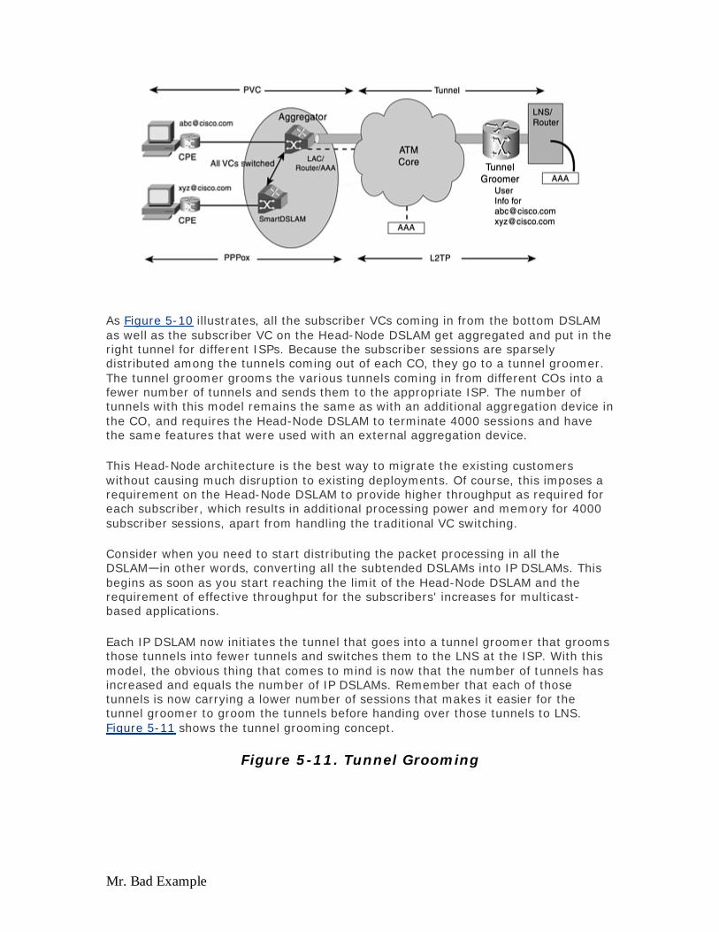
Mr. Bad Example
As Figure 5-10 illustrates, all the subscriber VCs coming in from the bottom DSLAM as well as the subscriber VC on the Head-Node DSLAM get aggregated and put in the right tunnel for different ISPs. Because the subscriber sessions are sparsely distributed among the tunnels coming out of each CO, they go to a tunnel groomer. The tunnel groomer grooms the various tunnels coming in from different COs into a fewer number of tunnels and sends them to the appropriate ISP. The number of tunnels with this model remains the same as with an additional aggregation device in the CO, and requires the Head-Node DSLAM to terminate 4000 sessions and have the same features that were used with an external aggregation device.
This Head-Node architecture is the best way to migrate the existing customers without causing much disruption to existing deployments. Of course, this imposes a requirement on the Head-Node DSLAM to provide higher throughput as required for each subscriber, which results in additional processing power and memory for 4000 subscriber sessions, apart from handling the traditional VC switching.
Consider when you need to start distributing the packet processing in all the DSLAM—in other words, converting all the subtended DSLAMs into IP DSLAMs. This begins as soon as you start reaching the limit of the Head-Node DSLAM and the requirement of effective throughput for the subscribers' increases for multicast-based applications.
Each IP DSLAM now initiates the tunnel that goes into a tunnel groomer that grooms those tunnels into fewer tunnels and switches them to the LNS at the ISP. With this model, the obvious thing that comes to mind is now that the number of tunnels has increased and equals the number of IP DSLAMs. Remember that each of those tunnels is now carrying a lower number of sessions that makes it easier for the tunnel groomer to groom the tunnels before handing over those tunnels to LNS. Figure 5-11 shows the tunnel grooming concept.
Figure 5-11. Tunnel Grooming
Evaluation notes were added to the output document. To get rid of these notes, please order your copy of ePrint IV now.

Mr. Bad Example
In the worst-case scenario, because the wholesaler is supporting 100 ISPs, you probably end up with 100 tunnels from each IP DSLAM. This is not realistic, but in case it does happen, you can use the Cisco IOS Software Tunnel Share option. This feature enables you to create only one tunnel for multiple domain names. This reduces the actual number of tunnels coming out of the DSLAM, as well as the number of tunnels flowing through the core of the DSL wholesaler. All the tunnels from each IP DSLAM using Tunnel Share first land at the tunnel groomer, which then sorts the traffic and creates appropriate tunnels to different ISPs by using the L2TP Multihop feature in Cisco IOS Software, which then forwards the subscriber traffic into appropriate tunnels. Both Tunnel Share and the L2TP
Multihop feature can be utilized with a Head-Node architecture. The only thing that you need to understand is that the tunnel groomer, Tunnel Share, and L2TP Multihop features are useful if the number of sessions being carried in a tunnel is sparse or few. When the sessions are few, it becomes easier for the tunnel groomer to put those fewer sessions into multiple tunnels into one or fewer tunnels.
Figure 5-12 shows the problems associated with configuring four LACs and three LNSs without a tunnel switch. As you can see, with just 4 LACs and 3 LNSs, 12 PVCs, and 12 tunnel definitions are needed on the entire network. Every time a new LAC is added, all the LNSs must be configured to be aware of the new LAC device in the network, and vice versa.
Figure 5-12. Tunnel Definition Without a Tunnel Switch
Evaluation notes were added to the output document. To get rid of these notes, please order your copy of ePrint IV now.

Mr. Bad Example
With the tunnel switching feature, tunnel definition is greatly simplified. Not only is the number of tunnel definitions greatly reduced, but adding an LNS or LAC is also simple. The only configuration that needs to take place when adding a LAC is between a LAC and the tunnel switch. Similarly, when adding an LNS, configuration is added to the LNS and tunnel switch. Figure 5-13 illustrates the concept of a tunnel switch.
Figure 5-13. Tunnel Definition with a Tunnel Switch
The only flaw to this design is that careful planning is required for all the tunnels going out, which increases complexity. In addition, you must implement careful routing. The other major challenge with this design that has a big impact is how you design your network management and provisioning system. Network management
Evaluation notes were added to the output document. To get rid of these notes, please order your copy of ePrint IV now.

Mr. Bad Example
needs to be carefully planned to achieve fault isolation and troubleshooting when thousands of IP nodes exist. Because this design is based mainly on the IP in the DSLAM, the redundancy can be achieved at both the IP layer as well as the ATM layer, as explained earlier, to reroute the traffic in case of failure.
Conclusion
A few main points about the solution for this case study follow:
By distributing the aggregation functionality at the edge by using an external aggregation device either in the CO or IP DSLAM, the DSL wholesaler can eliminate the VC depletion issue and also provide higher effective throughput per subscriber.
Deploying aggregation at the edge enables the wholesaler to add in more value-add services, such as security, QoS, and web caching, as well as the capability to provide enough throughput to subscribers to use high-bandwidth applications.
Using IP DSLAM enables the DSL wholesaler to reduce some of the network elements in the core and eliminates the issue of VC Provisioning delays.
Network management and provisioning must be carefully planned and designed for the distributed aggregation model and can possibly create more complexity in the existing NMS systems, as the number of managed devices increases.
Case Study 4: VPN Services
Requirements: The DSL SP is wholesaling the services to different ISPs and offering VPN services to corporations. In addition, the DSL SP has its own ISP that retails their services to customers. The retail business is currently selling only high-speed Internet access to residential consumers but wants to offer some value-add services to the current offerings and also wants to sell to small-to-medium businesses (SMBs).
Most of the requirements remain the same as mentioned in Case Study 2 and Case Study 3 except for the following modifications:
The DSL SP is not fixed on using only PPP-L2TP architecture and is willing to change its architecture if a more scalable approach is available and can still maintain some of the requirements of the ISP to provide IP addresses for their consumers for both wholesale and retail.
Because the DSL SP is acting as both the retail and wholesale provider, it is not fixed on any particular access encapsulations and uses the combination of all access encapsulation methods, depending on the service offering.
The DSL SP wants to offer IP VPN services, both managed and unmanaged, to its SMB subscribers.
The DSL SP wants to offer services such as streaming video and audio to its residential consumers along with voice and data and wants to ensure that the right infrastructure is in place to offer such services.
The DSL SP wants to deploy some mechanism for its retail business, where the users can choose different services and pay additional charges based on the kind or type of service being used.
Evaluation notes were added to the output document. To get rid of these notes, please order your copy of ePrint IV now.
Mr. Bad Example
For its subscribers, the DSL SP wants to offer different sets of bandwidth, ranging from 384 kbps to 4 Mbps, and also wants a mechanism for the subscriber to choose different bandwidths at different times.
Architecture Design Analysis
This architecture will be slightly different because the DSL SP wants to be in both the retail and wholesale business. The best approach for the DSL SP to be in both businesses is to have two or more service architectures overlay on a common core, assuming the core is ATM.
First consider the requirements of wholesaling for this SP. The DSL SP wants to wholesale subscribers to different ISPs, as well as sell VPN services to various corporations. The first thing that might come to mind is why not use PPP-L2TP architecture as discussed in Case Studies 2 and 3? The answer is absolutely yes. You can definitely use the PPP-L2TP to provide VPN services to corporations as well as wholesaling subscribers to different ISPs. However, it might become difficult for the DSL SP to make use of optimal routing in its core, especially if the number of subscribers is equal to or more than the number in Case Study 3.
Management of Tunnels
With the PPP-L2TP model, the issue is more than just the management of more tunnels. The DSL SP cannot achieve optimal routing in the core because each tunnel requires a point-to-point connection or VC, and each tunnel has two fixed endpoints that are established by running IP over ATM. In order to explain why the SP might lose the optimal routing in the core, consider a simple scenario where five LACs are talking to 25 different ISP LNSs; assume that each of those five LACs speaks to all 25 LNSs.
For each LAC to communicate to 25 LNSs, every LAC needs to a have a PVC for each of those LNSs, and they also need to know the endpoint IP address for each LNS. In this scenario, the SP is transporting IP over ATM. The LAC either has a static route to each LNS or it runs some routing protocols to reach the different LNSs. In your example, because all 25 LNSs belong to different ISPs, it is likely that the LAC uses static routes to reach those LNSs because it might not be practical to run routing protocols between 25 ISPs and the SP LAC. The LNS also needs to have a route to each of the LACs. If that point-to-point link fails between the LAC and one of the LNSs at one ISP, this traffic cannot be rerouted.
The subscriber sessions that go through that tunnel need to be re-established, which is not possible because there was only one point-to-point link, and that failed. Providing multiple LNS addresses at the LAC establishes some sort of resiliency for the new sessions coming in. Sessions that are already established need to be re-established when the tunnel is down. If multiple VCs go to multiple LNSs for the same ISP, and if some of the VCs fill to capacity while others are empty and have enough bandwidth left, some of the traffic cannot be rerouted from those filled VCs to those that have enough bandwidth to service the traffic. This results in wasting bandwidth on those nonfilled VCs.
Evaluation notes were added to the output document. To get rid of these notes, please order your copy of ePrint IV now.
Mr. Bad Example
Additionally, if several LACs in different COs go to different ISPs, the DSL SP might need to provision a VC from each LAC to each ISP. In such a scenario, sometimes if a new LAC is added or removed, it requires a lot of provisioning through the Layer 2 point-to-point VCs. In a full-meshed scenario, all affected elements need to be provisioned with this new LAC VC.
MPLS VPN on the Edge
By making use of L2TP in the core, the SP might lose some of the optimal routing on those PVCs for those tunnels because if one of the VC fails, the traffic cannot be rerouted unless MPLS is used. Therefore, to achieve optimal routing and avoid some of the scalability issues of L2TP, some SPs are migrating toward MPLS-based VPNs.
Your DSL SP now has two options for wholesaling: it can use either the PPP-L2TP model or adopt an MPLS VPN-based architecture, which does not require the subscriber to change their access encapsulation method but changes the architecture for the SP.
MPLS VPN for business customers and corporations might make perfect sense if they want VPN services. MPLS VPN provides the same level of security as provided by Frame Relay or an end-to-end VC model. When implementing MPLS-based VPNs, the DSL wholesaler needs to first make its core MPLS-aware. By making the core MPLS-aware, the SP takes the first step to make its core IP based and also utilizes the existing ATM infrastructure.
Assuming the DSL SP opts to deploy an MPLS VPN-based architecture for its wholesale business, you might need to consider a few things. No matter what access encapsulation is used, the sessions terminate on the Provider Edge (PE) router of the SP. This means that if the SP is wholesaling to the ISP, it needs some means to get the IP addresses from the ISP for the terminated sessions and forward that information back to the ISP. The DSL SP also needs to convince the ISP that terminating the sessions into the ISP's VPNs does not give the DSL SP access to the ISP's Layer 3.
If the access encapsulation used is either 1483 routed or bridged, in order for ISP to provide IP addresses to their end subscribers, the SP needs to implement VPN-based DHCP relay to forward the incoming DHCP request from subscribers to their respective ISP. If the incoming access encapsulation is PPP-based, the VPN-based RADIUS server can be used to associate the right IP address to each subscriber.
As mentioned earlier, one of the major concerns for the SP terminating the sessions on its aggregation device is how to keep the traffic of different ISPs or corporations separate. That problem is resolved by making use of a MPLS VPN-based architecture that creates a separate routing instance and routing table for each VPN—each ISP and corporation is associated with a unique VPN.
One of the other major concerns about terminating the PPP session is the issue of IP address management and summarization of different 32-bit host routes. This issue is especially crucial if the SP has different geographical locations and aggregation points. This issue is not resolved completely with the MPLS VPN approach. However,
Evaluation notes were added to the output document. To get rid of these notes, please order your copy of ePrint IV now.

Mr. Bad Example
the SP can use some intelligent CIDR-based routing protocols to aggregate these addresses at one stage in the core.
The access side was just discussed, which does not require much change on the part of the DSL SP. The only change that needs to take place is applying MPLS labels on the aggregation device. As explained earlier, in order to address some of the scalability challenges for a mass subscriber base, it is always better to start labeling the packets right at the edge so that the core can utilize its optimal routing to route those packets out through the best possible path. Figure 5-14 shows the IP DSL DSLAM functioning as a P (Provider) and Provider Edge (PE) router.
Figure 5-14. IP DSL DSLAM as a P and PE Router
Implementing each IP DSLAM to act as both the PE and P routers further enhances the performance and the scalability of the network. Careful planning of the design is required to determine whether to use a hub-and-spoke topology or a full-meshed topology. Depending on the number of VPNs, routes per VPN, and the number of devices in the MPLS core of the DSL SP, you also need to design how many route reflectors you might need in an MPLS network.
MPLS VPN on the Core
On the core side, the DSL SP needs to bring in a lot of additions and quite a few changes to its core design that was mainly ATM-based. Because MPLS brings in IP intelligence on top of ATM and makes use of the best of both worlds, the SP might need to either add IP functionality to the existing switches or connect to an external router for the IP intelligence. This is not an easy task and requires migration in phases. The beauty of this architecture is that you can create it in parallel with your existing ATM-based architecture and then migrate the core in phases. One of the phased approaches is to put business customers on an MPLS VPN while the ISP continues to use the L2TP model.
Evaluation notes were added to the output document. To get rid of these notes, please order your copy of ePrint IV now.
Mr. Bad Example
One question usually asked is "If I use an L2TP-based architecture, can I use it with the core migrated from pure ATM to MPLS-based?" The answer is yes. This is accomplished by overlaying the existing L2TP-based architecture over the MPLS VPN backbone. This enables the SP to preserve its access VPN services while migrating to an MPLS VPN backbone. ISPs or corporate customers do not have to reconfigure their networks in any way. In this model, the PE router in the SP's PoP or CO acts as a LAC that accepts incoming PPP sessions and tunnels them using L2TP over the MPLS VPN backbone to the LNS.
With this architecture, the VPN customer maintains the responsibility for authenticating the remote user and assigning it an IP address. The PE/LAC simply has to authorize the PPP sessions and associate them with a specific VPN. The PE/LAC must have a VPN IP address to route the L2TP tunnel to the LNS over the VPN and not over the public Internet. Also, if the LNS uses a private address, it is not possible for the PE/LAC to reach it through the public Internet. VPDN must be made VRF-aware in order to establish a tunnel to a destination with a private address.
Extending the MPLS VPN all the way to the edge of the IP network can result in fragmentation of the VPN address space and explosion of the VRF routing table. Therefore, without careful management of the IP addresses assigned to remote users and sites, proper design, or selection of the right topology, the scalability of the architecture can become limited.
The advantage of MPLS VPN for business customers is multifaceted. MPLS VPN provides the necessary VPN services for corporations and enterprises that might use existing leased lines to connect their remote branches by using Frame Relay. The MPLS VPN architecture provides not only a similar kind of service at a lower rate, but two offices in the same town use the same PoP so that traffic can be locally routed without actually going through the enterprise. Because of the scarcity of IP addresses, many corporations or enterprises use the same private IP addressing schemes. By using MPLS VPN, the DSL SP allows them to continue using the same IP addressing scheme without any change because MPLS VPN supports overlapping IP addresses, which is, again, a huge advantage for business customers.
MPLS VPN and Residential Customers
Does MPLS VPN make sense for residential consumers? Probably. But as the networks grow and the DSL SP gets a larger subscriber base, to make use of optimal routing in their core, SPs may be forced to move toward an MPLS-based core. SPs can potentially start putting ISPs into different VPNs for ease of management. One VPN can be assigned to small to medium business customers for VPN services, and one VPN can be assigned to residential customers. One VPN that has higher throughput QoS can be created as a service for subscribers to subscribe to on demand.
Value-Added Services
You understand how your DSL SP can offer some wholesale services and how it can make use of MPLS VPN as an alternate approach to the PPP-L2TP model used mainly for residential consumers. MPLS VPN not only enhances the SP core by providing optimal routing, but it can also help the SP provide various VPN services to
Evaluation notes were added to the output document. To get rid of these notes, please order your copy of ePrint IV now.

Mr. Bad Example
corporations while also wholesaling the residential subscribers to various ISPs. Now, you can concentrate on how the DSL SP offers other value-added services through its internal ISP service that it uses to retail to its own subscribers.
To offer the retail services, the DSL SP either offers some value-added services to the subscribers that belong to different ISP/corporations or the SP starts competing with those ISPs and starts providing its own set of ISP services along with voice and video. The former part is difficult. Why would an ISP allow its subscribers to get some value-added services from their infrastructure provider? The ISP, instead, should offer the same services and would like the DSL SP to only wholesale the infrastructure and no additional services. The latter scenario (the DSL SP's ISP actually sometimes competes with its wholesale customers) is more of a reality, and many DSL SPs are doing exactly that.
The DSL SP is now required to become involved in assigning IP addresses to its subscribers, performing user authentication, and holding accounting records for different services used by having its own ISP services and offering retail services. Now that the DSL SP provides the IP addresses, what do you think is the best access encapsulation method for its subscribers? The DSL SP can use any one of the available service architectures, but being in retail mode, it is more likely for the SP to terminate the subscriber sessions at the aggregation device rather then tunneling it out, to make best use of its core routing and network.
Take a closer look at what service architecture would be best used by the DSL SP, considering what services it wants to offer. You know that your DSL SP wants to offer value-added services such as voice and video on top of its current service offering of high-speed Internet access. For offering both voice and video, QoS plays an important role, both in the upstream and downstream direction in order to prioritize that traffic over any other. As far as voice goes, the DSL SP can opt to offer either Voice over ATM over DSL (Voice over AAL2), Voice over IP over DSL, or both.
Although many of the DSL SPs are considering or are currently migrating toward the IP core, they are still preferring Voice over AAL2 over IP in the current environment, simply because they believe that IP QoS is not as mature as the ATM QoS. However, that does not mean that they are not considering VoIP at all or are not building their infrastructure to support it in the future. In order not to lose the immediate revenue opportunity for the voice business over DSL, many of the DSL SPs are adopting Voice over AAL2. To deploy Voice over AAL2, the DSL SP needs to deploy a CPE device at the subscriber's premises, which can initiate AAL2. This would require the CPE device to initiate more than one PVC for both voice and data. After the DSLAM receives this traffic, it switches the AAL2 to a GR303 or V5.2 gateway, which in turn terminates the AAL2 session and provides the necessary circuitry to enable voice service. A typical architecture looks something like Figure 5-15.
Figure 5-15. Voice Over AAL2 with GR303
Evaluation notes were added to the output document. To get rid of these notes, please order your copy of ePrint IV now.
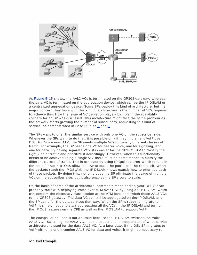
Mr. Bad Example
As Figure 5-15 shows, the AAL2 VCs is terminated on the GR303 gateway; whereas, the data VC is terminated on the aggregation device, which can be the IP DSLAM or a centralized aggregation device. Some SPs deploy this kind of architecture, but the major concern they have with this kind of architecture is the number of VCs required to achieve this. How the issue of VC depletion plays a big role in the scalability concern for an SP was discussed. This architecture might face the same problem as the network starts growing the number of subscribers, requesting this kind of service, as demonstrated in Case Studies 2 and 3.
The SPs want to offer the similar service with only one VC on the subscriber side. Whenever the SPs want to do that, it is possible only if they implement VoIP over DSL. For Voice over ATM, the SP needs multiple VCs to classify different classes of traffic. For example, the SP needs one VC for bearer voice, one for signaling, and one for data. By having separate VCs, it is easier for the SP's DSLAM to classify the right kind of traffic and prioritize it accordingly. However, when this functionality needs to be achieved using a single VC, there must be some means to classify the different classes of traffic. This is achieved by using IP QoS features, which results in the need for VoIP. IP QoS allows the SP to mark the packets in the CPE itself. When the packets reach the IP DSLAM, the IP DSLAM knows exactly how to prioritize each of these packets. By doing this, not only does the SP eliminate the usage of multiple VCs on the subscriber side, but it also enables the SP's core to scale.
On the basis of some of the architectural comments made earlier, your DSL SP can probably start with deploying Voice over ATM over DSL by using an IP DSLAM, which can perform the necessary classification at the ATM level and switch those AAL2 VCs to the GR303 gateway. The data VC can still be aggregated on the IP DSLAM, and the SP can offer the data services that way. When the SP is ready to migrate to VoIP, it simply needs to start aggregating all the VCs in the IP DSLAM and turn on the IP QoS features on the CPE as well as the IP DSLAM to support VoIP.
The encapsulation used is not an issue because the IP DSLAM switches the Voice AAL2 VCs. Switching the AAL2 VCs has no impact and is independent of what service architecture is used for the data AAL5 VC. At a later date, if the DSL SP migrates to VoIP with only one incoming AAL5 VC for data and voice, it might be necessary to
Evaluation notes were added to the output document. To get rid of these notes, please order your copy of ePrint IV now.

Mr. Bad Example
make the right choice of service architecture. The CPE and IP DSLAMs need to apply the right IP QoS feature for those packets. If you choose a service architecture such as PPP-L2TP where the IP DSLAM does not get involved in terminating the PPP sessions, it might be difficult for the IP DSLAM to associate those packets with the right QoS feature.
The key point here is that whenever the SP needs to offer such value-added services as VoIP, it needs to terminate the incoming sessions such as RBE or PPPoX as close to the subscribers as possible to perform proper classification of the traffic and necessary prioritization.
To offer video services, the DSL SP must perform the multicast replications for the subscribers as close to the subscribers as possible, and no better place to do that exists than in IP DSLAM. Again, in order for the IP DSLAM to participate in any sort of IP multicast replication, it needs to terminate the sessions. For video offering, the CPE can use either bridging or PPPoX on the access side, but bridging makes an attractive choice simply because of its simplicity and less configuration. In the IP DSLAM, your DSL SP needs to implement RBE to avoid some of the bridging security concerns and to get better performance.
The question asked about offering voice service also is asked about offering video service, "Should I do ATM multicast replications and use multiple VC to offer voice, video, and data service, or is it appropriate to offer all these services on a single VC?" Of course, considering the ease of provisioning and eliminating the VC depletion issue, the vote goes to using the single VC architecture. Using the single VC architecture imposes a burden on the capability of IP multicast replication as well as application of IP QoS. IP multicast replication is usually processor-intensive, and the number of streams or channels that need to be replicated can have an impact on the overall throughput of the device. When offering any kind of IP-based video service, the performance of the device that is ultimately going to perform the replication of the streams must be identified. Those devices also need to support some mechanisms to identify who joined the multicast group and who left, which can be achieved using IGMP snooping as well. However, if multiple VCs are used to deliver video, voice, and data, as mentioned earlier, it might become difficult to avoid the VC depletion issues and might result in substantial provisioning delays as well as complex VC mapping issues.
Because you are focusing mainly on the architecture and infrastructure, how both video and voice can be delivered is not discussed because it could result in a book of its own. The main thing to notice from the preceding discussion is that it is easier for a DSL SP that is in retail business to use a single VC model to offer various value add services, such as voice, video, and data. The DSL SP needs to terminate the subscriber sessions at the aggregation device to apply the necessary IP QoS and perform the required multicast replications. If the DSL SP uses multiple VCs for different services such as voice and video, it makes sense for the SP to use an IP DSLAM to avoid the VC depletion issue and provide ease of provisioning to the SP. This helps the DSL SP in the long run when it moves to a single VC model to offer high, effective throughput per subscriber.
Now consider the impact of terminating the sessions on the aggregation device and providing IP addresses to the subscribers that belong to your DSL SP's ISP. When the session is terminated, depending on what access encapsulation is used, the DSL
Evaluation notes were added to the output document. To get rid of these notes, please order your copy of ePrint IV now.

Mr. Bad Example
SP has different choices on how to assign IP addresses. For example, if the incoming session is a bridged session, the SP can use a DHCP server to assign IP addresses. Along with using a DHCP server, it is advisable for the SP to also use the DHCP option 82 feature to restrict the actual number of users. If incoming sessions are PPP, the SP can use individual local pools on each aggregation device or RADIUS server to allocate IP addresses to subscribers.
As mentioned in Chapter 4, careful planning is required to allocate a different range of IP addresses if local pools are used because it can result in wasting IP addresses. If the DSL SP has various geographical locations, it can potentially run into IP address management issues. The chance of that happening is less in this scenario because the subscribers get IP addresses from the DSL SP's domain. These address blocks will more than likely be contiguous or broken down into contiguous subnets, one per each geographical location, which is easier to aggregate.
One of the requirements for your DSL SP is to offer some sort of mechanism that allows the SP to offer different value-added services to its subscribers in such a way that the subscriber can dynamically change his bandwidth based on different services used and get billed accordingly. This can be achieved using the SSG functionality as explained in Chapter 4.
The use of Layer 3 Service Selection or Web-Based Service Selection allows the DSL SP to offer its value-added services to its subscribers, and it can also use the main page to advertise some of the portal services. Along with offering its own set of services, the DSL SP can wholesale this infrastructure to different ASPs and start offering their service, too.
By using this feature, if the DSL SP chooses, it can also use a private IP addressing scheme for all subscribers who are coming into the DSL SP's walled garden. For applications that need to go out of that walled garden, the DSL SP can perform NAT, although many SPs avoid NAT as much as possible simply because it breaks certain applications.
Web-Based Service Selection becomes useful for your DSL SP, especially when it wants to offer video services to its subscribers. By using the dashboard, the subscribers can select one of many video services available, along with the correct bandwidth, and then be charged accordingly. This method not only allows your DSL SP to offer different services simultaneously, but it also takes it away from the flat-billing service, consequently allowing the SP to generate more revenue by charging subscribers based on service and bandwidth usage. The accounting record is kept by the RADIUS server, and the RADIUS server can have a direct hook to the billing system of our DSL SP.
SPs that are offering such services to their subscribers have typically created a parallel IP-based core to their existing ATM infrastructure and plan to seamlessly migrate their ATM infrastructure to this IP-based network by making use of MPLS.
The design considerations for deploying such an architecture is similar to what Chapter 4 explained for SSG, and those guidelines should be followed. It is always a good idea to create a centralized farm with each SSD server able to provide a regional effect—a concept such as Yahoo India, Yahoo USA, and so forth but your Yahoo ID remains the same no matter where you log in from.
Evaluation notes were added to the output document. To get rid of these notes, please order your copy of ePrint IV now.

Mr. Bad Example
Conclusion
A few main points about the solution for this case study follow:
DSL SP can use MPLS as a first phase to migrate its cell-based core to a packet-based core utilizing the existing infrastructure.
Using MPLS VPN in the core allows the DSL SP to optimize routing in its core for a high number of subscribers and also allows it to offer other value-added IP-based services because they now have access to Layer 3 information.
MPLS VPN can be used as an alternate approach to point-to-point tunnels of L2TP for wholesaling services.
MPLS VPN is a better approach for offering IP VPN services to enterprise customers who are currently using point-to-point links or Layer 2 VPNs.
In the immediate future, the DSL SP might opt to offer voice by using VoATM or Voice over AAL2, simply because of their existing infrastructure and their possible confidence in ATM QoS over IP QoS. This SP with this kind of architecture can run into an issue of VC depletion and needs to use IP DSLAM for aggregating the data VCs and switch the AAL2 VCs.
SPs that already run into VC depletion might start using IP DSLAM or an aggregation device in the CO and VoIP to offer both voice and data service on a single VC.
For offering video services, the SP might need to deploy an IP DSLAM or bring the aggregation device closer to the edge to perform multicast replication at the edge and closer to the subscriber. Using separate VCs for voice, video, and data can result in a VC depletion issue and a complex provisioning scheme for VCs.
In order to offer retail services, a DSL SP needs to terminate sessions in its aggregation device and provide IP addresses to its subscribers.
By terminating the sessions, a retail DSL SP is not subjected to IP address management issues, and those issues can be well managed because the subscribers are only going into the walled garden of the retail SP.
Using the SSG Web-Based Service Selection feature enables the retail DSL SP to offer various simultaneous services to its subscribers along with different bandwidths, which results in higher revenue for the DSL SP by charging the subscribers based on usage of service and bandwidth rather than charging a flat rate.
Looking Ahead
So far, this book covered most of the service architectures, how they are implemented, what their design considerations are, and so forth. The next chapter concludes the book with coverage of the network management aspect of these architectures
Evaluation notes were added to the output document. To get rid of these notes, please order your copy of ePrint IV now.
Mr. Bad Example
Chapter 6. Network Management and Service Provisioning This chapter covers the following key topics:
Service Provisioning — The service-provisioning model today is manual and requires a lot of truck rolls to provision a DSL circuit. It takes a service technician approximately more than an hour to provision a DSL circuit, therefore slowing down the DSL deployment rate.
Flow-Through Service Provisioning — With the right interface to the existing service provisioning systems, Cisco Element Managers can interface with the DSL elements and configure them with just a few mouse clicks.
Accounting and Billing — Even though most DSL service offering are based on flat rate billing as the ISP starts providing multiple services, they might need to start billing the subscribers based on service usage and bandwidth provided. This section briefly provides an overview on some of the methods ISPs are considering today.
In the previous chapters, we discussed how DSL works, different technical issues regarding DSL deployment, and different DSL architectures that service providers use. This chapter provides an overview of some of the challenges and practical issues associated with DSL: network management and service provisioning. Like any other network, network management and service provisioning are broad topics and require a book of their own. This chapter provides an overview and introduction of some of those elements used in a DSL network.
With thousands of DSL elements such as DSLAMs, ATM switches, and DSL aggregation devices, special considerations have to be taken into account when it comes to managing these elements. With the proper tools to provision and manage a large-scale DSL roll out, much time and cost can be reduced, which can be passed down to the subscribers.
As telephone companies increasingly offer high-speed Internet access as well as traditional voice, a need exists to combine the phone bill together with the DSL bill. This only emphasizes the need of the DSL provisioning system to tie in with the service provider's existing billing and provisioning system. In the past, billing and accounting played an important role in dialup because some service providers charged their customers simply based on usage, such as the time connected to their modems and bytes transferred. With always-on applications such as DSL, accounting and billing also play an important role if the service provider offers differential services such as Voice over IP, video, and so forth. For these services, users are billed based on their usage time on top of their flat billing rate for only the time they used those additional services.
Service Provisioning
Quite a few service providers might have more than one million DSL lines installed a year. This can not be possible without an effective subscriber and service-provisioning model. If a service technician needs to be dispatched to a residence to
Evaluation notes were added to the output document. To get rid of these notes, please order your copy of ePrint IV now.

Mr. Bad Example
install CPE and turn on the DSL connection, he will spend a little more than an hour working on the installation. In order for an ISP to serve more than a million subscribers, the ISP can not afford to spend so many man-hours and the resulting high cost in just turning up a connection. In order to turn up a subscriber base of such a high magnitude, an ISP needs to turn up a subscriber every three seconds, a DSLAM every thirty minutes, and an LAC every week based on some research as part of the "Open DSL" initiative. (Open DSL addresses the issues of avoiding truck rolls and autoprovisioning of the subscriber and will be discussed later in the chapter). Case Study 3 —Very Large Wholesale SP— in Chapter 5, "Case Studies," requires an infrastructure to support up to one million customers. This means that we will need 500 COs, 75 aggregation devices, and 7500 tunnels. With the manual provisioning model that we have today, service providers need an army of technicians and order takers just to turn up customers, resulting in huge rollout costs. To combat this, service providers need applications that can provision the CPE, DSLAMs, and access concentrators with a few mouse clicks to ease DSL installation. This section provides an overview of the service provisioning model and Cisco's way of making this happen.
The Provisioning Model Today
Although some of the SPs have developed their own automated provisioning tools, they still adhere to the following basic steps of turning on a subscriber:
1. Customers have to call a hotline staffed with service representatives taking orders from them. The hotline usually belongs to the ISP or the NSP offering the actual service, such as high-speed Internet access. Service representatives manually record information such as address, phone number, billing information, and the type of service customers want to subscribe to into a database. The service representative also tries to assess the area where the subscriber is located and whether the ISP can offer service in that area through a local DSL access provider.
2. Assuming that the requested service can be offered, a work order is generated and forwarded to the local DSL access provider. The DSL access provider needs to ensure that the local loop to that subscriber can be used to offer xDSL if the lines are not already qualified (prequalified) for providing DSL in that area.
3. If the line (copper pair) is not prequalified, the DSL access provider needs to make sure that the line does not have any bridge taps or load coils and needs to make sure DSL can be provisioned with an acceptable noise margin. Even though most of these conditions are tested using some line simulator or loop qualification tools, such as Sunrise, Turnstone, or Hekimian, human intervention is inevitable.
4. After a line is qualified, a service technician will be dispatched to the customer premises to configure and install the CPE and POTS splitter.
5. At the CO, there is a cross-connect done from the POTS splitter to the voice switch (for baseband voice traffic) and to the DSLAM (for data traffic) if the
Evaluation notes were added to the output document. To get rid of these notes, please order your copy of ePrint IV now.

Mr. Bad Example
copper loop or line is "line shared"—the same line is used by the local telephone company to provide voice service to that subscriber.
6. The DSL access provider's Network Operation Center (NOC) personnel and the ISP need to ensure that all the network elements (CPE, DSLAM, aggregation if any, ISP router, and so on) between the subscriber and the chosen ISP are configured properly according to the service architecture previously agreed upon between the ISP and the DSL access provider. Figure 6-1 illustrates an example of configuring some of those network elements.
Figure 6-1. Components That Need Configurations
If these steps are followed without the proper automation tools, this process can turn out to be labor-intensive, resulting in provisioning delays and requiring a truck roll, where all the elements in Figure 6-1 need to be configured manually by an operator. Passing around the same information several times is error-prone. Manually configuring every single DSL component is time consuming, requires skilled personnel, and is difficult to troubleshoot. If phone companies want to deploy a million DSL lines in one year, this model will not scale.
What is needed is a provisioning system that will automate these steps, eliminating truck rolls and operator interventions as much as possible.
Flow-Through Service Provisioning
To a service provider's operator point of view, subscriber provisioning starts when he is given a list of customer phone numbers, names, and the services, including the ISP, in which the customer wants to subscribe. For each of these customers, a single entry to a provisioning system will trigger the appropriate actions to automatically, qualify a line, provision a DSL line, generate configurations, and download them to the appropriate DSL components. This is called flow-through provisioning. Figure 6-2 shows the same DSL components that need to be configured. A flow-through provisioning system starts at the service request and ends at appropriate configurations downloaded into DSL devices.
Figure 6-2. Flow-Through Provisioning System
Evaluation notes were added to the output document. To get rid of these notes, please order your copy of ePrint IV now.
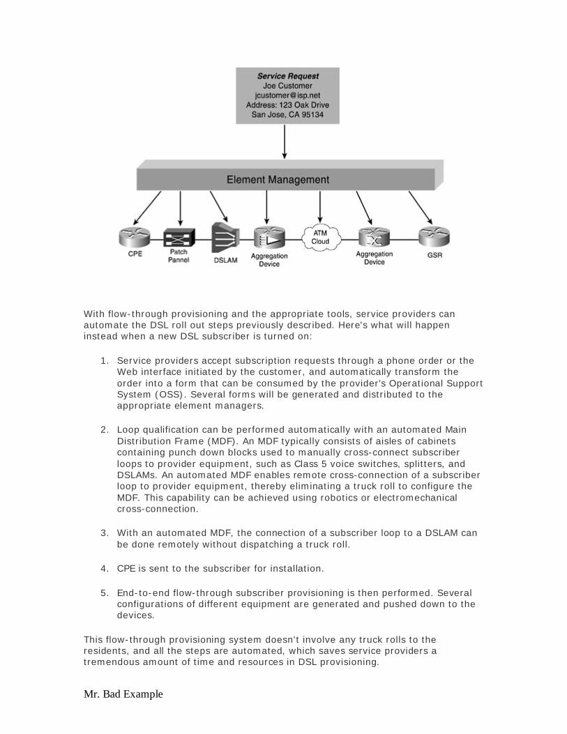
Mr. Bad Example
With flow-through provisioning and the appropriate tools, service providers can automate the DSL roll out steps previously described. Here's what will happen instead when a new DSL subscriber is turned on:
1. Service providers accept subscription requests through a phone order or the Web interface initiated by the customer, and automatically transform the order into a form that can be consumed by the provider's Operational Support System (OSS). Several forms will be generated and distributed to the appropriate element managers.
2. Loop qualification can be performed automatically with an automated Main Distribution Frame (MDF). An MDF typically consists of aisles of cabinets containing punch down blocks used to manually cross-connect subscriber loops to provider equipment, such as Class 5 voice switches, splitters, and DSLAMs. An automated MDF enables remote cross-connection of a subscriber loop to provider equipment, thereby eliminating a truck roll to configure the MDF. This capability can be achieved using robotics or electromechanical cross-connection.
3. With an automated MDF, the connection of a subscriber loop to a DSLAM can be done remotely without dispatching a truck roll.
4. CPE is sent to the subscriber for installation.
5. End-to-end flow-through subscriber provisioning is then performed. Several configurations of different equipment are generated and pushed down to the devices.
This flow-through provisioning system doesn't involve any truck rolls to the residents, and all the steps are automated, which saves service providers a tremendous amount of time and resources in DSL provisioning.
Evaluation notes were added to the output document. To get rid of these notes, please order your copy of ePrint IV now.

Mr. Bad Example
Each service provider has a different provisioning system in place to provision existing services and other support systems in place that need to be integrated with the DSL provisioning system. Service providers will need a common interface to communicate with software from equipment manufacturers. The Common Object Request Broker Architecture (CORBA) interface (www.omg.org/corbawww.omg.org/corba), which includes a set of standards, is a popular way to interconnect the service provider's OSS with other software.
Figure 6-3 illustrates the simplified processes for flow-through provisioning. The service request usually comes to the technician either by manual entry or through the Web interface. The existing OSS will take care of generating the appropriate work orders and billing, and will send the work order through the CORBA gateway. The CORBA gateway will interface with the Cisco Element Management Framework (CEMF), which in turn, will communicate with Element Managers (EMs) who will generate configurations for the appropriate device.
Figure 6-3. Flow-Through Provisioning Implementation
Evaluation notes were added to the output document. To get rid of these notes, please order your copy of ePrint IV now.
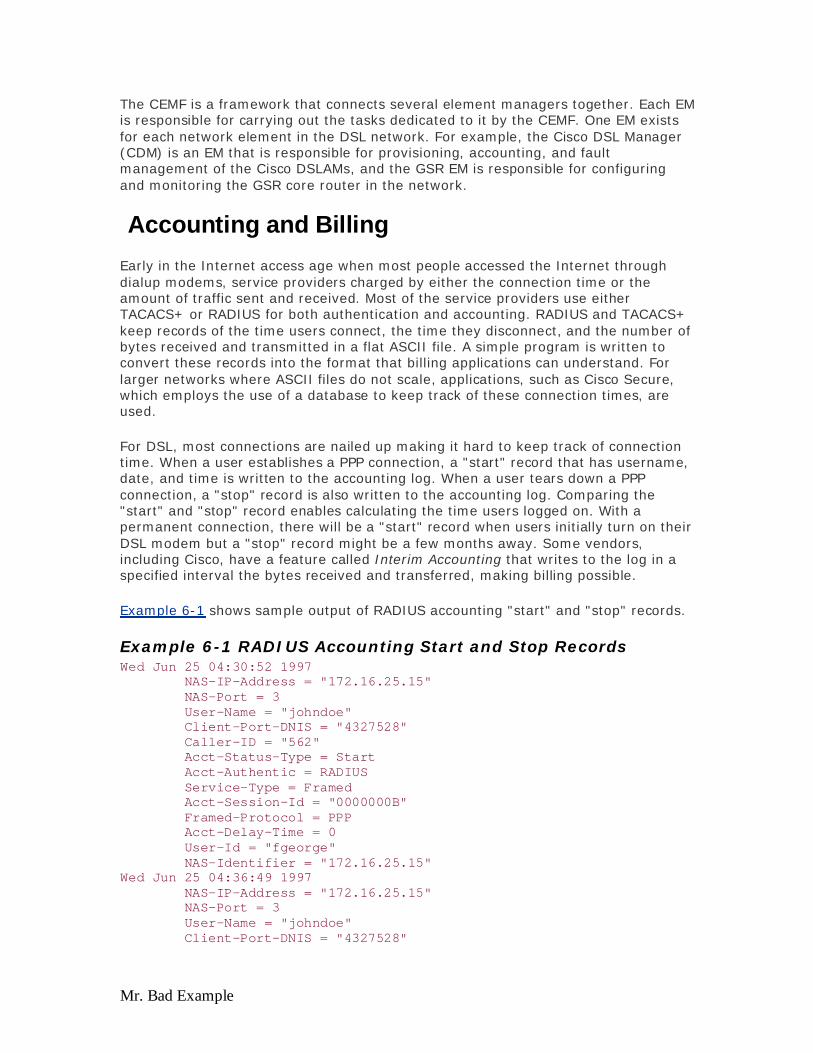
Mr. Bad Example
The CEMF is a framework that connects several element managers together. Each EM is responsible for carrying out the tasks dedicated to it by the CEMF. One EM exists for each network element in the DSL network. For example, the Cisco DSL Manager (CDM) is an EM that is responsible for provisioning, accounting, and fault management of the Cisco DSLAMs, and the GSR EM is responsible for configuring and monitoring the GSR core router in the network.
Accounting and Billing
Early in the Internet access age when most people accessed the Internet through dialup modems, service providers charged by either the connection time or the amount of traffic sent and received. Most of the service providers use either TACACS+ or RADIUS for both authentication and accounting. RADIUS and TACACS+ keep records of the time users connect, the time they disconnect, and the number of bytes received and transmitted in a flat ASCII file. A simple program is written to convert these records into the format that billing applications can understand. For larger networks where ASCII files do not scale, applications, such as Cisco Secure, which employs the use of a database to keep track of these connection times, are used.
For DSL, most connections are nailed up making it hard to keep track of connection time. When a user establishes a PPP connection, a "start" record that has username, date, and time is written to the accounting log. When a user tears down a PPP connection, a "stop" record is also written to the accounting log. Comparing the "start" and "stop" record enables calculating the time users logged on. With a permanent connection, there will be a "start" record when users initially turn on their DSL modem but a "stop" record might be a few months away. Some vendors, including Cisco, have a feature called Interim Accounting that writes to the log in a specified interval the bytes received and transferred, making billing possible.
Example 6-1 shows sample output of RADIUS accounting "start" and "stop" records.
Example 6-1 RADIUS Accounting Start and Stop Records Wed Jun 25 04:30:52 1997 NAS-IP-Address = "172.16.25.15" NAS-Port = 3 User-Name = "johndoe" Client-Port-DNIS = "4327528" Caller-ID = "562" Acct-Status-Type = Start Acct-Authentic = RADIUS Service-Type = Framed Acct-Session-Id = "0000000B" Framed-Protocol = PPP Acct-Delay-Time = 0 User-Id = "fgeorge" NAS-Identifier = "172.16.25.15" Wed Jun 25 04:36:49 1997 NAS-IP-Address = "172.16.25.15" NAS-Port = 3 User-Name = "johndoe" Client-Port-DNIS = "4327528"
Evaluation notes were added to the output document. To get rid of these notes, please order your copy of ePrint IV now.

Mr. Bad Example
Caller-ID = "562" Acct-Status-Type = Stop Acct-Authentic = RADIUS Service-Type = Framed Acct-Session-Id = "0000000B" Framed-Protocol = PPP Framed-IP-Address = "10.1.1.1" Acct-Input-Octets = 8630 Acct-Output-Octets = 5722 Acct-Input-Packets = 94 Acct-Output-Packets = 64 Acct-Session-Time = 357 Acct-Delay-Time = 0 User-Id = "johndoe" NAS-Identifier = "172.16.25.15"
People who use RADIUS accounting today in a DSL network mainly want to keep track of who telnets into their DSLAMs and routers. Because DSL is always on, most DSL lines are billed at a flat rate. Service providers that want to offer differential services, such as guaranteeing a minimum bandwidth for voice over IP, use a different application to collect the number of bytes that were used for voice. Cisco Netflow Collector™ is one of these applications that can keep track of number of packets that were marked with a high number of type of service (ToS) bits.
Summary
This chapter provided you with an overview of some of the network management and provisioning tools for DSL subscribers and solutions. As mentioned during the introduction, each SP has its own set of requirements as far as network management goes. (It is likely that we might have not covered all aspects of OSS in this chapter, as it might require a book on its own).
Remote access has come a long way since the 300-baud modem a little more than a decade ago. With millions of users clogging the phone network to access the Internet, DSL is a great solution to bring high-speed Internet access to the home without compromising the phone network.
DSL is a promising technology utilizing the existing wiring infrastructure for data communication, and with every new standard there are issues involved. Hopefully, this book has provided you with the tools you need to make a good judgement on your network design and implementation. The advantages and disadvantages of each method are spelled out, but only you can make a decision on how to architect your network, because only you know what your customers need. Use this knowledge to design a good DSL network and to make your customer's experience better.
Evaluation notes were added to the output document. To get rid of these notes, please order your copy of ePrint IV now.

Mr. Bad Example
Evaluation notes were added to the output document. To get rid of these notes, please order your copy of ePrint IV now.

Mr. Bad Example
Evaluation notes were added to the output document. To get rid of these notes, please order your copy of ePrint IV now.