Embed Size (px)
Citation preview
© 2012 Cisco and/or its affiliates. All rights reserved. This document is Cisco Public Information. Page 1 of 23
White Paper
Architecture for Mobile Data Offload over Wi-Fi Access Networks
Introduction
Mobile network traffic is growing exponentially, and service providers must manage their networks efficiently to
meet consumer demand. The technology evolution of radio access networks is limited by the laws of physics, and
significant growth in radio frequency (RF) efficiency can no longer be expected. Long-Term Evolution (LTE) radio
access is reaching the limits of Shannon’s law, the spectrum available for mobile data applications is limited, and
the only solution for increasing overall mobile network capacity is to increase the carrier-to-interference ratio while
decreasing cell size and deploying small cell technologies.
The most efficient way to use small cells is to position them in locations where significant amounts of data are
generated (shopping malls, stadiums, university campuses, public transportation hubs, etc.) and where
subscribers spend most of their time and therefore consume significant amounts of data (homes, offices, etc.).
Wi-Fi, one of the small cell technologies, appeals to many operators as a cost-effective mean of offloading large
amounts of mobile data traffic while delivering a variety of new services. It offers these features:
● Widespread existing deployments
● Availability of user devices that support the technology
● Cost efficiency
● Capability to address new users and devices without mobile subscription (without a subscriber identity
module [SIM])
● Globally available spectrum capacity
● Standards availability for integration into mobile core networks
This document explores technical aspects of Wi-Fi offload architecture and its capabilities and integration into
existing mobile networks to provide a viable and efficient way to offload subscriber traffic.
Overview of Wi-Fi Offload Architecture
The Third-Generation Partnership Project (3GPP) standard differentiates two types of Wi-Fi access (also referred
to as non-3GPP IP access):
● Untrusted: Introduced in the early stages of the Wi-Fi specification in 3GPP Release 6 (2005), untrusted
access includes any type of Wi-Fi access that either is not under control of the operator (public open
hotspot, subscriber’s home WLAN, etc.) or that does not provide sufficient security (authentication,
encryption, etc.).
● Trusted: Trusted access generally refers to operator-built Wi-Fi access with over-the-air encryption and a
secure authentication method. Trusted non-3GPP IP access was introduced only with the LTE standard in
3GPP Release 8 (2008). Although most of today’s offload designs are build on the trusted model, 3GPP
does not currently offer guidance for integration with the 3G or 2G packet core. However, as discussed in
this document, this type of access is natively integrated into LTE’s evolved packet core (EPC).
© 2012 Cisco and/or its affiliates. All rights reserved. This document is Cisco Public Information. Page 2 of 23
Because most of today’s mobile networks are 3G based, a significant part of this document describes the possible
methods of integrated trusted non-3GPP IP access into the 3G mobile packet core (MPC) together with its
associated policy and charging control (PCC) architecture. Although the term “trusted non-3GPP IP access” is
defined for EPC only, this document extends its definition in 3G contexts to describe Wi-Fi networks controlled by
mobile operators.
3GPP 24.302 has the following definition: “For a trusted non-3GPP IP access network, the communication
between the user equipment and the EPC is secure.” Thus, with the latest service provider Wi-Fi architectures
encompassing Extensible Authentication Protocol (EAP) and IEEE 802.1X-based authentication, and with IEEE
802.11i-based RF encryption and optional use of control and provisioning of wireless access points and Datagram
Transport Layer Security (DTLS) for secured user and control planes, all the elements exist for service provider
Wi-Fi to be considered as trusted non-3GPP.
After the 3G designs, this document describes the evolution of the architectures toward EPC integration as
specified in 3GPP standards. Session mobility and, more generally, IP address persistence when moving between
3G, LTE, and Wi-Fi are also covered. The document also discusses the integration models for untrusted networks,
although these are less commonly deployed in mobile networks.
In the 3GPP specification, the Wi-Fi network is referred to as the Wi-Fi access network only. No details about the
Wi-Fi network structure are specified. This document, however, separates the network into the access and
gateway components. The Wi-Fi network infrastructure for mobile data offload consists of three parts:
● Wi-Fi radio access network (Wi-Fi RAN)
● Wi-Fi access gateway (WAG) and Wi-Fi back-end systems (this document expands the definition from
3GPP TS 23.234 to refer also to non-3GPP WAG)
● Packet core integration elements (multiple options)
© 2012 Cisco and/or its affiliates. All rights reserved. This document is Cisco Public Information. Page 3 of 23
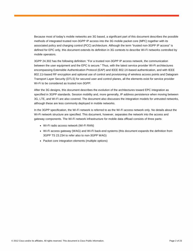
Figure 1 illustrates the architecture. It includes integration elements for 3G as well as LTE to show a summary of
all designs built throughout this document.
Figure 1. Wi-Fi Network Architecture
If the Wi-Fi network is used for mobile data offload, which is the topic of this document, it needs to take care of
these tasks:
● Authentication: To help ensure that only authorized subscribers can access the network
● PCC: For proper billing, quality of service (QoS), and policy enforcement for the traffic generated through
Wi-Fi access, ideally compliant with 3GPP PCC
● IP persistence: For service mobility between different access networks (3G to Wi-Fi, Wi-Fi to 3G, or across
the Wi-Fi network)
The following sections examine the details of each of these functions.
Authentication
To control subscriber access to Wi-Fi networks, multiple authentication methods can be used. The choice of
method is crucial to the usability of the network. The more transparent the authentication method is for the
subscriber, the greater the likelihood that the subscriber will connect to the network.
The authentication method also determines the subscriber and device types that can be addressed in a particular
network (subscribers with or without SIM cards, the operator’s subscribers, visiting subscribers, etc.).
In a typical modern Wi-Fi network, two types of authentication are available to address all possible subscribers
and at the same time provide convenient access to the network for frequent Wi-Fi users. The first method, portal-
based authentication, targets customers without a permanent contract with the operator (vouchers, time-limited
© 2012 Cisco and/or its affiliates. All rights reserved. This document is Cisco Public Information. Page 4 of 23
access, SMS payments, etc.). Alternatively, EAP authentication provides transparent and easy access for the
operator’s own subscribers with SIM cards or certificates.
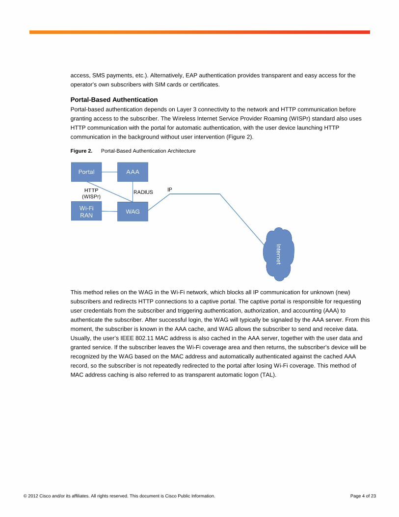
Portal-Based Authentication Portal-based authentication depends on Layer 3 connectivity to the network and HTTP communication before
granting access to the subscriber. The Wireless Internet Service Provider Roaming (WISPr) standard also uses
HTTP communication with the portal for automatic authentication, with the user device launching HTTP
communication in the background without user intervention (Figure 2).
Figure 2. Portal-Based Authentication Architecture
This method relies on the WAG in the Wi-Fi network, which blocks all IP communication for unknown (new)
subscribers and redirects HTTP connections to a captive portal. The captive portal is responsible for requesting
user credentials from the subscriber and triggering authentication, authorization, and accounting (AAA) to
authenticate the subscriber. After successful login, the WAG will typically be signaled by the AAA server. From this
moment, the subscriber is known in the AAA cache, and WAG allows the subscriber to send and receive data.
Usually, the user’s IEEE 802.11 MAC address is also cached in the AAA server, together with the user data and
granted service. If the subscriber leaves the Wi-Fi coverage area and then returns, the subscriber’s device will be
recognized by the WAG based on the MAC address and automatically authenticated against the cached AAA
record, so the subscriber is not repeatedly redirected to the portal after losing Wi-Fi coverage. This method of
MAC address caching is also referred to as transparent automatic logon (TAL).
© 2012 Cisco and/or its affiliates. All rights reserved. This document is Cisco Public Information. Page 5 of 23
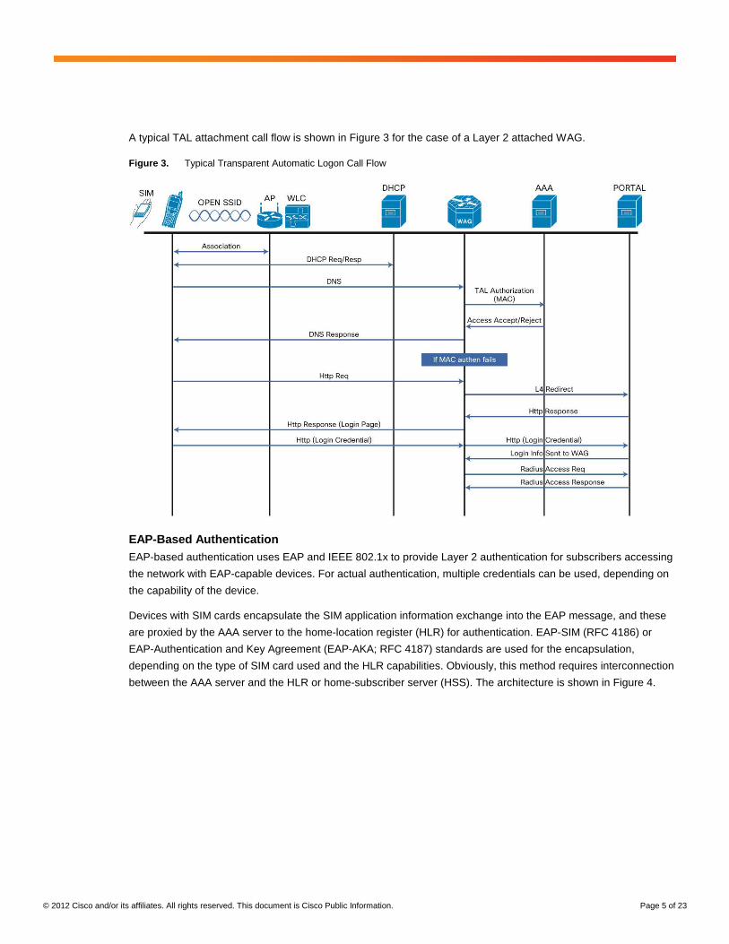
A typical TAL attachment call flow is shown in Figure 3 for the case of a Layer 2 attached WAG.
Figure 3. Typical Transparent Automatic Logon Call Flow
EAP-Based Authentication EAP-based authentication uses EAP and IEEE 802.1x to provide Layer 2 authentication for subscribers accessing
the network with EAP-capable devices. For actual authentication, multiple credentials can be used, depending on
the capability of the device.
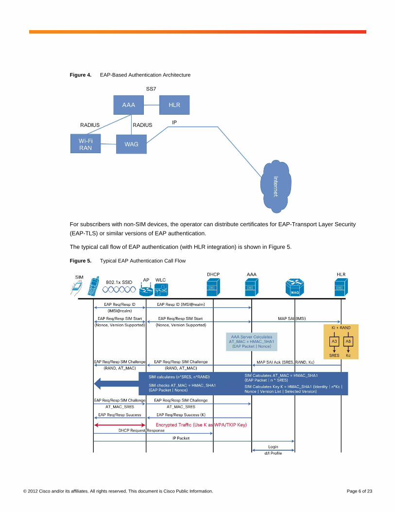
Devices with SIM cards encapsulate the SIM application information exchange into the EAP message, and these
are proxied by the AAA server to the home-location register (HLR) for authentication. EAP-SIM (RFC 4186) or
EAP-Authentication and Key Agreement (EAP-AKA; RFC 4187) standards are used for the encapsulation,
depending on the type of SIM card used and the HLR capabilities. Obviously, this method requires interconnection
between the AAA server and the HLR or home-subscriber server (HSS). The architecture is shown in Figure 4.
© 2012 Cisco and/or its affiliates. All rights reserved. This document is Cisco Public Information. Page 6 of 23
Figure 4. EAP-Based Authentication Architecture
For subscribers with non-SIM devices, the operator can distribute certificates for EAP-Transport Layer Security
(EAP-TLS) or similar versions of EAP authentication.
The typical call flow of EAP authentication (with HLR integration) is shown in Figure 5.
Figure 5. Typical EAP Authentication Call Flow
© 2012 Cisco and/or its affiliates. All rights reserved. This document is Cisco Public Information. Page 7 of 23
Note that EAP-based authentication offers a radio security advantage. Because the authentication is handled at
Layer 2, EAP messages can be used to negotiate encryption keys for the IEEE 802.11i-based encryption of the
radio interface. This approach provides much stronger security for radio communication compared to the
unencrypted radio interface of portal-based authentication and is uniquely able to prevent simple MAC address
spoofing attacks.
Next Generation Hotspot In 2010, Cisco and industry leaders formed the Next Generation Hotspot Task Group in the Wireless Broadband
Alliance (WBA). The goal was to rally the industry around a common set of Wi-Fi Alliance (WFA) standards called
Hotspot 2.0 that would bring a 3G-like end-user experience to Wi-Fi authentication and roaming. The outcome of
the Next Generation Hotspot Task Group is a set of operator guidelines and the Wi-Fi Certified Passpoint™
program expected in 2012 from the Wi-Fi Alliance. The certification will help ensure authentication and roaming
interoperability for operators and equipment vendors.
The Cisco® SP Wi-Fi solution features Next Generation Hotspot, enabling service providers to better manage and
monetize their carrier-grade Wi-Fi networks.
There are three main building blocks of the next-generation hotspot: IEEE 802.11u, Wi-Fi Protected Access 2
(WPA 2) Enterprise, and EAP-based authentication.
For a detailed description of the initiative, see The Future of Hotspots: Making Wi-Fi as Secure and Easy to Use
as Cellular.
Authentication Summary Because of the complementary functions of both authentication methods, mobile operators deploying Wi-Fi
access networks usually implement both EAP and IEEE 802.1X authentication and portal-based authentication in
their networks.
Portal-based authentication is used to attract subscribers visiting the network who don’t yet have a relation to the
operator. It allows typical public Wi-Fi use cases such as credit card payments, vouchers, and SMS passwords.
In general, it enables generation of new revenue from Wi-Fi networks.
EAP-based authentication targets primarily devices with the operator’s SIM card. It allows transparent
authentication and secure communication without much interaction from the subscriber (only initial configuration of
the service set ID (SSID) is needed when a device detects the Wi-Fi network for the first time). In real-life
deployments, the introduction of EAP-SIM or EAP-AKA authentication leads to significantly better utilization of the
network by subscribers and therefore enables much greater savings from offloading.
With the introduction of Wi-Fi Certified Passpoint devices, operators will be able to simplify Wi-Fi network access
even more. IEEE 802.11u devices do not need any intervention from the subscriber to connect to the Wi-Fi
network (unlike traditional devices, which require SSID selection). Roaming agreements based on the Next
Generation Hotspot recommendation (WLAN Roaming Inter-Exchange [WRIX]) enable user equipment with IEEE
802.11u support to choose the right SSID automatically, even in visited networks.
Policy and Charging Control
An important concern of mobile operators is the availability of similar or identical policy enforcement and charging
rules for the subscriber, regardless of the RAN being used. Therefore, the design of PCC integration is a crucial
part of Wi-Fi offload.
© 2012 Cisco and/or its affiliates. All rights reserved. This document is Cisco Public Information. Page 8 of 23
Experience from live deployments shows that the most efficient approach to PCC integration is the reuse of the
elements deployed for the 3GPP services. The actual integration option will depend on the PCC infrastructure
implemented in the particular mobile operator network. If the operator uses a device with the standalone policy
and charging enforcement function (PCEF), the WAG will be integrated as an additional gateway served by the
PCEF. If the PCEF is integrated into the gateway General Packet Radio Service (GPRS) support node (GGSN),
the WAG may emulate a serving GPRS support node (SGSN) and switch the Wi-Fi sessions to a GPRS Tunneling
Protocol (GTP) tunnel to the traditional GGSN. The following sections discuss the details of these two options.
Note that this document describes trusted non-3GPP access integration into 2G and 3G PCC. The 3GPP standard
offers no guidance for this integration. Later this document explores standardized architecture for LTE integration
and untrusted non-3GPP IP access integration.
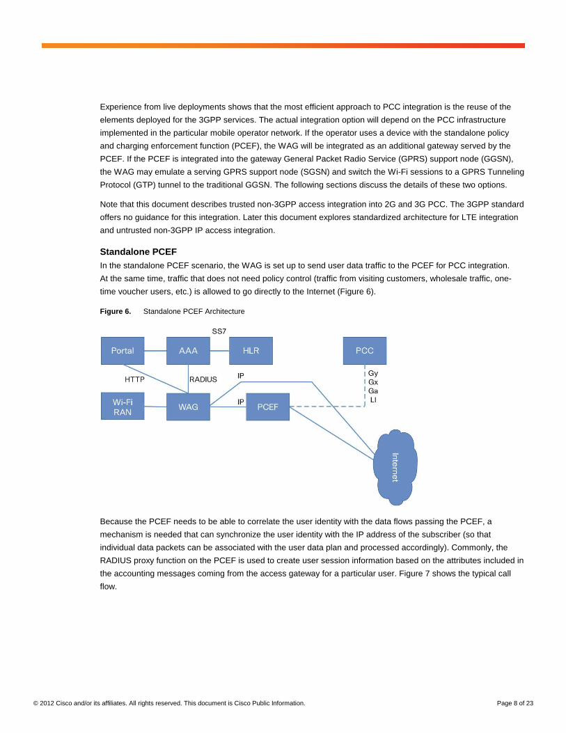
Standalone PCEF In the standalone PCEF scenario, the WAG is set up to send user data traffic to the PCEF for PCC integration.
At the same time, traffic that does not need policy control (traffic from visiting customers, wholesale traffic, one-
time voucher users, etc.) is allowed to go directly to the Internet (Figure 6).
Figure 6. Standalone PCEF Architecture
Because the PCEF needs to be able to correlate the user identity with the data flows passing the PCEF, a
mechanism is needed that can synchronize the user identity with the IP address of the subscriber (so that
individual data packets can be associated with the user data plan and processed accordingly). Commonly, the
RADIUS proxy function on the PCEF is used to create user session information based on the attributes included in
the accounting messages coming from the access gateway for a particular user. Figure 7 shows the typical call
flow.
© 2012 Cisco and/or its affiliates. All rights reserved. This document is Cisco Public Information. Page 9 of 23
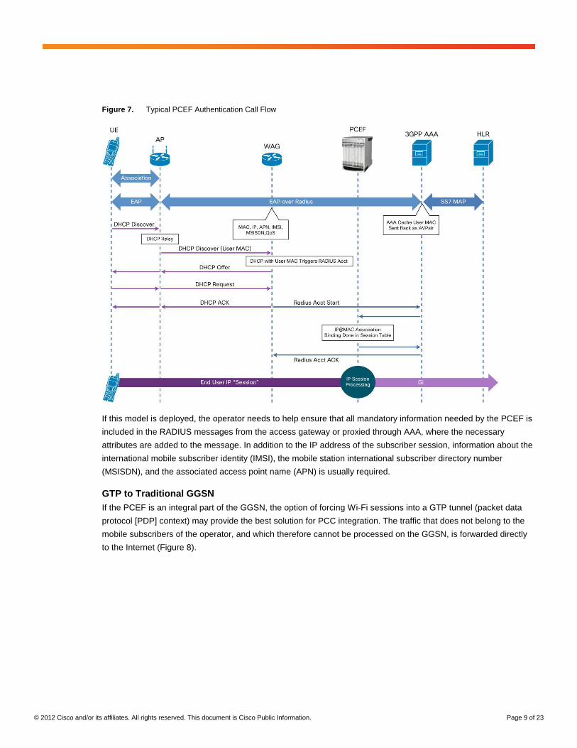
Figure 7. Typical PCEF Authentication Call Flow
If this model is deployed, the operator needs to help ensure that all mandatory information needed by the PCEF is
included in the RADIUS messages from the access gateway or proxied through AAA, where the necessary
attributes are added to the message. In addition to the IP address of the subscriber session, information about the
international mobile subscriber identity (IMSI), the mobile station international subscriber directory number
(MSISDN), and the associated access point name (APN) is usually required.
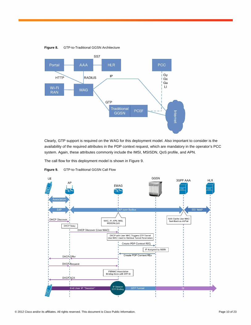
GTP to Traditional GGSN If the PCEF is an integral part of the GGSN, the option of forcing Wi-Fi sessions into a GTP tunnel (packet data
protocol [PDP] context) may provide the best solution for PCC integration. The traffic that does not belong to the
mobile subscribers of the operator, and which therefore cannot be processed on the GGSN, is forwarded directly
to the Internet (Figure 8).
© 2012 Cisco and/or its affiliates. All rights reserved. This document is Cisco Public Information. Page 10 of 23
Figure 8. GTP-to-Traditional GGSN Architecture
Clearly, GTP support is required on the WAG for this deployment model. Also important to consider is the
availability of the required attributes in the PDP context request, which are mandatory in the operator’s PCC
system. Again, these attributes commonly include the IMSI, MSISDN, QoS profile, and APN.
The call flow for this deployment model is shown in Figure 9.
Figure 9. GTP-to-Traditional GGSN Call Flow
© 2012 Cisco and/or its affiliates. All rights reserved. This document is Cisco Public Information. Page 11 of 23
Note that even though all sessions (3G and Wi-Fi) are anchored on the GGSN, this solution does not provide
transparent handover of the IP sessions between the Wi-Fi and 3G radio networks. This limitation exists because
the Wi-Fi and 3G PDP contexts are individual sessions, and the user device can open them simultaneously.
Unfortunately, the 3GPP standard does not provide a mechanism to help ensure that the same GGSN is chosen
for both of these PDP contexts, and therefore anchoring of the sessions on the same device cannot be achieved.
PCC Integration Considerations When performing PCC integration, note the following:
● The options listed are valid and needed for 3G. As discussed later, LTE provides native integration into the
EPC and therefore into the PCC
● The critical element is the capability of the WAG to provide all necessary information for charging
(specifically, some of these attributes are not part of EAP authentication and need to be retrieved
separately, if needed: for example, the MSISDN, the QoS profile, and optionally, the 3GPP charging
characteristics)
● Usually, the PCEF does not handle traffic from users who are not mobile customers of the operator
(non-SIM subscribers). This traffic is sent directly to the Internet. If these particular sessions need policy
or charging functions, these are usually handled by the WAG and Wi-Fi back-end systems directly
LTE
Before describing the third function of the Wi-Fi offload architecture, session handover, this document examines
the integration of PCC in an LTE scenario. This examination will help you later understand user session mobility
and anchoring.
3GPP TS 23.402 describes native integration of trusted and untrusted non-3GPP IP access networks into the
EPC. The standard accepts that the Wi-Fi network is as valid an access network as any other 3GPP radio access
network. This acceptance enables operators to use the standards-based EPC components for integration and
therefore helps ensure a good level of interoperability between different access types.
As mentioned earlier, this document concentrates first on the trusted part of the architecture. To force the Wi-Fi
traffic to the EPC, two interfaces are defined, both of them terminating Wi-Fi sessions on the packet data network
gateway (P-GW) as shown in Figure 10.
© 2012 Cisco and/or its affiliates. All rights reserved. This document is Cisco Public Information. Page 12 of 23
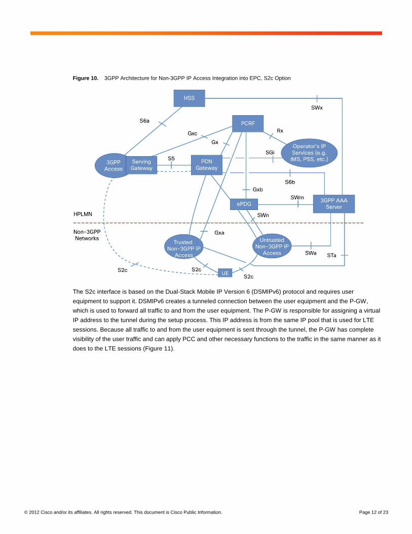
Figure 10. 3GPP Architecture for Non-3GPP IP Access Integration into EPC, S2c Option
The S2c interface is based on the Dual-Stack Mobile IP Version 6 (DSMIPv6) protocol and requires user
equipment to support it. DSMIPv6 creates a tunneled connection between the user equipment and the P-GW,
which is used to forward all traffic to and from the user equipment. The P-GW is responsible for assigning a virtual
IP address to the tunnel during the setup process. This IP address is from the same IP pool that is used for LTE
sessions. Because all traffic to and from the user equipment is sent through the tunnel, the P-GW has complete
visibility of the user traffic and can apply PCC and other necessary functions to the traffic in the same manner as it
does to the LTE sessions (Figure 11).
© 2012 Cisco and/or its affiliates. All rights reserved. This document is Cisco Public Information. Page 13 of 23
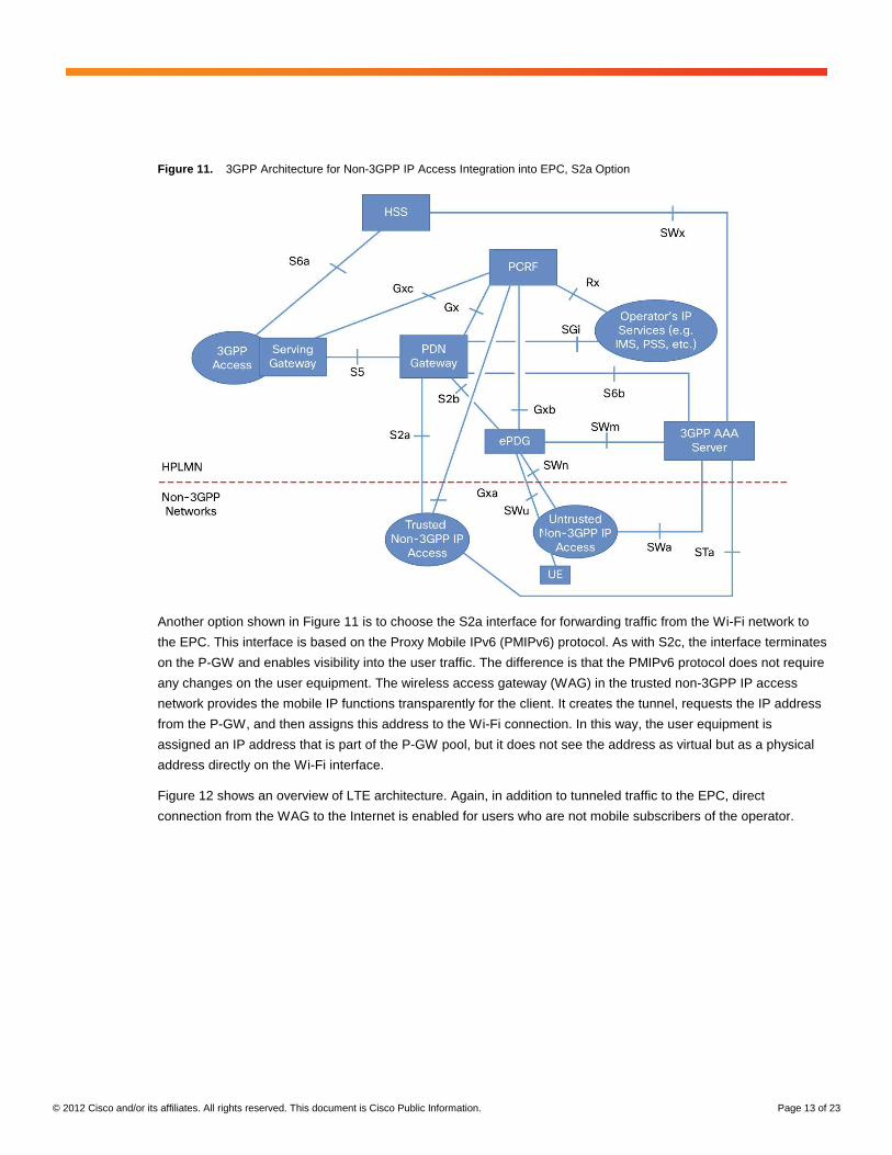
Figure 11. 3GPP Architecture for Non-3GPP IP Access Integration into EPC, S2a Option
Another option shown in Figure 11 is to choose the S2a interface for forwarding traffic from the Wi-Fi network to
the EPC. This interface is based on the Proxy Mobile IPv6 (PMIPv6) protocol. As with S2c, the interface terminates
on the P-GW and enables visibility into the user traffic. The difference is that the PMIPv6 protocol does not require
any changes on the user equipment. The wireless access gateway (WAG) in the trusted non-3GPP IP access
network provides the mobile IP functions transparently for the client. It creates the tunnel, requests the IP address
from the P-GW, and then assigns this address to the Wi-Fi connection. In this way, the user equipment is
assigned an IP address that is part of the P-GW pool, but it does not see the address as virtual but as a physical
address directly on the Wi-Fi interface.
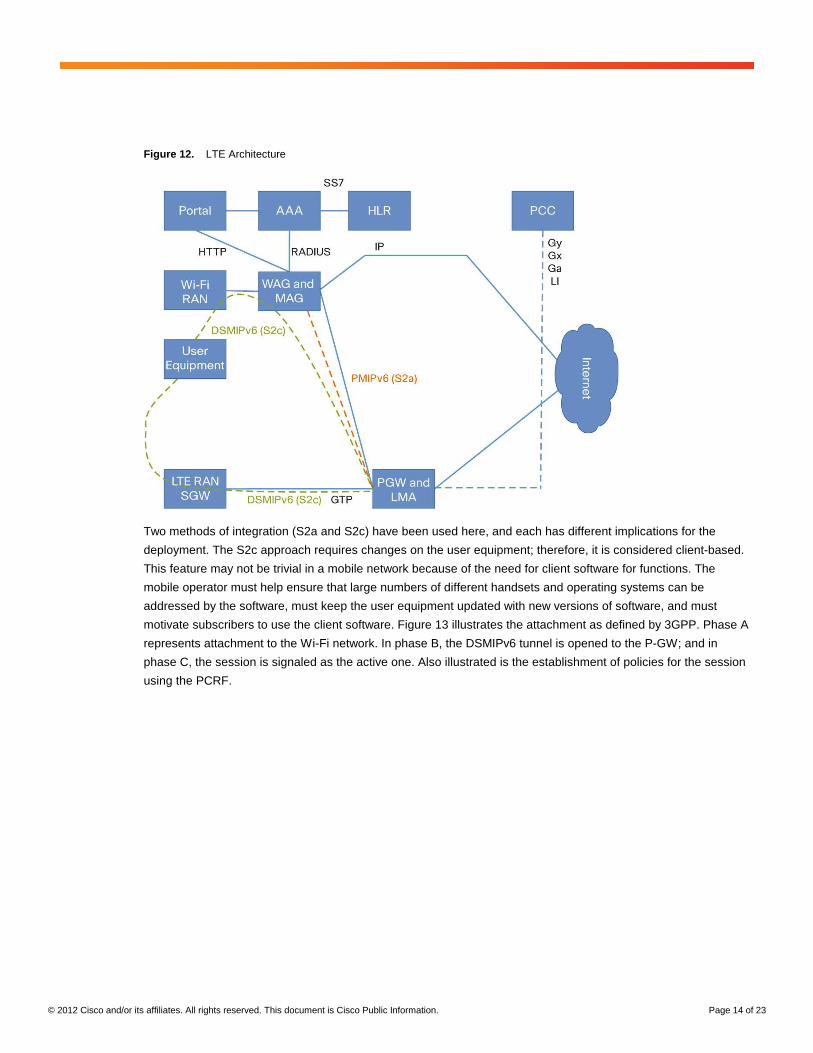
Figure 12 shows an overview of LTE architecture. Again, in addition to tunneled traffic to the EPC, direct
connection from the WAG to the Internet is enabled for users who are not mobile subscribers of the operator.
© 2012 Cisco and/or its affiliates. All rights reserved. This document is Cisco Public Information. Page 14 of 23
Figure 12. LTE Architecture
Two methods of integration (S2a and S2c) have been used here, and each has different implications for the
deployment. The S2c approach requires changes on the user equipment; therefore, it is considered client-based.
This feature may not be trivial in a mobile network because of the need for client software for functions. The
mobile operator must help ensure that large numbers of different handsets and operating systems can be
addressed by the software, must keep the user equipment updated with new versions of software, and must
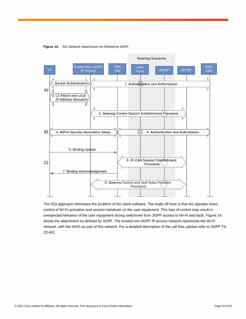
motivate subscribers to use the client software. Figure 13 illustrates the attachment as defined by 3GPP. Phase A
represents attachment to the Wi-Fi network. In phase B, the DSMIPv6 tunnel is opened to the P-GW; and in
phase C, the session is signaled as the active one. Also illustrated is the establishment of policies for the session
using the PCRF.
© 2012 Cisco and/or its affiliates. All rights reserved. This document is Cisco Public Information. Page 15 of 23
Figure 13. S2c Network Attachment As Defined by 3GPP
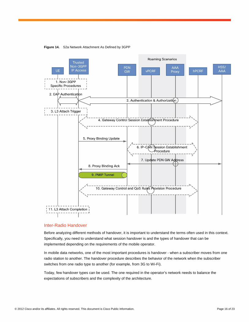
The S2a approach eliminates the problem of the client software. The trade-off here is that the operator loses
control of Wi-Fi activation and session handover on the user equipment. This loss of control may result in
unexpected behavior of the user equipment during switchover from 3GPP access to Wi-Fi and back. Figure 14
shows the attachment as defined by 3GPP. The trusted non-3GPP IP access network represents the Wi-Fi
network, with the WAG as part of this network. For a detailed description of the call flow, please refer to 3GPP TS
23.402.
© 2012 Cisco and/or its affiliates. All rights reserved. This document is Cisco Public Information. Page 16 of 23
Figure 14. S2a Network Attachment As Defined by 3GPP
Inter-Radio Handover
Before analyzing different methods of handover, it is important to understand the terms often used in this context.
Specifically, you need to understand what session handover is and the types of handover that can be
implemented depending on the requirements of the mobile operator.
In mobile data networks, one of the most important procedures is handover - when a subscriber moves from one
radio station to another. The handover procedure describes the behavior of the network when the subscriber
switches from one radio type to another (for example, from 3G to Wi-Fi).
Today, few handover types can be used. The one required in the operator’s network needs to balance the
expectations of subscribers and the complexity of the architecture.
© 2012 Cisco and/or its affiliates. All rights reserved. This document is Cisco Public Information. Page 17 of 23
● Handover without IP address persistency (connectivity handover): When a subscriber connects to the Wi-Fi
access network, the subscriber is authenticated transparently and is assigned a new IP address by the
Wi-Fi network. All new communications can use the new IP address as the source. All established TCP
and UDP connections can, however, still continue over the 3G network. If the user equipment logic
disables the 3G interface, then these established sockets will need to be (automatically) reestablished over
Wi-Fi, using the new IP address.
● Handover with IP persistency (IP handover): When a subscriber connects to the Wi-Fi network, the
subscriber will be assigned the same IP address as he used on the 3G or LTE network. If the established
TCP and UDP connections are bound to a physical interface (because of the TCP/IP stack implementation
of the UE), they will need to be (automatically) reestablished using the new Wi-Fi interface, even though
they will use the same IP address.
● Session handover (transparent handover): This type of handover is similar to IP handover, but the
handover must occur in a time range that allows real-time media applications (voice over IP, streaming
video, etc.) - for example, using established UDP sockets for media and TCP sockets for the control-plane
protocol - to continue without interruption or user-experience degradation as the device switches between
Wi-Fi and 3G cellular connectivity.
Note that seamless handover can be achieved only with user equipment cooperation, which means that software
updating (for client software) is needed on terminals. At minimum, this software needs to provide a virtual interface
adapter, to mask the physical interface structure for TCP and UDP sockets. The challenges of client software have
already been discussed above.
3GPP defines handover mechanisms for trusted Wi-Fi only as part of the LTE architecture. For untrusted Wi-Fi,
proposals exist for 3G and LTE. This document starts with a look at trusted non-3GPP IP access networks in LTE.
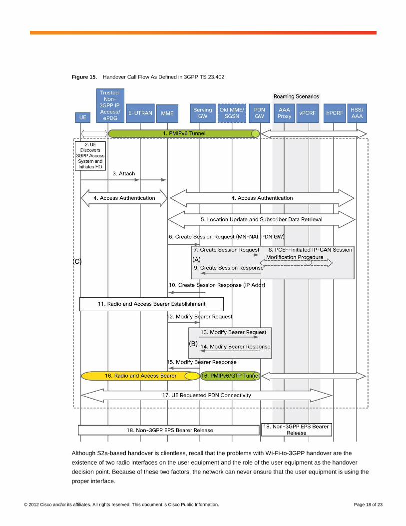
S2a-Based Handover (Clientless) The advantage of PMIPv6 as protocol for the S2a interface is that the protocol is built for network-based IP
mobility. Therefore, it can provide, without client involvement, handover of the IP address between different access
types. In this design, the P-GW is responsible for anchoring the session, assigning the IP addresses, and
switching the PMIPv6 or Ga TP tunnels between different access gateways in the event of handover. The access
gateways must support the mobile access gateway (MAG) function to fulfill all mobile IP-related mobile-node
functions.
Figure 15 illustrates the handover call flow as defined in 3GPP TS 23.402. The trusted non-3GPP IP access
element is equivalent to a WAG.
© 2012 Cisco and/or its affiliates. All rights reserved. This document is Cisco Public Information. Page 18 of 23
Figure 15. Handover Call Flow As Defined in 3GPP TS 23.402
Although S2a-based handover is clientless, recall that the problems with Wi-Fi-to-3GPP handover are the
existence of two radio interfaces on the user equipment and the role of the user equipment as the handover
decision point. Because of these two factors, the network can never ensure that the user equipment is using the
proper interface.
© 2012 Cisco and/or its affiliates. All rights reserved. This document is Cisco Public Information. Page 19 of 23
Note: The definition of what constitutes a proper interface can change on an operator-by-operator basis.
Also, at the user equipment, the TCP/IP stack needs to be able to cope with two physical interfaces that may
eventually have identical IP addresses. Additionally, in some TCP/IP stack implementations, application sockets
may be bound to a physical interface. Therefore, when the user equipment or application switches between
interfaces, the application connections must be dropped and may need to be reestablished from the new interface.
Given all of these dependencies, the PMIPv6-based architecture cannot (without user equipment support)
guarantee operation of a transparent handover function on all user equipment types. This situation can be
improved if a properly designed connection manager (with virtual adapters) is installed on all user equipment.
Cisco is actively working with chipset and handset vendors to support standardization and development of user
equipment that meets the requirements for smooth clientless handover.
S2c-Based Handover (Client-based) For the S2c interface, 3GPP reuses the IETF-defined DSMIPv6 protocol between the user equipment and the
P-GW as the anchor point. When on the non-3GPP network, the user equipment builds the DSMIPv6 to the
appropriate P-GW and is assigned a virtual IP address, which is then used for application communication.
The same IP address will be assigned to the user equipment over a 3GPP access network in the event of
handover. The 3GPP network is treated as the home network, and therefore the user equipment does not need to
set up a DSMIPv6 tunnel on the 3GPP access network.
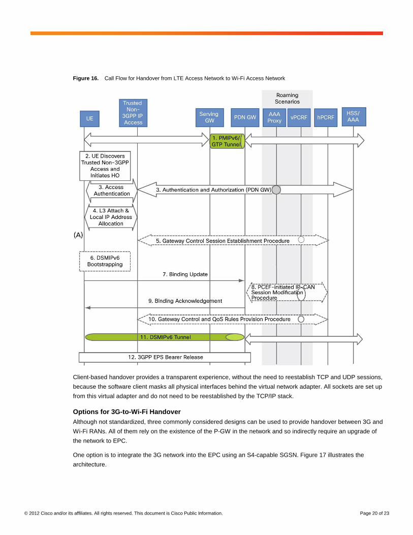
Figure 16, from 3GPP TS 23.402, summarizes the call flow during handover from an LTE access network to a
Wi-Fi access network.
© 2012 Cisco and/or its affiliates. All rights reserved. This document is Cisco Public Information. Page 20 of 23
Figure 16. Call Flow for Handover from LTE Access Network to Wi-Fi Access Network
Client-based handover provides a transparent experience, without the need to reestablish TCP and UDP sessions,
because the software client masks all physical interfaces behind the virtual network adapter. All sockets are set up
from this virtual adapter and do not need to be reestablished by the TCP/IP stack.
Options for 3G-to-Wi-Fi Handover Although not standardized, three commonly considered designs can be used to provide handover between 3G and
Wi-Fi RANs. All of them rely on the existence of the P-GW in the network and so indirectly require an upgrade of
the network to EPC.
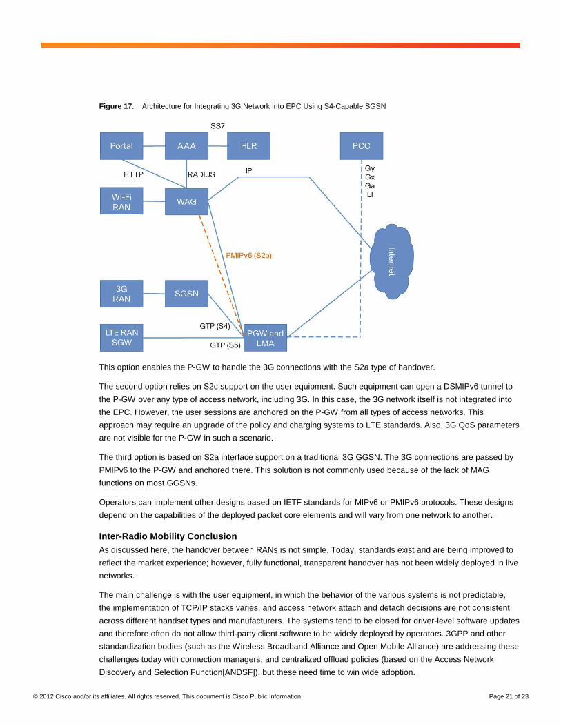
One option is to integrate the 3G network into the EPC using an S4-capable SGSN. Figure 17 illustrates the
architecture.
© 2012 Cisco and/or its affiliates. All rights reserved. This document is Cisco Public Information. Page 21 of 23
Figure 17. Architecture for Integrating 3G Network into EPC Using S4-Capable SGSN
This option enables the P-GW to handle the 3G connections with the S2a type of handover.
The second option relies on S2c support on the user equipment. Such equipment can open a DSMIPv6 tunnel to
the P-GW over any type of access network, including 3G. In this case, the 3G network itself is not integrated into
the EPC. However, the user sessions are anchored on the P-GW from all types of access networks. This
approach may require an upgrade of the policy and charging systems to LTE standards. Also, 3G QoS parameters
are not visible for the P-GW in such a scenario.
The third option is based on S2a interface support on a traditional 3G GGSN. The 3G connections are passed by
PMIPv6 to the P-GW and anchored there. This solution is not commonly used because of the lack of MAG
functions on most GGSNs.
Operators can implement other designs based on IETF standards for MIPv6 or PMIPv6 protocols. These designs
depend on the capabilities of the deployed packet core elements and will vary from one network to another.
Inter-Radio Mobility Conclusion As discussed here, the handover between RANs is not simple. Today, standards exist and are being improved to
reflect the market experience; however, fully functional, transparent handover has not been widely deployed in live
networks.
The main challenge is with the user equipment, in which the behavior of the various systems is not predictable,
the implementation of TCP/IP stacks varies, and access network attach and detach decisions are not consistent
across different handset types and manufacturers. The systems tend to be closed for driver-level software updates
and therefore often do not allow third-party client software to be widely deployed by operators. 3GPP and other
standardization bodies (such as the Wireless Broadband Alliance and Open Mobile Alliance) are addressing these
challenges today with connection managers, and centralized offload policies (based on the Access Network
Discovery and Selection Function[ANDSF]), but these need time to win wide adoption.
© 2012 Cisco and/or its affiliates. All rights reserved. This document is Cisco Public Information. Page 22 of 23
Today’s networks need to be ready for later implementations of various standards enabling handover with or
without user equipment client software.
Untrusted Non-3GPP IP Access Network
The first 3GPP Wi-Fi integration standards considered the Wi-Fi networks as untrusted access. There were
multiple reasons for that approach. The networks were not secured by EAP authentication, were not encrypted,
and often belonged to third-party service providers. Therefore, the standard required that security mechanisms be
implemented directly between the user equipment and the packet core.
In general, the architecture for untrusted access enables subscribers to use any type of access network to which
they can connect. After the subscriber connects, the software client on the user equipment opens an IP Security
(IPsec) tunnel to the packet core, where the tunnel is authenticated and assigned an IP address; all data traffic is
then routed over the packet core. All PCC-related functions can be reused from the existing core.
The 3GPP TS 23.234 specification handles 3G and untrusted Wi-Fi integration. For LTE, untrusted access is
specified in the same document (3GPP TS 23.402) as trusted access. The standard introduces a new packet core
function, tunnel termination gateway (TTG), responsible for terminating the IPsec tunnels and switching the traffic
from these IPsec tunnels to GTP tunnels to traditional GGSNs. In the LTE architecture, this function is part of the
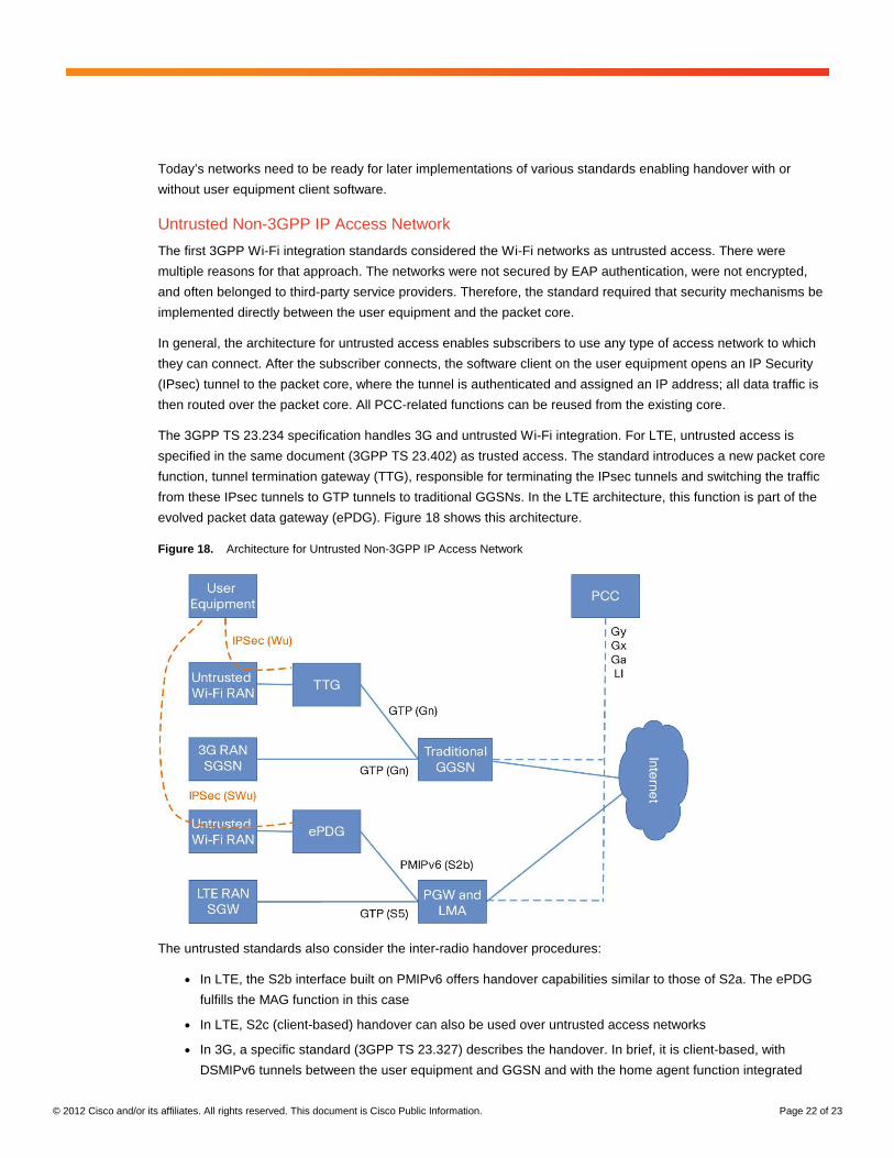
evolved packet data gateway (ePDG). Figure 18 shows this architecture.
Figure 18. Architecture for Untrusted Non-3GPP IP Access Network
The untrusted standards also consider the inter-radio handover procedures:
● In LTE, the S2b interface built on PMIPv6 offers handover capabilities similar to those of S2a. The ePDG
fulfills the MAG function in this case
● In LTE, S2c (client-based) handover can also be used over untrusted access networks
● In 3G, a specific standard (3GPP TS 23.327) describes the handover. In brief, it is client-based, with
DSMIPv6 tunnels between the user equipment and GGSN and with the home agent function integrated
© 2012 Cisco and/or its affiliates. All rights reserved. This document is Cisco Public Information. Page 23 of 23
Conclusion: Cisco Service Provider Wi-Fi Offload Solution
With its long history of Wi-Fi experience and strong presence in the mobile packet core, Cisco is well positioned to
offer an industry-leading end-to-end solution for Wi-Fi offload. The main elements of this solution are:
● Cisco Intelligent Access: A leading Wi-Fi access and controller portfolio with technology to enable excellent
coverage and radio efficiency
● Cisco ASR 1000 Series Aggregation Services Routers and Cisco Intelligent Services Gateway (ISG):
A combination that offers flexible policy and authentication of Wi-Fi subscribers and a full set of the
functions required from the WAG
● Cisco ASR 5000 Series: Cisco’s flagship product for packet core functions, with the Small Cell Gateway for
functions relevant to Wi-Fi/3G/4G handover such as P-GW, TTG, ePDG, and PCEF
● Cisco Prime™ product suite: Network management software for end-to-end network visibility and
operations; includes elements for network services such as Cisco Access Registrar for AAA functions,
Cisco Network Registrar for Dynamic Host Configuration Protocol (DHCP) functions, Cisco Network Control
System for centralized Wi-Fi network management and SP Wi-Fi Service Manager for subscriber policy,
self-provisioning, captive portal, and more
Cisco is committed to providing a Wi-Fi offload solution that is scalable, flexible, and ready for the upcoming
industry evolution as described in this document.
For More Information
For more information about the end-to-end architecture and product details, please see cisco.com/go/spwifi.
Printed in USA C11-701018-00 04/12


![Cellular Offload[1]](https://img.pdfslide.us/doc/110x75/577cd7ee1a28ab9e78a002b1/cellular-offload1.jpg)