Embed Size (px)
Citation preview
© 2016 Cisco and/or its affiliates. All rights reserved. This document is Cisco Public Information. Page 1 of 12
Data Sheet
Cisco Nexus 7000 Series Switches Environment
Product Overview
The Cisco Nexus® 7000 Series Switches comprise a modular data center-class product line designed for highly
scalable 10 Gigabit Ethernet networks with a fabric architecture that scales beyond 17 terabits per second (Tbps)
and that supports high-density 40 and 100 Gigabit Ethernet deployments. Designed to meet the requirements of
the most mission-critical data centers, it delivers continuous system operation and virtualized, pervasive services.
The Cisco Nexus 7000 Series is based on a proven operating system, with enhanced features to deliver real-time
system upgrades with exceptional manageability and serviceability.
The Cisco Nexus 7000 Series chassis (Figures 1, 2, 3, and 4) incorporate significant enhancements in design,
power, airflow, cooling, and cabling. The 10-slot chassis has front-to-back airflow, making it a good solution in hot-
aisle and cold-aisle deployments. The 9- and 18-slot chassis use side-to-side airflow to deliver high density in a
compact form factor. The 4-slot chassis has side-to-back airflow in the smallest form factor, making it a good
solution in smaller operation locations. The power supplies, fan trays, and fabrics can be replaced from the back of
the chassis without any obstruction from the I/O cables, thereby enabling operation efficiency. In addition, the
Cisco Nexus 7000 Series has many power saving enhancements such as temperature sensors, variable-speed
fans, and high-efficiency power supplies that reduce the total cost of ownership (TCO) for customers.
Figure 1. Cisco Nexus 7000 4-Slot Switch Chassis
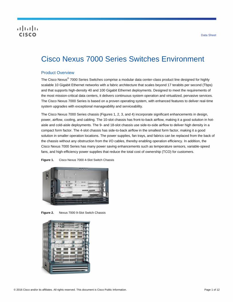
Figure 2. Nexus 7000 9-Slot Switch Chassis
© 2016 Cisco and/or its affiliates. All rights reserved. This document is Cisco Public Information. Page 2 of 12
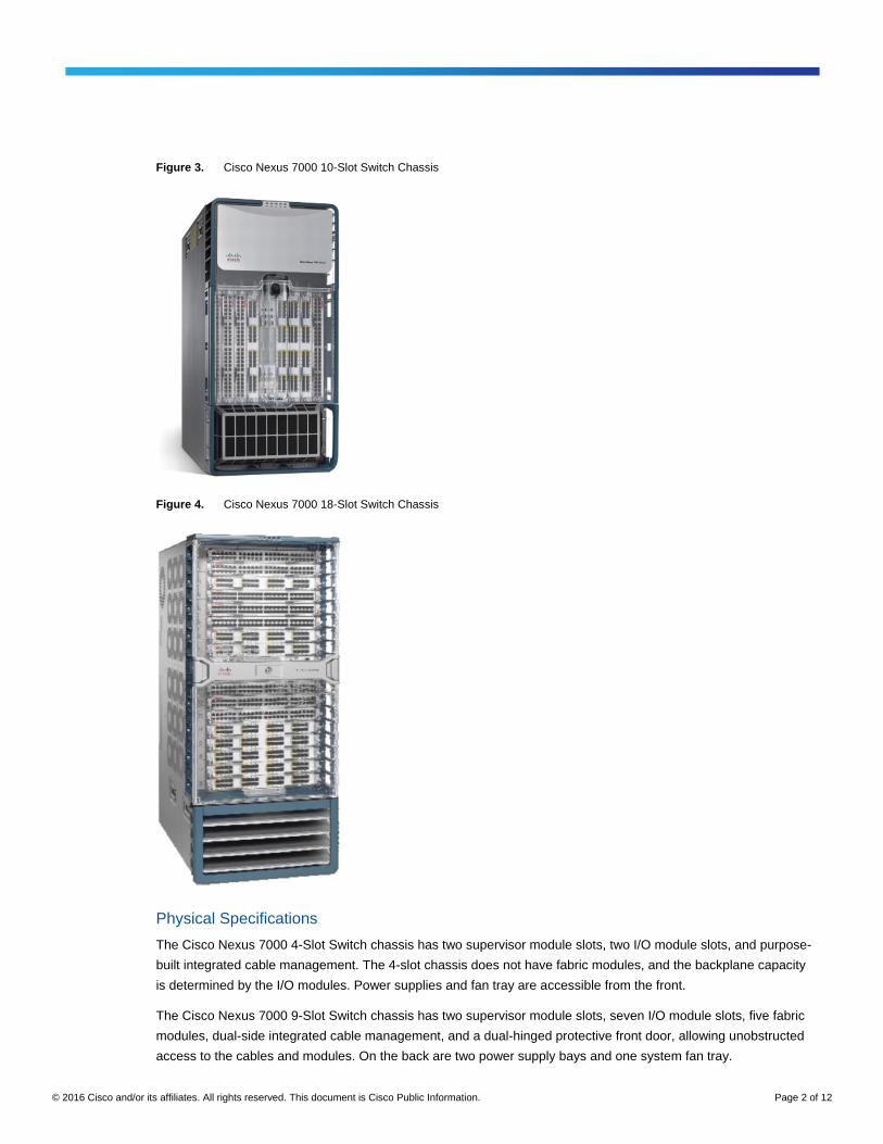
Figure 3. Cisco Nexus 7000 10-Slot Switch Chassis
Figure 4. Cisco Nexus 7000 18-Slot Switch Chassis
Physical Specifications
The Cisco Nexus 7000 4-Slot Switch chassis has two supervisor module slots, two I/O module slots, and purpose-
built integrated cable management. The 4-slot chassis does not have fabric modules, and the backplane capacity
is determined by the I/O modules. Power supplies and fan tray are accessible from the front.
The Cisco Nexus 7000 9-Slot Switch chassis has two supervisor module slots, seven I/O module slots, five fabric
modules, dual-side integrated cable management, and a dual-hinged protective front door, allowing unobstructed
access to the cables and modules. On the back are two power supply bays and one system fan tray.
© 2016 Cisco and/or its affiliates. All rights reserved. This document is Cisco Public Information. Page 3 of 12
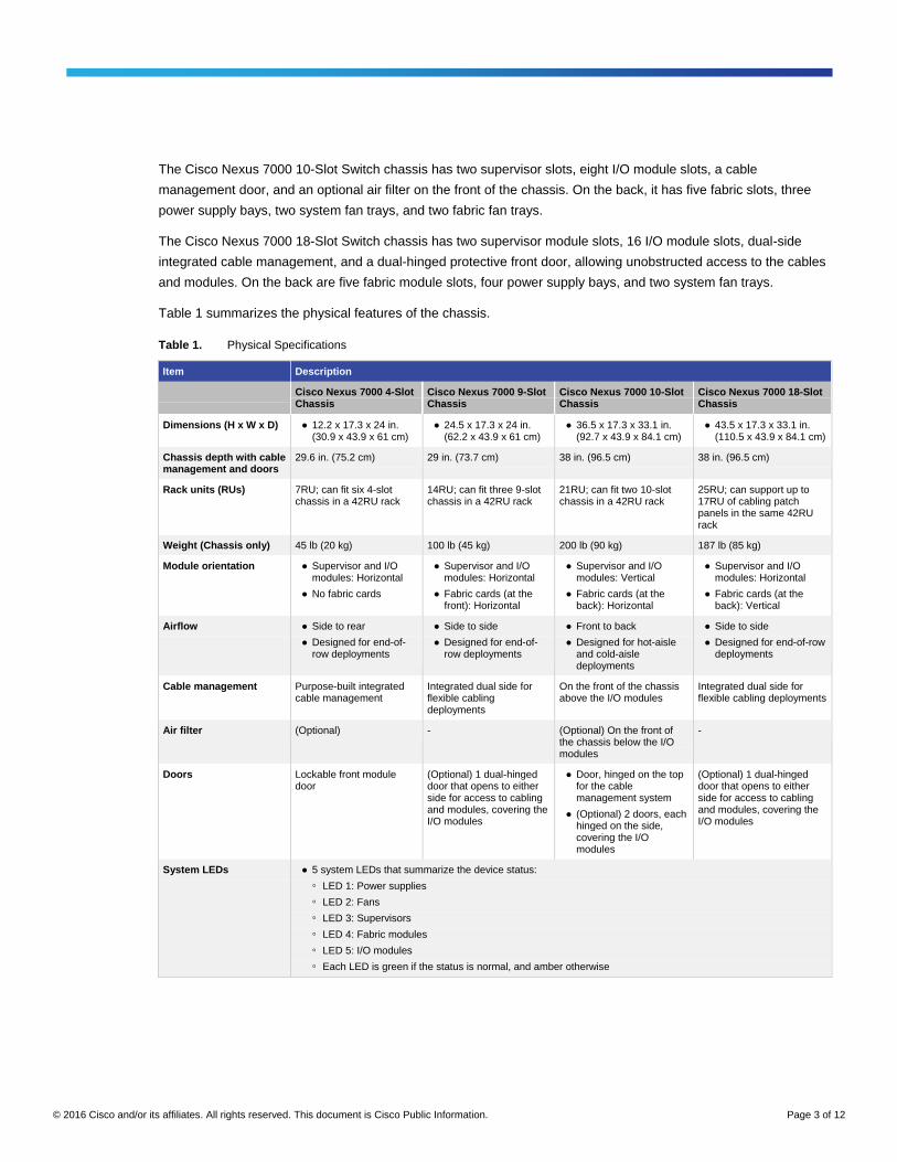
The Cisco Nexus 7000 10-Slot Switch chassis has two supervisor slots, eight I/O module slots, a cable
management door, and an optional air filter on the front of the chassis. On the back, it has five fabric slots, three
power supply bays, two system fan trays, and two fabric fan trays.
The Cisco Nexus 7000 18-Slot Switch chassis has two supervisor module slots, 16 I/O module slots, dual-side
integrated cable management, and a dual-hinged protective front door, allowing unobstructed access to the cables
and modules. On the back are five fabric module slots, four power supply bays, and two system fan trays.
Table 1 summarizes the physical features of the chassis.
Table 1. Physical Specifications
Item Description
Cisco Nexus 7000 4-Slot Chassis
Cisco Nexus 7000 9-Slot Chassis
Cisco Nexus 7000 10-Slot Chassis
Cisco Nexus 7000 18-Slot Chassis
Dimensions (H x W x D) ● 12.2 x 17.3 x 24 in. (30.9 x 43.9 x 61 cm)
● 24.5 x 17.3 x 24 in. (62.2 x 43.9 x 61 cm)
● 36.5 x 17.3 x 33.1 in. (92.7 x 43.9 x 84.1 cm)
● 43.5 x 17.3 x 33.1 in. (110.5 x 43.9 x 84.1 cm)
Chassis depth with cable management and doors
29.6 in. (75.2 cm) 29 in. (73.7 cm) 38 in. (96.5 cm) 38 in. (96.5 cm)
Rack units (RUs) 7RU; can fit six 4-slot chassis in a 42RU rack
14RU; can fit three 9-slot chassis in a 42RU rack
21RU; can fit two 10-slot chassis in a 42RU rack
25RU; can support up to 17RU of cabling patch panels in the same 42RU rack
Weight (Chassis only) 45 lb (20 kg) 100 lb (45 kg) 200 lb (90 kg) 187 lb (85 kg)
Module orientation ● Supervisor and I/O modules: Horizontal
● No fabric cards
● Supervisor and I/O modules: Horizontal
● Fabric cards (at the front): Horizontal
● Supervisor and I/O modules: Vertical
● Fabric cards (at the back): Horizontal
● Supervisor and I/O modules: Horizontal
● Fabric cards (at the back): Vertical
Airflow ● Side to rear
● Designed for end-of-row deployments
● Side to side
● Designed for end-of-row deployments
● Front to back
● Designed for hot-aisle and cold-aisle deployments
● Side to side
● Designed for end-of-row deployments
Cable management Purpose-built integrated cable management
Integrated dual side for flexible cabling deployments
On the front of the chassis above the I/O modules
Integrated dual side for flexible cabling deployments
Air filter (Optional) - (Optional) On the front of the chassis below the I/O modules
-
Doors Lockable front module door
(Optional) 1 dual-hinged door that opens to either side for access to cabling and modules, covering the I/O modules
● Door, hinged on the top for the cable management system
● (Optional) 2 doors, each hinged on the side, covering the I/O modules
(Optional) 1 dual-hinged door that opens to either side for access to cabling and modules, covering the I/O modules
System LEDs ● 5 system LEDs that summarize the device status:
◦ LED 1: Power supplies
◦ LED 2: Fans
◦ LED 3: Supervisors
◦ LED 4: Fabric modules
◦ LED 5: I/O modules
◦ Each LED is green if the status is normal, and amber otherwise
© 2016 Cisco and/or its affiliates. All rights reserved. This document is Cisco Public Information. Page 4 of 12
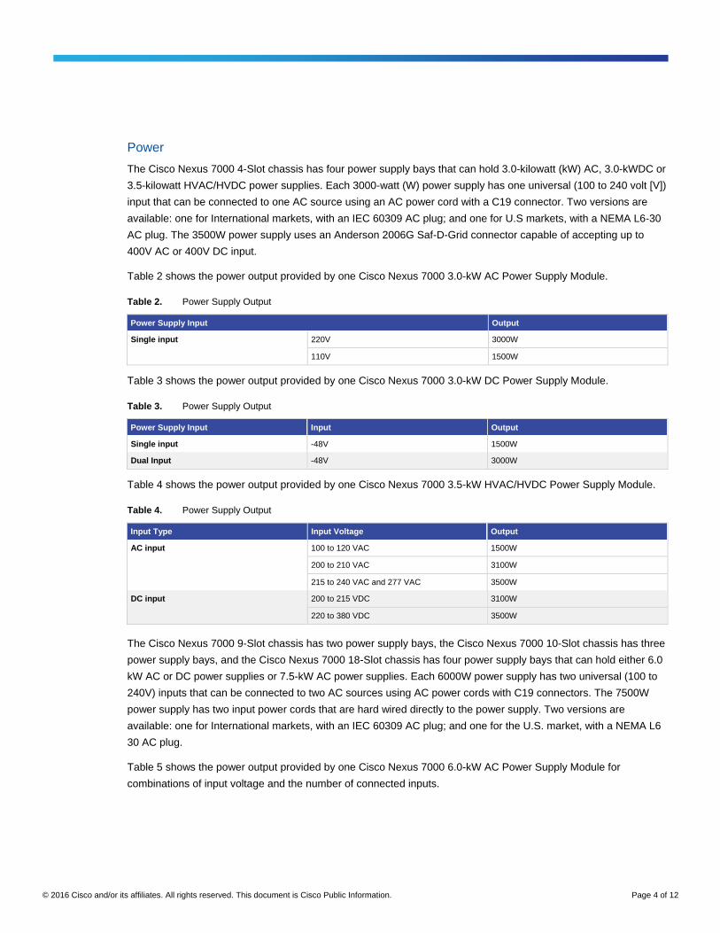
Power
The Cisco Nexus 7000 4-Slot chassis has four power supply bays that can hold 3.0-kilowatt (kW) AC, 3.0-kWDC or
3.5-kilowatt HVAC/HVDC power supplies. Each 3000-watt (W) power supply has one universal (100 to 240 volt [V])
input that can be connected to one AC source using an AC power cord with a C19 connector. Two versions are
available: one for International markets, with an IEC 60309 AC plug; and one for U.S markets, with a NEMA L6-30
AC plug. The 3500W power supply uses an Anderson 2006G Saf-D-Grid connector capable of accepting up to
400V AC or 400V DC input.
Table 2 shows the power output provided by one Cisco Nexus 7000 3.0-kW AC Power Supply Module.
Table 2. Power Supply Output
Power Supply Input Output
Single input 220V 3000W
110V 1500W
Table 3 shows the power output provided by one Cisco Nexus 7000 3.0-kW DC Power Supply Module.
Table 3. Power Supply Output
Power Supply Input Input Output
Single input -48V 1500W
Dual Input -48V 3000W
Table 4 shows the power output provided by one Cisco Nexus 7000 3.5-kW HVAC/HVDC Power Supply Module.
Table 4. Power Supply Output
Input Type Input Voltage Output
AC input 100 to 120 VAC 1500W
200 to 210 VAC 3100W
215 to 240 VAC and 277 VAC 3500W
DC input 200 to 215 VDC 3100W
220 to 380 VDC 3500W
The Cisco Nexus 7000 9-Slot chassis has two power supply bays, the Cisco Nexus 7000 10-Slot chassis has three
power supply bays, and the Cisco Nexus 7000 18-Slot chassis has four power supply bays that can hold either 6.0
kW AC or DC power supplies or 7.5-kW AC power supplies. Each 6000W power supply has two universal (100 to
240V) inputs that can be connected to two AC sources using AC power cords with C19 connectors. The 7500W
power supply has two input power cords that are hard wired directly to the power supply. Two versions are
available: one for International markets, with an IEC 60309 AC plug; and one for the U.S. market, with a NEMA L6
30 AC plug.
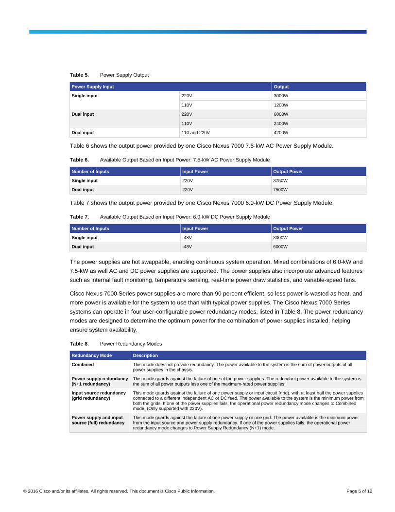
Table 5 shows the power output provided by one Cisco Nexus 7000 6.0-kW AC Power Supply Module for
combinations of input voltage and the number of connected inputs.
© 2016 Cisco and/or its affiliates. All rights reserved. This document is Cisco Public Information. Page 5 of 12
Table 5. Power Supply Output
Power Supply Input Output
Single input 220V 3000W
110V 1200W
Dual input 220V 6000W
110V 2400W
Dual input 110 and 220V 4200W
Table 6 shows the output power provided by one Cisco Nexus 7000 7.5-kW AC Power Supply Module.
Table 6. Available Output Based on Input Power: 7.5-kW AC Power Supply Module
Number of Inputs Input Power Output Power
Single input 220V 3750W
Dual input 220V 7500W
Table 7 shows the output power provided by one Cisco Nexus 7000 6.0-kW DC Power Supply Module.
Table 7. Available Output Based on Input Power: 6.0-kW DC Power Supply Module
Number of Inputs Input Power Output Power
Single input -48V 3000W
Dual input -48V 6000W
The power supplies are hot swappable, enabling continuous system operation. Mixed combinations of 6.0-kW and
7.5-kW as well AC and DC power supplies are supported. The power supplies also incorporate advanced features
such as internal fault monitoring, temperature sensing, real-time power draw statistics, and variable-speed fans.
Cisco Nexus 7000 Series power supplies are more than 90 percent efficient, so less power is wasted as heat, and
more power is available for the system to use than with typical power supplies. The Cisco Nexus 7000 Series
systems can operate in four user-configurable power redundancy modes, listed in Table 8. The power redundancy
modes are designed to determine the optimum power for the combination of power supplies installed, helping
ensure system availability.
Table 8. Power Redundancy Modes
Redundancy Mode Description
Combined This mode does not provide redundancy. The power available to the system is the sum of power outputs of all power supplies in the chassis.
Power supply redundancy (N+1 redundancy)
This mode guards against the failure of one of the power supplies. The redundant power available to the system is the sum of all power outputs less one of the maximum-rated power supplies.
Input source redundancy (grid redundancy)
This mode guards against the failure of one power supply or input circuit (grid), with at least half the power supplies connected to a different independent AC or DC feed. The power available to the system is the minimum power from both the grids. If one of the power supplies fails, the operational power redundancy mode changes to Combined mode. (Only supported with 220V).
Power supply and input source (full) redundancy
This mode guards against the failure of one power supply or one grid. The power available is the minimum power from the input source and power supply redundancy. If one of the power supplies fails, the operational power redundancy mode changes to Power Supply Redundancy (N+1) mode.
© 2016 Cisco and/or its affiliates. All rights reserved. This document is Cisco Public Information. Page 6 of 12
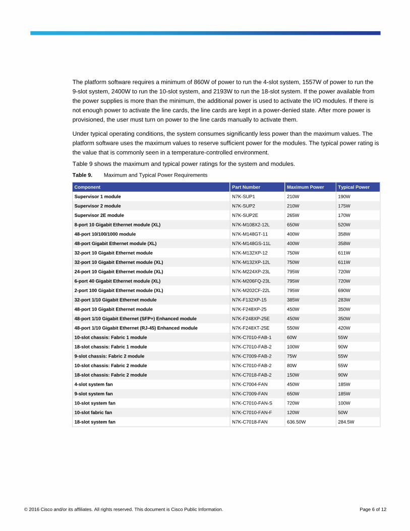
The platform software requires a minimum of 860W of power to run the 4-slot system, 1557W of power to run the
9-slot system, 2400W to run the 10-slot system, and 2193W to run the 18-slot system. If the power available from
the power supplies is more than the minimum, the additional power is used to activate the I/O modules. If there is
not enough power to activate the line cards, the line cards are kept in a power-denied state. After more power is
provisioned, the user must turn on power to the line cards manually to activate them.
Under typical operating conditions, the system consumes significantly less power than the maximum values. The
platform software uses the maximum values to reserve sufficient power for the modules. The typical power rating is
the value that is commonly seen in a temperature-controlled environment.
Table 9 shows the maximum and typical power ratings for the system and modules.
Table 9. Maximum and Typical Power Requirements
Component Part Number Maximum Power Typical Power
Supervisor 1 module N7K-SUP1 210W 190W
Supervisor 2 module N7K-SUP2 210W 175W
Supervisor 2E module N7K-SUP2E 265W 170W
8-port 10 Gigabit Ethernet module (XL) N7K-M108X2-12L 650W 520W
48-port 10/100/1000 module N7K-M148GT-11 400W 358W
48-port Gigabit Ethernet module (XL) N7K-M148GS-11L 400W 358W
32-port 10 Gigabit Ethernet module N7K-M132XP-12 750W 611W
32-port 10 Gigabit Ethernet module (XL) N7K-M132XP-12L 750W 611W
24-port 10 Gigabit Ethernet module (XL) N7K-M224XP-23L 795W 720W
6-port 40 Gigabit Ethernet module (XL) N7K-M206FQ-23L 795W 720W
2-port 100 Gigabit Ethernet module (XL) N7K-M202CF-22L 795W 690W
32-port 1/10 Gigabit Ethernet module N7K-F132XP-15 385W 283W
48-port 10 Gigabit Ethernet module N7K-F248XP-25 450W 350W
48-port 1/10 Gigabit Ethernet (SFP+) Enhanced module N7K-F248XP-25E 450W 350W
48-port 1/10 Gigabit Ethernet (RJ-45) Enhanced module N7K-F248XT-25E 550W 420W
10-slot chassis: Fabric 1 module N7K-C7010-FAB-1 60W 55W
18-slot chassis: Fabric 1 module N7K-C7010-FAB-2 100W 90W
9-slot chassis: Fabric 2 module N7K-C7009-FAB-2 75W 55W
10-slot chassis: Fabric 2 module N7K-C7010-FAB-2 80W 55W
18-slot chassis: Fabric 2 module N7K-C7018-FAB-2 150W 90W
4-slot system fan N7K-C7004-FAN 450W 185W
9-slot system fan N7K-C7009-FAN 650W 185W
10-slot system fan N7K-C7010-FAN-S 720W 100W
10-slot fabric fan N7K-C7010-FAN-F 120W 50W
18-slot system fan N7K-C7018-FAN 636.50W 284.5W
© 2016 Cisco and/or its affiliates. All rights reserved. This document is Cisco Public Information. Page 7 of 12
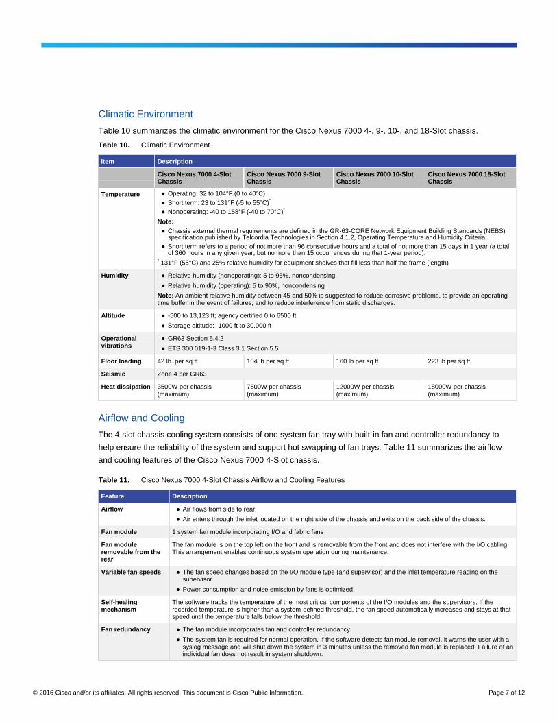
Climatic Environment
Table 10 summarizes the climatic environment for the Cisco Nexus 7000 4-, 9-, 10-, and 18-Slot chassis.
Table 10. Climatic Environment
Item Description
Cisco Nexus 7000 4-Slot Chassis
Cisco Nexus 7000 9-Slot Chassis
Cisco Nexus 7000 10-Slot Chassis
Cisco Nexus 7000 18-Slot Chassis
Temperature ● Operating: 32 to 104°F (0 to 40°C)
● Short term: 23 to 131°F (-5 to 55°C)*
● Nonoperating: -40 to 158°F (-40 to 70°C)*
Note:
● Chassis external thermal requirements are defined in the GR-63-CORE Network Equipment Building Standards (NEBS) specification published by Telcordia Technologies in Section 4.1.2, Operating Temperature and Humidity Criteria.
● Short term refers to a period of not more than 96 consecutive hours and a total of not more than 15 days in 1 year (a total of 360 hours in any given year, but no more than 15 occurrences during that 1-year period).
* 131°F (55°C) and 25% relative humidity for equipment shelves that fill less than half the frame (length)
Humidity ● Relative humidity (nonoperating): 5 to 95%, noncondensing
● Relative humidity (operating): 5 to 90%, noncondensing
Note: An ambient relative humidity between 45 and 50% is suggested to reduce corrosive problems, to provide an operating time buffer in the event of failures, and to reduce interference from static discharges.
Altitude ● -500 to 13,123 ft; agency certified 0 to 6500 ft
● Storage altitude: -1000 ft to 30,000 ft
Operational vibrations
● GR63 Section 5.4.2
● ETS 300 019-1-3 Class 3.1 Section 5.5
Floor loading 42 lb. per sq ft 104 lb per sq ft 160 lb per sq ft 223 lb per sq ft
Seismic Zone 4 per GR63
Heat dissipation 3500W per chassis (maximum)
7500W per chassis (maximum)
12000W per chassis (maximum)
18000W per chassis (maximum)
Airflow and Cooling
The 4-slot chassis cooling system consists of one system fan tray with built-in fan and controller redundancy to
help ensure the reliability of the system and support hot swapping of fan trays. Table 11 summarizes the airflow
and cooling features of the Cisco Nexus 7000 4-Slot chassis.
Table 11. Cisco Nexus 7000 4-Slot Chassis Airflow and Cooling Features
Feature Description
Airflow ● Air flows from side to rear.
● Air enters through the inlet located on the right side of the chassis and exits on the back side of the chassis.
Fan module 1 system fan module incorporating I/O and fabric fans
Fan module removable from the rear
The fan module is on the top left on the front and is removable from the front and does not interfere with the I/O cabling. This arrangement enables continuous system operation during maintenance.
Variable fan speeds ● The fan speed changes based on the I/O module type (and supervisor) and the inlet temperature reading on the supervisor.
● Power consumption and noise emission by fans is optimized.
Self-healing mechanism
The software tracks the temperature of the most critical components of the I/O modules and the supervisors. If the recorded temperature is higher than a system-defined threshold, the fan speed automatically increases and stays at that speed until the temperature falls below the threshold.
Fan redundancy ● The fan module incorporates fan and controller redundancy.
● The system fan is required for normal operation. If the software detects fan module removal, it warns the user with a syslog message and will shut down the system in 3 minutes unless the removed fan module is replaced. Failure of an individual fan does not result in system shutdown.
© 2016 Cisco and/or its affiliates. All rights reserved. This document is Cisco Public Information. Page 8 of 12
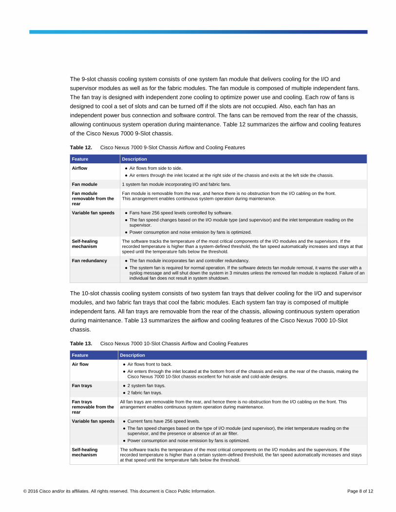
The 9-slot chassis cooling system consists of one system fan module that delivers cooling for the I/O and
supervisor modules as well as for the fabric modules. The fan module is composed of multiple independent fans.
The fan tray is designed with independent zone cooling to optimize power use and cooling. Each row of fans is
designed to cool a set of slots and can be turned off if the slots are not occupied. Also, each fan has an
independent power bus connection and software control. The fans can be removed from the rear of the chassis,
allowing continuous system operation during maintenance. Table 12 summarizes the airflow and cooling features
of the Cisco Nexus 7000 9-Slot chassis.
Table 12. Cisco Nexus 7000 9-Slot Chassis Airflow and Cooling Features
Feature Description
Airflow ● Air flows from side to side.
● Air enters through the inlet located at the right side of the chassis and exits at the left side the chassis.
Fan module 1 system fan module incorporating I/O and fabric fans.
Fan module removable from the rear
Fan module is removable from the rear, and hence there is no obstruction from the I/O cabling on the front. This arrangement enables continuous system operation during maintenance.
Variable fan speeds ● Fans have 256 speed levels controlled by software.
● The fan speed changes based on the I/O module type (and supervisor) and the inlet temperature reading on the supervisor.
● Power consumption and noise emission by fans is optimized.
Self-healing mechanism
The software tracks the temperature of the most critical components of the I/O modules and the supervisors. If the recorded temperature is higher than a system-defined threshold, the fan speed automatically increases and stays at that speed until the temperature falls below the threshold.
Fan redundancy ● The fan module incorporates fan and controller redundancy.
● The system fan is required for normal operation. If the software detects fan module removal, it warns the user with a syslog message and will shut down the system in 3 minutes unless the removed fan module is replaced. Failure of an individual fan does not result in system shutdown.
The 10-slot chassis cooling system consists of two system fan trays that deliver cooling for the I/O and supervisor
modules, and two fabric fan trays that cool the fabric modules. Each system fan tray is composed of multiple
independent fans. All fan trays are removable from the rear of the chassis, allowing continuous system operation
during maintenance. Table 13 summarizes the airflow and cooling features of the Cisco Nexus 7000 10-Slot
chassis.
Table 13. Cisco Nexus 7000 10-Slot Chassis Airflow and Cooling Features
Feature Description
Air flow ● Air flows front to back.
● Air enters through the inlet located at the bottom front of the chassis and exits at the rear of the chassis, making the Cisco Nexus 7000 10-Slot chassis excellent for hot-aisle and cold-aisle designs.
Fan trays ● 2 system fan trays.
● 2 fabric fan trays.
Fan trays removable from the rear
All fan trays are removable from the rear, and hence there is no obstruction from the I/O cabling on the front. This arrangement enables continuous system operation during maintenance.
Variable fan speeds ● Current fans have 256 speed levels.
● The fan speed changes based on the type of I/O module (and supervisor), the inlet temperature reading on the supervisor, and the presence or absence of an air filter.
● Power consumption and noise emission by fans is optimized.
Self-healing mechanism
The software tracks the temperature of the most critical components on the I/O modules and the supervisors. If the recorded temperature is higher than a certain system-defined threshold, the fan speed automatically increases and stays at that speed until the temperature falls below the threshold.
© 2016 Cisco and/or its affiliates. All rights reserved. This document is Cisco Public Information. Page 9 of 12
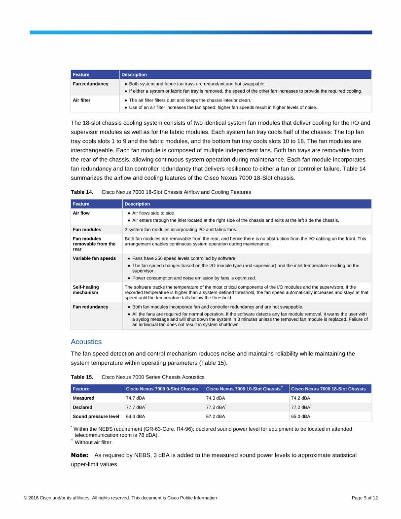
Feature Description
Fan redundancy ● Both system and fabric fan trays are redundant and hot swappable.
● If either a system or fabric fan tray is removed, the speed of the other fan increases to provide the required cooling.
Air filter ● The air filter filters dust and keeps the chassis interior clean.
● Use of an air filter increases the fan speed; higher fan speeds result in higher levels of noise.
The 18-slot chassis cooling system consists of two identical system fan modules that deliver cooling for the I/O and
supervisor modules as well as for the fabric modules. Each system fan tray cools half of the chassis: The top fan
tray cools slots 1 to 9 and the fabric modules, and the bottom fan tray cools slots 10 to 18. The fan modules are
interchangeable. Each fan module is composed of multiple independent fans. Both fan trays are removable from
the rear of the chassis, allowing continuous system operation during maintenance. Each fan module incorporates
fan redundancy and fan controller redundancy that delivers resilience to either a fan or controller failure. Table 14
summarizes the airflow and cooling features of the Cisco Nexus 7000 18-Slot chassis.
Table 14. Cisco Nexus 7000 18-Slot Chassis Airflow and Cooling Features
Feature Description
Air flow ● Air flows side to side.
● Air enters through the inlet located at the right side of the chassis and exits at the left side the chassis.
Fan modules 2 system fan modules incorporating I/O and fabric fans.
Fan modules removable from the rear
Both fan modules are removable from the rear, and hence there is no obstruction from the I/O cabling on the front. This arrangement enables continuous system operation during maintenance.
Variable fan speeds ● Fans have 256 speed levels controlled by software.
● The fan speed changes based on the I/O module type (and supervisor) and the inlet temperature reading on the supervisor.
● Power consumption and noise emission by fans is optimized.
Self-healing mechanism
The software tracks the temperature of the most critical components of the I/O modules and the supervisors. If the recorded temperature is higher than a system-defined threshold, the fan speed automatically increases and stays at that speed until the temperature falls below the threshold.
Fan redundancy ● Both fan modules incorporate fan and controller redundancy and are hot swappable.
● All the fans are required for normal operation. If the software detects any fan module removal, it warns the user with a syslog message and will shut down the system in 3 minutes unless the removed fan module is replaced. Failure of an individual fan does not result in system shutdown.
Acoustics
The fan speed detection and control mechanism reduces noise and maintains reliability while maintaining the
system temperature within operating parameters (Table 15).
Table 15. Cisco Nexus 7000 Series Chassis Acoustics
Feature Cisco Nexus 7000 9-Slot Chassis Cisco Nexus 7000 10-Slot Chassis** Cisco Nexus 7000 18-Slot Chassis
Measured 74.7 dBA 74.3 dBA 74.2 dBA
Declared 77.7 dBA* 77.3 dBA
* 77.2 dBA
*
Sound pressure level 64.4 dBA 67.2 dBA 65.0 dBA
* Within the NEBS requirement (GR-63-Core, R4-96); declared sound power level for equipment to be located in attended telecommunication room is 78 dBA).
** Without air filter.
Note: As required by NEBS, 3 dBA is added to the measured sound power levels to approximate statistical
upper-limit values
© 2016 Cisco and/or its affiliates. All rights reserved. This document is Cisco Public Information. Page 10 of 12
Cabling and Cabinet
The cable management system for the Cisco Nexus 7000 9- or 18-Slot chassis is located on both sides of the
chassis aligned with the module slots. The cable management is designed for high-density Cat6A cabling groomed
to either side or both sides.
The cable management system for the Cisco Nexus 7000 10-Slot chassis is located on the front of the chassis
above the modules. In the largest configuration, the chassis can support 384 Cat6A copper cables plus 8
management port cables. All cables can be groomed either to one side of the chassis or to the left and right. A top-
hinged door covers the cable management system. The cable management system can be removed to support
alternative ways of managing the cables.
The Cisco Nexus 7000 9- and 18-Slot chassis should be installed in either a four-post rack or a four-post cabinet
that meets the depth, total equipment weight, and network cabling requirements. Sufficient space must be provided
for cabling and for airflow on both sides. Multiple third-party vendor solutions are available to meet the system
cabling and airflow requirements and support the installation of external ducts to deflect air into the inlets and
return the warm air to the hot aisle in a hot-aisle and cold-aisle design. Use of ducting is recommended for
environments in which a cold-aisle and hot-aisle environment is required. Use of other four-post solutions that meet
the minimum requirements is supported.
The Cisco Nexus 7000 9-Slot chassis can also be installed in a two-post rack along with a four-post rack or a four-
post cabinet that meets the depth, total equipment weight, and network cabling requirements.
The Cisco Nexus 7000 10-Slot chassis should be installed in either a standard four-post rack or a four-post cabinet
that meets the depth, total equipment weight, and network cabling requirements. Multiple third-party vendor cabinet
solutions that meet the specifications for the 10-slot chassis are currently available.
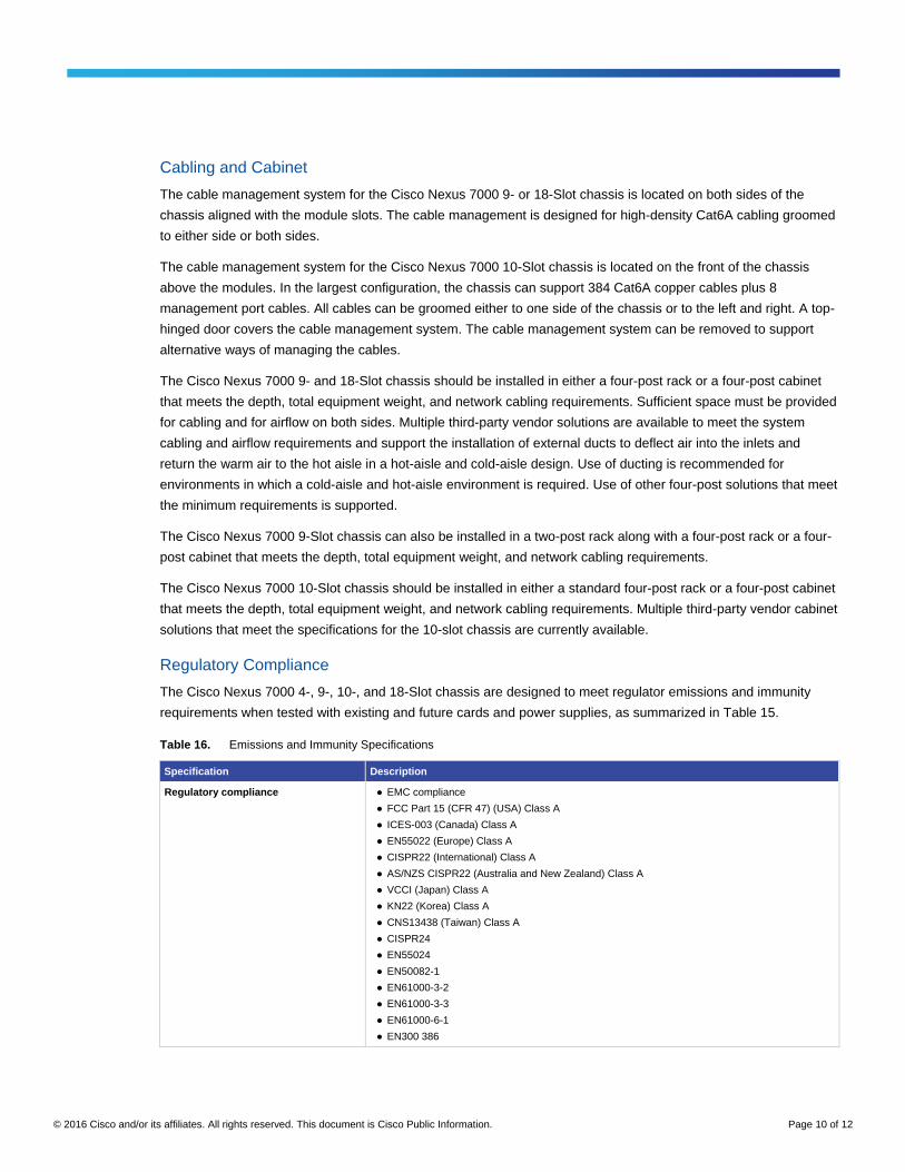
Regulatory Compliance
The Cisco Nexus 7000 4-, 9-, 10-, and 18-Slot chassis are designed to meet regulator emissions and immunity
requirements when tested with existing and future cards and power supplies, as summarized in Table 15.
Table 16. Emissions and Immunity Specifications
Specification Description
Regulatory compliance ● EMC compliance
● FCC Part 15 (CFR 47) (USA) Class A
● ICES-003 (Canada) Class A
● EN55022 (Europe) Class A
● CISPR22 (International) Class A
● AS/NZS CISPR22 (Australia and New Zealand) Class A
● VCCI (Japan) Class A
● KN22 (Korea) Class A
● CNS13438 (Taiwan) Class A
● CISPR24
● EN55024
● EN50082-1
● EN61000-3-2
● EN61000-3-3
● EN61000-6-1
● EN300 386
© 2016 Cisco and/or its affiliates. All rights reserved. This document is Cisco Public Information. Page 11 of 12
The Cisco Nexus 7000 Series is designed to meet GR-1089 issue 4 and service providers' acoustic specifications.
The sound level is within the NEBS criteria when operated without a filter (10-slot chassis only). Table 16
summarizes NEBS compliance.
Table 17. NEBS Specifications
Specification Description
Environmental standards ● NEBS criteria levels
● SR-3580 NEBS Level 3 (GR-63-CORE, issue 3, and GR-1089-CORE, issue 4)
● Verizon NEBS compliance
● Telecommunications Carrier Group (TCG) Checklist
● Qwest NEBS requirements
● Telecommunications Carrier Group (TCG) Checklist
● ATT NEBS requirements
● ATT TP76200 level 3 and TCG Checklist
● ETSI
● ETSI 300 019-1-1, Class 1.2 Storage
● ETSI 300 019-1-2, Class 2.3 Transportation
● ETSI 300 019-1-3, Class 3.2 Stationary Use
● Reduction of Hazardous Substances (ROHS) 5
The Cisco Nexus 7000 Series is designed to meet regulator safety requirements when tested with existing and
future cards and power supplies, as summarized in Table 17.
Table 18. Safety Specifications
Specification Description
Safety ● UL/CSA/IEC/EN 60950-1
● AS/NZS 60950
Service and Support
Cisco offers a wide range of services to help accelerate your success deploying and optimizing Cisco Nexus 7000
Series Switches in your data center. Our innovative services are delivered through a unique combination of people,
processes, tools, and partners, and are focused on helping you increase operating efficiency and improve your
data center network. Cisco® Advanced Services uses an architecture-led approach to help you align your data
center infrastructure with your business goals and provide long-term value. Cisco SMARTnet® Service helps you
resolve mission-critical problems with direct access at any time to Cisco network experts and award-winning
resources. With this service, you can take advantage of the Cisco Smart Call Home service capability that offers
proactive diagnostics and real-time alerts for your Cisco Nexus 7000 Series Switches. Spanning the entire network
lifecycle, Cisco Services help increase investment protection, optimize network operations, provide migration
support, and strengthen your IT expertise. For more information about Cisco Data Center Services, visit
http://www.cisco.com/go/dcservices.
Cisco Capital
Financing to Help You Achieve Your Objectives
Cisco Capital can help you acquire the technology you need to achieve your objectives and stay competitive. We
can help you reduce CapEx. Accelerate your growth. Optimize your investment dollars and ROI. Cisco Capital
financing gives you flexibility in acquiring hardware, software, services, and complementary third-party equipment.
And there’s just one predictable payment. Cisco Capital is available in more than 100 countries. Learn more.
© 2016 Cisco and/or its affiliates. All rights reserved. This document is Cisco Public Information. Page 12 of 12
For More Information
For more information about the Cisco Nexus 7000 Series Switches, visit the product homepage at
http://www.cisco.com/go/nexus7000 or contact your local account representative.
Printed in USA C78-437759-13 04/16