Embed Size (px)
Citation preview

Cisco Nexus 7000 Series Connectivity Management Processor Configuration GuideAugust 20, 2012
Americas HeadquartersCisco Systems, Inc.170 West Tasman DriveSan Jose, CA 95134-1706 USAhttp://www.cisco.comTel: 408 526-4000
800 553-NETS (6387)Fax: 408 527-0883
Text Part Number: OL-23072-03

THE SPECIFICATIONS AND INFORMATION REGARDING THE PRODUCTS IN THIS MANUAL ARE SUBJECT TO CHANGE WITHOUT NOTICE. ALL STATEMENTS, INFORMATION, AND RECOMMENDATIONS IN THIS MANUAL ARE BELIEVED TO BE ACCURATE BUT ARE PRESENTED WITHOUT WARRANTY OF ANY KIND, EXPRESS OR IMPLIED. USERS MUST TAKE FULL RESPONSIBILITY FOR THEIR APPLICATION OF ANY PRODUCTS.
THE SOFTWARE LICENSE AND LIMITED WARRANTY FOR THE ACCOMPANYING PRODUCT ARE SET FORTH IN THE INFORMATION PACKET THAT SHIPPED WITH THE PRODUCT AND ARE INCORPORATED HEREIN BY THIS REFERENCE. IF YOU ARE UNABLE TO LOCATE THE SOFTWARE LICENSE OR LIMITED WARRANTY, CONTACT YOUR CISCO REPRESENTATIVE FOR A COPY.
The following information is for FCC compliance of Class A devices: This equipment has been tested and found to comply with the limits for a Class A digital device, pursuant to part 15 of the FCC rules. These limits are designed to provide reasonable protection against harmful interference when the equipment is operated in a commercial environment. This equipment generates, uses, and can radiate radio-frequency energy and, if not installed and used in accordance with the instruction manual, may cause harmful interference to radio communications. Operation of this equipment in a residential area is likely to cause harmful interference, in which case users will be required to correct the interference at their own expense.
The following information is for FCC compliance of Class B devices: This equipment has been tested and found to comply with the limits for a Class B digital device, pursuant to part 15 of the FCC rules. These limits are designed to provide reasonable protection against harmful interference in a residential installation. This equipment generates, uses and can radiate radio frequency energy and, if not installed and used in accordance with the instructions, may cause harmful interference to radio communications. However, there is no guarantee that interference will not occur in a particular installation. If the equipment causes interference to radio or television reception, which can be determined by turning the equipment off and on, users are encouraged to try to correct the interference by using one or more of the following measures:
• Reorient or relocate the receiving antenna.
• Increase the separation between the equipment and receiver.
• Connect the equipment into an outlet on a circuit different from that to which the receiver is connected.
• Consult the dealer or an experienced radio/TV technician for help.
Modifications to this product not authorized by Cisco could void the FCC approval and negate your authority to operate the product.
The Cisco implementation of TCP header compression is an adaptation of a program developed by the University of California, Berkeley (UCB) as part of UCB’s public domain version of the UNIX operating system. All rights reserved. Copyright © 1981, Regents of the University of California.
NOTWITHSTANDING ANY OTHER WARRANTY HEREIN, ALL DOCUMENT FILES AND SOFTWARE OF THESE SUPPLIERS ARE PROVIDED “AS IS” WITH ALL FAULTS. CISCO AND THE ABOVE-NAMED SUPPLIERS DISCLAIM ALL WARRANTIES, EXPRESSED OR IMPLIED, INCLUDING, WITHOUT LIMITATION, THOSE OF MERCHANTABILITY, FITNESS FOR A PARTICULAR PURPOSE AND NONINFRINGEMENT OR ARISING FROM A COURSE OF DEALING, USAGE, OR TRADE PRACTICE.
IN NO EVENT SHALL CISCO OR ITS SUPPLIERS BE LIABLE FOR ANY INDIRECT, SPECIAL, CONSEQUENTIAL, OR INCIDENTAL DAMAGES, INCLUDING, WITHOUT LIMITATION, LOST PROFITS OR LOSS OR DAMAGE TO DATA ARISING OUT OF THE USE OR INABILITY TO USE THIS MANUAL, EVEN IF CISCO OR ITS SUPPLIERS HAVE BEEN ADVISED OF THE POSSIBILITY OF SUCH DAMAGES.
Cisco and the Cisco logo are trademarks or registered trademarks of Cisco and/or its affiliates in the U.S. and other countries. To view a list of Cisco trademarks, go to this URL: www.cisco.com/go/trademarks. Third-party trademarks mentioned are the property of their respective owners. The use of the word partner does not imply a partnership relationship between Cisco and any other company. (1110R)
Any Internet Protocol (IP) addresses used in this document are not intended to be actual addresses. Any examples, command display output, and figures included in the document are shown for illustrative purposes only. Any use of actual IP addresses in illustrative content is unintentional and coincidental.
Cisco Nexus 7000 Series Connectivity Management Processor Configuration Guide© 2008-2012 Cisco Systems, Inc. All rights reserved.
CisOL-23072-03
C O N T E N T S
Preface v
Audience v
Organization v
Document Conventions vi
Related Documentation vi
Obtaining Documentation and Submitting a Service Request vii
vii
C H A P T E R 1 Overview 1-1
Information About CMP 1-1
CMP MGMT Ethernet Port 1-2
CMP Access 1-3
High Availability 1-4
C H A P T E R 2 Connecting, Configuring, and Upgrading the CMP 2-1
Connecting to the CMP MGMT Ethernet Port 2-1
Configuring the CMP 2-2
Accessing the CMP from the CP 2-2
Logging Out of a CMP Session 2-2
Configuring the CMP-MGMT Interface 2-3
Using a Setup Script on the CP to Configure the CMP-MGMT Interface 2-4
Configuring an IPv4 IP Address for the CMP From the CP 2-4
Configuring an IPv4 IP Address for the CMP From the CMP 2-5
Configuring an IPv6 IP Address for the CMP From the CP 2-6
Configuring an IPv6 IP Address for the CMP From the CMP 2-7
Configuring an IPv4 Access Control List on the CMP 2-8
Configuring the Cisco Discovery Protocol for the CMP 2-9
Enabling and Disabling the CDP 2-10
Configuring Optional CDP Parameters 2-11
Default Settings 2-11
Additional References 2-11
Saving Console Output on the CMP 2-12
Logging Console Output on the CMP 2-12
Specifying the Size of the Logging File 2-13
iiico Nexus 7000 Series Connectivity Management Processor Configuration Guide

Contents
Showing Logged Output 2-14
Archiving a Log File 2-14
Clearing the Log File 2-15
Logging CMP Messages 2-16
Displaying Saved Messages 2-17
Configuring the Logging Level 2-17
Clearing the Log File 2-18
Directing Syslog Messages Externally 2-19
Changing the Communication Settings 2-21
Changing the Speed 2-22
Changing the Number of Bits in a Transmitted Character 2-23
Changing the Parity Checking 2-24
Changing the Asynchronous Stop Bits 2-25
Configuring Flow Control 2-26
Enabling or Disabling Flow Control for the CMP 2-26
Enabling or Disabling Flow Control for the CP 2-27
Configuring CMPs on a Dual Supervisor System 2-28
Verifying the CMP Configuration 2-29
Upgrading the CMP Image 2-30
Default Settings for CMP Parameters 2-31
C H A P T E R 3 Using the CMP 3-1
Monitoring the CP 3-2
Rebooting the CP 3-2
Rebooting the Entire Cisco NX-OS Device from the CMP 3-3
Rebooting the CMP from the CP 3-3
Rebooting the CMP from the CMP 3-3
Rebooting the System 3-4
I N D E X
ivCisco Nexus 7000 Series Connectivity Management Processor Configuration Guide
OL-23072-03

Preface
This preface describes the audience, organization, and conventions of the Cisco Nexus 7000 Series Connectivity Management Processor Configuration Guide. It also provides information on how to obtain related documentation.
This preface includes the following sections:
• Audience, page v
• Organization, page v
• Document Conventions, page vi
• Related Documentation, page vi
• Obtaining Documentation and Submitting a Service Request, page vii
AudienceThis guide is for experienced network system administrators who configure and maintain Nexus 7000 Series switches.
OrganizationThis document is organized as follows:
Chapter Description
Chapter 1, “Overview” Describes the Connectivity Management Processor.
Chapter 2, “Connecting, Configuring, and Upgrading the CMP”
Explains how to connect the CMP to the network, how to configure the CMP, and how to upgrade the CMP software image.
Chapter 3, “Using the CMP” Explains how to use the CMP to monitor the CP and system, how to use the CMP to reboot the CP or system, and how to use the CP to reboot the CMP.
vCisco Nexus 7000 Series Connectivity Management Processor Configuration Guide
OL-23072-03

Preface
Document ConventionsCommand descriptions use these conventions:
Screen examples use these conventions:
This document uses the following conventions:
Note Means reader take note. Notes contain helpful suggestions or references to material not covered in the publication.
Related DocumentationThis section includes the following topics:
• Hardware Documents, page vi
• Software Documents, page vii
Hardware DocumentsCisco Nexus 7000 Series documentation includes the following documents:
• Cisco Nexus 7000 Series Site Preparation Guide
• Cisco Nexus 7000 Series Hardware Installation and Reference Guide
• Cisco Nexus 7000 Series Regulatory Compliance and Safety Information
• Cisco Nexus 7000 Series Connectivity Management Processor Configuration Guide
Convention Description
boldface font Commands and keywords are in boldface.
italic font Arguments for which you supply values are in italics.
[ ] Elements in square brackets are optional.
[ x | y | z ] Optional alternative keywords are grouped in brackets and separated by vertical bars.
string A nonquoted set of characters. Do not use quotation marks around the string or the string will include the quotation marks.
screen font Terminal sessions and information that the switch displays are in screen font.
boldface screen font
Information you must enter is in boldface screen font.
italic screen font Arguments for which you supply values are in italic screen font.
< > Nonprinting characters, such as passwords, are in angle brackets.
[ ] Default responses to system prompts are in square brackets.
!, # An exclamation point (!) or a pound sign (#) at the beginning of a line of code indicates a comment line.
viCisco Nexus 7000 Series Connectivity Management Processor Configuration Guide
OL-23072-03

Preface
Software DocumentsThe Cisco Nexus 7000 Series switches ship with the Cisco NX-OS software. You can find software documentation for the Cisco NX-OS software at the following URL:
http://www.cisco.com/en/US/products/ps9402/tsd_products_support_series_home.html
The Cisco Datacenter Network Manager (DCNM) supports the Cisco Nexus 7000 Series. You can find documentation for DCNM at the following URL:
http://www.cisco.com/en/US/products/ps9369/tsd_products_support_series_home.html
Obtaining Documentation and Submitting a Service RequestFor information on obtaining documentation, submitting a service request, and gathering additional information, see the monthly What’s New in Cisco Product Documentation, which also lists all new and revised Cisco technical documentation, at:
http://www.cisco.com/en/US/docs/general/whatsnew/whatsnew.html
Subscribe to the What’s New in Cisco Product Documentation as a Really Simple Syndication (RSS) feed and set content to be delivered directly to your desktop using a reader application. The RSS feeds are a free service and Cisco currently supports RSS Version 2.0.
viiCisco Nexus 7000 Series Connectivity Management Processor Configuration Guide
OL-23072-03

Preface
viiiCisco Nexus 7000 Series Connectivity Management Processor Configuration Guide
OL-23072-03

Cisco Nexus 7000 Series ConneOL-23072-03
C H A P T E R 1
OverviewThis chapter provides an overview of the Connectivity Management Processor (CMP).
This chapter includes the following sections:
• Information About CMP, page 1-1
Information About CMP The CMP is a separate processor on the Cisco Nexus 7000 Series Supervisor 1 module that is in addition to the main control processor (CP). The CMP provides a second network interface to the switch for use even when the CP is not reachable. You can access the CMP to configure it and to perform system operations, such as taking over the CP console or restarting the CP.
Note The CMP is available only on the Supervisor 1 modules, not on the Supervisor 2 nor Supervisor 2E modules.
Each CMP contains its own RAM, bootflash, and front panel management Ethernet port. The CMP eliminates the need for a separate permanent terminal server attached to your supervisor module. You connect to the CMP through its CMP-management Ethernet (CMP-MGMT ETH) port with a Secure Shell (SSH) or Telnet session to monitor or reboot the supervisor module. If the associated supervisor module CP is operational, you can also connect to the CMP from the CP to reboot the CMP.
Each CMP remains operational even if its supervisor module is in standby mode or the switch is down because of issues such as over-temperature alarms. Each CMP gets power from an auxiliary power bus in the switch that remains operational so long as you have at least one power cable attached to the switch.
The CMP provides the following functions:
• Communicates with the Supervisor 1 module and I/O modules even if Cisco NX-OS switch is not responding on the mgmt0 port.
• Maintains connectivity when you reboot the supervisor module.
• Monitors the supervisor module console port.
• Reboots the local supervisor module or the entire system.
• Takes over the supervisor module console port.
• Collects failure logs and watches bootup diagnostic messages.
1-1ctivity Management Processor Configuration Guide

Chapter 1 OverviewInformation About CMP
Note The CMP runs a separate image from Cisco NX-OS (see the “Upgrading the CMP Image” section on page 2-30).
This section includes the following topics:
• CMP MGMT Ethernet Port, page 1-2
• CMP Access, page 1-3
• High Availability, page 1-4
CMP MGMT Ethernet PortThe CMP has a dedicated front-panel Ethernet port but does not have its own front-panel console port. Figure 1-1 shows the Supervisor 1 front panel, with the CMP MGMT Ethernet port on the far right.
Figure 1-1 Supervisor 1 Module Faceplate
The Supervisor 1 module contains a series of LEDs that reflect the status of the CMP and the CMP MGMT Ethernet port. Figure 1-1 identifies the LEDs and Table 1-1 describes their states and the conditions that they indicate.
1 CMP Status LED 4 ACT LED
2 Link LED 5 CMP MGMT Ethernet LED
3 CMP MGMT Ethernet port
SUP 1 CONSOLE COM1/AUX
STATUS
SYSTEM
ACTIVE
PWR MGMT
SERIAL PORT DEVICE PORT
USB
HOST PORTS
ID
LINK
ACT
RESET 1
2
LINK
ACT
CMP
STATUS
CMP MGMT ETH
2804
66
3 421
5
Table 1-1 CMP LEDs
LED Status Description
CMP STATUS off CMP is not receiving power.
red CMP is not operational.
amber CMP is booting.
green CMP is operational.
LINK off • CMP port link status is down.
• Cable is unplugged.
green CMP port link status is up.
1-2Cisco Nexus 7000 Series Connectivity Management Processor Configuration Guide
OL-23072-03

Chapter 1 OverviewInformation About CMP
CMP AccessWhen the CP and CMP are both operational, you can log into the CMP through the CP using your NX-OS configured username and password or the admin username and password. If the CP is configured with RADIUS or TACACS, then your authentication is also handled by RADIUS or TACACS. If the CP is operational, the CMP accepts logins from users with network-admin privileges. The CMPs use the same authentication mechanism to configure the CP (that is, RADIUS, TACACS, or local). The CP automatically synchronizes the admin password with the active and standby CMP so that you can use the “admin” username and password when a CP is not operational. For more information on user accounts and user roles, see the Cisco Nexus 7000 Series NX-OS Security Configuration Guide, Release 5.x.
Note The active CP also synchronizes all NX-OS configured usernames and passwords with the standby CP so that you can use your NX-OS configured username whenever a CP is operational.
If you are connecting to the CMP through Cisco NX-OS, you must be in the default virtual switch context (VDC). For more information on VDCs, see the Cisco Nexus 7000 Series NX-OS Virtual Device Context Configuration Guide, Release 5.x.
The SSH server is enabled by default on the CMP. We recommend that you do not disable the SSH server on the CMP, but if required, you can disable the SSH server and enable the Telnet server. Table 1-2 lists the commands that you can use to enable or disable the SSH server and Telnet server.
To view system messages that track who logged into the CMP, use the show logging command on the CMP.
ACT off • Port is not accessed.
• Port is down.
• Port cable is unplugged.
flashing green Port is being accessed.
CMP MGMT ETH amber Interface is not configured.
green Interface is configured.
Table 1-1 CMP LEDs (continued)
LED Status Description
Table 1-2 Enabling and Disabling Commands for the SSH Server and Telnet Server
Action Command
Enable SSH server (default setting) ssh server enable
Disable SSH server no ssh server enable
Enable Telnet server telnet server enable
Disable Telnet server no telnet server enable
1-3Cisco Nexus 7000 Series Connectivity Management Processor Configuration Guide
OL-23072-03

Chapter 1 OverviewInformation About CMP
High AvailabilityA fully redundant switch contains two supervisor modules. If these modules are Supervisor 1 modules, they each have a CMP. Although only one supervisor module is active at any one time, the CMP software in each supervisor module is always active. For a high-availability configuration, you should connect four Ethernet cables to these supervisor modules—one for each mgmt 0 interface and one for each cmp-mgmt interface. You should also configure three IP addresses—one for each cmp-mgmt interface and one that is shared between the active and standby supervisor mgmt 0 interfaces.
Note Supervisor module switchovers do not reload the CMPs.
A supervisor module is fully operational only if both the CP and its CMP are operational.
Note A CMP failure does not cause a supervisor module switchover.
1-4Cisco Nexus 7000 Series Connectivity Management Processor Configuration Guide
OL-23072-03

Cisco Nexus 7000 Series ConneOL-23072-03
C H A P T E R 2
Connecting, Configuring, and Upgrading the CMPThis chapter explains how to connect and configure the Connectivity Management Processor (CMP) on a Cisco Nexus 7000 Series switch. It also explains how to update the software image for the CMP.
This chapter includes the following sections:
• Connecting to the CMP MGMT Ethernet Port, page 2-1
• Configuring the CMP, page 2-2
• Verifying the CMP Configuration, page 2-29
• Upgrading the CMP Image, page 2-30
• Default Settings for CMP Parameters, page 2-31
Connecting to the CMP MGMT Ethernet PortTo connect the CMP to the network, follow these steps for each installed supervisor:
Step 1 Connect a modular, RJ-45, UTP cable to the CMP MGMT ETH port on the Supervisor 1 module.
Step 2 Route the cable through the central slot in the cable management system on the Cisco Nexus 7000 Series chassis.
Step 3 Connect the other end of the cable to the networking device.
You configure the cmp-mgmt interface during the initial setup script on the CP when you first configure your switch. See the Cisco Nexus 7000 Series NX-OS Fundamentals Configuration Guide, Release 5.x for details on the setup script.
Caution To prevent an IP address conflict, do not connect the CMP MGMT port to the network until the initial configuration is complete. For more information on Ethernet connections and cable management, see the Cisco Nexus 7000 Series Hardware Installation and Reference Guide.
2-1ctivity Management Processor Configuration Guide

Chapter 2 Connecting, Configuring, and Upgrading the CMPConfiguring the CMP
Configuring the CMPThis section includes the following topics:
• Accessing the CMP from the CP, page 2-2
• Logging Out of a CMP Session, page 2-2
• Configuring the CMP-MGMT Interface, page 2-3
• Configuring an IPv4 Access Control List on the CMP, page 2-8
• Configuring the Cisco Discovery Protocol for the CMP, page 2-9
• Saving Console Output on the CMP, page 2-12
• Logging CMP Messages, page 2-16
• Changing the Communication Settings, page 2-21
• Configuring Flow Control, page 2-26
• Configuring CMPs on a Dual Supervisor System, page 2-28
Accessing the CMP from the CPYou can access the CMP through a console, SSH, or Telnet session with the CP.
Note To access the CMP by SSH or Telnet, you must enable those sessions on the CMP (by default, the SSH server session is enabled). To enable or disable SSH or Telnet sessions, see Table 1-2 on page 1-3.
BEFORE YOU BEGIN
Ensure that you are in the default VDC (or use the switchback command).
SUMMARY STEPS
1. attach cmp
DETAILED STEPS
Logging Out of a CMP SessionWhen you log out of a CMP session, you must end the session then exit the mode.
Command Purpose
Step 1 attach cmp
Example:switch# attach cmp
ConnectedEscape character is '~,'switch-cmp#
Accesses the CMP on the active supervisor module.
2-2Cisco Nexus 7000 Series Connectivity Management Processor Configuration Guide
OL-23072-03

Chapter 2 Connecting, Configuring, and Upgrading the CMPConfiguring the CMP
BEFORE YOU BEGIN
You must be accessing the CMP.
SUMMARY STEPS
1. end
2. exit
DETAILED STEPS
Note If you are in an attached console session, use the ~, command to exit the CMP.
Configuring the CMP-MGMT Interface You must configure the CMP-MGMT interface before you can connect to the CMP through a SSH or Telnet session.
Note Unlike when you configure the CP, you do not need to use the copy running-config startup-config command configuring the CMP-MGMT interface. Each time that you enter a command when configuring the CMP-MGMT interface, the Cisco NX-OS operating system saves the configuration changes on the CMP flash drive.
The following sections explain each of the different ways that you can configure the CMP-MGMT interface:
• Using a Setup Script on the CP to Configure the CMP-MGMT Interface, page 2-4
• Configuring an IPv4 IP Address for the CMP From the CP, page 2-4
• Configuring an IPv4 IP Address for the CMP From the CMP, page 2-5
• Configuring an IPv6 IP Address for the CMP From the CP, page 2-6
• Configuring an IPv6 IP Address for the CMP From the CMP, page 2-7
Command Purpose
Step 1 end
Example:switch-cmp# end
switch-cmp#
Ends the configuration session.
Step 2 exit
Example:switch-cmp# exitswitch#
Exits from the CMP configuration mode.
2-3Cisco Nexus 7000 Series Connectivity Management Processor Configuration Guide
OL-23072-03
Chapter 2 Connecting, Configuring, and Upgrading the CMPConfiguring the CMP
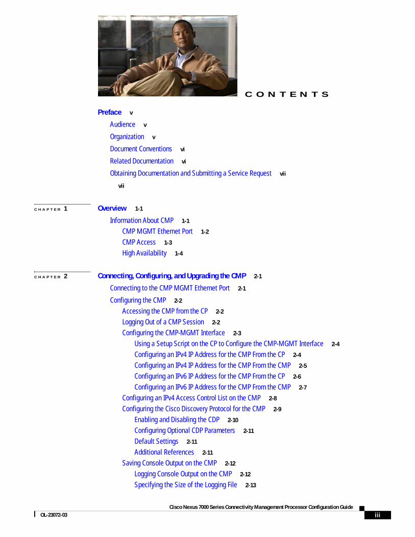
Using a Setup Script on the CP to Configure the CMP-MGMT Interface
The Cisco NX-OS setup script guides you through configuring the CMP-MGMT interface. To use this script, see the Cisco Nexus 7000 Series NX-OS Fundamentals Configuration Guide, Release 5.x.
Configuring an IPv4 IP Address for the CMP From the CP
You can use the Cisco NX-OS CLI on the CP to configure an IP address (IPv4 format) for the CMP-MGMT interface.
BEFORE YOU BEGIN
Ensure that you are in the default virtual device context (VDC) (or use the switchback command).
SUMMARY STEPS
1. configure terminal
2. interface cmp-mgmt module slot
3. ip address ipv4-address/length
4. ip default-gateway ipv4-address
5. (optional) show running-config cmp
DETAILED STEPS
Command Purpose
Step 1 configure terminal
Example:switch# configure terminalswitch(config)#
Enters configuration mode.
Step 2 interface cmp-mgmt module slot
Example:switch(config)# interface cmp-mgmt module 5switch(config-if-cmp)#
Enters interface configuration mode for the cmp-mgmt interface on either the active or the standby supervisor.
Step 3 ip address ipv4-address/length
Example:switch(config-if-cmp)# ip address 192.0.2.1/16
Configures the IPv4 IP address for this cmp-mgmt interface.
Step 4 ip default-gateway ipv4-address
Example:switch(config-if-cmp)# ip default-gateway 192.0.2.10
Configures the default gateway (IPv4 format) for this cmp-mgmt interface.
Step 5 show running-config cmp
Example:switch(config-if-cmp)# show running-config cmp
(Optional) Displays a summary of the CMP interface configuration.
2-4Cisco Nexus 7000 Series Connectivity Management Processor Configuration Guide
OL-23072-03

Chapter 2 Connecting, Configuring, and Upgrading the CMPConfiguring the CMP
Configuring an IPv4 IP Address for the CMP From the CMP
You can use the Cisco NX-OS CLI on the CP to configure an IP address (IPv4 format) for the CMP-MGMT interface.
BEFORE YOU BEGIN
Ensure that you are in the default VDC (or use the switchback command).
SUMMARY STEPS
1. attach cmp
2. configure terminal
3. ip default-gateway ipv4-address
4. interface cmp-mgmt
5. ip address ipv4-address/length
6. (optional) show running-config
7. (optional) ~,
DETAILED STEPS
Command Purpose
Step 1 attach cmp
Example:switch# attach cmpswitch-cmp5 login: adminPassword: <password>#
Connects to the CMP from the supervisor CP.
Step 2 configure terminal
Example:switch-cmp# configure terminalswitch-cmp(config)#
Enters configuration mode on the CMP.
Step 3 ip default-gateway ipv4-address
Example:switch-cmp(config)# ip default-gateway 192.0.2.10
Configures the default gateway for the cmp-mgmt interface.
Step 4 interface cmp-mgmt
Example:switch-cmp(config)# interface cmp-mgmt switch-cmp(config-if)#
Enters interface configuration mode for the cmp-mgmt interface on either the active or the standby supervisor.
Step 5 ip address ipv4-address/length
Example:switch-cmp(config-if)# ip address 192.0.2.1/16
Configures the IP address for this cmp-mgmt interface.
2-5Cisco Nexus 7000 Series Connectivity Management Processor Configuration Guide
OL-23072-03

Chapter 2 Connecting, Configuring, and Upgrading the CMPConfiguring the CMP
Configuring an IPv6 IP Address for the CMP From the CP
You can configure an IPv6 address for the CMP-MGMT interface from the CP.
BEFORE YOU BEGIN
Ensure that you are in the default VDC (or use the switchback command).
SUMMARY STEPS
1. configure terminal
2. interface cmp-mgmt module slot
3. ipv6 address ipv6-address/length
4. ipv6 default-gateway ipv6-address
5. (optional) show running-config cmp
DETAILED STEPS
Step 6 show running-config
Example:switch-cmp(config-if)# show running-config
(Optional) Displays the CMP configuration.
Step 7 ~,
Example:switch-cmp(config-if)# ~,switch#
(Optional) Exits the CMP console and returns to the Cisco NX-OS CLI on the CP.
Command Purpose
Command Purpose
Step 1 configure terminal
Example:switch# configure terminalswitch(config)#
Enters configuration mode.
Step 2 interface cmp-mgmt module slot
Example:switch(config)# interface cmp-mgmt module 5switch(config-if-cmp)#
Enters interface configuration mode for the CMP-MGMT interface on either the active or the standby supervisor.
Step 3 ipv6 address ipv6-address/length
Example:switch(config-if-cmp)# ipv6 address 2001:DB8:0:1::1/64
Configures the IP address (IPv6 format) for this cmp-mgmt interface.
2-6Cisco Nexus 7000 Series Connectivity Management Processor Configuration Guide
OL-23072-03

Chapter 2 Connecting, Configuring, and Upgrading the CMPConfiguring the CMP
To remove the IP address for the cmp-mgmt interface, use the no ipv6 address command.
To remove the IP address for the default gateway, use the no ipv6 default-gateway command.
Configuring an IPv6 IP Address for the CMP From the CMP
You can use the Cisco NX-OS CLI on the CP to configure an IPv6 IP address for the CMP-MGMT interface.
BEFORE YOU BEGIN
Ensure that you are in the default VDC (or use the switchback command).
SUMMARY STEPS
1. attach cmp
2. configure terminal
3. ipv6 default-gateway ipv6-address
4. interface cmp-mgmt
5. ipv6 address ipv6-address/length
6. (optional) show running-config
7. (optional) ~,
DETAILED STEPS
Step 4 ipv6 default-gateway ipv6-address
Example:switch(config-if-cmp)# ipv6 default-gateway 2001:DB8:0:1::8/64
Configures the default gateway (IPv6 address) for the cmp-mgmt interface.
Step 5 show running-config cmp
Example:switch(config-if-cmp)# show running-config cmp
(Optional) Displays a summary of the CMP interface configuration.
Command Purpose
Command Purpose
Step 1 attach cmp
Example:switch# attach cmpswitch-cmp5 login: adminPassword: <password>#
Connects to the CMP from the supervisor CP.
Step 2 configure terminal
Example:switch-cmp# configure terminalswitch-cmp(config)#
Enters configuration mode on the CMP.
2-7Cisco Nexus 7000 Series Connectivity Management Processor Configuration Guide
OL-23072-03

Chapter 2 Connecting, Configuring, and Upgrading the CMPConfiguring the CMP
Configuring an IPv4 Access Control List on the CMPYou can create an IPv4 access control list (ACL) and apply it to the cmp-mgmt interface. For more information on ACLs, see the Cisco Nexus 7000 Series NX-OS Security Configuration Guide, Release 5.x.
Note You can only configure an ACL on the CMP directly. You cannot configure an ACL from Cisco NX-OS software on the supervisor module CP.
BEFORE YOU BEGIN
You are connected to the CMP (see the “Configuring an IPv4 IP Address for the CMP From the CMP” section on page 2-5).
SUMMARY STEPS
1. configure terminal
2. ip access-list name
3. {permit | deny} protocol source destination
4. exit
5. interface cmp-mgmt
6. ip access-group access-list in
7. (optional) show running-config
Step 3 ipv6 default-gateway ipv6-address
Example:switch-cmp(config)# ipv6 default-gateway 192.0.2.10
Configures the default gateway (IPv6 format) for the cmp-mgmt interface.
Step 4 interface cmp-mgmt
Example:switch-cmp(config)# interface cmp-mgmt switch-cmp(config-if)#
Enters interface configuration mode for the cmp-mgmt interface on either the active or the standby supervisor.
Step 5 ipv6 address ipv6-address/length
Example:switch-cmp(config-if)# ipv6 address 192.0.2.1/16
Configures the IPv6 IP address for the cmp-mgmt interface.
Step 6 show running-config
Example:switch-cmp(config-if)# show running-config
(Optional) Displays the CMP configuration.
Step 7 ~,
Example:switch-cmp(config-if)# ~,switch#
(Optional) Exits the CMP console and returns to the Cisco NX-OS CLI on the CP.
Command Purpose
2-8Cisco Nexus 7000 Series Connectivity Management Processor Configuration Guide
OL-23072-03
Chapter 2 Connecting, Configuring, and Upgrading the CMPConfiguring the CMP
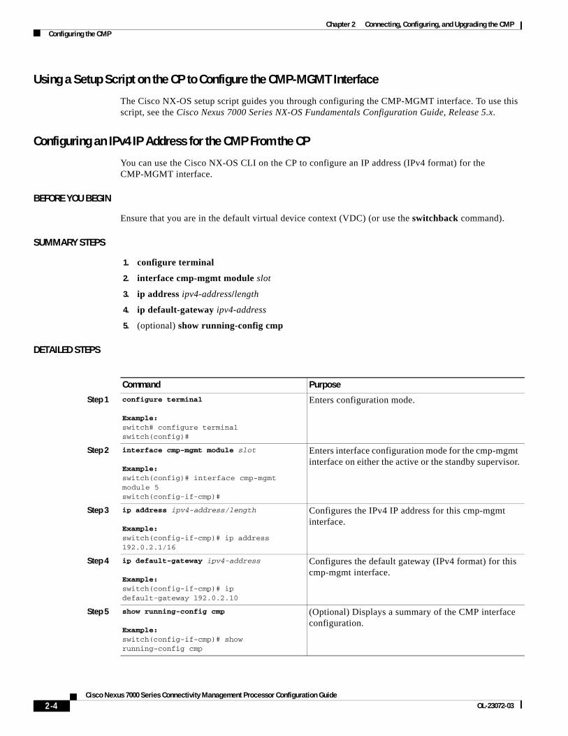
DETAILED STEPS
Configuring the Cisco Discovery Protocol for the CMPThe Cisco Discovery Protocol (CDP) is a media- and protocol-independent protocol that runs on all Cisco-manufactured equipment including routers, bridges, access and communication servers, and switches. You can use CDP to discover and view information about all the Cisco devices that are directly attached to the switch.
CDP gathers protocol addresses of neighboring devices and discovers the platform of those devices.
Each switch that you configure for CDP sends periodic advertisements to a multicast address. The advertisements also contain hold-time information, which indicates the length of time that a receiving device should hold CDP information before removing it. You can configure the advertisement or refresh timer and the hold timer.
This section includes the following topics:
• Enabling and Disabling the CDP, page 2-10
Command Purpose
Step 1 configure terminal
Example:switch-cmp# configure terminalswitch-cmp(config)#
Enters global configuration mode on the CMP.
Step 2 ip access-list name
Example:switch-cmp(config)# ip access-list acl-01switch-cmp(config-acl)#
Creates the IPv4 ACL and enters IP ACL configuration mode. The name argument can be up to 64 characters.
Step 3 {permit | deny} protocol source destination
Example:switch-cmp(config-acl)# permit ip 192.168.2.0/24 0.0.0.0/0
Creates a rule in the IPv4 ACL.
The permit and deny commands support many ways of identifying traffic. For more information, see the Cisco Nexus 7000 Series NX-OS Security Command Reference, Release 5.x.
Step 4 exit
Example:switch-cmp(config-acl)# exitswitch-cmp(config)#
Exits to configuration mode.
Step 5 interface cmp-mgmt
Example:switch-cmp(config)# interface cmp-mgmt switch-cmp(config-if)#
Enters interface configuration mode for the cmp-mgmt interface on either the active or the standby supervisor.
Step 6 ip access-group access-list in
Example:switch-cmp(config-if)# ip access-group acl-01 in
Applies an IPv4 ACL to the cmp-mgmt interface for traffic flowing into the interface.
Step 7 show running-config
Example:switch-cmp(config-if)# show running-config
(Optional) Displays the CMP configuration.
2-9Cisco Nexus 7000 Series Connectivity Management Processor Configuration Guide
OL-23072-03

Chapter 2 Connecting, Configuring, and Upgrading the CMPConfiguring the CMP
• Configuring Optional CDP Parameters, page 2-11
• Default Settings, page 2-11
• Additional References, page 2-11
Enabling and Disabling the CDP
CDP is enabled by default. You can disable CDP and then reenable it at a later time.
SUMMARY STEPS
1. attach cmp
2. configure terminal
3. cdp enable
DETAILED STEPS
To disable the CDP feature on the switch, use the no cdp enable command.
Command Purpose
Step 1 attach cmp
Example:switch# attach cmpConnectedEscape character is '~,' [tilde comma]
[EOT] switch#
Attaches the CMP.
Step 2 configure terminal
Example:switch# configure terminalEnter configuration commands, one per line. End with CNTL/Z switch(config)#
Places you in global configuration mode.
Step 3 cdp enable
Example:switch(config)# cdp enable
Enables the CDP feature on the entire switch. This feature is enabled by default.
2-10Cisco Nexus 7000 Series Connectivity Management Processor Configuration Guide
OL-23072-03

Chapter 2 Connecting, Configuring, and Upgrading the CMPConfiguring the CMP
Configuring Optional CDP Parameters
You can use the following optional commands in global configuration mode to modify CDP:
Default Settings
Table 2-1 lists the CDP default settings.
Additional References
For additional information related to implementing CDP, see Table 2-2.
Command Purposecdp advertise {v1 | v2}
Example:switch(config)# cdp advertise v1
Sets the CDP version supported by the switch. The default is v2.
cdp format device-id {mac-address | serial-number | system-name}
Example:switch(config)# cdp format device-id mac-address
Sets the CDP device ID. The options are as follows:
• mac-address—MAC address of the chassis
• other—Chassis serial number
• serial-number—Chassis serial number/Organizationally Unique Identifier (OUI)
• system-name—system name or domain name
The default is system-name.
Table 2-1 CDP Default Settings
Parameter Default
CDP Enabled globally and on all interfaces
CDP version Version 2
CDP device ID Serial number
CDP timer 60 seconds
CDP hold time 180 seconds
Table 2-2 Related Documents
Related Topic Document Title
CDP CLI commands Cisco Nexus 7000 Series NX-OS System Management Command Reference, Release 5.x
VDCs and VRFs Cisco Nexus 7000 Series NX-OS Virtual Device Context Configuration Guide, Release 5.x
2-11Cisco Nexus 7000 Series Connectivity Management Processor Configuration Guide
OL-23072-03

Chapter 2 Connecting, Configuring, and Upgrading the CMPConfiguring the CMP
Saving Console Output on the CMPBeginning with Cisco NX-OS Release 5.0, you can log console output on the CMP to help you troubleshoot problems that you might encounter when reloading the CP on your Cisco Nexus 7000 Series switch. To manage the log file on the CMP, you can specify the size of the file, display its logs, archive the file on the CP log flash drive, and clear logs from the file. The changes that you make to manage the logging of console output are recorded in the running configuration. To activate these changes for future sessions, you must copy the running configuration to the startup configuration after making the changes.
This section includes the following topics:
• Logging Console Output on the CMP, page 2-12
• Specifying the Size of the Logging File, page 2-13
• Showing Logged Output, page 2-14
• Archiving a Log File, page 2-14
• Clearing the Log File, page 2-15
Logging Console Output on the CMP
When you enable the logging of console output on the CMP, you can either use the default file size (50 kilobytes [KB]) for the logs or specify another file size between 10 KB and 100 KB. You can enable or disable this logging function while working in the CP or in the CMP.
Note When the log file fills with logs, the system creates another file and begins filling it with logs.
BEFORE YOU BEGIN
If you are operating in an attach CMP or detach CMP mode, your configuration change to enable or disable the logging is recorded in the running configuration but the switch does not change this function for the current session.
SUMMARY STEPS
1. configure terminal
2. capture cp console [file_size]
3. (optional) copy running-config startup-config
2-12Cisco Nexus 7000 Series Connectivity Management Processor Configuration Guide
OL-23072-03

Chapter 2 Connecting, Configuring, and Upgrading the CMPConfiguring the CMP
DETAILED STEPS
Note To disable the logging of console output, use the no capture cp console command. When you use this command on the CP, it applies the CMP configuration to both the active and standby supervisor modules.
Specifying the Size of the Logging File
You can specify the size of the console output logging file separately from enabling or disabling the logging function. You can do this action while working in the CP or in the CMP.
BEFORE YOU BEGIN
If you are configuring the CMP from the CP, you must not be in an attach CMP mode.
If you are configuring the CMP from the CMP, you must not be in a monitor CP mode.
Note If you are operating in an attach CMP or detach CMP mode, your configuration change to enable or disable the logging is recorded in the running configuration but the switch does not change this function for the current session.
SUMMARY STEPS
1. configure terminal
2. capture cp size [file_size]
3. (optional) copy running-config startup-config
Command Purpose
Step 1 configure terminal
Example:switch# configure terminalEnter configuration commands, one per line. End with CNTL/Z switch(config)#
Places you in global configuration mode.
Step 2 capture cp console 100
Example:switch(config)# capture cp console 100
Enables the logging of console output on the CMP in a file of the size specified by this integer in this command or in a default sized file (50 KB) if a file size is not specified.
Step 3 copy running-config startup-config
Example:switch(config)# copy running-config startup-config
(Optional) Saves this configuration change.
2-13Cisco Nexus 7000 Series Connectivity Management Processor Configuration Guide
OL-23072-03

Chapter 2 Connecting, Configuring, and Upgrading the CMPConfiguring the CMP
DETAILED STEPS
Showing Logged Output
You can display the contents of a console output log file or the last number of logs that you specify.
PROCEDURE
Archiving a Log File
You can archive the console output log file on the CP while working in the CP or in the CMP. By default, the switch archives the log file.
BEFORE YOU BEGIN
If you are configuring the CMP from the CP, you must not be in an attach CMP mode.
If you are configuring the CMP from the CMP, you must not be in a monitor CP mode.
Note If you are operating in an attach CMP or detach CMP mode, your configuration change to enable or disable the logging is recorded in the running configuration but the switch does not change this function for the current session.
Command Purpose
Step 1 configure terminal
Example:switch# configure terminalEnter configuration commands, one per line. End with CNTL/Z switch(config)#
Places you in global configuration mode.
Step 2 capture cp size 100
Example:switch(config)# capture cp size 100
Changes the KB size of the console output log file. Specify an integer between 10 and 100. The default is 50.
Step 3 copy running-config startup-config
Example:switch(config)# copy running-config startup-config
(Optional) Saves this configuration change.
Command Purpose
show capture all Displays all of the logs in the log file.
show capture last number_of_lines Displays the most recently logged output. You include an integer to specify the number of lines to display.
2-14Cisco Nexus 7000 Series Connectivity Management Processor Configuration Guide
OL-23072-03

Chapter 2 Connecting, Configuring, and Upgrading the CMPConfiguring the CMP
SUMMARY STEPS
1. configure terminal
2. capture cp archive enable
3. (optional) copy running-config startup-config
DETAILED STEPS
Note To stop the archiving of the console output to the CP, use the no capture cp archive enable command.
Clearing the Log File
You can clear the contents of a log file while configuring in the CMP.
SUMMARY STEPS
1. configure terminal
2. clear capture cp
3. (optional) copy running-config startup-config
Command Purpose
Step 1 configure terminal
Example:switch# configure terminalEnter configuration commands, one per line. End with CNTL/Z switch(config)#
Places you in global configuration mode.
Step 2 capture cp archive enable
Example:switch(config)# capture cp archive enable
Enables the archiving of console output log files on the CP.
Step 3 copy running-config startup-config
Example:switch(config)# copy running-config startup-config
(Optional) Saves this configuration change.
2-15Cisco Nexus 7000 Series Connectivity Management Processor Configuration Guide
OL-23072-03

Chapter 2 Connecting, Configuring, and Upgrading the CMPConfiguring the CMP
DETAILED STEPS
Logging CMP MessagesYou can save up to 256 CMP messages in a log file, and you can specify a severity threshold for the messages saved. When the file has 256 messages, the CMP automatically removes the oldest message whenever it saves a new message. Table 2-3 describes the message levels and types of messages that the CMP saves. When you specify a severity level, the CMP saves messages for that level and all levels below it in the log file.
Command Purpose
Step 1 configure terminal
Example:switch# configure terminalEnter configuration commands, one per line. End with CNTL/Z switch(config)#
Places you in global configuration mode.
Step 2 clear capture cp
Example:switch(config)# clear capture cp
Clears the contents of the log file.
Step 3 copy running-config startup-config
Example:switch(config)# copy running-config startup-config
(Optional) Saves this configuration change.
Table 2-3 CMP Message Severity Levels
Level Messages Saved Description
0 - Emergency — —
1 - Alert CP on this SUP has reset. CMP detected a nonmaskable interrupt on the CP.
2 - Critical CP is not online (could not establish communication with CP).
Connected with CP! LOG CP IS ONLINE.
Connection reset with CP!!
CMP cannot communicate with the CP.
CMP and CP can communicate.
CMP cannot detect the maximum number of CP heartbeats.
3 - Error — —
4 - Warning — —
5 - Notification — —
6 - Informational — —
7 - Debugging — —
2-16Cisco Nexus 7000 Series Connectivity Management Processor Configuration Guide
OL-23072-03

Chapter 2 Connecting, Configuring, and Upgrading the CMPConfiguring the CMP
This section includes the following topics:
• Displaying Saved Messages, page 2-17
• Configuring the Logging Level, page 2-17
• Clearing the Log File, page 2-18
Displaying Saved Messages
You can display all of the messages saved in the CMP log file.
BEFORE YOU BEGIN
Ensure that you are in the default VDC (or use the switchback command).
SUMMARY STEPS
1. attach cmp
2. show logging logfile
3. (optional) ~,
DETAILED STEPS
Configuring the Logging Level
By default, the CMP saves level 2 messages and below for each CMP process in the log file. You can specify a different level for the CMP to save for a process by using the logging level command.
BEFORE YOU BEGIN
Ensure that you are in the default VDC (or use the switchback command).
SUMMARY STEPS
1. attach cmp
Command Purpose
Step 1 attach cmp
Example:switch# attach cmpswitch-cmp#
Connects to the CMP from the supervisor CP.
Step 2 show logging logfile
Example:switch-cmp# show logging logfile
Shows the saved logfile messages.
Step 3 ~,
Example:switch-cmp(config)# ~,switch#
(Optional) Exits the CMP console and returns to the Cisco NX-OS CLI on the CP.
2-17Cisco Nexus 7000 Series Connectivity Management Processor Configuration Guide
OL-23072-03

Chapter 2 Connecting, Configuring, and Upgrading the CMPConfiguring the CMP
2. configure terminal
3. (optional) show logging level process
4. logging level process [1 | 2 | 3 | 4 | 5 | 6 | 7]
5. (optional) show logging level process
6. (optional) ~,
DETAILED STEPS
Clearing the Log File
You can clear the contents of the log file.
Command Purpose
Step 1 attach cmp
Example:switch# attach cmpswitch-cmp#
Connects to the CMP from the supervisor CP.
Step 2 configure terminal
Example:switch-cmp# configure terminalswitch-cmp(config)#
Enters the configuration mode on the CMP.
Step 3 show logging level process
Example:switch-cmp(config)# show logging level userFacility Default Severity Current Session Severity-------- ---------------- ------------------------user 2 2...switch-cmp(config)#
(Optional) Displays the current logging level for the specified process.
Step 4 logging level process [1 | 2 | 3 | 4 | 5 | 6 | 7]
Example:switch-cmp(config)# logging level user 3switch-cmp(config)#
Configures a new logging level threshold for a process.
Step 5 show logging level process
Example:switch-cmp(config)# show logging level user Facility Default Severity Current Session Severity-------- ---------------- ------------------------user 3 3...switch-cmp(config)#
(Optional) Displays the current logging level for the specified process.
Step 6 ~,
Example:switch-cmp(config)# ~,switch#
(Optional) Exits the CMP console and returns to the Cisco NX-OS CLI on the CP.
2-18Cisco Nexus 7000 Series Connectivity Management Processor Configuration Guide
OL-23072-03

Chapter 2 Connecting, Configuring, and Upgrading the CMPConfiguring the CMP
BEFORE YOU BEGIN
Ensure that you are in the default VDC (or use the switchback command).
SUMMARY STEPS
1. attach cmp
2. configure terminal
3. clear logging logfile
4. (optional) ~,
DETAILED STEPS
Directing Syslog Messages Externally
You can direct the CMP syslog messages to a maximum of five external devices (consoles and terminals), and you can specify the maximum level of the messages directed to each external device.
SUMMARY STEPS
1. attach cmp
2. configure terminal
3. logging server ip_address|ipv6_address {0 | 1 | 2 | 3 | 4 | 5 | 6 | 7} facility {auth | daemon | kernel | user}logging console {0 | 1 | 2 | 3 | 4 | 5 | 6 | 7}logging monitor {0 | 1 | 2 | 3 | 4 | 5 | 6 | 7}logging level logging_facility {0 | 1 | 2 | 3 | 4 | 5 | 6 | 7}
Command Purpose
Step 1 attach cmp
Example:switch# attach cmpswitch-cmp#
Connects to the CMP from the supervisor CP.
Step 2 configure terminal
Example:switch-cmp# configure terminalswitch-cmp(config)#
Enters the configuration mode on the CMP.
Step 3 clear logging logfile
Example:switch-cmp(config)# clear logging logfileswitch-cmp(config)#
Clears the contents of the log file.
Step 4 ~,
Example:switch-cmp(config)# ~,switch#
(Optional) Exits the CMP console and returns to the Cisco NX-OS CLI on the CP.
2-19Cisco Nexus 7000 Series Connectivity Management Processor Configuration Guide
OL-23072-03

Chapter 2 Connecting, Configuring, and Upgrading the CMPConfiguring the CMP
4. (Optional) show logging(Optional) show logging server(Optional) show logging console(Optional) show logging monitor(Optional) show logging level
5. (Optional) -,
DETAILED STEPS
Command Purpose
Step 1 attach cmp
Example:switch# attach cmpswitch-cmp#
Connects to the CMP from the supervisor CP.
Step 2 configure terminal
Example:switch-cmp# configure terminalswitch-cmp(config)#
Enters the configuration mode on the CMP.
Step 3 logging server {ip_address | ipv6_address} {0 | 1 | 2 | 3 | 4 | 5 | 6 | 7} facility {auth | daemon | kernel | user}
Example:switch-cmp(config)# logging server 22.22.22.22 6 facility critswitch-cmp(config)#
Configures the syslog server to send messages to ip_address or ipv6_address. This command also specifies the maximum logging level (0 for emergency, 1 for alert, 2 for critical, 3 for error, 4 for warning, 5 for notification, 6 for information, or 7 for debug) and the logging facility (authentication, daemon, kernel, or user).
logging console {0 | 1 | 2 | 3 | 4 | 5 | 6 | 7}
Example:switch-cmp(config)# logging console 6switch-cmp(config)#
Configures the console to receive syslog messages up to the type specified (0 for emergency, 1 for alert, 2 for critical, 3 for error, 4 for warning, 5 for notification, 6 for information, or 7 for debug).
logging monitor {0 | 1 | 2 | 3 | 4 | 5 | 6 | 7}
Example:switch-cmp(config)# logging monitor 5switch-cmp(config)#
Configures the monitor to receive syslog messages up to the type specified (0 for emergency, 1 for alert, 2 for critical, 3 for error, 4 for warning, 5 for notification, 6 for information, or 7 for debug).
logging level {auth | daemon | kernel | user} {0 | 1 | 2 | 3 | 4 | 5 | 6 | 7}
Example:switch-cmp(config)# logging level daemon 6switch-cmp(config)#
Configures the maximum logging level (0 for emergency, 1 for alert, 2 for critical, 3 for error, 4 for warning, 5 for notification, 6 for information, or 7 for debug) for a logging domain (facility).
2-20Cisco Nexus 7000 Series Connectivity Management Processor Configuration Guide
OL-23072-03

Chapter 2 Connecting, Configuring, and Upgrading the CMPConfiguring the CMP
Changing the Communication SettingsYou can change the communication speed, number of bits in a byte, terminal parity, asynchronous line stop bits, and flow control settings so that the CMP can communicate with its CP.
This section includes the following topics:
• Changing the Speed, page 2-22
• Changing the Number of Bits in a Transmitted Character, page 2-23
• Changing the Parity Checking, page 2-24
• Changing the Asynchronous Stop Bits, page 2-25
Step 4 show logging
Example:switch-cmp(config)# show logginglogging console: enabled (Severity :crit)logging monitor: enabled (Severity : notice)...switch#
(Optional) Displays all of the logging configurations for the server, console, monitor, and logging filters.
show logging server
Example:switch-cmp(config)# show logging serverlogging server: enabledswitch-cmp(config)#
(Optional) Displays the logging configurations for the server.
show logging console
Example:logging console: enabled (Severity : crit)...switch-cmp(config)#
(Optional) Displays the logging configuration for the console displaying syslog messages.
show logging monitor
Example:switch-cmp(config)# show logging monitorlogging monitor: enabled (Severity : notice)switch-cmp(config)#
(Optional) Displays the logging configuration for the monitor displaying syslog messages.
show logging level
Example:switch-cmp(config)# show logging levelFacility Default Severity Current Session Severity-------- ---------------- ------------------------auth 2 2...switch-cmp(config)#
(Optional) Displays the logging filter configuration.
Step 5 -,
Example:switch-cmp(config)# ~,switch#
(Optional) Exits the CMP console and returns to the Cisco NX-OS CLI on the CP.
Command Purpose
2-21Cisco Nexus 7000 Series Connectivity Management Processor Configuration Guide
OL-23072-03

Chapter 2 Connecting, Configuring, and Upgrading the CMPConfiguring the CMP
Changing the Speed
The CP and CMP must use the same speed (baud rate). If the CP and CMP use different speeds, you must change the speed used by the CMP so that it matches the CP speed.
BEFORE YOU BEGIN
Ensure that you are in the default VDC (or use the switchback command).
SUMMARY STEPS
1. attach cmp
2. configure terminal
3. line com1
4. (Optional) show line
5. speed number
6. (Optional) ~,
DETAILED STEPS
Command Purpose
Step 1 attach cmp
Example:switch# attach cmpswitch-cmp#
Connects to the CMP from the supervisor CP.
Step 2 configure terminal
Example:switch-cmp# configure terminalswitch-cmp(config)#
Enters the configuration mode on the CMP.
Step 3 line com1
Example:switch-cmp(config)# line com1switch-cmp(config-com1)#
Configures the main configuration line.
Step 4 show line
Example:switch-cmp(config-com1)# show line
(Optional) Displays the communications settings.
Step 5 speed number
Example:switch-cmp(config-com1)# speed 9600
Configures a speed at 300, 1200, 2400, 4800, 9600, 19200, 38400, 57600, or 115,200 baud.
Step 6 ~,
Example:switch-cmp(config)# ~,switch#
(Optional) Exits the CMP console and returns to the Cisco NX-OS CLI on the CP.
2-22Cisco Nexus 7000 Series Connectivity Management Processor Configuration Guide
OL-23072-03
Chapter 2 Connecting, Configuring, and Upgrading the CMPConfiguring the CMP
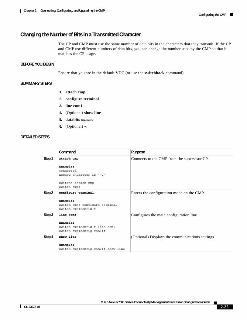
Changing the Number of Bits in a Transmitted Character
The CP and CMP must use the same number of data bits in the characters that they transmit. If the CP and CMP use different numbers of data bits, you can change the number used by the CMP so that it matches the CP usage.
BEFORE YOU BEGIN
Ensure that you are in the default VDC (or use the switchback command).
SUMMARY STEPS
1. attach cmp
2. configure terminal
3. line com1
4. (Optional) show line
5. databits number
6. (Optional) ~,
DETAILED STEPS
Command Purpose
Step 1 attach cmp
Example:ConnectedEscape character is '~,'
switch# attach cmpswitch-cmp#
Connects to the CMP from the supervisor CP.
Step 2 configure terminal
Example:switch-cmp# configure terminalswitch-cmp(config)#
Enters the configuration mode on the CMP.
Step 3 line com1
Example:switch-cmp(config)# line com1switch-cmp(config-com1)#
Configures the main configuration line.
Step 4 show line
Example:switch-cmp(config-com1)# show line
(Optional) Displays the communications settings.
2-23Cisco Nexus 7000 Series Connectivity Management Processor Configuration Guide
OL-23072-03

Chapter 2 Connecting, Configuring, and Upgrading the CMPConfiguring the CMP
Changing the Parity Checking
The CP and CMP must use the same type of parity checking. If the CP and CMP use different types, you must change the type used by the CMP so that it matches the CP type.
BEFORE YOU BEGIN
Ensure that you are in the default VDC (or use the switchback command).
SUMMARY STEPS
1. attach cmp
2. configure terminal
3. line com1
4. (Optional) show line
5. parity {even | odd | none}
6. (Optional) ~,
DETAILED STEPS
Step 5 databits number
Example:switch-cmp(config-com1)# databits 8
Configures the number of bits in a character (between 5 and 8).
Step 6 ~,
Example:switch-cmp(config)# ~,switch#
(Optional) Exits the CMP console and returns to the Cisco NX-OS CLI on the CP.
Command Purpose
Command Purpose
Step 1 attach cmp
Example:switch# attach cmpswitch-cmp#
Connects to the CMP from the supervisor CP.
Step 2 configure terminal
Example:switch-cmp# configure terminalswitch-cmp(config)#
Enters the configuration mode on the CMP.
Step 3 line com1
Example:switch-cmp(config)# line com1switch-cmp(config-com1)#
Configures the main configuration line.
Step 4 show line
Example:switch-cmp(config-com1)# show line
(Optional) Displays the communications settings.
2-24Cisco Nexus 7000 Series Connectivity Management Processor Configuration Guide
OL-23072-03

Chapter 2 Connecting, Configuring, and Upgrading the CMPConfiguring the CMP
Changing the Asynchronous Stop Bits
The CP and CMP must use the same number of stop bits. If the CP and CMP use different numbers of stop bits, you must change the number used by the CMP so that it matches the CP number.
BEFORE YOU BEGIN
Ensure that you are in the default VDC (or use the switchback command).
SUMMARY STEPS
1. attach cmp
2. configure terminal
3. line com1
4. stopbits {1 | 2}
5. exit
6. (Optional) show line
7. (Optional) ~,
DETAILED STEPS
Step 5 parity {even | odd | none}
Example:switch-cmp(config-com1)# parity none
Sets single-bit parity checking to check for even parity, odd parity, or ignore parity.
Step 6 ~,
Example:switch-cmp(config)# ~,switch#
(Optional) Exits the CMP console and returns to the Cisco NX-OS CLI on the CP.
Command Purpose
Command Purpose
Step 1 attach cmp
Example:switch# attach cmpswitch-cmp#
Connects to the CMP from the supervisor CP.
Step 2 configure terminal
Example:switch-cmp# configure terminalswitch-cmp(config)#
Enters the configuration mode on the CMP.
Step 3 line com1
Example:switch-cmp(config)# line com1switch-cmp(config-com1)#
Configures the main configuration line.
2-25Cisco Nexus 7000 Series Connectivity Management Processor Configuration Guide
OL-23072-03

Chapter 2 Connecting, Configuring, and Upgrading the CMPConfiguring the CMP
Configuring Flow ControlYou can use a hardware version of flow control to regulate the flow of data traffic over the internal serial connection between the CMP and CP. When enabled for both the CMP and CP, flow control delays the flow of frames until earlier frames are processed by the receiving processor.
This section includes the following topics:
• Enabling or Disabling Flow Control for the CMP, page 2-26
• Enabling or Disabling Flow Control for the CP, page 2-27
Enabling or Disabling Flow Control for the CMP
You can enable or disable the CMP to use a hardware version of flow control with the CP.
BEFORE YOU BEGIN
You must enable flow control on the CP (see the “Enabling or Disabling Flow Control for the CP” section on page 2-27).
Ensure that you are in the default VDC (or use the switchback command).
SUMMARY STEPS
1. attach cmp
2. configure terminal
3. line com1
4. {flowcontrol hardware} | {no flowcontrol hardware}
5. (Optional) show line com1
6. exit
7. (Optional) ~,
Step 4 stopbits {1 | 2}
Example:switch-cmp(config-com1)# stopbits 1
Configures the number of stop bits included in a character frame.
Step 5 exit
Example:switch-cmp(config-com1)# exitswitch-cmp(config)#
Exits COM1 configuration mode.
Step 6 show line
Example:switch-cmp(config-com1)# show line
(Optional) Displays the communications settings.
Step 7 ~,
Example:switch-cmp(config)# ~,switch#
(Optional) Exits the CMP console and returns to the Cisco NX-OS CLI on the CP.
Command Purpose
2-26Cisco Nexus 7000 Series Connectivity Management Processor Configuration Guide
OL-23072-03

Chapter 2 Connecting, Configuring, and Upgrading the CMPConfiguring the CMP
DETAILED STEPS
Enabling or Disabling Flow Control for the CP
You can enable or disable the CP to use a hardware version of flow-control with the CMP.
BEFORE YOU BEGIN
You must enable flow control on the CMP (see the “Enabling or Disabling Flow Control for the CMP” section on page 2-26).
SUMMARY STEPS
1. configure terminal
2. line console
3. {flowcontrol hardware} | {no flowcontrol hardware}
4. (Optional) show line console
5. exit
Command Purpose
Step 1 attach cmp
Example:switch# attach cmpswitch-cmp#
Connects to the CMP from the supervisor CP.
Step 2 configure terminal
Example:switch-cmp# configure terminalswitch-cmp(config)#
Enters configuration mode.
Step 3 line com1
Example:switch-cmp(config)# line com1switch-cmp(config-com1)#
Specifies to configure the CMP serial line.
Step 4 {flowcontrol hardware} | {no flowcontrol hardware}
Example:switch-cmp(config-com1)# flowcontrol hardware
Enables or disables flow control.
Step 5 show line com1
Example:switch-cmp(config-com1)# show line com1
(Optional) Displays the interface status, which includes the flow control parameters.
Step 6 exit
Example:switch-cmp(config-com1)# exitswitch-cmp(config)#
Exits COM1 configuration mode.
Step 7 ~,
Example:switch-cmp(config)# ~,switch#
(Optional) Exits the CMP console and returns to the Cisco NX-OS CLI on the CP.
2-27Cisco Nexus 7000 Series Connectivity Management Processor Configuration Guide
OL-23072-03

Chapter 2 Connecting, Configuring, and Upgrading the CMPConfiguring the CMP
6. exit
DETAILED STEPS
Configuring CMPs on a Dual Supervisor SystemThe CMP runs in active mode on both supervisor modules, even when only one supervisor module is active, so you must configure each CMP individually. You can configure the unique IP address for each CMP from the active CP by using Cisco NX-OS commands through either the CLI or scripts. To perform all other CMP configuration functions, connect directly to the CMP that you are configuring to perform those functions.
Command Purpose
Step 1 configure terminal
Example:switch# configure terminalswitch(config)#
Enters configuration mode.
Step 2 line console
Example:switch(config)# line consoleswitch(config-com1)#
Specifies the serial line to the CMP.
Step 3 {flowcontrol hardware} | {no flowcontrol hardware}
Example:switch(config-com1)# flowcontrol hardwareswitch(config-com1)#
Enables or disables flow control.
Step 4 show line console
Example:switch(config-com1)# show line consoleswitch(config-com1)
(Optional) Displays the interface status, which includes the flow control parameters.
Step 5 exit
Example:switch(config-com1)# exitswitch(config)#
Exits the COM1 configuration mode.
Step 6 exit
Example:switch(config)# exitswitch#
Exits the configuration mode.
2-28Cisco Nexus 7000 Series Connectivity Management Processor Configuration Guide
OL-23072-03

Chapter 2 Connecting, Configuring, and Upgrading the CMPVerifying the CMP Configuration
Verifying the CMP ConfigurationTo display CMP configuration information from the Cisco NX-OS CLI on the CP, use the following commands:
To display CMP configuration information from the CMP CLI, use the following commands:
Command Purpose
show running-config cmp Displays the running configuration for the CMP.
show tech-support cmp Displays the technical support output for the CMP.
show logging logfile | include cmp Displays the logs for the CMP.
Command Purpose
show attach sessions Displays information about active or suspended attach or monitor sessions.
show capture {all | last number} Displays the captured logs.
show cdp all Displays all interfaces that have CDP enabled.
show cdp configuration Displays the current CDP configuration.
show cdp global Displays the CDP global parameters.
show cdp neighbors [detail] Displays the CDP neighbor status.
show cdp traffic Displays the CDP traffic statistics on an interface.
show clock Displays the current date and time.
show hardware Displays information about the CMP hardware.
show interface Displays information about the cmp-mgmt interface.
show logging {console | level | logfile | monitor | server}
Displays the CMP log files.
show logs Displays the CMP syslog messages.
show processes Displays information about the CMP processes.
show running-config Displays the running configuration for the CMP.
show sprom Displays the SPROM contents on the CMP.
show ssh key Displays information about SSH key.
show system resources Displays information about CMP system resources.
show users Displays the users logged into the system.
show version Displays the software image versions for the supervisor CP and the CMP.
2-29Cisco Nexus 7000 Series Connectivity Management Processor Configuration Guide
OL-23072-03

Chapter 2 Connecting, Configuring, and Upgrading the CMPUpgrading the CMP Image
Upgrading the CMP ImageYou can upgrade the CMP image, which is part of the Cisco NX-OS system image and contains a subset of commands to support the CMP features.
Note The CMP image is independent of the CP image, so the version of the CMP image might not match the version of the CP image. To make sure that the CMP is running the latest compatible image, use the install all command from the Cisco NX-OS CLI on the CP.
To upgrade the Cisco NX-OS kickstart image, system image, and CMP image at the same time, use the install all command from the Cisco NX-OS CLI on the CP. This command automatically upgrades the software on both CMPs. After the software is upgraded, you must manually reload the CMP on each supervisor. For more information on software images, see the Cisco Nexus 7000 Series NX-OS Software Upgrade and Downgrade Guide, Release 5.x.
Use the following procedure if you want to update only the CMP image.
BEFORE YOU BEGIN
Ensure that you are in the default VDC (or use the switchback command).
SUMMARY STEPS
1. copy {ftp | tftp} remote-location local-location
2. (Optional) show module
3. install module active-slot cmp system local-location
4. install module standby-slot cmp system local-location
5. reload cmp module active-slot
6. reload cmp module standby-slot
7. (Optional) show version
DETAILED STEPS
Command Purpose
Step 1 copy {ftp | tftp} remote-location local-location
Example:switch# copy ftp://10.1.7.2/n7000-s1-dk9.4.0.3.bin bootflash:n7000-s1-dk9.4.0.3.bin
Copies the CMP image from an FTP server to the supervisor module.
Step 2 show module
Example:switch# show module
(Optional) Displays information about the location and status of modules on the switch.
2-30Cisco Nexus 7000 Series Connectivity Management Processor Configuration Guide
OL-23072-03

Chapter 2 Connecting, Configuring, and Upgrading the CMPDefault Settings for CMP Parameters
Default Settings for CMP ParametersTable 2-4 lists the default settings for CMP parameters.
Step 3 install module active-slot cmp system local-location
Example:switch# install module 5 cmp system bootflash:/n7000-s1-dk9.4.0.3.bin
Extracts the CMP image from the Cisco NX-OS system image and installs the CMP image on the CMP on the active supervisor module. The local-location argument consists of the file location and the filename.
For more information on installing images, see the Cisco Nexus 7000 Series NX-OS Software Upgrade and Downgrade Guide, Release 5.x.
Step 4 install module standby-slot cmp system location
Example:switch# install module 6 cmp system bootflash:/n7000-s1-dk9.4.0.3.bin
Extracts the CMP image from the Cisco NX-OS system image and installs the CMP image on the CMP on the standby supervisor module, if present. The location argument consists of the file location and the filename.
For more information on installing images, see the Cisco Nexus 7000 Series NX-OS Software Upgrade and Downgrade Guide, Release 5.x.
Step 5 reload cmp module active-slot
Example:switch# reload cmp module 5
Reloads the CMP for the active supervisor module to complete the upgrade.
Step 6 reload cmp module standby-slot
Example:switch# reload cmp module 5
Reloads the CMP for the standby supervisor module, if present, to complete the upgrade.
Step 7 show version
Example:switch# show version
(Optional) Displays the BIOS and software image versions of the CMP.
Command Purpose
Table 2-4 Default CMP Parameter Settings
Parameters Default
Logging level 2 (critical level)
SSH server Enabled
Telnet server Disabled
2-31Cisco Nexus 7000 Series Connectivity Management Processor Configuration Guide
OL-23072-03

Chapter 2 Connecting, Configuring, and Upgrading the CMPDefault Settings for CMP Parameters
2-32Cisco Nexus 7000 Series Connectivity Management Processor Configuration Guide
OL-23072-03
Cisco Nexus 7000 Series ConneOL-23072-03
C H A P T E R 3
Using the CMPThis chapter explains how to use the Connectivity Management Processor (CMP) to monitor the supervisor module control processor (CP) on the active Supervisor 1 module and to reboot the CP or Cisco NX-OS switch. It also explains how you can reboot the CMP from the CP or the CMP.
This chapter includes the following sections:
• Monitoring the CP, page 3-2
• Rebooting the CP, page 3-2
• Rebooting the Entire Cisco NX-OS Device from the CMP, page 3-3
• Rebooting the CMP from the CP, page 3-3
• Rebooting the CMP from the CMP, page 3-3
• Rebooting the System, page 3-4
3-1ctivity Management Processor Configuration Guide

Chapter 3 Using the CMPMonitoring the CP
Monitoring the CPYou can monitor the CP from the CMP.
To monitor the supervisor module CP, use the following optional commands:
Rebooting the CPYou can reboot the CP from the CMP.
To reboot the supervisor module CP from the CMP, use the following command:
Command Purposemonitor cp
Example:switch-cmp# monitor cpThis command will disconnect the front-panel console on this supervisor module - proceed(y/n)? yConnectedEscape character is '~,'switch#
Monitors all output on the local supervisor module CP console port.
attach cp
Example:switch-cmp# attach cpThis command will disconnect the front-panel console on this supervisor module - proceed(y/n)? yConnectedEscape character is '~,'switch#
Takes control of the local supervisor module CP console port.
~,
Example:switch# ~,switch-cmp#
Exits from the CP console and returns to CMP.
ping ip-address
Example:switch-cmp# ping 192.0.2.15
Pings a remote IP address and displays the results.
show cp state
Example:switch-cmp# show cp state
Displays status information about the supervisor module CP.
show version
Example:switch-cmp# show version
Displays the BIOS and software image versions of the CMP.
traceroute ip-address
Example:switch-cmp# traceroute 192.0.2.15
Tests the connection to a remote IP address and displays the results of each hop along the route.
3-2Cisco Nexus 7000 Series Connectivity Management Processor Configuration Guide
OL-23072-03

Chapter 3 Using the CMPRebooting the Entire Cisco NX-OS Device from the CMP
Note If you reboot a supervisor module from the Cisco NX-OS command-line interface (CLI) on the CP, the CMP also reboots. Use the reload soft command to reboot only the supervisor module CP and not the CMP.
Rebooting the Entire Cisco NX-OS Device from the CMPTo reboot the entire Cisco NX-OS device from the CMP, use the following command:
Rebooting the CMP from the CPYou can reboot the CMP from the CP.
To reboot the CMP from Cisco NX-OS on the supervisor module CP, use the following command:
Rebooting the CMP from the CMPYou can reboot the CMP from the CP.
To reboot the CMP from the CMP, use the following command:
Command Purpose
reload cp
Example:switch-cmp# reload cp
Reboots the supervisor module.
Command Purpose
reload system
Example:switch-cmp# reload system
Reboots the Cisco NX-OS device.
Command Purpose
reload cmp module slot
Example:switch# reload cmp module 5
Reboots the CMP.
Command Purpose
reload cmp
Example:switch-cmp# reload cmp
Reloads the CMP.
3-3Cisco Nexus 7000 Series Connectivity Management Processor Configuration Guide
OL-23072-03

Chapter 3 Using the CMPRebooting the System
Rebooting the SystemYou can reboot the system from the CMP on the active supervisor module while keeping the CMP session active by using the reload soft command. In addition, this command allows you to reset the active CP, power cycle the standby CP, and power cycle the modules.
Note To reload the complete system, including the CMPs, use the reload system command from the CMP.
To reboot the system, use the following command:
Command Purpose
reload soft
Example:switch-cmp# reload soft
Reloads the operating system for the system hardware on the CPs and standby CMP.
.
3-4Cisco Nexus 7000 Series Connectivity Management Processor Configuration Guide
OL-23072-03

Cisco Nexus 7000 Series ConneOL-23072-03
I N D E X
A
access control list. See ACL
access privileges 1-3
ACL, configuring
active sessions, displaying 2-29
ACT LED 1-3
alert messages 2-16
archiving console output 2-14
asynchronous stop bits, configuring 2-25
attach cmp command 2-17
attach cp command 3-2
B
baud rate, configuring 2-22
C
capture cp archive enable command 2-15
capture cp console command 2-12
capture cp size command 2-13
CDP
current configuration, displaying 2-29
default settings 2-11
device ID format 2-11
enabling and disabling 2-10
global parameters 2-29
interfaces enabled 2-29
neighbor status 2-29
traffic statistics 2-29
version 2-11
CDP, configuring 2-9
cdp advertise command 2-11
cdp enable command 2-10
cdp format command 2-11
Cisco Discovery Protocol. See CDP
clear capture cp command 2-15
clear logging logfile command 2-19
CMP 2-17
components 1-1
connections 1-1
dual CMP upgrades 2-30
flow control 2-26
functions 1-1
hardware information, displaying 2-29
image, installing 2-31
image, upgrading 2-30
interface configuration, displaying 2-4, 2-7
logging messages 2-16
message levels 2-17
power domain 1-1
processes, displaying 2-29
rebooting 3-3
reloading 2-31, 3-3
reloading software 3-4
system resources, displaying 2-29
verifying configurations 2-29
cmp-management interface, displaying 2-29
CMP management interface. See CMP-MGMT interface
CMP-MGMT Ethernet port 2-1
CMP MGMT ETH LED 1-3
CMP MGMT ETH port. See CMP management Ethernet port
CMP-MGMT interface
configuring through a setup script 2-4
IN-1ctivity Management Processor Configuration Guide

Index
configuring through the CMP 2-5, 2-7
configuring through the CP 2-6
IPv4 address 2-5
IPv6 address 2-6, 2-7
CMP STATUS LED 1-2
components 1-1
connecting
default VDC requirement 1-3
from CP 1-1
network 2-1
console output
clearing 2-15
displaying 2-14
file size 2-13
logging functions 2-12
console output log file, archiving 2-14
CP
attaching 3-2
flow control 2-27
monitoring 3-2
reloading 3-3
reloading software 3-4
status 3-2
critical messages 2-16
D
data bits, configuring 2-23
databits command 2-24
date, displaying 2-29
default gateway
IPv4 address 2-5
IPv6 address 2-6, 2-7
default gateway, configuring 2-4, 2-7
default settings 2-31
deny command 2-9
disabling CDP 2-10
disabling SSH 1-3
disabling the Telnet server command 1-3
IN-2Cisco Nexus 7000 Series Connectivity Management Processor Con
displaying logged output 2-14
E
enabling CDP 2-10
enabling the SSH server 1-3
enabling the Telnet server 1-3
F
file size, logging 2-12, 2-13
flow control
configuring for CMP 2-26
configuring for CP 2-27
flowcontrol hardware command 2-27
functions, CMP 1-1
G
gateway, configuring 2-4, 2-7
H
hardware flow control
configuring for CMP 2-26
configuring for CP 2-27
high availability 1-4
hops in a route, displaying 3-2
I
image version, displaying 3-2
install all command 2-30
install module command 2-31
interface cmp-mgmt module command 2-4, 2-6
interface configuration mode for CMP-MGMT 2-4, 2-6
ip access-group command 2-9
ip access-list command 2-9
figuration GuideOL-23072-03

Index
IP address, configuring 2-4, 2-6
ip address command 2-4, 2-5, 2-6
ip default-gateway command 2-4, 2-5, 2-7
IPv4 address
CMP-MGMT interface 2-5
default gateway 2-5
IPv6 address
CMP-MGMT interface 2-6, 2-7
default gateway 2-6, 2-7
ipv6 address command 2-6, 2-7, 2-8
ipv6 default-gateway command 2-6, 2-7, 2-8
L
LEDs 1-2
line com1 command 2-27
line console command 2-28
LINK LED 1-2
logged console output, displaying 2-14
logging CMP messages 2-16
logging configuration
displaying 2-29
logging file
clearing 2-15, 2-18
defined 2-16
logging file, archiving 2-14
logging file size 2-12, 2-13
logging functions 2-12
logging level command 2-18
logging messages, displaying 2-29
logging server command 2-20, 2-21
logs, displaying 2-29
M
message levels, configuring 2-17
messages
displaying 2-17
Cisco Nexus 7000 SeriOL-23072-03
logging 2-16
severity levels 2-16
monitor CP command 3-2
N
network connection 2-1
no ssh server enable command 1-3
no telnet server enable command 1-3
P
parity checking, configuring 2-24
parity command 2-25
passwords 1-3
permit command 2-9
ping command 3-2
power domains, separate 1-1
R
rebooting the system 3-4
redundancy 1-4
reload cmp command 2-31
reload cp command 3-3
reloading software 3-4
reloading the CMP 3-4
reloading the system 3-3, 3-4
reload soft command 3-4
reload system command 3-3, 3-4
RJ-45 connector 2-1
running configuration, displaying 2-29
S
severity levels, message 2-16
show attach sessions command 2-29
show capture command 2-29
IN-3es Connectivity Management Processor Configuration Guide

Index
show cdp all 2-29
show cdp configuration command 2-29
show cdp global command 2-29
show cdp neighbors command 2-29
show cdp traffic interface command 2-29
show clock command 2-29
show cp state command 3-2
show interface command 2-29
show logging command 1-3, 2-17, 2-29
show logging level command 2-18
show logging logfile command 2-17, 2-29
show logs command 2-29
show processes command 2-29
show running-config cmp command 2-29
show running-config command 2-29
show sprom command 2-29
show ssh command 2-29
show system resources command 2-29
show tech-support command 2-29
show users command 2-29
show version command 2-29, 3-2
software image information, displaying 2-29
speed, configuring 2-22
speed command 2-22
SPROM contents, displaying 2-29
SSH information, displaying 2-29
SSH server, enabling or disabling 1-3
ssh server enable command 1-3
status, LEDs 1-2
stop bits, configuring 2-25
stopbits command 2-26
suspended sessions, displaying 2-29
switchovers, CMP behavior 1-4
switchto vdc command 2-2, 2-3, 2-4, 2-5, 2-6, 2-7, 2-17, 2-19, 2-22, 2-23, 2-24, 2-25, 2-26, 2-30
synchronizing passwords 1-3
syslog messages, displaying 2-29
syslog server, configuring 2-20, 2-21
IN-4Cisco Nexus 7000 Series Connectivity Management Processor Con
T
technical support for CMP output 2-29
Telnet server, enabling or disabling 1-3
telnet server enable command 1-3
time, displaying 2-29
traceroute command 3-2
U
upgrade 2-30
usernames 1-3
users, displaying 2-29
figuration GuideOL-23072-03


![Cisco Nexus 7000 Series Switch Security TargetST] Nexus 7000... · Cisco Nexus 7000 Series Switch Security Target Version 1.0 ... The Nexus 7k switches are modular and are available](https://img.pdfslide.us/doc/110x75/5aa78f6a7f8b9a294b8c4363/cisco-nexus-7000-series-switch-security-target-st-nexus-7000cisco-nexus-7000.jpg)