Embed Size (px)
Citation preview
Cisco Nexus 3000 NX-OS Interfaces Configuration Guide, Release5.0(3)U3(1)First Published: February 29, 2012
Last Modified: April 20, 2012
Americas HeadquartersCisco Systems, Inc.170 West Tasman DriveSan Jose, CA 95134-1706USAhttp://www.cisco.comTel: 408 526-4000 800 553-NETS (6387)Fax: 408 527-0883
Text Part Number: OL-26623-01

THE SPECIFICATIONS AND INFORMATION REGARDING THE PRODUCTS IN THIS MANUAL ARE SUBJECT TO CHANGE WITHOUT NOTICE. ALL STATEMENTS,INFORMATION, AND RECOMMENDATIONS IN THIS MANUAL ARE BELIEVED TO BE ACCURATE BUT ARE PRESENTED WITHOUT WARRANTY OF ANY KIND,EXPRESS OR IMPLIED. USERS MUST TAKE FULL RESPONSIBILITY FOR THEIR APPLICATION OF ANY PRODUCTS.
THE SOFTWARE LICENSE AND LIMITEDWARRANTY FOR THE ACCOMPANYING PRODUCT ARE SET FORTH IN THE INFORMATION PACKET THAT SHIPPED WITHTHE PRODUCT AND ARE INCORPORATED HEREIN BY THIS REFERENCE. IF YOU ARE UNABLE TO LOCATE THE SOFTWARE LICENSE OR LIMITED WARRANTY,CONTACT YOUR CISCO REPRESENTATIVE FOR A COPY.
The Cisco implementation of TCP header compression is an adaptation of a program developed by the University of California, Berkeley (UCB) as part of UCB's public domain versionof the UNIX operating system. All rights reserved. Copyright © 1981, Regents of the University of California.
NOTWITHSTANDINGANYOTHERWARRANTYHEREIN, ALL DOCUMENT FILES AND SOFTWARE OF THESE SUPPLIERS ARE PROVIDED “AS IS"WITH ALL FAULTS.CISCO AND THE ABOVE-NAMED SUPPLIERS DISCLAIM ALL WARRANTIES, EXPRESSED OR IMPLIED, INCLUDING, WITHOUT LIMITATION, THOSE OFMERCHANTABILITY, FITNESS FORA PARTICULAR PURPOSEANDNONINFRINGEMENTORARISING FROMACOURSEOFDEALING, USAGE, OR TRADE PRACTICE.
IN NO EVENT SHALL CISCO OR ITS SUPPLIERS BE LIABLE FOR ANY INDIRECT, SPECIAL, CONSEQUENTIAL, OR INCIDENTAL DAMAGES, INCLUDING, WITHOUTLIMITATION, LOST PROFITS OR LOSS OR DAMAGE TO DATA ARISING OUT OF THE USE OR INABILITY TO USE THIS MANUAL, EVEN IF CISCO OR ITS SUPPLIERSHAVE BEEN ADVISED OF THE POSSIBILITY OF SUCH DAMAGES.
Cisco and the Cisco logo are trademarks or registered trademarks of Cisco and/or its affiliates in the U.S. and other countries. To view a list of Cisco trademarks, go to this URL: http://www.cisco.com/go/trademarks. Third-party trademarks mentioned are the property of their respective owners. The use of the word partner does not imply a partnershiprelationship between Cisco and any other company. (1110R)
Any Internet Protocol (IP) addresses used in this document are not intended to be actual addresses. Any examples, command display output, and figures included in the document are shownfor illustrative purposes only. Any use of actual IP addresses in illustrative content is unintentional and coincidental.
© 2012 Cisco Systems, Inc. All rights reserved.
C O N T E N T S
P r e f a c e Preface vii
Audience vii
Document Conventions vii
Related Documentation for Nexus 3000 Series NX-OS Software viii
Obtaining Documentation and Submitting a Service Request x
C H A P T E R 1 New and Changed Information for this Release 1
New and Changed Information in this Release 1
C H A P T E R 2 Configuring Layer 3 Interfaces 3
Information About Layer 3 Interfaces 3
Routed Interfaces 3
Subinterfaces 4
VLAN Interfaces 5
Loopback Interfaces 6
Tunnel Interfaces 6
Licensing Requirements for Layer 3 Interfaces 6
Guidelines and Limitations for Layer 3 Interfaces 6
Default Settings for Layer 3 Interfaces 7
Configuring Layer 3 Interfaces 7
Configuring a Routed Interface 7
Configuring a Subinterface 8
Configuring the Bandwidth on an Interface 8
Configuring a VLAN Interface 9
Configuring a Loopback Interface 10
Assigning an Interface to a VRF 11
Verifying the Layer 3 Interfaces Configuration 11
Cisco Nexus 3000 NX-OS Interfaces Configuration Guide, Release 5.0(3)U3(1) OL-26623-01 iii
Monitoring Layer 3 Interfaces 13
Configuration Examples for Layer 3 Interfaces 14
Related Documents for Layer 3 Interfaces 14
MIBs for Layer 3 Interfaces 15
Standards for Layer 3 Interfaces 15
Feature History for Layer 3 Interfaces 15
C H A P T E R 3 Configuring Port Channels 17
Information About Port Channels 17
Understanding Port Channels 17
Compatibility Requirements 18
Load Balancing Using Port Channels 20
Understanding LACP 21
LACP Overview 21
LACP ID Parameters 22
Channel Modes 23
LACP Marker Responders 24
LACP-Enabled and Static Port Channel Differences 24
LACP Port Channel MinLinks 24
Configuring Port Channels 25
Creating a Port Channel 25
Adding a Port to a Port Channel 25
Configuring Load Balancing Using Port Channels 26
Configuring Hardware Hashing for Multicast Traffic 27
Enabling LACP 28
Configuring the Channel Mode for a Port 28
Configuring LACP Port Channel MinLinks 29
Configuring the LACP Fast Timer Rate 30
Configuring the LACP System Priority and System ID 31
Configuring the LACP Port Priority 32
Verifying Port Channel Configuration 32
Verifying the Load-Balancing Outgoing Port ID 33
Feature History for Port Channels 34
C H A P T E R 4 Configuring Virtual Port Channels 35
Cisco Nexus 3000 NX-OS Interfaces Configuration Guide, Release 5.0(3)U3(1)iv OL-26623-01
Contents
Information About vPCs 35
vPC Overview 35
Terminology 36
vPC Terminology 36
Supported vPC Topologies 37
Cisco Nexus 3000 Series Switch vPC Topology 37
vPC Domain 37
Peer-Keepalive Link and Messages 38
Compatibility Parameters for vPC Peer Links 38
Configuration Parameters That Must Be Identical 39
Configuration Parameters That Should Be Identical 40
Graceful Type-1 Check 40
Per-VLAN Consistency Check 41
vPC Auto-Recovery 41
vPC Peer Links 41
vPC Peer Link Overview 41
vPC Number 42
vPC Interactions with Other Features 43
vPC and LACP 43
vPC Peer Links and STP 43
CFSoE 44
Guidelines and Limitations for vPCs 44
Configuring vPCs 45
Enabling vPCs 45
Disabling vPCs 45
Creating a vPC Domain 46
Configuring a vPC Keepalive Link and Messages 47
Creating a vPC Peer Link 49
Checking the Configuration Compatibility 50
Enabling vPC Auto-Recovery 51
Configuring the Restore Time Delay 51
Excluding VLAN Interfaces From Shutdown When vPC Peer Link Fails 52
Configuring the VRF Name 53
Binding a VRF Instance to a vPC 53
Moving Other Port Channels into a vPC 54
Cisco Nexus 3000 NX-OS Interfaces Configuration Guide, Release 5.0(3)U3(1) OL-26623-01 v
Contents

Manually Configuring a vPC Domain MAC Address 55
Manually Configuring the System Priority 55
Manually Configuring a vPC Peer Switch Role 56
Verifying the vPC Configuration 57
Viewing The Graceful Type-1 Check Status 58
Viewing A Global Type-1 Inconsistency 58
Viewing An Interface-Specific Type-1 Inconsistency 59
Viewing a Per-VLAN Consistency Status 60
vPC Default Settings 62
Cisco Nexus 3000 NX-OS Interfaces Configuration Guide, Release 5.0(3)U3(1)vi OL-26623-01
Contents
Preface
This preface contains the following sections:
• Audience, page vii
• Document Conventions, page vii
• Related Documentation for Nexus 3000 Series NX-OS Software, page viii
• Obtaining Documentation and Submitting a Service Request, page x
AudienceThis publication is for experienced network administrators who configure and maintain Cisco Nexus Seriesdevices.
Document ConventionsCommand descriptions use the following conventions:
DescriptionConvention
Bold text indicates the commands and keywords that you enter literallyas shown.
bold
Italic text indicates arguments for which the user supplies the values.Italic
Square brackets enclose an optional element(keyword or argument).[x]
Square brackets enclosing keywords or arguments separated by a verticalbar indicate an optional choice.
[x | y]
Braces enclosing keywords or arguments separated by a vertical barindicate a required choice.
{x | y}
Cisco Nexus 3000 NX-OS Interfaces Configuration Guide, Release 5.0(3)U3(1) OL-26623-01 vii
DescriptionConvention
Nested set of square brackets or braces indicate optional or requiredchoices within optional or required elements. Braces and a vertical barwithin square brackets indicate a required choice within an optionalelement.
[x {y | z}]
Indicates a variable for which you supply values, in context where italicscannot be used.
variable
A nonquoted set of characters. Do not use quotation marks around thestring or the string will include the quotation marks.
string
Examples use the following conventions:
DescriptionConvention
Terminal sessions and information the switch displays are in screen font.screen font
Information you must enter is in boldface screen font.boldface screen font
Arguments for which you supply values are in italic screen font.italic screen font
Nonprinting characters, such as passwords, are in angle brackets.< >
Default responses to system prompts are in square brackets.[ ]
An exclamation point (!) or a pound sign (#) at the beginning of a lineof code indicates a comment line.
!, #
This document uses the following conventions:
Means reader take note. Notes contain helpful suggestions or references to material not covered in themanual.
Note
Means reader be careful. In this situation, you might do something that could result in equipment damageor loss of data.
Caution
Related Documentation for Nexus 3000 Series NX-OS SoftwareThe entire Cisco NX-OS 3000 Series documentation set is available at the following URL:
http://www.cisco.com/en/US/products/ps11541/tsd_products_support_series_home.html
Cisco Nexus 3000 NX-OS Interfaces Configuration Guide, Release 5.0(3)U3(1)viii OL-26623-01
PrefaceRelated Documentation for Nexus 3000 Series NX-OS Software
Release Notes
The release notes are available at the following URL:
http://www.cisco.com/en/US/products/ps11541/prod_release_notes_list.html
Installation and Upgrade Guides
The installation and upgrade guides are available at the following URL:
http://www.cisco.com/en/US/products/ps11541/prod_installation_guides_list.html
The documents in this category include:
• Cisco Nexus 5000 Series, Cisco Nexus 3000 Series, and Cisco Nexus 2000 Series Safety Informationand Documentation
• Regulatory, Compliance, and Safety Information for the Cisco Nexus 5000 Series, Cisco Nexus 3000Series, and Cisco Nexus 2000 Series
• Cisco Nexus 3000 Series Hardware Installation Guide
Configuration Guides
The configuration guides are available at the following URL:
http://www.cisco.com/en/US/products/ps11541/products_installation_and_configuration_guides_list.html
The documents in this category include:
• Fundamentals Configuration Guide
• Interfaces Configuration Guide
• Layer 2 Switching Configuration Guide
• Multicast Configuration Guide
• Quality of Service Configuration Guide
• Security Configuration Guide
• System Management Configuration Guide
• Unicast Routing Configuration Guide
• Verified Scalability Guide for Cisco NX-OS
Technical References
The technical references are available at the following URL:
http://www.cisco.com/en/US/products/ps11541/prod_technical_reference_list.html
Error and System Messages
The error and system message reference guides are available at the following URL:
http://www.cisco.com/en/US/products/ps11541/products_system_message_guides_list.html
Cisco Nexus 3000 NX-OS Interfaces Configuration Guide, Release 5.0(3)U3(1) OL-26623-01 ix
PrefaceRelated Documentation for Nexus 3000 Series NX-OS Software
Obtaining Documentation and Submitting a Service RequestFor information on obtaining documentation, submitting a service request, and gathering additional information,see the monthlyWhat's New in Cisco Product Documentation, which also lists all new and revised Ciscotechnical documentation, at:
http://www.cisco.com/en/US/docs/general/whatsnew/whatsnew.html
Subscribe to theWhat's New in Cisco Product Documentation as a Really Simple Syndication (RSS) feedand set content to be delivered directly to your desktop using a reader application. The RSS feeds are a freeservice and Cisco currently supports RSS version 2.0.
Cisco Nexus 3000 NX-OS Interfaces Configuration Guide, Release 5.0(3)U3(1)x OL-26623-01
PrefaceObtaining Documentation and Submitting a Service Request

C H A P T E R 1New and Changed Information for this Release
The following table provides an overview of the significant changes to this guide for this current release.The table does not provide an exhaustive list of all changes made to the configuration guides or of the newfeatures in this release.
• New and Changed Information in this Release, page 1
New and Changed Information in this ReleaseThe following table provides an overview of the significant changes to this guide for this current release. Thetable does not provide an exhaustive list of all changes made to the configuration guides or of the new featuresin this release.
Where DocumentedAdded or Changed inRelease
DescriptionFeature
Configuring Layer 3Interfaces, on page 3
5.0(3)U3(1)The show interface vlanvlan-id counterscommand has beenenhanced to correctlyshow input and outputpacket counts.
show interface vlan-idcounters
Configuring PortChannels, on page 17
5.0(3)U3(1)Added information aboutsetting up and using theMinimum Links feature.
Minimum Links
Cisco Nexus 3000 NX-OS Interfaces Configuration Guide, Release 5.0(3)U3(1) OL-26623-01 1

Cisco Nexus 3000 NX-OS Interfaces Configuration Guide, Release 5.0(3)U3(1)2 OL-26623-01
New and Changed Information for this ReleaseNew and Changed Information in this Release
C H A P T E R 2Configuring Layer 3 Interfaces
This chapter contains the following sections:
• Information About Layer 3 Interfaces, page 3
• Licensing Requirements for Layer 3 Interfaces, page 6
• Guidelines and Limitations for Layer 3 Interfaces, page 6
• Default Settings for Layer 3 Interfaces, page 7
• Configuring Layer 3 Interfaces, page 7
• Verifying the Layer 3 Interfaces Configuration, page 11
• Monitoring Layer 3 Interfaces, page 13
• Configuration Examples for Layer 3 Interfaces, page 14
• Related Documents for Layer 3 Interfaces, page 14
• MIBs for Layer 3 Interfaces, page 15
• Standards for Layer 3 Interfaces, page 15
• Feature History for Layer 3 Interfaces, page 15
Information About Layer 3 InterfacesLayer 3 interfaces forward IPv4 and IPv6 packets to another device using static or dynamic routing protocols.You can use Layer 3 interfaces for IP routing and inter-VLAN routing of Layer 2 traffic.
Routed InterfacesYou can configure a port as a Layer 2 interface or a Layer 3 interface. A routed interface is a physical portthat can route IP traffic to another device. A routed interface is a Layer 3 interface only and does not supportLayer 2 protocols, such as the Spanning Tree Protocol (STP).
Cisco Nexus 3000 NX-OS Interfaces Configuration Guide, Release 5.0(3)U3(1) OL-26623-01 3
All Ethernet ports are Layer 2 (switchports) by default. You can change this default behavior using the noswitchport command from interface configuration mode. To change multiple ports at one time, you canspecify a range of interfaces and then apply the no switchport command.
You can assign an IP address to the port, enable routing, and assign routing protocol characteristics to thisrouted interface.
You can assign a static MAC address to a Layer 3 interface. For information on configuring MAC addresses,see the Cisco Nexus 3000 Series NX-OS Layer 2 Switching Configuration Guide.
You can also create a Layer 3 port channel from routed interfaces.
Routed interfaces and subinterfaces support exponentially decayed rate counters. Cisco NX-OS tracks thefollowing statistics with these averaging counters:
• Input packets/sec
• Output packets/sec
• Input bytes/sec
• Output bytes/sec
SubinterfacesYou can create virtual subinterfaces on a parent interface configured as a Layer 3 interface. A parent interfacecan be a physical port or a port channel.
Subinterfaces divide the parent interface into two or more virtual interfaces on which you can assign uniqueLayer 3 parameters such as IP addresses and dynamic routing protocols. The IP address for each subinterfaceshould be in a different subnet from any other subinterface on the parent interface.
You create a subinterface with a name that consists of the parent interface name (for example, Ethernet 2/1)followed by a period and then by a number that is unique for that subinterface. For example, you could createa subinterface for Ethernet interface 2/1 named Ethernet 2/1.1 where .1 indicates the subinterface.
Cisco NX-OS enables subinterfaces when the parent interface is enabled. You can shut down a subinterfaceindependent of shutting down the parent interface. If you shut down the parent interface, Cisco NX-OS shutsdown all associated subinterfaces as well.
One use of subinterfaces is to provide unique Layer 3 interfaces to each VLAN that is supported by the parentinterface. In this scenario, the parent interface connects to a Layer 2 trunking port on another device. Youconfigure a subinterface and associate the subinterface to a VLAN ID using 802.1Q trunking.
Cisco Nexus 3000 NX-OS Interfaces Configuration Guide, Release 5.0(3)U3(1)4 OL-26623-01
Configuring Layer 3 InterfacesSubinterfaces
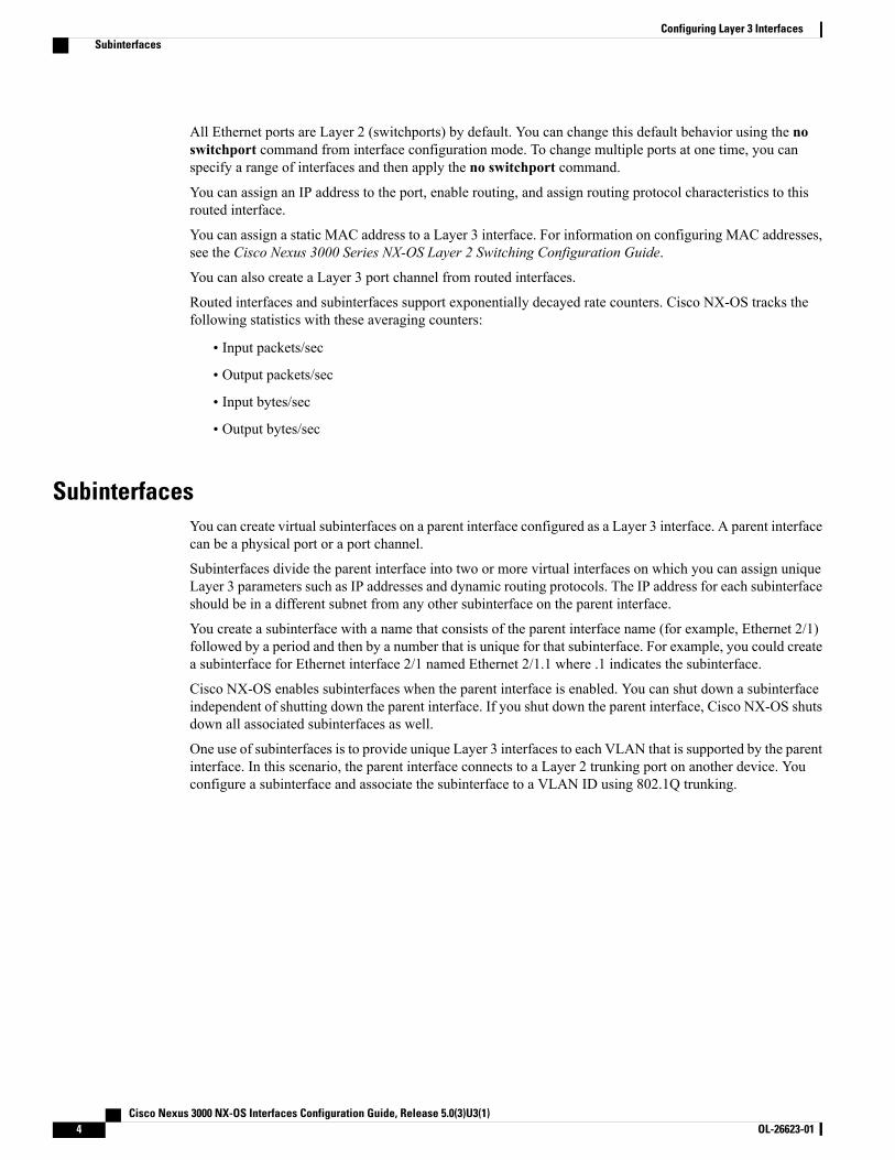
The figure shows a trunking port from a switch that connects to router B on interface E 2/1. This interfacecontains three subinterfaces that are associated with each of the three VLANs that are carried by the trunkingport.
Figure 1: Subinterfaces for VLANs
VLAN InterfacesA VLAN interface or a switch virtual interface (SVI) is a virtual routed interface that connects a VLAN onthe device to the Layer 3 router engine on the same device. Only one VLAN interface can be associated witha VLAN, but you need to configure a VLAN interface for a VLAN only when you want to route betweenVLANs or to provide IP host connectivity to the device through a virtual routing and forwarding (VRF)instance that is not the management VRF. When you enable VLAN interface creation, Cisco NX-OS createsa VLAN interface for the default VLAN (VLAN 1) to permit remote switch administration.
You must enable the VLAN network interface feature before you can configure it. The system automaticallytakes a checkpoint prior to disabling the feature, and you can roll back to this checkpoint. See the Cisco Nexus3000 NX-OS System Management Configuration Guide for information on rollbacks and checkpoints.
You cannot delete the VLAN interface for VLAN 1.Note
You can route across VLAN interfaces to provide Layer 3 inter-VLAN routing by configuring a VLANinterface for each VLAN that you want to route traffic to and assigning an IP address on the VLAN interface.For more information on IP addresses and IP routing, see theCisco Nexus 3000 Series NX-OSUnicast RoutingConfiguration Guide.
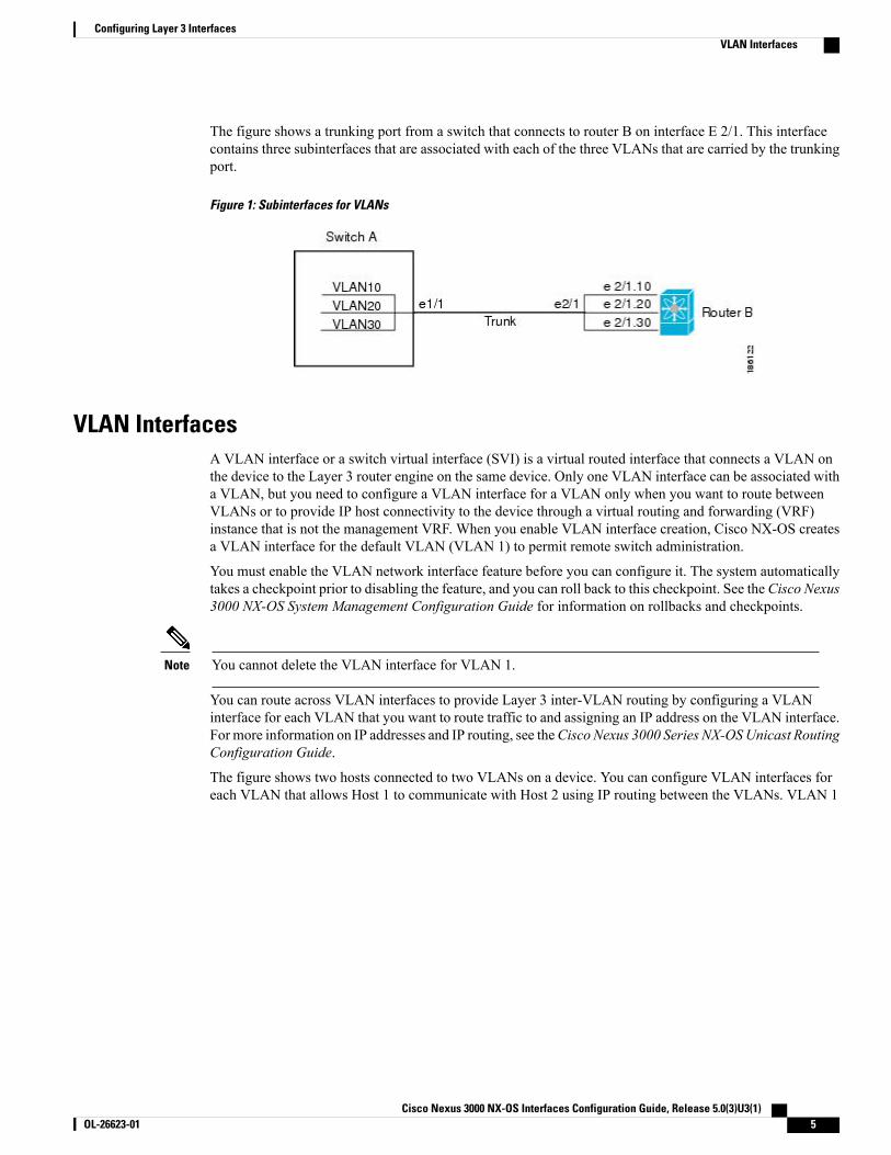
The figure shows two hosts connected to two VLANs on a device. You can configure VLAN interfaces foreach VLAN that allows Host 1 to communicate with Host 2 using IP routing between the VLANs. VLAN 1
Cisco Nexus 3000 NX-OS Interfaces Configuration Guide, Release 5.0(3)U3(1) OL-26623-01 5
Configuring Layer 3 InterfacesVLAN Interfaces
communicates at Layer 3 over VLAN interface 1and VLAN 10 communicates at Layer 3 over VLAN interface10.
Figure 2: Connecting Two VLANs with VLAN Interfaces
Loopback InterfacesA loopback interface is a virtual interface with a single endpoint that is always up. Any packet that is transmittedover a loopback interface is immediately received by this interface. Loopback interfaces emulate a physicalinterface.
You can use loopback interfaces for performance analysis, testing, and local communications. Loopbackinterfaces can act as a termination address for routing protocol sessions. This loopback configuration allowsrouting protocol sessions to stay up even if some of the outbound interfaces are down.
Tunnel InterfacesCisco Nexus 3000 Series devices do not support tunnel interfaces.
Licensing Requirements for Layer 3 InterfacesThis feature does not require a license. Any feature not included in a license package is bundled with the CiscoNX-OS system images and is provided at no extra charge to you. For a complete explanation of the CiscoNX-OS licensing scheme, see the Cisco NX-OS Licensing Guide.
Guidelines and Limitations for Layer 3 InterfacesLayer 3 interfaces have the following configuration guidelines and limitations:
• If you change a Layer 3 interface to a Layer 2 interface, Cisco NX-OS shuts down the interface, reenablesthe interface, and removes all configuration specific to Layer 3.
• If you change a Layer 2 interface to a Layer 3 interface, Cisco NX-OS shuts down the interface, reenablesthe interface, and deletes all configuration specific to Layer 2.
Cisco Nexus 3000 NX-OS Interfaces Configuration Guide, Release 5.0(3)U3(1)6 OL-26623-01
Configuring Layer 3 InterfacesLoopback Interfaces
Default Settings for Layer 3 InterfacesThe default setting for the Layer 3 Admin state is Shut.
Configuring Layer 3 Interfaces
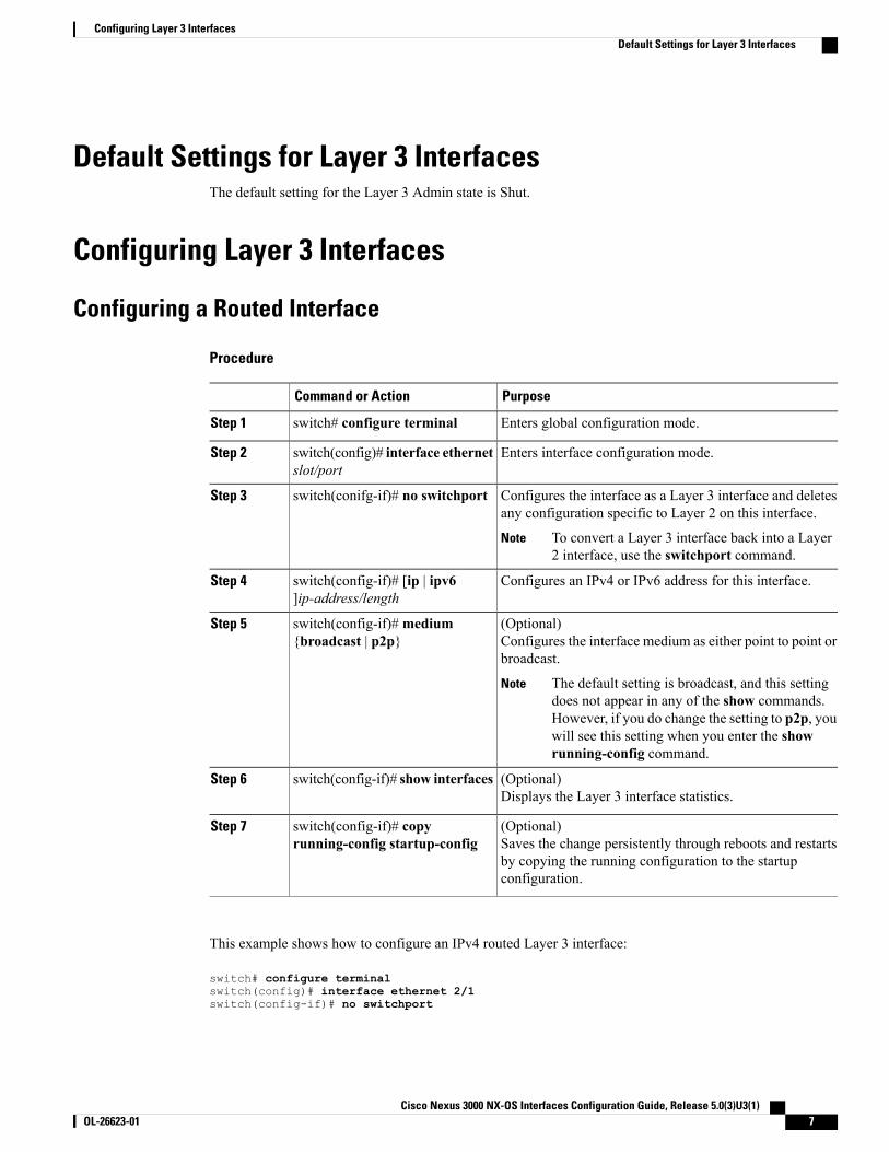
Configuring a Routed Interface
Procedure
PurposeCommand or Action
Enters global configuration mode.switch# configure terminalStep 1
Enters interface configuration mode.switch(config)# interface ethernetslot/port
Step 2
Configures the interface as a Layer 3 interface and deletesany configuration specific to Layer 2 on this interface.
switch(conifg-if)# no switchportStep 3
To convert a Layer 3 interface back into a Layer2 interface, use the switchport command.
Note
Configures an IPv4 or IPv6 address for this interface.switch(config-if)# [ip | ipv6]ip-address/length
Step 4
(Optional)Configures the interface medium as either point to point orbroadcast.
switch(config-if)#medium{broadcast | p2p}
Step 5
The default setting is broadcast, and this settingdoes not appear in any of the show commands.However, if you do change the setting to p2p, youwill see this setting when you enter the showrunning-config command.
Note
(Optional)Displays the Layer 3 interface statistics.
switch(config-if)# show interfacesStep 6
(Optional)Saves the change persistently through reboots and restartsby copying the running configuration to the startupconfiguration.
switch(config-if)# copyrunning-config startup-config
Step 7
This example shows how to configure an IPv4 routed Layer 3 interface:
switch# configure terminalswitch(config)# interface ethernet 2/1switch(config-if)# no switchport
Cisco Nexus 3000 NX-OS Interfaces Configuration Guide, Release 5.0(3)U3(1) OL-26623-01 7
Configuring Layer 3 InterfacesDefault Settings for Layer 3 Interfaces
switch(config-if)# ip address 192.0.2.1/8switch(config-if)# copy running-config startup-config
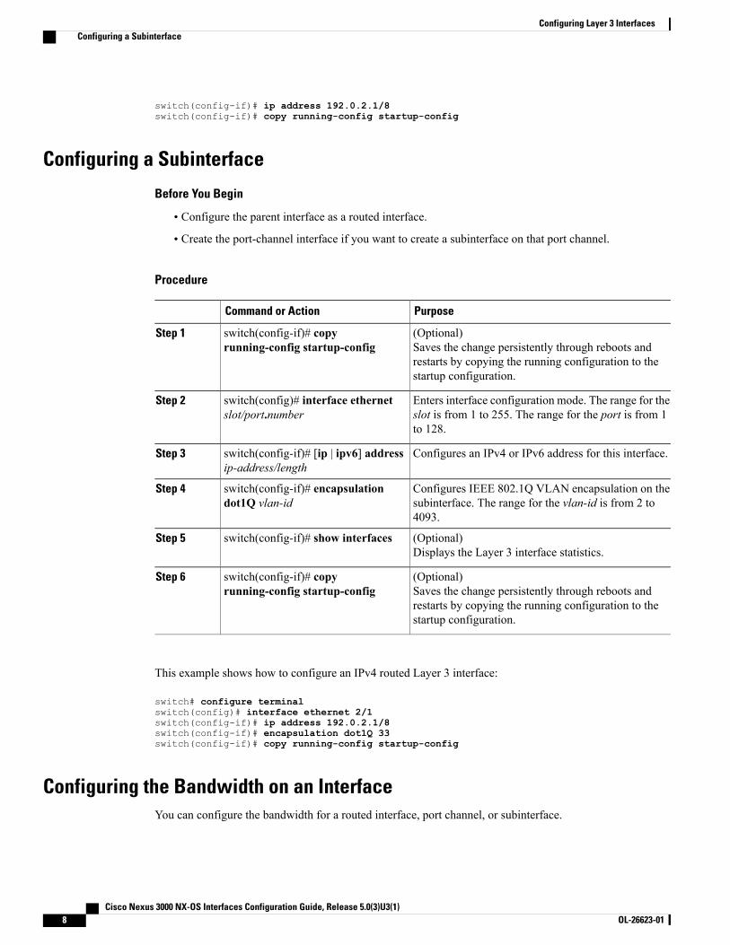
Configuring a Subinterface
Before You Begin
• Configure the parent interface as a routed interface.
• Create the port-channel interface if you want to create a subinterface on that port channel.
Procedure
PurposeCommand or Action
(Optional)Saves the change persistently through reboots andrestarts by copying the running configuration to thestartup configuration.
switch(config-if)# copyrunning-config startup-config
Step 1
Enters interface configuration mode. The range for theslot is from 1 to 255. The range for the port is from 1to 128.
switch(config)# interface ethernetslot/port.number
Step 2
Configures an IPv4 or IPv6 address for this interface.switch(config-if)# [ip | ipv6] addressip-address/length
Step 3
Configures IEEE 802.1Q VLAN encapsulation on thesubinterface. The range for the vlan-id is from 2 to4093.
switch(config-if)# encapsulationdot1Q vlan-id
Step 4
(Optional)Displays the Layer 3 interface statistics.
switch(config-if)# show interfacesStep 5
(Optional)Saves the change persistently through reboots andrestarts by copying the running configuration to thestartup configuration.
switch(config-if)# copyrunning-config startup-config
Step 6
This example shows how to configure an IPv4 routed Layer 3 interface:
switch# configure terminalswitch(config)# interface ethernet 2/1switch(config-if)# ip address 192.0.2.1/8switch(config-if)# encapsulation dot1Q 33switch(config-if)# copy running-config startup-config
Configuring the Bandwidth on an InterfaceYou can configure the bandwidth for a routed interface, port channel, or subinterface.
Cisco Nexus 3000 NX-OS Interfaces Configuration Guide, Release 5.0(3)U3(1)8 OL-26623-01
Configuring Layer 3 InterfacesConfiguring a Subinterface
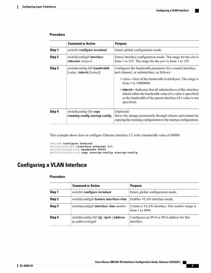
Procedure
PurposeCommand or Action
Enters global configuration mode.switch# configure terminalStep 1
Enters interface configuration mode. The range for the slot isfrom 1 to 255. The range for the port is from 1 to 128.
switch(config)# interfaceethernet slot/port
Step 2
Configures the bandwidth parameter for a routed interface,port channel, or subinterface, as follows:
switch(conifg-if)# bandwidth[value | inherit [value]]
Step 3
• value—Size of the bandwidth in kilobytes. The range isfrom 1 to 10000000.
• inherit—Indicates that all subinterfaces of this interfaceinherit either the bandwidth value (if a value is specified)or the bandwidth of the parent interface (if a value is notspecified).
(Optional)Saves the change persistently through reboots and restarts bycopying the running configuration to the startup configuration.
switch(config-if)# copyrunning-config startup-config
Step 4
This example shows how to configure Ethernet interface 2/1 with a bandwidth value of 80000:
switch# configure terminalswitch(config)# interface ethernet 2/1switch(config-if)# bandwidth 80000switch(config-if)# copy running-config startup-config
Configuring a VLAN Interface
Procedure
PurposeCommand or Action
Enters global configuration mode.switch# configure terminalStep 1
Enables VLAN interface mode.switch(config)# feature interface-vlanStep 2
Creates a VLAN interface. The number range isfrom 1 to 4094.
switch(config)# interface vlan numberStep 3
Configures an IPv4 or IPv6 address for thisinterface.
switch(config-if)# [ip | ipv6 ] addressip-address/length
Step 4
Cisco Nexus 3000 NX-OS Interfaces Configuration Guide, Release 5.0(3)U3(1) OL-26623-01 9
Configuring Layer 3 InterfacesConfiguring a VLAN Interface
PurposeCommand or Action
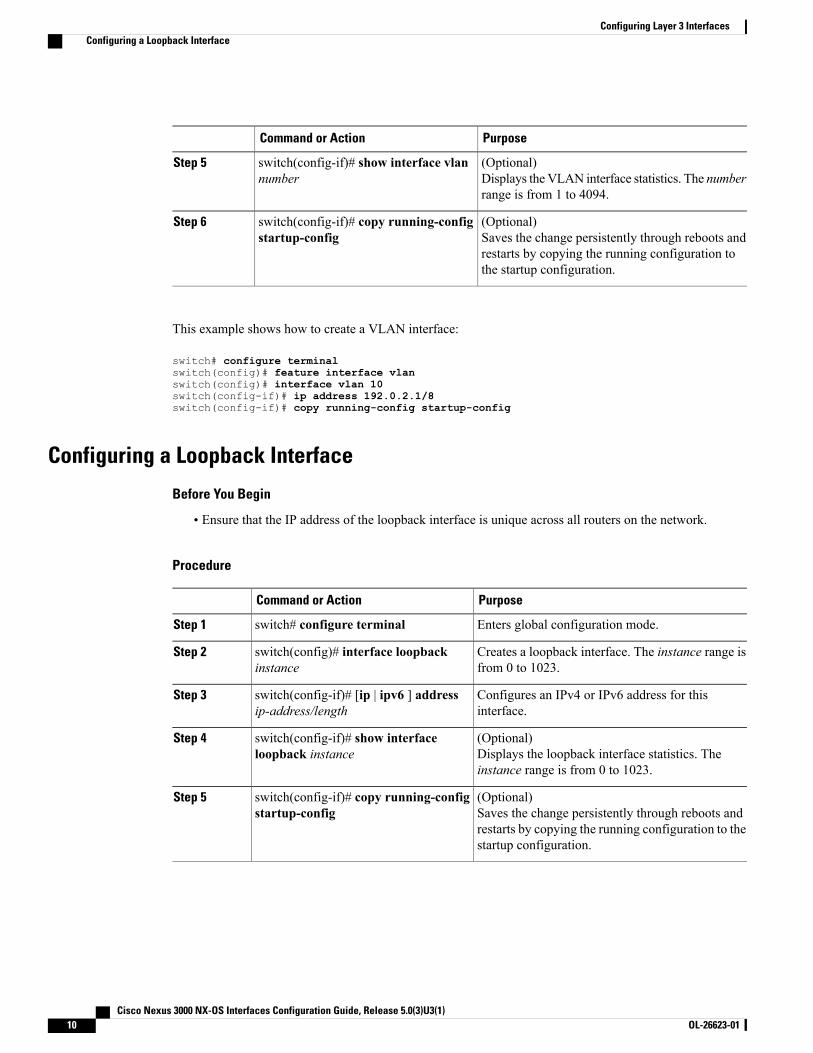
(Optional)Displays the VLAN interface statistics. The numberrange is from 1 to 4094.
switch(config-if)# show interface vlannumber
Step 5
(Optional)Saves the change persistently through reboots andrestarts by copying the running configuration tothe startup configuration.
switch(config-if)# copy running-configstartup-config
Step 6
This example shows how to create a VLAN interface:
switch# configure terminalswitch(config)# feature interface vlanswitch(config)# interface vlan 10switch(config-if)# ip address 192.0.2.1/8switch(config-if)# copy running-config startup-config
Configuring a Loopback Interface
Before You Begin
• Ensure that the IP address of the loopback interface is unique across all routers on the network.
Procedure
PurposeCommand or Action
Enters global configuration mode.switch# configure terminalStep 1
Creates a loopback interface. The instance range isfrom 0 to 1023.
switch(config)# interface loopbackinstance
Step 2
Configures an IPv4 or IPv6 address for thisinterface.
switch(config-if)# [ip | ipv6 ] addressip-address/length
Step 3
(Optional)Displays the loopback interface statistics. Theinstance range is from 0 to 1023.
switch(config-if)# show interfaceloopback instance
Step 4
(Optional)Saves the change persistently through reboots andrestarts by copying the running configuration to thestartup configuration.
switch(config-if)# copy running-configstartup-config
Step 5
Cisco Nexus 3000 NX-OS Interfaces Configuration Guide, Release 5.0(3)U3(1)10 OL-26623-01
Configuring Layer 3 InterfacesConfiguring a Loopback Interface
This example shows how to create a loopback interface:
switch# configure terminalswitch(config)# interface loopback 0switch(config-if)# ip address 192.0.2.100/8switch(config-if)# copy running-config startup-config
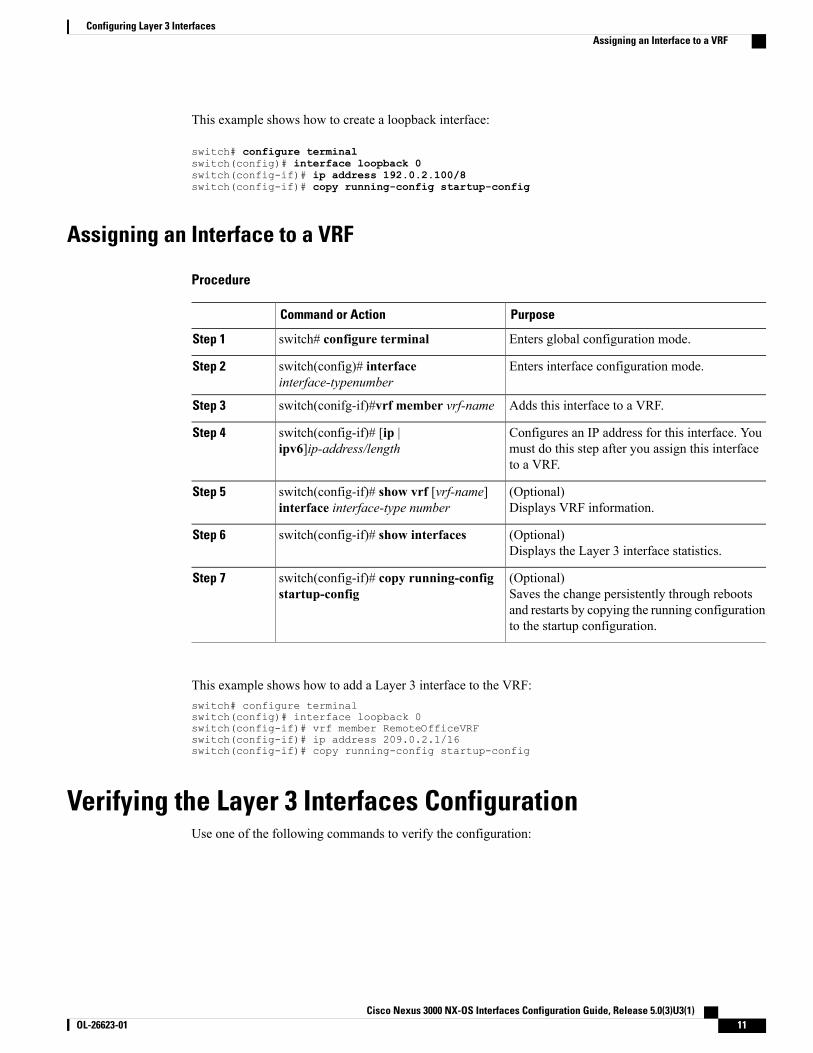
Assigning an Interface to a VRF
Procedure
PurposeCommand or Action
Enters global configuration mode.switch# configure terminalStep 1
Enters interface configuration mode.switch(config)# interfaceinterface-typenumber
Step 2
Adds this interface to a VRF.switch(conifg-if)#vrf member vrf-nameStep 3
Configures an IP address for this interface. Youmust do this step after you assign this interfaceto a VRF.
switch(config-if)# [ip |ipv6]ip-address/length
Step 4
(Optional)Displays VRF information.
switch(config-if)# show vrf [vrf-name]interface interface-type number
Step 5
(Optional)Displays the Layer 3 interface statistics.
switch(config-if)# show interfacesStep 6
(Optional)Saves the change persistently through rebootsand restarts by copying the running configurationto the startup configuration.
switch(config-if)# copy running-configstartup-config
Step 7
This example shows how to add a Layer 3 interface to the VRF:switch# configure terminalswitch(config)# interface loopback 0switch(config-if)# vrf member RemoteOfficeVRFswitch(config-if)# ip address 209.0.2.1/16switch(config-if)# copy running-config startup-config
Verifying the Layer 3 Interfaces ConfigurationUse one of the following commands to verify the configuration:
Cisco Nexus 3000 NX-OS Interfaces Configuration Guide, Release 5.0(3)U3(1) OL-26623-01 11
Configuring Layer 3 InterfacesAssigning an Interface to a VRF
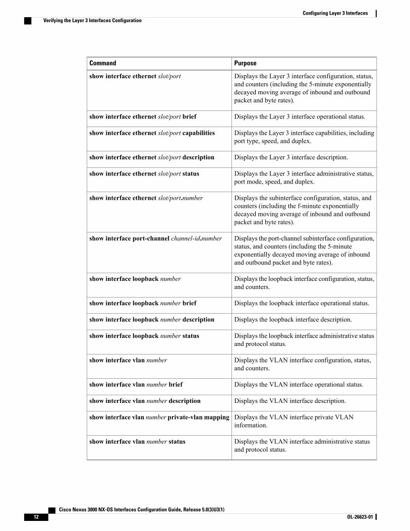
PurposeCommand
Displays the Layer 3 interface configuration, status,and counters (including the 5-minute exponentiallydecayed moving average of inbound and outboundpacket and byte rates).
show interface ethernet slot/port
Displays the Layer 3 interface operational status.show interface ethernet slot/port brief
Displays the Layer 3 interface capabilities, includingport type, speed, and duplex.
show interface ethernet slot/port capabilities
Displays the Layer 3 interface description.show interface ethernet slot/port description
Displays the Layer 3 interface administrative status,port mode, speed, and duplex.
show interface ethernet slot/port status
Displays the subinterface configuration, status, andcounters (including the f-minute exponentiallydecayed moving average of inbound and outboundpacket and byte rates).
show interface ethernet slot/port.number
Displays the port-channel subinterface configuration,status, and counters (including the 5-minuteexponentially decayed moving average of inboundand outbound packet and byte rates).
show interface port-channel channel-id.number
Displays the loopback interface configuration, status,and counters.
show interface loopback number
Displays the loopback interface operational status.show interface loopback number brief
Displays the loopback interface description.show interface loopback number description
Displays the loopback interface administrative statusand protocol status.
show interface loopback number status
Displays the VLAN interface configuration, status,and counters.
show interface vlan number
Displays the VLAN interface operational status.show interface vlan number brief
Displays the VLAN interface description.show interface vlan number description
Displays the VLAN interface private VLANinformation.
show interface vlan number private-vlan mapping
Displays the VLAN interface administrative statusand protocol status.
show interface vlan number status
Cisco Nexus 3000 NX-OS Interfaces Configuration Guide, Release 5.0(3)U3(1)12 OL-26623-01
Configuring Layer 3 InterfacesVerifying the Layer 3 Interfaces Configuration
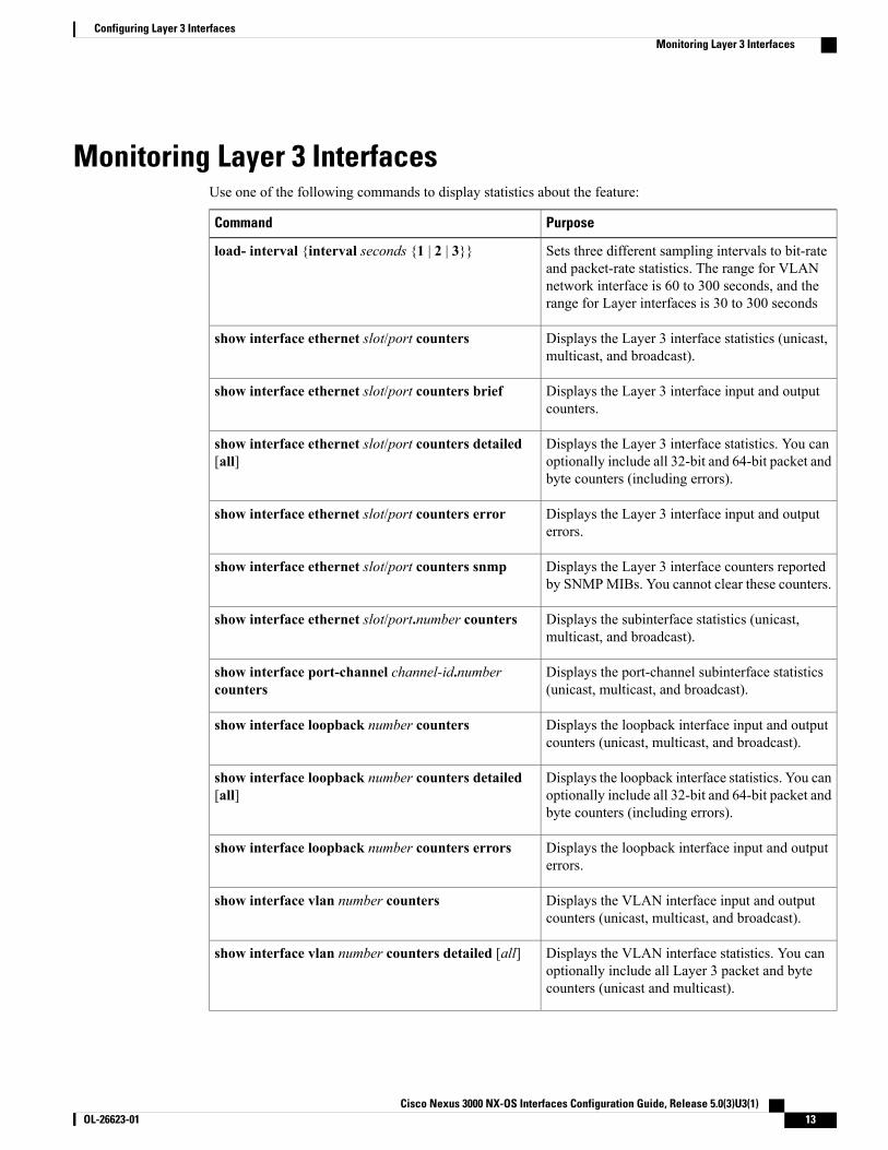
Monitoring Layer 3 InterfacesUse one of the following commands to display statistics about the feature:
PurposeCommand
Sets three different sampling intervals to bit-rateand packet-rate statistics. The range for VLANnetwork interface is 60 to 300 seconds, and therange for Layer interfaces is 30 to 300 seconds
load- interval {interval seconds {1 | 2 | 3}}
Displays the Layer 3 interface statistics (unicast,multicast, and broadcast).
show interface ethernet slot/port counters
Displays the Layer 3 interface input and outputcounters.
show interface ethernet slot/port counters brief
Displays the Layer 3 interface statistics. You canoptionally include all 32-bit and 64-bit packet andbyte counters (including errors).
show interface ethernet slot/port counters detailed[all]
Displays the Layer 3 interface input and outputerrors.
show interface ethernet slot/port counters error
Displays the Layer 3 interface counters reportedby SNMPMIBs. You cannot clear these counters.
show interface ethernet slot/port counters snmp
Displays the subinterface statistics (unicast,multicast, and broadcast).
show interface ethernet slot/port.number counters
Displays the port-channel subinterface statistics(unicast, multicast, and broadcast).
show interface port-channel channel-id.numbercounters
Displays the loopback interface input and outputcounters (unicast, multicast, and broadcast).
show interface loopback number counters
Displays the loopback interface statistics. You canoptionally include all 32-bit and 64-bit packet andbyte counters (including errors).
show interface loopback number counters detailed[all]
Displays the loopback interface input and outputerrors.
show interface loopback number counters errors
Displays the VLAN interface input and outputcounters (unicast, multicast, and broadcast).
show interface vlan number counters
Displays the VLAN interface statistics. You canoptionally include all Layer 3 packet and bytecounters (unicast and multicast).
show interface vlan number counters detailed [all]
Cisco Nexus 3000 NX-OS Interfaces Configuration Guide, Release 5.0(3)U3(1) OL-26623-01 13
Configuring Layer 3 InterfacesMonitoring Layer 3 Interfaces
PurposeCommand
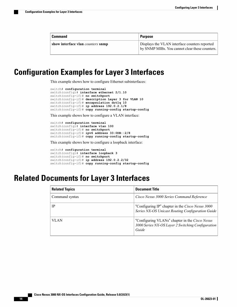
Displays the VLAN interface counters reportedby SNMPMIBs. You cannot clear these counters.
show interface vlan counters snmp
Configuration Examples for Layer 3 InterfacesThis example shows how to configure Ethernet subinterfaces:
switch# configuration terminalswitch(config)# interface ethernet 2/1.10switch(config-if)# no switchportswitch(config-if)# description Layer 3 for VLAN 10switch(config-if)# encapsulation dot1q 10switch(config-if)# ip address 192.0.2.1/8switch(config-if)# copy running-config startup-config
This example shows how to configure a VLAN interface:
switch# configuration terminalswitch(config)# interface vlan 100switch(config-if)# no switchportswitch(config-if)# ipv6 address 33:0DB::2/8switch(config-if)# copy running-config startup-config
This example shows how to configure a loopback interface:
switch# configuration terminalswitch(config)# interface loopback 3switch(config-if)# no switchportswitch(config-if)# ip address 192.0.2.2/32switch(config-if)# copy running-config startup-config
Related Documents for Layer 3 InterfacesDocument TitleRelated Topics
Cisco Nexus 3000 Series Command ReferenceCommand syntax
“Configuring IP” chapter in the Cisco Nexus 3000Series NX-OS Unicast Routing Configuration Guide
IP
“Configuring VLANs” chapter in the Cisco Nexus3000 Series NX-OS Layer 2 Switching ConfigurationGuide
VLAN
Cisco Nexus 3000 NX-OS Interfaces Configuration Guide, Release 5.0(3)U3(1)14 OL-26623-01
Configuring Layer 3 InterfacesConfiguration Examples for Layer 3 Interfaces
MIBs for Layer 3 InterfacesMIB LinkMIB
To locate and download MIBs, go to the followingURL:
http://www.cisco.com/public/sw-center/netmgmt/cmtk/mibs.shtml
IF-MIB
CISCO-IF-EXTENSION-MIB
ETHERLIKE-MIB
Standards for Layer 3 InterfacesNo new or modified standards are supported by this feature, and support for existing standards has not beenmodified by this feature.
Feature History for Layer 3 InterfacesFeature InformationReleaseFeature Name
The show interface vlan vlan-id counterscommand has been enhanced to correctlyshow input and output packet counts.
5.0(3)U3(1)show interface vlan vlan-id counterscommand
Cisco Nexus 3000 NX-OS Interfaces Configuration Guide, Release 5.0(3)U3(1) OL-26623-01 15
Configuring Layer 3 InterfacesMIBs for Layer 3 Interfaces

Cisco Nexus 3000 NX-OS Interfaces Configuration Guide, Release 5.0(3)U3(1)16 OL-26623-01
Configuring Layer 3 InterfacesFeature History for Layer 3 Interfaces
C H A P T E R 3Configuring Port Channels
This chapter contains the following sections:
• Information About Port Channels, page 17
• Configuring Port Channels, page 25
• Verifying Port Channel Configuration, page 32
• Verifying the Load-Balancing Outgoing Port ID , page 33
• Feature History for Port Channels, page 34
Information About Port ChannelsA port channel bundles up to 16 individual interfaces into a group to provide increased bandwidth andredundancy. Port channeling also load balances traffic across these physical interfaces. The port channel staysoperational as long as at least one physical interface within the port channel is operational.
You create an port channel by bundling compatible interfaces. You can configure and run either static portchannels or port channels running the Link Aggregation Control Protocol (LACP).
Any configuration changes that you apply to the port channel are applied to each member interface of thatport channel. For example, if you configure Spanning Tree Protocol (STP) parameters on the port channel,Cisco NX-OS applies those parameters to each interface in the port channel.
You can use static port channels, with no associated protocol, for a simplified configuration. For more efficientuse of the port channel, you can use the Link Aggregation Control Protocol (LACP), which is defined in IEEE802.3ad. When you use LACP, the link passes protocol packets.
Related Topics
LACP Overview, on page 21
Understanding Port ChannelsUsing port channels, Cisco NX-OS provides wider bandwidth, redundancy, and load balancing across thechannels.
Cisco Nexus 3000 NX-OS Interfaces Configuration Guide, Release 5.0(3)U3(1) OL-26623-01 17
You can collect up to 16 ports into a static port channel or you can enable the Link Aggregation ControlProtocol (LACP). Configuring port channels with LACP requires slightly different steps than configuringstatic port channels.
Cisco NX-OS does not support Port Aggregation Protocol (PAgP) for port channels.Note
A port channel bundles individual links into a channel group to create a single logical link that provides theaggregate bandwidth of up to 16 physical links. If a member port within a port channel fails, traffic previouslycarried over the failed link switches to the remaining member ports within the port channel.
Each port can be in only one port channel. All the ports in an port channel must be compatible; they must usethe same speed and operate in full-duplex mode. When you are running static port channels, without LACP,the individual links are all in the on channel mode; you cannot change this mode without enabling LACP.
You cannot change the mode from ON to Active or from ON to Passive.Note
You can create a port channel directly by creating the port-channel interface, or you can create a channelgroup that acts to aggregate individual ports into a bundle. When you associate an interface with a channelgroup, Cisco NX-OS creates a matching port channel automatically if the port channel does not already exist.You can also create the port channel first. In this instance, Cisco NX-OS creates an empty channel group withthe same channel number as the port channel and takes the default configuration.
A port channel is operationally up when at least one of the member ports is up and that port’s status ischanneling. The port channel is operationally down when all member ports are operationally down.
Note
Compatibility RequirementsWhen you add an interface to a port channel group, Cisco NX-OS checks certain interface attributes to ensurethat the interface is compatible with the channel group. Cisco NX-OS also checks a number of operationalattributes for an interface before allowing that interface to participate in the port-channel aggregation.
The compatibility check includes the following operational attributes:
• Port mode
• Access VLAN
• Trunk native VLAN
• Allowed VLAN list
• Speed
• 802.3x flow control setting
• MTU
• Broadcast/Unicast/Multicast Storm Control setting
• Priority-Flow-Control
Cisco Nexus 3000 NX-OS Interfaces Configuration Guide, Release 5.0(3)U3(1)18 OL-26623-01
Configuring Port ChannelsCompatibility Requirements
• Untagged CoS
Use the show port-channel compatibility-parameters command to see the full list of compatibility checksthat Cisco NX-OS uses.
You can only add interfaces configured with the channel mode set to on to static port channels. You can alsoonly add interfaces configured with the channel mode as active or passive to port channels that are runningLACP. You can configure these attributes on an individual member port.
When the interface joins a port channel, the following individual parameters are replaced with the values onthe port channel:
• Bandwidth
• MAC address
• Spanning Tree Protocol
The following interface parameters remain unaffected when the interface joins a port channel:
• Description
• CDP
• LACP port priority
• Debounce
After you enable forcing a port to be added to a channel group by entering the channel-group force command,the following two conditions occur:
• When an interface joins a port channel the following parameters are removed and they are operationallyreplaced with the values on the port channel; however, this change will not be reflected in therunning-configuration for the interface:
• QoS
• Bandwidth
• Delay
• STP
• Service policy
• ACLs
• When an interface joins or leaves a port channel, the following parameters remain unaffected:
• Beacon
• Description
• CDP
• LACP port priority
• Debounce
• UDLD
• Shutdown
Cisco Nexus 3000 NX-OS Interfaces Configuration Guide, Release 5.0(3)U3(1) OL-26623-01 19
Configuring Port ChannelsCompatibility Requirements
• SNMP traps
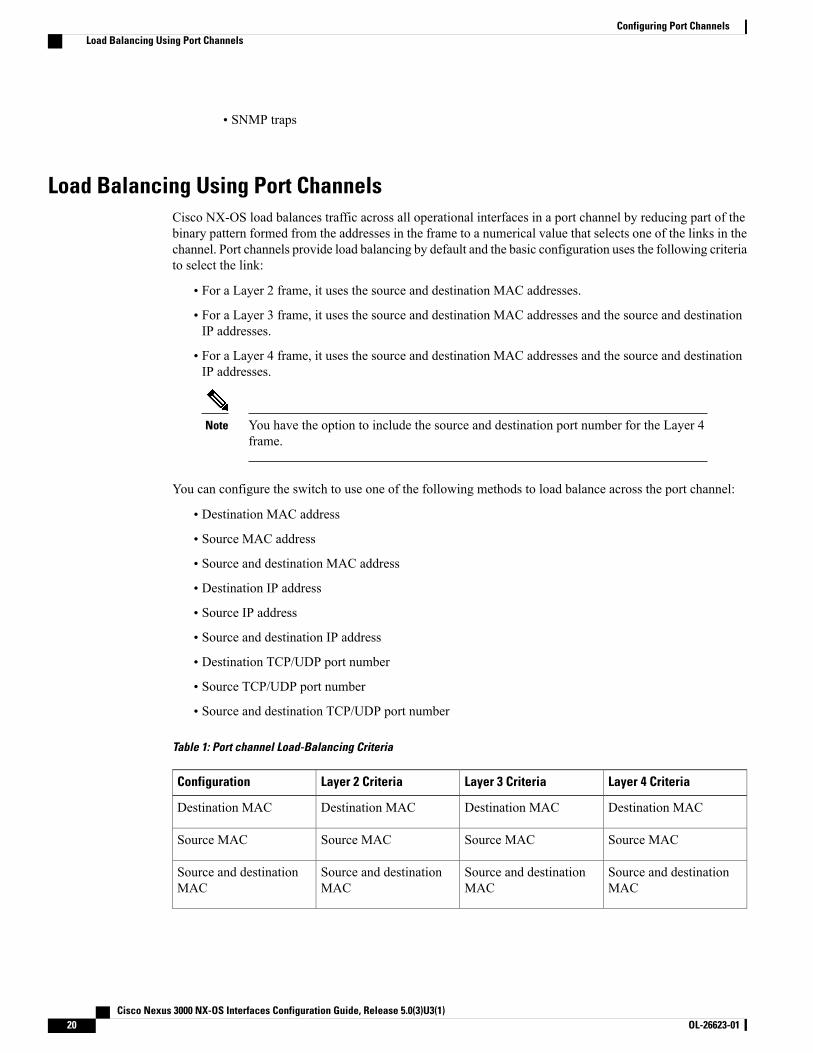
Load Balancing Using Port ChannelsCisco NX-OS load balances traffic across all operational interfaces in a port channel by reducing part of thebinary pattern formed from the addresses in the frame to a numerical value that selects one of the links in thechannel. Port channels provide load balancing by default and the basic configuration uses the following criteriato select the link:
• For a Layer 2 frame, it uses the source and destination MAC addresses.
• For a Layer 3 frame, it uses the source and destination MAC addresses and the source and destinationIP addresses.
• For a Layer 4 frame, it uses the source and destination MAC addresses and the source and destinationIP addresses.
You have the option to include the source and destination port number for the Layer 4frame.
Note
You can configure the switch to use one of the following methods to load balance across the port channel:
• Destination MAC address
• Source MAC address
• Source and destination MAC address
• Destination IP address
• Source IP address
• Source and destination IP address
• Destination TCP/UDP port number
• Source TCP/UDP port number
• Source and destination TCP/UDP port number
Table 1: Port channel Load-Balancing Criteria
Layer 4 CriteriaLayer 3 CriteriaLayer 2 CriteriaConfiguration
Destination MACDestination MACDestination MACDestination MAC
Source MACSource MACSource MACSource MAC
Source and destinationMAC
Source and destinationMAC
Source and destinationMAC
Source and destinationMAC
Cisco Nexus 3000 NX-OS Interfaces Configuration Guide, Release 5.0(3)U3(1)20 OL-26623-01
Configuring Port ChannelsLoad Balancing Using Port Channels
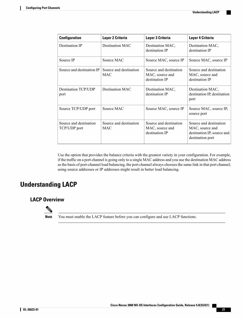
Layer 4 CriteriaLayer 3 CriteriaLayer 2 CriteriaConfiguration
Destination MAC,destination IP
Destination MAC,destination IP
Destination MACDestination IP
Source MAC, source IPSource MAC, source IPSource MACSource IP
Source and destinationMAC, source anddestination IP
Source and destinationMAC, source anddestination IP
Source and destinationMAC
Source and destination IP
Destination MAC,destination IP, destinationport
Destination MAC,destination IP
Destination MACDestination TCP/UDPport
Source MAC, source IP,source port
Source MAC, source IPSource MACSource TCP/UDP port
Source and destinationMAC, source anddestination IP, source anddestination port
Source and destinationMAC, source anddestination IP
Source and destinationMAC
Source and destinationTCP/UDP port
Use the option that provides the balance criteria with the greatest variety in your configuration. For example,if the traffic on a port channel is going only to a singleMAC address and you use the destinationMAC addressas the basis of port-channel load balancing, the port channel always chooses the same link in that port channel;using source addresses or IP addresses might result in better load balancing.
Understanding LACP
LACP Overview
You must enable the LACP feature before you can configure and use LACP functions.Note
Cisco Nexus 3000 NX-OS Interfaces Configuration Guide, Release 5.0(3)U3(1) OL-26623-01 21
Configuring Port ChannelsUnderstanding LACP
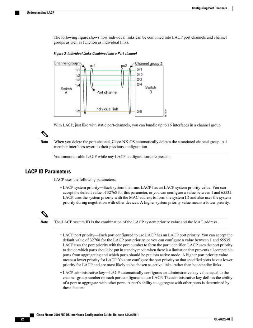
The following figure shows how individual links can be combined into LACP port channels and channelgroups as well as function as individual links.
Figure 3: Individual Links Combined into a Port channel
With LACP, just like with static port-channels, you can bundle up to 16 interfaces in a channel group.
When you delete the port channel, Cisco NX-OS automatically deletes the associated channel group. Allmember interfaces revert to their previous configuration.
Note
You cannot disable LACP while any LACP configurations are present.
LACP ID ParametersLACP uses the following parameters:
• LACP system priority—Each system that runs LACP has an LACP system priority value. You canaccept the default value of 32768 for this parameter, or you can configure a value between 1 and 65535.LACP uses the system priority with the MAC address to form the system ID and also uses the systempriority during negotiation with other devices. A higher system priority value means a lower priority.
The LACP system ID is the combination of the LACP system priority value and the MAC address.Note
• LACP port priority—Each port configured to use LACP has an LACP port priority. You can accept thedefault value of 32768 for the LACP port priority, or you can configure a value between 1 and 65535.LACP uses the port priority with the port number to form the port identifier. LACP uses the port priorityto decide which ports should be put in standbymode when there is a limitation that prevents all compatibleports from aggregating and which ports should be put into active mode. A higher port priority valuemeans a lower priority for LACP. You can configure the port priority so that specified ports have a lowerpriority for LACP and are most likely to be chosen as active links, rather than hot-standby links.
• LACP administrative key—LACP automatically configures an administrative key value equal to thechannel-group number on each port configured to use LACP. The administrative key defines the abilityof a port to aggregate with other ports. A port’s ability to aggregate with other ports is determined bythese factors:
Cisco Nexus 3000 NX-OS Interfaces Configuration Guide, Release 5.0(3)U3(1)22 OL-26623-01
Configuring Port ChannelsUnderstanding LACP
◦Port physical characteristics, such as the data rate, the duplex capability, and the point-to-point orshared medium state
◦Configuration restrictions that you establish
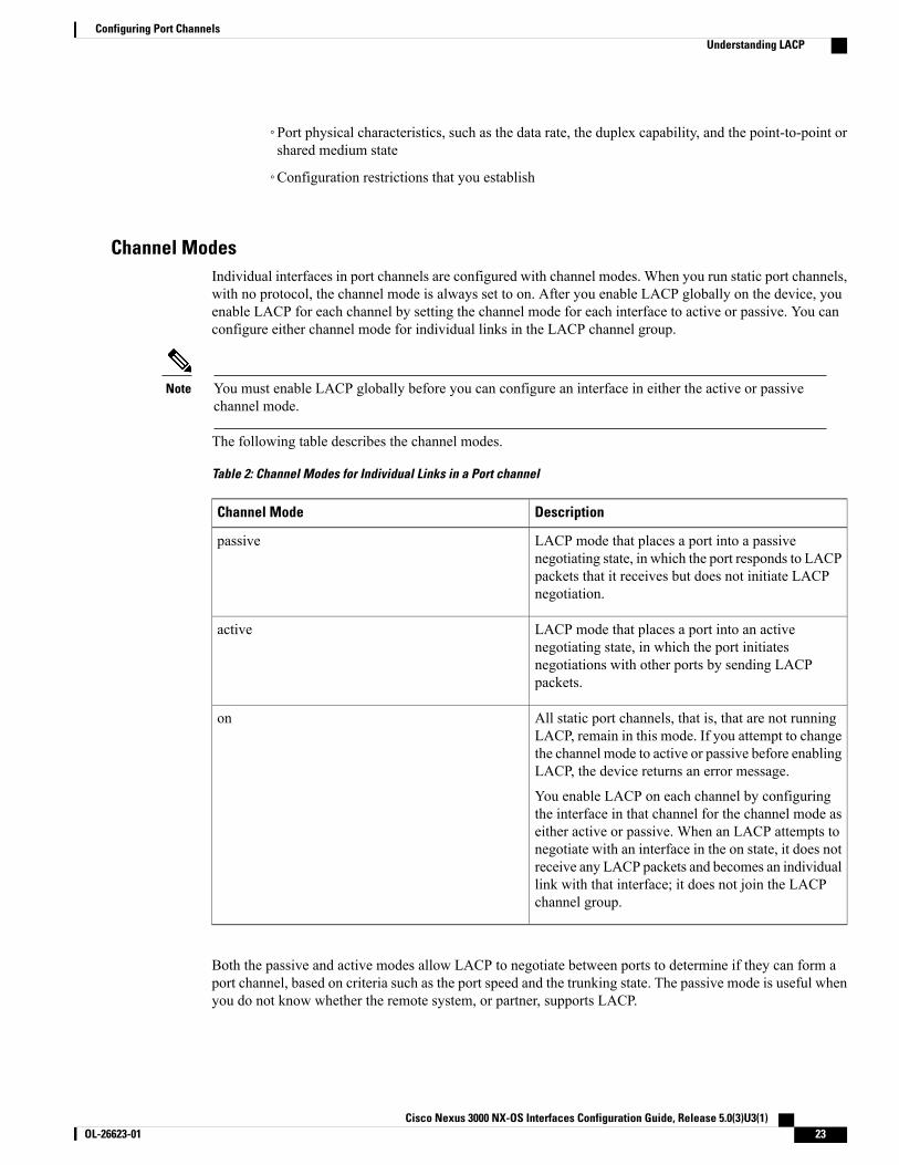
Channel ModesIndividual interfaces in port channels are configured with channel modes. When you run static port channels,with no protocol, the channel mode is always set to on. After you enable LACP globally on the device, youenable LACP for each channel by setting the channel mode for each interface to active or passive. You canconfigure either channel mode for individual links in the LACP channel group.
You must enable LACP globally before you can configure an interface in either the active or passivechannel mode.
Note
The following table describes the channel modes.
Table 2: Channel Modes for Individual Links in a Port channel
DescriptionChannel Mode
LACP mode that places a port into a passivenegotiating state, in which the port responds to LACPpackets that it receives but does not initiate LACPnegotiation.
passive
LACP mode that places a port into an activenegotiating state, in which the port initiatesnegotiations with other ports by sending LACPpackets.
active
All static port channels, that is, that are not runningLACP, remain in this mode. If you attempt to changethe channel mode to active or passive before enablingLACP, the device returns an error message.
You enable LACP on each channel by configuringthe interface in that channel for the channel mode aseither active or passive. When an LACP attempts tonegotiate with an interface in the on state, it does notreceive any LACP packets and becomes an individuallink with that interface; it does not join the LACPchannel group.
on
Both the passive and active modes allow LACP to negotiate between ports to determine if they can form aport channel, based on criteria such as the port speed and the trunking state. The passive mode is useful whenyou do not know whether the remote system, or partner, supports LACP.
Cisco Nexus 3000 NX-OS Interfaces Configuration Guide, Release 5.0(3)U3(1) OL-26623-01 23
Configuring Port ChannelsUnderstanding LACP
Ports can form an LACP port channel when they are in different LACP modes as long as the modes arecompatible as in the following examples:
• A port in active mode can form a port channel successfully with another port that is in active mode.
• A port in active mode can form a port channel with another port in passive mode.
• A port in passive mode cannot form a port channel with another port that is also in passive mode becauseneither port will initiate negotiation.
• A port in on mode is not running LACP.
LACP Marker RespondersUsing port channels, data traffic may be dynamically redistributed due to either a link failure or load balancing.LACP uses the Marker Protocol to ensure that frames are not duplicated or reordered because of thisredistribution. Cisco NX-OS supports only Marker Responders.
LACP-Enabled and Static Port Channel DifferencesThe following table provides a brief summary of major differences between port channels with LACP enabledand static port channels.
Table 3: Port channels with LACP Enabled and Static Port channels
Static EtherChannelsEtherChannels with LACP EnabledConfigurations
Not applicable.Enable globally.Protocol applied
Can only be On.Can be either:
• Active
• Passive
Channel mode of links
1616Maximum number of links inchannel
LACP Port Channel MinLinksA port channel aggregates similar ports to provide increased bandwidth in a single manageable interface. TheMinLinks feature allows you to define the minimum number of interfaces from a LACP bundle that must failbefore the port channel goes down.
The LACP port channel MinLinks feature does the following:
• Configures the minimum number of port channel interfaces that must be linked and bundled in the LACPport channel.
• Prevents a low-bandwidth LACP port channel from becoming active.
Cisco Nexus 3000 NX-OS Interfaces Configuration Guide, Release 5.0(3)U3(1)24 OL-26623-01
Configuring Port ChannelsUnderstanding LACP
• Causes the LACP port channel to become inactive if only a few active members ports supply the requiredminimum bandwidth.
The MinLinks feature works only with LACP port channels. The device allows you to configure thisfeature in non-LACP port channels, but the feature is not operational.
Note
Configuring Port Channels
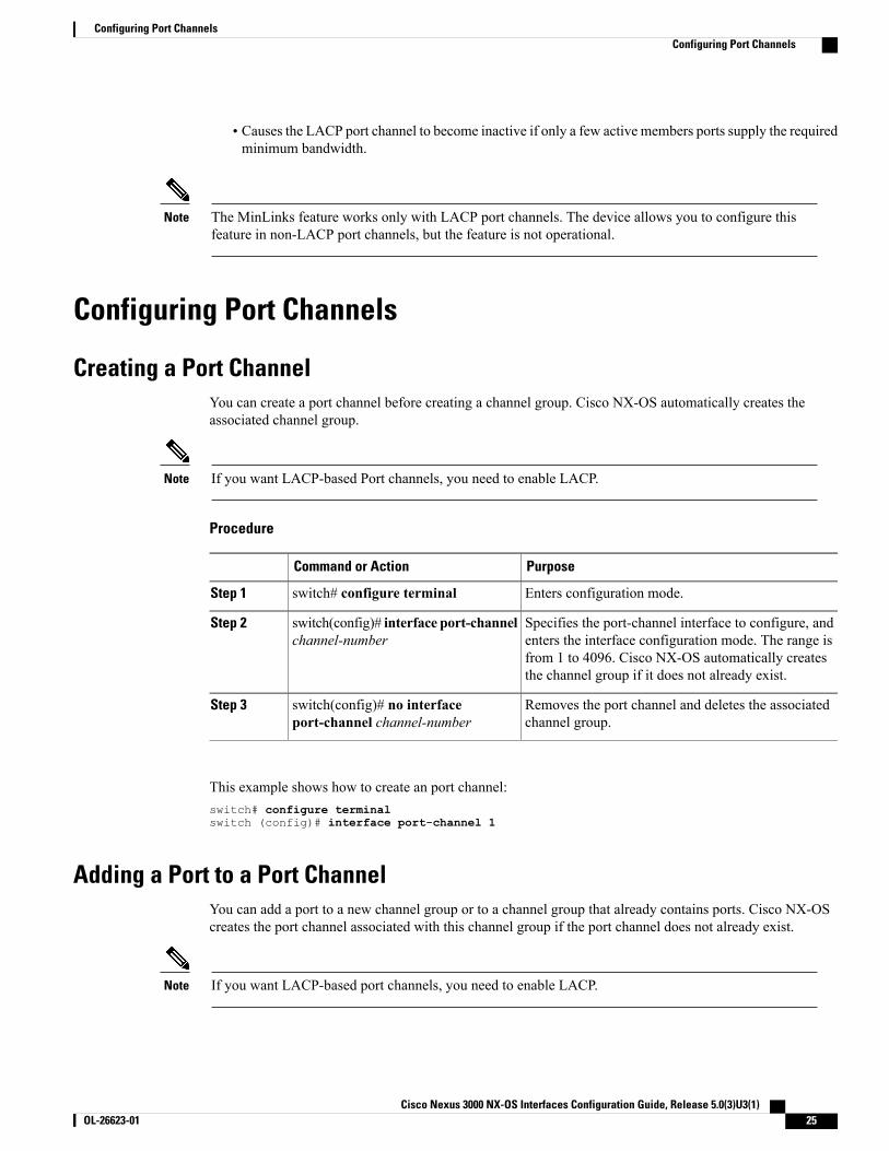
Creating a Port ChannelYou can create a port channel before creating a channel group. Cisco NX-OS automatically creates theassociated channel group.
If you want LACP-based Port channels, you need to enable LACP.Note
Procedure
PurposeCommand or Action
Enters configuration mode.switch# configure terminalStep 1
Specifies the port-channel interface to configure, andenters the interface configuration mode. The range is
switch(config)# interface port-channelchannel-number
Step 2
from 1 to 4096. Cisco NX-OS automatically createsthe channel group if it does not already exist.
Removes the port channel and deletes the associatedchannel group.
switch(config)# no interfaceport-channel channel-number
Step 3
This example shows how to create an port channel:switch# configure terminalswitch (config)# interface port-channel 1
Adding a Port to a Port ChannelYou can add a port to a new channel group or to a channel group that already contains ports. Cisco NX-OScreates the port channel associated with this channel group if the port channel does not already exist.
If you want LACP-based port channels, you need to enable LACP.Note
Cisco Nexus 3000 NX-OS Interfaces Configuration Guide, Release 5.0(3)U3(1) OL-26623-01 25
Configuring Port ChannelsConfiguring Port Channels
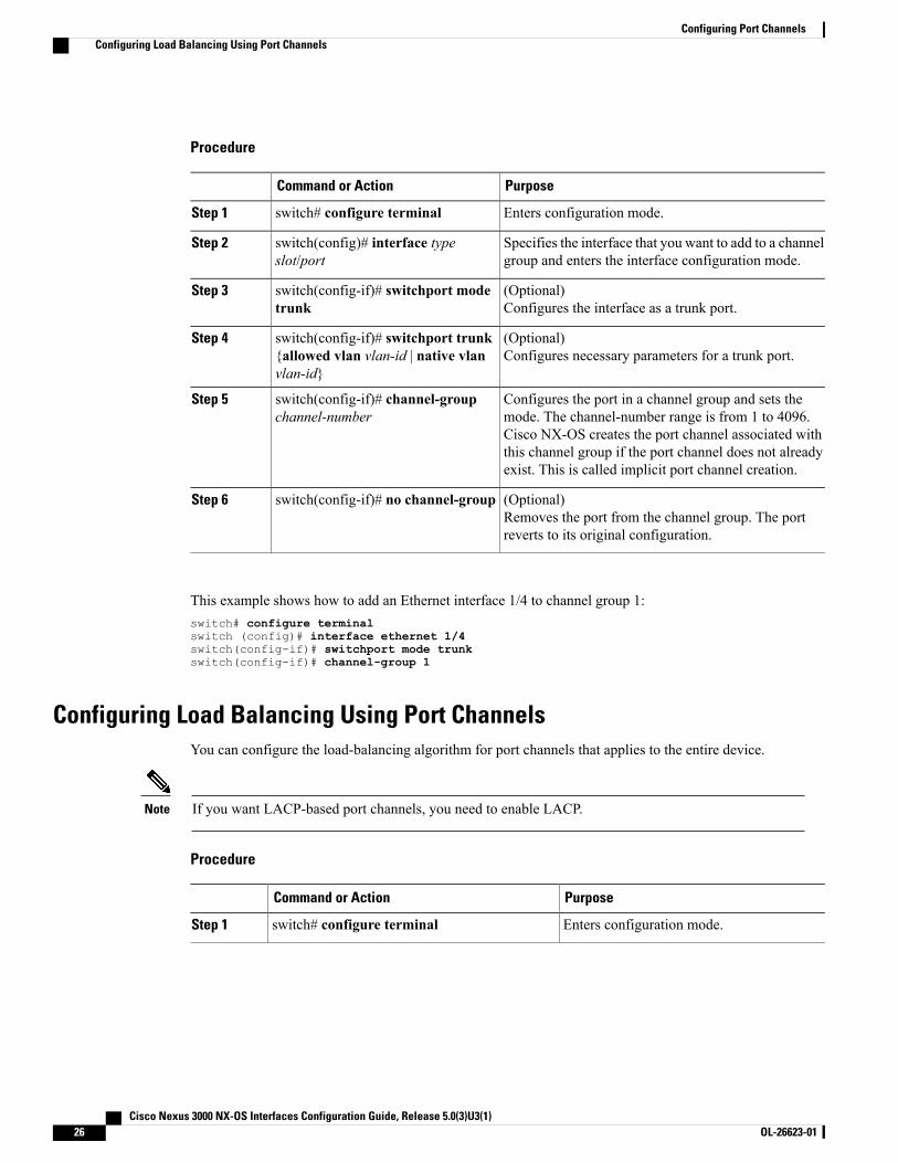
Procedure
PurposeCommand or Action
Enters configuration mode.switch# configure terminalStep 1
Specifies the interface that you want to add to a channelgroup and enters the interface configuration mode.
switch(config)# interface typeslot/port
Step 2
(Optional)Configures the interface as a trunk port.
switch(config-if)# switchport modetrunk
Step 3
(Optional)Configures necessary parameters for a trunk port.
switch(config-if)# switchport trunk{allowed vlan vlan-id | native vlanvlan-id}
Step 4
Configures the port in a channel group and sets themode. The channel-number range is from 1 to 4096.
switch(config-if)# channel-groupchannel-number
Step 5
Cisco NX-OS creates the port channel associated withthis channel group if the port channel does not alreadyexist. This is called implicit port channel creation.
(Optional)Removes the port from the channel group. The portreverts to its original configuration.
switch(config-if)# no channel-groupStep 6
This example shows how to add an Ethernet interface 1/4 to channel group 1:switch# configure terminalswitch (config)# interface ethernet 1/4switch(config-if)# switchport mode trunkswitch(config-if)# channel-group 1
Configuring Load Balancing Using Port ChannelsYou can configure the load-balancing algorithm for port channels that applies to the entire device.
If you want LACP-based port channels, you need to enable LACP.Note
Procedure
PurposeCommand or Action
Enters configuration mode.switch# configure terminalStep 1
Cisco Nexus 3000 NX-OS Interfaces Configuration Guide, Release 5.0(3)U3(1)26 OL-26623-01
Configuring Port ChannelsConfiguring Load Balancing Using Port Channels
PurposeCommand or Action
Specifies the load-balancing algorithm for thedevice. The range depends on the device. Thedefault is source-dest-mac.
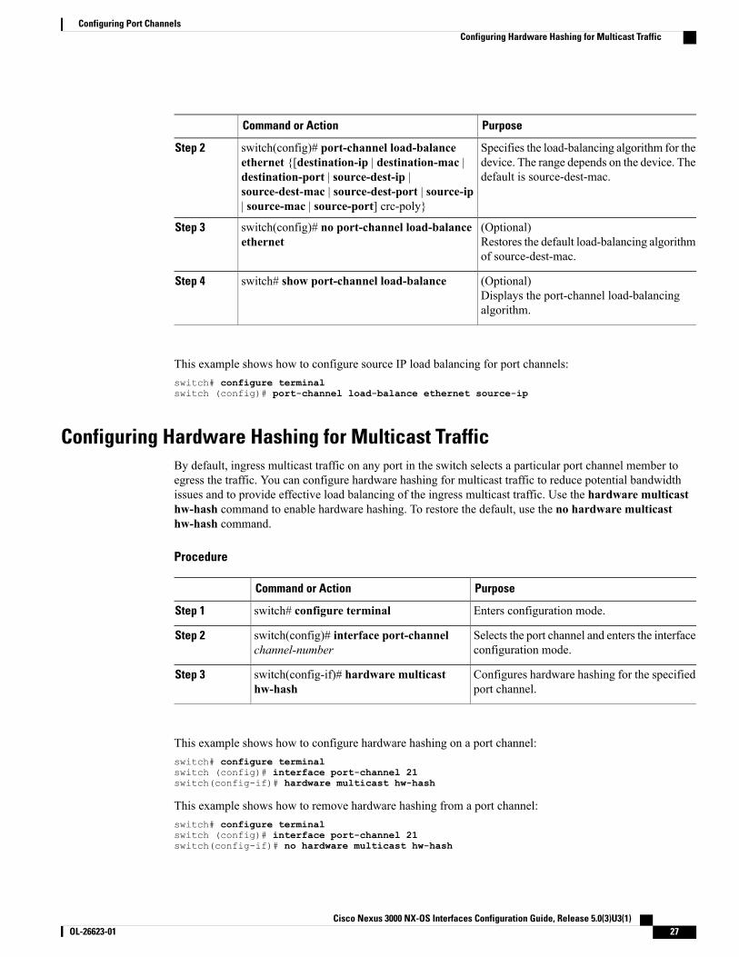
switch(config)# port-channel load-balanceethernet {[destination-ip | destination-mac |destination-port | source-dest-ip |source-dest-mac | source-dest-port | source-ip| source-mac | source-port] crc-poly}
Step 2
(Optional)Restores the default load-balancing algorithmof source-dest-mac.
switch(config)# no port-channel load-balanceethernet
Step 3
(Optional)Displays the port-channel load-balancingalgorithm.
switch# show port-channel load-balanceStep 4
This example shows how to configure source IP load balancing for port channels:switch# configure terminalswitch (config)# port-channel load-balance ethernet source-ip
Configuring Hardware Hashing for Multicast TrafficBy default, ingress multicast traffic on any port in the switch selects a particular port channel member toegress the traffic. You can configure hardware hashing for multicast traffic to reduce potential bandwidthissues and to provide effective load balancing of the ingress multicast traffic. Use the hardware multicasthw-hash command to enable hardware hashing. To restore the default, use the no hardware multicasthw-hash command.
Procedure
PurposeCommand or Action
Enters configuration mode.switch# configure terminalStep 1
Selects the port channel and enters the interfaceconfiguration mode.
switch(config)# interface port-channelchannel-number
Step 2
Configures hardware hashing for the specifiedport channel.
switch(config-if)# hardware multicasthw-hash
Step 3
This example shows how to configure hardware hashing on a port channel:switch# configure terminalswitch (config)# interface port-channel 21switch(config-if)# hardware multicast hw-hash
This example shows how to remove hardware hashing from a port channel:switch# configure terminalswitch (config)# interface port-channel 21switch(config-if)# no hardware multicast hw-hash
Cisco Nexus 3000 NX-OS Interfaces Configuration Guide, Release 5.0(3)U3(1) OL-26623-01 27
Configuring Port ChannelsConfiguring Hardware Hashing for Multicast Traffic
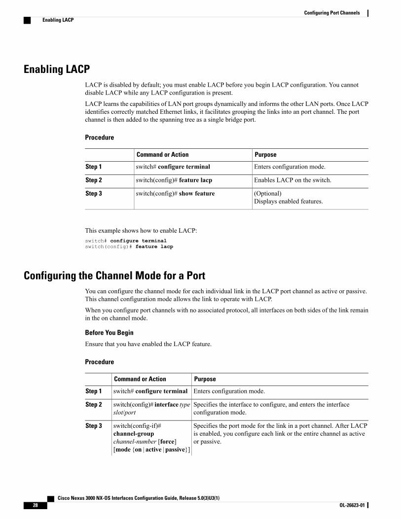
Enabling LACPLACP is disabled by default; you must enable LACP before you begin LACP configuration. You cannotdisable LACP while any LACP configuration is present.
LACP learns the capabilities of LAN port groups dynamically and informs the other LAN ports. Once LACPidentifies correctly matched Ethernet links, it facilitates grouping the links into an port channel. The portchannel is then added to the spanning tree as a single bridge port.
Procedure
PurposeCommand or Action
Enters configuration mode.switch# configure terminalStep 1
Enables LACP on the switch.switch(config)# feature lacpStep 2
(Optional)Displays enabled features.
switch(config)# show featureStep 3
This example shows how to enable LACP:switch# configure terminalswitch(config)# feature lacp
Configuring the Channel Mode for a PortYou can configure the channel mode for each individual link in the LACP port channel as active or passive.This channel configuration mode allows the link to operate with LACP.
When you configure port channels with no associated protocol, all interfaces on both sides of the link remainin the on channel mode.
Before You Begin
Ensure that you have enabled the LACP feature.
Procedure
PurposeCommand or Action
Enters configuration mode.switch# configure terminalStep 1
Specifies the interface to configure, and enters the interfaceconfiguration mode.
switch(config)# interface typeslot/port
Step 2
Specifies the port mode for the link in a port channel. After LACPis enabled, you configure each link or the entire channel as activeor passive.
switch(config-if)#channel-groupchannel-number [force][mode {on | active | passive}]
Step 3
Cisco Nexus 3000 NX-OS Interfaces Configuration Guide, Release 5.0(3)U3(1)28 OL-26623-01
Configuring Port ChannelsEnabling LACP
PurposeCommand or Action
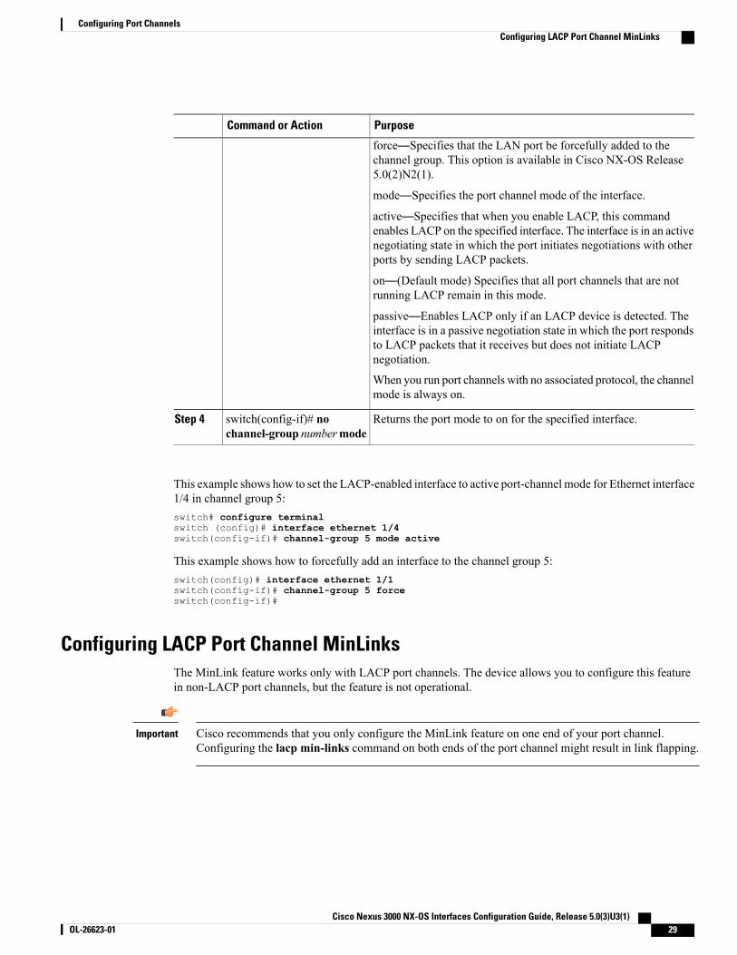
force—Specifies that the LAN port be forcefully added to thechannel group. This option is available in Cisco NX-OS Release5.0(2)N2(1).
mode—Specifies the port channel mode of the interface.
active—Specifies that when you enable LACP, this commandenables LACP on the specified interface. The interface is in an activenegotiating state in which the port initiates negotiations with otherports by sending LACP packets.
on—(Default mode) Specifies that all port channels that are notrunning LACP remain in this mode.
passive—Enables LACP only if an LACP device is detected. Theinterface is in a passive negotiation state in which the port respondsto LACP packets that it receives but does not initiate LACPnegotiation.
When you run port channels with no associated protocol, the channelmode is always on.
Returns the port mode to on for the specified interface.switch(config-if)# nochannel-group numbermode
Step 4
This example shows how to set the LACP-enabled interface to active port-channel mode for Ethernet interface1/4 in channel group 5:switch# configure terminalswitch (config)# interface ethernet 1/4switch(config-if)# channel-group 5 mode active
This example shows how to forcefully add an interface to the channel group 5:switch(config)# interface ethernet 1/1switch(config-if)# channel-group 5 forceswitch(config-if)#
Configuring LACP Port Channel MinLinksThe MinLink feature works only with LACP port channels. The device allows you to configure this featurein non-LACP port channels, but the feature is not operational.
Cisco recommends that you only configure the MinLink feature on one end of your port channel.Configuring the lacp min-links command on both ends of the port channel might result in link flapping.
Important
Cisco Nexus 3000 NX-OS Interfaces Configuration Guide, Release 5.0(3)U3(1) OL-26623-01 29
Configuring Port ChannelsConfiguring LACP Port Channel MinLinks
Procedure
PurposeCommand or Action
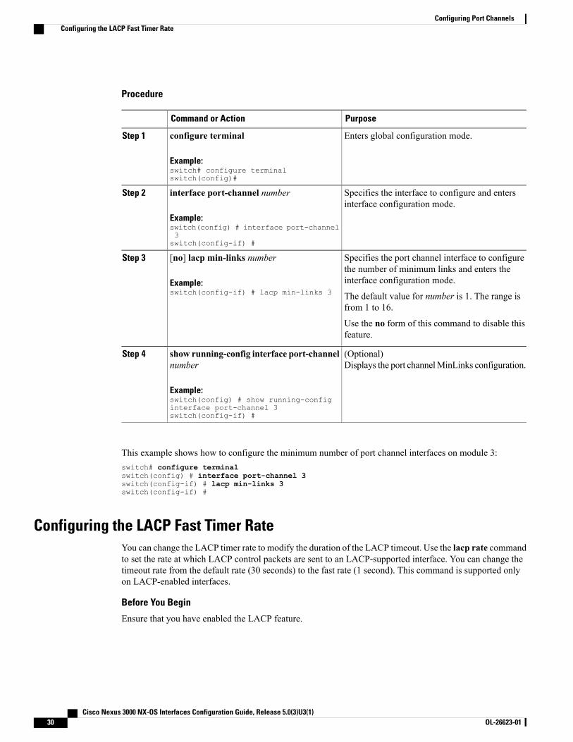
Enters global configuration mode.configure terminal
Example:switch# configure terminalswitch(config)#
Step 1
Specifies the interface to configure and entersinterface configuration mode.
interface port-channel number
Example:switch(config) # interface port-channel3switch(config-if) #
Step 2
Specifies the port channel interface to configurethe number of minimum links and enters theinterface configuration mode.
[no] lacp min-links number
Example:switch(config-if) # lacp min-links 3
Step 3
The default value for number is 1. The range isfrom 1 to 16.
Use the no form of this command to disable thisfeature.
(Optional)Displays the port channelMinLinks configuration.
show running-config interface port-channelnumber
Example:switch(config) # show running-configinterface port-channel 3switch(config-if) #
Step 4
This example shows how to configure the minimum number of port channel interfaces on module 3:switch# configure terminalswitch(config) # interface port-channel 3switch(config-if) # lacp min-links 3switch(config-if) #
Configuring the LACP Fast Timer RateYou can change the LACP timer rate to modify the duration of the LACP timeout. Use the lacp rate commandto set the rate at which LACP control packets are sent to an LACP-supported interface. You can change thetimeout rate from the default rate (30 seconds) to the fast rate (1 second). This command is supported onlyon LACP-enabled interfaces.
Before You Begin
Ensure that you have enabled the LACP feature.
Cisco Nexus 3000 NX-OS Interfaces Configuration Guide, Release 5.0(3)U3(1)30 OL-26623-01
Configuring Port ChannelsConfiguring the LACP Fast Timer Rate

Procedure
PurposeCommand or Action
Enters configuration mode.switch# configure terminalStep 1
Specifies the interface to configure and enters theinterface configuration mode.
switch(config)# interface type slot/portStep 2
Configures the fast rate (one second) at which LACPcontrol packets are sent to an LACP-supportedinterface.
switch(config-if)# lacp rate fastStep 3
This example shows how to configure the LACP fast rate on Ethernet interface 1/4:
switch# configure terminalswitch (config)# interface ethernet 1/4
switch(config-if)# lacp rate fast
This example shows how to restore the LACP default rate (30 seconds) on Ethernet interface 1/4.
switch# configure terminalswitch (config)# interface ethernet 1/4switch(config-if)# no lacp rate fast
Configuring the LACP System Priority and System IDThe LACP system ID is the combination of the LACP system priority value and the MAC address.
Before You Begin
Ensure that you have enabled the LACP feature.
Procedure
PurposeCommand or Action
Enters configuration mode.switch# configure terminalStep 1
Configures the system priority for use with LACP.Valid values are 1 through 65535, and higher numbershave lower priority. The default value is 32768.
switch(config)# lacp system-prioritypriority
Step 2
(Optional)Displays the LACP system identifier.
switch# show lacp system-identifierStep 3
Cisco Nexus 3000 NX-OS Interfaces Configuration Guide, Release 5.0(3)U3(1) OL-26623-01 31
Configuring Port ChannelsConfiguring the LACP System Priority and System ID
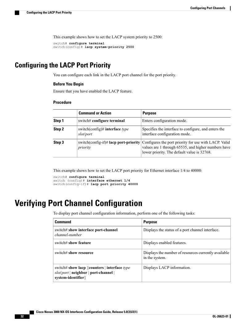
This example shows how to set the LACP system priority to 2500:switch# configure terminalswitch(config)# lacp system-priority 2500
Configuring the LACP Port PriorityYou can configure each link in the LACP port channel for the port priority.
Before You Begin
Ensure that you have enabled the LACP feature.
Procedure
PurposeCommand or Action
Enters configuration mode.switch# configure terminalStep 1
Specifies the interface to configure, and enters theinterface configuration mode.
switch(config)# interface typeslot/port
Step 2
Configures the port priority for use with LACP. Validvalues are 1 through 65535, and higher numbers havelower priority. The default value is 32768.
switch(config-if)# lacp port-prioritypriority
Step 3
This example shows how to set the LACP port priority for Ethernet interface 1/4 to 40000:switch# configure terminalswitch (config)# interface ethernet 1/4switch(config-if)# lacp port priority 40000
Verifying Port Channel ConfigurationTo display port channel configuration information, perform one of the following tasks:
PurposeCommand
Displays the status of a port channel interface.switch# show interface port-channelchannel-number
Displays enabled features.switch# show feature
Displays the number of resources currently availablein the system.
switch# show resource
Displays LACP information.switch# show lacp {counters | interface typeslot/port | neighbor | port-channel |system-identifier}
Cisco Nexus 3000 NX-OS Interfaces Configuration Guide, Release 5.0(3)U3(1)32 OL-26623-01
Configuring Port ChannelsConfiguring the LACP Port Priority
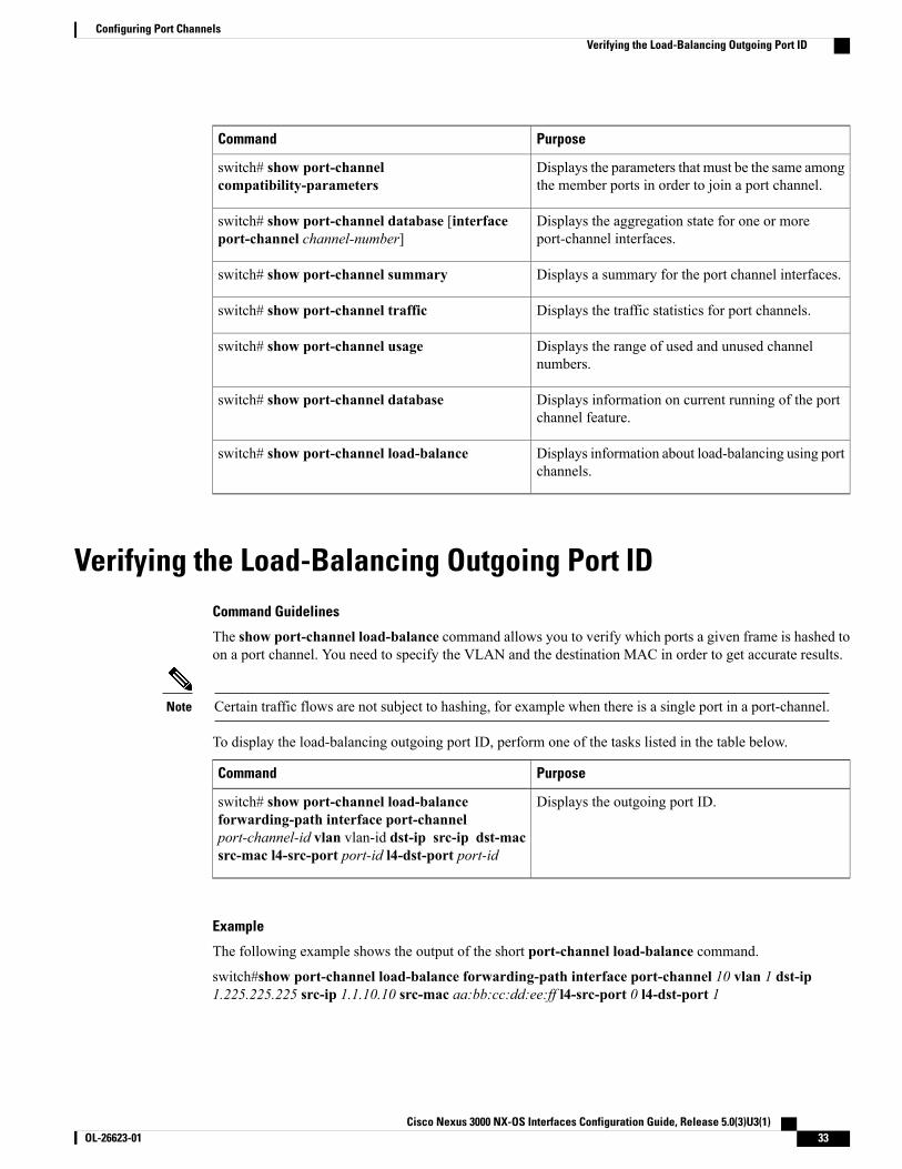
PurposeCommand
Displays the parameters that must be the same amongthe member ports in order to join a port channel.
switch# show port-channelcompatibility-parameters
Displays the aggregation state for one or moreport-channel interfaces.
switch# show port-channel database [interfaceport-channel channel-number]
Displays a summary for the port channel interfaces.switch# show port-channel summary
Displays the traffic statistics for port channels.switch# show port-channel traffic
Displays the range of used and unused channelnumbers.
switch# show port-channel usage
Displays information on current running of the portchannel feature.
switch# show port-channel database
Displays information about load-balancing using portchannels.
switch# show port-channel load-balance
Verifying the Load-Balancing Outgoing Port IDCommand Guidelines
The show port-channel load-balance command allows you to verify which ports a given frame is hashed toon a port channel. You need to specify the VLAN and the destination MAC in order to get accurate results.
Certain traffic flows are not subject to hashing, for example when there is a single port in a port-channel.Note
To display the load-balancing outgoing port ID, perform one of the tasks listed in the table below.
PurposeCommand
Displays the outgoing port ID.switch# show port-channel load-balanceforwarding-path interface port-channelport-channel-id vlan vlan-id dst-ip src-ip dst-macsrc-mac l4-src-port port-id l4-dst-port port-id
Example
The following example shows the output of the short port-channel load-balance command.
switch#show port-channel load-balance forwarding-path interface port-channel 10 vlan 1 dst-ip1.225.225.225 src-ip 1.1.10.10 src-mac aa:bb:cc:dd:ee:ff l4-src-port 0 l4-dst-port 1
Cisco Nexus 3000 NX-OS Interfaces Configuration Guide, Release 5.0(3)U3(1) OL-26623-01 33
Configuring Port ChannelsVerifying the Load-Balancing Outgoing Port ID
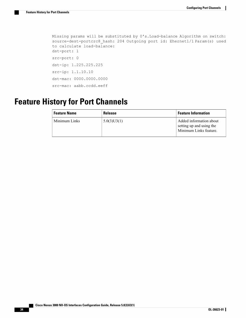
Missing params will be substituted by 0's.Load-balance Algorithm on switch:source-dest-portcrc8_hash: 204 Outgoing port id: Ehernet1/1 Param(s) usedto calculate load-balance:dst-port: 1
src-port: 0
dst-ip: 1.225.225.225
src-ip: 1.1.10.10
dst-mac: 0000.0000.0000
src-mac: aabb.ccdd.eeff
Feature History for Port ChannelsFeature InformationReleaseFeature Name
Added information aboutsetting up and using theMinimum Links feature.
5.0(3)U3(1)Minimum Links
Cisco Nexus 3000 NX-OS Interfaces Configuration Guide, Release 5.0(3)U3(1)34 OL-26623-01
Configuring Port ChannelsFeature History for Port Channels
C H A P T E R 4Configuring Virtual Port Channels
This chapter contains the following sections:
• Information About vPCs, page 35
• Guidelines and Limitations for vPCs, page 44
• Configuring vPCs, page 45
• Verifying the vPC Configuration, page 57
• vPC Default Settings, page 62
Information About vPCs
vPC OverviewA virtual port channel (vPC) allows links that are physically connected to two different Cisco Nexus 3000Series switches to appear as a single port channel by a third device (see the following figure). The third devicecan be a switch, server, or any other networking device. A vPC can provide multipathing, which allows youto create redundancy by enabling multiple parallel paths between nodes and load balancing traffic wherealternative paths exist.
You configure the EtherChannels by using one of the following:
• No protocol
• Link Aggregation Control Protocol (LACP)
When you configure the EtherChannels in a vPC—including the vPC peer link channel—each switch canhave up to 16 active links in a single EtherChannel.
You must enable the vPC feature before you can configure or run the vPC functionality.Note
To enable the vPC functionality, you must create a peer-keepalive link and a peer-link under the vPC domainfor the two vPC peer switches to provide the vPC functionality.
Cisco Nexus 3000 NX-OS Interfaces Configuration Guide, Release 5.0(3)U3(1) OL-26623-01 35
To create a vPC peer link you configure an EtherChannel on one Cisco Nexus 3000 Series switch by usingtwo or more Ethernet ports. On the other switch, you configure another EtherChannel again using two or moreEthernet ports. Connecting these two EtherChannels together creates a vPC peer link.
We recommend that you configure the vPC peer-link EtherChannels as trunks.Note
The vPC domain includes both vPC peer devices, the vPC peer-keepalive link, the vPC peer link, and all ofthe EtherChannels in the vPC domain connected to the downstream device. You can have only one vPCdomain ID on each vPC peer device.
Always attach all vPC devices using EtherChannels to both vPC peer devices.Note
A vPC provides the following benefits:
• Allows a single device to use an EtherChannel across two upstream devices
• Eliminates Spanning Tree Protocol (STP) blocked ports
• Provides a loop-free topology
• Uses all available uplink bandwidth
• Provides fast convergence if either the link or a switch fails
• Provides link-level resiliency
• Assures high availability
Terminology
vPC TerminologyThe terminology used in vPCs is as follows:
• vPC—The combined EtherChannel between the vPC peer devices and the downstream device.
• vPC peer device—One of a pair of devices that are connected with the special EtherChannel known asthe vPC peer link.
• vPC peer link—The link used to synchronize states between the vPC peer devices.
• vPC member port—Interfaces that belong to the vPCs.
• vPC domain—This domain includes both vPC peer devices, the vPC peer-keepalive link, and all of theport channels in the vPC connected to the downstream devices. It is also associated to the configurationmode that you must use to assign vPC global parameters. The vPC domain ID must be the same on bothswitches.
• vPC peer-keepalive link—The peer-keepalive link monitors the vitality of a vPC peer Cisco Nexus 3000Series device. The peer-keepalive link sends configurable, periodic keepalive messages between vPCpeer devices.
Cisco Nexus 3000 NX-OS Interfaces Configuration Guide, Release 5.0(3)U3(1)36 OL-26623-01
Configuring Virtual Port ChannelsTerminology
No data or synchronization traffic moves over the vPC peer-keepalive link; the only traffic on this linkis a message that indicates that the originating switch is operating and running vPCs.
Supported vPC Topologies
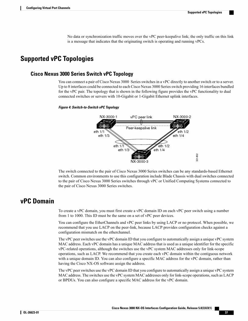
Cisco Nexus 3000 Series Switch vPC TopologyYou can connect a pair of Cisco Nexus 3000 Series switches in a vPC directly to another switch or to a server.Up to 8 interfaces could be connected to each Cisco Nexus 3000 Series switch providing 16 interfaces bundledfor the vPC pair. The topology that is shown in the following figure provides the vPC functionality to dualconnected switches or servers with 10-Gigabit or 1-Gigabit Ethernet uplink interfaces.
Figure 4: Switch-to-Switch vPC Topology
The switch connected to the pair of Cisco Nexus 3000 Series switches can be any standards-based Ethernetswitch. Common environments to use this configuration include Blade Chassis with dual switches connectedto the pair of Cisco Nexus 3000 Series switches through vPC or Unified Computing Systems connected tothe pair of Cisco Nexus 3000 Series switches.
vPC DomainTo create a vPC domain, you must first create a vPC domain ID on each vPC peer switch using a numberfrom 1 to 1000. This ID must be the same on a set of vPC peer devices.
You can configure the EtherChannels and vPC peer links by using LACP or no protocol. When possible, werecommend that you use LACP on the peer-link, because LACP provides configuration checks against aconfiguration mismatch on the etherchannel.
The vPC peer switches use the vPC domain ID that you configure to automatically assign a unique vPC systemMAC address. Each vPC domain has a unique MAC address that is used as a unique identifier for the specificvPC-related operations, although the switches use the vPC system MAC addresses only for link-scopeoperations, such as LACP. We recommend that you create each vPC domain within the contiguous networkwith a unique domain ID. You can also configure a specific MAC address for the vPC domain, rather thanhaving the Cisco NX-OS software assign the address.
The vPC peer switches use the vPC domain ID that you configure to automatically assign a unique vPC systemMAC address. The switches use the vPC systemMAC addresses only for link-scope operations, such as LACPor BPDUs. You can also configure a specific MAC address for the vPC domain.
Cisco Nexus 3000 NX-OS Interfaces Configuration Guide, Release 5.0(3)U3(1) OL-26623-01 37
Configuring Virtual Port ChannelsSupported vPC Topologies
Cisco recommends that you configure the same VPC domain ID on both peers and, the domain ID should beunique in the network. For example, if there are two different VPCs (one in access and one in aggregation)then each vPC should have a unique domain ID.
After you create a vPC domain, the Cisco NX-OS software automatically creates a system priority for thevPC domain. You can also manually configure a specific system priority for the vPC domain.
If you manually configure the system priority, you must ensure that you assign the same priority value onboth vPC peer switches. If the vPC peer switches have different system priority values, the vPC will notcome up.
Note
Peer-Keepalive Link and MessagesThe Cisco NX-OS software uses a peer-keepalive link between the vPC peers to transmit periodic, configurablekeepalive messages. Youmust have Layer 3 connectivity between the peer switches to transmit these messages;the system cannot bring up the vPC peer link unless a peer-keepalive link is already up and running.
If one of the vPC peer switches fails, the vPC peer switch on the other side of the vPC peer link senses thefailure when it does not receive any peer-keepalive messages. The default interval time for the vPCpeer-keepalive message is 1 second. You can configure the interval between 400 milliseconds and 10 seconds.You can also configure a timeout value with a range of 3 to 20 seconds; the default timeout value is 5 seconds.The peer-keepalive status is checked only when the peer-link goes down.
The vPC peer-keepalive can be carried either in the management or default VRF on the Cisco Nexus 3000Series switch. When you configure the switches to use the management VRF, the source and destination forthe keepalive messages are the mgmt 0 interface IP addresses. When you configure the switches to use thedefault VRF, an SVI must be created to act as the source and destination addresses for the vPC peer-keepalivemessages. Ensure that both the source and destination IP addresses used for the peer-keepalive messages areunique in your network and these IP addresses are reachable from the VRF associated with the vPCpeer-keepalive link.
We recommend that you configure the vPC peer-keepalive link on the Cisco Nexus 3000 Series switchto run in the management VRF using the mgmt 0 interfaces. If you configure the default VRF, ensure thatthe vPC peer link is not used to carry the vPC peer-keepalive messages.
Note
Compatibility Parameters for vPC Peer LinksMany configuration and operational parameters must be identical on all interfaces in the vPC. After you enablethe vPC feature and configure the peer link on both vPC peer switches, Cisco Fabric Services (CFS) messagesprovide a copy of the configuration on the local vPC peer switch configuration to the remote vPC peer switch.The system then determines whether any of the crucial configuration parameters differ on the two switches.
Enter the show vpc consistency-parameters command to display the configured values on all interfaces inthe vPC. The displayed configurations are only those configurations that would limit the vPC peer link andvPC from coming up.
The compatibility check process for vPCs differs from the compatibility check for regular EtherChannels.
Cisco Nexus 3000 NX-OS Interfaces Configuration Guide, Release 5.0(3)U3(1)38 OL-26623-01
Configuring Virtual Port ChannelsPeer-Keepalive Link and Messages
Configuration Parameters That Must Be IdenticalThe configuration parameters in this section must be configured identically on both switches at either end ofthe vPC peer link.
You must ensure that all interfaces in the vPC have the identical operational and configuration parameterslisted in this section.
Enter the show vpc consistency-parameters command to display the configured values on all interfacesin the vPC. The displayed configurations are only those configurations that would limit the vPC peer linkand vPC from coming up.
Note
The switch automatically check for compatibility of these parameters on the vPC interfaces. The per-interfaceparameters must be consistent per interface, and the global parameters must be consistent globally.
• Port-channel mode: on, off, or active
• Link speed per channel
• Duplex mode per channel
• Trunk mode per channel:
◦Native VLAN
◦VLANs allowed on trunk
◦Tagging of native VLAN traffic
• Spanning Tree Protocol (STP) mode
• STP region configuration for Multiple Spanning Tree (MST)
• Enable or disable state per VLAN
• STP global settings:
◦Bridge Assurance setting
◦Port type setting—We recommend that you set all vPC interfaces as normal ports
◦Loop Guard settings
• STP interface settings:
◦Port type setting
◦Loop Guard
◦Root Guard
If any of these parameters are not enabled or defined on either switch, the vPC consistency check ignoresthose parameters.
Cisco Nexus 3000 NX-OS Interfaces Configuration Guide, Release 5.0(3)U3(1) OL-26623-01 39
Configuring Virtual Port ChannelsCompatibility Parameters for vPC Peer Links
To ensure that none of the vPC interfaces are in the suspend mode, enter the show vpc brief and showvpc consistency-parameters commands and check the syslog messages.
Note
Configuration Parameters That Should Be IdenticalWhen any of the following parameters are not configured identically on both vPC peer switches, amisconfiguration may cause undesirable behavior in the traffic flow:
• MAC aging timers
• Static MAC entries
• VLAN interface—Each switch on the end of the vPC peer link must have a VLAN interface configuredfor the same VLAN on both ends and they must be in the same administrative and operational mode.Those VLANs configured on only one switch of the peer link do not pass traffic using the vPC or peerlink. You must create all VLANs on both the primary and secondary vPC switches, or the VLAN willbe suspended.
• Private VLAN configuration
• All ACL configurations and parameters
• Quality of service (QoS) configuration and parameters—Local parameters; global parameters must beidentical
• STP interface settings:
◦BPDU Filter
◦BPDU Guard
◦Cost
◦Link type
◦Priority
◦VLANs (Rapid PVST+)
To ensure that all the configuration parameters are compatible, we recommend that you display theconfigurations for each vPC peer switch once you configure the vPC.
Graceful Type-1 CheckWhen a consistency check fails, vPCs are brought down only on the secondary vPC switch. The VLANsremain up on the primary switch and Type-1 configurations can be performed without traffic disruption. Thisfeature is used both in the case of global as well as interface-specific Type-1 inconsistencies.
Cisco Nexus 3000 NX-OS Interfaces Configuration Guide, Release 5.0(3)U3(1)40 OL-26623-01
Configuring Virtual Port ChannelsGraceful Type-1 Check
Per-VLAN Consistency CheckSome Type-1 consistency checks are performed on a per-VLAN basis when spanning tree is enabled ordisabled on a VLAN. VLANs that do not pass the consistency check are brought down on both the primaryand secondary switches while other VLANs are not affected.
vPC Auto-RecoveryThe vPC auto-recovery feature re-enables vPC links in the following scenarios:
When both vPC peer switches reload and only one switch reboots, auto-recovery allows that switch to assumethe role of the primary switch and the vPC links will be allowed to come up after a predetermined period oftime. The reload delay period in this scenario can range from 240-3600 seconds.
When vPCs are disabled on a secondary vPC switch due to a peer-link failure and then the primary vPC switchfails or is unable to forward traffic, the secondary switch re-enables the vPCs. In this scenario, the vPC waitsfor three consecutive keep-alive failures to recover the vPC links.
The vPC auto-recovery feature is disabled by default.
vPC Peer LinksA vPC peer link is the link that is used to synchronize the states between the vPC peer devices.
You must configure the peer-keepalive link before you configure the vPC peer link or the peer link willnot come up.
Note
vPC Peer Link OverviewYou can have only two switches as vPC peers; each switch can serve as a vPC peer to only one other vPCpeer. The vPC peer switches can also have non-vPC links to other switches.
To make a valid configuration, you configure an EtherChannel on each switch and then configure the vPCdomain. You assign the EtherChannel on each switch as a peer link. For redundancy, we recommend that youshould configure at least two dedicated ports into the EtherChannel; if one of the interfaces in the vPC peerlink fails, the switch automatically falls back to use another interface in the peer link.
We recommend that you configure the EtherChannels in trunk mode.Note
Many operational parameters and configuration parameters must be the same in each switch connected by avPC peer link. Because each switch is completely independent on the management plane, you must ensurethat the switches are compatible on the critical parameters. vPC peer switches have separate control planes.After configuring the vPC peer link, you should display the configuration on each vPC peer switch to ensurethat the configurations are compatible.
Cisco Nexus 3000 NX-OS Interfaces Configuration Guide, Release 5.0(3)U3(1) OL-26623-01 41
Configuring Virtual Port ChannelsPer-VLAN Consistency Check
You must ensure that the two switches connected by the vPC peer link have certain identical operationaland configuration parameters.
Note
When you configure the vPC peer link, the vPC peer switches negotiate that one of the connected switchesis the primary switch and the other connected switch is the secondary switch. By default, the Cisco NX-OSsoftware uses the lowest MAC address to elect the primary switch. The software takes different actions oneach switch—that is, the primary and secondary—only in certain failover conditions. If the primary switchfails, the secondary switch becomes the operational primary switchwhen the system recovers, and the previouslyprimary switch is now the secondary switch.
You can also configure which of the vPC switches is the primary switch. If you want to configure the rolepriority again to make one vPC switch the primary switch, configure the role priority on both the primary andsecondary vPC switches with the appropriate values, shut down the EtherChannel that is the vPC peer linkon both switches by entering the shutdown command, and reenable the EtherChannel on both switches byentering the no shutdown command.
MAC addresses that are learned over vPC links are also synchronized between the peers.
Configuration information flows across the vPC peer links using the Cisco Fabric Services over Ethernet(CFSoE) protocol. All MAC addresses for those VLANs configured on both switches are synchronizedbetween vPC peer switches. The software uses CFSoE for this synchronization.
If the vPC peer link fails, the software checks the status of the remote vPC peer switch using the peer-keepalivelink, which is a link between vPC peer switches, to ensure that both switches are up. If the vPC peer switchis up, the secondary vPC switch disables all vPC ports on its switch. The data then forwards down the remainingactive links of the EtherChannel.
The software learns of a vPC peer switch failure when the keepalive messages are not returned over thepeer-keepalive link.
Use a separate link (vPC peer-keepalive link) to send configurable keepalive messages between the vPC peerswitches. The keepalive messages on the vPC peer-keepalive link determines whether a failure is on the vPCpeer link only or on the vPC peer switch. The keepalive messages are used only when all the links in the peerlink fail.
vPC NumberOnce you have created the vPC domain ID and the vPC peer link, you can create EtherChannels to attach thedownstream switch to each vPC peer switch. That is, you create one single EtherChannel on the downstreamswitch with half of the ports to the primary vPC peer switch and the other half of the ports to the secondarypeer switch.
On each vPC peer switch, you assign the same vPC number to the EtherChannel that connects to the downstreamswitch. You will experience minimal traffic disruption when you are creating vPCs. To simplify theconfiguration, you can assign the vPC ID number for each EtherChannel to be the same as the EtherChannelitself (that is, vPC ID 10 for EtherChannel 10).
The vPC number that you assign to the EtherChannel connecting to the downstream switch from the vPCpeer switch must be identical on both vPC peer switches.
Note
Cisco Nexus 3000 NX-OS Interfaces Configuration Guide, Release 5.0(3)U3(1)42 OL-26623-01
Configuring Virtual Port ChannelsvPC Number
vPC Interactions with Other Features
vPC and LACPThe Link Aggregation Control Protocol (LACP) uses the system MAC address of the vPC domain to formthe LACP Aggregation Group (LAG) ID for the vPC.
You can use LACP on all the vPC EtherChannels, including those channels from the downstream switch. Werecommend that you configure LACP with active mode on the interfaces on each EtherChannel on the vPCpeer switches. This configuration allows you tomore easily detect compatibility between switches, unidirectionallinks, and multihop connections, and provides dynamic reaction to run-time changes and link failures.
The vPC peer link supports 16 EtherChannel interfaces.
When manually configuring the system priority, you must ensure that you assign the same priority valueon both vPC peer switches. If the vPC peer switches have different system priority values, vPC will notcome up.
Note
vPC Peer Links and STPWhen you first bring up the vPC functionality, STP reconverges. STP treats the vPC peer link as a speciallink and always includes the vPC peer link in the STP active topology.
We recommend that you set all the vPC peer link interfaces to the STP network port type so that BridgeAssurance is automatically enabled on all vPC peer links. We also recommend that you do not enable any ofthe STP enhancement features on VPC peer links.
You must configure a list of parameters to be identical on the vPC peer switches on both sides of the vPCpeer link.
STP is distributed; that is, the protocol continues running on both vPC peer switches. However, the configurationon the vPC peer switch elected as the primary switch controls the STP process for the vPC interfaces on thesecondary vPC peer switch.
The primary vPC switch synchronizes the STP state on the vPC secondary peer switch using Cisco FabricServices over Ethernet (CFSoE).
The vPC manager performs a proposal/handshake agreement between the vPC peer switches that sets theprimary and secondary switches and coordinates the two switches for STP. The primary vPC peer switch thencontrols the STP protocol for vPC interfaces on both the primary and secondary switches.
The Bridge Protocol Data Units (BPDUs) use the MAC address set for the vPC for the STP bridge ID in thedesignated bridge ID field. The vPC primary switch sends these BPDUs on the vPC interfaces.
Display the configuration on both sides of the vPC peer link to ensure that the settings are identical. Usethe show spanning-tree command to display information about the vPC.
Note
Cisco Nexus 3000 NX-OS Interfaces Configuration Guide, Release 5.0(3)U3(1) OL-26623-01 43
Configuring Virtual Port ChannelsvPC Interactions with Other Features
CFSoEThe Cisco Fabric Services over Ethernet (CFSoE) is a reliable state transport mechanism that you can use tosynchronize the actions of the vPC peer devices. CFSoE carries messages and packets for many features linkedwith vPC, such as STP and IGMP. Information is carried in CFS/CFSoE protocol data units (PDUs).
When you enable the vPC feature, the device automatically enables CFSoE, and you do not have to configureanything. CFSoE distributions for vPCs do not need the capabilities to distribute over IP or the CFS regions.You do not need to configure anything for the CFSoE feature to work correctly on vPCs.
You can use the show mac address-table command to display the MAC addresses that CFSoE synchronizesfor the vPC peer link.
Do not enter the no cfs eth distribute or the no cfs distribute command. CFSoE must be enabled forvPC functionality. If you do enter either of these commands when vPC is enabled, the system displays anerror message.
Note
When you enter the show cfs application command, the output displays "Physical-eth," which shows theapplications that are using CFSoE.
Guidelines and Limitations for vPCsvPC has the following configuration guidelines and limitations:
• vPC is not qualified with IPv6.
• You must enable the vPC feature before you can configure vPC peer-link and vPC interfaces.
• You must configure the peer-keepalive link before the system can form the vPC peer link.
• The vPC peer-link needs to be formed using a minimum of two 10-Gigabit Ethernet interfaces.
• Cisco recommends that you configure the same vPC domain ID on both peers and, the domain ID shouldbe unique in the network. For example, if there are two different vPCs (one in access and one inaggregation) then each vPC should have a unique domain ID.
• Only Port Channels can be in vPCs. A vPC can be configured on a normal Port Channel (switch-to-switchvPC topology) and on an Port Channel host interface (host interface vPC topology).
• Youmust configure both vPC peer switches; the configuration is not automatically synchronized betweenthe vPC peer devices.
• Check that the necessary configuration parameters are compatible on both sides of the vPC peer link.
• You might experience minimal traffic disruption while configuring vPCs.
• You should configure all the Port Channels in the vPC using LACP with the interfaces in active mode.
• You might experience traffic disruption when the first member of a vPC is brought up.
Cisco Nexus 3000 NX-OS Interfaces Configuration Guide, Release 5.0(3)U3(1)44 OL-26623-01
Configuring Virtual Port ChannelsGuidelines and Limitations for vPCs
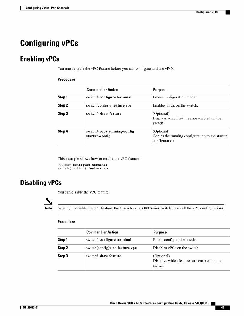
Configuring vPCs
Enabling vPCsYou must enable the vPC feature before you can configure and use vPCs.
Procedure
PurposeCommand or Action
Enters configuration mode.switch# configure terminalStep 1
Enables vPCs on the switch.switch(config)# feature vpcStep 2
(Optional)Displays which features are enabled on theswitch.
switch# show featureStep 3
(Optional)Copies the running configuration to the startupconfiguration.
switch# copy running-configstartup-config
Step 4
This example shows how to enable the vPC feature:switch# configure terminalswitch(config)# feature vpc
Disabling vPCsYou can disable the vPC feature.
When you disable the vPC feature, the Cisco Nexus 3000 Series switch clears all the vPC configurations.Note
Procedure
PurposeCommand or Action
Enters configuration mode.switch# configure terminalStep 1
Disables vPCs on the switch.switch(config)# no feature vpcStep 2
(Optional)Displays which features are enabled on theswitch.
switch# show featureStep 3
Cisco Nexus 3000 NX-OS Interfaces Configuration Guide, Release 5.0(3)U3(1) OL-26623-01 45
Configuring Virtual Port ChannelsConfiguring vPCs
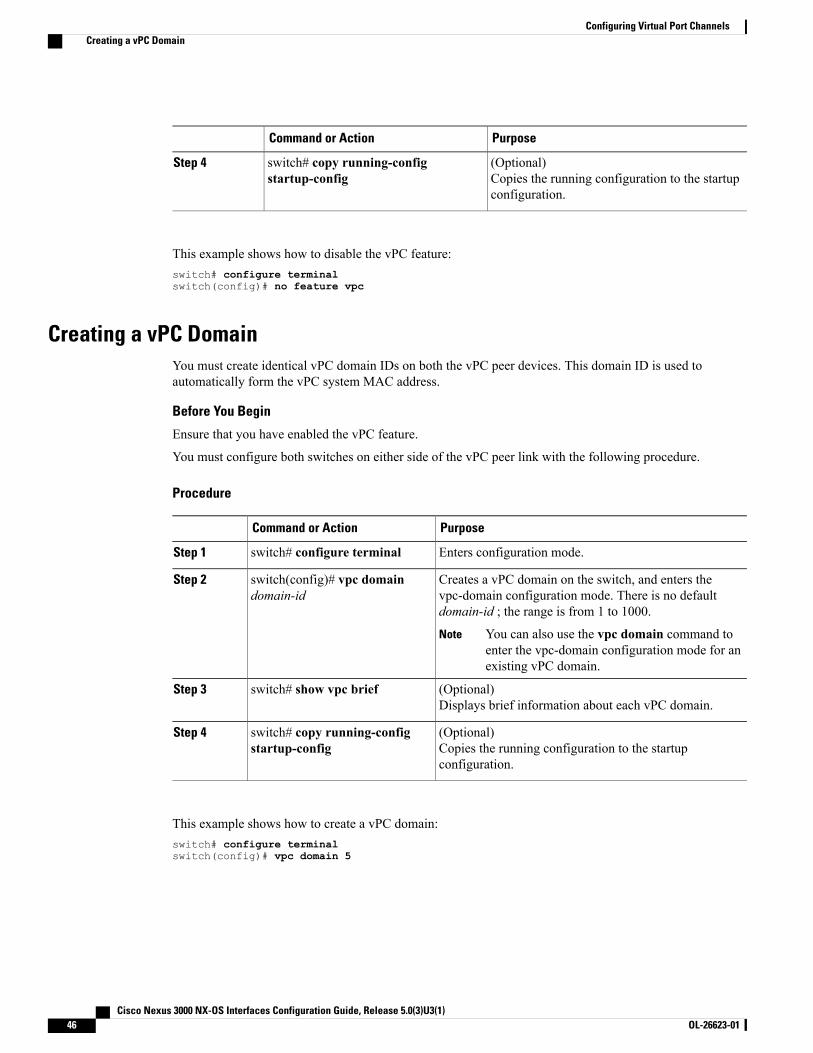
PurposeCommand or Action
(Optional)Copies the running configuration to the startupconfiguration.
switch# copy running-configstartup-config
Step 4
This example shows how to disable the vPC feature:switch# configure terminalswitch(config)# no feature vpc
Creating a vPC DomainYou must create identical vPC domain IDs on both the vPC peer devices. This domain ID is used toautomatically form the vPC system MAC address.
Before You Begin
Ensure that you have enabled the vPC feature.
You must configure both switches on either side of the vPC peer link with the following procedure.
Procedure
PurposeCommand or Action
Enters configuration mode.switch# configure terminalStep 1
Creates a vPC domain on the switch, and enters thevpc-domain configuration mode. There is no defaultdomain-id ; the range is from 1 to 1000.
switch(config)# vpc domaindomain-id
Step 2
You can also use the vpc domain command toenter the vpc-domain configuration mode for anexisting vPC domain.
Note
(Optional)Displays brief information about each vPC domain.
switch# show vpc briefStep 3
(Optional)Copies the running configuration to the startupconfiguration.
switch# copy running-configstartup-config
Step 4
This example shows how to create a vPC domain:switch# configure terminalswitch(config)# vpc domain 5
Cisco Nexus 3000 NX-OS Interfaces Configuration Guide, Release 5.0(3)U3(1)46 OL-26623-01
Configuring Virtual Port ChannelsCreating a vPC Domain
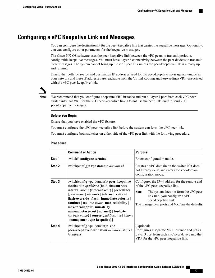
Configuring a vPC Keepalive Link and MessagesYou can configure the destination IP for the peer-keepalive link that carries the keepalive messages. Optionally,you can configure other parameters for the keepalive messages.
The Cisco NX-OS software uses the peer-keepalive link between the vPC peers to transmit periodic,configurable keepalive messages. You must have Layer 3 connectivity between the peer devices to transmitthese messages. The system cannot bring up the vPC peer link unless the peer-keepalive link is already upand running.
Ensure that both the source and destination IP addresses used for the peer-keepalive message are unique inyour network and these IP addresses are reachable from the Virtual Routing and Forwarding (VRF) associatedwith the vPC peer-keepalive link.
We recommend that you configure a separate VRF instance and put a Layer 3 port from each vPC peerswitch into that VRF for the vPC peer-keepalive link. Do not use the peer link itself to send vPCpeer-keepalive messages.
Note
Before You Begin
Ensure that you have enabled the vPC feature.
You must configure the vPC peer-keepalive link before the system can form the vPC peer link.
You must configure both switches on either side of the vPC peer link with the following procedure.
Procedure
PurposeCommand or Action
Enters configuration mode.switch# configure terminalStep 1
Creates a vPC domain on the switch if it doesnot already exist, and enters the vpc-domainconfiguration mode.
switch(config)# vpc domain domain-idStep 2
Configures the IPv4 address for the remote endof the vPC peer-keepalive link.
switch(config-vpc-domain)# peer-keepalivedestination ipaddress [hold-timeout secs |
Step 3
interval msecs {timeout secs} | precedence The system does not form the vPC peerlink until you configure a vPCpeer-keepalive link.
Note
The management ports and VRF are the defaults
{prec-value | network | internet | critical |flash-override | flash | immediate priority |routine} | tos {tos-value |max-reliability |max-throughput |min-delay |min-monetary-cost | normal} | tos-bytetos-byte-value} | source ipaddress | vrf {name|management vpc-keepalive}]
(Optional)Configures a separate VRF instance and puts aLayer 3 port from each vPC peer device into thatVRF for the vPC peer-keepalive link.
switch(config-vpc-domain)# vpcpeer-keepalive destination ipaddress sourceipaddress
Step 4
Cisco Nexus 3000 NX-OS Interfaces Configuration Guide, Release 5.0(3)U3(1) OL-26623-01 47
Configuring Virtual Port ChannelsConfiguring a vPC Keepalive Link and Messages
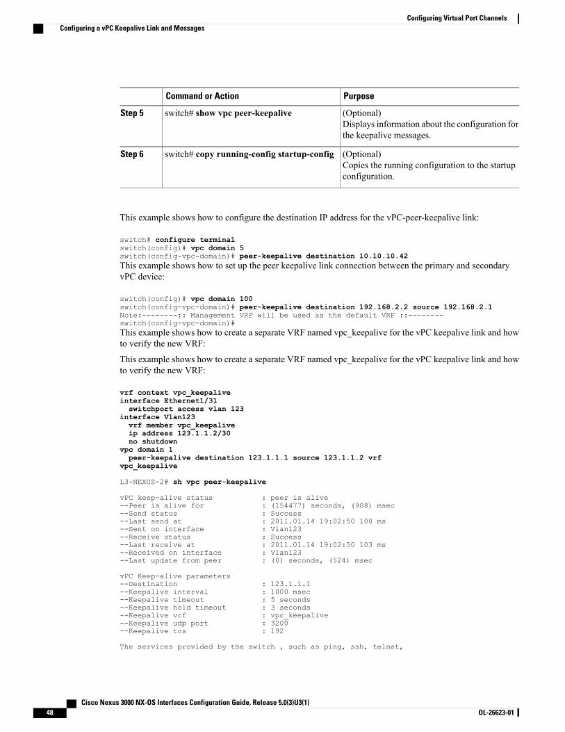
PurposeCommand or Action
(Optional)Displays information about the configuration forthe keepalive messages.
switch# show vpc peer-keepaliveStep 5
(Optional)Copies the running configuration to the startupconfiguration.
switch# copy running-config startup-configStep 6
This example shows how to configure the destination IP address for the vPC-peer-keepalive link:
switch# configure terminalswitch(config)# vpc domain 5switch(config-vpc-domain)# peer-keepalive destination 10.10.10.42This example shows how to set up the peer keepalive link connection between the primary and secondaryvPC device:
switch(config)# vpc domain 100switch(config-vpc-domain)# peer-keepalive destination 192.168.2.2 source 192.168.2.1Note:--------:: Management VRF will be used as the default VRF ::--------switch(config-vpc-domain)#This example shows how to create a separate VRF named vpc_keepalive for the vPC keepalive link and howto verify the new VRF:
This example shows how to create a separate VRF named vpc_keepalive for the vPC keepalive link and howto verify the new VRF:
vrf context vpc_keepaliveinterface Ethernet1/31switchport access vlan 123
interface Vlan123vrf member vpc_keepaliveip address 123.1.1.2/30no shutdown
vpc domain 1peer-keepalive destination 123.1.1.1 source 123.1.1.2 vrf
vpc_keepalive
L3-NEXUS-2# sh vpc peer-keepalive
vPC keep-alive status : peer is alive--Peer is alive for : (154477) seconds, (908) msec--Send status : Success--Last send at : 2011.01.14 19:02:50 100 ms--Sent on interface : Vlan123--Receive status : Success--Last receive at : 2011.01.14 19:02:50 103 ms--Received on interface : Vlan123--Last update from peer : (0) seconds, (524) msec
vPC Keep-alive parameters--Destination : 123.1.1.1--Keepalive interval : 1000 msec--Keepalive timeout : 5 seconds--Keepalive hold timeout : 3 seconds--Keepalive vrf : vpc_keepalive--Keepalive udp port : 3200--Keepalive tos : 192
The services provided by the switch , such as ping, ssh, telnet,
Cisco Nexus 3000 NX-OS Interfaces Configuration Guide, Release 5.0(3)U3(1)48 OL-26623-01
Configuring Virtual Port ChannelsConfiguring a vPC Keepalive Link and Messages
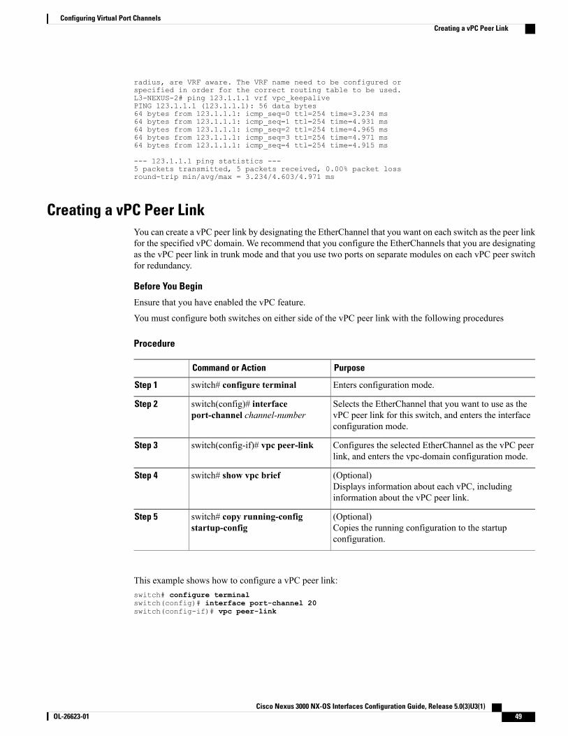
radius, are VRF aware. The VRF name need to be configured orspecified in order for the correct routing table to be used.L3-NEXUS-2# ping 123.1.1.1 vrf vpc_keepalivePING 123.1.1.1 (123.1.1.1): 56 data bytes64 bytes from 123.1.1.1: icmp_seq=0 ttl=254 time=3.234 ms64 bytes from 123.1.1.1: icmp_seq=1 ttl=254 time=4.931 ms64 bytes from 123.1.1.1: icmp_seq=2 ttl=254 time=4.965 ms64 bytes from 123.1.1.1: icmp_seq=3 ttl=254 time=4.971 ms64 bytes from 123.1.1.1: icmp_seq=4 ttl=254 time=4.915 ms
--- 123.1.1.1 ping statistics ---5 packets transmitted, 5 packets received, 0.00% packet lossround-trip min/avg/max = 3.234/4.603/4.971 ms
Creating a vPC Peer LinkYou can create a vPC peer link by designating the EtherChannel that you want on each switch as the peer linkfor the specified vPC domain. We recommend that you configure the EtherChannels that you are designatingas the vPC peer link in trunk mode and that you use two ports on separate modules on each vPC peer switchfor redundancy.
Before You Begin
Ensure that you have enabled the vPC feature.
You must configure both switches on either side of the vPC peer link with the following procedures
Procedure
PurposeCommand or Action
Enters configuration mode.switch# configure terminalStep 1
Selects the EtherChannel that you want to use as thevPC peer link for this switch, and enters the interfaceconfiguration mode.
switch(config)# interfaceport-channel channel-number
Step 2
Configures the selected EtherChannel as the vPC peerlink, and enters the vpc-domain configuration mode.
switch(config-if)# vpc peer-linkStep 3
(Optional)Displays information about each vPC, includinginformation about the vPC peer link.
switch# show vpc briefStep 4
(Optional)Copies the running configuration to the startupconfiguration.
switch# copy running-configstartup-config
Step 5
This example shows how to configure a vPC peer link:switch# configure terminalswitch(config)# interface port-channel 20switch(config-if)# vpc peer-link
Cisco Nexus 3000 NX-OS Interfaces Configuration Guide, Release 5.0(3)U3(1) OL-26623-01 49
Configuring Virtual Port ChannelsCreating a vPC Peer Link
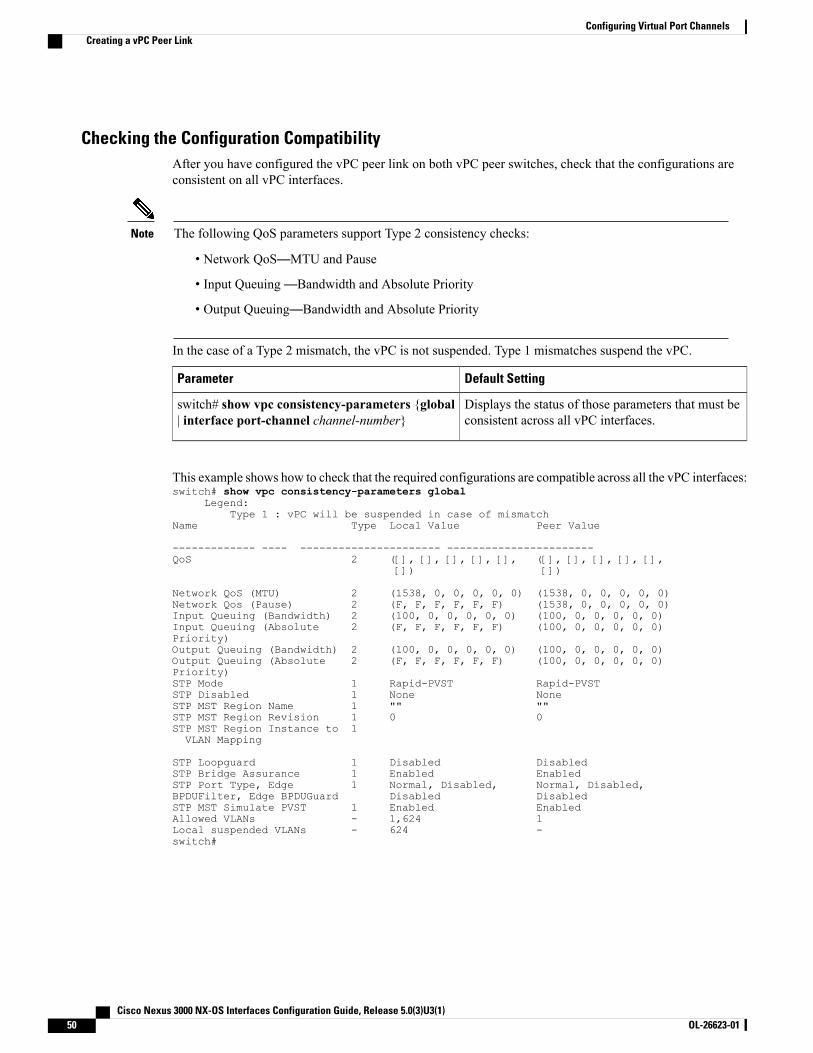
Checking the Configuration CompatibilityAfter you have configured the vPC peer link on both vPC peer switches, check that the configurations areconsistent on all vPC interfaces.
The following QoS parameters support Type 2 consistency checks:Note
• Network QoS—MTU and Pause
• Input Queuing—Bandwidth and Absolute Priority
• Output Queuing—Bandwidth and Absolute Priority
In the case of a Type 2 mismatch, the vPC is not suspended. Type 1 mismatches suspend the vPC.
Default SettingParameter
Displays the status of those parameters that must beconsistent across all vPC interfaces.
switch# show vpc consistency-parameters {global| interface port-channel channel-number}
This example shows how to check that the required configurations are compatible across all the vPC interfaces:switch# show vpc consistency-parameters global
Legend:Type 1 : vPC will be suspended in case of mismatch
Name Type Local Value Peer Value
------------- ---- ---------------------- -----------------------QoS 2 ([], [], [], [], [], ([], [], [], [], [],
[]) [])
Network QoS (MTU) 2 (1538, 0, 0, 0, 0, 0) (1538, 0, 0, 0, 0, 0)Network Qos (Pause) 2 (F, F, F, F, F, F) (1538, 0, 0, 0, 0, 0)Input Queuing (Bandwidth) 2 (100, 0, 0, 0, 0, 0) (100, 0, 0, 0, 0, 0)Input Queuing (Absolute 2 (F, F, F, F, F, F) (100, 0, 0, 0, 0, 0)Priority)Output Queuing (Bandwidth) 2 (100, 0, 0, 0, 0, 0) (100, 0, 0, 0, 0, 0)Output Queuing (Absolute 2 (F, F, F, F, F, F) (100, 0, 0, 0, 0, 0)Priority)STP Mode 1 Rapid-PVST Rapid-PVSTSTP Disabled 1 None NoneSTP MST Region Name 1 "" ""STP MST Region Revision 1 0 0STP MST Region Instance to 1VLAN Mapping
STP Loopguard 1 Disabled DisabledSTP Bridge Assurance 1 Enabled EnabledSTP Port Type, Edge 1 Normal, Disabled, Normal, Disabled,BPDUFilter, Edge BPDUGuard Disabled DisabledSTP MST Simulate PVST 1 Enabled EnabledAllowed VLANs - 1,624 1Local suspended VLANs - 624 -switch#
Cisco Nexus 3000 NX-OS Interfaces Configuration Guide, Release 5.0(3)U3(1)50 OL-26623-01
Configuring Virtual Port ChannelsCreating a vPC Peer Link
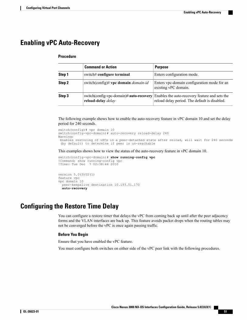
Enabling vPC Auto-Recovery
Procedure
PurposeCommand or Action
Enters configuration mode.switch# configure terminalStep 1
Enters vpc-domain configuration mode for anexisting vPC domain.
switch(config)# vpc domain domain-idStep 2
Enables the auto-recovery feature and sets thereload delay period. The default is disabled.
switch(config-vpc-domain)# auto-recoveryreload-delay delay
Step 3
The following example shows how to enable the auto-recovery feature in vPC domain 10 and set the delayperiod for 240 seconds.switch(config)# vpc domain 10switch(config-vpc-domain)# auto-recovery reload-delay 240Warning:Enables restoring of vPCs in a peer-detached state after reload, will wait for 240 seconds(by default) to determine if peer is un-reachable
This examples shows how to view the status of the auto-recovery feature in vPC domain 10.switch(config-vpc-domain)# show running-config vpc!Command: show running-config vpc!Time: Tue Dec 7 02:38:44 2010
version 5.0(3)U2(1)feature vpcvpc domain 10peer-keepalive destination 10.193.51.170auto-recovery
Configuring the Restore Time DelayYou can configure a restore timer that delays the vPC from coming back up until after the peer adjacencyforms and the VLAN interfaces are back up. This feature avoids packet drops when the routing tables maynot be converged before the vPC is once again passing traffic.
Before You Begin
Ensure that you have enabled the vPC feature.
You must configure both switches on either side of the vPC peer link with the following procedures.
Cisco Nexus 3000 NX-OS Interfaces Configuration Guide, Release 5.0(3)U3(1) OL-26623-01 51
Configuring Virtual Port ChannelsEnabling vPC Auto-Recovery
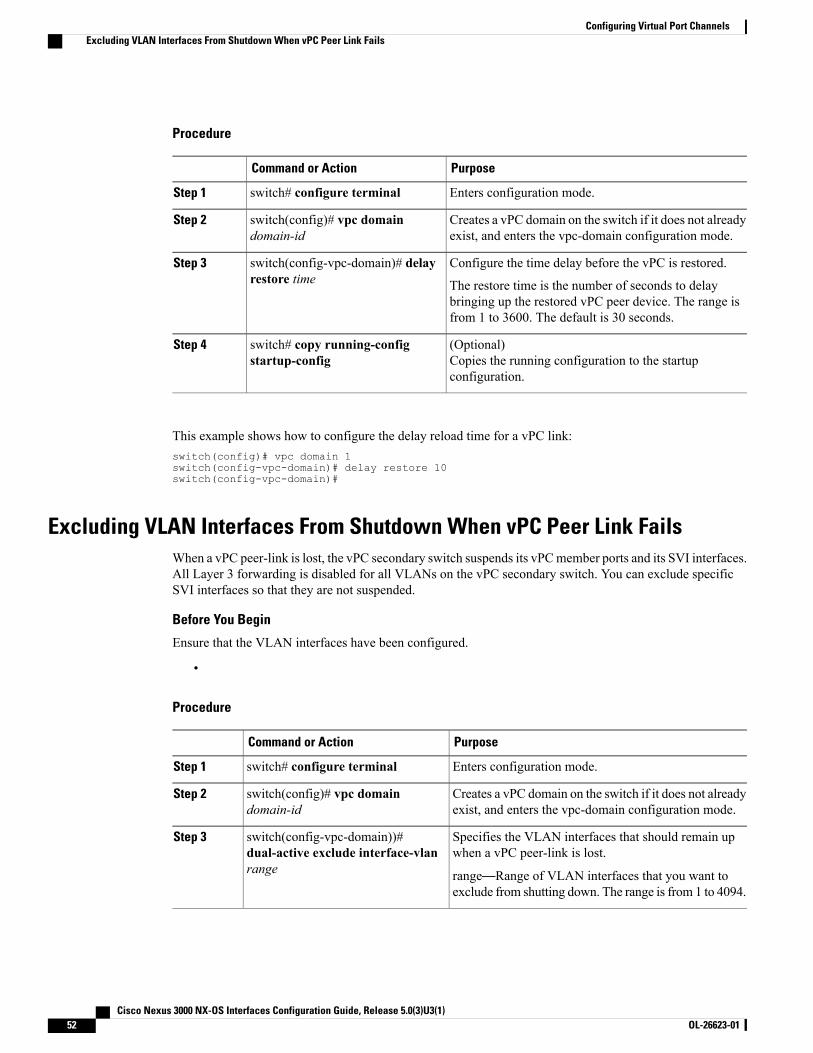
Procedure
PurposeCommand or Action
Enters configuration mode.switch# configure terminalStep 1
Creates a vPC domain on the switch if it does not alreadyexist, and enters the vpc-domain configuration mode.
switch(config)# vpc domaindomain-id
Step 2
Configure the time delay before the vPC is restored.switch(config-vpc-domain)# delayrestore time
Step 3
The restore time is the number of seconds to delaybringing up the restored vPC peer device. The range isfrom 1 to 3600. The default is 30 seconds.
(Optional)Copies the running configuration to the startupconfiguration.
switch# copy running-configstartup-config
Step 4
This example shows how to configure the delay reload time for a vPC link:switch(config)# vpc domain 1switch(config-vpc-domain)# delay restore 10switch(config-vpc-domain)#
Excluding VLAN Interfaces From Shutdown When vPC Peer Link FailsWhen a vPC peer-link is lost, the vPC secondary switch suspends its vPCmember ports and its SVI interfaces.All Layer 3 forwarding is disabled for all VLANs on the vPC secondary switch. You can exclude specificSVI interfaces so that they are not suspended.
Before You Begin
Ensure that the VLAN interfaces have been configured.
•
Procedure
PurposeCommand or Action
Enters configuration mode.switch# configure terminalStep 1
Creates a vPC domain on the switch if it does not alreadyexist, and enters the vpc-domain configuration mode.
switch(config)# vpc domaindomain-id
Step 2
Specifies the VLAN interfaces that should remain upwhen a vPC peer-link is lost.
switch(config-vpc-domain))#dual-active exclude interface-vlanrange
Step 3
range—Range of VLAN interfaces that you want toexclude from shutting down. The range is from 1 to 4094.
Cisco Nexus 3000 NX-OS Interfaces Configuration Guide, Release 5.0(3)U3(1)52 OL-26623-01
Configuring Virtual Port ChannelsExcluding VLAN Interfaces From Shutdown When vPC Peer Link Fails
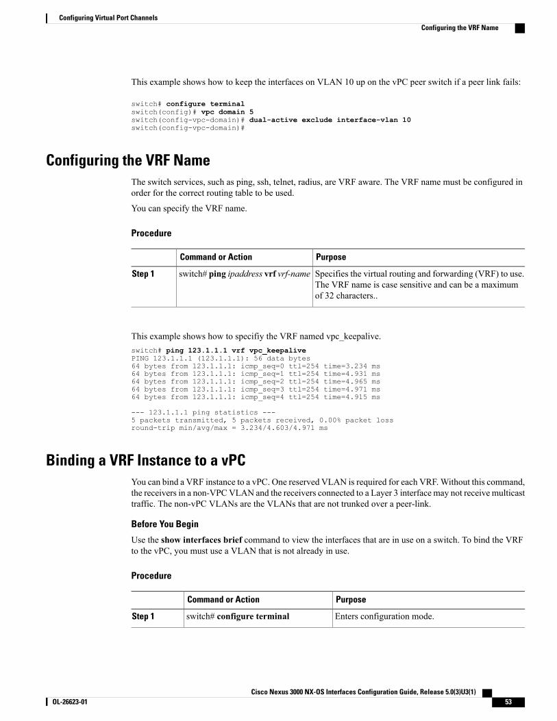
This example shows how to keep the interfaces on VLAN 10 up on the vPC peer switch if a peer link fails:
switch# configure terminalswitch(config)# vpc domain 5switch(config-vpc-domain)# dual-active exclude interface-vlan 10switch(config-vpc-domain)#
Configuring the VRF NameThe switch services, such as ping, ssh, telnet, radius, are VRF aware. The VRF name must be configured inorder for the correct routing table to be used.
You can specify the VRF name.
Procedure
PurposeCommand or Action
Specifies the virtual routing and forwarding (VRF) to use.The VRF name is case sensitive and can be a maximumof 32 characters..
switch# ping ipaddress vrf vrf-nameStep 1
This example shows how to specifiy the VRF named vpc_keepalive.switch# ping 123.1.1.1 vrf vpc_keepalivePING 123.1.1.1 (123.1.1.1): 56 data bytes64 bytes from 123.1.1.1: icmp_seq=0 ttl=254 time=3.234 ms64 bytes from 123.1.1.1: icmp_seq=1 ttl=254 time=4.931 ms64 bytes from 123.1.1.1: icmp_seq=2 ttl=254 time=4.965 ms64 bytes from 123.1.1.1: icmp_seq=3 ttl=254 time=4.971 ms64 bytes from 123.1.1.1: icmp_seq=4 ttl=254 time=4.915 ms
--- 123.1.1.1 ping statistics ---5 packets transmitted, 5 packets received, 0.00% packet lossround-trip min/avg/max = 3.234/4.603/4.971 ms
Binding a VRF Instance to a vPCYou can bind a VRF instance to a vPC. One reserved VLAN is required for each VRF.Without this command,the receivers in a non-VPCVLAN and the receivers connected to a Layer 3 interface may not receive multicasttraffic. The non-vPC VLANs are the VLANs that are not trunked over a peer-link.
Before You Begin
Use the show interfaces brief command to view the interfaces that are in use on a switch. To bind the VRFto the vPC, you must use a VLAN that is not already in use.
Procedure
PurposeCommand or Action
Enters configuration mode.switch# configure terminalStep 1
Cisco Nexus 3000 NX-OS Interfaces Configuration Guide, Release 5.0(3)U3(1) OL-26623-01 53
Configuring Virtual Port ChannelsConfiguring the VRF Name
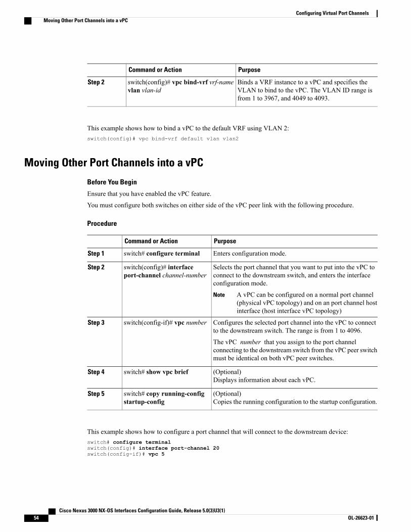
PurposeCommand or Action
Binds a VRF instance to a vPC and specifies theVLAN to bind to the vPC. The VLAN ID range isfrom 1 to 3967, and 4049 to 4093.
switch(config)# vpc bind-vrf vrf-namevlan vlan-id
Step 2
This example shows how to bind a vPC to the default VRF using VLAN 2:switch(config)# vpc bind-vrf default vlan vlan2
Moving Other Port Channels into a vPC
Before You Begin
Ensure that you have enabled the vPC feature.
You must configure both switches on either side of the vPC peer link with the following procedure.
Procedure
PurposeCommand or Action
Enters configuration mode.switch# configure terminalStep 1
Selects the port channel that you want to put into the vPC toconnect to the downstream switch, and enters the interfaceconfiguration mode.
switch(config)# interfaceport-channel channel-number
Step 2
A vPC can be configured on a normal port channel(physical vPC topology) and on an port channel hostinterface (host interface vPC topology)
Note
Configures the selected port channel into the vPC to connectto the downstream switch. The range is from 1 to 4096.
switch(config-if)# vpc numberStep 3
The vPC number that you assign to the port channelconnecting to the downstream switch from the vPC peer switchmust be identical on both vPC peer switches.
(Optional)Displays information about each vPC.
switch# show vpc briefStep 4
(Optional)Copies the running configuration to the startup configuration.
switch# copy running-configstartup-config
Step 5
This example shows how to configure a port channel that will connect to the downstream device:switch# configure terminalswitch(config)# interface port-channel 20switch(config-if)# vpc 5
Cisco Nexus 3000 NX-OS Interfaces Configuration Guide, Release 5.0(3)U3(1)54 OL-26623-01
Configuring Virtual Port ChannelsMoving Other Port Channels into a vPC
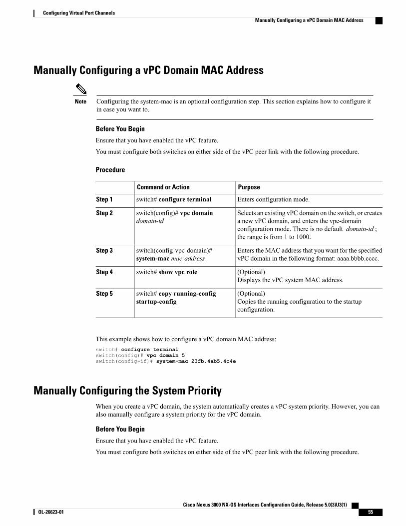
Manually Configuring a vPC Domain MAC Address
Configuring the system-mac is an optional configuration step. This section explains how to configure itin case you want to.
Note
Before You Begin
Ensure that you have enabled the vPC feature.
You must configure both switches on either side of the vPC peer link with the following procedure.
Procedure
PurposeCommand or Action
Enters configuration mode.switch# configure terminalStep 1
Selects an existing vPC domain on the switch, or createsa new vPC domain, and enters the vpc-domain
switch(config)# vpc domaindomain-id
Step 2
configuration mode. There is no default domain-id ;the range is from 1 to 1000.
Enters the MAC address that you want for the specifiedvPC domain in the following format: aaaa.bbbb.cccc.
switch(config-vpc-domain)#system-mac mac-address
Step 3
(Optional)Displays the vPC system MAC address.
switch# show vpc roleStep 4
(Optional)Copies the running configuration to the startupconfiguration.
switch# copy running-configstartup-config
Step 5
This example shows how to configure a vPC domain MAC address:switch# configure terminalswitch(config)# vpc domain 5switch(config-if)# system-mac 23fb.4ab5.4c4e
Manually Configuring the System PriorityWhen you create a vPC domain, the system automatically creates a vPC system priority. However, you canalso manually configure a system priority for the vPC domain.
Before You Begin
Ensure that you have enabled the vPC feature.
You must configure both switches on either side of the vPC peer link with the following procedure.
Cisco Nexus 3000 NX-OS Interfaces Configuration Guide, Release 5.0(3)U3(1) OL-26623-01 55
Configuring Virtual Port ChannelsManually Configuring a vPC Domain MAC Address
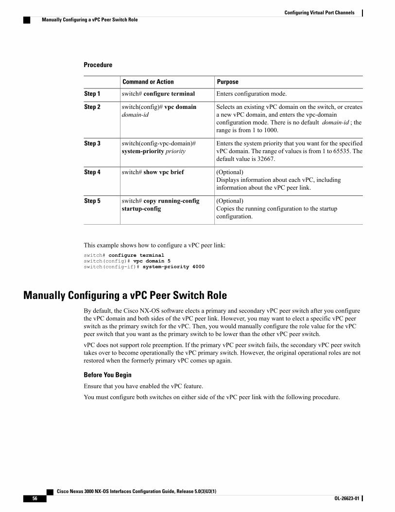
Procedure
PurposeCommand or Action
Enters configuration mode.switch# configure terminalStep 1
Selects an existing vPC domain on the switch, or createsa new vPC domain, and enters the vpc-domain
switch(config)# vpc domaindomain-id
Step 2
configuration mode. There is no default domain-id ; therange is from 1 to 1000.
Enters the system priority that you want for the specifiedvPC domain. The range of values is from 1 to 65535. Thedefault value is 32667.
switch(config-vpc-domain)#system-priority priority
Step 3
(Optional)Displays information about each vPC, includinginformation about the vPC peer link.
switch# show vpc briefStep 4
(Optional)Copies the running configuration to the startupconfiguration.
switch# copy running-configstartup-config
Step 5
This example shows how to configure a vPC peer link:switch# configure terminalswitch(config)# vpc domain 5switch(config-if)# system-priority 4000
Manually Configuring a vPC Peer Switch RoleBy default, the Cisco NX-OS software elects a primary and secondary vPC peer switch after you configurethe vPC domain and both sides of the vPC peer link. However, you may want to elect a specific vPC peerswitch as the primary switch for the vPC. Then, you would manually configure the role value for the vPCpeer switch that you want as the primary switch to be lower than the other vPC peer switch.
vPC does not support role preemption. If the primary vPC peer switch fails, the secondary vPC peer switchtakes over to become operationally the vPC primary switch. However, the original operational roles are notrestored when the formerly primary vPC comes up again.
Before You Begin
Ensure that you have enabled the vPC feature.
You must configure both switches on either side of the vPC peer link with the following procedure.
Cisco Nexus 3000 NX-OS Interfaces Configuration Guide, Release 5.0(3)U3(1)56 OL-26623-01
Configuring Virtual Port ChannelsManually Configuring a vPC Peer Switch Role
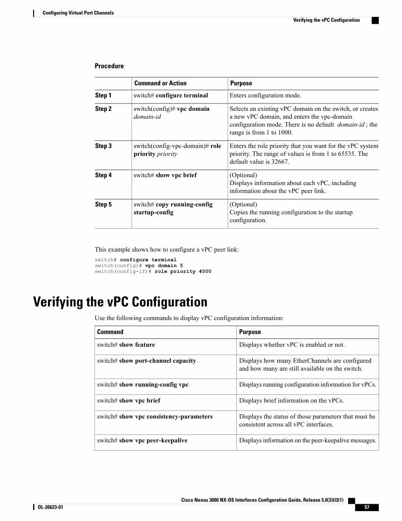
Procedure
PurposeCommand or Action
Enters configuration mode.switch# configure terminalStep 1
Selects an existing vPC domain on the switch, or createsa new vPC domain, and enters the vpc-domain
switch(config)# vpc domaindomain-id
Step 2
configuration mode. There is no default domain-id ; therange is from 1 to 1000.
Enters the role priority that you want for the vPC systempriority. The range of values is from 1 to 65535. Thedefault value is 32667.
switch(config-vpc-domain)# rolepriority priority
Step 3
(Optional)Displays information about each vPC, includinginformation about the vPC peer link.
switch# show vpc briefStep 4
(Optional)Copies the running configuration to the startupconfiguration.
switch# copy running-configstartup-config
Step 5
This example shows how to configure a vPC peer link:switch# configure terminalswitch(config)# vpc domain 5switch(config-if)# role priority 4000
Verifying the vPC ConfigurationUse the following commands to display vPC configuration information:
PurposeCommand
Displays whether vPC is enabled or not.switch# show feature
Displays how many EtherChannels are configuredand how many are still available on the switch.
switch# show port-channel capacity
Displays running configuration information for vPCs.switch# show running-config vpc
Displays brief information on the vPCs.switch# show vpc brief
Displays the status of those parameters that must beconsistent across all vPC interfaces.
switch# show vpc consistency-parameters
Displays information on the peer-keepalivemessages.switch# show vpc peer-keepalive
Cisco Nexus 3000 NX-OS Interfaces Configuration Guide, Release 5.0(3)U3(1) OL-26623-01 57
Configuring Virtual Port ChannelsVerifying the vPC Configuration
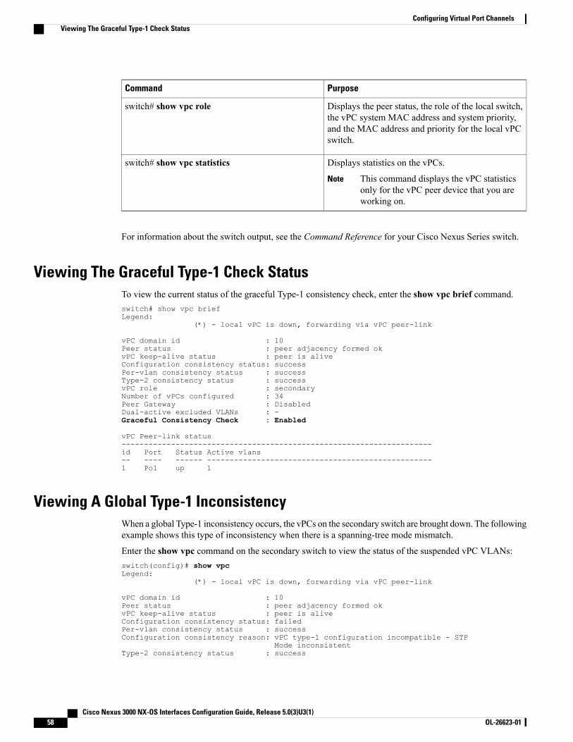
PurposeCommand
Displays the peer status, the role of the local switch,the vPC system MAC address and system priority,and the MAC address and priority for the local vPCswitch.
switch# show vpc role
Displays statistics on the vPCs.
This command displays the vPC statisticsonly for the vPC peer device that you areworking on.
Note
switch# show vpc statistics
For information about the switch output, see the Command Reference for your Cisco Nexus Series switch.
Viewing The Graceful Type-1 Check StatusTo view the current status of the graceful Type-1 consistency check, enter the show vpc brief command.switch# show vpc briefLegend:
(*) - local vPC is down, forwarding via vPC peer-link
vPC domain id : 10Peer status : peer adjacency formed okvPC keep-alive status : peer is aliveConfiguration consistency status: successPer-vlan consistency status : successType-2 consistency status : successvPC role : secondaryNumber of vPCs configured : 34Peer Gateway : DisabledDual-active excluded VLANs : -Graceful Consistency Check : Enabled
vPC Peer-link status---------------------------------------------------------------------id Port Status Active vlans-- ---- ------ --------------------------------------------------1 Po1 up 1
Viewing A Global Type-1 InconsistencyWhen a global Type-1 inconsistency occurs, the vPCs on the secondary switch are brought down. The followingexample shows this type of inconsistency when there is a spanning-tree mode mismatch.
Enter the show vpc command on the secondary switch to view the status of the suspended vPC VLANs:switch(config)# show vpcLegend:
(*) - local vPC is down, forwarding via vPC peer-link
vPC domain id : 10Peer status : peer adjacency formed okvPC keep-alive status : peer is aliveConfiguration consistency status: failedPer-vlan consistency status : successConfiguration consistency reason: vPC type-1 configuration incompatible - STP
Mode inconsistentType-2 consistency status : success
Cisco Nexus 3000 NX-OS Interfaces Configuration Guide, Release 5.0(3)U3(1)58 OL-26623-01
Configuring Virtual Port ChannelsViewing The Graceful Type-1 Check Status
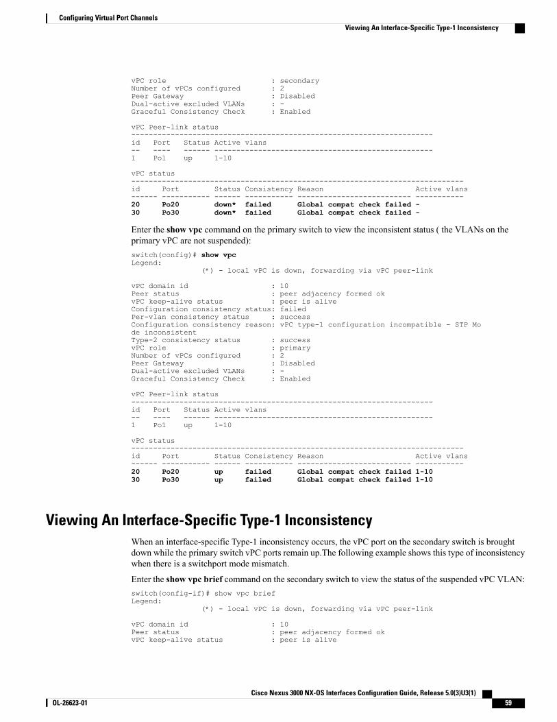
vPC role : secondaryNumber of vPCs configured : 2Peer Gateway : DisabledDual-active excluded VLANs : -Graceful Consistency Check : Enabled
vPC Peer-link status---------------------------------------------------------------------id Port Status Active vlans-- ---- ------ --------------------------------------------------1 Po1 up 1-10
vPC status----------------------------------------------------------------------------id Port Status Consistency Reason Active vlans------ ----------- ------ ----------- -------------------------- -----------20 Po20 down* failed Global compat check failed -30 Po30 down* failed Global compat check failed -
Enter the show vpc command on the primary switch to view the inconsistent status ( the VLANs on theprimary vPC are not suspended):switch(config)# show vpcLegend:
(*) - local vPC is down, forwarding via vPC peer-link
vPC domain id : 10Peer status : peer adjacency formed okvPC keep-alive status : peer is aliveConfiguration consistency status: failedPer-vlan consistency status : successConfiguration consistency reason: vPC type-1 configuration incompatible - STP Mode inconsistentType-2 consistency status : successvPC role : primaryNumber of vPCs configured : 2Peer Gateway : DisabledDual-active excluded VLANs : -Graceful Consistency Check : Enabled
vPC Peer-link status---------------------------------------------------------------------id Port Status Active vlans-- ---- ------ --------------------------------------------------1 Po1 up 1-10
vPC status----------------------------------------------------------------------------id Port Status Consistency Reason Active vlans------ ----------- ------ ----------- -------------------------- -----------20 Po20 up failed Global compat check failed 1-1030 Po30 up failed Global compat check failed 1-10
Viewing An Interface-Specific Type-1 InconsistencyWhen an interface-specific Type-1 inconsistency occurs, the vPC port on the secondary switch is broughtdown while the primary switch vPC ports remain up.The following example shows this type of inconsistencywhen there is a switchport mode mismatch.
Enter the show vpc brief command on the secondary switch to view the status of the suspended vPC VLAN:switch(config-if)# show vpc briefLegend:
(*) - local vPC is down, forwarding via vPC peer-link
vPC domain id : 10Peer status : peer adjacency formed okvPC keep-alive status : peer is alive
Cisco Nexus 3000 NX-OS Interfaces Configuration Guide, Release 5.0(3)U3(1) OL-26623-01 59
Configuring Virtual Port ChannelsViewing An Interface-Specific Type-1 Inconsistency
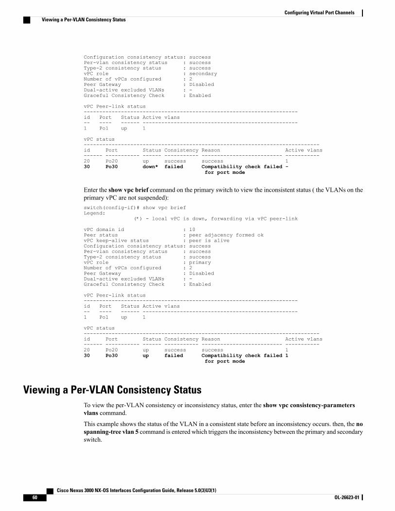
Configuration consistency status: successPer-vlan consistency status : successType-2 consistency status : successvPC role : secondaryNumber of vPCs configured : 2Peer Gateway : DisabledDual-active excluded VLANs : -Graceful Consistency Check : Enabled
vPC Peer-link status---------------------------------------------------------------------id Port Status Active vlans-- ---- ------ --------------------------------------------------1 Po1 up 1
vPC status----------------------------------------------------------------------------id Port Status Consistency Reason Active vlans------ ----------- ------ ----------- -------------------------- -----------20 Po20 up success success 130 Po30 down* failed Compatibility check failed -
for port mode
Enter the show vpc brief command on the primary switch to view the inconsistent status ( the VLANs on theprimary vPC are not suspended):switch(config-if)# show vpc briefLegend:
(*) - local vPC is down, forwarding via vPC peer-link
vPC domain id : 10Peer status : peer adjacency formed okvPC keep-alive status : peer is aliveConfiguration consistency status: successPer-vlan consistency status : successType-2 consistency status : successvPC role : primaryNumber of vPCs configured : 2Peer Gateway : DisabledDual-active excluded VLANs : -Graceful Consistency Check : Enabled
vPC Peer-link status---------------------------------------------------------------------id Port Status Active vlans-- ---- ------ --------------------------------------------------1 Po1 up 1
vPC status----------------------------------------------------------------------------id Port Status Consistency Reason Active vlans------ ----------- ------ ----------- -------------------------- -----------20 Po20 up success success 130 Po30 up failed Compatibility check failed 1
for port mode
Viewing a Per-VLAN Consistency StatusTo view the per-VLAN consistency or inconsistency status, enter the show vpc consistency-parametersvlans command.
This example shows the status of the VLAN in a consistent state before an inconsistency occurs. then, the nospanning-tree vlan 5 command is entered which triggers the inconsistency between the primary and secondaryswitch.
Cisco Nexus 3000 NX-OS Interfaces Configuration Guide, Release 5.0(3)U3(1)60 OL-26623-01
Configuring Virtual Port ChannelsViewing a Per-VLAN Consistency Status
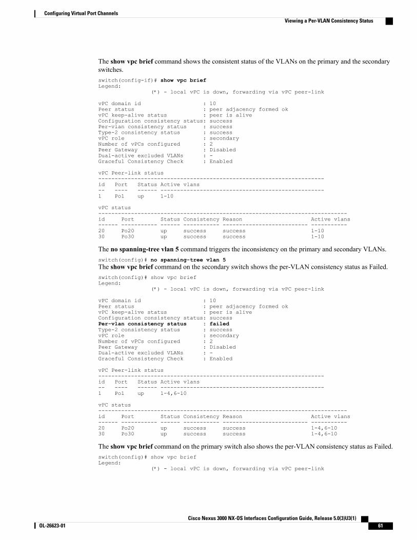
The show vpc brief command shows the consistent status of the VLANs on the primary and the secondaryswitches.switch(config-if)# show vpc briefLegend:
(*) - local vPC is down, forwarding via vPC peer-link
vPC domain id : 10Peer status : peer adjacency formed okvPC keep-alive status : peer is aliveConfiguration consistency status: successPer-vlan consistency status : successType-2 consistency status : successvPC role : secondaryNumber of vPCs configured : 2Peer Gateway : DisabledDual-active excluded VLANs : -Graceful Consistency Check : Enabled
vPC Peer-link status---------------------------------------------------------------------id Port Status Active vlans-- ---- ------ --------------------------------------------------1 Po1 up 1-10
vPC status----------------------------------------------------------------------------id Port Status Consistency Reason Active vlans------ ----------- ------ ----------- -------------------------- -----------20 Po20 up success success 1-1030 Po30 up success success 1-10
The no spanning-tree vlan 5 command triggers the inconsistency on the primary and secondary VLANs.switch(config)# no spanning-tree vlan 5The show vpc brief command on the secondary switch shows the per-VLAN consistency status as Failed.switch(config)# show vpc briefLegend:
(*) - local vPC is down, forwarding via vPC peer-link
vPC domain id : 10Peer status : peer adjacency formed okvPC keep-alive status : peer is aliveConfiguration consistency status: successPer-vlan consistency status : failedType-2 consistency status : successvPC role : secondaryNumber of vPCs configured : 2Peer Gateway : DisabledDual-active excluded VLANs : -Graceful Consistency Check : Enabled
vPC Peer-link status---------------------------------------------------------------------id Port Status Active vlans-- ---- ------ --------------------------------------------------1 Po1 up 1-4,6-10
vPC status----------------------------------------------------------------------------id Port Status Consistency Reason Active vlans------ ----------- ------ ----------- -------------------------- -----------20 Po20 up success success 1-4,6-1030 Po30 up success success 1-4,6-10
The show vpc brief command on the primary switch also shows the per-VLAN consistency status as Failed.switch(config)# show vpc briefLegend:
(*) - local vPC is down, forwarding via vPC peer-link
Cisco Nexus 3000 NX-OS Interfaces Configuration Guide, Release 5.0(3)U3(1) OL-26623-01 61
Configuring Virtual Port ChannelsViewing a Per-VLAN Consistency Status
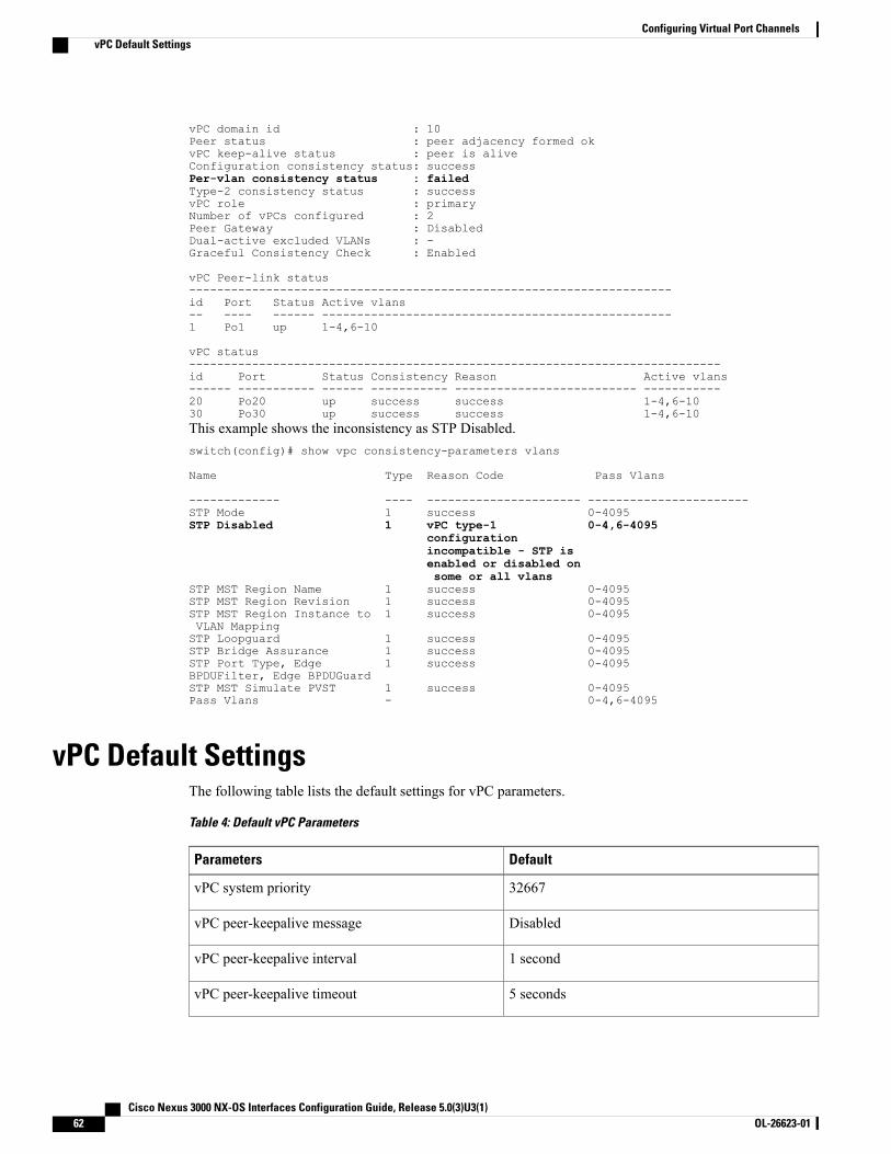
vPC domain id : 10Peer status : peer adjacency formed okvPC keep-alive status : peer is aliveConfiguration consistency status: successPer-vlan consistency status : failedType-2 consistency status : successvPC role : primaryNumber of vPCs configured : 2Peer Gateway : DisabledDual-active excluded VLANs : -Graceful Consistency Check : Enabled
vPC Peer-link status---------------------------------------------------------------------id Port Status Active vlans-- ---- ------ --------------------------------------------------1 Po1 up 1-4,6-10
vPC status----------------------------------------------------------------------------id Port Status Consistency Reason Active vlans------ ----------- ------ ----------- -------------------------- -----------20 Po20 up success success 1-4,6-1030 Po30 up success success 1-4,6-10This example shows the inconsistency as STP Disabled.switch(config)# show vpc consistency-parameters vlans
Name Type Reason Code Pass Vlans
------------- ---- ---------------------- -----------------------STP Mode 1 success 0-4095STP Disabled 1 vPC type-1 0-4,6-4095
configurationincompatible - STP isenabled or disabled onsome or all vlans
STP MST Region Name 1 success 0-4095STP MST Region Revision 1 success 0-4095STP MST Region Instance to 1 success 0-4095VLAN MappingSTP Loopguard 1 success 0-4095STP Bridge Assurance 1 success 0-4095STP Port Type, Edge 1 success 0-4095BPDUFilter, Edge BPDUGuardSTP MST Simulate PVST 1 success 0-4095Pass Vlans - 0-4,6-4095
vPC Default SettingsThe following table lists the default settings for vPC parameters.
Table 4: Default vPC Parameters
DefaultParameters
32667vPC system priority
DisabledvPC peer-keepalive message
1 secondvPC peer-keepalive interval
5 secondsvPC peer-keepalive timeout
Cisco Nexus 3000 NX-OS Interfaces Configuration Guide, Release 5.0(3)U3(1)62 OL-26623-01
Configuring Virtual Port ChannelsvPC Default Settings

DefaultParameters
3200vPC peer-keepalive UDP port
Cisco Nexus 3000 NX-OS Interfaces Configuration Guide, Release 5.0(3)U3(1) OL-26623-01 63
Configuring Virtual Port ChannelsvPC Default Settings

Cisco Nexus 3000 NX-OS Interfaces Configuration Guide, Release 5.0(3)U3(1)64 OL-26623-01
Configuring Virtual Port ChannelsvPC Default Settings

I N D E X
A
adding ports 25port channels 25
B
bandwidth 8configuring 8
C
changed information 1description 1
channel mode 28port channels 28
channel modes 23port channels 23
configuration 11Layer 3 interfaces 11
verifying 11configuration examples 14
Layer 3 interfaces 14configuring 7, 8, 9, 10
interface bandwidth 8loopback interfaces 10routed interfaces 7subinterfaces 8VLAN interfaces 9
configuring LACP 28
D
default settings 7Layer 3 interfaces 7
F
feature history 15, 34Layer 3 interfaces 15port channels 34
G
guidelines and limitations 6, 44Layer 3 interfaces 6vPCs 44
H
hardware hashing 27multicast traffic 27
I
interfaces 3, 5, 6, 8, 9, 10, 11, 13, 14assigning to a VRF 11configuring bandwidth 8Layer 3 3, 13, 14
configuration examples 14monitoring 13
loopback 6, 10routed 3tunnel 6VLAN 5, 9
configuring 9
L
LACP 17, 21, 22, 24, 28, 29, 32configuring 28marker responders 24port channel, minlinks 24, 29
Cisco Nexus 3000 NX-OS Interfaces Configuration Guide, Release 5.0(3)U3(1) OL-26623-01 IN-1
LACP (continued)port channels 21port priority 32system ID 22
LACP-enabled vs static 24port channels 24
Layer 3 interfaces 3, 6, 7, 11, 13, 14, 15configuration examples 14configuring routed interfaces 7default settings 7feature history 15guidelines and limitations 6interfaces 14, 15
Layer 3 14, 15feature history 15MIBs 15related documents 14standards 15
licensing requirements 6MIBs 15monitoring 13related documents 14standards 15verifying 11
licensing requirements 6Layer 3 interfaces 6
Link Aggregation Control Protocol 17load balancing 26
port channels 26configuring 26
loopback interfaces 6, 10configuring 10
M
MIBs 15Layer 3 interfaces 15
monitoring 13Layer 3 interfaces 13
multicast traffic 27hardware hashing 27
port channels 27
N
new information 1description 1
P
port channel 32verifying configuration 32
port channel, minlinks 24, 29LACP 24, 29
port channeling 17port channels 8, 17, 18, 20, 21, 24, 25, 26, 27, 28, 34, 54
adding ports 25channel mode 28compatibility requirements 18configuring bandwidth 8creating 25feature history 34hardware hashing 27LACP 21LACP-enabled vs static 24load balancing 20, 26
port channels 20moving into a vPC 54STP 17
R
related documents 14Layer 3 interfaces 14
routed interfaces 3, 7, 8configuring 7configuring bandwidth 8
S
standards 15Layer 3 interfaces 15
STP 17port channel 17
subinterfaces 4, 8configuring 8configuring bandwidth 8
T
tunnel interfaces 6
V
verifying 11Layer 3 interface configuration 11
Cisco Nexus 3000 NX-OS Interfaces Configuration Guide, Release 5.0(3)U3(1)IN-2 OL-26623-01
Index

VLAN 5interfaces 5
VLAN interfaces 9configuring 9
vPCs 44, 54guidelines and limitations 44moving port channels into 54
VRF 11assigning an interface to 11
Cisco Nexus 3000 NX-OS Interfaces Configuration Guide, Release 5.0(3)U3(1) OL-26623-01 IN-3
Index

Cisco Nexus 3000 NX-OS Interfaces Configuration Guide, Release 5.0(3)U3(1)IN-4 OL-26623-01
Index