Embed Size (px)
DESCRIPTION
Deployment of Cisco Nexus 100v virtual switches on VMware VSphere platform
Citation preview
© 2012 Cisco and/or its affiliates. All rights reserved. This document is Cisco Public Information. Page 1 of 44
For further information, questions and comments please contact [email protected]
Deployment Guide
Cisco Nexus 1000V Series Switches Deployment Guide
Version 3 Deployment Guide
November 2012
© 2012 Cisco and/or its affiliates. All rights reserved. This document is Cisco Public Information. Page 2 of 44
Contents
What You Will Learn ................................................................................................................................................ 3
Audience................................................................................................................................................................... 3
Introduction.............................................................................................................................................................. 3
Cisco Nexus 1000V Series Components ............................................................................................................... 4
Network-Based Policy ............................................................................................................................................. 5
Cisco Nexus 1000V Series Theory of Operation................................................................................................... 6 VMware Networking Overview........................................................................................................................... 6 System Overview ................................................................................................................................................ 7
Virtual Chassis ............................................................................................................................................... 8 Network Policy Management......................................................................................................................... 8 Policy Mobility ................................................................................................................................................ 8 Installation ...................................................................................................................................................... 9
Virtual Supervisor Module ................................................................................................................................. 9 Description ..................................................................................................................................................... 9 Cisco NX-OS Software ................................................................................................................................. 10 VSM Interfaces ............................................................................................................................................. 10 Domain ID ..................................................................................................................................................... 12 VSM and VMware vCenter Integration........................................................................................................ 12
Virtual Ethernet Module.................................................................................................................................... 14 Switch Port Interfaces ................................................................................................................................. 15 Switch Forwarding ....................................................................................................................................... 16 MAC Address Learning................................................................................................................................ 16 Loop Prevention ........................................................................................................................................... 16
VEM-to-VSM Communication .......................................................................................................................... 18
Enhanced Installer App......................................................................................................................................... 23 Port Profiles....................................................................................................................................................... 23
Virtual Ethernet Profiles .............................................................................................................................. 24 Live Policy Changes .................................................................................................................................... 25 Virtual Ethernet Profiles .............................................................................................................................. 25 Ethernet or Uplink Profiles .......................................................................................................................... 26 System VLANs .............................................................................................................................................. 27
Cisco Nexus 1000V Series Network Design........................................................................................................ 27 Design Considerations..................................................................................................................................... 27
VSM Best Practices...................................................................................................................................... 28 Benefits of Connecting VMware Interfaces to Cisco Nexus 1000V Series ............................................. 29
Traffic Classification......................................................................................................................................... 31 Bandwidth Reservation with QoS Queuing .................................................................................................... 32 VLAN Consistency ............................................................................................................................................ 32 Traffic Separation ............................................................................................................................................. 33 Upstream Switch Connectivity ........................................................................................................................ 33
Standard PortChannel ................................................................................................................................. 33 Special PortChannel .................................................................................................................................... 35 Load Balancing ............................................................................................................................................ 37 Network-State Tracking ............................................................................................................................... 38
Design Examples .............................................................................................................................................. 39 Connection to Two Clustered Upstream Switches ................................................................................... 39 Connection to Two Unclustered Upstream Switches ............................................................................... 41
Cisco Nexus 1000V Licensing .............................................................................................................................. 43
Conclusion ............................................................................................................................................................. 44

© 2012 Cisco and/or its affiliates. All rights reserved. This document is Cisco Public Information. Page 3 of 44
For More Information............................................................................................................................................. 44
© 2012 Cisco and/or its affiliates. All rights reserved. This document is Cisco Public Information. Page 4 of 44
What You Will Learn
This document provides design and configuration guidance for deployment of Cisco Nexus® 1000V Series
Switches with VMware vSphere. For detailed configuration documentation, refer to the respective Cisco® and
VMware product configuration guides. Links to the product configuration guides can be found in the “For More
Information” section of this document.
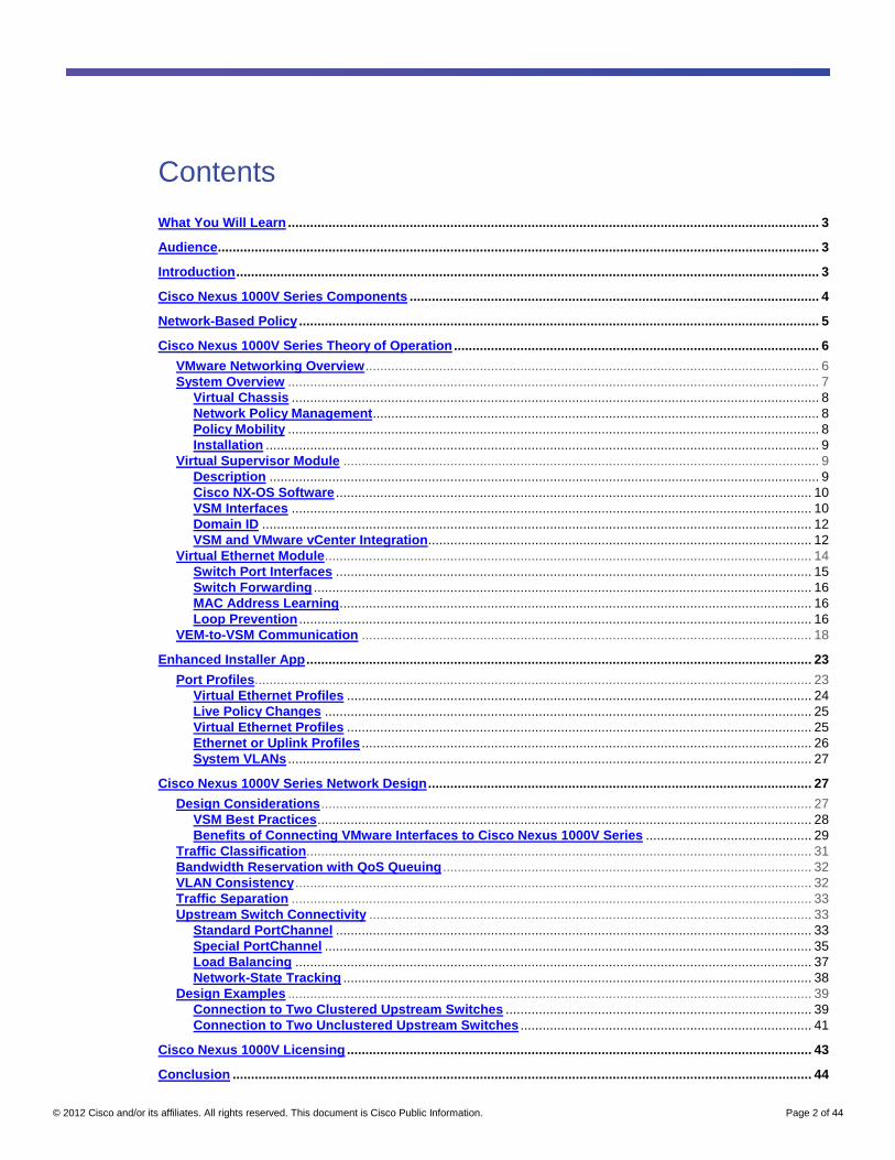
The flowchart in Figure 1 provides a visual overview of the topics discussed in this guide.
Figure 1. Topics Discussed in This Guide
Audience
This document is intended for network architects, network engineers, virtualization administrators, and server
administrators interested in understanding the deployment of VMware vSphere hosts in a Cisco® data center
environment.
Introduction
Cisco Nexus 1000V Series Switches are virtual machine access switches that are an intelligent software switch
implementation for VMware vSphere environments running Cisco NX-OS Software. Operating inside the VMware
ESX hypervisor, the Cisco Nexus 1000V Series supports Cisco VN-Link server virtualization technology to provide:
● Policy-based virtual machine connectivity
● Mobile virtual machine security and network policy
● Nondisruptive operation model for your server virtualization and networking teams
When server virtualization is deployed in the data center, virtual servers are not managed the same way as
physical servers. Server virtualization is treated as a special deployment, leading to longer deployment time, with a
greater degree of coordination among server, network, storage, and security administrators. With the Cisco Nexus
1000V Series, you have a consistent networking feature set and provisioning process from the virtual machine
access layer to the core of the data center network infrastructure. Virtual servers can use the same network
© 2012 Cisco and/or its affiliates. All rights reserved. This document is Cisco Public Information. Page 5 of 44
configuration, security policy, diagnostic tools, and operation models as their physical server counterparts
attached to dedicated physical network ports.
Virtualization administrators can access predefined network policy that follows mobile virtual machines to help
ensure proper connectivity, saving valuable time for focusing on virtual machine administration. This
comprehensive set of capabilities helps you deploy server virtualization faster and take advantage of the benefits.
Developed in close collaboration with VMware, the Cisco Nexus 1000V Series is certified by VMware and is
compatible with VMware vSphere, vCenter, ESX, and ESXi and with many other VMware vSphere features.
You can use the Cisco Nexus 1000V Series to manage your virtual machine connectivity with confidence in the
integrity of the server virtualization infrastructure.
Cisco Nexus 1000V Series Components
The Cisco Nexus 1000V Series provides Layer 2 switching, advanced networking functions, and a common
network management model in a virtualized server environment by replacing the virtual switch in VMware
vSphere. The Cisco Nexus 1000V Series manages a data center as defined in VMware vCenter Server. Each
server in the data center is represented as a line card in the Cisco Nexus 1000V Series Switch and can be
managed as if it were a line card in a physical Cisco switch.
The Cisco Nexus 1000V Series implementation has two main components:
● Virtual supervisor module (VSM)
● Virtual Ethernet module (VEM)
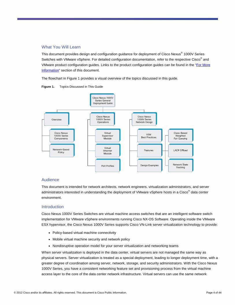
These two components together make up the Cisco Nexus 1000V Series Switch, with the VSM providing the
management plane and the VEM providing the data plane (Figure 2).
Figure 2. Cisco Nexus 1000V Series Components
© 2012 Cisco and/or its affiliates. All rights reserved. This document is Cisco Public Information. Page 6 of 44
Network-Based Policy
A unique aspect of the Cisco Nexus 1000V Series is the way network policy is defined and deployed. Today, a
network administrator configures each interface on a switch one at a time. For Cisco switches, this means entering
configuration mode and applying a series of switch commands that define the interface configuration.
Configuration can be manually applied to multiple interfaces on the same switch or different switches connected to
similar types of servers. This management model requires server administrators to depend on network
administrators to reconfigure the network each time a server is brought online. This process can create
unnecessary delays in deployment of new servers.
In a VMware environment, server administrators are required to configure network policy, using the VMware virtual
switch (vSwitch) and port-group features, to match the policy configured on the upstream physical switches.
This requirement removes a dependency on the network administrator for virtual access-layer switch configuration
(the first network hop in the data center) and makes the process of adding a new virtual machine as simple as
selecting the appropriate predefined port group. This approach creates operational and security challenges such
as policy enforcement and troubleshooting, but addresses many delays in deployment of new virtual machines
(no physical infrastructure to configure).
The Cisco Nexus 1000V Series provides an excellent model, with network administrators defining the network
policy that virtualization or server administrators can use as new similar virtual machines are added to the
infrastructure. Policies defined on the Cisco Nexus 1000V Series are exported to VMware vCenter Server to be
used and reused by server administrators as new virtual machines require access to specific network policies.
This concept is implemented on the Cisco Nexus 1000V Series using port profiles. The Cisco Nexus 1000V Series
with the port profile feature eliminates the requirement for the virtualization administrator to create or maintain
vSwitch and port-group configurations on any VMware ESX hosts.
Port profiles create a unique collaborative model, giving server administrators the autonomy to provision new
virtual machines without waiting for network reconfigurations to be implemented in the physical network
infrastructure. For network administrators, the combination of the Cisco Nexus 1000V Series feature set and the
capability to define a port profile using the same syntax as for existing physical Cisco switches helps ensure that
consistent policy is enforced without the burden of having to manage individual switch ports. The Cisco Nexus
1000V Series solution also provides a consistent network management, diagnostic, and troubleshooting interface
for the network operations team, allowing the virtual network infrastructure to be managed like any physical
infrastructure.
© 2012 Cisco and/or its affiliates. All rights reserved. This document is Cisco Public Information. Page 7 of 44
Cisco Nexus 1000V Series Theory of Operation
This section describes the major concepts and components of the Cisco Nexus 1000V Series and the interaction
of the components.
VMware Networking Overview To understand the Cisco Nexus 1000V Series, you must first understand the basics of the VMware networking
model. VMware networking consists of virtual network interface cards (vNICs) of various types, the physical NICs
(pNICs) on the hosts, and the virtual switches to interconnect them.
Each virtual machine has one or more vNICs. These vNICs are connected to a virtual switch (such as the Cisco
Nexus 1000V Series) to provide network connectivity to the virtual machine. The guest OS sees the vNICs as
pNICs. VMware can emulate several popular NIC types (vlance and Intel e1000), so the guest OS can use
standard device drivers for these vNICs. Alternatively, the VMware vmxnet interface type can be used; this
interface type requires VMware drivers on the guest OS.
Hosts running VMware ESX have a virtual management port called vswif, sometimes referred to as the service
console interface. This interface is used for communication with VMware vCenter Server, to manage the device
directly with the VMware vSphere client, or to use Secure Shell (SSH) to log in to the host’s command-line
interface (CLI). VMware ESXi hosts do not use vswif interfaces because the hosts lack a service console OS.
Each host also has one or more virtual ports called virtual machine kernel NICs (vmknics). These are used by
VMware ESX for Small Computer Systems Interface over IP (iSCSI) and Network File System (NFS) access, as
well as by VMware vMotion. On a VMware ESXi system, a vmknic is also used for communication with VMware
vCenter Server.
The pNICs on a VMware ESX host, called virtual machine NICs (VMNICs), are used as uplinks to the physical
network infrastructure.
The virtual and physical NICs are all connected by virtual switches. VMware provides two types of virtual switches.
The standard vSwitch is individually created for each host. The VMware vNetwork Distributed Switch (vDS)
provides a consistent virtual switch across a set of physical hosts. The Cisco Nexus 1000V Series is implemented
as a type of vDS.
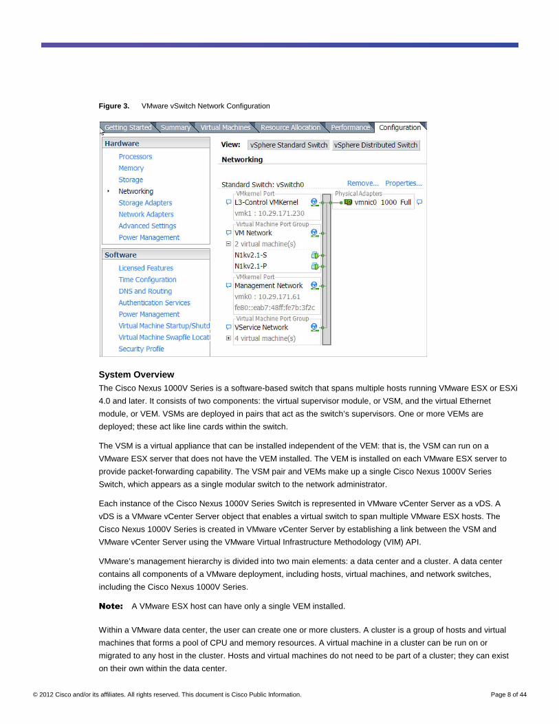
Each vNIC is connected to a standard vSwitch or vDS through a port group. Each port group belongs to a specific
vSwitch or vDS and specifies a VLAN or set of VLANs that a VMNIC, vswif, or vmknic will use. The port group
specifies other network attributes such as rate limiting and port security. Virtual machines are assigned to port
groups during the virtual machine creation process or through editing of the virtual machine properties later
(Figure 3).
© 2012 Cisco and/or its affiliates. All rights reserved. This document is Cisco Public Information. Page 8 of 44
Figure 3. VMware vSwitch Network Configuration
System Overview The Cisco Nexus 1000V Series is a software-based switch that spans multiple hosts running VMware ESX or ESXi
4.0 and later. It consists of two components: the virtual supervisor module, or VSM, and the virtual Ethernet
module, or VEM. VSMs are deployed in pairs that act as the switch’s supervisors. One or more VEMs are
deployed; these act like line cards within the switch.
The VSM is a virtual appliance that can be installed independent of the VEM: that is, the VSM can run on a
VMware ESX server that does not have the VEM installed. The VEM is installed on each VMware ESX server to
provide packet-forwarding capability. The VSM pair and VEMs make up a single Cisco Nexus 1000V Series
Switch, which appears as a single modular switch to the network administrator.
Each instance of the Cisco Nexus 1000V Series Switch is represented in VMware vCenter Server as a vDS. A
vDS is a VMware vCenter Server object that enables a virtual switch to span multiple VMware ESX hosts. The
Cisco Nexus 1000V Series is created in VMware vCenter Server by establishing a link between the VSM and
VMware vCenter Server using the VMware Virtual Infrastructure Methodology (VIM) API.
VMware’s management hierarchy is divided into two main elements: a data center and a cluster. A data center
contains all components of a VMware deployment, including hosts, virtual machines, and network switches,
including the Cisco Nexus 1000V Series.
Note: A VMware ESX host can have only a single VEM installed.
Within a VMware data center, the user can create one or more clusters. A cluster is a group of hosts and virtual
machines that forms a pool of CPU and memory resources. A virtual machine in a cluster can be run on or
migrated to any host in the cluster. Hosts and virtual machines do not need to be part of a cluster; they can exist
on their own within the data center.
© 2012 Cisco and/or its affiliates. All rights reserved. This document is Cisco Public Information. Page 9 of 44
Virtual Chassis
The Cisco Nexus 1000V Series uses a virtual chassis model to represent a pair of VSMs and their associated
VEMs. Like any Cisco chassis-based platform, the Cisco Nexus 1000V Series virtual chassis has slots and
modules, or line cards, associated with it. The VSMs are always associated with slot numbers 1 and 2 in the virtual
chassis. The VEMs are sequentially assigned to slots 3 through 66 based on the order in which their respective
hosts were added to the Cisco Nexus 1000V Series Switch.
Network Policy Management
Software-based virtual switching presents new challenges for data center management. The traditional
management model calls for the server administrator to manage the OS and applications while the network
administrator manages the switches and their associated policies. The link between the server and switch, usually
a Category 5 cable, is a clear boundary between administrative roles. The Cisco Nexus 1000V Series
management model calls for collaboration between server and network administrators who are maintaining the
configuration of the same piece of hardware: a VMware ESX host.
Server and network administrators are separate entities with separate responsibilities. The Cisco Nexus 1000V
Series maintains this separation, with distinct roles for each administrator. Collaboration between the
administrators is required, but the Cisco Nexus 1000V Series is designed to provide server and network
administrators with a high level of autonomy.
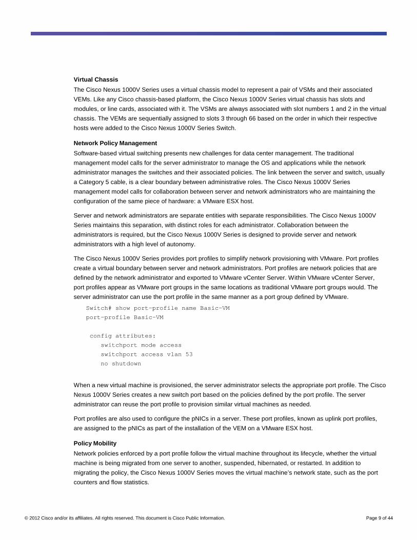
The Cisco Nexus 1000V Series provides port profiles to simplify network provisioning with VMware. Port profiles
create a virtual boundary between server and network administrators. Port profiles are network policies that are
defined by the network administrator and exported to VMware vCenter Server. Within VMware vCenter Server,
port profiles appear as VMware port groups in the same locations as traditional VMware port groups would. The
server administrator can use the port profile in the same manner as a port group defined by VMware.
Switch# show port-profile name Basic-VM
port-profile Basic-VM
config attributes:
switchport mode access
switchport access vlan 53
no shutdown
When a new virtual machine is provisioned, the server administrator selects the appropriate port profile. The Cisco
Nexus 1000V Series creates a new switch port based on the policies defined by the port profile. The server
administrator can reuse the port profile to provision similar virtual machines as needed.
Port profiles are also used to configure the pNICs in a server. These port profiles, known as uplink port profiles,
are assigned to the pNICs as part of the installation of the VEM on a VMware ESX host.
Policy Mobility
Network policies enforced by a port profile follow the virtual machine throughout its lifecycle, whether the virtual
machine is being migrated from one server to another, suspended, hibernated, or restarted. In addition to
migrating the policy, the Cisco Nexus 1000V Series moves the virtual machine’s network state, such as the port
counters and flow statistics.
© 2012 Cisco and/or its affiliates. All rights reserved. This document is Cisco Public Information. Page 10 of 44
Virtual machines participating in traffic monitoring activities, such as Cisco NetFlow or Encapsulated Remote
Switched Port Analyzer (ERSPAN), can continue these activities uninterrupted by VMware VMotion operations.
Installation
Installation of the Cisco Nexus 1000V Series is beyond the scope of this document. This section describes
installation at a high level for conceptual completeness. For guidance and detailed instructions about installation,
please refer to the Cisco Nexus 1000V Series Switches installation guide.
The main steps for installing the Cisco Nexus 1000V Series Switch as a virtual appliance are as follows:
1. The server administrator deploys the VSM. The Cisco Nexus 1000V Series Switch is installed through a GUI
installer using the .ova file.
2. The network administrator completes the installation of the Cisco Nexus 1000V Series. The network
administrator selects the IP address of the Cisco Nexus 1000V Series Switch that was defined by the server
administrator in step 1. This selection configures the VSM with the appropriate port-group VLAN and performs
the basic configuration of the Cisco Nexus 1000V Series, such as registering the Cisco Nexus 1000V Series
plug-in in VMware vCenter Server and enabling communication between the VSM and VMware vCenter
Server.
3. The network administrator, using SSH for the Cisco Nexus 1000V Series, defines the port profiles to be used
by the uplink interfaces, virtual machines, and other virtual interfaces.
4. The server administrator begins assigning the uplink port profiles to the appropriate pNICs and the port profile
to virtual machines, providing network connectivity to the guest OS and migrating the VSM on its own port
profile. If VMware Update Manager is used, the VEM code on each VMware ESX server will be installed
automatically, triggered by the addition of a new host to the Cisco Nexus 1000V Series Switch. If the server
administrator is not using VMware Update Manager, then the VEM must to be installed before the host is
added.
At this point, the installation of the Cisco Nexus 1000V Series virtual appliance is complete.
Note: A network administrator can also deploy the VSM as a virtual service blade on the Cisco Nexus 1010
Virtual Services Appliance. For more information, see the Cisco Nexus 1010 deployment guide.
Virtual Supervisor Module The VSM provides the management plane functions for the Cisco Nexus 1000V Series. Much like a supervisor
module in a Cisco Nexus 7000 Series Switch, the VSM is the single point of management for the network
administrator, coordinating configuration and functions across VEMs.
Description
Unlike a traditional Cisco switch, in which the management plane is integrated into the hardware, on the Cisco
Nexus 1000V Series, the VSM is deployed as either a virtual appliance on VMware ESX or as a virtual service
blade on the Cisco Nexus 1010. The deployment considerations discussed here cover the deployment of the VSM
as a virtual appliance on VMware ESX. Running Cisco NX-OS, the VSM is installed on VMware ESX in a way
similar to other virtual appliances using an Open Virtualization Format (OVF) template. It can also be installed
manually using an ISO file (Figure 4).
© 2012 Cisco and/or its affiliates. All rights reserved. This document is Cisco Public Information. Page 11 of 44
Figure 4. VSM Representation
The OVF file performs the configuration of the VSM. The server administrator can define the VSM manually, but
should note that the VSM has virtual machine requirements that need to be addressed, much as with other
traditional guest operating systems. At a high level, the VSM requires a single virtual CPU, 2 GB of dedicated
RAM, and three virtual network adapters (more information about these virtual network adapters is provided later
in this document).
The Cisco Nexus 1000V Series requires a VSM high-availability deployment model much like a physical chassis
that employs dual supervisors. Two VSMs are deployed in an active-standby configuration, with the first VSM
functioning in the primary role and the other VSM functioning in a secondary role. If the primary VSM fails, the
secondary VSM takes over.
Note that unlike cross-bar-based modular switching platforms, the VSM is not in the data path. General data
packets are not forwarded to the VSM to be processed, but instead are switched by the VEM directly. In two
specific cases, described later in this document, control traffic is processed by the VSM to be coordinated across
all VEMs.
Cisco NX-OS Software
Cisco NX-OS is a data center-class operating system built with modularity, resiliency, and serviceability at its
foundation. Based on the industry-proven Cisco MDS 9000 SAN-OS Software, Cisco NX-OS helps ensure
continuous availability and sets the standard for mission-critical data center environments. The self-healing and
highly modular design of Cisco NX-OS makes zero-impact operations a reality and enables exceptional operation
flexibility. Focused on the requirements of the data center, Cisco NX-OS provides a robust and comprehensive
feature set that can meet the Ethernet and storage networking requirements of present and future data centers.
With a CLI like that of Cisco IOS® Software, Cisco NX-OS provides state-of-the-art implementations of relevant
networking standards as well as a variety of true data center-class Cisco innovations.
VSM Interfaces
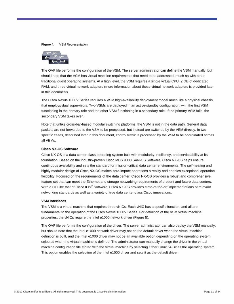
The VSM is a virtual machine that requires three vNICs. Each vNIC has a specific function, and all are
fundamental to the operation of the Cisco Nexus 1000V Series. For definition of the VSM virtual machine
properties, the vNICs require the Intel e1000 network driver (Figure 5).
The OVF file performs the configuration of the driver. The server administrator can also deploy the VSM manually,
but should note that the Intel e1000 network driver may not be the default driver when the virtual machine
definition is built, and the Intel e1000 driver may not be an available option depending on the operating system
selected when the virtual machine is defined. The administrator can manually change the driver in the virtual
machine configuration file stored with the virtual machine by selecting Other Linux 64-Bit as the operating system.
This option enables the selection of the Intel e1000 driver and sets it as the default driver.
© 2012 Cisco and/or its affiliates. All rights reserved. This document is Cisco Public Information. Page 12 of 44
Figure 5. Correct VSM Networking Configuration
Note: Refer to the Cisco Nexus 1000V Series Switches installation guide for detailed VSM installation
instructions.
Management Interface
The management interface appears as the mgmt0 port on a Cisco switch. As with the management interfaces of
other Cisco switches, an IP address is assigned to mgmt0. Although the management interface is not used to
exchange data between the VSM and VEM, it is used to establish and maintain the connection between the VSM
and VMware vCenter Server. When the software virtual switch (SVS) domain mode for control communication
between the VSM and VEM is set to Layer 3 mode, the management interface can also be used for control traffic.
Layer 3 mode is discussed in detail later in this document.
The management interface is always the second interface on the VSM and is usually labeled “Network Adapter 2”
in the virtual machine network properties.
Control Interface
The control interface is used to communicate with the VEMs when the SVS domain mode is Layer 2. This
interface is also used for VSM high-availability communication between the primary VSM and the secondary VSM
when high-availability mode is used. When SVS domain is Layer 3, still VSM high-availability communication use
control interface. This interface handles low-level control packets such as heartbeats as well as any configuration
and programming data that needs to be exchanged between the VSM and VEM. Because of the nature of the
traffic carried over the control interface, this interface is of most importance in the Cisco Nexus 1000V Series
solution, and the control traffic can be prioritized to help ensure that the control packets are not dropped.
© 2012 Cisco and/or its affiliates. All rights reserved. This document is Cisco Public Information. Page 13 of 44
The control interface is always the first interface on the VSM and is usually labeled “Network Adapter 1” in the
virtual machine network properties.
Packet Interface
The packet interface is used to carry packets that need to be processed by the VSM. This interface is mainly used
for two types of traffic: Cisco Discovery Protocol and Internet Group Management Protocol (IGMP) control packets.
The VSM presents a unified Cisco Discovery Protocol view to the network administrator through the Cisco NX-OS
CLI. When a VEM receives a Cisco Discovery Protocol packet, the VEM retransmits that packet to the VSM so
that the VSM can parse the packet and populate the Cisco Discovery Protocol entries in the CLI.
The packet interface is also used to coordinate IGMP across multiple servers. For example, when a server
receives an IGMP join request, that request is sent to the VSM, which coordinates the request across all the
modules in the switch.
The packet interface is always the third interface on the VSM and is usually labeled “Network Adapter 3” in the
virtual machine network properties. In the case of deployment in Layer 3 mode, all the packet communication
occurs through the Layer 3 interface used for VSM-to-VEM traffic.
Domain ID
A physical Ethernet switch typically passes control information between the data plane and the control plane using
an internal network (Cisco switches use an internal network called the Ethernet out-of-band channel [EoBC]) that
is not exposed to the network administrator. This internal network is isolated by design. In the case of the Cisco
Nexus 1000V Series, control packets between the VSM and VEM traverse the physical network. A potential,
although highly unlikely, scenario is the case in which a VEM receives control packets from a VSM that is
managing a completely different Cisco Nexus 1000V Series Switch. If the VEM were to respond to such packets
(for example, a request to reconfigure an interface), the VEM would not forward packets as expected. To prevent
this scenario, the Cisco Nexus 1000V Series implements a solution called domain IDs.
A domain ID is a parameter of the Cisco Nexus 1000V Series Switch that is used to identify a VSM and VEM as
related to one another. The domain ID of the Cisco Nexus 1000V Series Switch is defined when the VSM is first
installed and becomes part of the vSwitch data that is transmitted to VMware vCenter Server.
Each command sent by the VSM to any associated VEMs is tagged with this domain ID. When a VSM and VEM
share the same domain ID, the VEM will accept and respond to requests and commands from the VSM. If the
VEM receives a command or configuration request that is not tagged with the correct domain ID, that request is
ignored. Similarly, if the VSM receives a packet from a VEM that is tagged with the wrong domain ID, the packet
will be ignored.
VSM and VMware vCenter Integration
The Cisco Nexus 1000V Series is tightly integrated with VMware vCenter. This integration enables the network
administrator and the server administrator to collaborate efficiently without each having to learn a different
management tool. The network administrator uses the Cisco NX-OS CLI on the VSM, and the server administrator
continues to use VMware vCenter. Because of the tight relationship between the VSM and VMware vCenter, the
communication between the two needs to be reliable and secure.
Communication Between VSM and VMware vCenter
The VSM maintains a link to VMware vCenter Server that is used to maintain the definition of the Cisco Nexus
1000V Series within VMware vCenter Server as well as to propagate port profiles.
© 2012 Cisco and/or its affiliates. All rights reserved. This document is Cisco Public Information. Page 14 of 44
The server and network administrators both have roles in establishing the link between the Cisco Nexus 1000V
Series and VMware vCenter Server.
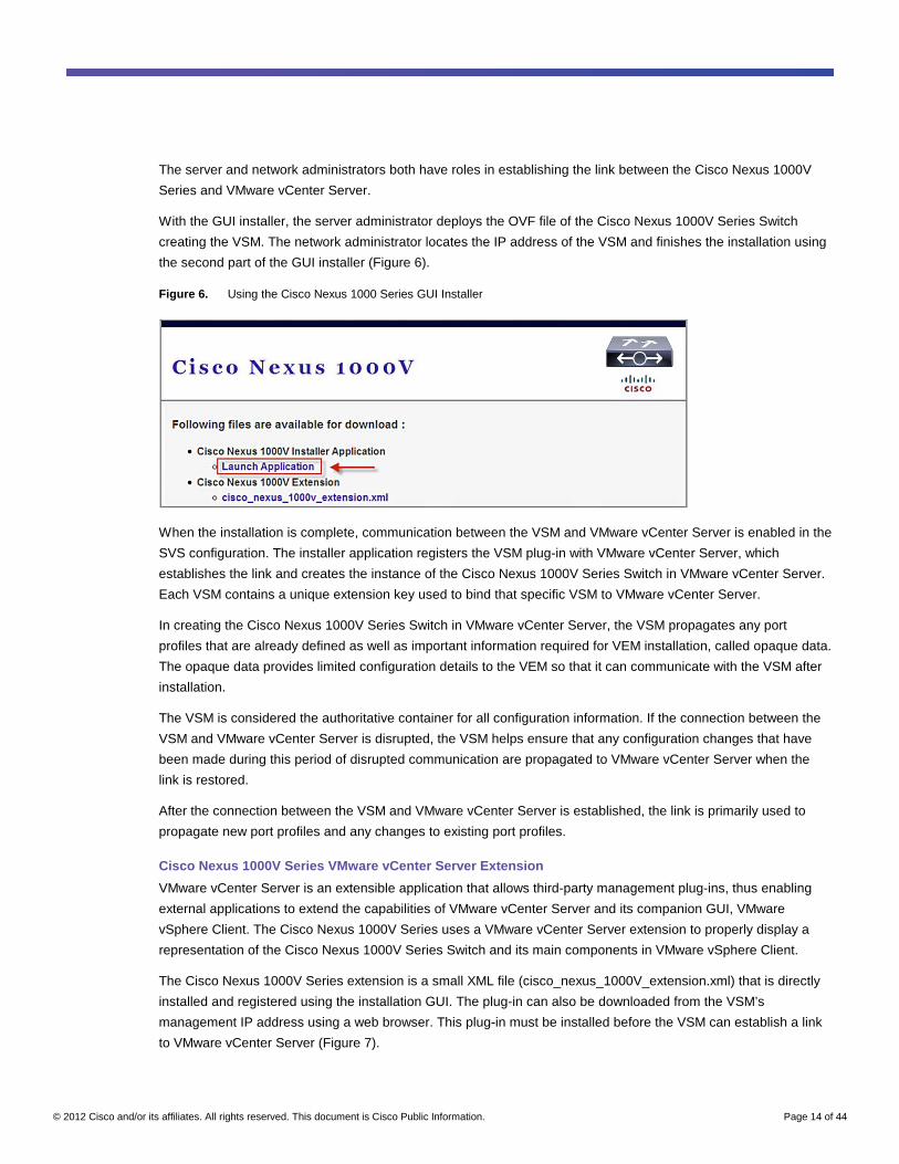
With the GUI installer, the server administrator deploys the OVF file of the Cisco Nexus 1000V Series Switch
creating the VSM. The network administrator locates the IP address of the VSM and finishes the installation using
the second part of the GUI installer (Figure 6).
Figure 6. Using the Cisco Nexus 1000 Series GUI Installer
When the installation is complete, communication between the VSM and VMware vCenter Server is enabled in the
SVS configuration. The installer application registers the VSM plug-in with VMware vCenter Server, which
establishes the link and creates the instance of the Cisco Nexus 1000V Series Switch in VMware vCenter Server.
Each VSM contains a unique extension key used to bind that specific VSM to VMware vCenter Server.
In creating the Cisco Nexus 1000V Series Switch in VMware vCenter Server, the VSM propagates any port
profiles that are already defined as well as important information required for VEM installation, called opaque data.
The opaque data provides limited configuration details to the VEM so that it can communicate with the VSM after
installation.
The VSM is considered the authoritative container for all configuration information. If the connection between the
VSM and VMware vCenter Server is disrupted, the VSM helps ensure that any configuration changes that have
been made during this period of disrupted communication are propagated to VMware vCenter Server when the
link is restored.
After the connection between the VSM and VMware vCenter Server is established, the link is primarily used to
propagate new port profiles and any changes to existing port profiles.
Cisco Nexus 1000V Series VMware vCenter Server Extension
VMware vCenter Server is an extensible application that allows third-party management plug-ins, thus enabling
external applications to extend the capabilities of VMware vCenter Server and its companion GUI, VMware
vSphere Client. The Cisco Nexus 1000V Series uses a VMware vCenter Server extension to properly display a
representation of the Cisco Nexus 1000V Series Switch and its main components in VMware vSphere Client.
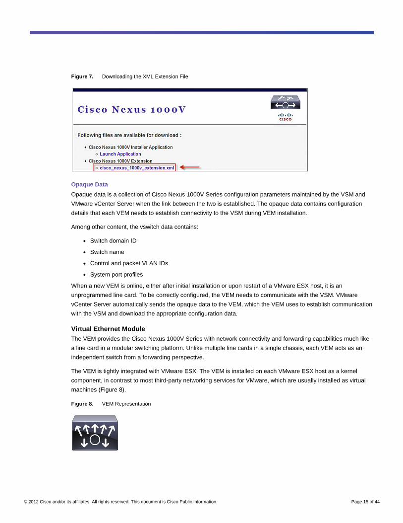
The Cisco Nexus 1000V Series extension is a small XML file (cisco_nexus_1000V_extension.xml) that is directly
installed and registered using the installation GUI. The plug-in can also be downloaded from the VSM’s
management IP address using a web browser. This plug-in must be installed before the VSM can establish a link
to VMware vCenter Server (Figure 7).
© 2012 Cisco and/or its affiliates. All rights reserved. This document is Cisco Public Information. Page 15 of 44
Figure 7. Downloading the XML Extension File
Opaque Data
Opaque data is a collection of Cisco Nexus 1000V Series configuration parameters maintained by the VSM and
VMware vCenter Server when the link between the two is established. The opaque data contains configuration
details that each VEM needs to establish connectivity to the VSM during VEM installation.
Among other content, the vswitch data contains:
● Switch domain ID
● Switch name
● Control and packet VLAN IDs
● System port profiles
When a new VEM is online, either after initial installation or upon restart of a VMware ESX host, it is an
unprogrammed line card. To be correctly configured, the VEM needs to communicate with the VSM. VMware
vCenter Server automatically sends the opaque data to the VEM, which the VEM uses to establish communication
with the VSM and download the appropriate configuration data.
Virtual Ethernet Module The VEM provides the Cisco Nexus 1000V Series with network connectivity and forwarding capabilities much like
a line card in a modular switching platform. Unlike multiple line cards in a single chassis, each VEM acts as an
independent switch from a forwarding perspective.
The VEM is tightly integrated with VMware ESX. The VEM is installed on each VMware ESX host as a kernel
component, in contrast to most third-party networking services for VMware, which are usually installed as virtual
machines (Figure 8).
Figure 8. VEM Representation
© 2012 Cisco and/or its affiliates. All rights reserved. This document is Cisco Public Information. Page 16 of 44
Unlike with the VSM, the VEM’s resources are unmanaged and dynamic. Although the storage footprint of the
VEM is fixed (approximately 6.4 MB of disk space), RAM utilization on the VMware ESX host is variable, based on
the configuration and scale of the Cisco Nexus 1000V Series deployment. In a typical configuration, each VEM
can be expected to require 10 to 50 MB of RAM, with an upper hard limit of 150 MB for a fully scaled solution with
all features turned on and used to their design limits.
Each instance of the Cisco Nexus 1000V Series is composed of two VSMs and one or more VEMs. The maximum
number of VEMs supported by a pair of VSMs is 64.
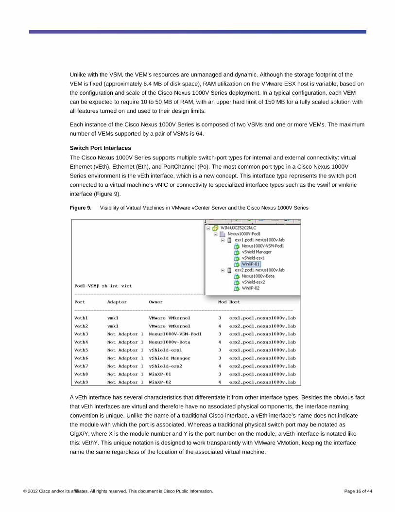
Switch Port Interfaces
The Cisco Nexus 1000V Series supports multiple switch-port types for internal and external connectivity: virtual
Ethernet (vEth), Ethernet (Eth), and PortChannel (Po). The most common port type in a Cisco Nexus 1000V
Series environment is the vEth interface, which is a new concept. This interface type represents the switch port
connected to a virtual machine’s vNIC or connectivity to specialized interface types such as the vswif or vmknic
interface (Figure 9).
Figure 9. Visibility of Virtual Machines in VMware vCenter Server and the Cisco Nexus 1000V Series
A vEth interface has several characteristics that differentiate it from other interface types. Besides the obvious fact
that vEth interfaces are virtual and therefore have no associated physical components, the interface naming
convention is unique. Unlike the name of a traditional Cisco interface, a vEth interface’s name does not indicate
the module with which the port is associated. Whereas a traditional physical switch port may be notated as
GigX/Y, where X is the module number and Y is the port number on the module, a vEth interface is notated like
this: vEthY. This unique notation is designed to work transparently with VMware VMotion, keeping the interface
name the same regardless of the location of the associated virtual machine.
© 2012 Cisco and/or its affiliates. All rights reserved. This document is Cisco Public Information. Page 17 of 44
The second characteristic that makes a vEth interface unique is its transient nature. A given vEth interface
appears or disappears based on the status of the virtual machine connected to it. The mapping of a virtual
machine’s vNIC to a vEth interface is static. When a new virtual machine is created, a vEth interface is also
created for each of the virtual machine’s vNICs. The vEth interfaces will persist as long as the virtual machine
exists. If the virtual machine is temporarily down (the guest OS is shut down), the vEth interfaces will remain
inactive but still bound to that specific virtual machine. If the virtual machine is deleted, the vEth interfaces will
become available for connection to newly provisioned virtual machines.
The Cisco Nexus 1000V Series contains two interface types related to the VMNICs (pNICs) in a VMware ESX
host. An Ethernet, or Eth, interface is the Cisco Nexus 1000V Series’ representation of a VMNIC. An Eth interface
is represented in standard Cisco interface notation (EthX/Y) using the Cisco NX-OS naming convention “Eth”
rather than a speed such as “Gig” or “Fast,” as is the custom in Cisco IOS Software. These Eth interfaces are
module specific and are designed to be fairly static within the environment.
PortChannels are the third interface type supported by the Cisco Nexus 1000V Series. A PortChannel is an
aggregation of multiple Eth interfaces on the same VEM.
Note: PortChannels are not created by default and must be explicitly defined.
Switch Forwarding
In many ways, the Cisco Nexus 1000V Series Switches are similar to physical Ethernet switches. For packet
forwarding, the Cisco Nexus 1000V Series uses the same techniques that other Ethernet switches apply, with a
MAC address-to-port mapping table used to determine the location to which packets should be forwarded.
The Cisco Nexus 1000V Series maintains forwarding tables in a slightly different manner than other modular
switches. Unlike physical switches with a centralized forwarding engine, each VEM maintains a separate
forwarding table. There is no synchronization between forwarding tables on different VEMs. In addition, there is no
concept of forwarding from a port on one VEM to a port on another VEM. Packets destined for a device not local to
a VEM are forwarded to the external network, which in turn may forward the packets to a different VEM.
MAC Address Learning
This distributed forwarding model in a centrally managed switch is demonstrated by the way the Cisco Nexus
1000V Series handles MAC address learning. A MAC address can be learned multiple times within a single Cisco
Nexus 1000V Series Switch in either of two ways: statically or dynamically. Static entries are automatically
generated for virtual machines running on the VEM; these entries do not time out. For devices not running on the
VEM, the VEM can learn a MAC address dynamically, through the pNICs in the server.
Each VEM maintains a separate MAC address table. Thus, a single Cisco Nexus 1000V Series Switch may learn
a given MAC address multiple times: as often as once per VEM. For example, one VEM may be hosting a virtual
machine, and the virtual machine’s MAC address will be statically learned on the VEM. A second VEM, in the
same Cisco Nexus 1000V Series Switch, may learn the virtual machine’s MAC address dynamically. Thus, within
the Cisco NX-OS CLI, you may see the virtual machine’s MAC address twice: as a dynamic entry and as a static
entry.
Loop Prevention
Another differentiating characteristic of the Cisco Nexus 1000V Series is that it does not run Spanning Tree
Protocol. Although this may seem to be a significant departure from other Ethernet switches, potentially
© 2012 Cisco and/or its affiliates. All rights reserved. This document is Cisco Public Information. Page 18 of 44
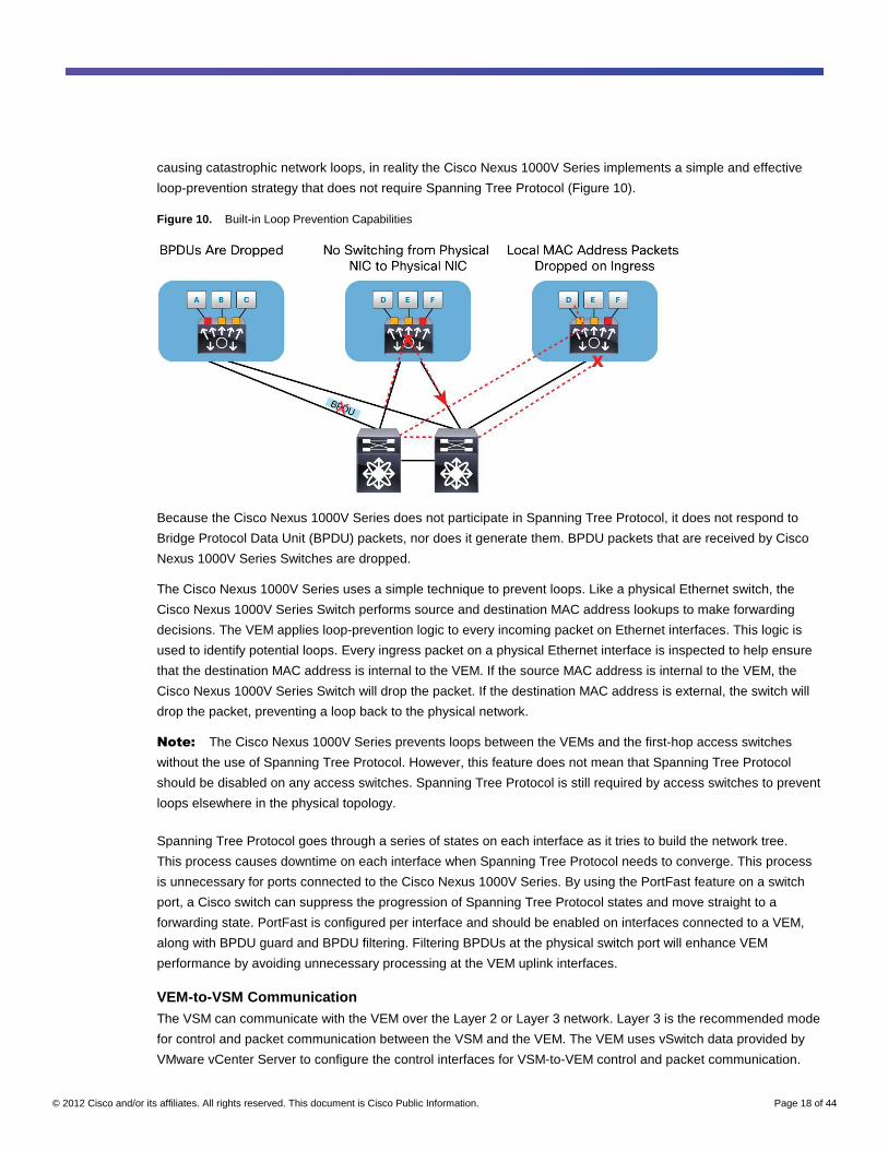
causing catastrophic network loops, in reality the Cisco Nexus 1000V Series implements a simple and effective
loop-prevention strategy that does not require Spanning Tree Protocol (Figure 10).
Figure 10. Built-in Loop Prevention Capabilities
Because the Cisco Nexus 1000V Series does not participate in Spanning Tree Protocol, it does not respond to
Bridge Protocol Data Unit (BPDU) packets, nor does it generate them. BPDU packets that are received by Cisco
Nexus 1000V Series Switches are dropped.
The Cisco Nexus 1000V Series uses a simple technique to prevent loops. Like a physical Ethernet switch, the
Cisco Nexus 1000V Series Switch performs source and destination MAC address lookups to make forwarding
decisions. The VEM applies loop-prevention logic to every incoming packet on Ethernet interfaces. This logic is
used to identify potential loops. Every ingress packet on a physical Ethernet interface is inspected to help ensure
that the destination MAC address is internal to the VEM. If the source MAC address is internal to the VEM, the
Cisco Nexus 1000V Series Switch will drop the packet. If the destination MAC address is external, the switch will
drop the packet, preventing a loop back to the physical network.
Note: The Cisco Nexus 1000V Series prevents loops between the VEMs and the first-hop access switches
without the use of Spanning Tree Protocol. However, this feature does not mean that Spanning Tree Protocol
should be disabled on any access switches. Spanning Tree Protocol is still required by access switches to prevent
loops elsewhere in the physical topology.
Spanning Tree Protocol goes through a series of states on each interface as it tries to build the network tree.
This process causes downtime on each interface when Spanning Tree Protocol needs to converge. This process
is unnecessary for ports connected to the Cisco Nexus 1000V Series. By using the PortFast feature on a switch
port, a Cisco switch can suppress the progression of Spanning Tree Protocol states and move straight to a
forwarding state. PortFast is configured per interface and should be enabled on interfaces connected to a VEM,
along with BPDU guard and BPDU filtering. Filtering BPDUs at the physical switch port will enhance VEM
performance by avoiding unnecessary processing at the VEM uplink interfaces.
VEM-to-VSM Communication The VSM can communicate with the VEM over the Layer 2 or Layer 3 network. Layer 3 is the recommended mode
for control and packet communication between the VSM and the VEM. The VEM uses vSwitch data provided by
VMware vCenter Server to configure the control interfaces for VSM-to-VEM control and packet communication.
© 2012 Cisco and/or its affiliates. All rights reserved. This document is Cisco Public Information. Page 19 of 44
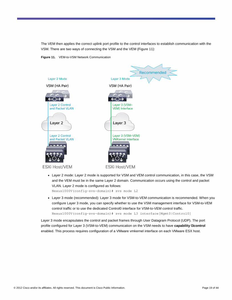
The VEM then applies the correct uplink port profile to the control interfaces to establish communication with the
VSM. There are two ways of connecting the VSM and the VEM (Figure 11):
Figure 11. VEM-to-VSM Network Communication
● Layer 2 mode: Layer 2 mode is supported for VSM and VEM control communication, in this case, the VSM
and the VEM must be in the same Layer 2 domain. Communication occurs using the control and packet
VLAN. Layer 2 mode is configured as follows: Nexus1000V(config-svs-domain)# svs mode L2
● Layer 3 mode (recommended): Layer 3 mode for VSM-to-VEM communication is recommended. When you
configure Layer 3 mode, you can specify whether to use the VSM management interface for VSM-to-VEM
control traffic or to use the dedicated Control0 interface for VSM-to-VEM control traffic. Nexus1000V(config-svs-domain)# svs mode L3 interface[Mgmt0|Control0]
Layer 3 mode encapsulates the control and packet frames through User Datagram Protocol (UDP). The port
profile configured for Layer 3 (VSM-to-VEM) communication on the VSM needs to have capability l3control
enabled. This process requires configuration of a VMware vmkernel interface on each VMware ESX host.
© 2012 Cisco and/or its affiliates. All rights reserved. This document is Cisco Public Information. Page 20 of 44
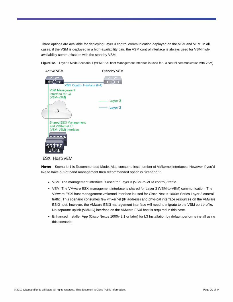
Three options are available for deploying Layer 3 control communication deployed on the VSM and VEM. In all
cases, if the VSM is deployed in a high-availability pair, the VSM control interface is always used for VSM high-
availability communication with the standby VSM.
Figure 12. Layer 3 Mode Scenario 1 (VEM/ESXi host Management Interface is used for L3 control communication with VSM)
Note: Scenario 1 is Recommended Mode. Also consume less number of VMkernel interfaces. However if you’d
like to have out-of band management then recommended option is Scenario 2:
● VSM: The management interface is used for Layer 3 (VSM-to-VEM control) traffic.
● VEM: The VMware ESXi management interface is shared for Layer 3 (VSM-to-VEM) communication. The
VMware ESXi host management vmkernel interface is used for Cisco Nexus 1000V Series Layer 3 control
traffic. This scenario consumes few vmkernel (IP address) and physical interface resources on the VMware
ESXi host; however, the VMware ESXi management interface will need to migrate to the VSM port profile.
No separate uplink (VMNIC) interface on the VMware ESXi host is required in this case.
● Enhanced Installer App (Cisco Nexus 1000v 2.1 or later) for L3 Installation by default performs install using
this scenario.
© 2012 Cisco and/or its affiliates. All rights reserved. This document is Cisco Public Information. Page 21 of 44
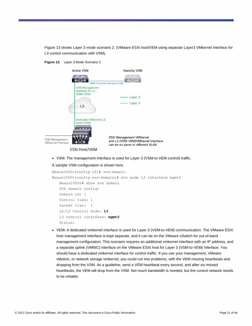
Figure 13 shows Layer 3 mode scenario 2. (VMware ESXi host/VEM using separate Layer3 VMkernel interface for
L3 control communication with VSM).
Figure 13. Layer 3 Mode Scenario 2
● VSM: The management interface is used for Layer 3 (VSM-to-VEM control) traffic.
A sample VSM configuration is shown here.
Nexus1000v(config-if)# svs-domain
Nexus1000v(config-svs-domain)# svs mode L3 interface mgmt0
Nexus1000v# show svs domain
SVS domain config:
Domain id: 1
Control vlan: 1
Packet vlan: 1
L2/L3 Control mode: L3
L3 control interface: mgmt0
Status:
● VEM: A dedicated vmkernel interface is used for Layer 3 (VSM-to-VEM) communication. The VMware ESXi
host management interface is kept separate, and it can be on the VMware vSwitch for out-of-band
management configuration. This scenario requires an additional vmkernel interface with an IP address, and
a separate uplink (VMNIC) interface on the VMware ESXi host for Layer 3 (VSM-to-VEM) Interface. You
should have a dedicated vmkernel interface for control traffic. If you use your management, VMware
vMotion, or network storage vmkernel, you could run into problems, with the VEM missing heartbeats and
dropping from the VSM. As a guideline, send a VEM heartbeat every second, and after six missed
heartbeats, the VEM will drop from the VSM. Not much bandwidth is needed, but the control network needs
to be reliable.
© 2012 Cisco and/or its affiliates. All rights reserved. This document is Cisco Public Information. Page 22 of 44
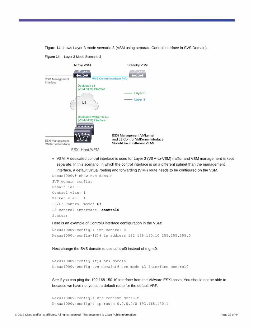
Figure 14 shows Layer 3 mode scenario 3 (VSM using separate Control interface in SVS Domain).
Figure 14. Layer 3 Mode Scenario 3
● VSM: A dedicated control interface is used for Layer 3 (VSM-to-VEM) traffic, and VSM management is kept
separate. In this scenario, in which the control interface is on a different subnet than the management
interface, a default virtual routing and forwarding (VRF) route needs to be configured on the VSM. Nexus1000v# show svs domain
SVS domain config:
Domain id: 1
Control vlan: 1
Packet vlan: 1
L2/L3 Control mode: L3
L3 control interface: control0
Status:
Here is an example of Control0 interface configuration in the VSM:
Nexus1000v(config)# int control 0
Nexus1000v(config-if)# ip address 192.168.150.10 255.255.255.0
Next change the SVS domain to use control0 instead of mgmt0.
Nexus1000v(config-if)# svs-domain
Nexus1000v(config-svs-domain)# svs mode L3 interface control0
See if you can ping the 192.168.150.10 interface from the VMware ESXi hosts. You should not be able to
because we have not yet set a default route for the default VRF.
Nexus1000v(config)# vrf context default
Nexus1000v(config)# ip route 0.0.0.0/0 192.168.150.1
© 2012 Cisco and/or its affiliates. All rights reserved. This document is Cisco Public Information. Page 23 of 44
Now add the hosts to the Cisco Nexus 1000V Series, and you should be set.
● VEM: A dedicated vmkernel interface is used for Layer 3 (VSM-to-VEM) communication. The VMware ESXi
host management interface is kept separate and can remain on the VMware vSwitch for out-of-band
management configuration. This scenario requires an additional vmkernel interface with an IP address, and
a separate uplink (VMNIC) interface on the VMware ESXi host for the Layer 3 (VSM-to-VEM) interface. Nexus1000V(config)# port-profile type vethernet L3vmkernel
Nexus1000V(config-port-profile)# switchport mode access
Nexus1000V(config-port-profile)# switchport access vlan <X>
Nexus1000V(config-port-profile)# vmware port-group
Nexus1000V(config-port-profile)# no shutdown
Nexus1000V(config-port-profile)# capability l3control
Nexus1000V(config-port-profile)# system vlan <X>
Nexus1000V(config-port-profile)# state enable
Note: <X> is the VLAN number that will be used by the vmkernel interface.
The l3control configuration sets up the VEM to use this interface to send Layer 3 packets, so even if the Cisco
Nexus 1000V Series is a Layer 2 switch, it can send IP packets.
Layer 3 Mode Preference
For VSM-to-VEM control communication, Layer 3 mode is the recommended option, in part for simplicity in
troubleshooting VSM-to-VEM communication problems. Communication between the VSM and VEM is crucial,
and use of Layer 3 mode makes troubleshooting easier using standard tools like ping and traceroute. With Layer 3
mode, VMware ESXi hosts do not need to be on the same Layer 2 domain to be on the Cisco Nexus 1000V Series
distributed virtual switch (DVS). With Layer 2 mode, all switches between the VEM and VSM must have the control
VLAN in place and need to verify the VLAN at each switch (ingress and egress) port. Troubleshooting in Layer 2
mode can be cumbersome because after the physical network switches are configured, the server administrator
needs to troubleshoot the VEM to verify that the appropriate VLANs and MAC addresses of the VSM are seen.
These additional processes in Layer 2 mode make troubleshooting more difficult; therefore, the recommended
approach is to enable Layer 3 mode.
Regardless of the mode of communication between the VSM and the VEM, after the VSM recognizes the VEM, a
new module will be virtually inserted into the Cisco Nexus 1000V Series Switch’s virtual chassis. The VSM CLI will
notify the network administrator that a new module is powered on, much as with a physical chassis.
The module assignment is sequential, meaning that the VEM will be assigned the lowest available module number
between 3 and 66. When a VEM comes online for the first time, the VSM assigns the module number and tracks
that module using the unique user ID (UUID) of the VMware ESX server, helping ensure that if the VMware ESX
host loses connectivity or is powered down for any reason, the VEM will retain its module number when the host
comes back online.
© 2012 Cisco and/or its affiliates. All rights reserved. This document is Cisco Public Information. Page 24 of 44
The VSM maintains a heartbeat with its associated VEMs. This heartbeat is transmitted at 1-second intervals. If
the VSM does not receive a response within 6 seconds, the VSM considers the VEM removed from the virtual
chassis. If the VEM is not responding because of a connectivity problem, the VEM will continue to switch packets
in its last-known good state. When communication is restored between a running VEM and the VSM, if no
configuration change has occurred since the disruption, no data traffic is lost. If there are differences between the
last-known state of the VEM and the latest configuration from the VSM, then the VEM is reprogrammed, causing a
slight pause (1 to 15 seconds) in network traffic.
All communication between the VSM and VEM is encrypted using a 128-bit algorithm.
Enhanced Installer App
Available with Nexus 1000V, Release 2.1 or later, Enhanced Installer App will perform installation of Nexus 1000V
at your fingertips. It is enhanced to extremely ease installation process of VSM and VEM modules.
More details can be found at Nexus 1000V Installation Guide.
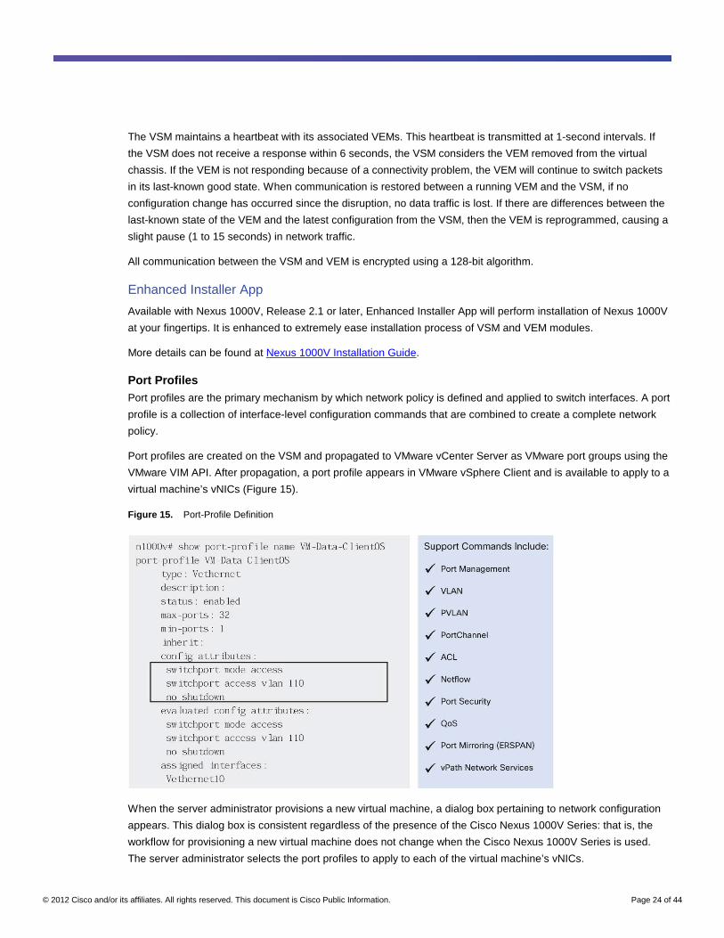
Port Profiles Port profiles are the primary mechanism by which network policy is defined and applied to switch interfaces. A port
profile is a collection of interface-level configuration commands that are combined to create a complete network
policy.
Port profiles are created on the VSM and propagated to VMware vCenter Server as VMware port groups using the
VMware VIM API. After propagation, a port profile appears in VMware vSphere Client and is available to apply to a
virtual machine’s vNICs (Figure 15).
Figure 15. Port-Profile Definition
When the server administrator provisions a new virtual machine, a dialog box pertaining to network configuration
appears. This dialog box is consistent regardless of the presence of the Cisco Nexus 1000V Series: that is, the
workflow for provisioning a new virtual machine does not change when the Cisco Nexus 1000V Series is used.
The server administrator selects the port profiles to apply to each of the virtual machine’s vNICs.
© 2012 Cisco and/or its affiliates. All rights reserved. This document is Cisco Public Information. Page 25 of 44
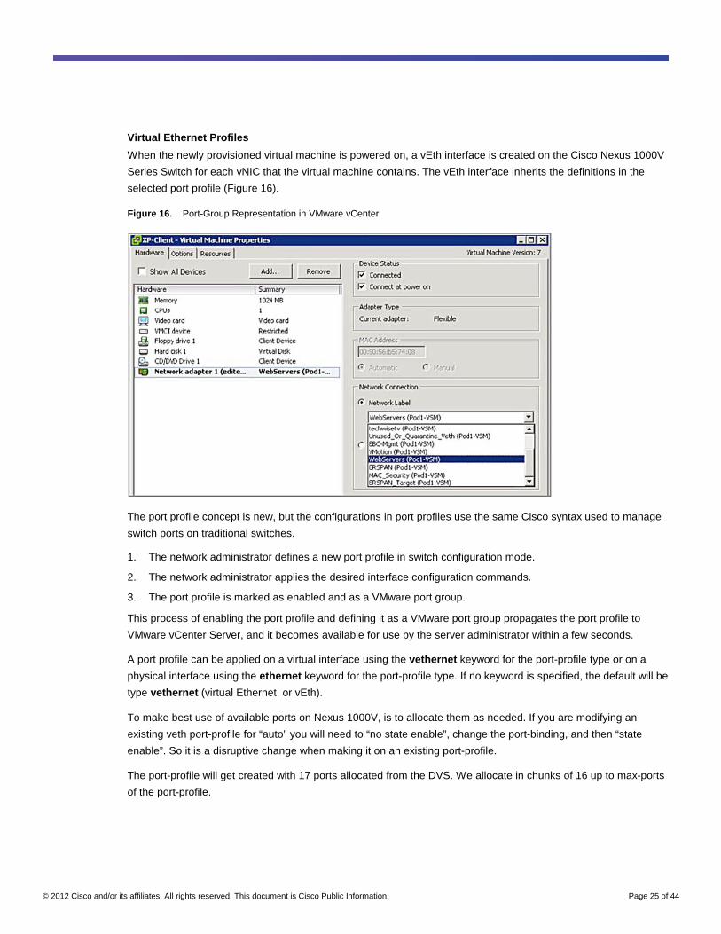
Virtual Ethernet Profiles
When the newly provisioned virtual machine is powered on, a vEth interface is created on the Cisco Nexus 1000V
Series Switch for each vNIC that the virtual machine contains. The vEth interface inherits the definitions in the
selected port profile (Figure 16).
Figure 16. Port-Group Representation in VMware vCenter
The port profile concept is new, but the configurations in port profiles use the same Cisco syntax used to manage
switch ports on traditional switches.
1. The network administrator defines a new port profile in switch configuration mode.
2. The network administrator applies the desired interface configuration commands.
3. The port profile is marked as enabled and as a VMware port group.
This process of enabling the port profile and defining it as a VMware port group propagates the port profile to
VMware vCenter Server, and it becomes available for use by the server administrator within a few seconds.
A port profile can be applied on a virtual interface using the vethernet keyword for the port-profile type or on a
physical interface using the ethernet keyword for the port-profile type. If no keyword is specified, the default will be
type vethernet (virtual Ethernet, or vEth).
To make best use of available ports on Nexus 1000V, is to allocate them as needed. If you are modifying an
existing veth port-profile for “auto” you will need to “no state enable”, change the port-binding, and then “state
enable”. So it is a disruptive change when making it on an existing port-profile.
The port-profile will get created with 17 ports allocated from the DVS. We allocate in chunks of 16 up to max-ports
of the port-profile.
© 2012 Cisco and/or its affiliates. All rights reserved. This document is Cisco Public Information. Page 26 of 44
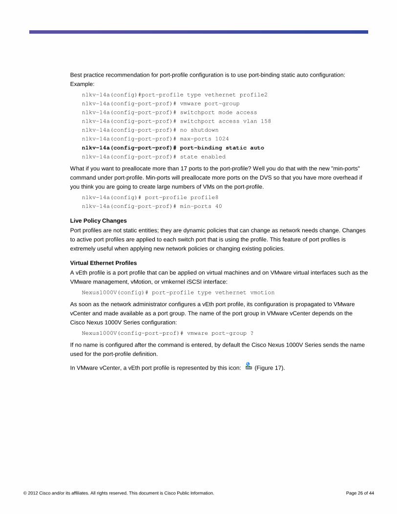
Best practice recommendation for port-profile configuration is to use port-binding static auto configuration:
Example:
n1kv-14a(config)#port-profile type vethernet profile2
n1kv-14a(config-port-prof)# vmware port-group
n1kv-14a(config-port-prof)# switchport mode access
n1kv-14a(config-port-prof)# switchport access vlan 158
n1kv-14a(config-port-prof)# no shutdown
n1kv-14a(config-port-prof)# max-ports 1024
n1kv-14a(config-port-prof)# port-binding static auto
n1kv-14a(config-port-prof)# state enabled
What if you want to preallocate more than 17 ports to the port-profile? Well you do that with the new "min-ports"
command under port-profile. Min-ports will preallocate more ports on the DVS so that you have more overhead if
you think you are going to create large numbers of VMs on the port-profile.
n1kv-14a(config)# port-profile profile8
n1kv-14a(config-port-prof)# min-ports 40
Live Policy Changes
Port profiles are not static entities; they are dynamic policies that can change as network needs change. Changes
to active port profiles are applied to each switch port that is using the profile. This feature of port profiles is
extremely useful when applying new network policies or changing existing policies.
Virtual Ethernet Profiles
A vEth profile is a port profile that can be applied on virtual machines and on VMware virtual interfaces such as the
VMware management, vMotion, or vmkernel iSCSI interface:
Nexus1000V(config)# port-profile type vethernet vmotion
As soon as the network administrator configures a vEth port profile, its configuration is propagated to VMware
vCenter and made available as a port group. The name of the port group in VMware vCenter depends on the
Cisco Nexus 1000V Series configuration:
Nexus1000V(config-port-prof)# vmware port-group ?
If no name is configured after the command is entered, by default the Cisco Nexus 1000V Series sends the name
used for the port-profile definition.
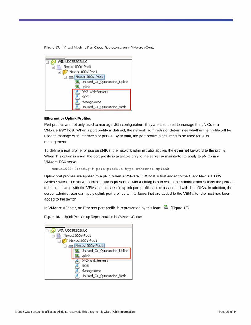
In VMware vCenter, a vEth port profile is represented by this icon: (Figure 17).
© 2012 Cisco and/or its affiliates. All rights reserved. This document is Cisco Public Information. Page 27 of 44
Figure 17. Virtual Machine Port-Group Representation in VMware vCenter
Ethernet or Uplink Profiles
Port profiles are not only used to manage vEth configuration; they are also used to manage the pNICs in a
VMware ESX host. When a port profile is defined, the network administrator determines whether the profile will be
used to manage vEth interfaces or pNICs. By default, the port profile is assumed to be used for vEth
management.
To define a port profile for use on pNICs, the network administrator applies the ethernet keyword to the profile.
When this option is used, the port profile is available only to the server administrator to apply to pNICs in a
VMware ESX server:
Nexus1000V(config)# port-profile type ethernet uplink
Uplink port profiles are applied to a pNIC when a VMware ESX host is first added to the Cisco Nexus 1000V
Series Switch. The server administrator is presented with a dialog box in which the administrator selects the pNICs
to be associated with the VEM and the specific uplink port profiles to be associated with the pNICs. In addition, the
server administrator can apply uplink port profiles to interfaces that are added to the VEM after the host has been
added to the switch.
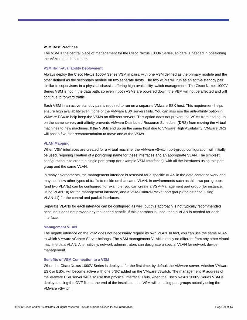
In VMware vCenter, an Ethernet port profile is represented by this icon: (Figure 18).
Figure 18. Uplink Port-Group Representation in VMware vCenter
© 2012 Cisco and/or its affiliates. All rights reserved. This document is Cisco Public Information. Page 28 of 44
System VLANs
System VLANs are defined by an optional parameter that can be added in a port profile. When used, this
parameter causes the port profile to become a special system port profile that is included in the Cisco Nexus
1000V Series vSwitch data. Interfaces that use the system port profile and that are members of one of the system
VLANs defined are automatically enabled and forwarded when VMware ESX starts, even if the VEM does not
have communication with the VSM. This behavior enables the use of critical host functions if the VMware ESX
host starts and cannot communicate with the VSM.
The system VLAN configuration is relevant not only on the Ethernet port profile, but also on the vEth port profile.
If the system VLAN definition, for example, is configured only on the Ethernet port profile, the VMware vmkernel
interface that inherits this port profile will not be enabled by default and hence will not be forwarding.
The control and packet VLANs must be defined as system VLANs. The service console interface and VMware
vmkernel iSCSI or NFS interface should also be defined as system VLANs.
Note: A system VLAN needs to be defined in both the Ethernet and vEth port profiles to allow a specific virtual
interface to be automatically enabled and capable of forwarding traffic on a physical interface.
Here is an example of a configuration:
Nexus1000V(config)# Port-profile type Ethernet uplink
Nexus1000V(config-port-prof)#switchport mode trunk
Nexus1000V(config-port-prof)#switchport trunk allowed vlan 10-15
Nexus1000V(config-port-prof)#system vlan 10,15
Nexus1000V(config-port-prof)#state enabled
Nexus1000V(config-port-prof)#vmware port-group
Nexus1000V(config)# port-profile type vethernet Service-Console
Nexus1000V(config-port-prof)#switchport mode access
Nexus1000V(config-port-prof)#switchport access vlan 10
Nexus1000V(config-port-prof)#system vlan 10
Nexus1000V(config-port-prof)#state enabled
Nexus1000V(config-port-prof)#vmware port-group
Cisco Nexus 1000V Series Network Design
This section discusses design considerations related to Cisco Nexus 1000V Series connectivity to the physical
access layer.
Design Considerations Multiple design considerations must be addressed when deploying the Cisco Nexus 1000V Series.
At a basic level, the design principles used when connecting the Cisco Nexus 1000V Series to a physical access
layer are similar to those used when connecting two physical switches together. However, because the Cisco
Nexus 1000V Series Switches are end-host switches, you can make certain assumptions that you cannot make for
other physical switches. For example, you do not need to rely on spanning tree to break loops, and you do not
need to define a PortChannel on the upstream switch.
Some design considerations are specific to the Cisco Nexus 1000V Series. Most likely, each VEM will be
connected to two access-layer switches, so dual-access switch designs are the focus of this section.
© 2012 Cisco and/or its affiliates. All rights reserved. This document is Cisco Public Information. Page 29 of 44
VSM Best Practices
The VSM is the central place of management for the Cisco Nexus 1000V Series, so care is needed in positioning
the VSM in the data center.
VSM High-Availability Deployment
Always deploy the Cisco Nexus 1000V Series VSM in pairs, with one VSM defined as the primary module and the
other defined as the secondary module on two separate hosts. The two VSMs will run as an active-standby pair
similar to supervisors in a physical chassis, offering high-availability switch management. The Cisco Nexus 1000V
Series VSM is not in the data path, so even if both VSMs are powered down, the VEM will not be affected and will
continue to forward traffic.
Each VSM in an active-standby pair is required to run on a separate VMware ESX host. This requirement helps
ensure high availability even if one of the VMware ESX servers fails. You can also use the anti-affinity option in
VMware ESX to help keep the VSMs on different servers. This option does not prevent the VSMs from ending up
on the same server; anti-affinity prevents VMware Distributed Resource Scheduler (DRS) from moving the virtual
machines to new machines. If the VSMs end up on the same host due to VMware High Availability, VMware DRS
will post a five-star recommendation to move one of the VSMs.
VLAN Mapping
When VSM interfaces are created for a virtual machine, the VMware vSwitch port-group configuration will initially
be used, requiring creation of a port-group name for these interfaces and an appropriate VLAN. The simplest
configuration is to create a single port group (for example VSM-Interfaces), with all the interfaces using this port
group and the same VLAN.
In many environments, the management interface is reserved for a specific VLAN in the data center network and
may not allow other types of traffic to reside on that same VLAN. In environments such as this, two port groups
(and two VLANs) can be configured: for example, you can create a VSM-Management port group (for instance,
using VLAN 10) for the management interface, and a VSM-Control-Packet port group (for instance, using
VLAN 11) for the control and packet interfaces.
Separate VLANs for each interface can be configured as well, but this approach is not typically recommended
because it does not provide any real added benefit. If this approach is used, then a VLAN is needed for each
interface.
Management VLAN
The mgmt0 interface on the VSM does not necessarily require its own VLAN. In fact, you can use the same VLAN
to which VMware vCenter Server belongs. The VSM management VLAN is really no different from any other virtual
machine data VLAN. Alternatively, network administrators can designate a special VLAN for network device
management.
Benefits of VSM Connection to a VEM
When the Cisco Nexus 1000V Series is deployed for the first time, by default the VMware server, whether VMware
ESX or ESXi, will become active with one pNIC added on the VMware vSwitch. The management IP address of
the VMware ESX server will also use that physical interface. Thus, when the Cisco Nexus 1000V Series VSM is
deployed using the OVF file, at the end of the installation the VSM will be using port groups actually using the
VMware vSwitch.
© 2012 Cisco and/or its affiliates. All rights reserved. This document is Cisco Public Information. Page 30 of 44
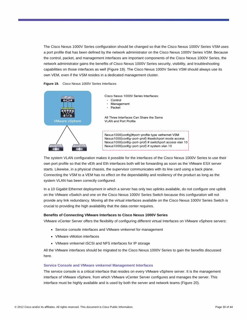
The Cisco Nexus 1000V Series configuration should be changed so that the Cisco Nexus 1000V Series VSM uses
a port profile that has been defined by the network administrator on the Cisco Nexus 1000V Series VSM. Because
the control, packet, and management interfaces are important components of the Cisco Nexus 1000V Series, the
network administrator gains the benefits of Cisco Nexus 1000V Series security, visibility, and troubleshooting
capabilities on those interfaces as well (Figure 19). The Cisco Nexus 1000V Series VSM should always use its
own VEM, even if the VSM resides in a dedicated management cluster.
Figure 19. Cisco Nexus 1000V Series Interfaces
The system VLAN configuration makes it possible for the interfaces of the Cisco Nexus 1000V Series to use their
own port profile so that the vEth and Eth interfaces both will be forwarding as soon as the VMware ESX server
starts. Likewise, in a physical chassis, the supervisor communicates with its line card using a back plane.
Connecting the VSM to a VEM has no effect on the dependability and resiliency of the product as long as the
system VLAN has been correctly configured.
In a 10 Gigabit Ethernet deployment in which a server has only two uplinks available, do not configure one uplink
on the VMware vSwitch and one on the Cisco Nexus 1000V Series Switch because this configuration will not
provide any link redundancy. Moving all the virtual interfaces available on the Cisco Nexus 1000V Series Switch is
crucial to providing the high availability that the data center requires.
Benefits of Connecting VMware Interfaces to Cisco Nexus 1000V Series
VMware vCenter Server offers the flexibility of configuring different virtual Interfaces on VMware vSphere servers:
● Service console interfaces and VMware vmkernel for management
● VMware vMotion interfaces
● VMware vmkernel iSCSI and NFS interfaces for IP storage
All the VMware interfaces should be migrated to the Cisco Nexus 1000V Series to gain the benefits discussed
here.
Service Console and VMware vmkernel Management Interfaces
The service console is a critical interface that resides on every VMware vSphere server. It is the management
interface of VMware vSphere, from which VMware vCenter Server configures and manages the server. This
interface must be highly available and is used by both the server and network teams (Figure 20).
© 2012 Cisco and/or its affiliates. All rights reserved. This document is Cisco Public Information. Page 31 of 44
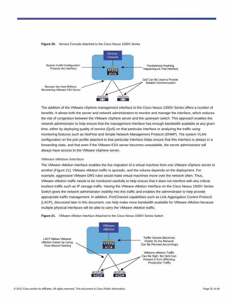
Figure 20. Service Console Attached to the Cisco Nexus 1000V Series
The addition of the VMware vSphere management interface to the Cisco Nexus 1000V Series offers a number of
benefits. It allows both the server and network administrators to monitor and manage the interface, which reduces
the risk of congestion between the VMware vSphere server and the upstream switch. This approach enables the
network administrator to help ensure that the management interface has enough bandwidth available at any given
time, either by deploying quality of service (QoS) on that particular interface or analyzing the traffic using
monitoring features such as NetFlow and Simple Network Management Protocol (SNMP). The system VLAN
configuration on the port profile attached to that particular interface helps ensure that this interface is always in a
forwarding state, and that even if the VMware ESX server becomes unavailable, the server administrator will
always have access to the VMware vSphere server.
VMware vMotion Interface
The VMware vMotion interface enables the live migration of a virtual machine from one VMware vSphere server to
another (Figure 21). VMware vMotion traffic is sporadic, and the volume depends on the deployment. For
example, aggressive VMware DRS rules would make virtual machines move over the network often. Thus,
VMware vMotion traffic needs to be monitored carefully to help ensure that it does not interfere with any critical,
lossless traffic such as IP storage traffic. Having the VMware vMotion interface on the Cisco Nexus 1000V Series
Switch gives the network administrator visibility into this traffic and enables the administrator to help provide
appropriate traffic management. In addition, PortChannel capabilities such as Link Aggregation Control Protocol
(LACP), discussed later in this document, can help make more bandwidth available for VMware vMotion because
multiple physical interfaces will be able to carry the VMware vMotion traffic.
Figure 21. VMware vMotion Interface Attached to the Cisco Nexus 1000V Series Switch
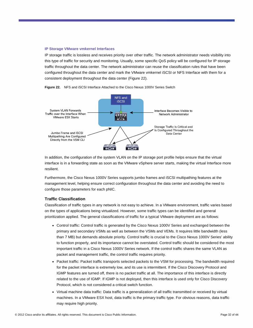
© 2012 Cisco and/or its affiliates. All rights reserved. This document is Cisco Public Information. Page 32 of 44
IP Storage VMware vmkernel Interfaces
IP storage traffic is lossless and receives priority over other traffic. The network administrator needs visibility into
this type of traffic for security and monitoring. Usually, some specific QoS policy will be configured for IP storage
traffic throughout the data center. The network administrator can reuse the classification rules that have been
configured throughout the data center and mark the VMware vmkernel iSCSI or NFS Interface with them for a
consistent deployment throughout the data center (Figure 22).
Figure 22. NFS and iSCSI Interface Attached to the Cisco Nexus 1000V Series Switch
In addition, the configuration of the system VLAN on the IP storage port profile helps ensure that the virtual
interface is in a forwarding state as soon as the VMware vSphere server starts, making the virtual Interface more
resilient.
Furthermore, the Cisco Nexus 1000V Series supports jumbo frames and iSCSI multipathing features at the
management level, helping ensure correct configuration throughout the data center and avoiding the need to
configure those parameters for each pNIC.
Traffic Classification Classification of traffic types in any network is not easy to achieve. In a VMware environment, traffic varies based
on the types of applications being virtualized. However, some traffic types can be identified and general
prioritization applied. The general classifications of traffic for a typical VMware deployment are as follows:
● Control traffic: Control traffic is generated by the Cisco Nexus 1000V Series and exchanged between the
primary and secondary VSMs as well as between the VSMs and VEMs. It requires little bandwidth (less
than 7 MB) but demands absolute priority. Control traffic is crucial to the Cisco Nexus 1000V Series’ ability
to function properly, and its importance cannot be overstated. Control traffic should be considered the most
important traffic in a Cisco Nexus 1000V Series network. If the control traffic shares the same VLAN as
packet and management traffic, the control traffic requires priority.
● Packet traffic: Packet traffic transports selected packets to the VSM for processing. The bandwidth required
for the packet interface is extremely low, and its use is intermittent. If the Cisco Discovery Protocol and
IGMP features are turned off, there is no packet traffic at all. The importance of this interface is directly
related to the use of IGMP. If IGMP is not deployed, then this interface is used only for Cisco Discovery
Protocol, which is not considered a critical switch function.
● Virtual machine data traffic: Data traffic is a generalization of all traffic transmitted or received by virtual
machines. In a VMware ESX host, data traffic is the primary traffic type. For obvious reasons, data traffic
may require high priority.
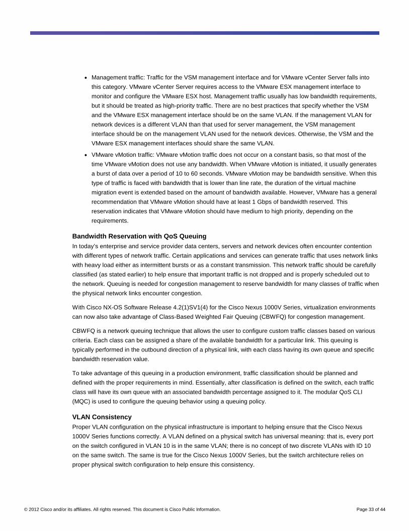
© 2012 Cisco and/or its affiliates. All rights reserved. This document is Cisco Public Information. Page 33 of 44
● Management traffic: Traffic for the VSM management interface and for VMware vCenter Server falls into
this category. VMware vCenter Server requires access to the VMware ESX management interface to
monitor and configure the VMware ESX host. Management traffic usually has low bandwidth requirements,
but it should be treated as high-priority traffic. There are no best practices that specify whether the VSM
and the VMware ESX management interface should be on the same VLAN. If the management VLAN for
network devices is a different VLAN than that used for server management, the VSM management
interface should be on the management VLAN used for the network devices. Otherwise, the VSM and the
VMware ESX management interfaces should share the same VLAN.
● VMware vMotion traffic: VMware vMotion traffic does not occur on a constant basis, so that most of the
time VMware vMotion does not use any bandwidth. When VMware vMotion is initiated, it usually generates
a burst of data over a period of 10 to 60 seconds. VMware vMotion may be bandwidth sensitive. When this
type of traffic is faced with bandwidth that is lower than line rate, the duration of the virtual machine
migration event is extended based on the amount of bandwidth available. However, VMware has a general
recommendation that VMware vMotion should have at least 1 Gbps of bandwidth reserved. This
reservation indicates that VMware vMotion should have medium to high priority, depending on the
requirements.
Bandwidth Reservation with QoS Queuing In today’s enterprise and service provider data centers, servers and network devices often encounter contention
with different types of network traffic. Certain applications and services can generate traffic that uses network links
with heavy load either as intermittent bursts or as a constant transmission. This network traffic should be carefully
classified (as stated earlier) to help ensure that important traffic is not dropped and is properly scheduled out to
the network. Queuing is needed for congestion management to reserve bandwidth for many classes of traffic when
the physical network links encounter congestion.
With Cisco NX-OS Software Release 4.2(1)SV1(4) for the Cisco Nexus 1000V Series, virtualization environments
can now also take advantage of Class-Based Weighted Fair Queuing (CBWFQ) for congestion management.
CBWFQ is a network queuing technique that allows the user to configure custom traffic classes based on various
criteria. Each class can be assigned a share of the available bandwidth for a particular link. This queuing is
typically performed in the outbound direction of a physical link, with each class having its own queue and specific
bandwidth reservation value.
To take advantage of this queuing in a production environment, traffic classification should be planned and
defined with the proper requirements in mind. Essentially, after classification is defined on the switch, each traffic
class will have its own queue with an associated bandwidth percentage assigned to it. The modular QoS CLI
(MQC) is used to configure the queuing behavior using a queuing policy.
VLAN Consistency Proper VLAN configuration on the physical infrastructure is important to helping ensure that the Cisco Nexus
1000V Series functions correctly. A VLAN defined on a physical switch has universal meaning: that is, every port
on the switch configured in VLAN 10 is in the same VLAN; there is no concept of two discrete VLANs with ID 10
on the same switch. The same is true for the Cisco Nexus 1000V Series, but the switch architecture relies on
proper physical switch configuration to help ensure this consistency.
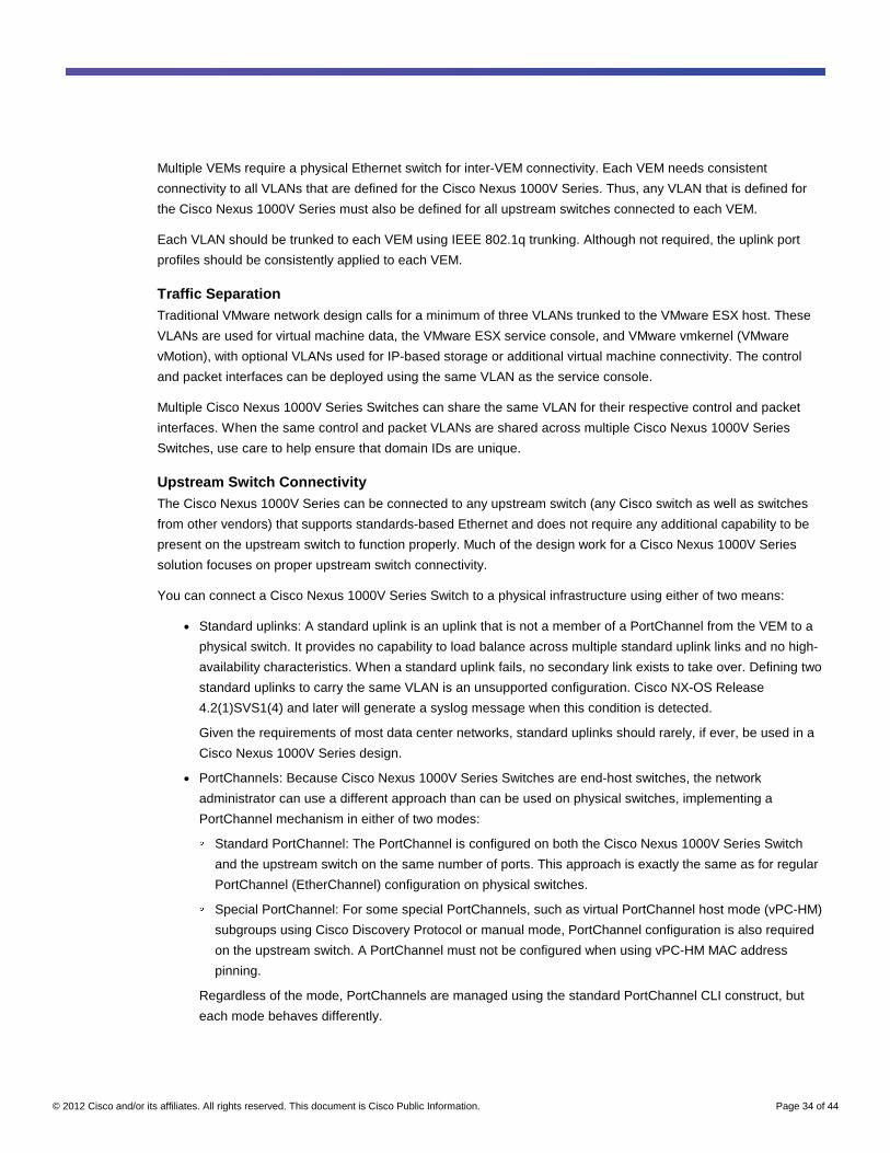
© 2012 Cisco and/or its affiliates. All rights reserved. This document is Cisco Public Information. Page 34 of 44
Multiple VEMs require a physical Ethernet switch for inter-VEM connectivity. Each VEM needs consistent
connectivity to all VLANs that are defined for the Cisco Nexus 1000V Series. Thus, any VLAN that is defined for
the Cisco Nexus 1000V Series must also be defined for all upstream switches connected to each VEM.
Each VLAN should be trunked to each VEM using IEEE 802.1q trunking. Although not required, the uplink port
profiles should be consistently applied to each VEM.
Traffic Separation Traditional VMware network design calls for a minimum of three VLANs trunked to the VMware ESX host. These
VLANs are used for virtual machine data, the VMware ESX service console, and VMware vmkernel (VMware
vMotion), with optional VLANs used for IP-based storage or additional virtual machine connectivity. The control
and packet interfaces can be deployed using the same VLAN as the service console.
Multiple Cisco Nexus 1000V Series Switches can share the same VLAN for their respective control and packet
interfaces. When the same control and packet VLANs are shared across multiple Cisco Nexus 1000V Series
Switches, use care to help ensure that domain IDs are unique.
Upstream Switch Connectivity The Cisco Nexus 1000V Series can be connected to any upstream switch (any Cisco switch as well as switches
from other vendors) that supports standards-based Ethernet and does not require any additional capability to be
present on the upstream switch to function properly. Much of the design work for a Cisco Nexus 1000V Series
solution focuses on proper upstream switch connectivity.
You can connect a Cisco Nexus 1000V Series Switch to a physical infrastructure using either of two means:
● Standard uplinks: A standard uplink is an uplink that is not a member of a PortChannel from the VEM to a
physical switch. It provides no capability to load balance across multiple standard uplink links and no high-
availability characteristics. When a standard uplink fails, no secondary link exists to take over. Defining two
standard uplinks to carry the same VLAN is an unsupported configuration. Cisco NX-OS Release
4.2(1)SVS1(4) and later will generate a syslog message when this condition is detected.
Given the requirements of most data center networks, standard uplinks should rarely, if ever, be used in a
Cisco Nexus 1000V Series design.
● PortChannels: Because Cisco Nexus 1000V Series Switches are end-host switches, the network
administrator can use a different approach than can be used on physical switches, implementing a
PortChannel mechanism in either of two modes: ◦ Standard PortChannel: The PortChannel is configured on both the Cisco Nexus 1000V Series Switch
and the upstream switch on the same number of ports. This approach is exactly the same as for regular
PortChannel (EtherChannel) configuration on physical switches. ◦ Special PortChannel: For some special PortChannels, such as virtual PortChannel host mode (vPC-HM)
subgroups using Cisco Discovery Protocol or manual mode, PortChannel configuration is also required
on the upstream switch. A PortChannel must not be configured when using vPC-HM MAC address
pinning.
Regardless of the mode, PortChannels are managed using the standard PortChannel CLI construct, but
each mode behaves differently.
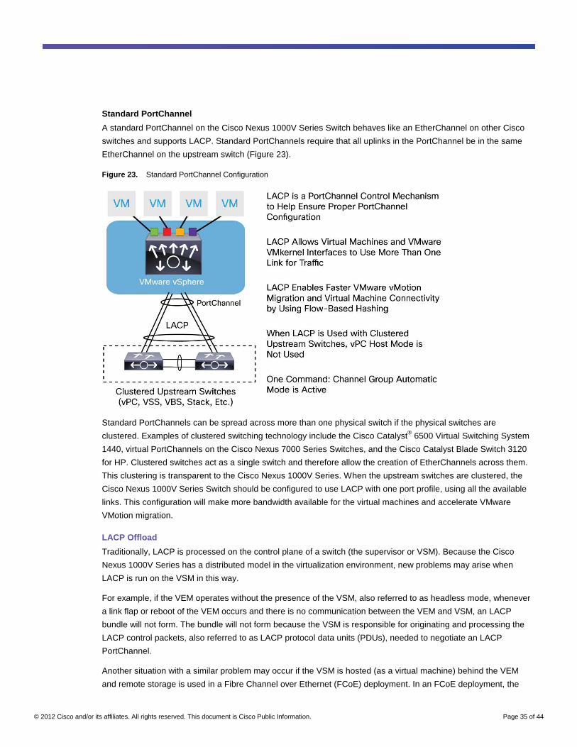
© 2012 Cisco and/or its affiliates. All rights reserved. This document is Cisco Public Information. Page 35 of 44
Standard PortChannel
A standard PortChannel on the Cisco Nexus 1000V Series Switch behaves like an EtherChannel on other Cisco
switches and supports LACP. Standard PortChannels require that all uplinks in the PortChannel be in the same
EtherChannel on the upstream switch (Figure 23).
Figure 23. Standard PortChannel Configuration
Standard PortChannels can be spread across more than one physical switch if the physical switches are
clustered. Examples of clustered switching technology include the Cisco Catalyst® 6500 Virtual Switching System
1440, virtual PortChannels on the Cisco Nexus 7000 Series Switches, and the Cisco Catalyst Blade Switch 3120
for HP. Clustered switches act as a single switch and therefore allow the creation of EtherChannels across them.
This clustering is transparent to the Cisco Nexus 1000V Series. When the upstream switches are clustered, the
Cisco Nexus 1000V Series Switch should be configured to use LACP with one port profile, using all the available
links. This configuration will make more bandwidth available for the virtual machines and accelerate VMware
VMotion migration.
LACP Offload
Traditionally, LACP is processed on the control plane of a switch (the supervisor or VSM). Because the Cisco
Nexus 1000V Series has a distributed model in the virtualization environment, new problems may arise when
LACP is run on the VSM in this way.
For example, if the VEM operates without the presence of the VSM, also referred to as headless mode, whenever
a link flap or reboot of the VEM occurs and there is no communication between the VEM and VSM, an LACP
bundle will not form. The bundle will not form because the VSM is responsible for originating and processing the
LACP control packets, also referred to as LACP protocol data units (PDUs), needed to negotiate an LACP
PortChannel.
Another situation with a similar problem may occur if the VSM is hosted (as a virtual machine) behind the VEM
and remote storage is used in a Fibre Channel over Ethernet (FCoE) deployment. In an FCoE deployment, the
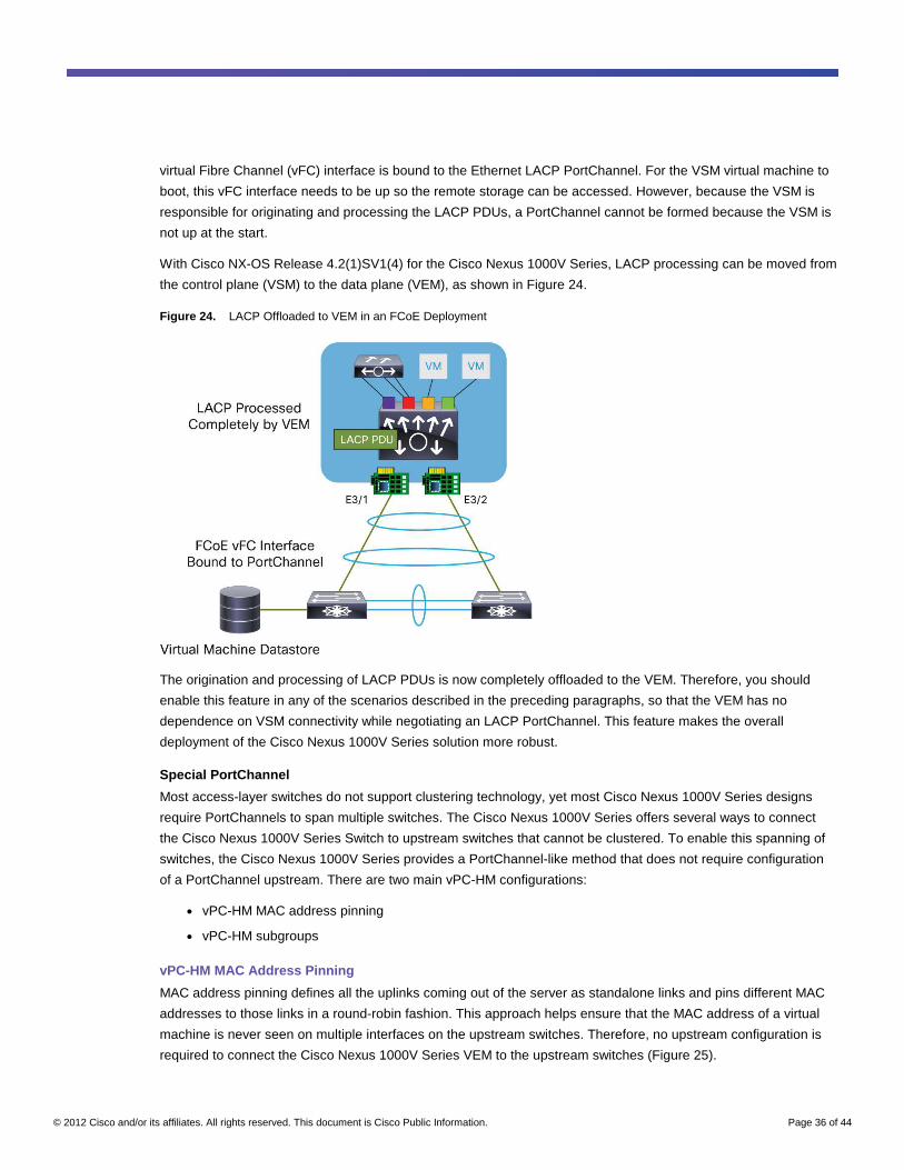
© 2012 Cisco and/or its affiliates. All rights reserved. This document is Cisco Public Information. Page 36 of 44
virtual Fibre Channel (vFC) interface is bound to the Ethernet LACP PortChannel. For the VSM virtual machine to
boot, this vFC interface needs to be up so the remote storage can be accessed. However, because the VSM is
responsible for originating and processing the LACP PDUs, a PortChannel cannot be formed because the VSM is
not up at the start.
With Cisco NX-OS Release 4.2(1)SV1(4) for the Cisco Nexus 1000V Series, LACP processing can be moved from
the control plane (VSM) to the data plane (VEM), as shown in Figure 24.
Figure 24. LACP Offloaded to VEM in an FCoE Deployment
The origination and processing of LACP PDUs is now completely offloaded to the VEM. Therefore, you should
enable this feature in any of the scenarios described in the preceding paragraphs, so that the VEM has no
dependence on VSM connectivity while negotiating an LACP PortChannel. This feature makes the overall
deployment of the Cisco Nexus 1000V Series solution more robust.
Special PortChannel
Most access-layer switches do not support clustering technology, yet most Cisco Nexus 1000V Series designs
require PortChannels to span multiple switches. The Cisco Nexus 1000V Series offers several ways to connect
the Cisco Nexus 1000V Series Switch to upstream switches that cannot be clustered. To enable this spanning of
switches, the Cisco Nexus 1000V Series provides a PortChannel-like method that does not require configuration
of a PortChannel upstream. There are two main vPC-HM configurations:
● vPC-HM MAC address pinning
● vPC-HM subgroups
vPC-HM MAC Address Pinning
MAC address pinning defines all the uplinks coming out of the server as standalone links and pins different MAC
addresses to those links in a round-robin fashion. This approach helps ensure that the MAC address of a virtual
machine is never seen on multiple interfaces on the upstream switches. Therefore, no upstream configuration is
required to connect the Cisco Nexus 1000V Series VEM to the upstream switches (Figure 25).
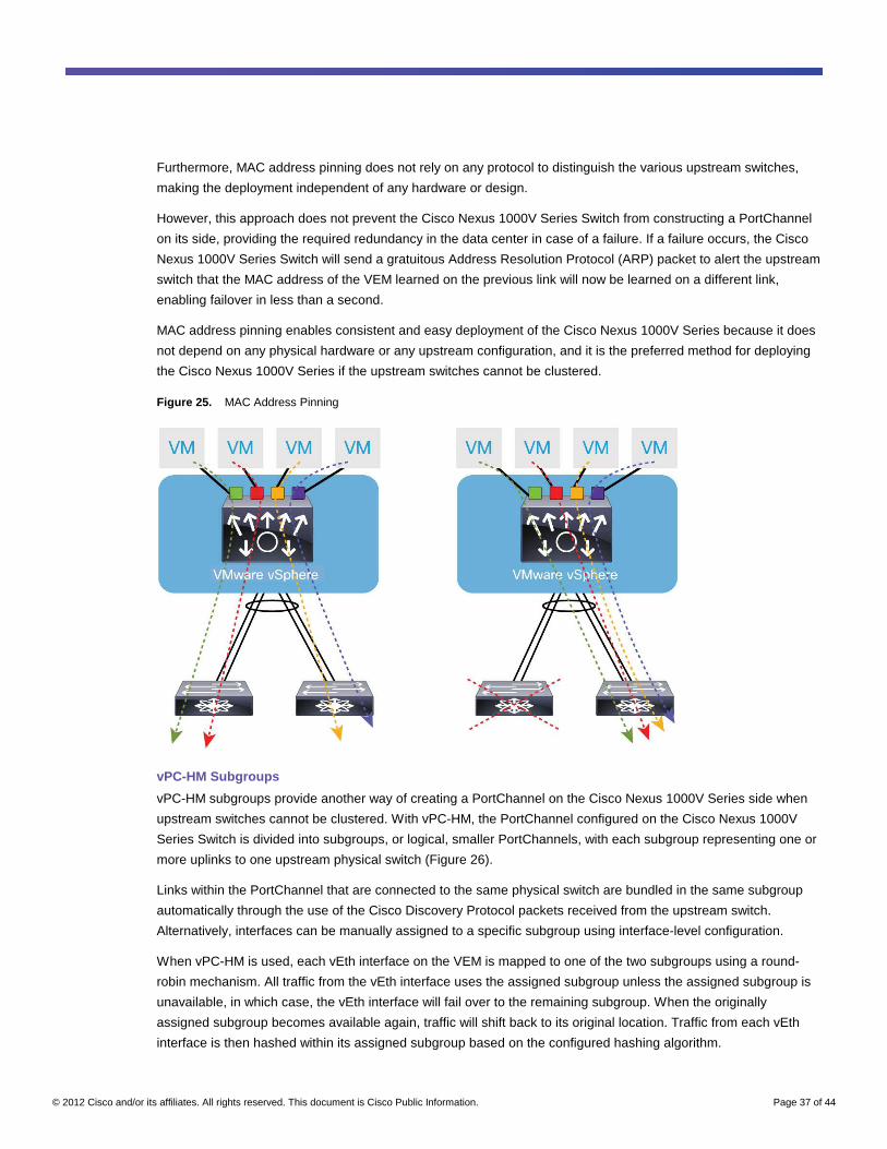
© 2012 Cisco and/or its affiliates. All rights reserved. This document is Cisco Public Information. Page 37 of 44
Furthermore, MAC address pinning does not rely on any protocol to distinguish the various upstream switches,
making the deployment independent of any hardware or design.
However, this approach does not prevent the Cisco Nexus 1000V Series Switch from constructing a PortChannel
on its side, providing the required redundancy in the data center in case of a failure. If a failure occurs, the Cisco
Nexus 1000V Series Switch will send a gratuitous Address Resolution Protocol (ARP) packet to alert the upstream
switch that the MAC address of the VEM learned on the previous link will now be learned on a different link,
enabling failover in less than a second.
MAC address pinning enables consistent and easy deployment of the Cisco Nexus 1000V Series because it does
not depend on any physical hardware or any upstream configuration, and it is the preferred method for deploying
the Cisco Nexus 1000V Series if the upstream switches cannot be clustered.
Figure 25. MAC Address Pinning
vPC-HM Subgroups
vPC-HM subgroups provide another way of creating a PortChannel on the Cisco Nexus 1000V Series side when
upstream switches cannot be clustered. With vPC-HM, the PortChannel configured on the Cisco Nexus 1000V
Series Switch is divided into subgroups, or logical, smaller PortChannels, with each subgroup representing one or
more uplinks to one upstream physical switch (Figure 26).
Links within the PortChannel that are connected to the same physical switch are bundled in the same subgroup
automatically through the use of the Cisco Discovery Protocol packets received from the upstream switch.
Alternatively, interfaces can be manually assigned to a specific subgroup using interface-level configuration.
When vPC-HM is used, each vEth interface on the VEM is mapped to one of the two subgroups using a round-
robin mechanism. All traffic from the vEth interface uses the assigned subgroup unless the assigned subgroup is
unavailable, in which case, the vEth interface will fail over to the remaining subgroup. When the originally
assigned subgroup becomes available again, traffic will shift back to its original location. Traffic from each vEth
interface is then hashed within its assigned subgroup based on the configured hashing algorithm.
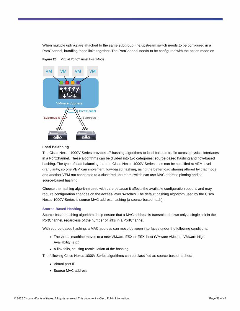
© 2012 Cisco and/or its affiliates. All rights reserved. This document is Cisco Public Information. Page 38 of 44
When multiple uplinks are attached to the same subgroup, the upstream switch needs to be configured in a
PortChannel, bundling those links together. The PortChannel needs to be configured with the option mode on.
Figure 26. Virtual PortChannel Host Mode
Load Balancing
The Cisco Nexus 1000V Series provides 17 hashing algorithms to load-balance traffic across physical interfaces
in a PortChannel. These algorithms can be divided into two categories: source-based hashing and flow-based
hashing. The type of load balancing that the Cisco Nexus 1000V Series uses can be specified at VEM-level
granularity, so one VEM can implement flow-based hashing, using the better load sharing offered by that mode,
and another VEM not connected to a clustered upstream switch can use MAC address pinning and so
source-based hashing.
Choose the hashing algorithm used with care because it affects the available configuration options and may
require configuration changes on the access-layer switches. The default hashing algorithm used by the Cisco
Nexus 1000V Series is source MAC address hashing (a source-based hash).
Source-Based Hashing
Source-based hashing algorithms help ensure that a MAC address is transmitted down only a single link in the
PortChannel, regardless of the number of links in a PortChannel.
With source-based hashing, a MAC address can move between interfaces under the following conditions:
● The virtual machine moves to a new VMware ESX or ESXi host (VMware vMotion, VMware High
Availability, etc.)
● A link fails, causing recalculation of the hashing
The following Cisco Nexus 1000V Series algorithms can be classified as source-based hashes:
● Virtual port ID
● Source MAC address
© 2012 Cisco and/or its affiliates. All rights reserved. This document is Cisco Public Information. Page 39 of 44
Flow-Based Hashing
Flow-based hashing enables traffic from a single MAC address to be distributed down multiple links in a
PortChannel simultaneously. Use of a flow-based hash increases the bandwidth available to a virtual machine or
to VMware vMotion and increases the utilization of the uplinks in a PortChannel by providing more precise load
balancing.
Flow-based hashing algorithms are any algorithms that use the following to hash:
● Packet destination
● Layer 4 port
● Combinations of source address, destination address, and Layer 4 port
Network-State Tracking
Network-state tracking (NST) is a mechanism that is used to detect Layer 1 and network connectivity failures that
would otherwise cause virtual machine traffic to be dropped during an uplink failure. An uplink failure occurs when
the upstream switch encounters a driver or firmware failure that prevents it from signaling a link to the neighboring
link interface (the Cisco Nexus 1000V Series VEM in this case). NST mitigates this problem by using NST
packets, which probe interfaces on other subgroups of the same VEM.
As shown in Figure 27, when a link failure occurs on the upstream switch, NST can detect the failure by sending
the tracking packet from one interface in Subgroup 0 to all interfaces in Subgroup 1. Because a link failure
occurred on the upstream switch, this tracking packet will not be received by Subgroup 1. The vPC-HM
PortChannel interface will then be identified as split, and a syslog will be generated for this split. Also, packet
counters are monitored to detect whether there is traffic coming into the subgroup that did not receive the tracking
packet. If packet counters are not incrementing, then the upstream switch is not transmitting to the VEM in the
subgroup. At this point, traffic that was originally pinned to the Subgroup 1 interface will be repinned to the active
interface in Subgroup 0.
You should enable NST when an uplink failure may cause traffic to be dropped. The most common deployment of
NST is in cases in which third-party networking entities may encounter driver or firmware or other software failures
in which the interface is not brought down completely and the VEM interface continues to forward traffic.
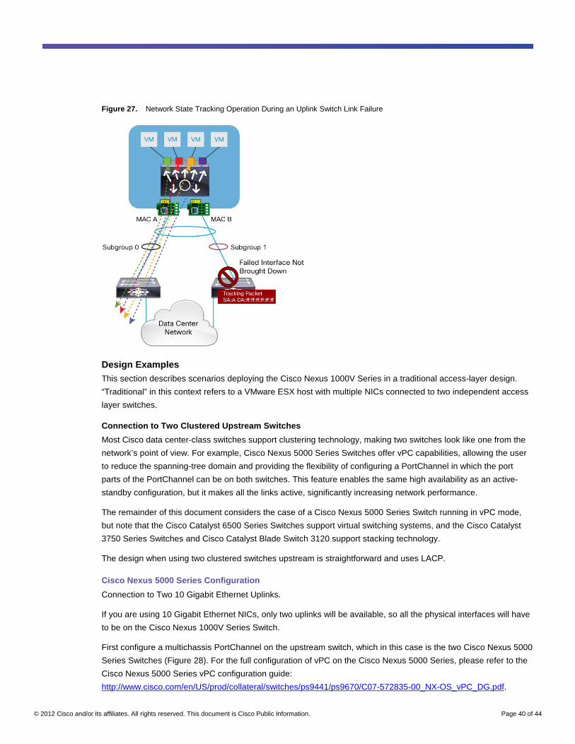
© 2012 Cisco and/or its affiliates. All rights reserved. This document is Cisco Public Information. Page 40 of 44
Figure 27. Network State Tracking Operation During an Uplink Switch Link Failure
Design Examples This section describes scenarios deploying the Cisco Nexus 1000V Series in a traditional access-layer design.
“Traditional” in this context refers to a VMware ESX host with multiple NICs connected to two independent access
layer switches.
Connection to Two Clustered Upstream Switches
Most Cisco data center-class switches support clustering technology, making two switches look like one from the
network’s point of view. For example, Cisco Nexus 5000 Series Switches offer vPC capabilities, allowing the user
to reduce the spanning-tree domain and providing the flexibility of configuring a PortChannel in which the port
parts of the PortChannel can be on both switches. This feature enables the same high availability as an active-
standby configuration, but it makes all the links active, significantly increasing network performance.
The remainder of this document considers the case of a Cisco Nexus 5000 Series Switch running in vPC mode,
but note that the Cisco Catalyst 6500 Series Switches support virtual switching systems, and the Cisco Catalyst
3750 Series Switches and Cisco Catalyst Blade Switch 3120 support stacking technology.
The design when using two clustered switches upstream is straightforward and uses LACP.
Cisco Nexus 5000 Series Configuration
Connection to Two 10 Gigabit Ethernet Uplinks.
If you are using 10 Gigabit Ethernet NICs, only two uplinks will be available, so all the physical interfaces will have
to be on the Cisco Nexus 1000V Series Switch.
First configure a multichassis PortChannel on the upstream switch, which in this case is the two Cisco Nexus 5000
Series Switches (Figure 28). For the full configuration of vPC on the Cisco Nexus 5000 Series, please refer to the
Cisco Nexus 5000 Series vPC configuration guide:
http://www.cisco.com/en/US/prod/collateral/switches/ps9441/ps9670/C07-572835-00_NX-OS_vPC_DG.pdf.
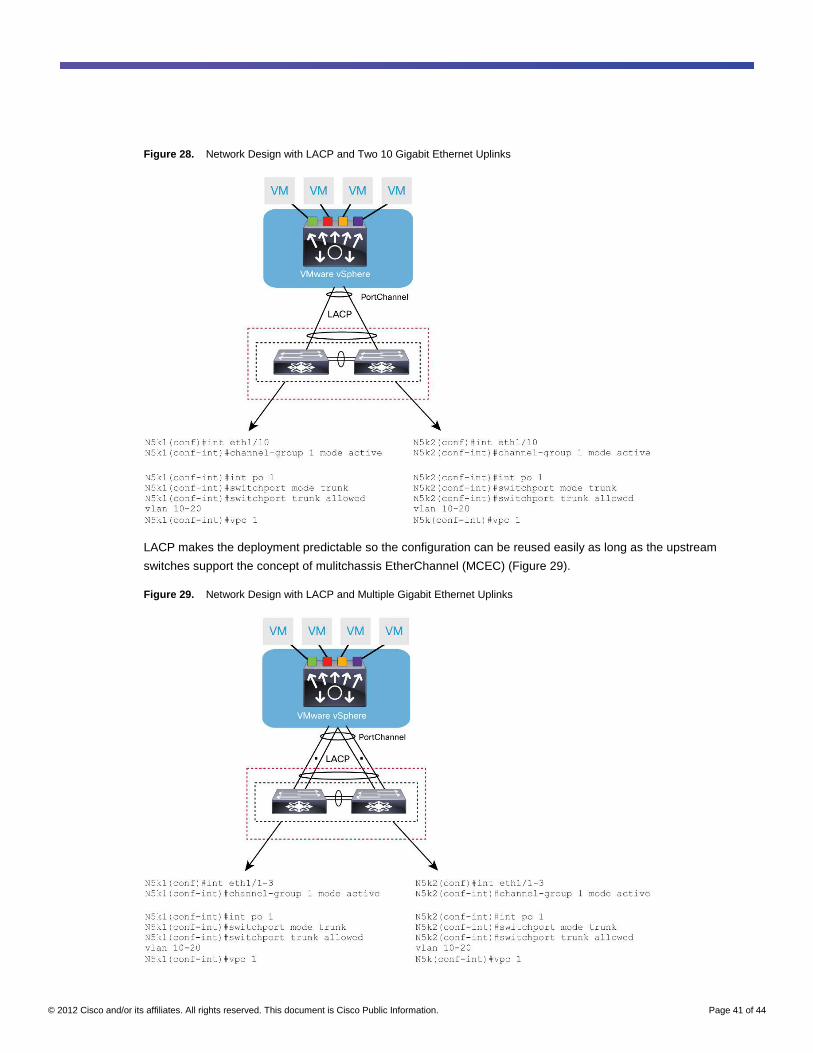
© 2012 Cisco and/or its affiliates. All rights reserved. This document is Cisco Public Information. Page 41 of 44
Figure 28. Network Design with LACP and Two 10 Gigabit Ethernet Uplinks
LACP makes the deployment predictable so the configuration can be reused easily as long as the upstream
switches support the concept of mulitchassis EtherChannel (MCEC) (Figure 29).
Figure 29. Network Design with LACP and Multiple Gigabit Ethernet Uplinks
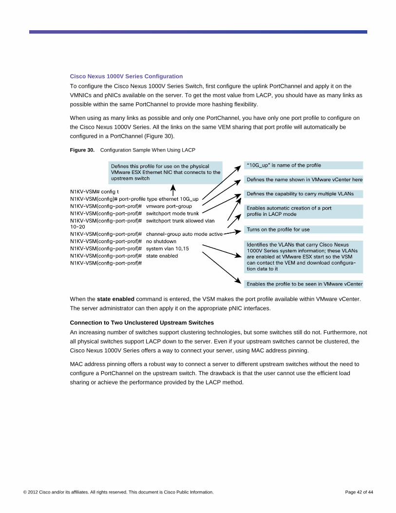
© 2012 Cisco and/or its affiliates. All rights reserved. This document is Cisco Public Information. Page 42 of 44
Cisco Nexus 1000V Series Configuration
To configure the Cisco Nexus 1000V Series Switch, first configure the uplink PortChannel and apply it on the
VMNICs and pNICs available on the server. To get the most value from LACP, you should have as many links as
possible within the same PortChannel to provide more hashing flexibility.
When using as many links as possible and only one PortChannel, you have only one port profile to configure on
the Cisco Nexus 1000V Series. All the links on the same VEM sharing that port profile will automatically be
configured in a PortChannel (Figure 30).
Figure 30. Configuration Sample When Using LACP
When the state enabled command is entered, the VSM makes the port profile available within VMware vCenter.
The server administrator can then apply it on the appropriate pNIC interfaces.
Connection to Two Unclustered Upstream Switches
An increasing number of switches support clustering technologies, but some switches still do not. Furthermore, not
all physical switches support LACP down to the server. Even if your upstream switches cannot be clustered, the
Cisco Nexus 1000V Series offers a way to connect your server, using MAC address pinning.
MAC address pinning offers a robust way to connect a server to different upstream switches without the need to
configure a PortChannel on the upstream switch. The drawback is that the user cannot use the efficient load
sharing or achieve the performance provided by the LACP method.
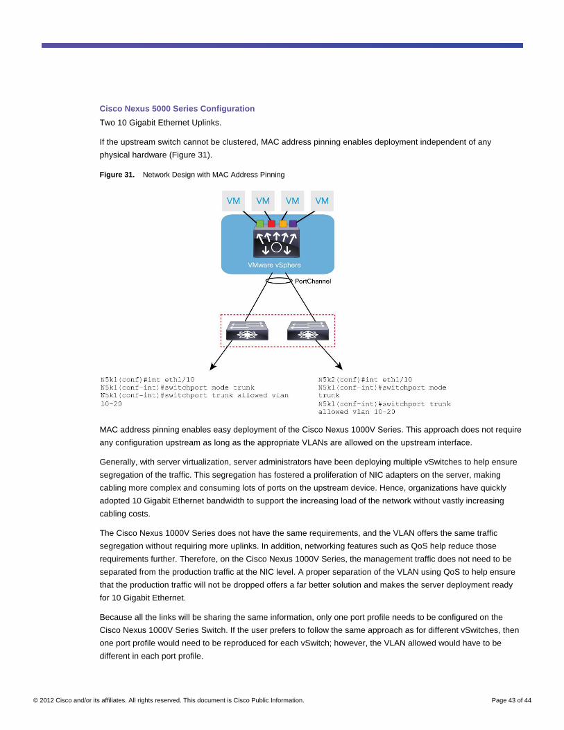
© 2012 Cisco and/or its affiliates. All rights reserved. This document is Cisco Public Information. Page 43 of 44
Cisco Nexus 5000 Series Configuration
Two 10 Gigabit Ethernet Uplinks.
If the upstream switch cannot be clustered, MAC address pinning enables deployment independent of any
physical hardware (Figure 31).
Figure 31. Network Design with MAC Address Pinning
MAC address pinning enables easy deployment of the Cisco Nexus 1000V Series. This approach does not require
any configuration upstream as long as the appropriate VLANs are allowed on the upstream interface.
Generally, with server virtualization, server administrators have been deploying multiple vSwitches to help ensure
segregation of the traffic. This segregation has fostered a proliferation of NIC adapters on the server, making
cabling more complex and consuming lots of ports on the upstream device. Hence, organizations have quickly
adopted 10 Gigabit Ethernet bandwidth to support the increasing load of the network without vastly increasing
cabling costs.
The Cisco Nexus 1000V Series does not have the same requirements, and the VLAN offers the same traffic
segregation without requiring more uplinks. In addition, networking features such as QoS help reduce those
requirements further. Therefore, on the Cisco Nexus 1000V Series, the management traffic does not need to be
separated from the production traffic at the NIC level. A proper separation of the VLAN using QoS to help ensure
that the production traffic will not be dropped offers a far better solution and makes the server deployment ready
for 10 Gigabit Ethernet.
Because all the links will be sharing the same information, only one port profile needs to be configured on the
Cisco Nexus 1000V Series Switch. If the user prefers to follow the same approach as for different vSwitches, then
one port profile would need to be reproduced for each vSwitch; however, the VLAN allowed would have to be
different in each port profile.
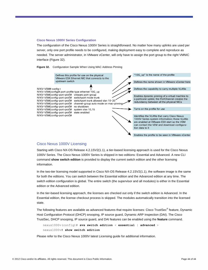
© 2012 Cisco and/or its affiliates. All rights reserved. This document is Cisco Public Information. Page 44 of 44
Cisco Nexus 1000V Series Configuration
The configuration of the Cisco Nexus 1000V Series is straightforward. No matter how many uplinks are used per
server, only one port profile needs to be configured, making deployment easy to complete and reproduce as
needed. The server administrator, in VMware vCenter, will only have to assign the port group to the right VMNIC
interface (Figure 32).
Figure 32. Configuration Sample When Using MAC Address Pinning
Cisco Nexus 1000V Licensing
Starting with Cisco NX-OS Release 4.2.1SV2(1.1), a tier-based licensing approach is used for the Cisco Nexus
1000V Series. The Cisco Nexus 1000V Series is shipped in two editions: Essential and Advanced. A new CLI
command show switch edition is provided to display the current switch edition and the other licensing
information.
In the two-tier licensing model supported in Cisco NX-OS Release 4.2.1SV2(1.1), the software image is the same
for both the editions. You can switch between the Essential edition and the Advanced edition at any time. The
switch edition configuration is global. The entire switch (the supervisor and all modules) is either in the Essential
edition or the Advanced edition.
In the tier-based licensing approach, the licenses are checked out only if the switch edition is Advanced. In the
Essential edition, the license checkout process is skipped. The modules automatically transition into the licensed
state.
The following features are available as advanced features that require licenses: Cisco TrustSec® feature, Dynamic
Host Configuration Protocol (DHCP) snooping, IP source guard, Dynamic ARP Inspection (DAI). The Cisco
TrustSec, DHCP snooping, IP source guard, and DAI features can be enabled using the feature command.
nexus1000v(config)# svs switch edition < essential | advanced >
nexus1000v# show switch edition
Please refer to the Cisco Nexus 1000V latest Licensing guide for additional information.
© 2012 Cisco and/or its affiliates. All rights reserved. This document is Cisco Public Information. Page 45 of 44
Conclusion
Cisco Nexus 1000V Series Switches integrate into the expanding virtualized data center, providing secure,
nondisruptive, policy-based enhanced networking features and visibility for the networking team into the server
virtualization environment. The comprehensive feature set of the Cisco Nexus 1000V Series allows the networking
team to troubleshoot more rapidly any problems in the server virtualization environment, increasing the uptime of
virtual machines and protecting the applications that propel the data center.
For More Information
For more information about the Cisco Nexus 1000V Series, please refer to the following:
● Cisco Nexus 1000V Series product information: http://www.cisco.com/go/1000v.
● Cisco Nexus 1000V Series technical documentation:
http://www.cisco.com/en/US/products/ps9902/prod_white_papers_list.html.
● Cisco Nexus 1000V Series community:
https://communities.cisco.com/community/technology/datacenter/nexus1000v.
Printed in USA C07-556626-04 11/12