Embed Size (px)
Citation preview

Cisco Firepower 2100 Series Hardware Installation GuideFirst Published: 2017-05-25
Last Modified: 2019-09-30
Americas HeadquartersCisco Systems, Inc.170 West Tasman DriveSan Jose, CA 95134-1706USAhttp://www.cisco.comTel: 408 526-4000
800 553-NETS (6387)Fax: 408 527-0883

THE SPECIFICATIONS AND INFORMATION REGARDING THE PRODUCTS IN THIS MANUAL ARE SUBJECT TO CHANGE WITHOUT NOTICE. ALL STATEMENTS,INFORMATION, AND RECOMMENDATIONS IN THIS MANUAL ARE BELIEVED TO BE ACCURATE BUT ARE PRESENTED WITHOUT WARRANTY OF ANY KIND,EXPRESS OR IMPLIED. USERS MUST TAKE FULL RESPONSIBILITY FOR THEIR APPLICATION OF ANY PRODUCTS.
THE SOFTWARE LICENSE AND LIMITED WARRANTY FOR THE ACCOMPANYING PRODUCT ARE SET FORTH IN THE INFORMATION PACKET THAT SHIPPED WITHTHE PRODUCT AND ARE INCORPORATED HEREIN BY THIS REFERENCE. IF YOU ARE UNABLE TO LOCATE THE SOFTWARE LICENSE OR LIMITED WARRANTY,CONTACT YOUR CISCO REPRESENTATIVE FOR A COPY.
The Cisco implementation of TCP header compression is an adaptation of a program developed by the University of California, Berkeley (UCB) as part of UCB's public domain version ofthe UNIX operating system. All rights reserved. Copyright © 1981, Regents of the University of California.
NOTWITHSTANDING ANY OTHERWARRANTY HEREIN, ALL DOCUMENT FILES AND SOFTWARE OF THESE SUPPLIERS ARE PROVIDED “AS IS" WITH ALL FAULTS.CISCO AND THE ABOVE-NAMED SUPPLIERS DISCLAIM ALL WARRANTIES, EXPRESSED OR IMPLIED, INCLUDING, WITHOUT LIMITATION, THOSE OFMERCHANTABILITY, FITNESS FOR A PARTICULAR PURPOSE AND NONINFRINGEMENT OR ARISING FROM A COURSE OF DEALING, USAGE, OR TRADE PRACTICE.
IN NO EVENT SHALL CISCO OR ITS SUPPLIERS BE LIABLE FOR ANY INDIRECT, SPECIAL, CONSEQUENTIAL, OR INCIDENTAL DAMAGES, INCLUDING, WITHOUTLIMITATION, LOST PROFITS OR LOSS OR DAMAGE TO DATA ARISING OUT OF THE USE OR INABILITY TO USE THIS MANUAL, EVEN IF CISCO OR ITS SUPPLIERSHAVE BEEN ADVISED OF THE POSSIBILITY OF SUCH DAMAGES.
Cisco and the Cisco logo are trademarks or registered trademarks of Cisco and/or its affiliates in the U.S. and other countries. To view a list of Cisco trademarks, go to this URL: www.cisco.comgo trademarks. Third-party trademarks mentioned are the property of their respective owners. The use of the word partner does not imply a partnership relationship between Cisco and anyother company. (1721R)
Any Internet Protocol (IP) addresses used in this document are not intended to be actual addresses. Any examples, command display output, and figures included in the document are shownfor illustrative purposes only. Any use of actual IP addresses in illustrative content is unintentional and coincidental.
© 2011 Cisco Systems, Inc. All rights reserved.
© 2017-2019 Cisco Systems, Inc. All rights reserved.

C O N T E N T S
Overview 1C H A P T E R 1
Features 1
Deployment Options 4
Package Contents 4
Serial Number Location 6
Front Panel 7
Front Panel LEDs 10
Rear Panel 14
Network Modules 16
10-Gb Network Module 16
1-Gb Network Module 17
Hardware Bypass Network Modules 18
1-Gb SX/10-Gb SR/10-Gb LR Network Module with Hardware Bypass 20
1-Gb Network Module with Hardware Bypass 22
Power Supply Modules 23
Fan Modules 26
SSDs 26
Supported SFP/SFP+ Transceivers 27
Hardware Specifications 30
Product ID Numbers 31
Power Cord Specifications 33
Installation Preparation 39C H A P T E R 2
Installation Warnings 39
Safety Recommendations 42
Maintain Safety with Electricity 42
Cisco Firepower 2100 Series Hardware Installation Guideiii

Prevent ESD Damage 43
Site Environment 43
Site Considerations 43
Power Supply Considerations 44
Rack Configuration Considerations 44
Mount the Chassis 45C H A P T E R 3
Unpack and Inspect the Chassis 45
Rack-Mount the Chassis 46
Rack-Mount the Chassis Using Slide Rails 48
Ground the Chassis 54
Maintenance and Upgrade 57C H A P T E R 4
Remove and Replace the Network Module 57
Remove and Replace the SSD 58
Remove and Replace the Power Supply Module 60
Connect the DC Power Supply Module 62
Secure the Power Cord on the Power Supply Module 66
Remove and Replace the Fan Tray 68
Cisco Firepower 2100 Series Hardware Installation Guideiv
Contents

C H A P T E R 1Overview
• Features, on page 1• Deployment Options, on page 4• Package Contents, on page 4• Serial Number Location, on page 6• Front Panel, on page 7• Front Panel LEDs, on page 10• Rear Panel, on page 14• Network Modules, on page 16• Hardware Bypass Network Modules, on page 18• Power Supply Modules, on page 23• Fan Modules, on page 26• SSDs, on page 26• Supported SFP/SFP+ Transceivers, on page 27• Hardware Specifications, on page 30• Product ID Numbers, on page 31• Power Cord Specifications, on page 33
FeaturesThe Cisco Firepower 2100 series security appliance is a standalone modular security services platform. Theseries includes the Firepower 2110, 2120, 2130, and 2140. See Product ID Numbers, on page 31 for a list ofthe product IDs (PIDs) associated with the 2100 series.
The Firepower 2100 series supports Cisco Firepower Threat Defense and Cisco ASA software. See the CiscoFirepower Compatibility Guide, which provides Cisco Firepower software and hardware compatibility,including operating system and hosting environment requirements, for each supported Firepower version.
The Firepower 2100 is certified for the following security standards on ASA 9.8.x and FTD 6.2.x:
• Common Criteria (CC)
• Federal Information Processing Standards (FIPS)
• Department of Defense Information Network Approved Product List (DoDIN APL)
• US Government Compliance for IPv6 (USGv6)
Cisco Firepower 2100 Series Hardware Installation Guide1

The Firepower 2130 is Network Equipment Building Systems (NEBS)-certified.Note
Firepower 2110/2120 and Firepower 2130/2140
See the Cisco Interactive Library for a video that displays the features and components of the Firepower 2100.
The following table lists the features for the Firepower 2100 series.
Table 1: Firepower 2100 Series Features
2140213021202110Feature
1 RU
Fits standard 19-in. (48.3-cm) square-hole rack.
Form factor
4-post EIA-310-D rack
(Optional) Two 2--post mount brackets
Two 2-post mount brackets
(Optional) 4-post EIA-310-D rack
Rack mount
Front to rear
Cold aisle to hot aisle
Airflow
Single 16-core at 1.3G
Single 8-core at 2.0G
Single 6-core at 1.9G
Single 4-core at 1.8G
Intel x86 processor
64 GB DDR4DRAM
32 GB DDR4DRAM
16 GB DDR4 DRAMIntel x86 memory
Single 16-core at 1.8G
Single 12-core at 1.2G
Single 8-core at 1.2G
Single 6-core at 1.2G
Cavium NetworkProcessor Unit(NPU)
16G8 GCavium NPU RAM
8 G (nominal)Flash
2416Maximum numberof interfaces
1 Gigabit Ethernet (10 M/100 M/1 G Base-T)Management port
RJ-45 serial portConsole port
USB 2.0 Type A (500 mA)USB port
Cisco Firepower 2100 Series Hardware Installation Guide2
OverviewFeatures

2140213021202110Feature
12 fixed RJ-45 1 G/100 M/10 M ports (named Ethernet 1/1 through 1/12 )Network ports
Four fixed 1-G/10-G SFP+ portsFour fixed 1-G SFP portsSFP ports
Displays serial numberPullout asset card
On rear panelGrounding lug
On front panelLocator beacon
On rear panelPower switch
One
Not hot-swappable
NoNetwork moduleslots
• 8-port 1-Gigabit Ethernet SFP+
• 8-port 10-Gigabit Ethernet SFP+
• 8-port 1-Gigabit Ethernet copper withhardware bypass
• 6-port 1-Gigabit Ethernet SX fiberSFP+ (built-in) with hardware bypass
• 6-port 10-Gigabit Ethernet SR fiberSFP+ (built-in) with hardware bypass
• 6-port 10-Gigabit Ethernet LR fiberSFP+ (built-in) with hardware bypass
—Network modules
Two power supplyslots
Ships with two400-W AC powersupply modules
Hot-swappable
Two power supplyslots
Ships with one400-W AC powersupply modules
Hot-swappable
One fixed AC power supply moduleAC power supply
Yes (optional)NoDC power supply
YesNoRedundant power
One hot-swappable fan tray with four fansFour fixed fans
Internal component only; notfield-replaceable
Fan
Cisco Firepower 2100 Series Hardware Installation Guide3
OverviewFeatures

2140213021202110Feature
Two SSD slots (200 GB )
Ships with one 200-GB SSD installed inslot 1
Slot 2 is reserved for the MSP.
Two SSD slots (100 GB )
Ships with one 100-GB SSD installed inslot 1
Slot 2 is reserved for the Malware StoragePack (MSP).
Storage
Installed in SSD slot 2MSP
Deployment OptionsHere are some examples of how you can deploy the Firepower 2100:
• As a firewall:
• At the enterprise Internet edge deployed in a high availability configuration
• At branch offices in either a high availability pair or standalone
• As a device that provides additional application control, URL filtering, or IPS/threat-centric capabilities:
• Behind an enterprise internet edge firewall in an inline in a transparent bump-in-the-wire configurationor as a standalone (requires hardware fail open network module support)
• Deployed passively off a SPAN port on a switch or a tap on a network, or standalone
• As a VPN device:
• For remote access VPN
• For site-to-site VPN
Package ContentsThe following figure shows the package contents for the Firepower 2110 and 2120. The contents are subjectto change and your exact contents will contain additional or fewer items depending on whether you order theoptional parts. See Product ID Numbers, on page 31 for a list of the PIDs associated with the 2110 and 2120package contents.
Cisco Firepower 2100 Series Hardware Installation Guide4
OverviewDeployment Options

Figure 1: Firepower 2110 and 2120 Package Contents
Blue console cable PC terminal adapter2Firepower 2110 or 2120 chassis1
SFP transceiver
(Optional; in package if ordered)
4One power cord (country-specific)3
One ground lug kit
#6 AWG lug, two 10-32 x .38-in. screws
6Two rack-mount brackets and six 8-32, 0.281-in.screws
5
Start Here: Cisco Firepower 2100
This document describes how to cable and set upyour Firepower 2100 and provides links to thedocuments you need to configure it.
8Cable management bracket kit
Two cable management brackets and four 8-32 x0.375-in. screws
(Optional; in package if ordered)
7
Rack-mount screws:
• Four 12-24, 0.75 in.
• Four 10-32, 0.75 in.
• Four M6, 19 mm
9
The following figure shows the package contents for the Firepower 2130 and 2140. The contents are subjectto change and your exact contents will contain additional or fewer items depending on whether you order theoptional parts. See Product ID Numbers, on page 31 for a list of the product IDs (PIDs) associated with the2130 and 2140 package contents.
Cisco Firepower 2100 Series Hardware Installation Guide5
OverviewPackage Contents

Figure 2: Firepower 2130 and 2140 Package Contents
Blue console cable PC terminal adapter2Firepower 2130 or 2140 chassis1
SFP transceiver
(Optional; in package if ordered)
4One or two power cords (country-specific)3
Six 8-32 x .25-in. slide rail locking bracket screws6Slide rail kit
Left and right slide rails and twoM3x6mmwaferhead screws
5
One ground lug kit
#6 AWG lug, two 10-32 x .38-in. screws
8Two slide rail locking brackets7
Start Here: Cisco Firepower 2100
This document describes how to cable and set upyour Firepower 2100 and provides links to thedocuments you need to configure it.
10Cable management bracket kit
Two cable management brackets and four 8-32 x0.375-in. screws
(Optional; in package if ordered)
9
Two power supply module tie wraps and clamps11
Serial Number LocationThe serial number for the Firepower 2100 series chassis is located on the pullout asset card on the front panel.
Cisco Firepower 2100 Series Hardware Installation Guide6
OverviewSerial Number Location

Figure 3: Serial Number on the Chassis
You can also view additional model information on the compliance label located on the bottom of the chassis.
Figure 4: Compliance Label on the Chassis
Front PanelThe following figure shows the front panel of the Firepower 2110 and 2120. See Front Panel LEDs, on page10 for a description of the LEDs.
Cisco Firepower 2100 Series Hardware Installation Guide7
OverviewFront Panel

Figure 5: Firepower 2110 and 2120 Front Panel
Gigabit Ethernet management port:
• Firepower Threat Defense—Management 0(also referred to as Management 1/1 andDiagnostic 1/1)
• ASA—Management 1/1
2Power LED1
SSD 1 (slot 1)412 RJ-45 1 G/100 M/10 M auto duplex/autoMDI-X Base-T ports
Ethernet 1/1 through 1/12 labeled top to bottom,left to right
3
System LEDs6Locator beacon5
RJ-45 console port8Type A USB 2.0 port7
Four fixed SFP (1 Gb) ports
Fiber ports 1/13 through 1/16 labeled left to right
10Pullout asset card with chassis serial number9
SSD (slot 2)11
The following figure shows the front panel of the Firepower 2130 and 2140. See Front Panel LEDs, on page10 for a description of the LEDs.
Figure 6: Firepower 2130 and 2140 Front Panel
Locator beacon2Power LED1
Cisco Firepower 2100 Series Hardware Installation Guide8
OverviewFront Panel

12 RJ-45 1 G/100 M/10 M auto duplex/autoMDI-X Base-T ports
Ethernet 1/1 through 1/12 labeled top to bottom,left to right
4Gigabit Ethernet management port:
• Firepower Threat Defense—Management 0(also referred to as Management 1/1 andDiagnostic 1/1)
• ASA—Management 1/1
3
SSD 26SSD 15
Type A USB 2.0 port8System LEDs7
Pullout asset card with chassis serial number10RJ-45 console port9
Network module (network module slot 1)12Four fixed SFP+ (1 Gb/10 Gb) ports
Fiber ports 1/13 through 1/16 labeled left to right
11
Management Port
The Firepower 2100 chassis has an RJ-45 copper management port.
RJ-45 Console Port
The Firepower 2100 chassis has a standard RJ-45 console port. You can use the CLI to configure your2100 through the RJ-45 serial console port by using a terminal server or a terminal emulation programon a computer.
The RJ-45 (8P8C) port supports RS-232 signaling to an internal UART controller. The console port doesnot have any hardware flow control, and does not support a remote dial-in modem. The baud rate is 9600.You can use the standard cable found in your accessory kit to convert the RJ-45 to DB-9 if necessary.
Type A USB Port
You can use the external Type A USB port to attach a data-storage device. The external USB driveidentifier is usbA:. The Type A USB port supports the following:
• Hot swapping
• USB drive formatted with FAT32
• Boot kickstart image from ROMMON for discovery recovery purposes
• Copy files to and from workspace:/ and volatile:/ within local-mgmt. The most relevant files are:
• Core files
• Ethanalyzer packet captures
• Tech-support files
• Security module log files
• Platform bundle image upload using download image usbA:
The Type A USB port does not support Cisco Secure Package (CSP) image upload support.
Cisco Firepower 2100 Series Hardware Installation Guide9
OverviewFront Panel

Network Ports
The Firepower 2100 chassis has 12 fixed RJ-45 1 G/100 M/10 M) ports. They are numbered from topto bottom, left to right starting with 1 and are named Ethernet 1/1 through Ethernet 1/12.
The 2110 and 2120 also have four fixed SFP (1 Gb) ports, and the 2130 and 2140 have four fixed SFP+(1 Gb/10 Gb) ports. They are fiber ports numbered left to right (1/13 through 1/16).
Each port has LEDs that represent Link/Activity status.
Front Panel LEDsThe following figure shows the Firepower 2110 and 2120 front panel LEDs.
Figure 7: Firepower 2110 and 2120 Front Panel LEDs
Locator Beacon
• Off—Locate is off.
• Blue—Locate is on.
The Locator beacon helps you locatea unit that needs physical serviceattention. This feature is activated inthe software.
Note
2PWR
• Off—Input power is not detected. Standbypower is off.
• Green, flashing—The system has detecteda power switch toggle event, and initiatedthe shutdown sequence. If the power switchis in the OFF position, the system powersoff after shutdown is completed. Do notremove the AC or DC power source whilethis LED is blinking so that the system hastime to perform a graceful shutdown.
• Amber—The system is powering up (beforethe BIOS boots). This takes one to fiveseconds at most.
• Green—The system is fully powered up.
1
Cisco Firepower 2100 Series Hardware Installation Guide10
OverviewFront Panel LEDs

ACT (Role of a high-availability pair)
• Off—The unit is not configured or enabledin a high-availability pair.
• Green—The unit is in active mode.
• Amber—The unit is in standby mode.
4SYS (Health)
• Off—The system has not booted up yet.
• Green, flashing—The system is booting upor in bootloader stage.
• Green—The system has fully booted.
• Amber—The system boot up has failed.
• Amber, flashing—Alarm condition, systemneeds service or attention and may not bootproperly.
3
SSD2 ACT
• Off—SSD is not present.
• Green—SSD is present; no activity.
• Green, flashing—SSD is active.
6SSD1 ACT
• Off—SSD is not present.
• Green—SSD is present; no activity.
• Green, flashing—SSD is active.
5
SSD1 Alert Status
• Off—SSD has normal activity.
• Amber—SSD failure.
8FAN
• Off—The environmental subsystem is notactive yet.
• Green—The fans are running normally. Itmay take up to one minute for the LEDstatus to turn green after power is on.
• Amber—One fan has failed. The system cancontinue to operate normally, but fan serviceis required.
• Amber, flashing—Two or more fans havefailed, or the fan tray has been removed fromthe system. Immediate attention is required.
7
Ethernet Link
• Green—The link partner is detected; noactivity.
• Green, flashing—Network activity isdetected.
10SSD2 Alert Status
• Off—SSD has normal activity.
• Amber—SSD failure.
9
Cisco Firepower 2100 Series Hardware Installation Guide11
OverviewFront Panel LEDs
Fiber Port
• Green—Port is enabled, the link partner isdetected.
• Amber—Port is enabled, but the link partneris not detected.
• Green, flashing—Port is enabled; networkactivity is detected.
12Ethernet Speed
• Green, flashing—The number of flashesdetermines link speed; 1 flash=10 Mbit,2=100 Mbit, 3=1 Gbit.
11
The following figure shows the Firepower 2130 and 2140 front panel LEDs.
Figure 8: Firepower 2130 and 2140 Front Panel LEDs
Locator LED
• Off—Locate is off.
• Blue—Locate is on.
The Locator beacon helps you locatea unit that needs physical serviceattention. This feature is activated inthe software.
Note
2Power
• Off—Input power is not detected. Standbypower is off.
• Green, flashing—The system has detecteda power switch toggle event, and initiatedthe shutdown sequence. If the power switchis in the OFF position, the system powersoff after shutdown is completed. Do notremove the AC or DC power source whilethis LED is blinking so that the system hastime to perform a graceful shutdown.
• Amber—The system is powering up (beforethe BIOS boots). This takes one to fiveseconds at most.
• Green—The system is fully powered up.
1
Cisco Firepower 2100 Series Hardware Installation Guide12
OverviewFront Panel LEDs

ACT (Role of a high-availability pair)
• Off—The unit is not configured or enabledin a high-availability pair.
• Green—The unit is in active mode.
• Amber—The unit is in standby mode.
4SYS (Health)
• Off—The system has not booted up yet.
• Green, flashing—The system is booting upor in bootloader stage.
• Green—The system has fully booted.
• Amber—The system boot up has failed.
• Amber, flashing—Alarm condition, systemneeds service or attention and may not bootproperly.
3
SSD2 ACT
• Off—The SSD is not present.
• Green—The SSD is present; no activity.
• Green, flashing—The SSD is active.
6SSD1 ACT
• Off—The SSD is not present.
• Green—The SSD is present; no activity.
• Green, flashing—The SSD is active.
5
PSU-2
• Off—The power supply module is notpresent or not detected.
• Green—The power supplymodule is presentand working properly.
• Amber—The power supply module ispresent but a fault or problem has beendetected.
8PSU-1
• Off—The power supply module is notpresent or not detected.
• Green—The power supplymodule is presentand working properly.
• Amber—The power supply module ispresent but a fault or problem has beendetected.
7
SSD1 Alert Status
• Off—SSD has normal activity.
• Amber—SSD failure.
10FAN
• Off—The environmental subsystem is notactive yet.
• Green—The fans are running normally. Itmay take up to one minute for the LEDstatus to turn green after power is on.
• Amber—One fan has failed. The system cancontinue to operate normally, but fan serviceis required.
• Amber, flashing—Two or more fans havefailed, or the fan tray has been removed fromthe system. Immediate attention is required.
9
Cisco Firepower 2100 Series Hardware Installation Guide13
OverviewFront Panel LEDs

Ethernet Link
• Green—The link partner is detected; noactivity.
• Green, flashing—Network activity isdetected.
12SSD2 Alert Status
• Off—SSD has normal activity.
• Amber—SSD failure.
11
Fiber Port
• Green—Port is enabled, the link partner isdetected.
• Amber—Port is enabled, but the link partneris not detected.
• Green, flashing—Port is enabled; networkactivity is detected.
14Ethernet Speed
• Green, flashing—The number of flashesdetermines link speed; 1 flash=10 Mbit,2=100 Mbit, 3=1 Gbit.
13
Rear PanelThe following figure shows the rear panel of the Firepower 2110 and 2120.
Figure 9: Firepower 2110 and 2120 Rear Panel
Fixed power supply module2Power on/off switch1
Two-post grounding lug
The two-post grounding lug isincluded in the accessory kit.
Note
4Fixed fans3
The following figure shows the rear panel of the Firepower 2130 and 2140.
Cisco Firepower 2100 Series Hardware Installation Guide14
OverviewRear Panel

Figure 10: Firepower 2130 and 2140 Rear Panel
Power supply module 1 FAIL LED2Power on/off switch1
Power supply module 14Power supply module 2 FAIL LED3
Fan tray6Power supply module 1 OK LED5
Power supply module 2 OK LED8Power supply module 27
Two-post grounding lug
The two-post grounding lug isincluded in the accessory kit.
Note
9
Power Switch
The power switch is located to the left of power supply module 1 on the rear of the chassis. It is a toggleswitch that controls power to the system. If the power switch is in standby position, only the 3.3-Vstandby power is enabled from the power supply module and the 12-V main power is OFF. When theswitch is in the ON position, the 12-V main power is turned on and the system boots.
Before you move the power switch to the OFF position, use the shutdown commands so that the systemcan perform a graceful shutdown. This may take several minutes to complete. After the graceful shutdownis complete, the console displays It is safe to power off now. The front panel blue locatorbeacon LED lights up indicating the system is ready to be powered off. You can now move the switchto the OFF position. The front panel PWR LED flashes momentarily and turns off.
See Front Panel LEDs, on page 10 for the PWR LED description. See the FXOS Configuration Guidefor more information on using the shutdown commands.
On the Firepower 2130 and 2140, the OK LEDs on the rear power supplies flash after the switch is turnedoff; this is expected behavior.
Note
If you move the power switch to the OFF position before the shutdown command sequence is completeor if you remove the system power cords before the graceful shutdown is complete, disk corruption canoccur.
Caution
Cisco Firepower 2100 Series Hardware Installation Guide15
OverviewRear Panel
After removing power from the chassis by unplugging the power cord, wait at least 10 seconds beforeturning power back ON.
Note
For More Information
• See Remove and Replace the Power Supply Module, on page 60 for the procedure for removing andreplacing the power supply module in the Firepower 2130 and 2140.
• See Remove and Replace the Fan Tray, on page 68 for the procedure for removing and replacing thefan tray in the Firepower 2130 and 2140.
• See Ground the Chassis, on page 54 for the procedure for using the grounding lug to ground the chassis.
• See Power Supply Modules, on page 23 for a description of the power supply module LEDs.
• See Front Panel LEDs, on page 10 for a description of the fan LEDs.
Network ModulesThe Firepower 2130 and 2140 contain one network module slot that provides optical or electrical networkinterfaces. Network modules are optional, removable I/O modules that provide either additional ports ordifferent interface types. The Firepower network module plugs into the chassis on the front panel.
For More Information
• See 10-Gb Network Module, on page 16 for a description of the 10-Gb network module.
• See 1-Gb Network Module, on page 17 for a description of the 1-Gb network module.
• See Supported SFP/SFP+ Transceivers, on page 27 for a list of supported SFPS.
• See Remove and Replace the Network Module, on page 57 for the procedure for removing and replacingnetwork modules.
10-Gb Network ModuleThe following figure shows the front panel of the 10-Gb network module (FPR2K-NM-8X10G). TheFPR2K-NM-8X10G is a single-wide module that supports hot swapping. The eight ports are numbered fromtop to bottom, left to right.
Make sure you have the correct firmware package and software version installed to support this networkmodule.
Note
The FPR2K-NM-8X10G is NEBS-compliant.Note
Cisco Firepower 2100 Series Hardware Installation Guide16
OverviewNetwork Modules

You can fit four copper SFPs in either the top row of ports or the bottom row of ports. Both rows cannot bepopulated at the same time, because of the port row spacing.
Note
Figure 11: FPR2K-NM-8X10G
Ethernet X/12Captive screw/handle1
Ethernet X/54Ethernet X/33
Ethernet X/26Ethernet X/75
Ethernet X/68Ethernet X/47
Network activity LEDs
• Off—No connection or port is not in use.
• Amber—No link or network failure.
• Green—Link up.
• Green, flashing—Network activity.
10Ethernet X/89
1-Gb Network ModuleThe following figure shows the front panel of the 1-Gb network module (FPR2K-NM-8X1G). TheFPR2K-NM-8X1G is a single-wide module that supports hot swapping. The eight ports are numbered fromtop to bottom, left to right.
Make sure you have the correct firmware package and software version installed to support this networkmodule.
Note
Cisco Firepower 2100 Series Hardware Installation Guide17
Overview1-Gb Network Module

You can fit four copper SFPs in either the top row of ports or the bottom row of ports. Both rows cannot bepopulated at the same time, because of the port row spacing. For a list of copper SFPS.
Note
Figure 12: FPR2K-NM-8X1G
Ethernet X/12Captive screw/handle1
Ethernet X/54Ethernet X/33
Ethernet X/26Ethernet X/75
Ethernet X/68Ethernet X/47
Network activity LEDs
• Unlit—No connection or port is not in use.
• Amber—No link or network failure.
• Green—Link up.
• Green, flashing—Network activity.
10Ethernet X/89
Hardware Bypass Network ModulesHardware bypass (also known as fail-to-wire) is a physical layer (Layer 1) bypass that allows paired interfacesto go into bypass mode so that the hardware forwards packets between these port pairs without softwareintervention. Hardware bypass provides network connectivity when there are software or hardware failures.Hardware bypass is useful on ports where the Firepower security appliance is only monitoring or loggingtraffic. The hardware bypass network modules have an optical switch that is capable of connecting the twoports when needed. The hardware bypass network modules have built-in SFPs.
Hardware bypass is supported only on a fixed set of ports. You can pair Port 1 with Port 2, Port 3 with Port4, but you cannot pair Port 1 with Port 4 for example.
Cisco Firepower 2100 Series Hardware Installation Guide18
OverviewHardware Bypass Network Modules
Hardware bypass is only supported in inline mode. Also, hardware bypass support depends on your softwareapplication.
Note
When the appliance switches from normal operation to hardware bypass or from hardware bypass back tonormal operation, traffic may be interrupted for several seconds. A number of factors can affect the length ofthe interruption; for example, behavior of the optical link partner such as how it handles link faults anddebounce timing; spanning tree protocol convergence; dynamic routing protocol convergence; and so on.During this time, you may experience dropped connections.
Note
There are three configuration options for hardware bypass network modules:
• Passive interfaces—Connection to a single port.
For each network segment you want to monitor passively, connect the cables to one interface. This ishow the nonhardware bypass network modules operate.
• Inline interfaces—Connection to any two like ports (10 Gb to 10 Gb for example) on one networkmodule,across network modules, or fixed ports.
For each network segment you want to monitor inline, connect the cables to pairs of interfaces.
• Inline with hardware bypass interfaces—Connection of a hardware bypass paired set.
For each network segment that you want to configure inline with fail-open, connect the cables to thepaired interface set.
For the 40-Gb network module, you connect the two ports to form a paired set. For the 1/10-Gb networkmodules, you connect the top port to the bottom port to form a hardware bypass paired set. This allowstraffic to flow even if the security appliance fails or loses power.
If you have an inline interface set with a mix of hardware bypass and nonhardware bypass interfaces, youcannot enable hardware bypass on this inline interface set. You can only enable hardware bypass on an inlineinterface set if all the pairs in the inline set are valid hardware bypass pairs.
Note
For More Information
• See 1-Gb SX/10-Gb SR/10-Gb LR Network Module with Hardware Bypass, on page 20 for adescription of the 1-G SX, 10-G SR, and LR network modules.
• See 1-Gb Network Module with Hardware Bypass, on page 22 for a description of the 1-G networkmodule.
• See Remove and Replace the Network Module, on page 57 for the procedure for removing andreplacing single-wide network modules.
Cisco Firepower 2100 Series Hardware Installation Guide19
OverviewHardware Bypass Network Modules

1-Gb SX/10-Gb SR/10-Gb LR Network Module with Hardware BypassThe following figure shows the front panel of the 1-Gb SX, 10-Gb SR and 10-Gb LR hardware bypass networkmodules FPR2K-NM-6X1SX-F, FPR2K-NM-6X10SR-F, FPR2K-NM-6X10LR-F). This is a single-widemodule that does not support hot swapping. The six ports are numbered from top to bottom, left to right. Pairports 1 and 2, 3 and 4, and 5 and 6 to form hardware bypass paired sets.
Make sure you have the correct firmware package and software version installed to support this networkmodule.
Note
Figure 13: FPR2K-NM-6X1SX-F, FPR2K-NM-6X10SR-F, FPR2K-NM-6X10LR-F
Six network activity LEDs
• Amber—No connection, or port is not in use,or no link or network failure.
• Green—Link up, no network activity.
• Green, flashing—Network activity.
2Captive screw/handle1
Ethernet X/1 (top port)
Ethernet X/2 (bottom port)
Ports 1 and 2 are paired together to form ahardware bypass pair.
4Bypass LEDs B1 through B3:
• Green—In standby mode.
• Amber, flashing—Port is in hardware bypassmode, failure event.
• Amber—Port is in hardware bypass mode,forced.
3
Ethernet X/5 (top port)
Ethernet X/6 (bottom port)
Ports 5 and 6 are paired together to form ahardware bypass pair.
6Ethernet X/3 (top port)
Ethernet X/4 (bottom port)
Ports 3 and 4 are paired together to form ahardware bypass pair.
5
Cisco Firepower 2100 Series Hardware Installation Guide20
Overview1-Gb SX/10-Gb SR/10-Gb LR Network Module with Hardware Bypass

The 1-Gb SX /10-Gb SR/10-Gb LR networkmodules have the following insertion loss measurements. Insertionloss measurements help you to troubleshoot the network by verifying cable installation and performance.
Table 2: 1-Gb SX Network Module (FPR2K-NM-6X1SX-F)
MaximumTypicalOperating Mode
1.4 dB
1.7 dB
0.9 dB
1.2 dB
Normal
Hardware bypass
Insertion loss
Cable distance
Half thedistancespecified bythe IEEEstandard.
Note
Modal bandwidth(MHz/km)
Core diameter (microns)
110 m
137 m
250 m
275 m
500 m
160 (FDDI)
200 (OM1)
400
500 (OM2)
2000 (OM3)
62.5
62.5
50
50
50
Cable and operatingdistance
Table 3: 10-Gb SR Network Module (FPR2K-NM-6X10SR-F)
MaximumTypicalOperating Mode
1.4 dB
1.7 dB
0.9 dB
1.2 dB
Normal
Hardware bypass
Insertion loss
Cable distance
Half thedistancespecified bythe IEEEstandard.
Note
Modal bandwidth(MHz/km)
Core diameter (microns)
13 m
16.5 m
33 m
41 m
150 m
200 m
160 (FDDI)
200 (OM1)
400
500 (OM2)
2000 (OM3)
4700 (OM4)
62.5
62.5
50
50
50
50
Cable and operatingdistance
Cisco Firepower 2100 Series Hardware Installation Guide21
Overview1-Gb SX/10-Gb SR/10-Gb LR Network Module with Hardware Bypass

Table 4: 10-Gb LR Network Module (FPR2K-NM-6X10LR-F)
MaximumTypicalOperating Mode
1.6 dB
1.9 dB
1.2 dB
1.5 dB
Normal
Hardware bypass
Insertion loss
Cable distance
Half thedistancespecified bythe IEEEstandard.
Note
Modal bandwidth(MHz/km)
Core diameter (microns)
5 kmSingle modeG.652Cable and operatingdistance
1-Gb Network Module with Hardware BypassThe following figure shows the front panel view of the 1-Gb network module with hardware bypass(FPR4K-NM-8X1G-F). Pair ports 1 and 2, 3 and 4, 5 and 6, and 7 and 8 to form hardware bypass paired sets.
Make sure you have the correct firmware package and software version installed to support this networkmodule.
Note
Figure 14: FPR-NM-8X1G-F
Cisco Firepower 2100 Series Hardware Installation Guide22
Overview1-Gb Network Module with Hardware Bypass

8 network activity LEDs
• Left LED—Green indicates network activitywhen a 10M/100M/1G connection is made.
• Right LED—Not in use at this time.
2Captive screw/handle1
Ethernet X/2
Ports 3 and 4 are paired together to form ahardware bypass pair. LED B2 applies to thispaired port.
4Ethernet X/1
Ports 1 and 2 are paired together to form ahardware bypass pair. LED B1 applies to thispaired port.
3
Ethernet X/2
Ports 7 and 8 are paired together to form ahardware bypass pair. LED B4 applies to thispaired port.
6Ethernet X/2
Ports 5 and 6 are paired together to form ahardware bypass pair. LED B3 applies to thispaired port.
5
Bypass LEDs B1 through B4
• Green—In standby mode.
• Amber, flashing—Port is in hardware bypassmode, failure event.
• Amber—Port is in hardware bypass mode,forced.
7
Power Supply ModulesThe Firepower 2110 and 2120 have one fixed AC power supply that is not field-replaceable. If the powersupply fails, you must get a return material authorization (RMA) for the entire chassis. See the Cisco ReturnsPortal for more information.
The Firepower 2130 and 2140 support two AC power supply modules so that dual power supply redundancyprotection is available. The Firepower 2130 ships with one AC power supply and the Firepower 2140 shipswith two AC power supplies. You can also install DC power supply modules instead of AC power on the2130 and 2140. Facing the back of the chassis, the power supply modules are numbered left to right, forexample, PSU1 and PSU2.
The power supply module is hot-swappable.
See Product ID Numbers, on page 31 for a list of the PIDs associated with the 2100 series power supplymodules.
You cannot mix AC and DC power supply modules in the chassis.Note
Cisco Firepower 2100 Series Hardware Installation Guide23
OverviewPower Supply Modules

After removing power from the chassis by unplugging the power cord, wait at least 10 seconds before turningpower back ON.
Note
Make sure that one power supply module is always active.Attention
The system power requirements are lower than the power supply module capabilities. See the following table.Note
AC Power Supply
The dual power supplies can supply up to 800-W power across the input voltage range. The load is sharedwhen both power supply modules are plugged in and running at the same time.
The system does not consume more than the capacity of one power supply module, so it will always operatein full redundancy mode (2130 and 2140 only) when two power supply modules are installed.
Note
Table 5: AC Power Supply Module Hardware Specifications
2140213021202110
100 to 240 V ACInput voltage
< 6 A< 4 AMaximum inputcurrent
400 W250 WMaximum outputpower
50 to 60 HzFrequency
89% at 50% load85% at 50% loadEfficiency
800W—Maximumredundancy outputpower
1+1 redundancy with dual power supplymodules
—Redundancy
DC Power Supply
The power supplies can supply up to 350 W power across the input voltage range. The load is shared whenboth power supply modules are plugged in and running at the same time.
Cisco Firepower 2100 Series Hardware Installation Guide24
OverviewPower Supply Modules
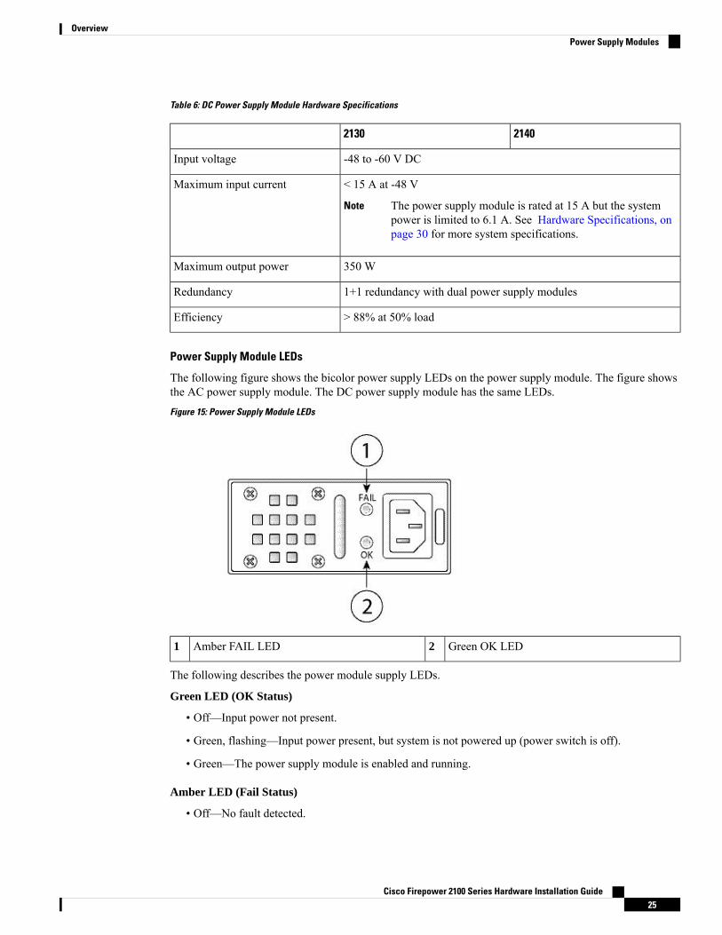
Table 6: DC Power Supply Module Hardware Specifications
21402130
-48 to -60 V DCInput voltage
< 15 A at -48 V
The power supply module is rated at 15 A but the systempower is limited to 6.1 A. See Hardware Specifications, onpage 30 for more system specifications.
Note
Maximum input current
350 WMaximum output power
1+1 redundancy with dual power supply modulesRedundancy
> 88% at 50% loadEfficiency
Power Supply Module LEDs
The following figure shows the bicolor power supply LEDs on the power supply module. The figure showsthe AC power supply module. The DC power supply module has the same LEDs.
Figure 15: Power Supply Module LEDs
Green OK LED2Amber FAIL LED1
The following describes the power module supply LEDs.
Green LED (OK Status)
• Off—Input power not present.
• Green, flashing—Input power present, but system is not powered up (power switch is off).
• Green—The power supply module is enabled and running.
Amber LED (Fail Status)
• Off—No fault detected.
Cisco Firepower 2100 Series Hardware Installation Guide25
OverviewPower Supply Modules

• Amber, flashing—Fault warning, power supply may still work but could fail due to high temperature,failing fan, or over current.
• Amber—Fault detected; power supply not working properly. Includes over voltage, over current, overtemperature, and fan failure.
For More Information
• See Remove and Replace the Power Supply Module, on page 60 for the procedure for removing andreplacing the power supply module in the Firepower 2130 and 2140.
Fan ModulesThe Firepower 2110 and 2120 have four fixed fans. If the fans fail, you must send your 2110 or 2120 forRMA.
The Firepower 2130 and 2140 have a removable fan tray with 3 + 1 redundant fans that are hot-swappable.The fan tray is installed in the rear of the chassis. Any one fan can fail indefinitely and the system continuesto function. When a fan fails, the remaining fans automatically spin up to full speed.
The fan LED is located on the front of the chassis. See Product ID Numbers, on page 31 for a list of the PIDsassociated with the 2100 series fans.
For More Information
• See Front Panel LEDs, on page 10 for the location and description of the fan LED.
• See Remove and Replace the Fan Tray, on page 68 for the procedure for removing and replacing thefan tray.
SSDsThe Firepower 2110 and 2120 have two SSD slots. These models ship with one 100-GB SSD installed in slot1. The Firepower 2130 and 2140 have two SSD slots. These models ship with one 200-GB SSD installed inslot 1. See Product ID Numbers, on page 31 for a list of the PIDs associated with the 2100 series SSDs. TheSSD drive identifiers are disk1 and disk2.
You can use the second SSD slot to upgrade to the MSP. The MSP must be installed in the second slot. Thesecond SSD slot remains empty unless you install theMSP in the second slot. TheMSP stores threat detectionresults for use in future analysis. It supports the Advanced Malware Protection (AMP) software feature. It isused as both storage and as the Malware application repository. RAID is not supported.
You cannot swap SSDs between different Firepower platforms. For example, you cannot use a 4100 seriesSSD in a 2100 series security appliance.
Caution
The 100-GB SSD is restricted to the 2110 and 2120 models. The 200-GB SSD is restricted to the 2130 and2140 models. Do not mix them.
Note
Cisco Firepower 2100 Series Hardware Installation Guide26
OverviewFan Modules

Although the hardware supports hot swapping for the SSDs, the software does not, so you must power downthe chassis before removing and replacing them.
For More Information
• See Front Panel LEDs, on page 10 for the location and description of the SSD LEDs on the front panel.
• See Remove and Replace the SSD, on page 58 for the procedure for removing and replacing the SSD.
Supported SFP/SFP+ TransceiversTake note of the following warnings:
Statement 1055—Class 1/1M Laser
Warning – Invisible Laser Radiation. Do not expose users of telescopic optics. Class 1/1M Laser Products.
Warning
Statement 1056—Unterminated Fiber Cable
Invisible laser radiation may be emitted from the end of the unterminated fiber cable or connector. Do notview directly with optical instruments. Viewing the laser output with certain optical instruments (for example,eye loupes, magnifiers, and microscopes) within a distance of 100 mm may pose an eye hazard.
Warning
Statement 1057—Hazardous Radiation Exposure
Use of controls or adjustments or performance of procedures other than those specified may result in hazardousradiation exposure.
Warning
The SFP/SFP+ transceiver is a bidirectional device with a transmitter and receiver in the same physicalpackage. It is a hot-swappable optical or electrical (copper) interface that plugs into the SFP/SFP+ ports onthe fixed ports and the network module ports, and provides Ethernet connectivity.
Cisco Firepower 2100 Series Hardware Installation Guide27
OverviewSupported SFP/SFP+ Transceivers

Figure 16: SFP Transceiver
Bail clasp2Dust plug1
Transmit optical bore4Receive optical bore3
Use appropriate ESD procedures when inserting the transceiver. Avoid touching the contacts at the rear, andkeep the contacts and ports free of dust and dirt. Keep unused transceivers in the ESD packing that they wereshipped in.
Warning
The 1-Gb transceivers are limited to 1-GB operation only (no auto-negotiation support). 100-M/10-M modesare not supported.
Note
Although non-Cisco SFPs are allowed, we do not recommend using them because they have not been testedand validated by Cisco. Cisco TAC may refuse support for any interoperability problems that result fromusing an untested third-party SFP transceiver.
Caution
The following table lists the supported transceivers.
Table 7: Supported SFPs
Ports SupportedPIDOptics Type
SFP 1Gb
Cisco Firepower 2100 Series Hardware Installation Guide28
OverviewSupported SFP/SFP+ Transceivers
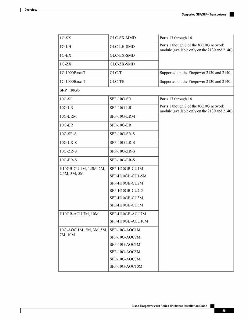
Ports 13 through 16
Ports 1 though 8 of the 8X10G networkmodule (available only on the 2130 and 2140)
GLC-SX-MMD1G-SX
GLC-LH-SMD1G-LH
GLC-EX-SMD1G-EX
GLC-ZX-SMD1G-ZX
Supported on the Firepower 2130 and 2140.GLC-T1G 1000Base-T
Supported on the Firepower 2130 and 2140.GLC-TE1G 1000Base-T
SFP+ 10Gb
Ports 13 through 16
Ports 1 though 8 of the 8X10G networkmodule (available only on the 2130 and 2140)
SFP-10G-SR10G-SR
SFP-10G-LR10G-LR
SFP-10G-LRM10G-LRM
SFP-10G-ER10G-ER
SFP-10G-SR-S10G-SR-S
SFP-10G-LR-S10G-LR-S
SFP-10G-ZR-S10G-ZR-S
SFP-10G-ER-S10G-ER-S
SFP-H10GB-CU1M
SFP-H10GB-CU1-5M
SFP-H10GB-CU2M
SFP-H10GB-CU2-5
SFP-H10GB-CU3M
SFP-H10GB-CU5M
H10GB-CU 1M, 1.5M, 2M,2.5M, 3M, 5M
SFP-H10GB-ACU7M
SFP-H10GB-ACU10M
H10GB-ACU 7M, 10M
SFP-10G-AOC1M
SFP-10G-AOC2M
SFP-10G-AOC3M
SFP-10G-AOC5M
SFP-10G-AOC7M
SFP-10G-AOC10M
10G-AOC 1M, 2M, 3M, 5M,7M, 10M
Cisco Firepower 2100 Series Hardware Installation Guide29
OverviewSupported SFP/SFP+ Transceivers

Hardware SpecificationsThe following table contains hardware specifications for the Firepower 2100 series security appliance.
2140213021202110Specification
1.73 x 16.90 x 19.76 in. (4.4 x 42.9 x 50.2 cm)Chassis dimensions(H x W x D)
1.2 x 3.7 x 9.6 in. (4.39 x 9.4 x 24.38)Network moduledimensions
21 lb (9.52 kg)19.4 lb (8.79 kg)16.1 lb (7.3 kg)Weight
100/240 V AC 2.9 A (at 100 VAC), 50 to60 Hz
The power supply module israted at 6.3 A, but the systempower is limited to 2.9 A.
Note
100/240V AC 1.9 A (at 100 VAC), 50 to60 Hz
The power supply module israted at 4 A, but the systempower is limited to 1.9 A.
Note
System power
Operating: 32 to 104°F (0 to 40°C)
Nonoperating: -40 to 149°F (-40 to 65°C) maximum altitude is 40,000 ft
Temperature
Operating altitude: 0 to 13,000 ft (3962 m)
Operating temperature:
• Long Term: 0 to 45°C up to 6000 ft (1829 m)
• Long Term: 0 to 35°C 6000-13000 ft (1829-3964 m)
• Short Term: -5 to 55°C up to 6000 ft (1829 m)
Firepower 2100 series NEBS compliance applies only to the 2130.Note
NEBS
Operating: 10 to 85 % noncondensing
Nonoperating: 5 to 95 % noncondensing
Humidity
Operating: 10,000 ft maximum
Nonoperating: 40,000 ft maximum
Altitude
55.7 dBA (typical)
76.7 dBA (maximum)
47.3 dBA (typical)
73.4 dBA (maximum)
Sound pressure
66 (typical)
84.5 (maximum)
60.2 (typical)
85.1 (maximum)
Sound power
Cisco Firepower 2100 Series Hardware Installation Guide30
OverviewHardware Specifications

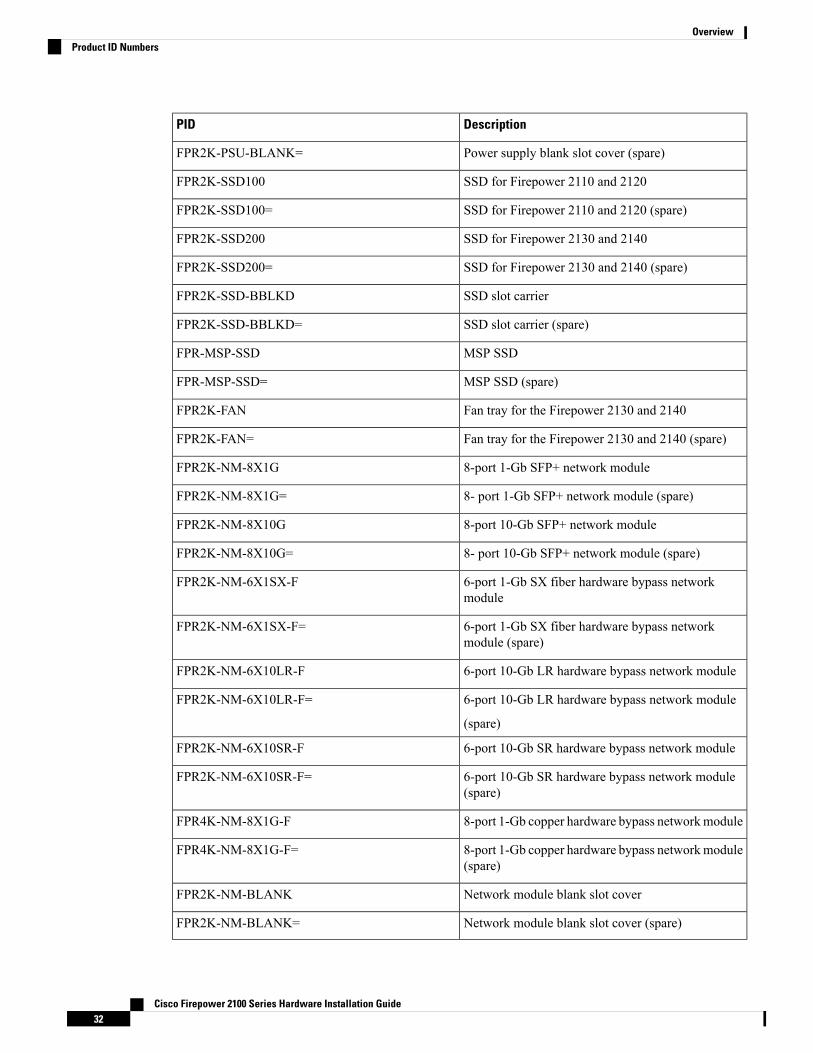
Product ID NumbersThe following table lists the PIDs associated with the Firepower 2100 series. All of the PIDs in the table arefield-replaceable. See the show inventory and show inventory expand commands in the Cisco FXOSTroubleshooting Guide for the Firepower 2100 Series to display a list of the PIDs for your Firepower 2100.Or see the show inventory command in the Cisco Firepower Threat Defense Command Reference or theCisco ASA Series Command Reference to display a list of the PIDs for your Firepower 2100.
Table 8: Firepower 2100 Series PIDs
DescriptionPID
Cisco Firepower 2110 NGFW appliance 1 RUFPR2110-NGFW-K9
Cisco Firepower 2120 NGFW appliance 1 RUFPR2120-NGFW-K9
Cisco Firepower 2130 NGFW appliance 1 RU withone network module bay
FPR2130-NGFW-K9
Cisco Firepower 2140 NGFW appliance 1 RU withone network module bay
FPR2140-NGFW-K9
Cisco Firepower 2110 ASA appliance 1 RUFPR2110-ASA-K9
Cisco Firepower 2120 ASA appliance 1 RUFPR2120-ASA-K9
Cisco Firepower 2130 ASA appliance 1 RU with onenetwork module bay
FPR2130-ASA-K9
Cisco Firepower 2140 ASA appliance 1 RU with onenetwork module bay
FPR2140-ASA-K9
Firepower 2110 appliance 1 RUwith no power supplyor fan (spare)
FPR2110-K9=
Firepower 2120 appliance 1 RUwith no power supplyor fan (spare)
FPR2120-K9=
Firepower 2130 appliance with one network modulebay and no power supply or fan (spare)
FPR2130-K9=
Firepower 2140 appliance with one network modulebay and no power supply or fan (spare)
FPR2140-K9=
350 W DC power supplyFPR2K-PWR-DC-350
350 W DC power supply (spare)FPR2K-PWR-DC-350=
400 W AC power supplyFPR2K-PWR-AC-400
400 W AC power supply (spare)FPR2K-PWR-AC-400=
Power supply blank slot coverFPR2K-PSU-BLANK
Cisco Firepower 2100 Series Hardware Installation Guide31
OverviewProduct ID Numbers
DescriptionPID
Power supply blank slot cover (spare)FPR2K-PSU-BLANK=
SSD for Firepower 2110 and 2120FPR2K-SSD100
SSD for Firepower 2110 and 2120 (spare)FPR2K-SSD100=
SSD for Firepower 2130 and 2140FPR2K-SSD200
SSD for Firepower 2130 and 2140 (spare)FPR2K-SSD200=
SSD slot carrierFPR2K-SSD-BBLKD
SSD slot carrier (spare)FPR2K-SSD-BBLKD=
MSP SSDFPR-MSP-SSD
MSP SSD (spare)FPR-MSP-SSD=
Fan tray for the Firepower 2130 and 2140FPR2K-FAN
Fan tray for the Firepower 2130 and 2140 (spare)FPR2K-FAN=
8-port 1-Gb SFP+ network moduleFPR2K-NM-8X1G
8- port 1-Gb SFP+ network module (spare)FPR2K-NM-8X1G=
8-port 10-Gb SFP+ network moduleFPR2K-NM-8X10G
8- port 10-Gb SFP+ network module (spare)FPR2K-NM-8X10G=
6-port 1-Gb SX fiber hardware bypass networkmodule
FPR2K-NM-6X1SX-F
6-port 1-Gb SX fiber hardware bypass networkmodule (spare)
FPR2K-NM-6X1SX-F=
6-port 10-Gb LR hardware bypass network moduleFPR2K-NM-6X10LR-F
6-port 10-Gb LR hardware bypass network module
(spare)
FPR2K-NM-6X10LR-F=
6-port 10-Gb SR hardware bypass network moduleFPR2K-NM-6X10SR-F
6-port 10-Gb SR hardware bypass network module(spare)
FPR2K-NM-6X10SR-F=
8-port 1-Gb copper hardware bypass networkmoduleFPR4K-NM-8X1G-F
8-port 1-Gb copper hardware bypass networkmodule(spare)
FPR4K-NM-8X1G-F=
Network module blank slot coverFPR2K-NM-BLANK
Network module blank slot cover (spare)FPR2K-NM-BLANK=
Cisco Firepower 2100 Series Hardware Installation Guide32
OverviewProduct ID Numbers

DescriptionPID
Cable management bracketsFPR2K-CBL-MGMT
Cable management brackets (spare)FPR2K-CBL-MGMT=
Rack-mount brackets (spare)FPR2K-RM-BRKT=
Slide rail kitFPR2K-SLIDE-RAILS
Slide rail kit (spare)FPR2K-SLIDE-RAILS=
Slide rail brackets (spare)FPR2K-RAIL-BRKT=
Power Cord SpecificationsEach power supply has a separate power cord. Standard power cords or jumper power cords are available forconnection to the security appliance. The jumper power cords for use in racks are available as an optionalalternative to the standard power cords.
If you do not order the optional power cord with the system, you are responsible for selecting the appropriatepower cord for the product. Using a incompatible power cord with this product may result in electrical safetyhazard. Orders delivered to Argentina, Brazil, and Japan must have the appropriate power cord ordered withthe system.
Only the approved power cords or jumper power cords provided with the security appliance are supported.Note
The following power cords are supported.
Figure 17: Argentina CAB-ACR
Cord set rating: 10 A, 250 V2Plug: IRAM 20731
Connector: IEC 60320/C133
Cisco Firepower 2100 Series Hardware Installation Guide33
OverviewPower Cord Specifications

Figure 18: Australia CAB-ACA
Cord set rating: 10 A, 250 V2Plug: A.S. 31121
Connector: IEC 60320/C133
Figure 19: Brazil CAB-C13-ACB
Cord set rating: 10 A, 250 V2Plug: NBR 141361
Connector: IEC 60320/C133
Figure 20: China CAB-ACC
Cord set rating: 10 A, 250 V2Plug: GB2099.1-2008/GB10021
Connector: IEC 60320/C133
Cisco Firepower 2100 Series Hardware Installation Guide34
OverviewPower Cord Specifications

Figure 21: Europe CAB-ACE
Cord set rating: 10 A, 250 V2Plug: CEE 7 VII1
Connector: IEC 60320/C133
Figure 22: India PWR-CORD-IND-D
Cord set rating: 10 A, 250 V2Plug: IS 6538-19711
Connector: IEC 60320/C133
Figure 23: Italy CAB-ACI
Cord set rating: 10 A, 250 V2Plug: CEI 23-161
Connector: IEC 60320/C133
Cisco Firepower 2100 Series Hardware Installation Guide35
OverviewPower Cord Specifications

Figure 24: Japan CAB-JPN
Cord set rating: 12 A, 125V
2Plug: JIS C83031
Connector: IEC 60320/C133
Figure 25: Japan CAB-JPN-3PIN
Cord set rating: 12 A, 125 V2Plug: JIS C8303/JIS C83061
Connector: IEC 60320/C133
Figure 26: Jumper CAB-C13-C14-2M
Cord set rating: 10 A, 250 V2IEC 60320/C14G1
Connector: IEC 60320/C133
Figure 27: Korea CAB-AC-C13-KOR
Cord set rating: 10 A, 250 V2Plug: KSC 83051
Cisco Firepower 2100 Series Hardware Installation Guide36
OverviewPower Cord Specifications
Connector: IEC 60320/C133
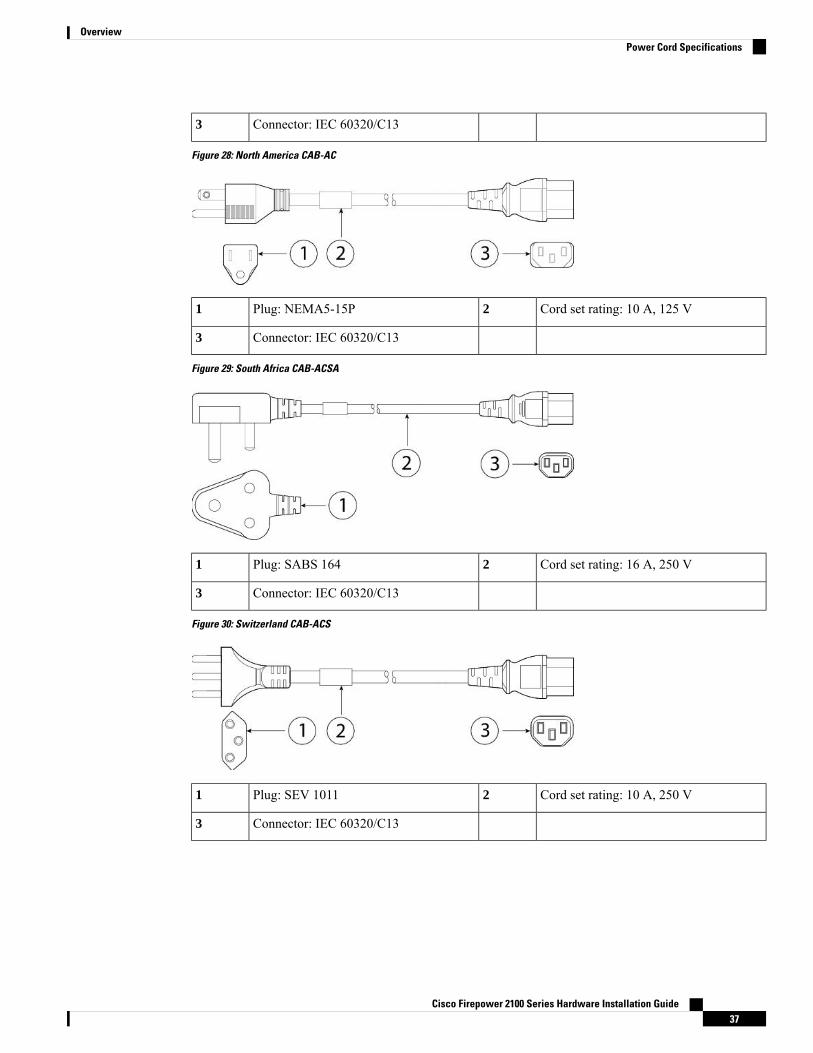
Figure 28: North America CAB-AC
Cord set rating: 10 A, 125 V2Plug: NEMA5-15P1
Connector: IEC 60320/C133
Figure 29: South Africa CAB-ACSA
Cord set rating: 16 A, 250 V2Plug: SABS 1641
Connector: IEC 60320/C133
Figure 30: Switzerland CAB-ACS
Cord set rating: 10 A, 250 V2Plug: SEV 10111
Connector: IEC 60320/C133
Cisco Firepower 2100 Series Hardware Installation Guide37
OverviewPower Cord Specifications

Figure 31: Taiwan CAB-ACTW
Cord set rating: 10 A, 125 V2Plug: CNS109171
Connector: IEC 60320/C133
Figure 32: United Kingdom CAB-ACU
Cord set rating: 10 A, 250 V2Plug: BS1363A/SS1451
Connector: IEC 60320/C133
Cisco Firepower 2100 Series Hardware Installation Guide38
OverviewPower Cord Specifications

C H A P T E R 2Installation Preparation
• Installation Warnings, on page 39• Safety Recommendations, on page 42• Maintain Safety with Electricity , on page 42• Prevent ESD Damage , on page 43• Site Environment , on page 43• Site Considerations, on page 43• Power Supply Considerations, on page 44• Rack Configuration Considerations, on page 44
Installation WarningsRead the Regulatory Compliance and Safety Information document before installing the security appliance.
Take note of the following warnings:
Statement 1071—Warning Definition
IMPORTANT SAFETY INSTRUCTIONS
This warning symbol means danger. You are in a situation that could cause bodily injury. Before you workon any equipment, be aware of the hazards involved with electrical circuitry and be familiar with standardpractices for preventing accidents. Use the statement number provided at the end of each warning to locateits translation in the translated safety warnings that accompanied this device.
SAVE THESE INSTRUCTIONS
Warning
Cisco Firepower 2100 Series Hardware Installation Guide39

<!--rcsi-show-stmt-number-->Statement 1015—Battery Handling
To reduce risk of fire, explosion or leakage of flammable liquid or gas,
• Replace the battery only with the same or equivalent type recommended by the manufacturer.
• Do not dismantle, crush, puncture, use sharp tool to remove, short external contacts, or dispose of in fire
• Do not use if battery is warped or swollen
• Do not store or use battery in a temperature > __/__ C
• Do not store or use battery in low air pressure environment < __/__
Warning
Statement 12—Power Supply Disconnection Warning
Before working on a chassis or working near power supplies, unplug the power cord on AC units; disconnectthe power at the circuit breaker on DC units.
Warning
Statement 43—Jewelry Removal Warning
Before working on equipment that is connected to power lines, remove jewelry (including rings, necklaces,and watches). Metal objects will heat up when connected to power and ground and can cause serious burnsor weld the metal object to the terminals.
Warning
Statement 94—Wrist Strap Warning
During this procedure, wear grounding wrist straps to avoid ESD damage to the card. Do not directly touchthe backplane with your hand or any metal tool, or you could shock yourself.
Warning
Statement 1004—Installation Instructions
Read the installation instructions before using, installing or connecting the system to the power source.
Warning
Statement 1007—TN and IT Power Systems
This equipment has been designed for connection to TN and IT power systems.
Warning
Statement 1017—Restricted Area
This unit is intended for installation in restricted access areas. A restricted access area can be accessed byskilled, instructed or qualified personnel.
Warning
Cisco Firepower 2100 Series Hardware Installation Guide40
Installation PreparationInstallation Warnings

Statement 1021—SELV Circuit
To avoid electric shock, do not connect safety extra-low voltage (SELV) circuits to telephone-network voltage(TNV) circuits. LAN ports contain SELV circuits, and WAN ports contain TNV circuits. Some LAN andWAN ports both use RJ-45 connectors. Use caution when connecting cables.
Warning
Statement 1024—Ground Conductor
This equipment must be grounded. To reduce the risk of electric shock, never defeat the ground conductor oroperate the equipment in the absence of a suitably installed ground conductor. Contact the appropriate electricalinspection authority or an electrician if you are uncertain that suitable grounding is available.
Warning
Statement 1028—More Than One Power Supply
This unit might have more than one power supply connection. To reduce risk of electric shock, all connectionsmust be removed to de-energize the unit.
Warning
Statement 1029—Blank Faceplates and Cover Panels
Blank faceplates and cover panels serve three important functions: they prevent exposure to hazardous voltagesand currents inside the chassis; they contain electromagnetic interference (EMI) that might disrupt otherequipment; and they direct the flow of cooling air through the chassis. Do not operate the system unless allcards, faceplates, front covers, and rear covers are in place.
Warning
Statement 1030—Equipment Installation
Only trained and qualified personnel should be allowed to install, replace, or service this equipment.
Warning
Statement 1040—Product Disposal
Ultimate disposal of this product should be handled according to all national laws and regulations.
Warning
Statement 1073—No User-Serviceable Parts
No serviceable parts inside. To avoid risk of electric shock, do not open.
Warning
Cisco Firepower 2100 Series Hardware Installation Guide41
Installation PreparationInstallation Warnings

Statement 1045—Short-Circuit Protection
This product requires short-circuit (overcurrent) protection to be provided as part of the building installation.Install only in accordance with national and local wiring regulations.
Warning
Statement 1074—Comply with Local and National Electrical Codes
To reduce risk of electric shock or fire, installation of the equipment must comply with local and nationalelectrical codes.
Warning
Safety RecommendationsObserve these safety guidelines:
• Keep the area clear and dust-free before, during, and after installation.
• Keep tools away from walkways, where you and others might trip over them.
• Do not wear loose clothing or jewelry, such as earrings, bracelets, or chains that could get caught in thechassis.
• Wear safety glasses if you are working under any conditions that might be hazardous to your eyes.
• Do not perform any action that creates a potential hazard to people or makes the equipment unsafe.
• Never attempt to lift an object that is too heavy for one person.
Maintain Safety with Electricity
Before working on a chassis, be sure the power cord is unplugged.Warning
Read the document before installing the security appliance.
Follow these guidelines when working on equipment powered by electricity:
• Before beginning procedures that require access to the interior of the chassis, locate the emergencypower-off switch for the room in which you are working. Then, if an electrical accident occurs, you canact quickly to turn off the power.
• Do not work alone if potentially hazardous conditions exist anywhere in your work space.
• Never assume that power is disconnected; always check.
• Look carefully for possible hazards in your work area, such as moist floors, ungrounded power extensioncables, frayed power cords, and missing safety grounds.
• If an electrical accident occurs:
Cisco Firepower 2100 Series Hardware Installation Guide42
Installation PreparationSafety Recommendations

• Use caution; do not become a victim yourself.
• Disconnect power from the system.
• If possible, send another person to get medical aid. Otherwise, assess the condition of the victim,and then call for help.
• Determine whether the person needs rescue breathing or external cardiac compressions; then takeappropriate action.
• Use the chassis within its marked electrical ratings and product usage instructions.
Prevent ESD DamageESD occurs when electronic components are improperly handled, and it can damage equipment and impairelectrical circuitry, resulting in intermittent or complete failure.
Always follow ESD-prevention procedures when removing and replacing components. Ensure that the chassisis electrically connected to an earth ground. Wear an ESD-preventive wrist strap, ensuring that it makes goodskin contact. Connect the grounding clip to an unpainted surface of the chassis frame to safely ground ESDvoltages. To properly guard against ESD damage and shocks, the wrist strap and cord must operate effectively.If no wrist strap is available, ground yourself by touching the metal part of the chassis.
For safety, periodically check the resistance value of the antistatic strap, which should be between one and10 megohms.
Site EnvironmentSee Hardware Specifications, on page 30 for information about physical specifications.
When planning the site layout and equipment locations, consider the information in the next sections to helpavoid equipment failures and reduce the possibility of environmentally caused shutdowns. If you are currentlyexperiencing shutdowns or unusually high error rates with your existing equipment, these considerations mayhelp you isolate the cause of failures and prevent future problems.
Site ConsiderationsConsidering the following helps you plan an acceptable operating environment for the chassis, and avoidenvironmentally caused equipment failures.
• Electrical equipment generates heat. Ambient air temperature might not be adequate to cool equipmentto acceptable operating temperatures without adequate circulation. Ensure that the room in which youoperate your system has adequate air circulation.
• Ensure that the chassis cover is secure. The chassis is designed to allow cooling air to flow effectivelywithin it. An open chassis allows air leaks, which may interrupt and redirect the flow of cooling air fromthe internal components.
• Always follow the ESD-prevention procedures described previously to avoid damage to equipment.Damage from static discharge can cause immediate or intermittent equipment failure.
Cisco Firepower 2100 Series Hardware Installation Guide43
Installation PreparationPrevent ESD Damage

Power Supply ConsiderationsSee Power Supply Modules, on page 23 for more detailed information about the power supply modules foryour model.
When installing the chassis, consider the following:
• Check the power at the site before installing the chassis to ensure that it is “clean” (free of spikes andnoise). Install a power conditioner, if necessary, to ensure proper voltages and power levels in the applianceinput voltage.
• Install proper grounding for the site to avoid damage from lightning and power surges.
• The chassis does not have a user-selectable operating range. Refer to the label on the chassis for thecorrect appliance input-power requirement.
• Several styles of AC-input power supply cords are available; make sure that you have the correct stylefor your site.
• Install an uninterruptible power source for your site, if possible.
• If you are using dual redundant (1+1) power supplies, we recommend that you use independent electricalcircuits for each power supply.
Rack Configuration ConsiderationsSee Rack-Mount the Chassis Using Slide Rails, on page 48 and Rack-Mount the Chassis, on page 46 for theprocedure for rack-mounting the chassis.
Consider the following when planning a rack configuration:
• Standard 19-in. (48.3 cm) 4-post EIA rack with mounting rails that conform to English universal holespacing according to section 1 of ANSI/EIA-310-D-1992.
• The rack-mounting posts need to be 2 to 3.5 mm thick to work with the slide rail rack mounting.
• If you are mounting a chassis in an open rack, make sure that the rack frame does not block the intakeor exhaust ports.
• If your rack includes closing front and rear doors, the doors must have 65 percent open perforated areaevenly distributed from top to bottom to permit adequate airflow.
• Be sure enclosed racks have adequate ventilation. Make sure that the rack is not overly congested as eachchassis generates heat. An enclosed rack should have louvered sides and a fan to provide cooling air.
• In an enclosed rack with a ventilation fan in the top, heat generated by equipment near the bottom of therack can be drawn upward and into the intake ports of the equipment above it in the rack. Ensure thatyou provide adequate ventilation for equipment at the bottom of the rack.
• Baffles can help to isolate exhaust air from intake air, which also helps to draw cooling air through thechassis. The best placement of the baffles depends on the airflow patterns in the rack. Experiment withdifferent arrangements to position the baffles effectively.
Cisco Firepower 2100 Series Hardware Installation Guide44
Installation PreparationPower Supply Considerations

C H A P T E R 3Mount the Chassis
• Unpack and Inspect the Chassis, on page 45• Rack-Mount the Chassis, on page 46• Rack-Mount the Chassis Using Slide Rails, on page 48• Ground the Chassis, on page 54
Unpack and Inspect the Chassis
Keep the shipping container in case the chassis requires shipping in the future.Tip
The chassis is thoroughly inspected before shipment. If any damage occurred during transportation or anyitems are missing, contact your customer service representative immediately.
Note
See Package Contents, on page 4 for a list of what shipped with the chassis.
Step 1 Remove the chassis from its cardboard container and save all packaging material.Step 2 Compare the shipment to the equipment list provided by your customer service representative. Verify that you have all
items.Step 3 Check for damage and report any discrepancies or damage to your customer service representative. Have the following
information ready:
• Invoice number of shipper (see the packing slip)
• Model and serial number of the damaged unit
• Description of damage
• Effect of damage on the installation
Cisco Firepower 2100 Series Hardware Installation Guide45

Rack-Mount the ChassisThis procedure describes how to install the Firepower 2100 in a rack using the rack-mount brackets. It alsodescribes how to install the optional cable management brackets. See Product ID Numbers, on page 31 for alist of the PIDs associated with rack-mounting the chassis.
Before you begin
You need the following to install the Firepower 2100 in a rack (4-post EIA-310-D rack):
• Phillips head screwdriver
• Two rack-mount brackets with six 8-32, 0.81-in. screws (ships with the Firepower 2110/2120, orderablefor the Firepower 2130/2140)
• Rack-mount screws (ships with the Firepower 2110/2120, orderable for the Firepower 2130/2140)
• Four 12-24, 0.75 in.
• Four 10-32, 0.75 in.
• Four M6, 19 mm
• Two cable management brackets with four 8-32 x 0.375-in. screws (optional)
Step 1 Attach a rack-mount bracket to each side of the chassis using the six 8-32 x .375-in. countersink Phillips head screws(three per side).
Cisco Firepower 2100 Series Hardware Installation Guide46
Mount the ChassisRack-Mount the Chassis

Figure 33: Attach the Rack-Mount Bracket to the Side of the Chassis
Rack-mount bracket2Chassis1
8-32 x 0.25-in. countersink Phillip head screws (3 perside)
3
Step 2 (Optional) Attach the cable management bracket to the rack-mount bracket:a) Install the cable management studs into the rack-mount bracket.
Cisco Firepower 2100 Series Hardware Installation Guide47
Mount the ChassisRack-Mount the Chassis

Figure 34: Install the Cable Management Studs into the Rack-Mount Bracket
b) Install two 8-32-in. screws through the inside of the rack-mount bracket to secure the cable management bracket tothe rack-mount bracket.
Step 3 Attach the chassis with the installed rack-mount bracket to the rack using the screws that work for your rack.
What to do next
• See Ground the Chassis, on page 54 for the procedure to ground the Firepower 2100.
• Install the cables according to your default software configuration as described in the quick start guidefor your version.
Rack-Mount the Chassis Using Slide RailsTake note of the following warnings:
Statement 1006—Chassis Warning for Rack-Mounting and Servicing
To prevent bodily injury when mounting or servicing this unit in a rack, you must take special precautions toensure that the system remains stable. The following guidelines are provided to ensure your safety:
• This unit should be mounted at the bottom of the rack if it is the only unit in the rack.
• When mounting this unit in a partially filled rack, load the rack from the bottom to the top with theheaviest component at the bottom of the rack.
• If the rack is provided with stabilizing devices, install the stabilizers before mounting or servicing theunit in the rack.
Warning
Cisco Firepower 2100 Series Hardware Installation Guide48
Mount the ChassisRack-Mount the Chassis Using Slide Rails

Statement 1024—Ground Conductor
This equipment must be grounded. To reduce the risk of electric shock, never defeat the ground conductor oroperate the equipment in the absence of a suitably installed ground conductor. Contact the appropriate electricalinspection authority or an electrician if you are uncertain that suitable grounding is available.
Warning
Statement 1030—Equipment Installation
Only trained and qualified personnel should be allowed to install, replace, or service this equipment.
Warning
Statement 1073—No User-Serviceable Parts
No serviceable parts inside. To avoid risk of electric shock, do not open.
Warning
Statement 1047—Overheating Prevention
To prevent the system from overheating, do not operate it in an area that exceeds the maximum recommendedambient temperature of: 40°C.
Warning
This procedure describes how to install the Firepower 2100 series in a rack using slide rails. It applies to allmodels of the 2100 series. It ships with the Firepower 2130 and 2140 chassis; it is optional for the 2110 and2120. For the 2110 and 2120, you install three screws on the chassis to secure the slide rail. For the 2130 and2140, you use the pegs on the chassis to secure the slide rail. See Product ID Numbers, on page 31 for a listof the PIDs associated with racking the chassis.
You can install the optional cable management bracket on all models of the 2100 series. The optional cablemanagement bracket kit comes with two cable management brackets and four 8-32 x 0.375-in. screws.
Before you begin
You need the following to install the Firepower 2100 in a rack (4-post EIA-310-D rack) using slide rails:
• Phillips head screwdriver
• One slide rail kit that contains the following:
The slide rail kit ships with the Firepower 2130/2140. You can order it for theFirepower 2110/2120.
Note
• Left and right slides rails with two M3x6 mm wafer-head screws
• Two slide rail locking brackets with six 8-32 x .25-in. screws
• (Optional) Two cable management brackets with four 8-32 x 0.375-in. screws
Cisco Firepower 2100 Series Hardware Installation Guide49
Mount the ChassisRack-Mount the Chassis Using Slide Rails

Slide rail assemblies work with four-post racks and cabinets with square slots, round 7.1mm holes, #10-32threaded holes, and #12-24 threaded holes on the rack post front. The slide rail works with front to backspacing of rack posts from 24 to 36 inches. The rack-mounting posts need to be 2 to 3.5 mm thick to workwith the slide rail rack mounting.
Step 1 Attach the slide-rail locking brackets to each side of the chassis using the six 8-32 x .375-in. countersink Phillips headscrews (three per side).
Figure 35: Attach the Slide-Rail Locking Bracket to the Side of the Chassis
Slide-rail locking bracket2Chassis1
8-32 x 0.25-in. countersink Phillips head screws (3 perside)
3
Step 2 (Optional) Attach the cable management bracket to the slide-rail locking bracket:a) Install the cable management studs into the slide-rail locking bracket.
Cisco Firepower 2100 Series Hardware Installation Guide50
Mount the ChassisRack-Mount the Chassis Using Slide Rails

Figure 36: Install the Cable Management Studs into the Slide-Rail Locking Bracket
b) Install two 8-32-in. screws through the inside of the slide-rail locking bracket to secure the cable management bracketto slide-rail locking bracket.
Step 3 Attach the inner rails to the sides of the chassis:a) Remove the inner rails from the slide rail assemblies.b) Align an inner rail with each side of the chassis:
• (2110/2120) Install the three 8-32-in. screws into each side of the chassis, and align the inner rail so that thethree slots on the rail line up with the screws on the chassis.
Figure 37: Install the Screws on the 2110/2120 Chassis and Line up the Inner Rail
Inner rail28-32-in. screw1
M3x6 mm screw (one per side)3
Cisco Firepower 2100 Series Hardware Installation Guide51
Mount the ChassisRack-Mount the Chassis Using Slide Rails

• (2130/2140) Align the inner rail so that the three slots on the rail line up with the three pegs on the side of thechassis.
Figure 38: Line up the Inner Rail with the Pegs on the 2130/2140 Chassis
Inner rail2Mounting peg on the chassis for the keyed slot1
M3x6mm screw (one per side)3
c) Set the keyed slots over the screws/pegs, and then slide the rail toward the front to lock it in place on the screw/pegs.The rear key slot has a metal clip that locks over the screw/peg.
d) Using one M3x6mm screw, secure the inner rail to the side of the chassis to prevent sliding.e) Install the second inner rail to the opposite side of the chassis and secure with the other M3x6mm screw.
Step 4 Open the front securing plate on both slide-rail assemblies. The front end of the slide-rail assembly has a spring-loadedsecuring plate that must be open before you can insert the mounting pegs into the rack-post holes.
On the outside of the assembly, push the green arrow button toward the rear to open the securing plate.
Figure 39: Front Securing Mechanism Inside the Front End
Securing plate shown pulled back to open position2Front mounting pegs
Works with square slots, 7.1 mm holes, and10-32 threaded holes.
Note
1
Cisco Firepower 2100 Series Hardware Installation Guide52
Mount the ChassisRack-Mount the Chassis Using Slide Rails

Rack post3
Step 5 Install the slide rails into the rack:a) Align one slide-rail assembly front end with the front rack-post holes that you want to use.
The slide rail front-end wraps around the outside of the rack post and the mounting pegs enter the rack-post holesfrom the outside-front.
The rack post must be between the mounting pegs and the open securing plate.Note
b) Push the mounting pegs into the rack-post holes from the outside-front.c) Press the securing plate release button marked 'PUSH.' The spring-loaded securing plate closes to lock the pegs in
place.d) Adjust the slide-rail length, and then push the rear mounting pegs into the corresponding rear rack-post holes. The
slide rail must be level front-to-rear.
The rear mounting pegs enter the rear rack-post holes from the inside of the rack post.
e) Attach the second slide-rail assembly to the opposite side of the rack. Make sure that the two slide-rail assembliesare at the same height with each other and are level front-to-back.
f) Pull the inner slide rails on each assembly out toward the rack front until they hit the internal stops and lock in place.
Step 6 Insert the chassis into the slide rails.a) Align the rear of the inner rails that are attached to the chassis sides with the front ends of the empty slide rails on
the rack.b) Push the inner rails into the slide rails on the rack until they stop at the internal stops.c) Slide the release clip toward the rear on both inner rails, and then continue pushing the chassis into the rack until the
mounting brackets meet the front of the slide rail.
Figure 40: Inner Rail Release Clip
Inner rail attached to chassis2Inner rail release clip1
Cisco Firepower 2100 Series Hardware Installation Guide53
Mount the ChassisRack-Mount the Chassis Using Slide Rails

Step 7 Use the captive screws on the front of the mounting brackets to fully secure the chassis to the rack.
What to do next
• See Ground the Chassis, on page 54 for the procedure to ground the Firepower 2100.
• Install the cables according to your default software configuration as described in the quick start guidefor your version.
Ground the ChassisTake note of the following warnings:
Statement 1024—Ground Conductor
This equipment must be grounded. To reduce the risk of electric shock, never defeat the ground conductor oroperate the equipment in the absence of a suitably installed ground conductor. Contact the appropriate electricalinspection authority or an electrician if you are uncertain that suitable grounding is available.
Warning
Statement 1046—Installing or Replacing the Unit
To reduce risk of electric shock, when installing or replacing the unit, the ground connection must always bemade first and disconnected last.
Warning
Statement 1025—Use Copper Conductors Only
To reduce risk of fire, use copper conductors only.
Warning
Grounding the chassis is required, even if the rack is already grounded. A grounding pad with 2 threaded M4holes is provided on the chassis for attaching a grounding lug. The ground lug must be NRTL-listed. Inaddition, a copper conductor (wires) must be used and the copper conductor must comply with NEC code forampacity.
Caution
Before you begin
• You need the following items that you provide:
• Wire-striping tool
• Crimping tool
• Grounding cable
• Two star lock washers for the 10-32 x .375-in. screws used to secure the ground lug
Cisco Firepower 2100 Series Hardware Installation Guide54
Mount the ChassisGround the Chassis

• You need the following items from the accessory kit:
• Ground lug #6 AWG, 90 degree, #10 post
• Two 10-32 x .375-in. screws used to secure the ground lug
Step 1 Use a wire-stripping tool to remove approximately 0.75 in. (19 mm) of the covering from the end of the grounding cable.Step 2 Insert the stripped end of the grounding cable into the open end of the grounding lug.
Figure 41: Insert the Cable into the Grounding Lug
Step 3 Use the crimping tool to secure the grounding cable in the grounding lug.Step 4 Remove the adhesive label from the grounding pad on the chassis.Step 5 Place the grounding lug against the grounding pad so that there is solid metal-to-metal contact, and insert the 2 screws
with washers through the holes in the grounding lug and into the grounding pad.
Cisco Firepower 2100 Series Hardware Installation Guide55
Mount the ChassisGround the Chassis
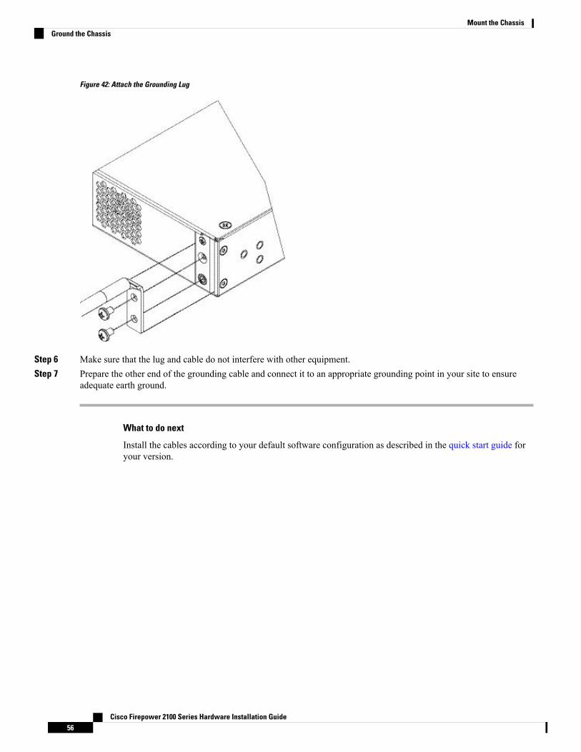
Figure 42: Attach the Grounding Lug
Step 6 Make sure that the lug and cable do not interfere with other equipment.Step 7 Prepare the other end of the grounding cable and connect it to an appropriate grounding point in your site to ensure
adequate earth ground.
What to do next
Install the cables according to your default software configuration as described in the quick start guide foryour version.
Cisco Firepower 2100 Series Hardware Installation Guide56
Mount the ChassisGround the Chassis

C H A P T E R 4Maintenance and Upgrade
• Remove and Replace the Network Module, on page 57• Remove and Replace the SSD, on page 58• Remove and Replace the Power Supply Module, on page 60• Connect the DC Power Supply Module, on page 62• Secure the Power Cord on the Power Supply Module, on page 66• Remove and Replace the Fan Tray, on page 68
Remove and Replace the Network ModuleTake note of the following warnings:
Statement 1030—Equipment Installation
Only trained and qualified personnel should be allowed to install, replace, or service this equipment.
Warning
Statement 1073—No User-Serviceable Parts
No serviceable parts inside. To avoid risk of electric shock, do not open.
Warning
You can remove and replace the network module in the Firepower 2130 and 2140. Although the hardwaresupports removing and replacing the network module while the system is running, the software does notcurrently support hot swapping. You must power down the chassis to remove and replace network modules.See Network Modules, on page 16 for more information about Firepower network modules.
Step 1 Save your configuration.Step 2 Power down the appliance by moving the power switch to the OFF position. See Rear Panel, on page 14 for more
information about the power switch.Step 3 To remove a network module, loosen the captive screw on the lower left side of the network module and pull out the
handle that is connected to the screw. This mechanically ejects the network module from the slot.
Cisco Firepower 2100 Series Hardware Installation Guide57

Figure 43: Remove the Network Module
If the slot is to remain empty, install a blank faceplate to ensure proper airflow and to keep dust out of the chassis;otherwise, install another network module.
Step 4 To replace a network module, hold the network module in front of the network module slot on the right of the chassisand pull the network module handle out.
Step 5 Slide the network module into the slot and push it firmly into place until the handle is flush with the front of the networkmodule.
Step 6 Tighten the captive screw on the lower left side of the network module.Step 7 Power on the chassis so that the new network module is recognized.
What to do next
Follow the procedures in the FXOS Configuration Guide to connect to the network module and make surethat it has been discovered correctly by the security appliance.
Remove and Replace the SSDTake note of the following warnings:
Statement 1030—Equipment Installation
Only trained and qualified personnel should be allowed to install, replace, or service this equipment.
Warning
Cisco Firepower 2100 Series Hardware Installation Guide58
Maintenance and UpgradeRemove and Replace the SSD

Statement 1073—No User-Serviceable Parts
No serviceable parts inside. To avoid risk of electric shock, do not open.
Warning
Although the hardware supports removing and replacing SSDs while the system is running, the software doesnot currently support hot swapping. You must power down the chassis to remove and replace SSDs.
The 100-GB SSD is restricted to the 2110 and 2120 models. The 200-GB SSD is restricted to the 2130 and2140 models. Do not mix them.
Note
You can install a Malware Storage Pack (MSP) in slot 2. TheMSP stores threat detection data for use in futureanalysis. It supports the Advanced Malware Protection (AMP) software feature. It is used as both storage andas the Malware application repository. RAID is not supported.
Do not switch the two SSDs. You MUST install the MSP in slot 2. If you remove it and install it in slot 1, allstored capture data are lost.
Caution
Step 1 Save your configuration.Step 2 Power down the chassis by moving the power switch to the OFF position. See Rear Panel, on page 14 for more information
on the power switch.Step 3 To remove the SSD in slot 1, face the front of the chassis, loosen the two captive screws on the SSD, and gently pull it
out of the chassis.
Cisco Firepower 2100 Series Hardware Installation Guide59
Maintenance and UpgradeRemove and Replace the SSD

Figure 44: Remove the SSD
Step 4 To replace the SSD in slot 1, make sure the power switch is still in the OFF position, and then hold the SSD in front ofslot 1 and push it in gently until it is seated.
Step 5 To install the MSP SSD, make sure the power switch is still in the OFF position, and then remove the blank faceplate inSlot 2 by loosening the captive screws on either side of the faceplate.
Step 6 Hold the MSP SSD in front of slot 2 and push it in gently until it is seated.
Do not switch the two SSDs. The MSP MUST be installed in slot 2. If you remove it and install it in slot 1, allstored file capture data are lost.
Caution
Step 7 Tighten the captive screws on either side of the SSD.Step 8 Check the SSD LED to make sure the SSD is operative. See Front Panel LEDs, on page 10 for a description of the SSD
LEDs.
Remove and Replace the Power Supply ModuleTake note of the following warnings:
Statement 1002—DC Power Supply
When stranded wiring is required, use approved wiring terminations, such as closed-loop or spade-type withupturned lugs. These terminations should be the appropriate size for the wires and should clamp both theinsulation and conductor.
Warning
Cisco Firepower 2100 Series Hardware Installation Guide60
Maintenance and UpgradeRemove and Replace the Power Supply Module

Statement 1003—DC Power Disconnection
Before performing any of the following procedures, ensure that power is removed from the DC circuit.
Warning
<!--rcsi-show-stmt-number-->Statement 1015—Battery Handling
To reduce risk of fire, explosion or leakage of flammable liquid or gas,
• Replace the battery only with the same or equivalent type recommended by the manufacturer.
• Do not dismantle, crush, puncture, use sharp tool to remove, short external contacts, or dispose of in fire
• Do not use if battery is warped or swollen
• Do not store or use battery in a temperature > __/__ C
• Do not store or use battery in low air pressure environment < __/__
Warning
Statement 1022—Disconnect Device
To reduce risk of electric shock and fire, a readily accessible two-poled disconnect device must be incorporatedin the fixed wiring.
Warning
Statement 1025—Use Copper Conductors Only
To reduce risk of fire, use copper conductors only.
Warning
Statement 1030—Equipment Installation
Only trained and qualified personnel should be allowed to install, replace, or service this equipment.
Warning
Statement 1046—Installing or Replacing the Unit
To reduce risk of electric shock, when installing or replacing the unit, the ground connection must always bemade first and disconnected last.
Warning
Statement 1073—No User-Serviceable Parts
No serviceable parts inside. To avoid risk of electric shock, do not open.
Warning
Power supply modules are hot swappable. You can remove and replace power supply modules while thesystem is running.
Cisco Firepower 2100 Series Hardware Installation Guide61
Maintenance and UpgradeRemove and Replace the Power Supply Module
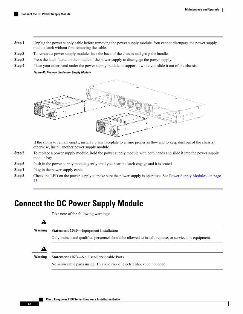
Step 1 Unplug the power supply cable before removing the power supply module. You cannot disengage the power supplymodule latch without first removing the cable.
Step 2 To remove a power supply module, face the back of the chassis and grasp the handle.Step 3 Press the latch found on the middle of the power supply to disengage the power supply.Step 4 Place your other hand under the power supply module to support it while you slide it out of the chassis.
Figure 45: Remove the Power Supply Module
If the slot is to remain empty, install a blank faceplate to ensure proper airflow and to keep dust out of the chassis;otherwise, install another power supply module.
Step 5 To replace a power supply module, hold the power supply module with both hands and slide it into the power supplymodule bay.
Step 6 Push in the power supply module gently until you hear the latch engage and it is seated.Step 7 Plug in the power supply cable.Step 8 Check the LED on the power supply to make sure the power supply is operative. See Power Supply Modules, on page
23.
Connect the DC Power Supply ModuleTake note of the following warnings:
Statement 1030—Equipment Installation
Only trained and qualified personnel should be allowed to install, replace, or service this equipment.
Warning
Statement 1073—No User-Serviceable Parts
No serviceable parts inside. To avoid risk of electric shock, do not open.
Warning
Cisco Firepower 2100 Series Hardware Installation Guide62
Maintenance and UpgradeConnect the DC Power Supply Module

For the Cisco 2130 and 2140, the input connector and plug must be UL recognized under UL 486 for fieldwiring. The connection polarity is from left to right: negative (–), positive (+), and ground.
Use the handle on the power supply installation and removal. You must support the module with one handbecause of its length.
Figure 46: Firepower 2100 DC Power Supply Module
FAIL and OK LEDs2Handle1
Ejector latch4DC power connector3
Before you begin
• The color coding of the DC input power supply leads depends on the color coding of the DC powersource at your site. Make sure that the lead color coding you choose for the DC input power supplymatches the lead color coding used at the DC power source and verify that the power source is connectedto the negative (–) terminal and to the positive (+) terminal on the power supply.
• Make sure that the chassis ground is connected on the chassis before you begin installing the DC powersupply. See Ground the Chassis, on page 54 for the procedure.
Step 1 Verify that the power is off to the DC circuit on the power supply module that you are installing.Step 2 While supporting the power supply module with one hand, insert the power supply module into the power supply bay
and gently push it in. See the illustration above for the location of the handle.Step 3 Use a wire-stripping tool to strip each of the 2 wires coming from the DC input power source. Strip the wires to
approximately 0.39 inch (10 mm) + 0.02 inch (0.5 mm). We recommend you use 14 AWG insulated wire.
Cisco Firepower 2100 Series Hardware Installation Guide63
Maintenance and UpgradeConnect the DC Power Supply Module

Do not strip more than the recommended length of wire because doing so could leave the wire exposed fromthe terminal block.
Note
Figure 47: Stripped DC Input Source Wire
Step 4 Insert the exposed wire into the terminal block. Ensure that you cannot see any wire lead outside the plastic cover. Onlywires with insulation should extend from the terminal block.
Step 5 Use a screwdriver to tighten the terminal block captive screws.
Do not overtorque the terminal block captive screws. Make sure that the connection is snug, but the wire is notcrushed. Verify by tugging lightly on each wire to make sure that they do not move.
Caution
Cisco Firepower 2100 Series Hardware Installation Guide64
Maintenance and UpgradeConnect the DC Power Supply Module

Figure 48: Tighten the Terminal Block Captive Screws
Positive (+) lead wire2Negative (-) lead wire1
Step 6 Repeat these steps for the remaining DC input power source wire as applicable.Step 7 Use a tie wrap so secure the wires to the rack, so that the wires are not pulled from the terminal block.Step 8 Set the DC disconnect switch in the circuit to ON. In a system with multiple power supplies, connect each power supply
to a separate DC power source. In the event of a power source failure, if the second source is still available, it can maintainsystem operation.
Step 9 Verify power supply operation by checking the power supply LED on the front of the chassis. See Front Panel LEDs, onpage 10 for the LED values.
Cisco Firepower 2100 Series Hardware Installation Guide65
Maintenance and UpgradeConnect the DC Power Supply Module

Secure the Power Cord on the Power Supply ModuleTo secure the power supplymodule against accidental removal and thus prevent disrupting system performance,use the tie wrap and clamp provided in the accessories kit that ships with your Firepower 2100.
Take note of the following warnings:
Statement 1030—Equipment Installation
Only trained and qualified personnel should be allowed to install, replace, or service this equipment.
Warning
Statement 1073—No User-Serviceable Parts
No serviceable parts inside. To avoid risk of electric shock, do not open.
Warning
Step 1 Attach the clamp to the tie wrap by holding the clamp with the loop side on the bottom and sliding the tie wrap throughthe box-shaped channel above the clamp (see the following figure).
One side of the tie wrap has evenly spaced ridges and the other is smooth. Be sure the ridged side is face up and that youslide it through the open side of the channel. You will hear a click as the tie slides through—it moves in one directiononly. To remove the tie wrap from the clamp, push the lever on the closed side of the box-shaped channel and slide outthe tie wrap.
Figure 49: Tie Wrap Through the Box Channel of the Clamp
Tie wrap2Box channel1
Step 2 Attach the clamp to the power supply module:a) Locate the hexagonal ventilation hole on the power supply module at the center of the plug just below the power
connector body (see the following figures).
Cisco Firepower 2100 Series Hardware Installation Guide66
Maintenance and UpgradeSecure the Power Cord on the Power Supply Module

b) Plug the snapping portion of the tie wrap into the hexagonal hole.c) With the clamp side facing up, push the tie wrap in until it is fully engaged.
Make sure you have the correct location because you cannot remove the tie wrap from the power supplymodule once you have installed it without damaging the tie wrap.
Caution
Figure 50: Connect the Tie Wrap
Hexagonal hole2Tie wrap1
Step 3 Secure the clamp:a) Plug in the power supply power cord and wrap the clamp around the over mold portion of the power cord.b) Squeeze the clamp ends together to the power supply so that the annular teeth engage with the mate on the clamp.c) Make sure the clamp fits snugly into the over mold.d) Adjust the clamp position on the tie wrap so that the clamp is tight against the front of the over mold and the power
cord cannot be removed by lightly pulling on it.
Cisco Firepower 2100 Series Hardware Installation Guide67
Maintenance and UpgradeSecure the Power Cord on the Power Supply Module

Figure 51: Clamp on Over Mold of Power Cord
Step 4 If you need to remove the power cord, push the release tab on the clamp to force the annular clamp teeth to disengageand the clamp opens up. You can then remove the clamp from the power cord.
Remove and Replace the Fan TrayYou can remove and replace the fan tray while the 2130 and 2140 are running. The air flow moves from frontto back. All fan modules are integrated in a single fan tray.
Removing the fan tray exposes the appliance to no airflow. Replace the fan tray within 30 seconds afterremoval to avoid overheating the appliance. If you wait longer than 30 seconds, the appliance may power offautomatically to prevent damage to components. The appliance does not power up and boot properly if thefan tray is missing.
Caution
Take note of the following warnings:
Statement 1030—Equipment Installation
Only trained and qualified personnel should be allowed to install, replace, or service this equipment.
Warning
Statement 1073—No User-Serviceable Parts
No serviceable parts inside. To avoid risk of electric shock, do not open.
Warning
Step 1 Have the fan tray ready for immediate insertion and near the appliance so that you can reinstall the fan tray within 30seconds.
Cisco Firepower 2100 Series Hardware Installation Guide68
Maintenance and UpgradeRemove and Replace the Fan Tray
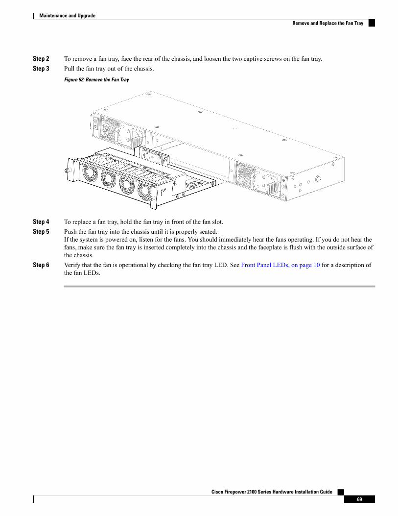
Step 2 To remove a fan tray, face the rear of the chassis, and loosen the two captive screws on the fan tray.Step 3 Pull the fan tray out of the chassis.
Figure 52: Remove the Fan Tray
Step 4 To replace a fan tray, hold the fan tray in front of the fan slot.Step 5 Push the fan tray into the chassis until it is properly seated.
If the system is powered on, listen for the fans. You should immediately hear the fans operating. If you do not hear thefans, make sure the fan tray is inserted completely into the chassis and the faceplate is flush with the outside surface ofthe chassis.
Step 6 Verify that the fan is operational by checking the fan tray LED. See Front Panel LEDs, on page 10 for a description ofthe fan LEDs.
Cisco Firepower 2100 Series Hardware Installation Guide69
Maintenance and UpgradeRemove and Replace the Fan Tray

Cisco Firepower 2100 Series Hardware Installation Guide70
Maintenance and UpgradeRemove and Replace the Fan Tray