Embed Size (px)
Citation preview

Americas HeadquartersCisco Systems, Inc.170 West Tasman DriveSan Jose, CA 95134-1706 USAhttp://www.cisco.comTel: 408 526-4000
800 553-NETS (6387)Fax: 408 527-0883
Cisco eXpandable Power System 2200 Hardware Installation GuideMarch 2011
Text Part Number: OL-19595-01

THE SPECIFICATIONS AND INFORMATION REGARDING THE PRODUCTS IN THIS MANUAL ARE SUBJECT TO CHANGE WITHOUT NOTICE. ALL STATEMENTS, INFORMATION, AND RECOMMENDATIONS IN THIS MANUAL ARE BELIEVED TO BE ACCURATE BUT ARE PRESENTED WITHOUT WARRANTY OF ANY KIND, EXPRESS OR IMPLIED. USERS MUST TAKE FULL RESPONSIBILITY FOR THEIR APPLICATION OF ANY PRODUCTS.
THE SOFTWARE LICENSE AND LIMITED WARRANTY FOR THE ACCOMPANYING PRODUCT ARE SET FORTH IN THE INFORMATION PACKET THAT SHIPPED WITH THE PRODUCT AND ARE INCORPORATED HEREIN BY THIS REFERENCE. IF YOU ARE UNABLE TO LOCATE THE SOFTWARE LICENSE OR LIMITED WARRANTY, CONTACT YOUR CISCO REPRESENTATIVE FOR A COPY.
The following information is for FCC compliance of Class A devices: This equipment has been tested and found to comply with the limits for a Class A digital device, pursuant to part 15 of the FCC rules. These limits are designed to provide reasonable protection against harmful interference when the equipment is operated in a commercial environment. This equipment generates, uses, and can radiate radio-frequency energy and, if not installed and used in accordance with the instruction manual, may cause harmful interference to radio communications. Operation of this equipment in a residential area is likely to cause harmful interference, in which case users will be required to correct the interference at their own expense.
The following information is for FCC compliance of Class B devices: The equipment described in this manual generates and may radiate radio-frequency energy. If it is not installed in accordance with Cisco’s installation instructions, it may cause interference with radio and television reception. This equipment has been tested and found to comply with the limits for a Class B digital device in accordance with the specifications in part 15 of the FCC rules. These specifications are designed to provide reasonable protection against such interference in a residential installation. However, there is no guarantee that interference will not occur in a particular installation.
Modifying the equipment without Cisco’s written authorization may result in the equipment no longer complying with FCC requirements for Class A or Class B digital devices. In that event, your right to use the equipment may be limited by FCC regulations, and you may be required to correct any interference to radio or television communications at your own expense.
You can determine whether your equipment is causing interference by turning it off. If the interference stops, it was probably caused by the Cisco equipment or one of its peripheral devices. If the equipment causes interference to radio or television reception, try to correct the interference by using one or more of the following measures:
• Turn the television or radio antenna until the interference stops.
• Move the equipment to one side or the other of the television or radio.
• Move the equipment farther away from the television or radio.
• Plug the equipment into an outlet that is on a different circuit from the television or radio. (That is, make certain the equipment and the television or radio are on circuits controlled by different circuit breakers or fuses.)
Modifications to this product not authorized by Cisco Systems, Inc. could void the FCC approval and negate your authority to operate the product.
The Cisco implementation of TCP header compression is an adaptation of a program developed by the University of California, Berkeley (UCB) as part of UCB’s public domain version of the UNIX operating system. All rights reserved. Copyright © 1981, Regents of the University of California.
NOTWITHSTANDING ANY OTHER WARRANTY HEREIN, ALL DOCUMENT FILES AND SOFTWARE OF THESE SUPPLIERS ARE PROVIDED “AS IS” WITH ALL FAULTS. CISCO AND THE ABOVE-NAMED SUPPLIERS DISCLAIM ALL WARRANTIES, EXPRESSED OR IMPLIED, INCLUDING, WITHOUT LIMITATION, THOSE OF MERCHANTABILITY, FITNESS FOR A PARTICULAR PURPOSE AND NONINFRINGEMENT OR ARISING FROM A COURSE OF DEALING, USAGE, OR TRADE PRACTICE.
IN NO EVENT SHALL CISCO OR ITS SUPPLIERS BE LIABLE FOR ANY INDIRECT, SPECIAL, CONSEQUENTIAL, OR INCIDENTAL DAMAGES, INCLUDING, WITHOUT LIMITATION, LOST PROFITS OR LOSS OR DAMAGE TO DATA ARISING OUT OF THE USE OR INABILITY TO USE THIS MANUAL, EVEN IF CISCO OR ITS SUPPLIERS HAVE BEEN ADVISED OF THE POSSIBILITY OF SUCH DAMAGES.
Cisco and the Cisco Logo are trademarks of Cisco Systems, Inc. and/or its affiliates in the U.S. and other countries. A listing of Cisco's trademarks can be found at www.cisco.com/go/trademarks. Third party trademarks mentioned are the property of their respective owners. The use of the word partner does not imply a partnership relationship between Cisco and any other company. (1005R)
Cisco eXpandable Power System 2200 Hardware Installation Guide©2011 Cisco Systems, Inc. All rights reserved.

OL-19595-01
C O N T E N T S
Preface v
Overview v
Obtaining Documentation and Submitting a Service Request vi
C H A P T E R 1 Product Overview 1-1
Product Description 1-1
Front Panel Description 1-2
LEDs 1-3
Select and Online/Offline Buttons 1-5
Fan Modules 1-6
Service Port 1-6
Rear Panel Description 1-6
Reset Button 1-6
Power Ports 1-6
Power Supply Modules 1-7
Management Options 1-10
C H A P T E R 2 XPS 2200 Installation 2-1
Preparing for Installation 2-1
Safety Warnings 2-1
Installation Guidelines 2-3
Stacking Guidelines 2-3
Tools and Equipment 2-3
Installing the XPS 2-4
Installing the Brackets 2-4
Mounting the XPS in a Rack 2-5
Connecting the XPS 2-6
Cabling Options 2-6
Connecting the Cables 2-7
iiiCisco eXpandable Power System 2200 Hardware Installation Guide

Contents
C H A P T E R 3 Power Supply and Fan Module Installation 3-1
Installation Guidelines 3-1
Installing an AC-Power Supply Module 3-2
Installing an DC-Power Supply Module 3-3
Tools That You Need 3-4
Installing the DC Power Supply in the XPS 3-4
Wiring the DC Input Power Source 3-5
Installing a Fan Module 3-6
C H A P T E R 4 Troubleshooting 4-1
LEDs 4-1
Diagnosing Problems 4-1
Finding the Serial Number 4-3
A P P E N D I X A Technical Specifications A-1
IN D E X
ivCisco eXpandable Power System 2200 Hardware Installation Guide
OL-19595-01

Preface
OverviewThis guide documents the hardware features of the Cisco eXpandable Power System 2200 (XPS 2200). It describes the physical and performance characteristics of the XPS 2200, explains how to install it, and provides troubleshooting information.
This guide does not describe system messages that you might receive or how to configure the XPS 2200 (hereafter referred to as the XPS). You configure the XPS through the CLI and manage it through the Cisco IOS or management software on the Catalyst 3750-X and 3560-X switches.
For information about configuring the XPS 2200, see the Cisco eXpandable Power System 2200 Configuration Note on Cisco.com.
For information about the standard Cisco IOS commands, see the Cisco IOS documentation set from the Cisco.com home page.
ConventionsThis document uses these conventions and symbols for notes, cautions, and warnings. Translations of the warning statements in this document appear in the Regulatory Compliance and Safety Information for the Cisco eXpandable Power System 2200.
Note Means reader take note. Notes contain helpful suggestions or references to materials not contained in this manual.
Caution Means reader be careful. In this situation, you might do something that could result in equipment damage or loss of data.
Warning This warning symbol means danger. You are in a situation that could cause bodily injury. Before you work on any equipment, be aware of the hazards involved with electrical circuitry and be familiar with standard practices for preventing accidents. Use the statement number provided at the end of each warning to locate its translation in the translated safety warnings that accompanied this device. Statement 1071
vCisco eXpandable Power System 2200 Hardware Installation Guide
OL-19595-01

PrefaceObtaining Documentation and Submitting a Service Request
Related PublicationsThese documents provide more information about the XPS and supported switches:
• Regulatory Compliance and Safety Information for the Cisco eXpandable Power System 2200
• Cisco eXpandable Power System 2200 Configuration Note
• Installation Notes for the Catalyst 3750-X and Catalyst 3560-X Switch Power Supply Modules
• Installation Notes for the Catalyst 3750-X and 3560-X Switch Fan Module
• Installation Notes for the Catalyst 3750-X and 3560-X Switch Network Modules
• Catalyst 3750-X and 3560-X Switch Getting Started Guide
• Catalyst 3750-X and 3560-X Switch Hardware Installation Guide
• Regulatory Compliance and Safety Information for the Catalyst 3750-X and 3560-X Switch
• Catalyst 3750-X and 3560-X Switch Software Configuration Guide
• Catalyst 3750-X and 3560-X Switch Command Reference
• Catalyst 3750-X, 3750-E, 3560-X, and 3560-E Switch System Message Guide
• Release Notes for the Catalyst 3750-X and 3560-X Switch
• Cisco IOS Software Installation Document
Obtaining Documentation and Submitting a Service RequestFor information on obtaining documentation, submitting a service request, and gathering additional information, see the monthly What’s New in Cisco Product Documentation, which also lists all new and revised Cisco technical documentation, at:
http://www.cisco.com/en/US/docs/general/whatsnew/whatsnew.html
Subscribe to the What’s New in Cisco Product Documentation as a Really Simple Syndication (RSS) feed and set content to be delivered directly to your desktop using a reader application. The RSS feeds are a free service and Cisco currently supports RSS Version 2.0.
viCisco eXpandable Power System 2200 Hardware Installation Guide
OL-19595-01

Cisco eXpandabOL-19595-01
C H A P T E R1
Product Overview• Product Description, page 1-1
• Front Panel Description, page 1-2
• Rear Panel Description, page 1-6
• Management Options, page 1-10
Product DescriptionThe XPS is an expandable power system that can support nine network switches.
Figure 1-1 Cisco XPS 2200
The XPS has two field-replacable-unit (FRU) power supply modules that are inserted into the slots on the XPS rear panel. You can use any combination of C3KX-PWR AC or DC power supply modules. See the “Power Supply Modules” section on page 1-7 for more information.
The nine XPS power ports provide the power and management signals to the Catalyst 3750-X and 3560-X switches. The XPS communicates with each switch through the XPS cable.
2815
35
1-1le Power System 2200 Hardware Installation Guide

Chapter 1 Product OverviewFront Panel Description
When you connect Catalyst 3750-X or 3560-X switches to the XPS, you create a power stack.
You can configure the XPS for redundancy, power sharing, or both.
• In redundant mode, the XPS provides power backup for up to two failed power supplies. When in redundant mode, each power supply can provide redundancy for a single power supply of equal value or less. The failed power supplies can be in different switches or in the same switch.
• In power-sharing mode, the XPS supplies power to the switches in the power stack (only Catalyst 3750-X switches running the IP base image). The power of all the power supplies in the stack (including the XPS) is aggregated and distributed among the stack members.
• In mixed-mode, where one power supply is in redundant mode and one power supply is in power-sharing mode, the XPS provides power backup for only one failed power supply.
Front Panel DescriptionThe XPS front panel has system LEDs, a Select button, an Online/Offline button, fan modules, and a service port (Figure 1-2).
Figure 1-2 XPS 2200 Front Panel
1 System LEDs, Select button, Online/Offline button
3 Service port
2 Fan modules
2815
36
2
1
3
1-2Cisco eXpandable Power System 2200 Hardware Installation Guide
OL-19595-01

Chapter 1 Product OverviewFront Panel Description
LEDsThe front panel LEDs (see Figure 1-3) show the XPS system status and mode for each power port. See Table 1-1, Table 1-2, and Table 1-3 for LED descriptions.
Figure 1-3 XPS LEDs
1 TEMP 5 PS1
2 FAN 6 S-PWR (power-sharing mode)
3 SYS 7 XPS (redundant mode)
4 PS2
Table 1-1 XPS Status LEDs
LED Off Green Blinking Amber Amber
System Not powered on. The XPS is in active mode and can back up a failed device.
The XPS is in select mode. The selected port is in standby mode and is not ready to back up a device.
The power supply modules are not compatible, or the XPS is in an overtemperature or overcurrent condition.
Fan Not powered on. The fan modules are operating properly.
— One of the fan modules is not operating properly.
Temp Not powered on. The XPS internal temperature is less than 131°F (55°C).
— The XPS is in an overtemperature condition (greater than 131°F [55°C]).
XPS-2200
SYSFAN
PS1PS2
TEMP
SEL ON-LINE/OFF-LINE
S-PWR XPS
PORTS
123456789
281537
7
5 64
3
2
1
1-3Cisco eXpandable Power System 2200 Hardware Installation Guide
OL-19595-01

Chapter 1 Product OverviewFront Panel Description
The S-PWR and XPS LEDs show the mode and status of the XPS power ports that you use to connect the XPS to the switch. The LEDs are numbered 1 to 9, which corresponds to the numbers on the power ports. For each numbered LED, only one LED is illuminated, depending on the mode for that port.
Table 1-3 lists the LED colors and their meanings.
Table 1-2 Power Supply LEDs
LED Off Green Blinking Green Amber Blinking Amber
Power supply 1
The power supply is not installed.
The power supply is in power sharing mode.
The power supply is in redundant mode.
The power supply is in power sharing mode, but it has failed.
The power supply is in redundant mode, but it has failed.
Power supply 2
Table 1-3 S-PWR and XPS LEDs
Color S-PWR (power-sharing mode) XPS (redundant mode)
Off The XPS is not powered up, or no device is connected to the XPS power port.
Green The XPS is connected to a device through this port and is sharing power with a device.
The XPS is capable of backing up the connected device.
Blinking green — The XPS is backing up the connected device.
Amber The XPS is disconnected, is not ready, or is not communicating.
The XPS cannot back up the connected device, or port is disconnected.
Blinking amber The XPS is experiencing a major port fault or a StackPower stack fault.
The XPS is experiencing a major port fault, or the port cannot be backed up.
1-4Cisco eXpandable Power System 2200 Hardware Installation Guide
OL-19595-01

Chapter 1 Product OverviewFront Panel Description
Select and Online/Offline ButtonsThe XPS has a Select button and an Online/Offline button. You can use these buttons to select a port and change its operation mode (enabled or disabled). Figure 1-4 shows the Select and Online/Offline buttons.
Figure 1-4 Select and Online/Offline Buttons
Use the Select button to select an XPS power port. Use the Online/Offline button to change the operation mode of the selected port.
Note The XPS and all ports are in enabled mode when it powers up.
To change the operation mode of a port, follow these steps:
Step 1 Press the Select buttonrepeatedly until the desired port blinks amber and green.
Step 2 Press the Online/Offline button to place the port in either enabled or disabled mode.
Note If you press the Online/Offline button on the XPS before pressing the Select button, the XPS toggles all nine ports between enable mode and disable mode. If this occurs, press the Select button again to select the desired port.
Step 3 Repeat this procedure as necessary to change the operation mode of any of the other ports.
1 Select button 2 Online/Offline button
XPS-2200
SYSFAN
PS1PS2
TEMP
SEL ON-LINE/OFF-LINE
S-PWR XPS
PORTS
123456789
281538
21
1-5Cisco eXpandable Power System 2200 Hardware Installation Guide
OL-19595-01

Chapter 1 Product OverviewRear Panel Description
Fan ModulesThe XPS supports hot swapping of the three fan modules. You can remove and replace them without disconnecting the system power and without interrupting normal system operation. For information about installing and removing the fan modules, see the “Installing a Fan Module” section on page 3-6.
Service PortUse the Service port to upgrade the image on the XPS. Refer to the Configuration Notes for the Cisco eXpandable Power System 2200 for software upgrade information.
Rear Panel DescriptionThe XPS rear panel has a reset button, nine power ports, and two power supply module slots (Figure 1-5).
Figure 1-5 XPS Rear Panel
Reset ButtonPress the reset button to perform a soft reset. Press and hold the reset button (more than 5 seconds) to power cycle the XPS.
Power PortsThe power ports provide the power and communication signals to the Catalyst 3750-X and the 3560-X switches. Two types of XPS cables connect the XPS to the switch. See the “Cabling Options” section on page 2-6.
1 Reset button 3 Power supply module slots
2 Power ports
281539
2
3
1
1-6Cisco eXpandable Power System 2200 Hardware Installation Guide
OL-19595-01

Chapter 1 Product OverviewRear Panel Description
Power Supply ModulesThe XPS power supply modules slide into the power supply slots in the rear of the XPS.
• The 350-W and 715-W AC power supply modules are autoranging units that support input voltages between 100 and 240 VAC.
• The 1100-W power supply module is an autoranging unit that supports input voltages between 115 and 240 VAC.
• The 440-W DC power supply module has dual input feeds (A and B) and supports input voltages between 36 and 72 VDC. The output voltage range is 51 to 57 V.
Each AC power supply module has a power cord for connection to an AC power outlet. The DC power supply module must be wired to a DC power source.
Note For systems configured for redundant mode, the lowest-rated power supply module in the XPS must be equal to or greater than the highest-rated power supply module in the switch.
Note If you ordered one power supply module, a spare power supply insert ships with the XPS. If you ordered two power supply modules, you can order the power supply insert (BLNK-XPS2200=) as a spare part.
If only one power supply module is installed in the XPS, the empty power supply slot in the XPS rear panel must have the spare power supply insert installed. The insert maintains proper airflow and cooling.
Warning Blank faceplates and cover panels serve three important functions: they prevent exposure to hazardous voltages and currents inside the chassis; they contain electromagnetic interference (EMI) that might disrupt other equipment; and they direct the flow of cooling air through the chassis. Do not operate the system unless all cards, faceplates, front covers, and rear covers are in place. Statement 1029
Caution Operating the XPS without the insert installed in the power supply slot can cause the XPS to overheat, and serious XPS faults might occur.
For information about installing and removing the power-supply modules and for power supply specifications, see Chapter 3, “Power Supply and Fan Module Installation” and Appendix A, “Technical Specifications.”
Table 1-4 Supported Power Supply Module Part Numbers and Descriptions
Part Number Description
C3KX-PWR-1100WAC= 1100-W AC power supply module
C3KX-PWR-715WAC= 715-W AC power supply module
C3KX-PWR-350WAC= 350-W AC power supply module
C3KX-PWR-440WDC=1
1. Not NEBS compliant.
440-W DC power supply module
1-7Cisco eXpandable Power System 2200 Hardware Installation Guide
OL-19595-01

Chapter 1 Product OverviewRear Panel Description
Figure 1-6 1100-W AC Power Supply
Figure 1-7 715-W AC Power Supply
1 1100-W AC power supply module 4 AC power cord connector
2 AC OK LED 5 Release latch
3 PS OK LED 6 Power cord retainer
AC OK
C3KX-PWR-1100WAC
PS OK
2535
60
1
6
2 3 4
5
1 715-W AC power supply module 4 AC power cord connector
2 AC OK LED 5 Release latch
3 PS OK LED 6 Power cord retainer
AC OK
C3KX-PWR-715WAC
PS OK
2535
61
1
6
2 3 4
5
1-8Cisco eXpandable Power System 2200 Hardware Installation Guide
OL-19595-01

Chapter 1 Product OverviewRear Panel Description
Figure 1-8 350-W AC Power Supply
Figure 1-9 440-W DC Power Supply Module
1 350-W AC power supply module 4 AC power cord connector
2 AC OK LED 5 Release latch
3 PS OK LED 6 Power cord retainer
AC OK
C3KX-PWR-715WAC
PS OK
2535
61
1
6
2 3 4
5
1 440-W DC power supply module 6 Grounding terminal
2 DC OK LED 7 Release latch
3 PS OK LED 8 Extraction handle
4 Input power terminals (positive polarity) 9 Terminal block safety cover
5 Input power terminals (negative polarity)
DC OK
C3KX-PWR-440WDC
PS OK
2535
62
1
8
2 3
7
4 5 6 5 4
INPUT-36 TO -72V/12AOUTPUT44W MAX/22A
9
1-9Cisco eXpandable Power System 2200 Hardware Installation Guide
OL-19595-01

Chapter 1 Product OverviewManagement Options
Management OptionsWhen the Catalyst 3750-X or 3560-X switch is atached to the XPS, you can configure and manage the XPS through the switch software:
• Cisco Network Assistant
Cisco Network Assistant is a PC-based network management GUI application optimized for LANs of small and medium-sized businesses. Cisco Network Assistant offers centralized management of Cisco switches ranging from the Catalyst Express 500 through the Cisco Catalyst 4506. Through a GUI, users can configure and manage switch clusters or standalone switches. Cisco Network Assistant is available at no cost and can be downloaded from this URL:
http://www.cisco.com/pcgi-bin/tablebuild.pl/NetworkAssistant
For information on starting the Network Assistant application, see the Getting Started with Cisco Network Assistant guide on Cisco.com.
• Cisco IOS CLI
The switch CLI is based on Cisco IOS software and is enhanced to support desktop-switching features. You can fully configure and monitor the switch and switch cluster members from the CLI. You can access the CLI either by connecting your management station directly to the switch management port or a console port or by using Telnet from a remote management station. See the switch command reference on Cisco.com for more information.
• CiscoWorks application
The CiscoWorks LAN Management Solution (LMS) is a suite of management tools that simplify the configuration, administration, monitoring, and troubleshooting of Cisco networks. See the LMS documentation for more information.
Table 1-5 Power Supply Module LEDs
AC Power Supply Module LEDs
AC OK Description PS OK Description
Off No AC input power. Off Output is disabled, or input is outside operating range.
Green AC input power present. Green Power output to switch.
Red Output has failed.
DC Power Supply Module LEDs
DC OK Description PS OK Description
Off No DC input power. Off Output is disabled, or input is outside operating range.
Green DC input power present. Green Power output to switch.
Red Output has failed.
1-10Cisco eXpandable Power System 2200 Hardware Installation Guide
OL-19595-01

Chapter 1 Product OverviewManagement Options
• SNMP network management
You can manage switches from a Simple Network Management Protocol (SNMP)-compatible management station that is running platforms such as HP OpenView or SunNet Manager. The switch supports a comprehensive set of Management Information Base (MIB) extensions and four Remote Monitoring (RMON) groups. See the switch software configuration guide on Cisco.com and the documentation that came with your SNMP application for more information.
1-11Cisco eXpandable Power System 2200 Hardware Installation Guide
OL-19595-01

Chapter 1 Product OverviewManagement Options
1-12Cisco eXpandable Power System 2200 Hardware Installation Guide
OL-19595-01

Cisco eXpandabOL-19595-01
C H A P T E R2
XPS 2200 InstallationThis chapter describes how to install and connect an XPS. Read the topics and perform the procedures in this order:
• Preparing for Installation, page 2-1
• Installing the XPS, page 2-4
• Connecting the XPS, page 2-6
Preparing for Installation
Safety WarningsThis section includes the basic installation caution and warning statements. Translations of the warning statements appear in the Regulatory Compliance and Safety Information for the Cisco eXpandable Power System 2200 document at Cisco.com. Read this section before you start the installation procedure.
Warning Before working on equipment that is connected to power lines, remove jewelry (including rings, necklaces, and watches). Metal objects will heat up when connected to power and ground and can cause serious burns or weld the metal object to the terminals. Statement 43
Warning Do not stack the chassis on any other equipment. If the chassis falls, it can cause severe bodily injury and equipment damage. Statement 48
Warning Do not reach into a vacant slot or chassis while you install or remove a module or a fan. Exposed circuitry could constitute an energy hazard. Statement 206
Warning Read the installation instructions before connecting the system to the power source. Statement 1004
2-1le Power System 2200 Hardware Installation Guide
Chapter 2 XPS 2200 InstallationPreparing for Installation
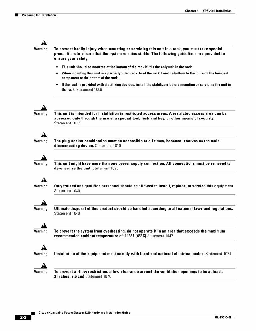
Warning This unit is intended for installation in restricted access areas. A restricted access area can be accessed only through the use of a special tool, lock and key, or other means of security. Statement 1017
Warning The plug-socket combination must be accessible at all times, because it serves as the main disconnecting device. Statement 1019
Warning This unit might have more than one power supply connection. All connections must be removed to de-energize the unit. Statement 1028
Warning Only trained and qualified personnel should be allowed to install, replace, or service this equipment. Statement 1030
Warning Ultimate disposal of this product should be handled according to all national laws and regulations. Statement 1040
Warning To prevent the system from overheating, do not operate it in an area that exceeds the maximum recommended ambient temperature of: 113°F (45°C) Statement 1047
Warning Installation of the equipment must comply with local and national electrical codes. Statement 1074
Warning To prevent airflow restriction, allow clearance around the ventilation openings to be at least:3 inches (7.6 cm) Statement 1076
Warning To prevent bodily injury when mounting or servicing this unit in a rack, you must take special precautions to ensure that the system remains stable. The following guidelines are provided to ensure your safety:
• This unit should be mounted at the bottom of the rack if it is the only unit in the rack.
• When mounting this unit in a partially filled rack, load the rack from the bottom to the top with the heaviest component at the bottom of the rack.
• If the rack is provided with stabilizing devices, install the stabilizers before mounting or servicing the unit in the rack. Statement 1006
2-2Cisco eXpandable Power System 2200 Hardware Installation Guide
OL-19595-01
Chapter 2 XPS 2200 InstallationPreparing for Installation
Installation GuidelinesWhen deciding where to place the XPS, be sure to observe these guidelines:
• Operating environment is within the ranges listed in Appendix A, “Technical Specifications.”
• Airflow around the XPS and through the vents is unrestricted.
• Clearance to the front and rear panel is such that:
– Front-panel indicators can be easily read.
– Access to ports is sufficient for unrestricted cabling.
– AC power cord can reach from the AC power outlet to the power supply modules on the XPS 2200 rear panel.
• Cabling is away from sources of electrical noise, such as radios, power lines, and fluorescent lighting fixtures. Make sure the cabling is safely away from other devices that might damage the cables.
To provide enough distance for cabling, place switches using the XPS close to the XPS. The maximum XPS cable length is 1.5 meters.
• If only one power supply is installed in the XPS, the spare power supply insert that ships with the XPS is installed in the empty power supply slot.
Stacking GuidelinesFor rack-mounted switch stacks connected to the XPS , we recommended this sequence:
• Install the XPS at the bottom of the stack. If needed, allow one RU space between the XPS and the first switch above to provide room for cabling.
• Connect the needed XPS cables to the XPS.
• Rack-mount the switches. If you have the 1100-W power supply module, rack-mount the switch before you install the power supply module.
• Connect the XPS cable to the first switch above the XPS.
• Connect the XPS cable to the second switch above the XPS.
• Repeat until all devices are connected.
Tools and EquipmentYou need these tools:
• Phillips screwdriver
• Number-2 Phillips head ratcheting screwdriver that exerts up to 15 pound-force inches (lbf-in.) or 240 ounce-force inches (ozf-in.) of pressure
2-3Cisco eXpandable Power System 2200 Hardware Installation Guide
OL-19595-01

Chapter 2 XPS 2200 InstallationInstalling the XPS
Installing the XPS
Installing the BracketsTo install the XPS in a 19-inch rack, follow the instructions in this section.
To install the XPS in a 23-inch or 24-inch rack, you need an optional bracket kit (part number C3KX-RACK-KIT=) not included with the XPS.
Figure 2-1 shows how to attach a bracket to one side of the XPS for installation into a 19-inch rack.
Figure 2-1 Attaching Brackets for 19-Inch Racks
1 Front-mounting position 3 Mid-mounting position
2 Number-8 Phillips flat-head screw 4 Rear-mounting position
2815
40
1
3
4
2
2
2
22
2-4Cisco eXpandable Power System 2200 Hardware Installation Guide
OL-19595-01

Chapter 2 XPS 2200 InstallationInstalling the XPS
Mounting the XPS in a RackAfter you attach the brackets to the XPS, use the four supplied number-12 or number-10 Phillips machine screws to attach the brackets to the rack (Figure 2-2).
Note If you are installing the XPS in a rack with a switch stack, install the XPS at the bottom of the rack. If needed, allow one RU space between the XPS and the switch above to provide room for cabling.
Figure 2-2 Mounting the XPS 2200 in a Rack
1 Front-mounting position 3 Mid-mounting position
2 Number-12 or number-10 Phillips machine screws
4 Rear-mounting position
2815
41
1
4
3
2
2
2
2-5Cisco eXpandable Power System 2200 Hardware Installation Guide
OL-19595-01
Chapter 2 XPS 2200 InstallationConnecting the XPS
Connecting the XPS • Cabling Options, page 2-6
• Connecting the Cables, page 2-7
Cabling Options
Note All cable connectors are keyed and color-coded, as are the connections on the switches.
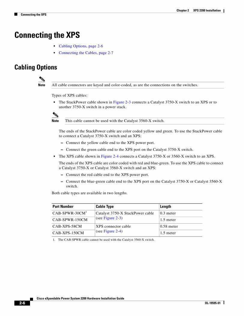
Types of XPS cables:
• The StackPower cable shown in Figure 2-3 connects a Catalyst 3750-X switch to an XPS or to another 3750-X switch in a power stack.
Note This cable cannot be used with the Catalyst 3560-X switch.
The ends of the StackPower cable are color coded yellow and green. To use the StackPower cable to connect a Catalyst 3750-X switch and an XPS:
– Connect the yellow cable end to the XPS power port.
– Connect the green cable end to the XPS port on the Catalyst 3750-X switch.
• The XPS cable shown in Figure 2-4 connects a Catalyst 3750-X or 3560-X switch to an XPS.
The ends of the XPS cable are color coded with red and blue-green. To use the XPS cable to connect a Catalyst 3750-X or Catalyst 3560-X switch and an XPS:
– Connect the red cable end to the XPS power port.
– Connect the blue-green cable end to the XPS port on the Catalyst 3750-X or Catalyst 3560-X switch.
Both cable types are available in two lengths.
Part Number Cable Type Length
CAB-SPWR-30CM1
1. The CAB-SPWR cable cannot be used with the Catalyst 3560-X switch.
Catalyst 3750-X StackPower cable (see Figure 2-3)
0.3 meter
CAB-SPWR-150CM 1.5 meter
CAB-XPS-58CM XPS connector cable (see Figure 2-4)
0.58 meter
CAB-XPS-150CM 1.5 meter
2-6Cisco eXpandable Power System 2200 Hardware Installation Guide
OL-19595-01

Chapter 2 XPS 2200 InstallationConnecting the XPS
Figure 2-3 StackPower Cable (for use only with Catalyst 3750-X Switches)
Figure 2-4 XPS 2200 Cables (for use with Catalyst 3750-X and Catalyst 3560-X Switches)
Connecting the Cables
Warning Take care when connecting units to the supply circuit so that wiring is not overloaded. Statement 1018
Follow these steps to connect the cables:
Step 1 Connect one end of the XPS cable to an XPS power port (Figure 2-5).
2533
9325
3394
2-7Cisco eXpandable Power System 2200 Hardware Installation Guide
OL-19595-01

Chapter 2 XPS 2200 InstallationConnecting the XPS
Figure 2-5 Connecting the Cable to the XPS Power Port
Step 2 Connect the other end of the XPS cable to the XPS port on the switch (Figure 2-6).
Figure 2-6 Connecting the Cable to the Switch
Step 3 Using a ratcheting torque screwdriver, torque each screw to 5 in-lbf. (80 ozf-in.).To ensure proper operation, be sure that you completely seat the connector and that you securely tighten the screws.
Step 4 Repeat Step 1 through Step 3 for each switch that the XPS supports. Figure 2-7 shows a nine-switch stack connected to the XPS.
RESET
12
34
56
78
9
CONSOLERESET
AUX
STACK 1STACK 2
S-PWR
XPS
S-PWR
2536
72
AC OK
AC OK
C3KX-PWR-715WAC
PS OK
S-PWR
XPS
S-PWR 2815
42
2-8Cisco eXpandable Power System 2200 Hardware Installation Guide
OL-19595-01

Chapter 2 XPS 2200 InstallationConnecting the XPS
Figure 2-7 StackPower Star Topology Using the XPS
Step 5 The LEDs for the connected devices should be green. If the LEDs for the connected devices are not green, see Chapter 4, “Troubleshooting.”
Note To power off the XPS 2200, disconnect the power from the XPS, and disconnect all power port cables.
AC OK
C3KX-PWR-1100WAC
PS OK
AC OK
C3KX-PWR-1100WAC
PS OK
CONSOLERESET
AUX
STACK 1STACK 2
S-PWR
XPS
S-PWR
AC OK
C3K-PWR-715WAC
PS OK
AC OK
C3K-PWR-715WAC
PS OKCONSOLE
RESET
AUX
STACK 1STACK 2
S-PWR
XPS
S-PWR
AC OK
C3K-PWR-715WAC
PS OK
AC OK
C3K-PWR-715WAC
PS OKCONSOLE
RESET
AUX
STACK 1STACK 2
S-PWR
XPS
S-PWR
AC OK
C3K-PWR-715WAC
PS OK
AC OK
C3K-PWR-715WAC
PS OKCONSOLE
RESET
AUX
STACK 1STACK 2
S-PWR
XPS
S-PWR
AC OK
C3K-PWR-715WAC
PS OK
AC OK
C3K-PWR-715WAC
PS OKCONSOLE
RESET
AUX
STACK 1STACK 2
S-PWR
XPS
S-PWR
AC OK
C3K-PWR-715WAC
PS OK
AC OK
C3K-PWR-715WAC
PS OKCONSOLE
RESET
AUX
STACK 1STACK 2
S-PWR
XPS
S-PWR
AC OK
C3K-PWR-715WAC
PS OK
AC OK
C3K-PWR-715WAC
PS OKCONSOLE
RESET
AUX
STACK 1STACK 2
S-PWR
XPS
S-PWR
AC OK
C3K-PWR-715WAC
PS OK
AC OK
C3K-PWR-715WAC
PS OKCONSOLE
RESET
AUX
STACK 1STACK 2
S-PWR
XPS
S-PWR
AC OK
C3K-PWR-715WAC
PS OK
AC OK
C3K-PWR-715WAC
PS OKCONSOLE
RESET
AUX
STACK 1STACK 2
S-PWR
XPS
S-PWR
AC OK
C3KX-PWR-715WAC
PS OK
AC OK
C3KX-PWR-715WAC
PS OK
2533
97
2-9Cisco eXpandable Power System 2200 Hardware Installation Guide
OL-19595-01

Chapter 2 XPS 2200 InstallationConnecting the XPS
2-10Cisco eXpandable Power System 2200 Hardware Installation Guide
OL-19595-01

Cisco eXpandabOL-19595-01
C H A P T E R3
Power Supply and Fan Module Installation• Installation Guidelines, page 3-1
• Installing an AC-Power Supply Module, page 3-2
• Installing an DC-Power Supply Module, page 3-3
• Installing a Fan Module, page 3-6
For module descriptions, see the “Fan Modules” section on page 1-6 and the “Power Supply Modules” section on page 1-7.
Installation GuidelinesObserve these guidelines when removing or installing a power supply module or fan module:
Caution Do not force the power supply module or fan module into the slot. This can damage the pins on the XPS if they are not aligned with the module.
• A power supply or fan module that is only partially connected to the XPS can disrupt the system operation.
• Remove power from the power supply module before removing or installing it.
• In redundant mode: You can hot swap a power supply module when a device is connected to it or when the XPS is not backing up a device.
Warning Do not reach into a vacant slot or chassis while you install or remove a module or a fan. Exposed circuitry could constitute an energy hazard. Statement 206
Warning Only trained and qualified personnel should be allowed to install, replace, or service this equipment. Statement 1030
3-1le Power System 2200 Hardware Installation Guide

Chapter 3 Power Supply and Fan Module InstallationInstalling an AC-Power Supply Module
Installing an AC-Power Supply Module
Warning The plug-socket combination must be accessible at all times, because it serves as the main disconnecting device. Statement 1019
To remove and install an AC-power supply module, follow these steps:
Step 1 Turn off the power at its source.
Step 2 Remove the power cord from the power cord retainer.
Step 3 Remove the power cord from the power connector.
Step 4 Press the release latch at the right side of the power supply module inward, and slide the power supply out.
Caution Do not leave the power supply slot open for more than 90 seconds while the switch is operating.
Step 5 Install the power supply into the power supply slot, and gently push it into the slot. When correctly inserted, the 350-W and 715-W power supply modules (excluding the power cord retainer) are flush with the rear panel. The 1100-W power supply module extends 1.5 inches from the rear panel (see Figure 3-1).
When inserting a power supply module into the XPS, do not use unnecessary force. Doing so can damage the connectors on the rear of the supply and on the midplane.
Figure 3-1 Inserting the AC-Power Supply Module
Step 6 (Optional) Make a loop in the power cord, and thread it through the power cord retainer (see Figure 3-2).
2815
43
AC OK
C3KX-PWR-715WAC
PS OK
AC OK
C3KX-PWR-715WAC
PS OK
3-2Cisco eXpandable Power System 2200 Hardware Installation Guide
OL-19595-01

Chapter 3 Power Supply and Fan Module InstallationInstalling an DC-Power Supply Module
Figure 3-2 AC- Power Supply Module with Power Cord Retainer
Warning Take care when connecting units to the supply circuit so that wiring is not overloaded. Statement 1018
Step 7 Connect the power cord to the power supply and to an AC power outlet.
Step 8 Confirm that the power supply AC OK and PS OK LEDs are green. See Table 1-5 for a description of the module LEDs.
Installing an DC-Power Supply Module• Tools That You Need, page 3-4
• Installing the DC Power Supply in the XPS, page 3-4
• Wiring the DC Input Power Source, page 3-5
Warning An exposed wire lead from a DC-input power source can conduct harmful levels of electricity. Be sure that no exposed portion of the DC-input power source wire extends from the terminal block plug. Statement 122
Warning Before connecting or disconnecting ground or power wires to the chassis, ensure that power is removed from the DC circuit. To ensure that all power is OFF, locate the circuit breaker on the panel board that services the DC circuit, switch the circuit breaker to the OFF position, and tape the switch handle of the circuit breaker in the OFF position. Use a voltmeter to test for 0 (zero) voltage at the power terminals on the chassis. Statement 196
Warning This product relies on the building's installation for short-circuit (overcurrent) protection. Ensure that the protective device is rated not greater than: 20 A. Statement 1005
Warning A readily accessible two-poled disconnect device must be incorporated in the fixed wiring. Statement 1022
2815
44
AC OK
C3KX-PWR-715WAC
PS OK
AC OK
C3KX-PWR-715WAC
PS OK
3-3Cisco eXpandable Power System 2200 Hardware Installation Guide
OL-19595-01

Chapter 3 Power Supply and Fan Module InstallationInstalling an DC-Power Supply Module
Warning Hazardous voltage or energy may be present on DC power terminals. Always replace cover when terminals are not in service. Be sure uninsulated conductors are not accessible when cover is in place. Statement 1075
Note The grounding architecture of this product is DC-isolated (DC-I)
Tools That You Need• Number-2 Phillips head ratcheting screwdriver that exerts up to 15 pound-force inches (lbf-in.) of
pressure.
• Panduit crimping tool with optional controlled-cycle mechanism (model CT-720, CT-920, CT-920CH, CT-930, or CT-940CH).
• Wire-stripping tools.
• Four leads of 14-gauge copper wire.
Installing the DC Power Supply in the XPS
Step 1 Turn off DC power. To ensure that power is off, change the circuit breakers to the OFF position, and tape the circuit-breaker switches in the OFF position.
Step 2 Remove the plastic safety cover from the power supply terminal block (Figure 1-9).
Step 3 Insert the power supply in the power-supply slot, and gently push it into the slot (Figure 3-3). When correctly installed, the DC power supply (excluding the extraction handle) is flush with the rear panel.
Figure 3-3 Inserting the DC Power Supply in the Switch
Step 4 Connect the input power as described in the “Wiring the DC Input Power Source” section.
2818
00
DC OK
C3KX-PWR-440WDC
PS OK
DC OK
C3KX-PWR-440WDC
PS OK
3-4Cisco eXpandable Power System 2200 Hardware Installation Guide
OL-19595-01

Chapter 3 Power Supply and Fan Module InstallationInstalling an DC-Power Supply Module
Wiring the DC Input Power Source
Step 1 Using a wire-stripping tool, strip each of the four wires from the DC-input power source to the appropriate length for the terminals.
Warning Use copper conductors only. Statement 1025
Step 2 Using a Panduit crimping tool, crimp the fork-type terminals to the copper conductor, 90C, 14-AWG DC power input wires.
Step 3 Connect the DC-input power terminals to the terminal blocks. See Figure 3-4 or Figure 3-5. Make sure to match the polarity (negative to negative, positive to positive) when connecting the wires to the terminal blocks. Connect the ground wire to a grounded metal rack or to earth ground if the XPS 2200 is not in a grounded rack.
Figure 3-4 DC Source A Isolated From Source B with No Common Ground
Figure 3-5 DC Source A and Source B Connections with Common Ground
Step 4 Torque all terminal block screws to 11 lbf-in.
Step 5 Replace the terminal block safety cover.
Step 6 Move the DC power source circuit-breakers to the ON position.
Step 7 Confirm that the power-supply DC OK and PS OK LEDs are green. See Table 1-5 for a description of the module LEDs.
2534
47
+
B- B+
--
A+ A-
+
2534
46
+
B- B+
--
A+ A-
+
3-5Cisco eXpandable Power System 2200 Hardware Installation Guide
OL-19595-01

Chapter 3 Power Supply and Fan Module InstallationInstalling a Fan Module
Installing a Fan Module
Step 1 Pinch the fan module release handle, and slide the module out.
Caution You should replace the fan module within 5 minutes to avoid overheating the XPS.
Step 2 Install the fan module in the fan slot, and firmly push it into the slot, applying pressure to the end of the module, not the extraction handles. (See Figure 3-6.) When correctly inserted, the fan module is flush with the front panel. When the fan is operating, a green LED is on in the top left corner of the fan module.
Warning Do not reach into a vacant slot or chassis while you install or remove a module or a fan. Exposed circuitry could constitute an energy hazard. Statement 206
Figure 3-6 Inserting the Fan Module
2815
45
3-6Cisco eXpandable Power System 2200 Hardware Installation Guide
OL-19595-01

Cisco eXpandabOL-19595-01
C H A P T E R 4
TroubleshootingThis chapter provides troubleshooting information for the XPS.
If a Catalyst 3750-X or 3560-X switch is attached to the XPS, you can troubleshoot it from Cisco Network Assistant or from the CLI. See the switch software configuration guide or the switch command reference guide on Cisco.com.
You can also access the Support and Documentation Website (http://www.cisco.com/en/US/support/index.html) for a list of known hardware problems and troubleshooting documentation.
LEDsLook at the LEDs for information when troubleshooting the switch. See the “LEDs” section on page 1-3 for descriptions of the LED colors and their meanings.
Diagnosing ProblemsThis section describes problems you might encounter with the XPS. Table 4-1 describes how to detect and resolve these problems.
Table 4-1 Common Problems and Solutions
Symptom Possible Cause Resolution
The XPS cannot back up the connected port.
The XPS cable is loose or is not connected properly.
Reconnect the cable to the XPS. Press the Select button, then the Online/Offline button to put the XPS in enabled mode.
XPS power is not available. A higher priority port is being backed up.
Assign a higher port priority to the selected port.
The port is in disabled mode. Place the XPS in enabled mode.
A hardware fault condition occurred.
Replace the XPS.
The power supply module is not connected properly or is faulty.
Verify that both the AC OK and and PS OK power supply module LEDs are green.
4-1le Power System 2200 Hardware Installation Guide

Chapter 4 TroubleshootingDiagnosing Problems
The XPS cannot communicate with the 3750-X or 3560-X switch.
The XPS cable is loose or is not connected properly.
Disconnect all switches from the XPS. Connect a known good switch to the XPS and place the XPS in enabled mode.
• If the XPS cannot communicate with the switch, replace the XPS.
• If the XPS can communicate with the switch, there might be a problem with the previously connected switch.
The XPS cable is defective. Replace the XPS cable; see the “Cabling Options” section on page 2-6.
An error was received by the SMB protocol.
Reconnect the XPS cable, and retry the communication.
A SMB communication hardware failure occurred.
Reset both the XPS and the switch.
Cannot attach the XPS cable to the XPS.
The XPS cable is incorrect. Use the correct XPS cable; see the “Cabling Options” section on page 2-6
The XPS displays the wrong temperature.
The XPS temperature sensing device is defective.
Replace the XPS.
The fan module is not working. The fan module vents are blocked.
Clear the blockage from the vents.
The fan module is not correctly installed in the XPS.
Make sure that the fan module is correctly inserted and secured to the XPS front panel.
The fan module is defective. Replace the fan module.
Table 4-1 Common Problems and Solutions (continued)
Symptom Possible Cause Resolution
4-2Cisco eXpandable Power System 2200 Hardware Installation Guide
OL-19595-01

Chapter 4 TroubleshootingFinding the Serial Number
Finding the Serial NumberIf you contact Cisco Technical Assistance, you need to know the XPS serial number. See Figure 4-1 to find the serial number on the XPS 2200.
Figure 4-1 XPS Serial Number Location
2549
14, 7
81-0
0709
-01
A0
SN: XXXNNNNXXXX
4-3Cisco eXpandable Power System 2200 Hardware Installation Guide
OL-19595-01

Chapter 4 TroubleshootingFinding the Serial Number
4-4Cisco eXpandable Power System 2200 Hardware Installation Guide
OL-19595-01

Cisco eXpandable PowOL-19595-01
A
P P E N D I X A Technical SpecificationsTable A-1 XPS 2200 Environmental and Physical Specifications
Environmental Ranges
Operating temperature 23 to 113°F (–5 to 45°C)
Storage temperature –40 to 158°F (–40 to 70°C)
Relative humidity Operating and nonoperating: 10 to 95% (noncondensing)
Operating altitude Up to 10,000 ft (3000 m)
Storage altitude Up to 15,000 ft (4570 m)
Physical Specifications
Dimensions (H x W x D)
Without power supply modules 1.75 x 17.5 x 18 in.(4.5 x 44.5 x 45.7 cm) 10.8 lb (4.9 kg)
With one C3K-PWR-1100W AC power supply module1
1. The C3KX-PWR-1100 W AC power supply extends 1.5 in. (3.8 cm) beyond the switch chassis
1.75 x 17.5 x 19.5 in.(4.5 x 44.5 x 49.5 cm) 13.8 lb (6.3 kg)
With two C3K-PWR-1100W AC power supply modules
1.75 x 17.5 x 19.5 in.(4.5 x 44.5 x 49.5 cm) 16.8 lb (7.6 kg)
With one C3K-PWR-715W AC power supply module
1.75 x 1.75 x 18 in.(4.5 x 44.5 x 45.7 cm) 13.6 lb (6.2 kg)
With two C3K-PWR-715W AC power supply modules
1.75 x 1.75 x 18 in.(4.5 x 44.5 x 45.7 cm) 16.4 lb (7.4 kg)
With one C3K-PWR-350W AC power supply module
1.75 x 1.75 x 18 in.(4.5 x 44.5 x 45.7 cm) 13.5 lb (6.1 kg)
With two C3K-PWR-350W AC power supply modules
1.75 x 1.75 x 18 in.(4.5 x 44.5 x 45.7 cm) 16.2 lb (7.3 kg)
A-1er System 2200 Hardware Installation Guide

Appendix A Technical Specifications
Table A-2 AC-Power Supply Specifications
Description C3K-PWR-1100WAC C3K-PWR-715WAC C3K-PWR-350WAC
Maximum output power 1100 W 715 W 350 W
Input voltage range and frequency
115–240 VAC (autoranging)50–60 Hz
100–240 VAC50–60 Hz
100–240 VAC50–60 Hz
Input current 12–6 A 10–5 A 4-2 A
Output ratings –56 V @19.64 A –56 V @ 12.8 A –56 V @ 6.25 A
Total input BTU1
1. The total input BTU ratings refer to power from the power source to the power supply. Total output BTU ratings refer to power output from the power supply to the switch. The BTU ratings are based on 100 VAC for the 350-W and 715-W power supplies and 115 VAC for the 1100-W power supply.
4263 Btus per hour, 1250 W
2742 Btus per hour, 804 W
1357 Btus per hour, 398 W
Table A-3 DC-Power Supply Specifications
Description C3KX-PWR-440WDC
Maximum output power 440 W
Input current 16-8 A
DC input voltage –36 to –72 VDC
Output ratings –56 V@ 7.86 A
Voltage range –36 VDC (minimum), –48 VDC (nominal), –72 VDC (maximum)
Total input BTU1
1. The total input BTU ratings refer to power from the power source to the power supply. Total output BTU ratings refer to power output from the power supply to the switch. The BTU ratings are based on -36 VDC.
1841 Btus per hour, 540 W
Total output BTU1 1502 Btus per hour, 440 W
Wire gauge for ground connection 12 AWG or 8 AWG
Branch circuit protection 20 A
A-2Cisco eXpandable Power System 2200 Hardware Installation Guide
OL-19595-01

Appendix A Technical Specifications
Table A-4 Regulatory Standards Compliance for the XPS 2200
Specification Description
Regulatory Compliance Products with the CE Marking are compliant with the 89/336/EEC and 73/23/EEC directives, which include the safety and EMC standards listed.
Safety UL 60950-1CAN/CSA C22.2 No. 60950-1EN 60950-1IEC 60950-1GB4943CE Marking
EMC FCC Part 15 Class AEN 55022 (CISPR22)EN 55024 (CISPR24)VCCI Class AAS/NZS CISPR22 Class ACEMICGOSTChina EMC Certifications
A-3Cisco eXpandable Power System 2200 Hardware Installation Guide
OL-19595-01

Appendix A Technical Specifications
A-4Cisco eXpandable Power System 2200 Hardware Installation Guide
OL-19595-01

Cisco eXpandabOL-19595-01
I N D E X
A
AC power supply specifications A-2
B
bodily injury protection warning 2-2
C
cables
connecting 2-7
options 2-6
Cisco Network Assistant 1-10
CiscoView 1-10
CLI 1-v, 4-1
management options 1-10
code compliance warning 2-2
configuring the XPS 1-v
connecting the cables 2-7
connecting the XPS 2-6
D
dimensions A-1
E
electrical noise, avoiding 2-3
F
fan module 1-6
installation 3-1, 3-6
LEDs 1-3
front panel 1-2, 1-3, 1-6
H
HP OpenView 1-11
humidity A-1
I
installation
attaching the brackets 2-4
connecting the cables 2-7
connecting the XPS 2-6
fan module 3-6
power supply module 3-2, 3-3
with a switch stack 2-5
installation guidelines
fan module 3-1
power supply module 3-1
XPS 2-3
J
jewelry removal warning 2-1
IN-1le Power System 2200 Hardware Installation Guide

Index
L
LEDs 1-3
fan module 1-3
status LEDs 1-3
troubleshooting 4-1
local and national electrical codes compliance 2-2
M
management options 1-10
mounting
brackets 2-4
in a rack 2-5
N
noise, electrical 2-3
O
overview, XPS 1-1
P
power connection warning 2-1
powering off the XPS 2-9
power supply insert 1-7
power supply modules
overview 1-7
specifications A-2
product disposal warning 2-2
R
rear panel 1-2
restricted access area warning 2-2
IN-2Cisco eXpandable Power System 2200 Hardware Installation Guide
S
safety 2-1
select and online/offline buttons 1-5
serial number location 4-3
servicing equipment warning 2-2
Simple Network Management Protocol
See SNMP
SNMP network management platforms 1-11
stacking equipment warning 2-1
SunNet Manager 1-11
support and documentation 4-1
T
technical specifications
environmental and physical A-1
Telnet, and accessing the CLI 1-10
temperature A-1
tools and equipment
XPS installation 2-3
troubleshooting
diagnosing problems 4-1
LED meanings 4-1
serial number location 4-3
W
warnings
code compliance 2-2
connecting the power 2-1
disposal of product 2-2
installation 2-1
preventing bodily injury 2-2
removing jewelry 2-1
restricted access area 2-2
servicing equipment 2-2
stacking equipment 2-1
OL-19595-01

Index
X
XPS overview 1-1
Cisco eOL-19595-01
IN-3Xpandable Power System 2200 Hardware Installation Guide

Index
IN-4Cisco eXpandable Power System 2200 Hardware Installation Guide
OL-19595-01