Embed Size (px)
Citation preview
Cisco Easy VPN Remote Phase II
Feature History
This document describes the Cisco Easy VPN Remote Phase II feature for Cisco 806, Cisco 826, Cisco 827, and Cisco 828 routers; Cisco 1700 series routers; and Cisco uBR905 and Cisco uBR925 cable access routers in Cisco IOS Release 12.2(8)YJ. This document provides information on configuring and monitoring the Cisco Easy VPN Remote Phase II feature to create IPSec Virtual Private Network (VPN) tunnels between a supported router and another Cisco router that supports this form of IPSec encryption and decryption.
This document includes the following sections:
• Feature Overview, page 2
• Supported Platforms, page 16
• Supported Standards, MIBs, and RFCs, page 17
• Prerequisites, page 17
• Configuration Tasks, page 18
• Configuration Examples, page 35
• Command Reference, page 61
• Glossary, page 86
Release Modification
12.2(4)YA Support for Phase I of this feature was introduced for Cisco 806, Cisco 826, Cisco 827, and Cisco 828 routers; Cisco 1700 series routers; and Cisco uBR905 and Cisco uBR925 cable access routers.
12.2(8)YJ Support for Phase II of this feature was introduced for Cisco 806, Cisco 826, Cisco 827, and Cisco 828 routers; Cisco 1700 series routers; and Cisco uBR905 and Cisco uBR925 cable access routers.
Corporate Headquarters:
Copyright © 2002. Cisco Systems, Inc. All rights reserved.
Cisco Systems, Inc., 170 West Tasman Drive, San Jose, CA 95134-1706 USA
Cisco Easy VPN Remote Phase IIFeature Overview
Feature OverviewCable modems, xDSL routers, and other forms of broadband access provide high-performance connections to the Internet, but many applications also require the security of VPN connections that perform a high level of authentication and that encrypt the data between two particular endpoints. However, establishing a VPN connection between two routers can be complicated, and typically requires tedious coordination between network administrators to configure the two routers’ VPN parameters.
The Cisco Easy VPN Remote Phase II feature eliminates much of this tedious work by implementing Cisco Unity Client Protocol, which allows most VPN parameters to be defined at a VPN remote access server. This server can be a dedicated VPN device such as a Cisco VPN 3000 concentrator or a Cisco PIX Firewall, or a Cisco IOS router that supports the Cisco Unity Client Protocol.
After the VPN remote access server has been configured, a VPN connection can be created with minimal configuration on an IPSec client, such as a Cisco uBR905 or Cisco uBR925 cable access router, as well as on the Cisco 806/826/827/828 and Cisco 1700 series routers. When the IPSec client then initiates the VPN tunnel connection, the VPN remote access server pushes the IPSec policies to the IPSec client and creates the corresponding VPN tunnel connection.
The Cisco Easy VPN Remote Phase II feature provides for automatic management of the following details:
• Negotiating tunnel parameters—Addresses, algorithms, lifetime, and so on.
• Establishing tunnels according to the parameters.
• Automatically creating the Network Address Translation (NAT)/Port Address Translation (PAT) and associated access lists that are needed, if any.
• Authenticating users—Making sure that users are who they say they are by way of usernames, group names, and passwords.
• Managing security keys for encryption and decryption.
• Authenticating, encrypting, and decrypting data through the tunnel.
Modes of OperationThe Cisco Easy VPN Remote Phase II feature supports two modes of operation:
• Client—Specifies that NAT/PAT be done, so that the PCs and other hosts at the client end of the VPN tunnel form a private network that does not use any IP addresses in the destination server’s IP address space.
In client mode, the Cisco Easy VPN Remote Phase II feature automatically configures the NAT/PAT translation and access lists that are needed to implement the VPN tunnel. These configurations are automatically created when the IPSec VPN connection is initiated. When the tunnel is torn down, the NAT/PAT and access list configurations are automatically deleted.
The NAT/PAT configuration is created with the following assumptions:
– The ip nat inside command is applied to all inside interfaces, including default inside interfaces. The default inside interface is the Ethernet0 interface (for the Cisco 806, Cisco 826, Cisco 827, Cisco 828 routers, and the Cisco uBR905 and Cisco uBR925 cable access routers).
2Cisco IOS Release 12.2(8)YJ
Cisco Easy VPN Remote Phase IIFeature Overview
– The ip nat outside command is applied to the interface that is configured with the Cisco Easy VPN Remote Phase II configuration. On the Cisco uBR905 and Cisco uBR925 routers, this is always the Cable-modem0 interface. On the Cisco 800 series and Cisco 1700 series routers, this is the outside interface configured with the Cisco Easy VPN Remote Phase II configuration. On the Cisco 1700 series routers, multiple outside interfaces can be configured.
Tip The NAT/PAT translation and access-list configurations that are created by the Cisco Easy VPN Remote Phase II feature are not written to either the startup-configuration or running-configuration files. These configurations, however, can be displayed using the show ip nat statistics and show access-list commands.
• Network Extension—Specifies that the PCs and other hosts at the client end of the VPN tunnel should be given IP addresses that are fully routable and reachable by the destination network over the tunneled network, so that they form one logical network. PAT is not used, which allows the client PCs and hosts to have direct access to the PCs and hosts at the destination network.
Both modes of operation also optionally support split tunneling, which allows secure access to corporate resources through the VPN tunnel while also allowing Internet access through a connection to an Internet Service Provider (ISP) or other service—thereby eliminating the corporate network from the path for web access.
Authentication can also be done using Extended Authentication (XAUTH). In this situation, when the VPN remote access server requests XAUTH authentication, the following messages are displayed on the router’s console:
EZVPN: Pending XAuth Request, Please enter the following command:EZVPN: crypto ipsec client ezvpn xauth
The user can then provide the necessary user ID, password, and other information by entering the crypto ipsec client ezvpn xauth command and responding to the prompts that follow.
Note The timeout for entering the username and password is determined by the configuration of the VPN remote access server. For servers running Cisco IOS software, this timeout value is specified by the crypto isakmp xauth timeout command.
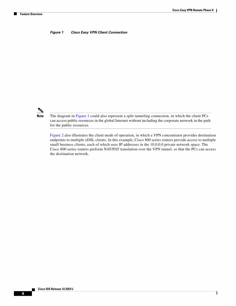
Figure 1 illustrates the client mode of operation. In this example, the Cisco uBR905 cable access router provides access to two PCs, which have IP addresses in the 10.0.0.0 private network space. These PCs connect to the Ethernet interface on the Cisco uBR905 router, which also has an IP address in the 10.0.0.0 private network space. The Cisco uBR905 router performs NAT/PAT translation over the VPN tunnel so that the PCs can access the destination network.
3Cisco IOS Release 12.2(8)YJ
Cisco Easy VPN Remote Phase IIFeature Overview
Figure 1 Cisco Easy VPN Client Connection
Note The diagram in Figure 1 could also represent a split tunneling connection, in which the client PCs can access public resources in the global Internet without including the corporate network in the path for the public resources.
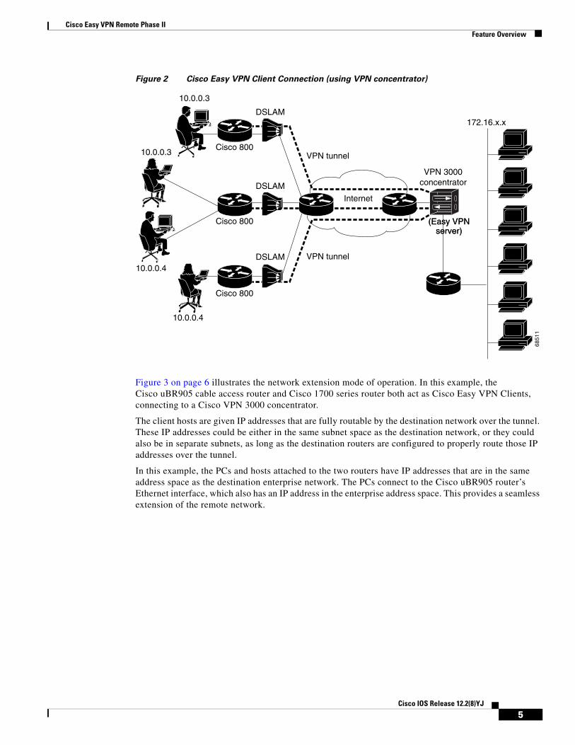
Figure 2 also illustrates the client mode of operation, in which a VPN concentrator provides destination endpoints to multiple xDSL clients. In this example, Cisco 800 series routers provide access to multiple small business clients, each of which uses IP addresses in the 10.0.0.0 private network space. The Cisco 800 series routers perform NAT/PAT translation over the VPN tunnel, so that the PCs can access the destination network.
4Cisco IOS Release 12.2(8)YJ
Cisco Easy VPN Remote Phase IIFeature Overview
Figure 2 Cisco Easy VPN Client Connection (using VPN concentrator)
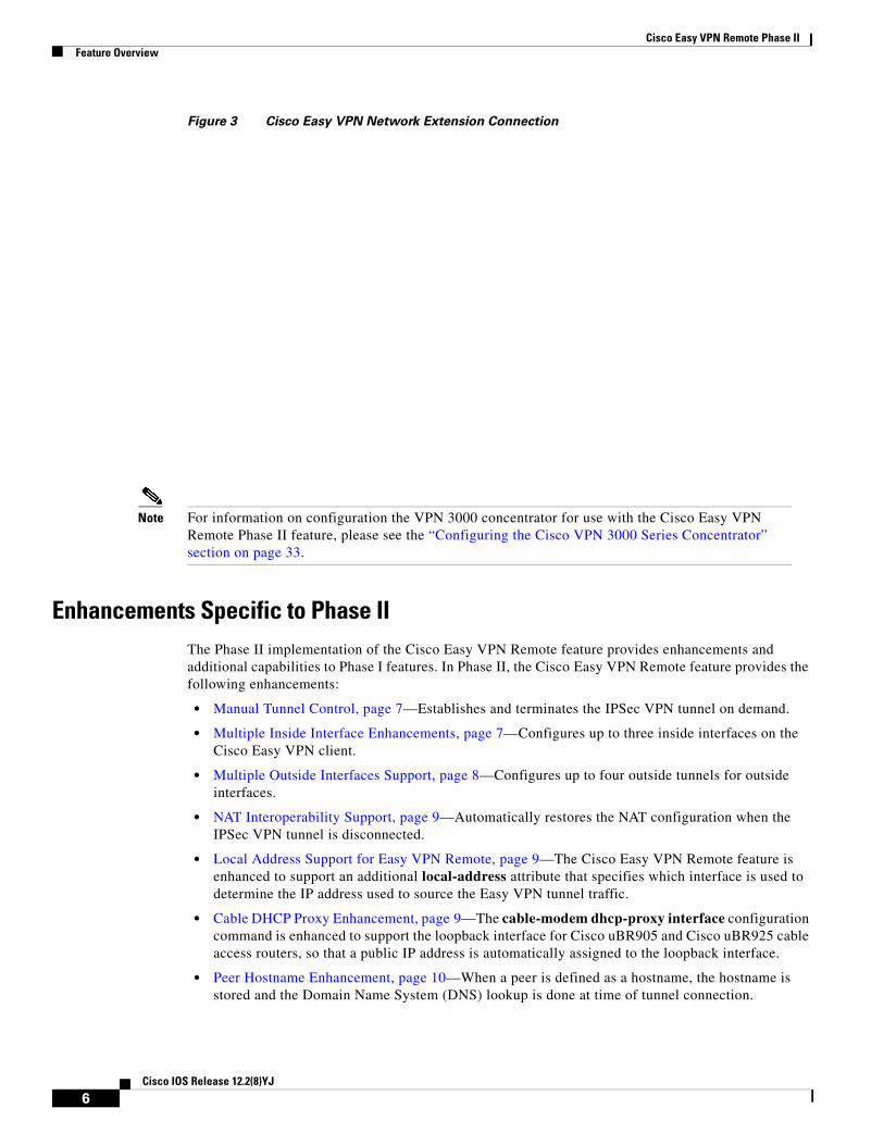
Figure 3 on page 6 illustrates the network extension mode of operation. In this example, the Cisco uBR905 cable access router and Cisco 1700 series router both act as Cisco Easy VPN Clients, connecting to a Cisco VPN 3000 concentrator.
The client hosts are given IP addresses that are fully routable by the destination network over the tunnel. These IP addresses could be either in the same subnet space as the destination network, or they could also be in separate subnets, as long as the destination routers are configured to properly route those IP addresses over the tunnel.
In this example, the PCs and hosts attached to the two routers have IP addresses that are in the same address space as the destination enterprise network. The PCs connect to the Cisco uBR905 router’s Ethernet interface, which also has an IP address in the enterprise address space. This provides a seamless extension of the remote network.
Internet
172.16.x.x
6851
1
10.0.0.3
10.0.0.3
10.0.0.4
10.0.0.4
VPN tunnel
VPN tunnelCisco 800
Cisco 800
Cisco 800
DSLAM
DSLAM
DSLAM
VPN 3000concentrator
(Easy VPNserver)
(Easy VPNserver)
5Cisco IOS Release 12.2(8)YJ
Cisco Easy VPN Remote Phase IIFeature Overview
Figure 3 Cisco Easy VPN Network Extension Connection
Note For information on configuration the VPN 3000 concentrator for use with the Cisco Easy VPN Remote Phase II feature, please see the “Configuring the Cisco VPN 3000 Series Concentrator” section on page 33.
Enhancements Specific to Phase IIThe Phase II implementation of the Cisco Easy VPN Remote feature provides enhancements and additional capabilities to Phase I features. In Phase II, the Cisco Easy VPN Remote feature provides the following enhancements:
• Manual Tunnel Control, page 7—Establishes and terminates the IPSec VPN tunnel on demand.
• Multiple Inside Interface Enhancements, page 7—Configures up to three inside interfaces on the Cisco Easy VPN client.
• Multiple Outside Interfaces Support, page 8—Configures up to four outside tunnels for outside interfaces.
• NAT Interoperability Support, page 9—Automatically restores the NAT configuration when the IPSec VPN tunnel is disconnected.
• Local Address Support for Easy VPN Remote, page 9—The Cisco Easy VPN Remote feature is enhanced to support an additional local-address attribute that specifies which interface is used to determine the IP address used to source the Easy VPN tunnel traffic.
• Cable DHCP Proxy Enhancement, page 9—The cable-modem dhcp-proxy interface configuration command is enhanced to support the loopback interface for Cisco uBR905 and Cisco uBR925 cable access routers, so that a public IP address is automatically assigned to the loopback interface.
• Peer Hostname Enhancement, page 10—When a peer is defined as a hostname, the hostname is stored and the Domain Name System (DNS) lookup is done at time of tunnel connection.
6Cisco IOS Release 12.2(8)YJ
Cisco Easy VPN Remote Phase IIFeature Overview
• Proxy DNS Server Support, page 10—Configures the router in a Cisco Easy VPN Remote configuration to act as a proxy DNS server for LAN connected users.
• PIX Interoperability Support, page 10—Supports Cisco PIX Firewall Version 6.2.
• Cisco IOS Firewall Support, page 10—Supports Cisco IOS Firewall configurations on all platforms.
• Simultaneous Easy VPN Client and Server Support, page 11—Configures simultaneous Easy VPN Client and Cisco Easy VPN Server support on the same Cisco 1700 series routers.
• Cisco Easy VPN Remote Web Manager, page 11—Users can manage the Cisco Easy VPN Remote feature on the Cisco uBR905 and Cisco uBR925 cable access routers using a built-in web interface.
In addition, as part of configuring the Cisco VPN 3000 series concentrator—for the Cisco Easy VPN Remote Phase II image—you do not need to create a new IPSec Security Association. Use the default Internet Key Exchange (IKE) and IPSec client lifetime configured on the Cisco VPN 3000 series concentrator.
Manual Tunnel Control
The IPSec Virtual Private Network (VPN) tunnel is automatically connected when the Cisco Easy VPN Remote feature is configured on an interface. If the tunnel times out or fails, the tunnel automatically reconnects and retries indefinitely. Cisco Easy VPN Remote Phase II implements manual control of IPSec VPN tunnels so that you can establish and terminate the IPSec VPN tunnel on demand.
The Easy VPN Remote configuration command, crypto ipsec client ezvpn name, is enhanced with a new subcommand, connect [auto | manual], to allow you to specify manual tunnel control.
Automatic is the default setting because it was the initial Phase I functionality. If automatic is the configuration, then you do not need to use the subcommand.
The manual setting means that the Cisco Easy VPN Client will wait for a command before attempting to establish the Cisco Easy VPN Remote connection. When the tunnel times out or fails, then subsequent connections will have to wait for the command also.
If the configuration is manual, then the tunnel is connected only after you issue the new command, crypto ipsec client ezvpn connect name.
The clear command, clear crypto ipsec client ezvpn [name], is enhanced to disconnect a given tunnel.
See “Configuring Manual Tunnel Control” section on page 18 for information on how to configure manual control of a tunnel.
Multiple Inside Interface Enhancements
The Cisco Easy VPN Client Phase I feature supported only one inside interface, which by default was the Fastethernet interface on the Cisco 1700 series and the ethernet interface on the Cisco 800 series and Cisco uBR900 series.
The inside interface support is enhanced in Cisco Easy VPN Remote Phase II to support multiple inside interfaces for all platforms. Inside interfaces can be manually configured with the enhanced command and subcommand:
interface interface-namecrypto ipsec client ezvpn name [outside | inside]
If you want to disable the default inside interface and configure another inside interface on the Cisco uBR905, Cisco uBR925, and on a Cisco 800 series router, you must configure the other inside interface first and then disable the default inside interface. You can use the following command to disable the default inside interface:
no crypto ipsec client ezvpn <name> inside
7Cisco IOS Release 12.2(8)YJ
Cisco Easy VPN Remote Phase IIFeature Overview
If you did not configure the other inside interface first before disabling the default inside interface, you receive a message such as the following:
ezvpn_client_37(config)#int e0ezvpn_client_37(config-if)#no crypto ipsec client ezvpn hw-client insideCannot remove the single inside interface unlessone other inside interface is configured
See “Configuring Multiple Inside Interfaces” section on page 19 for information on how to configure more than one inside interface.
The multiple inside interface enhancements support the following capabilities:
• Up to three inside interfaces are supported on the Cisco 1700 and 800 series routers. The Cisco uBR 925 only supports up to two inside interfaces (Ethernet and USB). The Cisco uBR905 is not affected as it only supports one inside interface (Ethernet).
• When multiple tunnels are configured, there can be confusion as to which tunnel gets the default inside interface. The Cisco 1700 series router has no default inside interface, and any inside interface must be configured. The Cisco 800 series and Cisco uBR905 and Cisco uBR925 series cable access routers have default inside interfaces (Ethernet interface). However, any inside interfaces for these platforms can be manually configured and the default inside interface can be disabled.
• At least one inside interface must be configured for each outside interface; otherwise, the Cisco Easy VPN Remote Phase II feature does not establish a connection.
• Adding a new inside interface or removing an existing inside interface automatically resets the Cisco Easy VPN Remote connection (the currently established tunnel). You must reconnect a manually configured tunnel, and if extended authentication (XAUTH) is required by the Cisco Easy VPN Server, the user is re-prompted. If you have set the Cisco Easy VPN Remote Phase II configuration to connect automatically and no XAUTH is required, then no user input is required.
Configuration information for the default inside interface is shown with the show crypto ipsec client ezvpn command. All inside interfaces, whether they belong to a tunnel, are listed in interface configuration mode as an inside interface, along with the tunnel name.
Multiple Outside Interfaces Support
The Cisco Easy VPN Client Phase I feature supported the configuration of only one tunnel for a single outside interface. The Phase II enhancement adds support for configuration of multiple tunnels for outside interfaces, by establishing one tunnel per outside interface. This functionality is applicable to multiple outside interface platforms such as the Cisco 1700 series routers. The Cisco 800 series router, and uBR905 and uBR925 cable access routers are not affected, because these routers support only one outside interface.
You can configure a maximum of four tunnels. This is done by the enhanced command, crypto ipsec client ezvpn name outside.
Note Each inside or outside interface supports only one tunnel. Multiple inside interfaces can be mapped to one outside interface.
To disconnect or clear a specific tunnel, the enhanced command, clear crypto ipsec ezvpn <name>, specifies the IPSec VPN tunnel name. If there is no tunnel name specified, then all existing tunnels are cleared.
See “Configuring Multiple Outside Interfaces” section on page 20 for more information on configuring more than one outside interface.
8Cisco IOS Release 12.2(8)YJ
Cisco Easy VPN Remote Phase IIFeature Overview
NAT Interoperability Support
Cisco Easy VPN Remote Phase II supports interoperability with Network Address Translation (NAT). You can have a NAT configuration and a Cisco Easy VPN Remote Phase II configuration coexist. When an IPSec VPN tunnel is down, the NAT configuration works.
The Cisco Easy VPN Remote Phase II feature automatically creates a NAT configuration, with the corresponding access lists, to implement client mode and split tunneling. In the initial release of the Cisco Easy VPN Client feature, this automatic NAT and access list configuration overrode any previous NAT and access list configuration. When a tunnel timed out or disconnected—due to manual tunnel control, for example—the automatic NAT and access configuration was automatically removed, which prevented any Internet access even to non-tunnel destinations.
In Phase II of the Cisco Easy VPN Remote feature, the router automatically restores the previous NAT configuration when the IPSec VPN tunnel is torn down. The user-defined access lists are not disturbed. Users can continue to access non-tunnel areas of the Internet when the tunnel times out or disconnects.
Local Address Support for Easy VPN Remote
The Cisco Easy VPN Remote Phase II feature is enhanced to support an additional local-address attribute that specifies which interface is used to determine the IP address used to source the Easy VPN Remote tunnel traffic. After specifying the interface with the local-address subcommand, you can manually assign a static IP address to the interface or use the cable-modem dhcp-proxy interface command to automatically configure the specified interface with a public IP address. See Configuring Easy VPN Remote with a Static IP Address, page 22 and Configuring Easy VPN Remote Using Cable DHCP Proxy, page 21 for configuration information. See “Cable DHCP Proxy Enhancement” section on page 9 for more information on the cable-modem dhcp-proxy interface command.
The local-address support is available for all platforms, but it is more applicable to the Cisco uBR905 and Cisco uBR925 cable access routers in conjunction with the cable-modem dhcp-proxy interface command. Typically, the loopback interface is the interface used to source tunnel traffic for the Cisco uBR905 and Cisco uBR925 cable access routers.
Cable DHCP Proxy Enhancement
In a typical DOCSIS network, the Cisco uBR905 and Cisco uBR925 cable access routers are normally configured with a private IP address on the cable-modem interface. In Cisco Easy VPN Client Phase I, a public IP address was required on the cable-modem interface to support the Easy VPN Client.
In Phase II, cable providers can use the Cable DHCP Proxy feature to obtain a public IP address and assign it to the cable modem interface, which is usually the loopback interface.
To support the Cisco Easy VPN Remote Phase II feature on the uBR905 and uBR925 cable access routers, the existing cable-modem dhcp-proxy interface configuration command is enhanced to support the loopback interface. The router automatically configures the loopback interface with the public IP address obtained from the DHCP server. You must create the loopback interface, which is a virtual interface, first before issuing the cable-modem dhcp-proxy interface command.
See “Configuring Easy VPN Remote Using Cable DHCP Proxy” section on page 21 for information on how to configure the Cable DHCP Proxy feature.
For more information on the cable-modem dhcp-proxy interface command, refer to the “Cable CPE Commands” chapter at http://www.cisco.com/univercd/cc/td/doc/product/cable/bbccmref/bbcmcpe.htm in the Cisco Broadband Cable Command Reference Guide at http://www.cisco.com/univercd/cc/td/doc/product/cable/bbccmref/index.htm.
9Cisco IOS Release 12.2(8)YJ
Cisco Easy VPN Remote Phase IIFeature Overview
Note The cable-modem dhcp-proxy interface command is only supported for the Cisco uBR905 and Cisco uBR925 cable access routers.
Peer Hostname Enhancement
The peer in a Cisco Easy VPN Remote Phase II feature configuration can be defined as an IP address or a hostname. Typically when a peer is defined as a hostname, a Domain Name System (DNS) lookup is done immediately to get an IP address. In the Cisco Easy VPN Remote Phase II feature, the peer hostname operation is enhanced to support DNS entry changes. The text string of the hostname is stored so that the DNS lookup is done at the time of the tunnel connection, not when the peer is defined as a hostname.
See “Configuring and Assigning the Cisco Easy VPN Remote Configuration” section on page 30 for information on enabling the peer hostname functionality.
Proxy DNS Server Support
When the WAN connection is down—that is, the IPSec VPN tunnel is down—the Domain Name System (DNS) addresses of the ISP or cable provider should be used to resolve DNS requests. When the WAN connection is up, the enterprise’s DNS addresses should be used.
As a way of implementing use of the cable provider’s DNS addresses when the WAN connection is down, the router in a Cisco Easy VPN Remote Phase II configuration can be configured to act as a proxy DNS server. The router, acting as a proxy DNS server for LAN connected users, receives DNS queries from local users on behalf of the real DNS server. The DHCP server then is able to send out the router’s LAN address as the DNS server’s IP address. Then after the WAN connection comes up, the router forwards the DNS queries to the real DNS server and caches the DNS query records.
See “Configuring Proxy DNS Server Support” section on page 22 for information on enabling the proxy DNS server functionality.
PIX Interoperability Support
The Cisco Easy VPN Remote Phase II feature supports Cisco PIX Firewall Version 6.2.
See “PIX Interoperability Support Example” section on page 38 for an example output.
You can refer to Cisco PIX Firewall and VPN Configuration Guide Version 6.2 documentation on Cisco.com at the following URL:
http://www.cisco.com/univercd/cc/td/doc/product/iaabu/pix/pix_62/config/index.htm
Cisco IOS Firewall Support
The Cisco Easy VPN Remote Phase II feature works in conjunction with Cisco IOS Firewall configurations on all platforms.
10Cisco IOS Release 12.2(8)YJ
Cisco Easy VPN Remote Phase IIFeature Overview
Simultaneous Easy VPN Client and Server Support
You can configure simultaneous Cisco Easy VPN Client and Cisco Easy VPN Server support on the same Cisco 1700 series routers. You can configure one outside interface as a Cisco Easy VPN Server and another outside interface on the same router as a Cisco Easy VPN Client. This support is applicable for multiple outside interface platforms, such as the Cisco 1700 series routers.
Cisco Easy VPN Remote Web Manager
The Cisco Easy VPN Remote Web Manager is a web interface used to manage the Cisco Easy VPN Remote Phase II feature for Cisco uBR905 and Cisco uBR925 cable access routers. Users do not need access to the command-line interface (CLI) to manage the Cisco Easy VPN Remote Phase II connection. The web interface allows the user to:
• See the current status of theCisco Easy VPN Remote Phase II tunnel.
• Connect a tunnel that is configured for manual control.
• Disconnect a tunnel that is configured for manual control or reset a tunnel configured for automatic connection.
• Be prompted for Xauth information if Xauth information is needed.
See Configuring and Using the Cisco Easy VPN Remote Web Manager, page 23 for more information.
Differences Between Cisco Easy VPN Remote Phase II and Phase I
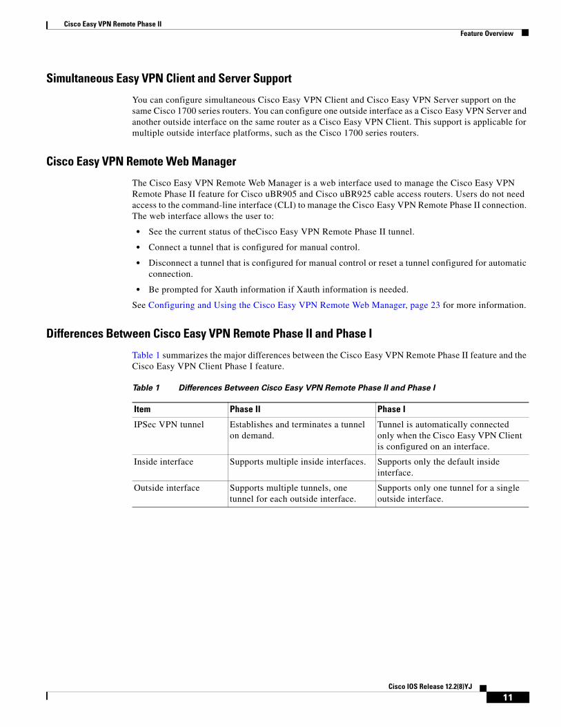
Table 1 summarizes the major differences between the Cisco Easy VPN Remote Phase II feature and the Cisco Easy VPN Client Phase I feature.
Table 1 Differences Between Cisco Easy VPN Remote Phase II and Phase I
Item Phase II Phase I
IPSec VPN tunnel Establishes and terminates a tunnel on demand.
Tunnel is automatically connected only when the Cisco Easy VPN Client is configured on an interface.
Inside interface Supports multiple inside interfaces. Supports only the default inside interface.
Outside interface Supports multiple tunnels, one tunnel for each outside interface.
Supports only one tunnel for a single outside interface.
11Cisco IOS Release 12.2(8)YJ
Cisco Easy VPN Remote Phase IIFeature Overview
Benefits• Allows dynamic configuration of end-user policy, requiring less manual configuration by end users
and field technicians, thus reducing errors and further service calls.
• Allows the provider to change equipment and network configurations as needed, with little or no reconfiguration of the end-user equipment.
• Provides for centralized security policy management.
• Enables large-scale deployments with rapid user provisioning.
• Eliminates the need for end users to purchase and configure external VPN devices.
• Eliminates the need for end users to install and configure VPN client software on their PCs.
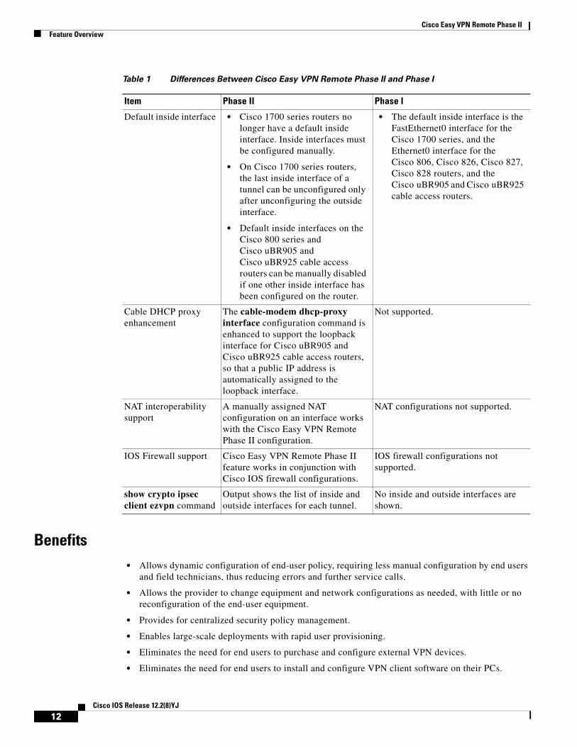
Default inside interface • Cisco 1700 series routers no longer have a default inside interface. Inside interfaces must be configured manually.
• On Cisco 1700 series routers, the last inside interface of a tunnel can be unconfigured only after unconfiguring the outside interface.
• Default inside interfaces on the Cisco 800 series and Cisco uBR905 and Cisco uBR925 cable access routers can be manually disabled if one other inside interface has been configured on the router.
• The default inside interface is the FastEthernet0 interface for the Cisco 1700 series, and the Ethernet0 interface for the Cisco 806, Cisco 826, Cisco 827, Cisco 828 routers, and the Cisco uBR905 and Cisco uBR925 cable access routers.
Cable DHCP proxy enhancement
The cable-modem dhcp-proxy interface configuration command is enhanced to support the loopback interface for Cisco uBR905 and Cisco uBR925 cable access routers, so that a public IP address is automatically assigned to the loopback interface.
Not supported.
NAT interoperability support
A manually assigned NAT configuration on an interface works with the Cisco Easy VPN Remote Phase II configuration.
NAT configurations not supported.
IOS Firewall support Cisco Easy VPN Remote Phase II feature works in conjunction with Cisco IOS firewall configurations.
IOS firewall configurations not supported.
show crypto ipsec client ezvpn command
Output shows the list of inside and outside interfaces for each tunnel.
No inside and outside interfaces are shown.
Table 1 Differences Between Cisco Easy VPN Remote Phase II and Phase I
Item Phase II Phase I
12Cisco IOS Release 12.2(8)YJ
Cisco Easy VPN Remote Phase IIFeature Overview
• Offloads the creation and maintenance of the VPN connections from the PC to the router.
• Reduces interoperability problems between the different PC-based software VPN clients, external hardware-based VPN solutions, and other VPN applications.
Restrictions
Sub-interfaces Not Supported
Establishing Cisco Easy VPN Remote Phase II tunnels over sub-interfaces is not supported in Cisco IOS Release 12.2(8)YJ.
Cisco Easy VPN Remote Web Manager Does Not Support Cable-Monitor Web Interface
The Cisco Easy VPN Remote Web Manager does not work with the cable -monitor web interface in Cisco IOS 12.2(8)YJ Release. To access the cable-monitor web interface, you must first disable the Cisco Easy VPN Remote web interface with the no ip http ezvpn command, and then enable the Cable Monitor with the ip http cable-monitor command.
Only One Destination Peer Supported
The Cisco Easy VPN Remote Phase II feature supports the configuration of only one destination peer and tunnel connection. If your application requires the creation of multiple VPN tunnels, you must manually configure the IPSec VPN and NAT/PAT parameters on both the client and the server.
Required Destination Servers
The Cisco Easy VPN Remote Phase II feature requires that the destination peer be a VPN remote access server or VPN concentrator that supports the Cisco Easy VPN Server feature. At the time of publication, this includes the following platforms when running the indicated software releases:
• Cisco 806, Cisco 826, Cisco 827, and Cisco 828 routers—Cisco IOS Release 12.2(8)T or later release
• Cisco 1700 series—Cisco IOS Release 12.2(8)T or later release
• Cisco 2600 series—Cisco IOS Release 12.2(8)T or later release
• Cisco 3620—Cisco IOS Release 12.2(8)T or later release
• Cisco 3640—Cisco IOS Release 12.2(8)T or later release
• Cisco 3660—Cisco IOS Release 12.2(8)T or later release
• Cisco 7100 series VPN routers—Cisco IOS Release 12.2(8)T or later release
• Cisco 7200 series routers—Cisco IOS Release 12.2(8)T or later release
• Cisco 7500 series routers—Cisco IOS Release 12.2(8)T or later release
• Cisco uBR905 and Cisco uBR925 cable access routers—Cisco IOS Release 12.2(8)T or later release
• Cisco VPN 3000 series—Software Release 3.11 or later release
• Cisco PIX 500 series—Software Release 6.2 or later release
Digital Certificates Not Supported
In Cisco IOS Release 12.2(8)YJ, the Cisco Easy VPN Remote Phase II feature does not support authentication using digital certificates. Authentication is supported using preshared keys and Extended Authentication (XAUTH).
13Cisco IOS Release 12.2(8)YJ
Cisco Easy VPN Remote Phase IIFeature Overview
Only ISAKMP Policy Group 2 Supported on IPSec Servers
The Unity Protocol supports only ISAKMP policies that use group 2 (1024-bit Diffie-Hellman) IKE negotiation, so the IPSec server being used with the Cisco Easy VPN Remote Phase II feature must be configured for a group 2 ISAKMP policy. The IPSec server cannot be configured for ISAKMP group 1 or group 5 when being used with a Cisco Easy VPN Client.
Perfect Forward Secrecy Not Supported
The Cisco Easy VPN Remote Phase II feature does not support the Perfect Forward Secrecy (PFS) feature that is available on the Cisco VPN 3000 concentrator.
Transform Sets Supported
To ensure a secure tunnel connection, the Cisco Easy VPN Remote Phase II feature does not support transform sets that provide encryption without authentication (ESP-DES and ESP-3DES) or transform sets that provide authentication without encryption (ESP-NULL ESP-SHA-HMAC and ESP-NULL ESP-MD5-HMAC).
Changing the IP Address on the LAN Interface on Cisco 800 Series Routers
The Ethernet 0 LAN interface on the Cisco 800 series routers defaults to a primary IP address in the private network of 10.10.10.0. You can change this IP address to match the local network’s configuration by using either the ip address CLI command or the Cisco Router Web Setup (CRWS) web interface.
These two techniques differ slightly in how the new IP address is assigned. When the CLI command is used, the new IP address is assigned as the primary address for the interface. When the CRWS interface is used, the new IP address is assigned as the secondary address and the existing IP address is preserved as the primary address for the interface. This allows the CRWS interface to maintain the existing connection between the PC web browser and the Cisco 800 series router.
Because of this behavior, the Cisco Easy VPN Remote Phase II feature assumes that if a secondary IP address exists on the Ethernet 0 interface, the secondary address should be used as the IP address for the inside interface for the NAT/PAT configuration. If no secondary address exists, the primary IP address is used for the inside interface address, as is normally done on other platforms. If this behavior is not desired, use the ip address CLI command to change the interface’s address, instead of using the CRWS web interface.
VPN 3000 Configuration
The configuration of the Cisco VPN 3000 concentrator has some restrictions when used with the Cisco Easy VPN Remote Phase II feature. See the “Configuring the Cisco VPN 3000 Series Concentrator” section on page 33 for more details.
See the “PIX Interoperability Support” section on page 10 for information on Cisco PIX Firewall Version 6.2 support.
Related DocumentsThis section lists other documentation related to the configuration and maintenance of the Cisco Easy VPN Remote Phase II feature and the supported routers.
14Cisco IOS Release 12.2(8)YJ
Cisco Easy VPN Remote Phase IIFeature Overview
Platform-Specific Documentation
Cisco 800 Series Routers
• Cisco 806 Router Hardware Installation Guide
• Cisco 806 Router and SOHO 71 Router Hardware Installation Guide
• Cisco 826 Router Hardware Installation Guide
• Cisco 826 and SOHO76 Router Hardware Installation Guide
• Cisco 827 Router Hardware Installation Guide
• Cisco 827 and SOHO 77 Routers Hardware Installation Guide
• Cisco 828 and SOHO 78 Routers Hardware Installation Guide
• Cisco 806 Software Configuration Guide
• Cisco 827 Router Software Configuration Guide
• Cisco 828 Router and SOHO 78 Router Software Configuration Guide
Cisco uBR905 and Cisco uBR925 Cable Access Routers
• Cisco uBR925 Cable Access Router Hardware Installation Guide
• Cisco uBR905 Hardware Installation Guide
• Cisco uBR905/uBR925 Cable Access Router Software Configuration Guide
• Cisco uBR925 Cable Access Router Subscriber Setup Quick Start Card
• Cisco uBR905 Cable Access Router Subscriber Setup Quick Start Card
• Cisco uBR925 Cable Access Router Quick Start User Guide
Cisco 1700 Series Routers
• Cisco 1700 Series Router Software Configuration Guide
• Cisco 1710 Security Router Hardware Installation Guide
• Cisco 1710 Security Router Software Configuration Guide
• Cisco 1720 Series Router Hardware Installation Guide
• Cisco 1721 Access Router Hardware Installation Guide
• Cisco 1750 Series Router Hardware Installation Guide
• Cisco 1751 Router Hardware Installation Guide
• Cisco 1751 Router Software Configuration Guide
• Cisco 1760 Modular Access Router Hardware Installation Guide
Also see the Cisco IOS release notes for Cisco IOS Release 12.2(4)YA:
• SOHO 70 and Cisco 800 Series—Release Notes for Release 12.2(4)YA
• Release Notes for Cisco uBR905 and Cisco uBR925 Cable Access Routers for Cisco IOS Release 12.2 YA
• Cisco 1700 Series—Release Notes for Release 12.2(4)YA
15Cisco IOS Release 12.2(8)YJ
Cisco Easy VPN Remote Phase IISupported Platforms
IPsec and VPN Documentation
For information on the VPN Remote Access Enhancements feature, which provides Cisco Unity client support for the Cisco Easy VPN Remote Phase II feature, see the VPN Remote Access Enhancements feature module for Cisco IOS Release 12.2(8)T.
For general information on IPSec and VPN subjects, see the following information in the product literature and IP technical tips sections on Cisco.com:
• Deploying IPsec—Provides an overview of IPsec encryption and its key concepts, along with sample configurations. Also provides a link to many other documents on related topics.
• Certificate Authority Support for IPsec Overview—Describes the concept of digital certificates and how they are used to authenticate IPsec users.
• An Introduction to IP Security (IPsec) Encryption—Provides a step-by-step description of how to configure IPsec encryption.
The following technical documents, available on Cisco.com and the Documentation CD-ROM, also provide more in-depth configuration information:
• Cisco IOS Security Configuration Guide, Cisco IOS Release 12.2—Provides an overview of Cisco IOS security features.
• Cisco IOS Security Command Reference, Cisco IOS Release 12.2—Provides a reference for each of the Cisco IOS commands used to configure IPsec encryption and related security features.
• Cisco IOS Software Command Summary, Cisco IOS Release 12.2—Summarizes the Cisco IOS commands used to configure all Release 12.1 security features.
Note Additional documentation on IPSec becomes available on Cisco.com and the Documentation CD-ROM as new features and platforms are added. Cisco Press also publishes several books on IPSec—go to http://www.ciscopress.com for more information on Cisco Press books.
Supported Platforms• Cisco 806, Cisco 826, Cisco 827, and Cisco 828 routers
• Cisco uBR905 and Cisco uBR925 cable access routers
• Cisco 1700 series routers
Determining Platform Support Through Feature Navigator
Cisco IOS software is packaged in feature sets that support specific platforms. To get updated information regarding platform support for this feature, access Feature Navigator. Feature Navigator dynamically updates the list of supported platforms as new platform support is added for the feature.
Feature Navigator is a web-based tool that enables you to quickly determine which Cisco IOS software images support a specific set of features and which features are supported in a specific Cisco IOS image.
To access Feature Navigator, you must have an account on Cisco.com. If you have forgotten or lost your account information, send a blank e-mail to [email protected]. An automatic check will verify that your e-mail address is registered with Cisco.com. If the check is successful, account details with a new random password will be e-mailed to you. Qualified users can establish an account on Cisco.com by following the directions at http://www.cisco.com/register.
16Cisco IOS Release 12.2(8)YJ

Cisco Easy VPN Remote Phase IISupported Standards, MIBs, and RFCs
Feature Navigator is updated regularly when major Cisco IOS software releases and technology releases occur. For the most current information, go to the Feature Navigator home page at the following URL:
http://www.cisco.com/go/fn
Supported Standards, MIBs, and RFCsStandards
No new or modified standards are supported by this feature.
MIBs
The following new or modified MIBs are supported by this feature:
• CISCO-IPSEC-FLOW-MONITOR-MIB—Contains attributes describing IPSec-based VPNs (IETF IPSec Working Group Draft).
• CISCO-IPSEC-MIB—Describes Cisco implementation-specific attributes for Cisco routers implementing IPSec VPNs.
• CISCO-IPSEC-POLICY-MAP-MIB—Extends the CISCO-IPSEC-FLOW-MONITOR-MIB to map dynamically instantiated structures to the policies, transforms, cryptomaps, and other structures that created or are using them.
To obtain lists of supported MIBs by platform and Cisco IOS release, and to download MIB modules, go to the Cisco MIB website on Cisco.com at the following URL:
http://www.cisco.com/public/sw-center/netmgmt/cmtk/mibs.shtml
RFCs
No new or modified RFCs are supported by this feature.
PrerequisitesThe following requirements are necessary to use the Cisco Easy VPN Remote Phase II feature:
• A Cisco 806, Cisco 826, Cisco 827, or Cisco 828 router; Cisco 1700 series router; or Cisco uBR905 or Cisco uBR925 cable access router running Cisco IOS Release 12.2(8)YJ or later, configured as a Cisco Easy VPN Client.
• Another Cisco router or VPN concentrator that supports the Cisco Easy VPN Server feature and configured as a VPN remote access server. See the “Required Destination Servers” section on page 13 for a detailed list.
17Cisco IOS Release 12.2(8)YJ
Cisco Easy VPN Remote Phase IIConfiguration Tasks
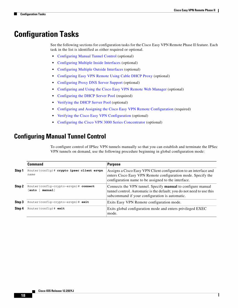
Configuration TasksSee the following sections for configuration tasks for the Cisco Easy VPN Remote Phase II feature. Each task in the list is identified as either required or optional.
• Configuring Manual Tunnel Control (optional)
• Configuring Multiple Inside Interfaces (optional)
• Configuring Multiple Outside Interfaces (optional)
• Configuring Easy VPN Remote Using Cable DHCP Proxy (optional)
• Configuring Proxy DNS Server Support (optional)
• Configuring and Using the Cisco Easy VPN Remote Web Manager (optional)
• Configuring the DHCP Server Pool (required)
• Verifying the DHCP Server Pool (optional)
• Configuring and Assigning the Cisco Easy VPN Remote Configuration (required)
• Verifying the Cisco Easy VPN Configuration (optional)
• Configuring the Cisco VPN 3000 Series Concentrator (optional)
Configuring Manual Tunnel ControlTo configure control of IPSec VPN tunnels manually so that you can establish and terminate the IPSec VPN tunnels on demand, use the following procedure beginning in global configuration mode:
Command Purpose
Step 1 Router(config)# crypto ipsec client ezvpn name
Assigns a Cisco Easy VPN Client configuration to an interface and enters Cisco Easy VPN Remote configuration mode. Specify the configuration name to be assigned to the interface.
Step 2 Router(config-crypto-ezvpn)# connect [auto | manual]
Connects the VPN tunnel. Specify manual to configure manual tunnel control. Automatic is the default; you do not need to use this subcommand if your configuration is automatic.
Step 3 Router(config-crypto-ezvpn)# exit Exits Easy VPN Remote configuration mode.
Step 4 Router(config)# exit Exits global configuration mode and enters privileged EXEC mode.
18Cisco IOS Release 12.2(8)YJ
Cisco Easy VPN Remote Phase IIConfiguration Tasks
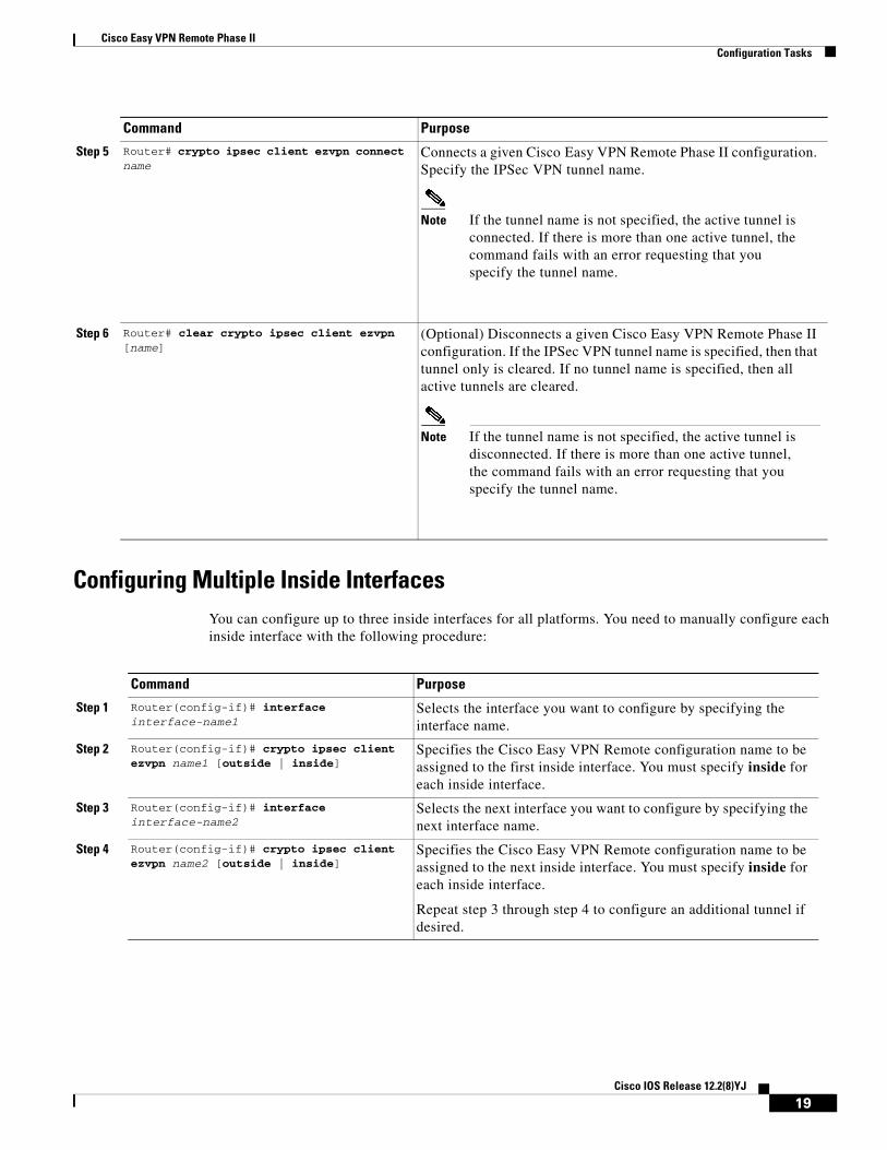
Configuring Multiple Inside InterfacesYou can configure up to three inside interfaces for all platforms. You need to manually configure each inside interface with the following procedure:
Step 5 Router# crypto ipsec client ezvpn connect name
Connects a given Cisco Easy VPN Remote Phase II configuration. Specify the IPSec VPN tunnel name.
Note If the tunnel name is not specified, the active tunnel is connected. If there is more than one active tunnel, the command fails with an error requesting that you specify the tunnel name.
Step 6 Router# clear crypto ipsec client ezvpn [name]
(Optional) Disconnects a given Cisco Easy VPN Remote Phase II configuration. If the IPSec VPN tunnel name is specified, then that tunnel only is cleared. If no tunnel name is specified, then all active tunnels are cleared.
Note If the tunnel name is not specified, the active tunnel is disconnected. If there is more than one active tunnel, the command fails with an error requesting that you specify the tunnel name.
Command Purpose
Command Purpose
Step 1 Router(config-if)# interface interface-name1
Selects the interface you want to configure by specifying the interface name.
Step 2 Router(config-if)# crypto ipsec client ezvpn name1 [outside | inside]
Specifies the Cisco Easy VPN Remote configuration name to be assigned to the first inside interface. You must specify inside for each inside interface.
Step 3 Router(config-if)# interface interface-name2
Selects the next interface you want to configure by specifying the next interface name.
Step 4 Router(config-if)# crypto ipsec client ezvpn name2 [outside | inside]
Specifies the Cisco Easy VPN Remote configuration name to be assigned to the next inside interface. You must specify inside for each inside interface.
Repeat step 3 through step 4 to configure an additional tunnel if desired.
19Cisco IOS Release 12.2(8)YJ
Cisco Easy VPN Remote Phase IIConfiguration Tasks
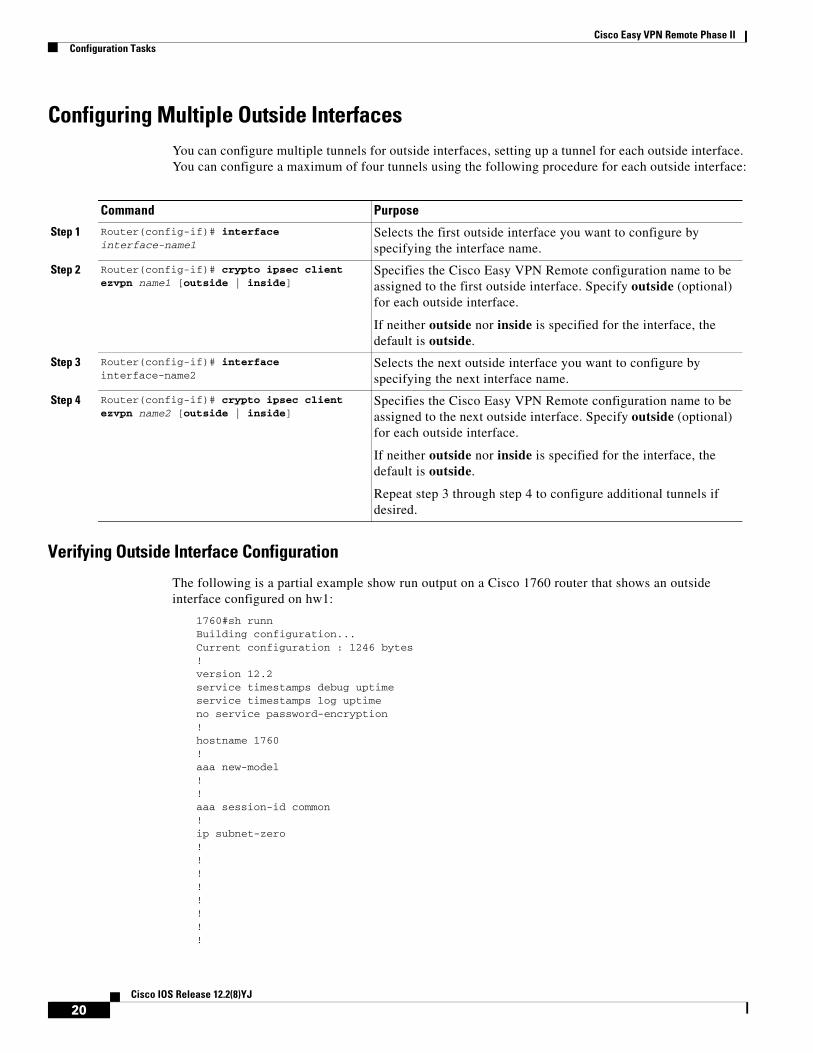
Configuring Multiple Outside InterfacesYou can configure multiple tunnels for outside interfaces, setting up a tunnel for each outside interface. You can configure a maximum of four tunnels using the following procedure for each outside interface:
Verifying Outside Interface Configuration
The following is a partial example show run output on a Cisco 1760 router that shows an outside interface configured on hw1:
1760#sh runn Building configuration...Current configuration : 1246 bytes ! version 12.2 service timestamps debug uptime service timestamps log uptime no service password-encryption ! hostname 1760 ! aaa new-model ! ! aaa session-id common ! ip subnet-zero ! ! ! ! ! ! ! !
Command Purpose
Step 1 Router(config-if)# interface interface-name1
Selects the first outside interface you want to configure by specifying the interface name.
Step 2 Router(config-if)# crypto ipsec client ezvpn name1 [outside | inside]
Specifies the Cisco Easy VPN Remote configuration name to be assigned to the first outside interface. Specify outside (optional) for each outside interface.
If neither outside nor inside is specified for the interface, the default is outside.
Step 3 Router(config-if)# interface interface-name2
Selects the next outside interface you want to configure by specifying the next interface name.
Step 4 Router(config-if)# crypto ipsec client ezvpn name2 [outside | inside]
Specifies the Cisco Easy VPN Remote configuration name to be assigned to the next outside interface. Specify outside (optional) for each outside interface.
If neither outside nor inside is specified for the interface, the default is outside.
Repeat step 3 through step 4 to configure additional tunnels if desired.
20Cisco IOS Release 12.2(8)YJ
Cisco Easy VPN Remote Phase IIConfiguration Tasks
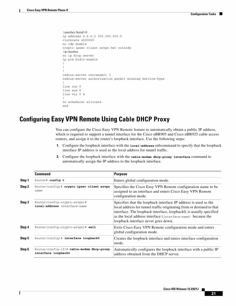
!interface Serial1/0 ip address 6.6.6.2 255.255.255.0 clockrate 4000000 no cdp enable crypto ipsec client ezvpn hw1 outside!ip classless no ip http server ip pim bidir-enable ! ! ! radius-server retransmit 3 radius-server authorization permit missing Service-Type ! line con 0 line aux 0 line vty 0 4 ! no scheduler allocate end
Configuring Easy VPN Remote Using Cable DHCP ProxyYou can configure the Cisco Easy VPN Remote feature to automatically obtain a public IP address, which is required to support a tunnel interface for the Cisco uBR905 and Cisco uBR925 cable access routers, and assign it to the router’s loopback interface. Use the following steps:
1. Configure the loopback interface with the local-address subcommand to specify that the loopback interface IP address is used as the local address for tunnel traffic.
2. Configure the loopback interface with the cable-modem dhcp-proxy interface command to automatically assign the IP address to the loopback interface.
Command Purpose
Step 1 Router# config t Enters global configuration mode.
Step 2 Router(config)# crypto ipsec client ezvpn name
Specifies the Cisco Easy VPN Remote configuration name to be assigned to an interface and enters Cisco Easy VPN Remote configuration mode.
Step 3 Router(config-crypto-ezvpn)# local-address interface-name
Specifies that the loopback interface IP address is used as the local address for tunnel traffic originating from or destined to that interface. The loopback interface, loopback0, is usually specified as the local address interface (interface-name) because the loopback interface never goes down.
Step 4 Router(config-crypto-ezvpn)# exit Exits Cisco Easy VPN Remote configuration mode and enters global configuration mode.
Step 5 Router(config)# interface loopback0 Creates the loopback interface and enters interface configuration mode.
Step 6 Router(config-if)# cable-modem dhcp-proxy interface loopback0
Automatically configures the loopback interface with a public IP address obtained from the DHCP server.
21Cisco IOS Release 12.2(8)YJ
Cisco Easy VPN Remote Phase IIConfiguration Tasks
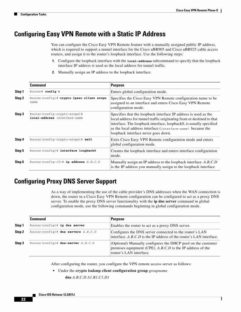
Configuring Easy VPN Remote with a Static IP AddressYou can configure the Cisco Easy VPN Remote feature with a manually assigned public IP address, which is required to support a tunnel interface for the Cisco uBR905 and Cisco uBR925 cable access routers, and assign it to the router’s loopback interface. Use the following steps:
1. Configure the loopback interface with the local-address subcommand to specify that the loopback interface IP address is used as the local address for tunnel traffic.
2. Manually assign an IP address to the loopback interface.
Configuring Proxy DNS Server SupportAs a way of implementing the use of the cable provider’s DNS addresses when the WAN connection is down, the router in a Cisco Easy VPN Remote configuration can be configured to act as a proxy DNS server. To enable the proxy DNS server functionality with the ip dns server command in global configuration mode, use the following commands beginning in global configuration mode.
After configuring the router, you configure the VPN remote access server as follows:
• Under the crypto isakmp client configuration group groupname
dns A.B.C.D A1.B1.C1.D1
Command Purpose
Step 1 Router# config t Enters global configuration mode.
Step 2 Router(config)# crypto ipsec client ezvpn name
Specifies the Cisco Easy VPN Remote configuration name to be assigned to an interface and enters Cisco Easy VPN Remote configuration mode.
Step 3 Router(config-crypto-ezvpn)# local-address interface-name
Specifies that the loopback interface IP address is used as the local address for tunnel traffic originating from or destined to that interface. The loopback interface, loopback0, is usually specified as the local address interface (interface-name) because the loopback interface never goes down.
Step 4 Router(config-crypto-ezvpn)# exit Exits Cisco Easy VPN Remote configuration mode and enters global configuration mode.
Step 5 Router(config)# interface loopback0 Creates the loopback interface and enters interface configuration mode.
Step 6 Router(config-if)# ip address A.B.C.D Manually assign an IP address to the loopback interface. A.B.C.D is the IP address you manually assign to the loopback interface
Command Purpose
Step 1 Router(config)# ip dns server Enables the router to act as a proxy DNS server.
Step 2 Router(config)# dns servers A.B.C.D Configures the DNS server connected to the router’s LAN interface. A.B.C.D is the IP address of the router’s LAN interface.
Step 3 Router(config)# dns-server A.B.C.D (Optional) Manually configures the DHCP pool on the customer premises equipment (CPE). A.B.C.D is the IP address of the router’s LAN interface.
22Cisco IOS Release 12.2(8)YJ
Cisco Easy VPN Remote Phase IIConfiguration Tasks
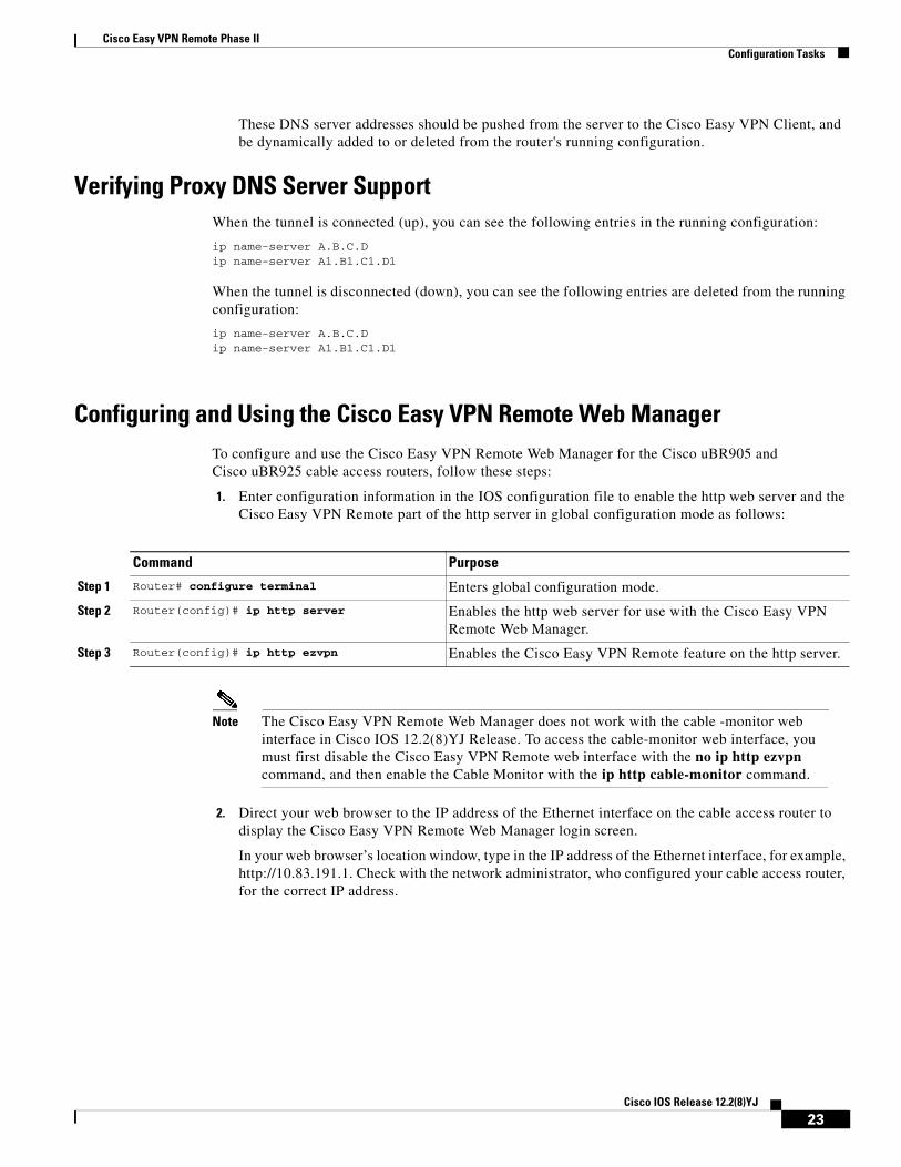
These DNS server addresses should be pushed from the server to the Cisco Easy VPN Client, and be dynamically added to or deleted from the router's running configuration.
Verifying Proxy DNS Server SupportWhen the tunnel is connected (up), you can see the following entries in the running configuration:
ip name-server A.B.C.D ip name-server A1.B1.C1.D1
When the tunnel is disconnected (down), you can see the following entries are deleted from the running configuration:
ip name-server A.B.C.D ip name-server A1.B1.C1.D1
Configuring and Using the Cisco Easy VPN Remote Web ManagerTo configure and use the Cisco Easy VPN Remote Web Manager for the Cisco uBR905 and Cisco uBR925 cable access routers, follow these steps:
1. Enter configuration information in the IOS configuration file to enable the http web server and the Cisco Easy VPN Remote part of the http server in global configuration mode as follows:
Note The Cisco Easy VPN Remote Web Manager does not work with the cable -monitor web interface in Cisco IOS 12.2(8)YJ Release. To access the cable-monitor web interface, you must first disable the Cisco Easy VPN Remote web interface with the no ip http ezvpn command, and then enable the Cable Monitor with the ip http cable-monitor command.
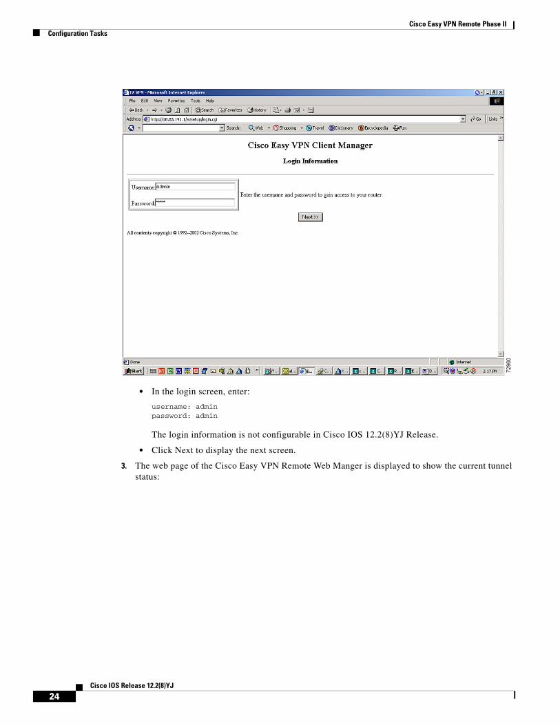
2. Direct your web browser to the IP address of the Ethernet interface on the cable access router to display the Cisco Easy VPN Remote Web Manager login screen.
In your web browser’s location window, type in the IP address of the Ethernet interface, for example, http://10.83.191.1. Check with the network administrator, who configured your cable access router, for the correct IP address.
Command Purpose
Step 1 Router# configure terminal Enters global configuration mode.
Step 2 Router(config)# ip http server Enables the http web server for use with the Cisco Easy VPN Remote Web Manager.
Step 3 Router(config)# ip http ezvpn Enables the Cisco Easy VPN Remote feature on the http server.
23Cisco IOS Release 12.2(8)YJ
Cisco Easy VPN Remote Phase IIConfiguration Tasks
• In the login screen, enter:
username: adminpassword: admin
The login information is not configurable in Cisco IOS 12.2(8)YJ Release.
• Click Next to display the next screen.
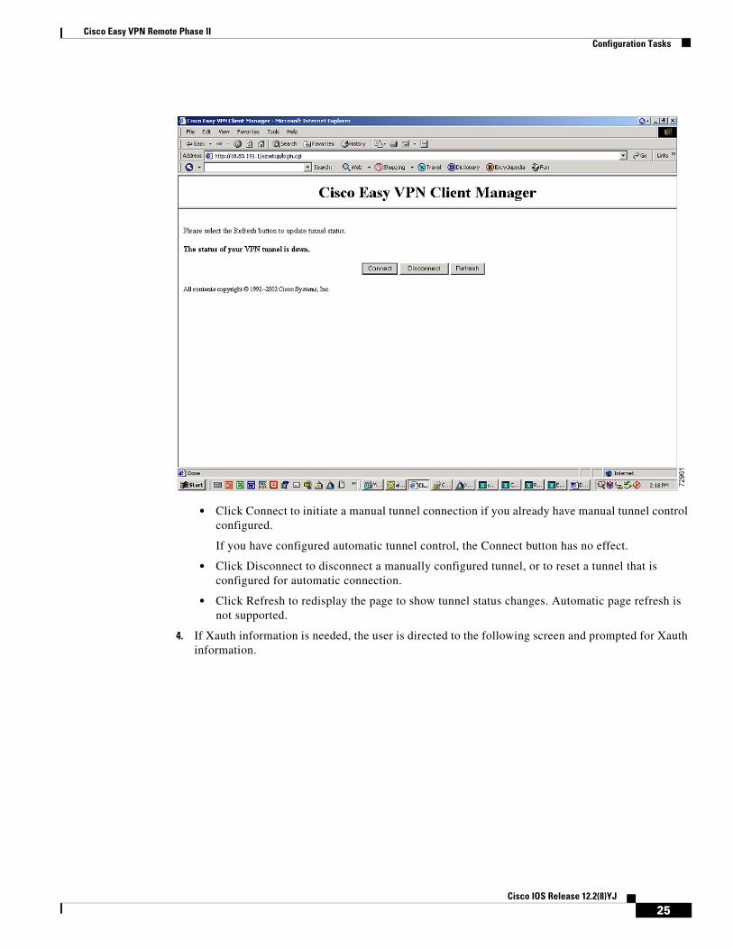
3. The web page of the Cisco Easy VPN Remote Web Manger is displayed to show the current tunnel status:
24Cisco IOS Release 12.2(8)YJ
Cisco Easy VPN Remote Phase IIConfiguration Tasks
• Click Connect to initiate a manual tunnel connection if you already have manual tunnel control configured.
If you have configured automatic tunnel control, the Connect button has no effect.
• Click Disconnect to disconnect a manually configured tunnel, or to reset a tunnel that is configured for automatic connection.
• Click Refresh to redisplay the page to show tunnel status changes. Automatic page refresh is not supported.
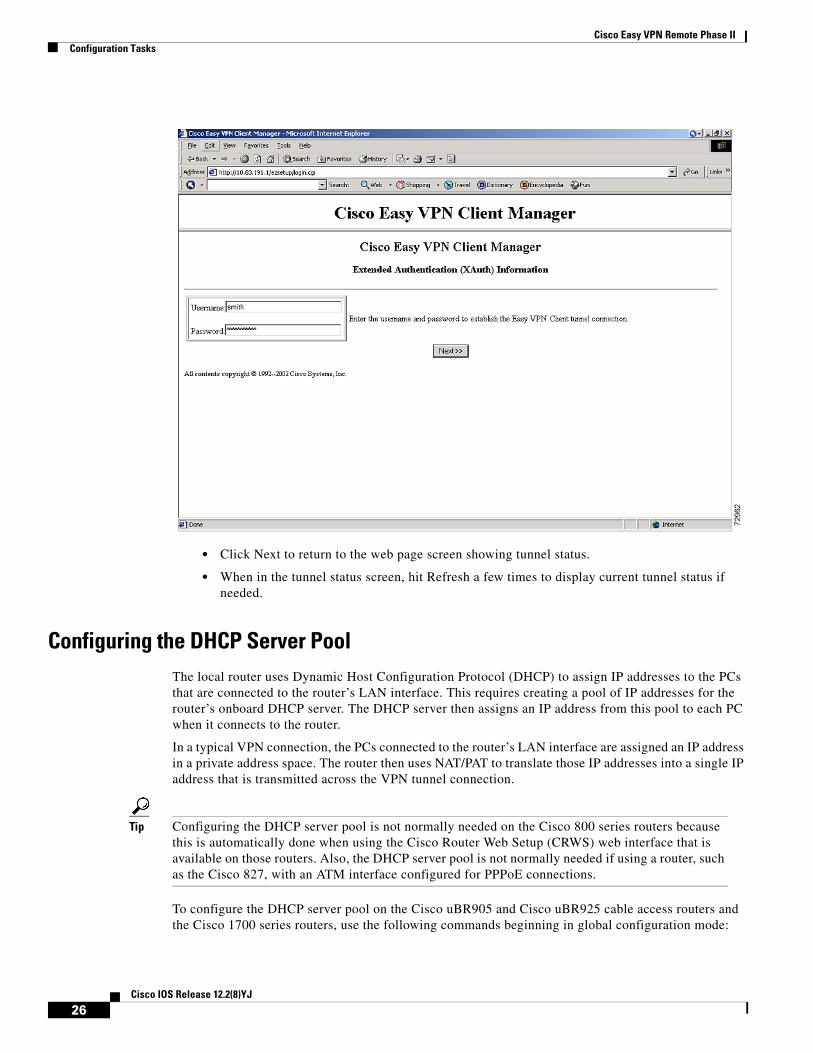
4. If Xauth information is needed, the user is directed to the following screen and prompted for Xauth information.
25Cisco IOS Release 12.2(8)YJ
Cisco Easy VPN Remote Phase IIConfiguration Tasks
• Click Next to return to the web page screen showing tunnel status.
• When in the tunnel status screen, hit Refresh a few times to display current tunnel status if needed.
Configuring the DHCP Server Pool The local router uses Dynamic Host Configuration Protocol (DHCP) to assign IP addresses to the PCs that are connected to the router’s LAN interface. This requires creating a pool of IP addresses for the router’s onboard DHCP server. The DHCP server then assigns an IP address from this pool to each PC when it connects to the router.
In a typical VPN connection, the PCs connected to the router’s LAN interface are assigned an IP address in a private address space. The router then uses NAT/PAT to translate those IP addresses into a single IP address that is transmitted across the VPN tunnel connection.
Tip Configuring the DHCP server pool is not normally needed on the Cisco 800 series routers because this is automatically done when using the Cisco Router Web Setup (CRWS) web interface that is available on those routers. Also, the DHCP server pool is not normally needed if using a router, such as the Cisco 827, with an ATM interface configured for PPPoE connections.
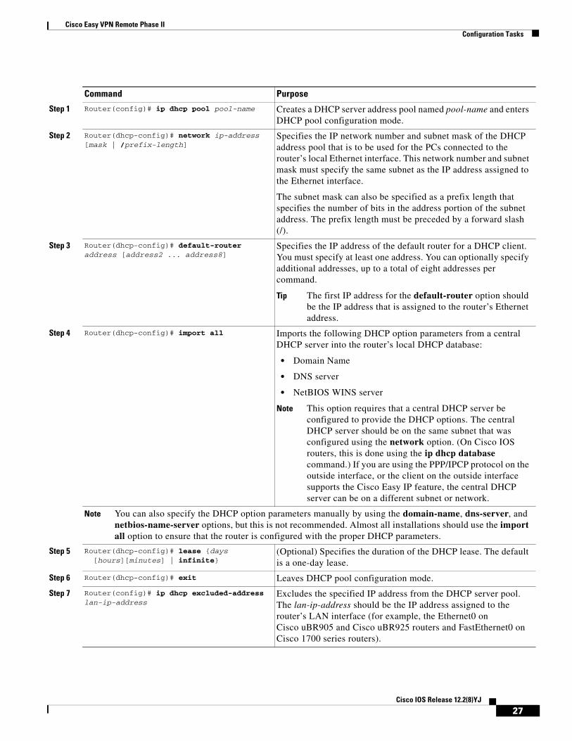
To configure the DHCP server pool on the Cisco uBR905 and Cisco uBR925 cable access routers and the Cisco 1700 series routers, use the following commands beginning in global configuration mode:
26Cisco IOS Release 12.2(8)YJ
Cisco Easy VPN Remote Phase IIConfiguration Tasks
Command Purpose
Step 1 Router(config)# ip dhcp pool pool-name Creates a DHCP server address pool named pool-name and enters DHCP pool configuration mode.
Step 2 Router(dhcp-config)# network ip-address [mask | /prefix-length]
Specifies the IP network number and subnet mask of the DHCP address pool that is to be used for the PCs connected to the router’s local Ethernet interface. This network number and subnet mask must specify the same subnet as the IP address assigned to the Ethernet interface.
The subnet mask can also be specified as a prefix length that specifies the number of bits in the address portion of the subnet address. The prefix length must be preceded by a forward slash (/).
Step 3 Router(dhcp-config)# default-router address [address2 ... address8]
Specifies the IP address of the default router for a DHCP client. You must specify at least one address. You can optionally specify additional addresses, up to a total of eight addresses per command.
Tip The first IP address for the default-router option should be the IP address that is assigned to the router’s Ethernet address.
Step 4 Router(dhcp-config)# import all Imports the following DHCP option parameters from a central DHCP server into the router’s local DHCP database:
• Domain Name
• DNS server
• NetBIOS WINS server
Note This option requires that a central DHCP server be configured to provide the DHCP options. The central DHCP server should be on the same subnet that was configured using the network option. (On Cisco IOS routers, this is done using the ip dhcp database command.) If you are using the PPP/IPCP protocol on the outside interface, or the client on the outside interface supports the Cisco Easy IP feature, the central DHCP server can be on a different subnet or network.
Note You can also specify the DHCP option parameters manually by using the domain-name, dns-server, and netbios-name-server options, but this is not recommended. Almost all installations should use the import all option to ensure that the router is configured with the proper DHCP parameters.
Step 5 Router(dhcp-config)# lease {days [hours][minutes] | infinite}
(Optional) Specifies the duration of the DHCP lease. The default is a one-day lease.
Step 6 Router(dhcp-config)# exit Leaves DHCP pool configuration mode.
Step 7 Router(config)# ip dhcp excluded-address lan-ip-address
Excludes the specified IP address from the DHCP server pool. The lan-ip-address should be the IP address assigned to the router’s LAN interface (for example, the Ethernet0 on Cisco uBR905 and Cisco uBR925 routers and FastEthernet0 on Cisco 1700 series routers).
27Cisco IOS Release 12.2(8)YJ
Cisco Easy VPN Remote Phase IIConfiguration Tasks
Note The ip dhcp pool command supports a number of options for configuring the DHCP server pool. These other options are typically not needed for a Cisco Easy VPN Remote Phase II configuration.
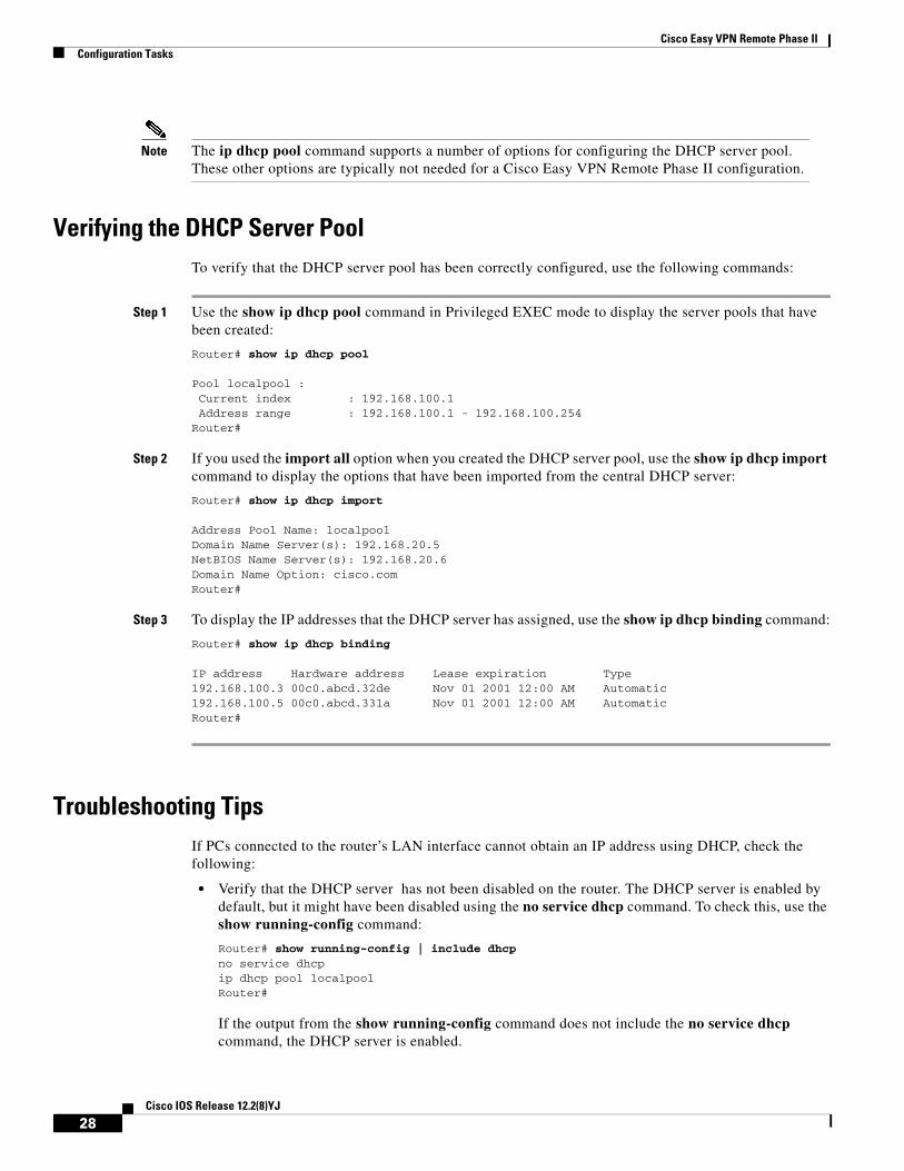
Verifying the DHCP Server PoolTo verify that the DHCP server pool has been correctly configured, use the following commands:
Step 1 Use the show ip dhcp pool command in Privileged EXEC mode to display the server pools that have been created:
Router# show ip dhcp pool
Pool localpool : Current index : 192.168.100.1 Address range : 192.168.100.1 - 192.168.100.254Router#
Step 2 If you used the import all option when you created the DHCP server pool, use the show ip dhcp import command to display the options that have been imported from the central DHCP server:
Router# show ip dhcp import
Address Pool Name: localpool Domain Name Server(s): 192.168.20.5 NetBIOS Name Server(s): 192.168.20.6 Domain Name Option: cisco.com Router#
Step 3 To display the IP addresses that the DHCP server has assigned, use the show ip dhcp binding command:
Router# show ip dhcp binding IP address Hardware address Lease expiration Type192.168.100.3 00c0.abcd.32de Nov 01 2001 12:00 AM Automatic192.168.100.5 00c0.abcd.331a Nov 01 2001 12:00 AM AutomaticRouter#
Troubleshooting TipsIf PCs connected to the router’s LAN interface cannot obtain an IP address using DHCP, check the following:
• Verify that the DHCP server has not been disabled on the router. The DHCP server is enabled by default, but it might have been disabled using the no service dhcp command. To check this, use the show running-config command:
Router# show running-config | include dhcp no service dhcpip dhcp pool localpoolRouter#
If the output from the show running-config command does not include the no service dhcp command, the DHCP server is enabled.
28Cisco IOS Release 12.2(8)YJ
Cisco Easy VPN Remote Phase IIConfiguration Tasks
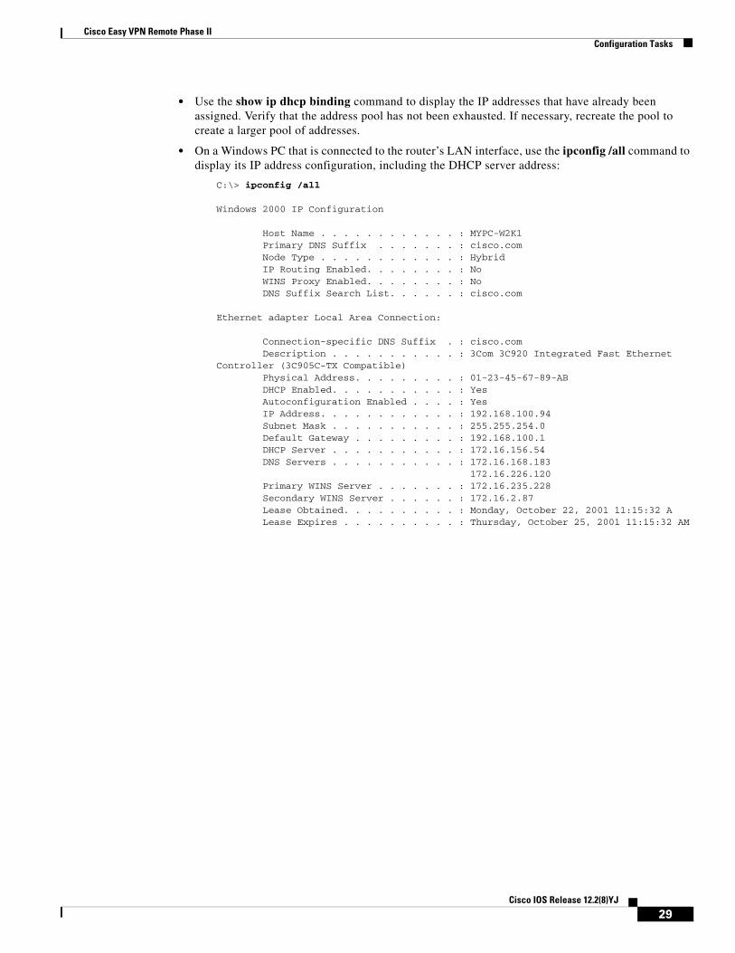
• Use the show ip dhcp binding command to display the IP addresses that have already been assigned. Verify that the address pool has not been exhausted. If necessary, recreate the pool to create a larger pool of addresses.
• On a Windows PC that is connected to the router’s LAN interface, use the ipconfig /all command to display its IP address configuration, including the DHCP server address:
C:\> ipconfig /all
Windows 2000 IP Configuration
Host Name . . . . . . . . . . . . : MYPC-W2K1 Primary DNS Suffix . . . . . . . : cisco.com Node Type . . . . . . . . . . . . : Hybrid IP Routing Enabled. . . . . . . . : No WINS Proxy Enabled. . . . . . . . : No DNS Suffix Search List. . . . . . : cisco.com
Ethernet adapter Local Area Connection:
Connection-specific DNS Suffix . : cisco.com Description . . . . . . . . . . . : 3Com 3C920 Integrated Fast EthernetController (3C905C-TX Compatible) Physical Address. . . . . . . . . : 01-23-45-67-89-AB DHCP Enabled. . . . . . . . . . . : Yes Autoconfiguration Enabled . . . . : Yes IP Address. . . . . . . . . . . . : 192.168.100.94 Subnet Mask . . . . . . . . . . . : 255.255.254.0 Default Gateway . . . . . . . . . : 192.168.100.1 DHCP Server . . . . . . . . . . . : 172.16.156.54 DNS Servers . . . . . . . . . . . : 172.16.168.183 172.16.226.120 Primary WINS Server . . . . . . . : 172.16.235.228 Secondary WINS Server . . . . . . : 172.16.2.87 Lease Obtained. . . . . . . . . . : Monday, October 22, 2001 11:15:32 A Lease Expires . . . . . . . . . . : Thursday, October 25, 2001 11:15:32 AM
29Cisco IOS Release 12.2(8)YJ
Cisco Easy VPN Remote Phase IIConfiguration Tasks
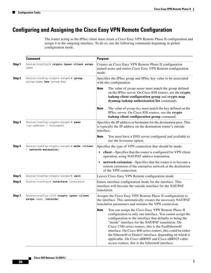
Configuring and Assigning the Cisco Easy VPN Remote ConfigurationThe router acting as the IPSec client must create a Cisco Easy VPN Remote Phase II configuration and assign it to the outgoing interface. To do so, use the following commands beginning in global configuration mode.
Command Purpose
Step 1 Router(config)# crypto ipsec client ezvpn name
Creates an Cisco Easy VPN Remote Phase II configuration named name and enters Cisco Easy VPN Remote configuration mode.
Step 2 Router(config-crypto-ezvpn)# group group-name key group-key
Specifies the IPSec group and IPSec key value to be associated with this configuration.
Note The value of group-name must match the group defined on the IPSec server. On Cisco IOS routers, use the crypto isakmp client configuration group and crypto map dynmap isakmp authorization list commands.
Note The value of group-key must match the key defined on the IPSec server. On Cisco IOS routers, use the crypto isakmp client configuration group command.
Step 3 Router(config-crypto-ezvpn)# peer [ip-address | hostname]
Specifies the IP address or hostname for the destination peer. This is typically the IP address on the destination router’s outside interface.
Note You must have a DNS server configured and available to use the hostname option.
Step 4 Router(config-crypto-ezvpn)# mode {client | network-extension}
Specifies the type of VPN connection that should be made:
• client—Specifies that the router is configured for VPN client operation, using NAT/PAT address translation.
• network-extension—Specifies that the router is to become a remote extension of the enterprise network at the destination of the VPN connection.
Step 5 Router(config-crypto-ezvpn)# exit Leaves Cisco Easy VPN Remote configuration mode.
Step 6 Router(config)# interface interface Enters interface configuration mode for the interface. This interface will become the outside interface for the NAT/PAT translation.
Step 7 Router(config-if)# crypto ipsec client ezvpn name [outside]
Assigns the Cisco Easy VPN Remote Phase II configuration to the interface. This automatically creates the necessary NAT/PAT translation parameters and initiates the VPN connection.
Note You can assign the Cisco Easy VPN Remote Phase II configuration to only one interface. You cannot assign the configuration to the interface that defaults to being the “inside” interface for the NAT/PAT translation. On Cisco 1700 series routers, this is the FastEthernet0 interface. On Cisco 800 series routers, this could be either the Ethernet0 or Dialer1 interface, depending on which is applicable. On Cisco uBR905 and Cisco uBR925 cable access routers, this is the Ethernet0 interface.
30Cisco IOS Release 12.2(8)YJ
Cisco Easy VPN Remote Phase IIConfiguration Tasks
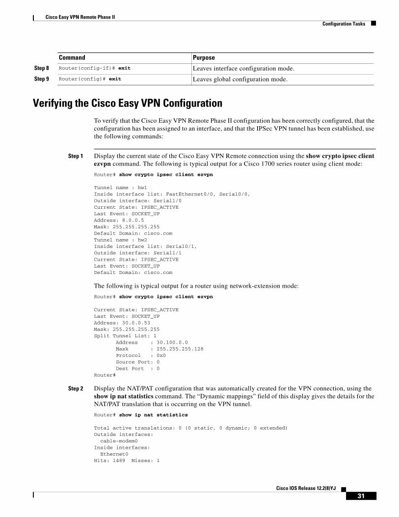
Verifying the Cisco Easy VPN ConfigurationTo verify that the Cisco Easy VPN Remote Phase II configuration has been correctly configured, that the configuration has been assigned to an interface, and that the IPSec VPN tunnel has been established, use the following commands:
Step 1 Display the current state of the Cisco Easy VPN Remote connection using the show crypto ipsec client ezvpn command. The following is typical output for a Cisco 1700 series router using client mode:
Router# show crypto ipsec client ezvpn
Tunnel name : hw1 Inside interface list: FastEthernet0/0, Serial0/0, Outside interface: Serial1/0 Current State: IPSEC_ACTIVE Last Event: SOCKET_UP Address: 8.0.0.5 Mask: 255.255.255.255 Default Domain: cisco.comTunnel name : hw2 Inside interface list: Serial0/1, Outside interface: Serial1/1 Current State: IPSEC_ACTIVE Last Event: SOCKET_UP Default Domain: cisco.com
The following is typical output for a router using network-extension mode:
Router# show crypto ipsec client ezvpn
Current State: IPSEC_ACTIVELast Event: SOCKET_UPAddress: 30.0.0.53Mask: 255.255.255.255Split Tunnel List: 1 Address : 30.100.0.0 Mask : 255.255.255.128 Protocol : 0x0 Source Port: 0 Dest Port : 0Router#
Step 2 Display the NAT/PAT configuration that was automatically created for the VPN connection, using the show ip nat statistics command. The “Dynamic mappings” field of this display gives the details for the NAT/PAT translation that is occurring on the VPN tunnel.
Router# show ip nat statistics
Total active translations: 0 (0 static, 0 dynamic; 0 extended)Outside interfaces: cable-modem0Inside interfaces: Ethernet0Hits: 1489 Misses: 1
Step 8 Router(config-if)# exit Leaves interface configuration mode.
Step 9 Router(config)# exit Leaves global configuration mode.
Command Purpose
31Cisco IOS Release 12.2(8)YJ

Cisco Easy VPN Remote Phase IIConfiguration Tasks
Expired translations: 1Dynamic mappings:-- Inside Sourceaccess-list 198 pool enterprise refcount 0 pool enterprise: netmask 255.255.255.0 start 198.1.1.90 end 198.1.1.90 type generic, total addresses 1, allocated 0 (0%), misses 0\Router#
Step 3 In client mode, the NAT/PAT translation creates one or more access lists that are also dynamically configured at the time the VPN tunnel is initiated. Display this access list using the show access-list command. The following is a typical display for a client configuration without split tunneling:
Router# show access-list
Extended IP access list 198 permit ip 192.1.1.0 0.0.0.255 anyRouter#
Note In this example, the Cisco Easy VPN Remote Phase II configuration creates access list 198 for the VPN tunnel NAT/PAT translation. The exact numbering of the access list can vary, depending on the other access lists that have been configured on the router. Do not assume that the VPN tunnel will use the same access list every time the connection is initiated.
The following is a typical display for a Cisco uBR905 or a Cisco uBR925 cable access router configured for client mode with split tunneling:
Router# show access-list
Extended IP access list 197 deny ip 192.168.100.0 0.0.0.255 172.168.0.128 0.0.0.127 deny ip 192.168.100.0 0.0.0.255 172.168.1.128 0.0.0.127 permit ip 192.168.100.0 0.0.0.255 anyExtended IP access list 198 permit ip 192.168.100.0 0.0.0.255 172.168.0.128 0.0.0.127 permit ip 192.168.100.0 0.0.0.255 172.168.1.128 0.0.0.127Router#
Tip Network extension mode without split tunneling does not need any access lists and thus does not create them. Network extension mode with split tunneling typically creates a single access list.
The following is a typical display for a Cisco 827 router configured for client mode with split tunneling:
c827# show access-list
Extended IP access list 197 deny ip 70.0.0.0 0.255.255.255 30.100.0.0 0.0.0.127 (5 matches) permit ip 70.0.0.0 0.255.255.255 anyExtended IP access list 198 permit ip 70.0.0.0 0.255.255.255 30.100.0.0 0.0.0.127 (5 matches)c827#
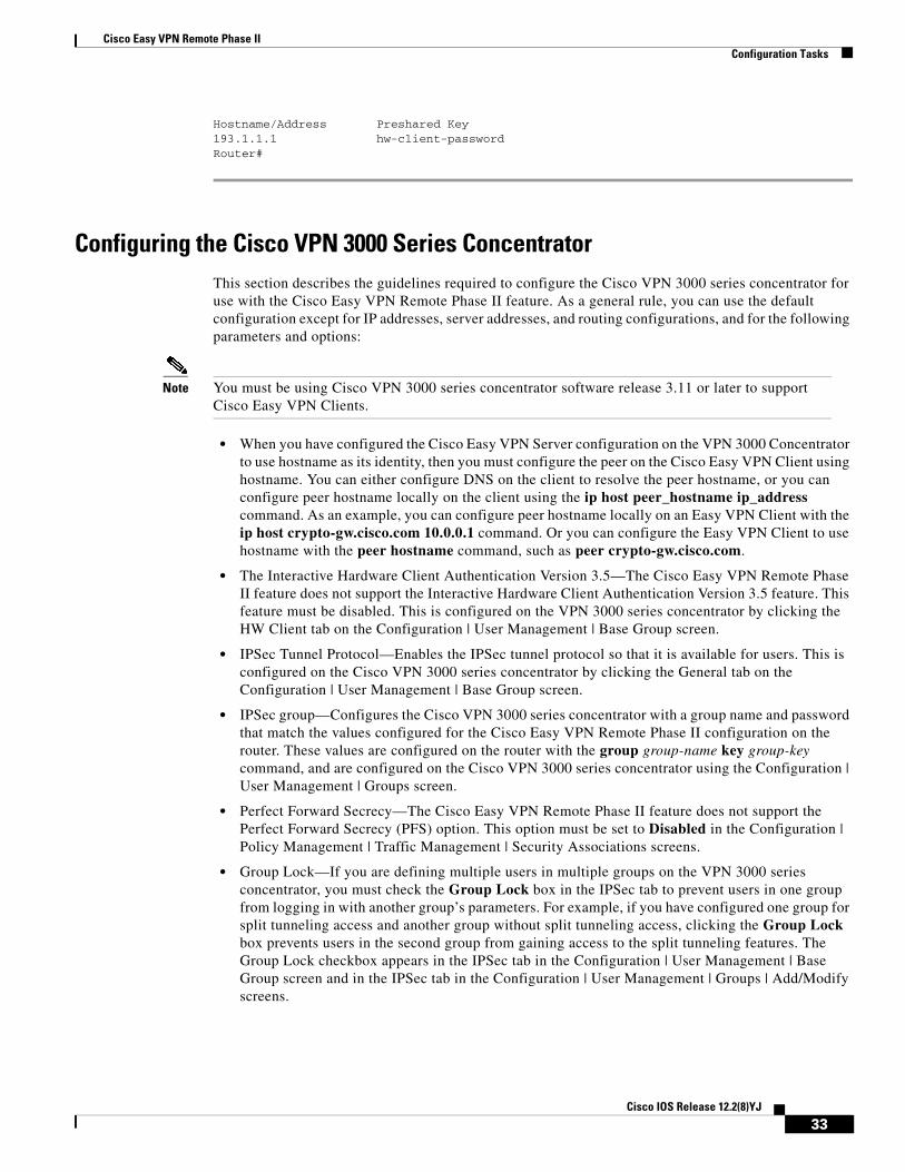
Step 4 Display the destination IPSec peer and the key value being used with the show crypto isakmp key command:
Router# show crypto isakmp key
32Cisco IOS Release 12.2(8)YJ
Cisco Easy VPN Remote Phase IIConfiguration Tasks
Hostname/Address Preshared Key193.1.1.1 hw-client-passwordRouter#
Configuring the Cisco VPN 3000 Series ConcentratorThis section describes the guidelines required to configure the Cisco VPN 3000 series concentrator for use with the Cisco Easy VPN Remote Phase II feature. As a general rule, you can use the default configuration except for IP addresses, server addresses, and routing configurations, and for the following parameters and options:
Note You must be using Cisco VPN 3000 series concentrator software release 3.11 or later to support Cisco Easy VPN Clients.
• When you have configured the Cisco Easy VPN Server configuration on the VPN 3000 Concentrator to use hostname as its identity, then you must configure the peer on the Cisco Easy VPN Client using hostname. You can either configure DNS on the client to resolve the peer hostname, or you can configure peer hostname locally on the client using the ip host peer_hostname ip_address command. As an example, you can configure peer hostname locally on an Easy VPN Client with the ip host crypto-gw.cisco.com 10.0.0.1 command. Or you can configure the Easy VPN Client to use hostname with the peer hostname command, such as peer crypto-gw.cisco.com.
• The Interactive Hardware Client Authentication Version 3.5—The Cisco Easy VPN Remote Phase II feature does not support the Interactive Hardware Client Authentication Version 3.5 feature. This feature must be disabled. This is configured on the VPN 3000 series concentrator by clicking the HW Client tab on the Configuration | User Management | Base Group screen.
• IPSec Tunnel Protocol—Enables the IPSec tunnel protocol so that it is available for users. This is configured on the Cisco VPN 3000 series concentrator by clicking the General tab on the Configuration | User Management | Base Group screen.
• IPSec group—Configures the Cisco VPN 3000 series concentrator with a group name and password that match the values configured for the Cisco Easy VPN Remote Phase II configuration on the router. These values are configured on the router with the group group-name key group-key command, and are configured on the Cisco VPN 3000 series concentrator using the Configuration | User Management | Groups screen.
• Perfect Forward Secrecy—The Cisco Easy VPN Remote Phase II feature does not support the Perfect Forward Secrecy (PFS) option. This option must be set to Disabled in the Configuration | Policy Management | Traffic Management | Security Associations screens.
• Group Lock—If you are defining multiple users in multiple groups on the VPN 3000 series concentrator, you must check the Group Lock box in the IPSec tab to prevent users in one group from logging in with another group’s parameters. For example, if you have configured one group for split tunneling access and another group without split tunneling access, clicking the Group Lock box prevents users in the second group from gaining access to the split tunneling features. The Group Lock checkbox appears in the IPSec tab in the Configuration | User Management | Base Group screen and in the IPSec tab in the Configuration | User Management | Groups | Add/Modify screens.
33Cisco IOS Release 12.2(8)YJ
Cisco Easy VPN Remote Phase IIConfiguration Tasks
• XAUTH—To use Extended Authentication (XAUTH), set the Authentication parameter to None. The Authentication parameter appears in the IPSec tab in the Configuration | User Management | Base Group screen and in the IPSec tab in the Configuration | User Management | Groups | Add/Modify screens.
• Split Tunneling—The Configuration | User Management | Base Group, Mode Configuration Parameters Tab screen includes a Split Tunnel option with a checkbox that says “Allow the networks in the list to bypass the tunnel.” When using the Cisco Easy VPN Remote Phase II feature, you must not click this checkbox, because it is intended only for software VPN clients and does not work with hardware clients such as the Cisco Easy VPN Remote Phase II feature.
• IKE Proposals—The Cisco VPN 3000 Series Concentrator is preconfigured with a default IKE proposal, CiscoVPNClient-3DES-MD5, that can be used with Cisco Easy VPN Clients. This IKE proposal supports preshared keys with extended authentication (XAUTH) using the MD5/HMAC-128 algorithm, and Diffie-Hellman Group 2.
This proposal is active by default, but verify that it is still an active proposal using the Configuration | System | Tunneling Protocols | IPSec | IKE Proposals screen.
Note You can also use the default IKE proposals IKE-DES-MD5 and IKE-3DES-MD5, but they do not enable XAUTH support by default.
• Create a new IPSec Security Association. Cisco Easy VPN Clients use a security association with the following parameters:
– Authentication Algorithm=ESP/MD5/HMAC-128
– Encryption Algorithm=DES-56 or 3DES-168 (recommended)
– Encapsulation Mode=Tunnel
– Digital Certificate=None (use preshared keys)
– IKE Proposal=CiscoVPNClient-3DES-MD5 (preferred)
The Cisco VPN 3000 Series Concentrator is preconfigured with several default security associations but they do not meet the IKE Proposal requirements. To use an IKE Proposal of CiscoVPNClient-3DES-MD5, copy the ESP/IKE-3DES-MD5 security association and modify it to use CiscoVPNClient-3DES-MD5 as its IKE proposal. This is configured on the VPN 3000 series concentrator using the Configuration | Policy Management | Traffic Management | Security Associations screen.
34Cisco IOS Release 12.2(8)YJ
Cisco Easy VPN Remote Phase IIConfiguration Examples
Troubleshooting TipsTo troubleshoot a VPN connection created using the Cisco Easy VPN Remote Phase II feature, use the following suggested techniques.
• Any changes to an active Cisco Easy VPN Remote Phase II configuration or IP address changes to the involved interfaces, such as adding or removing an inside interface, result in a reset of the Cisco Easy VPN Remote Phase II connection.
• Enable debugging of the Cisco Easy VPN Remote Phase II feature using the debug crypto ipsec client ezvpn command.
• Enable debugging of IPSec and Internet Key Exchange (IKE) events using the debug crypto ipsec and debug crypto isakmp commands.
• Display the active IPSec VPN connections using the show crypto engine connections active command.
• To reset the VPN connection, use the clear crypto ipsec client ezvpn command. If you have debugging enabled, you might prefer to use the clear crypto sa and clear crypto isakmp commands.
Configuration ExamplesThis section provides the following configuration examples:
• Cable DHCP Proxy Enhancement Configuration Examples
• Local Address Support for Easy VPN Remote Example
• PIX Interoperability Support Example
• Client Mode Configuration Examples
• Network Extension Mode Configuration Examples
• VPN Remote Access Server Configuration Examples
Cable DHCP Proxy Enhancement Configuration Examples
Note Cable DHCP Proxy Support configurations are only applicable for the Cisco uBR905 and Cisco uBR925 routers.
The following example shows a loopback interface created first and then the loopback interface being specified so the router automatically assigns it with the public IP address:
router# config t router(config)# interface loopback 0 router(config)# interface cable-modem 0router(config-if)# cable-modem dhcp-proxy interface loopback0 router(config-if)#
35Cisco IOS Release 12.2(8)YJ
Cisco Easy VPN Remote Phase IIConfiguration Examples
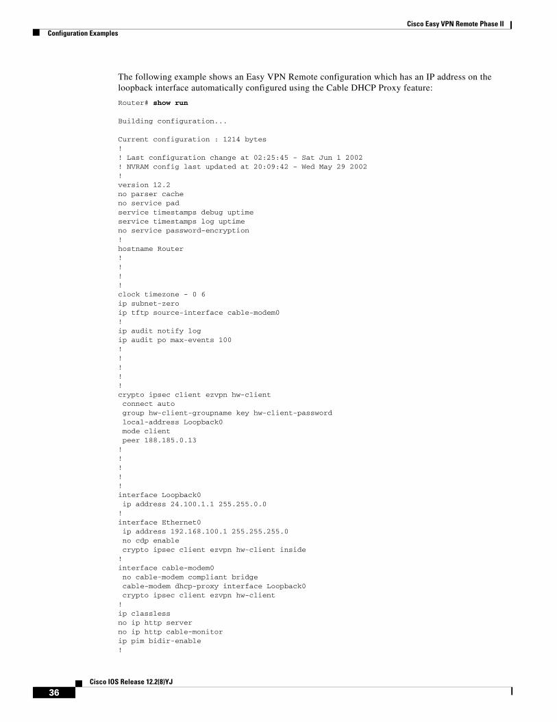
The following example shows an Easy VPN Remote configuration which has an IP address on the loopback interface automatically configured using the Cable DHCP Proxy feature:
Router# show run
Building configuration...
Current configuration : 1214 bytes!! Last configuration change at 02:25:45 - Sat Jun 1 2002! NVRAM config last updated at 20:09:42 - Wed May 29 2002!version 12.2no parser cacheno service padservice timestamps debug uptimeservice timestamps log uptimeno service password-encryption!hostname Router!!!!clock timezone - 0 6ip subnet-zeroip tftp source-interface cable-modem0!ip audit notify logip audit po max-events 100!!!!!crypto ipsec client ezvpn hw-client connect auto group hw-client-groupname key hw-client-password local-address Loopback0 mode client peer 188.185.0.13!!!!!interface Loopback0 ip address 24.100.1.1 255.255.0.0!interface Ethernet0 ip address 192.168.100.1 255.255.255.0 no cdp enable crypto ipsec client ezvpn hw-client inside!interface cable-modem0 no cable-modem compliant bridge cable-modem dhcp-proxy interface Loopback0 crypto ipsec client ezvpn hw-client!ip classlessno ip http serverno ip http cable-monitorip pim bidir-enable!
36Cisco IOS Release 12.2(8)YJ
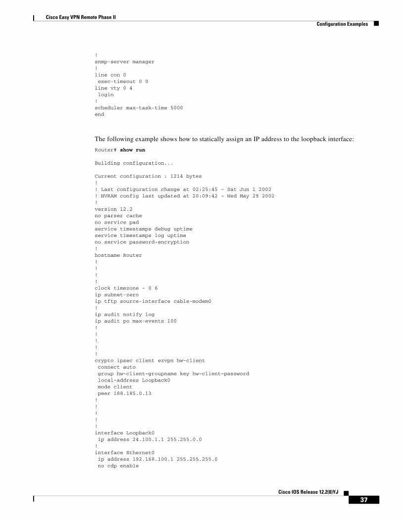
Cisco Easy VPN Remote Phase IIConfiguration Examples
!snmp-server manager!line con 0 exec-timeout 0 0line vty 0 4 login!scheduler max-task-time 5000end
The following example shows how to statically assign an IP address to the loopback interface:
Router# show run
Building configuration...
Current configuration : 1214 bytes!! Last configuration change at 02:25:45 - Sat Jun 1 2002! NVRAM config last updated at 20:09:42 - Wed May 29 2002!version 12.2no parser cacheno service padservice timestamps debug uptimeservice timestamps log uptimeno service password-encryption!hostname Router!!!!clock timezone - 0 6ip subnet-zeroip tftp source-interface cable-modem0!ip audit notify logip audit po max-events 100!!!!!crypto ipsec client ezvpn hw-client connect auto group hw-client-groupname key hw-client-password local-address Loopback0 mode client peer 188.185.0.13!!!!!interface Loopback0 ip address 24.100.1.1 255.255.0.0!interface Ethernet0 ip address 192.168.100.1 255.255.255.0 no cdp enable
37Cisco IOS Release 12.2(8)YJ
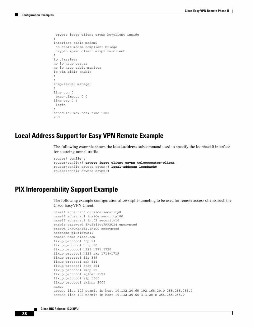
Cisco Easy VPN Remote Phase IIConfiguration Examples
crypto ipsec client ezvpn hw-client inside!interface cable-modem0 no cable-modem compliant bridge crypto ipsec client ezvpn hw-client!ip classlessno ip http serverno ip http cable-monitorip pim bidir-enable!!snmp-server manager!line con 0 exec-timeout 0 0line vty 0 4 login!scheduler max-task-time 5000end
Local Address Support for Easy VPN Remote ExampleThe following example shows the local-address subcommand used to specify the loopback0 interface for sourcing tunnel traffic:
router# config t router(config)# crypto ipsec client ezvpn telecommuter-client router(config-crypto-ezvpn)# local-address loopback0 router(config-crypto-ezvpn)#
PIX Interoperability Support ExampleThe following example configuration allows split-tunneling to be used for remote access clients such the Cisco EasyVPN Client:
nameif ethernet0 outside security0nameif ethernet1 inside security100nameif ethernet2 intf2 security10enable password 8Ry2YjIyt7RRXU24 encryptedpasswd 2KFQnbNIdI.2KYOU encryptedhostname pixfirewalldomain-name cisco.comfixup protocol ftp 21fixup protocol http 80fixup protocol h323 h225 1720fixup protocol h323 ras 1718-1719fixup protocol ils 389fixup protocol rsh 514fixup protocol rtsp 554fixup protocol smtp 25fixup protocol sqlnet 1521fixup protocol sip 5060fixup protocol skinny 2000namesaccess-list 102 permit ip host 10.132.20.65 192.168.20.0 255.255.255.0 access-list 102 permit ip host 10.132.20.65 3.3.20.0 255.255.255.0
38Cisco IOS Release 12.2(8)YJ
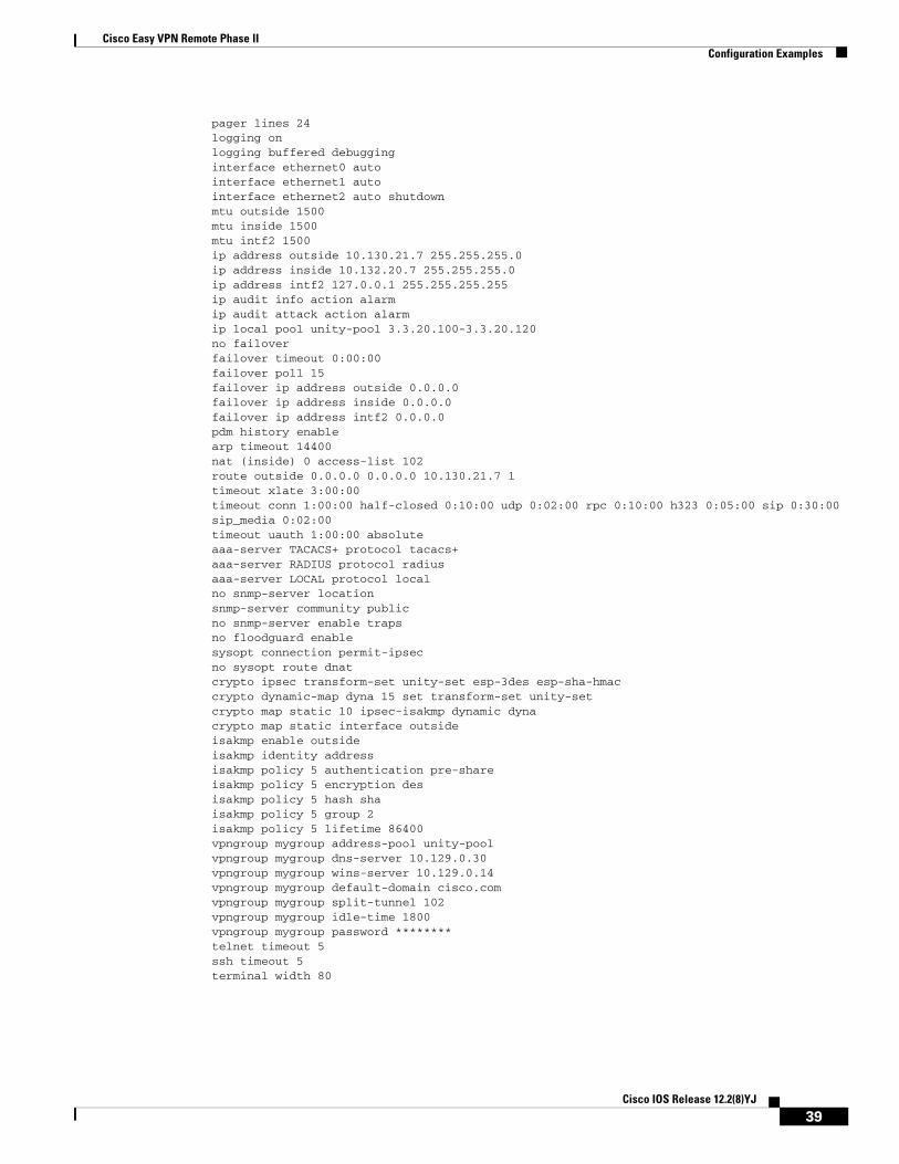
Cisco Easy VPN Remote Phase IIConfiguration Examples
pager lines 24logging onlogging buffered debugginginterface ethernet0 autointerface ethernet1 autointerface ethernet2 auto shutdownmtu outside 1500mtu inside 1500mtu intf2 1500ip address outside 10.130.21.7 255.255.255.0ip address inside 10.132.20.7 255.255.255.0ip address intf2 127.0.0.1 255.255.255.255ip audit info action alarmip audit attack action alarmip local pool unity-pool 3.3.20.100-3.3.20.120no failoverfailover timeout 0:00:00failover poll 15failover ip address outside 0.0.0.0failover ip address inside 0.0.0.0failover ip address intf2 0.0.0.0pdm history enablearp timeout 14400nat (inside) 0 access-list 102route outside 0.0.0.0 0.0.0.0 10.130.21.7 1timeout xlate 3:00:00timeout conn 1:00:00 half-closed 0:10:00 udp 0:02:00 rpc 0:10:00 h323 0:05:00 sip 0:30:00 sip_media 0:02:00timeout uauth 1:00:00 absoluteaaa-server TACACS+ protocol tacacs+ aaa-server RADIUS protocol radius aaa-server LOCAL protocol local no snmp-server locationsnmp-server community publicno snmp-server enable trapsno floodguard enablesysopt connection permit-ipsecno sysopt route dnatcrypto ipsec transform-set unity-set esp-3des esp-sha-hmac crypto dynamic-map dyna 15 set transform-set unity-setcrypto map static 10 ipsec-isakmp dynamic dynacrypto map static interface outsideisakmp enable outsideisakmp identity addressisakmp policy 5 authentication pre-shareisakmp policy 5 encryption desisakmp policy 5 hash shaisakmp policy 5 group 2isakmp policy 5 lifetime 86400vpngroup mygroup address-pool unity-poolvpngroup mygroup dns-server 10.129.0.30vpngroup mygroup wins-server 10.129.0.14vpngroup mygroup default-domain cisco.comvpngroup mygroup split-tunnel 102vpngroup mygroup idle-time 1800vpngroup mygroup password ********telnet timeout 5ssh timeout 5 terminal width 80
39Cisco IOS Release 12.2(8)YJ

Cisco Easy VPN Remote Phase IIConfiguration Examples
Note When you have configured the Cisco Easy VPN Server configuration on the VPN 3000 Concentrator to use hostname as its identity, then you must configure the peer on the Cisco Easy VPN Client using hostname. You can either configure DNS on the client to resolve the peer hostname, or you can configure peer hostname locally on the client using the ip host peer_hostname ip_address command. As an example, you can configure peer hostname locally on an Easy VPN Client with the ip host crypto-gw.cisco.com 10.0.0.1 command. Or you can configure the Easy VPN Client to use hostname with the peer hostname command, such as peer crypto-gw.cisco.com.
Client Mode Configuration ExamplesThis section shows the following examples that demonstrate configurations for the Cisco Easy VPN Remote Phase II feature in client mode. Also shown are the VPN remote access server configurations that correspond to these client configurations.
• Cisco Easy VPN Client in Client Mode (Cisco uBR905 and Cisco uBR925) Example
• Cisco Easy VPN Client in Client Mode (Cisco 806) Example
• Cisco Easy VPN Client in Client Mode (Cisco 827) Example
• Cisco Easy VPN Client in Client Mode (Cisco 1700 Series) Example
Note Typically, users configure the Cisco 800 series routers with the CRWS web interface, not by entering CLI commands. However, the configurations shown here for the Cisco 800 series routers display typical configurations that can be used if manual configuration is desired.
Cisco Easy VPN Client in Client Mode (Cisco uBR905 and Cisco uBR925) Example
The following example configures a Cisco uBR905 cable access router as an IPSec client, using the Cisco Easy VPN Remote Phase II feature in client mode. This example shows the following components of the Cisco Easy VPN Remote Phase II configuration:
• Routing mode—The no cable-modem compliant bridge command places the router in routing mode. IP routing, such as RIPv2, is not activated, because the VPN configuration directs all traffic to the destination point of the VPN tunnel.
• DHCP server pool—The ip dhcp pool command creates a pool of IP addresses to be assigned to the PCs connected to the router’s Ethernet interface. (On the Cisco uBR925 cable access router, this pool also applies to the PC connected to the router’s universal serial bus (USB) interface.) The pool assigns addresses in the class C private address space (192.168.100.0) and configures each PC so that its default route is 192.168.100.1, which is the IP address assigned to the router’s Ethernet interface. The DHCP lease period is 1 day.
• Cisco Easy VPN Remote Phase II configuration—The first crypto ipsec client ezvpn hw-client command (global configuration mode) creates an Cisco Easy VPN Remote Phase II configuration named hw-client. This configuration specifies a group name of hw-client-groupname and a shared key value of hw-client-password, and it sets the peer destination to the IP address 188.185.0.5 (which is the address assigned to the interface connected to the Internet on the destination peer router). The Cisco Easy VPN Remote Phase II configuration is configured for the default client mode.
40Cisco IOS Release 12.2(8)YJ
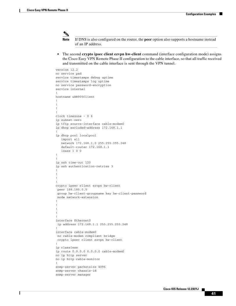
Cisco Easy VPN Remote Phase IIConfiguration Examples
Note If DNS is also configured on the router, the peer option also supports a hostname instead of an IP address.
• The second crypto ipsec client ezvpn hw-client command (interface configuration mode) assigns the Cisco Easy VPN Remote Phase II configuration to the cable interface, so that all traffic received and transmitted on the cable interface is sent through the VPN tunnel.
version 12.2no service padservice timestamps debug uptimeservice timestamps log uptimeno service password-encryptionservice internal!hostname uBR905Client!!!!clock timezone - 0 6ip subnet-zeroip tftp source-interface cable-modem0ip dhcp excluded-address 172.168.1.1 !ip dhcp pool localpool import all network 172.168.1.0 255.255.255.248 default-router 172.168.1.1 lease 1 0 0 !!ip ssh time-out 120ip ssh authentication-retries 3!!!!crypto ipsec client ezvpn hw-client peer 188.185.0.5 group hw-client-groupname key hw-client-password mode network-extension !!!!!interface Ethernet0 ip address 172.168.1.1 255.255.255.248 !interface cable-modem0 no cable-modem compliant bridge crypto ipsec client ezvpn hw-client!ip classlessip route 0.0.0.0 0.0.0.0 cable-modem0 no ip http serverno ip http cable-monitor!snmp-server packetsize 4096snmp-server chassis-id snmp-server manager
41Cisco IOS Release 12.2(8)YJ
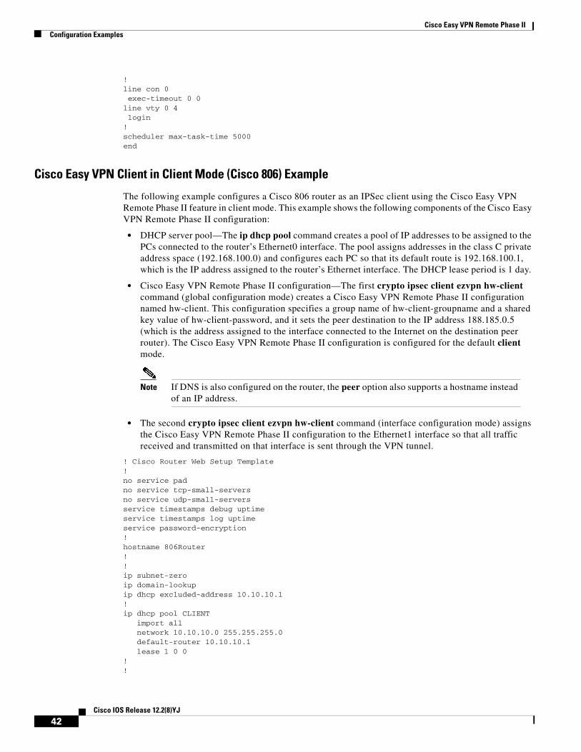
Cisco Easy VPN Remote Phase IIConfiguration Examples
!line con 0 exec-timeout 0 0line vty 0 4 login!scheduler max-task-time 5000end
Cisco Easy VPN Client in Client Mode (Cisco 806) Example
The following example configures a Cisco 806 router as an IPSec client using the Cisco Easy VPN Remote Phase II feature in client mode. This example shows the following components of the Cisco Easy VPN Remote Phase II configuration:
• DHCP server pool—The ip dhcp pool command creates a pool of IP addresses to be assigned to the PCs connected to the router’s Ethernet0 interface. The pool assigns addresses in the class C private address space (192.168.100.0) and configures each PC so that its default route is 192.168.100.1, which is the IP address assigned to the router’s Ethernet interface. The DHCP lease period is 1 day.
• Cisco Easy VPN Remote Phase II configuration—The first crypto ipsec client ezvpn hw-client command (global configuration mode) creates a Cisco Easy VPN Remote Phase II configuration named hw-client. This configuration specifies a group name of hw-client-groupname and a shared key value of hw-client-password, and it sets the peer destination to the IP address 188.185.0.5 (which is the address assigned to the interface connected to the Internet on the destination peer router). The Cisco Easy VPN Remote Phase II configuration is configured for the default client mode.
Note If DNS is also configured on the router, the peer option also supports a hostname instead of an IP address.
• The second crypto ipsec client ezvpn hw-client command (interface configuration mode) assigns the Cisco Easy VPN Remote Phase II configuration to the Ethernet1 interface so that all traffic received and transmitted on that interface is sent through the VPN tunnel.
! Cisco Router Web Setup Template!no service padno service tcp-small-serversno service udp-small-serversservice timestamps debug uptimeservice timestamps log uptimeservice password-encryption!hostname 806Router !!ip subnet-zeroip domain-lookupip dhcp excluded-address 10.10.10.1 !ip dhcp pool CLIENT import all network 10.10.10.0 255.255.255.0 default-router 10.10.10.1 lease 1 0 0 !!
42Cisco IOS Release 12.2(8)YJ
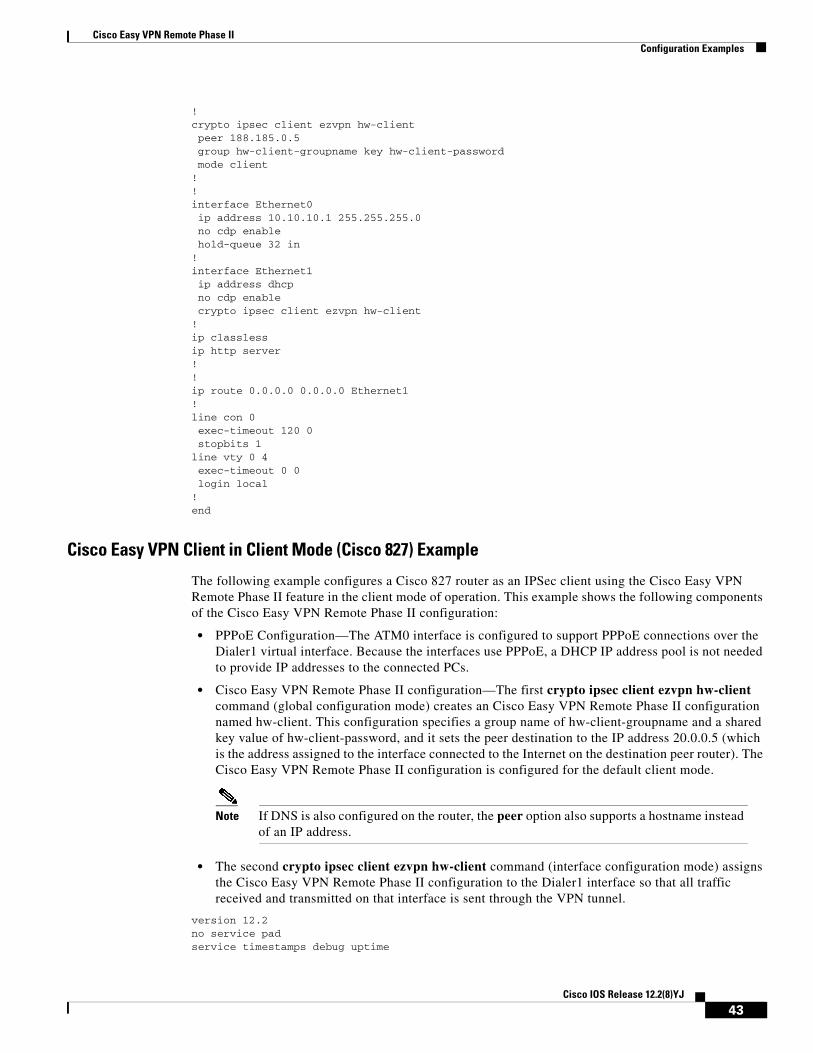
Cisco Easy VPN Remote Phase IIConfiguration Examples
!crypto ipsec client ezvpn hw-client peer 188.185.0.5 group hw-client-groupname key hw-client-password mode client!!interface Ethernet0 ip address 10.10.10.1 255.255.255.0 no cdp enable hold-queue 32 in!interface Ethernet1 ip address dhcp no cdp enable crypto ipsec client ezvpn hw-client!ip classlessip http server!!ip route 0.0.0.0 0.0.0.0 Ethernet1!line con 0 exec-timeout 120 0 stopbits 1line vty 0 4 exec-timeout 0 0 login local!end
Cisco Easy VPN Client in Client Mode (Cisco 827) Example
The following example configures a Cisco 827 router as an IPSec client using the Cisco Easy VPN Remote Phase II feature in the client mode of operation. This example shows the following components of the Cisco Easy VPN Remote Phase II configuration:
• PPPoE Configuration—The ATM0 interface is configured to support PPPoE connections over the Dialer1 virtual interface. Because the interfaces use PPPoE, a DHCP IP address pool is not needed to provide IP addresses to the connected PCs.
• Cisco Easy VPN Remote Phase II configuration—The first crypto ipsec client ezvpn hw-client command (global configuration mode) creates an Cisco Easy VPN Remote Phase II configuration named hw-client. This configuration specifies a group name of hw-client-groupname and a shared key value of hw-client-password, and it sets the peer destination to the IP address 20.0.0.5 (which is the address assigned to the interface connected to the Internet on the destination peer router). The Cisco Easy VPN Remote Phase II configuration is configured for the default client mode.
Note If DNS is also configured on the router, the peer option also supports a hostname instead of an IP address.
• The second crypto ipsec client ezvpn hw-client command (interface configuration mode) assigns the Cisco Easy VPN Remote Phase II configuration to the Dialer1 interface so that all traffic received and transmitted on that interface is sent through the VPN tunnel.
version 12.2no service padservice timestamps debug uptime
43Cisco IOS Release 12.2(8)YJ

Cisco Easy VPN Remote Phase IIConfiguration Examples
service timestamps log uptimeno service password-encryption!hostname c827!!mmi polling-interval 60no mmi auto-configureno mmi pvcmmi snmp-timeout 180ip subnet-zero!ip ssh time-out 120ip ssh authentication-retries 3vpdn enable!vpdn-group pppoe request-dialin protocol pppoe ip mtu adjust!!!!!!crypto ipsec client ezvpn hw-client group hw-client-groupname key hw-client-password mode client peer 20.0.0.5!!!!!interface Ethernet0 ip address 70.0.0.117 255.0.0.0 hold-queue 100 out!interface ATM0 no ip address no atm ilmi-keepalive pvc 1/40 pppoe-client dial-pool-number 1 ! dsl operating-mode auto!interface Dialer1 ip address 12.0.0.3 255.0.0.0 ip mtu 1492 encapsulation ppp dialer pool 1 crypto ipsec client ezvpn hw-client!ip classlessip route 0.0.0.0 0.0.0.0 ATM0ip route 0.0.0.0 0.0.0.0 Dialer1 permanentip route 20.0.0.0 255.0.0.0 12.0.0.13ip http serverip pim bidir-enable!line con 0 stopbits 1line vty 0 4
44Cisco IOS Release 12.2(8)YJ
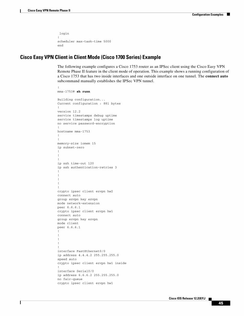
Cisco Easy VPN Remote Phase IIConfiguration Examples
login!scheduler max-task-time 5000end
Cisco Easy VPN Client in Client Mode (Cisco 1700 Series) Example
The following example configures a Cisco 1753 router as an IPSec client using the Cisco Easy VPN Remote Phase II feature in the client mode of operation. This example shows a running configuration of a Cisco 1753 that has two inside interfaces and one outside interface on one tunnel. The connect auto subcommand manually establishes the IPSec VPN tunnel.
!mma-1753# sh runn
Building configuration...Current configuration : 881 bytes ! version 12.2 service timestamps debug uptime service timestamps log uptime no service password-encryption ! hostname mma-1753 ! ! memory-size iomem 15 ip subnet-zero ! ! ! ip ssh time-out 120 ip ssh authentication-retries 3 ! ! ! ! ! crypto ipsec client ezvpn hw2 connect auto group ezvpn key ezvpn mode network-extension peer 6.6.6.1 crypto ipsec client ezvpn hw1 connect auto group ezvpn key ezvpn mode client peer 6.6.6.1 ! ! ! ! ! interface FastEthernet0/0 ip address 4.4.4.2 255.255.255.0 speed auto crypto ipsec client ezvpn hw1 inside ! interface Serial0/0 ip address 6.6.6.2 255.255.255.0 no fair-queue crypto ipsec client ezvpn hw1
45Cisco IOS Release 12.2(8)YJ
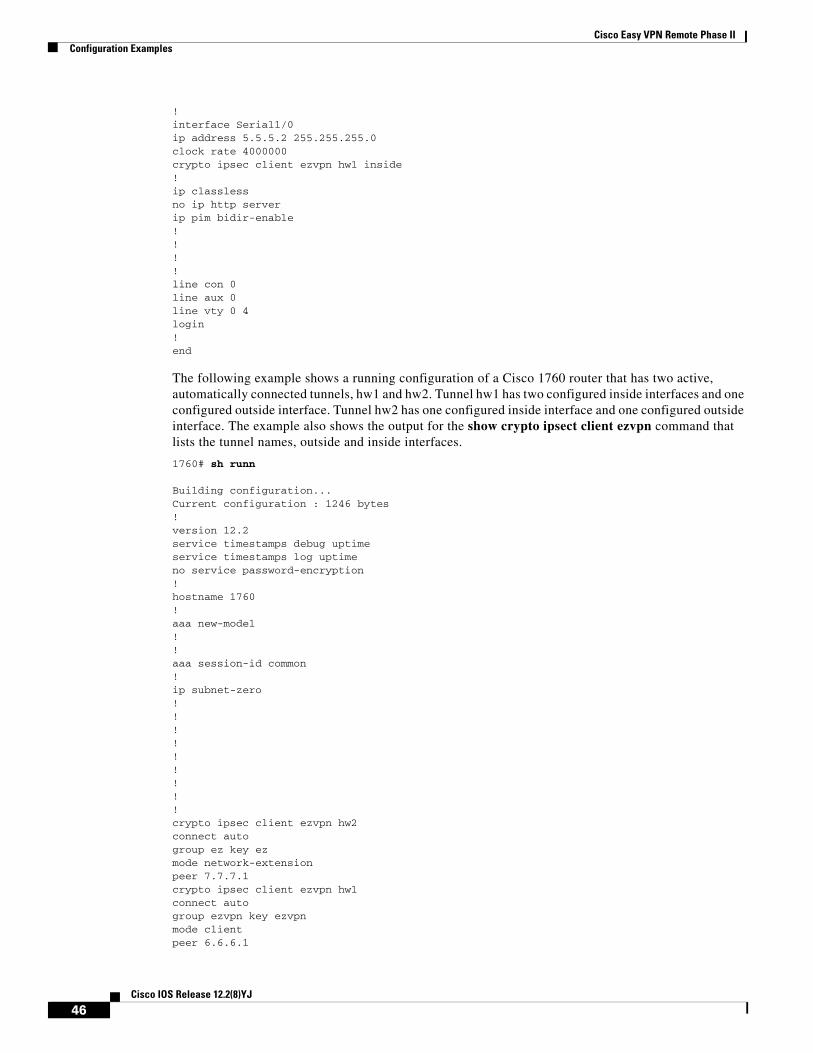
Cisco Easy VPN Remote Phase IIConfiguration Examples
! interface Serial1/0 ip address 5.5.5.2 255.255.255.0 clock rate 4000000 crypto ipsec client ezvpn hw1 inside ! ip classless no ip http server ip pim bidir-enable ! ! ! ! line con 0 line aux 0 line vty 0 4 login ! end
The following example shows a running configuration of a Cisco 1760 router that has two active, automatically connected tunnels, hw1 and hw2. Tunnel hw1 has two configured inside interfaces and one configured outside interface. Tunnel hw2 has one configured inside interface and one configured outside interface. The example also shows the output for the show crypto ipsect client ezvpn command that lists the tunnel names, outside and inside interfaces.
1760# sh runn
Building configuration...Current configuration : 1246 bytes ! version 12.2 service timestamps debug uptime service timestamps log uptime no service password-encryption ! hostname 1760 ! aaa new-model ! ! aaa session-id common ! ip subnet-zero ! ! ! ! ! ! ! ! ! crypto ipsec client ezvpn hw2 connect auto group ez key ez mode network-extension peer 7.7.7.1 crypto ipsec client ezvpn hw1 connect auto group ezvpn key ezvpn mode client peer 6.6.6.1
46Cisco IOS Release 12.2(8)YJ
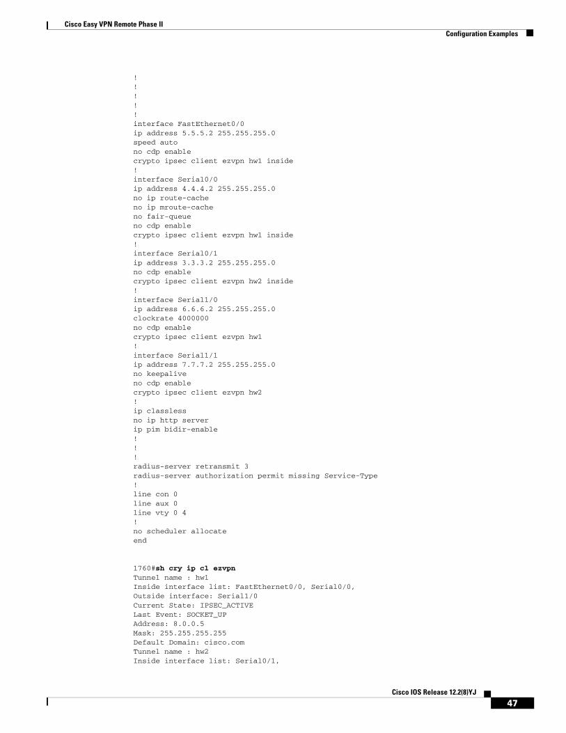
Cisco Easy VPN Remote Phase IIConfiguration Examples
! ! ! ! ! interface FastEthernet0/0 ip address 5.5.5.2 255.255.255.0 speed auto no cdp enable crypto ipsec client ezvpn hw1 inside ! interface Serial0/0 ip address 4.4.4.2 255.255.255.0 no ip route-cache no ip mroute-cache no fair-queue no cdp enable crypto ipsec client ezvpn hw1 inside ! interface Serial0/1 ip address 3.3.3.2 255.255.255.0 no cdp enable crypto ipsec client ezvpn hw2 inside ! interface Serial1/0 ip address 6.6.6.2 255.255.255.0 clockrate 4000000 no cdp enable crypto ipsec client ezvpn hw1 ! interface Serial1/1 ip address 7.7.7.2 255.255.255.0 no keepalive no cdp enable crypto ipsec client ezvpn hw2 ! ip classless no ip http server ip pim bidir-enable ! ! ! radius-server retransmit 3 radius-server authorization permit missing Service-Type ! line con 0 line aux 0 line vty 0 4 ! no scheduler allocate end
1760#sh cry ip cl ezvpnTunnel name : hw1 Inside interface list: FastEthernet0/0, Serial0/0, Outside interface: Serial1/0 Current State: IPSEC_ACTIVE Last Event: SOCKET_UP Address: 8.0.0.5 Mask: 255.255.255.255 Default Domain: cisco.comTunnel name : hw2 Inside interface list: Serial0/1,
47Cisco IOS Release 12.2(8)YJ
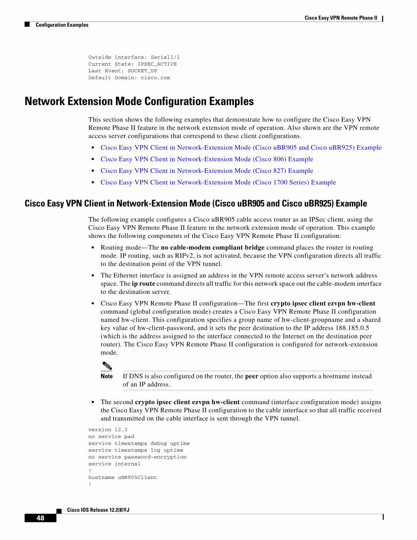
Cisco Easy VPN Remote Phase IIConfiguration Examples
Outside interface: Serial1/1 Current State: IPSEC_ACTIVE Last Event: SOCKET_UP Default Domain: cisco.com
Network Extension Mode Configuration ExamplesThis section shows the following examples that demonstrate how to configure the Cisco Easy VPN Remote Phase II feature in the network extension mode of operation. Also shown are the VPN remote access server configurations that correspond to these client configurations.
• Cisco Easy VPN Client in Network-Extension Mode (Cisco uBR905 and Cisco uBR925) Example
• Cisco Easy VPN Client in Network-Extension Mode (Cisco 806) Example
• Cisco Easy VPN Client in Network-Extension Mode (Cisco 827) Example
• Cisco Easy VPN Client in Network-Extension Mode (Cisco 1700 Series) Example
Cisco Easy VPN Client in Network-Extension Mode (Cisco uBR905 and Cisco uBR925) Example
The following example configures a Cisco uBR905 cable access router as an IPSec client, using the Cisco Easy VPN Remote Phase II feature in the network extension mode of operation. This example shows the following components of the Cisco Easy VPN Remote Phase II configuration:
• Routing mode—The no cable-modem compliant bridge command places the router in routing mode. IP routing, such as RIPv2, is not activated, because the VPN configuration directs all traffic to the destination point of the VPN tunnel.
• The Ethernet interface is assigned an address in the VPN remote access server’s network address space. The ip route command directs all traffic for this network space out the cable-modem interface to the destination server.
• Cisco Easy VPN Remote Phase II configuration—The first crypto ipsec client ezvpn hw-client command (global configuration mode) creates a Cisco Easy VPN Remote Phase II configuration named hw-client. This configuration specifies a group name of hw-client-groupname and a shared key value of hw-client-password, and it sets the peer destination to the IP address 188.185.0.5 (which is the address assigned to the interface connected to the Internet on the destination peer router). The Cisco Easy VPN Remote Phase II configuration is configured for network-extension mode.
Note If DNS is also configured on the router, the peer option also supports a hostname instead of an IP address.
• The second crypto ipsec client ezvpn hw-client command (interface configuration mode) assigns the Cisco Easy VPN Remote Phase II configuration to the cable interface so that all traffic received and transmitted on the cable interface is sent through the VPN tunnel.
version 12.2no service padservice timestamps debug uptimeservice timestamps log uptimeno service password-encryptionservice internal!hostname uBR905Client!
48Cisco IOS Release 12.2(8)YJ
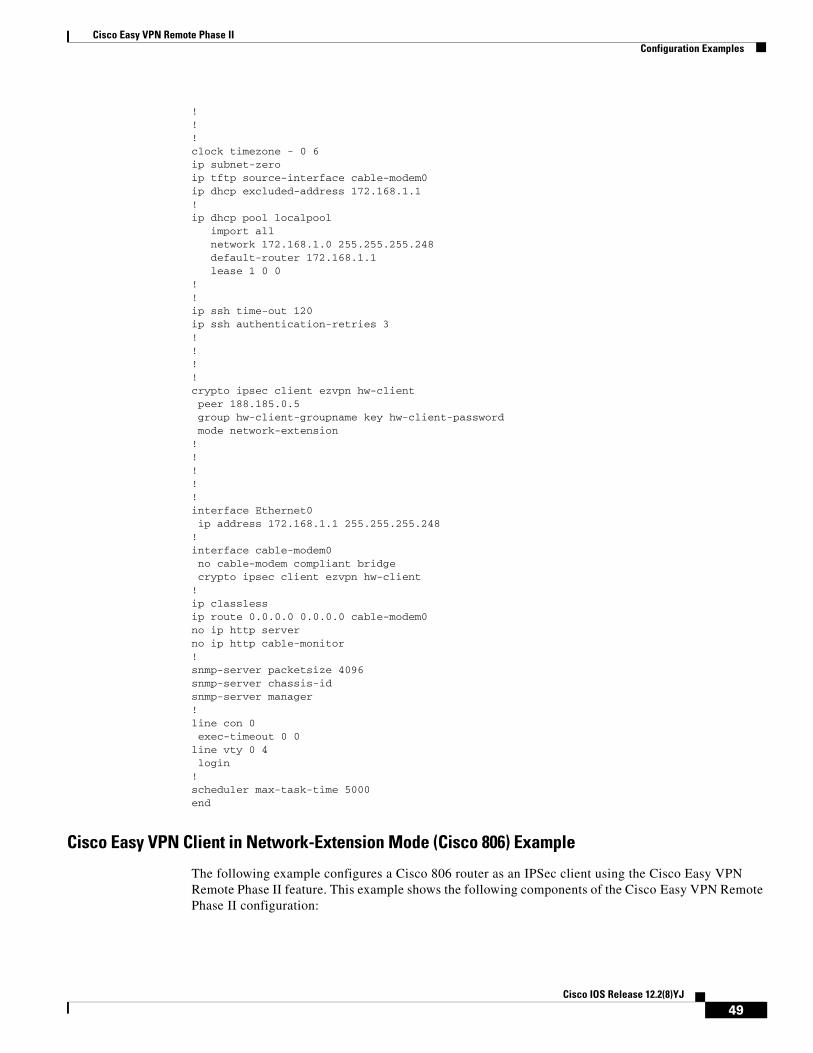
Cisco Easy VPN Remote Phase IIConfiguration Examples
!!!clock timezone - 0 6ip subnet-zeroip tftp source-interface cable-modem0ip dhcp excluded-address 172.168.1.1 !ip dhcp pool localpool import all network 172.168.1.0 255.255.255.248 default-router 172.168.1.1 lease 1 0 0 !!ip ssh time-out 120ip ssh authentication-retries 3!!!!crypto ipsec client ezvpn hw-client peer 188.185.0.5 group hw-client-groupname key hw-client-password mode network-extension !!!!!interface Ethernet0 ip address 172.168.1.1 255.255.255.248 !interface cable-modem0 no cable-modem compliant bridge crypto ipsec client ezvpn hw-client!ip classlessip route 0.0.0.0 0.0.0.0 cable-modem0 no ip http serverno ip http cable-monitor!snmp-server packetsize 4096snmp-server chassis-id snmp-server manager!line con 0 exec-timeout 0 0line vty 0 4 login!scheduler max-task-time 5000end
Cisco Easy VPN Client in Network-Extension Mode (Cisco 806) Example
The following example configures a Cisco 806 router as an IPSec client using the Cisco Easy VPN Remote Phase II feature. This example shows the following components of the Cisco Easy VPN Remote Phase II configuration:
49Cisco IOS Release 12.2(8)YJ
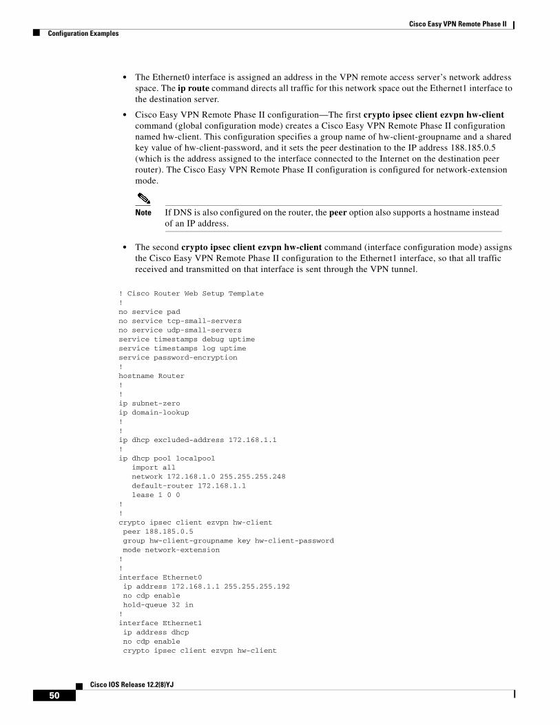
Cisco Easy VPN Remote Phase IIConfiguration Examples
• The Ethernet0 interface is assigned an address in the VPN remote access server’s network address space. The ip route command directs all traffic for this network space out the Ethernet1 interface to the destination server.
• Cisco Easy VPN Remote Phase II configuration—The first crypto ipsec client ezvpn hw-client command (global configuration mode) creates a Cisco Easy VPN Remote Phase II configuration named hw-client. This configuration specifies a group name of hw-client-groupname and a shared key value of hw-client-password, and it sets the peer destination to the IP address 188.185.0.5 (which is the address assigned to the interface connected to the Internet on the destination peer router). The Cisco Easy VPN Remote Phase II configuration is configured for network-extension mode.
Note If DNS is also configured on the router, the peer option also supports a hostname instead of an IP address.
• The second crypto ipsec client ezvpn hw-client command (interface configuration mode) assigns the Cisco Easy VPN Remote Phase II configuration to the Ethernet1 interface, so that all traffic received and transmitted on that interface is sent through the VPN tunnel.
! Cisco Router Web Setup Template!no service padno service tcp-small-serversno service udp-small-serversservice timestamps debug uptimeservice timestamps log uptimeservice password-encryption!hostname Router!!ip subnet-zeroip domain-lookup!!ip dhcp excluded-address 172.168.1.1 !ip dhcp pool localpool import all network 172.168.1.0 255.255.255.248 default-router 172.168.1.1 lease 1 0 0 !!crypto ipsec client ezvpn hw-client peer 188.185.0.5 group hw-client-groupname key hw-client-password mode network-extension !!interface Ethernet0 ip address 172.168.1.1 255.255.255.192 no cdp enable hold-queue 32 in!interface Ethernet1 ip address dhcp no cdp enable crypto ipsec client ezvpn hw-client
50Cisco IOS Release 12.2(8)YJ
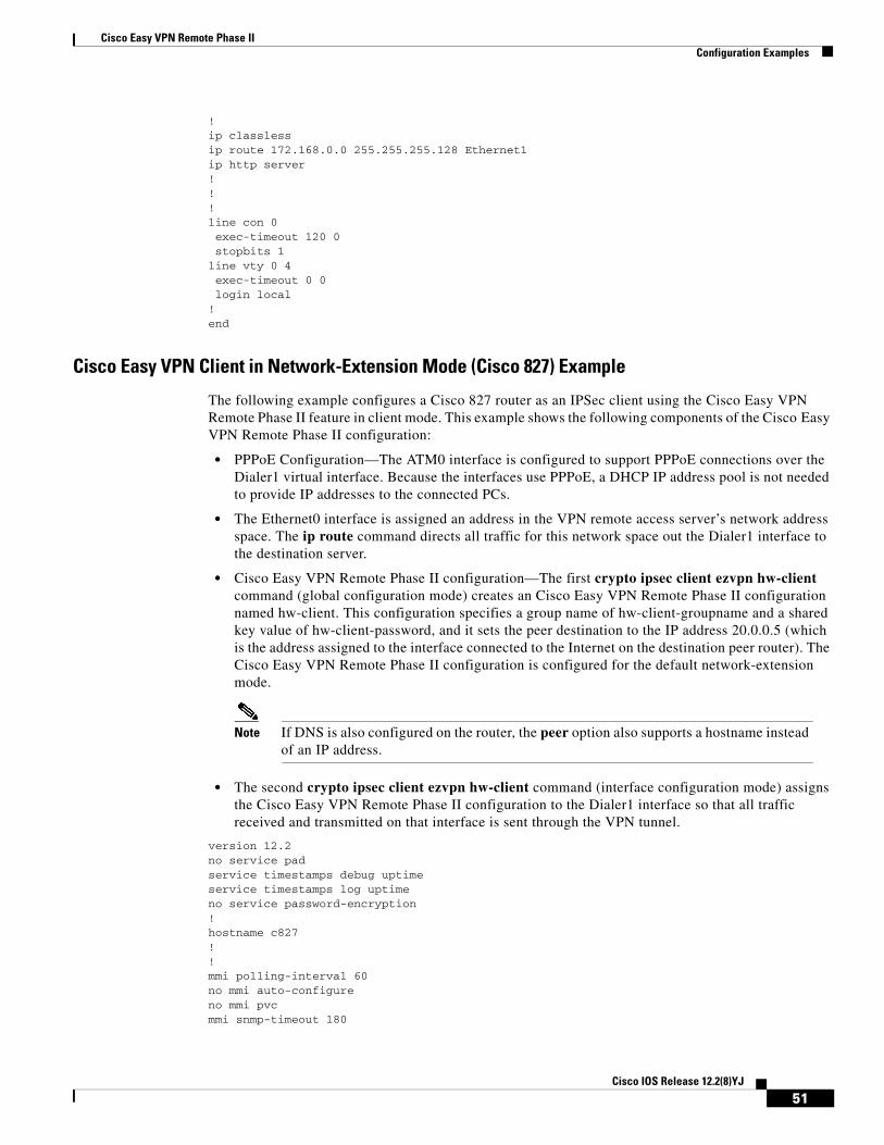
Cisco Easy VPN Remote Phase IIConfiguration Examples
!ip classlessip route 172.168.0.0 255.255.255.128 Ethernet1ip http server!!!line con 0 exec-timeout 120 0 stopbits 1line vty 0 4 exec-timeout 0 0 login local!end
Cisco Easy VPN Client in Network-Extension Mode (Cisco 827) Example
The following example configures a Cisco 827 router as an IPSec client using the Cisco Easy VPN Remote Phase II feature in client mode. This example shows the following components of the Cisco Easy VPN Remote Phase II configuration:
• PPPoE Configuration—The ATM0 interface is configured to support PPPoE connections over the Dialer1 virtual interface. Because the interfaces use PPPoE, a DHCP IP address pool is not needed to provide IP addresses to the connected PCs.
• The Ethernet0 interface is assigned an address in the VPN remote access server’s network address space. The ip route command directs all traffic for this network space out the Dialer1 interface to the destination server.
• Cisco Easy VPN Remote Phase II configuration—The first crypto ipsec client ezvpn hw-client command (global configuration mode) creates an Cisco Easy VPN Remote Phase II configuration named hw-client. This configuration specifies a group name of hw-client-groupname and a shared key value of hw-client-password, and it sets the peer destination to the IP address 20.0.0.5 (which is the address assigned to the interface connected to the Internet on the destination peer router). The Cisco Easy VPN Remote Phase II configuration is configured for the default network-extension mode.
Note If DNS is also configured on the router, the peer option also supports a hostname instead of an IP address.
• The second crypto ipsec client ezvpn hw-client command (interface configuration mode) assigns the Cisco Easy VPN Remote Phase II configuration to the Dialer1 interface so that all traffic received and transmitted on that interface is sent through the VPN tunnel.
version 12.2no service padservice timestamps debug uptimeservice timestamps log uptimeno service password-encryption!hostname c827!!mmi polling-interval 60no mmi auto-configureno mmi pvcmmi snmp-timeout 180
51Cisco IOS Release 12.2(8)YJ
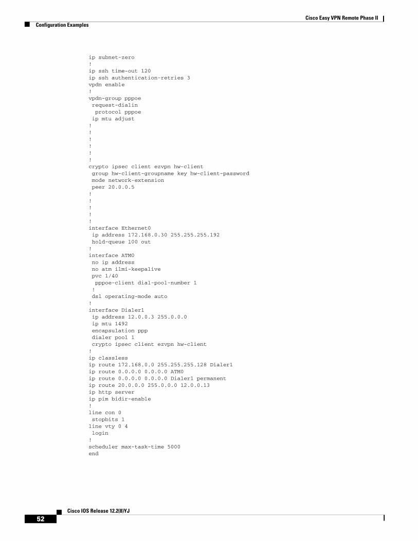
Cisco Easy VPN Remote Phase IIConfiguration Examples
ip subnet-zero!ip ssh time-out 120ip ssh authentication-retries 3vpdn enable!vpdn-group pppoe request-dialin protocol pppoe ip mtu adjust!!!!!!crypto ipsec client ezvpn hw-client group hw-client-groupname key hw-client-password mode network-extension peer 20.0.0.5!!!!!interface Ethernet0 ip address 172.168.0.30 255.255.255.192 hold-queue 100 out!interface ATM0 no ip address no atm ilmi-keepalive pvc 1/40 pppoe-client dial-pool-number 1 ! dsl operating-mode auto!interface Dialer1 ip address 12.0.0.3 255.0.0.0 ip mtu 1492 encapsulation ppp dialer pool 1 crypto ipsec client ezvpn hw-client!ip classlessip route 172.168.0.0 255.255.255.128 Dialer1ip route 0.0.0.0 0.0.0.0 ATM0ip route 0.0.0.0 0.0.0.0 Dialer1 permanentip route 20.0.0.0 255.0.0.0 12.0.0.13ip http serverip pim bidir-enable!line con 0 stopbits 1line vty 0 4 login!scheduler max-task-time 5000end
52Cisco IOS Release 12.2(8)YJ
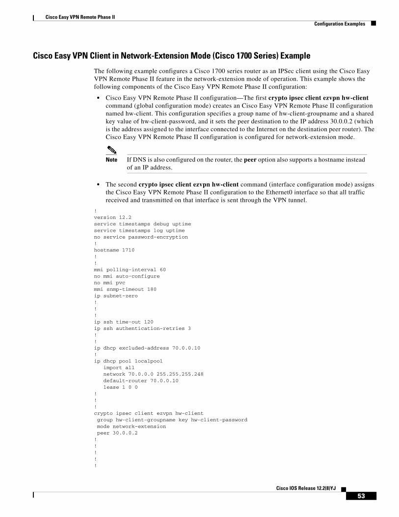
Cisco Easy VPN Remote Phase IIConfiguration Examples
Cisco Easy VPN Client in Network-Extension Mode (Cisco 1700 Series) Example
The following example configures a Cisco 1700 series router as an IPSec client using the Cisco Easy VPN Remote Phase II feature in the network-extension mode of operation. This example shows the following components of the Cisco Easy VPN Remote Phase II configuration:
• Cisco Easy VPN Remote Phase II configuration—The first crypto ipsec client ezvpn hw-client command (global configuration mode) creates an Cisco Easy VPN Remote Phase II configuration named hw-client. This configuration specifies a group name of hw-client-groupname and a shared key value of hw-client-password, and it sets the peer destination to the IP address 30.0.0.2 (which is the address assigned to the interface connected to the Internet on the destination peer router). The Cisco Easy VPN Remote Phase II configuration is configured for network-extension mode.
Note If DNS is also configured on the router, the peer option also supports a hostname instead of an IP address.
• The second crypto ipsec client ezvpn hw-client command (interface configuration mode) assigns the Cisco Easy VPN Remote Phase II configuration to the Ethernet0 interface so that all traffic received and transmitted on that interface is sent through the VPN tunnel.
!version 12.2service timestamps debug uptimeservice timestamps log uptimeno service password-encryption!hostname 1710!!mmi polling-interval 60no mmi auto-configureno mmi pvcmmi snmp-timeout 180ip subnet-zero!!!ip ssh time-out 120ip ssh authentication-retries 3!!ip dhcp excluded-address 70.0.0.10 !ip dhcp pool localpool import all network 70.0.0.0 255.255.255.248 default-router 70.0.0.10 lease 1 0 0 !!!crypto ipsec client ezvpn hw-client group hw-client-groupname key hw-client-password mode network-extension peer 30.0.0.2!!!!!
53Cisco IOS Release 12.2(8)YJ
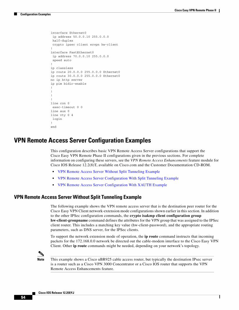
Cisco Easy VPN Remote Phase IIConfiguration Examples
interface Ethernet0 ip address 50.0.0.10 255.0.0.0 half-duplex crypto ipsec client ezvpn hw-client !interface FastEthernet0 ip address 70.0.0.10 255.0.0.0 speed auto!ip classlessip route 20.0.0.0 255.0.0.0 Ethernet0ip route 30.0.0.0 255.0.0.0 Ethernet0no ip http serverip pim bidir-enable!!!!line con 0 exec-timeout 0 0line aux 0line vty 0 4 login!end
VPN Remote Access Server Configuration ExamplesThis configuration describes basic VPN Remote Access Server configurations that support the Cisco Easy VPN Remote Phase II configurations given in the previous sections. For complete information on configuring these servers, see the VPN Remote Access Enhancements feature module for Cisco IOS Release 12.2(8)T, available on Cisco.com and the Customer Documentation CD-ROM.
• VPN Remote Access Server Without Split Tunneling Example
• VPN Remote Access Server Configuration With Split Tunneling Example
• VPN Remote Access Server Configuration With XAUTH Example
VPN Remote Access Server Without Split Tunneling Example
The following example shows the VPN remote access server that is the destination peer router for the Cisco Easy VPN Client network-extension mode configurations shown earlier in this section. In addition to the other IPSec configuration commands, the crypto isakmp client configuration group hw-client-groupname command defines the attributes for the VPN group that was assigned to the IPSec client router. This includes a matching key value (hw-client-password), and the appropriate routing parameters, such as DNS server, for the IPSec clients.
To support the network extension mode of operation, the ip route command instructs that incoming packets for the 172.168.0.0 network be directed out the cable-modem interface to the Cisco Easy VPN Client. Other ip route commands might be needed, depending on your network’s topology.
Note This example shows a Cisco uBR925 cable access router, but typically the destination IPsec server is a router such as a Cisco VPN 3000 Concentrator or a Cisco IOS router that supports the VPN Remote Access Enhancements feature.
54Cisco IOS Release 12.2(8)YJ
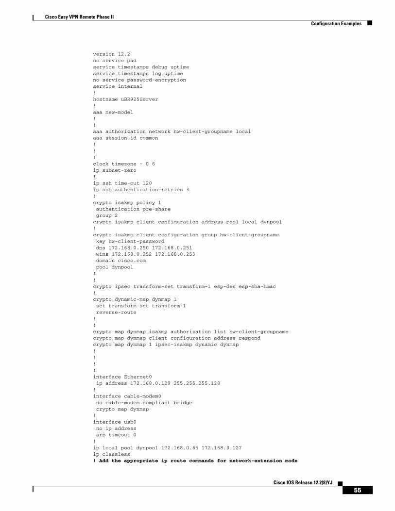
Cisco Easy VPN Remote Phase IIConfiguration Examples
version 12.2no service padservice timestamps debug uptimeservice timestamps log uptimeno service password-encryptionservice internal!hostname uBR925Server!aaa new-model!!aaa authorization network hw-client-groupname local aaa session-id common!!!clock timezone - 0 6ip subnet-zero!ip ssh time-out 120ip ssh authentication-retries 3!crypto isakmp policy 1 authentication pre-share group 2crypto isakmp client configuration address-pool local dynpool!crypto isakmp client configuration group hw-client-groupname key hw-client-password dns 172.168.0.250 172.168.0.251 wins 172.168.0.252 172.168.0.253 domain cisco.com pool dynpool!!crypto ipsec transform-set transform-1 esp-des esp-sha-hmac !crypto dynamic-map dynmap 1 set transform-set transform-1reverse-route
!!crypto map dynmap isakmp authorization list hw-client-groupnamecrypto map dynmap client configuration address respondcrypto map dynmap 1 ipsec-isakmp dynamic dynmap !!!!interface Ethernet0 ip address 172.168.0.129 255.255.255.128!interface cable-modem0 no cable-modem compliant bridge crypto map dynmap!interface usb0 no ip address arp timeout 0!ip local pool dynpool 172.168.0.65 172.168.0.127 ip classless! Add the appropriate ip route commands for network-extension mode
55Cisco IOS Release 12.2(8)YJ
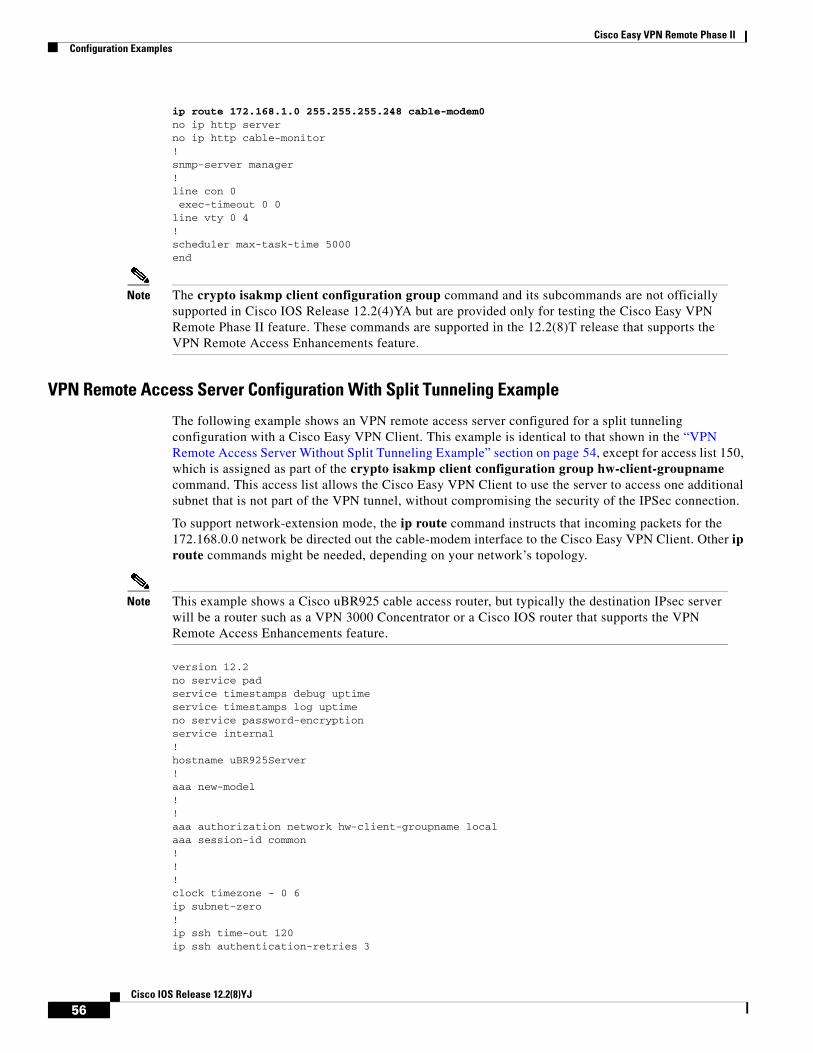
Cisco Easy VPN Remote Phase IIConfiguration Examples
ip route 172.168.1.0 255.255.255.248 cable-modem0 no ip http serverno ip http cable-monitor!snmp-server manager!line con 0 exec-timeout 0 0line vty 0 4!scheduler max-task-time 5000end
Note The crypto isakmp client configuration group command and its subcommands are not officially supported in Cisco IOS Release 12.2(4)YA but are provided only for testing the Cisco Easy VPN Remote Phase II feature. These commands are supported in the 12.2(8)T release that supports the VPN Remote Access Enhancements feature.
VPN Remote Access Server Configuration With Split Tunneling Example
The following example shows an VPN remote access server configured for a split tunneling configuration with a Cisco Easy VPN Client. This example is identical to that shown in the “VPN Remote Access Server Without Split Tunneling Example” section on page 54, except for access list 150, which is assigned as part of the crypto isakmp client configuration group hw-client-groupname command. This access list allows the Cisco Easy VPN Client to use the server to access one additional subnet that is not part of the VPN tunnel, without compromising the security of the IPSec connection.
To support network-extension mode, the ip route command instructs that incoming packets for the 172.168.0.0 network be directed out the cable-modem interface to the Cisco Easy VPN Client. Other ip route commands might be needed, depending on your network’s topology.
Note This example shows a Cisco uBR925 cable access router, but typically the destination IPsec server will be a router such as a VPN 3000 Concentrator or a Cisco IOS router that supports the VPN Remote Access Enhancements feature.
version 12.2no service padservice timestamps debug uptimeservice timestamps log uptimeno service password-encryptionservice internal!hostname uBR925Server!aaa new-model!!aaa authorization network hw-client-groupname local aaa session-id common!!!clock timezone - 0 6ip subnet-zero!ip ssh time-out 120ip ssh authentication-retries 3
56Cisco IOS Release 12.2(8)YJ
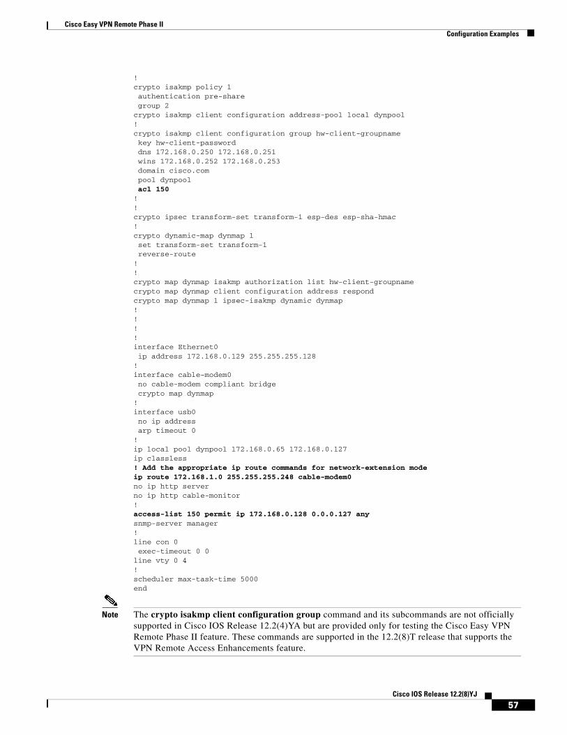
Cisco Easy VPN Remote Phase IIConfiguration Examples
!crypto isakmp policy 1 authentication pre-share group 2crypto isakmp client configuration address-pool local dynpool!crypto isakmp client configuration group hw-client-groupname key hw-client-password dns 172.168.0.250 172.168.0.251 wins 172.168.0.252 172.168.0.253 domain cisco.com pool dynpool acl 150 !!crypto ipsec transform-set transform-1 esp-des esp-sha-hmac !crypto dynamic-map dynmap 1 set transform-set transform-1reverse-route
!!crypto map dynmap isakmp authorization list hw-client-groupnamecrypto map dynmap client configuration address respondcrypto map dynmap 1 ipsec-isakmp dynamic dynmap !!!!interface Ethernet0 ip address 172.168.0.129 255.255.255.128!interface cable-modem0 no cable-modem compliant bridge crypto map dynmap!interface usb0 no ip address arp timeout 0!ip local pool dynpool 172.168.0.65 172.168.0.127 ip classless! Add the appropriate ip route commands for network-extension mode ip route 172.168.1.0 255.255.255.248 cable-modem0 no ip http serverno ip http cable-monitor!access-list 150 permit ip 172.168.0.128 0.0.0.127 any snmp-server manager!line con 0 exec-timeout 0 0line vty 0 4!scheduler max-task-time 5000end
Note The crypto isakmp client configuration group command and its subcommands are not officially supported in Cisco IOS Release 12.2(4)YA but are provided only for testing the Cisco Easy VPN Remote Phase II feature. These commands are supported in the 12.2(8)T release that supports the VPN Remote Access Enhancements feature.
57Cisco IOS Release 12.2(8)YJ
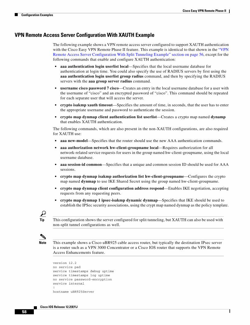
Cisco Easy VPN Remote Phase IIConfiguration Examples
VPN Remote Access Server Configuration With XAUTH Example
The following example shows a VPN remote access server configured to support XAUTH authentication with the Cisco Easy VPN Remote Phase II feature. This example is identical to that shown in the “VPN Remote Access Server Configuration With Split Tunneling Example” section on page 56, except for the following commands that enable and configure XAUTH authentication:
• aaa authentication login userlist local—Specifies that the local username database for authentication at login time. You could also specify the use of RADIUS servers by first using the aaa authentication login userlist group radius command, and then by specifying the RADIUS servers with the aaa group server radius command.
• username cisco password 7 cisco—Creates an entry in the local username database for a user with the username of “cisco” and an encrypted password of “cisco”. This command should be repeated for each separate user that will access the server.
• crypto isakmp xauth timeout—Specifies the amount of time, in seconds, that the user has to enter the appropriate username and password to authenticate the session.
• crypto map dynmap client authentication list userlist—Creates a crypto map named dynamp that enables XAUTH authentication.
The following commands, which are also present in the non-XAUTH configurations, are also required for XAUTH use:
• aaa new-model—Specifies that the router should use the new AAA authentication commands.
• aaa authorization network hw-client-groupname local—Requires authorization for all network-related service requests for users in the group named hw-client-groupname, using the local username database.
• aaa session-id common—Specifies that a unique and common session ID should be used for AAA sessions.
• crypto map dynmap isakmp authorization list hw-client-groupname—Configures the crypto map named dynmap to use IKE Shared Secret using the group named hw-client-groupname.
• crypto map dynmap client configuration address respond—Enables IKE negotiation, accepting requests from any requesting peers.
• crypto map dynmap 1 ipsec-isakmp dynamic dynmap—Specifies that IKE should be used to establish the IPSec security associations, using the crypt map named dynmap as the policy template.
Tip This configuration shows the server configured for split tunneling, but XAUTH can also be used with non-split tunnel configurations as well.
Note This example shows a Cisco uBR925 cable access router, but typically the destination IPsec server is a router such as a VPN 3000 Concentrator or a Cisco IOS router that supports the VPN Remote Access Enhancements feature.
version 12.2no service padservice timestamps debug uptimeservice timestamps log uptimeno service password-encryptionservice internal!hostname uBR925Server
58Cisco IOS Release 12.2(8)YJ
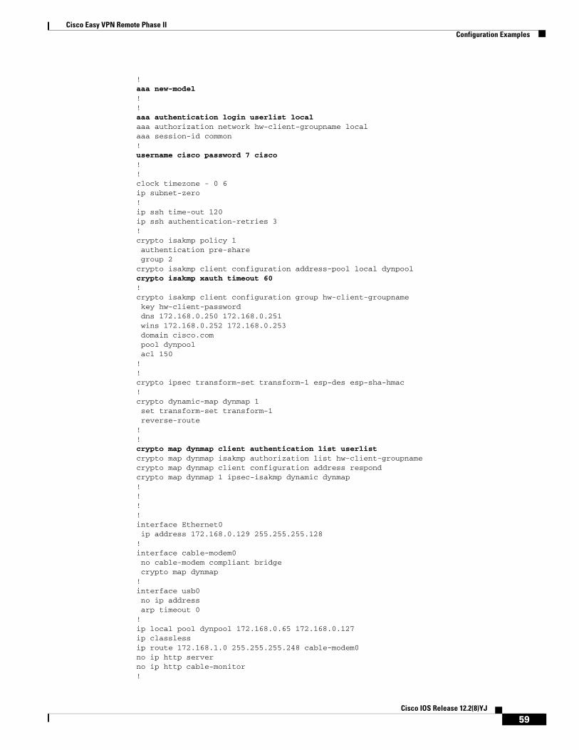
Cisco Easy VPN Remote Phase IIConfiguration Examples
!aaa new-model !!aaa authentication login userlist local aaa authorization network hw-client-groupname local aaa session-id common!username cisco password 7 cisco !!clock timezone - 0 6ip subnet-zero!ip ssh time-out 120ip ssh authentication-retries 3!crypto isakmp policy 1 authentication pre-share group 2crypto isakmp client configuration address-pool local dynpoolcrypto isakmp xauth timeout 60 !crypto isakmp client configuration group hw-client-groupname key hw-client-password dns 172.168.0.250 172.168.0.251 wins 172.168.0.252 172.168.0.253 domain cisco.com pool dynpool acl 150 !!crypto ipsec transform-set transform-1 esp-des esp-sha-hmac !crypto dynamic-map dynmap 1 set transform-set transform-1reverse-route
!!crypto map dynmap client authentication list userlist crypto map dynmap isakmp authorization list hw-client-groupnamecrypto map dynmap client configuration address respondcrypto map dynmap 1 ipsec-isakmp dynamic dynmap !!!!interface Ethernet0 ip address 172.168.0.129 255.255.255.128!interface cable-modem0 no cable-modem compliant bridge crypto map dynmap!interface usb0 no ip address arp timeout 0!ip local pool dynpool 172.168.0.65 172.168.0.127 ip classlessip route 172.168.1.0 255.255.255.248 cable-modem0 no ip http serverno ip http cable-monitor!
59Cisco IOS Release 12.2(8)YJ
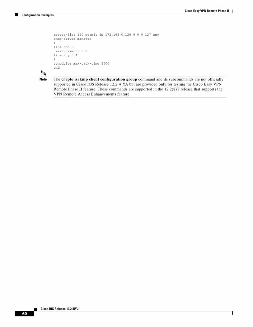
Cisco Easy VPN Remote Phase IIConfiguration Examples
access-list 150 permit ip 172.168.0.128 0.0.0.127 any snmp-server manager!line con 0 exec-timeout 0 0line vty 0 4!scheduler max-task-time 5000end
Note The crypto isakmp client configuration group command and its subcommands are not officially supported in Cisco IOS Release 12.2(4)YA but are provided only for testing the Cisco Easy VPN Remote Phase II feature. These commands are supported in the 12.2(8)T release that supports the VPN Remote Access Enhancements feature.
60Cisco IOS Release 12.2(8)YJ
Cisco Easy VPN Remote Phase IICommand Reference
Command ReferenceThis section documents new or modified commands to support the Cisco Easy VPN Remote Phase II feature. All other commands used with this feature are documented in the Cisco IOS Release 12.2 command reference publications.
• cable-modem dhcp-proxy, page 62
• clear crypto ipsec client ezvpn, page 65
• crypto ipsec client ezvpn xauth, page 67
• crypto ipsec client ezvpn (global configuration), page 69
• crypto ipsec client ezvpn (interface configuration), page 72
• crypto ipsec client ezvpn connect, page 75
• show crypto ipsec client ezvpn, page 78
• show tech-support, page 80
• debug crypto ipsec client ezvpn, page 83
61Cisco IOS Release 12.2(8)YJ
Cisco Easy VPN Remote Phase IIcable-modem dhcp-proxy
cable-modem dhcp-proxyTo specify that a Dynamic Host Configuration Protocol (DHCP) server should provide an IP address for the router’s Ethernet interface, for the loopback interface, or for the router’s Network Address Translation (NAT) address pool, use the cable-modem dhcp-proxy command in cable interface configuration mode. To disable this feature so that you can then manually assign an IP address to the Ethernet interface or NAT address pool, use the no form of this command.
Cisco uBR905, Cisco uBR924, Cisco uBR925 Cable Access Routers, and Cisco CVA122 Cable Voice Adapter
cable-modem dhcp-proxy {interface ethernet number | interface loopback number | nat pool-name}
no cable-modem dhcp-proxy {interface ethernet number | interface loopback number | nat pool-name}
Note This command is available only when the router is configured for routing mode and cannot be used when the router is configured for DOCSIS-compliant bridging.
Syntax Description
Defaults No default behavior or values
Command Modes Interface configuration (cable interface only)
Command History
interface ethernet number
Identifies the Ethernet interface to be assigned the static IP address from the DHCP server (always 0).
interface loopback number
Identifies the loopback interface to be assigned the static IP address from the DHCP server (always 0).
nat pool-name Specifies the name of the NAT pool to be created using the IP address and subnet mask supplied by the DHCP server. (This option is equivalent to giving the ip nat pool pool-name start-ip end-ip netmask subnet command, using the IP address and subnet mask supplied by the DHCP server.)
Release Modification
12.1(1)T This command was introduced on the Cisco uBR924 cable access router.
12.1(3)XL Support was added for the Cisco uBR905 cable access router.
12.1(5)XU1 Support was added for the Cisco CVA122 Cable Voice Adapter.
12.2(2)XA Support was added for the Cisco uBR925 cable access router.
12.2(8)YJ The loopback option was added to support automatic configuration of the IP address on the cable modem tunnel interface for the Cisco uBR905 and Cisco uBR925 cable access routers.
62Cisco IOS Release 12.2(8)YJ
Cisco Easy VPN Remote Phase IIcable-modem dhcp-proxy
Usage Guidelines This command is useful in three situations:
• When the router is configured for routing mode, an IP address must be assigned to its Ethernet interface. Without the cable-modem dhcp-proxy command, this IP address must be a static IP address assigned either by using a Cisco IOS configuration file or by manually entering the necessary interface configuration CLI commands. The cable-modem dhcp-proxy command allows a DHCP server to assign an IP address to the Ethernet interface.
• When NAT is used, an inside global address pool must be created on the Ethernet interface. Without the cable-modem dhcp-proxy command, this must be done by specifying a static IP address in the ip nat pool pool-name start-ip end-ip netmask subnet command. The cable-modem dhcp-proxy command allows a DHCP server to assign an IP address that automatically creates the NAT address pool.
When using this option, you must also use the following NAT configuration commands:
– Use the ip nat inside command in interface configuration mode to configure the Ethernet interface as the inside interface.
– Use the ip nat outside command in interface configuration mode to configure the cable interface as the outside interface.
– Specify the overload option with the ip nat command in global configuration mode to implement Port Address Translation (PAT) so that multiple PCs can use the single IP address in the NAT pool created by the cable-modem dhcp-proxy command.
• When using the Cisco Easy VPN feature to create a VPN tunnel, the command allows a static address to be used for the tunnel’s creation.
After configuring the router with the cable-modem dhcp-proxy command, reboot the router. During the DOCSIS provisioning process, the router sends a DHCP client request to obtain an IP address for the cable interface.
The router then sends a proxy DHCP request to the DHCP server using the Ethernet interface’s MAC address. The DHCP server replies with a second IP address that the router assigns to either the Ethernet or loopback interface, or to the NAT pool, depending on which option was used in the cable-modem dhcp-proxy command.
Note When replying to the proxy request for the Ethernet interface, the DHCP server should assign an IP address that is on the same network as the customer premises equipment (CPE) devices that are attached to the router’s Ethernet interface.
Examples The following example shows how to configure the router so that it makes a proxy DHCP request to obtain an IP address for its Ethernet interface:
Router(config)# interface c0 Router(config-if)# cable-modem dhcp-proxy interface ethernet 0
The following example creates a NAT address pool with the IP address assigned by the DHCP server; this IP address must be in the network attached to the Ethernet address (which in this case is 192.168.100.0).
Router(config)# ip nat inside source list 1 pool net-208 overload Router(config)# interface cable0 Router(config-if)# ip nat outside Router(config-if)# no cable compliant bridge Router(config-if)# cable-modem dhcp-proxy nat net-208 Router(config-if)# exit
63Cisco IOS Release 12.2(8)YJ
Cisco Easy VPN Remote Phase IIcable-modem dhcp-proxy
Router(config)# interface ethernet0 Router(config-if)# ip address 192.168.100.94 255.255.255.0 Router(config-if)# ip nat inside Router(config-if)# exit Router(config)# access-list 1 permit 192.168.100.0 0.0.0.255 Router(config)#
Related Commands Command Description
cable-modem compliant bridge Enables DOCSIS-compliant transparent bridging for the cable interface at startup.
64Cisco IOS Release 12.2(8)YJ
Cisco Easy VPN Remote Phase IIclear crypto ipsec client ezvpn
clear crypto ipsec client ezvpnTo reset the Cisco Easy VPN Remote state machine and bring down the Cisco Easy VPN Remote Phase II connection on all interfaces or on a given interface (tunnel), use the clear crypto ipsec client ezvpn command in privileged EXEC mode. If a tunnel name is specified, only the specified tunnel is cleared.
clear crypto ipsec client ezvpn [name]
Syntax Description
Defaults If no tunnel name is specified, all active tunnels on the machine are cleared.
Command Modes Privileged EXEC
Command History
Usage Guidelines The clear crypto ipsec client ezvpn command resets the Cisco Easy VPN Remote state machine, bringing down the current Cisco Easy VPN Remote Phase II connection and bringing it back up on the interface. If you specify a tunnel name, then only that tunnel is cleared. If no tunnel name is specified, all active tunnels on the machine are cleared.
If the Cisco Easy VPN Remote Phase II connection for a particular interface is configured for autoconnect, this command also initiates a new Cisco Easy VPN Remote Phase II connection.
Examples The following example shows the Cisco Easy VPN Remote state machine being reset:
Router# clear crypto ipsec client ezvpn Router#
name (Optional) Identifies the IPSec VPN tunnel that is to be disconnected or cleared with a unique, arbitrary name. If no name is specified, then all existing tunnels are disconnected or cleared.
Release Modification
12.2(4)YA This command was introduced for Cisco 806, Cisco 826, Cisco 827, and Cisco 828 routers; Cisco 1700 series routers; and Cisco uBR905 and Cisco uBR925 cable access routers.
12.2(8)YJ This command was enhanced to specify an IPSec VPN tunnel to be cleared or disconnected for Cisco 806, Cisco 826, Cisco 827, and Cisco 828 routers; Cisco 1700 series routers; and Cisco uBR905 and Cisco uBR925 cable access routers.
65Cisco IOS Release 12.2(8)YJ

Cisco Easy VPN Remote Phase IIclear crypto ipsec client ezvpn
Related Commands Command Description
crypto ipsec client ezvpn
(Global configuration mode) Creates a Cisco Easy VPN Remote Phase II configuration.
crypto ipsec client ezvpn
(Interface configuration mode) Assigns a Cisco Easy VPN Remote Phase II configuration to an interface.
66Cisco IOS Release 12.2(8)YJ
Cisco Easy VPN Remote Phase IIcrypto ipsec client ezvpn xauth
crypto ipsec client ezvpn xauthTo respond to a pending VPN authorization request, use the crypto ipsec client ezvpn xauth command in privileged EXEC mode.
crypto ipsec client ezvpn xauth name
Syntax Description
Defaults No default behavior or values
Command Modes Privileged EXEC
Command History
Usage Guidelines If the tunnel name is not specified, the authorization request is made on the active tunnel. If there is more than one active tunnel, the command fails with an error requesting that you specify the tunnel name.
When making a VPN connection, individual users might also be required to provide authorization information, such as a username or password. When the remote end requires this information, the router displays a message on the router’s console instructing the user to enter the crypto ipsec client ezvpn xauth command. The user then uses the CLI to give this command and reply to the following prompts to provide the required information.
Note If the user does not respond to the Authentication notification, the message is repeated every ten seconds.
Examples The following example shows the user being prompted to enter the crypto ipsec client ezvpn xauth command. The user then enters the requested information and continues.
Router# 20:27:39: EZVPN: Pending XAuth Request, Please enter the following command:20:27:39: EZVPN: crypto ipsec client ezvpn xauth
Router# crypto ipsec client ezvpn xauth Enter Username and Password: userid Password: ************
name Identifies the IPSec VPN tunnel with a unique, arbitrary name. This is required.
Release Modification
12.2(4)YA This command was introduced on Cisco 806, Cisco 826, Cisco 827, and Cisco 828 routers; Cisco 1700 series routers; and Cisco uBR905 and Cisco uBR925 cable access routers.
12.2(8)YJ This command was enhanced to specify an IPSec VPN tunnel for Cisco 806, Cisco 826, Cisco 827, and Cisco 828 routers; Cisco 1700 series routers; and Cisco uBR905 and Cisco uBR925 cable access routers.
67Cisco IOS Release 12.2(8)YJ

Cisco Easy VPN Remote Phase IIcrypto ipsec client ezvpn xauth
Router#
Related Commands Command Description
crypto ipsec client ezvpn
(Interface configuration mode) Assigns a Cisco Easy VPN Remote Phase II configuration to an interface.
68Cisco IOS Release 12.2(8)YJ
Cisco Easy VPN Remote Phase IIcrypto ipsec client ezvpn (global configuration)
crypto ipsec client ezvpn (global configuration)To create a Cisco Easy VPN Remote Phase II configuration and enter the Cisco Easy VPN Remote configuration mode, use the crypto ipsec client ezvpn command in global configuration mode. To delete the Cisco Easy VPN Remote Phase II configuration, use the no form of this command.
crypto ipsec client ezvpn name
no crypto ipsec client ezvpn name
Note A separate crypto ipsec client ezvpn command exists in interface configuration mode that assigns a Cisco Easy VPN Remote Phase II configuration to the interface.
Syntax Description
Defaults Newly created Cisco Easy VPN Remote Phase II configurations default to client mode.
Command Modes Global configuration
Command History
Usage Guidelines The crypto ipsec client ezvpn command creates a Cisco Easy VPN Remote Phase II configuration and then enters the Cisco Easy VPN Remote configuration mode, at which point you can enter the following subcommands:
• connect [auto | manual]—To manually establish and terminate an IPSec VPN tunnel on demand.
– The auto option is the default setting, because it was the initial Phase I functionality. The IPSec Virtual Private Network (VPN) tunnel is automatically connected when the Cisco Easy VPN Remote feature is configured on an interface.
– The manual option specifies the manual setting to direct the Cisco Easy VPN Remote to wait for a command or API call before attempting to establish the Cisco Easy VPN Remote Phase II connection. When the tunnel times out or fails, subsequent connections have to wait for the command to reset to manual or an application program interface (API) call.
• default—Sets the following command to its default values.
name Identifies the Cisco Easy VPN Remote Phase II configuration with a unique, arbitrary name.
Release Modification
12.2(4)YA This command was introduced for Cisco 806, Cisco 826, Cisco 827, and Cisco 828 routers; Cisco 1700 series routers; and Cisco uBR905 and Cisco uBR925 cable access routers.
12.2(8)YJ This command was enhanced to enable you to manually establish and terminate an IPSec VPN tunnel on demand for Cisco 806, Cisco 826, Cisco 827, and Cisco 828 routers; Cisco 1700 series routers; and Cisco uBR905 and Cisco uBR925 cable access routers.
69Cisco IOS Release 12.2(8)YJ
Cisco Easy VPN Remote Phase IIcrypto ipsec client ezvpn (global configuration)
• exit—Exits the Cisco Easy VPN configuration mode and returns to global configuration mode.
• group group-name key group-key—Specifies the group name and key value for the VPN connection.
• local-address interface-name—To inform the Cisco Easy VPN Client which interface is used to determine the public IP address, which is used to source the tunnel. This applies only to the Cisco uBR905 and Cisco uBR925 cable access routers.
– The value of interface-name specifies the interface used for tunnel traffic.
After specifying the local address used to source tunnel traffic, the IP address can be obtained in two ways:
– The local-address subcommand can be used with the cable-modem dhcp-proxy {interface loopback number} command to obtain a public IP address and automatically assign it to the loopback interface.
– The IP address can be manually assigned to the loopback interface.
• mode {client | network-extension}—Specifies the router’s VPN mode of operation:
– The client option (default) automatically configures the router for Cisco Easy VPN Client mode operation, which uses NAT/PAT address translations. When the Cisco Easy VPN Remote Phase II configuration is assigned to an interface, the router automatically creates the NAT/PAT and access-list configuration needed for the VPN connection.
– The network-extension option specifies that the router should become a remote extension of the enterprise network at the other end of the VPN connection. The PCs that are connected to the router typically are assigned an IP address in the enterprise network’s address space.
• no—Removes the command or sets it to its default values.
• peer {ipaddress | hostname}—Sets the peer IP address or hostname for the VPN connection. A hostname can be specified only when the router has a DNS server available for hostname resolution.
Note The Cisco Easy VPN Remote Phase II feature attempts to resolve the hostname when the peer command is given, not when the VPN tunnel is created. If the hostname cannot be resolved at that time, the peer command is not accepted.
After configuring the Cisco Easy VPN Remote Phase II configuration, use the exit command to exit the Cisco Easy VPN Remote configuration mode and return to global configuration mode.
Note You cannot use the no crypto ipsec client ezvpn command to delete a Cisco Easy VPN Remote Phase II configuration that is assigned to an interface. You must remove that Cisco Easy VPN Remote Phase II configuration from the interface before you can delete the configuration.
Examples The following example shows a Cisco Easy VPN Remote Phase II configuration named telecommuter-client being created on a Cisco uBR905 or Cisco uBR925 cable access router and being assigned to cable interface 0:
Router# config t Router(config)# crypto ipsec client ezvpn telecommuter-client Router(config-crypto-ezvpn)# group telecommute-group key secret-telecommute-key Router(config-crypto-ezvpn)# peer telecommuter-server Router(config-crypto-ezvpn)# mode client Router(config-crypto-ezvpn)# exit
70Cisco IOS Release 12.2(8)YJ
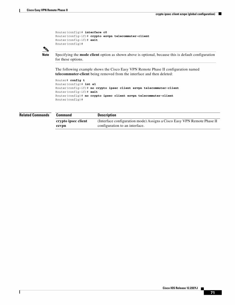
Cisco Easy VPN Remote Phase IIcrypto ipsec client ezvpn (global configuration)
Router(config)# interface c0 Router(config-if)# crypto ezvpn telecommuter-client Router(config-if)# exit Router(config)#
Note Specifying the mode client option as shown above is optional, because this is default configuration for these options.
The following example shows the Cisco Easy VPN Remote Phase II configuration named telecommuter-client being removed from the interface and then deleted:
Router# config t Router(config)# int e1 Router(config-if)# no crypto ipsec client ezvpn telecommuter-client Router(config-if)# exit Router(config)# no crypto ipsec client ezvpn telecommuter-client Router(config)#
Related Commands Command Description
crypto ipsec client ezvpn
(Interface configuration mode) Assigns a Cisco Easy VPN Remote Phase II configuration to an interface.
71Cisco IOS Release 12.2(8)YJ
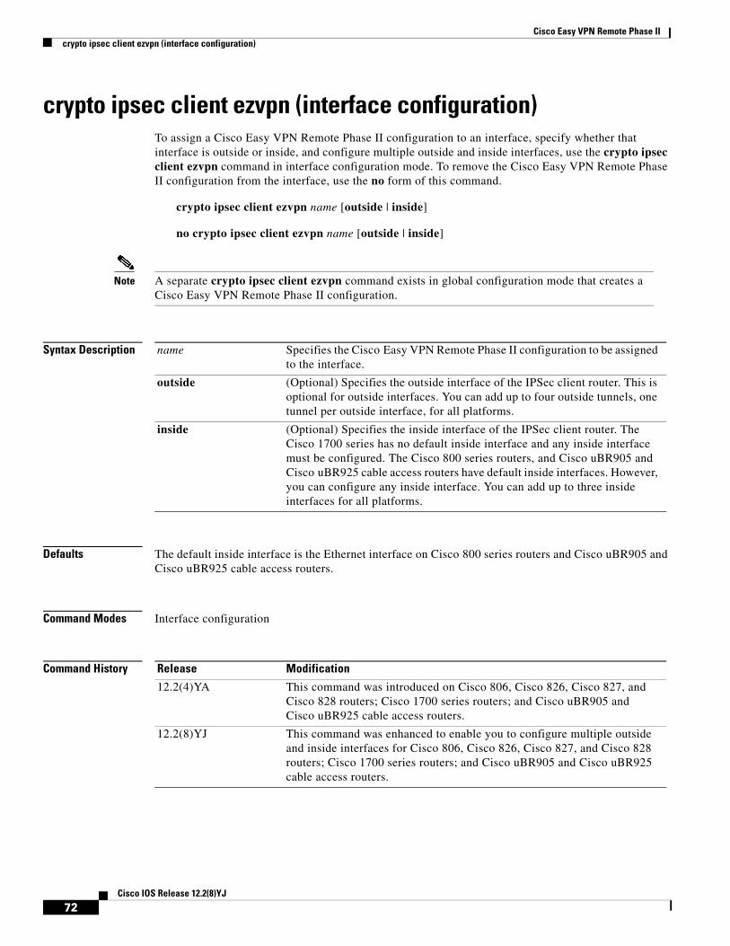
Cisco Easy VPN Remote Phase IIcrypto ipsec client ezvpn (interface configuration)
crypto ipsec client ezvpn (interface configuration)To assign a Cisco Easy VPN Remote Phase II configuration to an interface, specify whether that interface is outside or inside, and configure multiple outside and inside interfaces, use the crypto ipsec client ezvpn command in interface configuration mode. To remove the Cisco Easy VPN Remote Phase II configuration from the interface, use the no form of this command.
crypto ipsec client ezvpn name [outside | inside]
no crypto ipsec client ezvpn name [outside | inside]
Note A separate crypto ipsec client ezvpn command exists in global configuration mode that creates a Cisco Easy VPN Remote Phase II configuration.
Syntax Description
Defaults The default inside interface is the Ethernet interface on Cisco 800 series routers and Cisco uBR905 and Cisco uBR925 cable access routers.
Command Modes Interface configuration
Command History
name Specifies the Cisco Easy VPN Remote Phase II configuration to be assigned to the interface.
outside (Optional) Specifies the outside interface of the IPSec client router. This is optional for outside interfaces. You can add up to four outside tunnels, one tunnel per outside interface, for all platforms.
inside (Optional) Specifies the inside interface of the IPSec client router. The Cisco 1700 series has no default inside interface and any inside interface must be configured. The Cisco 800 series routers, and Cisco uBR905 and Cisco uBR925 cable access routers have default inside interfaces. However, you can configure any inside interface. You can add up to three inside interfaces for all platforms.
Release Modification
12.2(4)YA This command was introduced on Cisco 806, Cisco 826, Cisco 827, and Cisco 828 routers; Cisco 1700 series routers; and Cisco uBR905 and Cisco uBR925 cable access routers.
12.2(8)YJ This command was enhanced to enable you to configure multiple outside and inside interfaces for Cisco 806, Cisco 826, Cisco 827, and Cisco 828 routers; Cisco 1700 series routers; and Cisco uBR905 and Cisco uBR925 cable access routers.
72Cisco IOS Release 12.2(8)YJ
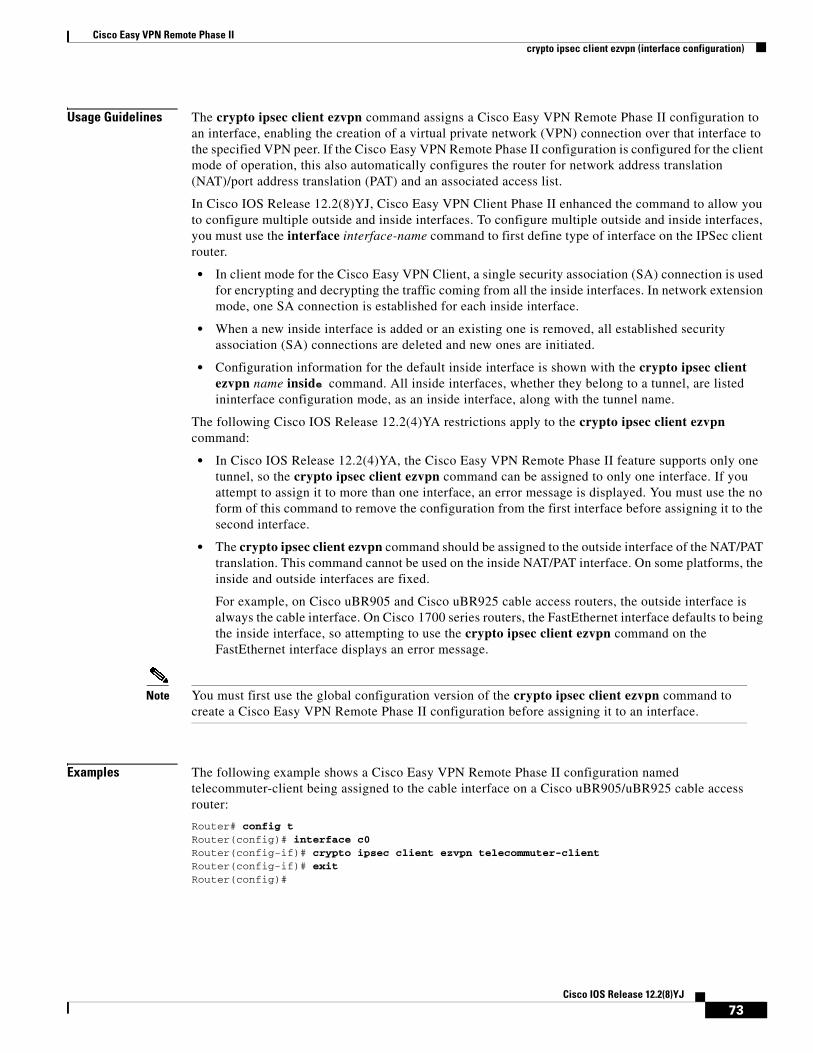
Cisco Easy VPN Remote Phase IIcrypto ipsec client ezvpn (interface configuration)
Usage Guidelines The crypto ipsec client ezvpn command assigns a Cisco Easy VPN Remote Phase II configuration to an interface, enabling the creation of a virtual private network (VPN) connection over that interface to the specified VPN peer. If the Cisco Easy VPN Remote Phase II configuration is configured for the client mode of operation, this also automatically configures the router for network address translation (NAT)/port address translation (PAT) and an associated access list.
In Cisco IOS Release 12.2(8)YJ, Cisco Easy VPN Client Phase II enhanced the command to allow you to configure multiple outside and inside interfaces. To configure multiple outside and inside interfaces, you must use the interface interface-name command to first define type of interface on the IPSec client router.
• In client mode for the Cisco Easy VPN Client, a single security association (SA) connection is used for encrypting and decrypting the traffic coming from all the inside interfaces. In network extension mode, one SA connection is established for each inside interface.
• When a new inside interface is added or an existing one is removed, all established security association (SA) connections are deleted and new ones are initiated.
• Configuration information for the default inside interface is shown with the crypto ipsec client ezvpn name inside command. All inside interfaces, whether they belong to a tunnel, are listed ininterface configuration mode, as an inside interface, along with the tunnel name.
The following Cisco IOS Release 12.2(4)YA restrictions apply to the crypto ipsec client ezvpn command:
• In Cisco IOS Release 12.2(4)YA, the Cisco Easy VPN Remote Phase II feature supports only one tunnel, so the crypto ipsec client ezvpn command can be assigned to only one interface. If you attempt to assign it to more than one interface, an error message is displayed. You must use the no form of this command to remove the configuration from the first interface before assigning it to the second interface.
• The crypto ipsec client ezvpn command should be assigned to the outside interface of the NAT/PAT translation. This command cannot be used on the inside NAT/PAT interface. On some platforms, the inside and outside interfaces are fixed.
For example, on Cisco uBR905 and Cisco uBR925 cable access routers, the outside interface is always the cable interface. On Cisco 1700 series routers, the FastEthernet interface defaults to being the inside interface, so attempting to use the crypto ipsec client ezvpn command on the FastEthernet interface displays an error message.
Note You must first use the global configuration version of the crypto ipsec client ezvpn command to create a Cisco Easy VPN Remote Phase II configuration before assigning it to an interface.
Examples The following example shows a Cisco Easy VPN Remote Phase II configuration named telecommuter-client being assigned to the cable interface on a Cisco uBR905/uBR925 cable access router:
Router# config t Router(config)# interface c0 Router(config-if)# crypto ipsec client ezvpn telecommuter-client Router(config-if)# exit Router(config)#
73Cisco IOS Release 12.2(8)YJ

Cisco Easy VPN Remote Phase IIcrypto ipsec client ezvpn (interface configuration)
The following example first shows an attempt to delete the Cisco Easy VPN Remote Phase II configuration named telecommuter-client, but the configuration cannot be deleted because it is still assigned to an interface. The configuration is then removed from the interface and then deleted:
Router# config t Router(config)# no crypto ipsec client ezvpn telecommuter-client Error: crypto map in use by interface; cannot deleteRouter(config)# int e1 Router(config-if)# no crypto ipsec client ezvpn telecommuter-client Router(config-if)# exit Router(config)# no crypto ipsec client ezvpn telecommuter-client Router(config)#
Related Commands Command Description
crypto ipsec client ezvpn
(Global configuration mode) Creates and modifies a Cisco Easy VPN Remote Phase II configuration.
74Cisco IOS Release 12.2(8)YJ
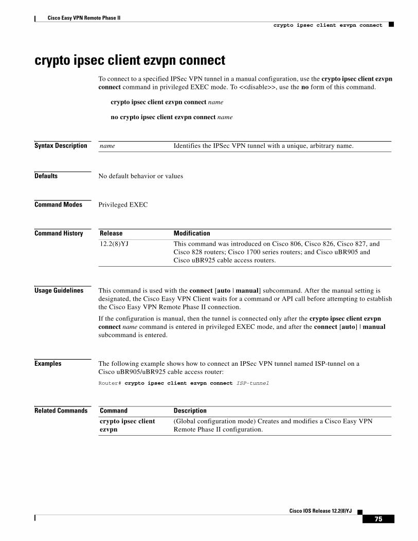
Cisco Easy VPN Remote Phase IIcrypto ipsec client ezvpn connect
crypto ipsec client ezvpn connectTo connect to a specified IPSec VPN tunnel in a manual configuration, use the crypto ipsec client ezvpn connect command in privileged EXEC mode. To <<disable>>, use the no form of this command.
crypto ipsec client ezvpn connect name
no crypto ipsec client ezvpn connect name
Syntax Description
Defaults No default behavior or values
Command Modes Privileged EXEC
Command History
Usage Guidelines This command is used with the connect [auto | manual] subcommand. After the manual setting is designated, the Cisco Easy VPN Client waits for a command or API call before attempting to establish the Cisco Easy VPN Remote Phase II connection.
If the configuration is manual, then the tunnel is connected only after the crypto ipsec client ezvpn connect name command is entered in privileged EXEC mode, and after the connect [auto] | manual subcommand is entered.
Examples The following example shows how to connect an IPSec VPN tunnel named ISP-tunnel on a Cisco uBR905/uBR925 cable access router:
Router# crypto ipsec client ezvpn connect ISP-tunnel
Related Commands
name Identifies the IPSec VPN tunnel with a unique, arbitrary name.
Release Modification
12.2(8)YJ This command was introduced on Cisco 806, Cisco 826, Cisco 827, and Cisco 828 routers; Cisco 1700 series routers; and Cisco uBR905 and Cisco uBR925 cable access routers.
Command Description
crypto ipsec client ezvpn
(Global configuration mode) Creates and modifies a Cisco Easy VPN Remote Phase II configuration.
75Cisco IOS Release 12.2(8)YJ
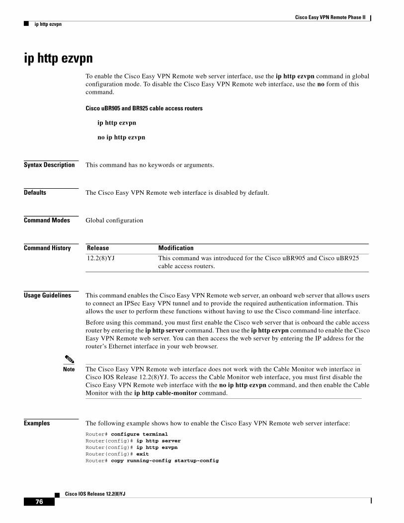
Cisco Easy VPN Remote Phase IIip http ezvpn
ip http ezvpnTo enable the Cisco Easy VPN Remote web server interface, use the ip http ezvpn command in global configuration mode. To disable the Cisco Easy VPN Remote web interface, use the no form of this command.
Cisco uBR905 and BR925 cable access routers
ip http ezvpn
no ip http ezvpn
Syntax Description This command has no keywords or arguments.
Defaults The Cisco Easy VPN Remote web interface is disabled by default.
Command Modes Global configuration
Command History
Usage Guidelines This command enables the Cisco Easy VPN Remote web server, an onboard web server that allows users to connect an IPSec Easy VPN tunnel and to provide the required authentication information. This allows the user to perform these functions without having to use the Cisco command-line interface.
Before using this command, you must first enable the Cisco web server that is onboard the cable access router by entering the ip http server command. Then use the ip http ezvpn command to enable the Cisco Easy VPN Remote web server. You can then access the web server by entering the IP address for the router’s Ethernet interface in your web browser.
Note The Cisco Easy VPN Remote web interface does not work with the Cable Monitor web interface in Cisco IOS Release 12.2(8)YJ. To access the Cable Monitor web interface, you must first disable the Cisco Easy VPN Remote web interface with the no ip http ezvpn command, and then enable the Cable Monitor with the ip http cable-monitor command.
Examples The following example shows how to enable the Cisco Easy VPN Remote web server interface:
Router# configure terminal Router(config)# ip http server Router(config)# ip http ezvpn Router(config)# exit Router# copy running-config startup-config
Release Modification
12.2(8)YJ This command was introduced for the Cisco uBR905 and Cisco uBR925 cable access routers.
76Cisco IOS Release 12.2(8)YJ

Cisco Easy VPN Remote Phase IIip http ezvpn
Related Commands Command Description
ip http cable-monitor Enables and disables the Cable Monitor web server feature.
ip http port Configures the TCP port number for the router’s HTTP web server. The default is the well-known web server port of 80.
ip http server Enables and disables the router’s HTTP web server.
77Cisco IOS Release 12.2(8)YJ
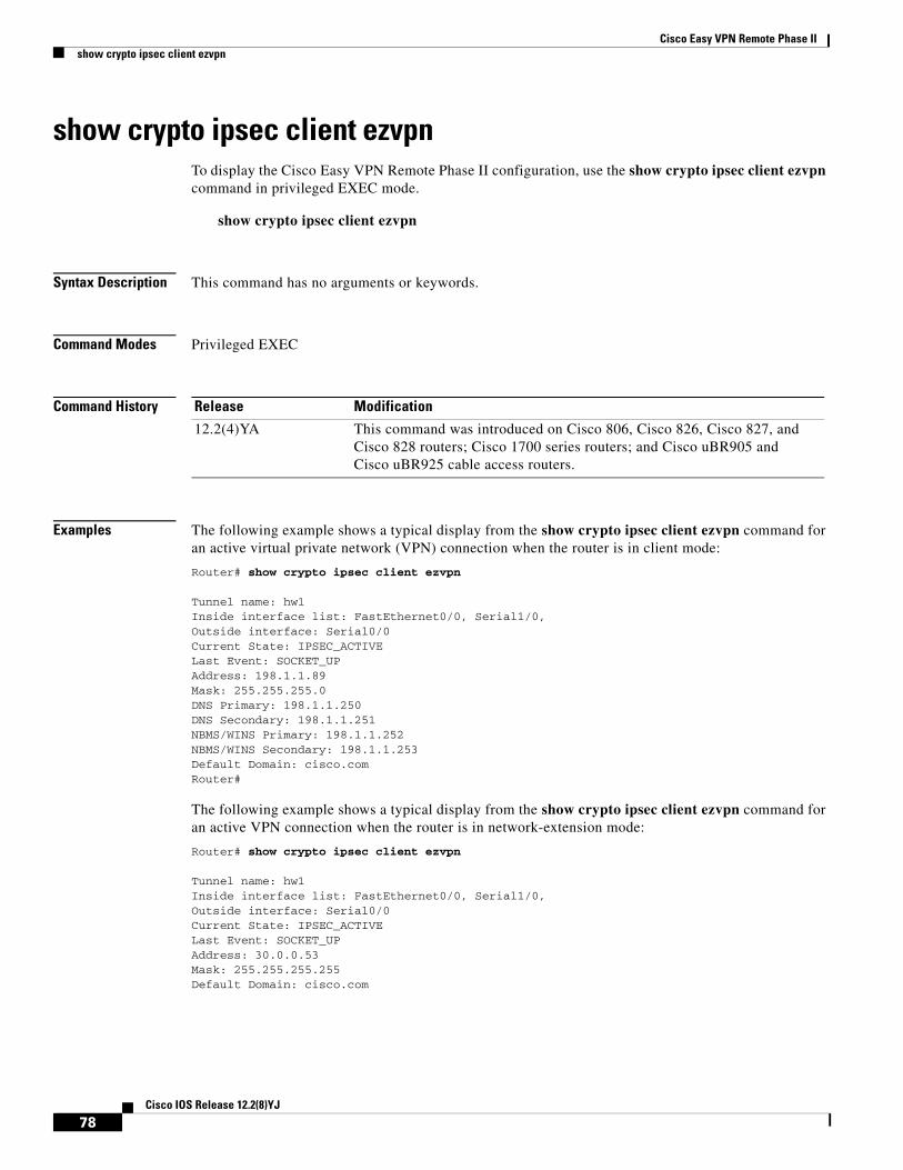
Cisco Easy VPN Remote Phase IIshow crypto ipsec client ezvpn
show crypto ipsec client ezvpnTo display the Cisco Easy VPN Remote Phase II configuration, use the show crypto ipsec client ezvpn command in privileged EXEC mode.
show crypto ipsec client ezvpn
Syntax Description This command has no arguments or keywords.
Command Modes Privileged EXEC
Command History
Examples The following example shows a typical display from the show crypto ipsec client ezvpn command for an active virtual private network (VPN) connection when the router is in client mode:
Router# show crypto ipsec client ezvpn
Tunnel name: hw1 Inside interface list: FastEthernet0/0, Serial1/0, Outside interface: Serial0/0 Current State: IPSEC_ACTIVELast Event: SOCKET_UPAddress: 198.1.1.89Mask: 255.255.255.0DNS Primary: 198.1.1.250DNS Secondary: 198.1.1.251NBMS/WINS Primary: 198.1.1.252NBMS/WINS Secondary: 198.1.1.253Default Domain: cisco.com Router#
The following example shows a typical display from the show crypto ipsec client ezvpn command for an active VPN connection when the router is in network-extension mode:
Router# show crypto ipsec client ezvpn
Tunnel name: hw1 Inside interface list: FastEthernet0/0, Serial1/0, Outside interface: Serial0/0 Current State: IPSEC_ACTIVELast Event: SOCKET_UPAddress: 30.0.0.53Mask: 255.255.255.255Default Domain: cisco.com
Release Modification
12.2(4)YA This command was introduced on Cisco 806, Cisco 826, Cisco 827, and Cisco 828 routers; Cisco 1700 series routers; and Cisco uBR905 and Cisco uBR925 cable access routers.
78Cisco IOS Release 12.2(8)YJ
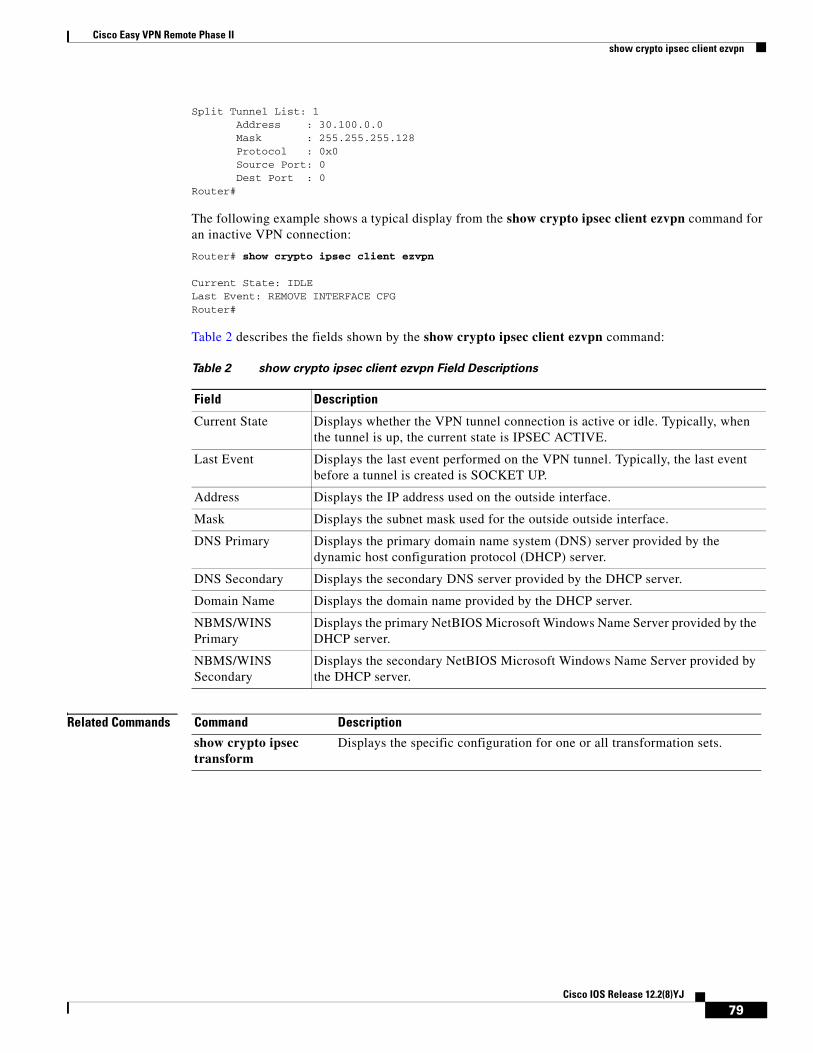
Cisco Easy VPN Remote Phase IIshow crypto ipsec client ezvpn
Split Tunnel List: 1 Address : 30.100.0.0 Mask : 255.255.255.128 Protocol : 0x0 Source Port: 0 Dest Port : 0Router#
The following example shows a typical display from the show crypto ipsec client ezvpn command for an inactive VPN connection:
Router# show crypto ipsec client ezvpn
Current State: IDLELast Event: REMOVE INTERFACE CFGRouter#
Table 2 describes the fields shown by the show crypto ipsec client ezvpn command:
Related Commands
Table 2 show crypto ipsec client ezvpn Field Descriptions
Field Description
Current State Displays whether the VPN tunnel connection is active or idle. Typically, when the tunnel is up, the current state is IPSEC ACTIVE.
Last Event Displays the last event performed on the VPN tunnel. Typically, the last event before a tunnel is created is SOCKET UP.
Address Displays the IP address used on the outside interface.
Mask Displays the subnet mask used for the outside outside interface.
DNS Primary Displays the primary domain name system (DNS) server provided by the dynamic host configuration protocol (DHCP) server.
DNS Secondary Displays the secondary DNS server provided by the DHCP server.
Domain Name Displays the domain name provided by the DHCP server.
NBMS/WINS Primary
Displays the primary NetBIOS Microsoft Windows Name Server provided by the DHCP server.
NBMS/WINS Secondary
Displays the secondary NetBIOS Microsoft Windows Name Server provided by the DHCP server.
Command Description
show crypto ipsec transform
Displays the specific configuration for one or all transformation sets.
79Cisco IOS Release 12.2(8)YJ
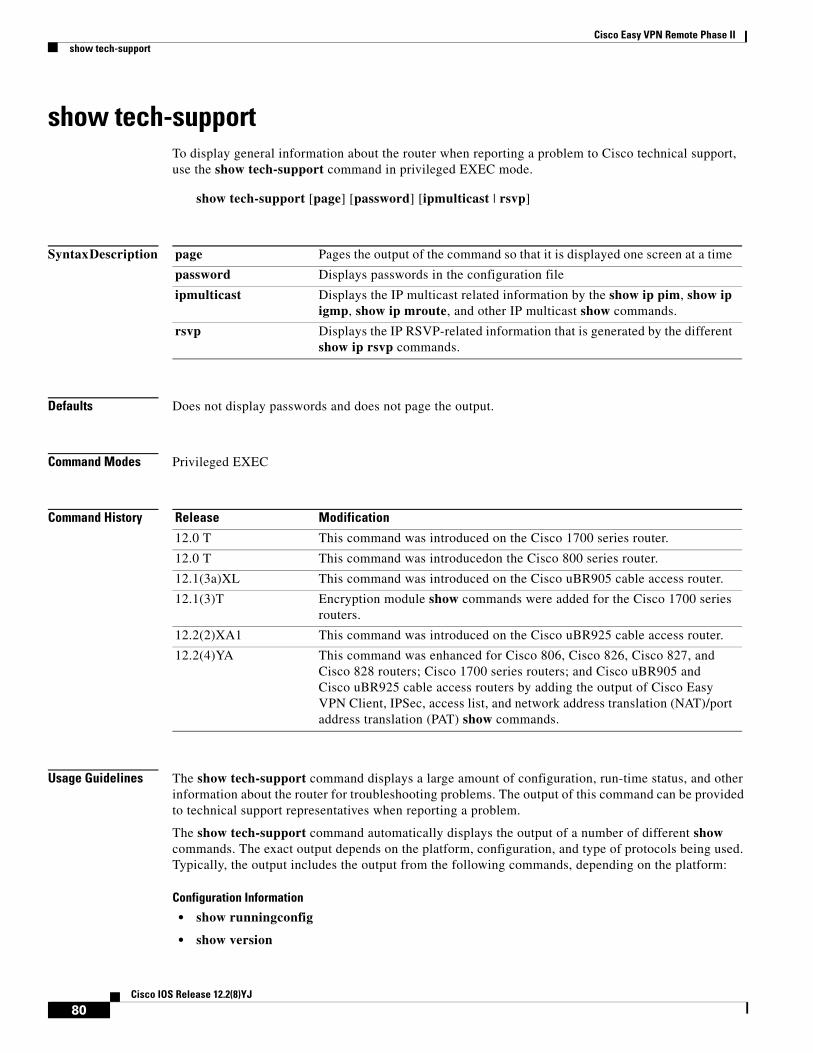
Cisco Easy VPN Remote Phase IIshow tech-support
show tech-supportTo display general information about the router when reporting a problem to Cisco technical support, use the show tech-support command in privileged EXEC mode.
show tech-support [page] [password] [ipmulticast | rsvp]
Syntax Description
Defaults Does not display passwords and does not page the output.
Command Modes Privileged EXEC
Command History
Usage Guidelines The show tech-support command displays a large amount of configuration, run-time status, and other information about the router for troubleshooting problems. The output of this command can be provided to technical support representatives when reporting a problem.
The show tech-support command automatically displays the output of a number of different show commands. The exact output depends on the platform, configuration, and type of protocols being used. Typically, the output includes the output from the following commands, depending on the platform:
Configuration Information
• show runningconfig
• show version
page Pages the output of the command so that it is displayed one screen at a time
password Displays passwords in the configuration file
ipmulticast Displays the IP multicast related information by the show ip pim, show ip igmp, show ip mroute, and other IP multicast show commands.
rsvp Displays the IP RSVP-related information that is generated by the different show ip rsvp commands.
Release Modification
12.0 T This command was introduced on the Cisco 1700 series router.
12.0 T This command was introducedon the Cisco 800 series router.
12.1(3a)XL This command was introduced on the Cisco uBR905 cable access router.
12.1(3)T Encryption module show commands were added for the Cisco 1700 series routers.
12.2(2)XA1 This command was introduced on the Cisco uBR925 cable access router.
12.2(4)YA This command was enhanced for Cisco 806, Cisco 826, Cisco 827, and Cisco 828 routers; Cisco 1700 series routers; and Cisco uBR905 and Cisco uBR925 cable access routers by adding the output of Cisco Easy VPN Client, IPSec, access list, and network address translation (NAT)/port address translation (PAT) show commands.
80Cisco IOS Release 12.2(8)YJ
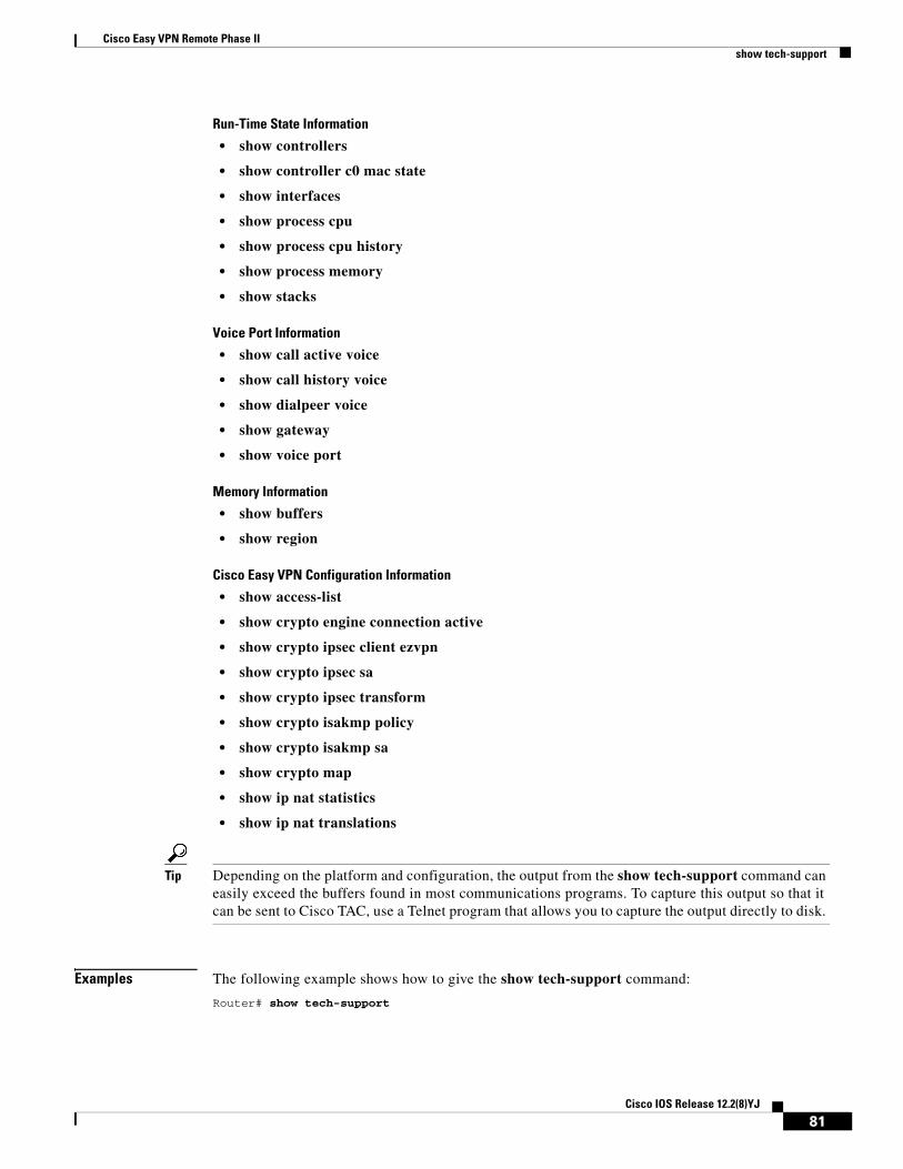
Cisco Easy VPN Remote Phase IIshow tech-support
Run-Time State Information
• show controllers
• show controller c0 mac state
• show interfaces
• show process cpu
• show process cpu history
• show process memory
• show stacks
Voice Port Information
• show call active voice
• show call history voice
• show dialpeer voice
• show gateway
• show voice port
Memory Information
• show buffers
• show region
Cisco Easy VPN Configuration Information
• show access-list
• show crypto engine connection active
• show crypto ipsec client ezvpn
• show crypto ipsec sa
• show crypto ipsec transform
• show crypto isakmp policy
• show crypto isakmp sa
• show crypto map
• show ip nat statistics
• show ip nat translations
Tip Depending on the platform and configuration, the output from the show tech-support command can easily exceed the buffers found in most communications programs. To capture this output so that it can be sent to Cisco TAC, use a Telnet program that allows you to capture the output directly to disk.
Examples The following example shows how to give the show tech-support command:
Router# show tech-support
81Cisco IOS Release 12.2(8)YJ

Cisco Easy VPN Remote Phase IIshow tech-support
Related Commands Command Description
show running-config Displays the current run-time configuration.
show startup-config Displays the configuration that was used to initially configure the CMTS at system startup.
show version Displays the configuration of the system hardware, the software version, the names and sources of configuration files, and the boot images.
82Cisco IOS Release 12.2(8)YJ
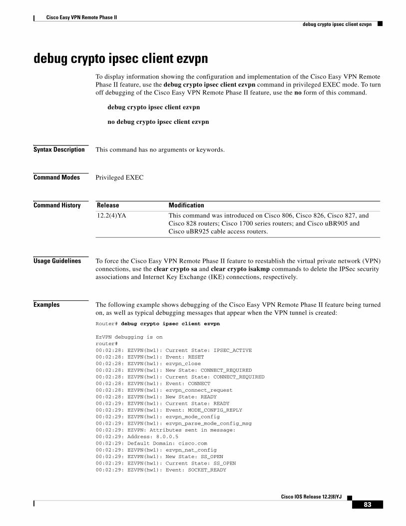
Cisco Easy VPN Remote Phase IIdebug crypto ipsec client ezvpn
debug crypto ipsec client ezvpnTo display information showing the configuration and implementation of the Cisco Easy VPN Remote Phase II feature, use the debug crypto ipsec client ezvpn command in privileged EXEC mode. To turn off debugging of the Cisco Easy VPN Remote Phase II feature, use the no form of this command.
debug crypto ipsec client ezvpn
no debug crypto ipsec client ezvpn
Syntax Description This command has no arguments or keywords.
Command Modes Privileged EXEC
Command History
Usage Guidelines To force the Cisco Easy VPN Remote Phase II feature to reestablish the virtual private network (VPN) connections, use the clear crypto sa and clear crypto isakmp commands to delete the IPSec security associations and Internet Key Exchange (IKE) connections, respectively.
Examples The following example shows debugging of the Cisco Easy VPN Remote Phase II feature being turned on, as well as typical debugging messages that appear when the VPN tunnel is created:
Router# debug crypto ipsec client ezvpn
EzVPN debugging is onrouter# 00:02:28: EZVPN(hw1): Current State: IPSEC_ACTIVE 00:02:28: EZVPN(hw1): Event: RESET 00:02:28: EZVPN(hw1): ezvpn_close 00:02:28: EZVPN(hw1): New State: CONNECT_REQUIRED 00:02:28: EZVPN(hw1): Current State: CONNECT_REQUIRED 00:02:28: EZVPN(hw1): Event: CONNECT 00:02:28: EZVPN(hw1): ezvpn_connect_request 00:02:28: EZVPN(hw1): New State: READY 00:02:29: EZVPN(hw1): Current State: READY 00:02:29: EZVPN(hw1): Event: MODE_CONFIG_REPLY 00:02:29: EZVPN(hw1): ezvpn_mode_config 00:02:29: EZVPN(hw1): ezvpn_parse_mode_config_msg 00:02:29: EZVPN: Attributes sent in message: 00:02:29: Address: 8.0.0.5 00:02:29: Default Domain: cisco.com 00:02:29: EZVPN(hw1): ezvpn_nat_config 00:02:29: EZVPN(hw1): New State: SS_OPEN 00:02:29: EZVPN(hw1): Current State: SS_OPEN 00:02:29: EZVPN(hw1): Event: SOCKET_READY
Release Modification
12.2(4)YA This command was introduced on Cisco 806, Cisco 826, Cisco 827, and Cisco 828 routers; Cisco 1700 series routers; and Cisco uBR905 and Cisco uBR925 cable access routers.
83Cisco IOS Release 12.2(8)YJ

Cisco Easy VPN Remote Phase IIdebug crypto ipsec client ezvpn
00:02:29: EZVPN(hw1): No state change 00:02:30: EZVPN(hw1): Current State: SS_OPEN 00:02:30: EZVPN(hw1): Event: MTU_CHANGED 00:02:30: EZVPN(hw1): No state change 00:02:30: EZVPN(hw1): Current State: SS_OPEN 00:02:30: EZVPN(hw1): Event: SOCKET_UP 00:02:30: ezvpn_socket_up 00:02:30: EZVPN(hw1): New State: IPSEC_ACTIVE
The following example shows the typical display for a VPN tunnel that is reset with the clear crypto ipsec client ezvpn command:
3d17h: EZVPN: Current State: READY3d17h: EZVPN: Event: RESET3d17h: ezvpn_reconnect_request3d17h: ezvpn_close3d17h: ezvpn_connect_request3d17h: EZVPN: New State: READY3d17h: EZVPN: Current State: READY3d17h: EZVPN: Event: MODE_CONFIG_REPLY3d17h: ezvpn_mode_config3d17h: ezvpn_parse_mode_config_msg3d17h: EZVPN: Attributes sent in message:3d17h: DNS Primary: 172.168.0.2503d17h: DNS Secondary: 172.168.0.2513d17h: NBMS/WINS Primary: 172.168.0.2523d17h: NBMS/WINS Secondary: 172.168.0.2533d17h: Split Tunnel List: 13d17h: Address : 172.168.0.1283d17h: Mask : 255.255.255.1283d17h: Protocol : 0x03d17h: Source Port: 03d17h: Dest Port : 03d17h: Split Tunnel List: 23d17h: Address : 172.168.1.1283d17h: Mask : 255.255.255.1283d17h: Protocol : 0x03d17h: Source Port: 03d17h: Dest Port : 03d17h: Default Domain: cisco.com3d17h: ezvpn_nat_config3d17h: EZVPN: New State: SS_OPEN3d17h: EZVPN: Current State: SS_OPEN3d17h: EZVPN: Event: SOCKET_READY3d17h: EZVPN: No state change3d17h: EZVPN: Current State: SS_OPEN3d17h: EZVPN: Event: SOCKET_READY3d17h: EZVPN: No state change3d17h: EZVPN: Current State: SS_OPEN3d17h: EZVPN: Event: MTU_CHANGED3d17h: EZVPN: No state change3d17h: EZVPN: Current State: SS_OPEN3d17h: EZVPN: Event: SOCKET_UP3d17h: EZVPN: New State: IPSEC_ACTIVE3d17h: EZVPN: Current State: IPSEC_ACTIVE3d17h: EZVPN: Event: MTU_CHANGED3d17h: EZVPN: No state change3d17h: EZVPN: Current State: IPSEC_ACTIVE3d17h: EZVPN: Event: SOCKET_UP
The following example shows the typical display for a VPN tunnel that is removed from the interface with the no crypto ipsec client ezvpn command:
84Cisco IOS Release 12.2(8)YJ
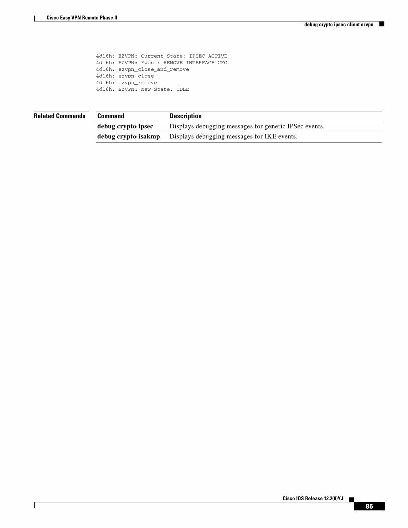
Cisco Easy VPN Remote Phase IIdebug crypto ipsec client ezvpn
4d16h: EZVPN: Current State: IPSEC ACTIVE4d16h: EZVPN: Event: REMOVE INTERFACE CFG4d16h: ezvpn_close_and_remove4d16h: ezvpn_close4d16h: ezvpn_remove4d16h: EZVPN: New State: IDLE
Related Commands Command Description
debug crypto ipsec Displays debugging messages for generic IPSec events.
debug crypto isakmp Displays debugging messages for IKE events.
85Cisco IOS Release 12.2(8)YJ
Cisco Easy VPN Remote Phase IIGlossary
GlossaryAAA—authentication, authorization, and accounting. A framework of security services that provide the method for identifying users (authentication); for remote access control (authorization); and for collecting and sending security server information used for billing, auditing, and reporting (accounting).
aggressive mode—This mode eliminates several steps during IKE authentication negotiation (Phase 1) between two or more IPSec peers. Aggressive mode is faster than main mode, but is not as secure.
authentication, authorization, and accounting—See AAA.
authorization—The method for remote access control, including one-time authorization or authorization for each service; per-user account list and profile; user group support; and support of IP, IPX, ARA, and Telnet. AAA authorization works by assembling a set of attributes that describe what the user is authorized to perform. These attributes are compared to the information contained in a database for a given user and the result is returned to AAA to determine the user's actual capabilities and restrictions. The database can be located locally on the access server or router, or it can be hosted remotely on a RADIUS or TACACS+ security server. Remote security servers, such as RADIUS and TACACS+, authorize users for specific rights by associating attribute-value (AV) pairs, which define those rights, with the appropriate user. All authorization methods must be defined through AAA.
IKE—A key management protocol standard that is used in conjunction with the IPSec standard. IPSec is an IP security feature that provides robust authentication and encryption of IP packets. IPSec can be configured without IKE, but IKE enhances IPSec by providing additional features, flexibility, and ease of configuration for the IPSec standard. IKE is a hybrid protocol that implements the Oakley key exchange and Skeme key exchange inside the Internet Security Association and Key Management Protocol (ISAKMP) framework. ISAKMP, Oakley, and Skeme are security protocols implemented by IKE.
CA—certificate authority. A certificate authority (CA) is an entity in a network that issues and manages security credentials and public keys (in the form of X509v3 certificates) for message encryption. As part of a public key infrastructure (PKI), a CA checks with a registration authority (RA) to verify information provided by the requestor of a digital certificate. If the RA verifies the requestor's information, the CA can then issue a certificate. Certificates generally include the owner's public key, the expiration date of the certificate, the owner's name, and other information about the public key owner.
certification authority—See CA.
Internet Key Exchange—See IKE.
IP Security Protocol—See IPSec.
IPSec—IP Security Protocol. A framework of open standards that provides data confidentiality, data integrity, and data authentication between participating peers. IPSec provides these security services at the IP layer. IPSec uses IKE to handle negotiation of protocols and algorithms based on local policy and to generate the encryption and authentication keys to be used by IPSec. IPSec can be used to protect one or more data flows between a pair of hosts, between a pair of security gateways, or between a security gateway and a host.
main mode—This mode ensures the highest level of security when two or more IPSec peers are negotiating IKE authentication (Phase 1). It requires more processing time than aggressive mode.
Management Information Base—See MIB.
MIB—Management Information Base. Database of network management information that is used and maintained by a network management protocol such as Simple Network Management Protocol (SNMP) or Common Management Information Protocol (CMIP). The value of a MIB object can be changed or
86Cisco IOS Release 12.2(8)YJ
Cisco Easy VPN Remote Phase IIGlossary
retrieved using SNMP or CMIP commands, usually through a graphical user interface (GUI) network management system (NMS). MIB objects are organized in a tree structure that includes public (standard) and private (proprietary) branches.
peer—A router or device that participates as an endpoint in IPSec and IKE.
pre-shared key—A pre-shared key is a shared, secret key that uses IKE for authentication.
QoS—quality of service. QoS refers to the capability of a network to provide better service to selected network traffic over various technologies, including Frame Relay; Asynchronous Transfer Mode (ATM); Ethernet; and 802.1 networks, SONET, and IP-routed networks that may use any or all of these underlying technologies.
RADIUS—Remote Authentication Dial-In User Service. A distributed client/server system that secures networks against unauthorized access. RADIUS clients run on Cisco routers and send authentication requests to a central RADIUS server that contains all user authentication and network service access information.
Remote Authentication Dial-In User Service—See RADIUS.
SA—security association. An instance of security policy and keying material applied to a data flow. Both IKE and IPSec use SAs, although SAs are independent of one another. IPSec SAs are unidirectional, and they are unique in each security protocol. An IKE SA is used by IKE only, and unlike the IPSec SA, it is bi-directional. IKE negotiates and establishes SAs on behalf of IPSec. A user can also establish IPSec SAs manually.
A set of SAs are needed for a protected data pipe, one per direction per protocol. For example, if you have a pipe that supports encapsulating security payload (ESP) between peers, one ESP SA is required for each direction. SAs are uniquely identified by destination (IPSec endpoint) address, security protocol (AH or ESP), and security parameter index (SPI).
security association—See SA.
Simple Network Management Protocol—See SNMP.
SNMP—Simple Network Management Protocol. An application-layer protocol that provides a message format for communication between SNMP managers and agents.
trap—Message sent by an SNMP agent to a network management system, console, or terminal to indicate the occurrence of a significant event, such as a specifically defined condition or a threshold that was reached.
Virtual Private Network—See VPN.
VPN—virtual private network. Enables IP traffic to travel securely over a public TCP/IP network by encrypting all traffic from one network to another. A VPN uses tunnels to encrypt all information at the IP level.
87Cisco IOS Release 12.2(8)YJ

Cisco Easy VPN Remote Phase IIGlossary
88Cisco IOS Release 12.2(8)YJ