Embed Size (px)
Citation preview
Cisco DNA Center SD-Access LAN Automation Deployment Guide
LAN Automation: Step-by-Step Deployment 2
Workflow 2
Step 1: Plan 3
Step 2: Design 12
Step 3: Discover 15
Step 4: Provision 25
Add Switches and Links to an Existing LAN-Automated Stack 40
Troubleshoot LAN Automation 45

Revised: September 11, 2019
LAN Automation: Step-by-Step DeploymentCisco LAN automation simplifies network operations; frees IT staff from time-consuming, repetitive network configuration tasks;and creates a standard, error-free underlay network. LAN automation accelerates building the SD Access overlay network withoutthe traditional network planning and implementation process.
This guide is based on Cisco DNA Center 1.3; however, some images are based on 1.2.6.
WorkflowCisco LAN automation provides the following key benefits:
• Zero-touch provisioning: Network devices are dynamically discovered, onboarded, and automated from their factory-defaultstate to fully integrated in the network.
• End-to-end topology: Dynamic discovery of new network systems and their physical connectivity can bemodeled and programmed.These new systems can be automated with Layer 3 IP addressing and routing protocols to dynamically build end-to-end routingtopologies.
• Resilience: Cisco LAN automation integrates system and network configuration parameters that optimize forwarding topologiesand redundancy. Cisco LAN automation enables system-level redundancy and automates best practices to enable best-in-classresiliency during planned or unplanned network outages.
• Security: Cisco-recommended network access and infrastructure protection parameters are automated, providing uncompromisedsecurity from the initial deployment.
• Compliance: LAN automation helps eliminate human errors, misconfigurations, and inconsistent rules and settings that drainIT resources. During new system onboarding, LAN automation provides compliance across the network infrastructure byautomating globally managed parameters from Cisco DNA Center.
In four main steps, the Cisco LAN automation workflow helps enterprise IT administrators prepare, plan, and automate greenfieldnetworks:
Procedure
Step 1 Plan: Understand the different roles in the LAN automation domain. Plan the site and IP pool and understand theprerequisites for seed devices.
Step 2 Design: Design and build global sites. Configure global network services and site-level network services. Configureglobal device credentials. Design the global IP address pool and assign the LAN automation pool.
Step 3 Discover: Discover seed devices.Step 4 Provision: Start and stop LAN automation:
a) Start LAN automation: Push the temporary configuration to seed devices, discover devices, upgrade the image, andpush the initial configuration to discovered devices.
b) Stop LAN automation: Convert all point-to-point links to Layer 3.
2
Step 1: PlanLAN automation planning is the first step in successfully building the underlay network. This section explains the aspects you mustplan to ensure that the Cisco LAN automation support matrix aligns with the targeted underlay network environment.
System Roles
Seed Device
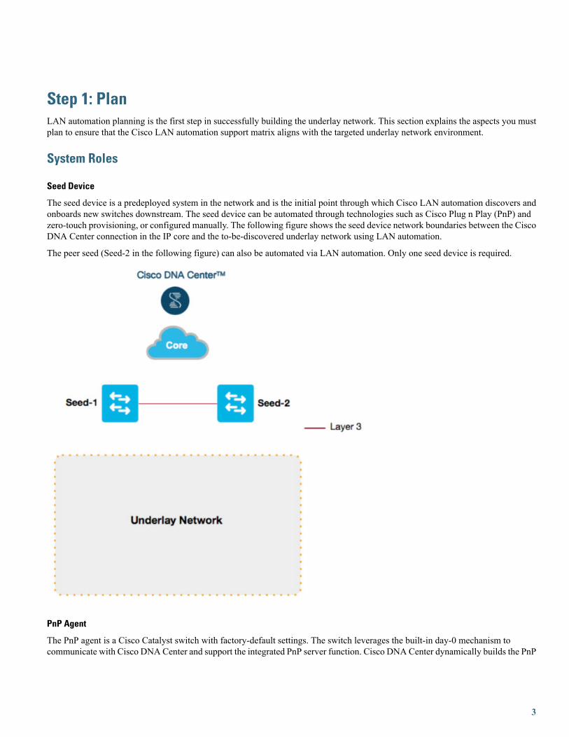
The seed device is a predeployed system in the network and is the initial point through which Cisco LAN automation discovers andonboards new switches downstream. The seed device can be automated through technologies such as Cisco Plug n Play (PnP) andzero-touch provisioning, or configured manually. The following figure shows the seed device network boundaries between the CiscoDNA Center connection in the IP core and the to-be-discovered underlay network using LAN automation.
The peer seed (Seed-2 in the following figure) can also be automated via LAN automation. Only one seed device is required.
PnP Agent
The PnP agent is a Cisco Catalyst switch with factory-default settings. The switch leverages the built-in day-0 mechanism tocommunicate with Cisco DNA Center and support the integrated PnP server function. Cisco DNA Center dynamically builds the PnP
3
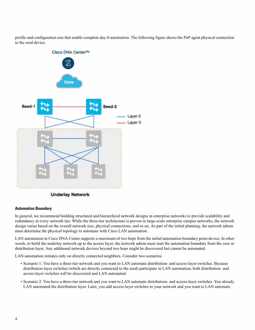
profile and configuration sets that enable complete day-0 automation. The following figure shows the PnP agent physical connectionto the seed device.
Automation Boundary
In general, we recommend building structured and hierarchical network designs in enterprise networks to provide scalability andredundancy at every network tier. While the three-tier architecture is proven in large-scale enterprise campus networks, the networkdesign varies based on the overall network size, physical connections, and so on. As part of the initial planning, the network adminmust determine the physical topology to automate with Cisco LAN automation.
LAN automation in Cisco DNA Center supports a maximum of two hops from the initial automation boundary point device. In otherwords, to build the underlay network up to the access layer, the network admin must start the automation boundary from the core ordistribution layer. Any additional network devices beyond two hops might be discovered but cannot be automated.
LAN automation initiates only on directly connected neighbors. Consider two scenarios:
• Scenario 1: You have a three-tier network and you want to LAN automate distribution- and access-layer switches. Becausedistribution-layer switches (which are directly connected to the seed) participate in LAN automation, both distribution- andaccess-layer switches will be discovered and LAN automated.
• Scenario 2: You have a three-tier network and you want to LAN automate distribution- and access-layer switches. You alreadyLAN automated the distribution layer. Later, you add access-layer switches to your network and you want to LAN automate
4

these switches. Because the distribution switches are already LAN automated and links converted to Layer 3, Tier 1 switchescannot be used as the seed. You must choose distribution as the seed in this scenario.
The following figure shows the automation boundary that Cisco LAN automation supports.
The following figure shows a two-tier and three-tier network design.
5

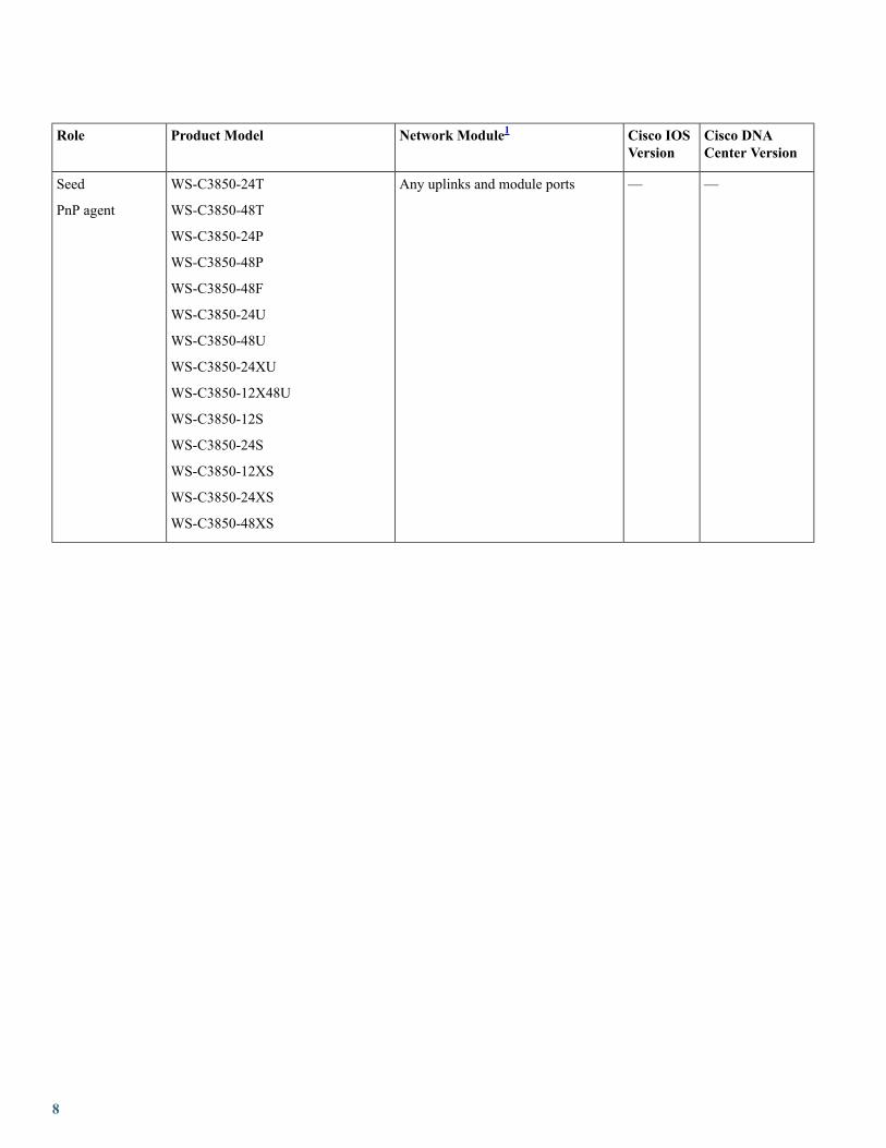
Supported Switches for Each Role at Different LayersThe following figure shows supported device families for the seed and PnP agent at different layers.
Cisco LAN Automation Product Support Matrix
Cisco DNACenter Version
Cisco IOSVersion
Network Module1Product ModelRole
1.3 and later16.11.x andlater
—C9500-32C
C9500-32QC
C9500-24Y4C
C9500-48Y4C
Seed
——Any front-panel ports2C9500-12Q
C9500-24Q
C9500-40X
C9500-16X
Seed
PnP agent
——Sup-13
Sup-1XL3
Sup-1XL-Y3
Any line card
C9404R
C9407R
C9410R
Seed
PnP agent
6

Cisco DNACenter Version
Cisco IOSVersion
Network Module1Product ModelRole
——Any uplinks and module portsC9300-24T
C9300-24P
C9300-24U
C9300-48T
C9300-48P
C9300-48U
C9300-24UX
C9300-48UXM
C9300-48UN
Seed
PnP agent
1.2.8 and later—Any uplinks and module portsC9200L-24T
C9200L-24P
C9200L-48T
C9200L-48P
Seed
PnP agent
——Sup6T
Any uplinks and module ports
C6807-XLSeed
——Any uplinks and module portsC6880-X
C6880-X-LE
Seed
——Any front-panel portsC6816-X-LE
C6832-X-LE
C6824-X-LE-40G
C6840-X-LE-40G
Seed
——Sup9-E3
Sup8-E
Any uplinks and module ports
WS-C4503-E
WS-C4506-E
WS-C4507R+E
WS-4510R+E
Seed
PnP agent
7
Cisco DNACenter Version
Cisco IOSVersion
Network Module1Product ModelRole
——Any uplinks and module portsWS-C3850-24T
WS-C3850-48T
WS-C3850-24P
WS-C3850-48P
WS-C3850-48F
WS-C3850-24U
WS-C3850-48U
WS-C3850-24XU
WS-C3850-12X48U
WS-C3850-12S
WS-C3850-24S
WS-C3850-12XS
WS-C3850-24XS
WS-C3850-48XS
Seed
PnP agent
8

Cisco DNACenter Version
Cisco IOSVersion
Network Module1Product ModelRole
——Any uplinks and module portsWS-C3650-24TS
WS-C3650-48TS
WS-C3650-24PS
WS-C3650-48PS
WS-C3650-48FS
WS-C3650-24TD
WS-C3650-48TD
WS-C3650-24PD
WS-C3650-24PDM
WS-C3650-48PD
WS-C3650-48FD
WS-C3650-8X24PD
WS-C3650-12X48FD
WS-C3650-48TQ
WS-C3650-48PQ
WS-C3650-48FQ
WS-C3650-48FQM
WS-C3650-8X24UQ
WS-C3650-12X48UQ
WS-C3650-12X48UR
WS-C3650-12X48UZ
Seed
PnP agent
1 LAN automation does not support a dedicated management port.2 LAN automation does not support a breakout cable.3 The 40-G uplink is supported on 16.11.1 and later.
Site PlanningUse the Cisco DNA Center Design application to create the required sites, buildings, and floors. Consider how the primary seed andpeer seed will be connected to the new devices—for example, will they all belong to the same site or follow a hierarchy? Consideralso how to share IP pools across different sites, buildings, and floors. One option is to have a pool specific to a site. Another optionis to share a common LAN pool for all sites in the hierarchy. If the devices are onboarded across multiple LAN automation sessions,ensure that the required IP pools are available across the various sites in the hierarchy.
Note the following constraints:
• In Release 1.1.x, LAN automation lets you choose only one site for the seed, peer seed, and PnP devices, meaning all devicesmust belong to a single site.
9

• After devices are provisioned, the site cannot be changed. For this reason, we recommend that you complete LAN automationbefore you provision devices.
IP Pool PlanningIP pools for LAN automation are created by first creating a global pool in Cisco DNA Center, followed by a site-specific LAN IPpool, which LAN automation allocates internally, as follows:
1. One part of the IP pool is reserved for a temporary DHCP server. The size of this pool depends on the size of the parent LANpool. For example, if the parent pool is 192.168.10.0/24, a subpool of size /26 is allocated for the DHCP server. If the pool sizeis larger than /24, the algorithm keeps increasing the size of the DHCP pool, up to a maximum of a /23 subpool (512 IP addresses).Therefore, a /24 pool reserves 64; a /23 pool reserves 128; a /22 pool reserves 256; and anything larger reserves 512 IP addressesfor the DHCP server. The minimum pool size to start LAN automation is /25; that reserves /27 or 32 IP addresses for the DHCPpool. This IP pool is reserved temporarily for the duration of the LAN automation discovery session. After the LAN automationdiscovery session completes, the DHCP pool is released and the IPs are returned to the LAN pool. Because the DHCP pool isusually the largest contiguous segment of IPs required, the pool should have at least one such segment available. If the pool istoo fragmented, it cannot allocate the DHCP pool and the LAN automation session ends with an IP pool allocation error.
2. The second part of the IP pool is used for link configuration between connected devices that participate in the discovery session.Participating devices are primary seed, peer seed, and discovered devices in the discovery session. All links between these devicesare configured with Layer 3 as required for IS-IS routing. The only exceptions are the links connected to the primary seed devicethat are not selected while starting discovery. These links could be links between seed devices or links between seed and discovereddevices. For each configured link, a /30 subpool (4 IP addresses) is allocated. For example, in a topology that contains four links,LAN automation allocates 16 IP addresses for the Layer 3 link configuration.
3. The third part of the IP pool is used to allocate a single loopback IP per discovered device. If the seed device or peer seed devicesdo not have loopback IPs configured, they are also configured with the loopback IPs. Internally, the IPAM library allocates a /27pool for single IPs. For example, when the LAN pool requests the first loopback IP for a device, the IPAM library allocates a /27pool (32 IP addresses) and returns one IP from this pool. On subsequent requests, the library continues to give IPs from thepreviously allocated /27 pool until it runs out of IPs. So for a /27 IP, the same internal pool is used for the 30 IP allocation.Currently, only 30 of the 32 IPs in the internal pool can be used for loopbacks. If the internal pool cannot be used for IP allocation,another /27 pool is allocated for additional single IP allocation. In this case, loopback allocation for discovered device number31 results in a new /27 subpool allocation.
IP Pool Usage Example
Imagine you want to LAN automate 10 devices using the same pool, where each device has one link to the primary seed and anotherlink to the secondary.
Consider a 192.168.199.0/24 pool. When LAN automation starts, a /26 pool is reserved for the DHCP addresses. In this example,192.168.199.1 to 192.168.199.63 are reserved and assigned to VLAN 1 for the 10 devices.
Next, a /30 pool is reserved for the point-to-point links, and a /27 pool is reserved for loopback addresses. Because there are 10 deviceswith two links each, a total of 2*10*4 = 80 IP addresses are reserved for point-to-point links and 10 loopback addresses are reserved.
In total, 100 IP addresses are reserved for the 10 devices: 10 for each VLAN 1, 10 for each loopback, and 80 for the point-to-pointlinks between devices and seeds.
After LAN automation stops, the VLAN 1 IP addresses are released back to the pool, and 90 addresses are allocated for the LANautomation session.
Note the following:
10
• The same IP pool can be used for multiple discovery sessions. For example, you can run one discovery session and discover thefirst set of devices. After discovery completes, you can provide the same IP pool for a subsequent LAN automation session.Similarly, you can choose one LAN pool for one discovery session and another LAN pool for a second discovery session.
• Every time you start LAN automation, it checks for 128 available IP addresses in the IP pool. If you decide to run LAN automationmultiple times with the same pool, use at least a /24 pool. If you plan to LAN automate only once for the IP pool, a /25 poolsuffices.
• Don't use an address pool that is in use elsewhere in the network, such as an address pool that belongs to the loopback or to otheraddresses configured on the device.
Site-Specific CLI and SNMP ConfigurationTo start LAN automation, a site-specific CLI and SNMPv2 read/write or SNMPv3 configuration is required. Use the Cisco DNACenter Design application to configure the site-specific CLI and SNMP. Save the configuration for the site that is used for LANautomation. If you configure the credentials at the global level, they are visible at the site level. You must click the radio button forthe specific site and then save the configuration to make it available for LAN automation.
Configuration on Seed DevicesWhen configuring the seed devices, follow these guidelines:
• The system maximum transmission unit (MTU) value must be at least 9100.
• Turn on IP routing on the seed devices.
• Set up routing between the seed service and Cisco DNA Center so that Cisco DNA Center has IP reachability to the LAN IPpool subnet.
• We recommend that you use the default interfaces connected to PnP agents. If the peer seed device has IP interfaces configuredon the interfaces connected to PnP agents, those links don't get configured. If you want to configure the peer device interfacesconnected to PnP agents, use the default interfaces and perform an inventory synchronization on the peer seed device. LANautomation works only when the ports are Layer 2. The ports on Cisco Catalyst 6000 and Cisco Catalyst 9500H devices areLayer 3 by default. Convert the ports to Layer 2 before starting LAN automation.
• Configure device credentials and SNMP credentials on the seed devices.
• If the seed devices have Layer 3 interfaces configured, ensure that there are no conflicts with any of the IP pools provided inCisco DNA Center.
• Ensure that the seed devices don't have any other interfaces connected to another DHCP server running in VLAN 1.
• If loopback is not configured on the seed devices, LAN automation configures loopback on the seed.
• If any configuration changes are made on the seed devices before running LAN automation, synchronize the seed devices withthe Cisco DNA Center inventory.
• Assign the seed devices to a site. (You don't have to provision the seed devices for LAN automation.)
Additional recommended configurations on seed devices:
• Run multiple discovery sessions for devices across sites connected to the same seed: If you plan to run multiple discoverysessions to onboard devices across different buildings and floors connected to the same seed devices, we recommend that youblock the ports for PnP agents that do not participate in the upcoming discovery session.
11
For example, imagine that seed devices are in Building-23 and are connected to PnP agents on Floor-1 and Floor-2. Floor-1devices are connected on interfaces Gig 1/0/10 through Gig 1/0/15. Floor-2 devices are connected on interfaces Gig 1/0/16through Gig 1/0/20. For the discovery session on Floor-1, we recommend that you shut down ports connected to Gig 1/0/16 toGig 1/0/20. Otherwise, the PnP agents connected to Floor-2 might also get DHCP IPs from the server running on the primaryseed device. Because these interfaces aren't selected for the discovery session, they remain as stale entries in the PnP database.When you run the discovery session for Floor-2, the discovery doesn't function correctly until these devices are deleted fromthe PnP application and write erase/reloaded. Therefore, we recommend that you shut down other discovery interfaces.
• Endpoint/client integration: For Cisco DNA Center 1.2.8 and earlier, if there are clients connected to a switch that is beingdiscovered, those clients contend for DHCP IP and might exhaust the pool, causing LAN automation to fail. Therefore, werecommend that you connect the client after LAN automation is complete.
This endpoint/client integration restriction does not apply to Cisco DNA Center 1.2.10 and later. Clients can remain connectedwhile the switch is undergoing LAN automation.
PnP Agent Initial StateEnsure that the device that you want to LAN automate is running the Advantage license level. Otherwise, some commands are notpushed.
New PnP agents have factory defaults and are ready to start LAN automation.
If you are reusing existing network devices, ensure the following:
• PnP agents must have the required license that can push the LISP, IS-IS routing, and CTS-related CLIs. Use the show licensecommand to see the current license level. If required, upgrade the license.
• PnP agents should be in a clean state. They should not have stale certificate, keys, and so on from the previous runs.
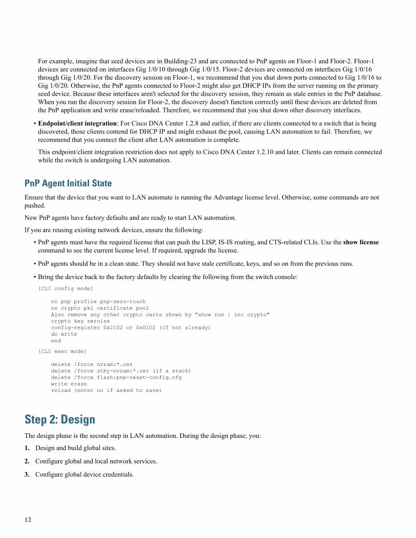
• Bring the device back to the factory defaults by clearing the following from the switch console:[CLI config mode]
no pnp profile pnp-zero-touchno crypto pki certificate poolAlso remove any other crypto certs shown by "show run | inc crypto"crypto key zeroizeconfig-register 0x2102 or 0x0102 (if not already)do writeend
[CLI exec mode]
delete /force nvram:*.cerdelete /force stby-nvram:*.cer (if a stack)delete /force flash:pnp-reset-config.cfgwrite erasereload (enter no if asked to save)
Step 2: DesignThe design phase is the second step in LAN automation. During the design phase, you:
1. Design and build global sites.
2. Configure global and local network services.
3. Configure global device credentials.
12
4. Design the global IP address pool and assign the LAN automation pool for the required site from the global pool.
Design and Build a SiteThis section explains how to design and build a site.
Procedure
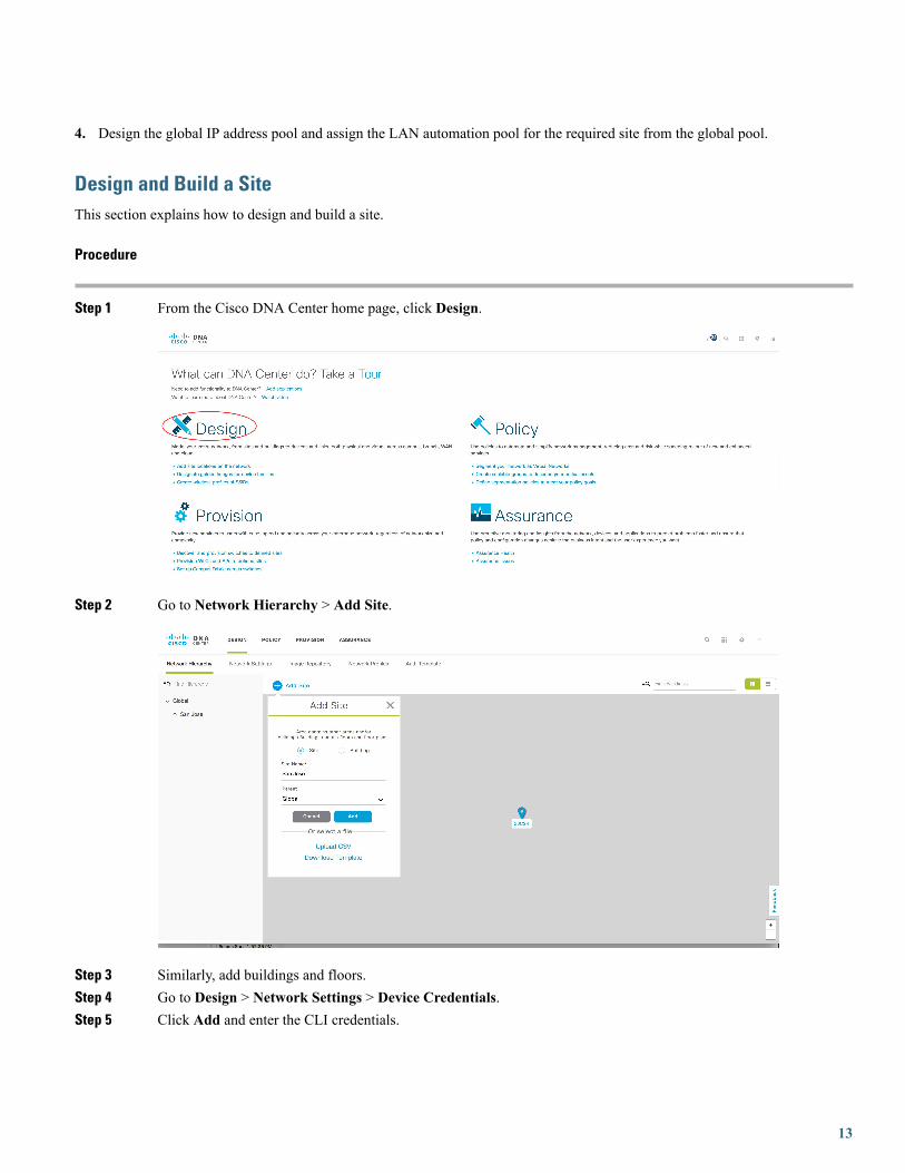
Step 1 From the Cisco DNA Center home page, click Design.
Step 2 Go to Network Hierarchy > Add Site.
Step 3 Similarly, add buildings and floors.Step 4 Go to Design > Network Settings > Device Credentials.Step 5 Click Add and enter the CLI credentials.
13
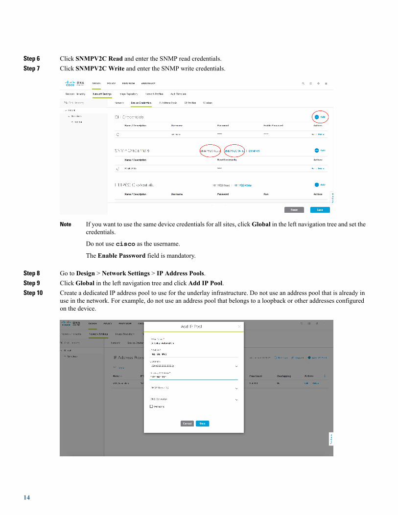
Step 6 Click SNMPV2C Read and enter the SNMP read credentials.Step 7 Click SNMPV2CWrite and enter the SNMP write credentials.
If you want to use the same device credentials for all sites, clickGlobal in the left navigation tree and set thecredentials.
Do not use cisco as the username.
The Enable Password field is mandatory.
Note
Step 8 Go to Design > Network Settings > IP Address Pools.Step 9 Click Global in the left navigation tree and click Add IP Pool.Step 10 Create a dedicated IP address pool to use for the underlay infrastructure. Do not use an address pool that is already in
use in the network. For example, do not use an address pool that belongs to a loopback or other addresses configuredon the device.
14
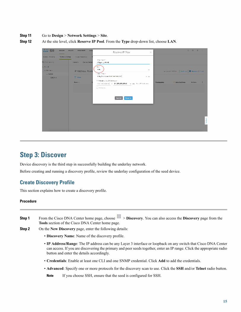
Step 11 Go to Design > Network Settings > Site.Step 12 At the site level, click Reserve IP Pool. From the Type drop-down list, choose LAN.
Step 3: DiscoverDevice discovery is the third step in successfully building the underlay network.
Before creating and running a discovery profile, review the underlay configuration of the seed device.
Create Discovery ProfileThis section explains how to create a discovery profile.
Procedure
Step 1 From the Cisco DNA Center home page, choose > Discovery. You can also access the Discovery page from theTools section of the Cisco DNA Center home page.
Step 2 On the New Discovery page, enter the following details:
• Discovery Name: Name of the discovery profile.
• IP Address/Range: The IP address can be any Layer 3 interface or loopback on any switch that Cisco DNA Centercan access. If you are discovering the primary and peer seeds together, enter an IP range. Click the appropriate radiobutton and enter the details accordingly.
• Credentials: Enable at least one CLI and one SNMP credential. Click Add to add the credentials.
• Advanced: Specify one or more protocols for the discovery scan to use. Click the SSH and/or Telnet radio button.
If you choose SSH, ensure that the seed is configured for SSH.Note
15

Step 3 Click Start. The Discovery settings and details are displayed.
The discovery process takes some time. Ensure that there are no failures after the process completes.Note
Step 4 To verify that the discovered device is added to the Inventory page, go to > Inventory.
16
Make sure that the discovered device has aReachability Status of Reachable and aLast Inventory CollectionStatus of Managed.
Note
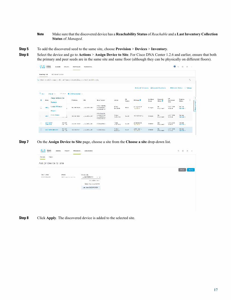
Step 5 To add the discovered seed to the same site, choose Provision > Devices > Inventory.Step 6 Select the device and go to Actions > Assign Device to Site. For Cisco DNA Center 1.2.6 and earlier, ensure that both
the primary and peer seeds are in the same site and same floor (although they can be physically on different floors).
Step 7 On the Assign Device to Site page, choose a site from the Choose a site drop-down list.
Step 8 Click Apply. The discovered device is added to the selected site.
17

If you don't see the Site column on the Device Inventory page, click , check the Site check box, and clickApply.
Note
Steps to Consider Before Starting LAN AutomationTake the following considerations into account before starting the LAN automation process.
IP Pool Subnet Reachability from Cisco DNA Center
LAN automation discovery uses the LAN pool to reach PnP agents. Cisco DNA Center should be able to reach the IPs allocated fromthe LAN pool. For example, if the LAN pool is 192.168.10.0, Cisco DNA Center should have the correct route to reach this subnet.To test the reachability, create an SVI on the primary seed device and ping a test between Cisco DNA Center and the seed. Refer tothe following sample code.
18
[On seed device]
Switch(config)#interface vlan1Switch(config-if)#ip address 192.168.99.1 255.255.255.0Switch(config-if)#end
[On Cisco DNA Center CLI console]
[Sat Jun 23 05:55:18 UTC] [email protected] (maglev-master-1) ~$ ping 192.168.99.1PING 192.168.99.1 (192.168.99.1) 56(84) bytes of data.64 bytes from 192.168.99.1: icmp_seq=1 ttl=252 time=0.579 ms64 bytes from 192.168.99.1: icmp_seq=2 ttl=252 time=0.684 ms64 bytes from 192.168.99.1: icmp_seq=3 ttl=252 time=0.541 ms
[On seed device]
Switch(config)#default int vlan 1Interface Vlan1 set to default configuration
If the ping test fails, the route is not set up correctly on Cisco DNA Center.
Static Route Addition for LAN Pool
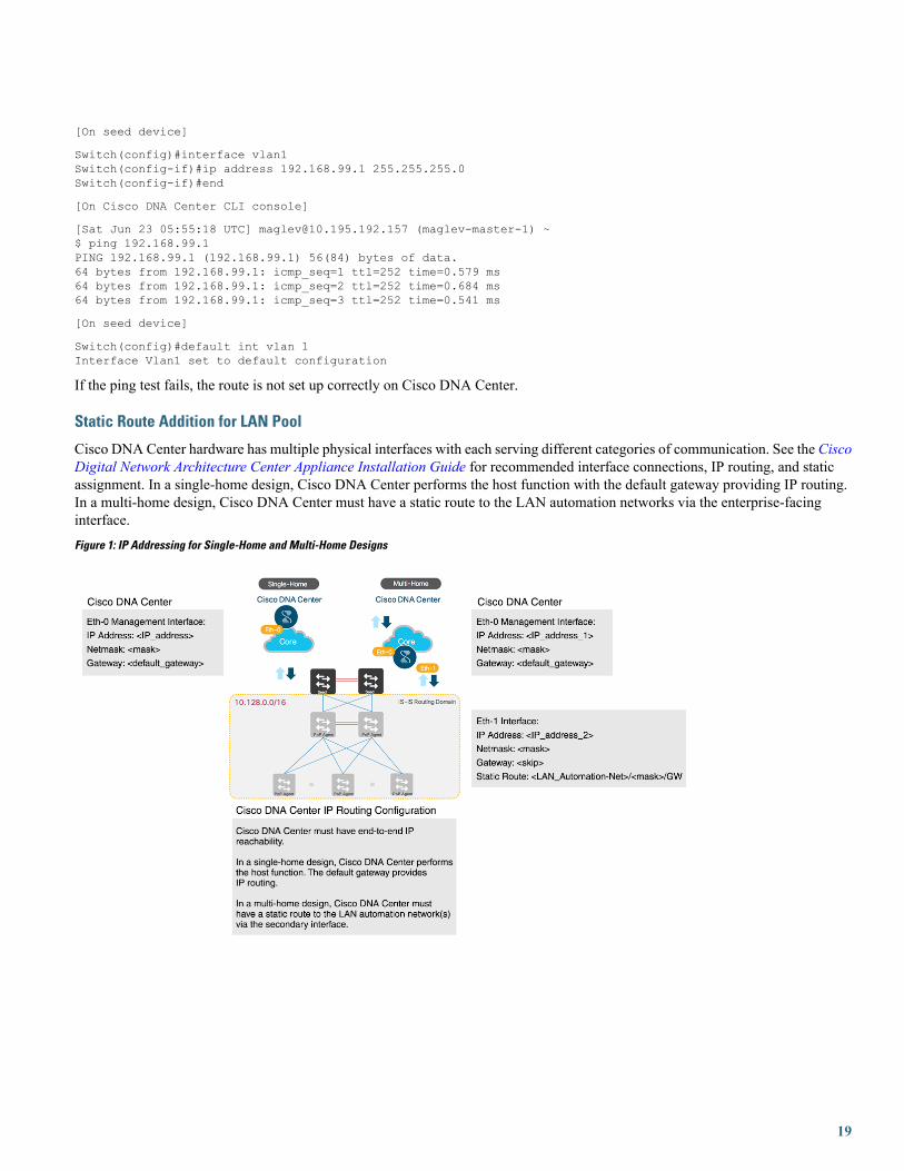
Cisco DNA Center hardware has multiple physical interfaces with each serving different categories of communication. See the CiscoDigital Network Architecture Center Appliance Installation Guide for recommended interface connections, IP routing, and staticassignment. In a single-home design, Cisco DNA Center performs the host function with the default gateway providing IP routing.In a multi-home design, Cisco DNA Center must have a static route to the LAN automation networks via the enterprise-facinginterface.Figure 1: IP Addressing for Single-Home and Multi-Home Designs
19

Figure 2: Static IP Routing Design
If the network design is a multi-home design, one way to fix the IP reachability issue is to add a static route on Cisco DNA Center.A network administrator can add a static route during the initial Cisco DNA Center configuration or later via a maglev command.(Don't use the Linux route command, because maglev APIs don't pick the correct information if the route is modified using the routecommand.)
For a single-home design, check the routing between the seed and Cisco DNA Center.
To add a static route on Cisco DNA Center:
Procedure
Step 1 On the Cisco DNA Center console, enter the command sudo maglev-config update. The config wizard opens.
20

Step 2 Enter the static route and click Next. The config wizard validates and configures host networking.Step 3 Ensure that the correct interface is selected to add the static route. Otherwise, click Next until the correct interface is
displayed on which to configure the route.Step 4 Leave the Network Proxy field blank. When the proxy validation fails, skip the proxy settings.Step 5 Click Proceed to apply the changes to the controller.
It takes from 5 to 6 minutes to add a static route. You can ignore any warning messages.
PnP Agent Initial State Before Starting LAN Automation
Procedure
Step 1 Before starting LAN automation, make sure that the PnP agent is in System Configuration Dialog state.FIPS: Flash Key Check : Key Not Found, FIPS Mode Not Enabledcisco C9300-24T (X86) processor with 1418286K/6147K bytes of memory.Processor board ID FCW2137G0322048K bytes of non-volatile configuration memory.8388608K bytes of physical memory.1638400K bytes of Crash Files at crashinfo:.11264000K bytes of Flash at flash:.0K bytes of WebUI ODM Files at webui:.
Base Ethernet MAC Address : f8:7b:20:48:d8:80Motherboard Assembly Number : 73-17952-06Motherboard Serial Number : FOC21354B06Model Revision Number : A0Motherboard Revision Number : A0Model Number : C9300-24TSystem Serial Number : FCW2137G032
%INIT: waited 0 seconds for NVRAM to be available
21

--- System Configuration Dialog ---
Would you like to enter the initial configuration dialog? [yes/no]:
Step 2 Do not press Yes or No. Leave the device in the same state.
If the device does not stop at this initial prompt and moves ahead, check the device config-register value usingthe CLI command show ver | inc register. In some cases, the value might be 0x142. Change theconfig-register value to 0x102 or 0x2102 and save the configuration. Check the CLI again; it showsConfigurationregister is 0x142 (will be 0x102 at next reload).
If the device comes up with the older config-register value even after changing the value to 0x102 or 0x2102and reloading the device, configure no system ignore startupconfig switch all on the device, save theconfiguration, and reload.
Note
Stack Considerations
• Follow the same procedure for the stack. Allow extra time to make sure that all members in the stack are up. Do notstart LAN automation until all switches are up.
• LAN automation is always initiated on the active switch.When all switches in a stack are booted together, the switchwith the lowest MAC address (assuming no switch priority is configured) becomes active. The second lowest switchbecomes the standby, and so on. Some customers require that the first switch is always active. In this case, if allswitches are booted together and the first switch does not have the lowest MAC address, it does not become theactive. To ensure that the first switch is the active, boot the switches in a staggered manner. That is, boot switch 1.After 120 seconds, boot switch 2, and so on. This ensures that the switch becomes active in the correct order: switch1 is active, switch 2 is standby, and so on. However, when you reload, the order is not maintained and the switchesobtain their role depending on their MAC address.
• To make sure that the switches maintain their order after reload, it is a good practice to assign switch priorities toensure that the switches always come up in the same order. The highest priority is 15. When priorities are assigned,they take preference over the switch MAC address. Assigning switch priorities does not change the NVRAMconfiguration. The values are written to ROMMON and persist after reload or write erase. As an example, see thefollowing sample code.3850_edge_2#switch 1 priority ?<1-15> Switch Priority
3850_edge_2#switch 1 priority 14WARNING: Changing the switch priority may result in a configuration change for that switch. Doyou want to continue?[y/n]? [yes]: y
You might have to clean up the switch after assigning priorities, because some certificates will have been configuredon the switch during boot up. To clean up the switch, see PnP Agent Initial State.
Do not start LAN automation until all switches in the stack are up.
If you are consoled in to the standby/member switches, do not press Enter, even though the screen says consoleis now available, Press RETURN to get started. Monitor the active switch, which should be at the SystemConfiguration Dialog state.
If LAN automation is already running and you don't want to stop it, close the seed link connecting to the PnPagent. That way, discovery doesn't occur until you are ready to open the port.
Note
22

Unplug the Management Port
Connect PnP agents directly to seed devices. Do not connect PnP agents to any other network (for example, the management network)or any network that can provide DHCP through another server on VLAN 1.
Ensure That Seed Ports Are Layer 2
Ensure that the seed ports connected to the PnP agents are Layer 2 and defaulted. For example, Cisco Catalyst 6500 and 9500H portsare Layer 3 by default.
Ensure That Primary Seed Port Does Not Block STP
Ensure that the port on the primary seed connecting to the PnP agents does not block STP.
Ensure That the Device Is Not Present in Inventory
This section applies to devices that were discovered or LAN automated at any point.
If the devices to discover in an upcoming LAN automation session are already present in the inventory, complete the following stepsto remove them from the inventory.
Before you begin
If a device was provisioned and added to the fabric, remove it from the fabric and unprovision it before you remove it from theinventory.
Procedure
Step 1 From the Cisco DNA Center home page, choose Tools > Inventory.Step 2 Filter the devices by Serial Number and then choose Actions > Delete.
Ensure That the Device Is Not Present in PnP
If the devices to discover in an upcoming LAN automation session are already available in PnP, complete the following steps toremove them from PnP before you run the discovery. Otherwise, the discovery won't work correctly.
Procedure
23

Step 1 From the Cisco DNA Center home page, choose Tools > Network Plug and Play.Step 2 Go to Devices > Unclaimed. Make sure that the device (Serial Number) being discovered is not available under
Unclaimed.
Step 3 If the device is available, console into the device and remove the PnP profile:[on PNP agent]
3850_edge_2#show run | sec pnp-zero-touchpnp profile pnp-zero-touchtransport https ipv4 192.168.99.2 port 443
3850_edge_2#conf tEnter configuration commands, one per line. End with CNTL/Z.3850_edge_2(config)#no pnp profile pnp-zero-touch3850_edge_2
Step 4 Check the check box of the device in the Unclaimed section and click Delete.
Use the Advantage License
Ensure that the PNP agent is running the Cisco DNA Center Advantage license level.
Ensure That the PNP Agent is in INSTALL Mode
For the image upgrade to occur during LAN automation, the PnP agent must be in INSTALL mode.
Image upgrade through LAN automation occurs in the background.
Procedure
Step 1 After PnP discovers the device, Cisco DNA Center checks whether any golden image is marked for the switch family(Cisco Catalyst 9300 or 3850) of the discovered device. To check whether a golden image is selected, choose Design >Image Repository.
If the golden image is marked and the discovered device is not running the golden image, LAN automation upgrades thediscovered device to the golden image. If not, Cisco DNA Center skips the image upgrade and proceeds to pushing theinitial device configuration.
Step 2 If you want LAN automation to upgrade the image on the discovered device, ensure that the device is running in INSTALLmode. Image upgrade through LAN automation does not occur if the device is in BUNDLE mode.
Step 3 If the device is in BUNDLE mode and you want to proceed with LAN automation, remove the golden image for thatparticular switch family Design > Image Repository.
24
Step 4: ProvisionProvisioning is the final step in the LAN automation process. It is divided into two stages:
1. Device discovery and onboarding (starting LAN automation).
When LAN automation starts, it:
• Pushes the loopback and IS-IS configuration to the primary and peer seed devices and the temporary configuration to theprimary seed device, enabling discovery and onboarding of the PnP agent.
• Discovers new devices.
• Upgrades the image and pushes the configuration to discovered devices.
The image is updated only if a golden image is marked for that switch type under the Cisco DNA Center home page> Design > Image repository.
Note
When LAN automation starts, the temporary configuration is pushed to the primary seed device, which discovers and onboardsthe PNP agent. Next, the PNP agent image is upgraded and basic configurations such as loopback address, system MTU, and IProuting are pushed to the PNP agent.
2. Interface configuration (stopping LAN automation).
When LAN automation stops:
• The discovery phase ends and all point-to-point links between the seed and discovered devices and between the discovereddevices (a maximum of two hops) are converted to Layer 3.
• All temporary DHCP and VLAN 1 configurations on the seed and discovered devices are removed. The DHCP subpool isreturned to the LAN automation pool.
Start LAN AutomationFor LAN automation, you must select the primary seed device, peer seed device, site for seed device, LAN IP pool, and interface.Optionally, you can select the device prefix, hostname CSV file, configurable IS-IS password, and so on.
Interface Selection
Interfaces on the primary seed device participate in the new device discovery and L3 configuration. The interfaces on seed devicesprovide a filter to directly connect PnP agents that can be onboarded through the LAN automation session. For example, considerfour directly connected PnP agents: device-1 through Gig1/0/10, device-2 through Gig 1/0/11, device-3 through Gig 1/0/12, anddevice-4 through Gig 1/0/13. If you choose Gig 1/0/11 and Gig 1/0/12 as part of the discovery interfaces, LAN automation discoversonly device-1 and device-2. If device-3 and device-4 also try to initiate the PnP flow, they are filtered, because they are connectedthrough interfaces that are not selected during the LAN automation session. This mechanism lets you restrict the discovery process.
Interface selection also lets you choose interfaces between the primary seed and the peer seed to configure with Layer 3 links. If thereare multiple interfaces between the primary and peer seeds, you can choose to configure any set of these interfaces with Layer 3 links.If no interfaces are chosen, they aren't configured with Layer 3 links.
25
The option to choose a peer seed interface is not available. Interfaces between peer seed and PnP agents are automatically inferredbased on the topology information gathered from the device. The topology information is built on the CDP information available onthe device.
Site Selection
Sites can be selected for seed devices and PnP agents. Currently, there is one site for seed device(s) and one site for PnP agents.
LAN Pool Selection
The LAN pool is selected based on PnP agent site information. To start LAN automation, select a LAN pool from the list of LANpools available for a particular site. You can select the same LAN pool for multiple LAN automation sessions. For example, you canrun one discovery session and discover the first set of devices. After the discovery session completes, you can provide the same IPpool for subsequent LAN automation sessions. Similarly, you can select a different LAN pool for different discovery sessions. Makesure that you select a LAN pool with enough remaining capacity.
IS-IS Password
• If you enter a value, enter the same password that is configured on the seed. If you enter a value that is different from the passwordconfigured on the primary and peer seeds, an error is returned.
• If the password on the primary and peer seeds does not match, an error is returned.
If you enter a value in the IS-IS Password field:
• If the primary seed has an IS-IS password configured, LAN automation configures the primary seed's IS-IS password on thePnP devices (and on the peer seed, if it doesn't already have the password).
• If the primary seed doesn't have an IS-IS password but the peer does, LAN automation configures the peer seed's IS-IS passwordon the PnP devices and on the primary seed.
• If the primary and peer seeds don't have an IS-IS password configured and you enter a value in the password field, LANautomation configures the user-entered password on the PnP devices and on the primary and peer seeds.
If you leave the IS-IS Password field blank:
• If the primary seed has an IS-IS password configured, LAN automation configures the primary seed's IS-IS password on thePnP devices (and on the peer seed, if it doesn't already have the password).
• If the primary seed doesn't have an IS-IS password but the peer does, LAN automation configures the peer seed's IS-IS passwordon the PnP devices and on the primary seed.
• If the primary and peer seeds don't have an IS-IS password configured, LAN automation uses the default value "cisco" for thePnP devices and for both seeds.
Hostname Mapping
• Default: If no value is entered, LAN automation sets the hostname as Switch, followed by the loopback address. Example:Switch-192-168-199-100.
• Device Name Prefix: The device prefix is used to generate hostnames for discovered devices. LAN automation keeps the sitecounter and generates the name using the prefix and the current site counter. For example, if the device prefix isBuilding-23-First-Floor, LAN automation generates device names such as Building-23-First-Floor-1, Building-23-First-Floor-2,and so on.
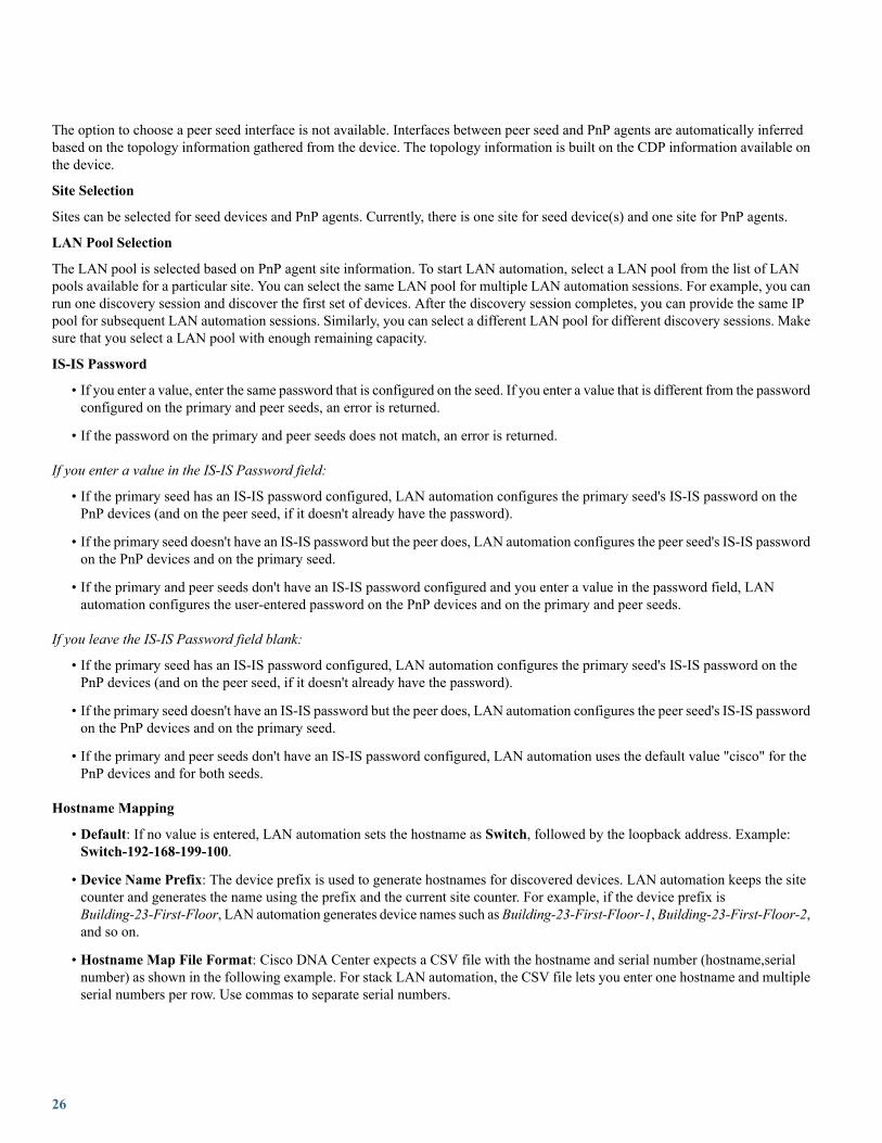
• Hostname Map File Format: Cisco DNA Center expects a CSV file with the hostname and serial number (hostname,serialnumber) as shown in the following example. For stack LAN automation, the CSV file lets you enter one hostname and multipleserial numbers per row. Use commas to separate serial numbers.
26
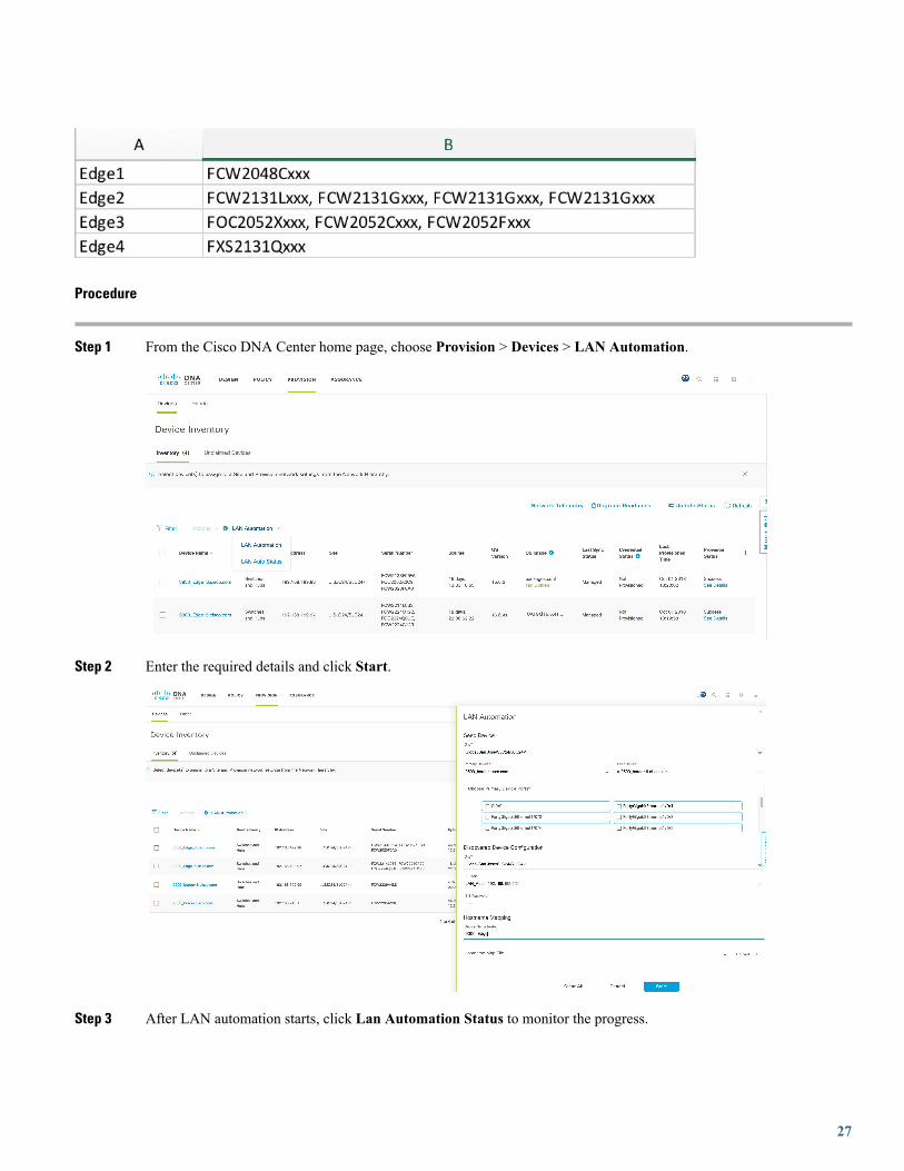
Procedure
Step 1 From the Cisco DNA Center home page, choose Provision > Devices > LAN Automation.
Step 2 Enter the required details and click Start.
Step 3 After LAN automation starts, click Lan Automation Status to monitor the progress.
27
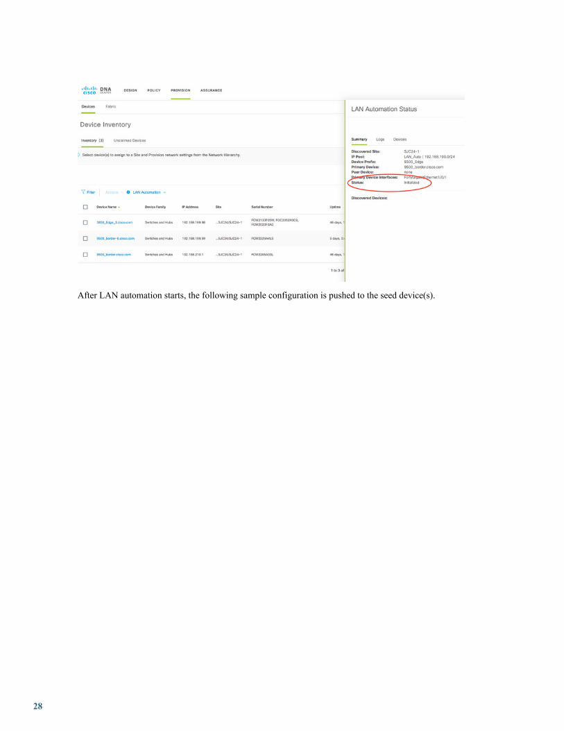
After LAN automation starts, the following sample configuration is pushed to the seed device(s).
28

Primary Seed Configuration
29
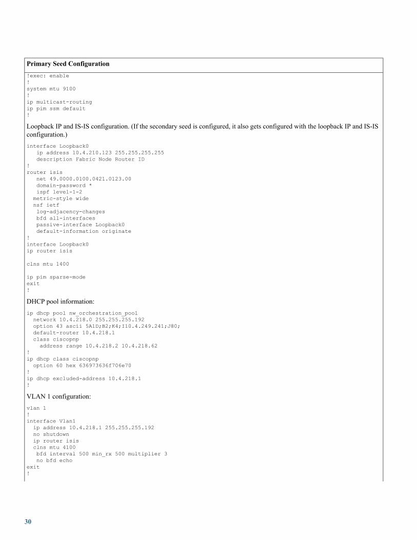
Primary Seed Configuration
!exec: enable!system mtu 9100!ip multicast-routingip pim ssm default!
Loopback IP and IS-IS configuration. (If the secondary seed is configured, it also gets configured with the loopback IP and IS-ISconfiguration.)interface Loopback0
ip address 10.4.210.123 255.255.255.255description Fabric Node Router ID
!router isis
net 49.0000.0100.0421.0123.00domain-password *ispf level-1-2metric-style widensf ietflog-adjacency-changesbfd all-interfacespassive-interface Loopback0default-information originate
!interface Loopback0ip router isis
clns mtu 1400
ip pim sparse-modeexit!
DHCP pool information:ip dhcp pool nw_orchestration_poolnetwork 10.4.218.0 255.255.255.192option 43 ascii 5A1D;B2;K4;I10.4.249.241;J80;default-router 10.4.218.1class ciscopnpaddress range 10.4.218.2 10.4.218.62
!ip dhcp class ciscopnpoption 60 hex 636973636f706e70
!ip dhcp excluded-address 10.4.218.1!
VLAN 1 configuration:vlan 1!interface Vlan1ip address 10.4.218.1 255.255.255.192no shutdownip router isisclns mtu 4100bfd interval 500 min_rx 500 multiplier 3no bfd echo
exit!
30

Primary Seed Configuration
Switch port configuration on interfaces used for discovery. (Each discovery interface on the primary seed device gets thisconfiguration.)interface TenGigabitEthernet1/1/8switchportswitchport mode accessswitchport access vlan 1
!interface TenGigabitEthernet1/1/7
switchportswitchport mode accessswitchport access vlan 1
exit
Multicast configuration (optional; only configured if the multicast check box is checked).
If the peer seed is configured, these multicast CLIs are pushed on the peer seed as well. The same rp-address is used to configureLoopback60000 on both the primary and peer seeds.interface Loopback 60000ip address 10.4.218.67 255.255.255.255ip pim sparse-modeip router isis
ip pim register-source Loopback60000ip pim rp-address 10.4.218.67
Secondary Seed Configuration
!exec: enable!system mtu 9100!ip multicast-routingip pim ssm default!interface Loopback0ip address 10.4.210.124 255.255.255.255description Fabric Node Router ID
!router isis
net 49.0000.0100.0421.0124.00domain-password *ispf level-1-2metric-style widensf ietflog-adjacency-changesbfd all-interfacespassive-interface Loopback0default-information originate
!interface Loopback0ip router isisclns mtu 4100ip pim sparse-modeexit!
Step 4 After device discovery starts, view logs on the PnP agent.
31
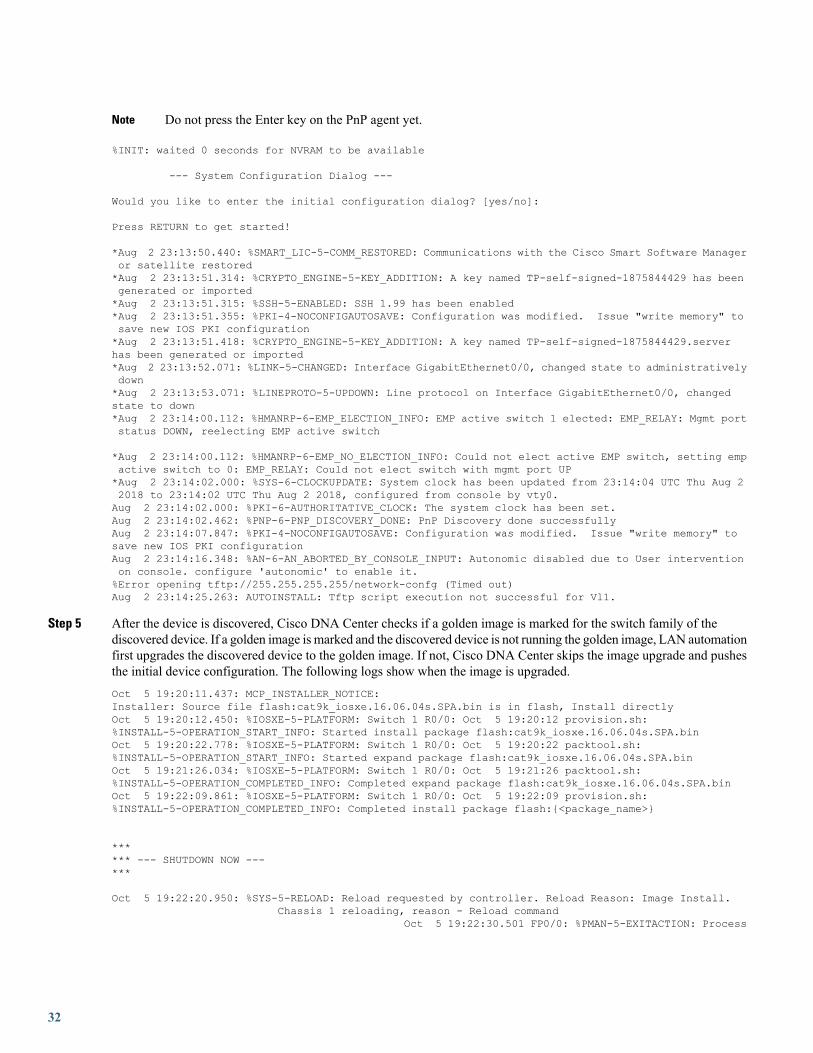
Do not press the Enter key on the PnP agent yet.Note
%INIT: waited 0 seconds for NVRAM to be available
--- System Configuration Dialog ---
Would you like to enter the initial configuration dialog? [yes/no]:
Press RETURN to get started!
*Aug 2 23:13:50.440: %SMART_LIC-5-COMM_RESTORED: Communications with the Cisco Smart Software Manageror satellite restored*Aug 2 23:13:51.314: %CRYPTO_ENGINE-5-KEY_ADDITION: A key named TP-self-signed-1875844429 has beengenerated or imported*Aug 2 23:13:51.315: %SSH-5-ENABLED: SSH 1.99 has been enabled*Aug 2 23:13:51.355: %PKI-4-NOCONFIGAUTOSAVE: Configuration was modified. Issue "write memory" tosave new IOS PKI configuration*Aug 2 23:13:51.418: %CRYPTO_ENGINE-5-KEY_ADDITION: A key named TP-self-signed-1875844429.serverhas been generated or imported*Aug 2 23:13:52.071: %LINK-5-CHANGED: Interface GigabitEthernet0/0, changed state to administrativelydown*Aug 2 23:13:53.071: %LINEPROTO-5-UPDOWN: Line protocol on Interface GigabitEthernet0/0, changedstate to down*Aug 2 23:14:00.112: %HMANRP-6-EMP_ELECTION_INFO: EMP active switch 1 elected: EMP_RELAY: Mgmt portstatus DOWN, reelecting EMP active switch
*Aug 2 23:14:00.112: %HMANRP-6-EMP_NO_ELECTION_INFO: Could not elect active EMP switch, setting empactive switch to 0: EMP_RELAY: Could not elect switch with mgmt port UP*Aug 2 23:14:02.000: %SYS-6-CLOCKUPDATE: System clock has been updated from 23:14:04 UTC Thu Aug 22018 to 23:14:02 UTC Thu Aug 2 2018, configured from console by vty0.Aug 2 23:14:02.000: %PKI-6-AUTHORITATIVE_CLOCK: The system clock has been set.Aug 2 23:14:02.462: %PNP-6-PNP_DISCOVERY_DONE: PnP Discovery done successfullyAug 2 23:14:07.847: %PKI-4-NOCONFIGAUTOSAVE: Configuration was modified. Issue "write memory" tosave new IOS PKI configurationAug 2 23:14:16.348: %AN-6-AN_ABORTED_BY_CONSOLE_INPUT: Autonomic disabled due to User interventionon console. configure 'autonomic' to enable it.%Error opening tftp://255.255.255.255/network-confg (Timed out)Aug 2 23:14:25.263: AUTOINSTALL: Tftp script execution not successful for Vl1.
Step 5 After the device is discovered, Cisco DNA Center checks if a golden image is marked for the switch family of thediscovered device. If a golden image is marked and the discovered device is not running the golden image, LAN automationfirst upgrades the discovered device to the golden image. If not, Cisco DNA Center skips the image upgrade and pushesthe initial device configuration. The following logs show when the image is upgraded.Oct 5 19:20:11.437: MCP_INSTALLER_NOTICE:Installer: Source file flash:cat9k_iosxe.16.06.04s.SPA.bin is in flash, Install directlyOct 5 19:20:12.450: %IOSXE-5-PLATFORM: Switch 1 R0/0: Oct 5 19:20:12 provision.sh:%INSTALL-5-OPERATION_START_INFO: Started install package flash:cat9k_iosxe.16.06.04s.SPA.binOct 5 19:20:22.778: %IOSXE-5-PLATFORM: Switch 1 R0/0: Oct 5 19:20:22 packtool.sh:%INSTALL-5-OPERATION_START_INFO: Started expand package flash:cat9k_iosxe.16.06.04s.SPA.binOct 5 19:21:26.034: %IOSXE-5-PLATFORM: Switch 1 R0/0: Oct 5 19:21:26 packtool.sh:%INSTALL-5-OPERATION_COMPLETED_INFO: Completed expand package flash:cat9k_iosxe.16.06.04s.SPA.binOct 5 19:22:09.861: %IOSXE-5-PLATFORM: Switch 1 R0/0: Oct 5 19:22:09 provision.sh:%INSTALL-5-OPERATION_COMPLETED_INFO: Completed install package flash:{<package_name>}
****** --- SHUTDOWN NOW ---***
Oct 5 19:22:20.950: %SYS-5-RELOAD: Reload requested by controller. Reload Reason: Image Install.Chassis 1 reloading, reason - Reload command
Oct 5 19:22:30.501 FP0/0: %PMAN-5-EXITACTION: Process
32
manager is exiting: reload fp action requestedOct 5 19:22:
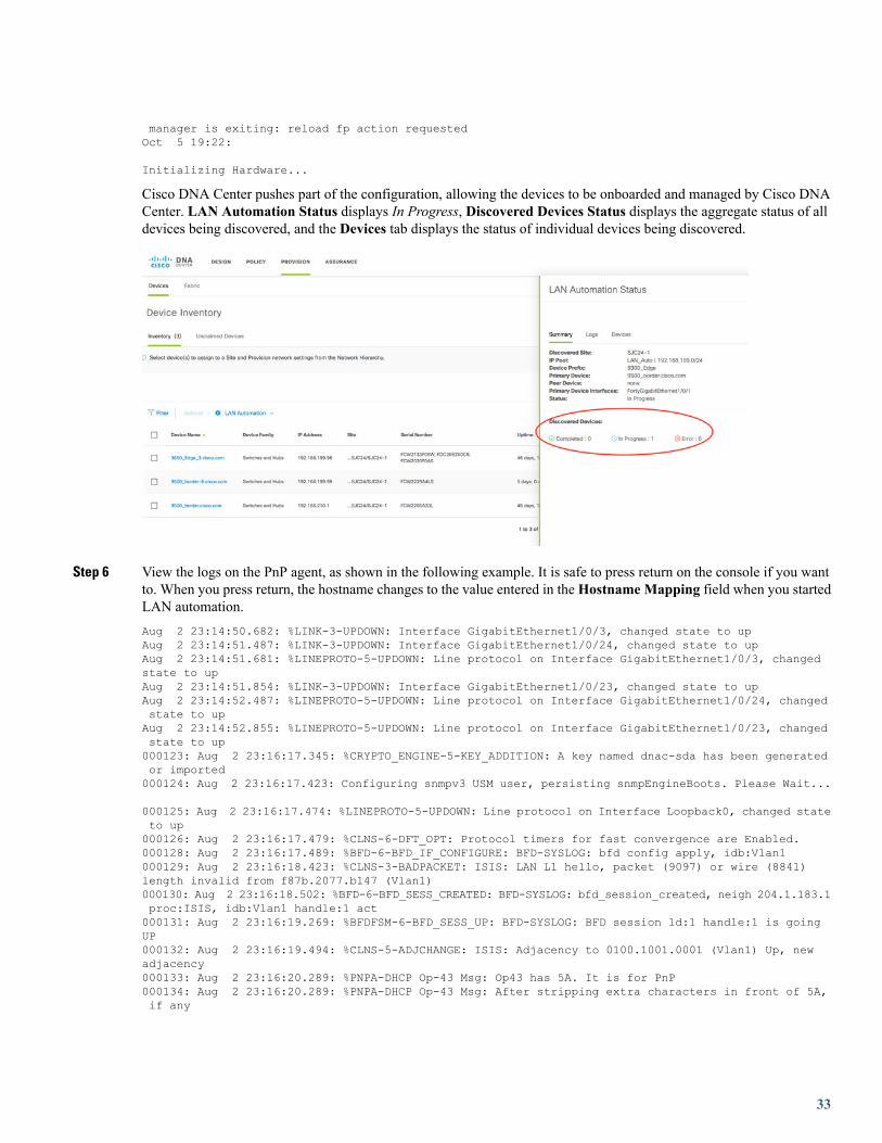
Initializing Hardware...
Cisco DNA Center pushes part of the configuration, allowing the devices to be onboarded and managed by Cisco DNACenter. LAN Automation Status displays In Progress, Discovered Devices Status displays the aggregate status of alldevices being discovered, and the Devices tab displays the status of individual devices being discovered.
Step 6 View the logs on the PnP agent, as shown in the following example. It is safe to press return on the console if you wantto. When you press return, the hostname changes to the value entered in theHostname Mapping field when you startedLAN automation.Aug 2 23:14:50.682: %LINK-3-UPDOWN: Interface GigabitEthernet1/0/3, changed state to upAug 2 23:14:51.487: %LINK-3-UPDOWN: Interface GigabitEthernet1/0/24, changed state to upAug 2 23:14:51.681: %LINEPROTO-5-UPDOWN: Line protocol on Interface GigabitEthernet1/0/3, changedstate to upAug 2 23:14:51.854: %LINK-3-UPDOWN: Interface GigabitEthernet1/0/23, changed state to upAug 2 23:14:52.487: %LINEPROTO-5-UPDOWN: Line protocol on Interface GigabitEthernet1/0/24, changedstate to upAug 2 23:14:52.855: %LINEPROTO-5-UPDOWN: Line protocol on Interface GigabitEthernet1/0/23, changedstate to up000123: Aug 2 23:16:17.345: %CRYPTO_ENGINE-5-KEY_ADDITION: A key named dnac-sda has been generatedor imported000124: Aug 2 23:16:17.423: Configuring snmpv3 USM user, persisting snmpEngineBoots. Please Wait...
000125: Aug 2 23:16:17.474: %LINEPROTO-5-UPDOWN: Line protocol on Interface Loopback0, changed stateto up000126: Aug 2 23:16:17.479: %CLNS-6-DFT_OPT: Protocol timers for fast convergence are Enabled.000128: Aug 2 23:16:17.489: %BFD-6-BFD_IF_CONFIGURE: BFD-SYSLOG: bfd config apply, idb:Vlan1000129: Aug 2 23:16:18.423: %CLNS-3-BADPACKET: ISIS: LAN L1 hello, packet (9097) or wire (8841)length invalid from f87b.2077.b147 (Vlan1)000130: Aug 2 23:16:18.502: %BFD-6-BFD_SESS_CREATED: BFD-SYSLOG: bfd_session_created, neigh 204.1.183.1proc:ISIS, idb:Vlan1 handle:1 act000131: Aug 2 23:16:19.269: %BFDFSM-6-BFD_SESS_UP: BFD-SYSLOG: BFD session ld:1 handle:1 is goingUP000132: Aug 2 23:16:19.494: %CLNS-5-ADJCHANGE: ISIS: Adjacency to 0100.1001.0001 (Vlan1) Up, newadjacency000133: Aug 2 23:16:20.289: %PNPA-DHCP Op-43 Msg: Op43 has 5A. It is for PnP000134: Aug 2 23:16:20.289: %PNPA-DHCP Op-43 Msg: After stripping extra characters in front of 5A,if any
33
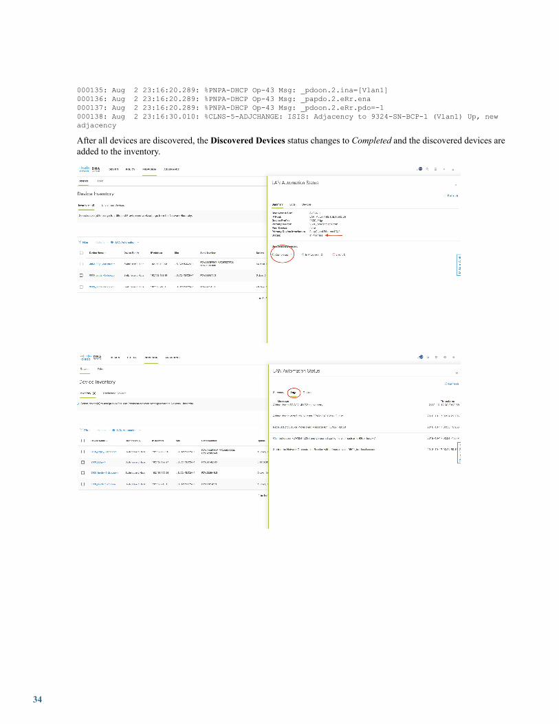
000135: Aug 2 23:16:20.289: %PNPA-DHCP Op-43 Msg: _pdoon.2.ina=[Vlan1]000136: Aug 2 23:16:20.289: %PNPA-DHCP Op-43 Msg: _papdo.2.eRr.ena000137: Aug 2 23:16:20.289: %PNPA-DHCP Op-43 Msg: _pdoon.2.eRr.pdo=-1000138: Aug 2 23:16:30.010: %CLNS-5-ADJCHANGE: ISIS: Adjacency to 9324-SN-BCP-1 (Vlan1) Up, newadjacency
After all devices are discovered, the Discovered Devices status changes to Completed and the discovered devices areadded to the inventory.
34

Step 7 From the Cisco DNA Center home page, choose Tools > Inventory and filter by serial number. The newly discoveredswitches appear asManaged.
The following example shows a sample configuration pushed to discovered devices.!archivelog configlogging enablelogging size 500hidekeys!!!service timestamps debug datetime msec!service timestamps log datetime msec!service password-encryption!service sequence-numbers!! Setup NTP Server! Setup Timezone & Daylight Savings!ntp server 10.4.250.104!! ntp update-calendar!! clock timezone <timezoneName> <timezoneOffsetHours> <timezoneOffsetMinutes>! clock summer-time <timezoneName> recurring!! Disable external HTTP(S) access
35
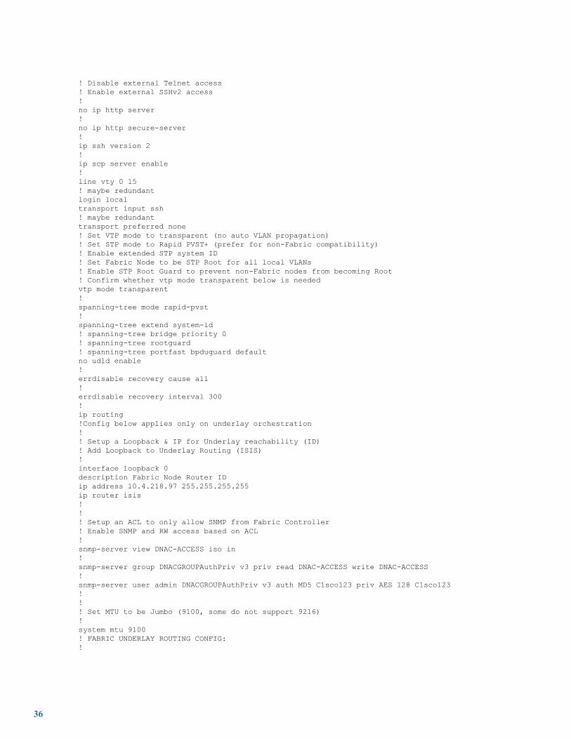
! Disable external Telnet access! Enable external SSHv2 access!no ip http server!no ip http secure-server!ip ssh version 2!ip scp server enable!line vty 0 15! maybe redundantlogin localtransport input ssh! maybe redundanttransport preferred none! Set VTP mode to transparent (no auto VLAN propagation)! Set STP mode to Rapid PVST+ (prefer for non-Fabric compatibility)! Enable extended STP system ID! Set Fabric Node to be STP Root for all local VLANs! Enable STP Root Guard to prevent non-Fabric nodes from becoming Root! Confirm whether vtp mode transparent below is neededvtp mode transparent!spanning-tree mode rapid-pvst!spanning-tree extend system-id! spanning-tree bridge priority 0! spanning-tree rootguard! spanning-tree portfast bpduguard defaultno udld enable!errdisable recovery cause all!errdisable recovery interval 300!ip routing!Config below applies only on underlay orchestration!! Setup a Loopback & IP for Underlay reachability (ID)! Add Loopback to Underlay Routing (ISIS)!interface loopback 0description Fabric Node Router IDip address 10.4.218.97 255.255.255.255ip router isis!!! Setup an ACL to only allow SNMP from Fabric Controller! Enable SNMP and RW access based on ACL!snmp-server view DNAC-ACCESS iso in!snmp-server group DNACGROUPAuthPriv v3 priv read DNAC-ACCESS write DNAC-ACCESS!snmp-server user admin DNACGROUPAuthPriv v3 auth MD5 C1sco123 priv AES 128 C1sco123!!! Set MTU to be Jumbo (9100, some do not support 9216)!system mtu 9100! FABRIC UNDERLAY ROUTING CONFIG:!
36
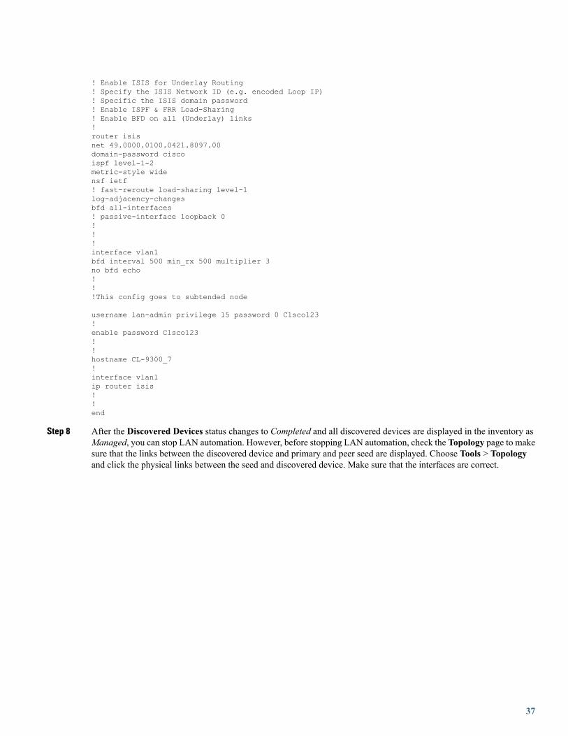
! Enable ISIS for Underlay Routing! Specify the ISIS Network ID (e.g. encoded Loop IP)! Specific the ISIS domain password! Enable ISPF & FRR Load-Sharing! Enable BFD on all (Underlay) links!router isisnet 49.0000.0100.0421.8097.00domain-password ciscoispf level-1-2metric-style widensf ietf! fast-reroute load-sharing level-1log-adjacency-changesbfd all-interfaces! passive-interface loopback 0!!!interface vlan1bfd interval 500 min_rx 500 multiplier 3no bfd echo!!!This config goes to subtended node
username lan-admin privilege 15 password 0 C1sco123!enable password C1sco123!!hostname CL-9300_7!interface vlan1ip router isis!!end
Step 8 After the Discovered Devices status changes to Completed and all discovered devices are displayed in the inventory asManaged, you can stop LAN automation. However, before stopping LAN automation, check the Topology page to makesure that the links between the discovered device and primary and peer seed are displayed. Choose Tools > Topologyand click the physical links between the seed and discovered device. Make sure that the interfaces are correct.
37

If the physical links are not visible, resynchronize the seed device where the physical links connect. After resync, checkthe Topology page again to make sure that the links are visible before stopping LAN automation.
Stop LAN AutomationYou stop LAN automation to finish discovering all required devices and to prevent inadvertent discovery of additional devices.
Click Stop.
After you click Stop:
• The remainder of the configuration is pushed to network devices, which includes converting the point-to-point links from Layer2 to Layer 3.
• The VLAN 1 configuration is removed and the VLAN 1 IP addresses are returned to the LAN automation pool.
• The device is onboarded in Cisco DNA Center and assigned to the site.
38

After the LAN automation stop process is initiated, the LAN Automation Status changes to STOP in Progress.
After LAN automation stops, the following sample configuration is pushed to the discovered device.
The network orchestration service issues a RESYNC for seed and PnP devices to retrieve the state of all links. After the initialRESYNC completes, it pushes the Layer 3 configuration on all Layer 2 links. Finally, it reissues RESYNC to resynchronize thecluster's link state.
The Layer 3 link configuration is pushed when network orchestration stops. (Each interface pair gets its configuration.)interface GigabitEthernet1/0/13description Fabric Physical Linkno switchportdampeningip address 192.168.2.97 255.255.255.252ip router isisip lisp source-locator Loopback0logging event link-statusload-interval 30bfd interval 500 min_rx 50 multiplier 3no bfd echoisis network point-to-point
39

After all the point-to-point links between the seeds and discovered devices—including links between peer seed and discovereddevices—are configured, the devices are added to the site and synced to Cisco DNA Center.
The LAN automation process completes and the LAN Automation Status changes to Completed.
Check the LAN automation logs.
Add Switches and Links to an Existing LAN-Automated StackThis section describes how to add a new switch, add an existing switch, or configure a link in a LAN-automated stack.
Add a New SwitchThis section explains how to add a brand new switch that was never present in Cisco DNA Center.
You can add switches to a stack that is already LAN automated and in provisioned state without having to LAN automate or discoverthe new switch.
Procedure
40

Step 1 Make sure that the switch was not part of Cisco DNA Center earlier. (The switch should not be discovered and presentin the inventory.)
Step 2 Make sure that the switch being added has the same image and license version as the provisioned standalone/stack. Usethe commands show ver and show license right-to-use to verify the image and license version.
Step 3 Make sure that the switch is in the same boot mode as the stack. It should be in either INSTALL (preferred) or BUNDLEmode.9300_Edge_1#show ver | inc INSTALL* 1 62 C9300-48U 16.6.3 CAT9K_IOSXE INSTALL
2 62 C9300-48U 16.6.3 CAT9K_IOSXE INSTALL3 62 C9300-48U 16.6.3 CAT9K_IOSXE INSTALL4 62 C9300-48U 16.6.3 CAT9K_IOSXE INSTALL
Step 4 Use the stack cable to connect the new switch to the stack. Then, power it on. After 2 to 3 minutes, the new switch isadded to the stack as a standby (if one switch is already present in the stack) or as a member (if two or more switches arealready present in the stack).
Step 5 Check the output of the commands show ver and show switch to make sure that the new switch is added. The output ofthe show ver command consists of serial numbers for all switches.
Step 6 After the switch is added to the stack, go to Inventory, select the original provisioned switch/stack, and perform a resync.Step 7 After the sync completes, the new serial number is displayed, completing the addition process.
You can add more than one switch at a time. Repeat this procedure, making sure to use the correct cabling.Note
The following image shows the serial number before the new switch is added.
The following image shows the serial number after the new switch is added.
41

Add an Existing SwitchThis section explains how to add an existing switch that was already present in Cisco DNA Center.
If the switch being added was previously LAN automated (part of another stack/standalone) or was discovered by PnP, to add it, youmust first remove the switch physically and then remove its entry from the inventory and PnP application/database.
Remove the Switch from Inventory
If the switch is a standalone, from the Cisco DNA Center home page, click Inventory and select the switch to remove. ChooseActions > Delete Device. If the switch is part of a stack, remove the switch physically, and then resync the original stack. After thesync completes, the removed switch serial number does not appear in the inventory.
Remove the Switch from PnP
• If the switch is a standalone, first unconfigure pnp profile pnp-zero-touch from the switch and then delete the entry fromthe PnP database under Device.
• If the switch is part of a stack, remove the switch physically. Make sure that the removed switch does not have pnp profile
pnp-zero-touch; then, delete the entry from the PnP database under Device.
Configure Additional Links After LAN Automation StopsUse this method when you want to configure:
• Additional links between the primary and peer seed devices or between distribution devices after LAN automation stops
• Uplinks from the newly added stack switch to the primary and peer seeds
If you chose the Enable Multicast option the first time LAN automation ran on the device, do not choose Enable Multicast when youconfigure additional links. Complete the following steps and when LAN automation stops, go to the newly configured Layer 3 portsand manually configure ip pim sparse-mode under the interface.
42

Procedure
Step 1 Check the output of the command show cdp neighbors to make sure that the neighbor connected to the new link isdisplayed. The following sample configuration shows a new link connected to port Ten 4/1/5 on switch 9300_Edge-7.On the other end, the link is connected to switch 9500_border-6 via port For 1/0/1.9300_Edge-7#show cdp neighborsCapability Codes: R - Router, T - Trans Bridge, B - Source Route Bridge
S - Switch, H - Host, I - IGMP, r - Repeater, P - Phone,D - Remote, C - CVTA, M - Two-port Mac Relay
Device ID Local Intrfce Holdtme Capability Platform Port ID9500_border.cisco.com
Ten 1/1/5 173 R S I C9500-12Q For 1/0/19500_border-6.cisco.com
Ten 4/1/5 136 R S I C9500-12Q For 1/0/1
Step 2 Make sure that the ports to which the link is connected (Ten 4/1/5 and For 1/0/1) do not have any Layer 3 configurationson them. If they have Layer 3 configurations, use the default interfaces connected to the new uplink being added andresynchronize both devices.
Step 3 From the Cisco DNA Center home page, choose Provision > LAN Automation.Step 4 In the Primary Device field, enter the switch (for example, 9500_border-6) to which the new link is connected.Step 5 In the Peer Device field, enter the switch (for example, 9300_Edge-7) where you want to configure the new link.Step 6 Select the port on the primary device where the uplink connects; that is, the port where the PnP device is connected (for
example, For 1/0/1).Step 7 Use the same LAN automation pool that was used to provision the original stack.
Step 8 Start LAN automation. Wait for 2 minutes and then stop LAN automation. Because there is no new device discovery toperform, you don't have to go through the entire LAN automation process. After you stop LAN automation, both portsconnected to the uplink are configured with an IP address from the same LAN automation pool.
Step 9 As shown in the following example, after LAN automation stops and completes, both ports are configured for Layer 3from the LAN pool.
43
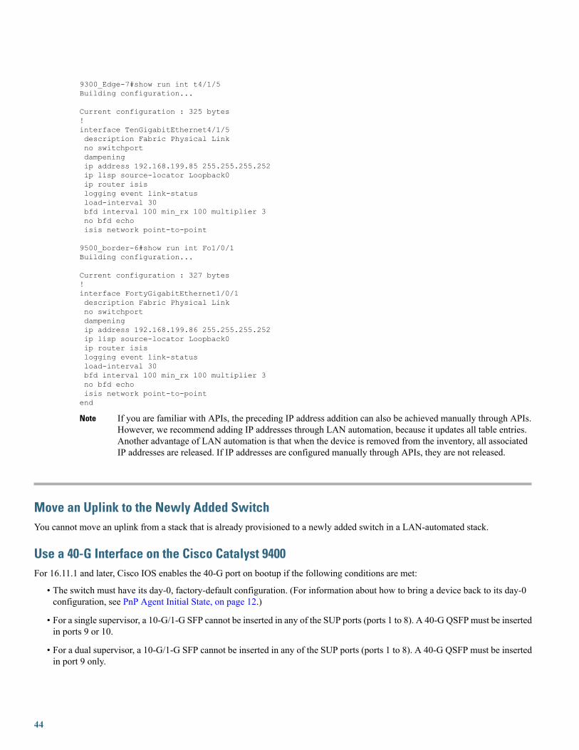
9300_Edge-7#show run int t4/1/5Building configuration...
Current configuration : 325 bytes!interface TenGigabitEthernet4/1/5description Fabric Physical Linkno switchportdampeningip address 192.168.199.85 255.255.255.252ip lisp source-locator Loopback0ip router isislogging event link-statusload-interval 30bfd interval 100 min_rx 100 multiplier 3no bfd echoisis network point-to-point
9500_border-6#show run int Fo1/0/1Building configuration...
Current configuration : 327 bytes!interface FortyGigabitEthernet1/0/1description Fabric Physical Linkno switchportdampeningip address 192.168.199.86 255.255.255.252ip lisp source-locator Loopback0ip router isislogging event link-statusload-interval 30bfd interval 100 min_rx 100 multiplier 3no bfd echoisis network point-to-pointend
If you are familiar with APIs, the preceding IP address addition can also be achieved manually through APIs.However, we recommend adding IP addresses through LAN automation, because it updates all table entries.Another advantage of LAN automation is that when the device is removed from the inventory, all associatedIP addresses are released. If IP addresses are configured manually through APIs, they are not released.
Note
Move an Uplink to the Newly Added SwitchYou cannot move an uplink from a stack that is already provisioned to a newly added switch in a LAN-automated stack.
Use a 40-G Interface on the Cisco Catalyst 9400For 16.11.1 and later, Cisco IOS enables the 40-G port on bootup if the following conditions are met:
• The switch must have its day-0, factory-default configuration. (For information about how to bring a device back to its day-0configuration, see PnP Agent Initial State, on page 12.)
• For a single supervisor, a 10-G/1-G SFP cannot be inserted in any of the SUP ports (ports 1 to 8). A 40-G QSFP must be insertedin ports 9 or 10.
• For a dual supervisor, a 10-G/1-G SFP cannot be inserted in any of the SUP ports (ports 1 to 8). A 40-G QSFP must be insertedin port 9 only.
44

Troubleshoot LAN AutomationIf you encounter any problems, collect the root cause analysis (RCA) file, which is helpful for troubleshooting. At the CLI, enter:$ sudo rca
For a three-node cluster, collect the RCA file for each cluster.
45

THE SPECIFICATIONS AND INFORMATION REGARDING THE PRODUCTS IN THIS MANUAL ARE SUBJECT TO CHANGE WITHOUT NOTICE. ALL STATEMENTS,INFORMATION, AND RECOMMENDATIONS IN THIS MANUAL ARE BELIEVED TO BE ACCURATE BUT ARE PRESENTED WITHOUT WARRANTY OF ANY KIND,EXPRESS OR IMPLIED. USERS MUST TAKE FULL RESPONSIBILITY FOR THEIR APPLICATION OF ANY PRODUCTS.
THE SOFTWARE LICENSE AND LIMITED WARRANTY FOR THE ACCOMPANYING PRODUCT ARE SET FORTH IN THE INFORMATION PACKET THAT SHIPPED WITHTHE PRODUCT AND ARE INCORPORATED HEREIN BY THIS REFERENCE. IF YOU ARE UNABLE TO LOCATE THE SOFTWARE LICENSE OR LIMITED WARRANTY,CONTACT YOUR CISCO REPRESENTATIVE FOR A COPY.
The Cisco implementation of TCP header compression is an adaptation of a program developed by the University of California, Berkeley (UCB) as part of UCB's public domain version ofthe UNIX operating system. All rights reserved. Copyright © 1981, Regents of the University of California.
NOTWITHSTANDING ANY OTHERWARRANTY HEREIN, ALL DOCUMENT FILES AND SOFTWARE OF THESE SUPPLIERS ARE PROVIDED “AS IS" WITH ALL FAULTS.CISCO AND THE ABOVE-NAMED SUPPLIERS DISCLAIM ALL WARRANTIES, EXPRESSED OR IMPLIED, INCLUDING, WITHOUT LIMITATION, THOSE OFMERCHANTABILITY, FITNESS FOR A PARTICULAR PURPOSE AND NONINFRINGEMENT OR ARISING FROM A COURSE OF DEALING, USAGE, OR TRADE PRACTICE.
IN NO EVENT SHALL CISCO OR ITS SUPPLIERS BE LIABLE FOR ANY INDIRECT, SPECIAL, CONSEQUENTIAL, OR INCIDENTAL DAMAGES, INCLUDING, WITHOUTLIMITATION, LOST PROFITS OR LOSS OR DAMAGE TO DATA ARISING OUT OF THE USE OR INABILITY TO USE THIS MANUAL, EVEN IF CISCO OR ITS SUPPLIERSHAVE BEEN ADVISED OF THE POSSIBILITY OF SUCH DAMAGES.
Any Internet Protocol (IP) addresses and phone numbers used in this document are not intended to be actual addresses and phone numbers. Any examples, command display output, networktopology diagrams, and other figures included in the document are shown for illustrative purposes only. Any use of actual IP addresses or phone numbers in illustrative content is unintentionaland coincidental.
All printed copies and duplicate soft copies of this document are considered uncontrolled. See the current online version for the latest version.
Cisco has more than 200 offices worldwide. Addresses and phone numbers are listed on the Cisco website at www.cisco.com/go/offices.
Cisco and the Cisco logo are trademarks or registered trademarks of Cisco and/or its affiliates in the U.S. and other countries. To view a list of Cisco trademarks, go to this URL: www.cisco.comgo trademarks. Third-party trademarks mentioned are the property of their respective owners. The use of the word partner does not imply a partnership relationship between Cisco and anyother company. (1721R)
© 2019 Cisco Systems, Inc. All rights reserved.

Europe HeadquartersAsia Pacific HeadquartersAmericas HeadquartersCiscoSystemsInternationalBVAmsterdam,TheNetherlands
CiscoSystems(USA)Pte.Ltd.Singapore
Cisco Systems, Inc.San Jose, CA 95134-1706USA
Cisco has more than 200 offices worldwide. Addresses, phone numbers, and fax numbers are listed on theCisco Website at www.cisco.com/go/offices.