Embed Size (px)
Citation preview

© 2011 Cisco and/or its affiliates. All rights reserved. This document is Cisco Public Information. Page 1 of 29
White Paper
Cisco Connected Sports Solutions: Use the Power of the Network to Transform Sports and Entertainment Venues
This document explores the challenges and opportunities facing today’s sports and entertainment venues and provides a technical overview of the solutions from Cisco that are designed to meet the needs of these venues.
Challenges
Today, sports and entertainment venues are facing a number of challenges brought about both by advances in
technology and the downturn in the economy.
One of the biggest challenges of sports and entertainment organizations today is keeping the in-venue experience
more compelling for fans than staying at home. Increasingly, fans have options at home—such as high-definition
TVs, digital video recorders (DVRs), and PCs—that give them better video quality, more control over what they
see, and more information about the game. Because most traditional sports and entertainment venues are
equipped to only deliver traditional experiences such as standard-definition video (if any) and limited fan
interactivity, it is difficult for these venues to compete with the in-home experience.
Another challenge is the growing trend in the adoption of Smartphones. Specific to the sports and entertainment
industry, venues, clubs and leagues are already creating applications and social networking sites for fans to get
stats, the latest scores and highlights, access fantasy sports, and view videos of other games and matches.
However, the concentrated increase in Smartphone data application usage within a venue can strain the
capabilities of a third-generation (3G) or fourth-generation (4G) network and interfere with voice and text services.
Although Smartphones are designed to offload data services to a local WLAN where available, the Wi-Fi networks
within the venue are typically not able to provide the increased coverage or capacity needed to accommodate data
service offload. This can have a negative impact on the overall fan experience in the venue.

© 2011 Cisco and/or its affiliates. All rights reserved. This document is Cisco Public Information. Page 2 of 29
In a challenging economy, it is also important for sports and entertainment organizations to take full advantage of
their venues as marketing environments to generate new revenue streams. It is crucial that concessions,
merchandise, and seat upgrades be made highly visible and available, and that opportunities for revenue-
generating sponsorship be compelling and pervasive.
In addition, traditional venues lack the flexibility required to adapt to changing needs and events and are typically
more complex and costly to maintain than next-generation venues. In the traditional venue, there is typically no
integration between the numerous business systems and networks that support all forms of communication,
entertainment, and operations, as in these examples.
● You may manage separate networks for video and data delivery.
● You may use several wireless networks to support ticketing, employee, and fan needs.
● You may have limited ability to centrally manage the delivery of game-day experiences such as video or ad
content.
This complexity typically results in increased support and maintenance costs. More importantly, lack of integration
between these core business systems limits your business opportunities.
All of these challenges create potential barriers for maximizing the revenue generation potential of the venue. To
meet fan demands and remain profitable, organizations must strive to:
● Enhance the fan experience
● Generate new revenue
● Simplify venue operations
The Solution
To achieve these goals requires a solution that provides a resilient and flexible infrastructure, which includes the
advanced features and capabilities that are essential to supporting both current and future requirements—such as
delivery of high-definition video with integrated signage, a high-density wireless LAN for fan interaction, and next-
generation building management and physical security systems.
To address the unique needs of sports and entertainment organizations, Cisco developed a family of Cisco®
Connected Sports solutions. These solutions are focused on transforming the nature of sports and entertainment
experiences through network-based innovation. Cisco Connected Sports solutions bring together all forms of
communication and entertainment onto a single network—connecting venues, teams, and their fans in entirely new
ways and creating new levels of value for all parties.
At the center of the Cisco Connected Sports solutions is the Cisco Connected Stadium solution, a highly scalable,
single-network architecture designed specifically for sports and entertainment venues. The Cisco Connected
Stadium solution provides a media-ready IP infrastructure that is optimized for video distribution. The solution
accommodates all aspects of your business: integrated communications and collaboration, mobile services, and
safety and security.
As an addition to the Cisco Connected Stadium network, the Cisco StadiumVision™ solution offers innovative, end-
to-end video and digital content distribution that transforms the look and feel of a venue. It is designed to easily and
cost-effectively deliver live game video and programming, targeted advertising, and content to each TV display at
the stadium, on a per-event basis. Cisco StadiumVision enhances fan experiences, increases marketable

© 2011 Cisco and/or its affiliates. All rights reserved. This document is Cisco Public Information. Page 3 of 29
advertising inventory; generates new revenue from ticketing, merchandise, and concessions; and promotes venue
utilization.
Another addition is the Cisco Connected Stadium Wi-Fi solution, which provides a single, converged Wi-Fi platform
for fans, venue employees and operations. It delivers reliable coverage to thousands of users throughout a venue,
including dense locales such as the venue “bowl.” The solution is optimized for data offload from a cellular network,
thereby enhancing the performance of data applications while improving voice and text services. Also, it allows Wi-
Fi devices to seamlessly access to media-rich applications in the venue, enabling venues to offer new revenue-
generating mobile applications and increased sponsorship and advertising options.
Cisco Connected Stadium
The Cisco Connected Stadium network follows the Cisco Borderless Network architecture, which is hierarchical
and modular in design. The design offers a highly scalable and redundant architecture based on standard venue
requirements, including provision of video distribution, IP telephony, video surveillance, ticketing and point of sale
services, and fan and luxury suite guest access, all through one easily-managed, flexible network.
Major design aspects of the Cisco Connected Stadium network include:
● Unicast and multicast support
● Hierarchical, tiered design with a collapsed core-distribution and access layer.
● Core-distribution layer that provides high-speed, redundant switching using the Cisco Nexus® 7000 or 6500
Series switches with dual 10-Gbps uplinks to the access layer switches
● User areas segregated using VLANs to contain traffic within confined work areas to avoid broadcast or
Layer 2 network problems from affecting other areas (a number of switch types may be used for access,
such as Cisco Catalyst® 3650, 3750, 4500, and for larger closets, 6500 Series switches)
● Power over Ethernet Plus (PoE+) in access layer switches for powering digital media players (DMPs), IP
phones, and access points
● Enhanced Interior Gateway Routing Protocol (EIGRP), which scales well and provides extremely quick
convergence times with minimal network traffic
● Quality-of-service (QoS) support in access layer switches to mark, queue, and police at the edge of the
network, with queuing enabled on the core to help ensure high-quality video and voice transport
● Protocol Independent Multicast (PIM) routing protocol in sparse mode for efficient multicast distribution
● Anycast rendezvous points (RPs) to provide load sharing and redundancy of RPs configured in the core
switches (Multicast Source Discovery Protocol [MSDP] is the mechanism used to allow RPs to share
information about active sources, and Anycast RP is used for non-broadcast-video multicast applications)
● PriorityCast, an innovative Cisco-invented technology that provides multicast video source and RP
redundancy to protect against node or link failure within the stadium network
● Modular architecture for limiting fault domains and scaling the network with minimal disruption
● Separate data center and video distribution blocks
● Due to the shared nature of the stadium network, use of a service provider security model that applies
layered security measures for protecting stadium server assets
● Optional Layer 2 demilitarized zone (DMZ) network edge for providing further traffic isolation to support
guest access or special events

© 2011 Cisco and/or its affiliates. All rights reserved. This document is Cisco Public Information. Page 4 of 29
Figure 1 illustrates the functional areas of the Cisco Connected Stadium network.
Figure 1. Hierarchical and Modular Design of the Cisco Connected Stadium Network
The result is a network that is:
● Hierarchical in design: Collapsed core-distribution and access layers
● Resilient: Redundant switches and redundant load-sharing, and high-speed uplinks
● Modular: Functional areas divided into service blocks with dedicated resources and redundant connections
to the network
● High-performance: Network bandwidth and capacity designed to withstand node or link failure, with load
balancing and redundancy
The two-tier hierarchical design allows high availability due to inherent fault isolation. Additionally, the modularity
supports growth within each of the functional areas with no effect on the rest of the network.

© 2011 Cisco and/or its affiliates. All rights reserved. This document is Cisco Public Information. Page 5 of 29
Layer 3 Infrastructure
In a Cisco Connected Stadium network, all unified communications, video distribution, and wired and wireless
access use the Layer 3 infrastructure to deliver services throughout the stadium. The Layer 3 infrastructure also
provides connectivity to the venue WAN and a secure connection to the Internet.
The Layer 3 infrastructure of the Cisco Connected Stadium solution uses a scalable tiered hierarchical design,
including collapsed core-distribution and access layers.
● The core layer provides high-speed, redundant switching of packets running at more than 40 Gbps—four
times faster than 10 Gigabit Ethernet, and 4000 times faster than conventional Ethernet.
● The distribution layer divides the network, providing fault isolation as well as dedicated bandwidth and paths
for specific traffic from the core. For highly concentrated numbers of users and devices, a pair of switches
provides additional redundancy.
● The access layer provides ports for users to connect to the network. The user areas are segregated using
VLANs to contain traffic within confined work areas and avoid broadcast or Layer 2 network problems from
affecting other areas.
Because the infrastructure is configured as Layer 3 from core to access, the number of spanning-tree domains are
reduced, thereby reducing the complexity and convergence considerations typically encountered with Layer 2
looped-access networks. The hierarchical design also provides a scalable way to incorporate additional access
blocks into the existing network to increase its size and capacity to handle future growth, while eliminating the need
for an expensive fully-meshed infrastructure by using the high-speed core.
Layer 2 DMZ
Optionally, the design can include an isolated Layer 2 infrastructure within the stadium, offering services for visiting
guests and events. Isolating this infrastructure and treating it as a DMZ limits the effect of rogue event traffic on the
main Layer 3 infrastructure of the Cisco Connected Stadium network.
The Layer 2 DMZ also provides wired connectivity for stadium guests and authorized contractors. Access is
controlled through Cisco Network Admissions Control (NAC) systems, which provide access verification for
authorized users and guests.
Network Security Design
Because the Cisco Connected Stadium network closely aligns with a resource that is shared by untrusted parties,
the security model is based on the service provider model.
Major design aspects of the Cisco Connected Stadium security model (Figure 2) include:
● Hierarchical security design using layered protection
● Identification-based networking services (for example, 802.1x or, NAC) and Cisco Catalyst security features
(for example, port security, Dynamic Host Configuration Protocol [DHCP] snooping, and bridge protocol
data unit [BPDU] guard) used at the access layer
● Adaptive Security Algorithms (ASAs) to provide perimeter security and secured remote access (firewall and
VPN) throughout the network, including the data center
● Intrusion Protection System (IPS) and extensive monitoring to provide protection within the data center

© 2011 Cisco and/or its affiliates. All rights reserved. This document is Cisco Public Information. Page 6 of 29
Figure 2. Cisco Connected Stadium Network Security Model
Stadium Data Center Design
The Cisco Connected Stadium data center provides the following services:
● Layer 3 data center server access
● Internet and WAN access and VPN
● Wireless LAN termination and routing
● Optional Layer 2 DMZ access
The data center switches are configured to handle appropriate speed and duplex settings for each server and host
system. Similarly, the settings for the user access VLAN ports, PortFast, and BPDU guard are configured to allow
quick link establishment while helping to ensure that miscabling does not create disruptive spanning-tree loops
within the network.

© 2011 Cisco and/or its affiliates. All rights reserved. This document is Cisco Public Information. Page 7 of 29
Major design aspects of the Cisco Connected Stadium data center (Figure 3) include:
● Modular design based on functional blocks (for example, Internet services, unified communications and
team services, and wireless services)
● EIGRP on switches to exchange routing information (the data center switches are cross-connected to each
core switch using four 10 Gigabit Ethernet links to provide both link and core switch redundancy)
● Network-interface-card (NIC) teaming and clustering connectivity, allowing servers with multiple NICs to be
connected to two switches for server network resilience if an NIC fails
● Firewalls, IPS, and NAC servers to provide highly secure access to services within the data center
● Wireless services block with redundant WLAN controllers to receive user data that has been tunneled
across the Cisco Connected Stadium network from lightweight access points at the edge of the network
(from there, the traffic is routed to the appropriate destination server)
Figure 3. Cisco Connected Stadium Data Center Design

© 2011 Cisco and/or its affiliates. All rights reserved. This document is Cisco Public Information. Page 8 of 29
High-Definition Video and Digital Content Distribution Design
The Cisco Connected Stadium solution provides the capabilities, reliability, and performance required to deliver
high-definition video throughout the venue. The Cisco StadiumVision solution (discussed in greater detail later in
this document) can be deployed on the Cisco Connected Stadium network to support the delivery of in-house and
external high-definition video feeds along with other digital content (such as advertisements and promotions,
concession menus, and directional signage) to video endpoints throughout the venue.
Major aspects of the Connected Stadium video distribution design (Figure 4) include:
● Support for redundant video headend sources (two video sources streaming identical video), with each
headend connecting to video distribution switches with redundant 10-Gb links to the core
● Video distribution switches (in the figure, VDS1 and 2) configured as redundant RPs for source and receiver
registration
● PIM routing protocol in sparse mode for efficient multicast video distribution
● PriorityCast to provide video source and RP redundancy with subsecond network failover

© 2011 Cisco and/or its affiliates. All rights reserved. This document is Cisco Public Information. Page 9 of 29
Figure 4. Multicast Video with PriorityCast Failure Protection
PriorityCast is a combination of unicast and multicast routing features used together to designate or give priority to
a source of multicast video onto the network. Meanwhile, the other video source is prepared to take over in case of
network failure.
The high-definition video headend system allows live in-house camera feeds, and terrestrial and satellite or cable
channels, to be distributed throughout the network to a Cisco DMP, which can be attached to almost any type of
TV or display. Displays can be located across concourse areas; in concession or retail areas; in luxury or prestige
suites; in clubs, restaurants, or bars; as well as in press boxes and back offices.
Voice Services Design
Public phone access, internal voice and video communications, and conferencing are provided using the Cisco
Unified Communications solution deployed on the Cisco Connected Stadium network.

© 2011 Cisco and/or its affiliates. All rights reserved. This document is Cisco Public Information. Page 10 of 29
Major aspects of the Cisco Connected Stadium voice services design include:
● Custom features to simplify deployment and optimize voice performance, such as automatic settings for the
voice VLAN and QoS
● Redundant Cisco Unified Communications block switches for subsecond network failover
● Network QoS tuned for voice
The architecture to support voice services in the Cisco Connected Stadium is shown in Figure 5.
Figure 5. Cisco Connected Stadium Voice Services Architecture

© 2011 Cisco and/or its affiliates. All rights reserved. This document is Cisco Public Information. Page 11 of 29
Call control is centralized through a call management system (Cisco Unified Communications Manager) and voice
gateways (Cisco 3945 Integrated Services Router) for public-switched-telephone-networks (PSTN) call
connections. Video conferencing systems (including Cisco TelePresence® systems) allow secure player interviews
with fans and press and internal stadium communication as necessary. To simplify deployment, Cisco Unified IP
Phones can use 802.3af Power over Ethernet (PoE).
When deployed with the Cisco StadiumVision solution, Cisco IP Phones also provide local TV control and
touchscreen access to concession and merchandise menus in the luxury suites.
Physical Safety and Security Design
To address the need for physical safety and security, venues can deploy Cisco Physical Security products and
solutions on the Cisco Connected Stadium network. These products and solutions allow venues to improve the
security of their staff, fans, and property, while reducing operating expenses.
For example, venues can deploy Cisco Video Surveillance solutions in ticketing and entrance areas, concession
areas, back-office operational areas, loading docks, and building entries and exits to accelerate response to
suspicious behaviors or incidents.
In theft-prone areas, such as concession stands and ticket booths, venues can set the cameras to continuously
record or stream video images. For other areas, the IP video surveillance system can be set to Record on Motion.
With this setting, when an IP camera detects motion in its viewing area it begins to record and stream the image
back to an archive server, which can be located in the data center or within the same intermediate distribution
frame (IDF) location. When there is no motion, the cameras do not send any video images across the network. To
simplify deployment, the cameras can be powered with 802.3af PoE.
In addition, Cisco Physical Access Gateways can connect door locks and card readers to the IP network and allow
venues to incorporate their existing physical security systems into the Cisco Connected Stadium solution. The
access gateways can control up to thousands of doors, and include the capability to cache and encrypt up to
250,000 credentials per device. In addition, venues can automatically link the gateway sensors to the relevant
video feeds through built-in integration with Cisco Video Surveillance Manager.
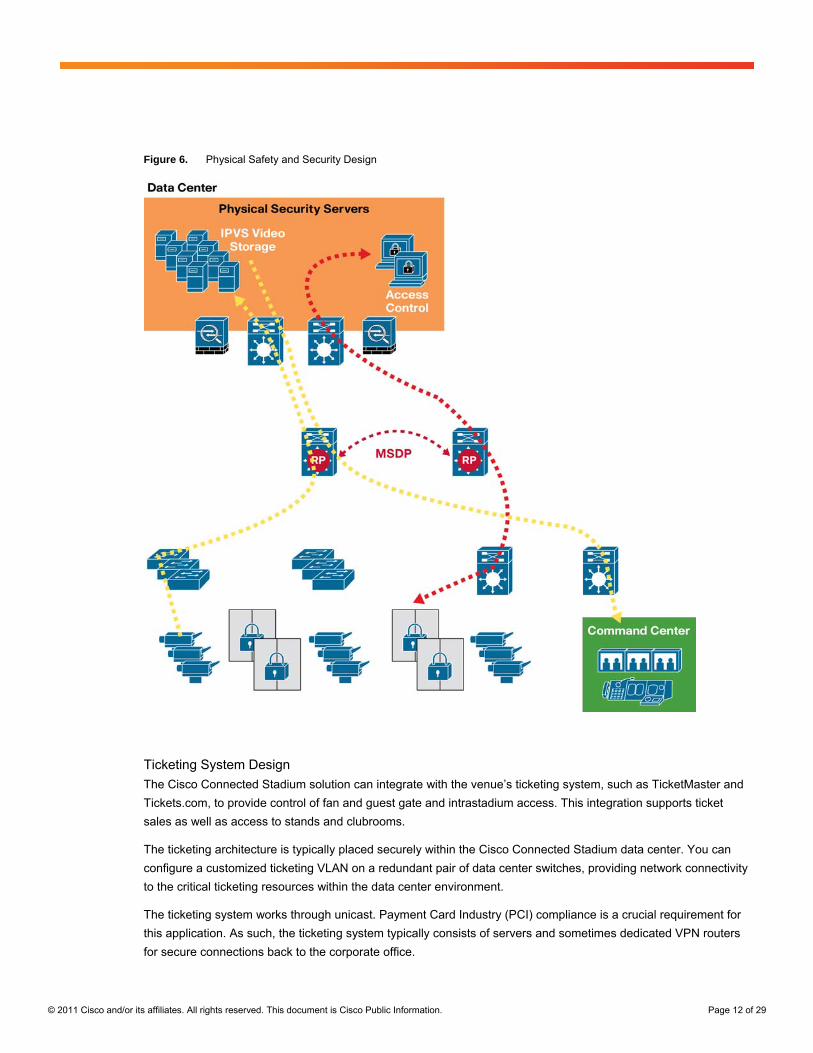
Major aspects of the Connected Stadium physical safety and security design (Figure 6) include:
● Port-based QoS for ports attached to IP surveillance cameras
● Cameras that stream video by unicast to central servers for storage
● Monitoring stations that view video through unicast or multicast, depending on the solution
● MSDP configured on core devices to provide redundancy for multicast applications
© 2011 Cisco and/or its affiliates. All rights reserved. This document is Cisco Public Information. Page 12 of 29
Figure 6. Physical Safety and Security Design
Ticketing System Design
The Cisco Connected Stadium solution can integrate with the venue’s ticketing system, such as TicketMaster and
Tickets.com, to provide control of fan and guest gate and intrastadium access. This integration supports ticket
sales as well as access to stands and clubrooms.
The ticketing architecture is typically placed securely within the Cisco Connected Stadium data center. You can
configure a customized ticketing VLAN on a redundant pair of data center switches, providing network connectivity
to the critical ticketing resources within the data center environment.
The ticketing system works through unicast. Payment Card Industry (PCI) compliance is a crucial requirement for
this application. As such, the ticketing system typically consists of servers and sometimes dedicated VPN routers
for secure connections back to the corporate office.

© 2011 Cisco and/or its affiliates. All rights reserved. This document is Cisco Public Information. Page 13 of 29
Major aspects of the Cisco Connected Stadium ticketing system design (Figure 7) include:
● Secure connections for wireless scanning devices and wired PCs
● Wireless data tunneled to the ticketing server
● Traffic tagged using QoS and serviced within a nonstrict priority queue
● VPN router that provides access for ticketing clients
Figure 7. Using Traffic Isolation for Ticketing System

© 2011 Cisco and/or its affiliates. All rights reserved. This document is Cisco Public Information. Page 14 of 29
Point of Sale Design
Integrating the Cisco Connected Stadium solution with the venue concourse Point of Sale (POS) system (such as
Radiant)—including terminals and cash registers, finishing kitchens, and wireless order-entry devices—provides
easy access to food and retail systems for fans, increasing revenue-generating opportunities while providing a cost
savings over using separate infrastructures.
Optionally, integrating the Cisco StadiumVision solution with the venue luxury-suite POS system (such as Quest
and Micros) allows guests or suite attendants in luxury suites to place orders for food, beverages, and merchandise
using the touchscreen of their Cisco IP Phones—enhancing the total luxury-suite experience.
The POS systems operate through unicast or multicast, depending upon the vendor. If multicast is used, sources
may exist in both the data center and in the IDFs. The Cisco Connected Stadium Anycast deployment will be used
where the core devices act as RPs. PCI compliance is also a crucial requirement for this application.
Major aspects of the Cisco Connected Stadium POS design include:
● Support for POS server discovery
● Secure connections for wireless order entry devices and wired PCs
● Wireless data tunneled to POS servers
● Traffic tagged using QoS and serviced within a nonstrict priority queue
● POS servers protected by ASA firewalls and IPS monitoring
Similar to the traffic isolation used in the ticketing application, the wired POS terminals connected to the access
layer switch are on a VLAN dedicated to POS (Figure 8). Virtual Route Forwarding (VRF) is configured in the
switch with a generic routing encapsulation (GRE) tunnel back to the POS servers.

© 2011 Cisco and/or its affiliates. All rights reserved. This document is Cisco Public Information. Page 15 of 29
Figure 8. Using Traffic Isolation for Point of Sale System
Cisco Connected Stadium Standard WLAN and the Connected Stadium Wi-Fi Solution
The Cisco Connected Stadium standard WLAN design and the optional Connected Stadium Wi-Fi solution are
designed specifically to address the unique challenges of a sports and entertainment venue.
● One of the most important aspects of providing WLAN access within a sports and entertainment venue is
the design and fine-tuning of the RF coverage and capacity handling required to deliver high-quality WLAN
service throughout the stadium or arena. For example, most venues require WLAN access to support hand-
held ticket scanning and point of sale devices; internet access for staff, contractors, guests, and press;

© 2011 Cisco and/or its affiliates. All rights reserved. This document is Cisco Public Information. Page 16 of 29
communications for video surveillance devices; voice over WLAN; and other services. In some cases, the
access must be private and protected, such as access in support of financial transaction handling. In other
cases, the access must be open, such as access for fan use. There may also be the need for the WLAN
infrastructure to support the use of location-based Wi-Fi tags for personnel, children, and tracking of
expensive assets within the stadium.
● Another essential element is the ability of the WLAN infrastructure to reliably deliver streaming video to
handheld devices within the venue for game replays as well as advertisements.
● In addition, the increasing use of 3G/4G enabled devices in the venues, particularly within the bowl, can put
a strain on service provider networks. The Connected Stadium Wi-Fi solution helps alleviate this by
providing 3G/4G offload for the higher-bandwidth applications.
All of these factors and use cases must be taken into account when planning for a WLAN solution for any venue.
As a result, the Cisco WLAN design for Connected Sports incorporates aspects of standard-practice WLAN
implementation along with new Cisco VideoStream enhancements and a unique design for high-density WLAN
coverage in the bowl called the Cisco Connected Stadium Wi-Fi solution (Figure 9).
Figure 9. Designing for WLAN Users
Major aspects of the Connected Stadium standard WLAN and Connected Stadium Wi-Fi solution design include:
● Support for 802.11a/b/g/n through PoE-powered dual-band access points deployed in lightweight mode with
antenna support for the 2.4 and 5 GHz bands; access point and antenna combinations are all FCC-
approved systems
● Access points that are strategically placed and use highly directional antennas in a downtilt mount to
contain coverage and create a matrix of microcells within the bowl to support high-speed WLAN access
● Channel assignment and power levels set to optimize coverage and capacity

© 2011 Cisco and/or its affiliates. All rights reserved. This document is Cisco Public Information. Page 17 of 29
● Support for a broad range of authentication options, such as Wi-Fi Protected Access Pre-Shared Key
(WPA-PSK), Wired Equivalent Privacy (WEP), and WPA2
● Transparent roaming
● Special design and tuning to support the high density of WLAN clients in the bowl
● Enterprise-class WLAN design for the lower-density areas of the stadium such as suites, administration
offices, ticketing areas at the gates, shops, and concourses
● Use of radio resource management (RRM) for optimal RF channel and power level settings across the
stadium
To simplify management and ongoing operations, the Cisco 5500 Series Wireless LAN Controller (WLC) or Cisco
Catalyst 6500 Series Wireless Services Module (WISM or WISM2) is used in a centralized WLAN model, where
traffic is tunneled across the Cisco Connected Stadium network to the WLC and bridged to its respective VLAN for
further routing to destination servers. Figure 10 illustrates how wireless LAN clients associate to their respective
Service Set Identifications (SSIDs) at the edge of the network and their traffic is tunneled to the wireless services
hub for secure routing to their respective destinations.

© 2011 Cisco and/or its affiliates. All rights reserved. This document is Cisco Public Information. Page 18 of 29
Figure 10. Centralized WLAN Deployment Model
The Connected Stadium standard WLAN uses Layer 2 roaming to provide devices with roaming between access
points while maintaining the same IP address (Figure 11). This is a simple and efficient way to allow users to move
about the stadium without losing their connections.

© 2011 Cisco and/or its affiliates. All rights reserved. This document is Cisco Public Information. Page 19 of 29
Figure 11. Layer 2 Roaming
Traffic Isolation
Although the operational systems (for example, point of sale, ticketing, and business management systems) are
now converged onto a single network, it is still necessary to maintain the isolation of the traffic of these systems
from the rest of the network. A Cisco Connected Stadium network supports traffic isolation through several features
used in combination to satisfy the unique requirements of a particular system.
Major aspects of the Cisco Connected Stadium traffic isolation design include:
● Control and Provisioning of Wireless Access Points (CAPWAP) tunneling
● Ethernet over IP (EoIP) tunneling
● GRE for tunneling traffic across the network

© 2011 Cisco and/or its affiliates. All rights reserved. This document is Cisco Public Information. Page 20 of 29
● VRF-lite for providing traffic isolation within the switch itself
● Access control lists for simply limiting what traffic can flow where across the network
Guest WLAN Access Design
Some venues require guest WLAN access and special event traffic (for example, press traffic) to be isolated from
the main stadium network. Figure 12 shows a scenario where all guest WLAN and special event traffic are carried
on the optional Layer 2 DMZ.
Figure 12. Wireless Guest Access

© 2011 Cisco and/or its affiliates. All rights reserved. This document is Cisco Public Information. Page 21 of 29
Video over WLAN
Increasingly, sports venues want to deliver streaming video to handheld devices. However, video is a very
demanding application that immediately exposes any weaknesses in the design of a WLAN. The quality of the
video experience when delivered over WLAN must be enterprise-class—the network must be capable of
supporting multiple video, audio, and data streams in a reliable, synchronized manner, without disruption.
Otherwise, if delay, packet loss, and jitter enter visible thresholds, the usefulness of video quickly drops to zero.
Extending video over WLAN has certain challenges compared to sending video over wired networks. These
challenges arise because WLAN introduces a set of network performance characteristics—including variable data
rates, packet loss, and multicast unreliability —that work against some of the traditional approaches to guaranteed
quality of service (QoS).
● Variable data rates: The data rate of transmission over WLAN varies over time, and depends on the
distance of the client from the access point. For example, consider a client that is operating at 54 Mbps, and
requesting a video stream of 10 Mbps. The system determines that the necessary airtime for the new
stream can be accommodated, and so admits the stream. But then the client moves away from the access
point, and the data rate of the client drops to 6 Mbps. Now the video stream cannot be supported.
● Packet loss: WLAN loses more packets than a wired network. The first reason is collisions—two WLAN
devices attempting to transmit at the same time. WLAN uses a shared half-duplex medium, and although
the “listen-before-talk” medium access method tries to avoid collisions, it cannot totally prevent them. A
second reason for packet loss is that WLAN transmissions are subject to short-term signal loss (fades). To
compensate, WLAN uses a retransmission mechanism whereby packets that are not successfully received
and acknowledged are resent. This mechanism generally serves to reduce the final packet loss rate (PLR)
to less than 0.1 percent. However, these retransmissions result in jitter and reduce overall network
throughput, both of which can affect QoS.
● Multicast unreliability: For multicast transmissions (with multiple receivers), WLAN does not provide a
retransmission mechanism. As a result, it is not uncommon for WLAN multicast traffic to experience a
packet loss rate of 5 percent. This is a serious problem for video, where loss of even a single packet can
result in an error that propagates for many video frames. For this reason, it is typical for multicast video
applications that work on a wired network to fail completely when they operate on a WLAN network.
An additional challenge is choosing the right data transmission rate for multicast, so that all clients have a
chance to receive the packet but transmission is not so slow that it uses up all the airtime of the cell.
Several network elements are required to support high-quality video performance, including enhancements to the
physical layer, MAC layer, and application layer of the network.
● Physical layer: A more reliable physical layer provides a higher data rate and fewer retransmissions, so
that video (and all other applications) operate more smoothly. For example, the use of 802.11n provides
some important advantages in the quality of the WLAN physical layer.
● MAC layer: One feature that can improve video performance is the use of Wi-Fi Multimedia (WMM)
extensions. WMM provides for four levels of priority queuing: voice, video, best effort, and background. By
taking advantage of WMM, video applications can run video traffic with priority over other best-effort traffic.
● Application layer: Crucial features for enhancing video over WLAN involve the infrastructure being aware
of video at the application layer or codec layer or both. For example, at the application layer the goal is to
have all applications identify themselves using the WMM traffic specification (TSPEC). However, until that

© 2011 Cisco and/or its affiliates. All rights reserved. This document is Cisco Public Information. Page 22 of 29
goal is met, the most common alternative method for identifying video streams is through the use of
differentiated services code point (DSCP) markings in the IP header.
To address the exceptional requirements and challenges of providing streaming video within a venue, Cisco
Connected Sports solutions include the Cisco VideoStream technology. Cisco VideoStream is a system-wide set of
features of the Cisco Unified Wireless Network that incorporates some of the main enhancements for delivering
superior video quality. Cisco VideoStream showcases Cisco’s RF and video expertise for delivering a reliable,
consistent platform for all types of video, taking into consideration the physical, MAC, and application layers of the
wireless LAN.
Cisco VideoStream enhances the delivery of video over WLAN through use of the following technologies.
● Stream admission and prioritization allows the network administrator to configure the media stream with
different priorities based on importance.
● Resource reservation control (RRC) provides enhanced capabilities to manage admission and policy
controls. Admission and policy decisions are made based on the radio frequency measurements, statistical
measurement of the traffic, and system configurations. RRC provides bandwidth protection for the video
client by denying requests that would cause oversubscription.
● Reliable multicast addresses some of the challenges of video over WLAN by converting the multicast traffic
to unicast. Essentially, the packets remain multicast at the IP layer. But at the WLAN layer (Layer 2), the
packets are unicast to each client who subscribes to the multicast group.
For more information about the Cisco VideoStream technology, see the whitepaper on “Optimizing Enterprise
Video over Wireless LAN” on Cisco.com.
Note: Cisco VideoStream addresses the challenges of delivering recorded video over a WLAN. Delivery of live
in-house video to wireless devices in the venue has additional challenges that must be addressed separately.
Connected Stadium Wi-Fi
The Cisco Connected Stadium design philosophy is to consider the whole stadium when designing the WLAN.
Access point placement, channel assignment, power levels, and antenna radiation patterns must be carefully
considered to provide the WLAN user the best experience possible in all parts of the stadium.
Fans within the bowl are the most challenging user group to accommodate, because of the high density of users,
the openness of the area, and limited stadium infrastructure available for mounting access points. Providing good
service to this user group requires a comprehensive site survey, an adequate number of access points for proper
capacity, directional antennas mounted with downtilt for limiting cell coverage, and fine-tuning of access point
channel assignment and RF power levels (Figure 13).

© 2011 Cisco and/or its affiliates. All rights reserved. This document is Cisco Public Information. Page 23 of 29
Figure 13. Coverage in the Bowl
The Cisco Connected Stadium Wi-Fi solution is an enhancement to the standard WLAN support provided by the
Connected Stadium infrastructure and is designed specifically to address the unique challenges of providing Wi-Fi
access to the heavy concentration of mobile device users in a stadium or arena, such as in the venue bowl, in the
press box, or in a club.
To address these challenges, the Cisco Connected Stadium Wi-Fi solution employs new, highly directional
antennas and high-performance, dual-band access points along with software algorithms to automatically tune the
wireless network to the constantly changing RF environment and CleanAir technology, which includes access
points with integrated, silicon-level spectrum intelligence that detects, classifies, and mitigates RF interference.
The Cisco Connected Stadium Wi-Fi solution uses advanced radio resource management (RRM) features and
high-gain antennas to deliver hundreds of micro Wi-Fi cells throughout a venue, with each cell supporting high
capacity and a diverse set of WLAN devices. As shown in Figure 14, this tighter packing of micro Wi-Fi cells makes
it possible to support a greater number of data users.

© 2011 Cisco and/or its affiliates. All rights reserved. This document is Cisco Public Information. Page 24 of 29
Figure 14. Improving Coverage and Capacity with Cisco Connected Stadium Wi-Fi
For more information about the Connected Stadium Wi-Fi solution, see the whitepaper posted at
http://www.cisco.com/go/sports.
Cisco StadiumVision
The Cisco StadiumVision solution is a proven, end-to-end, high-definition IPTV solution that provides advanced
digital content management and delivery that can transform the look and feel of venues. Built on the Cisco
Connected Stadium solution and centrally managed through Cisco StadiumVision Director, the Cisco
StadiumVision solution supports the integration and automated delivery of customized and dynamic content from
multiple sources to different areas of the stadium in standard definition, high definition, or both.
Cisco StadiumVision Director provides centralized, scripted management of the displays, including control of the
video feeds along with multiple options for overlaid advertisements and other digital content. You can segment
content on a per-TV or group basis, delivering targeted content to different areas of the venue. In addition to
centralized control, local TV control is provided in luxury suites, bars, clubs, and restaurants to give guests more
customized experiences. Luxury suites also have the option of integrating with the POS service for simplified
ordering of food, beverages, and merchandise by luxury-suite guests.
The Cisco StadiumVision solution includes a combination of video and digital signage content that is displayed on
TVs throughout the stadium. The digital signage content is prepositioned on the DMPs prior to an event. The only
effect on the network is when the content is being preloaded on the DMPs. This task is completed well in advance
of the display of the content.
Full-motion video, however, has more effect on the Cisco Connected Stadium network because this content is live-
streaming video that is distributed to TVs in real time. The streaming of the video occurs during an event and the
network needs to accommodate this.

© 2011 Cisco and/or its affiliates. All rights reserved. This document is Cisco Public Information. Page 25 of 29
Figure 15 depicts the architecture of the Cisco StadiumVision solution with the video headend equipment, including
video distribution switches and Cisco Digital Content Managers (DCMs), located in the video room, and also the
video endpoints, DMPs, and TVs connected to the access IDF switches throughout the stadium.
Figure 15. StadiumVision Architecture
With support for high-definition (and even standard-definition) video feeds in MPEG-2 or MPEG-4 formats, the
Cisco StadiumVision solution can deliver video simultaneously to thousands of displays with quality equal to or
better than what is delivered to the home. Almost any display can be accommodated.
Because the Cisco StadiumVision solution supports reliable delivery of content to up to 5000 endpoints, venues
have the flexibility to place numerous TVs throughout the concourses and in clubs, in luxury suites, in locker rooms
and back offices, and in the concession areas.
Video Headend
In the Cisco StadiumVision headend, video feeds are:
● Received from sources, such as in-house feeds (through the venue video control room), terrestrial channels
(typically from local broadcast networks), and broadcast channels from cable or satellite providers

© 2011 Cisco and/or its affiliates. All rights reserved. This document is Cisco Public Information. Page 26 of 29
● Encoded, transcoded, or decrypted using the appropriate Cisco encoder, transcoder, or decryption device
to create an MPEG-2 or MPEG-4 stream
● Tagged with an IP multicast address using a Cisco 9900 Series DCM
● Placed on the Cisco Connected Stadium network using a video distribution switch, which may be a Cisco
Catalyst 3560, 3750, or 6500 Series Switch
Acquired video feeds may be provided in high-definition or standard-definition resolution, and in encrypted or
unencrypted formats. The DCM can receive:
● MPEG-2 or MPEG-4 feeds over Asynchronous Serial Interface (ASI) connections from encoders or
demodulators
● MPEG-2 or MPEG-4 through direct IP feeds (unicast or multicast) from a video provider or from a local
source (in this case, the DCM serves as a demarcation point between the carrier and encoded feeds and
the IP video distribution network)
The resulting IP multicast streams are sent to the video distribution switches. These switches support the
advanced features (quality of service, IP multicast, and strict priority queuing) and the performance required to
distribute video streams over an IP network.
For video source and RP resiliency, an IP multicast technique called PriorityCast is used. The Cisco DCM and
video distribution switches are deployed in a redundant configuration. Each high-definition video channel is
sourced from two Cisco DCMs, which are configured as Active-Active. The two Cisco DCMs act as redundant
multicast sources for each channel and connect to separate access routers on Layer 3 interfaces. Although both
DCMs are actively sending video streams of the same content, the video streams of the secondary DCM will only
be forwarded on the network in the event of a network failure causing the loss of the primary video stream.
Major aspects of the Cisco StadiumVision video headend design include:
● Flexibility to accommodate feeds from a wide variety of sources
● Standard-definition and high-definition encoding in either MPEG-2 or MPEG-4
● Resiliency using redundant configuration
● Efficient delivery of video to the Cisco Connected Stadium network using IP multicast and QoS
Video Delivery
Cisco StadiumVision supports up to 5000 TVs (or displays) deployed within the stadium. Each of these TVs has an
associated DMP that is used to control the content displayed.
The digital signage content (static graphics, overlays with transparency, Adobe Flash files, and video files) is
prepositioned on each DMP and each IPTV channel is sent across the stadium network by IP multicast. The DMPs
use Internet Group Management Protocol (IGMP) to join the appropriate IP multicast group, as defined at the
headend, to receive the video stream for the desired IPTV channel. The DMPs receive the multicast streams,
decode them, and display them on the TV to which they are connected.
Instructions for the layout of the video and digital signage content, which IPTV channel to display, and which digital
content to display are received by the DMP from Cisco StadiumVision Director using event scripts. In addition,

© 2011 Cisco and/or its affiliates. All rights reserved. This document is Cisco Public Information. Page 27 of 29
Cisco StadiumVision allows a Cisco IP phone, infrared (IR) remote, or third-party touch panel to control which IPTV
channel is displayed on a TV.
Major aspects of the Cisco StadiumVision video delivery design include:
● Efficient use of network resources through IP multicast for video and prepositioned digital content
● Flexible options for content display, including customizable templates and flexible display arrangement
(video walls)
● Centralized and local control of content as well as TV functions, including volume and power
● PoE with low power requirements (12W)
Centralized Management and Control
Cisco StadiumVision Director is a set of related applications deployed on a high-performance server. These
applications coordinate, manage, and orchestrate interactivity between all areas of the venue, including luxury
suites, concourses, restaurants, press boxes, and the back office. Live streaming video, targeted and coordinated
advertisements, sponsor promotions, digital menus, directional signage, news feeds, display control, concessions,
and merchandise ordering are customized, with display-level control, to specific areas of the venue.
Major features of Cisco StadiumVision Director include:
● Scheduling and creation of events, including copying and duplication of prior events
● Manual or automatic orchestration of display power and content changes
● Creation of unique entitlement content areas for concourses, suites, and restaurants
● Standard or custom layout templates for the placement of content, video, and tickers
● Emergency signage or delay-of-event master control for designated areas
● Content importing, exporting, and tagging, with logging of content play
● Improvised content changes for displaying alternative content following score events
● Menu board control to facilitate concessionaire signage by grouping themes
For resiliency, Cisco StadiumVision Director can be deployed in a redundant configuration providing backup and
restoration capabilities.
Premium Fan Services
In addition to the delivery of high-definition video and content, the Cisco StadiumVision solution provides the luxury
suite guest with state-of-the-art features for an enhanced event experience. Not only are luxury suite guests given
the ability to select their own channels from the channel guide, but with optional integration to a POS application,
venues can give luxury-suite guests the opportunity to easily purchase food, beverages, and merchandise from the
comfort of their suite.
As shown in Figure 16, Cisco StadiumVision Director communicates with the POS server, the IP phone, the DMP,
and Cisco Unified Application Environment (CUAE) to:
● Obtain information about available items for purchase
● Display the items and prices on both the IP phone and the TV
● Process the order, including validation of customer credentials and order confirmation

© 2011 Cisco and/or its affiliates. All rights reserved. This document is Cisco Public Information. Page 28 of 29
Figure 16. Luxury Suite with POS Integration
Major aspects of the Cisco StadiumVision premium fan services design include:
● Access to special in-house camera angles and access to channels beyond the in-house feed
● Local control of TV channel, volume, power, and input source
● Customizable welcome messages
● Access to concession and merchandise ordering with account validation and in-suite delivery
Dynamic Menu Boards
In addition to the premium fan services, Cisco StadiumVision Director can interface with a POS server to obtain
information about items to display at concession stands throughout the venue. With the Cisco StadiumVision
Director dynamic menu boards feature, you can change the content of the menu during an event to reflect changes
in prices, availability, or selection. Concession-stand owners can draw attention to certain items and change the list
of available items.
This feature also allows multipurpose venues to easily accommodate different events. Multiple vendors can use the
same concession areas at different times. For example, an area can be used to sell children’s merchandise during
“Kids’ Day” at a game and be changed to sell programs and T-shirts for a concert that night.
Major aspects of the Cisco StadiumVision dynamic menu board design include:
● Customizable menu backgrounds and graphics
● Ability to obtain item data and pricing from a point of sale server
● Flexibility to change items and pricing during an event
● Flexibility to easily display different menus for different events
© 2011 Cisco and/or its affiliates. All rights reserved. This document is Cisco Public Information. Page 29 of 29
Summary
Cisco has a reputation for creating innovative technologies and for using those technologies to transform the way
people communicate, the way people conduct business, and the way businesses themselves operate. Now Cisco
offers leading-edge and proven technologies to transform the way venues conduct events and—more
importantly—the way fans experience the events.
The capabilities described in this document are just the beginning. With the Cisco Connected Stadium architecture
and the Cisco StadiumVision and Connected Stadium Wi-Fi solutions in place, sports and entertainment
organizations have numerous opportunities for future enhancements, such as using IP physical security analytics
to direct fans to the shortest concession line, using card-reader technology to automatically customize the luxury
suite channel options and dining selections, creating clubs in the venue that are built around a distinctively
immersive 3D sports experience, enabling exclusive location-based Smartphone applications, and providing new
levels of interaction for mobile fans.
For More Information
For more information about Cisco Connected Sports solutions, contact your Cisco Account Representative today
and learn how you can use the power of the network to transform your sports and entertainment venue.
http://www.cisco.com/go/sports
Printed in USA C11-682975-00 08/11