Embed Size (px)
Citation preview

8/10/2019 Cisco ConfiguratioGuide SW4500 IOS
http://slidepdf.com/reader/full/cisco-configuratioguide-sw4500-ios 1/607

8/10/2019 Cisco ConfiguratioGuide SW4500 IOS
http://slidepdf.com/reader/full/cisco-configuratioguide-sw4500-ios 2/607
THE SPECIFICATIONS AND INFORMATION REGARDING THE PRODUCTS IN THIS MANUAL ARE SUBJECT TO CHANGE WITHOUT NOTICE. ALL
STATEMENTS, INFORMATION, AND RECOMMENDATIONS IN THIS MANUAL ARE BELIEVED TO BE ACCURATE BUT ARE PRESENTED WITHOUT
WARRANTY OF ANY KIND, EXPRESS OR IMPLIED. USERS MUST TAKE FULL RESPONSIBILITY FOR THEIR APPLICATION OF ANY PRODUCTS.
THE SOFTWARE LICENSE AND LIMITED WARRANTY FOR THE ACCOMPANYING PRODUCT ARE SET FORTH IN THE INFORMATION PACKET THAT
SHIPPED WITH THE PRODUCT AND ARE INCORPORATED HEREIN BY THIS REFERENCE. IF YOU ARE UNA BLE TO LOCATE THE SOFTWARE LICENSEOR LIMITED WARRANTY, CONTACT YOUR CISCO REPRESENTATIVE FOR A COPY.
The Cisco implementation of TCP header compression is an adaptation of a program developed by the University of California, Berkeley (U CB) as part of UCB’s public
domain version of the UNIX operating system. All rights reserved. Copyright © 1981, Regents of the University of California.
NOTWITHSTANDING ANY OTHER WARRANTY HEREIN, ALL DOCUMENT FILES AND SOFTWARE OF THESE SUPPLIERS ARE PROVIDED “AS IS” WITH
ALL FAULTS. CISCO AND THE ABOVE-NAMED SUPPLIERS DISCLAIM ALL WARRANTIES, EXPRESSED OR IMPLIED, INCLUDING, WITHOUT
LIMITATION, THOSE OF MERCHANTABILITY, FITNESS FOR A PARTICULAR PURPOSE AND NONINFRINGEMENT OR ARISING FROM A COURSE OF
DEALING, USAGE, OR TRADE PRACTICE.
IN NO EVENT SHALL CISCO OR ITS SUPPLIERS BE LIABLE FOR ANY IND IRECT, SPECIAL, CONSEQUENTIAL, OR INCIDENTAL DAMAGES, INCLUDING,
WITHOUT LIMITATION, LOST PROFITS OR LOSS OR DAMAGE TO DATA ARISING OUT OF THE USE OR INABILITY TO USE THIS MANUAL, EVEN IF CISCO
OR ITS SUPPLIERS HAVE BEEN ADVISED OF THE POSSIBILITY OF SUCH DAMAG ES.
CCSP, the Cisco Square Bridge logo, Follow Me Browsing, and StackWise are trademarks of Cisco Systems, Inc.; Changing the Way We Work, Live, Play, and Learn, and
iQuick Study are service marks of Cisco Systems, Inc.; and Access Regist rar, Aironet, ASIST, BPX, Catalyst, CCDA, CCDP, CCIE, CCIP, CCNA, CCNP, Cisco, the Cisco
Certified Internetwork Expert logo, Cisco IOS, Cisco Press, Cisco Systems, Cisco Systems Capital, the Cisco Systems logo, Cisco Unity, Empowering the Internet Generation,
Enterprise/Solver, EtherChannel, EtherFast, EtherSwitch, Fast Step, FormShare, GigaDrive, GigaStack, HomeLink, Internet Quotient, IOS, IP/TV, iQ Expertise, the iQ logo,iQ Net Readiness Scorecard, LightStream, Linksys, MeetingPlace, MGX, the Networkers logo, Networking Academy, Network Registrar, Packet , PIX, Post-Routing,
Pre-Routing, ProConnect, RateMUX, ScriptShare, SlideCast, SMARTnet, StrataView Plus, SwitchProbe, TeleRouter, The Fastest Way to Increase Your Internet Quot ient,
TransPath, and VCO are registered trademarks of Cisco Systems, Inc. and/or its affiliates in the United States and certain other countries.
All other trademarks mentioned in thi s document or Website are the property of t heir respective owners. The use of the word partner d oes not imply a partnership relationship
between Cisco and any other company. (0411R)
Catalyst 4500 Series Switch Cisco I OS Software Configuration Guide
Copyright © 1999–2004 Cisco Systems, Inc. All rights reserved.
8/10/2019 Cisco ConfiguratioGuide SW4500 IOS
http://slidepdf.com/reader/full/cisco-configuratioguide-sw4500-ios 3/607
iii
Software Configuration Guide—Release 12.2(25)EW
OL-6696-01
C O N T E N T S
Preface xxi
Audience xxi
Organization xxi
Related Documentation xxiii
Conventions xxiv
Commands in Task Tables xxv
Obtaining Documentation xxv
Cisco.com xxv
Ordering Documentation xxv
Documentation Feedback xxvi
Obtaining Technical Assistance xxvi
Cisco Technical Support Website xxvi
Submitting a Service Request xxvii
Definitions of Service Request Severity xxvii
Obtaining Additional Publications and Information xxvii
CHAPTER 1 Product Overview 1-1
Layer 2 Software Features 1-1
802.1Q and Layer 2 Protocol Tunneling 1-2
Storm Control 1-2
CDP 1-2
DHCP Snooping 1-2
EtherChannel Bundles 1-3
IP Source Guard 1-3
Jumbo Frames 1-3
Layer 2 Traceroute 1-3
MST 1-4
PVRST+ 1-4
Spanning Tree Protocol 1-4
UDLD 1-5
Unidirectional Ethernet 1-5
VLANs 1-5
Layer 3 Software Features 1-6
CEF 1-6
8/10/2019 Cisco ConfiguratioGuide SW4500 IOS
http://slidepdf.com/reader/full/cisco-configuratioguide-sw4500-ios 4/607
Contents
iv
Software Configuration Guide—Release 12.2(25)EW
OL-6696-01
HSRP 1-6
IP Routing Protocols 1-6
Multicast Services 1-9
Network Security with ACLs 1-9
Policy-Based Routing 1-10
Unidirectional Link Routing 1-10
VRF-lite 1-10
QoS Features 1-10
Management and Security Features 1-11
CHAPTER 2 Command-Line Interfaces 2-1
Accessing the Switch CLI 2-1
Accessing the CLI Using the EIA/TIA-232 Console Interface 2-1
Accessing the CLI Through Telnet 2-2
Performing Command-Line Processing 2-3
Performing History Substitution 2-3
Understanding Cisco IOS Command Modes 2-4
Getting a List of Commands and Syntax 2-5
ROMMOM Command-Line Interface 2-6
CHAPTER 3 Configuring the Switch for the First Time 3-1
Default Switch Configuration 3-1
Configuring DHCP-Based Autoconfiguration 3-2
Understanding DHCP-Based Autoconfiguration 3-2
DHCP Client Request Process 3-3
Configuring the DHCP Server 3-3
Configuring the TFTP Server 3-4
Configuring the DNS Server 3-5
Configuring the Relay Device 3-5
Obtaining Configuration Files 3-6
Example Configuration 3-7
Configuring the Switch 3-8
Using Configuration Mode to Configure Your Switch 3-9
Checking the Running Configuration Settings 3-9
Saving the Running Configuration Settings to Your Start-up File 3-10
Reviewing the Configuration in NVRAM 3-10
Configuring a Default Gateway 3-11
Configuring a Static Route 3-11

8/10/2019 Cisco ConfiguratioGuide SW4500 IOS
http://slidepdf.com/reader/full/cisco-configuratioguide-sw4500-ios 5/607
Contents
v
Software Configuration Guide—Release 12.2(25)EW
OL-6696-01
Controlling Access to Privileged EXEC Commands 3-13
Setting or Changing a Static enable Password 3-13
Using the enable password and enable secret Commands 3-14
Setting or Changing a Privileged Password 3-14
Setting TACACS+ Password Protection for Privileged EXEC Mode 3-15
Encrypting Passwords 3-15
Configuring Multiple Privilege Levels 3-16
Recovering a Lost Enable Password 3-18
Modifying the Supervisor Engine Startup Configuration 3-18
Understanding the Supervisor Engine Boot Configuration 3-18
Configuring the Software Configuration Register 3-19
Specifying the Startup System Image 3-23
Controlling Environment Variables 3-24
CHAPTER 4 Configuring Interfaces 4-1
Overview of Interface Configuration 4-1
Using the interface Command 4-2
Configuring a Range of Interfaces 4-4
Defining and Using Interface-Range Macros 4-5
Configuring Optional Interface Features 4-6
Configuring Ethernet Interface Speed and Duplex Mode 4-7
Configuring Jumbo Frame Support 4-10
Interacting with the Baby Giants Feature 4-12
Understanding Online Insertion and Removal 4-13
Monitoring and Maintaining the Interface 4-13
Monitoring Interface and Controller Status 4-13
Clearing and Resetting the Interface 4-14
Shutting Down and Restarting an Interface 4-14
CHAPTER 5 Checking Port Status and Connectivity 5-1
Checking Module Status 5-1
Checking Interfaces Status 5-2
Checking MAC Addresses 5-3
Using Telnet 5-3
Changing the Logout Timer 5-4
Monitoring User Sessions 5-4
Using Ping 5-5
Understanding How Ping Works 5-5

8/10/2019 Cisco ConfiguratioGuide SW4500 IOS
http://slidepdf.com/reader/full/cisco-configuratioguide-sw4500-ios 6/607
Contents
vi
Software Configuration Guide—Release 12.2(25)EW
OL-6696-01
Running Ping 5-6
Using IP Traceroute 5-7
Understanding How IP Traceroute Works 5-7
Running IP Traceroute 5-7
Using Layer 2 Traceroute 5-8
Understanding Layer 2 Traceroute 5-8
Layer 2 Traceroute Usage Guidelines 5-8
Running Layer 2 Traceroute 5-9
Configuring ICMP 5-10
Enabling ICMP Protocol Unreachable Messages 5-10
Enabling ICMP Redirect Messages 5-11
Enabling ICMP Mask Reply Messages 5-11
CHAPTER 6 Configuring Supervisor Engine Redundancy Using RPR and SSO 6-1
Understanding Cisco IOS NSF-Awareness Support 6-2
Understanding Supervisor Engine Redundancy 6-3
Overview 6-3
RPR Operation 6-4
SSO Operation 6-4
Understanding Supervisor Engine Redundancy Synchronization 6-6
RPR Supervisor Engine Configuration Synchronization 6-6
SSO Supervisor Engine Configuration Synchronization 6-7
Supervisor Engine Redundancy Guidelines and Restrictions 6-7
Configuring Supervisor Engine Redundancy 6-8
Configuring Redundancy 6-8
Synchronizing the Supervisor Engine Configurations 6-10
Performing a Manual Switchover 6-11
Performing a Software Upgrade 6-12
Manipulating Bootflash on the Redundant Supervisor Engine 6-14
CHAPTER 7 Environmental Monitoring and Power Management 7-1
Understanding Environmental Monitoring 7-1
Using CLI Commands to Monitor your Environment 7-2
System Alarms 7-2
Power Management 7-3
Power Management for the Catalyst 4948 Switches 7-3
Power Management for the Catalyst 4500 Series Switches 7-4
Power Management for the Catalyst 4006 Switch 7-12

8/10/2019 Cisco ConfiguratioGuide SW4500 IOS
http://slidepdf.com/reader/full/cisco-configuratioguide-sw4500-ios 7/607
Contents
vii
Software Configuration Guide—Release 12.2(25)EW
OL-6696-01
Power Consumption of Chassis Components 7-15
Powering Down a Module 7-15
CHAPTER 8 Configuring Power over Ethernet 8-1
Power Management Modes 8-1
Configuring Power Consumption for Powered Devices on an Interface 8-3
Displaying the Operational Status for an Interface 8-6
Displaying the PoE Consumed by a Module 8-7
CHAPTER 9 Configuring Switches with Web-based Tools 9-1
Configuring and Using the Network Assistant 9-1
Understanding How the Network Assistant Works 9-2
Installation Requirements 9-2
Software and Hardware Requirements 9-2
Network Assistant-related Default Configuration 9-3
Installing the Network Assistant 9-3
Overview of the CLI Commands 9-4
Configuring the Cisco Device for Use with Network Assistant 9-4
Displaying the Network Assistant-Related Configuration 9-9
Launching the Network Assistant 9-10
Connecting Network Assistant to a Device 9-10
Clustering Switches 9-10
Understanding Switch Clusters 9-11Using the CLI to Manage Switch Clusters 9-13
Configuring Embedded CiscoView Support 9-13
Understanding Embedded CiscoView 9-13
Installing and Configuring Embedded CiscoView 9-14
Displaying Embedded CiscoView Information 9-16
CHAPTER 10 Understanding and Configuring VLANs 10-1
Overview of VLANs 10-1
VLAN Configuration Guidelines and Restrictions 10-3
VLAN Ranges 10-3
Configurable Normal-Range VLAN Parameters 10-4
VLAN Default Configuration 10-4
Configuring VLANs 10-4
Configuring VLANs in Global Configuration Mode 10-5
Configuring VLANs in VLAN Database Mode 10-7
Assigning a Layer 2 LAN Interface to a VLAN 10-8

8/10/2019 Cisco ConfiguratioGuide SW4500 IOS
http://slidepdf.com/reader/full/cisco-configuratioguide-sw4500-ios 8/607
Contents
viii
Software Configuration Guide—Release 12.2(25)EW
OL-6696-01
CHAPTER 11 Configuring Dynamic VLAN Membership 11-1
Understanding VMPS 11-1
VMPS Server Overview 11-1
Security Modes for VMPS Server 11-2
Fall-back VLAN 11-3
Illegal VMPS client requests 11-3
Understanding VMPS clients 11-4
Dynamic VLAN Membership Overview 11-4
Default VMPS Client Configuration 11-4
Configuring a Switch as a VMPS Client 11-5
Administering and Monitoring the VMPS 11-8
Troubleshooting Dynamic Port VLAN Membership 11-9
CHAPTER 12 Configuring Layer 2 Ethernet Interfaces 12-1
Overview of Layer 2 Ethernet Switching 12-1
Understanding Layer 2 Ethernet Switching 12-1
Understanding VLAN Trunks 12-3
Layer 2 Interface Modes 12-4
Default Layer 2 Ethernet Interface Configuration 12-4
Layer 2 Interface Configuration Guidelines and Restrictions 12-5
Configuring Ethernet Interfaces for Layer 2 Switching 12-5
Configuring an Ethernet Interface as a Layer 2 Trunk 12-6
Configuring an Interface as a Layer 2 Access Port 12-8
Clearing Layer 2 Configuration 12-9
CHAPTER 13 Configuring SmartPort Macros 13-1
Understanding SmartPort Macros 13-1
Configuring Smart-Port Macros 13-2
Default SmartPort Macro Configuration 13-2
SmartPort Macro Configuration Guidelines 13-4
Creating and Applying SmartPort Macros 13-4
Displaying SmartPort Macros 13-8
CHAPTER 14 Understanding and Configuring STP 14-1
Overview of STP 14-1
Understanding the Bridge ID 14-2
Bridge Protocol Data Units 14-3
Election of the Root Bridge 14-4

8/10/2019 Cisco ConfiguratioGuide SW4500 IOS
http://slidepdf.com/reader/full/cisco-configuratioguide-sw4500-ios 9/607
Contents
ix
Software Configuration Guide—Release 12.2(25)EW
OL-6696-01
STP Timers 14-4
Creating the STP Topology 14-4
STP Port States 14-5
MAC Address Allocation 14-5
STP and IEEE 802.1Q Trunks 14-6
Per-VLAN Rapid Spanning Tree 14-6
Default STP Configuration 14-6
Configuring STP 14-7
Enabling STP 14-7
Enabling the Extended System ID 14-8
Configuring the Root Bridge 14-9
Configuring a Secondary Root Switch 14-12
Configuring STP Port Priority 14-13
Configuring STP Port Cost 14-15
Configuring the Bridge Priority of a VLAN 14-16
Configuring the Hello Time 14-17
Configuring the Maximum Aging Time for a VLAN 14-18
Configuring the Forward-Delay Time for a VLAN 14-18
Disabling Spanning Tree Protocol 14-19
Enabling Per-VLAN Rapid Spanning Tree 14-20
CHAPTER 15 Configuring STP Features 15-1
Overview of Root Guard 15-2Overview of Loop Guard 15-2
Overview of PortFast 15-3
Overview of BPDU Guard 15-4
Overview of PortFast BPDU Filtering 15-4
Overview of UplinkFast 15-5
Overview of BackboneFast 15-6
Enabling Root Guard 15-8
Enabling Loop Guard 15-9
Enabling PortFast 15-11
Enabling BPDU Guard 15-12
Enabling PortFast BPDU Filtering 15-12
Enabling UplinkFast 15-14
Enabling BackboneFast 15-15

8/10/2019 Cisco ConfiguratioGuide SW4500 IOS
http://slidepdf.com/reader/full/cisco-configuratioguide-sw4500-ios 10/607
Contents
x
Software Configuration Guide—Release 12.2(25)EW
OL-6696-01
CHAPTER 16 Understanding and Configuring Multiple Spanning Trees 16-1
Overview of MST 16-1
IEEE 802.1s MST 16-2
IEEE 802.1w RSTP 16-3
MST-to-SST Interoperability 16-4
Common Spanning Tree 16-5
MST Instances 16-5
MST Configuration Parameters 16-5
MST Regions 16-6
Message Age and Hop Count 16-7
MST-to-PVST+ Interoperability 16-8
MST Configuration Restrictions and Guidelines 16-8
Configuring MST 16-9
Enabling MST 16-9
Configuring MST Instance Parameters 16-11
Configuring MST Instance Port Parameters 16-12
Restarting Protocol Migration 16-12
Displaying MST Configurations 16-13
CHAPTER 17 Understanding and Configuring EtherChannel 17-1
Overview of EtherChannel 17-1
Understanding Port-Channel Interfaces 17-2
Understanding How EtherChannels Are Configured 17-2
Understanding Load Balancing 17-5
EtherChannel Configuration Guidelines and Restrictions 17-5
Configuring EtherChannel 17-6
Configuring Layer 3 EtherChannels 17-6
Configuring Layer 2 EtherChannels 17-9
Configuring the LACP System Priority and System ID 17-11
Configuring EtherChannel Load Balancing 17-12
Removing an Interface from an EtherChannel 17-13
Removing an EtherChannel 17-14
CHAPTER 18 Configuring IGMP Snooping and Filtering 18-1
Overview of IGMP Snooping 18-1
Immediate-Leave Processing 18-3
Explicit Host Tracking 18-3
Configuring IGMP Snooping 18-4

8/10/2019 Cisco ConfiguratioGuide SW4500 IOS
http://slidepdf.com/reader/full/cisco-configuratioguide-sw4500-ios 11/607
Contents
xi
Software Configuration Guide—Release 12.2(25)EW
OL-6696-01
Default IGMP Snooping Configuration 18-4
Enabling IGMP Snooping 18-5
Configuring Learning Methods 18-6
Configuring a Multicast Router Port Statical 18-7
Enabling IGMP Immediate-Leave Processing 18-7
Configuring Explicit Host Tracking 18-8
Configuring a Host Statically 18-8
Suppressing Multicast Flooding 18-9
Displaying IGMP Snooping Information 18-11
Displaying Querier Information 18-12
Displaying IGMP Host Membership Information 18-12
Displaying Group Information 18-13
Displaying Multicast Router Interfaces 18-14
Displaying MAC Address Multicast Entries 18-15Displaying IGMP Snooping Information on a VLAN Interface 18-15
Configuring IGMP Filtering 18-16
Default IGMP Filtering Configuration 18-17
Configuring IGMP Profiles 18-17
Applying IGMP Profiles 18-18
Setting the Maximum Number of IGMP Groups 18-19
Displaying IGMP Filtering Configuration 18-20
CHAPTER
19 Configuring 802.1Q and Layer 2 Protocol Tunneling 19-1Understanding 802.1Q Tunneling 19-1
Configuring 802.1Q Tunneling 19-4
802.1Q Tunneling Configuration Guidelines 19-4
802.1Q Tunneling and Other Features 19-5
Configuring an 802.1Q Tunneling Port 19-6
Understanding Layer 2 Protocol Tunneling 19-7
Configuring Layer 2 Protocol Tunneling 19-9
Default Layer 2 Protocol Tunneling Configuration 19-9
Layer 2 Protocol Tunneling Configuration Guidelines 19-10Configuring Layer 2 Tunneling 19-10
Monitoring and Maintaining Tunneling Status 19-12
CHAPTER 20 Understanding and Configuring CDP 20-1
Overview of CDP 20-1
Configuring CDP 20-2

8/10/2019 Cisco ConfiguratioGuide SW4500 IOS
http://slidepdf.com/reader/full/cisco-configuratioguide-sw4500-ios 12/607
Contents
xii
Software Configuration Guide—Release 12.2(25)EW
OL-6696-01
Enabling CDP Globally 20-2
Displaying the CDP Global Configuration 20-2
Enabling CDP on an Interface 20-3
Displaying the CDP Interface Configuration 20-3
Monitoring and Maintaining CDP 20-3
CHAPTER 21 Configuring UDLD 21-1
Overview of UDLD 21-1
Default UDLD Configuration 21-2
Configuring UDLD on the Switch 21-2
Enabling UDLD Globally 21-3
Enabling UDLD on Individual Interfaces 21-3
Disabling UDLD on Nonfiber-Optic Interfaces 21-3
Disabling UDLD on Fiber-Optic Interfaces 21-4
Resetting Disabled Interfaces 21-4
CHAPTER 22 Configuring Unidirectional Ethernet 22-1
Overview of Unidirectional Ethernet 22-1
Configuring Unidirectional Ethernet 22-1
CHAPTER 23 Configuring Layer 3 Interfaces 23-1
Overview of Layer 3 Interfaces 23-1
Logical Layer 3 VLAN Interfaces 23-2
Physical Layer 3 Interfaces 23-2
Configuration Guidelines 23-3
Configuring Logical Layer 3 VLAN Interfaces 23-3
Configuring Physical Layer 3 Interfaces 23-4
CHAPTER 24 Configuring Cisco Express Forwarding 24-1
Overview of CEF 24-1
Benefits of CEF 24-1
Forwarding Information Base 24-2
Adjacency Tables 24-2
Catalyst 4500 Series Switch Implementation of CEF 24-3
Hardware and Software Switching 24-4
Load Balancing 24-6
Software Interfaces 24-6
CEF Configuration Restrictions 24-6

8/10/2019 Cisco ConfiguratioGuide SW4500 IOS
http://slidepdf.com/reader/full/cisco-configuratioguide-sw4500-ios 13/607
Contents
xiii
Software Configuration Guide—Release 12.2(25)EW
OL-6696-01
Configuring CEF 24-6
Enabling CEF 24-6
Configuring Load Balancing for CEF 24-7
Monitoring and Maintaining CEF 24-8
Displaying IP Statistics 24-8
CHAPTER 25 Understanding and Configuring IP Multicast 25-1
Overview of IP Multicast 25-1
IP Multicast Protocols 25-2
IP Multicast on the Catalyst 4500 Series Switch 25-4
Unsupported Features 25-12
Configuring IP Multicast Routing 25-12
Default Configuration in IP MUlticast Routing 25-13
Enabling IP Multicast Routing 25-13
Enabling PIM on an Interface 25-13
Monitoring and Maintaining IP Multicast Routing 25-15
Displaying System and Network Statistics 25-15
Displaying the Multicast Routing Table 25-16
Displaying IP MFIB 25-18
Displaying IP MFIB Fast Drop 25-19
Displaying PIM Statistics 25-20
Clearing Tables and Databases 25-20
Configuration Examples 25-21
PIM Dense Mode Example 25-21
PIM Sparse Mode Example 25-21
BSR Configuration Example 25-21
CHAPTER 26 Configuring Policy-Based Routing 26-1
Overview of Policy-Based Routing 26-1
Understanding PBR 26-2
Understanding PBR Flow Switching 26-2
Using Policy-Based Routing 26-2
Policy-Based Routing Configuration Task List 26-3
Enabling PBR 26-3
Enabling Local PBR 26-5
Unsupported Commands 26-5
Policy-Based Routing Configuration Examples 26-5
Equal Access Example 26-5
Differing Next Hops Example 26-6

8/10/2019 Cisco ConfiguratioGuide SW4500 IOS
http://slidepdf.com/reader/full/cisco-configuratioguide-sw4500-ios 14/607
Contents
xiv
Software Configuration Guide—Release 12.2(25)EW
OL-6696-01
Deny ACE Example 26-6
CHAPTER 27 Understanding and Configuring VTP 27-1
Overview of VTP 27-1
Understanding the VTP Domain 27-2
Understanding VTP Modes 27-2
Understanding VTP Advertisements 27-3
Understanding VTP Version 2 27-3
Understanding VTP Pruning 27-3
VTP Configuration Guidelines and Restrictions 27-5
VTP Default Configuration 27-5
Configuring VTP 27-6
Configuring VTP Global Parameters 27-6
Configuring the Switch as a VTP Server 27-7
Configuring the Switch as a VTP Client 27-8
Disabling VTP (VTP Transparent Mode) 27-9
Displaying VTP Statistics 27-10
CHAPTER 28 Configuring VRF-lite 28-1
Understanding VRF-lite 28-2
Default VRF-lite Configuration 28-3
VRF-lite Configuration Guidelines 28-4
Configuring VRFs 28-5
Configuring a VPN Routing Session 28-5
Configuring BGP PE to CE Routing Sessions 28-6
VRF-lite Configuration Example 28-7
Configuring Switch S8 28-8
Configuring Switch S20 28-9
Configuring Switch S11 28-10
Configuring the PE Switch S3 28-10
Displaying VRF-lite Status 28-11
CHAPTER 29 Configuring QoS 29-1
Overview of QoS 29-1
Prioritization 29-2
QoS Terminology 29-3
Basic QoS Model 29-5
Classification 29-5

8/10/2019 Cisco ConfiguratioGuide SW4500 IOS
http://slidepdf.com/reader/full/cisco-configuratioguide-sw4500-ios 15/607
Contents
xv
Software Configuration Guide—Release 12.2(25)EW
OL-6696-01
Policing and Marking 29-9
Mapping Tables 29-13
Queueing and Scheduling 29-13
Packet Modification 29-15
QoS and Software Processed Packets 29-15
Configuring Auto-QoS 29-16
Generated Auto-QoS Configuration 29-16
Effects of Auto-QoS on the Configuration 29-17
Configuration Guidelines 29-17
Enabling Auto-QoS for VoIP 29-18
Displaying Auto-QoS Information 29-19
Auto-QoS Configuration Example 29-20
Configuring QoS 29-22
Default QoS Configuration 29-22
Configuration Guidelines 29-24
Enabling QoS Globally 29-24
Configuring a Trusted Boundary to Ensure Port Security 29-24
Enabling Dynamic Buffer Limiting 29-26
Creating Named Aggregate Policers 29-26
Configuring a QoS Policy 29-28
Configuring User Based Rate Limiting 29-35
Enabling or Disabling QoS on an Interface 29-39
Configuring VLAN-Based QoS on Layer 2 Interfaces 29-39
Configuring the Trust State of Interfaces 29-40
Configuring the CoS Value for an Interface 29-41
Configuring DSCP Values for an Interface 29-42
Configuring Transmit Queues 29-43
Configuring DSCP Maps 29-45
CHAPTER 30 Configuring Voice Interfaces 30-1
Overview of Voice Interfaces 30-1
Configuring a Port to Connect to a Cisco 7690 IP Phone 30-2
Configuring Voice Ports for Voice and Data Traffic 30-2
Overriding the CoS Priority of Incoming Frames 30-3
Configuring Inline Power 30-4
CHAPTER 31 Understanding and Configuring 802.1X Port-Based Authentication 31-1
Understanding 802.1X Port-Based Authentication 31-1
Device Roles 31-2

8/10/2019 Cisco ConfiguratioGuide SW4500 IOS
http://slidepdf.com/reader/full/cisco-configuratioguide-sw4500-ios 16/607
Contents
xvi
Software Configuration Guide—Release 12.2(25)EW
OL-6696-01
Authentication Initiation and Message Exchange 31-3
Ports in Authorized and Unauthorized States 31-4
Using 802.1X with VLAN Assignment 31-5
Using 802.1X Authentication for Guest VLANs 31-6
Using 802.1X with Port Security 31-6
802.1X RADIUS Accounting 31-7
Using 802.1X with Voice VLAN Ports 31-10
Supported Topologies 31-10
How to Configure 802.1X 31-11
Default 802.1X Configuration 31-12
802.1X Configuration Guidelines 31-13
Enabling 802.1X Authentication 31-13
Configuring Switch-to-RADIUS-Server Communication 31-15
Enabling 802.1X Accounting 31-16Configuring 802.1X with Guest VLANs 31-17
Configuring 802.1X with Voice VLAN 31-18
Enabling Periodic Reauthentication 31-18
Manually Reauthenticating a Client Connected to a Port 31-19
Changing the Quiet Period 31-19
Changing the Switch-to-Client Retransmission Time 31-20
Setting the Switch-to-Client Frame-Retransmission Number 31-21
Enabling Multiple Hosts 31-21
Resetting the 802.1X Configuration to the Default Values 31-22
Displaying 802.1X Statistics and Status 31-22
CHAPTER 32 Configuring Port Security 32-1
Overview of Port Security 32-1
Default Port Security Configuration 32-3
Port Security Guidelines and Restrictions 32-3
Configuring Port Security 32-3
Configuring Port Security on an Interface 32-4
Configuring Port Security Aging 32-6
Displaying Port Security Settings 32-7
CHAPTER 33 Configuring DHCP Snooping and IP Source Guard 33-1
Overview of DHCP Snooping 33-1
Overview of the DHCP Snooping Database Agent 33-2
Configuring DHCP Snooping on the Switch 33-3
8/10/2019 Cisco ConfiguratioGuide SW4500 IOS
http://slidepdf.com/reader/full/cisco-configuratioguide-sw4500-ios 17/607
Contents
xvii
Software Configuration Guide—Release 12.2(25)EW
OL-6696-01
Default Configuration for DHCP Snooping 33-3
Enabling DHCP Snooping 33-4
Enabling DHCP Snooping on Private VLAN 33-5
Enabling the DHCP Snooping Database Agent 33-6
Configuration Examples for the Database Agent 33-6
Displaying DHCP Snooping Information 33-9
Displaying a Binding Table 33-10
Displaying the DHCP Snooping Configuration 33-10
Overview of IP Source Guard 33-10
Configuring IP Source Guard on the Switch 33-11
Configuring IP Source Guard on Private VLANs 33-12
Displaying IP Source Guard Information 33-13
Displaying IP Source Binding Information 33-14
CHAPTER 34 Understanding and Configuring Dynamic ARP Inspection 34-1
Overview of Dynamic ARP Inspection 34-1
ARP Cache Poisoning 34-2
Dynamic ARP Inspection 34-2
Interface Trust state, Security Coverage and Network Configuration 34-3
Relative Priority of Static Bindings and DHCP Snooping Entries 34-4
Logging of Denied Packets 34-4
Rate Limiting of ARP Packets 34-4
Port Channels and Their Behavior 34-4
Configuring Dynamic ARP Inspection 34-5
Scenario One: Two Switches Support Dynamic ARP Inspection 34-5
Scenario Two: One Switch Supports Dynamic ARP Inspection 34-9
CHAPTER 35 Configuring Network Security with ACLs 35-1
Understanding ACLs 35-1
ACL Overview 35-2
Supported Features That Use ACLs 35-2
Router ACLs 35-3Port ACLs 35-4
VLAN Maps 35-5
Hardware and Software ACL Support 35-5
TCAM Programming and ACLs 35-6
Layer 4 Operators in ACLs 35-7
Restrictions for Layer 4 Operations 35-8

8/10/2019 Cisco ConfiguratioGuide SW4500 IOS
http://slidepdf.com/reader/full/cisco-configuratioguide-sw4500-ios 18/607
Contents
xviii
Software Configuration Guide—Release 12.2(25)EW
OL-6696-01
Configuration Guidelines for Layer 4 Operations 35-8
How ACL Processing Impacts CPU 35-9
Configuring Unicast MAC Address Filtering 35-11
Configuring Named MAC Extended ACLs 35-11
Configuring VLAN Maps 35-12
VLAN Map Configuration Guidelines 35-13
Creating and Deleting VLAN Maps 35-13
Applying a VLAN Map to a VLAN 35-16
Using VLAN Maps in Your Network 35-16
Displaying VLAN Access Map Information 35-19
Using VLAN Maps with Router ACLs 35-19
Guidelines for Using Router ACLs and VLAN Maps 35-20
Examples of Router ACLs and VLAN Maps Applied to VLANs 35-20
Configuring PACLs 35-22
Creating a PACL 35-22
PACL Configuration Guidelines 35-23
Configuring IP and MAC ACLs on a Layer 2 Interface 35-23
Using PACL with Access-Group Mode 35-24
Configuring Access-group Mode on Layer 2 Interface 35-24
Applying ACLs to a Layer 2 Interface 35-25
Displaying an ACL Configuration on a Layer 2 Interface 35-25
Using PACL with VLAN Maps and Router ACLs 35-26
CHAPTER 36 Configuring Private VLANs 36-1
Overview of PVLANs 36-1
PVLAN Trunks 36-2
PVLANs and VLAN ACL/QoS 36-2
How to Configure PVLANs 36-3
PVLAN Configuration Guidelines and Restrictions 36-3
Configuring a VLAN as a PVLAN 36-5
Associating a Secondary VLAN with a Primary VLAN 36-6
Configuring a Layer 2 Interface as a PVLAN Promiscuous Port 36-7
Configuring a Layer 2 Interface as a PVLAN Host Port 36-8
Configuring a Layer 2 Interface as a PVLAN Trunk Port 36-9
Permitting Routing of Secondary VLAN Ingress Traffic 36-11
CHAPTER 37 Port Unicast and Multicast Flood Blocking 37-1
Overview of Flood Blocking 37-1

8/10/2019 Cisco ConfiguratioGuide SW4500 IOS
http://slidepdf.com/reader/full/cisco-configuratioguide-sw4500-ios 19/607
Contents
xix
Software Configuration Guide—Release 12.2(25)EW
OL-6696-01
Configuring Port Blocking 37-1
Blocking Flooded Traffic on an Interface 37-2
Resuming Normal Forwarding on a Port 37-3
CHAPTER 38 Configuring Port-Based Traffic Control 38-1
Overview of Storm Control 38-1
Hardware-based Storm Control Implementation 38-2
Software-based Storm Control Implementation 38-2
Enabling Storm Control 38-3
Disabling Storm Control 38-4
Displaying Storm Control 38-4
Multicast Storm Control 38-6
Multicast Suppression on the WS-X4516 Supervisor Engine 38-6
Multicast Suppression on the WS-X4515, WS-X4014, and WS-X4013+ Supervisor Engines 38-7
CHAPTER 39 Configuring SPAN and RSPAN 39-1
Overview of SPAN and RSPAN 39-1
SPAN and RSPAN Concepts and Terminology 39-3
SPAN and RSPAN Session Limits 39-6
Default SPAN and RSPAN Configuration 39-6
Configuring SPAN 39-6
SPAN Configuration Guidelines and Restrictions 39-7
Configuring SPAN Sources 39-8
Configuring SPAN Destinations 39-9
Monitoring Source VLANs on a Trunk Interface 39-9
Configuration Scenario 39-10
Verifying a SPAN Configuration 39-10
CPU Port Sniffing 39-10
Encapsulation Configuration 39-12
Ingress Packets 39-12
Access List Filtering 39-13
ACL Configuration Guidelines 39-13
Configuring Access List Filtering 39-14
Packet Type Filtering 39-14
Configuration Example 39-15
Configuring RSPAN 39-16
RSPAN Configuration Guidelines 39-16
Creating an RSPAN Session 39-17

8/10/2019 Cisco ConfiguratioGuide SW4500 IOS
http://slidepdf.com/reader/full/cisco-configuratioguide-sw4500-ios 20/607
Contents
xx
Software Configuration Guide—Release 12.2(25)EW
OL-6696-01
Creating an RSPAN Destination Session 39-18
Creating an RSPAN Destination Session and Enabling Ingress Traffic 39-19
Removing Ports from an RSPAN Session 39-21
Specifying VLANs to Monitor 39-22
Specifying VLANs to Filter 39-23
Displaying SPAN and RSPAN Status 39-24
CHAPTER 40 Configuring NetFlow Statistics Collection 40-1
Overview of NetFlow Statistics Collection 40-1
Information Derived from Hardware 40-3
Information Derived from Software 40-4
Determining the Input and Output Interface and AS Numbers 40-4
Feature Interaction of Netflow Statistics with UBRL and Microflow Policing 40-5
VLAN Statistics 40-5
Configuring NetFlow Statistics Collection 40-6
Checking for Required Hardware 40-6
Enabling NetFlow Statistics Collection 40-7
Exporting NetFlow Statistics 40-8
Managing NetFlow Statistics Collection 40-8
Configuring an Aggregation Cache 40-8
Configuring a NetFlow Minimum Prefix Mask for Router-Based Aggregation 40-9
Configuring NetFlow Aging Parameters 40-11
NetFlow Statistics Collection Configuration Example 40-11
NetFlow Configuration Examples 40-13
Sample NetFlow Enabling Schemes 40-13
Sample NetFlow Aggregation Configurations 40-13
Sample NetFlow Minimum Prefix Mask Router-Based Aggregation Schemes 40-14
APPENDIX A Acronyms A-1
INDEX

8/10/2019 Cisco ConfiguratioGuide SW4500 IOS
http://slidepdf.com/reader/full/cisco-configuratioguide-sw4500-ios 21/607

8/10/2019 Cisco ConfiguratioGuide SW4500 IOS
http://slidepdf.com/reader/full/cisco-configuratioguide-sw4500-ios 22/607
xxii
Software Configuration Guide—Release 12.2(25)EW
OL-6696-01
Preface
Organization
Chapter 10 Understanding and Configuring
VLANs
Describes how to set up and modify VLANs
Chapter 11 Configuring Dynamic VLAN
Membership
Describes how to configure dynamic VLAN
membership
Chapter 12 Configuring Layer 2 Ethernet
Interfaces
Describes how to configure interfaces to support
Layer 2 features, including VLAN trunks
Chapter 13 Configuring SmartPort Macros Describes how to configure SmartPort macros
Chapter 14 Understanding and
Configuring STP
Describes how to configure the Spanning Tree
Protocol (STP) and explains how spanning tree
works
Chapter 15 Configuring STP Features Describes how to configure the spanning-tree
PortFast, UplinkFast, BackboneFast, and other STP
features
Chapter 16 Understanding and Configuring
Multiple Spanning Trees
Describes how to configure the Multiple Spanning
Tree (MST) protocol and explains how it works
Chapter 17 Understanding and Configuring
EtherChannel
Describes how to configure Layer 2 and Layer 3
EtherChannel port bundles
Chapter 18 Configuring IGMP Snooping and
Filtering
Describes how to configure Internet Group
Management Protocol (IGMP) snooping
Chapter 19 Configuring 802.1Q and Layer 2
Protocol Tunneling
Describes how to configure 802.1Q and Layer 2
protocol Tunneling
Chapter 20 Understanding and Configuring
CDP
Describes how to configure the Cisco Discovery
Protocol (CDP)
Chapter 21 Configuring UDLD Describes how to configure the UniDirectional Link
Detection (UDLD) protocol
Chapter 22 Configuring UnidirectionalEthernet
Describes how to configure unidirectional Ethernet
Chapter 23 Configuring Layer 3 Interfaces Describes how to configure interfaces to support
Layer 3 features
Chapter 24 Configuring Cisco Express
Forwarding
Describes how to configure Cisco Express
Forwarding (CEF) for IP unicast traffic
Chapter 25 Understanding and Configuring IP
Multicast
Describes how to configure IP Multicast Multilayer
Switching (MMLS)
Chapter 26 Configuring Policy-Based
Routing
Describes how to configure policy-based routing
Chapter 27 Understanding and Configuring
VTP
Describes how to configure the VLAN Trunking
Protocol
Chapter 28 Configuring VRF-lite Describes how to configure multiple VPN
routing/forwarding (multi-VRF) instances in
customer edge (CE) devices
Chapter 29 Configuring QoS Describes how to configure quality of service (QoS)
Chapter 30 Configuring Voice Interfaces Describes how to configure multi-VLAN access
ports for use with Cisco IP phones
Chapter Title Description

8/10/2019 Cisco ConfiguratioGuide SW4500 IOS
http://slidepdf.com/reader/full/cisco-configuratioguide-sw4500-ios 23/607
xxiii
Software Configuration Guide—Release 12.2(25)EW
OL-6696-01
Preface
Related Documentation
Related DocumentationThe following publications are available for the Catalyst 4500 series switches:
• Catalyst 4000 Series Switch Installation Guide
• Catalyst 4500 Series Switch Installation Guide
• Catalyst 4500 Series Switch Module Installation Guide
• Catalyst 4500 Series Switch Cisco IOS Command Reference
• Catalyst 4500 Series Switch Cisco IOS System Message Guide
• Release Notes for the Catalyst 4500 series switch
• Cisco IOS configuration guides and command references—Use these publications to help you
configure Cisco IOS software features not described in the preceding publications:
– Configuration Fundamentals Configuration Guide
–Configuration Fundamentals Command Reference
– Interface Configuration Guide
– Interface Command Reference
– Network Protocols Configuration Guide, Part 1, 2, and 3
– Network Protocols Command Reference, Part 1, 2, and 3
– Security Configuration Guide
– Security Command Reference
Chapter 31 Understanding and Configuring
802.1X Port-Based
Authentication
Describes how to configure 802.1X port-based
authentication
Chapter 32 Configuring Port Security Describes how to configure the port security feature
Chapter 33 Configuring DHCP Snooping and
IP Source Guard
Describes how to configure DHCP snooping and IP
Source Guard
Chapter 34 Understanding and Configuring
Dynamic ARP Inspection
Describes how to configure Dynamic ARP
Inspection
Chapter 35 Configuring Network Security
with ACLs
Describes how to configure ACLS, VACLs, and
MACLs
Chapter 36 Configuring Private VLANs Describes how to set up and modify private VLANs
Chapter 37 Port Unicast and Multicast Flood
Blocking
Describes how to configure unicast flood blocking
Chapter 38 Configuring Port-Based Traffic
Control
Describes how to configure storm control
suppression
Chapter 39 Configuring SPAN and RSPAN Describes how to configure the Switched Port
Analyzer (SPAN)
Chapter 40 Configuring NetFlow Statistics
Collection
Describes how to configure NetFlow statistics
gathering
Appendix A Acronyms Defines acronyms used in this book
Chapter Title Description

8/10/2019 Cisco ConfiguratioGuide SW4500 IOS
http://slidepdf.com/reader/full/cisco-configuratioguide-sw4500-ios 24/607
xxiv
Software Configuration Guide—Release 12.2(25)EW
OL-6696-01
Preface
Conventions
– Switching Services Configuration Guide
– Switching Services Command Reference
– Voice, Video, and Fax Applications Configuration Guide
– Voice, Video, and Fax Applications Command Reference
–Cisco IOS IP Configuration Guide
– Cisco IOS IP Command Reference
The Cisco IOS configuration guides and command references are at
http://www.cisco.com/univercd/cc/td/doc/product/software/ios122/122cgcr/index.htm
• For information about MIBs, refer to
http://www.cisco.com/public/sw-center/netmgmt/cmtk/mibs.shtml
ConventionsThis document uses the following typographical conventions:
Notes use the following conventions:
Note Means reader take note. Notes contain helpful suggestions or references to material not covered in the
publication.
Convention Description
boldface font Commands, command options, and keywords are in boldface.
italic font Command arguments for which you supply values are in italics.
[ ] Command elements in square brackets are optional.
{ x | y | z } Alternative keywords in command lines are grouped in braces and separated by
vertical bars.
[ x | y | z ] Optional alternative keywords are grouped in brackets and separated by vertical
bars.
string A nonquoted set of characters. Do not use quotation marks around the string
because the string will include the quotation marks.
screen font System displays are in screen font.
boldface screen
font
Information you must enter verbatim is in boldface screen font.
italic screen font Arguments for which you supply values are in italic screen font.
This pointer highlights an important line of text in an example.
^ Represents the key labeled Control—for example, the key combination ^D in a
screen display means hold down the Control key while you press the D key.
< > Nonprinting characters such as passwords are in angle brackets.

8/10/2019 Cisco ConfiguratioGuide SW4500 IOS
http://slidepdf.com/reader/full/cisco-configuratioguide-sw4500-ios 25/607
xxv
Software Configuration Guide—Release 12.2(25)EW
OL-6696-01
Preface
Obtaining Documentation
Cautions use the following conventions:
Caution Means reader be careful. In this situation, you might do something that could result in equipment
damage or loss of data.
Commands in Task Tables
Commands listed in task tables show only the relevant information for completing the task and not all
available options for the command. For a complete description of a command, refer to the command in
the Catalyst 4500 Series Switch Cisco IOS Command Reference.
Obtaining DocumentationCisco documentation and additional literature are available on Cisco.com. Cisco also provides several
ways to obtain technical assistance and other technical resources. These sections explain how to obtaintechnical information from Cisco Systems.
Cisco.com
You can access the most current Cisco documentation at this URL:
http://www.cisco.com/univercd/home/home.htm
You can access the Cisco website at this URL:
http://www.cisco.com
You can access international Cisco websites at this URL:
http://www.cisco.com/public/countries_languages.shtml
Ordering Documentation
You can find instructions for ordering documentation at this URL:
http://www.cisco.com/univercd/cc/td/doc/es_inpck/pdi.htm
You can order Cisco documentation in these ways:
• Registered Cisco.com users (Cisco direct customers) can order Cisco product documentation from
the Ordering tool:
http://www.cisco.com/en/US/partner/ordering/index.shtml
• Nonregistered Cisco.com users can order documentation through a local account representative by
calling Cisco Systems Corporate Headquarters (California, USA) at 408 526-7208 or, elsewhere in
North America, by calling 1 800 553-NETS (6387).

8/10/2019 Cisco ConfiguratioGuide SW4500 IOS
http://slidepdf.com/reader/full/cisco-configuratioguide-sw4500-ios 26/607
xxvi
Software Configuration Guide—Release 12.2(25)EW
OL-6696-01
Preface
Documentation Feedback
Documentation FeedbackYou can send comments about technical documentation to [email protected].
You can submit comments by using the response card (if present) behind the front cover of your
document or by writing to the following address:
Cisco Systems
Attn: Customer Document Ordering
170 West Tasman Drive
San Jose, CA 95134-9883
We appreciate your comments.
Obtaining Technical AssistanceFor all customers, partners, resellers, and distributors who hold valid Cisco service contracts, Cisco
Technical Support provides 24-hour-a-day, award-winning technical assistance. The Cisco Technical
Support Website on Cisco.com features extensive online support resources. In addition, Cisco TechnicalAssistance Center (TAC) engineers provide telephone support. If you do not hold a valid Cisco service
contract, contact your reseller.
Cisco Technical Support Website
The Cisco Technical Support Website provides online documents and tools for troubleshooting and
resolving technical issues with Cisco products and technologies. The website is available 24 hours a day,
365 days a year, at this URL:
http://www.cisco.com/techsupport
Access to all tools on the Cisco Technical Support Website requires a Cisco.com user ID and password.
If you have a valid service contract but do not have a user ID or password, you can register at this URL:
http://tools.cisco.com/RPF/register/register.do
Note Use the Cisco Product Identification (CPI) tool to locate your product serial number before submitting
a web or phone request for service. You can access the CPI tool from the Cisco Technical Support
Website by clicking the Tools & Resources link under Documentation & Tools. Choose Cisco Product
Identification Tool from the Alphabetical Index drop-down list, or click the Cisco Product
Identification Tool link under Alerts & RMAs. The CPI tool offers three search options: by product ID
or model name; by tree view; or for certain products, by copying and pasting show command output.
Search results show an illustration of your product with the serial number label location highlighted.
Locate the serial number label on your product and record the information before placing a service call.

8/10/2019 Cisco ConfiguratioGuide SW4500 IOS
http://slidepdf.com/reader/full/cisco-configuratioguide-sw4500-ios 27/607
xxvii
Software Configuration Guide—Release 12.2(25)EW
OL-6696-01
Preface
Obtaining Additional Publications and Information
Submitting a Service Request
Using the online TAC Service Request Tool is the fastest way to open S3 and S4 service requests. (S3
and S4 service requests are those in which your network is minimally impaired or for which you require
product information.) After you describe your situation, the TAC Service Request Tool provides
recommended solutions. If your issue is not resolved using the recommended resources, your servicerequest is assigned to a Cisco TAC engineer. The TAC Service Request Tool is located at this URL:
http://www.cisco.com/techsupport/servicerequest
For S1 or S2 service requests or if you do not have Internet access, contact the Cisco TAC by telephone.
(S1 or S2 service requests are those in which your production network is down or severely degraded.)
Cisco TAC engineers are assigned immediately to S1 and S2 service requests to help keep your business
operations running smoothly.
To open a service request by telephone, use one of the following numbers:
Asia-Pacific: +61 2 8446 7411 (Australia: 1 800 805 227)
EMEA: +32 2 704 55 55
USA: 1 800 553-2447
For a complete list of Cisco TAC contacts, go to this URL:
http://www.cisco.com/techsupport/contacts
Definitions of Service Request Severity
To ensure that all service requests are reported in a standard format, Cisco has established severity
definitions.
Severity 1 (S1)—Your network is “down,” or there is a critical impact to your business operations. You
and Cisco will commit all necessary resources around the clock to resolve the situation.
Severity 2 (S2)—Operation of an existing network is severely degraded, or significant aspects of your
business operation are negatively affected by inadequate performance of Cisco products. You and Ciscowill commit full-time resources during normal business hours to resolve the situation.
Severity 3 (S3)—Operational performance of your network is impaired, but most business operations
remain functional. You and Cisco will commit resources during normal business hours to restore service
to satisfactory levels.
Severity 4 (S4)—You require information or assistance with Cisco product capabilities, installation, or
configuration. There is little or no effect on your business operations.
Obtaining Additional Publications and Information
Information about Cisco products, technologies, and network solutions is available from various onlineand printed sources.
• Cisco Marketplace provides a variety of Cisco books, reference guides, and logo merchandise. Visit
Cisco Marketplace, the company store, at this URL:
http://www.cisco.com/go/marketplace/
• The Cisco Product Catalog describes the networking products offered by Cisco Systems, as well as
ordering and customer support services. Access the Cisco Product Catalog at this URL:
http://cisco.com/univercd/cc/td/doc/pcat/
8/10/2019 Cisco ConfiguratioGuide SW4500 IOS
http://slidepdf.com/reader/full/cisco-configuratioguide-sw4500-ios 28/607
xxviii
Software Configuration Guide—Release 12.2(25)EW
OL-6696-01
Preface
Obtaining Additional Publications and Information
• Cisco Press publishes a wide range of general networking, training and certification titles. Both new
and experienced users will benefit from these publications. For current Cisco Press titles and other
information, go to Cisco Press at this URL:
http://www.ciscopress.com
• Packet magazine is the Cisco Systems technical user magazine for maximizing Internet and
networking investments. Each quarter, Packet delivers coverage of the latest industry trends,technology breakthroughs, and Cisco products and solutions, as well as network deployment and
troubleshooting tips, configuration examples, customer case studies, certification and training
information, and links to scores of in-depth online resources. You can access Packet magazine at
this URL:
http://www.cisco.com/packet
• iQ Magazine is the quarterly publication from Cisco Systems designed to help growing companies
learn how they can use technology to increase revenue, streamline their business, and expand
services. The publication identifies the challenges facing these companies and the technologies to
help solve them, using real-world case studies and business strategies to help readers make sound
technology investment decisions. You can access iQ Magazine at this URL:
http://www.cisco.com/go/iqmagazine• Internet Protocol Journal is a quarterly journal published by Cisco Systems for engineering
professionals involved in designing, developing, and operating public and private internets and
intranets. You can access the Internet Protocol Journal at this URL:
http://www.cisco.com/ipj
• World-class networking training is available from Cisco. You can view current offerings at
this URL:
http://www.cisco.com/en/US/learning/index.html

8/10/2019 Cisco ConfiguratioGuide SW4500 IOS
http://slidepdf.com/reader/full/cisco-configuratioguide-sw4500-ios 29/607
C H A P T E R
1-1
Software Configuration Guide—Release 12.2(25)EW
OL-6696-01
1
Product Overview
This chapter provides an overview of Catalyst 4500 series switches and includes the following major
sections:
• Layer 2 Software Features, page 1-1
• Layer 3 Software Features, page 1-6
• QoS Features, page 1-10
• Management and Security Features, page 1-11
Note For more information about the chassis, modules, and software features supported by the
Catalyst 4500 series switch, refer to the Release Notes for the Catalyst 4500 Series Switch, Cisco IOS
Release 12.2(25)EW at http://www.cisco.com/univercd/cc/td/doc/product/lan/cat4000/relnotes/
Layer 2 Software Features
The following subsections describe the key Layer 2 switching software features on theCatalyst 4500 series switch:
• 802.1Q and Layer 2 Protocol Tunneling, page 1-2
• Storm Control, page 1-2
• CDP, page 1-2
• DHCP Snooping, page 1-2
• EtherChannel Bundles, page 1-3
• IP Source Guard, page 1-3
• Jumbo Frames, page 1-3
• Layer 2 Traceroute, page 1-3• MST, page 1-4
• PVRST+, page 1-4
• Spanning Tree Protocol, page 1-4

8/10/2019 Cisco ConfiguratioGuide SW4500 IOS
http://slidepdf.com/reader/full/cisco-configuratioguide-sw4500-ios 30/607
1-2
Software Configuration Guide—Release 12.2(25)EW
OL-6696-01
Chapter 1 Product Overview
Layer 2 Software Features
• UDLD, page 1-5
• Unidirectional Ethernet, page 1-5
• VLANs, page 1-5
802.1Q and Layer 2 Protocol Tunneling802.1Q tunneling is a Q-in-Q technique that expands the VLAN space by retagging the tagged packets
that enter the service provider infrastructure. 802.1Q tunneling allows service providers to assign a
VLAN to each customer without losing the original customer VLAN IDs inside the tunnel. All data
traffic that enters the tunnel is encapsulated with the tunnel VLAN ID. Layer 2 Protocol Tunneling is a
similar technique for all Layer 2 control traffic. 802.1Q tunneling and Layer 2 Protocol Tunneling are
supported on Supervisor Engine V only.
For information on configuring 802.1Q tunneling, see Chapter 19, “Configuring 802.1Q and Layer 2
Protocol Tunneling.”
Storm ControlBroadcast suppression is used to prevent LANs from being disrupted by a broadcast storm on one or
more switch ports. A LAN broadcast storm occurs when broadcast packets flood the LAN, creating
excessive traffic and degrading network performance. Errors in the protocol-stack implementation or in
the network configuration can cause a broadcast storm. Multicast and broadcast suppression measures
how much broadcast traffic is passing through a port and compares the broadcast traffic with some
configurable threshold value within a specific time interval. If the amount of broadcast traffic reaches
the threshold during this interval, broadcast frames are dropped, and optionally the port is shut down.
For information on configuring broadcast suppression, see Chapter 38, “Configuring Port-Based Traffic
Control.”
CDP
The Cisco Discovery Protocol (CDP) is a device-discovery protocol that is both media- and
protocol-independent. CDP is available on all Cisco products, including routers, switches, bridges, and
access servers. Using CDP, a device can advertise its existence to other devices and receive information
about other devices on the same LAN. CDP enables Cisco switches and routers to exchange information,
such as their MAC addresses, IP addresses, and outgoing interfaces. CDP runs over the data-link layer
only, allowing two systems that support different network-layer protocols to learn about each other. Each
device configured for CDP sends periodic messages to a multicast address. Each device advertises at
least one address at which it can receive Simple Network Management Protocol (SNMP) messages.
For information on configuring CDP, see Chapter 20, “Understanding and Configuring CDP.”
DHCP Snooping
Dynamic Host Configuration Protocol (DHCP) snooping is a security feature that is a component of a
DHCP server. DHCP snooping provides security by intercepting untrusted DHCP messages and by
building and maintaining a DHCP snooping binding table. An untrusted message is a message that is
received from outside the network or firewall that can cause traffic attacks within your network.

8/10/2019 Cisco ConfiguratioGuide SW4500 IOS
http://slidepdf.com/reader/full/cisco-configuratioguide-sw4500-ios 31/607
1-3
Software Configuration Guide—Release 12.2(25)EW
OL-6696-01
Chapter 1 Product Overview
Layer 2 Software Features
DHCP snooping acts like a firewall between untrusted hosts and DHCP servers. It also provides a way
to differentiate between untrusted interfaces connected to the end-user and trusted interfaces connected
to the DHCP server or another switch.
For DHCP server configuration information, refer to the chapter, “Configuring DHCP,” in the Cisco IOS
IP and IP Routing Configuration Guide at the following URL:
http://www.cisco.com/univercd/cc/td/doc/product/software/ios122/122cgcr/ip_c/ipcprt1/1cddhcp.htmFor information on configuring DHCP snooping, see Chapter 33, “Configuring DHCP Snooping and IP
Source Guard.”
EtherChannel Bundles
EtherChannel port bundles allow you to create high-bandwidth connections between two switches by
grouping multiple ports into a single logical transmission path.
For information on configuring EtherChannel, see Chapter 17, “Understanding and Configuring
EtherChannel.”
IP Source Guard
Similar to DHCP snooping, this feature is enabled on an untrusted 12 port that is configured for DHCP
snooping. Initially all IP traffic on the port is blocked except for the DHCP packets, which are captured
by the DHCP snooping process. When a client receives a valid IP address from the DHCP server, a
PVACL is installed on the port, which restricts the client IP traffic only to clients with assigned IP
addresses, so any IP traffic with source IP addresses other than those assigned by the DHCP server will
be filtered out. This filtering prevents a malicious host from attacking a network by hijacking neighbor
host's IP address.
For information on configuring IP Source Guard, see Chapter 33, “Configuring DHCP Snooping and IP
Source Guard.”
Jumbo Frames
The jumbo frames feature allows the switch to forward packets as large as 9216 bytes (larger than the
IEEE Ethernet MTU), rather than declare those frames “oversize” and discard them. This feature is
typically used for large data transfers. The jumbo feature can be configured on a per-port basis on
Layer 2 and Layer 3 interfaces and is supported only on non-blocking GB front ports.
For information on Jumbo Frames, see Chapter 4, “Configuring Interfaces.”
Layer 2 Traceroute
The Layer 2 traceroute feature allows the switch to identify the physical path that a packet takes from a
source device to a destination device. Layer 2 traceroute supports only unicast source and destination
MAC addresses.
For information about Layer 2 Traceroute, see Chapter 5, “Checking Port Status and Connectivity.”
8/10/2019 Cisco ConfiguratioGuide SW4500 IOS
http://slidepdf.com/reader/full/cisco-configuratioguide-sw4500-ios 32/607
1-4
Software Configuration Guide—Release 12.2(25)EW
OL-6696-01
Chapter 1 Product Overview
Layer 2 Software Features
MST
IEEE 802.1s Multiple Spanning Tree (MST) allows for multiple spanning tree instances within a single
802.1Q or Inter-Switch Link (ISL) VLAN trunk. MST extends the IEEE 802.1w Rapid Spanning Tree
(RST) algorithm to multiple spanning trees. This extension provides both rapid convergence and load
balancing within a VLAN environment.MST allows you to build multiple spanning trees over trunks. You can group and associate VLANs to
spanning tree instances. Each instance can have a topology independent of other spanning tree instances.
This new architecture provides multiple forwarding paths for data traffic and enables load balancing.
Network fault tolerance is improved because a failure in one instance (forwarding path) does not affect
other instances (forwarding paths).
For information on configuring MST, see Chapter 16, “Understanding and Configuring Multiple
Spanning Trees.”
PVRST+
Per-VLAN Rapid Spanning Tree (PVRST+) is the implementation of 802.1w on a per-VLAN basis. It isthe same as PVST+ with respect to STP mode and runs RSTP protocol based on 802.1w.
For information on configuring PVRST+, see Chapter 14, “Understanding and Configuring STP.”
Spanning Tree Protocol
The Spanning Tree Protocol (STP) allows you to create fault-tolerant internetworks that ensure an active,
loop-free data path between all nodes in the network. STP uses an algorithm to calculate the best
loop-free path throughout a switched network.
For information on configuring STP, see Chapter 14, “Understanding and Configuring STP.”
The Catalyst 4500 series switch supports the following STP enhancements:• Spanning tree PortFast—PortFast allows a port with a directly attached host to transition to the
forwarding state directly, bypassing the listening and learning states.
• Spanning tree UplinkFast—UplinkFast provides fast convergence after a spanning-tree topology
change and achieves load balancing between redundant links using uplink groups. Uplink groups
provide an alternate path in case the currently forwarding link fails. UplinkFast is designed to
decrease spanning-tree convergence time for switches that experience a direct link failure.
• Spanning tree BackboneFast—BackboneFast reduces the time needed for the spanning tree to
converge after a topology change caused by an indirect link failure. BackboneFast decreases
spanning-tree convergence time for any switch that experiences an indirect link failure.
• Spanning tree root guard—Root guard forces a port to become a designated port so that no switch
on the other end of the link can become a root switch.
For information on the STP enhancements, see Chapter 15, “Configuring STP Features.”

8/10/2019 Cisco ConfiguratioGuide SW4500 IOS
http://slidepdf.com/reader/full/cisco-configuratioguide-sw4500-ios 33/607
1-5
Software Configuration Guide—Release 12.2(25)EW
OL-6696-01
Chapter 1 Product Overview
Layer 2 Software Features
UDLD
The UniDirectional Link Detection (UDLD) protocol allows devices connected through fiber-optic or
copper Ethernet cables to monitor the physical configuration of the cables and detect a unidirectional
link.
For information about UDLD, see Chapter 21, “Configuring UDLD.”
Unidirectional Ethernet
Unidirectional Ethernet uses only one strand of fiber for either transmitting or receiving one-way traffic
for the Gigaport, instead of two strands of fiber for a full-duplex Gigaport Ethernet.
For information about Unidirectional Ethernet, see Chapter 22, “Configuring Unidirectional Ethernet.”
VLANs
A VLAN configures switches and routers according to logical, rather than physical, topologies. Using
VLANs, a network administrator can combine any collection of LAN segments within an internetwork
into an autonomous user group, such that the segments appear as a single LAN in the network. VLANs
logically segment the network into different broadcast domains so that packets are switched only
between ports within the VLAN. Typically, a VLAN corresponds to a particular subnet, although not
necessarily.
For more information about VLANs, see Chapter 10, “Understanding and Configuring VLANs.”
The following VLAN-related features are also supported.
• VLAN Trunking Protocol (VTP)—VTP maintains VLAN naming consistency and connectivity
between all devices in the VTP management domain. You can have redundancy in a domain by using
multiple VTP servers, through which you can maintain and modify the global VLAN information.
Only a few VTP servers are required in a large network.
For more information about VTP, see Chapter 27, “Understanding and Configuring VTP.”
• Private VLANs—Private VLANs are sets of ports that have the features of normal VLANs and also
provide some Layer 2 isolation from other ports on the switch.
For information about private VLANs, see Chapter 36, “Configuring Private VLANs.”
• Private VLAN Trunk Ports—Private VLAN trunk ports allow a secondary port on a private VLAN
to carry multiple secondary VLANs.
• Dynamic VLAN Membership—Dynamic VLAN Membership allows you to assign switch ports to
VLANs dynamically, based on the source Media Access Control (MAC) address of the device
connected to the port. When you move a host from a port on one switch in the network to a port on
another switch in the network, that switch dynamically assigns the new port to the proper VLAN for
that host. With the VMPS Client feature, you can convert a dynamic access port to a VMPS client.VMPS clients can use VQP queries to communicate with the VMPS server to obtain a VLAN
assignment for the port based on the MAC address of the host attached to that port. For more
information about Dynamic VLAN Membership, see Chapter 11, “Configuring Dynamic VLAN
Membership.”

8/10/2019 Cisco ConfiguratioGuide SW4500 IOS
http://slidepdf.com/reader/full/cisco-configuratioguide-sw4500-ios 34/607
1-6
Software Configuration Guide—Release 12.2(25)EW
OL-6696-01
Chapter 1 Product Overview
Layer 3 Software Features
Layer 3 Software FeaturesA Layer 3 switch is a high-performance switch that has been optimized for a campus LAN or an intranet,
and it provides both wirespeed Ethernet routing and switching services. Layer 3 switching improves
network performance with two software functions—route processing and intelligent network services.
Compared to conventional software-based switches, Layer 3 switches process more packets faster; they
do so by using application-specific integrated circuit (ASIC) hardware instead of microprocessor-based
engines.
The following subsections describe the key Layer 3 switching software features on the Catalyst 4500
series switch:
• CEF, page 1-6
• HSRP, page 1-6
• IP Routing Protocols, page 1-6
• Multicast Services, page 1-9
• Policy-Based Routing, page 1-10
• Unidirectional Link Routing, page 1-10
• VRF-lite, page 1-10
CEF
Cisco Express Forwarding (CEF) is an advanced Layer 3 IP-switching technology. CEF optimizes
network performance and scalability in networks with large and dynamic traffic patterns, such as the
Internet, and on networks that use intensive web-based applications or interactive sessions. Although
you can use CEF in any part of a network, it is designed for high-performance, highly resilient Layer 3
IP-backbone switching.
For information on configuring CEF, see Chapter 24, “Configuring Cisco Express Forwarding.”
HSRP
The Hot Standby Router Protocol (HSRP) provides high network availability by routing IP traffic from
hosts on Ethernet networks without relying on the availability of any single Layer 3 switch. This feature
is particularly useful for hosts that do not support a router discovery protocol and do not have the
functionality to switch to a new router when their selected router reloads or loses power.
For information on configuring HSRP, refer to the following URL:
http://www.cisco.com/univercd/cc/td/doc/product/software/ios122/122cgcr/ip_c/ipcprt1/1cdip.htm
IP Routing Protocols
The following routing protocols are supported on the Catalyst 4500 series switch:
• RIP
• OSPF
• IS-IS
8/10/2019 Cisco ConfiguratioGuide SW4500 IOS
http://slidepdf.com/reader/full/cisco-configuratioguide-sw4500-ios 35/607
1-7
Software Configuration Guide—Release 12.2(25)EW
OL-6696-01
Chapter 1 Product Overview
Layer 3 Software Features
• IGRP
• EIGRP
• BGP
RIPThe Routing Information Protocol (RIP) is a distance-vector, intradomain routing protocol. RIP works
well in small, homogeneous networks. In large, complex internetworks, it has many limitations, such as
a maximum hop count of 15, lack of support for variable-length subnet masks (VLSMs), inefficient use
of bandwidth, and slow convergence. RIP II does support VLSMs.
OSPF
The Open Shortest Path First (OSPF) protocol is a standards-based IP routing protocol designed to
overcome the limitations of RIP. Because OSPF is a link-state routing protocol, it sends link-state
advertisements (LSAs) to all other routers within the same hierarchical area. Information on the attached
interfaces and their metrics is used in OSPF LSAs. As routers accumulate link-state information, they
use the shortest path first (SPF) algorithm to calculate the shortest path to each node. Additional OSPF
features include equal-cost multipath routing and routing based on the upper-layer type of service (ToS)
requests.
OSPF employs the concept of an area, which is a group of contiguous OSPF networks and hosts. OSPF
areas are logical subdivisions of OSPF autonomous systems in which the internal topology is hidden
from routers outside the area. Areas allow an additional level of hierarchy different from that provided
by IP network classes, and they can be used to aggregate routing information and mask the details of a
network. These features make OSPF particularly scalable for large networks.
IS-IS
The Intermediate System-to-Intermediate System Protocol (IS-IS Protocol) uses a link-state routingalgorithm. It closely follows the Open Shortest Path First (OSPF) routing protocol used within the
TCP/IP environment. The operation of ISO IS-IS Protocol requires each router to maintain a full
topology map of the network (that is, which intermediate systems and end systems are connected to
which other intermediate systems and end systems). Periodically, the router runs an algorithm over its
map to calculate the shortest path to all possible destinations.
The IS-IS Protocol uses a two-level hierarchy. Intermediate Systems (or routers) are classified as Level
1 and Level 2. Level 1 intermediate systems deal with a single routing area. Traffic is relayed only within
that area. Any other internetwork traffic is sent to the nearest Level 2 intermediate systems, which also
acts as a Level 1 intermediate systems. Level 2 intermediate systems move traffic between different
routing areas within the same domain.
An IS-IS with multi-area support allows multiple Level 1 areas within in a single intermediate system,
thus allowing an intermediate system to be in multiple areas. A single Level 2 area is used as backbonefor inter-area traffic.
Only Ethernet frames are supported. The IS-IS Protocol does not support IPX.

8/10/2019 Cisco ConfiguratioGuide SW4500 IOS
http://slidepdf.com/reader/full/cisco-configuratioguide-sw4500-ios 36/607
1-8
Software Configuration Guide—Release 12.2(25)EW
OL-6696-01
Chapter 1 Product Overview
Layer 3 Software Features
IGRP
The Interior Gateway Routing Protocol (IGRP) is a robust distance-vector Interior Gateway Protocol
(IGP) developed by Cisco to provide for routing within an autonomous system (AS). Distance vector
routing protocols request that a switch send all or a portion of its routing table data in a routing update
message at regular intervals to each of its neighboring routers. As routing information proliferates
through the network, routers can calculate distances to all nodes within the internetwork. IGRP uses a
combination of metrics: internetwork delay, bandwidth, reliability, and load are all factored into the
routing decision.
EIGRP
The Enhanced Interior Gateway Routing Protocol (EIGRP) is a version of IGRP that combines the
advantages of link-state protocols with distance-vector protocols. EIGRP incorporates the Diffusing
Update Algorithm (DUAL). EIGRP includes fast convergence, variable-length subnet masks, partially
bounded updates, and multiple network-layer support. When a network topology change occurs, EIGRP
checks its topology table for a suitable new route to the destination. If such a route exists in the table,
EIGRP updates the routing table instantly. You can use the fast convergence and partial updates that
EIGRP provides to route Internetwork Packet Exchange (IPX) packets.
EIGRP saves bandwidth by sending routing updates only when routing information changes. The
updates contain information only about the link that changed, not the entire routing table. EIGRP also
takes into consideration the available bandwidth when determining the rate at which it transmits updates.
Note Layer 3 switching does not support the Next Hop Resolution Protocol (NHRP).
BGP
The Border Gateway Protocol (BGP) is an exterior gateway protocol that allows you to set up an
interdomain routing system to automatically guarantee the loop-free exchange of routing informationbetween autonomous systems. In BGP, each route consists of a network number, a list of autonomous
systems that information has passed through (called the autonomous system path), and a list of other path
attributes.
The Catalyst 4500 series switch supports BGP version 4, including classless interdomain routing
(CIDR). CIDR lets you reduce the size of your routing tables by creating aggregate routes, resulting in
supernets. CIDR eliminates the concept of network classes within BGP and supports the advertising of
IP prefixes. CIDR routes can be carried by OSPF, EIGRP, and RIP.
For BGP configuration information, refer to the chapter “Configuring BGP” in the Cisco IOS IP and IP
Routing Configuration Guide at the following URL:
http://www.cisco.com/univercd/cc/td/doc/product/software/ios122/122cgcr/ip_c/ipcprt2/1cdbgp.htm
For a complete description of the BGP commands, refer to the chapter “BGP Commands” in the
Cisco IOS IP and IP Routing Command Reference at the following URL:http://www.cisco.com/univercd/cc/td/doc/product/software/ios122/122cgcr/ip_r/iprprt2/1rdbgp.htm

8/10/2019 Cisco ConfiguratioGuide SW4500 IOS
http://slidepdf.com/reader/full/cisco-configuratioguide-sw4500-ios 37/607
1-9
Software Configuration Guide—Release 12.2(25)EW
OL-6696-01
Chapter 1 Product Overview
Layer 3 Software Features
Multicast Services
Multicast services save bandwidth by forcing the network to replicate packets only when necessary and
by allowing hosts to join and leave groups dynamically. The following multicast services are supported
• Cisco Group Management Protocol (CGMP) server—CGMP server manages multicast traffic.
Multicast traffic is forwarded only to ports with attached hosts that request the multicast traffic.
• Internet Group Management Protocol (IGMP) snooping—IGMP snooping manages multicast
traffic. The switch software examines IP multicast packets and forwards packets based on their
content. Multicast traffic is forwarded only to ports with attached hosts that request multicast traffic
Support for IGMPv3 provides constrained flooding of multicast traffic in the presence of IGMPv3
hosts or routers. IGMPv3 snooping listens to IGMPv3 query and membership report messages to
maintain host-to-multicast group associations. It enables a switch to propagate multicast data only
to ports that need it. IGMPv3 snooping is fully interoperable with IGMPv1 and IGMPv2.
Explicit Host Tracking (EHT) is an extension to IGMPv3 snooping. EHT enables immediate leave
operations on a per-port basis. EHT can be used to track per host membership information or to
gather statistics about all IGMPv3 group members.
For information on configuring IGMP snooping, see Chapter 18, “Configuring IGMP Snooping andFiltering.”
• Protocol Independent Multicast (PIM)—PIM is protocol-independent because it can leverage
whichever unicast routing protocol is used to populate the unicast routing table, including EIGRP,
OSPF, BGP, or static route. PIM also uses a unicast routing table to perform the Reverse Path
Forwarding (RPF) check function instead of building a completely independent multicast routing
table.
For information on configuring multicast services, see Chapter 25, “Understanding and Configuring
IP Multicast.”
Network Security with ACLs
An access control list (ACL) filters network traffic by controlling whether routed packets are forwarded
or blocked at the router interfaces. The Catalyst 4500 series switch examines each packet to determine
whether to forward or drop the packet based on the criteria you specified within the access lists.
MAC access control lists (MACLs) and VLAN access control lists (VACLs) are supported. VACLs are
also known as VLAN maps in Cisco IOS.
The following security features are supported:
• MAC address filtering, which enables you to block unicast traffic for a MAC address on a VLAN
interface.
• Port ACLs, which enable you to apply ACLs to Layer 2 interfaces on a switch for inbound traffic.
For information on ACLs, MACLs, VLAN maps, MAC address filtering, and Port ACLs, seeChapter 35, “Configuring Network Security with ACLs.”

8/10/2019 Cisco ConfiguratioGuide SW4500 IOS
http://slidepdf.com/reader/full/cisco-configuratioguide-sw4500-ios 38/607
1-10
Software Configuration Guide—Release 12.2(25)EW
OL-6696-01
Chapter 1 Product Overview
QoS Features
Policy-Based Routing
Traditional IP forwarding decisions are based purely on the destination IP address of the packet being
forwarded. Policy Based Routing (PBR) enables forwarding based upon other information associated
with a packet, such as the source interface, IP source address, Layer 4 ports, and so on. This feature
allows network managers more flexibility in how they configure and design their networks.For more information on policy-based routing, see Chapter 26, “Configuring Policy-Based Routing.”
Unidirectional Link Routing
Unidirectional link routing (UDLR) provides a way to forward multicast packets over a physical
unidirectional interface (such as a satellite link of high bandwidth) to stub networks that have a back
channel.
For information on configuring unidirectional link routing, refer to the chapter “Configuring
Unidirectional Link Routing” in the Cisco IP and IP Routing Configuration Guide.
VRF-lite
VPN routing and forwarding (VRF-lite) is an extension of IP routing that provides multiple routing instances.
Along with BGP, it enables the creation of a Layer 3 VPN service by keeping separate IP routing and
forwarding tables for each VPN customer. VRF-lite uses input interfaces to distinguish routes for different
VPNs. It forms virtual packet-forwarding tables by associating one or more Layer 3 interfaces with each VRF,
allowing the creation of multiple Layer 3 VPNs on a single switch. Interfaces in a VRF could be either
physical, such as an Ethernet port, or logical, such as a VLAN switch virtual interface (SVI). However,
interfaces cannot belong to more than one VRF at any time.
For information on VRF-lite, see Chapter 28, “Configuring VRF-lite.”
QoS FeaturesThe quality of service (QoS) features prevent congestion by selecting network traffic and prioritizing it
according to its relative importance. Implementing QoS in your network makes network performance
more predictable and bandwidth use more effective.
The Catalyst 4500 series switch supports the following QoS features:
• Classification and marking
• Ingress and egress policing
• Sharing and shaping
Catalyst 4500 series switch supports trusted boundary, which uses the Cisco Discovery Protocol (CDP)to detect the presence of a Cisco IP phone (such as the Cisco IP Phone 7910, 7935, 7940, and 7960) on
a switch port. If the telephone is not detected, the trusted boundary feature disables the trusted setting
on the switch port and prevents misuse of a high-priority queue.
The Catalyst 4500 series switch also supports QoS Automation (Auto QoS), which simplifies the
deployment of existing QoS features through automatic configuration.
For information on QoS and Auto QoS, see Chapter 29, “Configuring QoS.”
8/10/2019 Cisco ConfiguratioGuide SW4500 IOS
http://slidepdf.com/reader/full/cisco-configuratioguide-sw4500-ios 39/607
1-11
Software Configuration Guide—Release 12.2(25)EW
OL-6696-01
Chapter 1 Product Overview
Management and Security Features
Management and Security FeaturesThe Catalyst 4500 series switch offers network management and control through the CLI or through
alternative access methods, such as SNMP. The switch software supports these network management and
security features:
• Intelligent Power Management—Intelligent Power Management (IPM)—Working with powered
devices (PDs) from Cisco, this feature uses power negotiation to refine the power consumption of a
802.3af-compliant PD beyond the granularity of power consumption provided by the 802.3af class.
Power negotiation also enables the backward compatibility of newer PDs with older modules that
do not support either 802.3af or high-power levels as required by IEEE standard.
• Stateful switchover (SSO)—This feature propagates configuration and state information from the
active to the redundant supervisor engine so that sub-second interruptions in Layer 2 traffic occur
when the active supervisor engine switches over to the redundant supervisor engine.
– Stateful IGMP Snooping
This feature propagates the IGMP data learned by the active supervisor engine to the redundant
supervisor engine so that when a switchover occurs, the newly active supervisor engine is aware
of the multicast group membership, which alleviates a disruption to multicast traffic during aswitchover.
– Stateful DHCP Snooping
This feature propagates the DHCP-snooped data from the active supervisor engine to the
redundant supervisor engine so that when a switchover occurs, the newly active supervisor
engine is aware of the DHCP data that was already snooped, and the security benefits continue
uninterrupted.
• 802.1X protocol—This feature provides a means for a host that is connected to a switch port to be
authenticated before it is given access to the switch services.
• 802.1X with VLAN assignment—This feature allows you to enable non-802.1X-capable hosts to
access networks that use 802.1X authentication.
• 802.1X authentication for guest VLANs—This feature allows you to use VLAN assignment to limitnetwork access for certain users.
• 802.1X RADIUS accounting—This feature allows you to track the usage of network devices.
• 802.1X with Voice VLAN—This feature allows you to use 802.1X security on a port while enabling
it to be used by both Cisco IP phones and devices with 802.1X supplicant support.
• Dynamic ARP inspection—This feature intercepts all ARP requests, replies on untrusted ports, and
verifies each intercepted packet for valid IP to MAC bindings. Dynamic ARP Inspection helps to
prevent attacks on a network by not relaying invalid ARP replies out to other ports in the same
VLAN. Denied ARP packets are logged by the switch for auditing.
• Password-protected access (read-only and read-write)—This feature protects management
interfaces against unauthorized configuration changes.
• Flood Blocking—This feature enables users to disable the flooding of unicast and multicast packets
on a per-port basis. Occasionally, unknown unicast or multicast traffic from an unprotected port is
flooded to a protected port because a MAC address has timed out or has not been learned by the
switch.
• Port Security—This feature restricts traffic on a port based upon the MAC address of the workstation
that accesses the port.

8/10/2019 Cisco ConfiguratioGuide SW4500 IOS
http://slidepdf.com/reader/full/cisco-configuratioguide-sw4500-ios 40/607
1-12
Software Configuration Guide—Release 12.2(25)EW
OL-6696-01
Chapter 1 Product Overview
Management and Security Features
• Local Authentication, Remote Authentication Dial-In User Service (RADIUS), and Terminal
Access Controller Access Control System Plus (TACACS+) authentication—These authentication
methods control access to the switch. For additional information, refer to the chapter
“Authentication, Authorization, and Accounting (AAA),” in Cisco IOS Security Configuration
Guide, Release 12.1, at the following URL:
http://www.cisco.com/univercd/cc/td/doc/product/software/ios122/122cgcr/secur_c/scprt1/index.htm
• Visual port status information—The switch LEDs provide visual management of port- and
switch-level status.
• Auto 10/100/1000 negotiation—This feature allows you to configure a port to limit the speed at
which it will autonegotiate to a speed lower than the physically maximum speed. This method of
reducing the throughput incurs much less overhead than using an ACL.
• Secure Shell—Secure Shell (SSH) is a program that enables you to log into another computer over
a network, to execute commands remotely, and to move files from one machine to another. The
switch may not initiate SSH connections: SSH will be limited to providing a remote login session
to the switch and will only function as a server.
• NetFlow statistics—This feature is a global traffic monitoring feature that allows flow-level
monitoring of all IPv4-routed traffic through the switch.
• User Based Rate Limiting (UBRL)—This feature adopts microflow policing to dynamically learn
traffic flows and rate limit each unique flow to an individual rate. UBRL is available only on the
Supervisor Engine V-10GE with the built-in NetFlow support.
• Switched Port Analyzer (SPAN)—SPAN allows you to monitor traffic on any port for analysis by a
network analyzer or Remote Monitoring (RMON) probe. You also can do the following:
– Configure ACLs on SPAN sessions.
– Allow incoming traffic on SPAN destination ports to be switched normally.
– Explicitly configure the encapsulation type of packets that are spanned out of a destination port.
– Restrict ingress sniffing depending on whether the packet is unicast, multicast, or broadcast, and
depending on whether the packet is valid.
– Mirror packets sent to or from the CPU out of a SPAN destination port for troubleshooting
purposes.
For information on SPAN, see Chapter 39, “Configuring SPAN and RSPAN.”
• Remote SPAN (RSPAN)—RSPAN is an extension of SPAN, where source ports and destination
ports are distributed across multiple switches, allowing remote monitoring of multiple switches
across the network. The traffic for each RSPAN session is carried over a user-specified RSPAN
VLAN that is dedicated for that RSPAN session on all participating switches.
For information on RSPAN, see Chapter 39, “Configuring SPAN and RSPAN.”
• Simple Network Management Protocol—SNMP facilitates the exchange of management
information between network devices. The Catalyst 4500 series switch supports these SNMP types
and enhancements:
– SNMP—A full Internet standard
– SNMP v2—Community-based administrative framework for version 2 of SNMP
– SNMP v3—Security framework with three levels: noAuthNoPriv, authNoPriv, and authPriv
(available only on a crypto image, like cat4000-i5k91s-mz)
– SNMP trap message enhancements—Additional information with certain SNMP trap messages,
including spanning-tree topology change notifications and configuration change notifications

8/10/2019 Cisco ConfiguratioGuide SW4500 IOS
http://slidepdf.com/reader/full/cisco-configuratioguide-sw4500-ios 41/607
1-13
Software Configuration Guide—Release 12.2(25)EW
OL-6696-01
Chapter 1 Product Overview
Management and Security Features
For information on SNMP, refer to the Cisco IOS Configuration Fundamentals Configuration Guide
and Cisco IOS Configuration Fundamentals Command Reference at the following URL:
http://www.cisco.com/univercd/cc/td/doc/product/software/ios121/121cgcr/index.htm
• Dynamic Host Control Protocol server—The Cisco IOS DHCP server feature is a full DHCP server
implementation that assigns and manages IP addresses from specified address pools within the
router to DHCP clients. If the Cisco IOS DHCP server cannot satisfy a DHCP request from its owndatabase, it can forward the request to one or more secondary DHCP servers defined by the network
administrator.
With DHCP-based autoconfiguration, your switch (the DHCP client) is automatically configured at
startup with IP address information and a configuration file.
For more information on configuring the DHCP server, refer to the following URL:
http://www.cisco.com/univercd/cc/td/doc/product/software/ios122/122newft/122t/
122t1/easyip2.htm
• Debugging features—The Catalyst 4500 series switch has several commands to help you debug
your initial setup. These commands include the following groups:
– platform
–debug platform
For more information, refer to the Catalyst 4500 Series Switch Cisco IOS Command Reference.

8/10/2019 Cisco ConfiguratioGuide SW4500 IOS
http://slidepdf.com/reader/full/cisco-configuratioguide-sw4500-ios 42/607
1-14
Software Configuration Guide—Release 12.2(25)EW
OL-6696-01
Chapter 1 Product Overview
Management and Security Features

8/10/2019 Cisco ConfiguratioGuide SW4500 IOS
http://slidepdf.com/reader/full/cisco-configuratioguide-sw4500-ios 43/607
C H A P T E R
2-1
Software Configuration Guide—Release 12.2(25)EW
OL-6696-01
2
Command-Line Interfaces
This chapter describes the CLIs you use to configure the Catalyst 4500 series switch. This chapter
includes the following major sections:
• Accessing the Switch CLI, page 2-1
• Performing Command-Line Processing, page 2-3
• Performing History Substitution, page 2-3
• Understanding Cisco IOS Command Modes, page 2-4
• Getting a List of Commands and Syntax, page 2-5
• ROMMOM Command-Line Interface, page 2-6
Note For complete syntax and usage information for the commands used in this chapter, refer to the
Catalyst 4500 Series Switch Cisco IOS Command Reference and related publications at
http://www.cisco.com/univercd/cc/td/doc/product/software/ios122/122cgcr/index.htm
Accessing the Switch CLIThe following sections describe how to access the switch CLI:
• Accessing the CLI Using the EIA/TIA-232 Console Interface, page 2-1
• Accessing the CLI Through Telnet, page 2-2
Accessing the CLI Using the EIA/TIA-232 Console Interface
Note EIA/TIA-232 was known as recommended standard 232 (RS-232) before its acceptance as a standard bythe Electronic Industries Alliance (EIA) and Telecommunications Industry Association (TIA).
Perform the initial switch configuration over a connection to the EIA/TIA-232 console interface. Refer
to the Catalyst 4500 Series Switch Module Installation Guide for console interface cable connection
procedures.
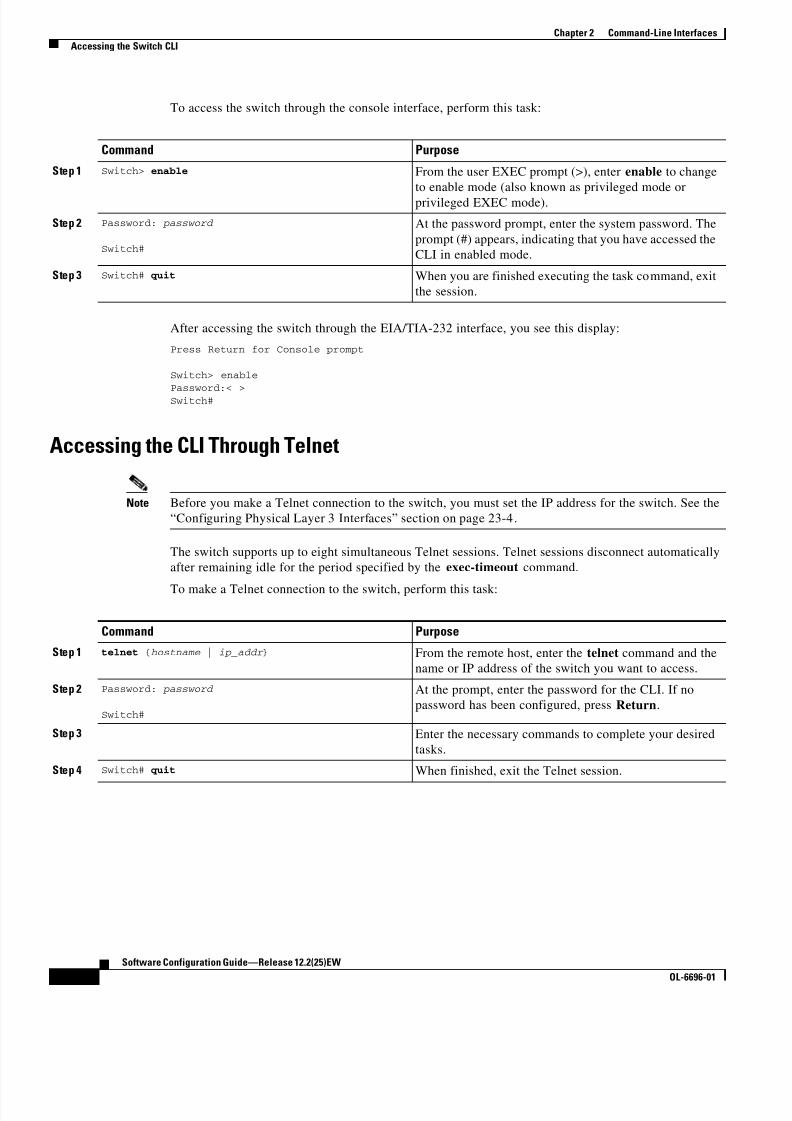
8/10/2019 Cisco ConfiguratioGuide SW4500 IOS
http://slidepdf.com/reader/full/cisco-configuratioguide-sw4500-ios 44/607
2-2
Software Configuration Guide—Release 12.2(25)EW
OL-6696-01
Chapter 2 Command-Line Interfaces
Accessing the Switch CLI
To access the switch through the console interface, perform this task:
After accessing the switch through the EIA/TIA-232 interface, you see this display:
Press Return for Console prompt
Switch> enable
Password:< >Switch#
Accessing the CLI Through Telnet
Note Before you make a Telnet connection to the switch, you must set the IP address for the switch. See the
“Configuring Physical Layer 3 Interfaces” section on page 23-4.
The switch supports up to eight simultaneous Telnet sessions. Telnet sessions disconnect automatically
after remaining idle for the period specified by the exec-timeout command.
To make a Telnet connection to the switch, perform this task:
Command Purpose
Step 1 Switch> enable From the user EXEC prompt (>), enter enable to change
to enable mode (also known as privileged mode or
privileged EXEC mode).
Step 2 Password: password
Switch#
At the password prompt, enter the system password. The
prompt (#) appears, indicating that you have accessed the
CLI in enabled mode.
Step 3 Switch# quit When you are finished executing the task command, exit
the session.
Command Purpose
Step 1 telnet {hostname | ip_addr } From the remote host, enter the telnet command and the
name or IP address of the switch you want to access.
Step 2 Password: password
Switch#
At the prompt, enter the password for the CLI. If no
password has been configured, press Return.
Step 3 Enter the necessary commands to complete your desired
tasks.
Step 4 Switch# quit When finished, exit the Telnet session.

8/10/2019 Cisco ConfiguratioGuide SW4500 IOS
http://slidepdf.com/reader/full/cisco-configuratioguide-sw4500-ios 45/607
2-3
Software Configuration Guide—Release 12.2(25)EW
OL-6696-01
Chapter 2 Command-Line Interfaces
Performing Command-Line Processing
This example shows how to open a Telnet session to the switch:
unix_host% telnet Switch_1Trying 172.20.52.40...
Connected to 172.20.52.40.Escape character is '^]'.
User Access Verification
Password:< >Switch_1> enable
Password:
Switch_1#
Performing Command-Line ProcessingSwitch commands are not case sensitive. You can abbreviate commands and parameters if the
abbreviations contain enough letters to be different from any other currently available commands or
parameters.
You can scroll through the last 20 commands stored in the history buffer and enter or edit a command at
the prompt. Table 2-1 lists the keyboard shortcuts for entering and editing switch commands.
Performing History SubstitutionThe history buffer stores the last 20 command lines you entered. History substitution allows you to
access these command lines without retyping them. Table 2-2 lists the history substitution commands.
Table 2-1 Keyboard Shortcuts
Keystrokes Result
Press Ctrl-B or
press the Left Arrow key1
1. The Arrow keys function only on ANSI-compatible terminals, such as VT100s.
Moves the cursor back one character.
Press Ctrl-F or
press the Right Arrow key1
Moves the cursor forward one character.
Press Ctrl-A Moves the cursor to the beginning of the command line.
Press Ctrl-E Moves the cursor to the end of the command line.
Press Esc-B Moves the cursor back one word.Press Esc-F Moves the cursor forward one word.
Table 2-2 History Substitution Commands
Command Purpose
Ctrl-P or the Up Arrow key1 Recalls commands in the history buffer, beginning with
the most recent command. Repeat the key sequence to
recall older commands successively.

8/10/2019 Cisco ConfiguratioGuide SW4500 IOS
http://slidepdf.com/reader/full/cisco-configuratioguide-sw4500-ios 46/607
2-4
Software Configuration Guide—Release 12.2(25)EW
OL-6696-01
Chapter 2 Command-Line Interfaces
Understanding Cisco IOS Command Modes
Understanding Cisco IOS Command Modes
Note For complete information about Cisco IOS command modes, refer to the Cisco IOS Configuration
Fundamentals Configuration Guide and the Cisco IOS Configuration Fundamentals Command Reference at: http://www.cisco.com/univercd/cc/td/doc/product/software/ios122/122cgcr/index.htm
The Cisco IOS user interface has many different modes: user EXEC, privileged EXEC (enable), global
configuration, interface, subinterface, and protocol-specific. The commands available to you depend on
which mode you are in. To get a list of the commands in a given mode, enter a question mark (?) at the
system prompt. See the “Getting a List of Commands and Syntax” section on page 2-5 for more
information.
When you start a session on the switch, you begin in user mode, also called user EXEC mode. Only a
small subset of commands are available in EXEC mode. To have access to all commands, you must enter
privileged EXEC mode, also called enable mode. To access the privileged EXEC mode, you must enter
a password. When you are in the privileged EXEC mode, you can enter any EXEC command or access
global configuration mode. Most EXEC commands are one-time commands, such as show commands,
which display the current configuration status, and clear commands, which reset counters or interfaces.
The EXEC commands are not saved when the switch is rebooted.
The configuration modes allow you to make changes to the running configuration. If you save the
configuration, these commands are stored when you reboot the switch. You must start in global
configuration mode. From global configuration mode, you can enter interface configuration mode,
subinterface configuration mode, and a variety of protocol-specific modes.
You would use a separate mode called ROMMON when the switch cannot boot up properly. For example,
the switch might enter ROMMON mode if it does not find a valid system image when it is booting, or if
its configuration file is corrupted. For more information, see the “ROMMOM Command-Line Interface”
section on page 2-6.
Table 2-3 lists and describes frequently used Cisco IOS modes.
Ctrl-N or the Down Arrow key1 Returns to more recent commands in the history buffer
after commands have been recalled with Ctrl-P or the
Up Arrow key. Repeat the key sequence to recall morerecent commands.
Switch# show history Lists the last several commands you have entered in
EXEC mode.
1. The Arrow keys function only on ANSI-compatible terminals such as VT100s.
Table 2-2 History Substitution Commands (continued)
Command Purpose

8/10/2019 Cisco ConfiguratioGuide SW4500 IOS
http://slidepdf.com/reader/full/cisco-configuratioguide-sw4500-ios 47/607
2-5
Software Configuration Guide—Release 12.2(25)EW
OL-6696-01
Chapter 2 Command-Line Interfaces
Getting a List of Commands and Syntax
The Cisco IOS command interpreter, called the EXEC, interprets and runs the commands you enter. You
can abbreviate commands and keywords by entering just enough characters to make the command uniquefrom other commands. For example, you can abbreviate the show command to sh and the configure
terminal command to config t.
When you type exit, the switch backs out one level. To exit configuration mode completely and return
to privileged EXEC mode, press Ctrl-Z.
Getting a List of Commands and SyntaxIn any command mode, you can get a list of available commands by entering a question mark (?).
Switch> ?
To obtain a list of commands that begin with a particular character sequence, enter those charactersfollowed by the question mark (?). Do not include a space before the question mark. This form of help
is called word help, because it completes a word for you.
Table 2-3 Frequently Used Cisco IOS Command Modes
Mode What You Use It For How to Access Prompt
User EXEC To connect to remote devices,
change terminal settings on a
temporary basis, perform basictests, and display system
information.
Log in. Switch>
Privileged EXEC (enable) To set operating parameters. The
privileged command set includes
the commands in user EXEC
mode, as well as the configure
command. Use the configure
command to access the other
command modes.
From user EXEC mode, enter the
enable command and the enable
password (if a password has been
configured).
Switch#
Global configuration To configure features that affect
the system as a whole, such as the
system time or switch name.
From privileged EXEC mode,
enter the configure terminal
command.
Switch(config)#
Interface configuration To enable or modify the operation
of a 10-Gigabit Ethernet, Gigabit
Ethernet, or Fast Ethernet interface
with interface commands.
From global configuration mode,
enter the interface type location
command.
Switch(config-if)#
Console configuration To configure the console interface;
from the directly connected
console or the virtual terminal;
used with Telnet.
From global configuration mode,
enter the line console 0 command.
Switch(config-line)#

8/10/2019 Cisco ConfiguratioGuide SW4500 IOS
http://slidepdf.com/reader/full/cisco-configuratioguide-sw4500-ios 48/607
2-6
Software Configuration Guide—Release 12.2(25)EW
OL-6696-01
Chapter 2 Command-Line Interfaces
ROMMOM Command-Line Interface
To list keywords or arguments, enter a question mark in place of a keyword or argument. Include a space
before the question mark. This form of help is called command syntax help, because it reminds you
which keywords or arguments are applicable based on the command, keywords, and arguments you have
already entered.
Switch# configure ?
memory Configure from NV memory
network Configure from a TFTP network host
overwrite-network Overwrite NV memory from TFTP network host terminal Configure from the terminal
<cr>
To redisplay a command you previously entered, press the Up Arrow key or Ctrl-P. You can continue
to press the Up Arrow key to see the last 20 commands you entered.
Tip If you are having trouble entering a command, check the system prompt and enter the question mark (?)
for a list of available commands. You might be in the wrong command mode or using incorrect syntax.
Type exit to return to the previous mode. Press Ctrl-Z or enter the end command in any mode to
immediately return to privileged EXEC mode.
ROMMOM Command-Line InterfaceROMMON is a ROM-based program that is involved at power-up or reset, or when a fatal exception error
occurs. The switch enters ROMMON mode if the switch does not find a valid software image, if the
NVRAM configuration is corrupted, or if the configuration register is set to enter ROMMON mode.
From the ROMMON mode, you can load a software image manually from Flash memory, from a network
server file, or from bootflash.
You can also enter ROMMON mode by restarting the switch and pressing Ctrl-C during the first five
seconds of startup.
Note Ctrl-C is always enabled for 60 seconds after you reboot the switch, even if Ctrl-C is configured to be
off in the configuration register settings.
When you enter ROMMON mode, the prompt changes to rommon 1>. Use the ? command to see the
available ROMMON commands.
For more information about the ROMMON commands, refer to the
Catalyst 4500 Series Switch Cisco IOS Command Reference.

8/10/2019 Cisco ConfiguratioGuide SW4500 IOS
http://slidepdf.com/reader/full/cisco-configuratioguide-sw4500-ios 49/607
C H A P T E R
3-1
Software Configuration Guide—Release 12.2(25)EW
OL-6696-01
3
Configuring the Switch for the First Time
This chapter describes how to initially configure a Catalyst 4500 series switch. The information
presented here supplements the administration information and procedures in these publications:
• Cisco IOS Configuration Fundamentals Configuration Guide, Release 12.2, at this URL:
http://www.cisco.com/univercd/cc/td/doc/product/software/ios122/122cgcr/fun_c/index.htm
• Cisco IOS Configuration Fundamentals Configuration Command Reference , Release 12.2, at this
URL:
http://www.cisco.com/univercd/cc/td/doc/product/software/ios122/122cgcr/fun_r/index.htm
This chapter includes the following major sections:
• Default Switch Configuration, page 3-1
• Configuring DHCP-Based Autoconfiguration, page 3-2
• Configuring the Switch, page 3-8
• Controlling Access to Privileged EXEC Commands, page 3-13
• Recovering a Lost Enable Password, page 3-18
• Modifying the Supervisor Engine Startup Configuration, page 3-18
Note For complete syntax and usage information for the switch commands used in this chapter, refer to the
Catalyst 4500 Series Switch Cisco IOS Command Reference and related publications at
http://www.cisco.com/univercd/cc/td/doc/product/software/ios122/122cgcr/index.htm
Default Switch ConfigurationThis section describes the default configurations for the Catalyst 4500 series switch. Table 3-1 shows the
default configuration settings for each feature.
Table 3-1 Default Switch Configuration
Feature Default Settings
Administrative connection Normal mode
Global switch information No default value for system name, system contact, and location
System clock No value for system clock time

8/10/2019 Cisco ConfiguratioGuide SW4500 IOS
http://slidepdf.com/reader/full/cisco-configuratioguide-sw4500-ios 50/607
3-2
Software Configuration Guide—Release 12.2(25)EW
OL-6696-01
Chapter 3 Configuring the Switch for the First Time
Configuring DHCP-Based Autoconfiguration
Configuring DHCP-Based AutoconfigurationThese sections describe how to configure DHCP-based autoconfiguration.
• Understanding DHCP-Based Autoconfiguration, page 3-2
• DHCP Client Request Process, page 3-3
•Configuring the DHCP Server, page 3-3
• Configuring the TFTP Server, page 3-4
• Configuring the DNS Server, page 3-5
• Configuring the Relay Device, page 3-5
• Obtaining Configuration Files, page 3-6
• Example Configuration, page 3-7
If your DHCP server is a Cisco device, or if you are configuring the switch as a DHCP server, refer to
the “ IP Addressing and Services” section in the Cisco IOS IP and IP Routing Configuration Guide for
Cisco IOS Release 12.1 for additional information about configuring DHCP.
Understanding DHCP-Based Autoconfiguration
Note Starting with Release 12.2(20)EW, you can enable DHCP AutoConfiguration by issuing the write erase
command. This command clears the startup-config in NVRAM. In images prior to Release 12.2(20)EW,
this command will not enable autoconfiguration.
DHCP provides configuration information to Internet hosts and internetworking devices. This protocol
consists of two components: one component for delivering configuration parameters from a DHCP
server to a device and another component that is a mechanism for allocating network addresses to
devices. DHCP is built on a client-server model, in which designated DHCP servers allocate network
addresses and deliver configuration parameters to dynamically configured devices. The switch can act
as both a DHCP client and a DHCP server.
With DHCP-based autoconfiguration, no DHCP client-side configuration is needed on your switch
because your switch (the DHCP client) is automatically configured at startup with IP address
information and a configuration file. However, you need to configure the DHCP server or the DHCP
server feature on your switch for various lease options associated with IP addresses. If you are using
DHCP to relay the configuration file location on the network, you might also need to configure a Trivial
File Transfer Protocol (TFTP) server and a Domain Name System (DNS) server.
DHCP-based autoconfiguration replaces the BOOTP client functionality on your switch.
Passwords No passwords are configured for normal mode or enable mode
(press the Return key)
Switch prompt Switch>
Interfaces Enabled, with speed and flow control autonegotiated, and without
IP addresses
Table 3-1 Default Switch Configuration (continued)
Feature Default Settings
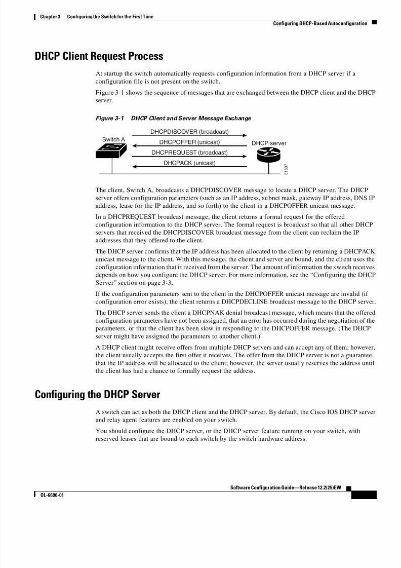
8/10/2019 Cisco ConfiguratioGuide SW4500 IOS
http://slidepdf.com/reader/full/cisco-configuratioguide-sw4500-ios 51/607
3-3
Software Configuration Guide—Release 12.2(25)EW
OL-6696-01
Chapter 3 Configuring the Switch for the First Time
Configuring DHCP-Based Autoconfiguration
DHCP Client Request Process
At startup the switch automatically requests configuration information from a DHCP server if a
configuration file is not present on the switch.
Figure 3-1 shows the sequence of messages that are exchanged between the DHCP client and the DHCP
server.
Figure 3-1 DHCP Client and Server Message Exchange
The client, Switch A, broadcasts a DHCPDISCOVER message to locate a DHCP server. The DHCP
server offers configuration parameters (such as an IP address, subnet mask, gateway IP address, DNS IPaddress, lease for the IP address, and so forth) to the client in a DHCPOFFER unicast message.
In a DHCPREQUEST broadcast message, the client returns a formal request for the offered
configuration information to the DHCP server. The formal request is broadcast so that all other DHCP
servers that received the DHCPDISCOVER broadcast message from the client can reclaim the IP
addresses that they offered to the client.
The DHCP server confirms that the IP address has been allocated to the client by returning a DHCPACK
unicast message to the client. With this message, the client and server are bound, and the client uses the
configuration information that i t received from the server. The amount of information the switch receives
depends on how you configure the DHCP server. For more information, see the “Configuring the DHCP
Server” section on page 3-3.
If the configuration parameters sent to the client in the DHCPOFFER unicast message are invalid (if
configuration error exists), the client returns a DHCPDECLINE broadcast message to the DHCP server
The DHCP server sends the client a DHCPNAK denial broadcast message, which means that the offered
configuration parameters have not been assigned, that an error has occurred during the negotiation of the
parameters, or that the client has been slow in responding to the DHCPOFFER message. (The DHCP
server might have assigned the parameters to another client.)
A DHCP client might receive offers from multiple DHCP servers and can accept any of them; however,
the client usually accepts the first offer it receives. The offer from the DHCP server is not a guarantee
that the IP address will be allocated to the client; however, the server usually reserves the address until
the client has had a chance to formally request the address.
Configuring the DHCP ServerA switch can act as both the DHCP client and the DHCP server. By default, the Cisco IOS DHCP server
and relay agent features are enabled on your switch.
You should configure the DHCP server, or the DHCP server feature running on your switch, with
reserved leases that are bound to each switch by the switch hardware address.
Switch A
DHCPACK (unicast)
DHCPREQUEST (broadcast)
DHCPOFFER (unicast)
DHCPDISCOVER (broadcast)
DHCP server
5 1 8 0 7

8/10/2019 Cisco ConfiguratioGuide SW4500 IOS
http://slidepdf.com/reader/full/cisco-configuratioguide-sw4500-ios 52/607
3-4
Software Configuration Guide—Release 12.2(25)EW
OL-6696-01
Chapter 3 Configuring the Switch for the First Time
Configuring DHCP-Based Autoconfiguration
If you want the switch to receive IP address information, you must configure the DHCP server with these
lease options:
• IP address of the client (required)
• Subnet mask of the client (required)
• DNS server IP address (optional)
• Router IP address (required)
Note The router IP address is the default gateway address for the switch.
If you want the switch to receive the configuration file from a TFTP server, you must configure the
DHCP server with these lease options:
• TFTP server name or IP address (required)
• Boot filename (the name of the configuration file that the client needs) (recommended)
• Host name (optional)
Depending on the settings of the DHCP server or the DHCP server feature running on your switch, theswitch can receive IP address information, the configuration file, or both.
If you do not configure the DHCP server, or the DHCP server feature running on your switch, with the
lease options described earlier, the switch replies to client requests with only those parameters that are
configured. If the IP address and subnet mask are not in the reply, the switch is not configured. If the
router IP address or TFTP server name (or IP address) are not found, the switch might send broadcast,
instead of unicast, TFTP requests. Unavailability of other lease options does not impact
autoconfiguration.
The DHCP server, or the DHCP server feature running on your switch, can be on the same LAN or on a
different LAN than the switch. If the DHCP server is running on a different LAN, you should configure
a DHCP relay, which forwards broadcast traffic between two directly connected LANs. A router does
not forward broadcast packets, but it forwards packets based on the destination IP address in the received
packet. For more information on relay devices, see the “Configuring the Relay Device” section onpage 3-5.
Configuring the TFTP Server
Based on the DHCP server configuration, the switch attempts to download one or more configuration
files from the TFTP server. If you configured the DHCP server to respond to the switch with all the
options required for IP connectivity to the TFTP server, and if you configured the DHCP server with a
TFTP server name, address, and configuration filename, the switch attempts to download the specified
configuration file from the specified TFTP server.
If you did not specify the configuration filename or the TFTP server name, or if the configuration file
could not be downloaded, the switch attempts to download a configuration file using variouscombinations of filenames and TFTP server addresses. The files include the specified configuration
filename (if any) and the following files: network-confg, cisconet.cfg, hostname.confg, or hostname.cfg,
where hostname is the current hostname of the switch and router-confg and ciscortr.cfg. The TFTP server
addresses used include the specified TFTP server address (if any) and the broadcast address
(255.255.255.255).

8/10/2019 Cisco ConfiguratioGuide SW4500 IOS
http://slidepdf.com/reader/full/cisco-configuratioguide-sw4500-ios 53/607
3-5
Software Configuration Guide—Release 12.2(25)EW
OL-6696-01
Chapter 3 Configuring the Switch for the First Time
Configuring DHCP-Based Autoconfiguration
For the switch to successfully download a configuration file, the TFTP server must contain one or more
configuration files in its base directory. The files can include the following:
• The configuration file named in the DHCP reply (the actual switch configuration file).
• The network-confg or the cisconet.cfg file (known as the default configuration files).
• The router-confg or the ciscortr.cfg file. (These files contain commands common to all switches.
Normally, if the DHCP and TFTP servers are properly configured, these files are not accessed.)
If you specify the TFTP server name in the DHCP server-lease database, you must also configure the
TFTP server name-to-IP-address mapping in the DNS-server database.
If the TFTP server you plan to use is on a different LAN from the switch, or if it is to be accessed by the
switch through the broadcast address (which occurs if the DHCP server response does not contain all the
required information described earlier), a relay must be configured to forward the TFTP packets to the
TFTP server. For more information, see the “Configuring the Relay Device” section on page 3-5. The
preferred solution is to configure either the DHCP server or the DHCP server feature running on your
switch with all the required information.
Configuring the DNS ServerThe DHCP server, or the DHCP server feature running on your switch, uses the DNS server to resolve
the TFTP server name to an IP address. You must configure the TFTP server name-to-IP address map on
the DNS server. The TFTP server contains the configuration files for the switch.
You can configure the IP addresses of the DNS servers in the lease database of the DHCP server where
the DHCP replies will retrieve them. You can enter up to two DNS server IP addresses in the lease
database.
The DNS server can be on the same or on a different LAN as the switch. If it is on a different LAN, the
switch must be able to access it through a router.
Configuring the Relay DeviceYou must configure a relay device to forward received broadcast packets to the destination host whenever
a switch sends broadcast packets to which a host on a different LAN must respond. Examples of such
broadcast packets are DHCP, DNS, and in some cases, TFTP packets.
If the relay device is a Cisco router, enable IP routing ( ip routing global configuration command), and
configure helper addresses (ip helper-address interface configuration command). For example, in
Figure 3-2, configure the router interfaces as follows:
On interface 10.0.0.2:
router(config-if)# ip helper-address 20.0.0.2
router(config-if)# ip helper-address 20.0.0.3
router(config-if)# ip helper-address 20.0.0.4
On interface 20.0.0.1
router(config-if)# ip helper-address 10.0.0.1

8/10/2019 Cisco ConfiguratioGuide SW4500 IOS
http://slidepdf.com/reader/full/cisco-configuratioguide-sw4500-ios 54/607
3-6
Software Configuration Guide—Release 12.2(25)EW
OL-6696-01
Chapter 3 Configuring the Switch for the First Time
Configuring DHCP-Based Autoconfiguration
Figure 3-2 Relay Device Used in Autoconfiguration
Obtaining Configuration Files
Depending on the availability of the IP address and the configuration filename in the DHCP reserved
lease, the switch obtains its configuration information in these ways:
• The IP address and the configuration filename are reserved for the switch and provided in the DHCP
reply (one-file read method).
The switch receives its IP address, subnet mask, TFTP server address, and the configuration
filename from either the DHCP server or the DHCP server feature running on your switch. The
switch sends a unicast message to the TFTP server to retrieve the named configuration file from the
base directory of the server, and upon receipt, completes its boot-up process.
• The IP address and the configuration filename is reserved for the switch, but the TFTP server
address is not provided in the DHCP reply (one-file read method).
The switch receives its IP address, subnet mask, and the configuration filename from either theDHCP server or the DHCP server feature running on your switch. The switch sends a broadcast
message to a TFTP server to retrieve the named configuration file from the base directory of the
server, and upon receipt, completes its boot-up process.
• Only the IP address is reserved for the switch and provided in the DHCP reply. The configuration
filename is not provided (two-file read method).
The switch receives its IP address, subnet mask, and the TFTP server address from either the DHCP
server or the DHCP server feature running on your switch. The switch sends a unicast message to
the TFTP server to retrieve the network-confg or cisconet.cfg default configuration file. (If the
network-confg file cannot be read, the switch reads the cisconet.cfg file.)
The default configuration file contains the host names-to-IP-address mapping for the switch. The
switch fills its host table with the information in the file and obtains its host name. If the host name
is not found in the file, the switch uses the host name in the DHCP reply. If the host name is not
specified in the DHCP reply, the switch uses the default Switch as its host name.
After obtaining its host name from the default configuration file or the DHCP reply, the switch reads
the configuration file that has the same name as its host name (hostname-confg or hostname.cfg,
depending on whether or not the network-confg file or the cisconet.cfg file was read earlier) from
the TFTP server. If the cisconet.cfg file is read, the filename of the host is truncated to eight
characters.
Switch(DHCP client)
Cisco router(Relay)
4 9 0 6 8
DHCP server TFTP server DNS server
20.0.0.2 20.0.0.3
20.0.0.1
10.0.0.2
10.0.0.1
20.0.0.4

8/10/2019 Cisco ConfiguratioGuide SW4500 IOS
http://slidepdf.com/reader/full/cisco-configuratioguide-sw4500-ios 55/607
3-7
Software Configuration Guide—Release 12.2(25)EW
OL-6696-01
Chapter 3 Configuring the Switch for the First Time
Configuring DHCP-Based Autoconfiguration
If the switch cannot read the network-confg, cisconet.cfg, or the hostname file, it reads the
router-confg file. If the switch cannot read the router-confg file, it reads the ciscortr.cfg file.
Note The switch broadcasts TFTP server requests provided that one of these conditions is met: 1) the TFTP
server is not obtained from the DHCP replies; 2) all attempts to read the configuration file through
unicast transmissions fail, or 3) the TFTP server name cannot be resolved to an IP address.
Example Configuration
Figure 3-3 shows a sample network for retrieving IP information using DHCP-based autoconfiguration.
Figure 3-3 DHCP-Based Autoconfiguration Network Example
Table 3-2 shows the configuration of the reserved leases on either the DHCP server or the DHCP server
feature running on your switch.
Switch 100e0.9f1e.2001
Cisco router
4 9 0 6 6
Switch 200e0.9f1e.2002
Switch 300e0.9f1e.2003
DHCP server DNS server TFTP server(maritsu)
10.0.0.1
10.0.0.10
10.0.0.2 10.0.0.3
Switch 400e0.9f1e.2004
Table 3-2 DHCP Server Configuration
Switch 1 Switch 2 Switch 3 Switch 4
Binding key
(hardware address)
00e0.9f1e.2001 00e0.9f1e.2002 00e0.9f1e.2003 00e0.9f1e.2004
IP address 10.0.0.21 10.0.0.22 10.0.0.23 10.0.0.24
Subnet mask 255.255.255.0 255.255.255.0 255.255.255.0 255.255.255.0
Router address 10.0.0.10 10.0.0.10 10.0.0.10 10.0.0.10
DNS server address 10.0.0.2 10.0.0.2 10.0.0.2 10.0.0.2
TFTP server name maritsu or 10.0.0.3 maritsu or 10.0.0.3 maritsu or 10.0.0.3 maritsu or 10.0.0.3
Boot filename
(configuration file)
(optional)
switch1-confg switch2-confg switch3-confg switch4-confg
Host name (optional) switch1 switch2 switch3 switch4

8/10/2019 Cisco ConfiguratioGuide SW4500 IOS
http://slidepdf.com/reader/full/cisco-configuratioguide-sw4500-ios 56/607
3-8
Software Configuration Guide—Release 12.2(25)EW
OL-6696-01
Chapter 3 Configuring the Switch for the First Time
Configuring the Switch
DNS Server Configuration
The DNS server maps the TFTP server name maritsu to IP address 10.0.0.3.
TFTP Server Configuration (on UNIX)
The TFTP server base directory is set to /tftpserver/work/. This directory contains the network-confg file
used in the two-file read method. This file contains the host name to be assigned to the switch based on
its IP address. The base directory also contains a configuration file for each switch ( switch1-confg,
switch2-confg, and so forth) as shown in the following display:
prompt> cd /tftpserver/work/prompt> ls
network-confgswitch1-confg
switch2-confg
switch3-confg
switch4-confgprompt> cat network-confg
ip host switch1 10.0.0.21ip host switch2 10.0.0.22
ip host switch3 10.0.0.23
ip host switch4 10.0.0.24
DHCP Client Configuration
No configuration file is present on Switch 1 through Switch 4.
Configuration Explanation
In Figure 3-3, Switch 1 reads its configuration file as follows:
• Switch 1 obtains its IP address 10.0.0.21 from the DHCP server.
• If no configuration filename is given in the DHCP server reply, Switch 1 reads the network-confg
file from the base directory of the TFTP server.
• Switch 1 adds the contents of the network-confg file to its host table.
• Switch 1 reads its host table by indexing its IP address 10.0.0.21 to its host name (switch1).
• Switch 1 reads the configuration file that corresponds to its host name; for example, it reads
switch1-confg from the TFTP server.
Switches 2 through 4 retrieve their configuration files and IP addresses in the same way.
Configuring the SwitchThe following sections describe how to configure your switch:
• Using Configuration Mode to Configure Your Switch, page 3-9
• Checking the Running Configuration Settings, page 3-9
• Saving the Running Configuration Settings to Your Start-up File, page 3-10
• Reviewing the Configuration in NVRAM, page 3-10
• Configuring a Default Gateway, page 3-11
• Configuring a Static Route, page 3-11

8/10/2019 Cisco ConfiguratioGuide SW4500 IOS
http://slidepdf.com/reader/full/cisco-configuratioguide-sw4500-ios 57/607
3-9
Software Configuration Guide—Release 12.2(25)EW
OL-6696-01
Chapter 3 Configuring the Switch for the First Time
Configuring the Switch
Using Configuration Mode to Configure Your Switch
To configure your switch from configuration mode, perform this procedure:
Step 1 Connect a console terminal to the console interface of your supervisor engine.
Step 2 After a few seconds, you will see the user EXEC prompt ( Switch>). Now, you may want to enter
privileged EXEC mode, also known as enable mode. Type enable to enter enable mode:
Switch> enable
Note You must be in enable mode to make configuration changes.
The prompt will change to the enable prompt (#):
Switch#
Step 3 At the enable prompt (#), enter the configure terminal command to enter global configuration mode:
Switch# configure terminalEnter configuration commands, one per line. End with CNTL/Z.
Switch(config)#
Step 4 At the global configuration mode prompt, enter the interface type slot/interface command to enter
interface configuration mode:
Switch(config)# interface fastethernet 5/1
Switch(config-if)#
Step 5 In either of these configuration modes, enter changes to the switch configuration.
Step 6 Enter the end command to exit configuration mode.
Step 7 Save your settings. (See the “Saving the Running Configuration Settings to Your Start-up File” section
on page 3-10.)
Your switch is now minimally configured and can boot with the configuration you entered. To see a list
of the configuration commands, enter ? at the prompt or press the help key in configuration mode.
Checking the Running Configuration Settings
To verify the configuration settings you entered or the changes you made, enter the show
running-config command at the enable prompt (#), as shown in this example:
Switch# show running-config
Building configuration...
Current configuration:
!version 12.0
service timestamps debug uptimeservice timestamps log uptime
no service password-encryption!

8/10/2019 Cisco ConfiguratioGuide SW4500 IOS
http://slidepdf.com/reader/full/cisco-configuratioguide-sw4500-ios 58/607
3-10
Software Configuration Guide—Release 12.2(25)EW
OL-6696-01
Chapter 3 Configuring the Switch for the First Time
Configuring the Switch
hostname Switch
<...output truncated...>
!line con 0
transport input none
line vty 0 4 exec-timeout 0 0 password lab
login transport input lat pad dsipcon mop telnet rlogin udptn nasi
!
endSwitch#
Saving the Running Configuration Settings to Your Start-up File
Caution This command saves the configuration settings that you created in configuration mode. If you fail to dothis step, your configuration will be lost the next time you reload the system.
To store the configuration, changes to the configuration, or changes to the startup configuration in
NVRAM, enter the copy running-config startup-config command at the enable prompt (#), as follows:
Switch# copy running-config startup-config
Reviewing the Configuration in NVRAM
To display information stored in NVRAM, enter the show startup-config EXEC command.
The following example shows a typical system configuration:
Switch# show startup-config
Using 1579 out of 491500 bytes, uncompressed size = 7372 bytesUncompressed configuration from 1579 bytes to 7372 bytes
!
version 12.1no service pad
service timestamps debug uptime
service timestamps log uptime
no service password-encryptionservice compress-config
!hostname Switch
!
!
ip subnet-zero
!
!!
!interface GigabitEthernet1/1
no snmp trap link-status
!
interface GigabitEthernet1/2 no snmp trap link-status
!--More--

8/10/2019 Cisco ConfiguratioGuide SW4500 IOS
http://slidepdf.com/reader/full/cisco-configuratioguide-sw4500-ios 59/607
3-11
Software Configuration Guide—Release 12.2(25)EW
OL-6696-01
Chapter 3 Configuring the Switch for the First Time
Configuring the Switch
<...output truncated...>
!line con 0
exec-timeout 0 0 transport input none
line vty 0 4
exec-timeout 0 0 password lab login
transport input lat pad dsipcon mop telnet rlogin udptn nasi!
end
Switch#
Configuring a Default Gateway
Note The switch uses the default gateway only when it is not configured with a routing protocol.
Configure a default gateway to send data to subnets other than its own when the switch is not configured
with a routing protocol. The default gateway must be the IP address of an interface on a router that is
directly connected to the switch.
To configure a default gateway, perform this task:
This example shows how to configure a default gateway and how to verify the configuration:
Switch# configure terminal
Enter configuration commands, one per line. End with CNTL/Z.
Switch(config)# ip default-gateway 172.20.52.35
Switch(config)# end3d17h: %SYS-5-CONFIG_I: Configured from console by console
Switch# show ip routeDefault gateway is 172.20.52.35
Host Gateway Last Use Total Uses Interface
ICMP redirect cache is emptySwitch#
Configuring a Static Route
If your Telnet station or SNMP network management workstation is on a different network from your
switch and a routing protocol has not been configured, you might need to add a s tatic routing table entry
for the network where your end station is located.
Command Purpose
Step 1 Switch(config)# ip default-gateway IP-address Configures a default gateway.
Step 2 Switch# show ip route Verifies that the default gateway is correctly displayed in
the IP routing table.

8/10/2019 Cisco ConfiguratioGuide SW4500 IOS
http://slidepdf.com/reader/full/cisco-configuratioguide-sw4500-ios 60/607
3-12
Software Configuration Guide—Release 12.2(25)EW
OL-6696-01
Chapter 3 Configuring the Switch for the First Time
Configuring the Switch
To configure a static route, perform this task:
This example shows how to use the ip route command to configure a static route to a workstation at IP
address 171.10.5.10 on the switch with a subnet mask and IP address 172.20.3.35 of the forwarding
router:
Switch# configure terminal
Enter configuration commands, one per line. End with CNTL/Z.Switch(config)# ip route 171.10.5.10 255.255.255.255 172.20.3.35
Switch(config)# end
Switch#
This example shows how to use the show running-config command to confirm the configuration of the
static route:
Switch# show running-config
Building configuration...
.
<...output truncated...>.
ip default-gateway 172.20.52.35ip classless
ip route 171.10.5.10 255.255.255.255 172.20.3.35
no ip http server
!line con 0
transport input noneline vty 0 4
exec-timeout 0 0
password lab login transport input lat pad dsipcon mop telnet rlogin udptn nasi
!end
Switch#
This example shows how to use the ip route command to configure the static route IP address 171.20.5.3
with subnet mask and connected over VLAN 1 to a workstation on the switch:
Switch# configure terminal
Switch(config)# ip route 171.20.5.3 255.255.255.255 vlan 1
Switch(config)# end
Switch#
This example shows how to use the show running-config command to confirm the configuration of the
static route:
Switch# show running-config
Building configuration....
<...output truncated...>
.
Command Purpose
Step 1 Switch(config)# ip route dest_IP_address mask {forwarding_IP | vlan vlan_ID }
Configures a static route to the remote network.
Step 2 Switch# show running-config Verifies that the static route is displayed correctly.

8/10/2019 Cisco ConfiguratioGuide SW4500 IOS
http://slidepdf.com/reader/full/cisco-configuratioguide-sw4500-ios 61/607
3-13
Software Configuration Guide—Release 12.2(25)EW
OL-6696-01
Chapter 3 Configuring the Switch for the First Time
Controlling Access to Privileged EXEC Commands
ip default-gateway 172.20.52.35
ip classless
ip route 171.20.5.3 255.255.255.255 Vlan1no ip http server
!!
x25 host z
!line con 0 transport input none
line vty 0 4 exec-timeout 0 0
password lab
login transport input lat pad dsipcon mop telnet rlogin udptn nasi
!
end
Switch#
Controlling Access to Privileged EXEC CommandsThe procedures in these sections let you control access to the system configuration file and privileged
EXEC commands:
• Setting or Changing a Static enable Password, page 3-13
• Using the enable password and enable secret Commands, page 3-14
• Setting or Changing a Privileged Password, page 3-14
• Setting TACACS+ Password Protection for Privileged EXEC Mode, page 3-15
• Encrypting Passwords, page 3-15
• Configuring Multiple Privilege Levels, page 3-16
Setting or Changing a Static enable Password
To set or change a static password that controls access to the enable mode, perform this task:
This example shows how to configure an enable password as “lab” at the privileged EXEC mode:
Switch# configure terminalSwitch(config)# enable password lab
Switch(config)#
For instructions on how to display the password or access level configuration, see the “Displaying the
Password, Access Level, and Privilege Level Configuration” section on page 3-17.
Command Purpose
Switch(config)# enable password password Sets a new password or changes an existing
password for the privileged EXEC mode.

8/10/2019 Cisco ConfiguratioGuide SW4500 IOS
http://slidepdf.com/reader/full/cisco-configuratioguide-sw4500-ios 62/607
3-14
Software Configuration Guide—Release 12.2(25)EW
OL-6696-01
Chapter 3 Configuring the Switch for the First Time
Controlling Access to Privileged EXEC Commands
Using the enable password and enable secret Commands
To provide an additional layer of security, particularly for passwords that cross the network or that are
stored on a TFTP server, you can use either the enable password or enable secret command. Both
commands configure an encrypted password that you must enter to access the enable mode (the default)
or any other privilege level that you specify.We recommend that you use the enable secret command.
If you configure the enable secret command, it takes precedence over the enable password command;
the two commands cannot be in effect simultaneously.
To configure the switch to require an enable password, perform either one of these tasks:
When you enter either of these password commands with the level option, you define a password for a
specific privilege level. After you specify the level and set a password, give the password only to users
who need to have access at this level. Use the privilege level configuration command to specify
commands accessible at various levels.
If you enable the service password-encryption command, the password you enter is encrypted. When
you display the password with the more system:running-config command, the password displays the
password in encrypted form.
If you specify an encryption type, you must provide an encrypted password—an encrypted password you
copy from another Catalyst 4500 series switch configuration.
Note You cannot recover a lost encrypted password. You must clear NVRAM and set a new password. See the
“Recovering a Lost Enable Password” section on page 3-18 for more information.
For information on how to display the password or access level configuration, see the “Displaying the
Password, Access Level, and Privilege Level Configuration” section on page 3-17.
Setting or Changing a Privileged PasswordTo set or change a privileged password, perform this task:
Command Purpose
Switch(config)# enable password [level level] { password | encryption-type
encrypted-password }
Establishes a password for the privileged EXEC
mode.
Switch(config)# enable secret [level
level] { password | encryption-typeencrypted-password }
Specifies a secret password that will be saved using
a nonreversible encryption method. (If
enable password and enable secret commands are
both set, users must enter the enable secret
password.)
Command Purpose
Switch(config-line)# password password Sets a new password or changes an existing password
for the privileged level.

8/10/2019 Cisco ConfiguratioGuide SW4500 IOS
http://slidepdf.com/reader/full/cisco-configuratioguide-sw4500-ios 63/607
3-15
Software Configuration Guide—Release 12.2(25)EW
OL-6696-01
Chapter 3 Configuring the Switch for the First Time
Controlling Access to Privileged EXEC Commands
For information on how to display the password or access level configuration, see the “Displaying the
Password, Access Level, and Privilege Level Configuration” section on page 3-17.
Setting TACACS+ Password Protection for Privileged EXEC Mode
For complete information about TACACS+ and RADIUS, refer to these publications:
• The “Authentication, Authorization, and Accounting (AAA)” chapter in the Cisco IOS Security
Configuration Guide, Release 12.2, at the following URL:
http://www.cisco.com/univercd/cc/td/doc/product/software/ios122/122cgcr/secur_c/scprt1/index.htm
• Cisco IOS Security Command Reference, Release 12.2, at the following URL:
http://www.cisco.com/univercd/cc/td/doc/product/software/ios122/122cgcr/secur_r/index.htm
To set the TACACS+ protocol to determine whether or not a user can access the privileged EXEC mode,
perform this task:
When you set TACACS password protection at the privileged EXEC mode, the enable EXEC command
prompts you for a new username and a new password. This information is then passed to the TACACS+
server for authentication.
If you use extended TACACS, another extension to the older TACACS protocol that provides additional
functionality, it also passes any existing UNIX user identification code to the TACACS+ server.
Extended TACACS provides information about protocol translator and router use. This information is
used in UNIX auditing trails and accounting files.
Note When used without extended TACACS, the enable use-tacacs command allows anyone with a valid
username and password to access the privileged EXEC mode, creating a potential security risk. This
problem occurs because the query resulting from enter ing the enable command is indistinguishable from
an attempt to log in without extended TACACS.
Encrypting Passwords
Because protocol analyzers can examine packets (and read passwords), you can increase access security
by configuring the Cisco IOS software to encrypt passwords. Encryption prevents the password from
being readable in the configuration file.
To configure the Cisco IOS software to encrypt passwords, perform this task:
Command Purpose
Switch(config)# enable use-tacacs Sets the TACACS-style user ID andpassword-checking mechanism for the privileged
EXEC mode.
Command Purpose
Switch(config)# service password-encryption Encrypts a password.

8/10/2019 Cisco ConfiguratioGuide SW4500 IOS
http://slidepdf.com/reader/full/cisco-configuratioguide-sw4500-ios 64/607
3-16
Software Configuration Guide—Release 12.2(25)EW
OL-6696-01
Chapter 3 Configuring the Switch for the First Time
Controlling Access to Privileged EXEC Commands
Encryption occurs when the current configuration is written or when a password is configured. Password
encryption is applied to all passwords, including authentication key passwords, the privileged command
password, console and virtual terminal line access passwords, and Border Gateway Protocol (BGP)
neighbor passwords. The service password-encryption command keeps unauthorized individuals from
viewing your password in your configuration file.
Caution The service password-encryption command does not provide a high level of network security. If you
use this command, you should also take additional network security measures.
Although you cannot recover a lost encrypted password (that is, you cannot get the original password
back), you can regain control of the switch after having lost or forgotten the encrypted password. See
the “Recovering a Lost Enable Password” section on page 3-18 for more information.
For information on how to display the password or access level configuration, see the “Displaying the
Password, Access Level, and Privilege Level Configuration” section on page 3-17.
Configuring Multiple Privilege Levels
By default, Cisco IOS software has two modes of password security: user EXEC mode and privileged
EXEC mode. You can configure up to 16 hierarchical levels of commands for each mode. By configuring
multiple passwords, you can allow different sets of users to have access to specified commands.
For example, if you want many users to have access to the clear line command, you can assign it level 2
security and distribute the level 2 password fairly widely. If you want more restricted access to the
configure command, you can assign it level 3 security and distribute that password to fewer users.
The procedures in the following sections describe how to configure additional levels of security:
• Setting the Privilege Level for a Command, page 3-16
• Changing the Default Privilege Level for Lines, page 3-17
• Logging In to a Privilege Level, page 3-17• Exiting a Privilege Level, page 3-17
• Displaying the Password, Access Level, and Privilege Level Configuration, page 3-17
Setting the Privilege Level for a Command
To set the privilege level for a command, perform this task:
For information on how to display the password or access level configuration, see the “Displaying the
Password, Access Level, and Privilege Level Configuration” section on page 3-17.
Command Purpose
Step 1 Switch(config)# privilege mode level level
command Sets the privilege level for a command.
Step 2 Switch(config)# enable password level level [encryption-type ] password
Specifies the enable password for a privilege level.
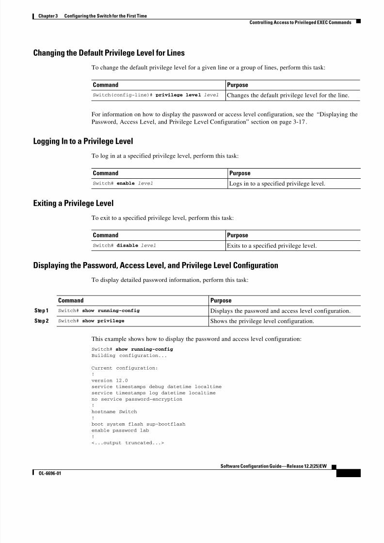
8/10/2019 Cisco ConfiguratioGuide SW4500 IOS
http://slidepdf.com/reader/full/cisco-configuratioguide-sw4500-ios 65/607
3-17
Software Configuration Guide—Release 12.2(25)EW
OL-6696-01
Chapter 3 Configuring the Switch for the First Time
Controlling Access to Privileged EXEC Commands
Changing the Default Privilege Level for Lines
To change the default privilege level for a given line or a group of lines, perform this task:
For information on how to display the password or access level configuration, see the “Displaying the
Password, Access Level, and Privilege Level Configuration” section on page 3-17.
Logging In to a Privilege Level
To log in at a specified privilege level, perform this task:
Exiting a Privilege Level
To exit to a specified privilege level, perform this task:
Displaying the Password, Access Level, and Privilege Level Configuration
To display detailed password information, perform this task:
This example shows how to display the password and access level configuration:
Switch# show running-config
Building configuration...
Current configuration:
!
version 12.0service timestamps debug datetime localtime
service timestamps log datetime localtime
no service password-encryption!
hostname Switch!
boot system flash sup-bootflash
enable password lab
!<...output truncated...>
Command Purpose
Switch(config-line)# privilege level level Changes the default privilege level for the line.
Command Purpose
Switch# enable level Logs in to a specified privilege level.
Command Purpose
Switch# disable level Exits to a specified privilege level.
Command Purpose
Step 1 Switch# show running-config Displays the password and access level configuration.
Step 2 Switch# show privilege Shows the privilege level configuration.

8/10/2019 Cisco ConfiguratioGuide SW4500 IOS
http://slidepdf.com/reader/full/cisco-configuratioguide-sw4500-ios 66/607
3-18
Software Configuration Guide—Release 12.2(25)EW
OL-6696-01
Chapter 3 Configuring the Switch for the First Time
Recovering a Lost Enable Password
This example shows how to display the privilege level configuration:
Switch# show privilegeCurrent privilege level is 15
Switch#
Recovering a Lost Enable Password
Note For more information on the configuration register which is preconfigured in NVRAM, see “Configuring
the Software Configuration Register” section on page 3-19.
Perform these steps to recover a lost enable password:
Step 1 Connect to the console interface.
Step 2 Stop the boot sequence and enter ROM monitor by pressing Ctrl-C during the first 5 seconds of bootup.
Step 3 Configure the switch to boot-up without reading the configuration memory (NVRAM).
Step 4 Reboot the system.
Step 5 Access enable mode (this can be done without a password if a password has not been configured).
Step 6 View or change the password, or erase the configuration.
Step 7 Reconfigure the switch to boot-up and read the NVRAM as it normally does.
Step 8 Reboot the system.
Modifying the Supervisor Engine Startup ConfigurationThese sections describe how the startup configuration on the supervisor engine works and how to modify
the configuration register and BOOT variable:
• Understanding the Supervisor Engine Boot Configuration, page 3-18
• Configuring the Software Configuration Register, page 3-19
• Specifying the Startup System Image, page 3-23
• Controlling Environment Variables, page 3-24
Understanding the Supervisor Engine Boot Configuration
The supervisor engine boot process involves two software images: ROM monitor and supervisor engine
software. When the switch is booted or reset, the ROMMON code is executed. Depending on the
NVRAM configuration, the supervisor engine either stays in ROMMON mode or loads the supervisor
engine software.
Two user-configurable parameters determine how the switch boots: the configuration register and the
BOOT environment variable. The configuration register is described in the “Modifying the Boot Field
and Using the boot Command” section on page 3-20. The BOOT environment variable is described in
the “Specifying the Startup System Image” section on page 3-23.
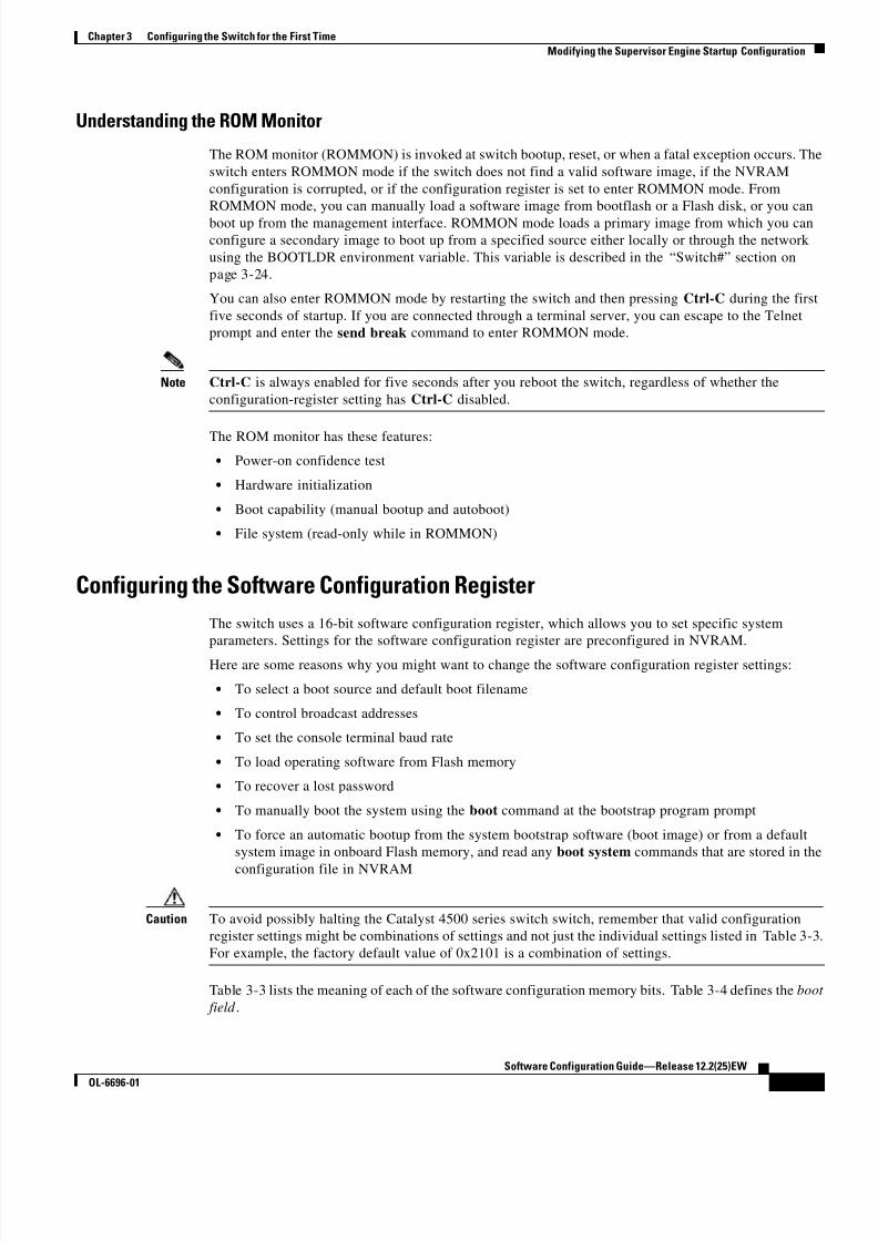
8/10/2019 Cisco ConfiguratioGuide SW4500 IOS
http://slidepdf.com/reader/full/cisco-configuratioguide-sw4500-ios 67/607
3-19
Software Configuration Guide—Release 12.2(25)EW
OL-6696-01
Chapter 3 Configuring the Switch for the First Time
Modifying the Supervisor Engine Startup Configuration
Understanding the ROM Monitor
The ROM monitor (ROMMON) is invoked at switch bootup, reset, or when a fatal exception occurs. The
switch enters ROMMON mode if the switch does not find a valid software image, if the NVRAM
configuration is corrupted, or if the configuration register is set to enter ROMMON mode. From
ROMMON mode, you can manually load a software image from bootflash or a Flash disk, or you can
boot up from the management interface. ROMMON mode loads a primary image from which you can
configure a secondary image to boot up from a specified source either locally or through the network
using the BOOTLDR environment variable. This variable is described in the “Switch#” section on
page 3-24.
You can also enter ROMMON mode by restarting the switch and then pressing Ctrl-C during the first
five seconds of startup. If you are connected through a terminal server, you can escape to the Telnet
prompt and enter the send break command to enter ROMMON mode.
Note Ctrl-C is always enabled for five seconds after you reboot the switch, regardless of whether the
configuration-register setting has Ctrl-C disabled.
The ROM monitor has these features:
• Power-on confidence test
• Hardware initialization
• Boot capability (manual bootup and autoboot)
• File system (read-only while in ROMMON)
Configuring the Software Configuration Register
The switch uses a 16-bit software configuration register, which allows you to set specific system
parameters. Settings for the software configuration register are preconfigured in NVRAM.
Here are some reasons why you might want to change the software configuration register settings:
• To select a boot source and default boot filename
• To control broadcast addresses
• To set the console terminal baud rate
• To load operating software from Flash memory
• To recover a lost password
• To manually boot the system using the boot command at the bootstrap program prompt
• To force an automatic bootup from the system bootstrap software (boot image) or from a default
system image in onboard Flash memory, and read any boot system commands that are stored in the
configuration file in NVRAM
Caution To avoid possibly halting the Catalyst 4500 series switch switch, remember that valid configuration
register settings might be combinations of settings and not just the individual settings listed in Table 3-3.
For example, the factory default value of 0x2101 is a combination of settings.
Table 3-3 lists the meaning of each of the software configuration memory bits. Table 3-4 defines the boot
field .

8/10/2019 Cisco ConfiguratioGuide SW4500 IOS
http://slidepdf.com/reader/full/cisco-configuratioguide-sw4500-ios 68/607
3-20
Software Configuration Guide—Release 12.2(25)EW
OL-6696-01
Chapter 3 Configuring the Switch for the First Time
Modifying the Supervisor Engine Startup Configuration
Modifying the Boot Field and Using the boot Command
The configuration register boot field determines whether the switch loads an operating system image
and, if so, where it obtains this system image. The following sections describe how to use and set the
configuration register boot field and the procedures you must perform to modify the configuration
register boot field. In ROMMON, you can use the confreg command to modify the configuration registerand change boot settings.
Bits 0 through 3 of the software configuration register contain the boot field.
Note The factory default configuration register setting for systems and spares is 0x2101. However, the
recommended value is 0x0102.
Table 3-3 Software Configuration Register Bits
Bit Number1
1. The factory default value for the configuration register is 0x2101. This value is a combination of the following: binary bit 13,
bit 8 = 0x0100 and binary bits 00 through 03 = 0x0001. (See Table 3-4.)
Hexadecimal Meaning
00 to 03 0x0000 to 0x000F Boot field (see Table 3-4)
04 0x0010 Unused
05 0x0020 Bit two of console line speed
06 0x0040 Causes system software to ignore NVRAM contents
07 0x0080 OEM2 bit enabled
2. OEM = original equipment manufacturer.
08 0x0100 Unused
09 0x0200 Unused
10 0x0400 IP broadcast with all zeros
11 to 12 0x0800 to 0x1000 Bits one and zero of Console line speed (default is 9600 baud)
13 0x2000 Loads ROM monitor after netboot fails
14 0x4000 IP broadcasts do not have network numbers
Table 3-4 Explanation of Boot Field (Configuration Register Bits 00 to 03)
Boot Field Meaning
00 Stays at the system bootstrap prompt (does not autoboot).
01 Boots the firs t system image in onboard Flash memory.
02 to 0F Autoboots using image(s) specified by the BOOT environment variable. If more than one
image is specified, the switch attempts to boot the first image specified in the BOOT
variable. As long as the switch can successfully boot from this image, the same image willbe used on a reboot. If the switch fails to boot from the image specified in the BOOT
variable, the switch will try to boot from the next image listed in the BOOT variable. If the
end of the BOOT variable is reached without the switch booting successfully, the switch
attempts the boot from the beginning of the BOOT variable. The autoboot continues until
the switch successfully boots from one of the images specified in the BOOT variable.

8/10/2019 Cisco ConfiguratioGuide SW4500 IOS
http://slidepdf.com/reader/full/cisco-configuratioguide-sw4500-ios 69/607
3-21
Software Configuration Guide—Release 12.2(25)EW
OL-6696-01
Chapter 3 Configuring the Switch for the First Time
Modifying the Supervisor Engine Startup Configuration
When the boot field is set to either 00 or 01 (0-0-0-0 or 0-0-0-1), the system ignores any boot instructions
in the system configuration file and the following occurs:
• When the boot field is set to 00, you must boot up the operating system manually by issuing the boot
command at the system bootstrap or ROMMON prompt.
• When the boot field is set to 01, the system boots the first image in the bootflash single in-line
memory module (SIMM).
• When the entire boot field equals a value between 0-0-1-0 and 1-1-1-1, the switch loads the system
image specified by boot system commands in the startup configuration file.
Caution If you set bootfield to a value between 0-0-1-0 and 1-1-1-1, you must specify a value in the boot system
command, else the switch cannot boot up and will remain stuck in ROMMON.
You can enter the boot command only or enter the command and include additional boot instructions,
such as the name of a file stored in Flash memory, or a file that you specify for booting from a network
server. If you use the boot command without specifying a file or any other boot instructions, the system
boots from the default Flash image (the first image in onboard Flash memory). Otherwise, you can
instruct the system to boot up from a specific Flash image (using the boot system flash filename command).
You can also use the boot command to boot up images stored in the compact Flash cards located in slot 0
on the supervisor engine.
Modifying the Boot Field
Modify the boot field from the software configuration register. To modify the software configuration
register boot field, perform this task:
To modify the configuration register while the switch is running Cisco IOS software, follow these steps
Step 1 Enter the enable command and your password to enter privileged level, as follows:
Switch> enable
Password:Switch#
Command Purpose
Step 1 Switch# show version Determines the current configuration register setting.
Step 2 Switch# configure terminal Enters configuration mode, and specify the terminal
option.
Step 3 Switch(config)# config-register value Modifies the existing configuration register setting to
reflect the way you want the switch to load a system
image.
Step 4 Switch(config)# end Exits configuration mode.
Step 5 Switch# reload Reboots the switch to make your changes take effect.

8/10/2019 Cisco ConfiguratioGuide SW4500 IOS
http://slidepdf.com/reader/full/cisco-configuratioguide-sw4500-ios 70/607
3-22
Software Configuration Guide—Release 12.2(25)EW
OL-6696-01
Chapter 3 Configuring the Switch for the First Time
Modifying the Supervisor Engine Startup Configuration
Step 2 Enter the configure terminal command at the EXEC mode prompt (#), as follows:
Switch# configure terminalEnter configuration commands, one per line. End with CNTL/Z.
Switch(config)#
Step 3 Configure the configuration register to 0x102 as follows:
Switch(config)# config-register 0x102
Set the contents of the configuration register by specifying the value command variable, where value is
a hexadecimal number preceded by 0x (see Table 3-3 on page 3-20).
Step 4 Enter the end command to exit configuration mode. The new value settings are saved to memory;
however, the new settings do not take effect until the system is rebooted.
Step 5 Enter the show version EXEC command to display the configuration register value currently in effect;
it will be used at the next reload. The value is displayed on the last line of the screen display, as shown
in this sample output:
Configuration register is 0x141 (will be 0x102 at next reload)
Step 6 Save your settings. (See the “Saving the Running Configuration Settings to Your Start-up File” section
on page 3-10. Note that configuration register changes take effect only after the system reloads, such as
when you enter a reload command from the console.)
Step 7 Reboot the system. The new configuration register value takes effect with the next system boot up.
Verifying the Configuration Register Setting
Enter the show version EXEC command to verify the current configuration register setting. In
ROMMON mode, enter the show version command to verify the configuration register setting.
To verify the configuration register setting for the switch, perform this task:
In this example, the show version command indicates that the current configuration register is set so that
the switch does not automatically load an operating system image. Instead, it enters ROMMON mode
and waits for you to enter ROM monitor commands.
Switch#show version
Cisco Internetwork Operating System Software
IOS (tm) Catalyst 4000 L3 Switch Software (cat4000-IS-M), Experimental Version 12.1(20010828:211314) [cisco 105]
Copyright (c) 1986-2001 by cisco Systems, Inc.
Compiled Thu 06-Sep-01 15:40 byImage text-base:0x00000000, data-base:0x00ADF444
ROM:1.15Switch uptime is 10 minutes
System returned to ROM by reloadRunning default software
Command Purpose
Switch# show version Displays the configuration register setting.

8/10/2019 Cisco ConfiguratioGuide SW4500 IOS
http://slidepdf.com/reader/full/cisco-configuratioguide-sw4500-ios 71/607
3-23
Software Configuration Guide—Release 12.2(25)EW
OL-6696-01
Chapter 3 Configuring the Switch for the First Time
Modifying the Supervisor Engine Startup Configuration
cisco Catalyst 4000 (MPC8240) processor (revision 3) with 262144K bytes
of memory.
Processor board ID Ask SN 12345Last reset from Reload
Bridging software.49 FastEthernet/IEEE 802.3 interface(s)
20 Gigabit Ethernet/IEEE 802.3 interface(s)
271K bytes of non-volatile configuration memory.
Configuration register is 0xEC60
Switch#
Specifying the Startup System Image
You can enter multiple boot commands in the startup configuration file or in the BOOT environment
variable to provide backup methods for loading a system image.
The BOOT environment variable is also described in the “Specify the Startup System Image in the
Configuration File” section in the “Loading and Maintaining System Images and Microcode” chapter of
the Cisco IOS Configuration Fundamentals Configuration Guide.
Use the following sections to configure your switch to boot from Flash memory. Flash memory can be
either single in-line memory modules (SIMMs) or Flash disks. Check the appropriate hardware
installation and maintenance guide for information about types of Flash memory.
Using Flash Memory
Flash memory allows you to do the following:
• Copy the system image to Flash memory using TFTP
• Boot the system from Flash memory either automatically or manually
• Copy the Flash memory image to a network server using TFTP or RCP
Flash Memory Features
Flash memory allows you to do the following:
• Remotely load multiple system software images through TFTP or RCP transfers (one transfer for
each file loaded)
• Boot a switch manually or automatically from a system software image stored in Flash memory (you
can also boot directly from ROM)
Security Precautions
Note the following security precaution when loading from Flash memory:
Caution You can only change the system image stored in Flash memory from privileged EXEC level on the
console terminal.

8/10/2019 Cisco ConfiguratioGuide SW4500 IOS
http://slidepdf.com/reader/full/cisco-configuratioguide-sw4500-ios 72/607
3-24
Software Configuration Guide—Release 12.2(25)EW
OL-6696-01
Chapter 3 Configuring the Switch for the First Time
Modifying the Supervisor Engine Startup Configuration
Configuring Flash Memory
To configure your switch to boot from Flash memory, perform the following procedure. (Refer to the
appropriate hardware installation and maintenance publication for complete instructions on installing
the hardware.)
Step 1 Copy a system image to Flash memory using TFTP or other protocols. Refer to the “Cisco IOS File
Management” and “Loading and Maintaining System Images” chapters in the Cisco IOS Configuration
Fundamentals Configuration Guide, Release 12.2, at the following URL:
http://www.cisco.com/univercd/cc/td/doc/product/software/ios122/122cgcr/fun_c/fcprt2/fcd203.htm
Step 2 Configure the system to boot automatically from the desired file in Flash memory. You might need to
change the configuration register value. See the “Modifying the Boot Field and Using the boot
Command” section on page 3-20, for more information on modifying the configuration register.
Step 3 Save your configurations.
Step 4 Power cycle and reboot your system to verify that all is working as expected.
Controlling Environment Variables
Although the ROM monitor controls environment variables, you can create, modify, or view them with
certain commands. To create or modify the BOOT and BOOTLDR variables, use the boot system and
boot bootldr global configuration commands, respectively. Refer to the “Specify the Startup System
Image in the Configuration File” section in the “Loading and Maintaining System Images and
Microcode” chapter of the Configuration Fundamentals Configuration Guide for details on setting the
BOOT environment variable.
Note When you use the boot system and boot bootldr global configuration commands, you affect only the
running configuration. To save the configuration for future use, you must save the environment variable
settings to your startup configuration, which places the information under ROM monitor control. Enter
the copy system:running-config nvram:startup-config command to save the environment variables
from your running configuration to your startup configuration.
You can view the contents of the BOOT and BOOTLDR variables using the show bootvar command.
This command displays the settings for these variables as they exist in the startup configuration and in
the running configuration if a running configuration setting differs from a startup configuration setting.
This example shows how to check the BOOT and BOOTLDR variables on the switch:
Switch# show bootvar
BOOTLDR variable = bootflash:cat4000-is-mz,1;Configuration register is 0x0
Switch#

8/10/2019 Cisco ConfiguratioGuide SW4500 IOS
http://slidepdf.com/reader/full/cisco-configuratioguide-sw4500-ios 73/607
C H A P T E R
4-1
Software Configuration Guide—Release 12.2(25)EW
OL-6696-01
4
Configuring Interfaces
This chapter describes how to configure interfaces for the Catalyst 4500 series switches. It also provides
guidelines, procedures, and configuration examples.
This chapter includes the following major sections:
• Overview of Interface Configuration, page 4-1
• Using the interface Command, page 4-2
• Configuring a Range of Interfaces, page 4-4
• Defining and Using Interface-Range Macros, page 4-5
• Configuring Optional Interface Features, page 4-6
• Understanding Online Insertion and Removal, page 4-13
• Monitoring and Maintaining the Interface, page 4-13
Note For complete syntax and usage information for the switch commands used in this chapter, refer to the
Catalyst 4500 Series Switch Cisco IOS Command Reference and related publications at
http://www.cisco.com/univercd/cc/td/doc/product/software/ios122/122cgcr/index.htm.
Overview of Interface ConfigurationBy default, all interfaces are enabled. The 10/100-Mbps Ethernet interfaces autonegotiate connection
speed and duplex. The 10/100/1000-Mbps Ethernet interfaces negotiate speed, duplex, and flow control.
The 1000-Mbps Ethernet interfaces negotiate flow control only. Autonegotiation automatically selects
the fastest speed possible on that port for the given pair. If a speed is explicitly stated for an interface,
that interface will default to half duplex unless it is explicitly set for full duplex.
Many features are enabled on a per-interface basis. When you enter the interface command, you must
specify the following:
• Interface type:
– Fast Ethernet (use the fastethernet keyword)
– Gigabit Ethernet (use the gigabitethernet keyword)
– 10-Gigabit Ethernet (use the tengigabitethernet keyword)

8/10/2019 Cisco ConfiguratioGuide SW4500 IOS
http://slidepdf.com/reader/full/cisco-configuratioguide-sw4500-ios 74/607
4-2
Software Configuration Guide—Release 12.2(25)EW
OL-6696-01
Chapter 4 Configuring Interfaces
Using the interface Command
• Slot number—The slot in which the interface module is installed. Slots are numbered starting
with 1, from top to bottom.
• Interface number — The interface number on the module. The interface numbers always begin with 1.
When you are facing the front of the switch, the interfaces are numbered from left to right.
You can identify interfaces by physically checking the slot/interface location on the switch. You can also
use the Cisco IOS show commands to display information about a specific interface or all the interfaces.
Using the interface CommandThese general instructions apply to all interface configuration processes:
Step 1 At the privileged EXEC prompt, enter the configure terminal command to enter global configuration
mode:
Switch# configure terminal
Enter configuration commands, one per line. End with CNTL/Z.
Switch(config)#
Step 2 In global configuration mode, enter the interface command. Identify the interface type and the number
of the connector on the interface card. The following example shows how to select Fast Ethernet, slot 5,
interface 1:
Switch(config)# interface fastethernet 5/1
Switch(config-if)#
Step 3 Interface numbers are assigned at the factory at the time of installation or when modules are added to a
system. Enter the show interfaces EXEC command to see a list of all interfaces installed on your switch.
A report is provided for each interface that your switch supports, as shown in this display:
Switch(config-if)#Ctrl-Z
Switch#show interfaces
Vlan1 is up, line protocol is down
Hardware is Ethernet SVI, address is 0004.dd46.7aff (bia 0004.dd46.7aff) MTU 1500 bytes, BW 1000000 Kbit, DLY 10 usec,
reliability 255/255, txload 1/255, rxload 1/255
Encapsulation ARPA, loopback not set
ARP type: ARPA, ARP Timeout 04:00:00 Last input never, output never, output hang never
Last clearing of "show interface" counters never Input queue: 0/75/0/0 (size/max/drops/flushes); Total output drops: 0
Queueing strategy: fifo
Output queue: 0/40 (size/max)
5 minute input rate 0 bits/sec, 0 packets/sec 5 minute output rate 0 bits/sec, 0 packets/sec
0 packets input, 0 bytes, 0 no buffer Received 0 broadcasts, 0 runts, 0 giants, 0 throttles
0 input errors, 0 CRC, 0 frame, 0 overrun, 0 ignored
0 packets output, 0 bytes, 0 underruns 0 output errors, 0 interface resets
0 output buffer failures, 0 output buffers swapped out
GigabitEthernet1/1 is up, line protocol is downHardware is Gigabit Ethernet Port, address is 0004.dd46.7700 (bia 0004.dd46.7700)
MTU 1500 bytes, BW 1000000 Kbit, DLY 10 usec,reliability 255/255, txload 1/255, rxload 1/255
Encapsulation ARPA, loopback not set
Keepalive set (10 sec) Auto-duplex, Auto-speed
ARP type: ARPA, ARP Timeout 04:00:00

8/10/2019 Cisco ConfiguratioGuide SW4500 IOS
http://slidepdf.com/reader/full/cisco-configuratioguide-sw4500-ios 75/607
4-3
Software Configuration Guide—Release 12.2(25)EW
OL-6696-01
Chapter 4 Configuring Interfaces
Using the interface Command
Last input never, output never, output hang never
Last clearing of "show interface" counters never
Input queue: 0/2000/0/0 (size/max/drops/flushes); Total output drops: 0 Queueing strategy: fifo
Output queue: 0/40 (size/max) 5 minute input rate 0 bits/sec, 0 packets/sec
5 minute output rate 0 bits/sec, 0 packets/sec
0 packets input, 0 bytes, 0 no buffer Received 0 broadcasts, 0 runts, 0 giants, 0 throttles 0 input errors, 0 CRC, 0 frame, 0 overrun, 0 ignored
0 input packets with dribble condition detected 0 packets output, 0 bytes, 0 underruns
0 output errors, 0 collisions, 0 interface resets
0 babbles, 0 late collision, 0 deferred 0 lost carrier, 0 no carrier
0 output buffer failures, 0 output buffers swapped out
GigabitEthernet1/2 is up, line protocol is down
Hardware is Gigabit Ethernet Port, address is 0004.dd46.7701 (bia 0004.dd46.7701) MTU 1500 bytes, BW 1000000 Kbit, DLY 10 usec,
reliability 255/255, txload 1/255, rxload 1/255 Encapsulation ARPA, loopback not set
Keepalive set (10 sec)
Auto-duplex, Auto-speed ARP type: ARPA, ARP Timeout 04:00:00 Last input never, output never, output hang never
Last clearing of "show interface" counters never Input queue: 0/2000/0/0 (size/max/drops/flushes); Total output drops: 0
Queueing strategy: fifo
Output queue: 0/40 (size/max)
5 minute input rate 0 bits/sec, 0 packets/sec 5 minute output rate 0 bits/sec, 0 packets/sec
0 packets input, 0 bytes, 0 no buffer Received 0 broadcasts, 0 runts, 0 giants, 0 throttles
0 input errors, 0 CRC, 0 frame, 0 overrun, 0 ignored
0 input packets with dribble condition detected
0 packets output, 0 bytes, 0 underruns 0 output errors, 0 collisions, 0 interface resets
0 babbles, 0 late collision, 0 deferred 0 lost carrier, 0 no carrier
0 output buffer failures, 0 output buffers swapped out
--More--<...output truncated...>
Step 4 To begin configuring Fast Ethernet interface 5/5, as shown in the following example, enter the interface
keyword, interface type, slot number, and interface number in global configuration mode:
Switch# configure terminal
Enter configuration commands, one per line. End with CNTL/Z.
Switch(config)# interface fastethernet 5/5 Switch(config-if)#
Note You do not need to add a space between the interface type and interface number. For example,in the preceding line you can specify either fastethernet 5/5 or fastethernet5/5.

8/10/2019 Cisco ConfiguratioGuide SW4500 IOS
http://slidepdf.com/reader/full/cisco-configuratioguide-sw4500-ios 76/607
4-4
Software Configuration Guide—Release 12.2(25)EW
OL-6696-01
Chapter 4 Configuring Interfaces
Configuring a Range of Interfaces
Step 5 Follow each interface command with the interface configuration commands your particular interface
requires. The commands you enter define the protocols and applications that will run on the interface.
The commands are collected and applied to the interface command until you enter another interface
command or press Ctrl-Z to exit interface configuration mode and return to privileged EXEC mode.
Step 6 After you configure an interface, check its status by using the EXEC show commands listed in
“Monitoring and Maintaining the Interface” section on page 4-13.
Configuring a Range of InterfacesThe interface-range configuration mode allows you to configure multiple interfaces with the same
configuration parameters. When you enter the interface-range configuration mode, all command
parameters you enter are attributed to all interfaces within that range until you exit interface-range
configuration mode.
To configure a range of interfaces with the same configuration, perform this task:
Note When you use the interface range command, you must add a space between the vlan, fastethernet,
gigabitethernet, tengigabitethernet, or macro keyword and the dash. For example, the command
interface range fastethernet 5/1 - 5 specifies a valid range; the command
interface range fastethernet 1-5 does not contain a valid range command.
Note The interface range command works only with VLAN interfaces that have been configured with the
interface vlan command (the show running-configuration command displays the configured VLAN
interfaces). VLAN interfaces that are not displayed by the show running-configuration command
cannot be used with the interface range command.
Command Purpose
Switch(config)# interface range { vlan vlan_ID - vlan_ID } |
{{fastethernet | gigabitethernet |
tengigabitethernet | macro macro_name }
slot/interface - interface } [,
{ vlan vlan_ID - vlan_ID } {{fastethernet | gigabitethernet | tengigabitethernet |
macro macro_name }
slot/interface - interface }]
Selects the range of interfaces to be configured. Note
the following:
• You are required to enter a space before the dash.
• You can enter up to five comma-separated
ranges.
• You are not required to enter spaces before or
after the comma.

8/10/2019 Cisco ConfiguratioGuide SW4500 IOS
http://slidepdf.com/reader/full/cisco-configuratioguide-sw4500-ios 77/607
4-5
Software Configuration Guide—Release 12.2(25)EW
OL-6696-01
Chapter 4 Configuring Interfaces
Defining and Using Interface-Range Macros
This example shows how to reenable all Fast Ethernet interfaces 5/1 to 5/5:
Switch(config)# interface range fastethernet 5/1 - 5 Switch(config-if-range)# no shutdown
Switch(config-if-range)#*Oct 6 08:24:35: %LINK-3-UPDOWN: Interface FastEthernet5/1, changed state to up
*Oct 6 08:24:35: %LINK-3-UPDOWN: Interface FastEthernet5/2, changed state to up
*Oct 6 08:24:35: %LINK-3-UPDOWN: Interface FastEthernet5/3, changed state to up*Oct 6 08:24:35: %LINK-3-UPDOWN: Interface FastEthernet5/4, changed state to up
*Oct 6 08:24:35: %LINK-3-UPDOWN: Interface FastEthernet5/5, changed state to up
*Oct 6 08:24:36: %LINEPROTO-5-UPDOWN: Line protocol on Interface FastEthernet5/
5, changed state to up*Oct 6 08:24:36: %LINEPROTO-5-UPDOWN: Line protocol on Interface FastEthernet5/
3, changed state to up*Oct 6 08:24:36: %LINEPROTO-5-UPDOWN: Line protocol on Interface FastEthernet5/
4, changed state to up
Switch(config-if)#
This example shows how to use a comma to add different interface type strings to the range to reenable
all Fast Ethernet interfaces in the range 5/1 to 5/5 and both Gigabit Ethernet interfaces 1/1 and 1/2:
Switch(config-if)# interface range fastethernet 5/1 - 5, gigabitethernet 1/1 - 2 Switch(config-if)# no shutdown
Switch(config-if)#*Oct 6 08:29:28: %LINK-3-UPDOWN: Interface FastEthernet5/1, changed state to up
*Oct 6 08:29:28: %LINK-3-UPDOWN: Interface FastEthernet5/2, changed state to up
*Oct 6 08:29:28: %LINK-3-UPDOWN: Interface FastEthernet5/3, changed state to up
*Oct 6 08:29:28: %LINK-3-UPDOWN: Interface FastEthernet5/4, changed state to up*Oct 6 08:29:28: %LINK-3-UPDOWN: Interface FastEthernet5/5, changed state to up
*Oct 6 08:29:28: %LINK-3-UPDOWN: Interface GigabitEthernet1/1, changed state to
up
*Oct 6 08:29:28: %LINK-3-UPDOWN: Interface GigabitEthernet1/2, changed state to
up*Oct 6 08:29:29: %LINEPROTO-5-UPDOWN: Line protocol on Interface FastEthernet5/
5, changed state to up
*Oct 6 08:29:29: %LINEPROTO-5-UPDOWN: Line protocol on Interface FastEthernet5/
3, changed state to up*Oct 6 08:29:29: %LINEPROTO-5-UPDOWN: Line protocol on Interface FastEthernet5/
4, changed state to upSwitch(config-if)#
If you enter multiple configuration commands while you are in interface-range configuration mode, each
command is run as it is entered (they are not batched together and run after you exit interface-range
configuration mode). If you exit interface-range configuration mode while the commands are being run,
some commands might not be run on all interfaces in the range. Wait until the command prompt is
displayed before exiting interface-range configuration mode.
Defining and Using Interface-Range Macros
You can define an interface-range macro to automatically select a range of interfaces for configuration.Before you can use the macro keyword in the interface-range macro command string, you must define
the macro.

8/10/2019 Cisco ConfiguratioGuide SW4500 IOS
http://slidepdf.com/reader/full/cisco-configuratioguide-sw4500-ios 78/607
4-6
Software Configuration Guide—Release 12.2(25)EW
OL-6696-01
Chapter 4 Configuring Interfaces
Configuring Optional Interface Features
To define an interface-range macro, perform this task:
This example shows how to define an interface-range macro named enet_list to select Fast Ethernet
interfaces 5/1 through 5/4:
Switch(config)# define interface-range enet_list fastethernet 5/1 - 4
To show the defined interface-range macro configuration, perform this task:
This example shows how to display the defined interface-range macro named enet_list:
Switch# show running-config | include define define interface-range enet_list FastEthernet5/1 - 4
Switch#
To use an interface-range macro in the interface range command, perform this task:
This example shows how to change to the interface-range configuration mode using the interface-range
macro enet_list:
Switch(config)# interface range macro enet_list
Switch(config-if)#
Configuring Optional Interface FeaturesThe following subsections describe optional procedures:
• Configuring Ethernet Interface Speed and Duplex Mode, page 4-7
• Configuring Jumbo Frame Support, page 4-10
• Interacting with the Baby Giants Feature, page 4-12
Command Purpose
Switch(config)# define interface-range macro_name
{ vlan vlan_ID - vlan_ID } | {{fastethernet |gigabitethernet} slot/interface - interface }
[, { vlan vlan_ID - vlan_ID } {{fastethernet |
gigabitethernet} slot/interface - interface }]
Defines the interface-range macro and
saves it in the running configuration file.
Command Purpose
Switch# show running-config Shows the defined interface-range macro
configuration.
Command Purpose
Switch(config)# interface range macro
name Selects the interface range to be configured using
the values saved in a named interface-range macro.
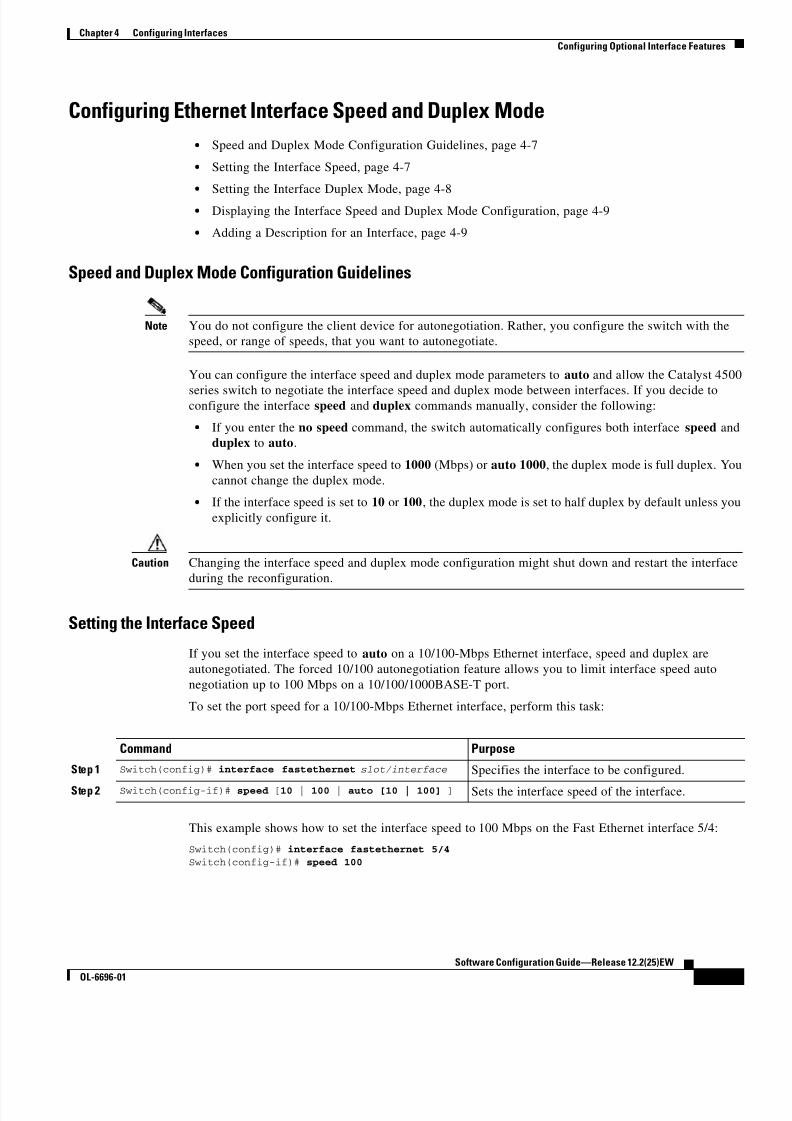
8/10/2019 Cisco ConfiguratioGuide SW4500 IOS
http://slidepdf.com/reader/full/cisco-configuratioguide-sw4500-ios 79/607
4-7
Software Configuration Guide—Release 12.2(25)EW
OL-6696-01
Chapter 4 Configuring Interfaces
Configuring Optional Interface Features
Configuring Ethernet Interface Speed and Duplex Mode
• Speed and Duplex Mode Configuration Guidelines, page 4-7
• Setting the Interface Speed, page 4-7
• Setting the Interface Duplex Mode, page 4-8
• Displaying the Interface Speed and Duplex Mode Configuration, page 4-9
• Adding a Description for an Interface, page 4-9
Speed and Duplex Mode Configuration Guidelines
Note You do not configure the client device for autonegotiation. Rather, you configure the switch with the
speed, or range of speeds, that you want to autonegotiate.
You can configure the interface speed and duplex mode parameters to auto and allow the Catalyst 4500
series switch to negotiate the interface speed and duplex mode between interfaces. If you decide toconfigure the interface speed and duplex commands manually, consider the following:
• If you enter the no speed command, the switch automatically configures both interface speed and
duplex to auto.
• When you set the interface speed to 1000 (Mbps) or auto 1000, the duplex mode is full duplex. You
cannot change the duplex mode.
• If the interface speed is set to 10 or 100, the duplex mode is set to half duplex by default unless you
explicitly configure it.
Caution Changing the interface speed and duplex mode configuration might shut down and restart the interface
during the reconfiguration.
Setting the Interface Speed
If you set the interface speed to auto on a 10/100-Mbps Ethernet interface, speed and duplex are
autonegotiated. The forced 10/100 autonegotiation feature allows you to limit interface speed auto
negotiation up to 100 Mbps on a 10/100/1000BASE-T port.
To set the port speed for a 10/100-Mbps Ethernet interface, perform this task:
This example shows how to set the interface speed to 100 Mbps on the Fast Ethernet interface 5/4:
Switch(config)# interface fastethernet 5/4
Switch(config-if)# speed 100
Command Purpose
Step 1 Switch(config)# interface fastethernet slot/interface Specifies the interface to be configured.
Step 2 Switch(config-if)# speed [10 | 100 | auto [10 | 100] ] Sets the interface speed of the interface.

8/10/2019 Cisco ConfiguratioGuide SW4500 IOS
http://slidepdf.com/reader/full/cisco-configuratioguide-sw4500-ios 80/607
4-8
Software Configuration Guide—Release 12.2(25)EW
OL-6696-01
Chapter 4 Configuring Interfaces
Configuring Optional Interface Features
This example shows how to allow Fast Ethernet interface 5/4 to autonegotiate the speed and duplex
mode:
Switch(config)# interface fastethernet 5/4
Switch(config-if)# speed auto
Note This is analogous to specifying speed auto 10 100.
This example shows how to limit the interface speed to 10 and 100 Mbps on the Gigabit Ethernet
interface 1/1 in auto-negotiation mode:
Switch(config)# interface gigabitethernet 1/1Switch(config-if)# speed auto 10 100
This example shows how to limit speed negotiation to 100 Mbps on the Gigabit Ethernet interface 1/1:
Switch(config)# interface gigabitethernet 1/1
Switch(config-if)# speed auto 100
Note Turning off autonegotiation on a Gigabit Ethernet interface will result in the port being forced into
1000 Mbps and full-duplex mode.
To turn off the port speed autonegotiation for Gigabit Ethernet interface 1/1, perform this task:
To restore autonegotiation, enter the no speed nonegotiate command in the interface configuration
mode.
Note For the blocking ports on the WS-X4416 module, do not set the speed to autonegotiate.
Setting the Interface Duplex Mode
Note When the interface is set to 1000 Mbps, you cannot change the duplex mode from full duplex to half
duplex.
To set the duplex mode of a Fast Ethernet interface, perform this task:
This example shows how to set the interface duplex mode to full on Fast Ethernet interface 5/4:
Switch(config)# interface fastethernet 5/4
Switch(config-if)# duplex full
Command Purpose
Step 1 Switch(config)# interface gigabitethernet1/1 Specifies the interface to be configured.
Step 2 Switch(config-if)# speed nonegotiate Disables autonegotiation on the interface.
Command Purpose
Step 1 Switch(config)# interface fastethernet
slot/interface Specifies the interface to be configured.
Step 2 Switch(config-if)# duplex [auto | full | half] Sets the duplex mode of the interface.

8/10/2019 Cisco ConfiguratioGuide SW4500 IOS
http://slidepdf.com/reader/full/cisco-configuratioguide-sw4500-ios 81/607
4-9
Software Configuration Guide—Release 12.2(25)EW
OL-6696-01
Chapter 4 Configuring Interfaces
Configuring Optional Interface Features
Displaying the Interface Speed and Duplex Mode Configuration
To display the interface speed and duplex mode configuration for an interface, perform this task:
This example shows how to display the interface speed and duplex mode of Fast Ethernet interface 6/1
Switch# show interface fastethernet 6/1
FastEthernet6/1 is up, line protocol is upHardware is Fast Ethernet Port, address is 0050.547a.dee0 (bia 0050.547a.dee0)
MTU 1500 bytes, BW 100000 Kbit, DLY 100 usec,reliability 255/255, txload 1/255, rxload 1/255
Encapsulation ARPA, loopback not set
Keepalive set (10 sec)
Full-duplex, 100Mb/s ARP type: ARPA, ARP Timeout 04:00:00
Last input 00:00:54, output never, output hang never Last clearing of "show interface" counters never Input queue: 50/2000/0/0 (size/max/drops/flushes); Total output drops: 0
Queueing strategy: fifo Output queue: 0/40 (size/max)
5 minute input rate 0 bits/sec, 0 packets/sec
5 minute output rate 0 bits/sec, 0 packets/sec
50 packets input, 11300 bytes, 0 no buffer Received 50 broadcasts, 0 runts, 0 giants, 0 throttles
0 input errors, 0 CRC, 0 frame, 0 overrun, 0 ignored 0 input packets with dribble condition detected
1456 packets output, 111609 bytes, 0 underruns
0 output errors, 0 collisions, 0 interface resets
0 babbles, 0 late collision, 0 deferred 1 lost carrier, 0 no carrier
0 output buffer failures, 0 output buffers swapped outSwitch#
Adding a Description for an Interface
You can add a description about an interface to help you remember its function. The description appears
in the output of the following commands: show configuration, show running-config, and
show interfaces.
To add a description for an interface, enter the following command:
This example shows how to add a description on Fast Ethernet interface 5/5:
Switch(config)# interface fastethernet 5/5 Switch(config-if)# description Channel-group to "Marketing"
Command Purpose
Switch# show interfaces [fastethernet |gigabitethernet | tengigabitethernet]slot/interface
Displays the interface speed and duplex modeconfiguration.
Command Purpose
Switch(config-if)# description string Adds a description for an interface.

8/10/2019 Cisco ConfiguratioGuide SW4500 IOS
http://slidepdf.com/reader/full/cisco-configuratioguide-sw4500-ios 82/607
4-10
Software Configuration Guide—Release 12.2(25)EW
OL-6696-01
Chapter 4 Configuring Interfaces
Configuring Optional Interface Features
Configuring Jumbo Frame Support
These subsections describe jumbo frame support:
• Ports and Modules that Support Jumbo Frames, page 4-10
• Understanding Jumbo Frame Support, page 4-10
• Configuring MTU Sizes, page 4-12
Ports and Modules that Support Jumbo Frames
The following ports and modules support jumbo frames:
• Supervisor uplink ports
• WS-X4306-GB: all ports
• WS-X4232-GB-RJ: ports 1-2
• WS-X4418-GB: ports 1-2
• WS-X4412-2GB-TX: ports 13-14
Each of the last three modules has two non-blocking ports that can support jumbo frames. Other
ports are over-subscribed ports and cannot support jumbo frames.
Understanding Jumbo Frame Support
These sections describe jumbo frame support:
• Jumbo Frame Support Overview, page 4-10
• Ethernet Ports, page 4-11
• VLAN Interfaces, page 4-11
Jumbo Frame Support Overview
A jumbo frame is a frame larger than the default Ethernet size. Enable jumbo frame support by
configuring a larger-than-default maximum transmission unit (MTU) size on a port or interface.
Catalyst 4500 series switch Ethernet LAN ports configured with a nondefault MTU size accept frames
containing packets with a size between 1500 and 9198 bytes. With a nondefault MTU size configured,
the packet size of ingress frames is checked. If the packet is larger than the configured MTU, it is
dropped.
For traffic that needs to be routed, the MTU of the egress port is checked. If the MTU is smaller than the
packet size, the packet is forwarded to the CPU. If the “do not fragment bit” is not set, it is fragmented.
Otherwise, the packet is dropped.
Note Jumbo frame support does not fragment Layer 2 switched packets.
The Catalyst 4500 series switch does not compare the packet size with the MTU at the egress port, but
jumbo frames are dropped in ports that do not support them. The frames can be transmitted in ports that
do support jumbo frames, even though the MTU is not configured to jumbo size.

8/10/2019 Cisco ConfiguratioGuide SW4500 IOS
http://slidepdf.com/reader/full/cisco-configuratioguide-sw4500-ios 83/607
4-11
Software Configuration Guide—Release 12.2(25)EW
OL-6696-01
Chapter 4 Configuring Interfaces
Configuring Optional Interface Features
Note Jumbo frame support is only configured per interface; jumbo frame support cannot be configured
globally.
Ethernet Ports
These sections describe configuring nondefault MTU sizes on Ethernet ports:
• Ethernet Port Overview, page 4-11
• Layer 3 and Layer 2 EtherChannels, page 4-11
Ethernet Port Overview
With Cisco IOS Release 12.2(25)EW, configuring a nondefault MTU size on certain Ethernet ports
limits the size of ingress packets. The MTU does not impact the egress packets.
With releases earlier than Cisco IOS Release 12.1(13)EW, you can configure the MTU size only on
Gigabit Ethernet.
Layer 3 and Layer 2 EtherChannelsWith Release Cisco IOS Release 12.2(25)EW and later releases, you can configure all the interfaces in
an EtherChannel provided that they have the same MTU. Changing the MTU of an EtherChannel
changes the MTU of all member ports. If the MTU of a member port cannot be changed to the new value,
that port is suspended (administratively shut down). A port cannot join an EtherChannel if the port has
a different MTU. If a member port of an EtherChannel changes MTU, the member port is suspended.
VLAN Interfaces
If switch ports reside in the same VLAN, either configure all of the switch ports to handle jumbo frames
and support the same MTU size, or configure none of them. However, such uniformity of MTU size in
the same VLAN is not enforced.
When a VLAN has switch ports with different MTU size, packets received from a port with a larger MTUmight be dropped when they are forwarded to a port with a smaller MTU.
If the switch ports in a VLAN have jumbo frames enabled, the corresponding SVI can have jumbo frames
enabled. The MTU of an SVI should always be smaller than the smallest MTU among all the switch ports
in the VLAN, but this condition is not enforced.
The MTU of a packet is not checked on the ingress side for an SVI; it is checked on the egress side of
an SVI. If the MTU of a packet is larger than the MTU of the egress SVI, the packet will be sent to the
CPU for fragmentation processing. If the “do not fragment” bit is not set, the packet is fragmented.
Otherwise, the packet is dropped.

8/10/2019 Cisco ConfiguratioGuide SW4500 IOS
http://slidepdf.com/reader/full/cisco-configuratioguide-sw4500-ios 84/607
4-12
Software Configuration Guide—Release 12.2(25)EW
OL-6696-01
Chapter 4 Configuring Interfaces
Configuring Optional Interface Features
Configuring MTU Sizes
To configure the MTU size, perform this task:
Note When configuring the MTU size for VLAN interfaces and Layer 3 and Layer 2 Ethernet ports, note that
the supported MTU values are from 1500 to 9198 bytes.
This example shows how to configure the MTU size on Gigabit Ethernet port 1/1:
switch# conf tswitch(config)# int gi1/1
switch(config-if)# mtu 9198
switch(config-if)# end
This example shows how to verify the configuration:
switch# show interface gigabitethernet 1/2GigabitEthernet1/2 is administratively down, line protocol is down Hardware is C6k 1000Mb 802.3, address is 0030.9629.9f88 (bia 0030.9629.9f88) MTU 9216 bytes, BW 1000000 Kbit, DLY 10 usec,<...Output Truncated...>switch#
Interacting with the Baby Giants Feature
The baby giants feature, introduced in Cisco IOS Release 12.1(12c)EW, uses the global command
system mtu <size> to set the global baby giant MTU. This feature also allows certain interfaces to
support Ethernet payload size of up to 1552 bytes.
Both the system mtu command and the per-interface mtu command can operate on interfaces that can
support jumbo frames, but the per-interface mtu command takes precedence.
For example, before setting the per-interface MTU for interface gi1/1, you issue thesystem mtu 1550 command to change the MTU for gi1/1 to 1550 bytes. Next, you issue the per-interface
mtu command to change the MTU for gi1/1 to 9198 bytes. Now, if you change the baby giant MTU to
1540 bytes with the command system mtu 1540, the MTU for gi1/1 remains unchanged at 9198 bytes.
Command Purpose
Step 1 Switch(config)# interface {{ vlan vlan_ID } |
{{type 1 slot/port} | { port-channel
port_channel_number } slot/port}}
1. type = fastethernet , gigabitethernet , or tengigabitethernet
Selects the interface to configure.
Step 2 Switch(config-if)# mtu mtu_size Configures the MTU size.
Switch(config-if)# no mtu Reverts to the default MTU size (1500 bytes).
Step 3 Switch(config-if)# end Exits configuration mode.
Step 4 Switch# show running-config interface
[{fastethernet | gigabitethernet} slot/port]Displays the running configuration.

8/10/2019 Cisco ConfiguratioGuide SW4500 IOS
http://slidepdf.com/reader/full/cisco-configuratioguide-sw4500-ios 85/607
4-13
Software Configuration Guide—Release 12.2(25)EW
OL-6696-01
Chapter 4 Configuring Interfaces
Understanding Online Insertion and Removal
Understanding Online Insertion and RemovalThe online insertion and removal (OIR) feature supported on the Catalyst 4500 series switch allows you
to remove and replace modules while the system is online. You can shut down the module before removal
and restart it after insertion without causing other software or interfaces to shut down.
You do not need to enter a command to notify the software that you are going to remove or install a
module. The system notifies the supervisor engine that a module has been removed or installed and scans
the system for a configuration change. The newly installed module is initialized, and each interface type
is verified against the system configuration; then the system runs diagnostics on the new interface. There
is no disruption to normal operation during module insertion or removal.
If you remove a module and then replace it, or insert a different module of the same type into the same
slot, no change to the system configuration is needed. An interface of a type that has been configured
previously will be brought online immediately. If you remove a module and insert a module of a different
type, the interface(s) on that module will be administratively up with the default configuration for that
module.
Monitoring and Maintaining the InterfaceThe following sections describe how to monitor and maintain the interfaces:
• Monitoring Interface and Controller Status, page 4-13
• Clearing and Resetting the Interface, page 4-14
• Shutting Down and Restarting an Interface, page 4-14
Monitoring Interface and Controller Status
The Cisco IOS software for the Catalyst 4500 series switch contains commands that you can enter at the
EXEC prompt to display information about the interface, including the version of the software and the
hardware, the controller status, and statistics about the interfaces. The following table lists some of the
interface monitoring commands. (You can display the full list of show commands by entering the show ?
command at the EXEC prompt.) These commands are fully described in the Interface Command
Reference.
To display information about the interface, perform this task:
Command Purpose
Step 1 Switch# show interfaces [type slot/interface ] Displays the status and configuration of all interfaces or of a
specific interface.
Step 2 Switch# show running-config Displays the configuration currently running in RAM.Step 3 Switch# show protocols [type slot/interface ] Displays the global (system-wide) and interface-specific
status of any configured protocol.
Step 4 Switch# show version Displays the hardware configuration, software version, the
names and sources of configuration files, and the boot images.

8/10/2019 Cisco ConfiguratioGuide SW4500 IOS
http://slidepdf.com/reader/full/cisco-configuratioguide-sw4500-ios 86/607
4-14
Software Configuration Guide—Release 12.2(25)EW
OL-6696-01
Chapter 4 Configuring Interfaces
Monitoring and Maintaining the Interface
This example shows how to display the status of Fast Ethernet interface 5/5:
Switch# show protocols fastethernet 5/5 FastEthernet5/5 is up, line protocol is up
Switch#
Clearing and Resetting the InterfaceTo clear the interface counters shown with the show interfaces command, enter the following command:
This example shows how to clear and reset the counters on Fast Ethernet interface 5/5:
Switch# clear counters fastethernet 5/5
Clear "show interface" counters on this interface [confirm] y Switch#
*Sep 30 08:42:55: %CLEAR-5-COUNTERS: Clear counter on interface FastEthernet5/5by vty1 (171.69.115.10)
Switch#
The clear counters command (without any arguments) clears all the current interface counters from all
interfaces.
Note The clear counters command does not clear counters retrieved with SNMP; it clears only those counters
displayed with the EXEC show interfaces command.
Shutting Down and Restarting an Interface
You can disable an interface, which disables all functions on the specified interface and marks theinterface as unavailable on all monitoring command displays. This information is communicated to other
network servers through all dynamic routing protocols. The interface will not be mentioned in any
routing updates.
To shut down an interface and then restart it, perform this task:
Command Purpose
Switch# clear counters {type slot/interface } Clears interface counters.
Command Purpose
Step 1 Switch(config)# interface { vlan vlan_ID } |
{{fastethernet | gigabitethernet |
tengigabitethernet} slot/ port} | { port-channel port_channel_number }
Specifies the interface to be configured.
Step 2 Switch(config-if)# shutdown
Shuts down the interface.Step 3 Switch(config-if)# no shutdown Reenables the interface.

8/10/2019 Cisco ConfiguratioGuide SW4500 IOS
http://slidepdf.com/reader/full/cisco-configuratioguide-sw4500-ios 87/607
4-15
Software Configuration Guide—Release 12.2(25)EW
OL-6696-01
Chapter 4 Configuring Interfaces
Monitoring and Maintaining the Interface
This example shows how to shut down Fast Ethernet interface 5/5:
Switch(config)# interface fastethernet 5/5 Switch(config-if)# shutdown
Switch(config-if)#*Sep 30 08:33:47: %LINK-5-CHANGED: Interface FastEthernet5/5, changed state to a
administratively down
Switch(config-if)#This example shows how to reenable Fast Ethernet interface 5/5:
Switch(config-if)# no shutdown
Switch(config-if)#*Sep 30 08:36:00: %LINK-3-UPDOWN: Interface FastEthernet5/5, changed state to up
Switch(config-if)#
To check whether or not an interface is disabled, enter the EXEC show interfaces command. An
interface that has been shut down is shown as being administratively down when you enter the show
interfaces command.

8/10/2019 Cisco ConfiguratioGuide SW4500 IOS
http://slidepdf.com/reader/full/cisco-configuratioguide-sw4500-ios 88/607
4-16
Software Configuration Guide—Release 12.2(25)EW
OL-6696-01
Chapter 4 Configuring Interfaces
Monitoring and Maintaining the Interface

8/10/2019 Cisco ConfiguratioGuide SW4500 IOS
http://slidepdf.com/reader/full/cisco-configuratioguide-sw4500-ios 89/607
C H A P T E R
5-1
Software Configuration Guide—Release 12.2(25)EW
OL-6696-01
5
Checking Port Status and Connectivity
This chapter describes how to check switch port status and connectivity on the Catalyst 4500 series
switch.
This chapter includes the following major sections:
• Checking Module Status, page 5-1
• Checking Interfaces Status, page 5-2
• Checking MAC Addresses, page 5-3
• Using Telnet, page 5-3
• Changing the Logout Timer, page 5-4
• Monitoring User Sessions, page 5-4
• Using Ping, page 5-5
• Using IP Traceroute, page 5-7
• Using Layer 2 Traceroute, page 5-8
• Configuring ICMP, page 5-10
Note For complete syntax and usage information for the switch commands used in this chapter, refer to the
Catalyst 4500 Series Switch Cisco IOS Command Reference and related publications at
http://www.cisco.com/univercd/cc/td/doc/product/software/ios122/122cgcr/index.htm.
Checking Module StatusThe Catalyst 4500 series switch is a multimodule system. You can see which modules are installed, as
well as the MAC address ranges and version numbers for each module, by using the show module
command. You can use the [mod_num] argument to specify a particular module number to see detailed
information on that module.

8/10/2019 Cisco ConfiguratioGuide SW4500 IOS
http://slidepdf.com/reader/full/cisco-configuratioguide-sw4500-ios 90/607
5-2
Software Configuration Guide—Release 12.2(25)EW
OL-6696-01
Chapter 5 Checking Port Status and Connectivity
Checking Interfaces Status
This example shows how to check module status for all modules on your switch:
Switch# show module all
Mod Ports Card Type Model Serial No.----+-----+--------------------------------------+-----------------+-----------
1 2 1000BaseX (GBIC) Supervisor Module WS-X4014 JAB012345AB
5 24 10/100/1000BaseTX (RJ45) WS-X4424-GB-RJ45 JAB045304EY 6 48 10/100BaseTX (RJ45) WS-X4148 JAB023402QK
M MAC addresses Hw Fw Sw Stat
--+--------------------------------+---+-----------------+---------------+----- 1 0004.dd46.9f00 to 0004.dd46.a2ff 0.0 12.1(10r)EW(1.21) 12.1(10)EW(1) Ok
5 0050.3e7e.1d70 to 0050.3e7e.1d87 0.0 Ok6 0050.0f10.2370 to 0050.0f10.239f 1.0 Ok
Switch#
Checking Interfaces StatusYou can view summary or detailed information on the switch ports using the show interfaces status
command. To see summary information on all of the ports on the switch, enter the show interfaces
status command with no arguments. Specify a particular module number to see information on the ports
on that module only. Enter both the module number and the port number to see detailed information
about the specified port.
To apply configuration commands to a particular port, you must specify the appropriate logical module.
For more information, see the “Checking Module Status” section on page 5-1.
This example shows how to display the status of all interfaces on a Catalyst 4500 series switch:
Switch#show interfaces status
Port Name Status Vlan Duplex Speed Type
Gi1/1 notconnect 1 auto auto No Gbic
Gi1/2 notconnect 1 auto auto No Gbic
Gi5/1 notconnect 1 auto auto 10/100/1000-TXGi5/2 notconnect 1 auto auto 10/100/1000-TX
Gi5/3 notconnect 1 auto auto 10/100/1000-TXGi5/4 notconnect 1 auto auto 10/100/1000-TX
Fa6/1 connected 1 a-full a-100 10/100BaseTX
Fa6/2 connected 2 a-full a-100 10/100BaseTX
Fa6/3 notconnect 1 auto auto 10/100BaseTXFa6/4 notconnect 1 auto auto 10/100BaseTX
Switch#
This example shows how to display the status of interfaces in error-disabled state:
Switch# show interfaces status err-disabled
Port Name Status Reason
Fa9/4 err-disabled link-flap
informational error message when the timer expires on a cause
--------------------------------------------------------------5d04h:%PM-SP-4-ERR_RECOVER:Attempting to recover from link-flap err-disable state on Fa9/4
Switch#

8/10/2019 Cisco ConfiguratioGuide SW4500 IOS
http://slidepdf.com/reader/full/cisco-configuratioguide-sw4500-ios 91/607

8/10/2019 Cisco ConfiguratioGuide SW4500 IOS
http://slidepdf.com/reader/full/cisco-configuratioguide-sw4500-ios 92/607
5-4
Software Configuration Guide—Release 12.2(25)EW
OL-6696-01
Chapter 5 Checking Port Status and Connectivity
Changing the Logout Timer
To establish a Telnet connection to another device on the network from the switch, perform this task:
This example shows how to establish a Telnet connection from the switch to the remote host named
labsparc:
Switch# telnet labsparc
Trying 172.16.10.3...
Connected to labsparc.Escape character is '^]'.
UNIX(r) System V Release 4.0 (labsparc)
login:
Changing the Logout TimerThe logout timer automatically disconnects a user from the switch when the user is idle for longer than
the specified time. To set the logout timer, perform this task:
Monitoring User SessionsYou can display the currently active user sessions on the switch using the show users command. The
command output lists all active console port and Telnet sessions on the switch.
To display the active user sessions on the switch, perform this task in privileged EXEC mode:
Command Purpose
Switch# telnet host [ port] Opens a Telnet session to a remote host.
Command Purpose
Switch# logoutwarning number Changes the logout timer value (a timeout value of 0 prevents idle
sessions from being disconnected automatically).
Use the no keyword to return to the default value.
Command Purpose
Switch# show users [all] Displays the currently active user sessions on the
switch.

8/10/2019 Cisco ConfiguratioGuide SW4500 IOS
http://slidepdf.com/reader/full/cisco-configuratioguide-sw4500-ios 93/607
5-5
Software Configuration Guide—Release 12.2(25)EW
OL-6696-01
Chapter 5 Checking Port Status and Connectivity
Using Ping
This example shows the output of the show users command when local authentication is enabled for
console and Telnet sessions (the asterisk [*] indicates the current session):
Switch#show users
Line User Host(s) Idle Location
* 0 con 0 idle 00:00:00
Interface User Mode Idle Peer Address
Switch#show users all
Line User Host(s) Idle Location
* 0 con 0 idle 00:00:001 vty 0 00:00:00
2 vty 1 00:00:00
3 vty 2 00:00:00
4 vty 3 00:00:005 vty 4 00:00:00
Interface User Mode Idle Peer Address
Switch#
To disconnect an active user session, perform this task:
This example shows how to disconnect an active console port session and an active Telnet session:
Switch> disconnect console
Console session disconnected.
Console> (enable) disconnect tim-nt.bigcorp.com
Telnet session from tim-nt.bigcorp.com disconnected. (1)Switch# show users
Session User Location
-------- ---------------- -------------------------
telnet jake jake-mac.bigcorp.com * telnet suzy suzy-pc.bigcorp.com
Switch#
Using PingThese sections describe how to use IP ping:
• Understanding How Ping Works, page 5-5
• Running Ping, page 5-6
Understanding How Ping Works
You can use the ping command to verify connectivity to remote hosts. If you attempt to ping a host in a
different IP subnetwork, you must define a static route to the network or configure a router to route
between those subnets.
Command Purpose
Switch# disconnect {console | ip_addr } Disconnects an active user session on the switch.
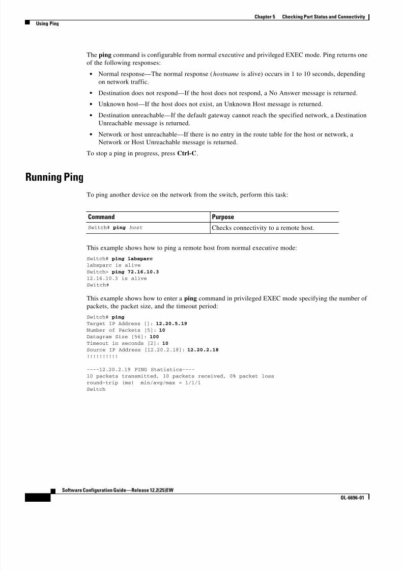
8/10/2019 Cisco ConfiguratioGuide SW4500 IOS
http://slidepdf.com/reader/full/cisco-configuratioguide-sw4500-ios 94/607
5-6
Software Configuration Guide—Release 12.2(25)EW
OL-6696-01
Chapter 5 Checking Port Status and Connectivity
Using Ping
The ping command is configurable from normal executive and privileged EXEC mode. Ping returns one
of the following responses:
• Normal response—The normal response (hostname is alive) occurs in 1 to 10 seconds, depending
on network traffic.
• Destination does not respond—If the host does not respond, a No Answer message is returned.
• Unknown host—If the host does not exist, an Unknown Host message is returned.
• Destination unreachable—If the default gateway cannot reach the specified network, a Destination
Unreachable message is returned.
• Network or host unreachable—If there is no entry in the route table for the host or network, a
Network or Host Unreachable message is returned.
To stop a ping in progress, press Ctrl-C.
Running Ping
To ping another device on the network from the switch, perform this task:
This example shows how to ping a remote host from normal executive mode:
Switch# ping labsparclabsparc is alive
Switch> ping 72.16.10.312.16.10.3 is alive
Switch#
This example shows how to enter a ping command in privileged EXEC mode specifying the number ofpackets, the packet size, and the timeout period:
Switch# pingTarget IP Address []: 12.20.5.19
Number of Packets [5]: 10
Datagram Size [56]: 100
Timeout in seconds [2]: 10Source IP Address [12.20.2.18]: 12.20.2.18
!!!!!!!!!!
----12.20.2.19 PING Statistics----
10 packets transmitted, 10 packets received, 0% packet loss
round-trip (ms) min/avg/max = 1/1/1
Switch
Command Purpose
Switch# ping host Checks connectivity to a remote host.

8/10/2019 Cisco ConfiguratioGuide SW4500 IOS
http://slidepdf.com/reader/full/cisco-configuratioguide-sw4500-ios 95/607

8/10/2019 Cisco ConfiguratioGuide SW4500 IOS
http://slidepdf.com/reader/full/cisco-configuratioguide-sw4500-ios 96/607
5-8
Software Configuration Guide—Release 12.2(25)EW
OL-6696-01
Chapter 5 Checking Port Status and Connectivity
Using Layer 2 Traceroute
This example shows use the trace command to display the route a packet takes through the network to
reach its destination:
Switch# trace ip ABA.NYC.mil
Type escape sequence to abort.
Tracing the route to ABA.NYC.mil (26.0.0.73)
1 DEBRIS.CISCO.COM (192.180.1.6) 1000 msec 8 msec 4 msec 2 BARRNET-GW.CISCO.COM (192.180.16.2) 8 msec 8 msec 8 msec 3 EXTERNAL-A-GATEWAY.STANFORD.EDU (192.42.110.225) 8 msec 4 msec 4 msec
4 BB2.SU.BARRNET.NET (192.200.254.6) 8 msec 8 msec 8 msec
5 SU.ARC.BARRNET.NET (192.200.3.8) 12 msec 12 msec 8 msec 6 MOFFETT-FLD-MB.in.MIL (192.52.195.1) 216 msec 120 msec 132 msec
7 ABA.NYC.mil (26.0.0.73) 412 msec 628 msec 664 msec
Switch#
Using Layer 2 TracerouteThese sections describe how to use the Layer 2 traceroute feature:
• Understanding Layer 2 Traceroute, page 5-8
• Layer 2 Traceroute Usage Guidelines, page 5-8
• Running Layer 2 Traceroute, page 5-9
Understanding Layer 2 Traceroute
The Layer 2 traceroute feature allows the switch to identify the physical path that a packet takes from a
source device to a destination device. Layer 2 traceroute supports only unicast source and destination
MAC addresses. It determines the path by using the MAC address tables of the switches in the path.
When the switch detects a device in the path that does not support Layer 2 traceroute, the switch
continues to send Layer 2 trace queries and lets them time out.
If you want the switch to trace the path from a host on a source device to a host on a destination device,
the switch can identify only the path from the source device to the destination device. It cannot identify
the path that a packet takes from source host to the source device or from the destination device to the
destination host.
Layer 2 Traceroute Usage Guidelines
These are the Layer 2 traceroute usage guidelines:
• CDP must be enabled on all the devices in the network. For Layer 2 traceroute to functional properly,
do not disable CDP.
If any devices in the physical path are transparent to CDP, the switch cannot identify the paththrough these devices.
Note For more information about enabling CDP, see Chapter 20, “Understanding and Configuring
CDP.”
• All switches in the physical path must have IP connectivity. When a switch is reachable from another
switch, you can test connectivity by using the ping command in privileged EXEC mode.

8/10/2019 Cisco ConfiguratioGuide SW4500 IOS
http://slidepdf.com/reader/full/cisco-configuratioguide-sw4500-ios 97/607
5-9
Software Configuration Guide—Release 12.2(25)EW
OL-6696-01
Chapter 5 Checking Port Status and Connectivity
Using Layer 2 Traceroute
• The maximum number of hops identified in the path is ten.
• You can enter the traceroute mac or the traceroute mac ip command in privileged EXEC mode on
a switch that is not in the physical path from the source device to the destination device. All switches
in the path must be reachable from this switch.
• The traceroute mac command output shows the Layer 2 path only when the specified source and
destination MAC addresses belong to the same VLAN. If you specify source and destination MACaddresses that belong to different VLANs, the Layer 2 path is not identified, and an error message
appears.
• If you specify a multicast source or destination MAC address, the path is not identified, and an error
message appears.
• If the source or destination MAC address belongs to multiple VLANs, you must specify the VLAN
to which both the source and destination MAC addresses belong. If the VLAN is not specified, the
path is not identified, and an error message appears.
• The traceroute mac ip command output shows the Layer 2 path when the specified source and
destination IP addresses belong to the same subnet. When you specify the IP addresses, the switch
uses Address Resolution Protocol (ARP) to associate the IP address with the corresponding MAC
address and the VLAN ID.– If an ARP entry exists for the specified IP address, the switch uses the associated MAC address
and identifies the physical path.
– If an ARP entry does not exist, the switch sends an ARP query and tries to resolve the IP
address. If the IP address is not resolved, the path is not identified, and an error message
appears.
• When multiple devices are attached to one port through hubs (for example, multiple CDP neighbors
are detected on a port), the Layer 2 traceroute feature is not supported. When more than one CDP
neighbor is detected on a port, the Layer 2 path is not identified, and an error message appears.
• This feature is not supported in Token Ring VLANs.
Running Layer 2 Traceroute
To display the physical path that a packet takes from a source device to a destination device, perform
either one of these tasks in privileged EXEC mode:
or
Command Purpose
Switch# traceroute mac {source-mac-address}
{destination-mac-address}Runs Layer 2 traceroute to trace the path that
packets take through the network.
Command Purpose
Switch# traceroute mac ip {source-mac-address}
{destination-mac-address}Runs IP traceroute to trace the path that
packets take through the network.

8/10/2019 Cisco ConfiguratioGuide SW4500 IOS
http://slidepdf.com/reader/full/cisco-configuratioguide-sw4500-ios 98/607
5-10
Software Configuration Guide—Release 12.2(25)EW
OL-6696-01
Chapter 5 Checking Port Status and Connectivity
Configuring ICMP
These examples show how to use the traceroute mac and traceroute mac ip commands to display the
physical path a packet takes through the network to reach its destination:
Switch# traceroute mac 0000.0201.0601 0000.0201.0201
Source 0000.0201.0601 found on con6[WS-C2950G-24-EI] (2.2.6.6)
con6 (2.2.6.6) :Fa0/1 => Fa0/3
con5 (2.2.5.5 ) : Fa0/3 => Gi0/1con1 (2.2.1.1 ) : Gi0/1 => Gi0/2con2 (2.2.2.2 ) : Gi0/2 => Fa0/1
Destination 0000.0201.0201 found on con2[WS-C3550-24] (2.2.2.2)
Layer 2 trace completedSwitch#
Switch# traceroute mac ip 2.2.66.66 2.2.22.22 detail
Translating IP to mac .....2.2.66.66 => 0000.0201.0601
2.2.22.22 => 0000.0201.0201
Source 0000.0201.0601 found on con6[WS-C2950G-24-EI] (2.2.6.6)
con6 / WS-C2950G-24-EI / 2.2.6.6 :
Fa0/1 [auto, auto] => Fa0/3 [auto, auto]
con5 / WS-C2950G-24-EI / 2.2.5.5 : Fa0/3 [auto, auto] => Gi0/1 [auto, auto]con1 / WS-C3550-12G / 2.2.1.1 :
Gi0/1 [auto, auto] => Gi0/2 [auto, auto]
con2 / WS-C3550-24 / 2.2.2.2 :
Gi0/2 [auto, auto] => Fa0/1 [auto, auto]Destination 0000.0201.0201 found on con2[WS-C3550-24] (2.2.2.2)
Layer 2 trace completed.Switch#
Configuring ICMPInternet Control Message Protocol (ICMP) provides many services that control and manage IP
connections. ICMP messages are sent by routers or access servers to hosts or other routers when a
problem is discovered with the Internet header. For detailed information on ICMP, refer to RFC 792.
Enabling ICMP Protocol Unreachable Messages
If the Cisco IOS software receives a nonbroadcast packet that uses an unknown protocol, it sends an
ICMP Protocol Unreachable message back to the source.
Similarly, if the software receives a packet that it is unable to deliver to the ultimate destination because
it knows of no route to the destination address, it sends an ICMP Host Unreachable message to the
source. This feature is enabled by default.
To enable the generation of ICMP Protocol Unreachable and Host Unreachable messages, enter thefollowing command in interface configuration mode:
Command Purpose
Switch (config-if)# [no] ip unreachables Enables ICMP destination unreachable messages.
Use the no keyword to disable the ICMP destination
unreachable messages.

8/10/2019 Cisco ConfiguratioGuide SW4500 IOS
http://slidepdf.com/reader/full/cisco-configuratioguide-sw4500-ios 99/607
5-11
Software Configuration Guide—Release 12.2(25)EW
OL-6696-01
Chapter 5 Checking Port Status and Connectivity
Configuring ICMP
To limit the rate that Internet Control Message Protocol (ICMP) destination unreachable messages are
generated, perform this task:
Enabling ICMP Redirect Messages
Data routes are sometimes less than optimal. For example, it is possible for the router to be forced to
resend a packet through the same interface on which it was received. If this occurs, the Cisco IOS
software sends an ICMP Redirect message to the originator of the packet telling the originator that the
router is on a subnet directly connected to the receiving device, and that it must forward the packet to
another system on the same subnet. The software sends an ICMP Redirect message to the packet's
originator because the originating host presumably could have sent that packet to the next hop without
involving this device at all. The Redirect message instructs the sender to remove the receiving device
from the route and substitute a specified device representing a more direct path. This feature is enabled
by default.
However, when Hot Standby Router Protocol (HSRP) is configured on an interface, ICMP Redirect
messages are disabled (by default) for the interface. For more information on HSRP, refer to the
following URL:
http://www.cisco.com/univercd/cc/td/doc/product/software/ios121/121cgcr/ip_c/ipcprt1/1cdip.htm
To enable the sending of ICMP Redirect messages if the Cisco IOS software is forced to resend a packet
through the same interface on which it was received, enter the following command in interface
configuration mode:
Enabling ICMP Mask Reply Messages
Occasionally, network devices must know the subnet mask for a particular subnetwork in the
internetwork. To obtain this information, devices can send ICMP Mask Request messages. These
messages are responded to by ICMP Mask Reply messages from devices that have the requestedinformation. The Cisco IOS software can respond to ICMP Mask Request messages if the ICMP Mask
Reply function is enabled.
Command Purpose
Switch (config)# [no] ip icmp rate-limit
unreachable [df] millisecondsLimits the rate that ICMP destination messages are
generated.
Use the no keyword to remove the rate limit and
reduce the CPU usage.
Command Purpose
Switch (config-if)# [no] ip redirects Enables ICMP Redirect messages.
Use the no keyword to disable the ICMP Redirect
messages and reduce CPU usage.

8/10/2019 Cisco ConfiguratioGuide SW4500 IOS
http://slidepdf.com/reader/full/cisco-configuratioguide-sw4500-ios 100/607
5-12
Software Configuration Guide—Release 12.2(25)EW
OL-6696-01
Chapter 5 Checking Port Status and Connectivity
Configuring ICMP
To have the Cisco IOS software respond to ICMP mask requests by sending ICMP Mask Reply
messages, perform this task:
Command Purpose
Switch (config-if)# [no] ip mask-reply Enables response to ICMP destination mask requests.
Use the no keyword to disable this functionality.

8/10/2019 Cisco ConfiguratioGuide SW4500 IOS
http://slidepdf.com/reader/full/cisco-configuratioguide-sw4500-ios 101/607
C H A P T E R
6-1
Software Configuration Guide—Release 12.2(25)EW
OL-6696-01
6
Configuring Supervisor Engine Redundancy UsingRPR and SSO
Catalyst 4500 series switches allow a redundant supervisor engine to take over if the active supervisor
engine fails. In software, supervisor engine redundancy is enabled by running the redundant supervisor
engine in route processor redundancy (RPR) or stateful switchover (SSO) operating mode.
Note The minimum ROMMON requirement for running SSO is Release 12.1(20r)EW1 or
Release 12.2(20r)EW.
This chapter describes how to configure supervisor engine redundancy on the Catalyst 4507R and
Catalyst 4510R switches. It also describes the relationship between SSO and Cisco IOS NSF-awareness
This chapter contains these major sections:
• Understanding Cisco IOS NSF-Awareness Support, page 6-2
• Understanding Supervisor Engine Redundancy, page 6-3
• Understanding Supervisor Engine Redundancy Synchronization, page 6-6
• Supervisor Engine Redundancy Guidelines and Restrictions, page 6-7
• Configuring Supervisor Engine Redundancy, page 6-8
• Performing a Manual Switchover, page 6-11
• Performing a Software Upgrade, page 6-12
• Manipulating Bootflash on the Redundant Supervisor Engine, page 6-14
Note For complete syntax and usage information for the switch commands used in this chapter, refer to the
Catalyst 4500 Series Switch Cisco IOS Command Reference and related publications at
http://www.cisco.com/univercd/cc/td/doc/product/software/ios122/122cgcr/index.htm.

8/10/2019 Cisco ConfiguratioGuide SW4500 IOS
http://slidepdf.com/reader/full/cisco-configuratioguide-sw4500-ios 102/607
6-2
Software Configuration Guide—Release 12.2(25)EW
OL-6696-01
Chapter 6 Configuring Supervisor Engine Redundancy Using RPR and SSO
Understanding Cisco IOS NSF-Awareness Support
Understanding Cisco IOS NSF-Awareness SupportCisco IOS Nonstop Forwarding (NSF) has two primary components:
NSF-capability—NSF works with SSO to minimize the amount of time that a Layer 3 network is
unavailable following a supervisor engine switchover by continuing to forward IP packets.
Reconvergence of Layer 3 routing protocols (BGP, EIGRP, OSPF v2, and IS-IS) is transparent to the
user and happens automatically in the background. The routing protocols recover routing
information from neighbor devices and rebuild the Cisco Express Forwarding (CEF) table.
NSF-awareness—If neighboring router devices detect that an NSF router can still forward packets
when RP (Route Processor) switchover happens, this capability is referred to as NSF-awareness.
Cisco IOS enhancements to the Layer 3 protocols OSPF, BGP, EIGRP and IS-IS are designed to
prevent route-flapping so that the CEF routing table does not timeout or the NSF router does not
drop routes. An NSF-aware router helps to send routing protocol information to the neighboring
NSF router.
Note NSF capable devices are Catalyst 6500 series switches, Cisco 7500 series routers, Cisco 10000 series
routers, and Cisco 12000 series routers. The Catalyst 4500 series switch is an NSF-aware device forRelease 12.2(20)EWA.
For more information on BGP, EIGRP, OSPF, and IS-IS NSF-awareness, refer to the URL:
http://www.cisco.com/en/US/products/sw/iosswrel/ps1839/products_feature_guides_list.html
A typical topology for NSF and NSF-aware routers is given below.
Figure 6-1 Topology for NSF and NSF-Aware Router
Si
SiSi
2 2
Catalyst 6500 NSF
Catalyst 4500NSF-Aware
Catalyst 4500NSF-Aware 1
2 0 1 0 3

8/10/2019 Cisco ConfiguratioGuide SW4500 IOS
http://slidepdf.com/reader/full/cisco-configuratioguide-sw4500-ios 103/607
6-3
Software Configuration Guide—Release 12.2(25)EW
OL-6696-01
Chapter 6 Configuring Supervisor Engine Redundancy Using RPR and SSO
Understanding Supervisor Engine Redundancy
Table 6-1 lists the supervisor engines and Catalyst 4500 series switches that support NSF-awareness:
In Release 12.2(20)EWA, NSF-awareness is supported on Catalyst 4500 series switches for EIGRP,
IS-IS, OSPF and BGP protocols. NSF-awareness is turned on by default for EIGRP, IS-IS and OSPF
protocols. For BGP, it needs to be turned on manually.
If the supervisor engine is configured for BGP (with the graceful-restart command), EIGRP, OSPF orIS-IS routing protocols, routing updates are automatically sent during the supervisor engine switchover
of a neighboring NSF capable switch (typically a Catalyst 6500 series switch).
Understanding Supervisor Engine RedundancyThese sections describe supervisor engine redundancy:
• Overview, page 6-3
• RPR Operation, page 6-4
• SSO Operation, page 6-4
• “Understanding Supervisor Engine Redundancy Synchronization” section on page 6-6
Overview
With supervisor engine redundancy enabled, if the active supervisor engine fails or if a manual
switchover is performed, the redundant supervisor engine becomes the active supervisor engine. The
redundant supervisor engine has been automatically initialized with the startup configuration of the
active supervisor engine, shortening the switchover time (30 seconds or longer in RPR mode, depending
on the configuration; subseconds in SSO mode).
In addition to the reduced switchover time, supervisor engine redundancy supports the following:
• Online insertion and removal (OIR) of the redundant supervisor engine.
Supervisor engine redundancy allows OIR of the redundant supervisor engine for maintenance.
When the redundant supervisor engine is inserted, the active supervisor engine detects its presence,
and the redundant supervisor engine boots into a partially-initialized state in RPR mode and a
fully-initialized state in SSO mode.
• Software upgrade. (See the “Performing a Software Upgrade” section on page 6-12.)
To minimize down time during software changes on the supervisor engine, load the new image on
the redundant supervisor engine, and conduct a switchover.
Table 6-1 NSF-Aware Capable Supervisor Engine and Catalyst 4500 Series Switch Matrix
NSF-Aware Capable Supervisor Engine Switch Support
Supervisor Engine III (WS-X4014) Catalyst 4506 series switch and Catalyst 4503series switch
Supervisor Engine IV (WS-X4515) Catalyst 4507R series switch, Catalyst 4506
series switch, and Catalyst 4503 series switch
Supervisor Engine V (WS-X4516) Catalyst 4507R series switch and Catalyst 4510R
series switch
Fixed Switch (WS-C4948) Catalyst 4948 switch

8/10/2019 Cisco ConfiguratioGuide SW4500 IOS
http://slidepdf.com/reader/full/cisco-configuratioguide-sw4500-ios 104/607
6-4
Software Configuration Guide—Release 12.2(25)EW
OL-6696-01
Chapter 6 Configuring Supervisor Engine Redundancy Using RPR and SSO
Understanding Supervisor Engine Redundancy
When power is first applied to a switch, the supervisor engine that boots first becomes the active
supervisor engine and remains active until a switchover occurs.
A switchover will occur when one or more of the following events take place:
• The active supervisor engine fails (due to either hardware or software function) or is removed.
• A user forces a switchover.
• A user reloads the active supervisor engine.
Table 6-2 provides information about chassis and supervisor engine support for redundancy.
RPR Operation
RPR is supported in Release 12.2(12c)EW and later releases. When a redundant supervisor engine runs
in RPR mode, it starts up in a partially-initialized state and is synchronized with the persistent
configuration of the active supervisor engine.
Note Persistent configuration includes the following components: startup-config, boot variables,
config-register, and VLAN database.
The redundant supervisor engine pauses the startup sequence after basic system initialization, and in the
event that the active supervisor engine fails, the redundant supervisor engine will become the new active
supervisor engine.
In a supervisor engine switchover, traffic is disrupted because in the RPR mode all of the physical ports
restart since there is no state maintained between supervisor engines relating to module types and
statuses. When the redundant supervisor engine completes its initialization, it will read hardware
information directly from the module.
SSO Operation
SSO is supported in Release 12.2(20)EWA and later releases. When a redundant supervisor engine runs
in SSO mode, the redundant supervisor engine starts up in a fully-initialized state and synchronizes with
the persistent configuration and the running configuration of the active supervisor engine. It
subsequently maintains the state on the protocols listed below, and all changes in hardware and software
states for features that support stateful switchover are kept in sync. Consequently, it offers no zero
interruption to Layer 2 sessions in a redundant supervisor engine configuration.
Table 6-2 Chassis and Supervisor Support
Chassis(Product Number) Supported Supervisor Engines
Catalyst 4507R
(WS-C4507R)
Supports redundant Supervisor Engine II-Plus (WS-X4013+),
Supervisor Engine IV (WS-X4515), redundant Supervisor
Engine V (WS-X4516)
Catalyst 4510R
(WS-C4510R)
Supports redundant Supervisor Engine V (WS-X4516)

8/10/2019 Cisco ConfiguratioGuide SW4500 IOS
http://slidepdf.com/reader/full/cisco-configuratioguide-sw4500-ios 105/607
6-5
Software Configuration Guide—Release 12.2(25)EW
OL-6696-01
Chapter 6 Configuring Supervisor Engine Redundancy Using RPR and SSO
Understanding Supervisor Engine Redundancy
Because the redundant supervisor engine recognizes the hardware link status of every link, ports that
were active before the switchover will remain active, including the uplink ports. However, because
uplink ports are physically on the supervisor engine, they will be disconnected if the supervisor engine
is removed.
If the active supervisor engine fails, the redundant supervisor engine become active. This newly active
supervisor engine uses existing Layer 2 switching information to continue forwarding traffic. Layer 3forwarding will be delayed until the routing tables have been repopulated in the newly active supervisor
engine.
SSO supports stateful switchover of the following Layer 2 features. The state of these features is
preserved between both the active and redundant supervisor engines:
• 802.3
• 802.3u
• 802.3x (Flow Control)
• 802.3ab (GE)
• 802.3z (Gigabit Ethernet including CWDM)
• 802.3ad (LACP)
• 802.1p (Layer 2 QoS)
• 802.1q
• 802.1X (Authentication)
• 802.1D (Spanning Tree Protocol)
• 802.3af (Inline power)
• PAgP
• VTP
• Dynamic ARP Inspection
• DHCP snooping
• IP source guard
• IGMP snooping (versions 1 and 2)
• DTP (802.1q and ISL)
• MST
• PVST+
• Rapid-PVST
• PortFast/UplinkFast/BackboneFast
• BPDU guard and filtering
• Voice VLAN
• Port security
• Unicast MAC filtering
• ACL (VACLS, PACLS, RACLS)
• QOS (DBL)
• Multicast storm control/broadcast storm control

8/10/2019 Cisco ConfiguratioGuide SW4500 IOS
http://slidepdf.com/reader/full/cisco-configuratioguide-sw4500-ios 106/607
6-6
Software Configuration Guide—Release 12.2(25)EW
OL-6696-01
Chapter 6 Configuring Supervisor Engine Redundancy Using RPR and SSO
Understanding Supervisor Engine Redundancy Synchronization
SSO is compatible with the following list of features. However, the protocol database for these features
is not synchronized between the redundant and active supervisor engines:
• 802.1Q tunneling with Layer 2 Protocol Tunneling (L2PT)
• Baby giants
• Jumbo frame support
• CDP
• Flood blocking
• UDLD
• SPAN/RSPAN
• NetFlow
The following features are learned on the redundant supervisor engine if the SSO feature is enabled:
• All Layer 3 protocols on Catalyst 4500 series switches (Switch Virtual Interfaces)
Understanding Supervisor Engine Redundancy SynchronizationDuring normal operation, the persistent configuration (RPR and SSO) and the running configuration
(SSO only) are synchronized by default between the two supervisor engines. In a switchover, the new
active supervisor engine uses the current configuration.
Note You cannot enter CLI commands on the redundant supervisor engine console.
These sections describe supervisor engine redundancy synchronization:
• RPR Supervisor Engine Configuration Synchronization, page 6-6
•SSO Supervisor Engine Configuration Synchronization, page 6-7
RPR Supervisor Engine Configuration Synchronization
Because the redundant supervisor engine is only partially initialized in RPR mode, it interacts with the
active supervisor engine only to receive configuration changes at startup and upon saving the
configuration changes.
When a redundant supervisor engine is running in RPR mode, the following events trigger
synchronization of the configuration information:
• When the redundant supervisor engine boots, the auto-sync command synchronizes the persistent
configuration. This command is enabled by default. For details, refer to “Synchronizing the
Supervisor Engine Configurations” section on page 6-10.
• When the active supervisor engine detects the redundant supervisor engine, the configuration
information is synchronized from the active supervisor engine to the redundant supervisor engine.
This synchronization overwrites any existing startup configuration file on the redundant supervisor
engine.
• When you make changes to the configuration, you must use the write command to save and
synchronize the startup configuration of the redundant supervisor engine.

8/10/2019 Cisco ConfiguratioGuide SW4500 IOS
http://slidepdf.com/reader/full/cisco-configuratioguide-sw4500-ios 107/607
6-7
Software Configuration Guide—Release 12.2(25)EW
OL-6696-01
Chapter 6 Configuring Supervisor Engine Redundancy Using RPR and SSO
Supervisor Engine Redundancy Guidelines and Restrictions
SSO Supervisor Engine Configuration Synchronization
When a redundant supervisor engine runs in SSO mode, the following events trigger synchronization of
the configuration information:
• When the active supervisor detects the redundant supervisor engine, synchronization of the
persistent and running configuration takes place, allowing the redundant supervisor engine to arriveat a fully-initiated state.
• When real-time changes occur, the active supervisor engine synchronizes the running-config and
(or) the persistent configuration (if necessary) with the redundant supervisor engine.
• When you change the configuration, you must use the write command to allow the active supervisor
engine to save and synchronize the startup configuration of the redundant supervisor engine.
Supervisor Engine Redundancy Guidelines and RestrictionsThe following guidelines and restrictions apply to supervisor engine redundancy:
• RPR requires Release 12.1(12c)EW, Release 12.1(19)E or later releases. SSO requires Release
12.2(20)EWA.
• The Catalyst 4507R switch and the 4510R switch are the only Catalyst 4500 series switches that
support supervisor engine redundancy.
• The Catalyst 4510R switch supports the WS-X4516 supervisor engine only. The Catalyst 4507R
switch supports supervisor engines WS-X4013+, WS-X4515, and WS-X4516.
• Redundancy requires both supervisor engines in the chassis to be of the same supervisor engine
model and to use the same Cisco IOS software image.
• Router ports are not supported when SSO redundancy mode is configured.
• When you use the WS-X4013+ and WS-X4515 supervisor engines in RPR or SSO mode, only the
Gig1/1 and Gig2/1 Gigabit Ethernet interfaces are available, but the Gig1/2 and Gig2/2 uplink portsare unavailable.
• When the WS-X4516 active and redundant supervisor engines are installed in the same chassis, the
four uplink ports (Gig1/1, Gig2/1, Gig 1/2, and Gig2/2) are available.
• The active and redundant supervisor engines in the chassis must be in slots 1 and 2.
• Each supervisor engine in the chassis must have its own Flash device and console port connections
to operate the switch on its own.
• Each supervisor engine must have a unique console connection. Do not connect a Y cable to the
console ports.
• Supervisor engine redundancy does not provide supervisor engine load balancing.
• The Cisco Express Forwarding (CEF) table is cleared on a switchover. As a result, routed traffic is
interrupted until route tables reconverge. This reconvergence time is minimal because the SSO
feature reduces the supervisor engine redundancy switchover time from 30+ seconds to subseconds,
so Layer 3 also has a faster failover time if the switch is configured for SSO.
• Static IP routes are maintained across a switchover because they are configured from entries in the
configuration file.
• Information about Layer 3 dynamic states that is maintained on the active supervisor engine is not
synchronized to the redundant supervisor engine and is lost on switchover.
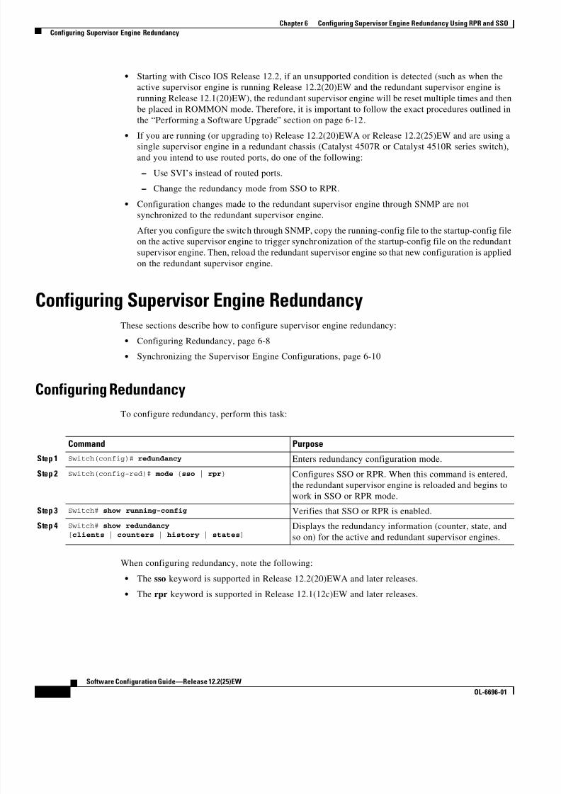
8/10/2019 Cisco ConfiguratioGuide SW4500 IOS
http://slidepdf.com/reader/full/cisco-configuratioguide-sw4500-ios 108/607
6-8
Software Configuration Guide—Release 12.2(25)EW
OL-6696-01
Chapter 6 Configuring Supervisor Engine Redundancy Using RPR and SSO
Configuring Supervisor Engine Redundancy
• Starting with Cisco IOS Release 12.2, if an unsupported condition is detected (such as when the
active supervisor engine is running Release 12.2(20)EW and the redundant supervisor engine is
running Release 12.1(20)EW), the redundant supervisor engine will be reset multiple times and then
be placed in ROMMON mode. Therefore, it is important to follow the exact procedures outlined in
the “Performing a Software Upgrade” section on page 6-12.
• If you are running (or upgrading to) Release 12.2(20)EWA or Release 12.2(25)EW and are using asingle supervisor engine in a redundant chassis (Catalyst 4507R or Catalyst 4510R series switch),
and you intend to use routed ports, do one of the following:
– Use SVI’s instead of routed ports.
– Change the redundancy mode from SSO to RPR.
• Configuration changes made to the redundant supervisor engine through SNMP are not
synchronized to the redundant supervisor engine.
After you configure the switch through SNMP, copy the running-config file to the startup-config file
on the active supervisor engine to trigger synchronization of the startup-config file on the redundant
supervisor engine. Then, reload the redundant supervisor engine so that new configuration is applied
on the redundant supervisor engine.
Configuring Supervisor Engine RedundancyThese sections describe how to configure supervisor engine redundancy:
• Configuring Redundancy, page 6-8
• Synchronizing the Supervisor Engine Configurations, page 6-10
Configuring Redundancy
To configure redundancy, perform this task:
When configuring redundancy, note the following:
• The sso keyword is supported in Release 12.2(20)EWA and later releases.
• The rpr keyword is supported in Release 12.1(12c)EW and later releases.
Command Purpose
Step 1 Switch(config)# redundancy Enters redundancy configuration mode.
Step 2 Switch(config-red)# mode {sso | rpr} Configures SSO or RPR. When this command is entered,
the redundant supervisor engine is reloaded and begins to
work in SSO or RPR mode.
Step 3 Switch# show running-config Verifies that SSO or RPR is enabled.
Step 4 Switch# show redundancy
[clients | counters | history | states]Displays the redundancy information (counter, state, and
so on) for the active and redundant supervisor engines.

8/10/2019 Cisco ConfiguratioGuide SW4500 IOS
http://slidepdf.com/reader/full/cisco-configuratioguide-sw4500-ios 109/607
6-9
Software Configuration Guide—Release 12.2(25)EW
OL-6696-01
Chapter 6 Configuring Supervisor Engine Redundancy Using RPR and SSO
Configuring Supervisor Engine Redundancy
This example shows how to configure the system for SSO and display the redundancy facility
information:
Switch> enable
Switch# configure terminal
Enter configuration commands, one per line. End with CNTL/Z.
Switch(config)# redundancy
Switch(config-red)# mode sso Switch(config-red)# end Switch# show redundancy
Redundant System Information :
------------------------------ Available system uptime = 2 days, 2 hours, 39 minutes
Switchovers system experienced = 0
Standby failures = 0
Last switchover reason = none
Hardware Mode = Duplex Configured Redundancy Mode = Stateful Switchover
Operating Redundancy Mode = Stateful Switchover
Maintenance Mode = Disabled
Communications = Up
Current Processor Information :-------------------------------
Active Location = slot 1
Current Software state = ACTIVE
Uptime in current state = 2 days, 2 hours, 39 minutes Image Version = Cisco Internetwork Operating System Software
IOS (tm) Catalyst 4000 L3 Switch Software (cat4000-I5S-M), Version 12.2(20)EWA(3.92), CISCO INTERNAL USE ONLY ENHANCED PRODUCTION VERSION
Copyright (c) 1986-2004 by cisco Systems, Inc.
Compiled Wed 14-Jul-04 04:42 by esi
BOOT = bootflash:cat4000-i5s-mz.122_20_EWA_392,1 Configuration register = 0x2002
Peer Processor Information :
----------------------------
Standby Location = slot 2 Current Software state = STANDBY HOT
Uptime in current state = 2 days, 2 hours, 39 minutes
Image Version = Cisco Internetwork Operating System Software
IOS (tm) Catalyst 4000 L3 Switch Software (cat4000-I5S-M), Version 12.2(20)EWA(3.92), CISCO INTERNAL USE ONLY ENHANCED PRODUCTION VERSION
Copyright (c) 1986-2004 by cisco Systems, Inc.Compiled Wed 14-Jul-04 0
BOOT = bootflash:cat4000-i5s-mz.122_20_EWA_392,1
Configuration register = 0x2002
Switch#
This example shows how to display redundancy facility state information:
Switch# show redundancy states my state = 13 -ACTIVE
peer state = 8 -STANDBY HOT Mode = Duplex
Unit = Primary
Unit ID = 2
Redundancy Mode (Operational) = Stateful Switchover
Redundancy Mode (Configured) = Stateful Switchover Split Mode = Disabled

8/10/2019 Cisco ConfiguratioGuide SW4500 IOS
http://slidepdf.com/reader/full/cisco-configuratioguide-sw4500-ios 110/607
6-10
Software Configuration Guide—Release 12.2(25)EW
OL-6696-01
Chapter 6 Configuring Supervisor Engine Redundancy Using RPR and SSO
Configuring Supervisor Engine Redundancy
Manual Swact = Enabled
Communications = Up
client count = 21
client_notification_TMR = 240000 milliseconds keep_alive TMR = 9000 milliseconds
keep_alive count = 0
keep_alive threshold = 18 RF debug mask = 0x0Switch#
This example shows how to change the system configuration from RPR to SSO mode:
Switch(config)# redundancy
Switch(config-red)# modeSwitch(config-red)# mode sso
Changing to sso mode will reset the standby. Do you want to continue?[confirm]
Switch(config-red)# end
Switch#*Aug 1 13:11:16: %C4K_REDUNDANCY-3-COMMUNICATION: Communication with the peer Supervisor
has been lost*Aug 1 13:11:16: %C4K_REDUNDANCY-3-SIMPLEX_MODE: The peer Supervisor has been lost
This example shows how to change the system configuration from SSO to RPR mode:Switch(config)# redundancy
Switch(config-red)# mode rpr
Changing to rpr mode will reset the standby. Do you want to continue?[confirm]Switch(config-red)# end
*Aug 1 13:11:16: %C4K_REDUNDANCY-3-COMMUNICATION: Communication with the peer Supervisorhas been lost
*Aug 1 13:11:16: %C4K_REDUNDANCY-3-SIMPLEX_MODE: The peer Supervisor has been lost
Synchronizing the Supervisor Engine Configurations
To manually synchronize the configurations used by the two supervisor engines, perform this task on the
active supervisor engine:
Note Configuration changes made to the redundant supervisor engine through SNMP are not synchronized to
the redundant supervisor engine. For information on how to handle this situation, see the “Supervisor
Engine Redundancy Guidelines and Restrictions” section on page 6-7.
Command Purpose
Step 1 Switch(config)# redundancy Enters redundancy configuration mode.
Step 2 Switch(config-red)# main-cpu Enters main-cpu configuration submode.
Step 3 Switch(config-r-mc)# auto-sync {startup-config |
config-register | bootvar | standard}Synchronizes the configuration elements.
Step 4 Switch(config-r-mc)# end Returns to privileged EXEC mode.
Step 5 Switch# copy running-config startup-config Synchronizes the running configuration in dynamic
random-access memory (DRAM) to the startup
configuration file in NVRAM.
Note This step is not required to synchronize the
running configuration file in (DRAM).

8/10/2019 Cisco ConfiguratioGuide SW4500 IOS
http://slidepdf.com/reader/full/cisco-configuratioguide-sw4500-ios 111/607
6-11
Software Configuration Guide—Release 12.2(25)EW
OL-6696-01
Chapter 6 Configuring Supervisor Engine Redundancy Using RPR and SSO
Performing a Manual Switchover
Note The auto-sync command controls the synchronization of the config-reg, bootvar, and startup/private
configuration files only. The calendar and VLAN database files are always synchronized when they
change. In SSO mode, the running-config is always synchronized.
This example shows how to reenable the default automatic synchronization feature using the auto-syncstandard command to synchronize the startup-config and config-register configuration of the active
supervisor engine with the redundant supervisor engine. Updates for the boot variables are automatic
and cannot be disabled.
Switch(config)# redundancySwitch(config-red)# main-cpu
Switch(config-r-mc)# auto-sync standard
Switch(config-r-mc)# end
Switch# copy running-config startup-config
Note To manually synchronize individual elements of the standard auto-sync configuration, disable the default
automatic synchronization feature.
This example shows how to disable default automatic synchronization and allow only automatic
synchronization of the config-registers of the active supervisor engine to the redundant supervisor
engine, while disallowing synchronization of the startup configuration:
Switch(config)# redundancy
Switch(config-red)# main-cpuSwitch(config-r-mc)# no auto-sync standard
Switch(config-r-mc)# auto-sync config-registerSwitch(config-r-mc)# end
Performing a Manual Switchover
This section describes how to perform a manual switchover (from the active supervisor engine to theredundant supervisor engine) for test purposes. We recommend that you perform a manual switchover
prior to deploying SSO in your production environment.
Note This discussion assumes that SSO has been configured as the redundant mode.
To perform a manual switchover, perform this task on the active supervisor engine:
Command Purpose
Step 1 Switch# show redundancy Verifies that the peer state is in the STANDBY HOT
state.
See the example of the show redundancy states
command on page 6-10.
Step 2 Switch# redundancy force-switchover Launches switchover from the active supervisor engine
to the redundant supervisor engine.
If the state of the redundant supervisor engine is not
standby hot, this command will not execute.

8/10/2019 Cisco ConfiguratioGuide SW4500 IOS
http://slidepdf.com/reader/full/cisco-configuratioguide-sw4500-ios 112/607
6-12
Software Configuration Guide—Release 12.2(25)EW
OL-6696-01
Chapter 6 Configuring Supervisor Engine Redundancy Using RPR and SSO
Performing a Software Upgrade
Be aware of these usage guidelines:
• To force a switchover, the redundant supervisor engine must be in a standby hot state. You can verify
the state with the show redundancy command. If the state is not standby hot, the
redundancy force-switchover command will not execute.
• Use the redundancy force-switchover command, rather than the reload command, to initiate a
switchover. The redundancy force-switchover command will first check that the redundantsupervisor engine is in the correct state. If you issue the reload command and the status is not
standby hot, the reload command will reset the current supervisor engine only.
After an initial switchover, there might be occasions when you want to make the supervisor engine in
slot 1 of the chassis the active supervisor engine. If the image on supervisor engine 1 is the one you
intend to run on both supervisor engines, it is not necessary to re-boot the image on the supervisor engine
in slot 1 to make it redundant . Instead, you can force another switchover. However, if you want a newer
version of the image to run on both supervisor engines, follow the steps under “Performing a Software
Upgrade” on page 12. Use the show module command to see which slot contains the active supervisor
engine, and force another switchover if necessary.
Performing a Software UpgradeThe software upgrade procedure supported by supervisor engine redundancy allows you to reload the
Cisco IOS software image on the redundant supervisor engine, and once complete, reload the active
supervisor engine once.
To perform a software upgrade, perform this task:
Command Purpose
Step 1 Switch# copy source_device :source_filename
slot0:target_filename
Or:Switch# copy source_device :source_filename bootflash:target_filename
Copies the new Cisco IOS software image to bootflash on
both supervisor engines.
Step 2 Switch# copy source_device :source_filename slaveslot0:target_filename
Or:
Switch# copy source_device :source_filename slavebootflash:target_filename
Copies the new image to a slave device (such as
slavebootflash and slaveslot0).
Step 3 Switch# config terminalSwitch(config)# config-register 0x2
Switch(config)# boot system flash
device :file_name
Configures the supervisor engines to boot the new image.
Step 4 Switch(config)# redundancy Enters redundancy configuration mode.
Step 5 Switch(config-red)# main-cpu Enters main-cpu configuration submode.
Step 6 Switch(config-r-mc)# auto-syn standard Synchronizes the configuration elements.
Step 7 Switch(config-r-mc)# end Returns to privileged EXEC mode.
Step 8 Switch# copy running-config start-config Saves the configuration.

8/10/2019 Cisco ConfiguratioGuide SW4500 IOS
http://slidepdf.com/reader/full/cisco-configuratioguide-sw4500-ios 113/607
6-13
Software Configuration Guide—Release 12.2(25)EW
OL-6696-01
Chapter 6 Configuring Supervisor Engine Redundancy Using RPR and SSO
Performing a Software Upgrade
This example shows how to perform a software upgrade:
Switch# config terminal
Switch(config)# config-register 0x2
Switch(config)# boot system flash slot0:cat4000-i5s-mz.122-20.EWA Switch(config)# redundancy
Switch(config-red)# main-cpuSwitch(config-r-mc)# auto-syn standard
Switch(config-r-mc)# end
Switch# copy running-config start-config
Switch# redundancy reload peerSwitch# redundancy force-switchover
Switch#
This example illustrates how to verify that the running configuration on the active supervisor engine has
successfully synchronized with the redundant supervisor engine:
Switch# config terminal
Switch(config)# redundancy
Switch(config-red)# main-cpuSwitch(config-r-mc)# auto-sync standard
4d01h: %C4K_REDUNDANCY-5-CONFIGSYNC: The bootvar has been successfully synchronized to the
standby supervisor4d01h: %C4K_REDUNDANCY-5-CONFIGSYNC: The config-reg has been successfully synchronized to
the standby supervisor4d01h: %C4K_REDUNDANCY-5-CONFIGSYNC: The startup-config has been successfully synchronized
to the standby supervisor
4d01h: %C4K_REDUNDANCY-5-CONFIGSYNC: The private-config has been successfully synchronized
to the standby supervisor
The example above shows that the boot variable, the config-register, and the startup configuration from
the active supervisor engine have successfully synchronized to the redundant supervisor engine.
Step 9 Switch# redundancy reload peer Reloads the redundant supervisor engine and brings it
back online (using the new release of the Cisco IOS
software).
Note Before proceeding to Step 10, ensure that the switch
is operating in RPR mode.
Step 10 Switch# redundancy force-switchover Conducts a manual switchover to the redundant
supervisor engine. The redundant supervisor engine
becomes the new active supervisor engine using the new
Cisco IOS software image.
The old active supervisor engine reboots with the new
image and becomes the redundant supervisor engine.
Command Purpose

8/10/2019 Cisco ConfiguratioGuide SW4500 IOS
http://slidepdf.com/reader/full/cisco-configuratioguide-sw4500-ios 114/607
6-14
Software Configuration Guide—Release 12.2(25)EW
OL-6696-01
Chapter 6 Configuring Supervisor Engine Redundancy Using RPR and SSO
Manipulating Bootflash on the Redundant Supervisor Engine
Manipulating Bootflash on the Redundant Supervisor Engine
Note The console port on the redundant supervisor engine is not available.
To manipulate the redundant supervisor engine bootflash, perform one or more of the following tasks:
Command Purpose
Switch# dir slaveslot0:target_filename
Or:
Switch# dir slavebootflash:target_filename
Lists the contents of the slot0: device on the redundant
supervisor engine.
Lists the contents of the bootflash: device on the redundant
supervisor engine.
Switch# delete slaveslot0:target_filename
Or:
Switch# delete slave bootflash:target_filename
Deletes specific files from the slot0: device on the redundant
supervisor engine.
Deletes specific files from the bootflash: device on the
redundant supervisor engine.
Switch# squeeze slaveslot0:target_filename
Or:
Switch# squeeze slavebootflash:target_filename
Squeezes the slot0: device on the redundant supervisor
engine.
Squeezes the bootflash: device on the redundant supervisor
engine.
Switch# format slaveslot0:target_filename
Or:
Switch# format slavebootflash:target_filename
Formats the slot0: device on the redundant supervisor engine.
Formats the bootflash: device on the redundant supervisor
engine.
Switch# copy source_device :source_filename
slaveslot0:target_filename
Or:
Switch# copy source_device :source_filename
slavebootflash:target_filename
Copies a file from the active supervisor engine to the slot0:
device on the redundant supervisor engine.
Copies a file to the bootflash: device on a redundant
supervisor engine.
Note Source could be the active supervisor engine or a TFTP server.

8/10/2019 Cisco ConfiguratioGuide SW4500 IOS
http://slidepdf.com/reader/full/cisco-configuratioguide-sw4500-ios 115/607
C H A P T E R
7-1
Software Configuration Guide—Release 12.2(25)EW
OL-6696-01
7
Environmental Monitoring and PowerManagement
Note Before reading this chapter, read the "Preparing for Installation” section of the
Catalyst 4500 Series Installation Guide. It is important to ensure that your installation site has enoughpower and cooling to accommodate the additional electrical load and heat introduced by PoE.
This chapter describes power management and environmental monitoring features in the Catalyst 4500
series switches. It provides guidelines, procedures, and configuration examples.
This chapter consists of the following major sections:
• Understanding Environmental Monitoring, page 7-1
• Power Management, page 7-3
Note For complete syntax and usage information for the switch commands used in this chapter, refer to the
Catalyst 4500 Series Switch Cisco IOS Command Reference and related publications at
http://www.cisco.com/univercd/cc/td/doc/product/software/ios122/122cgcr/index.htm.
Understanding Environmental MonitoringThis section contains the following subsections:
• Using CLI Commands to Monitor your Environment, page 7-2
• System Alarms, page 7-2
Environmental monitoring of chassis components provides early warning indications of possible
component failure. This warning helps you to ensure the safe and reliable operation of your system and
avoid network interruptions.
This section describes how to monitor critical system components so that you can identify and rapidly
correct hardware-related problems.

8/10/2019 Cisco ConfiguratioGuide SW4500 IOS
http://slidepdf.com/reader/full/cisco-configuratioguide-sw4500-ios 116/607
7-2
Software Configuration Guide—Release 12.2(25)EW
OL-6696-01
Chapter 7 Environmental Monitoring and Power Management
Understanding Environmental Monitoring
Using CLI Commands to Monitor your Environment
Use the show environment CLI command to monitor the system. This section gives a basic overview of
the command and keywords you will need.
Enter the show environment [alarm | status | temperature] command to display system status
information. Keyword descriptions are listed in Table 7-1.
The following example shows how to display the environment conditions. This output indicates that the
power supplies are different. The switch will use only one power supply and disable the other.
Switch# show environment
no alarm
Chassis Temperature = 35 degrees CelsiusChassis Over Temperature Threshold = 75 degrees Celsius
Chassis Critical Temperature Threshold = 95 degrees Celsius
Power Fan InlineSupply Model No Type Status Sensor Status
------ ---------------- --------- ----------- ------ ------
PS1 PWR-C45-2800AC AC 2800W good good good
PS2 PWR-C45-1000AC AC 1000W err-disable good n.a.
*** Power Supplies of different types have been detected***
Switch#
System Alarms
The system has two types of alarms: major and minor. A major alarm indicates a critical problem that
could lead to system shutdown. A minor alarm is informational—it alerts you to a problem that could
turn critical if corrective action is not taken.
When the system issues an alarm (major or minor) that indicates an over-temperature condition, the
switch does not cancel the alarm nor take any action (such as module reset or shutdown) for five minutes.
If the temperature falls 5 degrees Celsius below the alarm threshold during this period, the alarm is
canceled.
An LED on the supervisor indicates if an alarm has been issued. See Table 7-2 for more information.
Note Refer to the Catalyst 4500 Series Switch Module Installation Guide for information on LEDs, including
the startup behavior of the supervisor engine system LED.
Table 7-1 show environment Keyword Descriptions
Keyword Purpose
alarm Displays environmental alarms for the system.
status Displays field-replaceable unit (FRU) operational status and power
and power supply fan sensor information.
temperature Displays temperature of the chassis.

8/10/2019 Cisco ConfiguratioGuide SW4500 IOS
http://slidepdf.com/reader/full/cisco-configuratioguide-sw4500-ios 117/607
7-3
Software Configuration Guide—Release 12.2(25)EW
OL-6696-01
Chapter 7 Environmental Monitoring and Power Management
Power Management
Power ManagementThis section describes the power management feature in the Catalyst 4500 series switches and the
Catalyst 4006 switch, and it includes the following major sections:
• Power Management for the Catalyst 4948 Switches, page 7-3
• Power Management for the Catalyst 4500 Series Switches, page 7-4
• Power Management for the Catalyst 4006 Switch, page 7-12
• Power Consumption of Chassis Components, page 7-15
• Powering Down a Module, page 7-15
Power Management for the Catalyst 4948 Switches
You can select from AC or DC power supplies to ensure that you have enough power for your switch.The Catalyst 4948 switches support the following power supplies:
– 300 W AC
– 300 W DC
Table 7-2 Alarms for Supervisor Engine and Switching Modules
EventAlarmType
Supervisor LEDColor Description and Action
Supervisor engine1 temperature sensor
exceeds major threshold2
1. The Supervisor is not a distinct module on the Catalyst 4948 switch as it is on Catalyst 4500 series switches. See the Catalyst 4948 Installation Guide
for LED behavior on the Catalyst 4948 switch.
2. Temperature sensors monitor key supervisor engine components, including daughter cards.
Major Red Syslog message.
If the over-temperature condition is not corrected,
the system shuts down after 5 min.
Alarm threshold:
• Chassis critical temperature threshold = 95°C
Supervisor fails power on self-test
(POST)
Major Red Syslog message.
The supervisor fails to come up.
Chassis fan tray fails Major Red If not corrected, the system shuts down in 5 minutes.
Supervisor engine temperature sensor
exceeds minor threshold
Minor Orange Syslog message.
Monitor the condition.
Alarm threshold:
• Chassis over temperature threshold = 75°C
No problems None Green

8/10/2019 Cisco ConfiguratioGuide SW4500 IOS
http://slidepdf.com/reader/full/cisco-configuratioguide-sw4500-ios 118/607
7-4
Software Configuration Guide—Release 12.2(25)EW
OL-6696-01
Chapter 7 Environmental Monitoring and Power Management
Power Management
These power supplies are incompatible with Catalyst 4500 series switches. Since Power over Ethernet
(PoE) is not supported on the Catalyst 4948 switch, only a limited wattage is needed. (For information
on PoE, see Chapter 8, “Configuring Power over Ethernet.”) When you insert power supplies in your
switch, the EEPROM on the power supplies can be read by the system software even if the supply is not
powered on. You may mix AC and DC power supplies.
Power Management Modes
The Catalyst 4948 switches support the redundant power management mode. In this mode, if both power
supplies are operating normally, each provides from 20/80 to 45/55 percent of the total system power
requirements at all times. If one power supply fails, the other unit increases power to 100 percent of the
total power requirement.
Power Management for the Catalyst 4500 Series Switches
You can select from several different power supplies to ensure that you have enough power for the
modules installed in your switch. The Catalyst 4500 series switches support the following power
supplies:
• Fixed Wattage—This power supply always delivers a fixed amount of PoE and system power.
– 1000 W AC (not recommended on the Catalyst 4510R switch, PoE not supported)
– 1400 W AC—Data-only and does not support PoE
• Variable Wattage—These power supplies automatically adjusts the wattage to accommodate PoE
and system power requirements.
– 1300 W AC—Supports PoE.
– 1400 W DC—Supports up to 1400 W of system power and variable amounts of PoE, depending
on the input feed to the power supply. See “Special Considerations for the 1400 W DC Power
Supply” section on page 7-10 for more information.
– 1400 W DC Service Provider—Uses up to three lines (12.5 A, 15 A, 15 A) of DC input and
delivers varying amounts of power in the range 400 W-1400 W depending on the lines powered.
See “Special Considerations for the 1400 W DC SP Triple Input Power Supply” section on
page 7-11 for more information.
– 2800 W AC—Supports up to 1400 W of system power and up to 1400 W of PoE.
Note All Catalyst 4500 series switch AC-input power supplies require single-phase source AC. The source AC
can be out of phase between multiple power supplies or multiple AC-power plugs on the same power
supply because all AC power supply inputs are isolated. Each chassis power supply should have its own
dedicated branch circuit: 20A for North America and circuits sized to local and national codes for
International locations.
When you insert power supplies in your switch, use power supplies that are of the same wattage. If you
mix power supplies, the switch will use the one it recognizes first and ignore the other power supply. The
power supply status displays as err-disable and the summary displays as all zeros (0) for wattage values
in the output for the show power command.

8/10/2019 Cisco ConfiguratioGuide SW4500 IOS
http://slidepdf.com/reader/full/cisco-configuratioguide-sw4500-ios 119/607
7-5
Software Configuration Guide—Release 12.2(25)EW
OL-6696-01
Chapter 7 Environmental Monitoring and Power Management
Power Management
The following example shows the output for the show power command for mixed power supplies:
Switch# show powerPower Fan Inline
Supply Model No Type Status Sensor Status------ ---------------- --------- ----------- ------ ------
PS1 PWR-C45-2800AC AC 2800W good good good
PS2 PWR-C45-1000AC AC 1000W err-disable good n.a.
*** Power Supplies of different type have been detected***
Power supplies needed by system :1Power supplies currently available :1
Power Summary Maximum
(in Watts) Used Available
---------------------- ---- ---------
System Power (12V) 328 1360Inline Power (-50V) 0 1400
Backplane Power (3.3V) 10 40---------------------- ----
Total Used 338 (not to exceed Total Maximum Available = 750)
Switch#
Power Management Modes
The Catalyst 4500 series switches support two power management modes:
• Redundant mode—Redundant mode uses one power supply as a primary power supply and the
second power supply as a back-up. If the primary power supply fails, the second power supply
immediately supports the switch without any disruption in the network. Both power supplies must
be the same wattage. A single power supply must have enough power to support the switch
configuration.
• Combined mode—Combined mode uses the power from all installed power supplies to support the
switch configuration power requirements. However, combined mode has no power redundancy. If a
power supply fails, one or more modules might shut down.
Note On the Catalyst 4510R switch, the 1000 W AC power supply is not enough to support redundant
mode for all possible configurations. It is able to support redundant mode for limited
configurations that require less than 1000 W.
Note The 1400 W DC power supply supports combined mode for data power. It does not support
combined mode for PoE power.
Selecting a Power Management ModeBy default, a switch is set to redundant mode. In the show power command, if the power supplies
needed by system is 1, the switch is in redundant mode; if the power supplies needed by system is 2,
the switch is in combined mode.

8/10/2019 Cisco ConfiguratioGuide SW4500 IOS
http://slidepdf.com/reader/full/cisco-configuratioguide-sw4500-ios 120/607
7-6
Software Configuration Guide—Release 12.2(25)EW
OL-6696-01
Chapter 7 Environmental Monitoring and Power Management
Power Management
Your switch hardware configuration will dictate which power supply or supplies you should use. For
example, if your switch configuration requires more power than a single power supply provides, use the
combined mode. In combined mode, however, the switch has no power redundancy. Consider the
following possibilities:
• The supervisor engine consumes 110 W, the fan boxes for the Catalyst 4503 switch consume 30 W
each, the fan boxes for the Catalyst 4506 and Catalyst 4507 switches consume 50 W each, thebackplane for the Catalyst 4503 and Catalyst 4506 switches consumes 10 W, and the backplane for
the Catalyst 4507 switch consumes 40 W.
• 1000 W can support a fully loaded Catalyst 4503 switch with no powered device support.
• 1300 W can support a fully loaded Catalyst 4503 switch with Cisco powered devices.
• Each PoE port on a WS-X4148-RJ45V module requires 6.3 W. Five fully loaded WS-X4148-RJ45V
modules in a switch comprise 240 ports. This configuration requires 1512 W of PoE, plus 300 W for
the modules.
Power Management Limitations in Catalyst 4500 Series Switches
It is possible to configure a switch that requires more power than the power supplies provide. The twoways you could configure a switch to exceed the power capabilities are as follows:
• The power requirements for the installed modules exceed the power provided by the power supplies.
If you insert a single power supply and then set the switch to combined mode, the switch displays
this error message:
Insufficient power supplies present for specified configuration.
This error message also displays in the output for the show power command. This error message
displays because, by definition, combined mode requires that two working power supplies be
installed in your switch.
If the power requirements for the installed modules exceeds the power provided by the power
supplies, the switch displays this error message:
Insufficient power available for the current chassis configuration.
This error message also appears in the show power command output.
If you attempt to insert additional modules into your switch and exceed the power supply, the switch
immediately places the newly inserted module into reset mode, and the switch displays these error
messages:
Module has been inserted
Insufficient power supplies operating.
Additionally, if you power down a functioning switch and insert an additional module or change the
module configuration so that the power requirements exceed the available power, one or more
modules enter reset mode when you power on the switch again.
• The power requirements for the PoE exceed the PoE provided by the power supplies.
If you have too many IP phones drawing power from the system, power to IP phones is cut, and some
phones may be powered down to reduce the power requirements to match the power supplies.
In the first scenario (power requirements exceed the power supplied), the system attempts to resolve this
power usage limitation by evaluating the type and number of modules installed. During the evaluation
cycle, beginning from the bottom of the chassis, the system puts the modules that it is unable to support
(for lack of power) into reset mode. The supervisor engine and modules for which there is adequate

8/10/2019 Cisco ConfiguratioGuide SW4500 IOS
http://slidepdf.com/reader/full/cisco-configuratioguide-sw4500-ios 121/607

8/10/2019 Cisco ConfiguratioGuide SW4500 IOS
http://slidepdf.com/reader/full/cisco-configuratioguide-sw4500-ios 122/607

8/10/2019 Cisco ConfiguratioGuide SW4500 IOS
http://slidepdf.com/reader/full/cisco-configuratioguide-sw4500-ios 123/607
7-9
Software Configuration Guide—Release 12.2(25)EW
OL-6696-01
Chapter 7 Environmental Monitoring and Power Management
Power Management
• For variable power supplies, choose a power supply that provides enough power so that the chassis
and PoE requirements are less than the maximum available power. Variable power supplies
automatically adjust the power resources at startup to accommodate the chassis and PoE
requirements.
• The 1400 W DC power supply does not support combined mode. If you set the power budget to 2,
the switch disregards this setting.• If you have the power management mode set to combined mode and only one power supply installed,
your switch will accept the configuration, but power is available from only one power supply.
• When your switch is configured to combined mode, the total available power is not the mathematical
sum of the individual power supplies. The power supplies have a predetermined current sharing ratio
(See Table 7-3 on page 7-10 for more information.)
• The maximum available power for chassis and PoE for each power supply are listed in Table 7-3 on
page 7-10.
To configure combined mode on your Catalyst 4500 series switch, perform this task:
Note The power redundancy-mode combined command does not work on a Catalyst 4006 switch.
The following example shows how to set the power management mode to combined mode.
Switch (config)# power redundancy-mode combined
Switch (config)# endSwitch#
The following example shows how to display the current power redundancy mode. The power supplies
needed by system: 2 indicates that the switch is in combined mode.
Switch# show power suppliesPower supplies needed by system :2
Switch#
Available Power for Catalyst 4500 Series Switches Power Supplies
Table 7-3 lists the power available for use in the various Catalyst 4500 series switches power supplies.
When your switch is configured to combined mode, the total available power in not the mathematical
sum of the individual power supplies. The power supplies have a sharing ratio predetermined by the
hardware. In combined mode, the total power available is P + (P * sharing-ratio), where P is the amount
of power in the power supply.
Command Purpose
Step 1 Switch# configure terminal Enters configuration mode.
Step 2 Switch(config)# power redundancy-mode combined Sets the power management mode to
combined mode.
Step 3 Switch(config)# end Exits configuration mode.
Step 4 Switch# show power supplies Verifies the power redundancy mode for
the switch.

8/10/2019 Cisco ConfiguratioGuide SW4500 IOS
http://slidepdf.com/reader/full/cisco-configuratioguide-sw4500-ios 124/607
7-10
Software Configuration Guide—Release 12.2(25)EW
OL-6696-01
Chapter 7 Environmental Monitoring and Power Management
Power Management
Special Considerations for the 1400 W DC Power Supply
Caution Do not mix the 1400 W DC power supply with any other power supply, even for a hot swap or other
short-term emergency. Doing so can seriously damage your switch.
Keep in mind the following guidelines when using a 1400 W DC power supply with your Catalyst 4500series switch:
• The 1400 W DC power supply works with a variety of DC sources. The DC input can vary from
300 W to 7500 W. Refer to the power supply documentation for additional information.
• The supervisor engine cannot detect the DC source plugged into the 1400 W DC power supply. If
you are using the 1400 W DC power supply, use the power dc input command to set the DC input
power. For more information on this command, see the “Configuring the DC Input for a Power
Supply” section on page 7-11.
Table 7-3 Available Power for Switch Power Supplies
Power Supply Redundant Mode (W) Combined Mode (W) Sharing Ratio
1000 W AC Chassis1 = 1000
PoE = 0
1. Chassis power includes power for the supervisor(s), all line cards, and the fan tray.
Chassis = 1667
PoE = 0
2/3
1300 W AC Chassis (max) = 1000
PoE (max) = 800
Chassis + PoE + Backplane <
1300
Chassis (min) = 767
PoE (max) = 1333
Chassis (max) = 1667
PoE (min) = 533
Chassis + PoE +
Backplane < 2200
2/3
1400 W DC Chassis (min) = 200
Chassis (max) = 1360
PoE (max)2 = (DC Input3 -
[Chassis (min) + Backplane] /0.75) * 0.96
2. The efficiency for the 1400 W DC power supply is 0.75, and 0.96 is applied to PoE.
3. DC input can vary for the 1400 W DC power supply and is configurable. For more information, see “Special Considerations
for the 1400 W DC Power Supply” on page 10.
Chassis = 22674
PoE5
4. Not available for PoE.
5. Not available for PoE.
Chassis—2/3
PoE—0
1400 W AC Chassis = 1360
PoE = 06
6. No voice power.
Chassis = 2473
PoE = 0
9/11
2800 W AC Chassis = 1360
PoE = 1400
Chassis = 2473
PoE = 2333
Chassis7—9/11
PoE8—2/3
7. Data-only.
8. Inl ine power.

8/10/2019 Cisco ConfiguratioGuide SW4500 IOS
http://slidepdf.com/reader/full/cisco-configuratioguide-sw4500-ios 125/607
7-11
Software Configuration Guide—Release 12.2(25)EW
OL-6696-01
Chapter 7 Environmental Monitoring and Power Management
Power Management
• The software automatically adjusts between system power (for modules, backplane, and fans) and
PoE. Although PoE is 96 percent efficient, system power has only 75 percent efficiency. For
example, each 120 W of system power requires 160 W from the DC input. This requirement is
reflected in the “Power Used” column of the output for the show power available command.
• The 1400 W DC power supply does not support combined mode. If you set the power budget to 2
(combined mode), the switch allows you to configure combined modes but disregards the setting andremains in redundant mode.
• The 1400 W DC power supply has a separate power on or off switch for PoE. The power supply fan
status and main power supply status are tied together. If either of them fails, both the power supply
and its fan report as bad/off. You should verify that the main power is on before turning on the power
for the inline switch. In addition, you should verify that the power for the inline switch is off before
turning off the main power.
Configuring the DC Input for a Power Supply
To configure the DC input power for the 1400 W DC power supply or a power shelf, perform this task:
The same configuration is applied to both power slots. For example, if you set the dc power input to
1000 W, the switch expects 1000 W as the external DC source for both slot 1and slot 2 (if present)
respectively.
The following example shows how to set the external DC power source to 1000 W:
Switch# configure terminal
Switch (config)# power dc input 1000
Switch (config)# end
Switch#
If you use the 1400 W DC SP power supply in combined mode, the inputs do not have to match.
Special Considerations for the 1400 W DC SP Triple Input Power Supply
Unlike the 1400 W DC power supply, the 1400 W DC SP power supply has sub-modules (multiple
inputs) that can be powered on or off. With Release 12.2(25)EW, the output of the show power command
is modified to display the status of these sub-modules:
Switch# show power
Power Fan InlineSupply Model No Type Status Sensor Status
------ ---------------- --------- ----------- ------- -------PS1 PWR-C45-1400DC DCSP1400W good good n.a.
PS1-1 12.5A goodPS1-2 15.0A bad
PS1-3 15.0A off
PS2 none -- -- -- --
Command Purpose
Step 1 Switch# configure terminal Enters configuration mode
Step 2 Switch(config)# power dc input watts Sets the capacity of the DC input source.
Step 3 Switch(config)# end Exits configuration mode.

8/10/2019 Cisco ConfiguratioGuide SW4500 IOS
http://slidepdf.com/reader/full/cisco-configuratioguide-sw4500-ios 126/607
7-12
Software Configuration Guide—Release 12.2(25)EW
OL-6696-01
Chapter 7 Environmental Monitoring and Power Management
Power Management
Keep in mind the following guidelines when using a 1400 W DC SP power supply with your Catalyst
4500 series switch:
• When you use two 48 V power rails to drive two power supplies, you might employ cross-wiring to
connect the power supplies (to rails) to minimize the "inrush" current drawn during an initial power
up. In this situation, you should configure the switch in combined mode before you take a rail down
for maintenance.• Ordinarily, when configured for redundancy, two power supplies must be "matched" ( have identical
inputs). For example, you might provide power to inputs 1 and 3 on both PS1 and PS2. If power
supplies are mismatched upon bootup, the right (second) power supply will be in err-disable state.
Power Management for the Catalyst 4006 Switch
The power management feature for the Catalyst 4006 switch is designed to support an optimized
Catalyst 4006 chassis with a limited module configuration on a reduced number of power supplies.
The Catalyst 4006 chassis supports only the 400 W AC, 400 W DC, and 650 W DC power supplies and
allows you to mix AC-input and DC-input power supplies in the same chassis. In systems with redundant
power supplies, both power supplies should be of the same wattage. If you mix a 400 W power supplyand a 650 W power supply, the switch performs as if there were two 400 W power supplies. For detailed
information on supported power supply configurations for each chassis, refer to the Catalyst 4000 Series
Installation Guide.
Each Catalyst 4500 series module has different power requirements; thus, some switch configurations
require more power than 1+1 redundancy mode (a single power supply) can provide. In those
configurations, redundancy requires three power supplies. Redundant and nonredundant power
configurations are discussed in later sections of this chapter.
The Catalyst 4006 switch contains holding bays for up to three power supplies. You need two primary
power supplies to operate a fully loaded Catalyst 4006 chassis. You can set the power redundancy to two
primary plus one redundant power supply (2+1 redundancy mode) or to one primary plus one redundant
power supply (1+1 redundancy mode). The 1+1 redundancy mode might not support a fully loaded
chassis.
If your switch has only two power supplies and is in 2+1 redundancy mode (the default mode), there is
no redundancy. You can create redundancy with only two power supplies by setting the power
redundancy to operate in 1+1 redundancy mode (one primary plus one redundant power supply).
However, 1+1 redundancy will not support all configurations.
The 1+1 redundancy mode is designed and optimized for the following hardware configurations:
• One Catalyst 4006 chassis with a WS-X4014 supervisor engine with two 400 W power supplies (in
1+1 redundancy mode) and four WS-X4148-RJ or WS-X4148-RJ21 modules
• One Catalyst 4006 chassis with a WS-X4014 supervisor engine with two 650 W power supplies (in
1+1 redundancy mode) and five WS-X4148-RJ or WS-X4148-RJ21 modules
Although other configurations are possible, we do not recommend that you use them without careful
consideration of the power usage in the system. For example, other similar and possible configurations
may consist of four modules that consume less power, and the total module power usage does not exceed
the absolute maximum power usage for the system.
The supervisor engine uses 110 W, the fan box uses 25 W, and the backplane does not consume any
power. The system total load for the modules + supervisor + fan cannot total more than the power
supplied by the power supply. The 1+1 redundancy mode might not support a fully loaded chassis and,
therefore, one slot of the chassis might be empty. An attempt to use five modules risks an
oversubscription of available power.
8/10/2019 Cisco ConfiguratioGuide SW4500 IOS
http://slidepdf.com/reader/full/cisco-configuratioguide-sw4500-ios 127/607

8/10/2019 Cisco ConfiguratioGuide SW4500 IOS
http://slidepdf.com/reader/full/cisco-configuratioguide-sw4500-ios 128/607
7-14
Software Configuration Guide—Release 12.2(25)EW
OL-6696-01
Chapter 7 Environmental Monitoring and Power Management
Power Management
• Fan tray—25 W
This configuration requires less than the maximum that a single power supply can provide in 1+1
redundancy mode.
The following configuration requires more power than a single 400 W power supply can provide:
• WS-X4014 supervisor engine—110 W
• Two WS-X4148-RJ modules in slots 2 and 3—65 W each (130 W total)
• Two WS-X4448-GB-LX modules in slots 4 and 5—90 W each (180 W total)
• Fan tray—25 W
This configuration requires 445 W and cannot be used in 1+1 redundancy mode for a 400 W power
supply. A single 650 W power supply provides enough power for 1+1 redundancy mode for this
configuration.
The following configuration requires more power than either a single 400 W or 650 W power supply can
provide:
• WS-X4014 supervisor engine—110 W
• Five 48-port 100BASE-FX modules in slots 2 through 6—120 W each (600 W total)• Fan box—25 W
This configuration requires 735 W and cannot be used in 1+1 redundancy mode for either a 400 W or
650 W power supply.
Remember, when considering the 1+1 redundancy mode, you must carefully plan the configuration of
the module power usage of your chassis. An incorrect configuration will momentarily disrupt your
system during the evaluation cycle. To avoid this disruption, carefully plan your configuration to ensure
that it is within the power limits, or return to the default 2+1 redundancy configuration by installing a
third power supply in your switch and setting the power redundancy to 2+1 redundancy mode.
Use the power supplies required 2 command to set the power redundancy to the 2+1 redundancy mode.
Setting the Power Redundancy Mode
To configure the power redundancy mode on a Catalyst 4006 switch, perform this task:
Note The power supplies required command is not supported on a Catalyst 4500 series switch.
The default power redundancy mode is 2 (2+1) redundancy mode.
The following example shows how to set the power redundancy mode to 1 (1+1 redundancy mode).
Switch (config)# power supplies required 1Switch (config)# end
Command Purpose
Step 1 Switch# configure terminal Enters configuration mode.
Step 2 Switch(config)# power supplies required {1 | 2} Sets the power redundancy mode.
Step 3 Switch(config)# end Exits configuration mode.
Step 4 Switch# show power Verifies the power redundancy mode and the
current power usage for the switch.

8/10/2019 Cisco ConfiguratioGuide SW4500 IOS
http://slidepdf.com/reader/full/cisco-configuratioguide-sw4500-ios 129/607
7-15
Software Configuration Guide—Release 12.2(25)EW
OL-6696-01
Chapter 7 Environmental Monitoring and Power Management
Power Management
Switch#
The following example shows how to display the current power status of system components and the
power redundancy mode. The Power supplies needed by system: 1 indicates that the switch is in 1+1
redundancy mode:
Switch# show power supplies
Power supplies needed by system :1Switch#
The following example shows the show module command output for a system with inadequate power
for all installed modules. The system does not have enough power for Module 5; the “Status” displays
it as “PwrDeny.”
Switch# show module
Mod Ports Card Type Model Serial No.
----+-----+--------------------------------------+-----------------+-----------
1 2 1000BaseX (GBIC) Supervisor(active) WS-X4014 JAB054109GH
2 6 1000BaseX (GBIC) WS-X4306 00000110 3 18 1000BaseX (GBIC) WS-X4418 JAB025104WK
5 0 Not enough power for module WS-X4148-FX-MT 00000000000
6 48 10/100BaseTX (RJ45)V, Cisco/IEEE WS-X4248-RJ45V JAB074804LE
M MAC addresses Hw Fw Sw Status--+--------------------------------+---+------------+----------------+---------
1 005c.9d1a.f9d0 to 005c.9d1a.f9df 0.5 12.1(11br)EW 12.1(20020313:00 Ok
2 0010.7bab.9920 to 0010.7bab.9925 0.2 Ok
3 0050.7356.2b36 to 0050.7356.2b47 1.0 Ok 5 0001.64fe.a930 to 0001.64fe.a95f 0.0 PwrDeny
6 000d.edc6.dac0 to 000d.edc6.daef 2.0 OkSwitch#
Power Consumption of Chassis Components
For power consumption of all Catalyst 4000/4500 family modules, see Appendix A, Specifications, in the
Catalyst 4500 Series Module Installation Guide .
Enter the show power command to display the current power redundancy and the current system power
usage.
Powering Down a Module
If your system does not have enough power for all modules installed in the switch, you can power down
a module, and place it in reset mode. To power down a module, perform this task:
To power on a module that has been powered down, perform this task:
Command Purpose
Switch(config)# no hw-module module num power Turns power down to the specified module by
placing it in reset mode.
Command Purpose
Switch(config)# hw-module module num power Turns power on to the specified module.

8/10/2019 Cisco ConfiguratioGuide SW4500 IOS
http://slidepdf.com/reader/full/cisco-configuratioguide-sw4500-ios 130/607
7-16
Software Configuration Guide—Release 12.2(25)EW
OL-6696-01
Chapter 7 Environmental Monitoring and Power Management
Power Management
This example shows how to power down module 6:
Switch# configure terminal Enter configuration commands, one per line. End with CNTL/Z.
Switch(config)# no hw-module module 6 powerSwitch(config)# end
Switch#

8/10/2019 Cisco ConfiguratioGuide SW4500 IOS
http://slidepdf.com/reader/full/cisco-configuratioguide-sw4500-ios 131/607
C H A P T E R
8-1
Software Configuration Guide—Release 12.2(25)EW
OL-6696-01
8
Configuring Power over Ethernet
Note Before reading this chapter, read "Preparing for Installation” section of the
Catalyst 4500 Series Installation Guide. It is important to ensure that your installation site has enough
power and cooling to accommodate the additional electrical load and heat introduced by PoE.
This chapter describes how to configure Power over Ethernet (PoE) on the Catalyst 4500 series switch
This chapter contains the following sections:
• Power Management Modes, page 8-1
• Configuring Power Consumption for Powered Devices on an Interface, page 8-3
• Displaying the Operational Status for an Interface, page 8-6
• Displaying the PoE Consumed by a Module, page 8-7
Catalyst 4500 series switches can sense if a powered device is connected to a PoE module. They can
supply PoE to the powered device if there is no power on the circuit. (If there is power on the circuit, the
switch does not supply it.) The powered device can also be connected to an AC power source and supply
its own power to the voice circuit.
Note A powered device is any device connected to the switch that requires external power or can utilize PoE,
for example, an access point or Cisco IP phone.
Note For complete syntax and usage information for the switch commands used in this chapter, refer to the
Catalyst 4500 Series Switch Cisco IOS Command Reference and related publications at
http://www.cisco.com/univercd/cc/td/doc/product/software/ios122/122cgcr/index.htm.
Power Management ModesIf your switch has a module capable of providing PoE to end stations, you can set each interface on the
module to automatically detect and apply PoE if the end station requires power.

8/10/2019 Cisco ConfiguratioGuide SW4500 IOS
http://slidepdf.com/reader/full/cisco-configuratioguide-sw4500-ios 132/607

8/10/2019 Cisco ConfiguratioGuide SW4500 IOS
http://slidepdf.com/reader/full/cisco-configuratioguide-sw4500-ios 133/607
8-3
Software Configuration Guide—Release 12.2(25)EW
OL-6696-01
Chapter 8 Configuring Power over Ethernet
The following example shows how to set the Fast Ethernet interface 4/1 to automatically detect PoE and
send power through that interface:
Switch# configure terminal
Enter configuration commands, one per line. End with CNTL/Z.
Switch(config)# interface fastethernet 4/1
Switch(config-if)# power inline auto
Switch(config-if)# end
This example shows how to verify the PoE configuration for the Fast Ethernet interface 4/1:
Switch# show power inline fastethernet 4/1Available:677(w) Used:11(w) Remaining:666(w)
Interface Admin Oper Power(Watts) Device Class
From PS To Device--------- ------ ---------- ---------- ---------- ------------------- -----
Fa4/1 auto on 11.2 10.0 Ieee PD 0
Interface AdminPowerMax AdminConsumption
(Watts) (Watts)
---------- --------------- --------------------Fa4/1 15.4 10.0
Switch#
The following example shows how to configure an interface so that it never supplies power through the
interface:
Switch# configure terminal Enter configuration commands, one per line. End with CNTL/Z.
Switch(config)# interface fastethernet 5/2 Switch(config-if)# power inline never
Switch(config-if)# end
Switch#
Configuring Power Consumption for Powered Devices on an Interface
This section contains the following subsections:
• Overview, page 8-3
• Intelligent Power Management, page 8-5
• PoE and Supported Cabling Topology, page 8-5
Overview
By default, when the switch detects a powered device on an interface, it assumes the powered device
consumes the maximum the port can provide (7 W on a legacy Power over Ethernet (PoE) module and
15.4W on the IEEE PoE modules introduced in Release 12.2(18)EW). Then, when the switch receives a
CDP packet from the powered device, the wattage automatically adjusts downward to the specificamount required by that device. Normally, this automatic adjustment works well, and no further
configuration is required or recommended. However, you can specify the powered device’s consumption
for the entire switch (or for a particular interface) to provide extra functionality from your switch. This
is useful when CDP is disabled or not available.
Note When manually configuring the consumption for powered devices, you need to account for the power
loss over the cable between the switch and the powered device.

8/10/2019 Cisco ConfiguratioGuide SW4500 IOS
http://slidepdf.com/reader/full/cisco-configuratioguide-sw4500-ios 134/607
8-4
Software Configuration Guide—Release 12.2(25)EW
OL-6696-01
Chapter 8 Configuring Power over Ethernet
To change the power consumption for the entire switch, perform this task:
This example shows how to set the default PoE consumption of all powered devices connected to the
switch to 5000 milliwatts:
Switch# configure terminal
Enter configuration commands, one per line. End with CNTL/Z.Switch(config)# power inline consumption default 5000
Switch(config)# endSwitch#
This example shows how to verify the PoE consumption:
Switch# show power inline consumption default
Default PD consumption : 5000 mW
Switch#
To change the power consumption of a single powered device, perform this task:
This example shows how to set the PoE consumption to 5000 milliwatts for Fast Ethernet interface 4/1
regardless what is mandated by the 802.3af class of the discovered device, or by any CDP packet
received from the powered device:
Switch# configure terminal Enter configuration commands, one per line. End with CNTL/Z.
Switch(config)# interface fastethernet 4/1 Switch(config-if)# power inline consumption 5000
Switch(config-if)# end
Switch#
Command Purpose
Step 1 Switch(config)# [no] power inline consumptiondefault milli-watts
Sets the PoE consumption (in milliwatts) of all powered
devices connected to the switch. The power consumption can
range from 4000 to 15,400.
To re-enable the automatic adjustment of consumption,
either use the no keyword or specify 15,400 milliwatts.
Step 2 Switch(config)# end Exits configuration mode.
Step 3 Switch# show power inline consumption default Displays the administrative PoE consumption of powered
devices connected to the switch. The administrative PoE is
not the measured PoE value.
Command Purpose
Step 1 Switch(config)# interface {fastethernet |
gigabitethernet} slot/ port Selects the interface to configure.
Step 2 Switch(config-if)# [no] power inline
consumption milli-watts Sets the PoE consumption (in milliwatts) of the powered
device connected to a specific interface. The power
consumption can range from 4000 to 15,400.
To re-enable the automatic adjustment of consumption,
either use the no keyword or specify 15,400 milliwatts.
Step 3 Switch(config-if)# end Exits configuration mode.
Step 4 Switch# show power inline consumption
{fastethernet | gigabitethernet} slot/ portDisplays the PoE consumption for the interface.

8/10/2019 Cisco ConfiguratioGuide SW4500 IOS
http://slidepdf.com/reader/full/cisco-configuratioguide-sw4500-ios 135/607
8-5
Software Configuration Guide—Release 12.2(25)EW
OL-6696-01
Chapter 8 Configuring Power over Ethernet
This example shows how to verify the PoE consumption for a given interface:
Switch# show power inline fastethernet 4/1Available:677(w) Used:11(w) Remaining:666(w)
Interface Admin Oper Power(Watts) Device Class
From PS To Device
--------- ------ ---------- ---------- ---------- ------------------- -----
Fa4/1 auto on 11.2 10.0 Ieee PD 0
Interface AdminPowerMax AdminConsumption(Watts) (Watts)
---------- --------------- --------------------
Fa4/1 15.4 10.0
Switch#
Intelligent Power Management
All Catalyst 4500 PoE-capable modules use Intelligent Power Management to provision power on each
interface. When a powered device (PD) is attached to a PoE-capable port, the port will detect the PD andprovision power accordingly. If a Cisco PD is used, the switch and PD negotiate power using CDP
packets to determine the precise amount of power needed by the PD. If the PD is 802.3af compatible,
the difference between what is mandated by the 802.3af class and what is actually needed by the PD is
returned to the power budget for use by additional devices. In this way, power negotiation allows
customers to stretch their power budget and use it more effectively.
Power negotiation also enables the interoperability of newer Cisco powered devices with older legacy
PoE-capable ports from Cisco. Newer Cisco PDs do not consume more than what the switch port can
provide.
PoE and Supported Cabling Topology
When using PoE, pairs 2 and 3 (pins 1, 2, 3, and 6) of the four pairs in a standard UTP cable are used
for both the Ethernet data signals and the DC power at the same time. In DC, PoE flows from pair 3 (pins
3 and 6) to the device using PoE and back to pair 2 (pins 1 and 2) while the Ethernet port transmits
differential signals in pair 2 (between pins 1 and 2). This method of supplying DC power is sometimes
called “phantom power” because the power signals travel over the same two pairs used to transmit
Ethernet signals. The inline power signals are transparent to the Ethernet signals and do not interfere
with each other. The main electrical parameter that affects inline power operation and performance is the
DC resistance of the cable. The inline power method is designed to work with category 3 cable and
above, up to 100 meters.
PoE has been tested and found to work with the IBM Token Ring STP cable (100 meters) when used
with a Token Ring to Fast Ethernet adapter.
When you use PoE modules with type 1/2 shielded twisted pair (STP) cable configurations ( 90 and 125
meters), the modules perform the same as with Category 5 cable for the IEEE 802.3af standard at 10 and
100 Mb/s.
The following adapters have been tested and known to work properly with Catalyst 4500 PoE modules
• LanTel Silver Bullet (SB-LN/VIP-DATA adapter)
• BIP-1236/S (BATM)
• RIT P/N 13712017
• RIT balun with integrated unshielded twisted pair (UTP) cable, 6 and 24 foot lengths

8/10/2019 Cisco ConfiguratioGuide SW4500 IOS
http://slidepdf.com/reader/full/cisco-configuratioguide-sw4500-ios 136/607
8-6
Software Configuration Guide—Release 12.2(25)EW
OL-6696-01
Chapter 8 Configuring Power over Ethernet
The following topology is supported:
Figure 8-1 Supported Adapter Topology
In Figure 8-1, a Catalyst 4500 series switch is connected to a balun through a short length of Cat5 UTP
cable. Type 1/2 STP cable connects this balun to the next balun. Finally, another short length of Cat5
UTP cable connects the second balun to another Powered Device (e.g. Cisco IP phone).
Displaying the Operational Status for an Interface
Each interface has an operational status which reflects the PoE status for an interface. The operational
status for an interface is defined as one of the following:
• on—Power is supplied by the port.
• off—Power is not supplied by the port. If a powered device is connected to an interface with external
power, the switch does not recognize the powered device. The “Device” column in the show power
inline command displays as n/a.
• Power-deny—The supervisor engine does not have enough power to allocate to the port, or the
power that is configured for the port is less than the power required by the port; power is not being
supplied by the port.
• err-disable—The port is unable to provide power to the connected device that is configured in static
mode.
• faulty—The port failed diagnostics tests.
You can use the show power inline command to view the operational status for an interface.
This example shows how to display the operational status for all interfaces on module 3.
Switch# show power inline module 3
Available:677(w) Used:117(w) Remaining:560(w)
Interface Admin Oper Power(Watts) Device Class From PS To Device
--------- ------ ---------- ---------- ---------- ------------------- -----
Fa3/1 auto on 17.3 15.4 Ieee PD 0Fa3/2 auto on 4.5 4.0 Ieee PD 1
Fa3/3 auto on 7.1 6.3 Cisco IP Phone 7960 0Fa3/4 auto on 7.1 6.3 Cisco IP Phone 7960 n/a
Fa3/5 auto on 17.3 15.4 Ieee PD 0
Fa3/6 auto on 17.3 15.4 Ieee PD 0
Fa3/7 auto on 4.5 4.0 Ieee PD 1Fa3/8 auto on 7.9 7.0 Ieee PD 2
Fa3/9 auto on 17.3 15.4 Ieee PD 3Fa3/10 auto on 17.3 15.4 Ieee PD 4
Fa3/11 auto off 0 0 n/a n/a
UTP Cable Balun Type 1/2STP Cable
UTP Cable
Catalyst 4500
series switch Balun
Powered
Device
(Cisco IP Phone) 1 2 0 5 5 6

8/10/2019 Cisco ConfiguratioGuide SW4500 IOS
http://slidepdf.com/reader/full/cisco-configuratioguide-sw4500-ios 137/607
8-7
Software Configuration Guide—Release 12.2(25)EW
OL-6696-01
Chapter 8 Configuring Power over Ethernet
Fa3/12 auto off 0 0 n/a n/a
Fa3/13 auto off 0 0 n/a n/a
Fa3/14 auto off 0 0 n/a n/aFa3/15 auto off 0 0 n/a n/a
Fa3/16 auto off 0 0 n/a n/aFa3/17 auto off 0 0 n/a n/a
Fa3/18 auto off 0 0 n/a n/a
--------- ------ ---------- ---------- ---------- ------------------- -----
Totals: 10 on 117.5 104.6Switch#
This example shows how to display the operational status for Fast Ethernet interface 4/1:
Switch#show power inline fa4/1
Available:677(w) Used:11(w) Remaining:666(w)
Interface Admin Oper Power(Watts) Device Class
From PS To Device--------- ------ ---------- ---------- ---------- ------------------- -----
Fa4/1 auto on 11.2 10.0 Ieee PD 0
Interface AdminPowerMax AdminConsumption
(Watts) (Watts)---------- --------------- --------------------
Fa4/1 15.4 10.0
Switch#
Displaying the PoE Consumed by a Module
The switch can measure the actual PoE consumption for an 802.3af-compliant PoE module, and it
displays the measured PoE in both the show power module and show power detail commands.
However, the switch cannot display the consumption of an individual interface on an 802.3af-compliantPoE module, nor can it measure the actual PoE consumption for the WS-X4148-RJ45V module.
Therefore, for all PoE calculations, the PoE consumption on the WS-X4148-RJ45V module is presumed
to be equal to its administrative PoE.
The 802.3af-compliant PoE modules can consume up to 20 W of PoE to power FPGAs and other
hardware components on the module. Be sure to add at least 20 W to your PoE requirements for each
802.3af-compliant PoE module to ensure that the system has adequate power for the PDs connected to
the switch.
The example below displays the PoE consumption for an 802.3af-compliant module using the show
power module command.
The “Inline Power Oper” column displays the amount of PoE consumed by the powered devices that are
attached to the module, in addition to the PoE consumed by the FPGAs and other hardware components
on the module. The “Inline Power Admin” column displays only the amount of PoE allocated by the
powered devices attached to the module.
Note The operating PoE consumption for an 802.3af-compliant module can be non-zero, even when there are
no powered devices attached to the module, because of the PoE consumed by FPGAs and other hardware
components on the module. In addition, the operating PoE can vary due to fluctuations in the PoE
consumed by the hardware components.

8/10/2019 Cisco ConfiguratioGuide SW4500 IOS
http://slidepdf.com/reader/full/cisco-configuratioguide-sw4500-ios 138/607

8/10/2019 Cisco ConfiguratioGuide SW4500 IOS
http://slidepdf.com/reader/full/cisco-configuratioguide-sw4500-ios 139/607
8-9
Software Configuration Guide—Release 12.2(25)EW
OL-6696-01
Chapter 8 Configuring Power over Ethernet
Module Inline Power Summary (Watts)
(12V -> -48V on board conversion)
--------------------------------- Maximum
Mod Used Available--- ---- ---------
1 128 158
--- ---- ---------
Watts Used of System Power (12V)
Mod Model currently out of reset in reset---- ----------------- --------- ------------ --------
1 WS-X4013+TS 330 330 330
2 WS-X4548-GB-RJ45V 60 60 20 3 WS-X4548-GB-RJ45V 60 60 20
-- Fan Tray 30 -- --
----------------------- --------- ------------ -------
Total 480 450 370
Watts used of Chassis Inline Power (-50V) Inline Power Admin Inline Power Oper
Mod Model PS Device PS Device Efficiency
---- ----------------- ---------------- ---------------- ---------- 2 WS-X4548-GB-RJ45V 138 123 73 65 89 3 WS-X4548-GB-RJ45V 0 0 22 20 89
----------------------- ---------------- ---------------- ---------- Total 138 123 95 85
Watts used of Module Inline Power (12V -> -50V)
Inline Power Admin Inline Power OperMod Model PS Device PS Device Efficiency
---- ----------------- ---------------- ---------------- ---------- 1 WS-X4013+TS 128 128 64 64 100
----------------------- ---------------- ---------------- ----------
switch#switch# show power inline g1/1
Module 1 Inline Power Supply: Available:158(w) Used:128(w) Remaining:30(w)
Interface Admin Oper Power(Watts) Device Class
From PS To Device--------- ------ ---------- ---------- ---------- ------------------- -----
Gi1/1 auto on 10.3 10.3 CNU Platform 3
Interface AdminPowerMax AdminConsumption
(Watts) (Watts)---------- --------------- --------------------
Gi1/1 15.4 15.4
sh power modiuswitch# show power inline g2/1
Chassis Inline Power Supply: Available:800(w) Used:138(w) Remaining:662(w)
Interface Admin Oper Power(Watts) Device Class
From PS To Device
--------- ------ ---------- ---------- ---------- ------------------- -----
Gi2/1 auto on 11.5 10.2 CNU Platform n/a

8/10/2019 Cisco ConfiguratioGuide SW4500 IOS
http://slidepdf.com/reader/full/cisco-configuratioguide-sw4500-ios 140/607
8-10
Software Configuration Guide—Release 12.2(25)EW
OL-6696-01
Chapter 8 Configuring Power over Ethernet
Interface AdminPowerMax AdminConsumption
(Watts) (Watts)---------- --------------- --------------------
Gi2/1 15.4 15.4
switch#
switch#show power inline module 1Module 1 Inline Power Supply: Available:158(w) Used:128(w) Remaining:30(w)
Interface Admin Oper Power(Watts) Device Class
From PS To Device
--------- ------ ---------- ---------- ---------- ------------------- -----
Gi1/1 auto on 10.3 10.3 CNU Platform 3
Gi1/2 auto on 10.3 10.3 CNU Platform 3
Gi1/3 auto on 10.3 10.3 CNU Platform 3Gi1/4 auto on 10.3 10.3 CNU Platform 3
Gi1/5 auto on 10.3 10.3 CNU Platform 3Gi1/6 auto on 10.3 10.3 CNU Platform 3
Gi1/7 auto on 10.3 10.3 CNU Platform 3
Gi1/8 auto on 10.3 10.3 CNU Platform 3Gi1/9 auto on 10.3 10.3 CNU Platform 3Gi1/10 auto on 15.4 15.4 Cisco/Ieee PD 3
Gi1/11 auto on 10.3 10.3 CNU Platform 3Gi1/12 auto on 10.3 10.3 CNU Platform 3
--------- ------ ---------- ---------- ---------- ------------------- -----
Totals: 12 on 128.2 128.2
switch#
switch# show power inline module 2
Chassis Inline Power Supply: Available:800(w) Used:138(w) Remaining:662(w)
Interface Admin Oper Power(Watts) Device Class From PS To Device
--------- ------ ---------- ---------- ---------- ------------------- -----
Gi2/1 auto on 11.5 10.2 CNU Platform n/a
Gi2/2 auto on 11.5 10.2 CNU Platform n/aGi2/3 auto on 11.5 10.2 CNU Platform n/a
Gi2/4 auto on 11.5 10.2 CNU Platform n/a
Gi2/5 auto off 0.0 0.0 n/a n/a
Gi2/6 auto off 0.0 0.0 n/a n/aGi2/7 auto off 0.0 0.0 n/a n/a
Gi2/8 auto off 0.0 0.0 n/a n/aGi2/9 auto on 11.5 10.2 CNU Platform 3
Gi2/10 auto on 11.5 10.2 CNU Platform n/a
Gi2/11 auto on 11.5 10.2 CNU Platform n/a
Gi2/12 auto on 11.5 10.2 CNU Platform n/aGi2/13 auto on 11.5 10.2 CNU Platform 3
Gi2/14 auto on 11.5 10.2 CNU Platform 3
Gi2/15 auto on 11.5 10.2 CNU Platform 3Gi2/16 auto on 11.5 10.2 CNU Platform 3Gi2/17 auto off 0.0 0.0 n/a n/a
Gi2/18 auto off 0.0 0.0 n/a n/a

8/10/2019 Cisco ConfiguratioGuide SW4500 IOS
http://slidepdf.com/reader/full/cisco-configuratioguide-sw4500-ios 141/607
8-11
Software Configuration Guide—Release 12.2(25)EW
OL-6696-01
Chapter 8 Configuring Power over Ethernet
Interface Admin Oper Power(Watts) Device Class
From PS To Device--------- ------ ---------- ---------- ---------- ------------------- -----
Gi2/19 auto off 0.0 0.0 n/a n/a
Gi2/20 auto off 0.0 0.0 n/a n/a
Gi2/21 auto off 0.0 0.0 n/a n/aGi2/22 auto off 0.0 0.0 n/a n/aGi2/23 auto off 0.0 0.0 n/a n/a
Gi2/24 auto off 0.0 0.0 n/a n/aGi2/25 auto off 0.0 0.0 n/a n/a
Gi2/26 auto off 0.0 0.0 n/a n/a
Gi2/27 auto off 0.0 0.0 n/a n/aGi2/28 auto off 0.0 0.0 n/a n/a
Gi2/29 auto off 0.0 0.0 n/a n/a
Gi2/30 auto off 0.0 0.0 n/a n/a
Gi2/31 auto off 0.0 0.0 n/a n/aGi2/32 auto off 0.0 0.0 n/a n/a
Gi2/33 auto off 0.0 0.0 n/a n/aGi2/34 auto off 0.0 0.0 n/a n/a
Gi2/35 auto off 0.0 0.0 n/a n/a
Gi2/36 auto off 0.0 0.0 n/a n/aGi2/37 auto off 0.0 0.0 n/a n/aGi2/38 auto off 0.0 0.0 n/a n/a
Gi2/39 auto off 0.0 0.0 n/a n/aGi2/40 auto off 0.0 0.0 n/a n/a
Interface Admin Oper Power(Watts) Device Class
From PS To Device
--------- ------ ---------- ---------- ---------- ------------------- -----
Gi2/41 auto off 0.0 0.0 n/a n/aGi2/42 auto off 0.0 0.0 n/a n/a
Gi2/43 auto off 0.0 0.0 n/a n/a
Gi2/44 auto off 0.0 0.0 n/a n/a
Gi2/45 auto off 0.0 0.0 n/a n/aGi2/46 auto off 0.0 0.0 n/a n/a
Gi2/47 auto off 0.0 0.0 n/a n/aGi2/48 auto off 0.0 0.0 n/a n/a
--------- ------ ---------- ---------- ---------- ------------------- -----
Totals: 12 on 138.2 123.0
switch#

8/10/2019 Cisco ConfiguratioGuide SW4500 IOS
http://slidepdf.com/reader/full/cisco-configuratioguide-sw4500-ios 142/607
8-12
Software Configuration Guide—Release 12.2(25)EW
OL-6696-01
Chapter 8 Configuring Power over Ethernet

8/10/2019 Cisco ConfiguratioGuide SW4500 IOS
http://slidepdf.com/reader/full/cisco-configuratioguide-sw4500-ios 143/607
C H A P T E R
9-1
Software Configuration Guide—Release 12.2(25)EW
OL-6696-01
9
Configuring Switches with Web-based Tools
This chapter describes how to install and configure the Network Assistant and Embedded CiscoView on
the Catalyst 4500 series switch. It also provides an overview of the concepts and procedures used to
create and manage a cluster of Catalyst 4500 series switches.
This chapter describes these topics:
• Configuring and Using the Network Assistant, page 9-1
• Clustering Switches, page 9-10
• Configuring Embedded CiscoView Support, page 9-13
Note For complete syntax and usage information for the switch commands used in this chapter, refer to the
Catalyst 4500 Series Switch Cisco IOS Command Reference and related publications at
http://www.cisco.com/go/NetworkAssistant.
Configuring and Using the Network AssistantThis chapter contains these topics:
• Understanding How the Network Assistant Works, page 9-2
• Installation Requirements, page 9-2
• Software and Hardware Requirements, page 9-2
• Network Assistant-related Default Configuration, page 9-3
• Installing the Network Assistant, page 9-3
• Overview of the CLI Commands, page 9-4
• Configuring the Cisco Device for Use with Network Assistant, page 9-4
• Displaying the Network Assistant-Related Configuration, page 9-9• Launching the Network Assistant, page 9-10
• Connecting Network Assistant to a Device, page 9-10
• Clustering Switches, page 9-10
Note The Network Assistant is not bundled with an online software image on Cisco.com. You can download
the Network Assistant from this URL: at http://www.cisco.com/go/NetworkAssistant

8/10/2019 Cisco ConfiguratioGuide SW4500 IOS
http://slidepdf.com/reader/full/cisco-configuratioguide-sw4500-ios 144/607
9-2
Software Configuration Guide—Release 12.2(25)EW
OL-6696-01
Chapter 9 Configuring Switches with Web-based Tools
Configuring and Using the Network Assistant
Understanding How the Network Assistant Works
Network Assistant is an application that manages standalone devices and clusters of devices from
anywhere in your intranet. Using its graphical user interface, you can perform multiple configuration
tasks without having to remember command-line interface commands. Network Assistant enables you
to apply VLAN settings, link and device monitoring, and other networking features to multiple devicesand ports at the same time.
Network Assistant is a client-server application that sends Cisco IOS commands to configure and
manage the Catalyst 4500 series switch over HTTP. The client opens a connection to the HTTP server
and sends a request. The HTTP server receives the request, sends a response back to the client, and closes
the connection.
By default, the HTTP server is disabled on the Catalyst 4500 series switch. To connect the switch to the
Network Assistant, you must enable the HTTP server.
After you enable the HTTP server, it listens for requests on port number 80. Through the CLI, you can
change the TCP/IP port number to any number from 1 to 65,535. If you do not use the port number 80,
you will need to ensure that the new port number matches the number that is configured on the switch.
Although the HTTP server uses HTTP Version 1.0, it also supports HTTP Version 1.1 messaging.
Installation Requirements
The workstation on which you install Network Assistant must meet these minimum requirements:
• Processor speed: Pentium 300 MHz
• DRAM: 128 MB
• Number of colors: 65536
• Resolution: 1024 x 768
• Font size: Small
The following client platforms are supported by Network Assistant:
• Windows NT 4.0, with Service Pack 6 or later
• Windows 2000 Professional SP3+
• Windows XP Professional SP1+
Software and Hardware Requirements
The minimum Cisco IOS software required on the Catalyst 4500 series switch is Release 12.2(20)EWA.
Table 1 lists the hardware required to support the Network Assistant.
Table 1 Hardware Supported for Network Assistant 1.0 Support
Type Part Number
Chassis WS-C4503
WS-C4506
Power supplies PWR-C45-1300AC
PWR-C45-1000AC

8/10/2019 Cisco ConfiguratioGuide SW4500 IOS
http://slidepdf.com/reader/full/cisco-configuratioguide-sw4500-ios 145/607
9-3
Software Configuration Guide—Release 12.2(25)EW
OL-6696-01
Chapter 9 Configuring Switches with Web-based Tools
Configuring and Using the Network Assistant
Network Assistant-related Default ConfigurationTable 2 lists the Network Assistant-related configuration parameters on a Catalyst 4500 series switch.
Installing the Network Assistant
To install Network Assistant on your workstation, follow these steps:
Step 1 Go to this Web address: www.cisco.com/go/NetworkAssistant.
You must be a registered Cisco.com user as a guest, but you need no access privileges.
Step 2 Click on Free Download.
Step 3 Find the Network Assistant installer, cna-1 0-windows-k9-installer.1-0-1a.exe
Step 4 Download the Network Assistant Installer and initiate the application. (You can operate the installer
directly from the Web if your browser offers this choice.)
Network Assistant is free—there is no charge to download, install, or use it.
Supervisors WS-X4013+
WS-X4515
WS-X4013+TS
Modules WS-X4124-RJ45
WS-X4148-RJ
WS-X4224-RJ45V
WS-X4248-RJ45V
WS-X4548-GB-RJ45
WS-X4424-GB-RJ45
WS-X4306-GB
Table 1 Hardware Supported for Network Assistant 1.0 Support (continued)
Type Part Number
Table 2 Network Assistant-related Configuration on a Catalyst 4500 Series Switch
Feature Default Value Recommended Value
HTTP server Disabled Enabled1
1. Required for Network Assistant to access the device.
TCP/IP port number 80 Optional2
2. Port number on the Network Assistant and the Catalyst 4500 series switch must match.
Authentication Disabled Optional
Cluster Disabled Enabled3
3. Enabled only if you want to manage a cluster of devices.

8/10/2019 Cisco ConfiguratioGuide SW4500 IOS
http://slidepdf.com/reader/full/cisco-configuratioguide-sw4500-ios 146/607
9-4
Software Configuration Guide—Release 12.2(25)EW
OL-6696-01
Chapter 9 Configuring Switches with Web-based Tools
Configuring and Using the Network Assistant
When you initiate the installer, follow the displayed instructions. In the final panel, click Finish to
complete the installation of Network Assistant.
Overview of the CLI CommandsTable 3 is an overview of the Network Assistant-related CLI commands.
[
Configuring the Cisco Device for Use with Network Assistant
Before you can access the Network Assistant, you need to perform the following tasks:
• Enable Communication with Network Assistant, page 9-4
• Enable Intra-Cluster Communication, page 9-7
Enable Communication with Network Assistant
Network Assistant communicates with a Catalyst 4500 series switch by sending Cisco IOS commands
over a HTTP connection.
To enable Network Assistant to connect to a Catalyst 4500 series switch, perform this task on the switch:
Table 3 CLI Commands
Command Functions
[no] ip http server Configures the HTTP server on the switch.
[no] ip http port port_number Configures the HTTP port.
show version Displays the Cisco IOS version.
show running-config Displays the switch configuration.
[no] ip http authentication
{enable | local | tacacs}
Configures the HTTP authentication.
cluster run Enables clustering.
Command Purpose
Step 1 Switch# configure terminal Enters global configuration mode.
Step 2 Switch(config)# ip http server Enables the HTTP server on the switch.
By default, the HTTP server is disabled.
Step 3 Switch(config)# interface { vlan vlan_ID |
{fastethernet | gigabitethernet}
slot/interface | Port-channel number }
Selects an interface.

8/10/2019 Cisco ConfiguratioGuide SW4500 IOS
http://slidepdf.com/reader/full/cisco-configuratioguide-sw4500-ios 147/607
9-5
Software Configuration Guide—Release 12.2(25)EW
OL-6696-01
Chapter 9 Configuring Switches with Web-based Tools
Configuring and Using the Network Assistant
This example shows how to configure the HTTP server:Switch# configure terminal
Switch(config)# interface GigabitEthernet 3/21Switch(config-if)# ip address 10.77.209.183 255.255.255.0
Switch(config)# ip http server
Switch(config)# ip http port 80
Switch(config)# end
Switch# show running-configBuilding configuration...
!
ip http server
!
This example shows how to configure the TCP/IP port number to the default (80):
Switch(config)# default ip http port
This example shows how to configure the TCP port number to 2398:
Switch(config)# ip http port 2398
Step 4 Switch(config-if)# ip address ip_address
address_mask (Optionally) Assigns an IP address to the Catalyst 4500
series
Note This step is mandatory if the switch is a clustercommand switch candidate. This step is optional if
the switch is a cluster member candidate.
Step 5 Switch(config)# ip http port port_number (Optionally) Configures the HTTP port.
Note Perform this step only if you want to change the
default setting (80) for the TCP/IP port number on
the server.
Step 6 Switch(config)# ip http authentication
[enable | local | tacacs]Configures HTTP authentication on the switch.
The Catalyst 4500 series switch software allows you to
authenticate console, Telnet, and HTTP logins using theTACACS or Local database.
When you log in to the switch using HTTP, a dialog box
appears and prompts you for your username and password.
After you provide your username and password, the system
authenticates your login with the HTTP user-authentication
method. The system denies access unless the username and
password are valid.
Step 7 Switch(config-if)# end Returns to privileged EXEC mode.
Step 8 Switch# show running-config| include http Verifies that the HTTP server is enabled.
Command Purpose

8/10/2019 Cisco ConfiguratioGuide SW4500 IOS
http://slidepdf.com/reader/full/cisco-configuratioguide-sw4500-ios 148/607
9-6
Software Configuration Guide—Release 12.2(25)EW
OL-6696-01
Chapter 9 Configuring Switches with Web-based Tools
Configuring and Using the Network Assistant
This example shows how to configure the authentication login to use local passwords and to verify the
configuration:
Switch(config)# ip http authentication local
Switch(config)# end
Switch# show running-config | include http
ip http server
ip http authentication local
This example illustrates the sample configuration files for the cluster command switch candidate:
Current configuration : 2481 bytes!
version 12.2
no service pad
service timestamps debug uptimeservice timestamps log uptime
no service password-encryptionservice compress-config
!
hostname Switch
!!
vtp domain switchvtp mode transparent
ip subnet-zero
!
cluster run!
no file verify auto
spanning-tree mode pvst
spanning-tree extend system-id
power redundancy-mode redundant!
!
!
vlan internal allocation policy ascending!
vlan 17,100,110,117,120,200!
interface FastEthernet1
ip address 4.4.4.4 255.255.255.0
speed auto duplex auto
!interface GigabitEthernet1/1
!
interface GigabitEthernet1/2
!interface GigabitEthernet3/1
no switchport ip address 3.3.3.3 255.255.255.0
!
interface GigabitEthernet3/3!
interface GigabitEthernet3/4!
interface GigabitEthernet3/5
!
interface GigabitEthernet3/6!
interface GigabitEthernet3/7!

8/10/2019 Cisco ConfiguratioGuide SW4500 IOS
http://slidepdf.com/reader/full/cisco-configuratioguide-sw4500-ios 149/607
9-7
Software Configuration Guide—Release 12.2(25)EW
OL-6696-01
Chapter 9 Configuring Switches with Web-based Tools
Configuring and Using the Network Assistant
interface GigabitEthernet3/8
!
interface GigabitEthernet3/9 shutdown
!interface GigabitEthernet3/10
shutdown
!interface GigabitEthernet3/11 shutdown
interface Vlan1 no ip address
!
interface Vlan100 no ip address
!
ip http server
Enable Intra-Cluster Communication
You can use the following interfaces for intra-cluster communication: a router, an switched virtual
interface (SVI), an access port, or a trunk port. If you employ an access port or trunk port, the VLAN
used for inter-cluster communication must have an SVI in the no shut state.
To enable inter-cluster communication, perform this task on each of the Catalyst 4500 series switches
that will serve as cluster member candidates.
Command Purpose
Step 1 Switch# configuration terminal Enters global configuration mode.
Step 2 Switch(config)# cluster run Enables clustering.
Note Enable clustering on all switches that are part of the
potential cluster.
Step 3 Switch(config)# vlan vlan_id Specifies a VLAN used to communicate with the cluster
command switch.
Step 4 Switch(config-vlan)# no shutdown Enables a VLAN interface.
Step 5 Switch(config)# interface { vlan vlan_ID |
{fastethernet | gigabitethernet}slot/interface | Port-channel number }
Selects an interface.
Step 6 Switch(config-if)# no shutdown Enables the interface.
Step 7 Switch(config)# interface { vlan vlan_ID |
{fastethernet | gigabitethernet}
slot/interface | Port-channel number }
Selects a port interface.
Step 8 Switch(config-if)# switchport mode access Configures the port interface as an access port.
Step 9 Switch(config-if)# switchport access vlan
vlan-id Assigns the port interface to a VLAN.
Step 10 Switch(config-if)# end Returns to privileged EXEC mode.
Step 11 Switch# show running-config Verifies the configuration.

8/10/2019 Cisco ConfiguratioGuide SW4500 IOS
http://slidepdf.com/reader/full/cisco-configuratioguide-sw4500-ios 150/607
9-8
Software Configuration Guide—Release 12.2(25)EW
OL-6696-01
Chapter 9 Configuring Switches with Web-based Tools
Configuring and Using the Network Assistant
This example shows how to enable intra-cluster communication:
Switch# configure terminalSwitch(config)# cluster run
Switch(config)# vlan 100Switch(config-vlan)# no shutdown
Switch(config)# interface vlan 100
Switch(config-if)# no shutdown witch(config-if)# interface Gigabit Ethernet 3/24
Switch(config-if)# switchport mode access
SSwitch(config-if)# switchport access vlan 100
Switch(config)# endSwitch# show running-config
Building configuration...
Current configuration : 3954 bytes
!
version 12.2!
hostname Switch!
cluster run
!
!vlan 100
!interface GigabitEthernet3/24
switchport access vlan 100
switchport mode access
!interface Vlan100
ip address 100.100.100.1 255.255.255.0
!
ip http server
!end
Switch#
This example illustrates the sample configuration files for the cluster member candidate:
Building configuration...
Current configuration : 1492 bytes
!
version 12.2no service pad
service timestamps debug uptimeservice timestamps log uptime
no service password-encryption
service compress-config!
hostname g5-7
!
!vtp domain switch
vtp mode transparentip subnet-zero
!cluster run
!
no file verify auto
spanning-tree mode pvstspanning-tree extend system-id
vlan 2-3,5,17,100,200-201,300-301,555

8/10/2019 Cisco ConfiguratioGuide SW4500 IOS
http://slidepdf.com/reader/full/cisco-configuratioguide-sw4500-ios 151/607
9-9
Software Configuration Guide—Release 12.2(25)EW
OL-6696-01
Chapter 9 Configuring Switches with Web-based Tools
Configuring and Using the Network Assistant
!
interface GigabitEthernet1/1
!interface GigabitEthernet1/2
!interface FastEthernet3/1
switchport access vlan 100
switchport mode access!interface Vlan1
no ip address!
interface Vlan100
no ip addressip http server
Displaying the Network Assistant-Related Configuration
To display the Network Assistant configuration, perform this task:
This example shows how to display the Network Assistant-related configuration:
Switch# show running-config.....
Building configuration...
Current configuration : 3647 bytes
!
version 12.2...
!hostname Switch
!
boot system flash bootflash:cat4000-i5s-mz.122_20_EWA!
...
!
cluster runcluster enable sample-cluster 0
...!
...
ip http server
ip http port 800
!
...end
Command Purpose
Switch# show running-config Displays the Network Assistant-related
configuration.

8/10/2019 Cisco ConfiguratioGuide SW4500 IOS
http://slidepdf.com/reader/full/cisco-configuratioguide-sw4500-ios 152/607

8/10/2019 Cisco ConfiguratioGuide SW4500 IOS
http://slidepdf.com/reader/full/cisco-configuratioguide-sw4500-ios 153/607
9-11
Software Configuration Guide—Release 12.2(25)EW
OL-6696-01
Chapter 9 Configuring Switches with Web-based Tools
Clustering Switches
You can create and manage switch clusters by using the standalone Network Assistant application or the
command-line interface (CLI). Configuring switch clusters is performed more easily from the Network
Assistant than through the CLI.
Note For complete procedures about using Network Assistant to configure switch clusters, refer to Getting
Started with Cisco Network Assistant , available at:http://www.cisco.com/univercd/cc/td/doc/product/rtrmgmt/cna/v1_0/gsg/index.htmCisco.com .
For the CLI cluster commands, refer to the Catalyst 4500 Series Switch Cisco IOS Command Reference
and related publications at:
http://www.cisco.com/univercd/cc/td/doc/product/software/ios122/122cgcr/index.htm .
This section contains the following topics:
• Understanding Switch Clusters, page 9-11
• Using the CLI to Manage Switch Clusters, page 9-13
Understanding Switch ClustersThese sections describe:
• Clustering Overview, page 9-11
• Cluster Command Switch Characteristics, page 9-11
• Candidate Switch and Cluster Member Switch Characteristics, page 9-12
Note Clustering is disabled by default on the Catalyst 4500 series switch. Refer to the “Enable Intra-Cluster
Communication” section on page 9-7 for details on how to enable clustering.
Clustering Overview
A switch cluster is a set of up to 16 connected, cluster-capable Catalyst switches that are managed as a
single entity. The switches in the cluster use the switch clustering technology so that you can configure
and troubleshoot a group of different Catalyst 4500 series switch platforms through a single IP address.
Using switch clusters simplifies the management of multiple switches, regardless of their physical
location and platform families.
In a switch cluster, one switch must be the cluster command switch, and up to 15 other switches can be
cluster member switches. The total number of switches in a cluster cannot exceed 16 switches. The
cluster command switch is the single point of access used to configure, manage, and monitor the cluster
member switches. Cluster members can belong to only one cluster at a time.
Note Always chose a Catalyst 4500 series switch as the cluster command switch.
Cluster Command Switch Characteristics
A cluster command switch must meet these requirements:
• It is using Cisco IOS Release 12.2(20)EWA or later.

8/10/2019 Cisco ConfiguratioGuide SW4500 IOS
http://slidepdf.com/reader/full/cisco-configuratioguide-sw4500-ios 154/607
9-12
Software Configuration Guide—Release 12.2(25)EW
OL-6696-01
Chapter 9 Configuring Switches with Web-based Tools
Clustering Switches
• It has an IP address.
• It has Cisco Discovery Protocol (CDP) version 2 enabled (the default).
• It is using cluster-capable software and has clustering enabled.
• It has HTTP server enabled.
• It has 16 VTY lines.
• It is not a command or cluster member switch of another cluster.
Note If your switch cluster contains a Catalyst 4500 series switch, the cluster command switch must also be
a Catalyst 4500 series switch.
Network Assistant and VTY
Network Assistant uses virtual terminal (VTY) lines to communicate with the cluster command device.
Catalyst 4500 series switches have 5 VTY lines configured by default. Network Assistant can employ
an additional 8 lines. Therefore, you should configure the maximum number of lines (or at least, 8 + 5
= 13) so that Network Assistant can communicate with the switch and not use VTY lines that might beneeded for telnet.
You can configure the Catalyst 4500 series switch to support an appropriate number of VTY lines with
the line vty configuration command. For example, the line vty 6 15 command configures the switch to
include 15 VTY lines.
Note If your existing VTY lines have non-default configurations, you might want to apply those
configurations to the new VTY lines.
Candidate Switch and Cluster Member Switch Characteristics
Candidate switches are cluster-capable switches that have not yet been added to a cluster. Cluster
member switches are switches that have been added to a switch cluster. Although not required, a
candidate or cluster member switch can have its own IP address and password.
To join a cluster, a candidate switch must meet these requirements:
• It is running cluster-capable software and has clustering enabled.
• It has CDP version 2 enabled.
• It has HTTP server enabled.
• It has 16 VTY lines.
• It is not a command or cluster member switch of another cluster.
• It is connected to the cluster command switch through at least one common VLAN.
Catalyst 4500 candidate and cluster member switches must be configured with an SVI on the VLAN
connection to the cluster command switch.

8/10/2019 Cisco ConfiguratioGuide SW4500 IOS
http://slidepdf.com/reader/full/cisco-configuratioguide-sw4500-ios 155/607

8/10/2019 Cisco ConfiguratioGuide SW4500 IOS
http://slidepdf.com/reader/full/cisco-configuratioguide-sw4500-ios 156/607
9-14
Software Configuration Guide—Release 12.2(25)EW
OL-6696-01
Chapter 9 Configuring Switches with Web-based Tools
Configuring Embedded CiscoView Support
Installing and Configuring Embedded CiscoView
To install and configure Embedded CiscoView, perform this task:
Note The default password for accessing the switch web page is the enable-level password of the switch.
The following example shows how to install and configure Embedded CiscoView on your switch:
Switch# dir
Directory of bootflash:/
1 -rw- 8620304 Dec 23 2002 23:27:49 +00:00 wickwire.EW1
2 -rw- 9572396 Dec 30 2002 01:05:01 +00:00 cat4000-i9k2s-mz.121-19.EW
3 -rw- 9604192 Jan 3 2003 07:46:49 +00:00 cat4000-i5k2s-mz.121-19.EW
4 -rw- 1985024 Jan 21 2003 03:31:20 +00:00 Cat4000IOS.v4-0.tar
5 -rw- 1910127 Jan 23 2003 04:23:39 +00:00 cv/Cat4000IOS-4.0.sgz 6 -rw- 7258 Jan 23 2003 04:23:46 +00:00 cv/Cat4000IOS-4.0_ace.html
7 -rw- 405 Jan 23 2003 04:23:46 +00:00 cv/Cat4000IOS-4.0_error.html
8 -rw- 2738 Jan 23 2003 04:23:46 +00:00 cv/Cat4000IOS-4.0_install.html
9 -rw- 20450 Jan 23 2003 04:23:46 +00:00 cv/Cat4000IOS-4.0_jks.jar 10 -rw- 20743 Jan 23 2003 04:23:46 +00:00 cv/Cat4000IOS-4.0_nos.jar
11 -rw- 12383 Jan 23 2003 04:23:46 +00:00 cv/applet.html 12 -rw- 529 Jan 23 2003 04:23:46 +00:00 cv/cisco.x509
13 -rw- 2523 Jan 23 2003 04:23:46 +00:00 cv/identitydb.obj
14 -rw- 9630880 Feb 27 2003 01:25:16 +00:00 kurt70.devtest-enh
15 -rw- 1173 Mar 19 2003 05:50:26 +00:00 post-2003.03.19.05.50.07-passed.txt 16 -rw- 10511956 Mar 26 2003 04:24:12 +00:00 kurt_alpha_bas_crypto_103
61341696 bytes total (9436548 bytes free)
Switch#
Command Purpose
Step 1 Router# dir device_name Displays the contents of the device.
If you are installing Embedded CiscoView for the first
time, or if the CiscoView directory is empty, skip to
Step 5.
Step 2 Switch# delete device_name :cv/* Removes existing files from the CiscoView directory.
Step 3 Switch# squeeze device_name : Recovers the space in the file system.
Step 4 Switch# acopy tftp bootflash Copies the tar file to bootflash.
Step 5 Switch# archive tar /xtract tftp://
ip address of tftp server /ciscoview.tardevice_name :cv
Extracts the CiscoView files from the tar file on the TFTP
server to the CiscoView directory.
Step 6 Switch# dir device_name : Displays the contents of the device.
In a redundant configuration, repeat Step 1 through
Step 6 for the file system on the redundant supervisor
engine.
Step 7 Switch# configure terminal Enters global configuration mode.
Step 8 Switch(config)# ip http server Enables the HTTP web server.
Step 9 Switch(config)# snmp-server community string ro Configures the SNMP password for read-only operation.
Step 10 Switch(config)# snmp-server community string rw Configures the SNMP password for read/write operation.

8/10/2019 Cisco ConfiguratioGuide SW4500 IOS
http://slidepdf.com/reader/full/cisco-configuratioguide-sw4500-ios 157/607
9-15
Software Configuration Guide—Release 12.2(25)EW
OL-6696-01
Chapter 9 Configuring Switches with Web-based Tools
Configuring Embedded CiscoView Support
Switch# del cv/*
Delete filename [cv/*]?
Delete bootflash:cv/Cat4000IOS-4.0.sgz? [confirm]yDelete bootflash:cv/Cat4000IOS-4.0_ace.html? [confirm]y
Delete bootflash:cv/Cat4000IOS-4.0_error.html? [confirm]yDelete bootflash:cv/Cat4000IOS-4.0_install.html? [confirm]y
Delete bootflash:cv/Cat4000IOS-4.0_jks.jar? [confirm]y
Delete bootflash:cv/Cat4000IOS-4.0_nos.jar? [confirm]yDelete bootflash:cv/applet.html? [confirm]yDelete bootflash:cv/cisco.x509? [confirm]y
Delete bootflash:cv/identitydb.obj? [confirm]ySwitch#
Switch# squeeze bootflash:All deleted files will be removed. Continue? [confirm]y
Squeeze operation may take a while. Continue? [confirm]y
Squeeze of bootflash complete
Switch#Switch# copy tftp bootflash
Address or name of remote host []? 10.5.5.5Source filename []? Cat4000IOS.v5-1.tar
Destination filename [Cat4000IOS.v5-1.tar]?
Accessing tftp://10.5.5.5/Cat4000IOS.v5-1.tar...Loading Cat4000IOS.v5-1.tar from 10.5.5.5 (via FastEthernet1):!!!!!!!!!!!!!!!!!!!!!!!!!!!!!!!!!!!!
[OK - 2031616 bytes]
2031616 bytes copied in 11.388 secs (178400 bytes/sec)
Switch#
Switch# dirDirectory of bootflash:/
1 -rw- 8620304 Dec 23 2002 23:27:49 +00:00 wickwire.EW1
2 -rw- 9572396 Dec 30 2002 01:05:01 +00:00 cat4000-i9k2s-mz.121-19.EW
3 -rw- 9604192 Jan 3 2003 07:46:49 +00:00 cat4000-i5k2s-mz.121-19.EW
4 -rw- 1985024 Jan 21 2003 03:31:20 +00:00 Cat4000IOS.v4-0.tar 5 -rw- 9630880 Feb 27 2003 01:25:16 +00:00 kurt70.devtest-enh
6 -rw- 1173 Mar 19 2003 05:50:26 +00:00 post-2003.03.19.05.50.07-passed.txt 7 -rw- 10511956 Mar 26 2003 04:24:12 +00:00 kurt_alpha_bas_crypto_103
8 -rw- 2031616 Mar 26 2003 05:33:12 +00:00 Cat4000IOS.v5-1.tar
61341696 bytes total (9383128 bytes free)
Switch#
Switch# archive tar /xtract Cat4000IOS.v5-1.tar /cv
extracting Cat4000IOS-5.1.sgz (1956591 bytes)extracting Cat4000IOS-5.1_ace.html (7263 bytes)
extracting Cat4000IOS-5.1_error.html (410 bytes)extracting Cat4000IOS-5.1_install.html (2743 bytes)
extracting Cat4000IOS-5.1_jks.jar (20450 bytes)
extracting Cat4000IOS-5.1_nos.jar (20782 bytes)
extracting applet.html (12388 bytes)extracting cisco.x509 (529 bytes)
extracting identitydb.obj (2523 bytes)
Switch#Switch# dirDirectory of bootflash:/
1 -rw- 8620304 Dec 23 2002 23:27:49 +00:00 wickwire.EW1
2 -rw- 9572396 Dec 30 2002 01:05:01 +00:00 cat4000-i9k2s-mz.121-19.EW 3 -rw- 9604192 Jan 3 2003 07:46:49 +00:00 cat4000-i5k2s-mz.121-19.EW
4 -rw- 1985024 Jan 21 2003 03:31:20 +00:00 Cat4000IOS.v4-0.tar
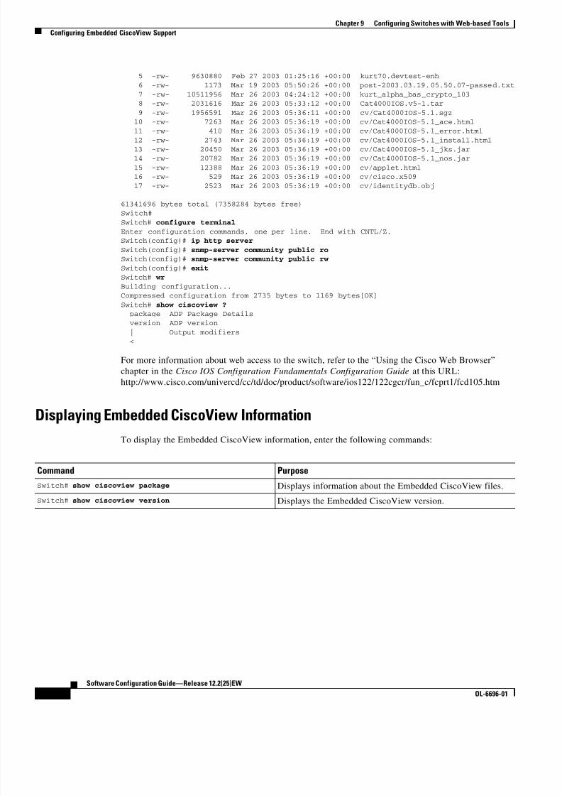
8/10/2019 Cisco ConfiguratioGuide SW4500 IOS
http://slidepdf.com/reader/full/cisco-configuratioguide-sw4500-ios 158/607
9-16
Software Configuration Guide—Release 12.2(25)EW
OL-6696-01
Chapter 9 Configuring Switches with Web-based Tools
Configuring Embedded CiscoView Support
5 -rw- 9630880 Feb 27 2003 01:25:16 +00:00 kurt70.devtest-enh
6 -rw- 1173 Mar 19 2003 05:50:26 +00:00 post-2003.03.19.05.50.07-passed.txt
7 -rw- 10511956 Mar 26 2003 04:24:12 +00:00 kurt_alpha_bas_crypto_103 8 -rw- 2031616 Mar 26 2003 05:33:12 +00:00 Cat4000IOS.v5-1.tar
9 -rw- 1956591 Mar 26 2003 05:36:11 +00:00 cv/Cat4000IOS-5.1.sgz 10 -rw- 7263 Mar 26 2003 05:36:19 +00:00 cv/Cat4000IOS-5.1_ace.html
11 -rw- 410 Mar 26 2003 05:36:19 +00:00 cv/Cat4000IOS-5.1_error.html
12 -rw- 2743 Mar 26 2003 05:36:19 +00:00 cv/Cat4000IOS-5.1_install.html 13 -rw- 20450 Mar 26 2003 05:36:19 +00:00 cv/Cat4000IOS-5.1_jks.jar 14 -rw- 20782 Mar 26 2003 05:36:19 +00:00 cv/Cat4000IOS-5.1_nos.jar
15 -rw- 12388 Mar 26 2003 05:36:19 +00:00 cv/applet.html 16 -rw- 529 Mar 26 2003 05:36:19 +00:00 cv/cisco.x509
17 -rw- 2523 Mar 26 2003 05:36:19 +00:00 cv/identitydb.obj
61341696 bytes total (7358284 bytes free)
Switch#
Switch# configure terminal
Enter configuration commands, one per line. End with CNTL/Z.Switch(config)# ip http server
Switch(config)# snmp-server community public ro Switch(config)# snmp-server community public rw
Switch(config)# exit
Switch# wrBuilding configuration...Compressed configuration from 2735 bytes to 1169 bytes[OK]
Switch# show ciscoview ? package ADP Package Details
version ADP version
| Output modifiers
<
For more information about web access to the switch, refer to the “Using the Cisco Web Browser”
chapter in the Cisco IOS Configuration Fundamentals Configuration Guide at this URL:
http://www.cisco.com/univercd/cc/td/doc/product/software/ios122/122cgcr/fun_c/fcprt1/fcd105.htm
Displaying Embedded CiscoView InformationTo display the Embedded CiscoView information, enter the following commands:
Command Purpose
Switch# show ciscoview package Displays information about the Embedded CiscoView files.
Switch# show ciscoview version Displays the Embedded CiscoView version.

8/10/2019 Cisco ConfiguratioGuide SW4500 IOS
http://slidepdf.com/reader/full/cisco-configuratioguide-sw4500-ios 159/607
9-17
Software Configuration Guide—Release 12.2(25)EW
OL-6696-01
Chapter 9 Configuring Switches with Web-based Tools
Configuring Embedded CiscoView Support
The following example shows how to display the Embedded CiscoView file and version information:
Switch# show ciscoview packageFile source:
CVFILE SIZE(in bytes)------------------------------------------------
Cat4000IOS-5.1.sgz 1956591
Cat4000IOS-5.1_ace.html 7263Cat4000IOS-5.1_error.html 410
Cat4000IOS-5.1_install.html 2743
Cat4000IOS-5.1_jks.jar 20450
Cat4000IOS-5.1_nos.jar 20782applet.html 12388
cisco.x509 529identitydb.obj 2523
Switch# show ciscoview version
Engine Version: 5.3.4 ADP Device: Cat4000IOS ADP Version: 5.1 ADK: 49Switch#

8/10/2019 Cisco ConfiguratioGuide SW4500 IOS
http://slidepdf.com/reader/full/cisco-configuratioguide-sw4500-ios 160/607
9-18
Software Configuration Guide—Release 12.2(25)EW
OL-6696-01
Chapter 9 Configuring Switches with Web-based Tools
Configuring Embedded CiscoView Support

8/10/2019 Cisco ConfiguratioGuide SW4500 IOS
http://slidepdf.com/reader/full/cisco-configuratioguide-sw4500-ios 161/607
C H A P T E R
10-1
Software Configuration Guide—Release 12.2(25)EW
OL-6696-01
10
Understanding and Configuring VLANs
This chapter describes VLANs on Catalyst 4500 series switches. It also provides guidelines, procedures,
and configuration examples.
This chapter includes the following major sections:
• Overview of VLANs, page 10-1
• VLAN Configuration Guidelines and Restrictions, page 10-3
• VLAN Default Configuration, page 10-4
• Configuring VLANs, page 10-4
Note For complete syntax and usage information for the switch commands used in this chapter, refer to the
Catalyst 4500 Series Switch Cisco IOS Command Reference and related publications at
http://www.cisco.com/univercd/cc/td/doc/product/software/ios122/122cgcr/index.htm.
Overview of VLANsA VLAN is a group of devices on one or more LANs that are configured to communicate as if they were
attached to the same wire, when in fact they are located on a number of different LAN segments. Because
VLANs are based on logical instead of physical connections, they are extremely flexible.
VLANs define broadcast domains in a Layer 2 network. A broadcast domain is the set of all devices that
will receive broadcast frames originating from any device within the set. Broadcast domains are typically
bounded by routers because routers do not forward broadcast frames. Layer 2 switches create broadcast
domains based on the configuration of the switch. Switches are multiport bridges that allow you to create
multiple broadcast domains. Each broadcast domain is like a distinct virtual bridge within a switch.
You can define one or many virtual bridges within a switch. Each virtual bridge you create in the switch
defines a new broadcast domain (VLAN). Traffic cannot pass directly to another VLAN (between
broadcast domains) within the switch or between two switches. To interconnect two different VLANs,you must use routers or Layer 3 switches. See the “Overview of Layer 3 Interfaces” section on page 23-1
for information on inter-VLAN routing on Catalyst 4500 series switches.
Figure 10-1 shows an example of three VLANs that create logically defined networks.

8/10/2019 Cisco ConfiguratioGuide SW4500 IOS
http://slidepdf.com/reader/full/cisco-configuratioguide-sw4500-ios 162/607
10-2
Software Configuration Guide—Release 12.2(25)EW
OL-6696-01
Chapter 10 Understanding and Configuring VLANs
Overview of VLANs
Figure 10-1 Sample VLANs
VLANs are often associated with IP subnetworks. For example, all of the end stations in a particular IP
subnet belong to the same VLAN. Traffic between VLANs must be routed. You must assign LAN
interface VLAN membership on an interface-by-interface basis (this is known as interface-based or
static VLAN membership).
You can set the following parameters when you create a VLAN in the management domain:
• VLAN number
• VLAN name
• VLAN type
• VLAN state (active or suspended)
• Maximum transmission unit (MTU) for the VLAN
• Security Association Identifier (SAID)
• VLAN number to use when translating from one VLAN type to another
Note When the software translates from one VLAN type to another, it requires a different VLAN number for
each media type.
Floor 1
Floor 2
EngineeringVLAN
Cisco router
FastEthernet
Floor 3
MarketingVLAN
AccountingVLAN
1 6 7 5 1

8/10/2019 Cisco ConfiguratioGuide SW4500 IOS
http://slidepdf.com/reader/full/cisco-configuratioguide-sw4500-ios 163/607

8/10/2019 Cisco ConfiguratioGuide SW4500 IOS
http://slidepdf.com/reader/full/cisco-configuratioguide-sw4500-ios 164/607
10-4
Software Configuration Guide—Release 12.2(25)EW
OL-6696-01
Chapter 10 Understanding and Configuring VLANs
VLAN Default Configuration
Configurable Normal-Range VLAN Parameters
Note Ethernet VLANs 1 and 1006 through 4094 use only default values.
You can configure the following parameters for VLANs 2 through 1001:
• VLAN name
• VLAN type
• VLAN state (active or suspended)
• SAID
• STP type for VLANs
VLAN Default ConfigurationTable 10-2 shows the default VLAN configuration values.
Note Catalyst 4500 series switches do not support Token Ring or FDDI media. The switch does not forward
FDDI, FDDI-NET, TrCRF, or TrBRF traffic, but it does propagate the VLAN configuration via VTP. The
software reserves parameters for these media types, but they are not truly supported.
Configuring VLANsNote Before you configure VLANs, you must use VLAN Trunking Protocol (VTP) to maintain global VLAN
configuration information for your network. For complete information on VTP, see Chapter 27,
“Understanding and Configuring VTP.”
Table 10-2 Ethernet VLAN Defaults and Ranges
Parameter Default Valid Values
VLAN ID 1 1–4094
VLAN name VLAN x , where x is a number assigned by
the software.
No range
802.10 SAID 100,001 1–4,294,967,294
MTU size 1500 1500–18,190
Translational bridge 1 1002 0–1005
Translational bridge 2 1003 0–1005
VLAN state active active; suspend; shutdown
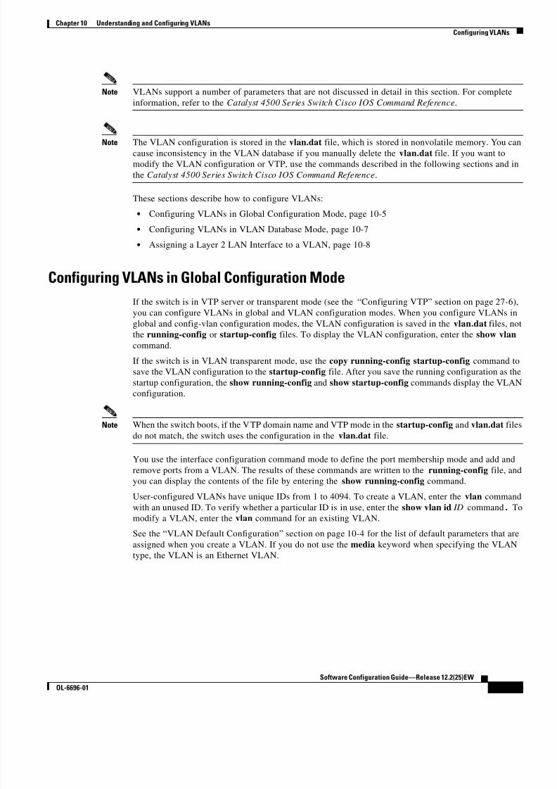
8/10/2019 Cisco ConfiguratioGuide SW4500 IOS
http://slidepdf.com/reader/full/cisco-configuratioguide-sw4500-ios 165/607
10-5
Software Configuration Guide—Release 12.2(25)EW
OL-6696-01
Chapter 10 Understanding and Configuring VLANs
Configuring VLANs
Note VLANs support a number of parameters that are not discussed in detail in this section. For complete
information, refer to the Catalyst 4500 Series Switch Cisco IOS Command Reference.
Note The VLAN configuration is stored in the vlan.dat file, which is stored in nonvolatile memory. You can
cause inconsistency in the VLAN database if you manually delete the vlan.dat file. If you want to
modify the VLAN configuration or VTP, use the commands described in the following sections and in
the Catalyst 4500 Series Switch Cisco IOS Command Reference.
These sections describe how to configure VLANs:
• Configuring VLANs in Global Configuration Mode, page 10-5
• Configuring VLANs in VLAN Database Mode, page 10-7
• Assigning a Layer 2 LAN Interface to a VLAN, page 10-8
Configuring VLANs in Global Configuration ModeIf the switch is in VTP server or transparent mode (see the “Configuring VTP” section on page 27-6),
you can configure VLANs in global and VLAN configuration modes. When you configure VLANs in
global and config-vlan configuration modes, the VLAN configuration is saved in the vlan.dat files, not
the running-config or startup-config files. To display the VLAN configuration, enter the show vlan
command.
If the switch is in VLAN transparent mode, use the copy running-config startup-config command to
save the VLAN configuration to the startup-config file. After you save the running configuration as the
startup configuration, the show running-config and show startup-config commands display the VLAN
configuration.
Note When the switch boots, if the VTP domain name and VTP mode in the startup-config and vlan.dat files
do not match, the switch uses the configuration in the vlan.dat file.
You use the interface configuration command mode to define the port membership mode and add and
remove ports from a VLAN. The results of these commands are written to the running-config file, and
you can display the contents of the file by entering the show running-config command.
User-configured VLANs have unique IDs from 1 to 4094. To create a VLAN, enter the vlan command
with an unused ID. To verify whether a particular ID is in use, enter the show vlan id ID command. To
modify a VLAN, enter the vlan command for an existing VLAN.
See the “VLAN Default Configuration” section on page 10-4 for the list of default parameters that are
assigned when you create a VLAN. If you do not use the media keyword when specifying the VLAN
type, the VLAN is an Ethernet VLAN.

8/10/2019 Cisco ConfiguratioGuide SW4500 IOS
http://slidepdf.com/reader/full/cisco-configuratioguide-sw4500-ios 166/607

8/10/2019 Cisco ConfiguratioGuide SW4500 IOS
http://slidepdf.com/reader/full/cisco-configuratioguide-sw4500-ios 167/607
10-7
Software Configuration Guide—Release 12.2(25)EW
OL-6696-01
Chapter 10 Understanding and Configuring VLANs
Configuring VLANs
Configuring VLANs in VLAN Database Mode
When the switch is in VTP server or transparent mode, you can configure VLANs in the VLAN database
mode. When you configure VLANs in VLAN database mode, the VLAN configuration is saved in the
vlan.dat file, not the running-config or startup-config files. To display the VLAN configuration, enter
the show running-config vlan command.User-configurable VLANs have unique IDs from 1 to 4094. Database mode supports configuration of
IDs from 1 to 1001, but not the extended addresses from 1006 to 4094. To create a VLAN, enter the vlan
command with an unused ID. To verify whether a particular ID is in use, enter the show vlan id ID
command. To modify a VLAN, enter the vlan command for an existing VLAN.
See the “VLAN Default Configuration” section on page 10-4 for a listing of the default parameters that
are assigned when you create a VLAN. If you do not use the media keyword when specifying the VLAN
type, the VLAN is an Ethernet VLAN.
To create a VLAN, perform this task:
This example shows how to create an Ethernet VLAN in VLAN database mode and verify the
configuration:
Switch# vlan database
Switch(vlan)# vlan 3
VLAN 3 added: Name: VLAN0003
Switch(vlan)# exit
APPLY completed.Exiting....
Switch# show vlan name VLAN0003
VLAN Name Status Ports---- -------------------------------- --------- ---------------------
3 VLAN0003 active
VLAN Type SAID MTU Parent RingNo BridgeNo Stp Trans1 Trans2
---- ----- ---------- ----- ------ ------ -------- ---- ------ ------3 enet 100003 1500 - - - - 0 0
Switch#
Command Purpose
Step 1 Switch# vlan database Enters VLAN database mode.
Step 2 Switch(vlan)# vlan vlan_ID Adds an Ethernet VLAN.
Note You cannot delete the default VLANs for these media
types: Ethernet VLAN 1 and FDDI or Token Ring
VLANs 1002 to 1005.
When you delete a VLAN, any LAN interfaces
configured as access ports assigned to that VLAN become
inactive. They remain associated with the VLAN (and
thus inactive) until you assign them to a new VLAN.
You can use the no keyword to delete a VLAN.
Step 3Switch(vlan)# exit
Returns to enable mode.Step 4 Switch# show vlan [id | name] vlan_name Verifies the VLAN configuration.

8/10/2019 Cisco ConfiguratioGuide SW4500 IOS
http://slidepdf.com/reader/full/cisco-configuratioguide-sw4500-ios 168/607
10-8
Software Configuration Guide—Release 12.2(25)EW
OL-6696-01
Chapter 10 Understanding and Configuring VLANs
Configuring VLANs
Assigning a Layer 2 LAN Interface to a VLAN
A VLAN created in a management domain remains unused until you assign one or more LAN interfaces
to the VLAN.
Note Make sure you assign LAN interfaces to a VLAN of the proper type. Assign Fast Ethernet, Gigabit
Ethernet, and 10-Gigabit Ethernet interfaces to Ethernet-type VLANs.
To assign one or more LAN interfaces to a VLAN, complete the procedures in the “Configuring Ethernet
Interfaces for Layer 2 Switching” section on page 12-5.

8/10/2019 Cisco ConfiguratioGuide SW4500 IOS
http://slidepdf.com/reader/full/cisco-configuratioguide-sw4500-ios 169/607
C H A P T E R
11-1
Software Configuration Guide—Release 12.2(25)EW
OL-6696-01
11
Configuring Dynamic VLAN Membership
This chapter describes how to configure dynamic port VLAN membership by using the VLAN
Membership Policy Server (VMPS).
This chapter includes the following major sections:
• Understanding VMPS, page 11-1
• Understanding VMPS clients, page 11-4
Note For complete syntax and usage information for the switch commands used in this chapter, refer to the
Catalyst 4500 Series Switch Cisco IOS Command Reference and related publications at
http://www.cisco.com/univercd/cc/td/doc/product/software/ios122/122cgcr/index.htm.
Understanding VMPSThe following subsections describe what a VMPS server does and how it operates.
The following topics are included:
• VMPS Server Overview, page 11-1
• Security Modes for VMPS Server, page 11-2
• Fall-back VLAN, page 11-3
• Illegal VMPS client requests, page 11-3
VMPS Server Overview
A VLAN Membership Policy Server (VMPS) provides a centralized server for selecting the VLAN for
a port dynamically based on the MAC address of the device connected to the port. When the host moves
from a port on one switch in the network to a port on another switch in the network, that switch
dynamically assigns the new port to the proper VLAN for that host.
A Catalyst 4500 series switch running Cisco IOS software does not support the functionality of a VMPS.
It can only function as a VLAN Query Protocol (VQP) client, which communicates with a VMPS
through the VQP. For VMPS functionality, you need to use a Catalyst 4500 series switch (or Catalyst
6500 series switch) running Catalyst operating system (OS) software.

8/10/2019 Cisco ConfiguratioGuide SW4500 IOS
http://slidepdf.com/reader/full/cisco-configuratioguide-sw4500-ios 170/607
11-2
Software Configuration Guide—Release 12.2(25)EW
OL-6696-01
Chapter 11 Configuring Dynamic VLAN Membership
Understanding VMPS
VMPS uses a UDP port to listen to VQP requests from clients, so, it is not necessary for VMPS clients
to know if the VMPS resides on a local or remote device on the network. Upon receiving a valid request
from a VMPS client, a VMPS server searches its database for an entry of a MAC-address to VLAN
mapping.
In response to a request, the VMPS takes one of the following actions:
• If the assigned VLAN is restricted to a group of ports, the VMPS verifies the requesting port againstthis group and responds as follows:
– If the VLAN is allowed on the port, the VMPS sends the VLAN name to the client in response.
– If the VLAN is not allowed on the port and the VMPS is not in secure mode, the VMPS sends
an “access-denied” response.
– If the VLAN is not allowed on the port and the VMPS is in secure mode, the VMPS sends a
“port-shutdown” response.
• If the VLAN in the database does not match the current VLAN on the port and there are active hosts
on the port, the VMPS sends an “access-denied” (open), a “fallback VLAN name” (open with
fallback VLAN configured), a “port-shutdown” (secure) , or a “new VLAN name” (multiple)
response, depending on the secure mode setting of the VMPS.
If the switch receives an “access-denied” response from the VMPS, the switch continues to block
traffic from the MAC address to or from the port. The switch continues to monitor the packets
directed to the port and sends a query to the VMPS when it identifies a new address. If the switch
receives a “port-shutdown” response from the VMPS, the switch disables the port. The port must be
manually re-enabled by using the CLI, Cisco Visual Switch Manager (CVSM), or SNMP.
You can also use an explicit entry in the configuration table to deny access to specific MAC
addresses for security reasons. If you enter the none keyword for the VLAN name, the VMPS sends
an “access-denied” or “port-shutdown” response.
For more information on a Catalyst 6500 series switch VMPS running Catalyst operating system
software, refer to the
“Configuring Dynamic Port VLAN Membership with VMPS” chapter at the URL:
http://www.cisco.com/univercd/cc/td/doc/product/lan/cat6000/sw_8_3/confg_gd/vmps.htm
Security Modes for VMPS Server
VMPS operates in three different modes. The way a VMPS server responds to illegal requests depends
on the mode in which the VMPS is configured:
• Open mode, page 11-2
• Secure mode, page 11-3
• Multiple mode, page 11-3
Open modeIf the assigned VLAN is restricted to a group of ports, VMPS verifies the requesting port against this
group:
• If the VLAN is allowed on the port, the VLAN name is returned to the client.
• If the VLAN is not allowed on the port, the host receives an “access denied” response.

8/10/2019 Cisco ConfiguratioGuide SW4500 IOS
http://slidepdf.com/reader/full/cisco-configuratioguide-sw4500-ios 171/607

8/10/2019 Cisco ConfiguratioGuide SW4500 IOS
http://slidepdf.com/reader/full/cisco-configuratioguide-sw4500-ios 172/607
11-4
Software Configuration Guide—Release 12.2(25)EW
OL-6696-01
Chapter 11 Configuring Dynamic VLAN Membership
Understanding VMPS clients
Understanding VMPS clientsThe following subsections describe how to configure a switch as a VMPS client and configure its ports
for dynamic VLAN membership.
The following topics are included:
• Dynamic VLAN Membership Overview, page 11-4
• Default VMPS Client Configuration, page 11-4
• Configuring a Switch as a VMPS Client, page 11-5
• Administering and Monitoring the VMPS, page 11-8
• Troubleshooting Dynamic Port VLAN Membership, page 11-9
Dynamic VLAN Membership Overview
When a port is configured as “dynamic,” it receives VLAN information based on the MAC-address that
is on the port. The VLAN is not statically assigned to the port; it is dynamically acquired from the VMPSbased on the MAC-address on the port.
A dynamic port can belong to one VLAN only. When the link becomes active, the switch does not
forward traffic to or from this port until the port is assigned to a VLAN. The source MAC address from
the first packet of a new host on the dynamic port is sent to the VMPS as part of the VQP request, which
attempts to match the MAC address to a VLAN in the VMPS database. If there is a match, the VMPS
sends the VLAN number for that port. If there is no match, the VMPS either denies the request or shuts
down the port (depending on the VMPS security mode setting). See the “Understanding VMPS” section
on page 11-1 for a complete description of possible VMPS responses.
Multiple hosts (MAC addresses) can be active on a dynamic port if all are in the same VLAN. If the link
goes down on a dynamic port, the port returns to the unassigned state and does not belong to a VLAN.
Any hosts that come online through the port are checked again with the VMPS before the port is assigned
to a VLAN.
For this behavior to work, the client device must be able to reach the VMPS. A VMPS client sends VQP
requests as UDP packets, trying a certain number of times before giving up. For details on how to set the
retry interval, refer to section “Configuring the Retry Interval” on page 8.
The VMPS client also periodically reconfirms the VLAN membership. For details on how to set the
reconfirm frequency, refer to section “Administering and Monitoring the VMPS” on page 8.
A maximum of 50 hosts are supported on a given port at any given time. Once this maximum is exceeded,
the port is shut down, irrespective of the operating mode of the VMPS server.
Note The VMPS shuts down a dynamic port if more than 50 hosts are active on that port.
Default VMPS Client Configuration
Table 11-1 shows the default VMPS and dynamic port configuration on client switches.

8/10/2019 Cisco ConfiguratioGuide SW4500 IOS
http://slidepdf.com/reader/full/cisco-configuratioguide-sw4500-ios 173/607
11-5
Software Configuration Guide—Release 12.2(25)EW
OL-6696-01
Chapter 11 Configuring Dynamic VLAN Membership
Understanding VMPS clients
Configuring a Switch as a VMPS Client
This section contains the following topics:
• Configuring the IP Address of the VMPS Server, page 11-5
• Configuring Dynamic Access Ports on a VMPS Client, page 11-6
• Reconfirming VLAN Memberships, page 11-7
• Configuring Reconfirmation Interval, page 11-7
• Reconfirming VLAN Memberships, page 11-7
Configuring the IP Address of the VMPS Server
To configure a Catalyst 4500 series switch as a VMPS client, you must enter the IP address or hostname
of the switch acting as the VMPS.
To define the primary and secondary VMPS on a Catalyst 4500 series switch, perform this task:
This example shows how to define the primary and secondary VMPS devices:
Switch# configure terminal
Enter configuration commands, one per line. End with CNTL/Z.Switch(config)# vmps server 172.20.128.179 primary
Switch(config)# vmps server 172.20.128.178Switch(config)# end
Note You can configure up to four VMPS servers using this CLI on the VMPS client.
Table 11-1 Default VMPS Client and Dynamic Port Configuration
Feature Default Configuration
VMPS domain server None
VMPS reconfirm interval 60 minutes
VMPS server retry count 3
Dynamic ports None configured
Command Purpose
Step 1 Switch# configure terminal Enters global configuration mode.
Step 2 Switch(config)# vmps server {ipaddress | hostname } primary
Specifies the IP address or hostname of the switch acting as the
primary VMPS server.
Step 3 Switch(config)# vmps server
{ipaddress | hostname }Specifies the IP address or hostname of the switch acting as a
secondary VMPS server.
Step 4 Switch(config)# end Returns to privileged EXEC mode.
Step 5 Switch# show vmps Verifies the VMPS server entry.
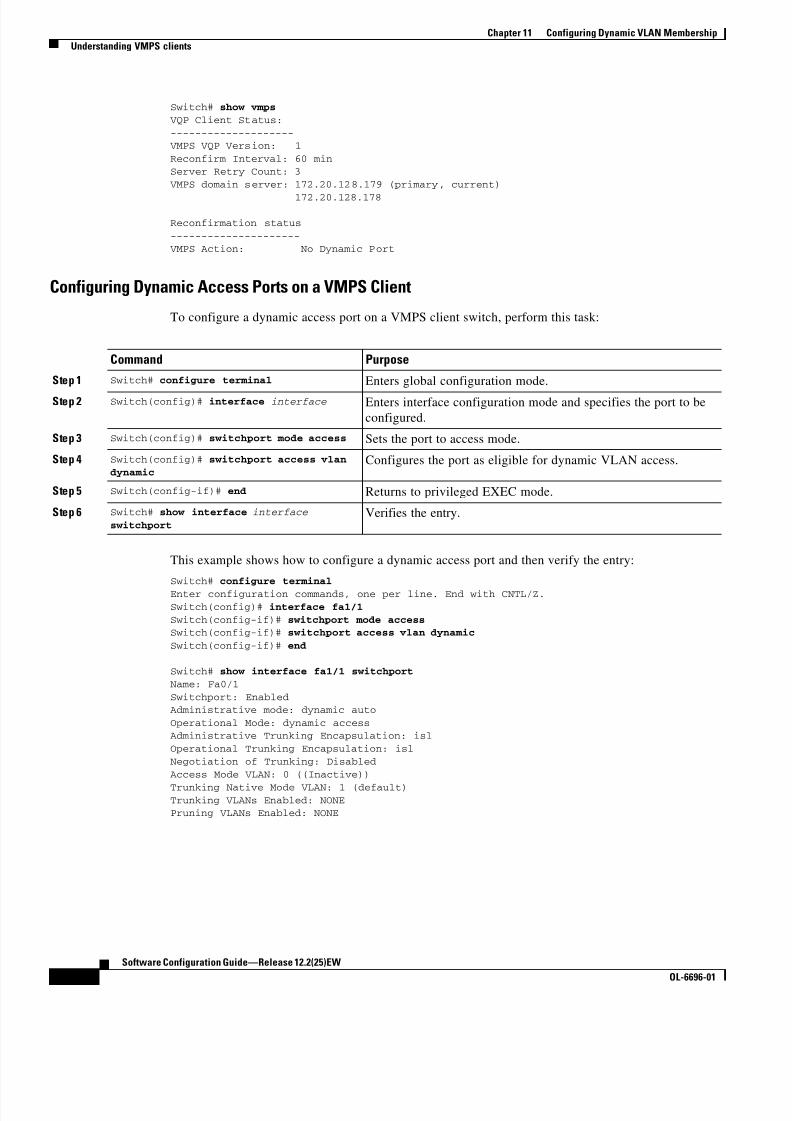
8/10/2019 Cisco ConfiguratioGuide SW4500 IOS
http://slidepdf.com/reader/full/cisco-configuratioguide-sw4500-ios 174/607

8/10/2019 Cisco ConfiguratioGuide SW4500 IOS
http://slidepdf.com/reader/full/cisco-configuratioguide-sw4500-ios 175/607
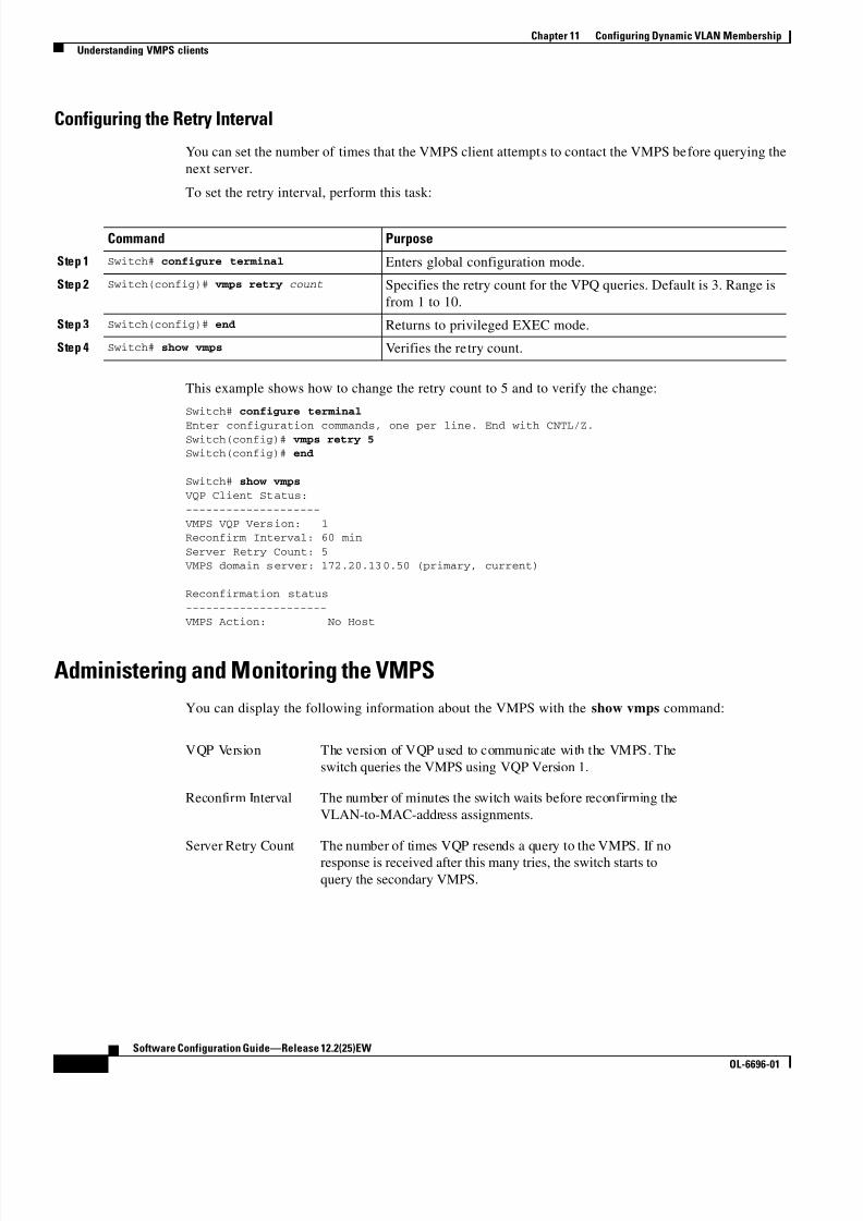
8/10/2019 Cisco ConfiguratioGuide SW4500 IOS
http://slidepdf.com/reader/full/cisco-configuratioguide-sw4500-ios 176/607
11-8
Software Configuration Guide—Release 12.2(25)EW
OL-6696-01
Chapter 11 Configuring Dynamic VLAN Membership
Understanding VMPS clients
Configuring the Retry Interval
You can set the number of times that the VMPS client attempts to contact the VMPS before querying the
next server.
To set the retry interval, perform this task:
This example shows how to change the retry count to 5 and to verify the change:
Switch# configure terminal
Enter configuration commands, one per line. End with CNTL/Z.Switch(config)# vmps retry 5Switch(config)# end
Switch# show vmps
VQP Client Status:
--------------------
VMPS VQP Version: 1Reconfirm Interval: 60 min
Server Retry Count: 5 VMPS domain server: 172.20.130.50 (primary, current)
Reconfirmation status
--------------------- VMPS Action: No Host
Administering and Monitoring the VMPS
You can display the following information about the VMPS with the show vmps command:
Command Purpose
Step 1 Switch# configure terminal Enters global configuration mode.
Step 2 Switch(config)# vmps retry count Specifies the retry count for the VPQ queries. Default is 3. Range is
from 1 to 10.
Step 3 Switch(config)# end Returns to privileged EXEC mode.
Step 4 Switch# show vmps Verifies the retry count.
VQP Version The version of VQP used to communicate with the VMPS. The
switch queries the VMPS using VQP Version 1.
Reconfirm Interval The number of minutes the switch waits before reconfirming the
VLAN-to-MAC-address assignments.
Server Retry Count The number of times VQP resends a query to the VMPS. If no
response is received after this many tries, the switch starts to
query the secondary VMPS.

8/10/2019 Cisco ConfiguratioGuide SW4500 IOS
http://slidepdf.com/reader/full/cisco-configuratioguide-sw4500-ios 177/607

8/10/2019 Cisco ConfiguratioGuide SW4500 IOS
http://slidepdf.com/reader/full/cisco-configuratioguide-sw4500-ios 178/607
11-10
Software Configuration Guide—Release 12.2(25)EW
OL-6696-01
Chapter 11 Configuring Dynamic VLAN Membership
Understanding VMPS clients

8/10/2019 Cisco ConfiguratioGuide SW4500 IOS
http://slidepdf.com/reader/full/cisco-configuratioguide-sw4500-ios 179/607
C H A P T E R
12-1
Software Configuration Guide—Release 12.2(25)EW
OL-6696-01
12
Configuring Layer 2 Ethernet Interfaces
This chapter describes how to use the command-line interface (CLI) to configure Fast Ethernet and
Gigabit Ethernet interfaces for Layer 2 switching on Catalyst 4500 series switches. It also provides
guidelines, procedures, and configuration examples. The configuration tasks in this chapter apply to Fast
Ethernet and Gigabit Ethernet interfaces on any module, including the uplink ports on the supervisor
engine.
This chapter includes the following major sections:
• Overview of Layer 2 Ethernet Switching, page 12-1
• Default Layer 2 Ethernet Interface Configuration, page 12-4
• Layer 2 Interface Configuration Guidelines and Restrictions, page 12-5
• Configuring Ethernet Interfaces for Layer 2 Switching, page 12-5
Note To configure Layer 3 interfaces, see Chapter 23, “Configuring Layer 3 Interfaces.”
Note For complete syntax and usage information for the switch commands used in this chapter, refer to theCatalyst 4500 Series Switch Cisco IOS Command Reference and related publications at
http://www.cisco.com/univercd/cc/td/doc/product/software/ios122/122cgcr/index.htm.
Overview of Layer 2 Ethernet SwitchingThe following sections describe how Layer 2 Ethernet switching works on Catalyst 4500 series switches
• Understanding Layer 2 Ethernet Switching, page 12-1
• Understanding VLAN Trunks, page 12-3
• Layer 2 Interface Modes, page 12-4
Understanding Layer 2 Ethernet Switching
Catalyst 4500 series switches support simultaneous, parallel connections between Layer 2 Ethernet
segments. Switched connections between Ethernet segments last only for the duration of the packet. New
connections can be made between different segments for successive packets.

8/10/2019 Cisco ConfiguratioGuide SW4500 IOS
http://slidepdf.com/reader/full/cisco-configuratioguide-sw4500-ios 180/607
12-2
Software Configuration Guide—Release 12.2(25)EW
OL-6696-01
Chapter 12 Configuring Layer 2 Ethernet Interfaces
Overview of Layer 2 Ethernet Switching
Note With release 12.1(13)EW, the Catalyst 4500 series switches can handle packets of 1600 bytes, rather
than treat them as “oversized” and discard them. This size is larger than the usual IEEE Ethernet
Maximum Transmission Unit (MTU) (1518 bytes) and 802.1q MTU (1522 bytes). The ability to handle
larger packets is required to support two nested 802.1q headers and Multiprotocol Label Switching
(MPLS) on a network.
The Catalyst 4500 series solves congestion problems caused by high-bandwidth devices and a large
number of users by assigning each device (for example, a server) to its own 10-, 100-, or 1000-Mbps
segment. Because each Ethernet interface on the switch represents a separate Ethernet segment, servers
in a properly configured switched environment achieve full access to the bandwidth.
Because collisions are a major bottleneck in Ethernet networks, an effective solution is full-duplex
communication. Normally, Ethernet operates in half-duplex mode, which means that stations can either
receive or transmit. In full-duplex mode, two devices can transmit and receive at the same time. When
packets can flow in both directions simultaneously, effective Ethernet bandwidth doubles to 20 Mbps for
10-Mbps interfaces and to 200 Mbps for Fast Ethernet interfaces. Gigabit Ethernet interfaces on the
Catalyst 4500 series switch are full-duplex mode only, providing 2-Gbps effective bandwidth.
Switching Frames Between Segments
Each Ethernet interface on a Catalyst 4500 series switch can connect to a single workstation or server,
or to a hub through which workstations or servers connect to the network.
On a typical Ethernet hub, all ports connect to a common backplane within the hub, and the bandwidth
of the network is shared by all devices attached to the hub. If two devices establish a session that uses a
significant level of bandwidth, the network performance of all other stations attached to the hub is
degraded.
To reduce degradation, the switch treats each interface as an individual segment. When stations on
different interfaces need to communicate, the switch forwards frames from one interface to the other at
wire speed to ensure that each session receives full bandwidth.
To switch frames between interfaces efficiently, the switch maintains an address table. When a frame
enters the switch, it associates the MAC address of the sending station with the interface on which it was
received.
Building the MAC Address Table
The Catalyst 4500 series builds the MAC address table by using the source address of the frames
received. When the switch receives a frame for a destination address not listed in its MAC address table,
it floods the frame to all interfaces of the same VLAN except the interface that received the frame. When
the destination device replies, the switch adds its relevant source address and interface ID to the address
table. The switch then forwards subsequent frames to a single interface without flooding to all interfaces.
The address table can store at least 32,000 address entries without flooding any entries. The switch usesan aging mechanism, defined by a configurable aging timer, so if an address remains inactive for a
specified number of seconds, it is removed from the address table.

8/10/2019 Cisco ConfiguratioGuide SW4500 IOS
http://slidepdf.com/reader/full/cisco-configuratioguide-sw4500-ios 181/607
12-3
Software Configuration Guide—Release 12.2(25)EW
OL-6696-01
Chapter 12 Configuring Layer 2 Ethernet Interfaces
Overview of Layer 2 Ethernet Switching
Understanding VLAN Trunks
A trunk is a point-to-point link between one or more Ethernet switch interfaces and another networking
device such as a router or a switch. Trunks carry the traffic of multiple VLANs over a single link and
allow you to extend VLANs across an entire network.
Two trunking encapsulations are available on all Ethernet interfaces:
• Inter-Switch Link (ISL) Protocol—ISL is a Cisco-proprietary trunking encapsulation.
Note The blocking Gigabit ports on the WS-X4418-GB and WS-X4412-2GB-T modules do not
support ISL. Ports 3 to 18 are blocking Gigabit ports on the WS-X4418-GB module. Ports
1to 12 are blocking Gigabit ports on the WS-X4412-2GB-T module.
• 802.1Q—802.1Q is an industry-standard trunking encapsulation.
You can configure a trunk on a single Ethernet interface or on an EtherChannel bundle. For more
information about EtherChannel, see Chapter 17, “Understanding and Configuring EtherChannel.”
Ethernet trunk interfaces support different trunking modes (see Table 12-2). You can specify whether thetrunk uses ISL encapsulation, 802.1Q encapsulation, or if the encapsulation type is autonegotiated.
To autonegotiate trunking, make sure your interfaces are in the same VTP domain. Use the trunk or
nonegotiate keywords to force interfaces in different domains to trunk. For more information on VTP
domains, see Chapter 27, “Understanding and Configuring VTP.”
Trunk negotiation is managed by the Dynamic Trunking Protocol (DTP). DTP supports autonegotiation
of both ISL and 802.1Q trunks.
Encapsulation Types
Table 12-1 lists the Ethernet trunk encapsulation types.
The trunking mode, the trunk encapsulation type, and the hardware capabilities of the two connected
interfaces determine whether a link becomes an ISL or 802.1Q trunk.
Table 12-1 Ethernet Trunk Encapsulation Types
Encapsulation Type Encapsulation Command Purpose
ISL switchport trunk encapsulation isl Specifies ISL encapsulation on the trunk link.
802.1Q switchport trunk encapsulation dot1q Specifies 802.1Q encapsulation on the trunk link.
Negotiate switchport trunk encapsulation negotiate Specifies that the interface negotiate with the
neighboring interface to become an ISL (preferred)
or 802.1Q trunk, depending on the configuration
and capabilities of the neighboring interface.

8/10/2019 Cisco ConfiguratioGuide SW4500 IOS
http://slidepdf.com/reader/full/cisco-configuratioguide-sw4500-ios 182/607
12-4
Software Configuration Guide—Release 12.2(25)EW
OL-6696-01
Chapter 12 Configuring Layer 2 Ethernet Interfaces
Default Layer 2 Ethernet Interface Configuration
Layer 2 Interface Modes
Table 12-2 lists the Layer 2 interface modes and describes how they function on Ethernet interfaces.
Note DTP is a point-to-point protocol. However, some internetworking devices might forward DTP frames
improperly. To avoid this problem, ensure that interfaces connected to devices that do not support DTPare configured with the access keyword if you do not intend to trunk across those links. To enable
trunking to a device that does not support DTP, use the nonegotiate keyword to cause the interface to
become a trunk without generating DTP frames.
Default Layer 2 Ethernet Interface ConfigurationTable 12-3 shows the Layer 2 Ethernet interface default configuration.
Table 12-2 Layer 2 Interface Modes
Mode Purpose
switchport mode access Puts the interface into permanent nontrunking mode and
negotiates to convert the link into a nontrunking link. The
interface becomes a nontrunk interface even if the neighboring
interface does not change.
switchport mode dynamic
desirable
Makes the interface actively attempt to convert the link to a
trunking link. The interface becomes a trunk interface if the
neighboring interface is set to trunk, desirable, or auto mode.
This is the default mode for all Ethernet interfaces.
switchport mode dynamic auto Makes the interface convert the link to a trunking link if the
neighboring interface is set to trunk or desirable mode. This is
the default mode for all Ethernet interfaces.
switchport mode trunk Puts the interface into permanent trunking mode and negotiates to
convert the link into a trunking link. The interface becomes a
trunk interface even if the neighboring interface does not change.
switchport nonegotiate Puts the interface into permanent trunking mode but prevents the
interface from generating DTP frames. You must configure the
neighboring interface manually as a trunk interface to establish a
trunking link.
Table 12-3 Layer 2 Ethernet Interface Default Configuration
Feature Default Value
Interface mode switchport mode dynamic auto
Trunk encapsulation switchport trunk encapsulation negotiate
Allowed VLAN range VLANs 1–1005
VLAN range eligible for pruning VLANs 2–1001
Default VLAN (for access ports) VLAN 1

8/10/2019 Cisco ConfiguratioGuide SW4500 IOS
http://slidepdf.com/reader/full/cisco-configuratioguide-sw4500-ios 183/607
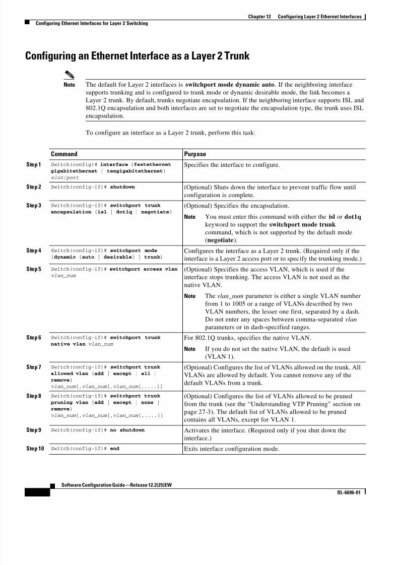
8/10/2019 Cisco ConfiguratioGuide SW4500 IOS
http://slidepdf.com/reader/full/cisco-configuratioguide-sw4500-ios 184/607

8/10/2019 Cisco ConfiguratioGuide SW4500 IOS
http://slidepdf.com/reader/full/cisco-configuratioguide-sw4500-ios 185/607

8/10/2019 Cisco ConfiguratioGuide SW4500 IOS
http://slidepdf.com/reader/full/cisco-configuratioguide-sw4500-ios 186/607

8/10/2019 Cisco ConfiguratioGuide SW4500 IOS
http://slidepdf.com/reader/full/cisco-configuratioguide-sw4500-ios 187/607
12-9
Software Configuration Guide—Release 12.2(25)EW
OL-6696-01
Chapter 12 Configuring Layer 2 Ethernet Interfaces
Configuring Ethernet Interfaces for Layer 2 Switching
Switch(config-if)# switchport mode access
Switch(config-if)# switchport access vlan 200
Switch(config-if)# no shutdown Switch(config-if)# end
Switch# exit
This example shows how to verify the running configuration:
Switch# show running-config interface fastethernet 5/6
Building configuration...
!
Current configuration :33 bytesinterface FastEthernet 5/6
switchport access vlan 200switchport mode access
end
This example shows how to verify the switch port configuration:
Switch# show running-config interface fastethernet 5/6 switchportName:Fa5/6
Switchport:Enabled
Administrative Mode:dynamic auto
Operational Mode:static accessAdministrative Trunking Encapsulation:negotiate
Operational Trunking Encapsulation:native
Negotiation of Trunking:OnAccess Mode VLAN:1 (default)
Trunking Native Mode VLAN:1 (default)Administrative private-vlan host-association:none
Administrative private-vlan mapping:none
Operational private-vlan:none
Trunking VLANs Enabled:ALLPruning VLANs Enabled:2-1001
Switch#
Clearing Layer 2 ConfigurationTo clear the Layer 2 configuration on an interface, perform this task:
This example shows how to clear the Layer 2 configuration on the Fast Ethernet interface 5/6:
Switch# configure terminal
Enter configuration commands, one per line. End with CNTL/Z.
Switch(config)# default interface fastethernet 5/6
Switch(config)# end Switch# exit
Command Purpose
Step 1 Switch(config)# default interface {fastethernet |gigabitethernet | tengigabitethernet} slot/ port
Specifies the interface to clear.
Step 2 Switch(config-if)# end Exits interface configuration mode.
Step 3 Switch# show running-config interface
{fastethernet | gigabitethernet |
tengigabitethernet} slot/ port
Displays the running configuration of the interface.
Step 4 Switch# show interfaces [{fastethernet |
gigabitethernet | tengigabitethernet} slot/ port]switchport
Displays the switch port configuration of the interface.

8/10/2019 Cisco ConfiguratioGuide SW4500 IOS
http://slidepdf.com/reader/full/cisco-configuratioguide-sw4500-ios 188/607
12-10
Software Configuration Guide—Release 12.2(25)EW
OL-6696-01
Chapter 12 Configuring Layer 2 Ethernet Interfaces
Configuring Ethernet Interfaces for Layer 2 Switching
This example shows how to verify that the Layer 2 configuration was cleared:
Switch# show running-config interface fastethernet 5/6 Building configuration...
Current configuration:!
interface FastEthernet5/6
end
This example shows how to verify the switch port configuration:
Switch# show interfaces fastethernet 5/6 switchport Name: Fa5/6
Switchport: EnabledSwitch#

8/10/2019 Cisco ConfiguratioGuide SW4500 IOS
http://slidepdf.com/reader/full/cisco-configuratioguide-sw4500-ios 189/607
C H A P T E R
13-1
Software Configuration Guide—Release 12.2(25)EW
OL-6696-01
13
Configuring SmartPort Macros
This chapter describes how to configure and apply SmartPort macros on your switch.
Note For complete syntax and usage information for the switch commands used in this chapter, refer to the
Catalyst 4500 Series Switch Cisco IOS Command Reference and related publications at
http://www.cisco.com/univercd/cc/td/doc/product/software/ios122/122cgcr/index.htm.
This chapter consists of these sections:
• Understanding SmartPort Macros, page 13-1
• Configuring Smart-Port Macros, page 13-2
• Displaying SmartPort Macros, page 13-8
Understanding SmartPort MacrosSmartPort macros provide a convenient way to save and share common configurations. You can use
SmartPort macros to enable features and settings based on the location of a switch in the network and
for mass configuration deployments across the network.
Each SmartPort macro is a set of CLI commands that you define. SmartPort macro sets do not contain
new CLI commands; Each SmartPort macro is a group of existing CLI commands.
When you apply a SmartPort macro on an interface, the CLI commands contained within the macro are
configured on the interface. When the macro is applied to an interface, the existing interface
configurations are not lost. The new commands are added to interface and are saved in the running
configuration file.

8/10/2019 Cisco ConfiguratioGuide SW4500 IOS
http://slidepdf.com/reader/full/cisco-configuratioguide-sw4500-ios 190/607
13-2
Software Configuration Guide—Release 12.2(25)EW
OL-6696-01
Chapter 13 Configuring SmartPort Macros
Configuring Smart-Port Macros
Configuring Smart-Port MacrosYou can create a new SmartPort macro or use an existing macro as a template to create a new macro that
is specific to your application. After you create the macro, you can apply it to an interface or a range of
interfaces.
This section includes information about these topics:
• Default SmartPort Macro Configuration, page 13-2
• SmartPort Macro Configuration Guidelines, page 13-4
• Creating and Applying SmartPort Macros, page 13-4
Default SmartPort Macro Configuration
This section illustrates the default configurations for the four supported macros. These macros can only
be viewed and applied; they cannot be modified by the user.
• cisco-desktop, page 13-2
• cisco-phone, page 13-2
• cisco-switch, page 13-3
• cisco-router, page 13-3
cisco-desktop
# Basic interface - Enable data VLAN only
# Recommended value for access vlan (AVID) should not be 1
switchport access vlan $AVIDswitchport mode access
# Enable port security limiting port to a single
# MAC address -- that of desktopswitchport port-security
# Ensure port-security age is greater than one minute# and use inactivity timer
# “Port-security maximum 1” is the default and will not
# Show up in the config
switchport port-security violation restrictswitchport port-security aging time 2
switchport port-security aging type inactivity# Configure port as an edge network port
spanning-tree portfast
spanning-tree bpduguard enable
cisco-phone
# VoIP enabled interface - Enable data VLAN
# and voice VLAN (VVID)# Recommended value for access vlan (AVID) should not be 1\
switchport access vlan $AVID
switchport mode access
# Update the Voice VLAN (VVID) value which should be# different from data VLAN
# Recommended value for voice vlan (VVID) should not be 1switchport voice vlan $VVID
# Enable port security limiting port to a 3 MAC

8/10/2019 Cisco ConfiguratioGuide SW4500 IOS
http://slidepdf.com/reader/full/cisco-configuratioguide-sw4500-ios 191/607
13-3
Software Configuration Guide—Release 12.2(25)EW
OL-6696-01
Chapter 13 Configuring SmartPort Macros
Configuring Smart-Port Macros
# addressess -- One for desktop and two for phone
switchport port-security
switchport port-security maximum 3# Ensure port-security age is greater than one minute
# and use inactivity timerswitchport port-security violation restrict
switchport port-security aging time 2
switchport port-security aging type inactivity# Enable auto-qos to extend trust to attached Cisco phoneauto qos voip cisco-phone
# Configure port as an edge network portspanning-tree portfast
spanning-tree bpduguard enable@
cisco-switch
# Access Uplink to Distributionswitchport trunk encapsulation dot1q
# Define unique Native VLAN on trunk ports
# Recommended value for native vlan (NVID) should not be 1switchport trunk native vlan $NVID
# Update the allowed VLAN range (VRANGE) such that it# includes data, voice and native VLANs
# switchport trunk allowed vlan $VRANGE
# Hardcode trunk and disable negotiation to
# speed up convergenceswitchport mode trunk
switchport nonegotiate# Configure qos to trust this interface
auto qos voip trust
# 802.1w defines the link as pt-pt for rapid convergence
spanning-tree link-type point-to-point
cisco-router
# Access Uplink to Distributionswitchport trunk encapsulation dot1q
# Define unique Native VLAN on trunk ports# Recommended value for native vlan (NVID) should not be 1
switchport trunk native vlan $NVID# Update the allowed VLAN range (VRANGE) such that it
# includes data, voice and native VLANs
# switchport trunk allowed vlan $VRANGE
# Hardcode trunk and disable negotiation to# speed up convergence
# Hardcode speed and duplex to routerswitchport mode trunk
switchport nonegotiate
speed 100
duplex full
# Configure qos to trust this interfaceauto qos voip trust
qos trust dscp
# Ensure fast access to the network when enabling the interface.
# Ensure that switch devices cannot become active on the interface.spanning-tree portfast
spanning-tree bpduguard enable

8/10/2019 Cisco ConfiguratioGuide SW4500 IOS
http://slidepdf.com/reader/full/cisco-configuratioguide-sw4500-ios 192/607
13-4
Software Configuration Guide—Release 12.2(25)EW
OL-6696-01
Chapter 13 Configuring SmartPort Macros
Configuring Smart-Port Macros
SmartPort Macro Configuration Guidelines
Follow these guidelines when configuring macros on your switch:
• Do not use exit or end commands when creating a macro. This action could cause commands that
follow exit or end to execute in a different command mode.
• When creating a macro, all CLI commands should be interface configuration mode commands.
• Some CLI commands are specific to certain interface types. The macro will fail the syntax check or
the configuration check, and the switch will return an error message if it is applied to an interface
that does not accept the configuration.
• When a macro is applied to an interface, all existing configuration on the interface is retained. This
is helpful when applying an incremental configuration to an interface.
• If you modify a macro definition by adding or deleting commands, the changes are not reflected on
the interface where the original macro was applied. You need to reapply the updated macro on the
interface to apply the new or changed commands.
• You can use the macro trace macro-name interface configuration command to show what macros
are running on an interface or to debug the macro to determine any syntax or configuration errors.
• If a command fails when you apply a macro, either due to a syntax error or to a configuration error,
the macro continues to apply the remaining commands to the interface.
• Applying a macro to an interface range is the same as applying a macro to a single interface. When
you use an interface range, the macro is applied sequentially to each individual interface within the
range. If a macro command fails on one interface, it is still applied to the remaining interfaces.
Creating and Applying SmartPort Macros
To create and apply a SmartPort macro, perform the following task:
Command Purpose
Step 1 Switch # configure terminal Enters global configuration mode.
Step 2 Switch(config)# macro name macro-name
Creates a macro definition, and enters a macro name. A macro definition
can contain up to 3000 characters.
Enters the macro commands with one command per line. Use the @
character to end the macro. Use the # character at the beginning of a line
to enter comment text within the macro.
Do not use the exit or end commands in a macro. This action could
cause any commands following exit or end to execute in a different
command mode. For best results, all commands in a macro should be
interface configuration mode commands.
Step 3 Switch(config)# interface interface-id Enters interface configuration mode and specifies the interface on which
to apply the macro.
Step 4 Switch(config-if)# macro {apply |trace} macro-name
Applies each command defined in the macro to the interface.
Step 5 Switch(config-if)# macro description text
(Optional) Enters a description about the macro that is applied to the
interface.
Step 6 Switch(config-if)# end Returns to privileged EXEC mode.

8/10/2019 Cisco ConfiguratioGuide SW4500 IOS
http://slidepdf.com/reader/full/cisco-configuratioguide-sw4500-ios 193/607
13-5
Software Configuration Guide—Release 12.2(25)EW
OL-6696-01
Chapter 13 Configuring SmartPort Macros
Configuring Smart-Port Macros
The no form of the macro name global configuration command only deletes the macro definition. It
does not affect the configuration of those interfaces on which the macro is already applied. You can
delete a macro-applied configuration on an interface by entering the default interface interface-id
interface configuration command. Alternatively, you can create an anti-macro for an existing macro that
contains the no form of all the corresponding commands in the original macro. Then apply the
anti-macro to the interface.
The following sections illustrate how to apply and display the attachments on each of the supported
macros:
• cisco-desktop, page 13-5
• cisco-phone, page 13-6
• cisco-switch, page 13-6
• cisco-router, page 13-7
cisco-desktop
This example shows how to apply the cisco-desktop macro to interface Fast Ethernet interface 2/9:
Switch(config)# interface fastethernet2/9
Switch(config-if)# macro apply cisco-desktop $AVID 35
Switch(config-if)# endSwitch# show parser macro name cisco-desktop
Macro name : cisco-desktop
Macro type : customizable
# Basic interface - Enable data VLAN only
# Recommended value for access vlan (AVID) should not be 1switchport access vlan $AVID [access_vlan_id]
switchport mode access# Enable port security limiting port to a single
# MAC address -- that of desktop
switchport port-security
# Ensure port-security age is greater than one minute# and use inactivity timer
# “Port-security maximum 1” is the default and will not# Show up in the config
switchport port-security violation restrict
switchport port-security aging time 2
switchport port-security aging type inactivity# Configure port as an edge network port
spanning-tree portfast
spanning-tree bpduguard enableSwitch# show parser macro description
Interface Macro Description--------------------------------------------------------------
Fa2/9 cisco-desktop
--------------------------------------------------------------
Step 7 Switch# show parser macro Verifies that the macro was created.
Step 8 Switch# show running-config interface interface-id
Verifies that the macro is applied to an interface.
Step 9 Switch# copy running-config
startup-config
(Optional) Saves your entries in the configuration file.
Command Purpose

8/10/2019 Cisco ConfiguratioGuide SW4500 IOS
http://slidepdf.com/reader/full/cisco-configuratioguide-sw4500-ios 194/607
13-6
Software Configuration Guide—Release 12.2(25)EW
OL-6696-01
Chapter 13 Configuring SmartPort Macros
Configuring Smart-Port Macros
cisco-phone
This example shows how to apply the cisco-phone macro to interface Fast Ethernet interface 2/9:
Switch(config)# interface fastethernet2/9
Switch(config-if)# macro apply cisco-phoneSwitch(config-if)# macro description cisco-phone $AVID 35 $VVID 56
Switch(config-if)# endSwitch# show parser macro name cisco-phone
Macro name : cisco-phoneMacro type : customizable
# VoIP enabled interface - Enable data VLAN
# and voice VLAN (VVID)
# Recommended value for access vlan (AVID) should not be 1\
switchport access vlan $AVID [access_vlan_id]switchport mode access
# Update the Voice VLAN (VVID) value which should be
# different from data VLAN# Recommended value for voice vlan (VVID) should not be 1
switchport voice vlan $VVID [voice_vlan_id]# Enable port security limiting port to a 3 MAC
# addressess -- One for desktop and two for phoneswitchport port-security
switchport port-security maximum 3# Ensure port-security age is greater than one minute
# and use inactivity timerswitchport port-security violation restrict
switchport port-security aging time 2
switchport port-security aging type inactivity
# Enable auto-qos to extend trust to attached Cisco phoneauto qos voip cisco-phone
# Configure port as an edge network portspanning-tree portfast
spanning-tree bpduguard enable@
Switch# show parser macro description
Interface Macro Description--------------------------------------------------------------Fa2/9 cisco-phone
--------------------------------------------------------------
cisco-switch
This example shows how to apply the cisco-switch macro to interface Fast Ethernet interface 2/9:
Switch(config)# interface fastethernet2/9
Switch(config-if)# macro apply cisco-switchSwitch(config-if)# macro description cisco-switch $NVID 38
Switch(config-if)# end
Switch# show parser macro name cisco-switch
Macro name : cisco-switch
Macro type : customizable
# Access Uplink to Distribution
switchport trunk encapsulation dot1q# Define unique Native VLAN on trunk ports
# Recommended value for native vlan (NVID) should not be 1
switchport trunk native vlan $NVID [native_vlan_id]

8/10/2019 Cisco ConfiguratioGuide SW4500 IOS
http://slidepdf.com/reader/full/cisco-configuratioguide-sw4500-ios 195/607
13-7
Software Configuration Guide—Release 12.2(25)EW
OL-6696-01
Chapter 13 Configuring SmartPort Macros
Configuring Smart-Port Macros
# Update the allowed VLAN range (VRANGE) such that it
# includes data, voice and native VLANs
# switchport trunk allowed vlan $VRANGE [vlan_range]# Hardcode trunk and disable negotiation to
# speed up convergenceswitchport mode trunk
switchport nonegotiate
# Configure qos to trust this interfaceauto qos voip trust# 802.1w defines the link as pt-pt for rapid convergence
spanning-tree link-type point-to-point
Switch# show parser macro description
Interface Macro Description--------------------------------------------------------------
Fa2/9 cisco-switch
--------------------------------------------------------------
cisco-router
This example shows how to apply the cisco-router macro to interface Fast Ethernet interface 2/9:
Switch(config)# interface fastethernet2/9
Switch(config-if)# macro apply cisco-router
Switch(config-if)# macro description cisco-router $NVID 45I
Switch(config-if)# endSwitch# show parser macro name cisco-router
Macro name : cisco-routerMacro type : customizable
# Access Uplink to Distribution
switchport trunk encapsulation dot1q# Define unique Native VLAN on trunk ports
# Recommended value for native vlan (NVID) should not be 1switchport trunk native vlan $NVID [native_vlan_id]
# Update the allowed VLAN range (VRANGE) such that it
# includes data, voice and native VLANs# switchport trunk allowed vlan $VRANGE [vlan_range]
# Hardcode trunk and disable negotiation to
# speed up convergence
# Hardcode speed and duplex to routerswitchport mode trunk
switchport nonegotiatespeed 100
duplex full
# Configure qos to trust this interface
auto qos voip trustqos trust dscp
# Ensure fast access to the network when enabling the interface.# Ensure that switch devices cannot become active on the interface.
spanning-tree portfast
spanning-tree bpduguard enable
Switch# show parser macro description
Interface Macro Description--------------------------------------------------------------
Fa2/9 cisco-router
--------------------------------------------------------------

8/10/2019 Cisco ConfiguratioGuide SW4500 IOS
http://slidepdf.com/reader/full/cisco-configuratioguide-sw4500-ios 196/607
13-8
Software Configuration Guide—Release 12.2(25)EW
OL-6696-01
Chapter 13 Configuring SmartPort Macros
Displaying SmartPort Macros
Displaying SmartPort MacrosTo display the SmartPort macros, use one or more of the privileged EXEC commands in Table 13-1.
Table 13-1 Commands for Displaying SmartPort Macros
Command Purpose
show parser macro Displays all configured macros.
show parser macro name macro-name Displays a specific macro.
show parser macro brief Displays the configured macro names.
show parser macro description [interface
interface-id ]
Displays the macro description for all interfaces or for a specified
interface.

8/10/2019 Cisco ConfiguratioGuide SW4500 IOS
http://slidepdf.com/reader/full/cisco-configuratioguide-sw4500-ios 197/607

8/10/2019 Cisco ConfiguratioGuide SW4500 IOS
http://slidepdf.com/reader/full/cisco-configuratioguide-sw4500-ios 198/607

8/10/2019 Cisco ConfiguratioGuide SW4500 IOS
http://slidepdf.com/reader/full/cisco-configuratioguide-sw4500-ios 199/607
14-3
Software Configuration Guide—Release 12.2(25)EW
OL-6696-01
Chapter 14 Understanding and Configuring STP
Overview of STP
STP MAC Address Allocation
A Catalyst 4500 series switch chassis has either 64 or 1024 MAC addresses available to support software
features like STP. Enter the show module command to view the MAC address range on your chassis.
Release 12.1(12c)EW and later releases support chassis with 64 or 1024 MAC addresses. For chassis
with 64 MAC addresses, STP uses the extended system ID plus a MAC address to make the bridge IDunique for each VLAN.
Earlier releases support chassis with 1024 MAC addresses. With earlier releases, STP uses one MAC
address per VLAN to make the bridge ID unique for each VLAN.
Bridge Protocol Data Units
The following elements determine the stable active spanning tree topology of a switched network:
• The unique bridge ID (bridge priority and MAC address) associated with each VLAN on each switch
• The spanning tree path cost (or bridge priority value) to the root bridge
• The port identifier (port priority and MAC address) associated with each Layer 2 interface
Bridge protocol data units (BPDUs) contain information about the transmitting bridge and its ports,
including the bridge and MAC addresses, bridge priority, port priority, and path cost. The system
computes the spanning tree topology by transmitting BPDUs among connecting switches, and in one
direction from the root switch. Each configuration BPDU contains at least the following:
• The unique bridge ID of the switch that the transmitting switch believes to be the root switch
• The spanning tree path cost to the root
• The bridge ID of the transmitting bridge
• The age of the message
• The identifier of the transmitting port
• Values for the hello, forward delay, and max-age protocol timers
When a switch transmits a BPDU frame, all switches connected to the LAN on which the frame is
transmitted receive the BPDU. When a switch receives a BPDU, it does not forward the frame but instead
uses the information in the frame to calculate a BPDU and, if the topology changes, initiate a BPDU
transmission.
A BPDU exchange results in the following:
• One switch is elected as the root bridge.
• The shortest distance to the root bridge is calculated for each switch based on the path cost.
• A designated bridge for each LAN segment is selected. This is the switch closest to the root bridge
through which frames are forwarded to the root.
• A root port is selected. This is the port providing the best path from the bridge to the root bridge.
• Ports included in the spanning tree are selected.

8/10/2019 Cisco ConfiguratioGuide SW4500 IOS
http://slidepdf.com/reader/full/cisco-configuratioguide-sw4500-ios 200/607
14-4
Software Configuration Guide—Release 12.2(25)EW
OL-6696-01
Chapter 14 Understanding and Configuring STP
Overview of STP
Election of the Root Bridge
For each VLAN, the switch with the highest bridge priority (the lowest numerical priority value) is
elected as the root bridge. If all switches are configured with the default priority value (32,768), the
switch with the lowest MAC address in the VLAN becomes the root bridge.
The spanning tree root bridge is the logical center of the spanning tree topology in a switched network.All paths that are not required to reach the root bridge from anywhere in the switched network are placed
in spanning tree blocking mode.
A spanning tree uses the information provided by BPDUs to elect the root bridge and root port for the
switched network, as well as the root port and designated port for each switched segment.
STP Timers
Table 14-3 describes the STP timers that affect the performance of the entire spanning tree.
Creating the STP Topology
The goal of the spanning tree algorithm is to make the most direct link the root port. When the spanning
tree topology is calculated based on default parameters, the path between source and destination end
stations in a switched network might not be optimal according to link speed. For instance, connecting
higher-speed links to a port that has a higher number than the current root port can cause a root-port
change.
In Figure 14-1, Switch A is elected as the root bridge. (This could happen if the bridge priority of all the
switches is set to the default value [32,768] and Switch A has the lowest MAC address.) However, due
to traffic patterns, the number of forwarding ports, or link types, Switch A might not be the ideal root
bridge. By increasing the STP port priority (lowering the numerical value) of the ideal switch so that it
becomes the root bridge, you force a spanning tree recalculation to form a new spanning tree topology
with the ideal switch as the root.
Table 14-3 Spanning Tree Protocol Timers
Variable Description
hello_time Determines how often the switch broadcasts hello messages to other
switches.
forward_time Determines how long each of the listening and learning states will last before
the port begins forwarding.
max_age Determines the amount of time that protocol information received on a port
is stored by the switch.

8/10/2019 Cisco ConfiguratioGuide SW4500 IOS
http://slidepdf.com/reader/full/cisco-configuratioguide-sw4500-ios 201/607
14-5
Software Configuration Guide—Release 12.2(25)EW
OL-6696-01
Chapter 14 Understanding and Configuring STP
Overview of STP
Figure 14-1 Spanning Tree Topology
For example, assume that one port on Switch B is a fiber-optic link, and another port on Switch B (an
unshielded twisted-pair [UTP] link) is the root port. Network traffic might be more efficient over the
high-speed fiber-optic link. By changing the spanning tree port priority on the fiber-optic port to a higher
priority (lower numerical value) than the priority set for the root port, the fiber-optic port becomes the
new root port.
STP Port States
Propagation delays can occur when protocol information passes through a switched LAN. As a result,
topology changes can take place at different times and at different places in a switched network. When
a Layer 2 interface transitions directly from nonparticipation in the spanning tree topology to the
forwarding state, it can create temporary data loops. Ports must wait for new topology information to
propagate through the switched LAN before starting to forward frames. They must allow the frame
lifetime to expire for frames that have been forwarded under the old topology.
Each Layer 2 interface on a switch that uses spanning tree exists in one of the following five states:
• Blocking—In this state, the Layer 2 interface does not participate in frame forwarding.
• Listening—This state is the first transitional state after the blocking state when spanning tree
determines that the Layer 2 interface should participate in frame forwarding.
• Learning—In this state, the Layer 2 interface prepares to participate in frame forwarding.
• Forwarding—In this state, the Layer 2 interface forwards frames.
• Disabled—In this state, the Layer 2 interface does not participate in spanning tree and does not
forward frames.
MAC Address Allocation
The supervisor engine has a pool of 1024 MAC addresses that are used as the bridge IDs for the VLAN
spanning trees. You can use the show module command to view the MAC address range (allocation
range for the supervisor) that the spanning tree uses for the algorithm.
MAC addresses for the Catalyst 4506 switch are allocated sequentially, with the first MAC address in
the range assigned to VLAN 1, the second MAC address in the range assigned to VLAN 2, and so forth.
For example, if the MAC address range is 00-e0-1e-9b-2e-00 to 00-e0-1e-9b-31-ff, the VLAN 1 bridge
ID is 00-e0-1e-9b-2e-00, the VLAN 2 bridge ID is 00-e0-1e-9b-2e-01, the VLAN 3 bridge ID is
00-e0-1e-9b-2e-02, and so on. On other Catalyst 4500 series platforms, all VLANS map to the same
MAC address rather than mapping to separate MAC addresses.
S 5 6 8 8
DP
DP
RP DP
DPRP
DP
RP = Root PortDP = Designated Port
DP
RP
DP
DA
CB

8/10/2019 Cisco ConfiguratioGuide SW4500 IOS
http://slidepdf.com/reader/full/cisco-configuratioguide-sw4500-ios 202/607
14-6
Software Configuration Guide—Release 12.2(25)EW
OL-6696-01
Chapter 14 Understanding and Configuring STP
Default STP Configuration
STP and IEEE 802.1Q Trunks
802.1Q VLAN trunks impose some limitations on the spanning tree strategy for a network. In a network
of Cisco switches connected through 802.1Q trunks, the switches maintain one instance of spanning tree
for each VLAN allowed on the trunks. However, non-Cisco 802.1Q switches maintain only one instance
of spanning tree for all VLANs allowed on the trunks.When you connect a Cisco switch to a non-Cisco device (that supports 802.1Q) through an 802.1Q trunk,
the Cisco switch combines the spanning tree instance of the 802.1Q native VLAN of the trunk with the
spanning tree instance of the non-Cisco 802.1Q switch. However, all per-VLAN spanning tree
information is maintained by Cisco switches separated by a network of non-Cisco 802.1Q switches. The
non-Cisco 802.1Q network separating the Cisco switches is treated as a single trunk link between the
switches.
Note For more information on 802.1Q trunks, see Chapter 12, “Configuring Layer 2 Ethernet Interfaces.”
Per-VLAN Rapid Spanning TreePer-VLAN Rapid Spanning Tree (PVRST+) is the same as PVST+, although PVRST+ utilizes a rapid
STP based on IEEE 802.1w rather than 802.1D to provide faster convergence. PVRST+ uses roughly the
same configuration as PVST+ and needs only minimal configuration. In PVRST+, dynamic CAM entries
are flushed immediately on a per-port basis when any topology change is made. UplinkFast and
BackboneFast are enabled but not active in this mode, since the functionality is built into the Rapid STP.
PVRST+ provides for rapid recovery of connectivity following the failure of a bridge, bridge port, or
LAN.
For enabling information, see “Enabling Per-VLAN Rapid Spanning Tree” on page 20.
Default STP ConfigurationTable 14-4 shows the default spanning tree configuration.
Table 14-4 Spanning Tree Default Configuration Values
Feature Default Value
Enable state Spanning tree enabled for all VLANs
Bridge priority value 32,768
Spanning tree port priority value (configurable on a
per-interface basis—used on interfaces configured as
Layer 2 access ports)
128
Spanning tree port cost (configurable on a per-interface
basis—used on interfaces configured as Layer 2 access
ports)
• 10-Gigabit Ethernet: 2
• Gigabit Ethernet: 4
• Fast Ethernet: 19
Spanning tree VLAN port priority value (configurable on
a per-VLAN basis—used on interfaces configured as
Layer 2 trunk ports)
128
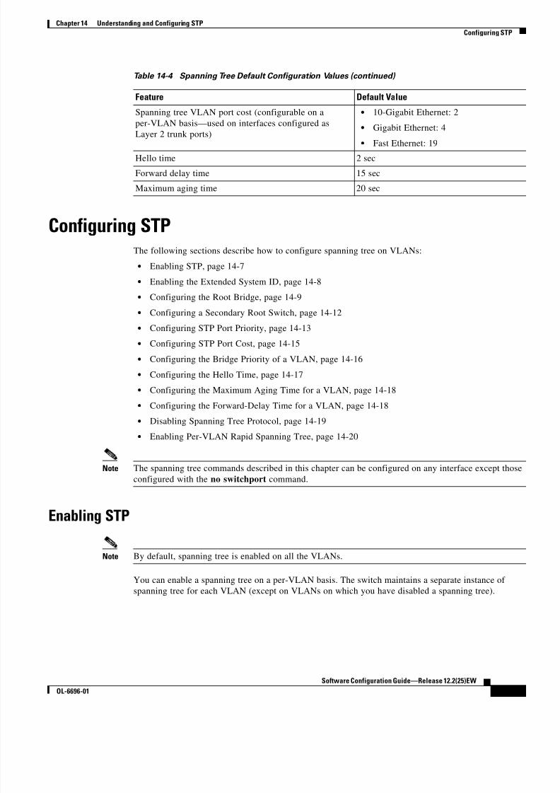
8/10/2019 Cisco ConfiguratioGuide SW4500 IOS
http://slidepdf.com/reader/full/cisco-configuratioguide-sw4500-ios 203/607
14-7
Software Configuration Guide—Release 12.2(25)EW
OL-6696-01
Chapter 14 Understanding and Configuring STP
Configuring STP
Configuring STPThe following sections describe how to configure spanning tree on VLANs:
• Enabling STP, page 14-7
• Enabling the Extended System ID, page 14-8
• Configuring the Root Bridge, page 14-9
• Configuring a Secondary Root Switch, page 14-12
• Configuring STP Port Priority, page 14-13
• Configuring STP Port Cost, page 14-15
• Configuring the Bridge Priority of a VLAN, page 14-16
• Configuring the Hello Time, page 14-17
• Configuring the Maximum Aging Time for a VLAN, page 14-18
• Configuring the Forward-Delay Time for a VLAN, page 14-18
• Disabling Spanning Tree Protocol, page 14-19
• Enabling Per-VLAN Rapid Spanning Tree, page 14-20
Note The spanning tree commands described in this chapter can be configured on any interface except those
configured with the no switchport command.
Enabling STP
Note By default, spanning tree is enabled on all the VLANs.
You can enable a spanning tree on a per-VLAN basis. The switch maintains a separate instance of
spanning tree for each VLAN (except on VLANs on which you have disabled a spanning tree).
Spanning tree VLAN port cost (configurable on a
per-VLAN basis—used on interfaces configured as
Layer 2 trunk ports)
• 10-Gigabit Ethernet: 2
• Gigabit Ethernet: 4
• Fast Ethernet: 19
Hello time 2 sec
Forward delay time 15 sec
Maximum aging time 20 sec
Table 14-4 Spanning Tree Default Configuration Values (continued)
Feature Default Value

8/10/2019 Cisco ConfiguratioGuide SW4500 IOS
http://slidepdf.com/reader/full/cisco-configuratioguide-sw4500-ios 204/607

8/10/2019 Cisco ConfiguratioGuide SW4500 IOS
http://slidepdf.com/reader/full/cisco-configuratioguide-sw4500-ios 205/607

8/10/2019 Cisco ConfiguratioGuide SW4500 IOS
http://slidepdf.com/reader/full/cisco-configuratioguide-sw4500-ios 206/607
14-10
Software Configuration Guide—Release 12.2(25)EW
OL-6696-01
Chapter 14 Understanding and Configuring STP
Configuring STP
Use the diameter keyword to specify the Layer 2 network diameter (the maximum number of bridge
hops between any two end stations in the network). When you specify the network diameter, a switch
automatically picks an optimal hello time, forward delay time, and maximum age time for a network of
that diameter. This can significantly reduce the spanning tree convergence time.
Use the hello-time keyword to override the automatically calculated hello time.
Note We recommend that you avoid manually configuring the hello time, forward delay time, and maximum
age time after configuring the switch as the root bridge.
To configure a switch as the root switch, perform this task:
This example shows how to configure a switch as the root bridge for VLAN 10, with a network diameter
of 4:
Switch# configure terminal
Switch(config)# spanning-tree vlan 10 root primary diameter 4 Switch(config)# end
Switch#
This example shows how the configuration changes when a switch becomes a spanning tree root. This
is the configuration before the switch becomes the root for VLAN 1:
Switch#show spanning-tree vlan 1
VLAN1 is executing the ieee compatible Spanning Tree protocol
Bridge Identifier has priority 32768, address 0030.94fc.0a00 Configured hello time 2, max age 20, forward delay 15
Current root has priority 32768, address 0001.6445.4400
Root port is 323 (FastEthernet6/3), cost of root path is 19
Topology change flag not set, detected flag not set Number of topology changes 2 last change occurred 00:02:19 ago
from FastEthernet6/1
Times: hold 1, topology change 35, notification 2
hello 2, max age 20, forward delay 15
Timers:hello 0, topology change 0, notification 0, aging 300
Port 323 (FastEthernet6/3) of VLAN1 is forwarding
Port path cost 19, Port priority 128, Port Identifier 129.67.
Designated root has priority 32768, address 0001.6445.4400 Designated bridge has priority 32768, address 0001.6445.4400
Designated port id is 129.67, designated path cost 0 Timers:message age 2, forward delay 0, hold 0
Number of transitions to forwarding state:1
BPDU:sent 3, received 91
Command Purpose
Step 1 Switch(config)# [no] spanning-tree vlan vlan_ID
root primary [diameter hops [hello-time seconds]]Configures a switch as the root switch.
You can use the no keyword to restore the defaults.
Step 2 Switch(config)# end Exits configuration mode.

8/10/2019 Cisco ConfiguratioGuide SW4500 IOS
http://slidepdf.com/reader/full/cisco-configuratioguide-sw4500-ios 207/607
14-11
Software Configuration Guide—Release 12.2(25)EW
OL-6696-01
Chapter 14 Understanding and Configuring STP
Configuring STP
Port 324 (FastEthernet6/4) of VLAN1 is blocking
Port path cost 19, Port priority 128, Port Identifier 129.68.
Designated root has priority 32768, address 0001.6445.4400 Designated bridge has priority 32768, address 0001.6445.4400
Designated port id is 129.68, designated path cost 0 Timers:message age 2, forward delay 0, hold 0
Number of transitions to forwarding state:0
BPDU:sent 1, received 89
Now, you can set the switch as the root:
Switch# configure terminal Switch(config)# spanning-tree vlan 1 root primary
Switch(config)# spanning-tree vlan 1 root primary VLAN 1 bridge priority set to 8192
VLAN 1 bridge max aging time unchanged at 20
VLAN 1 bridge hello time unchanged at 2
VLAN 1 bridge forward delay unchanged at 15Switch(config)# end
This is the configuration after the switch becomes the root:
Switch# show spanning-tree vlan 1
VLAN1 is executing the ieee compatible Spanning Tree protocol
Bridge Identifier has priority 8192, address 0030.94fc.0a00
Configured hello time 2, max age 20, forward delay 15 We are the root of the spanning tree
Topology change flag set, detected flag set Number of topology changes 3 last change occurred 00:00:09 ago
Times: hold 1, topology change 35, notification 2
hello 2, max age 20, forward delay 15
Timers:hello 0, topology change 25, notification 0, aging 15
Port 323 (FastEthernet6/3) of VLAN1 is forwarding Port path cost 19, Port priority 128, Port Identifier 129.67.
Designated root has priority 8192, address 0030.94fc.0a00
Designated bridge has priority 8192, address 0030.94fc.0a00
Designated port id is 129.67, designated path cost 0 Timers:message age 0, forward delay 0, hold 0
Number of transitions to forwarding state:1 BPDU:sent 9, received 105
Port 324 (FastEthernet6/4) of VLAN1 is listening
Port path cost 19, Port priority 128, Port Identifier 129.68. Designated root has priority 8192, address 0030.94fc.0a00
Designated bridge has priority 8192, address 0030.94fc.0a00 Designated port id is 129.68, designated path cost 0
Timers:message age 0, forward delay 5, hold 0
Number of transitions to forwarding state:0
BPDU:sent 6, received 102
Switch#
Note Because the bridge priority is now set at 8192, this switch becomes the root of the spanning tree.

8/10/2019 Cisco ConfiguratioGuide SW4500 IOS
http://slidepdf.com/reader/full/cisco-configuratioguide-sw4500-ios 208/607
14-12
Software Configuration Guide—Release 12.2(25)EW
OL-6696-01
Chapter 14 Understanding and Configuring STP
Configuring STP
Configuring a Secondary Root Switch
When you configure a switch as the secondary root, the spanning tree bridge priority is modified from
the default value (32,768) to 16,384. This means that the switch is likely to become the root bridge for
the specified VLANs if the primary root bridge fails (assuming the other switches in the network use the
default bridge priority of 32,768).You can run this command on more than one switch to configure multiple backup root switches. Use the
same network diameter and hello time values that you used when configuring the primary root switch.
Note We recommend that you avoid manually configuring the hello time, forward delay time, and maximum
age time after configuring the switch as the root bridge.
To configure a switch as the secondary root switch, perform this task:
This example shows how to configure the switch as the secondary root switch for VLAN 10, with a
network diameter of 4:
Switch# configure terminal
Switch(config)# spanning-tree vlan 10 root secondary diameter 4 VLAN 10 bridge priority set to 16384
VLAN 10 bridge max aging time set to 14
VLAN 10 bridge hello time unchanged at 2
VLAN 10 bridge forward delay set to 10Switch(config)# end
Switch#
This example shows how to verify the configuration of VLAN 1:
Switch#sh spanning-tree vlan 1
VLAN0001
Spanning tree enabled protocol ieee
Root ID Priority 32768
Address 0003.6b10.e800 This bridge is the root
Hello Time 2 sec Max Age 20 sec Forward Delay 15 sec
Bridge ID Priority 32768 Address 0003.6b10.e800
Hello Time 2 sec Max Age 20 sec Forward Delay 15 sec Aging Time 300
Interface Role Sts Cost Prio.Nbr Status
---------------- ---- --- --------- -------- --------------------------------Fa3/1 Desg FWD 19 128.129 P2p
Fa3/2 Desg FWD 19 128.130 P2pFa3/48 Desg FWD 19 128.176 Edge P2p
Switch#
Command Purpose
Step 1 Switch(config)# [no] spanning-tree vlan vlan_ID root secondary [diameter hops [hello-time
seconds]]Configures a switch as the secondary root switch.You can use the no keyword to restore the defaults.
Step 2 Switch(config)# end Exits configuration mode.

8/10/2019 Cisco ConfiguratioGuide SW4500 IOS
http://slidepdf.com/reader/full/cisco-configuratioguide-sw4500-ios 209/607
14-13
Software Configuration Guide—Release 12.2(25)EW
OL-6696-01
Chapter 14 Understanding and Configuring STP
Configuring STP
Configuring STP Port Priority
In the event of a loop, a spanning tree considers port priority when selecting an interface to put into the
forwarding state. You can assign higher priority values to interfaces that you want a spanning tree to
select first and lower priority values to interfaces that you want a spanning tree to select last. If all
interfaces have the same priority value, a spanning tree puts the interface with the lowest interfacenumber in the forwarding state and blocks other interfaces. The possible priority range is 0 through 240,
configurable in increments of 16 (the default is 128).
Note The Cisco IOS software uses the port priority value when the interface is configured as an access port
and uses VLAN port priority values when the interface is configured as a trunk port.
To configure the spanning tree port priority of an interface, perform this task:
This example shows how to configure the spanning tree port priority of a Fast Ethernet interface:
Switch# configure terminal Switch(config)# interface fastethernet 5/8
Switch(config-if)# spanning-tree port-priority 100
Switch(config-if)# end
Switch#
This example shows how to verify the configuration of a Fast Ethernet interface when it is configured as
an access port:Switch# show spanning-tree interface fastethernet 3/1
Vlan Role Sts Cost Prio.Nbr Status
---------------- ---- --- --------- -------- --------------------------------
VLAN0001 Desg FWD 19 128.129 P2p VLAN1002 Desg FWD 19 128.129 P2p
VLAN1003 Desg FWD 19 128.129 P2p VLAN1004 Desg FWD 19 128.129 P2p
VLAN1005 Desg FWD 19 128.129 P2p
Switch#
Command Purpose
Step 1 Switch(config)# interface {{fastethernet |
gigabitethernet | tengigabitethernet} slot/ port}| { port-channel port_channel_number }
Specifies an interface to configure.
Step 2 Switch(config-if)# [no] spanning-tree
port-priority port_priority Configures the port priority for an interface. The
port_priority value can be from 0 to 240, in increments
of 16.
You can use the no keyword to restore the defaults.
Step 3 Switch(config-if)# [no] spanning-tree vlan
vlan_ID port-priority port_priority Configures the VLAN port priority for an interface. The
port_priority value can be from 0 to 240, in increments
of 16.
You can use the no keyword to restore the defaults.
Step 4 Switch(config-if)# end Exits configuration mode.
Step 5 Switch# show spanning-tree interface {{fastethernet | gigabitethernet} slot/ port} |
{ port-channel port_channel_number }show spanning-tree vlan vlan_ID
Verifies the configuration.

8/10/2019 Cisco ConfiguratioGuide SW4500 IOS
http://slidepdf.com/reader/full/cisco-configuratioguide-sw4500-ios 210/607
14-14
Software Configuration Guide—Release 12.2(25)EW
OL-6696-01
Chapter 14 Understanding and Configuring STP
Configuring STP
This example shows how to display the details of the interface configuration when the interface is
configured as an access port:
Switch# show spanning-tree interface fastethernet 3/1 detail
Port 129 (FastEthernet3/1) of VLAN0001 is forwarding
Port path cost 19, Port priority 128, Port Identifier 128.129.
Designated root has priority 32768, address 0003.6b10.e800
Designated bridge has priority 32768, address 0003.6b10.e800 Designated port id is 128.129, designated path cost 0 Timers:message age 0, forward delay 0, hold 0
Number of transitions to forwarding state:1
Link type is point-to-point by default BPDU:sent 187, received 1
Port 129 (FastEthernet3/1) of VLAN1002 is forwarding
Port path cost 19, Port priority 128, Port Identifier 128.129. Designated root has priority 32768, address 0003.6b10.ebe9
Designated bridge has priority 32768, address 0003.6b10.ebe9 Designated port id is 128.129, designated path cost 0
Timers:message age 0, forward delay 0, hold 0
Number of transitions to forwarding state:1
Link type is point-to-point by default
BPDU:sent 94, received 2
Port 129 (FastEthernet3/1) of VLAN1003 is forwarding
Port path cost 19, Port priority 128, Port Identifier 128.129.
Designated root has priority 32768, address 0003.6b10.ebea
Designated bridge has priority 32768, address 0003.6b10.ebea Designated port id is 128.129, designated path cost 0
Timers:message age 0, forward delay 0, hold 0 Number of transitions to forwarding state:1
Link type is point-to-point by default
BPDU:sent 94, received 2
Port 129 (FastEthernet3/1) of VLAN1004 is forwarding
Port path cost 19, Port priority 128, Port Identifier 128.129. Designated root has priority 32768, address 0003.6b10.ebeb
Designated bridge has priority 32768, address 0003.6b10.ebeb
Designated port id is 128.129, designated path cost 0 Timers:message age 0, forward delay 0, hold 0
Number of transitions to forwarding state:1
Link type is point-to-point by default
BPDU:sent 95, received 2
Port 129 (FastEthernet3/1) of VLAN1005 is forwardingPort path cost 19, Port priority 128, Port Identifier 128.129.
Designated root has priority 32768, address 0003.6b10.ebec
Designated bridge has priority 32768, address 0003.6b10.ebec
Designated port id is 128.129, designated path cost 0 Timers:message age 0, forward delay 0, hold 0
Number of transitions to forwarding state:1 Link type is point-to-point by default
BPDU:sent 95, received 2
Switch#
Note The show spanning-tree port-priority command displays only information for ports with an active
link. If there is no port with an active link, enter a show running-config interface command to verify
the configuration.

8/10/2019 Cisco ConfiguratioGuide SW4500 IOS
http://slidepdf.com/reader/full/cisco-configuratioguide-sw4500-ios 211/607

8/10/2019 Cisco ConfiguratioGuide SW4500 IOS
http://slidepdf.com/reader/full/cisco-configuratioguide-sw4500-ios 212/607

8/10/2019 Cisco ConfiguratioGuide SW4500 IOS
http://slidepdf.com/reader/full/cisco-configuratioguide-sw4500-ios 213/607
14-17
Software Configuration Guide—Release 12.2(25)EW
OL-6696-01
Chapter 14 Understanding and Configuring STP
Configuring STP
To configure the spanning tree bridge priority of a VLAN, perform this task:
This example shows how to configure the bridge priority of VLAN 200 to 33,792:
Switch# configure terminal
Switch(config)# spanning-tree vlan 200 priority 33792
Switch(config)# end Switch#
This example shows how to verify the configuration:
Switch# show spanning-tree vlan 200 bridge brief Hello Max Fwd
Vlan Bridge ID Time Age Delay Protocol
---------------- -------------------- ---- ---- ----- --------
VLAN200 33792 0050.3e8d.64c8 2 20 15 ieeeSwitch#
Configuring the Hello Time
Note Exercise care when configuring the hello time. In most cases, we recommend that you use the
spanning-tree vlan vlan_ID root primary and the spanning-tree vlan vlan_ID root secondary commands to modify the hello time.
To configure the spanning tree hello time of a VLAN, perform this task:
This example shows how to configure the hello time for VLAN 200 to 7 seconds:
Switch# configure terminal
Switch(config)# spanning-tree vlan 200 hello-time 7
Switch(config)# end
Switch#
Command Purpose
Step 1 Switch(config)# [no] spanning-tree vlan vlan_ID priority bridge_priority
Configures the bridge priority of a VLAN. The
bridge_priority value can be from 1 to 65,535.
You can use the no keyword to restore the defaults.
Step 2 Switch(config)# end Exits configuration mode.
Step 3 Switch# show spanning-tree vlan vlan_ID bridge[brief]
Verifies the configuration.
Command Purpose
Step 1 Switch(config)# [no] spanning-tree vlan vlan_IDhello-time hello_time
Configures the hello time of a VLAN. The hello_time
value can be from 1 to 10 seconds.
You can use the no keyword to restore the defaults.
Step 2 Switch(config)# end Exits configuration mode.
Step 3Switch# show spanning-tree vlan vlan_ID bridge[brief] Verifies the configuration.

8/10/2019 Cisco ConfiguratioGuide SW4500 IOS
http://slidepdf.com/reader/full/cisco-configuratioguide-sw4500-ios 214/607
14-18
Software Configuration Guide—Release 12.2(25)EW
OL-6696-01
Chapter 14 Understanding and Configuring STP
Configuring STP
This example shows how to verify the configuration:
Switch# show spanning-tree vlan 200 bridge brief Hello Max Fwd
Vlan Bridge ID Time Age Delay Protocol---------------- -------------------- ---- ---- ----- --------
VLAN200 49152 0050.3e8d.64c8 7 20 15 ieee
Switch#
Configuring the Maximum Aging Time for a VLAN
Note Exercise care when configuring aging time. In most cases, we recommend that you use the
spanning-tree vlan vlan_ID root primary and the spanning-tree vlan vlan_ID root secondary
commands to modify the maximum aging time.
To configure the spanning tree maximum aging time for a VLAN, perform this task:
This example shows how to configure the maximum aging time for VLAN 200 to 36 seconds:
Switch# configure terminal
Switch(config)# spanning-tree vlan 200 max-age 36 Switch(config)# end
Switch#
This example shows how to verify the configuration:
Switch# show spanning-tree vlan 200 bridge brief Hello Max Fwd
Vlan Bridge ID Time Age Delay Protocol---------------- -------------------- ---- ---- ----- --------
VLAN200 49152 0050.3e8d.64c8 2 36 15 ieee
Switch#
Configuring the Forward-Delay Time for a VLAN
Note Exercise care when configuring forward-delay time. In most cases, we recommend that you use the
spanning-tree vlan vlan_ID root primary and the spanning-tree vlan vlan_ID root secondary
commands to modify the forward delay time.
Command Purpose
Step 1 Switch(config)# [no] spanning-tree vlan vlan_ID
max-age max_age Configures the maximum aging time of a VLAN. The
max_age value can be from 6 to 40 seconds.
You can use the no keyword to restore the defaults.
Step 2 Switch(config)# end Exits configuration mode.
Step 3 Switch# show spanning-tree vlan vlan_ID bridge
[brief]Verifies the configuration.

8/10/2019 Cisco ConfiguratioGuide SW4500 IOS
http://slidepdf.com/reader/full/cisco-configuratioguide-sw4500-ios 215/607
14-19
Software Configuration Guide—Release 12.2(25)EW
OL-6696-01
Chapter 14 Understanding and Configuring STP
Configuring STP
To configure the spanning tree forward delay time for a VLAN, perform this task:
This example shows how to configure the forward delay time for VLAN 200 to 21 seconds:
Switch# configure terminal
Switch(config)# spanning-tree vlan 200 forward-time 21
Switch(config)# end Switch#
This example shows how to verify the configuration:
Switch# show spanning-tree vlan 200 bridge brief Hello Max Fwd
Vlan Bridge ID Time Age Delay Protocol
---------------- -------------------- ---- ---- ----- --------
VLAN200 49152 0050.3e8d.64c8 2 20 21 ieeeSwitch#
This example shows how to display spanning tree information for the bridge:
Switch# show spanning-tree bridge
Hello Max Fwd
Vlan Bridge ID Time Age Dly Protocol
---------------- --------------------------------- ----- --- --- --------
VLAN200 49152 0050.3e8d.64c8 2 20 15 ieee
VLAN202 49152 0050.3e8d.64c9 2 20 15 ieee VLAN203 49152 0050.3e8d.64ca 2 20 15 ieee
VLAN204 49152 0050.3e8d.64cb 2 20 15 ieee
VLAN205 49152 0050.3e8d.64cc 2 20 15 ieee
VLAN206 49152 0050.3e8d.64cd 2 20 15 ieeeSwitch#
Disabling Spanning Tree Protocol
To disable spanning tree on a per-VLAN basis, perform this task:
Command Purpose
Step 1 Switch(config)# [no] spanning-tree vlan vlan_IDforward-time forward_time
Configures the forward time of a VLAN. The
forward_time value can be from 4 to 30 seconds.
You can use the no keyword to restore the defaults.
Step 2 Switch(config)# end Exits configuration mode.
Step 3 Switch# show spanning-tree vlan vlan_ID bridge[brief]
Verifies the configuration.
Command PurposeStep 1 Switch(config)# no spanning-tree vlan vlan_ID Disables spanning tree on a per-VLAN basis.
Step 2 Switch(config)# end Exits configuration mode.
Step 3 Switch# show spanning-tree vlan vlan_ID Verifies that spanning tree is disabled.

8/10/2019 Cisco ConfiguratioGuide SW4500 IOS
http://slidepdf.com/reader/full/cisco-configuratioguide-sw4500-ios 216/607
14-20
Software Configuration Guide—Release 12.2(25)EW
OL-6696-01
Chapter 14 Understanding and Configuring STP
Configuring STP
This example shows how to disable spanning tree on VLAN 200:
Switch# configure terminal Switch(config)# no spanning-tree vlan 200
Switch(config)# end Switch#
This example shows how to verify the configuration:Switch# show spanning-tree vlan 200
Spanning tree instance for VLAN 200 does not exist.
Switch#
Enabling Per-VLAN Rapid Spanning Tree
Per-VLAN Rapid Spanning Tree (PVRST+) uses the existing PVST+ framework for configuration purposes
and for interaction with other features. It also supports some of the PVST+ extensions.
To configure PVRST+, perform this task:
The following example shows how to configure Rapid-PVST+:
Switch# config t
Enter configuration commands, one per line. End with CNTL/Z.
Switch(config)# spanning-tree mode rapid-pvst
Switch(config)# int fa 6/4Switch(config-if)# spanning-tree link-type point-to-point
Switch(config-if)# endSwitch(config)# end
Switch#
23:55:32:%SYS-5-CONFIG_I:Configured from console by consoleSwitch# clear spanning-tree detected-protocols
Command Purpose
Step 1 Switch(config)# [no] spantree mode rapid-pvst Enables rapid-PVST+.
Step 2 Switch(config)# interface interface/port Switches to interface configuration mode.
Step 3 Switch(config)#
spanning-tree link-type point-to-point Sets the link-type to point-to-point mode for the port.
Step 4 Switch(config-if)# exit Exits interface mode.
Step 5 Switch(config)# exit Exits configuration mode.
Step 6 Switch(config-if)# clear spantreedetected-protocols mod/port
Detects any legacy bridges on the port
Step 7 Switch# show spanning-tree summary totals Verifies the rapid-PVST+ configuration.

8/10/2019 Cisco ConfiguratioGuide SW4500 IOS
http://slidepdf.com/reader/full/cisco-configuratioguide-sw4500-ios 217/607

8/10/2019 Cisco ConfiguratioGuide SW4500 IOS
http://slidepdf.com/reader/full/cisco-configuratioguide-sw4500-ios 218/607
14-22
Software Configuration Guide—Release 12.2(25)EW
OL-6696-01
Chapter 14 Understanding and Configuring STP
Configuring STP

8/10/2019 Cisco ConfiguratioGuide SW4500 IOS
http://slidepdf.com/reader/full/cisco-configuratioguide-sw4500-ios 219/607
C H A P T E R
15-1
Software Configuration Guide—Release 12.2(25)EW
OL-6696-01
15
Configuring STP Features
This chapter describes the Spanning Tree Protocol (STP) features supported on the Catalyst 4500 series
switches. It also provides guidelines, procedures, and configuration examples.
This chapter includes the following major sections:
• Overview of Root Guard, page 15-2
• Overview of Loop Guard, page 15-2
• Overview of PortFast, page 15-3
• Overview of BPDU Guard, page 15-4
• Overview of PortFast BPDU Filtering, page 15-4
• Overview of UplinkFast, page 15-5
• Overview of BackboneFast, page 15-6
• Enabling Root Guard, page 15-8
• Enabling Loop Guard, page 15-9
• Enabling PortFast, page 15-11
• Enabling BPDU Guard, page 15-12
• Enabling PortFast BPDU Filtering, page 15-12
• Enabling UplinkFast, page 15-14
• Enabling BackboneFast, page 15-15
Note For information on configuring STP, see Chapter 14, “Understanding and Configuring STP.”
Note For complete syntax and usage information for the switch commands used in this chapter, refer to the
Catalyst 4500 Series Switch Cisco IOS Command Reference and related publications athttp://www.cisco.com/univercd/cc/td/doc/product/software/ios122/122cgcr/index.htm.

8/10/2019 Cisco ConfiguratioGuide SW4500 IOS
http://slidepdf.com/reader/full/cisco-configuratioguide-sw4500-ios 220/607
15-2
Software Configuration Guide—Release 12.2(25)EW
OL-6696-01
Chapter 15 Configuring STP Features
Overview of Root Guard
Overview of Root GuardSpanning Tree root guard forces an interface to become a designated port, to protect the current root
status and prevent surrounding switches from becoming the root switch.
When you enable root guard on a per-port basis, it is automatically applied to all of the active VLANs
to which that port belongs. When you disable root guard, it is disabled for the specified port and the port
automatically goes into the listening state.
When a switch that has ports with root guard enabled detects a new root, the ports will go into
root-inconsistent state. Then, when the switch no longer detects a new root, its ports will automatically
go into the listening state.
Overview of Loop GuardLoop guard helps prevent bridging loops that could occur because of a unidirectional link failure on a
point-to-point link. When enabled globally, loop guard applies to all point-to-point ports on the system.
Loop guard detects root ports and blocked ports and ensures that they keep receiving BPDUs from theirdesignated port on the segment. If a loop-guard-enabled root or blocked port stop receiving BPDUs from
its designated port, it transitions to the blocking state, assuming there is a physical link error on this port.
The port recovers from this state as soon as it receives a BPDU.
You can enable loop guard on a per-port basis. When you enable loop guard, it is automatically applied
to all of the active instances or VLANs to which that port belongs. When you disable loop guard, it is
disabled for the specified ports. Disabling loop guard moves all loop-inconsistent ports to the listening
state.
If you enable loop guard on a channel and the first link becomes unidirectional, loop guard blocks the
entire channel until the affected port is removed from the channel. Figure 15-1 shows loop guard in a
triangular switch configuration.
Figure 15-1 Triangular Switch Configuration with Loop Guard
3/1 3/1
3/2
3/1 3/2
3/2
A B
C
Designated port
Root port
Alternate port 5 5 7 7 2

8/10/2019 Cisco ConfiguratioGuide SW4500 IOS
http://slidepdf.com/reader/full/cisco-configuratioguide-sw4500-ios 221/607
15-3
Software Configuration Guide—Release 12.2(25)EW
OL-6696-01
Chapter 15 Configuring STP Features
Overview of PortFast
Figure 15-1 illustrates the following configuration:
• Switches A and B are distribution switches.
• Switch C is an access switch.
• Loop guard is enabled on ports 3/1 and 3/2 on Switches A, B, and C.
Enabling loop guard on a root switch has no effect but provides protection when a root switch becomesa nonroot switch.
Follow these guidelines when using loop guard:
• Do not enable loop guard on PortFast-enabled or dynamic VLAN ports.
• Do not enable loop guard if root guard is enabled.
Loop guard interacts with other features as follows:
• Loop guard does not affect the functionality of UplinkFast or BackboneFast.
• Enabling loop guard on ports that are not connected to a point-to-point link will not work.
• Root guard forces a port to always be the root port. Loop guard is effective only if the port is a root
port or an alternate port. You cannot enable loop guard and root guard on a port at the same time.
• Loop guard uses the ports known to spanning tree. Loop guard can take advantage of logical ports
provided by the Port Aggregation Protocol (PAgP). However, to form a channel, all the physical
ports grouped in the channel must have compatible configurations. PAgP enforces uniform
configurations of root guard or loop guard on all the physical ports to form a channel.
These caveats apply to loop guard:
– Spanning tree always chooses the first operational port in the channel to send the BPDUs. If that
link becomes unidirectional, loop guard blocks the channel, even if other links in the channel
are functioning properly.
– If a set of ports that are already blocked by loop guard are grouped together to form a channel,
spanning tree loses all the state information for those ports and the new channel port may obtain
the forwarding state with a designated role.
– If a channel is blocked by loop guard and the channel breaks, spanning tree loses all the state
information. The individual physical ports may obtain the forwarding state with the designatedrole, even if one or more of the links that formed the channel are unidirectional.
Note You can enable UniDirectional Link Detection (UDLD) to help isolate the link failure.
A loop may occur until UDLD detects the failure, but loop guard will not be able to
detect it.
• Loop guard has no effect on a disabled spanning tree instance or a VLAN.
Overview of PortFastSpanning Tree PortFast causes an interface configured as a Layer 2 access port to enter the forwarding
state immediately, bypassing the listening and learning states. You can use PortFast on Layer 2 access
ports connected to a single workstation or server to allow those devices to connect to the network
immediately, rather than waiting for spanning tree to converge. If the interface receives a bridge protocol
data unit (BPDU), which should not happen if the interface is connected to a single workstation or server
spanning tree puts the port into the blocking state.
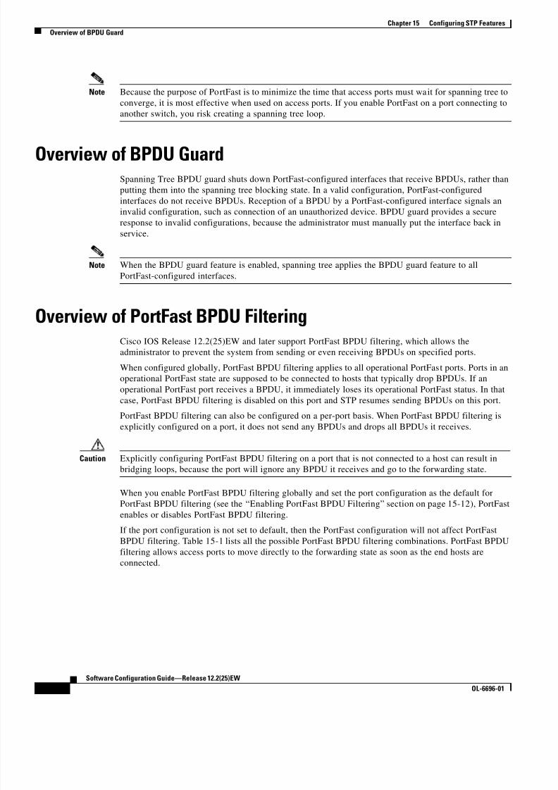
8/10/2019 Cisco ConfiguratioGuide SW4500 IOS
http://slidepdf.com/reader/full/cisco-configuratioguide-sw4500-ios 222/607
15-4
Software Configuration Guide—Release 12.2(25)EW
OL-6696-01
Chapter 15 Configuring STP Features
Overview of BPDU Guard
Note Because the purpose of PortFast is to minimize the time that access ports must wait for spanning tree to
converge, it is most effective when used on access ports. If you enable PortFast on a port connecting to
another switch, you risk creating a spanning tree loop.
Overview of BPDU GuardSpanning Tree BPDU guard shuts down PortFast-configured interfaces that receive BPDUs, rather than
putting them into the spanning tree blocking state. In a valid configuration, PortFast-configured
interfaces do not receive BPDUs. Reception of a BPDU by a PortFast-configured interface signals an
invalid configuration, such as connection of an unauthorized device. BPDU guard provides a secure
response to invalid configurations, because the administrator must manually put the interface back in
service.
Note When the BPDU guard feature is enabled, spanning tree applies the BPDU guard feature to all
PortFast-configured interfaces.
Overview of PortFast BPDU FilteringCisco IOS Release 12.2(25)EW and later support PortFast BPDU filtering, which allows the
administrator to prevent the system from sending or even receiving BPDUs on specified ports.
When configured globally, PortFast BPDU filtering applies to all operational PortFast ports. Ports in an
operational PortFast state are supposed to be connected to hosts that typically drop BPDUs. If an
operational PortFast port receives a BPDU, it immediately loses its operational PortFast status. In that
case, PortFast BPDU filtering is disabled on this port and STP resumes sending BPDUs on this port.
PortFast BPDU filtering can also be configured on a per-port basis. When PortFast BPDU filtering isexplicitly configured on a port, it does not send any BPDUs and drops all BPDUs it receives.
Caution Explicitly configuring PortFast BPDU filtering on a port that is not connected to a host can result in
bridging loops, because the port will ignore any BPDU it receives and go to the forwarding state.
When you enable PortFast BPDU filtering globally and set the port configuration as the default for
PortFast BPDU filtering (see the “Enabling PortFast BPDU Filtering” section on page 15-12), PortFast
enables or disables PortFast BPDU filtering.
If the port configuration is not set to default, then the PortFast configuration will not affect PortFast
BPDU filtering. Table 15-1 lists all the possible PortFast BPDU filtering combinations. PortFast BPDU
filtering allows access ports to move directly to the forwarding state as soon as the end hosts areconnected.
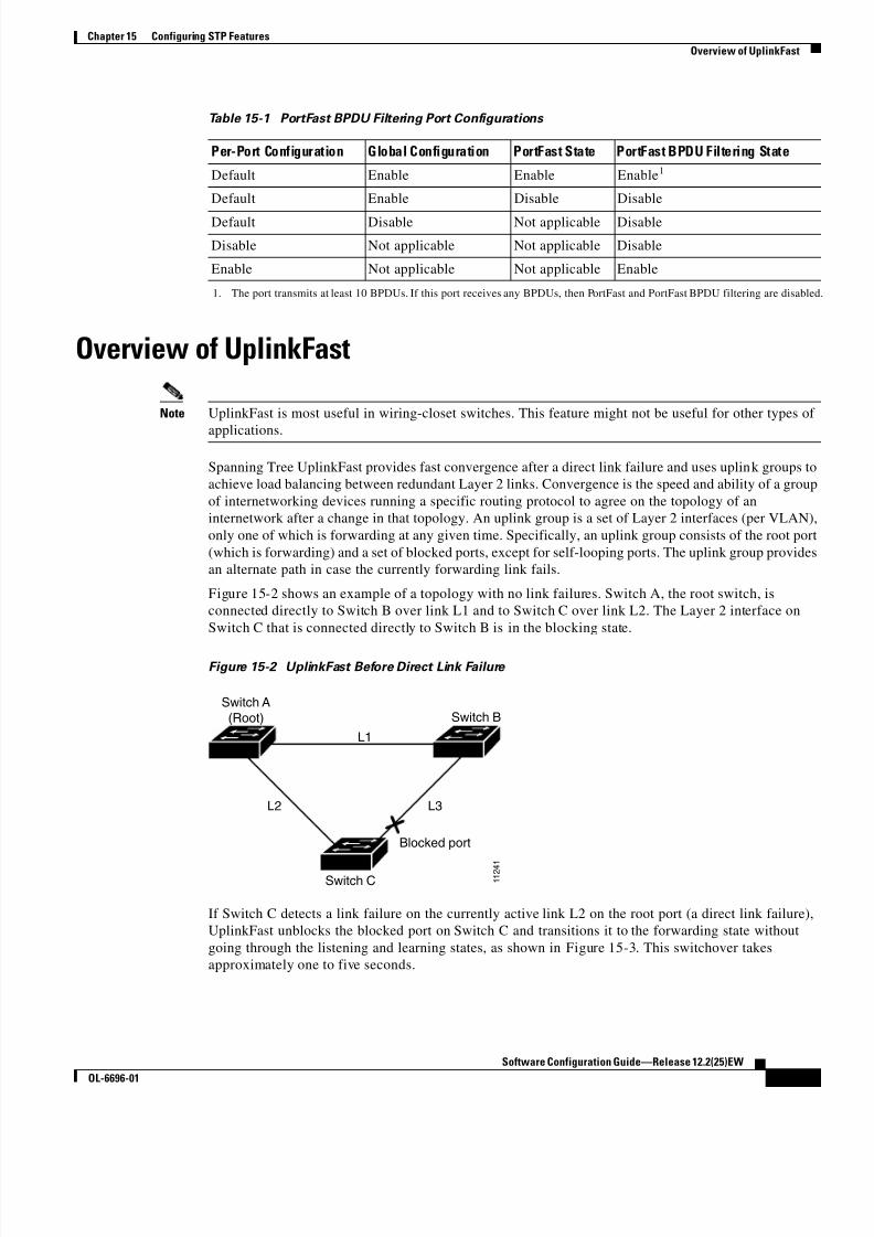
8/10/2019 Cisco ConfiguratioGuide SW4500 IOS
http://slidepdf.com/reader/full/cisco-configuratioguide-sw4500-ios 223/607
15-5
Software Configuration Guide—Release 12.2(25)EW
OL-6696-01
Chapter 15 Configuring STP Features
Overview of UplinkFast
Overview of UplinkFast
Note UplinkFast is most useful in wiring-closet switches. This feature might not be useful for other types of
applications.
Spanning Tree UplinkFast provides fast convergence after a direct link failure and uses uplink groups to
achieve load balancing between redundant Layer 2 links. Convergence is the speed and ability of a group
of internetworking devices running a specific routing protocol to agree on the topology of an
internetwork after a change in that topology. An uplink group is a set of Layer 2 interfaces (per VLAN),
only one of which is forwarding at any given time. Specifically, an uplink group consists of the root port
(which is forwarding) and a set of blocked ports, except for self-looping ports. The uplink group provides
an alternate path in case the currently forwarding link fails.
Figure 15-2 shows an example of a topology with no link failures. Switch A, the root switch, is
connected directly to Switch B over link L1 and to Switch C over link L2. The Layer 2 interface on
Switch C that is connected directly to Switch B is in the blocking state.
Figure 15-2 UplinkFast Before Direct Link Failure
If Switch C detects a link failure on the currently active link L2 on the root port (a direct link failure),
UplinkFast unblocks the blocked port on Switch C and transitions it to the forwarding state without
going through the listening and learning states, as shown in Figure 15-3. This switchover takes
approximately one to five seconds.
Table 15-1 PortFast BPDU Filtering Port Configurations
Per-Port Configuration Global Configuration PortFast State PortFast BPDU Filtering State
Default Enable Enable Enable1
Default Enable Disable Disable
Default Disable Not applicable Disable
Disable Not applicable Not applicable Disable
Enable Not applicable Not applicable Enable
1. The port transmits at least 10 BPDUs. If this port receives any BPDUs, then PortFast and PortFast BPDU filtering are disabled
L1
L2 L3
Switch C
Switch A
(Root) Switch B
Blocked port
1 1 2 4
1

8/10/2019 Cisco ConfiguratioGuide SW4500 IOS
http://slidepdf.com/reader/full/cisco-configuratioguide-sw4500-ios 224/607
15-6
Software Configuration Guide—Release 12.2(25)EW
OL-6696-01
Chapter 15 Configuring STP Features
Overview of BackboneFast
Figure 15-3 UplinkFast After Direct Link Failure
Overview of BackboneFastBackboneFast is a complementary technology to UplinkFast. Whereas UplinkFast is designed to quickly
respond to failures on links directly connected to leaf-node switches, it does not help with indirect
failures in the backbone core. BackboneFast optimizes based on the Max Age setting. It allows the
default convergence time for indirect failures to be reduced from 50 seconds to 30 seconds. However, it
never eliminates forward delays and offers no assistance for direct failures.
Note BackboneFast should be enabled on every switch in your network.
Sometimes a switch receives a BPDU from a designated switch that identifies the root bridge and the
designated bridge as the same switch. Because this shouldn’t happen, the BPDU is considered inferior.
BPDUs are considered inferior when a link from the designated switch has lost its link to the root bridge.
The designated switch transmits the BPDUs with the information that it is now the root bridge as wellas the designated bridge. The receiving switch will ignore the inferior BPDU for the time defined by the
Max Age setting.
After receiving inferior BPDUs, the receiving switch will try to determine if there is an alternate path to
the root bridge.
• If the port that the inferior BPDUs are received on is already in blocking mode, then the root port
and other blocked ports on the switch become alternate paths to the root bridge.
• If the inferior BPDUs are received on a root port, then all presently blocking ports become the
alternate paths to the root bridge. Also, if the inferior BPDUs are received on a root port and there
are no other blocking ports on the switch, the receiving switch assumes that the link to the root
bridge is down and the time defined by the Max Age setting expires, which turns the switch into the
root switch.If the switch finds an alternate path to the root bridge, it will use this new alternate path. This new path,
and any other alternate paths, will be used to send a Root Link Query (RLQ) BPDU. When BackboneFast
is enabled, the RLQ BPDUs are sent out as soon as an inferior BPDU is received. This process can enable
faster convergence in the event of a backbone link failure.
Figure 15-4 shows an example of a topology with no link failures. Switch A, the root switch, connects
directly to Switch B over link L1 and to Switch C over link L2. In this example, because switch B has a
lower priority than A but higher than C, switch B becomes the designated bridge for L3. Consequently,
the Layer 2 interface on Switch C that connects directly to Switch B must be in the blocking state.
L1
L2 L3
Switch C
Switch A
(Root) Switch B
UplinkFast transitions port
directly to forwarding state
Link failure
1 1 2 4 2

8/10/2019 Cisco ConfiguratioGuide SW4500 IOS
http://slidepdf.com/reader/full/cisco-configuratioguide-sw4500-ios 225/607
15-7
Software Configuration Guide—Release 12.2(25)EW
OL-6696-01
Chapter 15 Configuring STP Features
Overview of BackboneFast
Figure 15-4 BackboneFast Before Indirect Link Failure
Next, assume that L1 fails. Switch A and Switch B, the switches directly connected to this segment,
instantly know that the link is down. The blocking interface on Switch C must enter the forwarding state
for the network to recover by itself. However, because L1 is not directly connected to Switch C, Switch C
does not start sending any BPDUs on L3 under the normal rules of STP until the time defined by the Max
Age setting has expired.In an STP environment without BackboneFast, if L1 should fail, Switch C cannot detect this failure
because it is not connected directly to link L1. However, because Switch B is directly connected to the
root switch over L1, Switch B detects the failure and elects itself the root. Then Switch B begins sending
configuration BDPUs to Switch C, listing itself as the root.
Here is what happens additionally when you use BackboneFast to eliminate the time defined by the Max
Age setting (20-second) delay:
1. When Switch C receives the inferior configuration BPDUs from Switch B, Switch C infers that an
indirect failure has occurred.
2. Switch C then sends out an RLQ.
3. Switch A receives the RLQ. Because Switch A is the root bridge, it replies with an RLQ response,
listing itself as the root bridge.
4. When Switch C receives the RLQ response on its existing root port, it knows that it still has a stable
connection to the root bridge. Because Switch C originated the RLQ request, it does not need to
forward the RLQ response on to other switches.
5. BackboneFast allows the blocked port on Switch C to move immediately to the listening state
without waiting for the time defined by the Max Age setting for the port to expire.
6. BackboneFast transitions the Layer 2 interface on Switch C to the forwarding state, providing a path
from Switch B to Switch A.
This switchover takes approximately 30 seconds, twice the Forward Delay time if the default forward
delay time of 15 seconds is set.
Figure 15-5 shows how BackboneFast reconfigures the topology to account for the failure of link L1.
L1
L2 L3
Switch C
Switch A
(Root) Switch B
Blocked port
1 1 2 4 1

8/10/2019 Cisco ConfiguratioGuide SW4500 IOS
http://slidepdf.com/reader/full/cisco-configuratioguide-sw4500-ios 226/607
15-8
Software Configuration Guide—Release 12.2(25)EW
OL-6696-01
Chapter 15 Configuring STP Features
Enabling Root Guard
Figure 15-5 BackboneFast after Indirect Link Failure
If a new switch is introduced into a shared-medium topology as shown in Figure 15-6, BackboneFast is
not activated, because the inferior BPDUs did not come from the recognized designated bridge
(Switch B). The new switch begins sending inferior BPDUs that say it is the root switch. However, the
other switches ignore these inferior BPDUs, and the new switch learns that Switch B is the designated
bridge to Switch A, the root switch.
Figure 15-6 Adding a Switch in a Shared-Medium Topology
Enabling Root GuardTo enable root guard on a Layer 2 access port (to force it to become a designated port), perform this task:
L1
L2 L3
Switch C
Switch A
(Root) Switch B
Link failure
1 1 2 4 4
BackboneFast transitions port
through listening and learning
states to forwarding state
Switch A
(Root)
Switch C Switch B
(Designated Bridge)
Added switch
1 1 2 4 5
Blocked port
Command Purpose
Step 1 Switch(config)# interface {{fastethernet |
gigabitethernet | tengigabitethernet} slot/ port}Specifies an interface to configure.
Step 2 Switch(config-if)# [no] spanning-tree guard root Enables root guard.
You can use the no keyword to disable Root Guard.

8/10/2019 Cisco ConfiguratioGuide SW4500 IOS
http://slidepdf.com/reader/full/cisco-configuratioguide-sw4500-ios 227/607
15-9
Software Configuration Guide—Release 12.2(25)EW
OL-6696-01
Chapter 15 Configuring STP Features
Enabling Loop Guard
This example shows how to enable root guard on Fast Ethernet interface 5/8:Switch(config)# interface fastethernet 5/8
Switch(config-if)# spanning-tree guard root
Switch(config-if)# end
Switch#
This example shows how to verify the configuration:
Switch# show running-config interface fastethernet 5/8
Building configuration...
Current configuration: 67 bytes
!
interface FastEthernet5/8 switchport mode access
spanning-tree guard rootend
Switch#
This example shows how to determine whether any ports are in root inconsistent state:
Switch# show spanning-tree inconsistentports
Name Interface Inconsistency-------------------- ---------------------- ------------------
VLAN0001 FastEthernet3/1 Port Type Inconsistent
VLAN0001 FastEthernet3/2 Port Type Inconsistent
VLAN1002 FastEthernet3/1 Port Type Inconsistent VLAN1002 FastEthernet3/2 Port Type Inconsistent
VLAN1003 FastEthernet3/1 Port Type Inconsistent
VLAN1003 FastEthernet3/2 Port Type Inconsistent VLAN1004 FastEthernet3/1 Port Type Inconsistent
VLAN1004 FastEthernet3/2 Port Type Inconsistent
VLAN1005 FastEthernet3/1 Port Type Inconsistent VLAN1005 FastEthernet3/2 Port Type Inconsistent
Number of inconsistent ports (segments) in the system :10
Enabling Loop GuardYou can enable loop guard globally or per port.
To enable loop guard globally on the switch, perform this task:
Step 3 Switch(config-if)# end Exits configuration mode.
Step 4 Switch# show spanning-tree Verifies the configuration.
Command Purpose
Command Purpose
Step 1 Switch(config)# spanning-tree loopguard default Enables loop guard globally on the switch.
Step 2 Switch(config)# end Exits configuration mode.
Step 3 Switch# show spanning tree interface 4/4 detail Verifies the configuration impact on a port.

8/10/2019 Cisco ConfiguratioGuide SW4500 IOS
http://slidepdf.com/reader/full/cisco-configuratioguide-sw4500-ios 228/607
15-10
Software Configuration Guide—Release 12.2(25)EW
OL-6696-01
Chapter 15 Configuring STP Features
Enabling Loop Guard
This example shows how to enable loop guard globally:
Switch(config)# spanning-tree loopguard default Switch(config)# Ctrl-Z
This example shows how to verify the previous configuration of port 4/4:
Switch# show spanning-tree interface fastethernet 4/4 detail Port 196 (FastEthernet4/4) of VLAN0010 is forwarding
Port path cost 1000, Port priority 160, Port Identifier 160.196.
Designated root has priority 32768, address 00d0.00b8.140a
Designated bridge has priority 32768, address 00d0.00b8.140a Designated port id is 160.196, designated path cost 0
Timers:message age 0, forward delay 0, hold 0 Number of transitions to forwarding state:1
The port is in the portfast mode by portfast trunk configuration
Link type is point-to-point by default
Bpdu filter is enabled Loop guard is enabled by default on the port
BPDU:sent 0, received 0
To enable loop guard on an interface, perform this task:
This example shows how to enable loop guard on port 4/4:
Switch(config)# interface fastEthernet 4/4
Switch(config-if)# spanning-tree guard loop
Switch(config-if)# ^Z
This example shows how to verify the configuration impact on port 4/4:
Switch# show spanning-tree interface fastEthernet 4/4 detail
Port 196 (FastEthernet4/4) of VLAN0010 is forwardingPort path cost 1000, Port priority 160, Port Identifier 160.196.
Designated root has priority 32768, address 00d0.00b8.140a
Designated bridge has priority 32768, address 00d0.00b8.140a
Designated port id is 160.196, designated path cost 0 Timers:message age 0, forward delay 0, hold 0
Number of transitions to forwarding state:1
The port is in the portfast mode by portfast trunk configuration Link type is point-to-point by default
Bpdu filter is enabled
Loop guard is enabled on the port BPDU:sent 0, received 0
Switch#
Command Purpose
Step 1 Switch(config)# interface {type slot/port} |
{ port-channel port_channel_number }Selects an interface to configure.
Step 2 Switch(config-if)# spanning-tree guard loop Configures loop guard.
Step 3 Switch(config)# end Exits configuration mode.
Step 4 Switch# show spanning tree interface 4/4 detail Verifies the configuration impact on that port.

8/10/2019 Cisco ConfiguratioGuide SW4500 IOS
http://slidepdf.com/reader/full/cisco-configuratioguide-sw4500-ios 229/607
15-11
Software Configuration Guide—Release 12.2(25)EW
OL-6696-01
Chapter 15 Configuring STP Features
Enabling PortFast
Enabling PortFast
Caution Use PortFast only when connecting a single end station to a Layer 2 access port. Otherwise, you might
create a network loop.
To enable PortFast on a Layer 2 access port to force it to enter the forwarding state immediately, perform
this task:
This example shows how to enable PortFast on Fast Ethernet interface 5/8:
Switch(config)# interface fastethernet 5/8
Switch(config-if)# spanning-tree portfast Switch(config-if)# end
Switch#
This example shows how to verify the configuration:
Switch# show running-config interface fastethernet 5/8 Building configuration...
Current configuration:!
interface FastEthernet5/8
no ip address
switchport switchport access vlan 200
switchport mode access spanning-tree portfast
end
Switch#
Command Purpose
Step 1 Switch(config)# interface {{fastethernet |
gigabitethernet | tengigabitethernet} slot/ port}
| { port-channel port_channel_number }
Specifies an interface to configure.
Step 2 Switch(config-if)# [no] spanning-tree portfast Enables PortFast on a Layer 2 access port connected to a
single workstation or server.
You can use the no keyword to disable PortFast.
Step 3 Switch(config-if)# end Exits configuration mode.
Step 4 Switch# show running interface {{fastethernet |gigabitethernet | tengigabitethernet} slot/ port}
| { port-channel port_channel_number }
Verifies the configuration.

8/10/2019 Cisco ConfiguratioGuide SW4500 IOS
http://slidepdf.com/reader/full/cisco-configuratioguide-sw4500-ios 230/607

8/10/2019 Cisco ConfiguratioGuide SW4500 IOS
http://slidepdf.com/reader/full/cisco-configuratioguide-sw4500-ios 231/607
15-13
Software Configuration Guide—Release 12.2(25)EW
OL-6696-01
Chapter 15 Configuring STP Features
Enabling PortFast BPDU Filtering
This example shows how to verify the BPDU configuration in PVST+ mode:
Switch# show spanning-tree summary totals Root bridge for:VLAN0010
EtherChannel misconfiguration guard is enabledExtended system ID is disabled
Portfast is enabled by default
PortFast BPDU Guard is disabled by defaultPortfast BPDU Filter is enabled by default
Loopguard is disabled by default
UplinkFast is disabled
BackboneFast is disabledPathcost method used is long
Name Blocking Listening Learning Forwarding STP Active
---------------------- -------- --------- -------- ---------- ----------
2 vlans 0 0 0 3 3
Switch#
Note For PVST+ information, see Chapter 16, “Understanding and Configuring Multiple Spanning Trees.”
To enable PortFast BPDU filtering, perform this task:
This example shows how to enable PortFast BPDU filtering on port 4/4:
Switch(config)# interface fastethernet 4/4
Switch(config-if)# spanning-tree bpdufilter enable
Switch(config-if)# ^Z
This example shows how to verify that PortFast BPDU filtering is enabled:
Switch# show spanning-tree interface fastethernet 4/4
Vlan Role Sts Cost Prio.Nbr Status
---------------- ---- --- --------- -------- -------------------------------- VLAN0010 Desg FWD 1000 160.196 Edge P2p
This example shows more detail on the port:
Switch# show spanning-tree interface fastEthernet 4/4 detail Port 196 (FastEthernet4/4) of VLAN0010 is forwarding
Port path cost 1000, Port priority 160, Port Identifier 160.196.
Designated root has priority 32768, address 00d0.00b8.140a Designated bridge has priority 32768, address 00d0.00b8.140a Designated port id is 160.196, designated path cost 0
Timers:message age 0, forward delay 0, hold 0 Number of transitions to forwarding state:1
The port is in the portfast mode by portfast trunk configuration
Link type is point-to-point by default
Bpdu filter is enabled
BPDU:sent 0, received 0
Switch#
Command Purpose
Step 1 Switch(config)# interface fastEthernet 4/4 Selects the interface to configure.
Step 2 Switch(config-if)# spanning-tree bpdufilter enable Enables BPDU filtering.
Step 3 Switch# show spanning-tree interface fastethernet 4/4 Verifies the configuration.
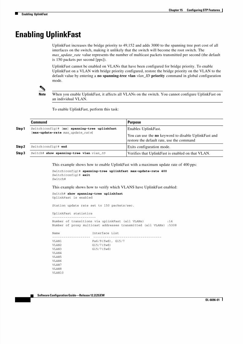
8/10/2019 Cisco ConfiguratioGuide SW4500 IOS
http://slidepdf.com/reader/full/cisco-configuratioguide-sw4500-ios 232/607
15-14
Software Configuration Guide—Release 12.2(25)EW
OL-6696-01
Chapter 15 Configuring STP Features
Enabling UplinkFast
Enabling UplinkFastUplinkFast increases the bridge priority to 49,152 and adds 3000 to the spanning tree port cost of all
interfaces on the switch, making it unlikely that the switch will become the root switch. The
max_update_rate value represents the number of multicast packets transmitted per second (the default
is 150 packets per second [pps]).
UplinkFast cannot be enabled on VLANs that have been configured for bridge priority. To enable
UplinkFast on a VLAN with bridge priority configured, restore the bridge priority on the VLAN to the
default value by entering a no spanning-tree vlan vlan_ID priority command in global configuration
mode.
Note When you enable UplinkFast, it affects all VLANs on the switch. You cannot configure UplinkFast on
an individual VLAN.
To enable UplinkFast, perform this task:
This example shows how to enable UplinkFast with a maximum update rate of 400 pps:
Switch(config)# spanning-tree uplinkfast max-update-rate 400 Switch(config)# exit
Switch#
This example shows how to verify which VLANS have UplinkFast enabled:
Switch# show spanning-tree uplinkfast UplinkFast is enabled
Station update rate set to 150 packets/sec.
UplinkFast statistics
-----------------------Number of transitions via uplinkFast (all VLANs) :14
Number of proxy multicast addresses transmitted (all VLANs) :5308
Name Interface List
-------------------- ------------------------------------
VLAN1 Fa6/9(fwd), Gi5/7 VLAN2 Gi5/7(fwd)
VLAN3 Gi5/7(fwd)
VLAN4 VLAN5
VLAN6 VLAN7
VLAN8 VLAN10
Command Purpose
Step 1 Switch(config)# [no] spanning-tree uplinkfast
[ max-update-rate max_update_rate ]Enables UplinkFast.
You can use the no keyword to disable UplinkFast and
restore the default rate, use the command
Step 2 Switch(config)# end Exits configuration mode.
Step 3 Switch# show spanning-tree vlan vlan_ID Verifies that UplinkFast is enabled on that VLAN.

8/10/2019 Cisco ConfiguratioGuide SW4500 IOS
http://slidepdf.com/reader/full/cisco-configuratioguide-sw4500-ios 233/607
15-15
Software Configuration Guide—Release 12.2(25)EW
OL-6696-01
Chapter 15 Configuring STP Features
Enabling BackboneFast
VLAN15
VLAN1002 Gi5/7(fwd)
VLAN1003 Gi5/7(fwd) VLAN1004 Gi5/7(fwd)
VLAN1005 Gi5/7(fwd)Switch#
Enabling BackboneFast
Note For BackboneFast to work, you must enable it on all switches in the network. BackboneFast is supported
for use with third-party switches but it is not supported on Token Ring VLANs.
To enable BackboneFast, perform this task:
This example shows how to enable BackboneFast:
Switch(config)# spanning-tree backbonefast
Switch(config)# end
Switch#
This example shows how to verify that BackboneFast is enabled:
Switch# show spanning-tree backbonefast BackboneFast is enabled
BackboneFast statistics-----------------------
Number of transition via backboneFast (all VLANs) : 0
Number of inferior BPDUs received (all VLANs) : 0Number of RLQ request PDUs received (all VLANs) : 0
Number of RLQ response PDUs received (all VLANs) : 0Number of RLQ request PDUs sent (all VLANs) : 0
Number of RLQ response PDUs sent (all VLANs) : 0
Switch#
This example shows how to display a summary of port states:
Switch#show spanning-tree summary
Root bridge for:VLAN0001, VLAN1002-VLAN1005
Extended system ID is disabled
Portfast is enabled by defaultPortFast BPDU Guard is disabled by default
Portfast BPDU Filter is enabled by default
Loopguard is disabled by default
EtherChannel misconfiguration guard is enabled
UplinkFast is enabledBackboneFast is enabled
Pathcost method used is short
Command Purpose
Step 1 Switch(config)# [no] spanning-tree backbonefast Enables BackboneFast.
You can use the no keyword to disable BackboneFast.
Step 2 Switch(config)# end Exits configuration mode.
Step 3 Switch# show spanning-tree backbonefast Verifies that BackboneFast is enabled.

8/10/2019 Cisco ConfiguratioGuide SW4500 IOS
http://slidepdf.com/reader/full/cisco-configuratioguide-sw4500-ios 234/607

8/10/2019 Cisco ConfiguratioGuide SW4500 IOS
http://slidepdf.com/reader/full/cisco-configuratioguide-sw4500-ios 235/607
C H A P T E R
16-1
Software Configuration Guide—Release 12.2(25)EW
OL-6696-01
16
Understanding and Configuring MultipleSpanning Trees
This chapter describes how to configure the IEEE 802.1s Multiple Spanning Tree (MST) protocol on the
Catalyst 4500 series switch. MST is a new IEEE standard derived from Cisco's proprietary
Multi-Instance Spanning-Tree Protocol (MISTP) implementation. With MST, you can map a single
spanning-tree instance to several VLANs.
This chapter includes the following major sections:
• Overview of MST, page 16-1
• MST Configuration Restrictions and Guidelines, page 16-8
• Configuring MST, page 16-9
Note For complete syntax and usage information for the switch commands used in this chapter, refer to the
Catalyst 4500 Series Switch Cisco IOS Command Reference and related publications at
http://www.cisco.com/univercd/cc/td/doc/product/software/ios122/122cgcr/index.htm.
Overview of MSTThe following sections describe how MST works on a Catalyst 4500 series switch:
• IEEE 802.1s MST, page 16-2
• IEEE 802.1w RSTP, page 16-3
• MST-to-SST Interoperability, page 16-4
• Common Spanning Tree, page 16-5
• MST Instances, page 16-5
• MST Configuration Parameters, page 16-5
• MST Regions, page 16-6
• Message Age and Hop Count, page 16-7
• MST-to-PVST+ Interoperability, page 16-8

8/10/2019 Cisco ConfiguratioGuide SW4500 IOS
http://slidepdf.com/reader/full/cisco-configuratioguide-sw4500-ios 236/607
16-2
Software Configuration Guide—Release 12.2(25)EW
OL-6696-01
Chapter 16 Understanding and Configuring Multiple Spanning Trees
Overview of MST
IEEE 802.1s MST
MST extends the IEEE 802.1w rapid spanning tree (RST) algorithm to multiple spanning trees. This
extension provides both rapid convergence and load balancing in a VLAN environment. MST converges
faster than Per VLAN Spanning Tree Plus (PVST+) and is backward compatible with 802.1D STP,
802.1w (Rapid Spanning Tree Protocol [RSTP]), and the Cisco PVST+ architecture.MST allows you to build multiple spanning trees over trunks. You can group and associate VLANs to
spanning tree instances. Each instance can have a topology independent of other spanning tree instances.
This architecture provides multiple forwarding paths for data traffic and enables load balancing.
Network fault tolerance is improved because a failure in one instance (forwarding path) does not affect
other instances.
In large networks, you can more easily administer the network and use redundant paths by locating
different VLAN and spanning tree instance assignments in different parts of the network. A
spanning tree instance can exist only on bridges that have compatible VLAN instance assignments. You
must configure a set of bridges with the same MST configuration information, which allows them to
participate in a specific set of spanning tree instances. Interconnected bridges that have the same MST
configuration are referred to as an MST region.
MST uses the modified RSTP, MSTP. MST has the following characteristics:
• MST runs a variant of spanning tree called Internal Spanning Tree (IST). IST augments Common
Spanning Tree (CST) information with internal information about the MST region. The MST region
appears as a single bridge to adjacent single spanning tree (SST) and MST regions.
• A bridge running MST provides interoperability with SST bridges as follows:
– MST bridges run IST, which augments CST information with internal information about the
MST region.
– IST connects all the MST bridges in the region and appears as a subtree in the CST that includes
the whole bridged domain. The MST region appears as a virtual bridge to adjacent SST bridges
and MST regions.
– The Common and Internal Spanning Tree (CIST) is the collection of the following: ISTs in each
MST region, the CST that interconnects the MST regions, and the SST bridges. CIST is
identical to an IST inside an MST region and identical to a CST outside an MST region. TheSTP, RSTP, and MSTP together elect a single bridge as the root of the CIST.
• MST establishes and maintains additional spanning trees within each MST region. These spanning
trees are termed MST instances (MSTIs). The IST is numbered 0, and the MSTIs are numbered 1,
2, 3, and so on. Any MSTI is local to the MST region and is independent of MSTIs in another region,
even if the MST regions are interconnected.
MST instances combine with the IST at the boundary of MST regions to become the CST as follows:
– Spanning tree information for an MSTI is contained in an MSTP record (M-record).
M-records are always encapsulated within MST bridge protocol data units (BPDUs). The
original spanning trees computed by MSTP are called M-trees, which are active only within the
MST region. M-trees merge with the IST at the boundary of the MST region and form the CST.
• MST provides interoperability with PVST+ by generating PVST+ BPDUs for the non-CST VLANs.
• MST supports some of the PVST+ extensions in MSTP as follows:
– UplinkFast and BackboneFast are not available in MST mode; they are part of RSTP.
– PortFast is supported.
– BPDU filter and BPDU guard are supported in MST mode.
– Loop guard and root guard are supported in MST. MST preserves the VLAN 1 disabled
functionality except that BPDUs are still transmitted in VLAN 1.

8/10/2019 Cisco ConfiguratioGuide SW4500 IOS
http://slidepdf.com/reader/full/cisco-configuratioguide-sw4500-ios 237/607
16-3
Software Configuration Guide—Release 12.2(25)EW
OL-6696-01
Chapter 16 Understanding and Configuring Multiple Spanning Trees
Overview of MST
– MST switches operate as if MAC reduction is enabled.
– For private VLANs (PVLANs), you must map a secondary VLAN to the same instance as the
primary.
IEEE 802.1w RSTPRSTP, specified in 802.1w, supersedes STP specified in 802.1D, but remains compatible with STP. You
configure RSTP when you configure the MST feature. For more information, see the “Configuring MST”
section on page 16-9.
RSTP provides the structure on which the MST operates, significantly reducing the time to reconfigure
the active topology of a network when its physical topology or configuration parameters change. RSTP
selects one switch as the root of a spanning-tree-connected active topology and assigns port roles to
individual ports of the switch, depending on whether that port is part of the active topology.
RSTP provides rapid connectivity following the failure of a switch, switch port, or a LAN. A new root
port and the designated port on the other side of the bridge transition to the forwarding state through an
explicit handshake between them. RSTP allows switch port configuration so the ports can transition to
forwarding directly when the switch reinitializes.
RSTP provides backward compatibility with 802.1D bridges as follows:
• RSTP selectively sends 802.1D-configured BPDUs and Topology Change Notification (TCN)
BPDUs on a per-port basis.
• When a port initializes, the migration delay timer starts and RSTP BPDUs are transmitted. While
the migration delay timer is active, the bridge processes all BPDUs received on that port.
• If the bridge receives an 802.1D BPDU after a port’s migration delay timer expires, the bridge
assumes it is connected to an 802.1D bridge and starts using only 802.1D BPDUs.
• When RSTP uses 802.1D BPDUs on a port and receives an RSTP BPDU after the migration delay
expires, RSTP restarts the migration delay timer and begins using RSTP BPDUs on that port.
RSTP Port Roles
In RSTP, the port roles are defined as follows:
• Root—A forwarding port elected for the spanning tree topology.
• Designated—A forwarding port elected for every switched LAN segment.
• Alternate—An alternate path to the root bridge to that provided by the current root port.
• Backup—A backup for the path provided by a designated port toward the leaves of the spanning tree.
Backup ports can exist only where two ports are connected together in a loopback mode or bridge
with two or more connections to a shared LAN segment.
• Disabled—A port that has no role within the operation of spanning tree.
The system assigns port roles as follows:
• A root port or designated port role includes the port in the active topology.
• An alternate port or backup port role excludes the port from the active topology.

8/10/2019 Cisco ConfiguratioGuide SW4500 IOS
http://slidepdf.com/reader/full/cisco-configuratioguide-sw4500-ios 238/607

8/10/2019 Cisco ConfiguratioGuide SW4500 IOS
http://slidepdf.com/reader/full/cisco-configuratioguide-sw4500-ios 239/607
16-5
Software Configuration Guide—Release 12.2(25)EW
OL-6696-01
Chapter 16 Understanding and Configuring Multiple Spanning Trees
Overview of MST
To STP running in the SST region, an MST region appears as a single SST or pseudobridge, which
operates as follows:
• Although the values for root identifiers and root path costs match for all BPDUs in all
pseudobridges, a pseudobridge differs from a single SST bridge as follows:
– The pseudobridge BPDUs have different bridge identifiers. This difference does not affect STP
operation in the neighboring SST regions because the root identifier and root cost are the same
– BPDUs sent from the pseudobridge ports may have significantly different message ages.
Because the message age increases by one second for each hop, the difference in the message
age is measured in seconds.
• Data traffic from one port of a pseudobridge (a port at the edge of a region) to another port follows
a path entirely contained within the pseudobridge or MST region. Data traffic belonging to different
VLANs might follow different paths within the MST regions established by MST.
• The system prevents looping by doing either of the following:
– Blocking the appropriate pseudobridge ports by allowing one forwarding port on the boundary
and blocking all other ports.
– Setting the CST partitions to block the ports of the SST regions.
Common Spanning Tree
CST (802.1Q) is a single spanning tree for all the VLANs. In a Catalyst 4000 family switch running
PVST+, the VLAN 1 spanning tree corresponds to CST. In a Catalyst 4000 family switch running MST,
IST (instance 0) corresponds to CST.
MST Instances
This release supports up to 16 instances; each spanning tree instance is identified by an instance ID that
ranges from 0 to 15. Instance 0 is mandatory and is always present. Instances 1 through 15 are optional.
MST Configuration Parameters
MST configuration has three parts, as follows:
• Name—A 32-character string (null padded) that identifies the MST region.
• Revision number—An unsigned 16-bit number that identifies the revision of the current MST
configuration.
Note You must set the revision number when required as part of the MST configuration. The
revision number is not incremented automatically each time you commit the MSTconfiguration.
• MST configuration table—An array of 4096 bytes. Each byte, interpreted as an unsigned integer,
corresponds to a VLAN. The value is the instance number to which the VLAN is mapped. The first
byte that corresponds to VLAN 0 and the 4096th byte that corresponds to VLAN 4095 are unused
and always set to zero.
You must configure each byte manually. You can use SNMP or the CLI to perform the configuration.

8/10/2019 Cisco ConfiguratioGuide SW4500 IOS
http://slidepdf.com/reader/full/cisco-configuratioguide-sw4500-ios 240/607
16-6
Software Configuration Guide—Release 12.2(25)EW
OL-6696-01
Chapter 16 Understanding and Configuring Multiple Spanning Trees
Overview of MST
MST BPDUs contain the MST configuration ID and the checksum. An MST bridge accepts an MST
BPDU only if the MST BPDU configuration ID and the checksum match its own MST region
configuration ID and checksum. If either value is different, the MST BPDU is considered to be an
SST BPDU.
MST RegionsThese sections describe MST regions:
• MST Region Overview, page 16-6
• Boundary Ports, page 16-6
• IST Master, page 16-7
• Edge Ports, page 16-7
• Link Type, page 16-7
MST Region OverviewInterconnected bridges that have the same MST configuration are referred to as an MST region. There
is no limit on the number of MST regions in the network.
To form an MST region, bridges can be either of the following:
• An MST bridge that is the only member of the MST region.
• An MST bridge interconnected by a LAN. A LAN’s designated bridge has the same MST
configuration as an MST bridge. All the bridges on the LAN can process MST BPDUs.
If you connect two MST regions with different MST configurations, the MST regions do the following:
• Load balance across redundant paths in the network. If two MST regions are redundantly connected,
all traffic flows on a single connection with the MST regions in a network.
• Provide an RSTP handshake to enable rapid connectivity between regions. However, thehandshaking is not as fast as between two bridges. To prevent loops, all the bridges inside the region
must agree upon the connections to other regions. This situation introduces a delay. We do not
recommend partitioning the network into a large number of regions.
Boundary Ports
A boundary port is a port that connects to a LAN, the designated bridge of which is either an SST bridge
or a bridge with a different MST configuration. A designated port knows that it is on the boundary if it
detects an STP bridge or receives an agreement message from an RST or MST bridge with a different
configuration.
At the boundary, the role of MST ports do not matter; their state is forced to be the same as the IST port
state. If the boundary flag is set for the port, the MSTP Port Role selection mechanism assigns a port
role to the boundary and the same state as that of the IST port. The IST port at the boundary can take up
any port role except a backup port role.

8/10/2019 Cisco ConfiguratioGuide SW4500 IOS
http://slidepdf.com/reader/full/cisco-configuratioguide-sw4500-ios 241/607
16-7
Software Configuration Guide—Release 12.2(25)EW
OL-6696-01
Chapter 16 Understanding and Configuring Multiple Spanning Trees
Overview of MST
IST Master
The IST master of an MST region is the bridge with the lowest bridge identifier and the least path cost
to the CST root. If an MST bridge is the root bridge for CST, then it is the IST master of that MST region.
If the CST root is outside the MST region, then one of the MST bridges at the boundary is selected as
the IST master. Other bridges on the boundary that belong to the same region eventually block the
boundary ports that lead to the root.
If two or more bridges at the boundary of a region have an identical path to the root, you can set a slightly
lower bridge priority to make a specific bridge the IST master.
The root path cost and message age inside a region stay constant, but the IST path cost is incremented
and the IST remaining hops are decremented at each hop. Enter the show spanning-tree mst command
to display the information about the IST master, path cost, and remaining hops for the bridge.
Edge Ports
A port that is connected to a nonbridging device (for example, a host or a switch) is an edge port. A port
that connects to a hub is also an edge port if the hub or any LAN that is connected to it does not have a
bridge. An edge port can start forwarding as soon as the link is up.
MST requires that you configure each port connected to a host. To establish rapid connectivity after a
failure, you need to block the non-edge designated ports of an intermediate bridge. If the port connects
to another bridge that can send back an agreement, then the port starts forwarding immediately.
Otherwise, the port needs twice the forward delay time to start forwarding again. You must explicitly
configure the ports that are connected to the hosts and switches as edge ports while using MST.
To prevent a misconfiguration, the PortFast operation is turned off if the port receives a BPDU. You can
display the configured and operational status of PortFast by using the show spanning-tree mst interface
command.
Link Type
Rapid connectivity is established only on point-to-point links. You must configure ports explicitly to a
host or switch. However, cabling in most networks meets this requirement, and you can avoid explicit
configuration by treating all full-duplex links as point-to-point links by entering the spanning-tree
linktype command.
Message Age and Hop Count
IST and MST instances do not use the message age and maximum age timer settings in the BPDU. IST
and MST use a separate hop count mechanism that is very similar to the IP time-to live (TTL)
mechanism. You can configure each MST bridge with a maximum hop count. The root bridge of the
instance sends a BPDU (or M-record) with the remaining hop count that is equal to the maximum hop
count. When a bridge receives a BPDU (or M-record), it decrements the received remaining hop countby one. The bridge discards the BPDU (M-record) and ages out the information held for the port if the
count reaches zero after decrementing. The nonroot bridges propagate the decremented count as the
remaining hop count in the BPDUs (M-records) they generate.
The message age and maximum age timer settings in the RST portion of the BPDU remain the same
throughout the region, and the same values are propagated by the region’s designated ports at the
boundary.

8/10/2019 Cisco ConfiguratioGuide SW4500 IOS
http://slidepdf.com/reader/full/cisco-configuratioguide-sw4500-ios 242/607
16-8
Software Configuration Guide—Release 12.2(25)EW
OL-6696-01
Chapter 16 Understanding and Configuring Multiple Spanning Trees
MST Configuration Restrictions and Guidelines
MST-to-PVST+ Interoperability
Keep these guidelines in mind when you configure MST switches (in the same region) to interact with
PVST+ switches:
• Configure the root for all VLANs inside the MST region as shown in this example:
Switch# show spanning-tree mst interface gigabitethernet 1/1
GigabitEthernet1/1 of MST00 is root forwarding
Edge port: no (trunk) port guard : none (default)
Link type: point-to-point (auto) bpdu filter: disable (default)
Boundary : boundary (PVST) bpdu guard : disable (default)Bpdus sent 10, received 310
Instance Role Sts Cost Prio.Nbr Vlans mapped
-------- ---- --- --------- -------- -------------------------------
0 Root FWD 20000 128.1 1-2,4-2999,4000-4094
3 Boun FWD 20000 128.1 3,3000-3999
The ports that belong to the MST switch at the boundary simulate PVST+ and send PVST+ BPDUs
for all the VLANs.If you enable loop guard on the PVST+ switches, the ports might change to a loop-inconsistent state
when the MST switches change their configuration. To correct the loop-inconsistent state, you must
disable and renewable loop guard on that PVST+ switch.
• Do not locate the root for some or all of the VLANs inside the PVST+ side of the MST switch
because when the MST switch at the boundary receives PVST+ BPDUs for all or some of the
VLANs on its designated ports, root guard sets the port to the blocking state.
When you connect a PVST+ switch to two different MST regions, the topology change from the PVST+
switch does not pass beyond the first MST region. In such a case, the topology changes are propagated
only in the instance to which the VLAN is mapped. The topology change stays local to the first MST
region, and the Cisco Access Manager (CAM) entries in the other region are not flushed. To make the
topology change visible throughout other MST regions, you can map that VLAN to IST or connect the
PVST+ switch to the two regions through access links.
MST Configuration Restrictions and GuidelinesFollow these restrictions and guidelines to avoid configuration problems:
• Do not disable spanning tree on any VLAN in any of the PVST bridges.
• Do no use PVST bridges as the root of CST.
• Do not connect switches with access links, because access links may partition a VLAN.
• Ensure that all PVST root bridges have lower (numerically higher) priority than the CST root bridge.
• Ensure that trunks carry all of the VLANs mapped to an instance or do not carry any VLANs at allfor this instance.
• Complete any MST configuration that incorporates a large number of either existing or new logical
VLAN ports during a maintenance window because the complete MST database gets reinitialized
for any incremental change (such as adding new VLANs to instances or moving VLANs across
instances).
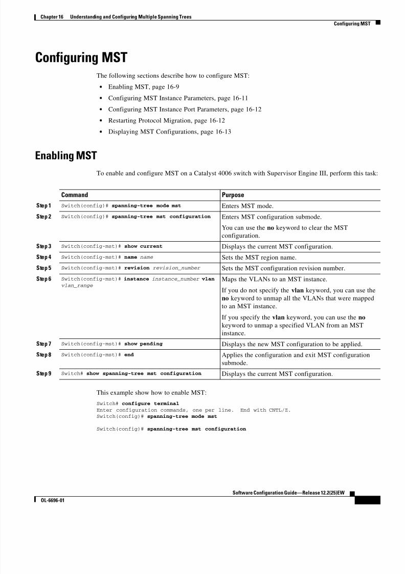
8/10/2019 Cisco ConfiguratioGuide SW4500 IOS
http://slidepdf.com/reader/full/cisco-configuratioguide-sw4500-ios 243/607
16-9
Software Configuration Guide—Release 12.2(25)EW
OL-6696-01
Chapter 16 Understanding and Configuring Multiple Spanning Trees
Configuring MST
Configuring MSTThe following sections describe how to configure MST:
• Enabling MST, page 16-9
• Configuring MST Instance Parameters, page 16-11• Configuring MST Instance Port Parameters, page 16-12
• Restarting Protocol Migration, page 16-12
• Displaying MST Configurations, page 16-13
Enabling MST
To enable and configure MST on a Catalyst 4006 switch with Supervisor Engine III, perform this task:
This example show how to enable MST:
Switch# configure terminal Enter configuration commands, one per line. End with CNTL/Z.Switch(config)# spanning-tree mode mst
Switch(config)# spanning-tree mst configuration
Command Purpose
Step 1 Switch(config)# spanning-tree mode mst Enters MST mode.
Step 2 Switch(config)# spanning-tree mst configuration Enters MST configuration submode.
You can use the no keyword to clear the MST
configuration.
Step 3 Switch(config-mst)# show current Displays the current MST configuration.
Step 4 Switch(config-mst)# name name Sets the MST region name.
Step 5 Switch(config-mst)# revision revision_number Sets the MST configuration revision number.
Step 6 Switch(config-mst)# instance instance_number vlan vlan_range
Maps the VLANs to an MST instance.
If you do not specify the vlan keyword, you can use the
no keyword to unmap all the VLANs that were mapped
to an MST instance.
If you specify the vlan keyword, you can use the no
keyword to unmap a specified VLAN from an MST
instance.
Step 7 Switch(config-mst)# show pending Displays the new MST configuration to be applied.
Step 8 Switch(config-mst)# end Applies the configuration and exit MST configuration
submode.
Step 9 Switch# show spanning-tree mst configuration Displays the current MST configuration.

8/10/2019 Cisco ConfiguratioGuide SW4500 IOS
http://slidepdf.com/reader/full/cisco-configuratioguide-sw4500-ios 244/607
16-10
Software Configuration Guide—Release 12.2(25)EW
OL-6696-01
Chapter 16 Understanding and Configuring Multiple Spanning Trees
Configuring MST
Switch(config-mst)# show currentCurrent MST configurationName []Revision 0Instance Vlans mapped-------- ---------------------------------------------------------------------0 1-4094
-------------------------------------------------------------------------------Switch(config-mst)# name ciscoSwitch(config-mst)# revision 2Switch(config-mst)# instance 1 vlan 1Switch(config-mst)# instance 2 vlan 1-1000Switch(config-mst)# show pendingPending MST configurationName [cisco]Revision 2Instance Vlans mapped-------- ---------------------------------------------------------------------0 1001-40942 1-1000-------------------------------------------------------------------------------
Switch(config-mst)# no instance 2Switch(config-mst)# show pending
Pending MST configurationName [cisco]Revision 2Instance Vlans mapped-------- ---------------------------------------------------------------------0 1-4094-------------------------------------------------------------------------------
Switch(config-mst)# instance 1 vlan 2000-3000Switch(config-mst)# no instance 1 vlan 1500Switch(config-mst)# show pendingPending MST configurationName [cisco]Revision 2Instance Vlans mapped-------- ---------------------------------------------------------------------0 1-1999,2500,3001-40941 2000-2499,2501-3000-------------------------------------------------------------------------------
Switch(config-mst)# endSwitch(config)# no spanning-tree mst configurationSwitch(config)# endSwitch# show spanning-tree mst configurationName []Revision 0Instance Vlans mapped-------- ---------------------------------------------------------------------0 1-4094-------------------------------------------------------------------------------
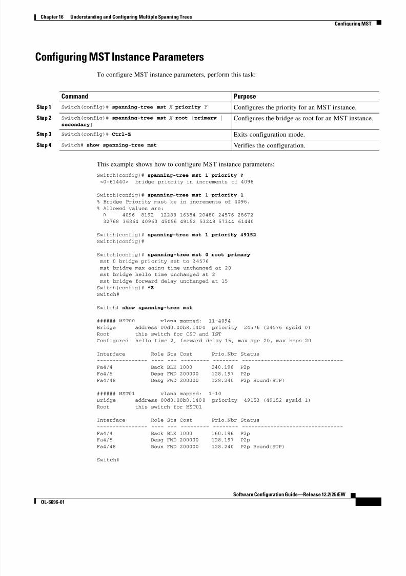
8/10/2019 Cisco ConfiguratioGuide SW4500 IOS
http://slidepdf.com/reader/full/cisco-configuratioguide-sw4500-ios 245/607

8/10/2019 Cisco ConfiguratioGuide SW4500 IOS
http://slidepdf.com/reader/full/cisco-configuratioguide-sw4500-ios 246/607
16-12
Software Configuration Guide—Release 12.2(25)EW
OL-6696-01
Chapter 16 Understanding and Configuring Multiple Spanning Trees
Configuring MST
Configuring MST Instance Port Parameters
To configure MST instance port parameters, perform this task:
This example shows how to configure MST instance port parameters:
Switch(config)# interface fastethernet 4/4
Switch(config-if)# spanning-tree mst 1 ?
cost Change the interface spanning tree path cost for an instance port-priority Change the spanning tree port priority for an instance
Switch(config-if)# spanning-tree mst 1 cost 1234567
Switch(config-if)# spanning-tree mst 1 port-priority 240Switch(config-if)# ^Z
Switch# show spanning-tree mst 1 interface fastethernet 4/4
FastEthernet4/4 of MST01 is backup blocking
Edge port:no (default) port guard :none (default)Link type:point-to-point (auto) bpdu filter:disable (default)
Boundary :internal bpdu guard :disable (default)
Bpdus (MRecords) sent 125, received 1782
Instance Role Sts Cost Prio.Nbr Vlans mapped
-------- ---- --- --------- -------- -------------------------------
1 Back BLK 1234567 240.196 1-10
Switch#
Restarting Protocol Migration
RSTP and MST have built-in compatibility mechanisms that allow them to interact properly with other
regions or other versions of IEEE spanning-tree. For example, an RSTP bridge connected to a legacy
bridge can send 802.1D BPDUs on one of its ports. Similarly, when an MST bridge receives a legacy
BPDU or an MST BPDU associated with a different region, it is also to detect that a port is at the
boundary of a region.
Unfortunately, these mechanisms cannot always revert to the most efficient mode. For example, an RSTP
bridge designated for a legacy 802.1D will stay in 802.1D mode even after the legacy bridge has been
removed from the link. Similarly, an MST port still assumes that it is a boundary port when the bridge(s)
to which it is connected have joined the same region. To force a Catalyst 4000 family switch to
renegotiate with the neighbors (that is, to restart protocol migration), you must enter the clear
spanning-tree detected-protocols command, as follows:
Switch# clear spanning-tree detected-protocols fastethernet 4/4
Switch#
Command Purpose
Step 1 Switch(config-if)# spanning-tree mst x cost y Configures the MST instance port cost.
Step 2 Switch(config-if)# spanning-tree mst x port-priority y Configures the MST instance port priority.
Step 3 Switch(config-if)# Ctrl-Z Exits configuration mode.
Step 4 Switch# show spanning-tree mst x interface y Verifies the configuration.

8/10/2019 Cisco ConfiguratioGuide SW4500 IOS
http://slidepdf.com/reader/full/cisco-configuratioguide-sw4500-ios 247/607
16-13
Software Configuration Guide—Release 12.2(25)EW
OL-6696-01
Chapter 16 Understanding and Configuring Multiple Spanning Trees
Configuring MST
Displaying MST Configurations
To display MST configurations, perform this task:
The following examples show how to display spanning tree VLAN configurations in MST mode:
Switch(config)# spanning-tree mst configuration
Switch(config-mst)# instance 1 vlan 1-10
Switch(config-mst)# name cisco
Switch(config-mst)# revision 1Switch(config-mst)# Ctrl-D
Switch# show spanning-tree mst configuration
Name [cisco]
Revision 1Instance Vlans mapped
-------- ---------------------------------------------------------------------
0 11-4094
1 1-10-------------------------------------------------------------------------------
Switch# show spanning-tree mst
###### MST00 vlans mapped: 11-4094
Bridge address 00d0.00b8.1400 priority 32768 (32768 sysid 0)Root address 00d0.004a.3c1c priority 32768 (32768 sysid 0)
port Fa4/48 path cost 203100IST master this switch
Operational hello time 2, forward delay 15, max age 20, max hops 20
Configured hello time 2, forward delay 15, max age 20, max hops 20
Interface Role Sts Cost Prio.Nbr Status
---------------- ---- --- --------- -------- --------------------------------Fa4/4 Back BLK 1000 240.196 P2p
Fa4/5 Desg FWD 200000 128.197 P2p
Fa4/48 Root FWD 200000 128.240 P2p Bound(STP)
###### MST01 vlans mapped: 1-10
Bridge address 00d0.00b8.1400 priority 32769 (32768 sysid 1)
Root this switch for MST01
Interface Role Sts Cost Prio.Nbr Status---------------- ---- --- --------- -------- --------------------------------
Fa4/4 Back BLK 1000 240.196 P2p
Fa4/5 Desg FWD 200000 128.197 P2p
Fa4/48 Boun FWD 200000 128.240 P2p Bound(STP)
Command Purpose
Step 1 Switch# show spanning-tree mst configuration Displays the active region configuration information.
Step 2 Switch# show spanning-tree mst [detail] Displays detailed MST protocol information.
Step 3 Switch# show spanning-tree mst instance-id [detail] Displays information about a specific MST instance.
Step 4 Switch# show spanning-tree mst interface interface [detail]
Displays information for a given port.
Step 5 Switch# show spanning-tree mst instance-id
interface interface [detail]Displays MST information for a given port and a given
instance.
Step 6 Switch# show spanning-tree vlan vlan_ID Displays VLAN information in MST mode.

8/10/2019 Cisco ConfiguratioGuide SW4500 IOS
http://slidepdf.com/reader/full/cisco-configuratioguide-sw4500-ios 248/607
16-14
Software Configuration Guide—Release 12.2(25)EW
OL-6696-01
Chapter 16 Understanding and Configuring Multiple Spanning Trees
Configuring MST
Switch# show spanning-tree mst 1
###### MST01 vlans mapped: 1-10
Bridge address 00d0.00b8.1400 priority 32769 (32768 sysid 1)Root this switch for MST01
Interface Role Sts Cost Prio.Nbr Status---------------- ---- --- --------- -------- --------------------------------Fa4/4 Back BLK 1000 240.196 P2p
Fa4/5 Desg FWD 200000 128.197 P2pFa4/48 Boun FWD 200000 128.240 P2p Bound(STP)
Switch# show spanning-tree mst interface fastethernet 4/4
FastEthernet4/4 of MST00 is backup blocking
Edge port:no (default) port guard :none (default)
Link type:point-to-point (auto) bpdu filter:disable (default)Boundary :internal bpdu guard :disable (default)
Bpdus sent 2, received 368
Instance Role Sts Cost Prio.Nbr Vlans mapped
-------- ---- --- --------- -------- -------------------------------0 Back BLK 1000 240.196 11-40941 Back BLK 1000 240.196 1-10
Switch# show spanning-tree mst 1 interface fastethernet 4/4
FastEthernet4/4 of MST01 is backup blockingEdge port:no (default) port guard :none (default)
Link type:point-to-point (auto) bpdu filter:disable (default)Boundary :internal bpdu guard :disable (default)
Bpdus (MRecords) sent 2, received 364
Instance Role Sts Cost Prio.Nbr Vlans mapped-------- ---- --- --------- -------- -------------------------------
1 Back BLK 1000 240.196 1-10
Switch# show spanning-tree mst 1 detail
###### MST01 vlans mapped: 1-10
Bridge address 00d0.00b8.1400 priority 32769 (32768 sysid 1)
Root this switch for MST01
FastEthernet4/4 of MST01 is backup blocking
Port info port id 240.196 priority 240 cost 1000Designated root address 00d0.00b8.1400 priority 32769 cost 0
Designated bridge address 00d0.00b8.1400 priority 32769 port id 128.197
Timers:message expires in 5 sec, forward delay 0, forward transitions 0
Bpdus (MRecords) sent 123, received 1188
FastEthernet4/5 of MST01 is designated forwarding
Port info port id 128.197 priority 128 cost 200000Designated root address 00d0.00b8.1400 priority 32769 cost 0Designated bridge address 00d0.00b8.1400 priority 32769 port id 128.197
Timers:message expires in 0 sec, forward delay 0, forward transitions 1
Bpdus (MRecords) sent 1188, received 123

8/10/2019 Cisco ConfiguratioGuide SW4500 IOS
http://slidepdf.com/reader/full/cisco-configuratioguide-sw4500-ios 249/607
16-15
Software Configuration Guide—Release 12.2(25)EW
OL-6696-01
Chapter 16 Understanding and Configuring Multiple Spanning Trees
Configuring MST
FastEthernet4/48 of MST01 is boundary forwarding
Port info port id 128.240 priority 128 cost 200000
Designated root address 00d0.00b8.1400 priority 32769 cost 0Designated bridge address 00d0.00b8.1400 priority 32769 port id 128.240
Timers:message expires in 0 sec, forward delay 0, forward transitions 1Bpdus (MRecords) sent 78, received 0
Switch# show spanning-tree vlan 10
MST01
Spanning tree enabled protocol mstp Root ID Priority 32769
Address 00d0.00b8.1400
This bridge is the root Hello Time 2 sec Max Age 20 sec Forward Delay 15 sec
Bridge ID Priority 32769 (priority 32768 sys-id-ext 1)
Address 00d0.00b8.1400 Hello Time 2 sec Max Age 20 sec Forward Delay 15 sec
Interface Role Sts Cost Prio.Nbr Status
---------------- ---- --- --------- -------- --------------------------------
Fa4/4 Back BLK 1000 240.196 P2pFa4/5 Desg FWD 200000 128.197 P2p
Switch# show spanning-tree summary Root bridge for:MST01
EtherChannel misconfiguration guard is enabled
Extended system ID is enabled
Portfast is disabled by defaultPortFast BPDU Guard is disabled by default
Portfast BPDU Filter is disabled by defaultLoopguard is disabled by default
UplinkFast is disabled
BackboneFast is disabled
Pathcost method used is long
Name Blocking Listening Learning Forwarding STP Active---------------------- -------- --------- -------- ---------- ----------
MST00 1 0 0 2 3
MST01 1 0 0 2 3---------------------- -------- --------- -------- ---------- ----------
2 msts 2 0 0 4 6
Switch#

8/10/2019 Cisco ConfiguratioGuide SW4500 IOS
http://slidepdf.com/reader/full/cisco-configuratioguide-sw4500-ios 250/607
16-16
Software Configuration Guide—Release 12.2(25)EW
OL-6696-01
Chapter 16 Understanding and Configuring Multiple Spanning Trees
Configuring MST

8/10/2019 Cisco ConfiguratioGuide SW4500 IOS
http://slidepdf.com/reader/full/cisco-configuratioguide-sw4500-ios 251/607
C H A P T E R
17-1
Software Configuration Guide—Release 12.2(25)EW
OL-6696-01
17
Understanding and Configuring EtherChannel
This chapter describes how to use the command-line interface (CLI) to configure EtherChannel on the
Catalyst 4500 series switch Layer 2 or Layer 3 interfaces. It also provides guidelines, procedures, and
configuration examples.
This chapter includes the following major sections:
• Overview of EtherChannel, page 17-1
• EtherChannel Configuration Guidelines and Restrictions, page 17-5
• Configuring EtherChannel, page 17-6
Note The commands in the following sections can be used on all Ethernet interfaces on a Catalyst 4500 series
switch, including the uplink ports on the supervisor engine.
Note For complete syntax and usage information for the switch commands used in this chapter, refer to the
Catalyst 4500 Series Switch Cisco IOS Command Reference and related publications at
http://www.cisco.com/univercd/cc/td/doc/product/software/ios122/122cgcr/index.htm.
Overview of EtherChannelThese subsections describe how EtherChannel works:
• Understanding Port-Channel Interfaces, page 17-2
• Understanding How EtherChannels Are Configured, page 17-2
• Understanding Load Balancing, page 17-5
EtherChannel bundles individual Ethernet links into a single logical link that provides bandwidth up to
1600 Mbps (Fast EtherChannel full duplex) or 16 Gbps (Gigabit EtherChannel) between a Catalyst 4500series switch and another switch or host.
A Catalyst 4500 series switch supports a maximum of 64 EtherChannels. You can form an EtherChannel
with up to eight compatibly configured Ethernet interfaces across modules in a Catalyst 4500 series
switch. All interfaces in each EtherChannel must be the same speed and must be configured as either
Layer 2 or Layer 3 interfaces.

8/10/2019 Cisco ConfiguratioGuide SW4500 IOS
http://slidepdf.com/reader/full/cisco-configuratioguide-sw4500-ios 252/607
17-2
Software Configuration Guide—Release 12.2(25)EW
OL-6696-01
Chapter 17 Understanding and Configuring EtherChannel
Overview of EtherChannel
Note The network device to which a Catalyst 4500 series switch is connected may impose its own limits on
the number of interfaces in an EtherChannel.
If a segment within an EtherChannel fails, traffic previously carried over the failed link switches to the
remaining segments within the EtherChannel. Once the segment fails, an SNMP trap is sent, identifyingthe switch, the EtherChannel, and the failed link. Inbound broadcast and multicast packets on one
segment in an EtherChannel are blocked from returning on any other segment of the EtherChannel.
Understanding Port-Channel Interfaces
Each EtherChannel has a numbered port-channel interface. A configuration applied to the port-channel
interface affects all physical interfaces assigned to that interface.
Note QoS does not propagate to members. The defaults, QoS cos = 0 and QoS dscp = 0, apply on the
port-channel. Input or output policies applied on individual interfaces will be ignored.
After you configure an EtherChannel, the configuration that you apply to the port-channel interface
affects the EtherChannel; the configuration that you apply to the physical interfaces affects only the
interface where you apply the configuration. To change the parameters of all ports in an EtherChannel,
apply configuration commands to the port-channel interface (such commands can be STP commands or
commands to configure a Layer 2 EtherChannel as a trunk).
Understanding How EtherChannels Are Configured
These subsections describe how EtherChannels are configured:
• EtherChannel Configuration Overview, page 17-2
• Understanding Manual EtherChannel Configuration, page 17-3
• Understanding PAgP EtherChannel Configuration, page 17-3
• Understanding IEEE 802.3ad LACP EtherChannel Configuration, page 17-3
EtherChannel Configuration Overview
You can configure EtherChannels manually or you can use the Port Aggregation Control Protocol
(PAgP) or, with Release Cisco IOS Release 12.2(25)EW and later, the Link Aggregation Control
Protocol (LACP) to form EtherChannels. The EtherChannel protocols allow ports with similar
characteristics to form an EtherChannel through dynamic negotiation with connected network devices.
PAgP is a Cisco-proprietary protocol and LACP is defined in IEEE 802.3ad.
PAgP and LACP do not interoperate with each other. Ports configured to use PAgP cannot form
EtherChannels with ports configured to use LACP and vice versa.
Table 17-1 lists the user-configurable EtherChannel modes.

8/10/2019 Cisco ConfiguratioGuide SW4500 IOS
http://slidepdf.com/reader/full/cisco-configuratioguide-sw4500-ios 253/607
17-3
Software Configuration Guide—Release 12.2(25)EW
OL-6696-01
Chapter 17 Understanding and Configuring EtherChannel
Overview of EtherChannel
Understanding Manual EtherChannel Configuration
Manually configured EtherChannel ports do not exchange EtherChannel protocol packets. A manually
configured EtherChannel forms only when you enter configure all ports in the EtherChannel compatibly.
Understanding PAgP EtherChannel Configuration
PAgP supports the automatic creation of EtherChannels by exchanging PAgP packets between LAN
ports. PAgP packets are exchanged only between ports in auto and desirable modes.
The protocol learns the capabilities of LAN port groups dynamically and informs the other LAN ports.
Once PAgP identifies correctly matched Ethernet links, it facilitates grouping the links into an
EtherChannel. The EtherChannel is then added to the spanning tree as a single bridge port.Both the auto and desirable modes allow PAgP to negotiate between LAN ports to determine if they can
form an EtherChannel, based on criteria such as port speed and trunking state. Layer 2 EtherChannels
also use VLAN numbers.
LAN ports can form an EtherChannel when they are in different PAgP modes if the modes are
compatible. For example:
• A LAN port in desirable mode can form an EtherChannel successfully with another LAN port that
is in desirable mode.
• A LAN port in desirable mode can form an EtherChannel with another LAN port in auto mode.
• A LAN port in auto mode cannot form an EtherChannel with another LAN port that is also in auto
mode, because neither port will initiate negotiation.
Understanding IEEE 802.3ad LACP EtherChannel Configuration
Release Cisco IOS Release 12.2(25)EW and later releases support IEEE 802.3ad LACP EtherChannels.
LACP supports the automatic creation of EtherChannels by exchanging LACP packets between LAN
ports. LACP packets are exchanged only between ports in passive and active modes.
Table 17-1 EtherChannel Modes
Mode Description
on Mode that forces the LAN port to channel unconditionally. In the on mode, a usable
EtherChannel exists only when a LAN port group in the on mode is connected to another
LAN port group in the on mode. Because ports configured in the on mode do not negotiate,there is no negotiation traffic between the ports.
auto PAgP mode that places a LAN port into a passive negotiating state, in which the port
responds to PAgP packets it receives but does not initiate PAgP negotiation.
desirable PAgP mode that places a LAN port into an active negotiating state, in which the port
initiates negotiations with other LAN ports by sending PAgP packets.
passive LACP mode that places a port into a passive negotiating state, in which the port responds
to LACP packets it receives but does not initiate LACP negotiation.
active LACP mode that places a port into an active negotiating state, in which the port initiates
negotiations with other ports by sending LACP packets.

8/10/2019 Cisco ConfiguratioGuide SW4500 IOS
http://slidepdf.com/reader/full/cisco-configuratioguide-sw4500-ios 254/607
8/10/2019 Cisco ConfiguratioGuide SW4500 IOS
http://slidepdf.com/reader/full/cisco-configuratioguide-sw4500-ios 255/607
17-5
Software Configuration Guide—Release 12.2(25)EW
OL-6696-01
Chapter 17 Understanding and Configuring EtherChannel
EtherChannel Configuration Guidelines and Restrictions
Understanding Load Balancing
EtherChannel can balance the traffic load across the links in the channel. It does this by reducing part of
the binary pattern formed from the addresses or ports in the frame to a numerical value that selects one
of the links in the channel. To balance the load, EtherChannel uses MAC addresses, IP addresses, or
Layer 4 port numbers, and either the message source or message destination, or both.Use the option that provides the greatest variety in your configuration. For example, if the traffic on a
channel is going only to a single MAC address, using the destination MAC address always chooses the
same link in the channel; using source addresses or IP addresses might result in better load balancing.
Note Load balancing can only be configured globally. As a result, all channels (manually configured, PagP,
or LACP) will use the same load balancing method.
For additional information on load balancing, see the “Configuring EtherChannel Load Balancing”
section on page 17-12.
EtherChannel Configuration Guidelines and RestrictionsIf improperly configured, some EtherChannel interfaces are disabled automatically to avoid network
loops and other problems. Follow these guidelines and restrictions to avoid configuration problems:
• All Ethernet interfaces on all modules support EtherChannel (maximum of eight interfaces) with no
requirement that interfaces be physically contiguous or on the same module.
• Configure all interfaces in an EtherChannel to operate at the same speed and duplex mode.
• Enable all interfaces in an EtherChannel. If you shut down an interface in an EtherChannel, it is
treated as a link failure and its traffic is transferred to one of the remaining interfaces in the
EtherChannel.
• An EtherChannel will not form if one of the interfaces is a Switched Port Analyzer (SPAN)destination port.
• For Layer 3 EtherChannels:
– Assign Layer 3 addresses to the port-channel logical interface, not to the physical interfaces in
the channel.
• For Layer 2 EtherChannels:
– Assign all interfaces in the EtherChannel to the same VLAN, or configure them as trunks.
– If you configure an EtherChannel from trunk interfaces, verify that the trunking mode is the
same on all the trunks. Interfaces in an EtherChannel with different trunk modes can have
unexpected results.
–An EtherChannel supports the same allowed range of VLANs on all the interfaces in a trunkingLayer 2 EtherChannel. If the allowed range of VLANs is not the same, the interfaces do not
form an EtherChannel.
– Interfaces with different Spanning Tree Protocol (STP) port path costs can form an
EtherChannel as long they are otherwise compatibly configured. Setting different STP port path
costs does not, by itself, make interfaces incompatible for the formation of an EtherChannel.

8/10/2019 Cisco ConfiguratioGuide SW4500 IOS
http://slidepdf.com/reader/full/cisco-configuratioguide-sw4500-ios 256/607
17-6
Software Configuration Guide—Release 12.2(25)EW
OL-6696-01
Chapter 17 Understanding and Configuring EtherChannel
Configuring EtherChannel
• After you configure an EtherChannel, any configuration that you apply to the port-channel interface
affects the EtherChannel; any configuration that you apply to the physical interfaces affects only the
interface where you apply the configuration.
• You cannot configure a 802.1X port in an EtherChannel.
Configuring EtherChannelThese sections describe how to configure EtherChannel:
• Configuring Layer 3 EtherChannels, page 17-6
• Configuring Layer 2 EtherChannels, page 17-9
• Configuring the LACP System Priority and System ID, page 17-11
• Configuring EtherChannel Load Balancing, page 17-12
• Removing an Interface from an EtherChannel, page 17-13
• Removing an EtherChannel, page 17-14
Note Ensure that the interfaces are configured correctly. (See the “EtherChannel Configuration Guidelines
and Restrictions” section on page 17-5.)
Configuring Layer 3 EtherChannels
To configure Layer 3 EtherChannels, create the port-channel logical interface and then put the Ethernet
interfaces into the port-channel.
These sections describe Layer 3 EtherChannel configuration:
• Creating Port-Channel Logical Interfaces, page 17-6• Configuring Physical Interfaces as Layer 3 EtherChannels, page 17-7
Creating Port-Channel Logical Interfaces
Note To move an IP address from a physical interface to an EtherChannel, you must delete the IP address from
the physical interface before configuring it on the port-channel interface.

8/10/2019 Cisco ConfiguratioGuide SW4500 IOS
http://slidepdf.com/reader/full/cisco-configuratioguide-sw4500-ios 257/607
17-7
Software Configuration Guide—Release 12.2(25)EW
OL-6696-01
Chapter 17 Understanding and Configuring EtherChannel
Configuring EtherChannel
To create a port-channel interface for a Layer 3 EtherChannel, perform this task:
This example shows how to create port-channel interface 1:
Switch# configure terminal
Switch(config)# interface port-channel 1
Switch(config-if)# ip address 172.32.52.10 255.255.255.0 Switch(config-if)# end
This example shows how to verify the configuration of port-channel interface 1:
Switch# show running-config interface port-channel 1 Building configuration...
Current configuration:
!interface Port-channel1
ip address 172.32.52.10 255.255.255.0 no ip directed-broadcast
end
Switch#
Configuring Physical Interfaces as Layer 3 EtherChannelsTo configure physical interfaces as Layer 3 EtherChannels, perform this task for each interface:
Command Purpose
Step 1 Switch(config)# interface port-channel port_channel_number
Creates the port-channel interface. The value for
port_channel_number can range from 1 to 64
Step 2 Switch(config-if)# ip address ip_address mask Assigns an IP address and subnet mask to the
EtherChannel.
Step 3 Switch(config-if)# end Exits configuration mode.
Step 4 Switch# show running-config interface
port-channel port_channel_number Verifies the configuration.
Command Purpose
Step 1 Switch(config)# interface {fastethernet |gigabitethernet | tengigabitethernet} slot/ port
Selects a physical interface to configure.
Step 2 Switch(config-if)# no switchport Makes this a Layer 3 routed port.
Step 3 Switch(config-if)# no ip address Ensures that there is no IP address assigned to the
physical interface.
Step 4 Switch(config-if)# channel-group port_channel_number
mode {active | on | auto | passive | desirable}
Configures the interface in a port-channel and specify
the PAgP or LACP mode.
If you use PAgP, select the keywords auto and
desirable.
If you use LACP, select the keywords active and
passive.

8/10/2019 Cisco ConfiguratioGuide SW4500 IOS
http://slidepdf.com/reader/full/cisco-configuratioguide-sw4500-ios 258/607
17-8
Software Configuration Guide—Release 12.2(25)EW
OL-6696-01
Chapter 17 Understanding and Configuring EtherChannel
Configuring EtherChannel
This example shows how to configure Fast Ethernet interfaces 5/4 and 5/5 into port-channel 1 with PAgP
mode desirable:
Switch# configure terminal
Switch(config)# interface range fastethernet 5/4 - 5 (Note: Space is mandatory.)Switch(config-if)# no switchport
Switch(config-if)# no ip address Switch(config-if)# channel-group 1 mode desirable
Switch(config-if)# end
Note See the “Configuring a Range of Interfaces” section on page 4-4 for information about the range
keyword.
The following two examples shows how to verify the configuration of Fast Ethernet interface 5/4:
Switch# show running-config interface fastethernet 5/4
Building configuration...
Current configuration:!
interface FastEthernet5/4no ip address
no switchport
no ip directed-broadcast
channel-group 1 mode desirableend
Switch# show interfaces fastethernet 5/4 etherchannel
Port state = EC-Enbld Up In-Bndl Usr-Config
Channel group = 1 Mode = Desirable Gcchange = 0Port-channel = Po1 GC = 0x00010001 Pseudo-port-channel = Po1
Port indx = 0 Load = 0x55
Flags: S - Device is sending Slow hello. C - Device is in Consistent state. A - Device is in Auto mode. P - Device learns on physical port.
Timers: H - Hello timer is running. Q - Quit timer is running. S - Switching timer is running. I - Interface timer is running.
Local information:
Hello Partner PAgP Learning GroupPort Flags State Timers Interval Count Priority Method Ifindex
Fa5/4 SC U6/S7 30s 1 128 Any 55
Step 5 Switch(config-if)# end Exits configuration mode.
Step 6 Switch# show running-config interface port-channel port_channel_number
Switch# show running-config interface {fastethernet | gigabitethernet | tengigabitethernet} slot/ port
Switch# show interfaces {fastethernet |
gigabitethernet | tengigabitethernet} slot/ port etherchannel
Switch# show etherchannel 1 port-channel
Verifies the configuration.
Command Purpose

8/10/2019 Cisco ConfiguratioGuide SW4500 IOS
http://slidepdf.com/reader/full/cisco-configuratioguide-sw4500-ios 259/607
17-9
Software Configuration Guide—Release 12.2(25)EW
OL-6696-01
Chapter 17 Understanding and Configuring EtherChannel
Configuring EtherChannel
Partner's information:
Partner Partner Partner Partner GroupPort Name Device ID Port Age Flags Cap.
Fa5/4 JAB031301 0050.0f10.230c 2/45 1s SAC 2D
Age of the port in the current state: 00h:54m:52s
Switch#
This example shows how to verify the configuration of port-channel interface 1 after the interfaces have
been configured:
Switch# show etherchannel 1 port-channel
Channel-group listing: ----------------------
Group: 1------------
Port-channels in the group:
----------------------
Port-channel: Po1------------
Age of the Port-channel = 01h:56m:20s
Logical slot/port = 10/1 Number of ports = 2
GC = 0x00010001 HotStandBy port = nullPort state = Port-channel L3-Ag Ag-Inuse
Ports in the Port-channel:
Index Load Port
------------------- 1 00 Fa5/6
0 00 Fa5/7
Time since last port bundled: 00h:23m:33s Fa5/6
Switch#
Configuring Layer 2 EtherChannels
To configure Layer 2 EtherChannels, configure the Ethernet interfaces with the channel-group
command. This creates the port-channel logical interface.
Note Cisco IOS software creates port-channel interfaces for Layer 2 EtherChannels when you configure
Layer 2 Ethernet interfaces with the channel-group command.

8/10/2019 Cisco ConfiguratioGuide SW4500 IOS
http://slidepdf.com/reader/full/cisco-configuratioguide-sw4500-ios 260/607
17-10
Software Configuration Guide—Release 12.2(25)EW
OL-6696-01
Chapter 17 Understanding and Configuring EtherChannel
Configuring EtherChannel
To configure Layer 2 Ethernet interfaces as Layer 2 EtherChannels, perform this task for each interface:
This example shows how to configure Fast Ethernet interfaces 5/6 and 5/7 into port-channel 2 with PAgP
mode desirable:
Switch# configure terminal
Switch(config)# interface range fastethernet 5/6 - 7 (Note: Space is mandatory.)Switch(config-if-range)# channel-group 2 mode desirable
Switch(config-if-range)# end
Note See the “Configuring a Range of Interfaces” section on page 4-4 for information about the range
keyword.
This example shows how to verify the configuration of port-channel interface 2:
Switch# show running-config interface port-channel 2
Building configuration...
Current configuration:!
interface Port-channel2
switchport access vlan 10
switchport mode access
end
Switch#
The following two examples show how to verify the configuration of Fast Ethernet interface 5/6:
Switch# show running-config interface fastethernet 5/6 Building configuration...
Current configuration:
!interface FastEthernet5/6
switchport access vlan 10 switchport mode access
channel-group 2 mode desirable
end
Command Purpose
Step 1 Switch(config)# interface {fastethernet | gigabitethernet| tengigabitethernet} slot/ port
Selects a physical interface to configure.
Step 2 Switch(config-if)# channel-group port_channel_number mode
{active | on | auto | passive | desirable}Configures the interface in a port-channel and
specify the PAgP or LACP mode.
If you use PAgP, select the keywords active
and desirable.
If you use LACP, select the keywords active
and passive.
Step 3 Switch(config-if)# end Exits configuration mode.
Step 4 Switch# show running-config interface {fastethernet |
gigabitethernet} slot/ port
Switch# show interface {fastethernet | gigabitethernet |
tengigabitethernet} slot/ port etherchannel
Verifies the configuration.

8/10/2019 Cisco ConfiguratioGuide SW4500 IOS
http://slidepdf.com/reader/full/cisco-configuratioguide-sw4500-ios 261/607
17-11
Software Configuration Guide—Release 12.2(25)EW
OL-6696-01
Chapter 17 Understanding and Configuring EtherChannel
Configuring EtherChannel
Switch# show interfaces fastethernet 5/6 etherchannel
Port state = EC-Enbld Up In-Bndl Usr-Config
Channel group = 1 Mode = Desirable Gcchange = 0Port-channel = Po1 GC = 0x00010001
Port indx = 0 Load = 0x55
Flags: S - Device is sending Slow hello. C - Device is in Consistent state.
A - Device is in Auto mode. P - Device learns on physical port. d - PAgP is down.Timers: H - Hello timer is running. Q - Quit timer is running.
S - Switching timer is running. I - Interface timer is running.Local information:
Hello Partner PAgP Learning Group
Port Flags State Timers Interval Count Priority Method IfindexFa5/6 SC U6/S7 30s 1 128 Any 56
Partner's information:
Partner Partner Partner Partner Group
Port Name Device ID Port Age Flags Cap.Fa5/6 JAB031301 0050.0f10.230c 2/47 18s SAC 2F
Age of the port in the current state: 00h:10m:57s
This example shows how to verify the configuration of port-channel interface 2 after the interfaces have
been configured:
Switch# show etherchannel 2 port-channel Port-channels in the group:
----------------------
Port-channel: Po2
------------
Age of the Port-channel = 00h:23m:33s
Logical slot/port = 10/2 Number of ports in agport = 2
GC = 0x00020001 HotStandBy port = null
Port state = Port-channel Ag-Inuse
Ports in the Port-channel:
Index Load Port
------------------- 1 00 Fa5/6
0 00 Fa5/7
Time since last port bundled: 00h:23m:33s Fa5/6
Switch#
Configuring the LACP System Priority and System ID
The LACP system ID is the combination of the LACP system priority value and the MAC address of the
switch.

8/10/2019 Cisco ConfiguratioGuide SW4500 IOS
http://slidepdf.com/reader/full/cisco-configuratioguide-sw4500-ios 262/607
17-12
Software Configuration Guide—Release 12.2(25)EW
OL-6696-01
Chapter 17 Understanding and Configuring EtherChannel
Configuring EtherChannel
To configure the LACP system priority and system ID, perform this task:
This example shows how to configure the LACP system priority:
Switch# configure terminal Switch(config)# lacp system-priority 23456Switch(config)# end Switch(config)#Switch>show module
Mod Ports Card Type Model Serial No.
----+-----+--------------------------------------+-----------------+----------- 1 2 1000BaseX (GBIC) Supervisor(active) WS-X4014 JAB063808YZ
2 48 10/100BaseTX (RJ45) WS-X4148-RJ JAB0447072W
3 48 10/100BaseTX (RJ45)V WS-X4148-RJ45V JAE061704J6
4 48 10/100BaseTX (RJ45)V WS-X4148-RJ45V JAE061704ML
M MAC addresses Hw Fw Sw Status
--+--------------------------------+---+------------+----------------+---------
1 0005.9a39.7a80 to 0005.9a39.7a81 2.1 12.1(12r)EW 12.1(13)EW(0.26) Ok 2 0002.fd80.f530 to 0002.fd80.f55f 0.1 Ok
3 0009.7c45.67c0 to 0009.7c45.67ef 1.6 Ok 4 0009.7c45.4a80 to 0009.7c45.4aaf 1.6 Ok
This example shows how to verify the configuration:
Switch# show lacp sys-id 23456,0050.3e8d.6400Switch#
The system priority is displayed first, followed by the MAC address of the switch.
Configuring EtherChannel Load Balancing
Note Load balancing can only be configured globally. As a result, all channels (manually configured, PagP,
or LACP) will use the same load balancing method.
To configure EtherChannel load balancing, perform this task:
Command Purpose
Step 1 Router(config)# lacp system-priority priority_value
(Optional for LACP) Valid values are 1 through 65535.
Higher numbers have lower priority. The default is 32768.
Router(config)# no system port-priority Reverts to the default.
Step 2 Router(config)# end Exits configuration mode.
Step 3 Router# show lacp sys-id Verifies the configuration.
Command Purpose
Step 1 Switch(config)# [no] port-channel load-balance
{src-mac | dst-mac | src-dst-mac | src-ip |
dst-ip | src-dst-ip | src-port | dst-port |
src-dst-port}
Configures EtherChannel load balancing.
Use the no keyword to return EtherChannel load
balancing to the default configuration.

8/10/2019 Cisco ConfiguratioGuide SW4500 IOS
http://slidepdf.com/reader/full/cisco-configuratioguide-sw4500-ios 263/607
17-13
Software Configuration Guide—Release 12.2(25)EW
OL-6696-01
Chapter 17 Understanding and Configuring EtherChannel
Configuring EtherChannel
The load-balancing keywords are:• src-mac—Source MAC addresses
• dst-mac—Destination MAC addresses
• src-dst-mac—Source and destination MAC addresses
• src-ip—Source IP addresses
• dst-ip—Destination IP addresses
• src-dst-ip—Source and destination IP addresses (Default)
• src-port—Source Layer 4 port
• dst-port—Destination Layer 4 port
• src-dst-port—Source and destination Layer 4 portThis example shows how to configure EtherChannel to use source and destination IP addresses:
Switch# configure terminal
Switch(config)# port-channel load-balance dst-mac Switch(config)# end
Switch(config)#
This example shows how to verify the configuration:
Switch# show etherchannel load-balance Source XOR Destination IP address
Switch#
Removing an Interface from an EtherChannelTo remove an Ethernet interface from an EtherChannel, perform this task:
This example shows how to remove Fast Ethernet interfaces 5/4 and 5/5 from port-channel 1:
Switch# configure terminal Switch(config)# interface range fastethernet 5/4 - 5 (Note: Space is mandatory.)
Switch(config-if)# no channel-group 1 Switch(config-if)# end
Step 2 Switch(config)# end Exits configuration mode.
Step 3 Switch# show etherchannel load-balance Verifies the configuration.
Command Purpose
Command Purpose
Step 1 Switch(config)# interface {fastethernet |
gigabitethernet | tengigabitethernet} slot/ port Selects a physical interface to configure.
Step 2 Switch(config-if)# no channel-group Removes the interface from the port-channel interface.
Step 3 Switch(config-if)# end Exits configuration mode.
Step 4 Switch# show running-config interface {fastethernet | gigabitethernet |
tengigabitethernet} slot/ port Switch# show interface {fastethernet |
gigabitethernet | tengigabitethernet} slot/ port etherchannel
Verifies the configuration.
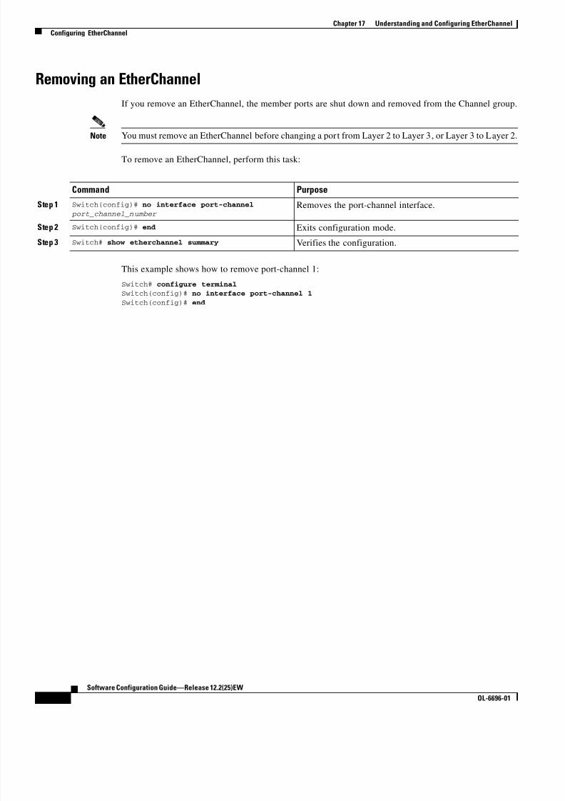
8/10/2019 Cisco ConfiguratioGuide SW4500 IOS
http://slidepdf.com/reader/full/cisco-configuratioguide-sw4500-ios 264/607
17-14
Software Configuration Guide—Release 12.2(25)EW
OL-6696-01
Chapter 17 Understanding and Configuring EtherChannel
Configuring EtherChannel
Removing an EtherChannel
If you remove an EtherChannel, the member ports are shut down and removed from the Channel group.
Note You must remove an EtherChannel before changing a port from Layer 2 to Layer 3, or Layer 3 to Layer 2.
To remove an EtherChannel, perform this task:
This example shows how to remove port-channel 1:
Switch# configure terminal Switch(config)# no interface port-channel 1
Switch(config)# end
Command Purpose
Step 1 Switch(config)# no interface port-channel
port_channel_number Removes the port-channel interface.
Step 2 Switch(config)# end Exits configuration mode.
Step 3 Switch# show etherchannel summary Verifies the configuration.

8/10/2019 Cisco ConfiguratioGuide SW4500 IOS
http://slidepdf.com/reader/full/cisco-configuratioguide-sw4500-ios 265/607
C H A P T E R
18-1
Software Configuration Guide—Release 12.2(25)EW
OL-6696-01
18
Configuring IGMP Snooping and Filtering
This chapter describes how to configure Internet Group Management Protocol (IGMP) snooping on the
Catalyst 4500 series switch. It provides guidelines, procedures, and configuration examples.
This chapter consists of the following major sections:
• Overview of IGMP Snooping, page 18-1
• Configuring IGMP Snooping, page 18-4
• Displaying IGMP Snooping Information, page 18-11
• Configuring IGMP Filtering, page 18-16
• Displaying IGMP Filtering Configuration, page 18-20
Note To support Cisco Group Management Protocol (CGMP) client devices, configure the switch as a CGMP
server. For more information, see the chapters “IP Multicast” and “Configuring IP Multicast Routing”
in the Cisco IOS IP and IP Routing Configuration Guide, Release 12.2 at this URL:
http://www.cisco.com/univercd/cc/td/doc/product/software/ios122/122cgcr/ip_c/ipcprt3/1cdmulti.htm
Note For complete syntax and usage information for the switch commands used in this chapter, refer to the
Catalyst 4500 Series Switch Cisco IOS Command Reference and related publications at
http://www.cisco.com/univercd/cc/td/doc/product/software/ios122/122cgcr/index.htm.
Overview of IGMP SnoopingThis section includes the following subsections:
• Immediate-Leave Processing, page 18-3
• Explicit Host Tracking, page 18-3
Note Quality of service does not apply to IGMP packets.
IGMP snooping allows a switch to snoop or capture information from IGMP packets transmitted
between hosts and a router. Based on this information, a switch will add or delete multicast addresses
from its address table, thereby enabling (or disabling) multicast traffic from flowing to individual host
ports. IGMP snooping supports all versions of IGMP: IGMPv1, IGMPv2, and IGMPv3.

8/10/2019 Cisco ConfiguratioGuide SW4500 IOS
http://slidepdf.com/reader/full/cisco-configuratioguide-sw4500-ios 266/607
18-2
Software Configuration Guide—Release 12.2(25)EW
OL-6696-01
Chapter 18 Configuring IGMP Snooping and Filtering
Overview of IGMP Snooping
In contrast to IGMPv1 and IGMPv2, IGMPv3 snooping provides immediate-leave processing by default.
It provides Explicit Host Tracking (EHT) and allows network administrators to deploy SSM
functionality on Layer 2 devices that truly support IGMPv3. (See Explicit Host Tracking, page 18-3.)
In subnets where IGMP is configured, IGMP snooping manages multicast traffic at Layer 2. You can
configure interfaces to dynamically forward multicast traffic only to those interfaces that are interested
in receiving it by using the switchport keyword.IGMP snooping restricts traffic in MAC multicast groups 0100.5e00.0001 to 01-00-5e-ff-ff-ff. IGMP
snooping does not restrict Layer 2 multicast packets generated by routing protocols.
Note For more information on IP multicast and IGMP, refer to RFC 1112, RFC 2236, RFC 3376 (for
IGMPv3).
IGMP (configured on a router) periodically sends out IGMP general queries. A host responds to these
queries with IGMP membership reports for groups that it is interested in. When IGMP snooping is
enabled, the switch creates one entry per VLAN in the Layer 2 forwarding table for each Layer 2
multicast group from which it receives an IGMP join request. All hosts interested in this multicast traffic
send IGMP membership reports and are added to the forwarding table entry.
Layer 2 multicast groups learned through IGMP snooping are dynamic. However, you can statically
configure Layer 2 multicast groups using the ip igmp snooping static command. If you specify group
membership statically, your setting supersedes any automatic manipulation by IGMP snooping.
Multicast group membership lists can contain both user-defined and IGMP snooping settings.
Groups with IP addresses in the range 224.0.0.0 to 224.0.0.255, which map to the multicast MAC address
range 0100.5E00.0001 to 0100.5E00.00FF, are reserved for routing control packets. These groups are
flooded to all forwarding ports of the VLAN with the exception of 224.0.0.22, which is used for IGMPv3
membership reports.
Note If a VLAN experiences a spanning-tree topology change, IP multicast traffic floods on all VLAN ports
where PortFast is not enabled, as well as on ports with the no igmp snooping tcn flood command
configured for a period of TCN query count.
For a Layer 2 IGMPv2 host interface to join an IP multicast group, a host sends an IGMP membership
report for the IP multicast group. For a host to leave a multicast group, it can either ignore the periodic
IGMP general queries or it can send an IGMP leave message. When the switch receives an IGMP leave
message from a host, it sends out an IGMP group-specific query to determine whether any devices
connected to that interface are interested in traffic for the specific multicast group. The switch then
updates the table entry for that Layer 2 multicast group so that only those hosts interested in receiving
multicast traffic for the group are listed.
In contrast, IGMPv3 hosts send IGMPv3 membership reports (with the allow group record mode) to join
a specific multicast group. When IGMPv3 hosts send membership reports (with the block group record)
to reject traffic from all sources in the previous source list, the last host on the port will be removed by
immediate-leave if EHT is enabled.

8/10/2019 Cisco ConfiguratioGuide SW4500 IOS
http://slidepdf.com/reader/full/cisco-configuratioguide-sw4500-ios 267/607
18-3
Software Configuration Guide—Release 12.2(25)EW
OL-6696-01
Chapter 18 Configuring IGMP Snooping and Filtering
Overview of IGMP Snooping
Immediate-Leave Processing
IGMP snooping immediate-leave processing allows the switch to remove an interface from the
forwarding-table entry without first sending out IGMP group-specific queries to the interface. The
VLAN interface is pruned from the multicast tree for the multicast group specified in the original IGMP
leave message. Immediate-leave processing ensures optimal bandwidth management for all hosts on aswitched network, even when multiple multicast groups are being used simultaneously.
When a switch with IGMP snooping enabled receives an IGMPv2 or IGMPv3 leave message, it sends
an IGMP group-specific query from the interface where the leave message was received to determine
when there are other hosts attached to that interface that are interested in joining the MAC multicast
group. If the switch does not receive an IGMP join message within the query response interval, the
interface is removed from the port list of the (MAC-group, VLAN) entry in the Layer 2 forwarding table
Note By default all IGMP joins are forwarded to all multicast router ports.
With immediate-leave processing enabled on the VLAN, an interface can be removed immediately from
the port list of the Layer 2 entry when the IGMP leave message is received, unless a multicast router was
learned on the port.
Note When using IGMPv2 snooping, use immediate-leave processing only on VLANs where just one host is
connected to each interface. If immediate-leave processing is enabled on VLANs where multiple hosts
are connected to an interface, some hosts might be dropped inadvertently. When using IGMPv3,
immediate-leave processing is enabled by default, and due to Explicit Host Tracking (see below), the
switch can detect when a port has single or multiple hosts maintained by the switch for IGMPv3 hosts.
As a result, the switch can perform immediate-leave processing when it detects a single host behind a
given port.
Note IGMPv3 is interoperable with older versions of IGMP.
Use the show ip igmp snooping querier vlan command to display the IGMP version on a particular
VLAN.
Use the show ip igmp snooping vlan command to display whether or not the switch supports IGMPv3
snooping.
Use the ip igmp snooping immediate-leave command to enable immediate-leave for IGMPv2.
Note Immediate-leave processing is enabled by default for IGMPv3.
Explicit Host Tracking
Explicit Host Tracking (EHT) monitors group membership by tracking hosts that are sending IGMPv3
membership reports. This tracking enables a switch to detect host information associated with the groups
of each port. Furthermore, EHT enables the user to track the membership and various statistics.
EHT enables a switch to track membership on a per-port basis. Consequently, a switch is aware of the
hosts residing on each port and can perform immediate-leave processing when there is only one host
behind a port.

8/10/2019 Cisco ConfiguratioGuide SW4500 IOS
http://slidepdf.com/reader/full/cisco-configuratioguide-sw4500-ios 268/607
18-4
Software Configuration Guide—Release 12.2(25)EW
OL-6696-01
Chapter 18 Configuring IGMP Snooping and Filtering
Configuring IGMP Snooping
To determine whether or not EHT is enabled on a VLAN, use the show ip igmp snoop vlan command.
Configuring IGMP Snooping
Note When configuring IGMP, configure the VLAN in the VLAN database mode. (See Chapter 10,
“Understanding and Configuring VLANs”.)
IGMP snooping allows switches to examine IGMP packets and make forwarding decisions based on their
content.
These sections describe how to configure IGMP snooping:
• Default IGMP Snooping Configuration, page 18-4
• Enabling IGMP Snooping, page 18-5
• Configuring Learning Methods, page 18-6
• Configuring a Multicast Router Port Statical, page 18-7
• Enabling IGMP Immediate-Leave Processing, page 18-7
• Configuring Explicit Host Tracking, page 18-8
• Configuring a Host Statically, page 18-8
• Suppressing Multicast Flooding, page 18-9
Default IGMP Snooping Configuration
Table 18-1 shows the IGMP snooping default configuration values.
Table 18-1 IGMP Snooping Default Configuration Values
Feature Default Value
IGMP snooping Enabled
Multicast routers None configured
Explicit Host Tracking Enabled for IGMPv3; Not available for IGMPv2
Immediate-leave processing Enabled for IGMPv3; Disabled for IGMPv2
Report Suppression Enabled
IGMP snooping learning method PIM/DVMRP1
1. PIM/DVMRP = Protocol Independent Multicast/Distance Vector Multicast Routing Protocol

8/10/2019 Cisco ConfiguratioGuide SW4500 IOS
http://slidepdf.com/reader/full/cisco-configuratioguide-sw4500-ios 269/607
18-5
Software Configuration Guide—Release 12.2(25)EW
OL-6696-01
Chapter 18 Configuring IGMP Snooping and Filtering
Configuring IGMP Snooping
Enabling IGMP Snooping
To enable IGMP snooping globally, perform this task:
This example shows how to enable IGMP snooping globally and verify the configuration:
Switch(config)# ip igmp snooping
Switch(config)# end Switch# show ip igmp snooping
Global IGMP Snooping configuration:
-----------------------------------
IGMP snooping : EnabledIGMPv3 snooping : Enabled
Report suppression : Enabled
TCN solicit query : DisabledTCN flood query count : 2
Vlan 1:
--------
IGMP snooping : Enabled
IGMPv2 immediate leave : DisabledExplicit host tracking : Enabled
Multicast router learning mode : pim-dvmrpCGMP interoperability mode : IGMP_ONLY
Vlan 2:
--------IGMP snooping : Enabled
IGMPv2 immediate leave : DisabledExplicit host tracking : Enabled
Multicast router learning mode : pim-dvmrp
CGMP interoperability mode : IGMP_ONLY
To enable IGMP snooping on a VLAN, perform this task:
Command Purpose
Step 1 Switch(config)# [no] ip igmp snooping Enables IGMP snooping.
Use the no keyword to disable IGMP snooping.
Step 2 Switch(config)# end Exits configuration mode.
Step 3 Switch# show ip igmp snooping | include Verifies the configuration.
Command Purpose
Step 1 Switch(config)# [no] ip igmp snooping vlan vlan_ID Enables IGMP snooping.
Use the no keyword to disable IGMP snooping.
Step 2 Switch(config)# end Exits configuration mode.
Step 3 Switch# show ip igmp snooping vlan vlan_ID Verifies the configuration.

8/10/2019 Cisco ConfiguratioGuide SW4500 IOS
http://slidepdf.com/reader/full/cisco-configuratioguide-sw4500-ios 270/607
18-6
Software Configuration Guide—Release 12.2(25)EW
OL-6696-01
Chapter 18 Configuring IGMP Snooping and Filtering
Configuring IGMP Snooping
This example shows how to enable IGMP snooping on VLAN 2 and verify the configuration:
Switch# configure terminalSwitch(config)# ip igmp snooping vlan 2
Switch(config)# end Switch# show ip igmp snooping vlan 2
Global IGMP Snooping configuration:
-----------------------------------IGMP snooping : Enabled
IGMPv3 snooping : Enabled
Report suppression : Enabled
TCN solicit query : DisabledTCN flood query count : 2
Vlan 2:
--------
IGMP snooping : Enabled
IGMPv2 immediate leave : DisabledExplicit host tracking : Enabled
Multicast router learning mode : pim-dvmrpCGMP interoperability mode : IGMP_ONLY
Configuring Learning Methods
The following sections describe IGMP snooping learning methods:
• Configuring PIM/DVMRP Learning, page 18-6
• Configuring CGMP Learning, page 18-6
Configuring PIM/DVMRP Learning
To configure IGMP snooping to learn from PIM/DVMRP packets, perform this task:
This example shows how to configure IP IGMP snooping to learn from PIM/DVMRP packets:
Switch(config)# ip igmp snooping vlan 1 mrouter learn pim-dvmrp
Switch(config)# end
Switch#
Configuring CGMP Learning
To configure IGMP snooping to learn from CGMP self-join packets, perform this task:
Command Purpose
Switch(config)# ip igmp snooping vlan vlan_ID mrouter learn [cgmp | pim-dvmrp]
Specifies the learning method for the VLAN.
Command Purpose
Switch(config)# ip igmp snooping vlan
vlan_ID mrouter learn [cgmp | pim-dvmrp]Specifies the learning method for the VLAN.

8/10/2019 Cisco ConfiguratioGuide SW4500 IOS
http://slidepdf.com/reader/full/cisco-configuratioguide-sw4500-ios 271/607
18-7
Software Configuration Guide—Release 12.2(25)EW
OL-6696-01
Chapter 18 Configuring IGMP Snooping and Filtering
Configuring IGMP Snooping
This example shows how to configure IP IGMP snooping to learn from CGMP self-join packets:
Switch(config)# ip igmp snooping vlan 1 mrouter learn cgmp Switch(config)# end
Switch#
Configuring a Multicast Router Port StaticalTo configure a static connection to a multicast router, enter the ip igmp snooping mrouter command on
the switch.
To configure a static connection to a multicast router, perform this task:
This example shows how to configure a static connection to a multicast router:
Switch(config)# ip igmp snooping vlan 200 mrouter interface fastethernet 2/10
Switch# show ip igmp snooping mrouter vlan 200
vlan ports
-----+---------------------------------------- 200 Fa2/10
Switch#
Enabling IGMP Immediate-Leave Processing
When you enable IGMP immediate-leave processing on a VLAN, a switch will remove an interface from
the multicast group when it detects an IGMPv2 leave message on that interface.
Note For IGMPv3, immediate-leave processing is enabled by default with EHT.
To enable immediate-leave processing on an IGMPv2 interface, perform this task:
Command Purpose
Step 1 Switch(config)# ip igmp snooping vlan vlan_ID
mrouter interface interface_numSpecifies a static connection to a multicast router for the
VLAN.
Note The interface to the router must be in the VLAN
where you are entering the command. The routermust be administratively up, and the line
protocol must be up.
Step 2 Switch(config)# end Exits configuration mode.
Step 3 Switch# show ip igmp snooping mrouter vlan vlan_ID Verifies the configuration.
Command Purpose
Switch(config)# ip igmp snooping vlan
vlan_ID immediate-leaveEnables immediate-leave processing in the
VLAN.
Note This command applies only to IGMPv2
hosts.
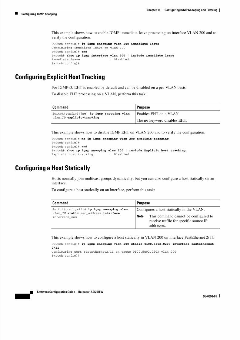
8/10/2019 Cisco ConfiguratioGuide SW4500 IOS
http://slidepdf.com/reader/full/cisco-configuratioguide-sw4500-ios 272/607
18-8
Software Configuration Guide—Release 12.2(25)EW
OL-6696-01
Chapter 18 Configuring IGMP Snooping and Filtering
Configuring IGMP Snooping
This example shows how to enable IGMP immediate-leave processing on interface VLAN 200 and to
verify the configuration:
Switch(config)# ip igmp snooping vlan 200 immediate-leave
Configuring immediate leave on vlan 200
Switch(config)# end
Switch# show ip igmp interface vlan 200 | include immediate leave
Immediate leave : DisabledSwitch(config)#
Configuring Explicit Host Tracking
For IGMPv3, EHT is enabled by default and can be disabled on a per-VLAN basis.
To disable EHT processing on a VLAN, perform this task:
This example shows how to disable IGMP EHT on VLAN 200 and to verify the configuration:
Switch(config)# no ip igmp snooping vlan 200 explicit-tracking Switch(config)#
Switch(config)# end Switch# show ip igmp snooping vlan 200 | include Explicit host tracking
Explicit host tracking : Disabled
Configuring a Host Statically
Hosts normally join multicast groups dynamically, but you can also configure a host statically on aninterface.
To configure a host statically on an interface, perform this task:
This example shows how to configure a host statically in VLAN 200 on interface FastEthernet 2/11:Switch(config)# ip igmp snooping vlan 200 static 0100.5e02.0203 interface fastethernet2/11
Configuring port FastEthernet2/11 on group 0100.5e02.0203 vlan 200Switch(config)#
Command Purpose
Switch(config)#[no] ip igmp snooping vlan
vlan_ID explicit-tracking
Enables EHT on a VLAN.
The no keyword disables EHT.
Command Purpose
Switch(config-if)# ip igmp snooping vlan
vlan_ID static mac_address interface
interface_num
Configures a host statically in the VLAN.
Note This command cannot be configured to
receive traffic for specific source IP
addresses.

8/10/2019 Cisco ConfiguratioGuide SW4500 IOS
http://slidepdf.com/reader/full/cisco-configuratioguide-sw4500-ios 273/607
18-9
Software Configuration Guide—Release 12.2(25)EW
OL-6696-01
Chapter 18 Configuring IGMP Snooping and Filtering
Configuring IGMP Snooping
Suppressing Multicast Flooding
An IGMP snooping-enabled switch will flood multicast traffic to all ports in a VLAN when a
spanning-tree Topology Change Notification (TCN) is received. Multicast flooding suppression enables
a switch to stop sending such traffic. To support flooding suppression, a new interface command and two
new global commands are introduced in release 12.1(11b)EW.The new interface command is as follows:
[no | default] ip igmp snooping tcn flood
These are the new global commands:
[no | default] ip igmp snooping tcn flood query count [1 - 10]
[no | default] ip igmp snooping tcn query solicit
Prior to release 12.1(11b)EW, when a spanning tree topology change notification (TCN) was received
by a switch, the multicast traffic was flooded to all the ports in a VLAN for a period of three IGMP query
intervals. This was necessary for redundant configurations. In release 12.1(11b)EW, the default time
period the switch will wait before multicast flooding will stop was changed to two IGMP query intervals.
This flooding behavior is undesirable if the switch that does the flooding has many ports that aresubscribed to different groups. The traffic could exceed the capacity of the link between the switch and
the end host, resulting in packet loss.
With the no ip igmp snooping tcn flood command, you can disable multicast flooding on a switch
interface following a topology change. Only the multicast groups that have been joined by a port are sent
to that port, even during a topology change.
With the ip igmp snooping tcn flood query count command, you can enable multicast flooding on a
switch interface for a short period of time following a topology change by configuring an IGMP query
threshold.
Typically, if a topology change occurs, the spanning tree root switch issues a global IGMP leave message
(referred to as a “query solicitation”) with the group multicast address 0.0.0.0. When a switch receives
this solicitation, it floods this solicitation on all ports in the VLAN where the spanning tree change
occurred. When the upstream router receives this solicitation, it immediately issues an IGMP general
query.
With the ip igmp snooping tcn query solicit command, you can now direct a non-spanning tree root
switch to issue the same query solicitation.
The following sections provide additional details on the new commands and illustrate how you can use
them.
IGMP Snooping Interface Configuration
A topology change in a VLAN may invalidate previously learned IGMP snooping information. A host
that was on one port before the topology change may move to another port after the topology change.
When the topology changes, the Catalyst 4500 series switch takes special actions to ensure that multicasttraffic is delivered to all multicast receivers in that VLAN.
When the spanning tree protocol is running in a VLAN, a spanning tree topology change notification
(TCN) is issued by the root switch in the VLAN. A Catalyst 4500 series switch that receives a TCN in
a VLAN for which IGMP snooping has been enabled immediately enters into “multicast flooding mode”
for a period of time until the topology restabilizes and the new locations of all multicast receivers are
learned.
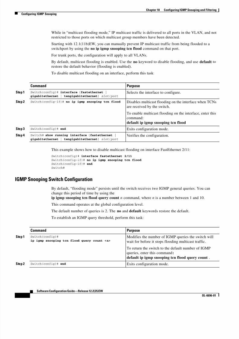
8/10/2019 Cisco ConfiguratioGuide SW4500 IOS
http://slidepdf.com/reader/full/cisco-configuratioguide-sw4500-ios 274/607
18-10
Software Configuration Guide—Release 12.2(25)EW
OL-6696-01
Chapter 18 Configuring IGMP Snooping and Filtering
Configuring IGMP Snooping
While in “multicast flooding mode,” IP multicast traffic is delivered to all ports in the VLAN, and not
restricted to those ports on which multicast group members have been detected.
Starting with 12.1(11b)EW, you can manually prevent IP multicast traffic from being flooded to a
switchport by using the no ip igmp snooping tcn flood command on that port.
For trunk ports, the configuration will apply to all VLANs.
By default, multicast flooding is enabled. Use the no keyword to disable flooding, and use default to
restore the default behavior (flooding is enabled).
To disable multicast flooding on an interface, perform this task:
This example shows how to disable multicast flooding on interface FastEthernet 2/11:
Switch(config)# interface fastethernet 2/11
Switch(config-if)# no ip igmp snooping tcn floodSwitch(config-if)# end
Switch#
IGMP Snooping Switch Configuration
By default, “flooding mode” persists until the switch receives two IGMP general queries. You can
change this period of time by using the
ip igmp snooping tcn flood query count n command, where n is a number between 1 and 10.
This command operates at the global configuration level.
The default number of queries is 2. The no and default keywords restore the default.
To establish an IGMP query threshold, perform this task:
Command Purpose
Step 1 Switch(config)# interface {fastethernet |gigabitethernet | tengigabitethernet} slot/ port
Selects the interface to configure.
Step 2 Switch(config-if)# no ip igmp snooping tcn flood Disables multicast flooding on the interface when TCNs
are received by the switch.
To enable multicast flooding on the interface, enter this
command:default ip igmp snooping tcn flood
Step 3 Switch(config)# end Exits configuration mode.
Step 4 Switch# show running interface {fastethernet |
gigabitethernet | tengigabitethernet} slot/ portVerifies the configuration.
Command Purpose
Step 1 Switch(config)#ip igmp snooping tcn flood query count <n> Modifies the number of IGMP queries the switch will
wait for before it stops flooding multicast traffic.
To return the switch to the default number of IGMP
queries, enter this command:
default ip igmp snooping tcn flood query count .
Step 2 Switch(config)# end Exits configuration mode.

8/10/2019 Cisco ConfiguratioGuide SW4500 IOS
http://slidepdf.com/reader/full/cisco-configuratioguide-sw4500-ios 275/607

8/10/2019 Cisco ConfiguratioGuide SW4500 IOS
http://slidepdf.com/reader/full/cisco-configuratioguide-sw4500-ios 276/607
18-12
Software Configuration Guide—Release 12.2(25)EW
OL-6696-01
Chapter 18 Configuring IGMP Snooping and Filtering
Displaying IGMP Snooping Information
Displaying Querier Information
To display querier information, perform this task:
This example shows how to display the IGMP snooping querier information for all VLANs on the
switch:
Switch# show ip igmp snooping querier
Vlan IP Address IGMP Version Port
---------------------------------------------------2 10.10.10.1 v2 Router
3 172.20.50.22 v3 Fa3/15
This example shows how to display the IGMP snooping querier information for VLAN 3:
Switch# show ip igmp snooping querier vlan 3 Vlan IP Address IGMP Version Port
---------------------------------------------------
3 172.20.50.22 v3 Fa3/15
Displaying IGMP Host Membership Information
Note By default, EHT maintains a maximum of 1000 entries in the EHT database. Once this limit is reached,
no additional entries are created. To create additional entries, clear the database with the clear ip igmp
snooping membership vlan command.
To display host membership information, perform this task:
This example shows how to display host membership information for VLAN 20 and to delete the EHT
database:
Switch# show ip igmp snooping membership vlan 20
#channels: 5#hosts : 1
Source/Group Interface Reporter Uptime Last-Join Last-Leave
40.40.40.2/224.10.10.10 Gi4/1 20.20.20.20 00:23:37 00:06:50 00:20:3040.40.40.3/224.10.10.10 Gi4/2 20.20.2020 00:23:37 00:06:50 00:20:30
40.40.40.4/224.10.10.10Gi4/1 20.20.20.20 00:39:42 00:09:17 -
Command Purpose
Switch# show ip igmp snooping querier [ vlan
vlan_ID ]Displays multicast router interfaces.
Command Purpose
Switch# show ip igmp snooping membership
[interface interface_num ][ vlan vlan_ID ]
[reporter a.b.c.d ] [source a.b.c.d group
a.b.c.d ]
Displays Explicit Host Tracking information.
Note This command is valid only if EHT is
enabled on the switch.

8/10/2019 Cisco ConfiguratioGuide SW4500 IOS
http://slidepdf.com/reader/full/cisco-configuratioguide-sw4500-ios 277/607

8/10/2019 Cisco ConfiguratioGuide SW4500 IOS
http://slidepdf.com/reader/full/cisco-configuratioguide-sw4500-ios 278/607
18-14
Software Configuration Guide—Release 12.2(25)EW
OL-6696-01
Chapter 18 Configuring IGMP Snooping and Filtering
Displaying IGMP Snooping Information
This example shows how to display the host types and ports of a group in VLAN 1:
Switch# show ip igmp snooping groups vlan 10 226.6.6.7 Vlan Group Version Ports
---------------------------------------------------------10 226.6.6.7 v3 Fa7/13, Fa7/14
Switch>
This example shows how to display the current state of a group with respect to a source IP address:
Switch# show ip igmp snooping groups vlan 10 226.6.6.7 sourcesSource information for group 226.6.6.7:
Timers: Expired sources are deleted on next IGMP General Query
SourceIP Expires Uptime Inc Hosts Exc Hosts
-------------------------------------------------------
2.0.0.1 00:03:04 00:03:48 2 02.0.0.2 00:03:04 00:02:07 2 0
Switch>
This example shows how to display the current state of a group with respect to a host MAC address:
Switch# show ip igmp snooping groups vlan 10 226.6.6.7 hosts
IGMPv3 host information for group 226.6.6.7Timers: Expired hosts are deleted on next IGMP General Query
Host (MAC/IP) Filter mode Expires Uptime # Sources-------------------------------------------------------------
175.1.0.29 INCLUDE stopped 00:00:51 2175.2.0.30 INCLUDE stopped 00:04:14 2
This example shows how to display summary information for an IGMPv3 group:
Switch# show ip igmp snooping groups vlan 10 226.6.6.7 summary
Group Address (Vlan 10) : 226.6.6.7Host type : v3
Member Ports : Fa7/13, Fa7/14Filter mode : INCLUDE
Expires : stoppedSources : 2
Reporters (Include/Exclude) : 2/0
This example shows how to display the total number of group addresses learned by the system globally:
Switch# show ip igmp snooping groups count
Total number of groups: 54
This example shows how to display the total number of group addresses learned on VLAN 5:
Switch# show ip igmp snooping groups vlan 5 countTotal number of groups: 30
Displaying Multicast Router InterfacesWhen you enable IGMP snooping, the switch automatically learns to which interface the multicast
routers are connected.

8/10/2019 Cisco ConfiguratioGuide SW4500 IOS
http://slidepdf.com/reader/full/cisco-configuratioguide-sw4500-ios 279/607
18-15
Software Configuration Guide—Release 12.2(25)EW
OL-6696-01
Chapter 18 Configuring IGMP Snooping and Filtering
Displaying IGMP Snooping Information
To display multicast router interfaces, perform this task:
This example shows how to display the multicast router interfaces in VLAN 1:
Switch# show ip igmp snooping mrouter vlan 1vlan ports
-----+----------------------------------------
1 Gi1/1,Gi2/1,Fa3/48,Router
Switch#
Displaying MAC Address Multicast Entries
To display MAC address multicast entries for a VLAN, perform this task:
This example shows how to display MAC address multicast entries for VLAN 1:
Switch# show mac-address-table multicast vlan 1
Multicast Entries
vlan mac address type ports-------+---------------+-------+-------------------------------------------
1 0100.5e01.0101 igmp Switch,Gi6/1
1 0100.5e01.0102 igmp Switch,Gi6/1
1 0100.5e01.0103 igmp Switch,Gi6/1 1 0100.5e01.0104 igmp Switch,Gi6/1
1 0100.5e01.0105 igmp Switch,Gi6/1 1 0100.5e01.0106 igmp Switch,Gi6/1
Switch#
This example shows how to display a total count of MAC address entries for VLAN 1:
Switch# show mac-address-table multicast vlan 1 countMulticast MAC Entries for vlan 1: 4
Switch#
Displaying IGMP Snooping Information on a VLAN Interface
To display IGMP snooping information on a VLAN, perform this task:
Command Purpose
Switch# show ip igmp snooping mrouter vlan
vlan_ID Displays multicast router interfaces.
Command Purpose
Switch# show mac-address-table multicast
vlan vlan_ID [count]Displays MAC address multicast entries for a
VLAN.
Command Purpose
Switch# show ip igmp snooping vlan vlan_ID Displays IGMP snooping information on a VLAN
interface.
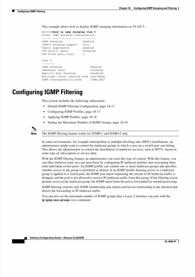
8/10/2019 Cisco ConfiguratioGuide SW4500 IOS
http://slidepdf.com/reader/full/cisco-configuratioguide-sw4500-ios 280/607
18-16
Software Configuration Guide—Release 12.2(25)EW
OL-6696-01
Chapter 18 Configuring IGMP Snooping and Filtering
Configuring IGMP Filtering
This example shows how to display IGMP snooping information on VLAN 5:
Switch#show ip igmp snooping vlan 5Global IGMP Snooping configuration:
-----------------------------------IGMP snooping :Enabled
IGMPv3 snooping support :Full
Report suppression :EnabledTCN solicit query :Disabled
TCN flood query count :2
Vlan 5:--------
IGMP snooping :EnabledImmediate leave :Disabled
Explicit Host Tracking :Disabled
Multicast router learning mode :pim-dvmrp
CGMP interoperability mode :IGMP_ONLY
Configuring IGMP FilteringThis section includes the following subsections:
• Default IGMP Filtering Configuration, page 18-17
• Configuring IGMP Profiles, page 18-17
• Applying IGMP Profiles, page 18-18
• Setting the Maximum Number of IGMP Groups, page 18-19
Note The IGMP filtering feature works for IGMPv1 and IGMPv2 only.
In some environments, for example metropolitan or multiple-dwelling unit (MDU) installations, an
administrator might want to control the multicast groups to which a user on a switch port can belong.This allows the administrator to control the distribution of multicast services, such as IP/TV, based on
some type of subscription or service plan.
With the IGMP filtering feature, an administrator can exert this type of control. With this feature, you
can filter multicast joins on a per-port basis by configuring IP multicast profiles and associating them
with individual switch ports. An IGMP profile can contain one or more multicast groups and specifies
whether access to the group is permitted or denied. If an IGMP profile denying access to a multicast
group is applied to a switch port, the IGMP join report requesting the stream of IP multicast traffic is
dropped, and the port is not allowed to receive IP multicast traffic from that group. If the filtering action
permits access to the multicast group, the IGMP report from the port is forwarded for normal processing.
IGMP filtering controls only IGMP membership join reports and has no relationship to the function that
directs the forwarding of IP multicast traffic.
You can also set the maximum number of IGMP groups that a Layer 2 interface can join with the
ip igmp max-groups <n> command.

8/10/2019 Cisco ConfiguratioGuide SW4500 IOS
http://slidepdf.com/reader/full/cisco-configuratioguide-sw4500-ios 281/607
18-17
Software Configuration Guide—Release 12.2(25)EW
OL-6696-01
Chapter 18 Configuring IGMP Snooping and Filtering
Configuring IGMP Filtering
Default IGMP Filtering Configuration
Table 18-2 shows the default IGMP filtering configuration.
Configuring IGMP Profiles
To configure an IGMP profile and to enter IGMP profile configuration mode, use the ip igmp profile
global configuration command. From the IGMP profile configuration mode, you can specify the
parameters of the IGMP profile to be used for filtering IGMP join requests from a port. When you are
in IGMP profile configuration mode, you can create the profile using these commands:
• deny: Specifies that matching addresses are denied; this is the default condition.
• exit: Exits from igmp-profile configuration mode.
• no: Negates a command or sets its defaults.
• permit: Specifies that matching addresses are permitted.
• range: Specifies a range of IP addresses for the profile. You can enter a single IP address or a range
with starting and ending addresses.
By default, no IGMP profiles are configured. When a profile is configured with neither the permit nor
the deny keyword, the default is to deny access to the range of IP addresses.
To create an IGMP profile for a port, perform this task:
Table 18-2 Default IGMP Filtering Settings
Feature Default Setting
IGMP filters No filtering
IGMP maximum number of IGMP groups No limit
IGMP profiles None defined
Command Purpose
Step 1 Switch# configure terminal Enters global configuration mode.
Step 2 Switch(config)# ip igmp profile profilenumber
Enters IGMP profile configuration mode, and assigns a
number to the profile you are configuring. The range is from
1 to 4,294,967,295.
Step 3 Switch(config-igmp-profile)# permit | deny (Optional) Sets the action to permit or deny access to the IP
multicast address. If no action is configured, the default for
the profile is to deny access.
Step 4 Switch(config-igmp-profile)# range ip
multicast address
Enters the IP multicast address or range of IP multicast
addresses to which access is being controlled. If entering arange, enter the low IP multicast address, a space, and the
high IP multicast address.
You can use the range command multiple times to enter
multiple addresses or ranges of addresses.
Step 5 Switch(config-igmp-profile)# end Returns to privileged EXEC mode.

8/10/2019 Cisco ConfiguratioGuide SW4500 IOS
http://slidepdf.com/reader/full/cisco-configuratioguide-sw4500-ios 282/607
18-18
Software Configuration Guide—Release 12.2(25)EW
OL-6696-01
Chapter 18 Configuring IGMP Snooping and Filtering
Configuring IGMP Filtering
To delete a profile, use the no ip igmp profile profile number global configuration command.To delete an IP multicast address or range of IP multicast addresses, use the no range ip multicast
address IGMP profile configuration command.
This example shows how to create IGMP profile 4 (allowing access to the single IP multicast address)
and how to verify the configuration. If the action were to deny (the default), it would not appear in the
show ip igmp profile command output.
Switch# config t
Switch(config)# ip igmp profile 4
Switch(config-igmp-profile)# permitSwitch(config-igmp-profile)# range 229.9.9.0
Switch(config-igmp-profile)# end
Switch# show ip igmp profile 4IGMP Profile 4
permit range 229.9.9.0 229.9.9.0
Applying IGMP Profiles
To control access as defined in an IGMP profile, use the ip igmp filter interface configuration command
to apply the profile to the appropriate interfaces. You can apply a profile to multiple interfaces, but each
interface can only have one profile applied to it.
Note You can apply IGMP profiles to Layer 2 ports only. You cannot apply IGMP profiles to routed ports (or
SVIs) or to ports that belong to an EtherChannel port group.
To apply an IGMP profile to a switch port, perform this task:
Step 6 Switch# show ip igmp profile profile number Verifies the profile configuration.
Step 7 Switch# copy running-config startup-config (Optional) Saves your entries in the configuration file.
Command Purpose
Command Purpose
Step 1 Switch# configure terminal Enters global configuration mode.
Step 2 Switch(config)# interface interface-id Enters interface configuration mode, and enter the physical
interface to configure, for example fastethernet2/3. The interface
must be a Layer 2 port that does not belong to an EtherChannel
port group.
Step 3 Switch(config-if)# ip igmp filter profilenumber
Applies the specified IGMP profile to the interface. The profile
number can be from 1 to 4,294,967,295.
Step 4 Switch(config-if)# end Returns to privileged EXEC mode.
Step 5 Switch# show running configurationinterface interface-id
Verifies the configuration.
Step 6 Switch# copy running-config startup-config (Optional) Saves your entries in the configuration file.

8/10/2019 Cisco ConfiguratioGuide SW4500 IOS
http://slidepdf.com/reader/full/cisco-configuratioguide-sw4500-ios 283/607
18-19
Software Configuration Guide—Release 12.2(25)EW
OL-6696-01
Chapter 18 Configuring IGMP Snooping and Filtering
Configuring IGMP Filtering
To remove a profile from an interface, use the no ip igmp filter command.
This example shows how to apply IGMP profile 4 to an interface and to verify the configuration:
Switch# config t
Switch(config)# interface fastethernet2/12Switch(config-if)# ip igmp filter 4
Switch(config-if)# endSwitch# show running-config interface fastethernet2/12
Building configuration...
Current configuration : 123 bytes!
interface FastEthernet2/12 no ip address
shutdown
snmp trap link-status
ip igmp max-groups 25 ip igmp filter 4
end
Setting the Maximum Number of IGMP GroupsYou can set the maximum number of IGMP groups that a Layer 2 interface can join by using the ip igmp
max-groups interface configuration command. Use the no form of this command to set the maximum
back to the default, which is no limit.
Note This restriction can be applied to Layer 2 ports only. You cannot set a maximum number of IGMP groups
on routed ports (or SVIs) or on ports that belong to an EtherChannel port group.
To apply an IGMP profile on a switch port, perform this task:
Command Purpose
Step 1 Switch# configure terminal Enters global configuration mode.
Step 2 Switch(config)# interface interface-id Enters interface configuration mode, and enter the physical
interface to configure, for example gigabitethernet1/1. The
interface must be a Layer 2 port that does not belong to an
EtherChannel group.
Step 3 Switch(config-if)# ip igmp max-groupsnumber
Sets the maximum number of IGMP groups that the interface can
join. The range is from 0 to 4,294,967,294. By default, no
maximum is set.
Step 4 Switch(config-if)# end Returns to privileged EXEC mode.
Step 5 Switch# show running-configuration
interface interface-id
Verifies the configuration.
Step 6 Switch# copy running-config
startup-config(Optional) Saves your entries in the configuration file.

8/10/2019 Cisco ConfiguratioGuide SW4500 IOS
http://slidepdf.com/reader/full/cisco-configuratioguide-sw4500-ios 284/607
18-20
Software Configuration Guide—Release 12.2(25)EW
OL-6696-01
Chapter 18 Configuring IGMP Snooping and Filtering
Displaying IGMP Filtering Configuration
To remove the maximum group limitation and return to the default of no maximum, use the no ip igmp
max-groups command.
This example shows how to limit the number of IGMP groups that an interface can join to 25.
Switch# config tSwitch(config)# interface fastethernet2/12
Switch(config-if)# ip igmp max-groups 25Switch(config-if)# end
Switch# show running-config interface fastethernet2/12Building configuration...
Current configuration : 123 bytes
!
interface FastEthernet2/12
no ip address shutdown
snmp trap link-status ip igmp max-groups 25
ip igmp filter 4
end
Displaying IGMP Filtering ConfigurationYou can display IGMP profile and maximum group configuration for all interfaces on the switch or for
a specified interface.
To display IGMP profiles, perform this task:
To display interface configuration, perform this task:
This is an example of the show ip igmp profile privileged EXEC command when no profile number is
entered. All profiles defined on the switch are displayed.
Switch# show ip igmp profileIGMP Profile 3 range 230.9.9.0 230.9.9.0
IGMP Profile 4
permit
range 229.9.9.0 229.255.255.255
Command Purpose
Switch# show ip igmp profile [ profile number ] Displays the specified IGMP profile or all IGMP profiles defined
on the switch.
Command Purpose
Switch# show running-configuration [interface
interface-id ] Displays the configuration of the specified interface or all
interfaces on the switch, including (if configured) the maximum
number of IGMP groups to which an interface can belong and the
IGMP profile applied to the interface.

8/10/2019 Cisco ConfiguratioGuide SW4500 IOS
http://slidepdf.com/reader/full/cisco-configuratioguide-sw4500-ios 285/607

8/10/2019 Cisco ConfiguratioGuide SW4500 IOS
http://slidepdf.com/reader/full/cisco-configuratioguide-sw4500-ios 286/607
18-22
Software Configuration Guide—Release 12.2(25)EW
OL-6696-01
Chapter 18 Configuring IGMP Snooping and Filtering
Displaying IGMP Filtering Configuration

8/10/2019 Cisco ConfiguratioGuide SW4500 IOS
http://slidepdf.com/reader/full/cisco-configuratioguide-sw4500-ios 287/607
C H A P T E R
19-1
Software Configuration Guide—Release 12.2(25)EW
OL-6696-01
19
Configuring 802.1Q and Layer 2 ProtocolTunneling
Virtual private networks (VPNs) provide enterprise-scale connectivity on a shared infrastructure, often
Ethernet-based, with the same security, prioritization, reliability, and manageability requirements of
private networks. Tunneling is a feature designed for service providers who carry traffic of multiple
customers across their networks and who are required to maintain the VLAN and Layer 2 protocol
configurations of each customer without impacting the traffic of other customers. The Catalyst 4500
series switch supports IEEE 802.1Q tunneling and Layer 2 protocol tunneling.
Note 802.1Q requires Supervisor Engine V; Layer 2 protocol tunneling is supported on all supervisor engines
Note For complete syntax and usage information for the switch commands used in this chapter, refer to the
Catalyst 4500 Series Switch Cisco IOS Command Reference and related publications at
http://www.cisco.com/univercd/cc/td/doc/product/software/ios122/122cgcr/index.htm.
This chapter contains these sections:
• Understanding 802.1Q Tunneling, page 19-1
• Configuring 802.1Q Tunneling, page 19-4
• Understanding Layer 2 Protocol Tunneling, page 19-7
• Configuring Layer 2 Protocol Tunneling, page 19-9
• Monitoring and Maintaining Tunneling Status, page 19-12
Understanding 802.1Q TunnelingThe VLAN ranges required by different customers in the same Service Provider network might overlap,
and customer traffic through the infrastructure might be mixed. Assigning a unique range of VLAN IDs
to each customer would restrict customer configurations and could easily exceed the VLAN limit (4096)
of the 802.1Q specification.
802.1Q tunneling enables Service Providers to use a single VLAN to support customers who have
multiple VLANs, while preserving customer VLAN IDs and keeping traffic in different customer
VLANs segregated.

8/10/2019 Cisco ConfiguratioGuide SW4500 IOS
http://slidepdf.com/reader/full/cisco-configuratioguide-sw4500-ios 288/607
19-2
Software Configuration Guide—Release 12.2(25)EW
OL-6696-01
Chapter 19 Configuring 802.1Q and Layer 2 Protocol Tunneling
Understanding 802.1Q Tunneling
A port configured to support 802.1Q tunneling is called a tunnel port. When you configure tunneling,
you assign a tunnel port to a VLAN ID that is dedicated to tunneling. Each customer requires a separate
Service Provider VLAN ID, but that Service Provider VLAN ID supports VLANs of all the customers.
Customer traffic tagged in the normal way with appropriate VLAN IDs comes from an 802.1Q trunk port
on the customer device and into a tunnel port on the Service Provider edge switch. The link between the
customer device and the edge switch is asymmetric because one end is configured as an 802.1Q trunkport, and the other end is configured as a tunnel port. You assign the tunnel port interface to an access
VLAN ID that is unique to each customer. See Figure 19-1.
Figure 19-1 802.1Q Tunnel Ports in a Service Provider Network
Packets coming from the customer trunk port into the tunnel port on the Service Provider edge switch
are normally 802.1Q-tagged with the appropriate VLAN ID. When the tagged packets exit the trunk port
into the Service Provider network, they are encapsulated with another layer of an 802.1Q tag (called the
metro tag) that contains the VLAN ID that is unique to the customer. The original customer 802.1Q tag
is preserved in the encapsulated packet. Therefore, packets entering the Service Provider network are
double-tagged, with the metro tag containing the customer’s access VLAN ID, and the inner VLAN ID
being that of the incoming traffic.
When the double-tagged packet enters another trunk port in a Service Provider core switch, the metro
tag is stripped as the switch processes the packet. When the packet exits another trunk port on the same
core switch, the same metro tag is again added to the packet. Figure 19-2 shows the tag structures of theEthernet packets starting with the original, or normal, frame.
Customer AVLANs 1 to 100
Customer BVLANs 1 to 200
Customer BVLANs 1 to 200
Customer AVLANs 1 to 100
Tunnel portVLAN 40
Tunnel portVLAN 30
Trunkports
Trunkports
Tunnel portVLAN 30
Tunnel portVLAN 40
Service
provider
7 4 0 1 6
TrunkAsymmetric link
Tunnel portVLAN 30

8/10/2019 Cisco ConfiguratioGuide SW4500 IOS
http://slidepdf.com/reader/full/cisco-configuratioguide-sw4500-ios 289/607
19-3
Software Configuration Guide—Release 12.2(25)EW
OL-6696-01
Chapter 19 Configuring 802.1Q and Layer 2 Protocol Tunneling
Understanding 802.1Q Tunneling
Figure 19-2 Original (Normal), 802.1Q, and Double-Tagged Ethernet Packet Formats
When the packet enters the trunk port of the Service Provider egress switch, the metro tag is again
stripped as the switch processes the packet. However, the metro tag is not added when the packet is sent
out the tunnel port on the edge switch into the customer network. The packet is sent as a normal
802.1Q-tagged frame to preserve the original VLAN numbers in the customer network.
All packets entering the Service Provider network through a tunnel port on an edge switch are treated as
untagged packets, whether they are untagged or already tagged with 802.1Q headers. The packets are
encapsulated with the metro tag VLAN ID (set to the access VLAN of the tunnel port) when they are
sent through the Service Provider network on an 802.1Q trunk port. The priority field on the metro tag
is set to the interface class of service (CoS) priority configured on the tunnel port. (The default is zero
if none is configured.)
In Figure 19-1, Customer A was assigned VLAN 30, and Customer B was assigned VLAN 40. Packets
entering the edge-switch tunnel ports with 802.1Q tags are double-tagged when they enter the Service
Provider network, with the metro tag containing VLAN ID 30 or 40, appropriately, and the inner tag
containing the original customer VLAN number, for example, VLAN 100. Even if Customers A and B
both have VLAN 100 in their networks, the traffic remains segregated within the Service Provider
network because the metro tag is different. Each customer controls its own VLAN numbering space,
which is independent of the VLAN numbering space used by other customers and the VLAN numbering
space used by the Service Provider network.
Double-tagged
frame in serviceproviderinfrastructure
IEE 802.1Q frame fromcustomer network
Original Ethernet frame
Destinationaddress
Length/ EtherType
Frame CheckSequence
Sourceaddress
SADA Len/Etype Data FCS
SADA Len/Etype DataEtype Tag FCS
SADA Len/Etype DataEtype Tag Etype Tag FCS 7 4 0 7 2

8/10/2019 Cisco ConfiguratioGuide SW4500 IOS
http://slidepdf.com/reader/full/cisco-configuratioguide-sw4500-ios 290/607
19-4
Software Configuration Guide—Release 12.2(25)EW
OL-6696-01
Chapter 19 Configuring 802.1Q and Layer 2 Protocol Tunneling
Configuring 802.1Q Tunneling
Configuring 802.1Q TunnelingThese sections describe 802.1Q tunneling configuration:
• 802.1Q Tunneling Configuration Guidelines, page 19-4
• 802.1Q Tunneling and Other Features, page 19-5• Configuring an 802.1Q Tunneling Port, page 19-6
Note By default, 802.1Q tunneling is disabled because the default switch port mode is dynamic auto. Tagging
of 802.1Q native VLAN packets on all 802.1Q trunk ports is also disabled.
802.1Q Tunneling Configuration Guidelines
When you configure 802.1Q tunneling, you should always use asymmetrical links for traffic going
through a tunnel and should dedicate one VLAN for each tunnel. You should also be aware of
configuration requirements for native VLANs and maximum transmission units (MTUs). For moreinformation about MTUs, see the “System MTU” section on page 19-5.
Native VLANs
When configuring 802.1Q tunneling on an edge switch, you must use 802.1Q trunk ports for sending
packets into the Service Provider network. However, packets going through the core of the Service
Provider network can be carried through 802.1Q trunks, ISL trunks, or nontrunking links. When 802.1Q
trunks are used in these core switches, the native VLANs of the 802.1Q trunks must not match any native
VLAN of the nontrunking (tunneling) port on the same switch because traffic on the native VLAN would
not be tagged on the 802.1Q sending trunk port.
See Figure 19-3. VLAN 40 is configured as the native VLAN for the 802.1Q trunk port from Customer A
at the ingress edge switch in the Service Provider network (Switch 2). Switch 1 of Customer A sends atagged packet on VLAN 30 to the ingress tunnel port of Switch 2 in the Service Provider network, which
belongs to access VLAN 40. Because the access VLAN of the tunnel port (VLAN 40) is the same as the
native VLAN of the edge-switch trunk port (VLAN 40), the metro tag is not added to tagged packets
received from the tunnel port. The packet carries only the VLAN 30 tag through the Service Provider
network to the trunk port of the egress-edge switch (Switch 3) and is misdirected through the egress
switch tunnel port to Customer B.
These are some ways to solve this problem:
• Use ISL trunks between core switches in the Service Provider network. Although customer
interfaces connected to edge switches must be 802.1Q trunks, we recommend using ISL trunks for
connecting switches in the core layer.
• Use the switchport trunk native vlan tag per-port command and the vlan dot1q tag native globalconfiguration command to configure the edge switch so that all packets going out an 802.1Q trunk,
including the native VLAN, are tagged. If the switch is configured to tag native VLAN packets on
all 802.1Q trunks, the switch accepts untagged packets, but sends only tagged packets.
• Ensure that the native VLAN ID on the edge-switch trunk port is not within the customer VLAN
range. For example, if the trunk port carries traffic of VLANs 100 to 200, assign the native VLAN
a number outside that range.

8/10/2019 Cisco ConfiguratioGuide SW4500 IOS
http://slidepdf.com/reader/full/cisco-configuratioguide-sw4500-ios 291/607
19-5
Software Configuration Guide—Release 12.2(25)EW
OL-6696-01
Chapter 19 Configuring 802.1Q and Layer 2 Protocol Tunneling
Configuring 802.1Q Tunneling
Figure 19-3 Potential Problem with 802.1Q Tunneling and Native VLANs
System MTU
The default system MTU for traffic on the Catalyst 4500 series switch is 1500 bytes. You can configure
the switch to support larger frames by using the system mtu global configuration command. Because
the 802.1Q tunneling feature increases the frame size by 4 bytes when the metro tag is added, you mustconfigure all switches in the Service Provider network to be able to process larger frames by increasing
the switch system MTU size to at least 1504 bytes. The maximum allowable system MTU for Catalyst
4500 Gigabit Ethernet switches is 9198 bytes; the maximum system MTU for Fast Ethernet switches is
1552 bytes.
802.1Q Tunneling and Other Features
Although 802.1Q tunneling works well for Layer 2 packet switching, there are incompatibilities between
some Layer 2 features and Layer 3 switching.
• A tunnel port cannot be a routed port.
• IP routing is not supported on a VLAN that includes 802.1Q ports. Packets received from a tunnel
port are forwarded based only on Layer 2 information. If routing is enabled on a switch virtual
interface (SVI) that includes tunnel ports, untagged IP packets received from the tunnel port are
recognized and routed by the switch. Customers can access the Internet through the native VLAN.
If this access is not needed, you should not configure SVIs on VLANs that include tunnel ports.
• Tunnel ports do not support IP access control lists (ACLs).
• Layer 3 quality of service (QoS) ACLs and other QoS features related to Layer 3 information are
not supported on tunnel ports. MAC-based QoS is supported on tunnel ports.
802.1Qtrunk portVLANs 30-40Native VLAN 40
Tunnel portAccess VLAN 30
Tunnel port
Serviceprovider
Tag not addedfor VLAN 40
Tagremoved
VLANs 5-50
Switch 4Customer A
VLANs 30-40Native VLAN 40
Switch 2 Switch 3
Q
Switch 5Customer B
Switch 1Customer A
NativeVLAN 40
7 4 0 7 4
Trunk
Asymmetric link
Correct path for traffic
Incorrect path for traffic due tomisconfiguration of native VLANby sending port on Switch 2
Q = 802.1Q trunk ports
Tunnel portAccess VLAN 40
Packet taggedfor VLAN 30
VLAN 40

8/10/2019 Cisco ConfiguratioGuide SW4500 IOS
http://slidepdf.com/reader/full/cisco-configuratioguide-sw4500-ios 292/607
19-6
Software Configuration Guide—Release 12.2(25)EW
OL-6696-01
Chapter 19 Configuring 802.1Q and Layer 2 Protocol Tunneling
Configuring 802.1Q Tunneling
• EtherChannel port groups are compatible with tunnel ports as long as the 802.1Q configuration is
consistent within an EtherChannel port group.
• Port Aggregation Protocol (PAgP), Link Aggregation Control Protocol (LACP), and UniDirectional
Link Detection (UDLD) are supported on 802.1Q tunnel ports.
• Dynamic Trunking Protocol (DTP) is not compatible with 802.1Q tunneling because you must
manually configure asymmetric links with tunnel ports and trunk ports.
• Loopback detection is supported on 802.1Q tunnel ports.
• When a port is configured as an 802.1Q tunnel port, spanning-tree bridge protocol data unit (BPDU)
filtering is automatically enabled on the interface. Cisco Discovery Protocol (CDP) is automatically
disabled on the interface.
Configuring an 802.1Q Tunneling Port
To configure a port as an 802.1Q tunnel port, perform this task:
Use the no vlan dot1q tag native global command and the no switchport mode dot1q-tunnel interface
configuration command to return the port to the default state of dynamic auto. Use the no vlan dot1qtag native global configuration command to disable tagging of native VLAN packets.
Command Purpose
Step 1 Switch# configure terminal Enters global configuration mode.
Step 2 Switch(config)# interface
interface-id Enters interface configuration mode and the interface to be configured as
a tunnel port. This should be the edge port in the Service Provider network
that connects to the customer switch. Valid interfaces include physical
interfaces and port-channel logical interfaces (port channels 1 to 64).
Step 3 Switch(config-if)# switchport
access vlan vlan-id Specifies the default VLAN, which is used if the interface stops trunking.
This VLAN ID is specific to the particular customer.
Step 4 Switch(config-if)# switchport mode
dot1q-tunnelSets the interface as an 802.1Q tunnel port.
Step 5 Switch(config-if)# exit Returns to global configuration mode.
Step 6 Switch(config)# vlan dot1q tagnative
(Optional) Sets the switch to enable tagging of native VLAN packets on
all 802.1Q trunk ports. When not set, and a customer VLAN ID is the
same as the native VLAN, the trunk port does not apply a metro tag, and
packets could be sent to the wrong destination.
Step 7 Switch(config)# end Returns to privileged EXEC mode.
Step 8 Switch# show dot1q-tunnel Displays the tunnel ports on the switch.
Step 9 Switch# show vlan dot1q tag native Displays 802.1Q native-VLAN tagging status.
Step 10 Switch# copy running-configstartup-config
(Optional) Saves your entries in the configuration file.

8/10/2019 Cisco ConfiguratioGuide SW4500 IOS
http://slidepdf.com/reader/full/cisco-configuratioguide-sw4500-ios 293/607
19-7
Software Configuration Guide—Release 12.2(25)EW
OL-6696-01
Chapter 19 Configuring 802.1Q and Layer 2 Protocol Tunneling
Understanding Layer 2 Protocol Tunneling
This example shows how to configure an interface as a tunnel port, enable tagging of native VLAN
packets, and verify the configuration. In this configuration, the VLAN ID for the customer connected to
Gigabit Ethernet interface 2/7 is VLAN 22.
Switch(config)# interface gigabitethernet2/7Switch(config-if)# switchport access vlan 22
% Access VLAN does not exist. Creating vlan 22
Switch(config-if)# switchport mode dot1q-tunnelSwitch(config-if)# exit
Switch(config)# vlan dot1q tag native
Switch(config)# endSwitch# show dot1q-tunnel interface gigabitethernet2/7
Port-----
LAN Port(s)
-----
Gi2/7Switch# show vlan dot1q tag native
dot1q native vlan tagging is enabled globally
Understanding Layer 2 Protocol TunnelingCustomers at different sites connected across a Service Provider network need to use various Layer 2
protocols to scale their topologies to include all remote and local sites. STP must run properly, and every
VLAN should build a proper spanning tree that includes the local site and all remote sites across the
Service Provider network. Cisco Discovery Protocol (CDP) must discover neighboring Cisco devices
from local and remote sites. VLAN Trunking Protocol (VTP) must provide consistent VLAN
configuration throughout all sites in the customer network.
When protocol tunneling is enabled, edge switches on the inbound side of the Service Provider network
encapsulate Layer 2 protocol packets with a special MAC address and send them across the Service
Provider network. Core switches in the network do not process these packets but forward them as normal
packets. Layer 2 protocol data units (PDUs) for CDP, STP, or VTP cross the Service Provider network
and are delivered to customer switches on the outbound side of the Service Provider network. Identicalpackets are received by all customer ports on the same VLANs with these results:
• Users on each of a customer’s sites can properly run STP, and every VLAN can build a correct
spanning tree, based on parameters from all sites and not just from the local site.
• CDP discovers and shows information about the other Cisco devices connected through the Service
Provider network.
• VTP provides consistent VLAN configuration throughout the customer network, propagating to all
switches through the Service Provider.
Layer 2 protocol tunneling can be used independently or can enhance 802.1Q tunneling. If protocol
tunneling is not enabled on 802.1Q tunneling ports, remote switches at the receiving end of the Service
Provider network do not receive the PDUs and cannot properly run STP, CDP, and VTP. When protocol
tunneling is enabled, Layer 2 protocols within each customer’s network are totally separate from thoserunning within the Service Provider network. Customer switches on different sites that send traffic
through the Service Provider network with 802.1Q tunneling achieve complete knowledge of the
customer’s VLAN. If 802.1Q tunneling is not used, you can still enable Layer 2 protocol tunneling by
connecting to the customer switch through access ports and by enabling tunneling on the Service
Provider access port.
As an example, Customer A in Figure 19-4 has four switches in the same VLAN that are connected
through the Service Provider network. If the network does not tunnel PDUs, switches on the far ends of
the network cannot properly run STP, CDP, and VTP. For example, STP for a VLAN on a switch in

8/10/2019 Cisco ConfiguratioGuide SW4500 IOS
http://slidepdf.com/reader/full/cisco-configuratioguide-sw4500-ios 294/607
19-8
Software Configuration Guide—Release 12.2(25)EW
OL-6696-01
Chapter 19 Configuring 802.1Q and Layer 2 Protocol Tunneling
Understanding Layer 2 Protocol Tunneling
Customer A’s Site 1 will build a spanning tree on the switches at that site without considering
convergence parameters based on Customer A’s switch in Site 2. Figure 19-5 shows one possible
spanning tree topology.
Figure 19-4 Layer 2 Protocol Tunneling
Figure 19-5 Layer 2 Network Topology without Proper Convergence
Customer A Site 2VLANs 1 to 100
Customer B Site 2VLANs 1 to 200
Customer B Site 1VLANs 1 to 200
Customer A Site 1VLANs 1 to 100
VLAN 30
Trunk
ports
Switch 1
Switch 1
Trunkports
VLAN 30
VLAN 40
Serviceprovider
7 4 0 7 3
TrunkAsymmetric link
VLAN 30
VLAN 40
Trunkports
Switch 2
Switch 3
Switch 4
Trunk
ports
7 4 0 1 7
Customer Avirtual networkVLANs 1 to 100

8/10/2019 Cisco ConfiguratioGuide SW4500 IOS
http://slidepdf.com/reader/full/cisco-configuratioguide-sw4500-ios 295/607
19-9
Software Configuration Guide—Release 12.2(25)EW
OL-6696-01
Chapter 19 Configuring 802.1Q and Layer 2 Protocol Tunneling
Configuring Layer 2 Protocol Tunneling
Configuring Layer 2 Protocol TunnelingYou can enable Layer 2 protocol tunneling (by protocol) on the access ports or tunnel ports that are
connected to the customer in the edge switches of the Service Provider network. The Service Provider
edge switches connected to the customer switch perform the tunneling process. Edge-switch tunnel ports
are connected to customer 802.1Q trunk ports. Edge-switch access ports are connected to customeraccess ports.
When the Layer 2 PDUs that entered the Service Provider inbound edge switch through the tunnel port
or the access port exit through its the trunk port into the Service Provider network, the switch overwrites
the customer PDU-destination MAC address with a well-known Cisco proprietary multicast address
(01-00-0c-cd-cd-d0). I f 802.1Q tunneling is enabled, packets are also double-tagged; the outer tag is the
customer metro tag, and the inner tag is the customer’s VLAN tag. The core switches ignore the inner
tags and forward the packet to all trunk ports in the same metro VLAN. The edge switches on the
outbound side restore the proper Layer 2 protocol and MAC address information and forward the packets
to all tunnel or access ports in the same metro VLAN. Therefore, the Layer 2 PDUs remain intact and
are delivered across the Service Provider network to the other side of the customer network.
See Figure 19-4, with Customer A and Customer B in access VLANs 30 and 40, respectively.
Asymmetric links connect the Customers in Site 1 to edge switches in the Service Provider network. TheLayer 2 PDUs (for example, BPDUs) coming into Switch 2 from Customer B in Site 1 are forwarded to
the infrastructure as double-tagged packets with the well-known MAC address as the destination MAC
address. These double-tagged packets have the metro VLAN tag of 40, as well as an inner VLAN tag
(for example, VLAN 100). When the double-tagged packets enter Switch 4, the metro VLAN tag 40 is
removed. The well-known MAC address is replaced with the respective Layer 2 protocol MAC address,
and the packet is sent to Customer B on Site 2 as a single-tagged frame in VLAN 100.
You can also enable Layer 2 protocol tunneling on access ports on the edge switch connected to access
ports on the customer switch. In this case, the encapsulation and de-encapsulation process is the same
as described in the previous paragraph, except that the packets are not double-tagged in the Service
Provider network. The single tag is the customer-specific access VLAN tag.
This section contains the following subsections:
• Default Layer 2 Protocol Tunneling Configuration, page 19-9
• Layer 2 Protocol Tunneling Configuration Guidelines, page 19-10
• Configuring Layer 2 Tunneling, page 19-10
Default Layer 2 Protocol Tunneling Configuration
Table 19-1 shows the default configuration for Layer 2 protocol tunneling.
Table 19-1 Default Layer 2 Ethernet Interface VLAN Configuration
Feature Default SettingLayer 2 protocol tunneling Disabled.
Shutdown threshold None set.
Drop threshold None set.
CoS value If a CoS value is configured on the interface for data packets, that
value is the default used for Layer 2 PDUs. If none is configured, the
default is 5.
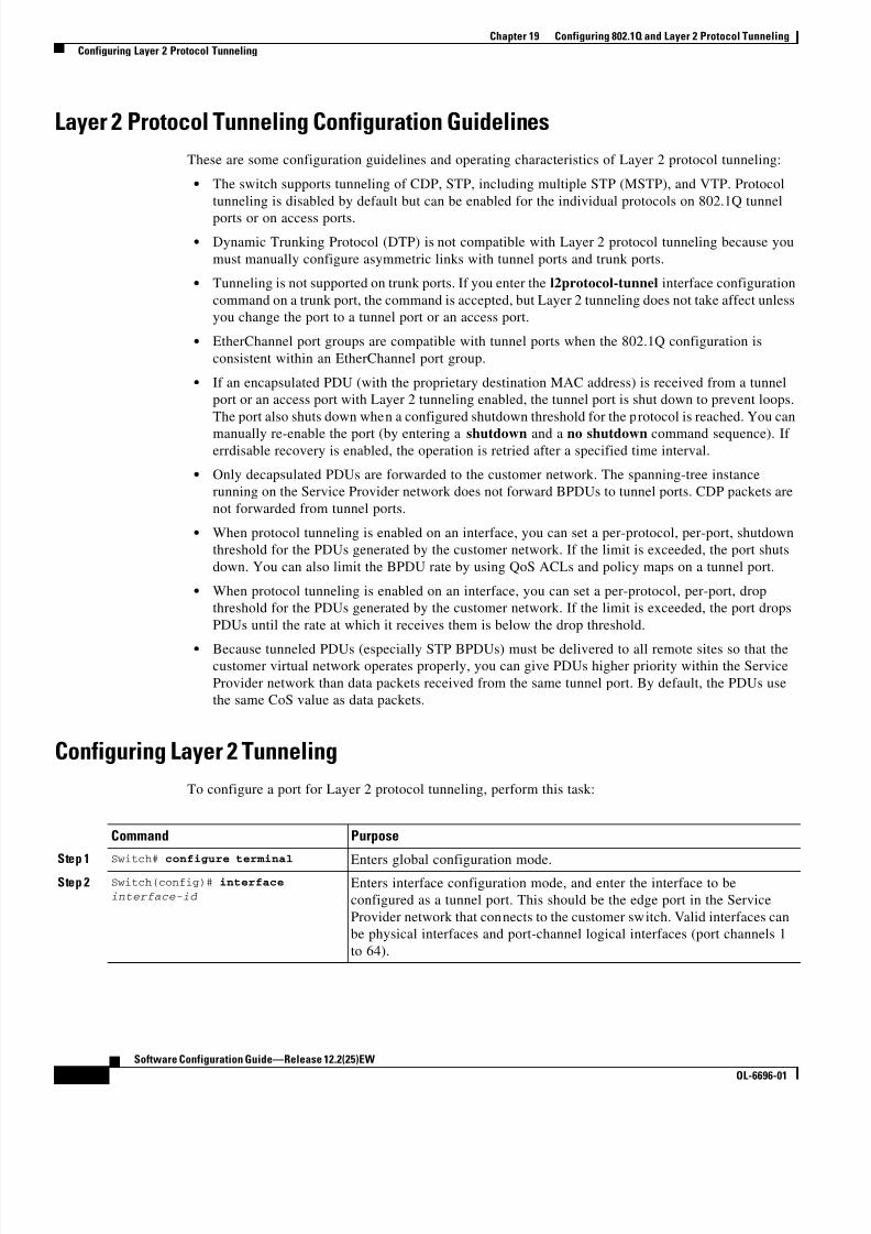
8/10/2019 Cisco ConfiguratioGuide SW4500 IOS
http://slidepdf.com/reader/full/cisco-configuratioguide-sw4500-ios 296/607
19-10
Software Configuration Guide—Release 12.2(25)EW
OL-6696-01
Chapter 19 Configuring 802.1Q and Layer 2 Protocol Tunneling
Configuring Layer 2 Protocol Tunneling
Layer 2 Protocol Tunneling Configuration Guidelines
These are some configuration guidelines and operating characteristics of Layer 2 protocol tunneling:
• The switch supports tunneling of CDP, STP, including multiple STP (MSTP), and VTP. Protocol
tunneling is disabled by default but can be enabled for the individual protocols on 802.1Q tunnel
ports or on access ports.
• Dynamic Trunking Protocol (DTP) is not compatible with Layer 2 protocol tunneling because you
must manually configure asymmetric links with tunnel ports and trunk ports.
• Tunneling is not supported on trunk ports. If you enter the l2protocol-tunnel interface configuration
command on a trunk port, the command is accepted, but Layer 2 tunneling does not take affect unless
you change the port to a tunnel port or an access port.
• EtherChannel port groups are compatible with tunnel ports when the 802.1Q configuration is
consistent within an EtherChannel port group.
• If an encapsulated PDU (with the proprietary destination MAC address) is received from a tunnel
port or an access port with Layer 2 tunneling enabled, the tunnel port is shut down to prevent loops.
The port also shuts down when a configured shutdown threshold for the protocol is reached. You can
manually re-enable the port (by entering a shutdown and a no shutdown command sequence). Iferrdisable recovery is enabled, the operation is retried after a specified time interval.
• Only decapsulated PDUs are forwarded to the customer network. The spanning-tree instance
running on the Service Provider network does not forward BPDUs to tunnel ports. CDP packets are
not forwarded from tunnel ports.
• When protocol tunneling is enabled on an interface, you can set a per-protocol, per-port, shutdown
threshold for the PDUs generated by the customer network. If the limit is exceeded, the port shuts
down. You can also limit the BPDU rate by using QoS ACLs and policy maps on a tunnel port.
• When protocol tunneling is enabled on an interface, you can set a per-protocol, per-port, drop
threshold for the PDUs generated by the customer network. If the limit is exceeded, the port drops
PDUs until the rate at which it receives them is below the drop threshold.
• Because tunneled PDUs (especially STP BPDUs) must be delivered to all remote sites so that thecustomer virtual network operates properly, you can give PDUs higher priority within the Service
Provider network than data packets received from the same tunnel port. By default, the PDUs use
the same CoS value as data packets.
Configuring Layer 2 Tunneling
To configure a port for Layer 2 protocol tunneling, perform this task:
Command Purpose
Step 1Switch# configure terminal
Enters global configuration mode.Step 2 Switch(config)# interface
interface-id Enters interface configuration mode, and enter the interface to be
configured as a tunnel port. This should be the edge port in the Service
Provider network that connects to the customer switch. Valid interfaces can
be physical interfaces and port-channel logical interfaces (port channels 1
to 64).

8/10/2019 Cisco ConfiguratioGuide SW4500 IOS
http://slidepdf.com/reader/full/cisco-configuratioguide-sw4500-ios 297/607
19-11
Software Configuration Guide—Release 12.2(25)EW
OL-6696-01
Chapter 19 Configuring 802.1Q and Layer 2 Protocol Tunneling
Configuring Layer 2 Protocol Tunneling
Use the no l2protocol-tunnel [cdp | stp | vtp] interface configuration command to disable protocol
tunneling for one of the Layer 2 protocols or for all three. Use the no l2protocol-tunnel
shutdown-threshold [cdp | stp | vtp] and the no l2protocol-tunnel drop-threshold [cdp | stp | vtp]commands to return the shutdown and drop thresholds to the default settings.
This example shows how to configure Layer 2 protocol tunneling for CDP, STP, and VTP and how to
verify the configuration.
Switch(config)# interface FastEthernet2/1
Switch(config-if)# l2protocol-tunnel cdp
Switch(config-if)# l2protocol-tunnel stp
Switch(config-if)# l2protocol-tunnel vtp
Step 3 Switch(config-if)# switchport
mode accessor
switchport mode dot1q-tunnel
Configures the interface as an access port or as an 802.1Q tunnel port.
Step 4 Switch(config-if)#l2protocol-tunnel [cdp | stp |
vtp]
Enables protocol tunneling for the desired protocol. If no keyword isentered, tunneling is enabled for all three Layer 2 protocols.
Step 5 Switch(config-if)#
l2protocol-tunnelshutdown-threshold [cdp | stp |
vtp] value
(Optional) Configures the threshold for packets-per-second accepted for
encapsulation. The interface is disabled if the configured threshold is
exceeded. If no protocol option is specified, the threshold applies to each of
the tunneled Layer 2 protocol types. The range is 1 to 4096. The default is
to have no threshold configured.
Note If you also set a drop threshold on this interface, the
shutdown-threshold value must be greater than or equal to the
drop-threshold value.
Step 6 Switch(config-if)#l2protocol-tunnel drop-threshold
[cdp | stp | vtp] value
(Optional) Configures the threshold for packets-per-second accepted for
encapsulation. The interface drops packets if the configured threshold isexceeded. If no protocol option is specified, the threshold applies to each of
the tunneled Layer 2 protocol types. The range is 1 to 4096. The default is
to have no threshold configured.
Note If you also set a shutdown threshold on this interface, the
drop-threshold value must be less than or equal to the
shutdown-threshold value.
Step 7 Switch(config-if)# exit Returns to global configuration mode.
Step 8 Switch(config)# errdisable
recovery cause l2ptguard(Optional) Configures the recovery mechanism from a Layer 2
maximum-rate error so that the interface is re-enabled and can try again.
Errdisable recovery is disabled by default; when enabled, the default time
interval is 300 seconds.
Step 9 Switch(config)# l2protocol-tunnel
cos value (Optional) Configures the CoS value for all tunneled Layer 2 PDUs. The
range is 0 to 7; the default is the default CoS value for the interface. If none
is configured, the default is 5.
Step 10 Switch(config)# end Returns to privileged EXEC mode.
Step 11 Switch# show l2protocol Displays the Layer 2 tunnel ports on the switch, including the protocols
configured, the thresholds, and the counters.
Step 12 Switch# copy running-config
startup-config(Optional) Saves your entries in the configuration file.
Command Purpose
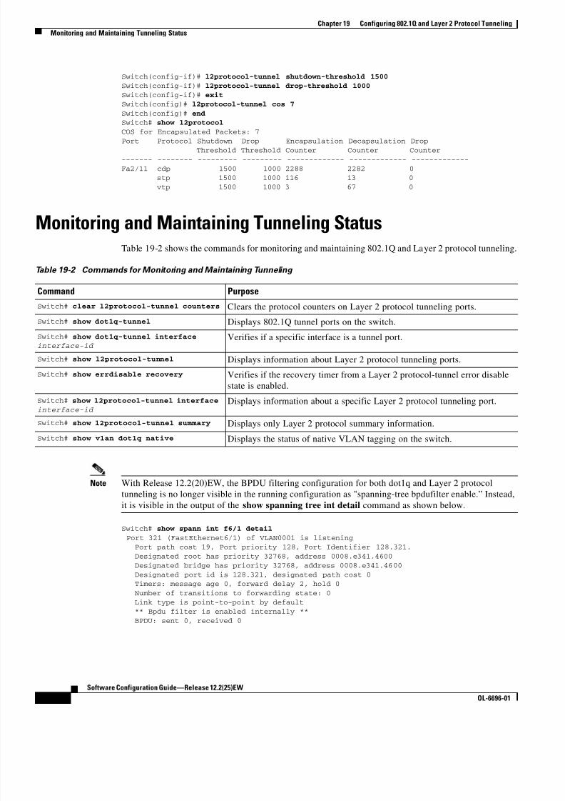
8/10/2019 Cisco ConfiguratioGuide SW4500 IOS
http://slidepdf.com/reader/full/cisco-configuratioguide-sw4500-ios 298/607
19-12
Software Configuration Guide—Release 12.2(25)EW
OL-6696-01
Chapter 19 Configuring 802.1Q and Layer 2 Protocol Tunneling
Monitoring and Maintaining Tunneling Status
Switch(config-if)# l2protocol-tunnel shutdown-threshold 1500
Switch(config-if)# l2protocol-tunnel drop-threshold 1000
Switch(config-if)# exitSwitch(config)# l2protocol-tunnel cos 7
Switch(config)# endSwitch# show l2protocol
COS for Encapsulated Packets: 7
Port Protocol Shutdown Drop Encapsulation Decapsulation Drop Threshold Threshold Counter Counter Counter------- -------- --------- --------- ------------- ------------- -------------
Fa2/11 cdp 1500 1000 2288 2282 0 stp 1500 1000 116 13 0
vtp 1500 1000 3 67 0
Monitoring and Maintaining Tunneling StatusTable 19-2 shows the commands for monitoring and maintaining 802.1Q and Layer 2 protocol tunneling.
Note With Release 12.2(20)EW, the BPDU filtering configuration for both dot1q and Layer 2 protocol
tunneling is no longer visible in the running configuration as "spanning-tree bpdufilter enable.” Instead,
it is visible in the output of the show spanning tree int detail command as shown below.
Switch# show spann int f6/1 detail
Port 321 (FastEthernet6/1) of VLAN0001 is listening Port path cost 19, Port priority 128, Port Identifier 128.321.
Designated root has priority 32768, address 0008.e341.4600
Designated bridge has priority 32768, address 0008.e341.4600
Designated port id is 128.321, designated path cost 0 Timers: message age 0, forward delay 2, hold 0
Number of transitions to forwarding state: 0 Link type is point-to-point by default
** Bpdu filter is enabled internally **
BPDU: sent 0, received 0
Table 19-2 Commands for Monitoring and Maintaining Tunneling
Command Purpose
Switch# clear l2protocol-tunnel counters Clears the protocol counters on Layer 2 protocol tunneling ports.
Switch# show dot1q-tunnel Displays 802.1Q tunnel ports on the switch.
Switch# show dot1q-tunnel interfaceinterface-id
Verifies if a specific interface is a tunnel port.
Switch# show l2protocol-tunnel Displays information about Layer 2 protocol tunneling ports.
Switch# show errdisable recovery Verifies if the recovery timer from a Layer 2 protocol-tunnel error disable
state is enabled.
Switch# show l2protocol-tunnel interface interface-id
Displays information about a specific Layer 2 protocol tunneling port.
Switch# show l2protocol-tunnel summary Displays only Layer 2 protocol summary information.
Switch# show vlan dot1q native Displays the status of native VLAN tagging on the switch.

8/10/2019 Cisco ConfiguratioGuide SW4500 IOS
http://slidepdf.com/reader/full/cisco-configuratioguide-sw4500-ios 299/607
C H A P T E R
20-1
Software Configuration Guide—Release 12.2(25)EW
OL-6696-01
20
Understanding and Configuring CDP
This chapter describes how to configure Cisco Discovery Protocol (CDP) on the Catalyst 4500 series
switch. It also provides guidelines, procedures, and configuration examples.
This chapter includes the following major sections:
• Overview of CDP, page 20-1
• Configuring CDP, page 20-2
Note For complete syntax and usage information for the commands used in this chapter, refer to the
Cisco IOS Configuration Fundamentals Configuration Guide, Release 12.2;
Cisco IOS System Management ; Configuring Cisco Discovery Protocol (CDP) at this URL:
http://www.cisco.com/univercd/cc/td/doc/product/software/ios122/122cgcr/fun_c/fcprt3/fcd301c.htm
and to the Cisco IOS Configuration Fundamentals Command Reference, Release 12.1;
Cisco IOS System Management Commands; and CDP Commands publication at this URL:
http://www.cisco.com/univercd/cc/td/doc/product/software/ios122/122cgcr/fun_r/frprt3/frd3001b.htm
Note For complete syntax and usage information for the switch commands used in this chapter, refer to the
Catalyst 4500 Series Switch Cisco IOS Command Reference and related publications at
http://www.cisco.com/univercd/cc/td/doc/product/software/ios122/122cgcr/index.htm.
Overview of CDPCDP is a protocol that runs over Layer 2 (the data link layer) on all Cisco routers, bridges, access servers,
and switches. CDP allows network management applications to discover Cisco devices that are
neighbors of already known devices, in particular, neighbors running lower-layer, transparent
protocols.With CDP, network management applications can learn the device type and the SNMP agent
address of neighboring devices. CDP enables applications to send SNMP queries to neighboring devicesCDP runs on all LAN and WAN media that support Subnetwork Access Protocol (SNAP).
Each CDP-configured device sends periodic messages to a multicast address. Each device advertises at
least one address at which it can receive SNMP messages. The advertisements also contain the
time-to-live, or holdtime information, which indicates the length of time a receiving device should hold
CDP information before discarding it.

8/10/2019 Cisco ConfiguratioGuide SW4500 IOS
http://slidepdf.com/reader/full/cisco-configuratioguide-sw4500-ios 300/607
20-2
Software Configuration Guide—Release 12.2(25)EW
OL-6696-01
Chapter 20 Understanding and Configuring CDP
Configuring CDP
Configuring CDPThe following sections describe how to configure CDP:
• Enabling CDP Globally, page 20-2
• Displaying the CDP Global Configuration, page 20-2• Enabling CDP on an Interface, page 20-3
• Displaying the CDP Interface Configuration, page 20-3
• Monitoring and Maintaining CDP, page 20-3
Enabling CDP Globally
To enable CDP globally, perform this task:
This example shows how to enable CDP globally:
Switch(config)# cdp run
Displaying the CDP Global Configuration
To display the CDP configuration, perform this task:
This example shows how to display the CDP configuration:
Switch# show cdp
Global CDP information: Sending CDP packets every 120 seconds
Sending a holdtime value of 180 seconds
Sending CDPv2 advertisements is enabled
Switch#
For additional CDP show commands, see the “Monitoring and Maintaining CDP” section on page 20-3.
Command Purpose
Switch(config)# [no] cdp run Enables CDP globally.
Use the no keyword to disable CDP globally.
Command Purpose
Switch# show cdp Displays global CDP information.

8/10/2019 Cisco ConfiguratioGuide SW4500 IOS
http://slidepdf.com/reader/full/cisco-configuratioguide-sw4500-ios 301/607
20-3
Software Configuration Guide—Release 12.2(25)EW
OL-6696-01
Chapter 20 Understanding and Configuring CDP
Configuring CDP
Enabling CDP on an Interface
To enable CDP on an interface, perform this task:
This example shows how to enable CDP on Fast Ethernet interface 5/1:
Switch(config)# interface fastethernet 5/1
Switch(config-if)# cdp enable
This example shows how to disable CDP on Fast Ethernet interface 5/1:
Switch(config)# interface fastethernet 5/1Switch(config-if)# no cdp enable
Displaying the CDP Interface Configuration
To display the CDP configuration for an interface, perform this task:
This example shows how to display the CDP configuration of Fast Ethernet interface 5/1:
Switch# show cdp interface fastethernet 5/1FastEthernet5/1 is up, line protocol is up
Encapsulation ARPA Sending CDP packets every 120 seconds
Holdtime is 180 secondsSwitch#
Monitoring and Maintaining CDP
To monitor and maintain CDP on your device, perform one or more of these tasks:
Command Purpose
Switch(config-if)# [no] cdp enable Enables CDP on an interface.
Use the no keyword to disable CDP on an interface.
Command Purpose
Switch# show cdp interface [type /number ] Displays information about interfaces where CDP is
enabled.
Command Purpose
Switch# clear cdp counters Resets the traffic counters to zero.
Switch# clear cdp table Deletes the CDP table of information about neighbors.
Switch# show cdp Displays global information such as frequency of
transmissions and the holdtime for packets being
transmitted.

8/10/2019 Cisco ConfiguratioGuide SW4500 IOS
http://slidepdf.com/reader/full/cisco-configuratioguide-sw4500-ios 302/607
20-4
Software Configuration Guide—Release 12.2(25)EW
OL-6696-01
Chapter 20 Understanding and Configuring CDP
Configuring CDP
This example shows how to clear the CDP counter configuration on your switch:
Switch# clear cdp counters
This example shows how to display information about the neighboring equipment:
Switch# show cdp neighbors
Capability Codes: R - Router, T - Trans Bridge, B - Source Route Bridge
S - Switch, H - Host, I - IGMP, r - Repeater
Device ID Local Intrfce Holdtme Capability Platform Port ID
JAB023807H1 Fas 5/3 127 T S WS-C2948 2/46
JAB023807H1 Fas 5/2 127 T S WS-C2948 2/45
JAB023807H1 Fas 5/1 127 T S WS-C2948 2/44JAB023807H1 Gig 1/2 122 T S WS-C2948 2/50
JAB023807H1 Gig 1/1 122 T S WS-C2948 2/49
JAB03130104 Fas 5/8 167 T S WS-C4003 2/47
JAB03130104 Fas 5/9 152 T S WS-C4003 2/48
Switch# show cdp entry entry_name
[ protocol | version]Displays information about a specific neighbor. The
display can be limited to protocol or version
information.
Switch# show cdp interface
[type /number ]
Displays information about interfaces on which CDP is
enabled.
Switch# show cdp neighbors
[type /number ] [detail]Displays information about neighboring equipment.
The display can be limited to neighbors on a specific
interface and expanded to provide more detailed
information.
Switch# show cdp traffic Displays CDP counters, including the number of
packets sent and received and checksum errors.
Switch# show debugging Displays information about the types of debugging that
are enabled for your switch.
Command Purpose

8/10/2019 Cisco ConfiguratioGuide SW4500 IOS
http://slidepdf.com/reader/full/cisco-configuratioguide-sw4500-ios 303/607
C H A P T E R
21-1
Software Configuration Guide—Release 12.2(25)EW
OL-6696-01
21
Configuring UDLD
This chapter describes how to configure the UniDirectional Link Detection (UDLD) and Unidirectional
Ethernet on the Catalyst 4500 series switch. It also provides guidelines, procedures, and configuration
examples.
This chapter includes the following major sections:
• Overview of UDLD, page 21-1
• Default UDLD Configuration, page 21-2
• Configuring UDLD on the Switch, page 21-2
Note For complete syntax and usage information for the switch commands used in this chapter, refer to the
Catalyst 4500 Series Switch Cisco IOS Command Reference and related publications at
http://www.cisco.com/univercd/cc/td/doc/product/software/ios122/122cgcr/index.htm.
Overview of UDLDUDLD allows devices connected through fiber-optic or copper Ethernet cables (for example, Category 5
cabling) to monitor the physical configuration of the cables and detect when a unidirectional link exists.
A unidirectional link occurs whenever traffic transmitted by the local device over a link is received by
the neighbor but traffic transmitted from the neighbor is not received by the local device. When a
unidirectional link is detected, UDLD shuts down the affected interface and alerts the user.
Unidirectional links can cause a variety of problems, including spanning tree topology loops.
UDLD is a Layer 2 protocol that works with the Layer 1 mechanisms to determine the physical status of
a link. At Layer 1, autonegotiation takes care of physical signaling and fault detection. UDLD performs
tasks that autonegotiation cannot perform, such as detecting the identities of neighbors and shutting
down misconnected interfaces. When you enable both autonegotiation and UDLD, Layer 1 and Layer 2
detections work together to prevent physical and logical unidirectional connections and the
malfunctioning of other protocols.If one of the fiber strands in a pair is disconnected, as long as autonegotiation is active, the link does not
stay up. In this case, the logical link is undetermined, and UDLD does not take any action. If both fibers
are working normally from a Layer 1 perspective, then UDLD at Layer 2 determines whether or not those
fibers are connected correctly and whether or not traffic is flowing bidirectionally between the right
neighbors. This check cannot be performed by autonegotiation because autonegotiation operates at
Layer 1.

8/10/2019 Cisco ConfiguratioGuide SW4500 IOS
http://slidepdf.com/reader/full/cisco-configuratioguide-sw4500-ios 304/607
21-2
Software Configuration Guide—Release 12.2(25)EW
OL-6696-01
Chapter 21 Configuring UDLD
Default UDLD Configuration
The switch periodically transmits UDLD packets to neighbor devices on interfaces with UDLD enabled.
If the packets are echoed back within a specific time frame and they are lacking a specific
acknowledgment (echo), the link is flagged as unidirectional and the interface is shut down. Devices on
both ends of the link must support UDLD in order for the protocol to successfully identify and disable
unidirectional links.
Note By default, UDLD is locally disabled on copper interfaces to avoid sending unnecessary control traffic
on this type of media, since it is often used for access interfaces.
Figure 21-1 shows an example of a unidirectional link condition. Switch B successfully receives traffic
from Switch A on the interface. However, Switch A does not receive traffic from Switch B on the same
interface. UDLD detects the problem and disables the interface.
Figure 21-1 Unidirectional Link
Default UDLD ConfigurationTable 21-1 shows the UDLD default configuration.
Configuring UDLD on the SwitchThe following sections describe how to configure UDLD:
• Enabling UDLD Globally, page 21-3
• Enabling UDLD on Individual Interfaces, page 21-3
• Disabling UDLD on Nonfiber-Optic Interfaces, page 21-3
• Disabling UDLD on Fiber-Optic Interfaces, page 21-4
• Resetting Disabled Interfaces, page 21-4
TX
TX
RX
RX
Switch A
Switch B
1 8 7 2 0
Table 21-1 UDLD Default Configuration
Feature Default Status
UDLD global enable state Globally disabled
UDLD per-interface enable state for fiber-optic media Enabled on all Ethernet fiber-optic interfaces
UDLD per-interface enable state for twisted-pair (copper) media Disabled on all Ethernet 10/100 and 1000BaseTX
interfaces

8/10/2019 Cisco ConfiguratioGuide SW4500 IOS
http://slidepdf.com/reader/full/cisco-configuratioguide-sw4500-ios 305/607
21-3
Software Configuration Guide—Release 12.2(25)EW
OL-6696-01
Chapter 21 Configuring UDLD
Configuring UDLD on the Switch
Enabling UDLD Globally
To enable UDLD globally on all fiber-optic interfaces on the switch, perform this task:
Enabling UDLD on Individual Interfaces
To enable UDLD on individual interfaces, perform this task:
Disabling UDLD on Nonfiber-Optic Interfaces
To disable UDLD on individual nonfiber-optic interfaces, perform this task:
Command Purpose
Switch(config)# [no] udld enable Enables UDLD globally on fiber-optic interfaces on the
switch.
Use the no keyword to globally disable UDLD on fiber-optic
interfaces.
Note This command configures only fiber-optic interfaces.
An individual interface configuration overrides the
setting of this command.
Command Purpose
Step 1 Switch(config-if)# udld enable Enables UDLD on a specific interface. On a fiber-optic
interface, this command overrides the udld enable global
configuration command setting.
Step 2 Switch# show udld interface Verifies the configuration.
Command Purpose
Step 1 Switch(config-if)# no udld enable Disables UDLD on a nonfiber-optic interface.
Note On fiber-optic interfaces, the no udld enable
command reverts the interface configuration to
the udld enable global configuration command
setting.
Step 2 Switch# show udld interface Verifies the configuration.

8/10/2019 Cisco ConfiguratioGuide SW4500 IOS
http://slidepdf.com/reader/full/cisco-configuratioguide-sw4500-ios 306/607
21-4
Software Configuration Guide—Release 12.2(25)EW
OL-6696-01
Chapter 21 Configuring UDLD
Configuring UDLD on the Switch
Disabling UDLD on Fiber-Optic Interfaces
To disable UDLD on individual fiber-optic interfaces, perform this task:
Resetting Disabled Interfaces
To reset all interfaces that have been shut down by UDLD, perform this task:
Command Purpose
Step 1 Switch(config-if)# udld disable Disables UDLD on a fiber-optic interface.
Note This command is not supported on nonfiber-optic
interfaces.
Use the no keyword to revert to the udld enable global
configuration command setting.
Step 2 Switch# show udld interface Verifies the configuration.
Command Purpose
Switch# udld reset Resets all interfaces that have been shut down by UDLD.

8/10/2019 Cisco ConfiguratioGuide SW4500 IOS
http://slidepdf.com/reader/full/cisco-configuratioguide-sw4500-ios 307/607
C H A P T E R
22-1
Software Configuration Guide—Release 12.2(25)EW
OL-6696-01
22
Configuring Unidirectional Ethernet
This chapter describes how to configure Unidirectional Ethernet on the Catalyst 4500 series switch and
contains these sections:
• Overview of Unidirectional Ethernet, page 22-1
• Configuring Unidirectional Ethernet, page 22-1
Note For complete syntax and usage information for the switch commands used in this chapter, refer to the
Catalyst 4500 Series Switch Cisco IOS Command Reference and related publications at
http://www.cisco.com/univercd/cc/td/doc/product/software/ios122/122cgcr/index.htm.
Overview of Unidirectional EthernetYou can set non-blocking GigaPorts to unidirectionally transmit or receive traffic. Unidirectional
Ethernet uses only one strand of fiber for either transmitting or receiving one-way traffic for the
GigaPort, instead of two strands of fiber for a full-duplex GigaPort Ethernet. Configuring your GigaPorts
either to transmit or receive traffic effectively doubles the amount of traffic capabilities for applications,
such as video streaming, where most traffic is sent as unacknowledged unidirectional video broadcast
streams.
Configuring Unidirectional Ethernet
Note You must configure Unidirectional Ethernet on the non-blocking GigaPort, which will automatically
disable UDLD on the port.

8/10/2019 Cisco ConfiguratioGuide SW4500 IOS
http://slidepdf.com/reader/full/cisco-configuratioguide-sw4500-ios 308/607
22-2
Software Configuration Guide—Release 12.2(25)EW
OL-6696-01
Chapter 22 Configuring Unidirectional Ethernet
Configuring Unidirectional Ethernet
To enable Unidirectional Ethernet, perform this task:
This example shows how to set Gigabit Ethernet interface 1/1 to unidirectionally send traffic:
Switch# configure terminal Enter configuration commands, one per line. End with CNTL/Z.
Switch(config)# interface gigabitethernet 1/1 Switch(config-if)# unidirectional send-only
Switch(config-if)# end
Warning!
Enable l2 port unidirectional mode will automatically disable port udld.
You must manually ensure that the unidirectional link does not create
a spanning tree loop in the network.
Enable l3 port unidirectional mode will automatically disable ip routing
on the port. You must manually configure static ip route and arp entry
in order to route ip traffic.
This example shows how to set Gigabit Ethernet interface 1/1 to receive traffic unidirectionally:
Switch# configure terminal
Enter configuration commands, one per line. End with CNTL/Z.
Switch(config)# interface gigabitethernet 1/1
Switch(config-if)# unidrectional receive-onlySwitch(config-if)# end
Warning!
Enable l2 port unidirectional mode will automatically disable port udld.
You must manually ensure that the unidirectional link does not createa spanning tree loop in the network.
Enable l3 port unidirectional mode will automatically disable ip routing
on the port. You must manually configure static ip route and arp entryin order to route ip traffic.
This example shows how to verify the configuration
Switch>show interface gigabitethernet 1/1 unidirectional show interface gigabitethernet 1/1 unidirectional
Unidirectional configuration mode: send only CDP neighbour unidirectional configuration mode: receive only
Command Purpose
Step 1 Switch(config)# interface { vlan vlan_ID |{fastethernet | gigabitethernet |
tengigabitethernet} slot/interface | Port-channelnumber }
Selects the interface to configure.
Step 2 Switch(config-if)# [no] unidirectional {send-only
| receive-only}Enables Unidirectional Ethernet.
Use the no keyword to disable Unidirectional Ethernet.
Step 3 Switch(config-if)# end Exits configuration mode.
Step 4 Switch# show interface { vlan vlan_ID |
{fastethernet | gigabitethernet |
tengigabitethernet} slot/interface } unidirectional
Verifies the configuration.

8/10/2019 Cisco ConfiguratioGuide SW4500 IOS
http://slidepdf.com/reader/full/cisco-configuratioguide-sw4500-ios 309/607
22-3
Software Configuration Guide—Release 12.2(25)EW
OL-6696-01
Chapter 22 Configuring Unidirectional Ethernet
Configuring Unidirectional Ethernet
This example shows how to disable Unidirectional Ethernet on Gigabit Ethernet interface 1/1:
Switch# configure terminal Enter configuration commands, one per line. End with CNTL/Z.
Switch(config)# interface gigabitethernet 1/1 Switch(config-if)# no unidirectional
Switch(config-if)# end
This example shows the result of issuing the show interface command for a port that does not support
Unidirectional Ethernet:
Switch#show interface f6/1 unidirectionalUnidirectional Ethernet is not supported on FastEthernet6/1

8/10/2019 Cisco ConfiguratioGuide SW4500 IOS
http://slidepdf.com/reader/full/cisco-configuratioguide-sw4500-ios 310/607
22-4
Software Configuration Guide—Release 12.2(25)EW
OL-6696-01
Chapter 22 Configuring Unidirectional Ethernet
Configuring Unidirectional Ethernet

8/10/2019 Cisco ConfiguratioGuide SW4500 IOS
http://slidepdf.com/reader/full/cisco-configuratioguide-sw4500-ios 311/607
C H A P T E R
23-1
Software Configuration Guide—Release 12.2(25)EW
OL-6696-01
23
Configuring Layer 3 Interfaces
This chapter describes the Layer 3 interfaces on a Catalyst 4500 series switch. It also provides
guidelines, procedures, and configuration examples.
This chapter includes the following major sections:
• Overview of Layer 3 Interfaces, page 23-1
• Configuration Guidelines, page 23-3
• Configuring Logical Layer 3 VLAN Interfaces, page 23-3
• Configuring Physical Layer 3 Interfaces, page 23-4
Note For complete syntax and usage information for the switch commands used in this chapter, refer to the
Catalyst 4500 Series Switch Cisco IOS Command Reference and related publications at
http://www.cisco.com/univercd/cc/td/doc/product/software/ios122/122cgcr/index.htm.
Overview of Layer 3 InterfacesThis section contains the following subsections:
• Logical Layer 3 VLAN Interfaces, page 23-2
• Physical Layer 3 Interfaces, page 23-2
The Catalyst 4500 series switch supports Layer 3 interfaces with the Cisco IOS IP and IP routing
protocols. Layer 3, the network layer, is primarily responsible for the routing of data in packets across
logical internetwork paths.
Layer 2, the data link layer, contains the protocols that control the physical layer (Layer 1) and how data
is framed before being transmitted on the medium. The Layer 2 function of filtering and forwarding data
in frames between two segments on a LAN is known as bridging.
The Catalyst 4500 series switch supports two types of Layer 3 interfaces. The logical Layer 3 VLANinterfaces integrate the functions of routing and bridging. The physical Layer 3 interfaces allow the
Catalyst 4500 series switch to be configured like a traditional router.

8/10/2019 Cisco ConfiguratioGuide SW4500 IOS
http://slidepdf.com/reader/full/cisco-configuratioguide-sw4500-ios 312/607
23-2
Software Configuration Guide—Release 12.2(25)EW
OL-6696-01
Chapter 23 Configuring Layer 3 Interfaces
Overview of Layer 3 Interfaces
Logical Layer 3 VLAN Interfaces
The logical Layer 3 VLAN interfaces provide logical routing interfaces to VLANs on Layer 2 switches.
A traditional network requires a physical interface from a router to a switch to perform inter-VLAN
routing. The Catalyst 4500 series switch supports inter-VLAN routing by integrating the routing and
bridging functions on a single Catalyst 4500 series switch.Figure 23-1 shows how the routing and bridging functions in the three physical devices of the traditional
network are performed logically on one Catalyst 4500 series switch.
Figure 23-1 Logical Layer 3 VLAN Interfaces for the Catalyst 4500 Series Switch
Physical Layer 3 Interfaces
The physical Layer 3 interfaces support capabilities equivalent to a traditional router. These Layer 3
interfaces provide hosts with physical routing interfaces to a Catalyst 4500 series switch.
Figure 23-2 shows how the Catalyst 4500 series switch functions as a traditional router.
Figure 23-2 Physical Layer 3 Interfaces for the Catalyst 4500 Series Switch
L2 Switch L2 Switch
Router
Host 1 Host 2
Traditional network topology for routingbetween VLANS
Host 1 Host 2
Logical Inter-VLAN routing on a singleCatalyst 4500 series switch
Routing
VLAN1 VLAN2
VLAN1 VLAN2
9 4 1 6 9
Interface Ethernet1.1.1.1
Interface VLAN11.1.1.1
Interface VLAN22.1.1.1
Interface Ethernet2.1.1.1
Router
Host 1 Host 2
Physical Inter-VLAN Routing on a Catalyst 4500 series switch
Interface Ethernet1.1.1.1
Interface Ethernet2.1.1.1
9 4 1 6 8
2/1 2/2

8/10/2019 Cisco ConfiguratioGuide SW4500 IOS
http://slidepdf.com/reader/full/cisco-configuratioguide-sw4500-ios 313/607
23-3
Software Configuration Guide—Release 12.2(25)EW
OL-6696-01
Chapter 23 Configuring Layer 3 Interfaces
Configuration Guidelines
Configuration GuidelinesA Catalyst 4500 series switch supports AppleTalk routing and IPX routing. For AppleTalk routing and
IPX routing information, refer to “Configuring AppleTalk” and “Configuring Novell IPX” in the
Cisco IOS AppleTalk and Novell IPX Configuration Guide at the following URL:
http://www.cisco.com/univercd/cc/td/doc/product/software/ios122/122cgcr/atipx_c/index.htm
A Catalyst 4500 series switch does not support subinterfaces or the encapsulation keyword on Layer 3
Fast Ethernet or Gigabit Ethernet interfaces.
Configuring Logical Layer 3 VLAN Interfaces
Note Before you can configure logical Layer 3 VLAN interfaces, you must create and configure the VLANs
on the switch, assign VLAN membership to the Layer 2 interfaces, enable IP routing if IP routing is
disabled, and specify an IP routing protocol.
To configure logical Layer 3 VLAN interfaces, perform this task:
This example shows how to configure the logical Layer 3 VLAN interface vlan 2 and assign an IP
address:
Switch> enable
Switch# config term Enter configuration commands, one per line. End with CNTL/Z.
Switch(config)# vlan 2Switch(config)# interface vlan 2
Switch(config-if)# ip address 10.1.1.1 255.255.255.248
Switch(config-if)# no shutdown
Switch(config-if)# end
Command Purpose
Step 1 Switch(config)# vlan vlan_ID Creates the VLAN.
Step 2 Switch(config)# interface vlan vlan_ID Selects an interface to configure.
Step 3 Switch(config-if)# ip address ip_address subnet_mask Configures the IP address and IP subnet.
Step 4 Switch(config-if)# no shutdown Enables the interface.
Step 5 Switch(config-if)# end Exits configuration mode.
Step 6 Switch# copy running-config startup-config
Saves your configuration changes to NVRAM.Step 7 Switch# show interfaces [type slot/interface ]
Switch# show ip interfaces [type slot/interface ]
Switch# show running-config interfaces [type
slot/interface ]Switch# show running-config interfaces vlan vlan_ID
Verifies the configuration.

8/10/2019 Cisco ConfiguratioGuide SW4500 IOS
http://slidepdf.com/reader/full/cisco-configuratioguide-sw4500-ios 314/607
23-4
Software Configuration Guide—Release 12.2(25)EW
OL-6696-01
Chapter 23 Configuring Layer 3 Interfaces
Configuring Physical Layer 3 Interfaces
This example uses the show interfaces command to display the interface IP address configuration and
status of Layer 3 VLAN interface vlan 2:
Switch# show interfaces vlan 2
Vlan2 is up, line protocol is down
Hardware is Ethernet SVI, address is 00D.588F.B604 (bia 00D.588F.B604)
Internet address is 172.20.52.106/29
MTU 1500 bytes, BW 1000000 Kbit, DLY 10 usec, reliability 255/255, txload 1/255, rxload 1/255 Encapsulation ARPA, loopback not set
ARP type: ARPA, ARP Timeout 04:00:00
Last input never, output never, output hang never Last clearing of "show interface" counters never
Input queue: 0/75/0/0 (size/max/drops/flushes); Total output drops: 0
Queueing strategy: fifo
Output queue: 0/40 (size/max) 5 minute input rate 0 bits/sec, 0 packets/sec
5 minute output rate 0 bits/sec, 0 packets/sec 0 packets input, 0 bytes, 0 no buffer
Received 0 broadcasts, 0 runts, 0 giants, 0 throttles
0 input errors, 0 CRC, 0 frame, 0 overrun, 0 ignored
0 packets output, 0 bytes, 0 underruns
0 output errors, 0 interface resets 0 output buffer failures, 0 output buffers swapped outSwitch#
This example uses the show running-config command to display the interface IP address configuration
of Layer 3 VLAN interface vlan 2:
Switch# show running-config
Building configuration...
Current configuration : !
interface Vlan2
ip address 10.1.1.1 255.255.255.248
!
ip classlessno ip http server
!
!
line con 0line aux 0
line vty 0 4!
end
Configuring Physical Layer 3 Interfaces
Note Before you can configure physical Layer 3 interfaces, you must enable IP routing if IP routing isdisabled, and specify an IP routing protocol.
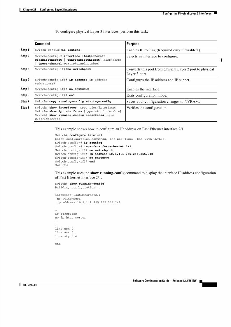
8/10/2019 Cisco ConfiguratioGuide SW4500 IOS
http://slidepdf.com/reader/full/cisco-configuratioguide-sw4500-ios 315/607
23-5
Software Configuration Guide—Release 12.2(25)EW
OL-6696-01
Chapter 23 Configuring Layer 3 Interfaces
Configuring Physical Layer 3 Interfaces
To configure physical Layer 3 interfaces, perform this task:
This example shows how to configure an IP address on Fast Ethernet interface 2/1:
Switch# configure terminal
Enter configuration commands, one per line. End with CNTL/Z.
Switch(config)# ip routing
Switch(config)# interface fastethernet 2/1Switch(config-if)# no switchport
Switch(config-if)# i p address 10.1.1.1 255.255.255.248
Switch(config-if)# no shutdown
Switch(config-if)# endSwitch#
This example uses the show running-config command to display the interface IP address configurationof Fast Ethernet interface 2/1:
Switch# show running-configBuilding configuration...
!
interface FastEthernet2/1
no switchport ip address 10.1.1.1 255.255.255.248
!…
ip classless
no ip http server
!!
line con 0line aux 0line vty 0 4
!end
Command Purpose
Step 1 Switch(config)#ip routing Enables IP routing (Required only if disabled.)
Step 2 Switch(config)# interface {fastethernet |gigabitethernet | tengigabitethernet} slot/ port}
| { port-channel port_channel_number }
Selects an interface to configure.
Step 3 Switch(config-if)#no switchport Converts this port from physical Layer 2 port to physical
Layer 3 port.
Step 4 Switch(config-if)# ip address ip_address
subnet_mask Configures the IP address and IP subnet.
Step 5 Switch(config-if)# no shutdown Enables the interface.
Step 6 Switch(config-if)# end Exits configuration mode.
Step 7 Switch# copy running-config startup-config Saves your configuration changes to NVRAM.
Step 8 Switch# show interfaces [type slot/interface ]Switch# show ip interfaces [type slot/interface ]
Switch# show running-config interfaces [typeslot/interface ]
Verifies the configuration.

8/10/2019 Cisco ConfiguratioGuide SW4500 IOS
http://slidepdf.com/reader/full/cisco-configuratioguide-sw4500-ios 316/607
23-6
Software Configuration Guide—Release 12.2(25)EW
OL-6696-01
Chapter 23 Configuring Layer 3 Interfaces
Configuring Physical Layer 3 Interfaces

8/10/2019 Cisco ConfiguratioGuide SW4500 IOS
http://slidepdf.com/reader/full/cisco-configuratioguide-sw4500-ios 317/607
C H A P T E R
24-1
Software Configuration Guide—Release 12.2(25)EW
OL-6696-01
24
Configuring Cisco Express Forwarding
This chapter describes Cisco Express Forwarding (CEF) on the Catalyst 4500 series switch. It also
provides guidelines, procedures, and examples to configure this feature.
This chapter includes the following major sections:
• Overview of CEF, page 24-1
• Catalyst 4500 Series Switch Implementation of CEF, page 24-3
• CEF Configuration Restrictions, page 24-6
• Configuring CEF, page 24-6
• Monitoring and Maintaining CEF, page 24-8
Note For complete syntax and usage information for the switch commands used in this chapter, refer to the
Catalyst 4500 Series Switch Cisco IOS Command Reference and related publications at
http://www.cisco.com/univercd/cc/td/doc/product/software/ios122/122cgcr/index.htm.
Overview of CEFThis section contains information on the two primary components that comprise the CEF operation:
• Benefits of CEF, page 24-1
• Forwarding Information Base, page 24-2
• Adjacency Tables, page 24-2
Benefits of CEF
CEF is advanced Layer 3 IP switching technology that optimizes performance and scalability for largenetworks with dynamic traffic patterns or networks with intensive web-based applications and
interactive sessions.

8/10/2019 Cisco ConfiguratioGuide SW4500 IOS
http://slidepdf.com/reader/full/cisco-configuratioguide-sw4500-ios 318/607
24-2
Software Configuration Guide—Release 12.2(25)EW
OL-6696-01
Chapter 24 Configuring Cisco Express Forwarding
Overview of CEF
CEF provides the following benefits:
• Improves performance over the caching schemes of multilayer switches, which often flush the entire
cache when information changes in the routing tables.
• Provides load balancing that distributes packets across multiple links based on Layer 3 routing
information. If a network device discovers multiple paths to a destination, the routing table is
updated with multiple entries for that destination. Traffic to that destination is then distributedamong the various paths.
CEF stores information in several data structures rather than the route cache of multilayer switches. The
data structures optimize lookup for efficient packet forwarding.
Forwarding Information Base
The Forwarding Information Base (FIB) is a table that contains a copy of the forwarding information in
the IP routing table. When routing or topology changes occur in the network, the route processor updates
the IP routing table and CEF updates the FIB. Because there is a one-to-one correlation between FIB
entries and routing table entries, the FIB contains all known routes and eliminates the need for route
cache maintenance that is associated with switching paths, such as fast switching and optimumswitching. CEF uses the FIB to make IP destination-based switching decisions and maintain next-hop
address information based on the information in the IP routing table.
On the Catalyst 4500 series switches, CEF loads the FIB in to the Integrated Switching Engine hardware
to increase the performance of forwarding. The Integrated Switching Engine has a finite number of
forwarding slots for storing routing information. If this limit is exceeded, CEF is automatically disabled
and all packets are forwarded in software. In this situation, you should reduce the number of routes on
the switch and then reenable hardware switching with the ip cef command.
Adjacency Tables
In addition to the FIB, CEF uses adjacency tables to prepend Layer 2 addressing information. Nodes inthe network are said to be adjacent if they are within a single hop from each other. The adjacency table
maintains Layer 2 next-hop addresses for all FIB entries.
Adjacency Discovery
The adjacency table is populated as new adjacent nodes are discovered. Each time an adjacency entry is
created (such as through the Address Resolution Protocol (ARP), a link-layer header for that adjacent
node is stored in the adjacency table. Once a route is determined, the link-layer header points to a next
hop and corresponding adjacency entry. The link-layer header is subsequently used for encapsulation
during CEF switching of packets.
Adjacency Resolution
A route might have several paths to a destination prefix, such as when a router is configured for
simultaneous load balancing and redundancy. For each resolved path, a pointer is added for the
adjacency corresponding to the next-hop interface for that path. This mechanism is used for load
balancing across several paths.

8/10/2019 Cisco ConfiguratioGuide SW4500 IOS
http://slidepdf.com/reader/full/cisco-configuratioguide-sw4500-ios 319/607
24-3
Software Configuration Guide—Release 12.2(25)EW
OL-6696-01
Chapter 24 Configuring Cisco Express Forwarding
Catalyst 4500 Series Switch Implementation of CEF
Adjacency Types That Require Special Handling
In addition to adjacencies for next-hop interfaces (host-route adjacencies), other types of adjacencies are
used to expedite switching when certain exception conditions exist. When the prefix is defined, prefixes
requiring exception processing are cached with one of the special adjacencies listed in Table 24-1.
Unresolved Adjacency
When a link-layer header is prepended to packets, FIB requires the prepend to point to an adjacency
corresponding to the next hop. If an adjacency was created by FIB and was not discovered through a
mechanism such as ARP, the Layer 2 addressing information is not known and the adjacency is
considered incomplete. When the Layer 2 information is known, the packet is forwarded to the route
processor, and the adjacency is determined through ARP.
Catalyst 4500 Series Switch Implementation of CEFThis section contains the following subsections:
• Hardware and Software Switching, page 24-4
• Load Balancing, page 24-6
• Software Interfaces, page 24-6
Catalyst 4500 series switches support an ASIC-based Integrated Switching Engine that provides these
features:
• Ethernet bridging at Layer 2
• IP routing at Layer 3
Because the ASIC is specifically designed to forward packets, the Integrated Switching Engine hardware
can run this process much faster than CPU subsystem software.
Figure 24-1 shows a high-level view of the ASIC-based Layer 2 and Layer 3 switching process on the
Integrated Switching Engine.
Table 24-1 Adjacency Types for Exception Processing
This adjacency type.. . Receives this processing...
Null adjacency Packets destined for a Null0 interface are dropped. A Null0 interface can
be used as an effective form of access filtering.
Glean adjacency When a router is connected directly to several hosts, the FIB table on the
router maintains a prefix for the subnet rather than for each individual
host. The subnet prefix points to a glean adjacency. When packets need
to be forwarded to a specific host, the adjacency database is gleaned for
the specific prefix.
Punt adjacency Features that require special handling or features that are not yet
supported by CEF switching are sent (punted) to the next higherswitching level.
Discard adjacency Packets are discarded.
Drop adjacency Packets are dropped.

8/10/2019 Cisco ConfiguratioGuide SW4500 IOS
http://slidepdf.com/reader/full/cisco-configuratioguide-sw4500-ios 320/607
24-4
Software Configuration Guide—Release 12.2(25)EW
OL-6696-01
Chapter 24 Configuring Cisco Express Forwarding
Catalyst 4500 Series Switch Implementation of CEF
Figure 24-1 Logical L2/L3 Switch Components
The Integrated Switching Engine performs inter-VLAN routing on logical Layer 3 interfaces with the
ASIC hardware. The ASIC hardware also supports a physical Layer 3 interface that can be configured
to connect with a host, a switch, or a router.
Hardware and Software Switching
For the majority of packets, the Integrated Switching Engine performs the packet forwarding function in
hardware. These packets are hardware-switched at very high rates. Exception packets are forwarded by
the CPU subsystem software. Statistic reports should show that the Integrated Switching Engine is
forwarding the vast majority of packets in hardware. Software forwarding is significantly slower than
hardware forwarding, but packets forwarded by the CPU subsystem do not reduce hardware forwarding
speed.
Figure 24-2 shows a logical view of the Integrated Switching Engine and the CPU subsystem switching
components.
Integrated Switching Engine (ASIC)
L3 physical
interface
Logical Router
L3 logicalinterfaces
L2 switchports
6 8
4 0 2
VLAN1
Gig 1/1
VLAN2

8/10/2019 Cisco ConfiguratioGuide SW4500 IOS
http://slidepdf.com/reader/full/cisco-configuratioguide-sw4500-ios 321/607
24-5
Software Configuration Guide—Release 12.2(25)EW
OL-6696-01
Chapter 24 Configuring Cisco Express Forwarding
Catalyst 4500 Series Switch Implementation of CEF
Figure 24-2 Hardware and Software Switching Components
The Integrated Switching Engine performs inter-VLAN routing in hardware. The CPU subsystem
software supports Layer 3 interfaces to VLANs that use Subnetwork Access Protocol (SNAP)
encapsulation. The CPU subsystem software also supports generic routing encapsulation (GRE) tunnel.
Hardware Switching
Hardware switching is the normal operation for the Supervisor Engine III and Supervisor Engine IV.
Software Switching
Software switching occurs when traffic cannot be processed in hardware. The following types ofexception packets are processed in software at a much slower rate:
• Packets that use IP header options
Note Packets that use TCP header options are switched in hardware because they do not affect the
forwarding decision.
• Packets that have an expiring IP time-to-live (TTL) counter
• Packets that are forwarded to a tunnel interface
• Packets that arrive with non-supported encapsulation types
• Packets that are routed to an interface with non-supported encapsulation types• Packets that exceed the MTU of an output interface and must be fragmented
• Packets that require an IGMP redirect to be routed
• 802.3 Ethernet packets
Integrated Switching Engine CPU Subsystem
GREtunnel
L3 physicalinterface
Router
L3 interfaces
L2 switchports
6 8 1 2 7
VLAN1
Gig 1/1
VLAN2GREtunnel

8/10/2019 Cisco ConfiguratioGuide SW4500 IOS
http://slidepdf.com/reader/full/cisco-configuratioguide-sw4500-ios 322/607
24-6
Software Configuration Guide—Release 12.2(25)EW
OL-6696-01
Chapter 24 Configuring Cisco Express Forwarding
CEF Configuration Restrictions
Load Balancing
The Catalyst 4500 series switch supports load balancing for routing packets in the Integrated Switching
Engine hardware. Load balancing is always enabled. It works when multiple routes for the same network
with different next-hop addresses are configured. These routes can be configured either statically or
through a routing protocol such as OSPF or EIGRP.The hardware makes a forwarding decision by using a hardware load sharing hash function to compute
a value, based on the source and destination IP addresses and the source and destination TCP port
numbers (if available). This load sharing hash value is then used to select which route to use to forward
the packet. All hardware switching within a particular flow (such as a TCP connection) will be routed to
the same next hop, thereby reducing the chance that packet reordering will occur. Up to eight different
routes for a particular network are supported.
Software Interfaces
Cisco IOS for the Catalyst 4500 series switch supports GRE and IP tunnel interfaces that are not part of
the hardware forwarding engine. All packets that flow to or from these interfaces must be processed insoftware and will have a significantly lower forwarding rate than that of hardware-switched interfaces.
Also, Layer 2 features are not supported on these interfaces.
CEF Configuration RestrictionsThe Integrated Switching Engine supports only ARPA and ISL/802.1q encapsulation types for Layer 3
switching in hardware. The CPU subsystem supports a number of encapsulations such as SNAP for
Layer 2 switching that you can use for Layer 3 switching in software.
Configuring CEFThese sections describe how to configure CEF:
• Enabling CEF, page 24-6
• Configuring Load Balancing for CEF, page 24-7
Enabling CEF
By default, CEF is enabled globally on the Catalyst 4500 series switch. No configuration is required.
To reenable CEF, perform this task:
Command Purpose
Switch(config)# ip cef Enables standard CEF operation.

8/10/2019 Cisco ConfiguratioGuide SW4500 IOS
http://slidepdf.com/reader/full/cisco-configuratioguide-sw4500-ios 323/607
24-7
Software Configuration Guide—Release 12.2(25)EW
OL-6696-01
Chapter 24 Configuring Cisco Express Forwarding
Configuring CEF
Configuring Load Balancing for CEF
CEF load balancing is based on a combination of source and destination packet information; it allows
you to optimize resources by dist ributing traffic over multiple paths for transferring data to a destination.
You can configure load balancing on a per-destination basis. Load-balancing decisions are made on the
outbound interface. You can configure per-destination load balancing for CEF on outbound interfaces.The following topics are discussed:
• Configuring Per-Destination Load Balancing, page 24-7
• Configuring Load Sharing Hash Function, page 24-7
• Viewing CEF Information, page 24-8
Configuring Per-Destination Load Balancing
Per-destination load balancing is enabled by default when you enable CEF. To use per-destination load
balancing, you do not perform any additional tasks once you enable CEF.
Per-destination load balancing allows the router to use multiple paths to achieve load sharing. Packetsfor a given source-destination host pair are guaranteed to take the same path, even if multiple paths are
available. Traffic destined for different pairs tend to take different paths. Per-destination load balancing
is enabled by default when you enable CEF; it is the load balancing method of choice in most situations
Because per-destination load balancing depends on the statistical distribution of traffic, load sharing
becomes more effective as the number of source-destination pairs increases.
You can use per-destination load balancing to ensure that packets for a given host pair arrive in order.
All packets for a certain host pair are routed over the same link or links.
Configuring Load Sharing Hash Function
When multiple unicast routes exist to a particular destination IP prefix, the hardware will send packets
matching that prefix across all possible routes, thereby sharing the load across all next hop routers. By
default, the route used is chosen by computing a hash of the source and destination IP addresses and
using the resulting value to select the route. This preserves packet ordering for packets within a flow by
ensuring that all packets within a single IP source/destination flow are sent on the same route, but it
provides a near-random distribution of flows to routes.
The load-sharing hash function can be changed, so that in addition to the source and destination IP
addresses, the source TCP/UDP port, the destination TCP/UDP port, or both can also be included in the
hash.
To the configure load sharing hash function to use the source and/or destination ports, perform this task
Command Purpose
Switch (config)# [no] ip cef load-sharing
algorithm include-ports source
destination]
Enables load sharing hash function to use source
and destination ports.
Use the no keyword to set the switch to use the
default Cisco IOS load-sharing algorithm.

8/10/2019 Cisco ConfiguratioGuide SW4500 IOS
http://slidepdf.com/reader/full/cisco-configuratioguide-sw4500-ios 324/607

8/10/2019 Cisco ConfiguratioGuide SW4500 IOS
http://slidepdf.com/reader/full/cisco-configuratioguide-sw4500-ios 325/607
24-9
Software Configuration Guide—Release 12.2(25)EW
OL-6696-01
Chapter 24 Configuring Cisco Express Forwarding
Monitoring and Maintaining CEF
This example shows how to display IP unicast statistics for Part 3/1:
Switch# show interface fastethernet 3/1 counters detail
Port InBytes InUcastPkts InMcastPkts InBcastPktsFa3/1 7263539133 5998222 6412307 156
Port OutBytes OutUcastPkts OutMcastPkts OutBcastPktsFa3/1 7560137031 5079852 12140475 38
Port InPkts 64 OutPkts 64 InPkts 65-127 OutPkts 65-127
Fa3/1 11274 168536 7650482 12395769
Port InPkts 128-255 OutPkts 128-255 InPkts 256-511 OutPkts 256-511Fa3/1 31191 55269 26923 65017
Port InPkts 512-1023 OutPkts 512-1023
Fa3/1 133807 151582
Port InPkts 1024-1518 OutPkts 1024-1518 InPkts 1519-1548 OutPkts 1519-1548Fa3/1 N/A N/A N/A N/A
Port InPkts 1024-1522 OutPkts 1024-1522 InPkts 1523-1548 OutPkts 1523-1548
Fa3/1 4557008 4384192 0 0
Port Tx-Bytes-Queue-1 Tx-Bytes-Queue-2 Tx-Bytes-Queue-3 Tx-Bytes-Queue-4Fa3/1 64 0 91007 7666686162
Port Tx-Drops-Queue-1 Tx-Drops-Queue-2 Tx-Drops-Queue-3 Tx-Drops-Queue-4
Fa3/1 0 0 0 0
Port Rx-No-Pkt-Buff RxPauseFrames TxPauseFrames PauseFramesDrop
Fa3/1 0 0 0 N/A
Port UnsupOpcodePauseFa3/1 0
Switch#
To display CEF (software switched) and hardware IP unicast adjacency table information, perform this
task:
This example shows how to display adjacency statistics:
Switch# show adjacency gigabitethernet 3/5 detail
Protocol Interface Address
IP GigabitEthernet9/5 172.20.53.206(11)
504 packets, 6110 bytes 00605C865B82
000164F83FA50800 ARP 03:49:31
Note Adjacency statistics are updated approximately every 10 seconds.
Command Purpose
Switch# show adjacency [interface ] [detail
| internal | summary]Displays detailed adjacency information, including
Layer 2 information, when the optional detail
keyword is used.

8/10/2019 Cisco ConfiguratioGuide SW4500 IOS
http://slidepdf.com/reader/full/cisco-configuratioguide-sw4500-ios 326/607
24-10
Software Configuration Guide—Release 12.2(25)EW
OL-6696-01
Chapter 24 Configuring Cisco Express Forwarding
Monitoring and Maintaining CEF

8/10/2019 Cisco ConfiguratioGuide SW4500 IOS
http://slidepdf.com/reader/full/cisco-configuratioguide-sw4500-ios 327/607
C H A P T E R
25-1
Software Configuration Guide—Release 12.2(25)EW
OL-6696-01
25
Understanding and Configuring IP Multicast
This chapter describes IP multicast routing on the Catalyst 4500 series switch. It also provides
procedures and examples to configure IP multicast routing.
Note For complete syntax and usage information for the switch commands used in this chapter, refer to the
Catalyst 4500 Series Switch Cisco IOS Command Reference and related publications athttp://www.cisco.com/univercd/cc/td/doc/product/software/ios122/122cgcr/index.htm.
Note For more detailed information on IP multicast, refer to the discussion at:
http://www.cisco.com/univercd/cc/td/doc/product/software/ios122/122cgcr/fipr_c/ipcpt3/
This chapter includes the following major sections:
• Overview of IP Multicast, page 25-1
• Configuring IP Multicast Routing, page 25-12
• Monitoring and Maintaining IP Multicast Routing, page 25-15
• Configuration Examples, page 25-21
Overview of IP MulticastThis section includes these subsections:
• IP Multicast Protocols, page 25-2
• IP Multicast on the Catalyst 4500 Series Switch, page 25-4
• Unsupported Features, page 25-12
At one end of the IP communication spectrum is IP unicast, where a source IP host sends packets to a
specific destination IP host. In IP unicast, the destination address in the IP packet is the address of a
single, unique host in the IP network. These IP packets are forwarded across the network from the source
to the destination host by routers. At each point on the path between source and destination, a router uses
a unicast routing table to make unicast forwarding decisions, based on the IP destination address in the
packet.

8/10/2019 Cisco ConfiguratioGuide SW4500 IOS
http://slidepdf.com/reader/full/cisco-configuratioguide-sw4500-ios 328/607
25-2
Software Configuration Guide—Release 12.2(25)EW
OL-6696-01
Chapter 25 Understanding and Configuring IP Multicast
Overview of IP Multicast
At the other end of the IP communication spectrum is an IP broadcast, where a source host sends packets
to all hosts on a network segment. The destination address of an IP broadcast packet has the host portion
of the destination IP address set to all ones and the network portion set to the address of the subnet. IP
hosts, including routers, understand that packets, which contain an IP broadcast address as the
destination address, are addressed to all IP hosts on the subnet. Unless specifically configured otherwise,
routers do not forward IP broadcast packets, so IP broadcast communication is normally limited to a
local subnet.
IP multicasting falls between IP unicast and IP broadcast communication. IP multicast communication
enables a host to send IP packets to a group of hosts anywhere within the IP network. To send
information to a specific group, IP multicast communication uses a special form of IP destination
address called an IP multicast group address. The IP multicast group address is specified in the IP
destination address field of the packet.
To multicast IP information, Layer 3 switches and routers must forward an incoming IP packet to all
output interfaces that lead to members of the IP multicast group. In the multicasting process on the
Catalyst 4500 series switch, a packet is replicated in the Integrated Switching Engine, forwarded to the
appropriate output interfaces, and sent to each member of the multicast group.
It is not uncommon for people to think of IP multicasting and video conferencing as almost the same
thing. Although the first application in a network to use IP multicast is often video conferencing, videois only one of many IP multicast applications that can add value to a company’s business model. Other
IP multicast applications that have potential for improving productivity include multimedia
conferencing, data replication, real-time data multicasts, and simulation applications.
This section contains the following subsections:
• IP Multicast Protocols, page 25-2
• IP Multicast on the Catalyst 4500 Series Switch, page 25-4
• Unsupported Features, page 25-12
IP Multicast Protocols
The Catalyst 4500 series switch primarily uses these protocols to implement IP multicast routing:
• Internet Group Management Protocol (IGMP)
• Protocol Independent Multicast (PIM)
• IGMP snooping and Cisco Group Management Protocol
Figure 25-1 shows where these protocols operate within the IP multicast environment.

8/10/2019 Cisco ConfiguratioGuide SW4500 IOS
http://slidepdf.com/reader/full/cisco-configuratioguide-sw4500-ios 329/607
25-3
Software Configuration Guide—Release 12.2(25)EW
OL-6696-01
Chapter 25 Understanding and Configuring IP Multicast
Overview of IP Multicast
Figure 25-1 IP Multicast Routing Protocols
Internet Group Management Protocol
IGMP messages are used by IP multicast hosts to send their local Layer 3 switch or router a request to
join a specific multicast group and begin receiving multicast traffic. With some extensions in IGMPv2,IP hosts can also send a request to a Layer 3 switch or router to leave an IP multicast group and not
receive the multicast group traffic.
Using the information obtained via IGMP, a Layer 3 switch or router maintains a list of multicast group
memberships on a per-interface basis. A multicast group membership is active on an interface if at least
one host on the interface sends an IGMP request to receive multicast group traffic.
Protocol-Independent Multicast
PIM is protocol independent because it can leverage whichever unicast routing protocol is used to
populate the unicast routing table, including EIGRP, OSPF, BGP, or static route, to support IP multicast.
PIM also uses a unicast routing table to perform the reverse path forwarding (RPF) check function
instead of building a completely independent multicast routing table. PIM does not send and receivemulticast routing updates between routers like other routing protocols do.
PIM Dense Mode
PIM Dense Mode (PIM-DM) uses a push model to flood multicast traffic to every corner of the network.
PIM-DM is intended for networks in which most LANs need to receive the multicast, such as LAN TV
and corporate or financial information broadcasts. It can be an efficient delivery mechanism if there are
active receivers on every subnet in the network.
PIM Sparse Mode
PIM Sparse Mode (PIM-SM) uses a pull model to deliver multicast traffic. Only networks with active
receivers that have explicitly requested the data will be forwarded the traffic. PIM-SM is intended for
networks with several different multicasts, such as desktop video conferencing and collaborative
computing, that go to a small number of receivers and are typically in progress simultaneously.
For more detailed information on PIM Dense and Spare Mode, refer to this URL:
http://www.cisco.com/univercd/cc/td/doc/product/software/ios122/122cgcr/fipr_c/ipcpt3.
Catalyst 4500 series switch Router
Internet
PIMIGMP andIGMP
Snooping
Host A
Host B
9 4 1 5 0

8/10/2019 Cisco ConfiguratioGuide SW4500 IOS
http://slidepdf.com/reader/full/cisco-configuratioguide-sw4500-ios 330/607
25-4
Software Configuration Guide—Release 12.2(25)EW
OL-6696-01
Chapter 25 Understanding and Configuring IP Multicast
Overview of IP Multicast
IGMP Snooping and CGMP
IGMP snooping is used for multicasting in a Layer 2 switching environment. With IGMP snooping, a
Layer 3 switch or router examines Layer 3 information in the IGMP packets in transit between hosts and
a router. When the switch receives the IGMP Host Report from a host for a particular multicast group,
the switch adds the host's port number to the associated multicast table entry. When the switch receives
the IGMP Leave Group message from a host, it removes the host's port from the table entry.
Because IGMP control messages are transmitted as multicast packets, they are indistinguishable from
multicast data if only the Layer 2 header is examined. A switch running IGMP snooping examines every
multicast data packet to determine whether it contains any pertinent IGMP control information. If IGMP
snooping is implemented on a low end switch with a slow CPU, performance could be severely impacted
when data is transmitted at high rates. On the Catalyst 4500 series switches, IGMP snooping is
implemented in the forwarding ASIC, so it does not impact the forwarding rate.
Note A Catalyst 4500 series switch can act as a CGMP server for switches that do not support IGMP snooping,
such as Catalyst 4500 family switches with Supervisor Engine I and Supervisor Engine II. You cannot
configure the switch as a CGMP client. To configure a Catalyst 4500 series switch as a client, use IGMP
snooping.
CGMP is a Cisco protocol that allows Catalyst switches to leverage IGMP information on Cisco routers
to make Layer 2 forwarding decisions. CGMP is configured on the multicast routers and the Layer 2
switches. As a result, IP multicast traffic is delivered only to those Catalyst switchports with hosts that
have requested the traffic. Switchports that have not explicitly requested the traffic will not receive it.
IP Multicast on the Catalyst 4500 Series Switch
The Catalyst 4500 series switch supports an ASIC-based Integrated Switching Engine that provides
Ethernet bridging at Layer 2 and IP routing at Layer 3. Because the ASIC is specifically designed to
forward packets, the Integrated Switching Engine hardware provides very high performance with ACLsand QoS enabled. At wire-speed, forwarding in hardware is significantly faster than the CPU subsystem
software, which is designed to handle exception packets.
The Integrated Switching Engine hardware supports interfaces for inter-VLAN routing and switchports
for Layer 2 bridging. It also provides a physical Layer 3 interface that can be configured to connect with
a host, a switch, or a router.
Figure 25-2 shows a logical view of Layer 2 and Layer 3 forwarding in the Integrated Switching Engine
hardware.
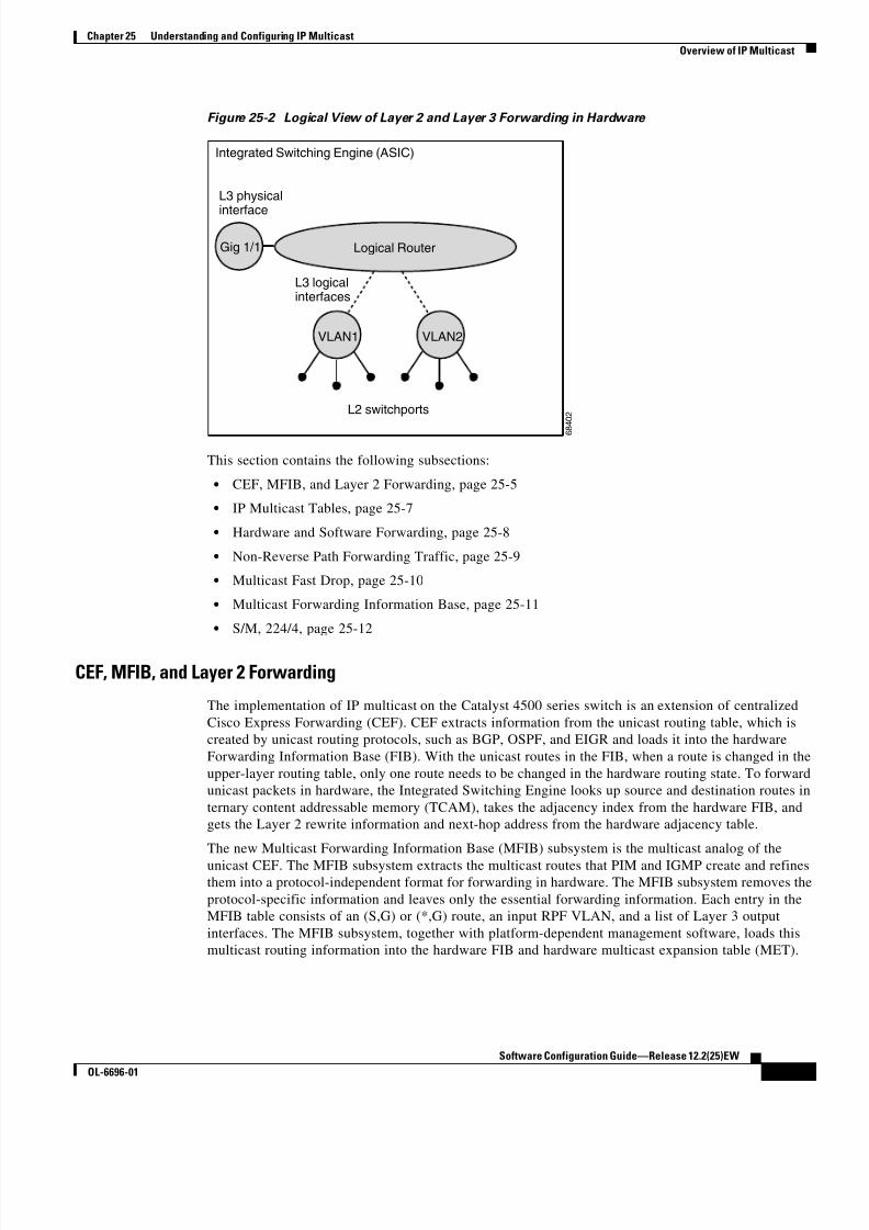
8/10/2019 Cisco ConfiguratioGuide SW4500 IOS
http://slidepdf.com/reader/full/cisco-configuratioguide-sw4500-ios 331/607
25-5
Software Configuration Guide—Release 12.2(25)EW
OL-6696-01
Chapter 25 Understanding and Configuring IP Multicast
Overview of IP Multicast
Figure 25-2 Logical View of Layer 2 and Layer 3 Forwarding in Hardware
This section contains the following subsections:
• CEF, MFIB, and Layer 2 Forwarding, page 25-5
• IP Multicast Tables, page 25-7
• Hardware and Software Forwarding, page 25-8
• Non-Reverse Path Forwarding Traffic, page 25-9
• Multicast Fast Drop, page 25-10
• Multicast Forwarding Information Base, page 25-11
• S/M, 224/4, page 25-12
CEF, MFIB, and Layer 2 Forwarding
The implementation of IP multicast on the Catalyst 4500 series switch is an extension of centralized
Cisco Express Forwarding (CEF). CEF extracts information from the unicast routing table, which is
created by unicast routing protocols, such as BGP, OSPF, and EIGR and loads it into the hardware
Forwarding Information Base (FIB). With the unicast routes in the FIB, when a route is changed in the
upper-layer routing table, only one route needs to be changed in the hardware routing state. To forward
unicast packets in hardware, the Integrated Switching Engine looks up source and destination routes in
ternary content addressable memory (TCAM), takes the adjacency index from the hardware FIB, and
gets the Layer 2 rewrite information and next-hop address from the hardware adjacency table.
The new Multicast Forwarding Information Base (MFIB) subsystem is the multicast analog of the
unicast CEF. The MFIB subsystem extracts the multicast routes that PIM and IGMP create and refinesthem into a protocol-independent format for forwarding in hardware. The MFIB subsystem removes the
protocol-specific information and leaves only the essential forwarding information. Each entry in the
MFIB table consists of an (S,G) or (*,G) route, an input RPF VLAN, and a list of Layer 3 output
interfaces. The MFIB subsystem, together with platform-dependent management software, loads this
multicast routing information into the hardware FIB and hardware multicast expansion table (MET).
Integrated Switching Engine (ASIC)
L3 physical
interface
Logical Router
L3 logicalinterfaces
L2 switchports
6 8 4 0 2
VLAN1
Gig 1/1
VLAN2
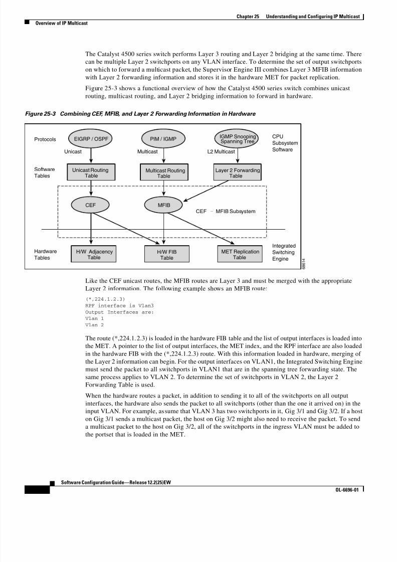
8/10/2019 Cisco ConfiguratioGuide SW4500 IOS
http://slidepdf.com/reader/full/cisco-configuratioguide-sw4500-ios 332/607
25-6
Software Configuration Guide—Release 12.2(25)EW
OL-6696-01
Chapter 25 Understanding and Configuring IP Multicast
Overview of IP Multicast
The Catalyst 4500 series switch performs Layer 3 routing and Layer 2 bridging at the same time. There
can be multiple Layer 2 switchports on any VLAN interface. To determine the set of output switchports
on which to forward a multicast packet, the Supervisor Engine III combines Layer 3 MFIB information
with Layer 2 forwarding information and stores it in the hardware MET for packet replication.
Figure 25-3 shows a functional overview of how the Catalyst 4500 series switch combines unicast
routing, multicast routing, and Layer 2 bridging information to forward in hardware.
Figure 25-3 Combining CEF, MFIB, and Layer 2 Forwarding Information in Hardware
Like the CEF unicast routes, the MFIB routes are Layer 3 and must be merged with the appropriate
Layer 2 information. The following example shows an MFIB route:
(*,224.1.2.3)
RPF interface is Vlan3
Output Interfaces are: Vlan 1
Vlan 2
The route (*,224.1.2.3) is loaded in the hardware FIB table and the list of output interfaces is loaded into
the MET. A pointer to the list of output interfaces, the MET index, and the RPF interface are also loaded
in the hardware FIB with the (*,224.1.2.3) route. With this information loaded in hardware, merging of
the Layer 2 information can begin. For the output interfaces on VLAN1, the Integrated Switching Engine
must send the packet to all switchports in VLAN1 that are in the spanning tree forwarding state. The
same process applies to VLAN 2. To determine the set of switchports in VLAN 2, the Layer 2
Forwarding Table is used.
When the hardware routes a packet, in addition to sending it to all of the switchports on all outputinterfaces, the hardware also sends the packet to all switchports (other than the one it arrived on) in the
input VLAN. For example, assume that VLAN 3 has two switchports in it, Gig 3/1 and Gig 3/2. If a host
on Gig 3/1 sends a multicast packet, the host on Gig 3/2 might also need to receive the packet. To send
a multicast packet to the host on Gig 3/2, all of the switchports in the ingress VLAN must be added to
the portset that is loaded in the MET.
Unicast RoutingTable
Multicast RoutingTable
Layer 2 ForwardingTable
H/W FIBTable
H/W AdjacencyTable
MET ReplicationTable
Protocols
Hardware
Tables
Software
Tables
Unicast Multicast
CEF – MFIB Subsystem
CPU
Subsystem
Software
Integrated
Switching
Engine
L2 Multicast
EIGRP / OSPF PIM / IGMP IGMP SnoopingSpanning Tree
CEF MFIB
6 8 6 1 4

8/10/2019 Cisco ConfiguratioGuide SW4500 IOS
http://slidepdf.com/reader/full/cisco-configuratioguide-sw4500-ios 333/607
25-7
Software Configuration Guide—Release 12.2(25)EW
OL-6696-01
Chapter 25 Understanding and Configuring IP Multicast
Overview of IP Multicast
If VLAN 1 contains 1/1 and 1/2, VLAN 2 contains 2/1 and 2/2, and VLAN 3 contains 3/1 and 3/2, the
MET chain for this route would contain these switchports: (1/1,1/2,2/1,2/2,3/1, and 3/2).
If IGMP snooping is on, the packet should not be forwarded to all output switchports on VLAN 2. The
packet should be forwarded only to switchports where IGMP snooping has determined that there is either
a group member or router. For example, if VLAN 1 had IGMP snooping enabled, and IGMP snooping
determined that only port 1/2 had a group member on it, then the MET chain would contain theseswitchports: (1/1,1/2, 2/1, 2/2, 3/1, and 3/2).
IP Multicast Tables
Figure 25-4 shows some key data structures that the Catalyst 4500 series switch uses to forward IP
multicast packets in hardware.
Figure 25-4 IP Multicast Tables and Protocols
The Integrated Switching Engine maintains the hardware FIB table to identify individual IP multicast
routes. Each entry consists of a destination group IP address and an optional source IP address. Multicast
traffic flows on primarily two types of routes: (S,G) and (*,G). The (S,G) routes flow from a source to a
group based on the IP address of the multicast source and the IP address of the multicast groupdestination. Traffic on a (*,G) route flows from the PIM RP to all receivers of group G. Only
sparse-mode groups use (*,G) routes. The Integrated Switching Engine hardware contains space for a
total of 128,000 routes, which are shared by unicast routes, multicast routes, and multicast fast-drop
entries.
6 8 1 3 5
Integrated Switching Engine CPU Subsystem
Routing Protocols
L3 Protocols
• PIM• IGMP
L2 Protocols•
•
IGMPsnooping
Spanning tree
Hardware FIB Table
(S,G), RPF Vlan, MET Index(*,G), Interfaces, MET Index
Hardware Tables
Hardware MET Table(Replication)
Index, set of {Vlan, switchport}
Software Tables
Multicast RoutingTable
• (S,G), RPF
output interfaces
L2 ForwardingTable
Vlan, MAC address
S,G rpf interface met index
S1, G1 vlan 3 1219
S2, G2 vlan 7 1241
*, G4 vlan 99 1356
index set of {vlan, switchport}
0 ..
.. ..
.. ..
1279 {v lan3, Fa 3/1} {v lan5, Fa 3/2}, …
switchports
interface, set of

8/10/2019 Cisco ConfiguratioGuide SW4500 IOS
http://slidepdf.com/reader/full/cisco-configuratioguide-sw4500-ios 334/607
25-8
Software Configuration Guide—Release 12.2(25)EW
OL-6696-01
Chapter 25 Understanding and Configuring IP Multicast
Overview of IP Multicast
Output interface lists are stored in the multicast expansion table (MET). The MET has room for up to
32,000 output interface lists. The MET resources are shared by both Layer 3 multicast routes and by
Layer 2 multicast entries. The actual number of output interface lists available in hardware depends on
the specific configuration. If the total number of multicast routes exceed 32,000, multicast packets might
not be switched by the Integrated Switching Engine. They would be forwarded by the CPU subsystem
at much slower speeds.
Hardware and Software Forwarding
The Integrated Switching Engine forwards the majority of packets in hardware at very high rates of
speed. The CPU subsystem forwards exception packets in software. Statistical reports should show that
the Integrated Switching Engine is forwarding the vast majority of packets in hardware.
Figure 25-5 shows a logical view of the hardware and software forwarding components.
Figure 25-5 Hardware and Software Forwarding Components
In the normal mode of operation, the Integrated Switching Engine performs inter-VLAN routing in
hardware. The CPU subsystem supports generic routing encapsulation (GRE) tunnels for forwarding in
software.
Replication is a particular type of forwarding where, instead of sending out one copy of the packet, the
packet is replicated and multiple copies of the packet are sent out. At Layer 3, replication occurs only
for multicast packets; unicast packets are never replicated to multiple Layer 3 interfaces. In IP
multicasting, for each incoming IP multicast packet that is received, many replicas of the packet are sent
out.
IP multicast packets can be transmitted on the following types of routes:
• Hardware routes
• Software routes
• Partial routes
Integrated Switching Engine CPU Subsystem
GREtunnel
L3 physicalinterface
Router
L3 interfaces
L2 switchports
6 8 1 2 7
VLAN1
Gig 1/1
VLAN2GREtunnel

8/10/2019 Cisco ConfiguratioGuide SW4500 IOS
http://slidepdf.com/reader/full/cisco-configuratioguide-sw4500-ios 335/607
25-9
Software Configuration Guide—Release 12.2(25)EW
OL-6696-01
Chapter 25 Understanding and Configuring IP Multicast
Overview of IP Multicast
Hardware routes occur when the Integrated Switching Engine hardware forwards all replicas of a packet.
Software routes occur when the CPU subsystem software forwards all replicas of a packet. Partial routes
occur when the Integrated Switching Engine forwards some of the replicas in hardware and the CPU
subsystem forwards some of the replicas in software.
Partial Routes
Note The conditions listed below cause the replicas to be forwarded by the CPU subsystem software, but the
performance of the replicas that are forwarded in hardware is not affected.
The following conditions cause some replicas of a packet for a route to be forwarded by the CPU
subsystem:
• The switch is configured with the ip igmp join-group command as a member of the IP multicast
group on the RPF interface of the multicast source.
• The switch is the first-hop to the source in PIM sparse mode. In this case, the switch must send
PIM-register messages to the RP.
Software Routes
Note If any one of the following conditions is configured on the RPF interface or the output interface, all
replication of the output is performed in software.
The following conditions cause all replicas of a packet for a route to be forwarded by the CPU subsystem
software:
• The interface is configured with multicast helper.
• The interface is a generic routing encapsulation (GRE) or Distance Vector Multicast Routing
Protocol (DVMRP) tunnel.• The interface uses non-Advanced Research Products Agency (ARPA) encapsulation.
The following packets are always forwarded in software:
• Packets sent to multicast groups that fall into the range 224.0.0.* (where * is in the range from 0 to
255). This range is used by routing protocols. Layer 3 switching supports all other multicast group
addresses.
• Packets with IP options.
Non-Reverse Path Forwarding Traffic
Traffic that fails an Reverse Path Forwarding (RPF) check is called non-RPF traffic. Non-RPF traffic is
forwarded by the Integrated Switching Engine by filtering (persistently dropping) or rate limiting thenon-RPF traffic.
In a redundant configuration where multiple Layer 3 switches or routers connect to the same LAN
segment, only one device forwards the multicast traffic from the source to the receivers on the outgoing
interfaces. Figure 25-6 shows how Non-RPF traffic can occur in a common network configuration.

8/10/2019 Cisco ConfiguratioGuide SW4500 IOS
http://slidepdf.com/reader/full/cisco-configuratioguide-sw4500-ios 336/607
25-10
Software Configuration Guide—Release 12.2(25)EW
OL-6696-01
Chapter 25 Understanding and Configuring IP Multicast
Overview of IP Multicast
Figure 25-6 Redundant Multicast Router Configuration in a Stub Network
In this kind of topology, only Router A, the PIM designated router (PIM DR), forwards data to the
common VLAN. Router B receives the forwarded multicast traffic, but must drop this traffic because it
has arrived on the wrong interface and fails the RPF check. Traffic that fails the RPF check is callednon-RPF traffic.
Multicast Fast Drop
In IP multicast protocols, such as PIM-SM and PIM-DM, every (S,G) or (*,G) route has an incoming
interface associated with it. This interface is referred to as the reverse path forwarding interface. In some
cases, when a packet arrives on an interface other than the expected RPF interface, the packet must be
forwarded to the CPU subsystem software to allow PIM to perform special protocol processing on the
packet. One example of this special protocol processing that PIM performs is the PIM Assert protocol.
By default, the Integrated Switching Engine hardware sends all packets that arrive on a non-RPF
interface to the CPU subsystem software. However, processing in software is not necessary in many
cases, because these non-RPF packets are often not needed by the multicast routing protocols. Theproblem is that if no action is taken, the non-RPF packets that are sent to the software can overwhelm
the CPU.
Use the ip mfib fastdrop command to enable or disable MFIB fast drops.
To prevent this from happening, the CPU subsystem software loads fast-drop entries in the hardware
when it receives an RPF failed packet that is not needed by the PIM protocols running on the switch. A
fast-drop entry is keyed by (S,G, incoming interface). Any packet matching a fast-drop entry is bridged
in the ingress VLAN, but is not sent to the software, so the CPU subsystem software is not overloaded
by processing these RPF failures unnecessarily.
Protocol events, such as a link going down or a change in the unicast routing table, can impact the set of
packets that can safely be fast dropped. A packet that was correctly fast dropped before might, after a
topology change, need to be forwarded to the CPU subsystem software so that PIM can process it. The
CPU subsystem software handles flushing fast-drop entries in response to protocol events so that the
PIM code in IOS can process all the necessary RPF failures.
The use of fast-drop entries in the hardware is critical in some common topologies because it is possible
to have persistent RPF failures. Without the fast-drop entries, the CPU would be exhausted by RPF failed
packets that it did not need to process.
Router A Router B
Network A
Network B
Multicast Traffic
Non-RPF Traffic 6 8 3 3 1

8/10/2019 Cisco ConfiguratioGuide SW4500 IOS
http://slidepdf.com/reader/full/cisco-configuratioguide-sw4500-ios 337/607
25-11
Software Configuration Guide—Release 12.2(25)EW
OL-6696-01
Chapter 25 Understanding and Configuring IP Multicast
Overview of IP Multicast
Multicast Forwarding Information Base
The Multicast Forwarding Information Base (MFIB) subsystem supports IP multicast routing in the
Integrated Switching Engine hardware on the Catalyst 4500 series switch. The MFIB logically resides
between the IP multicast routing protocols in the CPU subsystem software (PIM, IGMP, MSDP, MBGP,
and DVMRP) and the platform-specific code that manages IP multicast routing in hardware. The MFIB
translates the routing table information created by the multicast routing protocols into a simplified
format that can be efficiently processed and used for forwarding by the Integrated Switching Engine
hardware.
To display the information in the multicast routing table, use the show ip mroute command. To display
the MFIB table information, use the show ip mfib command. To display the information in the hardware
tables, use the show platform hardware command.
The MFIB table contains a set of IP multicast routes. There are several types of IP multicast routes,
including (S,G) and (*,G) routes. Each route in the MFIB table can have one or more optional flags
associated with it. The route flags indicate how a packet that matches a route should be forwarded. For
example, the Internal Copy (IC) flag on an MFIB route indicates that a process on the switch needs to
receive a copy of the packet. The following flags can be associated with MFIB routes:
• Internal Copy (IC) flag—set on a route when a process on the router needs to receive a copy of allpackets matching the specified route
• Signalling (S) flag—set on a route when a process needs to be notified when a packet matching the
route is received; the expected behavior is that the protocol code updates the MFIB state in response
to receiving a packet on a signalling interface
• Connected (C) flag—–when set on an MFIB route, has the same meaning as the Signalling (S) flag,
except that the C flag indicates that only packets sent by directly connected hosts to the route should
be signalled to a protocol process
A route can also have a set of optional flags associated with one or more interfaces. For example, an
(S,G) route with the flags on VLAN 1 indicates how packets arriving on VLAN 1 should be treated, and
they also indicate whether packets matching the route should be forwarded onto VLAN 1. The
per-interface flags supported in the MFIB include the following:
• Accepting (A)—set on the interface that is known in multicast routing as the RPF interface. A packet
that arrives on an interface that is marked as Accepting (A) is forwarded to all Forwarding (F)
interfaces.
• Forwarding (F)—used in conjunction with the Accepting (A) flag as described above. The set of
Forwarding interfaces that form what is often referred to as the multicast “olist” or output interface
list.
• Signalling (S)—set on an interface when some multicast routing protocol process in IOS needs to
be notified of packets arriving on that interface.
• Not platform fast-switched (NP)—used in conjunction with the Forwarding (F) flag. A Forwarding
interface is also marked as not platform fast-switched whenever that output interface cannot be fast
switched by the platform. The NP flag is typically used when the Forwarding interface cannot be
routed in hardware and requires software forwarding. For example, Catalyst 4500 series switch
tunnel interfaces are not hardware switched, so they are marked with the NP flag. If there are any
NP interfaces associated with a route, then for every packet arriving on an Accepting interface, one
copy of that packet is sent to the software forwarding path for software replication to those interfaces
that were not switched in hardware.

8/10/2019 Cisco ConfiguratioGuide SW4500 IOS
http://slidepdf.com/reader/full/cisco-configuratioguide-sw4500-ios 338/607
25-12
Software Configuration Guide—Release 12.2(25)EW
OL-6696-01
Chapter 25 Understanding and Configuring IP Multicast
Configuring IP Multicast Routing
Note When PIM-SM routing is in use, the MFIB route might include an interface like in this example:
PimTunnel [1.2.3.4]. This is a virtual interface that the MFIB subsystem creates to indicate that packets
are being tunnelled to the specified destination address. A PimTunnel interface cannot be displayed with
the normal show interface command.
S/M, 224/4
An (S/M, 224/4) entry is created in the MFIB for every multicast-enabled interface. This entry ensures
that all packets sent by directly connected neighbors can be Register-encapsulated to the PIM-SM RP.
Typically, only a small number of packets would be forwarded using the (S/M,224/4) route, until the
(S,G) route is established by PIM-SM.
For example, on an interface with IP address 10.0.0.1 and netmask 255.0.0.0, a route would be created
matching all IP multicast packets in which the source address is anything in the class A network 10. This
route can be written in conventional subnet/masklength notation as (10/8,224/4). If an interface has
multiple assigned IP addresses, then one route is created for each such IP address.
Unsupported Features
The following IP multicast features are not supported in this release:
• Controlling the transmission rate to a multicast group
• Load splitting IP multicast traffic across equal-cost paths
Configuring IP Multicast RoutingThe following sections describe IP multicast routing configuration tasks:
• Default Configuration in IP MUlticast Routing, page 25-13
• Enabling IP Multicast Routing, page 25-13
• Enabling PIM on an Interface, page 25-13
For more detailed information on IP multicast routing, such as Auto-RP, PIM Version 2, and IP multicast
static routes, refer to the Cisco IOS IP and IP Routing Configuration Guide, Release 12.2.

8/10/2019 Cisco ConfiguratioGuide SW4500 IOS
http://slidepdf.com/reader/full/cisco-configuratioguide-sw4500-ios 339/607
25-13
Software Configuration Guide—Release 12.2(25)EW
OL-6696-01
Chapter 25 Understanding and Configuring IP Multicast
Configuring IP Multicast Routing
Default Configuration in IP MUlticast Routing
Table 25-1 shows the IP multicast default configuration.
Note Source-specific multicast and IGMP v3 are supported.
For more information about source-specific multicast with IGMPv3 and IGMP, see the following URL
http://www.cisco.com/univercd/cc/td/doc/product/software/ios122/122cgcr/fipr_c/ipcpt3/1cfssm.htm
Enabling IP Multicast Routing
Enabling IP multicast routing allows the Catalyst 4500 series switch to forward multicast packets. To
enable IP multicast routing on the router, perform this task in global configuration mode:
Enabling PIM on an InterfaceEnabling PIM on an interface also enables IGMP operation on that interface. An interface can be
configured to be in dense mode, sparse mode, or sparse-dense mode. The mode determines how the
Layer 3 switch or router populates its multicast routing table and how the Layer 3 switch or router
forwards multicast packets it receives from its directly connected LANs. You must enable PIM in one of
these modes for an interface to perform IP multicast routing.
Table 25-1 Default IP Multicast Configuration
Feature Default Value
Rate limiting of RPF Enabled globally
IP multicast routing Disabled globally
Note When IP multicast routing is disabled, IP multicast traffic data
packets are not forwarded by the Catalyst 4500 series switch.
However, IP multicast control traffic will continue to be processed
and forwarded. Therefore, IP multicast routes can remain in the
routing table even if IP multicast routing is disabled.
PIM Disabled on all interfaces
IGMP snooping Enabled on all VLAN interfaces
Note If you disable IGMP snooping on an interface, all output ports areforwarded by the Integrated Switching Engine. When IGMP
snooping is disabled on an input VLAN interface, multicast packets
related to that interface are sent to all forwarding switchports in the
VLAN.
Command Purpose
Switch(config)# ip multicast-routing Enables IP multicast routing.

8/10/2019 Cisco ConfiguratioGuide SW4500 IOS
http://slidepdf.com/reader/full/cisco-configuratioguide-sw4500-ios 340/607
25-14
Software Configuration Guide—Release 12.2(25)EW
OL-6696-01
Chapter 25 Understanding and Configuring IP Multicast
Configuring IP Multicast Routing
When the switch populates the multicast routing table, dense-mode interfaces are always added to the
table. Sparse-mode interfaces are added to the table only when periodic join messages are received from
downstream routers, or when there is a directly connected member on the interface. When forwarding
from a LAN, sparse-mode operation occurs if there is an RP known for the group. If so, the packets are
encapsulated and sent toward the RP. When no RP is known, the packet is flooded in a dense-mode
fashion. If the multicast traffic from a specific source is sufficient, the receiver’s first-hop router can send
join messages toward the source to build a source-based distribution tree.
There is no default mode setting. By default, multicast routing is disabled on an interface.
Enabling Dense Mode
To configure PIM on an interface to be in dense mode, perform this task:
See the “PIM Dense Mode Example” section at the end of this chapter for an example of how to
configure a PIM interface in dense mode.
Enabling Sparse Mode
To configure PIM on an interface to be in sparse mode, perform this task:
See the “PIM Sparse Mode Example” section at the end of this chapter for an example of how to
configure a PIM interface in sparse mode.
Enabling Sparse-Dense Mode
When you enter either the ip pim sparse-mode or ip pim dense-mode command, sparseness or
denseness is applied to the interface as a whole. However, some environments might require PIM to run
in a single region in sparse mode for some groups and in dense mode for other groups.
An alternative to enabling only dense mode or only sparse mode is to enable sparse-dense mode. In this
case, the interface is treated as dense mode if the group is in dense mode; the interface is treated in sparse
mode if the group is in sparse mode. If you want to treat the group as a sparse group, and the interface
is in sparse-dense mode, you must have an RP.If you configure sparse-dense mode, the idea of sparseness or denseness is applied to the group on the
switch, and the network manager should apply the same concept throughout the network.
Another benefit of sparse-dense mode is that Auto-RP information can be distributed in a dense-mode
manner; yet, multicast groups for user groups can be used in a sparse-mode manner. Thus, there is no
need to configure a default RP at the leaf routers.
Command Purpose
Switch(config-if)# ip pim dense-mode Enables dense-mode PIM on the interface.
Command Purpose
Switch(config-if)# ip pim
sparse-modeEnables sparse-mode PIM on the interface.

8/10/2019 Cisco ConfiguratioGuide SW4500 IOS
http://slidepdf.com/reader/full/cisco-configuratioguide-sw4500-ios 341/607
25-15
Software Configuration Guide—Release 12.2(25)EW
OL-6696-01
Chapter 25 Understanding and Configuring IP Multicast
Monitoring and Maintaining IP Multicast Routing
When an interface is treated in dense mode, it is populated in a multicast routing table’s outgoing
interface list when either of the following is true:
• When there are members or DVMRP neighbors on the interface
• When there are PIM neighbors and the group has not been pruned
When an interface is treated in sparse mode, it is populated in a multicast routing table’s outgoing
interface list when either of the following is true:
• When there are members or DVMRP neighbors on the interface
• When an explicit join has been received by a PIM neighbor on the interface
To enable PIM to operate in the same mode as the group, perform this task:
Monitoring and Maintaining IP Multicast RoutingYou can remove all contents of a particular cache, table, or database. You also can display specific
statistics. The following sections describe how to monitor and maintain IP multicast:
• Displaying System and Network Statistics, page 25-15
• Displaying the Multicast Routing Table, page 25-16
• Displaying IP MFIB, page 25-18
• Displaying IP MFIB Fast Drop, page 25-19
• Displaying PIM Statistics, page 25-20
• Clearing Tables and Databases, page 25-20
Displaying System and Network Statistics
You can display specific statistics, such as the contents of IP routing tables and databases. Information
provided can be used to determine resource utilization and solve network problems. You can also display
information about node reachability and discover the routing path your device’s packets are taking
through the network.
To display various routing statistics, you can perform any of these tasks:
Command Purpose
Switch(config-if)# ip pim
sparse-dense-modeEnables PIM to operate in sparse or dense mode,
depending on the group.
Command Purpose
Switch# ping [group-name | group-address] Sends an ICMP Echo Request to a multicast
group address.
Switch# show ip mroute [hostname |
group_number ]Displays the contents of the IP multicast routing
table.
Switch# show ip pim interface [type number ][count]
Displays information about interfaces configured
for PIM.
Switch# show ip interface Displays PIM information for all interfaces.
8/10/2019 Cisco ConfiguratioGuide SW4500 IOS
http://slidepdf.com/reader/full/cisco-configuratioguide-sw4500-ios 342/607
25-16
Software Configuration Guide—Release 12.2(25)EW
OL-6696-01
Chapter 25 Understanding and Configuring IP Multicast
Monitoring and Maintaining IP Multicast Routing
Displaying the Multicast Routing Table
The following is sample output from the show ip mroute command for a router operating in dense mode.
This command displays the contents of the IP multicast FIB table for the multicast group named
cbone-audio.
Switch# show ip mroute cbone-audio IP Multicast Routing Table
Flags: D - Dense, S - Sparse, C - Connected, L - Local, P - PrunedR - RP-bit set, F - Register flag, T - SPT-bit set
Timers: Uptime/Expires
Interface state: Interface, Next-Hop, State/Mode
(*, 224.0.255.1), uptime 0:57:31, expires 0:02:59, RP is 0.0.0.0, flags: DC
Incoming interface: Null, RPF neighbor 0.0.0.0, Dvmrp
Outgoing interface list: Ethernet0, Forward/Dense, 0:57:31/0:02:52
Tunnel0, Forward/Dense, 0:56:55/0:01:28
(198.92.37.100/32, 224.0.255.1), uptime 20:20:00, expires 0:02:55, flags: C
Incoming interface: Tunnel0, RPF neighbor 10.20.37.33, DvmrpOutgoing interface list:
Ethernet0, Forward/Dense, 20:20:00/0:02:52
The following is sample output from the show ip mroute command for a router operating in sparse
mode:
Switch# show ip mroute
IP Multicast Routing Table
Flags: D - Dense, S - Sparse, C - Connected, L - Local, P - Pruned
R - RP-bit set, F - Register flag, T - SPT-bit setTimers: Uptime/Expires
Interface state: Interface, Next-Hop, State/Mode
(*, 224.0.255.3), uptime 5:29:15, RP is 198.92.37.2, flags: SC
Incoming interface: Tunnel0, RPF neighbor 10.3.35.1, Dvmrp Outgoing interface list:
Ethernet0, Forward/Sparse, 5:29:15/0:02:57
(198.92.46.0/24, 224.0.255.3), uptime 5:29:15, expires 0:02:59, flags: C Incoming interface: Tunnel0, RPF neighbor 10.3.35.1
Outgoing interface list: Ethernet0, Forward/Sparse, 5:29:15/0:02:57
Note Interface timers are not updated for hardware-forwarded packets. Entry timers are updated
approximately every five seconds.
The following is sample output from the show ip mroute command with the summary keyword:
Switch# show ip mroute summary
IP Multicast Routing Table
Flags: D - Dense, S - Sparse, C - Connected, L - Local, P - Pruned
R - RP-bit set, F - Register flag, T - SPT-bit set, J - Join SPTTimers: Uptime/Expires
Interface state: Interface, Next-Hop, State/Mode
(*, 224.255.255.255), 2d16h/00:02:30, RP 171.69.10.13, flags: SJPC

8/10/2019 Cisco ConfiguratioGuide SW4500 IOS
http://slidepdf.com/reader/full/cisco-configuratioguide-sw4500-ios 343/607
25-17
Software Configuration Guide—Release 12.2(25)EW
OL-6696-01
Chapter 25 Understanding and Configuring IP Multicast
Monitoring and Maintaining IP Multicast Routing
(*, 224.2.127.253), 00:58:18/00:02:00, RP 171.69.10.13, flags: SJC
(*, 224.1.127.255), 00:58:21/00:02:03, RP 171.69.10.13, flags: SJC
(*, 224.2.127.254), 2d16h/00:00:00, RP 171.69.10.13, flags: SJCL (128.9.160.67/32, 224.2.127.254), 00:02:46/00:00:12, flags: CLJT
(129.48.244.217/32, 224.2.127.254), 00:02:15/00:00:40, flags: CLJT
(130.207.8.33/32, 224.2.127.254), 00:00:25/00:02:32, flags: CLJT (131.243.2.62/32, 224.2.127.254), 00:00:51/00:02:03, flags: CLJT (140.173.8.3/32, 224.2.127.254), 00:00:26/00:02:33, flags: CLJT
(171.69.60.189/32, 224.2.127.254), 00:03:47/00:00:46, flags: CLJT
The following is sample output from the show ip mroute command with the active keyword:
Switch# show ip mroute active
Active IP Multicast Sources - sending >= 4 kbps
Group: 224.2.127.254, (sdr.cisco.com)
Source: 146.137.28.69 (mbone.ipd.anl.gov) Rate: 1 pps/4 kbps(1sec), 4 kbps(last 1 secs), 4 kbps(life avg)
Group: 224.2.201.241, ACM 97
Source: 130.129.52.160 (webcast3-e1.acm97.interop.net) Rate: 9 pps/93 kbps(1sec), 145 kbps(last 20 secs), 85 kbps(life avg)
Group: 224.2.207.215, ACM 97
Source: 130.129.52.160 (webcast3-e1.acm97.interop.net)
Rate: 3 pps/31 kbps(1sec), 63 kbps(last 19 secs), 65 kbps(life avg)
The following is sample output from the show ip mroute command with the count keyword:
Switch# show ip mroute count
IP Multicast Statistics - Group count: 8, Average sources per group: 9.87Counts: Pkt Count/Pkts per second/Avg Pkt Size/Kilobits per second
Group: 224.255.255.255, Source count: 0, Group pkt count: 0
RP-tree: 0/0/0/0
Group: 224.2.127.253, Source count: 0, Group pkt count: 0 RP-tree: 0/0/0/0
Group: 224.1.127.255, Source count: 0, Group pkt count: 0
RP-tree: 0/0/0/0
Group: 224.2.127.254, Source count: 9, Group pkt count: 14 RP-tree: 0/0/0/0
Source: 128.2.6.9/32, 2/0/796/0
Source: 128.32.131.87/32, 1/0/616/0 Source: 128.125.51.58/32, 1/0/412/0
Source: 130.207.8.33/32, 1/0/936/0
Source: 131.243.2.62/32, 1/0/750/0
Source: 140.173.8.3/32, 1/0/660/0 Source: 146.137.28.69/32, 1/0/584/0
Source: 171.69.60.189/32, 4/0/447/0 Source: 204.162.119.8/32, 2/0/834/0
Group: 224.0.1.40, Source count: 1, Group pkt count: 3606
RP-tree: 0/0/0/0
Source: 171.69.214.50/32, 3606/0/48/0, RPF Failed: 1203

8/10/2019 Cisco ConfiguratioGuide SW4500 IOS
http://slidepdf.com/reader/full/cisco-configuratioguide-sw4500-ios 344/607
25-18
Software Configuration Guide—Release 12.2(25)EW
OL-6696-01
Chapter 25 Understanding and Configuring IP Multicast
Monitoring and Maintaining IP Multicast Routing
Group: 224.2.201.241, Source count: 36, Group pkt count: 54152
RP-tree: 7/0/108/0
Source: 13.242.36.83/32, 99/0/123/0 Source: 36.29.1.3/32, 71/0/110/0
Source: 128.9.160.96/32, 505/1/106/0 Source: 128.32.163.170/32, 661/1/88/0
Source: 128.115.31.26/32, 192/0/118/0
Source: 128.146.111.45/32, 500/0/87/0 Source: 128.183.33.134/32, 248/0/119/0 Source: 128.195.7.62/32, 527/0/118/0
Source: 128.223.32.25/32, 554/0/105/0 Source: 128.223.32.151/32, 551/1/125/0
Source: 128.223.156.117/32, 535/1/114/0
Source: 128.223.225.21/32, 582/0/114/0 Source: 129.89.142.50/32, 78/0/127/0
Source: 129.99.50.14/32, 526/0/118/0
Source: 130.129.0.13/32, 522/0/95/0
Source: 130.129.52.160/32, 40839/16/920/161 Source: 130.129.52.161/32, 476/0/97/0
Source: 130.221.224.10/32, 456/0/113/0 Source: 132.146.32.108/32, 9/1/112/0
Note Multicast route byte and packet statistics are supported only for the first 1024 multicast routes. Output
interface statistics are not maintained.
Displaying IP MFIB
You can display all routes in the MFIB, including routes that might not exist directly in the upper-layer
routing protocol database but that are used to accelerate fast switching. These routes appear in the MFIB,
even if dense-mode forwarding is in use.
To display various MFIB routing routes, perform one of these tasks:
Command Purpose
Switch# show ip mfib Displays the (S,G) and (*,G) routes that are used for packet
forwarding. Displays counts for fast, slow, and
partially-switched packets for every multicast route.
Switch# show ip mfib all Displays all routes in the MFIB, including routes that may
not exist directly in the upper-layer routing protocol
database, but that are used to accelerate fast
switching.These routes include the (S/M,224/4) routes.
Switch# show ip mfib log [n] Displays a log of the most recent n MFIB related events,
most recent first.
Switch# show ip mfib counters Displays counts of MFIB related events. Only non-zero
counters are shown.

8/10/2019 Cisco ConfiguratioGuide SW4500 IOS
http://slidepdf.com/reader/full/cisco-configuratioguide-sw4500-ios 345/607
25-19
Software Configuration Guide—Release 12.2(25)EW
OL-6696-01
Chapter 25 Understanding and Configuring IP Multicast
Monitoring and Maintaining IP Multicast Routing
The following is sample output from the show ip mfib command.
IP Multicast Forwarding Information BaseEntry Flags: C - Directly Connected, S - Signal,
IC - Internal CopyInterface Flags: A - Accept, F - Forward, S - Signal,
NP - Not platform switched
Packets: Fast/Partial/Slow Bytes: Fast/Partial/Slow:(171.69.10.13, 224.0.1.40), flags (IC)
Packets: 2292/2292/0, Bytes: 518803/0/518803
Vlan7 (A)
Vlan100 (F NS) Vlan105 (F NS)
(*, 224.0.1.60), flags () Packets: 2292/0/0, Bytes: 518803/0/0
Vlan7 (A NS)
(*, 224.0.1.75), flags ()
Vlan7 (A NS)(10.34.2.92, 239.192.128.80), flags ()
Packets: 24579/100/0, 2113788/15000/0 bytes Vlan7 (F NS)
Vlan100 (A)
(*, 239.193.100.70), flags ()
Packets: 1/0/0, 1500/0/0 bytes Vlan7 (A)
..
The fast-switched packet count represents the number of packets that were switched in hardware on the
corresponding route.
The partially switched packet counter represents the number of times that a fast-switched packet was
also copied to the CPU for software processing or for forwarding to one or more non-platform switched
interfaces (such as a PimTunnel interface).
The slow-switched packet count represents the number of packets that were switched completely in
software on the corresponding route.
Displaying IP MFIB Fast Drop
To display fast-drop entries, perform this task:
The following is sample output from the show ip mfib fastdrop command.
Switch> show ip mfib fastdropMFIB fastdrop is enabled.
MFIB fast-dropped flows:
(10.0.0.1, 224.1.2.3, Vlan9 ) 00:01:32
(10.1.0.2, 224.1.2.3, Vlan9 ) 00:02:30(1.2.3.4, 225.6.7.8, Vlan3) 00:01:50
The full (S,G) flow and the ingress interface on which incoming packets are dropped is shown. The
timestamp indicates the age of the entry.
Command Purpose
Switch# show ip mfib fastdrop Displays all currently active fast-drop entries and indicates
whether fastdrop is enabled.
8/10/2019 Cisco ConfiguratioGuide SW4500 IOS
http://slidepdf.com/reader/full/cisco-configuratioguide-sw4500-ios 346/607
25-20
Software Configuration Guide—Release 12.2(25)EW
OL-6696-01
Chapter 25 Understanding and Configuring IP Multicast
Monitoring and Maintaining IP Multicast Routing
Displaying PIM Statistics
The following is sample output from the show ip pim interface command:
Switch# show ip pim interface
Address Interface Mode Neighbor Query DR Count Interval
198.92.37.6 Ethernet0 Dense 2 30 198.92.37.33198.92.36.129 Ethernet1 Dense 2 30 198.92.36.131
10.1.37.2 Tunnel0 Dense 1 30 0.0.0.0
The following is sample output from the show ip pim interface command with a count:
Switch# show ip pim interface count
Address Interface FS Mpackets In/Out171.69.121.35 Ethernet0 * 548305239/13744856
171.69.121.35 Serial0.33 * 8256/67052912
198.92.12.73 Serial0.1719 * 219444/862191
The following is sample output from the show ip pim interface command with a count when IP
multicast is enabled. The example lists the PIM interfaces that are fast-switched and process-switched,
and the packet counts for these. The H is added to interfaces where IP multicast is enabled.
Switch# show ip pim interface count
States: FS - Fast Switched, H - Hardware SwitchedAddress Interface FS Mpackets In/Out
192.1.10.2 Vlan10 * H 40886/0
192.1.11.2 Vlan11 * H 0/40554
192.1.12.2 Vlan12 * H 0/40554192.1.23.2 Vlan23 * 0/0
192.1.24.2 Vlan24 * 0/0
Clearing Tables and DatabasesYou can remove all contents of a particular cache, table, or database. Clearing a cache, table, or database
might be necessary when the contents of the particular structure have become, or are suspected to be,
invalid.
To clear IP multicast caches, tables, and databases, perform one of these tasks:
Note IP multicast routes can be regenerated in response to protocol events and as data packets arrive.
Command Purpose
Switch# clear ip mroute Deletes entries from the IP routing table.
Switch# clear ip mfib counters Deletes all per-route and global MFIB counters.
Switch# clear ip mfib fastdrop Deletes all fast-drop entries.

8/10/2019 Cisco ConfiguratioGuide SW4500 IOS
http://slidepdf.com/reader/full/cisco-configuratioguide-sw4500-ios 347/607
25-21
Software Configuration Guide—Release 12.2(25)EW
OL-6696-01
Chapter 25 Understanding and Configuring IP Multicast
Configuration Examples
Configuration ExamplesThe following sections provide IP multicast routing configuration examples:
• PIM Dense Mode Example, page 25-21
• PIM Sparse Mode Example, page 25-21• BSR Configuration Example, page 25-21
PIM Dense Mode Example
This example is a configuration of dense-mode PIM on an Ethernet interface:
ip multicast-routing
interface ethernet 0
ip pim dense-mode
PIM Sparse Mode ExampleThis example is a configuration of sparse-mode PIM. The RP router is the router with the address
10.8.0.20.
ip multicast-routingip pim rp-address 10.8.0.20 1
interface ethernet 1ip pim sparse-mode
BSR Configuration Example
This example is a configuration of a candidate BSR, which also happens to be a candidate RP:
version 11.3
!
ip multicast-routing!
interface Ethernet0
ip address 171.69.62.35 255.255.255.240
!interface Ethernet1
ip address 172.21.24.18 255.255.255.248 ip pim sparse-dense-mode
!
interface Ethernet2
ip address 172.21.24.12 255.255.255.248
ip pim sparse-dense-mode
!
router ospf 1 network 172.21.24.8 0.0.0.7 area 1 network 172.21.24.16 0.0.0.7 area 1
!
ip pim bsr-candidate Ethernet2 30 10
ip pim rp-candidate Ethernet2 group-list 5access-list 5 permit 239.255.2.0 0.0.0.255

8/10/2019 Cisco ConfiguratioGuide SW4500 IOS
http://slidepdf.com/reader/full/cisco-configuratioguide-sw4500-ios 348/607
25-22
Software Configuration Guide—Release 12.2(25)EW
OL-6696-01
Chapter 25 Understanding and Configuring IP Multicast
Configuration Examples

8/10/2019 Cisco ConfiguratioGuide SW4500 IOS
http://slidepdf.com/reader/full/cisco-configuratioguide-sw4500-ios 349/607
C H A P T E R
26-1
Software Configuration Guide—Release 12.2(25)EW
OL-6696-01
26
Configuring Policy-Based Routing
This chapter describes the tasks for configuring policy-based routing (PBR) on a router and includes
these major sections:
• Overview of Policy-Based Routing, page 26-1
• Policy-Based Routing Configuration Task List, page 26-3
• Policy-Based Routing Configuration Examples, page 26-5
Note For a complete description of the PBR commands in this chapter, refer to the Cisco IOS Quality of
Service Solutions Command Reference at:
http://www.cisco.com/univercd/cc/td/doc/product/software/ios123/123tcr/123tqr/
Note To identify the hardware platform or software image information associated with a feature, use the
Feature Navigator on Cisco.com to search for information about the feature or refer to the software
release notes for a specific release.
Overview of Policy-Based RoutingThis section contains the following subsections:
• Understanding PBR, page 26-2
• Understanding PBR Flow Switching, page 26-2
• Using Policy-Based Routing, page 26-2
PBR gives you a flexible means of routing packets by allowing you to configure a defined policy for
traffic flows, lessening reliance on routes derived from routing protocols. To this end, PBR gives you
more control over routing by extending and complementing the existing mechanisms provided by routing
protocols. PBR allows you to specify a path for certain traffic, such as priority traffic over a high-cost
link.
You can set up PBR as a way to route packets based on configured policies. For example, you can
implement routing policies to allow or deny paths based on the identity of a particular end system, an
application protocol, or the size of packets.

8/10/2019 Cisco ConfiguratioGuide SW4500 IOS
http://slidepdf.com/reader/full/cisco-configuratioguide-sw4500-ios 350/607
26-2
Software Configuration Guide—Release 12.2(25)EW
OL-6696-01
Chapter 26 Configuring Policy-Based Routing
Overview of Policy-Based Routing
PBR allows you to perform the following tasks:
• Classify traffic based on extended access list criteria. Access lists, then establish the match criteria.
• Route packets to specific traffic-engineered paths.
Policies can be based on IP address, port numbers, or protocols. For a simple policy, you can use any
one of these descriptors; for a complicated policy, you can use all of them.
Understanding PBR
All packets received on an interface with PBR enabled are passed through enhanced packet filters known
as route maps. The route maps used by PBR dictate the policy, determining to where the packets are
forwarded.
Route maps are composed of statements. The route map statements can be marked as permit or deny, and
they are interpreted in the following ways:
• If a statement is marked as deny, the packets meeting the match criteria are sent back through the
normal forwarding channels and destination-based routing is performed.
• If the statement is marked as permit and a packet matches the access-lists, then the first valid set
clause is applied to that packet.
You specify PBR on the incoming interface (the interface on which packets are received), not outgoing
interface.
Understanding PBR Flow Switching
The Catalyst 4500 switching engine supports matching a “set next-hop” route-map action with a packet
on a permit ACL. All other route-map actions, as well as matches of deny ACLs, are supported by a flow
switching model. In this model, the first packet on a flow that matches a route-map will be delivered to
the software for forwarding. Software determines the correct destination for the packet and installs an
entry into the TCAM so that future packets on that flow are switched in hardware. The Catalyst 4500
switching engine supports a maximum of 4096 flows.
Using Policy-Based Routing
You can enable PBR to change the routing path of certain packets from the obvious shortest path. For
example, PBR can be used to provide the following functionality:
• equal access
• protocol-sensitive routing
• source-sensitive routing
• routing based on interactive versus batch traffic
• routing based on dedicated links
Some applications or traffic can benefit from source-specific routing; for example, you can transfer stock
records to a corporate office on a higher-bandwidth, higher-cost link for a short time while sending
routine application data, such as e-mail, over a lower-bandwidth, lower-cost link.
8/10/2019 Cisco ConfiguratioGuide SW4500 IOS
http://slidepdf.com/reader/full/cisco-configuratioguide-sw4500-ios 351/607
26-3
Software Configuration Guide—Release 12.2(25)EW
OL-6696-01
Chapter 26 Configuring Policy-Based Routing
Policy-Based Routing Configuration Task List
Policy-Based Routing Configuration Task ListTo configure PBR, perform the tasks described in the following sections. The task in the first section is
required; the tasks in the remaining sections are optional. See the end of this chapter for the section
“Policy-Based Routing Configuration Examples.”
• Enabling PBR (Required)
• Enabling Local PBR (Optional)
Enabling PBR
To enable PBR, you must create a route map that specifies the match criteria and the resulting action if
all of the match clauses are met. Then you must enable PBR for that route map on a particular interface.
All packets arriving on the specified interface matching the match clauses will be subject to PBR.
To enable PBR on an interface, perform this task:
Command Purpose
Step 1 Switch(config)# route-map map-tag [ permit |
deny] [sequence-number ]Defines a route map to control where packets are output. This
command puts the router into route-map configuration mode.
Step 2 Switch(config-route-map)# match ip address{access-list-number | name }
[...access-list-number | name ]
Specifies the match criteria. Matches the source and
destination IP address that is permitted by one or more
standard or extended access lists.

8/10/2019 Cisco ConfiguratioGuide SW4500 IOS
http://slidepdf.com/reader/full/cisco-configuratioguide-sw4500-ios 352/607
26-4
Software Configuration Guide—Release 12.2(25)EW
OL-6696-01
Chapter 26 Configuring Policy-Based Routing
Policy-Based Routing Configuration Task List
The set commands can be used in conjunction with each other. These commands are evaluated in the
order shown in Step 3 in the previous task table. A usable next hop implies an interface. Once the local
router finds a next hop and a usable interface, it routes the packet.
Step 3
Switch(config-route-map)# set ip next-hop
ip-address [... ip-address]
Switch(config-route-map)# set interface interface-type interface-number
[... type number ]
Switch(config-route-map)# set ip defaultnext-hop ip-address [... ip-address]
Switch(config-route-map)# set defaultinterface interface-type interface-number [...
type ...number ]
Specifies the action or actions to take on the packets that
match the criteria. You can specify any or all of the following:
• Specifies the next hop for which to route the packet (the
next hop must be adjacent). This behavior is identical to
a next hop specified in the normal routing table.
• Sets output interface for the packet. This action specifies
that the packet is forwarded out of the local interface. The
interface must be a Layer 3 interface (no switchports),
and the destination address in the packet must lie within
the IP network assigned to that interface. If the
destination address for the packet does not lie within that
network, the packet is dropped.
• Sets next hop to which to route the packet if there is no
explicit route for this destination. Before forwarding the
packet to the next hop, the switch looks up the packet’s
destination address in the unicast routing table. If a match
is found, the packet is forwarded by way of the routing
table. If no match is found, the packet is forwarded to the
specified next hop.
• Sets output interface for the packet if there is no explicit
route for this destination. Before forwarding the packet to
the next hop, the switch looks up the packet’s destination
address in the unicast routing table. If a match is found,
the packet is forwarded via the routing table. If no match
is found, the packet is forwarded to the specified output
interface. If the destination address for the packet does
not lie within that network, the packet is dropped.
Step 4 Switch(config-route-map)# interface
interface-type interface-number Specifies the interface. This command puts the router intointerface configuration mode.
Step 5 Switch(config-if)# ip policy route-map map-tag Identifies the route map to use for PBR. One interface can
only have one route map tag, but you can have multiple route
map entries with different sequence numbers. These entries
are evaluated in sequence number order until the first match.
If there is no match, packets will be routed as usual.
Command Purpose

8/10/2019 Cisco ConfiguratioGuide SW4500 IOS
http://slidepdf.com/reader/full/cisco-configuratioguide-sw4500-ios 353/607
26-5
Software Configuration Guide—Release 12.2(25)EW
OL-6696-01
Chapter 26 Configuring Policy-Based Routing
Policy-Based Routing Configuration Examples
Enabling Local PBR
Packets that are generated by the router are not normally policy-routed. To enable local PBR for such
packets, indicate which route map the router should use by performing this task:
All packets originating on the router will then be subject to local PBR.
Use the show ip local policy command to display the route map used for local PBR, if one exists.
Unsupported Commands
The following PBR commands in config-route-map mode are in the CLI but not supported in Cisco IOS
for the Catalyst 4500 series switches. If you attempt to use these commands, an error message displays
• match-length
• set ip qos
• set ip tos
• set ip precedence
Policy-Based Routing Configuration ExamplesThe following sections provide PBR configuration examples:
• Equal Access Example, page 26-5
• Differing Next Hops Example, page 26-6
• Deny ACE Example, page 26-6
For information on how to configure policy-based routing, see the section “Policy-Based Routing
Configuration Task List” in this chapter.
Equal Access Example
The following example provides two sources with equal access to two different service providers.
Packets arriving on interface fastethernet 3/1 from the source 1.1.1.1 are sent to the router at 6.6.6.6 if
the router has no explicit route for the destination of the packet. Packets arriving from the source 2.2.2.2
are sent to the router at 7.7.7.7 if the router has no explicit route for the destination of the packet. Allother packets for which the router has no explicit route to the destination are discarded.
Switch (config)# access-list 1 permit ip 1.1.1.1
access-list 1 permit ip 1.1.1.1
!
interface fastethernet 3/1ip policy route-map equal-access
Command Purpose
Switch(config)# ip local policy route-map map-tag Identifies the route map to use for local PBR.

8/10/2019 Cisco ConfiguratioGuide SW4500 IOS
http://slidepdf.com/reader/full/cisco-configuratioguide-sw4500-ios 354/607
26-6
Software Configuration Guide—Release 12.2(25)EW
OL-6696-01
Chapter 26 Configuring Policy-Based Routing
Policy-Based Routing Configuration Examples
!
route-map equal-access permit 10 match ip address 1
set ip default next-hop 6.6.6.6route-map equal-access permit 20
match ip address 2
set ip default next-hop 7.7.7.7route-map equal-access permit 30set default interface null0
Note If the packets you want to drop do not match either of the first two route-map clauses, then change set
default interface null0 to set interface null0.
Differing Next Hops Example
The following example illustrates how to route traffic from different sources to different places (next
hops). Packets arriving from source 1.1.1.1 are sent to the next hop at 3.3.3.3; packets arriving from
source 2.2.2.2 are sent to the next hop at 3.3.3.5.
access-list 1 permit ip 1.1.1.1access-list 2 permit ip 2.2.2.2
!
interface fastethernet 3/1 ip policy route-map Texas
!
route-map Texas permit 10
match ip address 1 set ip next-hop 3.3.3.3
!route-map Texas permit 20
match ip address 2
set ip next-hop 3.3.3.5
Deny ACE Example
The following example illustrates how to stop processing a given route map sequence, and to jump to
the next sequence. Packets arriving from source 1.1.1.1 will skip sequence 10 and jump to sequence 20.
All other packets from subnet 1.1.1.0 will follow the set statement in sequence 10.
access-list 1 deny ip 1.1.1.1
access-list 1 permit ip 1.1.1.0 0.0.0.255access-list 2 permit ip 1.1.1.1
access-list 2 permit ip 2.2.2.2!
interface fastethernet 3/1
ip policy route-map Texas
!route-map Texas permit 10
match ip address 1
set ip next-hop 3.3.3.3
!
route-map Texas permit 20 match ip address 2
set ip next-hop 3.3.3.5

8/10/2019 Cisco ConfiguratioGuide SW4500 IOS
http://slidepdf.com/reader/full/cisco-configuratioguide-sw4500-ios 355/607
C H A P T E R
27-1
Software Configuration Guide—Release 12.2(25)EW
OL-6696-01
27
Understanding and Configuring VTP
This chapter describes the VLAN Trunking Protocol (VTP) on the Catalyst 4500 series switch. It also
provides guidelines, procedures, and configuration examples.
This chapter includes the following major sections:
• Overview of VTP, page 27-1
• VTP Configuration Guidelines and Restrictions, page 27-5
• VTP Default Configuration, page 27-5
• Configuring VTP, page 27-6
Note For complete syntax and usage information for the switch commands used in this chapter, refer to the
Catalyst 4500 Series Switch Cisco IOS Command Reference and related publications at
http://www.cisco.com/univercd/cc/td/doc/product/software/ios122/122cgcr/index.htm.
Overview of VTPVTP is a Layer 2 messaging protocol that maintains VLAN configuration consistency by managing the
addition, deletion, and renaming of VLANs within a VTP domain. A VTP domain (also called a VLAN
management domain) is made up of one or more network devices that share the same VTP domain name
and that are interconnected with trunks. VTP minimizes misconfigurations and configuration
inconsistencies that can result in a number of problems, such as duplicate VLAN names, incorrect
VLAN-type specifications, and security violations.
Before you create VLANs, you must decide whether you want to use VTP in your network. With VTP,
you can make configuration changes centrally on one or more network devices and have those changes
automatically communicated to all the other network devices in the network.
Note For complete information on configuring VLANs, see Chapter 10, “Understanding and ConfiguringVLANs.”
These sections describe how VTP works:
• Understanding the VTP Domain, page 27-2
• Understanding VTP Modes, page 27-2
• Understanding VTP Advertisements, page 27-3

8/10/2019 Cisco ConfiguratioGuide SW4500 IOS
http://slidepdf.com/reader/full/cisco-configuratioguide-sw4500-ios 356/607
27-2
Software Configuration Guide—Release 12.2(25)EW
OL-6696-01
Chapter 27 Understanding and Configuring VTP
Overview of VTP
• Understanding VTP Version 2, page 27-3
• Understanding VTP Pruning, page 27-3
Understanding the VTP Domain
A VTP domain is made up of one or more interconnected network devices that share the same VTP
domain name. A network device can be configured to be in only one VTP domain. You make global
VLAN configuration changes for the domain using either the command-line interface (CLI) or Simple
Network Management Protocol (SNMP).
By default, the Catalyst 4500 series switch is in VTP server mode and is in the no-management domain
state until the switch receives an advertisement for a domain over a trunk link or you configure a
management domain. You cannot create or modify VLANs on a VTP server until the management
domain name is specified or learned.
If the switch receives a VTP advertisement over a trunk link, it inherits the management domain name
and the VTP configuration revision number. The switch ignores advertisements with a different
management domain name or an earlier configuration revision number.
If you configure the switch as VTP transparent, you can create and modify VLANs, but the changes
affect only the individual switch.
When you make a change to the VLAN configuration on a VTP server, the change is propagated to all
network devices in the VTP domain. VTP advertisements are transmitted out all Inter-Switch Link (ISL)
and IEEE 802.1Q trunk connections.
VTP maps VLANs dynamically across multiple LAN types with unique names and internal index
associations. Mapping eliminates unnecessary device administration for network administrators.
Understanding VTP Modes
You can configure a Catalyst 4500 series switch to operate in any one of these VTP modes:
• Server—In VTP server mode, you can create, modify, and delete VLANs and specify other
configuration parameters (such as VTP version and VTP pruning) for the entire VTP domain. VTP
servers advertise their VLAN configuration to other network devices in the same VTP domain and
synchronize their VLAN configuration with other network devices based on advertisements received
over trunk links. VTP server is the default mode.
• Client—VTP clients behave the same way as VTP servers, but you cannot create, change, or delete
VLANs on a VTP client.
• Transparent—VTP transparent network devices do not participate in VTP. A VTP transparent
network device does not advertise its VLAN configuration and does not synchronize its VLAN
configuration based on received advertisements. However, in VTP version 2, transparent network
devices do forward VTP advertisements that they receive on their trunking LAN interfaces.
Note Catalyst 4500 series switch automatically change from VTP server mode to VTP client mode if the
switch detects a failure while writing configuration to NVRAM. If this happens, the switch cannot be
returned to VTP server mode until the NVRAM is functioning.

8/10/2019 Cisco ConfiguratioGuide SW4500 IOS
http://slidepdf.com/reader/full/cisco-configuratioguide-sw4500-ios 357/607
27-3
Software Configuration Guide—Release 12.2(25)EW
OL-6696-01
Chapter 27 Understanding and Configuring VTP
Overview of VTP
Understanding VTP Advertisements
Each network device in the VTP domain sends periodic advertisements out each trunking LAN interface
to a reserved multicast address. VTP advertisements are received by neighboring network devices, which
update their VTP and VLAN configurations as necessary.
The following global configuration information is distributed in VTP advertisements:
• VLAN IDs (ISL and 802.1Q)
• Emulated LAN names (for ATM LANE)
• 802.10 SAID values (FDDI)
• VTP domain name
• VTP configuration revision number
• VLAN configuration, including maximum transmission unit (MTU) size for each VLAN
• Frame format
Understanding VTP Version 2
If you use VTP in your network, you must decide whether to use VTP version 1 or version 2.
Note Catalyst 4500 series switch do not support Token Ring or FDDI media. The switch does not forward
FDDI, FDDI-Net, Token Ring Concentrator Relay Function [TrCRF], or Token Ring Bridge Relay
Function [TrBRF] traffic, but it does propagate the VLAN configuration via VTP.
VTP version 2 supports the following features, which are not supported in version 1:
• Token Ring support—VTP version 2 supports Token Ring LAN switching and VLANs (TrBRF and
TrCRF).
• Unrecognized Type-Length-Value (TLV) Support—A VTP server or client propagates configuration
changes to its other trunks, even for TLVs it is not able to parse. The unrecognized TLV is saved in
NVRAM.
• Version-Dependent Transparent Mode—In VTP version 1, a VTP transparent network device
inspects VTP messages for the domain name and version, and forwards a message only if the version
and domain name match. Because only one domain is supported in the supervisor engine software,
VTP version 2 forwards VTP messages in transparent mode, without checking the version.
• Consistency Checks—In VTP version 2, VLAN consistency checks (such as VLAN names and
values) are performed only when you enter new information through the CLI or SNMP. Consistency
checks are not performed when new information is obtained from a VTP message or when
information is read from NVRAM. If the digest on a received VTP message is correct, its
information is accepted without consistency checks.
Understanding VTP Pruning
VTP pruning enhances network bandwidth use by reducing unnecessary flooded traffic, such as
broadcast, multicast, and unicast packets. VTP pruning increases available bandwidth by restricting
flooded traffic to those trunk links that the traffic must use to access the appropriate network devices.
By default, VTP pruning is disabled.

8/10/2019 Cisco ConfiguratioGuide SW4500 IOS
http://slidepdf.com/reader/full/cisco-configuratioguide-sw4500-ios 358/607
27-4
Software Configuration Guide—Release 12.2(25)EW
OL-6696-01
Chapter 27 Understanding and Configuring VTP
Overview of VTP
For VTP pruning to be effective, all devices in the management domain must either support VTP pruning
or, on devices that do not support VTP pruning, you must manually configure the VLANs allowed on
trunks.
Figure 27-1 shows a switched network without VTP pruning enabled. Interface 1 on Switch 1 and
Interface 2 on Switch 4 are assigned to the Red VLAN. A broadcast is sent from the host connected to
Switch 1. Switch 1 floods the broadcast and every network device in the network receives it, even thoughSwitches 3, 5, and 6 have no interfaces in the Red VLAN.
You can enable pruning globally on the Catalyst 4500 series switch (see the “Enabling VTP Pruning”
section on page 27-6).
Figure 27-1 Flooding Traffic without VTP Pruning
Figure 27-2 shows the same switched network with VTP pruning enabled. The broadcast traffic from
Switch 1 is not forwarded to Switches 3, 5, and 6 because traffic for the Red VLAN has been pruned onthe links indicated (Interface 5 on Switch 2 and Interface 4 on Switch 4).
Figure 27-2 Flooding Traffic with VTP Pruning
Catalyst seriesswitch 4
Catalyst series
switch 5
Catalyst seriesswitch 3
Catalyst seriesswitch 6
Catalyst seriesswitch 1
Catalyst series
switch 2
Interface 1
Interface 2
RedVLAN
9 4 1 5 1
Switch 4
Switch 5
Switch 3Switch 6 Switch 1
Switch 2
Interface 1
Interface 2
Red
VLAN
3 1 0 7 5
Interface 4
Interface 5
Flooded traffic
is pruned.

8/10/2019 Cisco ConfiguratioGuide SW4500 IOS
http://slidepdf.com/reader/full/cisco-configuratioguide-sw4500-ios 359/607
27-5
Software Configuration Guide—Release 12.2(25)EW
OL-6696-01
Chapter 27 Understanding and Configuring VTP
VTP Configuration Guidelines and Restrictions
Enabling VTP pruning on a VTP server enables pruning for the entire management domain. VTP pruning
takes effect several seconds after you enable it. By default, VLANs 2 through 1000 are eligible for
pruning. VTP pruning does not prune traffic from pruning-ineligible VLANs. VLAN 1 is always
ineligible for pruning; traffic from VLAN 1 cannot be pruned.
To configure VTP pruning on a trunking LAN interface, use the switchport trunk pruning vlan
command. VTP pruning operates when a LAN interface is trunking. You can set VLAN pruningeligibility regardless of whether VTP pruning is enabled or disabled for the VTP domain, whether any
given VLAN exists, and regardless of whether the LAN interface is currently trunking.
VTP Configuration Guidelines and RestrictionsFollow these guidelines and restrictions when implementing VTP in your network:
• All network devices in a VTP domain must run the same VTP version.
• You must configure a password on each network device in the management domain when VTP is in
secure mode.
Caution If you configure VTP in secure mode, the management domain will not function properly if you do not
assign a management domain password to each network device in the domain.
• A VTP version 2-capable network device can operate in the same VTP domain as a network device
running VTP version 1 if VTP version 2 is disabled on the VTP version 2-capable network device
(VTP version 2 is disabled by default).
• Do not enable VTP version 2 on a network device unless all of the network devices in the same VTP
domain are version 2-capable. When you enable VTP version 2 on a server, all of the
version 2-capable network devices in the domain enable VTP version 2.
• Enabling or disabling VTP pruning on a VTP server enables or disables VTP pruning for the entire
management domain.• Configuring VLANs as eligible for pruning on a Catalyst 4500 series switch affects pruning
eligibility for those VLANs on that switch only, not on all network devices in the VTP domain.
VTP Default ConfigurationTable 27-1 shows the default VTP configuration.
Table 27-1 VTP Default Configuration
Feature Default Value
VTP domain name Null
VTP mode Server
VTP version 2 enable state Version 2 is disabled
VTP password None
VTP pruning Disabled

8/10/2019 Cisco ConfiguratioGuide SW4500 IOS
http://slidepdf.com/reader/full/cisco-configuratioguide-sw4500-ios 360/607
27-6
Software Configuration Guide—Release 12.2(25)EW
OL-6696-01
Chapter 27 Understanding and Configuring VTP
Configuring VTP
Configuring VTPThe following sections describe how to configure VTP:
• Configuring VTP Global Parameters, page 27-6
• Configuring the Switch as a VTP Server, page 27-7• Configuring the Switch as a VTP Client, page 27-8
• Disabling VTP (VTP Transparent Mode), page 27-9
• Displaying VTP Statistics, page 27-10
Configuring VTP Global Parameters
The following sections describe configuring the VTP global parameters:
• Configuring a VTP Password, page 27-6
• Enabling VTP Pruning, page 27-6
• Enabling VTP Version 2, page 27-7
Configuring a VTP Password
To configure the VTP password, perform this task:
This example shows how to configure a VTP password:
Switch# vtp password WATERSetting device VLAN database password to WATER.
Switch#show vtp password
VTP Password:WATER
Switch#
Enabling VTP Pruning
To enable VTP pruning in the management domain, perform this task:
Command Purpose
Switch# [no] vtp password password_string
Sets a password for the VTP domain. The password can
be from 8 to 64 characters.
Uses the no keyword to remove the password.
Command Purpose
Step 1 Switch# [no] vtp pruning Enables VTP pruning in the management domain.
Use the no keyword to disable VTP pruning in the
management domain.
Step 2 Switch# show vtp status Verifies the configuration.

8/10/2019 Cisco ConfiguratioGuide SW4500 IOS
http://slidepdf.com/reader/full/cisco-configuratioguide-sw4500-ios 361/607
27-7
Software Configuration Guide—Release 12.2(25)EW
OL-6696-01
Chapter 27 Understanding and Configuring VTP
Configuring VTP
This example shows how to enable VTP pruning in the management domain:
Switch# vtp pruningPruning switched ON
This example shows how to verify the configuration:
Switch# show vtp status | include Pruning VTP Pruning Mode : Enabled
Switch#
Enabling VTP Version 2
By default, VTP version 2 is disabled on VTP version 2-capable network devices. When you enable VTP
version 2 on a server, every VTP version 2-capable network device in the VTP domain enables version 2
Caution VTP version 1 and VTP version 2 are not interoperable on network devices in the same VTP domain.
Every network device in the VTP domain must use the same VTP version. Do not enable VTP version 2
unless every network device in the VTP domain supports version 2.
To enable VTP version 2, perform this task:
This example shows how to enable VTP version 2:
Switch# vtp version 2
V2 mode enabled.Switch#
This example shows how to verify the configuration:
Switch# show vtp status | include V2 VTP V2 Mode : Enabled
Switch#
Configuring the Switch as a VTP Server
To configure the Catalyst 4500 series switch as a VTP server, perform this task:
Command Purpose
Step 1 Switch# [no] vtp version {1 | 2} Enables VTP version 2.
Use the no keyword to revert to the default.
Step 2 Switch# show vtp status Verifies the configuration.
Command Purpose
Step 1 Switch# configuration terminal Enters configuration mode.
Step 2 Switch(config)# vtp mode server Configures the switch as a VTP server.
Step 3 Switch(config)# vtp domain domain_name Defines the VTP domain name, which can be up to
32 characters long.

8/10/2019 Cisco ConfiguratioGuide SW4500 IOS
http://slidepdf.com/reader/full/cisco-configuratioguide-sw4500-ios 362/607
27-8
Software Configuration Guide—Release 12.2(25)EW
OL-6696-01
Chapter 27 Understanding and Configuring VTP
Configuring VTP
This example shows how to configure the switch as a VTP server:Switch# configuration terminal
Switch(config)# vtp mode server
Setting device to VTP SERVER mode.
Switch(config)# vtp domain Lab_NetworkSetting VTP domain name to Lab_Network
Switch(config)# endSwitch#
This example shows how to verify the configuration:
Switch# show vtp status
VTP Version : 2
Configuration Revision : 247Maximum VLANs supported locally : 1005
Number of existing VLANs : 33 VTP Operating Mode : Server
VTP Domain Name : Lab_Network
VTP Pruning Mode : Enabled
VTP V2 Mode : Disabled VTP Traps Generation : Disabled
MD5 digest : 0x45 0x52 0xB6 0xFD 0x63 0xC8 0x49 0x80Configuration last modified by 0.0.0.0 at 8-12-99 15:04:49
Local updater ID is 172.20.52.34 on interface Gi1/1 (first interface found)
Switch#
Configuring the Switch as a VTP Client
To configure the Catalyst 4500 series switch as a VTP client, perform this task:
This example shows how to configure the switch as a VTP client:
Switch# configuration terminalSwitch(config)# vtp mode client
Setting device to VTP CLIENT mode.Switch(config)# exit
Switch#
Step 4 Switch(config)# end Exits VLAN configuration mode.
Step 5 Switch# show vtp status Verifies the configuration.
Command Purpose
Command Purpose
Step 1 Switch# configuration terminal Enters configuration mode.
Step 2 Switch(config)# [no] vtp mode client Configure the switch as a VTP client.
Use the no keyword to return to the default setting (server
mode).
Step 3 Switch(config)# end Exits configuration mode.
Step 4 Switch# show vtp status Verifies the configuration.

8/10/2019 Cisco ConfiguratioGuide SW4500 IOS
http://slidepdf.com/reader/full/cisco-configuratioguide-sw4500-ios 363/607
27-9
Software Configuration Guide—Release 12.2(25)EW
OL-6696-01
Chapter 27 Understanding and Configuring VTP
Configuring VTP
This example shows how to verify the configuration:
Switch# show vtp status VTP Version : 2
Configuration Revision : 247Maximum VLANs supported locally : 1005
Number of existing VLANs : 33
VTP Operating Mode : Client VTP Domain Name : Lab_Network
VTP Pruning Mode : Enabled
VTP V2 Mode : Disabled
VTP Traps Generation : DisabledMD5 digest : 0x45 0x52 0xB6 0xFD 0x63 0xC8 0x49 0x80
Configuration last modified by 0.0.0.0 at 8-12-99 15:04:49Switch#
Disabling VTP (VTP Transparent Mode)
To disable VTP on the Catalyst 4500 series switch, perform this task:
This example shows how to disable VTP on the switch:
Switch# configuration terminal
Switch(config)# vtp transparent
Setting device to VTP mode.Switch(config)# endSwitch#
This example shows how to verify the configuration:
Switch# show vtp status
VTP Version : 2
Configuration Revision : 247Maximum VLANs supported locally : 1005
Number of existing VLANs : 33 VTP Operating Mode : Transparent
VTP Domain Name : Lab_Network
VTP Pruning Mode : Enabled
VTP V2 Mode : Disabled VTP Traps Generation : Disabled
MD5 digest : 0x45 0x52 0xB6 0xFD 0x63 0xC8 0x49 0x80Configuration last modified by 0.0.0.0 at 8-12-99 15:04:49
Switch#
Command Purpose
Step 1 Switch# configuration terminal Enters configuration mode.
Step 2 Switch(config)# [no] vtp mode transparent Disables VTP on the switch.Use the no keyword to return
to the default setting (server mode).
Step 3 Switch(config)# end Exits configuration mode.
Step 4 Switch# show vtp status Verifies the configuration.

8/10/2019 Cisco ConfiguratioGuide SW4500 IOS
http://slidepdf.com/reader/full/cisco-configuratioguide-sw4500-ios 364/607
27-10
Software Configuration Guide—Release 12.2(25)EW
OL-6696-01
Chapter 27 Understanding and Configuring VTP
Configuring VTP
Displaying VTP Statistics
To display VTP statistics, including VTP advertisements sent and received and VTP errors, perform this
task:
This example shows how to display VTP statistics:
Switch# show vtp counters
VTP statistics:Summary advertisements received : 7
Subset advertisements received : 5Request advertisements received : 0
Summary advertisements transmitted : 997
Subset advertisements transmitted : 13
Request advertisements transmitted : 3
Number of config revision errors : 0Number of config digest errors : 0Number of V1 summary errors : 0
VTP pruning statistics:
Trunk Join Transmitted Join Received Summary advts received from
non-pruning-capable device---------------- ---------------- ---------------- ---------------------------
Fa5/8 43071 42766 5
Command Purpose
Switch# show vtp counters Displays VTP statistics.

8/10/2019 Cisco ConfiguratioGuide SW4500 IOS
http://slidepdf.com/reader/full/cisco-configuratioguide-sw4500-ios 365/607
C H A P T E R
28-1
Software Configuration Guide—Release 12.2(25)EW
OL-6696-01
28
Configuring VRF-lite
Virtual Private Networks (VPNs) provide a secure way for customers to share bandwidth over an ISP
backbone network. A VPN is a collection of sites sharing a common routing table. A customer site is
connected to the service provider network by one or more interfaces, and the service provider associates
each interface with a VPN routing table. A VPN routing table is called a VPN routing/forwarding (VRF)
table.
With the VRF-lite feature, the Catalyst 4500 series switch supports multiple VPN routing/forwarding
instances in customer edge devices. (VRF-lite is also termed multi-VRF CE, or multi-VRF Customer
Edge Device). VRF-lite allows a service provider to support two or more VPNs with overlapping IP
addresses using one interface.
Note The switch does not use Multiprotocol Label Switching (MPLS) to support VPNs. For information about
MPLS VRF, refer to the Cisco IOS Switching Services Configuration Guide for Release 12.3 at:
http://www.cisco.com/univerd/cc/td/doc/product/software/ios123/123cgcr/swit_vcg.htm
This chapter includes these topics:
• Understanding VRF-lite, page 28-2
• Default VRF-lite Configuration, page 28-3
• VRF-lite Configuration Guidelines, page 28-4
• Configuring VRFs, page 28-5
• Configuring a VPN Routing Session, page 28-5
• Configuring BGP PE to CE Routing Sessions, page 28-6
• VRF-lite Configuration Example, page 28-7
• Displaying VRF-lite Status, page 28-11
Note For complete syntax and usage information for the switch commands used in this chapter, refer to the
Catalyst 4500 Series Switch Cisco IOS Command Reference and related publications at
http://www.cisco.com/univercd/cc/td/doc/product/software/ios122/122cgcr/index.htm.

8/10/2019 Cisco ConfiguratioGuide SW4500 IOS
http://slidepdf.com/reader/full/cisco-configuratioguide-sw4500-ios 366/607
28-2
Software Configuration Guide—Release 12.2(25)EW
OL-6696-01
Chapter 28 Configuring VRF-lite
Understanding VRF-lite
Understanding VRF-liteVRF-lite is a feature that enables a service provider to support two or more VPNs, where IP addresses
can be overlapped among the VPNs. VRF-lite uses input interfaces to distinguish routes for different
VPNs and forms virtual packet-forwarding tables by associating one or more Layer 3 interfaces with
each VRF. Interfaces in a VRF can be either physical, such as Ethernet ports, or logical, such as VLANSVIs, but a Layer 3 interface cannot belong to more than one VRF at any time.
Note VRF-lite interfaces must be Layer 3 interfaces.
VRF-lite includes these devices:
• Customer edge (CE) devices provide customer access to the service provider network over a data
link to one or more provider edge routers. The CE device advertises the site’s local routes to the
provider edge router and learns the remote VPN routes from it. A Catalyst 4500 switch can be a CE.
• Provider edge (PE) routers exchange routing information with CE devices by using static routing or
a routing protocol such as BGP, RIPv1, or RIPv2.
• The PE is only required to maintain VPN routes for those VPNs to which it is directly attached,
eliminating the need for the PE to maintain all of the service provider VPN routes. Each PE router
maintains a VRF for each of its directly connected sites. Multiple interfaces on a PE router can be
associated with a single VRF if all of these sites participate in the same VPN. Each VPN is mapped
to a specified VRF. After learning local VPN routes from CEs, a PE router exchanges VPN routing
information with other PE routers by using internal BGP (IBPG).
• Provider routers (or core routers) are any routers in the service provider network that do not attach
to CE devices.
With VRF-lite, multiple customers can share one CE, and only one physical link is used between the CE
and the PE. The shared CE maintains separate VRF tables for each customer and switches or routes
packets for each customer based on its own routing table. VRF-lite extends limited PE functionality to
a CE device, giving it the ability to maintain separate VRF tables to extend the privacy and security ofa VPN to the branch office.
Figure 28-1 shows a configuration where each Catalyst 4500 switch acts as multiple virtual CEs.
Because VRF-lite is a Layer 3 feature, each interface in a VRF must be a Layer 3 interface.
Figure 28-1 Catalyst 4500 Switches Acting as Multiple Virtual CEs
VPN 1
VPN 2
VPN 1
VPN 2
CE
MPLS-VRFrouter
MPLS-VRFrouter
Catalyst 4500
switch
Catalyst 4500
switch
PE PE
MPLS
network
CE
CE = Customer edge devicePE = Provider edge router 9
9 7 2 1
Si Si

8/10/2019 Cisco ConfiguratioGuide SW4500 IOS
http://slidepdf.com/reader/full/cisco-configuratioguide-sw4500-ios 367/607
28-3
Software Configuration Guide—Release 12.2(25)EW
OL-6696-01
Chapter 28 Configuring VRF-lite
Default VRF-lite Configuration
This is the packet-forwarding process in a VRF-lite CE-enabled network as shown in Figure 28-1:
• When the CE receives a packet from a VPN, it looks up the routing table based on the input interface.
When a route is found, the CE forwards the packet to the PE.
• When the ingress PE receives a packet from the CE, it performs a VRF lookup. When a route is
found, the router adds a corresponding MPLS label to the packet and sends it to the MPLS network
• When an egress PE receives a packet from the network, it strips the label and uses the label to
identify the correct VPN routing table. Then the egress PE performs the normal route lookup. When
a route is found, it forwards the packet to the correct adjacency.
• When a CE receives a packet from an egress PE, it uses the input interface to look up the correct
VPN routing table. If a route is found, the CE forwards the packet within the VPN.
To configure VRF, create a VRF table and specify the Layer 3 interface associated with the VRF. Then
configure the routing protocols in the VPN and between the CE and the PE. BGP is the preferred routing
protocol used to distribute VPN routing information across the provider’s backbone. The VRF-lite
network has three major components:
• VPN route target communities—Lists of all other members of a VPN community. You need to
configure VPN route targets for each VPN community member.
• Multiprotocol BGP peering of VPN community PE routers—Propagates VRF reachability
information to all members of a VPN community. You need to configure BGP peering in all PE
routers within a VPN community.
• VPN forwarding—Transports all traffic between all VPN community members across a VPN
service-provider network.
Default VRF-lite ConfigurationTable 28-1 shows the default VRF configuration.
Table 28-1 Default VRF Configuration
Feature Default Setting
VRF Disabled. No VRFs are defined.
Maps No import maps, export maps, or route maps are defined.
VRF maximum routes None.
Forwarding table The default for an interface is the global routing table .

8/10/2019 Cisco ConfiguratioGuide SW4500 IOS
http://slidepdf.com/reader/full/cisco-configuratioguide-sw4500-ios 368/607
28-4
Software Configuration Guide—Release 12.2(25)EW
OL-6696-01
Chapter 28 Configuring VRF-lite
VRF-lite Configuration Guidelines
VRF-lite Configuration GuidelinesConsider these points when configuring VRF in your network:
• A switch with VRF-lite is shared by multiple customers, and all customers have their own routing
tables.
• Because customers use different VRF tables, the same IP addresses can be reused. Overlapped IP
addresses are allowed in different VPNs.
• VRF-lite lets multiple customers share the same physical link between the PE and the CE. Trunk
ports with multiple VLANs separate packets among customers. All customers have their own
VLANs.
• VRF-lite does not support all MPLS-VRF functionality: label exchange, LDP adjacency, or labeled
packets.
• For the PE router, there is no difference between using VRF-lite or using multiple CEs. In
Figure 28-1, multiple virtual Layer 3 interfaces are connected to the VRF-lite device.
• The Catalyst 4500 series switch supports configuring VRF by using physical ports, VLAN SVIs, or
a combination of both. The SVIs can be connected through an access port or a trunk port.• A customer can use multiple VLANs as long as they do not overlap with those of other customers.
A customer’s VLANs are mapped to a specific routing table ID that is used to identify the
appropriate routing tables stored on the switch.
• The Layer 3 TCAM resource is shared between all VRFs. To ensure that any one VRF has sufficient
CAM space, use the maximum routes command.
• A Catalyst 4500 series switch using VRF can support one global network and up to 64 VRFs. The
total number of routes supported is limited by the size of the TCAM.
• Most routing protocols (BGP, OSPF, EIGRP, RIP and static routing) can be used between the CE
and the PE. However, we recommend using external BGP (EBGP) for these reasons:
– BGP does not require multiple algorithms to communicate with multiple CEs.
– BGP is designed for passing routing information between systems run by different
administrations.
– BGP makes it easy to pass attributes of the routes to the CE.
• VRF-lite does not support IGRP and ISIS.
• VRF-lite does not affect the packet switching rate.
• Multicast cannot be configured on the same Layer 3 interface at the same time.
• The capability vrf-lite subcommand under router ospf should be used when configuring OSPF as
the routing protocol between the PE and the CE.

8/10/2019 Cisco ConfiguratioGuide SW4500 IOS
http://slidepdf.com/reader/full/cisco-configuratioguide-sw4500-ios 369/607
28-5
Software Configuration Guide—Release 12.2(25)EW
OL-6696-01
Chapter 28 Configuring VRF-lite
Configuring VRFs
Configuring VRFsTo configure one or more VRFs, perform this task:
Note For complete syntax and usage information for the commands, refer to the switch command reference
for this release and the Cisco IOS Switching Services Command Reference for Release 12.2.
Use the no ip vrf vrf-name global configuration command to delete a VRF and to remove all interfaces
from it. Use the no ip vrf forwarding interface configuration command to remove an interface from the
VRF.
Configuring a VPN Routing SessionRouting within the VPN can be configured with any supported routing protocol (RIP, OSPF, or BGP) or
with static routing. The configuration shown here is for OSPF, but the process is the same for other
protocols.
Command PurposeStep 1 Switch# configure terminal Enters global configuration mode.
Step 2 Switch(config)# ip routing Enables IP routing.
Step 3 Switch(config)# ip vrf vrf-name Names the VRF, and enter VRF configuration mode.
Step 4 Switch(config-vrf)# rdroute-distinguisher
Creates a VRF table by specifying a route distinguisher.
Enter either an AS number and an arbitrary number
(xxx:y) or an IP address and arbitrary number
(A.B.C.D:y).
Step 5 Switch(config-vrf)# route-target
{export | import | both}route-target-ext-community
Creates a list of import, export, or import and export route
target communities for the specified VRF. Enter either an
AS system number and an arbitrary number (xxx:y) or an
IP address and an arbitrary number (A.B.C.D:y).Note This command is effective only if BGP is running.
Step 6 Switch(config-vrf)# import maproute-map
(Optional) Associates a route map with the VRF.
Step 7 Switch(config-vrf)# interface
interface-id Enters interface configuration mode and specify the Layer
3 interface to be associated with the VRF. The interface
can be a routed port or SVI.
Step 8 Switch(config-if)# ip vrf forwarding vrf-name
Associates the VRF with the Layer 3 interface.
Step 9 Switch(config-if)# end Returns to privileged EXEC mode.
Step 10 Switch# show ip vrf [brief | detail | interfaces] [vrf-name ]
Verifies the configuration. Display information about the
configured VRFs.
Step 11 Switch# copy running-config
startup-config(Optional) Saves your entries in the configuration file.

8/10/2019 Cisco ConfiguratioGuide SW4500 IOS
http://slidepdf.com/reader/full/cisco-configuratioguide-sw4500-ios 370/607
28-6
Software Configuration Guide—Release 12.2(25)EW
OL-6696-01
Chapter 28 Configuring VRF-lite
Configuring BGP PE to CE Routing Sessions
To configure OSPF in the VPN, perform this task:
Use the no router ospf process-id vrf vrf-name global configuration command to disassociate the VPN
forwarding table from the OSPF routing process.
Configuring BGP PE to CE Routing SessionsTo configure a BGP PE to CE routing session, perform this task:
Command Purpose
Step 1 Switch# configure terminal Enters global configuration mode.
Step 2 Switch(config)# router ospf process-id vrf vrf-name Enables OSPF routing, specifies a VPN forwarding table,and enters router configuration mode.
Step 3 Switch(config-router)#log-adjacency-changes
(Optional) Logs changes in the adjacency state. This is the
default state.
Step 4 Switch(config-router)# redistribute
bgp autonomous-system-number subnetsSets the switch to redistribute information from the BGP
network to the OSPF network.
Step 5 Switch(config-router)# network network-number area area-id
Defines a network address and mask on which OSPF runs
and the area ID for that network address.
Step 6 Switch(config-router)# end Returns to privileged EXEC mode.
Step 7 Switch# show ip ospf process-id Verifies the configuration of the OSPF network.
Step 8 Switch# copy running-config
startup-config
(Optional) Saves your entries in the configuration file.
Command Purpose
Step 1 Switch# configure terminal Enters global configuration mode.
Step 2 Switch(config)# router bgp
autonomous-system-number Configures the BGP routing process with the AS number
passed to other BGP routers and enters router
configuration mode.
Step 3 Switch(config-router)# networknetwork-number mask network-mask
Specifies a network and mask to announce using BGP.
Step 4 Switch(config-router)# redistribute
ospf process-id match internalSets the switch to redistribute OSPF internal routes.
Step 5 Switch(config-router)# network network-number area area-id
Defines a network address and mask on which OSPF runs
and the area ID for that network address.
Step 6 Switch(config-router-af)#
address-family ipv4 vrf vrf-name
Defines BGP parameters for PE to CE routing sessions and
enters VRF address-family mode.Step 7 Switch(config-router-af)# neighbor
address remote-as as-number Defines a BGP session between PE and CE routers.
Step 8 Switch(config-router-af)# neighbor
address activate Activates the advertisement of the IPv4 address family.
Step 9 Switch(config-router-af)# end Returns to privileged EXEC mode.

8/10/2019 Cisco ConfiguratioGuide SW4500 IOS
http://slidepdf.com/reader/full/cisco-configuratioguide-sw4500-ios 371/607
28-7
Software Configuration Guide—Release 12.2(25)EW
OL-6696-01
Chapter 28 Configuring VRF-lite
VRF-lite Configuration Example
Use the no router bgp autonomous-system-number global configuration command to delete the BGP
routing process. Use the command with keywords to delete routing characteristics.
VRF-lite Configuration ExampleFigure 28-2 is a simplified example of the physical connections in a network similar to that in
Figure 28-1. OSPF is the protocol used in VPN1, VPN2, and the global network. BGP is used in the CE
to PE connections. The example commands show how to configure the CE switch S8 and include the
VRF configuration for switches S20 and S11 and the PE router commands related to traffic with switch
S8. Commands for configuring the other switches are not included but would be similar.
Figure 28-2 VRF-lite Configuration Example
Step 10 Switch# show ip bgp [ipv4] [neighbors] Verifies BGP configuration.
Step 11 Switch# copy running-configstartup-config
(Optional) Saves your entries in the configuration file.
Command Purpose
Catalyst 4500Switch S8
Switch S20
VPN1
VPN2CE
Global network
208.0.0.0FastEthernet3/8
FastEthernet
3/5
9 9 7 2 2
Si
Router
PE
Catalyst 4500Switch S9
CE
Si
Switch S10
108.0.0.0Fast
Ethernet3/7
Switch S11
118.0.0.0FastEthernet3/11
Switch S16
168.0.0.0FastEthernet
3/3
VPN1
VPN2
Global network
Switch S13
Switch S14
Switch S15
CE = Customer edge device
PE = Provider edge router
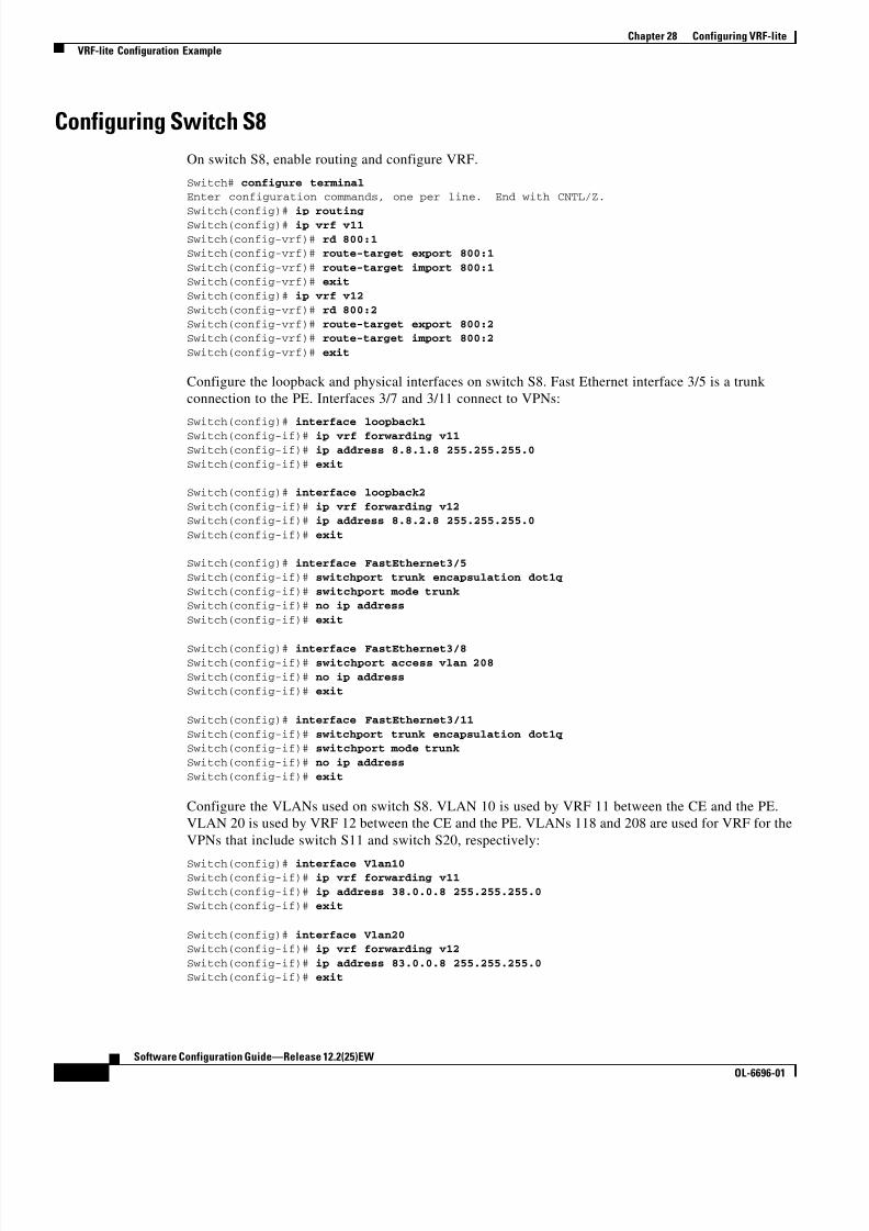
8/10/2019 Cisco ConfiguratioGuide SW4500 IOS
http://slidepdf.com/reader/full/cisco-configuratioguide-sw4500-ios 372/607
28-8
Software Configuration Guide—Release 12.2(25)EW
OL-6696-01
Chapter 28 Configuring VRF-lite
VRF-lite Configuration Example
Configuring Switch S8
On switch S8, enable routing and configure VRF.
Switch# configure terminalEnter configuration commands, one per line. End with CNTL/Z.
Switch(config)# ip routing Switch(config)# ip vrf v11
Switch(config-vrf)# rd 800:1Switch(config-vrf)# route-target export 800:1
Switch(config-vrf)# route-target import 800:1Switch(config-vrf)# exit
Switch(config)# ip vrf v12
Switch(config-vrf)# rd 800:2
Switch(config-vrf)# route-target export 800:2Switch(config-vrf)# route-target import 800:2
Switch(config-vrf)# exit
Configure the loopback and physical interfaces on switch S8. Fast Ethernet interface 3/5 is a trunk
connection to the PE. Interfaces 3/7 and 3/11 connect to VPNs:
Switch(config)# interface loopback1
Switch(config-if)# ip vrf forwarding v11Switch(config-if)# ip address 8.8.1.8 255.255.255.0
Switch(config-if)# exit
Switch(config)# interface loopback2
Switch(config-if)# ip vrf forwarding v12Switch(config-if)# ip address 8.8.2.8 255.255.255.0
Switch(config-if)# exit
Switch(config)# interface FastEthernet3/5
Switch(config-if)# switchport trunk encapsulation dot1q
Switch(config-if)# switchport mode trunkSwitch(config-if)# no ip address
Switch(config-if)# exit
Switch(config)# interface FastEthernet3/8Switch(config-if)# switchport access vlan 208
Switch(config-if)# no ip address
Switch(config-if)# exit
Switch(config)# interface FastEthernet3/11
Switch(config-if)# switchport trunk encapsulation dot1qSwitch(config-if)# switchport mode trunk
Switch(config-if)# no ip address
Switch(config-if)# exit
Configure the VLANs used on switch S8. VLAN 10 is used by VRF 11 between the CE and the PE.
VLAN 20 is used by VRF 12 between the CE and the PE. VLANs 118 and 208 are used for VRF for the
VPNs that include switch S11 and switch S20, respectively:
Switch(config)# interface Vlan10Switch(config-if)# ip vrf forwarding v11
Switch(config-if)# ip address 38.0.0.8 255.255.255.0
Switch(config-if)# exit
Switch(config)# interface Vlan20Switch(config-if)# ip vrf forwarding v12
Switch(config-if)# ip address 83.0.0.8 255.255.255.0Switch(config-if)# exit
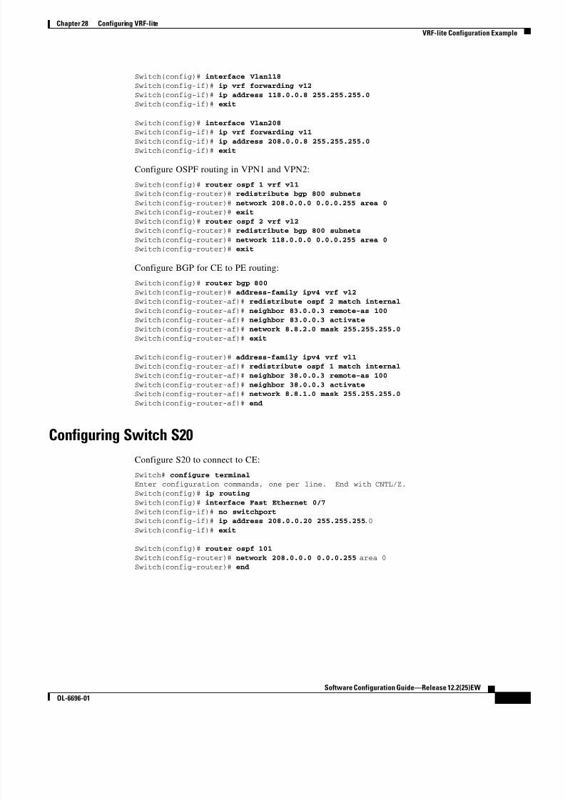
8/10/2019 Cisco ConfiguratioGuide SW4500 IOS
http://slidepdf.com/reader/full/cisco-configuratioguide-sw4500-ios 373/607
28-9
Software Configuration Guide—Release 12.2(25)EW
OL-6696-01
Chapter 28 Configuring VRF-lite
VRF-lite Configuration Example
Switch(config)# interface Vlan118
Switch(config-if)# ip vrf forwarding v12
Switch(config-if)# ip address 118.0.0.8 255.255.255.0Switch(config-if)# exit
Switch(config)# interface Vlan208Switch(config-if)# ip vrf forwarding v11
Switch(config-if)# ip address 208.0.0.8 255.255.255.0Switch(config-if)# exit
Configure OSPF routing in VPN1 and VPN2:
Switch(config)# router ospf 1 vrf vl1Switch(config-router)# redistribute bgp 800 subnets
Switch(config-router)# network 208.0.0.0 0.0.0.255 area 0Switch(config-router)# exit
Switch(config)# router ospf 2 vrf vl2
Switch(config-router)# redistribute bgp 800 subnets
Switch(config-router)# network 118.0.0.0 0.0.0.255 area 0Switch(config-router)# exit
Configure BGP for CE to PE routing:
Switch(config)# router bgp 800Switch(config-router)# address-family ipv4 vrf vl2Switch(config-router-af)# redistribute ospf 2 match internal
Switch(config-router-af)# neighbor 83.0.0.3 remote-as 100Switch(config-router-af)# neighbor 83.0.0.3 activate
Switch(config-router-af)# network 8.8.2.0 mask 255.255.255.0
Switch(config-router-af)# exit
Switch(config-router)# address-family ipv4 vrf vl1Switch(config-router-af)# redistribute ospf 1 match internal
Switch(config-router-af)# neighbor 38.0.0.3 remote-as 100
Switch(config-router-af)# neighbor 38.0.0.3 activateSwitch(config-router-af)# network 8.8.1.0 mask 255.255.255.0
Switch(config-router-af)# end
Configuring Switch S20
Configure S20 to connect to CE:
Switch# configure terminalEnter configuration commands, one per line. End with CNTL/Z.
Switch(config)# ip routing
Switch(config)# interface Fast Ethernet 0/7
Switch(config-if)# no switchportSwitch(config-if)# ip address 208.0.0.20 255.255.255.0
Switch(config-if)# exit
Switch(config)# router ospf 101
Switch(config-router)# network 208.0.0.0 0.0.0.255 area 0Switch(config-router)# end

8/10/2019 Cisco ConfiguratioGuide SW4500 IOS
http://slidepdf.com/reader/full/cisco-configuratioguide-sw4500-ios 374/607
28-10
Software Configuration Guide—Release 12.2(25)EW
OL-6696-01
Chapter 28 Configuring VRF-lite
VRF-lite Configuration Example
Configuring Switch S11
Configure S11 to connect to CE:
Switch# configure terminalEnter configuration commands, one per line. End with CNTL/Z.
Switch(config)# ip routingSwitch(config)# interface Gigabit Ethernet 0/3
Switch(config-if)# switchport trunk encapsulation dot1qSwitch(config-if)# switchport mode trunk
Switch(config-if)# no ip addressSwitch(config-if)# exit
Switch(config)# interface Vlan118
Switch(config-if)# ip address 118.0.0.11 255.255.255.0Switch(config-if)# exit
Switch(config)# router ospf 101
Switch(config-router)# network 118.0.0.0 0.0.0.255 area 0
Switch(config-router)# end
Configuring the PE Switch S3
On switch S3 (the router), these commands configure only the connections to switch S8:
Router# configure terminal Enter configuration commands, one per line. End with CNTL/Z.
Router(config)# ip vrf v1
Router(config-vrf)# rd 100:1
Router(config-vrf)# route-target export 100:1Router(config-vrf)# route-target import 100:1
Router(config-vrf)# exit
Router(config)# ip vrf v2
Router(config-vrf)# rd 100:2
Router(config-vrf)# route-target export 100:2Router(config-vrf)# route-target import 100:2
Router(config-vrf)# exit
Router(config)# ip cef
Router(config)# interface Loopback1
Router(config-if)# ip vrf forwarding v1
Router(config-if)# ip address 3.3.1.3 255.255.255.0Router(config-if)# exit
Router(config)# interface Loopback2
Router(config-if)# ip vrf forwarding v2
Router(config-if)# ip address 3.3.2.3 255.255.255.0
Router(config-if)# exit
Router(config)# interface Fast Ethernet3/0.10Router(config-if)# encapsulation dot1q 10
Router(config-if)# ip vrf forwarding v1
Router(config-if)# ip address 38.0.0.3 255.255.255.0Router(config-if)# exit
Router(config)# interface Fast Ethernet3/0.20
Router(config-if)# encapsulation dot1q 20Router(config-if)# ip vrf forwarding v2
Router(config-if)# ip address 83.0.0.3 255.255.255.0Router(config-if)# exit

8/10/2019 Cisco ConfiguratioGuide SW4500 IOS
http://slidepdf.com/reader/full/cisco-configuratioguide-sw4500-ios 375/607
28-11
Software Configuration Guide—Release 12.2(25)EW
OL-6696-01
Chapter 28 Configuring VRF-lite
Displaying VRF-lite Status
Router(config)# router bgp 100
Router(config-router)# address-family ipv4 vrf v2
Router(config-router-af)# neighbor 83.0.0.8 remote-as 800
Router(config-router-af)# neighbor 83.0.0.8 activateRouter(config-router-af)# network 3.3.2.0 mask 255.255.255.0
Router(config-router-af)# exit
Router(config-router)# address-family ipv4 vrf vlRouter(config-router-af)# neighbor 83.0.0.8 remote-as 800
Router(config-router-af)# neighbor 83.0.0.8 activateRouter(config-router-af)# network 3.3.1.0 mask 255.255.255.0
Router(config-router-af)# end
Displaying VRF-lite StatusTo display information about VRF-lite configuration and status, perform one of the following tasks:
Note For more information about the information in the displays, refer to the Cisco IOS Switching Services
Command Reference for Release 12.2 at:
http://www.cisco.com/univercd/cc/td/doc/product/software/ios122/122cgcr/fswtch_r
Command Purpose
Switch# show ip protocols vrf vrf-name Displays routing protocol information associated
with a VRF.
Switch# show ip route vrf vrf-name [connected] [ protocol [as-number ]] [list] [ mobile] [odr] [ profile] [static] [summary][supernets-only]
Displays IP routing table information associated
with a VRF.
Switch# show ip vrf [brief | detail | interfaces] [vrf-name ] Displays information about the defined VRF
instances.

8/10/2019 Cisco ConfiguratioGuide SW4500 IOS
http://slidepdf.com/reader/full/cisco-configuratioguide-sw4500-ios 376/607
28-12
Software Configuration Guide—Release 12.2(25)EW
OL-6696-01
Chapter 28 Configuring VRF-lite
Displaying VRF-lite Status

8/10/2019 Cisco ConfiguratioGuide SW4500 IOS
http://slidepdf.com/reader/full/cisco-configuratioguide-sw4500-ios 377/607
C H A P T E R
29-1
Software Configuration Guide—Release 12.2(25)EW
OL-6696-01
29
Configuring QoS
This chapter describes how to configure quality of service (QoS) by using automatic QoS (auto-QoS)
commands or by using standard QoS commands on a Catalyst 4500 series switch. It also provides
guidelines, procedures, and configuration examples.
This chapter consists of these sections:
• Overview of QoS, page 29-1
• Configuring Auto-QoS, page 29-16
• Configuring QoS, page 29-22
Note For complete syntax and usage information for the switch commands used in this chapter, refer to the
Catalyst 4500 Series Switch Cisco IOS Command Reference and related publications at
http://www.cisco.com/univercd/cc/td/doc/product/software/ios122/122cgcr/index.htm.
Overview of QoSTypically, networks operate on a best-effort delivery basis, which means that all traffic has equal priority
and an equal chance of being delivered in a timely manner. When congestion occurs, all traffic has an
equal chance of being dropped.
QoS selects network traffic (both unicast and multicast), prioritizes it according to its relative
importance, and uses congestion avoidance to provide priority-indexed treatment; QoS can also limit the
bandwidth used by network traffic. QoS can make network performance more predictable and bandwidth
utilization more effective.
This section contains the following subsections:
• Prioritization, page 29-2
• QoS Terminology, page 29-3
• Basic QoS Model, page 29-5
• Classification, page 29-5
• Policing and Marking, page 29-9
• Mapping Tables, page 29-13
• Queueing and Scheduling, page 29-13
• Packet Modification, page 29-15

8/10/2019 Cisco ConfiguratioGuide SW4500 IOS
http://slidepdf.com/reader/full/cisco-configuratioguide-sw4500-ios 378/607
29-2
Software Configuration Guide—Release 12.2(25)EW
OL-6696-01
Chapter 29 Configuring QoS
Overview of QoS
Prioritization
The QoS implementation for this release is based on the DiffServ architecture, an emerging standard
from the Internet Engineering Task Force (IETF). This architecture specifies that each packet is
classified upon entry into the network. The classification is carried in the IP packet header, using 6 bits
from the deprecated IP type of service (TOS) field to carry the classification ( class) information.Classification can also be carried in the Layer 2 frame. These special bits in the Layer 2 frame or
a Layer 3 packet are described here and shown in Figure 29-1:
• Prioritization values in Layer 2 frames:
Layer 2 Inter-Switch Link (ISL) frame headers have a 1-byte User field that carries an IEEE 802.1p
class of service (CoS) value in the three least-significant bits. On interfaces configured as Layer 2
ISL trunks, all traffic is in ISL frames.
Layer 2 802.1Q frame headers have a 2-byte Tag Control Information field that carries the CoS value
in the three most-significant bits, which are called the User Priority bits. On interfaces configured
as Layer 2 802.1Q trunks, all traffic is in 802.1Q frames except for traffic in the native VLAN.
Other frame types cannot carry Layer 2 CoS values.
Layer 2 CoS values range from 0 for low priority to 7 for high priority.
• Prioritization bits in Layer 3 packets:
Layer 3 IP packets can carry either an IP precedence value or a Differentiated Services Code Point
(DSCP) value. QoS supports the use of either value because DSCP values are backward-compatible
with IP precedence values.
IP precedence values range from 0 to 7.
DSCP values range from 0 to 63.
Figure 29-1 QoS Classification Layers in Frames and Packets
6 8 1 4 0
Encapsulated Packet
Layer 2header
IP header
3 bits used for CoS
Data
Layer 2 ISL Frame
ISL header(26 bytes)
Encapsulated frame ...FCS
(4 bytes)
Layer 2 802.1Q/P Frame
PreambleStart frame
delimiter DA
Len
SA Tag PT Data FCS
Layer 3 IPv4 Packet
Versionlength
ToS(1 byte)
ID Offset TTL Proto FCS IP-SA IP-DA Data
3 bits used for CoS (user priority)
IP precedence or DSCP

8/10/2019 Cisco ConfiguratioGuide SW4500 IOS
http://slidepdf.com/reader/full/cisco-configuratioguide-sw4500-ios 379/607
29-3
Software Configuration Guide—Release 12.2(25)EW
OL-6696-01
Chapter 29 Configuring QoS
Overview of QoS
All switches and routers across the Internet rely on the class information to provide the same forwarding
treatment to packets with the same class information and different treatment to packets with different
class information. The class information in the packet can be assigned by end hosts or by switches or
routers along the way, based on a configured policy, detailed examination of the packet, or both. Detailed
examination of the packet is expected to happen closer to the edge of the network so that the core
switches and routers are not overloaded.
Switches and routers along the path can use the class information to limit the amount of resources
allocated per traffic class. The behavior of an individual device when handling traffic in the DiffServ
architecture is called per-hop behavior. If all devices along a path provide a consistent per-hop behavior,
you can construct an end-to-end QoS solution.
Implementing QoS in your network can be a simple or complex task and depends on the QoS features
offered by your internetworking devices, the traffic types and patterns in your network, and the
granularity of control you need over incoming and outgoing traffic.
QoS Terminology
The following terms are used when discussing QoS features:• Packets carry traffic at Layer 3.
• Frames carry traffic at Layer 2. Layer 2 frames carry Layer 3 packets.
• Labels are prioritization values carried in Layer 3 packets and Layer 2 frames:
– Layer 2 class of service (CoS) values, which range between zero for low priority and seven for
high priority:
Layer 2 Inter-Switch Link (ISL) frame headers have a 1-byte User field that carries an IEEE
802.1p CoS value in the three least significant bits.
Layer 2 802.1Q frame headers have a 2-byte Tag Control Information field that carries the CoS
value in the three most significant bits, which are called the User Priority bits.
Other frame types cannot carry Layer 2 CoS values.
Note On interfaces configured as Layer 2 ISL trunks, all traffic is in ISL frames. On interfaces
configured as Layer 2 802.1Q trunks, all traffic is in 802.1Q frames except for traffic in the
native VLAN.
– Layer 3 IP precedence values—The IP version 4 specification defines the three most significant
bits of the 1-byte ToS field as IP precedence. IP precedence values range between zero for low
priority and seven for high priority.
– Layer 3 differentiated services code point (DSCP) values—The Internet Engineering Task
Force (IETF) has defined the six most significant bits of the 1-byte IP ToS field as the DSCP.
The per-hop behavior represented by a particular DSCP value is configurable. DSCP valuesrange between 0 and 63. See the “Configuring DSCP Maps” section on page 29-45.
Note Layer 3 IP packets can carry either an IP precedence value or a DSCP value. QoS supports
the use of either value, since DSCP values are backwards compatible with IP precedence
values. See Table 29-1.

8/10/2019 Cisco ConfiguratioGuide SW4500 IOS
http://slidepdf.com/reader/full/cisco-configuratioguide-sw4500-ios 380/607
29-4
Software Configuration Guide—Release 12.2(25)EW
OL-6696-01
Chapter 29 Configuring QoS
Overview of QoS
• Classification is the selection of traffic to be marked.
• Marking, according to RFC 2475, is the process of setting a Layer 3 DSCP value in a packet; in this
publication, the definition of marking is extended to include setting Layer 2 CoS values.• Scheduling is the assignment of Layer 2 frames to a queue. QoS assigns frames to a queue based on
internal DSCP values as shown in Internal DSCP Values, page 29-12.
• Policing is limiting bandwidth used by a flow of traffic. Policing can mark or drop traffic.
Table 29-1 IP Precedence and DSCP Values
3-bit IP
Precedence
6 MSb1 of ToS
1. MSb = most significant bit
6-bit
DSCP
3-bit IP
Precedence
6 MSb1 of ToS 6-bit
DSCP8 7 6 5 4 3 8 7 6 5 4 3
0 0
0
0
0
0
0
0
0
0
0
0
0
0
0
0
0
0
0
0
0
0
0
0
0
0
0
0
0
1
1
1
1
0
0
1
1
0
0
1
1
0
1
0
1
0
1
0
1
0
1
2
3
4
5
6
7
4 1
1
1
1
1
1
1
1
0
0
0
0
0
0
0
0
0
0
0
0
0
0
0
0
0
0
0
0
1
1
1
1
0
0
1
1
0
0
1
1
0
1
0
1
0
1
0
1
32
33
34
35
36
37
38
39
1 0
0
0
0
0
00
0
0
0
0
0
0
00
0
1
1
1
1
1
11
1
0
0
0
0
1
11
1
0
0
1
1
0
01
1
0
1
0
1
0
10
1
8
9
10
11
12
1314
15
5 1
1
1
1
1
11
1
0
0
0
0
0
00
0
1
1
1
1
1
11
1
0
0
0
0
1
11
1
0
0
1
1
0
01
1
0
1
0
1
0
10
1
40
41
42
43
44
4546
47
2 0
0
0
0
0
0
0
0
1
1
1
1
1
1
1
1
0
0
0
0
0
0
0
0
0
0
0
0
1
1
1
1
0
0
1
1
0
0
1
1
0
1
0
1
0
1
0
1
16
17
18
19
20
21
22
23
6 1
1
1
1
1
1
1
1
1
1
1
1
1
1
1
1
0
0
0
0
0
0
0
0
0
0
0
0
1
1
1
1
0
0
1
1
0
0
1
1
0
1
0
1
0
1
0
1
48
49
50
51
52
53
54
55
3 0
00
0
0
0
0
0
1
11
1
1
1
1
1
1
11
1
1
1
1
1
0
00
0
1
1
1
1
0
01
1
0
0
1
1
0
10
1
0
1
0
1
24
2526
27
28
29
30
31
7 1
11
1
1
1
1
1
1
11
1
1
1
1
1
1
11
1
1
1
1
1
0
00
0
1
1
1
1
0
01
1
0
0
1
1
0
10
1
0
1
0
1
56
5758
59
60
61
62
63
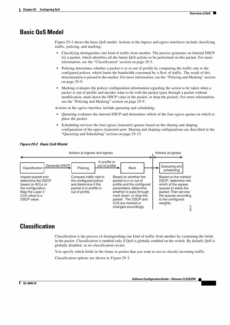
8/10/2019 Cisco ConfiguratioGuide SW4500 IOS
http://slidepdf.com/reader/full/cisco-configuratioguide-sw4500-ios 381/607
29-5
Software Configuration Guide—Release 12.2(25)EW
OL-6696-01
Chapter 29 Configuring QoS
Overview of QoS
Basic QoS Model
Figure 29-2 shows the basic QoS model. Actions at the ingress and egress interfaces include classifying
traffic, policing, and marking:
• Classifying distinguishes one kind of traffic from another. The process generates an internal DSCP
for a packet, which identifies all the future QoS actions to be performed on this packet. For moreinformation, see the “Classification” section on page 29-5.
• Policing determines whether a packet is in or out of profile by comparing the traffic rate to the
configured policer, which limits the bandwidth consumed by a flow of traffic. The result of this
determination is passed to the marker. For more information, see the “Policing and Marking” section
on page 29-9.
• Marking evaluates the policer configuration information regarding the action to be taken when a
packet is out of profile and decides what to do with the packet (pass through a packet without
modification, mark down the DSCP value in the packet, or drop the packet). For more information,
see the “Policing and Marking” section on page 29-9.
Actions at the egress interface include queueing and scheduling:
• Queueing evaluates the internal DSCP and determines which of the four egress queues in which toplace the packet.
• Scheduling services the four egress (transmit) queues based on the sharing and shaping
configuration of the egress (transmit) port. Sharing and shaping configurations are described in the
“Queueing and Scheduling” section on page 29-13.
Figure 29-2 Basic QoS Model
ClassificationClassification is the process of distinguishing one kind of traffic from another by examining the fields
in the packet. Classification is enabled only if QoS is globally enabled on the switch. By default, QoS is
globally disabled, so no classification occurs.
You specify which fields in the frame or packet that you want to use to classify incoming traffic.
Classification options are shown in Figure 29-3.
6 8 1 4 1
Classification PolicingGenerate DSCP
Actions at ingress and egress Actions at egress
Mark
In profile orout of profile
Inspect packet anddetermine the DSCPbased on ACLs orthe configuration.Map the Layer 2CoS value to aDSCP value.
Compare traffic rate tothe configured policerand determine if thepacket is in profile orout of profile.
Based on whether thepacket is in or out ofprofile and the configuredparameters, determinewhether to pass through,mark down, or drop thepacket. The DSCP andCoS are marked orchanged accordingly.
Queueing and
scheduling
Based on the markedDSCP, determine intowhich of the egressqueues to place thepacket. Then servicethe queues accordingto the configuredweights.

8/10/2019 Cisco ConfiguratioGuide SW4500 IOS
http://slidepdf.com/reader/full/cisco-configuratioguide-sw4500-ios 382/607
29-6
Software Configuration Guide—Release 12.2(25)EW
OL-6696-01
Chapter 29 Configuring QoS
Overview of QoS
For non-IP traffic, you have the following classification options:
• Use the port default. If the packet is a non-IP packet, assign the default port DSCP value to the
incoming packet.
• Trust the CoS value in the incoming frame (configure the port to trust CoS). Then use the
configurable CoS-to-DSCP map to generate the internal DSCP value. Layer 2 ISL frame headers
carry the CoS value in the three least-significant bits of the 1-byte User field. Layer 2 802.1Q frameheaders carry the CoS value in the three most-significant bits of the Tag Control Information field.
CoS values range from 0 for low priority to 7 for high priority. If the frame does not contain a CoS
value, assign the default port CoS to the incoming frame.
The trust DSCP configuration is meaningless for non-IP traffic. If you configure a port with trust
DSCP and non-IP traffic is received, the switch assigns the default port DSCP.
For IP traffic, you have the following classification options:
• Trust the IP DSCP in the incoming packet (configure the port to trust DSCP), and assign the same
DSCP to the packet for internal use. The IETF defines the six most-significant bits of the 1-byte
Type of Service (ToS) field as the DSCP. The priority represented by a particular DSCP value is
configurable. DSCP values range from 0 to 63.
• Trust the CoS value (if present) in the incoming packet, and generate the DSCP by using theCoS-to-DSCP map.
• Perform the classification based on a configured IP standard or extended ACL, which examines
various fields in the IP header. If no ACL is configured, the packet is assigned the default DSCP
based on the trust state of the ingress port; otherwise, the policy map specifies the DSCP to assign
to the incoming frame.
For information on the maps described in this section, see the “Mapping Tables” section on page 29-13.
For configuration information on port trust states, see the “Configuring the Trust State of Interfaces”
section on page 29-40.

8/10/2019 Cisco ConfiguratioGuide SW4500 IOS
http://slidepdf.com/reader/full/cisco-configuratioguide-sw4500-ios 383/607
29-7
Software Configuration Guide—Release 12.2(25)EW
OL-6696-01
Chapter 29 Configuring QoS
Overview of QoS
Figure 29-3 Classification Flowchart
Yes
Yes
Yes
No
No
No
No
No
No
No
No No
Yes Yes
Yes Yes
Yes
Yes
Read interfaceconfiguration for classification.
Is there aQoS policy attached
to this interface?
TrustDSCP?
IPPacket?
Is Trustconfigured for this
traffic class
TrustCoS?
Packet
recieved withTag (with
CoS)?
Are thereany more
traffic classes withQoS
actions?
Does thepacket satisfy
the classificationmatch criteria?
Does thepolicy action
specify DSCP forthis traffic
class
Start
Done
Use Policy Trustconfiguration.
Use PortCoS
Use Portdefault DSCP
Use configuredDSCP in ACL
Use DSCP fromthe packet
Generate DSCP from CoSusing CoS to DSCP map
Use Port Trustconfiguration.
Assign Port defaultDSCP
6 3 7 0 4

8/10/2019 Cisco ConfiguratioGuide SW4500 IOS
http://slidepdf.com/reader/full/cisco-configuratioguide-sw4500-ios 384/607
29-8
Software Configuration Guide—Release 12.2(25)EW
OL-6696-01
Chapter 29 Configuring QoS
Overview of QoS
Classification Based on QoS ACLs
A packet can be classified for QoS using multiple match criteria, and the classification can specify
whether the packet should match all of the specified match criteria or at least one of the match criteria.
To define a QoS classifier, you can provide the match criteria using the match statements in a class map.
In the 'match' statements, you can specify the fields in the packet to match on, or you can use IP standard
or IP extended ACLs. For more information, see the “Classification Based on Class Maps and Policy
Maps” section on page 29-8.
If the class map is configured to match all the match criteria, then a packet must satisfy all the match
statements in the class map before the QoS action is taken. The QoS action for the packet is not taken if
the packet does not match even one match criterion in the class map.
If the class map is configured to match at least one match criterion, then a packet must satisfy at least
one of the match statements in the class map before the QoS action is taken. The QoS action for the
packet is not taken if the packet does not match any match criteria in the class map.
Note When you use the IP standard and IP extended ACLs, the permit and deny ACEs in the ACL have a
slightly different meaning in the QoS context.
• If a packet encounters (and satisfies) an ACE with a “permit,” then the packet “matches” the match
criterion in the QoS classification.
• If a packet encounters (and satisfies) an ACE with a “deny,” then the packet “does not match” the
match criterion in the QoS classification.
• If no match with a permit action is encountered and all the ACEs have been examined, then the
packet “does not match” the criterion in the QoS classification.
Note When creating an access list, remember that, by default, the end of the access list contains an implicit
deny statement for everything if it did not find a match before reaching the end.
After a traffic class has been defined with the class map, you can create a policy that defines the QoS
actions for a traffic class. A policy might contain multiple classes with actions specified for each one of
them. A policy might include commands to classify the class as a particular aggregate (for example,
assign a DSCP) or rate limit the class. This policy is then attached to a particular port on which it
becomes effective.
You implement IP ACLs to classify IP traffic by using the access-list global configuration command.
For configuration information, see the “Configuring a QoS Policy” section on page 29-28.
Classification Based on Class Maps and Policy Maps
A class map is a mechanism that you use to isolate and name a specific traffic flow (or class) from all
other traffic. The class map defines the criterion used to match against a specific traffic flow to furtherclassify it; the criteria can include matching the access group defined by the ACL or matching a specific
list of DSCP or IP precedence values. If you have more than one type of traffic that you want to classify,
you can create another class map and use a different name. After a packet is matched against the
class-map criteria, you can specify the QoS actions via a policy map.
A policy map specifies the QoS actions for the traffic classes. Actions can include trusting the CoS or
DSCP values in the traffic class; setting a specific DSCP or IP precedence value in the traffic class; or
specifying the traffic bandwidth limitations and the action to take when the traffic is out of profile.
Before a policy map can be effective, you must attach it to an interface.

8/10/2019 Cisco ConfiguratioGuide SW4500 IOS
http://slidepdf.com/reader/full/cisco-configuratioguide-sw4500-ios 385/607
29-9
Software Configuration Guide—Release 12.2(25)EW
OL-6696-01
Chapter 29 Configuring QoS
Overview of QoS
You create a class map by using the class-map global configuration command. When you enter the
class-map command, the switch enters the class-map configuration mode. In this mode, you define the
match criteria for the traffic by using the match class-map configuration command.
You create and name a policy map by using the policy-map global configuration command. When you
enter this command, the switch enters the policy-map configuration mode. In this mode, you specify the
actions to take on a specific traffic class by using the trust or set policy-map configuration andpolicy-map class configuration commands. To make the policy map effective, you attach it to an interface
by using the service-policy interface configuration command.
The policy map can also contain commands that define the policer, (the bandwidth limitations of the
traffic) and the action to take if the limits are exceeded. For more information, see the “Policing and
Marking” section on page 29-9.
A policy map also has these characteristics:
• A policy map can contain up to 255 class statements.
• You can have different classes within a policy map.
• A policy-map trust state supersedes an interface trust state.
For configuration information, see the “Configuring a QoS Policy” section on page 29-28.
Policing and Marking
After a packet is classified and has an internal DSCP value assigned to it, the policing and marking
process can begin as shown in Figure 29-4.
Policing involves creating a policer that specifies the bandwidth limits for the traffic. Packets that exceed
the limits are out of profile or nonconforming . Each policer specifies the action to take for packets that
are in or out of profile. These actions, carried out by the marker, include passing through the packet
without modification, dropping the packet, or marking down the packet with a new DSCP value that is
obtained from the configurable policed-DSCP map. For information on the policed-DSCP map, see the
“Mapping Tables” section on page 29-13.
You can create these types of policers:
• Individual
QoS applies the bandwidth limits specified in the policer separately to each matched traffic class for
each port/VLAN to which the policy map is attached to. You configure this type of policer within a
policy map by using the police command under policy-map class configuration mode.
• Aggregate
QoS applies the bandwidth limits specified in an aggregate policer cumulatively to all matched
traffic flows. You configure this type of policer by specifying the aggregate policer name within a
policy map by using the police aggregate policy-map configuration command. You specify the
bandwidth limits of the policer by using the qos aggregate-policer global configuration command.
In this way, the aggregate policer is shared by multiple classes of traffic within a policy map.• Flow or Microflow
With flow-based policing, all the identified flows are policed to the specified rate individually.
Because the flows are dynamic, key distinguishing fields must be configured in class maps. Two
flow-matching options are provided: source ip based (each flow with unique source IP address is
treated as a new flow) and destination ip based (each flow with unique destination IP address is
treated as new flow). For information on flow-based policer configuration, see “Configuring User
Based Rate Limiting” on page 35.

8/10/2019 Cisco ConfiguratioGuide SW4500 IOS
http://slidepdf.com/reader/full/cisco-configuratioguide-sw4500-ios 386/607
29-10
Software Configuration Guide—Release 12.2(25)EW
OL-6696-01
Chapter 29 Configuring QoS
Overview of QoS
When configuring policing and policers, keep these items in mind:
• For IP packets, only the length of the IP payload (the total length field in the IP header) is used by
the policer for policing computation. The Layer 2 header and trailer length are not taken into
account. For example, for a 64-byte Ethernet II IP packet, only 46 bytes are taken into account for
policing (64 bytes - 14 byte Ethernet Header - 4 bytes Ethernet CRC).
For non-IP packets, the Layer 2 length as specified in the Layer 2 Header is used by the policer forpolicing computation. To specify additional Layer 2 encapsulation length when policing IP packets,
use the qos account layer2 encapsulation command.
• By default, no policers are configured.
• Only the average rate and committed burst parameters are configurable.
• Policing for individual and aggregate policers can occur in ingress and egress interfaces.
– With the Supervisor Engine V-10GE (WS-X4516-10GE), 8192 policers are supported on
ingress and on egress.
– With all other supervisor engines, 1024 policers are supported on ingress and on egress.
Note Four policers in ingress and egress direction are reserved.
• Policers can be of individual or aggregate type. On the Supervisor Engine V-10GE, flow-based
policers are supported.
• Policing for flow policers can occur on ingress Layer 3 interfaces only.
– 512 unique flow policers can be configured on the Supervisor Engine V-10GE.
Note Because one flow policer is reserved by software, 511 unique flow policers can be defined.
– Greater than 100,000 flows can be microflow policed. For details, refer to the “Checking for
Required Hardware” section on page 40-6.
Note Microflow currently supports two flow matching options (source IP address based and
destination IP address based). When microflow policing is used together with Netflow Statistics
Collection, full flow statistics for the flows matching the source IP address or destination IP
address will not be available. For information on configuring Netflow Statistics, refer to
“Enabling NetFlow Statistics Collection” on page 7.
• On an interface configured for QoS, all traffic received or sent through the interface is classified,
policed, and marked according to the policy map attached to the interface. However, if the interface
is configured to use VLAN-based QoS (using the qos vlan-based command), the traffic received or
sent through the interface is classified, policed, and marked according to the policy map attached to
the VLAN (configured on the VLAN interface) to which the packet belongs. If there is no policymap attached to the VLAN to which the packet belongs, the policy map attached to the interface is
used.
After you configure the policy map and policing actions, attach the policy to an ingress or egress
interface by using the service-policy interface configuration command. For configuration information,
see the “Configuring a QoS Policy” section on page 29-28 and the “Creating Named Aggregate Policers”
section on page 29-26.

8/10/2019 Cisco ConfiguratioGuide SW4500 IOS
http://slidepdf.com/reader/full/cisco-configuratioguide-sw4500-ios 387/607
29-11
Software Configuration Guide—Release 12.2(25)EW
OL-6696-01
Chapter 29 Configuring QoS
Overview of QoS
Figure 29-4 Policing and Marking Flowchart
Start
Use QoSpolicy onthe VLAN
Use QoSpolicy onthe port
Done
Is therea QoS Policyattached to the
port?
Are thereany more QoS
ACLs in thepolicy?
Does the
packet match a"permit" ACB inthe ACL?
Are thereany more QoS
ACLs in thepolicy?
Is the packet
in-profile forthe policer?
Out of ProfileAction?
Is theport QoS VLAN-
based?
Is there a QoSPolicy attached to the
VLAN to which thepacket belongs
Is there a QoSPolicy attached to the
VLAN to which thepacket belongs
6 3 7 0 3
Mark-down
Mark-down
Drop
Drop
Transmit
No
No
No
No
No
No
Yes
Yes
No
Yes
Yes
Yes
Yes
Yes
Yes

8/10/2019 Cisco ConfiguratioGuide SW4500 IOS
http://slidepdf.com/reader/full/cisco-configuratioguide-sw4500-ios 388/607
29-12
Software Configuration Guide—Release 12.2(25)EW
OL-6696-01
Chapter 29 Configuring QoS
Overview of QoS
Internal DSCP Values
The following sections describe the internal DSCP values:
• Internal DSCP Sources, page 29-12
• Egress ToS and CoS Sources, page 29-12
Internal DSCP Sources
During processing, QoS represents the priority of all traffic (including non-IP traffic) with an internal
DSCP value. QoS derives the internal DSCP value from the following:
• For trust-CoS traffic, from received or ingress interface Layer 2 CoS values
• For trust-DSCP traffic, from received or ingress interface DSCP values
• For untrusted traffic, from ingress interface DSCP value
The trust state of traffic is the trust state of the ingress interface unless set otherwise by a policy action
for this traffic class.
QoS uses configurable mapping tables to derive the internal 6-bit DSCP value from CoS, which are 3-bit
values (see the“Configuring DSCP Maps” section on page 29-45).
Egress ToS and CoS Sources
For egress IP traffic, QoS creates a ToS byte from the internal DSCP value and sends it to the egress
interface to be written into IP packets. For trust-dscp and untrusted IP traffic, the ToS byte includes
the original 2 least-significant bits from the received ToS byte.
Note The internal ToS value can mimic an IP precedence value (see Table 29-1 on page 29-4).
For all egress traffic, QoS uses a configurable mapping table to derive a CoS value from the internal ToS
value associated with traffic (see the “Configuring the DSCP-to-CoS Map” section on page 29-47). QoSsends the CoS value to be written into ISL and 802.1Q frames.
For traffic received on an ingress interface configured to trust CoS using the qos trust cos command, the
transmit CoS is always the incoming packet CoS (or the ingress interface default CoS if the packet is
received untagged).
When the interface trust state is not configured to trust dscp using the qos trust dscp command, the
security and QoS ACL classification will always use the interface DSCP and not the incoming packet
DSCP.

8/10/2019 Cisco ConfiguratioGuide SW4500 IOS
http://slidepdf.com/reader/full/cisco-configuratioguide-sw4500-ios 389/607
29-13
Software Configuration Guide—Release 12.2(25)EW
OL-6696-01
Chapter 29 Configuring QoS
Overview of QoS
Mapping Tables
During QoS processing, the switch represents the priority of all traffic (including non-IP traffic) with an
internal DSCP value:
• During classification, QoS uses configurable mapping tables to derive the internal DSCP (a 6-bit
value) from received CoS. These maps include the CoS-to-DSCP map.
• During policing, QoS can assign another DSCP value to an IP or non-IP packet (if the packet is out
of profile and the policer specifies a marked down DSCP value). This configurable map is called the
policed-DSCP map.
• Before the traffic reaches the scheduling stage, QoS uses the internal DSCP to select one of the four
egress queues for output processing. The DSCP-to-egress queue mapping can be configured using
the qos map dscp to tx-queue command.
The CoS-to-DSCP and DSCP-to-CoS map have default values that might or might not be appropriate for
your network.
For configuration information, see the “Configuring DSCP Maps” section on page 29-45.
Queueing and Scheduling
Each physical port has four transmit queues (egress queues). Each packet that needs to be transmitted is
enqueued to one of the transmit queues. The transmit queues are then serviced based on the transmit
queue scheduling algorithm.
Once the final transmit DSCP is computed (including any markdown of DSCP), the transmit DSCP to
transmit queue mapping configuration determines the transmit queue. The packet is placed in the
transmit queue of the transmit port, determined from the transmit DSCP. Use the qos map dscp to
tx-queue command to configure the transmit DSCP to transmit queue mapping. The transmit DSCP is
the internal DSCP value if the packet is a non-IP packet as determined by the QoS policies and trust
configuration on the ingress and egress ports.
For configuration information, see the “Configuring Transmit Queues” section on page 29-43.
Active Queue Management
Active queue management (AQM) is the pro-active approach of informing you about congestion before
a buffer overflow occurs. AQM is done using Dynamic buffer limiting (DBL). DBL tracks the queue
length for each traffic flow in the switch. When the queue length of a flow exceeds its limit, DBL will
drop packets or set the Explicit Congestion Notification (ECN) bits in the packet headers.
DBL classifies flows in two categories, adaptive and aggressive. Adaptive flows reduce the rate of packet
transmission once it receives congestion notification. Aggressive flows do not take any corrective action
in response to congestion notification. For every active flow the switch maintains two parameters,
“buffersUsed” and “credits”. All flows start with “max-credits”, a global parameter. When a flow withcredits less than “aggressive-credits” (another global parameter) it is considered an aggressive flow and
is given a small buffer limit called “aggressiveBufferLimit”.
Queue length is measured by the number of packets. The number of packets in the queue determines the
amount of buffer space that a flow is given. When a f low has a high queue length the computed value is
lowered. This allows new incoming flows to receive buffer space in the queue. This allows all flows to
get a proportional share of packets through the queue.

8/10/2019 Cisco ConfiguratioGuide SW4500 IOS
http://slidepdf.com/reader/full/cisco-configuratioguide-sw4500-ios 390/607
29-14
Software Configuration Guide—Release 12.2(25)EW
OL-6696-01
Chapter 29 Configuring QoS
Overview of QoS
Sharing Link Bandwidth Among Transmit Queues
The four transmit queues for a transmit port share the available link bandwidth of that t ransmit port. You
can set the link bandwidth to be shared differently among the transmit queues using bandwidth
command in interface transmit queue configuration mode. With this command, you assign the minimum
guaranteed bandwidth for each transmit queue.
By default, all queues are scheduled in a round robin manner.
For systems using Supervisor Engine II-Plus, Supervisor Engine II-Plus TS, Supervisor Engine III, and
Supervisor Engine IV, bandwidth can be configured on these ports only:
• Uplink ports on supervisor engines
• Ports on the WS-X4306-GB module
• The 2 1000BASE-X ports on the WS-X4232-GB-RJ module
• The first 2 ports on the WS-X4418-GB module
• The two 1000BASE-X ports on the WS-X4412-2GB-TX module
For systems using Supervisor Engine V, bandwidth can be configured on all ports (10/100 Fast Ethernet,
10/100/1000BASE-T, and 1000BASE-X).
Strict Priority / Low Latency Queueing
You can configure transmit queue 3 on each port with higher priority using the priority high tx-queue
configuration command in the interface configuration mode. When transmit queue 3 is configured with
higher priority, packets in transmit queue 3 are scheduled ahead of packets in other queues.
When transmit queue 3 is configured at a higher priority, the packets are scheduled for transmission
before the other transmit queues only if it has not met the allocated bandwidth sharing configuration.
Any traffic that exceeds the configured shape rate will be queued and transmitted at the configured rate.
If the burst of traffic, exceeds the size of the queue, packets will be dropped to maintain transmission at
the configured shape rate.
Traffic Shaping
Traffic Shaping provides the ability to control the rate of outgoing traffic in order to make sure that the
traffic conforms to the maximum rate of transmission contracted for it. Traffic that meets certain profile
can be shaped to meet the downstream traffic rate requirements to handle any data rate mismatches.
Each transmit queue can be configured to transmit a maximum rate using the shape command. The
configuration allows you to specify the maximum rate of traffic. Any traffic that exceeds the configured
shape rate will be queued and transmitted at the configured rate. If the burst of traffic exceeds the size
of the queue, packets will be dropped to maintain transmission at the configured shape rate.

8/10/2019 Cisco ConfiguratioGuide SW4500 IOS
http://slidepdf.com/reader/full/cisco-configuratioguide-sw4500-ios 391/607
29-15
Software Configuration Guide—Release 12.2(25)EW
OL-6696-01
Chapter 29 Configuring QoS
Overview of QoS
Packet Modification
A packet is classified, policed, and queued to provide QoS. Packet modifications can occur during this
process:
• For IP packets, classification involves assigning a DSCP to the packet. However, the packet is not
modified at this stage; only an indication of the assigned DSCP is carried along. The reason for thisis that QoS classification and ACL lookup occur in parallel, and it is possible that the ACL specifies
that the packet should be denied and logged. In this situation, the packet is forwarded with its
original DSCP to the CPU, where it is again processed through ACL software.
• For non-IP packets, classification involves assigning an internal DSCP to the packet, but because
there is no DSCP in the non-IP packet, no overwrite occurs. Instead, the internal DSCP is used both
for queueing and scheduling decisions and for writing the CoS priority value in the tag if the packet
is being transmitted on either an ISL or 802.1Q trunk port.
• During policing, IP and non-IP packets can have another DSCP assigned to them (if they are out of
profile and the policer specifies a markdown DSCP). Once again, the DSCP in the packet is not
modified, but an indication of the marked-down value is carried along. For IP packets, the packet
modification occurs at a later stage.
QoS and Software Processed Packets
The Catalyst 4500 platform does not apply the QoS marking or policing configuration for any packets
that are forwarded or generated by the Cisco IOS software. This means that any input or output QoS
policy configured on the port or VLAN is not applied to packets if the Cisco IOS is forwarding or
generating packets.
However, Cisco IOS marks all the generated control packets appropriately and uses the internal IP DSCP
to determine the transmit queue on the output transmission interface. For IP packets, the internal IP
DSCP is the IP DSCP field in the IP packet. For non-IP packets, Cisco IOS assigns a packet priority
internally and maps it to an internal IP DSCP value.
Cisco IOS assigns an IP precedence of 6 to routing protocol packets on the control plane. As noted in
RFC 791,"The Internetwork Control designation is intended for use by gateway control originators
only." Specifically, Cisco IOS marks the following IP-based control packets: Open Shortest Path First
(OSPF), Routing Information Protocol (RIP), Enhanced Interior Gateway Routing Protocol (EIGRP)
hellos, and keepalives. Telnet packets to and from the router also receive an IP precedence value of 6.
The assigned value remains with the packets when the output interface transmits them into the network
For Layer 2 control protocols, the software assigns an internal IP DSCP. Typically, Layer 2 control
protocol packets are assigned an internal DSCP value of 48 (corresponding to an IP precedence value of
6).
The internal IP DSCP is used to determine the transmit queue to which the packet is enqueued on the
transmission interface. See “Configuring Transmit Queues” on page 43 for details on how to configure
the DSCP to transmit queues.The internal IP DSCP is also used to determine the transmit CoS marking if the packet is transmitted
with a IEEE 802.1q or ISL tag on a trunk interface. See “Configuring the DSCP-to-CoS Map” on page 47
for details on how to configure the DSCP to CoS mapping.

8/10/2019 Cisco ConfiguratioGuide SW4500 IOS
http://slidepdf.com/reader/full/cisco-configuratioguide-sw4500-ios 392/607
29-16
Software Configuration Guide—Release 12.2(25)EW
OL-6696-01
Chapter 29 Configuring QoS
Configuring Auto-QoS
Configuring Auto-QoSYou can use the auto-QoS feature to simplify the deployment of existing QoS features. Auto-QoS makes
assumptions about the network design, and as a result, the switch can prioritize different traffic flows
and appropriately use the egress queues instead of using the default QoS behavior. (The default is that
QoS is disabled. The switch then offers best-effort service to each packet, regardless of the packetcontent or size, and sends it from a single queue.)
When you enable auto-QoS, it automatically classifies traffic based on ingress packet label. The switch
uses the resulting classification to choose the appropriate egress queue.
You use auto-QoS commands to identify ports connected to Cisco IP phones and to identify ports that
receive trusted voice over IP (VoIP) traffic through an uplink. Auto-QoS then performs these functions:
• Detects the presence or absence of IP phones
• Configures QoS classification
• Configures egress queues
These sections describe how to configure auto-QoS on your switch:
• Generated Auto-QoS Configuration, page 29-16
• Effects of Auto-QoS on the Configuration, page 29-17
• Configuration Guidelines, page 29-17
• Enabling Auto-QoS for VoIP, page 29-18
Generated Auto-QoS Configuration
By default, auto-QoS is disabled on all interfaces.
When you enable the auto-QoS feature on the first interface, these automatic actions occur:
• QoS is globally enabled (qos global configuration command).• DBL is enabled globally (qos dbl global configuration command)
• When you enter the auto qos voip trust interface configuration command, the ingress classification
on the specified interface is set to trust the CoS label received in the packet if the specified interface
is configured as Layer 2 (and is set to trust DSCP if the interface is configured as Layer 3). (See
Table 29-2.)
• When you enter the auto qos voip cisco-phone interface configuration command, the trusted
boundary feature is enabled. It uses the Cisco Discovery Protocol (CDP) to detect the presence or
absence of a Cisco IP phone. When a Cisco IP phone is detected, the ingress classification on the
interface is set to trust the cos label received in the packet, if the interface is configured as Layer 2.
(The classification is set to trust DSCP if the interface is configured as Layer 3.) When a Cisco IP
phone is absent, the ingress classification is set to not trust the cos label in the packet.
For information about the trusted boundary feature, see the “Configuring a Trusted Boundary to
Ensure Port Security” section on page 29-24.
When you enable auto-QoS by using the auto qos voip cisco-phone or the auto qos voip trust interface
configuration commands, the switch automatically generates a QoS configuration based on the traffic
type and ingress packet label and applies the commands listed in Table 29-2 to the interface.

8/10/2019 Cisco ConfiguratioGuide SW4500 IOS
http://slidepdf.com/reader/full/cisco-configuratioguide-sw4500-ios 393/607
29-17
Software Configuration Guide—Release 12.2(25)EW
OL-6696-01
Chapter 29 Configuring QoS
Configuring Auto-QoS
Effects of Auto-QoS on the Configuration
When auto-QoS is enabled, the auto qos voip interface configuration command and the generated
configuration are added to the running configuration.
Configuration Guidelines
Before configuring auto-QoS, you should be aware of this information:
• In this release, auto-QoS configures the switch only for VoIP with Cisco IP phones.
• To take advantage of the auto-QoS defaults, do not configure any standard-QoS commands before
entering the auto-QoS commands. If necessary, you can fine-tune the QoS configuration, but we
recommend that you do so only after the auto-QoS configuration is completed.
• You can enable auto-QoS on static, dynamic-access, voice VLAN access, and trunk ports.
• By default, the CDP is enabled on all interfaces. For auto-QoS to function properly, do not disable
the CDP.
• To enable auto qos voip trust on Layer 3 interfaces, change the port to Layer 3, then apply auto-QoS
to make it trust DSCP.
Table 29-2 Generated Auto-QoS Configuration
Description Automatically Generated Command
The switch automatically enables standard QoS and DBL
configures the cos-to-DSCP map (maps CoS values in
incoming packets to a DSCP value).
Switch(config)# qos
Switch(config)# qos map cos 3 to 26
Switch(config)# qos dblSwitch(config)# qos map cos 5 to 46
The switch automatically configures the DSCP-to-Tx-queue
mapping.
Switch(config)# qos map dscp 24 25 26 27 b28 29 30
31 to tx-queue 4Switch(config)# qos map dscp 32 33 34 35 36 37 38 39
to tx-queue 4
The switch automatically sets the ingress classification on the
interface to trust the CoS/DSCP value received in the packet.
Switch(config-if)# qos trust cosor
Switch(config-if)# qos trust dscp
The switch automatically creates a QoS service policy, enables
DBL on the policy, and attaches it to the interface.
Switch(config)# policy-map autoqos-voip-policySwitch(config-pmap)# class class-default
Switch(config-pmap-c)# dbl
If you entered the auto qos voip cisco-phone command, the
switch automatically enables the trusted boundary feature,which uses the CDP to detect the presence or absence of a
Cisco IP phone.
Switch(config-if)# qos trust device cisco-phone
The switch assigns a higher priority for queue 3. Limit for
shaping on queue 3 is selected so that it is 33 percent of the link
speed. Configure shaping as 33 percent on those ports where
sharing is supported.
This procedure ensures that the higher-priority queue does not
starve other queues.
Switch(config-if)# tx-queue 3
Switch(config-if-tx-queue)# priority high
Switch(config-if-tx-queue)# shape percent 33
Switch(config-if-tx-queue)# bandwidth percent 33

8/10/2019 Cisco ConfiguratioGuide SW4500 IOS
http://slidepdf.com/reader/full/cisco-configuratioguide-sw4500-ios 394/607
29-18
Software Configuration Guide—Release 12.2(25)EW
OL-6696-01
Chapter 29 Configuring QoS
Configuring Auto-QoS
Enabling Auto-QoS for VoIP
To enable auto-QoS for VoIP within a QoS domain, perform this task:
To disable auto-QoS on an interface, use the no auto qos voip interface configuration command. When
you enter this command, the switch changes the auto-QoS settings to the standard-QoS default settings
for that interface. It will not change any global configuration performed by auto-QoS. Global
configuration remains the same.
This example shows how to enable auto-QoS and to trust the CoS labels in incoming packets when the
device connected to Fast Ethernet interface 1/1 is detected as a Cisco IP phone:
Switch(config)# interface fastethernet1/1Switch(config-if)# auto qos voip cisco-phone
This example shows how to enable auto-QoS and to trust the cos/dscp labels in incoming packets when
the switch or router connected to Gigabit Ethernet interface 1/1 is a trusted device:
Switch(config)# interface gigabitethernet1/1
Switch(config-if)# auto qos voip trust
Command Purpose
Step 1 Switch# debug auto qos (Optional) Enables debugging for auto-QoS. When debugging is
enabled, the switch displays the QoS commands that are
automatically generated and applied when auto-QoS is enabled or
disabled.
Step 2 Switch# configure terminal Enters global configuration mode.
Step 3 Switch(config)# interface interface-id Enters interface configuration mode, and specify the interface that is
connected to a Cisco IP phone or the uplink interface that is
connected to another switch or router in the interior of the network.
Step 4 Switch(config-if)# auto qos voip{cisco-phone | trust}
Enables auto-QoS.
The keywords have these meanings:
• cisco-phone—If the interface is connected to a Cisco IP phone,the cos labels of incoming packets are trusted only when the
telephone is detected.
• trust—The uplink interface is connected to a trusted switch or
router, and the VoIP traffic classification in the ingress packet is
trusted.
Step 5 Switch(config)# end Returns to privileged EXEC mode.
Step 6 Switch# show auto qos interface
interface-id Verifies your entries.
This command displays the auto-QoS configuration that was initially
applied; it does not display any user changes to the configuration that
might be in effect.

8/10/2019 Cisco ConfiguratioGuide SW4500 IOS
http://slidepdf.com/reader/full/cisco-configuratioguide-sw4500-ios 395/607
29-19
Software Configuration Guide—Release 12.2(25)EW
OL-6696-01
Chapter 29 Configuring QoS
Configuring Auto-QoS
This example shows how to display the QoS commands that are automatically generated when auto-QoS
is enabled:
Switch# debug auto qos
AutoQoS debugging is on
Switch# configure terminal
Enter configuration commands, one per line. End with CNTL/Z.
Switch(config)# interface gigabitethernet1/1Switch(config-if)# auto qos voip cisco-phone
Displaying Auto-QoS Information
To display the initial auto-QoS configuration, use the show auto qos [interface [interface-id ]]
privileged EXEC command. To display any user changes to that configuration, use the show
running-config privileged EXEC command. You can compare the show auto qos and the show
running-config command output to identify the user-defined QoS settings.
To display information about the QoS configuration that might be affected by auto-QoS, use one of these
commands:
• show qos
• show qos map
• show qos interface [interface-id ]
For more information about these commands, refer to the command reference for this release.

8/10/2019 Cisco ConfiguratioGuide SW4500 IOS
http://slidepdf.com/reader/full/cisco-configuratioguide-sw4500-ios 396/607
29-20
Software Configuration Guide—Release 12.2(25)EW
OL-6696-01
Chapter 29 Configuring QoS
Configuring Auto-QoS
Auto-QoS Configuration Example
This section describes how you could implement auto-QoS in a network, as shown in Figure 29-5.
Figure 29-5 Auto-QoS Configuration Example Network
The intelligent wiring closets in Figure 29-5 are composed of Catalyst 4500 switches. The object of this
example is to prioritize the VoIP traffic over all other traffic. To do so, enable auto-QoS on the switches
at the edge of the QoS domains in the wiring closets.
Note You should not configure any standard QoS commands before entering the auto-QoS commands. You
can fine-tune the QoS configuration, but we recommend that you do so only after the auto-QoS
configuration is completed.
Cisco router
Intelligent wiring closetCatalyst 4500 switch
Catalyst4500 switch
Catalyst 4500 switchat the edge of theQoS domain
Catalyst 4500 switchat the edge of the
QoS domain
Catalyst4500 switch
GigabitEthernet 1/1
GigabitEthernet2/1
GigabitEthernet 1/1
Intelligent wiring closetCatalyst 4500 switch
To Internet
Catalyst 4500 switch
Gigabit Ethernet 1/1
Gigabit Ethernet 1/2
GigabitEthernet
1/2 GigabitEthernet1/1
Trunklink
Gigabit Ethernet 2/2
Trunklink
Cisco IP phones
End stations
Fast Ethernet 2/7
Fast Ethernet 2/3
Fast Ethernet 2/7
Fast Ethernet 2/3
Fast Ethernet 2/5 Fast Ethernet 2/5
Cisco IP phones
Video server172.20.10.16
9 4 1 8 3
IP
IP
IP
IP
IP
IP
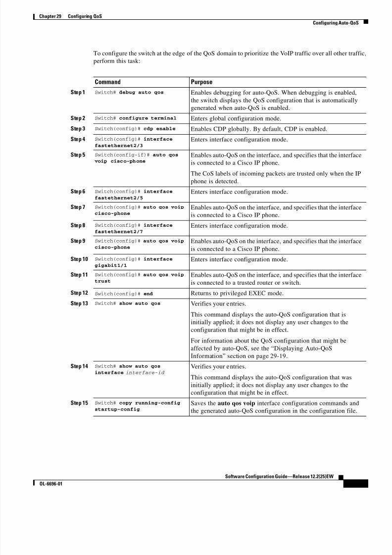
8/10/2019 Cisco ConfiguratioGuide SW4500 IOS
http://slidepdf.com/reader/full/cisco-configuratioguide-sw4500-ios 397/607
29-21
Software Configuration Guide—Release 12.2(25)EW
OL-6696-01
Chapter 29 Configuring QoS
Configuring Auto-QoS
To configure the switch at the edge of the QoS domain to prioritize the VoIP traffic over all other traffic,
perform this task:
Command Purpose
Step 1 Switch# debug auto qos Enables debugging for auto-QoS. When debugging is enabled,
the switch displays the QoS configuration that is automatically
generated when auto-QoS is enabled.
Step 2 Switch# configure terminal Enters global configuration mode.
Step 3 Switch(config)# cdp enable Enables CDP globally. By default, CDP is enabled.
Step 4 Switch(config)# interface
fastethernet2/3Enters interface configuration mode.
Step 5 Switch(config-if)# auto qos voip cisco-phone
Enables auto-QoS on the interface, and specifies that the interface
is connected to a Cisco IP phone.
The CoS labels of incoming packets are trusted only when the IP
phone is detected.
Step 6Switch(config)# interface
fastethernet2/5 Enters interface configuration mode.
Step 7 Switch(config)# auto qos voipcisco-phone
Enables auto-QoS on the interface, and specifies that the interface
is connected to a Cisco IP phone.
Step 8 Switch(config)# interface
fastethernet2/7Enters interface configuration mode.
Step 9 Switch(config)# auto qos voip
cisco-phoneEnables auto-QoS on the interface, and specifies that the interface
is connected to a Cisco IP phone.
Step 10 Switch(config)# interface
gigabit1/1Enters interface configuration mode.
Step 11 Switch(config)# auto qos voip
trustEnables auto-QoS on the interface, and specifies that the interface
is connected to a trusted router or switch.
Step 12 Switch(config)# end Returns to privileged EXEC mode.
Step 13 Switch# show auto qos Verifies your entries.
This command displays the auto-QoS configuration that is
initially applied; it does not display any user changes to the
configuration that might be in effect.
For information about the QoS configuration that might be
affected by auto-QoS, see the “Displaying Auto-QoS
Information” section on page 29-19.
Step 14 Switch# show auto qos
interface interface-id Verifies your entries.
This command displays the auto-QoS configuration that was
initially applied; it does not display any user changes to the
configuration that might be in effect.
Step 15 Switch# copy running-config
startup-config Saves the auto qos voip interface configuration commands and
the generated auto-QoS configuration in the configuration file.
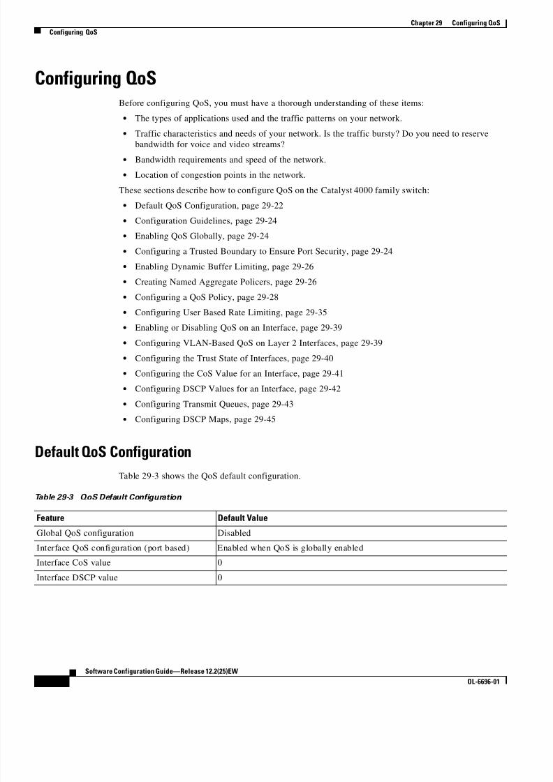
8/10/2019 Cisco ConfiguratioGuide SW4500 IOS
http://slidepdf.com/reader/full/cisco-configuratioguide-sw4500-ios 398/607
29-22
Software Configuration Guide—Release 12.2(25)EW
OL-6696-01
Chapter 29 Configuring QoS
Configuring QoS
Configuring QoSBefore configuring QoS, you must have a thorough understanding of these items:
• The types of applications used and the traffic patterns on your network.
• Traffic characteristics and needs of your network. Is the traffic bursty? Do you need to reservebandwidth for voice and video streams?
• Bandwidth requirements and speed of the network.
• Location of congestion points in the network.
These sections describe how to configure QoS on the Catalyst 4000 family switch:
• Default QoS Configuration, page 29-22
• Configuration Guidelines, page 29-24
• Enabling QoS Globally, page 29-24
• Configuring a Trusted Boundary to Ensure Port Security, page 29-24
• Enabling Dynamic Buffer Limiting, page 29-26
• Creating Named Aggregate Policers, page 29-26
• Configuring a QoS Policy, page 29-28
• Configuring User Based Rate Limiting, page 29-35
• Enabling or Disabling QoS on an Interface, page 29-39
• Configuring VLAN-Based QoS on Layer 2 Interfaces, page 29-39
• Configuring the Trust State of Interfaces, page 29-40
• Configuring the CoS Value for an Interface, page 29-41
• Configuring DSCP Values for an Interface, page 29-42
• Configuring Transmit Queues, page 29-43
• Configuring DSCP Maps, page 29-45
Default QoS Configuration
Table 29-3 shows the QoS default configuration.
Table 29-3 QoS Default Configuration
Feature Default Value
Global QoS configuration Disabled
Interface QoS configuration (port based) Enabled when QoS is globally enabled
Interface CoS value 0
Interface DSCP value 0

8/10/2019 Cisco ConfiguratioGuide SW4500 IOS
http://slidepdf.com/reader/full/cisco-configuratioguide-sw4500-ios 399/607
29-23
Software Configuration Guide—Release 12.2(25)EW
OL-6696-01
Chapter 29 Configuring QoS
Configuring QoS
CoS to DSCP map
(DSCP set from CoS values)
CoS 0 = DSCP 0
CoS 1 = DSCP 8
CoS 2 = DSCP 16CoS 3 = DSCP 24
CoS 4 = DSCP 32
CoS 5 = DSCP 40
CoS 6 = DSCP 48
CoS 7 = DSCP 56
DSCP to CoS map
(CoS set from DSCP values)
DSCP 0–7 = CoS 0
DSCP 8–15 = CoS 1
DSCP 16–23 = CoS 2
DSCP 24–31 = CoS 3
DSCP 32–39 = CoS 4
DSCP 40–47 = CoS 5
DSCP 48–55 = CoS 6
DSCP 56–63 = CoS 7
Marked-down DSCP from DSCP map
(Policed-DSCP)
Marked-down DSCP value equals original DSCP value (no markdown)
Policers None
Policy maps None
Transmit queue sharing 1/4 of the link bandwidth
Transmit queue size 1/4 of the transmit queue entries for the port. The transmit queue size of a
port depends on the type of port, ranging from 240 packets per transmit
queue to 1920 packets per transmit queue.
Transmit queue shaping None
DCSP-to-Transmit queue map DSCP 0–15 Queue 1DSCP 16–31 Queue 2
DSCP 32–47 Queue 3
DSCP 48–63 Queue 4
High priority transmit queue Disabled
With QoS disabled
Interface trust state Trust DSCP
With QoS enabled With QoS enabled and all other QoS parameters at default values, QoS sets
IP DSCP to zero and Layer 2 CoS to zero in all traffic transmitted.
Interface trust state Untrusted
Table 29-3 QoS Default Configuration (continued)
Feature Default Value

8/10/2019 Cisco ConfiguratioGuide SW4500 IOS
http://slidepdf.com/reader/full/cisco-configuratioguide-sw4500-ios 400/607
29-24
Software Configuration Guide—Release 12.2(25)EW
OL-6696-01
Chapter 29 Configuring QoS
Configuring QoS
Configuration Guidelines
Before beginning the QoS configuration, you should be aware of this information:
• If you have EtherChannel ports configured on your switch, you must configure QoS classification
and policing on the EtherChannel. The transmit queue configuration must be configured on the
individual physical ports that comprise the EtherChannel.
• It is not possible to match IP fragments against configured IP extended ACLs to enforce QoS. IP
fragments are transmitted as best effort. IP fragments are denoted by fields in the IP header.
• It is not possible to match IP options against configured IP extended ACLs to enforce QoS. These
packets are sent to the CPU and processed by software. IP options are denoted by fields in the IP
header.
• Control traffic (such as spanning-tree BPDUs and routing update packets) received by the switch are
subject to all ingress QoS processing.
• If you want to use the set command in the policy map, you must enable IP routing (disabled by
default) and configure an IP default route to send traffic to the next-hop device that is capable of
forwarding.
Note QoS processes both unicast and multicast traffic.
Enabling QoS Globally
To enable QoS globally, perform this task:
This example shows how to enable QoS globally:
Switch(config)# qos
Switch(config)# end Switch#
This example shows how to verify the configuration:
Switch# show qos
QoS is enabled globally
Switch#
Configuring a Trusted Boundary to Ensure Port Security
In a typical network, you connect a Cisco IP phone to a switch port as discussed in Chapter 30,
“Configuring Voice Interfaces.” Traffic sent from the telephone to the switch is typically marked with a
tag that uses the 802.1Q header. The header contains the VLAN information and the class of service
Command Purpose
Step 1 Switch(config)# qos Enables QoS on the switch.
Use the no qos command to globally disable QoS.
Step 2 Switch(config)# end Exits configuration mode.
Step 3 Switch# show qos Verifies the configuration.
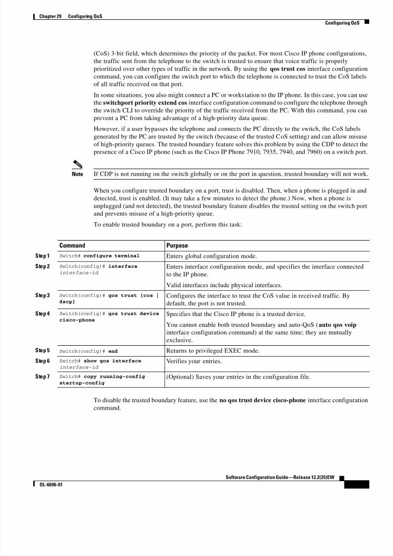
8/10/2019 Cisco ConfiguratioGuide SW4500 IOS
http://slidepdf.com/reader/full/cisco-configuratioguide-sw4500-ios 401/607
29-25
Software Configuration Guide—Release 12.2(25)EW
OL-6696-01
Chapter 29 Configuring QoS
Configuring QoS
(CoS) 3-bit field, which determines the priority of the packet. For most Cisco IP phone configurations,
the traffic sent from the telephone to the switch is trusted to ensure that voice traffic is properly
prioritized over other types of traffic in the network. By using the qos trust cos interface configuration
command, you can configure the switch port to which the telephone is connected to trust the CoS labels
of all traffic received on that port.
In some situations, you also might connect a PC or workstation to the IP phone. In this case, you can usethe switchport priority extend cos interface configuration command to configure the telephone through
the switch CLI to override the priority of the traffic received from the PC. With this command, you can
prevent a PC from taking advantage of a high-priority data queue.
However, if a user bypasses the telephone and connects the PC directly to the switch, the CoS labels
generated by the PC are trusted by the switch (because of the trusted CoS setting) and can allow misuse
of high-priority queues. The trusted boundary feature solves this problem by using the CDP to detect the
presence of a Cisco IP phone (such as the Cisco IP Phone 7910, 7935, 7940, and 7960) on a switch port.
Note If CDP is not running on the switch globally or on the port in question, trusted boundary will not work.
When you configure trusted boundary on a port, trust is disabled. Then, when a phone is plugged in and
detected, trust is enabled. (It may take a few minutes to detect the phone.) Now, when a phone is
unplugged (and not detected), the trusted boundary feature disables the trusted setting on the switch port
and prevents misuse of a high-priority queue.
To enable trusted boundary on a port, perform this task:
To disable the trusted boundary feature, use the no qos trust device cisco-phone interface configuration
command.
Command Purpose
Step 1 Switch# configure terminal Enters global configuration mode.
Step 2 Switch(config)# interface
interface-id Enters interface configuration mode, and specifies the interface connected
to the IP phone.
Valid interfaces include physical interfaces.
Step 3 Switch(config)# qos trust [cos |dscp]
Configures the interface to trust the CoS value in received traffic. By
default, the port is not trusted.
Step 4 Switch(config)# qos trust device
cisco-phoneSpecifies that the Cisco IP phone is a trusted device.
You cannot enable both trusted boundary and auto-QoS (auto qos voip
interface configuration command) at the same time; they are mutually
exclusive.
Step 5 Switch(config)# end Returns to privileged EXEC mode.
Step 6 Switch# show qos interface
interface-id Verifies your entries.
Step 7 Switch# copy running-config
startup-config(Optional) Saves your entries in the configuration file.

8/10/2019 Cisco ConfiguratioGuide SW4500 IOS
http://slidepdf.com/reader/full/cisco-configuratioguide-sw4500-ios 402/607
29-26
Software Configuration Guide—Release 12.2(25)EW
OL-6696-01
Chapter 29 Configuring QoS
Configuring QoS
Enabling Dynamic Buffer Limiting
To enable DBL globally on the switch, perform this task:
This example shows how to enable DBL globally:
Switch(config)# qos dbl
Global DBL enabledSwitch(config)# end
Switch#
This example shows how to verify the configuration:
Switch# show qos dbl
DBL is enabled globally
DBL flow includes vlanDBL flow includes l4-ports
DBL does not use ecn to indicate congestionDBL exceed-action mark probability:15%
DBL max credits:15
DBL aggressive credit limit:10
DBL aggressive buffer limit:2 packetsSwitch#
Creating Named Aggregate Policers
To create a named aggregate policer, perform this task:
An aggregate policer can be applied to one or more interfaces. However, if you apply the same policer
to the input direction on one interface and to the output direction on a different interface, then you have
created the equivalent of two different aggregate policers in the switching engine. Each policer has the
same policing parameters, with one policing the ingress traffic on one interface and the other policingthe egress traffic on another interface. If an aggregate policer is applied to multiple interfaces in the same
direction, then only one instance of the policer is created in the switching engine.
Similarly, an aggregate policer can be applied to a port or to a VLAN. If you apply the same aggregate
policer to a port and to a VLAN, then you have created the equivalent of two different aggregate policers
in the switching engine. Each policer has the same policing parameters, with one policing the traffic on
the configured port and the other policing the traffic on the configured VLAN. If an aggregate policer is
applied to only ports or only VLANs, then only one instance of the policer is created in the switching
engine.
Command Purpose
Step 1 Switch(config)# qos dbl Enables DBL on the switch.
Use the no qos dbl command to disable AQM.
Step 2 Switch(config)# end Exits configuration mode.
Step 3 Switch# show qos dbl Verifies the configuration.
Command Purpose
Switch(config)# qos aggregate-policer policer_name rate burst [[conform-action {transmit | drop}]
[exceed-action {transmit | drop |
policed-dscp-transmit}]]
Creates a named aggregate policer.

8/10/2019 Cisco ConfiguratioGuide SW4500 IOS
http://slidepdf.com/reader/full/cisco-configuratioguide-sw4500-ios 403/607
29-27
Software Configuration Guide—Release 12.2(25)EW
OL-6696-01
Chapter 29 Configuring QoS
Configuring QoS
In effect, if you apply a single aggregate policer to ports and VLANs in different directions, then you
have created the equivalent of four aggregate policers; one for all ports sharing the policer in input
direction, one for all ports sharing the policer in output direction, one for all VLANs sharing the policer
in input direction and one for all VLANs sharing the policer in output direction.
When creating a named aggregate policer, note the following:
• The valid range of values for the rate parameter is as follows:
– Minimum—32 kilobits per second
– Maximum—32 gigabits per second
See the “Configuration Guidelines” section on page 29-24.
• Rates can be entered in bits-per-second, or you can use the following abbreviations:
– k to denote 1000 bps
– m to denote 1000000 bps
– g to denote 1000000000 bps
Note You can also use a decimal point. For example, a rate of 1,100,000 bps can be enteredas 1.1m.
• The valid range of values for the burst parameter is as follows:
– Minimum—1 kilobyte
– Maximum—512 megabytes
• Bursts can be entered in bytes, or you can use the following abbreviation:
– k to denote 1000 bytes
– m to denote 1000000 bytes
– g to denote 1000000000 bytes
Note You can also use a decimal point. For example, a burst of 1,100,000 bytes can be entered
as 1.1m.
• Optionally, you can specify a conform action for matched in-profile traffic as follows:
– The default conform action is transmit.
– Enter the drop keyword to drop all matched traffic.
Note When you configure drop as the conform action, QoS configures drop as the exceed action
• Optionally, for traffic that exceeds the CIR, you can specify an exceed action as follows:
– The default exceed action is drop.
– Enter the policed-dscp-transmit keyword to cause all matched out-of-profile traffic to be
marked down as specified in the markdown map.
– For no policing, enter the transmit keyword to transmit all matched out-of-profile traffic.
• You can enter the no qos aggregate-policer policer_name command to delete a named aggregate
policer.

8/10/2019 Cisco ConfiguratioGuide SW4500 IOS
http://slidepdf.com/reader/full/cisco-configuratioguide-sw4500-ios 404/607
29-28
Software Configuration Guide—Release 12.2(25)EW
OL-6696-01
Chapter 29 Configuring QoS
Configuring QoS
This example shows how to create a named aggregate policer with a 10 Mbps rate limit and a 1-MB burst
size that transmits conforming traffic and marks down out-of-profile traffic.
Switch(config)# qos aggregate-policer aggr-1 10000000 1000000 conform-action transmit
exceed-action policed-dscp-transmit
Switch(config)# end
Switch#
This example shows how to verify the configuration:
Switch# show qos aggregate-policer aggr-1
Policer aggr-1 Rate(bps):10000000 Normal-Burst(bytes):1000000
conform-action:transmit exceed-action:policed-dscp-transmit
Policymaps using this policer:
Switch#
Configuring a QoS Policy
The following subsections describe QoS policy configuration:
• Overview of QoS Policy Configuration, page 29-28
• Configuring a Class Map (Optional), page 29-29
• Verifying Class Map Configuration, page 29-30
• Configuring a Policy Map, page 29-30
• Verifying Policy-Map Configuration, page 29-33
• Attaching a Policy Map to an Interface, page 29-34
Note QoS policies process both unicast and multicast traffic.
Overview of QoS Policy Configuration
Configuring a QoS policy requires you to configure traffic classes and the policies that will be applied
to those traffic classes, and to attach the policies to interfaces using these commands:
• access-list (optional for IP traffic—you can filter IP traffic with class-map commands):
– QoS supports these access list types:
– See Chapter 35, “Configuring Network Security with ACLs,” for information about ACLs on
the Catalyst 4500 series switches.
• class-map (optional)—Enter the class-map command to define one or more traffic classes by
specifying the criteria by which traffic is classified. (See the “Configuring a Class Map (Optional)”
section on page 29-29.)
Protocol Numbered Access Lists? Extended Access Lists? Named Access Lists?
IP Yes:
1 to 99
1300 to 1999
Yes:
100 to 199
2000 to 2699
Yes

8/10/2019 Cisco ConfiguratioGuide SW4500 IOS
http://slidepdf.com/reader/full/cisco-configuratioguide-sw4500-ios 405/607
29-29
Software Configuration Guide—Release 12.2(25)EW
OL-6696-01
Chapter 29 Configuring QoS
Configuring QoS
• policy-map—Enter the policy-map command to define the following for each class of traffic:
– Internal DSCP source
– Aggregate or individual policing and marking
• service-policy—Enter the service-policy command to attach a policy map to an interface.
Configuring a Class Map (Optional)
The following subsections describe class map configuration:
• Creating a Class Map, page 29-29
• Configuring Filtering in a Class Map, page 29-29
Enter the class-map configuration command to define a traffic class and the match criteria that will be
used to identify traffic as belonging to that class. Match statements can include criteria such as an ACL,
an IP precedence value, or a DSCP value. The match criteria are defined with one match statement
entered within the class-map configuration mode.
Creating a Class Map
To create a class map, perform this task:
Configuring Filtering in a Class Map
To configure filtering in a class map, perform one of these tasks:
Command Purpose
Switch(config)# [no] class-map [ match-all |
match-any] class_name Creates a named class map.
Use the no keyword to delete a class map.
Command Purpose
Switch(config-cmap)# [no] match access-group
{acl_index | name acl_name }(Optional) Specifies the name of the ACL used to filter traffic.
Use the no keyword to remove the statement from a class
map.
Note Access lists are not documented in this publication.
See the reference under access-list in the
“Configuring a QoS Policy” section on page 29-28.
Switch (config-cmap)# [no] match ip precedence
ipp_value1 [ipp_value2 [ipp_valueN ]](Optional—for IP traffic only) Specifies up to eight IP
precedence values used as match criteria. Use the no keyword
to remove the statement from a class map.
Switch (config-cmap)# [no] match ip dscp dscp_value1
[dscp_value2 [dscp_valueN ]](Optional—for IP traffic only) Specifies up to eight DSCP
values used as match criteria. Use the no keyword to remove
the statement from a class map.
Switch (config-cmap)# [no] match any (Optional) Matches any IP traffic or non-IP traffic.
Switch (config-cmap)# match flow ip {source-address
source-address | destination-addressdestination-address}
(Optional) Treats each flow with a unique IP source address
or destination address as a new flow.

8/10/2019 Cisco ConfiguratioGuide SW4500 IOS
http://slidepdf.com/reader/full/cisco-configuratioguide-sw4500-ios 406/607
29-30
Software Configuration Guide—Release 12.2(25)EW
OL-6696-01
Chapter 29 Configuring QoS
Configuring QoS
Note Any Input or Output policy that uses a class map with the match ip precedence or match ip dscp
class-map commands, requires that the port on which the packet is received, be configured to trust dscp.
If the incoming port trust state is not set to trust dscp, the IP packet DSCP/IP-precedence is not used
for matching the traffic; instead the receiving port’s default DSCP is used.
Note The interfaces on the Catalyst 4000 family switch do not support the match classmap, match
destination-address, match input-interface, match mpls, match not, match protocol, match
qos-group, and match source-address keywords.
Verifying Class Map Configuration
To verify class-map configuration, perform this task:
This example shows how to create a class map named ipp5 and how to configure filtering to match traffic
with IP precedence 5:
Switch# configure terminal
Enter configuration commands, one per line. End with CNTL/Z.Switch(config)# class-map ipp5
Switch(config-cmap)# match ip precedence 5
Switch(config-cmap)# end Switch#
This example shows how to verify the configuration:
Switch# show class-map ipp5
Class Map match-all ipp5 (id 1) Match ip precedence 5
Switch#
Configuring a Policy Map
You can attach only one policy map to an interface. Policy maps can contain one or more policy-map
classes, each with different match criteria and policers.
Configure a separate policy-map class in the policy map for each type of traffic that an interface receives.
Put all commands for each type of traffic in the same policy-map class. QoS does not attempt to applycommands from more than one policy-map class to matched traffic.
The following sections describe policy-map configuration:
• Creating a Policy Map, page 29-31
• Configuring Policy-Map Class Actions, page 29-31
Command Purpose
Step 1 Switch (config-cmap)# end Exits configuration mode.
Step 2 Switch# show class-map class_name Verifies the configuration.

8/10/2019 Cisco ConfiguratioGuide SW4500 IOS
http://slidepdf.com/reader/full/cisco-configuratioguide-sw4500-ios 407/607
29-31
Software Configuration Guide—Release 12.2(25)EW
OL-6696-01
Chapter 29 Configuring QoS
Configuring QoS
Creating a Policy Map
To create a policy map, perform this task:
Configuring Policy-Map Class Actions
These sections describe policy-map class action configuration:
• Configuring the Policy-Map Class Trust State, page 29-31
• Configuring the Policy Map Class DBL State, page 29-31
• Configuring Policy-Map Class Policing, page 29-32
• Using a Named Aggregate Policer, page 29-32
• Configuring a Per-Interface Policer, page 29-32
Configuring the Policy-Map Class Trust State
To configure the policy-map class trust state, perform this task:
When configuring the policy-map class trust state, note the following:
• You can enter the no trust command to use the trust state configured on the ingress interface (this
is the default).
• With the cos keyword, QoS sets the internal DSCP value from received or interface CoS.
• With the dscp keyword, QoS uses received DSCP.
Configuring the Policy Map Class DBL State
To configure the policy map class DBL state, perform this task:
Command Purpose
Switch(config)# [no] policy-map policy_name Creates a policy map with a user-specified name.
Use the no keyword to delete the policy map.
Command Purpose
Switch(config-pmap-c)# [no] trust{cos | dscp}
Configures the policy-map class trust state, which selects
the value that QoS uses as the source of the internal
DSCP value (see the “Internal DSCP Values” section on
page 29-12).
Use the no keyword to clear a configured value and returnto the default.
Command Purpose
Switch(config-pmap-c)# [no] dbl Configures the policy-map class DBL state, which tracks
the queue length of traffic flows (see the “Active Queue
Management” section on page 29-13).
Use the no keyword to clear an DBL value and return to
the default.

8/10/2019 Cisco ConfiguratioGuide SW4500 IOS
http://slidepdf.com/reader/full/cisco-configuratioguide-sw4500-ios 408/607
29-32
Software Configuration Guide—Release 12.2(25)EW
OL-6696-01
Chapter 29 Configuring QoS
Configuring QoS
When configuring the policy-map class DBL state, note the following:
• Any class that uses a named aggregate policer must have the same DBL configuration to work.
Configuring Policy-Map Class Policing
These sections describe configuration of policy-map class policing:
• Using a Named Aggregate Policer, page 29-32
• Configuring a Per-Interface Policer, page 29-32
Using a Named Aggregate Policer
To use a named aggregate policer (see the “Creating Named Aggregate Policers” section on page 29-26),
perform this task:
Configuring a Per-Interface Policer
To configure a per-interface policer (see the “Policing and Marking” section on page 29-9), perform this
task:
When configuring a per-interface policer, note the following:
• The valid range of values for the rate parameter is as follows:
– Minimum—32 kilobits per second, entered as 32000
– Maximum—32 gigabits per second, entered as 32000000000
Note See the “Configuration Guidelines” section on page 29-24.
• Rates can be entered in bits-per-second, or you can use the following abbreviations:
– k to denote 1000 bps
– m to denote 1000000 bps
– g to denote 1000000000 bps
Note You can also use a decimal point. For example, a rate of 1,100,000 bps can be entered
as 1.1m.
Command Purpose
Switch(config-pmap-c)# [no] police aggregate
aggregate_name Uses a previously defined aggregate policer.
Use the no keyword to delete the policer from the
policy map class.
Command Purpose
Switch(config-pmap-c)# [no] police rate burst[[conform-action {transmit | drop}]
[exceed-action {transmit | drop |
policed-dscp-transmit}]]
Configures a per-interface policer.
Use the no keyword to delete a policer from the
policy map class.

8/10/2019 Cisco ConfiguratioGuide SW4500 IOS
http://slidepdf.com/reader/full/cisco-configuratioguide-sw4500-ios 409/607

8/10/2019 Cisco ConfiguratioGuide SW4500 IOS
http://slidepdf.com/reader/full/cisco-configuratioguide-sw4500-ios 410/607
29-34
Software Configuration Guide—Release 12.2(25)EW
OL-6696-01
Chapter 29 Configuring QoS
Configuring QoS
This example shows how to verify the configuration:
Switch# show policy-map ipp5-policy show policy ipp5-policy
Policy Map ipp5-policy class ipp5
set ip precedence 6
dblpolice 2000000000 2000000 conform-action transmit exceed-action
policed-dscp-transmit
Switch#
Attaching a Policy Map to an Interface
To attach a policy map to an interface, perform this task:
This example shows how to attach the policy map named pmap1 to Fast Ethernet interface 5/36:
Switch# configure terminal
Enter configuration commands, one per line. End with CNTL/Z.Switch(config)# interface fastethernet 5/36
Switch(config-if)# service-policy input pmap1Switch(config-if)# end
This example shows how to verify the configuration:
Switch# show policy-map interface fastethernet 5/36
FastEthernet6/1
service-policy input:p1
class-map:c1 (match-any)
238474 packets
match:access-group 100
38437 packets
police:aggr-1
Conform:383934 bytes Exceed:949888 bytes
class-map:class-default (match-any) 0 packets
match:any
0 packets
Switch#
Command Purpose
Step 1 Switch(config)# interface { vlan vlan_ID |
{fastethernet | gigabitethernet |
tengigabitethernet} slot/interface | Port-channelnumber }
Selects the interface to configure.
Step 2 Switch(config-if)# [no] service-policy input policy_map_name
Attaches a policy map to the input direction of the
interface. Use the no keyword to detach a policy map
from an interface.
Step 3 Switch(config-if)# end Exits configuration mode.
Step 4 Switch# show policy-map interface { vlan vlan_ID |{fastethernet | gigabitethernet |
tengigabitethernet} slot/interface }
Verifies the configuration.

8/10/2019 Cisco ConfiguratioGuide SW4500 IOS
http://slidepdf.com/reader/full/cisco-configuratioguide-sw4500-ios 411/607
29-35
Software Configuration Guide—Release 12.2(25)EW
OL-6696-01
Chapter 29 Configuring QoS
Configuring QoS
Configuring User Based Rate Limiting
The feature User Based Rate Limiting (UBRL) adopts microflow policing to dynamically learn traffic
flows and rate limit each unique flow to an individual rate. A flow is defined as a five-tuple (IP source
address, IP destination address, IP head protocol field, Layer 4 source and destination ports). Flow-based
policers enable you to police traffic on a per flow basis. Because flows are dynamic, they requiredistinguishing values in the class map.
Note Flow policers (and UBRL) are supported only on the Supervisor Engine V-10GE. Flow policers are
supported only in the input direction and on Layer 3 interfaces. You can configure up to 511 unique flow
policers and can “microflow” police more than 100,000 flows.
When you specify the match flow command with the source-address keyword, each flow with a unique
source address is treated as a new flow. When you specify the match flow command with the
destination-address keyword, each flow with a unique destination address is treated as a new flow. If
the class map used by the policy map has any flow options configured, it i s treated as a flow-based policy
map.
To configure the flow-based class maps and policy maps, perform this task:
This example shows how to create a flow-based class map associated with a source address:
Switch(config)# class-map match-all c1
Switch(config-cmap)# match flow ip source-addressSwitch(config-cmap)# end
Switch#
Switch# show class-map c1Class Map match-all c1 (id 2)
Match flow ip source-address
This example shows how to create a flow-based class map associated with a destination address:
Switch(config)# class-map match-all c1Switch(config-cmap)# match flow ip destination-address
Switch(config-cmap)# end
Switch#
Switch# show class-map c1
Class Map match-all c1 (id 2) Match flow ip destination-address
Command Purpose
Step 1 Switch(config)# class-map match-all class_name Creates a named class map.
Step 2 Switch(config-cmap)# match flow ip {source-address |
destination-address}Specifies the key fields of the flow.
Step 3 Switch(config-cmap)# end Exits class-map configuration mode.
Step 4 Switch# show class-map class-name Verifies the configuration.

8/10/2019 Cisco ConfiguratioGuide SW4500 IOS
http://slidepdf.com/reader/full/cisco-configuratioguide-sw4500-ios 412/607
29-36
Software Configuration Guide—Release 12.2(25)EW
OL-6696-01
Chapter 29 Configuring QoS
Configuring QoS
Assume there are two active flows on the Fast Ethernet interface 6/1 with source addresses
192.168.10.20 and 192.168.10.21. The following example shows how to maintain each flow at 1 Mbps
with an allowed burst value of 9000 bytes:
Switch# conf tEnter configuration commands, one per line. End with CNTL/Z.
Switch(config)# class-map c1
Switch(config-cmap)# match flow ip source-addressSwitch(config-cmap)# exit
Switch(config)# policy-map p1
Switch(config-pmap)# class c1Switch(config-pmap-c)# police 1000000 9000
Switch(config-pmap-c)# exitSwitch(config-pmap)# exit
Switch(config)# interface fa6/1
Switch(config-if)# service-policy input p1
Switch(config-if)# endSwitch# write memory
Switch# show policy-map interfaceFastEthernet6/1
Service-policy input: p1
Class-map: c1 (match-all)
15432182 packets Match: flow ip source-address
police: Per-interface Conform: 64995654 bytes Exceed: 2376965424 bytes
Class-map: class-default (match-any)
0 packets Match: any
0 packets
Assume there are two active flows on the Fast Ethernet interface 6/1 with destination addresses of
192.168.20.20 and 192.168.20.21. The following example shows how to maintain each flow at 1 Mbps
with an allowed burst value of 9000 byte:
Switch# conf tEnter configuration commands, one per line. End with CNTL/Z.
Switch(config)# class-map c1Switch(config-cmap)# match flow ip destination-address
Switch(config-cmap)# exit
Switch(config)# policy-map p1Switch(config-pmap)# class c1
Switch(config-pmap-c)# police 1000000 9000
Switch(config-pmap-c)# exit
Switch(config-pmap)# exitSwitch(config)# interface fa6/1
Switch(config-if)# service-policy input p1Switch(config-if)# end
Switch# write memory
Switch# show policy-map interface
FastEthernet6/1
Service-policy input: p1

8/10/2019 Cisco ConfiguratioGuide SW4500 IOS
http://slidepdf.com/reader/full/cisco-configuratioguide-sw4500-ios 413/607
29-37
Software Configuration Guide—Release 12.2(25)EW
OL-6696-01
Chapter 29 Configuring QoS
Configuring QoS
Class-map: c1 (match-all)
2965072 packets
Match: flow ip destination-address police: Per-interface
Conform: 6105636 bytes Exceed: 476652528 bytes
Class-map: class-default (match-any)
0 packets Match: any 0 packets
Hierarchical policers
You can tie flow policers with the existing policers to create dual policing rates on an interface. For
example, using dual policing, you can limit all incoming traffic rates on a given interface to 50 Mbps
and can limit the rate of each flow that is part of this traffic to 2 Mbps.
You can configure hierarchical policers with the service-policy policy-map config command. A policy
map is termed flow-based if the class map it uses matches any of the flow-based match criteria
(such as match flow ip source-address). Each child policy map inherits all the match access-group
commands of the parent.
NoteYou can configure only flow-based policy maps as child policy maps. A parent policy map cannot be a
flow-based policy map. Both the child policy map and parent policy map must have match-all in their
class-map configuration.
To configure a flow-based policy map as a child of an individual or aggregate policer, perform this task
This example shows how to create a hierarchical policy map. A policy map with the name
aggregate-policy has a class map with the name aggregate-class. A flow-based policy map with the name
flow-policy is attached to this policy map as a child policy map.
Switch(config)#
Switch(config)# policy-map aggregate-policySwitch(config-pmap)# class aggregate-class
Switch(config-pmap-c)# service-policy flow-policySwitch(config-pmap-c)# end
Switch#
In the following example, traffic in the IP address range of 101.237.0.0 to 101.237.255.255 is policed to
50 Mbps. Flows ranging from 101.237.10.0 to 101.237.10.255 are individually policed to a rate of 2
Mbps. This traffic goes through two policers: the aggregate policer and the other flow-based policer.
Command Purpose
Step 1 Switch(config)# policy-map policy_name Specifies the individual or aggregate
policy-map name.
Step 2 Switch(config-pmap)# class class_name Specifies the class-map name of this policy
map.
Step 3 Switch(config-flow-cache)# service-policy
service_policy_name Specifies the name of the flow-based policy
map.

8/10/2019 Cisco ConfiguratioGuide SW4500 IOS
http://slidepdf.com/reader/full/cisco-configuratioguide-sw4500-ios 414/607
29-38
Software Configuration Guide—Release 12.2(25)EW
OL-6696-01
Chapter 29 Configuring QoS
Configuring QoS
The following example shows the configuration for this scenario:
class-map match-all flow-class match flow ip source-address
match access-group 20!
class-map match-all aggregate-class
match access-group 10!
policy-map flow-policy
class flow-class
police 2000000 bps 10000 byte conform-action transmit exceed-action drop!
policy-map aggregate-policy class aggregate-class
police 50000000 bps 40000 byte conform-action transmit exceed-action drop
service-policy flow-policy
!access-list 10 permit 101.237.0.0 0.0.255.255
access-list 20 permit 0.0.10.0 255.255.0.255
The following example shows how to verify the configuration:
Switch# show policy-map flow-policy Policy Map flow-policy
Class flow-class
police 2000000 bps 10000 byte conform-action transmit exceed-action dropSwitch# show policy-map aggregate-policy
Policy Map aggregate-policy Class aggregate-class
police 50000000 bps 40000 byte conform-action transmit exceed-action drop
service-policy flow-policy
Switch# show policy-map interface
FastEthernet6/1Service-policy input: aggregate-policy
Class-map: aggregate-class (match-all)
132537 packets Match: access-group 10
police: Per-interface Conform: 3627000 bytes Exceed: 0 bytes
Service-policy : flow-policy
Class-map: flow-class (match-all)
8867 packets Match: access-group 20
Match: flow ip source-address
police: Per-interface Conform: 1649262 bytes Exceed: 59601096 bytes
Class-map: class-default (match-any)
0 packets Match: any 0 packets
Class-map: class-default (match-any)
5 packets Match: any 5 packets

8/10/2019 Cisco ConfiguratioGuide SW4500 IOS
http://slidepdf.com/reader/full/cisco-configuratioguide-sw4500-ios 415/607
29-39
Software Configuration Guide—Release 12.2(25)EW
OL-6696-01
Chapter 29 Configuring QoS
Configuring QoS
Enabling or Disabling QoS on an Interface
The qos interface command reenables any previously configured QoS features. The qos interface
command does not affect the interface queueing configuration.
To enable or disable QoS features for traffic from an interface, perform this task:
This example shows how to disable QoS on interface VLAN 5:
Switch# configure terminal
Enter configuration commands, one per line. End with CNTL/Z.
Switch(config)# interface vlan 5
Switch(config-if)# no qos Switch(config-if)# end
Switch#
This example shows how to verify the configuration:
Switch# show qos | begin QoS is disabled
QoS is disabled on the following interfaces:
Vl5
<...Output Truncated...>
Switch#
Configuring VLAN-Based QoS on Layer 2 Interfaces
By default, QoS uses policy maps attached to physical interfaces. For Layer 2 interfaces, you can
configure QoS to use policy maps attached to a VLAN. (See the “Attaching a Policy Map to an Interface”
section on page 29-34.)
To configure VLAN-based QoS on a Layer 2 interface, perform this task:
Command Purpose
Step 1 Switch(config)# interface { vlan vlan_ID |
{fastethernet | gigabitethernet |tengigabitethernet} slot/interface | Port-channelnumber }
Selects the interface to configure.
Step 2 Switch(config-if)# [no] qos Enables QoS on the interface.
Use the no keyword to disable QoS on an interface.
Step 3 Switch(config-if)# end Exits configuration mode.
Step 4 Switch# show qos interface Verifies the configuration.
Command Purpose
Step 1 Switch(config)# interface {fastethernet |gigabitethernet | tengigabitethernet}
slot/interface | Port-channel number
Selects the interface to configure.
Step 2 Switch(config-if)# [no] qos vlan-based Configures VLAN-based QoS on a Layer 2 interface.
Use the no keyword to disable VLAN-based QoS on an
interface.
Step 3 Switch(config-if)# end Exits configuration mode.
Step 4 Switch# show qos Verifies the configuration.

8/10/2019 Cisco ConfiguratioGuide SW4500 IOS
http://slidepdf.com/reader/full/cisco-configuratioguide-sw4500-ios 416/607
29-40
Software Configuration Guide—Release 12.2(25)EW
OL-6696-01
Chapter 29 Configuring QoS
Configuring QoS
Note If no input QoS policy is attached to a Layer 2 interface, then the input QoS policy attached to the VLAN
(on which the packet is received), if any, is used even if the port is not configured as VLAN-based. If
you do not want this default, attach a placeholder input QoS policy to the Layer 2 interface. Similarly,
if no output QoS policy is attached to a Layer 2 interface, then the output QoS policy attached to the
VLAN (on which the packet is transmitted), if any, is used even if the port is not configured asVLAN-based. If you do not want this default, attach a placeholder output QoS policy to the layer 2
interface.
This example shows how to configure VLAN-based QoS on Fast Ethernet interface 5/42:
Switch# configure terminal
Enter configuration commands, one per line. End with CNTL/Z.
Switch(config)# interface fastethernet 5/42
Switch(config-if)# qos vlan-based Switch(config-if)# end
This example shows how to verify the configuration:
Switch# show qos | begin QoS is vlan-based
QoS is vlan-based on the following interfaces: Fa5/42
Switch#
Note When a layer 2 interface is configured with VLAN-based QoS, and if a packet is received on the port for
a VLAN on which there is no QoS policy, then the QoS policy attached to the port, if any is used. This
applies for both Input and Output QoS policies.
Configuring the Trust State of Interfaces
This command configures the trust state of interfaces. By default, all interfaces are untrusted.
To configure the trust state of an interface, perform this task:
Command Purpose
Step 1 Switch(config)# interface { vlan vlan_ID |
{fastethernet | gigabitethernet |tengigabitethernet} slot/interface | Port-channelnumber }
Selects the interface to configure.
Step 2 Switch(config-if)# [no] qos trust [dscp | cos] Configures the trust state of an interface.
Use the no keyword to clear a configured value and
return to the default.
Step 3 Switch(config-if)# end Exits configuration mode.
Step 4 Switch# show qos Verifies the configuration.
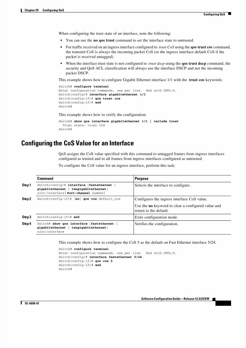
8/10/2019 Cisco ConfiguratioGuide SW4500 IOS
http://slidepdf.com/reader/full/cisco-configuratioguide-sw4500-ios 417/607
29-41
Software Configuration Guide—Release 12.2(25)EW
OL-6696-01
Chapter 29 Configuring QoS
Configuring QoS
When configuring the trust state of an interface, note the following:
• You can use the no qos trust command to set the interface state to untrusted.
• For traffic received on an ingress interface configured to trust CoS using the qos trust cos command,
the transmit CoS is always the incoming packet CoS (or the ingress interface default CoS if the
packet is received untagged).
• When the interface trust state is not configured to trust dscp using the qos trust dscp command, the
security and QoS ACL classification will always use the interface DSCP and not the incoming
packet DSCP.
This example shows how to configure Gigabit Ethernet interface 1/1 with the trust cos keywords:
Switch# configure terminal
Enter configuration commands, one per line. End with CNTL/Z.Switch(config)# interface gigabitethernet 1/1
Switch(config-if)# qos trust cos Switch(config-if)# end
Switch#
This example shows how to verify the configuration:
Switch# show qos interface gigabitethernet 1/1 | include trust Trust state: trust COS
Switch#
Configuring the CoS Value for an Interface
QoS assigns the CoS value specified with this command to untagged frames from ingress interfaces
configured as trusted and to all frames from ingress interfaces configured as untrusted.
To configure the CoS value for an ingress interface, perform this task:
This example shows how to configure the CoS 5 as the default on Fast Ethernet interface 5/24:Switch# configure terminal
Enter configuration commands, one per line. End with CNTL/Z.Switch(config)# interface fastethernet 5/24
Switch(config-if)# qos cos 5
Switch(config-if)# end
Switch#
Command Purpose
Step 1 Switch(config)# interface {fastethernet |
gigabitethernet | tengigabitethernet}
slot/interface | Port-channel number }
Selects the interface to configure.
Step 2 Switch(config-if)# [no] qos cos default_cos Configures the ingress interface CoS value.
Use the no keyword to clear a configured value and
return to the default.
Step 3 Switch(config-if)# end Exits configuration mode.
Step 4 Switch# show qos interface {fastethernet |gigabitethernet | tengigabitethernet}
slot/interface
Verifies the configuration.

8/10/2019 Cisco ConfiguratioGuide SW4500 IOS
http://slidepdf.com/reader/full/cisco-configuratioguide-sw4500-ios 418/607
29-42
Software Configuration Guide—Release 12.2(25)EW
OL-6696-01
Chapter 29 Configuring QoS
Configuring QoS
This example shows how to verify the configuration:
Switch# show qos interface fastethernet 5/24 | include Default COS Default COS is 5
Switch#
Configuring DSCP Values for an InterfaceQoS assigns the DSCP value specified with this command to non IPv4 frames received on interfaces
configured to trust DSCP and to all frames received on interfaces configured as untrusted.
To configure the DSCP value for an ingress interface, perform this task:
This example shows how to configure the DSCP 5 as the default on Fast Ethernet interface 5/24:
Switch# configure terminal
Enter configuration commands, one per line. End with CNTL/Z.Switch(config)# interface fastethernet 5/24
Switch(config-if)# qos dscp 5
Switch(config-if)# end Switch#
This example shows how to verify the configuration:
Switch# show qos interface fastethernet 6/1QoS is enabled globally
Port QoS is enabled
Port Trust State:CoS
Default DSCP:0 Default CoS:0
Tx-Queue Bandwidth ShapeRate Priority QueueSize
(bps) (bps) (packets) 1 31250000 disabled N/A 240
2 31250000 disabled N/A 240
3 31250000 disabled normal 2404 31250000 disabled N/A 240
Switch#
Command Purpose
Step 1 Switch(config)# interface {fastethernet |
gigabitethernet | tengigabitethernet}
slot/interface | Port-channel number
Selects the interface to configure.
Step 2 Switch(config-if)# [no] qos dscp default_dscp Configures the ingress interface DSCP value.
Use the no keyword to clear a configured value and
return to the default.
Step 3 Switch(config-if)# end Exits configuration mode.
Step 4 Switch# show qos interface {fastethernet |
gigabitethernet | tengigabitethernet}
slot/interface
Verifies the configuration.

8/10/2019 Cisco ConfiguratioGuide SW4500 IOS
http://slidepdf.com/reader/full/cisco-configuratioguide-sw4500-ios 419/607
29-43
Software Configuration Guide—Release 12.2(25)EW
OL-6696-01
Chapter 29 Configuring QoS
Configuring QoS
Configuring Transmit Queues
The following sections describes how to configure the transmit queues:
• Mapping DSCP Values to Specific Transmit Queues, page 29-43
• Allocating Bandwidth Among Transmit Queues, page 29-44
• Configuring Traffic Shaping of Transmit Queues, page 29-44
• Configuring a High Priority Transmit Queue, page 29-45
Depending on the complexity of your network and your QoS solution, you might need to perform all of
the procedures in the next sections, but first you will need to make decisions about these characteristics
• Which packets are assigned (by DSCP value) to each queue?
• What is the size of a transmit queue relative to other queues for a given port?
• How much of the available bandwidth is allotted to each queue?
• What is the maximum rate and burst of traffic that can be transmitted out of each transmit queue?
Mapping DSCP Values to Specific Transmit Queues
To map the DSCP values to a transmit queue, perform this task:
This example shows how to map DSCP values to transit queue 2.
Switch# configure terminal Enter configuration commands, one per line. End with CNTL/Z.
Switch(config)# qos map dscp 50 to tx-queue 2
Switch(config)# end
Switch#
This example shows how to verify the configuration.
Switch# show qos maps dscp tx-queue
DSCP-TxQueue Mapping Table (dscp = d1d2)
d1 :d2 0 1 2 3 4 5 6 7 8 9-------------------------------------
0 : 02 02 02 01 01 01 01 01 01 01
1 : 01 01 01 01 01 01 02 02 02 022 : 02 02 02 02 02 02 02 02 02 02
3 : 02 02 03 03 03 03 03 03 03 034 : 03 03 03 03 03 03 03 03 04 04
5 : 04 04 04 04 04 04 04 04 04 04
6 : 04 04 04 04
Switch#
Command Purpose
Step 1 Switch(config)# [no] qos map dscp dscp-values to
tx-queue queue-id Maps the DSCP values to the transit queue. dscp-list can
contain up 8 DSCP values. The queue-id can range from
1 to 4.
Use the no qos map dscp to tx-queue command to clear
the DSCP values from the transit queue.
Step 2 Switch(config)# end Exits configuration mode.
Step 3 Switch# show qos maps dscp tx-queues Verifies the configuration.

8/10/2019 Cisco ConfiguratioGuide SW4500 IOS
http://slidepdf.com/reader/full/cisco-configuratioguide-sw4500-ios 420/607
29-44
Software Configuration Guide—Release 12.2(25)EW
OL-6696-01
Chapter 29 Configuring QoS
Configuring QoS
Allocating Bandwidth Among Transmit Queues
To configure the transmit queue bandwidth, perform this task:
The bandwidth rate varies with the interface.
Bandwidth can only be configured on these interfaces:
• Uplink ports on Supervisor Engine III (WS-X4014)
• Ports on the WS-X4306-GB module
• The 2 1000BASE-X ports on the WS-X4232-GB-RJ module
• The first 2 ports on the WS-X4418-GB module
• The two 1000BASE-X ports on the WS-X4412-2GB-TX module
This example shows how to configure the bandwidth of 1 Mbps on transmit queue 2.
Switch# configure terminal
Enter configuration commands, one per line. End with CNTL/Z.
Switch(config)# interface gigabitethernet 1/1
Switch(config-if)# tx-queue 2Switch(config-if-tx-queue)# bandwidth 1000000Switch(config-if-tx-queue)# end
Switch#
Configuring Traffic Shaping of Transmit Queues
To guarantee that packets transmitted from a transmit queue do not exceed a specified maximum rate,
perform this task:
Command Purpose
Step 1 Switch(config)# interface gigabitethernet
slot/interface Selects the interface to configure.
Step 2 Switch(config-if)# tx-queue queue_id Selects the transmit queue to configure.
Step 3 Switch(config-if-tx-queue)# [no] [bandwidth rate
| percent percent]Sets the bandwidth rate for the transmit queue.
Use the no keyword to reset the transmit queue
bandwidth ratios to the default values.
Step 4 Switch(config-if-tx-queue)# end Exits configuration mode.
Step 5 Switch# show qos interface Verifies the configuration.
Command Purpose
Step 1 Switch(config)# interface {fastethernet |
gigabitethernet | tengigabitethernet}slot/interface
Selects the interface to configure.
Step 2 Switch(config-if)# tx-queue queue_id Selects the transmit queue to configure.
Step 3 Switch(config-if-tx-queue)# [no] [shape rate |
percent percent]Sets the transmit rate for the transmit queue.
Use the no keyword to clear the transmit queue maximum
rate.

8/10/2019 Cisco ConfiguratioGuide SW4500 IOS
http://slidepdf.com/reader/full/cisco-configuratioguide-sw4500-ios 421/607
29-45
Software Configuration Guide—Release 12.2(25)EW
OL-6696-01
Chapter 29 Configuring QoS
Configuring QoS
This example shows how to configure the shape rate to 1 Mbps on transmit queue 2.Switch# configure terminal
Enter configuration commands, one per line. End with CNTL/Z.
Switch(config)# interface gigabitethernet 1/1
Switch(config-if-tx-queue)# tx-queue 2Switch(config-if-tx-queue)# shape 1000000
Switch(config-if-tx-queue)# end Switch#
Configuring a High Priority Transmit Queue
To configure transmit queue 3 at a higher priority, perform this task:
This example shows how to configure transmit queue 3 to high priority.
Switch# configure terminal Enter configuration commands, one per line. End with CNTL/Z.
Switch(config)# interface gigabitethernet 1/1
Switch(config-if-tx-queue)# tx-queue 3Switch(config-if-tx-queue)# priority high
Switch(config-if)# end
Switch#
Configuring DSCP Maps
The following sections describes how to configure the DSCP maps. It contains this configuration
information:• Configuring the CoS-to-DSCP Map, page 29-46
• Configuring the Policed-DSCP Map, page 29-46
• Configuring the DSCP-to-CoS Map, page 29-47
All the maps are globally defined and are applied to all ports.
Step 4 Switch(config-if-tx-queue)# end Exits configuration mode.
Step 5 Switch# show qos interface Verifies the configuration.
Command Purpose
Command Purpose
Step 1 Switch(config)# interface {fastethernet |
gigabitethernet | tengigabitethernet}
slot/interface
Selects the interface to configure.
Step 2 Switch(config-if)# tx-queue 3 Selects transmit queue 3 to configure.
Step 3 Switch(config-if)# [no] priority high Sets the transmit queue to high priority.
Use the no keyword to clear the transmit queue priority.
Step 4 Switch(config-if)# end Exits configuration mode.
Step 5 Switch# show qos interface Verifies the configuration.

8/10/2019 Cisco ConfiguratioGuide SW4500 IOS
http://slidepdf.com/reader/full/cisco-configuratioguide-sw4500-ios 422/607
29-46
Software Configuration Guide—Release 12.2(25)EW
OL-6696-01
Chapter 29 Configuring QoS
Configuring QoS
Configuring the CoS-to-DSCP Map
You use the CoS-to-DSCP map to map CoS values in incoming packets to a DSCP value that QoS uses
internally to represent the priority of the traffic.
Table 29-4 shows the default CoS-to-DSCP map.
If these values are not appropriate for your network, you need to modify them.
To modify the CoS-to-DSCP map, perform this task:
To return to the default map, use the no qos cos to dscp global configuration command.
This example shows how to modify and display the CoS-to-DSCP map:Switch# configure terminalSwitch(config)# qos map cos 0 to dscp 20
Switch(config)# endSwitch# show qos maps cos dscp
CoS-DSCP Mapping Table:
CoS: 0 1 2 3 4 5 6 7--------------------------------
DSCP: 20 8 16 24 32 40 48 56Switch(config)#
Configuring the Policed-DSCP Map
You use the policed-DSCP map to mark down a DSCP value to a new value as the result of a policing
and marking action.
The default policed-DSCP map is a null map, which maps an incoming DSCP value to the same DSCP
value.
Table 29-4 Default CoS-to-DSCP Map
CoS value 0 1 2 3 4 5 6 7
DSCP value 0 8 16 24 32 40 48 56
Command Purpose
Step 1 Switch# configure terminal Enters global configuration mode.
Step 2 Switch(config)# qos map cos cos1 ... cos8
to dscp dscp Modifies the CoS-to-DSCP map.
For cos1...cos8, you can enter up to 8 CoS; valid values range
from 0 to 7. Separate each CoS value with a space.
The dscp range is 0 to 63.
Step 3 Switch(config)# end Returns to privileged EXEC mode.
Step 4 Switch# show qos maps cos-dscp Verifies your entries.
Step 5 Switch# copy running-config startup-config (Optional) Saves your entries in the configuration file.
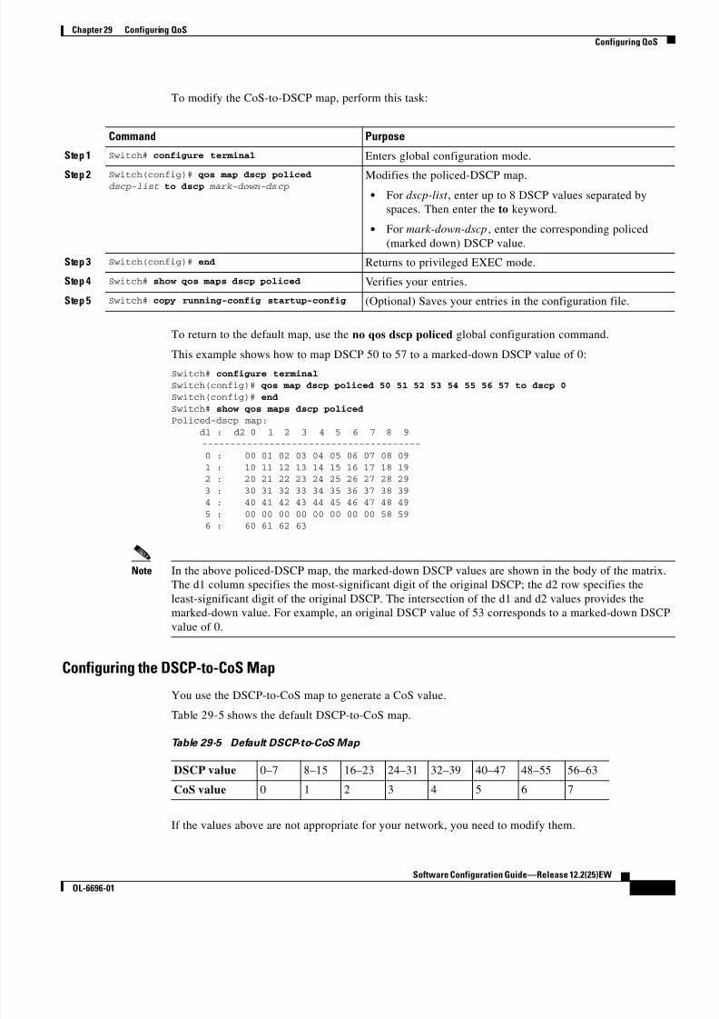
8/10/2019 Cisco ConfiguratioGuide SW4500 IOS
http://slidepdf.com/reader/full/cisco-configuratioguide-sw4500-ios 423/607
29-47
Software Configuration Guide—Release 12.2(25)EW
OL-6696-01
Chapter 29 Configuring QoS
Configuring QoS
To modify the CoS-to-DSCP map, perform this task:
To return to the default map, use the no qos dscp policed global configuration command.
This example shows how to map DSCP 50 to 57 to a marked-down DSCP value of 0:Switch# configure terminal
Switch(config)# qos map dscp policed 50 51 52 53 54 55 56 57 to dscp 0
Switch(config)# end
Switch# show qos maps dscp policedPoliced-dscp map:
d1 : d2 0 1 2 3 4 5 6 7 8 9
---------------------------------------
0 : 00 01 02 03 04 05 06 07 08 09
1 : 10 11 12 13 14 15 16 17 18 19 2 : 20 21 22 23 24 25 26 27 28 29
3 : 30 31 32 33 34 35 36 37 38 39
4 : 40 41 42 43 44 45 46 47 48 49
5 : 00 00 00 00 00 00 00 00 58 59 6 : 60 61 62 63
Note In the above policed-DSCP map, the marked-down DSCP values are shown in the body of the matrix.
The d1 column specifies the most-significant digit of the original DSCP; the d2 row specifies the
least-significant digit of the original DSCP. The intersection of the d1 and d2 values provides the
marked-down value. For example, an original DSCP value of 53 corresponds to a marked-down DSCP
value of 0.
Configuring the DSCP-to-CoS Map
You use the DSCP-to-CoS map to generate a CoS value.
Table 29-5 shows the default DSCP-to-CoS map.
If the values above are not appropriate for your network, you need to modify them.
Command Purpose
Step 1 Switch# configure terminal Enters global configuration mode.
Step 2 Switch(config)# qos map dscp policeddscp-list to dscp mark-down-dscp Modifies the policed-DSCP map.• For dscp-list , enter up to 8 DSCP values separated by
spaces. Then enter the to keyword.
• For mark-down-dscp , enter the corresponding policed
(marked down) DSCP value.
Step 3 Switch(config)# end Returns to privileged EXEC mode.
Step 4 Switch# show qos maps dscp policed Verifies your entries.
Step 5 Switch# copy running-config startup-config (Optional) Saves your entries in the configuration file.
Table 29-5 Default DSCP-to-CoS Map
DSCP value 0–7 8–15 16–23 24–31 32–39 40–47 48–55 56–63
CoS value 0 1 2 3 4 5 6 7

8/10/2019 Cisco ConfiguratioGuide SW4500 IOS
http://slidepdf.com/reader/full/cisco-configuratioguide-sw4500-ios 424/607
29-48
Software Configuration Guide—Release 12.2(25)EW
OL-6696-01
Chapter 29 Configuring QoS
Configuring QoS
To modify the DSCP-to-CoS map, perform this task:
To return to the default map, use the no qos dscp to cos global configuration command.
This example shows how to map DSCP values 0, 8, 16, 24, 32, 40, 48, and 50 to CoS value 0 and to
display the map:
Switch# configure terminal
Switch(config)# qos map dscp 0 8 16 24 32 40 48 50 to cos 0
Switch(config)# endSwitch# show qos maps dscp cos
Dscp-cos map: d1 : d2 0 1 2 3 4 5 6 7 8 9
---------------------------------------
0 : 00 00 00 00 00 00 00 00 00 01
1 : 01 01 01 01 01 01 00 02 02 02 2 : 02 02 02 02 00 03 03 03 03 03
3 : 03 03 00 04 04 04 04 04 04 04 4 : 00 05 05 05 05 05 05 05 00 06
5 : 00 06 06 06 06 06 07 07 07 07
6 : 07 07 07 07
Note In the above DSCP-to-CoS map, the CoS values are shown in the body of the matrix. The d1 column
specifies the most-significant digit of the DSCP; the d2 row specifies the least-significant digit of the
DSCP. The intersection of the d1 and d2 values provides the CoS value. For example, in the
DSCP-to-CoS map, a DSCP value of 08 corresponds to a CoS value of 0.
Command Purpose
Step 1 Switch# configure terminal Enters global configuration mode.
Step 2 Switch(config)# qos map dscp dscp-list to cos cos Modifies the DSCP-to-CoS map.• For dscp-list , enter up to 8 DSCP values separated by spaces.
Then enter the to keyword.
• For cos, enter only one CoS value to which the DSCP values
correspond.
The DSCP range is 0 to 63; the CoS range is 0 to 7.
Step 3 Switch(config)# end Returns to privileged EXEC mode.
Step 4 Switch# show qos maps dscp to cos Verifies your entries.
Step 5 Switch# copy running-config
startup-config(Optional) Saves your entries in the configuration file.

8/10/2019 Cisco ConfiguratioGuide SW4500 IOS
http://slidepdf.com/reader/full/cisco-configuratioguide-sw4500-ios 425/607
C H A P T E R
30-1
Software Configuration Guide—Release 12.2(25)EW
OL-6696-01
30
Configuring Voice Interfaces
This chapter describes how to configure voice interfaces for the Catalyst 4500 series switches.
This chapter includes the following major sections:
• Overview of Voice Interfaces, page 30-1
• Configuring a Port to Connect to a Cisco 7690 IP Phone, page 30-2
• Configuring Voice Ports for Voice and Data Traffic, page 30-2
• Overriding the CoS Priority of Incoming Frames, page 30-3
• Configuring Inline Power, page 30-4
Note For complete syntax and usage information for the switch commands used in this chapter, refer to the
Catalyst 4500 Series Switch Cisco IOS Command Reference and related publications at
http://www.cisco.com/univercd/cc/td/doc/product/software/ios122/122cgcr/index.htm.
Overview of Voice Interfaces Catalyst 4500 series switches can connect to a Cisco 7960 IP phone and carry IP voice traffic. If
necessary, the switch can supply electrical power to the circuit connecting it to the Cisco 7960 IP phone
Because the sound qual ity of an IP telephone call can deteriorate if the data is unevenly sent, the switch
uses quality of service (QoS) based on IEEE 802.1p class of service (CoS). QoS uses classification and
scheduling to transmit network traffic from the switch in a predictable manner. See Chapter 29,
“Configuring QoS” for more information on QoS.
You can configure the Cisco 7960 IP phone to forward traffic with an 802.1p priority. You can use the
CLI to configure a Catalyst 4500 series switch to honor or ignore a traffic priority assigned by a
Cisco 7960 IP phone.
The Cisco 7960 IP phone contains an integrated three-port 10/100 switch. The ports are dedicated
connections as described below:
• Port 1 connects to the Catalyst 4500 series switch or other device that supports voice-over-IP.
• Port 2 is an internal 10/100 interface that carries the phone traffic.
• Port 3 connects to a PC or other device.
Figure 30-1 shows one way to configure a Cisco 7960 IP phone.

8/10/2019 Cisco ConfiguratioGuide SW4500 IOS
http://slidepdf.com/reader/full/cisco-configuratioguide-sw4500-ios 426/607
30-2
Software Configuration Guide—Release 12.2(25)EW
OL-6696-01
Chapter 30 Configuring Voice Interfaces
Configuring a Port to Connect to a Cisco 7690 IP Phone
Figure 30-1 Cisco 7960 IP Phone Connected to a Catalyst 4500 Series Switch
Configuring a Port to Connect to a Cisco 7690 IP PhoneBecause a Cisco 7960 IP phone also supports connection to a PC or another device, an interface
connecting a Catalyst 4500 series switch to a Cisco 7960 IP phone can carry a mix of voice and data
traffic.
There are three configurations for a port connected to a Cisco 7960 IP phone:
• All traffic is transmitted according to the default CoS priority of the port. This is the default.
• Voice traffic is given a higher priority by the phone (CoS priority is always 5), and all traffic is in
the same VLAN.
• Voice and data traffic are carried on separate VLANs.
To configure a port to instruct the phone to give voice traffic a higher priority and to forward all traffic
through the 802.1Q native VLAN, perform this task:
Configuring Voice Ports for Voice and Data TrafficBecause voice and data traffic can travel through the same voice port, you should specify a different
VLAN for each type of traffic. You can configure a switch port to forward voice and data traffic on
different VLANs.
Note See the “Using 802.1X with Voice VLAN Ports” section on page 31-10 for information about
using 802.1X with voice VLANs.
IP PhoneCatalyst 4500 Series SwitchPC
1 0 5 2 4 7
IP
Command Purpose
Step 1 Switch# configure terminal Enters configuration mode.
Step 2 Switch(config)# interface {fastethernet |gigabitethernet} slot/port
Specifies the interface to configure.
Step 3 Switch(config-if)# switchport voice vlan dot1p Instructs the switch to use 802.1p priority tagging for voice
traffic and to use VLAN 1 (default native VLAN) to carry
all traffic.
Step 4 Switch(config-if)# end Returns to privileged EXEC mode.
Step 5 Switch# show interface {fastethernet |
gigabitethernet} slot/port switchportVerifies the port configuration.

8/10/2019 Cisco ConfiguratioGuide SW4500 IOS
http://slidepdf.com/reader/full/cisco-configuratioguide-sw4500-ios 427/607
30-3
Software Configuration Guide—Release 12.2(25)EW
OL-6696-01
Chapter 30 Configuring Voice Interfaces
Overriding the CoS Priority of Incoming Frames
To configure a port to receive voice and data from a Cisco IP Phone on different VLANs, perform this
task:
In the following example, VLAN 1 carries data traffic, and VLAN 2 carries voice traffic. In this
configuration, you must connect all Cisco IP phones and other voice-related devices to switch ports that
belong to VLAN 2.Switch# configure terminal
Switch(config)# interface fastethernet 2/5 SSwitch(config-if)# switchport voice vlan 2
switchport voice vlan 2
Switch(config-if)# end
Switch# show interface fastethernet 2/5 switchportshow interface fastethernet 2/5 switchport
Name:Fa2/5
Switchport:Enabled
Administrative Mode:dynamic auto
Operational Mode:downAdministrative Trunking Encapsulation:negotiate
Negotiation of Trunking:On
Access Mode VLAN:1 (default)
Trunking Native Mode VLAN:1 (default) Voice VLAN:2 ((Inactive))
Appliance trust:noneAdministrative private-vlan host-association:none
Administrative private-vlan mapping:none
Operational private-vlan:none
Trunking VLANs Enabled:ALLPruning VLANs Enabled:2-1001
Switch#
Overriding the CoS Priority of Incoming Frames
A PC or another data device can connect to a Cisco 7960 IP phone port. The PC can generate packetswith an assigned CoS value. You can also use the switch CLI to override the priority of frames arriving
on the phone port from connected devices, and you can set the phone port to accept (trust) the priority
of frames arriving on the port.
Command Purpose
Step 1 Switch# configure terminal Enters configuration mode.
Step 2 Switch(config)# interface {fastethernet |
gigabitethernet} slot/ port Specifies the interface to configure.
Step 3 Switch(config-if)# switchport voice vlan
vlan_num Instructs the Cisco IP phone to forward all voice traffic
through a specified VLAN. The Cisco IP phone forwards
the traffic with an 802.1p priority of 5.
Step 4 Switch(config-if)# end Returns to privileged EXEC mode.
Step 5 Switch# show interface {fastethernet |gigabitethernet} slot/port switchport
Verifies the configuration.

8/10/2019 Cisco ConfiguratioGuide SW4500 IOS
http://slidepdf.com/reader/full/cisco-configuratioguide-sw4500-ios 428/607
30-4
Software Configuration Guide—Release 12.2(25)EW
OL-6696-01
Chapter 30 Configuring Voice Interfaces
Configuring Inline Power
To override the CoS priority setting received from the non-voice port on the Cisco 7960 IP phone,
perform this task:
Configuring Inline PowerThe Catalyst 4500 series switch senses if it is connected to a Cisco 7960 IP phone. The Catalyst 4500
series switch can supply inline power to the Cisco 7960 IP phone if there is no power on the circuit. The
Cisco 7960 IP phone can also be connected to an AC power source and supply its own power to the voice
circuit. If there is power on the circuit, the switch does not supply it.
You can configure the switch not to supply power to the Cisco 7960 IP phone and to disable the detection
mechanism. See the “Enter the show power command to display the current power redundancy and the
current system power usage.” section on page 7-15 for the CLI commands that you can use to supply
inline power to a Cisco 7960 IP phone.
Command Purpose
Step 1 Switch# configure terminal Enters configuration mode.
Step 2 Switch(config)# interface {fastethernet |
gigabitethernet} slot/ port Specifies the interface to configure.
Step 3 Switch(config-if)# [no] qos trust extend cos 3 Sets the phone port to override the priority received from
the PC or the attached device and forward the received data
with a priority of 3.
Use the no keyword to return the port to its default setting.
Step 4 Switch(config-if)# end Returns to privileged EXEC mode.
Step 5 Switch# show interface {fastethernet |
gigabitethernet} slot/port switchportVerifies the change.

8/10/2019 Cisco ConfiguratioGuide SW4500 IOS
http://slidepdf.com/reader/full/cisco-configuratioguide-sw4500-ios 429/607
C H A P T E R
31-1
Software Configuration Guide—Release 12.2(25)EW
OL-6696-01
31
Understanding and Configuring 802.1XPort-Based Authentication
This chapter describes how to configure IEEE 802.1X port-based authentication to prevent unauthorized
client devices from gaining access to the network.
This chapter includes the following major sections:• Understanding 802.1X Port-Based Authentication, page 31-1
• How to Configure 802.1X, page 31-11
• Displaying 802.1X Statistics and Status, page 31-22
Note For complete syntax and usage information for the switch commands used in this chapter, refer to the
Catalyst 4500 Series Switch Cisco IOS Command Reference and related publications at
http://www.cisco.com/univercd/cc/td/doc/product/software/ios122/122cgcr/index.htm.
Understanding 802.1X Port-Based AuthenticationTo configure 802.1X port-based authentication, you need to understand the concepts in these sections:
• Device Roles, page 31-2
• Authentication Initiation and Message Exchange, page 31-3
• Ports in Authorized and Unauthorized States, page 31-4
• Using 802.1X with VLAN Assignment, page 31-5
• Using 802.1X Authentication for Guest VLANs, page 31-6
• Using 802.1X with Port Security, page 31-6
• 802.1X RADIUS Accounting, page 31-7
• Using 802.1X with Voice VLAN Ports, page 31-10
• Supported Topologies, page 31-10
Note 802.1X support requires an authentication server that is configured for Remote Authentication Dial-In
User Service (RADIUS). 802.1X authentication does not work unless the network access switch can
route packets to the configured authentication RADIUS server. To verify that the switch can route
packets, you must ping the server from the switch.

8/10/2019 Cisco ConfiguratioGuide SW4500 IOS
http://slidepdf.com/reader/full/cisco-configuratioguide-sw4500-ios 430/607
31-2
Software Configuration Guide—Release 12.2(25)EW
OL-6696-01
Chapter 31 Understanding and Configuring 802.1X Port-Based Authentication
Understanding 802.1X Port-Based Authentication
802.1X defines 802.1X port-based authentication as a client-server based access control and
authentication protocol that restricts unauthorized clients from connecting to a LAN through publicly
accessible ports. An authentication server validates each supplicant (client) connected to an
authenticator (network access switch) port before making available any services offered by the switch or
the LAN.
Until a client is authenticated, only Extensible Authentication Protocol over LAN (EAPOL) traffic isallowed through the port to which the client is connected. Once authentication succeeds, normal traffic
can pass through the port.
Device Roles
With 802.1X port-based authentication, network devices have specific roles. Figure 31-1 shows the roles
of each device.
Figure 31-1 802.1X Device Roles
• Client—The workstation that requests access to the LAN, and responds to requests from the switch.
The workstation must be running 802.1X-compliant client software.
Note For more information on 802.1X-compliant client application software such as Microsoft
Windows 2000 Professional or Windows XP, refer to the Microsoft Knowledge Base article
at this URL: http://support.microsoft.com
• Authenticator—Controls physical access to the network based on the authentication status of the
client. The switch acts as an intermediary between the client and the authentication server,
requesting identity information from the client, verifying that information with the authentication
server, and relaying a response to the client. The switch encapsulates and decapsulates the
Extensible Authentication Protocol (EAP) frames and interacts with the RADIUS authentication
server.
When the switch receives EAPOL frames and relays them to the authentication server, the Ethernet
header is stripped and the remaining EAP frame is reencapsulated in the RADIUS format. The EAPframes are not modified or examined during encapsulation, and the authentication server must
support EAP within the native frame format. When the switch receives frames from the
authentication server, the frame header is removed from the server, leaving the EAP frame, which
is then encapsulated for Ethernet and sent to the client.
Cisco devices that are capable of functioning as an 802.1X network access point include
Catalyst 4500 series switches, the Catalyst 3550 multilayer switch, the Catalyst 2950 switch, and a
Cisco Airnet series wireless access point. These devices must be running software that supports the
RADIUS client and 802.1X.
ClientWorkstations
Supplicants Authenticator Authenticationserver 9
4 1 5 8
Catalyst 4500 NetworkAccess Switch RADIUS

8/10/2019 Cisco ConfiguratioGuide SW4500 IOS
http://slidepdf.com/reader/full/cisco-configuratioguide-sw4500-ios 431/607
31-3
Software Configuration Guide—Release 12.2(25)EW
OL-6696-01
Chapter 31 Understanding and Configuring 802.1X Port-Based Authentication
Understanding 802.1X Port-Based Authentication
• Authentication server—Performs the actual authentication of the client. The authentication server
validates the identity of the client and notifies the switch that the client is authorized to access the
LAN and switch services. (The only supported authentication server is the RADIUS authentication
server with EAP extensions; it is available in Cisco Secure Access Control Server version 3.2 and
later.)
Authentication Initiation and Message Exchange
The switch or the client can initiate authentication. If you enable authentication on a port by using the
dot1x port-control auto interface configuration command, the switch must initiate authentication when
it determines that the port link state has changed. It then sends an EAP-request/identity frame to the
client to request its identity (typically, the switch sends an initial identity/request frame followed by one
or more requests for authentication information). Upon receipt of the frame, the client responds with an
EAP-response/identity frame.
However, if during bootup, the client does not receive an EAP-request/identity frame from the switch,
the client can initiate authentication by sending an EAPOL-start frame, which prompts the switch to
request the client’s identity.
If 802.1X is not enabled or supported on the network access device, any EAPOL frames from the client
are dropped. If the client does not receive an EAP-request/identity frame after three attempts to start
authentication, the client transmits frames as if the port is in the authorized state. A port in the authorized
state means that the client has been successfully authenticated.When the client supplies its identity, the
switch begins its role as the intermediary, passing EAP frames between the client and the authentication
server until authentication succeeds or fails. If the authentication succeeds, the switch port becomes
authorized.
The specific exchange of EAP frames depends on the authentication method being used. Figure 31-2
shows a message exchange that is initiated by the client using the One-Time Password (OTP)
authentication method with an authentication server.

8/10/2019 Cisco ConfiguratioGuide SW4500 IOS
http://slidepdf.com/reader/full/cisco-configuratioguide-sw4500-ios 432/607
31-4
Software Configuration Guide—Release 12.2(25)EW
OL-6696-01
Chapter 31 Understanding and Configuring 802.1X Port-Based Authentication
Understanding 802.1X Port-Based Authentication
Figure 31-2 Message Exchange
Ports in Authorized and Unauthorized States
The switch port state determines whether or not the client is granted access to the network. The port
starts in the unauthorized state. While in this s tate, the port disallows all ingress and egress traffic except
for 802.1X protocol packets. When a client is successfully authenticated, the port transitions to the
authorized state, allowing all traffic for the client to flow normally.
If a client that does not support 802.1X is connected to an unauthorized 802.1X port, the switch requests
the client’s identity. In this situation, the client does not respond to the request, the port remains in the
unauthorized state, and the client is not granted access to the network. If the guest VLAN is configured
for a port that connects to a client that does not support 802.1X, the port is placed in the configured guest
VLAN and in the authorized state. For more information, see the “Using 802.1X Authentication for
Guest VLANs” section on page 31-6.
In contrast, when an 802.1X-enabled client connects to a port that is not running the 802.1X protocol,
the client initiates the authentication process by sending the EAPOL-start frame. When no response is
received, the client sends the request a fixed number of times. Because no response is received, the client
begins sending frames as if the port is in the authorized state.
You can control the port authorization state with the dot1x port-control interface configuration
command and these keywords:
• force-authorized—Disables 802.1X authentication and causes the port to transition to the
authorized state without any authentication exchange required. The port transmits and receives
normal traffic without 802.1X-based authentication of the client. This setting is the default.
• force-unauthorized—Causes the port to remain in the unauthorized state, ignoring all attempts by
the client to authenticate. The switch cannot provide authentication services to the client through the
interface.
Port Authorized
Port Unauthorized
Authenticator
EAPOL-Start
EAP-Request/Identity
EAP-Response/Identity
EAP-Request/OTP
EAP-Response/OTP
EAP-Success
RADIUS Access-Request
RADIUS Access-Challenge
RADIUS Access-Request
RADIUS Access-Accept
EAPOL-Logoff
9 4 1 5 9
Supplicant Authenticationserver
ClientWorkstation Catalyst 4500 Network
Access Switch RADIUS

8/10/2019 Cisco ConfiguratioGuide SW4500 IOS
http://slidepdf.com/reader/full/cisco-configuratioguide-sw4500-ios 433/607
31-5
Software Configuration Guide—Release 12.2(25)EW
OL-6696-01
Chapter 31 Understanding and Configuring 802.1X Port-Based Authentication
Understanding 802.1X Port-Based Authentication
• auto—Enables 802.1X authentication and causes the port to begin in the unauthorized state,
allowing only EAPOL frames to be sent and received through the port. The authentication process
begins when the link state of the port transitions from down to up or when an EAPOL-start frame is
received. The switch requests the identity of the client and begins relaying authentication messages
between the client and the authentication server. The switch can uniquely identify each client
attempting to access the network by the client’s MAC address.
If the client is successfully authenticated (receives an Accept frame from the authentication server), the
port state changes to authorized, and all frames from the authenticated client are allowed through the
port. If authentication fails, the port remains in the unauthorized state, but authentication can be retried.
If the authentication server cannot be reached, the switch can retransmit the request. If no response is
received from the server after the specified number of attempts, authentication fails and network access
is not granted.
If the link state of a port transitions from up to down, or if an EAPOL-logoff frame is received by the
port, the port returns to the unauthorized state.
Using 802.1X with VLAN Assignment
You can use the VLAN assignment to limit network access for certain users. With the VLAN assignment,
802.1X-authenticated ports are assigned to a VLAN based on the username of the client connected to
that port. The RADIUS server database maintains the username-to-VLAN mappings. After successful
802.1X authentication of the port, the RADIUS server sends the VLAN assignment to the switch.
Note To enable the guest VLAN feature in Release 12.1(19)EW and later releases, the port must be statically
configured as an access port.
When configured on the switch and the RADIUS server, 802.1X with VLAN assignment has these
characteristics:
• If no VLAN is supplied by the RADIUS server, the port is configured in its access VLAN when
authentication succeeds.
• If the authentication server provides invalid VLAN information, the port remains unauthorized. This
situation prevents ports from appearing unexpectedly in an inappropriate VLAN due to a
configuration error.
Configuration errors might occur if you specify a VLAN for a routed port, a malformed VLAN ID,
or a nonexistent or internal (routed port) VLAN ID. Similarly, an error might occur if you make an
assignment to a voice VLAN ID.
• If the authentication server provides valid VLAN information, the port is authorized and placed in
the specified VLAN when authentication succeeds.
• If the multiple-hosts mode is enabled, all hosts are in the same VLAN as the first authenticated user
• If 802.1X is disabled on the port, the port is returned to the configured access VLAN.To configure VLAN assignment you need to perform these tasks:
• Enable AAA authorization with the network keyword to allow interface configuration from the
RADIUS server. For an illustration of how to apply the aaa authorization network group radius
command, refer to the section “Enabling 802.1X Authentication” on page 13.
• Enable 802.1X. (The VLAN assignment feature is automatically enabled when you configure
802.1X on an access port.)
8/10/2019 Cisco ConfiguratioGuide SW4500 IOS
http://slidepdf.com/reader/full/cisco-configuratioguide-sw4500-ios 434/607
31-6
Software Configuration Guide—Release 12.2(25)EW
OL-6696-01
Chapter 31 Understanding and Configuring 802.1X Port-Based Authentication
Understanding 802.1X Port-Based Authentication
• Assign vendor-specific tunnel attributes in the RADIUS server. To ensure proper VLAN assignment,
the RADIUS server must return these attributes to the switch:
– Tunnel-Type = VLAN
– Tunnel-Medium-Type = 802
– Tunnel-Private-Group-ID = VLAN NAME
Using 802.1X Authentication for Guest VLANs
You can use guest VLANs to enable non-802.1X capable hosts to access networks that use 802.1X
authentication. For example, you can use guest VLANs while you are upgrading your system to support
802.1X authentication.
Guest VLANs are supported on a per-port basis, and you can use any VLAN (except a private VLAN) as a
guest VLAN. If a port is already forwarding on the guest VLAN and you enable 802.1X support on the
network interface of the host, the port is immediately moved out of the guest VLAN and the authenticator
waits for authentication to occur.
Enabling 802.1X authentication on a port starts the 802.1X protocol. If the host fails to respond to the
packets from the authenticator within a certain amount of time, the authenticator puts the port in theguest VLAN.
Usage Guidelines for Using 802.1X Authentication with Guest VLANs on Windows-XP Hosts
The usage guidelines for using 802.1X authentication with guest VLANs on Windows-XP hosts are as
follows:
• If the host fails to respond to the authenticator, the port attempts to connect three times (with a 30
second timeout between each attempt). After this time, the login/password window does not appear
on the host, so you must unplug and reconnect the network interface cable.
• Hosts responding with an incorrect login/password fail authentication. Hosts failing authentication
are not put in the guest VLAN. The first time that a host fails authentication, the quiet-period timerstarts, and no activity occurs for the duration of the quiet-period timer. When the quiet-period timer
expires, the host is presented with the login/password window. If the host fails authentication for the
second time, the quiet-period timer starts again, and no activity will occur for the duration of the
quiet-period timer. The host is presented with the login/password window a third time. If the host
fails authentication the third time, the port is placed in the unauthorized state, and you must
disconnect and reconnect the network interface cable.
Using 802.1X with Port Security
You can enable port security on an 802.1X port in either single- or multiple-host mode. (To do so, you
must configure port security with the switchport port-security interface configuration command. Refer
to the “Configuring Port Security” chapter in this guide.) When you enable port security and 802.1X on
a port, 802.1X authenticates the port, and port security manages the number of MAC addresses allowed
on that port, including that of the client. Hence an 802.1X port with port security enabled can be used to
limit the number or group of clients that can access the network.

8/10/2019 Cisco ConfiguratioGuide SW4500 IOS
http://slidepdf.com/reader/full/cisco-configuratioguide-sw4500-ios 435/607
31-7
Software Configuration Guide—Release 12.2(25)EW
OL-6696-01
Chapter 31 Understanding and Configuring 802.1X Port-Based Authentication
Understanding 802.1X Port-Based Authentication
These examples describe the interaction between 802.1X and port security on the switch:
• When a client is authenticated, and the port security table is not full, the client’s MAC address is
added to the port security list of secure hosts. The port then proceeds to come up normally.
When a client is authenticated and manually configured for port security, it is guaranteed an entry
in the secure host table (unless port security static aging has been enabled).
A security violation occurs if an additional host is learned on the port. The action taken depends on
which feature (802.1X or port security) detects the security violation:
– If 802.1X detects the violation, the action is to err-disable the port.
– If port security detects the violation, the action is to shutdown or restrict the port (the action is
configurable).
The following describes when port security and 802.1X security violations occur:
– In single host mode, after the port is authorized, any MAC address received other than the
client’s will cause a 802.1X security violation.
– In single host mode, if installation of an 802.1X client’s MAC address fails because port
security has already reached its limit (due to a configured secure MAC addresses), a port
security violation is triggered.
– In multi host mode, once the port is authorized, any additional MAC addresses that cannot be
installed because the port security has reached its limit will trigger a port security violation.
• When an 802.1X client logs off, the port transitions back to an unauthenticated state, and all
dynamic entries in the secure host table are cleared, including the entry for the client. Normal
authentication then ensues.
• If you administratively shut down the port, the port becomes unauthenticated, and all dynamic
entries are removed from the secure host table.
• Only 802.1X can remove the client’s MAC address from the port security table. Note that in multi
host mode, with the exception of the client’s MAC address, all MAC addresses that are learned by
port security can be deleted using port security CLIs.
• Whenever port security ages out a 802.1X client’s MAC address, 802.1X attempts to reauthenticate
the client. Only if the reauthentication succeeds will the client’s MAC address be retained in the port
security table.
• All of the 802.1X client’s MAC addresses are tagged with (dot1x) when you display the port security
table by using CLI.
802.1X RADIUS Accounting
802.1X RADIUS accounting relays important events to the RADIUS server (such as the client’s
connection session). This session is defined as the difference in time from when client is authorized to
use the port and when the client stops using the port.
Figure 31-3 shows the 802.1X device roles.

8/10/2019 Cisco ConfiguratioGuide SW4500 IOS
http://slidepdf.com/reader/full/cisco-configuratioguide-sw4500-ios 436/607
31-8
Software Configuration Guide—Release 12.2(25)EW
OL-6696-01
Chapter 31 Understanding and Configuring 802.1X Port-Based Authentication
Understanding 802.1X Port-Based Authentication
Figure 31-3 Radius Accounting
NoteYou must configure the 802.1X client to send an EAP-logoff (Stop) message to the switch when the userlogs off. If you do not configure the 802.1X client, an EAP-logoff message is not sent to the switch and
the accompanying accounting Stop message will not be sent to the authentication server. Refer to the
Microsoft Knowledge Base article at the URL: http://support.microsoft.com. Also refer to the Microsoft
article at the URL:
http://www.microsoft.com/technet/treeview/default.asp?url=/technet/columns/cableguy/cg0703.asp ,
and set the SupplicantMode registry to 3 and the AuthMode registry to 1.
The client uses EAP to authenticate itself with the RADIUS server. The switch relays EAP packets
between the client and the RADIUS server.
After the client is authenticated, the switch sends accounting-request packets to the RADIUS server,
which responds with accounting-response packets to acknowledge the receipt of the request.
A RADIUS accounting-request packet contains one or more Attribute-Value pairs to report variousevents and related information to the RADIUS server. The following events are tracked:
• User successfully authenticates
• User logs-off
• Link-down occurs on a 802.1X port
• Reauthentication succeeds
• Reauthentication fails
ClientWorkstation Catalyst 4500 Network
Access Switch
Port Unauthorized
Supplicant Authenticator Authenticationserver
Port Authorized
EAPOL-Start
EAP-Request/Identity
EAP-Response/Identity
EAP-Request/OTP
EAP-Response/OTP
EAP-Success
RADIUS Access-Request
RADIUS Access-Challenge
RADIUS Access-Request
RADIUS Access-Accept
RADIUS Account-Request (start)
RADIUS Account-Response
RADIUS Account-Request (stop)
RADIUS Account-Response
EAPOL-Logoff
RADIUS
1 0 5 2 8 3

8/10/2019 Cisco ConfiguratioGuide SW4500 IOS
http://slidepdf.com/reader/full/cisco-configuratioguide-sw4500-ios 437/607
31-9
Software Configuration Guide—Release 12.2(25)EW
OL-6696-01
Chapter 31 Understanding and Configuring 802.1X Port-Based Authentication
Understanding 802.1X Port-Based Authentication
When the port state transitions between authorized and unauthorized, the RADIUS messages are
transmitted to the RADIUS server.
The switch does not log any accounting information. Instead, it sends such information to the RADIUS
server, which must be configured to log accounting messages.
The 802.1X authentication, authorization and accounting process is as follows:
Step 1 A user connects to a port on the switch.
Step 2 Authentication is performed, for example, using the username/password method.
Step 3 VLAN assignment is enabled, as appropriate, per RADIUS server configuration.
Step 4 The switch sends a start message to an accounting server.
Step 5 Reauthentication is performed, as necessary.
Step 6 The switch sends an interim accounting update to the accounting server that is based on the result of
reauthentication.
Step 7 The user disconnects from the port.
Step 8 The switch sends a stop message to the accounting server.
To configure 802.1X accounting, you need to do the following tasks:
• Enable logging of “Update/Watchdog packets from this AAA client” in your RADIUS server’s
Network Configuration tab.
• Enable “Logging>CVS RADIUS Accounting” in your RADIUS server System Configuration tab.
• Enable 802.1X accounting on your switch.
• Enable AAA accounting by using the aaa system accounting command. Refer to the “Enabling
802.1X Accounting” section on page 31-16.
Enabling AAA system accounting along with 802.1X accounting allows system reload events to be sentto the accounting RADIUS server for logging. By doing this, the accounting RADIUS server can infer
that all active 802.1X sessions are appropriately closed.
Because RADIUS uses the unreliable transport protocol UDP, accounting messages may be lost due to
poor network conditions. If the switch does not receive the accounting response message from the
RADIUS server after a configurable number of retransmissions of an accounting request, the following
system message appears:
Accounting message %s for session %s failed to receive Accounting Response.
When the stop message is not transmitted successfully, the following message appears:
00:09:55: %RADIUS-3-NOACCOUNTINGRESPONSE: Accounting message Start for session
172.20.50.145 sam 11/06/03 07:01:16 11000002 failed to receive Accounting Response.
Use the show radius statistics command to display the number of RADIUS messages that do not receive
the accounting response message.

8/10/2019 Cisco ConfiguratioGuide SW4500 IOS
http://slidepdf.com/reader/full/cisco-configuratioguide-sw4500-ios 438/607
31-10
Software Configuration Guide—Release 12.2(25)EW
OL-6696-01
Chapter 31 Understanding and Configuring 802.1X Port-Based Authentication
Understanding 802.1X Port-Based Authentication
Using 802.1X with Voice VLAN Ports
A voice VLAN port is a special access port associated with two VLAN identifiers:
• Voice VLAN ID (VVID) to carry voice traffic to and from the IP phone. The VVID is used to
configure the IP phone connected to the port.
• Port VLAN ID (PVID) to carry the data traffic to and from the workstation connected to the switch
through the IP phone. The PVID is the native VLAN of the port.
Each port that you configure for a voice VLAN is associated with a VVID and a PVID. This
configuration allows voice traffic and data traffic to be separated onto different VLANs.
When you enable the single-host mode, only one 802.1X client is allowed on the primary VLAN; other
workstations are blocked. When you enable the multiple-hosts mode and an 802.1X client is
authenticated on the primary VLAN, additional clients on the voice VLAN are unrestricted after 802.1X
authentication succeeds on the primary VLAN.
A voice VLAN port becomes active when there is link, and the device MAC address appears in the
MAC-address table after the first CDP message from the IP phone. Cisco IP phones do not relay CDP
messages from other devices. As a result, if several Cisco IP phones are connected in series, the switch
recognizes only the one directly connected to it. When 802.1X is enabled on a voice VLAN port, theswitch drops packets from unrecognized Cisco IP phones more than one hop away.
When 802.1X is enabled on a port, you cannot configure a PVID that is equal to a VVID. For more
information about voice VLANs, see Chapter 30, “Configuring Voice Interfaces.”
Be aware of the following feature interactions:
• 802.1X VLAN assignment cannot assign to the port the same VLAN as the voice VLAN; otherwise,
the 802.1X authentication will fail.
• 802.1X guest VLAN works with the 802.1X voice VLAN port feature. However, the guest VLAN
cannot be the same as the voice VLAN.
• 802.1X port security works with the 802.1X voice VLAN port feature and is configured per port.
Three secure addresses must be configured: one for the Cisco IP phone MAC address on the VVID,
one for the PC MAC-address on PVID, and a third to allow the Cisco IP phone MAC address on the
PVID.
However, you cannot use the 802.1X voice VLAN port feature with 802.1X port security’s sticky
MAC address configuration and 802.1X port-security's statically configured MAC address
configuration.
• 802.1X accounting is unaffected by the 802.1X voice VLAN port feature.
• When 802.1X is configured on a port, you cannot connect multiple IP-phones to a Catalyst 4500
series switch through a hub.
Supported Topologies
The 802.1X port-based authentication supports two topologies:
• Point to point
• Wireless LAN
In a point-to-point configuration (see Figure 31-1 on page 31-2), only one client can be connected to the
802.1X-enabled switch port when the multi-host mode is not enabled (the default). The switch detects
the client when the port link state changes to the up state. If a client leaves or is replaced with another
client, the switch changes the port link state to down, and the port returns to the unauthorized state.

8/10/2019 Cisco ConfiguratioGuide SW4500 IOS
http://slidepdf.com/reader/full/cisco-configuratioguide-sw4500-ios 439/607

8/10/2019 Cisco ConfiguratioGuide SW4500 IOS
http://slidepdf.com/reader/full/cisco-configuratioguide-sw4500-ios 440/607
31-12
Software Configuration Guide—Release 12.2(25)EW
OL-6696-01
Chapter 31 Understanding and Configuring 802.1X Port-Based Authentication
How to Configure 802.1X
Default 802.1X Configuration
Table 31-1 shows the default 802.1X configuration.
Table 31-1 Default 802.1X Configuration
Feature Default Setting
Authentication, authorization, and accounting (AAA) Disabled
RADIUS server
• IP address
• UDP authentication port
• Key
• None specified
• 1812
• None specified
Per-interface 802.1X protocol enable state Disabled (force-authorized)
The port transmits and receives normal traffic without
802.1X-based authentication of the client.
Periodic reauthentication Disabled
Time between reauthentication attempts 3600 sec
Quiet period 60 sec
Number of seconds that the switch remains in the quiet state
following a failed authentication exchange with the client.
Retransmission time 30 sec
Number of seconds that the switch should wait for a response to an
EAP request/identity frame from the client before retransmitting the
request.
Maximum retransmission number 2
Number of times that the switch will send an EAP-request/identityframe before restarting the authentication process.
Multiple host support Disabled
Client timeout period 30 sec
When relaying a request from the authentication server to the client,
the amount of time that the switch waits for a response before
retransmitting the request to the client.
Authentication server timeout period 30 sec
When relaying a response from the client to the authentication
server, the amount of time that the switch waits for a reply before
retransmitting the response to the server. This setting is not
configurable.

8/10/2019 Cisco ConfiguratioGuide SW4500 IOS
http://slidepdf.com/reader/full/cisco-configuratioguide-sw4500-ios 441/607
31-13
Software Configuration Guide—Release 12.2(25)EW
OL-6696-01
Chapter 31 Understanding and Configuring 802.1X Port-Based Authentication
How to Configure 802.1X
802.1X Configuration Guidelines
This section describes the guidelines for configuring 802.1X authentication:
• The 802.1X protocol is supported on both Layer 2 static-access ports and Layer 3 routed ports, but
it is not supported on the following port types:
– Trunk port—If you try to enable 802.1X on a trunk port, an error message appears, and 802.1X
is not enabled. If you try to change the mode of an 802.1X-enabled port to trunk, the port mode
is not changed.
– Default ports—All ports default as dynamic-access ports (auto). Use the no switchport
command to access a router port.
– Dynamic ports—A port in dynamic mode can negotiate with its neighbor to become a trunk
port. If you try to enable 802.1X on a dynamic port, an error message appears, and 802.1X is
not enabled. If you try to change the mode of an 802.1X-enabled port to dynamic, the port mode
is not changed.
– EtherChannel port—Before enabling 802.1X on the port, you must first remove it from the
EtherChannel. If you try to enable 802.1X on an EtherChannel or on an active port in an
EtherChannel, an error message appears, and 802.1X is not enabled. If you enable 802.1X on anot-yet active port of an EtherChannel, the port does not join the EtherChannel.
– Switched Port Analyzer (SPAN) destination port—You can enable 802.1X on a port that is a
SPAN destination port; however, 802.1X is disabled until the port is removed as a SPAN
destination. You can enable 802.1X on a SPAN source port.
If you are planning to use either 802.1X accounting or VLAN assignment, be aware that both features
utilize general AAA commands. For information how to configure AAA, refer to “Enabling 802.1X
Authentication” on page 13 and “Enabling 802.1X Accounting” on page 16. Alternatively, you can refer
to the Cisco IOS security documentation.
Refer to the following Cisco IOS security documentation for information on how to configure AAA
system accounting:
• http://www.cisco.com/univercd/cc/td/doc/product/software/ios122/122cgcr/fsecur_c/index.htm
• http://www.cisco.com/univercd/cc/td/doc/product/software/ios122/122cgcr/fsecur_r/index.htm
Enabling 802.1X Authentication
To enable 802.1X port-based authentication, you first must enable 802.1X globally on your switch, then
enable AAA and specify the authentication method list. A method list describes the sequence and
authentication methods that must be queried to authenticate a user.
The software uses the first method listed in the method list to authenticate users; if that method fails to
respond, the software selects the next authentication method in the list. This process continues until there
is successful communication with a listed authentication method or until all defined methods are
exhausted. If authentication fails at any point in this cycle, the authentication process stops, and no other
authentication methods are attempted.
To allow VLAN assignment, you must enable AAA authorization to configure the switch for all
network-related service requests.

8/10/2019 Cisco ConfiguratioGuide SW4500 IOS
http://slidepdf.com/reader/full/cisco-configuratioguide-sw4500-ios 442/607
31-14
Software Configuration Guide—Release 12.2(25)EW
OL-6696-01
Chapter 31 Understanding and Configuring 802.1X Port-Based Authentication
How to Configure 802.1X
To configure 802.1X port-based authentication, perform this task:
To disable AAA, use the no aaa new-model global configuration command.
To disable 802.1X AAA authentication, use the no aaa authentication dot1x {default | list-name}
method1 [method2...] global configuration command.To disable 802.1X authentication, use the dot1x port-control force-authorized or the no dot1x
port-control interface configuration command.
Command Purpose
Step 1 Switch# configure terminal Enters global configuration mode.
Step 2 Switch(config)# [no] dot1x system-auth-control Enables the 802.1X feature on your switch.
Step 3 Switch(config)# aaa new-model Enables AAA.
Step 4 Switch(config)# aaa authenticationdot1x {default} method1 [ method2...]
Creates an 802.1X authentication method list.
To create a default list that is used when a named list is not specified in
the authentication command, use the default keyword followed by the
methods that are to be used in default situations. The default method list
is automatically applied to all interfaces.
Enter at least one of these keywords:
• group radius—Use the list of all RADIUS servers for authentication.
• none—Use no authentication. The client is automatically
authenticated by the switch without using the information supplied bythe client.
Step 5 Switch(config)# aaa authorization
network {default} group radius(Optional) Configure the switch for user RADIUS authorization for all
network-related service requests, such as VLAN assignment.
Step 6 Switch(config)# interface interface-id
Enters interface configuration mode and specifies the interface to be
enabled for 802.1X authentication.
Step 7 Switch(config-if)# dot1x
port-control autoEnables 802.1X authentication on the interface.
For feature interaction information with trunk, dynamic, dynamic-access,
EtherChannel, secure, and SPAN ports, see the “802.1X Configuration
Guidelines” section on page 31-13.
Step 8 Switch(config-if)# end Returns to privileged EXEC mode.
Step 9 Switch # show dot1x all Verifies your entries.
Check the Status column in the 802.1X Port Summary section of the
display. An enabled status means that the port-control value is set either
to auto or to force-unauthorized.
Step 10 Switch# show running-config Verifies your entries.
Step 11 Switch# copy running-config
startup-config(Optional) Saves your entries in the configuration file.

8/10/2019 Cisco ConfiguratioGuide SW4500 IOS
http://slidepdf.com/reader/full/cisco-configuratioguide-sw4500-ios 443/607
31-15
Software Configuration Guide—Release 12.2(25)EW
OL-6696-01
Chapter 31 Understanding and Configuring 802.1X Port-Based Authentication
How to Configure 802.1X
This example shows how to enable AAA and 802.1X on Fast Ethernet port 2/1:
Switch# configure terminalSwitch(config)# dot1x system-auth-control
Switch(config)# aaa new-modelSwitch(config)# aaa authentication dot1x default group radius
Switch(config)# interface fastethernet2/1
Switch(config-if)# dot1x port-control autoSwitch(config-if)# end
Configuring Switch-to-RADIUS-Server Communication
A RADIUS security server is ident ified by its host name or IP address, host name and specific UDP port
number, or IP address and specific UDP port numbers. The combination of the IP address and UDP port
number creates a unique identifier, which enables RADIUS requests to be sent to multiple UDP ports on
a server at the same IP address. If two different host entries on the same RADIUS server are configured
for the same service—for example, authentication—the second host entry configured acts as the fail-over
backup to the first one. The RADIUS host entries are tried in the order they were configured.
To configure the RADIUS server parameters on the switch, perform this task:
Command Purpose
Step 1 Switch# configure terminal Enters global configuration mode.
Step 2 Switch(config)# radius-server host
{hostname | ip-address} auth-port
port-number [acct-port port-number ]
key string
Configures the RADIUS server parameters on the switch.
For hostname | ip-address, specify the hostname or IP address of the
remote RADIUS server.
For auth-port port-number , specify the UDP destination port for
authentication requests. The default is 1812.
For acct-port port-number , specify the UDP destination port for
accounting requests. The default is 1813.
For key string, specify the authentication and encryption key used
between the switch and the RADIUS daemon running on the RADIUS
server. The key is a text string that must match the encryption key used on
the RADIUS server.
Note Always configure the key as the last item in the radius-server
host command syntax because leading spaces are ignored, but
spaces within and at the end of the key are used. If you use spaces
in the key, do not enclose the key in quotation marks unless the
quotation marks are part of the key. This key must match the
encryption used on the RADIUS daemon.
If you want to use multiple RADIUS servers, reenter this command.
Step 3 Switch(config-if)# ip radius
source-interface m/pEstablishes the IP address to be used as the source address for all outgoing
RADIUS packets.
Step 4 Switch(config)# end Returns to privileged EXEC mode.
Step 5 Switch# show running-config Verifies your entries.
Step 6 Switch# copy running-config
startup-config(Optional) Saves your entries in the configuration file.

8/10/2019 Cisco ConfiguratioGuide SW4500 IOS
http://slidepdf.com/reader/full/cisco-configuratioguide-sw4500-ios 444/607

8/10/2019 Cisco ConfiguratioGuide SW4500 IOS
http://slidepdf.com/reader/full/cisco-configuratioguide-sw4500-ios 445/607
31-17
Software Configuration Guide—Release 12.2(25)EW
OL-6696-01
Chapter 31 Understanding and Configuring 802.1X Port-Based Authentication
How to Configure 802.1X
This example shows how to configure 802.1X accounting. The first command configures the RADIUS
server, specifying 1813 as the UDP port for accounting:
Switch(config)# radius-server host 172.120.39.46 auth-port 1812 acct-port 1813 key rad123
Switch(config)# aaa accounting dot1x default start-stop group radius
Switch(config)# aaa accounting system default start-stop group radius
Note You must configure the RADIUS server to perform accounting tasks, such as logging start, stop, and
interim-update messages and time stamps. To turn on these functions, enable logging of
“Update/Watchdog packets from this AAA client” in your RADIUS server Network Configuration tab.
Next, enable “CVS RADIUS Accounting” in your RADIUS server System Configuration tab.
Configuring 802.1X with Guest VLANs
Note When a port is put into a guest VLAN, it is automatically placed into multihost mode, and an unlimited
number of hosts can connect through the port. Changing the multihost configuration does not effect a
port in a guest VLAN.
To configure 802.1X with guest-VLAN, perform this task:
To disable the guest VLAN feature on a particular port, use the no dot1x guest-vlan interface
configuration command.
This example shows how to enable a guest VLAN on Fast Ethernet interface 4/3:
Switch# configure terminal
Switch(config)# interface fastethernet4/3Switch(config-if)# dot1x port-control autoSwitch(config-if)# dot1x guest-vlan 50
Switch(config-if)# endSwitch(config)# end
Switch#
Command Purpose
Step 1 Switch # configure terminal Enters global configuration mode.
Step 2 Switch(config)# interface interface-id
Enters interface configuration mode and specifies the interface to be
enabled for 802.1X authentication.
Step 3 Switch(config-if)# dot1x
port-control auto]Enables 802.1X authentication on the interface.
For feature interaction information with trunk, dynamic, dynamic-access,
EtherChannel, secure, and SPAN ports, see the “802.1X ConfigurationGuidelines” section on page 31-13.
Step 4 Switch(config-if)# dot1x guest-vlanvlan-id
Enables a guest VLAN on a particular interface.
Step 5 Switch(config-if)# end Returns to configuration mode.
Step 6 Switch(config)# end Returns to privileged EXEC mode.

8/10/2019 Cisco ConfiguratioGuide SW4500 IOS
http://slidepdf.com/reader/full/cisco-configuratioguide-sw4500-ios 446/607
31-18
Software Configuration Guide—Release 12.2(25)EW
OL-6696-01
Chapter 31 Understanding and Configuring 802.1X Port-Based Authentication
How to Configure 802.1X
Configuring 802.1X with Voice VLAN
To enable 802.1X with voice VLAN feature, perform this task:
This example shows how to enable 802.1X with voice VLAN feature on Fast Ethernet interface 5/9:
Switch# configure terminalSwitch(config)# interface fastethernet5/9
Switch(config-if)# switchport access vlan 2
Switch(config-if)# switchport mode access
Switch(config-if)# switchport voice vlan 10Switch(config-if)# dot1x port-control auto
Switch(config-if)# end
Note You must configure 802.1X and voice VLAN at the same time.
Enabling Periodic Reauthentication
You can enable periodic 802.1X client reauthentication and specify how often it occurs. If you do not
specify a time value before enabling reauthentication, the interval between reauthentication attempts is
3600 seconds.
Automatic 802.1X client reauthentication is a per-interface setting and can be set for clients connected
to individual ports. To manually reauthenticate the client connected to a specific port, see the “Manually
Reauthenticating a Client Connected to a Port” section on page 31-19.
To enable periodic reauthentication of the client and to configure the number of seconds between
reauthentication attempts, perform this task:
Command Purpose
Step 1 Switch # configure terminal Enters global configuration mode.
Step 2 Switch(config)# interface interface-id
Enters interface configuration mode.
Step 3 Switch(config-if)# switchport
access vlan vlan-id Sets the VLAN for a switched interface in access mode.
Step 4 Switch(config-if)# switchport mode
accessSpecifies a nontrunking, nontagged single VLAN Layer 2 interface.
Step 5 Switch(config-if)# switchport voice
vlan vlan-id Sets the voice VLAN for the interface.
Step 6 Switch(config-if)# dot1x
port-control autoEnables 802.1X authentication on the interface.
Step 7 Switch(config-if)# end Returns to configuration mode.Step 8 Switch(config)# end Returns to privileged EXEC mode.
Command Purpose
Step 1 Switch# configure terminal Enters global configuration mode.
Step 2 Switch(config)# interface interface-id
Enters interface configuration mode and specifies the interface to be
enabled for periodic reauthentication.

8/10/2019 Cisco ConfiguratioGuide SW4500 IOS
http://slidepdf.com/reader/full/cisco-configuratioguide-sw4500-ios 447/607
31-19
Software Configuration Guide—Release 12.2(25)EW
OL-6696-01
Chapter 31 Understanding and Configuring 802.1X Port-Based Authentication
How to Configure 802.1X
To disable periodic reauthentication, use the no dot1x re-authentication interface configuration
command. To return to the default number of seconds between reauthentication attempts, use the no
dot1x timeout reauth-period global configuration command.
This example shows how to enable periodic reauthentication and set the number of seconds betweenreauthentication attempts to 4000:
Switch(config)# dot1x timeout reauth-period 4000Switch(config)# dot1x re-authentication
Manually Reauthenticating a Client Connected to a Port
You can manually reauthenticate a client connected to a specific port at any time by entering the dot1x
re-authenticate interface interface-id privileged EXEC command. If you want to enable or disable
periodic reauthentication, see the “Enabling Periodic Reauthentication” section on page 31-18.
This example shows how to manually reauthenticate the client connected to Fast Ethernet port 1/1:
Switch# dot1x re-authenticate interface fastethernet1/1
Starting reauthentication on FastEthernet1/1
Changing the Quiet Period
When the switch cannot authenticate the client, the switch remains idle for a set period of time, and then
tries again. The idle time is determined by the quiet-period value. A failed authentication of the client
might occur because the client provided an invalid password. You can provide a faster response time to
the user by entering a number smaller than the default.
To change the quiet period, perform this task:
Step 3 Switch(config-if)# dot1x
re-authenticationEnables periodic reauthentication of the client, which is disabled by
default.
Step 4 Switch(config)# dot1x timeout
reauth-period secondsSpecifies the number of seconds between reauthentication attempts.
The range is 1 to 65,535; the default is 3600 seconds.This command affects the behavior of the switch only if periodic
reauthentication is enabled.
Step 5 Switch(config)# end Returns to privileged EXEC mode.
Step 6 Switch# show dot1x all Verifies your entries.
Step 7 Switch(config)# copy running-config
startup-config(Optional) Saves your entries in the configuration file.
Command Purpose
Command Purpose
Step 1 Switch# configure terminal Enters global configuration mode.
Step 2 Switch(config)# interface interface-id
Enters interface configuration mode and specifies the interface to be
enabled for timeout quiet-period.

8/10/2019 Cisco ConfiguratioGuide SW4500 IOS
http://slidepdf.com/reader/full/cisco-configuratioguide-sw4500-ios 448/607
31-20
Software Configuration Guide—Release 12.2(25)EW
OL-6696-01
Chapter 31 Understanding and Configuring 802.1X Port-Based Authentication
How to Configure 802.1X
To return to the default quiet-period, use the no dot1x timeout quiet-period configuration command.
This example shows how to set the quiet-period on the switch to 30 seconds:
Switch(config)# dot1x timeout quiet-period 30
Changing the Switch-to-Client Retransmission Time
The client responds to the EAP-request/identity frame from the switch with an EAP-response/identity
frame. If the switch does not receive this response, it waits a set period of time (known as the
retransmission time) and then retransmits the frame.
Note You should change the default value of this command only to adjust for unusual circumstances, such as
unreliable links or specific behavioral problems with certain clients and authentication servers.
To change the amount of time that the switch waits for client notification, perform this task:
To return to the default retransmission time, use the no dot1x timeout tx-period interface configuration
command.
This example shows how to set the retransmission time to 60 seconds:
Switch(config)# dot1x timeout tx-period 60
Step 3 Switch(config)# dot1x timeout
quiet-period secondsSets the number of seconds that the switch remains in the quiet-period
following a failed authentication exchange with the client.
The range is 0 to 65,535 seconds; the default is 60.
Step 4 Switch(config)# end Returns to privileged EXEC mode.Step 5 Switch# show dot1x all Verifies your entries.
Step 6 Switch# copy running-config
startup-config(Optional) Saves your entries in the configuration file.
Command Purpose
Command Purpose
Step 1 Switch# configure terminal Enters global configuration mode.Step 2 Switch(config)# interface
interface-id Enters interface configuration mode and specifies the interface to be
enabled for timeout tx-period.
Step 3 Switch(config-if)# dot1x timeout
tx-period secondsSets the number of seconds that the switch waits for a response to an
EAP-request/identity frame from the client before retransmitting the
request.
The range is 1 to 65,535 seconds; the default is 30.
Step 4 Switch(config)# end Returns to privileged EXEC mode.
Step 5 Switch# show dot1x all Verifies your entries.
Step 6 Switch# copy running-configstartup-config
(Optional) Saves your entries in the configuration file.

8/10/2019 Cisco ConfiguratioGuide SW4500 IOS
http://slidepdf.com/reader/full/cisco-configuratioguide-sw4500-ios 449/607
31-21
Software Configuration Guide—Release 12.2(25)EW
OL-6696-01
Chapter 31 Understanding and Configuring 802.1X Port-Based Authentication
How to Configure 802.1X
Setting the Switch-to-Client Frame-Retransmission Number
In addition to changing the switch-to-client retransmission times, you can change the number of times
that the switch sends EAP-Request/Identity and other EAP-Request frames to the client before restarting
the authentication process. The number of EAP-Request/Identity retransmissions is controlled by the
dot1x max-reauth-req command; the number of retransmissions for other EAP-Request frames iscontrolled by the dot1x max-req command.
Note You should change the default values of these commands only to adjust for unusual circumstances such
as unreliable links or specific behavioral problems with certain clients and authentication servers.
To set the switch-to-client frame-retransmission numbers, perform this task:
To return to the default retransmission number, use the no dot1x max-req and
no dot1x max-reauth-req global configuration command.
This example shows how to set 5 as the number of times that the switch retransmits an
EAP-request/identity request before restarting the authentication process:
Switch(config)# dot1x max-reauth-req 5
Enabling Multiple HostsYou can attach multiple hosts to a single 802.1X-enabled port as shown in Figure 31-4 on page 31-11.
In this mode, only one of the attached hosts must be successfully authorized for all hosts to be granted
network access. If the port becomes unauthorized (reauthentication fails or an EAPOL-logoff message
is received), all attached clients are denied access to the network.
Command Purpose
Step 1 Switch# configure terminal Enters global configuration mode.
Step 2 Switch(config)# interface interface-id
Enters interface configuration mode and specifies the interface to be
enabled for max-reauth-req and/or max-req.
Step 3 Switch(config-if)# dot1x max-req
count
or
Switch(config-if)# dot1x max-req
count
Specifies the number of times that the switch retransmits an EAP-request
frame of a type other than EAP-request/identity to the client before
restarting the authentication process.
Specifies the number of times that the switch retransmits an
EAP-request/identity frame to the client before restarting the
authentication process.
The range for count is 1 to 10; the default is 2.
Step 4 Switch(config)# end Returns to privileged EXEC mode.
Step 5 Switch# show dot1x all Verifies your entries.
Step 6 Switch# copy running-config
startup-config(Optional) Saves your entries in the configuration file.

8/10/2019 Cisco ConfiguratioGuide SW4500 IOS
http://slidepdf.com/reader/full/cisco-configuratioguide-sw4500-ios 450/607
31-22
Software Configuration Guide—Release 12.2(25)EW
OL-6696-01
Chapter 31 Understanding and Configuring 802.1X Port-Based Authentication
Displaying 802.1X Statistics and Status
To allow multiple hosts (clients) on an 802.1X-authorized port that has the dot1x port-control interface
configuration command set to auto, perform this task:
To disable multiple hosts on the port, use the no dot1x multiple-hosts interface configuration command.
This example shows how to enable 802.1X on Fast Ethernet interface 0/1 and to allow multiple hosts:
Switch(config)# interface fastethernet0/1
Switch(config-if)# dot1x port-control auto
Switch(config-if)# dot1x multiple-hosts
Resetting the 802.1X Configuration to the Default Values
To reset the 802.1X configuration to the default values, perform this task:
Displaying 802.1X Statistics and StatusTo display 802.1X statistics for all interfaces, use the show dot1x statistics privileged EXEC command.
To display 802.1X statistics for a specific interface, use the show dot1x statistics interface interface-id
privileged EXEC command.
To display the 802.1X administrative and operational status for the switch, use the show dot1x all
privileged EXEC command. To display the 802.1X administrative and operational status for a specific
interface, use the show dot1x interface interface-id privileged EXEC command.
Command Purpose
Step 1 Switch# configure terminal Enters global configuration mode.
Step 2 Switch(config)# interface
interface-id Enters interface configuration mode and specifies the interface to which
multiple hosts are indirectly attached.
Step 3 Switch(config-if)# dot1x host-mode
multiple-hostsAllows multiple hosts (clients) on an 802.1X-authorized port.
Make sure that the dot1x port-control interface configuration command
set is set to auto for the specified interface.
Step 4 Switch(config-if)# end Returns to privileged EXEC mode.
Step 5 Switch# show dot1x all interface
interface-id Verifies your entries.
Step 6 Switch# copy running-config
startup-config(Optional) Saves your entries in the configuration file.
Command Purpose
Step 1 Switch# configure terminal Enters global configuration mode.
Step 2 Switch(config)# dot1x default Resets the configurable 802.1X parameters to the default values.
Step 3 Switch(config)# end Returns to privileged EXEC mode.
Step 4 Switch# show dot1x all Verifies your entries.
Step 5 Switch# copy running-configstartup-config
(Optional) Saves your entries in the configuration file.

8/10/2019 Cisco ConfiguratioGuide SW4500 IOS
http://slidepdf.com/reader/full/cisco-configuratioguide-sw4500-ios 451/607
C H A P T E R
32-1
Software Configuration Guide—Release 12.2(25)EW
OL-6696-01
32
Configuring Port Security
This chapter describes how to configure port security on Catalyst 4500 series switches. It provides
guidelines, procedures, and configuration examples.
Note For complete syntax and usage information for the switch commands used in this chapter, refer to the
Catalyst 4500 Series Switch Cisco IOS Command Reference and related publications athttp://www.cisco.com/univercd/cc/td/doc/product/software/ios122/122cgcr/index.htm.
This chapter consists of these sections:
• Overview of Port Security, page 32-1
• Default Port Security Configuration, page 32-3
• Port Security Guidelines and Restrictions, page 32-3
• Configuring Port Security, page 32-3
• Displaying Port Security Settings, page 32-7
Overview of Port SecurityYou can use the port security feature to restrict input to an interface by limiting and identifying MAC
addresses of the workstations that are allowed to access the port. When you assign secure MAC
addresses to a secure port, the port does not forward packets with source addresses outside the group of
defined addresses. If you limit the number of secure MAC addresses to one and assign a single secure
MAC address, the workstation attached to that port is assured the full bandwidth of the port.
If a port is configured as a secure port and the maximum number of secure MAC addresses is reached,
when the MAC address of a workstation attempting to access the port is different from any of the
identified secure MAC addresses, a security violation occurs.
After you have set the maximum number of secure MAC addresses on a port, the secure addresses are
included in an address table in one of these ways:
• You can configure all secure MAC addresses by using the switchport port-security mac-address
mac_address interface configuration command.
• You can allow the port to dynamically configure secure MAC addresses with the MAC addresses of
connected devices.
• You can configure a number of addresses and allow the rest to be dynamically configured.

8/10/2019 Cisco ConfiguratioGuide SW4500 IOS
http://slidepdf.com/reader/full/cisco-configuratioguide-sw4500-ios 452/607
32-2
Software Configuration Guide—Release 12.2(25)EW
OL-6696-01
Chapter 32 Configuring Port Security
Overview of Port Security
Note If the port shuts down, all dynamically learned addresses are removed.
• You can configure MAC addresses to be sticky. These can be dynamically learned or manually
configured, stored in the address table, and added to the running configuration. If these addresses
are saved in the configuration file, the interface does not need to dynamically relearn them when theswitch restarts. Although sticky secure addresses can be manually configured, it is not
recommended.
You can configure an interface to convert the dynamic MAC addresses to sticky secure MAC addresses
and to add them to the running configuration by enabling sticky learning. To enable sticky learning, enter
the switchport port-security mac-address sticky command. When you enter this command, the
interface converts all the dynamic secure MAC addresses, including those that were dynamically learned
before sticky learning was enabled, to sticky secure MAC addresses.
The sticky secure MAC addresses do not automatically become part of the configuration file, which is
the startup configuration used each time the switch restarts. If you save the sticky secure MAC addresses
in the configuration file, when the switch restarts, the interface does not need to relearn these addresses.
If you do not save the configuration, they are lost.
If sticky learning is disabled, the sticky secure MAC addresses are converted to dynamic secure
addresses and are removed from the running configuration.
After the maximum number of secure MAC addresses is configured, they are stored in an address table.
To ensure that an attached device has the full bandwidth of the port, configure the MAC address of the
attached device and set the maximum number of addresses to one, which is the default.
Note When a Catalyst 4500 series switch port is configured to support voice as well as port security, the
maximum number of allowable MAC addresses on this port should be changed to three.
A security violation occurs if the maximum number of secure MAC addresses has been added to the
address table and a workstation whose MAC address is not in the address table attempts to access the
interface.
You can configure the interface for one of these violation modes, based on the action to be taken if a
violation occurs:
• Restrict—A port security violation restricts data, causes the SecurityViolation counter to increment,
and causes an SNMP Notification to be generated. The rate at which SNMP traps are generated can be
controlled by the snmp-server enable traps port-security trap-rate command. The default value (“0”)
causes an SNMP trap to be generated for every security violation.
• Shutdown—A port security violation causes the interface to shut down immediately. When a secure
port is in the error-disabled state, you can bring it out of this state by entering the errdisable
recovery cause psecure-violation global configuration command or you can manually reenable it
by entering the shutdown and no shut down interface configuration commands. This is the default
mode.You can also customize the time to recover from the specified error disable cause (default is 300
seconds) by entering the errdisable recovery interval interval command.

8/10/2019 Cisco ConfiguratioGuide SW4500 IOS
http://slidepdf.com/reader/full/cisco-configuratioguide-sw4500-ios 453/607
32-3
Software Configuration Guide—Release 12.2(25)EW
OL-6696-01
Chapter 32 Configuring Port Security
Default Port Security Configuration
Default Port Security ConfigurationTable 32-1 shows the default port security configuration for an interface.
Port Security Guidelines and RestrictionsFollow these guidelines when configuring port security:
• A secure port cannot be a trunk port.
• A secure port cannot be a destination port for Switch Port Analyzer (SPAN).
• A secure port cannot belong to an EtherChannel port-channel interface.
• A secure port and static MAC address configuration are mutually exclusive.
Configuring Port SecurityThese sections describe how to configure port security:
• Configuring Port Security on an Interface, page 32-4
• Configuring Port Security Aging, page 32-6
Table 32-1 Default Port Security Configuration
Feature Default Setting
Port security Disabled on a port
Maximum number of secure MAC addresses 1
Violation mode Shutdown. The port shuts down when the maximum
number of secure MAC addresses is exceeded, and an
SNMP trap notification is sent.
Aging Disabled
Aging type Absolute
Static Aging Disabled
Sticky Disabled

8/10/2019 Cisco ConfiguratioGuide SW4500 IOS
http://slidepdf.com/reader/full/cisco-configuratioguide-sw4500-ios 454/607
32-4
Software Configuration Guide—Release 12.2(25)EW
OL-6696-01
Chapter 32 Configuring Port Security
Configuring Port Security
Configuring Port Security on an Interface
To restrict traffic through a port by limiting and identifying MAC addresses of the stations allowed to
access the port, perform this task:
Command Purpose
Step 1 Switch(config)# interface interface_id Enters interface configuration mode and enters the
physical interface to configure, for example
gigabitethernet 3/1.
Step 2 Switch(config-if)# switchport mode access Sets the interface mode as access; an interface in the
default mode (dynamic desirable) cannot be configured as
a secure port.
Step 3 Switch(config-if)# switchport port-security Enables port security on the interface.
Step 4 Switch(config-if)# switchport port-security maximum value
(Optional) Sets the maximum number of secure MAC
addresses for the interface. The range is 1 to 3072; the
default is 1.
Step 5 Switch(config-if)# switchport port-security
violation {restrict | shutdown}(Optional) Sets the violation mode, the action to be taken
when a security violation is detected, as one of these:
• restrict—A port security violation restricts data and
causes the SecurityViolation counter to increment
and send an SNMP trap notification.
• shutdown—The interface is error-disabled when a
security violation occurs.
Note When a secure port is in the error-disabled state,
you can bring it out of this state by entering the
errdisable recovery cause psecure-violation
global configuration command or you can
manually reenable it by entering the shutdown and no shut down interface configuration
commands.
Step 6 Switch(config-if)# switchport port-security limitrate invalid-source-mac
Sets the rate limit for bad packets.
Step 7 Switch(config-if)# switchport port-security
mac-address mac_address (Optional) Enters a secure MAC address for the interface.
You can use this command to enter the maximum number
of secure MAC addresses. If you configure fewer secure
MAC addresses than the maximum, the remaining MAC
addresses are dynamically learned.
Step 8 Switch(config-if)# switchport port-security mac-address sticky
(Optional) Enable sticky learning on the interface.
Step 9 Switch(config-if)# end Returns to privileged EXEC mode.
Step 10 Switch# show port-security addressinterface interface_id
Switch# show port-security address
Verifies your entries.

8/10/2019 Cisco ConfiguratioGuide SW4500 IOS
http://slidepdf.com/reader/full/cisco-configuratioguide-sw4500-ios 455/607
32-5
Software Configuration Guide—Release 12.2(25)EW
OL-6696-01
Chapter 32 Configuring Port Security
Configuring Port Security
• To return the interface to the default condition as not a secure port, use the no switchport
port-security interface configuration command.
• To return the interface to the default number of secure MAC addresses, use the no switchport
port-security maximum value.
• To delete a MAC address from the address table, use the no switchport port-security mac-address
mac_address command.
• To return the violation mode to the default condition (shutdown mode), use the no switchport
port-security violation {restrict | shutdown} command.
• To disable sticky learning on an interface, use the no switchport port-security mac-address sticky
command. The interface converts the sticky secure MAC addresses to dynamic secure addresses.
• To delete a sticky secure MAC addresses from the address table, use the no switchport
port-security sticky mac-address mac_address command. To delete all the sticky addresses on an
interface or a VLAN, use the no switchport port-security sticky interface interface-id command
• To clear dynamically learned port security MAC in the CAM table, use the clear port-security
dynamic command. The address keyword enables you to clear a secure MAC addresses. The
interface keyword enables you to clear all secure addresses on an interface.
This example shows how to enable port security on Fast Ethernet port 12 and how to set the maximum
number of secure addresses to 5. The violation mode is the default, and no secure MAC addresses are
configured.
Switch# configure terminalEnter configuration commands, one per line. End with CNTL/Z.
Switch(config)# interface fastethernet 3/12
Switch(config-if)# switchport mode access
Switch(config-if)# switchport port-securitySwitch(config-if)# switchport port-security maximum 5
Switch(config-if)# switchport port-security mac-address sticky
Switch(config-if)# end
Switch# show port-security interface fastethernet 3/12
Port Security :EnabledPort Status :Secure-up
Violation Mode :Shutdown
Aging Time :0
Aging Type :AbsoluteSecureStatic Address Aging :Enabled
Maximum MAC Addresses :5Total MAC Addresses :0
Configured MAC Addresses :0
Sticky MAC Addresses :11
Last Source Address :0000.0000.0401Security Violation Count :0
This example shows how to configure a secure MAC address on Fast Ethernet port 5/1 and verify the
configuration:
Switch# configure terminal
Enter configuration commands, one per line. End with CNTL/Z.Switch(config)# interface fastethernet 5/1
Switch(config-if)# switchport mode access
Switch(config-if)# switchport port-security
Switch(config-if)# switchport port-security maximum 10Switch(config-if)# switchport port-security mac-address 0000.0000.0003 (Static secure MAC)
Switch(config-if)# switchport port-security mac-address sticky
Switch(config-if)#
switchport port-security mac-address sticky 0000.0000.0001 (Sticky static MAC)Switch(config-if)# switchport port-security mac-address sticky 0000.0000.0002
Switch(config-if)# end

8/10/2019 Cisco ConfiguratioGuide SW4500 IOS
http://slidepdf.com/reader/full/cisco-configuratioguide-sw4500-ios 456/607
32-6
Software Configuration Guide—Release 12.2(25)EW
OL-6696-01
Chapter 32 Configuring Port Security
Configuring Port Security
Switch#show port address
Secure Mac Address Table
------------------------------------------------------------------------ Vlan Mac Address Type Ports Remaining Age
(mins)---- ----------- ---- ----- -------------
1 0000.0000.0001 SecureSticky Fa5/1 -
1 0000.0000.0002 SecureSticky Fa5/1 - 1 0000.0000.0003 SecureConfigured Fa5/1 -
------------------------------------------------------------------------Total Addresses in System (excluding one mac per port) : 2
Max Addresses limit in System (excluding one mac per port) : 1024
Configuring Port Security Aging
You can use port security aging to set the aging time and aging type for all secure addresses on a port.
Use this feature to remove and add PCs on a secure port without manually deleting the existing secure
MAC addresses while still limiting the number of secure addresses on a port.
To configure port security aging, perform this task:
To disable port security aging for all secure addresses on a port, use the no switchport port-security
aging time interface configuration command.
This example shows how to set the aging time as 2 hours for the secure addresses on the Fast Ethernet
interface 5/1:
Switch(config)# interface fastethernet 5/1
Switch(config-if)# switchport port-security aging time 120
Command Purpose
Step 1 Switch(config)# interface interface_id Enters interface configuration mode for the port on which
you want to enable port security aging.
Step 2 Switch(config-if)# switchport port-security
[ aging {static | time aging_time | type
{absolute | inactivity} ]
Sets the aging time for the secure port.
The static keyword enables aging for statically
configured secure addresses on this port.
The time aging_time keyword specifies the aging time for
this port. Valid range for aging_time is from 0 to 1440
minutes. If the time is equal to 0, aging is disabled for thisport.
The type keyword sets the aging type as absolute or
inactive. For absolute aging, all the secure addresses on
this port ago out exactly after the time (minutes) specified
and are removed from the secure address list. For inactive
aging, the secure addresses on this port ago out only if
there is no data traffic from the secure source address for
the specified time period.
Step 3 Switch(config-if)# end Returns to privileged EXEC mode.
Step 4 Switch# show port security [interface
interface_id ] [address]Verifies your entries.

8/10/2019 Cisco ConfiguratioGuide SW4500 IOS
http://slidepdf.com/reader/full/cisco-configuratioguide-sw4500-ios 457/607
32-7
Software Configuration Guide—Release 12.2(25)EW
OL-6696-01
Chapter 32 Configuring Port Security
Displaying Port Security Settings
This example shows how to set the aging time as 2 minutes:
Switch(config-if)# switchport port-security aging time 2
You can verify the previous commands by entering the show port-security interface interface_id
command.
Displaying Port Security SettingsUse the show port-security command to display port-security settings for an interface or for the switch
To display traffic control information, perform one or more of these tasks:
This example displays output from the show port-security command when you do not enter an interface
Switch# show port-securitySecure Port MaxSecureAddr CurrentAddr SecurityViolation Security Action (Count) (Count) (Count)
--------------------------------------------------------------------------- Fa3/1 2 2 0 Restrict
Fa3/2 2 2 0 Restrict
Fa3/3 2 2 0 Shutdown Fa3/4 2 2 0 Shutdown Fa3/5 2 2 0 Shutdown
Fa3/6 2 2 0 Shutdown Fa3/7 2 2 0 Shutdown
Fa3/8 2 2 0 Shutdown
Fa3/10 1 0 0 Shutdown
Fa3/11 1 0 0 Shutdown Fa3/12 1 0 0 Restrict
Fa3/13 1 0 0 Shutdown
Fa3/14 1 0 0 Shutdown Fa3/15 1 0 0 Shutdown
Fa3/16 1 0 0 Shutdown---------------------------------------------------------------------------
Total Addresses in System (excluding one mac per port) :8
Max Addresses limit in System (excluding one mac per port) :1024
Global SNMP trap control for port-security :20 (traps per second)
Command Purpose
Switch# show port-security [interface interface_id ] Displays port security settings for the switch or for the
specified interface, including the maximum allowed number of
secure MAC addresses for each interface, the number of secure
MAC addresses on the interface, the number of securityviolations that have occurred, and the violation mode.
Switch# show port-security [interface interface_id ]
address Displays all secure MAC addresses configured on all switch
interfaces or on a specified interface with aging information
for each address.

8/10/2019 Cisco ConfiguratioGuide SW4500 IOS
http://slidepdf.com/reader/full/cisco-configuratioguide-sw4500-ios 458/607
32-8
Software Configuration Guide—Release 12.2(25)EW
OL-6696-01
Chapter 32 Configuring Port Security
Displaying Port Security Settings
This example displays output from the show port-security command for a specified interface:
Switch# show port-security interface fastethernet 5/1Port Security : EnabledPort Status : Secure-up Violation Mode : ShutdownAging Time : 0 minsAging Type : Absolute
SecureStatic Address Aging : DisabledMaximum MAC Addresses : 1Total MAC Addresses : 1Configured MAC Addresses : 0Sticky MAC Addresses : 1Last Source Address : 0000.0001.001aSecurity Violation Count : 0
This example displays output from the show port-security address command:
Switch#sh port-security address
Secure Mac Address Table-------------------------------------------------------------------
Vlan Mac Address Type Ports Remaining Age (mins)
---- ----------- ---- ----- -------------
1 0000.0001.0000 SecureConfigured Fa3/1 15 (I) 1 0000.0001.0001 SecureConfigured Fa3/1 14 (I) 1 0000.0001.0100 SecureConfigured Fa3/2 -
1 0000.0001.0101 SecureConfigured Fa3/2 - 1 0000.0001.0200 SecureConfigured Fa3/3 -
1 0000.0001.0201 SecureConfigured Fa3/3 -
1 0000.0001.0300 SecureConfigured Fa3/4 -
1 0000.0001.0301 SecureConfigured Fa3/4 - 1 0000.0001.1000 SecureDynamic Fa3/5 -
1 0000.0001.1001 SecureDynamic Fa3/5 - 1 0000.0001.1100 SecureDynamic Fa3/6 -
1 0000.0001.1101 SecureDynamic Fa3/6 -
1 0000.0001.1200 SecureSticky Fa3/7 -
1 0000.0001.1201 SecureSticky Fa3/7 - 1 0000.0001.1300 SecureSticky Fa3/8 -
1 0000.0001.1301 SecureSticky Fa3/8 --------------------------------------------------------------------
Total Addresses in System (excluding one mac per port) :8
Max Addresses limit in System (excluding one mac per port) :1024

8/10/2019 Cisco ConfiguratioGuide SW4500 IOS
http://slidepdf.com/reader/full/cisco-configuratioguide-sw4500-ios 459/607
C H A P T E R
33-1
Software Configuration Guide—Release 12.2(25)EW
OL-6696-01
33
Configuring DHCP Snooping and IP Source Guard
This chapter describes how to configure Dynamic Host Configuration Protocol (DHCP) snooping and IP
Source Guard on Catalyst 4500 series switches. It provides guidelines, procedures, and configuration
examples.
This chapter consists of the following major sections:
• Overview of DHCP Snooping, page 33-1
• Configuring DHCP Snooping on the Switch, page 33-3
• Displaying DHCP Snooping Information, page 33-9
• Overview of IP Source Guard, page 33-10
• Configuring IP Source Guard on the Switch, page 33-11
• Displaying IP Source Guard Information, page 33-13
• Displaying IP Source Binding Information, page 33-14
Note For complete syntax and usage information for the switch commands used in this chapter, refer to the
Catalyst 4500 Series Switch Cisco IOS Command Reference and related publications athttp://www.cisco.com/univercd/cc/td/doc/product/software/ios122/122cgcr/index.htm.
Overview of DHCP SnoopingDHCP snooping is a DHCP security feature that provides security by filtering untrusted DHCP messages
and by building and maintaining a DHCP snooping binding table. An untrusted message is a message
that is received from outside the network or firewall and that can cause traffic attacks within your
network.
The DHCP snooping binding table contains the MAC address, IP address, lease time, binding type,
VLAN number, and interface information that corresponds to the local untrusted interfaces of a switch;
it does not contain information regarding hosts interconnected with a trusted interface. An untrusted
interface is an interface that is configured to receive messages from outside the network or firewall. A
trusted interface is an interface that is configured to receive only messages from within the network.
DHCP snooping acts like a firewall between untrusted hosts and DHCP servers. It also gives you a way
to differentiate between untrusted interfaces connected to the end-user and trusted interfaces connected
to the DHCP server or another switch.

8/10/2019 Cisco ConfiguratioGuide SW4500 IOS
http://slidepdf.com/reader/full/cisco-configuratioguide-sw4500-ios 460/607
33-2
Software Configuration Guide—Release 12.2(25)EW
OL-6696-01
Chapter 33 Configuring DHCP Snooping and IP Source Guard
Overview of DHCP Snooping
Note In order to enable DHCP snooping on a VLAN, you must enable DHCP snooping on the switch.
You can configure DHCP snooping for switches and VLANs. When you enable DHCP snooping on a
switch, the interface acts as a Layer 2 bridge, intercepting and safeguarding DHCP messages going to a
Layer 2 VLAN. When you enable DHCP snooping on a VLAN, the switch acts as a Layer 2 bridgewithin a VLAN domain.
Overview of the DHCP Snooping Database Agent
To retain the bindings across switch reloads, you must use the DHCP snooping database agent. Without
this agent, the bindings established by DHCP snooping are lost upon switch reload. Connectivity is lost
as well.
The mechanism for the database agent stores the bindings in a file at a configured location. Upon reload,
the switch reads the file to build the database for the bindings. The switch keeps the file current by
writing to the file as the database changes.
The format of the file that contains the bindings is as follows:
<initial-checksum>TYPE DHCP-SNOOPING
VERSION 1BEGIN
<entry-1> <checksum-1>
<entry-2> <checksum-1-2>
...
...
<entry-n> <checksum-1-2-..-n>END
Each entry in the file is tagged with a checksum that is used to validate the entries whenever the file is
read. The <initial-checksum> entry on the first line helps distinguish entries associated with the latest
write from entries that are associated with a previous write.
This is a sample bindings file:
3ebe1518TYPE DHCP-SNOOPING
VERSION 1BEGIN
1.1.1.1 512 0001.0001.0005 3EBE2881 Gi1/1 e5e1e733
1.1.1.1 512 0001.0001.0002 3EBE2881 Gi1/1 4b3486ec
1.1.1.1 1536 0001.0001.0004 3EBE2881 Gi1/1 f0e028721.1.1.1 1024 0001.0001.0003 3EBE2881 Gi1/1 ac41adf9
1.1.1.1 1 0001.0001.0001 3EBE2881 Gi1/1 34b3273eEND
Each entry holds an IP address, VLAN, MAC address, lease time (in hex), and the interface associated
with a binding. At the end of each entry is a checksum that accounts for all the bytes from the start of
the file through all the bytes associated with the entry. Each entry consists of 72 bytes of data, followed
by a space, followed by a checksum.
Upon bootup, when the calculated checksum equals the stored checksum, a switch reads entries from the
file and adds the bindings to the DHCP snooping database. When the calculated checksum does not equal
the stored checksum, the entry read from the file is ignored and so are all the entries following the failed
entry. The switch also ignores all those entries from the file whose lease time has expired. (This situation

8/10/2019 Cisco ConfiguratioGuide SW4500 IOS
http://slidepdf.com/reader/full/cisco-configuratioguide-sw4500-ios 461/607
33-3
Software Configuration Guide—Release 12.2(25)EW
OL-6696-01
Chapter 33 Configuring DHCP Snooping and IP Source Guard
Configuring DHCP Snooping on the Switch
is possible because the lease time might indicate an expired time.) An entry from the file is also ignored
if the interface referred to in the entry, no longer exists on the system or if it is a router port or a DHCP
snooping-trusted interface.
When a switch learns of new bindings or when it loses some bindings, the switch writes the modified set
of entries from the snooping database to the file. The writes are performed with a configurable delay to
batch as many changes as possible before the actual write happens. Associated with each transfer is atimeout after which a transfer is aborted if it is not completed. These timers are referred to as the write
delay and abort timeout.
Configuring DHCP Snooping on the SwitchWhen you configure DHCP snooping on your switch, you are enabling the switch to differentiate
untrusted interfaces from trusted interfaces. You must enable DHCP snooping globally before you can
use DHCP snooping on a VLAN. You can enable DHCP snooping independently from other DHCP
features.
Once you have enabled DHCP snooping, all the DHCP relay information option configuration
commands are disabled; this includes the following commands:
• ip dhcp relay information check
• ip dhcp relay information policy
• ip dhcp relay information trusted
• ip dhcp relay information trust-all
These sections describe how to configure DHCP snooping:
• Default Configuration for DHCP Snooping, page 33-3
• Enabling DHCP Snooping, page 33-4
• Enabling DHCP Snooping on Private VLAN, page 33-5
• Enabling the DHCP Snooping Database Agent, page 33-6
• Configuration Examples for the Database Agent, page 33-6
Note For DHCP server configuration information, refer to “Configuring DHCP” in the Cisco IOS IP and IP
Routing Configuration Guide at:
http://www.cisco.com/univercd/cc/td/doc/product/software/ios122/122cgcr/ip_c/ipcprt1/1cddhcp.htm
Default Configuration for DHCP Snooping
DHCP snooping is disabled by default. Table 33-1 shows all the default configuration values for each
DHCP snooping option.
Table 33-1 Default Configuration Values for DHCP Snooping
Option Default Value/State
DHCP snooping Disabled
DHCP snooping information option Enabled
DHCP snooping limit rate Infinite (functions as if rate limiting were disabled)

8/10/2019 Cisco ConfiguratioGuide SW4500 IOS
http://slidepdf.com/reader/full/cisco-configuratioguide-sw4500-ios 462/607
33-4
Software Configuration Guide—Release 12.2(25)EW
OL-6696-01
Chapter 33 Configuring DHCP Snooping and IP Source Guard
Configuring DHCP Snooping on the Switch
If you want to change the default configuration values, see the “Enabling DHCP Snooping” section.
Enabling DHCP Snooping
Note When DHCP snooping is enabled globally, DHCP requests are dropped until the ports are configured.
Consequently, you should probably this feature during a maintenance window and not during
production.
To enable DHCP snooping, perform this task:
You can configure DHCP snooping for a single VLAN or a range of VLANs. To configure a single
VLAN, enter a single VLAN number. To configure a range of VLANs, enter a beginning and an ending
VLAN number or a dash and range of VLANs.
This example shows how to enable DHCP snooping on VLANs 10 through 100:
Switch# configure terminal
Enter configuration commands, one per line. End with CNTL/Z.Switch(config)# ip dhcp snooping
Switch(config)# ip dhcp snooping vlan 10 100Switch(config)# interface GigabitEthernet 5/1
Switch(config-if)# ip dhcp snooping trust
Switch(config-if)# interface FastEthernet 2/1
Switch(config-if)# ip dhcp snooping limit rate 100
DHCP snooping trust Untrusted
DHCP snooping vlan Disabled
Table 33-1 Default Configuration Values for DHCP Snooping (continued)
Option Default Value/State
Command Purpose
Step 1 Switch(config)# ip dhcp snooping Enables DHCP snooping globally.
You can use the no keyword to disable DHCP snooping.
Step 2 Switch(config)# ip dhcp snooping vlan number
[number ] | vlan {vlan range }]Enables DHCP snooping on your VLAN or VLAN range
Step 3 Switch(config-if)# ip dhcp snooping trust Configures the interface as trusted or untrusted.
You can use the no keyword to configure an interface to
receive messages from an untrusted client.
Step 4 Switch(config-if)# ip dhcp snooping limit raterate Configures the number of DHCP packets per second(pps) that an interface can receive.1
1. Cisco recommends not configuring the untrusted interface rate limit to more than 100 packets per second. The recommended rate limit for
each untrusted client is 15 packets per second. Normally, the rate limit applies to untrusted interfaces. If you want to set up rate limiting for
trusted interfaces, keep in mind that trusted interfaces aggregate all DHCP traffic in the switch, and you will need to adjust the rate limit to a
higher value. You should fine tune this threshold depending on the network configuration. The CPU should not receive DHCP packets at a
sustained rate of more than 1,000 packets per second
Step 5 Switch(config)# end Exits configuration mode.
Step 6 Switch# show ip dhcp snooping Verifies the configuration.

8/10/2019 Cisco ConfiguratioGuide SW4500 IOS
http://slidepdf.com/reader/full/cisco-configuratioguide-sw4500-ios 463/607
33-5
Software Configuration Guide—Release 12.2(25)EW
OL-6696-01
Chapter 33 Configuring DHCP Snooping and IP Source Guard
Configuring DHCP Snooping on the Switch
Switch(config)# end
Switch# show ip dhcp snooping
Switch DHCP snooping is enabled.DHCP Snooping is configured on the following VLANs:
10-100Insertion of option 82 information is enabled.
Interface Trusted Rate limit (pps)
--------- ------- ----------------FastEthernet2/1 yes 100FastEthernet2/2 yes none
FastEthernet3/1 no 20GigabitEthernet5/1 yes none
Switch#
The following configuration describes the DHCP snooping configuration steps if routing is defined on
another Catalyst switch (for example, a Catalyst 6500 series switch):
// Trust the uplink gigabit Ethernet trunk port
interface range GigabitEthernet 1/1 – 2
switchport mode trunk
switchport trunk encapsulation dot1qip dhcp snooping trust
!
interface VLAN 14ip address 10.33.234.1 255.255.254.0
ip helper-address 10.5.1.2
Note If you are enabling trunking on uplink gigabit interfaces, and the above routing configuration is defined
on a Catalyst 6500 series switch, you must configure the “trust” relationship with downstream DHCP
Snooping (on a Catalyst 4500 series switch) which adds Option 82. On a Catalyst 6500 series switch,
this task is accomplished with ip dhcp relay information trusted VLAN configuration command.
Enabling DHCP Snooping on Private VLAN
DHCP snooping can be enabled on private VLANs, which provide isolation between Layer 2 ports
within the same VLAN. If DHCP snooping is enabled (or disabled), the configuration is propagated to
both the primary VLAN and its associated secondary VLANs. You cannot enable (or disable) DHCP
snooping on a primary VLAN without reflecting this configuration change on the secondary VLANs.
Configuring DHCP snooping on a secondary VLAN is still allowed, but it will not take effect if the
associated primary VLAN is already configured. If the associated primary VLAN is configured, the
effective DHCP snooping mode on the secondary VLAN is derived from the corresponding primary
VLAN. Manually configuring DHCP snooping on a secondary VLAN will cause the switch to issue this
warning message:
DHCP Snooping configuration may not take effect on secondary vlan XXX
The show ip dhcp snooping command will display all VLANs (both primary and secondary) that have
DHCP snooping enabled.

8/10/2019 Cisco ConfiguratioGuide SW4500 IOS
http://slidepdf.com/reader/full/cisco-configuratioguide-sw4500-ios 464/607
33-6
Software Configuration Guide—Release 12.2(25)EW
OL-6696-01
Chapter 33 Configuring DHCP Snooping and IP Source Guard
Configuring DHCP Snooping on the Switch
Enabling the DHCP Snooping Database Agent
To configure the database agent, perform one or more of the following tasks:
Note Because both NVRAM and bootflash have limited storage capacity, using TFTP or network-based files
is preferrable. If you use bootflash to store the database file, new updates to the file (by the agent) result
in the creation of new files, causing the flash to fill very quickly. Moreover, when a file is stored in a
remote location accessible through TFTP, an RPR standby supervisor engine can take over the binding
list when a switchover occurs.
Note Network-based URLs (such as TFTP and FTP) require that you create an empty file at the configured
URL before the switch can write the set of bindings for the first time.
Configuration Examples for the Database Agent
The following examples show how to use the above commands.
Example 1: Enabling the Database Agent
The following example shows how to configure the DHCP snooping database agent to store the bindingsat a given location and to view the configuration and operating state:
Switch# configure terminal
Switch(config)# ip dhcp snooping database tftp://10.1.1.1/directory/file
Switch(config)# endSwitch# show ip dhcp snooping database detail
Agent URL : tftp://10.1.1.1/directory/file Write delay Timer : 300 seconds
Abort Timer : 300 seconds
Command Purpose
Switch(config)# ip dhcp snooping database { url |
write-delay seconds | timeout seconds }
Switch(config)# no ip dhcp snooping database
[write-delay | timeout]
(Required) Configures a URL for the database agent (or file)
and the related timeout values.
Switch# show ip dhcp snooping database [detail] (Optional) Displays the current operating state of the
database agent and statistics associated with the transfers.
Switch# clear ip dhcp snooping database statistics (Optional) Clears the statistics associated with the database
agent.
Switch# renew ip dhcp snooping database [validationnone] [url]
(Optional) Requests the read entries from a file at the given
URL.
Switch# ip dhcp snooping binding mac-addr vlan vlan ipaddr interface ifname expiry lease-in-seconds
Switch# no ip dhcp snooping binding mac-addr vlan
vlan ipaddr interface ifname
(Optional) Adds/deletes bindings to the snooping database.

8/10/2019 Cisco ConfiguratioGuide SW4500 IOS
http://slidepdf.com/reader/full/cisco-configuratioguide-sw4500-ios 465/607
33-7
Software Configuration Guide—Release 12.2(25)EW
OL-6696-01
Chapter 33 Configuring DHCP Snooping and IP Source Guard
Configuring DHCP Snooping on the Switch
Agent Running : No
Delay Timer Expiry : 7 (00:00:07)
Abort Timer Expiry : Not Running
Last Succeded Time : NoneLast Failed Time : 17:14:25 UTC Sat Jul 7 2001
Last Failed Reason : Unable to access URL.
Total Attempts : 21 Startup Failures : 0Successful Transfers : 0 Failed Transfers : 21
Successful Reads : 0 Failed Reads : 0Successful Writes : 0 Failed Writes : 21
Media Failures : 0
First successful access: Read
Last ignored bindings counters :
Binding Collisions : 0 Expired leases : 0Invalid interfaces : 0 Unsupported vlans : 0
Parse failures : 0Last Ignored Time : None
Total ignored bindings counters:Binding Collisions : 0 Expired leases : 0Invalid interfaces : 0 Unsupported vlans : 0
Parse failures : 0
Switch#
The first three lines of output show the configured URL and related timer configuration values. The next
three lines show the operating state and the amount of time left for expiry of write delay and abort timers
Among the statistics shown in the output, startup failures indicate the number of attempts the read or
create of the file has failed upon bootup.
Note Because the location is based off in the network, you must create a temporary file on the TFTP server.
You can create a temporary file on a typical UNIX workstation by creating a 0 byte file “file” in the
directory “directory” that can be referenced by the TFTP server daemon. With some server
implementations on UNIX workstations, the file should be provided with full (777) permissions for write
access to the file.
DHCP snooping bindings are keyed on the MAC address and VLAN combination. Therefore, if an entry
in the remote file has an entry for a given MAC address and VLAN set, for which the switch already has
a binding, the entry from the remote file is ignored when the file is read. This condition is referred to as
the binding collision.
An entry in a file may no longer be valid because the lease indicated by the entry may have expired by
the time it is read. The expired leases counter indicates the number of bindings ignored because of this
condition. The Invalid interfaces counter refers to the number of bindings that have been ignored when
the interface referred by the entry either does not exist on the system or is a router or DHCP snoopingtrusted interface if it exists, when the read happened. Unsupported VLANs refers to the number of
entries that have been ignored because the indicated VLAN is not supported on the system. The Parse
failures counter provides the number of entries that have been ignored when the switch is unable to
interpret the meaning of the entries from the file.

8/10/2019 Cisco ConfiguratioGuide SW4500 IOS
http://slidepdf.com/reader/full/cisco-configuratioguide-sw4500-ios 466/607
33-8
Software Configuration Guide—Release 12.2(25)EW
OL-6696-01
Chapter 33 Configuring DHCP Snooping and IP Source Guard
Configuring DHCP Snooping on the Switch
The switch maintains two sets of counters for these ignored bindings. One provides the counters for a
read that has at least one binding ignored by at least one of these conditions. These counters are shown
as the “Last ignored bindings counters.” The total ignored bindings counters provides a sum of the
number of bindings that have been ignored because of all the reads since the switch bootup. These two
set of counters are cleared by the clear command. Therefore, the total counter set may indicate the
number of bindings that have been ignored since the last clear.
Example 2: Reading Binding Entries from a TFTP File
To manually read the entries from a TFTP file, perform this task:
This is an example of how to manually read entries from the tftp://10.1.1.1/directory/file:
Switch# sh ip dhcp snooping database
Agent URL : Write delay Timer : 300 seconds
Abort Timer : 300 seconds
Agent Running : No
Delay Timer Expiry : Not Running
Abort Timer Expiry : Not Running
Last Succeded Time : None
Last Failed Time : None
Last Failed Reason : No failure recorded.
Total Attempts : 0 Startup Failures : 0
Successful Transfers : 0 Failed Transfers : 0
Successful Reads : 0 Failed Reads : 0
Successful Writes : 0 Failed Writes : 0Media Failures : 0
Switch#Switch# renew ip dhcp snoop data tftp://10.1.1.1/directory/file
Loading directory/file from 10.1.1.1 (via GigabitEthernet1/1): !
[OK - 457 bytes]
Database downloaded successfully.
Switch#00:01:29: %DHCP_SNOOPING-6-AGENT_OPERATION_SUCCEEDED: DHCP snooping database Read
succeeded.
Switch#Switch# sh ip dhcp snoop data
Agent URL :
Write delay Timer : 300 secondsAbort Timer : 300 seconds
Agent Running : No
Delay Timer Expiry : Not Running
Abort Timer Expiry : Not Running
Command Purpose
Step 1 Switch# sh ip dhcp snooping database Displays the DHCP snooping database agent statistics.
Step 2 Switch# renew ip dhcp snoop data url Directs the switch to read the file from given URL.
Step 3 Switch# sh ip dhcp snoop data Displays the read status.
Step 4 Switch# sh ip dhcp snoop bind Verifies whether the bindings were read successfully.

8/10/2019 Cisco ConfiguratioGuide SW4500 IOS
http://slidepdf.com/reader/full/cisco-configuratioguide-sw4500-ios 467/607
33-9
Software Configuration Guide—Release 12.2(25)EW
OL-6696-01
Chapter 33 Configuring DHCP Snooping and IP Source Guard
Displaying DHCP Snooping Information
Last Succeded Time : 15:24:34 UTC Sun Jul 8 2001
Last Failed Time : None
Last Failed Reason : No failure recorded.
Total Attempts : 1 Startup Failures : 0Successful Transfers : 1 Failed Transfers : 0
Successful Reads : 1 Failed Reads : 0
Successful Writes : 0 Failed Writes : 0Media Failures : 0Switch#
Switch# sh ip dhcp snoop bindMacAddress IpAddress Lease(sec) Type VLAN Interface
------------------ --------------- ---------- ------------- ---- --------------------
00:01:00:01:00:05 1.1.1.1 49810 dhcp-snooping 512 GigabitEthernet1/100:01:00:01:00:02 1.1.1.1 49810 dhcp-snooping 512 GigabitEthernet1/1
00:01:00:01:00:04 1.1.1.1 49810 dhcp-snooping 1536 GigabitEthernet1/1
00:01:00:01:00:03 1.1.1.1 49810 dhcp-snooping 1024 GigabitEthernet1/1
00:01:00:01:00:01 1.1.1.1 49810 dhcp-snooping 1 GigabitEthernet1/1Switch#
Switch#clear ip dhcp snoop bindSwitch#sh ip dhcp snoop bind
MacAddress IpAddress Lease(sec) Type VLAN Interface
------------------ --------------- ---------- ------------- ---- --------------------Switch#
Example 3: Adding Information to the DHCP Snooping Database
To manually add a binding to the DHCP snooping database, perform the following task:
This example shows how to manually add a binding to the DHCP snooping database:
Switch# show ip dhcp snooping binding
MacAddress IpAddress Lease(sec) Type VLAN Interface------------------ --------------- ---------- ------------- ---- --------------------
Switch#
Switch# ip dhcp snooping binding 1.1.1 vlan 1 1.1.1.1 interface gi1/1 expiry 1000
Switch# show ip dhcp snooping binding
MacAddress IpAddress Lease(sec) Type VLAN Interface------------------ --------------- ---------- ------------- ---- --------------------
00:01:00:01:00:01 1.1.1.1 992 dhcp-snooping 1 GigabitEthernet1/1
Switch#
Displaying DHCP Snooping InformationYou can display a DHCP snooping binding table and configuration information for all interfaces on a
switch.
Command Purpose
Step 1 Switch# show ip dhcp snooping binding Views the DHCP snooping database
Step 2 Switch# ip dhcp snooping binding binding-id vlanvlan-id interface interface expiry lease-time
Adds the binding using the 'ip dhcp snooping' exec
command
Step 3 Switch# show ip dhcp snooping binding Checks the DHCP snooping database

8/10/2019 Cisco ConfiguratioGuide SW4500 IOS
http://slidepdf.com/reader/full/cisco-configuratioguide-sw4500-ios 468/607
33-10
Software Configuration Guide—Release 12.2(25)EW
OL-6696-01
Chapter 33 Configuring DHCP Snooping and IP Source Guard
Overview of IP Source Guard
Displaying a Binding Table
The DHCP snooping binding table for each switch contains binding entries that correspond to untrusted
ports. The table does not contain information about hosts interconnected with a trusted port because each
interconnected switch will have its own DHCP snooping binding table.
This example shows how to display the DHCP snooping binding information for a switch:
Switch# sh ip dhcp snooping binding
MacAddress IpAddress Lease(sec) Type VLAN Interface
------------------ --------------- ---------- ------------- ---- --------------------00:02:B3:3F:3B:99 55.5.5.2 6943 dhcp-snooping 10 FastEthernet6/10
Switch#
Table 33-2 describes the fields in the show ip dhcp snooping binding command output.
Displaying the DHCP Snooping Configuration
This example shows how to display the DHCP snooping configuration for a switch.Switch# show ip dhcp snooping
Switch DHCP snooping is enabled.
DHCP Snooping is configured on the following VLANs:10 30-40 100 200-220
Insertion of option 82 information is enabled.Interface Trusted Rate limit (pps)
--------- ------- ----------------
FastEthernet2/1 yes 10
FastEthernet3/1 yes noneGigabitEthernet1/1 no 20
Switch#
Overview of IP Source GuardSimilar to DHCP snooping, this feature is enabled on a DHCP snooping untrusted Layer 2 port. Initially,
all IP traffic on the port is blocked except for DHCP packets that are captured by the DHCP snooping
process. When a client receives a valid IP address from the DHCP server, or when a static IP source
binding is configured by the user, a per-port and VLAN Access Control List (PVACL) is installed on the
port. This process restricts the client IP traffic to those source IP addresses configured in the binding;
any IP traffic with a source IP address other than that in the IP source binding will be filtered out. This
filtering limits a host’s ability to attack the network by claiming a neighbor host's IP address.
Table 33-2 show ip dhcp snooping binding Command Output
Field Description
MAC Address Client hardware MAC address
IP Address Client IP address assigned from the DHCP server
Lease (seconds) IP address lease time
Type Binding type; dynamic binding learned by dhcp-snooping or
statically-configured binding.
VLAN VLAN number of the client interface
Interface Interface that connects to the DHCP client host

8/10/2019 Cisco ConfiguratioGuide SW4500 IOS
http://slidepdf.com/reader/full/cisco-configuratioguide-sw4500-ios 469/607
33-11
Software Configuration Guide—Release 12.2(25)EW
OL-6696-01
Chapter 33 Configuring DHCP Snooping and IP Source Guard
Configuring IP Source Guard on the Switch
Note If IP Source Guard is enabled on a trunk port with a large number of VLANs that have DHCP snooping
enabled, you might run out of ACL hardware resources, and some packets might be switched in sof tware
instead.
Note When IP Source Guard is enabled, you might want to designate an alternative scheme for ACL hardware
programming. For more information, see the “TCAM Programming and ACLs” section in the
"Configuring Network Security with ACLs” chapter.
IP Source Guard supports the Layer 2 port only, including both access and trunk. For each untrusted
Layer 2 port, there are two levels of IP traffic security filtering:
• Source IP address filter
IP traffic is filtered based on its source IP address. Only IP traffic with a source IP address that
matches the IP source binding entry is permitted.
An IP source address filter is changed when a new IP source entry binding is created or deleted on
the port. The port PVACL will be recalculated and reapplied in the hardware to reflect the IP sourcebinding change. By default, if the IP filter is enabled without any IP source binding on the port, a
default PVACL that denies all IP traffic is installed on the port. Similarly, when the IP filter is
disabled, any IP source filter PVACL will be removed from the interface.
• Source IP and MAC address filter
IP traffic is filtered based on its source IP address as well as its MAC address; only IP traffic with
source IP and MAC addresses matching the IP source binding entry are permitted.
Note When IP source guard is enabled in IP and MAC filtering mode, the DHCP snooping option 82 must be
enabled to ensure that the DHCP protocol works properly. Without option 82 data, the switch cannot
locate the client host port to forward the DHCP server reply. Instead, the DHCP server reply is dropped,
and the client cannot obtain an IP address.
Configuring IP Source Guard on the SwitchTo enable IP Source Guard, perform this task:
Command Purpose
Step 1 Switch(config)# ip dhcp snooping Enables DHCP snooping globally.
You can use the no keyword to disable DHCP snooping.
Step 2 Switch(config)# ip dhcp snooping vlan number [number ]
Enables DHCP snooping on your VLANs.
Step 3 Switch(config-if)# no ip dhcp snooping trust Configures the interface as trusted or untrusted.
You can use the no keyword of to configure an interface
to receive only messages from within the network.
Step 4 Switch(config-if)# ip verify source vlandhcp-snooping port-security
Enables IP source guard, source IP, and source MAC
address filtering on the port.

8/10/2019 Cisco ConfiguratioGuide SW4500 IOS
http://slidepdf.com/reader/full/cisco-configuratioguide-sw4500-ios 470/607
33-12
Software Configuration Guide—Release 12.2(25)EW
OL-6696-01
Chapter 33 Configuring DHCP Snooping and IP Source Guard
Configuring IP Source Guard on the Switch
Note The static IP source binding can only be configured on switch port. If you issue the
ip source binding vlan interface command on a Layer 3 port, you will receive this error message:
Static IP source binding can only be configured on switch port .
This example shows how to enable per-Layer 2-port IP source guard on VLANs 10 through 20:
Switch# configure terminalEnter configuration commands, one per line. End with CNTL/Z.
Switch(config)# ip dhcp snooping
Switch(config)# ip dhcp snooping vlan 10 20
Switch(config)# interface fa6/1Switch(config-if)# switchport trunk encapsulation dot1q
Switch(config-if)# switchport mode trunkSwitch(config-if)# switchport trunk native vlan 10
Switch(config-if)# switchport trunk allowed vlan 11-20
Switch(config-if)# no ip dhcp snooping trust
Switch(config-if)# ip verify source vlan dhcp-snoopingSwitch(config)# end
Switch# sh ip verify source interface f6/1Interface Filter-type Filter-mode IP-address Mac-address Vlan--------- ----------- ----------- --------------- ----------------- ----------
Fa6/1 ip-mac active 10.0.0.1 10Fa6/1 ip-mac active deny-all 11-20
Switch#
The output shows that there is one valid DHCP binding to VLAN 10.
Configuring IP Source Guard on Private VLANs
For private VLAN ports, you must enable DHCP snooping on primary VLANs in order for IP source
guard to be effective. IP source guard on a primary VLAN will automatically propagate to a secondary
VLAN. Configuring a static IP source binding on a secondary VLAN is allowed, but it will not takeeffect. When manually configuring a static IP source binding on a secondary VLAN, you will receive
the following warning:
Warning IP source filter may not take effect on secondary vlan where IP source binding is configured. If private
vlan feature is enabled, IP source filter on primary vlan will automatically propagate to all secondary
vlans.
Step 5 Switch(config-if)# switchport port-security limit
rate invalid-source-mac N Enables security rate limiting for learned source MAC
addresses on the port.
Note This limit only applies to the port where IP
Source Guard is enabled as filtering both IP and
MAC addresses.
Step 6 Switch(config)# ip source binding ip-addr ip vlan
number interface interface Configures a static IP binding on the port.
Step 7 Switch(config)# end Exits configuration mode.
Step 8 Switch# show ip verify source interface
interface-name Verifies the configuration.
Command Purpose
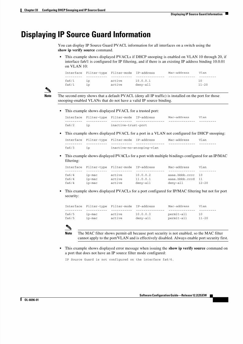
8/10/2019 Cisco ConfiguratioGuide SW4500 IOS
http://slidepdf.com/reader/full/cisco-configuratioguide-sw4500-ios 471/607
33-13
Software Configuration Guide—Release 12.2(25)EW
OL-6696-01
Chapter 33 Configuring DHCP Snooping and IP Source Guard
Displaying IP Source Guard Information
Displaying IP Source Guard InformationYou can display IP Source Guard PVACL information for all interfaces on a switch using the
show ip verify source command.
• This example shows displayed PVACLs if DHCP snooping is enabled on VLAN 10 through 20, if
interface fa6/1 is configured for IP filtering, and if there is an existing IP address binding 10.0.01
on VLAN 10:
Interface Filter-type Filter-mode IP-address Mac-address Vlan--------- ----------- ----------- --------------- -------------- ---------
fa6/1 ip active 10.0.0.1 10fa6/1 ip active deny-all 11-20
Note The second entry shows that a default PVACL (deny all IP traffic) is installed on the port for those
snooping-enabled VLANs that do not have a valid IP source binding.
• This example shows displayed PVACL for a trusted port:
Interface Filter-type Filter-mode IP-address Mac-address Vlan
--------- ----------- ----------- --------------- -------------- ---------fa6/2 ip inactive-trust-port
• This example shows displayed PVACL for a port in a VLAN not configured for DHCP snooping:
Interface Filter-type Filter-mode IP-address Mac-address Vlan
--------- ----------- ----------- --------------- -------------- ---------fa6/3 ip inactive-no-snooping-vlan
• This example shows displayed PVACLs for a port with multiple bindings configured for an IP/MAC
filtering:
Interface Filter-type Filter-mode IP-address Mac-address Vlan
--------- ----------- ----------- --------------- -------------- ---------fa6/4 ip-mac active 10.0.0.2 aaaa.bbbb.cccc 10
fa6/4 ip-mac active 11.0.0.1 aaaa.bbbb.cccd 11fa6/4 ip-mac active deny-all deny-all 12-20
• This example shows displayed PVACLs for a port configured for IP/MAC filtering but not for port
security:
Interface Filter-type Filter-mode IP-address Mac-address Vlan
--------- ----------- ----------- --------------- -------------- ---------fa6/5 ip-mac active 10.0.0.3 permit-all 10
fa6/5 ip-mac active deny-all permit-all 11-20
Note The MAC filter shows permit-all because port security is not enabled, so the MAC filter
cannot apply to the port/VLAN and is effectively disabled. Always enable port security first
• This example shows displayed error message when issuing the show ip verify source command on
a port that does not have an IP source filter mode configured:
IP Source Guard is not configured on the interface fa6/6.

8/10/2019 Cisco ConfiguratioGuide SW4500 IOS
http://slidepdf.com/reader/full/cisco-configuratioguide-sw4500-ios 472/607
33-14
Software Configuration Guide—Release 12.2(25)EW
OL-6696-01
Chapter 33 Configuring DHCP Snooping and IP Source Guard
Displaying IP Source Binding Information
You can also use the show ip verify source command to display all interfaces on the switch that have IP
source guard enabled:
Interface Filter-type Filter-mode IP-address Mac-address Vlan
--------- ----------- ----------- --------------- -------------- ---------
fa6/1 ip active 10.0.0.1 10
fa6/1 ip active deny-all 11-20
fa6/2 ip inactive-trust-portfa6/3 ip inactive-no-snooping-vlanfa6/4 ip-mac active 10.0.0.2 aaaa.bbbb.cccc 10
fa6/4 ip-mac active 11.0.0.1 aaaa.bbbb.cccd 11
fa6/4 ip-mac active deny-all deny-all 12-20fa6/5 ip-mac active 10.0.0.3 permit-all 10
fa6/5 ip-mac active deny-all permit-all 11-20
Displaying IP Source Binding InformationYou can display all IP source bindings configured on all interfaces on a switch using the
show ip source binding command.
Switch# sh ip source bindingMacAddress IpAddress Lease(sec) Type VLAN Interface
------------------ --------------- ---------- ------------- ---- --------------------
00:02:B3:3F:3B:99 55.5.5.2 6522 dhcp-snooping 10 FastEthernet6/1000:00:00:0A:00:0B 11.0.0.1 infinite static 10 FastEthernet6/10
Switch#
Table 33-3 describes the fields in the show ip source binding command output.
Table 33-3 show ip source binding Command Output
Field Description
MAC Address Client hardware MAC address
IP Address Client IP address assigned from the DHCP server
Lease (seconds) IP address lease time
Type Binding type; static bindings configured from CLI to dynamic binding
learned from DHCP Snooping
VLAN VLAN number of the client interface
Interface Interface that connects to the DHCP client host

8/10/2019 Cisco ConfiguratioGuide SW4500 IOS
http://slidepdf.com/reader/full/cisco-configuratioguide-sw4500-ios 473/607
C H A P T E R
34-1
Software Configuration Guide—Release 12.2(25)EW
OL-6696-01
34
Understanding and Configuring Dynamic ARPInspection
This chapter describes how to configure Dynamic ARP Inspection (DAI) on the Catalyst 4500 series
switch.
This chapter includes the following major sections:• Overview of Dynamic ARP Inspection, page 34-1
• Configuring Dynamic ARP Inspection, page 34-5
Note For complete syntax and usage information for the switch commands used in this chapter, refer to the
Catalyst 4500 Series Switch Cisco IOS Command Reference and related publications at
http://www.cisco.com/univercd/cc/td/doc/product/software/ios122/122cgcr/index.htm.
Overview of Dynamic ARP InspectionDynamic ARP Inspection (DAI) is a security feature that validates Address Resolution Protocol (ARP)
packets in a network. DAI allows a network administrator to intercept, log, and discard ARP packets with
invalid MAC address to IP address bindings. This capability protects the network from certain
“man-in-the-middle” attacks.
This section contains the following subsections:
• ARP Cache Poisoning, page 34-2
• Dynamic ARP Inspection, page 34-2
• Interface Trust state, Security Coverage and Network Configuration, page 34-3
• Relative Priority of Static Bindings and DHCP Snooping Entries, page 34-4
• Logging of Denied Packets, page 34-4
• Rate Limiting of ARP Packets, page 34-4
• Port Channels and Their Behavior, page 34-4

8/10/2019 Cisco ConfiguratioGuide SW4500 IOS
http://slidepdf.com/reader/full/cisco-configuratioguide-sw4500-ios 474/607
34-2
Software Configuration Guide—Release 12.2(25)EW
OL-6696-01
Chapter 34 Understanding and Configuring Dynamic ARP Inspection
Overview of Dynamic ARP Inspection
ARP Cache Poisoning
You can attack hosts, switches, and routers connected to your Layer 2 network by “poisoning” their ARP
caches. For example, a malicious user might intercept traffic intended for other hosts on the subnet by
poisoning the ARP caches of systems connected to the subnet.
Consider the following configuration:
Figure 34-1 ARP Cache Poisoning
Hosts HA, HB, and HC are connected to the switch on interfaces A, B and C, all of which are on the
same subnet. Their IP and MAC addresses are shown in parentheses; for example, Host HA uses IP
address IA and MAC address MA. When HA needs to communicate to HB at the IP Layer, HA
broadcasts an ARP request for the MAC address associated with IB. As soon as HB receives the ARP
request, the ARP cache on HB is populated with an ARP binding for a host with the IP address IA and
a MAC address MA; for example, IP address IA is bound to MAC address MA. When HB responds, the
ARP cache on HA is populated with a binding for a host with the IP address IB and a MAC address MB.
Host HC can “poison” the ARP caches of HA and HB by broadcasting forged ARP responses with
bindings for a host with an IP address of IA (or IB) and a MAC address of MC. Hosts with poisoned
ARP caches use the MAC address MC as the destination MAC address for traffic intended for IA or IB.
This means that HC intercepts that traffic. Because HC knows the true MAC addresses associated with
IA and IB, HC can forward the intercepted traffic to those hosts using the correct MAC address as the
destination. HC has inserted itself into the traffic stream from HA to HB, the classic “man in the middle”
attack.
Dynamic ARP Inspection
To prevent ARP poisoning attacks such as the one descr ibed in the previous section, a switch must ensure
that only valid ARP requests and responses are relayed. DAI prevents these attacks by intercepting all
ARP requests and responses. Each of these intercepted packets is verified for valid MAC address to IP
address bindings before the local ARP cache is updated or the packet is forwarded to the appropriate
destination. Invalid ARP packets are dropped.
DAI determines the validity of an ARP packet based on valid MAC address to IP address bindings stored
in a trusted database. This database is built at runtime by DHCP snooping, provided that it is enabled on
the VLANs and on the switch in question. In addition, DAI can also validate ARP packets against
user-configured ARP ACLs in order to handle hosts that use statically configured IP addresses.
DAI can also be configured to drop ARP packets when the IP addresses in the packet are invalid or when
the MAC addresses in the body of the ARP packet do not match the addresses specified in the Ethernet
header.
A B
C
HA(IA, MA)
HB(IB, MB)
HC(IC, MC)
9 4 0 7 2

8/10/2019 Cisco ConfiguratioGuide SW4500 IOS
http://slidepdf.com/reader/full/cisco-configuratioguide-sw4500-ios 475/607
34-3
Software Configuration Guide—Release 12.2(25)EW
OL-6696-01
Chapter 34 Understanding and Configuring Dynamic ARP Inspection
Overview of Dynamic ARP Inspection
Interface Trust state, Security Coverage and Network Configuration
DAI associates a trust state with each interface on the system. Packets arriving on trusted interfaces
bypass all DAI validation checks, while those arriving on untrusted interfaces go through the DAI
validation process. In a typical network configuration for DAI, all ports connected to host ports are
configured as untrusted, while all ports connected to switches are configured as trusted. With thisconfiguration, all ARP packets entering the network from a given switch will have passed the security
check; it is unnecessary to perform a validation at any other place in the VLAN / network:
Figure 34-2 Validation of ARP Packets on a DAI-enabled VLAN
Use the trust state configuration carefully.
Configuring interfaces as untrusted when they should be trusted can result in a loss of connectivity. If
we assume that both S1 and S2 (in Figure 34-2) run DAI on the VLAN that holds H1 and H2, and if H1
and H2 were to acquire their IP addresses from S1, then only S2 binds the IP to MAC address of H1.
Therefore, if the interface between S1 and S2 is untrusted, the ARP packets from H1 get dropped on S2.
This condition would result in a loss of connectivity between H1 and H2.
Configuring interfaces to be trusted when they are actually untrusted leaves a security hole in the
network. If S1 were not running DAI, then H1 can easily poison the ARP of S2 (and H2, if the inter-
switch link is configured as trusted). This condition can occur even though S2 is running DAI.
DAI ensures that hosts (on untrusted interfaces) connected to a switch running DAI do not poison the
ARP caches of other hosts in the network. It does not, however, ensure that hosts from other portions of
the network do not poison the caches of the hosts connected to it.
To handle cases in which some switches in a VLAN run DAI and other switches do not, the interfaces
connecting such switches should be configured as untrusted. To validate the bindings of packets from
non-DAI switches, however, the switch running DAI should be configured with ARP ACLs. When it is
not feasible to determine such bindings, switches running DAI should be isolated from non-DAI
switches at Layer 3.
Note Depending on the setup of DHCP server and the network, it may not be possible to perform validation
of a given ARP packet on all switches in the VLAN.
DHCP server
Switch S1 Switch S2
Host H1 Host H2
Fa6/4 Fa3/4
Fa6/3 Fa3/3
9 4 0 7 5

8/10/2019 Cisco ConfiguratioGuide SW4500 IOS
http://slidepdf.com/reader/full/cisco-configuratioguide-sw4500-ios 476/607
34-4
Software Configuration Guide—Release 12.2(25)EW
OL-6696-01
Chapter 34 Understanding and Configuring Dynamic ARP Inspection
Overview of Dynamic ARP Inspection
Relative Priority of Static Bindings and DHCP Snooping Entries
As mentioned previously, DAI populates its database of valid MAC address to IP address bindings
through DHCP snooping. It also validates ARP packets against statically configured ARP ACLs. It is
important to note that ARP ACLs have precedence over entries in the DHCP snooping database. ARP
Packets are first compared to user-configured ARP ACLs. If the ARP ACL denies the ARP packet, thenthe packet will be denied even if a valid binding exists in the database populated by DHCP snooping.
Logging of Denied Packets
DAI maintains a log of denied IP ARP packets. Log messages are generated at a controlled rate, and log
entries are cleared once messages are generated on their behalf.
Rate Limiting of ARP Packets
DAI performs validation checks in the CPU, so the number of incoming ARP packets is rate-limited to
prevent a denial of service attack. By default, the rate for untrusted interfaces is set to 15 packets per
second, whereas trusted interfaces have no rate limit. When the rate of incoming ARP packets exceeds
the configured limit, the port is placed in the errdisable state. The port remains in that state until an
administrator intervenes. You can enable errdisable recovery so that ports emerge from this state
automatically after a specified timeout period.
Unless a rate limit is explicitly configured on an interface, changing the trust state of the interface will
also change its rate limit to the default value for that trust state; that is, 15 packets per second for
untrusted interfaces and unlimited for trusted interfaces. Once a rate limit is configured explicitly, the
interface retains the rate limit even when its trust state is changed. At any time, the interface reverts to
its default rate limit if the no form of the rate limit command is applied.
Port Channels and Their BehaviorA given physical port can join a channel only when the trust state of the physical port and of the channel
match. Otherwise, the physical port remains suspended in the channel. A channel inherits its trust state
from the first physical port that joined the channel. Consequently, the trust state of the first physical port
need not match the trust state of the channel.
Conversely, when the trust state is changed on the channel, the new trust state is configured on all the
physical ports that comprise the channel.
The rate limit check on port channels is unique. The rate of incoming packets on a physical port is
checked against the port channel configuration rather than the physical ports configuration.
The rate limit configuration on a port channel is independent of the configuration on its physical ports.
The rate limit is cumulative across all physical port; that is, the rate of incoming packets on a port
channel equals the sum of rates across all physical ports.
When you configure rate limits for ARP packets on trunks, you must account for VLAN aggregation
because a high rate limit on one VLAN can cause a “denial of service” attack to other VLANs when the
port is errdisabled by software. Similarly, when a port channel is errdisabled, a high rate limit on one
physical port can cause other ports in the channel to go down.

8/10/2019 Cisco ConfiguratioGuide SW4500 IOS
http://slidepdf.com/reader/full/cisco-configuratioguide-sw4500-ios 477/607
34-5
Software Configuration Guide—Release 12.2(25)EW
OL-6696-01
Chapter 34 Understanding and Configuring Dynamic ARP Inspection
Configuring Dynamic ARP Inspection
Configuring Dynamic ARP InspectionThis section includes these scenarios:
• Scenario One: Two Switches Support Dynamic ARP Inspection, page 34-5
• Scenario Two: One Switch Supports Dynamic ARP Inspection, page 34-9
Scenario One: Two Switches Support Dynamic ARP Inspection
Assume that there are two switches, S1 and S2 with hosts H1 and H2 attached, respectively. Both S1 and
S2 are running DAI on VLAN 1 where the hosts are located. The S1 interface fa6/3 is connected to the
S2 interface fa3/3, and a DHCP server is connected to S1. Both hosts acquire their IP addresses from the
same DHCP server. Therefore, S1 has the binding for H1 and H2, and S2 has the binding for host H2.
To make the setup effective, you must configure the interface fa3/3 on S2 to be trusted. (You can leave
interface fa6/3 on S1 as untrusted.) If the DHCP server is moved from S1 to a different location, however,
the configuration will not work. To ensure that this setup works permanently, without compromising
security, you must configure both interfaces fa6/3 on S1 and fa3/3 on S2 as trusted.
Configuring Switch S1
To enable DAI and configure fa6/3 on S1 as trusted, follow these steps:
Step 1 Verify the connection between switches S1 and S2:
S1# show cdp neighborsCapability Codes: R - Router, T - Trans Bridge, B - Source Route Bridge
S - Switch, H - Host, I - IGMP, r - Repeater, P - Phone
Device ID Local Intrfce Holdtme Capability Platform Port ID
S2 Fas 6/3 177 R S I WS-C4006 Fas 3/3
S1#
Step 2 Enable DAI on VLAN 1 and verify the configuration:
S1# conf t
Enter configuration commands, one per line. End with CNTL/Z.
S1(config)# ip arp inspection vlan 1
S1(config)# endS1# show ip arp inspection vlan 1
Source Mac Validation : Disabled
Destination Mac Validation : Disabled
IP Address Validation : Disabled
Vlan Configuration Operation ACL Match Static ACL
---- ------------- --------- --------- ---------- 1 Enabled Active
Vlan ACL Logging DHCP Logging ---- ----------- ------------
1 Deny Deny
S1#

8/10/2019 Cisco ConfiguratioGuide SW4500 IOS
http://slidepdf.com/reader/full/cisco-configuratioguide-sw4500-ios 478/607
34-6
Software Configuration Guide—Release 12.2(25)EW
OL-6696-01
Chapter 34 Understanding and Configuring Dynamic ARP Inspection
Configuring Dynamic ARP Inspection
Step 3 Configure interface fa6/3 as trusted:
S1# conf tEnter configuration commands, one per line. End with CNTL/Z.
S1(config)# in fa6/3S1(config-if)# ip arp inspection trust
S1(config-if)# end
S1# show ip arp inspection interfaces fastEthernet 6/3
Interface Trust State Rate (pps)
--------------- ----------- ----------
Fa6/3 Trusted NoneS1#
Step 4 Verify the bindings:
S1# show ip dhcp snooping binding
MacAddress IpAddress Lease(sec) Type VLAN Interface------------------ --------------- ---------- ------------- ---- --------------------
00:02:00:02:00:02 1.1.1.2 4993 dhcp-snooping 1 FastEthernet6/4S1#
Step 5 Check the statistics before and after Dynamic ARP processes any packets:
S1# show ip arp inspection statistics vlan 1
Vlan Forwarded Dropped DHCP Drops ACL Drops---- --------- ------- ---------- ----------
1 0 0 0 0
Vlan DHCP Permits ACL Permits Source MAC Failures
---- ------------ ----------- -------------------
1 0 0 0
Vlan Dest MAC Failures IP Validation Failures ---- ----------------- ----------------------
1 0 0
S1#
If H1 then sends out two ARP requests with an IP address of 1.1.1.2 and a MAC address of
0002.0002.0002, both requests are permitted, as reflected in the following statistics:
S1# show ip arp inspection statistics vlan 1
Vlan Forwarded Dropped DHCP Drops ACL Drops
---- --------- ------- ---------- ---------- 1 2 0 0 0
Vlan DHCP Permits ACL Permits Source MAC Failures
---- ------------ ----------- -------------------
1 2 0 0
Vlan Dest MAC Failures IP Validation Failures
---- ----------------- ----------------------
1 0 0S1#
If H1 then tries to send an ARP request with an IP address of 1.1.1.3, the packet is dropped and an error
message is logged:
00:12:08: %SW_DAI-4-DHCP_SNOOPING_DENY: 2 Invalid ARPs (Req) on Fa6/4, vlan
1.([0002.0002.0002/1.1.1.3/0000.0000.0000/0.0.0.0/02:42:35 UTC Tue Jul 10 2001])
S1# show ip arp inspection statistics vlan 1S1#

8/10/2019 Cisco ConfiguratioGuide SW4500 IOS
http://slidepdf.com/reader/full/cisco-configuratioguide-sw4500-ios 479/607

8/10/2019 Cisco ConfiguratioGuide SW4500 IOS
http://slidepdf.com/reader/full/cisco-configuratioguide-sw4500-ios 480/607
34-8
Software Configuration Guide—Release 12.2(25)EW
OL-6696-01
Chapter 34 Understanding and Configuring Dynamic ARP Inspection
Configuring Dynamic ARP Inspection
Interface Trust State Rate (pps)
--------------- ----------- ----------
Gi1/1 Untrusted 15 Gi1/2 Untrusted 15
Gi3/1 Untrusted 15 Gi3/2 Untrusted 15
Fa3/3 Trusted None
Fa3/4 Untrusted 15 Fa3/5 Untrusted 15 Fa3/6 Untrusted 15
Fa3/7 Untrusted 15
<output truncated>
S2#
Step 4 Verify the list of DHCP snooping bindings:
S2# show ip dhcp snooping bindingMacAddress IpAddress Lease(sec) Type VLAN Interface
------------------ --------------- ---------- ------------- ---- --------------------00:01:00:01:00:01 1.1.1.1 4995 dhcp-snooping 1 FastEthernet3/4
S2#
Step 5 Check the statistics before and after Dynamic ARP processes any packets:
S2# show ip arp inspection statistics vlan 1
Vlan Forwarded Dropped DHCP Drops ACL Drops
---- --------- ------- ---------- ---------- 1 0 0 0 0
Vlan DHCP Permits ACL Permits Source MAC Failures
---- ------------ ----------- ------------------- 1 0 0 0
Vlan Dest MAC Failures IP Validation Failures
---- ----------------- ----------------------
1 0 0
S2#
If H2 then sends out an ARP request with the IP address 1.1.1.1 and the MAC address 0001.0001.0001,
the packet is forwarded and the statistics are updated appropriately:
S2# show ip arp inspection statistics vlan 1
Vlan Forwarded Dropped DHCP Drops ACL Drops
---- --------- ------- ---------- ----------
1 1 0 0 0
Vlan DHCP Permits ACL Permits Source MAC Failures
---- ------------ ----------- -------------------
1 1 0 0
Vlan Dest MAC Failures IP Validation Failures ---- ----------------- ----------------------
1 0 0S2#
Conversely, if H2 attempts to send an ARP request with the IP address 1.1.1.2, the request is dropped
and an error message is logged:
00:18:08: %SW_DAI-4-DHCP_SNOOPING_DENY: 1 Invalid ARPs (Req) on Fa3/4, vlan
1.([0001.0001.0001/1.1.1.2/0000.0000.0000/0.0.0.0/01:53:21 UTC Fri May 23 2003])
S2#

8/10/2019 Cisco ConfiguratioGuide SW4500 IOS
http://slidepdf.com/reader/full/cisco-configuratioguide-sw4500-ios 481/607
34-9
Software Configuration Guide—Release 12.2(25)EW
OL-6696-01
Chapter 34 Understanding and Configuring Dynamic ARP Inspection
Configuring Dynamic ARP Inspection
The statistics will display as follows:
S2# show ip arp inspection statistics vlan 1
Vlan Forwarded Dropped DHCP Drops ACL Drops---- --------- ------- ---------- ----------
1 1 1 1 0
Vlan DHCP Permits ACL Permits Source MAC Failures
---- ------------ ----------- -------------------
1 1 0 0
Vlan Dest MAC Failures IP Validation Failures
---- ----------------- ---------------------- 1 0 0
S2#
Scenario Two: One Switch Supports Dynamic ARP Inspection
If switch S2 does not support DAI or DHCP snooping, configuring interface fa6/3 as trusted would leave
a security hole because both S1 and H1 could be attacked by either S2 or H2. To prevent this possibility,
you must configure interface fa6/3 as untrusted. To permit ARP packets from H2, you must set up an
ARP ACL and apply it to VLAN 1. If the IP address of H2 is not static, such that it is impossible to apply
the ACL configuration on S1, S1 and S2 must be separated at Layer 3, that is, have a router routing
packets between S1 and S2.
To set up an ARP ACL on switch S1, follow these steps:
Step 1 Set up the access list to permit the IP address 1.1.1.1 and the MAC address 0001.0001.0001, and verify
the configuration:
S1# conf t
Enter configuration commands, one per line. End with CNTL/Z.S1(config)# arp access-list H2
S1(config-arp-nacl)# permit ip host 1.1.1.1 mac host 1.1.1
S1(config-arp-nacl)# end
S1# show arp access-listARP access list H2
permit ip host 1.1.1.1 mac host 0001.0001.0001
Step 2 Apply the ACL to VLAN 1, and verify the configuration:
S1# conf tEnter configuration commands, one per line. End with CNTL/Z.
S1(config)# ip arp inspection filter H2 vlan 1S1(config)# end
S1#
S1# show ip arp inspection vlan 1
Source Mac Validation : Disabled
Destination Mac Validation : Disabled
IP Address Validation : Disabled
Vlan Configuration Operation ACL Match Static ACL
---- ------------- --------- --------- ---------- 1 Enabled Active H2 No

8/10/2019 Cisco ConfiguratioGuide SW4500 IOS
http://slidepdf.com/reader/full/cisco-configuratioguide-sw4500-ios 482/607
34-10
Software Configuration Guide—Release 12.2(25)EW
OL-6696-01
Chapter 34 Understanding and Configuring Dynamic ARP Inspection
Configuring Dynamic ARP Inspection
Vlan ACL Logging DHCP Logging
---- ----------- ------------
1 Deny DenyS1#
Step 3 Establish the interface fa6/3 as untrusted, and verify the configuration:
S1# conf tEnter configuration commands, one per line. End with CNTL/Z.
S1(config)# in fa6/3
S1(config-if)# no ip arp inspection trust
S1(config-if)# endSwitch# show ip arp inspection interfaces fastEthernet 6/3
Interface Trust State Rate (pps)
--------------- ----------- ----------
Fa6/3 Untrusted 15
Switch#
When H2 sends 5 ARP requests through interface fa6/3 on S1 and a “get” is permitted by S1, the
statistics are updated appropriately:
Switch# show ip arp inspection statistics vlan 1 Vlan Forwarded Dropped DHCP Drops ACL Drops
---- --------- ------- ---------- ----------
1 5 0 0 0
Vlan DHCP Permits ACL Permits Source MAC Failures ---- ------------ ----------- -------------------
1 0 5 0
Vlan Dest MAC Failures IP Validation Failures
---- ----------------- ----------------------
1 0 0Switch#

8/10/2019 Cisco ConfiguratioGuide SW4500 IOS
http://slidepdf.com/reader/full/cisco-configuratioguide-sw4500-ios 483/607
C H A P T E R
35-1
Software Configuration Guide—Release 12.2(25)EW
OL-6696-01
35
Configuring Network Security with ACLs
This chapter describes how to use access control lists (ACLs) to configure network security on the
Catalyst 4500 series switches.
Note For complete syntax and usage information for the switch commands used in this chapter, refer to the
Catalyst 4500 Series Switch Cisco IOS Command Reference and related publications athttp://www.cisco.com/univercd/cc/td/doc/product/software/ios122/122cgcr/index.htm.
This chapter consists of the following major sections:
• Understanding ACLs, page 35-1
• Hardware and Software ACL Support, page 35-5
• TCAM Programming and ACLs, page 35-6
• Layer 4 Operators in ACLs, page 35-7
• Configuring Unicast MAC Address Filtering, page 35-11
• Configuring Named MAC Extended ACLs, page 35-11
• Configuring VLAN Maps, page 35-12
• Displaying VLAN Access Map Information, page 35-19
• Using VLAN Maps with Router ACLs, page 35-19
• Configuring PACLs, page 35-22
• Using PACL with VLAN Maps and Router ACLs, page 35-26
Understanding ACLsThis section contains the following subsections:
• ACL Overview, page 35-2
• Supported Features That Use ACLs, page 35-2
• Router ACLs, page 35-3
• Port ACLs, page 35-4
• VLAN Maps, page 35-5

8/10/2019 Cisco ConfiguratioGuide SW4500 IOS
http://slidepdf.com/reader/full/cisco-configuratioguide-sw4500-ios 484/607
8/10/2019 Cisco ConfiguratioGuide SW4500 IOS
http://slidepdf.com/reader/full/cisco-configuratioguide-sw4500-ios 485/607
35-3
Software Configuration Guide—Release 12.2(25)EW
OL-6696-01
Chapter 35 Configuring Network Security with ACLs
Understanding ACLs
You can apply only one IP access list and one MAC access list to a Layer 2 interface.
• VLAN ACLs or VLAN maps control the access of all packets (bridged and routed). You can use
VLAN maps to filter traffic between devices in the same VLAN. You do not need the enhanced
image to create or apply VLAN maps. VLAN maps are configured to control access based on
Layer 3 addresses for IP. MAC addresses using Ethernet ACEs control the access of unsupported
protocols. After you apply a VLAN map to a VLAN, all packets (routed or bridged) entering theVLAN are checked against that map. Packets can either enter the VLAN through a switch port or
through a routed port after being routed.
You can use both router ACLs and VLAN maps on the same switch.
Router ACLs
You can apply router ACLs on switch virtual interfaces (SVIs), which are Layer 3 interfaces to VLANs;
on physical Layer 3 interfaces; and on Layer 3 EtherChannel interfaces. Router ACLs are applied on
interfaces for specific directions (inbound or outbound). You can apply one IP access list in each
direction.
Multiple features can use one ACL for a given interface, and one feature can use multiple ACLs. Whena single router ACL is used by multiple features, it is examined multiple times. The access list type
determines the input to the matching operation:
• Standard IP access lists use source addresses for matching operations.
• Extended IP access lists use source and destination addresses and optional protocol type information
for matching operations.
The switch examines ACLs associated with features configured on a given interface and a direction. As
packets enter the switch on an interface, ACLs associated with all inbound features configured on that
interface are examined. After packets are routed and before they are forwarded to the next hop, all ACLs
associated with outbound features configured on the egress interface are examined.
ACLs permit or deny packet forwarding based on how the packet matches the entries in the ACL. For
example, you can use access lists to allow one host to access a part of a network, but prevent anotherhost from accessing the same part. In Figure 35-1, ACLs applied at the router input allow Host A to
access the Human Resources network, but prevent Host B from accessing the same network.

8/10/2019 Cisco ConfiguratioGuide SW4500 IOS
http://slidepdf.com/reader/full/cisco-configuratioguide-sw4500-ios 486/607
35-4
Software Configuration Guide—Release 12.2(25)EW
OL-6696-01
Chapter 35 Configuring Network Security with ACLs
Understanding ACLs
Figure 35-1 Using ACLs to Control Traffic to a Network
Port ACLs
You can also apply ACLs to Layer 2 interfaces on a switch. Port ACLs are supported on physical
interfaces and EtherChannel interfaces.
The following access lists are supported on Layer 2 interfaces:
• Standard IP access lists using source addresses
• Extended IP access lists using source and destination addresses and optional protocol typeinformation
• MAC extended access lists using source and destination MAC addresses and optional protocol type
information
As with router ACLs, the switch examines ACLs associated with features configured on a given interface
and permits or denies packet forwarding based on how the packet matches the entries in the ACL. In the
example in Figure 35-1, if all workstations were in the same VLAN, ACLs applied at the Layer 2 input
would allow Host A to access the Human Resources network, but prevent Host B from accessing the
same network.
When you apply a port ACL to a trunk port, the ACL filters traffic on all VLANs present on the trunk
port. When you apply a port ACL to a port with voice VLAN, the ACL filters traffic on both data and
voice VLANs.
With port ACLs, you can filter IP traffic by using IP access lists and non-IP traffic by using MAC
addresses. You can filter both IP and non-IP traffic on the same Layer 2 interface by applying both an IP
access list and a MAC access list to the interface.
Note You cannot apply more than one IP access list and one MAC access list to a Layer 2 interface. If an IP
access list or MAC access list is already configured on a Layer 2 interface and you apply a new IP access
list or MAC access list to the interface, the new ACL replaces the previously configured one.
SiHost A
Host B
9 4 1 5 2
Research &Development
network
= ACL denying traffic from Host B
and permitting traffic from Host A= Packet
Catalyst 4500 series switch
HumanResources
network

8/10/2019 Cisco ConfiguratioGuide SW4500 IOS
http://slidepdf.com/reader/full/cisco-configuratioguide-sw4500-ios 487/607
35-5
Software Configuration Guide—Release 12.2(25)EW
OL-6696-01
Chapter 35 Configuring Network Security with ACLs
Hardware and Software ACL Support
VLAN Maps
VLAN maps can control the access of all traffic in a VLAN. You can apply VLAN maps on the switch
to all packets that are routed into or out of a VLAN or are bridged within a VLAN. Unlike router ACLs,
VLAN maps are not defined by direction (input or output).
You can configure VLAN maps to match Layer 3 addresses for IP traffic. Access of all non-IP protocolsis controlled with a MAC address and an Ethertype using MAC ACLs in VLAN maps. (IP traffic is not
controlled by MAC ACLs in VLAN maps.) You can enforce VLAN maps only on packets going through
the switch; you cannot enforce VLAN maps on traffic between hosts on a hub or on another switch
connected to this switch.
With VLAN maps, forwarding packets is permitted or denied, based on the action specified in the map.
Figure 35-2 illustrates how a VLAN map is applied to deny a specific type of traffic from Host A in
VLAN 10 from being forwarded.
Figure 35-2 Using VLAN Maps to Control Traffic
Hardware and Software ACL Support
This section describes how to determine whether ACLs are processed in hardware or in software:
• Flows that match a deny statement in standard and extended ACLs (input only) are dropped in
hardware if ICMP unreachable messages are disabled.
• Flows that match a permit statement in standard and extended ACLs (input and output) are processed
in hardware.
• The following ACL types are not supported in software:
– Standard Xerox Network Systems (XNS) Protocol access list
– Extended XNS access list
– DECnet access list
– Protocol type-code access list
– Standard Internet Packet Exchange (IPX) access list
– Extended IPX access list
Si
Host B(VLAN 10)
Host A(VLAN 10)
9 4 1 5 3
= VLAN map denying specific typeof traffic from Host A
= Packet
Catalyst 4500 series switch

8/10/2019 Cisco ConfiguratioGuide SW4500 IOS
http://slidepdf.com/reader/full/cisco-configuratioguide-sw4500-ios 488/607
35-6
Software Configuration Guide—Release 12.2(25)EW
OL-6696-01
Chapter 35 Configuring Network Security with ACLs
TCAM Programming and ACLs
Note Packets that require logging are processed in software. A copy of the packets is sent to the CPU for
logging while the actual packets are forwarded in hardware so that non-logged packet processing is not
impacted.
By default, the Catalyst 4500 series switch sends ICMP unreachable messages when a packet is deniedby an access list; these packets are not dropped in hardware but are forwarded to the switch so that it can
generate the ICMP unreachable message.
To drop access-list denied packets in hardware on the input interface, you must disable ICMP
unreachable messages using the no ip unreachables interface configuration command. The ip
unreachables command is enabled by default.
Packets denied by an output access list are always forwarded to the CPU.
TCAM Programming and ACLs
Two types of hardware resources are consumed when you program ACLs: entries and masks. If one ofthese resources is exhausted, no additional ACLs can be programmed into hardware. If the masks on a
system are exhausted, but entries are available, changing the programming scheme from packed to
scattered might free up masks, allowing additional ACLs to be programmed into hardware.
The goal is to use TCAM resources more efficiently by minimizing the number of masks per ACL
entries. To compare TCAM utilization when employing the scattered or packed algorithms, use the
show platform hardware acl statistics utilization brief command. To change the algorithm from
packed to scattered, use the access-list hardware entries command. To disable an algorithm, use the no
acccess-list hardware entries command.
Note To determine whether the packed algorithm is configured, use the show running config command. If
packed is configured, the line access-list hardware entries packed will appear.
Note The default TCAM programming algorithm is packed.
The following output was collected from a switch running in packed mode. Observe that 89 percent of
the masks are required to program only 49 percent of the ACL entries.
Switch# configure terminal
Enter configuration commands, one per line. End with CNTL/Z.Switch(config)# access-list hardware entries packed
Switch(config)# end
Switch#
01:15:34: %SYS-5-CONFIG_I: Configured from console by console
Switch#

8/10/2019 Cisco ConfiguratioGuide SW4500 IOS
http://slidepdf.com/reader/full/cisco-configuratioguide-sw4500-ios 489/607
35-7
Software Configuration Guide—Release 12.2(25)EW
OL-6696-01
Chapter 35 Configuring Network Security with ACLs
Layer 4 Operators in ACLs
Switch# show platform hardware acl statistics utilization brief
Entries/Total(%) Masks/Total(%)
----------------- --------------- Input Acl(PortAndVlan) 2016 / 4096 ( 49) 460 / 512 ( 89)
Input Acl(PortOrVlan) 6 / 4096 ( 0) 4 / 512 ( 0) Input Qos(PortAndVlan) 0 / 4096 ( 0) 0 / 512 ( 0)
Input Qos(PortOrVlan) 0 / 4096 ( 0) 0 / 512 ( 0)
Output Acl(PortAndVlan) 0 / 4096 ( 0) 0 / 512 ( 0) Output Acl(PortOrVlan) 0 / 4096 ( 0) 0 / 512 ( 0) Output Qos(PortAndVlan) 0 / 4096 ( 0) 0 / 512 ( 0)
Output Qos(PortOrVlan) 0 / 4096 ( 0) 0 / 512 ( 0)
L4Ops: used 2 out of 64
The following output was collected after the algorithm was switched to scattered. Observe that the
number of masks required to program 49 percent of the entries has decreased to 49 percent.
Note When you enable DHCP snooping and IP Source Guard on all ports on a chassis, you must use the
scattered keyword.
Switch# configure terminalEnter configuration commands, one per line. End with CNTL/Z.
Switch(config)# access-list hardware entries scatteredSwitch(config)# end
Switch#01:39:37: %SYS-5-CONFIG_I: Configured from console by console
Switch#
Switch# show platform hardware acl statistics utilization brief
Entries/Total(%) Masks/Total(%) ----------------- ---------------
Input Acl(PortAndVlan) 2016 / 4096 ( 49) 252 / 512 ( 49) Input Acl(PortOrVlan) 6 / 4096 ( 0) 5 / 512 ( 0)
Input Qos(PortAndVlan) 0 / 4096 ( 0) 0 / 512 ( 0)
Input Qos(PortOrVlan) 0 / 4096 ( 0) 0 / 512 ( 0) Output Acl(PortAndVlan) 0 / 4096 ( 0) 0 / 512 ( 0)
Output Acl(PortOrVlan) 0 / 4096 ( 0) 0 / 512 ( 0) Output Qos(PortAndVlan) 0 / 4096 ( 0) 0 / 512 ( 0)
Output Qos(PortOrVlan) 0 / 4096 ( 0) 0 / 512 ( 0)
L4Ops: used 2 out of 64Switch#
Layer 4 Operators in ACLsThe following sections describe guidelines and restrictions for configuring ACLs that include Layer 4
port operations:
• Restrictions for Layer 4 Operations, page 35-8
• Configuration Guidelines for Layer 4 Operations, page 35-8
• How ACL Processing Impacts CPU, page 35-9

8/10/2019 Cisco ConfiguratioGuide SW4500 IOS
http://slidepdf.com/reader/full/cisco-configuratioguide-sw4500-ios 490/607
35-8
Software Configuration Guide—Release 12.2(25)EW
OL-6696-01
Chapter 35 Configuring Network Security with ACLs
Layer 4 Operators in ACLs
Restrictions for Layer 4 Operations
You can specify these operator types, each of which uses one Layer 4 operation in the hardware:
• gt (greater than)
• lt (less than)
• neq (not equal)
• range (inclusive range)
We recommend that you not specify more than six different operations on the same ACL. If you exceed
this number, each new operation might cause the affected ACE (access control entry) to be translated
into multiple ACEs in hardware. If you exceed this number, the affected ACE might be processed in
software.
Configuration Guidelines for Layer 4 Operations
Keep the following guidelines in mind when using Layer 4 operators:
• Layer 4 operations are considered different if the operator or operand differ. For example, the
following ACL contains three different Layer 4 operations because gt 10 and gt 11 are considered
two different Layer 4 operations:
... gt 10 permit
... lt 9 deny
... gt 11 deny
Note The eq operator can be used an unlimited number of times because eq does not use a Layer 4 operation
in hardware.
• Layer 4 operations are considered different if the same operator/operand couple applies once to a
source port and once to a destination port, as in the following example:
... Src gt 10....
... Dst gt 10
A more detailed example follows:
access-list 101
... (dst port) gt 10 permit
... (dst port) lt 9 deny
... (dst port) gt 11 deny
... (dst port) neq 6 permit
... (src port) neq 6 deny
... (dst port) gt 10 deny
access-list 102... (dst port) gt 20 deny... (src port) lt 9 deny
... (src port) range 11 13 deny
... (dst port) neq 6 permit

8/10/2019 Cisco ConfiguratioGuide SW4500 IOS
http://slidepdf.com/reader/full/cisco-configuratioguide-sw4500-ios 491/607
35-9
Software Configuration Guide—Release 12.2(25)EW
OL-6696-01
Chapter 35 Configuring Network Security with ACLs
Layer 4 Operators in ACLs
Access lists 101 and 102 use the following Layer 4 operations:
• Access list 101 Layer 4 operations: 5
– gt 10 permit and gt 10 deny both use the same operation because they are identical and both
operate on the destination port.
• Access list 102 Layer 4 operations: 4
• Total Layer 4 operations: 8 (due to sharing between the two access lists)
– neg6 permit is shared between the two ACLs because they are identical and both operate on the
same destination port.
• A description of the Layer 4 operations usage is as follows:
– Layer 4 operation 1 stores gt 10 permit and gt 10 deny from ACL 101
– Layer 4 operation 2 stores lt 9 deny from ACL 101
– Layer 4 operation 3 stores gt 11 deny from ACL 101
– Layer 4 operation 4 stores neg 6 permit from ACL 101 and 102
– Layer 4 operation 5 stores neg 6 deny from ACL 101
– Layer 4 operation 6 stores gt 20 deny from ACL 102
– Layer 4 operation 7 stores lt 9 deny from ACL 102
– Layer 4 operation 8 stores range 11 13 deny from ACL 102
How ACL Processing Impacts CPU
ACL processing can impact the CPU in two ways:
• For some packets, when the hardware runs out of resources, the software must perform the ACL
matches:
–TCP flag combinations other than rst ack and syn fin rst are processed in software. rst ack isequivalent to the keyword established.
– You can specify up to six Layer 4 operations (lt, gt, neq, and range) in an ACL in order for all
operations to be guaranteed to be processed in hardware. More than six Layer 4 operations will
trigger an attempt to translate the excess operations into multiple ACEs in hardware. If this
attempt fails, packets will be processed in software. The translation process is less likely to
succeed on large ACLs with a great number of Layer 4 operations, and on switches with large
numbers of ACLs configured. The precise limit depends on how many other ACLs are
configured and which specific Layer 4 operations are used by the ACLs being translated. The
eq operator does not require any Layer 4 operations and can be used any number of times.
– If the total number of Layer 4 operations in an ACL is less than six, you can distribute the
operations in any way you choose.
Examples:
The following access lists will be processed completely in hardware:
access-list 104 permit tcp any any establishedaccess-list 105 permit tcp any any rst ack
access-list 107 permit tcp any synfin rst

8/10/2019 Cisco ConfiguratioGuide SW4500 IOS
http://slidepdf.com/reader/full/cisco-configuratioguide-sw4500-ios 492/607
35-10
Software Configuration Guide—Release 12.2(25)EW
OL-6696-01
Chapter 35 Configuring Network Security with ACLs
Layer 4 Operators in ACLs
Access lists 104 and 105 are identical; established is shorthand for rst and ack.
Access list 101, below, will be processed completely in software:
access-list 101 permit tcp any any urg
Because four source and two destination operations exist, access list 106, below, will be
processed in hardware:access-list 106 permit tcp any range 100 120 any range 120 140access-list 106 permit tcp any range 140 160 any range 180 200
access-list 106 permit tcp any range 200 220access-list 106 deny tcp any range 220 240
In the following code, the Layer 4 operations for the third ACE will trigger an attempt to
translate dst lt 1023 into multiple ACEs in hardware, because three source and three destination
operations exist. If the translation attempt fails, the third ACE will be processed in software.
access-list 102 permit tcp any lt 80 any gt 100
access-list 102 permit tcp any range 100 120 any range 120 1024access-list 102 permit tcp any gt 1024 any lt 1023
Similarly, for access list 103, below, the third ACE will trigger an attempt to translate dst gt
1023 into multiple ACEs in hardware. If the attempt fails, the third ACE will be processed in
software. Although the operations for source and destination ports look similar, they are
considered different Layer 4 operations.)
access-list 103 permit tcp any lt 80 any lt 80
access-list 103 permit tcp any range 100 120 any range 100 120
access-list 103 permit tcp any gt 1024 any gt 1023
Note Remember that source port lt 80 and destination port lt 80 are considered different
operations.
• Some packets must be sent to the CPU for accounting purposes, but the action is still performed by
the hardware. For example, if a packet must be logged, a copy is sent to the CPU for logging, butthe forwarding (or dropping) is performed in the hardware. Although logging slows the CPU, it does
not affect the forwarding rate. This sequence of events would happen under the following
conditions:
– When a log keyword is used
– When an output ACL denies a packet
– When an input ACL denies a packet, and on the interface where the ACL is applied, ip
unreachable is enabled (ip unreachable is enabled by default on all the interfaces)

8/10/2019 Cisco ConfiguratioGuide SW4500 IOS
http://slidepdf.com/reader/full/cisco-configuratioguide-sw4500-ios 493/607
35-11
Software Configuration Guide—Release 12.2(25)EW
OL-6696-01
Chapter 35 Configuring Network Security with ACLs
Configuring Unicast MAC Address Filtering
Configuring Unicast MAC Address FilteringTo block all unicast traffic to or from a MAC address in a specified VLAN, perform this task:
This example shows how to block all unicast traffic to or from MAC address 0050.3e8d.6400 in VLAN
12:
Router# configure terminal Router(config)# mac-address-table static 0050.3e8d.6400 vlan 12 drop
Configuring Named MAC Extended ACLsYou can filter non-IP traffic on a VLAN and on a physical Layer 2 port by using MAC addresses and
named MAC extended ACLs. The procedure is similar to that of configuring other extended named
ACLs. You can use a number to name the access list, but MAC access list numbers from 700 to 799 are
not supported.
Note Named MAC extended ACLs cannot be applied to Layer 3 interfaces.
For more information about the supported non-IP protocols in the mac access-list extended command,
refer to the Catalyst 4500 Series Switch Cisco IOS Command Reference.
To create a named MAC extended ACL, perform this task:
Command PurposeSwitch(config)# mac-address-table static mac_address
vlan vlan_ID drop Blocks all traffic to or from the configured unicast MAC
address in the specified VLAN.
To clear MAC address-based blocking, use the no form of this
command without the drop keyword.
Command Purpose
Step 1 Switch# configure terminal Enters global configuration mode.
Step 2 Switch(config)# mac access-list extended
name Defines an extended MAC access list using a name.
Step 3 Switch(config-ext-macl)# {deny | permit}
{any | host source MAC address | sourceMAC address mask } {any | host destination
MAC address | destination MAC address mask } [ protocol-family {appletalk |
arp-non-ipv4 | decnet | ipx | ipv6 |rarp-ipv4 | rarp-non-ipv4 | vines | xns}]
In extended MAC access-list configuration mode, specify to
permit or deny any source MAC address, a source MAC address
with a mask, or a specific host source MAC address and any
destination MAC address, destination MAC address with a mask,
or a specific destination MAC address.(Optional)
• [ protocol-family {appletalk | arp-non-ipv4 | decnet | ipx |
ipv6 | rarp-ipv4 | rarp-non-ipv4 | vines | xns }]
Step 4 Switch(config-ext-macl)# end Returns to privileged EXEC mode.
Step 5 Switch# show access-lists [number | name ] Shows the access list configuration.
Step 6 Switch(config)# copy running-configstartup-config
(Optional) Saves your entries in the configuration file.

8/10/2019 Cisco ConfiguratioGuide SW4500 IOS
http://slidepdf.com/reader/full/cisco-configuratioguide-sw4500-ios 494/607
35-12
Software Configuration Guide—Release 12.2(25)EW
OL-6696-01
Chapter 35 Configuring Network Security with ACLs
Configuring VLAN Maps
You can use the no mac access-list extended name global configuration command to delete the entire
ACL. You can also delete individual ACEs from named MAC extended ACLs.
This example shows how to create and display an access list named mac1, denying only EtherType
DECnet Phase IV traffic, but permitting all other types of traffic.
Switch(config)# mac access-list extended mac1
Switch(config-ext-macl)# deny any any decnet-iv (old) protocol-family decnet (new)Switch(config-ext-macl)# permit any any
Switch(config-ext-macl)# endSwitch # show access-lists
Extended MAC access list mac1
deny any any decnet-iv (old) protocol-family decnet (new)
permit any any
Configuring VLAN MapsThis section contains the following subsections:
• VLAN Map Configuration Guidelines, page 35-13
• Creating and Deleting VLAN Maps, page 35-13
• Applying a VLAN Map to a VLAN, page 35-16
• Using VLAN Maps in Your Network, page 35-16
This section describes how to configure VLAN maps, which is the only way to control filtering within
a VLAN. VLAN maps have no direction. To filter traffic in a specific direction by using a VLAN map,
you need to include an ACL with specific source or destination addresses. If there is a match clause for
that type of packet (IP or MAC) in the VLAN map, the default action is to drop the packet if the packet
does not match any of the entries within the map. If there is no match clause for that type of packet, the
default is to forward the packet.
To create a VLAN map and apply it to one or more VLANs, perform this task
Step 1 Create the standard or extended IP ACLs or named MAC extended ACLs that you want to apply to the
VLAN.
Step 2 Enter the vlan access-map global configuration command to create a VLAN ACL map entry.
Step 3 In access map configuration mode, you have the optional to enter an action (forward [the default] or
drop) and enter the match command to specify an IP packet or a non-IP packet and to match the packet
against one or more ACLs (standard or extended). If a match clause is not specified, the action is applied
to all packets. The match clause can be used to match against multiple ACLs. If a packet matches any of
the specified ACLs, the action is applied.
Note If the VLAN map has a match clause for the type of packet (IP or MAC) and the packet does not
match the type, the default is to drop the packet. If there is no match clause in the VLAN mapfor that type of packet, and no action specified, the packet is forwarded.
Step 4 Use the vlan filter global configuration command to apply a VLAN map to one or more VLANs.

8/10/2019 Cisco ConfiguratioGuide SW4500 IOS
http://slidepdf.com/reader/full/cisco-configuratioguide-sw4500-ios 495/607
35-13
Software Configuration Guide—Release 12.2(25)EW
OL-6696-01
Chapter 35 Configuring Network Security with ACLs
Configuring VLAN Maps
Note You cannot apply a VLAN map to a VLAN on a switch that has ACLs applied to Layer 2 interfaces (port
ACLs).
VLAN Map Configuration GuidelinesKeep the following guidelines in mind when configuring VLAN maps:
• VLAN maps do not filter IPv4 ARP packets.
• If there is no router ACL configured to deny traffic on a routed VLAN interface (input or output),
and no VLAN map configured, all traffic is permitted.
• Each VLAN map consists of a series of entries. The order of entries in a VLAN map is important.
A packet that comes into the switch is tes ted against the first entry in the VLAN map. If it matches,
the action specified for that part of the VLAN map is taken. If there is no match, the packet is tested
against the next entry in the map.
• If the VLAN map has at least one match clause for the type of packet (IP or MAC) and the packet
does not match any of these match clauses, the default is to drop the packet. If there is no match
clause for that type of packet in the VLAN map, the default is to forward the packet.
• The system might take longer to boot if you have configured a very large number of ACLs.
Creating and Deleting VLAN Maps
Each VLAN map consists of an ordered series of entries. To create, add to, or delete a VLAN map entry,
perform this task:
Command Purpose
Step 1 Switch# configure terminal Enters global configuration mode.
Step 2 Switch(config)# vlan access-map
name [number ]Creates a VLAN map, and give it a name and (optionally) a number. The
number is the sequence number of the entry within the map.
When you create VLAN maps with the same name, numbers are assigned
sequentially in increments of 10. When modifying or deleting maps, you
can enter the number of the map entry that you want to modify or delete.
This command enables access-map configuration mode.
Step 3 Switch(config-access-map)# action{drop | forward}
(Optional) Sets the action for the map entry. The default is to forward.
Step 4 Switch(config-access-map)# match
{ip | mac} address {name |
number } [name | number ]
Matches the packet (using either the IP or MAC address) against one or
more standard or extended access lists. Note that packets are matched only
against access lists of the correct protocol type. IP packets are compared
with standard or extended IP access lists. Non-IP packets are only compared
with named MAC extended access lists. If a match clause is not specified,
the action is taken on all packets.
Step 5 Switch(config-access-map)# end Returns to global configuration mode.

8/10/2019 Cisco ConfiguratioGuide SW4500 IOS
http://slidepdf.com/reader/full/cisco-configuratioguide-sw4500-ios 496/607
35-14
Software Configuration Guide—Release 12.2(25)EW
OL-6696-01
Chapter 35 Configuring Network Security with ACLs
Configuring VLAN Maps
You can use the no vlan access-map name global configuration command to delete a map. You can use
the no vlan access-map name number global configuration command to delete a single sequence entry
from within the map. You can use the no action access-map configuration command to enforce the
default action, which is to forward.
VLAN maps do not use the specific permit or deny keywords. To deny a packet by using VLAN maps,
create an ACL that would match the packet, and then set the action to drop. A permit in the ACL is the
same as a match. A deny in the ACL means no match.
Examples of ACLs and VLAN Maps
These examples show how to create ACLs and VLAN maps that for specific purposes.
Example 1
This example shows how to create an ACL and a VLAN map to deny a packet. In the first map, any
packets that match the ip1 ACL (TCP packets) would be dropped. You first create the ip1 ACL to permit
any TCP packet and no other packets. Because there is a match clause for IP packets in the VLAN map,
the default action is to drop any IP packet that does not match any of the match clauses.
Switch(config)# ip access-list extended ip1
Switch(config-ext-nacl)# permit tcp any anySwitch(config-ext-nacl)# exit
Switch(config)# vlan access-map map_1 10Switch(config-access-map)# match ip address ip1
Switch(config-access-map)# action drop
This example shows how to create a VLAN map to permit a packet. ACL ip2 permits UDP packets; and
any packets that match the ip2 ACL are forwarded.
Switch(config)# ip access-list extended ip2
Switch(config-ext-nacl)# permit udp any anySwitch(config-ext-nacl)# exit
Switch(config)# vlan access-map map_1 20Switch(config-access-map)# match ip address ip2
Switch(config-access-map)# action forward
In this map, any IP packets that did not match any of the previous ACLs (that is, packets that are not TCP
packets or UDP packets) would get dropped.
Step 6 Switch(config)# show
running-configDisplays the access list configuration.
Step 7 Switch(config)# copy
running-config startup-config (Optional) Saves your entries in the configuration file.
Command Purpose

8/10/2019 Cisco ConfiguratioGuide SW4500 IOS
http://slidepdf.com/reader/full/cisco-configuratioguide-sw4500-ios 497/607
35-15
Software Configuration Guide—Release 12.2(25)EW
OL-6696-01
Chapter 35 Configuring Network Security with ACLs
Configuring VLAN Maps
Example 2
In this example, the VLAN map is configured to drop IP packets and to forward MAC packets by default.
By applying standard ACL 101 and the extended named access lists igmp-match and tcp-match, the
VLAN map is configured to do the following:
• Forward all UDP packets
• Drop all IGMP packets
• Forward all TCP packets
• Drop all other IP packets
• Forward all non-IP packets
Switch(config)# access-list 101 permit udp any any
Switch(config)# ip access-list extended igmp-matchSwitch(config-ext-nacl)# permit igmp any any
Switch(config)# ip access-list extended tcp-match
Switch(config-ext-nacl)# permit tcp any any
Switch(config-ext-nacl)# exitSwitch(config)# vlan access-map drop-ip-default 10
Switch(config-access-map)# match ip address 101Switch(config-access-map)# action forward
Switch(config-access-map)# exit
Switch(config)# vlan access-map drop-ip-default 20
Switch(config-access-map)# match ip address igmp-matchSwitch(config-access-map)# action drop
Switch(config-access-map)# exit
Switch(config)# vlan access-map drop-ip-default 30
Switch(config-access-map)# match ip address tcp-match
Switch(config-access-map)# action forward
Example 3
In this example, the VLAN map is configured to drop MAC packets and forward IP packets by default.
By applying MAC extended access lists, good-hosts and good-protocols, the VLAN map is configured
to do the following:
• Forward MAC packets from hosts 0000.0c00.0111 and 0000.0c00.0211
• Forward MAC packets of DECnet or VINES (Virtual Integrated Network Service) protocol-family
• Drop all other non-IP packets
• Forward all IP packets
Switch(config)# mac access-list extended good-hostsSwitch(config-ext-macl)# permit host 000.0c00.0111 any
Switch(config-ext-macl)# permit host 000.0c00.0211 anySwitch(config-ext-nacl)# exit
Switch(config)# mac access-list extended good-protocols
Switch(config-ext-macl)# permit any any protocol-family decnet
Switch(config-ext-macl)# permit any any protocol-family vines
Switch(config-ext-nacl)# exit
Switch(config)# vlan access-map drop-mac-default 10Switch(config-access-map)# match mac address good-hosts
Switch(config-access-map)# action forwardSwitch(config-access-map)# exit
Switch(config)# vlan access-map drop-mac-default 20
Switch(config-access-map)# match mac address good-protocols
Switch(config-access-map)# action forward

8/10/2019 Cisco ConfiguratioGuide SW4500 IOS
http://slidepdf.com/reader/full/cisco-configuratioguide-sw4500-ios 498/607
35-16
Software Configuration Guide—Release 12.2(25)EW
OL-6696-01
Chapter 35 Configuring Network Security with ACLs
Configuring VLAN Maps
Example 4
In this example, the VLAN map is configured to drop all packets (IP and non-IP). By applying access
lists tcp-match and good-hosts, the VLAN map is configured to do the following:
• Forward all TCP packets
• Forward MAC packets from hosts 0000.0c00.0111 and 0000.0c00.0211
• Drop all other IP packets
• Drop all other MAC packets
Switch(config)# vlan access-map drop-all-default 10Switch(config-access-map)# match ip address tcp-match
Switch(config-access-map)# action forwardSwitch(config-access-map)# exit
Switch(config)# vlan access-map drop-all-default 20
Switch(config-access-map)# match mac address good-hosts
Switch(config-access-map)# action forward
Applying a VLAN Map to a VLANTo apply a VLAN map to one or more VLANs, perform this task:
Note You cannot apply a VLAN map to a VLAN on a switch that has ACLs applied to Layer 2 interfaces (port
ACLs).
This example shows how to apply VLAN map 1 to VLANs 20 through 22:
Switch(config)# vlan filter map 1 vlan-list 20-22
Using VLAN Maps in Your NetworkFigure 35-3 shows a typical wiring closet configuration. Host X and Host Y are in different VLANs,
connected to wiring closet switches A and C. Traffic moving from Host X to Host Y is routed by Switch
B. Access to traffic moving from Host X to Host Y can be controlled at the entry point of Switch A. In
the following configuration, the switch can support a VLAN map and a QoS classification ACL.
Command Purpose
Step 1 Switch# configure terminal Enters global configuration mode.
Step 2 Switch(config)# vlan filter
mapname vlan-list listApplies the VLAN map to one or more VLAN IDs.
The list can be a single VLAN ID (22), a consecutive list (10-22), or a string
of VLAN IDs (12, 22, 30). Spaces around comma, and dash, are optional.
Step 3 Switch(config)# show
running-configDisplays the access list configuration.
Step 4 cSwitch(config)# copyrunning-config startup-config
(Optional) Saves your entries in the configuration file.

8/10/2019 Cisco ConfiguratioGuide SW4500 IOS
http://slidepdf.com/reader/full/cisco-configuratioguide-sw4500-ios 499/607
35-17
Software Configuration Guide—Release 12.2(25)EW
OL-6696-01
Chapter 35 Configuring Network Security with ACLs
Configuring VLAN Maps
Figure 35-3 Wiring Closet Configuration
For example, if you do not want HTTP traffic to be switched from Host X to Host Y, you could apply a
VLAN map on Switch A to drop all HTTP traffic moving from Host X (IP address 10.1.1.32) to Host Y
(IP address 10.1.1.34) at Switch A and not bridge the traffic to Switch B. To configure this scenario, you
would do the following:
First, define an IP access list http to permit (match) any TCP traffic on the HTTP port, as follows:
Switch(config)# ip access-list extended http
Switch(config-ext-nacl)# permit tcp host 10.1.1.32 host 10.1.1.34 eq www
Switch(config-ext-nacl)# exit
Next, create a VLAN access map named map2 so that traffic that matches the http access list is droppedand all other IP traffic is forwarded, as follows:
Switch(config)# vlan access-map map2 10
Switch(config-access-map)# match ip address httpSwitch(config-access-map)# action drop
Switch(config-access-map)# exit
Switch(config)# ip access-list extended match_allSwitch(config-ext-nacl)# permit ip any any
Switch(config-ext-nacl)# exitSwitch(config)# vlan access-map map2 20
Switch(config-access-map)# match ip address match_all
Switch(config-access-map)# action forward
Then, apply the VLAN access map named map2 to VLAN 1, as follows:Switch(config)# vlan filter map2 vlan 1
Catalyst 4500 series switch
Switch A Switch C
Switch B
VLAN map: Deny HTTPfrom X to Y
HTTP is droppedat entry point
Host X10.1.1.32
Host Y10.1.1.34
VLAN 1VLAN 2
Packet 9 4 1 5 4
Si

8/10/2019 Cisco ConfiguratioGuide SW4500 IOS
http://slidepdf.com/reader/full/cisco-configuratioguide-sw4500-ios 500/607
35-18
Software Configuration Guide—Release 12.2(25)EW
OL-6696-01
Chapter 35 Configuring Network Security with ACLs
Configuring VLAN Maps
Denying Access to a Server on Another VLAN
Figure 35-4 shows how to restrict access to a server on another VLAN. In this example, server
10.1.1.100 in VLAN 10 has the following access restrictions:
• Hosts in subnet 10.1.2.0/8 in VLAN 20 should not have access.
• Hosts 10.1.1.4 and 10.1.1.8 in VLAN 10 should not have access.
Figure 35-4 Deny Access to a Server on Another VLAN
This procedure configures ACLs with VLAN maps to deny access to a server on another VLAN. The
VLAN map SERVER 1_ACL denies access to hosts in subnet 10.1.2.0/8, host 10.1.1.4, and host
10.1.1.8. Then it permits all other IP traffic. In Step 3, VLAN map SERVER1 is applied to VLAN 10.
To configure this scenario, you could take the following steps:
Step 1 Define the IP ACL to match and permit the correct packets.Switch(config)# ip access-list extended SERVER1_ACLSwitch(config-ext-nacl))# permit ip 10.1.2.0 0.0.0.255 host 10.1.1.100
Switch(config-ext-nacl))# permit ip host 10.1.1.4 host 10.1.1.100
Switch(config-ext-nacl))# permit ip host 10.1.1.8 host 10.1.1.100Switch(config-ext-nacl))# exit
Step 2 Define a VLAN map using the ACL to drop IP packets that match SERVER1_ACL and forward IP
packets that do not match the ACL.
Switch(config)# vlan access-map SERVER1_MAPSwitch(config-access-map)# match ip address SERVER1_ACL
Switch(config-access-map)# action dropSwitch(config)# vlan access-map SERVER1_MAP 20
Switch(config-access-map)# action forward
Switch(config-access-map)# exit
Step 3 Apply the VLAN map to VLAN 10.
Switch(config)# vlan filter SERVER1_MAP vlan-list 10.
Catalyst 4500 series switchHost (VLAN 20)
Host (VLAN 10)
Host (VLAN 10)
Server (VLAN 10)
9 4 1 5 5
VLAN map
Subnet10.1.2.0/8
10.1.1.100
10.1.1.4
10.1.1.8
Packet

8/10/2019 Cisco ConfiguratioGuide SW4500 IOS
http://slidepdf.com/reader/full/cisco-configuratioguide-sw4500-ios 501/607
35-19
Software Configuration Guide—Release 12.2(25)EW
OL-6696-01
Chapter 35 Configuring Network Security with ACLs
Displaying VLAN Access Map Information
Displaying VLAN Access Map InformationTo display information about VLAN access maps or VLAN filters, perform one of these tasks.
This is a sample output of the show vlan access-map command:
Switch# show vlan access-map
Vlan access-map "map_1" 10
Match clauses:
ip address: ip1Action:
drop Vlan access-map "map_1" 20
Match clauses:
mac address: mac1
Action:forward
Vlan access-map "map_1" 30
Match clauses:
Action:
drop
Note Sequence 30 does not have a match clause. All packets (IP as well as non-IP) will be matched against it
and dropped.
This is a sample output of the show vlan filter command:Switch# show vlan filter
VLAN Map map_1 is filtering VLANs:20-22
Using VLAN Maps with Router ACLsIf the VLAN map has a match clause for a packet type (IP or MAC) and the packet does not match the
type, the default is to drop the packet. If there is no match clause in the VLAN map, and no action is
specified, the packet is forwarded if it does not match any VLAN map entry.
Note You cannot combine VLAN maps or input router ACLs with port ACLs on a switch.
Command PurposeSwitch# show vlan access-map [ mapname ] Show information about all VLAN access-maps or the
specified access map.
Switch# show vlan filter [access-map name | vlan vlan-id ]
Show information about all VLAN filters or about a specified
VLAN or VLAN access map.

8/10/2019 Cisco ConfiguratioGuide SW4500 IOS
http://slidepdf.com/reader/full/cisco-configuratioguide-sw4500-ios 502/607
35-20
Software Configuration Guide—Release 12.2(25)EW
OL-6696-01
Chapter 35 Configuring Network Security with ACLs
Using VLAN Maps with Router ACLs
Guidelines for Using Router ACLs and VLAN Maps
Use these guidelines when you need to use a router ACL and a VLAN map on the same VLAN.
Because the switch hardware performs one lookup for each direction (input and output), you must merge
a router ACL and a VLAN map when they are configured on the same VLAN. Merging the router ACL
with the VLAN map can significantly increase the number of ACEs.
When possible, try to write the ACL so that all entries have a single action except for the final, default
action. You should write the ACL using one of these two forms:
permit...
permit...
permit...
deny ip any any
or
deny...
deny...
deny...
permit ip any any
To define multiple permit or deny actions in an ACL, group each action type together to reduce the
number of entries.
If you need to specify the full-flow mode and the ACL contains both IP ACEs and TCP/UDP/ICMP
ACEs with Layer 4 information, put the Layer 4 ACEs at the end of the list. Doing this gives priority to
the filtering of traffic based on IP addresses.
Examples of Router ACLs and VLAN Maps Applied to VLANs
These examples show how router ACLs and VLAN maps are applied on a VLAN to control the access
of switched, bridged, routed, and multicast packets. Although the following illustrations show packets
being forwarded to their destination, each time a packet crosses a line indicating a VLAN map or an
ACL, the packet could be dropped rather than forwarded.
ACLs and Switched Packets
Figure 35-5 shows how an ACL processes packets that are switched within a VLAN. Packets switched
within the VLAN are not processed by router ACLs.

8/10/2019 Cisco ConfiguratioGuide SW4500 IOS
http://slidepdf.com/reader/full/cisco-configuratioguide-sw4500-ios 503/607
35-21
Software Configuration Guide—Release 12.2(25)EW
OL-6696-01
Chapter 35 Configuring Network Security with ACLs
Using VLAN Maps with Router ACLs
Figure 35-5 Applying ACLs on Switched Packets
ACLs and Routed Packets
Figure 35-6 shows how ACLs are applied on routed packets. For routed packets, the ACLs are applied
in this order:
1. VLAN map for input VLAN
2. Input router ACL
3. Output router ACL
4. VLAN map for output VLAN
VLAN 10map
Frame
Input
routerACL
Output
routerACL
Routing function
Catalyst 4500 series switch
VLAN 10 VLAN 20
Host C(VLAN 10)
Host A(VLAN 10)
VLAN 20map
Packet 9 4 1 5 6

8/10/2019 Cisco ConfiguratioGuide SW4500 IOS
http://slidepdf.com/reader/full/cisco-configuratioguide-sw4500-ios 504/607
35-22
Software Configuration Guide—Release 12.2(25)EW
OL-6696-01
Chapter 35 Configuring Network Security with ACLs
Configuring PACLs
Figure 35-6 Applying ACLs on Routed Packets
Configuring PACLsThis section describes how to configure PACLs, which are used to control filtering on Layer 2 interfaces.
PACLs can filter traffic to or from Layer 2 interfaces based on Layer 3 information, Layer 4 head
information or non-IP Layer 2 information.
This section contains the following topics:
• Creating a PACL, page 35-22
• PACL Configuration Guidelines, page 35-23
• Configuring IP and MAC ACLs on a Layer 2 Interface, page 35-23
• Using PACL with Access-Group Mode, page 35-24
• Configuring Access-group Mode on Layer 2 Interface, page 35-24
• Applying ACLs to a Layer 2 Interface, page 35-25
• Displaying an ACL Configuration on a Layer 2 Interface, page 35-25
Creating a PACL
To create a PACL and apply it to one or more interfaces, perform this task:
Step 1 Create the standard or extended IP ACLs or named MAC extended ACLs that you want to apply to the
interface.
Step 2 Use the ip access-group or mac access-group interface command to apply a IP ACL or MAC ACL to
one or more Layer 2 interfaces.
Frame
Routing function
VLAN 10
Host A(VLAN 10)
Packet 9 4
1 5 7
Catalyst 4500 series switch
VLAN 20
Host B(VLAN 20)
VLAN 10map
Input
routerACL
Output
routerACL
VLAN 20map

8/10/2019 Cisco ConfiguratioGuide SW4500 IOS
http://slidepdf.com/reader/full/cisco-configuratioguide-sw4500-ios 505/607
35-23
Software Configuration Guide—Release 12.2(25)EW
OL-6696-01
Chapter 35 Configuring Network Security with ACLs
Configuring PACLs
PACL Configuration Guidelines
Consider the following guidelines when configuring PACLs:
• There can be at most one IP access list and MAC access list applied to the same Layer 2 interface
per direction.
• The IP access list filters only IP packets, whereas the MAC access list filters only non-IP packets.
• The number of ACLs and ACEs that can be configured as part of a PACL are bounded by the
hardware resources on the switch. Those hardware resources are shared by various ACL features
(for example, RACL, VACL) that are configured on the system. If there are insufficient hardware
resources to program PACL in hardware, the actions for input and output PACLs differ:
– For input PACLs, some packets are sent to CPU for software forwarding.
– For output PACLs, the PACL is disabled on the port.
• These restrictions pertain to output PACLs only:
– If there are insufficient hardware resources to program the PACL, the output PACL is not
applied to the port, and you receive a warning message.
–If an output PACL is configured on a Layer 2 port, then neither a VACL nor a Router ACL can
be configured on the VLANs to which the Layer 2 port belongs.
If any VACL or Router ACL is configured on the VLANs to which the Layer 2 port belongs, the
output PACL cannot be configured on the Layer 2 port. That is, PACLs and VLAN-based ACLs
(VACL and Router ACL) are mutually exclusive on Layer 2 ports.
• The input IP ACL logging option is supported, although logging is not supported for output IP
ACLs, and MAC ACLs.
• The access group mode can change the way PACLs interact with other ACLs. To maintain consistent
behavior across Cisco platforms, use the default access group mode.
Configuring IP and MAC ACLs on a Layer 2 InterfaceOnly IP or MAC ACLs can be applied to Layer 2 physical interfaces. Standard (numbered, named) and
Extended (numbered, named) IP ACLs, and Extended Named MAC ACLs are also supported.
To apply IP or MAC ACLs on a Layer 2 interface, perform this task:
Command Purpose
Step 1 Switch# configure t Enters global configuration mode.
Step 2 Switch(config)# interface
interface Enters interface config mode.
Step 3 Switch(config-if)# [no] {ip | mac
} access-group {name | number|in| out}
Applies numbered or named ACL to the Layer 2 interface. The NO prefix
deletes the IP or MAC ACL from the Layer 2 interface.
Step 4 Switch(config)# show
running-configDisplays the access list configuration.

8/10/2019 Cisco ConfiguratioGuide SW4500 IOS
http://slidepdf.com/reader/full/cisco-configuratioguide-sw4500-ios 506/607
35-24
Software Configuration Guide—Release 12.2(25)EW
OL-6696-01
Chapter 35 Configuring Network Security with ACLs
Configuring PACLs
The following example shows how to configure the Extended Named IP ACL simple-ip-acl to permit all
TCP traffic and implicitly deny all other IP traffic:
Switch(config)# ip access-list extended simple-ip-acl
Switch(config-ext-nacl)# permit tcp any any
Switch(config-ext-nacl)# end
The following example shows how to configure the Extended Named MACL simple-mac-acl to permitsource host 000.000.011 to any destination host:
Switch(config)# mac access-list extended simple-mac-acl
Switch(config-ext-macl)# permit host 000.000.011 any
Switch(config-ext-macl)# end
Using PACL with Access-Group Mode
You can use the access group mode to change the way PACLs interact with other ACLs. For example, if
a Layer 2 interface belongs to VLAN100, VACL (VLAN filter) V1 is applied on VLAN100, and PACL
P1 is applied on the Layer 2 interface. In this situation, you must specify how P1 and V1 impact the
traffic with the Layer 2 interface on VLAN100. In a per-interface fashion, the access-group mode
command can be used to specify one of the desired behaviors that are defined below.
The following modes are defined:
• prefer port mode—If PACL is configured on a Layer 2 interface, then PACL takes effect and
overwrites the effect of other ACLs (Router ACL and VACL). If no PACL feature is configured on
the Layer 2 interface, other features applicable to the interface are merged and applied on the
interface. This is the default access group mode.
• prefer vlan mode—VLAN-based ACL features take effect on the port provided they have been
applied on the port and no PACLs are in effect. If no VLAN-based ACL features are applicable to
the Layer 2 interface, then the PACL feature already on the interface is applied.
• merge mode—Merges applicable ACL features before they are programmed into the hardware.
Note Because output PACLs are mutually exclusive with VACL and Router ACLs, the access group mode does
not change the behavior of output traffic filtering.
Configuring Access-group Mode on Layer 2 Interface
To configure an access mode on a Layer 2 interface, perform this task:
Command Purpose
Step 1 Switch# configure t Enters global configuration mode.
Step 2 Switch(config)# interfaceinterface
Enters interface config mode.
Step 3 Switch(config-if)# [no]
access-group mode
{ prefer { port | vlan} | merge}
Applies numbered or named ACL to the Layer 2 interface. The no prefix
deletes the IP or MAC ACL from the Layer 2 interface.
Step 4 Switch(config)# showrunning-config
Displays the access list configuration.

8/10/2019 Cisco ConfiguratioGuide SW4500 IOS
http://slidepdf.com/reader/full/cisco-configuratioguide-sw4500-ios 507/607
35-25
Software Configuration Guide—Release 12.2(25)EW
OL-6696-01
Chapter 35 Configuring Network Security with ACLs
Configuring PACLs
This example shows how to merge and apply features other than PACL on the interface:
Switch# configure tSwitch(config)# interface interface
Switch(config-if)# access-group mode prefer port
This example shows how to merge applicable ACL features before they are programmed into hardware
Switch# configure t
Switch(config)# interface interface
Switch(config-if)# access-group mode merge
Applying ACLs to a Layer 2 Interface
To apply IP and MAC ACLs to a Layer 2 interface, perform one of these tasks:
Note Supervisor Engines III and Supervisor Engine IV running on a Catalyst 4500 series switch support both
input and output PACLs on an interface.
This example applies the extended named IP ACL simple-ip-acl to interface FastEthernet 6/1 ingress
traffic:
Switch# configure tSwitch(config)# interface fastEthernet 6/1
Switch(config-if)# ip access-group simple-ip-acl in
This example applies the extended named MAC ACL simple-mac-acl to interface FastEthernet 6/1egress traffic:
Switch# configure tSwitch(config)# interface fastEthernet 6/1
Switch(config-if)# mac access-group simple-mac-acl out
Displaying an ACL Configuration on a Layer 2 Interface
To display information about an ACL configuration on Layer 2 interfaces, perform one of these tasks:
Command Purpose
Switch(config-if)# ip access-group ip-acl {in | out} Applies an IP ACL to the Layer 2 interface
Switch(config-if)# mac access-group mac-acl {in | out} Applies a MAC ACL to the Layer 2 interface.
Command Purpose
Switch# show ip interface [interface-name ] Shows the IP access group configuration on the interface.
Switch# show mac access-group interface
[interface-name ]Shows the MAC access group configuration on the
interface.
Switch# show access-group mode interface
[interface-name ]Shows the access group mode configuration on the
interface.

8/10/2019 Cisco ConfiguratioGuide SW4500 IOS
http://slidepdf.com/reader/full/cisco-configuratioguide-sw4500-ios 508/607
35-26
Software Configuration Guide—Release 12.2(25)EW
OL-6696-01
Chapter 35 Configuring Network Security with ACLs
Using PACL with VLAN Maps and Router ACLs
This example shows that the IP access group simple-ip-acl is configured on the inbound direction of
interface fa6/1:
Switch# show ip interface fast 6/1
FastEthernet6/1 is up, line protocol is up
Inbound access list is simple-ip-acl
Outgoing access list is not set
This example shows that MAC access group simple-mac-acl is configured on the inbound direction of
interface fa6/1:
Switch# show mac access-group interface fast 6/1
Interface FastEthernet6/1:
Inbound access-list is simple-mac-aclOutbound access-list is not set
This example shows that access group merge is configured on interface fa6/1:
Switch# show access-group mode interface fast 6/1
Interface FastEthernet6/1:
Access group mode is: merge
Using PACL with VLAN Maps and Router ACLsFor output PACLs, there is no interaction with VACL or output Router ACLs. (See the restrictions listed
in the “PACL Configuration Guidelines” section on page 35-23.) For input PACLs, however, the
interaction with Router ACLs and VACLs depends on the interface access group mode as shown in
Table 35-1.
Each ACL Type listed in Table 35-1 is synonymous with a different scenario, as explained in the
following discussion.
Table 35-1 Interaction Between PACLs, VACLs and Router ACLs
ACL Type(s) Input PACL
prefer port
mode
prefer vlan
mode
merge mode
1. Input Router ACL PACL applied Input Router
ACL applied
PACL, Input Router ACL (merged)
applied in order (ingress)
2. VACL PACL applied VACL
applied
PACL, VACL (merged) applied in order
(ingress)
3. VACL + Input Router
ACL
PACL applied VACL +
Input Router
ACL applied
PACL, VACL, Input Router ACL
(merged) applied in order (ingress)

8/10/2019 Cisco ConfiguratioGuide SW4500 IOS
http://slidepdf.com/reader/full/cisco-configuratioguide-sw4500-ios 509/607
35-27
Software Configuration Guide—Release 12.2(25)EW
OL-6696-01
Chapter 35 Configuring Network Security with ACLs
Using PACL with VLAN Maps and Router ACLs
Scenario 1: Host A is connected to an interface in VLAN 20, which has an SVI configured. The interface
has input PACL configured, and the SVI has input Router ACL configured as shown in Figure 35-7:
Figure 35-7 Scenario 1: PACL Interaction with an Input Router ACL
If the interface access group mode is prefer port, then only the input PACL is applied on the ingress
traffic from Host A. If the mode is prefer vlan, then only the input Router ACL is applied to ingress
traffic from Host A that requires routing. If the mode is merge, then the input PACL is first applied to
the ingress traffic from Host A, and the input Router ACL is applied on the traffic that requires routing.
Scenario 2: Host A is connected to an interface in VLAN 10, which has a VACL (VLAN Map)
configured and an input PACL configured as shown in Figure 35-8:
Figure 35-8 Scenario 2: PACL Interaction with a VACL
Frame
Routing function
VLAN 10
Host A(VLAN 10)
Packet 9 4 0 9 2
Catalyst 4500 series switch
VLAN 20
Host B(VLAN 20)
InputPACL
InputrouterACL
OutputPACL
Frame
VLAN 10
Host A(VLAN 10)
Packet 9 4 0 9 3
Catalyst 4500 series switch
Host B(VLAN 10)
InputPACL
VLAN 10map

8/10/2019 Cisco ConfiguratioGuide SW4500 IOS
http://slidepdf.com/reader/full/cisco-configuratioguide-sw4500-ios 510/607
35-28
Software Configuration Guide—Release 12.2(25)EW
OL-6696-01
Chapter 35 Configuring Network Security with ACLs
Using PACL with VLAN Maps and Router ACLs
If the interface access group mode is prefer port, then only the input PACL is applied on the ingress
traffic from Host A. If the mode is prefer vlan, then only the VACL is applied to the ingress traffic from
Host A. If the mode is merge, the input PACL is first applied to the ingress traffic from Host A, and the
VACL is applied on the traffic.
Scenario 3: Host A is connected to an interface in VLAN 10, which has a VACL and an SVI configured.
The SVI has an input Router ACL configured and the interface has an input PACL configured, as shownin Figure 35-9:
Figure 35-9 Scenario 3: VACL and Input Router ACL
If the interface access group mode is prefer port, then only the input PACL is applied on the ingress
traffic from Host A. If the mode is prefer vlan, then the merged results of the VACL and the input Router
ACL are applied to the ingress traffic from Host A. If the mode is merge, the input PACL is first applied
to the ingress traffic from Host A, the VACL is applied on the traffic and finally, and the input Router
ACL is applied to the traffic that needs routing. (that is, the merged results of the input PACL, VACL,
and input Router ACL are applied to the traffic).
Frame
Routing function
VLAN 10
Host A(VLAN 10)
Packet 9 4 0 9 4
Catalyst 4500 series switch
VLAN 20
Host B(VLAN 20)
VLAN 10map
InputPACL
InputrouterACL
OutputrouterACL
VLAN 20map

8/10/2019 Cisco ConfiguratioGuide SW4500 IOS
http://slidepdf.com/reader/full/cisco-configuratioguide-sw4500-ios 511/607
C H A P T E R
36-1
Software Configuration Guide—Release 12.2(25)EW
OL-6696-01
36
Configuring Private VLANs
This chapter describes private VLANs (PVLANs) on Catalyst 4500 series switches. It also provides
restrictions, procedures, and configuration examples.
This chapter includes the following major sections:
• Overview of PVLANs, page 36-1
• How to Configure PVLANs, page 36-3
Note For complete syntax and usage information for the switch commands used in this chapter, refer to the
Catalyst 4500 Series Switch Cisco IOS Command Reference and related publications at
http://www.cisco.com/univercd/cc/td/doc/product/software/ios122/122cgcr/index.htm.
Overview of PVLANsPVLANs provide Layer 2 isolation between ports within the same PVLAN. There are three types of
PVLAN ports:• Promiscuous—A promiscuous port can communicate with all interfaces, including the isolated and
community ports within a PVLAN.
• Isolated—An isolated port has complete Layer 2 separation from the other ports within the same
PVLAN, but not from the promiscuous ports. PVLANs block all traffic to isolated ports except
traffic from promiscuous ports. Traffic from isolated port is forwarded only to promiscuous ports.
• Community—Community ports communicate among themselves and with their promiscuous ports.
These interfaces are separated at Layer 2 from all other interfaces in other communities or isolated
ports within their PVLAN.
Because trunks can support the VLANs carrying traffic between isolated, community, and promiscuous
ports, isolated and community port traffic might enter or leave the switch through a trunk interface.
PVLAN ports are associated with a set of supporting VLANs that are used to create the PVLANstructure. A PVLAN uses VLANs three ways:
• As a primary VLAN—Carries traffic from promiscuous ports to isolated, community, and other
promiscuous ports in the same primary VLAN.
• As an isolated VLAN—Carries traffic from isolated ports to a promiscuous port.
• As a community VLAN—Carries traffic between community ports and to promiscuous ports. You
can configure multiple community VLANs in a PVLAN.

8/10/2019 Cisco ConfiguratioGuide SW4500 IOS
http://slidepdf.com/reader/full/cisco-configuratioguide-sw4500-ios 512/607
36-2
Software Configuration Guide—Release 12.2(25)EW
OL-6696-01
Chapter 36 Configuring Private VLANs
Overview of PVLANs
Isolated and community VLANs are called secondary VLANs. You can extend PVLANs across multiple
devices by trunking the primary, isolated, and community VLANs to other devices that support
PVLANs.
In a switched environment, you can assign an individual PVLAN and associated IP subnet to each
individual or common group of end stations. The end stations need to communicate with a default
gateway only to gain access outside the PVLAN. With end stations in a PVLAN, you can do thefollowing:
• Designate which ports will be connected to end stations. For example, interfaces connected to
servers as isolated ports prevent any communication at Layer 2.
• Designate the interfaces to which the default gateway(s) and selected end stations (for example,
backup servers or LocalDirector) are attached as promiscuous ports to allow all end stations access.
• Reduce VLAN and IP subnet consumption, because you can prevent traffic between end stations
even though they are in the same VLAN and IP subnet.
Note A promiscuous port can service only one primary VLAN. A promiscuous port can service one isolated
or many community VLANs.
With a promiscuous port, you can connect a wide range of devices as access points to a PVLAN. For
example, you can connect a promiscuous port to the server port of a LocalDirector to connect an isolated
VLAN or a number of community VLANs to the server. LocalDirector can load balance the servers
present in the isolated or community VLANs, or you can use a promiscuous port to monitor or back up
all the PVLAN servers from an administration workstation.
PVLAN Trunks
A PVLAN trunkport can carry multiple secondary and non-PVLANs. Packets are received and
transmitted with secondary or regular VLAN tags on the PVLAN trunk ports.
PVLAN trunk port behavior is the same as PVLAN isolated or community port behavior, except thatPVLANs can tag packets and carry multiple secondary and regular VLANs.
Note Only IEEE 802.1q encapsulation is supported.
PVLANs and VLAN ACL/QoS
PVLAN ports use primary and secondary VLANs, as follows:
• A packet received on a PVLAN host port belongs to the secondary VLAN.
• A packet received on a PVLAN trunk port belongs to the secondary VLAN if the packet is taggedwith a secondary VLAN or if the packet is untagged and the native VLAN on the port is a secondary
VLAN.
A packet received on a PVLAN host or trunk port and assigned to a secondary VLAN is bridged on the
secondary VLAN. Because of this bridging, the secondary VLAN ACL as well as the secondary VLAN
QoS (on input direction) apply.

8/10/2019 Cisco ConfiguratioGuide SW4500 IOS
http://slidepdf.com/reader/full/cisco-configuratioguide-sw4500-ios 513/607
36-3
Software Configuration Guide—Release 12.2(25)EW
OL-6696-01
Chapter 36 Configuring Private VLANs
How to Configure PVLANs
When a packet is transmitted out of a PVLAN host or trunk port, the packet logically belongs to the
primary VLAN. This relationship applies even though the packet may be transmitted with the secondary
VLAN tagging for PVLAN trunk ports. In this situation, the primary VLAN ACL and the primary VLAN
QoS on output apply to the packet.
How to Configure PVLANsTo configure a PVLAN, follow this procedure:
Step 1 Set VTP mode to transparent. See the “Disabling VTP (VTP Transparent Mode)” section on page 27-9
Step 2 Create the secondary VLANs. See the “Configuring a VLAN as a PVLAN” section on page 36-5.
Step 3 Create the primary VLAN. See the “Configuring a VLAN as a PVLAN” section on page 36-5.
Step 4 Associate the secondary VLAN to the primary VLAN. See the “Associating a Secondary VLAN with a
Primary VLAN” section on page 36-6.
Note Only one isolated VLAN can be mapped to a primary VLAN, but more than one community
VLAN can be mapped to a primary VLAN.
Step 5 Configure an interface to an isolated or community port. See the “Configuring a Layer 2 Interface as a
PVLAN Host Port” section on page 36-8.
Step 6 Associate the isolated port or community port to the primary-secondary VLAN pair. See the
“Associating a Secondary VLAN with a Primary VLAN” section on page 36-6.
Step 7 Configure an interface as a promiscuous port. See the “Configuring a Layer 2 Interface as a PVLAN
Promiscuous Port” section on page 36-7.
Step 8 Map the promiscuous port to the primary-secondary VLAN pair. See the “Configuring a Layer 2
Interface as a PVLAN Promiscuous Port” section on page 36-7.
These sections describe how to configure PVLANs:
• “PVLAN Configuration Guidelines and Restrictions” section on page 36-3
• “Configuring a VLAN as a PVLAN” section on page 36-5
• “Associating a Secondary VLAN with a Primary VLAN” section on page 36-6
• “Configuring a Layer 2 Interface as a PVLAN Promiscuous Port” section on page 36-7
• “Configuring a Layer 2 Interface as a PVLAN Host Port” section on page 36-8
• “Permitting Routing of Secondary VLAN Ingress Traffic” section on page 36-11
PVLAN Configuration Guidelines and Restrictions
Follow these guidelines when configuring PVLANs:
• To configure a PVLAN correctly, enable VTP in transparent mode.
• Do not include VLAN 1 or VLANs 1002 through 1005 in PVLANs.

8/10/2019 Cisco ConfiguratioGuide SW4500 IOS
http://slidepdf.com/reader/full/cisco-configuratioguide-sw4500-ios 514/607
36-4
Software Configuration Guide—Release 12.2(25)EW
OL-6696-01
Chapter 36 Configuring Private VLANs
How to Configure PVLANs
• Use only PVLAN commands to assign ports to primary, isolated, or community VLANs.
Layer 2 interfaces on primary, isolated, or community VLANs are inactive in PVLANs. Layer 2
trunk interfaces remain in the STP forwarding state.
• You cannot configure Layer 3 VLAN interfaces for secondary VLANs.
Layer 3 VLAN interfaces for isolated and community (secondary) VLANs are inactive while the
VLAN is configured as an isolated or community VLAN.
• Do not configure PVLAN ports as EtherChannel.
EtherChannel ports in PVLANs are inactive.
• Do not configure private VLAN ports as EtherChannels. While a port is part of the private VLAN
configuration, its associated EtherChannel configuration is inactive.
• Do not apply dynamic access control entries (ACEs) to primary VLANs.
Cisco IOS dynamic ACL configuration applied to a primary VLAN is inactive while the VLAN is
part of the PVLAN configuration.
• To prevent spanning tree loops due to misconfigurations, enable PortFast on the PVLAN trunk ports
with the spanning-tree portfast trunk command.
• Any VLAN ACL configured on a secondary VLAN is effective in the input direction, and any VLAN
ACL configured on the primary VLAN associated with the secondary VLAN is effective in the
output direction.
• You can stop Layer 3 switching on an isolated or community VLAN by deleting the mapping of that
VLAN with its primary VLAN.
• PVLAN ports can be on different network devices as long as the devices are trunk-connected and
the primary and secondary VLANs remain associated with the trunk.
• Isolated ports on two different devices cannot communicate with each other, but community VLAN
ports can.
• Private VLANs support the following SPAN features:
–You can configure a private VLAN port as a SPAN source port.
– You can use VLAN-based SPAN (VSPAN) on primary, isolated, and community VLANs or use
SPAN on only one VLAN to monitor egress or ingress traffic separately.
For more information about SPAN, see Chapter 39, “Configuring SPAN and RSPAN.”
• A primary VLAN can be associated with multiple community VLANs, but only one isolated VLAN.
• An isolated or community VLAN can be associated with only one primary VLAN.
• If you delete a VLAN used in a private VLAN configuration, the private VLAN ports associated
with the VLAN become inactive.
• VTP does not support private VLANs. You must configure private VLANs on each device in which
you plan to use private VLAN ports.
• To maintain the security of your PVLAN configuration and avoid other use of VLANs configured
as PVLANs, configure PVLANs on all intermediate devices, even if the devices have no PVLAN
ports.
• Prune the PVLANs from trunks on devices that carry no traffic in the PVLANs.
• With port ACLS functionality available, you can apply Cisco IOS ACLS to secondary VLAN ports
and Cisco IOS ACLS to PVLANS (VACLs). For more information on VACLs, see Chapter 35,
“Configuring Network Security with ACLs.”

8/10/2019 Cisco ConfiguratioGuide SW4500 IOS
http://slidepdf.com/reader/full/cisco-configuratioguide-sw4500-ios 515/607
36-5
Software Configuration Guide—Release 12.2(25)EW
OL-6696-01
Chapter 36 Configuring Private VLANs
How to Configure PVLANs
• You can apply different quality of service (QoS) configurations to primary, isolated, and community
VLANs. (See Chapter 29, “Configuring QoS.”) Cisco IOS ACLs applied to the Layer 3 VLAN
interface of a primary VLAN automatically apply to the associated isolated and community VLANs
• On a PVLAN trunk port a secondary VLAN ACL is applied on ingress traffic and a primary VLAN
ACL is applied on egress traffic.
• On a promiscuous port the primary VLAN ACL is applied on ingress traffic.
• PVLAN trunk ports support only IEEE 802.1q encapsulation.
• You cannot change the VTP mode to client or server for PVLANs.
• An isolated or community VLAN can have only one primary VLAN associated with it.
• VTP does not support PVLANs. You must configure PVLANs on each device where you want
PVLAN ports.
• Community VLANs cannot be propagated or carried over private VLAN trunks.
• ARP entries learned on Layer 3 PVLAN interfaces are termed “sticky” ARP entries (we recommend
that you display and verify PVLAN interface ARP entries).
• For security reasons, PVLAN port sticky ARP entries do not age out. Connecting a device with a
different MAC address but with the same IP address generates an error message and the ARP entry
is not created.
• Because PVLAN port sticky ARP entries do not age out, you must manually remove the entries if
you change the MAC address. To overwrite a sticky ARP entry, first delete the entry with the no arp
command, then overwrite the entry with the arp command.
• In a DHCP environment, if you shut down your PC, it is not possible to give your IP address to
someone else. To solve this problem, the Catalyst 4500 series switch supports the no ip sticky-arp
command. This command promotes IP address overwriting and reuse in a DHCP environment.
Configuring a VLAN as a PVLAN
To configure a VLAN as a PVLAN, perform this task:
This example shows how to configure VLAN 202 as a primary VLAN and verify the configuration:
Switch# configure terminal
Switch(config)# vlan 202
Switch(config-vlan)# private-vlan primary Switch(config-vlan)# end
Switch# show vlan private-vlan
Command Purpose
Step 1 Switch# configure terminal Enters configuration mode.
Step 2 Switch(config)# vlan vlan_ID
Switch(config-vlan)# private-vlan {community | isolated | primary}
Configures a VLAN as a PVLAN.
• This command does not take effect until you exit
VLAN configuration submode.
• You can use the no keyword to clear PVLAN status.
Step 3 Switch(config-vlan)# end Exits VLAN configuration mode.
Step 4 Switch# show vlan private-vlan [type] Verifies the configuration.

8/10/2019 Cisco ConfiguratioGuide SW4500 IOS
http://slidepdf.com/reader/full/cisco-configuratioguide-sw4500-ios 516/607
36-6
Software Configuration Guide—Release 12.2(25)EW
OL-6696-01
Chapter 36 Configuring Private VLANs
How to Configure PVLANs
Primary Secondary Type Interfaces------- --------- ----------------- ------------------------------------------202 primary
This example shows how to configure VLAN 303 as a community VLAN and verify the configuration:
Switch# configure terminal
Switch(config)# vlan 303 Switch(config-vlan)# private-vlan community Switch(config-vlan)# end Switch# show vlan private-vlan
Primary Secondary Type Interfaces------- --------- ----------------- ------------------------------------------202 primary 303 community
This example shows how to configure VLAN 440 as an isolated VLAN and verify the configuration:
Switch# configure terminal Switch(config)# vlan 440 Switch(config-vlan)# private-vlan isolated Switch(config-vlan)# end Switch# show vlan private-vlan
Primary Secondary Type Interfaces------- --------- ----------------- ------------------------------------------202 primary 303 community
440 isolated
Associating a Secondary VLAN with a Primary VLAN
To associate secondary VLANs with a primary VLAN, perform this task:
When you associate secondary VLANs with a primary VLAN, note the following:
• The secondary_vlan_list parameter cannot contain spaces. It can contain multiple comma-separated
items. Each item can be a single private VLAN ID or a hyphenated range of private VLAN IDs.
• The secondary_vlan_list parameter can contain multiple community VLAN IDs.
• The secondary_vlan_list parameter can contain only one isolated VLAN ID.
• Enter a secondary_vlan_list or use the add keyword with a secondary_vlan_list to associate
secondary VLANs with a primary VLAN.
Command Purpose
Step 1 Switch# configure terminal Enters configuration mode.
Step 2 Switch(config)# vlan primary_vlan_ID Enters VLAN configuration mode for the primary
VLAN.
Step 3 Switch(config-vlan)# [no] private-vlan
association {secondary_vlan_list | add secondary_vlan_list | remove secondary_vlan_list}
Associates the secondary VLAN with the primary
VLAN. The list can contain only one VLAN.
You can use the no keyword to clear all secondary
associations.
Step 4 Switch(config-vlan)# end Exits VLAN configuration mode.
Step 5 Switch# show vlan private-vlan [type] Verifies the configuration.

8/10/2019 Cisco ConfiguratioGuide SW4500 IOS
http://slidepdf.com/reader/full/cisco-configuratioguide-sw4500-ios 517/607
36-7
Software Configuration Guide—Release 12.2(25)EW
OL-6696-01
Chapter 36 Configuring Private VLANs
How to Configure PVLANs
• Use the remove keyword with a secondary_vlan_list to clear the association between secondary
VLANs and a primary VLAN.
• The command does not take effect until you exit VLAN configuration submode.
This example shows how to associate community VLANs 303 through 307 and 309 and isolated VLAN
440 with primary VLAN 202 and verify the configuration:
Switch# configure terminal
Switch(config)# vlan 202 Switch(config-vlan)# private-vlan association 303-307,309,440
Switch(config-vlan)# end
Switch# show vlan private-vlan
Primary Secondary Type Interfaces
------- --------- ----------------- ------------------------------------------202 303 community
202 304 community
202 305 community
202 306 community202 307 community
202 309 community202 440 isolated
308 community
Note The secondary VLAN 308 has no associated primary VLAN.
Configuring a Layer 2 Interface as a PVLAN Promiscuous Port
To configure a Layer 2 interface as a PVLAN promiscuous port, perform this task:
When you configure a Layer 2 interface as a PVLAN promiscuous port, note the following:
• The secondary_vlan_list parameter cannot contain spaces. It can contain multiple comma-separated
items. Each item can be a single PVLAN ID or a hyphenated range of PVLAN IDs.
• Enter a secondary_vlan_list or use the add keyword with a secondary_vlan_list to map the
secondary VLANs to the PVLAN promiscuous port.
Command Purpose
Step 1 Switch# configure terminal Enters global configuration mode.
Step 2 Switch(config)# interface {fastethernet |gigabitethernet | tengigabitethernet} slot/ port
Specifies the LAN interface to configure.
Step 3 Switch(config-if)# switchport mode private-vlan
{host | promiscuous | trunk}Configures a Layer 2 interface as a PVLAN promiscuous
port.
Step 4 Switch(config-if)# [no] switchport private-vlan
mapping primary_vlan_ID {secondary_vlan_list |add secondary_vlan_list | remove
secondary_vlan_list}
Maps the PVLAN promiscuous port to a primary VLAN
and to selected secondary VLANs.
You can use the no keyword to delete all associations
from the primary VLAN.
Step 5 Switch(config-if)# end Exits configuration mode.
Step 6 Switch# show interfaces {fastethernet |
gigabitethernet | tengigabitethernet} slot/ port switchport
Verifies the configuration.

8/10/2019 Cisco ConfiguratioGuide SW4500 IOS
http://slidepdf.com/reader/full/cisco-configuratioguide-sw4500-ios 518/607
36-8
Software Configuration Guide—Release 12.2(25)EW
OL-6696-01
Chapter 36 Configuring Private VLANs
How to Configure PVLANs
• Use the remove keyword with a secondary_vlan_list to clear the mapping between secondary
VLANs and the PVLAN promiscuous port.
This example shows how to configure interface FastEthernet 5/2 as a PVLAN promiscuous port, map it
to a PVLAN, and verify the configuration:
Switch# configure terminal
Switch(config)# interface fastethernet 5/2 Switch(config-if)# switchport mode private-vlan promiscuous
Switch(config-if)# switchport private-vlan mapping 200 2Switch(config-if)# end
Switch#show interfaces fastethernet 5/2 switchport
Name:Fa5/2Switchport:Enabled
Administrative Mode:private-vlan promiscuousOperational Mode:private-vlan promiscuous
Administrative Trunking Encapsulation:negotiate
Operational Trunking Encapsulation:native
Negotiation of Trunking:OffAccess Mode VLAN:1 (default)
Trunking Native Mode VLAN:1 (default)
Voice VLAN:noneAdministrative Private VLAN Host Association:none
Administrative Private VLAN Promiscuous Mapping:200 (VLAN0200) 2 (VLAN0002)
Private VLAN Trunk Native VLAN:noneAdministrative Private VLAN Trunk Encapsulation:dot1q
Administrative Private VLAN Trunk Normal VLANs:noneAdministrative Private VLAN Trunk Private VLANs:none
Operational Private VLANs:
200 (VLAN0200) 2 (VLAN0002)
Trunking VLANs Enabled:ALLPruning VLANs Enabled:2-1001
Capture Mode Disabled
Capture VLANs Allowed:ALL
Configuring a Layer 2 Interface as a PVLAN Host PortTo configure a Layer 2 interface as a PVLAN host port, perform this task:
Command Purpose
Step 1 Switch# configure terminal Enters configuration mode.
Step 2 Switch(config)# interface {fastethernet |
gigabitethernet | tengigabitethernet} slot/ port Specifies the LAN port to configure.
Step 3 Switch(config-if)# switchport mode private-vlan {host | promiscuous} | trunk
Configures a Layer 2 interface as a PVLAN host port.
Step 4 Switch(config-if)# [no] switchport private-vlan
host-association primary_vlan_ID secondary_vlan_ID
Associates the Layer 2 interface with a PVLAN.
You can use the no keyword to delete all associations
from the primary VLAN.
Step 5 Switch(config-if)# end Exits configuration mode.
Step 6 Switch# show interfaces {fastethernet |
gigabitethernet | tengigabitethernet} slot/ port switchport
Verifies the configuration.

8/10/2019 Cisco ConfiguratioGuide SW4500 IOS
http://slidepdf.com/reader/full/cisco-configuratioguide-sw4500-ios 519/607
36-9
Software Configuration Guide—Release 12.2(25)EW
OL-6696-01
Chapter 36 Configuring Private VLANs
How to Configure PVLANs
This example shows how to configure interface FastEthernet 5/1 as a PVLAN host port and verify the
configuration:
Switch# configure terminal
Switch(config)# interface fastethernet 5/1
Switch(config-if)# switchport mode private-vlan host
Switch(config-if)# switchport private-vlan host-association 202 440
Switch(config-if)# end
Switch#show interfaces fastethernet 5/1 switchportName: Fa5/1
Switchport: EnabledAdministrative Mode: private-vlan host
Operational Mode: private-vlan host
Administrative Trunking Encapsulation: negotiate
Operational Trunking Encapsulation: nativeNegotiation of Trunking: Off
Access Mode VLAN: 1 (default)Trunking Native Mode VLAN: 1 (default)
Voice VLAN: none
Appliance trust: none
Administrative Private VlanHost Association: 202 (VLAN0202) 440 (VLAN0440)
Promiscuous Mapping: noneTrunk encapsulation : dot1q
Trunk vlans:
Operational private-vlan(s):2 (VLAN0202) 3 (VLAN0440)
Trunking VLANs Enabled: ALL
Pruning VLANs Enabled: 2-1001
Capture Mode DisabledCapture VLANs Allowed: ALL
Configuring a Layer 2 Interface as a PVLAN Trunk Port
To configure a Layer 2 interface as a PVLAN trunk port, perform this task:
Command Purpose
Step 1 Switch> enable Enters privileged EXEC mode.
Step 2 Switch# configure terminal Enters global configuration mode.
Step 3 Switch(config)# interface {fastethernet |
gigabitethernet | tengigabitethernet} slot/ port Specifies the LAN port to configure.
Step 4 Switch(config-if)# switchport mode private-vlan
{host | promiscuous | trunk}Configures a Layer 2 interface as a PVLAN trunk port for
multiple secondary VLANs.

8/10/2019 Cisco ConfiguratioGuide SW4500 IOS
http://slidepdf.com/reader/full/cisco-configuratioguide-sw4500-ios 520/607
36-10
Software Configuration Guide—Release 12.2(25)EW
OL-6696-01
Chapter 36 Configuring Private VLANs
How to Configure PVLANs
This example shows how to configure interface FastEthernet 5/1 as a PVLAN trunk port, maps
VLAN0202 to VLAN0440, and configures the PVLAN trunk:
Switch# configure terminal
Switch(config)# interface fastethernet 5/1
Switch(config-if)# switchport private-vlan association trunk 202 440
Switch(config-if)# switchport mode private-vlan trunk
Switch(config-if)# end
Switch#show interfaces fastethernet 5/1 switchport
Name: Fa5/1Switchport: Enabled
Administrative Mode: private-vlan trunk
Operational Mode: private-vlan trunk
Administrative Trunking Encapsulation: negotiateOperational Trunking Encapsulation: dot1q
Negotiation of Trunking: On
Step 5 Switch(config-if)# [no] switchport private-vlan
association trunk primary_vlan_ID secondary_vlan_ID
Configures association between primary VLANs and
secondary VLANs the PVLAN trunk port with a
PVLAN.
Note Multiple PVLAN pairs can be specified using
this command so that a PVLAN trunk port can
carry multiple secondary VLANs. If an
association is specified for the existing primary
VLAN, the existing association is replaced. If
there is no trunk association, any packets
received on secondary VLANs are dropped.
You can use the no keyword to delete all associations
from the primary VLAN.
Step 6 Switch(config-if)# [no] switchport private-vlantrunk allowed vlan vlan_list all | none | [add |
remove | except] vlan_atom [,vlan_atom ...]
Configures a list of allowed normal VLANs on a PVLAN
trunk port.
You can use the no keyword to remove all allowed
normal VLANs on a PVLAN trunk port.
Step 7 Switch(config-if)# [no] switchport private-vlantrunk native vlan vlan_id
Configures a VLAN to which untagged packets (as in
IEEE 802.1Q tagging) are assigned on a PVLAN trunk
port.
If there is no native VLAN configured, all untagged
packets are dropped.
If the native VLAN is a secondary VLAN and the port
does not have the association for the secondary VLAN,
the untagged packets are dropped.
You can use the no keyword to remove all native
VLANs on a PVLAN trunk port.
Step 8 Switch(config-if)# end Exits configuration mode.
Step 9 Switch# show interfaces {fastethernet |
gigabitethernet | tengigabitethernet} slot/ port
switchport
Verifies the configuration.
Command Purpose

8/10/2019 Cisco ConfiguratioGuide SW4500 IOS
http://slidepdf.com/reader/full/cisco-configuratioguide-sw4500-ios 521/607
36-11
Software Configuration Guide—Release 12.2(25)EW
OL-6696-01
Chapter 36 Configuring Private VLANs
How to Configure PVLANs
Access Mode VLAN: 1 (default)
Trunking Native Mode VLAN: 1 (default)
Voice VLAN: noneAppliance trust: none
Administrative Private VlanHost Association: 202 (VLAN0202) 440 (VLAN0440)
Promiscuous Mapping: none
Trunk encapsulation : dot1q Trunk vlans: 202 (VLAN0202) 440 (VLAN0440)
Operational private-vlan(s):202 (VLAN0202) 440 (VLAN0440)
Trunking VLANs Enabled: ALL
Pruning VLANs Enabled: 2-1001Capture Mode Disabled
Capture VLANs Allowed: ALL
Permitting Routing of Secondary VLAN Ingress Traffic
Note Isolated and community VLANs are both called secondary VLANs.
To permit routing of secondary VLAN ingress traffic, perform this task:
When you permit routing on the secondary VLAN ingress traffic, note the following:
• The private-vlan mapping interface configuration command only affects private VLAN ingress
traffic that is Layer 3 switched.
• The secondary_vlan_list parameter cannot contain spaces. It can contain multiple comma-separated
items. Each item can be a single private VLAN ID or a hyphenated range of private VLAN IDs.
• Enter a secondary_vlan_list parameter or use the add keyword with a secondary_vlan_list parameter to map the secondary VLANs to the primary VLAN.
• Use the remove keyword with a secondary_vlan_list parameter to clear the mapping between
secondary VLANs and the primary VLAN.
Command Purpose
Step 1 Switch# configure terminal Enters global configuration mode.
Step 2 Switch(config)# interface vlan primary_vlan_ID Enters interface configuration mode for the primary
VLAN.
Step 3 Switch(config-if)# [no] private-vlan mapping
primary_vlan_ID {secondary_vlan_list | add
secondary_vlan_list | remove secondary_vlan_list}
To permit routing on the secondary VLAN ingress traffic,
map the secondary VLAN to the primary VLAN.
You can use the no keyword to delete all associations
from the primary VLAN.
Step 4 Switch(config-if)# end Exits configuration mode.
Step 5 Switch# show interface private-vlan mapping Verifies the configuration.

8/10/2019 Cisco ConfiguratioGuide SW4500 IOS
http://slidepdf.com/reader/full/cisco-configuratioguide-sw4500-ios 522/607
36-12
Software Configuration Guide—Release 12.2(25)EW
OL-6696-01
Chapter 36 Configuring Private VLANs
How to Configure PVLANs
This example shows how to permit routing of secondary VLAN ingress traffic from private VLANs 303
through 307, 309, and 440 and verify the configuration:
Switch# configure terminal
Switch(config)# interface vlan 202
Switch(config-if)# private-vlan mapping add 303-307,309,440
Switch(config-if)# end
Switch# show interfaces private-vlan mapping Interface Secondary VLAN Type--------- -------------- -----------------
vlan202 303 community
vlan202 304 communityvlan202 305 community
vlan202 306 community
vlan202 307 community
vlan202 309 communityvlan202 440 isolated
Switch#

8/10/2019 Cisco ConfiguratioGuide SW4500 IOS
http://slidepdf.com/reader/full/cisco-configuratioguide-sw4500-ios 523/607
C H A P T E R
37-1
Software Configuration Guide—Release 12.2(25)EW
OL-6696-01
37
Port Unicast and Multicast Flood Blocking
This chapter describes how to configure multicast and unicast flood blocking on the Catalyst 4500 series
switch. This chapter contains these topics:
• Overview of Flood Blocking, page 37-1
• Configuring Port Blocking, page 37-1
Note For complete syntax and usage information for the switch commands used in this chapter, refer to the
Catalyst 4500 Series Switch Cisco IOS Command Reference and related publications at
http://www.cisco.com/univercd/cc/td/doc/product/software/ios122/122cgcr/index.htm.
Overview of Flood BlockingOccasionally, unknown unicast or multicast traffic is flooded to a switch port because a MAC address
has timed out or has not been learned by the switch. (This condition is especially undesirable for a private
VLAN isolated port.) To guarantee that no unicast and multicast traffic is flooded to the port, use the
switchport block unicast and switchport block multicast commands to enable flood blocking on the
switch.
Note The flood blocking feature is supported on all switched ports (including PVLAN ports) and is applied
to all VLANs on which the port is forwarding.
Configuring Port BlockingBy default, a switch floods packets with unknown destination MAC addresses to all ports. If unknown
unicast and multicast traffic is forwarded to a switch port, there might be security issues. To prevent
forwarding such traffic, you can configure a port to block unknown unicast or multicast packets.
Note Blocking of unicast or multicast traffic is not automatically enabled on a switch port; you must
explicitly configure it.

8/10/2019 Cisco ConfiguratioGuide SW4500 IOS
http://slidepdf.com/reader/full/cisco-configuratioguide-sw4500-ios 524/607
37-2
Software Configuration Guide—Release 12.2(25)EW
OL-6696-01
Chapter 37 Port Unicast and Multicast Flood Blocking
Configuring Port Blocking
Blocking Flooded Traffic on an Interface
Note The interface can be a physical interface (for example, GigabitEthernet 1/1) or an EtherChannel
group (such as port-channel 5). When you block multicast or unicast traffic for a port channel, it is
blocked on all ports in the port channel group.
To disable the flooding of multicast and unicast packets to an interface, perform this task:
This example shows how to block unicast and multicast flooding on a GigabitEthernet interface 0/1 and
how to verify the configuration:
Switch# configure terminalSwitch(config)# interface gigabitethernet0/1
Switch(config-if)# switchport block multicast
Switch(config-if)# switchport block unicastSwitch(config-if)# endSwitch# show interface gigabitethernet1/1 switchport
Name: Gi1/3
Switchport: Enabled
<output truncated>
Port Protected: On
Unknown Unicast Traffic: Not Allowed
Unknown Multicast Traffic: Not Allowed
Broadcast Suppression Level: 100Multicast Suppression Level: 100
Unicast Suppression Level: 100
Command Purpose
Step 1 Switch# configure terminal Enters global configuration mode.
Step 2 Switch(config)# interface interface-id Enters interface configuration mode and enter the type and
number of the switchport interface (for example,
GigabitEthernet 1/1).
Step 3 Switch(config-if)# switchport block
multicastBlocks unknown multicast forwarding to the port.
Step 4 Switch(config-if)# switchport block unicast Blocks unknown unicast forwarding to the port.
Step 5 Switch(config)# end Returns to privileged EXEC mode.
Step 6 Switch#
show interface interface-id switchportVerifies your entry.
Step 7 Switch# copy running-config startup-config (Optional) Saves your entries in the configuration file.
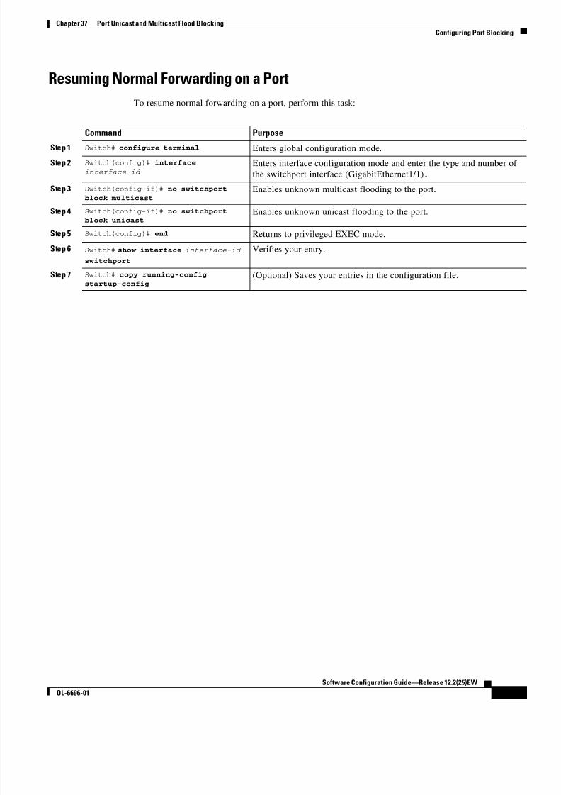
8/10/2019 Cisco ConfiguratioGuide SW4500 IOS
http://slidepdf.com/reader/full/cisco-configuratioguide-sw4500-ios 525/607
37-3
Software Configuration Guide—Release 12.2(25)EW
OL-6696-01
Chapter 37 Port Unicast and Multicast Flood Blocking
Configuring Port Blocking
Resuming Normal Forwarding on a Port
To resume normal forwarding on a port, perform this task:
Command Purpose
Step 1 Switch# configure terminal Enters global configuration mode.
Step 2 Switch(config)# interface
interface-id Enters interface configuration mode and enter the type and number of
the switchport interface (GigabitEthernet1/1).
Step 3 Switch(config-if)# no switchport
block multicastEnables unknown multicast flooding to the port.
Step 4 Switch(config-if)# no switchportblock unicast
Enables unknown unicast flooding to the port.
Step 5 Switch(config)# end Returns to privileged EXEC mode.
Step 6 Switch# show interface interface-id
switchport
Verifies your entry.
Step 7 Switch# copy running-configstartup-config (Optional) Saves your entries in the configuration file.

8/10/2019 Cisco ConfiguratioGuide SW4500 IOS
http://slidepdf.com/reader/full/cisco-configuratioguide-sw4500-ios 526/607
37-4
Software Configuration Guide—Release 12.2(25)EW
OL-6696-01
Chapter 37 Port Unicast and Multicast Flood Blocking
Configuring Port Blocking
8/10/2019 Cisco ConfiguratioGuide SW4500 IOS
http://slidepdf.com/reader/full/cisco-configuratioguide-sw4500-ios 527/607
C H A P T E R
38-1
Software Configuration Guide—Release 12.2(25)EW
OL-6696-01
38
Configuring Port-Based Traffic Control
This chapter describes how to configure port-based traffic control on the Catalyst 4500 series switch.
Note For complete syntax and usage information for the switch commands used in this chapter, refer to the
Catalyst 4500 Series Switch Cisco IOS Command Reference and related publications at
http://www.cisco.com/univercd/cc/td/doc/product/software/ios122/122cgcr/index.htm.
This chapter consists of these sections:
• Overview of Storm Control, page 38-1
• Enabling Storm Control, page 38-3
• Disabling Storm Control, page 38-4
• Displaying Storm Control, page 38-4
• Multicast Storm Control, page 38-6
Overview of Storm ControlThis section contains the following subsections:
• Hardware-based Storm Control Implementation, page 38-2
• Software-based Storm Control Implementation, page 38-2
Storm control prevents LAN interfaces from being disrupted by a broadcast storm. A broadcast storm
occurs when broadcast packets flood the subnet, creating excessive traffic and degrading network
performance. Errors in the protocol-stack implementation or in the network configuration can cause a
broadcast storm.
Note Storm control is supported in hardware on all ports on the WS-X4516 supervisor engine. In contrast, thesupervisor engines WS-X4515, WS-X4014, and WS-X4013+ support storm control in hardware on
non-blocking gigabit ports and in software on all other ports, implying that the counters for these
interfaces are approximate and computed. Multicast storm control is only supported on the WS-X4516
supervisor engine.

8/10/2019 Cisco ConfiguratioGuide SW4500 IOS
http://slidepdf.com/reader/full/cisco-configuratioguide-sw4500-ios 528/607
38-2
Software Configuration Guide—Release 12.2(25)EW
OL-6696-01
Chapter 38 Configuring Port-Based Traffic Control
Overview of Storm Control
Hardware-based Storm Control Implementation
Broadcast suppression uses filtering that measures broadcast activity in a subnet over a one-second
interval and compares the measurement with a predefined threshold. If the threshold is reached, further
broadcast activity is suppressed for the duration of the interval. Broadcast suppression is disabled by
default.Figure 38-1 shows the broadcast traffic patterns on a LAN interface over a given interval. In this
example, broadcast suppression occurs between times T1 and T2 and between T4 and T5. During those
intervals, the amount of broadcast traffic exceeded the configured threshold.
Figure 38-1 Storm Control Example - Hardware-based Implementation
The broadcast suppression threshold numbers and the time interval combination make the broadcast
suppression algorithm work with different levels of granularity. A higher threshold allows more
broadcast packets to pass through.
Broadcast suppression on the Catalyst 4500 series switches is implemented in hardware. The
suppression circuitry monitors packets passing from a LAN interface to the switching bus. If the packetdestination address is broadcast, then the broadcast suppression circuitry tracks the current count of
broadcasts within the one-second interval, and when a threshold is reached, it filters out subsequent
broadcast packets.
Because hardware broadcast suppression uses a bandwidth-based method to measure broadcast activity,
the most significant implementation factor is setting the percentage of total available bandwidth that can
be used by broadcast traffic. Because packets do not arrive at uniform intervals, the one-second interval
during which broadcast activity is measured can affect the behavior of broadcast suppression.
Software-based Storm Control Implementation
When storm control is enabled on an interface, the switch monitors packets received on the interface anddetermines whether or not the packets are broadcast. The switch monitors the number of broadcast
packets received within a one-second time interval. When the interface threshold is met, all incoming
data traffic on the interface is dropped. This threshold is specified as a percentage of total available
bandwidth that can be used by broadcast traffic. If the lower threshold is specified, all data traffic is
forwarded as soon as the incoming traffic falls below that threshold.
Totalnumber of
broadcastpacketsor bytes
0 T1
Threshold
T2 T4 T5 S 5 7 0 6
T3 Time

8/10/2019 Cisco ConfiguratioGuide SW4500 IOS
http://slidepdf.com/reader/full/cisco-configuratioguide-sw4500-ios 529/607
38-3
Software Configuration Guide—Release 12.2(25)EW
OL-6696-01
Chapter 38 Configuring Port-Based Traffic Control
Enabling Storm Control
Enabling Storm ControlTo enable storm control, perform this task:
The following example shows how to enable storm control on interface.
Switch# conf t
Enter configuration commands, one per line. End with CNTL/Z.Switch(config)# int fa3/1
Switch(config-if)# storm-control broadcast level 50
Switch(config-if)# end
Switch# write memoryBuilding configuration...
00:11:06: %SYS-5-CONFIG_I: Configured from console by consoleCompressed configuration from
5394 bytes to 1623 bytes[OK]
Switch#sh stor
Switch#sh storm-controlInterface Filter State Upper Lower Current
--------- ------------- ------- ------- -------
Fa3/1 Forwarding 50.00% 50.00% 0.00%
Switch#
Command PurposeStep 1 Switch# configure terminal Enters global configuration mode.
Step 2 Switch(config)# interface interface-id Enters interface configuration mode and enter the port to configure.
Step 3 Switch(config-if)# storm-control
broadcast level [high level] [lower
level]
Configures broadcast storm control.
Specifies the upper threshold levels for broadcast traffic. The storm
control action occurs when traffic utilization reaches this level.
(Optional) Specifies the falling threshold level. The normal
transmission restarts (if the action is filtering) when traffic drops
below this level for interfaces that support software-based
suppression.
Note For ports that perform hardware-based suppression, the
lower threshold is ignored.
Step 4 Switch(config-if)# storm-control
action {shutdown | trap}Specifies the action to be taken when a storm is detected.
The default is to filter out the broadcast traffic and not to send out
traps.
The shutdown keyword sets the port to error-disable state during a
storm. If the recover interval is not set, the port remains in shutdown
state.
Note The trap keyword generates an SNMP trap when a storm is
detected. This keyword is available but not supported in the
12.1(19)EW release.
Step 5 Switch(config-if)# exit Returns to configuration mode.
Step 6 Switch(config)# end Returns to privileged EXEC mode.
Step 7 Switch# show storm-control [interface]
broadcastDisplays the number of packets suppressed.
Step 8 Switch# copy running-config
startup-config(Optional) Saves your entries in the configuration file.

8/10/2019 Cisco ConfiguratioGuide SW4500 IOS
http://slidepdf.com/reader/full/cisco-configuratioguide-sw4500-ios 530/607
38-4
Software Configuration Guide—Release 12.2(25)EW
OL-6696-01
Chapter 38 Configuring Port-Based Traffic Control
Disabling Storm Control
Disabling Storm ControlTo disable storm control, perform this task:
The following example shows how to disable storm control on interface.
Switch# conf tEnter configuration commands, one per line. End with CNTL/Z.
Switch(config)#int fa3/1
Switch(config-if)# no storm-control broadcast level
Switch(config-if)# endSwitch# wr
Building configuration...
00:12:09: %SYS-5-CONFIG_I: Configured from console by consoleCompressed configuration from
5357 bytes to 1594 bytes[OK]Switch# sh stoSwitch# sh storm-control
Interface Filter State Upper Lower Current--------- ------------- ------- ------- -------
Switch#
Displaying Storm Control
Note Use the show interface capabilities command to determine the mode in which storm control is
supported on an interface.
The following example shows an interface that supports broadcast suppression in software (sw).
Switch# show interfaces g4/4 capabilitiesshow interfaces g4/4 capabilities
GigabitEthernet4/4
Model: WS-X4418-Gbic
Type: 1000BaseSX
Command PurposeStep 1 Switch# configure terminal Enters global configuration mode.
Step 2 Switch(config)# interface
interface-id Enters interface configuration mode and enter the port to configure.
Step 3 Switch(config-if)# no storm-control
broadcast levelDisables port storm control.
Step 4 Switch(config-if)# no storm-controlaction {shutdown | trap}
Disables the specified storm control action and returns to default filter
action.
Step 5 Switch(config-if)# exit Returns to configuration mode.
Step 6 Switch(config)# end Returns to privileged EXEC mode.
Step 7 Switch# show storm-control
broadcast
Verifies your entries.
Step 8 Switch# copy running-configstartup-config
(Optional) Saves your entries in the configuration file.

8/10/2019 Cisco ConfiguratioGuide SW4500 IOS
http://slidepdf.com/reader/full/cisco-configuratioguide-sw4500-ios 531/607
38-5
Software Configuration Guide—Release 12.2(25)EW
OL-6696-01
Chapter 38 Configuring Port-Based Traffic Control
Displaying Storm Control
Speed: 1000
Duplex: full
Trunk encap. type: 802.1Q Trunk mode: on,off,desirable,nonegotiate
Channel: yes Broadcast suppression: percentage(0-100), sw
Flowcontrol: rx-(off,on,desired),tx-(off,on,desired)
VLAN Membership: static, dynamic Fast Start: yes Queuing: rx-(N/A), tx-(4q1t, Shaping)
CoS rewrite: yes ToS rewrite: yes
Inline power: no
SPAN: source/destination UDLD: yes
Link Debounce: no
Link Debounce Time: no
Port Security: yes Dot1x: yes
Maximum MTU: 1552 bytes (Baby Giants) Media Type: no
Switch#
The following example shows an interface that supports broadcast suppression in hardware (hw).
Switch# show interfaces g4/1 capabilities
show interfaces g4/1 capabilities
GigabitEthernet4/1
Model: WS-X4418-Gbic Type: No Gbic
Speed: 1000
Duplex: full
Trunk encap. type: 802.1Q,ISL
Trunk mode: on,off,desirable,nonegotiate Channel: yes
Broadcast suppression: percentage(0-100), hw
Flowcontrol: rx-(off,on,desired),tx-(off,on,desired)
VLAN Membership: static, dynamic Fast Start: yes
Queuing: rx-(N/A), tx-(4q1t, Sharing/Shaping) CoS rewrite: yes
ToS rewrite: yes
Inline power: no
SPAN: source/destination UDLD: yes
Link Debounce: no Link Debounce Time: no
Port Security: yes
Dot1x: yes
Maximum MTU: 1552 bytes (Baby Giants) Media Type: no
Switch#
Note Use the show interfaces counters storm-control command to display a count of discarded packets.
Switch# show interfaces counters storm-control
Port BcastSuppLevel TotalSuppressedPacketsGi4/4 2.00% 0
Switch#
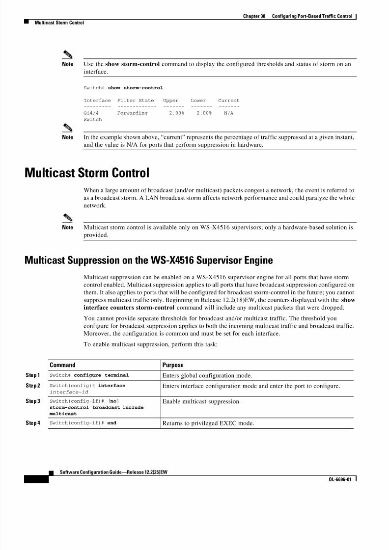
8/10/2019 Cisco ConfiguratioGuide SW4500 IOS
http://slidepdf.com/reader/full/cisco-configuratioguide-sw4500-ios 532/607
38-6
Software Configuration Guide—Release 12.2(25)EW
OL-6696-01
Chapter 38 Configuring Port-Based Traffic Control
Multicast Storm Control
Note Use the show storm-control command to display the configured thresholds and status of storm on an
interface.
Switch# show storm-control
Interface Filter State Upper Lower Current--------- ------------- ------- ------- -------
Gi4/4 Forwarding 2.00% 2.00% N/A
Switch
Note In the example shown above, “current” represents the percentage of traffic suppressed at a given instant,
and the value is N/A for ports that perform suppression in hardware.
Multicast Storm Control
When a large amount of broadcast (and/or multicast) packets congest a network, the event is referred toas a broadcast storm. A LAN broadcast storm affects network performance and could paralyze the whole
network.
Note Multicast storm control is available only on WS-X4516 supervisors; only a hardware-based solution is
provided.
Multicast Suppression on the WS-X4516 Supervisor Engine
Multicast suppression can be enabled on a WS-X4516 supervisor engine for all ports that have storm
control enabled. Multicast suppression applies to all ports that have broadcast suppression configured on
them. It also applies to ports that will be configured for broadcast storm-control in the future; you cannot
suppress multicast traffic only. Beginning in Release 12.2(18)EW, the counters displayed with the show
interface counters storm-control command will include any multicast packets that were dropped.
You cannot provide separate thresholds for broadcast and/or multicast traffic. The threshold you
configure for broadcast suppression applies to both the incoming multicast traffic and broadcast traffic.
Moreover, the configuration is common and must be set for each interface.
To enable multicast suppression, perform this task:
Command Purpose
Step 1 Switch# configure terminal Enters global configuration mode.
Step 2 Switch(config)# interfaceinterface-id
Enters interface configuration mode and enter the port to configure.
Step 3 Switch(config-if)# [no] storm-control broadcast include
multicast
Enable multicast suppression.
Step 4 Switch(config-if)# end Returns to privileged EXEC mode.

8/10/2019 Cisco ConfiguratioGuide SW4500 IOS
http://slidepdf.com/reader/full/cisco-configuratioguide-sw4500-ios 533/607
38-7
Software Configuration Guide—Release 12.2(25)EW
OL-6696-01
Chapter 38 Configuring Port-Based Traffic Control
Multicast Storm Control
The following example shows how to enable multicast suppression on ports that have broadcast
suppression already enabled:
Switch# configuration terminal
Enter configuration commands, one per line. End with CNTL/Z.
Switch(config)# interface fa3/1
Switch(config-if)# storm-control broadcast include multicast
Switch(config-if)# endSwitch#
Multicast Suppression on the WS-X4515, WS-X4014, and WS-X4013+Supervisor Engines
Hardware does not provide support for multicast suppression on the WS-X4515, WS-X4014, and
WS-X4013+ supervisor engines. One consequence of using software-based broadcast suppression on
these modules is that all incoming data packets are dropped. Irrespective of your selecting to configure
broadcast suppression only, multicast packets are filtered as well on stub and blocking gigabit ports. The
non blocking gigabit ports that do provide broadcast suppression in hardware also do not filter multicast
packets.

8/10/2019 Cisco ConfiguratioGuide SW4500 IOS
http://slidepdf.com/reader/full/cisco-configuratioguide-sw4500-ios 534/607
38-8
Software Configuration Guide—Release 12.2(25)EW
OL-6696-01
Chapter 38 Configuring Port-Based Traffic Control
Multicast Storm Control

8/10/2019 Cisco ConfiguratioGuide SW4500 IOS
http://slidepdf.com/reader/full/cisco-configuratioguide-sw4500-ios 535/607
C H A P T E R
39-1
Software Configuration Guide—Release 12.2(25)EW
OL-6696-01
39
Configuring SPAN and RSPAN
This chapter describes how to configure the Switched Port Analyzer (SPAN) and Remote SPAN
(RSPAN) on the Catalyst 4500 series switches. SPAN selects network traffic for analysis by a network
analyzer, such as a SwitchProbe device or other Remote Monitoring (RMON) probe.
This chapter consists of the following sections:
• Overview of SPAN and RSPAN, page 39-1
• Configuring SPAN, page 39-6
• CPU Port Sniffing, page 39-10
• Encapsulation Configuration, page 39-12
• Ingress Packets, page 39-12
• Access List Filtering, page 39-13
• Packet Type Filtering, page 39-14
• Configuration Example, page 39-15
• Configuring RSPAN, page 39-16
• Displaying SPAN and RSPAN Status, page 39-24
Note For complete syntax and usage information for the switch commands used in this chapter, refer to the
Catalyst 4500 Series Switch Cisco IOS Command Reference and related publications at
http://www.cisco.com/univercd/cc/td/doc/product/software/ios122/122cgcr/index.htm.
Overview of SPAN and RSPANThis sections includes the following subsections:
• SPAN and RSPAN Concepts and Terminology, page 39-3• SPAN and RSPAN Session Limits, page 39-6
• Default SPAN and RSPAN Configuration, page 39-6
SPAN mirrors traffic from one or more source interfaces on any VLAN or from one or more VLANs to
a destination interface for analysis. In Figure 39-1, all traffic on Ethernet interface 5 (the source
interface) is mirrored to Ethernet interface 10. A network analyzer on Ethernet interface 10 receives all
network traffic from Ethernet interface 5 without being physically attached to it.

8/10/2019 Cisco ConfiguratioGuide SW4500 IOS
http://slidepdf.com/reader/full/cisco-configuratioguide-sw4500-ios 536/607
39-2
Software Configuration Guide—Release 12.2(25)EW
OL-6696-01
Chapter 39 Configuring SPAN and RSPAN
Overview of SPAN and RSPAN
For SPAN configuration, the source interfaces and the destination interface must be on the same switch.
SPAN does not affect the switching of network traffic on source interfaces; copies of the packets received
or transmitted by the source interfaces are sent to the destination interface.
Figure 39-1 Example SPAN Configuration
RSPAN extends SPAN by enabling remote monitoring of multiple switches across your network. The
traffic for each RSPAN session is carried over a user-specified RSPAN VLAN that is dedicated for that
RSPAN session in all participating switches. The SPAN traffic from the sources is copied onto the
RSPAN VLAN and then forwarded over trunk ports that are carrying the RSPAN VLAN to any RSPAN
destination sessions monitoring the RSPAN VLAN, as shown in Figure 39-2.
Figure 39-2 Example of RSPAN Configuration
SPAN and RSPAN do not affect the switching of network traffic on source ports or source VLANs; a
copy of the packets received or sent by the sources is sent to the destination. Except for traffic that is
required for the SPAN or RSPAN session, by default, destination ports do not receive or forward traffic.
You can use the SPAN or RSPAN destination port to forward transmitted traffic from a network security
device. For example, if you connect a Cisco Intrusion Detection System (IDS) sensor appliance to adestination port, the IDS device can send TCP reset packets to close down the TCP session of a suspected
attacker.
1 2 3 4 5 6 7 8 9 10 11 12Port 5 traffic mirroredon port 10
E3E2
E1
E4E5
E6 E7E8
E9E11
E12
E10
Network analyzer S 6 8 8 4
Source switch Intermediate switch Destination switch
1 0 5 0 2 8
RSPANsource port
RSPANdestination port
RSPANVLAN
RSPANVLAN

8/10/2019 Cisco ConfiguratioGuide SW4500 IOS
http://slidepdf.com/reader/full/cisco-configuratioguide-sw4500-ios 537/607
39-3
Software Configuration Guide—Release 12.2(25)EW
OL-6696-01
Chapter 39 Configuring SPAN and RSPAN
Overview of SPAN and RSPAN
SPAN and RSPAN Concepts and Terminology
This section describes concepts and terminology associated with SPAN and RSPAN configuration and
includes the following subsections:
• SPAN Session, page 39-3
• Traffic Types, page 39-3
• Source Port, page 39-4
• Destination Port, page 39-5
• VLAN-Based SPAN, page 39-5
• SPAN Traffic, page 39-6
SPAN Session
A local SPAN session associates a destination port with source ports. You can monitor incoming or
outgoing traffic on a series or range of ports and source VLANs. An RSPAN session associates source
ports and source VLANs across your network with an RSPAN VLAN. The destination source is theRSPAN VLAN.
You configure SPAN sessions by using parameters that specify the source of network traffic to monitor
You can configure multiple SPAN or RSPAN sessions with separate or overlapping sets of SPAN
sources. Both switched and routed ports can be configured as SPAN sources or destination ports.
An RSPAN source session associates SPAN source ports or VLANs with a destination RSPAN VLAN.
An RSPAN destination session associates an RSPAN VLAN with a destination port.
SPAN sessions do not interfere with the normal operation of the switch; however, an oversubscribed
SPAN destination (for example, a 10-Mbps port monitoring a 100-Mbps port) results in dropped or lost
packets.
You can configure SPAN sessions on disabled ports; however, a SPAN session does not become active
unless you enable the destination port and at least one source port or VLAN for that session.
A SPAN session remains inactive after system startup until the destination port is operational.
Traffic Types
SPAN sessions include these traffic types:
• Receive (Rx) SPAN—The goal of receive (or ingress) SPAN is to monitor as much as possible all
packets received by the source interface or VLAN before any modification or processing is
performed by the switch. A copy of each packet received by the source is sent to the destination port
for that SPAN session. You can monitor a series or range of ingress ports or VLANs in a SPAN
session.
On tagged packets (Inter-Switch Link [ISL] or IEEE 802.1Q), the tagging is removed at the ingress
port. At the destination port, if tagging is enabled, the packets appear with the ISL or 802.1Q
headers. If no tagging is specified, packets appear in the native format.
Packets that are modified because of routing are copied without modification for Rx SPAN; that is,
the original packet is copied. Packets that are modified because of quality of service (QoS)—for
example, modified Differentiated Services Code Point (DSCP)—are copied with modification for Rx
SPAN.

8/10/2019 Cisco ConfiguratioGuide SW4500 IOS
http://slidepdf.com/reader/full/cisco-configuratioguide-sw4500-ios 538/607
39-4
Software Configuration Guide—Release 12.2(25)EW
OL-6696-01
Chapter 39 Configuring SPAN and RSPAN
Overview of SPAN and RSPAN
Some features that can cause a packet to be dropped during receive processing have no effect on
SPAN; the destination port receives a copy of the packet even if the actual incoming packet is
dropped. These features include IP standard and extended input access control lists (ACLs), IP
standard and extended output ACLs for unicast and ingress QoS policing, VLAN maps, ingress QoS
policing, and policy-based routing. Switch congestion that causes packets to be dropped also has no
effect on SPAN.
• Transmit (Tx) SPAN—The goal of transmit (or egress) SPAN is to monitor as much as possible all
packets sent by the source interface after the switch performs all modification and processing. After
the packet is modified, the source sends a copy of each packet to the destination port for that SPAN
session. You can monitor a range of egress ports in a SPAN session.
Packets that are modified because of routing—for example, with a time-to-live (TTL) or
MAC-address modification—are duplicated at the destination port. On packets that are modified
because of QoS, the modified packet might not have the same DSCP (IP packet) or CoS (non-IP
packet) as the SPAN source.
Some features that can cause a packet to be dropped during transmit processing might also affect the
duplicated copy for SPAN. These features include VLAN maps, IP standard and extended output
ACLs on multicast packets, and egress QoS pol icing. In the case of output ACLs, if the SPAN source
drops the packet, the SPAN destination would also drop the packet. In the case of egress QoSpolicing, if the SPAN source drops the packet, the SPAN destination might not drop it. If the source
port is oversubscribed, the destination ports will have different dropping behavior.
• Both—In a SPAN session, you can monitor a single port series or a range of ports for both received
and sent packets.
Source Port
A source port (also called a monitored port) is a switched or routed port that you monitor for network
traffic analysis. In a single local SPAN session or RSPAN source session, you can monitor source port
traffic, such as received (Rx), transmitted (Tx), or bidirectional (both). The switch supports any number
of source ports (up to the maximum number of available ports on the switch) and any number of source
VLANs.
A source port has these characteristics:
• It can be any port type (for example, EtherChannel, Fast Ethernet, Gigabit Ethernet, and so forth).
• It can be monitored in multiple SPAN sessions.
• It cannot be a destination port.
• Each source port can be configured with a direction (ingress, egress, or both) to monitor. For
EtherChannel sources, the monitored direction would apply to all physical ports in the group.
• Source ports can be in the same or different VLANs.
• For VLAN SPAN sources, all active ports in the source VLAN are included as source ports.
You can configure a trunk port as a source port. By default, all VLANs active on the trunk are monitored.You can limit SPAN traffic monitoring on trunk source ports to specific VLANs by using VLAN
filtering. Only switched traffic in the selected VLANs is sent to the destination port. This feature affects
only traffic forwarded to the destination SPAN port and does not affect the switching of normal traffic.
This feature is not allowed in sessions with VLAN sources.
8/10/2019 Cisco ConfiguratioGuide SW4500 IOS
http://slidepdf.com/reader/full/cisco-configuratioguide-sw4500-ios 539/607
39-5
Software Configuration Guide—Release 12.2(25)EW
OL-6696-01
Chapter 39 Configuring SPAN and RSPAN
Overview of SPAN and RSPAN
Destination Port
Each local SPAN session or RSPAN destination session must have a destination port (also called a
monitoring port) that receives a copy of traffic from the source ports and VLANs.
A destination port has these characteristics:
• A destination port must reside on the same switch as the source port (for a local SPAN session).
• A destination port can be any Ethernet physical port.
• A destination port can participate in only one SPAN session at a time. (A destination port in one
SPAN session cannot be a destination port for a second SPAN session.)
• A destination port cannot be a source port.
• A destination port cannot be an EtherChannel group.
• A destination port can be a physical port that is assigned to an EtherChannel group, even if the
EtherChannel group has been specified as a SPAN source. The port is removed from the group while
it is configured as a SPAN destination port.
• The port does not transmit any traffic except that traffic required for the SPAN session unless
learning is enabled. If learning is enabled, the port will also transmit traffic directed to hosts thathave been learned on the destination port.
• If ingress traffic forwarding is enabled for a network security device, the destination port forwards
traffic at Layer 2.
• A destination port does not participate in spanning tree while the SPAN session is active.
• When it is a destination port, it does not participate in any of the Layer 2 protocols (STP, VTP, CDP,
DTP, PagP).
• A destination port that belongs to a source VLAN of any SPAN session is excluded from the source
list and is not monitored.
• A destination port receives copies of sent and received traffic for all monitored source ports. If a
destination port is oversubscribed, it could become congested. This congestion could affect traffic
forwarding on one or more of the source ports.
VLAN-Based SPAN
VLAN-based SPAN (VSPAN) is the monitoring of the network traffic in one or more VLANs.
Use these guidelines for VSPAN sessions:
• Traffic on RSPAN VLANs is not monitored by VLAN-based SPAN sessions.
• Only traffic on the monitored VLAN is sent to the destination port.
• If a destination port belongs to a source VLAN, it is excluded from the source list and is not
monitored.
• If ports are added to or removed from the source VLANs, the traffic on the source VLAN receivedby those ports is added to or removed from the sources being monitored.
• VLAN pruning and the VLAN allowed list have no effect on SPAN monitoring.
• VSPAN monitors only traffic that enters the switch, not traffic that is routed between VLANs. For
example, if a VLAN is being Rx-monitored, and the multilayer switch routes traffic from another
VLAN to the monitored VLAN, that traffic is not monitored and is not received on the SPAN
destination port.

8/10/2019 Cisco ConfiguratioGuide SW4500 IOS
http://slidepdf.com/reader/full/cisco-configuratioguide-sw4500-ios 540/607
39-6
Software Configuration Guide—Release 12.2(25)EW
OL-6696-01
Chapter 39 Configuring SPAN and RSPAN
Configuring SPAN
• You cannot use filter VLANs in the same session with VLAN sources.
• You can monitor only Ethernet VLANs.
SPAN Traffic
You can use local SPAN to monitor all network traffic, including multicast and bridge protocol data unit(BPDU) packets, Cisco Discovery Protocol (CDP), VLAN Trunk Protocol (VTP), Dynamic Trunking
Protocol (DTP), Spanning Tree Protocol (STP), and Port Aggregation Protocol (PAgP) packets. You
cannot use RSPAN to monitor Layer 2 protocols. (See the “RSPAN Configuration Guidelines” section
on page 39-16 for more information.)
In some SPAN configurations, multiple copies of the same source packet are sent to the SPAN
destination port. For example, a bidirectional (both Rx and Tx) SPAN session is configured for the
sources a1 Rx monitor and the a2 Rx and Tx monitor to destination port d1. If a packet enters the switch
through a1 and is switched to a2, both incoming and outgoing packets are sent to destination port d1.
Both packets are the same (unless a Layer-3 rewrite occurs, in which case the packets are different
because of the added Layer 3 information).
SPAN and RSPAN Session Limits
You can configure up to two simultaneous SPAN sessions containing ingress sources and up to four
simultaneous SPAN sessions containing egress sources. Bidirectional sources count as both ingress and
egress. RSPAN destination sessions count as a session containing an ingress source.
Default SPAN and RSPAN Configuration
Table 39-1 shows the default SPAN and RSPAN configuration.
Configuring SPANThe following sections describe how to configure SPAN:
• SPAN Configuration Guidelines and Restrictions, page 39-7
• Configuring SPAN Sources, page 39-8
• Configuring SPAN Destinations, page 39-9
• Monitoring Source VLANs on a Trunk Interface, page 39-9
Table 39-1 Default SPAN and RSPAN Configuration
Feature Default Setting
SPAN state Disabled.
Source port traffic to monitor Both received and sent traffic (both).
Filters All VLANs, all packet types, all address types.
Encapsulation type (destination port) Native form (no encapsulation type header).
Ingress forwarding (destination port) Disabled.
Host learning (destination port) Disabled.

8/10/2019 Cisco ConfiguratioGuide SW4500 IOS
http://slidepdf.com/reader/full/cisco-configuratioguide-sw4500-ios 541/607
39-7
Software Configuration Guide—Release 12.2(25)EW
OL-6696-01
Chapter 39 Configuring SPAN and RSPAN
Configuring SPAN
• Configuration Scenario, page 39-10
• Verifying a SPAN Configuration, page 39-10
Note Entering SPAN configuration commands does not clear previously configured SPAN parameters. You
must enter the no monitor session command to clear configured SPAN parameters.
SPAN Configuration Guidelines and Restrictions
Follow these guidelines and restrictions when configuring SPAN:
• You must use a network analyzer to monitor interfaces.
• You cannot mix source VLANs and filter VLANs within a SPAN session. You can have source
VLANs or filter VLANs, but not both at the same time.
• EtherChannel interfaces can be SPAN source interfaces; they cannot be SPAN destination interfaces
• When you specify source interfaces and do not specify a traffic type (Tx, Rx, or both), “both” is used
by default.
• If you specify multiple SPAN source interfaces, the interfaces can belong to different VLANs.
• You must enter the no monitor session number command with no other parameters to clear the
SPAN session number .
• The no monitor command clears all SPAN sessions.
• SPAN destinations never participate in any spanning tree instance. SPAN includes BPDUs in the
monitored traffic, so any BPDUs seen on the SPAN destination are from the SPAN source.

8/10/2019 Cisco ConfiguratioGuide SW4500 IOS
http://slidepdf.com/reader/full/cisco-configuratioguide-sw4500-ios 542/607
39-8
Software Configuration Guide—Release 12.2(25)EW
OL-6696-01
Chapter 39 Configuring SPAN and RSPAN
Configuring SPAN
Configuring SPAN Sources
To configure the source for a SPAN session, perform this task:
This example shows how to configure SPAN session 1 to monitor bidirectional traffic from source
interface Fast Ethernet 5/1:Switch(config)# monitor session 1 source interface fastethernet 5/1
This example shows how to configure sources with differing directions within a SPAN session:
Switch(config)# monitor session 1 source interface fa2/3 rx
Switch(config)# monitor session 1 source interface fa2/2 tx
Switch(config)#
Command Purpose
Switch(config)# [no] monitor session
{session_number } {source {interface
<interface_list> | { vlan vlan_IDs | cpu
[queue queue_ids] } [rx | tx | both]
Specifies the SPAN session number (1 through 6),
the source interfaces (FastEthernet or
GigabitEthernet), VLANs (1 through 4094),
whether or not traffic received or sent from the
CPU is copied to the session destination, and the
traffic direction to be monitored.
For session_number , specifies the session number
identified with this RSPAN session (1 through 6).
For interface-list , specifies the source port to
monitor. Valid interfaces include physical
interfaces and port-channel logical interfaces
(port-channel port-channel-number ).
For vlan_IDs, specifies the source VLAN.
For queue_ids, specifies the queue(s) involved.
(Optional) [, | -] Specifies a series or range of
interfaces. Enter a space after the comma; enter a
space before and after the hyphen.
(Optional) Specifies the direction of traffic to
monitor. If you do not specify a traffic direction,
the source interface sends both transmitted (Tx)
and received (Rx) traffic. Only received traffic
can be monitored on additional source ports.
• Rx—Monitor received traffic.
• Tx—Monitor transmitted traffic.
• both—Monitor both received and transmitted
traffic (bidirectional).
Queues may be identified either by number or by
name. Queue names may subsume multiple
numbered queues for convenience.
Use the no keyword to restore the defaults.

8/10/2019 Cisco ConfiguratioGuide SW4500 IOS
http://slidepdf.com/reader/full/cisco-configuratioguide-sw4500-ios 543/607
39-9
Software Configuration Guide—Release 12.2(25)EW
OL-6696-01
Chapter 39 Configuring SPAN and RSPAN
Configuring SPAN
Configuring SPAN Destinations
To configure the destination for a SPAN session, perform this task:
This example shows how to configure interface Fast Ethernet 5/48 as the destination for SPAN session 1
Switch(config)# monitor session 1 destination interface fastethernet 5/48
Monitoring Source VLANs on a Trunk Interface
To monitor specific VLANs when the SPAN source is a trunk interface, perform this task:
This example shows how to monitor VLANs 1 through 5 and VLAN 9 when the SPAN source is a trunk
interface:Switch(config)# monitor session 2 filter vlan 1 - 5 , 9
Command Purpose
Switch(config)# [no] monitor session
<session_number > destination interface
<interface> [encapsulation {isl | dot1q}]
[ingress [ vlan vlan_IDs] [learning}]
Specifies the SPAN session number (1 through
6) and the destination interfaces or VLANs.
For session_number , specifies the session
number identified with this RSPAN session
(1 through 6).
For interface, specifies the destination
interface.
For vlan_IDs, specifies the destination VLAN.
Use the no keyword to restore the defaults.
Command Purpose
Switch(config)# [no] monitor session
{session_number } filter {vlan vlan_IDs
[, | - ]} | { packet-type {good | bad}} | {address-type { unicast | multicast | broadcast} [rx | tx |
both]}
Monitors specific VLANs when the SPAN source is a
trunk interface. The filter keyword restricts
monitoring to traffic that is on the specified VLANs; i t
is typically used when monitoring a trunk interface.
For session_number , specifies the session number
identified with this RSPAN session (1 through 6).
For vlan_IDs, specifies the VLAN.
Monitoring is established through all the ports in the
specified VLANs
Use the no keyword to restore the defaults.

8/10/2019 Cisco ConfiguratioGuide SW4500 IOS
http://slidepdf.com/reader/full/cisco-configuratioguide-sw4500-ios 544/607
39-10
Software Configuration Guide—Release 12.2(25)EW
OL-6696-01
Chapter 39 Configuring SPAN and RSPAN
CPU Port Sniffing
Configuration Scenario
This example shows how to use the commands described in this chapter to completely configure and
unconfigure a span session. Assume that you want to monitor bidirectional traffic from source interface
Fast Ethernet 4/10, which is configured as a t runk interface carrying VLANs 1 through 4094. Moreover,
you want to monitor only traffic in VLAN 57 on that trunk. Using Fast Ethernet 4/15 as your destinationinterface, you would enter the following commands:
Switch(config)# monitor session 1 source interface fastethernet 4/10
Switch(config)# monitor session 1 filter vlan 57Switch(config)# monitor session 1 destination interface fastethernet 4/15
You are now monitoring traffic from interface Fast Ethernet 4/10 that is on VLAN 57 out of interface
FastEthernet 4/15. To disable the span session enter the following command:
Switch(config)# no monitor session 1
Verifying a SPAN Configuration
This example shows how to verify the configuration of SPAN session 2:
Switch# show monitor session 2
Session 2---------
Source Ports: RX Only: Fa5/12
TX Only: None
Both: None
Source VLANs: RX Only: None
TX Only: None Both: None
Destination Ports: Fa5/45
Filter VLANs: 1-5,9
Switch#
CPU Port SniffingWhen configuring a SPAN session, you can specify the CPU (or a subset of CPU queues) as a SPAN
source. Queues may be specified either by number or by name. When such a source is specified, traffic
going to the CPU through one of the specified queues is mirrored and sent out of the SPAN destination
port in the session. This traffic includes both control packets and regular data packets that are sent to or
from the CPU (due to software forwarding).
You can mix the CPU source with either regular port sources or VLAN sources.

8/10/2019 Cisco ConfiguratioGuide SW4500 IOS
http://slidepdf.com/reader/full/cisco-configuratioguide-sw4500-ios 545/607
39-11
Software Configuration Guide—Release 12.2(25)EW
OL-6696-01
Chapter 39 Configuring SPAN and RSPAN
CPU Port Sniffing
To configure CPU source sniffing, perform this task:
This example shows how to configure a CPU source to sniff all packets received by the CPU:
Switch(config)# monitor session 1 source cpu rx
This example shows how to use queue names and queue number ranges for the CPU as a SPAN source
Switch(config)# monitor session 2 source cpu queue control-packet rxSwitch(config)# monitor session 3 source cpu queue 21 -23 rx
Command Purpose
Switch(config)# [no] monitor session
{session_number } {source {interface
interface_list | { vlan vlan_IDs | cpu [queue queue_ids] } [rx | tx | both]
Specifies that the CPU will cause traffic received
by or sent from the CPU to be copied to the
destination of the session. The queue identifier
optionally allows sniffing-only traffic (received)
on the specified CPU queue(s).
For session_number , specifies the session number
identified with this SPAN session (1 through 6).
For interface-list , specifies the source port to
monitor. Valid interfaces include physical
interfaces and port-channel logical interfaces
(port-channel port-channel-number ).
For vlan_IDs, specifies the source VLAN.
For queue_ids, specifies the queue(s) involved.
(Optional) [, | -] Specifies a series or range of
interfaces. Enter a space after the comma; enter a
space before and after the hyphen.
(Optional) Specifies the direction of traffic to
monitor. If you do not specify a traffic direction,
the source interface sends both transmitted (Tx)
and received (Rx) traffic. Only received traffic
can be monitored on additional source ports.
• Rx—Monitor received traffic.
• Tx—Monitor transmitted traffic.
• both—Monitor both received and transmittedtraffic (bidirectional).
Queues may be identified either by number or by
name. Queue names may subsume multiple
numbered queues for convenience.
Use the no keyword to restore the defaults.

8/10/2019 Cisco ConfiguratioGuide SW4500 IOS
http://slidepdf.com/reader/full/cisco-configuratioguide-sw4500-ios 546/607
39-12
Software Configuration Guide—Release 12.2(25)EW
OL-6696-01
Chapter 39 Configuring SPAN and RSPAN
Encapsulation Configuration
Encapsulation ConfigurationWhen configuring a SPAN destination port, you can explicitly specify the encapsulation type used by
the port. Packets sent out the port are tagged in accordance with the specified mode. (The encapsulation
mode also controls how tagged packets are handled when the ingress packet option is enabled.) The
Catalyst 4500 series switch supervisor engines support ISL encapsulation and 802.1q encapsulation, aswell as untagged packets. The “replicate” encapsulation type (in which packets are transmitted from the
destination port using whatever encapsulation applied to the original packet) is not supported. If no
encapsulation mode is specified, the port default is untagged. To view the task of configuring
encapsulation, see the command table below.
Ingress PacketsWhen ingress is enabled, the SPAN destination port accepts incoming packets (potentially tagged
depending on the specified encapsulation mode) and switches them normally. When configuring a SPAN
destination port, you can specify whether or not the ingress feature is enabled and what VLAN to use to
switch untagged ingress packets. (Specifying an ingress VLAN is not required when ISL encapsulationis configured, as all ISL encapsulated packets have VLAN tags.) Although the port is STP forwarding,
it does not participate in the STP, so use caution when configuring this feature lest a spanning-tree loop
be introduced in the network. When both ingress and a trunk encapsulation are specified on a SPAN
destination port, the port will go forwarding in all active VLANs. Configuring a non-existent VLAN as
an ingress VLAN is not allowed.
By default, host learning is disabled on SPAN destination ports with ingress enabled. The port is also
removed from VLAN floodsets, so regular traffic will not be switched out of the destination port. If
learning is enabled, however, then traffic for hosts learned on the destination port will be switched out
the destination port. It is also possible to configure static host entries (including a static ARP entry and
a static entry in the MAC-address table) on SPAN destination ports.
Note This configuration will not work if the SPAN session does not have a source configured; the session is
half configured with only the SPAN destination port.
To configure ingress packets and encapsulation, perform this task:
Command Purpose
Switch(config)# [no] monitor session
<session_number > destination interface
<interface> [encapsulation {isl | dot1q}]
[ingress [ vlan vlan_IDs] [learning]]
Specifies the configuration of the ingress
packet and the encapsulation type of the
destination port.
For session_number , specifies the session
number identified with this SPAN session (1
through 6).
For interface, specifies the destination
interface.
For vlan_IDs, specifies the destination VLAN.
Use the no keyword to restore the defaults.

8/10/2019 Cisco ConfiguratioGuide SW4500 IOS
http://slidepdf.com/reader/full/cisco-configuratioguide-sw4500-ios 547/607
39-13
Software Configuration Guide—Release 12.2(25)EW
OL-6696-01
Chapter 39 Configuring SPAN and RSPAN
Access List Filtering
This example shows how to configure a destination port with 802.1q encapsulation and ingress packets
using native VLAN 7:
Switch(config)# monitor session 1 destination interface fastethernet 5/48
encapsulation dot1q ingress vlan 7
With this configuration, traffic from SPAN sources associated with session 1 would be copied out of
interface Fast Ethernet 5/48, with 802.1q encapsulation. Incoming traffic would be accepted andswitched, with untagged packets being classified into VLAN 7.
Access List FilteringWhen configuring a SPAN session, you can apply access list filtering. Access list filtering applies to all
packets passing through a SPAN destination port that might be sniffed in the egress or ingress direct ion.
Access list filters are allowed on local SPAN sessions only. If the SPAN destination is an RSPAN VLAN,
the access list filter is rejected.
Note Access list filtering is available in Release 12.2(20)EW and later releases.
ACL Configuration Guidelines
You can configure ACLs on a SPAN session. Use these guidelines for ACL/SPAN sessions:
• If an ACL is associated with a SPAN session, the rules associated with that ACL are applied against
all packets exiting the SPAN destination interface. Rules pertaining to other VACLs or RACLs
previously associated with the SPAN destination interface are not applied.
• Only one ACL can be associated with a SPAN session.
• When no ACLs are applied to packets exiting a SPAN destination interface, all traffic is permitted
regardless of the PACLs, VACLs, or RACLs that have been previously applied to the destinationinterface or VLAN to which the SPAN destination interface belongs.
• If an ACL is removed from a SPAN session, all traffic is permitted once again.
• If SPAN configuration is removed from the SPAN session, all rules associated with the SPAN
destination interface are applied once again.
• If a SPAN destination port is configured as a trunk port and the VLANs to which it belongs have
ACLs associated with them, the traffic is not subjected to the VACLs.
• ACL configuration applies normally to the RSPAN VLAN and to trunk ports carrying the RSPAN
VLAN. This configuration enables the user to apply VACLs on RSPAN VLANs. If a user attempts
to configure an ACL on a SPAN session with the destination port as an RSPAN VLAN, the
configuration is rejected.
• If CAM resources are exhausted and packets are passed to the CPU for lookup, any output port ACLs
associated with a SPAN session are not applied.
• If a named IP ACL is configured on a SPAN session before an ACL is created, the configuration is
accepted, and the software creates an empty ACL with no ACEs. (An empty ACL permits all
packets.) Subsequently, the rules can be added to the ACL.
• The ACLs associated with a SPAN session are applied on the destination interface on output.

8/10/2019 Cisco ConfiguratioGuide SW4500 IOS
http://slidepdf.com/reader/full/cisco-configuratioguide-sw4500-ios 548/607
39-14
Software Configuration Guide—Release 12.2(25)EW
OL-6696-01
Chapter 39 Configuring SPAN and RSPAN
Packet Type Filtering
• No policing is allowed on traffic exiting SPAN ports.
• Only IP ACLs are supported on SPAN sessions.
Configuring Access List Filtering
To configure access list filtering, perform this task:
Note IP access lists must be created in configuration mode as described in the chapter “Configuring Network
Security with ACLs.”
This example shows how to configure IP access group 10 on a SPAN session and verify that an access
list has been configured:
Switch(config)# monitor session 1 source interface fa6/1 both Switch(config)# monitor session 1 destination interface fa6/2
Switch(config)# monitor session 1 filter vlan 1 Switch(config)# monitor session 1 filter ip access-group 10
Switch(config)# exit
Switch# show monitor
Session 1
---------Type : Local Session
Source Ports :
Both : Fa6/1
Destination Ports : Fa6/2 Encapsulation : Native
Ingress : Disabled Learning : Disabled
Filter VLANs : 1
IP Access-group : 10
Packet Type FilteringWhen configuring a SPAN session, you can specify packet filter parameters similar to VLAN filters.
When specified, the packet filters indicate types of packets that may be sniffed. If no packet filters are
specified, packets of all types may be sniffed. Different types of packet filters may be specified for
ingress and egress traffic.
Command Purpose
Switch(config)# [no] monitor session{session_number } filter {ip access-group
[name | id ] }{ vlan vlan_IDs [, | - ] } |
{ packet-type {good | bad}} | {address-type {unicast | multicast |
broadcast} [rx | tx | both]}
Specifies filter sniffing based on the access list.
For session_number , specify the session number
identified with this SPAN session (1 through 6).
You can specify either a name or a numeric ID for the
access list.
For name, specify the IP access list name.
For id , specify a standard <1 to 199> or extended<1300-2699> IP access list.

8/10/2019 Cisco ConfiguratioGuide SW4500 IOS
http://slidepdf.com/reader/full/cisco-configuratioguide-sw4500-ios 549/607
39-15
Software Configuration Guide—Release 12.2(25)EW
OL-6696-01
Chapter 39 Configuring SPAN and RSPAN
Configuration Example
There are two categories of packet filtering: packet-based (good, error) or address-based
(unicast/multicast/broadcast). Packet-based filters can only be applied in the ingress direction. Packets
are classified as broadcast, multicast, or unicast by the hardware based on the destination address.
Note When filters of both types are configured, only packets that pass both filters are spanned. For example,
if you set both “error” and “multicast,” only multicast packets with errors will be spanned.
To configure packet type filtering, perform this task:
This example shows how to configure a session to accept only unicast packets in the ingress direction:
Switch(config)# monitor session 1 filter address-type unicast rx
Configuration ExampleThe following is an example of SPAN configuration using some of the SPAN enhancements.
In the example below, you configure a session to sniff unicast traffic arriving on interface Gi1/1. The
traffic is mirrored out of interface Gi1/2 with ISL encapsulation. Ingress traffic is permitted.
Switch(config)# monitor session 1 source interface gi1/1 rx
Switch(config)# monitor session 1 destination interface gi1/2 encapsulation isl ingress
Switch(config)# monitor session 1 filter address-type unicast rxSwitch(config)# exit
Switch# show monitor
Session 1
---------
Type : Local SessionSource Ports :
RX Only : Gi1/1
Destination Ports : Gi1/2 Encapsulation : ISL
Ingress : Enabled Learning : Disabled
Filter Addr Type :RX Only : Unicast
Command Purpose
Switch(config)# [no] monitor session{session_number } filter { vlan vlan_IDs
[, | - ] } | { packet-type {good | bad}}
| {address-type {unicast | multicast |
broadcast} [rx | tx | both]}
Specifies filter sniffing of the specified packet types in
the specified directions.
For session_number , specifies the session number
identified with this SPAN session (1 through 6).
For vlan_IDs, specifies the VLAN.
You can specify both Rx and Tx type filters, as well asspecify multiple type filters at the same time (such as
good and unicast to only sniff non-error unicast
frames). As with VLAN filters, if no type or filter is
specified, then the session will sniff all packet types.
Use the no keyword to restore the defaults.

8/10/2019 Cisco ConfiguratioGuide SW4500 IOS
http://slidepdf.com/reader/full/cisco-configuratioguide-sw4500-ios 550/607
39-16
Software Configuration Guide—Release 12.2(25)EW
OL-6696-01
Chapter 39 Configuring SPAN and RSPAN
Configuring RSPAN
Configuring RSPANThis section describes how to configure RSPAN on your switch and it contains this configuration
information:
• RSPAN Configuration Guidelines, page 39-16
• Creating an RSPAN Session, page 39-17
• Creating an RSPAN Destination Session, page 39-18
• Creating an RSPAN Destination Session and Enabling Ingress Traffic, page 39-19
• Removing Ports from an RSPAN Session, page 39-21
• Specifying VLANs to Monitor, page 39-22
• Specifying VLANs to Filter, page 39-23
RSPAN Configuration Guidelines
Follow these guidelines when configuring RSPAN:
Note Since RSPAN VLANs have special properties, you should reserve a few VLANs across your network
for use as RSPAN VLANs; do not assign access ports to these VLANs.
Note You can apply an output access control list (ACL) to RSPAN traffic to selectively filter or monitor
specific packets. Specify these ACLs on the RSPAN VLAN in the RSPAN source switches.
• RSPAN sessions can coexist with SPAN sessions within the limits described in the “SPAN and
RSPAN Session Limits” section on page 39-6.
• For RSPAN configuration, you can distribute the source ports and the destination ports across
multiple switches in your network.
• RSPAN does not support BPDU packet monitoring or other Layer 2 switch protocols.
• The RSPAN VLAN is configured only on trunk ports and not on access ports. To avoid unwanted
traffic in RSPAN VLANs, make sure that all participating switches support the VLAN remote-span
feature. Access ports on the RSPAN VLAN are silently disabled.
• You should create an RSPAN VLAN before configuring an RSPAN source or destination session.
• If you enable VTP and VTP pruning, RSPAN traffic is pruned in the trunks to prevent the unwanted
flooding of RSPAN traffic across the network for VLAN-IDs that are lower than 1005.
• Because RSPAN traffic is carried across a network on an RSPAN VLAN, the original VLAN
association of the mirrored packets is lost. Therefore, RSPAN can only support forwarding of trafficfrom an IDS device onto a single user-specified VLAN.

8/10/2019 Cisco ConfiguratioGuide SW4500 IOS
http://slidepdf.com/reader/full/cisco-configuratioguide-sw4500-ios 551/607
39-17
Software Configuration Guide—Release 12.2(25)EW
OL-6696-01
Chapter 39 Configuring SPAN and RSPAN
Configuring RSPAN
Creating an RSPAN Session
First create an RSPAN VLAN that does not exist for the RSPAN session in any of the switches that wil l
participate in RSPAN. With VTP enabled in the network, you can create the RSPAN VLAN in one
switch, and then VTP propagates it to the other switches in the VTP domain for VLAN-IDs that are lower
than 1005.Use VTP pruning to get efficient flow of RSPAN traffic, or manually delete the RSPAN VLAN from all
trunks that do not need to carry the RSPAN traffic.
To start an RSPAN source session and to specify the source (monitored) ports and the destination RSPAN
VLAN, perform this task:
Command Purpose
Step 1 Switch# configure terminal Enters global configuration mode.
Step 2 Switch(config)# no monitor session
{session_number | all | local | remote}Clears any existing RSPAN configuration for the session.
For session_number , specifies the session number identified with this
RSPAN session (1 through 6).Specifies all to remove all RSPAN sessions, local to remove all local
sessions, or remote to remove all remote SPAN sessions.
Step 3 Switch(config)# [no] monitor session
{session_number } {source {interface
<interface_list> | { vlan vlan_IDs | cpu [queue queue_ids]} [rx | tx | both]
Specifies the RSPAN session and the source port (monitored port).
For session_number , specifies the session number identified with this
RSPAN session (1 through 6).
For interface-list , specifies the source port to monitor. Valid
interfaces include physical interfaces and port-channel logical
interfaces (port-channel port-channel-number ).
For vlan-IDs, specifies the source VLAN or VLANs to monitor.
Valid VLANs are in the range from 1 to 4094.
For queue_ids, specifies either a set of CPU queue numerical
identifiers from 1 to 32, or a named queue.
(Optional) [, | -] Specifies a series or range of interfaces. Enter a
space after the comma; enter a space before and after the hyphen.
(Optional) Specifies the direction of traffic to monitor. If you do not
specify a traffic direction, the source interface sends both transmitted
(Tx) and received (Rx) traffic. Only received traffic can be monitored
on additional source ports.
• Rx—Monitor received traffic.
• Tx—Monitor transmitted traffic.
• both—Monitor both received and transmitted traffic(bidirectional).
Step 4 Switch(config)# monitor session
session_number destination remote vlan
vlan-ID
Specifies the RSPAN session and the destination remote VLAN.
For session_number , specifies the session number identified with this
RSPAN session (1 through 6).
For vlan-ID, specifies the RSPAN VLAN to carry the monitored
traffic to the destination port.

8/10/2019 Cisco ConfiguratioGuide SW4500 IOS
http://slidepdf.com/reader/full/cisco-configuratioguide-sw4500-ios 552/607
39-18
Software Configuration Guide—Release 12.2(25)EW
OL-6696-01
Chapter 39 Configuring SPAN and RSPAN
Configuring RSPAN
This example shows how to clear any existing RSPAN configuration for session 1, configure RSPAN
session 1 to monitor multiple source interfaces, and configure the destination RSPAN VLAN.
Switch(config)# no monitor session 1Switch(config)# monitor session 1 source interface fastEthernet3/10 tx
Switch(config)# monitor session 1 source interface fastEthernet3/2 rx
Switch(config)# monitor session 1 source interface fastEthernet3/3 rx
Switch(config)# monitor session 1 source interface port-channel 102 rxSwitch(config)# monitor session 1 destination remote vlan 901
Switch(config)# end
Creating an RSPAN Destination SessionTo create an RSPAN destination session and to specify the source RSPAN VLAN and the destination
port, perform this task:
Step 5 Switch(config)# end Returns to privileged EXEC mode.
Step 6 Switch# show monitor [sessionsession_number ]
Verifies your entries.
Step 7 Switch# copy running-config
startup-config
(Optional) Saves your entries in the configuration file.
Command Purpose
Command Purpose
Step 1 Switch# configure terminal Enters global configuration mode.
Step 2 Switch(config)# monitor session
session_number source remote vlan
vlan-ID
Specifies the RSPAN session and the source RSPAN VLAN.
For session_number , specifies the session number identified with this
RSPAN session (1 through 6).
For vlan-ID, specifies the source RSPAN VLAN to monitor.Step 3 Switch(config)# [no] monitor session
<session_number > destination interface
<interface > [encapsulation {isl | dot1q}] [ingress [ vlan vlan_IDs]
[learning]]
Specifies the RSPAN session and the destination interface.
For session_number , specifies the session number identified with this
RSPAN session (1 through 6).
For interface, specifies the destination interface.
For vlan_IDs, specifies the ingress VLAN, if necessary.
(Optional) [, | -] Specifies a series or range of interfaces. Enter a
space after the comma; enter a space before and after the hyphen.
(Optional) Specifies the direction of traffic to monitor. If you do not
specify a traffic direction, the source interface sends both sent and
received traffic. Only received (rx) traffic can be monitored onadditional source ports.
• isl—Use ISL encapsulation.
• dot1q—Use 802.1Q encapsulation.
Step 4 Switch(config)# end Returns to privileged EXEC mode.

8/10/2019 Cisco ConfiguratioGuide SW4500 IOS
http://slidepdf.com/reader/full/cisco-configuratioguide-sw4500-ios 553/607
39-19
Software Configuration Guide—Release 12.2(25)EW
OL-6696-01
Chapter 39 Configuring SPAN and RSPAN
Configuring RSPAN
This example shows how to configure VLAN 901 as the source remote VLAN and port 5 as the
destination interface:
Switch(config)# monitor session 1 source remote vlan 901
Switch(config)# monitor session 1 destination interface gigabitEthernet1/2
Switch(config)# end
Creating an RSPAN Destination Session and Enabling Ingress Traffic
To create an RSPAN destination session, to specify the source RSPAN VLAN, and to enable ingress
traffic on the destination port for a network security device (such as a Cisco IDS [Intrusion Detection
System] sensor appliance), perform this task:
Step 5 Switch# show monitor [session
session_number ]Verifies your entries.
Step 6 Switch# copy running-config
startup-config(Optional) Saves your entries in the configuration file.
Command Purpose
Command Purpose
Step 1 Switch# configure terminal Enters global configuration mode.
Step 2 Switch(config)# monitor session
{session_number } source vlan vlan_IDsSpecifies the RSPAN session and the source RSPAN VLAN.
For session_number , specifies the session number identified with this
RSPAN session (1 through 6).
For vlan_IDs, specifies the source VLAN or VLANs to monitor.
Valid VLANs are in the range from 1 to 4094.

8/10/2019 Cisco ConfiguratioGuide SW4500 IOS
http://slidepdf.com/reader/full/cisco-configuratioguide-sw4500-ios 554/607
39-20
Software Configuration Guide—Release 12.2(25)EW
OL-6696-01
Chapter 39 Configuring SPAN and RSPAN
Configuring RSPAN
This example shows how to configure VLAN 901 as the source remote VLAN and how to configure the
destination port for ingress traffic on VLAN 5 by using a security device that supports 802.1Q
encapsulation:
Switch(config)# monitor session 1 source remote vlan 901
Switch(config)# monitor session 1 destination interface gigabitEthernet1/2 ingress vlan 5
Switch(config)# end
Step 3 Switch(config)# [ monitor session
session_number destination interface interface-id [encapsulation {dot1q
[ingress vlan vlan id ] | ISL [ingress]}
| ingress vlan vlan id ] [learning]]
Specifies the RSPAN session, the destination port, the packet
encapsulation, and the ingress VLAN.
For session_number , specifies the session number identified with this
RSPAN session (1 through 6).
For interface-id , specifies the destination port. Valid interfaces
include physical interfaces.
(Optional) Specifies the encapsulation of the packets transmitted on
the RSPAN destination port. If no encapsulation is specified, all
transmitted packets will be sent in native format (untagged).
• Enter encapsulation dot1q to send native VLAN packets
untagged, and all other VLAN tx packets tagged dot1q.
• Enter encapsulation isl to send all tx packets encapsulated using
ISL.
(Optional) Specifies whether forwarding is enabled for ingress traffic
on the RSPAN destination port.• For native (untagged) and dot1q encapsulation, specify ingress
vlan vlan id to enable ingress forwarding with vlan id as the
native VLAN; vlan id will also be used as the native VLAN for
transmitted packets.
• Specify ingress to enable ingress forwarding when using ISL
encapsulation.
• Specify learning to enable learning when ingress is enabled.
Step 4 Switch(config)# end Returns to privileged EXEC mode.
Step 5 Switch# show monitor [session
session_number ]Verifies your entries.
Step 6 Switch# copy running-configstartup-config
(Optional) Saves your entries in the configuration file.
Command Purpose

8/10/2019 Cisco ConfiguratioGuide SW4500 IOS
http://slidepdf.com/reader/full/cisco-configuratioguide-sw4500-ios 555/607
39-21
Software Configuration Guide—Release 12.2(25)EW
OL-6696-01
Chapter 39 Configuring SPAN and RSPAN
Configuring RSPAN
Removing Ports from an RSPAN Session
To remove a port as an RSPAN source for a session, perform this task:
This example shows how to remove port 1 as an RSPAN source for RSPAN session 1:
Switch(config)# no monitor session 1 source interface gigabitEthernet1/1
Switch(config)# end
This example shows how to disable received traffic monitoring on port 1, which was configured for
bidirectional monitoring:
Switch(config)# no monitor session 1 source interface gigabitEthernet1/1 rx
The monitoring of traffic received on port 1 is disabled, but traffic transmitted from this port continues
to be monitored.
Command Purpose
Step 1 Switch# configure terminal Enters global configuration mode.
Step 2 Switch(config)# [no] monitor session
{session_number } {source {interface
interface_list | { vlan vlan_IDs | cpu
[queue queue_ids]} [rx | tx | both]
Specifies the characteristics of the RSPAN source port (monitored
port) to remove.
For session_number , specifies the session number identified with
this RSPAN session (1 through 6).
For interface-list , specifies the source port to no longer monitor.
Valid interfaces include physical interfaces and port-channel
logical interfaces (port-channel port-channel-number ).
For vlan_IDs, specifies the source vlan or vlans to monitor. Valid
VLANs are in the range from 1 to 4094.
For queue_ids, specifies either a set of CPU queue numericalidentifiers from 1 to 32, or a named queue.
(Optional) [, | -] Specifies a series or range of interfaces. Enter a
space after the comma; enter a space before and after the hyphen.
(Optional) Specifies the direction of traffic to monitor. If you do
not specify a traffic direction, the source interface sends both
transmitted (Tx) and received (Rx) traffic. Only received traffic can
be monitored on additional source ports.
• Rx—Monitor received traffic.
• Tx—Monitor transmitted traffic.
• both—Monitor both received and transmitted traffic
(bidirectional).
Step 3 Switch(config)# end Returns to privileged EXEC mode.
Step 4 Switch# show monitor [sessionsession_number ]
Verifies your entries.
Step 5 Switch# copy running-config
startup-config(Optional) Saves your entries in the configuration file.

8/10/2019 Cisco ConfiguratioGuide SW4500 IOS
http://slidepdf.com/reader/full/cisco-configuratioguide-sw4500-ios 556/607
39-22
Software Configuration Guide—Release 12.2(25)EW
OL-6696-01
Chapter 39 Configuring SPAN and RSPAN
Configuring RSPAN
Specifying VLANs to Monitor
VLAN monitoring is similar to port monitoring. To specify VLANs to monitor, perform this task:
To remove one or more source VLANs from the RSPAN session, use the no monitor session
session_number source vlan vlan-id rx global configuration command.
Command Purpose
Step 1 Switch# configure terminal Enters global configuration mode.
Step 2 Switch(config)# no monitor session
{session_number | all | local |
remote}
Clears any existing SPAN configuration for the session.
For session_number , specifies the session number identified with this
RSPAN session (1 through 6).
Specify all to remove all SPAN sessions, local to remove all local
sessions, or remote to remove all remote SPAN sessions.
Step 3 Switch(config)# [no] monitor session
{session_number } {source {interface
interface_list | { vlan vlan_IDs | cpu
[queue queue_ids]} [rx | tx | both]
Specifies the RSPAN session and the source VLANs (monitored
VLANs). You can monitor only received (rx) traffic on VLANs.
For session_number , specifies the session number identified with this
RSPAN session (1 through 6).
For interface-list , specifies the source port to no longer monitor. Valid
interfaces include physical interfaces and port-channel logical
interfaces (port-channel port-channel-number ).
For vlan-IDs, the range is 1 to 4094; do not enter leading zeros.
For queue_ids, specifies the source queue.
(Optional) [, | -] Specifies a series or range of interfaces. Enter a space
after the comma; enter a space before and after the hyphen.
(Optional) Specifies the direction of traffic to monitor. If you do not
specify a traffic direction, the source interface sends both transmitted
(Tx) and received (Rx) traffic. Only received traffic can be monitored
on additional source ports.
• Rx—Monitor received traffic.
• Tx—Monitor transmitted traffic.
• both—Monitor both received and transmitted traffic
(bidirectional).
Step 4 Switch(config)# monitor session
session_number destination remote vlan vlan-id
Specifies the RSPAN session, the destination remote VLAN.
For session_number , specifies the session number identified with this
RSPAN session (1 through 6).
For vlan-id , specifies the RSPAN VLAN to carry the monitored traffic
to the destination port.
Step 5 Switch(config)# end
Returns to privileged EXEC mode.Step 6 Switch# show monitor [session
session_number ]Verifies your entries.
Step 7 Switch# copy running-config
startup-config(Optional) Saves your entries in the configuration file.

8/10/2019 Cisco ConfiguratioGuide SW4500 IOS
http://slidepdf.com/reader/full/cisco-configuratioguide-sw4500-ios 557/607
39-23
Software Configuration Guide—Release 12.2(25)EW
OL-6696-01
Chapter 39 Configuring SPAN and RSPAN
Configuring RSPAN
This example shows how to clear any existing configuration on RSPAN session 2, configure RSPAN
session 2 to monitor received traffic on all ports belonging to VLANs 1 through 3, and send it to
destination remote VLAN 902. The configuration is then modified to also monitor received traffic on all
ports belonging to VLAN 10.
Switch(config)# no monitor session 2
Switch(config)# monitor session 2 source vlan 1 - 3 rx
Switch(config)# monitor session 2 destination remote vlan 902
Switch(config)# monitor session 2 source vlan 10 rxSwitch(config)# end
Specifying VLANs to Filter
To limit RSPAN source traffic to specific VLANs, perform this task:
Command Purpose
Step 1 Switch# configure terminal Enters global configuration mode.
Step 2 Switch(config)# no monitor session {session_number | all | local |remote}
Clears any existing SPAN configuration for the session.
For session_number , specifies the session number identified with this
RSPAN session (1 through 6).
Specify all to remove all SPAN sessions, local to remove all local
sessions, or remote to remove all remote SPAN sessions.
Step 3 Switch(config)# [no] monitor session
{session_number } {source {interface interface_list | { vlan vlan_IDs | cpu
[queue queue_ids]} [rx | tx | both]
Specifies the characteristics of the source port (monitored port) and
RSPAN session.
For session_number , specifies the session number identified with this
RSPAN session (1 through 6).
For interface-list , specifies the source port to monitor. The interface
specified must already be configured as a trunk port.
For vlan-IDs, the range is 1 to 4094; do not enter leading zeros.
For queue_ids, specifies the source queue.
(Optional) [, | -] Specifies a series or range of interfaces. Enter a space
after the comma; enter a space before and after the hyphen.
(Optional) Specifies the direction of traffic to monitor. If you do not
specify a traffic direction, the source interface sends both transmitted
(Tx) and received (Rx) traffic. Only received traffic can be monitored
on additional source ports.
• Rx—Monitor received traffic.
• Tx—Monitor transmitted traffic.
• both—Monitor both received and transmitted traffic
(bidirectional).

8/10/2019 Cisco ConfiguratioGuide SW4500 IOS
http://slidepdf.com/reader/full/cisco-configuratioguide-sw4500-ios 558/607
39-24
Software Configuration Guide—Release 12.2(25)EW
OL-6696-01
Chapter 39 Configuring SPAN and RSPAN
Displaying SPAN and RSPAN Status
To monitor all VLANs on the trunk port, use the no monitor session session_number filter vlan global
configuration command.
This example shows how to clear any existing configuration on RSPAN session 2, configure RSPAN
session 2 to monitor traffic received on trunk port 4, and send traffic for only VLANs 1 through 5 and 9
to destination remote VLAN 902.
Switch(config)# no monitor session 2
Switch(config)# monitor session 2 source interface gigabitethernet1/1 rxSwitch(config)# monitor session 2 filter vlan 1 - 5 , 9
Switch(config)# monitor session 2 destination remote vlan 902Switch(config)# end
Displaying SPAN and RSPAN StatusTo display the status of the current SPAN or RSPAN configuration, use the show monitor privileged
EXEC command.
This example displays the output for the show monitor command for SPAN source session 1:
Switch# show monitor session 1
Session 1
---------
Type: Local Source SessionSource Ports: RX Only: Fa3/13
TX Only: None
Both: None
Step 4 Switch(config)# monitor session
session_number filter vlan vlan-id [,| -]
Limits the RSPAN source traffic to specific VLANs.
For session_number , specifies the session number identified with this
RSPAN session (1 through 6).
For vlan-id , the range is 1 to 4094; do not enter leading zeros.(Optional) Use a comma (,) to specify a series of VLANs or use a
hyphen (-) to specify a range of VLANs. Enter a space after the
comma; enter a space before and after the hyphen.
Step 5 Switch(config)# monitor sessionsession_number destination remote vlan
vlan-id
Specifies the RSPAN session, the destination remote VLAN.
For session_number , specifies the session number identified with this
RSPAN session (1 through 6).
For vlan-id , specifies the RSPAN VLAN to carry the monitored traffic
to the destination port.
Step 6 Switch(config)# end Returns to privileged EXEC mode.
Step 7 Switch# show monitor [session
session_number ]Verifies your entries.
Step 8 Switch# copy running-config
startup-config(Optional) Saves your entries in the configuration file.
Command Purpose

8/10/2019 Cisco ConfiguratioGuide SW4500 IOS
http://slidepdf.com/reader/full/cisco-configuratioguide-sw4500-ios 559/607
39-25
Software Configuration Guide—Release 12.2(25)EW
OL-6696-01
Chapter 39 Configuring SPAN and RSPAN
Displaying SPAN and RSPAN Status
Source VLANs:
RX Only: None
TX Only: None Both: None
Source RSPAN VLAN: NoneDestination Ports: None
Encapsulation: DOT1Q
Ingress:Enabled, default VLAN=5Filter VLANs: NoneDest RSPAN VLAN: None
Ingress : Enabled, default VLAN=2Learning : Disabled

8/10/2019 Cisco ConfiguratioGuide SW4500 IOS
http://slidepdf.com/reader/full/cisco-configuratioguide-sw4500-ios 560/607
39-26
Software Configuration Guide—Release 12.2(25)EW
OL-6696-01
Chapter 39 Configuring SPAN and RSPAN
Displaying SPAN and RSPAN Status

8/10/2019 Cisco ConfiguratioGuide SW4500 IOS
http://slidepdf.com/reader/full/cisco-configuratioguide-sw4500-ios 561/607
C H A P T E R
40-1
Software Configuration Guide—Release 12.2(25)EW
OL-6696-01
40
Configuring NetFlow Statistics Collection
This chapter describes how to configure NetFlow Statistics on the Catalyst 4500 series switches. It also
provides guidelines, procedures, and configuration examples.
Note To use the NetFlow feature, you must have the Supervisor Engine V-10GE (the functionality is
embedded in the supervisor engine), or the NetFlow Services Card (WS-F4531) and either aSupervisor Engine IV or a Supervisor Engine V.
Note For complete syntax and usage information for the commands used in this chapter, refer to the
Catalyst 4500 Series Switch Cisco IOS Command Reference and related publications at
http://www.cisco.com/univercd/cc/td/doc/product/software/ios122/122cgcr/index.htm . Refer to the
NetFlow Solutions Guide for more detailed information on NetFlow usage and management.
The following topics are included:
• Overview of NetFlow Statistics Collection, page 40-1
• NoteNetFlow support has hardware limitations that restrict the platform support to a subset of allNetFlow fields. Specifically, TCP Flags and the ToS byte (DSCP) are not supported., page 40-6
• Configuring NetFlow Statistics Collection, page 40-6
• NetFlow Statistics Collection Configuration Example, page 40-11
• NetFlow Configuration Examples, page 40-13
Overview of NetFlow Statistics CollectionA network flow is defined as a unidirectional stream of packets between a given source and destination
—both defined by a network-layer IP address and transport-layer port number. Specifically, a flow is
identified as the combination of the following fields: source IP address, destination IP address, source
port number, destination port number, protocol type, type of service, and input interface.
NetFlow Statistics is a global traffic monitoring feature that allows flow-level monitoring of all
IPv4-routed traffic through the switch using NetFlow Data Export (NDE). Collected statistics can be
exported to an external device (NetFlow Collector/Analyzer) for further processing. Network planners
can selectively enable NetFlow Statistics (and NDE) on a per-device basis to gain traffic performance,
control, or accounting benefits in specific network locations.

8/10/2019 Cisco ConfiguratioGuide SW4500 IOS
http://slidepdf.com/reader/full/cisco-configuratioguide-sw4500-ios 562/607
40-2
Software Configuration Guide—Release 12.2(25)EW
OL-6696-01
Chapter 40 Configuring NetFlow Statistics Collection
Overview of NetFlow Statistics Collection
NetFlow exports flow information in UDP datagrams in one of two formats. The version 1 format was
the initial released version, and version 5 is a later enhancement to add Border Gateway Protocol (BGP)
autonomous system (AS) information and flow sequence numbers. In version 1 and version 5 format, the
datagram consists of a header and one or more flow records. The first field of the header contains the
version number of the export datagram.
This section contains the following subsections:• Information Derived from Hardware, page 40-3
• Information Derived from Hardware, page 40-3
• Information Derived from Software, page 40-4
• Determining the Input and Output Interface and AS Numbers, page 40-4
• Feature Interaction of Netflow Statistics with UBRL and Microflow Policing, page 40-5
• VLAN Statistics, page 40-5
NDE Versions
The Catalyst 4500 series switch supports NDE versions 1 and 5 for the captured statistics. NetFlowaggregation requires NDE version 8.
Depending on the current flow mask, some fields in the flow records might not have values. Unsupported
fields contain a zero (0).
The following tables describe the supported fields for NDE version 5:
• Table 40-1—Version 5 header format
• Table 40-2—Version 5 f low record format
Table 40-1 NDE Version 5 Header Format
Bytes Content Description
0–1 version NetFlow export format version number
2–3 count Number of flows exported in this packet (1–30)
4–7 SysUptime Current time in milliseconds since router booted
8–11 unix_secs Current seconds since 0000 UTC 1970
12–15 unix_nsecs Residual nanoseconds since 0000 UTC 1970
16–19 flow_sequence Sequence counter of total flows seen
20–21 engine_type Type of flow switching engine
21–23 engine_id Slot number of the flow switching engine

8/10/2019 Cisco ConfiguratioGuide SW4500 IOS
http://slidepdf.com/reader/full/cisco-configuratioguide-sw4500-ios 563/607
40-3
Software Configuration Guide—Release 12.2(25)EW
OL-6696-01
Chapter 40 Configuring NetFlow Statistics Collection
Overview of NetFlow Statistics Collection
Information Derived from Hardware
Information available in a typical NetFlow record from hardware includes the following:
• the packet and byte counts
• start and end timestamps
Table 40-2 NDE Version 5 Flow Record Format
Bytes Content Description
Flow masks:• X=Populated• A=Additional field
S o u r c e
D e s t i n a t i o n
D e s t i n a t i o n
S o u r c e
D e s t i n a t i o n
S o u r c e
I n t e r f a c e
F u l l
F u l l
I n t e r f a c e
0–3 srcaddr Source IP address X X X X X
4–7 dstaddr Destination IP address X X X X X
8–11 nexthop Next hop router’s IP address A1
1. With the destination flow mask, the “Next hop router’s IP address” field and the “Output interface’s SNMP ifIndex” field might not contain information
that is accurate for all flows.
A A A A
12–13 input Ingress interface SNMP ifIndex X X
14–15 output Egress interface SNMP ifIndex A1 A A A A
16–19 dPkts Packets in the flow X X X X X X
20–23 dOctets Octets (bytes) in the flow X X X X X X
24–27 first SysUptime at start of the flow X X X X X X
28–31 last SysUptime at the time the
last packet of the flow was received
X X X X X X
32–33 srcport Layer 4 source port number or equivalent X2
2. In PFC3BXL or PFC3B mode, ICMP traffic contains the ICMP code and type values.
X2
34–35 dstport Layer 4 destination port number or equivalent X X
36 pad1 Unused (zero) byte
37 tcp_flags Cumulative OR of TCP flags
38 prot Layer 4 protocol
(for example, 6=TCP, 17=UDP)
X X
39 tos IP type-of-service byte
40–41 src_as Autonomous system number of the source,
either origin or peer
X X X X X
42–43 dst_as Autonomous system number of the
destination, either origin or peer
X X X X X
44–45 src_mask Source address prefix mask bits X X X X X
46–47 dst_mask Destination address prefix mask bits X X X X X
48 pad2 Pad 2 is unused (zero) bytes

8/10/2019 Cisco ConfiguratioGuide SW4500 IOS
http://slidepdf.com/reader/full/cisco-configuratioguide-sw4500-ios 564/607
40-4
Software Configuration Guide—Release 12.2(25)EW
OL-6696-01
Chapter 40 Configuring NetFlow Statistics Collection
Overview of NetFlow Statistics Collection
• source and destination IP addresses
• IP protocol
• source and destination port numbers.
Information Derived from SoftwareThe software infers the following fields:
• Input and output identifiers
• Routing information, including next-hop address, origin and peer AS, source and destination prefix
mask
Determining the Input and Output Interface and AS Numbers
The following topics are discussed:
• Determining the Inferred Fields, page 40-4
• Determining the Output Interface and Output Related Inferred Fields, page 40-4
• Determining the Input Interface and Input Related Inferred Fields, page 40-5
Determining the Inferred Fields
The Catalyst 4500 series switch collects netflow flows in hardware. The hardware collects a sub-set of
all the netflow flow fields. The rest of the fields are then filled in by the software when the software
examines the routing state.
The Netflow Services Card does not provide enough information to accurately and consistently
determine the input interface, output interface and other routing information associated with NetFlow
Flows. The Catalyst 4500 series switch has a software mechanism to largely compensate for this. Themechanism is described in the next paragraph.
Determining the Output Interface and Output Related Inferred Fields
Software determines the output interface information by looking up the Forwarding Information Base
(FIB) entry in the default FIB table (based on the destination IP address). From this FIB entry, the
software gains access to the destination AS number for this destination IP address, as well as the
appropriate adjacency that stores the interface information. Therefore, the output interface is based
solely on the destination IP address. If load balancing is enabled on the switch, the load balancing hash,
instead of looking at the adjacency in the FIB entry, will be applied to access the appropriate FIB path
and access the appropriate adjacency. Although this process will typically yield correct results, a
potential inaccuracy can occur when using a PBR that shares IP addresses with the default FIB table.Under these circumstances, there would then be multiple FIB table entries and associated adjacencies
for the same destination IP address.

8/10/2019 Cisco ConfiguratioGuide SW4500 IOS
http://slidepdf.com/reader/full/cisco-configuratioguide-sw4500-ios 565/607
40-5
Software Configuration Guide—Release 12.2(25)EW
OL-6696-01
Chapter 40 Configuring NetFlow Statistics Collection
Overview of NetFlow Statistics Collection
Determining the Input Interface and Input Related Inferred Fields
Similarly, the input interface and the source AS number for the source IP address are determined by
looking up the FIB entry in the default FIB table based on the source IP address. Therefore, the input
interface is based solely on the source IP address and a reverse lookup is done to determine to which
interface a packet with this IP destination address needs to be routed. This process assumes that the
forwarding paths are symmetrical. However, if this process yields multiple input interfaces, a
deterministic algorithm will be applied to pick one of them the one with the lowest IP address. Although
this process typically yields correct values, there are scenarios where the values are inaccurate:
• If load balancing is being applied by an upstream adjacent switch, one input interface must be
chosen arbitrarily out of the multiple input interfaces available. This action is necessary because the
input interface that would be used depends on the type of load balancing algorithm being deployed
by the adjacent upstream switch. It is not always feasible to know the algorithm. Therefore, all flow
statistics will be attributed to one input interface. Software selects the interface with the lowest IP
subnet number.
• In an asymmetric routing scheme, where the traffic for an IP subnet might be received on an
interface that is different from the interface where packets are sent to this IP subnet, the inferences
noted previously for selecting an input interface, based on a reverse lookup, would be incorrect and
cannot be verified.
• If PBR or VRF is enabled on the switch and the flow is destined to an address that resides in the
PBR or VRF range or is sourced from an address that resides in the PBR or VRF range, the
information will be incorrect. In this case, the input and output interface will most likely point to
the default route (if configured) or will have no value at all (NULL)
• If VRF is enabled on the switch on some interfaces and the flow is sourced from a VRF interface,
the information will be incorrect. In this case, the input and output interface will most likely point
to the default route (if configured) or will have no value (NULL).
Note The Supervisor Engine V-10GE does a better job at this by providing the input interface information via
hardware. Having this information greatly improves the accuracy of the inferred fields.
Feature Interaction of Netflow Statistics with UBRL and Microflow Policing
On systems with Supervisor Engine V-10GE, there is a feature interaction between Netflow Statistics
and UBRL (User Based Rate Limiting). As part of correctly configuring UBRL on a given interface, the
class-map must specify a flow-mask. In turn, this flow mask is used to create hardware-based netflow
statistics for the flow. By default, for traditional full-flow netflow statistics, the full-flow mask is used.
With UBRL, however, the masks can differ. If UBRL is configured on a given interface, the statistics are
collected based on the mask configured for UBRL. Consequently, the system will not collect full-flow
statistics for traffic transiting an interface configured with UBRL. For more details, refer to the
“Configuring User Based Rate Limiting” section on page 29-35.
VLAN Statistics
With NetFlow support, you can report Layer 2 output VLAN statistics, as well as VLAN statistics for
routed traffic in and out of a VLAN.

8/10/2019 Cisco ConfiguratioGuide SW4500 IOS
http://slidepdf.com/reader/full/cisco-configuratioguide-sw4500-ios 566/607
40-6
Software Configuration Guide—Release 12.2(25)EW
OL-6696-01
Chapter 40 Configuring NetFlow Statistics Collection
Configuring NetFlow Statistics Collection
The following example shows the CLI output for a specific VLAN:
cat4k-sup4-2# sh vlan counters or show vlan id 22 count* Multicast counters include broadcast packets
Vlan Id :22L2 Unicast Packets :38
L2 Unicast Octets :2432
L3 Input Unicast Packets :14344621L3 Input Unicast Octets :659852566
L3 Output Unicast Packets :8983050
L3 Output Unicast Octets :413220300
L3 Output Multicast Packets :0L3 Output Multicast Octets :0
L3 Input Multicast Packets :0L3 Input Multicast Octets :0
L2 Multicast Packets :340
L2 Multicast Octets :21760
Note NetFlow support has hardware limitations that restrict the platform support to a subset of all NetFlow
fields. Specifically, TCP Flags and the ToS byte (DSCP) are not supported.
Configuring NetFlow Statistics CollectionTo configure NetFlow switching, complete the tasks in these sections:
• Checking for Required Hardware, page 40-6
• Enabling NetFlow Statistics Collection, page 40-7
• Exporting NetFlow Statistics, page 40-8
• Managing NetFlow Statistics Collection, page 40-8
• Configuring an Aggregation Cache, page 40-8
• Configuring a NetFlow Minimum Prefix Mask for Router-Based Aggregation, page 40-9
• Configuring NetFlow Aging Parameters, page 40-11
Checking for Required Hardware
To ensure that the necessary hardware is enabled, enter the show module command, as follows:
Switch# show module all
Chassis Type : WS-C4507R
Power consumed by backplane : 40 Watts
Mod Ports Card Type ModelSerial No.---+-----+--------------------------------------+------------------+-----------
1 2 1000BaseX (GBIC) Supervisor(active) WS-X4515
JAB062604KB
2 2 1000BaseX (GBIC) Supervisor(standby) WS-X4515JAB062408CB
6 48 10/100BaseTX (RJ45) WS-X4148JAB032305UH
M MAC addresses Hw Fw Sw Status

8/10/2019 Cisco ConfiguratioGuide SW4500 IOS
http://slidepdf.com/reader/full/cisco-configuratioguide-sw4500-ios 567/607
40-7
Software Configuration Guide—Release 12.2(25)EW
OL-6696-01
Chapter 40 Configuring NetFlow Statistics Collection
Configuring NetFlow Statistics Collection
--+--------------------------------+---+------------+----------------+---------
1 0001.6442.2c00 to 0001.6442.2c01 0.4 12.1(14r)EW( 12.1(20030513:00 Ok
2 0001.6442.2c02 to 0001.6442.2c03 0.4 12.1(14r)EW( 12.1(20030513:00 Ok6 0050.3ed8.6780 to 0050.3ed8.67af 1.6 12.1(14r)EW( 12.1(20030513:00 Ok
Mod Submodule Model Serial No. Hw Status
----+-----------------------+-----------------+------------+----+---------
1 Netflow Services Card WS-F4531 JAB062209CG 0.2 Ok2 Netflow Services Card WS-F4531 JAB062209AG 0.2 Ok
Switch#
Note Enabling this feature does not impact the hardware-forwarding performance of the switch.
The effective size of the hardware flow “cache” table is 85,000 flows. (The hardware flow cache for the
Supervisor Engine V-10GE is 100,000 flows.) If more than 100,000 flows are active simultaneously,
statistics may be lost for some of the flows.
The effective size of the software flow table is 256, 000 flows. The NetFlow software manages the
consistency between the hardware and software tables, keeping the hardware table open by purging
inactive hardware flows to the software table.User-configured timeout settings dictate when the flows are purged and exported through NDE from the
software cache. Hardware flow management ensures consistency between hardware flow purging and the
user-configured timeout settings.
Software-forwarded flows are also monitored. Moreover, statistics will overflow if any flow receives
traffic at a sustained rate exceeding 2 gigabits per second. Generally, this situation should not occur
because a port cannot transmit at a rate higher than 1 gigabit per second.
Note By design, even if the timeout settings are high, flows will automatically “age out” as they approach their
statistics limit.
Enabling NetFlow Statistics Collection
Note NetFlow Flow Statistics are disabled by default.
To enable NetFlow switching, first configure the switch for IP routing as described in the IP
configuration chapters in the Cisco IOS IP and IP Routing Configuration Guide . After you configure IP
routing, perform one of these tasks:
Command Purpose
Switch(config)# ip flow ingress Enables NetFlow for IP routing.
Switch(config)# ip flow ingress
infer-fieldsEnables NetFlow with inferred input/output
interfaces and source/destination BGP as
information.
The inter-fields option must be configured for AS
information to be determined.

8/10/2019 Cisco ConfiguratioGuide SW4500 IOS
http://slidepdf.com/reader/full/cisco-configuratioguide-sw4500-ios 568/607
40-8
Software Configuration Guide—Release 12.2(25)EW
OL-6696-01
Chapter 40 Configuring NetFlow Statistics Collection
Configuring NetFlow Statistics Collection
Exporting NetFlow Statistics
To configure the switch to export NetFlow Statistics to a workstation when a flow expires, perform one
of these tasks:
Managing NetFlow Statistics Collection
You can display and clear NetFlow Statistics, including IP flow switching cache information and flow
information, such as the protocol, total flow, flows per second, and so forth. You can also use theresulting information to obtain information about your switch traffic.
To manage NetFlow switching statistics, perform one or both of following tasks:
Configuring an Aggregation Cache
Aggregation of NetFlow Statistics is typically performed by NetFlow collection tools on management
workstations. By extending this support to the Catalyst 4500 series switch, you can do the following:
• Reduce the required bandwidth between the switch and workstations, because fewer NDE packets
are exported.
• Reduce the number of collection workstations required.
• Provide visibility to aggregated flow statistics at the CLI.
Command Purpose
Switch(config)# ip flow-export destination {hostname | ip-address} udp-port
(Required) Configures the switch to export NetFlow cache
entries to a specific destination (for example, a workstation).
Note You can specify multiple destinations.
Switch(config)# ip flow-export version
{1 | {5 [origin-as | peer-as]}}(Optional) Configures the switch to export NetFlow cache
entries to a workstation if you are using receiving software
that requires version 1 or 5. Version 1 is the default.
origin-as causes NetFlow to determine the origin BGP
autonomous system of both the source and the destination
hosts of the flow.
peer-as causes NetFlow to determine the peer BGPautonomous system of both the input and output interfaces of
the flow.
Switch(config)# ip flow-export source <interface > (Optional) Specifies an interface whose IP address will be
used as the source IP address in the IP header of the NetFlow
Data Export (NDE) packet. Default is the NDE output
interface.
Command Purpose
Switch# show ip cache flow Displays the NetFlow switching statistics.
Switch# clear ip flow stats Clears the NetFlow switching statistics.

8/10/2019 Cisco ConfiguratioGuide SW4500 IOS
http://slidepdf.com/reader/full/cisco-configuratioguide-sw4500-ios 569/607
40-9
Software Configuration Guide—Release 12.2(25)EW
OL-6696-01
Chapter 40 Configuring NetFlow Statistics Collection
Configuring NetFlow Statistics Collection
To configure an aggregation cache, you must enter the aggregation cache configuration mode, and you
must decide which type of aggregation scheme you would like to configure: autonomous system,
destination prefix, protocol prefix, or source prefix aggregation cache. Once you define the aggregation
scheme, define the operational parameters for that scheme. More than one aggregation cache can be
configured concurrently.
To configure an aggregation cache, perform this task:
Verifying Aggregation Cache Configuration and Data Export
To verify the aggregation cache information, perform this task:
To confirm data export, perform the following task:
Configuring a NetFlow Minimum Prefix Mask for Router-Based Aggregation
The minimum prefix mask specifies the shortest subnet mask that will be used for aggregating flowswithin one of the IP-address based aggregation caches (e.g. source-prefix, destination-prefix, prefix). In
these caches, flows are aggregated based upon the IP address (source, destination, or both, respectively)
and masked by the longer of the Minimum Prefix mask and the subnet mask of the route to the
source/destination host of the flow (as found in the switch routing table).
Command Purpose
Step 1 Router(config)# ip flow-aggregation cache as Enters aggregation cache configuration mode and enables an
aggregation cache scheme (autonomous system,
destination-prefix, prefix, protocol-port, or source-prefix).
Step 2 Router(config-flow-cache)#
cache timeout inactive 199Specifies the number of seconds (in this example, 199) in
which an inactive entry is allowed to remain in the
aggregation cache before it is deleted.
Step 3 Router(config-flow-cache)#cache timeout active 45
Specifies the number of minutes (in this example, 45) in
which an active entry is active.
Step 4 Router(config-flow-cache)#export destination 10.42.41.1 9991
Enables the data export.
Step 5 Router(config-flow-cache)# enabled Enables aggregation cache creation.
Command Purpose
Router# show ip cache flow aggregation
destination-prefixDisplays the specified aggregation cache
information.
Command Purpose
Router# show ip flow export Displays the statistics for the data export including
the main cache and all other enabled caches.

8/10/2019 Cisco ConfiguratioGuide SW4500 IOS
http://slidepdf.com/reader/full/cisco-configuratioguide-sw4500-ios 570/607
40-10
Software Configuration Guide—Release 12.2(25)EW
OL-6696-01
Chapter 40 Configuring NetFlow Statistics Collection
Configuring NetFlow Statistics Collection
Note The default value of the minimum mask is zero. The configurable range for the minimum mask is from
1 to 32. You should chose an appropriate value depending on the traffic. A higher value for the minimum
mask will provide more detailed network addresses, but it may also result in increased number of flows
in the aggregation cache.
To configure a minimum prefix mask for the Router-Based Aggregation feature, perform the tasks
described in the following sections. Each task is optional.
• Configuring the Minimum Mask of a Prefix Aggregation Scheme
• Configuring the Minimum Mask of a Destination-Prefix Aggregation Scheme
• Configuring the Minimum Mask of a Source-Prefix Aggregation Scheme
• Monitoring and Maintaining Minimum Masks for Aggregation Schemes
Configuring the Minimum Mask of a Prefix Aggregation Scheme
To configure the minimum mask of a prefix aggregation scheme, perform this task:
Configuring the Minimum Mask of a Destination-Prefix Aggregation Scheme
To configure the minimum mask of a destination-prefix aggregation scheme, perform this task:
Configuring the Minimum Mask of a Source-Prefix Aggregation Scheme
To configure the minimum mask of a source-prefix aggregation scheme, perform this task:
Command Purpose
Step 1 Router(config)# ip flow-aggregation cache prefix Configures the prefix aggregation cache.
Step 2 Router(config-flow-cache)# mask source minimum value Specifies the minimum value for the source
mask.
Step 3 Router(config-flow-cache)# mask destination minimum value Specifies minimum value for the
destination mask.
Command Purpose
Step 1 Router(config)# ip flow-aggregation cache destination-prefix Configures the destination aggregation
cache.
Step 2 Router(config-flow-cache)# mask destination minimum value Specifies the minimum value for the
destination mask.
Command Purpose
Step 1 Router(config)# ip flow-aggregation cache source-prefix Configures the source-prefix aggregation
cache.
Step 2 Router(config-flow-cache)# mask source minimum value Specifies the minimum value for the source
mask.

8/10/2019 Cisco ConfiguratioGuide SW4500 IOS
http://slidepdf.com/reader/full/cisco-configuratioguide-sw4500-ios 571/607
40-11
Software Configuration Guide—Release 12.2(25)EW
OL-6696-01
Chapter 40 Configuring NetFlow Statistics Collection
NetFlow Statistics Collection Configuration Example
Monitoring and Maintaining Minimum Masks for Aggregation Schemes
To view the configured value of the minimum mask, use the following commands for each aggregation
scheme, as needed:
Configuring NetFlow Aging Parameters
You can control when flows are purged from the software flow cache (and, if configured, reported
through NDE) with the configuration aging parameters, Active and Inactive, of the ip flow-cache
timeout command.
Active Aging specifies the period of time in which a flow should be removed from the software flow
cache after the flow is created. Generally, this parameter is used to periodically notify external collection
devices about active flows. This parameter operates independently of existing traffic on the flow. Active
timeout settings tend to be on the order of minutes (default is 30min).
Inactive Aging specifies how long after the last packet is seen a flow is removed. The Inactive parameter
clears the flow cache of “stale” flows thereby preventing new flows from starving (due to lack of
resources). Inactive timeout settings tend to be on the order of seconds (default is 15sec).
NetFlow Statistics Collection Configuration ExampleThe following example shows how to modify the configuration to enable NetFlow switching. It also
shows how to export the flow statistics for further processing to UDP port 9991 on a workstation with
the IP address of 40.0.0.2. In this example, existing NetFlow Statistics are cleared, thereby ensuring that
the show ip cache flow command displays an accurate summary of the NetFlow switching statistics:
Switch# config t
Enter configuration commands, one per line. End with CNTL/Z.
Switch(config)# ip route-cache flow
Switch(config)# ip flow-export destination 40.0.0.2 9991Switch(config)# ip flow-export version 5Switch(config)# end
Switch# show ip flow export
Flow export is enabled
Exporting flows to 40.0.0.2 (9991) Exporting using source IP address 40.0.0.1
Version 5 flow records 2 flows exported in 1 udp datagrams
0 flows failed due to lack of export packet
Command Purpose
Router# show ip cache flow aggregation prefix Displays the configured value of the
minimum mask in the prefix aggregation
scheme.
Router# show ip cache flow aggregation
destination-prefixDisplays the configured value of the
minimum mask in the destination-prefix
aggregation scheme.
Router# show ip cache flow aggregation
source-prefixDisplays the configured value of the
minimum mask in the source-prefix
aggregation scheme.

8/10/2019 Cisco ConfiguratioGuide SW4500 IOS
http://slidepdf.com/reader/full/cisco-configuratioguide-sw4500-ios 572/607
40-12
Software Configuration Guide—Release 12.2(25)EW
OL-6696-01
Chapter 40 Configuring NetFlow Statistics Collection
NetFlow Statistics Collection Configuration Example
0 export packets were sent up to process level
0 export packets were dropped due to no fib
0 export packets were dropped due to adjacency issues 0 export packets were dropped due to fragmentation failures
0 export packets were dropped due to encapsulation fixup failuresSwitch#
Switch# show ip cache flow
IP Flow Switching Cache, 17826816 bytes
69 active, 262075 inactive, 15087 added 4293455 ager polls, 0 flow alloc failures
Active flows timeout in 30 minutes
Inactive flows timeout in 15 secondsIP Sub Flow Cache, 1081480 bytes
0 active, 65536 inactive, 0 added, 0 added to flow
0 alloc failures, 0 force free
1 chunk, 1 chunk added last clearing of statistics never
Protocol Total Flows Packets Bytes Packets Active(Sec) Idle(Sec)-------- Flows /Sec /Flow /Pkt /Sec /Flow /Flow
TCP-Telnet 28 0.0 167 40 0.0 20.9 11.9
TCP-other 185 0.0 2 48 0.0 6.2 15.4UDP-DNS 4 0.0 1 61 0.0 0.0 15.5UDP-other 13466 0.0 3396586 46 91831.3 139.3 15.9
ICMP 97 0.0 2 95 0.0 2.3 15.4IGMP 1 0.0 2 40 0.0 0.9 15.1
IP-other 1120 0.0 38890838 46 87453.0 1354.5 24.0
Total: 14901 0.0 5992629 46 179284.3 227.8 16.5
SrcIf SrcIPaddress DstIf DstIPaddress Pr SrcP DstP Pkts
SrcIf SrcIPaddress DstIf DstIPaddress Pr SrcP DstP Pkts
Gi6/2 30.20.1.18 Gi6/1 30.10.1.18 11 4001 4001 537K
Gi6/2 30.20.1.19 Gi6/1 30.10.1.19 11 4001 4001 537K
Gi6/2 30.20.1.16 Gi6/1 30.10.1.16 11 4001 4001 537KGi6/2 30.20.1.17 Gi6/1 30.10.1.17 11 4001 4001 537K
Gi6/2 30.20.1.20 Gi6/1 30.10.1.20 11 4001 4001 537KGi6/2 30.20.1.10 Gi6/1 30.10.1.10 11 4001 4001 539K
Gi6/2 30.20.1.11 Gi6/1 30.10.1.11 11 4001 4001 539K
Gi6/2 30.20.1.14 Gi6/1 30.10.1.14 11 4001 4001 539KGi6/2 30.20.1.15 Gi6/1 30.10.1.15 11 4001 4001 539K
Gi6/2 30.20.1.12 Gi6/1 30.10.1.12 11 4001 4001 539K
Gi6/2 30.20.1.13 Gi6/1 30.10.1.13 11 4001 4001 539K
Gi5/48 171.69.23.149 Local 172.20.64.200 06 8214 0017 759Gi6/1 30.10.1.12 Gi6/2 30.20.1.12 11 4001 4001 539K
Gi6/1 30.10.1.13 Gi6/2 30.20.1.13 11 4001 4001 539KGi6/1 30.10.1.14 Gi6/2 30.20.1.14 11 4001 4001 539K
Gi6/1 30.10.1.15 Gi6/2 30.20.1.15 11 4001 4001 539K
Gi6/1 30.10.1.10 Gi6/2 30.20.1.10 11 4001 4001 539K
Gi6/1 30.10.1.11 Gi6/2 30.20.1.11 11 4001 4001 539KGi6/1 30.10.1.20 Gi6/2 30.20.1.20 11 4001 4001 537K
Gi6/1 30.10.1.16 Gi6/2 30.20.1.16 11 4001 4001 537K
Gi6/1 30.10.1.17 Gi6/2 30.20.1.17 11 4001 4001 537KGi6/1 30.10.1.18 Gi6/2 30.20.1.18 11 4001 4001 537KGi6/1 30.10.1.19 Gi6/2 30.20.1.19 11 4001 4001 537K
Switch#

8/10/2019 Cisco ConfiguratioGuide SW4500 IOS
http://slidepdf.com/reader/full/cisco-configuratioguide-sw4500-ios 573/607
40-13
Software Configuration Guide—Release 12.2(25)EW
OL-6696-01
Chapter 40 Configuring NetFlow Statistics Collection
NetFlow Configuration Examples
NetFlow Configuration ExamplesThis section provides the following basic configuration examples:
• Sample NetFlow Enabling Schemes, page 40-13
• Sample NetFlow Aggregation Configurations, page 40-13• Sample NetFlow Minimum Prefix Mask Router-Based Aggregation Schemes, page 40-14
Sample NetFlow Enabling Schemes
Note Enabling NetFlow on a per interface basis is not supported on a Catalyst 4500 switch.
This example shows how to enable NetFlow globally:
Switch# configure terminal
Switch(config)# ip flow ingress
This example shows how to enable NetFlow with support for inferred fields:
Switch# configure terminal
Switch(config)# ip flow ingress infer-fields
Sample NetFlow Aggregation Configurations
This section provides the following aggregation cache configuration examples:
• Autonomous System Configuration, page 40-13
• Destination Prefix Configuration, page 40-14
• Prefix Configuration, page 40-14
• Protocol Port Configuration, page 40-14
• Source Prefix Configuration, page 40-14
Autonomous System Configuration
This example shows how to configure an autonomous system aggregation cache with an inactive timeout
of 200 seconds, a cache active timeout of 45 minutes, an export destination IP address of 10.42.42.1, and
a destination port of 9992:
Switch(config)# ip flow-aggregation cache asSwitch(config-flow-cache)# cache timeout inactive 200
Switch(config-flow-cache)# cache timeout active 45Switch(config-flow-cache)# export destination 10.42.42.1 9992
Switch(config-flow-cache)# enabled

8/10/2019 Cisco ConfiguratioGuide SW4500 IOS
http://slidepdf.com/reader/full/cisco-configuratioguide-sw4500-ios 574/607
40-14
Software Configuration Guide—Release 12.2(25)EW
OL-6696-01
Chapter 40 Configuring NetFlow Statistics Collection
NetFlow Configuration Examples
Destination Prefix Configuration
This example shows how to configure a destination prefix aggregation cache with an inactive timeout of
200 seconds, a cache active timeout of 45 minutes, an export destination IP address of 10.42.42.1, and
a destination port of 9992:
Switch(config)# ip flow-aggregation cache destination-prefixSwitch(config-flow-cache)# cache timeout inactive 200Switch(config-flow-cache)# cache timeout active 45
Switch(config-flow-cache)# export destination 10.42.42.1 9992
Switch(config-flow-cache)# enabled
Prefix Configuration
This example shows how to configure a prefix aggregation cache with an inactive timeout of 200
seconds, a cache active timeout of 45 minutes, an export destination IP address of 10.42.42.1, and a
destination port of 9992:
Switch(config)# ip flow-aggregation cache prefix
Switch(config-flow-cache)# cache timeout inactive 200
Switch(config-flow-cache)# cache timeout active 45Switch(config-flow-cache)# export destination 10.42.42.1 9992Switch(config-flow-cache)# enabled
Protocol Port Configuration
This example shows how to configure a protocol port aggregation cache with an inactive timeout of 200
seconds, a cache active timeout of 45 minutes, an export destination IP address of 10.42.42.1, and a
destination port of 9992:
Switch(config)# ip flow-aggregation cache protocol-port
Switch(config-flow-cache)# cache timeout inactive 200Switch(config-flow-cache)# cache timeout active 45
Switch(config-flow-cache)# export destination 10.42.42.1 9992
Switch(config-flow-cache)# enabled
Source Prefix Configuration
This example shows how to configure a source prefix aggregation cache with an inactive timeout of 200
seconds, a cache active timeout of 45 minutes, an export destination IP address of 10.42.42.1, and a
destination port of 9992:
Switch(config)# ip flow-aggregation cache source-prefix
Switch(config-flow-cache)# cache timeout inactive 200Switch(config-flow-cache)# cache timeout active 45
Switch(config-flow-cache)# export destination 10.42.42.1 9992Switch(config-flow-cache)# enabled
Sample NetFlow Minimum Prefix Mask Router-Based Aggregation Schemes
This section provides examples for the NetFlow minimum prefix mask aggregation cache configuration:
• Prefix Aggregation Scheme
• Destination-Prefix Aggregation Scheme
• Source-Prefix Aggregation Scheme
8/10/2019 Cisco ConfiguratioGuide SW4500 IOS
http://slidepdf.com/reader/full/cisco-configuratioguide-sw4500-ios 575/607
40-15
Software Configuration Guide—Release 12.2(25)EW
OL-6696-01
Chapter 40 Configuring NetFlow Statistics Collection
NetFlow Configuration Examples
Prefix Aggregation Scheme
This is an example of a prefix aggregation cache configuration:
!
ip flow-aggregation cache prefix mask source minimum 24
mask destination minimum 28
In this example, assume the following configuration:
ip route 118.42.20.160 255.255.255.224 110.42.13.2
ip route 122.16.93.160 255.255.255.224 111.22.21.2
Both routes have a 27-bit subnet mask in the routing table on the switch.
Flows travelling from the 118.42.20.160 subnet to the 122.16.93.160 subnet whose source IP addresses
match with a mask of 27 bits and whose destination IP addresses match with a mask of 28 bits are
aggregated together in the cache statistics.
Destination-Prefix Aggregation Scheme
This is an example of a destination-prefix aggregation cache configuration:
!ip flow-aggregation cache destination-prefix
mask destination minimum 32!
Source-Prefix Aggregation Scheme
This is an example of a source-prefix aggregation cache configuration:
ip flow-aggregation cache source-prefix
mask source minimum 30

8/10/2019 Cisco ConfiguratioGuide SW4500 IOS
http://slidepdf.com/reader/full/cisco-configuratioguide-sw4500-ios 576/607
40-16
Software Configuration Guide—Release 12.2(25)EW
OL-6696-01
Chapter 40 Configuring NetFlow Statistics Collection
NetFlow Configuration Examples

8/10/2019 Cisco ConfiguratioGuide SW4500 IOS
http://slidepdf.com/reader/full/cisco-configuratioguide-sw4500-ios 577/607
A-1
Software Configuration Guide—Release 12.2(25)EW
OL-6696-01
A P P E N D I X A
Acronyms
Table A-1 defines the acronyms used in this publication.
Table A-1 Acronyms
Acronym Expansion
ACE access control entry
ACL access control list
AFI authority and format identifier
Agport aggregation port
ALPS Airline Protocol Support
AMP Active Monitor Present
APaRT Automated Packet Recognition and Translation
ARP Address Resolution Protocol
AV attribute value
AVVID Architecture for Voice, Video and Integrated Data
BDD binary decision diagrams
BECN backward explicit congestion notification
BGP Border Gateway Protocol
BPDU bridge protocol data unit
BRF bridge relay function
BSC Bisync
BSTUN Block Serial Tunnel
BUS broadcast and unknown server
BVI bridge-group virtual interface
CAM content-addressable memory
CAR committed access rate
CCA circuit card assembly
CDP Cisco Discovery Protocol
CEF Cisco Express Forwarding
CGMP Cisco Group Management Protocol
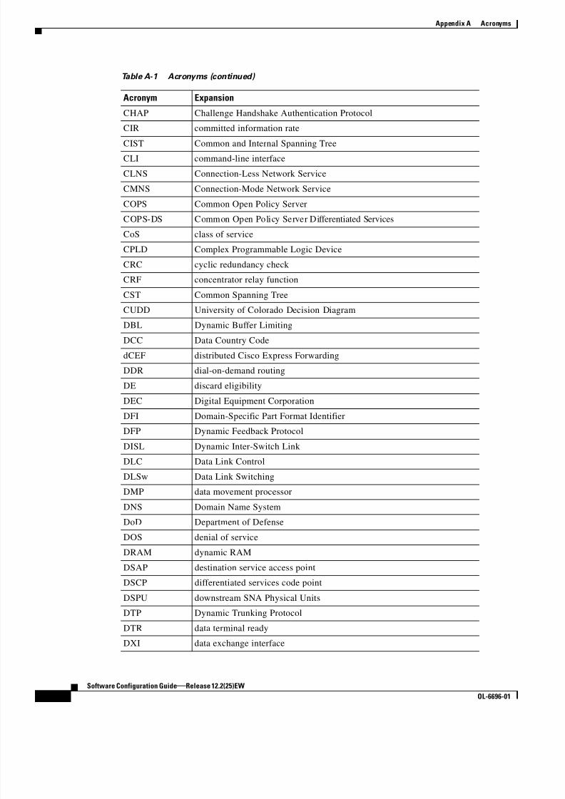
8/10/2019 Cisco ConfiguratioGuide SW4500 IOS
http://slidepdf.com/reader/full/cisco-configuratioguide-sw4500-ios 578/607
A-2
Software Configuration Guide—Release 12.2(25)EW
OL-6696-01
Appendix A Acronyms
CHAP Challenge Handshake Authentication Protocol
CIR committed information rate
CIST Common and Internal Spanning Tree
CLI command-line interface
CLNS Connection-Less Network Service
CMNS Connection-Mode Network Service
COPS Common Open Policy Server
COPS-DS Common Open Policy Server Differentiated Services
CoS class of service
CPLD Complex Programmable Logic Device
CRC cyclic redundancy check
CRF concentrator relay function
CST Common Spanning Tree
CUDD University of Colorado Decision Diagram
DBL Dynamic Buffer Limiting
DCC Data Country Code
dCEF distributed Cisco Express Forwarding
DDR dial-on-demand routing
DE discard eligibility
DEC Digital Equipment Corporation
DFI Domain-Specific Part Format IdentifierDFP Dynamic Feedback Protocol
DISL Dynamic Inter-Switch Link
DLC Data Link Control
DLSw Data Link Switching
DMP data movement processor
DNS Domain Name System
DoD Department of Defense
DOS denial of service
DRAM dynamic RAM
DSAP destination service access point
DSCP differentiated services code point
DSPU downstream SNA Physical Units
DTP Dynamic Trunking Protocol
DTR data terminal ready
DXI data exchange interface
Table A-1 Acronyms (continued)
Acronym Expansion

8/10/2019 Cisco ConfiguratioGuide SW4500 IOS
http://slidepdf.com/reader/full/cisco-configuratioguide-sw4500-ios 579/607
A-3
Software Configuration Guide—Release 12.2(25)EW
OL-6696-01
Appendix A Acronyms
EAP Extensible Authentication Protocol
EARL Enhanced Address Recognition Logic
EEPROM electrically erasable programmable read-only memory
EHSA enhanced high system availability
EHT Explicit Host Tracking
EIA Electronic Industries Association
ELAN Emulated Local Area Network
EOBC Ethernet out-of-band channel
ESI end-system identifier
FECN forward explicit congestion notification
FM feature manager
FRU field replaceable unit
FSM feasible successor metrics
GARP General Attribute Registration Protocol
GMRP GARP Multicast Registration Protocol
GVRP GARP VLAN Registration Protocol
HSRP Hot Standby Routing Protocol
ICC Inter-card Communication
ICD International Code Designator
ICMP Internet Control Message Protocol
IDB interface descriptor block IDP initial domain part or Internet Datagram Protocol
IFS IOS File System
IGMP Internet Group Management Protocol
IGRP Interior Gateway Routing Protocol
ILMI Integrated Local Management Interface
IP Internet Protocol
IPC interprocessor communication
IPX Internetwork Packet Exchange
IS-IS Intermediate System-to-Intermediate System Intradomain Routing
Protocol
ISL Inter-Switch Link
ISO International Organization of Standardization
LAN local area network
LANE LAN Emulation
LAPB Link Access Procedure, Balanced
Table A-1 Acronyms (continued)
Acronym Expansion

8/10/2019 Cisco ConfiguratioGuide SW4500 IOS
http://slidepdf.com/reader/full/cisco-configuratioguide-sw4500-ios 580/607
A-4
Software Configuration Guide—Release 12.2(25)EW
OL-6696-01
Appendix A Acronyms
LDA Local Director Acceleration
LCP Link Control Protocol
LEC LAN Emulation Client
LECS LAN Emulation Configuration Server
LEM link error monitor
LER link error rate
LES LAN Emulation Server
LLC Logical Link Control
LTL Local Target Logic
MAC Media Access Control
MACL MAC Access Control
MD5 Message Digest 5
MFD multicast fast drop
MIB Management Information Base
MII media-independent interface
MLS Multilayer Switching
MLSE maintenance loop signaling entity
MOP Maintenance Operation Protocol
MOTD message-of-the-day
MLSE maintenance loops signaling entity
MRM multicast routing monitorMSDP Multicast Source Discovery Protocol
MST Multiple Spanning Tree
MSTI MST instance
MTU maximum transmission unit
MVAP multiple VLAN access port
NBP Name Binding Protocol
NCIA Native Client Interface Architecture
NDE NetFlow Data Export
NET network entity title
NetBIOS Network Basic Input/Output System
NFFC NetFlow Feature Card
NMP Network Management Processor
NSAP network service access point
NTP Network Time Protocol
NVRAM nonvolatile RAM
Table A-1 Acronyms (continued)
Acronym Expansion

8/10/2019 Cisco ConfiguratioGuide SW4500 IOS
http://slidepdf.com/reader/full/cisco-configuratioguide-sw4500-ios 581/607
A-5
Software Configuration Guide—Release 12.2(25)EW
OL-6696-01
Appendix A Acronyms
OAM Operation, Administration, and Maintenance
ODM order dependent merge
OSI Open System Interconnection
OSPF open shortest path first
PACL Port Access Control List
PAE port access entity
PAgP Port Aggregation Protocol
PBD packet buffer daughterboard
PBR Policy Based Routing
PC Personal Computer
PCM pulse code modulation
PCR peak cell rate
PDP policy decision point
PDU protocol data unit
PEP policy enforcement point
PGM Pragmatic General Multicast
PHY physical sublayer
PIB policy information base
PIM Protocol Independent Multicast
PoE Power over Internet
PPP Point-to-Point ProtocolPRID Policy Rule Identifiers
PVST+ Per VLAN Spanning Tree+
QM QoS manager
QoS quality of service
RADIUS Remote Access Dial-In User Service
RAM random-access memory
RCP Remote Copy Protocol
RGMP Router-Ports Group Management Protocol
RIB routing information base
RIF Routing Information Field
RMON remote network monitor
ROM read-only memory
ROMMON ROM monitor
RP route processor or rendezvous point
RPC remote procedure call
Table A-1 Acronyms (continued)
Acronym Expansion

8/10/2019 Cisco ConfiguratioGuide SW4500 IOS
http://slidepdf.com/reader/full/cisco-configuratioguide-sw4500-ios 582/607
A-6
Software Configuration Guide—Release 12.2(25)EW
OL-6696-01
Appendix A Acronyms
RPF reverse path forwarding
RPR Route Processor Redundancy
RSPAN remote SPAN
RST reset
RSVP ReSerVation Protocol
SAID Security Association Identifier
SAP service access point
SCM service connection manager
SCP Switch-Module Configuration Protocol
SDLC Synchronous Data Link Control
SGBP Stack Group Bidding Protocol
SIMM single in-line memory module
SLB server load balancing
SLCP Supervisor Line-Card Processor
SLIP Serial Line Internet Protocol
SMDS Software Management and Delivery Systems
SMF software MAC filter
SMP Standby Monitor Present
SMRP Simple Multicast Routing Protocol
SMT Station Management
SNAP Subnetwork Access ProtocolSNMP Simple Network Management Protocol
SPAN Switched Port Analyzer
SSTP Cisco Shared Spanning Tree
STP Spanning Tree Protocol
SVC switched virtual circuit
SVI switched virtual interface
TACACS+ Terminal Access Controller Access Control System Plus
TARP Target Identifier Address Resolution Protocol
TCAM Ternary Content Addressable Memory
TCL table contention level
TCP/IP Transmission Control Protocol/Internet Protocol
TFTP Trivial File Transfer Protocol
TIA Telecommunications Industry Association
TopN Utility that allows the user to analyze port traffic by reports
TOS type of service
Table A-1 Acronyms (continued)
Acronym Expansion

8/10/2019 Cisco ConfiguratioGuide SW4500 IOS
http://slidepdf.com/reader/full/cisco-configuratioguide-sw4500-ios 583/607
A-7
Software Configuration Guide—Release 12.2(25)EW
OL-6696-01
Appendix A Acronyms
TLV type-length-value
TTL Time To Live
TVX valid transmission
UDLD UniDirectional Link Detection Protocol
UDP User Datagram Protocol
UNI User-Network Interface
UTC Coordinated Universal Time
VACL VLAN access control list
VCC virtual channel circuit
VCI virtual circuit identifier
VCR Virtual Configuration Register
VINES Virtual Network System
VLAN virtual LAN
VMPS VLAN Membership Policy Server
VPN virtual private network
VRF VPN routing and forwarding
VTP VLAN Trunking Protocol
VVID voice VLAN ID
WFQ weighted fair queueing
WRED weighted random early detection
WRR weighted round-robinXNS Xerox Network System
Table A-1 Acronyms (continued)
Acronym Expansion

8/10/2019 Cisco ConfiguratioGuide SW4500 IOS
http://slidepdf.com/reader/full/cisco-configuratioguide-sw4500-ios 584/607
A-8
Software Configuration Guide—Release 12.2(25)EW
OL-6696-01
Appendix A Acronyms

8/10/2019 Cisco ConfiguratioGuide SW4500 IOS
http://slidepdf.com/reader/full/cisco-configuratioguide-sw4500-ios 585/607
IN-1
Software Configuration Guide—Release 12.2(25)EW
OL-6696-01
I N D E X
Numerics
10/100 autonegotiation feature, forced 4-7
802.10 SAID (default) 10-4
802.1Q
trunks 14-6tunneling
compatibility with other features 19-5
defaults 19-4
described 19-2
tunnel ports with other features 19-6
802.1Q VLANs
encapsulation 12-3
trunk restrictions 12-5
802.1s
See MST
802.1w
See MST
802.1X
See port-based authentication
802.1X authentication
for guest VLANs 31-6
RADIUS accounting 31-7
with port security 31-6
with VLAN assignment 31-5
with voice VLAN ports 31-10
802.3ad
See LACP
A
abbreviating commands 2-5
access control entries
See ACEs
access list filtering, SPAN enhancement 39-13
access ports
and Layer 2 protocol tunneling 19-9
configuring 12-8
access VLANs 12-6
accounting
configuring for 802.1X 31-16
ACEs
ACLs 35-2
Ethernet 35-2
IP 35-2
Layer 4 operation restrictions 35-8
ACLs
ACEs 35-2
and SPAN 39-5
and TCAM programming 35-6
applying on routed packets 35-21
applying on switched packets 35-20
compatibility on the same switch 35-3
configuring with VLAN maps 35-20
CPU impact 35-9
hardware and software support 35-5
IP, matching criteria for port ACLs 35-4
MAC extended 35-11
matching criteria for router ACLs 35-3
port
and voice VLAN 35-4
defined 35-2

8/10/2019 Cisco ConfiguratioGuide SW4500 IOS
http://slidepdf.com/reader/full/cisco-configuratioguide-sw4500-ios 586/607
Index
IN-2
Software Configuration Guide—Release 12.2(25)EW
OL-6696-01
limitations 35-4
processing 35-9
types supported 35-2
acronyms, list of A-1
active queue management 29-13
addresses
See MAC addresses
adjacency tables
description 24-2
displaying statistics 24-9
advertisements, VTP
See VTP advertisements
alarms
major 7-2
minor 7-2
asymmetrical links, and 802.1Q tunneling 19-4
audience xxi
authentication
See also port-based authentication
authentication server
defined 31-3
RADIUS server 31-3
authorized and unauthorized ports 31-4
authorized ports with 802.1X 31-4
autoconfiguration 3-2
automatic QoS
See QoS
autonegotiation feature
forced 10/100Mbps 4-7
Auto-QoS
configuring 29-16
auto-sync command 6-8
B
BackboneFast
adding a switch (figure) 15-2
and MST 16-2
configuring 15-15
link failure (figure) 15-7, 15-8
not supported MST 16-2
understanding 15-6
See also STP
BGP 1-8
routing session with multi-VRF CE 28-6
blocking packets 37-1
blocking state (STP)
RSTP comparisons (table) 16-4
boot bootldr command 3-24
boot command 3-21
boot fields
See configuration register boot fields
boot system command 3-19, 3-24
boot system flash command 3-21
Border Gateway Protocol
See BGP
boundary ports
description 16-6
BPDU Guard
and MST 16-2
configuring 15-12
overview 15-4
BPDUs
and media speed 14-2
pseudobridges and 16-5
what they contain 14-3
bridge ID
See STP bridge ID
bridge priority (STP) 14-16
bridge protocol data units
See BPDUs
broadcast storm control
disabling 38-4
BSR
configuration example 25-21
burst rate 29-44
burst size 29-27

8/10/2019 Cisco ConfiguratioGuide SW4500 IOS
http://slidepdf.com/reader/full/cisco-configuratioguide-sw4500-ios 587/607
Index
IN-3
Software Configuration Guide—Release 12.2(25)EW
OL-6696-01
C
candidate switch
defined 9-12
requirements 9-12
See also command switch and member switch
cautions for passwords
encrypting 3-16
TACACS+ 3-15
CDP
and trusted boundary 29-25
configuration 20-2
displaying configuration 20-3
enabling on interfaces 20-3
Layer 2 protocol tunneling 19-7
maintaining 20-3
monitoring 20-3
overview 1-2, 20-1
cdp enable command 20-3
CEF
adjacency tables 24-2
configuring load balancing 24-7
displaying statistics 24-8enabling 24-6
hardware switching 24-4
load balancing 24-6
overview 24-1
software switching 24-4
CGMP
overview 18-1
channel-group group command 17-7, 17-10
Cisco Discovery Protocol
See CDP
Cisco Express Forwarding
See CEF
Cisco Group Management Protocol
See CGMP
Cisco IOS NSF-awareness support 6-2
Cisco IP Phones
configuring 30-2
Cisco IP phones
sound quality 30-1
CIST
description 16-2
class-map command 29-28
class of service
See CoS
clear cdp counters command 20-4
clear cdp table command 20-3
clear counters command 4-14
clearing
IP multicast table entries 25-20
clear ip flow stats command 40-8
CLI
accessing 2-1
backing out one level 2-5
getting commands 2-5
history substitution 2-3
managing clusters 9-13
modes 2-5
monitoring environments 39-1
ROM monitor 2-6
software basics 2-4
clients
in 802.1X authentication 31-2
clustering switches
command switch characteristics 9-11, 9-12
and VTY 9-12
managing
through CLI 9-13
overview 9-11
planning considerations
CLI 9-13
command-line processing 2-3
command modes 2-5
commands
listing 2-5
command switch

8/10/2019 Cisco ConfiguratioGuide SW4500 IOS
http://slidepdf.com/reader/full/cisco-configuratioguide-sw4500-ios 588/607
Index
IN-4
Software Configuration Guide—Release 12.2(25)EW
OL-6696-01
requirements 9-11
common and internal spanning tree
See CIST
common spanning tree
See CST
community ports
description 36-1
community VLANs
and SPAN features 36-4
configure as a PVLAN 36-5
description 36-1
config-register command 3-22
config terminal command 3-9
configuration files
obtaining with DHCP 3-6
saving 3-10
configuration register
boot fields
listing value 3-22
modifying 3-21
changing settings 3-21 to 3-22
configuring 3-19
settings at startup 3-20
configure terminal command 3-22, 4-2
console configuration mode 2-5
console port
disconnecting user sessions 5-5
monitoring user sessions 5-4
copy running-config startup-config command 3-10
copy system:running-config nvram:startup-config
command 3-24
CoS
configuring port value 29-41
definition 29-3
figure 29-2
overriding on Cisco IP Phones 30-3
priority 30-3
CoS-to-DSCP maps 29-46
counters
clearing MFIB 25-20
clearing on interfaces 4-14
CPU port sniffing 39-10
CST
description 16-5
IST and 16-2
MST and 16-2
customer edge devices 28-2
D
default configuration
802.1X 31-12
auto-QoS 29-16
IGMP filtering 18-17
Layer 2 protocol tunneling 19-9
multi-VRF CE 28-3
SPAN and RSPAN 39-6
default gateway
configuring 3-11
verifying configuration 3-11
default ports
and support for 802.1X authentication 31-13
description command 4-9
detecting unidirectional links 21-1
DHCP-based autoconfiguration
client request message exchange 3-3
configuring
client side 3-2
DNS 3-5
relay device 3-5
server-side 3-3TFTP server 3-4
example 3-7
lease options
for IP address information 3-4
for receiving the configuration file 3-4
overview 3-2
relationship to BOOTP 3-2

8/10/2019 Cisco ConfiguratioGuide SW4500 IOS
http://slidepdf.com/reader/full/cisco-configuratioguide-sw4500-ios 589/607
Index
IN-5
Software Configuration Guide—Release 12.2(25)EW
OL-6696-01
DHCP snooping
configuring 33-3
default configuration 33-3
displaying binding tables 33-10
displaying configuration 33-10
enabling 33-4
enabling on private VLAN 33-5
enabling the database agent 33-6
monitoring 33-9, 33-13, 33-14
overview 33-1
Snooping database agent 33-2
DHCP Snooping Database Agent
adding to the database (example) 33-9
enabling (example) 33-6
overview 33-2
reading from a TFTP file (example) 33-8
Differentiated Services Code Point values
See DSCP values
DiffServ architecture, QoS 29-2
disabled state
RSTP comparisons (table) 16-4
disabling
broadcast storm control 38-4
disconnect command 5-5
DNS
and DHCP-based autoconfiguration 3-5
documentation
organization xxi
related xxiii
double-tagged packets
802.1Q tunneling 19-2
Layer 2 protocol tunneling 19-9
drop threshold for Layer 2 protocol packets 19-9
DSCP maps 29-45
DSCP-to-CoS maps
configuring 29-47
DSCP values
configuring maps 29-45
configuring port value 29-42
definition 29-3
IP precedence 29-2
mapping markdown 29-23
mapping to transmit queues 29-43
DTP
VLAN trunks and 12-3
duplex command 4-8
duplex mode
configuring interface 4-7
Dynamic Host Configuration Protocol snooping
See DHCP snooping
dynamic port VLAN membership
limit on hosts 11-9
reconfirming 11-7
troubleshooting 11-9
Dynamic Trunking Protocol
See DTP
E
EAP frame
request/identity 31-3
response/identity 31-3
EAP frames
changing retransmission time 31-20
exchanging (figure) 31-4
setting retransmission number 31-21
EAPOL frames
802.1X authentication and 31-2
OTP authentication, example (figure) 31-4
start 31-3
edge portsdescription 16-7
EGP
overview 1-8
EIGRP
overview 1-8
Embedded CiscoView
displaying information 9-16

8/10/2019 Cisco ConfiguratioGuide SW4500 IOS
http://slidepdf.com/reader/full/cisco-configuratioguide-sw4500-ios 590/607

8/10/2019 Cisco ConfiguratioGuide SW4500 IOS
http://slidepdf.com/reader/full/cisco-configuratioguide-sw4500-ios 591/607
Index
IN-7
Software Configuration Guide—Release 12.2(25)EW
OL-6696-01
hop counts
configuring MST bridges 16-7
host
configuring host statically 18-8
limit on dynamic port 11-9
Hot Standby Routing Protocol
See HSRP
HSRP
description 1-6
hw-module module num power command 7-15
I
ICMP
enabling 5-10
ping 5-5
running IP traceroute 5-7
time exceeded messages 5-7
IDS
using with SPAN and RSPAN 39-2
IEEE 802.1s
See MST
IEEE 802.1w
See MST
IEEE 802.3ad
See LACP
IGMP
description 25-3
enabling 25-13
explicit host tracking 18-3, 18-8
immediate-leave processing 18-3
overview 18-1IGMP filtering
configuring 18-17
default configuration 18-17
described 18-16
monitoring 18-20
IGMP groups
setting the maximum number 18-19
IGMP profile
applying 18-18
configuration mode 18-17
configuring 18-17
IGMP snooping
configuration guidelines 18-4
enabling 18-5
IP multicast and 25-4
monitoring 18-11
overview 18-1
IGRP
description 1-8
immediate-leave processing
enabling 18-7
IGMP
See fast-leave processing
ingress packets, SPAN enhancement 39-12
inline power
configuring on Cisco IP phones 30-4
Intelligent Power Management 8-5
interface command 3-9, 4-1
interface port-channel command 17-7
interface range command 4-4
interface range macro command 4-5
interfaces
adding descriptive name 4-9
clearing counters 4-14
configuring 4-2
configuring ranges 4-4
displaying information about 4-13
Layer 2 modes 12-4
maintaining 4-13
monitoring 4-13
naming 4-9
numbers 4-2
overview 4-1
restarting 4-14
See also Layer 2 interfaces
Interior Gateway Routing Protocol

8/10/2019 Cisco ConfiguratioGuide SW4500 IOS
http://slidepdf.com/reader/full/cisco-configuratioguide-sw4500-ios 592/607
Index
IN-8
Software Configuration Guide—Release 12.2(25)EW
OL-6696-01
See IGRP
Internet Control Message Protocol
See ICMP
Internet Group Management Protocol
See IGMP
Inter-Switch Link encapsulation
See ISL encapsulation
Intrusion Detection System
See IDS
IP
configuring default gateway 3-11
configuring static routes 3-11
displaying statistics 24-8
flow switching cache 40-8
IP addresses
candidate or member 9-12
command switch 9-12
See also IP information
ip cef command 24-6
ip flow-aggregation cache destination-prefix
command 40-10
ip flow-aggregation cache prefix command 40-10
ip flow-aggregation cache source-prefix command 40-10
ip flow-export command 40-8
ip icmp rate-limit unreachable command 5-11
ip igmp profile command 18-17
ip igmp snooping tcn flood command 18-10
ip igmp snooping tcn flood query count command 18-10
ip igmp snooping tcn query solicit command 18-11
IP information
assigned
through DHCP-based autoconfiguration 3-2
ip load-sharing per-destination command 24-7
ip local policy route-map command 26-5
ip mask-reply command 5-12
IP multicast
clearing table entries 25-20
configuring 25-12
default configuration 25-13
displaying PIM information 25-15
displaying the routing table information 25-16
enabling 25-13
enabling dense-mode PIM 25-14
enabling sparse-mode 25-14
features not supported 25-12
hardware forwarding 25-8
IGMP snooping and 18-4, 25-4
monitoring 25-15
overview 25-1
routing protocols 25-2
software forwarding 25-8
See also Auto-RP; IGMP; PIM; RP; RPF
ip multicast-routing command 25-13
IP phones
automatic classification and queueing 29-16
configuring voice ports 30-2
See Cisco IP Phones 30-1
trusted boundary for QoS 29-24
ip pim command 25-14
ip pim dense-mode command 25-14
ip pim sparse-dense-mode command 25-15
ip policy route-map command 26-4
ip redirects command 5-11
ip route-cache flow command 40-7
IP routing tables
deleting entries 25-20
IP Source Guard
configuring 33-11
configuring on private VLANs 33-12
displaying 33-13, 33-14
overview 33-10
IP statistics
displaying 24-8
IP traceroute
executing 5-7
overview 5-7
IP unicast
displaying statistics 24-8

8/10/2019 Cisco ConfiguratioGuide SW4500 IOS
http://slidepdf.com/reader/full/cisco-configuratioguide-sw4500-ios 593/607
Index
IN-9
Software Configuration Guide—Release 12.2(25)EW
OL-6696-01
ip unreachables command 5-10
IPX
redistribution of route information with EIGRP 1-8
ISL
encapsulation 12-3
trunking with 802.1Q tunneling 19-4
isolated ports
description 36-1
isolated VLANs
description 36-1
IST
description 16-2
master 16-7
MST regions and 16-2
J
jumbo frames
and ethernet ports 4-11
configuring MTU sizes for 4-12
ports and linecards that support 4-10
VLAN interfaces 4-11
K
keyboard shortcuts 2-3
L
l2protocol-tunnel command 19-11
labels
definition 29-3LACP
system ID 17-4
Layer 2 access ports 12-8
Layer 2 frames
classification with CoS 29-2
Layer 2 interfaces
assigning VLANs 10-8
configuring 12-5
configuring as PVLAN host ports 36-8
configuring as PVLAN promiscuous ports 36-7
configuring as PVLAN trunk ports 36-9
defaults 12-5
disabling configuration 12-9
modes 12-4
show interfaces command 12-7
Layer 2 interface type
resetting 36-12
setting 36-12
Layer 2 protocol tunneling
configuring 19-9
default configuration 19-9
defined 19-7
guidelines 19-10
Layer 2 switching
overview 12-1
Layer 2 Traceroute
and ARP 5-9
and CDP 5-8
described 5-8
host-to-host paths 5-8
IP addresses and subnets 5-9
MAC addresses and VLANs 5-9
multicast traffic 5-9
multiple devices on a port 5-9
unicast traffic 1-3, 5-8
usage guidelines 5-8
Layer 2 trunks
configuring 12-6
overview 12-3
Layer 3 packets
classification methods 29-2
Layer 4 port operations
configuration guidelines 35-8
restrictions 35-8
LEDs

8/10/2019 Cisco ConfiguratioGuide SW4500 IOS
http://slidepdf.com/reader/full/cisco-configuratioguide-sw4500-ios 594/607
Index
IN-10
Software Configuration Guide—Release 12.2(25)EW
OL-6696-01
description (table) 7-2
listening state (STP)
RSTP comparisons (table) 16-4
load balancing
configuring for CEF 24-7
configuring for EtherChannel 17-12
overview 17-5, 24-6
per-destination 24-7
login timer
changing 5-4
logoutwarning command 5-4
loop guard
and MST 16-2
configuring 15-9
overview 15-2
M
MAC addresses
allocating 14-5
building tables 12-2
convert dynamic to sticky secure 32-2
displaying 5-3
displaying in DHCP snooping binding table 33-10
in ACLs 35-11
sticky 32-2
sticky secure, adding 32-2
MAC extended access lists 35-11
macros
See SmartPort macros
main-cpu command 6-8
mappingDSCP markdown values 29-23
DSCP values to transmit queues 29-43
mapping tables
configuring DSCP 29-45
described 29-13
mask destination command 40-10
mask source command 40-10
match ip address command 26-3
maximum aging time (STP)
configuring 14-18
member switch
defined 9-11
managing 9-13
requirements 9-12
metro tags 19-2
MFIB
CEF 25-5
displaying 25-18
overview 25-11
modules
checking status 5-1
powering down 7-15
monitoring
802.1Q tunneling 19-12
ACL information 35-28
IGMP filters 18-20
IGMP snooping 18-11
Layer 2 protocol tunneling 19-12
multi-VRF CE 28-11
tunneling 19-12
VLAN filters 35-19
VLAN maps 35-19
M-record 16-2
MST
and multiple spanning trees 1-4, 16-2
boundary ports 16-6
BPDUs 16-2
configuration parameters 16-5
configuring 16-9
displaying configurations 16-13
edge ports 16-7
enabling 16-9
hop count 16-7
instances
configuring parameters 16-12
description 16-2

8/10/2019 Cisco ConfiguratioGuide SW4500 IOS
http://slidepdf.com/reader/full/cisco-configuratioguide-sw4500-ios 595/607
Index
IN-11
Software Configuration Guide—Release 12.2(25)EW
OL-6696-01
number supported 16-5
interoperability with PVST+ 16-2
link type 16-7
master 16-7
message age 16-7
regions 16-5, 16-6
restrictions 16-8
to-SST interoperability 16-4
MSTP
M-record 16-2
M-tree 16-2
M-tree 16-2
MTU size
configuring 4-12
default 10-4
multicast
See IP multicast
multicast packets
blocking 37-2
multicast routers
displaying routing tables 25-16
flood suppression 18-9
Multicast Storm Controloverview 38-6
suppression on WS-X4014 38-7
suppression on WS-X4016 38-6
multiple forwarding paths 1-4, 16-2
Multiple Spanning Tree
See MST
multiple VPN routing/forwarding
See multi-VRF CE
multi-VRF CE
components 28-3
configuration example 28-7
default configuration 28-3
defined 28-1
displaying 28-11
monitoring 28-11
network components 28-3
packet-forwarding process 28-3
N
native VLAN
and 802.1Q tunneling 19-4
specifying 12-6
NetFlow
aggregation
minimum mask,default value 40-10
destination-prefix aggregation
configuration (example) 40-15
minimum mask, configuring 40-10
IP
flow switching cache 40-8
prefix aggregation
configuration (example) 40-13
minimum mask, configuring 40-10
source-prefix aggregation
minimum mask, configuring 40-10
switching
configuration (example) 40-11
configuring 40-7
exporting cache entries 40-8
statistics 40-8
NetFlow statistics
caveats on supervisor 40-6
configuring collection 40-6
implementing collection 40-6
overview of collection 40-1
Network Assistant
and VTY 9-12configure
display configuration 9-9
enable communication with switch 9-4
enable inter-cluster communication 9-7
connect to a device 9-10
default configuration 9-3
installation requirements 9-2

8/10/2019 Cisco ConfiguratioGuide SW4500 IOS
http://slidepdf.com/reader/full/cisco-configuratioguide-sw4500-ios 596/607
Index
IN-12
Software Configuration Guide—Release 12.2(25)EW
OL-6696-01
installing 9-3
launch 9-10
overview of CLI commands 9-4
software and hardware requirements 9-2
understanding 9-2
network fault tolerance 1-4, 16-2
network management
configuring 20-1
Next Hop Resolution Protocol
See NHRP
NFFC/NFFC II
IGMP snooping and 18-4
NHRP
support 1-8
non-IP traffic filtering 35-11
non-RPF traffic
description 25-9
in redundant configurations (figure) 25-10
nonvolatile random-access memory
See NVRAM
normal-range VLANs
See VLANs
NSF-awareness support 6-2
NVRAM
saving settings 3-10
O
OIR
overview 4-13
online insertion and removal
See OIROpen Shortest Path First
See OSPF
operating system images
See system images
OSPF
area concept 1-7
description 1-7
P
packets
modifying 29-15
software processed
and QoS 29-15
packet type filtering
overview 39-14
SPAN enhancement 39-14
PAgP
understanding 17-3
passwords
configuring enable password 3-14
configuring enable secret password 3-14
encrypting 3-15
recovering lost enable password 3-18
setting line password 3-14
setting TACACS+ 3-15
PBR (policy-based routing)
configuration (example) 26-5
enabling 26-3
features 26-2
overview 26-1route maps 26-2
when to use 26-2
per-port and VLAN Access Control List 33-10
Per-VLAN Rapid Spanning Tree 14-6
enabling 14-20
overview 14-6
PE to CE routing, configuring 28-6
PIM
configuring dense mode 25-14
configuring sparse mode 25-14
displaying information 25-15
displaying statistics 25-20
enabling sparse-dense mode 25-14, 25-15
overview 25-3
PIM-DM 25-3
PIM-SM 25-3

8/10/2019 Cisco ConfiguratioGuide SW4500 IOS
http://slidepdf.com/reader/full/cisco-configuratioguide-sw4500-ios 597/607
Index
IN-13
Software Configuration Guide—Release 12.2(25)EW
OL-6696-01
ping
executing 5-6
overview 5-5
ping command 5-6, 25-15
PoE 8-7
configuring power consumption for single device 8-4
configuring power consumption for switch 8-4
power consumption for powered devices
Intelligent Power Management 8-5
overview 8-3
supported cabling topology 8-5
powering down a module 7-15
power management modes 8-1
show interface status 8-6
point-to-point
in 802.1X authentication (figure) 31-2, 31-8
police command 29-32
policed-DSCP map 29-46
policers
description 29-5
types of 29-9
policies
See QoS policiespolicing
See QoS policing
policy-map command 29-29, 29-31
policy maps
attaching to interfaces 29-34
configuring 29-30
port ACLs
and voice VLAN 35-4
defined 35-2
limitations 35-4
Port Aggregation Protocol
see PAgP
port-based authentication
802.1X with voice VLAN 31-10
changing the quiet period 31-19
client, defined 31-2
configuration guidelines 31-13
configure 802.1X accounting 31-16
configure switch-to-RADIUS server
communication 31-15
configure with Guest-VLANs 31-17, 31-18
configuring Guest-VLAN 31-15
configuring manual re-authentication of a client 31-19
controlling authorization state 31-4
default configuration 31-12
described 31-2
device roles 31-2
disabling 31-14
displaying statistics 31-22
enabling 31-13enabling multiple hosts 31-21
enabling periodic re-authentication 31-18
encapsulation 31-2
initiation and message exchange 31-3
method lists 31-13
ports not supported 31-4
resetting to default values 31-22
setting retransmission number 31-21
setting retransmission time 31-20
topologies, supported 31-10
using with port security 31-6
with VLAN assignment 31-5
port-based QoS features
See QoS
port-channel interfaces
See also EtherChannel
creating 17-6
overview 17-2
port-channel load-balance
command 17-12
command example 17-12
port-channel load-balance command 17-12
port cost (STP)
configuring 14-15
PortFast

8/10/2019 Cisco ConfiguratioGuide SW4500 IOS
http://slidepdf.com/reader/full/cisco-configuratioguide-sw4500-ios 598/607
Index
IN-14
Software Configuration Guide—Release 12.2(25)EW
OL-6696-01
and MST 16-2
BPDU filter, configuring 15-12
configuring or enabling 15-11
overview 15-3
PortFast BPDU filtering
and MST 16-2
enabling 15-12
overview 15-4
port priority
configuring MST instances 16-12
configuring STP 14-13
ports
blocking 37-1
checking status 5-2
community 36-1
dynamic VLAN membership
reconfirming 11-7
forwarding, resuming 37-3
isolated 36-1
PVLAN types 36-1
secure 32-1
See also interfaces
port securityaging 32-6
and QoS trusted boundary 29-24
configuring 32-4
default configuration 32-3
described 32-1
displaying 32-7
RADIUS accounting 31-7
sticky learning 32-2
using with 802.1X 31-6
violations 32-2
with other features 32-3
port states
description 14-5
port trust state
See trust states
power
inline 30-4
power dc input command 7-11
power inline command 8-2
power inline consumption command 8-4
power management
1+1 redundancy mode 7-12
2+1 redundancy mode 7-12
Catalyst 4006 switch 7-12
Catalyst 4500 series 7-4
Catalyst 4500 Series power supplies 7-9
Catalyst 4948 series 7-3
combined mode 7-5
configuring combined mode 7-8
configuring redundant mode 7-7
overview 7-1
redundancy 7-12
redundant mode 7-5
power redundancy
setting on Catalyst 4006 7-14
power redundancy-mode command 7-8
power supplies
fixed 7-4
variable 7-3, 7-4
power supplies required command 7-14
primary VLANs
associating with secondary VLANs 36-6
configuring as a PVLAN 36-5
description 36-1
priority
overriding CoS of incoming frames 30-3
privileged EXEC mode 2-5
privileges
changing default 3-17
configuring levels 3-16
exiting 3-17
logging in 3-17
promiscuous ports
configuring PVLAN 36-7
description 36-1

8/10/2019 Cisco ConfiguratioGuide SW4500 IOS
http://slidepdf.com/reader/full/cisco-configuratioguide-sw4500-ios 599/607
Index
IN-15
Software Configuration Guide—Release 12.2(25)EW
OL-6696-01
setting mode 36-12
protocol timers 14-4
provider edge devices 28-2
pruning, VTP
See VTP pruning
pseudobridges
description 16-5
PVACL 33-10
PVID (port VLAN ID)
and 802.1X with voice VLAN ports 31-10
PVLANs
802.1q support 36-5
configuration guidelines 36-3
configuring 36-3
configuring a VLAN 36-5
configuring promiscuous ports 36-7
host ports
configuring a Layer 2 interface 36-8
setting 36-12
isolated VLANs 36-1
overview 36-1
permitting routing, example 36-11
promiscuous modesetting 36-12
setting
interface mode 36-12
Q
QoS
allocating bandwidth 29-44
and software processed packets 29-15auto-QoS
configuration and defaults display 29-19
configuration guidelines 29-17
described 29-16
displaying 29-19
effects on NVRAM configuration 29-17
enabling for VoIP 29-18
basic model 29-5
burst size 29-27
classification 29-5 to 29-9
configuration guidelines 29-24
auto-QoS 29-17
configuring
auto-QoS 29-16
DSCP maps 29-45
traffic shaping 29-44
trusted boundary 29-24
VLAN-based 29-39
configuring user based rate limiting 29-35
hierarchical policers 29-37
creating policing rules 29-28
default auto configuration 29-16
default configuration 29-22
definitions 29-3
disabling on interfaces 29-34
enabling on interfaces 29-34
flowcharts 29-7, 29-11
IP phones
automatic classification and queueing 29-16
detection and trusted settings 29-16, 29-24
overview 29-1
packet modification 29-15
port-based 29-39
priority 29-14
traffic shaping 29-14
transmit rate 29-44
trust states
trusted device 29-24
VLAN-based 29-39
See also COS; DSCP values; transmit queues
QoS active queue management
tracking queue length 29-13
QoS labels
definition 29-3
QoS mapping tables
CoS-to-DSCP 29-46
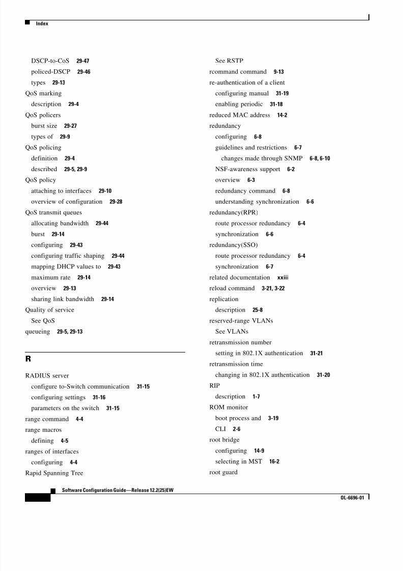
8/10/2019 Cisco ConfiguratioGuide SW4500 IOS
http://slidepdf.com/reader/full/cisco-configuratioguide-sw4500-ios 600/607
Index
IN-16
Software Configuration Guide—Release 12.2(25)EW
OL-6696-01
DSCP-to-CoS 29-47
policed-DSCP 29-46
types 29-13
QoS marking
description 29-4
QoS policers
burst size 29-27
types of 29-9
QoS policing
definition 29-4
described 29-5, 29-9
QoS policy
attaching to interfaces 29-10
overview of configuration 29-28
QoS transmit queues
allocating bandwidth 29-44
burst 29-14
configuring 29-43
configuring traffic shaping 29-44
mapping DHCP values to 29-43
maximum rate 29-14
overview 29-13
sharing link bandwidth 29-14
Quality of service
See QoS
queueing 29-5, 29-13
R
RADIUS server
configure to-Switch communication 31-15
configuring settings 31-16parameters on the switch 31-15
range command 4-4
range macros
defining 4-5
ranges of interfaces
configuring 4-4
Rapid Spanning Tree
See RSTP
rcommand command 9-13
re-authentication of a client
configuring manual 31-19
enabling periodic 31-18
reduced MAC address 14-2
redundancy
configuring 6-8
guidelines and restrictions 6-7
changes made through SNMP 6-8, 6-10
NSF-awareness support 6-2
overview 6-3
redundancy command 6-8
understanding synchronization 6-6
redundancy(RPR)
route processor redundancy 6-4
synchronization 6-6
redundancy(SSO)
route processor redundancy 6-4
synchronization 6-7
related documentation xxiii
reload command 3-21, 3-22
replicationdescription 25-8
reserved-range VLANs
See VLANs
retransmission number
setting in 802.1X authentication 31-21
retransmission time
changing in 802.1X authentication 31-20
RIP
description 1-7
ROM monitor
boot process and 3-19
CLI 2-6
root bridge
configuring 14-9
selecting in MST 16-2
root guard

8/10/2019 Cisco ConfiguratioGuide SW4500 IOS
http://slidepdf.com/reader/full/cisco-configuratioguide-sw4500-ios 601/607
Index
IN-17
Software Configuration Guide—Release 12.2(25)EW
OL-6696-01
and MST 16-2
enabling 15-8
overview 15-2
routed packets
ACLs 35-21
route-map (IP) command 26-3
route maps
defining 26-3
PBR 26-2
router ACLs
description 35-2
using with VLAN maps 35-20
route targets
VPN 28-3
Routing Information Protocol
See RIP
RSPAN
configuration guidelines 39-16
destination ports 39-5
IDS 39-2
monitored ports 39-4
monitoring ports 39-5
received traffic 39-3
sessions
creating 39-17
defined 39-3
limiting source traffic to specific VLANs 39-23
monitoring VLANs 39-22
removing source (monitored) ports 39-21
specifying monitored ports 39-17
source ports 39-4
transmitted traffic 39-4
VLAN-based 39-5
RSTP
compatibility 16-3
description 16-2
port roles 16-3
port states 16-4
S
SAID
See 802.10 SAID
scheduling 29-13
defined 29-4
overview 29-5
secondary root switch 14-12
secondary VLANs
associating with primary 36-6
description 36-2
permitting routing 36-11
secure ports, configuring 32-1
Security Association Identifier
See 802.10 SAID
servers, VTP
See VTP servers
service-policy command 29-29
service-policy input command 22-2, 29-34
service-provider networks
and customer VLANs 19-2
Layer 2 protocols across 19-7
set default interface command 26-4set interface command 26-4
set ip default next-hop command 26-4
set ip next-hop command 26-4
show adjacency command 24-9
show boot command 3-24
show catalyst4000 chassis-mac-address command 14-3
show cdp command 20-2, 20-3
show cdp entry command 20-4
show cdp interface command 20-3
show cdp neighbors command 20-4
show cdp traffic command 20-4
show ciscoview package command 9-16
show ciscoview version command 9-16
show cluster members command 9-13
show configuration command 4-9
show debugging command 20-4

8/10/2019 Cisco ConfiguratioGuide SW4500 IOS
http://slidepdf.com/reader/full/cisco-configuratioguide-sw4500-ios 602/607

8/10/2019 Cisco ConfiguratioGuide SW4500 IOS
http://slidepdf.com/reader/full/cisco-configuratioguide-sw4500-ios 603/607
Index
IN-19
Software Configuration Guide—Release 12.2(25)EW
OL-6696-01
SPAN destination ports
802.1X authentication not supported 31-13
SPAN enhancements
access list filtering 39-13
configuration example 39-15
CPU port sniffing 39-10
encapsulation configuration 39-12
ingress packets 39-12
packet type filtering 39-14
spanning-tree backbonefast command 15-15
spanning-tree cost command 14-15
spanning-tree guard root command 15-8
spanning-tree portfast bpdu-guard command 15-12
spanning-tree portfast command 15-11
spanning-tree port-priority command 14-13
spanning-tree uplinkfast command 15-14
spanning-tree vlan
command 14-9
command example 14-9
spanning-tree vlan command 14-8
spanning-tree vlan cost command 14-15
spanning-tree vlan forward-time command 14-19
spanning-tree vlan hello-time command 14-17
spanning-tree vlan max-age command 14-18
spanning-tree vlan port-priority command 14-13
spanning-tree vlan priority command 14-17
spanning-tree vlan root primary command 14-10
spanning-tree vlan root secondary command 14-12
speed
configuring interface 4-7
speed command 4-7
SST
description 16-2
interoperability 16-4
static routes
configuring 3-11
verifying 3-12
statistics
displaying 802.1X 31-22
displaying PIM 25-20
NetFlow accounting 40-8
sticky learning
configuration file 32-2
defined 32-2
disabling 32-2
enabling 32-2
saving addresses 32-2
sticky MAC addresses
configuring 32-4
defined 32-2
Storm Control
disabling 38-4
displaying 38-4
enabling 38-3
hardware-based, implementing 38-2
overview 38-1
STP
bridge ID 14-2
configuring 14-7 to 14-20
creating topology 14-4
defaults 14-6
disabling 14-19
enabling 14-7
enabling extended system ID 14-8
enabling Per-VLAN Rapid Spanning Tree 14-20
forward-delay time 14-18
hello time 14-17
Layer 2 protocol tunneling 19-7
maximum aging time 14-18
overview 14-1, 14-3
per-VLAN rapid spanning tree 14-6
port cost 14-15
port priority 14-13
root bridge 14-9
supervisor engine
accessing the redundant 6-14
configuring 3-8 to 3-13
copying files to standby 6-14

8/10/2019 Cisco ConfiguratioGuide SW4500 IOS
http://slidepdf.com/reader/full/cisco-configuratioguide-sw4500-ios 604/607
Index
IN-20
Software Configuration Guide—Release 12.2(25)EW
OL-6696-01
default configuration 3-1
default gateways 3-11
environmental monitoring 7-1
ROM monitor 3-19
startup configuration 3-18
static routes 3-11
synchronizing configurations 6-10
SVIs
and router ACLs 35-3
switched packets
and ACLs 35-20
Switched Port Analyzer
See SPAN
switching, NetFlow
configuration (example) 40-11
configuring 40-7
exporting cache entries 40-8
switchport
show interfaces 4-12
switchport access vlan command 12-6, 12-8
switchport block multicast command 37-2
switchport block unicast command 37-2
switchport mode access command 12-8
switchport mode dot1q-tunnel command 19-6
switchport mode dynamic command 12-6
switchport mode trunk command 12-6
switch ports
See access ports
switchport trunk allowed vlan command 12-6
switchport trunk encapsulation command 12-6
switchport trunk encapsulation dot1q command 12-3
switchport trunk encapsulation isl command 12-3
switchport trunk encapsulation negotiate command 12-3
switchport trunk native vlan command 12-6
switchport trunk pruning vlan command 12-6
switch-to-RADIUS server communication
configuring 31-15
syslog messages 7-2
system
reviewing configuration 3-10
settings at startup 3-20
system images
loading from Flash memory 3-23
modifying boot field 3-20
specifying 3-23
system MTU
802.1Q tunneling 19-5
maximums 19-5
T
TACACS+
setting passwords 3-15
tagged packets
802.1Q 19-3
Layer 2 protocol 19-7
TCAM programming and ACLs 35-6
Telnet
accessing CLI 2-2
disconnecting user sessions 5-5
executing 5-3
monitoring user sessions 5-4
telnet command 5-4
TFTP
configuration files in base directory 3-5
configuring for autoconfiguration 3-4
time exceeded messages 5-7
timer
See login timer
Token Ring
media not supported (note) 10-4, 27-3TOS
description 29-3
trace command 5-7
traceroute
See IP traceroute
See Layer 2 Traceroute
traceroute mac command 5-9

8/10/2019 Cisco ConfiguratioGuide SW4500 IOS
http://slidepdf.com/reader/full/cisco-configuratioguide-sw4500-ios 605/607
Index
IN-21
Software Configuration Guide—Release 12.2(25)EW
OL-6696-01
traceroute mac ip command 5-9
traffic
blocking flooded 37-2
traffic control
using ACLs (figure) 35-4
using VLAN maps (figure) 35-5
traffic shaping 29-14
translational bridge numbers (defaults) 10-4
transmit queues
See QoS transmit queues
transmit rate 29-44
troubleshooting
with traceroute 5-7
trunk ports
802.1X authentication not supported on 31-13
configuring PVLAN 36-9 to 36-11
trunks
802.1Q restrictions 12-5
configuring 12-6
configuring access VLANs 12-6
configuring allowed VLANs 12-6
default interface configuration 12-6
different VTP domains 12-3
enabling to non-DTP device 12-4
encapsulation 12-3
specifying native VLAN 12-6
understanding 12-3
trusted boundary for QoS 29-24
trust states
configuring 29-40
tunneling
defined 19-1
Layer 2 protocol 19-7
tunnel ports
802.1Q, configuring 19-6
described 19-2
incompatibilities with other features 19-5
type of service
See TOS
U
UDLD
default configuration 21-2
disabling 21-3
enabling 21-3
overview 21-1, 34-1
unauthorized ports with 802.1X 31-4
unicast
See IP unicast
unicast flood blocking
configuring 37-1
unicast traffic
blocking 37-2
unidirectional ethernet
enabling 22-2
example of setting 22-2
overview 22-1
UniDirectional Link Detection Protocol
See UDLD
UplinkFast
and MST 16-2
enabling 15-14MST and 16-3
overview 15-5
user EXEC mode 2-5
user sessions
disconnecting 5-5
monitoring 5-4
V
VACLs
Layer 4 port operations 35-7
virtual LANs
See VLANs
Virtual Private Network
See VPN
VLAN ACLs

8/10/2019 Cisco ConfiguratioGuide SW4500 IOS
http://slidepdf.com/reader/full/cisco-configuratioguide-sw4500-ios 606/607
Index
IN-22
Software Configuration Guide—Release 12.2(25)EW
OL-6696-01
See VLAN maps
vlan command 10-6, 10-7
vlan database command 10-7
vlan dot1q tag native command 19-4
VLAN Management Policy Server
See VMPS
VLAN maps
applying 35-16, 35-24
common uses for 35-16
configuration example 35-17
configuration guidelines 35-13
configuring 35-12
creating entries 35-13
defined 35-3
denying access example 35-18
denying packets 35-14
displaying 35-19
examples 35-18
order of entries 35-13
permitting packets 35-14
router ACLs and 35-20
using (figure) 35-5
VLANsallowed on trunk 12-6
configuration guidelines 10-3
configuring 10-4
customer numbering in service-provider networks 19-3
default configuration 10-4
description 1-5
extended range 10-3
IDs (default) 10-4
interface assignment 10-8
limiting source traffic with RSPAN 39-23
monitoring with RSPAN 39-22
name (default) 10-4
normal range 10-3
overview 10-1
reserved range 10-3
See also PVLANs
VLAN Trunking Protocol
See VTP
VLAN trunks
overview 12-3
VMPS
configuring dynamic access ports on client 11-6
configuring retry interval 11-8
dynamic port membership
reconfirming 11-7
reconfirming assignments 11-7
reconfirming membership interval 11-7
server overview 11-1
VMPS client
administering and monitoring 11-8
configure switch
configure reconfirmation interval 11-7
dynamic ports 11-6
entering IP VMPS address 11-5
reconfirmation interval 11-8
reconfirm VLAM membership 11-7
default configuration 11-4
dynamic VLAN membership overview 11-4
troubleshooting dynamic port VLAN membership 11-9
VMPS server
fall-back VLAN 11-3
illegal VMPS client requests 11-3
overview 11-1
security modes
multiple 11-3
open 11-2
secure 11-3
voice interfaces
configuring 30-1
Voice over IP
configuring 30-1
voice ports
configuring VVID 30-2
voice traffic 8-1, 30-4
voice VLAN ports

8/10/2019 Cisco ConfiguratioGuide SW4500 IOS
http://slidepdf.com/reader/full/cisco-configuratioguide-sw4500-ios 607/607
Index