Embed Size (px)
Citation preview
© 2021 Cisco and/or its affiliates. All rights reserved. Page 1 of 15
Cisco Catalyst PON Series
White paper
Cisco public

© 2021 Cisco and/or its affiliates. All rights reserved. Page 2 of 15
Contents
Introduction 3
Cisco Catalyst PON Series 4
Cisco Catalyst PON OLTs 4
Cisco Catalyst PON ONTs 5
Cisco Catalyst PON Manager 6
Optical Distribution Network (ODN) 7
Passive optical splitter 7
Splitting level design 7
Centralized split design 8
Distributed split (cascaded) design 8
Splitting ratio 9
Cisco Catalyst PON optics 10
Optical power loss 10
Cisco Catalyst PON Type B protection 12
Packet walks 13
Summary 15

© 2021 Cisco and/or its affiliates. All rights reserved. Page 3 of 15
Introduction
A passive optical network (PON) is a point-to-multipoint architecture that uses a single strand of single-mode
fiber and unpowered optical splitters to deliver voice, video, and data to several users (or devices). PONs use
passive splitters in the optical distribution network (ODN), enabling one single feeding fiber from the provider’s
central location to serve multiple homes and offices.
The Cisco® Catalyst® PON Series offers a competitive network solution with high performance, simple
management, and easy maintenance. Moreover, the Catalyst PON Series can help organizations simplify
complexity, optimize IT, and reduce operational costs by providing 2.5 Gbps of downstream bandwidth and
1.25 Gbps of upstream bandwidth.
The three main network components of the Cisco Catalyst PON Series are the Optical Line Terminal (OLT), the
passive optical splitter, and the Optical Network Terminal (ONT). The OLT can be used in the core layer, and the
ONT can be used in the access layer.
Figure 1.
Active Ethernet network vs. passive optical network
By using passive optical splitters, the Cisco Catalyst PON Series can substitute for the distribution switching
layer, present in traditional active Ethernet architectures, and reduce the amount of infrastructure required.
Each fiber optic cable can be shared by up to 128 ONTs, minimizing the amount of fiber cabling required.
Although multiple users share the same PON, the Cisco Catalyst PON Series provides Quality-of-Service (QoS)
mechanisms that help ensure that the traffic is correctly prioritized.
© 2021 Cisco and/or its affiliates. All rights reserved. Page 4 of 15
Cisco Catalyst PON Series
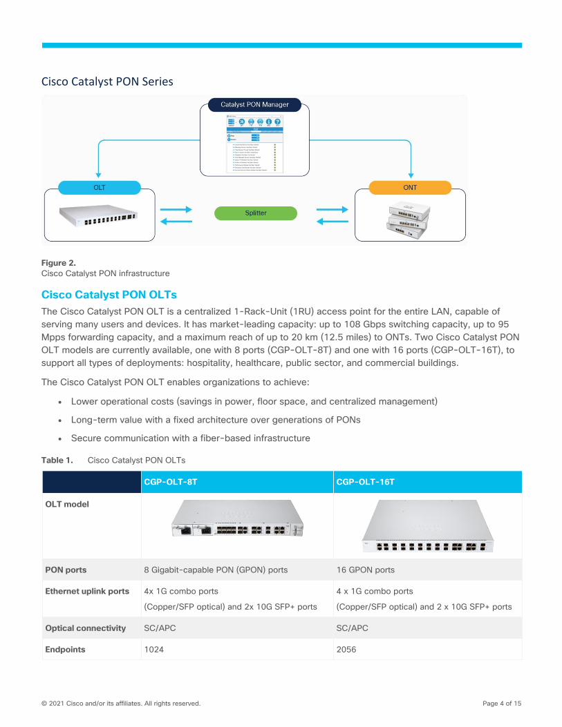
Figure 2.
Cisco Catalyst PON infrastructure
Cisco Catalyst PON OLTs
The Cisco Catalyst PON OLT is a centralized 1-Rack-Unit (1RU) access point for the entire LAN, capable of
serving many users and devices. It has market-leading capacity: up to 108 Gbps switching capacity, up to 95
Mpps forwarding capacity, and a maximum reach of up to 20 km (12.5 miles) to ONTs. Two Cisco Catalyst PON
OLT models are currently available, one with 8 ports (CGP-OLT-8T) and one with 16 ports (CGP-OLT-16T), to
support all types of deployments: hospitality, healthcare, public sector, and commercial buildings.
The Cisco Catalyst PON OLT enables organizations to achieve:
● Lower operational costs (savings in power, floor space, and centralized management)
● Long-term value with a fixed architecture over generations of PONs
● Secure communication with a fiber-based infrastructure
Table 1. Cisco Catalyst PON OLTs
CGP-OLT-8T CGP-OLT-16T
OLT model
PON ports 8 Gigabit-capable PON (GPON) ports 16 GPON ports
Ethernet uplink ports 4x 1G combo ports
(Copper/SFP optical) and 2x 10G SFP+ ports
4 x 1G combo ports
(Copper/SFP optical) and 2 x 10G SFP+ ports
Optical connectivity SC/APC SC/APC
Endpoints 1024 2056
© 2021 Cisco and/or its affiliates. All rights reserved. Page 5 of 15
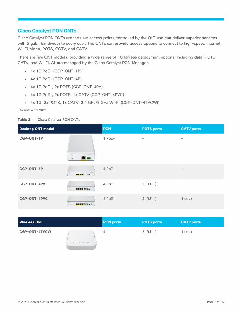
Cisco Catalyst PON ONTs
Cisco Catalyst PON ONTs are the user access points controlled by the OLT and can deliver superior services
with Gigabit bandwidth to every user. The ONTs can provide access options to connect to high-speed internet,
Wi-Fi, video, POTS, CCTV, and CATV.
There are five ONT models, providing a wide range of 1G fanless deployment options, including data, POTS,
CATV, and Wi-Fi. All are managed by the Cisco Catalyst PON Manager.
● 1x 1G PoE+ (CGP-ONT-1P)*
● 4x 1G PoE+ (CGP-ONT-4P)
● 4x 1G PoE+, 2x POTS (CGP-ONT-4PV)
● 4x 1G PoE+, 2x POTS, 1x CATV (CGP-ONT-4PVC)
● 4x 1G, 2x POTS, 1x CATV, 2.4 GHz/5 GHz Wi-Fi (CGP-ONT-4TVCW)*
* Available Q1 2021
Table 2. Cisco Catalyst PON ONTs
Desktop ONT model PON POTS ports CATV ports
CGP-ONT-1P
1 PoE+ – –
CGP-ONT-4P
4 PoE+ – –
CGP-ONT-4PV
4 PoE+ 2 (RJ11) –
CGP-ONT-4PVC
4 PoE+ 2 (RJ11) 1 coax
Wireless ONT PON ports POTS ports CATV ports
CGP-ONT-4TVCW
4 2 (RJ11) 1 coax

© 2021 Cisco and/or its affiliates. All rights reserved. Page 6 of 15
Cisco Catalyst PON Manager
Cisco Catalyst PON Manager is used for remote centralized network management of Cisco Catalyst PON OLT
and ONT devices. The integrated network management system includes a fully graphical interface that is easy
to operate and use.
Figure 3.
Cisco Catalyst PON Manager
Cisco Catalyst PON Manager uses a client/server structure. That is, a server connects with several clients in the
Cisco Catalyst PON Manager. The PON Manager server provides network nodes (OLT or ONT) with data
processing and storage functions. Users can operate and maintain network nodes via the PON Manager client.
The following figure shows the Cisco Catalyst PON Manager hardware architecture.
© 2021 Cisco and/or its affiliates. All rights reserved. Page 7 of 15
Figure 4.
Cisco Catalyst PON Manager architecture
For more information on Cisco Catalyst PON Manager, please visit:
https://www.cisco.com/c/en/us/td/docs/switches/lan/catalyst_pon/overview_guide/b-cisco-catalyst-pon-
manager-overview-guide/overview_guide.html
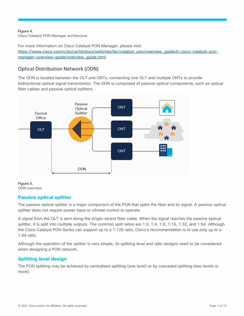
Optical Distribution Network (ODN)
The ODN is located between the OLT and ONTs, connecting one OLT and multiple ONTs to provide
bidirectional optical signal transmission. The ODN is composed of passive optical components, such as optical
fiber cables and passive optical splitters.
Figure 5.
ODN overview
Passive optical splitter
The passive optical splitter is a major component of the PON that splits the fiber and its signal. A passive optical
splitter does not require power input or climate control to operate.
A signal from the OLT is sent along the single-strand fiber cable. When the signal reaches the passive optical
splitter, it is split into multiple outputs. The common split ratios are 1:2, 1:4, 1:8, 1:16, 1:32, and 1:64. Although
the Cisco Catalyst PON Series can support up to a 1:128 ratio, Cisco’s recommendation is to use only up to a
1:64 ratio.
Although the operation of the splitter is very simple, its splitting level and ratio designs need to be considered
when designing a PON network.
Splitting level design
The PON splitting may be achieved by centralized splitting (one level) or by cascaded splitting (two levels or
more).

© 2021 Cisco and/or its affiliates. All rights reserved. Page 8 of 15
Centralized split design
Centralized splitting uses a single-stage splitter in a central hub to provide flexibility in PON management. This
design requires more fiber cables from the splitter to the user locations, but it has the advantage of an easily
accessed testing point.
In a centralized design, the splitter is directly connected via a single fiber to an OLT in the central office. On the
other side of the splitter, 32 fibers are connected to 32 homes using ONTs if a 1:32 or 2:32 splitter is used.
Figure 6.
Centralized optical split design
Table 3. Centralized splitting advantages and disadvantages
Advantages Disadvantages
Better OLT utilization More distribution fiber
Future-ready and flexible PON design Higher CapEx
Easy monitoring and maintenance
Distributed split (cascaded) design
A distributed split (cascaded) design uses multiple splitters in a series to accomplish the overall desired split
ratio. For example, it would use a 1:4 splitter and 1:8 splitters as two splitting levels. This distributed design can
reduce the amount of fiber in the distribution network. However, this design generally has poorer OLT port
utilization, compared to a centralized split architecture.
In the scenario shown in the figure below, the OLT from the central office is connected to a 1:4 splitter. Each of
the four fibers leaving the stage 1 splitter is directed to a 1:8 stage 2 splitter. There will be total of 32 fibers
(4x8) reaching 32 locations.

© 2021 Cisco and/or its affiliates. All rights reserved. Page 9 of 15
Figure 7.
Distributed optical split design
Table 4. Distributed splitting advantages and disadvantages
Advantages Disadvantages
Lower CapEx More actives and more splitters
Less flexible network
Complex monitoring and maintenance
Splitting ratio
The most common optical splitter deployed in a PON is a splitter with a 1:N or 2:N splitting ratio, where N is the
number of output ports. Different splitting ratios will provide different network performance as well as a different
distance between OLT and ONT.
For the highest-capacity bandwidth, connecting a few ONTs to a single PON port could provide a 20-km (12.5-
mile) distance with the full bandwidth of the PON port. Each PON port can provide 2.488 Gbps downstream and
1.244 Gbps upstream.
For the highest capacity of users, a splitter with a 1:128 ratio connected to a PON port could provide 128
clients with equal bandwidth of about 19 Mbps download and 9 Mbps upload when the clients are all within a
range of 8 km (5 miles).

© 2021 Cisco and/or its affiliates. All rights reserved. Page 10 of 15
Cisco Catalyst PON optics
The Cisco Catalyst PON Series supports Class C+ optics to support the maximum acceptable optical power
loss. Class C+ optics can provide a longer reach of 20 km (12.5 miles) with most splitter ratios and can support
a maximum optical loss of -32 dB. Optical power loss of all the ONTs must be within this maximum loss range.
Table 5. PON optic classes
Optical module
OLT ONT Maximum system optical loss (dB)
Transmitted optical power (dbm)
Receiving sensitivity (dB)
Transmitted optical power (dbm)
Receiving sensitivity (dB)
Min Max Min Max Downstream Upstream
Class B+ 1.5 5 -28 0.5 5 -27 28 28
Class C+ 3 7 -32 0.5 5 -30 32 32
Optical power loss
Attenuation is the most important factor in designing a GPON. Knowledge of the following sources of
attenuation and calculation of the optical power level (dBm) is required in designing the PON.
● Upstream length loss (1310 nm): ~0.42 dB per km
● Downstream length loss (1490 nm): ~0.3 dB per km
● Splices loss: ~0.1 dB per splice
● Connectors loss: ~0.3 dB per connector
● Splitter loss: See the table below.
Table 6. Loss calculation per splitter type
Splitter type Loss value (dB)
1×2 3.9
1×4 7.2
1×8 10.5
1×16 13.8
1×32 17.1
1×64 20.1
1×128 23.7
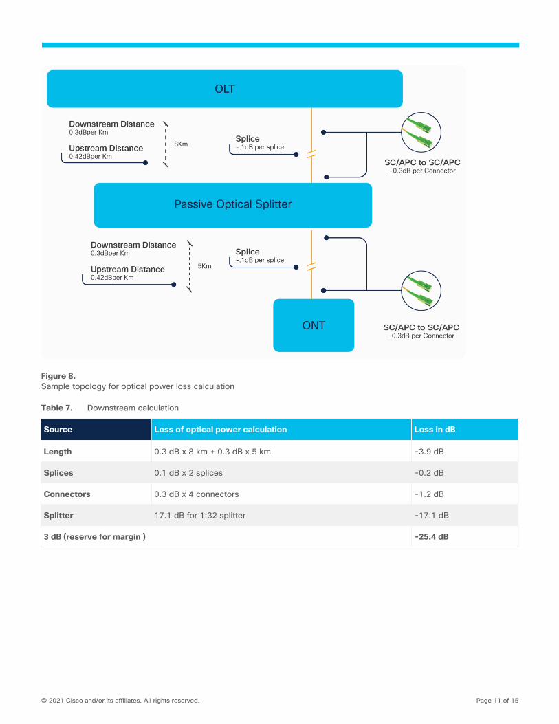
Here is a sample calculation of upstream and downstream optical power loss based on the topology shown in
the figure below. The distance between OLT and ONT is 13 km. Total optical power loss needs to be less than
the maximum supported optical power loss.
© 2021 Cisco and/or its affiliates. All rights reserved. Page 11 of 15
Figure 8.
Sample topology for optical power loss calculation
Table 7. Downstream calculation
Source Loss of optical power calculation Loss in dB
Length 0.3 dB x 8 km + 0.3 dB x 5 km -3.9 dB
Splices 0.1 dB x 2 splices -0.2 dB
Connectors 0.3 dB x 4 connectors -1.2 dB
Splitter 17.1 dB for 1:32 splitter -17.1 dB
3 dB (reserve for margin ) -25.4 dB
© 2021 Cisco and/or its affiliates. All rights reserved. Page 12 of 15
Table 8. Upstream calculation
Source Loss of optical power calculation Loss in dB
Length 0.42 dB x 8 km + 0.4 2dB x 5 km -5.46 dB
Splices 0.1 dB x 2 splices -0.2 dB
Connectors 0.3 dB x 4 connectors -1.2 dB
Splitter 17.1 dB for 1:32 splitter -17.1 dB
3 dB (reserve for margin ) -26.96 dB
Both the upstream and downstream signals are within the acceptable range of maximum optical loss of 32 dB
with Class C+ optics.
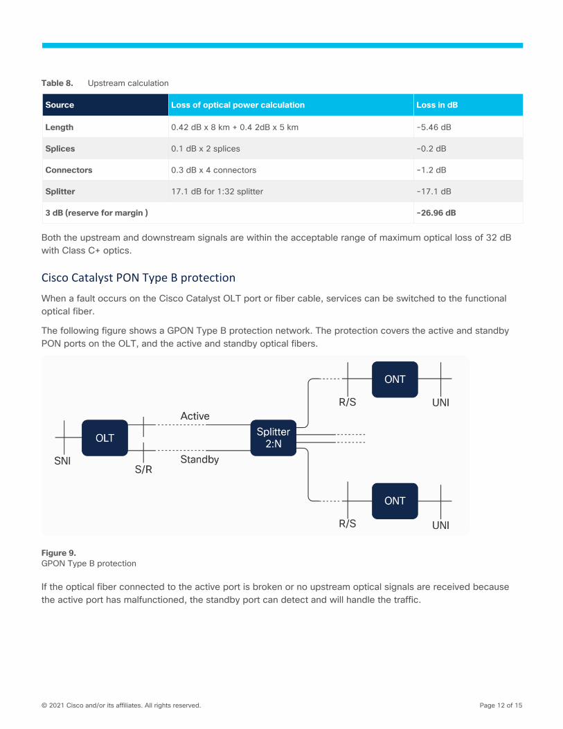
Cisco Catalyst PON Type B protection
When a fault occurs on the Cisco Catalyst OLT port or fiber cable, services can be switched to the functional
optical fiber.
The following figure shows a GPON Type B protection network. The protection covers the active and standby
PON ports on the OLT, and the active and standby optical fibers.
Figure 9.
GPON Type B protection
If the optical fiber connected to the active port is broken or no upstream optical signals are received because
the active port has malfunctioned, the standby port can detect and will handle the traffic.

© 2021 Cisco and/or its affiliates. All rights reserved. Page 13 of 15
Packet walks
Downstream traffic
Figure 10.
PON downstream traffic
1. OLT sends Ethernet frames to the GPON service processing module within the OLT based on
configured mapping rules between upstream data ports and OLT uplink ports.
2. GPON service processing module then encapsulates the Ethernet frames into GPON Encapsulation
Method (GEM) Packet Data Units (PDUs) for downstream transmission using a PON port.
3. GPON Transmission Convergence (GTC) frames containing GEM PDUs are broadcast to all ONTs
connected to the PON port.
4. ONT filters the received data according to the GEM port ID contained in the GEM PDU header and
retains only the data belonging to the GEM ports of this ONT.
5. ONT decapsulates the data to Ethernet frames and sends them to end users using ONT data ports.
© 2021 Cisco and/or its affiliates. All rights reserved. Page 14 of 15
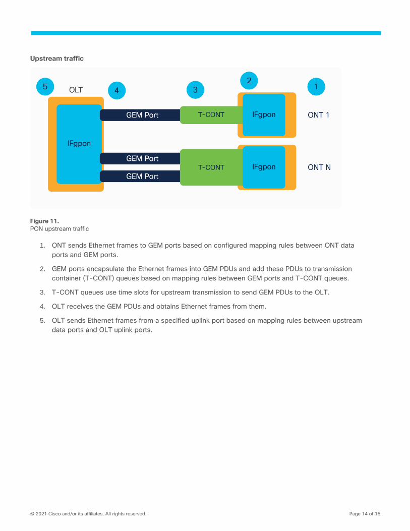
Upstream traffic
Figure 11.
PON upstream traffic
1. ONT sends Ethernet frames to GEM ports based on configured mapping rules between ONT data
ports and GEM ports.
2. GEM ports encapsulate the Ethernet frames into GEM PDUs and add these PDUs to transmission
container (T-CONT) queues based on mapping rules between GEM ports and T-CONT queues.
3. T-CONT queues use time slots for upstream transmission to send GEM PDUs to the OLT.
4. OLT receives the GEM PDUs and obtains Ethernet frames from them.
5. OLT sends Ethernet frames from a specified uplink port based on mapping rules between upstream
data ports and OLT uplink ports.

© 2021 Cisco and/or its affiliates. All rights reserved. Page 15 of 15
Summary
Catalyst PON Series switches are the industry’s all-optical solution with differentiated resiliency and progressive
architecture for cost-effective optical network access.
Cisco Catalyst PON OLT products are compact, high-density network aggregation devices, meeting the
requirements of ITU-T G.984 and relative GPON standards, with high access capacity, carrier-class reliability,
and powerful security functions.
Cisco Catalyst PON ONT products provide access for comprehensive services, including high-speed internet,
video, VoIP, CCTV, and CATV to subscribers in FTTx applications with powerful interoperability and stability.
Cisco Catalyst PON Series switches make refreshing your passive optical network easy. With enterprise-grade
features such as power and uplink redundancy, PoE+, and sensitivity to cost and ease of operations, the Cisco
Catalyst PON Series gives you what you need today with the confidence that your investment is protected with
future innovations to come.
Printed in USA C11-744796-00 03/21