Embed Size (px)
Citation preview
Cisco Catalyst 9300 Series Switches Hardware Installation GuideFirst Published: 2017-06-20
Last Modified: 2018-07-25
Americas HeadquartersCisco Systems, Inc.170 West Tasman DriveSan Jose, CA 95134-1706USAhttp://www.cisco.comTel: 408 526-4000
800 553-NETS (6387)Fax: 408 527-0883
C O N T E N T S
Preface ixP R E F A C E
Document Conventions ix
Related Documentation xi
Obtaining Documentation and Submitting a Service Request xi
Product Overview 1C H A P T E R 1
Switch Models 1
Front Panel Components 2
10/100/1000 Ports 4
PoE, PoE+, and Cisco UPoE Ports 4
Multigigabit ports 5
Management Ports 5
USB Type A Port 6
Network Modules 6
LEDs 7
USB Console LED 7
System LED 8
Active LED 8
STACK LED 8
PoE LED 9
XPS LED 10
S-PWR LED 10
Port LEDs and Modes 11
Beacon LED 13
Network Module LEDs 13
Cisco Catalyst 9300 Series Switches Hardware Installation Guideii
Contents
Rear Panel 14
RFID Tag 14
RJ-45 Console Port LED 15
StackWise Ports 15
Power Supply Modules 15
Fan Module 17
StackPower Connector 18
USB 3.0 SSD Port 18
Ethernet Management Port 18
RJ-45 Console Port 18
Network Configurations 19
Switch Installation 21C H A P T E R 2
Preparing for Installation 21
Safety Warnings 21
Installation Guidelines 23
Shipping Box Contents 24
Tools and Equipment 25
Verifying Switch Operation 25
Planning a Switch Data Stack 25
Switch Stacking and Power Stacking Guidelines 26
Data Stack Cabling Configurations 26
Data Stack Bandwidth and Partitioning Examples 26
Power-On Sequence for Switch Stacks 28
Planning a StackPower Stack 29
StackPower Stacking Guidelines 29
StackPower Cabling Configurations 29
StackPower Partitioning Examples 31
Installing the Switch 32
Rack-Mounting 32
Attaching the Rack-Mount Brackets 34
Mounting the Switch a Rack 34
Installing the Switch on a Table or Shelf 35
After Switch Installation 35
Cisco Catalyst 9300 Series Switches Hardware Installation Guideiii
Contents
Connecting to the StackWise Ports 36
Connecting to the StackPower Ports 38
Installing a Network Module in the Switch 38
Installing and Removing SFP, SFP+, SFP28 and QSFP+ Modules 38
Connecting Devices to the Ethernet Ports 38
10/100/1000 Port Connections 39
Auto-MDIX Connections 39
PoE+ and Cisco UPOE Port Connections 39
Installing a Network Module 41C H A P T E R 3
Network Modules Overview 41
Installing a Network Module in the Switch 42
Safety Warnings 42
Equipment That You Need 42
Installing Network Modules 43
Network Module Port Configurations 45
C9300-NM-2Q Module 45
C9300-NM-4G Module 46
C9300-NM-4M Module 46
C9300-NM-2Y Module 46
C9300-NM-8X Module 47
C3850-NM-4-1G Module 47
C3850-NM-4-10G Module 48
C3850-NM-2-10G Module 48
C3850-NM-8-10G Module 49
C3850-NM-2-40G Module 49
Removing a Network Module 50
SFP, SFP+ and SFP28 Modules 51
Installing SFP, SFP+ and SFP28 Modules 51
Removing SFP, SFP+ and SFP28 Modules 53
Finding the Network Module Serial Number 53
Installing a Power Supply 55C H A P T E R 4
Power Supply Modules Overview 55
Cisco Catalyst 9300 Series Switches Hardware Installation Guideiv
Contents
Installation Guidelines 57
Installing or Replacing an AC Power Supply 59
Finding the Power Supply Module Serial Number 60
Installing a Fan Module 63C H A P T E R 5
Fan Modules Overview 63
Installation Guidelines 64
Installing a Fan Module 64
Finding the Fan Module Serial Number 65
Installing a USB 3.0 SSD 67C H A P T E R 6
USB 3.0 SSD Overview 67
Installing an SSD-120G 68
Configuring the Switch 69C H A P T E R 7
Configuring the Switch Using the Web User Interface 69
Setting up the Switch 69
Connecting to the Switch 69
Creating User Accounts 70
Choosing Setup Options 72
Configuring Basic Device Settings 72
Configuring Your Device Based on a Site Profile 74
Configuring Switch Wide Settings 83
Configuring VLAN Settings 83
Configure STP Settings 84
Configuring DHCP, NTP, DNS and SNMP Settings 85
Configuring Port Settings 87
Configuring the Switch Using the CLI 89
Accessing the CLI Through the Console Port 89
Connecting the RJ-45 Console Port 90
Connecting the USB Console Port 90
Installing the Cisco Microsoft Windows USB Device Driver 91
Installing the Cisco Microsoft Windows XP USB Driver 91
Installing the Cisco Microsoft Windows 2000 USB Driver 92
Cisco Catalyst 9300 Series Switches Hardware Installation Guidev
Contents
Installing the Cisco Microsoft Windows Vista and Windows 7 USB Driver 92
Uninstalling the Cisco Microsoft Windows USB Driver 92
Uninstalling the Cisco Microsoft Windows XP and 2000 USB Driver 92
Uninstalling the Cisco Microsoft Windows Vista and Windows 7 USB Driver 93
Technical Specifications 95A P P E N D I X A
Environmental and Physical Specifications 95
Specifications for the Power Supplies, Switches, and Fan 97
Connector and Cable Specifications 101A P P E N D I X B
Connector Specifications 101
10/100/1000 Ports (Including PoE) 101
SFP Module Connectors 101
Console Port 102
Cables and Adapters 103
StackWise Cables 103
SFP Module Cables 103
Cable Pinouts 104
Console Port Adapter Pinouts 105
Cisco Catalyst 9300 Series Switches Hardware Installation Guidevi
Contents

THE SPECIFICATIONS AND INFORMATION REGARDING THE PRODUCTS IN THIS MANUAL ARE SUBJECT TO CHANGE WITHOUT NOTICE. ALL STATEMENTS,INFORMATION, AND RECOMMENDATIONS IN THIS MANUAL ARE BELIEVED TO BE ACCURATE BUT ARE PRESENTED WITHOUT WARRANTY OF ANY KIND,EXPRESS OR IMPLIED. USERS MUST TAKE FULL RESPONSIBILITY FOR THEIR APPLICATION OF ANY PRODUCTS.
THE SOFTWARE LICENSE AND LIMITED WARRANTY FOR THE ACCOMPANYING PRODUCT ARE SET FORTH IN THE INFORMATION PACKET THAT SHIPPED WITHTHE PRODUCT AND ARE INCORPORATED HEREIN BY THIS REFERENCE. IF YOU ARE UNABLE TO LOCATE THE SOFTWARE LICENSE OR LIMITED WARRANTY,CONTACT YOUR CISCO REPRESENTATIVE FOR A COPY.
The following information is for FCC compliance of Class A devices: This equipment has been tested and found to comply with the limits for a Class A digital device, pursuant to part 15of the FCC rules. These limits are designed to provide reasonable protection against harmful interference when the equipment is operated in a commercial environment. This equipmentgenerates, uses, and can radiate radio-frequency energy and, if not installed and used in accordance with the instruction manual, may cause harmful interference to radio communications.Operation of this equipment in a residential area is likely to cause harmful interference, in which case users will be required to correct the interference at their own expense.
The following information is for FCC compliance of Class B devices: This equipment has been tested and found to comply with the limits for a Class B digital device, pursuant to part 15 ofthe FCC rules. These limits are designed to provide reasonable protection against harmful interference in a residential installation. This equipment generates, uses and can radiate radiofrequency energy and, if not installed and used in accordance with the instructions, may cause harmful interference to radio communications. However, there is no guarantee that interferencewill not occur in a particular installation. If the equipment causes interference to radio or television reception, which can be determined by turning the equipment off and on, users areencouraged to try to correct the interference by using one or more of the following measures:
• Reorient or relocate the receiving antenna.
• Increase the separation between the equipment and receiver.
• Connect the equipment into an outlet on a circuit different from that to which the receiver is connected.
• Consult the dealer or an experienced radio/TV technician for help.
Modifications to this product not authorized by Cisco could void the FCC approval and negate your authority to operate the product
The Cisco implementation of TCP header compression is an adaptation of a program developed by the University of California, Berkeley (UCB) as part of UCB’s public domain version ofthe UNIX operating system. All rights reserved. Copyright © 1981, Regents of the University of California.
NOTWITHSTANDING ANY OTHERWARRANTY HEREIN, ALL DOCUMENT FILES AND SOFTWARE OF THESE SUPPLIERS ARE PROVIDED "AS IS" WITH ALL FAULTS.CISCO AND THE ABOVE-NAMED SUPPLIERS DISCLAIM ALL WARRANTIES, EXPRESSED OR IMPLIED, INCLUDING, WITHOUT LIMITATION, THOSE OFMERCHANTABILITY, FITNESS FOR A PARTICULAR PURPOSE AND NONINFRINGEMENT OR ARISING FROM A COURSE OF DEALING, USAGE, OR TRADE PRACTICE.
IN NO EVENT SHALL CISCO OR ITS SUPPLIERS BE LIABLE FOR ANY INDIRECT, SPECIAL, CONSEQUENTIAL, OR INCIDENTAL DAMAGES, INCLUDING, WITHOUTLIMITATION, LOST PROFITS OR LOSS OR DAMAGE TO DATA ARISING OUT OF THE USE OR INABILITY TO USE THIS MANUAL, EVEN IF CISCO OR ITS SUPPLIERSHAVE BEEN ADVISED OF THE POSSIBILITY OF SUCH DAMAGES.
Any Internet Protocol (IP) addresses and phone numbers used in this document are not intended to be actual addresses and phone numbers. Any examples, command display output, networktopology diagrams, and other figures included in the document are shown for illustrative purposes only. Any use of actual IP addresses or phone numbers in illustrative content is unintentionaland coincidental.
Cisco and the Cisco logo are trademarks or registered trademarks of Cisco and/or its affiliates in the U.S. and other countries. To view a list of Cisco trademarks, go to this URL: www.cisco.comgo trademarks. Third-party trademarks mentioned are the property of their respective owners. The use of the word partner does not imply a partnership relationship between Cisco and anyother company. (1721R)
© 2017 Cisco Systems, Inc. All rights reserved.

Preface
• Document Conventions , on page ix• Related Documentation, on page xi• Obtaining Documentation and Submitting a Service Request, on page xi
Document ConventionsThis document uses the following conventions:
DescriptionConvention
Both the ^ symbol and Ctrl represent the Control (Ctrl) key on a keyboard. Forexample, the key combination ^D orCtrl-Dmeans that you hold down the Controlkey while you press the D key. (Keys are indicated in capital letters but are notcase sensitive.)
^ or Ctrl
Commands and keywords and user-entered text appear in bold font.bold font
Document titles, new or emphasized terms, and arguments for which you supplyvalues are in italic font.
Italic font
Terminal sessions and information the system displays appear in courier font.Courier font
Bold Courier font indicates text that the user must enter.Bold Courier font
Elements in square brackets are optional.[x]
An ellipsis (three consecutive nonbolded periods without spaces) after a syntaxelement indicates that the element can be repeated.
...
A vertical line, called a pipe, indicates a choice within a set of keywords orarguments.
|
Optional alternative keywords are grouped in brackets and separated by verticalbars.
[x | y]
Required alternative keywords are grouped in braces and separated by verticalbars.
{x | y}
Cisco Catalyst 9300 Series Switches Hardware Installation Guideix
DescriptionConvention
Nested set of square brackets or braces indicate optional or required choices withinoptional or required elements. Braces and a vertical bar within square bracketsindicate a required choice within an optional element.
[x {y | z}]
A nonquoted set of characters. Do not use quotation marks around the string orthe string will include the quotation marks.
string
Nonprinting characters such as passwords are in angle brackets.< >
Default responses to system prompts are in square brackets.[ ]
An exclamation point (!) or a pound sign (#) at the beginning of a line of codeindicates a comment line.
!, #
Reader Alert Conventions
This document may use the following conventions for reader alerts:
Means reader take note. Notes contain helpful suggestions or references to material not covered in the manual.Note
Means the following information will help you solve a problem.Tip
Means reader be careful. In this situation, you might do something that could result in equipment damage orloss of data.
Caution
Means the described action saves time.You can save time by performing the action described in the paragraph.Timesaver
IMPORTANT SAFETY INSTRUCTIONS
This warning symbol means danger. You are in a situation that could cause bodily injury. Before you workon any equipment, be aware of the hazards involved with electrical circuitry and be familiar with standardpractices for preventing accidents. Use the statement number provided at the end of each warning to locateits translation in the translated safety warnings that accompanied this device. Statement 1071
SAVE THESE INSTRUCTIONS
Warning
Cisco Catalyst 9300 Series Switches Hardware Installation Guidex
PrefacePreface
Related Documentation
Before installing or upgrading the switch, refer to the switch Release Notes.Note
• Cisco Catalyst 9300 Series Switches documentation, located at: http://www.cisco.com/go/c9300
• Cisco SFP and SFP+ modules documentation, including compatibility matrixes, located at:
http://www.cisco.com/en/US/products/hw/modules/ps5455/tsd_products_support_series_home.html
• Cisco Validated Designs documents, located at:
http://www.cisco.com/go/designzone
Obtaining Documentation and Submitting a Service RequestFor information on obtaining documentation, submitting a service request, and gathering additional information,see the monthlyWhat's New in Cisco Product Documentation, which also lists all new and revised Ciscotechnical documentation, at:
http://www.cisco.com/c/en/us/td/docs/general/whatsnew/whatsnew.html
Subscribe to theWhat's New in Cisco Product Documentation as a Really Simple Syndication (RSS) feedand set content to be delivered directly to your desktop using a reader application. The RSS feeds are a freeservice and Cisco currently supports RSS version 2.0.
Cisco Catalyst 9300 Series Switches Hardware Installation Guidexi
PrefaceRelated Documentation

Cisco Catalyst 9300 Series Switches Hardware Installation Guidexii
PrefaceObtaining Documentation and Submitting a Service Request
C H A P T E R 1Product Overview
Cisco Catalyst 9300 Series Switches family is the stackable enterprise switching platform built for Security,IoT, Mobility, and Cloud. It has the most flexible uplink architecture with support for 1G, 10G, and 40G.
Cisco Catalyst 9300 Series Switches provide support for the following features:
• 24 and 48 10/100/1000M downlink ports with data, PoE+, and Cisco UPOE support
• 24 and 48 100Mbps/1/2.5/5/10Gbps ports with Cisco UPOE support
• Uplink modules with 1G, 10G, 25G, 40G and Multigigabit slots
• Advanced security capabilities like Encrypted Traffic Analytics (ETA), AES-256 MACSEC encryption,and TrustWorthy systems
• Local back-panel stacking bandwidth solution (480G) with Stackwise-480
• Intelligent PowerManagement with StackPower technology that provides power stacking amongmembersfor power redundancy
• IoT integration and policy-based automation from the edge to the cloud with SD-Access solution
• RJ-45 and USB Mini-Type B console ports
• Switch Models, on page 1• Front Panel Components, on page 2• Rear Panel, on page 14• Network Configurations, on page 19
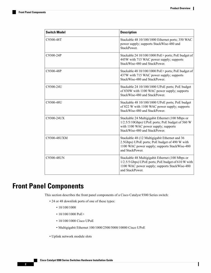
Switch ModelsTable 1: Cisco Catalyst 9300 Series Switches Models and Descriptions
DescriptionSwitch Model
Stackable 24 10/100/1000 Ethernet ports; 350 WACpower supply; supports StackWise-480 andStackPower.
C9300-24T
Cisco Catalyst 9300 Series Switches Hardware Installation Guide1
DescriptionSwitch Model
Stackable 48 10/100/1000 Ethernet ports; 350 WACpower supply; supports StackWise-480 andStackPower.
C9300-48T
Stackable 24 10/100/1000 PoE+ ports; PoE budget of445W with 715 WAC power supply; supportsStackWise-480 and StackPower.
C9300-24P
Stackable 48 10/100/1000 PoE+ ports; PoE budget of437W with 715 WAC power supply; supportsStackWise-480 and StackPower.
C9300-48P
Stackable 24 10/100/1000 UPoE ports; PoE budgetof 830W with 1100 WAC power supply; supportsStackWise-480 and StackPower.
C9300-24U
Stackable 48 10/100/1000 UPoE ports; PoE budgetof 822 W with 1100 WAC power supply; supportsStackWise-480 and StackPower.
C9300-48U
Stackable 24 Multigigabit Ethernet (100 Mbps or1/2.5/5/10Gbps) UPoE ports; PoE budget of 560 Wwith 1100 WAC power supply; supportsStackWise-480 and StackPower.
C9300-24UX
Stackable 48 (12 Multigigabit Ethernet and 362.5Gbps) UPoE ports; PoE budget of 490 W with1100 WAC power supply; supports StackWise-480and StackPower.
C9300-48UXM
Stackable 48 Multigigabit Ethernet (100 Mbps or1/2.5/5 Gbps) UPoE ports; PoE budget of 610Wwith1100 WAC power supply; supports StackWise-480and StackPower.
C9300-48UN
Front Panel ComponentsThis section describes the front panel components of a Cisco Catalyst 9300 Series switch:
• 24 or 48 downlink ports of one of these types:
• 10/100/1000
• 10/100/1000 PoE+
• 10/100/1000 Cisco UPoE
• Multigigabit Ethernet 100/1000/2500/5000/10000 Cisco UPoE
• Uplink network module slots
Cisco Catalyst 9300 Series Switches Hardware Installation Guide2
Product OverviewFront Panel Components
• USB Type A connector
• USB mini-Type B (console) port
• LEDs
• Mode button
• Beacon LED (UID button)
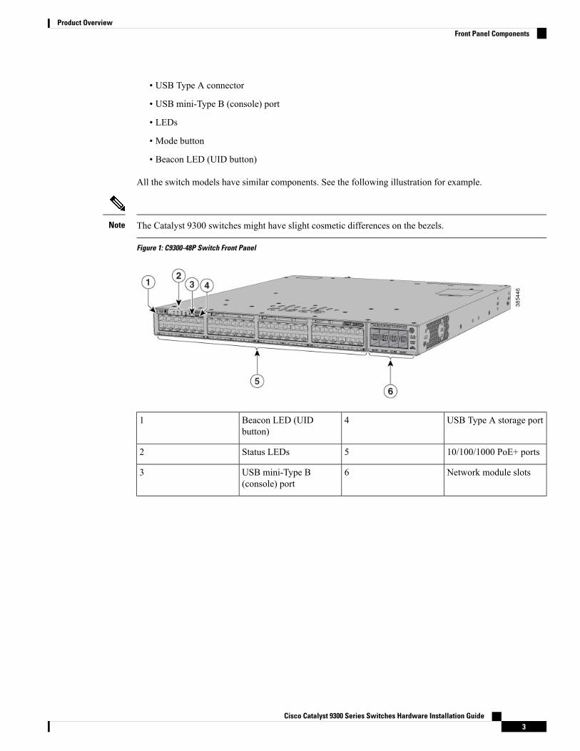
All the switch models have similar components. See the following illustration for example.
The Catalyst 9300 switches might have slight cosmetic differences on the bezels.Note
Figure 1: C9300-48P Switch Front Panel
USB Type A storage port4Beacon LED (UIDbutton)
1
10/100/1000 PoE+ ports5Status LEDs2
Network module slots6USB mini-Type B(console) port
3
Cisco Catalyst 9300 Series Switches Hardware Installation Guide3
Product OverviewFront Panel Components
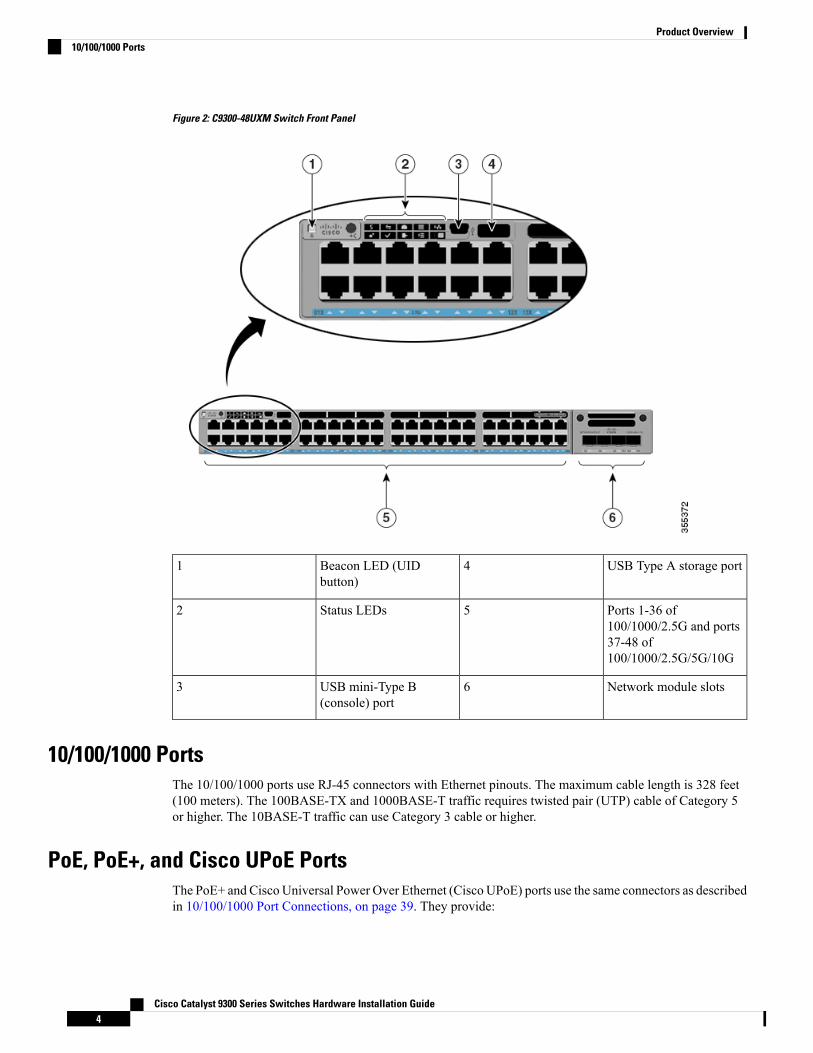
Figure 2: C9300-48UXM Switch Front Panel
USB Type A storage port4Beacon LED (UIDbutton)
1
Ports 1-36 of100/1000/2.5G and ports37-48 of100/1000/2.5G/5G/10G
5Status LEDs2
Network module slots6USB mini-Type B(console) port
3
10/100/1000 PortsThe 10/100/1000 ports use RJ-45 connectors with Ethernet pinouts. The maximum cable length is 328 feet(100 meters). The 100BASE-TX and 1000BASE-T traffic requires twisted pair (UTP) cable of Category 5or higher. The 10BASE-T traffic can use Category 3 cable or higher.
PoE, PoE+, and Cisco UPoE PortsThe PoE+ and Cisco Universal Power Over Ethernet (Cisco UPoE) ports use the same connectors as describedin 10/100/1000 Port Connections, on page 39. They provide:
Cisco Catalyst 9300 Series Switches Hardware Installation Guide4
Product Overview10/100/1000 Ports
• PoE+ ports: Support for IEEE 802.3af-compliant powered devices (up to 15.4 W PoE per port) andsupport for IEEE 802.3at-compliant powered devices (up to 30 W PoE+ per port).
• Support for pre-standard Cisco powered devices.
• Support Cisco UPOE powered devices (up to 60W PoE per port). The maximum total PoE power in a1RU switch is 1800W.
• Configuration for StackPower. When the switch internal power supply module(s) cannot support thetotal load, StackPower configurations allow the switch to leverage power available from other switches.
• Configurable support for Cisco intelligent power management, including enhanced power negotiation,power reservation, and per-port power policing.
See the Power Supply Modules, on page 15 for the power supply matrix that defines the available PoE, PoE+,and Cisco UPOE power per port. The output of the PoE+ or UPOE circuit has been evaluated as a LimitedPower Source (LPS) per IEC 60950-1.
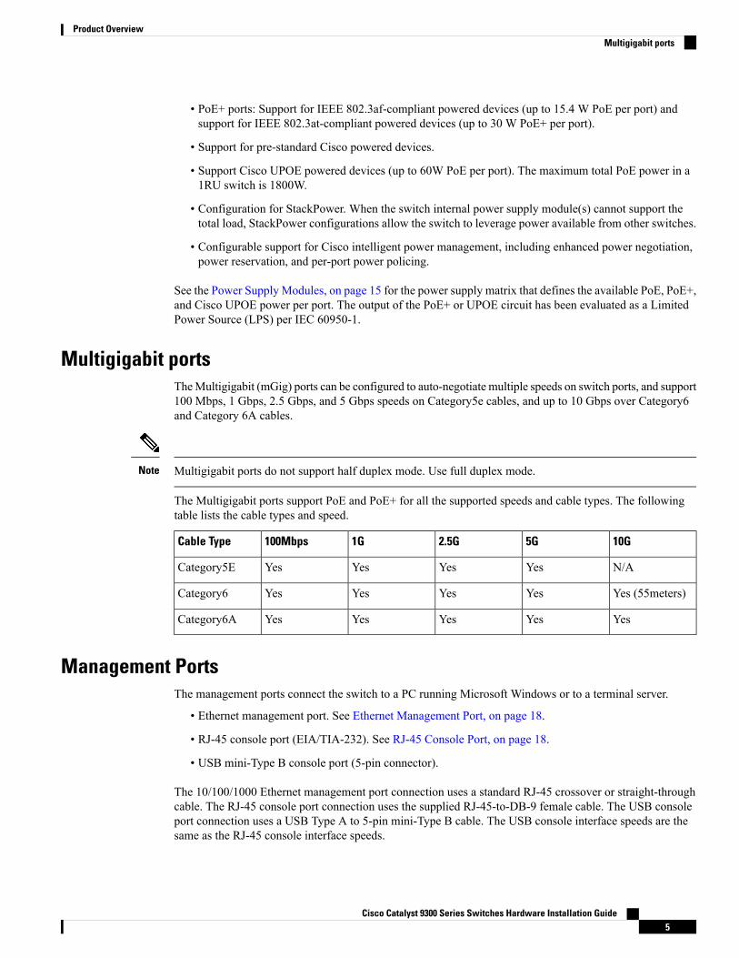
Multigigabit portsTheMultigigabit (mGig) ports can be configured to auto-negotiate multiple speeds on switch ports, and support100 Mbps, 1 Gbps, 2.5 Gbps, and 5 Gbps speeds on Category5e cables, and up to 10 Gbps over Category6and Category 6A cables.
Multigigabit ports do not support half duplex mode. Use full duplex mode.Note
The Multigigabit ports support PoE and PoE+ for all the supported speeds and cable types. The followingtable lists the cable types and speed.
10G5G2.5G1G100MbpsCable Type
N/AYesYesYesYesCategory5E
Yes (55meters)YesYesYesYesCategory6
YesYesYesYesYesCategory6A
Management PortsThe management ports connect the switch to a PC running Microsoft Windows or to a terminal server.
• Ethernet management port. See Ethernet Management Port, on page 18.
• RJ-45 console port (EIA/TIA-232). See RJ-45 Console Port, on page 18.
• USB mini-Type B console port (5-pin connector).
The 10/100/1000 Ethernet management port connection uses a standard RJ-45 crossover or straight-throughcable. The RJ-45 console port connection uses the supplied RJ-45-to-DB-9 female cable. The USB consoleport connection uses a USB Type A to 5-pin mini-Type B cable. The USB console interface speeds are thesame as the RJ-45 console interface speeds.
Cisco Catalyst 9300 Series Switches Hardware Installation Guide5
Product OverviewMultigigabit ports
If you use the USB mini-Type B console port, the Cisco Windows USB device driver must be installed onany PC connected to the console port (for operation with Microsoft Windows). Mac OS X or Linux do notrequire special drivers.
The 4-pin mini-Type B connector resembles the 5-pin mini-Type B connectors. They are not compatible. Useonly the 5-pin mini-Type B.Figure 3: USB Mini-Type B Port
This illustration shows a 5-pin mini-Type B USB port.
With the CiscoWindows USB device driver, you can connect and disconnect the USB cable from the consoleport without affecting Windows HyperTerminal operations.
The console output always goes to both the RJ-45 and the USB console connectors, but the console input isactive on only one of the console connectors at any one time. The USB console takes precedence over theRJ-45 console.When a cable is connected into the USB console port, the RJ-45 console port becomes inactive.Conversely, when the USB cable is disconnected from the USB console port, the RJ-45 port becomes active.
You can use the command-line interface (CLI) to configure an inactivity timeout which reactivates the RJ-45console if the USB console has been activated and no input activity has occurred on the USB console for aspecified time.
After the USB console deactivates due to inactivity, you cannot use the CLI to reactivate it. Disconnect andreconnect the USB cable to reactivate the USB console. For information on using the CLI to configure theUSB console interface, see the Software Configuration Guide.
USB Type A PortThe USB Type A port provides access to external USB flash devices (also known as thumb drives or USBkeys).
The port supports Cisco USB flash drives with capacities from 128 MB to 8 GB (USB devices with portdensities of 128 MB, 256 MB, 1 GB, 4 GB, and 8 GB are supported). When combined with stacking, you canupgrade other switches in the stack from an USB key inserted in any switch within the stack. Cisco IOSsoftware provides standard file system access to the flash device: read, write, erase, and copy, as well as theability to format the flash device with a FAT file system.
It provides you with the ability to automatically upgrade the internal flash with the USB drive's configurationand image for emergency switch recovery using USB auto-upgrade. This feature checks the internal flash fora bootable image and configuration and if either image or the configuration is not available, then the USBdrive is checked for boot images and configuration. If the boot image and configuration are available, theseare copied to flash for the reboot.
Network ModulesThe switch supports one hot-swappable network module that provides uplink ports to connect to other devices.The switch should only be operated with either a network module or a blank module installed.
The switch generates logs when you insert or remove a network module with SFP/SFP+/SFP28 ports.
Cisco Catalyst 9300 Series Switches Hardware Installation Guide6
Product OverviewUSB Type A Port
The following table lists the optional Cisco Catalyst 9300 uplink network modules with 1-Gigabit, 10-Gigabitand 25-Gigabit slots. In addition, Cisco Catalyst 9300 Series switches also support 3850 uplink networkmodules. For the complete list of supported network modules, see Network Modules Overview, on page 41.
Table 2: Network Modules
DescriptionNetwork Module1
This module has four 1G SFP module slots. Any combination of standard SFPmodules are supported. SFP+ modules are not supported.
If you insert an SFP+ module in the 1G network module, the SFP+ module doesnot operate, and the switch logs an error message.
C9300-NM-4G
This module has eight 10G slots with an SFP+ port in each slot. Each port supportsa 1G or 10G connection.
Any combination of SFP and SFP+ modules are supported.
C9300-NM-8X
This module has two 40G slots with a QSFP+ connector in each slot.C9300-NM-2Q
This module has four Multigigabit (mGig) module slots.C9300-NM-4M
This module has two 25 Gigabit Ethernet SFP28 module slots.
Any combination of SFP, SFP+ and SFP28 modules are supported.
C9300-NM-2Y
Insert this blank module when the switch has no uplink ports (this is required forsufficient air flow).
C9300-NM-BLANK
1 All network modules are hot-swappable.
For information about the network modules, see the Installing a Network Module in the Switch, on page 42.For cable specifications, see Cables and Adapters, on page 103.
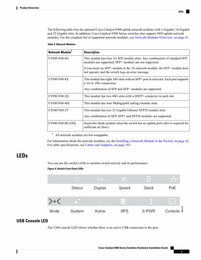
LEDsYou can use the switch LEDs to monitor switch activity and its performance.Figure 4: Switch Front Panel LEDs
USB Console LEDThe USB console LED shows whether there is an active USB connection to the port.
Cisco Catalyst 9300 Series Switches Hardware Installation Guide7
Product OverviewLEDs
Table 3: USB Console LED
DescriptionColorLED
USB console port is active.GreenUSB console port
The USB is disabled.Off
System LED
Table 4: System LED
System StatusColor
System is not powered on.Off
System is operating normally.Green
System is loading the software.Blinking green
System is receiving power but is not functioningproperly.
Amber
There is a fault with one of the following:
• Network module (non traffic-related)• Power supply• Fan module
Blinking amber
Active LED
Table 5: Active LED
DescriptionColor
Switch is not the active switch.Off
Switch is the active switch or a standalone switch.Green
Switch is in stack standby mode.Slow blinking green
An error occurred when the switch was selecting the active switch, or another typeof stack error occurred.
Amber
STACK LEDThe STACK LED shows the sequence of member switches in a stack. Up to eight switches can be membersof a stack. The first eight port LEDs show the member number of a switch in a stack.Figure 5: STACK LED
This figure shows the LEDs on for each switch. When you press the Mode button to select the STACK LED,the corresponding port LEDs will blink green for each switch. For example, for switch 1, port 1 will blink
Cisco Catalyst 9300 Series Switches Hardware Installation Guide8
Product OverviewSystem LED
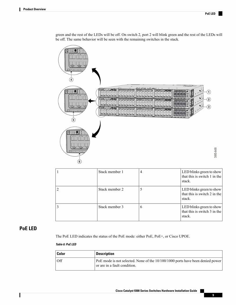
green and the rest of the LEDs will be off. On switch 2, port 2 will blink green and the rest of the LEDs willbe off. The same behavior will be seen with the remaining switches in the stack.
LED blinks green to showthat this is switch 1 in thestack.
4Stack member 11
LED blinks green to showthat this is switch 2 in thestack.
5Stack member 22
LED blinks green to showthat this is switch 3 in thestack.
6Stack member 33
PoE LEDThe PoE LED indicates the status of the PoE mode: either PoE, PoE+, or Cisco UPOE.
Table 6: PoE LED
DescriptionColor
PoE mode is not selected. None of the 10/100/1000 ports have been denied poweror are in a fault condition.
Off
Cisco Catalyst 9300 Series Switches Hardware Installation Guide9
Product OverviewPoE LED
DescriptionColor
PoE mode is selected, and the port LEDs show the PoE mode status.Green
PoE mode is not selected. At least one of the 10/100/1000 ports has been deniedpower, or at least one of the 10/100/1000 ports has a PoE mode fault.
Blinking amber
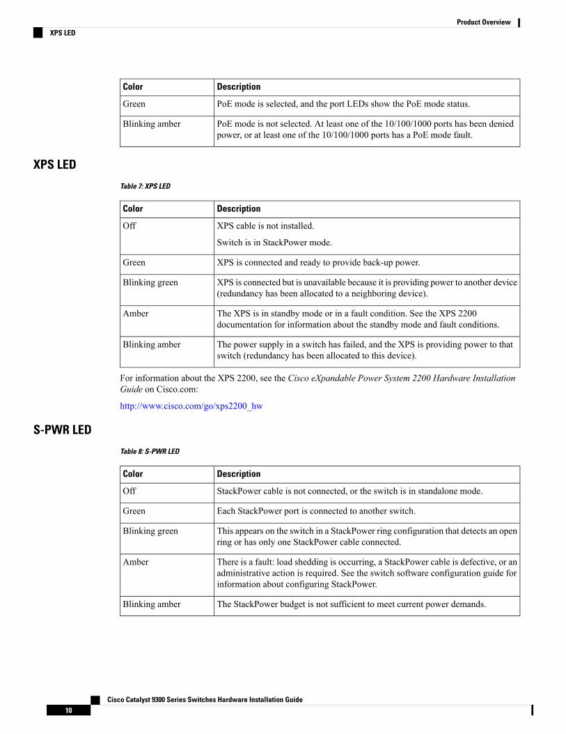
XPS LED
Table 7: XPS LED
DescriptionColor
XPS cable is not installed.
Switch is in StackPower mode.
Off
XPS is connected and ready to provide back-up power.Green
XPS is connected but is unavailable because it is providing power to another device(redundancy has been allocated to a neighboring device).
Blinking green
The XPS is in standby mode or in a fault condition. See the XPS 2200documentation for information about the standby mode and fault conditions.
Amber
The power supply in a switch has failed, and the XPS is providing power to thatswitch (redundancy has been allocated to this device).
Blinking amber
For information about the XPS 2200, see the Cisco eXpandable Power System 2200 Hardware InstallationGuide on Cisco.com:
http://www.cisco.com/go/xps2200_hw
S-PWR LED
Table 8: S-PWR LED
DescriptionColor
StackPower cable is not connected, or the switch is in standalone mode.Off
Each StackPower port is connected to another switch.Green
This appears on the switch in a StackPower ring configuration that detects an openring or has only one StackPower cable connected.
Blinking green
There is a fault: load shedding is occurring, a StackPower cable is defective, or anadministrative action is required. See the switch software configuration guide forinformation about configuring StackPower.
Amber
The StackPower budget is not sufficient to meet current power demands.Blinking amber
Cisco Catalyst 9300 Series Switches Hardware Installation Guide10
Product OverviewXPS LED
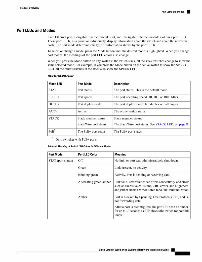
Port LEDs and ModesEach Ethernet port, 1-Gigabit Ethernet module slot, and 10-Gigabit Ethernet module slot has a port LED.These port LEDs, as a group or individually, display information about the switch and about the individualports. The port mode determines the type of information shown by the port LEDs.
To select or change a mode, press the Mode button until the desired mode is highlighted. When you changeport modes, the meanings of the port LED colors also change.
When you press the Mode button on any switch in the switch stack, all the stack switches change to show thesame selected mode. For example, if you press the Mode button on the active switch to show the SPEEDLED, all the other switches in the stack also show the SPEED LED.
Table 9: Port Mode LEDs
DescriptionPort ModeMode LED
The port status. This is the default mode.Port statusSTAT
The port operating speed: 10, 100, or 1000 Mb/s.Port speedSPEED
The port duplex mode: full duplex or half duplex.Port duplex modeDUPLX
The active switch status.ActiveACTV
Stack member status.
The StackWise port status. See STACK LED, on page 8.
Stack member status
StackWise port status
STACK
The PoE+ port status.The PoE+ port status.PoE2
2 Only switches with PoE+ ports.
Table 10: Meaning of Switch LED Colors in Different Modes
MeaningPort LED ColorPort Mode
No link, or port was administratively shut down.OffSTAT (port status)
Link present, no activity.Green
Activity. Port is sending or receiving data.Blinking green
Link fault. Error frames can affect connectivity, and errorssuch as excessive collisions, CRC errors, and alignmentand jabber errors are monitored for a link-fault indication.
Alternating green-amber
Port is blocked by Spanning Tree Protocol (STP) and isnot forwarding data.
After a port is reconfigured, the port LED can be amberfor up to 30 seconds as STP checks the switch for possibleloops.
Amber
Cisco Catalyst 9300 Series Switches Hardware Installation Guide11
Product OverviewPort LEDs and Modes
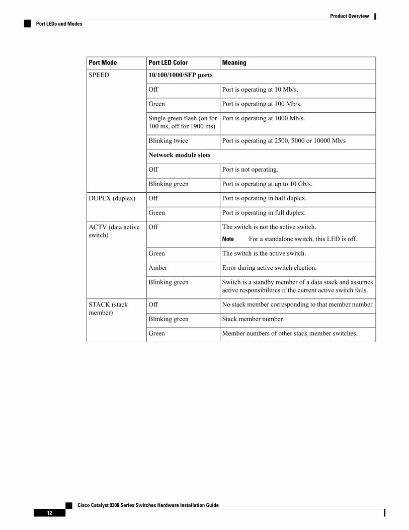
MeaningPort LED ColorPort Mode
10/100/1000/SFP portsSPEED
Port is operating at 10 Mb/s.Off
Port is operating at 100 Mb/s.Green
Port is operating at 1000 Mb/s.Single green flash (on for100 ms, off for 1900 ms)
Port is operating at 2500, 5000 or 10000 Mb/sBlinking twice
Network module slots
Port is not operating.Off
Port is operating at up to 10 Gb/s.Blinking green
Port is operating in half duplex.OffDUPLX (duplex)
Port is operating in full duplex.Green
The switch is not the active switch.
For a standalone switch, this LED is off.Note
OffACTV (data activeswitch)
The switch is the active switch.Green
Error during active switch election.Amber
Switch is a standby member of a data stack and assumesactive responsibilities if the current active switch fails.
Blinking green
No stack member corresponding to that member number.OffSTACK (stackmember)
Stack member number.Blinking green
Member numbers of other stack member switches.Green
Cisco Catalyst 9300 Series Switches Hardware Installation Guide12
Product OverviewPort LEDs and Modes
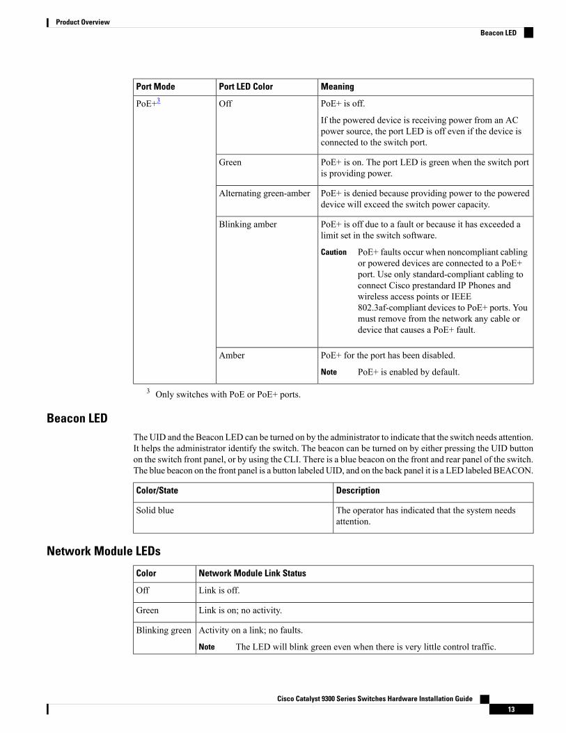
MeaningPort LED ColorPort Mode
PoE+ is off.
If the powered device is receiving power from an ACpower source, the port LED is off even if the device isconnected to the switch port.
OffPoE+3
PoE+ is on. The port LED is green when the switch portis providing power.
Green
PoE+ is denied because providing power to the powereddevice will exceed the switch power capacity.
Alternating green-amber
PoE+ is off due to a fault or because it has exceeded alimit set in the switch software.
PoE+ faults occur when noncompliant cablingor powered devices are connected to a PoE+port. Use only standard-compliant cabling toconnect Cisco prestandard IP Phones andwireless access points or IEEE802.3af-compliant devices to PoE+ ports. Youmust remove from the network any cable ordevice that causes a PoE+ fault.
Caution
Blinking amber
PoE+ for the port has been disabled.
PoE+ is enabled by default.Note
Amber
3 Only switches with PoE or PoE+ ports.
Beacon LEDThe UID and the Beacon LED can be turned on by the administrator to indicate that the switch needs attention.It helps the administrator identify the switch. The beacon can be turned on by either pressing the UID buttonon the switch front panel, or by using the CLI. There is a blue beacon on the front and rear panel of the switch.The blue beacon on the front panel is a button labeled UID, and on the back panel it is a LED labeled BEACON.
DescriptionColor/State
The operator has indicated that the system needsattention.
Solid blue
Network Module LEDs
Network Module Link StatusColor
Link is off.Off
Link is on; no activity.Green
Activity on a link; no faults.
The LED will blink green even when there is very little control traffic.Note
Blinking green
Cisco Catalyst 9300 Series Switches Hardware Installation Guide13
Product OverviewBeacon LED
Network Module Link StatusColor
Link is off due to a fault or because it has exceeded a limit set in the switch software.
Link faults occur when noncompliant cabling is connected to an SFP/SFP+/SFP28port. Use only standard-compliant cabling to connect to Cisco SFP/SFP+/SFP28ports. You must remove from the network any cable or device that causes a linkfault.
Caution
Blinking amber
Link for the SFP/SFP+/SFP28 has been disabled.Amber
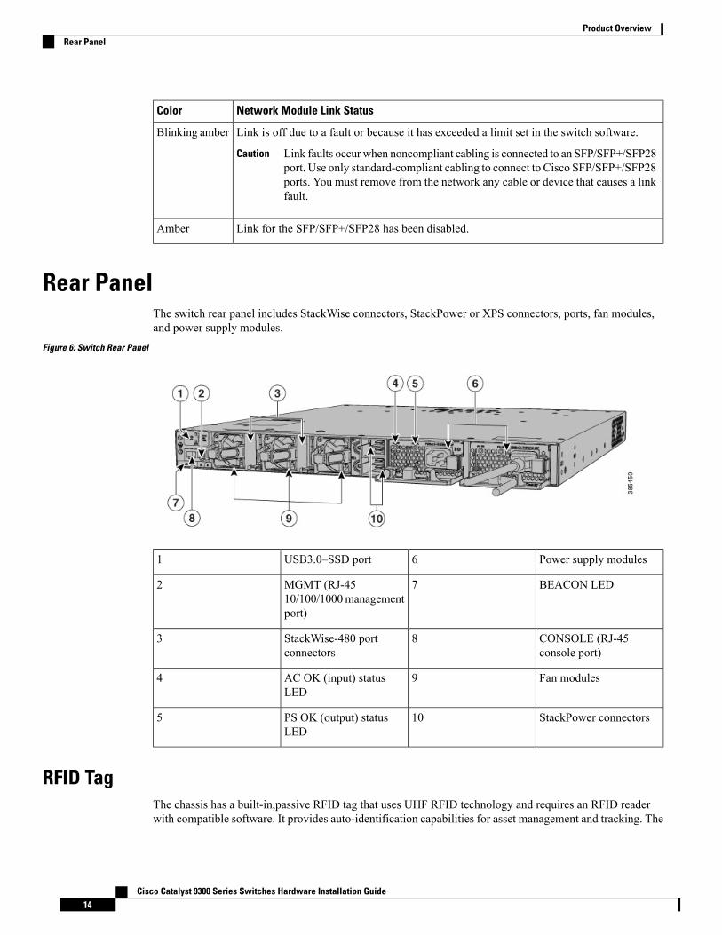
Rear PanelThe switch rear panel includes StackWise connectors, StackPower or XPS connectors, ports, fan modules,and power supply modules.
Figure 6: Switch Rear Panel
Power supply modules6USB3.0–SSD port1
BEACON LED7MGMT (RJ-4510/100/1000managementport)
2
CONSOLE (RJ-45console port)
8StackWise-480 portconnectors
3
Fan modules9AC OK (input) statusLED
4
StackPower connectors10PS OK (output) statusLED
5
RFID TagThe chassis has a built-in,passive RFID tag that uses UHF RFID technology and requires an RFID readerwith compatible software. It provides auto-identification capabilities for asset management and tracking. The
Cisco Catalyst 9300 Series Switches Hardware Installation Guide14
Product OverviewRear Panel
RFID tags are compatible with the Generation 2 GS1 EPC Global Standard and are ISO 18000-6C compliant.They operate in the 860- to 960-MHz UHF band. For more information, see Radio Frequency Identification(RFID) on Cisco Catalyst 9000 Family Switches White Paper.
RJ-45 Console Port LEDTable 11: RJ-45 Console Port LED
RJ-45 Console Port StatusColor
RJ-45 console is disabled. USB console is active.Off
RJ-45 console is enabled. USB console is disabled.Green
StackWise PortsStackWise ports are used to connect switches in StackWise stacking configurations. The switch ships with a0.5-meter StackWise cable that you can use to connect the StackWise ports. For more information on StackWisecables, see Connecting to the StackWise Ports, on page 36.
Use only approved cables, and connect only to similar Cisco equipment. Equipment might be damaged ifconnected to nonapproved Cisco cables or equipment.
Caution
Power Supply ModulesThe switches are powered through one or two internal power supply modules.
Following are the supported power supply modules:
• PWR-C1-350WAC
• PWR-C1-715WAC
• PWR-C1-1100WAC
• PWR-C1-1100WAC-P
The switch has two internal power supply module slots. You can use two AC modules or one power supplymodule and a blank module.
The switch can operate with either one or two active power supply modules or with power supplied by a stack.A switch that is in a StackPower stack can operate with power supplied by other switches in the stack.
Switch Models, on page 1 shows the default power supply modules that ship with each switch model. Allpower supply modules (except the blank modules) have internal fans. All switches ship with a blank powersupply module in the second power supply slot.
Do not operate the switch with one power supply module slot empty. For proper chassis cooling, both powersupply module slots must be populated with either a power supply or a blank module.
Caution
Cisco Catalyst 9300 Series Switches Hardware Installation Guide15
Product OverviewRJ-45 Console Port LED
The 350-W and 715-W AC power supply modules are autoranging units that support input voltages between100 and 240 VAC. The 1100-W power supply module is an autoranging unit that supports input voltagesbetween 115 and 240 VAC. The output voltage range is 51 to 57 V.
Each AC power supply module has a power cord for connection to an AC power outlet. The 1100-W and715-W modules use a 16-AWG cord (only North America). All other modules use an 18-AWG cord.
The following tables show the PoE available and PoE requirements for PoE switch models.
Table 12: Available PoE with AC Power Supply
Available PoEDefault Power SupplyModels
—PWR-C1-350WAC24-port data switch
48-port data switch
445 WPWR-C1-715WAC24-port PoE+ switch
437 W48-port PoE+ switch
800 WPWR-C1-1100WAC48-port full PoE+ switch
830 W24-port Cisco UPOE switch
822 W48-port Cisco UPOE switch
560 W24 Multigigabit Cisco UPOEswitch
490 W12 Multigigabit Ethernet and 362.5Gbps Cisco UPOE
645 WPWR-C1-1100WAC-P48 Multigigabit Cisco UPOE 5Gswitch
Table 13: Switch Power Supply Requirements for PoE, PoE+, and Cisco UPoE
48-Port Switch424-Port SwitchPoE Option
These are the combinations ofpower supplies:
• (1) 1100 W
• (1) 715 W + (1) 715 W
(1) 715 WPoE (up to 15.4 W per port)
These are the combinations ofpower supplies:
• (1) 1100 W + (1) 715 W
• (2) 1100 W
These are the combinations ofpower supplies:
• (1) 1100 W
• (1) 715 W + (1) 715 W
PoE+ (up to 30 W per ports)
Cisco Catalyst 9300 Series Switches Hardware Installation Guide16
Product OverviewPower Supply Modules
48-Port Switch424-Port SwitchPoE Option
These are the combinations ofpower supplies:
• (1) 1100 W + (1) 715 W
• (2) 1100 W
Up to 30 PoE ports canreceive full CiscoUPoE.
Note
(2) 1100 WCisco UPoE (up to 60 W per port)
4 A 48-port switch with one 715-W power supply provides up to 8.7 W of PoE to all ports.
The power supply modules have two status LEDs.
Table 14: Switch Power Supply Module LEDs
DescriptionPS OKDescriptionAC OK
Output is disabled, or input is outsideoperating range (AC LED is off).
OffNo AC input power.Off
Power output to switch active.GreenAC input power present.Green
Output has failed.Red
Fan ModuleThe switch supports three internal hot-swappable 12-V fanmodules (FAN-T2=) are available. The air circulationsystem consists of the fan modules and the power supply modules. The airflow patterns vary depending onthe power supply configuration.
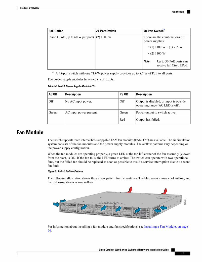
When the fan modules are operating properly, a green LED at the top left corner of the fan assembly (viewedfrom the rear), is ON. If the fan fails, the LED turns to amber. The switch can operate with two operationalfans, but the failed fan should be replaced as soon as possible to avoid a service interruption due to a secondfan fault.Figure 7: Switch Airflow Patterns
The following illustration shows the airflow pattern for the switches. The blue arrow shows cool airflow, andthe red arrow shows warm airflow.
For information about installing a fan module and fan specifications, see Installing a Fan Module, on page64.
Cisco Catalyst 9300 Series Switches Hardware Installation Guide17
Product OverviewFan Module
StackPower ConnectorThe switches have a StackPower connector for use with Cisco StackPower cables to configure a switch powerstack that includes up to four switches. A switch power stack can be configured in redundant or power-sharingmode.
You can order these StackPower cables from your Cisco sales representative:
• CAB-SPWR-30CM (0.3-meter cable)
• CAB-SPWR-150CM (1.5-meter cable)
For details about connecting StackPower cables and StackPower guidelines, see Planning a StackPower Stack,on page 29.
USB 3.0 SSD PortTo support the storage needs on the switch, the Cisco Catalyst 9300 Series Switches provide support forpluggable 120GB USB 3.0 Solid State Drive (SSD) module. The USB 3.0 SSD module slot is located at therear panel of the switch. The storage drive can also be used to save packet captures and trace logs generatedby the operating system. The USB 3.0 SSD device is field replaceable.
For information about installing a USB 3.0 SSD module, see Installing a USB 3.0 SSD, on page 67.
Ethernet Management PortYou can connect the switch to a host such as a Windows workstation or a terminal server through the10/100/1000 Ethernet management port or one of the console ports. The 10/100/1000 Ethernet managementport is a VPN routing/forwarding (VRF) interface and uses a RJ-45 crossover or straight-through cable.
The 10/100/1000 Ethernet management port is an RJ-45 connector that should be connected to a Windowsworkstation or a terminal server. Do not connect this port to another port in the same switch or to any portwithin the same switch stack.
Note
The following table shows the Ethernet management port LED colors and their meanings.
Table 15: Ethernet Management Port LED
DescriptionColor
Link up but no activity.Green
Link up and activity.Blinking green
Link down.Off
RJ-45 Console PortThe RJ-45 console port connection uses the supplied RJ-45-to-DB-9 female cable.
Cisco Catalyst 9300 Series Switches Hardware Installation Guide18
Product OverviewStackPower Connector
The following table shows the RJ-45 console port LED colors and their meanings.
Table 16: RJ-45 Console LED
DescriptionColor
RJ-45 console port is active.Green
The port is not active.Off
Network ConfigurationsSee the switch software configuration guide for network configuration concepts and examples of using theswitch to create dedicated network segments and interconnecting the segments through Fast Ethernet andGigabit Ethernet connections.
Cisco Catalyst 9300 Series Switches Hardware Installation Guide19
Product OverviewNetwork Configurations

Cisco Catalyst 9300 Series Switches Hardware Installation Guide20
Product OverviewNetwork Configurations
C H A P T E R 2Switch Installation
For initial switch setup, assigning the switch IP address, and powering on information, see the switch gettingstarted guide on Cisco.com.
This chapter contains these topics:
• Preparing for Installation, on page 21• Planning a Switch Data Stack, on page 25• Data Stack Cabling Configurations, on page 26• Planning a StackPower Stack, on page 29• StackPower Cabling Configurations, on page 29• Installing the Switch, on page 32• Connecting to the StackWise Ports, on page 36• Connecting to the StackPower Ports, on page 38• Installing a Network Module in the Switch, on page 38• Installing and Removing SFP, SFP+, SFP28 and QSFP+ Modules, on page 38• Connecting Devices to the Ethernet Ports, on page 38
Preparing for Installation
Safety WarningsThis section includes the basic installation caution and warning statements. Read this section before you startthe installation procedure. Translations of the warning statements appear in the Regulatory Compliance andSafety Information guide on Cisco.com.
Before working on equipment that is connected to power lines, remove jewelry (including rings, necklaces,and watches). Metal objects will heat up when connected to power and ground and can cause serious burnsor weld the metal object to the terminals. Statement 43
Warning
Do not stack the chassis on any other equipment. If the chassis falls, it can cause severe bodily injury andequipment damage. Statement 48
Warning
Cisco Catalyst 9300 Series Switches Hardware Installation Guide21
Ethernet cables must be shielded when used in a central office environment. Statement 171Warning
Do not work on the system or connect or disconnect cables during periods of lightning activity. Statement1001
Warning
Read the installation instructions before connecting the system to the power source. Statement 1004Warning
Class 1 laser product. Statement 1008Warning
This unit is intended for installation in restricted access areas. A restricted access area can be accessed onlythrough the use of a special tool, lock and key, or other means of security. Statement 1017
Warning
The plug-socket combination must be accessible at all times, because it serves as the main disconnectingdevice. Statement 1019
Warning
Use copper conductors only. Statement 1025Warning
This unit might have more than one power supply connection. All connections must be removed to de-energizethe unit. Statement 1028
Warning
Only trained and qualified personnel should be allowed to install, replace, or service this equipment. Statement1030
Warning
Ultimate disposal of this product should be handled according to all national laws and regulations. Statement1040
Warning
To prevent the system from overheating, do not operate it in an area that exceeds the maximum recommendedambient temperature of: <113°F (45°C). Statement 1047
Warning
Cisco Catalyst 9300 Series Switches Hardware Installation Guide22
Switch InstallationSafety Warnings
Installation of the equipment must comply with local and national electrical codes. Statement 1074Warning
To prevent airflow restriction, allow clearance around the ventilation openings to be at least: 3 inches (7.6cm). Statement 1076
Warning
The grounding architecture of this product is DC-isolated (DC-I).Note
Installation GuidelinesWhen determining where to install the switch, verify that these guidelines are met:
• Clearance to the switch front and rear panel meets these conditions:
• Front-panel LEDs can be easily read.
• Access to ports is sufficient for unrestricted cabling.
• AC power cord can reach from the AC power outlet to the connector on the switch rear panel.
• The SFP/SFP+/SFP28 module minimum bend radius and connector length is met. See theSFP/SFP+/SFP28 module documentation for more information.
• Cabling is away from sources of electrical noise, such as radios, power lines, and fluorescent lightingfixtures. Make sure that the cabling is safely away from other devices that might damage the cables.
• For switches with the optional 1100-W power-supply module (PWR-C1-1100WAC=), first rack-mountthe switch before installing the power-supply module.
• Make sure power-supply modules and fan modules are securely inserted in the chassis before movingthe switch.
• When connecting or disconnecting the power cord on a switch that is installed above or below a 1100-Wpower supply-equipped switch, you might need to remove the module from the switch to access thepower cord.
• Airflow around the switch and through the vents is unrestricted.
• For copper connections on Ethernet ports, cable lengths from the switch to connected devices can be upto 328 feet (100 meters).
• Temperature around the unit does not exceed 113°F (45°C). If the switch is installed in a closed ormultirack assembly, the temperature around it might be greater than normal room temperature.
• Humidity around the switch does not exceed 95 percent.
• Altitude at the installation site is not greater than 10,000 feet.
• Cooling mechanisms, such as fans and blowers in the switch, can draw dust and other particles causingcontaminant buildup inside the chassis, which can result in system malfunction. You must install this
Cisco Catalyst 9300 Series Switches Hardware Installation Guide23
Switch InstallationInstallation Guidelines
equipment in an environment as free from dust and foreign conductive material (such as metal flakesfrom construction activities) as is possible.
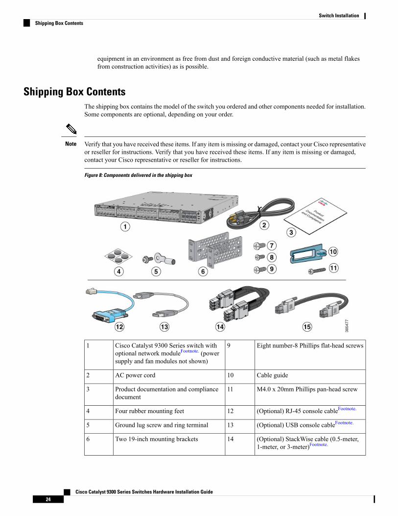
Shipping Box ContentsThe shipping box contains the model of the switch you ordered and other components needed for installation.Some components are optional, depending on your order.
Verify that you have received these items. If any item is missing or damaged, contact your Cisco representativeor reseller for instructions. Verify that you have received these items. If any item is missing or damaged,contact your Cisco representative or reseller for instructions.
Note
Figure 8: Components delivered in the shipping box
Eight number-8 Phillips flat-head screws9Cisco Catalyst 9300 Series switch withoptional network moduleFootnote. (powersupply and fan modules not shown)
1
Cable guide10AC power cord2
M4.0 x 20mm Phillips pan-head screw11Product documentation and compliancedocument
3
(Optional) RJ-45 console cableFootnote.12Four rubber mounting feet4
(Optional) USB console cableFootnote.13Ground lug screw and ring terminal5
(Optional) StackWise cable (0.5-meter,1-meter, or 3-meter)Footnote.
14Two 19-inch mounting brackets6
Cisco Catalyst 9300 Series Switches Hardware Installation Guide24
Switch InstallationShipping Box Contents
(Optional) StackPower cable (0.3-meteror 1.5-meter)Footnote.
15Four number-12 pan-head screws7
Four number-10 pan-head screws8
5 Item is orderable.
Tools and EquipmentObtain these necessary tools:
• A Number-2 Phillips screwdriver to rack-mount the switch
Verifying Switch OperationBefore you install the switch in a rack, on a wall, or on a table or shelf, power on the switch and verify thatit passes POST.
To power on the switch, plug one end of the AC power cord into the switch AC power connector, and plugthe other end into an AC power outlet.
As the switch powers on, it begins the POST, a series of tests that runs automatically to ensure that the switchfunctions properly. LEDs can blink during the test. POST lasts approximately 1 minute. The SYST LEDblinks green, and the other LEDs remain solid green.
When the switch completes POST successfully, the SYST LED remains green. The RPS LED remains greenfor some time and then reflects the switch operating status. The other LEDs turn off and then reflect the switchoperating status. If a switch fails POST, the SYST LED turns amber.
POST failures are usually fatal. Call Cisco technical support representative if your switch fails POST.
After a successful POST, unplug the power cord from the switch and install the switch in a rack, on a wall,on a table, or on a shelf.
If your configuration has an RPS, connect the switch and the RPS to different AC power sources. See theCisco RPS documentation for information.
When you connect the RPS to the switch, put the RPS in standby mode. Set the RPS to active mode duringnormal operation.
Note
Attach only the following Cisco external power system to the switch: Cisco XPS 2200 Statement 387Warning
Planning a Switch Data StackCisco Catalyst 9300 switches can share bandwidth by using data stacking.
Cisco Catalyst 9300 Series Switches Hardware Installation Guide25
Switch InstallationTools and Equipment
Switch Stacking and Power Stacking GuidelinesBefore connecting the switches in a stack, keep in mind these stacking guidelines:
• Size of the switch and any optional power-supply module. The 1100-W power-supply module is longerthan the other modules. Stacking switches with the same power-supply modules together makes it easierto cable the switches.
• Length of cable. Depending on the configurations that you have, you might need different-sized cables.If you do not specify the length of the StackWise cable, the 0.5-meter cable is supplied. If you need the1-meter cable or the 3-meter cable, you can order it from your Cisco supplier. For cable part numbers,see StackWise Ports, on page 15. The Data Stack Cabling Configurations, on page 26 provides examplesof recommended configurations.
• For rack-mounted switch stacks that are members of a StackPower stack as well as a data stack, seePlanning a StackPower Stack, on page 29.
• You can create data stacks with up to eight switches in a stack.
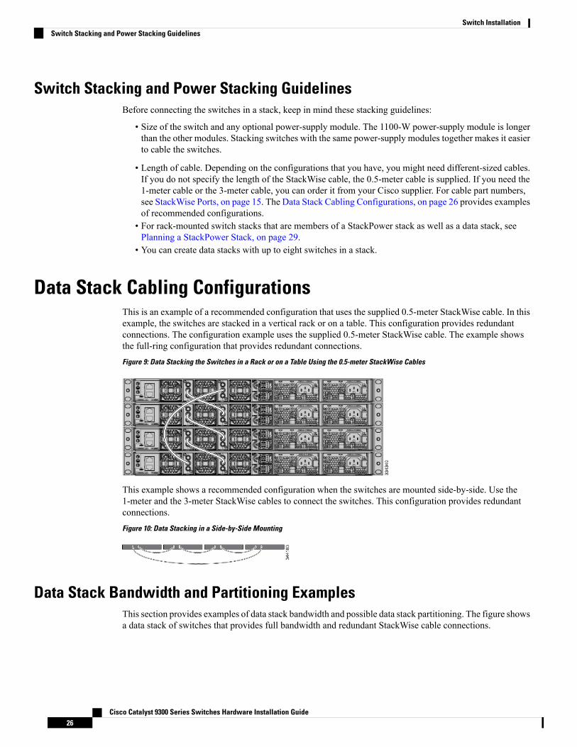
Data Stack Cabling ConfigurationsThis is an example of a recommended configuration that uses the supplied 0.5-meter StackWise cable. In thisexample, the switches are stacked in a vertical rack or on a table. This configuration provides redundantconnections. The configuration example uses the supplied 0.5-meter StackWise cable. The example showsthe full-ring configuration that provides redundant connections.Figure 9: Data Stacking the Switches in a Rack or on a Table Using the 0.5-meter StackWise Cables
This example shows a recommended configuration when the switches are mounted side-by-side. Use the1-meter and the 3-meter StackWise cables to connect the switches. This configuration provides redundantconnections.Figure 10: Data Stacking in a Side-by-Side Mounting
Data Stack Bandwidth and Partitioning ExamplesThis section provides examples of data stack bandwidth and possible data stack partitioning. The figure showsa data stack of switches that provides full bandwidth and redundant StackWise cable connections.
Cisco Catalyst 9300 Series Switches Hardware Installation Guide26
Switch InstallationSwitch Stacking and Power Stacking Guidelines
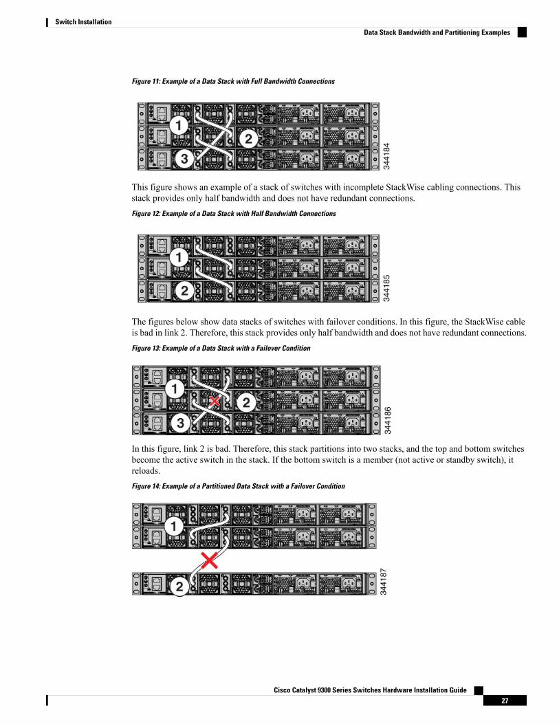
Figure 11: Example of a Data Stack with Full Bandwidth Connections
This figure shows an example of a stack of switches with incomplete StackWise cabling connections. Thisstack provides only half bandwidth and does not have redundant connections.Figure 12: Example of a Data Stack with Half Bandwidth Connections
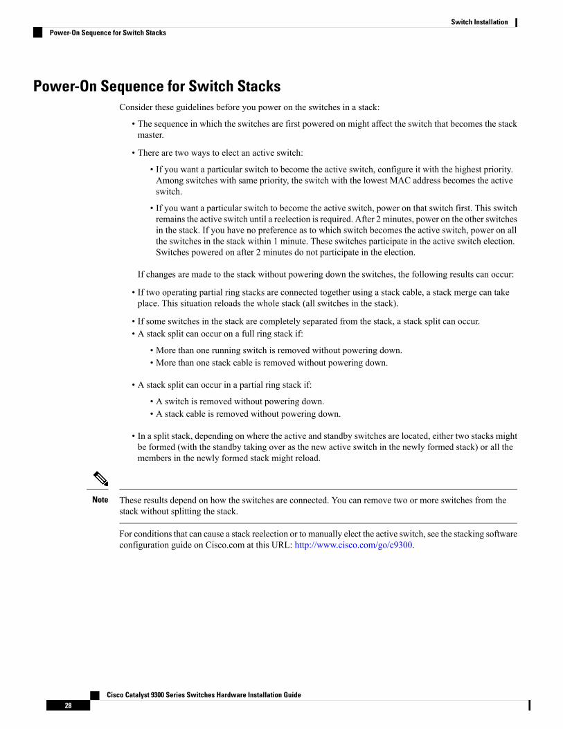
The figures below show data stacks of switches with failover conditions. In this figure, the StackWise cableis bad in link 2. Therefore, this stack provides only half bandwidth and does not have redundant connections.Figure 13: Example of a Data Stack with a Failover Condition
In this figure, link 2 is bad. Therefore, this stack partitions into two stacks, and the top and bottom switchesbecome the active switch in the stack. If the bottom switch is a member (not active or standby switch), itreloads.Figure 14: Example of a Partitioned Data Stack with a Failover Condition
Cisco Catalyst 9300 Series Switches Hardware Installation Guide27
Switch InstallationData Stack Bandwidth and Partitioning Examples
Power-On Sequence for Switch StacksConsider these guidelines before you power on the switches in a stack:
• The sequence in which the switches are first powered on might affect the switch that becomes the stackmaster.
• There are two ways to elect an active switch:
• If you want a particular switch to become the active switch, configure it with the highest priority.Among switches with same priority, the switch with the lowest MAC address becomes the activeswitch.
• If you want a particular switch to become the active switch, power on that switch first. This switchremains the active switch until a reelection is required. After 2 minutes, power on the other switchesin the stack. If you have no preference as to which switch becomes the active switch, power on allthe switches in the stack within 1 minute. These switches participate in the active switch election.Switches powered on after 2 minutes do not participate in the election.
If changes are made to the stack without powering down the switches, the following results can occur:
• If two operating partial ring stacks are connected together using a stack cable, a stack merge can takeplace. This situation reloads the whole stack (all switches in the stack).
• If some switches in the stack are completely separated from the stack, a stack split can occur.• A stack split can occur on a full ring stack if:
• More than one running switch is removed without powering down.• More than one stack cable is removed without powering down.
• A stack split can occur in a partial ring stack if:
• A switch is removed without powering down.• A stack cable is removed without powering down.
• In a split stack, depending on where the active and standby switches are located, either two stacks mightbe formed (with the standby taking over as the new active switch in the newly formed stack) or all themembers in the newly formed stack might reload.
These results depend on how the switches are connected. You can remove two or more switches from thestack without splitting the stack.
Note
For conditions that can cause a stack reelection or to manually elect the active switch, see the stacking softwareconfiguration guide on Cisco.com at this URL: http://www.cisco.com/go/c9300.
Cisco Catalyst 9300 Series Switches Hardware Installation Guide28
Switch InstallationPower-On Sequence for Switch Stacks
Planning a StackPower Stack
StackPower Stacking GuidelinesYou can configure a StackPower stack for either power sharing or redundancy. In power-sharing mode, thepower of all the power supplies in the stack is aggregated and distributed among the stack members.
In redundant mode, when the total power budget of the stack is calculated, the wattage of the largest powersupply is not included. That power is held in reserve and used to maintain power to switches and attacheddevices when one power supply fails. Following the failure of a power supply, the StackPower mode becomespower sharing.
Power-sharing mode is the recommended configuration for Cisco Catalyst 9300 Series Switches.Note
For general concepts and management procedures for switch power stacks, see the Software ConfigurationGuide on Cisco.com.
Before connecting the switches in a power stack, keep in mind these guidelines:
• A switch power stack can include a maximum of four switches in a ring topology and eight switches ina star topology.
• Size of the switch and any optional power supply module. The 1100-W power-supply module is 1.5inches (3.81 cm) longer than the other modules, and with the attached cable retention clip, it extends 3inches (7.62 cm) from the switch chassis. Stacking switches with the same power-supplymodules togethermakes it easier to cable the switches. For switch dimensions, see Appendix A, “Technical Specifications.”
• Length of cable. Depending on the configurations that you have, you might need different-sized cables.If you do not specify the length of the StackPower cable, the 0.3 meter cable is supplied. If you need the1.5 meter cable, you can order it from your Cisco supplier. For cable part numbers, see StackPowerConnector, on page 18. The StackPower Cabling Configurations, on page 29 provides examples ofrecommended configurations.
• For rack-mounted switch stacks that are members of a data stack and a StackPower stack, see SwitchStacking and Power Stacking Guidelines, on page 26
StackPower Cabling ConfigurationsThis section describes the recommended cabling configurations for a StackPower stack. There are two typesof StackPower cables.
The cable in the figure connects a switch to another switch in a power stack or with an XPS. StackPowercables have color bands on the cable ends:
• The cable end with the green band can connect only to a switch.
• The cable end with the yellow band can connect to a switch or an XPS.
The cable is available in two lengths.
Cisco Catalyst 9300 Series Switches Hardware Installation Guide29
Switch InstallationPlanning a StackPower Stack
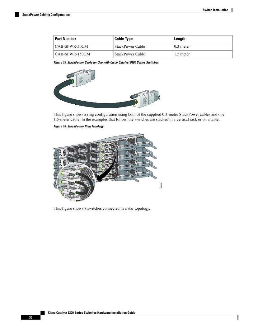
LengthCable TypePart Number
0.3 meterStackPower CableCAB-SPWR-30CM
1.5 meterStackPower CableCAB-SPWR-150CM
Figure 15: StackPower Cable for Use with Cisco Catalyst 9300 Series Switches
This figure shows a ring configuration using both of the supplied 0.3-meter StackPower cables and one1.5-meter cable. In the examples that follow, the switches are stacked in a vertical rack or on a table.Figure 16: StackPower Ring Topology
This figure shows 8 switches connected in a star topology.
Cisco Catalyst 9300 Series Switches Hardware Installation Guide30
Switch InstallationStackPower Cabling Configurations
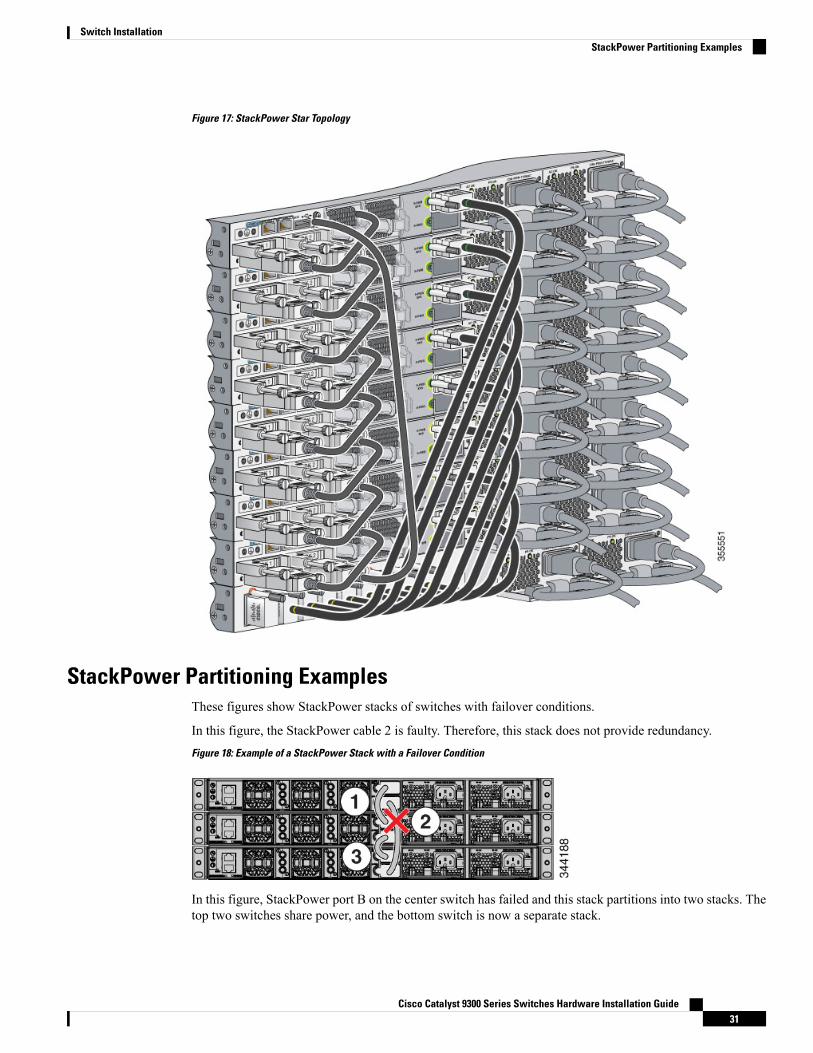
Figure 17: StackPower Star Topology
StackPower Partitioning ExamplesThese figures show StackPower stacks of switches with failover conditions.
In this figure, the StackPower cable 2 is faulty. Therefore, this stack does not provide redundancy.Figure 18: Example of a StackPower Stack with a Failover Condition
In this figure, StackPower port B on the center switch has failed and this stack partitions into two stacks. Thetop two switches share power, and the bottom switch is now a separate stack.
Cisco Catalyst 9300 Series Switches Hardware Installation Guide31
Switch InstallationStackPower Partitioning Examples
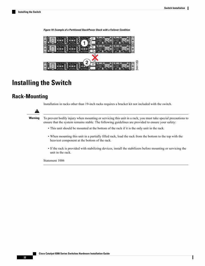
Figure 19: Example of a Partitioned StackPower Stack with a Failover Condition
Installing the Switch
Rack-MountingInstallation in racks other than 19-inch racks requires a bracket kit not included with the switch.
To prevent bodily injury when mounting or servicing this unit in a rack, you must take special precautions toensure that the system remains stable. The following guidelines are provided to ensure your safety:
• This unit should be mounted at the bottom of the rack if it is the only unit in the rack.
• When mounting this unit in a partially filled rack, load the rack from the bottom to the top with theheaviest component at the bottom of the rack.
• If the rack is provided with stabilizing devices, install the stabilizers before mounting or servicing theunit in the rack.
Statement 1006
Warning
Cisco Catalyst 9300 Series Switches Hardware Installation Guide32
Switch InstallationInstalling the Switch
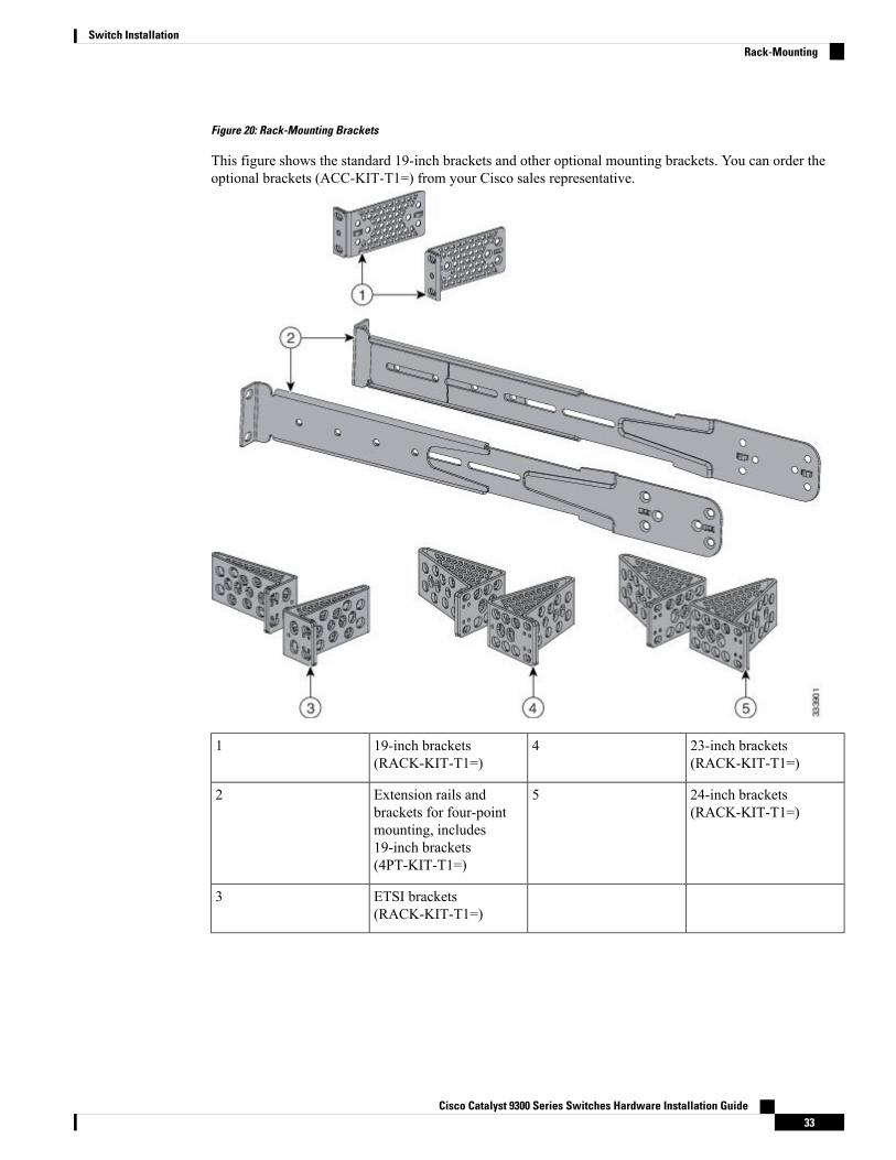
Figure 20: Rack-Mounting Brackets
This figure shows the standard 19-inch brackets and other optional mounting brackets. You can order theoptional brackets (ACC-KIT-T1=) from your Cisco sales representative.
23-inch brackets(RACK-KIT-T1=)
419-inch brackets(RACK-KIT-T1=)
1
24-inch brackets(RACK-KIT-T1=)
5Extension rails andbrackets for four-pointmounting, includes19-inch brackets(4PT-KIT-T1=)
2
ETSI brackets(RACK-KIT-T1=)
3
Cisco Catalyst 9300 Series Switches Hardware Installation Guide33
Switch InstallationRack-Mounting
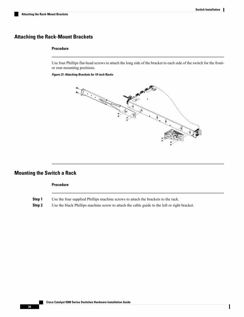
Attaching the Rack-Mount Brackets
Procedure
Use four Phillips flat-head screws to attach the long side of the bracket to each side of the switch for the front-or rear-mounting positions.Figure 21: Attaching Brackets for 19-inch Racks
Mounting the Switch a Rack
Procedure
Step 1 Use the four supplied Phillips machine screws to attach the brackets to the rack.Step 2 Use the black Phillips machine screw to attach the cable guide to the left or right bracket.
Cisco Catalyst 9300 Series Switches Hardware Installation Guide34
Switch InstallationAttaching the Rack-Mount Brackets
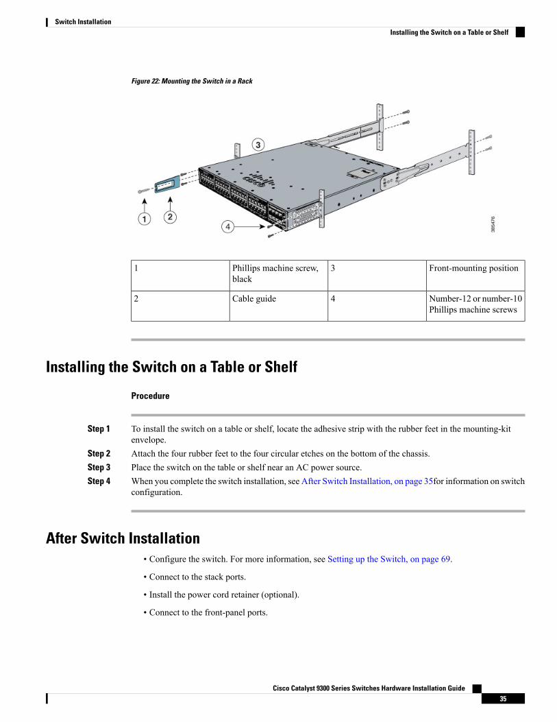
Figure 22: Mounting the Switch in a Rack
Front-mounting position3Phillips machine screw,black
1
Number-12 or number-10Phillips machine screws
4Cable guide2
Installing the Switch on a Table or Shelf
Procedure
Step 1 To install the switch on a table or shelf, locate the adhesive strip with the rubber feet in the mounting-kitenvelope.
Step 2 Attach the four rubber feet to the four circular etches on the bottom of the chassis.Step 3 Place the switch on the table or shelf near an AC power source.Step 4 When you complete the switch installation, see After Switch Installation, on page 35for information on switch
configuration.
After Switch Installation• Configure the switch. For more information, see Setting up the Switch, on page 69.
• Connect to the stack ports.
• Install the power cord retainer (optional).
• Connect to the front-panel ports.
Cisco Catalyst 9300 Series Switches Hardware Installation Guide35
Switch InstallationInstalling the Switch on a Table or Shelf
Connecting to the StackWise PortsBefore you begin
Before connecting the StackWise cables, review the Planning a Switch Data Stack, on page 25. Always usea Cisco-approved StackWise cable to connect the switches.
Procedure
Step 1 Remove the dust covers from the StackWise cables and StackWise ports, and store them for future use.Step 2 Connect the cable to the StackWise port on the switch rear panel. Align the connector and connect the StackWise
cable to the StackWise port on the switch rear panel and finger-tighten the screws (clockwise direction). Makesure the Cisco logo is on the top side of the connector as shown in the figure.
Step 3 Connect the other end of the cable to the port on the other switch and finger-tighten the screws. Avoidovertightening the screws.
Cisco Catalyst 9300 Series Switches Hardware Installation Guide36
Switch InstallationConnecting to the StackWise Ports
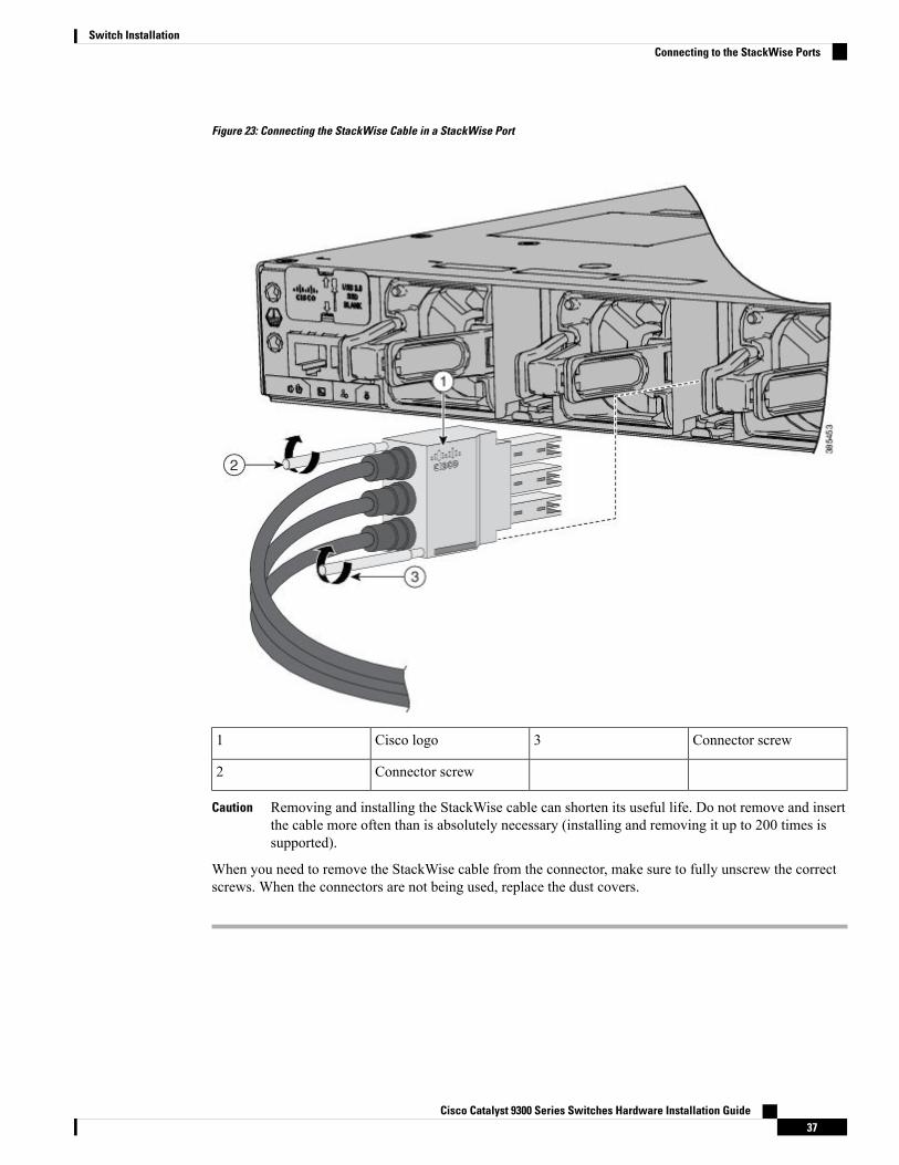
Figure 23: Connecting the StackWise Cable in a StackWise Port
Connector screw3Cisco logo1
Connector screw2
Removing and installing the StackWise cable can shorten its useful life. Do not remove and insertthe cable more often than is absolutely necessary (installing and removing it up to 200 times issupported).
Caution
When you need to remove the StackWise cable from the connector, make sure to fully unscrew the correctscrews. When the connectors are not being used, replace the dust covers.
Cisco Catalyst 9300 Series Switches Hardware Installation Guide37
Switch InstallationConnecting to the StackWise Ports
Connecting to the StackPower PortsBefore you begin
Before connecting the StackPower cables, review Planning a Switch Data Stack, on page 25. Always use aCisco-approved StackWise cable to connect the switches. To prevent misconfiguration, the StackPower portson the switch are keyed and have colored bands that match the keying and bands on the StackPower cableconnectors.
Procedure
Step 1 Remove the dust covers from the StackPower cable connectors.Step 2 Connect the end of the cable with a green band to either StackPower port on the first switch. Align the connector
correctly, and insert it into a StackPower port on the switch rear panel.Step 3 Connect the end of the cable with the yellow band to another switch (to configure StackPower power sharing).Step 4 Hand-tighten the captive screws to secure the StackPower cable connectors in place.
Removing and installing the StackPower cable can shorten its useful life. Do not remove and insertthe cable more often than is absolutely necessary.
Caution
Installing a Network Module in the SwitchSee these sections for information on network modules:
• Installing Network Modules, on page 43
Installing and Removing SFP, SFP+, SFP28 and QSFP+ ModulesSee these sections for information on SFP, SFP, SFP28 and QSFP+ modules:
• Installing SFP, SFP+ and SFP28 Modules, on page 51
• Removing SFP, SFP+ and SFP28 Modules, on page 53
• Cisco 40-Gigabit QSFP+ Transceiver Modules Installation Note
Connecting Devices to the Ethernet Ports• 10/100/1000 Port Connections, on page 39
• PoE+ and Cisco UPOE Port Connections, on page 39
Cisco Catalyst 9300 Series Switches Hardware Installation Guide38
Switch InstallationConnecting to the StackPower Ports
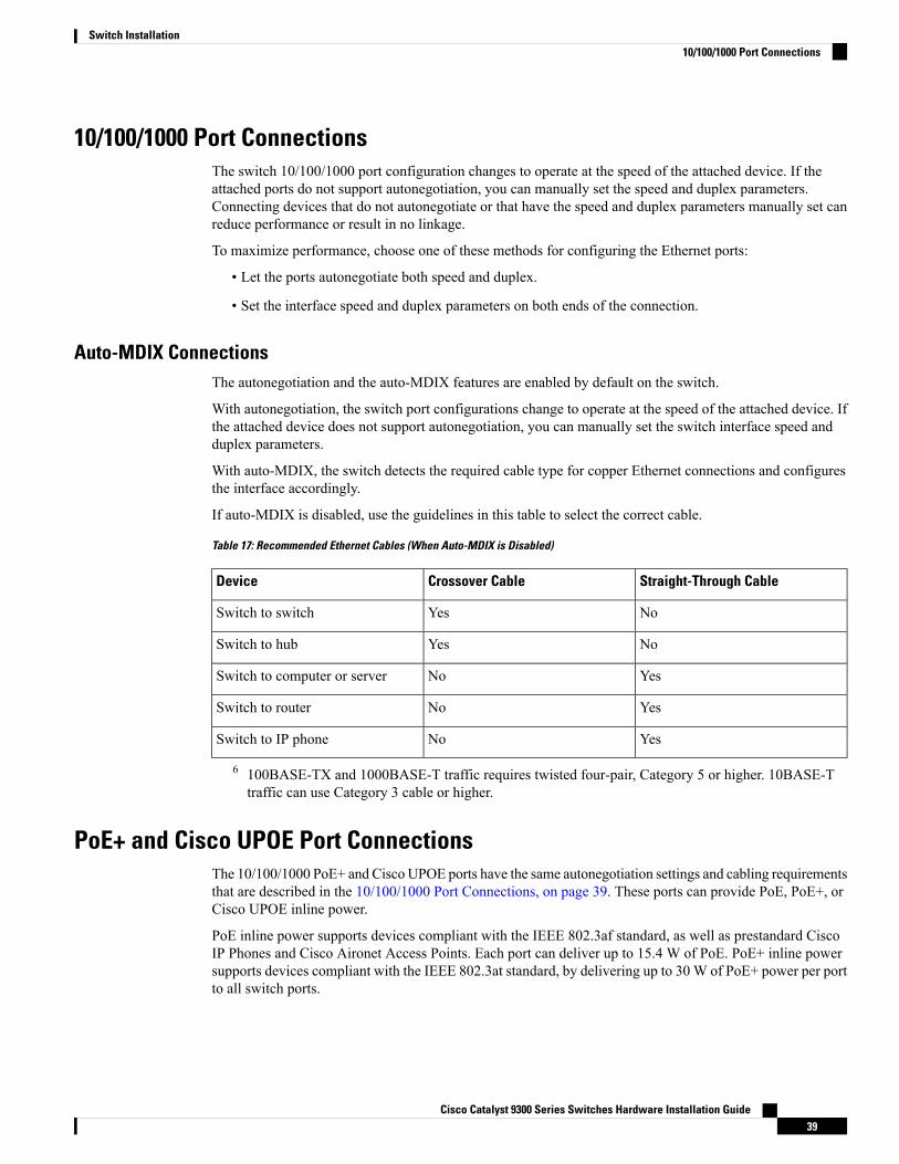
10/100/1000 Port ConnectionsThe switch 10/100/1000 port configuration changes to operate at the speed of the attached device. If theattached ports do not support autonegotiation, you can manually set the speed and duplex parameters.Connecting devices that do not autonegotiate or that have the speed and duplex parameters manually set canreduce performance or result in no linkage.
To maximize performance, choose one of these methods for configuring the Ethernet ports:
• Let the ports autonegotiate both speed and duplex.
• Set the interface speed and duplex parameters on both ends of the connection.
Auto-MDIX ConnectionsThe autonegotiation and the auto-MDIX features are enabled by default on the switch.
With autonegotiation, the switch port configurations change to operate at the speed of the attached device. Ifthe attached device does not support autonegotiation, you can manually set the switch interface speed andduplex parameters.
With auto-MDIX, the switch detects the required cable type for copper Ethernet connections and configuresthe interface accordingly.
If auto-MDIX is disabled, use the guidelines in this table to select the correct cable.
Table 17: Recommended Ethernet Cables (When Auto-MDIX is Disabled)
Straight-Through CableCrossover CableDevice
NoYesSwitch to switch
NoYesSwitch to hub
YesNoSwitch to computer or server
YesNoSwitch to router
YesNoSwitch to IP phone
6 100BASE-TX and 1000BASE-T traffic requires twisted four-pair, Category 5 or higher. 10BASE-Ttraffic can use Category 3 cable or higher.
PoE+ and Cisco UPOE Port ConnectionsThe 10/100/1000 PoE+ and Cisco UPOE ports have the same autonegotiation settings and cabling requirementsthat are described in the 10/100/1000 Port Connections, on page 39. These ports can provide PoE, PoE+, orCisco UPOE inline power.
PoE inline power supports devices compliant with the IEEE 802.3af standard, as well as prestandard CiscoIP Phones and Cisco Aironet Access Points. Each port can deliver up to 15.4 W of PoE. PoE+ inline powersupports devices compliant with the IEEE 802.3at standard, by delivering up to 30W of PoE+ power per portto all switch ports.
Cisco Catalyst 9300 Series Switches Hardware Installation Guide39
Switch Installation10/100/1000 Port Connections
See Power Supply Modules, on page 15 for the power supply modules required to support PoE, PoE+, andCisco UPOE on 24- and 48-port switches.
Voltages that present a shock hazard may exist on Power over Ethernet (PoE) circuits if interconnections aremade using uninsulated exposed metal contacts, conductors, or terminals. Avoid using such interconnectionmethods, unless the exposed metal parts are located within a restricted access location and users and servicepeople who are authorized within the restricted access location are made aware of the hazard. A restrictedaccess area can be accessed only through the use of a special tool, lock and key or other means of security.Statement 1072
Warning
Voice over IP (VoIP) service and the emergency calling service do not function if power fails or is disrupted.After power is restored, you might have to reset or reconfigure equipment to regain access to VoIP and theemergency calling service. In the USA, this emergency number is 911. You need to be aware of the emergencynumber in your country. Statement 371
Warning
Category 5e and Category 6 cables can store high levels of static electricity. Always ground the cables to asuitable and safe earth ground before connecting them to the switch or other devices.
Caution
Noncompliant cabling or powered devices can cause a PoE port fault. Use only standard-compliant cablingto connect Cisco prestandard IP Phones and wireless access points, IEEE 802.3af, or 802.3at (PoE+)-compliantdevices. You must remove any cable or device that causes a PoE fault.
Caution
Cisco Catalyst 9300 Series Switches Hardware Installation Guide40
Switch InstallationPoE+ and Cisco UPOE Port Connections
C H A P T E R 3Installing a Network Module
• Network Modules Overview, on page 41• Installing a Network Module in the Switch, on page 42• Removing a Network Module, on page 50• SFP, SFP+ and SFP28 Modules, on page 51• Finding the Network Module Serial Number, on page 53
Network Modules OverviewThe Cisco Catalyst 9300 Series Switches supports the following optional network modules for uplink ports.
DescriptionNetwork Module
This module has four 1G SFP module slots. Any combination of standard SFPmodules are supported.
Supported only on Cisco Catalyst 9300 Series Switches.Note
C9300-NM-4G
This module has eight 10G SFP+ module slots.
Supported only on Cisco Catalyst 9300 Series Switches.Note
C9300-NM-8X
This module has two 40G QSFP+ module slots.
Supported only on Cisco Catalyst 9300 Series Switches.Note
C9300-NM-2Q
This module has four Multigigabit Ethernet (mGig) module slots.
Supported only on Cisco Catalyst 9300 Series Switches.Note
C9300-NM-4M
This module has two 25G SFP28 module slots.
Supported only on Cisco Catalyst 9300 Series Switches.Note
C9300-NM-2Y
This module has four 1G SFP module slots. Any combination of standard SFPmodules are supported. SFP+ modules are not supported.
If you insert an SFP+ module in the 1G network module, the SFP+ module doesnot operate, and the switch logs an error message.
C3850-NM-4-1G
Cisco Catalyst 9300 Series Switches Hardware Installation Guide41
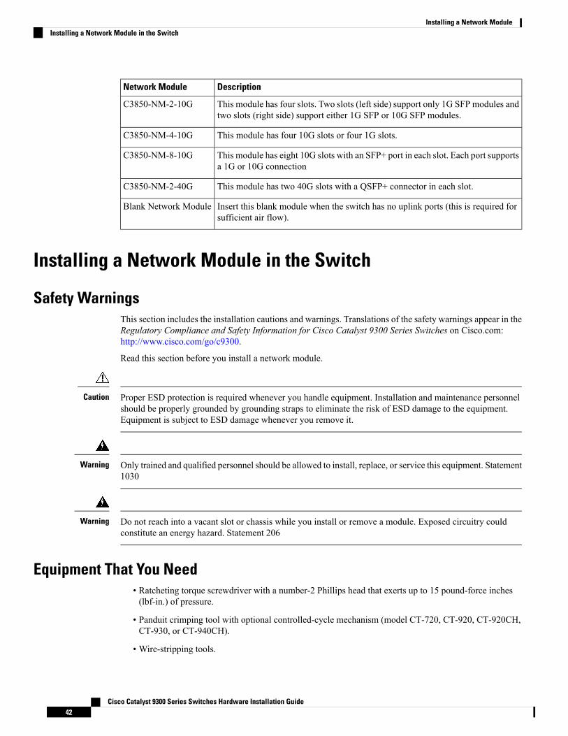
DescriptionNetwork Module
This module has four slots. Two slots (left side) support only 1G SFP modules andtwo slots (right side) support either 1G SFP or 10G SFP modules.
C3850-NM-2-10G
This module has four 10G slots or four 1G slots.C3850-NM-4-10G
This module has eight 10G slots with an SFP+ port in each slot. Each port supportsa 1G or 10G connection
C3850-NM-8-10G
This module has two 40G slots with a QSFP+ connector in each slot.C3850-NM-2-40G
Insert this blank module when the switch has no uplink ports (this is required forsufficient air flow).
Blank Network Module
Installing a Network Module in the Switch
Safety WarningsThis section includes the installation cautions and warnings. Translations of the safety warnings appear in theRegulatory Compliance and Safety Information for Cisco Catalyst 9300 Series Switches on Cisco.com:http://www.cisco.com/go/c9300.
Read this section before you install a network module.
Proper ESD protection is required whenever you handle equipment. Installation and maintenance personnelshould be properly grounded by grounding straps to eliminate the risk of ESD damage to the equipment.Equipment is subject to ESD damage whenever you remove it.
Caution
Only trained and qualified personnel should be allowed to install, replace, or service this equipment. Statement1030
Warning
Do not reach into a vacant slot or chassis while you install or remove a module. Exposed circuitry couldconstitute an energy hazard. Statement 206
Warning
Equipment That You Need• Ratcheting torque screwdriver with a number-2 Phillips head that exerts up to 15 pound-force inches(lbf-in.) of pressure.
• Panduit crimping tool with optional controlled-cycle mechanism (model CT-720, CT-920, CT-920CH,CT-930, or CT-940CH).
• Wire-stripping tools.
Cisco Catalyst 9300 Series Switches Hardware Installation Guide42
Installing a Network ModuleInstalling a Network Module in the Switch
• 12-gauge copper ground wire (insulated or not) for the single-hole ground connection.
• Single-hole ground lug and screw (included in the switch accessory kit).
• Four leads of 14-gauge copper wire.
Installing Network Modules
The switch can operate without a network module, but a blank module (with no ports or SFP slots) is availableand should be installed when uplink ports are not required.
Note
The switch generates logs when you insert or remove a network module with SFP/SFP+/SFP28 slots.Note
Use only supported network modules and SFP, SFP+, SFP28 or QSFP modules. Each module has an internalserial EEPROM that is encoded with security information.
The network module is hot-swappable. If you remove a module, replace it with another network module ora blank module.
The switch complies with EMC, safety, and thermal specifications when a network module is present. If nouplink ports are required, install a blank network module.
Note
Before you begin
When installing network modules, observe these precautions:
• Do not remove the blank module from the slot unless you are installing an SFP, SFP+, SFP28 or QSFPmodule. Either a module or a dust plug must be in the slot at all times.
• Do not remove the dust plugs from the fiber-optic SFP, SFP+, SFP28 and QSFP modules or the rubbercaps from the fiber-optic cable until you connect the cable. The plugs and caps protect the module portsand cables from contamination and ambient light.
• Removing and installing a network module can shorten its useful life. Do not remove and insert a networkmodule more often than is necessary.
• To prevent ESD damage, follow your normal board and component handling procedures when connectingcables to the switch and other devices.
Cisco Catalyst 9300 Series Switches Hardware Installation Guide43
Installing a Network ModuleInstalling Network Modules
Unlike other network modules, the C9300-NM-8X cannot be fully inserted and secured until the jackscrewis properly tightened.
1. Push the module into the uplink slot until the jackscrew connects with the rightmost tab.
2. You will feel some light resistance, because a spring-loaded tab inside the slot will push back against theC9300-NM-8X module
3. Continue to tighten the jackscrew while gently pushing the front panel of the network module into theslot.
Note
Procedure
Step 1 Attach an ESD-preventive wrist strap to your wrist and to an earth ground surface.Step 2 Remove the module from the protective packaging.Step 3 Remove the blank module from the switch and save it.
Verify the correct orientation of your module before installing it. Incorrect installation can damagethe module.
Caution
Do not install the network module with connected cables or installed SFP/SFP+/SFP28 modules.Always remove any cables and modules before you install the network module.
Caution
Amodule interface might become error-disabled when a network module with connected fiber-opticcables is installed or removed. If an interface is error-disabled, you can reenable the interface byusing the shutdown and no shutdown interface configuration commands.
Caution
Step 4 Position the module face up to install it in the module slot. Slide the module into the slot until the back of themodule faceplate is flush with the switch faceplate. Fasten the captive screws to secure the network modulein place.
Cisco Catalyst 9300 Series Switches Hardware Installation Guide44
Installing a Network ModuleInstalling Network Modules
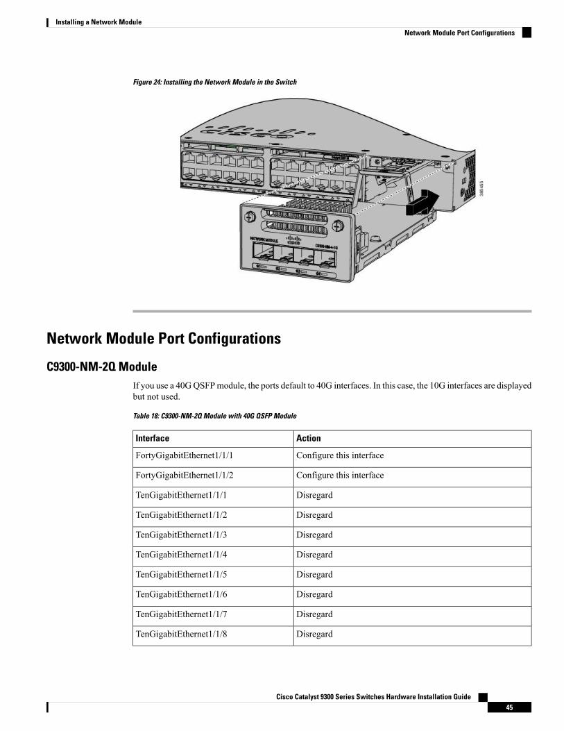
Figure 24: Installing the Network Module in the Switch
Network Module Port Configurations
C9300-NM-2Q ModuleIf you use a 40GQSFPmodule, the ports default to 40G interfaces. In this case, the 10G interfaces are displayedbut not used.
Table 18: C9300-NM-2Q Module with 40G QSFP Module
ActionInterface
Configure this interfaceFortyGigabitEthernet1/1/1
Configure this interfaceFortyGigabitEthernet1/1/2
DisregardTenGigabitEthernet1/1/1
DisregardTenGigabitEthernet1/1/2
DisregardTenGigabitEthernet1/1/3
DisregardTenGigabitEthernet1/1/4
DisregardTenGigabitEthernet1/1/5
DisregardTenGigabitEthernet1/1/6
DisregardTenGigabitEthernet1/1/7
DisregardTenGigabitEthernet1/1/8
Cisco Catalyst 9300 Series Switches Hardware Installation Guide45
Installing a Network ModuleNetwork Module Port Configurations
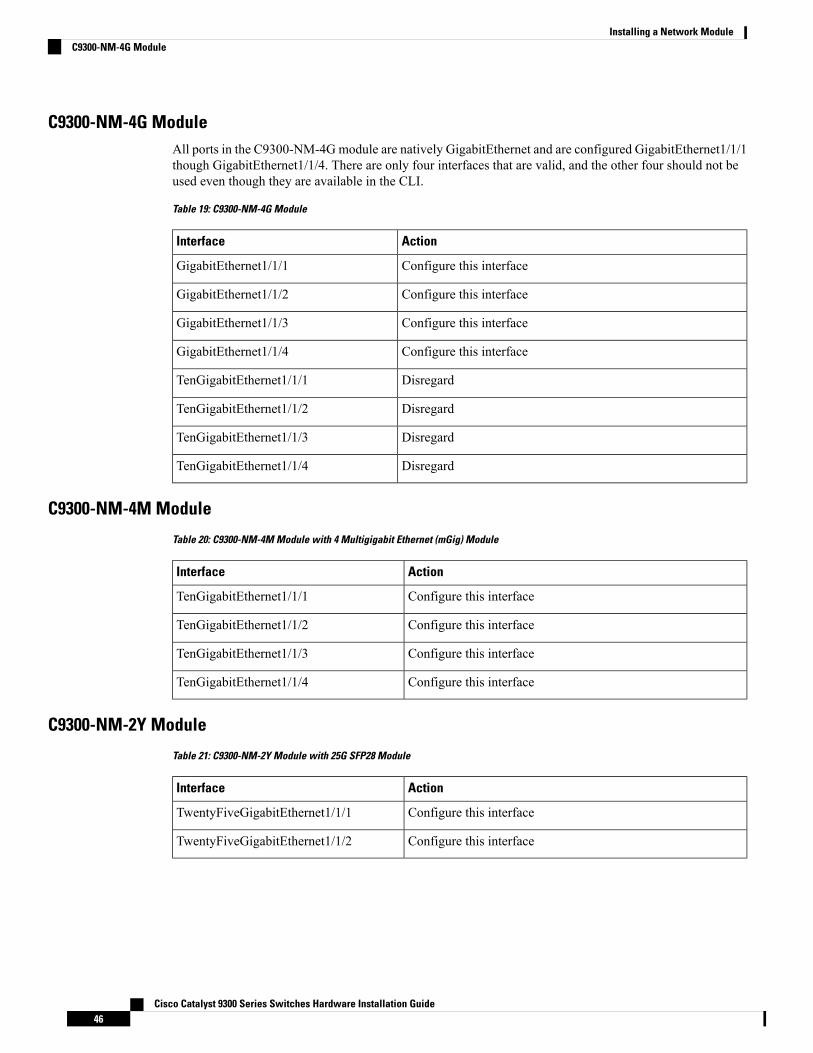
C9300-NM-4G ModuleAll ports in the C9300-NM-4Gmodule are natively GigabitEthernet and are configured GigabitEthernet1/1/1though GigabitEthernet1/1/4. There are only four interfaces that are valid, and the other four should not beused even though they are available in the CLI.
Table 19: C9300-NM-4G Module
ActionInterface
Configure this interfaceGigabitEthernet1/1/1
Configure this interfaceGigabitEthernet1/1/2
Configure this interfaceGigabitEthernet1/1/3
Configure this interfaceGigabitEthernet1/1/4
DisregardTenGigabitEthernet1/1/1
DisregardTenGigabitEthernet1/1/2
DisregardTenGigabitEthernet1/1/3
DisregardTenGigabitEthernet1/1/4
C9300-NM-4M Module
Table 20: C9300-NM-4M Module with 4 Multigigabit Ethernet (mGig) Module
ActionInterface
Configure this interfaceTenGigabitEthernet1/1/1
Configure this interfaceTenGigabitEthernet1/1/2
Configure this interfaceTenGigabitEthernet1/1/3
Configure this interfaceTenGigabitEthernet1/1/4
C9300-NM-2Y Module
Table 21: C9300-NM-2Y Module with 25G SFP28 Module
ActionInterface
Configure this interfaceTwentyFiveGigabitEthernet1/1/1
Configure this interfaceTwentyFiveGigabitEthernet1/1/2
Cisco Catalyst 9300 Series Switches Hardware Installation Guide46
Installing a Network ModuleC9300-NM-4G Module
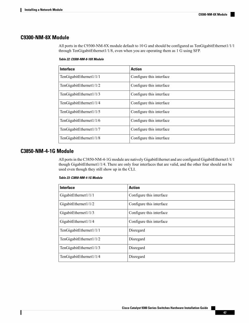
C9300-NM-8X ModuleAll ports in the C9300-NM-8X module default to 10 G and should be configured as TenGigabitEthernet1/1/1through TenGigabitEthernet1/1/8, even when you are operating them as 1 G using SFP.
Table 22: C9300-NM-8-10X Module
ActionInterface
Configure this interfaceTenGigabitEthernet1/1/1
Configure this interfaceTenGigabitEthernet1/1/2
Configure this interfaceTenGigabitEthernet1/1/3
Configure this interfaceTenGigabitEthernet1/1/4
Configure this interfaceTenGigabitEthernet1/1/5
Configure this interfaceTenGigabitEthernet1/1/6
Configure this interfaceTenGigabitEthernet1/1/7
Configure this interfaceTenGigabitEthernet1/1/8
C3850-NM-4-1G ModuleAll ports in the C3850-NM-4-1Gmodule are natively GigabitEthernet and are configured GigabitEthernet1/1/1though GigabitEthernet1/1/4. There are only four interfaces that are valid, and the other four should not beused even though they still show up in the CLI.
Table 23: C3850-NM-4-1G Module
ActionInterface
Configure this interfaceGigabitEthernet1/1/1
Configure this interfaceGigabitEthernet1/1/2
Configure this interfaceGigabitEthernet1/1/3
Configure this interfaceGigabitEthernet1/1/4
DisregardTenGigabitEthernet1/1/1
DisregardTenGigabitEthernet1/1/2
DisregardTenGigabitEthernet1/1/3
DisregardTenGigabitEthernet1/1/4
Cisco Catalyst 9300 Series Switches Hardware Installation Guide47
Installing a Network ModuleC9300-NM-8X Module
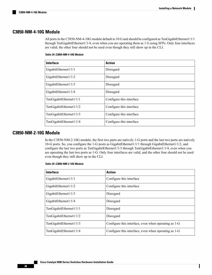
C3850-NM-4-10G ModuleAll ports in the C3850-NM-4-10Gmodule default to 10 G and should be configured as TenGigabitEthernet1/1/1through TenGigabitEthernet1/1/4, even when you are operating them as 1 G using SFPs. Only four interfacesare valid; the other four should not be used even though they still show up in the CLI.
Table 24: C3850-NM-4-10G Module
ActionInterface
DisregardGigabitEthernet1/1/1
DisregardGigabitEthernet1/1/2
DisregardGigabitEthernet1/1/3
DisregardGigabitEthernet1/1/4
Configure this interfaceTenGigabitEthernet1/1/1
Configure this interfaceTenGigabitEthernet1/1/2
Configure this interfaceTenGigabitEthernet1/1/3
Configure this interfaceTenGigabitEthernet1/1/4
C3850-NM-2-10G ModuleIn the C3850-NM-2-10G module, the first two parts are natively 1-G ports and the last two ports are natively10-G ports. So, you configure the 1-G posts as GigabitEthernet1/1/1 through GigabitEthernet1/1/2, andconfigure the last two ports as TenGigabitEthernet1/1/3 through TenGigabitEthernet1/1/4, even when youare operating the last two ports as 1-G. Only four interfaces are valid, and the other four should not be usedeven though they still show up in the CLI.
Table 25: C3850-NM-2-10G Module
ActionInterface
Configure this interfaceGigabitEthernet1/1/1
Configure this interfaceGigabitEthernet1/1/2
DisregardGigabitEthernet1/1/3
DisregardGigabitEthernet1/1/4
DisregardTenGigabitEthernet1/1/1
DisregardTenGigabitEthernet1/1/2
Configure this interface, even when operating as 1-GTenGigabitEthernet1/1/3
Configure this interface, even when operating as 1-GTenGigabitEthernet1/1/4
Cisco Catalyst 9300 Series Switches Hardware Installation Guide48
Installing a Network ModuleC3850-NM-4-10G Module
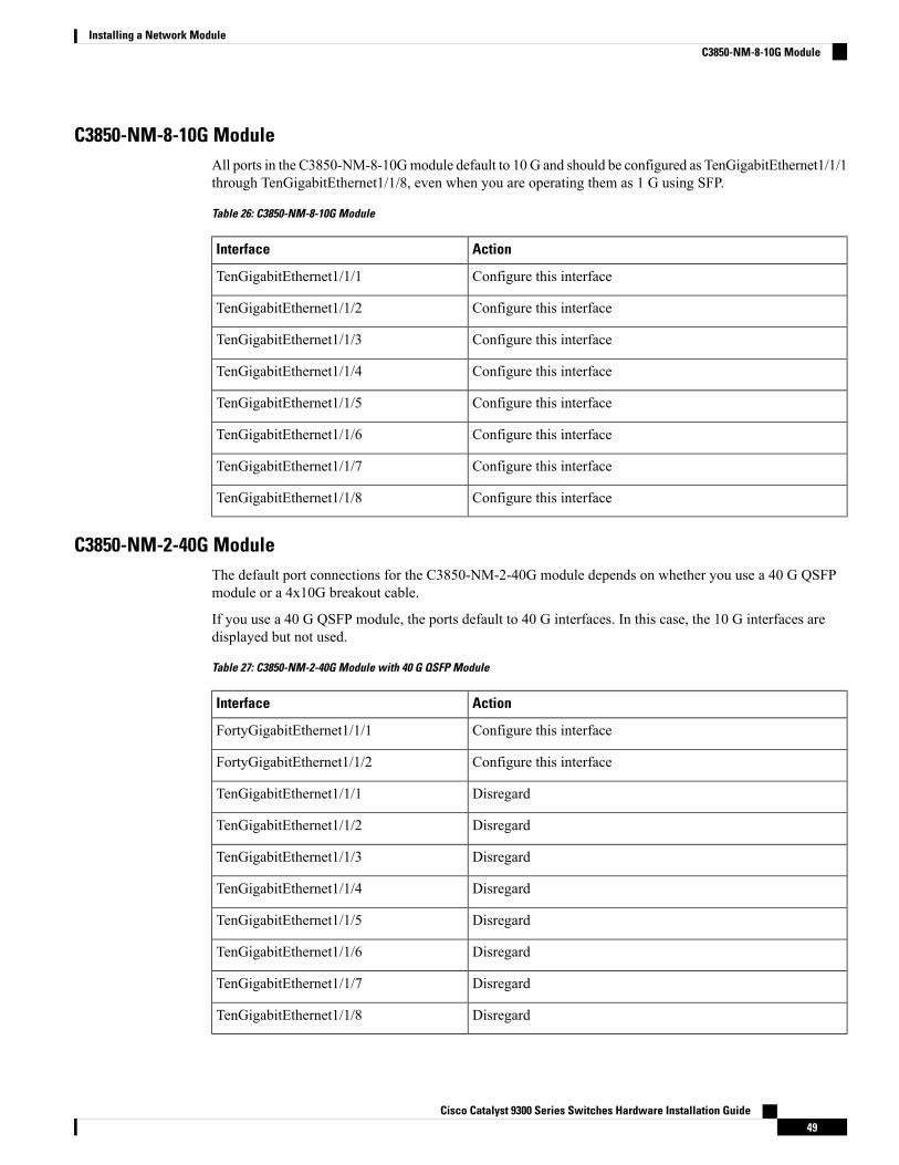
C3850-NM-8-10G ModuleAll ports in the C3850-NM-8-10Gmodule default to 10 G and should be configured as TenGigabitEthernet1/1/1through TenGigabitEthernet1/1/8, even when you are operating them as 1 G using SFP.
Table 26: C3850-NM-8-10G Module
ActionInterface
Configure this interfaceTenGigabitEthernet1/1/1
Configure this interfaceTenGigabitEthernet1/1/2
Configure this interfaceTenGigabitEthernet1/1/3
Configure this interfaceTenGigabitEthernet1/1/4
Configure this interfaceTenGigabitEthernet1/1/5
Configure this interfaceTenGigabitEthernet1/1/6
Configure this interfaceTenGigabitEthernet1/1/7
Configure this interfaceTenGigabitEthernet1/1/8
C3850-NM-2-40G ModuleThe default port connections for the C3850-NM-2-40G module depends on whether you use a 40 G QSFPmodule or a 4x10G breakout cable.
If you use a 40 G QSFP module, the ports default to 40 G interfaces. In this case, the 10 G interfaces aredisplayed but not used.
Table 27: C3850-NM-2-40G Module with 40 G QSFP Module
ActionInterface
Configure this interfaceFortyGigabitEthernet1/1/1
Configure this interfaceFortyGigabitEthernet1/1/2
DisregardTenGigabitEthernet1/1/1
DisregardTenGigabitEthernet1/1/2
DisregardTenGigabitEthernet1/1/3
DisregardTenGigabitEthernet1/1/4
DisregardTenGigabitEthernet1/1/5
DisregardTenGigabitEthernet1/1/6
DisregardTenGigabitEthernet1/1/7
DisregardTenGigabitEthernet1/1/8
Cisco Catalyst 9300 Series Switches Hardware Installation Guide49
Installing a Network ModuleC3850-NM-8-10G Module
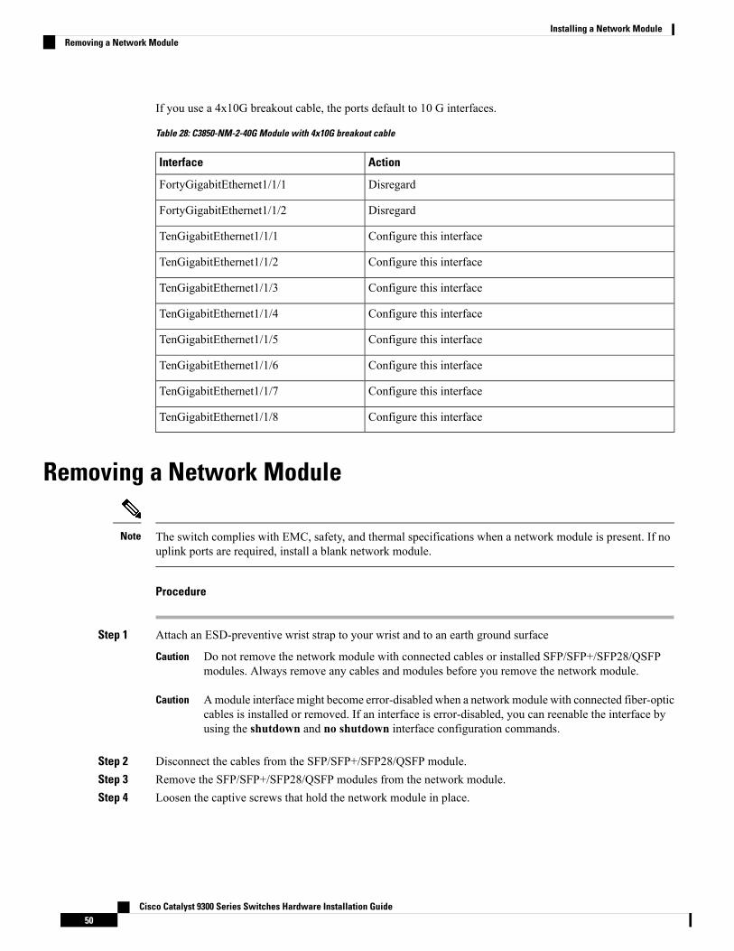
If you use a 4x10G breakout cable, the ports default to 10 G interfaces.
Table 28: C3850-NM-2-40G Module with 4x10G breakout cable
ActionInterface
DisregardFortyGigabitEthernet1/1/1
DisregardFortyGigabitEthernet1/1/2
Configure this interfaceTenGigabitEthernet1/1/1
Configure this interfaceTenGigabitEthernet1/1/2
Configure this interfaceTenGigabitEthernet1/1/3
Configure this interfaceTenGigabitEthernet1/1/4
Configure this interfaceTenGigabitEthernet1/1/5
Configure this interfaceTenGigabitEthernet1/1/6
Configure this interfaceTenGigabitEthernet1/1/7
Configure this interfaceTenGigabitEthernet1/1/8
Removing a Network Module
The switch complies with EMC, safety, and thermal specifications when a network module is present. If nouplink ports are required, install a blank network module.
Note
Procedure
Step 1 Attach an ESD-preventive wrist strap to your wrist and to an earth ground surface
Do not remove the network module with connected cables or installed SFP/SFP+/SFP28/QSFPmodules. Always remove any cables and modules before you remove the network module.
Caution
Amodule interface might become error-disabled when a network module with connected fiber-opticcables is installed or removed. If an interface is error-disabled, you can reenable the interface byusing the shutdown and no shutdown interface configuration commands.
Caution
Step 2 Disconnect the cables from the SFP/SFP+/SFP28/QSFP module.Step 3 Remove the SFP/SFP+/SFP28/QSFP modules from the network module.Step 4 Loosen the captive screws that hold the network module in place.
Cisco Catalyst 9300 Series Switches Hardware Installation Guide50
Installing a Network ModuleRemoving a Network Module
The C3850-NM-8-10G module is held secure in the switch by only one jackscrew. This screw alsohelps to eject the module from its connector interface. Before the module can be removed completely,the screwmust be unscrewed all the way out. When removing the screw, a spring pushes the moduleout when the screw is completely disengaged. Ensure that you hold the module securely until it iscompletely removed.
Note
Step 5 Grasp the captive screws, and carefully slide it out of the slot.Step 6 Install a replacement network module or a blank module in the slot.Step 7 Place the module that you removed in an antistatic bag or other protective environment.
SFP, SFP+ and SFP28 Modules
Installing SFP, SFP+ and SFP28 Modules
Before you begin
You must have an installed network module to use SFP, SFP+ and SFP28 modules. See the switch releasenotes on Cisco.com for the list of supported SFP, SFP+ and SFP28 modules. Use only supportedSFP/SFP+/SFP28 modules on the switch. For the latest information about supported SFP, SFP+ and SFP28modules, refer to the Cisco Transceiver Modules Compatibility Information.
For information about installing, removing, cabling, and troubleshooting SFP/SFP+/SFP28 modules, see themodule documentation that shipped with your device.
Observe these precautions:
Class 1 laser product. Statement 1008Warning
• Do not remove the dust plugs from the SFP/SFP+/SFP28 modules or the rubber caps from the fiber-opticcable until you are ready to connect the cable. The plugs and caps protect the module ports and cablesfrom contamination and ambient light.
• Removing and installing an SFP/SFP+/SFP28 module can shorten its useful life. Do not remove andinsert any SFP/SFP+/SFP28 module more often than is necessary.
• To prevent ESD damage, follow your normal board and component handling procedures when connectingcables to the switch and other devices.
• When you insert several SFP/SFP+/SFP28 modules in multiple switch ports, wait for 5 seconds betweeninserting each SFP/SFP+/SFP28. This will prevent the ports from going into error disabled mode.Similarly, when you remove an SFP/SFP+/SFP28 from a port, wait for 5 seconds before reinserting it.
Procedure
Step 1 Attach an ESD-preventive wrist strap to your wrist and to an earth ground surface.Step 2 Find the send (TX) and receive (RX) markings that identify the top of the SFP/SFP+/SFP28 module.
Cisco Catalyst 9300 Series Switches Hardware Installation Guide51
Installing a Network ModuleSFP, SFP+ and SFP28 Modules
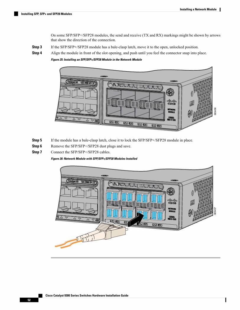
On some SFP/SFP+/SFP28 modules, the send and receive (TX and RX) markings might be shown by arrowsthat show the direction of the connection.
Step 3 If the SFP/SFP+/SFP28 module has a bale-clasp latch, move it to the open, unlocked position.Step 4 Align the module in front of the slot opening, and push until you feel the connector snap into place.
Figure 25: Installing an SFP/SFP+/SFP28 Module in the Network Module
Step 5 If the module has a bale-clasp latch, close it to lock the SFP/SFP+/SFP28 module in place.Step 6 Remove the SFP/SFP+/SFP28 dust plugs and save.Step 7 Connect the SFP/SFP+/SFP28 cables.
Figure 26: Network Module with SFP/SFP+/SFP28 Modules Installed
Cisco Catalyst 9300 Series Switches Hardware Installation Guide52
Installing a Network ModuleInstalling SFP, SFP+ and SFP28 Modules
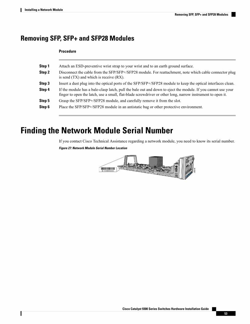
Removing SFP, SFP+ and SFP28 Modules
Procedure
Step 1 Attach an ESD-preventive wrist strap to your wrist and to an earth ground surface.Step 2 Disconnect the cable from the SFP/SFP+/SFP28 module. For reattachment, note which cable connector plug
is send (TX) and which is receive (RX).Step 3 Insert a dust plug into the optical ports of the SFP/SFP+/SFP28 module to keep the optical interfaces clean.Step 4 If the module has a bale-clasp latch, pull the bale out and down to eject the module. If you cannot use your
finger to open the latch, use a small, flat-blade screwdriver or other long, narrow instrument to open it.Step 5 Grasp the SFP/SFP+/SFP28 module, and carefully remove it from the slot.Step 6 Place the SFP/SFP+/SFP28 module in an antistatic bag or other protective environment.
Finding the Network Module Serial NumberIf you contact Cisco Technical Assistance regarding a network module, you need to know its serial number.Figure 27: Network Module Serial Number Location
Cisco Catalyst 9300 Series Switches Hardware Installation Guide53
Installing a Network ModuleRemoving SFP, SFP+ and SFP28 Modules

Cisco Catalyst 9300 Series Switches Hardware Installation Guide54
Installing a Network ModuleFinding the Network Module Serial Number
C H A P T E R 4Installing a Power Supply
• Power Supply Modules Overview, on page 55• Installation Guidelines, on page 57• Installing or Replacing an AC Power Supply, on page 59• Finding the Power Supply Module Serial Number, on page 60
Power Supply Modules OverviewThe switch operates with either one or two active power supply modules. A switch that is part of a StackPowerstack operates with power supplied by other stack switches.
You can use two AC modules or one module and a blank cover. All power supply modules have internal fans.All switches ship with a blank cover in the second power supply slot.
The following table describes the supported internal power supply modules.
Table 29: Power Supply Module Part Numbers and Descriptions
DescriptionPart Number
1100-W AC power supply modulePWR-C1-1100WAC
715-W AC power supply modulePWR-C1-715WAC
350-W AC power supply modulePWR-C1-350WAC
1100-W AC Platinum certified power supply modulePWR-C1-1100WAC-P
Blank coverPWR-C1-BLANK
For information on available PoE, PoE+, and UPOE and PoE requirements, see these sections the PowerSupply Modules, on page 15.
The 350-W and 715-W AC power supply modules are autoranging units that support input voltages between100 and 240 VAC. The 1100-W power supply module is an autoranging unit that supports input voltagesbetween 115 and 240 VAC.
Each AC power supply module has a power cord for connection to an AC power outlet. The 1100-W and715-W modules use a 16-AWG cord (only North America). All other modules use an 18-AWG cord.
The following illustrations show the power supply modules.
Cisco Catalyst 9300 Series Switches Hardware Installation Guide55
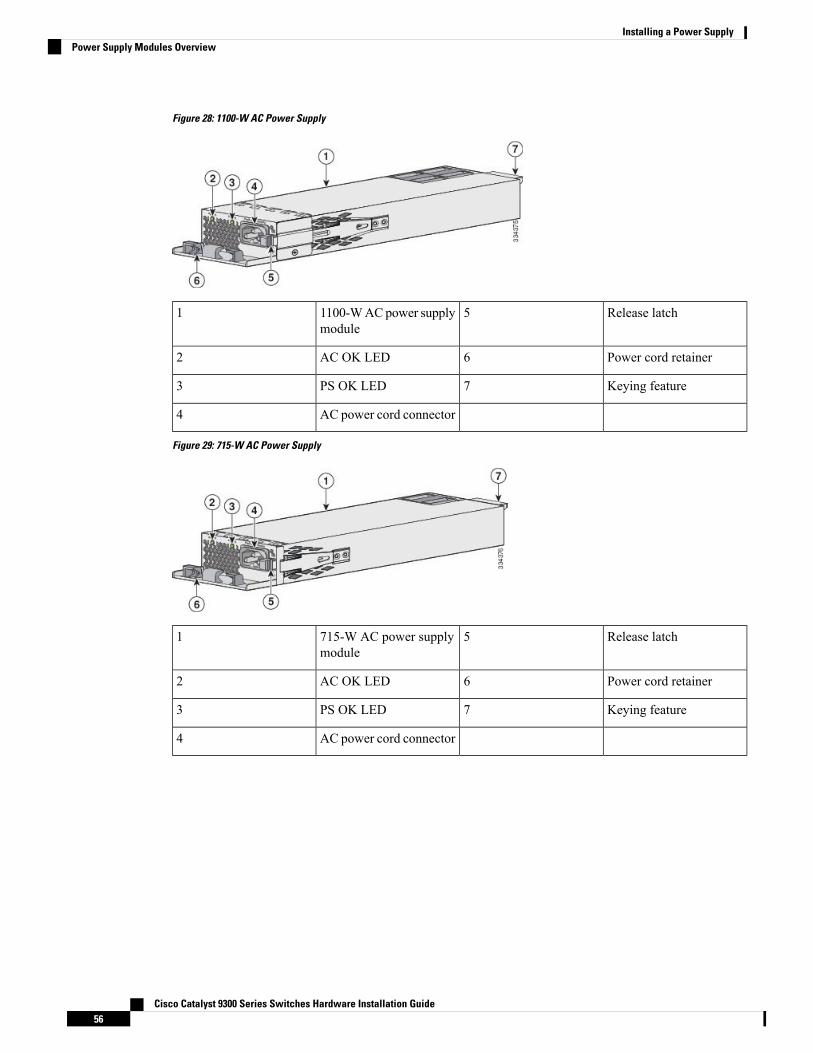
Figure 28: 1100-W AC Power Supply
Release latch51100-WACpower supplymodule
1
Power cord retainer6AC OK LED2
Keying feature7PS OK LED3
AC power cord connector4
Figure 29: 715-W AC Power Supply
Release latch5715-W AC power supplymodule
1
Power cord retainer6AC OK LED2
Keying feature7PS OK LED3
AC power cord connector4
Cisco Catalyst 9300 Series Switches Hardware Installation Guide56
Installing a Power SupplyPower Supply Modules Overview
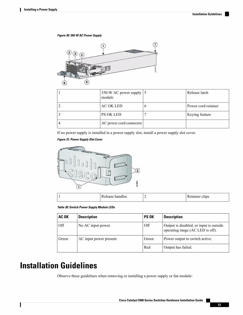
Figure 30: 350-W AC Power Supply
Release latch5350-W AC power supplymodule
1
Power cord retainer6AC OK LED2
Keying feature7PS OK LED3
AC power cord connector4
If no power supply is installed in a power supply slot, install a power supply slot cover.Figure 31: Power Supply Slot Cover
Retainer clips2Release handles1
Table 30: Switch Power Supply Module LEDs
DescriptionPS OKDescriptionAC OK
Output is disabled, or input is outsideoperating range (AC LED is off).
OffNo AC input power.Off
Power output to switch active.GreenAC input power present.Green
Output has failed.Red
Installation GuidelinesObserve these guidelines when removing or installing a power supply or fan module:
Cisco Catalyst 9300 Series Switches Hardware Installation Guide57
Installing a Power SupplyInstallation Guidelines
• Do not force the power supply or fan module into the slot. This can damage the pins on the switch if theyare not aligned with the module.
• A power supply that is only partially connected to the switch can disrupt the system operation.
• Remove power from the power-supply module before removing or installing the module.
• The power supply is hot-swappable. In some configurations, such as full PoE+ or power sharing mode,removing a power supply causes powered devices to shut down until the power budget matches the inputpower of a single power supply. To minimize network interruption, hot swap the power supply underthese circumstances:
• The switch is in StackPower mode and sufficient power is available.
• The switch is powered by other switches in a power stack, and no active backup is in progress.
For the switch commands that display available power budget, see the software configuration guide.
Do not operate the switch with one power-supply module slot empty. For proper chassis cooling, both moduleslots must be populated, with either a power supply or a blank module.
Caution
This equipment must be grounded. Never defeat the ground conductor or operate the equipment in the absenceof a suitably installed ground conductor. Contact the appropriate electrical inspection authority or an electricianif you are uncertain that suitable grounding is available.
Statement 1024
Warning
Blank faceplates and cover panels serve three important functions: they prevent exposure to hazardous voltagesand currents inside the chassis; they contain electromagnetic interference (EMI) that might disrupt otherequipment; and they direct the flow of cooling air through the chassis. Do not operate the system unless allcards, faceplates, front covers, and rear covers are in place.
Statement 1029
Warning
Do not reach into a vacant slot or chassis while you install or remove a module. Exposed circuitry couldconstitute an energy hazard.
Statement 206
Warning
Only trained and qualified personnel should be allowed to install, replace, or service this equipment.
Statement 1030
Warning
Cisco Catalyst 9300 Series Switches Hardware Installation Guide58
Installing a Power SupplyInstallation Guidelines
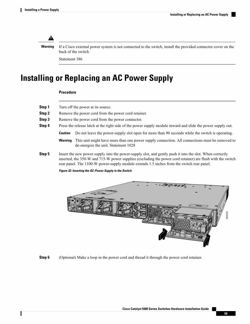
If a Cisco external power system is not connected to the switch, install the provided connector cover on theback of the switch.
Statement 386
Warning
Installing or Replacing an AC Power SupplyProcedure
Step 1 Turn off the power at its source.Step 2 Remove the power cord from the power cord retainer.Step 3 Remove the power cord from the power connector.Step 4 Press the release latch at the right side of the power supply module inward and slide the power supply out.
Do not leave the power-supply slot open for more than 90 seconds while the switch is operating.Caution
This unit might have more than one power supply connection. All connections must be removed tode-energize the unit. Statement 1028
Warning
Step 5 Insert the new power supply into the power-supply slot, and gently push it into the slot. When correctlyinserted, the 350-W and 715-W power supplies (excluding the power cord retainer) are flush with the switchrear panel. The 1100-W power-supply module extends 1.5 inches from the switch rear panel.Figure 32: Inserting the AC-Power Supply in the Switch
Step 6 (Optional) Make a loop in the power cord and thread it through the power cord retainer.
Cisco Catalyst 9300 Series Switches Hardware Installation Guide59
Installing a Power SupplyInstalling or Replacing an AC Power Supply
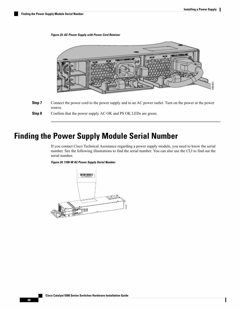
Figure 33: AC-Power Supply with Power Cord Retainer
Step 7 Connect the power cord to the power supply and to an AC power outlet. Turn on the power at the powersource.
Step 8 Confirm that the power supply AC OK and PS OK LEDs are green.
Finding the Power Supply Module Serial NumberIf you contact Cisco Technical Assistance regarding a power supply module, you need to know the serialnumber. See the following illustrations to find the serial number. You can also use the CLI to find out theserial number.Figure 34: 1100-W AC Power Supply Serial Number
Cisco Catalyst 9300 Series Switches Hardware Installation Guide60
Installing a Power SupplyFinding the Power Supply Module Serial Number
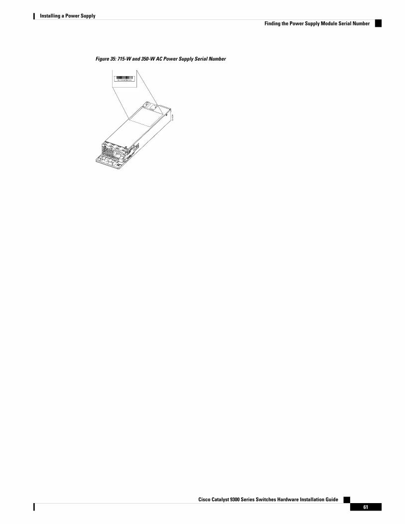
Figure 35: 715-W and 350-W AC Power Supply Serial Number
Cisco Catalyst 9300 Series Switches Hardware Installation Guide61
Installing a Power SupplyFinding the Power Supply Module Serial Number

Cisco Catalyst 9300 Series Switches Hardware Installation Guide62
Installing a Power SupplyFinding the Power Supply Module Serial Number
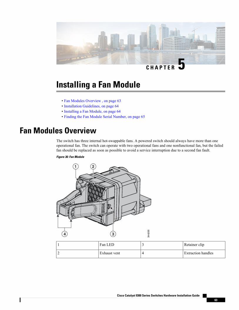
C H A P T E R 5Installing a Fan Module
• Fan Modules Overview , on page 63• Installation Guidelines, on page 64• Installing a Fan Module, on page 64• Finding the Fan Module Serial Number, on page 65
Fan Modules OverviewThe switch has three internal hot-swappable fans. A powered switch should always have more than oneoperational fan. The switch can operate with two operational fans and one nonfunctional fan, but the failedfan should be replaced as soon as possible to avoid a service interruption due to a second fan fault.Figure 36: Fan Module
Retainer clip3Fan LED1
Extraction handles4Exhaust vent2
Cisco Catalyst 9300 Series Switches Hardware Installation Guide63
The switch requires three fans for proper cooling.Note
Installation GuidelinesObserve these guidelines when removing or installing a fan module:
• Do not force the fan module into the slot. This can damage the pins on the switch if they are not alignedwith the module.
• A fan module that is only partially connected to the switch can disrupt the system operation.
• The switch supports hot swapping of the fan module. You can remove and replace the module withoutinterrupting normal switch operation.
Only trained and qualified personnel should be allowed to install, replace, or service this equipment. Statement1030
Warning
Installing a Fan ModuleProcedure
Step 1 Pinch the fan module release handle, and slide the module out.
You should replace the fan module within 5 minutes to avoid overheating the switch.Caution
Step 2 Install the fan module in the fan slot, and firmly push it into the slot, applying pressure to the end of themodule, not the extraction handles. When correctly inserted, the fan module is flush with the switch rear panel.When the fan is operating, a green LED is on in the top left corner of the fan.
Do not reach into a vacant slot when installing or removing a module. Exposed circuitry is an energyhazard. Statement 206
Warning
Cisco Catalyst 9300 Series Switches Hardware Installation Guide64
Installing a Fan ModuleInstallation Guidelines
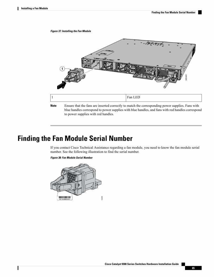
Figure 37: Installing the Fan Module
Fan LED1
Ensure that the fans are inserted correctly to match the corresponding power supplies. Fans withblue handles correspond to power supplies with blue handles, and fans with red handles correspondto power supplies with red handles.
Note
Finding the Fan Module Serial NumberIf you contact Cisco Technical Assistance regarding a fan module, you need to know the fan module serialnumber. See the following illustration to find the serial number.Figure 38: Fan Module Serial Number
Cisco Catalyst 9300 Series Switches Hardware Installation Guide65
Installing a Fan ModuleFinding the Fan Module Serial Number

Cisco Catalyst 9300 Series Switches Hardware Installation Guide66
Installing a Fan ModuleFinding the Fan Module Serial Number
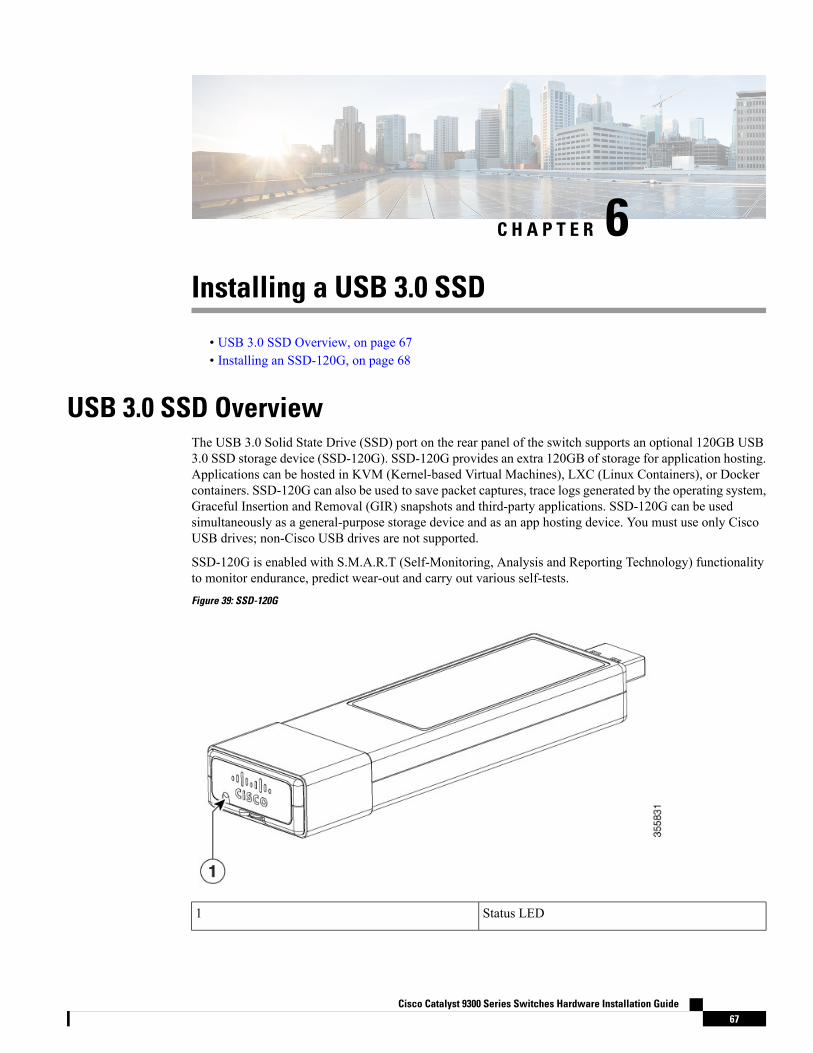
C H A P T E R 6Installing a USB 3.0 SSD
• USB 3.0 SSD Overview, on page 67• Installing an SSD-120G, on page 68
USB 3.0 SSD OverviewThe USB 3.0 Solid State Drive (SSD) port on the rear panel of the switch supports an optional 120GB USB3.0 SSD storage device (SSD-120G). SSD-120G provides an extra 120GB of storage for application hosting.Applications can be hosted in KVM (Kernel-based Virtual Machines), LXC (Linux Containers), or Dockercontainers. SSD-120G can also be used to save packet captures, trace logs generated by the operating system,Graceful Insertion and Removal (GIR) snapshots and third-party applications. SSD-120G can be usedsimultaneously as a general-purpose storage device and as an app hosting device. You must use only CiscoUSB drives; non-Cisco USB drives are not supported.
SSD-120G is enabled with S.M.A.R.T (Self-Monitoring, Analysis and Reporting Technology) functionalityto monitor endurance, predict wear-out and carry out various self-tests.Figure 39: SSD-120G
Status LED1
Cisco Catalyst 9300 Series Switches Hardware Installation Guide67
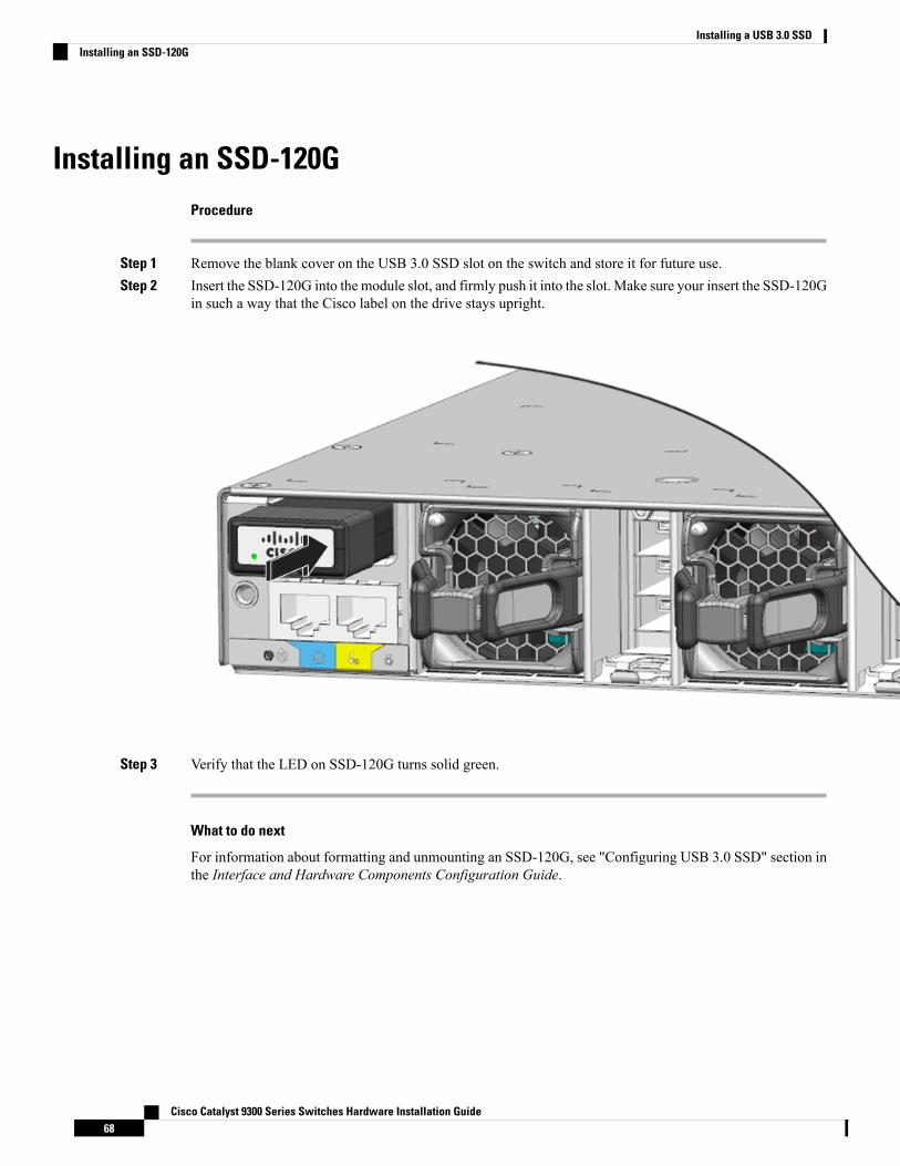
Installing an SSD-120GProcedure
Step 1 Remove the blank cover on the USB 3.0 SSD slot on the switch and store it for future use.Step 2 Insert the SSD-120G into the module slot, and firmly push it into the slot. Make sure your insert the SSD-120G
in such a way that the Cisco label on the drive stays upright.
Step 3 Verify that the LED on SSD-120G turns solid green.
What to do next
For information about formatting and unmounting an SSD-120G, see "Configuring USB 3.0 SSD" section inthe Interface and Hardware Components Configuration Guide.
Cisco Catalyst 9300 Series Switches Hardware Installation Guide68
Installing a USB 3.0 SSDInstalling an SSD-120G
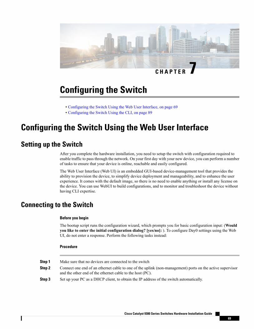
C H A P T E R 7Configuring the Switch
• Configuring the Switch Using the Web User Interface, on page 69• Configuring the Switch Using the CLI, on page 89
Configuring the Switch Using the Web User Interface
Setting up the SwitchAfter you complete the hardware installation, you need to setup the switch with configuration required toenable traffic to pass through the network. On your first day with your new device, you can perform a numberof tasks to ensure that your device is online, reachable and easily configured.
The Web User Interface (Web UI) is an embedded GUI-based device-management tool that provides theability to provision the device, to simplify device deployment and manageability, and to enhance the userexperience. It comes with the default image, so there is no need to enable anything or install any license onthe device. You can use WebUI to build configurations, and to monitor and troubleshoot the device withouthaving CLI expertise.
Connecting to the Switch
Before you begin
The bootup script runs the configuration wizard, which prompts you for basic configuration input: (Wouldyou like to enter the initial configuration dialog? [yes/no]: ). To configure Day0 settings using the WebUI, do not enter a response. Perform the following tasks instead:
Procedure
Step 1 Make sure that no devices are connected to the switchStep 2 Connect one end of an ethernet cable to one of the uplink (non-management) ports on the active supervisor
and the other end of the ethernet cable to the host (PC).Step 3 Set up your PC as a DHCP client, to obtain the IP address of the switch automatically.
Cisco Catalyst 9300 Series Switches Hardware Installation Guide69
It may take up to three mins. You must complete the Day0 setup through the WebUI before using the deviceterminal.
Step 4 Launch aWeb browser on the PC and enter the device IP address (https://192.168.1.1) in the addressbar.
What to do next
Create a user account.
Creating User AccountsSetting a username and password is the first task you will perform on your device. Typically, as a networkadministrator, you will want to control access to your device and prevent unauthorized users from seeing yournetwork configuration or manipulating your settings.
Procedure
Step 1 Log on using the default username and password provided with the device.
The default username is cisco; the default password is the serial number of the switch chassis.
Step 2 Set a password of up to 25 alphanumeric characters. The username password combination you set gives youprivilege 15 access. The string cannot start with a number, is case sensitive, and allows spaces but ignoresleading spaces.
Cisco Catalyst 9300 Series Switches Hardware Installation Guide70
Configuring the SwitchCreating User Accounts
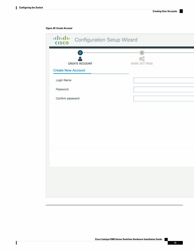
Figure 40: Create Account
Cisco Catalyst 9300 Series Switches Hardware Installation Guide71
Configuring the SwitchCreating User Accounts
Choosing Setup OptionsSelectWired Network to configure your device based on a site profile, and continue to configure switchwide settings. Otherwise, continue to the next step and configure only basic settings for your device.
Configuring Basic Device SettingsOn the Basic Device Settings page configure the following information:
Procedure
Step 1 In the Device ID and Location Settings section, type a unique name to identify your device in the network.Step 2 Choose the date and time settings for your device. To synchronize your device with a valid outside timing
mechanism, such as an NTP clock source, choose Automatic, or choose Manual to set it yourself.
Cisco Catalyst 9300 Series Switches Hardware Installation Guide72
Configuring the SwitchChoosing Setup Options
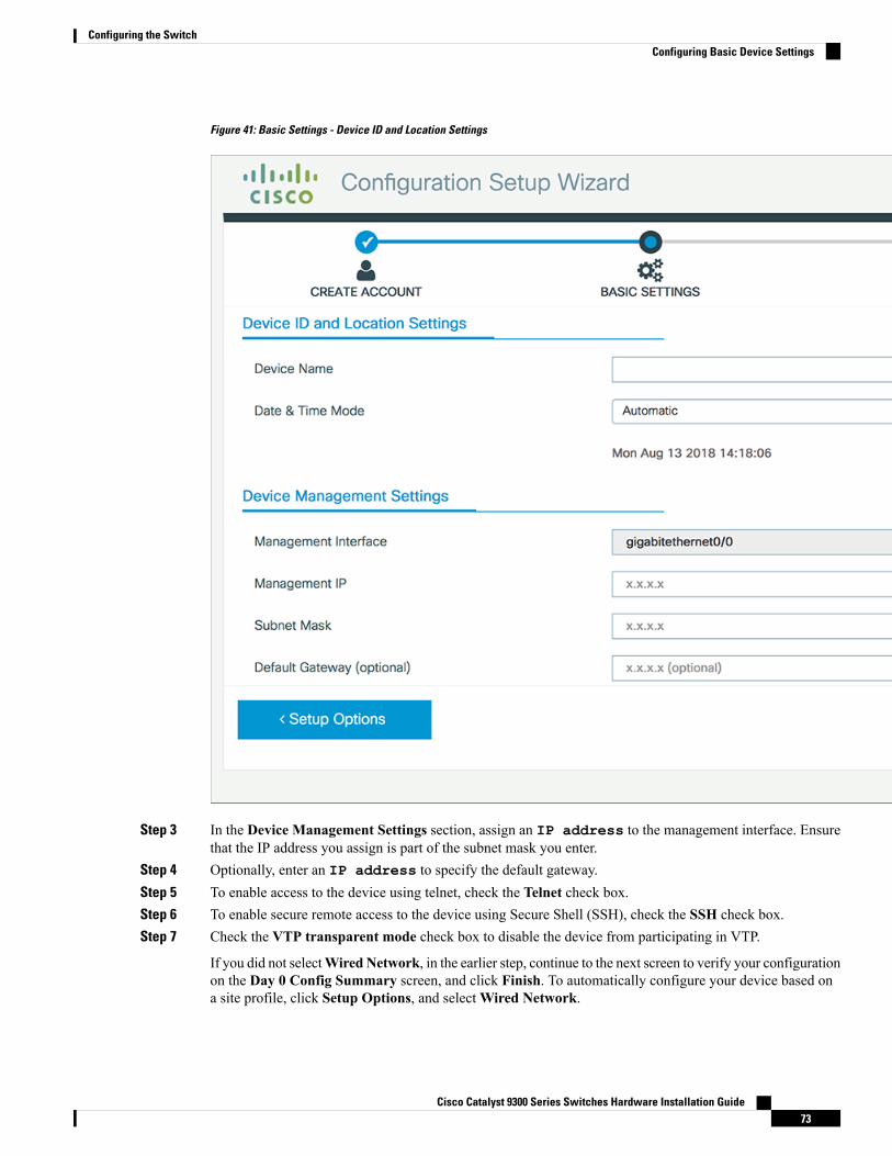
Figure 41: Basic Settings - Device ID and Location Settings
Step 3 In the Device Management Settings section, assign an IP address to the management interface. Ensurethat the IP address you assign is part of the subnet mask you enter.
Step 4 Optionally, enter an IP address to specify the default gateway.Step 5 To enable access to the device using telnet, check the Telnet check box.Step 6 To enable secure remote access to the device using Secure Shell (SSH), check the SSH check box.Step 7 Check the VTP transparent mode check box to disable the device from participating in VTP.
If you did not selectWired Network, in the earlier step, continue to the next screen to verify your configurationon the Day 0 Config Summary screen, and click Finish. To automatically configure your device based ona site profile, click Setup Options, and selectWired Network.
Cisco Catalyst 9300 Series Switches Hardware Installation Guide73
Configuring the SwitchConfiguring Basic Device Settings
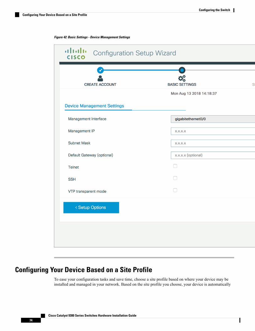
Figure 42: Basic Settings - Device Management Settings
Configuring Your Device Based on a Site ProfileTo ease your configuration tasks and save time, choose a site profile based on where your device may beinstalled and managed in your network. Based on the site profile you choose, your device is automatically
Cisco Catalyst 9300 Series Switches Hardware Installation Guide74
Configuring the SwitchConfiguring Your Device Based on a Site Profile
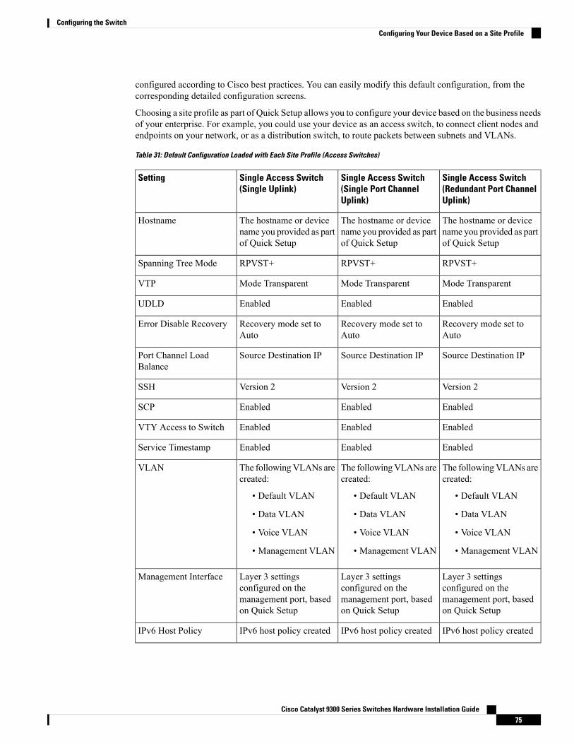
configured according to Cisco best practices. You can easily modify this default configuration, from thecorresponding detailed configuration screens.
Choosing a site profile as part of Quick Setup allows you to configure your device based on the business needsof your enterprise. For example, you could use your device as an access switch, to connect client nodes andendpoints on your network, or as a distribution switch, to route packets between subnets and VLANs.
Table 31: Default Configuration Loaded with Each Site Profile (Access Switches)
Single Access Switch(Redundant Port ChannelUplink)
Single Access Switch(Single Port ChannelUplink)
Single Access Switch(Single Uplink)
Setting
The hostname or devicename you provided as partof Quick Setup
The hostname or devicename you provided as partof Quick Setup
The hostname or devicename you provided as partof Quick Setup
Hostname
RPVST+RPVST+RPVST+Spanning Tree Mode
Mode TransparentMode TransparentMode TransparentVTP
EnabledEnabledEnabledUDLD
Recovery mode set toAuto
Recovery mode set toAuto
Recovery mode set toAuto
Error Disable Recovery
Source Destination IPSource Destination IPSource Destination IPPort Channel LoadBalance
Version 2Version 2Version 2SSH
EnabledEnabledEnabledSCP
EnabledEnabledEnabledVTY Access to Switch
EnabledEnabledEnabledService Timestamp
The followingVLANs arecreated:
• Default VLAN
• Data VLAN
• Voice VLAN
• Management VLAN
The followingVLANs arecreated:
• Default VLAN
• Data VLAN
• Voice VLAN
• Management VLAN
The followingVLANs arecreated:
• Default VLAN
• Data VLAN
• Voice VLAN
• Management VLAN
VLAN
Layer 3 settingsconfigured on themanagement port, basedon Quick Setup
Layer 3 settingsconfigured on themanagement port, basedon Quick Setup
Layer 3 settingsconfigured on themanagement port, basedon Quick Setup
Management Interface
IPv6 host policy createdIPv6 host policy createdIPv6 host policy createdIPv6 Host Policy
Cisco Catalyst 9300 Series Switches Hardware Installation Guide75
Configuring the SwitchConfiguring Your Device Based on a Site Profile
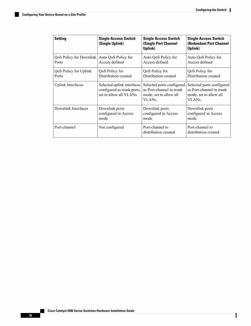
Single Access Switch(Redundant Port ChannelUplink)
Single Access Switch(Single Port ChannelUplink)
Single Access Switch(Single Uplink)
Setting
Auto QoS Policy forAccess defined
Auto QoS Policy forAccess defined
Auto QoS Policy forAccess defined
QoS Policy for DownlinkPorts
QoS Policy forDistribution created
QoS Policy forDistribution created
QoS Policy forDistribution created
QoS Policy for UplinkPorts
Selected ports configuredas Port-channel in trunkmode, set to allow allVLANs.
Selected ports configuredas Port-channel in trunkmode, set to allow allVLANs.
Selected uplink interfacesconfigured as trunk ports,set to allow all VLANs
Uplink Interfaces
Downlink portsconfigured in Accessmode
Downlink portsconfigured in Accessmode
Downlink portsconfigured in Accessmode
Downlink Interfaces
Port-channel todistribution created
Port-channel todistribution created
Not configuredPort-channel
Cisco Catalyst 9300 Series Switches Hardware Installation Guide76
Configuring the SwitchConfiguring Your Device Based on a Site Profile
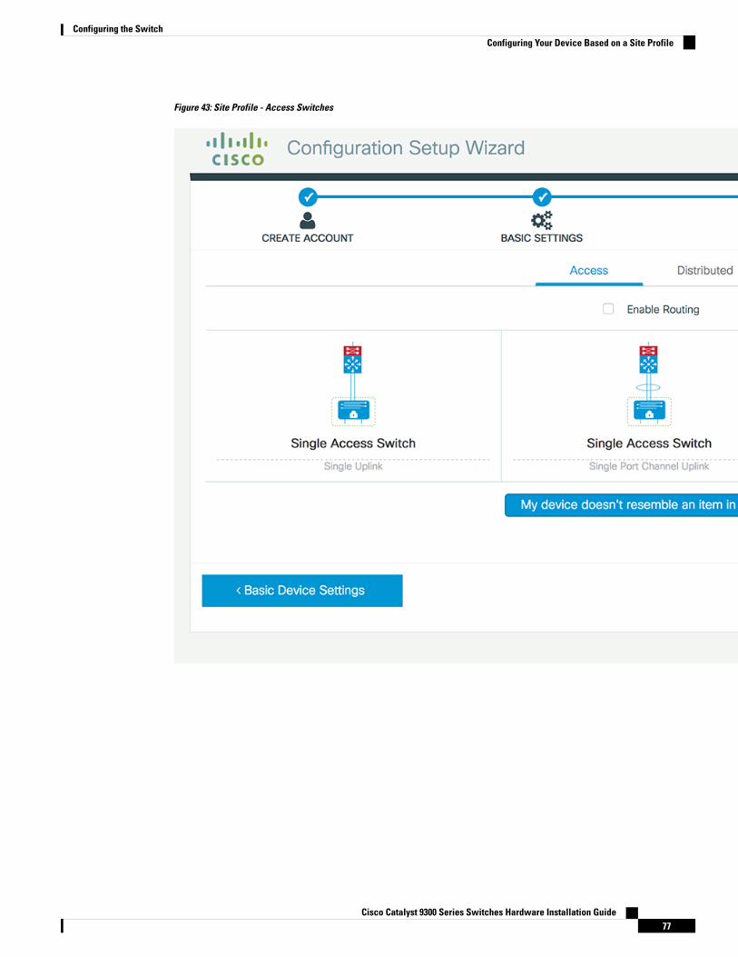
Figure 43: Site Profile - Access Switches
Cisco Catalyst 9300 Series Switches Hardware Installation Guide77
Configuring the SwitchConfiguring Your Device Based on a Site Profile
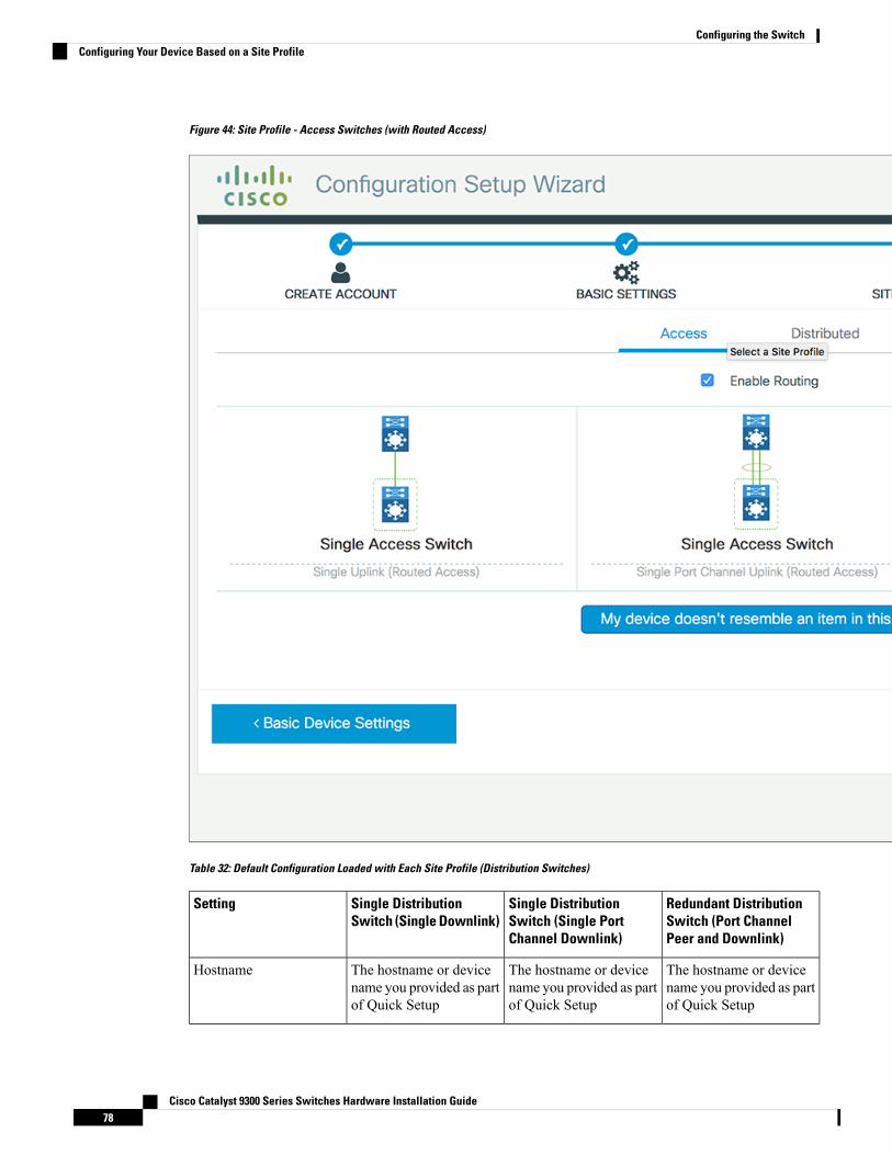
Figure 44: Site Profile - Access Switches (with Routed Access)
Table 32: Default Configuration Loaded with Each Site Profile (Distribution Switches)
Redundant DistributionSwitch (Port ChannelPeer and Downlink)
Single DistributionSwitch (Single PortChannel Downlink)
Single DistributionSwitch (Single Downlink)
Setting
The hostname or devicename you provided as partof Quick Setup
The hostname or devicename you provided as partof Quick Setup
The hostname or devicename you provided as partof Quick Setup
Hostname
Cisco Catalyst 9300 Series Switches Hardware Installation Guide78
Configuring the SwitchConfiguring Your Device Based on a Site Profile
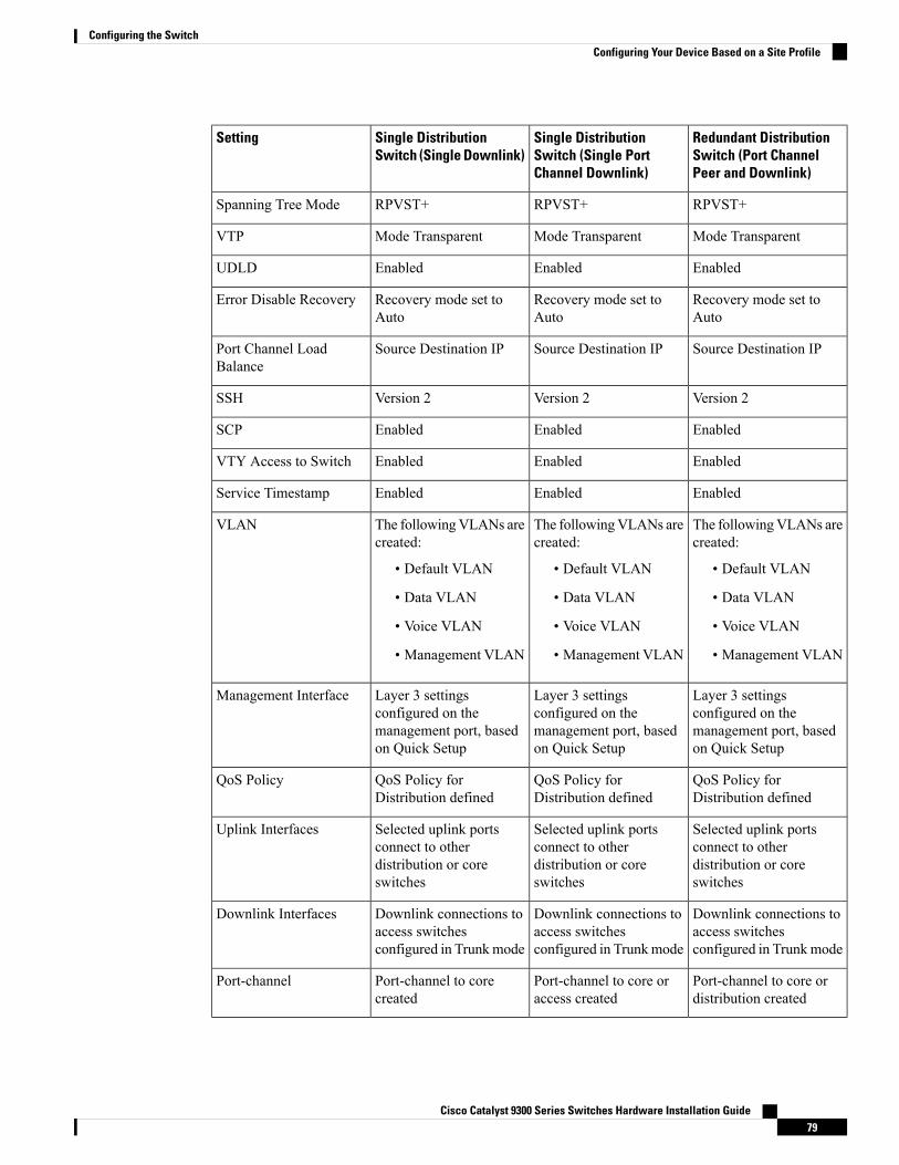
Redundant DistributionSwitch (Port ChannelPeer and Downlink)
Single DistributionSwitch (Single PortChannel Downlink)
Single DistributionSwitch (Single Downlink)
Setting
RPVST+RPVST+RPVST+Spanning Tree Mode
Mode TransparentMode TransparentMode TransparentVTP
EnabledEnabledEnabledUDLD
Recovery mode set toAuto
Recovery mode set toAuto
Recovery mode set toAuto
Error Disable Recovery
Source Destination IPSource Destination IPSource Destination IPPort Channel LoadBalance
Version 2Version 2Version 2SSH
EnabledEnabledEnabledSCP
EnabledEnabledEnabledVTY Access to Switch
EnabledEnabledEnabledService Timestamp
The followingVLANs arecreated:
• Default VLAN
• Data VLAN
• Voice VLAN
• Management VLAN
The followingVLANs arecreated:
• Default VLAN
• Data VLAN
• Voice VLAN
• Management VLAN
The followingVLANs arecreated:
• Default VLAN
• Data VLAN
• Voice VLAN
• Management VLAN
VLAN
Layer 3 settingsconfigured on themanagement port, basedon Quick Setup
Layer 3 settingsconfigured on themanagement port, basedon Quick Setup
Layer 3 settingsconfigured on themanagement port, basedon Quick Setup
Management Interface
QoS Policy forDistribution defined
QoS Policy forDistribution defined
QoS Policy forDistribution defined
QoS Policy
Selected uplink portsconnect to otherdistribution or coreswitches
Selected uplink portsconnect to otherdistribution or coreswitches
Selected uplink portsconnect to otherdistribution or coreswitches
Uplink Interfaces
Downlink connections toaccess switchesconfigured in Trunkmode
Downlink connections toaccess switchesconfigured in Trunkmode
Downlink connections toaccess switchesconfigured in Trunkmode
Downlink Interfaces
Port-channel to core ordistribution created
Port-channel to core oraccess created
Port-channel to corecreated
Port-channel
Cisco Catalyst 9300 Series Switches Hardware Installation Guide79
Configuring the SwitchConfiguring Your Device Based on a Site Profile
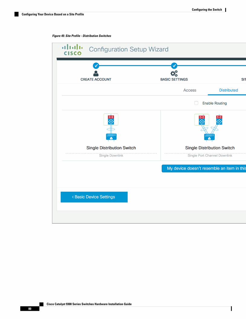
Figure 45: Site Profile - Distribution Switches
Cisco Catalyst 9300 Series Switches Hardware Installation Guide80
Configuring the SwitchConfiguring Your Device Based on a Site Profile
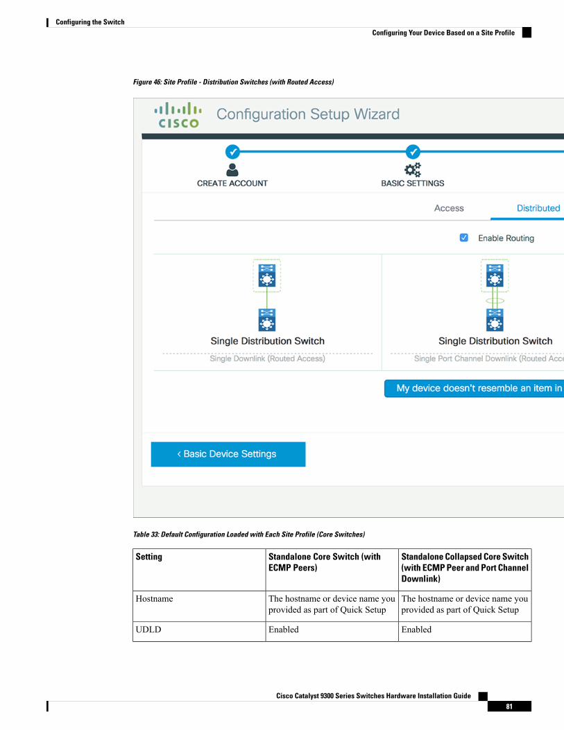
Figure 46: Site Profile - Distribution Switches (with Routed Access)
Table 33: Default Configuration Loaded with Each Site Profile (Core Switches)
Standalone Collapsed Core Switch(with ECMP Peer and Port ChannelDownlink)
Standalone Core Switch (withECMP Peers)
Setting
The hostname or device name youprovided as part of Quick Setup
The hostname or device name youprovided as part of Quick Setup
Hostname
EnabledEnabledUDLD
Cisco Catalyst 9300 Series Switches Hardware Installation Guide81
Configuring the SwitchConfiguring Your Device Based on a Site Profile
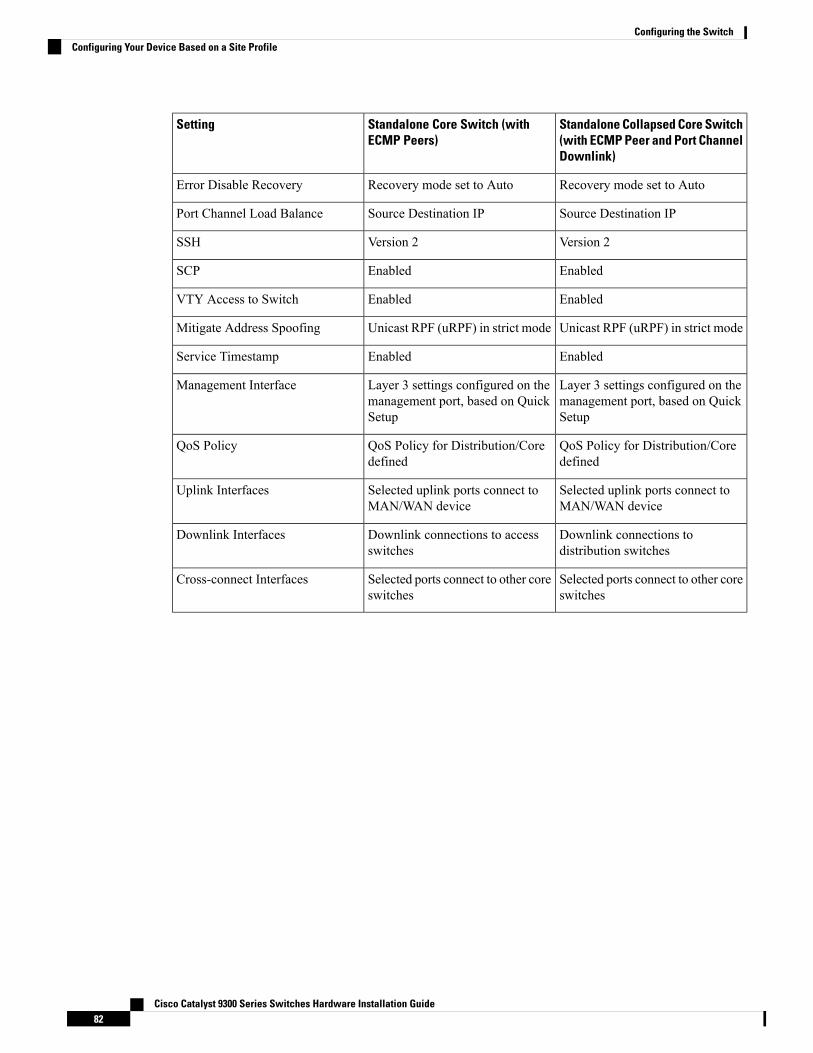
Standalone Collapsed Core Switch(with ECMP Peer and Port ChannelDownlink)
Standalone Core Switch (withECMP Peers)
Setting
Recovery mode set to AutoRecovery mode set to AutoError Disable Recovery
Source Destination IPSource Destination IPPort Channel Load Balance
Version 2Version 2SSH
EnabledEnabledSCP
EnabledEnabledVTY Access to Switch
Unicast RPF (uRPF) in strict modeUnicast RPF (uRPF) in strict modeMitigate Address Spoofing
EnabledEnabledService Timestamp
Layer 3 settings configured on themanagement port, based on QuickSetup
Layer 3 settings configured on themanagement port, based on QuickSetup
Management Interface
QoS Policy for Distribution/Coredefined
QoS Policy for Distribution/Coredefined
QoS Policy
Selected uplink ports connect toMAN/WAN device
Selected uplink ports connect toMAN/WAN device
Uplink Interfaces
Downlink connections todistribution switches
Downlink connections to accessswitches
Downlink Interfaces
Selected ports connect to other coreswitches
Selected ports connect to other coreswitches
Cross-connect Interfaces
Cisco Catalyst 9300 Series Switches Hardware Installation Guide82
Configuring the SwitchConfiguring Your Device Based on a Site Profile
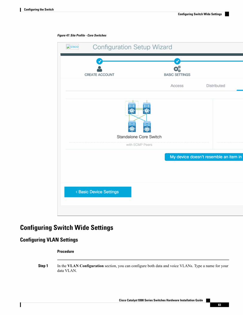
Figure 47: Site Profile - Core Switches
Configuring Switch Wide Settings
Configuring VLAN Settings
Procedure
Step 1 In the VLAN Configuration section, you can configure both data and voice VLANs. Type a name for yourdata VLAN.
Cisco Catalyst 9300 Series Switches Hardware Installation Guide83
Configuring the SwitchConfiguring Switch Wide Settings
Step 2 To configure a data VLAN, ensure that the Data VLAN check box is checked, type a name for your VLAN,and assign a VLAN ID to it. If you are creating several VLANs, indicate only a VLAN range.
Step 3 To configure a voice VLAN, ensure that theVoice VLAN check box is checked, type a name for your VLAN,and assign a VLAN ID to it. If you are creating several VLANs, indicate a VLAN range.
Configure STP Settings
Procedure
Step 1 RPVST is the default STP mode configured on your device. You can change it to PVST from the STPModedrop-down list.
Step 2 To change a bridge priority number from the default value 32748, change Bridge Priority to Yes and choosea priority number from the drop-down list.
Cisco Catalyst 9300 Series Switches Hardware Installation Guide84
Configuring the SwitchConfigure STP Settings
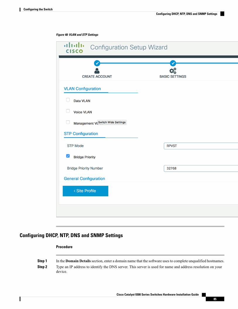
Figure 48: VLAN and STP Settings
Configuring DHCP, NTP, DNS and SNMP Settings
Procedure
Step 1 In theDomain Details section, enter a domain name that the software uses to complete unqualified hostnames.Step 2 Type an IP address to identify the DNS server. This server is used for name and address resolution on your
device.
Cisco Catalyst 9300 Series Switches Hardware Installation Guide85
Configuring the SwitchConfiguring DHCP, NTP, DNS and SNMP Settings
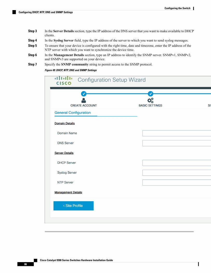
Step 3 In the Server Details section, type the IP address of the DNS server that you want to make available to DHCPclients.
Step 4 In the Syslog Server field, type the IP address of the server to which you want to send syslog messages.Step 5 To ensure that your device is configured with the right time, date and timezone, enter the IP address of the
NTP server with which you want to synchronize the device time.Step 6 In theManagement Details section, type an IP address to identify the SNMP server. SNMPv1, SNMPv2,
and SNMPv3 are supported on your device.Step 7 Specify the SNMP community string to permit access to the SNMP protocol.
Figure 49: DHCP, NTP, DNS and SNMP Settings
Cisco Catalyst 9300 Series Switches Hardware Installation Guide86
Configuring the SwitchConfiguring DHCP, NTP, DNS and SNMP Settings
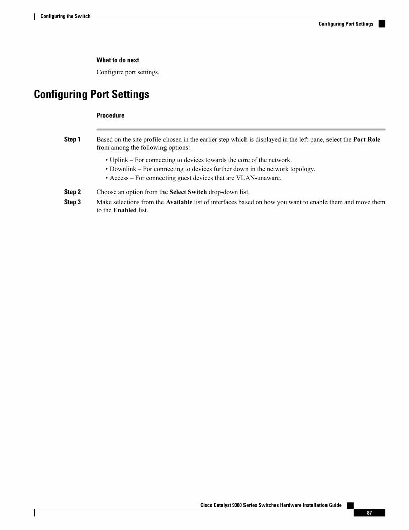
What to do next
Configure port settings.
Configuring Port Settings
Procedure
Step 1 Based on the site profile chosen in the earlier step which is displayed in the left-pane, select the Port Rolefrom among the following options:
• Uplink – For connecting to devices towards the core of the network.• Downlink – For connecting to devices further down in the network topology.• Access – For connecting guest devices that are VLAN-unaware.
Step 2 Choose an option from the Select Switch drop-down list.Step 3 Make selections from the Available list of interfaces based on how you want to enable them and move them
to the Enabled list.
Cisco Catalyst 9300 Series Switches Hardware Installation Guide87
Configuring the SwitchConfiguring Port Settings
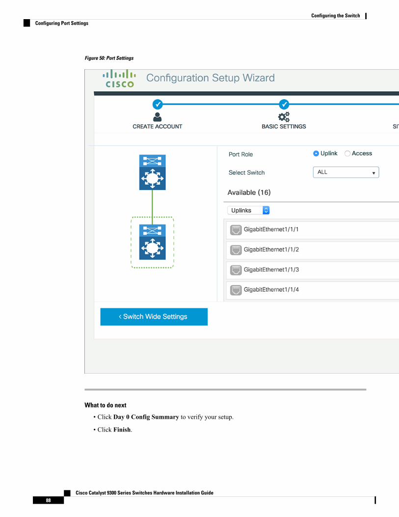
Figure 50: Port Settings
What to do next
• Click Day 0 Config Summary to verify your setup.
• Click Finish.
Cisco Catalyst 9300 Series Switches Hardware Installation Guide88
Configuring the SwitchConfiguring Port Settings
Figure 51: Day 0 Config Summary
Configuring the Switch Using the CLI
Accessing the CLI Through the Console PortYou can access the CLI on a configured or unconfigured switch by connecting the RJ-45 console port or USBconsole port of the switch to your PC or workstation and accessing the switch through a terminal emulationprogram.
Cisco Catalyst 9300 Series Switches Hardware Installation Guide89
Configuring the SwitchConfiguring the Switch Using the CLI
If you have stacked your switches, connect to the console port of one of the switches in the stack. You caninitially configure the entire stack from any member switch.
Note
Connecting the RJ-45 Console Port
Procedure
Step 1 Connect the RJ-45-to-DB-9 adapter cable to the 9-pin serial port on the PC. Connect the other end of the cableto the switch console port.
Step 2 Start the terminal-emulation program on the PC or the terminal. The program, frequently a PC applicationsuch as HyperTerminal or ProcommPlus, makes communication between the switch and your PC or terminalpossible.
Step 3 Configure the baud rate and character format of the PC or terminal to match the console port defaultcharacteristics:
• 9600 baud
• 8 data bits
• 1 stop bit
• No parity
• None (flow control)
Step 4 Power on the switch as described in the switch getting started guide.Step 5 The PC or terminal displays the bootloader sequence. Press Enter to display the setup prompt.
Connecting the USB Console Port
Procedure
Step 1 If you are connecting the switch USB console port to a Windows-based PC for the first time, install the USBdriver. See Installing the Cisco Microsoft Windows USB Device Driver, on page 91.
USB Type A port on the switch provides file system support and is NOT a console port. See USBType A Port section.
Note
Step 2 Connect a USB cable to the PC USB port. Connect the other end of the cable to the switch mini-B(5-pin-connector) USB console port.
Step 3 Start the terminal-emulation program on the PC or the terminal. The program, frequently a PC applicationsuch as HyperTerminal or ProcommPlus, makes communication between the switch and your PC or terminalpossible.
Cisco Catalyst 9300 Series Switches Hardware Installation Guide90
Configuring the SwitchConnecting the RJ-45 Console Port
Step 4 Configure the baud rate and character format of the PC or terminal to match the console port defaultcharacteristics:
• 9600 baud
• 8 data bits
• 1 stop bit
• No parity
• None (flow control)
Step 5 Power on the switch as described in the switch getting started guide.Step 6 The PC or terminal displays the bootloader sequence. Press Enter to display the setup prompt. Follow the
steps in the Setup program.
Installing the Cisco Microsoft Windows USB Device DriverA USB device driver must be installed the first time a Microsoft Windows-based PC is connected to the USBconsole port on the switch.
• Installing the Cisco Microsoft Windows XP USB Driver
• Installing the Cisco Microsoft Windows 2000 USB Driver
• Installing the Cisco Microsoft Windows Vista and Windows 7 USB Driver
Installing the Cisco Microsoft Windows XP USB Driver
Procedure
Step 1 Obtain the Cisco USB console driver file from the Cisco.com web site and unzip it.
You can download the driver file from the Cisco.com site for downloading the switch software.Note
Step 2 If using 32-bitWindows XP, double-click the setup.exe file in theWindows_32 folder. If using 64-bitWindowsXP, double-click the setup(x64).exe file in the Windows_64 folder.
Step 3 The Cisco Virtual Com InstallShield Wizard begins.Step 4 The Ready to Install the Program window appears. Click Install.Step 5 The InstallShield Wizard Completed window appears. Click Finish.Step 6 Connect the USB cable to the PC and the switch console port. The USB console port LED turns green, and
the Found New Hardware Wizard appears. Follow the instructions to complete the driver installation.
Cisco Catalyst 9300 Series Switches Hardware Installation Guide91
Configuring the SwitchInstalling the Cisco Microsoft Windows USB Device Driver
Installing the Cisco Microsoft Windows 2000 USB Driver
Procedure
Step 1 Obtain the Cisco USB console driver file from the Cisco.com web site and unzip it.
You can download the driver file from the Cisco.com site for downloading the switch software.Note
Step 2 Double-click the setup.exe file.Step 3 The Cisco Virtual Com InstallShield Wizard begins. Click Next.Step 4 The Ready to Install the Program window appears. Click Install.Step 5 The InstallShield Wizard Completed window appears. Click Finish.Step 6 Connect the USB cable to the PC and the switch console port. The USB console port LED turns green, and
the Found New Hardware Wizard appears. Follow the instructions to complete the driver installation.
Installing the Cisco Microsoft Windows Vista and Windows 7 USB Driver
Procedure
Step 1 Obtain the Cisco USB console driver file from the Cisco.com web site and unzip it.
You can download the driver file from the Cisco.com site for downloading the switch software.Note
Step 2 If using 32-bit Windows Vista or Windows 7, double-click the setup.exe file in the Windows_32 folder. Ifusing 64-bit Windows Vista or Windows 7, double-click the setup(x64).exe file in the Windows_64 folder.
Step 3 The Cisco Virtual Com InstallShield Wizard begins. Click Next.Step 4 The Ready to Install the Program window appears. Click Install.
If a User Account Control warning appears, click Allow - I trust this program to proceed.Note
Step 5 The InstallShield Wizard Completed window appears. Click Finish.Step 6 Connect the USB cable to the PC and the switch console port. The USB console port LED turns green, and
the Found New Hardware Wizard appears. Follow the instructions to complete the driver installation.
Uninstalling the Cisco Microsoft Windows USB Driver
Uninstalling the Cisco Microsoft Windows XP and 2000 USB DriverUse the Windows Add or Remove Programs utility or the setup.exe file.
Cisco Catalyst 9300 Series Switches Hardware Installation Guide92
Configuring the SwitchInstalling the Cisco Microsoft Windows 2000 USB Driver
Using the Setup.exe Program
Before you begin
Disconnect the switch console terminal before uninstalling the driver.
Procedure
Step 1 Run setup.exe for Windows 32-bit or setup(x64).exe for Windows-64bit. Click Next.Step 2 The InstallShield Wizard for Cisco Virtual Com appears. Click Next.Step 3 When the Program Maintenance window appears, select the Remove radio button. Click Next.Step 4 When the Remove the Program window appears, click Remove.Step 5 When the InstallShield Wizard Completed window appears, click Finish.
Using the Add or Remove Programs Utility
Before you begin
Disconnect the switch console terminal before uninstalling the driver.
Procedure
Step 1 Click Start > Control Panel > Add or Remove Programs.Step 2 Scroll to Cisco Virtual Com and click Remove.Step 3 When the Program Maintenance window appears, select the Remove radio button. Click Next.
Uninstalling the Cisco Microsoft Windows Vista and Windows 7 USB Driver
Before you begin
Disconnect the switch console terminal before uninstalling the driver.
Procedure
Step 1 Run setup.exe for Windows 32-bit or setup(x64).exe for Windows-64bit. Click Next.Step 2 The InstallShield Wizard for Cisco Virtual Com appears. Click Next.Step 3 When the Program Maintenance window appears, select the Remove radio button. Click Next.Step 4 When the Remove the Program window appears, click Remove.
If a User Account Control warning appears, click Allow - I trust this program to proceed.Note
Cisco Catalyst 9300 Series Switches Hardware Installation Guide93
Configuring the SwitchUsing the Setup.exe Program

Step 5 When the InstallShield Wizard Completed window appears, click Finish.
Cisco Catalyst 9300 Series Switches Hardware Installation Guide94
Configuring the SwitchUninstalling the Cisco Microsoft Windows Vista and Windows 7 USB Driver
A P P E N D I X ATechnical Specifications
• Environmental and Physical Specifications, on page 95• Specifications for the Power Supplies, Switches, and Fan, on page 97
Environmental and Physical SpecificationsThis table describes the environmental specifications.
Table 34: Environmental Specifications for the Switch
Environmental Ranges
23 to 113°F (–5 to 45°C)Operating temperature7
–40 to 158°F (–40 to 70°C)Storage temperature
5 to 90% (noncondensing)Relative humidity
Up to 10,000 ft (3000 m)Operating altitude
Up to 15,000 ft (4500 m)Storage altitude
7 Minimum ambient temperature for cold start is 32°F (0°C)
This table describes the environmental specifications.
Table 35: Environmental Specifications for the Power Supplies
Environmental Ranges
23°F to 113°F (–5°C to 45°C) up to 5000 feet (1500m)
23°F to 104°F (–5°C to 40ºC) up to 10,000 feet(3000m)
Operating temperature
–40 to 158°F (–40 to 70°C)Storage temperature
10 to 90% (noncondensing)Relative humidity
Cisco Catalyst 9300 Series Switches Hardware Installation Guide95
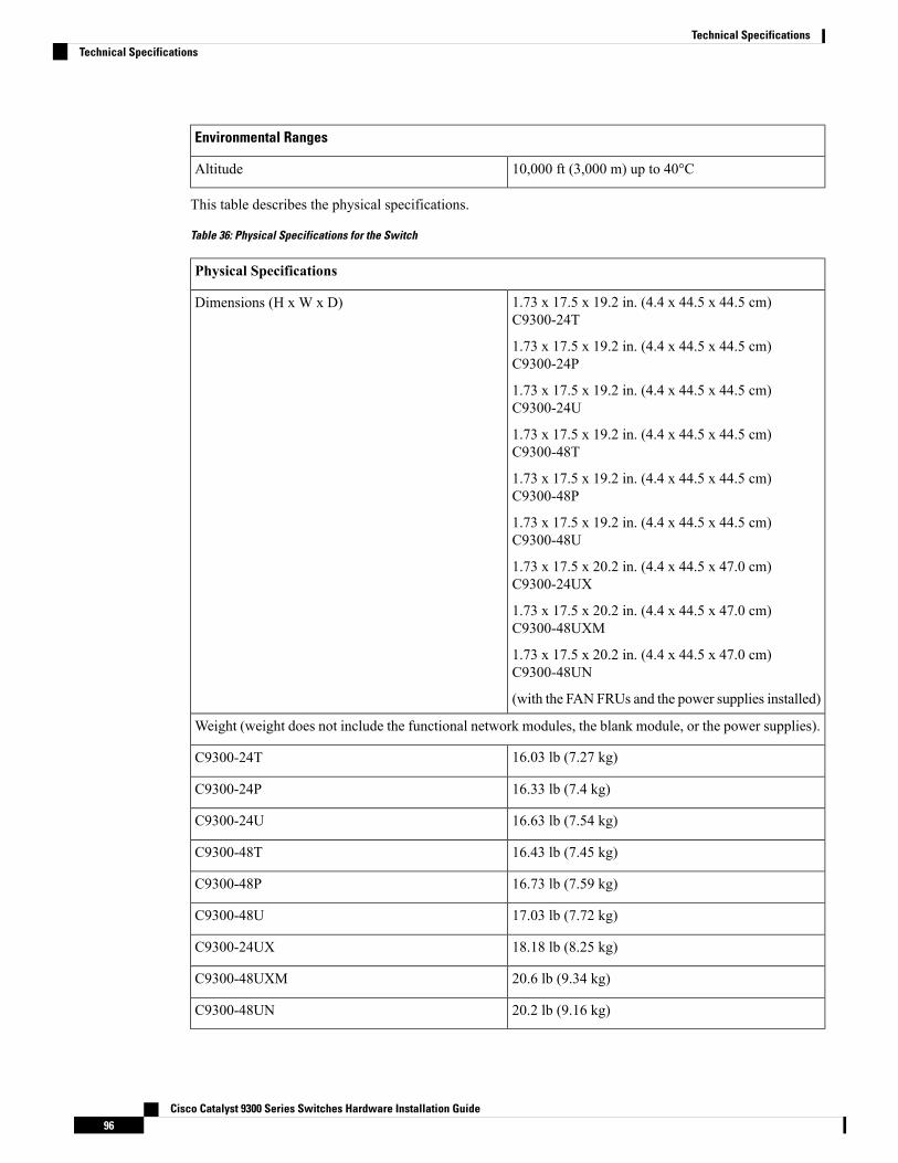
Environmental Ranges
10,000 ft (3,000 m) up to 40°CAltitude
This table describes the physical specifications.
Table 36: Physical Specifications for the Switch
Physical Specifications
1.73 x 17.5 x 19.2 in. (4.4 x 44.5 x 44.5 cm)C9300-24T
1.73 x 17.5 x 19.2 in. (4.4 x 44.5 x 44.5 cm)C9300-24P
1.73 x 17.5 x 19.2 in. (4.4 x 44.5 x 44.5 cm)C9300-24U
1.73 x 17.5 x 19.2 in. (4.4 x 44.5 x 44.5 cm)C9300-48T
1.73 x 17.5 x 19.2 in. (4.4 x 44.5 x 44.5 cm)C9300-48P
1.73 x 17.5 x 19.2 in. (4.4 x 44.5 x 44.5 cm)C9300-48U
1.73 x 17.5 x 20.2 in. (4.4 x 44.5 x 47.0 cm)C9300-24UX
1.73 x 17.5 x 20.2 in. (4.4 x 44.5 x 47.0 cm)C9300-48UXM
1.73 x 17.5 x 20.2 in. (4.4 x 44.5 x 47.0 cm)C9300-48UN
(with the FAN FRUs and the power supplies installed)
Dimensions (H x W x D)
Weight (weight does not include the functional network modules, the blank module, or the power supplies).
16.03 lb (7.27 kg)C9300-24T
16.33 lb (7.4 kg)C9300-24P
16.63 lb (7.54 kg)C9300-24U
16.43 lb (7.45 kg)C9300-48T
16.73 lb (7.59 kg)C9300-48P
17.03 lb (7.72 kg)C9300-48U
18.18 lb (8.25 kg)C9300-24UX
20.6 lb (9.34 kg)C9300-48UXM
20.2 lb (9.16 kg)C9300-48UN
Cisco Catalyst 9300 Series Switches Hardware Installation Guide96
Technical SpecificationsTechnical Specifications
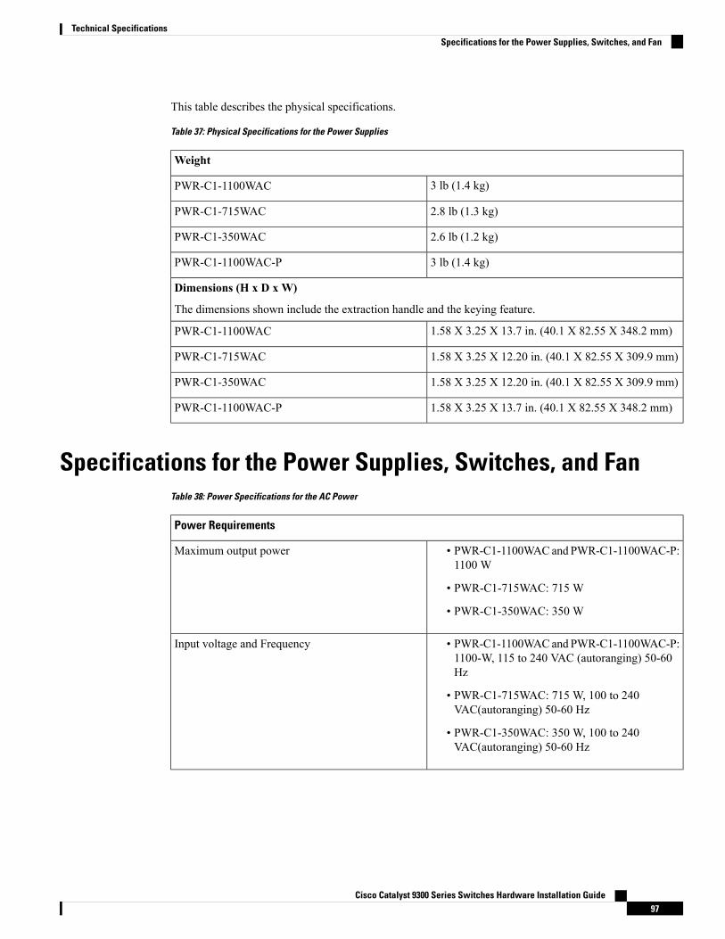
This table describes the physical specifications.
Table 37: Physical Specifications for the Power Supplies
Weight
3 lb (1.4 kg)PWR-C1-1100WAC
2.8 lb (1.3 kg)PWR-C1-715WAC
2.6 lb (1.2 kg)PWR-C1-350WAC
3 lb (1.4 kg)PWR-C1-1100WAC-P
Dimensions (H x D x W)
The dimensions shown include the extraction handle and the keying feature.
1.58 X 3.25 X 13.7 in. (40.1 X 82.55 X 348.2 mm)PWR-C1-1100WAC
1.58 X 3.25 X 12.20 in. (40.1 X 82.55 X 309.9 mm)PWR-C1-715WAC
1.58 X 3.25 X 12.20 in. (40.1 X 82.55 X 309.9 mm)PWR-C1-350WAC
1.58 X 3.25 X 13.7 in. (40.1 X 82.55 X 348.2 mm)PWR-C1-1100WAC-P
Specifications for the Power Supplies, Switches, and FanTable 38: Power Specifications for the AC Power
Power Requirements
• PWR-C1-1100WACand PWR-C1-1100WAC-P:1100 W
• PWR-C1-715WAC: 715 W
• PWR-C1-350WAC: 350 W
Maximum output power
• PWR-C1-1100WACand PWR-C1-1100WAC-P:1100-W, 115 to 240 VAC (autoranging) 50-60Hz
• PWR-C1-715WAC: 715 W, 100 to 240VAC(autoranging) 50-60 Hz
• PWR-C1-350WAC: 350 W, 100 to 240VAC(autoranging) 50-60 Hz
Input voltage and Frequency
Cisco Catalyst 9300 Series Switches Hardware Installation Guide97
Technical SpecificationsSpecifications for the Power Supplies, Switches, and Fan
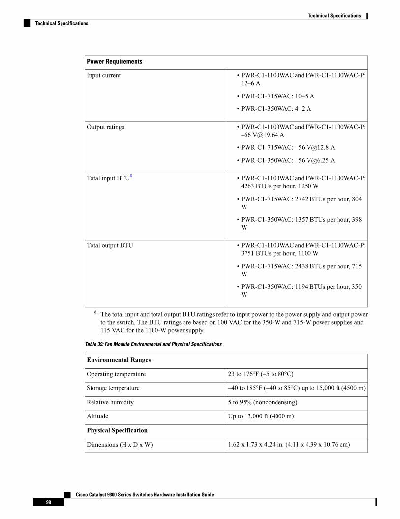
Power Requirements
• PWR-C1-1100WACand PWR-C1-1100WAC-P:12–6 A
• PWR-C1-715WAC: 10–5 A
• PWR-C1-350WAC: 4–2 A
Input current
• PWR-C1-1100WACand PWR-C1-1100WAC-P:–56 [email protected] A
• PWR-C1-715WAC: –56 [email protected] A
• PWR-C1-350WAC: –56 [email protected] A
Output ratings
• PWR-C1-1100WACand PWR-C1-1100WAC-P:4263 BTUs per hour, 1250 W
• PWR-C1-715WAC: 2742 BTUs per hour, 804W
• PWR-C1-350WAC: 1357 BTUs per hour, 398W
Total input BTU8
• PWR-C1-1100WACand PWR-C1-1100WAC-P:3751 BTUs per hour, 1100 W
• PWR-C1-715WAC: 2438 BTUs per hour, 715W
• PWR-C1-350WAC: 1194 BTUs per hour, 350W
Total output BTU
8 The total input and total output BTU ratings refer to input power to the power supply and output powerto the switch. The BTU ratings are based on 100 VAC for the 350-W and 715-W power supplies and115 VAC for the 1100-W power supply.
Table 39: Fan Module Environmental and Physical Specifications
Environmental Ranges
23 to 176°F (–5 to 80°C)Operating temperature
–40 to 185°F (–40 to 85°C) up to 15,000 ft (4500 m)Storage temperature
5 to 95% (noncondensing)Relative humidity
Up to 13,000 ft (4000 m)Altitude
Physical Specification
1.62 x 1.73 x 4.24 in. (4.11 x 4.39 x 10.76 cm)Dimensions (H x D x W)
Cisco Catalyst 9300 Series Switches Hardware Installation Guide98
Technical SpecificationsTechnical Specifications
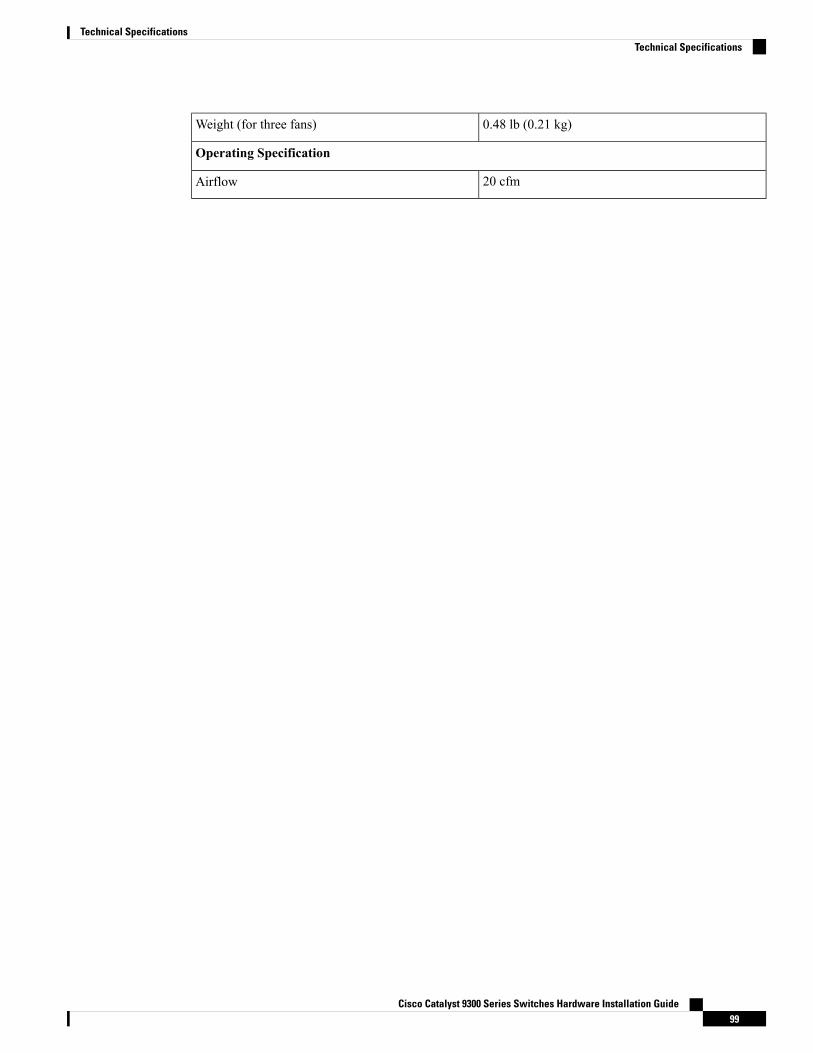
0.48 lb (0.21 kg)Weight (for three fans)
Operating Specification
20 cfmAirflow
Cisco Catalyst 9300 Series Switches Hardware Installation Guide99
Technical SpecificationsTechnical Specifications

Cisco Catalyst 9300 Series Switches Hardware Installation Guide100
Technical SpecificationsTechnical Specifications
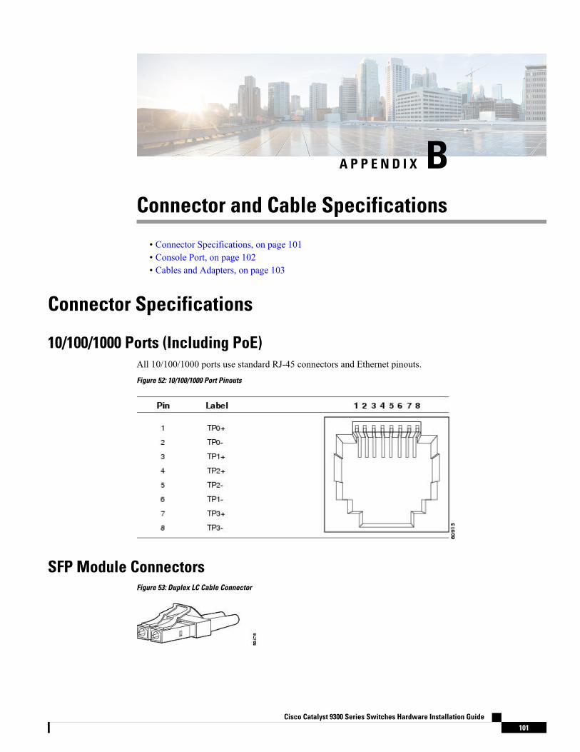
A P P E N D I X BConnector and Cable Specifications
• Connector Specifications, on page 101• Console Port, on page 102• Cables and Adapters, on page 103
Connector Specifications
10/100/1000 Ports (Including PoE)All 10/100/1000 ports use standard RJ-45 connectors and Ethernet pinouts.Figure 52: 10/100/1000 Port Pinouts
SFP Module ConnectorsFigure 53: Duplex LC Cable Connector
Cisco Catalyst 9300 Series Switches Hardware Installation Guide101
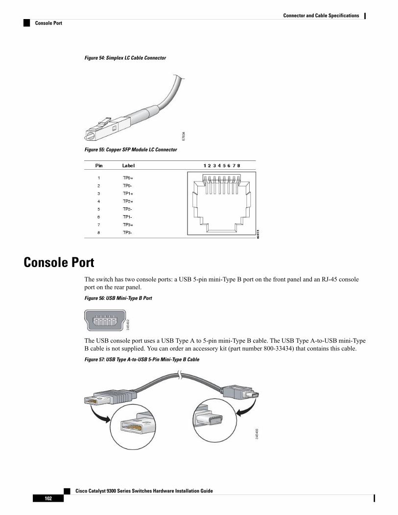
Figure 54: Simplex LC Cable Connector
Figure 55: Copper SFP Module LC Connector
Console PortThe switch has two console ports: a USB 5-pin mini-Type B port on the front panel and an RJ-45 consoleport on the rear panel.Figure 56: USB Mini-Type B Port
The USB console port uses a USB Type A to 5-pin mini-Type B cable. The USB Type A-to-USB mini-TypeB cable is not supplied. You can order an accessory kit (part number 800-33434) that contains this cable.Figure 57: USB Type A-to-USB 5-Pin Mini-Type B Cable
Cisco Catalyst 9300 Series Switches Hardware Installation Guide102
Connector and Cable SpecificationsConsole Port
The RJ-45 console port uses an 8-pin RJ-45 connection. The supplied RJ-45-to-DB-9 adapter cable is usedto connect the console port of the switch to a console PC. You need to provide a RJ-45-to-DB-25 female DTEadapter if you want to connect the switch console port to a terminal.
Cables and Adapters
StackWise CablesYou can order these StackWise cables (nonhalogen) from your Cisco sales representative:
• STACK-T1-50CM= (0.5-meter cable)
• STACK-T1-1M= (1-meter cable)
• STACK-T1-3M= (3-meter cable)
Table 40: StackWise Cables Minimum Bend Radius and Coiled Diameter
Minimum Coiled DiameterMinimum Bend RadiusCable LengthCable Part Number
5.20 in. (132 mm)2.60 in. (66 mm)1.64 feet (0.5 m)STACK-T1-50CM
5.20 in. (132 mm)2.60 in. (66 mm)3.28 feet (1.0 m)STACK-T1-1M
7.17 in. (182 mm)3.58 in. (91 mm)9.84 feet (3.0 m)STACK-T1-3M
5.20 in. (132 mm)2.60 in. (66 mm)1.64 feet (0.5 m)STACK-T2-50CM
5.20 in. (132 mm)2.60 in. (66 mm)3.28 feet (1.0 m)STACK-T2-1M
7.17 in. (182 mm)3.58 in. (91 mm)9.84 feet (3.0 m)STACK-T2-3M
SFP Module CablesFor cabling specifications, refer to the following notes:
• Cisco SFP and SFP+ Transceiver Module Installation Notes
• Cisco 40-Gigabit QSFP+ Transceiver Modules Installation Note
Each port must match the wave-length specifications on the other end of the cable, and the cable must notexceed the stipulated cable length. Copper 1000BASE-T SFPmodule transceivers use standard four twisted-pair,Category 5 cable at lengths up to 328 feet (100 meters).
Cisco Catalyst 9300 Series Switches Hardware Installation Guide103
Connector and Cable SpecificationsCables and Adapters
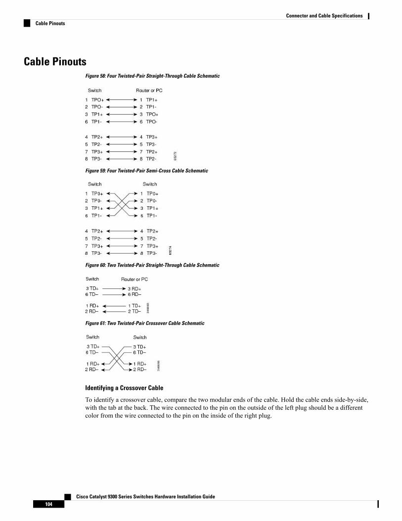
Cable PinoutsFigure 58: Four Twisted-Pair Straight-Through Cable Schematic
Figure 59: Four Twisted-Pair Semi-Cross Cable Schematic
Figure 60: Two Twisted-Pair Straight-Through Cable Schematic
Figure 61: Two Twisted-Pair Crossover Cable Schematic
Identifying a Crossover Cable
To identify a crossover cable, compare the two modular ends of the cable. Hold the cable ends side-by-side,with the tab at the back. The wire connected to the pin on the outside of the left plug should be a differentcolor from the wire connected to the pin on the inside of the right plug.
Cisco Catalyst 9300 Series Switches Hardware Installation Guide104
Connector and Cable SpecificationsCable Pinouts

Figure 62: Identifying a Crossover Cable
Console Port Adapter PinoutsThe RS-232 console port uses an 8-pin RJ-45 connector. Use an RJ-45-to-DB-9 adapter cable to connect theswitch console port to a console PC. You need to provide a RJ-45-to-DB-25 female DTE adapter to connectthe switch console port to a terminal.
Table 41: Console Port Signaling with a DB-9 Adapter
Console DeviceRJ-45-to-DB-9 Terminal AdapterSwitch Console Port (DTE)
SignalDB-9 PinSignal
CTS8RTS
DSR6DTR
RxD2TxD
GND5GND
GND5GND
TxD3RxD
DTR4DSR
RTS7CTS
Table 42: Console Port Signaling with a DB-25 Adapter
Console DeviceRJ-45-to-DB-25 Terminal AdapterSwitch Console Port (DTE)
SignalDB-25 PinSignal
CTS5RTS
DSR6DTR
RxD3TxD
GND7GND
Cisco Catalyst 9300 Series Switches Hardware Installation Guide105
Connector and Cable SpecificationsConsole Port Adapter Pinouts
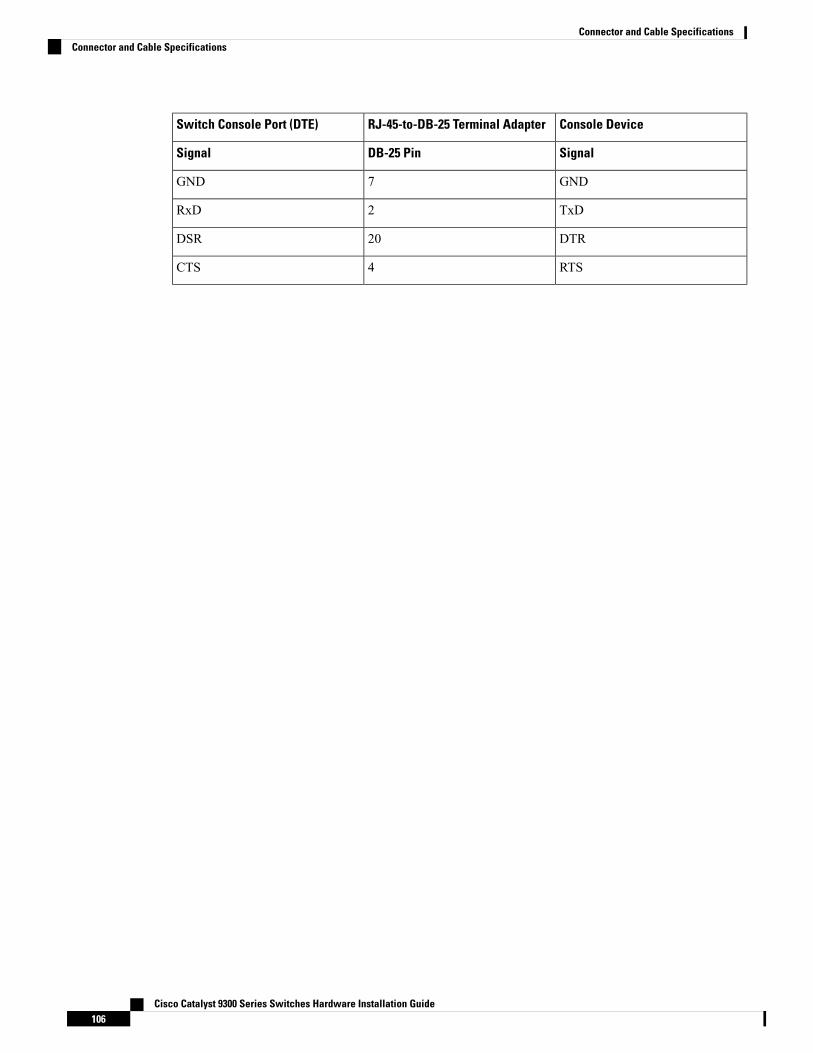
Console DeviceRJ-45-to-DB-25 Terminal AdapterSwitch Console Port (DTE)
SignalDB-25 PinSignal
GND7GND
TxD2RxD
DTR20DSR
RTS4CTS
Cisco Catalyst 9300 Series Switches Hardware Installation Guide106
Connector and Cable SpecificationsConnector and Cable Specifications