Embed Size (px)
Citation preview

Cisco BTS 10200 Softswitch ISDN Guide, Release 6.0.4May 14, 2012
Americas HeadquartersCisco Systems, Inc.170 West Tasman DriveSan Jose, CA 95134-1706 USAhttp://www.cisco.comTel: 408 526-4000
800 553-NETS (6387)Fax: 408 527-0883
Text Part Number: OL-25001-02

THE SPECIFICATIONS AND INFORMATION REGARDING THE PRODUCTS IN THIS MANUAL ARE SUBJECT TO CHANGE WITHOUT NOTICE. ALL STATEMENTS, INFORMATION, AND RECOMMENDATIONS IN THIS MANUAL ARE BELIEVED TO BE ACCURATE BUT ARE PRESENTED WITHOUT WARRANTY OF ANY KIND, EXPRESS OR IMPLIED. USERS MUST TAKE FULL RESPONSIBILITY FOR THEIR APPLICATION OF ANY PRODUCTS.
THE SOFTWARE LICENSE AND LIMITED WARRANTY FOR THE ACCOMPANYING PRODUCT ARE SET FORTH IN THE INFORMATION PACKET THAT SHIPPED WITH THE PRODUCT AND ARE INCORPORATED HEREIN BY THIS REFERENCE. IF YOU ARE UNABLE TO LOCATE THE SOFTWARE LICENSE OR LIMITED WARRANTY, CONTACT YOUR CISCO REPRESENTATIVE FOR A COPY.
The Cisco implementation of TCP header compression is an adaptation of a program developed by the University of California, Berkeley (UCB) as part of UCB’s public domain version of the UNIX operating system. All rights reserved. Copyright © 1981, Regents of the University of California.
NOTWITHSTANDING ANY OTHER WARRANTY HEREIN, ALL DOCUMENT FILES AND SOFTWARE OF THESE SUPPLIERS ARE PROVIDED “AS IS” WITH ALL FAULTS. CISCO AND THE ABOVE-NAMED SUPPLIERS DISCLAIM ALL WARRANTIES, EXPRESSED OR IMPLIED, INCLUDING, WITHOUT LIMITATION, THOSE OF MERCHANTABILITY, FITNESS FOR A PARTICULAR PURPOSE AND NONINFRINGEMENT OR ARISING FROM A COURSE OF DEALING, USAGE, OR TRADE PRACTICE.
IN NO EVENT SHALL CISCO OR ITS SUPPLIERS BE LIABLE FOR ANY INDIRECT, SPECIAL, CONSEQUENTIAL, OR INCIDENTAL DAMAGES, INCLUDING, WITHOUT LIMITATION, LOST PROFITS OR LOSS OR DAMAGE TO DATA ARISING OUT OF THE USE OR INABILITY TO USE THIS MANUAL, EVEN IF CISCO OR ITS SUPPLIERS HAVE BEEN ADVISED OF THE POSSIBILITY OF SUCH DAMAGES.
Cisco and the Cisco logo are trademarks or registered trademarks of Cisco and/or its affiliates in the U.S. and other countries. To view a list of Cisco trademarks, go to this URL: www.cisco.com/go/trademarks. Third-party trademarks mentioned are the property of their respective owners. The use of the word partner does not imply a partnership relationship between Cisco and any other company. (1110R)
Cisco BTS 10200 Softswitch ISDN Guide, Release 6.0.4Copyright © 2012 Cisco Systems, Inc. All rights reserved.

OL-25001-02
C O N T E N T S
Preface vii
Introduction vii
Organization vii
Obtaining Documentation and Submitting a Service Request vii
Document Change History viii
C H A P T E R 1 ISDN Provisioning 1-1
Introduction 1-1
Description of Backhaul Set, Group, and Session 1-2
Network Side PRI 1-2
User Side PRI 1-3
Cisco BTS 10200 Provisioning 1-4
Provisioning 1-4
Information as seen on IOS Gateway 1-6
Place MGW, ISDN D Channels, Trunk Groups, and Trunks In Service 1-9
Verify Status of ISDN Services 1-10
Verify MGW Status 1-10
Verify D Channel Status 1-11
Verify Trunk Group Status 1-11
Verify Trunk Termination and Trunk Status 1-11
International PRI Setup 1-13
ISDN Profiles 1-15
Maintenance Message Support 1-15
Customizing Trunk Group Profiles 1-17
ISDN Timer Configuration Parameters 1-18
ISDN Features and Supplementary Services 1-19
Information Digit Feature 1-20
Calling and Connected Name Delivery 1-21
Calling Number Identification Service (CNIP/CNIR) 1-22
Redirecting Number IE Support 1-22
ISDN PRI PBX Variant Setup 1-22
Intertel 256 with NI2 1-24
Intertel 256 with DMS-100 1-25
Intertel 256 with 4ESS 1-25
iiiCisco BTS 10200 Softswitch ISDN Guide, Release 6.0.4

Contents
Intertel 256 with 5ESS 1-25
Lucent Definity G3r with NI2 1-25
Lucent Definity G3r with DMS-100 1-26
Lucent Definity G3r with 5ESS 1-26
Nortel Northstar with NI2 1-26
Nortel Option 11 with NI2 1-26
Nortel Option 11 with DMS-100 1-27
Siemens Hicom 300 with NI2 1-27
Siemens Hicom 300 with DMS-100 1-27
Siemens Hicom 300 with 4ESS 1-27
Siemens Hicom 300 with 5ESS 1-27
Toshiba Strada DK424 with NI2 1-28
C H A P T E R 2 Multiple Trunk Groups on a Single ISDN D Channel 2-1
Introduction 2-1
Provisioning 2-1
Sample Line Test Configuration for Multiple Trunk Groups on a Single ISDN D Channel 2-3
C H A P T E R 3 ISDN Backhaul Support using IUA/SCTP 3-1
Introduction 3-1
IUA/SCTP Protocols 3-1
Provisioning an IUA Trunk Group 3-2
C H A P T E R 4 Maintaining and Troubleshooting the ISDN System 4-1
Introduction 4-1
Status and Control Commands 4-1
How to Troubleshoot When the ISDN D Channel Fails to be Restored 4-4
Checking the Status of a Trunk Termination 4-6
Trunk Static State Is Set to Locally Blocked 4-7
Trunk Static State Is Set to TRNS 4-7
Trunk Static State Is Set to RBLK 4-8
Termination Status Is Faulty 4-8
Cannot Make a Call 4-8
IUA Traces 4-9
Checking MGW Provisioning 4-10
IOS Gateway 4-10
IUA/SCTP Gateway 4-12
Additional CLI Verification 4-16
ivCisco BTS 10200 Softswitch ISDN Guide, Release 6.0.4
OL-25001-02

Contents
Maintenance of a Call Agent Connected to an ISDN Trunk Group 4-17
ISDN D Channel and Trunk Group CLI Command Troubleshooting 4-17
vCisco BTS 10200 Softswitch ISDN Guide, Release 6.0.4
OL-25001-02

Contents
viCisco BTS 10200 Softswitch ISDN Guide, Release 6.0.4
OL-25001-02

Preface
Revised: May 14, 2012, OL-25001-02
IntroductionThis document describes the ISDN provisioning and troubleshooting for the Cisco BTS 10200 Softswitch. This document is intended for use by service provider management, system administration, and engineering personnel who are responsible for designing, installing, provisioning, and maintaining networks that use the Cisco BTS 10200 Softswitch system.
OrganizationThis document is divided into the following chapters:
• Chapter 1, “Description of Backhaul Set, Group, and Session”—Describes ISDN provisioning for the Cisco BTS 10200 Softswitch. It provides the procedures to operate, manage, and troubleshoot ISDN signaling on the Cisco BTS 10200 Softswitch and voice gateways.
• Chapter 2, “Provisioning”—Describes provisioning multiple trunk groups on a single ISDN D channel.
• Chapter 3, “IUA/SCTP Protocols”—Describes the support of ISDN backhaul using ISDN Q.921-User Adaptation (IUA) and the Stream Control Transmission Protocol (SCTP).
• Chapter 4, “Maintaining and Troubleshooting the ISDN System”—Describes ISDN maintenance and troubleshooting commands and procedures for the Cisco BTS 10200 Softswitch.
Obtaining Documentation and Submitting a Service RequestFor information on obtaining documentation, submitting a service request, and gathering additional information, see the monthly What’s New in Cisco Product Documentation, which also lists all new and revised Cisco technical documentation, at
http://www.cisco.com/en/US/docs/general/whatsnew/whatsnew.html
Subscribe to the What’s New in Cisco Product Documentation as a Really Simple Syndication (RSS) feed and set content to be delivered directly to your desktop using a reader application. The RSS feeds are a free service and Cisco currently supports RSS Version 2.0.
viiCisco BTS 10200 Softswitch ISDN Guide, Release 6.0.4
OL-25001-02

Preface
Document Change HistoryThe following table provides the revision history for the Cisco BTS 10200 Softswitch ISDN Guide, Release 6.0.4.
Version Number Issue Date Status Reason for Change
OL-25001-02 May 14, 2012
Initial Initial document for Release 6.0.4
viiiCisco BTS 10200 Softswitch ISDN Guide, Release 6.0.4
OL-25001-02

CisOL-25001-02
C H A P T E R 1
ISDN ProvisioningRevised: May 14, 2012, OL-25001-02
IntroductionThis chapter describes ISDN provisioning for the Cisco BTS 10200 Softswitch. It provides the procedures to operate, manage, and troubleshoot ISDN signaling on the Cisco BTS 10200 Softswitch and voice gateways.
For Stream Control Transmission Protocol (SCTP)/User Adaptation (IUA)ISDN Provisioning, the basic ISDN network elements and signaling connections are shown in Figure 1-1. Standby elements in the figure are omitted for clarity.
Figure 1-1 ISDN Network Elements
Note The Cisco BTS 10200 Softswitch Call Agent (CA) supports multiple voice gateways, or PBXs.
PBX Phone
IPnetwork
Cisco voicegateway
Backhaul session,Q.931 messaging
PRI T1s with one D channeland 23 B channels per T1
5207
4
V
IPnetwork
1-1co BTS 10200 Softswitch ISDN Guide, Release 6.0.4

Chapter 1 ISDN ProvisioningDescription of Backhaul Set, Group, and Session
Description of Backhaul Set, Group, and SessionThe backhaul session parameters used in provisioning are illustrated in Figure 1-2. As shown in the figure, Call Agent Side A is connected to the media gateway (MGW) using the Group A signaling paths (Sessions A1 and A2), and is designated as primary. If one of these sessions goes down, the system uses the other session for signaling between Call Agent Side A and the MGW. There is no need for the Softswitch to switch over to Call Agent Side B. If the primary Call Agent goes down, then the Cisco BTS 10200 switches to the secondary Call Agent.
Figure 1-2 Backhaul Set, Group, and Session
Network Side PRIThe Network Side PRI feature allows the Cisco BTS 10200 Softswitch to communicate with PBXs. This feature provides support for the ISDN PRI Network Side basic call-control procedures as described in Q.931 ISDN Call Control Procedures. The network-side stack has the following PRI variants enabled:
• ISDN US NI2 PRI (TR 1268)
• ISDN Q931 PRI
• ISDN DMS
• ISDN ATT 4ESS PRI
• ISDN ATT 5ESS PRI
5207
5
IP network
Voice gatewayCisco AS5300
Gbit Ethernet
Ethernet
Router
Router
Call agentbackhaul port
Call agentbackhaul port
Call agentbackhaul ports
Backhaul setGroup BGroup A
Session A1Session A2
MGW backhaul port
Sessions B1 and B2are established onGroup B. They becomeactive if the Side B CallAgent takes over fromthe Side A Call Agentdue to a switchover.
Router
DNS
Softswitch
Physical linkGroup A logical linkGroup B logical link
Legend:
Call agentSide B (secondary)
Call agentSide A (primary)
1-2Cisco BTS 10200 Softswitch ISDN Guide, Release 6.0.4
OL-25001-02

Chapter 1 ISDN ProvisioningUser Side PRI
Figure 1-3 shows a sample PRI network-side configuration.
Figure 1-3 PRI Network-Side Configuration
User Side PRI The User Side PRI feature allows provisioning when the Cisco BTS 10200 Softswitch does not support the SS7 variant of a particular country. This feature provides support for the ISDN PRI User Side basic call-control procedures as described in Q.931 ISDN Call Control Procedures. The user-side stack has the following PRI variants enabled:
• ISDN US NI2 PRI (TR 1268)
• ISDN Q931 PRI
• ISDN DMS
• ISDN ATT 4ESS PRI
• ISDN ATT 5ESS PRI
SIP Phones
1199
38
PRI User SideSignaling
Network SideCisco BTS 10200
IPNetwork(VoIP)
Gateway
PSTN
PBX
SS7
PR
I Net
wor
k S
ide
Sig
nalin
g
1-3Cisco BTS 10200 Softswitch ISDN Guide, Release 6.0.4
OL-25001-02

Chapter 1 ISDN ProvisioningCisco BTS 10200 Provisioning
Figure 1-4 shows a sample PRI user-side configuration.
Figure 1-4 PRI User-Side Configuration
Cisco BTS 10200 ProvisioningThis section provides an overview of the Cisco BTS 10200 Softswitch provisioning steps. The basic Cisco BTS 10200 provisioning sequence is outlined below.
Note These steps provision ISDN-specific data in the Cisco BTS 10200 Softswitch database. Referenced data tables, such as Dial Plan and Subscriber Profile must already be provisioned. Additional commands are also necessary to provision routing and translation for ISDN channels (see the Cisco BTS 10200 Softswitch CLI Database for more information).
ProvisioningThis section provides the ISDN provisioning steps.
• See the Cisco BTS 10200 Softswitch CLI Database for explanations of each token in the command.
• After entering each command, press the Return (Enter) key.
• See the “ISDN Profiles” section on page 1-15 for information regarding profiles.
• Performing steps 1, 2 and 3 provisions ISDN FAS for ISDN backhaul using RUDP.
• Performing steps 1, 2 and 4 provisions ISDN NFAS for ISDN backhaul using RUDP, which includes D channel backup.
• See the “International PRI Setup” section on page 1-13 for information on provisioning for International PRI.
• See the “ISDN PRI PBX Variant Setup” section on page 1-22 for information on provisioning certain specific PBX variants.
• See Chapter 2, “Multiple Trunk Groups on a Single ISDN D Channel” for provisioning multiple trunk groups on a single D channel.
1199
37
SIP Phones
User SideCisco BTS 10200
IP Network(VoIP)
Gateway
PSTN
PR
I Use
r S
ide
Sig
nalin
g
PRI Network SideSignaling
1-4Cisco BTS 10200 Softswitch ISDN Guide, Release 6.0.4
OL-25001-02

Chapter 1 ISDN ProvisioningCisco BTS 10200 Provisioning
• See Chapter 3, “ISDN Backhaul Support using IUA/SCTP” in Chapter 3 to provision ISDN backhaul for IUA/SCTP.
Note On a big, fast gateway (BFG), there is no concept of a slot number from a PRI backhaul perspective, although a BFG resides on a particular slot in the chassis. The architecture of a BFG is such that each slot acts as an independent gateway in itself. The Cisco BTS 10200 Softswitch addresses individual BFG cards by the card IP address—so the slot number is zero. Current CLI implementation uses a total of 16 bits with the D channel slot represented by 8 bits and the D channel port represented by 8 bits. To interface with a BFG, set the slot to 0 when the port is greater than 255 (8 bits).
Note The proprietary-supp token must be set to 8 bits when provisioning NI2.
The following steps provide the commands and examples for ISDN provisioning:
Step 1 Log on to the active EMS by entering the following commands on a console that can communicate by IP with the active EMS.
Note To verify which EMS is currently active, log on to any EMS or CA/Feature Server (FS) machine as a root user, and enter the command nodestat. This displays the IP address of the active EMS. Then exit.
a. Open a UNIX shell or XTerm window (or, in Windows, choose Start > Run > Command prompt).
b. At the UNIX shell prompt, enter ssh and the IP address or domain name of the active EMS.
ssh -l <CLI username> ip address
c. At the password prompt, enter the password for the CLI username.
<password for CLI username>
The system responds with a prompt.
Step 2 Add the MGW and backhaul set. Refer to Figure 1-5 on page 1-6 for a sample configuration for backhaul session connections between a CA and a gateway.
a. Add the MGW profile for the voice gateway. Multiple MGW profiles can be created for different media gateways per your configuration requirements.
add mgw-profile id=mgwprofile2; vendor=Cisco; packet-type=IP; mgcp-variant=NONE; rbk-on-conn-supp=n; isdn=y; mgcp-erqnt-supp=n; mgcp-hairpin-supp=n; mgcp-cmd-seq-supp=n; mgcp-version=MGCP_1_0;
b. Add the MGW using the MGW profile created in Step 2a.
add mgw ID=mgw-isdn; tsap-addr=10.89.227.200; call-agent-id=CA146; mgw-profile-id=mgwprofile2; type=TGW;
c. Add the backhaul session set ID for the gateway using the MGW ID specified in Step 2b with the appropriate values for your system.
add backhaul-set SET-ID=backset1; MGW-ID=mgw-isdn; SET-NAME=set1;
1-5Cisco BTS 10200 Softswitch ISDN Guide, Release 6.0.4
OL-25001-02

Chapter 1 ISDN ProvisioningCisco BTS 10200 Provisioning
d. Add the Reliable User Datagram Protocol (RUDP) backhaul sessions for the gateway using the backhaul session set ID created in Step 2c and appropriate values configured on the gateway:
Information as seen on IOS Gateway
session group group1 10.89.225.223 9000 10.89.227.200 9000 0session group group1 10.89.226.223 9001 10.89.227.200 9001 0 session group group2 10.89.225.224 9000 10.89.227.200 9000 0session group group2 10.89.226.224 9001 10.89.227.200 9001 0
CLI associated with information seen on gateway:add rudp-backhaul-session set-id=backset1; session-name=session1; group-name=group1;
call-agent-tsap-addr=10.89.225.223;
call-agent-backhaul-port=9000;mgw-tsap-addr=10.89.227.200; mgw- backhaul-port=9000;
add rudp-backhaul-session set-id=backset1; session-name=session2; group-name=group1; call-agent-tsap-addr=10.89.226.223; call-agent-backhaul-port=9001; mgw-tsap-addr=10.89.227.200; mgw-backhaul-port=9001;
add rudp-backhaul-session set-id=backset1; session-name=session3; group-name=group2; call-agent-tsap-addr=10.89.225.224; call-agent-backhaul-port=9000; mgw-tsap-addr=10.89.227.200; mgw-backhaul-port=9000;
add rudp-backhaul-session set-id=backset1; session-name=session4; group-name=group2; call-agent-tsap-addr=10.89.226.224; call-agent-backhaul-port=9001; mgw-tsap-addr=10.89.227.200; mgw-backhaul-port=9001;
Note The call-agent-tsap-addr token must be a physical IP address.
Figure 1-5 Sample Configuration for Backhaul Session Connections Between a CA and a
Gateway
Primary Call Agent GatewaySet 1Group 1
Session 1
Session 2
Session 3
Session 4
Group 2
Ethernet Port 1(10.89.225.223)UDP port 9000
Ethernet Port 2(10.89.226.224)UDP port 9001
Ethernet Port 1(10.89.225.224)UDP port 9000
Ethernet Port 2(10.89.226.223)UDP port 9001
Ethernet Port 1(10.89.227.200)UDP port 9001
Secondary Call Agent
6996
0Ethernet Port 1(10.89.227.200)UDP port 9000
1-6Cisco BTS 10200 Softswitch ISDN Guide, Release 6.0.4
OL-25001-02

Chapter 1 ISDN ProvisioningCisco BTS 10200 Provisioning
Step 3 Configure PRI FAS. Figure 1-6 shows a sample configuration for Facility Associated Signaling (FAS).
Note To configure PRI NFAS, go to Step 4.
Figure 1-6 Sample Configuration for FAS
a. Add an ISDN D channel profile with the nfas-supp token set to N.
add isdn-dchan-profile id=NI2; description=dallas isdn dchan profile no.1;type=swv-us-ni2-pri; interface-type=network; isdn-restart-pri-supp=y;isdn-restart-interface-supp=y;isdn-service-supp=n; isdn-restart-chan-supp=y; isdn-farend-init=n;isdn-query-supp=n;nfas-supp=n; bchan-neg-supp=y; t-301=300; t-302=10; t-303=4; t-305=30;t-308=4; t-309=90;t-310=10; t-316=30; t-321=20;t-322=4; t-323=30;
Note See the “ISDN Profiles” section on page 1-15 for more information.
b. Add the ISDN interfaces.
add isdn-intf isdn-dchan-id=100; intf=0;
c. Add the ISDN D channels using the backhaul session set ID added in Step 2c and ISDN interfaces added in Step 3b (where dchan-port refers to the DS1 span number used).
add isdn-dchan id=100; backhaul-type=RUDP;SET-ID=backset1; dchan-slot=0;dchan-port=1; dchan-type=primary; dchan-intf=0;isdn-dchan-profile-id=NI2;
d. Add an ISDN trunk group profile.
add isdn-tg-profile id=dallas1; chrg-num-supp=Y;
e. Add the ISDN trunk groups using the ISDN trunk group profile added in Step 3d.
add trunk-grp id=100;call-agent-id=CA146;tg-type=ISDN;tg-profile-id=dallas1; pop-id=1;glare=all;mgcp-pkg-type=T; dial-plan-id=dp1; isdn-dchan-id=100;
Note For ISDN trunk groups, the mgcp-pkg-type token must be set to T.
f. Add the ISDN terminations using the MGW ID added in Step 2b.
add termination prefix=S4/DS1-1/; port-start=1; port-end=23; type=trunk; mgw-id=mgw-isdn;
g. Add the ISDN trunks using the trunk group profile added in Step 3d, the ISDN interface added in Step 3b, the MGW ID added in Step 2b, and the ISDN termination used in Step 3f.
add trunk cic-start=1; cic-end=23; tgn-id=100; mgw-id=mgw-isdn; termination-prefix=S4/DS1-1/; termination-port-start=1;termination-port-end=23;intf=0;
D Channel
Trunk group (100)CIC start - 1 CIC end - 23
Interface - 0
6972
2
1 23 24
1-7Cisco BTS 10200 Softswitch ISDN Guide, Release 6.0.4
OL-25001-02

Chapter 1 ISDN ProvisioningCisco BTS 10200 Provisioning
h. Add the subscriber, then link to the trunk group. See the Cisco BTS 10200 Softswitch Provisioning Guide for additional details. In the following example, the subscriber profile ID must already exist:
add subscriber [email protected]; category=pbx; name=pbx1; status=active;address1=1651 n glenville;address2=Richardson tx 75081; ss-number=643-77-1837;billing-dn=972-233-9000; dn1=972-233-9000; ring-type-dn1=1;tgn-id=100; sub-profile-id=dp1; term-type=none;
change trunk-grp id=100; [email protected];
i. Go to the “Place MGW, ISDN D Channels, Trunk Groups, and Trunks In Service” section on page 1-9.
Step 4 Configure PRI NFAS. Figure 1-7 shows a sample configuration for NFAS.
Note To perform an ISDN D channel switchover, refer the Cisco BTS 10200 Softswitch CLI Database for additional information.
This step also creates and provisions a backup ISDN D channel.
Figure 1-7 Sample Configuration for NFAS
a. Add the ISDN D channel profile with the nfas-supp token set to Y.
add isdn-dchan-profile id=NI2; description=dallas isdn dchan profile no.1;type=swv-us-ni2-pri; interface-type=network; isdn-restart-pri-supp=y;isdn-restart-interface-supp=y;isdn-service-supp=n; isdn-restart-chan-supp=y; isdn-farend-init=n;isdn-query-supp=n;nfas-supp=y; bchan-neg-supp=y; t-301=300; t-302=10; t-303=4; t-305=30;t-308=4; t-309=90;t-310=10; t-316=30; t-321=20;t-322=4; t-323=30;
b. Add the ISDN interfaces.
add isdn-intf isdn-dchan-id=100; intf=0;add isdn-intf isdn-dchan-id=100; intf=1;add isdn-intf isdn-dchan-id=100; intf=2;
c. Add the primary and backup ISDN D channels using the session set ID added in Step 2c and the ISDN interfaces added in Step 4b.
add isdn-dchan id=100; backhaul-type=RUDP; set-id=backset1; dchan-slot=0; dchan-port=0; dchan-type=primary; dchan-intf=0; isdn-dchan-profile-id=NI2;
add isdn-dchan id=100; backhaul-type=RUDP; set-id=backset1; dchan-slot=0; dchan-port=1; dchan-type=backup; dchan-intf=1; isdn-dchan-profile-id=NI2;
Primary D Channel
Backup D Channel
Trunk group (100)
Interface - 1
Interface - 2
CIC start - 1
CIC start - 24
CIC end - 23
CIC end - 70CIC start - 47
CIC end - 46
Interface - 0
6972
1
1 23 24
1 23 24
1 23 24
1-8Cisco BTS 10200 Softswitch ISDN Guide, Release 6.0.4
OL-25001-02

Chapter 1 ISDN ProvisioningCisco BTS 10200 Provisioning
d. Add an ISDN trunk group profile.
add isdn-tg-profile id=dallas1; chrg-num-supp=Y;
e. Add the ISDN trunk groups using the ISDN trunk group profile added in Step 4d.
add trunk-grp id=100;call-agent-id=CA146; tg-type=ISDN; tg-profile-id=ISDN; pop-id=1;glare=ALL;mgcp-pkg-type=T; dial-plan-id=dp1;isdn-dchan-id=100;
f. Add the ISDN terminations using the MGW added in Step 2b.
add termination prefix=s0/ds1-0/; port-start=1; port-end=23; type=trunk; mgw-id=mgw_isdn;
add termination prefix=s0/ds1-1/; port-start=1; port-end=23; type=trunk; mgw-id=mgw_isdn;
add termination prefix=s0/ds1-2/; port-start=1; port-end=24; type=trunk; mgw-id=mgw-isdn;
g. Add the ISDN trunks using the trunk group ID added in Step 4e, the ISDN interfaces added in Step 4b, the MGW added in Step 2b, and the termination prefix added in Step 4f.
add trunk cic-start=1; cic-end=23; tgn-id=100; mgw-id=mgw-isdn; termination-prefix=s0/ds1-0/; termination-port-start=1; termination-port-end=23;intf=0;
add trunk cic-start=24; cic-end=46; tgn-id=100; mgw-id=mgw-isdn; termination-prefix=s0/ds1-1/; termination-port-start=1; termination-port-end=23;intf=1;
add trunk cic-start=47; cic-end=70; tgn-id=100; mgw-id=mgw-isdn; termination-prefix=s0/ds1-2/; termination-port-start=1; termination-port-end=24;intf=2;
h. Add the subscriber, and then link the subscriber to the trunk group.
add subscriber [email protected]; category=pbx; name=pbx1; status=active; address1=1651 n glenville suite 200; address2=Richardson tx 75081; ss-number=643-77-1837; billing-dn=972-233-9000; dn1=972-233-9000; ring-type-dn1=1;tgn-id=100; sub-profile-id=dp1;
change trunk-grp id=100; [email protected];
Place MGW, ISDN D Channels, Trunk Groups, and Trunks In ServiceThis procedure places the MGW and the ISDN trunk groups in service. This does not automatically place the trunk terminations in service. The trunk terminations must be equipped and placed in service separately.
Step 1 Place the MGW in service.
control mgw id=mgw-isdn; target-state=INS; mode=forced;
Step 2 Place the ISDN D channel in service.
control isdn-dchan id=100; dchan-type=PRIMARY; target_state=ins;
1-9Cisco BTS 10200 Softswitch ISDN Guide, Release 6.0.4
OL-25001-02

Chapter 1 ISDN ProvisioningCisco BTS 10200 Provisioning
Step 3 Place the ISDN trunk group in service.
control trunk-grp id=100; mode=forced; target_state=ins;
Step 4 Equip the trunk-terminations.
equip trunk-termination tgn-id=100; cic=all;
Step 5 Place the trunk-terminations in service.
control trunk-termination tgn-id=100; mode=forced; target-state=ins; cic=all;
Verify Status of ISDN ServicesThis procedure verifies that the MGW, MGW terminations, trunks, ISDN D channels and trunk groups are in service. When the system reports that both the administrative and operational states are in service, it means that ISDN signaling is enabled in the network served by this Cisco BTS 10200 Softswitch. If the system reports any administrative or operational states as out of service (OOS), or not functioning, follow the specified troubleshooting instructions in the “Obtaining Documentation and Submitting a Service Request” section on page vii to correct the problem.
Note For a description of all administrative and operational states reported by the status command, see the Cisco BTS 10200 Softswitch Operations and Maintenance Guide, Release 6.0.4.
Verify MGW Status
Perform the following steps to verify the MGW status:
Step 1 Check the MGW status.
>status mgw ID=mgw-isdn MGW_ID -> mgw-isdnRESULT -> ADM configure result in successREASON -> ADM executed successfullyADMIN_STATE -> ADMIN_INSOPER_STATE -> Media gateway in working statusISDN_BACKHAUL_STATUS -> SG is in service, RUDP backhaul session is upAGGR_ID -> NULLCACHED_IP_ADDRESS1 -> 10.89.227.117CACHED_IP_ADDRESS2 -> 0.0.0.0CACHED_IP_ADDRESS3 -> 0.0.0.0CACHED_IP_ADDRESS4 -> 0.0.0.0
Step 2 If the administrative state is ADMIN_INS and the operational state is working status and the CA-to-MGW connection is functioning properly then ISDN backhaul status shows as "SG is in service, RUDP backhaul session is up". Proceed to the “Verify D Channel Status” section on page 1-11.
Otherwise, stop and perform troubleshooting in accordance with the “Obtaining Documentation and Submitting a Service Request” section on page vii.
1-10Cisco BTS 10200 Softswitch ISDN Guide, Release 6.0.4
OL-25001-02

Chapter 1 ISDN ProvisioningCisco BTS 10200 Provisioning
Verify D Channel Status
Perform the following steps to verify the D channel status:
Step 1 Verify the D channel status.
status isdn-dchan id=100; dchan-type=PRIMARY;
Step 2 If the administrative state is ADMIN_INS and the operational state is in-service, then signaling is functioning properly on this D channel. Proceed to the “Verify Trunk Group Status” section on page 1-11.
Otherwise, stop and perform troubleshooting in accordance with the “Obtaining Documentation and Submitting a Service Request” section on page vii.
Verify Trunk Group Status
Perform the following steps to verify the trunk group status:
Step 1 Verify the trunk group status.
status trunk-grp id=100;
Step 2 If the administrative state is ADMIN_INS and the operational state is in-service, signaling is functioning properly on this trunk group. Proceed to the “Verify Trunk Termination and Trunk Status” section on page 1-11.
Otherwise, stop and perform troubleshooting in accordance with the “Obtaining Documentation and Submitting a Service Request” section on page vii.
Verify Trunk Termination and Trunk Status
Perform the following steps to verify the trunk termination and trunk status:
Step 1 Verify the trunk termination and trunk status. The following command queries both the trunk termination status and trunk (channel) status:
status trunk-termination tgn-id=100; cic=8;
Reply : Success:RESULT -> ADM configure result in successREASON -> ADM executed successfulTGN ID -> 100CIC -> 8TERM ADMIN STATE -> ADMIN_INSTERM OPER STATE -> Termination is idleTERM REASON -> No fault reason availableTRUNK STATIC STATE -> ACTVTRUNK DYNAMIC STATE -> TRNSTRUNK REASON -> NON_FAULTY
1-11Cisco BTS 10200 Softswitch ISDN Guide, Release 6.0.4
OL-25001-02

Chapter 1 ISDN ProvisioningCisco BTS 10200 Provisioning
The command in the following example queries trunk termination status and trunk status for channels 1 to 4:
status trunk-termination tgn-id=100; cic=1-4;
Reply : Success: Entries 1-4 of 4 returned.
TGN_ID -> 100CIC -> 4RESULT -> ADM configure result in successREASON -> ADM executed successfulTERM_ADMIN_STATE -> ADMIN_INSTERM_OPER_STATE -> Termination is idleTERM_REASON -> No fault reason availableTRUNK_STATIC_STATE -> ACTVTRUNK_DYNAMIC_STATE -> IDLETRUNK_REASON -> NON_FAULTY
TGN_ID -> 100CIC -> 3RESULT -> ADM configure result in successREASON -> ADM executed successfulTERM_ADMIN_STATE -> ADMIN_INSTERM_OPER_STATE -> Termination is idleTERM_REASON -> No fault reason availableTRUNK_STATIC_STATE -> ACTVTRUNK_DYNAMIC_STATE -> IDLETRUNK_REASON -> NON_FAULTY
TGN_ID -> 100CIC -> 2RESULT -> ADM configure result in successREASON -> ADM executed successfulTERM_ADMIN_STATE -> ADMIN_INSTERM_OPER_STATE -> Termination is idleTERM_REASON -> No fault reason availableTRUNK_STATIC_STATE -> ACTVTRUNK_DYNAMIC_STATE -> IDLETRUNK_REASON -> NON_FAULTY
TGN_ID -> 100CIC -> 1RESULT -> ADM configure result in successREASON -> ADM executed successfulTERM_ADMIN_STATE -> ADMIN_INSTERM_OPER_STATE -> Termination is idleTERM_REASON -> No fault reason availableTRUNK_STATIC_STATE -> ACTVTRUNK_DYNAMIC_STATE -> IDLETRUNK_REASON -> NON_FAULTY
Step 2 The system is functioning properly if all of the following conditions are shown in the system response:
• TERM_ADMIN_STATUS is ADMIN_INS
• TERM_OPER_STATUS is TERMINATION IS IDLE
• TERM_REASON is No fault reason available
• TRUNK_STATIC_STATE is ACTV
• TRUNK_DYNAMIC_STATE is IDLE
• TRUNK_REASON is NON_FAULTY
1-12Cisco BTS 10200 Softswitch ISDN Guide, Release 6.0.4
OL-25001-02

Chapter 1 ISDN ProvisioningCisco BTS 10200 Provisioning
If all of these conditions are shown in the system response, you have completed this procedure.
Otherwise, perform troubleshooting in accordance with the “Obtaining Documentation and Submitting a Service Request” section on page vii.
International PRI SetupThis section describes how to provision the Cisco BTS 10200 Softswitch for International PRI. International PRI uses the International Telecommunications Union (ITU)/European Telecommunication Standards Institute (ETSI) standard.
Note ITU/ETSI uses a primary net-5 switch.
Step 1 Configure PRI FAS.
Figure 1-8 shows a sample configuration for Facility Associated Signaling (FAS).
Figure 1-8 Sample Configuration for FAS
a. Add ISDN D channel profile with the nfas-supp token set to N.
add isdn-dchan-profile ID=NI2; description=dallas isdn dchan profile no.1;type=SWV-ETSI-PRI; interface-type=network; isdn-restart-pri-supp=Y;isdn-restart-interface-supp=y;isdn-service-supp=n; isdn-restart-chan-supp=y; isdn-farend-init=n;isdn-query-supp=n;nfas-supp=n; bchan-neg-supp=y; t-301=300; t-302=10; t-303=4; t-305=30;t-308=4; t-309=90;t-310=10; t-316=30; t-321=20;t-322=4; t-323=30;
Note See the “ISDN Profiles” section on page 1-15 for more information.
b. Add the ISDN interfaces.
add isdn-intf isdn-dchan-id=100; INTF=0;
c. Add the ISDN D channels using the backhaul session set ID added in Step 2c in the “Provisioning” section on page 1-4 and the ISDN interfaces added in Step 1b.
add isdn-dchan id=100; backhaul-type=RUDP;set-id=backset1; DCHAN-SLOT=0;DCHAN-PORT=1; DCHAN-TYPE=primary; DCHAN-INTF=0; isdn-dchan-profile-id=NI2;
d. Add an ISDN trunk group profile.
add isdn-tg-profile id=dallas1; chrg-num-supp=Y;
e. Add the ISDN trunk groups using the ISDN trunk group profile added in Step 1d.
add trunk-grp id=100; call-agent-id=CA146;tg-type=ISDN; tg-profile-id=ISDN1; glare=all; mgcp-pkg-type=T; dial-plan-id=dp1; dial-plan-id=dp1; isdn-dchan-id=100;
1196
191 3216Interface - 0
CIC start D Channel CIC end
Trunk group (100)
1-13Cisco BTS 10200 Softswitch ISDN Guide, Release 6.0.4
OL-25001-02

Chapter 1 ISDN ProvisioningCisco BTS 10200 Provisioning
Note For ISDN trunk groups, the mgcp-pkg-type token must be set to T.
f. Add ISDN terminations using the MGW-ID added in Step 2b in the “Provisioning” section on page 1-4.
add termination PREFIX=S4/DS1-1/; PORT-START=1; PORT-END=15; TYPE=trunk; MMGW-ID=mgw-isdn;add termination PREFIX=S4/DS1-1/; PORT-START=17; PORT-END=32; TYPE=trunk; MGW-ID=mgw-isdn;
Note Port 16 is reserved as the D channel. Do not add a termination and trunk for port 16.
g. Add the ISDN trunks using the tgn-id added in Step 1e, the isdn-intf added in Step 1b, the termination-prefix used in Step 1f, and the mgw-id added in Step 2b in the “Provisioning” section on page 1-4.
add trunk CIC-START=1; CIC-END=15; TGN-ID=100; MGW-ID=mgw-isdn; TERMINATION-PREFIX=S4/DS1-1/; TERMINATION-PORT-START=1;TERMINATION-PORT-END=15;INTF=0;
add trunk CIC-START=17; CIC-END=32; TGN-ID=100; MGW-ID=mgw-isdn; TERMINATION-PREFIX=S4/DS1-1/; TERMINATION-PORT-START=17;TERMINATION-PORT-END=32;INTF=0;
h. Add the subscriber, and then link to the trunk group.
add subscriber id=<subscriber ID>; category=pbx; name=<name for PBX>; status=active;address1=<street address>; address2=<city, state, zip code>; ssnumber=<Social Securitynumber of main subscriber, if available>; sip-url=//<gateway domain name>;billing-dn=<phone number to be billed>; dn1=<phone number of main subscriber>;ring-type-dn1=<audible ringing type>;tgn-id=<TG ID number>; sub-profile-id=<ID ofsubscriber-profile table for this subscriber>;
i. Link to the trunk group.
change trunk-grp id=<TG ID number>; main-sub-id=<ID of main subscriber in subscribertable>;
1-14Cisco BTS 10200 Softswitch ISDN Guide, Release 6.0.4
OL-25001-02

Chapter 1 ISDN ProvisioningISDN Profiles
ISDN ProfilesThis section describes the supported ISDN profiles.
Maintenance Message SupportThis section describes the ISDN D channel profile parameters, which hold information about the ISDN D channels. These parameters are used to configure the Call Agent to interact with various types of PBXs having different configurations (for example, FAS), initialization procedures (Service or Restart), supporting different call-control or maintenance timer values, and so forth.
Consider the following definitions and meanings when:
• The Call Agent can send restart messages to a PBX during trunk group initialization (restoral). The restart message can be any of the following:
– One for all interfaces (all B channels on all T1 interfaces)
– One for each interface (all B channels on a specified T1 interface)
– A separate restart message for individual (indicated) B channels
• The PBX can support sending service messages to the Call Agent.
– Support by the PBX means the PBX takes action on service messages from the Call Agent and sends an acknowledgment message back to the Call Agent.
– Nonsupport by the PBX means the PBX does not send an acknowledgment message back to the Call Agent.
• The Maintenance message support the use of service and the restart messages handles the protocol discriminator for national coding (0x43). Unsolicited service acknowledgment messages are also handled, including proper update of the trunk or channel states.
The ISDN D channel profile is provisioned by use of the CLI. See the Cisco BTS 10200 Softswitch CLI Database for additional information. The following tokens configure the Call Agent to communicate properly with the PBX:
• ISDN-RESTART-PRI-SUPP
– If YES—The CA sends a restart message for all interfaces (Restart Class 7).
– If NO—The PBX does not support a restart message for all interfaces (Restart Class 7). The CA does not send a “Restart All Interfaces” message.
• ISDN-RESTART-INTERFACE-SUPP
– If YES—The PBX supports a restart message for single interface (Restart Class 6). The CA sends a single restart message for an individual interface.
– If NO—The PBX does not support a restart message for a single interface (Restart Class 6).
• ISDN-SERVICE-SUPP
– If NO—The PBX does not support service messages (B-channel availability). The CA sends a single service message for an individual channel.
– If YES—The PBX supports service messages (B-channel availability).
• ISDN-RESTART-CHAN-SUPP
– If YES—The CA sends single restart messages for individual channels (Restart Class 0).
– If NO—The CA does not send single restart messages for individual channels (Restart Class 0).
1-15Cisco BTS 10200 Softswitch ISDN Guide, Release 6.0.4
OL-25001-02

Chapter 1 ISDN ProvisioningISDN Profiles
• ISDN-FAREND-INIT—Allows PBX to bring far end in-service.
– If YES—The CA sets B channels to Remote Block (RBLK) and waits for the remote PBX to send restart and service messages.
– If NO—The CA performs an initialization or restoral procedure (sends RESTART or SERVICE messages)
• ISDN-QUERY-SUPP—Allows the CA to send ISDN status enquiry message to audit active calls.
– If YES—The PBX supports status enquiry messages.
– If NO—The PBX does not support status enquiry messages.
Note This value must be set correctly; otherwise, all calls will be lost during switchover.
The following cases show situations where the tokens listed above are used:
---------------------------------------------------------------------------------------
Case 1: CA sends RESTART All Interface (Restart Class 7), a single restart for all interfaces in a PRI group.
ISDN-RESTART-PRI-SUPP=YES
---------------------------------------------------------------------------------------
Case 2: CA sends RESTART Single Interface (Restart Class 6), a single restart for each interface in the PRI group.
ISDN-RESTART-PRI-SUPP=NO
ISDN-RESTART-INTERFACE-SUPP=YES
---------------------------------------------------------------------------------------
Case 3: CA sends a SERVICE Message for each B channel in each interface of the PRI group.
ISDN-RESTART-PRI-SUPP=NO
ISDN-RESTART-INTERFACE-SUPP=NO
ISDN-SERVICE-SUPP=YES
---------------------------------------------------------------------------------------
Case 4: CA sends RESTART Single Channel (Restart Class 0), a single restart for each B-channel in each interface of the PRI group.
ISDN-RESTART-PRI-SUPP=NO
ISDN-RESTART-INTERFACE-SUPP=NO
ISDN-SERVICE-SUPP=NO
ISDN-RESTART-CHAN-SUPP=YES
---------------------------------------------------------------------------------------
Case 5: CA does not send any message and the remote side is responsible for initialization.
ISDN-RESTART-PRI-SUPP=NO
ISDN-RESTART-INTERFACE-SUPP=NO
ISDN-SERVICE-SUPP=NO
ISDN-RESTART-CHAN-SUPP=NO
1-16Cisco BTS 10200 Softswitch ISDN Guide, Release 6.0.4
OL-25001-02

Chapter 1 ISDN ProvisioningISDN Profiles
ISDN-FAREND-INIT=YES
---------------------------------------------------------------------------------------
Case 6: CA does not send any message and no initialization is required for either side.
ISDN-RESTART-PRI-SUPP=NO
ISDN-RESTART-INTERFACE-SUPP=NO
ISDN-SERVICE-SUPP=NO
ISDN-RESTART-CHAN-SUPP=NO
ISDN-FAREND-INIT=NO
---------------------------------------------------------------------------------------
Customizing Trunk Group Profiles To turn up a BTS 10200 trunk group with a new ISDN trunk group profile, you need to know the capabilities supported by the specific PBX at the remote site. The best way to determine these PBX capabilities is to review the appropriate version (model, software release, and patch number) of the PBX vendor documentation. If that documentation is unavailable or insufficient, the following BTS 10200 procedure is intended to help you determine some of the capabilities of the PBX as you customize the trunk group profile. However, the procedure might not provide you with all of the settings you need, or might not result in the correct values for all settings. Therefore, we strongly recommend that you use the PBX vendor documentation as your primary source of information about the PBX device when possible.
Perform the following steps on the BTS 10200 to customize the trunk group profile.
Step 1 Determine whether PBX supports the service message:
a. Set the following tokens in the isdn-dchan-profile:
isdn-service-supp=y;
isdn-restart-chan-supp=n;
isdn-restart-interface-supp=n;
isdn-farend-init=n;
isdn-restart-pri-supp=n;
b. Control the D channel out of service, then back in service.
c. Check the status of the trunk terminations within 30 seconds of restoring the D channel group.
– If the operational state for the trunks is TRANS, the service message is not supported by the PBX (set isdn-service-supp=n;).
– If the operational state is IDLE, the service message is supported by the PBX (set isdn-service-supp=y;).
Step 2 Determine whether PBX supports the restart message for a particular bearer channel:
a. Set the following tokens in the isdn-dchan-profile:
isdn-service-supp=<specify Y/N depending on whether service is supported>;
isdn-restart-chan-supp=y;
isdn-restart-interface-supp=n;
isdn-farend-init=n;
1-17Cisco BTS 10200 Softswitch ISDN Guide, Release 6.0.4
OL-25001-02

Chapter 1 ISDN ProvisioningISDN Profiles
isdn-restart-pri-supp=n;
b. Control the D channel out of service, then back in service.
c. Check the status of the trunk terminations.
– If the operational state for the trunks is TRANS, the restart channel message is not supported by the PBX (set isdn-restart-chan-supp=n;).
– If the operational state is IDLE, then the restart channel message is supported by the PBX (set isdn-restart-chan-supp=y;).
Step 3 Determine whether the PBX supports restart for the whole interface:
a. Set the following tokens in the isdn-dchan-profile:
isdn-service-supp=whatever;
isdn-restart-chan-supp=whatever;
isdn-restart-interface-supp=y;
isdn-farend-init=n;
isdn-restart-pri-supp=n;
b. Control the D channel out of service, then back in service.
c. Check the status of the trunk terminations.
– If the operational state for terminations is TRANS, the restart interface message is not supported by the PBX (set isdn-restart-interface-supp=n;).
– If the operational state is IDLE, the restart interface message is supported by the PBX (set isdn-restart-interface-supp=y;).
Step 4 Determine whether the PBX supports the query message. The ISDN-QUERY-SUPP flag in the isdn-tg-profile indicates whether the PBX supports the ISDN query message.
• If this flag is NO (default), the query message is not supported by the PBX.
• If this flag is YES, the query message is supported by the PBX.
• If you do not know the answer to whether the PBX supports the query message, then set ISDN-QUERY-SUPP=N;.
See the “Obtaining Documentation and Submitting a Service Request” section on page vii for more troubleshooting information.
ISDN Timer Configuration Parameters The timer default values for the command-line interface (CLI) are set to default values required by the network side. There are minor differences in the timer values of user-side timer versus network-side timers, and these can be fine-tuned in accordance with user requirements. Table 1-1 compares the timer values of network-side and user-side state machines as specified in Q.931 and as implemented in the Cisco BTS 10200 Softswitch.
1-18Cisco BTS 10200 Softswitch ISDN Guide, Release 6.0.4
OL-25001-02

Chapter 1 ISDN ProvisioningISDN Features and Supplementary Services
ISDN Features and Supplementary ServicesISDN features and supplementary services include the following:
• Information Digit Feature
• Calling and Connected Name Delivery, page 1-21
• Calling Number Identification Service (CNIP/CNIR), page 1-22
• Redirecting Number IE Support, page 1-22
Table 1-1 Configuration (Protocol) Timers
Timer Number BTS Default User Side Network Side
T301 300 >180 >180
T302 10 15 10–15
T303 4 4 4
T304 20 30 20
T305 30 30 30
T306 60 — 30
T307 3 — 180
T308 4 4 4
T309 90 90 90
T310 10 30–120 10
T312 — (T303 restarted instead)
— 6
T313 Not implemented 4 —
T314 Not implemented 4 4
T316 30 120 120
T317 Not implemented < 120 < 120
T318 Not applicable for PRI 4 —
T319 Not applicable for PRI 4 —
T320 Not implemented — 30
T321 20 30 30
T322 4 4 4
T323 30 30 30
1-19Cisco BTS 10200 Softswitch ISDN Guide, Release 6.0.4
OL-25001-02

Chapter 1 ISDN ProvisioningISDN Features and Supplementary Services
Information Digit FeatureThe Information Digit feature provides the functionality to receive and deliver originating line information (OLI or II digits) collected from an originating switch (or provisioned in the Cisco BTS 10200 Softswitch for local subscribers) to the far-end. The Nortel DMS variant of the ISDN PRI protocol supports using the Generic Digits Information element (Type of Digit = 4) to carry information such as Info Digits.
If Info Digits (Type of Digits = 4) are received from an incoming ISDN trunk group, these digits are considered as OLI and are used for policy-based routing. The OLI information can also be used for digit manipulation.
The processing of Generic Digits is controlled by use of the configurable GENDIGITS-IE-SUPP flag in the ISDN D Channel Profile table for an incoming trunk group. If this is configured as N, the Cisco BTS 10200 Softswitch ignores and drops the Generic Digits parameter in the SETUP message.
If GENDIGIT-IE-SUPP is configured as Y, the Cisco BTS 10200 Softswitch decodes and processes the Generic Digits IE from any code set is received.
Note The GENDIGITS-IE-CODESET flag in the ISDN D Channel Profile table is not applicable to the receiving trunk group.
The following new ISDN D Channel Profile table tokens are used to provision Generic Digits:
• gendigit-ie-supp
• gendigit-ie-codeset
• gendigit-tod-infodigit
The following example shows how to provision new generic digit tokens:
add isdn-dchan-profile id=dms-250; type=swv-dms-pri; interface-type=network; gendigit-ie-supp=y; gendigit-ie-codeset=6; gendigit-tod-infodigit=4;
Because the Info Digits information is associated with a charge number, whether the information is sent out as Info Digits depends on following factors:
• If the send-bdn-as-cpn or send-bdn-for-emg token is set to Y for the main subscriber entry configured for an incoming trunk group (which can be CAS, ISDN, H323 or SIP), the Cisco BTS 10200 Softswitch sends the OLI configured in the incoming Subscriber table entry as Info Digits.
• If the billing-dn token is configured for a main subscriber entry for an incoming trunk group (which can be CAS, ISDN, H323 or SIP), the Cisco BTS 10200 Softswitch sends the OLI configured in the incoming Subscriber table entry as Info Digits.
• If the OLI is available in a new call message from an incoming trunk group (which can be received as Generic Digits in ISDN or OLI in SS7), the Cisco BTS 10200 Softswitch passes the OLI received in the incoming message to the outgoing SETUP message.
• If the main Subscriber entry is configured for the incoming trunk group, the Cisco BTS 10200 Softswitch sends the OLI configured in the incoming Subscriber table as Info Digits.
• If none of the configurations in the above bullets occurred, the Cisco BTS 10200 Softswitch does not send any Info Digits.
1-20Cisco BTS 10200 Softswitch ISDN Guide, Release 6.0.4
OL-25001-02

Chapter 1 ISDN ProvisioningISDN Features and Supplementary Services
If the gendigits-ie-supp token in an outgoing ISDN D Channel Profile is configured as Y and the gendigit-tod-infodigit token is nonzero, the Cisco BTS 10200 Softswitch sends a setup message with OLI in the Generic Digits IE (type of digits=GENDIGIT-TOD-INFODIGIT configured in the outgoing ISDN D Channel Profile).
If the gendigits-ie-supp token is configured as N in the outgoing ISDN D Channel Profile, or if the gendigits-tod-infodigits token is configured as 0 in the outgoing ISDN D Channel Profile, no Generic Digits IE is sent out.
The encoding of Generic Digits is always IA5. If a single I (single-digit Info Digit) is received in an incoming trunk group, the Cisco BTS 10200 Softswitch pads it with 0 and encodes it as II.
The code set in which a Generic Digits IE is sent is controlled by the gendigits-ie-codeset token in an outgoing ISDN D Channel Profile.
Calling and Connected Name DeliveryCalling Name (CNAME) delivery is a supplementary service that allows identification of a calling, or connected, name for PRI interfaces. The service allows calls flowing through a Cisco BTS 10200 Softswitch ISDN virtual gateway to pass the calling, or connected, name data between the ISDN adapter and the internal signaling adapter interface (SAI) to the basic call module (BCM). The service is configured in the ISDN D Channel Profile table. Table 1-2 describes the variants, messages, and IEs used for transporting a calling name IE.
Table 1-2 Variants, Messages, and IEs used for Transporting a Calling Name IE
Switch Type Messages IEs Comments
DMS-100 PRI
type= swv-dms-pri
NOTIFY DISPLAY IE
Sent if:
disp-ie-supp=y;
cname-encode-method=protocol;
Display IE is supported in codeset0 as an optional IE in both user-to-network and network-to-user directions.
Note If cname-encode-method=raw-display, no Display IE is sent in a NOTIFY message.
DMS-100 PRI
type=swv-dms-pri
SETUP DISPLAY IE
Sent if:
disp-ie-supp=y;
cname-encode-method=protocol/ raw-disp;
Display IE is supported in codeset0 as an optional IE in both user-to-network and network-to-user directions.
The raw display value overrides the standard DMS protocol use of DISPLAY IE. When cname-encode-method=raw-disp, calling name is carried in a Display IE as a null terminated ASCII string.
1-21Cisco BTS 10200 Softswitch ISDN Guide, Release 6.0.4
OL-25001-02

Chapter 1 ISDN ProvisioningISDN PRI PBX Variant Setup
Calling Number Identification Service (CNIP/CNIR)The Calling Number Identification Presentation (CNIP) and Calling Number Identification Restriction (CNIR) services provide for:
• Delivering a redirecting number to and from a PRI interface
• Populating a PRI calling number with the original provisionable Signaling System 7 (SS7) calling party number (CPN), or the charge number (CN), if available
• Transferring a connected number received in a connect message end-to-end on a PRI-to-PRI call
Redirecting Number IE SupportRedirecting Number IE support is available for NI2/4ESS and 5ESS switch types, and allows passing a redirecting number IE from one call leg to another. DMS Original Called Party Number support is also available. This allows the Cisco BTS 10200 Softswitch to receive an original called party number (OCPN) from an incoming PRI (configured as DMS-100), and to send an OCPN to a PRI (configured as DMS-100) interface.
ISDN PRI PBX Variant SetupThe ISDN PRI implementation enhances the Cisco BTS 10200 Softswitch by allowing interconnection to small and medium businesses using legacy PBX PRI interfaces. The design provides for the transport of additional PRI Information Elements (IEs) and two messages. The IEs include high layer
NI PRI
type=swv-us-ni2-pri
FACILITY, SETUP
FACILITY IESent if:
facil-ie-supp=y;
cname-encode-method=protocol;
DISPLAY IE
Sent if:
disp-ie-supp=y;
cname-encode-method=raw-disp;
Facility IE carrying Cname is supported in the SETUP message in both the user-to-network and network-to-user directions as an optional IE. The Facility IE is ASN.1 encoded.
The raw display value overrides the standard use of Facility IE. When cname-encode-method=raw-disp, calling, or connected, name is carried in a Display IE as a null terminated ASCII string.
AT&T 4ESS/5ESS PRI
type= swv-4ess
or
type=swv-5ess-pri
SETUP, CONNECT
DISPLAY IE
Sent if:
disp-ie-supp=y; cname-encode-method=raw-disp
Calling, or called, name functionality is not supported by the standard in either a Display IE or a Facility IE.
However, if the raw display cname-encode-method token is configured, the calling or connected name is carried in a Display IE as a null terminated ASCII string.
Table 1-2 Variants, Messages, and IEs used for Transporting a Calling Name IE (continued)
Switch Type Messages IEs Comments
1-22Cisco BTS 10200 Softswitch ISDN Guide, Release 6.0.4
OL-25001-02

Chapter 1 ISDN ProvisioningISDN PRI PBX Variant Setup
compatibility (HLC), low layer compatibility (LLC), redirecting number (RGN), original called number (OCN), and Connected Number (CN). Message support is also provided for NOTIFY messages, and supplementary service support is provided for the Calling Name feature.
The Cisco BTS 10200 Softswitch supports the following PRI variants:
• Nortel DMS-100
• Lucent-5ESS
• AT&T-4ESS
• NI2
Note The proprietary-supp token must be set to 8 bits when provisioning NI2.
1-23Cisco BTS 10200 Softswitch ISDN Guide, Release 6.0.4
OL-25001-02

Chapter 1 ISDN ProvisioningISDN PRI PBX Variant Setup
The following sections provide the provisioning steps for specific PBXs. The steps are executed by using the Cisco BTS 10200 Softswitch CLI. For more information about using the CLI, see the Cisco BTS 10200 Softswitch CLI Database.
Table 1-3 lists the switch vendors, protocol, the section, and the page of the configuration example.
Use the ISDN provisioning steps provided in the “Cisco BTS 10200 Provisioning” section on page 1-4 to provision the following PBXs, with the exception of Step 3a in the “Provisioning” section on page 1-4. Replace Step 3a, adding an ISDN D Channel profile, using the examples shown below for each PBX. You may need to modify the example given to suit your specific equipment setup.
Note We recommend configuring a DN1 on the main subscriber of each ISDN trunk for the CNAM feature. Otherwise, number delivery may not work as expected.
Intertel 256 with NI2To provision an Intertel 256 with NI2 (Intertel NI2 PBX), replace Step 3a with the following:
add isdn-dchan-profile id=intertel-cnamraw;type=swv-us-ni2-pri;isdn-service-supp=n; isdn-restart-pri-supp=n;isdn-query-supp=y; isdn-restart-chan-supp=n;isdn-restart-interface-supp=y; nfas-supp=n;bchan-neg-supp=y; cname-encode-method=raw-disp; disp-ie-supp=y; disp-ie-codeset=0; isdn-farend-init=y;send-group-dn=n;
Table 1-3 Switch Vendors, Protocol and Configuration Examples
Switch Vendor NI2 DMS-100 4ESS 5ESS
Lucent Lucent Definity G3r with NI2, page 1-25
Lucent Definity G3r with DMS-100, page 1-26
Unknown Lucent Definity G3r with 5ESS, page 1-26
Nortel Nortel Option 11 with NI2, page 1-26
Nortel Northstar with NI2, page 1-26
Nortel Option 11 with DMS-100, page 1-27
Unknown Unknown
Intertel Intertel 256 with NI2, page 1-24
Intertel 256 with DMS-100, page 1-25
Intertel 256 with 4ESS, page 1-25
Intertel 256 with 5ESS, page 1-25
Siemens Siemens Hicom 300 with NI2, page 1-27 (New)
Siemens Hicom 300 with DMS-100, page 1-27
Siemens Hicom 300 with 4ESS, page 1-27
Siemens Hicom 300 with 5ESS, page 1-27
Toshiba Toshiba Strada DK424 with NI2, page 1-28
Unknown Unknown Unknown
1-24Cisco BTS 10200 Softswitch ISDN Guide, Release 6.0.4
OL-25001-02

Chapter 1 ISDN ProvisioningISDN PRI PBX Variant Setup
Intertel 256 with DMS-100To provision an Intertel 256 with DMS-100 (Intertel DMS-100 PBX), replace Step 3a with the following:
add isdn-dchan-profile id=intertel-dms100;type=swv-dms-pri;interface-type=network;isdn-service-supp=y; isdn-restart-chan-supp=y; isdn-restart-interface-supp=y;isdn-farend-init=n; send-group-dn=n;t-301=300;t-302=10;t-303=4;t-305=30; t-308=4;t-309=90;t-310=10;t-316=30;t-322=4; t-323=30; isdn-query-supp=y;isdn-restart-pri-supp=y;nfas-supp=n;t-321=20;bchan-neg-supp=y;iw-spec=t1-609;disp-ie-supp=y;facil-ie-supp=n;cname-encode-method=protocol;
Intertel 256 with 4ESSTo provision an Intertel 256 with 4ESS (Intertel 4ESS PBX) with calling name support in a raw display IE, replace Step 3a with the following:
add isdn-dchan-profile id=intertel-4ess;type=swv-4ess;isdn-service-supp=n; isdn-restart-pri-supp=n;isdn-query-supp=y; isdn-restart-chan-supp=n; isdn-restart-interface-supp=y; nfas-supp=n;bchan-neg-supp=y;cname-encode-method=raw-disp; disp-ie-supp=y; disp-ie-codeset=0; isdn-farend-init=y;facil-ie-supp=n; facil-ie-codeset=0; flip-chan-ext-bit=n;
Intertel 256 with 5ESSTo provision an Intertel 256 with 5ESS (Intertel 5ESS PBX), replace Step 3a with the following:
add isdn-dchan-profile id=intertel-5ess; type=swv-5ess-pri; isdn-service-supp=n;isdn-farend-init=n; isdn-restart-pri-supp=n;isdn-query-supp=y; nfas-supp=n;isdn-restart-chan-supp=n; bchan-neg-supp=y;disp-ie-supp=y;disp-ie-codeset=0; cname-encode-method=raw-disp
Lucent Definity G3r with NI2To provision a Lucent Definity G3r with NI2 (FAS NI2 Lucent PBX) without service messaging, replace Step 3a with the following:
add isdn-dchan-profile id=lucent-fas; type=swv-us-ni2-pri;isdn-service-supp=n;isdn-farend-init=y; isdn-restart-pri-supp=n; isdn-query-supp=y; nfas-supp=n;isdn-restart-chan-supp=n; isdn-restart-interface-supp=y; bchan-neg-supp=y;
Note This configuration does not support CNAME.
To provision an NI2 Lucent PBX with calling name support (per GR1367), and replacement of a calling party number with a charge number, replace Step 3a with the following two commands:
add isdn-dchan-profile id=lucent-ni2; type=swv-us-ni2-pri;isdn-service-supp=n;isdn-farend-init=y; isdn-restart-pri-supp=n; isdn-query-supp=y;nfas-supp=n;isdn-restart-chan-supp=n; isdn-restart-interface-supp=y;bchan-neg-supp=y;cname-encode-method=protocol;facil-ie-supp=y;facil-ie-codeset=0;
add isdn-tg-profile id=lucent; inband-info=y; chrg-num-supp=y;
To provision an NI2 Lucent PBX with calling name support in a raw display IE, replace Step 3a with the following:
1-25Cisco BTS 10200 Softswitch ISDN Guide, Release 6.0.4
OL-25001-02

Chapter 1 ISDN ProvisioningISDN PRI PBX Variant Setup
add isdn-dchan-profile id=lucent-cnamraw;type=swv-us-ni2-pri;isdn-service-supp=n;isdn-restart-pri-supp=n;isdn-query-supp=y; isdn-restart-chan-supp=n;isdn-restart-interface-supp=y; nfas-supp=n;bchan-neg-supp=y;cname-encode-method=raw-disp; disp-ie-supp=y; disp-ie-codeset=0; isdn-farend-init=y;
Lucent Definity G3r with DMS-100To provision a Lucent Definity G3r with DMS-100 (Lucent DMS-100 PBX), replace Step 3a with the following:
add isdn-dchan-profile id=lucentdms100;type=swv-dms-pri;interface-type=network;isdn-service-supp=n; isdn-restart-chan-supp=y;isdn-restart-interface-supp=y;isdn-farend-init=n;t-301=300;t-302=10;t-303=4;t-305=30;t-308=4;t-309=90;t-310=10;t-316=30;t-322=4; t-323=30;isdn-query-supp=y;isdn-restart-pri-supp=y;nfas-supp=n;t-321=20;bchan-neg-supp=y;iw-spec=t1-609;disp-ie-supp=y;facil-ie-supp=n;
Lucent Definity G3r with 5ESSTo provision a Lucent Definity G3r with 5ESS (Lucent-5ESS PBX), replace Step 3a with the following:
add isdn-dchan-profile id=lucent-5ess; type=swv-5ess-pri; isdn-service-supp=n;isdn-farend-init=n;isdn-restart-pri-supp=n;isdn-query-supp=y;nfas-supp=n;isdn-restart-chan-supp=n;bchan-neg-supp=y;cname-encode-method=raw-disp;disp-ie-supp=y; disp-ie-codeset=0;
Note With 5ESS, the calling, or connected, name is carried in a Display IE, thus cname-encode-method=raw-disp.
Nortel Northstar with NI2To provision a Nortel Northstar PBX with NI2, replace Step 3a with the following:
add isdn-dchan-profile id=nt-ni2; type=swv-us-ni2-pri;interface-type=network; isdn-service-supp=n; isdn-restart-chan-supp=n; isdn-restart-interface-supp=y; isdn-farend-init=n; isdn-query-supp=y; isdn-restart-pri-supp=n; nfas-supp=n; bchan-neg-supp=y; iw-spec=t1-609;disp-ie-supp=y; facil-ie-supp=y;flip-chan-ext-bit=n; facil-ie-codeset=0; disp-ie-codeset=0;proprietary-supp=0; cname-encode-method=protocol;
Nortel Option 11 with NI2To provision a Nortel NI2 PBX with calling name in a raw display IE support, replace Step 3a with the following:
add isdn-dchan-profile id=nt-ni2;type=swv-us-ni2-pri;isdn-service-supp=n;isdn-farend-init=n;isdn-restart-pri-supp=n;isdn-query-supp=y;nfas-supp=n;isdn-restart-chan-supp=n; isdn-restart-interface-supp=y;bchan-neg-supp=y;cname-encode-method=protocol;disp-ie-supp=y; disp-ie-codeset=0;
1-26Cisco BTS 10200 Softswitch ISDN Guide, Release 6.0.4
OL-25001-02

Chapter 1 ISDN ProvisioningISDN PRI PBX Variant Setup
Nortel Option 11 with DMS-100To provision a Nortel DMS-100 PBX with calling name support (per DMS-100 specifications) and replacement of calling party number with charge number, replace Step 3a with the following two commands:
add isdn-dchan-profile id=nt-dms100;type=swv-dms-pri;isdn-service-supp=n;isdn-farend-init=n isdn-restart-pri-supp=n;isdn-query-supp=y; nfas-supp=n;isdn-restart-chan-supp=n;isdn-restart-interface-supp=y;bchan-neg-supp=y;cname-encode-method=protocol;disp-ie-supp=y; disp-ie-codeset=0;
add isdn-tg-profile id=lucent; inband-info=y; chrg-num-supp=y;
Siemens Hicom 300 with NI2To provision a Siemens Hicom 300 with NI2 (Siemens NI1 PBX), replace Step 3a with the following:
add isdn-dchan-profile id=sieman-cnamraw;type=swv-us-ni2-pri;isdn-service-supp=n;isdn-restart-pri-supp=n;isdn-query-supp=y; isdn-restart-chan-supp=n;isdn-restart-interface-supp=y; nfas-supp=n;bchan-neg-supp=y;cname-encode-method=raw-disp; disp-ie-supp=y; disp-ie-codeset= 0; isdn-farend-init=y;
Siemens Hicom 300 with DMS-100To provision a Siemens Hicom 300 with DMS-100 (Siemens NI1 PBX), replace Step 3a with the following:
add isdn-dchan-profile id=sieman-dms100;type=swv-dms-pri;interface-type=network;isdn-service-supp=y; isdn-restart-chan-supp=y;isdn-restart-interface-supp=y;isdn-farend-init=n; t-301=300;t-302=10; t-303=4;t-305=30;t-308=4;t-309=90;t-310=10;t-316=30;t-322=4; t-323=30; isdn-query-supp=y;isdn-restart-pri-supp=y;nfas-supp=n;t-321=20;bchan-neg-supp=y;iw-spec=t1-609;disp-ie-supp=y;facil-ie-supp=n;cname-encode-method=protocol;
Siemens Hicom 300 with 4ESSTo provision a Siemens 4ESS PBX with calling name support in a raw display IE, replace Step 3a with the following:
add isdn-dchan-profile id=siemens-4ess;type=swv-4ess;isdn-service-supp=n; isdn-restart-pri-supp=n;isdn-query-supp=y; isdn-restart-chan-supp=n; isdn-restart-interface-supp=y; nfas-supp=n;bchan-neg-supp=y;cname-encode-method=raw-disp; disp-ie-supp=y; disp-ie-codeset= 0; isdn-farend-init=y; facil-ie-supp=n;facil-ie-codeset= 0; flip-chan-ext-bit=n;
Siemens Hicom 300 with 5ESSTo provision a Siemens Hicom 300 with 5ESS (Siemens NI1 PBX), replace Step 3a with the following:
add isdn-dchan-profile id=sieman-5ess; type=swv-5ess-pri; isdn-service-supp=y; isdn-farend-init=n; isdn-restart-pri-supp=n;isdn-query-supp=y; nfas-supp=n; isdn-restart-chan-supp=n; bchan-neg-supp=y;disp-ie-supp=y; disp-ie-codeset=0;cname-encode-method=raw-disp
1-27Cisco BTS 10200 Softswitch ISDN Guide, Release 6.0.4
OL-25001-02

Chapter 1 ISDN ProvisioningISDN PRI PBX Variant Setup
Toshiba Strada DK424 with NI2To provision a Toshiba Strada DK424 with NI2 (Toshiba NI1 PBX), replace Step 3a with the following:
add isdn-dchan-profile id=toshiba-ni2; type=swv-us-ni2-pri; interface-type=network;isdn-service-supp=n; isdn-restart-chan-supp=y; isdn-restart-interface-supp=y;isdn-farend-init=n; t-301=300;t-302=10;t-303=4;t-305=30;t-308=4; t-309=90;t-310=10;t-316=30;t-322=4;t-323=30;isdn-query-supp=y; isdn-restart-pri-supp=y;nfas-supp=n;t-321=20;bchan-neg-supp=y; iw-spec=t1-609;disp-ie-supp=y;cname-encode-method=raw-disp; facil-ie-supp=n; facil-ie-codeset=0;disp-ie-codeset=6;
Note You might need special steps in order to modify the digits sent to the PBX. For example, if your Toshiba NI2 PBX needs only 3 digits of the dialed number, modify the following tokens:
add digman-profile id=toshiba;add digman id=toshiba;rule=1; match-string=^9722591; replace-string=none;change destination dest-id=isdn-131; dnis-digman-id=toshiba;add dial-plan id=dp1; digit-string=9722591; dest-id=isdn-131; noa=unknown;
1-28Cisco BTS 10200 Softswitch ISDN Guide, Release 6.0.4
OL-25001-02

CisOL-25001-02
C H A P T E R 2
Multiple Trunk Groups on a Single ISDN D ChannelRevised: May 14, 2012, OL-25001-02
IntroductionThe Cisco BTS 10200 Softswitch supports ISDN 23B+D on a single T1 port with the ability to define explicit routing from a DN to a group of CICs or DS0s. To support using a different DN to route to an ISDN 23B+D, multiple trunk groups must be provisioned on a single D channel. The trunk group is a logical entity used to group a range of B-channels or a single B-channel in a D channel (ISDN T1). Specific DNs can be associated with the trunk groups for explicit routing of a DN to a specific range of B-channels in the ISDN D channel (23B+D).
ProvisioningThis section describes provisioning multiple trunk groups on a single ISDN D channel.
Step 1 Add one ISDN D channel id.
add isdn-dchan id=40089; dchan-type=primary; dchan-format=slot-port; dchan-slot=2;dchan-port=21;sctp_assoc_id=c5400_102; backhaul-type=IUA;isdn_dchan-profile-id=NI2; dchan-intf=0;
Step 2 Provision multiple trunk groups to the same ISDN D channel id (40089). In this example, six trunk groups are provisioned: 9950, 9951, 9952, 9953, 9954, 9955 are provisioned.
add trunk-grp id=9950;call-agent-id=CA146;tg-type=ISDN;tg-profile-id=tb78-isdn-dchan1; pop-id=tb78;GLARE=ALL;mgcp-pkg-type=T; dial-plan-id=tb78;isdn-dchan-id=40089;
add trunk-grp id=9951;call-agent-id=CA146;tg-type=ISDN;tg-profile-id=tb78-isdn-dchan1; pop-id=tb78;GLARE=ALL;mgcp-pkg-type=T; dial-plan-id=tb78;isdn-dchan-id=40089;
add trunk-grp id=9952;call-agent-id=CA146;tg-type=ISDN;tg-profile-id=tb78-isdn-dchan1; pop-id=tb78;GLARE=ALL;mgcp-pkg-type=T; dial-plan-id=tb78;isdn-dchan-id=40089;
add trunk-grp id=9953;call-agent-id=CA146;tg-type=ISDN;tg-profile-id=tb78-isdn-dchan1; pop-id=tb78;GLARE=ALL;mgcp-pkg-type=T; dial-plan-id=tb78;isdn-dchan-id=40089;
2-1co BTS 10200 Softswitch ISDN Guide, Release 6.0.4

Chapter 2 Multiple Trunk Groups on a Single ISDN D ChannelProvisioning
add trunk-grp id=9954;call-agent-id=CA146;tg-type=ISDN;tg-profile-id=tb78-isdn-dchan1; pop-id=tb78;GLARE=ALL;mgcp-pkg-type=T; dial-plan-id=tb78;isdn-dchan-id=40089;
add trunk-grp id=9955;call-agent-id=CA146;tg-type=ISDN;tg-profile-id=tb78-isdn-dchan1; pop-id=tb78;GLARE=ALL;mgcp-pkg-type=T; dial-plan-id=tb78;isdn-dchan-id=40089;
Step 3 Provision one T1 endpoint to the 23 B-channels.
add termination prefix=S2/DS1-21/; port-start=1; port-end=23; type=trunk; mgw-id=mgw_5400_isdn;
Step 4 Provision a group of B-channels to a specific trunk-group
add trunk cic-start=1; cic-end=7; tgn-id=9950; mgw-id=mgw_5400_isdn; termination-prefix=S2/DS1-21/; termination-port-start=1; termination-port-end=7;INTF=0;
add trunk cic-start=8; cic-end=13; tgn-id=9951; mgw-id=mgw_5400_isdn; termination-prefix=S2/DS1-21/; termination-port-start=8; termination-port-end=13;INTF=0;
add trunk cic-start=14; cic-end=15; tgn-id=9952; mgw-id=mgw_5400_isdn; termination-prefix=S2/DS1-21/; termination-port-start=14; termination-port-end=15;INTF=0;
add trunk cic-start=16; cic-end=17; tgn-id=9953; mgw-id=mgw_5400_isdn; termination-prefix=S2/DS1-21/; termination-port-start=16; termination-port-end=17;INTF=0;
add trunk cic-start=18; cic-end=20; tgn-id=9954; mgw-id=mgw_5400_isdn; termination-prefix=S2/DS1-21/; termination-port-start=18; termination-port-end=20;INTF=0;
add trunk cic-start=21; cic-end=23; tgn-id=9955; mgw-id=mgw_5400_isdn; termination-prefix=S2/DS1-21/; termination-port-start=21; termination-port-end=23;INTF=0;
Step 5 Provision a dial plan for each of the six destination trunk groups.
a. Add the destination ID.
add destination dest-id=9950; call-type=local; route-type=route; route-guide-id=9950; add destination dest-id=9951; call-type=local; route-type=route; route-guide-id=9951;add destination dest-id=9952; call-type=local; route-type=route; route-guide-id=9952;add destination dest-id=9953; call-type=local; route-type=route; route-guide-id=9953;add destination dest-id=9954; call-type=local; route-type=route; route-guide-id=9954;add destination dest-id=9955; call-type=local; route-type=route; route-guide-id=9955;
b. Add the dial plan ID.
add dial-plan id=tb78;digit-string=469450; dest-id=9950;add dial-plan id=tb78;digit-string=469451; dest-id=9951;add dial-plan id=tb78;digit-string=469452; dest-id=9952;add dial-plan id=tb78;digit-string=469453; dest-id=9953;add dial-plan id=tb78;digit-string=469454; dest-id=9954;add dial-plan id=tb78;digit-string=469455; dest-id=9955;
c. Add the route guide ID.
add route-guide id=9950;policy-type=ROUTE; policy-id=9950;add route-guide id=9951;policy-type=ROUTE; policy-id=9951;add route-guide id=9952;policy-type=ROUTE; policy-id=9952;add route-guide id=9953;policy-type=ROUTE; policy-id=9953;add route-guide id=9954;policy-type=ROUTE; policy-id=9954;add route-guide id=9955;policy-type=ROUTE; policy-id=9955;
d. Add the route ID.
add route id=9950;tgn1-id=9950;add route id=9951;tgn1-id=9951;add route id=9952;tgn1-id=9952;add route id=9953;tgn1-id=9953;
2-2Cisco BTS 10200 Softswitch ISDN Guide, Release 6.0.4
OL-25001-02

Chapter 2 Multiple Trunk Groups on a Single ISDN D ChannelSample Line Test Configuration for Multiple Trunk Groups on a Single ISDN D Channel
add route id=9954;tgn1-id=9954;add route id=9955;tgn1-id=9955;
Sample Line Test Configuration for Multiple Trunk Groups on a Single ISDN D Channel
A single ISDN 23B+D can support multiple test lines to run different tests. Each B-channel in the ISDN 23B+D is connected to a different type of test and requires a different DN to route to the test destination.
Table 2-1 provides a sample ISDN 23B+D line test configuration supporting multiple trunk groups. Each trunk group in the D channel is routed using a different DN (one T1 Port per slot or port).
Table 2-1 Sample ISDN 23B+D Line Test Configuration
DS0 (B-channel) Test Type Phone Number Agent Type
Trunk Group
Channel #1 PESQ 2.1, VQES 3.0, DTMF 1.1, Speech and DTMF 1.0 XXX-XXX-XXXX Initiator 9950
Channel #2 PESQ 2.1, VQES 3.0, DTMF 1.1, Speech and DTMF 1.0
Channel #3 PESQ 2.1, VQES 3.0, DTMF 1.1, Speech and DTMF 1.0
Channel #4 PESQ 2.1, VQES 3.0, DTMF 1.1, Speech and DTMF 1.0
Channel #5 PESQ 2.1, VQES 3.0, DTMF 1.1, Speech and DTMF 1.0
Channel #6 PESQ 2.1, VQES 3.0, DTMF 1.1, Speech and DTMF 1.0
Channel #7 PESQ 2.1, VQES 3.0, DTMF 1.1, Speech and DTMF 1.0
Channel #8 PESQ 2.1, VQES 3.0, DTMF 1.1 YYY-YYY-YYYY Responder 9951
Channel #9 PESQ 2.1, VQES 3.0, DTMF 1.1
Channel #10 PESQ 2.1, VQES 3.0, DTMF 1.1
Channel #11 PESQ 2.1, VQES 3.0, DTMF 1.1
Channel #12 PESQ 2.1, VQES 3.0, DTMF 1.1
Channel #13 PESQ 2.1, VQES 3.0, DTMF 1.1
Channel #14 Fax Termination ZZZ-ZZZ-ZZZZ Initiator 9952
Channel #15 Fax Termination
Channel #16 Fax Termination VVV-VVV-VVVV Responder 9953
Channel #17 Fax Termination
Channel #18 Code 100, 102, 105 PPP-PPP-PPPP Initiator 9954
Channel #19 Code 100, 102, 105
Channel #20 Code 100, 102, 105
Channel #21 Code 105 NNN-NNN-NNNN Responder 9955
Channel #22 Code 105
Channel #23 Code 105
Channel #24 ISDN D Channel N/A Special N/A
2-3Cisco BTS 10200 Softswitch ISDN Guide, Release 6.0.4
OL-25001-02

Chapter 2 Multiple Trunk Groups on a Single ISDN D ChannelSample Line Test Configuration for Multiple Trunk Groups on a Single ISDN D Channel
2-4Cisco BTS 10200 Softswitch ISDN Guide, Release 6.0.4
OL-25001-02

CisOL-25001-02
C H A P T E R 3
ISDN Backhaul Support using IUA/SCTPRevised: May 14, 2012, OL-25001-02
IntroductionThis chapter describes the support of ISDN backhaul using ISDN Q.921-User Adaptation (IUA) and the Stream Control Transmission Protocol (SCTP). This support applies to both the user and network interfaces of an ISDN PRI configuration for facility associated signaling (FAS) as defined in RFC 3057. At this time, only FAS is supported for IUA. Using the Reliable User Datagram Protocol (RUDP) for PRI backhauling is not impacted by IUA/SCTP support. An ISDN trunking gateway can be configured to use either RUDP or IUA, but not both at the same time.
IUA/SCTP ProtocolsIUA and SCTP are two protocols defined for the transportation of telephony signaling over a packet network. SCTP is a reliable transport protocol like RUDP. IUA is the adaptation layer that makes SCTP services available to Q.921 services users, such as Q.931 and NI2. There are several benefits to using IUA/SCTP in place of Session Manager (SM)/RUDP, including the following:
• The multi-streaming feature of SCTP allows each D channel to use a different stream to prevent head-of-line blocking.
• The multi-homing feature of SCTP provides more efficient network redundancy compared to RUDP.
• SCTP allows a configurable maximum outstanding receive window in number of bytes to get data through the network faster. RUDP supports a fixed value of 32 datagrams.
• SCTP uses dynamic timers based on calculated round trip time; RUDP has fixed timers.
• SCTP provides a cookie mechanism for better security.
In a typical network topology, one SCTP association is established between the gateway and each Call Agent. Multiple SCTP streams are carried out within each association. One stream is always dedicated for management purposes, and separate SCTP streams are used for each D channel. Two IP addresses for each side are designated to the same SCTP association for multi-homing.
The IUA manager (IUM) process provides an interface to the IUA and SCTP stacks and communicates with the gateways. The Cisco SCTP and IUA stacks are used for this feature.
3-1co BTS 10200 Softswitch ISDN Guide, Release 6.0.4

Chapter 3 ISDN Backhaul Support using IUA/SCTPProvisioning an IUA Trunk Group
Provisioning an IUA Trunk GroupThis section provides examples of the steps required to build and provision an IUA trunk group on the Cisco BTS 10200 Softswitch.
Note These tasks include examples of CLI commands that illustrate how to provision the specific feature. For a complete list of all CLI tables and tokens, refer to the Cisco BTS 10200 Softswitch CLI database.
Step 1 Add a media gateway profile.
Note Several tokens have values that can be overwritten after the Call Agent queries the media gateway for supported capabilities. If the media gateway returns a value different from the value originally provisioned, the returned value automatically replaces the originally provisioned value.
add mgw-profile id=5400-iuasctpmgwp;vendor=Cisco;refresh-digit-map=y;
Step 2 Add a media gateway.
add mgw id=5400-iuasctp-mgw; tsap-addr=c5400-93; call-agent-id=CA146; mgw-profile-id=5400-iuasctpmgwp; type=TGW; mgw-port=2427;
Step 3 Add an SCTP Association profile. The remote port configured in the SCTP Association table must match the local port specified on the gateway side when the Application Server was configured.
add sctp-assoc-profile id=5400-sctp-asscp;
Step 4 Add an SCTP Association. The ULP token must be set to IUA for IUA/SCTP backhauling. The remote port specified in the gateway to configure ASP must match the standard local port used in the Cisco BTS 10200 Softswitch (for example, 9900).
add sctp-assoc id=iuasctp-assc1;ulp=IUA;mgw-id=5400-iuasctp-mgw;sctp-assoc-profile-id=5400-sctp-asscp;platform-id=CA146;remote-port=9900;remote-tsap-addr1=c5400-93;
Step 5 Add an ISDN D channel profile.
add isdn-dchan-profile id=iua-dchanp
Step 6 Add the ISDN interface. The ISDN Interface table defines the number of T1s per primary rate interface (PRI).
add isdn-intf intf=0;isdn-dchan-id=iua-s70;
Step 7 Add the ISDN D channel. Backhaul type must be set to IUA for IUA/SCTP backhauling.
add isdn-dchan id=iua-s70; dchan-type=PRIMARY; dchan-format=slot-port; dchan-slot=7; dchan-port=0; sctp-assoc-id=iuasctp-assc1; backhaul-type=IUA; isdn-dchan-profile-id=iua-dchanp;
Step 8 Add an ISDN trunk group profile.
add isdn-tg-profile id=iua-dchnl-tgp1;
3-2Cisco BTS 10200 Softswitch ISDN Guide, Release 6.0.4
OL-25001-02

Chapter 3 ISDN Backhaul Support using IUA/SCTPProvisioning an IUA Trunk Group
Step 9 Add a trunk group. Pop1 and tb16 have already been provisioned.
add trunk-grp id=54007001;call-agent-id=CA146;tg-type=ISDN;tg-profile-id=iua-dchnl-tgp1;glare=ALL; mgcp-pkg-type=T; dial-plan-id=tb16; isdn-dchan-id=iua-s70;pop-id=pop1;
Step 10 Add a termination.
add termination prefix=S7/DS1-0/;port-start=1;port-end=23;type=trunk; mgw-id=5400-iuasctp-mgw;
Step 11 Add a trunk.
add trunk cic-start=1; cic-end=23; tgn-id=54007001; mgw-id=5400-iuasctp-mgw; termination-prefix=S7/DS1-0/; termination-port-start=1; termination-port-end=23; intf=0;
Note Inorder to support multiple trunk groups in one D channel configuration, the 23 B-channels or CICs in the trunk table can be split or logically grouped into different trunk groups. See Chapter 2, “Multiple Trunk Groups on a Single ISDN D Channel” for more information.
Step 12 Add a route. The Route table contains a list of up to ten trunk groups that you can use to route a call.
add route id=isdn-iua-te; tgn1-id=54007001;
Step 13 Add a route guide.
add route-guide ID=isdn-iua-rg; policy-type=ROUTE; policy-id=isdn-iua-rte;
Step 14 Add a destination.
add destination dest-id=isdn-iua; call-type=toll; route-type=ROUTE; route-id=isdn-iua-rte; route-guide-id=isdn-iua-rg;
Step 15 Add a dial plan.
add dial-plan id=tb16; digit-string=416483; dest-id=isdn-iua;.
Step 16 Control the media gateway, SCTP Association, ISDN D Channel and the trunk group in service (in the order stated).
control mgw id=5400-iuasctp-mgw;target-state=INS;mode=forced;control sctp-assoc id=iuasctp-assc1;target-state=INS;mode=forced;control isdn-dchan id=iua-s70;dchan-type=PRIMARY; target-state=INS;control trunk-grp id=54007001;target-state=INS;mode=forced;
Step 17 Equip the trunk termination and control it in service.
equip trunk-termination tgn-id=54007001;cic=all;
control trunk-termination tgn-id=54007001; cic=all; target-state=INS; mode=forced;
3-3Cisco BTS 10200 Softswitch ISDN Guide, Release 6.0.4
OL-25001-02

Chapter 3 ISDN Backhaul Support using IUA/SCTPProvisioning an IUA Trunk Group
3-4Cisco BTS 10200 Softswitch ISDN Guide, Release 6.0.4
OL-25001-02

CisOL-25001-02
C H A P T E R 4
Maintaining and Troubleshooting the ISDN SystemRevised: May 14, 2012, OL-25001-02
IntroductionThis chapter describes ISDN maintenance and troubleshooting commands and procedures for the Cisco BTS 10200 Softswitch. See also the Cisco BTS 10200 Softswitch Troubleshooting Guide for more details about causes and corrective actions related to events and alarms.
Status and Control Commands This section describes the status and control commands for ISDN.
Table Name: ISDN-DCHAN
Table Containment Area: EMS, Call Agent
Command Types Status and control
Examples Status isdn-dchan dchan-type=primary; Status isdn-dchan dchan-type= backup; Control isdn-dchan dchan-type=primary; mode=forced; target-state=oos; Control isdn-dchan dchan-type=backup; mode=forced; target-state=oos; Control isdn-dchan dchan-type=primary; mode=forced; target-state=ins; Control isdn-dchan dchan-type=backup; mode=forced; target-state=ins;
Usage Guidelines Table 4-1 describes the D channel operational status to status output mappings.
4-1co BTS 10200 Softswitch ISDN Guide, Release 6.0.4

Chapter 4 Maintaining and Troubleshooting the ISDN SystemStatus and Control Commands
Table 4-1 D Channel Operational Status to Status Output Mapping
D Channel Operational Status Status Output
DCHAN_OOS ISDN D Channel is Out-Of-Service
DCHAN_INS ISDN D Channel is In-Service
DCHAN_RESTORE_SESSION_SET_REQ_NORMAL
ISDN D Channel restore session set request normal
DCHAN_RESTORE_SESSION_SET_REQ_SWITCHOVER
ISDN D Channel restore session set request switchover
DCHAN_RESTORE_SESSION_SET_FAIL_NORMAL
ISDN D Channel restore session set fail normal
DCHAN_RESTORE_SESSION_SET_FAIL_SWITCHOVER
ISDN D Channel restore session set fail switchover
DCHAN_RESTORE_SCTP_ASSOC_REQ_NORMAL
ISDN D Channel restore SCTP association request normal
DCHAN_RESTORE_SCTP_ASSOC_REQ_SWITCHOVER
ISDN D Channel restore SCTP association request switchover
DCHAN_RESTORE_SCTP_ASSOC_ESTB_NORMAL
ISDN D Channel restore SCTP association establish normal
DCHAN_RESTORE_SCTP_ASSOC_ESTB_SWITCHOVER
ISDN D Channel restore SCTP association establish switchover
DCHAN_ RESTORE _IUA_ACTIVE_NORMAL ISDN D Channel restore IUA layer active normal
DCHAN_ RESTORE _IUA_ACTIVE_SWITCHOVER
ISDN D Channel restore IUA layer active switchover
DCHAN_RESTORE_ESTABLISH_REQ_NORMAL
ISDN D Channel restore establish request normal
DCHAN_RESTORE_ESTABLISH_REQ_SWITCHOVER
ISDN D Channel restore establish request switchover
DCHAN_RESTORE_ESTABLISH_FAIL_NORMAL
ISDN D Channel restore establish fail normal
DCHAN_RESTORE_ESTABLISH_FAIL_SWITCHOVER
ISDN D Channel restore establish fail switchover
DCHAN_DOWN_ SESSION_SET_FAIL_SOFT_NORMAL
ISDN D Channel down session set fail soft normal
DCHAN_DOWN_ SESSION_SET_FAIL_HARD_NORMAL
ISDN D Channel down session set fail hard normal
DCHAN_DOWN_SCTP_ASSOC_FAIL_SOFT_NORMAL
ISDN D Channel down SCTP association fail soft normal
DCHAN_DOWN_SCTP_ASSOC_FAIL_HARD_NORMAL
ISDN D Channel down SCTP association fail hard normal
DCHAN_DOWN_IUA_INACTIVE_SOFT_NORMAL
ISDN D Channel down IUA layer inactive soft normal
DCHAN_DOWN_IUA_INACTIVE_HARD_NORMAL
ISDN D Channel down IUA layer inactive hard normal
4-2Cisco BTS 10200 Softswitch ISDN Guide, Release 6.0.4
OL-25001-02

Chapter 4 Maintaining and Troubleshooting the ISDN SystemStatus and Control Commands
Table 4-2 describes the D Channel NFAS operational status to status output mappings.
Syntax Description See the Cisco BTS 10200 Softswitch CLI Database for more information on the ISDN D Channel token.
DCHAN_DOWN_ESTABLISH_REQ_SOFT_NORMAL
ISDN D Channel down establish request soft normal
DCHAN_DOWN_ESTABLISH_REQ_HARD_NORMAL
ISDN D Channel down establish request hard normal
DCHAN_DOWN_ESTABLISH_FAIL_SOFT_NORMAL
ISDN D Channel down establish fail soft normal
DCHAN_DOWN_ESTABLISH_FAIL_HARD_NORMAL
ISDN D Channel down establish fail hard normal
DCHAN_REMOVE_RELEASE_REQ ISDN D Channel remove release request
DCHAN_REMOVE_SESSION_SET_REQ ISDN D Channel remove session set request
DCHAN_REMOVE_SCTP_ASSOC_REQ ISDN D Channel remove SCTP association request
ISDN_DCHAN_REMOVE_GRACEFUL ISDN D Channel remove gracefully
Table 4-1 D Channel Operational Status to Status Output Mapping (continued)
D Channel Operational Status Status Output
Table 4-2 D Channel NFAS Operational Status to Status Output Mapping
D Channel NFAS Operational Status Status Output
ISDN_DCHAN_STATE_MOOS ISDN D Channel is Manual Out-of-Service
ISDN_DCHAN_STATE_SESSION_DOWN ISDN D Channel is Backhaul Session Down
ISDN_DCHAN_STATE_SESSION_UP ISDN D Channel is Backhaul Session Up
ISDN_DCHAN_STATE_OOS ISDN D Channel is Out-of-Service
ISDN_DCHAN_STATE_ESTB_REQ ISDN D Channel sent Establish Request
ISDN_DCHAN_STATE_REL_REQ ISDN D Channel sent Release Request
ISDN_DCHAN_STATE_IS ISDN D Channel is In-Service
ISDN_DCHAN_STATE_MB ISDN D Channel is Maintenance Busy
ISDN_DCHAN_STATE_WAIT ISDN D Channel is in Wait for Service Ack
ISDN_DCHAN_STATE_STBY ISDN D Channel is Standby
ISDN_DCHAN_STATE_CREATE_SCTP_ASSOC ISDN D Channel create SCTP Assoc Request
ISDN_DCHAN_STATE_SCTP_ASSOC_ESTB ISDN D Channel SCTP Assoc Established
ISDN_DCHAN_STATE_DELETE_SCTP_ASSOC ISDN D Channel delete SCTP Assoc Request
4-3Cisco BTS 10200 Softswitch ISDN Guide, Release 6.0.4
OL-25001-02

Chapter 4 Maintaining and Troubleshooting the ISDN SystemHow to Troubleshoot When the ISDN D Channel Fails to be Restored
How to Troubleshoot When the ISDN D Channel Fails to be Restored
This section shows how to troubleshoot if the ISDN D Channel fails to restore. Determine if the D Channel failed to restore by entering the following command:
status isdn-dchan id=nnn;dchan-type=<primary | backup>;
• If the response shows that the D Channel is out-of-service for the administrative state, then enter the control command.
status isdn-dchan id=100;dchan-type=primary
REASON -> ADM executed successfullyRESULT -> ADM configure result in successISDN DCHAN ID -> 100DCHAN TYPE -> PRIMARYADMIN STATE -> ADMIN_OOS OPER STATE -> ISDN D Channel is Out-Of-Service
Reply : Success: at 2007-01-03 14:56:18 by btsadmin
control isdn-dchan id=nnn;dchan-type=<primary | backup>;target-state=ins
• If the response does not show that the D Channel is in-service; and if the NFAS or D Channel backup shows ISDN_DCHAN_STATE_INS for the D Channel operational status, then:
– If the response is “ISDN D Channel out-of-service” go to Step 1.
– If the response is ISDN D “Channel restore session set fail normal or switchover” go to Step 2.
– If the response is “ISDN D Channel restore establish fail normal or switchover” go to Step 3.
– If the response is “ISDN D Channel is in Wait for Service Ack or ISDN D Channel is Maintenance Busy” go to Step 4.
– If the response is “ISDN D Channel down session set fail hard normal” go to Step 5.
– If the response is “ISDN D Channel down establish fail hard normal” go to Step 6.
– If the response is “ISDN D Channel delete graceful” go to Step 7.
Step 1 D Channel state for FAS: “ISDN D Channel out-of-service”, or NFAS: “ISDN D Channel is Manual Out-of-Service”.
This means the administrative state was set to in service, but the command to go to operational state was ignored due to bad provisioning.
Things to Check:
Make sure that the correct entries exist in the ISDN D Channel table.
Step 2 D Channel states for FAS: “ISDN D Channel restore session set fail normal or switchover”; or NFAS: “ISDN D Channel is Backhaul Session Down”.
This response means that the Call Agent and the media gateway are not communicating. The backhaul session is not coming up. The problem has to do with the UDP port numbers, IP addresses or DNS names, or network connectivity. These values are all provisioned in the RUDP Backhaul Session table in the Call Agent. For Cisco IOS gateways, these values are part of the session group groupn.....
4-4Cisco BTS 10200 Softswitch ISDN Guide, Release 6.0.4
OL-25001-02

Chapter 4 Maintaining and Troubleshooting the ISDN SystemHow to Troubleshoot When the ISDN D Channel Fails to be Restored
Things to Check
a. Do the four entries in the RUDP Backhaul Session table of the Call Agent match the values in the gateway? (for Cisco IOS gateways, these values are part of session group groupn...).
b. If the call-agent-tsap-addr, or the mgw-tsap-addr are DNS names, does nslookup on both Call Agents resolve the values to one unique IP address?
c. Can the call-agent-tsap-addr in the four entries be pinged from the media gateway? Do the Call Agents actually have the IP addresses, or DNS names, specified?
d. Can the mgw-tsap-addr be pinged from both Call Agents?
e. Does the isdn-dchan-profile exist (show isdn-dchan-profile id=%)? Keep in mind that the profile id is case sensitive.
f. Snoop can be used to see if the gateway and Call Agent are talking in order to establish the session. Snoop can be used to eliminate the question of whether the problem is on the Call Agent or the media gateway side.
g. The show backhaul session all command on the media gateway can be useful in debugging.
h. Look at the trace.log on the Call Agent. Search for BSM_create_ss or bsm_create_ss. This shows the exact values used by the Call Agent.
Note Backhaul deletion is triggered by all D Channels of a backhaul-set being in the admin-OOS state. Backhaul creation is triggered by controlling one of the trunk groups to INS. Determine the D Channel list using the show isdn-dchan set-id command.
Step 3 D Channel states for FAS: “ISDN D Channel restore establish fail normal or switchover” or NFAS: “ISDN D Channel sent Establish Request”.
This means the specific ISDN D Channel could not be restored. This is likely related to ISDN layer1 or layer2 not being up, or it is related to DCHAN-SLOT and DCHAN-PORT in the ISDN D Channel table. The media gateway and Call Agent are communicating successfully (session came up).
Things to Check:
a. On the media gateway, enter a show isdn status command. Is layer 1 shown as ACTIVE? If not, there may be a cable problem, or the PBX is down.
b. Does the show isdn status command return a “Network side configuration”? The PBX should be set up for the user side. The gateway should be set up for the network side.
c. Was the media gateway reloaded (rebooted) after setting up the parameters? There can be problems when this has not been done. This is usually reflected by having two TEI values for the T1.
d. Are the DCHAN-SLOT and DCHAN-PORT provisioned correctly in the IDSN D Channel table?
e. Does the T1 on the media gateway show an alarm (red or yellow lights)? These are more clues that there is an ISDN layer1 or layer2 problem.
f. Is the controller T1, or interface Serialn:23, provisioned correctly on the gateway?
g. Look at the trace.log on the Call Agent. Search for BSM_dchan_tbl_insert or bsm_dchan_tbl_insert. The slot-port value is the actual value retrieved from the database. For the AS5300, this value should be 0, 1, 2, or 3. This is a decimal value. The top 16 bits are the slot and the bottom 16 bits are the port.
Step 4 D Channel states for NFAS: “ISDN D Channel is in Wait for Service Ack or ISDN D Channel is Maintenance Busy”.
4-5Cisco BTS 10200 Softswitch ISDN Guide, Release 6.0.4
OL-25001-02

Chapter 4 Maintaining and Troubleshooting the ISDN SystemChecking the Status of a Trunk Termination
This means the states at the far end are going to send a SERVICE_ACK to the Cisco BTS 10200 Softswitch service message for PRI.
Things to Check:
Make sure the far end is sending a SERVICE_ACK. There are some other D Channel states that happen after the ISDN backhaul is successfully established.
Step 5 Trunk group states for FAS: “ISDN D Channel down session set fail hard normal” or NFAS: “ISDN D Channel is Backhaul Session Down”.
As seen in the “ISDN D Channel restore session set fail normal or ISDN D Channel is Backhaul Session Down” error message, here, the backhaul session was already successfully established, and then went out. This likely means that the Call Agent and media gateway have lost IP connectivity. Or, the media gateway has lost power. This can also happen if the provisioning was changed, particularly the session settings in the media gateway.
Step 6 D Channel states for FAS: “ISDN D Channel down establish fail hard normal” or NFAS: “ISDN D Channel sent Establish Request”.
This is the same as ISDN “D Channel restore establish fail normal” or “ISDN D Channel sent Establish Request”. However, in this case, the D channel was already successfully established, and then went out.
Things to Check:
a. Was, the cable unplugged between the PBX and the gateway?
b. Was the provisioning changed on the gateway?
Step 7 Trunk group state for FAS: ISDN D Channel delete graceful.
The following command indicates you are waiting for calls to finish before going to out-of-service. If the wait time is too long, you can control the trunk group with mode=forced.
control isdn-dchan id=xxxx; mode=graceful; target-state=oos;dchan-type=<primary | backup>
Checking the Status of a Trunk Termination Check the status of a trunk termination using the following command:
status trunk-termination tgn-id=<trunk group number>;cic=<cic number>;
Reply : Success:
TGN_ID -> 100CIC -> 8RESULT -> ADM configure result in successREASON -> ADM executed successfullyTERM_ADMIN_STATE -> ADMIN_INSTERM_OPER_STATE -> Term is available for new callsTERM_REASON -> No fault reason availableTRUNK_STATIC_STATE -> ACTVTRUNK_DYNAMIC_STATE -> IDLETRUNK_REASON -> NON_FAULTY
Reply : Success: at 2007-01-03 15:41:32 by btsadminEntry 1 of 1 returned.
The above status shows that the trunk is active, in idle mode, and ready for call use.
4-6Cisco BTS 10200 Softswitch ISDN Guide, Release 6.0.4
OL-25001-02

Chapter 4 Maintaining and Troubleshooting the ISDN SystemChecking the Status of a Trunk Termination
If the trunk static state is set to locally blocked, go to the “Trunk Static State Is Set to Locally Blocked” section.
If the trunk static state is set to TRNS, go to the “Trunk Static State Is Set to TRNS” section.
If the trunk static state is set to remotely blocked, go to the “Trunk Static State Is Set to RBLK” section.
If the trunk static state is set to TERM_STATUS_FAULTY, go to the “Termination Status Is Faulty” section.
If the trunk static state returns Cannot Make Call, go to the “Cannot Make a Call” section.
Trunk Static State Is Set to Locally BlockedThe three Trunk Static State is set to locally blocked (LBLK) stateif the following is true:
Step 1 If the Trunk Reason is set to MAINT-OOS, then a user has manually taken the trunks out of service. The user must manually put the trunks into the in-service mode.
Use the control command on the specified trunk to put the trunk back into the in-service mode.
Clear the MAINT-OOS. Trunks should be in active or idle mode and ready for use.
Step 2 If the Trunk Reason is set to Signalling-fault, then the D channels are not in-service. Check the D Channels ADMIN and OPER states.
• If the D Channel ADMIN state is ADMIN_OOS, use the control command to put the D Channel into in-service mode.
• If the D Channel ADMIN state is ADMIN _INS, verify that the D Channel OPER-STATE is IN-SERVICE (see the “How to Troubleshoot When the ISDN D Channel Fails to be Restored” section on page 4-4 in case of any issues).
• Clear any SIGNALLING-FAULT states. Trunks must be in active or idle mode and ready for use.
Step 3 If Trunk Reason is set to TERM_FAULT, then the terminations are in Faulty states. Verify the IP connectivity from the CA to the gateway.
a. Clear any termination faults at the gateway by turning off, then turning on, MGCP (use the mgcp, no mgcp procedure on the media gateway).
b. Clear any TERM_FAULT on the Cisco BTS 10200 Softswitch. Trunks must be in active or idle mode and ready for use.
Trunk Static State Is Set to TRNSPerform the following steps when the trunk static state is set to TRNS.
Note If the trunk static state is set to TRNS, then the PBX has not responded with a SERVICE_ACK or RESTART_ACK for the service or restart message set by the Call Agent.
4-7Cisco BTS 10200 Softswitch ISDN Guide, Release 6.0.4
OL-25001-02

Chapter 4 Maintaining and Troubleshooting the ISDN SystemChecking the Status of a Trunk Termination
Step 1 Verify that the initialization procedure, as depicted by the associated isdn-dchan-profile, and as used by PBX, is synchronized.
Step 2 Verify that the isdn-service-supp token is set to N if PBX does not support service messages.
Trunk Static State Is Set to RBLKPerform the following steps if trunk static state is set to RBLK.
Note If the trunk static state is set to RBLK, and isdn-dchan-profile has isdn-farend-init=Y, then the PBX must start the initialization procedure, or the PBX specifically sends a service message with SERVICE-OOS mode to the Cisco BTS 10200 Softswitch to put the trunks into the remote out-of-state mode.
Step 1 Verify that the initialization procedure (ISDN-FAREND-INIT token) used by the PBX is in sync, as depicted by associated isdn-dchan-profile in the Cisco BTS 10200 Softswitch.
Step 2 Using the CLI command control trunk-termination to reset the RBLK state, perform a control trunk-termination to OOS, then control trunk-termination to INS—in case there is an error on the PBX side. Also, set the isdn-service-supp token in the ISDN D Channel group profile according to the procedures supported by the PBX.
Termination Status Is Faulty The “TERM_STATUS_FAULTY” message indicates an MGCP problem.
Things to Check:
• Is the MGW profile set up for the trunk?
• Is the MGW in the in-service operational state?
Perform the “no mgcp, mgcp” commands on the gateway if an MGCP problem is indicated.
Cannot Make a CallIf you have a problem making a call, use the following “Things to Check”, and then go to the “Checking MGW Provisioning” section on page 4-10
Note When terminations are added, they have strings like S0/DS1-2/1. The S# refers to the slot number. The DS1-# refers to the port number. The /# at the end refers to the specific B channel (1–23). The slot and port numbers must match the dchan values (dchan-slot, dchan-port) for the related D Channel id (dchan-id), assuming that the DS0 is on a T1 that contains a D channel.
4-8Cisco BTS 10200 Softswitch ISDN Guide, Release 6.0.4
OL-25001-02

Chapter 4 Maintaining and Troubleshooting the ISDN SystemIUA Traces
Things to Check:
• Are all Cisco BTS 10200 Softswitch Ethernet cables plugged in and intact?
• Are all gateway Ethernet cables plugged in and intact?
IUA TracesThe existing Cisco BTS 10200 Softswitch trace capability is used to troubleshoot IUA and SCTP. Use the get-trace and set-trace CLI commands to enable and disable various trace details of the IUA/SCTP protocol at run time. Set the IUM process trace levels to INFO5 to enable IUA/SCTP traces.
The Call Agent table has an additional field, IUA-DEBUG-LEVEL, to enable and disable various trace details of the IUA stack using the get-trace and set-trace commands. The IUA-DEBUG-LEVEL can be set to any of the following:
• ERROR (default)—Only error traces
• STATE—State transitions and errors
• PACKET—IUA packets sent or received and errors
• ALL—SCTP signals received from SCTP stack, state transitions, IUA packets sent or received and errors
In the following example, a CLI command enables specific trace details:
set-trace call-agent id=CA146; trace-sctp-api=y; trace-sctp-txrxchunks=y; trace-sctp-state=y; trace-sctp-signal=y; trace-sctp-multihome=y; trace-sctp-congestion=y; trace-sctp-init=y;
The following example displays the output from the get-trace command:
get-trace call-agent id=CA146 CA ID -> CA146RESULT -> ADM configure result in successREASON -> ADM executed successfullyTRACE SCTP API -> YTRACE SCTP TXRXCHUNKS -> YTRACE SCTP STATE -> YTRACE SCTP SIGNAL -> YTRACE SCTP MULTIHOME -> YTRACE SCTP CONGESTION -> YTRACE SCTP INIT -> YIUA DEBUG LEVEL -> ERROR Reply : Success: at 2006-04-10 13:11:59 by btsadmin
4-9Cisco BTS 10200 Softswitch ISDN Guide, Release 6.0.4
OL-25001-02

Chapter 4 Maintaining and Troubleshooting the ISDN SystemChecking MGW Provisioning
Checking MGW ProvisioningThis section describes how to check provisioning on IOS and IUA/SCTP gateways.
IOS GatewayThe following example shows how a Cisco IOS gateway is provisioned for ISDN backhauling using RUDP.
Note The typical problem areas are in bold type. Look at the problem area after the Call Agent is provisioned.
Current configuration:!================version 12.2no service padservice timestamps debug datetime msecservice timestamps log datetime localtimeno service password-encryption!hostname c2421.200!enable password xxxxxxx!clock timezone CDT -6network-clock base-rate 56knetwork-clock-select 3 T1 0network-clock-select 1 T1 1network-clock-select 2 system (SCB)ip subnet-zero!!ip domain-name ipclab.cisco.comip name-server 10.89.224.1!ip audit notify logip audit po max-events 100backhaul-session-manager set isdn1 client ft group group1 set isdn1 group group2 set isdn1 session group group1 10.89.225.223 9000 10.89.227.200 9000 1 session group group1 10.89.226.223 9001 10.89.227.200 9001 2 session group group2 10.89.225.224 9000 10.89.227.200 9000 1 session group group2 10.89.226.224 9001 10.89.227.200 9001 2 isdn switch-type primary-niisdn voice-call-failure 0!!!!!!!no voice confirmation-tonevoice-card 0!
4-10Cisco BTS 10200 Softswitch ISDN Guide, Release 6.0.4
OL-25001-02

Chapter 4 Maintaining and Troubleshooting the ISDN SystemChecking MGW Provisioning
controller T1 0 framing esf linecode b8zs channel-group 0 timeslots 1-24 speed 64!controller T1 1 framing esf linecode b8zs pri-group timeslots 1-24 service mgcp!!!!interface Ethernet0 ip address 10.89.227.200 255.255.255.0 no cdp enable!interface Serial0 no ip address shutdown!interface Serial0:0 no ip address ip nat outside encapsulation ppp shutdown no cdp enable!interface Serial1:23 bandwidth 64000 no ip address no logging event link-status isdn switch-type primary-ni isdn protocol-emulate network isdn incoming-voice voice isdn bind-l3 backhaul isdn1 no cdp enable!ip classlessip route 0.0.0.0 0.0.0.0 10.89.227.254no ip http serverip pim bidir-enable!!access-list 1 permit 10.0.24.0 0.0.0.255call rsvp-sync!voice-port 1:23!mgcpmgcp call-agent mgcp-SYS01CA.ipclab.cisco.com service-type mgcp version 1.0mgcp dtmf-relay voip codec all mode nte-gwmgcp package-capability rtp-packagemgcp default-package dt-packageno mgcp timer receive-rtcp!mgcp profile default timeout tsmax 100 max2 retries 3!dial-peer cor custom!!!
4-11Cisco BTS 10200 Softswitch ISDN Guide, Release 6.0.4
OL-25001-02

Chapter 4 Maintaining and Troubleshooting the ISDN SystemChecking MGW Provisioning
dial-peer voice 1 pots application mgcpapp port 1:23!!line con 0line aux 0line 2 3line vty 0 4 password xxxxxxxx login!ntp server 10.89.227.254end
IUA/SCTP GatewayThe following example shows how a gateway is provisioned for IUA/SCTP.
Note The typical problem areas are in bold type. Look at the problem area after the Call Agent is provisioned.
Current configuration:Current configuration : 3734 bytes!! No configuration change since last restart!version 12.2service timestamps debug datetime msecservice timestamps log datetime localtimeno service password-encryption!hostname c5400-102!boot system flash:c5400-is-mz.sc70930no boot startup-testlogging queue-limit 100logging buffered 99999 debuggingenable password callagent!!!resource-pool disableclock timezone cdt -5spe default-firmware spe-firmware-1aaa new-model!!aaa authentication login default group tacacs+ enableaaa authorization config-commandsaaa authorization exec default group tacacs+ none aaa authorization commands 1 default group tacacs+ none aaa authorization commands 15 default group tacacs+ none aaa accounting exec default start-stop group tacacs+aaa accounting commands 1 default start-stop group tacacs+aaa accounting commands 15 default start-stop group tacacs+aaa session-id commonip subnet-zero
4-12Cisco BTS 10200 Softswitch ISDN Guide, Release 6.0.4
OL-25001-02

Chapter 4 Maintaining and Troubleshooting the ISDN SystemChecking MGW Provisioning
ip cefip domain name ipclab.cisco.comip name-server 10.89.224.1ip name-server 10.89.224.9!isdn switch-type primary-niisdn voice-call-failure 0isdn debug 0000043D!!!!!!!no voice hpi capture bufferno voice hpi capture destination !!!mta receive maximum-recipients 0!iua AS as-tb78 10.89.232.102 9900 ASP asp-tb78 AS as-tb78 190.101.56.214 190.101.55.214 9900 ASP asp-sec-tb78 AS as-tb78 190.101.56.212 190.101.55.212 9900 !!controller T1 6/0 framing esf linecode b8zs pri-group timeslots 1-24 service mgcp!controller T1 6/1 framing esf linecode b8zs!controller T1 6/2 framing sf linecode ami!controller T1 6/3 framing sf linecode ami pri-group timeslots 1-24 service mgcp!controller T1 6/4 framing sf linecode ami!controller T1 6/5 framing sf linecode amicontroller T1 6/6 framing sf linecode ami!controller T1 6/7 framing sf linecode ami!controller T1 7/0 framing sf linecode ami
4-13Cisco BTS 10200 Softswitch ISDN Guide, Release 6.0.4
OL-25001-02

Chapter 4 Maintaining and Troubleshooting the ISDN SystemChecking MGW Provisioning
!controller T1 7/1 framing sf linecode ami!controller T1 7/2 framing sf linecode ami!controller T1 7/3 framing sf linecode ami!controller T1 7/4 framing sf linecode ami!controller T1 7/5 framing sf linecode ami!controller T1 7/6 framing sf linecode ami!controller T1 7/7 framing sf linecode ami!!interface FastEthernet0/0 ip address 10.89.232.102 255.255.255.0 duplex auto!interface FastEthernet0/1 no ip address shutdown duplex auto speed auto!interface Serial0/0 no ip address shutdown clockrate 2000000!interface Serial6/0 no ip address shutdown!interface Serial7/0 no ip address shutdown!interface Serial0/1 no ip address shutdown clockrate 2000000!interface Serial6/0:23 no ip address isdn switch-type primary-ni isdn protocol-emulate network isdn bind-l3 iua-backhaul as-tb78 no cdp enable
4-14Cisco BTS 10200 Softswitch ISDN Guide, Release 6.0.4
OL-25001-02

Chapter 4 Maintaining and Troubleshooting the ISDN SystemChecking MGW Provisioning
!interface Serial6/3:23 no ip address isdn switch-type primary-ni no cdp enable!interface Group-Async0 no ip address group-range 1/00 5/107!ip classlessip route 0.0.0.0 0.0.0.0 10.89.232.254ip http server!!logging trap debugginglogging 10.89.227.251!tacacs-server host 10.89.232.104tacacs-server timeout 15tacacs-server directed-requestsnmp-server community public ROsnmp-server community private RWsnmp-server system-shutdownsnmp-server enable traps tty!radius-server authorization permit missing Service-Typecall rsvp-sync!voice-port 6/0:23!voice-port 6/3:23!mgcpmgcp call-agent mga-SYS78CA146.ipclab.cisco.com service-type mgcp version 1.0!mgcp profile default!dial-peer cor custom!!!!!line con 0line aux 0line vty 0 4 exec-timeout 30 0 password callagentline 1/00 3/107 no flush-at-activation modem InOutline 5/00 5/107 no flush-at-activation modem InOut!scheduler allocate 10000 400ntp server 10.89.227.254end
4-15Cisco BTS 10200 Softswitch ISDN Guide, Release 6.0.4
OL-25001-02

Chapter 4 Maintaining and Troubleshooting the ISDN SystemAdditional CLI Verification
Additional CLI VerificationPerform the following steps to provide additional CLI verification of a problem:
Step 1 Use the control command to put the trunk group out of service (OOS) and back into service (INS):
Place OOS:
control tgn-id=17; target-state=oos; mode=graceful;
Place INS:
control tgn-id=17; target-state=ins; mode=forced;
Step 2 If the B channel is not IDLE, use the control command to put each circuit OOS and back INS:
Place OOS:
control trunk-termination tgn-id=17; cic=1; target-state=oos; mode=forced;
Place INS:
control trunk-termination tgn-id=17; cic=1; target-state=ins; mode=forced;
Step 3 Check the status of the trunk group:
status trunk-grp id=<TG ID number; call-agent-id=<CA ID;
If the trunk group status has still not changed to ADMIN_INS—even though the commands in Steps 1 and 2 were successful—communication to the MGW has been lost. Notify your system administrator and have the problem corrected before continuing.
Step 4 Check trunk termination and trunk status. The single command shown here queries both the trunk-termination status and trunk (channel) status:
status trunk-termination tgn-id=17; cic=all;
Reply : Request was successful.
REPLY=1status is ....CONFIGURATION COMMAND EXECUTED TRUNK_GRP -17 -CIC -1TERM ADMINstatus -ADMIN_INSTERM OPERstatus -TERM_STATE_IDLECIC STATIC STATE -ACTVCIC DYNAMIC STATE -IDLE
...
...
23status is ....CONFIGURATION COMMAND EXECUTED TRUNK_GRP -17 -CIC -23TERM ADMINstatus -ADMIN_INSTERM OPERstatus -TERM_STATE_IDLECIC STATIC STATE -ACTVCIC DYNAMIC STATE -IDLE
status trunk-termination tgn-id=17; cic=23
Reply : Request was successful.
REPLY=CONFIGURATION COMMAND EXECUTED ISDN_TRUNK_GROUP -17 -CIC -23TERM ADMINstatus -ADMIN_INSTERM OPERstatus -TERM_STATE_IDLE
4-16Cisco BTS 10200 Softswitch ISDN Guide, Release 6.0.4
OL-25001-02

Chapter 4 Maintaining and Troubleshooting the ISDN SystemMaintenance of a Call Agent Connected to an ISDN Trunk Group
CIC STATIC STATE -ACTVCIC DYNAMIC STATE -IDLE
Maintenance of a Call Agent Connected to an ISDN Trunk GroupDuring system operations, the operator can use the CLI control command to switch the Call Agent into one of three states:
• NORMAL
• FORCED-ACTIVE-STANDBY
• FORCED-STANDBY-ACTIVE
When the control command is entered on a Call Agent connected to an ISDN trunk group (D channel), the Call Agent switchover time is approximately 20 seconds. During all but the first 6 seconds of this switchover time, the ISDN D channel is temporarily down. However, the D channel comes back up, and the ISDN trunk group automatically returns to in-service (INS), when the switchover is complete.
Note This switchover process does not have any impact on stable calls.
ISDN D Channel and Trunk Group CLI Command TroubleshootingTable 4-3 on page 4-18 lists CLI commands for performing common ISDN D Channel and trunk group operations for RUDP and IUA. The table shows how the commands differ from one release to the next, starting with Release 4.5.x through 6.0.x.
Use this table to ensure that you are using the correct command for your release.
Note In Release 4.5.x, the number of maximum BSM/RUDP session is increased from 1500 to 2000 counts.
Due to the increased number of sessions from 1500 to 2000, the recovery time of the sessions will also increase. Ensure that the parameters configured in their ISDN gateway are set and changed correctly. Any changes made to the RUDP message time-out value in the networks gateway can adversely affect the link recovery time, and calls can be lost during a switchover.
The retransmit timer value should be at least 2000 and the maximum retransmission count should be 30. The following example displays the configuration in gateway side:
backhaul-session-manager set isdn1 client ft group group1 set isdn1 group group1 timer keepalive 10000 group group1 timer retransmit 2000 group group1 retrans 30 group group2 set isdn1 group group2 timer keepalive 10000 group group2 timer retransmit 2000 group group2 retrans 30
Note Cisco BTS 10200 5.0.x and 6.0.x IUA does not support Non Facility Associated Signalling (NFAS).
4-17Cisco BTS 10200 Softswitch ISDN Guide, Release 6.0.4
OL-25001-02

Chapter 4 Maintaining and Troubleshooting the ISDN SystemISDN D Channel and Trunk Group CLI Command Troubleshooting
Table 4-3 CLI Command Differences by Release
Command Description Release 4.5.x RUDP
Release 5.0.x RUDP Release 5.0.x IUA Release 6.0.x RUDP Release 6.0.x IUA
Bring up a backhaul session.
—
Controlling the trunk group in service automatically creates the backhaul session if the backhaul session was not already created.
—
Controlling the D Channel in service automatically brings up the backhaul session if the backhaul session was not already created.
control sctp-assoc id=<isdn1>; mode=forced; target-state=ins;
—
Controlling the D Channel in service automatically brings up the backhaul session if the backhaul session was not already created.
control sctp-assoc id=<isdn1>; mode=forced; target-state=ins;
Bring up a D Channel.
—
Controlling a trunk group in service automatically brings up the D Channel if the D Channel is not already up.
control isdn-dchan id=<dchan1>; dchan-type=primary; target-state=ins; mode=forced;
control isdn-dchan id=<dchan1>; dchan-type=primary; target-state=ins; mode=forced;
control isdn-dchan id=<dchan1>; dchan-type=primary; target-state=ins; mode=forced;
control isdn-dchan id=<dchan1>; dchan-type=primary; target-state=ins; mode=forced;
Bring up a trunk group.
control trunk-grp id=<100>; target-state=ins; mode=forced;
control trunk-grp id=<100>; target-state=ins; mode=forced;
control trunk-grp id=<100>; target-state=ins; mode=forced;
control trunk-grp id=<100>; target-state=ins; mode=forced;
control trunk-grp id=<100>; target-state=ins; mode=forced;
Bring down a trunk group.
control trunk-grp
id=<100>;
target-state=oos;
mode=forced;
Controlling a trunk group out of service automatically brings down the D Channel. It also brings down the backhaul session if the trunk group was the last trunk group configured in the gateway.
control trunk-grp id=<100>; target-state=oos; mode=forced;
control trunk-grp id=<100>; target-state=oos; mode=forced;
control trunk-grp id=<100>; target-state=oos; mode=forced;
control trunk-grp id=<100>; target-state=oos; mode=forced;
D Channel switchover (NFAS).
control isdn-dchan tgn-id=<100>;
control isdn-dchan id=<dchan1>; mode=forced; target-state=switchover;
BTS 10200 5.0.x IUA does not support NFAS.
control isdn-dchan id=<dchan1>; mode=forced; target-state=switchover;
BTS 10200 6.0.x does not supports NFAS.
4-18Cisco BTS 10200 Softswitch ISDN Guide, Release 6.0.4
OL-25001-02
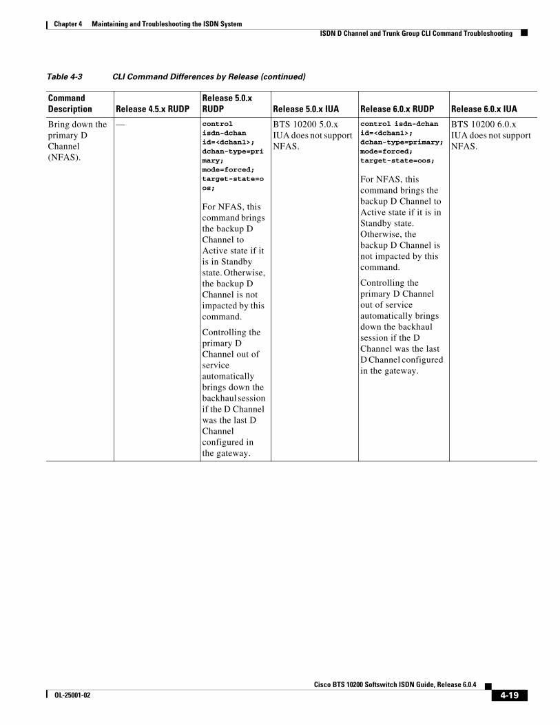
Chapter 4 Maintaining and Troubleshooting the ISDN SystemISDN D Channel and Trunk Group CLI Command Troubleshooting
Bring down the primary D Channel (NFAS).
— control isdn-dchan id=<dchan1>; dchan-type=primary; mode=forced; target-state=oos;
For NFAS, this command brings the backup D Channel to Active state if it is in Standby state. Otherwise, the backup D Channel is not impacted by this command.
Controlling the primary D Channel out of service automatically brings down the backhaul session if the D Channel was the last D Channel configured in the gateway.
BTS 10200 5.0.x IUA does not support NFAS.
control isdn-dchan id=<dchan1>; dchan-type=primary; mode=forced; target-state=oos;
For NFAS, this command brings the backup D Channel to Active state if it is in Standby state. Otherwise, the backup D Channel is not impacted by this command.
Controlling the primary D Channel out of service automatically brings down the backhaul session if the D Channel was the last D Channel configured in the gateway.
BTS 10200 6.0.x IUA does not support NFAS.
Table 4-3 CLI Command Differences by Release (continued)
Command Description Release 4.5.x RUDP
Release 5.0.x RUDP Release 5.0.x IUA Release 6.0.x RUDP Release 6.0.x IUA
4-19Cisco BTS 10200 Softswitch ISDN Guide, Release 6.0.4
OL-25001-02

Chapter 4 Maintaining and Troubleshooting the ISDN SystemISDN D Channel and Trunk Group CLI Command Troubleshooting
Bring down the backup D Channel (NFAS).
— control isdn-dchan id=<dchan1>; dchan-type=backup; mode=forced; target-state=oos;
This command brings the primary D Channel to Active state if it is in Standby state. Otherwise, the primary D Channel is not impacted by this command.
Controlling the backup D Channel out of service automatically brings down the backhaul session if the D Channel was the last D Channel configured in the gateway.
BTS 10200 5.0.x IUA does not support NFAS.
control isdn-dchan id=<dchan1>; dchan-type=backup; mode=forced; target-state=oos;
This command brings the primary D Channel to Active state if it is in Standby state. Otherwise, the primary D Channel is not impacted by this command.
Controlling the backup D Channel out of service automatically brings down the backhaul session if the D Channel was the last D Channel configured in the gateway.
BTS 10200 6.0.x IUA does not support NFAS.
Table 4-3 CLI Command Differences by Release (continued)
Command Description Release 4.5.x RUDP
Release 5.0.x RUDP Release 5.0.x IUA Release 6.0.x RUDP Release 6.0.x IUA
4-20Cisco BTS 10200 Softswitch ISDN Guide, Release 6.0.4
OL-25001-02

Chapter 4 Maintaining and Troubleshooting the ISDN SystemISDN D Channel and Trunk Group CLI Command Troubleshooting
Bring down both the primary and backup D Channels (if NFAS is configured).
Note that you need to bring down the D Channels one by one, therefore you need to specify the D Channel type in order to bring down a D Channel. For example:
btsadmin>control isdn_dchan id=1000;mode=FORCED;target_state=OOS; Reply : Failure: at 2008-02-28 06:06:37 by btsadminPlease enter DCHAN_TYPE.
— control isdn-dchan id=<dchan1>; mode=forced; target-state=oos;
Controlling the D Channel out of service automatically brings down the backhaul session if the D Channel was the last D Channel configured in the gateway.
control isdn-dchan id=<dchan1>; mode=forced; target-state=oos;
control isdn-dchan id=<dchan1>; mode=forced; target-state=oos;
Controlling the D Channel out of service automatically brings down the backhaul session if the D Channel was the last D Channel configured in the gateway.
control isdn-dchan id=<dchan1>; mode=forced; target-state=oos;
Table 4-3 CLI Command Differences by Release (continued)
Command Description Release 4.5.x RUDP
Release 5.0.x RUDP Release 5.0.x IUA Release 6.0.x RUDP Release 6.0.x IUA
4-21Cisco BTS 10200 Softswitch ISDN Guide, Release 6.0.4
OL-25001-02

Chapter 4 Maintaining and Troubleshooting the ISDN SystemISDN D Channel and Trunk Group CLI Command Troubleshooting
Bring down the D Channel (if FAS is configured).
— control isdn-dchan id=<dchan1>; dchan-type=primary; mode=forced; target-state=oos;
Controlling the D Channel out of service automatically brings down the backhaul session if the D Channel was the last D Channel configured in the gateway.
control isdn-dchan id=<dchan1>; dchan-type=primary; mode=forced; target-state=oos;
control isdn-dchan id=<dchan1>; dchan-type=primary; mode=forced; target-state=oos;
Controlling the D Channel out of service automatically brings down the backhaul session if the D Channel was the last D Channel configured in the gateway.
control isdn-dchan id=<dchan1>; dchan-type=primary; mode=forced; target-state=oos;
Bring down the backhaul session.
— — control sctp-assoc id=<isdn1>; target-state=oos; mode=forced;
— control sctp-assoc id=<isdn1>; target-state=oos; mode=forced;
Bring up thebackup D channel.
— Control isdn_dchan id=<dchan>;dchan_type=backup;mode=Forced;target_state=INS
— Control isdn_dchan id=<dchan>;dchan_type=backup;mode=Forced;target_state=INS
—
Table 4-3 CLI Command Differences by Release (continued)
Command Description Release 4.5.x RUDP
Release 5.0.x RUDP Release 5.0.x IUA Release 6.0.x RUDP Release 6.0.x IUA
4-22Cisco BTS 10200 Softswitch ISDN Guide, Release 6.0.4
OL-25001-02