Embed Size (px)
Citation preview
Cisco AVVID Network Infrastructure Data-only Enterprise Site-to-Site VPN DesignSolutions Reference Network Design
Corporate HeadquartersCisco Systems, Inc.170 West Tasman DriveSan Jose, CA 95134-1706 USAhttp://www.cisco.comTel: 408 526-4000
800 553-NETS (6387)Fax: 408 526-4100
Customer Order Number: 956377June 2003

THE SPECIFICATIONS AND INFORMATION REGARDING THE PRODUCTS IN THIS MANUAL ARE SUBJECT TO CHANGE WITHOUT NOTICE. ALL STATEMENTS, INFORMATION, AND RECOMMENDATIONS IN THIS MANUAL ARE BELIEVED TO BE ACCURATE BUT ARE PRESENTED WITHOUT WARRANTY OF ANY KIND, EXPRESS OR IMPLIED. USERS MUST TAKE FULL RESPONSIBILITY FOR THEIR APPLICATION OF ANY PRODUCTS.
THE SOFTWARE LICENSE AND LIMITED WARRANTY FOR THE ACCOMPANYING PRODUCT ARE SET FORTH IN THE INFORMATION PACKET THAT SHIPPED WITH THE PRODUCT AND ARE INCORPORATED HEREIN BY THIS REFERENCE. IF YOU ARE UNABLE TO LOCATE THE SOFTWARE LICENSE OR LIMITED WARRANTY, CONTACT YOUR CISCO REPRESENTATIVE FOR A COPY.
The Cisco implementation of TCP header compression is an adaptation of a program developed by the University of California, Berkeley (UCB) as part of UCB’s public domain version of the UNIX operating system. All rights reserved. Copyright © 1981, Regents of the University of California.
NOTWITHSTANDING ANY OTHER WARRANTY HEREIN, ALL DOCUMENT FILES AND SOFTWARE OF THESE SUPPLIERS ARE PROVIDED “AS IS” WITH ALL FAULTS. CISCO AND THE ABOVE-NAMED SUPPLIERS DISCLAIM ALL WARRANTIES, EXPRESSED OR IMPLIED, INCLUDING, WITHOUT LIMITATION, THOSE OF MERCHANTABILITY, FITNESS FOR A PARTICULAR PURPOSE AND NONINFRINGEMENT OR ARISING FROM A COURSE OF DEALING, USAGE, OR TRADE PRACTICE.
IN NO EVENT SHALL CISCO OR ITS SUPPLIERS BE LIABLE FOR ANY INDIRECT, SPECIAL, CONSEQUENTIAL, OR INCIDENTAL DAMAGES, INCLUDING, WITHOUT LIMITATION, LOST PROFITS OR LOSS OR DAMAGE TO DATA ARISING OUT OF THE USE OR INABILITY TO USE THIS MANUAL, EVEN IF CISCO OR ITS SUPPLIERS HAVE BEEN ADVISED OF THE POSSIBILITY OF SUCH DAMAGES.
Cisco AVVID Network Infrastructure Data-only Enterprise Site-to-Site VPN DesignCopyright © 2003 Cisco Systems, Inc. All rights reserved.
CCIP, CCSP, the Cisco Arrow logo, the Cisco Powered Network mark, Cisco Unity, Follow Me Browsing, FormShare, and StackWise are trademarks of Cisco Systems, Inc.; Changing the Way We Work, Live, Play, and Learn, and iQuick Study are service marks of Cisco Systems, Inc.; and Aironet, ASIST, BPX, Catalyst, CCDA, CCDP, CCIE, CCNA, CCNP, Cisco, the Cisco Certified Internetwork Expert logo, Cisco IOS, the Cisco IOS logo, Cisco Press, Cisco Systems, Cisco Systems Capital, the Cisco Systems logo, Empowering the Internet Generation, Enterprise/Solver, EtherChannel, EtherSwitch, Fast Step, GigaStack, Internet Quotient, IOS, IP/TV, iQ Expertise, the iQ logo, iQ Net Readiness Scorecard, LightStream, MGX, MICA, the Networkers logo, Networking Academy, Network Registrar, Packet, PIX, Post-Routing, Pre-Routing, RateMUX, Registrar, ScriptShare, SlideCast, SMARTnet, StrataView Plus, Stratm, SwitchProbe, TeleRouter, The Fastest Way to Increase Your Internet Quotient, TransPath, and VCO are registered trademarks of Cisco Systems, Inc. and/or its affiliates in the U.S. and certain other countries.
All other trademarks mentioned in this document or Web site are the property of their respective owners. The use of the word partner does not imply a partnership relationship between Cisco and any other company. (0304R)
Cisco AVVID Network Infra956377
C O N T E N T S
Preface vii
Scope viii
Target Audience viii
Obtaining Documentation ix
World Wide Web ix
Documentation CD-ROM ix
Ordering Documentation ix
Documentation Feedback x
Obtaining Technical Assistance x
Cisco.com x
Technical Assistance Center xi
Cisco TAC Web Site xi
Cisco TAC Escalation Center xi
C H A P T E R 1 Enterprise Site-to-Site VPN Introduction 1-1
Solution Overview 1-3
Starting Assumptions 1-3
Design Overview 1-4
Cisco VPN Product Overview 1-7
Solution Benefits 1-8
References and Reading 1-8
C H A P T E R 2 Solution Design Recommendations 2-1
General Design Considerations 2-2
Making a Solution Selection, IPSec with GRE or IPSec Alone 2-3
Solution Characteristics, Solution One, IPSec with GRE 2-3
Solution Characteristics, Solution Two, IPSec with DPD, RRI and HSRP 2-4
General Solution Characteristics 2-5
Solution One, IPSec with GRE Specific Recommendations 2-5
Implementing Generic Route Encapsulation (GRE) 2-6
High Availability and Resiliency 2-6
Head-end Load Distribution 2-8
Number of Tunnels per Device 2-9
Path MTU Discovery 2-9
iiistructure Data-only Enterprise Site-to-Site VPN Design
Contents
Alternative Network Topologies 2-9
Using a Routing Protocol across the VPN 2-10
Route Propagation Strategy 2-10
Solution Two, IPSec with DPD, RRI and HSRP Specific Recommendations 2-11
Alternatives to Using a Routing Protocol 2-11
Dead Peer Detection 2-11
Reverse Route Injection 2-12
Dynamic Crypto Maps 2-12
Hot Standby Router Protocol 2-12
Number of Tunnels per Device and Load Distribution 2-12
General Solution-specific Recommendations 2-13
Using IPSec for Data Encryption 2-13
Minimizing Packet Fragmentation 2-13
IP Addressing 2-15
Placement of VPN Head-ends Relative to Firewall 2-16
Solution Two Limitations 2-16
Failover and Convergence Performance 2-16
Solution One Failover and Convergence Performance 2-16
Solution Two Failover and Convergence Performance 2-19
Security 2-20
Split Tunneling 2-20
Multicast 2-20
IPSec Interactions with Other Networking Functions 2-21
Routing Protocols 2-21
Network Address Translation (NAT) and Port Address Translation (PAT) 2-21
Dynamic Host Configuration Protocol (DHCP) 2-21
Service Provider Dependencies 2-22
Management 2-22
C H A P T E R 3 Solution Component Recommendations 3-1
Scalability Testing Methodology 3-1
Subsequent Testing 3-2
New Traffic Mix 3-2
Conservative Results 3-3
Tunnel Quantity Effects on Throughput 3-3
GRE Encapsulation Effects on Throughput 3-3
Routing Protocols Effects on Throughput 3-3
Test Results Presentation 3-3
ivCisco AVVID Network Infrastructure Data-only Enterprise Site-to-Site VPN Design
956377
Contents
Deploy Hardware-Accelerated Encryption 3-4
Head-end Encryption Acceleration Options 3-4
Hardware Encryption Acceleration Options for Edge Routers 3-4
Head-end Devices 3-5
Sizing the Head-end 3-5
Cisco VPN Routers for Head-ends 3-8
Other Cisco Products for the Head End 3-10
PIX VPN Limitations 3-10
Branch Site Devices 3-11
Sizing the Branch Site 3-11
Cisco VPN Routers for Branch Sites 3-11
Other Cisco Products for the Branch 3-13
Software Releases Evaluated 3-13
C H A P T E R 4 Enterprise Site-to-Site VPN Configuration 4-1
Configuration Discussion Solution One 4-1
IKE Policy Configuration 4-1
IPSec Transform and Protocol Configuration 4-2
Access List Configuration for Encryption 4-3
Crypto Map Configuration 4-3
Applying Crypto Maps 4-4
Common Configuration Mistakes 4-5
ACL Mirroring 4-5
Peer Address Matching 4-5
Transform Set Matches 4-5
IKE Policy Matching 4-5
Configuration Discussion Solution Two 4-6
Solution Two, IKE Configuration 4-6
Dead Peer Detection 4-6
IKE Configurations, Head End 4-6
IKE Configurations, Branch 4-7
Solution Two, IPSec Configuration 4-7
Reverse Route Injection 4-7
Dynamic IPSec Tunnels 4-7
IPSec Configurations, Head End 4-7
IPSec Configurations, Branch 4-8
Solution Two, Head-end HSRP and Interface Configuration 4-8
Hot Standby Router Protocol and IPSec 4-8
Head End HSRP and Interface Configurations 4-8
vCisco AVVID Network Infrastructure Data-only Enterprise Site-to-Site VPN Design
956377
Contents
Branch IPSec Interface Configurations 4-9
Solution Two, Head-end Redistribution for RRI Configuration 4-9
Static Route Redistribution 4-10
Head End RRI Configuration 4-10
C H A P T E R 5 Enterprise Site-to-Site VPN Case Study 5-1
Network Overview 5-1
Design Considerations 5-3
Preliminary Design Considerations 5-3
Sizing the Head-end 5-4
Sizing the Branch Sites 5-5
Tunnel Aggregation and Load Distribution 5-5
Network Layout 5-5
A P P E N D I X A Enterprise Site-to-Site VPN Solution Test Bed Configuration A-1
Scalability Testbed Network Diagram A-1
Scalability Testbed Configuration Files A-3
Head-end Configuration A-3
Branch Site Configuration A-5
A P P E N D I X B High-Level IPSec Overview B-1
Tunneling Protocols B-1
Introduction to IPSec B-1
IPSec Protocols B-2
Encapsulating Security Protocol (ESP) B-2
Authentication Header (AH) B-4
IPSec Modes B-5
Tunnel Mode B-5
Transport Mode B-6
Internet Key Exchange (IKE) B-6
Security Association (SA) B-7
IKE Phase 1 B-7
IKE Phase 2 B-7
IKE Authentication B-7
Pre-shared Keys B-7
Digital Certificates B-8
IN D E X
viCisco AVVID Network Infrastructure Data-only Enterprise Site-to-Site VPN Design
956377
Preface
This design guide defines the comprehensive functional components required to build an Enterprise site-to-site Virtual Private Network (VPN) solution. The design guide identifies the individual hardware requirements and their interconnections, software features, management needs, and partner dependencies, to enable a customer deployable, manageable, and maintainable Enterprise site-to-site VPN solution.
This document serves as a design guide for those intending to deploy a site-to-site VPN based on IP Security (IPSec). This version of the design guide focuses on Cisco IOS VPN Router products.
The design is based on the SAFE VPN Architecture and this design guide seeks to provide an additional level of information on how to deploy SAFE VPN. The reader should first be familiar with the SAFE VPN White Paper. Cisco SAFE documentation can be found at: http://www.cisco.com/go/safe.
Specific chapters address the following topics:
• Chapter 1, “Enterprise Site-to-Site VPN Introduction”—Summarizes the benefits and characteristics of Cisco’s Enterprise site-to-site VPN solution.
• Chapter 2, “Solution Design Recommendations”—Provides an overview of some general design considerations and a summary of the two design recommendations.
• Chapter 3, “Solution Component Recommendations”—Presents steps to selecting Cisco products for Enterprise site-to-site VPN solutions.
• Chapter 4, “Enterprise Site-to-Site VPN Configuration”—Presents the configurations used to create the solution detailed in this design guide.
• Chapter 5, “Enterprise Site-to-Site VPN Case Study”—Provides a reference example for an Enterprise site-to-site VPN design.
• Appendix A, “Enterprise Site-to-Site VPN Solution Test Bed Configuration”—Describes the test network used for the Enterprise site-to-site Enterprise VPN scalability tests presented in this publication.
• Appendix B, “High-Level IPSec Overview”—Introduces IPSec and its application in VPNs.
viiCisco AVVID Network Infrastructure Data-only Enterprise Site-to-Site VPN Design
956377
PrefaceScope
ScopeThis version of the design guide addresses the following applications of the solution:
• IPSec in combination with Generic Routing Encapsulation (GRE)
Or
• IPSec as the solitary tunneling method with Dead Peer Detection (DPD), Reverse Route Injection (RRI) and Hot Standby Router Protocol (HSRP) for failover
• Site-to-site VPN topologies
• Cisco VPN routers running Cisco Internetwork Operating System (IOS)
• Use of Enhanced Interior Gateway Routing Protocol (EIGRP) as a routing protocol across the VPN with GRE configurations
• Data as the primary traffic component
• No Quality of Service (QoS) features are enabled
• Evaluation of Cisco VPN product performance in scalable and resilient designs
The following VPN applications are not addressed:
• Multi-Protocol Label Switching (MPLS)-based VPNs
• VPN management software
Where applicable, relevant configuration fragments are included.
A Cisco SAFE white paper addressing secure WLAN deployment in the Enterprise is available at:
• http://www.cisco.com/go/safe
The SAFE white paper covers more detail on the security-specific aspects of design, whereas this design guide is focused on the overall WLAN solution. Although there are differences between the SAFE white paper designs and the designs presented here, those differences are not generally considered substantive and the designs are compatible.
Target AudienceThis publication provides solution guidelines for large-scale enterprises implementing site-to-site VPN using Cisco Systems products. The intended audiences for this design guide include network architects, network managers, and others concerned with the implementation of secure Enterprise site-to-site VPN solutions, including:
• Cisco sales and support engineers
• Cisco partners
• Cisco customers
viiiCisco AVVID Network Infrastructure Data-only Enterprise Site-to-Site VPN Design
956377
PrefaceObtaining Documentation
Obtaining DocumentationThe following sections explain how to obtain documentation from Cisco Systems.
World Wide WebYou can access the most current Cisco documentation on the World Wide Web at the following URL:
http://www.cisco.com
Translated documentation is available at the following URL:
http://www.cisco.com/public/countries_languages.shtml
Documentation CD-ROMCisco documentation and additional literature are available in a Cisco Documentation CD-ROM package, which is shipped with your product. The Documentation CD-ROM is updated monthly and may be more current than printed documentation. The CD-ROM package is available as a single unit or through an annual subscription.
Ordering DocumentationCisco documentation is available in the following ways:
• Registered Cisco Direct Customers can order Cisco product documentation from the Networking Products MarketPlace:
http://www.cisco.com/cgi-bin/order/order_root.pl
• Registered Cisco.com users can order the Documentation CD-ROM through the online Subscription Store:
http://www.cisco.com/go/subscription
• Nonregistered Cisco.com users can order documentation through a local account representative by calling Cisco corporate headquarters (California, USA) at 408 526-7208 or, elsewhere in North America, by calling 800 553-NETS (6387).
ixCisco AVVID Network Infrastructure Data-only Enterprise Site-to-Site VPN Design
956377
PrefaceObtaining Technical Assistance
Documentation FeedbackIf you are reading Cisco product documentation on Cisco.com, you can submit technical comments electronically. Click Leave Feedback at the bottom of the Cisco Documentation home page. After you complete the form, print it out and fax it to Cisco at 408 527-0730.
You can e-mail your comments to [email protected].
To submit your comments by mail, use the response card behind the front cover of your document, or write to the following address:
Cisco SystemsAttn: Document Resource Connection170 West Tasman DriveSan Jose, CA 95134-9883
We appreciate your comments.
Obtaining Technical AssistanceCisco provides Cisco.com as a starting point for all technical assistance. Customers and partners can obtain documentation, troubleshooting tips, and sample configurations from online tools by using the Cisco Technical Assistance Center (TAC) Web Site. Cisco.com registered users have complete access to the technical support resources on the Cisco TAC Web Site.
Cisco.comCisco.com is the foundation of a suite of interactive, networked services that provides immediate, open access to Cisco information, networking solutions, services, programs, and resources at any time, from anywhere in the world.
Cisco.com is a highly integrated Internet application and a powerful, easy-to-use tool that provides a broad range of features and services to help you to
• Streamline business processes and improve productivity
• Resolve technical issues with online support
• Download and test software packages
• Order Cisco learning materials and merchandise
• Register for online skill assessment, training, and certification programs
You can self-register on Cisco.com to obtain customized information and service. To access Cisco.com, go to the following URL:
http://www.cisco.com
xCisco AVVID Network Infrastructure Data-only Enterprise Site-to-Site VPN Design
956377
PrefaceObtaining Technical Assistance
Technical Assistance CenterThe Cisco TAC is available to all customers who need technical assistance with a Cisco product, technology, or solution. Two types of support are available through the Cisco TAC: the Cisco TAC Web Site and the Cisco TAC Escalation Center.
Inquiries to Cisco TAC are categorized according to the urgency of the issue:
• Priority level 4 (P4)—You need information or assistance concerning Cisco product capabilities, product installation, or basic product configuration.
• Priority level 3 (P3)—Your network performance is degraded. Network functionality is noticeably impaired, but most business operations continue.
• Priority level 2 (P2)—Your production network is severely degraded, affecting significant aspects of business operations. No workaround is available.
• Priority level 1 (P1)—Your production network is down, and a critical impact to business operations will occur if service is not restored quickly. No workaround is available.
Which Cisco TAC resource you choose is based on the priority of the problem and the conditions of service contracts, when applicable.
Cisco TAC Web Site
The Cisco TAC Web Site allows you to resolve P3 and P4 issues yourself, saving both cost and time. The site provides around-the-clock access to online tools, knowledge bases, and software. To access the Cisco TAC Web Site, go to the following URL:
http://www.cisco.com/tac
All customers, partners, and resellers who have a valid Cisco services contract have complete access to the technical support resources on the Cisco TAC Web Site. The Cisco TAC Web Site requires a Cisco.com login ID and password. If you have a valid service contract but do not have a login ID or password, go to the following URL to register:
http://www.cisco.com/register/
If you cannot resolve your technical issues by using the Cisco TAC Web Site, and you are a Cisco.com registered user, you can open a case online by using the TAC Case Open tool at the following URL:
http://www.cisco.com/tac/caseopen
If you have Internet access, it is recommended that you open P3 and P4 cases through the Cisco TAC Web Site.
Cisco TAC Escalation Center
The Cisco TAC Escalation Center addresses issues that are classified as priority level 1 or priority level 2; these classifications are assigned when severe network degradation significantly impacts business operations. When you contact the TAC Escalation Center with a P1 or P2 problem, a Cisco TAC engineer will automatically open a case.
To obtain a directory of toll-free Cisco TAC telephone numbers for your country, go to the following URL:
http://www.cisco.com/warp/public/687/Directory/DirTAC.shtml
xiCisco AVVID Network Infrastructure Data-only Enterprise Site-to-Site VPN Design
956377

PrefaceObtaining Technical Assistance
Before calling, please check with your network operations center to determine the level of Cisco support services to which your company is entitled; for example, SMARTnet, SMARTnet Onsite, or Network Supported Accounts (NSA). In addition, please have available your service agreement number and your product serial number.
xiiCisco AVVID Network Infrastructure Data-only Enterprise Site-to-Site VPN Design
956377
Cisco AVVID Network Infrastructure Data-956377
C H A P T E R 1
Enterprise Site-to-Site VPN IntroductionThis chapter provides an introduction to Enterprise site-to-site VPN solution implementation considerations. It includes the following specific sections:
• Solution Overview, page 1-3
• Cisco VPN Product Overview, page 1-7
• Solution Benefits, page 1-8
• References and Reading, page 1-8
Subsequent chapters deal with the specifics of design, product selection and deployment considerations.
A high-level diagram of the network topology is shown in Figure 1-1.
1-1only Enterprise Site-to-Site VPN Design
Chapter 1 Enterprise Site-to-Site VPN Introduction
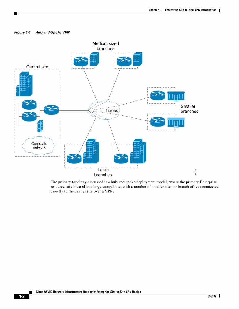
Figure 1-1 Hub-and-Spoke VPN
The primary topology discussed is a hub-and-spoke deployment model, where the primary Enterprise resources are located in a large central site, with a number of smaller sites or branch offices connected directly to the central site over a VPN.
Internet
Central site
Medium sizedbranches
Largebranches
Smallerbranches
Corporatenetwork
7416
7
1-2Cisco AVVID Network Infrastructure Data-only Enterprise Site-to-Site VPN Design
956377
Chapter 1 Enterprise Site-to-Site VPN IntroductionSolution Overview
Solution OverviewThis section provides an overview of the site-to-site VPN design topology and characteristics. Chapter 2, “Solution Design Recommendations,” provides more detail on the design considerations. Chapter 3, “Solution Component Recommendations,” then presents Cisco product options for deploying the design. Key discussions addressed in this section:
• Starting Assumptions, page 1-3
• Design Overview, page 1-4
• Solution Benefits, page 1-8
Starting AssumptionsThe design approach presented in this design guide makes several starting assumptions:
• The design supports a typical data traffic profile for networks (refer to the “Scalability Testing Methodology” section on page 3-1 for more details on the traffic profile used during scalability testing). Additional testing includes multi-service traffic in addition to the typical data traffic profile (refer to the “Subsequent Testing” section on page 3-2) for more information.
• High availability and resiliency after failover are critically important, therefore the recommendations in this design guide reflect the benefits of built-in redundancy and failover with fast convergence. This is discussed further in Chapter 2, “Solution Design Recommendations.”.
• It is assumed that the network has a need for diverse traffic requirements, such as IP multicast, multi-protocol, and support for routing. The use of GRE and a routing protocol are also discussed in more detail in Chapter 2, “Solution Design Recommendations.”
• An additional design is presented in this document. This design utilizes IPSec alone as the sole tunneling method. The elimination of GRE as an additional tunneling protocol reduces the encrypted packet size by an average of 24 bytes. This configuration is useful for many Enterprises that do not require support for a routing protocol passing through the tunnel, multicast traffic or multi-protocol traffic. Additional information on this solution is presented in Chapter 2, “Solution Design Recommendations.”
• Cisco products should be maintained at reasonable CPU utilization levels. This is discussed in more detail in Chapter 3, “Solution Component Recommendations,” including recommendations for both head-end and branch-end devices and software revisions.
• While costs were certainly considered, the design recommendations assume that the network will deploy current VPN technologies, including hardware-accelerated encryption.
• Voice over IP (VoIP), video and other latency sensitive traffic is not addressed in this design guide. Considerations for handling multi-service and other latency sensitive applications may be found in the Voice and Video Enabled IPSec VPN (V3PN) design guide available here:
http://www.cisco.com/application/pdf/en/us/guest/netsol/ns241/c649/ccmigration_09186a0080146c8e.pdf
• Finally, this design is targeted for deployment by Enterprise-owned VPNs; however, the concepts and conclusions are valid regardless of the ownership of the edge tunneling equipment, and are therefore valuable for Service Provider managed VPNs as well.
1-3Cisco AVVID Network Infrastructure Data-only Enterprise Site-to-Site VPN Design
956377
Chapter 1 Enterprise Site-to-Site VPN IntroductionSolution Overview
Design OverviewVPNs have many applications, including extending reachability of an Enterprise WAN, or replacing classic WAN technologies such as leased lines, Frame Relay and ATM. Site-to-site VPNs are primarily deployed to connect branch office locations to the central site (or sites) of an Enterprise.1
The requirements of Enterprise networks for traditional private WAN services, such as multi-protocol support, high availability, scalability, and security, are also requirements for VPNs. VPNs can often meet these requirements more cost-effectively and with greater flexibility than private WAN services.
The key components of this site-to-site VPN design are the following:
• Cisco high-end VPN routers serving as VPN head-end termination devices at a central campus (head-end devices)
• Cisco VPN access routers serving as VPN branch-end termination devices at branch office locations (branch-end devices)
• IPSec/GRE tunnels that interconnect the head-end and branch-end devices in the VPN
Or
• IPSec tunnels with DPD, RRI and HSRP to interconnect head-ends to branch-ends
• Internet services procured from a third-party Internet Service Provider (ISP) or ISPs serving as the WAN interconnection medium
Cisco VPN Routers are a good choice for site-to-site VPN deployments because they can accommodate any network requirement inherited from the Frame Relay or private line network, such as support for multicast and latency-sensitive traffic, routing for resiliency, and support for non-IP protocols like IPX or SNA. Refer to Chapter 3, “Solution Component Recommendations,” for a discussion on selection of head-end and branch-end products.
The network topology of the design is shown in Figure 1-2.
1. See http://www.cisco.com/warp/public/779/largeent/learn/technologies/vpn/site2site.html
1-4Cisco AVVID Network Infrastructure Data-only Enterprise Site-to-Site VPN Design
956377
Chapter 1 Enterprise Site-to-Site VPN IntroductionSolution Overview
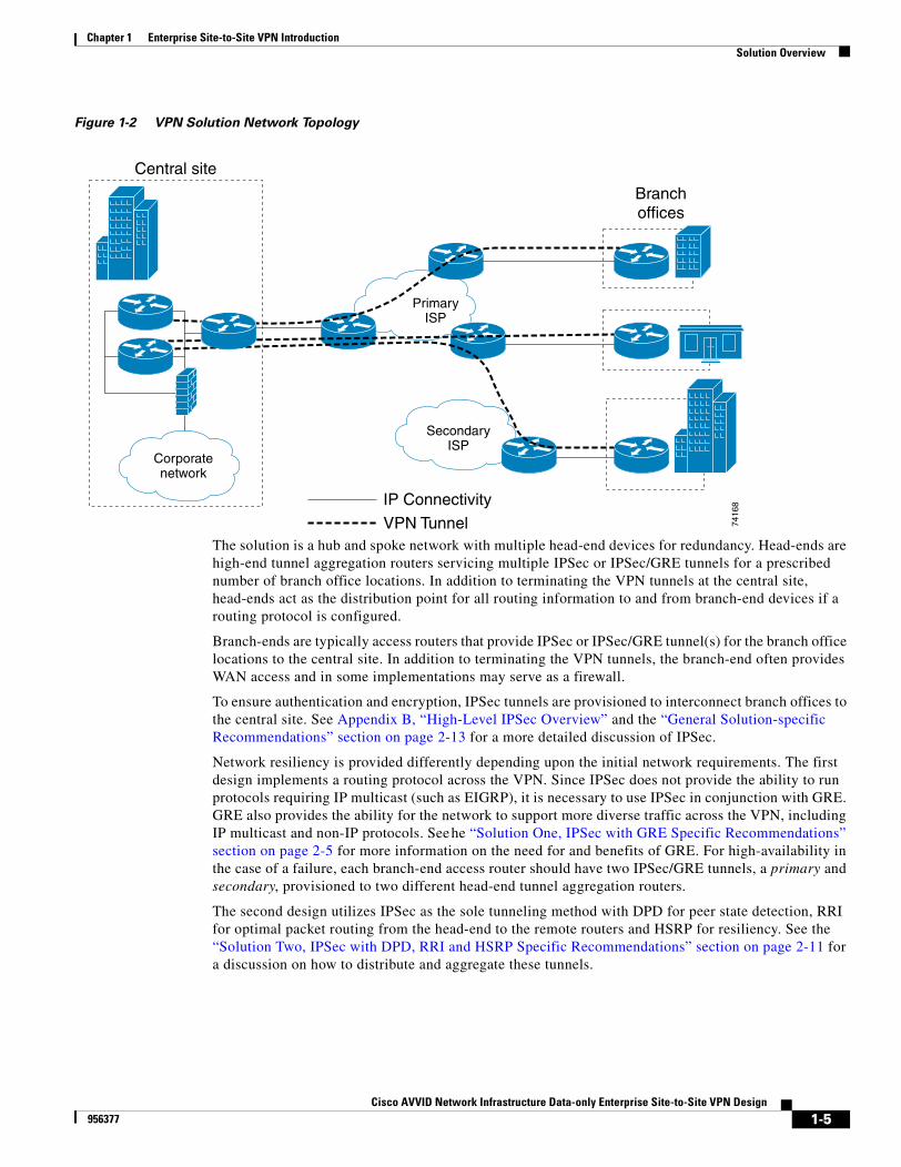
Figure 1-2 VPN Solution Network Topology
The solution is a hub and spoke network with multiple head-end devices for redundancy. Head-ends are high-end tunnel aggregation routers servicing multiple IPSec or IPSec/GRE tunnels for a prescribed number of branch office locations. In addition to terminating the VPN tunnels at the central site, head-ends act as the distribution point for all routing information to and from branch-end devices if a routing protocol is configured.
Branch-ends are typically access routers that provide IPSec or IPSec/GRE tunnel(s) for the branch office locations to the central site. In addition to terminating the VPN tunnels, the branch-end often provides WAN access and in some implementations may serve as a firewall.
To ensure authentication and encryption, IPSec tunnels are provisioned to interconnect branch offices to the central site. See Appendix B, “High-Level IPSec Overview” and the “General Solution-specific Recommendations” section on page 2-13 for a more detailed discussion of IPSec.
Network resiliency is provided differently depending upon the initial network requirements. The first design implements a routing protocol across the VPN. Since IPSec does not provide the ability to run protocols requiring IP multicast (such as EIGRP), it is necessary to use IPSec in conjunction with GRE. GRE also provides the ability for the network to support more diverse traffic across the VPN, including IP multicast and non-IP protocols. Seehe “Solution One, IPSec with GRE Specific Recommendations” section on page 2-5 for more information on the need for and benefits of GRE. For high-availability in the case of a failure, each branch-end access router should have two IPSec/GRE tunnels, a primary and secondary, provisioned to two different head-end tunnel aggregation routers.
The second design utilizes IPSec as the sole tunneling method with DPD for peer state detection, RRI for optimal packet routing from the head-end to the remote routers and HSRP for resiliency. See the “Solution Two, IPSec with DPD, RRI and HSRP Specific Recommendations” section on page 2-11 for a discussion on how to distribute and aggregate these tunnels.
PrimaryISP
SecondaryISP
Branchoffices
IP Connectivity
VPN Tunnel 7416
8
Central site
Corporatenetwork
1-5Cisco AVVID Network Infrastructure Data-only Enterprise Site-to-Site VPN Design
956377

Chapter 1 Enterprise Site-to-Site VPN IntroductionSolution Overview
There are several Service Provider options available to Enterprise networks today for deploying a VPN, including the Enterprise owning and managing the VPN, seeking only Internet service from ISPs. Optionally an Enterprise may consider outsourcing their VPN to the Service Provider. For the most part, the architecture and recommendations provided in this design guide are valid for either VPN deployment option, differing only in the owner of the edge VPN equipment.
This design guide supports a wide variety of alternatives for deploying a flexible VPN solution that will respond to changing network requirements. However, the scale of deployment will affect decisions on which products are used and the challenge to configure.
1-6Cisco AVVID Network Infrastructure Data-only Enterprise Site-to-Site VPN Design
956377
Chapter 1 Enterprise Site-to-Site VPN IntroductionCisco VPN Product Overview
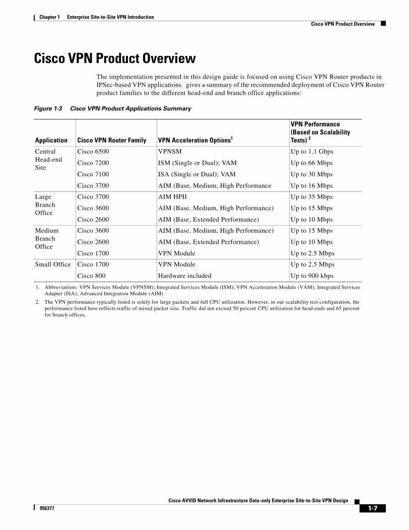
Cisco VPN Product OverviewThe implementation presented in this design guide is focused on using Cisco VPN Router products in IPSec-based VPN applications. gives a summary of the recommended deployment of Cisco VPN Router product families to the different head-end and branch office applications:
Figure 1-3 Cisco VPN Product Applications Summary
Application Cisco VPN Router Family VPN Acceleration Options1
1. Abbreviations: VPN Services Module (VPNSM); Integrated Services Module (ISM); VPN Acceleration Module (VAM); Integrated Services Adapter (ISA); Advanced Integration Module (AIM)
VPN Performance (Based on Scalability Tests) 2
2. The VPN performance typically listed is solely for large packets and full CPU utilization. However, in our scalability test configuration, the performance listed here reflects traffic of mixed packet size. Traffic did not exceed 50 percent CPU utilization for head-ends and 65 percent for branch offices.
Central Head-end Site
Cisco 6500
Cisco 7200
Cisco 7100
Cisco 3700
VPNSM
ISM (Single or Dual); VAM
ISA (Single or Dual); VAM
AIM (Base, Medium, High Performance
Up to 1.1 Gbps
Up to 66 Mbps
Up to 30 Mbps
Up to 16 Mbps
Large Branch Office
Cisco 3700
Cisco 3600
Cisco 2600
AIM HPII
AIM (Base, Medium, High Performance)
AIM (Base, Extended Performance)
Up to 35 Mbps
Up to 15 Mbps
Up to 10 Mbps
Medium Branch Office
Cisco 3600
Cisco 2600
Cisco 1700
AIM (Base, Medium, High Performance)
AIM (Base, Extended Performance)
VPN Module
Up to 15 Mbps
Up to 10 Mbps
Up to 2.5 Mbps
Small Office Cisco 1700
Cisco 800
VPN Module
Hardware included
Up to 2.5 Mbps
Up to 900 kbps
1-7Cisco AVVID Network Infrastructure Data-only Enterprise Site-to-Site VPN Design
956377
Chapter 1 Enterprise Site-to-Site VPN IntroductionSolution Benefits
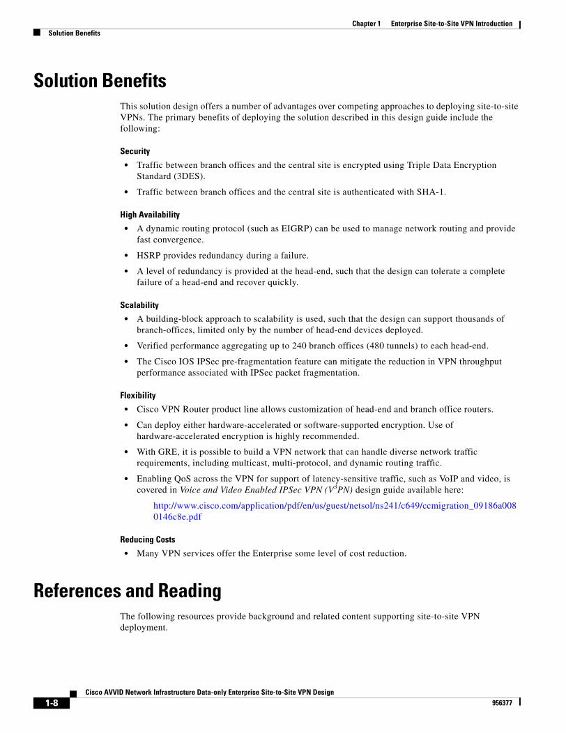
Solution BenefitsThis solution design offers a number of advantages over competing approaches to deploying site-to-site VPNs. The primary benefits of deploying the solution described in this design guide include the following:
Security
• Traffic between branch offices and the central site is encrypted using Triple Data Encryption Standard (3DES).
• Traffic between branch offices and the central site is authenticated with SHA-1.
High Availability
• A dynamic routing protocol (such as EIGRP) can be used to manage network routing and provide fast convergence.
• HSRP provides redundancy during a failure.
• A level of redundancy is provided at the head-end, such that the design can tolerate a complete failure of a head-end and recover quickly.
Scalability
• A building-block approach to scalability is used, such that the design can support thousands of branch-offices, limited only by the number of head-end devices deployed.
• Verified performance aggregating up to 240 branch offices (480 tunnels) to each head-end.
• The Cisco IOS IPSec pre-fragmentation feature can mitigate the reduction in VPN throughput performance associated with IPSec packet fragmentation.
Flexibility
• Cisco VPN Router product line allows customization of head-end and branch office routers.
• Can deploy either hardware-accelerated or software-supported encryption. Use of hardware-accelerated encryption is highly recommended.
• With GRE, it is possible to build a VPN network that can handle diverse network traffic requirements, including multicast, multi-protocol, and dynamic routing traffic.
• Enabling QoS across the VPN for support of latency-sensitive traffic, such as VoIP and video, is covered in Voice and Video Enabled IPSec VPN (V3PN) design guide available here:
http://www.cisco.com/application/pdf/en/us/guest/netsol/ns241/c649/ccmigration_09186a0080146c8e.pdf
Reducing Costs
• Many VPN services offer the Enterprise some level of cost reduction.
References and ReadingThe following resources provide background and related content supporting site-to-site VPN deployment.
1-8Cisco AVVID Network Infrastructure Data-only Enterprise Site-to-Site VPN Design
956377
Chapter 1 Enterprise Site-to-Site VPN IntroductionReferences and Reading
Documents
• SAFE VPN: IPSec Virtual Private Networks in Depth—http://www.cisco.com/warp/public/cc/so/cuso/epso/sqfr/safev_wp.htm
Request For Comment (RFC) Papers
• RFC2401—Security Architecture for the Internet Protocol
• RFC2402—IP Authentication Header
• RFC2403—The Use of HMAC-MD5-96 within ESP and AH
• RFC2404—The Use of HMAC-SHA-1-96 within ESP and AH
• RFC2405—The ESP DES-CBC Cipher Algorithm With Explicit IV
• RFC2406—IP Encapsulating Security Payload (ESP)
• RFC2407—The Internet IP Security Domain of Interpretation for ISAKMP
• RFC2408—Internet Security Association and Key Management Protocol (ISAKMP)
• RFC2409—The Internet Key Exchange (IKE)
• RFC2410—The NULL Encryption Algorithm and Its Use With IPsec
• RFC2411—IP Security Document Roadmap
• RFC2412—The OAKLEY Key Determination Protocol
Worldwide Web Resource
• Enterprise VPNs—http://www.cisco.com/go/evpn
• Cisco SAFE Blueprint—http://www.cisco.com/go/safe
• Cisco Network Security—http://www.cisco.com/go/security
• Cisco AVVID Partner Program—http://www.cisco.com/go/securityassociates
• Cisco VPN Product Documentation—http://www.cisco.com/univercd/cc/td/doc/product/vpn/
• Download VPN Software from CCO—http://www.cisco.com/kobayashi/sw-center/sw-vpn.shtml
• Improving Security on Cisco Routers—http://www.cisco.com/warp/public/707/21.html
• Essential Cisco IOS Features Every ISP Should Consider—http://www.cisco.com/warp/public/707/EssentialIOSfeatures_pdf.zip
• Increasing Security on IP Networks—http://www.cisco.com/cpress/cc/td/cpress/ccie/ndcs798/nd2016.htm
• Cisco TAC Security Technical Tips—http://www.cisco.com/warp/public/707/
• IPSec Support Page—http://www.cisco.com/cgi-bin/Support/PSP/psp_view.pl?p=Internetworking:IPSec
• Networking Professionals Connection—http://forums.cisco.com
1-9Cisco AVVID Network Infrastructure Data-only Enterprise Site-to-Site VPN Design
956377

Chapter 1 Enterprise Site-to-Site VPN IntroductionReferences and Reading
1-10Cisco AVVID Network Infrastructure Data-only Enterprise Site-to-Site VPN Design
956377

Cisco AVVID Network Infrastructure Data-956377
C H A P T E R 2
Solution Design RecommendationsIn designing a VPN deployment for an Enterprise network, it is essential to integrate broader design considerations, such as high availability and resiliency, security, and potentially QoS.
This chapter starts with an overview of some general design considerations, followed by a summary of the two design recommendations, the requirements and prerequisites, and additional detailed sections on these recommendations as required.
Specific sections provided in this chapter include:
• General Design Considerations, page 2-2
• Solution One, IPSec with GRE Specific Recommendations, page 2-5
• Solution Two, IPSec with DPD, RRI and HSRP Specific Recommendations, page 2-11
• General Solution-specific Recommendations, page 2-13
• Failover and Convergence Performance, page 2-16
• Security, page 2-20
• Multicast, page 2-20
• IPSec Interactions with Other Networking Functions, page 2-21
• Service Provider Dependencies, page 2-22
• Management, page 2-22
2-1only Enterprise Site-to-Site VPN Design
Chapter 2 Solution Design RecommendationsGeneral Design Considerations
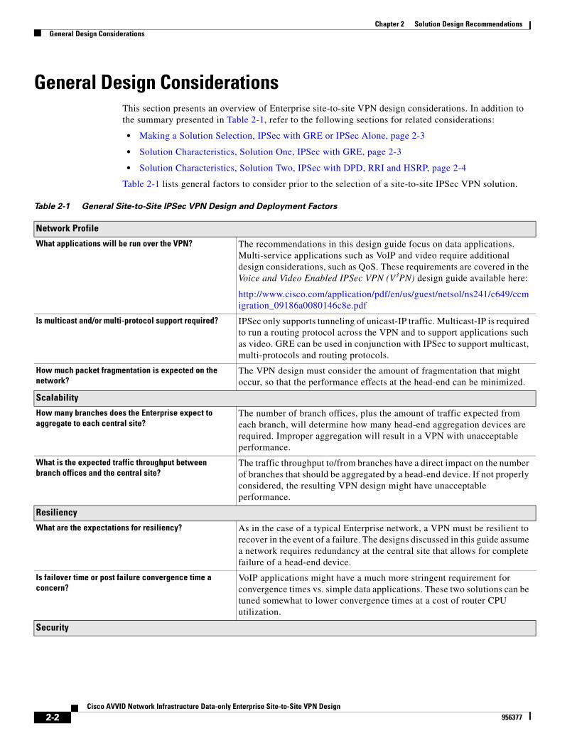
General Design ConsiderationsThis section presents an overview of Enterprise site-to-site VPN design considerations. In addition to the summary presented in Table 2-1, refer to the following sections for related considerations:
• Making a Solution Selection, IPSec with GRE or IPSec Alone, page 2-3
• Solution Characteristics, Solution One, IPSec with GRE, page 2-3
• Solution Characteristics, Solution Two, IPSec with DPD, RRI and HSRP, page 2-4
Table 2-1 lists general factors to consider prior to the selection of a site-to-site IPSec VPN solution.
Table 2-1 General Site-to-Site IPSec VPN Design and Deployment Factors
Network Profile
What applications will be run over the VPN? The recommendations in this design guide focus on data applications. Multi-service applications such as VoIP and video require additional design considerations, such as QoS. These requirements are covered in the Voice and Video Enabled IPSec VPN (V3PN) design guide available here:
http://www.cisco.com/application/pdf/en/us/guest/netsol/ns241/c649/ccmigration_09186a0080146c8e.pdf
Is multicast and/or multi-protocol support required? IPSec only supports tunneling of unicast-IP traffic. Multicast-IP is required to run a routing protocol across the VPN and to support applications such as video. GRE can be used in conjunction with IPSec to support multicast, multi-protocols and routing protocols.
How much packet fragmentation is expected on the network?
The VPN design must consider the amount of fragmentation that might occur, so that the performance effects at the head-end can be minimized.
Scalability
How many branches does the Enterprise expect to aggregate to each central site?
The number of branch offices, plus the amount of traffic expected from each branch, will determine how many head-end aggregation devices are required. Improper aggregation will result in a VPN with unacceptable performance.
What is the expected traffic throughput between branch offices and the central site?
The traffic throughput to/from branches have a direct impact on the number of branches that should be aggregated by a head-end device. If not properly considered, the resulting VPN design might have unacceptable performance.
Resiliency
What are the expectations for resiliency? As in the case of a typical Enterprise network, a VPN must be resilient to recover in the event of a failure. The designs discussed in this guide assume a network requires redundancy at the central site that allows for complete failure of a head-end device.
Is failover time or post failure convergence time a concern?
VoIP applications might have a much more stringent requirement for convergence times vs. simple data applications. These two solutions can be tuned somewhat to lower convergence times at a cost of router CPU utilization.
Security
2-2Cisco AVVID Network Infrastructure Data-only Enterprise Site-to-Site VPN Design
956377
Chapter 2 Solution Design RecommendationsGeneral Design Considerations
Keep in mind that this design guide provides general design considerations. Each network might require customization due to network-specific requirements.
Making a Solution Selection, IPSec with GRE or IPSec AloneAn initial decision based on network requirements should be made. Does the requirement for protocols other than unicast IP alone exist? Will this requirement exist at any time in the future? If so, the deployment should include an additional tunneling protocol. GRE will be used in this solution. GRE will subject a packet to additional overhead and expansion. Careful consideration should be made to this decision, as it might be difficult and time-consuming to change the deployment later on. When no further requirements for either multicast or non-IP protocols require additional encapsulation methods such as GRE, the network implementer might opt to configure IPSec High Availability (HA).
This solution utilizes IPSec as the sole tunneling method. This configuration utilizes DPD for peer state feedback, RRI for optimal routing from the campus network to the remote routers and HSRP for head end resilience. This solution is more conservative with router CPU resources than the IPSec with GRE solution.
This chapter summarizes the best practices for deployment of an Enterprise site-to-site IPSec-based VPN. It is divided into two sections depending upon the enterprise network design requirements. Solution One deals with the choice of IPSec along with GRE tunneling for VPN. Solution two uses IPSec as the sole tunneling method.
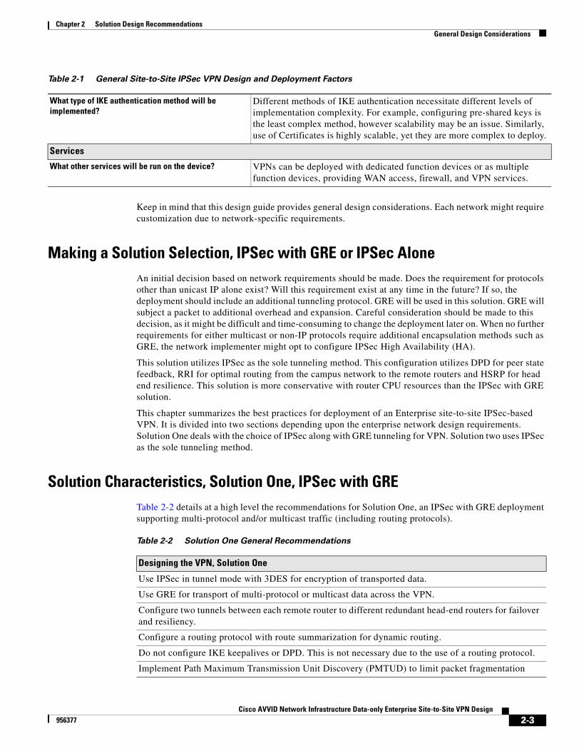
Solution Characteristics, Solution One, IPSec with GRETable 2-2 details at a high level the recommendations for Solution One, an IPSec with GRE deployment supporting multi-protocol and/or multicast traffic (including routing protocols).
What type of IKE authentication method will be implemented?
Different methods of IKE authentication necessitate different levels of implementation complexity. For example, configuring pre-shared keys is the least complex method, however scalability may be an issue. Similarly, use of Certificates is highly scalable, yet they are more complex to deploy.
Services
What other services will be run on the device? VPNs can be deployed with dedicated function devices or as multiple function devices, providing WAN access, firewall, and VPN services.
Table 2-1 General Site-to-Site IPSec VPN Design and Deployment Factors
Table 2-2 Solution One General Recommendations
Designing the VPN, Solution One
Use IPSec in tunnel mode with 3DES for encryption of transported data.
Use GRE for transport of multi-protocol or multicast data across the VPN.
Configure two tunnels between each remote router to different redundant head-end routers for failover and resiliency.
Configure a routing protocol with route summarization for dynamic routing.
Do not configure IKE keepalives or DPD. This is not necessary due to the use of a routing protocol.
Implement Path Maximum Transmission Unit Discovery (PMTUD) to limit packet fragmentation
2-3Cisco AVVID Network Infrastructure Data-only Enterprise Site-to-Site VPN Design
956377
Chapter 2 Solution Design RecommendationsGeneral Design Considerations
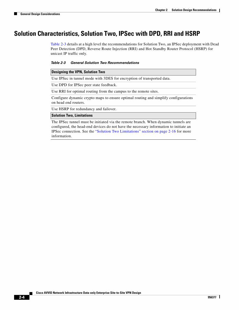
Solution Characteristics, Solution Two, IPSec with DPD, RRI and HSRPTable 2-3 details at a high level the recommendations for Solution Two, an IPSec deployment with Dead Peer Detection (DPD, Reverse Route Injection (RRI) and Hot Standby Router Protocol (HSRP) for unicast IP traffic only.
Table 2-3 General Solution Two Recommendations
Designing the VPN, Solution Two
Use IPSec in tunnel mode with 3DES for encryption of transported data.
Use DPD for IPSec peer state feedback.
Use RRI for optimal routing from the campus to the remote sites.
Configure dynamic crypto maps to ensure optimal routing and simplify configurations on head end routers.
Use HSRP for redundancy and failover.
Solution Two, Limitations
The IPSec tunnel must be initiated via the remote branch. When dynamic tunnels are configured, the head-end devices do not have the necessary information to initiate an IPSec connection. See the “Solution Two Limitations” section on page 2-16 for more information.
2-4Cisco AVVID Network Infrastructure Data-only Enterprise Site-to-Site VPN Design
956377
Chapter 2 Solution Design RecommendationsGeneral Solution Characteristics
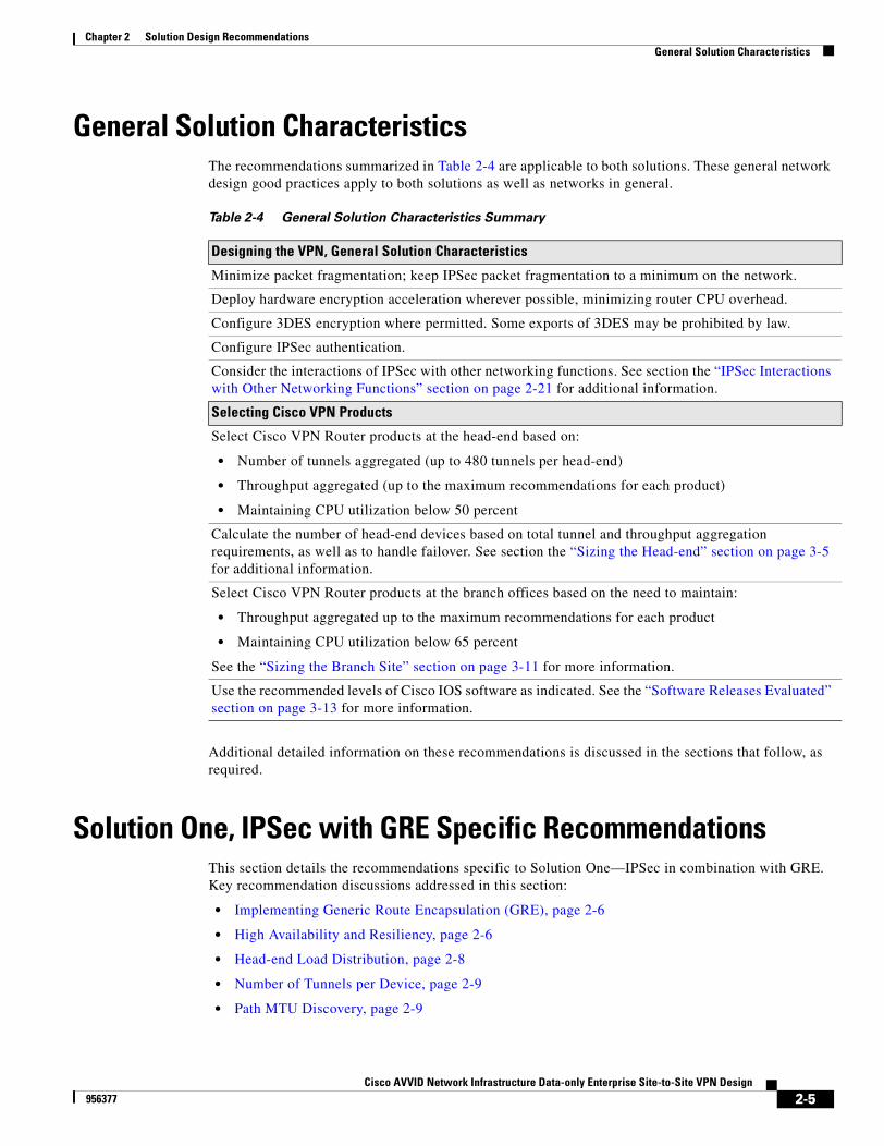
General Solution CharacteristicsThe recommendations summarized in Table 2-4 are applicable to both solutions. These general network design good practices apply to both solutions as well as networks in general.
Additional detailed information on these recommendations is discussed in the sections that follow, as required.
Solution One, IPSec with GRE Specific RecommendationsThis section details the recommendations specific to Solution One—IPSec in combination with GRE. Key recommendation discussions addressed in this section:
• Implementing Generic Route Encapsulation (GRE), page 2-6
• High Availability and Resiliency, page 2-6
• Head-end Load Distribution, page 2-8
• Number of Tunnels per Device, page 2-9
• Path MTU Discovery, page 2-9
Table 2-4 General Solution Characteristics Summary
Designing the VPN, General Solution Characteristics
Minimize packet fragmentation; keep IPSec packet fragmentation to a minimum on the network.
Deploy hardware encryption acceleration wherever possible, minimizing router CPU overhead.
Configure 3DES encryption where permitted. Some exports of 3DES may be prohibited by law.
Configure IPSec authentication.
Consider the interactions of IPSec with other networking functions. See section the “IPSec Interactions with Other Networking Functions” section on page 2-21 for additional information.
Selecting Cisco VPN Products
Select Cisco VPN Router products at the head-end based on:
• Number of tunnels aggregated (up to 480 tunnels per head-end)
• Throughput aggregated (up to the maximum recommendations for each product)
• Maintaining CPU utilization below 50 percent
Calculate the number of head-end devices based on total tunnel and throughput aggregation requirements, as well as to handle failover. See section the “Sizing the Head-end” section on page 3-5 for additional information.
Select Cisco VPN Router products at the branch offices based on the need to maintain:
• Throughput aggregated up to the maximum recommendations for each product
• Maintaining CPU utilization below 65 percent
See the “Sizing the Branch Site” section on page 3-11 for more information.
Use the recommended levels of Cisco IOS software as indicated. See the “Software Releases Evaluated” section on page 3-13 for more information.
2-5Cisco AVVID Network Infrastructure Data-only Enterprise Site-to-Site VPN Design
956377
Chapter 2 Solution Design RecommendationsSolution One, IPSec with GRE Specific Recommendations
• Alternative Network Topologies, page 2-9
• Using a Routing Protocol across the VPN, page 2-10
• Route Propagation Strategy, page 2-10
Note Solution One is recommendation when multi-protocol, multicast support is needed, or when routing protocol support is necessary. For deployments without these specific requirements, Solution Two may be used instead. Refer to “Solution Two, IPSec with DPD, RRI and HSRP Specific Recommendations” section on page 2-11.
Implementing Generic Route Encapsulation (GRE)While IPSec provides a secure method for tunneling data across an IP network, it has several limitations. First, IPSec does not support broadcast or multicast IP, preventing the use of protocols that rely on these features, such as routing protocols. Second, IPSec does not support the use of multi-protocol traffic.
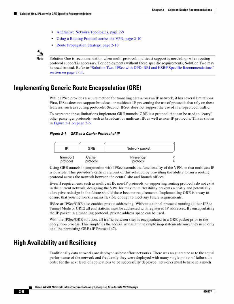
To overcome these limitations implement GRE tunnels. GRE is a protocol that can be used to “carry” other passenger protocols, such as broadcast or multicast IP, as well as non-IP protocols. This is shown in Figure 2-1 on page 2-6.
Figure 2-1 GRE as a Carrier Protocol of IP
Using GRE tunnels in conjunction with IPSec extends the functionality of the VPN, so that multicast IP is possible. This provides a critical element of this solution by providing the ability to run a routing protocol across the network between the central site and branch offices.
Even if requirements such as multicast IP, non-IP protocols, or supporting routing protocols do not exist in the current network, designing the VPN for maximum flexibility prevents a costly and potentially disruptive redesign in the future should these become requirements. Implementing GRE is a way to ensure that your network remains flexible enough to meet any future requirements.
IPSec or IPSec/GRE also enables private addressing. Without a tunnel protocol running (either IPSec Tunnel Mode or GRE) all end stations must be addressed with registered IP addresses. By encapsulating the IP packet in a tunneling protocol, private address space can be used.
With the IPSec/GRE solution, all traffic between sites is encapsulated in a GRE packet prior to the encryption process. This simplifies the access list used in the crypto map statements since they need only one line permitting GRE (IP Protocol 47).
High Availability and ResiliencyTraditionally data networks are deployed as best effort networks. There was no guarantee as to the actual performance of the network and frequently they were deployed with many single points of failure. In order for the next level of applications to be successfully deployed, networks must behave in a much
GRE Network packetIP
Carrierprotocol
Passengerprotocol
Transportprotocol 74
173
2-6Cisco AVVID Network Infrastructure Data-only Enterprise Site-to-Site VPN Design
956377
Chapter 2 Solution Design RecommendationsSolution One, IPSec with GRE Specific Recommendations
more predictable manner. This not only includes recovery from failures within specific timeframes but also includes the ability to transport the packets to their destination with specific and repeatable (minimized) delays.
In all cases, networks should be designed so that the individual elements that make up the network are operating conservatively. These elements include network devices—such as routers and switches—and the LAN and WAN links that connect these devices together.
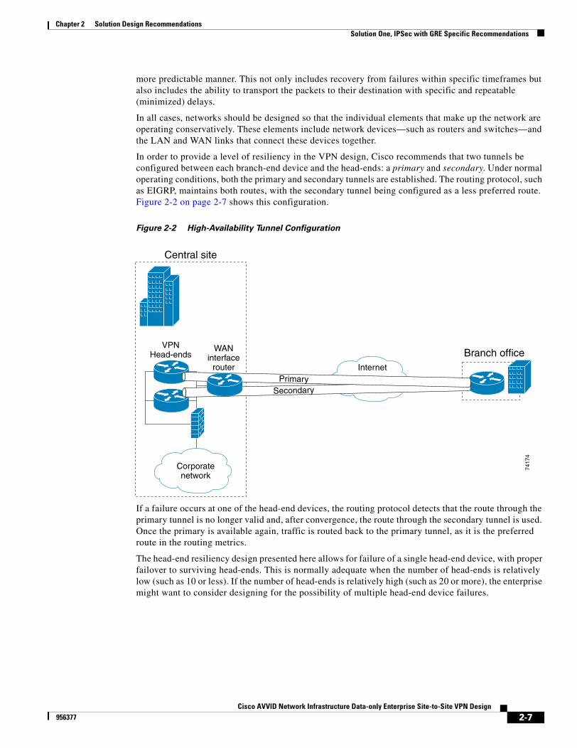
In order to provide a level of resiliency in the VPN design, Cisco recommends that two tunnels be configured between each branch-end device and the head-ends: a primary and secondary. Under normal operating conditions, both the primary and secondary tunnels are established. The routing protocol, such as EIGRP, maintains both routes, with the secondary tunnel being configured as a less preferred route. Figure 2-2 on page 2-7 shows this configuration.
Figure 2-2 High-Availability Tunnel Configuration
If a failure occurs at one of the head-end devices, the routing protocol detects that the route through the primary tunnel is no longer valid and, after convergence, the route through the secondary tunnel is used. Once the primary is available again, traffic is routed back to the primary tunnel, as it is the preferred route in the routing metrics.
The head-end resiliency design presented here allows for failure of a single head-end device, with proper failover to surviving head-ends. This is normally adequate when the number of head-ends is relatively low (such as 10 or less). If the number of head-ends is relatively high (such as 20 or more), the enterprise might want to consider designing for the possibility of multiple head-end device failures.
WANinterface
router
VPNHead-ends
Internet
Branch office
7417
4
Central site
Corporatenetwork
PrimarySecondary
2-7Cisco AVVID Network Infrastructure Data-only Enterprise Site-to-Site VPN Design
956377
Chapter 2 Solution Design RecommendationsSolution One, IPSec with GRE Specific Recommendations
Note The probability of multiple failures with a small number of head-ends is relatively small. As the number of head ends grows, the possibility that more than one may be failed during the same time period also grows. If there are a very large number of head-end devices, the same scheme to load balance in the event of a single failure could be used to load balance in the event of multiple failures. However, this would likely require more than two tunnels per remote node depending on how the remote nodes are distributed on each head-end.
It might also be necessary in the overall network strategy to have head-end devices geographically dispersed. Although not scalability tested, the architecture presented in this design guide should readily support this configuration. More information regarding this architecture is also discussed in the SAFE VPN White Paper. Cisco SAFE documentation can be found at http://www.cisco.com/go/safe.
Configuration of primary and secondary tunnels to appropriate head-ends is critical to maintain network resiliency. Please refer to section “Head-end Load Distribution” section on page 2-8 for a discussion of tunnel aggregation.
Head-end Load DistributionWhen laying out the network topology, it is important to consider load balancing across multiple head-end devices, especially in the case of a head-end device failure. This design recommends that there be at least two tunnels configured between a branch device and the head-end.
The primary tunnel (the preferred route) should be configured (via a bandwidth statement) to carry traffic under normal circumstances. The preferred primary tunnels should be evenly divided among the head-end devices. The secondary tunnels for branches should be evenly spread among the remaining (surviving) head-end devices.
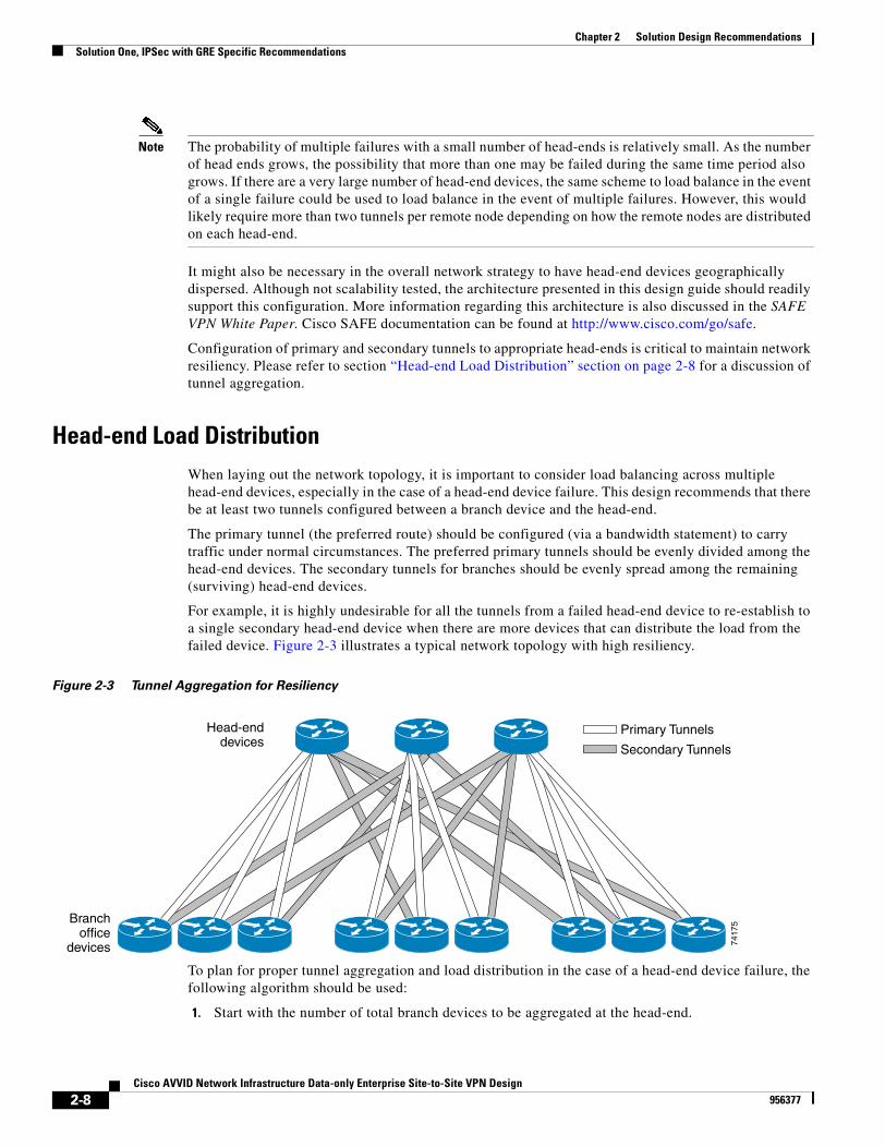
For example, it is highly undesirable for all the tunnels from a failed head-end device to re-establish to a single secondary head-end device when there are more devices that can distribute the load from the failed device. Figure 2-3 illustrates a typical network topology with high resiliency.
Figure 2-3 Tunnel Aggregation for Resiliency
To plan for proper tunnel aggregation and load distribution in the case of a head-end device failure, the following algorithm should be used:
1. Start with the number of total branch devices to be aggregated at the head-end.
Head-enddevices
Branchoffice
devices
Primary Tunnels
Secondary Tunnels74
175
2-8Cisco AVVID Network Infrastructure Data-only Enterprise Site-to-Site VPN Design
956377
Chapter 2 Solution Design RecommendationsSolution One, IPSec with GRE Specific Recommendations
2. Divide this number by the number of head-end devices.
3. Multiply the result by two for primary and secondary tunnels. This is the total tunnels per head-end device.
4. Allocate the primary tunnels to each head-end device in the arrangement shown in Figure 2-3.
5. For each group, allocate the secondary tunnels in a round-robin fashion to all head-end devices except the one serving as a primary for that group. This arrangement is also shown in Figure 2-3.
6. Check to see that each head-end device is now allocated the same number of total tunnels per head-end device.
Please note that this calculation should take into account any tunnel throughput variances.
Number of Tunnels per DeviceThe number of tunnels required for each head-end device should be scaled to the overall size of the network in which the VPN solution is being deployed. Please refer to Chapter 3, “Solution Component Recommendations” for more information.
It should be noted that head-end scalability testing did not include an exhaustive evaluation of the maximum number of tunnels that can be terminated to head-end devices. In addition, scalability testing of branch site devices was performed with two tunnels per branch device. This did not include exhaustive testing of the number of tunnels these different platforms can support.
Path MTU DiscoveryA feature of IP called Path MTU Discovery (PMTUD) can eliminate the possibility of fragmentation if it is supported by the end stations. This procedure is run between two end stations with the participation of the network devices between them.
During PMTUD, an MTU-sized packet is sent out by an end station with the don’t fragment (DF) bit set. If this packet encounters a link with a lower MTU than the packet size, an ICMP error message is generated with a three in the type field (destination unreachable) and a four in the code field (fragmentation needed and DF set) and the next hop’s MTU size in the unused field of the ICMP header.
In order for this process to work over an IPSec network with GRE, the GRE tunnel MTU should be set to a value low enough to ensure that the packet will make it through the encryption process without exceeding the MTU on the outbound interface, usually 1400 bytes.
Alternative Network TopologiesThis design guide recommends a hub and spoke topology. Other possible topologies include partially meshed and fully meshed networks.
While these alternative topologies can be implemented in an IPSec VPN, both lead to more difficulties during deployment and scalability. For example, in a meshed network, the larger number of active tunnels per peer places more of a performance burden on the devices running IPSec, possibly requiring more CPU and memory resources.
The configuration of these devices also becomes more complex. At a minimum, an additional access list must be created for each peer connection, as well as additional crypto map entries.
2-9Cisco AVVID Network Infrastructure Data-only Enterprise Site-to-Site VPN Design
956377
Chapter 2 Solution Design RecommendationsSolution One, IPSec with GRE Specific Recommendations
In addition, the routing protocol (such as EIGRP) must deal with many more adjacencies, nullifying the advantages of routing protocol efficiencies like summarization and stub. Refer to “Using a Routing Protocol across the VPN” section on page 2-10.
For smaller deployments, a fully meshed or partially meshed topology is possible, but the size of these deployments should be limited and carefully tested prior to roll out. Partially and fully meshed topologies were not scalability tested for this design guide.
Using a Routing Protocol across the VPNThis design recommends the use of a routing protocol to propagate routes from the head-end to the branch offices. Using a routing protocol has several advantages over the current mechanisms in IPSec alone.
One key advantage of using a routing protocol is that the VPN receives the same level of benefit as doing so on a traditional network. This includes receiving information about the network connectivity available over a particular interface, topology information about a network, notification when that topology changes (such as when a link fails), and information about the status of remote peers.
Another advantage is that while there are alternatives to a routing protocol, most only verify the “health” of the VPN device. With a routing protocol, it is possible to verify that traffic is actually reaching its destination.
Several routing protocols are candidates for operation over an IPSec VPN, including EIGRP and Open Shortest Path First (OSPF). Solution One presented in this design guide uses EIGRP as the routing protocol, as EIGRP was used during the scalability tests conducted. EIGRP is recommended as the routing protocol to use due to its conservative use of router CPU and network bandwidth as well as its quick convergence times. EIGRP also provides a range of options for address summarization and default route propagation.
Routing protocols do increase the CPU utilization on a network device and their use must be taken into consideration when sizing those devices.
Route Propagation StrategyThere are a number of approaches to propagating routes from the head-end to the branch offices. For this design, the recommended approach is for the each head-end router to advertise a default route to each of the tunnels it terminates with a preferred cost for the primary path. With this in mind, each of the branch office routers must add a static host route for each of the head-end peer (primary and secondary) IP addresses, with a next hop destined for their respective ISP IP address.
For example, the configuration excerpts shown below are used (for EIGRP as the routing protocol) in a scenario where one branch has a primary and secondary tunnel to two head-end routers:
Head-end Router (Primary) interface e0ip address 1.1.1.2 255.255.255.0!router eigrp 1redistribute static!ip route 0.0.0.0 0.0.0.0 1.1.1.1
Head-end Router (Secondary)interface e0
2-10Cisco AVVID Network Infrastructure Data-only Enterprise Site-to-Site VPN Design
956377
Chapter 2 Solution Design RecommendationsSolution Two, IPSec with DPD, RRI and HSRP Specific Recommendations
ip address 1.1.1.3 255.255.255.0!router eigrp 1redistribute static!ip route 0.0.0.0 0.0.0.0 1.1.1.1
Branch Site Routerrouter eigrp 1!ip route 1.1.1.2 255.255.255.255 2.2.2.2ip route 1.1.1.3 255.255.255.255 2.2.2.2
In this example, the IP address 2.2.2.2 refers to the ISP provider network of the branch office. IP addresses 1.1.1.2 and 1.1.1.3 represent the two head-end routers. Note that the branch site router configuration contains static routes for the two head-end routers, with the ISP as the next hop router. Also, note that the head-end routers advertise a default route to 1.1.1.1.
Solution Two, IPSec with DPD, RRI and HSRP Specific Recommendations
Often the requirements for a VPN do not include multiprotocol or multicast data. An IPSec VPN can achieve a higher throughput without the use of GRE if these requirements do not exist. The routers configured for the VPN will not undergo the overhead necessary to perform the GRE encapsulation and the packets themselves will not contain the GRE overhead, usually 24 bytes. As a rule of thumb, the CPU utilization on head-end routers will be about 10 percent less when GRE is not configured. Key recommendation discussions addressed in this section:
• Alternatives to Using a Routing Protocol, page 2-11
• Dead Peer Detection, page 2-11
• Reverse Route Injection, page 2-12
• Dynamic Crypto Maps, page 2-12
• Hot Standby Router Protocol, page 2-12
• Number of Tunnels per Device and Load Distribution, page 2-12
Alternatives to Using a Routing ProtocolA routing protocol provides several vital features when deployed over a network. These include peer state detection, optimal routing and the ability to facilitate alternate routes in the event of a failure.
Dead Peer DetectionDead Peer Detection (DPD) is a Cisco IOS feature that enhances the IKE keepalives feature. DPD operates by sending a hello message to an IPSec peer that it has not received traffic from during a specified configurable period. If normal IPSec traffic is received from a peer and decrypted correctly, that peer is assumed alive and no hello message is sent and the DPD counter for that peer is reset. This results in lower CPU utilization than occurs with IKE keepalives.
2-11Cisco AVVID Network Infrastructure Data-only Enterprise Site-to-Site VPN Design
956377
Chapter 2 Solution Design RecommendationsSolution Two, IPSec with DPD, RRI and HSRP Specific Recommendations
Reverse Route InjectionReverse Route Injection (RRI) is another Cisco IOS IPSec feature. RRI takes the information derived from the negotiated IPSec security associations (SAs) and creates a static route to the networks contained in those SAs. Route redistribution can then take place between these static routes and any routing protocol configured on the router.
Dynamic Crypto MapsRather than pre-defining all the IPSec peers, another option is creating dynamic crypto maps. Dynamic crypto maps allow an IPSec connection between two peers when one of the peers, usually the central site peer, does not have the complete configuration necessary to complete an IPSec negotiation with a remote peer. This situation might occur when the remote peer has its IP address dynamically assigned. One example is a residential class service connection such as a cable or xDSL connection. Since the remote peer’s IP address is unknown, it cannot be preconfigured in the central site device. IKE is required for authentication with dynamic crypto maps. The IKE authentication completes based on an identity other than the remote node’s IP address, such as the peer’s Fully Qualified Domain Name (FQDN). Information from the IKE session is used to complete the missing information in the dynamic crypto map configuration.
Hot Standby Router ProtocolHot Standby Router Protocol (HSRP) enables IPSec to use the standby group address as its IPSec peer address. If the current owner of the HSRP group fails, that address transfers over to the secondary standby router. Currently, no IPSec or IKE security association (SA) state information is transferred during failure. A remote peer router configured with an HSRP group address as an IPSec peer must renegotiate its IKE SA’s and IPSec SA’s prior to any subsequent traffic transmission.
Number of Tunnels per Device and Load DistributionThe number of tunnels required for each head-end device should be scaled to the overall size of the network in which the VPN solution is being deployed. Please refer to the “Head-end Devices” section on page 3-5 for more information. In addition, the normal load from a number of branch sites may be distributed across two or more head end devices. This is accomplished by configuring multiple standby groups—one group for each group of branch devices. By using HSRP in this manner, a number of remote routers can be evenly divided among a number of head-end devices for load sharing during normal operation. During a failure event, only the branch devices connected as primary to the failed HSRP group owner is subject to re-negotiation of the IPSec SAs resulting in enhanced failover performance.
It should be noted that head-end scalability testing did not include an exhaustive evaluation of the maximum number of tunnels that can be terminated to head-end devices. In addition, scalability testing of branch site devices was performed with two tunnels per branch device. This did not include exhaustive testing of the number of tunnels these different platforms can support.
2-12Cisco AVVID Network Infrastructure Data-only Enterprise Site-to-Site VPN Design
956377
Chapter 2 Solution Design RecommendationsGeneral Solution-specific Recommendations
General Solution-specific RecommendationsThe following recommendations are applicable to both solutions. These general good network design practices apply to both solutions as well as networks in general. Key recommendation discussions addressed in this section:
• Using IPSec for Data Encryption, page 2-13
• Minimizing Packet Fragmentation, page 2-13
• IP Addressing, page 2-15
• Placement of VPN Head-ends Relative to Firewall, page 2-16
• Solution Two Limitations, page 2-16
Using IPSec for Data EncryptionThere are three elements to consider when securing the traffic flowing over the VPN:
• Authentication—Authentication of the IPSec peers is handled using IKE.
• Confidentiality—Confidentiality of data transported over the VPN is handled using encryption algorithms such as DES or 3DES. Since 3DES is more secure, it should be implemented if possible, except in cases where export restrictions limit the implementation to DES.1
• Message Integrity—Message integrity is ensured using the IPSec protocol with a hash method, such as Message Digest 5 (MD5) or Secure Hash Algorithm 1 (SHA-1). It is possible to implement only a hash method or only an encryption standard to secure the VPN. However, it is highly recommended that both be implemented in combination. In this design guide, the combination of 3DES and SHA-1 is recommended.
With hardware-accelerated encryption implemented, performance is not significantly affected by choice of encryption method.
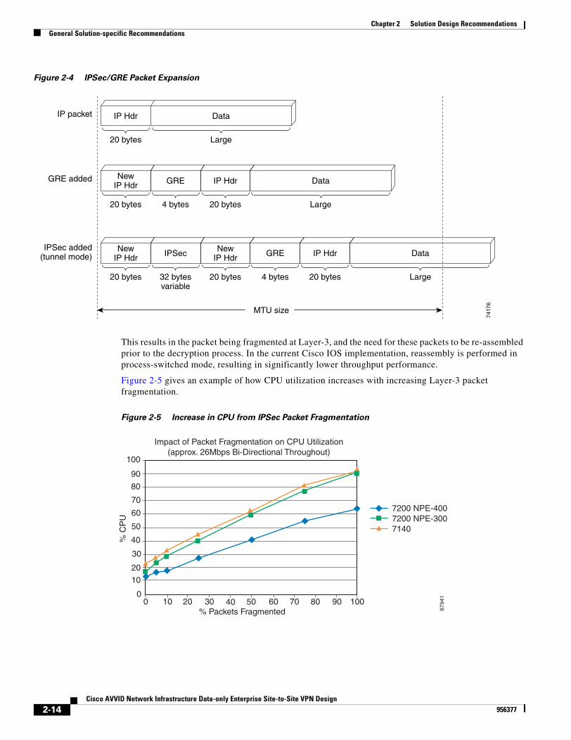
Minimizing Packet FragmentationIPSec and GRE headers increase the size of packets. Packet fragmentation is also a cause of decreased performance in IPSec networks. If the size of a packet before encryption is at or near the MTU of the transmission media, the encrypted packet with the additional IPsec and GRE headers become greater than the MTU of the transmitting interface. This results in Layer-3 fragmentations on the outbound interface. This is shown in Figure 2-4.
1. There are various laws and restrictions that govern domestic and international use and export of en-cryption technology.
2-13Cisco AVVID Network Infrastructure Data-only Enterprise Site-to-Site VPN Design
956377
Chapter 2 Solution Design RecommendationsGeneral Solution-specific Recommendations
Figure 2-4 IPSec/GRE Packet Expansion
This results in the packet being fragmented at Layer-3, and the need for these packets to be re-assembled prior to the decryption process. In the current Cisco IOS implementation, reassembly is performed in process-switched mode, resulting in significantly lower throughput performance.
Figure 2-5 gives an example of how CPU utilization increases with increasing Layer-3 packet fragmentation.
Figure 2-5 Increase in CPU from IPSec Packet Fragmentation
DataIP Hdr
20 bytes
IP packet
7417
6
Large
DataNewIP Hdr
20 bytes
GRE added GRE IP Hdr
4 bytes 20 bytes Large
DataNewIP Hdr
20 bytes
IPSec added(tunnel mode) IPSec New
IP Hdr
32 bytesvariable
20 bytes
GRE
4 bytes
MTU size
IP Hdr
20 bytes Large
8794
100
10
20
40302010
100
90
80
70
60
50
40
30
1009080706050% Packets Fragmented
% C
PU
7200 NPE-4007200 NPE-3007140
Impact of Packet Fragmentation on CPU Utilization(approx. 26Mbps Bi-Directional Throughout)
2-14Cisco AVVID Network Infrastructure Data-only Enterprise Site-to-Site VPN Design
956377
Chapter 2 Solution Design RecommendationsGeneral Solution-specific Recommendations
Whenever possible, Cisco recommends that fragmentation be avoided by using one of the following methods. The methods below are listed in least to most effort, complexity, and cost:
1. Employ PMTUD. Refer to the “Path MTU Discovery” section on page 2-9 for more information on this method.
2. Set the MTU of attached workstations to 1400 bytes.
Note A feature implemented in Cisco IOS pre-fragments packets prior to encryption. However, this feature is only supported for IPSec Tunnel Mode. It is not supported in Transport Mode.
The throughput results presented in this design guide are shown with and without Layer-3 fragmentation whenever possible.
IP AddressingProper IP addressing is critical for a successful VPN. In order to maintain scalability, performance, and manageability, it is highly recommended that remote sites use a subnet of the major network to allow for summarization. Using this method, the crypto Access Control Lists (ACLs) contain a single line for every local network—possibly a single entry if the local networks are summarized.
The following Cisco IOS configuration examples illustrate a crypto ACL with a single line for every local network followed by a single entry example for instances in which the local networks are summarized.
If the subnets are not addressed in a contiguous range, each subnet would need its own access-list entry:
access-list 100 permit ip 10.1.1.1 0.0.0.192 anyaccess-list 100 permit ip 10.1.2.1 0.0.0.128 anyaccess-list 100 permit ip 10.1.3.1 0.0.0.255 anyaccess-list 100 permit ip 10.1.4.1 0.0.0.128 any
With the preceding example, there is no way to define the address ranges with one access-list statement. As an example, if there were four subnets behind the router performing encryption and they were addressed this way:
10.1.1.1 subnet mask 255.255.255.19210.1.1.65 subnet mask 255.255.255.19210.1.1.129 subnet mask 255.255.255.19210.1.1.193 subnet mask 255.255.255.192
they could be summarized in the crypto access-list as:
access-list 100 permit ip 10.1.1.1 0.0.0.255 any
This would make the processing of the ACL faster and lighten the load on the router since there would only one set of security associations would be negotiated for the ACL instead of four as in the preceding example.
Proper address summarization is highly recommended. Address summarization conserves router resources making routing table sizes smaller. Address summarization also saves memory in routers, and eases troubleshooting tasks. In addition to conserving router resources, address summarization also simplifies the configuration of routers in IPSec networks.
Please consult the IP Addressing section of the Cisco SAFE VPN White Paper for a more thorough discussion. Cisco SAFE documentation can be found at: http://www.cisco.com/go/safe.
2-15Cisco AVVID Network Infrastructure Data-only Enterprise Site-to-Site VPN Design
956377
Chapter 2 Solution Design RecommendationsFailover and Convergence Performance
Placement of VPN Head-ends Relative to FirewallThe placement of the VPN head-end devices in the network relative to the Enterprise’s firewall can critically affect the security of any VPN deployment.
Recommended architectures are discussed in the SAFE VPN White Paper. Cisco SAFE documentation can be found at http://www.cisco.com/go/safe.
Solution Two LimitationsA limitation exists with Solution Two with regard to tunnel initiation.
Tunnel Initiation Not Possible From Head Ends—Due to the use of dynamic tunnels, the IPSec connection can only be initiated by the branch router. Since the head end devices utilize dynamic crypto maps, they do not have all the information necessary to create an IPSec SA by themselves. This is a concern when traffic forwarding is required from a central site to a remote site without the remote site initiating the connection. If the IPSec tunnel initiation will be required from the head end, static crypto maps should be used.
Failover and Convergence PerformanceNetwork performance in the event of a failure is a primary concern during an IPSec VPN deployment. Key discussions addressed in this section:
• Solution One Failover and Convergence Performance, page 2-16
• Solution Two Failover and Convergence Performance, page 2-19
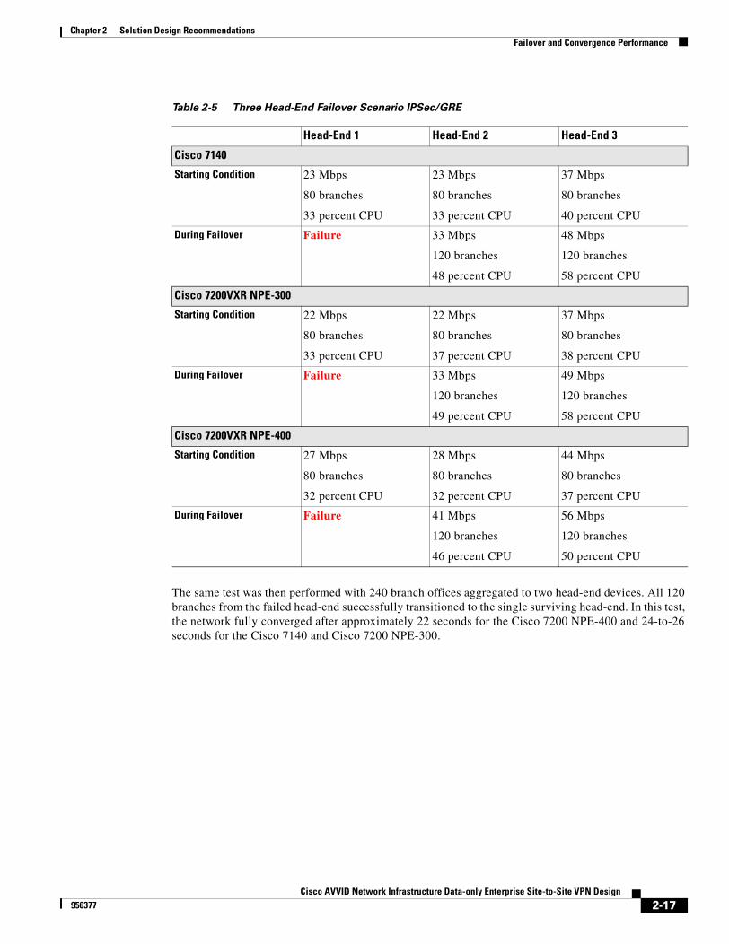
Solution One Failover and Convergence PerformanceEach network might have different convergence time requirements. The design principles in this guide were used to perform a scalability test with up to 480 branch offices aggregated to two (2) head-end devices.
The test was performed by powering off one of the head-end devices to simulate a complete failure. In this test, the network fully converged after approximately 32 seconds maximum. The starting and failover traffic/tunnel aggregation conditions are shown in Table 2-5 on page 2-17.
2-16Cisco AVVID Network Infrastructure Data-only Enterprise Site-to-Site VPN Design
956377
Chapter 2 Solution Design RecommendationsFailover and Convergence Performance
The same test was then performed with 240 branch offices aggregated to two head-end devices. All 120 branches from the failed head-end successfully transitioned to the single surviving head-end. In this test, the network fully converged after approximately 22 seconds for the Cisco 7200 NPE-400 and 24-to-26 seconds for the Cisco 7140 and Cisco 7200 NPE-300.
Table 2-5 Three Head-End Failover Scenario IPSec/GRE
Head-End 1 Head-End 2 Head-End 3
Cisco 7140
Starting Condition 23 Mbps
80 branches
33 percent CPU
23 Mbps
80 branches
33 percent CPU
37 Mbps
80 branches
40 percent CPU
During Failover Failure 33 Mbps
120 branches
48 percent CPU
48 Mbps
120 branches
58 percent CPU
Cisco 7200VXR NPE-300
Starting Condition 22 Mbps
80 branches
33 percent CPU
22 Mbps
80 branches
37 percent CPU
37 Mbps
80 branches
38 percent CPU
During Failover Failure 33 Mbps
120 branches
49 percent CPU
49 Mbps
120 branches
58 percent CPU
Cisco 7200VXR NPE-400
Starting Condition 27 Mbps
80 branches
32 percent CPU
28 Mbps
80 branches
32 percent CPU
44 Mbps
80 branches
37 percent CPU
During Failover Failure 41 Mbps
120 branches
46 percent CPU
56 Mbps
120 branches
50 percent CPU
2-17Cisco AVVID Network Infrastructure Data-only Enterprise Site-to-Site VPN Design
956377
Chapter 2 Solution Design RecommendationsFailover and Convergence Performance
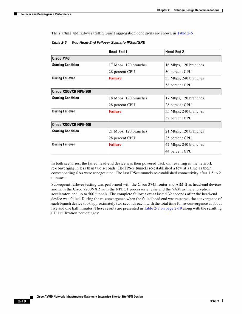
The starting and failover traffic/tunnel aggregation conditions are shown in Table 2-6.
In both scenarios, the failed head-end device was then powered back on, resulting in the network re-converging in less than two seconds. The IPSec tunnels re-established a few at a time as their corresponding SAs were renegotiated. The last IPSec tunnels re-established connectivity after 1.5 to 2 minutes.
Subsequent failover testing was performed with the Cisco 3745 router and AIM II as head-end devices and with the Cisco 7200VXR with the NPEG1 processor engine and the VAM as the encryption accelerator, and up to 500 tunnels. The complete failover event lasted 32 seconds after the head-end device was failed. During the re-convergence when the failed head end was restored, the convergence of each branch device took approximately two seconds each, with the total time for re-convergence at about five and one half minutes. These results are presented in Table 2-7 on page 2-19 along with the resulting CPU utilization percentages:
Table 2-6 Two Head-End Failover Scenario IPSec/GRE
Head-End 1 Head-End 2
Cisco 7140
Starting Condition 17 Mbps, 120 branches
28 percent CPU
16 Mbps, 120 branches
30 percent CPU
During Failover Failure 33 Mbps, 240 branches
58 percent CPU
Cisco 7200VXR NPE-300
Starting Condition 18 Mbps, 120 branches
28 percent CPU
17 Mbps, 120 branches
28 percent CPU
During Failover Failure 35 Mbps, 240 branches
52 percent CPU
Cisco 7200VXR NPE-400
Starting Condition 21 Mbps, 120 branches
28 percent CPU
21 Mbps, 120 branches
25 percent CPU
During Failover Failure 42 Mbps, 240 branches
44 percent CPU
2-18Cisco AVVID Network Infrastructure Data-only Enterprise Site-to-Site VPN Design
956377
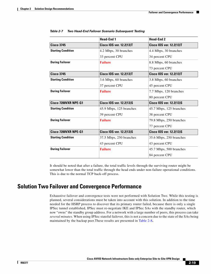
Chapter 2 Solution Design RecommendationsFailover and Convergence Performance
It should be noted that after a failure, the total traffic levels through the surviving router might be somewhat lower than the total traffic through the head ends under non-failure operational conditions. This is due to the normal TCP back-off process.
Solution Two Failover and Convergence PerformanceExhaustive failover and convergence tests were not performed with Solution Two. While this testing is planned, several considerations must be taken into account with this solution. In addition to the time needed for the HSRP process to discover that its primary router failed, because there is only a single IPSec tunnel established, IPSec must re-negotiate IKE and IPSec SAs with the standby router, which now “owns” the standby group address. For a network with a large number of peers, this process can take several minutes. When using IPSec stateful failover, this is not a concern due to the state of the SAs being maintained by the backup peer.These results are presented in Table 2-8.
Table 2-7 Two Head-End Failover Scenario Subsequent Testing
Head-End 1 Head-End 2
Cisco 3745 Cisco IOS ver. 12.2(13)T Cisco IOS ver. 12.2(13)T
Starting Condition 4.2 Mbps, 30 branches
33 percent CPU
4.4 Mbps, 30 branches
34 percent CPU
During Failover Failure 8.8 Mbps, 60 branches
73 percent CPU
Cisco 3745 Cisco IOS ver. 12.2(13)T Cisco IOS ver. 12.2(13)T
Starting Condition 3.6 Mbps, 60 branches
37 percent CPU
3.8 Mbps, 60 branches
45 percent CPU
During Failover Failure 7.7 Mbps, 120 branches
80 percent CPU
Cisco 7200VXR NPE-G1 Cisco IOS ver. 12.2(13)S Cisco IOS ver. 12.2(13)S
Starting Condition 45.9 Mbps, 125 branches
39 percent CPU
45.7 Mbps, 125 branches
38 percent CPU
During Failover Failure 79.8 Mbps, 250 branches
77 percent CPU
Cisco 7200VXR NPE-G1 Cisco IOS ver. 12.2(13)S Cisco IOS ver. 12.2(13)S
Starting Condition 37.5 Mbps, 250 branches
43 percent CPU
35.6 Mbps, 250 branches
43 percent CPU
During Failover Failure 45.7 Mbps, 500 branches
84 percent CPU
2-19Cisco AVVID Network Infrastructure Data-only Enterprise Site-to-Site VPN Design
956377
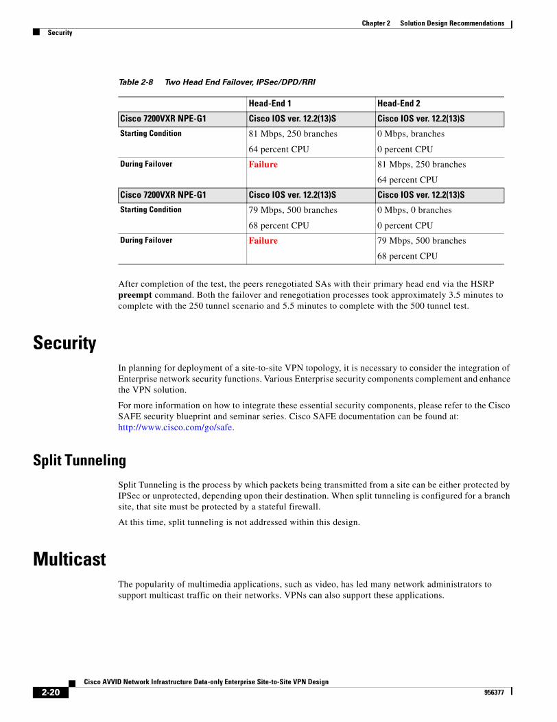
Chapter 2 Solution Design RecommendationsSecurity
After completion of the test, the peers renegotiated SAs with their primary head end via the HSRP preempt command. Both the failover and renegotiation processes took approximately 3.5 minutes to complete with the 250 tunnel scenario and 5.5 minutes to complete with the 500 tunnel test.
SecurityIn planning for deployment of a site-to-site VPN topology, it is necessary to consider the integration of Enterprise network security functions. Various Enterprise security components complement and enhance the VPN solution.
For more information on how to integrate these essential security components, please refer to the Cisco SAFE security blueprint and seminar series. Cisco SAFE documentation can be found at: http://www.cisco.com/go/safe.
Split TunnelingSplit Tunneling is the process by which packets being transmitted from a site can be either protected by IPSec or unprotected, depending upon their destination. When split tunneling is configured for a branch site, that site must be protected by a stateful firewall.
At this time, split tunneling is not addressed within this design.
MulticastThe popularity of multimedia applications, such as video, has led many network administrators to support multicast traffic on their networks. VPNs can also support these applications.
Table 2-8 Two Head End Failover, IPSec/DPD/RRI
Head-End 1 Head-End 2
Cisco 7200VXR NPE-G1 Cisco IOS ver. 12.2(13)S Cisco IOS ver. 12.2(13)S
Starting Condition 81 Mbps, 250 branches
64 percent CPU
0 Mbps, branches
0 percent CPU
During Failover Failure 81 Mbps, 250 branches
64 percent CPU
Cisco 7200VXR NPE-G1 Cisco IOS ver. 12.2(13)S Cisco IOS ver. 12.2(13)S
Starting Condition 79 Mbps, 500 branches
68 percent CPU
0 Mbps, 0 branches
0 percent CPU
During Failover Failure 79 Mbps, 500 branches
68 percent CPU
2-20Cisco AVVID Network Infrastructure Data-only Enterprise Site-to-Site VPN Design
956377
Chapter 2 Solution Design RecommendationsIPSec Interactions with Other Networking Functions
IPSec supports only tunneling of unicast IP traffic, therefore it is necessary to implement GRE in conjunction with IPSec to support multicast. See the “Solution One, IPSec with GRE Specific Recommendations” section on page 2-5 Solution One is the recommendation when multi-protocol and/or multicast support is needed, or when routing protocol support is necessary. For deployments without these specific requirements, Solution Two may be used instead.
Note Multicast traffic is not currently supported by most firewalls. This requires the termination of the IPSec tunnels on the inside interface of the firewall.
IPSec Interactions with Other Networking FunctionsBecause IPSec hides the packet and increases the packet size, interactions with other networking functions must also be taken into consideration. The following sections discuss various aspects to consider when deploying site-to-site IPSec-based VPNs. Key discussions addressed in this section:
• Routing Protocols, page 2-21
• Network Address Translation (NAT) and Port Address Translation (PAT), page 2-21
• Dynamic Host Configuration Protocol (DHCP), page 2-21
Routing ProtocolsAll IP routing protocols use either broadcast or multicast as a method of transmitting routing table information. Since IPSec does not support either broadcast or multicast, this design recommends using GRE as a tunneling method to overcome this limitation. See the “Solution One, IPSec with GRE Specific Recommendations” section on page 2-5 This section details the recommendations specific to Solution One, IPSec in combination with GRE. Solution One is the recommendation when multi-protocol or multicast support is needed, or when routing protocol support is necessary. For deployments without these specific requirements, Solution Two may be used instead. See the “Using a Routing Protocol across the VPN” section on page 2-10 for more information on running a routing protocol across a VPN.
Network Address Translation (NAT) and Port Address Translation (PAT)While Network Address Translation (NAT) and Port Address Translation (PAT) can result in an added layer of security and address conservation, they both present challenges to the implementation of an IPSec VPN. Internet Security Association and Key Management Protocol (ISAKMP)—which is used by IPsec—relies on an individual IP address per peer for proper operation. PAT works by masquerading multiple peers behind a single IP address.
For this reason, IPSec peers with a PAT process in between them will fail to negotiate properly. However, site-to-site IPSec networks can operate between NAT processes. The un-translated peer must be configured with the remote peer’s translated address for proper operation.
Dynamic Host Configuration Protocol (DHCP)In order for a host at a remote site to be able to use a DHCP server over an IPSec tunnel at a central site, an IP helper address must be configured on the router interface associated with the host.
2-21Cisco AVVID Network Infrastructure Data-only Enterprise Site-to-Site VPN Design
956377
Chapter 2 Solution Design RecommendationsService Provider Dependencies
One drawback of this approach is that if connectivity to the central site is lost, a host at a remote site might not receive an IP address. This can prevent the host from communicating with other hosts on its local network.
A Cisco IOS router may also be configured to act as a standalone DHCP server. These features were not scale tested with IPSec VPN.
Service Provider DependenciesVPNs inherently rely on one or more Service Providers to provide Internet service to the head-end and branch offices in order to deploy the network. It follows then that choosing a Service Provider is a critical element of deploying a VPN. Many factors must be considered including cost, services available, reliability, and the expected geographical coverage of the Enterprise VPN.
At a minimum, the Enterprise should have an service level agreement (SLA) with the Service Provider that outlines the critical service elements of their VPN. These factors include availability, bandwidth, and latency.
When the situation requires an Enterprise to use multiple Service Providers to cover their branch locations, this can certainly add a level of complexity and be potentially problematic to obtain the desired level of end-to-end VPN service. This can be especially critical in the case where the network supports mission-critical applications that are delay-sensitive. In addition, determining whether the Enterprise intends to run latency-sensitive applications, such as VoIP and video, across the VPN in the future must also be considered.
For this reason, it is recommended to seek a SLA with a single Service Provider that can guarantee a level of end-to-end service for the Enterprise locations.
Another concern is that some Internet Service Providers (ISPs) for DSL and cable services implement policing of traffic for residential class service. This means that protocols such as IPSec may be blocked unless a business class service is subscribed to.
ManagementCisco brings all of its VPN products together through management systems that provide such status information as device availability and throughput, for example, management integration through products such as VPN/Security Management Solution (VMS) and IP Solution Center (ISC).
For more information on how implement network management over IPSec tunnels, please refer to the Cisco SAFE security blueprint and seminar series. Cisco SAFE documentation can be found at: http://www.cisco.com/go/safe.
2-22Cisco AVVID Network Infrastructure Data-only Enterprise Site-to-Site VPN Design
956377
Cisco AVVID Network Infrastructure Data-956377
C H A P T E R 3
Solution Component RecommendationsThis chapter presents the steps to selecting Cisco products for a deployable VPN solution. Specific topics addressed in this chapter are:
• Scalability Testing Methodology, page 3-1
• Subsequent Testing, page 3-2
• Deploy Hardware-Accelerated Encryption, page 3-4
• Head-end Devices, page 3-5
• Branch Site Devices, page 3-11
• Software Releases Evaluated, page 3-13
Scalability Testing MethodologyAs shown in Figure A-1 on page A-2 in Appendix A, “Enterprise Site-to-Site VPN Solution Test Bed Configuration,” the scalability test bed included 240 branch offices aggregated to three head-end devices (aggregation to two head-ends was also tested). The head-ends consisted of the Cisco 7100 and Cisco 7200 series Cisco VPN Router products (refer to the “Head-end Devices” section on page 3-5 for exact models tested). The branch offices consisted of Cisco VPN Router products from the Cisco 800, Cisco 1700, Cisco 2600, and Cisco 3600 series (refer to the “Branch Site Devices” section on page 3-11 for exact models tested).
Head-end products were evaluated with hardware-accelerated encryption installed, while branch products were evaluated with both software-based encryption and hardware-accelerated encryption. 3DES was selected as the encryption standard and SHA-1 as the hash method.
Each branch router was provisioned with two IPSec/GRE tunnels (primary and secondary) back to two different head-ends. EIGRP was used as the routing protocol to distribute routes from the head-ends to the branches. Note that the testing was conducted with a fully summarized network configuration.
Traffic flows were then established using the NetIQ ChariotTM testing tool. The mix of traffic types consisted of the following protocols:
• Real Time Protocol (RTP)—64 bytes
• Domain Name System (DNS)—100 bytes
• File Transfer Protocol (FTP)—1400 bytes
The overall packet mix was split up as approximately 35 percent UDP and 65 percent TCP traffic.
Traffic rates were increased to find the throughput points on each product type where the CPU utilization reached 50 percent for head-ends, and 65 percent for branch products, without packet loss.
3-1only Enterprise Site-to-Site VPN Design
Chapter 3 Solution Component RecommendationsSubsequent Testing
An initial finding was the head-end throughput reduction caused by IPSec packet fragmentation (refer to the “Minimizing Packet Fragmentation” section on page 2-13 for more information on performance packet fragmentation impact and mitigation strategies). Therefore the testing was conducted both with fragmentation occurring in the network as well as with no fragmentation (MTU was set to 1400 on our test endpoints).
Individual product throughput performance data is presented in the “Head-end Devices” section on page 3-5 for head-end products and section “Branch Site Devices” section on page 3-11 for branch products.
In addition to throughput testing, failover testing was also conducted. Please refer to “Failover and Convergence Performance” section on page 2-16 for more information on the failover test scenario.
All scalability testing for this design guide revision was obtained using IPSec Tunnel Mode; therefore, the throughput results may differ in Transport Mode.
Subsequent TestingIn order to speed solution testing and provide more accurate information in a timely fashion, site-to-site VPN testing was combined with V3PN solution testing. This entailed changing the traffic mix to more closely emulate VoIP traffic. Due to the VoIP traffic in the V3PN solution, this solution utilizes a slightly different traffic profile than normally encountered in a data-only Enterprise network. These tests also yielded results that are more conservative than ordinarily obtained with previous data-only testing methods. Therefore, a design carrying data-only traffic has a larger average packet size than used in the testing for this solution and achieves better performance.
Discussions addressed here include:
• New Traffic Mix, page 3-2
• Conservative Results, page 3-3
• Tunnel Quantity Effects on Throughput, page 3-3
• GRE Encapsulation Effects on Throughput, page 3-3
• Routing Protocols Effects on Throughput, page 3-3
• Test Results Presentation, page 3-3
New Traffic MixEnterprise traffic was simulated by a variety of various traffic mixes and packet sizes. Imix is available in many different forms. For V3PN testing, samples were taken from various Enterprise networking environments. These included networks reflecting the health care and the insurance industries. Profiles were created to simulate these packet mixes with the ChariotTM test tool used by the Cisco Enterprise Solutions Engineering labs. The flows generated very closely match the traffic patterns found in the sampled Enterprises The single change to these flows in the current and future rounds of testing are the inclusion of simulated VoIP flows. While these are not actual VoIP flows, periodic checks were made with real VoIP flows to ensure that the results obtained are accurate. The VoIP flows are characterized by smaller packet sizes. This lowers the overall average packet size handled by each router. The greater number of smaller packets causes a higher CPU utilization on the routers performing encryption.
3-2Cisco AVVID Network Infrastructure Data-only Enterprise Site-to-Site VPN Design
956377

Chapter 3 Solution Component RecommendationsSubsequent Testing
Conservative ResultsResults of this new traffic profile are the more conservative results it produces. The effect of smaller packets (and larger numbers of packets) on router CPU is higher utilization. Three CPU utilization levels were tested: 50 percent; 65 percent; and, 80 percent. These CPU utilization levels are reached slightly earlier than is typically experienced due to the larger number of smaller packets.
Tunnel Quantity Effects on ThroughputAs tunnel quantities are increased, the overall throughput tends to decrease. When a router receives a packet from a different peer than the one that sent the packet that was just decrypted, a lookup based on the security parameters index of the new packet must be performed. The packet’s transform set information and negotiated key is then loaded into the hardware decryption engine for processing. Larger numbers of SA traffic tends to negatively affect throughput performance.
In the discussion that follows, head-end devices are shown with multiple tunnels established. Head-end traffic is also distributed as evenly as possible across each active tunnel. When this cannot be done evenly, it is shown. Branch devices are shown with either one or two tunnels configured.
GRE Encapsulation Effects on ThroughputRouter encryption throughput is negatively affected by the configuration of GRE. In addition to the headers that are added to the beginning of each packet, these headers also must be encrypted. The GRE encapsulation process itself affects total CPU utilization approximately 10 percent. In other words, CPU utilization is approximately 10 percent higher than normal if GRE encapsulation is configured.
Routing Protocols Effects on ThroughputThroughput is also affected by running a routing protocol. The router’s processing of keepalives and maintaining a routing table uses a finite amount of CPU time. This amount varies with the number of routing peers and the size of the routing table. A key objective in creating this design recommendation is to determine a safe number of routing peers for an Enterprise VPN. The total number of routers is a concern because the processing power available on any given network router is decreased as the number of routing peers is increased.
Test Results PresentationThe targeted CPU utilization for a router deployment is always the subject of debate. This publication presents a range of CPU utilizations on the higher side of a normal network deployment. These utilizations are 50 percent, 65 percent and 80 percent. While the high number 80 percent is not recommended during normal operation, this number is provided to enable an engineer to see what traffic levels can be handled by a router in a failover scenario.
3-3Cisco AVVID Network Infrastructure Data-only Enterprise Site-to-Site VPN Design
956377
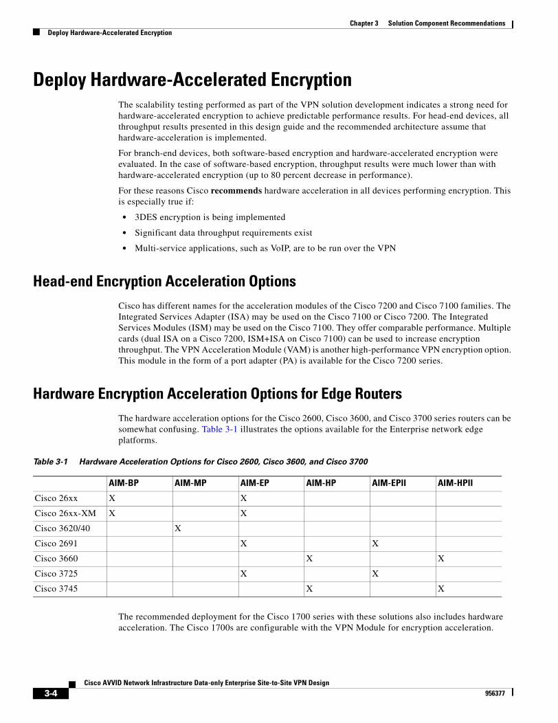
Chapter 3 Solution Component RecommendationsDeploy Hardware-Accelerated Encryption
Deploy Hardware-Accelerated EncryptionThe scalability testing performed as part of the VPN solution development indicates a strong need for hardware-accelerated encryption to achieve predictable performance results. For head-end devices, all throughput results presented in this design guide and the recommended architecture assume that hardware-acceleration is implemented.
For branch-end devices, both software-based encryption and hardware-accelerated encryption were evaluated. In the case of software-based encryption, throughput results were much lower than with hardware-accelerated encryption (up to 80 percent decrease in performance).
For these reasons Cisco recommends hardware acceleration in all devices performing encryption. This is especially true if:
• 3DES encryption is being implemented
• Significant data throughput requirements exist
• Multi-service applications, such as VoIP, are to be run over the VPN
Head-end Encryption Acceleration OptionsCisco has different names for the acceleration modules of the Cisco 7200 and Cisco 7100 families. The Integrated Services Adapter (ISA) may be used on the Cisco 7100 or Cisco 7200. The Integrated Services Modules (ISM) may be used on the Cisco 7100. They offer comparable performance. Multiple cards (dual ISA on a Cisco 7200, ISM+ISA on Cisco 7100) can be used to increase encryption throughput. The VPN Acceleration Module (VAM) is another high-performance VPN encryption option. This module in the form of a port adapter (PA) is available for the Cisco 7200 series.
Hardware Encryption Acceleration Options for Edge RoutersThe hardware acceleration options for the Cisco 2600, Cisco 3600, and Cisco 3700 series routers can be somewhat confusing. Table 3-1 illustrates the options available for the Enterprise network edge platforms.
The recommended deployment for the Cisco 1700 series with these solutions also includes hardware acceleration. The Cisco 1700s are configurable with the VPN Module for encryption acceleration.
Table 3-1 Hardware Acceleration Options for Cisco 2600, Cisco 3600, and Cisco 3700
AIM-BP AIM-MP AIM-EP AIM-HP AIM-EPII AIM-HPII
Cisco 26xx X X
Cisco 26xx-XM X X
Cisco 3620/40 X
Cisco 2691 X X
Cisco 3660 X X
Cisco 3725 X X
Cisco 3745 X X
3-4Cisco AVVID Network Infrastructure Data-only Enterprise Site-to-Site VPN Design
956377
Chapter 3 Solution Component RecommendationsHead-end Devices
The Cisco 800 series of routers that are recommended include built-in hardware acceleration. These models are the Cisco 831 dual Ethernet, the Cisco 836 ADSL over ISDN, and the Cisco 837 ADSL router. Other models of the Cisco 800 series without hardware encryption are no longer recommended for these applications.
See the “Head-end Devices” section on page 3-5 and the “Branch Site Devices” section on page 3-11 for more detailed performance data that supports these recommendations.
Head-end DevicesThe head-end devices are responsible for:
• Originating/terminating IPSec encapsulated GRE tunnels from the branch sites
• Running routing protocol inside GRE tunnels to advertise internal routes to branches
• Providing redundancy to eliminate the possibility of a single point of failure
The following sections identify factors to take into account in sizing the head-end (or sites):
• Head-end Encryption Acceleration Options, page 3-4
• Hardware Encryption Acceleration Options for Edge Routers, page 3-4
• Sizing the Head-end, page 3-5
• Cisco VPN Routers for Head-ends, page 3-8
• Other Cisco Products for the Head End, page 3-10
• PIX VPN Limitations, page 3-10
Sizing the Head-endIt is important to size the head-end correctly before choosing the devices to deploy. This ensures that the overall network can support the intended (and possibly future) traffic profiles that the Enterprise desires to run over the VPN.
Two critical factors must be considered when sizing the head-end:
• How many branch offices need to be connected to the head-end? This determines the number of primary tunnels requiring aggregation.
• What is the expected traffic profile, including the average packets-per-second (pps) and bits-per-second (bps) throughput rates for each branch office? This determines the aggregated data throughput required across the VPN.
Either or both of these can be the limiting factor in sizing the head-end, therefore both must be considered together.
The decision flow shown in Figure 3-1 should be applied to size the head-end:
3-5Cisco AVVID Network Infrastructure Data-only Enterprise Site-to-Site VPN Design
956377
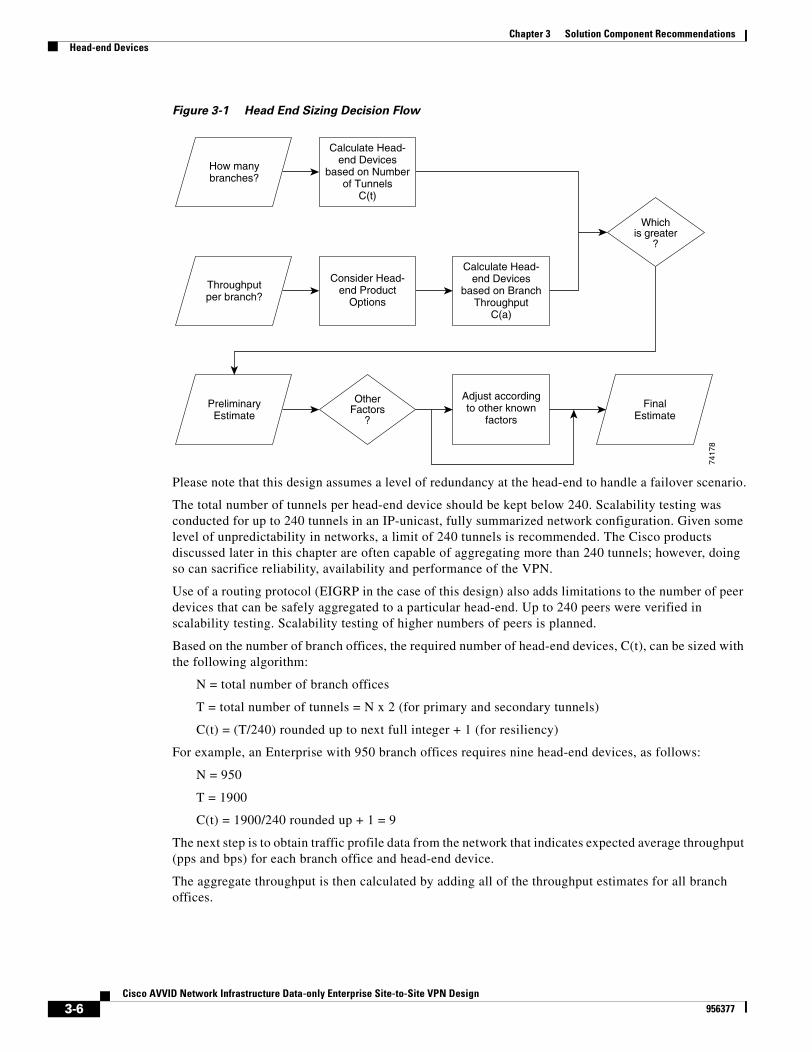
Chapter 3 Solution Component RecommendationsHead-end Devices
Figure 3-1 Head End Sizing Decision Flow
Please note that this design assumes a level of redundancy at the head-end to handle a failover scenario.
The total number of tunnels per head-end device should be kept below 240. Scalability testing was conducted for up to 240 tunnels in an IP-unicast, fully summarized network configuration. Given some level of unpredictability in networks, a limit of 240 tunnels is recommended. The Cisco products discussed later in this chapter are often capable of aggregating more than 240 tunnels; however, doing so can sacrifice reliability, availability and performance of the VPN.
Use of a routing protocol (EIGRP in the case of this design) also adds limitations to the number of peer devices that can be safely aggregated to a particular head-end. Up to 240 peers were verified in scalability testing. Scalability testing of higher numbers of peers is planned.
Based on the number of branch offices, the required number of head-end devices, C(t), can be sized with the following algorithm:
N = total number of branch offices
T = total number of tunnels = N x 2 (for primary and secondary tunnels)
C(t) = (T/240) rounded up to next full integer + 1 (for resiliency)
For example, an Enterprise with 950 branch offices requires nine head-end devices, as follows:
N = 950
T = 1900
C(t) = 1900/240 rounded up + 1 = 9
The next step is to obtain traffic profile data from the network that indicates expected average throughput (pps and bps) for each branch office and head-end device.
The aggregate throughput is then calculated by adding all of the throughput estimates for all branch offices.
Whichis greater
?
OtherFactors
?
7417
8
Calculate Head-end Devices
based on Numberof Tunnels
C(t)
How manybranches?
Adjust accordingto other known
factors
PreliminaryEstimate
FinalEstimate
Consider Head-end Product
Options
Calculate Head-end Devices
based on BranchThroughput
C(a)
Throughputper branch?
3-6Cisco AVVID Network Infrastructure Data-only Enterprise Site-to-Site VPN Design
956377
Chapter 3 Solution Component RecommendationsHead-end Devices
At this point, it is necessary to consider the available head-end devices and the maximum throughput supported by each. The Cisco 7140 and Cisco 7200VXR routers are the preferred platforms for use as IPSec VPN head-end devices. Each of these routers has a range of options for interfaces as well as the ability to configure hardware-accelerated encryption. Refer to “Head-end Devices” section on page 3-5 for more details on product selection and throughput performance.
Next, divide the aggregate throughput requirements by the throughput value for each respective platform value in Table 3-3 on page 3-8 and Table 3-4 on page 3-9. This provides the number of head-end devices required, based on aggregate throughput:
A = sum of throughput estimates for each branch office (the aggregate)
H = single head-end device throughput
C(a) = A/H, rounded up to nearest full integer, + 1 for resiliency
For example, an Enterprise with 300 branch offices, each having throughput requirements of 500 Kbps requires six head-end devices, as follows:
A = 300 branches @ 500 Kbps = 300 x 0.5 Mbps = 150 Mbps
H = 30 Mbps (for Cisco 7140 router)
C(a) = 150/30 (rounded to next nearest integer) + 1 = 6
Compare the number of head-end devices calculated based on number of tunnels, C(t), to the number based on aggregate throughput, C(a). The greater of the two numbers is required to support the design.
As the number of tunnels increases there is a corresponding decrease in encrypted throughput. This means that a design that has a uniformly distributed traffic load from branch offices across many tunnels requires more CPU than a design where the majority of traffic load is generated from a subset of the total tunnels being aggregated.
In addition to the two critical factors identified above, the following factors must also be considered at this point:
• Given the network’s current topology and traffic profile, what is the current CPU utilization on each distribution router, and how many branch offices are connected to each distribution router?
This provides a baseline of expected CPU utilization levels. The combination of crypto/IPSec and GRE adds an additional overhead to each distribution router.
• What are the aggregate WAN sizes for each respective branch?
How the aggregate WAN speed is subdivided into a number of tunnels affects the overall number of tunnels that can be supported in this design. As discussed previously, as the number of tunnels increases, there is a corresponding decrease in throughput (or an increase in CPU utilization).
• What other applications/protocols does the organization intend to run across the VPN?
Multi-protocols perform differently in Cisco IOS compared to unicast-IP. In the scalability testing performed to date, multi-protocols were not comprehensively evaluated.
The result is that the number of head-end devices might need to be adjusted upward after these additional factors are considered.
Cisco recommends that head-end devices be chosen so that CPU utilization does not exceed 50 percent. This ensures that the device has enough performance left over to deal with various events that take place during the course of normal network operations, including network re-convergence in the event of a failure, re-keying IPSec SAs, and bursts of traffic seen in a normal operating network.
After initial deployment and testing, it might be possible to run head-end devices at CPU utilization levels higher than 50 percent (60-to-65 percent for example). However, this design guide conservatively recommends staying at or below 50 percent, and therefore the throughput results presented where chosen at the 50 percent level.
3-7Cisco AVVID Network Infrastructure Data-only Enterprise Site-to-Site VPN Design
956377
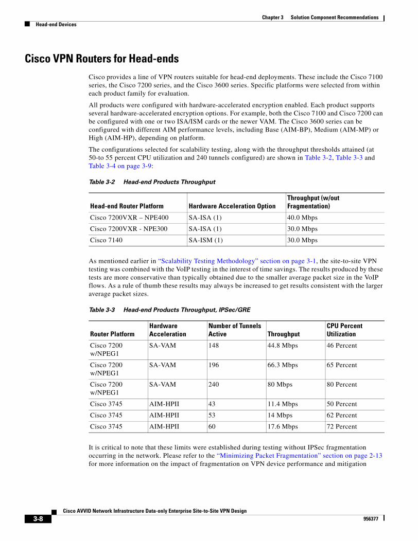
Chapter 3 Solution Component RecommendationsHead-end Devices
Cisco VPN Routers for Head-endsCisco provides a line of VPN routers suitable for head-end deployments. These include the Cisco 7100 series, the Cisco 7200 series, and the Cisco 3600 series. Specific platforms were selected from within each product family for evaluation.
All products were configured with hardware-accelerated encryption enabled. Each product supports several hardware-accelerated encryption options. For example, both the Cisco 7100 and Cisco 7200 can be configured with one or two ISA/ISM cards or the newer VAM. The Cisco 3600 series can be configured with different AIM performance levels, including Base (AIM-BP), Medium (AIM-MP) or High (AIM-HP), depending on platform.
The configurations selected for scalability testing, along with the throughput thresholds attained (at 50-to 55 percent CPU utilization and 240 tunnels configured) are shown in Table 3-2, Table 3-3 and Table 3-4 on page 3-9:
As mentioned earlier in “Scalability Testing Methodology” section on page 3-1, the site-to-site VPN testing was combined with the VoIP testing in the interest of time savings. The results produced by these tests are more conservative than typically obtained due to the smaller average packet size in the VoIP flows. As a rule of thumb these results may always be increased to get results consistent with the larger average packet sizes.
It is critical to note that these limits were established during testing without IPSec fragmentation occurring in the network. Please refer to the “Minimizing Packet Fragmentation” section on page 2-13 for more information on the impact of fragmentation on VPN device performance and mitigation
Table 3-2 Head-end Products Throughput
Head-end Router Platform Hardware Acceleration OptionThroughput (w/out Fragmentation)
Cisco 7200VXR – NPE400 SA-ISA (1) 40.0 Mbps
Cisco 7200VXR - NPE300 SA-ISA (1) 30.0 Mbps
Cisco 7140 SA-ISM (1) 30.0 Mbps
Table 3-3 Head-end Products Throughput, IPSec/GRE
Router PlatformHardware Acceleration
Number of Tunnels Active Throughput
CPU Percent Utilization
Cisco 7200 w/NPEG1
SA-VAM 148 44.8 Mbps 46 Percent
Cisco 7200 w/NPEG1
SA-VAM 196 66.3 Mbps 65 Percent
Cisco 7200 w/NPEG1
SA-VAM 240 80 Mbps 80 Percent
Cisco 3745 AIM-HPII 43 11.4 Mbps 50 Percent
Cisco 3745 AIM-HPII 53 14 Mbps 62 Percent
Cisco 3745 AIM-HPII 60 17.6 Mbps 72 Percent
3-8Cisco AVVID Network Infrastructure Data-only Enterprise Site-to-Site VPN Design
956377
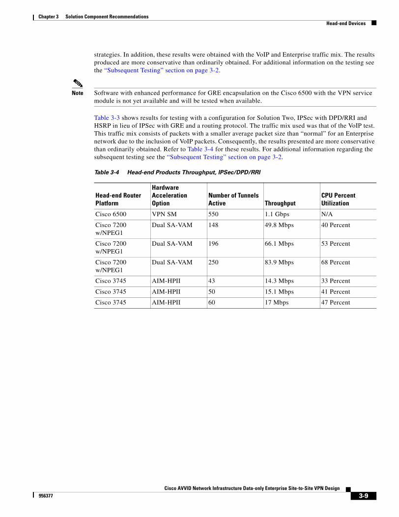
Chapter 3 Solution Component RecommendationsHead-end Devices
strategies. In addition, these results were obtained with the VoIP and Enterprise traffic mix. The results produced are more conservative than ordinarily obtained. For additional information on the testing see the “Subsequent Testing” section on page 3-2.
Note Software with enhanced performance for GRE encapsulation on the Cisco 6500 with the VPN service module is not yet available and will be tested when available.
Table 3-3 shows results for testing with a configuration for Solution Two, IPSec with DPD/RRI and HSRP in lieu of IPSec with GRE and a routing protocol. The traffic mix used was that of the VoIP test. This traffic mix consists of packets with a smaller average packet size than “normal” for an Enterprise network due to the inclusion of VoIP packets. Consequently, the results presented are more conservative than ordinarily obtained. Refer to Table 3-4 for these results. For additional information regarding the subsequent testing see the “Subsequent Testing” section on page 3-2.
Table 3-4 Head-end Products Throughput, IPSec/DPD/RRI
Head-end Router Platform
Hardware Acceleration Option
Number of Tunnels Active Throughput
CPU Percent Utilization
Cisco 6500 VPN SM 550 1.1 Gbps N/A
Cisco 7200 w/NPEG1
Dual SA-VAM 148 49.8 Mbps 40 Percent
Cisco 7200 w/NPEG1
Dual SA-VAM 196 66.1 Mbps 53 Percent
Cisco 7200 w/NPEG1
Dual SA-VAM 250 83.9 Mbps 68 Percent
Cisco 3745 AIM-HPII 43 14.3 Mbps 33 Percent
Cisco 3745 AIM-HPII 50 15.1 Mbps 41 Percent
Cisco 3745 AIM-HPII 60 17 Mbps 47 Percent
3-9Cisco AVVID Network Infrastructure Data-only Enterprise Site-to-Site VPN Design
956377
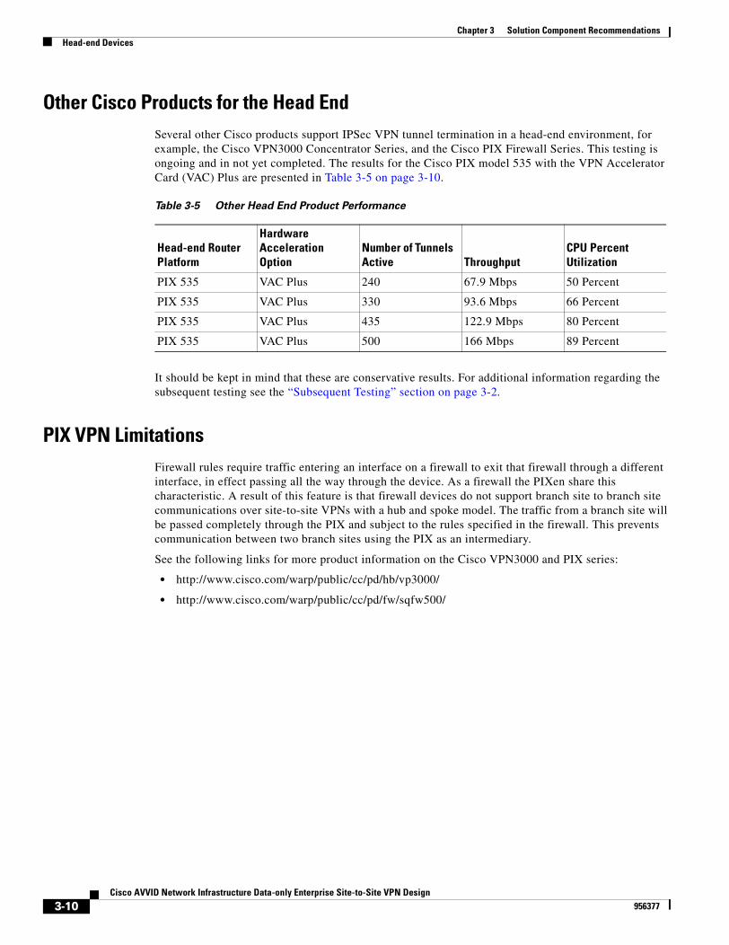
Chapter 3 Solution Component RecommendationsHead-end Devices
Other Cisco Products for the Head EndSeveral other Cisco products support IPSec VPN tunnel termination in a head-end environment, for example, the Cisco VPN3000 Concentrator Series, and the Cisco PIX Firewall Series. This testing is ongoing and in not yet completed. The results for the Cisco PIX model 535 with the VPN Accelerator Card (VAC) Plus are presented in Table 3-5 on page 3-10.
It should be kept in mind that these are conservative results. For additional information regarding the subsequent testing see the “Subsequent Testing” section on page 3-2.
PIX VPN LimitationsFirewall rules require traffic entering an interface on a firewall to exit that firewall through a different interface, in effect passing all the way through the device. As a firewall the PIXen share this characteristic. A result of this feature is that firewall devices do not support branch site to branch site communications over site-to-site VPNs with a hub and spoke model. The traffic from a branch site will be passed completely through the PIX and subject to the rules specified in the firewall. This prevents communication between two branch sites using the PIX as an intermediary.
See the following links for more product information on the Cisco VPN3000 and PIX series:
• http://www.cisco.com/warp/public/cc/pd/hb/vp3000/
• http://www.cisco.com/warp/public/cc/pd/fw/sqfw500/
Table 3-5 Other Head End Product Performance
Head-end Router Platform
Hardware Acceleration Option
Number of Tunnels Active Throughput
CPU Percent Utilization
PIX 535 VAC Plus 240 67.9 Mbps 50 Percent
PIX 535 VAC Plus 330 93.6 Mbps 66 Percent
PIX 535 VAC Plus 435 122.9 Mbps 80 Percent
PIX 535 VAC Plus 500 166 Mbps 89 Percent
3-10Cisco AVVID Network Infrastructure Data-only Enterprise Site-to-Site VPN Design
956377
Chapter 3 Solution Component RecommendationsBranch Site Devices
Branch Site DevicesThe branch site devices are responsible for:
• Originating/terminating IPSec encapsulated GRE tunnels from the head-end
• Running a routing protocol inside of the GRE tunnels to advertise internal routes
The branch site device may also be responsible for forwarding DHCP requests to the central site, or even functioning as the DHCP server.
The following sections identify factors to take into account when sizing the branch sites:
• Sizing the Branch Site, page 3-11
• Cisco VPN Routers for Branch Sites, page 3-11
• Other Cisco Products for the Branch, page 3-13
Sizing the Branch SiteThe most important factor to consider when choosing a product for the branch office is expected traffic throughput to the head-end.
Other factors that should be considered include:
• What other features/functionality is the branch router providing (such as WAN access, VoIP, Cisco IOS Firewall, etc.)?
• Different branch devices offer a range of features that accommodate various levels of growth. For example, the Cisco 3660 supports six modular slots and various WAN adapters, whereas the Cisco 2600 series supports only two slots.
While the number of IPSec tunnels does not play as large a role in the branch device sizing, each branch site router must be able to terminate at least two IPSec encapsulated GRE tunnels (primary and secondary).
The primary concern is the amount of traffic throughput along with the corresponding CPU utilization. Cisco recommends that branch devices be chosen so that CPU utilization does not exceed 65 percent. This ensures that the device has enough performance left over to deal with various events that take place during the course of normal network operations. The CPU on a branch site may run slightly higher than a head-end router due to the minimal routing convergence duties.
After initial deployment and testing, it might be possible to run branch devices at CPU utilization levels higher than 65 percent. However, this design guide conservatively recommends staying at or below 65 percent, and therefore the throughput results presented where chosen at the 65 percent level.
Cisco VPN Routers for Branch SitesCisco provides a line of VPN Routers suitable for branch site deployments. These include the Cisco 3700 series, the Cisco 3600 series, the Cisco 2600 series, the Cisco 1700 series, and the Cisco 800 series. All recommended branch devices support hardware-accelerated encryption.
Specific platforms were selected from within each product family for evaluation. All products were configured with hardware-accelerated encryption enabled. Throughput results (at approximately 60-to-65 percent CPU utilization) are summarized in Table 3-6.
3-11Cisco AVVID Network Infrastructure Data-only Enterprise Site-to-Site VPN Design
956377
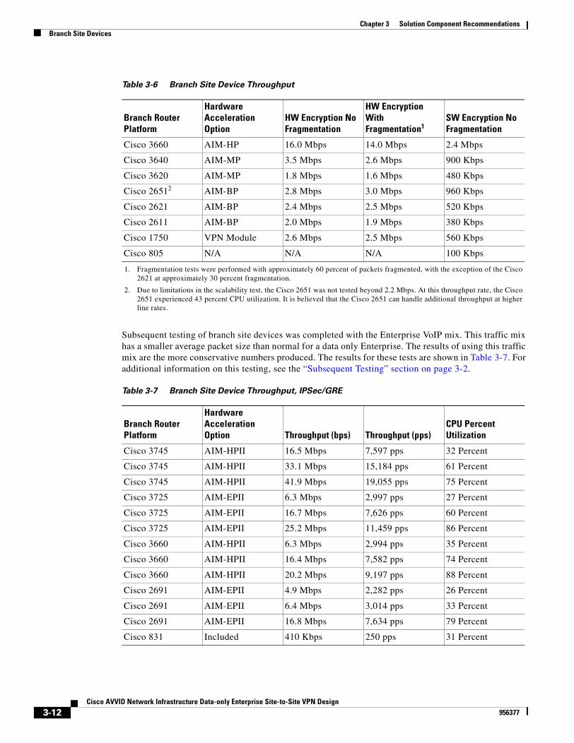
Chapter 3 Solution Component RecommendationsBranch Site Devices
Subsequent testing of branch site devices was completed with the Enterprise VoIP mix. This traffic mix has a smaller average packet size than normal for a data only Enterprise. The results of using this traffic mix are the more conservative numbers produced. The results for these tests are shown in Table 3-7. For additional information on this testing, see the “Subsequent Testing” section on page 3-2.
Table 3-6 Branch Site Device Throughput
Branch Router Platform
Hardware Acceleration Option
HW Encryption No Fragmentation
HW Encryption With Fragmentation1
1. Fragmentation tests were performed with approximately 60 percent of packets fragmented, with the exception of the Cisco 2621 at approximately 30 percent fragmentation.
SW Encryption No Fragmentation
Cisco 3660 AIM-HP 16.0 Mbps 14.0 Mbps 2.4 Mbps
Cisco 3640 AIM-MP 3.5 Mbps 2.6 Mbps 900 Kbps
Cisco 3620 AIM-MP 1.8 Mbps 1.6 Mbps 480 Kbps
Cisco 26512
2. Due to limitations in the scalability test, the Cisco 2651 was not tested beyond 2.2 Mbps. At this throughput rate, the Cisco 2651 experienced 43 percent CPU utilization. It is believed that the Cisco 2651 can handle additional throughput at higher line rates.
AIM-BP 2.8 Mbps 3.0 Mbps 960 Kbps
Cisco 2621 AIM-BP 2.4 Mbps 2.5 Mbps 520 Kbps
Cisco 2611 AIM-BP 2.0 Mbps 1.9 Mbps 380 Kbps
Cisco 1750 VPN Module 2.6 Mbps 2.5 Mbps 560 Kbps
Cisco 805 N/A N/A N/A 100 Kbps
Table 3-7 Branch Site Device Throughput, IPSec/GRE
Branch Router Platform
Hardware Acceleration Option Throughput (bps) Throughput (pps)
CPU Percent Utilization
Cisco 3745 AIM-HPII 16.5 Mbps 7,597 pps 32 Percent
Cisco 3745 AIM-HPII 33.1 Mbps 15,184 pps 61 Percent
Cisco 3745 AIM-HPII 41.9 Mbps 19,055 pps 75 Percent
Cisco 3725 AIM-EPII 6.3 Mbps 2,997 pps 27 Percent
Cisco 3725 AIM-EPII 16.7 Mbps 7,626 pps 60 Percent
Cisco 3725 AIM-EPII 25.2 Mbps 11,459 pps 86 Percent
Cisco 3660 AIM-HPII 6.3 Mbps 2,994 pps 35 Percent
Cisco 3660 AIM-HPII 16.4 Mbps 7,582 pps 74 Percent
Cisco 3660 AIM-HPII 20.2 Mbps 9,197 pps 88 Percent
Cisco 2691 AIM-EPII 4.9 Mbps 2,282 pps 26 Percent
Cisco 2691 AIM-EPII 6.4 Mbps 3,014 pps 33 Percent
Cisco 2691 AIM-EPII 16.8 Mbps 7,634 pps 79 Percent
Cisco 831 Included 410 Kbps 250 pps 31 Percent
3-12Cisco AVVID Network Infrastructure Data-only Enterprise Site-to-Site VPN Design
956377
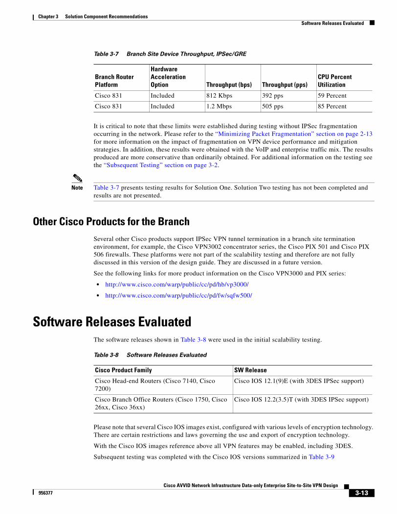
Chapter 3 Solution Component RecommendationsSoftware Releases Evaluated
It is critical to note that these limits were established during testing without IPSec fragmentation occurring in the network. Please refer to the “Minimizing Packet Fragmentation” section on page 2-13 for more information on the impact of fragmentation on VPN device performance and mitigation strategies. In addition, these results were obtained with the VoIP and enterprise traffic mix. The results produced are more conservative than ordinarily obtained. For additional information on the testing see the “Subsequent Testing” section on page 3-2.
Note Table 3-7 presents testing results for Solution One. Solution Two testing has not been completed and results are not presented.
Other Cisco Products for the BranchSeveral other Cisco products support IPSec VPN tunnel termination in a branch site termination environment, for example, the Cisco VPN3002 concentrator series, the Cisco PIX 501 and Cisco PIX 506 firewalls. These platforms were not part of the scalability testing and therefore are not fully discussed in this version of the design guide. They are discussed in a future version.
See the following links for more product information on the Cisco VPN3000 and PIX series:
• http://www.cisco.com/warp/public/cc/pd/hb/vp3000/
• http://www.cisco.com/warp/public/cc/pd/fw/sqfw500/
Software Releases EvaluatedThe software releases shown in Table 3-8 were used in the initial scalability testing.
Please note that several Cisco IOS images exist, configured with various levels of encryption technology. There are certain restrictions and laws governing the use and export of encryption technology.
With the Cisco IOS images reference above all VPN features may be enabled, including 3DES.
Subsequent testing was completed with the Cisco IOS versions summarized in Table 3-9
Cisco 831 Included 812 Kbps 392 pps 59 Percent
Cisco 831 Included 1.2 Mbps 505 pps 85 Percent
Table 3-7 Branch Site Device Throughput, IPSec/GRE
Branch Router Platform
Hardware Acceleration Option Throughput (bps) Throughput (pps)
CPU Percent Utilization
Table 3-8 Software Releases Evaluated
Cisco Product Family SW Release
Cisco Head-end Routers (Cisco 7140, Cisco 7200)
Cisco IOS 12.1(9)E (with 3DES IPSec support)
Cisco Branch Office Routers (Cisco 1750, Cisco 26xx, Cisco 36xx)
Cisco IOS 12.2(3.5)T (with 3DES IPSec support)
3-13Cisco AVVID Network Infrastructure Data-only Enterprise Site-to-Site VPN Design
956377
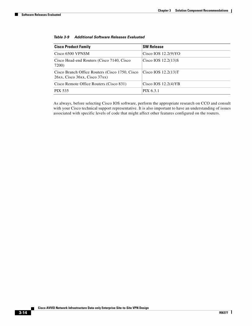
Chapter 3 Solution Component RecommendationsSoftware Releases Evaluated
As always, before selecting Cisco IOS software, perform the appropriate research on CCO and consult with your Cisco technical support representative. It is also important to have an understanding of issues associated with specific levels of code that might affect other features configured on the routers.
Table 3-9 Additional Software Releases Evaluated
Cisco Product Family SW Release
Cisco 6500 VPNSM Cisco IOS 12.2(9)YO
Cisco Head-end Routers (Cisco 7140, Cisco 7200)
Cisco IOS 12.2(13)S
Cisco Branch Office Routers (Cisco 1750, Cisco 26xx, Cisco 36xx, Cisco 37xx)
Cisco IOS 12.2(13)T
Cisco Remote Office Routers (Cisco 831) Cisco IOS 12.2(4)YB
PIX 535 PIX 6.3.1
3-14Cisco AVVID Network Infrastructure Data-only Enterprise Site-to-Site VPN Design
956377
Cisco AVVID Network Infrastructure Data-956377
C H A P T E R 4
Enterprise Site-to-Site VPN ConfigurationThis chapter presents the configurations used to create the solutions detailed in this design guide. The following specific sections are provided:
• Configuration Discussion Solution One, page 4-1
• Configuration Discussion Solution Two, page 4-6
Configuration Discussion Solution OneThe configuration issues defined in this chapter are specific to VPN implementation. It is assumed that the reader is reasonably familiar with standard Cisco configuration practices at the Command Line Interface (CLI) level.
All example configurations shown are for IPSec in Tunnel Mode.
An IPSec configuration is implemented by completing the following steps:
• IKE Policy Configuration, page 4-1
• IPSec Transform and Protocol Configuration, page 4-2
• Access List Configuration for Encryption, page 4-3
• Crypto Map Configuration, page 4-3
• Applying Crypto Maps, page 4-4
In addition, typical startup problems are addressed in the “Common Configuration Mistakes” section on page 4-5.
This chapter covers each of these steps in more detail. In addition, the following link offers additional information:
• http://www.cisco.com/cgi-bin/Support/PSP/psp_view.pl?p=Internetworking:IPSec
IKE Policy ConfigurationThere must be at least one matching IKE policy between two potential IPSec peers. The example configuration below shows a policy using pre-shared keys with 3DES as the encryption transform. There is a default IKE policy that contains the default values for the transform, hash method, Diffie-Helman group, authentication and lifetime parameters. This is the lowest priority IKE policy.
4-1only Enterprise Site-to-Site VPN Design
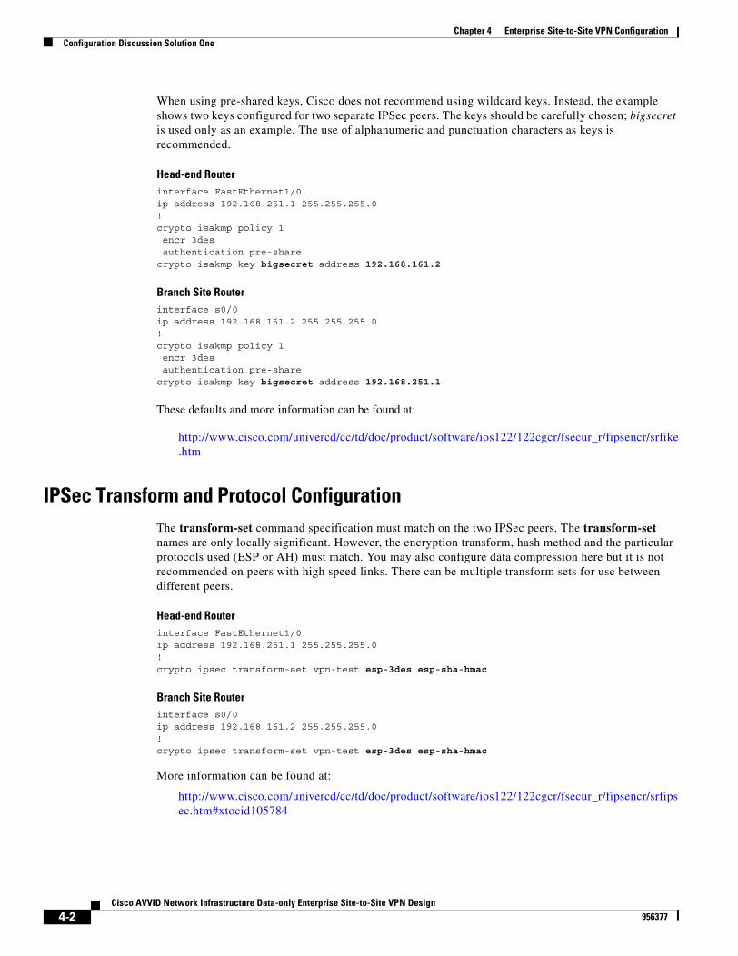
Chapter 4 Enterprise Site-to-Site VPN ConfigurationConfiguration Discussion Solution One
When using pre-shared keys, Cisco does not recommend using wildcard keys. Instead, the example shows two keys configured for two separate IPSec peers. The keys should be carefully chosen; bigsecret is used only as an example. The use of alphanumeric and punctuation characters as keys is recommended.
Head-end Routerinterface FastEthernet1/0ip address 192.168.251.1 255.255.255.0!crypto isakmp policy 1 encr 3des authentication pre-sharecrypto isakmp key bigsecret address 192.168.161.2
Branch Site Routerinterface s0/0ip address 192.168.161.2 255.255.255.0!crypto isakmp policy 1 encr 3des authentication pre-sharecrypto isakmp key bigsecret address 192.168.251.1
These defaults and more information can be found at:
http://www.cisco.com/univercd/cc/td/doc/product/software/ios122/122cgcr/fsecur_r/fipsencr/srfike.htm
IPSec Transform and Protocol ConfigurationThe transform-set command specification must match on the two IPSec peers. The transform-set names are only locally significant. However, the encryption transform, hash method and the particular protocols used (ESP or AH) must match. You may also configure data compression here but it is not recommended on peers with high speed links. There can be multiple transform sets for use between different peers.
Head-end Routerinterface FastEthernet1/0ip address 192.168.251.1 255.255.255.0!crypto ipsec transform-set vpn-test esp-3des esp-sha-hmac
Branch Site Routerinterface s0/0ip address 192.168.161.2 255.255.255.0!crypto ipsec transform-set vpn-test esp-3des esp-sha-hmac
More information can be found at:
http://www.cisco.com/univercd/cc/td/doc/product/software/ios122/122cgcr/fsecur_r/fipsencr/srfipsec.htm#xtocid105784
4-2Cisco AVVID Network Infrastructure Data-only Enterprise Site-to-Site VPN Design
956377
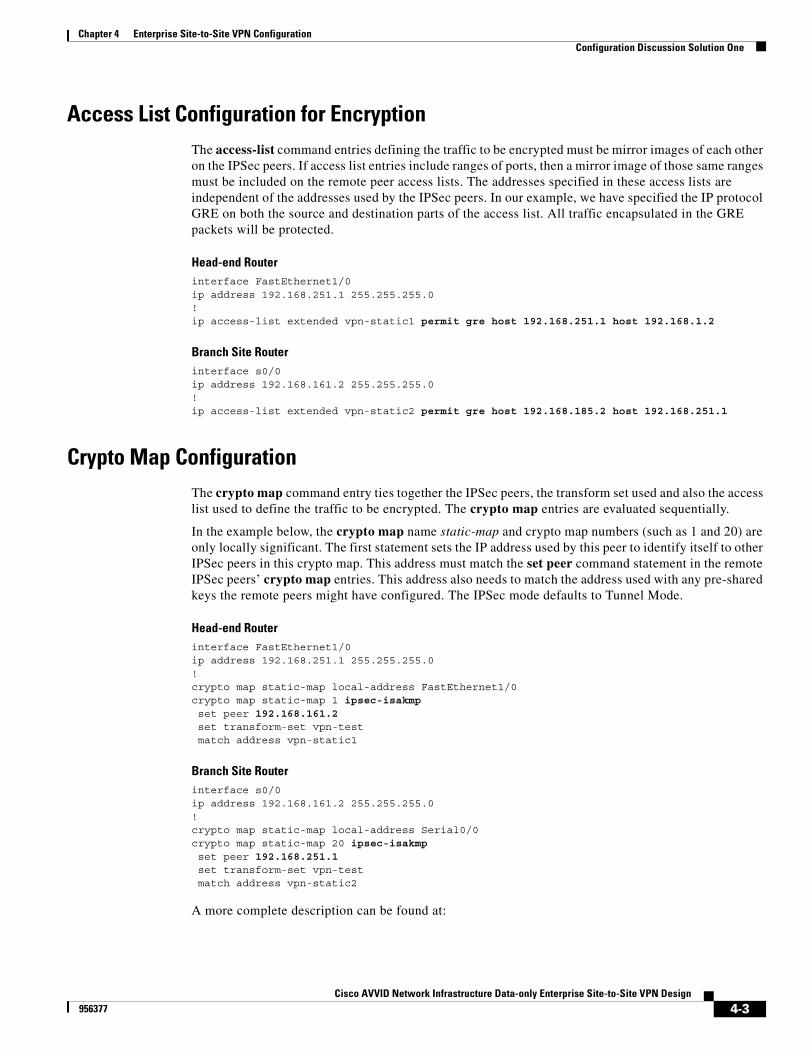
Chapter 4 Enterprise Site-to-Site VPN ConfigurationConfiguration Discussion Solution One
Access List Configuration for EncryptionThe access-list command entries defining the traffic to be encrypted must be mirror images of each other on the IPSec peers. If access list entries include ranges of ports, then a mirror image of those same ranges must be included on the remote peer access lists. The addresses specified in these access lists are independent of the addresses used by the IPSec peers. In our example, we have specified the IP protocol GRE on both the source and destination parts of the access list. All traffic encapsulated in the GRE packets will be protected.
Head-end Routerinterface FastEthernet1/0ip address 192.168.251.1 255.255.255.0!ip access-list extended vpn-static1 permit gre host 192.168.251.1 host 192.168.1.2
Branch Site Routerinterface s0/0ip address 192.168.161.2 255.255.255.0!ip access-list extended vpn-static2 permit gre host 192.168.185.2 host 192.168.251.1
Crypto Map ConfigurationThe crypto map command entry ties together the IPSec peers, the transform set used and also the access list used to define the traffic to be encrypted. The crypto map entries are evaluated sequentially.
In the example below, the crypto map name static-map and crypto map numbers (such as 1 and 20) are only locally significant. The first statement sets the IP address used by this peer to identify itself to other IPSec peers in this crypto map. This address must match the set peer command statement in the remote IPSec peers’ crypto map entries. This address also needs to match the address used with any pre-shared keys the remote peers might have configured. The IPSec mode defaults to Tunnel Mode.
Head-end Routerinterface FastEthernet1/0ip address 192.168.251.1 255.255.255.0!crypto map static-map local-address FastEthernet1/0crypto map static-map 1 ipsec-isakmp set peer 192.168.161.2 set transform-set vpn-test match address vpn-static1
Branch Site Routerinterface s0/0ip address 192.168.161.2 255.255.255.0!crypto map static-map local-address Serial0/0crypto map static-map 20 ipsec-isakmp set peer 192.168.251.1 set transform-set vpn-test match address vpn-static2
A more complete description can be found at:
4-3Cisco AVVID Network Infrastructure Data-only Enterprise Site-to-Site VPN Design
956377
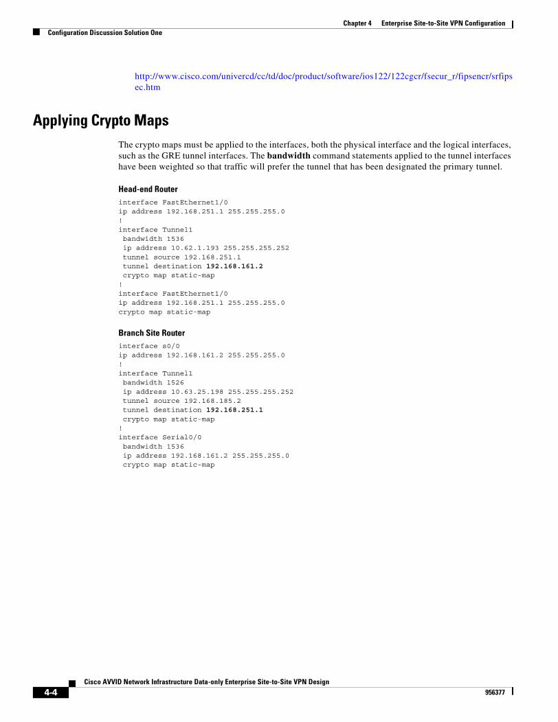
Chapter 4 Enterprise Site-to-Site VPN ConfigurationConfiguration Discussion Solution One
http://www.cisco.com/univercd/cc/td/doc/product/software/ios122/122cgcr/fsecur_r/fipsencr/srfipsec.htm
Applying Crypto MapsThe crypto maps must be applied to the interfaces, both the physical interface and the logical interfaces, such as the GRE tunnel interfaces. The bandwidth command statements applied to the tunnel interfaces have been weighted so that traffic will prefer the tunnel that has been designated the primary tunnel.
Head-end Routerinterface FastEthernet1/0ip address 192.168.251.1 255.255.255.0!interface Tunnel1 bandwidth 1536 ip address 10.62.1.193 255.255.255.252 tunnel source 192.168.251.1 tunnel destination 192.168.161.2 crypto map static-map!interface FastEthernet1/0ip address 192.168.251.1 255.255.255.0crypto map static-map
Branch Site Routerinterface s0/0ip address 192.168.161.2 255.255.255.0!interface Tunnel1 bandwidth 1526 ip address 10.63.25.198 255.255.255.252 tunnel source 192.168.185.2 tunnel destination 192.168.251.1 crypto map static-map!interface Serial0/0 bandwidth 1536 ip address 192.168.161.2 255.255.255.0 crypto map static-map
4-4Cisco AVVID Network Infrastructure Data-only Enterprise Site-to-Site VPN Design
956377
Chapter 4 Enterprise Site-to-Site VPN ConfigurationConfiguration Discussion Solution One
Common Configuration MistakesThe following sections outline some common mistakes and problems encountered when configuring IPSec.
• ACL Mirroring, page 4-5
• Peer Address Matching, page 4-5
• Transform Set Matches, page 4-5
• IKE Policy Matching, page 4-5
ACL Mirroring
The access lists that define the traffic to be encrypted must be mirror images of each other. The source port and source address in the access list on one peer must match the destination port and destination address on the other peer. The elimination of the source and destination ports is permissible, however the use of the keyword any for the addresses is strongly discouraged. This will ensure proper processing of encrypted traffic on the remote peer.
Peer Address Matching
The IP address used as the IPSec source address must match the address configured as the destination address on the IPSec peer and vice-versa. Unless the address is configured specifically, the address of the outgoing interface will be used as the IPSec peer’s address.
Transform Set Matches
At least one matching transform set must be configured between two IPSec peers. It should be mentioned that, when specifying a particular strength of encryption algorithm, a similar strength IKE algorithm should also be configured. Failure to do so could weaken the encryption strength of the entire solution.
IKE Policy Matching
There is a default IKE policy present in all Cisco IOS devices. This policy uses lower security hash methods and encryption transform sets. If a stronger IKE policy is desired, at least one matching IKE policy must be configured between each IPSec peer.
It is recommended to use the same transform set and hash methods in IKE and IPSec policies.
4-5Cisco AVVID Network Infrastructure Data-only Enterprise Site-to-Site VPN Design
956377
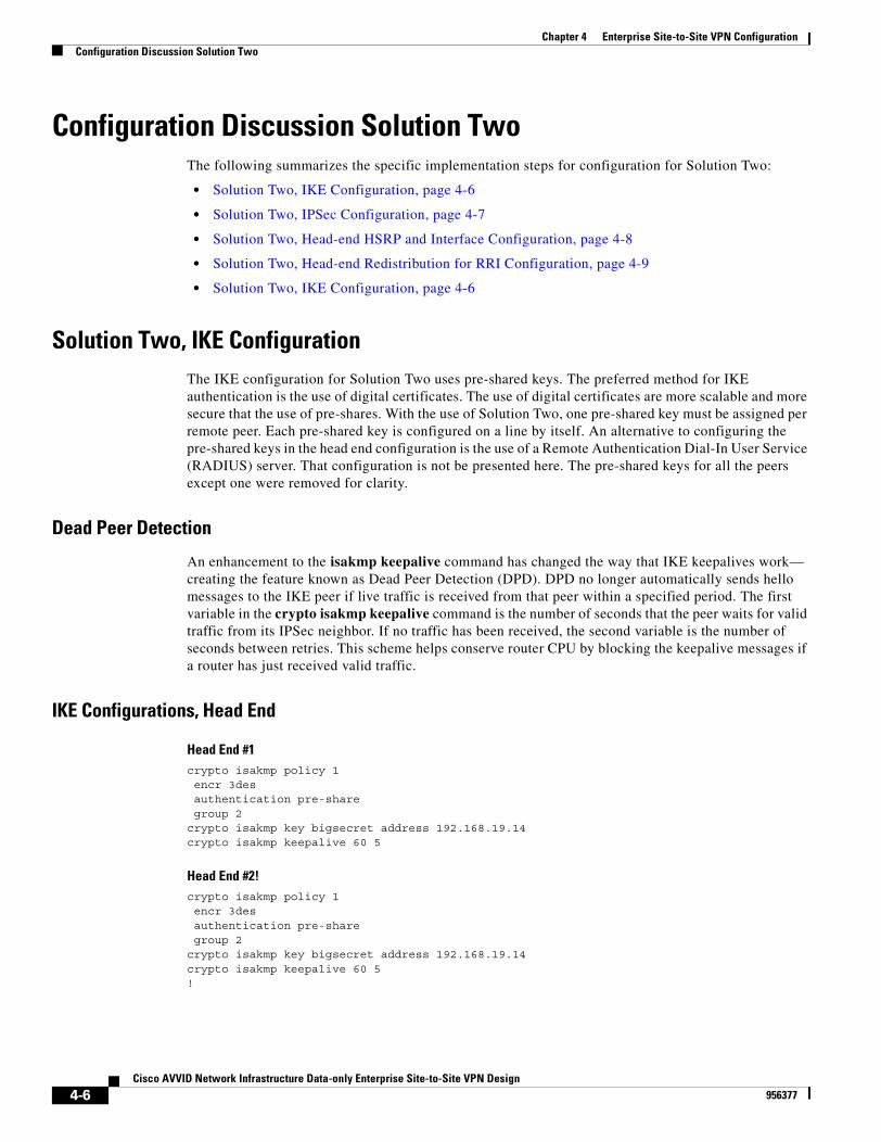
Chapter 4 Enterprise Site-to-Site VPN ConfigurationConfiguration Discussion Solution Two
Configuration Discussion Solution TwoThe following summarizes the specific implementation steps for configuration for Solution Two:
• Solution Two, IKE Configuration, page 4-6
• Solution Two, IPSec Configuration, page 4-7
• Solution Two, Head-end HSRP and Interface Configuration, page 4-8
• Solution Two, Head-end Redistribution for RRI Configuration, page 4-9
• Solution Two, IKE Configuration, page 4-6
Solution Two, IKE ConfigurationThe IKE configuration for Solution Two uses pre-shared keys. The preferred method for IKE authentication is the use of digital certificates. The use of digital certificates are more scalable and more secure that the use of pre-shares. With the use of Solution Two, one pre-shared key must be assigned per remote peer. Each pre-shared key is configured on a line by itself. An alternative to configuring the pre-shared keys in the head end configuration is the use of a Remote Authentication Dial-In User Service (RADIUS) server. That configuration is not be presented here. The pre-shared keys for all the peers except one were removed for clarity.
Dead Peer Detection
An enhancement to the isakmp keepalive command has changed the way that IKE keepalives work— creating the feature known as Dead Peer Detection (DPD). DPD no longer automatically sends hello messages to the IKE peer if live traffic is received from that peer within a specified period. The first variable in the crypto isakmp keepalive command is the number of seconds that the peer waits for valid traffic from its IPSec neighbor. If no traffic has been received, the second variable is the number of seconds between retries. This scheme helps conserve router CPU by blocking the keepalive messages if a router has just received valid traffic.
IKE Configurations, Head End
Head End #1crypto isakmp policy 1 encr 3des authentication pre-share group 2crypto isakmp key bigsecret address 192.168.19.14crypto isakmp keepalive 60 5
Head End #2!crypto isakmp policy 1 encr 3des authentication pre-share group 2crypto isakmp key bigsecret address 192.168.19.14crypto isakmp keepalive 60 5!
4-6Cisco AVVID Network Infrastructure Data-only Enterprise Site-to-Site VPN Design
956377
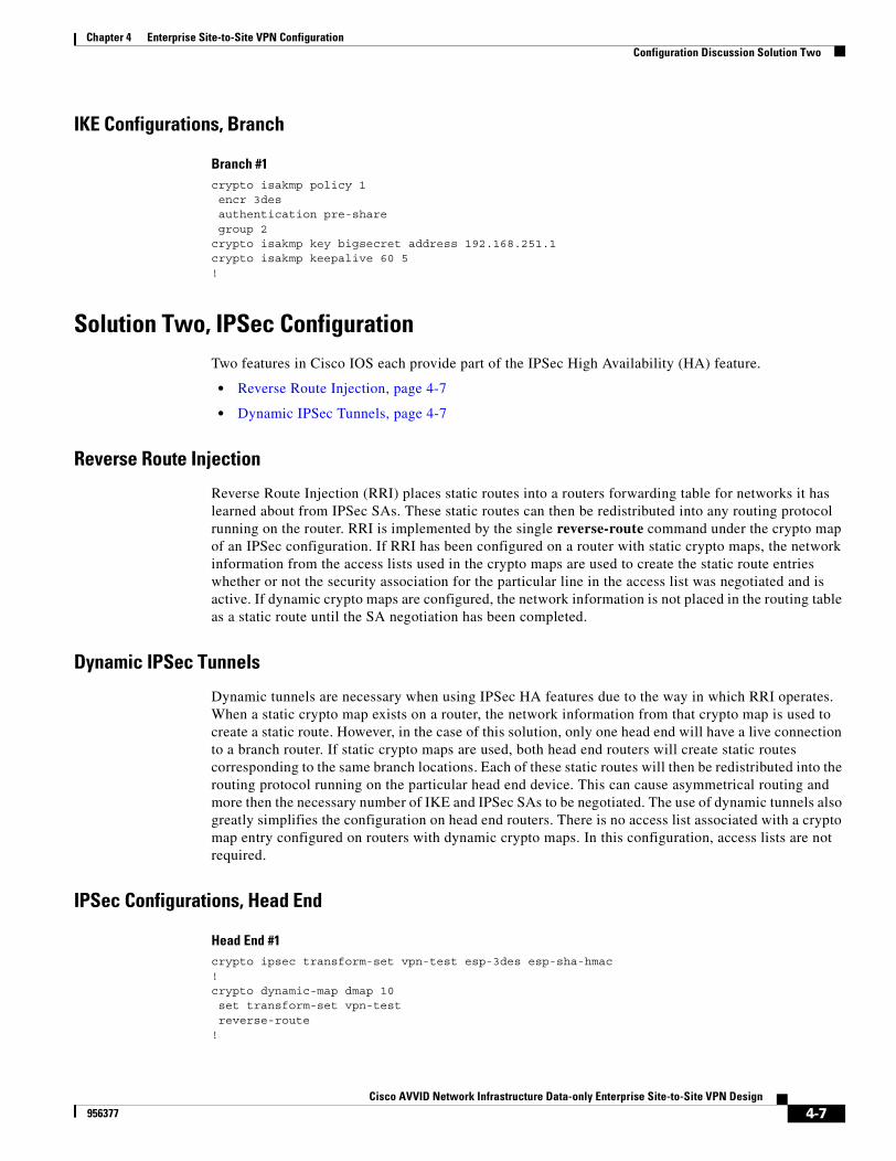
Chapter 4 Enterprise Site-to-Site VPN ConfigurationConfiguration Discussion Solution Two
IKE Configurations, Branch
Branch #1crypto isakmp policy 1 encr 3des authentication pre-share group 2crypto isakmp key bigsecret address 192.168.251.1crypto isakmp keepalive 60 5!
Solution Two, IPSec ConfigurationTwo features in Cisco IOS each provide part of the IPSec High Availability (HA) feature.
• Reverse Route Injection, page 4-7
• Dynamic IPSec Tunnels, page 4-7
Reverse Route Injection
Reverse Route Injection (RRI) places static routes into a routers forwarding table for networks it has learned about from IPSec SAs. These static routes can then be redistributed into any routing protocol running on the router. RRI is implemented by the single reverse-route command under the crypto map of an IPSec configuration. If RRI has been configured on a router with static crypto maps, the network information from the access lists used in the crypto maps are used to create the static route entries whether or not the security association for the particular line in the access list was negotiated and is active. If dynamic crypto maps are configured, the network information is not placed in the routing table as a static route until the SA negotiation has been completed.
Dynamic IPSec Tunnels
Dynamic tunnels are necessary when using IPSec HA features due to the way in which RRI operates. When a static crypto map exists on a router, the network information from that crypto map is used to create a static route. However, in the case of this solution, only one head end will have a live connection to a branch router. If static crypto maps are used, both head end routers will create static routes corresponding to the same branch locations. Each of these static routes will then be redistributed into the routing protocol running on the particular head end device. This can cause asymmetrical routing and more then the necessary number of IKE and IPSec SAs to be negotiated. The use of dynamic tunnels also greatly simplifies the configuration on head end routers. There is no access list associated with a crypto map entry configured on routers with dynamic crypto maps. In this configuration, access lists are not required.
IPSec Configurations, Head End
Head End #1crypto ipsec transform-set vpn-test esp-3des esp-sha-hmac !crypto dynamic-map dmap 10 set transform-set vpn-test reverse-route!
4-7Cisco AVVID Network Infrastructure Data-only Enterprise Site-to-Site VPN Design
956377
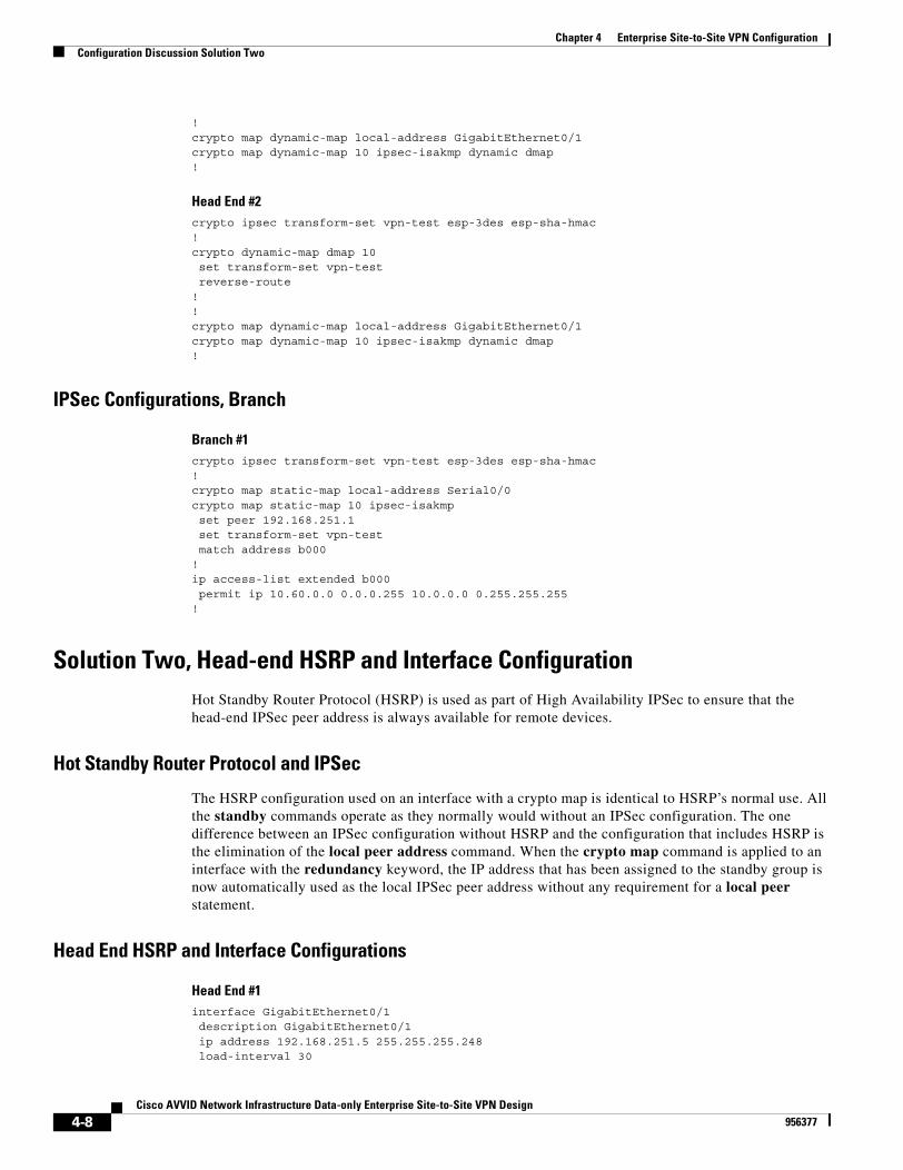
Chapter 4 Enterprise Site-to-Site VPN ConfigurationConfiguration Discussion Solution Two
!crypto map dynamic-map local-address GigabitEthernet0/1crypto map dynamic-map 10 ipsec-isakmp dynamic dmap !
Head End #2crypto ipsec transform-set vpn-test esp-3des esp-sha-hmac !crypto dynamic-map dmap 10 set transform-set vpn-test reverse-route!!crypto map dynamic-map local-address GigabitEthernet0/1crypto map dynamic-map 10 ipsec-isakmp dynamic dmap !
IPSec Configurations, Branch
Branch #1crypto ipsec transform-set vpn-test esp-3des esp-sha-hmac !crypto map static-map local-address Serial0/0crypto map static-map 10 ipsec-isakmp set peer 192.168.251.1 set transform-set vpn-test match address b000!ip access-list extended b000 permit ip 10.60.0.0 0.0.0.255 10.0.0.0 0.255.255.255!
Solution Two, Head-end HSRP and Interface ConfigurationHot Standby Router Protocol (HSRP) is used as part of High Availability IPSec to ensure that the head-end IPSec peer address is always available for remote devices.
Hot Standby Router Protocol and IPSec
The HSRP configuration used on an interface with a crypto map is identical to HSRP’s normal use. All the standby commands operate as they normally would without an IPSec configuration. The one difference between an IPSec configuration without HSRP and the configuration that includes HSRP is the elimination of the local peer address command. When the crypto map command is applied to an interface with the redundancy keyword, the IP address that has been assigned to the standby group is now automatically used as the local IPSec peer address without any requirement for a local peer statement.
Head End HSRP and Interface Configurations
Head End #1interface GigabitEthernet0/1 description GigabitEthernet0/1 ip address 192.168.251.5 255.255.255.248 load-interval 30
4-8Cisco AVVID Network Infrastructure Data-only Enterprise Site-to-Site VPN Design
956377
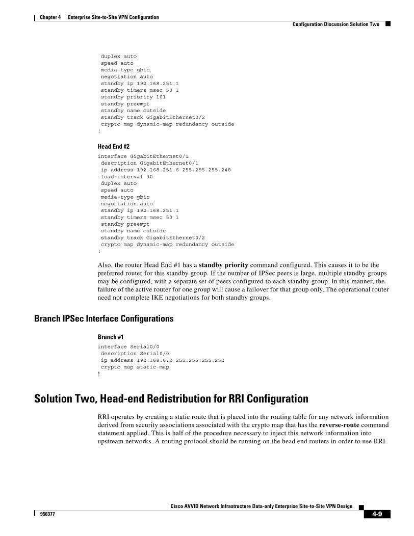
Chapter 4 Enterprise Site-to-Site VPN ConfigurationConfiguration Discussion Solution Two
duplex auto speed auto media-type gbic negotiation auto standby ip 192.168.251.1 standby timers msec 50 1 standby priority 101 standby preempt standby name outside standby track GigabitEthernet0/2 crypto map dynamic-map redundancy outside!
Head End #2interface GigabitEthernet0/1 description GigabitEthernet0/1 ip address 192.168.251.6 255.255.255.248 load-interval 30 duplex auto speed auto media-type gbic negotiation auto standby ip 192.168.251.1 standby timers msec 50 1 standby preempt standby name outside standby track GigabitEthernet0/2 crypto map dynamic-map redundancy outside!
Also, the router Head End #1 has a standby priority command configured. This causes it to be the preferred router for this standby group. If the number of IPSec peers is large, multiple standby groups may be configured, with a separate set of peers configured to each standby group. In this manner, the failure of the active router for one group will cause a failover for that group only. The operational router need not complete IKE negotiations for both standby groups.
Branch IPSec Interface Configurations
Branch #1interface Serial0/0 description Serial0/0 ip address 192.168.0.2 255.255.255.252 crypto map static-map
!
Solution Two, Head-end Redistribution for RRI ConfigurationRRI operates by creating a static route that is placed into the routing table for any network information derived from security associations associated with the crypto map that has the reverse-route command statement applied. This is half of the procedure necessary to inject this network information into upstream networks. A routing protocol should be running on the head end routers in order to use RRI.
4-9Cisco AVVID Network Infrastructure Data-only Enterprise Site-to-Site VPN Design
956377
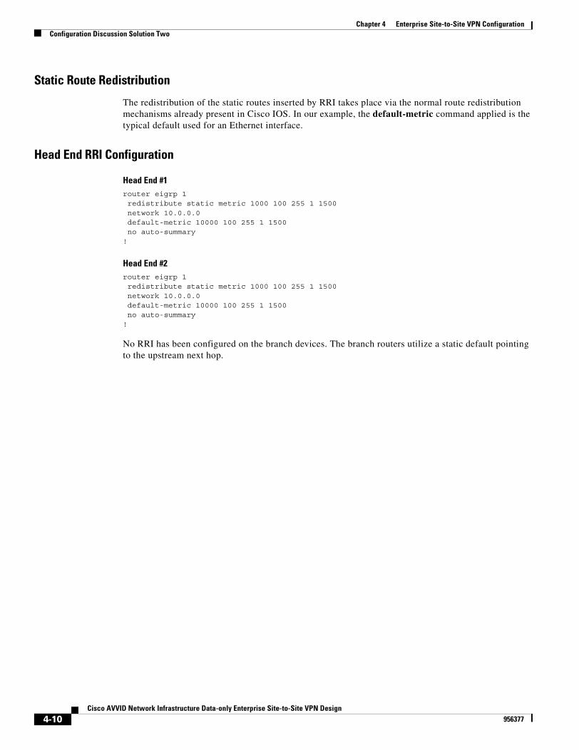
Chapter 4 Enterprise Site-to-Site VPN ConfigurationConfiguration Discussion Solution Two
Static Route Redistribution
The redistribution of the static routes inserted by RRI takes place via the normal route redistribution mechanisms already present in Cisco IOS. In our example, the default-metric command applied is the typical default used for an Ethernet interface.
Head End RRI Configuration
Head End #1router eigrp 1 redistribute static metric 1000 100 255 1 1500 network 10.0.0.0 default-metric 10000 100 255 1 1500 no auto-summary!
Head End #2router eigrp 1 redistribute static metric 1000 100 255 1 1500 network 10.0.0.0 default-metric 10000 100 255 1 1500 no auto-summary!
No RRI has been configured on the branch devices. The branch routers utilize a static default pointing to the upstream next hop.
4-10Cisco AVVID Network Infrastructure Data-only Enterprise Site-to-Site VPN Design
956377
Cisco AVVID Network Infrastructure Data-956377
C H A P T E R 5
Enterprise Site-to-Site VPN Case StudyThe key objective of this case study is to provide a reference example for a site-to-site VPN design. It provides an example of how these design principles can be applied in a real-world scenario.
This case study assumes that all of the design considerations in Chapter 2, “Solution Design Recommendations” and Chapter 3, “Solution Component Recommendations” were addressed, and that best practice design recommendations are adopted by the organization.
The case study also assumes that the Cisco IOS software levels listed in the “Software Releases Evaluated” section on page 3-13 are acceptable to the organization.
The details of the Service Provider backbone and WAN connectivity are not addressed in the case study, since the focus is on VPN deployment on the Enterprise network side.
The following primary sections are presented in this chapter:
• Network Overview, page 5-1
• Design Considerations, page 5-3
Network OverviewMoose Widgets has developed products at their Portland, Oregon headquarters (HQ) for several years. In addition, Moose has a single distribution center and 20 retail outlets across the United States (US).
Moose Widgets utilizes a traditional Frame Relay (FR) WAN service to connect its headquarters to its distribution center. There is currently no connectivity to retail outlets, with the exception of a few outlets that, use a Personal Computer (PC) to dial-up to the corporate HQ. The current network topology shown in Figure 5-1 on page 5-2:
5-1only Enterprise Site-to-Site VPN Design
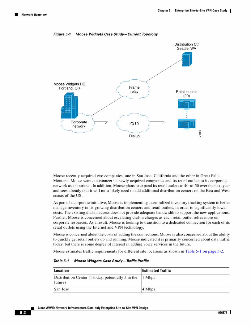
Chapter 5 Enterprise Site-to-Site VPN Case StudyNetwork Overview
Figure 5-1 Moose Widgets Case Study—Current Topology
Moose recently acquired two companies, one in San Jose, California and the other in Great Falls, Montana. Moose wants to connect its newly acquired companies and its retail outlets to its corporate network as an intranet. In addition, Moose plans to expand its retail outlets to 40-to-50 over the next year and sees already that it will most likely need to add additional distribution centers on the East and West coasts of the US.
As part of a corporate initiative, Moose is implementing a centralized inventory tracking system to better manage inventory in its growing distribution centers and retail outlets, in order to significantly lower costs. The existing dial-in access does not provide adequate bandwidth to support the new applications. Further, Moose is concerned about escalating dial-in charges as each retail outlet relies more on corporate resources. As a result, Moose is looking to transition to a dedicated connection for each of its retail outlets using the Internet and VPN technology.
Moose is concerned about the costs of adding the connections. Moose is also concerned about the ability to quickly get retail outlets up and running. Moose indicated it is primarily concerned about data traffic today, but there is some degree of interest in adding voice services in the future.
Moose estimates traffic requirements for different site locations as shown in Table 5-1 on page 5-2:
Corporatenetwork
Framerelay Retail outlets
(20)
Distribution CtrSeattle, WA
Moose Widgets HQPortland, OR
PSTN
Dialup 7418
0
Table 5-1 Moose Widgets Case Study—Traffic Profile
Location Estimated Traffic
Distribution Center (1 today, potentially 3 in the future)
1 Mbps
San Jose 4 Mbps
5-2Cisco AVVID Network Infrastructure Data-only Enterprise Site-to-Site VPN Design
956377

Chapter 5 Enterprise Site-to-Site VPN Case StudyDesign Considerations
Moose approached Cisco to see how a VPN might solve their problems.
Design ConsiderationsA site-to-site IPSec VPN will be deployed with the Moose corporate HQ serving as the head-end, and all other locations treated as branch sites. This allows a branch office to subscribe to a local ISP, get authenticated, and be inside the corporate intranet.
At the same time, end-to-end encryption is attained using IPSec tunneling. Switching to VPN offers Moose significant cost savings over dial-up solutions and the ability to outsource to a Service Provider that has VPN service as a core competency, providing more efficiency with cost and scalability.
Four principal design steps are addressed in this case study:
• Preliminary Design Considerations, page 5-3
• Sizing the Head-end, page 5-4
• Sizing the Branch Sites, page 5-5
• Tunnel Aggregation and Load Distribution, page 5-5
For more information about these specific steps, refer to Chapter 2, “Solution Design Recommendations” and Chapter 3, “Solution Component Recommendations.”
Preliminary Design ConsiderationsThe design is straightforward and offers flexibility. As new retail locations are put into service, Moose can purchase Internet connectivity from the local ISP, deploy a Cisco VPN Router at the branch site, configure the IPSec tunnels to the head-end devices at the corporate headquarters, and be up and running in a short amount of time.
Using the questions from “General Design Considerations” section on page 2-2, the following table summarizes the preliminary design considerations.
Great Falls 4 Mbps
Retail Outlets (up to 50) 50 Kbps – typical (40), 200 Kbps – larger (10)
TOTAL 15Mbps
Table 5-1 Moose Widgets Case Study—Traffic Profile
Location Estimated Traffic
Table 5-2 Preliminary Design Consideration Summary
Question Answer Comments
What applications does the organization expect to run over the VPN?
Data Interested in future voice services
Is multi-protocol support required?
Yes, IP and multicast GRE tunnels enable multi-protocol traffic transport.
5-3Cisco AVVID Network Infrastructure Data-only Enterprise Site-to-Site VPN Design
956377
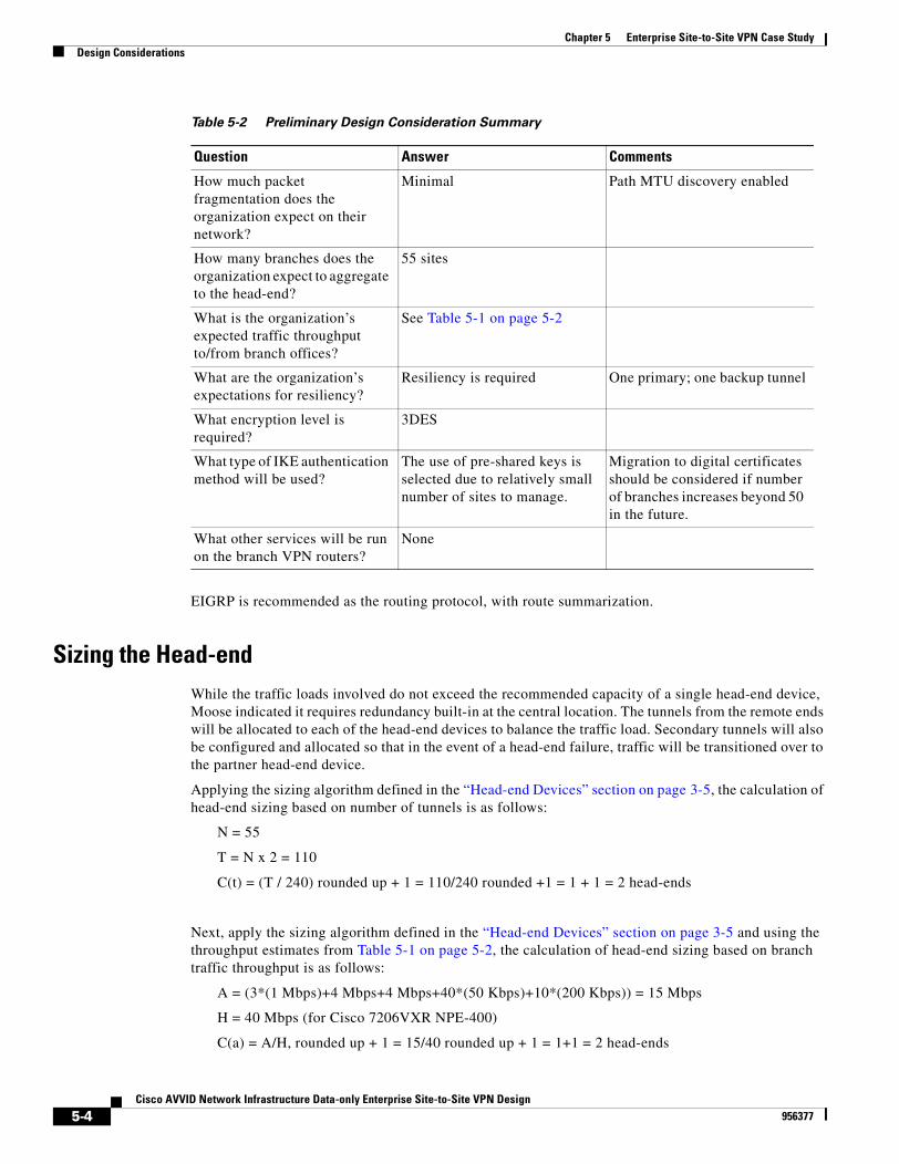
Chapter 5 Enterprise Site-to-Site VPN Case StudyDesign Considerations
EIGRP is recommended as the routing protocol, with route summarization.
Sizing the Head-endWhile the traffic loads involved do not exceed the recommended capacity of a single head-end device, Moose indicated it requires redundancy built-in at the central location. The tunnels from the remote ends will be allocated to each of the head-end devices to balance the traffic load. Secondary tunnels will also be configured and allocated so that in the event of a head-end failure, traffic will be transitioned over to the partner head-end device.
Applying the sizing algorithm defined in the “Head-end Devices” section on page 3-5, the calculation of head-end sizing based on number of tunnels is as follows:
N = 55
T = N x 2 = 110
C(t) = (T / 240) rounded up + 1 = 110/240 rounded +1 = 1 + 1 = 2 head-ends
Next, apply the sizing algorithm defined in the “Head-end Devices” section on page 3-5 and using the throughput estimates from Table 5-1 on page 5-2, the calculation of head-end sizing based on branch traffic throughput is as follows:
A = (3*(1 Mbps)+4 Mbps+4 Mbps+40*(50 Kbps)+10*(200 Kbps)) = 15 Mbps
H = 40 Mbps (for Cisco 7206VXR NPE-400)
C(a) = A/H, rounded up + 1 = 15/40 rounded up + 1 = 1+1 = 2 head-ends
How much packet fragmentation does the organization expect on their network?
Minimal Path MTU discovery enabled
How many branches does the organization expect to aggregate to the head-end?
55 sites
What is the organization’s expected traffic throughput to/from branch offices?
See Table 5-1 on page 5-2
What are the organization’s expectations for resiliency?
Resiliency is required One primary; one backup tunnel
What encryption level is required?
3DES
What type of IKE authentication method will be used?
The use of pre-shared keys is selected due to relatively small number of sites to manage.
Migration to digital certificates should be considered if number of branches increases beyond 50 in the future.
What other services will be run on the branch VPN routers?
None
Table 5-2 Preliminary Design Consideration Summary
Question Answer Comments
5-4Cisco AVVID Network Infrastructure Data-only Enterprise Site-to-Site VPN Design
956377
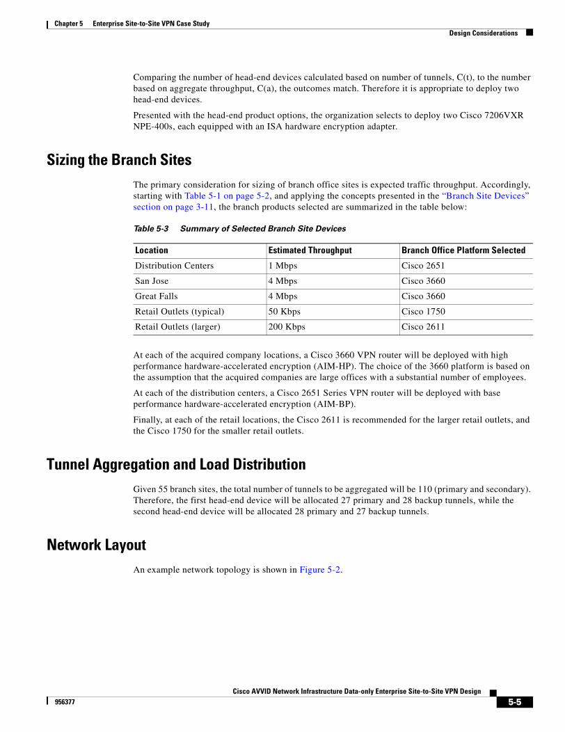
Chapter 5 Enterprise Site-to-Site VPN Case StudyDesign Considerations
Comparing the number of head-end devices calculated based on number of tunnels, C(t), to the number based on aggregate throughput, C(a), the outcomes match. Therefore it is appropriate to deploy two head-end devices.
Presented with the head-end product options, the organization selects to deploy two Cisco 7206VXR NPE-400s, each equipped with an ISA hardware encryption adapter.
Sizing the Branch SitesThe primary consideration for sizing of branch office sites is expected traffic throughput. Accordingly, starting with Table 5-1 on page 5-2, and applying the concepts presented in the “Branch Site Devices” section on page 3-11, the branch products selected are summarized in the table below:
At each of the acquired company locations, a Cisco 3660 VPN router will be deployed with high performance hardware-accelerated encryption (AIM-HP). The choice of the 3660 platform is based on the assumption that the acquired companies are large offices with a substantial number of employees.
At each of the distribution centers, a Cisco 2651 Series VPN router will be deployed with base performance hardware-accelerated encryption (AIM-BP).
Finally, at each of the retail locations, the Cisco 2611 is recommended for the larger retail outlets, and the Cisco 1750 for the smaller retail outlets.
Tunnel Aggregation and Load DistributionGiven 55 branch sites, the total number of tunnels to be aggregated will be 110 (primary and secondary). Therefore, the first head-end device will be allocated 27 primary and 28 backup tunnels, while the second head-end device will be allocated 28 primary and 27 backup tunnels.
Network LayoutAn example network topology is shown in Figure 5-2.
Table 5-3 Summary of Selected Branch Site Devices
Location Estimated Throughput Branch Office Platform Selected
Distribution Centers 1 Mbps Cisco 2651
San Jose 4 Mbps Cisco 3660
Great Falls 4 Mbps Cisco 3660
Retail Outlets (typical) 50 Kbps Cisco 1750
Retail Outlets (larger) 200 Kbps Cisco 2611
5-5Cisco AVVID Network Infrastructure Data-only Enterprise Site-to-Site VPN Design
956377
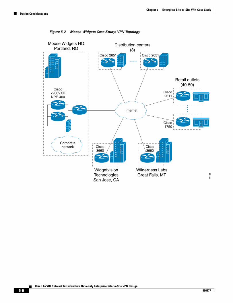
Chapter 5 Enterprise Site-to-Site VPN Case StudyDesign Considerations
Figure 5-2 Moose Widgets Case Study: VPN Topology
Internet
Moose Widgets HQPortland, RO
Distribution centers(3)
WidgetvisionTechnologiesSan Jose, CA
Wilderness LabsGreat Falls, MT
Retail outlets(40-50)
Cisco7206VXRNPE-400
Cisco 2651
Cisco2611
Cisco1750
Cisco3660
Cisco3660
Cisco 2651
7418
1
Corporatenetwork
5-6Cisco AVVID Network Infrastructure Data-only Enterprise Site-to-Site VPN Design
956377
Cisco AVVID Network Infrastructure Data-956377
A P P E N D I X A
Enterprise Site-to-Site VPN Solution Test Bed ConfigurationScalability Testbed Network DiagramFigure A-1 illustrates the test network used for the site-to-site Enterprise VPN scalability tests presented in this publication.
A-1only Enterprise Site-to-Site VPN Design
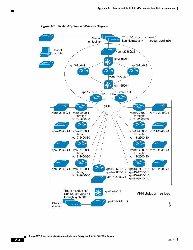
Appendix A Enterprise Site-to-Site VPN Solution Test Bed Configuration
Figure A-1 Scalability Testbed Network Diagram
Si
Si
Si
7418
2
vpn6-2948G-1 vpn6-2600-1through
vpn6-2600-30
vpn14-3620-1-5vpn14-3660-1-5
"Core / Campus endpoints"Sun Netras: vpn4-n1 through vpn4-n30
"Branch endpoints"Sun Netras: vpn5-n1through vpn5-n30
Chariotconsole
Chariotendpoints
Chariotendpoints
vpn4-2948GL2
vpn2-6500-1
vpn1-6500-1
vpn3-7xx0-3
vpn2-7500-2FEC FEC
(HDLC)
vpn3-7xx0-2
vpn3-7xx0-1
vpn2-7505-1
vpn14-2948G-1
vpn5-2948GL2-1
VPN Solution Testbedvpn2-6500-2
vpn10-2948G-1vpn10-2600-1through
vpn10-2600-30
vpn7-2948G-1 vpn7-2600-1through
vpn7-2600-30
vpn11-2948G-1vpn11-2600-1through
vpn11-2600-30
vpn8-2948G-1 vpn8-2600-1through
vpn8-2600-30
vpn12-2948G-1vpn12-2600-1through
vpn12-2600-30
vpn9-2948G-1 vpn9-2600-1through
vpn9-2600-30
ci13-2948G-1vpn13-800 - 1-5vpn13-1700-1-5vpn13-2600-1-5vpn13-3640-1-5
A-2Cisco AVVID Network Infrastructure Data-only Enterprise Site-to-Site VPN Design
956377
Appendix A Enterprise Site-to-Site VPN Solution Test Bed Configuration
Scalability Testbed Configuration FilesThe configuration for the central and branch sites are listed below in the sections which follow.
Note These configurations have been extracted from real configurations used in scalability testing. They are provided as a reference only.
The use of GRE as a tunneling method requires static tunnel endpoint configuration. Configuring IPSec peers was also done statically.
Head-end Configuration
The head-end is setup with two GRE (one primary and one secondary) for each branch site that it terminates. The configuration below is an excerpt and does not contain config commands for all branches.
!ip cef !!ip ssh time-out 120ip ssh authentication-retries 3!xsmxsm privilege configuration level 15xsm privilege monitor level 1xsm vdmxsm edmno xsm history vdmno xsm history edm!!crypto isakmp policy 1 encr 3des authentication pre-sharecrypto isakmp key bigsecret address 192.168.161.2crypto isakmp key bigsecret address 192.168.162.2!!crypto ipsec transform-set vpn-test esp-3des esp-sha-hmaccrypto mib ipsec flowmib history tunnel size 200crypto mib ipsec flowmib history failure size 200!crypto map static-map local-address FastEthernet1/0crypto map static-map 1 ipsec-isakmp set peer 192.168.1.2 set transform-set vpn-test match address vpn-static1crypto map static-map 2 ipsec-isakmp set peer 192.168.2.2 set transform-set vpn-test match address vpn-static2!!controller ISA 2/1!!!buffers small permanent 2048
A-3Cisco AVVID Network Infrastructure Data-only Enterprise Site-to-Site VPN Design
956377
Appendix A Enterprise Site-to-Site VPN Solution Test Bed Configuration
buffers small max-free 10240buffers small min-free 512buffers middle permanent 2048buffers middle max-free 10240buffers middle min-free 512buffers big permanent 2048buffers big max-free 10240buffers big min-free 512buffers verybig permanent 2048buffers verybig max-free 10240buffers verybig min-free 512buffers large permanent 2048buffers large max-free 10240buffers large min-free 512buffers huge permanent 128buffers huge max-free 512buffers huge min-free 32!!interface Loopback0 ip address 10.57.1.255 255.255.255.255 no ip route-cache no ip mroute-cache!interface Tunnel1 description vpn6-2600-1 bandwidth 1536 ip address 10.62.1.193 255.255.255.252 ip summary-address eigrp 1 10.0.0.0 255.0.0.0 5 load-interval 30 tunnel source 192.168.251.1 tunnel destination 192.168.1.2 crypto map static-map!interface Tunnel2 description vpn6-2600-2 bandwidth 1536 ip address 10.62.2.193 255.255.255.252 ip summary-address eigrp 1 10.0.0.0 255.0.0.0 5 load-interval 30 tunnel source 192.168.251.1 tunnel destination 192.168.2.2 crypto map static-map!!interface FastEthernet0/0 description FastEthernet0/0 ip address 172.26.156.17 255.255.254.0 no ip mroute-cache load-interval 30 duplex full!interface FastEthernet1/0 description FastEthernet1/0 ip address 192.168.251.1 255.255.255.0 load-interval 30 duplex full speed 100 crypto map static-map!interface FastEthernet1/1 description FastEthernet1/1 ip address 10.57.1.1 255.255.255.252 no ip proxy-arp
A-4Cisco AVVID Network Infrastructure Data-only Enterprise Site-to-Site VPN Design
956377
Appendix A Enterprise Site-to-Site VPN Solution Test Bed Configuration
load-interval 30 duplex full speed 100!router eigrp 1 redistribute static passive-interface FastEthernet0/0 passive-interface FastEthernet1/0 network 10.0.0.0 no auto-summary eigrp log-neighbor-changes!ip classlessip route 0.0.0.0 0.0.0.0 192.168.251.2!!ip access-list extended vpn-static1 permit gre host 192.168.251.1 host 192.168.1.2ip access-list extended vpn-static2 permit gre host 192.168.251.1 host 192.168.2.2
Branch Site Configuration
For resiliency, two tunnels are configured (primary and secondary) to the central site.
!ip cef!!crypto isakmp policy 1 encr 3des authentication pre-sharecrypto isakmp key bigsecret address 192.168.253.1crypto isakmp key bigsecret address 192.168.251.1!!crypto ipsec transform-set vpn-test esp-3des esp-sha-hmaccrypto mib ipsec flowmib history tunnel size 200crypto mib ipsec flowmib history failure size 200!crypto map static-map local-address Serial0/0crypto map static-map 10 ipsec-isakmp set peer 192.168.253.1 set transform-set vpn-test match address vpn-static1crypto map static-map 20 ipsec-isakmp set peer 192.168.251.1 set transform-set vpn-test match address vpn-static2!!interface Loopback0 ip address 10.63.25.254 255.255.255.255!interface Tunnel0 description Tunnel0 bandwidth 1536 ip address 10.63.25.194 255.255.255.252 ip summary-address eigrp 1 10.63.25.0 255.255.255.0 5 load-interval 30 tunnel source 192.168.185.2 tunnel destination 192.168.253.1
A-5Cisco AVVID Network Infrastructure Data-only Enterprise Site-to-Site VPN Design
956377
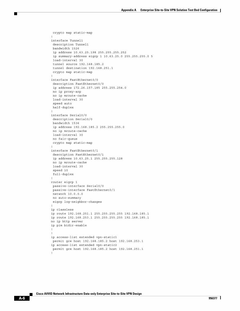
Appendix A Enterprise Site-to-Site VPN Solution Test Bed Configuration
crypto map static-map!interface Tunnel1 description Tunnel1 bandwidth 1526 ip address 10.63.25.198 255.255.255.252 ip summary-address eigrp 1 10.63.25.0 255.255.255.0 5 load-interval 30 tunnel source 192.168.185.2 tunnel destination 192.168.251.1 crypto map static-map!interface FastEthernet0/0 description FastEthernet0/0 ip address 172.26.157.185 255.255.254.0 no ip proxy-arp no ip mroute-cache load-interval 30 speed auto half-duplex!interface Serial0/0 description Serial0/0 bandwidth 1536 ip address 192.168.185.2 255.255.255.0 no ip mroute-cache load-interval 30 no fair-queue crypto map static-map!interface FastEthernet0/1 description FastEthernet0/1 ip address 10.63.25.1 255.255.255.128 no ip mroute-cache load-interval 30 speed 10 full-duplex!router eigrp 1 passive-interface Serial0/0 passive-interface FastEthernet0/1 network 10.0.0.0 no auto-summary eigrp log-neighbor-changes!ip classlessip route 192.168.251.1 255.255.255.255 192.168.185.1ip route 192.168.253.1 255.255.255.255 192.168.185.1no ip http serverip pim bidir-enable!!ip access-list extended vpn-static1 permit gre host 192.168.185.2 host 192.168.253.1ip access-list extended vpn-static2 permit gre host 192.168.185.2 host 192.168.251.1!
A-6Cisco AVVID Network Infrastructure Data-only Enterprise Site-to-Site VPN Design
956377
Cisco AVVID Network Infrastructure Data-956377
A P P E N D I X B
High-Level IPSec OverviewThe purpose of this section is to introduce IPSec and its application in VPNs. General descriptions of the following IPsec topics are presented:
• Tunneling Protocols, page B-1
• Introduction to IPSec, page B-1
• IPSec Protocols, page B-2
• IPSec Modes, page B-5
• Internet Key Exchange (IKE), page B-6
For a more in-depth understanding of IPSec, the reader should consult the Cisco SAFE VPN White Paper. Cisco SAFE documentation can be found at the following URL:
http://www.cisco.com/go/safe
Tunneling ProtocolsThere are varieties of tunneling protocols from which to choose. They vary in terms of the features they support, the problems they are designed to solve, and the amount of security they provide to the data being transported.
The design presented in this paper focuses on the use of IPSec as a tunneling protocol alone and in conjunction with GRE tunnels. When used alone, IPSec can provide a private, resilient network when support for multicast, routing protocols or non IP protocols is not required. When support for one or more of these features is required, IPSec should be used in conjunction with GRE. When implemented individually, these tunneling protocols do not provide the necessary features to simultaneously ensure privacy and support multi-protocols. The combination of IPSec and GRE concurrently achieves both functions.
Other tunneling protocols include Point-to-Point Tunneling Protocol (PPTP) and Layer 2 Tunneling Protocol (L2TP). PPTP and L2TP are intended for user or client to concentrator networks, commonly called remote access solutions and are not used in the site-to-site VPN solution.
Introduction to IPSecThe IPSec standard provides a method to manage authentication and data protection between multiple peers engaging in secure data transfer. IPSec includes Internet Security Association and Key Management Protocol (ISAKMP) and the Oakley Key Determination Protocol and two IPSec IP protocols—Encapsulating Security Protocol (ESP) and Authentication Header (AH).
B-1only Enterprise Site-to-Site VPN Design
Appendix B High-Level IPSec OverviewIPSec Protocols
IPSec uses symmetrical encryption algorithms for data protection. Symmetrical encryption transforms are more efficient and are easier to implement in hardware. These algorithms need a secure method of key exchange in order to ensure the data protection. Internet Key Exchange’s (IKE) ISAKMP/Oakley protocols provide that capability.
This solution requires a standards based way to secure data from eavesdropping and modification. IPSec provides such a method. IPSec permits the network designer to choose the strength of data protection by allowing the choice of transform set. IPSec also has several hash methods to choose from, each giving different levels of protection.
IPSec ProtocolsThere are two IP protocols used in the IPSec standard: Encapsulating Security Protocol (ESP) and Authentication Header (AH). These protocols are summarized briefly in the next two sections:
• Encapsulating Security Protocol (ESP), page B-2
• Authentication Header (AH), page B-4
Encapsulating Security Protocol (ESP)The ESP header (IP protocol 50) forms the core of the IPSec protocol. This protocol in conjunction with an agreed upon encryption method or transform set, protects data by rendering it undecipherable. This protocol protects the data portion of the packet only. It can also optionally provide for authentication of the protected data. Figure B-1 shows how ESP encapsulates an IP packet:
B-2Cisco AVVID Network Infrastructure Data-only Enterprise Site-to-Site VPN Design
956377
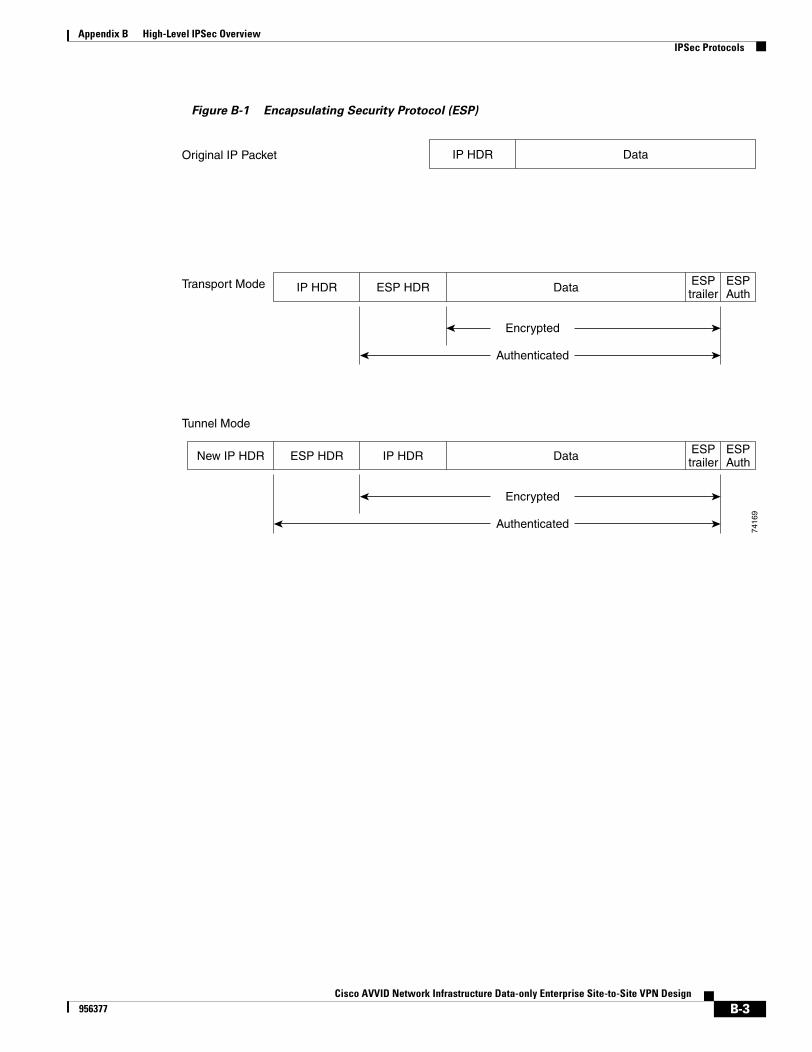
Appendix B High-Level IPSec OverviewIPSec Protocols
Figure B-1 Encapsulating Security Protocol (ESP)
IP HDR Data
Encrypted
Authenticated
ESPtrailer
ESPAuthNew IP HDR ESP HDR
Data
Encrypted
Authenticated
ESPtrailer
ESPAuthIP HDR ESP HDR
DataIP HDROriginal IP Packet
Transport Mode
Tunnel Mode
7416
9
B-3Cisco AVVID Network Infrastructure Data-only Enterprise Site-to-Site VPN Design
956377
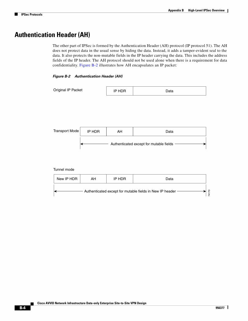
Appendix B High-Level IPSec OverviewIPSec Protocols
Authentication Header (AH)The other part of IPSec is formed by the Authentication Header (AH) protocol (IP protocol 51). The AH does not protect data in the usual sense by hiding the data. Instead, it adds a tamper-evident seal to the data. It also protects the non-mutable fields in the IP header carrying the data. This includes the address fields of the IP header. The AH protocol should not be used alone when there is a requirement for data confidentiality. Figure B-2 illustrates how AH encapsulates an IP packet:
Figure B-2 Authentication Header (AH)
IP HDR DataNew IP HDR AH
Data
Authenticated except for mutable fields
IP HDR AH
Original IP Packet
Transport Mode
Tunnel mode
DataIP HDR
Authenticated except for mutable fields in New IP header
7417
0
B-4Cisco AVVID Network Infrastructure Data-only Enterprise Site-to-Site VPN Design
956377
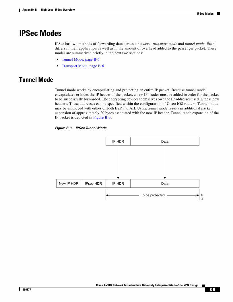
Appendix B High-Level IPSec OverviewIPSec Modes
IPSec ModesIPSec has two methods of forwarding data across a network: transport mode and tunnel mode. Each differs in their application as well as in the amount of overhead added to the passenger packet. These modes are summarized briefly in the next two sections:
• Tunnel Mode, page B-5
• Transport Mode, page B-6
Tunnel ModeTunnel mode works by encapsulating and protecting an entire IP packet. Because tunnel mode encapsulates or hides the IP header of the packet, a new IP header must be added in order for the packet to be successfully forwarded. The encrypting devices themselves own the IP addresses used in these new headers. These addresses can be specified within the configuration of Cisco IOS routers. Tunnel mode may be employed with either or both ESP and AH. Using tunnel mode results in additional packet expansion of approximately 20 bytes associated with the new IP header. Tunnel mode expansion of the IP packet is depicted in Figure B-3.
Figure B-3 IPSec Tunnel Mode
IP HDR DataNew IP HDR IPsec HDR
IP HDR Data
To be protected
7417
1
B-5Cisco AVVID Network Infrastructure Data-only Enterprise Site-to-Site VPN Design
956377
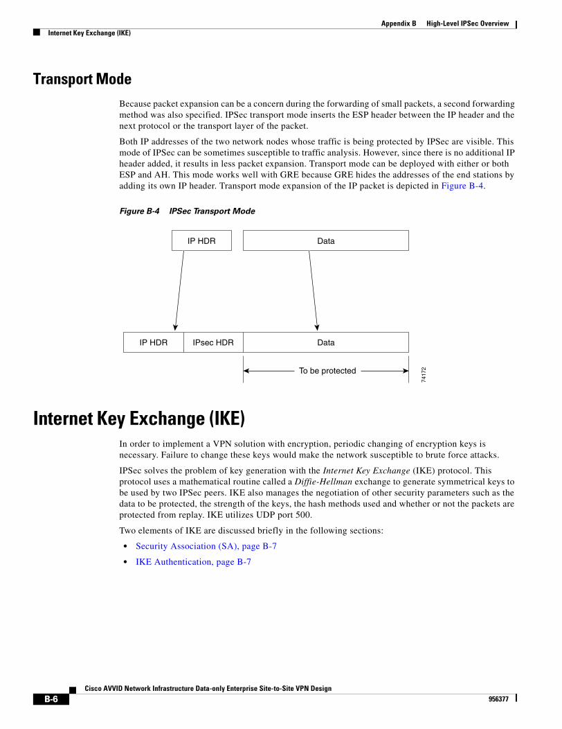
Appendix B High-Level IPSec OverviewInternet Key Exchange (IKE)
Transport ModeBecause packet expansion can be a concern during the forwarding of small packets, a second forwarding method was also specified. IPSec transport mode inserts the ESP header between the IP header and the next protocol or the transport layer of the packet.
Both IP addresses of the two network nodes whose traffic is being protected by IPSec are visible. This mode of IPSec can be sometimes susceptible to traffic analysis. However, since there is no additional IP header added, it results in less packet expansion. Transport mode can be deployed with either or both ESP and AH. This mode works well with GRE because GRE hides the addresses of the end stations by adding its own IP header. Transport mode expansion of the IP packet is depicted in Figure B-4.
Figure B-4 IPSec Transport Mode
Internet Key Exchange (IKE)In order to implement a VPN solution with encryption, periodic changing of encryption keys is necessary. Failure to change these keys would make the network susceptible to brute force attacks.
IPSec solves the problem of key generation with the Internet Key Exchange (IKE) protocol. This protocol uses a mathematical routine called a Diffie-Hellman exchange to generate symmetrical keys to be used by two IPSec peers. IKE also manages the negotiation of other security parameters such as the data to be protected, the strength of the keys, the hash methods used and whether or not the packets are protected from replay. IKE utilizes UDP port 500.
Two elements of IKE are discussed briefly in the following sections:
• Security Association (SA), page B-7
• IKE Authentication, page B-7
IPsec HDR DataIP HDR
IP HDR Data
To be protected
7417
2
B-6Cisco AVVID Network Infrastructure Data-only Enterprise Site-to-Site VPN Design
956377
Appendix B High-Level IPSec OverviewInternet Key Exchange (IKE)
Security Association (SA)A Security Association (SA) is an agreement between two peers engaging in an IPSec exchange. This agreement includes things like the type and strength of the encryption used to protect the data. It includes the method and strength of the data authentication (if any) and also the method of creating new keys for that data protection. SAs are performed in two phases as described in the following two sections:
• IKE Phase 1, page B-7
• IKE Phase 2, page B-7
IKE Phase 1
Phase 1 is the initial negotiation of SAs between two IPSec peers. Phase 1 can optionally also include an authentication in which each peer is able to verify the identity of the other. This interaction between two IPSec peers can be subject to eavesdropping with no significant vulnerability of the keys being recovered. Phase 1 SAs are bi-directional—data may be sent and received using the same key material generated.
Phase 1 has three possible authentication methods: pre-shared keys (PSK), Digital Certificates, or RSA Encryption (encrypted nonces). This publication focuses on pre-shared keys implementations.
IKE Phase 2
Phase 2 SAs are negotiated by the Internet Security Association and Key Management Protocol (ISAKMP) on behalf of other services, such as IPSec, that need key material for operation. Since the SAs used by IPSec are unidirectional, a separate key exchange is needed for data flowing in the forward direction from the reverse direction. This doubles the amount of eavesdropping effort that would be required to successfully recover both sides of an interaction.
IKE AuthenticationThe two primary methods of configuring VPN devices to authenticate with their respective peers are:
• Pre-shared Keys, page B-7
• Digital Certificates, page B-8
These are discussed briefly in the sections that follow.
Pre-shared Keys
Implementing pre-shared keys involves configuration using a set of keys known in advance to both peer VPN devices.
As the number of IPSec devices in the VPN grows, scalability becomes an issue because a separate key must be maintained for each IPsec peer. Replacement of a device in the network could also lead to compromise of the keys in use at the time.
The scalability testing performed for this publication utilized the pre-shared keys method of authentication.
B-7Cisco AVVID Network Infrastructure Data-only Enterprise Site-to-Site VPN Design
956377

Appendix B High-Level IPSec OverviewInternet Key Exchange (IKE)
Digital Certificates
An alternative to the pre-shared keys method is to implement the use of digital signatures contained in digital certificates. Digital signatures use a trusted third party, known as a certificate authority, to digitally sign the public key portion of the encrypted nonce.
Included with the signature is a name, serial number, validity period and other information that an IPSec device can use to determine the validity of the certificate. Certificates can also be revoked, denying the IPSec device the ability to successfully authenticate.
The discussion and setup of a certificate authority is beyond the scope of this paper.
B-8Cisco AVVID Network Infrastructure Data-only Enterprise Site-to-Site VPN Design
956377
Cisco AVVID Network Infrastructure Data-onl956377
I N D E X
Numerics
3DES
scalability testing 3-1
VPN design 2-3, 2-5
A
access list
configuring for encryption 4-3
mirroring 4-5
access-list command 4-3
aggregation
planning algorithm 2-8
AH
packet (figure) B-4
audience viii
Authentication Header. See AH.
B
bandwidth command 4-4
branch site
case study 5-5
other product options 3-13
overview 3-11
router options 3-11
sizing 3-11
C
case study
branch site sizing 5-5
design considerations 5-3
head-end sizing 5-4
initial topology (figure) 5-2
load distribution 5-5
network layout 5-5
network overview 5-1
traffic profile (table) 5-2
tunnel aggregation 5-5
VPN topology (figure) 5-6
Chariot 3-2
Cisco Internetwork Operating System
See Cisco IOS.
Cisco IOS
evaluated for VPN 3-13
pre-fragment feature 2-15
configuration
access list for encryption 4-3
branch, IKE 4-7
common mistakes 4-5
crypto map 4-3
DPD 4-6
head-end, HSRP and interface 4-8
head-end, IKE 4-6
head-end redistribution and RRI 4-9
IKE policy 4-1
IPSec
branch 4-8, 4-9
head-end 4-7
transform and protocol 4-2
with DPD, RRI and HSRP 4-6
with GRE 4-1
RRI 4-7
convergence
IN-1y Enterprise Site-to-Site VPN Design
Index
performance 2-16
crypto isakmp keepalive command 4-6
crypto map
applying 4-4
configuration 4-3
crypto map command 4-3
D
Dead Peer Detection
See DPD.
default-metric command 4-10
design
alternatives to hub-and-spoke 2-9
assumptions 1-3
general considerations 2-2
high availability 2-6
overview 1-4
resiliency 2-6
digital certificates B-8
DPD
configuration 4-6
failover performance (table) 2-20
IKE keepalives feature 2-11
DPD, RRI and HSRP
recommendations 2-11
solution characteristics 2-4
dynamic crypto map
IPSec connections 2-12
E
EIGRP
adjacencies 2-10
high-availability design 2-7
route propagation 2-10
VPN routing option 2-10
Encapsulating Security Protocol. See ESP.
IN-2Cisco AVVID Network Infrastructure Data-only Enterprise Site-to-S
encryption
edge router options 3-4
hardware-accelerated 3-4
head-end options 3-4
IPSec 2-13
Enhanced Interior Gateway Routing Protocol
See EIGRP.
ESP
packet (figure) B-3
summarized B-2
F
failover
performance 2-16
feature summary 2-9
firewall
placement in VPN 2-16
FQDN
dynamic crypto map 2-12
Fully Qualified Domain Name
See FQDN.
G
Generic Routing Encapsulation
See GRE.
GRE
failover performance (table) 2-17, 2-18, 2-19
implementing 2-6
IPSec packet expansion (figure) 2-14
recommendations 2-5
throughput effects 3-3
H
head-end
case study 5-4
ite VPN Design956377
Index
load distribution 2-8, 2-12
non-router options 3-10
overview 3-5
sizing 3-5
VPN routers 3-8
high availability
tunnel configuration (figure) 2-7
Hot Standby Router Protocol
See HSRP.
HSRP
head-end configuration 4-8
IPSec standby group address 2-12
hub-and-spoke
design overview (figure) 1-2
I
IKE
authentication B-7
branch configuration 4-7
Diffie-Hellman exchange B-6
digital certificates B-8
head-end configuration 4-6
policy
configuration 4-1, 4-6
matching 4-5
pre-shared keys B-7
security association (SA) B-7
Imix 3-2
interface
configuration 4-8
Internet Key Exchange
See IKE
Internet Security Association and Key Management Protocol. See ISAKMP.
IP addressing
VPN 2-15
IPSec
AH packet (figure) B-4
Cisco AVVID Network956377
branch configuration 4-8, 4-9
configuring dynamic tunnels 4-7
DPD, RRI and HSRP
recommendations 2-11
solution characteristics (table) 2-4
DPD/RRI failover performance (table) 2-20
ESP packet (figure) B-3
GRE
failover performance (table) 2-17, 2-18, 2-19
packet (figure) 2-14
recommendations 2-5
solution characteristics (table) 2-3
head-end configuration 4-7
protocols B-2
routing protocol interaction 2-21
security associations 2-12
technology overview B-1
transform and protocol configuration 4-2
transport mode B-6
tunnel mode B-5
using for data encryption 2-13
VPN design considerations (table) 2-2
ISAKMP
interaction with PAT 2-21
isakmp keepalive command 4-6
L
load distribution
case study 5-5
head-end 2-8, 2-12
local peer address command 4-8
M
maximum transmission unit
See MTU.
MTU
IN-3 Infrastructure Data-only Enterprise Site-to-Site VPN Design
Index
IPSec setting recommendation 2-9
packet fragmentation 2-13
path MTU discovery operation 2-9
workstation setting 2-15
multicast
site-to-site VPN support 2-21
N
NAT
VPN operations with NAT 2-21
Network Address Translation
See NAT.
network diagram
scalability test A-1
O
Open Shortest Path First
See OSPF.
OSPF
VPN routing option 2-10
P
packet fragmentation
minimizing 2-13
PAT
problems with ISAKMP 2-21
Path Maximum Transmission Unit Discovery
See path MTU discovery
path MTU discovery 2-9
peer address matching 4-5
performance
failover and convergence 2-16
PIX
VPN limitations 3-10
Port Address Translation
IN-4Cisco AVVID Network Infrastructure Data-only Enterprise Site-to-S
See PAT.
pre-fragment
Cisco IOS feature 2-15
pre-shared keys B-7
product summary (table) 1-7
R
recommendations
solution components 3-1
redistribution
static route 4-10
references and readings 1-8
resiliency
tunnel aggregation (figure) 2-8
reverse-route command 4-7, 4-9
Reverse Route Injection
See RRI.
route propagation
options 2-10
routing protocol
across the VPN 2-10
IPSec interaction 2-21
recommendations 2-10
throughput effects 3-3
using in VPNs 2-10
RRI
configuration 4-7, 4-9
failover performance (table) 2-20
IPSec security association 2-12
S
scalability testing
branch site configuration A-5
configuration example A-3
head-end configuration A-3
methods 3-1
ite VPN Design956377
Index
network diagram A-1, A-2
set peer command 4-3
site-to-site VPN
design
assumptions 1-3
design overview 1-4
general design considerations (table) 2-2
introduction 1-1
security 2-20
solution
benefits 1-8
overview 1-3
topology (figure) 1-5
software
evaluated for VPN 3-13
solution
audience viii
benefits 1-8
characteristics
general (table) 2-5
IPSec with DPD, RRI and HSRP (table) 2-4
IPSec with GRE (table) 2-3
component recommendations 3-1
scope viii
selection 2-3
topology (figure) 1-5
standby command 4-8
standby priority command 4-9
static route
redistribution 4-10
T
testing
methods, scalability 3-1
V3PN combination 3-2
throughput
branch routers 3-11
GRE effects 3-3
Cisco AVVID Network956377
head-end options 3-8
routing effects 3-3
tunnel effects 3-3
topology
alternative designs 2-9
network topology 1-5
traffic
VoIP mix 3-2
transform-set command 4-2
transform set matches 4-5
Triple Data Encryption Standard
See 3DES
Triple DES
See 3DES
tunnel
aggregation (figure) 2-8
aggregation planning 2-8
case study, aggregation 5-5
configuration (figure) 2-7
configuring dynamic IPSec 4-7
effect on throughput 3-3
implementation limitation 2-16
number per device 2-9
per device 2-12
primary and secondary 2-7
protocols B-1
V
V3PN
combined testing 3-2
Virtual Private Network
See VPN.
Voice over IP
See VoIP
VoIP
traffic mix, flows 3-2
VPN
branch routers 3-11
IN-5 Infrastructure Data-only Enterprise Site-to-Site VPN Design
Index
design assumptions 1-3
design overview 1-4
firewall placement 2-16
general solution characteristics (table) 2-5
head-end placement 2-16
head-end routers 3-8
hub-and-spoke (figure) 1-2
IP addressing 2-15
PIX limitations 3-10
product application summary (table) 1-7
solution benefits 1-8
solution overview 1-3
solution selection 2-3
solution topology (figure) 1-5
tunneling protocols B-1
IN-6Cisco AVVID Network Infrastructure Data-only Enterprise Site-to-S
ite VPN Design956377