Embed Size (px)
Citation preview

Cisco ASR 9000 Series Aggregation Services Router MPLS Layer 3 VPNConfiguration Guide, Release 5.3.xFirst Published: 2015-01-15
Last Modified: 2015-09-01
Americas HeadquartersCisco Systems, Inc.170 West Tasman DriveSan Jose, CA 95134-1706USAhttp://www.cisco.comTel: 408 526-4000
800 553-NETS (6387)Fax: 408 527-0883

THE SPECIFICATIONS AND INFORMATION REGARDING THE PRODUCTS IN THIS MANUAL ARE SUBJECT TO CHANGE WITHOUT NOTICE. ALL STATEMENTS,INFORMATION, AND RECOMMENDATIONS IN THIS MANUAL ARE BELIEVED TO BE ACCURATE BUT ARE PRESENTED WITHOUT WARRANTY OF ANY KIND,EXPRESS OR IMPLIED. USERS MUST TAKE FULL RESPONSIBILITY FOR THEIR APPLICATION OF ANY PRODUCTS.
THE SOFTWARE LICENSE AND LIMITED WARRANTY FOR THE ACCOMPANYING PRODUCT ARE SET FORTH IN THE INFORMATION PACKET THAT SHIPPED WITHTHE PRODUCT AND ARE INCORPORATED HEREIN BY THIS REFERENCE. IF YOU ARE UNABLE TO LOCATE THE SOFTWARE LICENSE OR LIMITED WARRANTY,CONTACT YOUR CISCO REPRESENTATIVE FOR A COPY.
The Cisco implementation of TCP header compression is an adaptation of a program developed by the University of California, Berkeley (UCB) as part of UCB's public domain version ofthe UNIX operating system. All rights reserved. Copyright © 1981, Regents of the University of California.
NOTWITHSTANDING ANY OTHERWARRANTY HEREIN, ALL DOCUMENT FILES AND SOFTWARE OF THESE SUPPLIERS ARE PROVIDED “AS IS" WITH ALL FAULTS.CISCO AND THE ABOVE-NAMED SUPPLIERS DISCLAIM ALL WARRANTIES, EXPRESSED OR IMPLIED, INCLUDING, WITHOUT LIMITATION, THOSE OFMERCHANTABILITY, FITNESS FOR A PARTICULAR PURPOSE AND NONINFRINGEMENT OR ARISING FROM A COURSE OF DEALING, USAGE, OR TRADE PRACTICE.
IN NO EVENT SHALL CISCO OR ITS SUPPLIERS BE LIABLE FOR ANY INDIRECT, SPECIAL, CONSEQUENTIAL, OR INCIDENTAL DAMAGES, INCLUDING, WITHOUTLIMITATION, LOST PROFITS OR LOSS OR DAMAGE TO DATA ARISING OUT OF THE USE OR INABILITY TO USE THIS MANUAL, EVEN IF CISCO OR ITS SUPPLIERSHAVE BEEN ADVISED OF THE POSSIBILITY OF SUCH DAMAGES.
Any Internet Protocol (IP) addresses and phone numbers used in this document are not intended to be actual addresses and phone numbers. Any examples, command display output, networktopology diagrams, and other figures included in the document are shown for illustrative purposes only. Any use of actual IP addresses or phone numbers in illustrative content is unintentionaland coincidental.
Cisco and the Cisco logo are trademarks or registered trademarks of Cisco and/or its affiliates in the U.S. and other countries. To view a list of Cisco trademarks, go to this URL:https://www.cisco.com/go/trademarks. Third-party trademarks mentioned are the property of their respective owners. The use of the word partner does not imply a partnership relationshipbetween Cisco and any other company. (1721R)
© 2015 Cisco Systems, Inc. All rights reserved.
C O N T E N T S
Preface ixP R E F A C E
Changes to This Document ix
Obtaining Documentation and Submitting a Service Request ix
New and Changed VPN Features 1C H A P T E R 1
New and Changed VPN Feature Information 1
Implementing MPLS Layer 3 VPNs 3C H A P T E R 2
Prerequisites for Implementing MPLS L3VPN 3
MPLS L3VPN Restrictions 4
Information About MPLS Layer 3 VPNs 5
MPLS L3VPN Overview 5
MPLS L3VPN Benefits 6
How MPLS L3VPN Works 6
Virtual Routing and Forwarding Tables 7
VPN Routing Information: Distribution 7
BGP Distribution of VPN Routing Information 7
MPLS Forwarding 8
Automatic Route Distinguisher Assignment 8
MPLS L3VPN Major Components 9
Inter-AS Support for L3VPN 9
Inter-AS Support: Overview 9
Inter-AS and ASBRs 10
Confederations 10
MPLS VPN Inter-AS BGP Label Distribution 12
Exchanging IPv4 Routes with MPLS labels 12
Cisco ASR 9000 Series Aggregation Services Router MPLS Layer 3 VPN Configuration Guide, Release 5.3.xiii
BGP Routing Information 13
BGP Messages and MPLS Labels 13
Sending MPLS Labels with Routes 14
Generic Routing Encapsulation Support for L3VPN 14
GRE Restriction for L3VPN 14
VPNv4 Forwarding Using GRE Tunnels 15
Ingress of Encapsulation Router 15
Egress of Encapsulation Router 15
Ingress of Decapsulation Router 15
Egress of Decapsulation Router 15
Carrier Supporting Carrier Support for L3VPN 15
CSC Prerequisites 16
CSC Benefits 16
Configuration Options for the Backbone and Customer Carriers 17
Customer Carrier: ISP with IP Core 17
Customer Carrier: MPLS Service Provider 17
How to Implement MPLS Layer 3 VPNs 18
Configuring the Core Network 18
Assessing the Needs of MPLS VPN Customers 18
Configuring Routing Protocols in the Core 19
Configuring MPLS in the Core 19
Determining if FIB Is Enabled in the Core 19
Configuring Multiprotocol BGP on the PE Routers and Route Reflectors 19
Connecting MPLS VPN Customers 21
Defining VRFs on the PE Routers to Enable Customer Connectivity 21
Configuring VRF Interfaces on PE Routers for Each VPN Customer 23
Configuring BGP as the Routing Protocol Between the PE and CE Routers 24
Configuring RIPv2 as the Routing Protocol Between the PE and CE Routers 28
Configuring Static Routes Between the PE and CE Routers 30
Configuring OSPF as the Routing Protocol Between the PE and CE Routers 32
Configuring EIGRP as the Routing Protocol Between the PE and CE Routers 34
Configuring EIGRP Redistribution in the MPLS VPN 37
Providing VPN Connectivity Across Multiple Autonomous Systems with MPLS VPN Inter-AS withASBRs Exchanging IPv4 Routes and MPLS Labels 38
Cisco ASR 9000 Series Aggregation Services Router MPLS Layer 3 VPN Configuration Guide, Release 5.3.xiv
Contents
Configuring ASBRs to Exchange IPv4 Routes and MPLS Labels 39
Configuring the Route Reflectors to Exchange VPN-IPv4 Routes 41
Configuring the Route Reflector to Reflect Remote Routes in its AS 43
Providing VPN Connectivity Across Multiple Autonomous Systems with MPLS VPN Inter-AS withASBRs Exchanging VPN-IPv4 Addresses 46
Configuring the ASBRs to Exchange VPN-IPv4 Addresses for IP Tunnels 46
Configuring a Static Route to an ASBR Peer 49
Configuring EBGP Routing to Exchange VPN Routes Between Subautonomous Systems in aConfederation 50
Configuring MPLS Forwarding for ASBR Confederations 53
Configuring a Static Route to an ASBR Confederation Peer 54
Configuring Carrier Supporting Carrier 55
Identifying the Carrier Supporting Carrier Topology 55
Configuring the Backbone Carrier Core 56
Configuring the CSC-PE and CSC-CE Routers 56
Configuring a Static Route to a Peer 57
Verifying the MPLS Layer 3 VPN Configuration 58
Configuring L3VPN over GRE 62
Creating a GRE Tunnel between Provider Edge Routers 62
Configuring IGP between Provider Edge Routers 63
Configuring LDP/GRE on the Provider Edge Routers 65
Configuring L3VPN 68
Configuration Examples for Implementing MPLS Layer 3 VPNs 73
Configuring an MPLS VPN Using BGP: Example 73
Configuring the Routing Information Protocol on the PE Router: Example 74
Configuring the PE Router Using EIGRP: Example 75
Configuration Examples for MPLS VPN CSC 75
Configuring the Backbone Carrier Core: Examples 75
Configuring the Links Between CSC-PE and CSC-CE Routers: Examples 75
Configuring a Static Route to a Peer: Example 76
Configuring L3VPN over GRE: Example 76
Implementing IPv6 VPN Provider Edge Transport over MPLS 81C H A P T E R 3
Prerequisites for Implementing 6PE/VPE 81
Cisco ASR 9000 Series Aggregation Services Router MPLS Layer 3 VPN Configuration Guide, Release 5.3.xv
Contents
Information About 6PE/VPE 82
Overview of 6PE/VPE 82
Benefits of 6PE/VPE 82
IPv6 on the Provider Edge and Customer Edge Routers 83
IPv6 Provider Edge Multipath 83
OSPFv3 6VPE 84
Multiple VRF Support 84
OSPFv3 PE-CE Extensions 84
VRF Lite 84
How to Implement 6PE/VPE 85
Configuring 6PE/VPE 85
Configuring PE to PE Core 87
Configuring OSPFv3 as the Routing Protocol Between the PE and CE Routers 90
Configuration Examples for 6PE/VPE 93
Configuring 6PE on a PE Router: Example 93
Configuring 6VPE on a PE Router: Example 94
Implementing Generic Routing Encapsulation 95C H A P T E R 4
Prerequisites for Configuring Generic Routing Encapsulation 95
Information About Generic Routing Encapsulation 96
GRE Overview 96
GRE Features 96
MPLS/L3VPN over GRE 96
6PE/6VPE 98
6PE/6VPE over GRE 98
GRE Tunnel Key 99
GRE Tunnel Key-Ignore 100
GRE tunnel in VRF domains 100
Restrictions on a GRE tunnel 101
GRE IPv4 Transport Over MPLS 102
How to Configure Generic Routing Encapsulation 102
Configuring a GRE Tunnel 102
Configuring the Tunnel Key 105
Configuring the Tunnel Key-Ignore 106
Cisco ASR 9000 Series Aggregation Services Router MPLS Layer 3 VPN Configuration Guide, Release 5.3.xvi
Contents
Configuring a VRF Interface 108
Configuring VRF Routing Protocol 109
Configuring IGP for Remote PE Reachability 111
Configuring LDP on GRE Tunnel 112
Configuring MP-iBGP to Exchange VPN-IPv4 Routes 113
Configuration Examples for Generic Routing Encapsulation 115
Configuring an IPv4 GRE Tunnel: Example 115
Configuring an IPv6 GRE Tunnel: Example 115
Verifying GRE tunnel Configuration: Example 115
Configuring Global VRF: Example 116
Configuring a VRF Interface: Example 116
Configuring VRF Routing Protocol: Example 116
Configuring IGP for Remote PE Reachability: Example 117
Configuring LDP on GRE Tunnel: Example 117
Configuring MP-iBGP to Exchange VPN-IPv4 Routes: Example 117
Implementing VXLAN 119C H A P T E R 5
Configuring a Layer 3 VXLAN gateway 119
Prerequisites 119
Restrictions 119
Creating and configuring the Network Virtualization Endpoint (NVE) interface 120
Configuring the L3 bridge virtual interface 121
Configuring a bridge domain 122
Configuration Example for Implementing Layer 3 VXLAN Gateway 123
Implementing IP in IP Tunnel 127C H A P T E R 6
IP in IP Tunneling 127
Restrictions 127
Configuring IP in IP Tunnel 128
IP in IP Tunneling: Examples 129
Implementing DCI VXLAN Layer 3 Gateway 133C H A P T E R 7
Prerequisites for Implementing Data Center Interconnect Layer 3 Gateway 133
Data Center Interconnect VXLAN Layer 3 Gateway 134
Cisco ASR 9000 Series Aggregation Services Router MPLS Layer 3 VPN Configuration Guide, Release 5.3.xvii
Contents
Route Targets 135
Route Re-origination 135
Route Address-Family and Encoded Address-Family 135
Local VPNv4 or VPNv6 Routes Advertisement 135
Data Center VXLAN with Support for MP-BGP 135
Default-Originate Forwarding to BGP EVPN Neighbor 136
Configure Data Center Interconnect Router 136
Configure VRF and route targets import/export rules 136
Configure Bridge Domain for DCI Gateway 137
Configure VTEP 139
Configure EVPN BGP neighbor and route advertisements 140
Configure L3VPN BGP neighbor relationship and route advertisements 142
Verification of Data Center Gateway Configuration 144
Example: Data Center Interconnection Layer 3 Gateway Configuration 153
Cisco ASR 9000 Series Aggregation Services Router MPLS Layer 3 VPN Configuration Guide, Release 5.3.xviii
Contents
Preface
From Release 6.1.2 onwards, Cisco introduces support for the 64-bit Linux-based IOS XR operating system.Extensive feature parity is maintained between the 32-bit and 64-bit environments. Unless explicitly markedotherwise, the contents of this document are applicable for both the environments. For more details on CiscoIOS XR 64 bit, refer to the Release Notes for Cisco ASR 9000 Series Routers, Release 6.1.2 document.
This guide describes the Cisco ASR 9000 Series Router configurations. The preface for the Cisco ASR 9000Series Aggregation Services Router MPLS Layer 3 VPN Configuration Guide contains these sections:
• Changes to This Document, on page ix• Obtaining Documentation and Submitting a Service Request, on page ix
Changes to This DocumentThe following table lists the technical changes made to this document since it was first published.
Change SummaryDate
Initial release of this document.January 2015
Republished with documentation updates for CiscoIOS XR Release 5.3.1.
May 2015
Republished with documentation updates for CiscoIOS XR Release 5.3.2.
August 2015
Obtaining Documentation and Submitting a Service RequestFor information on obtaining documentation, submitting a service request, and gathering additional information,see the monthly What's New in Cisco Product Documentation, which also lists all new and revised Ciscotechnical documentation, at:
http://www.cisco.com/en/US/docs/general/whatsnew/whatsnew.html
Subscribe to the What's New in Cisco Product Documentation as a Really Simple Syndication (RSS) feedand set content to be delivered directly to your desktop using a reader application. The RSS feeds are a freeservice and Cisco currently supports RSS version 2.0.
Cisco ASR 9000 Series Aggregation Services Router MPLS Layer 3 VPN Configuration Guide, Release 5.3.xix

Cisco ASR 9000 Series Aggregation Services Router MPLS Layer 3 VPN Configuration Guide, Release 5.3.xx
PrefaceObtaining Documentation and Submitting a Service Request
C H A P T E R 1New and Changed VPN Features
This table summarizes the new and changed feature information for the Cisco ASR 9000 Series AggregationServices Router VPN Configuration Guide, and tells you where they are documented. For a complete list ofNew and Changed features in Cisco IOS XR Software, Release 5.1.x, see the New and Changed Features inCisco IOS XR Software, Release 5.1.x for Cisco ASR 9000 Series Aggregation Services Router document.
• New and Changed VPN Feature Information, on page 1
New and Changed VPN Feature InformationWhere DocumentedIntroduced/Changed in
ReleaseDescriptionFeature
--Release 5.3.0--No new features areintroduced
Implementing IP in IPTunnel, on page 127chapter
Release 5.3.1IP in IP tunneling refersto the encapsulation of anIP packet as a payload inanother IP packet.
IP in IP tunnel
Implementing GenericRouting Encapsulationchapter
GRE IPv4 Transport OverMPLS, on page 102
Release 5.3.2Amechanism to configureGRE tunnels, where thetunnel destination IPv4address is reachablethrough an MPLS LSP.
GRE IPv4 Transport OverMPLS
Implementing DCIVXLAN Layer 3Gateway, on page 133chapter
Release 5.3.2The ASR 9000 SeriesRouter can serve as a DataCenter L3 Gateway toprovide IP connectivitybetweenVxLAN-enabledmulti-tenant remote DataCenter sites.
Data Center InterconnectLayer 3 Gateway
Cisco ASR 9000 Series Aggregation Services Router MPLS Layer 3 VPN Configuration Guide, Release 5.3.x1

Cisco ASR 9000 Series Aggregation Services Router MPLS Layer 3 VPN Configuration Guide, Release 5.3.x2
New and Changed VPN FeaturesNew and Changed VPN Feature Information
C H A P T E R 2Implementing MPLS Layer 3 VPNs
A Multiprotocol Label Switching (MPLS) Layer 3 Virtual Private Network (VPN) consists of a set of sitesthat are interconnected by means of an MPLS provider core network. At each customer site, one or morecustomer edge (CE) routers attach to one or more provider edge (PE) routers.
This module provides the conceptual and configuration information forMPLS Layer 3 VPNs on Cisco IOSXRsoftware.
You must acquire an evaluation or permanent license in order to use MPLS Layer 3 VPN functionality.However, if you are upgrading from a previous version of the software, MPLS Layer 3 VPN functionalitywill continue to work using an implicit license for 90 days (during which time, you can purchase a permanentlicense). For more information about licenses, see the Software Entitlement on the Cisco ASR 9000 SeriesRouter module in the Cisco ASR 9000 Series Aggregation Services Router SystemManagement ConfigurationGuide.
Note
For a complete description of the commands listed in this module, refer to the Cisco ASR 9000 SeriesAggregation Services Router VPN and Ethernet Services Command Reference. To locate documentation ofother commands that appear in this chapter, use the command reference master index, or search online.
Note
Feature History for Implementing MPLS Layer 3 VPNs
• Prerequisites for Implementing MPLS L3VPN, on page 3• MPLS L3VPN Restrictions, on page 4• Information About MPLS Layer 3 VPNs, on page 5• Inter-AS Support for L3VPN, on page 9• Carrier Supporting Carrier Support for L3VPN, on page 15• How to Implement MPLS Layer 3 VPNs, on page 18• Configuration Examples for Implementing MPLS Layer 3 VPNs, on page 73
Prerequisites for Implementing MPLS L3VPNThe following prerequisites are required to configure MPLS Layer 3 VPN:
Cisco ASR 9000 Series Aggregation Services Router MPLS Layer 3 VPN Configuration Guide, Release 5.3.x3
• To perform these configuration tasks, your Cisco IOS XR software system administrator must assignyou to a user group associated with a task group that includes the corresponding command task IDs. Allcommand task IDs are listed in individual command references and in theCisco IOS XR Task ID ReferenceGuide.
• If you suspect user group assignment is preventing you from using a command, contact your AAAadministrator for assistance.
• You must be in a user group associated with a task group that includes the proper task IDs for:
• • BGP commands
• MPLS commands (generally)
• MPLS Layer 3 VPN commands
• To configure MPLS Layer 3 VPNs, routers must support MPLS forwarding and Forwarding InformationBase (FIB).
The following prerequisites are required for configuring MPLS VPN Inter-AS with autonomous systemboundary routers (ASBRs) exchanging VPN-IPV4 addresses or IPv4 routes and MPLS labels:
• Before configuring external Border Gateway Protocol (eBGP) routing between autonomous systems orsubautonomous systems in an MPLS VPN, ensure that all MPLS VPN routing instances and sessionsare properly configured (see the How to Implement MPLS Layer 3 VPNs, for procedures)
• These following tasks must be performed:
• Define VPN routing instances
• Configure BGP routing sessions in the MPLS core
• Configure PE-to-PE routing sessions in the MPLS core
• Configure BGP PE-to-CE routing sessions
• Configure a VPN-IPv4 eBGP session between directly connected ASBRs
MPLS L3VPN RestrictionsThe following are restrictions for implementing MPLS Layer 3 VPNs:
• Multihop VPN-IPv4 eBGP is not supported for configuring eBGP routing between autonomous systemsor subautonomous systems in an MPLS VPN.
• MPLS VPN supports only IPv4 address families.
The following restrictions apply when configuringMPLSVPN Inter-ASwith ASBRs exchanging IPv4 routesand MPLS labels:
• For networks configured with eBGP multihop, a label switched path (LSP) must be configured betweennon adjacent routers.
• Inter-AS supports IPv4 routes only. IPv6 is not supported.
Cisco ASR 9000 Series Aggregation Services Router MPLS Layer 3 VPN Configuration Guide, Release 5.3.x4
Implementing MPLS Layer 3 VPNsMPLS L3VPN Restrictions
The physical interfaces that connect the BGP speakers must support FIB and MPLS.Note
The following restrictions apply to routing protocols OSPF and RIP:
• IPv6 is not supported on OSPF and RIP.
Information About MPLS Layer 3 VPNsTo implement MPLS Layer 3 VPNs, you need to understand the following concepts:
MPLS L3VPN OverviewBefore defining an MPLS VPN, VPN in general must be defined. A VPN is:
• An IP-based network delivering private network services over a public infrastructure
• A set of sites that are allowed to communicate with each other privately over the Internet or other publicor private networks
Conventional VPNs are created by configuring a full mesh of tunnels or permanent virtual circuits (PVCs) toall sites in a VPN. This type of VPN is not easy to maintain or expand, as adding a new site requires changingeach edge device in the VPN.
MPLS-based VPNs are created in Layer 3 and are based on the peer model. The peer model enables the serviceprovider and the customer to exchange Layer 3 routing information. The service provider relays the databetween the customer sites without customer involvement.
MPLSVPNs are easier to manage and expand than conventional VPNs.When a new site is added to anMPLSVPN, only the edge router of the service provider that provides services to the customer site needs to beupdated.
The components of the MPLS VPN are described as follows:
• Provider (P) router—Router in the core of the provider network. PE routers run MPLS switching and donot attach VPN labels to routed packets. VPN labels are used to direct data packets to the correct privatenetwork or customer edge router.
• PE router—Router that attaches the VPN label to incoming packets based on the interface or subinterfaceon which they are received, and also attaches the MPLS core labels. A PE router attaches directly to aCE router.
• Customer (C) router—Router in the Internet service provider (ISP) or enterprise network.
• Customer edge (CE) router—Edge router on the network of the ISP that connects to the PE router on thenetwork. A CE router must interface with a PE router.
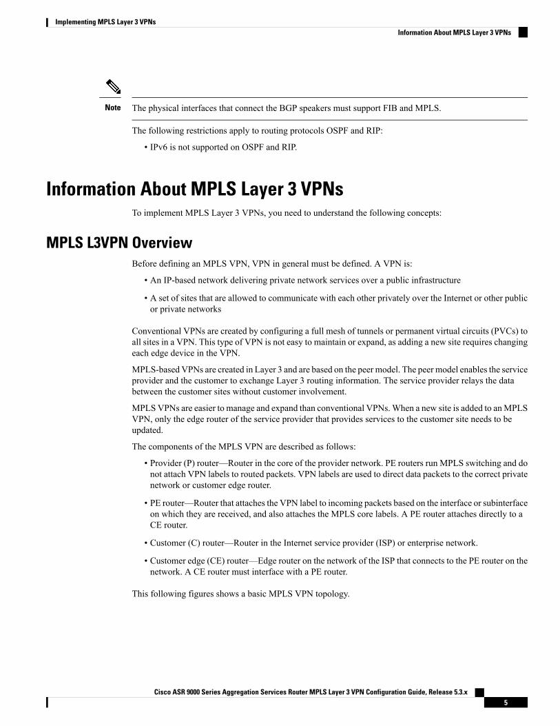
This following figures shows a basic MPLS VPN topology.
Cisco ASR 9000 Series Aggregation Services Router MPLS Layer 3 VPN Configuration Guide, Release 5.3.x5
Implementing MPLS Layer 3 VPNsInformation About MPLS Layer 3 VPNs
Figure 1: Basic MPLS VPN Topology
MPLS L3VPN BenefitsMPLS L3VPN provides the following benefits:
• Service providers can deploy scalable VPNs and deliver value-added services.
• Connectionless service guarantees that no prior action is necessary to establish communication betweenhosts.
• Centralized Service: Building VPNs in Layer 3 permits delivery of targeted services to a group of usersrepresented by a VPN.
• Scalability: Create scalable VPNs using connection-oriented, point-to-point overlays, Frame Relay, orATM virtual connections.
• Security: Security is provided at the edge of a provider network (ensuring that packets received from acustomer are placed on the correct VPN) and in the backbone.
• Integrated Quality of Service (QoS) support: QoS provides the ability to address predictable performanceand policy implementation and support for multiple levels of service in an MPLS VPN.
• StraightforwardMigration: Service providers can deploy VPN services using a straightforward migrationpath.
• Migration for the end customer is simplified. There is no requirement to support MPLS on the CE routerand no modifications are required for a customer intranet.
How MPLS L3VPN WorksMPLS VPN functionality is enabled at the edge of an MPLS network. The PE router performs the followingtasks:
• Exchanges routing updates with the CE router
• Translates the CE routing information into VPN version 4 (VPNv4) routes.
• Exchanges VPNv4 and VPNv6 routes with other PE routers through the Multiprotocol Border GatewayProtocol (MP-BGP)
Cisco ASR 9000 Series Aggregation Services Router MPLS Layer 3 VPN Configuration Guide, Release 5.3.x6
Implementing MPLS Layer 3 VPNsMPLS L3VPN Benefits
Virtual Routing and Forwarding TablesEach VPN is associated with one or more VPN routing and forwarding (VRF) instances. A VRF defines theVPN membership of a customer site attached to a PE router. A VRF consists of the following components:
• An IP version 4 (IPv4) unicast routing table
• A derived FIB table
• A set of interfaces that use the forwarding table
• A set of rules and routing protocol parameters that control the information that is included in the routingtable
These components are collectively called a VRF instance.
A one-to-one relationship does not necessarily exist between customer sites and VPNs. A site can be a memberof multiple VPNs. However, a site can associate with only one VRF. A VRF contains all the routes availableto the site from the VPNs of which it is a member.
Packet forwarding information is stored in the IP routing table and the FIB table for each VRF. A separateset of routing and FIB tables is maintained for each VRF. These tables prevent information from beingforwarded outside a VPN and also prevent packets that are outside a VPN from being forwarded to a routerwithin the VPN.
VPN Routing Information: DistributionThe distribution of VPN routing information is controlled through the use of VPN route target communities,implemented by BGP extended communities. VPN routing information is distributed as follows:
• When a VPN route that is learned from a CE router is injected into a BGP, a list of VPN route targetextended community attributes is associated with it. Typically, the list of route target community extendedvalues is set from an export list of route targets associated with the VRF fromwhich the route was learned.
• An import list of route target extended communities is associated with each VRF. The import list definesroute target extended community attributes that a route must have for the route to be imported into theVRF. For example, if the import list for a particular VRF includes route target extended communitiesA, B, and C, then any VPN route that carries any of those route target extended communities—A, B, orC—is imported into the VRF.
BGP Distribution of VPN Routing InformationA PE router can learn an IP prefix from the following sources:
• A CE router by static configuration
• An eBGP session with the CE router
• A Routing Information Protocol (RIP) exchange with the CE router
• Open Shortest Path First (OSPF), Enhanced Interior Gateway Routing Protocol (EIGRP), and RIP asInterior Gateway Protocols (IGPs)
The IP prefix is a member of the IPv4 address family. After the PE router learns the IP prefix, the PE convertsit into the VPN-IPv4 prefix by combining it with a 64-bit route distinguisher. The generated prefix is a memberof the VPN-IPv4 address family. It uniquely identifies the customer address, even if the customer site is using
Cisco ASR 9000 Series Aggregation Services Router MPLS Layer 3 VPN Configuration Guide, Release 5.3.x7
Implementing MPLS Layer 3 VPNsVirtual Routing and Forwarding Tables
globally nonunique (unregistered private) IP addresses. The route distinguisher used to generate the VPN-IPv4prefix is specified by the rd command associated with the VRF on the PE router.
BGP distributes reachability information for VPN-IPv4 prefixes for each VPN. BGP communication takesplace at two levels:
• Within the IP domain, known as an autonomous system.
• Between autonomous systems.
PE to PE or PE to route reflector (RR) sessions are iBGP sessions, and PE to CE sessions are eBGP sessions.PE to CE eBGP sessions can be directly or indirectly connected (eBGP multihop).
BGP propagates reachability information for VPN-IPv4 prefixes among PE routers by the BGP protocolextensions (see RFC 2283, Multiprotocol Extensions for BGP-4), which define support for address familiesother than IPv4. Using the extensions ensures that the routes for a given VPN are learned only by othermembers of that VPN, enabling members of the VPN to communicate with each other.
MPLS ForwardingBased on routing information stored in the VRF IP routing table and the VRF FIB table, packets are forwardedto their destination using MPLS.
A PE router binds a label to each customer prefix learned from a CE router and includes the label in thenetwork reachability information for the prefix that it advertises to other PE routers.When a PE router forwardsa packet received from a CE router across the provider network, it labels the packet with the label learnedfrom the destination PE router. When the destination PE router receives the labeled packet, it pops the labeland uses it to direct the packet to the correct CE router. Label forwarding across the provider backbone isbased on either dynamic label switching or traffic engineered paths. A customer data packet carries two levelsof labels when traversing the backbone:
• The top label directs the packet to the correct PE router.
• The second label indicates how that PE router should forward the packet to the CE router.
More labels can be stacked if other features are enabled. For example, if traffic engineering (TE) tunnels withfast reroute (FRR) are enabled, the total number of labels imposed in the PE is four (Layer 3 VPN, LabelDistribution Protocol (LDP), TE, and FRR).
Automatic Route Distinguisher AssignmentTo take advantage of iBGP load balancing, every network VRFmust be assigned a unique route distinguisher.VRF is require a route distinguisher for BGP to distinguish between potentially identical prefixes receivedfrom different VPNs.
With thousands of routers in a network each supporting multiple VRFs, configuration and management ofroute distinguishers across the network can present a problem. Cisco IOS XR software simplifies this processby assigning unique route distinguisher to VRFs using the rd auto command.
To assign a unique route distinguisher for each router, you must ensure that each router has a unique BGProuter-id. If so, the rd auto command assigns a Type 1 route distinguisher to the VRF using the followingformat: ip-address:number. The IP address is specified by the BGP router-id statement and the number (whichis derived as an unused index in the 0 to 65535 range) is unique across theVRFs.
Cisco ASR 9000 Series Aggregation Services Router MPLS Layer 3 VPN Configuration Guide, Release 5.3.x8
Implementing MPLS Layer 3 VPNsMPLS Forwarding
Finally, route distinguisher values are checkpointed so that route distinguisher assignment to VRF is persistentacross failover or process restart. If an route distinguisher is explicitely configured for a VRF, this value isnot overridden by the autoroute distinguisher.
MPLS L3VPN Major ComponentsAn MPLS-based VPN network has three major components:
• VPN route target communities—A VPN route target community is a list of all members of a VPNcommunity. VPN route targets need to be configured for each VPN community member.
• Multiprotocol BGP (MP-BGP) peering of the VPN community PE routers—MP-BGP propagates VRFreachability information to all members of a VPN community. MP-BGP peering needs to be configuredin all PE routers within a VPN community.
• MPLS forwarding—MPLS transports all traffic between all VPN community members across a VPNservice-provider network.
A one-to-one relationship does not necessarily exist between customer sites and VPNs. A given site can be amember of multiple VPNs. However, a site can associate with only one VRF. A customer-site VRF containsall the routes available to the site from the VPNs of which it is a member
Inter-AS Support for L3VPNThis section contains the following topics:
Inter-AS Support: OverviewAn autonomous system (AS) is a single network or group of networks that is controlled by a common systemadministration group and uses a single, clearly defined routing protocol.
As VPNs grow, their requirements expand. In some cases, VPNs need to reside on different autonomoussystems in different geographic areas. In addition, some VPNs need to extend across multiple service providers(overlapping VPNs). Regardless of the complexity and location of the VPNs, the connection betweenautonomous systems must be seamless.
An MPLS VPN Inter-AS provides the following benefits:
• Allows a VPN to cross more than one service provider backbone.
Service providers, running separate autonomous systems, can jointly offer MPLS VPN services to thesame end customer. A VPN can begin at one customer site and traverse different VPN service providerbackbones before arriving at another site of the same customer. Previously, MPLS VPN could traverseonly a single BGP autonomous system service provider backbone. This feature lets multiple autonomoussystems form a continuous, seamless network between customer sites of a service provider.
• Allows a VPN to exist in different areas.
A service provider can create a VPN in different geographic areas. Having all VPN traffic flow throughone point (between the areas) allows for better rate control of network traffic between the areas.
• Allows confederations to optimize iBGP meshing.
Cisco ASR 9000 Series Aggregation Services Router MPLS Layer 3 VPN Configuration Guide, Release 5.3.x9
Implementing MPLS Layer 3 VPNsMPLS L3VPN Major Components
Internal Border Gateway Protocol (iBGP) meshing in an autonomous system is more organized andmanageable. You can divide an autonomous system into multiple, separate subautonomous systems andthen classify them into a single confederation. This capability lets a service provider offer MPLS VPNsacross the confederation, as it supports the exchange of labeled VPN-IPv4 Network Layer ReachabilityInformation (NLRI) between the subautonomous systems that form the confederation.
Inter-AS and ASBRsSeparate autonomous systems from different service providers can communicate by exchanging IPv4 NLRIand IPv6 in the form of VPN-IPv4 addresses. The ASBRs use eBGP to exchange that information. Then anInterior Gateway Protocol (IGP) distributes the network layer information for VPN-IPV4 prefixes throughouteach VPN and each autonomous system. The following protocols are used for sharing routing information:
• Within an autonomous system, routing information is shared using an IGP.
• Between autonomous systems, routing information is shared using an eBGP. An eBGP lets serviceproviders set up an interdomain routing system that guarantees the loop-free exchange of routinginformation between separate autonomous systems.
The primary function of an eBGP is to exchange network reachability information between autonomoussystems, including information about the list of autonomous system routes. The autonomous systemsuse EBGP border edge routers to distribute the routes, which include label switching information. Eachborder edge router rewrites the next-hop and MPLS labels.
Inter-AS configurations supported in an MPLS VPN can include:
• Interprovider VPN—MPLS VPNs that include two or more autonomous systems, connected byseparate border edge routers. The autonomous systems exchange routes using eBGP. No IGP orrouting information is exchanged between the autonomous systems.
• BGP Confederations—MPLS VPNs that divide a single autonomous system into multiplesubautonomous systems and classify them as a single, designated confederation. The networkrecognizes the confederation as a single autonomous system. The peers in the different autonomoussystems communicate over eBGP sessions; however, they can exchange route information as if theywere iBGP peers.
ConfederationsA confederation is multiple subautonomous systems grouped together. A confederation reduces the totalnumber of peer devices in an autonomous system. A confederation divides an autonomous system intosubautonomous systems and assigns a confederation identifier to the autonomous systems. A VPN can spanservice providers running in separate autonomous systems or multiple subautonomous systems that form aconfederation.
In a confederation, each subautonomous system is fully meshed with other subautonomous systems. Thesubautonomous systems communicate using an IGP, such as Open Shortest Path First (OSPF) or IntermediateSystem-to-Intermediate System (IS-IS). Each subautonomous system also has an eBGP connection to theother subautonomous systems. The confederation eBGP (CEBGP) border edge routers forward next-hop-selfaddresses between the specified subautonomous systems. The next-hop-self address forces the BGP to use aspecified address as the next hop rather than letting the protocol choose the next hop.
You can configure a confederation with separate subautonomous systems two ways:
Cisco ASR 9000 Series Aggregation Services Router MPLS Layer 3 VPN Configuration Guide, Release 5.3.x10
Implementing MPLS Layer 3 VPNsInter-AS and ASBRs
• Configure a router to forward next-hop-self addresses between only the CEBGP border edge routers(both directions). The subautonomous systems (iBGP peers) at the subautonomous system border do notforward the next-hop-self address. Each subautonomous system runs as a single IGP domain. However,the CEBGP border edge router addresses are known in the IGP domains.
• Configure a router to forward next-hop-self addresses between the CEBGP border edge routers (bothdirections) and within the iBGP peers at the subautonomous system border. Each subautonomous systemruns as a single IGP domain but also forwards next-hop-self addresses between the PE routers in thedomain. The CEBGP border edge router addresses are known in the IGP domains.
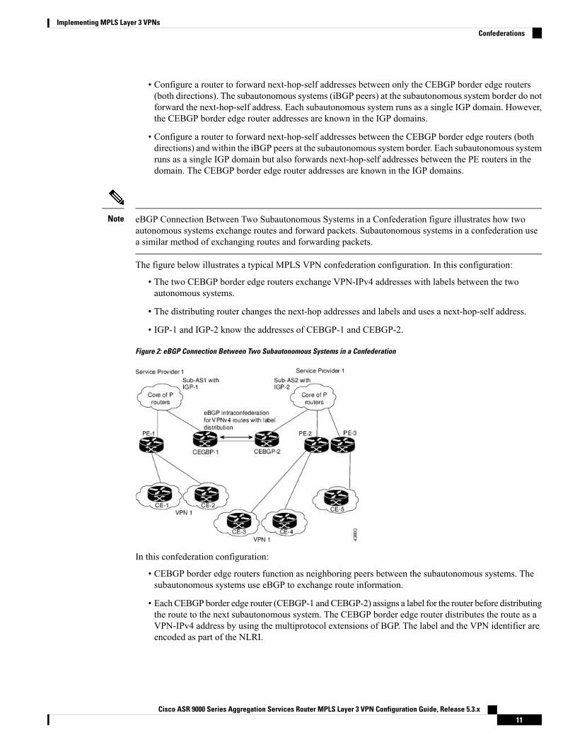
eBGP Connection Between Two Subautonomous Systems in a Confederation figure illustrates how twoautonomous systems exchange routes and forward packets. Subautonomous systems in a confederation usea similar method of exchanging routes and forwarding packets.
Note
The figure below illustrates a typical MPLS VPN confederation configuration. In this configuration:
• The two CEBGP border edge routers exchange VPN-IPv4 addresses with labels between the twoautonomous systems.
• The distributing router changes the next-hop addresses and labels and uses a next-hop-self address.
• IGP-1 and IGP-2 know the addresses of CEBGP-1 and CEBGP-2.
Figure 2: eBGP Connection Between Two Subautonomous Systems in a Confederation
In this confederation configuration:
• CEBGP border edge routers function as neighboring peers between the subautonomous systems. Thesubautonomous systems use eBGP to exchange route information.
• EachCEBGP border edge router (CEBGP-1 andCEBGP-2) assigns a label for the router before distributingthe route to the next subautonomous system. The CEBGP border edge router distributes the route as aVPN-IPv4 address by using the multiprotocol extensions of BGP. The label and the VPN identifier areencoded as part of the NLRI.
Cisco ASR 9000 Series Aggregation Services Router MPLS Layer 3 VPN Configuration Guide, Release 5.3.x11
Implementing MPLS Layer 3 VPNsConfederations
• Each PE and CEBGP border edge router assigns its own label to each VPN-IPv4 address prefix beforeredistributing the routes. The CEBGP border edge routers exchange IPV-IPv4 addresses with the labels.The next-hop-self address is included in the label (as the value of the eBGP next-hop attribute). Withinthe subautonomous systems, the CEBGP border edge router address is distributed throughout the iBGPneighbors, and the two CEBGP border edge routers are known to both confederations.
• For more information about how to configure confederations, see the .
MPLS VPN Inter-AS BGP Label Distribution
This section is not applicable to Inter-AS over IP tunnels.Note
You can set up the MPLS VPN Inter-AS network so that the ASBRs exchange IPv4 routes with MPLS labelsof the provider edge (PE) routers. Route reflectors (RRs) exchange VPN-IPv4 routes by using multihop,multiprotocol external Border Gateway Protocol (eBGP). This method of configuring the Inter-AS system isoften called MPLS VPN Inter-AS BGP Label Distribution.
Configuring the Inter-AS system so that the ASBRs exchange the IPv4 routes and MPLS labels has thefollowing benefits:
• Saves the ASBRs from having to store all the VPN-IPv4 routes. Using the route reflectors to store theVPN-IPv4 routes and forward them to the PE routers results in improved scalability compared withconfigurations in which the ASBR holds all the VPN-IPv4 routes and forwards the routes based onVPN-IPv4 labels.
• Having the route reflectors hold the VPN-IPv4 routes also simplifies the configuration at the border ofthe network.
• Enables a non-VPN core network to act as a transit network for VPN traffic. You can transport IPv4routes with MPLS labels over a non-MPLS VPN service provider.
• Eliminates the need for any other label distribution protocol between adjacent label switch routers (LSRs).If two adjacent LSRs are also BGP peers, BGP can handle the distribution of the MPLS labels. No otherlabel distribution protocol is needed between the two LSRs.
Exchanging IPv4 Routes with MPLS labels
This section is not applicable to Inter-AS over IP tunnels.Note
You can set up a VPN service provider network to exchange IPv4 routes withMPLS labels. You can configurethe VPN service provider network as follows:
• Route reflectors exchange VPN-IPv4 routes by using multihop, multiprotocol eBGP. This configurationalso preserves the next-hop information and the VPN labels across the autonomous systems.
• A local PE router (for example, PE1 in the figure below) needs to know the routes and label informationfor the remote PE router (PE2).
Cisco ASR 9000 Series Aggregation Services Router MPLS Layer 3 VPN Configuration Guide, Release 5.3.x12
Implementing MPLS Layer 3 VPNsMPLS VPN Inter-AS BGP Label Distribution
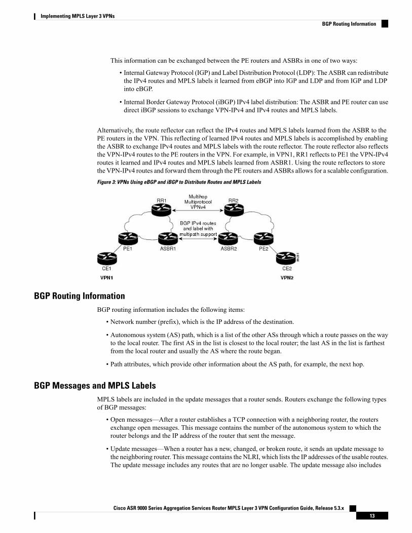
This information can be exchanged between the PE routers and ASBRs in one of two ways:
• Internal Gateway Protocol (IGP) and Label Distribution Protocol (LDP): The ASBR can redistributethe IPv4 routes and MPLS labels it learned from eBGP into IGP and LDP and from IGP and LDPinto eBGP.
• Internal Border Gateway Protocol (iBGP) IPv4 label distribution: The ASBR and PE router can usedirect iBGP sessions to exchange VPN-IPv4 and IPv4 routes and MPLS labels.
Alternatively, the route reflector can reflect the IPv4 routes and MPLS labels learned from the ASBR to thePE routers in the VPN. This reflecting of learned IPv4 routes and MPLS labels is accomplished by enablingthe ASBR to exchange IPv4 routes and MPLS labels with the route reflector. The route reflector also reflectsthe VPN-IPv4 routes to the PE routers in the VPN. For example, in VPN1, RR1 reflects to PE1 the VPN-IPv4routes it learned and IPv4 routes and MPLS labels learned from ASBR1. Using the route reflectors to storethe VPN-IPv4 routes and forward them through the PE routers and ASBRs allows for a scalable configuration.Figure 3: VPNs Using eBGP and iBGP to Distribute Routes and MPLS Labels
BGP Routing InformationBGP routing information includes the following items:
• Network number (prefix), which is the IP address of the destination.
• Autonomous system (AS) path, which is a list of the other ASs through which a route passes on the wayto the local router. The first AS in the list is closest to the local router; the last AS in the list is farthestfrom the local router and usually the AS where the route began.
• Path attributes, which provide other information about the AS path, for example, the next hop.
BGP Messages and MPLS LabelsMPLS labels are included in the update messages that a router sends. Routers exchange the following typesof BGP messages:
• Open messages—After a router establishes a TCP connection with a neighboring router, the routersexchange open messages. This message contains the number of the autonomous system to which therouter belongs and the IP address of the router that sent the message.
• Update messages—When a router has a new, changed, or broken route, it sends an update message tothe neighboring router. This message contains the NLRI, which lists the IP addresses of the usable routes.The update message includes any routes that are no longer usable. The update message also includes
Cisco ASR 9000 Series Aggregation Services Router MPLS Layer 3 VPN Configuration Guide, Release 5.3.x13
Implementing MPLS Layer 3 VPNsBGP Routing Information
path attributes and the lengths of both the usable and unusable paths. Labels for VPN-IPv4 routes areencoded in the update message, as specified in RFC 2858. The labels for the IPv4 routes are encoded inthe update message, as specified in RFC 3107.
• Keepalive messages—Routers exchange keepalive messages to determine if a neighboring router is stillavailable to exchange routing information. The router sends these messages at regular intervals. (Sixtyseconds is the default for Cisco routers.) The keepalive message does not contain routing data; it containsonly a message header.
• Notification messages—When a router detects an error, it sends a notification message.
Sending MPLS Labels with RoutesWhen BGP (eBGP and iBGP) distributes a route, it can also distribute an MPLS label that is mapped to thatroute. The MPLS label mapping information for the route is carried in the BGP update message that containsthe information about the route. If the next hop is not changed, the label is preserved.
When you issue the show bgp neighbors ip-address command on both BGP routers, the routers advertise toeach other that they can then send MPLS labels with the routes. If the routers successfully negotiate theirability to send MPLS labels, the routers add MPLS labels to all outgoing BGP updates.
Generic Routing Encapsulation Support for L3VPNGeneric Routing Encapsulation (GRE) is a tunneling protocol that can encapsulate many types of packets toenable data transmission using a tunnel. The GRE tunneling protocol enables:
• High assurance Internet Protocol encryptor (HAIPE) devices for encryption over the public Internet andnonsecure connections.
• Service providers (that do not run MPLS in their core network) to provide VPN services along with thesecurity services.
GRE is used with IP to create a virtual point-to-point link to routers at remote points in a network. For detailedinformation about configuring GRE tunnel interfaces, see the <module-name> module of the Cisco IOS XRInterfaces and Hardware Components Configuration Guide.
GRE is used with IP to create a virtual point-to-point link to routers at remote points in a network. For detailedinformation about configuring GRE tunnel interfaces, refer to the Cisco IOS XR Interfaces and HardwareComponents Configuration Guide. For a PE to PE (core) link, enable LDP (with implicit null) on the GREinterfaces for L3VPN.
Note
GRE Restriction for L3VPNThe following restrictions are applicable to L3VPN forwarding over GRE:
• Carrier Supporting Carrier (CsC) or Inter-AS is not supported.
• GRE-based L3VPN does not interwork with MPLS or IP VPNs.
• GRE tunnel is supported only as a core link(PE-PE, PE-P, P-P, P-PE). A PE-CE (edge) link is notsupported.
Cisco ASR 9000 Series Aggregation Services Router MPLS Layer 3 VPN Configuration Guide, Release 5.3.x14
Implementing MPLS Layer 3 VPNsSending MPLS Labels with Routes
• VPNv6 forwarding using GRE tunnels is not supported.
VPNv4 Forwarding Using GRE TunnelsThis section describes the working of VPNv4 forwarding over GRE tunnels. The following description assumesthat GRE is used only as a core link between the encapsulation and decapsulation provider edge (PE) routersthat are connected to one or more customer edge (CE) routers.
Ingress of Encapsulation RouterOn receiving prefixes from the CE routers, Border Gateway Protocol (BGP) assigns the VPN label to theprefixes that need to be exported. These VPN prefixes are then forwarded to the Forwarding Information Base(FIB) using the Route Information Base (RIB) or the label switched database (LSD). The FIB then populatesthe prefix in the appropriate VRF table. The FIB also populates the label in the global label table. Using BGP,the prefixes are then relayed to the remote PE router (decapsulation router).
Egress of Encapsulation RouterThe forwarding behavior on egress of the encapsulation PE router is similar to theMPLSVPN label imposition.Regardless of whether the VPN label imposition is performed on the ingress or egress side, the GRE tunnelforwards a packet that has an associated label. This labeled packet is then encapsulated with a GRE headerand forwarded based on the IP header.
Ingress of Decapsulation RouterThe decapsulation PE router learns the VPN prefixes and label information from the remote encapsulationPE router using BGP. The next-hop information for the VPN prefix is the address of the GRE tunnel interfaceconnecting the two PE routers. BGP downloads these prefixes to the RIB. The RIB downloads the routes tothe FIB and the FIB installs the routes in the hardware.
Egress of Decapsulation RouterThe egress forwarding behavior on the decapsulation PE router is similar to VPN disposition and forwarding,based on the protocol type of the inner payload.
Carrier Supporting Carrier Support for L3VPNThis section provides conceptual information aboutMPLSVPNCarrier Supporting Carrier (CSC) functionalityand includes the following topics:
• CSC Prerequisites• CSC Benefits• Configuration Options for the Backbone and Customer Carriers
Throughout this document, the following terminology is used in the context of CSC:
backbone carrier—Service provider that provides the segment of the backbone network to the other provider.A backbone carrier offers BGP and MPLS VPN services.
customer carrier—Service provider that uses the segment of the backbone network. The customer carriermay be an Internet service provider (ISP) or a BGP/MPLS VPN service provider.
Cisco ASR 9000 Series Aggregation Services Router MPLS Layer 3 VPN Configuration Guide, Release 5.3.x15
Implementing MPLS Layer 3 VPNsVPNv4 Forwarding Using GRE Tunnels
CE router—A customer edge router is part of a customer network and interfaces to a provider edge (PE)router. In this document, the CE router sits on the edge of the customer carrier network.
PE router—A provider edge router is part of a service provider's network connected to a customer edge (CE)router. In this document, the PE router sits on the edge of the backbone carrier network
ASBR—An autonomous system boundary router connects one autonomous system to another.
CSC PrerequisitesThe following prerequisites are required to configure CSC:
• You must be able to configure MPLS VPNs with end-to-end (CE-to-CE router) pings working.
• You must be able to configure Interior Gateway Protocols (IGPs), MPLS Label Distribution Protocol(LDP), and Multiprotocol Border Gateway Protocol (MP-BGP).
• You must ensure that CSC-PE and CSC-CE routers support BGP label distribution.
BGP is the only supported label distribution protocol on the link between CE and PE.Note
CSC BenefitsThis section describes the benefits of CSC to the backbone carrier and customer carriers.
Benefits to the Backbone Carrier
• The backbone carrier can accommodate many customer carriers and give them access to its backbone.
• The MPLS VPN carrier supporting carrier feature is scalable.
• The MPLS VPN carrier supporting carrier feature is a flexible solution.
Benefits to the Customer Carriers
• The MPLS VPN carrier supporting carrier feature removes from the customer carrier the burden ofconfiguring, operating, and maintaining its own backbone.
• Customer carriers who use the VPN services provided by the backbone carrier receive the same level ofsecurity that Frame Relay or ATM-based VPNs provide.
• Customer carriers can use any link layer technology to connect the CE routers to the PE routers .
• The customer carrier can use any addressing scheme and still be supported by a backbone carrier.
Benefits of Implementing MPLS VPN CSC Using BGP
The benefits of using BGP to distribute IPv4 routes and MPLS label routes are:
• BGP takes the place of an IGP and LDP in a VPN forwarding and routing instance (VRF) table.
• BGP is the preferred routing protocol for connecting two ISPs.
Cisco ASR 9000 Series Aggregation Services Router MPLS Layer 3 VPN Configuration Guide, Release 5.3.x16
Implementing MPLS Layer 3 VPNsCSC Prerequisites
Configuration Options for the Backbone and Customer CarriersTo enable CSC, the backbone and customer carriers must be configured accordingly:
• The backbone carrier must offer BGP and MPLS VPN services.
• The customer carrier can take several networking forms. The customer carrier can be:
• An ISP with an IP core (see the “Customer Carrier: ISP with IP Core”).
• An MPLS service provider with or without VPN services (see “Customer Carrier: MPLS ServiceProvider”).
An IGP in the customer carrier network is used to distribute next hops and loopbacks to the CSC-CE. IBGPwith label sessions are used in the customer carrier network to distribute next hops and loopbacks to theCSC-CE.
Note
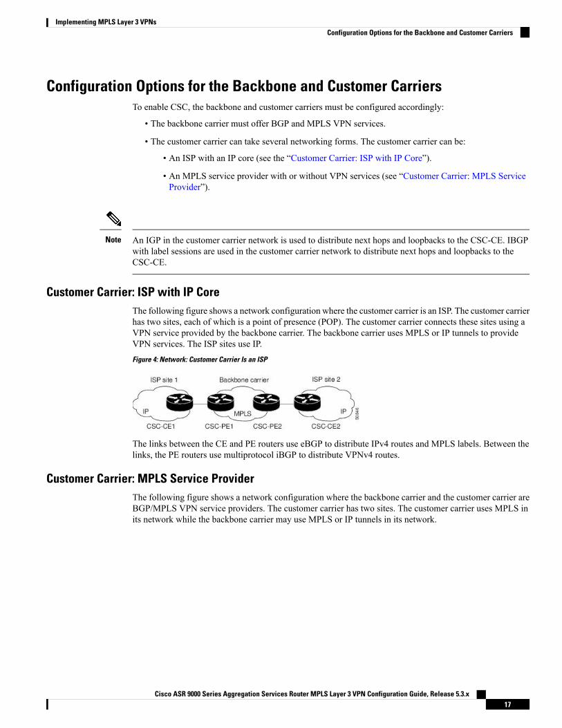
Customer Carrier: ISP with IP CoreThe following figure shows a network configuration where the customer carrier is an ISP. The customer carrierhas two sites, each of which is a point of presence (POP). The customer carrier connects these sites using aVPN service provided by the backbone carrier. The backbone carrier uses MPLS or IP tunnels to provideVPN services. The ISP sites use IP.Figure 4: Network: Customer Carrier Is an ISP
The links between the CE and PE routers use eBGP to distribute IPv4 routes and MPLS labels. Between thelinks, the PE routers use multiprotocol iBGP to distribute VPNv4 routes.
Customer Carrier: MPLS Service ProviderThe following figure shows a network configuration where the backbone carrier and the customer carrier areBGP/MPLS VPN service providers. The customer carrier has two sites. The customer carrier uses MPLS inits network while the backbone carrier may use MPLS or IP tunnels in its network.
Cisco ASR 9000 Series Aggregation Services Router MPLS Layer 3 VPN Configuration Guide, Release 5.3.x17
Implementing MPLS Layer 3 VPNsConfiguration Options for the Backbone and Customer Carriers
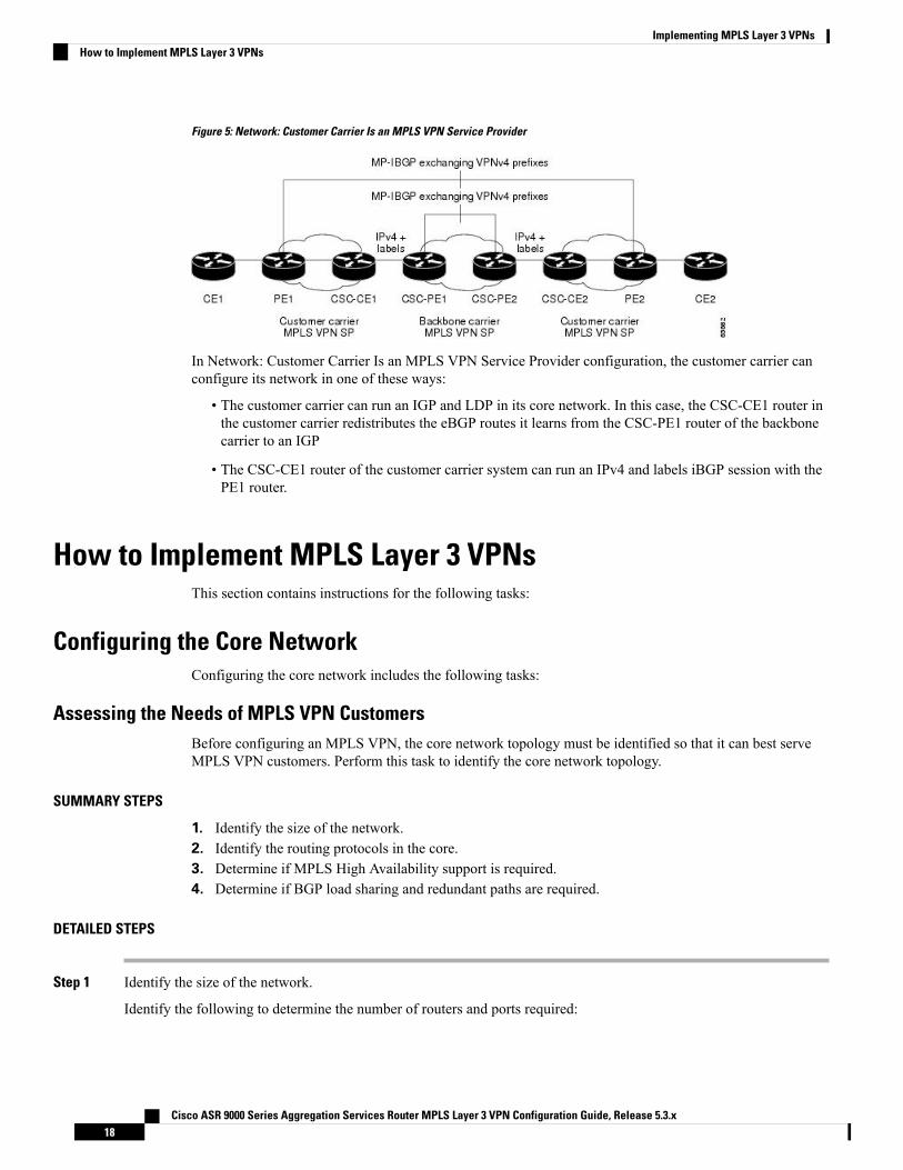
Figure 5: Network: Customer Carrier Is an MPLS VPN Service Provider
In Network: Customer Carrier Is an MPLS VPN Service Provider configuration, the customer carrier canconfigure its network in one of these ways:
• The customer carrier can run an IGP and LDP in its core network. In this case, the CSC-CE1 router inthe customer carrier redistributes the eBGP routes it learns from the CSC-PE1 router of the backbonecarrier to an IGP
• The CSC-CE1 router of the customer carrier system can run an IPv4 and labels iBGP session with thePE1 router.
How to Implement MPLS Layer 3 VPNsThis section contains instructions for the following tasks:
Configuring the Core NetworkConfiguring the core network includes the following tasks:
Assessing the Needs of MPLS VPN CustomersBefore configuring an MPLS VPN, the core network topology must be identified so that it can best serveMPLS VPN customers. Perform this task to identify the core network topology.
SUMMARY STEPS
1. Identify the size of the network.2. Identify the routing protocols in the core.3. Determine if MPLS High Availability support is required.4. Determine if BGP load sharing and redundant paths are required.
DETAILED STEPS
Step 1 Identify the size of the network.
Identify the following to determine the number of routers and ports required:
Cisco ASR 9000 Series Aggregation Services Router MPLS Layer 3 VPN Configuration Guide, Release 5.3.x18
Implementing MPLS Layer 3 VPNsHow to Implement MPLS Layer 3 VPNs
• How many customers will be supported?• How many VPNs are required for each customer?• How many virtual routing and forwarding (VRF) instances are there for each VPN?
Step 2 Identify the routing protocols in the core.
Determine which routing protocols are required in the core network.
Step 3 Determine if MPLS High Availability support is required.
MPLS VPN nonstop forwarding and graceful restart are supported on select routers and Cisco IOS XR software releases.
Step 4 Determine if BGP load sharing and redundant paths are required.
Determine if BGP load sharing and redundant paths in the MPLS VPN core are required.
Configuring Routing Protocols in the CoreTo configure a routing protocol, see the Cisco ASR 9000 Series Aggregation Services Router RoutingConfiguration Guide.
Configuring MPLS in the CoreTo enable MPLS on all routers in the core, you must configure a Label Distribution Protocol (LDP). You canuse either of the following as an LDP:
• MPLS LDP—See the Implementing MPLS Label Distribution Protocol chapter in the Cisco ASR 9000Series Aggregation Services Router MPLS Configuration Guide for configuration information.
• MPLS Traffic Engineering Resource Reservation Protocol (RSVP)—See Implementing RSVP forMPLS-TE module in the Cisco ASR 9000 Series Aggregation Services Router MPLS ConfigurationGuide for configuration information.
Determining if FIB Is Enabled in the CoreForwarding Information Base (FIB) must be enabled on all routers in the core, including the provider edge(PE) routers. For information on how to determine if FIB is enabled, see the Implementing Cisco ExpressForwarding module in the Cisco ASR 9000 Series Aggregation Services Router IP Addresses and ServicesConfiguration Guide.
Configuring Multiprotocol BGP on the PE Routers and Route ReflectorsPerform this task to configuremultiprotocol BGP (MP-BGP) connectivity on the PE routers and route reflectors.
SUMMARY STEPS
1. configure2. router bgp autonomous-system-number3. address-family vpnv4 unicast or address-family vpnv6 unicast4. neighbor ip-address remote-as autonomous-system-number5. address-family vpnv4 unicast or address-family vpnv6 unicast6. Use the commit or end command.
Cisco ASR 9000 Series Aggregation Services Router MPLS Layer 3 VPN Configuration Guide, Release 5.3.x19
Implementing MPLS Layer 3 VPNsConfiguring Routing Protocols in the Core
DETAILED STEPS
Step 1 configure
Example:
RP/0/RSP0/CPU0:router# configure
Enters the Global Configuration mode.
Step 2 router bgp autonomous-system-number
Example:
RP/0/RSP0/CPU0:router(config)# router bgp 120
Enters BGP configuration mode allowing you to configure the BGP routing process.
Step 3 address-family vpnv4 unicast or address-family vpnv6 unicast
Example:
RP/0/RSP0/CPU0:router(config-bgp)# address-family vpnv4 unicast
Enters VPNv4 or VPNv6 address family configuration mode for the VPNv4 or VPNv6 address family.
Step 4 neighbor ip-address remote-as autonomous-system-number
Example:
RP/0/RSP0/CPU0:router(config-bgp)# neighbor 172.168.40.24 remote-as 2002
Creates a neighbor and assigns it a remote autonomous system number.
Step 5 address-family vpnv4 unicast or address-family vpnv6 unicast
Example:
RP/0/RSP0/CPU0:router(config-bgp-nbr)# address-family vpnv4 unicast
Enters VPNv4 or VPNv6 address family configuration mode for the VPNv4 or VPNv6 address family.
Step 6 Use the commit or end command.
commit - Saves the configuration changes and remains within the configuration session.
end - Prompts user to take one of these actions:
• Yes - Saves configuration changes and exits the configuration session.• No - Exits the configuration session without committing the configuration changes.• Cancel - Remains in the configuration mode, without committing the configuration changes.
Cisco ASR 9000 Series Aggregation Services Router MPLS Layer 3 VPN Configuration Guide, Release 5.3.x20
Implementing MPLS Layer 3 VPNsConfiguring Multiprotocol BGP on the PE Routers and Route Reflectors
Connecting MPLS VPN CustomersTo connect MPLS VPN customers to the VPN, perform the following tasks:
Defining VRFs on the PE Routers to Enable Customer ConnectivityPerform this task to define VPN routing and forwarding (VRF) instances.
SUMMARY STEPS
1. configure2. vrf vrf-name3. address-family ipv4 unicast4. import route-policy policy-name5. import route-target [ as-number:nn | ip-address:nn ]6. export route-policy policy-name7. export route-target [ as-number:nn | ip-address:nn ]8. exit9. exit10. router bgp autonomous-system-number11. vrf vrf-name12. rd { as-number | ip-address | auto }13. Use the commit or end command.
DETAILED STEPS
Step 1 configure
Example:
RP/0/RSP0/CPU0:router# configure
Enters Global Configuration mode.
Step 2 vrf vrf-name
Example:
RP/0/RSP0/CPU0:router(config)# vrf vrf_1
Configures a VRF instance and enters VRF configuration mode.
Step 3 address-family ipv4 unicast
Example:
RP/0/RSP0/CPU0:router(config-vrf)# address-family ipv4 unicast
Enters VRF address family configuration mode for the IPv4 address family.
Step 4 import route-policy policy-name
Cisco ASR 9000 Series Aggregation Services Router MPLS Layer 3 VPN Configuration Guide, Release 5.3.x21
Implementing MPLS Layer 3 VPNsConnecting MPLS VPN Customers
Example:
RP/0/RSP0/CPU0:router(config-vrf-af)# import route-policy policy_A
Specifies a route policy that can be imported into the local VPN.
Step 5 import route-target [ as-number:nn | ip-address:nn ]
Example:
RP/0/RSP0/CPU0:router(config-vrf-af)# import route-target 120:1
Allows exported VPN routes to be imported into the VPN if one of the route targets of the exported route matches oneof the local VPN import route targets.
Step 6 export route-policy policy-name
Example:
RP/0/RSP0/CPU0:router(config-vrf-af)# export route-policy policy_B
Specifies a route policy that can be exported from the local VPN.
Step 7 export route-target [ as-number:nn | ip-address:nn ]
Example:
RP/0/RSP0/CPU0:router(config-vrf-af)# export route-target 120:2
Associates the local VPN with a route target. When the route is advertised to other provider edge (PE) routers, theexport route target is sent along with the route as an extended community.
Step 8 exit
Example:
RP/0/RSP0/CPU0:router(config-vrf-af)# exit
Exits VRF address family configuration mode and returns the router to VRF configuration mode.
Step 9 exit
Example:
RP/0/RSP0/CPU0:router(config-vrf)# exit
Exits VRF configuration mode and returns the router to Global Configuration mode.
Step 10 router bgp autonomous-system-number
Example:
RP/0/RSP0/CPU0:router(config)# router bgp 120
Cisco ASR 9000 Series Aggregation Services Router MPLS Layer 3 VPN Configuration Guide, Release 5.3.x22
Implementing MPLS Layer 3 VPNsDefining VRFs on the PE Routers to Enable Customer Connectivity
Enters BGP configuration mode allowing you to configure the BGP routing process.
Step 11 vrf vrf-name
Example:
RP/0/RSP0/CPU0:router(config-bgp)# vrf vrf_1
Configures a VRF instance and enters VRF configuration mode for BGP routing.
Step 12 rd { as-number | ip-address | auto }
Example:
RP/0/RSP0/CPU0:router(config-bgp-vrf)# rd auto
Automatically assigns a unique route distinguisher (RD) to vrf_1.
Step 13 Use the commit or end command.
commit - Saves the configuration changes and remains within the configuration session.
end - Prompts user to take one of these actions:
• Yes - Saves configuration changes and exits the configuration session.• No - Exits the configuration session without committing the configuration changes.• Cancel - Remains in the configuration mode, without committing the configuration changes.
Configuring VRF Interfaces on PE Routers for Each VPN CustomerPerform this task to associate a VPN routing and forwarding (VRF) instance with an interface or a subinterfaceon the PE routers.
Youmust remove IPv4/IPv6 addresses from an interface prior to assigning, removing, or changing an interface'sVRF. If this is not done in advance, any attempt to change the VRF on an IP interface is rejected.
Note
SUMMARY STEPS
1. configure2. interface type interface-path-id3. vrf vrf-name4. ipv4 address ipv4-address mask5. Use the commit or end command.
DETAILED STEPS
Step 1 configure
Cisco ASR 9000 Series Aggregation Services Router MPLS Layer 3 VPN Configuration Guide, Release 5.3.x23
Implementing MPLS Layer 3 VPNsConfiguring VRF Interfaces on PE Routers for Each VPN Customer
Example:
RP/0/RSP0/CPU0:router# configure
Enters Global Configuration mode.
Step 2 interface type interface-path-id
Example:
RP/0/RSP0/CPU0:router(config)# interface TenGigE 0/3/0/0
Enters interface configuration mode.
Step 3 vrf vrf-name
Example:
RP/0/RSP0/CPU0:router(config-if)# vrf vrf_A
Configures a VRF instance and enters VRF configuration mode.
Step 4 ipv4 address ipv4-address mask
Example:
RP/0/RSP0/CPU0:router(config-if)# ipv4 address 192.168.1.27 255.255.255.0
Configures a primary IPv4 address for the specified interface.
Step 5 Use the commit or end command.
commit - Saves the configuration changes and remains within the configuration session.
end - Prompts user to take one of these actions:
• Yes - Saves configuration changes and exits the configuration session.• No - Exits the configuration session without committing the configuration changes.• Cancel - Remains in the configuration mode, without committing the configuration changes.
Configuring BGP as the Routing Protocol Between the PE and CE RoutersPerform this task to configure PE-to-CE routing sessions using BGP.
SUMMARY STEPS
1. configure2. router bgp autonomous-system-number3. bgp router-id {ip-address}4. vrf vrf-name5. label-allocation-mode per-ce6. address-family ipv4 unicast
Cisco ASR 9000 Series Aggregation Services Router MPLS Layer 3 VPN Configuration Guide, Release 5.3.x24
Implementing MPLS Layer 3 VPNsConfiguring BGP as the Routing Protocol Between the PE and CE Routers
7. Do one of the following:
• redistribute connected [ metric metric-value ] [ route-policy route-policy-name ]• redistribute isis process-id [ level {1 | 1-inter-area | 2 } ] [metric metric-value][route-policy route-policy-name]
• redistribute ospf process-id [match { external [ 1 | 2 ] | internal | nssa-external [ 1 | 2 ] } ][ metric metric-value ] [route-policy route-policy-name ]
• redistribute static [metric metric-value ] [ route-policy route-policy-name ]
8. aggregate-address address/mask-length [as-set] [as-confed-set] [summary-only] [route-policyroute-policy-name]
9. network {ip-address/prefix-length | ip-address mask } [ route-policy route-policy-name]10. exit11. neighbor ip-address12. remote-as autonomous-system-number13. password { clear | encrypted } password14. ebgp-multihop [ ttl-value ]15. address-family ipv4 unicast16. allowas-in [as-occurrence-number ]17. route-policy route-policy-name in18. route-policy route-policy-name out19. Use the commit or end command.
DETAILED STEPS
Step 1 configure
Example:
RP/0/RSP0/CPU0:router# configure
Enters Global Configuration mode.
Step 2 router bgp autonomous-system-number
Example:
RP/0/RSP0/CPU0:router(config)# router bgp 120
Enters Border Gateway Protocol (BGP) configuration mode allowing you to configure the BGP routing process.
Step 3 bgp router-id {ip-address}
Example:
RP/0/RSP0/CPU0:router(config-bgp)# bgp router-id 192.168.70.24
Configures the local router with a router ID of 192.168.70.24.
Step 4 vrf vrf-name
Cisco ASR 9000 Series Aggregation Services Router MPLS Layer 3 VPN Configuration Guide, Release 5.3.x25
Implementing MPLS Layer 3 VPNsConfiguring BGP as the Routing Protocol Between the PE and CE Routers
Example:
RP/0/RSP0/CPU0:router(config-bgp)# vrf vrf_1
Configures a VPN routing and forwarding (VRF) instance and enters VRF configuration mode for BGP routing.
Step 5 label-allocation-mode per-ce
Example:
RP/0/RSP0/CPU0:router(config-bgp-vrf)# label-allocation-mode per-ce
Sets the MPLS VPN label allocation mode for each customer edge (CE) label mode allowing the provider edge (PE)router to allocate one label for every immediate next-hop.
Step 6 address-family ipv4 unicast
Example:
RP/0/RSP0/CPU0:router(config-bgp-vrf)# address-family ipv4 unicast
Enters VRF address family configuration mode for the IPv4 address family.
Step 7 Do one of the following:
• redistribute connected [ metric metric-value ] [ route-policy route-policy-name ]• redistribute isis process-id [ level {1 | 1-inter-area | 2 } ] [metric metric-value] [route-policyroute-policy-name]
• redistribute ospf process-id [match { external [ 1 | 2 ] | internal | nssa-external [ 1 | 2 ] } ] [ metricmetric-value ] [route-policy route-policy-name ]
• redistribute static [metric metric-value ] [ route-policy route-policy-name ]
Example:
RP/0/RSP0/CPU0:router(config-bgp-vrf-af)# redistribute connected
Causes routes to be redistributed into BGP. The routes that can be redistributed into BGP are:
• Connected• Intermediate System-to-Intermediate System (IS-IS)• Open Shortest Path First (OSPF)• Static
Step 8 aggregate-address address/mask-length [as-set] [as-confed-set] [summary-only] [route-policy route-policy-name]
Example:
RP/0/RSP0/CPU0:router(config-bgp-vrf-af)# aggregate-address 10.0.0.0/8 as-set
Creates an aggregate address. The path advertised for this route is an autonomous system set consisting of all elementscontained in all paths that are being summarized.
• The as-set keyword generates autonomous system set path information and community information from contributingpaths.
Cisco ASR 9000 Series Aggregation Services Router MPLS Layer 3 VPN Configuration Guide, Release 5.3.x26
Implementing MPLS Layer 3 VPNsConfiguring BGP as the Routing Protocol Between the PE and CE Routers
• The as-confed-set keyword generates autonomous system confederation set path information from contributingpaths.
• The summary-only keyword filters all more specific routes from updates.• The route-policy route-policy-name keyword and argument specify the route policy used to set the attributes ofthe aggregate route.
Step 9 network {ip-address/prefix-length | ip-address mask } [ route-policy route-policy-name]
Example:
RP/0/RSP0/CPU0:router(config-bgp-vrf-af)# network 172.20.0.0/16
Configures the local router to originate and advertise the specified network.
Step 10 exit
Example:
RP/0/RSP0/CPU0:router(config-bgp-vrf-af)# exit
Exits VRF address family configuration mode and returns the router to VRF configuration mode for BGP routing.
Step 11 neighbor ip-address
Example:
RP/0/RSP0/CPU0:router(config-bgp-vrf)# neighbor 172.168.40.24
Places the router in VRF neighbor configuration mode for BGP routing and configures the neighbor IP address172.168.40.24 as a BGP peer.
Step 12 remote-as autonomous-system-number
Example:
RP/0/RSP0/CPU0:router(config-bgp-vrf-nbr)# remote-as 2002
Creates a neighbor and assigns it a remote autonomous system number.
Step 13 password { clear | encrypted } password
Example:
RP/0/RSP0/CPU0:router(config-bgp-vrf-nbr)# password clear pswd123
Configures neighbor 172.168.40.24 to use MD5 authentication with the password pswd123.
Step 14 ebgp-multihop [ ttl-value ]
Example:
RP/0/RSP0/CPU0:router(config-bgp-vrf-nbr)# ebgp-multihop
Allows a BGP connection to neighbor 172.168.40.24.
Cisco ASR 9000 Series Aggregation Services Router MPLS Layer 3 VPN Configuration Guide, Release 5.3.x27
Implementing MPLS Layer 3 VPNsConfiguring BGP as the Routing Protocol Between the PE and CE Routers
Step 15 address-family ipv4 unicast
Example:
RP/0/RSP0/CPU0:router(config-bgp-vrf-nbr)# address-family ipv4 unicast
Enters VRF neighbor address family configuration mode for BGP routing.
Step 16 allowas-in [as-occurrence-number ]
Example:
RP/0/RSP0/CPU0:router(config-bgp-vrf-nbr-af)# allowas-in 3
Replaces the neighbor autonomous system number (ASN) with the PE ASN in the AS path three times.
Step 17 route-policy route-policy-name in
Example:
RP/0/RSP0/CPU0:router(config-bgp-vrf-nbr-af)# route-policy In-Ipv4 in
Applies the In-Ipv4 policy to inbound IPv4 unicast routes.
Step 18 route-policy route-policy-name out
Example:
RP/0/RSP0/CPU0:router(config-bgp-vrf-nbr-af)# route-policy In-Ipv4 in
Applies the In-Ipv4 policy to outbound IPv4 unicast routes.
Step 19 Use the commit or end command.
commit - Saves the configuration changes and remains within the configuration session.
end - Prompts user to take one of these actions:
• Yes - Saves configuration changes and exits the configuration session.• No - Exits the configuration session without committing the configuration changes.• Cancel - Remains in the configuration mode, without committing the configuration changes.
Configuring RIPv2 as the Routing Protocol Between the PE and CE RoutersPerform this task to configure provider edge (PE)-to-customer edge (CE) routing sessions using RoutingInformation Protocol version 2 (RIPv2).
SUMMARY STEPS
1. configure2. router rip3. vrf vrf-name
Cisco ASR 9000 Series Aggregation Services Router MPLS Layer 3 VPN Configuration Guide, Release 5.3.x28
Implementing MPLS Layer 3 VPNsConfiguring RIPv2 as the Routing Protocol Between the PE and CE Routers
4. interface type instance5. site-of-origin { as-number : number | ip-address : number }6. exit7. Do one of the following:
• redistribute bgp as-number [ [ external | internal | local ] [ route-policy name ]• redistribute connected [ route-policy name ]• redistribute isis process-id [ level-1 | level-1-2 | level-2 ] [ route-policy name ]• redistribute eigrp as-number [ route-policy name ]• redistribute ospf process-id [ match { external [ 1 | 2 ] | internal | nssa-external [ 1 | 2 ] } ] [route-policy name ]
• redistribute static [ route-policy name ]
8. Use the commit or end command.
DETAILED STEPS
Step 1 configure
Example:
RP/0/RSP0/CPU0:router# configure
Enters Global Configuration mode.
Step 2 router rip
Example:
RP/0/RSP0/CPU0:router(config)# router rip
Enters the Routing Information Protocol (RIP) configuration mode allowing you to configure the RIP routing process.
Step 3 vrf vrf-name
Example:
RP/0/RSP0/CPU0:router(config-rip)# vrf vrf_1
Configures a VPN routing and forwarding (VRF) instance and enters VRF configuration mode for RIP routing.
Step 4 interface type instance
Example:
RP/0/RSP0/CPU0:router(config-rip-vrf)# interface TenGigE 0/3/0/0
Enters VRF interface configuration mode.
Step 5 site-of-origin { as-number : number | ip-address : number }
Example:
Cisco ASR 9000 Series Aggregation Services Router MPLS Layer 3 VPN Configuration Guide, Release 5.3.x29
Implementing MPLS Layer 3 VPNsConfiguring RIPv2 as the Routing Protocol Between the PE and CE Routers
RP/0/RSP0/CPU0:router(config-rip-vrf-if)# site-of-origin 200:1
Identifies routes that have originated from a site so that the re-advertisement of that prefix back to the source site can beprevented. Uniquely identifies the site from which a PE router has learned a route.
Step 6 exit
Example:
RP/0/RSP0/CPU0:router(config-rip-vrf-if)# exit
Exits VRF interface configuration mode, and returns the router to VRF configuration mode for RIP routing.
Step 7 Do one of the following:
• redistribute bgp as-number [ [ external | internal | local ] [ route-policy name ]• redistribute connected [ route-policy name ]• redistribute isis process-id [ level-1 | level-1-2 | level-2 ] [ route-policy name ]• redistribute eigrp as-number [ route-policy name ]• redistribute ospf process-id [match { external [ 1 | 2 ] | internal | nssa-external [ 1 | 2 ] } ] [ route-policy name]
• redistribute static [ route-policy name ]
Example:
RP/0/RSP0/CPU0:router(config-rip-vrf)# redistribute connected
Causes routes to be redistributed into RIP. The routes that can be redistributed into RIP are:
• Border Gateway Protocol (BGP)• Connected• Enhanced Interior Gateway Routing Protocol (EIGRP)• Intermediate System-to-Intermediate System (IS-IS)• Open Shortest Path First (OSPF)• Static
Step 8 Use the commit or end command.
commit - Saves the configuration changes and remains within the configuration session.
end - Prompts user to take one of these actions:
• Yes - Saves configuration changes and exits the configuration session.• No - Exits the configuration session without committing the configuration changes.• Cancel - Remains in the configuration mode, without committing the configuration changes.
Configuring Static Routes Between the PE and CE RoutersPerform this task to configure provider edge (PE)-to-customer edge (CE) routing sessions that use static routes.
Cisco ASR 9000 Series Aggregation Services Router MPLS Layer 3 VPN Configuration Guide, Release 5.3.x30
Implementing MPLS Layer 3 VPNsConfiguring Static Routes Between the PE and CE Routers
Youmust remove IPv4/IPv6 addresses from an interface prior to assigning, removing, or changing an interface'sVRF. If this is not done in advance, any attempt to change the VRF on an IP interface is rejected.
Note
SUMMARY STEPS
1. configure2. router static3. vrf vrf-name4. address-family ipv4 unicast5. prefix/mask [ vrf vrf-name ] { ip-address | type interface-path-id }6. prefix/mask [vrf vrf-name] bfd fast-detect7. Use the commit or end command.
DETAILED STEPS
Step 1 configure
Example:
RP/0/RSP0/CPU0:router# configure
Enters Global Configuration mode.
Step 2 router static
Example:
RP/0/RSP0/CPU0:router(config)# router static
Enters static routing configuration mode allowing you to configure the static routing process.
Step 3 vrf vrf-name
Example:
RP/0/RSP0/CPU0:router(config-static)# vrf vrf_1
Configures a VPN routing and forwarding (VRF) instance and enters VRF configuration mode for static routing.
Step 4 address-family ipv4 unicast
Example:
RP/0/RSP0/CPU0:router(config-static-vrf)# address-family ipv4 unicast
Enters VRF address family configuration mode for the IPv4 address family.
Step 5 prefix/mask [ vrf vrf-name ] { ip-address | type interface-path-id }
Cisco ASR 9000 Series Aggregation Services Router MPLS Layer 3 VPN Configuration Guide, Release 5.3.x31
Implementing MPLS Layer 3 VPNsConfiguring Static Routes Between the PE and CE Routers
Example:
RP/0/RSP0/CPU0:router(config-static-vrf-afi)# 172.168.40.24/24 vrf vrf_1 10.1.1.1
Assigns the static route to vrf_1.
Step 6 prefix/mask [vrf vrf-name] bfd fast-detect
Example:
RP/0/RSP0/CPU0:router(config-static-vrf-afi)# 172.168.40.24/24 vrf vrf_1 bfd fast-detect
Enables bidirectional forwarding detection (BFD) to detect failures in the path between adjacent forwarding engines.
This option is available is when the forwarding router address is specified in Step 5 .
Step 7 Use the commit or end command.
commit - Saves the configuration changes and remains within the configuration session.
end - Prompts user to take one of these actions:
• Yes - Saves configuration changes and exits the configuration session.• No - Exits the configuration session without committing the configuration changes.• Cancel - Remains in the configuration mode, without committing the configuration changes.
Configuring OSPF as the Routing Protocol Between the PE and CE RoutersPerform this task to configure provider edge (PE)-to-customer edge (CE) routing sessions that use OpenShortest Path First (OSPF).
SUMMARY STEPS
1. configure2. router ospf process-name3. vrf vrf-name4. router-id {router-id | type interface-path-id}5. Do one of the following:
• redistribute bgp process-id [metricmetric-value] [metric-type {1 | 2}] [route-policy policy-name] [ tag tag-value]
• redistribute connected [metric metric-value] [metric-type {1 | 2}] [route-policy policy-name][tag tag-value]
• redistribute ospf process-id [match {external [1 | 2] | internal | nssa-external [1 | 2]}] [metricmetric-value] [metric-type {1 | 2}] [route-policy policy-name] [tag tag-value]
• redistribute static [metric metric-value] [metric-type {1 | 2}] [route-policy policy-name] [tagtag-value]
• redistribute eigrp process-id [match {external [1 | 2] | internal | nssa-external [1 | 2]]} [metricmetric-value] [metric-type {1 | 2}] [route-policy policy-name] [tag tag-value]
• redistribute rip [metric metric-value] [metric-type {1 | 2}] [route-policy policy-name] [tagtag-value]
Cisco ASR 9000 Series Aggregation Services Router MPLS Layer 3 VPN Configuration Guide, Release 5.3.x32
Implementing MPLS Layer 3 VPNsConfiguring OSPF as the Routing Protocol Between the PE and CE Routers
6. area area-id7. interface type interface-path-id8. Use the commit or end command.
DETAILED STEPS
Step 1 configure
Example:
RP/0/RSP0/CPU0:router# configure
Enters Global Configuration mode.
Step 2 router ospf process-name
Example:
RP/0/RSP0/CPU0:router(config)# router ospf 109
Enters OSPF configuration mode allowing you to configure the OSPF routing process.
Step 3 vrf vrf-name
Example:
RP/0/RSP0/CPU0:router(config-ospf)# vrf vrf_1
Configures a VPN routing and forwarding (VRF) instance and enters VRF configuration mode for OSPF routing.
Step 4 router-id {router-id | type interface-path-id}
Example:
RP/0/RSP0/CPU0:router(config-ospf-vrf)# router-id 172.20.10.10
Configures the router ID for the OSPF routing process.
Step 5 Do one of the following:
• redistribute bgp process-id [metricmetric-value] [metric-type {1 | 2}] [route-policy policy-name ] [ tag tag-value]• redistribute connected [metric metric-value] [metric-type {1 | 2}] [route-policy policy-name] [tag tag-value]• redistribute ospf process-id [match {external [1 | 2] | internal | nssa-external [1 | 2]}] [metric metric-value][metric-type {1 | 2}] [route-policy policy-name] [tag tag-value]
• redistribute static [metric metric-value] [metric-type {1 | 2}] [route-policy policy-name] [tag tag-value]• redistribute eigrp process-id [match {external [1 | 2] | internal | nssa-external [1 | 2]]} [metric metric-value][metric-type {1 | 2}] [route-policy policy-name] [tag tag-value]
• redistribute rip [metric metric-value] [metric-type {1 | 2}] [route-policy policy-name] [tag tag-value]
Example:
Cisco ASR 9000 Series Aggregation Services Router MPLS Layer 3 VPN Configuration Guide, Release 5.3.x33
Implementing MPLS Layer 3 VPNsConfiguring OSPF as the Routing Protocol Between the PE and CE Routers
RP/0/RSP0/CPU0:router(config-ospf-vrf)# redistribute connected
Causes routes to be redistributed into OSPF. The routes that can be redistributed into OSPF are:
• Border Gateway Protocol (BGP)• Connected• Enhanced Interior Gateway Routing Protocol (EIGRP)• OSPF• Static• Routing Information Protocol (RIP)
Step 6 area area-id
Example:
RP/0/RSP0/CPU0:router(config-ospf-vrf)# area 0
Configures the OSPF area as area 0.
Step 7 interface type interface-path-id
Example:
RP/0/RSP0/CPU0:router(config-ospf-vrf-ar)# interface TenGigE 0/3/0/0
Associates interface TenGigE 0/3/0/0 with area 0.
Step 8 Use the commit or end command.
commit - Saves the configuration changes and remains within the configuration session.
end - Prompts user to take one of these actions:
• Yes - Saves configuration changes and exits the configuration session.• No - Exits the configuration session without committing the configuration changes.• Cancel - Remains in the configuration mode, without committing the configuration changes.
Configuring EIGRP as the Routing Protocol Between the PE and CE RoutersPerform this task to configure provider edge (PE)-to-customer edge (CE) routing sessions that use EnhancedInterior Gateway Routing Protocol (EIGRP).
Using EIGRP between the PE and CE routers allows you to transparently connect EIGRP customer networksthrough anMPLS-enable Border Gateway Protocol (BGP) core network so that EIGRP routes are redistributedthrough the VPN across the BGP network as internal BGP (iBGP) routes.
Before you begin
BGP is configured in the network. See the Implementing BGP module in the Cisco ASR 9000 SeriesAggregation Services Router Routing Configuration Guide
Cisco ASR 9000 Series Aggregation Services Router MPLS Layer 3 VPN Configuration Guide, Release 5.3.x34
Implementing MPLS Layer 3 VPNsConfiguring EIGRP as the Routing Protocol Between the PE and CE Routers
Youmust remove IPv4/IPv6 addresses from an interface prior to assigning, removing, or changing an interface'sVRF. If this is not done in advance, any attempt to change the VRF on an IP interface is rejected.
Note
SUMMARY STEPS
1. configure2. router eigrp as-number3. vrf vrf-name4. address-family ipv45. router-id router-id6. autonomous-system as-number7. default-metric bandwidth delay reliability loading mtu8. redistribute { { bgp | connected | isis | ospf | rip | static } [ as-number | instance-name ] } [ route-policy
name ]9. interface type interface-path-id10. site-of-origin { as-number:number | ip-address : number }11. Use the commit or end command.
DETAILED STEPS
Step 1 configure
Example:
RP/0/RSP0/CPU0:router# configure
Enters Global Configuration mode.
Step 2 router eigrp as-number
Example:
RP/0/RSP0/CPU0:router(config)# router eigrp 24
Enters EIGRP configuration mode allowing you to configure the EIGRP routing process.
Step 3 vrf vrf-name
Example:
RP/0/RSP0/CPU0:router(config-eigrp)# vrf vrf_1
Configures a VPN routing and forwarding (VRF) instance and enters VRF configuration mode for EIGRP routing.
Step 4 address-family ipv4
Example:
Cisco ASR 9000 Series Aggregation Services Router MPLS Layer 3 VPN Configuration Guide, Release 5.3.x35
Implementing MPLS Layer 3 VPNsConfiguring EIGRP as the Routing Protocol Between the PE and CE Routers
RP/0/RSP0/CPU0:router(config-eigrp-vrf)# address family ipv4
Enters VRF address family configuration mode for the IPv4 address family.
Step 5 router-id router-id
Example:
RP/0/RSP0/CPU0:router(config-eigrp-vrf-af)# router-id 172.20.0.0
Configures the router ID for the Enhanced Interior Gateway Routing Protocol (EIGRP) routing process.
Step 6 autonomous-system as-number
Example:
RP/0/RSP0/CPU0:router(config-eigrp-vrf-af)# autonomous-system 6
Configures the EIGRP routing process to run within a VRF.
Step 7 default-metric bandwidth delay reliability loading mtu
Example:
RP/0/RSP0/CPU0:router(config-eigrp-vrf-af)# default-metric 100000 4000 200 45 4470
Sets the metrics for an EIGRP.
Step 8 redistribute { { bgp | connected | isis | ospf | rip | static } [ as-number | instance-name ] } [ route-policy name ]
Example:
RP/0/RSP0/CPU0:router(config-eigrp-vrf-af)# redistribute connected
Causes connected routes to be redistributed into EIGRP.
Step 9 interface type interface-path-id
Example:
RP/0/RSP0/CPU0:router(config-eigrp-vrf-af)# interface TenGigE 0/3/0/0
Associates interface TenGigE 0/3/0/0 with the EIGRP routing process.
Step 10 site-of-origin { as-number:number | ip-address : number }
Example:
RP/0/RSP0/CPU0:router(config-eigrp-vrf-af-if)# site-of-origin 201:1
Configures site of origin (SoO) on interface TenGigE 0/3/0/0.
Step 11 Use the commit or end command.
Cisco ASR 9000 Series Aggregation Services Router MPLS Layer 3 VPN Configuration Guide, Release 5.3.x36
Implementing MPLS Layer 3 VPNsConfiguring EIGRP as the Routing Protocol Between the PE and CE Routers
commit - Saves the configuration changes and remains within the configuration session.
end - Prompts user to take one of these actions:
• Yes - Saves configuration changes and exits the configuration session.• No - Exits the configuration session without committing the configuration changes.• Cancel - Remains in the configuration mode, without committing the configuration changes.
Configuring EIGRP Redistribution in the MPLS VPNPerform this task for every provider edge (PE) router that provides VPN services to enable Enhanced InteriorGateway Routing Protocol (EIGRP) redistribution in the MPLS VPN.
Before you begin
The metric can be configured in the route-policy configuring using the redistribute command (or configuredwith the default-metric command). If an external route is received from another EIGRP autonomous systemor a non-EIGRP network without a configured metric, the route is not installed in the EIGRP database. If anexternal route is received from another EIGRP autonomous system or a non-EIGRP network without aconfigured metric, the route is not advertised to the CE router. See the Implementing EIGRPmodule in theCisco ASR 9000 Series Aggregation Services Router Routing Configuration Guide.
Redistribution between native EIGRP VPN routing and forwarding (VRF) instances is not supported. Thisbehavior is designed.
Restriction
SUMMARY STEPS
1. configure2. router eigrp as-number3. vrf vrf-name4. address-family ipv45. redistribute bgp [as-number] [route-policy policy-name]6. Use the commit or end command.
DETAILED STEPS
Step 1 configure
Example:
RP/0/RSP0/CPU0:router# configure
Enters Global Configuration mode.
Step 2 router eigrp as-number
Example:
Cisco ASR 9000 Series Aggregation Services Router MPLS Layer 3 VPN Configuration Guide, Release 5.3.x37
Implementing MPLS Layer 3 VPNsConfiguring EIGRP Redistribution in the MPLS VPN
RP/0/RSP0/CPU0:router(config)# router eigrp 24
Enters EIGRP configuration mode allowing you to configure the EIGRP routing process.
Step 3 vrf vrf-name
Example:
RP/0/RSP0/CPU0:router(config-eigrp)# vrf vrf_1
Configures a VRF instance and enters VRF configuration mode for EIGRP routing.
Step 4 address-family ipv4
Example:
RP/0/RSP0/CPU0:router(config-eigrp-vrf)# address family ipv4
Enters VRF address family configuration mode for the IPv4 address family.
Step 5 redistribute bgp [as-number] [route-policy policy-name]
Example:
RP/0/RSP0/CPU0:router(config-eigrp-vrf-af)# redistribute bgp 24 route-policy policy_A
Causes Border Gateway Protocol (BGP) routes to be redistributed into EIGRP.
Step 6 Use the commit or end command.
commit - Saves the configuration changes and remains within the configuration session.
end - Prompts user to take one of these actions:
• Yes - Saves configuration changes and exits the configuration session.• No - Exits the configuration session without committing the configuration changes.• Cancel - Remains in the configuration mode, without committing the configuration changes.
Providing VPN Connectivity Across Multiple Autonomous Systems with MPLSVPN Inter-AS with ASBRs Exchanging IPv4 Routes and MPLS Labels
This section is not applicable to Inter-AS over IP tunnels.Note
This section contains instructions for the following tasks:
Cisco ASR 9000 Series Aggregation Services Router MPLS Layer 3 VPN Configuration Guide, Release 5.3.x38
Implementing MPLS Layer 3 VPNsProviding VPN Connectivity Across Multiple Autonomous Systems with MPLS VPN Inter-AS with ASBRs Exchanging IPv4 Routes and MPLS Labels
Configuring ASBRs to Exchange IPv4 Routes and MPLS LabelsPerform this task to configure the autonomous system boundary routers (ASBRs) to exchange IPv4 routesand MPLS labels.
SUMMARY STEPS
1. configure2. router bgp autonomous-system-number3. address-family ipv4 unicast4. allocate-label all5. neighbor ip-address6. remote-as autonomous-system-number7. address-family ipv4 labeled-unicast8. route-policy route-policy-name in9. route-policy route-policy-name out10. Use the commit or end command.
DETAILED STEPS
Step 1 configure
Example:
RP/0/RSP0/CPU0:router# configure
Enters Global Configuration mode.
Step 2 router bgp autonomous-system-number
Example:
RP/0/RSP0/CPU0:router(config)# router bgp 120RP/0/RSP0/CPU0:router(config-bgp)#
Enters Border Gateway Protocol (BGP) configuration mode allowing you to configure the BGP routing process.
Step 3 address-family ipv4 unicast
Example:
RP/0/RSP0/CPU0:router(config-bgp)# address-family ipv4 unicastRP/0/RSP0/CPU0:router(config-bgp-af)#
Enters global address family configuration mode for the IPv4 unicast address family.
Step 4 allocate-label all
Example:
RP/0/CPU0:router(config-bgp-af)# allocate-label all
Cisco ASR 9000 Series Aggregation Services Router MPLS Layer 3 VPN Configuration Guide, Release 5.3.x39
Implementing MPLS Layer 3 VPNsConfiguring ASBRs to Exchange IPv4 Routes and MPLS Labels
Allocates the MPLS labels for a specific IPv4 unicast or VPN routing and forwarding (VRF) IPv4 unicast routes sothat the BGP router can send labels with BGP routes to a neighboring router that is configured for a labeled-unicastsession.
Step 5 neighbor ip-address
Example:
RP/0/RSP0/CPU0:router(config-bgp-af)# neighbor 172.168.40.24
RP/0/RSP0/CPU0:router(config-bgp-nbr)#
Places the router in neighbor configuration mode for BGP routing and configures the neighbor IP address 172.168.40.24as a BGP peer.
Step 6 remote-as autonomous-system-number
Example:
RP/0/RSP0/CPU0:router(config-bgp-nbr)# remote-as 2002
Creates a neighbor and assigns it a remote autonomous system number.
Step 7 address-family ipv4 labeled-unicast
Example:
RP/0/RSP0/CPU0:router(config-bgp-nbr)# address-family ipv4 labeled-unicastRP/0/RSP0/CPU0:router(config-bgp-nbr-af)
Enters neighbor address family configuration mode for the IPv4 labeled-unicast address family.
Step 8 route-policy route-policy-name in
Example:
RP/0/RSP0/CPU0:router(config-bgp-nbr-af)# route-policy pass-all in
Applies a routing policy to updates that are received from a BGP neighbor.
• Use the route-policy-name argument to define the name of the of route policy. The example shows that the routepolicy name is defined as pass-all.
• Use the in keyword to define the policy for inbound routes.
Step 9 route-policy route-policy-name out
Example:
RP/0/RSP0/CPU0:router(config-bgp-nbr-af)# route-policy pass-all out
Applies a routing policy to updates that are sent to a BGP neighbor.
• Use the route-policy-name argument to define the name of the of route policy. The example shows that the routepolicy name is defined as pass-all.
• Use the out keyword to define the policy for outbound routes.
Cisco ASR 9000 Series Aggregation Services Router MPLS Layer 3 VPN Configuration Guide, Release 5.3.x40
Implementing MPLS Layer 3 VPNsConfiguring ASBRs to Exchange IPv4 Routes and MPLS Labels
Step 10 Use the commit or end command.
commit - Saves the configuration changes and remains within the configuration session.
end - Prompts user to take one of these actions:
• Yes - Saves configuration changes and exits the configuration session.• No - Exits the configuration session without committing the configuration changes.• Cancel - Remains in the configuration mode, without committing the configuration changes.
Configuring the Route Reflectors to Exchange VPN-IPv4 RoutesPerform this task to enable the route reflectors to exchange VPN-IPv4 routes by using multihop. This taskspecifies that the next-hop information and the VPN label are to be preserved across the autonomous system.
SUMMARY STEPS
1. configure2. router bgp autonomous-system-number3. neighbor ip-address4. remote-as autonomous-system-number5. ebgp-multihop [ttl-value]6. update-source type interface-path-id7. address-family vpnv4 unicast8. route-policy route-policy-name in9. route-policy route-policy-name out10. next-hop-unchanged11. Use the commit or end command.
DETAILED STEPS
Step 1 configure
Example:
RP/0/RSP0/CPU0:router# configure
Enters Global Configuration mode.
Step 2 router bgp autonomous-system-number
Example:
RP/0/RSP0/CPU0:router(config)# router bgp 120RP/0/RSP0/CPU0:router(config-bgp)#
Enters Border Gateway Protocol (BGP) configuration mode allowing you to configure the BGP routing process.
Step 3 neighbor ip-address
Example:
Cisco ASR 9000 Series Aggregation Services Router MPLS Layer 3 VPN Configuration Guide, Release 5.3.x41
Implementing MPLS Layer 3 VPNsConfiguring the Route Reflectors to Exchange VPN-IPv4 Routes
RP/0/RSP0/CPU0:router(config-bgp)# neighbor 172.168.40.24RP/0/RSP0/CPU0:router(config-bgp-nbr)#
Places the router in neighbor configuration mode for BGP routing and configures the neighbor IP address 172.168.40.24as a BGP peer.
Step 4 remote-as autonomous-system-number
Example:
RP/0/RSP0/CPU0:router(config-bgp-nbr)# remote-as 2002
Creates a neighbor and assigns it a remote autonomous system number.
Step 5 ebgp-multihop [ttl-value]
Example:
RP/0/RSP0/CPU0:router(config-bgp-nbr)# ebgp-multihop
Enables multihop peerings with external BGP neighbors.
Step 6 update-source type interface-path-id
Example:
RP/0/RSP0/CPU0:router(config-bgp-nbr)# update-source loopback0
Allows BGP sessions to use the primary IP address from a particular interface as the local address.
Step 7 address-family vpnv4 unicast
Example:
RP/0/RSP0/CPU0:router(config-bgp-nbr)# address-family vpnv4 unicastRP/0/RSP0/CPU0:router(config-bgp-nbr-af)#
Configures VPNv4 address family.
Step 8 route-policy route-policy-name in
Example:
RP/0/RSP0/CPU0:router(config-bgp-nbr-af)# route-policy pass-all in
Applies a routing policy to updates that are received from a BGP neighbor.
• Use the route-policy-name argument to define the name of the of route policy. The example shows that the routepolicy name is defined as pass-all.
• Use the in keyword to define the policy for inbound routes.
Step 9 route-policy route-policy-name out
Example:
Cisco ASR 9000 Series Aggregation Services Router MPLS Layer 3 VPN Configuration Guide, Release 5.3.x42
Implementing MPLS Layer 3 VPNsConfiguring the Route Reflectors to Exchange VPN-IPv4 Routes
RP/0/RSP0/CPU0:router(config-bgp-nbr-af)# route-policy pass-all out
Applies a routing policy to updates that are sent to a BGP neighbor.
• Use the route-policy-name argument to define the name of the of route policy. The example shows that the routepolicy name is defined as pass-all.
• Use the out keyword to define the policy for outbound routes.
Step 10 next-hop-unchanged
Example:
RP/0/RSP0/CPU0:router(config-bgp-nbr-af)# next-hop-unchanged
Disables overwriting of the next hop before advertising to external Border Gateway Protocol (eBGP) peers.
Step 11 Use the commit or end command.
commit - Saves the configuration changes and remains within the configuration session.
end - Prompts user to take one of these actions:
• Yes - Saves configuration changes and exits the configuration session.• No - Exits the configuration session without committing the configuration changes.• Cancel - Remains in the configuration mode, without committing the configuration changes.
Configuring the Route Reflector to Reflect Remote Routes in its ASPerform this task to enable the route reflector (RR) to reflect the IPv4 routes and labels learned by theautonomous system boundary router (ASBR) to the provider edge (PE) routers in the autonomous system.This task is accomplished by making the ASBR and PE route reflector clients of the RR.
SUMMARY STEPS
1. configure2. router bgp autonomous-system-number3. address-family ipv4 unicast4. allocate-label all5. neighbor ip-address6. remote-as autonomous-system-number7. update-source type interface-path-id8. address-family ipv4 labeled-unicast9. route-reflector-client10. neighbor ip-address11. remote-as autonomous-system-number12. update-source type interface-path-id13. address-family ipv4 labeled-unicast14. route-reflector-client15. Use the commit or end command.
Cisco ASR 9000 Series Aggregation Services Router MPLS Layer 3 VPN Configuration Guide, Release 5.3.x43
Implementing MPLS Layer 3 VPNsConfiguring the Route Reflector to Reflect Remote Routes in its AS
DETAILED STEPS
Step 1 configure
Example:
RP/0/RSP0/CPU0:router# configure
Enters Global Configuration mode.
Step 2 router bgp autonomous-system-number
Example:
RP/0/RSP0/CPU0:router(config)# router bgp 120
Enters Border Gateway Protocol (BGP) configuration mode allowing you to configure the BGP routing process.
Step 3 address-family ipv4 unicast
Example:
RP/0/RSP0/CPU0:router(config-bgp)# address-family ipv4 unicastRP/0/RSP0/CPU0:router(config-bgp-af)#
Enters global address family configuration mode for the IPv4 unicast address family.
Step 4 allocate-label all
Example:
RP/0/RSP0/CPU0:router(config-bgp-af)# allocate-label all
Allocates the MPLS labels for a specific IPv4 unicast or VPN routing and forwarding (VRF) IPv4 unicast routes sothat the BGP router can send labels with BGP routes to a neighboring router that is configured for a labeled-unicastsession.
Step 5 neighbor ip-address
Example:
RP/0/RSP0/CPU0:router(config-bgp-af)# neighbor 172.168.40.24RP/0/RSP0/CPU0:router(config-bgp-nbr)#
Places the router in neighbor configuration mode for BGP routing and configures the neighbor IP address 172.168.40.24as an ASBR eBGP peer.
Step 6 remote-as autonomous-system-number
Example:
RP/0/RSP0/CPU0:router(config-bgp-nbr)# remote-as 2002
Cisco ASR 9000 Series Aggregation Services Router MPLS Layer 3 VPN Configuration Guide, Release 5.3.x44
Implementing MPLS Layer 3 VPNsConfiguring the Route Reflector to Reflect Remote Routes in its AS
Creates a neighbor and assigns it a remote autonomous system number.
Step 7 update-source type interface-path-id
Example:
RP/0/RSP0/CPU0:router(config-bgp-nbr)# update-source loopback0
Allows BGP sessions to use the primary IP address from a particular interface as the local address.
Step 8 address-family ipv4 labeled-unicast
Example:
RP/0/RSP0/CPU0:router(config-bgp-nbr)# address-family ipv4 labeled-unicastRP/0/RSP0/CPU0:router(config-bgp-nbr-af)#
Enters neighbor address family configuration mode for the IPv4 labeled-unicast address family.
Step 9 route-reflector-client
Example:
RP/0/RSP0/CPU0:router(config-bgp-nbr-af)# route-reflector-client
Configures the router as a BGP route reflector and neighbor 172.168.40.24 as its client.
Step 10 neighbor ip-address
Example:
RP/0/RSP0/CPU0:router(config-bgp-nbr-af)# neighbor 10.40.25.2RP/0/RSP0/CPU0:router(config-bgp-nbr)#
Places the router in neighbor configuration mode for BGP routing and configures the neighbor IP address .40.25.2 asan VPNv4 iBGP peer.
Step 11 remote-as autonomous-system-number
Example:
RP/0/RSP0/CPU0:router(config-bgp-nbr)# remote-as 2002
Creates a neighbor and assigns it a remote autonomous system number.
Step 12 update-source type interface-path-id
Example:
RP/0/RSP0/CPU0:router(config-bgp-nbr)# update-source loopback0
Allows BGP sessions to use the primary IP address from a particular interface as the local address.
Step 13 address-family ipv4 labeled-unicast
Cisco ASR 9000 Series Aggregation Services Router MPLS Layer 3 VPN Configuration Guide, Release 5.3.x45
Implementing MPLS Layer 3 VPNsConfiguring the Route Reflector to Reflect Remote Routes in its AS
Example:
RP/0/RSP0/CPU0:router(config-bgp-nbr)# address-family ipv4 labeled-unicastRP/0/RSP0/CPU0:router(config-bgp-nbr-af)#
Enters neighbor address family configuration mode for the IPv4 labeled-unicast address family.
Step 14 route-reflector-client
Example:
RP/0/RSP0/CPU0:router(config-bgp-nbr-af)# route-reflector-client
Configures the neighbor as a route reflector client.
Step 15 Use the commit or end command.
commit - Saves the configuration changes and remains within the configuration session.
end - Prompts user to take one of these actions:
• Yes - Saves configuration changes and exits the configuration session.• No - Exits the configuration session without committing the configuration changes.• Cancel - Remains in the configuration mode, without committing the configuration changes.
Providing VPN Connectivity Across Multiple Autonomous Systems with MPLSVPN Inter-AS with ASBRs Exchanging VPN-IPv4 Addresses
This section contains instructions for the following tasks:
Configuring the ASBRs to Exchange VPN-IPv4 Addresses for IP TunnelsPerform this task to configure an external Border Gateway Protocol (eBGP) autonomous system boundaryrouter (ASBR) to exchange VPN-IPv4 routes with another autonomous system.
SUMMARY STEPS
1. configure2. router bgp autonomous-system-number3. address-family { ipv4 tunnel }4. address-family { vpnv4 unicast }5. neighbor ip-address6. remote-as autonomous-system-number7. address-family { vpnv4 unicast }8. route-policy route-policy-name { in }9. route-policy route-policy-name { out }10. neighbor ip-address11. remote-as autonomous-system-number12. update-source type interface-path-id
Cisco ASR 9000 Series Aggregation Services Router MPLS Layer 3 VPN Configuration Guide, Release 5.3.x46
Implementing MPLS Layer 3 VPNsProviding VPN Connectivity Across Multiple Autonomous Systems with MPLS VPN Inter-AS with ASBRs Exchanging VPN-IPv4 Addresses
13. address-family { ipv4 tunnel }14. address-family { vpnv4 unicast }15. Use the commit or end command.
DETAILED STEPS
Step 1 configure
Example:RP/0/RSP0/CPU0:router# configure
Enters the Global Configuration mode.
Step 2 router bgp autonomous-system-number
Example:RP/0/RSP0/CPU0:router(config)# router bgp 120RP/0/RSP0/CPU0:router(config-bgp)#
Enters Border Gateway Protocol (BGP) configuration mode allowing you to configure the BGP routing process.
Step 3 address-family { ipv4 tunnel }
Example:RP/0/RSP0/CPU0:router(config-bgp)# address-family ipv4 tunnelRP/0/RSP0/CPU0:router(config-bgp-af)#
Configures IPv4 tunnel address family.
Step 4 address-family { vpnv4 unicast }
Example:RP/0/RSP0/CPU0:router(config-bgp-af)# address-family vpnv4 unicast
Configures VPNv4 address family.
Step 5 neighbor ip-address
Example:RP/0/RSP0/CPU0:router(config-bgp-af)# neighbor 172.168.40.24RP/0/RSP0/CPU0:router(config-bgp-nbr)#
Places the router in neighbor configuration mode for BGP routing and configures the neighbor IP address 172.168.40.24as an ASBR eBGP peer.
Step 6 remote-as autonomous-system-number
Example:RP/0/RSP0/CPU0:router(config-bgp-nbr)# remote-as 2002
Creates a neighbor and assigns it a remote autonomous system number.
Step 7 address-family { vpnv4 unicast }
Cisco ASR 9000 Series Aggregation Services Router MPLS Layer 3 VPN Configuration Guide, Release 5.3.x47
Implementing MPLS Layer 3 VPNsConfiguring the ASBRs to Exchange VPN-IPv4 Addresses for IP Tunnels
Example:RP/0/RSP0/CPU0:router(config-bgp-nbr)# address-family vpnv4 unicastRP/0/RSP0/CPU0:router(config-bgp-nbr-af)#
Configures VPNv4 address family.
Step 8 route-policy route-policy-name { in }
Example:RP/0/RSP0/CPU0:router(config-bgp-nbr-af)# route-policy pass-all in
Applies a routing policy to updates that are received from a BGP neighbor.
• Use the route-policy-name argument to define the name of the of route policy. The example shows that the routepolicy name is defined as pass-all.
• Use the in keyword to define the policy for inbound routes.
Step 9 route-policy route-policy-name { out }
Example:RP/0/RSP0/CPU0:router(config-bgp-nbr-af)# route-policy pass-all out
Applies a routing policy to updates that are sent from a BGP neighbor.
• Use the route-policy-name argument to define the name of the route policy. The example shows that the routepolicy name is defined as pass-all.
• Use the out keyword to define the policy for outbound routes.
Step 10 neighbor ip-address
Example:RP/0/RSP0/CPU0:router(config-bgp-nbr-af)# neighbor 175.40.25.2RP/0/RSP0/CPU0:router(config-bgp-nbr)#
Places the router in neighbor configuration mode for BGP routing and configures the neighbor IP address 175.40.25.2as an VPNv4 iBGP peer.
Step 11 remote-as autonomous-system-number
Example:RP/0/RSP0/CPU0:router(config-bgp-nbr)# remote-as 2002
Creates a neighbor and assigns it a remote autonomous system number.
Step 12 update-source type interface-path-id
Example:RP/0/RSP0/CPU0:router(config-bgp-nbr)# update-source loopback0
Allows BGP sessions to use the primary IP address from a particular interface as the local address.
Step 13 address-family { ipv4 tunnel }
Example:
Cisco ASR 9000 Series Aggregation Services Router MPLS Layer 3 VPN Configuration Guide, Release 5.3.x48
Implementing MPLS Layer 3 VPNsConfiguring the ASBRs to Exchange VPN-IPv4 Addresses for IP Tunnels

RP/0/RSP0/CPU0:router(config-bgp-nbr)# address-family ipv4 tunnelRP/0/RSP0/CPU0:router(config-bgp-nbr-af)#
Configures IPv4 tunnel address family.
Step 14 address-family { vpnv4 unicast }
Example:RP/0/RSP0/CPU0:router(config-bgp-nbr-af)# address-family vpnv4 unicast
Configures VPNv4 address family.
Step 15 Use the commit or end command.
commit - Saves the configuration changes and remains within the configuration session.
end - Prompts user to take one of these actions:
• Yes - Saves configuration changes and exits the configuration session.• No - Exits the configuration session without committing the configuration changes.• Cancel - Remains in the configuration mode, without committing the configuration changes.
Configuring a Static Route to an ASBR PeerPerform this task to configure a static route to an ASBR peer.
SUMMARY STEPS
1. configure2. router static3. address-family ipv4 unicast4. A.B.C.D/length next-hop5. Use the commit or end command.
DETAILED STEPS
Step 1 configure
Example:RP/0/RSP0/CPU0:router# configure
Enters the Global Configuration mode.
Step 2 router static
Example:
RP/0/RSP0/CPU0:router(config)# router staticRP/0/RSP0/CPU0:router(config-static)#
Enters router static configuration mode.
Cisco ASR 9000 Series Aggregation Services Router MPLS Layer 3 VPN Configuration Guide, Release 5.3.x49
Implementing MPLS Layer 3 VPNsConfiguring a Static Route to an ASBR Peer
Step 3 address-family ipv4 unicast
Example:
RP/0/RSP0/CPU0:router(config-static)# address-family ipv4 unicastRP/0/RSP0/CPU0:router(config-static-afi)#
Enables an IPv4 address family.
Step 4 A.B.C.D/length next-hop
Example:
RP/0/RSP0/CPU0:router(config-static-afi)# 10.10.10.10/32 10.9.9.9
Enters the address of the destination router (including IPv4 subnet mask).
Step 5 Use the commit or end command.
commit - Saves the configuration changes and remains within the configuration session.
end - Prompts user to take one of these actions:
• Yes - Saves configuration changes and exits the configuration session.• No - Exits the configuration session without committing the configuration changes.• Cancel - Remains in the configuration mode, without committing the configuration changes.
Configuring EBGP Routing to Exchange VPN Routes Between Subautonomous Systems in aConfederation
Perform this task to configure external Border Gateway Protocol (eBGP) routing to exchange VPN routesbetween subautonomous systems in a confederation.
To ensure that host routes for VPN-IPv4 eBGP neighbors are propagated (by means of the Interior GatewayProtocol [IGP]) to other routers and PE routers, specify the redistribute connected command in the IGPconfiguration portion of the confederation eBGP (CEBGP) router. If you are using Open Shortest Path First(OSPF), make sure that the OSPF process is not enabled on the CEBGP interface in which the “redistributeconnected” subnet exists.
Note
SUMMARY STEPS
1. configure2. router bgp autonomous-system-number3. bgp confederation peers peer autonomous-system-number4. bgp confederation identifier autonomous-system-number5. address-family vpnv4 unicast6. neighbor ip-address7. remote-as autonomous-system-number
Cisco ASR 9000 Series Aggregation Services Router MPLS Layer 3 VPN Configuration Guide, Release 5.3.x50
Implementing MPLS Layer 3 VPNsConfiguring EBGP Routing to Exchange VPN Routes Between Subautonomous Systems in a Confederation
8. address-family vpnv4 unicast9. route-policy route-policy-name in10. route-policy route-policy-name out11. next-hop-self12. Use the commit or end command.
DETAILED STEPS
Step 1 configure
Example:
RP/0/RSP0/CPU0:router# configure
Enters Global Configuration mode.
Step 2 router bgp autonomous-system-number
Example:
RP/0/RSP0/CPU0:router(config)# router bgp 120RP/0/RSP0/CPU0:router(config-bgp)#
Enters BGP configuration mode allowing you to configure the BGP routing process.
Step 3 bgp confederation peers peer autonomous-system-number
Example:
RP/0/RSP0/CPU0:router(config-bgp)# bgp confederation peers 8
Configures the peer autonomous system number that belongs to the confederation.
Step 4 bgp confederation identifier autonomous-system-number
Example:
RP/0/RSP0/CPU0:router(config-bgp)# bgp confederation identifier 5
Specifies the autonomous system number for the confederation ID.
Step 5 address-family vpnv4 unicast
Example:
RP/0/RSP0/CPU0:router(config-bgp)# address-family vpnv4 unicastRP/0/RSP0/CPU0:router(config-bgp-af)#
Configures VPNv4 address family.
Step 6 neighbor ip-address
Example:
Cisco ASR 9000 Series Aggregation Services Router MPLS Layer 3 VPN Configuration Guide, Release 5.3.x51
Implementing MPLS Layer 3 VPNsConfiguring EBGP Routing to Exchange VPN Routes Between Subautonomous Systems in a Confederation
RP/0/RSP0/CPU0:router(config-bgp-af)# neighbor 10.168.40.24RP/0/RSP0/CPU0:router(config-bgp-nbr)#
Places the router in neighbor configuration mode for BGP routing and configures the neighbor IP address 10.168.40.24as a BGP peer.
Step 7 remote-as autonomous-system-number
Example:
RP/0/RSP0/CPU0:router(config-bgp-nbr)# remote-as 2002
Creates a neighbor and assigns it a remote autonomous system number.
Step 8 address-family vpnv4 unicast
Example:
RP/0/RSP0/CPU0:router(config-bgp-nbr)# address-family vpnv4 unicastRP/0/RSP0/CPU0:router(config-bgp-nbr-af)#
Configures VPNv4 address family.
Step 9 route-policy route-policy-name in
Example:
RP/0/RSP0/CPU0:router(config-bgp-nbr-af)# route-policy In-Ipv4 in
Applies a routing policy to updates received from a BGP neighbor.
Step 10 route-policy route-policy-name out
Example:
RP/0/RSP0/CPU0:router(config-bgp-nbr-af)# route-policy Out-Ipv4 out
Applies a routing policy to updates advertised to a BGP neighbor.
Step 11 next-hop-self
Example:
RP/0/RSP0/CPU0:router(config-bgp-nbr-af)# next-hop-self
Disables next-hop calculation and let you insert your own address in the next-hop field of BGP updates.
Step 12 Use the commit or end command.
commit - Saves the configuration changes and remains within the configuration session.
end - Prompts user to take one of these actions:
• Yes - Saves configuration changes and exits the configuration session.
Cisco ASR 9000 Series Aggregation Services Router MPLS Layer 3 VPN Configuration Guide, Release 5.3.x52
Implementing MPLS Layer 3 VPNsConfiguring EBGP Routing to Exchange VPN Routes Between Subautonomous Systems in a Confederation
• No - Exits the configuration session without committing the configuration changes.• Cancel - Remains in the configuration mode, without committing the configuration changes.
Configuring MPLS Forwarding for ASBR ConfederationsPerform this task to configure MPLS forwarding for autonomous system boundary router (ASBR)confederations (in BGP) on a specified interface.
This configuration adds the implicit NULL rewrite corresponding to the peer associated with the interface,which is required to prevent BGP from automatically installing rewrites by LDP (in multihop instances).
Note
SUMMARY STEPS
1. configure2. router bgp as-number3. mpls activate4. interface type interface-path-id5. Use the commit or end command.
DETAILED STEPS
Step 1 configure
Example:
RP/0/RSP0/CPU0:router# configure
Enters Global Configuration mode.
Step 2 router bgp as-number
Example:
RP/0/RSP0/CPU0:router(config)# router bgp 120RP/0/RSP0/CPU0:router(config-bgp)
Enters BGP configuration mode allowing you to configure the BGP routing process.
Step 3 mpls activate
Example:
RP/0/RSP0/CPU0:router(config-bgp)# mpls activateRP/0/RSP0/CPU0:router(config-bgp-mpls)#
Enters BGP MPLS activate configuration mode.
Cisco ASR 9000 Series Aggregation Services Router MPLS Layer 3 VPN Configuration Guide, Release 5.3.x53
Implementing MPLS Layer 3 VPNsConfiguring MPLS Forwarding for ASBR Confederations
Step 4 interface type interface-path-id
Example:
RP/0/RSP0/CPU0:router(config-bgp-mpls)# interface GigabitEthernet 0/3/0/0
Enables MPLS on the interface.
Step 5 Use the commit or end command.
commit - Saves the configuration changes and remains within the configuration session.
end - Prompts user to take one of these actions:
• Yes - Saves configuration changes and exits the configuration session.• No - Exits the configuration session without committing the configuration changes.• Cancel - Remains in the configuration mode, without committing the configuration changes.
Configuring a Static Route to an ASBR Confederation PeerPerform this task to configure a static route to an Inter-AS confederation peer. For more detailed information,see “Configuring a Static Route to a Peer" section.
SUMMARY STEPS
1. configure2. router static3. address-family ipv4 unicast4. A.B.C.D/length next-hop5. Use the commit or end command.
DETAILED STEPS
Step 1 configure
Example:
RP/0/RSP0/CPU0:router# configure
Enters Global Configuration mode.
Step 2 router static
Example:
RP/0/RSP0/CPU0:router(config)# router staticRP/0/RSP0/CPU0:router(config-static)#
Enters router static configuration mode.
Step 3 address-family ipv4 unicast
Cisco ASR 9000 Series Aggregation Services Router MPLS Layer 3 VPN Configuration Guide, Release 5.3.x54
Implementing MPLS Layer 3 VPNsConfiguring a Static Route to an ASBR Confederation Peer
Example:
RP/0/RSP0/CPU0:router(config-static)# address-family ipv4 unicastRP/0/RSP0/CPU0:router(config-static-afi)#
Enables an IPv4 address family.
Step 4 A.B.C.D/length next-hop
Example:
RP/0/RSP0/CPU0:router(config-static-afi)# 10.10.10.10/32 10.9.9.9
Enters the address of the destination router (including IPv4 subnet mask).
Step 5 Use the commit or end command.
commit - Saves the configuration changes and remains within the configuration session.
end - Prompts user to take one of these actions:
• Yes - Saves configuration changes and exits the configuration session.• No - Exits the configuration session without committing the configuration changes.• Cancel - Remains in the configuration mode, without committing the configuration changes.
Configuring Carrier Supporting CarrierPerform the tasks in this section to configure Carrier Supporting Carrier (CSC):
Identifying the Carrier Supporting Carrier TopologyBefore you configure the MPLS VPN CSC with BGP, you must identify both the backbone and customercarrier topology.
You can connect multiple CSC-CE routers to the same PE, or you can connect a single CSC-CE router tomultiple CSC-PEs using more than one CSC-CE interface to provide redundancy and multiple path supportin a CSC topology.
Note
Perform this task to identify the carrier supporting carrier topology.
SUMMARY STEPS
1. Identify the type of customer carrier, ISP, or MPLS VPN service provider.2. Identify the CE routers.3. Identify the customer carrier core router configuration.4. Identify the customer carrier edge (CSC-CE) routers.5. Identify the backbone carrier router configuration.
Cisco ASR 9000 Series Aggregation Services Router MPLS Layer 3 VPN Configuration Guide, Release 5.3.x55
Implementing MPLS Layer 3 VPNsConfiguring Carrier Supporting Carrier
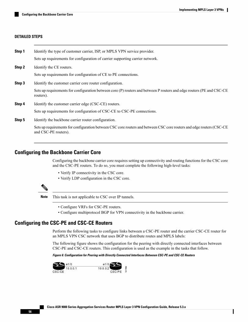
DETAILED STEPS
Step 1 Identify the type of customer carrier, ISP, or MPLS VPN service provider.
Sets up requirements for configuration of carrier supporting carrier network.
Step 2 Identify the CE routers.
Sets up requirements for configuration of CE to PE connections.
Step 3 Identify the customer carrier core router configuration.
Sets up requirements for configuration between core (P) routers and between P routers and edge routers (PE and CSC-CErouters).
Step 4 Identify the customer carrier edge (CSC-CE) routers.
Sets up requirements for configuration of CSC-CE to CSC-PE connections.
Step 5 Identify the backbone carrier router configuration.
Sets up requirements for configuration between CSC core routers and between CSC core routers and edge routers (CSC-CEand CSC-PE routers).
Configuring the Backbone Carrier CoreConfiguring the backbone carrier core requires setting up connectivity and routing functions for the CSC coreand the CSC-PE routers. To do so, you must complete the following high-level tasks:
• Verify IP connectivity in the CSC core.• Verify LDP configuration in the CSC core.
This task is not applicable to CSC over IP tunnels.Note
• Configure VRFs for CSC-PE routers.• Configure multiprotocol BGP for VPN connectivity in the backbone carrier.
Configuring the CSC-PE and CSC-CE RoutersPerform the following tasks to configure links between a CSC-PE router and the carrier CSC-CE router foran MPLS VPN CSC network that uses BGP to distribute routes and MPLS labels:
The following figure shows the configuration for the peering with directly connected interfaces betweenCSC-PE and CSC-CE routers. This configuration is used as the example in the tasks that follow.Figure 6: Configuration for Peering with Directly Connected Interfaces Between CSC-PE and CSC-CE Routers
Cisco ASR 9000 Series Aggregation Services Router MPLS Layer 3 VPN Configuration Guide, Release 5.3.x56
Implementing MPLS Layer 3 VPNsConfiguring the Backbone Carrier Core
Configuring a Static Route to a PeerPerform this task to configure a static route to an Inter-AS or CSC-CE peer.
When you configure an Inter-AS or CSC peer, BGP allocates a label for a /32 route to that peer and performsa NULL label rewrite. When forwarding a labeled packet to the peer, the router removes the top label fromthe label stack; however, in such an instance, BGP expects a /32 route to the peer. This task ensures that thereis, in fact, a /32 route to the peer.
Please be aware of the following facts before performing this task:
• A /32 route is not required to establish BGP peering. A route using a shorter prefix length will also work.• A shorter prefix length route is not associated with the allocated label; even though the BGP sessioncomes up between the peers, without the static route, forwarding will not work.
To configure a static route on a CSC-PE, youmust configure the router under the VRF (as noted in the detailedsteps).
Note
SUMMARY STEPS
1. configure2. router static3. address-family ipv4 unicast4. A.B.C.D/length next-hop5. Use the commit or end command.
DETAILED STEPS
Step 1 configure
Example:
RP/0/RSP0/CPU0:router# configure
Enters the Global Configuration mode.
Step 2 router static
Example:
RP/0/RSP0/CPU0:router(config)# router static
Enters router static configuration mode.
Step 3 address-family ipv4 unicast
Example:
RP/0/RSP0/CPU0:router(config-static)# address-family ipv4 unicast
Cisco ASR 9000 Series Aggregation Services Router MPLS Layer 3 VPN Configuration Guide, Release 5.3.x57
Implementing MPLS Layer 3 VPNsConfiguring a Static Route to a Peer
Enables an IPv4 address family.
To configure a static route on a CSC-PE, you must first configure the VRF using the vrf command beforeaddress-family.
Note
Step 4 A.B.C.D/length next-hop
Example:
RP/0/RSP0/CPU0:router(config-static-afi)# 10.10.10.10/32 10.9.9.9
Enters the address of the destination router (including IPv4 subnet mask).
Step 5 Use the commit or end command.
commit - Saves the configuration changes and remains within the configuration session.
end - Prompts user to take one of these actions:
• Yes - Saves configuration changes and exits the configuration session.• No - Exits the configuration session without committing the configuration changes.• Cancel - Remains in the configuration mode, without committing the configuration changes.
Verifying the MPLS Layer 3 VPN ConfigurationPerform this task to verify the MPLS Layer 3 VPN configuration.
SUMMARY STEPS
1. show running-config router bgp as-number vrf vrf-name2. show running-config routes3. show ospf vrf vrf-name database4. show running-config router bgp as-number vrf vrf-name neighbor ip-address5. show bgp vrf vrf-name summary6. show bgp vrf vrf-name neighbors ip-address7. show bgp vrf vrf-name8. show route vrf vrf-name ip-address9. show bgp vpn unicast summary10. show running-config router isis11. show running-config mpls12. show isis adjacency13. show mpls ldp forwarding14. show bgp vpnv4 unicast or show bgp vrf vrf-name15. show bgp vrf vrf-name imported-routes16. show route vrf vrf-name ip-address17. show cef vrf vrf-name ip-address18. show cef vrf vrf-name ip-address location node-id19. show bgp vrf vrf-name ip-address
Cisco ASR 9000 Series Aggregation Services Router MPLS Layer 3 VPN Configuration Guide, Release 5.3.x58
Implementing MPLS Layer 3 VPNsVerifying the MPLS Layer 3 VPN Configuration
20. show ospf vrf vrf-name database
DETAILED STEPS
Step 1 show running-config router bgp as-number vrf vrf-name
Example:
RP/0/RSP0/CPU0:router# show running-config router bgp 3 vrf vrf_A
Displays the specified VPN routing and forwarding (VRF) content of the currently running configuration.
Step 2 show running-config routes
Example:
RP/0/RSP0/CPU0:router# show running-config routes
Displays the Open Shortest Path First (OSPF) routes table in the currently running configuration.
Step 3 show ospf vrf vrf-name database
Example:
RP/0/RSP0/CPU0:router# show ospf vrf vrf_A database
Displays lists of information related to the OSPF database for a specified VRF.
Step 4 show running-config router bgp as-number vrf vrf-name neighbor ip-address
Example:
RP/0/RSP0/CPU0:router# show running-config router bgp 3 vrf vrf_A neighbor 172.168.40.24
Displays the Border Gateway Protocol (BGP) VRF neighbor content of the currently running configuration.
Step 5 show bgp vrf vrf-name summary
Example:
RP/0/RSP0/CPU0:router# show bgp vrf vrf_A summary
Displays the status of the specified BGP VRF connections.
Step 6 show bgp vrf vrf-name neighbors ip-address
Example:
RP/0/RSP0/CPU0:router# show bgp vrf vrf_A neighbors 172.168.40.24
Displays information about BGP VRF connections to the specified neighbors.
Step 7 show bgp vrf vrf-name
Cisco ASR 9000 Series Aggregation Services Router MPLS Layer 3 VPN Configuration Guide, Release 5.3.x59
Implementing MPLS Layer 3 VPNsVerifying the MPLS Layer 3 VPN Configuration
Example:
RP/0/RSP0/CPU0:router# show bgp vrf vrf_A
Displays information about a specified BGP VRF.
Step 8 show route vrf vrf-name ip-address
Example:
RP/0/RSP0/CPU0:router# show route vrf vrf_A 10.0.0.0
Displays the current routes in the Routing Information Base (RIB) for a specified VRF.
Step 9 show bgp vpn unicast summary
Example:
RP/0/RSP0/CPU0:router# show bgp vpn unicast summary
Displays the status of all BGP VPN unicast connections.
Step 10 show running-config router isis
Example:
RP/0/RSP0/CPU0:router# show running-config router isis
Displays the Intermediate System-to-Intermediate System (IS-IS) content of the currently running configuration.
Step 11 show running-config mpls
Example:
RP/0/RSP0/CPU0:router# show running-config mpls
Displays the MPLS content of the currently running-configuration.
Step 12 show isis adjacency
Example:
RP/0/RSP0/CPU0:router# show isis adjacency
Displays IS-IS adjacency information.
Step 13 show mpls ldp forwarding
Example:
RP/0/RSP0/CPU0:router# show mpls ldp forwarding
Displays the Label Distribution Protocol (LDP) forwarding state installed in MPLS forwarding.
Cisco ASR 9000 Series Aggregation Services Router MPLS Layer 3 VPN Configuration Guide, Release 5.3.x60
Implementing MPLS Layer 3 VPNsVerifying the MPLS Layer 3 VPN Configuration
Step 14 show bgp vpnv4 unicast or show bgp vrf vrf-name
Example:
RP/0/RSP0/CPU0:router# show bgp vpnv4 unicast
Displays entries in the BGP routing table for VPNv4 or VPNv6 unicast addresses.
Step 15 show bgp vrf vrf-name imported-routes
Example:
RP/0/RSP0/CPU0:router# show bgp vrf vrf_A imported-routes
Displays BGP information for routes imported into specified VRF instances.
Step 16 show route vrf vrf-name ip-address
Example:
RP/0/RSP0/CPU0:router# show route vrf vrf_A 10.0.0.0
Displays the current specified VRF routes in the RIB.
Step 17 show cef vrf vrf-name ip-address
Example:
RP/0/RSP0/CPU0:router# show cef vrf vrf_A 10.0.0.1
Displays the IPv4 Cisco Express Forwarding (CEF) table for a specified VRF.
Step 18 show cef vrf vrf-name ip-address location node-id
Example:
RP/0/RSP0/CPU0:router# show cef vrf vrf_A 10.0.0.1 location 0/1/cpu0
Displays the IPv4 CEF table for a specified VRF and location.
Step 19 show bgp vrf vrf-name ip-address
Example:
RP/0/RSP0/CPU0:router# show bgp vrf vrf_A 10.0.0.0
Displays entries in the BGP routing table for VRF vrf_A.
Step 20 show ospf vrf vrf-name database
Example:
RP/0/RSP0/CPU0:router# show ospf vrf vrf_A database
Cisco ASR 9000 Series Aggregation Services Router MPLS Layer 3 VPN Configuration Guide, Release 5.3.x61
Implementing MPLS Layer 3 VPNsVerifying the MPLS Layer 3 VPN Configuration
Displays lists of information related to the OSPF database for a specified VRF.
Configuring L3VPN over GREPerform the following tasks to configure L3VPN over GRE:
Creating a GRE Tunnel between Provider Edge RoutersPerform this task to configure a GRE tunnel between provider edge routers.
SUMMARY STEPS
1. configure2. interface tunnel-ip number3. ipv4 address ipv4-address subnet-mask4. ipv6 address ipv6-prefix/prefix-length5. tunnel mode gre ipv46. tunnel source type path-id7. tunnel destination ip-address8. Use the commit or end command.
DETAILED STEPS
Step 1 configure
Example:
RP/0/RSP0/CPU0:router# configure
Enters the Global Configuration mode.
Step 2 interface tunnel-ip number
Example:
RP/0/RSP0/CPU0:router(config)# interface tunnel-ip 4000
Enters tunnel interface configuration mode.
• number is the number associated with the tunnel interface.
Step 3 ipv4 address ipv4-address subnet-mask
Example:
RP/0/RSP0/CPU0:router(config-if)# ipv4 address 10.1.1.1 255.255.255.0
Specifies the IPv4 address and subnet mask for the interface.
Cisco ASR 9000 Series Aggregation Services Router MPLS Layer 3 VPN Configuration Guide, Release 5.3.x62
Implementing MPLS Layer 3 VPNsConfiguring L3VPN over GRE
• ipv4-address specifies the IP address of the interface.
• subnet-mask specifies the subnet mask of the interface.
Step 4 ipv6 address ipv6-prefix/prefix-length
Example:
RP/0/RSP0/CPU0:router(config-if)# ipv6 address 100:1:1:1::1/64
Specifies an IPv6 network assigned to the interface.
Step 5 tunnel mode gre ipv4
Example:
RP/0/RSP0/CPU0:router(config-if)# tunnel mode gre ipv4
Sets the encapsulation mode of the tunnel interface to GRE.
Step 6 tunnel source type path-id
Example:
RP/0/RSP0/CPU0:router(config-if)# tunnel source TenGigE0/2/0/1
Specifies the source of the tunnel interface.
Step 7 tunnel destination ip-address
Example:
RP/0/RSP0/CPU0:router(config-if)# tunnel destination 145.12.5.2
Defines the tunnel destination.
Step 8 Use the commit or end command.
commit - Saves the configuration changes and remains within the configuration session.
end - Prompts user to take one of these actions:
• Yes - Saves configuration changes and exits the configuration session.• No - Exits the configuration session without committing the configuration changes.• Cancel - Remains in the configuration mode, without committing the configuration changes.
Configuring IGP between Provider Edge RoutersPerform this task to configure IGP between provider edge routers.
SUMMARY STEPS
1. configure
Cisco ASR 9000 Series Aggregation Services Router MPLS Layer 3 VPN Configuration Guide, Release 5.3.x63
Implementing MPLS Layer 3 VPNsConfiguring IGP between Provider Edge Routers
2. router ospf process-name3. nsr4. router-id { router-id }5. mpls ldp sync6. dead-interval seconds7. hello-interval seconds8. area area-id9. interface tunnel-ip number10. Use the commit or end command.
DETAILED STEPS
Step 1 configure
Example:RP/0/RSP0/CPU0:router# configure
Enters the Global Configuration mode.
Step 2 router ospf process-name
Example:RP/0/RSP0/CPU0:router(config)# router ospf 1
Enables OSPF routing for the specified routing process and places the router in router configuration mode.
Step 3 nsr
Example:RP/0/RSP0/CPU0:router(config-ospf)# nsr
Activates BGP NSR.
Step 4 router-id { router-id }
Example:RP/0/RSP0/CPU0:router(config-ospf)# router-id 1.1.1.1
Configures a router ID for the OSPF process.
We recommend using a stable IP address as the router ID.Note
Step 5 mpls ldp sync
Example:RP/0/RSP0/CPU0:router(config-ospf)# mpls ldp sync
Enables MPLS LDP synchronization.
Step 6 dead-interval seconds
Cisco ASR 9000 Series Aggregation Services Router MPLS Layer 3 VPN Configuration Guide, Release 5.3.x64
Implementing MPLS Layer 3 VPNsConfiguring IGP between Provider Edge Routers
Example:RP/0/RSP0/CPU0:router(config-ospf)# dead-interval 60
Sets the time to wait for a hello packet from a neighbor before declaring the neighbor down.
Step 7 hello-interval seconds
Example:RP/0/RSP0/CPU0:router(config-ospf)# hello-interval 15
Specifies the interval between hello packets that OSPF sends on the interface.
Step 8 area area-id
Example:RP/0/RSP0/CPU0:router(config-ospf)# area 0
Enters area configuration mode and configures an area for the OSPF process.
Step 9 interface tunnel-ip number
Example:RP/0/RSP0/CPU0:router(config-ospf)# interface tunnel-ip 4
Enters tunnel interface configuration mode.
• number is the number associated with the tunnel interface.
Step 10 Use the commit or end command.
commit - Saves the configuration changes and remains within the configuration session.
end - Prompts user to take one of these actions:
• Yes - Saves configuration changes and exits the configuration session.• No - Exits the configuration session without committing the configuration changes.• Cancel - Remains in the configuration mode, without committing the configuration changes.
Configuring LDP/GRE on the Provider Edge RoutersPerform this task to configure LDP/GRE on the provider edge routers.
SUMMARY STEPS
1. configure2. mpls ldp3. router-id { router-id }4. discovery hello holdtime seconds5. discovery hello interval seconds6. nsr7. graceful-restart
Cisco ASR 9000 Series Aggregation Services Router MPLS Layer 3 VPN Configuration Guide, Release 5.3.x65
Implementing MPLS Layer 3 VPNsConfiguring LDP/GRE on the Provider Edge Routers
8. graceful-restart reconnect-timeout seconds9. graceful-restart forwarding-state-holdtime seconds10. holdtime seconds11. neighbor ip-address12. interface tunnel-ip number13. Use the commit or end command.
DETAILED STEPS
Step 1 configure
Example:RP/0/RSP0/CPU0:router# configure
Enters the Global Configuration mode.
Step 2 mpls ldp
Example:RP/0/RSP0/CPU0:router(config)# mpls ldp
Enables MPLS LDP configuration mode.
Step 3 router-id { router-id }
Example:RP/0/RSP0/CPU0:router(config-ldp)# router-id 1.1.1.1
Configures a router ID for the OSPF process.
We recommend using a stable IP address as the router ID.Note
Step 4 discovery hello holdtime seconds
Example:RP/0/RSP0/CPU0:router(config-ldp)# discovery hello holdtime 40
Defines the period of time a discovered LDP neighbor is remembered without receipt of an LDP Hello message fromthe neighbor.
We recommend using a stable IP address as the router ID.Note
Step 5 discovery hello interval seconds
Example:RP/0/RSP0/CPU0:router(config-ldp)# discovery hello holdtime 20
Defines the period of time between the sending of consecutive Hello messages.
Step 6 nsr
Example:
Cisco ASR 9000 Series Aggregation Services Router MPLS Layer 3 VPN Configuration Guide, Release 5.3.x66
Implementing MPLS Layer 3 VPNsConfiguring LDP/GRE on the Provider Edge Routers
RP/0/RSP0/CPU0:router(config-ldp)# nsr
Activates BGP NSR.
Step 7 graceful-restart
Example:RP/0/RSP0/CPU0:router(config-ldp)# graceful-restart
Enables graceful restart on the router.
Step 8 graceful-restart reconnect-timeout seconds
Example:RP/0/RSP0/CPU0:router(config-ldp)# graceful-restart recoonect-timeout 180
Defines the time for which the neighbor should wait for a reconnection if the LDP session is lost.
Step 9 graceful-restart forwarding-state-holdtime seconds
Example:RP/0/RSP0/CPU0:router(config-ldp)# graceful-restart forwarding-state-holdtime 300
Defines the time that the neighbor should retain the MPLS forwarding state during a recovery.
Step 10 holdtime seconds
Example:RP/0/RSP0/CPU0:router(config-ldp)# holdtime 90
Configures the hold time for an interface.
Step 11 neighbor ip-address
Example:RP/0/RSP0/CPU0:router(config-ldp)# neighbor 10.1.1.0
Defines a neighboring router.
Step 12 interface tunnel-ip number
Example:RP/0/RSP0/CPU0:router(config-ldp)# interface tunnel-ip 4
Enters tunnel interface configuration mode.
• number is the number associated with the tunnel interface.
Step 13 Use the commit or end command.
commit - Saves the configuration changes and remains within the configuration session.
end - Prompts user to take one of these actions:
• Yes - Saves configuration changes and exits the configuration session.
Cisco ASR 9000 Series Aggregation Services Router MPLS Layer 3 VPN Configuration Guide, Release 5.3.x67
Implementing MPLS Layer 3 VPNsConfiguring LDP/GRE on the Provider Edge Routers
• No - Exits the configuration session without committing the configuration changes.• Cancel - Remains in the configuration mode, without committing the configuration changes.
Configuring L3VPNPerform this task to configure L3VPN.
SUMMARY STEPS
1. configure2. vrf vrf-name3. address-family { ipv4 | ipv6 } unicast4. import route-target [ as-number:nn | ip-address:nn ]5. export route-target [ as-number:nn | ip-address:nn ]6. interface type interface-path-id7. vrf vrf-name8. ipv4 address ipv4-address subnet-mask9. dot1q native vlan vlan-id10. router bgp as-number11. nsr12. bgp router-id ip-address13. address-family {vpnv4 | vpnv6} unicast14. neighbor ip-address15. remote-as as-number16. update-source type interface-path-id17. address-family { vpnv4 | vpnv6 } unicast18. route-policy route-policy-name in19. route-policy route-policy-name out20. vrf vrf-name21. rd { as-number:nn | ip-address:nn | auto }22. address-family { ipv4 | ipv6 } unicast23. redistribute connected [ metric metric-value ] [ route-policy route-policy-name ]24. redistribute static [ metric metric-value ] [ route-policy route-policy-name ]25. neighbor ip-address26. remote-as as-number27. ebg-multihop ttl-value28. address-family { ipv4 | ipv6 } unicast29. route-policy route-policy-name in30. route-policy route-policy-name out31. Use the commit or end command.
DETAILED STEPS
Step 1 configure
Cisco ASR 9000 Series Aggregation Services Router MPLS Layer 3 VPN Configuration Guide, Release 5.3.x68
Implementing MPLS Layer 3 VPNsConfiguring L3VPN
Example:RP/0/RSP0/CPU0:router# configure
Enters the Global Configuration mode.
Step 2 vrf vrf-name
Example:RP/0/RSP0/CPU0:router(config)# vrf vpn1
Configures a VRF instance.
Step 3 address-family { ipv4 | ipv6 } unicast
Example:RP/0/RSP0/CPU0:router(config-vrf)# address-family { ipv4 | ipv6 } unicast
Specifies either the IPv4 or IPv6 address family and enters address family configuration submode.
Step 4 import route-target [ as-number:nn | ip-address:nn ]
Example:RP/0/RSP0/CPU0:router(config-vrf)# import route-target 2:1
Specifies a list of route target (RT) extended communities. Only prefixes that are associated with the specified importroute target extended communities are imported into the VRF.
Step 5 export route-target [ as-number:nn | ip-address:nn ]
Example:RP/0/RSP0/CPU0:router(config-vrf)# export route-target 1:1
Specifies a list of route target extended communities. Export route target communities are associated with prefixeswhen they are advertised to remote PEs. The remote PEs import them into VRFs which have import RTs that matchthese exported route target communities.
Step 6 interface type interface-path-id
Example:RP/0/RSP0/CPU0:router(config)# interface TenGigE0/2/0/0.1
Enters interface configuration mode and configures an interface.
Step 7 vrf vrf-name
Example:RP/0/RSP0/CPU0:router(config-if)# vrf vpn1
Configures a VRF instance.
Step 8 ipv4 address ipv4-address subnet-mask
Example:
Cisco ASR 9000 Series Aggregation Services Router MPLS Layer 3 VPN Configuration Guide, Release 5.3.x69
Implementing MPLS Layer 3 VPNsConfiguring L3VPN
RP/0/RSP0/CPU0:router(config-if)# ipv4 address 150.1.1.1 255.255.255.0
Specifies the IPv4 address and subnet mask for the interface.
• ipv4-address specifies the IP address of the interface.
• subnet-mask specifies the subnet mask of the interface.
Step 9 dot1q native vlan vlan-id
Example:RP/0/RSP0/CPU0:router(config-if)# dot1q nativevlan 1
Assigns the native VLAN ID of a physical interface trunking 802.1Q VLAN traffic.
Step 10 router bgp as-number
Example:
RP/0/RSP0/CPU0:router(config)# router bgp 1
Specifies the autonomous system number and enters the BGP configuration mode, allowing you to configure the BGProuting process.
Step 11 nsr
Example:RP/0/RSP0/CPU0:router(config-bgp)# nsr
Activates BGP NSR.
Step 12 bgp router-id ip-address
Example:RP/0/RSP0/CPU0:router(config-bgp)# bgp router-id 1.1.1.1
Configures the local router with a specified router ID.
Step 13 address-family {vpnv4 | vpnv6} unicast
Example:RP/0/RSP0/CPU0:router(config-bgp)# address-family vpnv4 unicast
Enters address family configuration submode for the specified address family.
Step 14 neighbor ip-address
Example:RP/0/RSP0/CPU0:router(config-bgp)# neighbor 4.4.4.4
Places the router in neighbor configuration mode for BGP routing and configures the neighbor IP address as a BGPpeer.
Cisco ASR 9000 Series Aggregation Services Router MPLS Layer 3 VPN Configuration Guide, Release 5.3.x70
Implementing MPLS Layer 3 VPNsConfiguring L3VPN
Step 15 remote-as as-number
Example:RP/0/RSP0/CPU0:router(config-bgp-nbr)#remote-as 1
Creates a neighbor and assigns a remote autonomous system number to it..
Step 16 update-source type interface-path-id
Example:RP/0/RSP0/CPU0:router(config-bgp-nbr)#update-source Loopback0
Allows sessions to use the primary IP address from a specific interface as the local address when forming a sessionwith a neighbor.
Step 17 address-family { vpnv4 | vpnv6 } unicast
Example:RP/0/RSP0/CPU0:router(config-bgp-nbr)# address-family vpnv4 unicast
Enters address family configuration submode for the specified address family.
Step 18 route-policy route-policy-name in
Example:RP/0/RSP0/CPU0:router(config-bgp-nbr-af)#route-policy pass-all in
Defines a route policy and enters route policy configuration mode.
Step 19 route-policy route-policy-name out
Example:RP/0/RSP0/CPU0:router(config-bgp-nbr-af)#route-policy pass-all out
Defines a route policy and enters route policy configuration mode.
Step 20 vrf vrf-name
Example:RP/0/RSP0/CPU0:router(config)# vrf vpn1
Configures a VRF instance.
Step 21 rd { as-number:nn | ip-address:nn | auto }
Example:RP/0/RSP0/CPU0:router(config-vrf)#rd 1:1
Configures the route distinguisher.
Step 22 address-family { ipv4 | ipv6 } unicast
Example:
Cisco ASR 9000 Series Aggregation Services Router MPLS Layer 3 VPN Configuration Guide, Release 5.3.x71
Implementing MPLS Layer 3 VPNsConfiguring L3VPN
RP/0/RSP0/CPU0:router(config-vrf)# address-family ipv4 unicast
Specifies either the IPv4 or IPv6 address family and enters address family configuration submode.
Step 23 redistribute connected [ metric metric-value ] [ route-policy route-policy-name ]
Example:RP/0/RSP0/CPU0:router(config-vrf-af)#redistribute connected
Configures the local router with a specified router ID.
Step 24 redistribute static [ metric metric-value ] [ route-policy route-policy-name ]
Example:RP/0/RSP0/CPU0:router(config-vrf-af)#redistribute static
Causes routes from the specified instance to be redistributed into BGP.
Step 25 neighbor ip-address
Example:RP/0/RSP0/CPU0:router(config-bgp)# neighbor 150.1.1.2
Places the router in neighbor configuration mode for BGP routing and configures the neighbor IP address as a BGPpeer.
Step 26 remote-as as-number
Example:RP/0/RSP0/CPU0:router(config-bgp-nbr)#remote-as 7501
Creates a neighbor and assigns a remote autonomous system number to it..
Step 27 ebg-multihop ttl-value
Example:RP/0/RSP0/CPU0:router(config-bgp-nbr)#ebgp-multihop 10
Configures the CE neighbor to accept and attempt BGP connections to external peers residing on networks that are notdirectly connected.
Step 28 address-family { ipv4 | ipv6 } unicast
Example:RP/0/RSP0/CPU0:router(config-bgp-nbr)# address-family ipv4 unicast
Specifies either the IPv4 or IPv6 address family and enters address family configuration submode.
Step 29 route-policy route-policy-name in
Example:
Cisco ASR 9000 Series Aggregation Services Router MPLS Layer 3 VPN Configuration Guide, Release 5.3.x72
Implementing MPLS Layer 3 VPNsConfiguring L3VPN
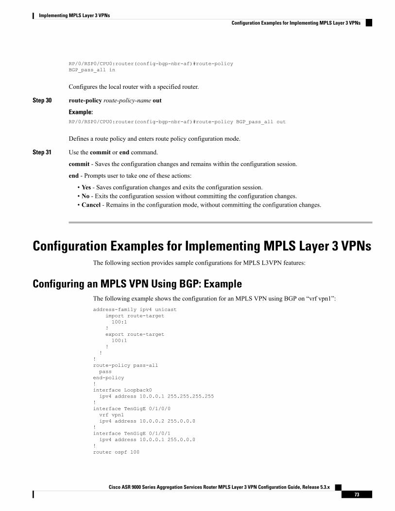
RP/0/RSP0/CPU0:router(config-bgp-nbr-af)#route-policyBGP_pass_all in
Configures the local router with a specified router.
Step 30 route-policy route-policy-name out
Example:RP/0/RSP0/CPU0:router(config-bgp-nbr-af)#route-policy BGP_pass_all out
Defines a route policy and enters route policy configuration mode.
Step 31 Use the commit or end command.
commit - Saves the configuration changes and remains within the configuration session.
end - Prompts user to take one of these actions:
• Yes - Saves configuration changes and exits the configuration session.• No - Exits the configuration session without committing the configuration changes.• Cancel - Remains in the configuration mode, without committing the configuration changes.
Configuration Examples for Implementing MPLS Layer 3 VPNsThe following section provides sample configurations for MPLS L3VPN features:
Configuring an MPLS VPN Using BGP: ExampleThe following example shows the configuration for an MPLS VPN using BGP on “vrf vpn1”:address-family ipv4 unicast
import route-target100:1
!export route-target100:1
!!
!route-policy pass-allpass
end-policy!interface Loopback0ipv4 address 10.0.0.1 255.255.255.255
!interface TenGigE 0/1/0/0vrf vpn1ipv4 address 10.0.0.2 255.0.0.0
!interface TenGigE 0/1/0/1ipv4 address 10.0.0.1 255.0.0.0
!router ospf 100
Cisco ASR 9000 Series Aggregation Services Router MPLS Layer 3 VPN Configuration Guide, Release 5.3.x73
Implementing MPLS Layer 3 VPNsConfiguration Examples for Implementing MPLS Layer 3 VPNs
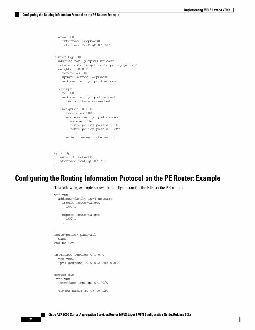
area 100interface loopback0interface TenGigE 0/1/0/1
!!router bgp 100address-family vpnv4 unicastretain route-target route-policy policy1neighbor 10.0.0.3remote-as 100update-source Loopback0address-family vpnv4 unicast
!vrf vpn1rd 100:1address-family ipv4 unicastredistribute connected
!neighbor 10.0.0.1remote-as 200address-family ipv4 unicastas-overrideroute-policy pass-all inroute-policy pass-all out
!advertisement-interval 5
!!
!mpls ldproute-id looback0interface TenGigE 0/1/0/1
!
Configuring the Routing Information Protocol on the PE Router: ExampleThe following example shows the configuration for the RIP on the PE router:vrf vpn1address-family ipv4 unicastimport route-target100:1
!export route-target100:1
!!
!route-policy pass-allpass
end-policy!
interface TenGigE 0/1/0/0vrf vpn1ipv4 address 10.0.0.2 255.0.0.0
!
router ripvrf vpn1interface TenGigE 0/1/0/0!timers basic 30 90 90 120
Cisco ASR 9000 Series Aggregation Services Router MPLS Layer 3 VPN Configuration Guide, Release 5.3.x74
Implementing MPLS Layer 3 VPNsConfiguring the Routing Information Protocol on the PE Router: Example
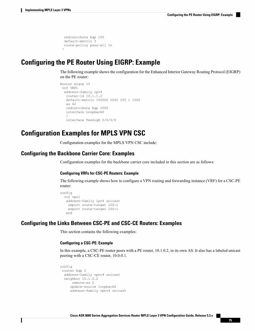
redistribute bgp 100default-metric 3route-policy pass-all in!
Configuring the PE Router Using EIGRP: ExampleThe following example shows the configuration for the Enhanced Interior Gateway Routing Protocol (EIGRP)on the PE router:Router eigrp 10vrf VRF1address-family ipv4router-id 10.1.1.2default-metric 100000 2000 255 1 1500as 62redistribute bgp 2000interface Loopback0!interface TenGigE 0/6/0/0
Configuration Examples for MPLS VPN CSCConfiguration examples for the MPLS VPN CSC include:
Configuring the Backbone Carrier Core: ExamplesConfiguration examples for the backbone carrier core included in this section are as follows:
Configuring VRFs for CSC-PE Routers: Example
The following example shows how to configure a VPN routing and forwarding instance (VRF) for a CSC-PErouter:configvrf vpn1address-family ipv4 unicastimport route-target 100:1export route-target 100:1end
Configuring the Links Between CSC-PE and CSC-CE Routers: ExamplesThis section contains the following examples:
Configuring a CSC-PE: Example
In this example, a CSC-PE router peers with a PE router, 10.1.0.2, in its own AS. It also has a labeled unicastpeering with a CSC-CE router, 10.0.0.1.
configrouter bgp 2address-family vpnv4 unicastneighbor 10.1.0.2
remote-as 2update-source loopback0address-family vpnv4 unicast
Cisco ASR 9000 Series Aggregation Services Router MPLS Layer 3 VPN Configuration Guide, Release 5.3.x75
Implementing MPLS Layer 3 VPNsConfiguring the PE Router Using EIGRP: Example
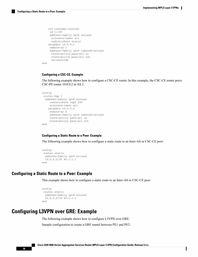
vrf customer-carrierrd 1:100address-family ipv4 unicastallocate-label allredistribute static
neighbor 10.0.0.1remote-as 1address-family ipv4 labeled-unicastroute-policy pass-all inroute-policy pass-all outas-override
end
Configuring a CSC-CE: Example
The following example shows how to configure a CSC-CE router. In this example, the CSC-CE router peersCSC-PE router 10.0.0.2 in AS 2.
configrouter bgp 1address-family ipv4 unicast
redistribute ospf 200allocate-label allneighbor 10.0.0.2remote-as 2address-family ipv4 labeled-unicastroute-policy pass-all inroute-policy pass-all out
end
Configuring a Static Route to a Peer: Example
The following example shows how to configure a static route to an Inter-AS or CSC-CE peer:
configrouter staticaddress-family ipv4 unicast10.0.0.2/32 40.1.1.1
end
Configuring a Static Route to a Peer: ExampleThis example shows how to configure a static route to an Inter-AS or CSC-CE peer:
configrouter staticaddress-family ipv4 unicast10.0.0.2/32 40.1.1.1
end
Configuring L3VPN over GRE: ExampleThe following example shows how to configure L3VPN over GRE:
Sample configuration to create a GRE tunnel between PE1 and PE2:
Cisco ASR 9000 Series Aggregation Services Router MPLS Layer 3 VPN Configuration Guide, Release 5.3.x76
Implementing MPLS Layer 3 VPNsConfiguring a Static Route to a Peer: Example
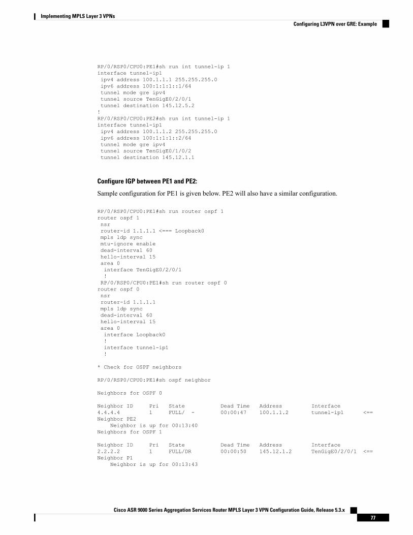
RP/0/RSP0/CPU0:PE1#sh run int tunnel-ip 1interface tunnel-ip1ipv4 address 100.1.1.1 255.255.255.0ipv6 address 100:1:1:1::1/64tunnel mode gre ipv4tunnel source TenGigE0/2/0/1tunnel destination 145.12.5.2!RP/0/RSP0/CPU0:PE2#sh run int tunnel-ip 1interface tunnel-ip1ipv4 address 100.1.1.2 255.255.255.0ipv6 address 100:1:1:1::2/64tunnel mode gre ipv4tunnel source TenGigE0/1/0/2tunnel destination 145.12.1.1
Configure IGP between PE1 and PE2:
Sample configuration for PE1 is given below. PE2 will also have a similar configuration.
RP/0/RSP0/CPU0:PE1#sh run router ospf 1router ospf 1nsrrouter-id 1.1.1.1 <=== Loopback0mpls ldp syncmtu-ignore enabledead-interval 60hello-interval 15area 0interface TenGigE0/2/0/1!RP/0/RSP0/CPU0:PE1#sh run router ospf 0router ospf 0nsrrouter-id 1.1.1.1mpls ldp syncdead-interval 60hello-interval 15area 0interface Loopback0!interface tunnel-ip1!
* Check for OSPF neighbors
RP/0/RSP0/CPU0:PE1#sh ospf neighbor
Neighbors for OSPF 0
Neighbor ID Pri State Dead Time Address Interface4.4.4.4 1 FULL/ - 00:00:47 100.1.1.2 tunnel-ip1 <==Neighbor PE2
Neighbor is up for 00:13:40Neighbors for OSPF 1
Neighbor ID Pri State Dead Time Address Interface2.2.2.2 1 FULL/DR 00:00:50 145.12.1.2 TenGigE0/2/0/1 <==Neighbor P1
Neighbor is up for 00:13:43
Cisco ASR 9000 Series Aggregation Services Router MPLS Layer 3 VPN Configuration Guide, Release 5.3.x77
Implementing MPLS Layer 3 VPNsConfiguring L3VPN over GRE: Example
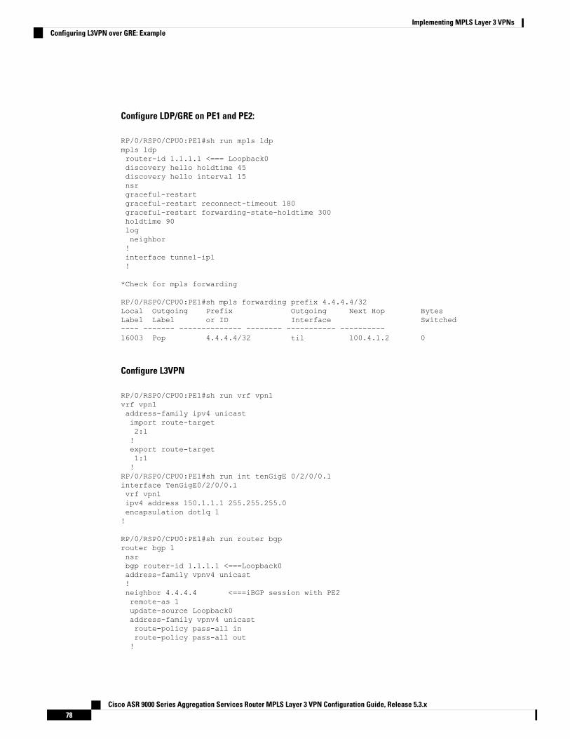
Configure LDP/GRE on PE1 and PE2:
RP/0/RSP0/CPU0:PE1#sh run mpls ldpmpls ldprouter-id 1.1.1.1 <=== Loopback0discovery hello holdtime 45discovery hello interval 15nsrgraceful-restartgraceful-restart reconnect-timeout 180graceful-restart forwarding-state-holdtime 300holdtime 90logneighbor!interface tunnel-ip1!
*Check for mpls forwarding
RP/0/RSP0/CPU0:PE1#sh mpls forwarding prefix 4.4.4.4/32Local Outgoing Prefix Outgoing Next Hop BytesLabel Label or ID Interface Switched---- ------- -------------- -------- ----------- ----------16003 Pop 4.4.4.4/32 ti1 100.4.1.2 0
Configure L3VPN
RP/0/RSP0/CPU0:PE1#sh run vrf vpn1vrf vpn1address-family ipv4 unicastimport route-target2:1!export route-target1:1!
RP/0/RSP0/CPU0:PE1#sh run int tenGigE 0/2/0/0.1interface TenGigE0/2/0/0.1vrf vpn1ipv4 address 150.1.1.1 255.255.255.0encapsulation dot1q 1!
RP/0/RSP0/CPU0:PE1#sh run router bgprouter bgp 1nsrbgp router-id 1.1.1.1 <===Loopback0address-family vpnv4 unicast!neighbor 4.4.4.4 <===iBGP session with PE2remote-as 1update-source Loopback0address-family vpnv4 unicastroute-policy pass-all inroute-policy pass-all out!
Cisco ASR 9000 Series Aggregation Services Router MPLS Layer 3 VPN Configuration Guide, Release 5.3.x78
Implementing MPLS Layer 3 VPNsConfiguring L3VPN over GRE: Example
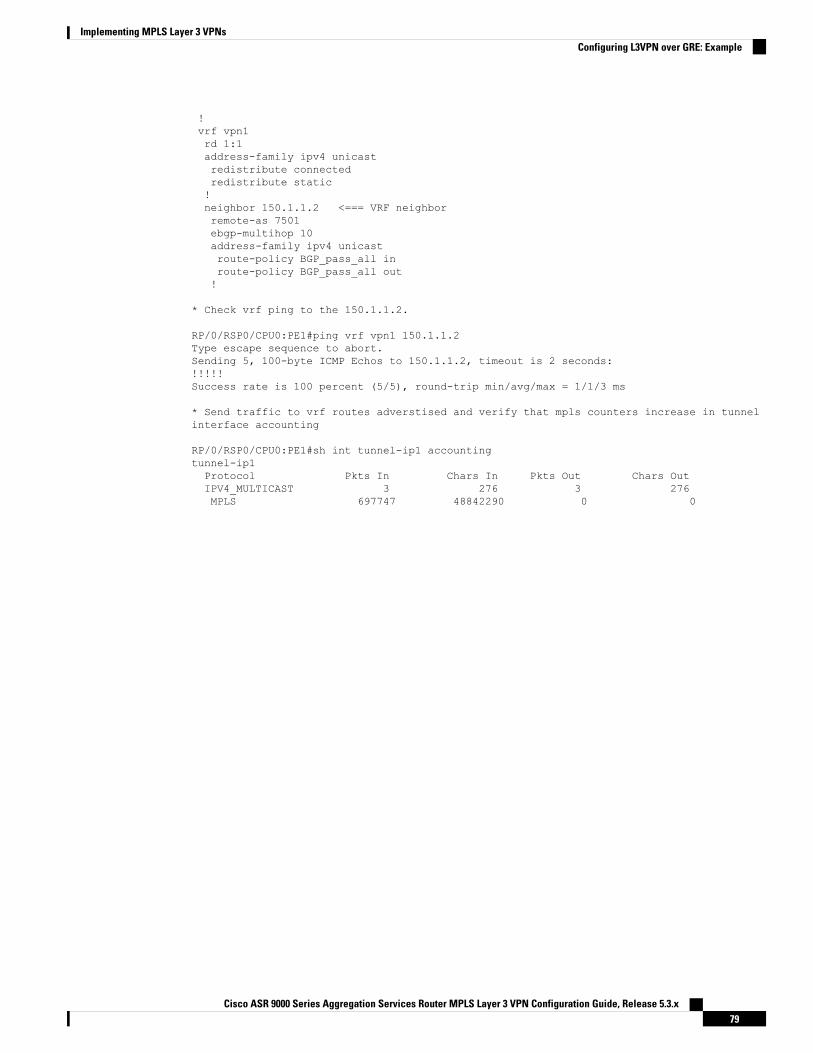
!vrf vpn1rd 1:1address-family ipv4 unicastredistribute connectedredistribute static!neighbor 150.1.1.2 <=== VRF neighborremote-as 7501ebgp-multihop 10address-family ipv4 unicastroute-policy BGP_pass_all inroute-policy BGP_pass_all out!
* Check vrf ping to the 150.1.1.2.
RP/0/RSP0/CPU0:PE1#ping vrf vpn1 150.1.1.2Type escape sequence to abort.Sending 5, 100-byte ICMP Echos to 150.1.1.2, timeout is 2 seconds:!!!!!Success rate is 100 percent (5/5), round-trip min/avg/max = 1/1/3 ms
* Send traffic to vrf routes adverstised and verify that mpls counters increase in tunnelinterface accounting
RP/0/RSP0/CPU0:PE1#sh int tunnel-ip1 accountingtunnel-ip1Protocol Pkts In Chars In Pkts Out Chars OutIPV4_MULTICAST 3 276 3 276MPLS 697747 48842290 0 0
Cisco ASR 9000 Series Aggregation Services Router MPLS Layer 3 VPN Configuration Guide, Release 5.3.x79
Implementing MPLS Layer 3 VPNsConfiguring L3VPN over GRE: Example

Cisco ASR 9000 Series Aggregation Services Router MPLS Layer 3 VPN Configuration Guide, Release 5.3.x80
Implementing MPLS Layer 3 VPNsConfiguring L3VPN over GRE: Example
C H A P T E R 3Implementing IPv6 VPN Provider Edge Transportover MPLS
IPv6 Provider Edge or IPv6 VPN Provider Edge (6PE/VPE) uses the existing MPLS IPv4 core infrastructurefor IPv6 transport. 6PE/VPE enables IPv6 sites to communicate with each other over an MPLS IPv4 corenetwork using MPLS label switched paths (LSPs).
This feature relies heavily on multiprotocol Border Gateway Protocol (BGP) extensions in the IPv4 networkconfiguration on the provider edge (PE) router to exchange IPv6 reachability information (in addition to anMPLS label) for each IPv6 address prefix. Edge routers are configured as dual-stack, running both IPv4 andIPv6, and use the IPv4 mapped IPv6 address for IPv6 prefix reachability exchange.
For detailed information about the commands used to configure 6PE/VPE, see the Cisco ASR 9000 SeriesAggregation Services Router VPN and Ethernet Services Command Reference.
Feature History for Implementing 6PE/VPE Transport over MPLS
ModificationRelease
This feature was introduced.Release 3.9.1
Support was added for the 6PE and 6VPE features forIPv6 L3VPN on A9K-SIP-700.
Support was added for the BGP per VRF/CE labelallocation for 6PE feature.
Release 4.0.0
Support for the Open Shortest Path First version 3(OSPFv3) IPv6 VPN Provider Edge (6VPE) featurewas added.
Release 4.1.0
• Prerequisites for Implementing 6PE/VPE, on page 81• Information About 6PE/VPE, on page 82• How to Implement 6PE/VPE, on page 85• Configuration Examples for 6PE/VPE, on page 93
Prerequisites for Implementing 6PE/VPEThe following prerequisites are required to implement 6PE/VPE:
Cisco ASR 9000 Series Aggregation Services Router MPLS Layer 3 VPN Configuration Guide, Release 5.3.x81
• You must be in a user group associated with a task group that includes the proper task IDs. The commandreference guides include the task IDs required for each command.
If you suspect user group assignment is preventing you from using a command, contact your AAAadministrator for assistance.
• Familiarity with MPLS and BGP4 configuration and troubleshooting.
Information About 6PE/VPETo configure the 6PE/VPE feature, you should understand the concepts that are described in these sections:
Overview of 6PE/VPEMultiple techniques are available to integrate IPv6 services over service provider core backbones:
• Dedicated IPv6 network running over various data link layers
• Dual-stack IPv4-IPv6 backbone
• Existing MPLS backbone leverage
These solutions are deployed on service providers’ backbones when the amount of IPv6 traffic and the revenuegenerated are in line with the necessary investments and the agreed-upon risks. Conditions are favorable forthe introduction of native IPv6 services, from the edge, in a scalable way, without any IPv6 addressingrestrictions and without putting a well-controlled IPv4 backbone in jeopardy. Backbone stability is essentialfor service providers that have recently stabilized their IPv4 infrastructure.
Service providers running an MPLS/IPv4 infrastructure follow similar trends because several integrationscenarios that offer IPv6 services on an MPLS network are possible. Cisco Systems has specially developedCisco 6PE or IPv6 Provider Edge Router over MPLS, to meet all those requirements.
Inter-AS support for 6PE requires support of Border Gateway Protocol (BGP) to enable the address familiesand to allocate and distribute PE and ASBR labels.
Cisco IOS XR displays actual IPv4 next-hop addresses for IPv6 labeled-unicast and VPNv6 prefixes.IPv4-mapped-to-IPv6 format is not supported.
Note
Benefits of 6PE/VPEService providers who currently deploy MPLS experience these benefits of Cisco 6PE/VPE:
• Minimal operational cost and risk—No impact on existing IPv4 and MPLS services.
• Provider edge routers upgrade only—A 6PE/VPE router can be an existing PE router or a new onededicated to IPv6 traffic.
• No impact on IPv6 customer edge routers—The ISP can connect to any customer CE running Static,IGP or EGP.
• Production services ready—An ISP can delegate IPv6 prefixes.
Cisco ASR 9000 Series Aggregation Services Router MPLS Layer 3 VPN Configuration Guide, Release 5.3.x82
Implementing IPv6 VPN Provider Edge Transport over MPLSInformation About 6PE/VPE
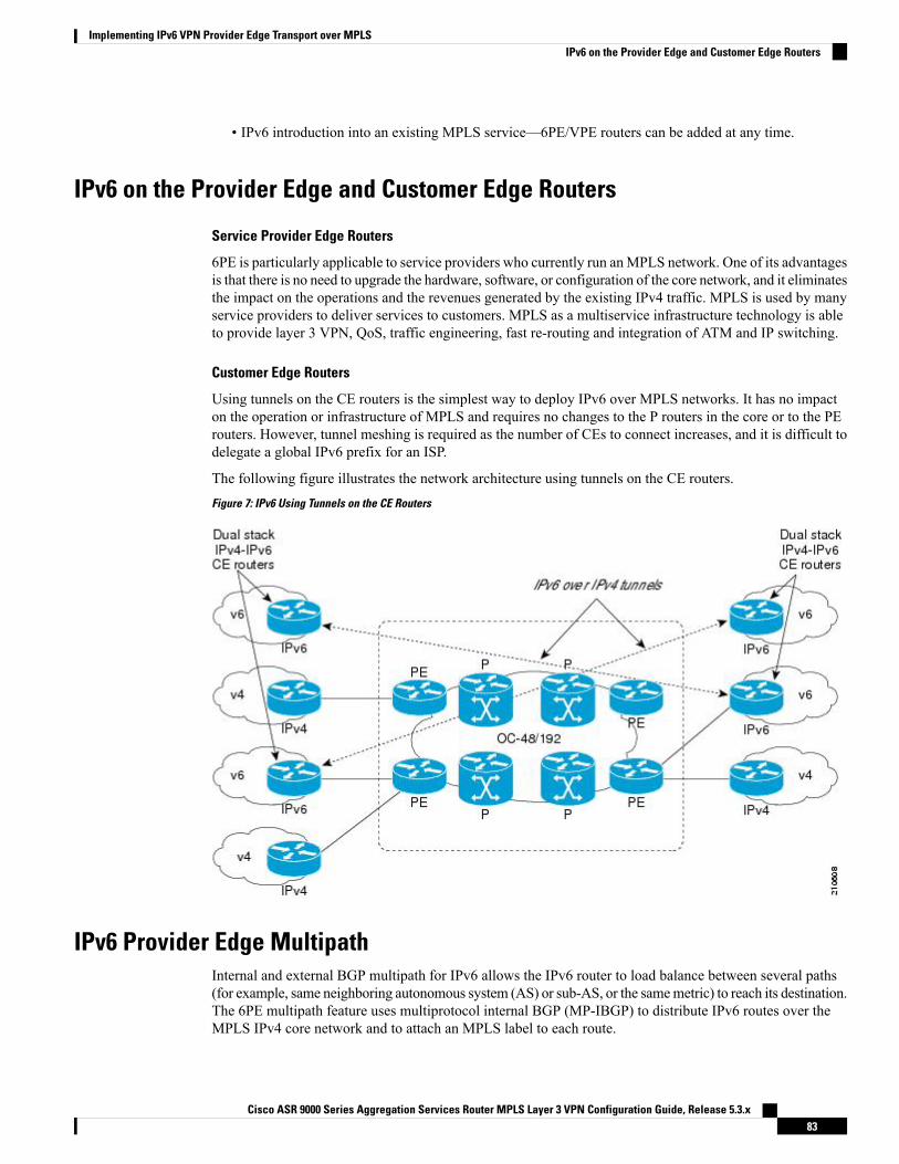
• IPv6 introduction into an existing MPLS service—6PE/VPE routers can be added at any time.
IPv6 on the Provider Edge and Customer Edge Routers
Service Provider Edge Routers
6PE is particularly applicable to service providers who currently run anMPLS network. One of its advantagesis that there is no need to upgrade the hardware, software, or configuration of the core network, and it eliminatesthe impact on the operations and the revenues generated by the existing IPv4 traffic. MPLS is used by manyservice providers to deliver services to customers. MPLS as a multiservice infrastructure technology is ableto provide layer 3 VPN, QoS, traffic engineering, fast re-routing and integration of ATM and IP switching.
Customer Edge Routers
Using tunnels on the CE routers is the simplest way to deploy IPv6 over MPLS networks. It has no impacton the operation or infrastructure of MPLS and requires no changes to the P routers in the core or to the PErouters. However, tunnel meshing is required as the number of CEs to connect increases, and it is difficult todelegate a global IPv6 prefix for an ISP.
The following figure illustrates the network architecture using tunnels on the CE routers.Figure 7: IPv6 Using Tunnels on the CE Routers
IPv6 Provider Edge MultipathInternal and external BGP multipath for IPv6 allows the IPv6 router to load balance between several paths(for example, same neighboring autonomous system (AS) or sub-AS, or the samemetric) to reach its destination.The 6PE multipath feature uses multiprotocol internal BGP (MP-IBGP) to distribute IPv6 routes over theMPLS IPv4 core network and to attach an MPLS label to each route.
Cisco ASR 9000 Series Aggregation Services Router MPLS Layer 3 VPN Configuration Guide, Release 5.3.x83
Implementing IPv6 VPN Provider Edge Transport over MPLSIPv6 on the Provider Edge and Customer Edge Routers
When MP-IBGP multipath is enabled on the 6PE router, all labeled paths are installed in the forwarding tablewith MPLS information (label stack) when MPLS information is available. This functionality enables 6PEto perform load balancing.
OSPFv3 6VPEThe Open Shortest Path First version 3 (OSPFv3) IPv6 VPN Provider Edge (6VPE) feature adds VPN routingand forwarding (VRF) and provider edge-to-customer edge(PE-CE) routing support to Cisco IOSXROSPFv3implementation. This feature allows:
• Multiple VRF support per OSPFv3 routing process
• OSPFV3 PE-CE extensions
Multiple VRF SupportOSPFv3 supports multiple VRFs in a single routing process that allows scaling to tens and hundreds of VRFswithout consuming too much route processor (RP) resources.
Multiple OSPFv3 processes can be configured on a single router. In large-scale VRF deployments, this allowspartition VRF processing across multiple RPs. It is also used to isolate default routing table or high impactVRFs from the regular VRFs. It is recommended to use a single process for all the VRFs. If needed, a secondOSPFv3 process must be configured for IPv6 routing.
The maximum of four OSPFv3 processes are supported.Note
OSPFv3 PE-CE ExtensionsIPv6 protocol is being vastly deployed in today's customer networks. Service Providers (SPs) need to be ableto offer Virtual Private Network (VPN) services to their customers for supporting IPv6 protocol, in additionto the already offered VPN services for IPv4 protocol.
In order to support IPv6, routing protocols require additional extensions for operating in the VPN environment.Extensions to OSPFv3 are required in order for OSPFv3 to operate at the PE-CE links.
VRF LiteVRF lite feature enables VRF deployment without BGP orMPLS based backbone. In VRF lite, the PE routersare directly connected using VRF interfaces. For OSPFv3, the following needs to operate differently in theVRF lite scenario, as opposed to the deployment with BGP or MPLS backbone:
• DN bit processing—In VRF lite environment, the DN bit processing is disabled.
• ABR status—In VRF context (except default VRF), OSPFv3 router is automatically set as an ABR,regardless to it’s connectivity to area 0. This automatic ABR status setting is disabled in the VRF liteenvironment.
To enable VRF Lite, issue the capability vrf-lite command in the OSPFv3 VRF configuration submode.Note
Cisco ASR 9000 Series Aggregation Services Router MPLS Layer 3 VPN Configuration Guide, Release 5.3.x84
Implementing IPv6 VPN Provider Edge Transport over MPLSOSPFv3 6VPE
How to Implement 6PE/VPEThis section includes these implementation procedures:
Configuring 6PE/VPEThis task describes how to configure 6PE/VPE on PE routers to transport the IPv6 prefixes across the IPv4cloud.
Ensure that you configure 6PE/VPE on PE routers participating in both the IPv4 cloud and IPv6 clouds.
For 6PE, you can use all routing protocols supported on Cisco IOS XR software such as BGP, OSPF, IS-IS,EIGRP, RIP, and Static to learn routes from both clouds. However, for 6VPE, you can use only the BGP,EIGRP and Static routing protocols to learn routes. Also, 6VPE supports OSPFv3 routing protocol betweenPE and CE routers.
Note
SUMMARY STEPS
1. configure2. router bgp as-number3. neighbor ip-address4. remote-as as-number5. address-family ipv6 labeled-unicast6. exit7. exit8. address-family ipv6 unicast9. allocate-label [all | route-policy policy_name]10. Use the commit or end command.
DETAILED STEPS
Step 1 configure
Example:
RP/0/RSP0/CPU0:router# configure
Enters the Global Configuration mode.
Step 2 router bgp as-number
Example:
RP/0/RSP0/CPU0:router(config)# router bgp 1
Enters the number that identifies the autonomous system (AS) in which the router resides.
Cisco ASR 9000 Series Aggregation Services Router MPLS Layer 3 VPN Configuration Guide, Release 5.3.x85
Implementing IPv6 VPN Provider Edge Transport over MPLSHow to Implement 6PE/VPE
Range for 2-byte numbers is 1 to 65535. Range for 4-byte numbers is 1.0 to 65535.65535.
Step 3 neighbor ip-address
Example:
RP/0/RSP0/CPU0:router(config-bgp)# neighbor 1.1.1.1
Enters neighbor configuration mode for configuring Border Gateway Protocol (BGP) routing sessions.
Step 4 remote-as as-number
Example:
RP/0/RSP0/CPU0:router(config-bgp-nbr)# remote-as 100
Creates a neighbor and assigns a remote autonomous system number to it.
Step 5 address-family ipv6 labeled-unicast
Example:
RP/0/RSP0/CPU0:router(config-bgp-nbr)# address-family ipv6 labeled-unicast
Specifies IPv6 labeled-unicast address prefixes.
This option is also available in IPv6 neighbor configuration mode and VRF neighbor configuration mode.Note
Step 6 exit
Example:
RP/0/RSP0/CPU0:router(config-bgp-nbr-af)# exit
Exits BGP address-family submode.
Step 7 exit
Example:
RP/0/RSP0/CPU0:router(config-bgp-nbr)# exit
Exits BGP neighbor submode.
Step 8 address-family ipv6 unicast
Example:
RP/0/RSP0/CPU0:router(config-bgp)# address-family ipv6 unicast
Specifies IPv6 unicast address prefixes.
Step 9 allocate-label [all | route-policy policy_name]
Example:
Cisco ASR 9000 Series Aggregation Services Router MPLS Layer 3 VPN Configuration Guide, Release 5.3.x86
Implementing IPv6 VPN Provider Edge Transport over MPLSConfiguring 6PE/VPE
RP/0/RSP0/CPU0:router(config-bgp-af)# allocate-label all
Allocates MPLS labels for specified IPv4 unicast routes.
The route-policy keyword provides finer control to filter out certain routes from being advertised to theneighbor.
Note
Step 10 Use the commit or end command.
commit - Saves the configuration changes and remains within the configuration session.
end - Prompts user to take one of these actions:
• Yes - Saves configuration changes and exits the configuration session.• No - Exits the configuration session without committing the configuration changes.• Cancel - Remains in the configuration mode, without committing the configuration changes.
Configuring PE to PE CoreThis task describes how to configure a Provider Edge (PE) to PE Core.
For information on configuring VPN Routing and Forwarding (VRF), refer to the Implementing BGPmoduleof the Cisco ASR 9000 Series Aggregation Services Router Routing Configuration Guide.
SUMMARY STEPS
1. configure2. router bgp3. address-family vpnv6 unicast4. bgp dampening [ half-life [ reuse suppress max-suppress-time ] | route-policy route-policy-name ]5. bgp client-to-client reflection { cluster-id | disable }6. neighbor ip-address7. remote-as as-number8. description text9. password { clear | encrypted } password10. shutdown11. timers keepalive hold-time12. update-source type interface-id13. address-family vpnv6 unicast14. route-policy route-policy-name { in | out }15. exit16. vrf vrf-name17. rd { as-number : nn | ip-address : nn | auto }18. Use the commit or end command.
Cisco ASR 9000 Series Aggregation Services Router MPLS Layer 3 VPN Configuration Guide, Release 5.3.x87
Implementing IPv6 VPN Provider Edge Transport over MPLSConfiguring PE to PE Core
DETAILED STEPS
Step 1 configure
Example:RP/0/RSP0/CPU0:router# configure
Enters the Global Configuration mode.
Step 2 router bgp
Example:
RP/0/RSP0/CPU0:router(config)# router bgp 10
Specifies the BGP AS number and enters the BGP configuration mode, allowing you to configure the BGP routingprocess.
Step 3 address-family vpnv6 unicast
Example:
RP/0/RSP0/CPU0:router(config-bgp)# address-family vpnv6 unicast
Specifies the vpnv6 address family and enters address family configuration submode.
Step 4 bgp dampening [ half-life [ reuse suppress max-suppress-time ] | route-policy route-policy-name ]
Example:
RP/0/RSP0/CPU0:router(config-bgp-af)# bgp dampening 30 1500 10000 120
Configures BGP dampening for the specified address family.
Step 5 bgp client-to-client reflection { cluster-id | disable }
Example:
RP/0/RSP0/CPU0:router(config-bgp-af)# bgp client-to-clientreflection disable
Configures client to client route reflection.
Step 6 neighbor ip-address
Example:
RP/0/RSP0/CPU0:router(config-bgp)# neighbor 10.1.1.1
Places the router in neighbor configuration mode for BGP routing and configures the neighbor IP address as a BGPpeer.
Step 7 remote-as as-number
Cisco ASR 9000 Series Aggregation Services Router MPLS Layer 3 VPN Configuration Guide, Release 5.3.x88
Implementing IPv6 VPN Provider Edge Transport over MPLSConfiguring PE to PE Core
Example:
RP/0/RSP0/CPU0:router(config-bgp-nbr)# remote-as 100
Creates a neighbor and assigns a remote autonomous system number to it.
Step 8 description text
Example:
RP/0/RSP0/CPU0:router(config-bgp-nbr)# description neighbor 172.16.1.1
Provides a description of the neighbor. The description is used to save comments and does not affect software function.
Step 9 password { clear | encrypted } password
Example:
RP/0/RSP0/CPU0:router(config-bgp-nbr)# password encrypted 123abc
Enables Message Digest 5 (MD5) authentication on the TCP connection between the two BGP neighbors.
Step 10 shutdown
Example:
RP/0/RSP0/CPU0:router(config-bgp-nbr)# router bgp 1
Terminates any active sessions for the specified neighbor and removes all associated routing information.
Step 11 timers keepalive hold-time
Example:
RP/0/RSP0/CPU0:router(config-bgp-nbr)# timers 12000 200
Set the timers for the BGP neighbor.
Step 12 update-source type interface-id
Example:
RP/0/RSP0/CPU0:router(config-bgp-nbr)# update-source TenGigE 0/1/5/0
Allows iBGP sessions to use the primary IP address from a specific interface as the local address when forming aniBGP session with a neighbor.
Step 13 address-family vpnv6 unicast
Example:
RP/0/RSP0/CPU0:router(config-bgp-nbr)# address-family vpvn6 unicast
Enters VPN neighbor address family configuration mode.
Cisco ASR 9000 Series Aggregation Services Router MPLS Layer 3 VPN Configuration Guide, Release 5.3.x89
Implementing IPv6 VPN Provider Edge Transport over MPLSConfiguring PE to PE Core
Step 14 route-policy route-policy-name { in | out }
Example:
RP/0/RSP0/CPU0:router(config-bgp-nbr-af)# route-policy pe-pe-vpn-out out
Specifies a routing policy for an outbound route. The policy can be used to filter routes or modify route attributes.
Step 15 exit
Example:
RP/0/RSP0/CPU0:router(config-bgp-nbr-af)# exit
Exits address family configuration and neighbor submode.
Step 16 vrf vrf-name
Example:
RP/0/RSP0/CPU0:router(config-bgp)# vrf vrf-pe
Configures a VRF instance.
Step 17 rd { as-number : nn | ip-address : nn | auto }
Example:
RP/0/RSP0/CPU0:router(config-bgp-vrf)# rd 345:567
Configures the route distinguisher.
Use the auto keyword if you want the router to automatically assign a unique RD to the VRF.
Step 18 Use the commit or end command.
commit - Saves the configuration changes and remains within the configuration session.
end - Prompts user to take one of these actions:
• Yes - Saves configuration changes and exits the configuration session.• No - Exits the configuration session without committing the configuration changes.• Cancel - Remains in the configuration mode, without committing the configuration changes.
Configuring OSPFv3 as the Routing Protocol Between the PE and CE RoutersPerform this task to configure provider edge (PE)-to-customer edge (CE) routing sessions that use OpenShortest Path First version 3 (OSPFv3).
SUMMARY STEPS
1. configure
Cisco ASR 9000 Series Aggregation Services Router MPLS Layer 3 VPN Configuration Guide, Release 5.3.x90
Implementing IPv6 VPN Provider Edge Transport over MPLSConfiguring OSPFv3 as the Routing Protocol Between the PE and CE Routers
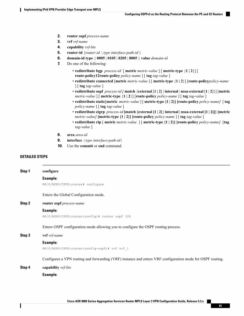
2. router ospf process-name3. vrf vrf-name4. capability vrf-lite5. router-id {router-id | type interface-path-id }6. domain-id type { 0005 | 0105 | 0205 | 8005 } value domain-id7. Do one of the following:
• redistribute bgp process-id [ metric metric-value ] [ metric-type {1 | 2}] [route-policy12route-policy policy-name ] [ tag tag-value ]
• redistribute connected [metric metric-value ] [ metric-type {1 | 2}] [route-policypolicy-name] [ tag tag-value ]
• redistribute ospf process-id [match {external [1 | 2] | internal | nssa-external [1 | 2]}] [metricmetric-value ] [ metric-type {1 | 2}] [route-policy policy-name ] [ tag tag-value ]
• redistribute static[metric metric-value ] [metric-type {1 | 2}] [route-policy policy-name] [ tagpolicy-name ] [ tag tag-value ]
• redistribute eigrp process-id [match {external [1 | 2] | internal | nssa-external [1 | 2]]} [metricmetric-value] [metric-type {1 | 2}] [route-policy policy-name ] [ tag tag-value ]
• redistribute rip [ metric metric-value ] [ metric-type {1 | 2}] [route-policy policy-name] [tagtag-value ]
8. area area-id9. interface {type interface-path-id}10. Use the commit or end command.
DETAILED STEPS
Step 1 configure
Example:RP/0/RSP0/CPU0:router# configure
Enters the Global Configuration mode.
Step 2 router ospf process-name
Example:RP/0/RSP0/CPU0:router(config)# router ospf 109
Enters OSPF configuration mode allowing you to configure the OSPF routing process.
Step 3 vrf vrf-name
Example:RP/0/RSP0/CPU0:router(config-ospf)# vrf vrf_1
Configures a VPN routing and forwarding (VRF) instance and enters VRF configuration mode for OSPF routing.
Step 4 capability vrf-lite
Example:
Cisco ASR 9000 Series Aggregation Services Router MPLS Layer 3 VPN Configuration Guide, Release 5.3.x91
Implementing IPv6 VPN Provider Edge Transport over MPLSConfiguring OSPFv3 as the Routing Protocol Between the PE and CE Routers
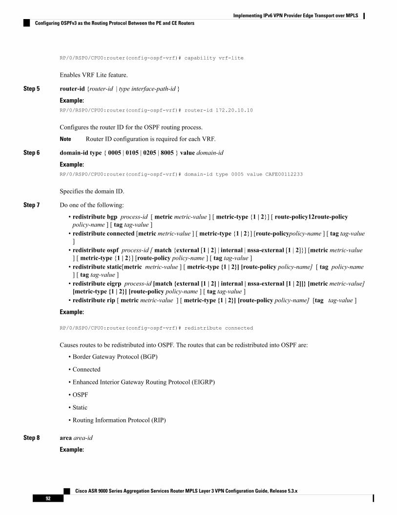
RP/0/RSP0/CPU0:router(config-ospf-vrf)# capability vrf-lite
Enables VRF Lite feature.
Step 5 router-id {router-id | type interface-path-id }
Example:RP/0/RSP0/CPU0:router(config-ospf-vrf)# router-id 172.20.10.10
Configures the router ID for the OSPF routing process.
Router ID configuration is required for each VRF.Note
Step 6 domain-id type { 0005 | 0105 | 0205 | 8005 } value domain-id
Example:RP/0/RSP0/CPU0:router(config-ospf-vrf)# domain-id type 0005 value CAFE00112233
Specifies the domain ID.
Step 7 Do one of the following:
• redistribute bgp process-id [ metric metric-value ] [ metric-type {1 | 2}] [ route-policy12route-policypolicy-name ] [ tag tag-value ]
• redistribute connected [metric metric-value ] [metric-type {1 | 2}] [route-policypolicy-name ] [ tag tag-value]
• redistribute ospf process-id [match {external [1 | 2] | internal | nssa-external [1 | 2]}] [metric metric-value] [ metric-type {1 | 2}] [route-policy policy-name ] [ tag tag-value ]
• redistribute static[metric metric-value ] [ metric-type {1 | 2}] [route-policy policy-name] [ tag policy-name] [ tag tag-value ]
• redistribute eigrp process-id [match {external [1 | 2] | internal | nssa-external [1 | 2]]} [metric metric-value][metric-type {1 | 2}] [route-policy policy-name ] [ tag tag-value ]
• redistribute rip [ metric metric-value ] [ metric-type {1 | 2}] [route-policy policy-name] [tag tag-value ]
Example:
RP/0/RSP0/CPU0:router(config-ospf-vrf)# redistribute connected
Causes routes to be redistributed into OSPF. The routes that can be redistributed into OSPF are:
• Border Gateway Protocol (BGP)
• Connected
• Enhanced Interior Gateway Routing Protocol (EIGRP)
• OSPF
• Static
• Routing Information Protocol (RIP)
Step 8 area area-id
Example:
Cisco ASR 9000 Series Aggregation Services Router MPLS Layer 3 VPN Configuration Guide, Release 5.3.x92
Implementing IPv6 VPN Provider Edge Transport over MPLSConfiguring OSPFv3 as the Routing Protocol Between the PE and CE Routers
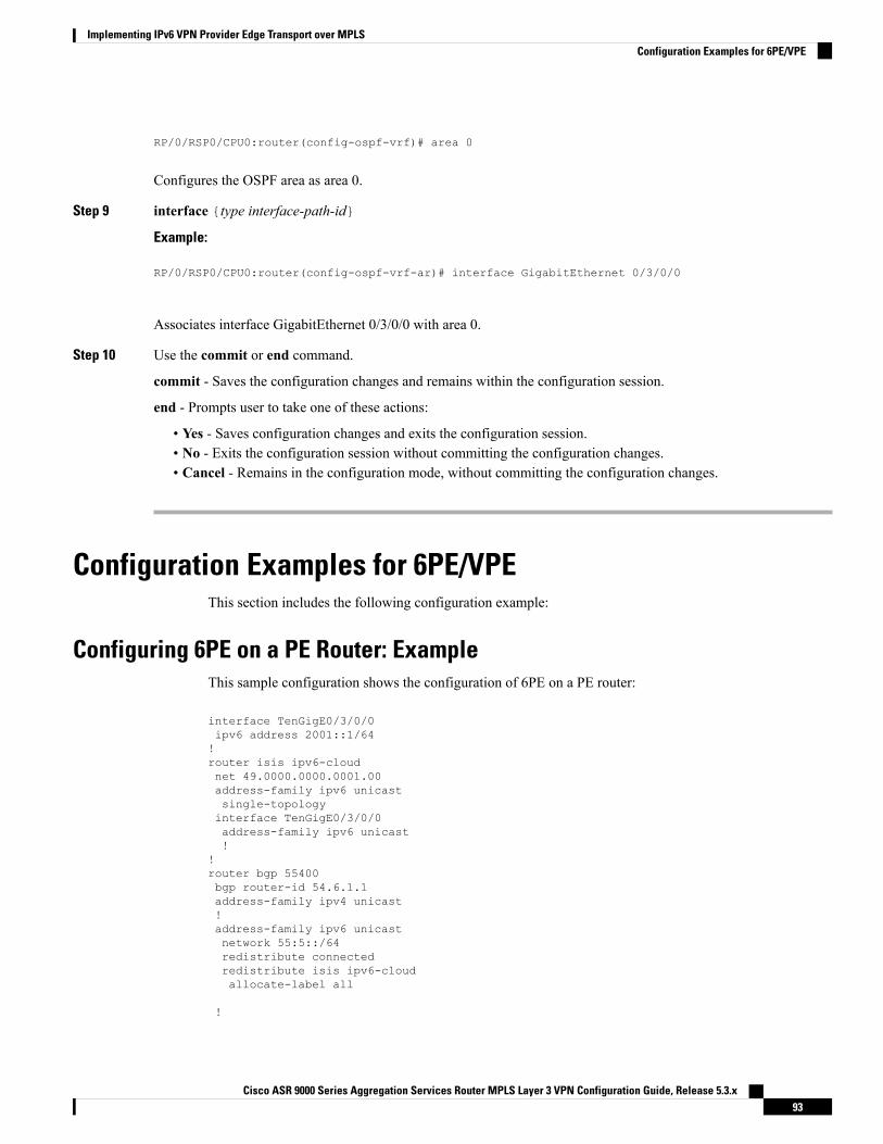
RP/0/RSP0/CPU0:router(config-ospf-vrf)# area 0
Configures the OSPF area as area 0.
Step 9 interface {type interface-path-id}
Example:
RP/0/RSP0/CPU0:router(config-ospf-vrf-ar)# interface GigabitEthernet 0/3/0/0
Associates interface GigabitEthernet 0/3/0/0 with area 0.
Step 10 Use the commit or end command.
commit - Saves the configuration changes and remains within the configuration session.
end - Prompts user to take one of these actions:
• Yes - Saves configuration changes and exits the configuration session.• No - Exits the configuration session without committing the configuration changes.• Cancel - Remains in the configuration mode, without committing the configuration changes.
Configuration Examples for 6PE/VPEThis section includes the following configuration example:
Configuring 6PE on a PE Router: ExampleThis sample configuration shows the configuration of 6PE on a PE router:
interface TenGigE0/3/0/0ipv6 address 2001::1/64!router isis ipv6-cloudnet 49.0000.0000.0001.00address-family ipv6 unicastsingle-topologyinterface TenGigE0/3/0/0address-family ipv6 unicast!
!router bgp 55400bgp router-id 54.6.1.1address-family ipv4 unicast!address-family ipv6 unicastnetwork 55:5::/64redistribute connectedredistribute isis ipv6-cloudallocate-label all
!
Cisco ASR 9000 Series Aggregation Services Router MPLS Layer 3 VPN Configuration Guide, Release 5.3.x93
Implementing IPv6 VPN Provider Edge Transport over MPLSConfiguration Examples for 6PE/VPE
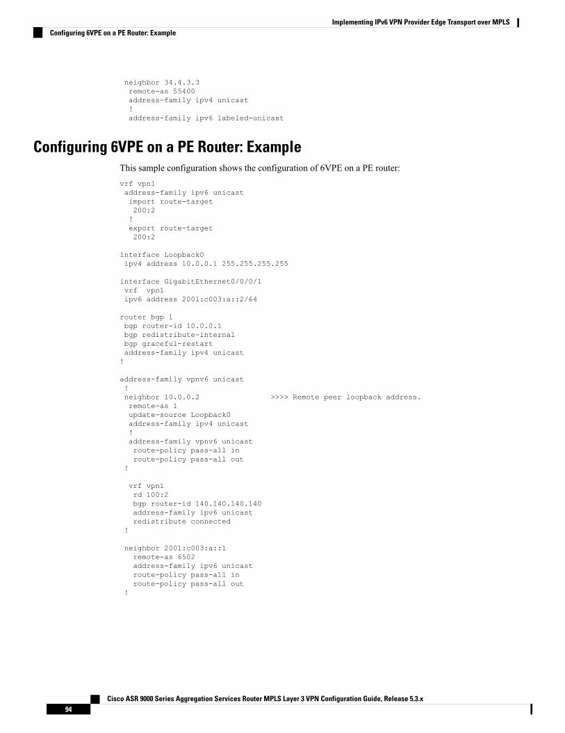
neighbor 34.4.3.3remote-as 55400address-family ipv4 unicast!address-family ipv6 labeled-unicast
Configuring 6VPE on a PE Router: ExampleThis sample configuration shows the configuration of 6VPE on a PE router:vrf vpn1address-family ipv6 unicastimport route-target200:2!export route-target200:2
interface Loopback0ipv4 address 10.0.0.1 255.255.255.255
interface GigabitEthernet0/0/0/1vrf vpn1ipv6 address 2001:c003:a::2/64
router bgp 1bgp router-id 10.0.0.1bgp redistribute-internalbgp graceful-restartaddress-family ipv4 unicast!
address-family vpnv6 unicast!neighbor 10.0.0.2 >>>> Remote peer loopback address.remote-as 1update-source Loopback0address-family ipv4 unicast!address-family vpnv6 unicastroute-policy pass-all inroute-policy pass-all out
!
vrf vpn1rd 100:2bgp router-id 140.140.140.140address-family ipv6 unicastredistribute connected
!
neighbor 2001:c003:a::1remote-as 6502address-family ipv6 unicastroute-policy pass-all inroute-policy pass-all out
!
Cisco ASR 9000 Series Aggregation Services Router MPLS Layer 3 VPN Configuration Guide, Release 5.3.x94
Implementing IPv6 VPN Provider Edge Transport over MPLSConfiguring 6VPE on a PE Router: Example
C H A P T E R 4Implementing Generic Routing Encapsulation
Generic Routing Encapsulation (GRE) is a tunneling protocol developed by Cisco Systems that encapsulatesa wide variety of network layer protocols inside virtual point-to-point links over an Internet Protocolinternetwork.
Feature History for Configuring Link Bundling on Cisco IOS XR Software
ModificationRelease
These feature were supported on the Cisco ASR 9000 Series Aggregation Services Routers:
• MPLS/L3VPNoGRE on ASR 9000 Enhanced Ethernet Line Card and Cisco ASR 9000Series SPA Interface Processor-700
• RSVP/TEoGREonASR 9000 Enhanced Ethernet Line Card and CiscoASR 9000 SeriesSPA Interface Processor-700
• VRF aware GRE on ASR 9000 Enhanced Ethernet Line Card and Cisco ASR 9000Series SPA Interface Processor-700
• L2VPN (VPWS and VPLS) on GRE for ASR 9000 Enhanced Ethernet Line Card only
Release 4.3.0
Support for GRE Tunnel Key and Tunnel Key-Ignore was introduced.Release 5.1.1
Support for GRE tunnel on an IPv6 transport network.Release 5.2.2
Support for GRE IPv4 Transport Over MPLS was introduced.Release 5.3.2
• Prerequisites for Configuring Generic Routing Encapsulation, on page 95• Information About Generic Routing Encapsulation, on page 96• GRE IPv4 Transport Over MPLS, on page 102• How to Configure Generic Routing Encapsulation, on page 102• Configuration Examples for Generic Routing Encapsulation, on page 115
Prerequisites for Configuring Generic Routing EncapsulationBefore configuring Link Bundling, be sure that these tasks and conditions are met:
• You must be in a user group associated with a task group that includes the proper task IDs. The commandreference guides include the task IDs required for each command.
Cisco ASR 9000 Series Aggregation Services Router MPLS Layer 3 VPN Configuration Guide, Release 5.3.x95
If you suspect user group assignment is preventing you from using a command, contact your AAA administratorfor assistance.
Information About Generic Routing EncapsulationTo implement the GRE feature, you must understand these concepts:
GRE OverviewGeneric Routing Encapsulation (GRE) tunneling protocol provides a simple generic approach to transportpackets of one protocol over another protocol by means of encapsulation.
GRE encapsulates a payload, that is, an inner packet that needs to be delivered to a destination network insidean outer IP packet. GRE tunnel endpoints send payloads through GRE tunnels by routing encapsulated packetsthrough intervening IP networks. Other IP routers along the way do not parse the payload (the inner packet);they only parse the outer IP packet as they forward it towards the GRE tunnel endpoint. Upon reaching thetunnel endpoint, GRE encapsulation is removed and the payload is forwarded to it’s ultimate destination.
MPLS networks provide VPN functionality by tunneling customer data through public networks using routinglabels. Service Providers (SP) provide MPLS L3VPN, 6PE/6VPE and L2VPN services to their customerswho have interconnected private networks.
MPLS and L3VPN are supported over regular interfaces on Cisco ASR 9000 Series Aggregation ServicesRouters through GRE tunnels over an IPv4 transport network. MPLS support is extended over IPv4 GREtunnels between routers as the provider core may not be fully MPLS aware.
GRE FeaturesThe following sections list the GRE features:
An IPv6 GRE tunnel does not support features that involve transport of MPLS packets through a GRE tunnel.Note
MPLS/L3VPN over GRETheMPLSVPN over GRE feature provides amechanism for tunnelingMultiprotocol Label Switching (MPLS)packets over a non-MPLS network. This feature utilizesMPLS over generic routing encapsulation (MPLSoGRE)to encapsulate MPLS packets inside IP tunnels. The encapsulation of MPLS packets inside IP tunnels createsa virtual point-to-point link across non-MPLS networks.
L3VPN over GRE basically means encapsulating L3VPN traffic in GRE header and its outer IPv4 headerwith tunnel destination and source IP addresses after imposing zero or more MPLS labels, and transportingit across the tunnel over to the remote tunnel end point. The incoming packet can be a pure IPv4 packet or anMPLS packet. If the incoming packet is IPv4, the packet enters the tunnel through a VRF interface, and if theincoming packet is MPLS, then the packet enters through an MPLS interface. In the IPv4 case, beforeencapsulating in the outer IPv4 and GRE headers, a VPN label corresponding to the VRF prefix and any IGPlabel corresponding to the IGP prefix of the GRE tunnel destination is imposed on the packet. In the case ofMPLS, the top IGP label is swapped with any label corresponding to the GRE tunnel destination address.
Cisco ASR 9000 Series Aggregation Services Router MPLS Layer 3 VPN Configuration Guide, Release 5.3.x96
Implementing Generic Routing EncapsulationInformation About Generic Routing Encapsulation
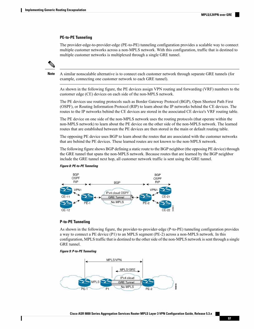
PE-to-PE Tunneling
The provider-edge-to-provider-edge (PE-to-PE) tunneling configuration provides a scalable way to connectmultiple customer networks across a non-MPLS network. With this configuration, traffic that is destined tomultiple customer networks is multiplexed through a single GRE tunnel.
A similar nonscalable alternative is to connect each customer network through separate GRE tunnels (forexample, connecting one customer network to each GRE tunnel).
Note
As shown in the following figure, the PE devices assign VPN routing and forwarding (VRF) numbers to thecustomer edge (CE) devices on each side of the non-MPLS network.
The PE devices use routing protocols such as Border Gateway Protocol (BGP), Open Shortest Path First(OSPF), or Routing Information Protocol (RIP) to learn about the IP networks behind the CE devices. Theroutes to the IP networks behind the CE devices are stored in the associated CE device's VRF routing table.
The PE device on one side of the non-MPLS network uses the routing protocols (that operate within thenon-MPLS network) to learn about the PE device on the other side of the non-MPLS network. The learnedroutes that are established between the PE devices are then stored in the main or default routing table.
The opposing PE device uses BGP to learn about the routes that are associated with the customer networksthat are behind the PE devices. These learned routes are not known to the non-MPLS network.
The following figure shows BGP defining a static route to the BGP neighbor (the opposing PE device) throughthe GRE tunnel that spans the non-MPLS network. Because routes that are learned by the BGP neighborinclude the GRE tunnel next hop, all customer network traffic is sent using the GRE tunnel.Figure 8: PE-to-PE Tunneling
P-to-PE Tunneling
As shown in the following figure, the provider-to-provider-edge (P-to-PE) tunneling configuration providesa way to connect a PE device (P1) to an MPLS segment (PE-2) across a non-MPLS network. In thisconfiguration,MPLS traffic that is destined to the other side of the non-MPLS network is sent through a singleGRE tunnel.Figure 9: P-to-PE Tunneling
Cisco ASR 9000 Series Aggregation Services Router MPLS Layer 3 VPN Configuration Guide, Release 5.3.x97
Implementing Generic Routing EncapsulationMPLS/L3VPN over GRE
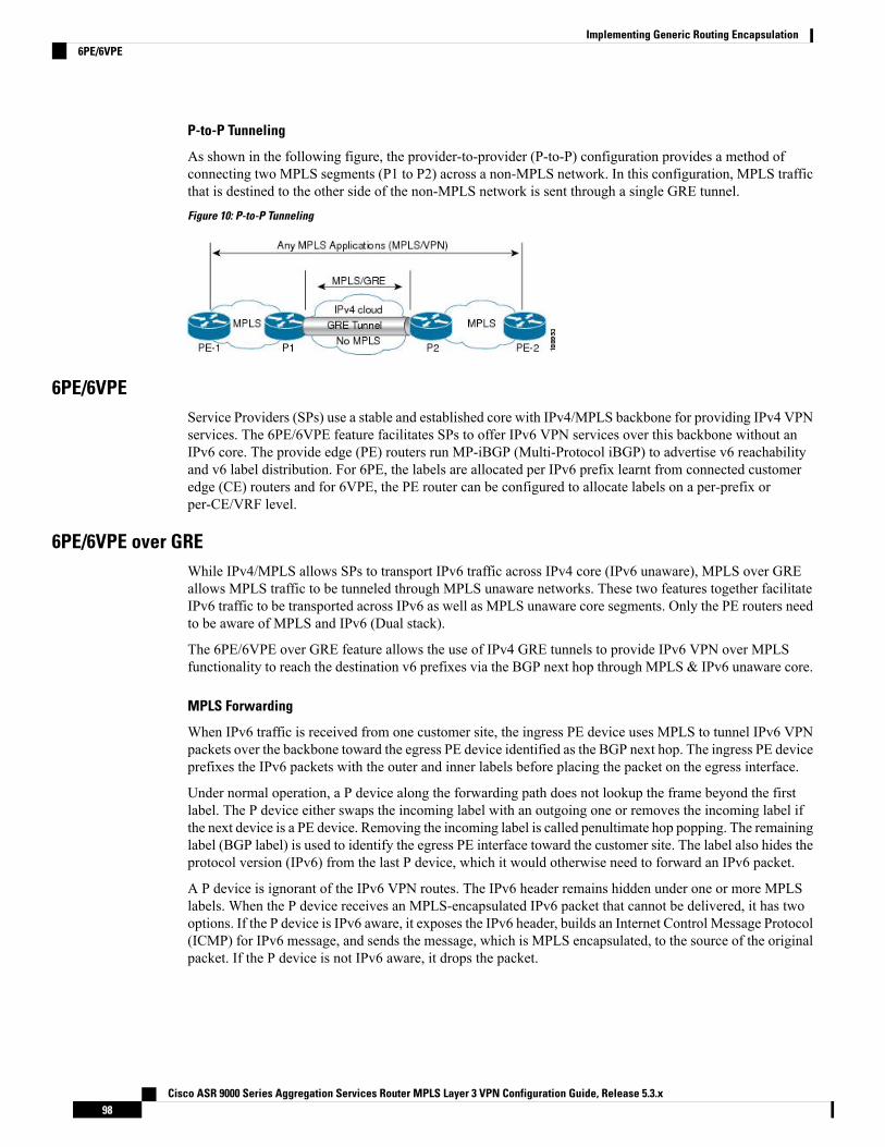
P-to-P Tunneling
As shown in the following figure, the provider-to-provider (P-to-P) configuration provides a method ofconnecting two MPLS segments (P1 to P2) across a non-MPLS network. In this configuration, MPLS trafficthat is destined to the other side of the non-MPLS network is sent through a single GRE tunnel.Figure 10: P-to-P Tunneling
6PE/6VPEService Providers (SPs) use a stable and established core with IPv4/MPLS backbone for providing IPv4 VPNservices. The 6PE/6VPE feature facilitates SPs to offer IPv6 VPN services over this backbone without anIPv6 core. The provide edge (PE) routers run MP-iBGP (Multi-Protocol iBGP) to advertise v6 reachabilityand v6 label distribution. For 6PE, the labels are allocated per IPv6 prefix learnt from connected customeredge (CE) routers and for 6VPE, the PE router can be configured to allocate labels on a per-prefix orper-CE/VRF level.
6PE/6VPE over GREWhile IPv4/MPLS allows SPs to transport IPv6 traffic across IPv4 core (IPv6 unaware), MPLS over GREallows MPLS traffic to be tunneled through MPLS unaware networks. These two features together facilitateIPv6 traffic to be transported across IPv6 as well as MPLS unaware core segments. Only the PE routers needto be aware of MPLS and IPv6 (Dual stack).
The 6PE/6VPE over GRE feature allows the use of IPv4 GRE tunnels to provide IPv6 VPN over MPLSfunctionality to reach the destination v6 prefixes via the BGP next hop through MPLS & IPv6 unaware core.
MPLS Forwarding
When IPv6 traffic is received from one customer site, the ingress PE device uses MPLS to tunnel IPv6 VPNpackets over the backbone toward the egress PE device identified as the BGP next hop. The ingress PE deviceprefixes the IPv6 packets with the outer and inner labels before placing the packet on the egress interface.
Under normal operation, a P device along the forwarding path does not lookup the frame beyond the firstlabel. The P device either swaps the incoming label with an outgoing one or removes the incoming label ifthe next device is a PE device. Removing the incoming label is called penultimate hop popping. The remaininglabel (BGP label) is used to identify the egress PE interface toward the customer site. The label also hides theprotocol version (IPv6) from the last P device, which it would otherwise need to forward an IPv6 packet.
A P device is ignorant of the IPv6 VPN routes. The IPv6 header remains hidden under one or more MPLSlabels. When the P device receives an MPLS-encapsulated IPv6 packet that cannot be delivered, it has twooptions. If the P device is IPv6 aware, it exposes the IPv6 header, builds an Internet Control Message Protocol(ICMP) for IPv6 message, and sends the message, which is MPLS encapsulated, to the source of the originalpacket. If the P device is not IPv6 aware, it drops the packet.
Cisco ASR 9000 Series Aggregation Services Router MPLS Layer 3 VPN Configuration Guide, Release 5.3.x98
Implementing Generic Routing Encapsulation6PE/6VPE
6PE/6VPE over GRE
As discussed earlier, 6PE/6VPE over GRE basically means enabling IPv6/IPv6 VPN over MPLS over GRE.
The ingress PE device uses IPv4 generic routing encapsulation (GRE) tunnels combined with 6PE/6VPE overMPLS to tunnel IPv6 VPN packets over the backbone toward the egress PE device identified as the BGP nexthop.
The PE devices establish MP-iBGP sessions and MPLS LDP sessions just as in the case of 6PE/6VPE. Thedifference here is that these sessions are established over GRE tunnels, which also means that the PEs are justone IGP hop away. The P routers in the tunnel path only need to forward the traffic to the tunnel destination,which is an IPv4 address.
This is how the IPv6 LSP is setup for label switching the IPv6 traffic:
• After the LDP and BGP sessions are established, the PEs exchange IPv6 prefixes that they learn fromthe CEs and the corresponding IPv6 labels, just as in the case of IPv4 VPN.
• The IPv6 labels occupy the inner most position in the label stack.• The IPv4 labels corresponding to the PE IPv4 addresses occupy the outer position in the stack.• When IPv6 traffic needs to be forwarded from PE1 to PE2, the outer PE2 IPv4 label is used to labelswitch the traffic to PE2, and the inner IPv6 label is used to send the packet out of the interface connectedto the CE.
GRE Tunnel KeyThe GRE Tunnel Key feature enables the encapsulation router to add a four-byte key, as part of the GREheader, during encapsulation. In the decapsulation router, the GRE key of an incoming packet should matchthe key value configured under the GRE tunnel. During decapsulation, if a mismatch between the key valueof the incoming GRE packet and the key value configured under the GRE tunnel is identified, the incomingpacket is dropped.
• GRE tunnel key feature is supported only on Cisco ASR 9000 Enhanced Ethernet line cards. It ismandatory to have ingress and egress line cards as Enhanced Ethernet line cards.
• Either the same key or different keys can be configured under multiple GRE tunnels for a given router.However, more than one tunnel, having the same tunnel source and destination but a different tunnel keyis not supported because the source and destination pair for various configured tunnels must be uniqueirrespective of the key value. Also, two tunnels with the same tunnel source and destination, but onetunnel being with key and the other tunnel being without key is not supported.
• Different traffic streams passing through the same GRE tunnel contains the same GRE key configuredfor that tunnel.
• Use the tunnel key command to configure the key value at both ends of a GRE tunnel.
Note
The following figure shows a simple representation of the GRE tunnel key configuration:
Cisco ASR 9000 Series Aggregation Services Router MPLS Layer 3 VPN Configuration Guide, Release 5.3.x99
Implementing Generic Routing EncapsulationGRE Tunnel Key
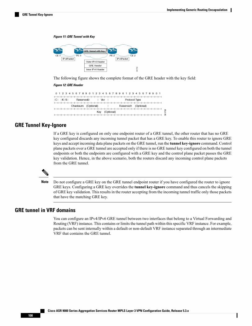
Figure 11: GRE Tunnel with Key
The following figure shows the complete format of the GRE header with the key field:Figure 12: GRE Header
GRE Tunnel Key-IgnoreIf a GRE key is configured on only one endpoint router of a GRE tunnel, the other router that has no GREkey configured discards any incoming tunnel packet that has a GRE key. To enable this router to ignore GREkeys and accept incoming data plane packets on the GRE tunnel, run the tunnel key-ignore command. Controlplane packets over a GRE tunnel are accepted only if there is no GRE tunnel key configured on both the tunnelendpoints or both the endpoints are configured with a GRE key and the control plane packet passes the GREkey validation. Hence, in the above scenario, both the routers discard any incoming control plane packetsfrom the GRE tunnel.
Do not configure a GRE key on the GRE tunnel endpoint router if you have configured the router to ignoreGRE keys. Configuring a GRE key overrides the tunnel key-ignore command and thus cancels the skippingof GRE key validation. This results in the router accepting from the incoming tunnel traffic only those packetsthat have the matching GRE key.
Note
GRE tunnel in VRF domainsYou can configure an IPv4/IPv6 GRE tunnel between two interfaces that belong to a Virtual Forwarding andRouting (VRF) instance. This contains or limits the tunnel path within this specific VRF instance. For example,packets can be sent internally within a default or non-default VRF instance separated through an intermediateVRF that contains the GRE tunnel.
Cisco ASR 9000 Series Aggregation Services Router MPLS Layer 3 VPN Configuration Guide, Release 5.3.x100
Implementing Generic Routing EncapsulationGRE Tunnel Key-Ignore
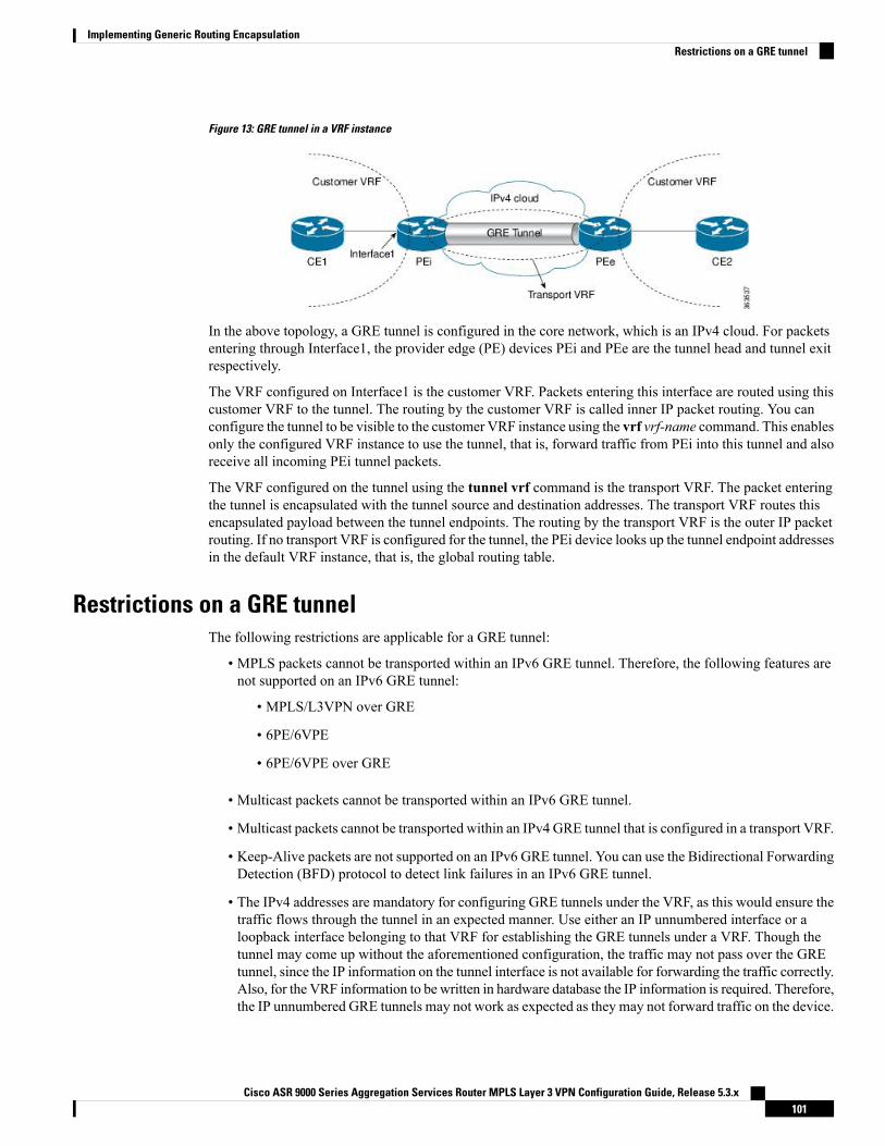
Figure 13: GRE tunnel in a VRF instance
In the above topology, a GRE tunnel is configured in the core network, which is an IPv4 cloud. For packetsentering through Interface1, the provider edge (PE) devices PEi and PEe are the tunnel head and tunnel exitrespectively.
The VRF configured on Interface1 is the customer VRF. Packets entering this interface are routed using thiscustomer VRF to the tunnel. The routing by the customer VRF is called inner IP packet routing. You canconfigure the tunnel to be visible to the customer VRF instance using the vrf vrf-name command. This enablesonly the configured VRF instance to use the tunnel, that is, forward traffic from PEi into this tunnel and alsoreceive all incoming PEi tunnel packets.
The VRF configured on the tunnel using the tunnel vrf command is the transport VRF. The packet enteringthe tunnel is encapsulated with the tunnel source and destination addresses. The transport VRF routes thisencapsulated payload between the tunnel endpoints. The routing by the transport VRF is the outer IP packetrouting. If no transport VRF is configured for the tunnel, the PEi device looks up the tunnel endpoint addressesin the default VRF instance, that is, the global routing table.
Restrictions on a GRE tunnelThe following restrictions are applicable for a GRE tunnel:
• MPLS packets cannot be transported within an IPv6 GRE tunnel. Therefore, the following features arenot supported on an IPv6 GRE tunnel:
• MPLS/L3VPN over GRE
• 6PE/6VPE
• 6PE/6VPE over GRE
• Multicast packets cannot be transported within an IPv6 GRE tunnel.
• Multicast packets cannot be transported within an IPv4 GRE tunnel that is configured in a transport VRF.
• Keep-Alive packets are not supported on an IPv6 GRE tunnel. You can use the Bidirectional ForwardingDetection (BFD) protocol to detect link failures in an IPv6 GRE tunnel.
• The IPv4 addresses are mandatory for configuring GRE tunnels under the VRF, as this would ensure thetraffic flows through the tunnel in an expected manner. Use either an IP unnumbered interface or aloopback interface belonging to that VRF for establishing the GRE tunnels under a VRF. Though thetunnel may come up without the aforementioned configuration, the traffic may not pass over the GREtunnel, since the IP information on the tunnel interface is not available for forwarding the traffic correctly.Also, for the VRF information to be written in hardware database the IP information is required. Therefore,the IP unnumbered GRE tunnels may not work as expected as they may not forward traffic on the device.
Cisco ASR 9000 Series Aggregation Services Router MPLS Layer 3 VPN Configuration Guide, Release 5.3.x101
Implementing Generic Routing EncapsulationRestrictions on a GRE tunnel
GRE IPv4 Transport Over MPLSThe Generic Routing Encapsulation (GRE) IPv4 transport overMultiprotocol Label Switching (MPLS) featureprovides a mechanism to configure GRE tunnels, where the tunnel destination IPv4 address is reachablethrough an MPLS label switched path (LSP). With this feature, IPv4, IPv6, routing protocols - OSPF, ISIS,and L2VPN and L3VPN packets are accepted as payload packets for GRE encapsulation , but only IPv4 issupported as the GRE delivery protocol.
This feature overcomes the restriction of not being able to configure the tunnel destination endpoint throughan MPLS LSP during tunnel configuration.
The GRE IPv4 transport over MPLS feature facilitates creation of GRE tunnels over LSPs, through L3VPNinter-AS (autonomous system) options:
• External Border Gateway Protocol (EBGP) redistribution of labeled VPN IPv4 routes from an AS to aneighboring AS.
• Multi-hop EBGP redistribution of labeled VPN IPv4 routes between source and destination ASs, withEBGP redistribution of labeled IPv4 routes from an AS to a neighboring AS.
Multipoint GRE IPv4 transport over MPLS is also supported.
The GRE IPv4 transport over MPLS feature is supported on the following types of Cisco ASR 9000 linecards:
• Cisco ASR 9000 Enhanced Ethernet line card
• Cisco ASR 9000 High Density 100GE Ethernet line card
Limitations
The following features are not supported:
• GRE IPv6 transport over MPLS
• GRE IPv4 transport over MPLS-TE tunnels .
• GREoMPLS with IP Fast Reroute (IPFRR).
How to Configure Generic Routing Encapsulation
Configuring a GRE TunnelPerform this task to configure a GRE tunnel.
SUMMARY STEPS
1. configure2. interface tunnel-ip number3. vrf vrf-name4. ipv4 address ipv4-address mask
Cisco ASR 9000 Series Aggregation Services Router MPLS Layer 3 VPN Configuration Guide, Release 5.3.x102
Implementing Generic Routing EncapsulationGRE IPv4 Transport Over MPLS
5. tunnel mode gre {ipv4 | ipv6}6. tunnel source { ip-address | type path-id }7. tunnel destination ip-address8. tunnel vrf transport-vrf-name9. Use the commit or end command.
DETAILED STEPS
Step 1 configure
Example:
RP/0/RSP0/CPU0:router# configure
Enters the Global Configuration mode.
Step 2 interface tunnel-ip number
Example:
RP/0/RSP0/CPU0:router(config)# interface tunnel-ip 4000
Enters tunnel interface configuration mode.
• number is the number associated with the tunnel interface.
Step 3 vrf vrf-name
Example:
RP/0/RSP0/CPU0:router(config-if)# vrf vrf1
(Optional) Specifies the VRF domain that can route packets into and from the tunnel.
This step is not required if the tunnel is available for global routing and therefore, is not specific to a VRF.Note
Step 4 ipv4 address ipv4-address mask
Example:
RP/0/RSP0/CPU0:router(config-if)# ipv4 address 10.1.1.1 255.255.255.0
Specifies the IPv4 address and subnet mask for the interface.
• ipv4-address specifies the IP address of the interface.• subnet-mask specifies the subnet mask of the interface.
Step 5 tunnel mode gre {ipv4 | ipv6}
Example:
Cisco ASR 9000 Series Aggregation Services Router MPLS Layer 3 VPN Configuration Guide, Release 5.3.x103
Implementing Generic Routing EncapsulationConfiguring a GRE Tunnel
RP/0/RSP0/CPU0:router(config-if)# tunnel mode gre ipv4
Specify whether the transport network is an IPv4 or IPv6 network. The default GRE tunnel mode is IPv4.
The tunnel source and destination addresses should match the tunnel mode. Amismatch in configuration causesthe tunnel to fail without any error message.
Note
Step 6 tunnel source { ip-address | type path-id }
Example:
RP/0/RSP0/CPU0:router(config-if)# tunnel source TenGigE0/2/0/1
Specifies the source of the tunnel interface.
It is recommended that the tunnel source is identified using the interface ID and not the IP address. Using theinterface ID enables the router to mark the tunnel as down when the interface is down and the routing protocoltries to find and use an alternate route to the tunnel route.
Note
Step 7 tunnel destination ip-address
Example:
RP/0/RSP0/CPU0:router(config-if)# tunnel destination 145.12.5.2
Defines the tunnel destination.
Step 8 tunnel vrf transport-vrf-name
Example:
RP/0/RSP0/CPU0:router(config-if)# tunnel vrf vrf99
(Optional) Associates the transport VRF with the tunnel. The transport VRF contains the interfaces over which the tunnelsends as well as receives packets (outer IP packet routing).
This step is not required if the tunnel endpoints belong to the global routing table.Note
Step 9 Use the commit or end command.
commit - Saves the configuration changes and remains within the configuration session.
end - Prompts user to take one of these actions:
• Yes - Saves configuration changes and exits the configuration session.• No - Exits the configuration session without committing the configuration changes.• Cancel - Remains in the configuration mode, without committing the configuration changes.
Cisco ASR 9000 Series Aggregation Services Router MPLS Layer 3 VPN Configuration Guide, Release 5.3.x104
Implementing Generic Routing EncapsulationConfiguring a GRE Tunnel
Configuring the Tunnel KeyPerform this task to configure the tunnel key for the GRE encapsulated packets. You need to perform sameconfiguration steps on the other endpoint router of the tunnel ensuring that the key value is the same at boththe local and remote GRE interfaces.
SUMMARY STEPS
1. configure2. interface tunnel-ip number3. ipv4 address ipv4-address subnet-mask4. tunnel key value5. (Optional) tunnel tos tos-value6. tunnel source type path-id7. tunnel destination ip-address8. Use the commit or end command.
DETAILED STEPS
Step 1 configure
Example:
RP/0/RSP0/CPU0:router# configure
Enters the Global Configuration mode.
Step 2 interface tunnel-ip number
Example:
RP/0/RSP0/CPU0:router(config)# interface tunnel-ip 10
Enters tunnel interface configuration mode.
• number is the number associated with the tunnel interface.
Step 3 ipv4 address ipv4-address subnet-mask
Example:
RP/0/RSP0/CPU0:router(config-if)# ipv4 address 101.0.9.1 255.255.255.0
Specifies the IPv4 address and subnet mask for the interface.
• ipv4-address specifies the IP address of the interface.• subnet-mask specifies the subnet mask of the interface.
Step 4 tunnel key value
Cisco ASR 9000 Series Aggregation Services Router MPLS Layer 3 VPN Configuration Guide, Release 5.3.x105
Implementing Generic Routing EncapsulationConfiguring the Tunnel Key
Example:
RP/0/RSP0/CPU0:router(config-if)# tunnel key 10
Enables tunnel key.
Step 5 (Optional) tunnel tos tos-value
Example:
RP/0/RSP0/CPU0:router(config-if)# tunnel tos 96
Specifies the value of the TOS field in the tunnel encapsulating packets.
Step 6 tunnel source type path-id
Example:
RP/0/RSP0/CPU0:router(config-if)# tunnel source Loopback10
Specifies the source of the tunnel interface.
Step 7 tunnel destination ip-address
Example:
RP/0/RSP0/CPU0:router(config-if)# tunnel destination 33.0.9.33
Defines the tunnel destination.
Step 8 Use the commit or end command.
commit - Saves the configuration changes and remains within the configuration session.
end - Prompts user to take one of these actions:
• Yes - Saves configuration changes and exits the configuration session.• No - Exits the configuration session without committing the configuration changes.• Cancel - Remains in the configuration mode, without committing the configuration changes.
Configuring the Tunnel Key-IgnorePerform this task to configure the tunnel key-ignore for the GRE encapsulated packets. You need to performsame configuration steps on the other endpoint router of the tunnel.
SUMMARY STEPS
1. configure2. interface tunnel-ip number3. ipv4 address ipv4-address subnet-mask
Cisco ASR 9000 Series Aggregation Services Router MPLS Layer 3 VPN Configuration Guide, Release 5.3.x106
Implementing Generic Routing EncapsulationConfiguring the Tunnel Key-Ignore
4. tunnel key-ignore5. (Optional) tunnel tos tos-value6. tunnel source type path-id7. tunnel destination ip-address8. Use the commit or end command.
DETAILED STEPS
Step 1 configure
Example:
RP/0/RSP0/CPU0:router# configure
Enters the Global Configuration mode.
Step 2 interface tunnel-ip number
Example:
RP/0/RSP0/CPU0:router(config)# interface tunnel-ip 10
Enters tunnel interface configuration mode.
• number is the number associated with the tunnel interface.
Step 3 ipv4 address ipv4-address subnet-mask
Example:
RP/0/RSP0/CPU0:router(config-if)# ipv4 address 101.0.9.1 255.255.255.0
Specifies the IPv4 address and subnet mask for the interface.
• ipv4-address specifies the IP address of the interface.• subnet-mask specifies the subnet mask of the interface.
Step 4 tunnel key-ignore
Example:
RP/0/RSP0/CPU0:router(config-if)# tunnel key-ignore
Enables tunnel key-ignore.
Step 5 (Optional) tunnel tos tos-value
Example:
RP/0/RSP0/CPU0:router(config-if)# tunnel tos 96
Specifies the value of the TOS field in the tunnel encapsulating packets.
Cisco ASR 9000 Series Aggregation Services Router MPLS Layer 3 VPN Configuration Guide, Release 5.3.x107
Implementing Generic Routing EncapsulationConfiguring the Tunnel Key-Ignore
Step 6 tunnel source type path-id
Example:
RP/0/RSP0/CPU0:router(config-if)# tunnel source Loopback10
Specifies the source of the tunnel interface.
Step 7 tunnel destination ip-address
Example:
RP/0/RSP0/CPU0:router(config-if)# tunnel destination 33.0.9.33
Defines the tunnel destination.
Step 8 Use the commit or end command.
commit - Saves the configuration changes and remains within the configuration session.
end - Prompts user to take one of these actions:
• Yes - Saves configuration changes and exits the configuration session.• No - Exits the configuration session without committing the configuration changes.• Cancel - Remains in the configuration mode, without committing the configuration changes.
Configuring a VRF InterfacePerform this task to configure a VRF interface.
SUMMARY STEPS
1. configure2. interface type interface-path-id3. vrf vrf-name4. ipv4 address ipv4-address mask5. Use the commit or end command.
DETAILED STEPS
Step 1 configure
Example:RP/0/RSP0/CPU0:router# configure
Enters the Global Configuration mode.
Step 2 interface type interface-path-id
Example:
Cisco ASR 9000 Series Aggregation Services Router MPLS Layer 3 VPN Configuration Guide, Release 5.3.x108
Implementing Generic Routing EncapsulationConfiguring a VRF Interface
RP/0/RSP0/CPU0:router(config)# interface tunnel-ip 100
Enters interface configuration mode.
Step 3 vrf vrf-name
Example:
RP/0/RSP0/CPU0:router(config-if)# vrf vrf_A
Configures a VRF instance and enters VRF configuration mode.
Step 4 ipv4 address ipv4-address mask
Example:
RP/0/RSP0/CPU0:router(config-if)# ipv4 address 192.168.1.27 255.255.255.0
Configures a primary IPv4 address for the specified interface.
Step 5 Use the commit or end command.
commit - Saves the configuration changes and remains within the configuration session.
end - Prompts user to take one of these actions:
• Yes - Saves configuration changes and exits the configuration session.• No - Exits the configuration session without committing the configuration changes.• Cancel - Remains in the configuration mode, without committing the configuration changes.
Configuring VRF Routing ProtocolPerform this task to configure the VRF routing protocol.
SUMMARY STEPS
1. configure2. router ospf process-name3. vrf vrf-name4. router-id {router-id | type interface-path-id}5. area area-id6. interface type interface-path-id7. Use the commit or end command.
DETAILED STEPS
Step 1 configure
Example:
Cisco ASR 9000 Series Aggregation Services Router MPLS Layer 3 VPN Configuration Guide, Release 5.3.x109
Implementing Generic Routing EncapsulationConfiguring VRF Routing Protocol
RP/0/RSP0/CPU0:router# configure
Enters the Global Configuration mode.
Step 2 router ospf process-name
Example:
RP/0/RSP0/CPU0:router(config)# router ospf 109
Enters OSPF configuration mode allowing you to configure the OSPF routing process.
Step 3 vrf vrf-name
Example:
RP/0/RSP0/CPU0:router(config-ospf)# vrf vrf_1
Configures a VPN routing and forwarding (VRF) instance and enters VRF configuration mode for OSPF routing.
Step 4 router-id {router-id | type interface-path-id}
Example:
RP/0/RSP0/CPU0:router(config-ospf-vrf)# router-id 172.20.10.10
Configures the router ID for the OSPF routing process.
Step 5 area area-id
Example:
RP/0/RSP0/CPU0:router(config-ospf-vrf)# area 0
Configures the OSPF area as area 0.
Step 6 interface type interface-path-id
Example:
RP/0/RSP0/CPU0:router(config-ospf-vrf-ar)# interface GigabitEthernet 0/3/0/0
Associates interface GigabitEthernet 0/3/0/0 with area 0.
Step 7 Use the commit or end command.
commit - Saves the configuration changes and remains within the configuration session.
end - Prompts user to take one of these actions:
• Yes - Saves configuration changes and exits the configuration session.• No - Exits the configuration session without committing the configuration changes.
Cisco ASR 9000 Series Aggregation Services Router MPLS Layer 3 VPN Configuration Guide, Release 5.3.x110
Implementing Generic Routing EncapsulationConfiguring VRF Routing Protocol
• Cancel - Remains in the configuration mode, without committing the configuration changes.
Configuring IGP for Remote PE ReachabilityPerform this task to configure IGP for remote PE reachability.
SUMMARY STEPS
1. configure2. router ospf process-name3. router-id {router-id}4. area area-id5. interface tunnel-ip number6. Use the commit or end command.
DETAILED STEPS
Step 1 configure
Example:RP/0/RSP0/CPU0:router# configure
Enters the Global Configuration mode.
Step 2 router ospf process-name
Example:
RP/0/RSP0/CPU0:router(config)# router ospf 1
Enables OSPF routing for the specified routing process and places the router in router configuration mode.
Step 3 router-id {router-id}
Example:
RP/0/RSP0/CPU0:router(config-ospf)# router-id 1.1.1.1
Configures a router ID for the OSPF process.
We recommend using a stable IP address as the router ID.Note
Step 4 area area-id
Example:
RP/0/RSP0/CPU0:router(config-ospf)# area 0
Enters area configuration mode and configures an area for the OSPF process.
Cisco ASR 9000 Series Aggregation Services Router MPLS Layer 3 VPN Configuration Guide, Release 5.3.x111
Implementing Generic Routing EncapsulationConfiguring IGP for Remote PE Reachability
Step 5 interface tunnel-ip number
Example:
RP/0/RSP0/CPU0:router(config-ospf-ar)# interface tunnel-ip 4
Enters tunnel interface configuration mode.
• number is the number associated with the tunnel interface.
Step 6 Use the commit or end command.
commit - Saves the configuration changes and remains within the configuration session.
end - Prompts user to take one of these actions:
• Yes - Saves configuration changes and exits the configuration session.• No - Exits the configuration session without committing the configuration changes.• Cancel - Remains in the configuration mode, without committing the configuration changes.
Configuring LDP on GRE TunnelPerform this task to configure LDP on a GRE tunnel.
SUMMARY STEPS
1. configure2. mpls ldp3. router-id {router-id}4. interface tunnel-ip number5. Use the commit or end command.
DETAILED STEPS
Step 1 configure
Example:RP/0/RSP0/CPU0:router# configure
Enters the Global Configuration mode.
Step 2 mpls ldp
Example:
RP/0/RSP0/CPU0:router(config)# mpls ldp
Enables MPLS LDP configuration mode.
Step 3 router-id {router-id}
Cisco ASR 9000 Series Aggregation Services Router MPLS Layer 3 VPN Configuration Guide, Release 5.3.x112
Implementing Generic Routing EncapsulationConfiguring LDP on GRE Tunnel
Example:
RP/0/RSP0/CPU0:router(config-ldp)# router-id 1.1.1.1
Configures a router ID for the OSPF process.
We recommend using a stable IP address as the router ID.Note
Step 4 interface tunnel-ip number
Example:
RP/0/RSP0/CPU0:router(config-ldp)# interface tunnel-ip 4
Enters tunnel interface configuration mode.
• number is the number associated with the tunnel interface.
Step 5 Use the commit or end command.
commit - Saves the configuration changes and remains within the configuration session.
end - Prompts user to take one of these actions:
• Yes - Saves configuration changes and exits the configuration session.• No - Exits the configuration session without committing the configuration changes.• Cancel - Remains in the configuration mode, without committing the configuration changes.
Configuring MP-iBGP to Exchange VPN-IPv4 RoutesPerform this task to configure MP-iBGP to exchange VPN-IPv4 routes.
SUMMARY STEPS
1. configure2. router bgp as-number3. router-id ip-address4. neighbor ip-address5. remote-as as-number6. update-source type interface-path-id7. address-family { vpnv4 | vpnv6 unicast }8. Use the commit or end command.
DETAILED STEPS
Step 1 configure
Example:RP/0/RSP0/CPU0:router# configure
Cisco ASR 9000 Series Aggregation Services Router MPLS Layer 3 VPN Configuration Guide, Release 5.3.x113
Implementing Generic Routing EncapsulationConfiguring MP-iBGP to Exchange VPN-IPv4 Routes
Enters the Global Configuration mode.
Step 2 router bgp as-number
Example:
RP/0/RSP0/CPU0:router(config)# router bgp 1
Specifies the autonomous system number and enters the BGP configuration mode, allowing you to configure the BGProuting process.
Step 3 router-id ip-address
Example:
RP/0/RSP0/CPU0:router(config-bgp)# router-id 1.1.1.1
Configures the local router with a specified router ID.
Step 4 neighbor ip-address
Example:
RP/0/RSP0/CPU0:router(config-bgp)# neighbor 4.4.4.4
Places the router in neighbor configuration mode for BGP routing and configures the neighbor IP address as a BGP peer.
Step 5 remote-as as-number
Example:
RP/0/RSP0/CPU0:router(config-bgp-nbr)#remote-as 1
Creates a neighbor and assigns a remote autonomous system number to it.
Step 6 update-source type interface-path-id
Example:
RP/0/RSP0/CPU0:router(config-bgp-nbr)#update-source Loopback0
Allows sessions to use the primary IP address from a specific interface as the local address when forming a session witha neighbor.
Step 7 address-family { vpnv4 | vpnv6 unicast }
Example:
RP/0/RSP0/CPU0:router(config-bgp-nbr)# address-family vpnv4 unicast
Enters address family configuration submode for the specified address family.
Step 8 Use the commit or end command.
commit - Saves the configuration changes and remains within the configuration session.
Cisco ASR 9000 Series Aggregation Services Router MPLS Layer 3 VPN Configuration Guide, Release 5.3.x114
Implementing Generic Routing EncapsulationConfiguring MP-iBGP to Exchange VPN-IPv4 Routes
end - Prompts user to take one of these actions:
• Yes - Saves configuration changes and exits the configuration session.• No - Exits the configuration session without committing the configuration changes.• Cancel - Remains in the configuration mode, without committing the configuration changes.
Configuration Examples for Generic Routing EncapsulationThis section provides examples to configure GRE:
Configuring an IPv4 GRE Tunnel: ExampleThis example shows how to configure an IPv4 GRE tunnel:
configureinterface tunnel-ip1ipv4 address 12.0.0.1 255.255.255.0tunnel source Loopback0tunnel destination 200.200.200.1
end
Configuring an IPv6 GRE Tunnel: Exampleinterface tunnel-ip 1vrf REDipv4 address 10.1.1.2/24ipv6 address 10::2/64tunnel mode gre ipv6tunnel source GigabitEthernet 0/0/0/0tunnel destination 100::1tunnel vrf BLUE!
Verifying GRE tunnel Configuration: Examplevrf bluedescription connected to IXIA in blue VRFaddress-family ipv4 unicastimport route-target100:1!export route-target
100:1!
vrf reddescription connected to core interface in red VRFaddress-family ipv4 unicastimport route-target200:1!export route-target
200:1
Cisco ASR 9000 Series Aggregation Services Router MPLS Layer 3 VPN Configuration Guide, Release 5.3.x115
Implementing Generic Routing EncapsulationConfiguration Examples for Generic Routing Encapsulation
!
interface tunnel-ip1vrf blueipv4 address 10.10.10.1 255.255.255.0tunnel source Loopback0keepalivetunnel vrf redtunnel destination 12.12.12.12
RP/0/RSP0/CPU0:ios#ping vrf red 12.12.12.12Type escape sequence to abort.Sending 5, 100-byte ICMP Echos to 12.12.12.12, timeout is 2 seconds:!!!!!Success rate is 100 percent (5/5), round-trip min/avg/max = 1/1/2 ms
RP/0/RSP0/CPU0:ios#ping vrf blue 10.10.10.1Type escape sequence to abort.Sending 5, 100-byte ICMP Echos to 10.10.10.1, timeout is 2 seconds:!!!!!Success rate is 100 percent (5/5), round-trip min/avg/max = 1/4/19 ms
Configuring Global VRF: ExampleThis example shows how to configure global VRF:
configurevrf VRF1address-family ipv4 unicastimport route-target 120:1export route-target 120:2
exitexitrouter bgp120vrf VRF1rd auto
end
Configuring a VRF Interface: ExampleThis example shows how to configure a VRF interface:
configureinterface tunnel-ip 100vrf VRF1ipv4 address 1.1.1.1 255.255.255.0ipv6 address 100::2/64
end
Configuring VRF Routing Protocol: ExampleThis example shows how to configure VRF routing protocol:
Cisco ASR 9000 Series Aggregation Services Router MPLS Layer 3 VPN Configuration Guide, Release 5.3.x116
Implementing Generic Routing EncapsulationConfiguring Global VRF: Example
configurerouter ospf109vrf VRF1router-id 172.20.10.10area0interface GigabitEthernet0/3/0/0
end
Configuring IGP for Remote PE Reachability: ExampleThis example shows how to configure IGP for remote provider edge (PE) reachability:configurerouter ospf109router-id 172.20.10.10area0interface tunnel-ip1
end
Configuring LDP on GRE Tunnel: ExampleThis example shows how to configure LDP on a GRE tunnel:configurempls ldprouter-id 172.20.10.10interface tunnel-ip1end
Configuring MP-iBGP to Exchange VPN-IPv4 Routes: ExampleThis example shows how to configure MP-iBGP to exchange VPN-IPv4 routes:configurerouter bgp100router-id 172.20.10.10neighbor 2.2.2.2 remote-as 100update-source Loopback0address-family vpnv4 unicast
end
Cisco ASR 9000 Series Aggregation Services Router MPLS Layer 3 VPN Configuration Guide, Release 5.3.x117
Implementing Generic Routing EncapsulationConfiguring IGP for Remote PE Reachability: Example

Cisco ASR 9000 Series Aggregation Services Router MPLS Layer 3 VPN Configuration Guide, Release 5.3.x118
Implementing Generic Routing EncapsulationConfiguring MP-iBGP to Exchange VPN-IPv4 Routes: Example
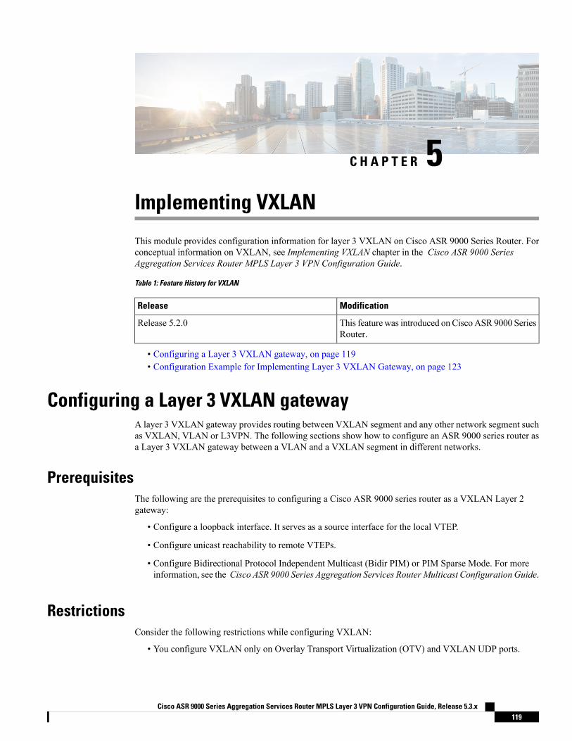
C H A P T E R 5Implementing VXLAN
This module provides configuration information for layer 3 VXLAN on Cisco ASR 9000 Series Router. Forconceptual information on VXLAN, see Implementing VXLAN chapter in the Cisco ASR 9000 SeriesAggregation Services Router MPLS Layer 3 VPN Configuration Guide.
Table 1: Feature History for VXLAN
ModificationRelease
This feature was introduced on CiscoASR 9000 SeriesRouter.
Release 5.2.0
• Configuring a Layer 3 VXLAN gateway, on page 119• Configuration Example for Implementing Layer 3 VXLAN Gateway, on page 123
Configuring a Layer 3 VXLAN gatewayA layer 3 VXLAN gateway provides routing between VXLAN segment and any other network segment suchas VXLAN, VLAN or L3VPN. The following sections show how to configure an ASR 9000 series router asa Layer 3 VXLAN gateway between a VLAN and a VXLAN segment in different networks.
PrerequisitesThe following are the prerequisites to configuring a Cisco ASR 9000 series router as a VXLAN Layer 2gateway:
• Configure a loopback interface. It serves as a source interface for the local VTEP.
• Configure unicast reachability to remote VTEPs.
• Configure Bidirectional Protocol Independent Multicast (Bidir PIM) or PIM Sparse Mode. For moreinformation, see the Cisco ASR 9000 Series Aggregation Services Router Multicast Configuration Guide.
RestrictionsConsider the following restrictions while configuring VXLAN:
• You configure VXLAN only on Overlay Transport Virtualization (OTV) and VXLAN UDP ports.
Cisco ASR 9000 Series Aggregation Services Router MPLS Layer 3 VPN Configuration Guide, Release 5.3.x119
• The source interface can only be a loopback interface.
• You cannot share a VNI or a multicast group or a source interface across multiple NVE interfaces.
• The VNI range and the multicast range both can only be specified contiguously. A non-contiguous rangewith comma separated values is not supported.
• The VNI to multicast group mapping can be only either 1:1 or N:1. For example,
• The "member vni 5000 mcast-group 239.1.1.1" command configures a valid 1:1 mapping.
• The "member vni 5000-5005 mcast-group 239.1.1.1" command configures a valid N:1 mapping.
• When a VNI is configured as a part of a VNI range, it can be modified or deleted only as part of the samerange. For example, if the "member vni 5000-5002 mcast-group 239.1.1.1" command is configured, youcannot disassociate just the VNI 5001 from the NVE interface with a "no member vni 5001" command.
• Static MAC configuration is not supported.
• You can configure a maximum of 128k Layer 2 and Layer 3 sub-interfaces per system. The configurationcan be a combination of both Layer 2 sub-interfaces and Layer 3 sub-interfaces; or either fully Layer 2sub-interfaces or Layer 3 sub-interfaces.
Though the system allows you to configure more than 128k sub-interfaces per system, you cannot usethis configuration for services. Though the system displays a warning message on reaching the thresholdof 128k sub-interfaces, the configuration is still applied. However, you cannot use this configuration forservices.
Creating and configuring the Network Virtualization Endpoint (NVE) interfacePerform this task to create an NVE interface and configure it as a VXLAN Tunnel EndPoint (VTEP) forVxLAN.
SUMMARY STEPS
1. interface nve nve-identifier2. source-interface loopback loopback-interface-identifier3. member vni vni_number [ -end_vni_range ]mcast-group ip_address [ end_ip_address_range ]4. Use the commit or end command.
DETAILED STEPS
Step 1 interface nve nve-identifier
Example:RP/0/RSP0/CPU0:router(config)# interface nve 1
Creates the NVE interface and enters the NVE interface configuration sub-mode.
Step 2 source-interface loopback loopback-interface-identifier
Example:RP/0/RSP0/CPU0:router(config-if)# source-interface loopback 1
Cisco ASR 9000 Series Aggregation Services Router MPLS Layer 3 VPN Configuration Guide, Release 5.3.x120
Implementing VXLANCreating and configuring the Network Virtualization Endpoint (NVE) interface
Sets a loopback interface as the source interface for the VTEP.
Step 3 member vni vni_number [ -end_vni_range ]mcast-group ip_address [ end_ip_address_range ]
Example:RP/0/RSP0/CPU0:router(config-if)# member vni 1-10 mcast-group 224.2.2.2
Associates a single VxLAN or a contiguous range of VxLANs with the NVE interface using their VxLAN NetworkIdentifiers (VNIs) and specifies a multicast address or a contiguous multicast address range associated with these VNIs.
The mapping between the VNIs and the multicast groups is either one-to-one or many-to-one.Note
Step 4 Use the commit or end command.
commit - Saves the configuration changes and remains within the configuration session.
end - Prompts user to take one of these actions:
• Yes - Saves configuration changes and exits the configuration session.• No - Exits the configuration session without committing the configuration changes.• Cancel - Remains in the configuration mode, without committing the configuration changes.
Configuring the L3 bridge virtual interfacePerform this task to configure the IPv4 address for a bridge virtual interface for L3 routing.
SUMMARY STEPS
1. interface BVI BVI-identifier2. ipv4 address ip-address{/prefix | subnet mask}3. Use the commit or end command.
DETAILED STEPS
Step 1 interface BVI BVI-identifier
Example:RP/0/RSP0/CPU0:router(config)# interface BVI 1
Enters the bridge virtual interface configuration mode.Step 2 ipv4 address ip-address{/prefix | subnet mask}
Example:RP/0/RSP0/CPU0:router(config-if)# ipv4 address 1.1.1.1 255.0.0.0
Sets the IPv4 address for the bridge virtual interface.
Step 3 Use the commit or end command.
commit - Saves the configuration changes and remains within the configuration session.
end - Prompts user to take one of these actions:
Cisco ASR 9000 Series Aggregation Services Router MPLS Layer 3 VPN Configuration Guide, Release 5.3.x121
Implementing VXLANConfiguring the L3 bridge virtual interface
• Yes - Saves configuration changes and exits the configuration session.• No - Exits the configuration session without committing the configuration changes.• Cancel - Remains in the configuration mode, without committing the configuration changes.
Configuring a bridge domainPerform this task to configure a bridge domain.
SUMMARY STEPS
1. l2vpn2. bridge group bridge-group-name3. bridge-domain bridge-domain-name4. member vni vxlan-id5. routed interface BVI BVI-id6. Use the commit or end command.
DETAILED STEPS
Step 1 l2vpn
Example:RP/0/RSP0/CPU0:router(config)# l2vpn
Enters the l2vpn configuration mode.
Step 2 bridge group bridge-group-name
Example:RP/0/RSP0/CPU0:router(config-l2vpn)# bridge group bgroup1
Enters the bridge group configuration mode.
Step 3 bridge-domain bridge-domain-name
Example:RP/0/RSP0/CPU0:router(config-l2vpn-bg)# bridge-domain bdomain1
Enters the bridge domain configuration mode.Step 4 member vni vxlan-id
Example:RP/0/RSP0/CPU0:router(config-l2vpn-bg-bd)# member vni 10
Associates a member VNI with the bridge domain.Step 5 routed interface BVI BVI-id
Example:RP/0/RSP0/CPU0:router(config-l2vpn-bg-bd)# routed interface BVI 1
Sets the bridge virtual interface for the bridge domain.
Cisco ASR 9000 Series Aggregation Services Router MPLS Layer 3 VPN Configuration Guide, Release 5.3.x122
Implementing VXLANConfiguring a bridge domain
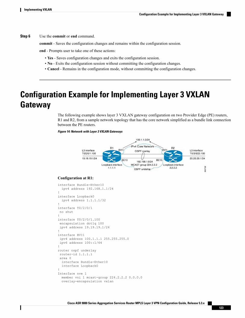
Step 6 Use the commit or end command.
commit - Saves the configuration changes and remains within the configuration session.
end - Prompts user to take one of these actions:
• Yes - Saves configuration changes and exits the configuration session.• No - Exits the configuration session without committing the configuration changes.• Cancel - Remains in the configuration mode, without committing the configuration changes.
Configuration Example for Implementing Layer 3 VXLANGateway
The following example shows layer 3 VXLAN gateway configuration on two Provider Edge (PE) routers,R1 and R2, from a sample network topology that has the core network simplified as a bundle link connectionbetween the PE routers.Figure 14: Network with Layer 3 VXLAN Gateways
Configuration at R1:interface Bundle-Ether10ipv4 address 192.168.1.1/24
!interface Loopback0ipv4 address 1.1.1.1/32
!interface T0/2/0/1no shut!interface T0/2/0/1.100encapsulation dot1q 100ipv4 address 19.19.19.1/24!interface BVI1ipv4 address 100.1.1.1 255.255.255.0ipv6 address 100::1/64!router ospf underlayrouter-id 1.1.1.1area 0interface Bundle-Ether10interface Loopback0
!Interface nve 1member vni 1 mcast-group 224.2.2.2 0.0.0.0overlay-encapsulation vxlan
Cisco ASR 9000 Series Aggregation Services Router MPLS Layer 3 VPN Configuration Guide, Release 5.3.x123
Implementing VXLANConfiguration Example for Implementing Layer 3 VXLAN Gateway
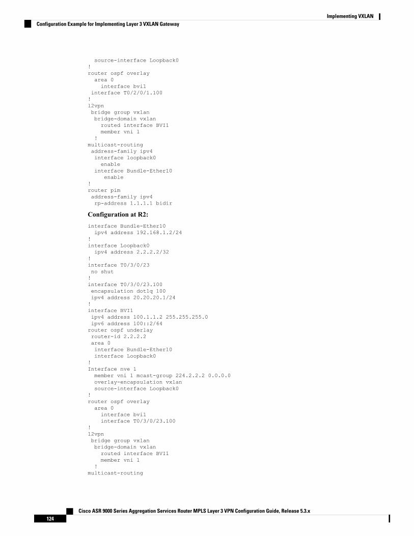
source-interface Loopback0!router ospf overlayarea 0interface bvi1
interface T0/2/0/1.100!l2vpnbridge group vxlanbridge-domain vxlanrouted interface BVI1member vni 1
!multicast-routingaddress-family ipv4interface loopback0enable
interface Bundle-Ether10enable
!router pimaddress-family ipv4rp-address 1.1.1.1 bidir
Configuration at R2:interface Bundle-Ether10ipv4 address 192.168.1.2/24
!interface Loopback0ipv4 address 2.2.2.2/32
!interface T0/3/0/23no shut!interface T0/3/0/23.100encapsulation dot1q 100ipv4 address 20.20.20.1/24!interface BVI1ipv4 address 100.1.1.2 255.255.255.0ipv6 address 100::2/64router ospf underlayrouter-id 2.2.2.2area 0interface Bundle-Ether10interface Loopback0
!Interface nve 1member vni 1 mcast-group 224.2.2.2 0.0.0.0overlay-encapsulation vxlansource-interface Loopback0
!router ospf overlayarea 0interface bvi1interface T0/3/0/23.100
!l2vpnbridge group vxlanbridge-domain vxlanrouted interface BVI1member vni 1
!multicast-routing
Cisco ASR 9000 Series Aggregation Services Router MPLS Layer 3 VPN Configuration Guide, Release 5.3.x124
Implementing VXLANConfiguration Example for Implementing Layer 3 VXLAN Gateway

address-family ipv4interface loopback0enable
interface Bundle-Ether10enable
!router pimaddress-family ipv4rp-address 1.1.1.1 bidir
Cisco ASR 9000 Series Aggregation Services Router MPLS Layer 3 VPN Configuration Guide, Release 5.3.x125
Implementing VXLANConfiguration Example for Implementing Layer 3 VXLAN Gateway

Cisco ASR 9000 Series Aggregation Services Router MPLS Layer 3 VPN Configuration Guide, Release 5.3.x126
Implementing VXLANConfiguration Example for Implementing Layer 3 VXLAN Gateway
C H A P T E R 6Implementing IP in IP Tunnel
This chapter module provides conceptual and configuration information for IP in IP tunnels on Cisco ASR 9000Series Router.
For a complete description of the IP in IP tunnel commands listed in this chapter, see the Cisco ASR 9000Series Aggregation Services Router VPN and Ethernet Services Command Reference. To locate documentationof other commands that appear in this chapter, use the command reference master index, or search online.
Note
Table 2: Feature History for IP in IP tunnel
ModificationRelease
This feature was introduced on CiscoASR 9000 SeriesRouter.
Release 5.3.1
• IP in IP Tunneling, on page 127• Configuring IP in IP Tunnel, on page 128• IP in IP Tunneling: Examples, on page 129
IP in IP TunnelingIP in IP tunneling refers to the encapsulation of an IP packet as a payload in another IP packet. ASR9K routerssupport IP in IP tunnels with all possible combinations of IPv4 and IPv6; that is, IPv4 over IPv4, IPv6 overIPv4, IPv4 over IPv6, and IPv6 over IPv6. For example, an IPv4 over IPv6 refers to an IPv4 packet as apayload encapsulated within an IPv6 packet and routed across an IPv6 network to reach the destination IPv4network, where it is decapsulated.
IP in IP tunneling does not require any additional header such as a GRE header used in the GRE tunnels. So,IP in IP tunneling is preferred over GRE tunnels if both the networks are IP networks.
RestrictionsThe following are not supported in IP in IP tunnels:
• MPLS
Cisco ASR 9000 Series Aggregation Services Router MPLS Layer 3 VPN Configuration Guide, Release 5.3.x127
• Multicast packets
• Keep-Alive packets
• Path MTU (Maximum Transmission Unit) discovery
• DF (Do not Fragment) bit configuration in IPv6 tunnel mode.
If DF bit is configured for the tunnel interface, you cannot enable IPv6 tunnelmode.
Note
Configuring IP in IP TunnelPerform the following steps to configure an IP in IP tunnel.
SUMMARY STEPS
1. configure2. interface tunnel-ip tunnel-id3. {ipv4 | ipv6} address ip-address4. tunnel mode {ipv4 | ipv6}5. tunnel source {interface-id | ipv4/v6-address}6. tunnel destination ipv4/v6-address7. (Optional) tunnel df-bit {copy | disable}8. (Optional) tunnel tos tos-value9. commit
DETAILED STEPS
PurposeCommand or Action
Enters the Global Configuration mode.configure
Example:
Step 1
RP/0/RSP0/CPU0:router# configure
Creates a tunnel interface and enters the tunnel configurationsub-mode. The tunnel-id is the numeric identifier for thetunnel interface.
interface tunnel-ip tunnel-id
Example:RP/0/RSP0/CPU0:router(config)# interface tunnel-ip1
Step 2
Sets the IPv4 or IPv6 address, as required, for the tunnelinterface.
{ipv4 | ipv6} address ip-address
Example:
Step 3
RP/0/RSP0/CPU0:router(config-if)# ipv6 address10::1/64
Cisco ASR 9000 Series Aggregation Services Router MPLS Layer 3 VPN Configuration Guide, Release 5.3.x128
Implementing IP in IP TunnelConfiguring IP in IP Tunnel
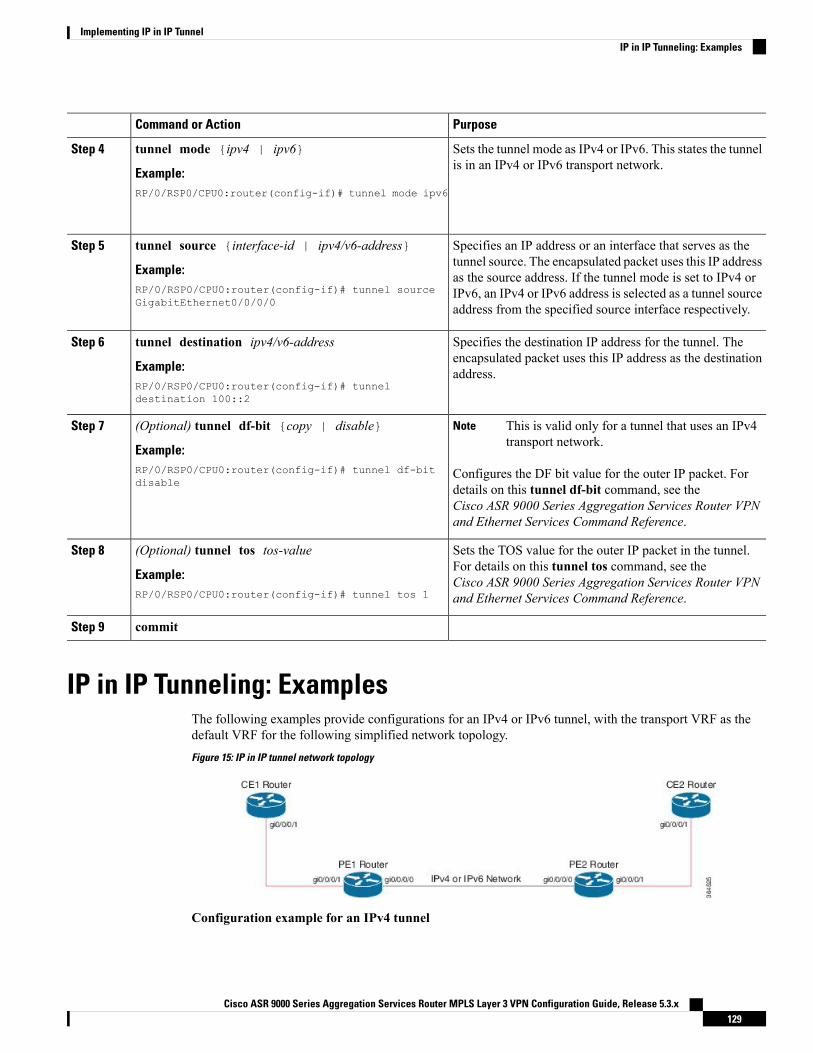
PurposeCommand or Action
Sets the tunnel mode as IPv4 or IPv6. This states the tunnelis in an IPv4 or IPv6 transport network.
tunnel mode {ipv4 | ipv6}
Example:
Step 4
RP/0/RSP0/CPU0:router(config-if)# tunnel mode ipv6
Specifies an IP address or an interface that serves as thetunnel source. The encapsulated packet uses this IP address
tunnel source {interface-id | ipv4/v6-address}
Example:
Step 5
as the source address. If the tunnel mode is set to IPv4 orRP/0/RSP0/CPU0:router(config-if)# tunnel sourceGigabitEthernet0/0/0/0
IPv6, an IPv4 or IPv6 address is selected as a tunnel sourceaddress from the specified source interface respectively.
Specifies the destination IP address for the tunnel. Theencapsulated packet uses this IP address as the destinationaddress.
tunnel destination ipv4/v6-address
Example:RP/0/RSP0/CPU0:router(config-if)# tunneldestination 100::2
Step 6
(Optional) tunnel df-bit {copy | disable}Step 7 This is valid only for a tunnel that uses an IPv4transport network.
Note
Example:RP/0/RSP0/CPU0:router(config-if)# tunnel df-bitdisable
Configures the DF bit value for the outer IP packet. Fordetails on this tunnel df-bit command, see theCisco ASR 9000 Series Aggregation Services Router VPNand Ethernet Services Command Reference.
Sets the TOS value for the outer IP packet in the tunnel.For details on this tunnel tos command, see the
(Optional) tunnel tos tos-value
Example:
Step 8
Cisco ASR 9000 Series Aggregation Services Router VPNand Ethernet Services Command Reference.RP/0/RSP0/CPU0:router(config-if)# tunnel tos 1
commitStep 9
IP in IP Tunneling: ExamplesThe following examples provide configurations for an IPv4 or IPv6 tunnel, with the transport VRF as thedefault VRF for the following simplified network topology.Figure 15: IP in IP tunnel network topology
Configuration example for an IPv4 tunnel
Cisco ASR 9000 Series Aggregation Services Router MPLS Layer 3 VPN Configuration Guide, Release 5.3.x129
Implementing IP in IP TunnelIP in IP Tunneling: Examples
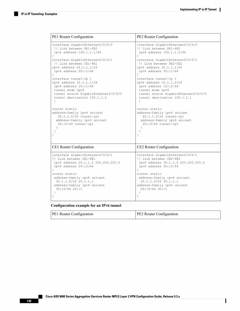
PE2 Router ConfigurationPE1 Router Configuration
interface GigabitEthernet0/0/0/0!! Link between PE1-PE2ipv4 address 100.1.1.2/64!interface GigabitEthernet0/0/0/1!! Link between PE2-CE2ipv4 address 30.1.1.1/24ipv6 address 30::1/64!interface tunnel-ip 1ipv4 address 10.1.1.2/24ipv6 address 10::2/64tunnel mode ipv4tunnel source GigabitEthernet0/0/0/0tunnel destination 100.1.1.1!
router staticaddress-family ipv4 unicast
20.1.1.0/24 tunnel-ip1address-family ipv6 unicast20::0/64 tunnel-ip1!!!
interface GigabitEthernet0/0/0/0!! Link between PE1-PE2ipv4 address 100.1.1.1/64!interface GigabitEthernet0/0/0/1!! Link between CE1-PE1ipv4 address 20.1.1.1/24ipv6 address 20::1/64!interface tunnel-ip 1ipv4 address 10.1.1.1/24ipv6 address 10::1/64tunnel mode ipv4tunnel source GigabitEthernet0/0/0/0tunnel destination 100.1.1.2!
router staticaddress-family ipv4 unicast
30.1.1.0/24 tunnel-ip1address-family ipv6 unicast30::0/64 tunnel-ip1!!!
CE2 Router ConfigurationCE1 Router Configuration
interface GigabitEthernet0/0/0/1!! Link between CE2-PE2ipv4 address 30.1.1.2 255.255.255.0ipv6 address 30::2/64!router staticaddress-family ipv4 unicast20.1.1.0/24 30.1.1.1
address-family ipv6 unicast20::0/64 30::1!!
interface GigabitEthernet0/0/0/1!! Link between CE1-PE1ipv4 address 20.1.1.2 255.255.255.0ipv6 address 20::2/64!router staticaddress-family ipv4 unicast30.1.1.0/24 20.1.1.1address-family ipv6 unicast30::0/64 20::1!!
Configuration example for an IPv6 tunnel
PE2 Router ConfigurationPE1 Router Configuration
Cisco ASR 9000 Series Aggregation Services Router MPLS Layer 3 VPN Configuration Guide, Release 5.3.x130
Implementing IP in IP TunnelIP in IP Tunneling: Examples
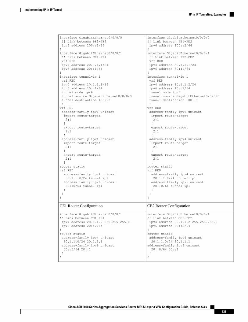
interface GigabitEthernet0/0/0/0!! Link between PE1-PE2ipv6 address 100::2/64!interface GigabitEthernet0/0/0/1!! Link between PE2-CE2vrf REDipv4 address 30.1.1.1/24ipv6 address 30::1/64!interface tunnel-ip 1vrf REDipv4 address 10.1.1.2/24ipv6 address 10::2/64tunnel mode ipv6tunnel source GigabitEthernet0/0/0/0tunnel destination 100::1!vrf REDaddress-family ipv6 unicastimport route-target2:1!export route-target2:1!address-family ipv4 unicastimport route-target2:1!export route-target2:1!
router staticvrf REDaddress-family ipv4 unicast20.1.1.0/24 tunnel-ip1address-family ipv6 unicast20::0/64 tunnel-ip1!!!
interface GigabitEthernet0/0/0/0!! Link between PE1-PE2ipv6 address 100::1/64!interface GigabitEthernet0/0/0/1!! Link between CE1-PE1vrf REDipv4 address 20.1.1.1/24ipv6 address 20::1/64!interface tunnel-ip 1vrf REDipv4 address 10.1.1.1/24ipv6 address 10::1/64tunnel mode ipv6tunnel source GigabitEthernet0/0/0/0tunnel destination 100::2!vrf REDaddress-family ipv6 unicastimport route-target2:1!export route-target2:1!address-family ipv4 unicastimport route-target2:1!export route-target2:1!
router staticvrf REDaddress-family ipv4 unicast30.1.1.0/24 tunnel-ip1address-family ipv6 unicast30::0/64 tunnel-ip1!!!
CE2 Router ConfigurationCE1 Router Configuration
interface GigabitEthernet0/0/0/1!! Link between CE2-PE2ipv4 address 30.1.1.2 255.255.255.0ipv6 address 30::2/64!router staticaddress-family ipv4 unicast20.1.1.0/24 30.1.1.1
address-family ipv6 unicast20::0/64 30::1!!
interface GigabitEthernet0/0/0/1!! Link between CE1-PE1ipv4 address 20.1.1.2 255.255.255.0ipv6 address 20::2/64!router staticaddress-family ipv4 unicast30.1.1.0/24 20.1.1.1address-family ipv6 unicast30::0/64 20::1!!
Cisco ASR 9000 Series Aggregation Services Router MPLS Layer 3 VPN Configuration Guide, Release 5.3.x131
Implementing IP in IP TunnelIP in IP Tunneling: Examples

Cisco ASR 9000 Series Aggregation Services Router MPLS Layer 3 VPN Configuration Guide, Release 5.3.x132
Implementing IP in IP TunnelIP in IP Tunneling: Examples
C H A P T E R 7Implementing DCI VXLAN Layer 3 Gateway
This chapter module provides conceptual and configuration information for Data Center Interconnect (DCI)VXLAN Layer 3 Gateway on Cisco ASR 9000 Series Router.
ModificationRelease
This feature was introduced.Release 5.3.2
These features were added:
• OpFlex
Release 6.1.x
• Prerequisites for Implementing Data Center Interconnect Layer 3 Gateway, on page 133• Data Center Interconnect VXLAN Layer 3 Gateway, on page 134• Configure Data Center Interconnect Router, on page 136• Example: Data Center Interconnection Layer 3 Gateway Configuration, on page 153
Prerequisites for Implementing Data Center Interconnect Layer3 Gateway
• You must be in a user group associated with a task group that includes the proper task IDs. The commandreference guides include the task IDs required for each command. If you suspect user group assignmentis preventing you from using a command, contact your AAA administrator for assistance.
• You need to have understanding of the following features:
• VxLAN: For detailed conceptual and configuration information, see the chapters ImplementingLayer 2 VxLAN Gateway and Implementing Layer 3 VxLAN Gateway in Cisco ASR 9000 SeriesAggregation Services Router L2VPN and Ethernet Services Configuration Guide and Cisco ASR9000 Series Aggregation Services Router MPLS Layer 3 VPN Configuration Guide.
• MP-BGP: For detailed conceptual and configuration information, see the chapter ImplementingBGP in the Cisco ASR 9000 Series Aggregation Services Router Routing Configuration Guide.
• MPLS L3VPN: For detailed conceptual and configuration information, see the Cisco ASR 9000Series Aggregation Services Router MPLS Layer 3 VPN Configuration Guide.
Cisco ASR 9000 Series Aggregation Services Router MPLS Layer 3 VPN Configuration Guide, Release 5.3.x133
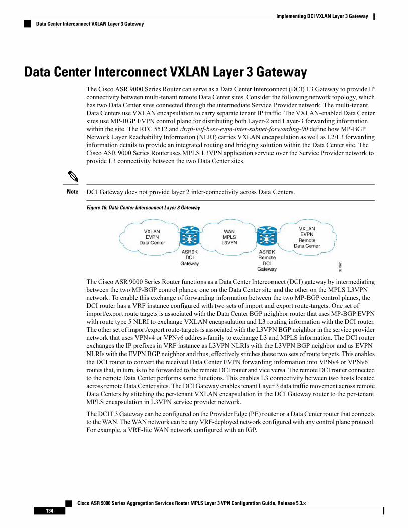
Data Center Interconnect VXLAN Layer 3 GatewayThe Cisco ASR 9000 Series Router can serve as a Data Center Interconnect (DCI) L3 Gateway to provide IPconnectivity between multi-tenant remote Data Center sites. Consider the following network topology, whichhas two Data Center sites connected through the intermediate Service Provider network. The multi-tenantData Centers use VXLAN encapsulation to carry separate tenant IP traffic. The VXLAN-enabled Data Centersites use MP-BGP EVPN control plane for distributing both Layer-2 and Layer-3 forwarding informationwithin the site. The RFC 5512 and draft-ietf-bess-evpn-inter-subnet-forwarding-00 define how MP-BGPNetwork Layer Reachability Information (NLRI) carries VXLAN encapsulation as well as L2/L3 forwardinginformation details to provide an integrated routing and bridging solution within the Data Center site. TheCisco ASR 9000 Series Routeruses MPLS L3VPN application service over the Service Provider network toprovide L3 connectivity between the two Data Center sites.
DCI Gateway does not provide layer 2 inter-connectivity across Data Centers.Note
Figure 16: Data Center Interconnect Layer 3 Gateway
The Cisco ASR 9000 Series Router functions as a Data Center Interconnect (DCI) gateway by intermediatingbetween the two MP-BGP control planes, one on the Data Center site and the other on the MPLS L3VPNnetwork. To enable this exchange of forwarding information between the two MP-BGP control planes, theDCI router has a VRF instance configured with two sets of import and export route-targets. One set ofimport/export route targets is associated with the Data Center BGP neighbor router that uses MP-BGP EVPNwith route type 5 NLRI to exchange VXLAN encapsulation and L3 routing information with the DCI router.The other set of import/export route-targets is associated with the L3VPNBGP neighbor in the service providernetwork that uses VPNv4 or VPNv6 address-family to exchange L3 and MPLS information. The DCI routerexchanges the IP prefixes in VRF instance as L3VPN NLRIs with the L3VPN BGP neighbor and as EVPNNLRIs with the EVPNBGP neighbor and thus, effectively stitches these two sets of route targets. This enablesthe DCI router to convert the received Data Center EVPN forwarding information into VPNv4 or VPNv6routes that, in turn, is to be forwarded to the remote DCI router and vice versa. The remote DCI router connectedto the remote Data Center performs same functions. This enables L3 connectivity between two hosts locatedacross remote Data Center sites. The DCI Gateway enables tenant Layer 3 data traffic movement across remoteData Centers by stitching the per-tenant VXLAN encapsulation in the DCI Gateway router to the per-tenantMPLS encapsulation in L3VPN service provider network.
The DCI L3Gateway can be configured on the Provider Edge (PE) router or a Data Center router that connectsto theWAN. TheWAN network can be any VRF-deployed network configured with any control plane protocol.For example, a VRF-lite WAN network configured with an IGP.
Cisco ASR 9000 Series Aggregation Services Router MPLS Layer 3 VPN Configuration Guide, Release 5.3.x134
Implementing DCI VXLAN Layer 3 GatewayData Center Interconnect VXLAN Layer 3 Gateway
Route TargetsFor each VRF on the DCI router, there are two sets of manually configured import and export route-targets.One set of import and export route-targets is associated with the Data Center BGP neighbor that uses EVPNaddress-family to exchange L3 information; the other set of import and export route-targets is associated withthe L3VPN BGP neighbor that use VPNv4 or VPNv6 unicast address-family to exchange L3 information.This separation of route targets (RTs) enables the two sets of RTs to be independently configured. The DCIrouter effectively stitches the two set of RTs. The RTs associated with the EVPN BGP neighbor are labelledas stitching RTs. The RTs associated with the L3VPN BGP neighbor are normal RTs.
Route Re-originationConsider the case of control plane information propagation by the DCI from the L3VPN side to the DataCenter side. Here, instead of advertising the remote Data Center's original BGP EVPN routes, you can configurethe DCI router to advertise to its BGP EVPN neighbor the routes that are re-originated after importing themfrom the L3VPNBGP neighbor. For this case of VPNv4 or VPNv6 routes being propagated to the BGP EVPNneighbors (Data Center neighbors), re-originating the routes refers to replacing the normal route-targets withthe local route-target values associated with the BGP EVPN neighbors . The converse holds true for the routinginformation traffic propagation from the BGP EVPN control plane to BGP L3VPN control plane. You canconfigure this re-origination by using the re-originate keyword in the import re-originate command..Configuring this command, by default, also enables advertisement of L2VPN EVPN prefixes to the EVPNBGP neighbors. You can suppress native L2VPN EVPN address-family NLRI advertisements towards theEVPN Neighbor using the advertise l2vpn evpn disable command under the EVPN BGP address-familyconfiguration mode.
Route Address-Family and Encoded Address-FamilyWhen an address-family is configured for a BGP neighbor, it means that the specified address-family routesencoded with the NLRI for that address-family is advertised to the neighbor. This does not hold for data centerBGP neighbors because they use only EVPN address-family. Here, BGP neighbors advertise VPNv4 or VPNv6unicast routes using the EVPN NLRI encoding. Thus, here the encoded address-family and route addressfamily can be possibly different. You can advertise the VPNv4 or VPNv6 address-family using the advertisevpnv4 unicast or advertise vpnv6 unicast command. For example, a EVPN address-family BGP neighborconfigured with the advertise vpnv4 unicast command sends VPNv4 unicast routes in an EVPN encodedNLRI.
Local VPNv4 or VPNv6 Routes AdvertisementOn the DCI router, the locally sourced VPNv4 or VPNv6 routes can be advertised to the BGP EVPN neighborswith the normal route targets (RTs) configured for the VRF or the stitching RTs associated with the BGPEVPN neighbors. By default, these routes are advertised with the normal route targets. You can configurethese local VPNv4 or VPNv6 route advertisements to be advertised with stitching RTs to the BGP EVPNneighbors by using the advertise vpnv4 unicast local stitching-rt or advertise vpnv6 unicast local stitching-rtcommand as required.
Data Center VXLAN with Support for MP-BGPTheData Center VXLAN usesMP-BGP for control-plane learning of end-host Layer 2 and Layer 3 reachabilityinformation. The DCI router is configured with a VXLANTunnel EndPoint (VTEP). For VTEP configuration
Cisco ASR 9000 Series Aggregation Services Router MPLS Layer 3 VPN Configuration Guide, Release 5.3.x135
Implementing DCI VXLAN Layer 3 GatewayRoute Targets
details, see the chapter Implementing Layer 3 VXLAN Gateway. You also need to run the host-reachabiltyprotocol bgp command to specify that control-plane learning within Data center site is through BGP routingprotocol.
The DCI Gateway router and the EVPN BGP neighbor (Data Center BGP neighbor) exchange BGP EVPNNLRIs of route type 5 that carry L3 routing information and associated VXLAN encapsulation information.Some of the VXLAN information is carried in the EVPN NLRI and the rest is carried in RFC 5512 TunnelType Encapsulation EXTCOMM and Router MAC EXTCOMM defined indraft-ietf-bess-evpn-inter-subnet-forwarding-00. BGP downloads VXLAN encapsulation as RIB remote nexthop opaque attribute to L3RIB.
Default-Originate Forwarding to BGP EVPN NeighborInstead of advertising the specific networks available in the remote Data Center, you can configure the DCIgateway to advertise a default route to the directly connected Data Center neighbor. To send the default routefor a VRF instance to the Data Center BGP EVPN neighbor, the VPN default-originate information that istypically forwarded to the L3VPN BGP neighbor, is also configured to be forwarded to the BGP EVPNneighbor in the Data Center. To do so, you need to configure allow vpn default-originate command in theBGP VRF configuration mode and also configure default-originate command under EVPN BGP neighborin L2VPN EVPN address-family configuration mode. This configures BGP to forward only one default routeinformation for a VRF instance from the DCI Gateway to the BGP neighbor that has L2VPN EVPNaddress-family. This default route information is encoded in the EVPN "IP Prefix Route" NLRI.
With the advertisement of a default route to the connected Data Center, the DCI Gateway should not advertisespecific prefixes of the remote Data Center to the BGP EVPN neighbor. To prevent forwarding of VRFprefixes, you need to configure the DCI gateway with a EVPN BGP neighbor policy that drops forwardingof all prefixes.
Configure Data Center Interconnect RouterThis section describes tasks to configure the Data Center Interconnect (DCI) router. Perform the followingtasks to complete the configuration:
Configure VRF and route targets import/export rulesPerform the following steps to configure VRF and define route targets to be used for import and export offorwarding information.
SUMMARY STEPS
1. configure2. vrf vrf-name3. address-family { ipv4 | ipv6 } unicast4. import route-target route-target-id5. export route-target route-target-id6. import route-target route-target-id stitching7. export route-target route-target-id stitching8. commit
Cisco ASR 9000 Series Aggregation Services Router MPLS Layer 3 VPN Configuration Guide, Release 5.3.x136
Implementing DCI VXLAN Layer 3 GatewayDefault-Originate Forwarding to BGP EVPN Neighbor
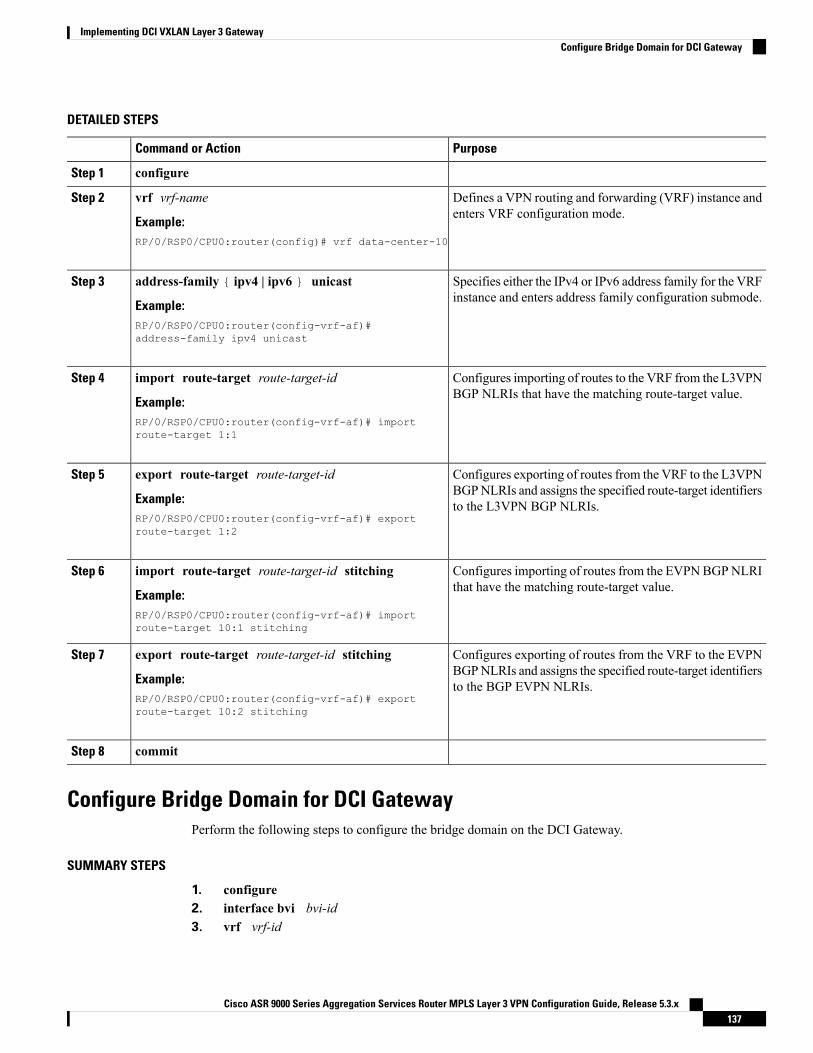
DETAILED STEPS
PurposeCommand or Action
configureStep 1
Defines a VPN routing and forwarding (VRF) instance andenters VRF configuration mode.
vrf vrf-name
Example:
Step 2
RP/0/RSP0/CPU0:router(config)# vrf data-center-10
Specifies either the IPv4 or IPv6 address family for the VRFinstance and enters address family configuration submode.
address-family { ipv4 | ipv6 } unicast
Example:
Step 3
RP/0/RSP0/CPU0:router(config-vrf-af)#address-family ipv4 unicast
Configures importing of routes to the VRF from the L3VPNBGP NLRIs that have the matching route-target value.
import route-target route-target-id
Example:
Step 4
RP/0/RSP0/CPU0:router(config-vrf-af)# importroute-target 1:1
Configures exporting of routes from the VRF to the L3VPNBGPNLRIs and assigns the specified route-target identifiersto the L3VPN BGP NLRIs.
export route-target route-target-id
Example:RP/0/RSP0/CPU0:router(config-vrf-af)# exportroute-target 1:2
Step 5
Configures importing of routes from the EVPNBGPNLRIthat have the matching route-target value.
import route-target route-target-id stitching
Example:
Step 6
RP/0/RSP0/CPU0:router(config-vrf-af)# importroute-target 10:1 stitching
Configures exporting of routes from the VRF to the EVPNBGPNLRIs and assigns the specified route-target identifiersto the BGP EVPN NLRIs.
export route-target route-target-id stitching
Example:RP/0/RSP0/CPU0:router(config-vrf-af)# exportroute-target 10:2 stitching
Step 7
commitStep 8
Configure Bridge Domain for DCI GatewayPerform the following steps to configure the bridge domain on the DCI Gateway.
SUMMARY STEPS
1. configure2. interface bvi bvi-id3. vrf vrf-id
Cisco ASR 9000 Series Aggregation Services Router MPLS Layer 3 VPN Configuration Guide, Release 5.3.x137
Implementing DCI VXLAN Layer 3 GatewayConfigure Bridge Domain for DCI Gateway
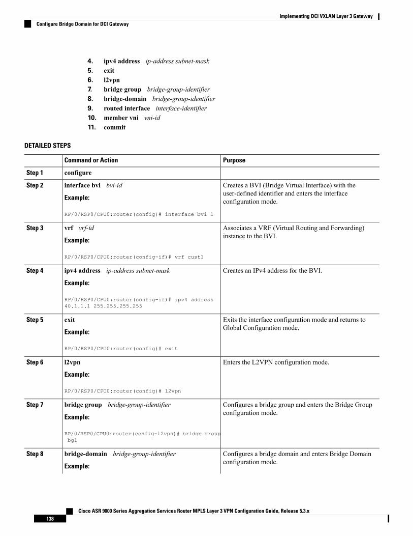
4. ipv4 address ip-address subnet-mask5. exit6. l2vpn7. bridge group bridge-group-identifier8. bridge-domain bridge-group-identifier9. routed interface interface-identifier10. member vni vni-id11. commit
DETAILED STEPS
PurposeCommand or Action
configureStep 1
Creates a BVI (Bridge Virtual Interface) with theuser-defined identifier and enters the interfaceconfiguration mode.
interface bvi bvi-id
Example:
RP/0/RSP0/CPU0:router(config)# interface bvi 1
Step 2
Associates a VRF (Virtual Routing and Forwarding)instance to the BVI.
vrf vrf-id
Example:
Step 3
RP/0/RSP0/CPU0:router(config-if)# vrf cust1
Creates an IPv4 address for the BVI.ipv4 address ip-address subnet-mask
Example:
Step 4
RP/0/RSP0/CPU0:router(config-if)# ipv4 address40.1.1.1 255.255.255.255
Exits the interface configuration mode and returns toGlobal Configuration mode.
exit
Example:
Step 5
RP/0/RSP0/CPU0:router(config)# exit
Enters the L2VPN configuration mode.l2vpn
Example:
Step 6
RP/0/RSP0/CPU0:router(config)# l2vpn
Configures a bridge group and enters the Bridge Groupconfiguration mode.
bridge group bridge-group-identifier
Example:
Step 7
RP/0/RSP0/CPU0:router(config-l2vpn)# bridge groupbg1
Configures a bridge domain and enters Bridge Domainconfiguration mode.
bridge-domain bridge-group-identifier
Example:
Step 8
Cisco ASR 9000 Series Aggregation Services Router MPLS Layer 3 VPN Configuration Guide, Release 5.3.x138
Implementing DCI VXLAN Layer 3 GatewayConfigure Bridge Domain for DCI Gateway
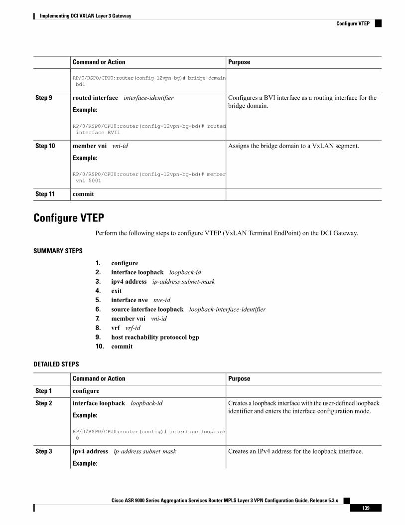
PurposeCommand or Action
RP/0/RSP0/CPU0:router(config-l2vpn-bg)# bridge-domainbd1
Configures a BVI interface as a routing interface for thebridge domain.
routed interface interface-identifier
Example:
Step 9
RP/0/RSP0/CPU0:router(config-l2vpn-bg-bd)# routedinterface BVI1
Assigns the bridge domain to a VxLAN segment.member vni vni-id
Example:
Step 10
RP/0/RSP0/CPU0:router(config-l2vpn-bg-bd)# membervni 5001
commitStep 11
Configure VTEPPerform the following steps to configure VTEP (VxLAN Terminal EndPoint) on the DCI Gateway.
SUMMARY STEPS
1. configure2. interface loopback loopback-id3. ipv4 address ip-address subnet-mask4. exit5. interface nve nve-id6. source interface loopback loopback-interface-identifier7. member vni vni-id8. vrf vrf-id9. host reachability protoocol bgp10. commit
DETAILED STEPS
PurposeCommand or Action
configureStep 1
Creates a loopback interfacewith the user-defined loopbackidentifier and enters the interface configuration mode.
interface loopback loopback-id
Example:
Step 2
RP/0/RSP0/CPU0:router(config)# interface loopback0
Creates an IPv4 address for the loopback interface.ipv4 address ip-address subnet-mask
Example:
Step 3
Cisco ASR 9000 Series Aggregation Services Router MPLS Layer 3 VPN Configuration Guide, Release 5.3.x139
Implementing DCI VXLAN Layer 3 GatewayConfigure VTEP
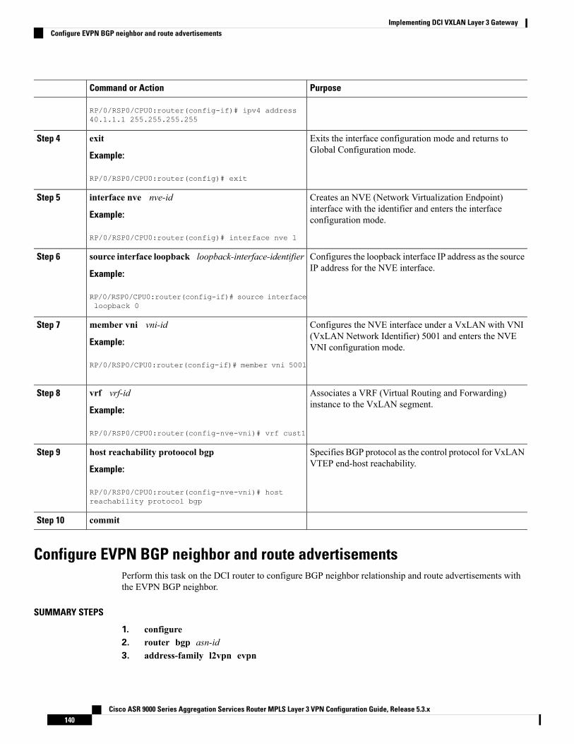
PurposeCommand or Action
RP/0/RSP0/CPU0:router(config-if)# ipv4 address40.1.1.1 255.255.255.255
Exits the interface configuration mode and returns toGlobal Configuration mode.
exit
Example:
Step 4
RP/0/RSP0/CPU0:router(config)# exit
Creates an NVE (Network Virtualization Endpoint)interface with the identifier and enters the interfaceconfiguration mode.
interface nve nve-id
Example:
RP/0/RSP0/CPU0:router(config)# interface nve 1
Step 5
Configures the loopback interface IP address as the sourceIP address for the NVE interface.
source interface loopback loopback-interface-identifier
Example:
Step 6
RP/0/RSP0/CPU0:router(config-if)# source interfaceloopback 0
Configures the NVE interface under a VxLAN with VNI(VxLAN Network Identifier) 5001 and enters the NVEVNI configuration mode.
member vni vni-id
Example:
RP/0/RSP0/CPU0:router(config-if)# member vni 5001
Step 7
Associates a VRF (Virtual Routing and Forwarding)instance to the VxLAN segment.
vrf vrf-id
Example:
Step 8
RP/0/RSP0/CPU0:router(config-nve-vni)# vrf cust1
Specifies BGP protocol as the control protocol for VxLANVTEP end-host reachability.
host reachability protoocol bgp
Example:
Step 9
RP/0/RSP0/CPU0:router(config-nve-vni)# hostreachability protocol bgp
commitStep 10
Configure EVPN BGP neighbor and route advertisementsPerform this task on the DCI router to configure BGP neighbor relationship and route advertisements withthe EVPN BGP neighbor.
SUMMARY STEPS
1. configure2. router bgp asn-id3. address-family l2vpn evpn
Cisco ASR 9000 Series Aggregation Services Router MPLS Layer 3 VPN Configuration Guide, Release 5.3.x140
Implementing DCI VXLAN Layer 3 GatewayConfigure EVPN BGP neighbor and route advertisements
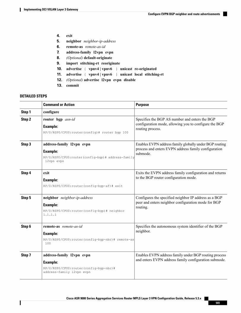
4. exit5. neighbor neighbor-ip-address6. remote-as remote-as-id7. address-family l2vpn evpn8. (Optional) default-originate9. import stitching-rt reoriginate10. advertise { vpnv4 | vpnv6 } unicast re-originated11. advertise { vpnv4 | vpnv6 } unicast local stitching-rt12. (Optional) advertise l2vpn evpn disable13. commit
DETAILED STEPS
PurposeCommand or Action
configureStep 1
Specifies the BGP AS number and enters the BGPconfiguration mode, allowing you to configure the BGProuting process.
router bgp asn-id
Example:RP/0/RSP0/CPU0:router(config)# router bgp 100
Step 2
Enables EVPN address family globally under BGP routingprocess and enters EVPN address family configurationsubmode.
address-family l2vpn evpn
Example:RP/0/RSP0/CPU0:router(config-bgp)# address-familyl2vpn evpn
Step 3
Exits the EVPN address family configuration and returnsto the BGP router configuration mode.
exit
Example:
Step 4
RP/0/RSP0/CPU0:router(config-bgp-af)# exit
Configures the specified neighbor IP address as a BGPpeer and enters neighbor configuration mode for BGProuting.
neighbor neighbor-ip-address
Example:RP/0/RSP0/CPU0:router(config-bgp)# neighbor1.1.1.1
Step 5
Specifies the autonomous system identifier of the BGPneighbor.
remote-as remote-as-id
Example:
Step 6
RP/0/RSP0/CPU0:router(config-bgp-nbr)# remote-as100
Enables EVPN address family under BGP routing processand enters EVPN address family configuration submode.
address-family l2vpn evpn
Example:
Step 7
RP/0/RSP0/CPU0:router(config-bgp-nbr)#address-family l2vpn evpn
Cisco ASR 9000 Series Aggregation Services Router MPLS Layer 3 VPN Configuration Guide, Release 5.3.x141
Implementing DCI VXLAN Layer 3 GatewayConfigure EVPN BGP neighbor and route advertisements
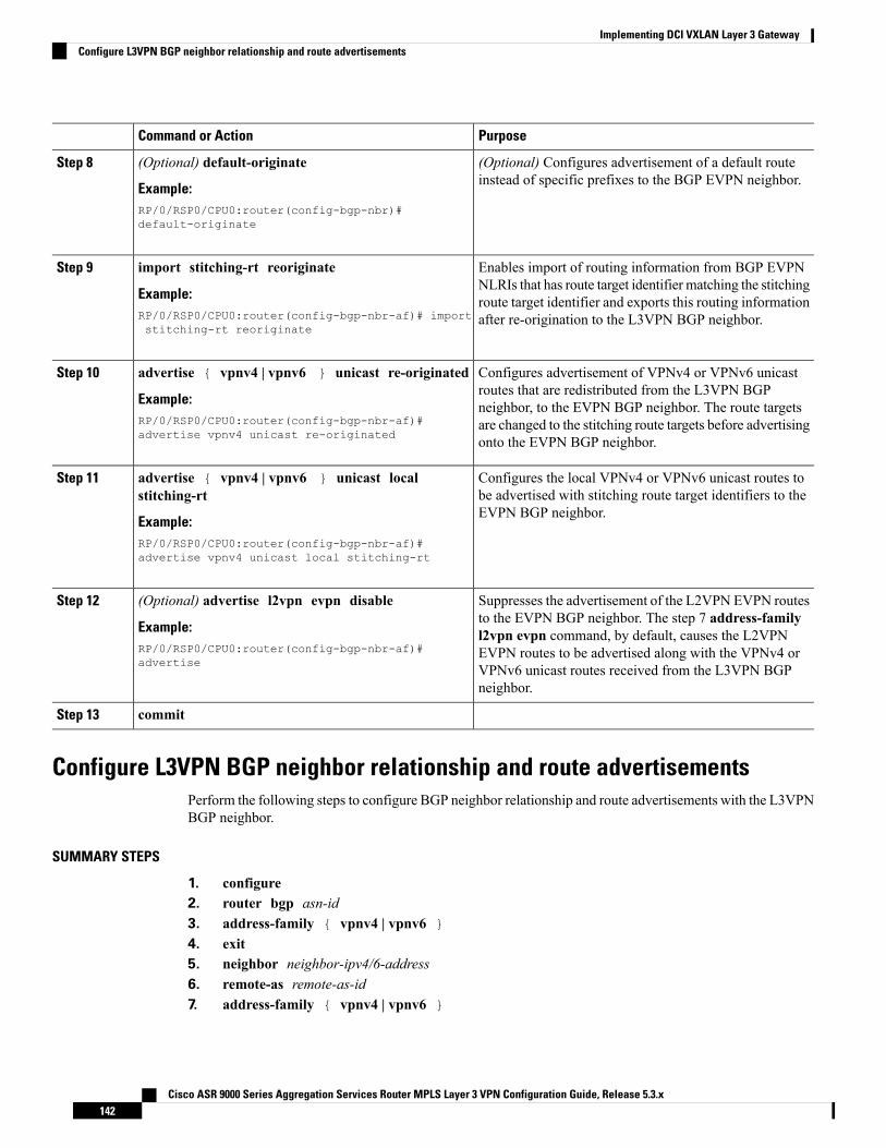
PurposeCommand or Action
(Optional) Configures advertisement of a default routeinstead of specific prefixes to the BGP EVPN neighbor.
(Optional) default-originate
Example:
Step 8
RP/0/RSP0/CPU0:router(config-bgp-nbr)#default-originate
Enables import of routing information from BGP EVPNNLRIs that has route target identifier matching the stitching
import stitching-rt reoriginate
Example:
Step 9
route target identifier and exports this routing informationafter re-origination to the L3VPN BGP neighbor.RP/0/RSP0/CPU0:router(config-bgp-nbr-af)# import
stitching-rt reoriginate
Configures advertisement of VPNv4 or VPNv6 unicastroutes that are redistributed from the L3VPN BGP
advertise { vpnv4 | vpnv6 } unicast re-originated
Example:
Step 10
neighbor, to the EVPN BGP neighbor. The route targetsRP/0/RSP0/CPU0:router(config-bgp-nbr-af)#advertise vpnv4 unicast re-originated
are changed to the stitching route targets before advertisingonto the EVPN BGP neighbor.
Configures the local VPNv4 or VPNv6 unicast routes tobe advertised with stitching route target identifiers to theEVPN BGP neighbor.
advertise { vpnv4 | vpnv6 } unicast localstitching-rt
Example:
Step 11
RP/0/RSP0/CPU0:router(config-bgp-nbr-af)#advertise vpnv4 unicast local stitching-rt
Suppresses the advertisement of the L2VPN EVPN routesto the EVPN BGP neighbor. The step 7 address-family
(Optional) advertise l2vpn evpn disable
Example:
Step 12
l2vpn evpn command, by default, causes the L2VPNRP/0/RSP0/CPU0:router(config-bgp-nbr-af)#advertise
EVPN routes to be advertised along with the VPNv4 orVPNv6 unicast routes received from the L3VPN BGPneighbor.
commitStep 13
Configure L3VPN BGP neighbor relationship and route advertisementsPerform the following steps to configure BGP neighbor relationship and route advertisements with the L3VPNBGP neighbor.
SUMMARY STEPS
1. configure2. router bgp asn-id3. address-family { vpnv4 | vpnv6 }4. exit5. neighbor neighbor-ipv4/6-address6. remote-as remote-as-id7. address-family { vpnv4 | vpnv6 }
Cisco ASR 9000 Series Aggregation Services Router MPLS Layer 3 VPN Configuration Guide, Release 5.3.x142
Implementing DCI VXLAN Layer 3 GatewayConfigure L3VPN BGP neighbor relationship and route advertisements
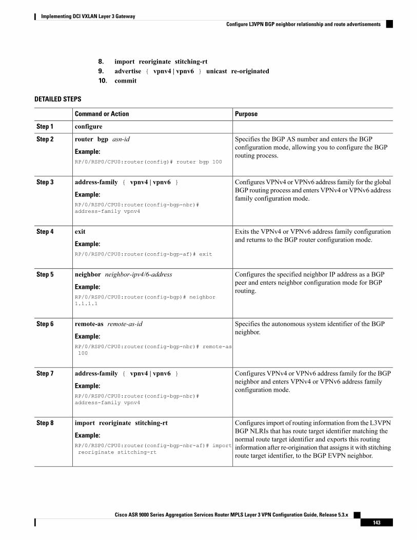
8. import reoriginate stitching-rt9. advertise { vpnv4 | vpnv6 } unicast re-originated10. commit
DETAILED STEPS
PurposeCommand or Action
configureStep 1
Specifies the BGP AS number and enters the BGPconfiguration mode, allowing you to configure the BGProuting process.
router bgp asn-id
Example:RP/0/RSP0/CPU0:router(config)# router bgp 100
Step 2
Configures VPNv4 or VPNv6 address family for the globalBGP routing process and enters VPNv4 or VPNv6 addressfamily configuration mode.
address-family { vpnv4 | vpnv6 }
Example:RP/0/RSP0/CPU0:router(config-bgp-nbr)#address-family vpnv4
Step 3
Exits the VPNv4 or VPNv6 address family configurationand returns to the BGP router configuration mode.
exit
Example:
Step 4
RP/0/RSP0/CPU0:router(config-bgp-af)# exit
Configures the specified neighbor IP address as a BGPpeer and enters neighbor configuration mode for BGProuting.
neighbor neighbor-ipv4/6-address
Example:RP/0/RSP0/CPU0:router(config-bgp)# neighbor1.1.1.1
Step 5
Specifies the autonomous system identifier of the BGPneighbor.
remote-as remote-as-id
Example:
Step 6
RP/0/RSP0/CPU0:router(config-bgp-nbr)# remote-as100
Configures VPNv4 or VPNv6 address family for the BGPneighbor and enters VPNv4 or VPNv6 address familyconfiguration mode.
address-family { vpnv4 | vpnv6 }
Example:RP/0/RSP0/CPU0:router(config-bgp-nbr)#address-family vpnv4
Step 7
Configures import of routing information from the L3VPNBGP NLRIs that has route target identifier matching the
import reoriginate stitching-rt
Example:
Step 8
normal route target identifier and exports this routingRP/0/RSP0/CPU0:router(config-bgp-nbr-af)# importreoriginate stitching-rt
information after re-origination that assigns it with stitchingroute target identifier, to the BGP EVPN neighbor.
Cisco ASR 9000 Series Aggregation Services Router MPLS Layer 3 VPN Configuration Guide, Release 5.3.x143
Implementing DCI VXLAN Layer 3 GatewayConfigure L3VPN BGP neighbor relationship and route advertisements
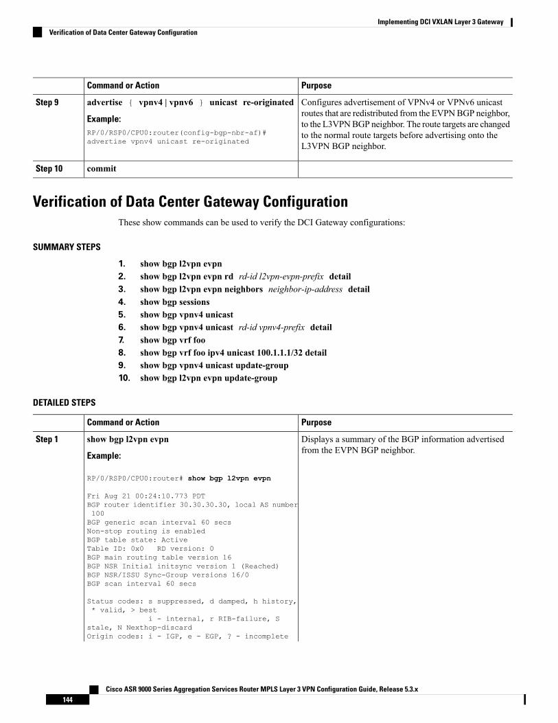
PurposeCommand or Action
Configures advertisement of VPNv4 or VPNv6 unicastroutes that are redistributed from the EVPNBGP neighbor,
advertise { vpnv4 | vpnv6 } unicast re-originated
Example:
Step 9
to the L3VPNBGP neighbor. The route targets are changedRP/0/RSP0/CPU0:router(config-bgp-nbr-af)#advertise vpnv4 unicast re-originated
to the normal route targets before advertising onto theL3VPN BGP neighbor.
commitStep 10
Verification of Data Center Gateway ConfigurationThese show commands can be used to verify the DCI Gateway configurations:
SUMMARY STEPS
1. show bgp l2vpn evpn2. show bgp l2vpn evpn rd rd-id l2vpn-evpn-prefix detail3. show bgp l2vpn evpn neighbors neighbor-ip-address detail4. show bgp sessions5. show bgp vpnv4 unicast6. show bgp vpnv4 unicast rd-id vpnv4-prefix detail7. show bgp vrf foo8. show bgp vrf foo ipv4 unicast 100.1.1.1/32 detail9. show bgp vpnv4 unicast update-group10. show bgp l2vpn evpn update-group
DETAILED STEPS
PurposeCommand or Action
Displays a summary of the BGP information advertisedfrom the EVPN BGP neighbor.
show bgp l2vpn evpn
Example:
Step 1
RP/0/RSP0/CPU0:router# show bgp l2vpn evpn
Fri Aug 21 00:24:10.773 PDTBGP router identifier 30.30.30.30, local AS number100BGP generic scan interval 60 secsNon-stop routing is enabledBGP table state: ActiveTable ID: 0x0 RD version: 0BGP main routing table version 16BGP NSR Initial initsync version 1 (Reached)BGP NSR/ISSU Sync-Group versions 16/0BGP scan interval 60 secs
Status codes: s suppressed, d damped, h history,* valid, > best
i - internal, r RIB-failure, Sstale, N Nexthop-discardOrigin codes: i - IGP, e - EGP, ? - incomplete
Cisco ASR 9000 Series Aggregation Services Router MPLS Layer 3 VPN Configuration Guide, Release 5.3.x144
Implementing DCI VXLAN Layer 3 GatewayVerification of Data Center Gateway Configuration
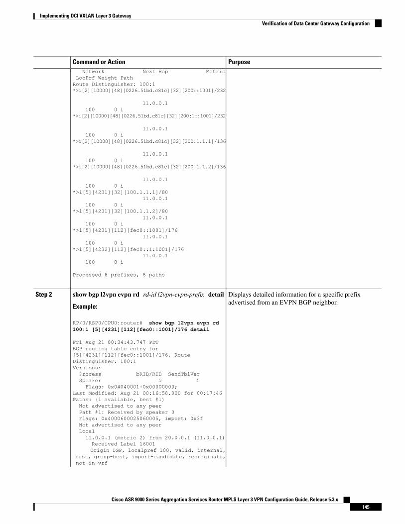
PurposeCommand or ActionNetwork Next Hop Metric
LocPrf Weight PathRoute Distinguisher: 100:1*>i[2][10000][48][0226.51bd.c81c][32][200::1001]/232
11.0.0.1100 0 i
*>i[2][10000][48][0226.51bd.c81c][32][200:1::1001]/232
11.0.0.1100 0 i
*>i[2][10000][48][0226.51bd.c81c][32][200.1.1.1]/136
11.0.0.1100 0 i
*>i[2][10000][48][0226.51bd.c81c][32][200.1.1.2]/136
11.0.0.1100 0 i
*>i[5][4231][32][100.1.1.1]/8011.0.0.1
100 0 i*>i[5][4231][32][100.1.1.2]/80
11.0.0.1100 0 i
*>i[5][4231][112][fec0::1001]/17611.0.0.1
100 0 i*>i[5][4232][112][fec0::1:1001]/176
11.0.0.1100 0 i
Processed 8 prefixes, 8 paths
Displays detailed information for a specific prefixadvertised from an EVPN BGP neighbor.
show bgp l2vpn evpn rd rd-id l2vpn-evpn-prefix detail
Example:
Step 2
RP/0/RSP0/CPU0:router# show bgp l2vpn evpn rd100:1 [5][4231][112][fec0::1001]/176 detail
Fri Aug 21 00:34:43.747 PDTBGP routing table entry for[5][4231][112][fec0::1001]/176, RouteDistinguisher: 100:1Versions:Process bRIB/RIB SendTblVerSpeaker 5 5Flags: 0x04040001+0x00000000;
Last Modified: Aug 21 00:16:58.000 for 00:17:46Paths: (1 available, best #1)Not advertised to any peerPath #1: Received by speaker 0Flags: 0x4000600025060005, import: 0x3fNot advertised to any peerLocal11.0.0.1 (metric 2) from 20.0.0.1 (11.0.0.1)Received Label 16001Origin IGP, localpref 100, valid, internal,
best, group-best, import-candidate, reoriginate,not-in-vrf
Cisco ASR 9000 Series Aggregation Services Router MPLS Layer 3 VPN Configuration Guide, Release 5.3.x145
Implementing DCI VXLAN Layer 3 GatewayVerification of Data Center Gateway Configuration
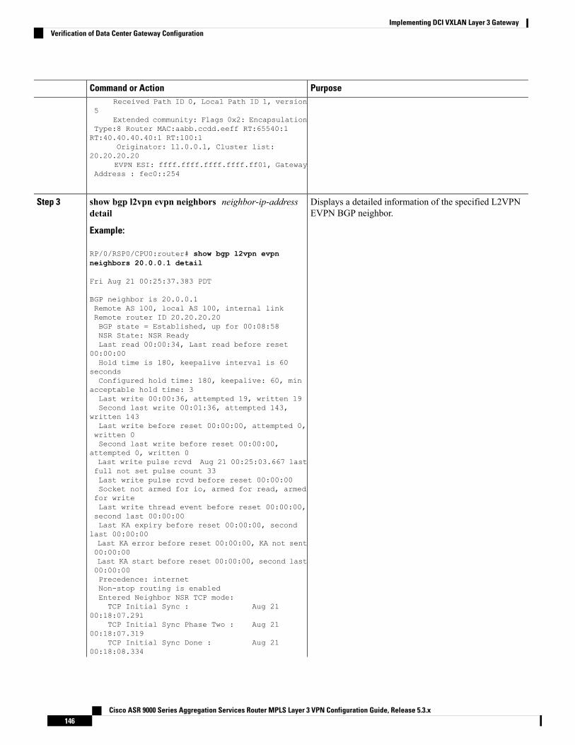
PurposeCommand or ActionReceived Path ID 0, Local Path ID 1, version
5Extended community: Flags 0x2: Encapsulation
Type:8 Router MAC:aabb.ccdd.eeff RT:65540:1RT:40.40.40.40:1 RT:100:1
Originator: 11.0.0.1, Cluster list:20.20.20.20
EVPN ESI: ffff.ffff.ffff.ffff.ff01, GatewayAddress : fec0::254
Displays a detailed information of the specified L2VPNEVPN BGP neighbor.
show bgp l2vpn evpn neighbors neighbor-ip-addressdetail
Example:
Step 3
RP/0/RSP0/CPU0:router# show bgp l2vpn evpnneighbors 20.0.0.1 detail
Fri Aug 21 00:25:37.383 PDT
BGP neighbor is 20.0.0.1Remote AS 100, local AS 100, internal linkRemote router ID 20.20.20.20BGP state = Established, up for 00:08:58NSR State: NSR ReadyLast read 00:00:34, Last read before reset
00:00:00Hold time is 180, keepalive interval is 60
secondsConfigured hold time: 180, keepalive: 60, min
acceptable hold time: 3Last write 00:00:36, attempted 19, written 19Second last write 00:01:36, attempted 143,
written 143Last write before reset 00:00:00, attempted 0,written 0Second last write before reset 00:00:00,
attempted 0, written 0Last write pulse rcvd Aug 21 00:25:03.667 lastfull not set pulse count 33Last write pulse rcvd before reset 00:00:00Socket not armed for io, armed for read, armedfor writeLast write thread event before reset 00:00:00,second last 00:00:00Last KA expiry before reset 00:00:00, second
last 00:00:00Last KA error before reset 00:00:00, KA not sent00:00:00Last KA start before reset 00:00:00, second last00:00:00Precedence: internetNon-stop routing is enabledEntered Neighbor NSR TCP mode:TCP Initial Sync : Aug 21
00:18:07.291TCP Initial Sync Phase Two : Aug 21
00:18:07.319TCP Initial Sync Done : Aug 21
00:18:08.334
Cisco ASR 9000 Series Aggregation Services Router MPLS Layer 3 VPN Configuration Guide, Release 5.3.x146
Implementing DCI VXLAN Layer 3 GatewayVerification of Data Center Gateway Configuration
PurposeCommand or ActionMulti-protocol capability receivedNeighbor capabilities: Adv
RcvdRoute refresh: Yes
Yes4-byte AS: Yes
YesAddress family VPNv4 Unicast: Yes
NoAddress family VPNv6 Unicast: Yes
NoAddress family L2VPN EVPN: Yes
YesMessage stats:InQ depth: 0, OutQ depth: 0
Last_Sent SentLast_Rcvd RcvdOpen: Aug 21 00:16:38.087 1
Aug 21 00:16:40.123 1Notification: --- 0
--- 0Update: Aug 21 00:24:01.421 9
Aug 21 00:24:03.652 13Keepalive: Aug 21 00:25:01.434 8
Aug 21 00:25:03.667 9Route_Refresh: Aug 21 00:24:01.377 3
--- 0Total: 21
23Minimum time between advertisement runs is 0
secsInbound message logging enabled, 3 messages
bufferedOutbound message logging enabled, 3 messages
buffered
For Address Family: VPNv4 UnicastBGP neighbor version 35Update group: 0.3 Filter-group: 0.1 No Refreshrequest being processedAdvertise Reorigination EnabledAdvertise AFI EoR can be sentRoute refresh request: received 0, sent 00 accepted prefixes, 0 are bestpathsCumulative no. of prefixes denied: 0.Prefix advertised 4, suppressed 0, withdrawn 0Maximum prefixes allowed 2097152Threshold for warning message 75%, restart
interval 0 minAIGP is enabledAn EoR was not received during read-only modeLast ack version 35, Last synced ack version 35
Outstanding version objects: current 0, max 1Additional-paths operation: NoneSend Multicast Attributes
For Address Family: VPNv6 UnicastBGP neighbor version 29Update group: 0.3 Filter-group: 0.1 No Refreshrequest being processedAdvertise Reorigination Enabled
Cisco ASR 9000 Series Aggregation Services Router MPLS Layer 3 VPN Configuration Guide, Release 5.3.x147
Implementing DCI VXLAN Layer 3 GatewayVerification of Data Center Gateway Configuration
PurposeCommand or ActionAdvertise AFI EoR can be sentRoute refresh request: received 0, sent 00 accepted prefixes, 0 are bestpathsCumulative no. of prefixes denied: 0.Prefix advertised 0, suppressed 0, withdrawn 0Maximum prefixes allowed 1048576Threshold for warning message 75%, restart
interval 0 minAIGP is enabledAn EoR was not received during read-only modeLast ack version 29, Last synced ack version 29
Outstanding version objects: current 0, max 0Additional-paths operation: NoneSend Multicast AttributesAdvertise VPNv4 routes enabled with
Reoriginate,Local with stitching-RT option
For Address Family: L2VPN EVPNBGP neighbor version 18Update group: 0.2 Filter-group: 0.1 No Refreshrequest being processedRoute refresh request: received 0, sent 38 accepted prefixes, 8 are bestpathsCumulative no. of prefixes denied: 0.Prefix advertised 4, suppressed 0, withdrawn 6Maximum prefixes allowed 2097152Threshold for warning message 75%, restart
interval 0 minAIGP is enabledAn EoR was received during read-only modeLast ack version 18, Last synced ack version 18
Outstanding version objects: current 0, max 2Additional-paths operation: NoneSend Multicast AttributesAdvertise VPNv4 routes enabled with Reoriginate,optionAdvertise VPNv6 routes is enabled with
Reoriginate, optionImport Stitching is enabled for this neighbor
address-familyImport Reoriginate is enabled for this neighboraddress-family
Connections established 1; dropped 0Local host: 30.0.0.1, Local port: 59405, IF
Handle: 0x00000000Foreign host: 20.0.0.1, Foreign port: 179Last reset 00:00:00
Displays current BGP sessions.show bgp sessions
Example:
Step 4
RP/0/RSP0/CPU0:router# show bgp sessions
Fri Aug 21 00:25:57.216 PDT
Neighbor VRF Spk ASInQ OutQ NBRState NSRState
Cisco ASR 9000 Series Aggregation Services Router MPLS Layer 3 VPN Configuration Guide, Release 5.3.x148
Implementing DCI VXLAN Layer 3 GatewayVerification of Data Center Gateway Configuration
PurposeCommand or Action20.0.0.1 default 0 100
0 0 Established NSR Ready[PP]32.0.0.2 default 0 200
0 0 Established NSR Ready
Displays summary information of unicast BGP prefixes.The show bgp vpnv6 unicast provides similar outputinformation for IPv6 prefixes.
show bgp vpnv4 unicast
Example:
RP/0/RSP0/CPU0:router# show bgp vpnv4 unicast
Step 5
Fri Aug 21 00:28:41.253 PDTBGP router identifier 30.30.30.30, local AS number100BGP generic scan interval 60 secsNon-stop routing is enabledBGP table state: ActiveTable ID: 0x0 RD version: 0BGP main routing table version 39BGP NSR Initial initsync version 4 (Reached)BGP NSR/ISSU Sync-Group versions 39/0BGP scan interval 60 secs
Status codes: s suppressed, d damped, h history,* valid, > best
i - internal, r RIB-failure, Sstale, N Nexthop-discardOrigin codes: i - IGP, e - EGP, ? - incomplete
Network Next Hop MetricLocPrf Weight PathRoute Distinguisher: 1:1*> 1.1.1.0/24 32.0.0.2
0 200 300 i*> 1.1.2.0/24 32.0.0.2
0 200 300 iRoute Distinguisher: 30.30.30.30:0 (default forvrf foo)*> 1.1.1.0/24 32.0.0.2
0 200 300 i*> 1.1.2.0/24 32.0.0.2
0 200 300 i*>i100.1.1.1/32 11.0.0.1
100 0 i*>i100.1.1.2/32 11.0.0.1
100 0 i*>i200.1.1.1/32 11.0.0.1
100 0 i*>i200.1.1.2/32 11.0.0.1
100 0 i
Displays detailed information of specifiedVPNv4 prefixes.The show bgp vpnv6 unicast provides similar outputinformation for VPNv6 prefixes.
show bgp vpnv4 unicast rd-id vpnv4-prefix detail
Example:
RP/0/RSP0/CPU0:router# show bgp vpnv4 unicast rd
Step 6
30.30.30.30:0 1.1.1.0/24 detail
Fri Aug 21 00:28:57.824 PDTBGP routing table entry for 1.1.1.0/24, Route
Cisco ASR 9000 Series Aggregation Services Router MPLS Layer 3 VPN Configuration Guide, Release 5.3.x149
Implementing DCI VXLAN Layer 3 GatewayVerification of Data Center Gateway Configuration
PurposeCommand or ActionDistinguisher: 30.30.30.30:0Versions:Process bRIB/RIB SendTblVerSpeaker 26 26Flags: 0x04103001+0x00000000;
Last Modified: Aug 21 00:24:01.000 for 00:04:58Paths: (1 available, best #1)Advertised to peers (in unique update groups):20.0.0.1
Path #1: Received by speaker 0Flags: 0x4000c00005060001, import: 0x80Advertised to peers (in unique update groups):20.0.0.1
200 30032.0.0.2 from 32.0.0.2 (40.40.40.40)Received Label 24001Origin IGP, localpref 100, valid, external,
best, group-best, import-candidate, imported,reoriginated with stitching-rt
Received Path ID 0, Local Path ID 1, version26
Extended community: RT:100:2Source AFI: VPNv4 Unicast, Source VRF:
default, Source Route Distinguisher: 1:1
Displays summary information of prefixes in the specifiedVRF instance BGP table.
show bgp vrf foo
Example:
Step 7
RP/0/RSP0/CPU0:router# show bgp vrf foo
Fri Aug 21 00:24:36.523 PDTBGP VRF foo, state: ActiveBGP Route Distinguisher: 30.30.30.30:0VRF ID: 0x60000002BGP router identifier 30.30.30.30, local AS number100Non-stop routing is enabledBGP table state: ActiveTable ID: 0xe0000011 RD version: 35BGP main routing table version 35BGP NSR Initial initsync version 4 (Reached)BGP NSR/ISSU Sync-Group versions 31/0
Status codes: s suppressed, d damped, h history,* valid, > best
i - internal, r RIB-failure, Sstale, N Nexthop-discardOrigin codes: i - IGP, e - EGP, ? - incomplete
Network Next Hop MetricLocPrf Weight PathRoute Distinguisher: 30.30.30.30:0 (default forvrf foo)*> 1.1.1.0/24 32.0.0.2
0 200 300 i*> 1.1.2.0/24 32.0.0.2
0 200 300 i*>i100.1.1.1/32 11.0.0.1
100 0 i*>i100.1.1.2/32 11.0.0.1
100 0 i
Cisco ASR 9000 Series Aggregation Services Router MPLS Layer 3 VPN Configuration Guide, Release 5.3.x150
Implementing DCI VXLAN Layer 3 GatewayVerification of Data Center Gateway Configuration
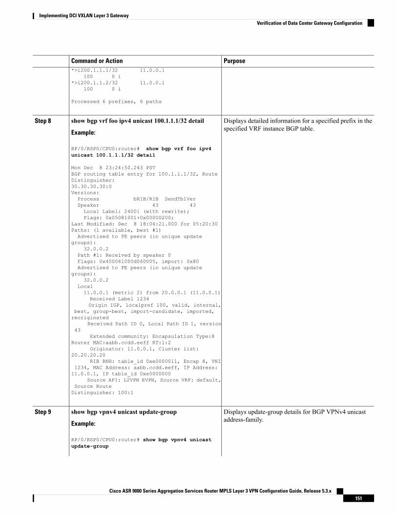
PurposeCommand or Action*>i200.1.1.1/32 11.0.0.1
100 0 i*>i200.1.1.2/32 11.0.0.1
100 0 i
Processed 6 prefixes, 6 paths
Displays detailed information for a specified prefix in thespecified VRF instance BGP table.
show bgp vrf foo ipv4 unicast 100.1.1.1/32 detail
Example:
Step 8
RP/0/RSP0/CPU0:router# show bgp vrf foo ipv4unicast 100.1.1.1/32 detail
Mon Dec 8 23:24:50.243 PSTBGP routing table entry for 100.1.1.1/32, RouteDistinguisher:30.30.30.30:0Versions:Process bRIB/RIB SendTblVerSpeaker 43 43Local Label: 24001 (with rewrite);Flags: 0x05081001+0x00000200;
Last Modified: Dec 8 18:04:21.000 for 05:20:30Paths: (1 available, best #1)Advertised to PE peers (in unique update
groups):32.0.0.2
Path #1: Received by speaker 0Flags: 0x400061000d060005, import: 0x80Advertised to PE peers (in unique update
groups):32.0.0.2
Local11.0.0.1 (metric 2) from 20.0.0.1 (11.0.0.1)Received Label 1234Origin IGP, localpref 100, valid, internal,
best, group-best, import-candidate, imported,reoriginated
Received Path ID 0, Local Path ID 1, version43
Extended community: Encapsulation Type:8Router MAC:aabb.ccdd.eeff RT:1:2
Originator: 11.0.0.1, Cluster list:20.20.20.20
RIB RNH: table_id 0xe0000011, Encap 8, VNI1234, MAC Address: aabb.ccdd.eeff, IP Address:11.0.0.1, IP table_id 0xe0000000
Source AFI: L2VPN EVPN, Source VRF: default,Source RouteDistinguisher: 100:1
Displays update-group details for BGP VPNv4 unicastaddress-family.
show bgp vpnv4 unicast update-group
Example:
Step 9
RP/0/RSP0/CPU0:router# show bgp vpnv4 unicastupdate-group
Cisco ASR 9000 Series Aggregation Services Router MPLS Layer 3 VPN Configuration Guide, Release 5.3.x151
Implementing DCI VXLAN Layer 3 GatewayVerification of Data Center Gateway Configuration
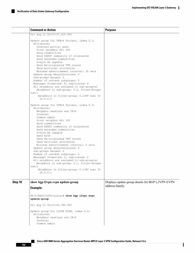
PurposeCommand or ActionFri Aug 21 00:27:57.910 PDT
Update group for VPNv4 Unicast, index 0.1:Attributes:Outbound policy: passFirst neighbor AS: 200Send communitiesSend GSHUT community if originatedSend extended communities4-byte AS capableSend Re-originated VPN routesSend multicast attributesMinimum advertisement interval: 30 secs
Update group desynchronized: 0Sub-groups merged: 0Number of refresh subgroups: 0Messages formatted: 8, replicated: 8All neighbors are assigned to sub-group(s)Neighbors in sub-group: 0.2, Filter-Groups
num:1Neighbors in filter-group: 0.2(RT num: 0)32.0.0.2
Update group for VPNv4 Unicast, index 0.3:Attributes:Neighbor sessions are IPv4InternalCommon adminFirst neighbor AS: 100Send communitiesSend GSHUT community if originatedSend extended communities4-byte AS capableSend AIGPSend Re-originated VPN routesSend multicast attributesMinimum advertisement interval: 0 secs
Update group desynchronized: 0Sub-groups merged: 0Number of refresh subgroups: 0Messages formatted: 2, replicated: 2All neighbors are assigned to sub-group(s)Neighbors in sub-group: 0.1, Filter-Groups
num:1Neighbors in filter-group: 0.1(RT num: 0)20.0.0.1
Displays update-group details for BGP L2VPN EVPNaddress-family.
show bgp l2vpn evpn update-group
Example:
Step 10
RP/0/RSP0/CPU0:router# show bgp l2vpn evpnupdate-group
Fri Aug 21 00:27:42.786 PDT
Update group for L2VPN EVPN, index 0.2:Attributes:Neighbor sessions are IPv4InternalCommon admin
Cisco ASR 9000 Series Aggregation Services Router MPLS Layer 3 VPN Configuration Guide, Release 5.3.x152
Implementing DCI VXLAN Layer 3 GatewayVerification of Data Center Gateway Configuration
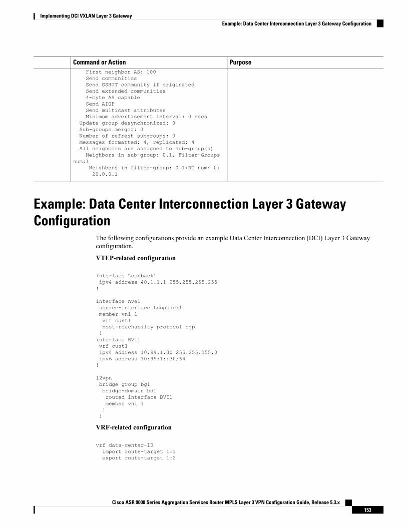
PurposeCommand or ActionFirst neighbor AS: 100Send communitiesSend GSHUT community if originatedSend extended communities4-byte AS capableSend AIGPSend multicast attributesMinimum advertisement interval: 0 secs
Update group desynchronized: 0Sub-groups merged: 0Number of refresh subgroups: 0Messages formatted: 4, replicated: 4All neighbors are assigned to sub-group(s)Neighbors in sub-group: 0.1, Filter-Groups
num:1Neighbors in filter-group: 0.1(RT num: 0)20.0.0.1
Example: Data Center Interconnection Layer 3 GatewayConfiguration
The following configurations provide an example Data Center Interconnection (DCI) Layer 3 Gatewayconfiguration.
VTEP-related configuration
interface Loopback1ipv4 address 40.1.1.1 255.255.255.255!
interface nve1source-interface Loopback1member vni 1vrf cust1host-reachabilty protocol bgp!interface BVI1vrf cust1ipv4 address 10.99.1.30 255.255.255.0ipv6 address 10:99:1::30/64!
l2vpnbridge group bg1bridge-domain bd1routed interface BVI1member vni 1!!
VRF-related configuration
vrf data-center-10import route-target 1:1export route-target 1:2
Cisco ASR 9000 Series Aggregation Services Router MPLS Layer 3 VPN Configuration Guide, Release 5.3.x153
Implementing DCI VXLAN Layer 3 GatewayExample: Data Center Interconnection Layer 3 Gateway Configuration
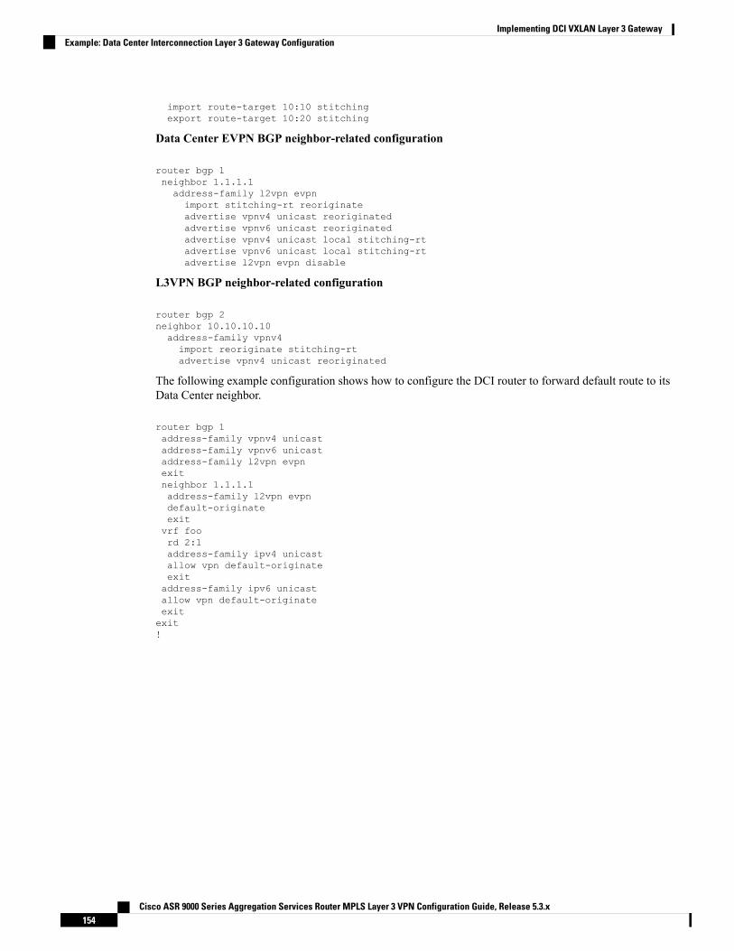
import route-target 10:10 stitchingexport route-target 10:20 stitching
Data Center EVPN BGP neighbor-related configuration
router bgp 1neighbor 1.1.1.1address-family l2vpn evpnimport stitching-rt reoriginateadvertise vpnv4 unicast reoriginatedadvertise vpnv6 unicast reoriginatedadvertise vpnv4 unicast local stitching-rtadvertise vpnv6 unicast local stitching-rtadvertise l2vpn evpn disable
L3VPN BGP neighbor-related configuration
router bgp 2neighbor 10.10.10.10address-family vpnv4import reoriginate stitching-rtadvertise vpnv4 unicast reoriginated
The following example configuration shows how to configure the DCI router to forward default route to itsData Center neighbor.
router bgp 1address-family vpnv4 unicastaddress-family vpnv6 unicastaddress-family l2vpn evpnexitneighbor 1.1.1.1address-family l2vpn evpndefault-originateexitvrf foord 2:1address-family ipv4 unicastallow vpn default-originateexitaddress-family ipv6 unicastallow vpn default-originateexitexit!
Cisco ASR 9000 Series Aggregation Services Router MPLS Layer 3 VPN Configuration Guide, Release 5.3.x154
Implementing DCI VXLAN Layer 3 GatewayExample: Data Center Interconnection Layer 3 Gateway Configuration