Embed Size (px)
Citation preview

Cisco Analog Video Gateway CLI Administrator Guide August 17, 2009
Americas HeadquartersCisco Systems, Inc.170 West Tasman DriveSan Jose, CA 95134-1706 USAhttp://www.cisco.comTel: 408 526-4000
800 553-NETS (6387)Fax: 408 527-0883

THE SPECIFICATIONS AND INFORMATION REGARDING THE PRODUCTS IN THIS MANUAL ARE SUBJECT TO CHANGE WITHOUT NOTICE. ALL STATEMENTS, INFORMATION, AND RECOMMENDATIONS IN THIS MANUAL ARE BELIEVED TO BE ACCURATE BUT ARE PRESENTED WITHOUT WARRANTY OF ANY KIND, EXPRESS OR IMPLIED. USERS MUST TAKE FULL RESPONSIBILITY FOR THEIR APPLICATION OF ANY PRODUCTS.
THE SOFTWARE LICENSE AND LIMITED WARRANTY FOR THE ACCOMPANYING PRODUCT ARE SET FORTH IN THE INFORMATION PACKET THAT SHIPPED WITH THE PRODUCT AND ARE INCORPORATED HEREIN BY THIS REFERENCE. IF YOU ARE UNABLE TO LOCATE THE SOFTWARE LICENSE OR LIMITED WARRANTY, CONTACT YOUR CISCO REPRESENTATIVE FOR A COPY.
The Cisco implementation of TCP header compression is an adaptation of a program developed by the University of California, Berkeley (UCB) as part of UCB’s public domain version of the UNIX operating system. All rights reserved. Copyright © 1981, Regents of the University of California.
NOTWITHSTANDING ANY OTHER WARRANTY HEREIN, ALL DOCUMENT FILES AND SOFTWARE OF THESE SUPPLIERS ARE PROVIDED “AS IS” WITH ALL FAULTS. CISCO AND THE ABOVE-NAMED SUPPLIERS DISCLAIM ALL WARRANTIES, EXPRESSED OR IMPLIED, INCLUDING, WITHOUT LIMITATION, THOSE OF MERCHANTABILITY, FITNESS FOR A PARTICULAR PURPOSE AND NONINFRINGEMENT OR ARISING FROM A COURSE OF DEALING, USAGE, OR TRADE PRACTICE.
IN NO EVENT SHALL CISCO OR ITS SUPPLIERS BE LIABLE FOR ANY INDIRECT, SPECIAL, CONSEQUENTIAL, OR INCIDENTAL DAMAGES, INCLUDING, WITHOUT LIMITATION, LOST PROFITS OR LOSS OR DAMAGE TO DATA ARISING OUT OF THE USE OR INABILITY TO USE THIS MANUAL, EVEN IF CISCO OR ITS SUPPLIERS HAVE BEEN ADVISED OF THE POSSIBILITY OF SUCH DAMAGES.
CCDE, CCENT, CCSI, Cisco Eos, Cisco HealthPresence, Cisco Ironport, the Cisco logo, Cisco Lumin, Cisco Nexus, Cisco Nurse Connect, Cisco Stackpower, Cisco StadiumVision, Cisco TelePresence, Cisco Unified Computing System, Cisco WebEx, DCE, Flip Channels, Flip for Good, Flip Mino, Flip Video, Flip Video (Design), Flipshare (Design), Flip Ultra, and Welcome to the Human Network are trademarks; Changing the Way We Work, Live, Play, and Learn, Cisco Store, and Flip Gift Card are service marks; and Access Registrar, Aironet, AsyncOS, Bringing the Meeting To You, Catalyst, CCDA, CCDP, CCIE, CCIP, CCNA, CCNP, CCSP, CCVP, Cisco, the Cisco Certified Internetwork Expert logo, Cisco IOS, Cisco Press, Cisco Systems, Cisco Systems Capital, the Cisco Systems logo, Cisco Unity, Collaboration Without Limitation, EtherFast, EtherSwitch, Event Center, Fast Step, Follow Me Browsing, FormShare, GigaDrive, HomeLink, Internet Quotient, IOS, iPhone, iQuick Study, IronPort, the IronPort logo, LightStream, Linksys, MediaTone, MeetingPlace, MeetingPlace Chime Sound, MGX, Networkers, Networking Academy, Network Registrar, PCNow, PIX, PowerPanels, ProConnect, ScriptShare, SenderBase, SMARTnet, Spectrum Expert, StackWise, The Fastest Way to Increase Your Internet Quotient, TransPath, WebEx, and the WebEx logo are registered trademarks of Cisco Systems, Inc. and/or its affiliates in the United States and certain other countries.
All other trademarks mentioned in this document or website are the property of their respective owners. The use of the word partner does not imply a partnership relationship between Cisco and any other company. (0907R)
Any Internet Protocol (IP) addresses and phone numbers used in this document are not intended to be actual addresses and phone numbers. Any examples, command display output, network topology diagrams, and other figures included in the document are shown for illustrative purposes only. Any use of actual IP addresses or phone numbers in illustrative content is unintentional and coincidental.
Cisco Analog Video Gateway CLI Administrator Guide Copyright © 2009 Cisco Systems, Inc. All rights reserved.

OL-15158-04
C O N T E N T S
Cisco Analog Video Gateway Module Overview 1
System Application 3Video Ports 3Video Services 3
Video Profiles 4
Contact Closure Ports 4
Alarm Monitor Profiles 5RS-485 Ports for Camera Control 5
Configuring Host Router and Cisco Analog Video Gateway Module Interfaces 7
Before Configuring the Cisco Analog Video Gateway 7Cisco ISR 8Network Module 8File Server 9
Entering and Exiting the Command Environment 9EXEC and Configuration Modes 9Entering the Command Environment 9
Prerequisites 9Exiting the Command Environment 10
Configuring Interfaces 11
Interface Configuration Tasks 12
Examples 14
Opening and Closing a Network Module Session 14
Configuring the Cisco Analog Video Gateway Profiles 16
Administering the Cisco Analog Video Gateway 17
Shutting Down and Starting Up the Cisco Analog Video Gateway Application 18
Backing Up and Restoring Configurations 19
Verifying System Status 20
Diagnostics and Logging Options 22
Adding a DNS Server (Optional) 23
Additional References 26
Related Documents 26
iiiCisco Analog Video Gateway CLI Administrator Guide

Contents
Technical Assistance 27
Configuring Video Parameters 29
Configuring Video Ports 29
Restrictions 29
Examples 32
Configuring Video Profiles 33
Video Codec Profile 33
Supported Skip Factor 36
Video Motion Region Profile 38
Video Motion Detection Profile 40
Video Stream Profile 42
Configuring Video Cross-Connect Loopback 45
Configuring Contact Closure Profiles 49
Examples 50
Configuring Alarm Monitor Profiles 53
Alarm Monitor—Destination Profile 53
Alarm Monitor—Monitor Profile 55
Alarm Monitor—Notifier Profile 58
Configuring Camera Controls 61
Restrictions 61
Examples 63
Cisco Analog Video Gateway Command Reference 65
Cisco Analog Gateway Module Commands 65
Cisco IOS Commands 119
Index
ivCisco Analog Video Gateway CLI Administrator Guide
OL-15158-04

Cisco Analog Video Gateway Module Overview
Last Updated: August 17, 2009
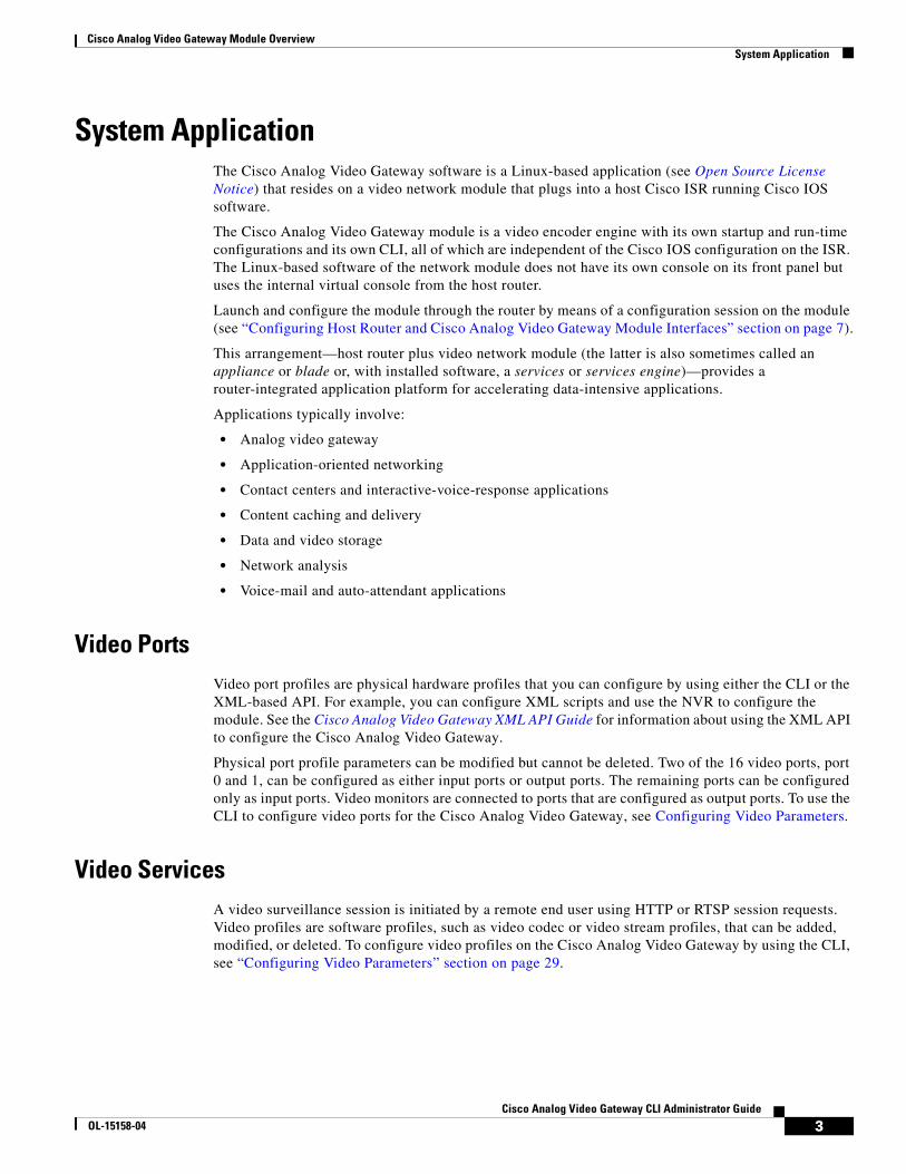
The Cisco IP Video Surveillance 16-Port Analog Video Gateway Network Module, referred to as the Cisco Analog Video Gateway module throughout this guide, converts analog camera signals into IP-accessible endpoints. The network module receives input from analog video cameras and converts analog signals to IP video streams for IP networks used in closed-circuit IP video surveillance (IPVS) systems (see Figure 1). These video streams can be displayed over a network or locally on analog monitors.
The Cisco Analog Video Gateway module fits into Cisco Integrated Services Routers (Cisco ISRs) that are optimized for the secure, wire-speed delivery of concurrent data, voice, video, and wireless services.
The Cisco Analog Video Gateway aggregates video streams for transport across the network. By transporting the video over your existing IP network, you no longer need to maintain a separate, duplicate system. Specific capabilities of the Cisco Analog Video Gateway include:
• High-density analog video encoding: Up to 16 ports in a single module
• Maximum-quality video resolution:
– Common Intermediate Format (CIF) to 2CIF/4CIF
– Frame rates up to 30 frames per second (fps) per port
• Remote camera control: Two independent RS-485 loops for serial pan-tilt-zoom (PTZ) control of traditional cameras
• Flexible codec selection: Motion JPEG (MJPEG), MPEG4, and H.264
• Integrated contact closure ports: Four input and four additional configurable inputs and outputs
• Embedded motion detection
• Hardware is based on a flexible digital-signal-processor (DSP) platform
This router-integrated, single-box solution is designed for video surveillance and other network services such as routing, security, and unified communications. It allows you to consolidate costly branch-office servers and deploy new applications centrally, while offering real-time access to physical security video and data.
Whenever possible, configuration and management of the Cisco Analog Video Gateway module should be configured using the Video Surveillance Operations Manager (VSOM) graphical user interface.
This guide supports features for version 1.2 and earlier versions of the Cisco Analog Video Gateway network module. To view the product feature history, see the Release Notes for the Cisco Video Management and Storage System, which lists feature support for Cisco Analog Video Gateway versions.
1Cisco Analog Video Gateway CLI Administrator Guide
OL-15158-04

Cisco Analog Video Gateway Module Overview
Figure 1 Analog Camera Signals Converted to IP Video Streams
Analog cameras are connected to video input ports of the network module over coaxial cable using DB-37 connector. Each Cisco Analog Video Gateway module has 16 ports, all of which can be configured as inputs. Ports 0 and 1 can be configured as inputs or outputs for connecting to analog monitors.
The video encoder converts the analog signal into a compressed video stream for transmission over the IP network and sends it to a network video recorder (NVR), which is typically located in the data center.
Security operations personnel can access and review archived surveillance video recorded at remote sites from terminals in their local facility. The NVR can reposition remote cameras by centering, focusing, and zooming them based on event triggers. Pan-tilt-zoom (PTZ) camera control is tunneled across the IP network using serial (RS-232/RS-485) interfaces.
Contact closure of eight input sensors and four output control elements allows the video surveillance system to report on events detected by the input sensors and allows the system to determine output control movements or feedback to the PTZ devices.
The primary means of configuring the Cisco Analog Video Gateway is by using the Cisco Video and Management Storage System (for details, see the Cisco Video Management and Storage System CLI Administrator Guide). The Cisco Analog Video Gateway can also be configured using either its command-line interface (CLI) or the XML-based application programming interface (API). For example, you can configure XML scripts and use the NVR to configure the module. See the Cisco Analog Video Gateway XML API Guide for information about using the XML API to configure the Cisco Analog Video Gateway. This guide describes how to use the CLI to configure the software options of the Cisco Analog Video Gateway module.
The Cisco Analog Video Gateway is one of four components that make up the Cisco IP Video Surveillance solution. Other components are the:
• Cisco integrated services routers (ISRs)
• Cisco Video Management and Storage System Network Module
• Cisco Video Surveillance Manager product line, consisting of the Cisco Video Surveillance Operations Manager Software and the Cisco Video Surveillance Media Server Software
2312
42
Operations center Remote offices
Analog cameras
IP
Analog cameras
Analog cameras
WAN
2Cisco Analog Video Gateway CLI Administrator Guide
OL-15158-04
Cisco Analog Video Gateway Module OverviewSystem Application
System ApplicationThe Cisco Analog Video Gateway software is a Linux-based application (see Open Source License Notice) that resides on a video network module that plugs into a host Cisco ISR running Cisco IOS software.
The Cisco Analog Video Gateway module is a video encoder engine with its own startup and run-time configurations and its own CLI, all of which are independent of the Cisco IOS configuration on the ISR. The Linux-based software of the network module does not have its own console on its front panel but uses the internal virtual console from the host router.
Launch and configure the module through the router by means of a configuration session on the module (see “Configuring Host Router and Cisco Analog Video Gateway Module Interfaces” section on page 7).
This arrangement—host router plus video network module (the latter is also sometimes called an appliance or blade or, with installed software, a services or services engine)—provides a router-integrated application platform for accelerating data-intensive applications.
Applications typically involve:
• Analog video gateway
• Application-oriented networking
• Contact centers and interactive-voice-response applications
• Content caching and delivery
• Data and video storage
• Network analysis
• Voice-mail and auto-attendant applications
Video PortsVideo port profiles are physical hardware profiles that you can configure by using either the CLI or the XML-based API. For example, you can configure XML scripts and use the NVR to configure the module. See the Cisco Analog Video Gateway XML API Guide for information about using the XML API to configure the Cisco Analog Video Gateway.
Physical port profile parameters can be modified but cannot be deleted. Two of the 16 video ports, port 0 and 1, can be configured as either input ports or output ports. The remaining ports can be configured only as input ports. Video monitors are connected to ports that are configured as output ports. To use the CLI to configure video ports for the Cisco Analog Video Gateway, see Configuring Video Parameters.
Video ServicesA video surveillance session is initiated by a remote end user using HTTP or RTSP session requests. Video profiles are software profiles, such as video codec or video stream profiles, that can be added, modified, or deleted. To configure video profiles on the Cisco Analog Video Gateway by using the CLI, see “Configuring Video Parameters” section on page 29.
3Cisco Analog Video Gateway CLI Administrator Guide
OL-15158-04

Cisco Analog Video Gateway Module OverviewContact Closure Ports
Video Profiles
Video stream profiles are created for every camera and are viewed through the stream ID created for every port. Video profiles can be created by using the CLI or the XML APIs.
The following are basic types of video profiles:
• Video Codec Profiles
• Video Motion Detection Profiles
• Video Stream Profiles
Video Codec Profiles
The video codec profile is a collection of characteristics for that codec. You can configure frame rate, codec type, resolution, bit rate, maximum bit rate, signal format, and groups of pictures (GOPs). Single or multiple video codec profiles can be created and associated with all the video ports. You can enable or disable deinterlacing, which is the process of converting interlaced video into a non-interlaced form, starting with Cisco Analog Video Gateway 1.1, and later versions.
The MJPEG, H.264, and MPEG4 codecs can use a variable bit-rate (VBR) algorithm, in which the desired bit rate can be controlled through the quality factor for MJPEG and the bit-rate can be maximized for MPEG4 and H.264. The H.264 and MPEG4 codecs can also use constant bit-rate (CBR) algorithms that allow the setting of a maximum bit-rate parameter.
Video Motion Detection Profiles
Cisco video servers support motion detection algorithms (MDAs) for all video codecs. Motion detection (using raw motion detection) for MJPEG is supported starting with Cisco Analog Video Gateway 1.1, and later versions. A motion detection region is created with x, y coordinates. Multiple regions can be created for motion detection.
Video Stream Profiles
A video stream profile is a collection of video characteristics that includes codec, detection, and port information.
Video streaming is controlled through the XMLAPI, in which the network video recorders attempt a TCP connection to the Cisco Analog Video Gateway module to establish video streaming.
Input streams from the camera to the Cisco Analog Video Gateway module are analog, and output streams from the network module to the IP network are packetized.
Contact Closure PortsEach Cisco Analog Video Gateway module has eight contact-closure interfaces. The first four contact-closure interfaces can be configured as alarm inputs or relay outputs. The other interfaces can be configured only as inputs. The contact-closure inputs are used to detect contact trigger events and the outputs are used to control external devices.
You can configure and monitor these alarm interfaces by using the CLI or the XML API. See the Cisco Analog Video Gateway XML API Guide for information about using the XML API to configure the Cisco Analog Video Gateway. A contact-closure software module manages the alarm interfaces. To configure contact-closure ports on the Cisco Analog Video Gateway using the CLI, see “Configuring Contact Closure Profiles” section on page 49.
4Cisco Analog Video Gateway CLI Administrator Guide
OL-15158-04

Cisco Analog Video Gateway Module OverviewAlarm Monitor Profiles
Alarm Monitor ProfilesThe Cisco Analog Video Gateway alarm software module serves as a central point for the control of alarms and relay interfaces in the video network module. The alarm software module sets the alarm interfaces to their predetermined states and monitors trigger events. When an alarm is detected, the alarm software module determines the source of the alarm, updates the system log file, and sends predefined HTTP messages to the controllers. The controllers act on these messages, based on the nature of the alarm. For example, a controller might adjust the camera, start video streaming, or trigger the external devices.
All four relay interface outputs in the video network module can be accessed by multiple users, but each interface can be operated by only one user at a time.
The alarm monitor senses alarm events on each alarm interface. When an event is triggered, it notifies the alarm application, which then passes the information to the configured monitor destination. To configure alarm profiles on the Cisco Analog Video Gateway using the CLI, see Configuring Alarm Monitor Profiles.
RS-485 Ports for Camera ControlThe Cisco Analog Video Gateway module only supports a half-duplex, two-wire RS-485 communication network, sometimes called a ring, which is used to connect PTZ cameras. The video network module consists of two RS-485 ports.
The RS-485 application is designed to work with external third-party vendor software in the NVR and supports only pass-through mode. You can configure and monitor these alarm interfaces using the CLI or GUI interfaces. See the Cisco Analog Video Gateway XML API Guide to configure the Cisco Analog Video Gateway using the XML API. To configure destination profiles on the Cisco Analog Video Gateway using the CLI, see “Configuring Camera Controls” section on page 61.
5Cisco Analog Video Gateway CLI Administrator Guide
OL-15158-04

Cisco Analog Video Gateway Module OverviewAlarm Monitor Profiles
6Cisco Analog Video Gateway CLI Administrator Guide
OL-15158-04

Configuring Host Router and Cisco Analog Video Gateway Module Interfaces
Last Updated: August 17, 2009
To configure the Cisco Analog Video Gateway network module after it is installed in your host Cisco Integrated Services Router (ISR), you need to configure the following:
• Cisco ISR external interface to an external network link using the Cisco IOS CLI for setting standard router settings
• Cisco ISR internal interface to the Cisco Analog Video Gateway module, using the Cisco IOS CLI for setting the network module IP address and default gateway router
• Cisco Analog Video Gateway module internal interface to the host router, using network module firmware for setting application settings
• Cisco Analog Video Gateway module external interface to an external link, using the module firmware for servicing external requests
Whenever possible, configuration and management of the Cisco Analog Video Gateway module should be configured using the Video Surveillance Operations Manager (VSOM) graphical user interface.
The following sections describe the tasks required to configure the host router and Cisco Analog Video Gateway module interfaces:
• Before Configuring the Cisco Analog Video Gateway, page 7
• Entering and Exiting the Command Environment, page 9
• Configuring Interfaces, page 11
• Opening and Closing a Network Module Session, page 14
• Configuring the Cisco Analog Video Gateway Profiles, page 16
Before Configuring the Cisco Analog Video GatewayComplete the following prerequisites for the ISR, network module, and file server before you attempt to configure the Cisco Analog Video Gateway:
7Cisco Analog Video Gateway CLI Administrator Guide
OL-15158-04

Configuring Host Router and Cisco Analog Video Gateway Module InterfacesBefore Configuring the Cisco Analog Video Gateway
Cisco ISR • Plan software installations, upgrades, or downgrades for times when you can take out of service or
off line all applications that run on the host router.
• Ensure that your Cisco router serves as your host router, running the appropriate Cisco IOS release. To learn which release your router is currently running, check the output from the show version command.
Note When minimum release requirements are met, you can change images on either the host router or on the Cisco Analog Video Gateway module, without affecting the other image.
Network Module • If it is not already installed at the factory, install the Cisco Analog Video Gateway network module
into the host router with sufficient physical memory (see Table 1) to accommodate the Cisco Analog Video Gateway application software.
Note For detailed information on hardware installation, see Installing Cisco Network Modules in Cisco Access Routers.
• Before swapping out a Cisco Analog Video Gateway module in an existing system, perform a full backup of all data.
• After the swap, restore the data.
Note For more information, see the “Backing Up and Restoring Configurations” section on page 19.
• Note the Cisco Analog Video Gateway module location in the host router:
– slot: Number of the host router chassis slot for the module. After you install the module, you can obtain this information by using the router show running-config command.
– unit: Number of the daughter card on the module. This value should be 0.
Note You need this information for the “Interface Configuration Tasks” section on page 12 and the “Opening and Closing a Network Module Session” section on page 14.
Table 1 Cisco Analog Video Gateway Module Memory Requirements
Type of Memory Required Size
CompactFlash memory 512 M
RAM 512 M
8Cisco Analog Video Gateway CLI Administrator Guide
OL-15158-04

Configuring Host Router and Cisco Analog Video Gateway Module InterfacesEntering and Exiting the Command Environment
File Server • Verify that your download File Transfer Protocol (FTP) or Trivial File Transfer Protocol (TFTP) file
server is accessible:
– FTP file server: Use for installations, backups, and data restores.
– TFTP file server: Use for boot helper operations to recover from a failed installation.
• Configure the Cisco Analog Video Gateway module software only from a console that connects to a serial console port on the host router.
Note See the Cisco Analog Video Gateway Installation and Upgrade Guide for more information.
• Access the Cisco Analog Video Gateway module software only by first accessing one of the following:
– Cisco IOS command-line interface (CLI)
– Cisco Analog Video Gateway XML application programming interface (API)
Entering and Exiting the Command EnvironmentThis section describes the procedures for entering and exiting the command environment, in which the Cisco Analog Video Gateway configuration commands are executed. The following sections describe these procedures:
• EXEC and Configuration Modes, page 9
• Entering the Command Environment, page 9
• Exiting the Command Environment, page 10
EXEC and Configuration ModesThe Cisco Analog Video Gateway user EXEC, privileged EXEC, and configuration command modes are similar to the user EXEC, privilege EXEC, and configuration modes for Cisco IOS CLI commands. The description for each command of this section indicates the command mode.
Entering the Command EnvironmentWhen the Cisco Analog Video Gateway module has been installed and is active, use the following procedure to enter the command environment.
Prerequisites
The following information is required to enter the command environment:
• IP address of the Cisco ISR that contains the Cisco Analog Video Gateway module
• Username and password for logging in to the router
• Slot number of the module
9Cisco Analog Video Gateway CLI Administrator Guide
OL-15158-04

Configuring Host Router and Cisco Analog Video Gateway Module InterfacesEntering and Exiting the Command Environment
SUMMARY STEPS
1. Open a Telnet session.
2. telnet ip-address
3. Enter the user ID and password of the router.
4. service-module video-service-engine slot/port session
5. (Optional) enable
DETAILED STEPS
Exiting the Command EnvironmentTo leave the Cisco Analog Video Gateway module command environment and return to the router command environment, return to the Cisco Analog Video Gateway EXEC mode and enter the exit command twice.
The following example shows the exit procedure:
se-10-0-0-0# exitse-10-0-0-0> exitRouter#
Command or Action Purpose
Step 1 Open a Telnet session. Use Microsoft Windows command prompt window, a secure shell, or a software emulation tool such as WRQ Reflection.
Step 2 telnet ip-address
Example:C:\>telnet 172.16.231.11
Specifies the IP address of the router.
Step 3 Username: useridPassword: password
Enter your user ID and password for the router.
Step 4 service-module video-service-engine slot/port session
Example:Router# service-module video-service-engine 1/0 sessionse-10-0-0-0#
Enters the Cisco Analog Video Gateway module command environment by using the module located in slot and port. The prompt changes to the service module prompt with the IP address of the network module.
If the message “Trying ip-address slot/port ...” Connection refused by remote host appears, enter the command service-module video-service-engine slot/port
session clear and repeat Step 4.
Step 5 enable
Example:se-10-0-0-0# enable
(Optional) Enters Cisco Analog Video Gateway EXEC mode. You can begin configuring the network module.
10Cisco Analog Video Gateway CLI Administrator Guide
OL-15158-04

Configuring Host Router and Cisco Analog Video Gateway Module InterfacesConfiguring Interfaces
Configuring InterfacesThe host router and the Cisco Analog Video Gateway network module use several interfaces for internal and external communication (see Figure 2). Each interface is configurable—for the router by using the Cisco IOS CLI, and for the module by using the module firmware Linux-based CLI or XML API.
Figure 2 Router and Cisco Analog Video Gateway Module Interfaces
The following sections describe the tasks that are necessary for configuring the host router and network module interfaces:
• Interface Configuration Tasks, page 12
• Opening and Closing a Network Module Session, page 14
On This Hardware Interface... Configure These Settings...Using This Configuration Interface
1 Host router interface to external link
Standard router settings Host router Cisco IOS CLI
2 Host router interface to module Cisco Analog Video Gateway network module IP address and default gateway router
3 Cisco Analog Video Gateway module interface to router
All other Cisco Analog Video Gateway module application settings
Cisco Analog Video Gateway module CLI or XML API4 Cisco Analog Video Gateway
module interface to external link
Support for data requests and transfers from outside sources
Note This external network interface was disabled and is not usable in software version 1.2 and later.
15
56
30
Router interface to module
Host Router (Top View)
Module interface to router
Network Module
Module interface to external link Router interface to external link14
3
2
11Cisco Analog Video Gateway CLI Administrator Guide
OL-15158-04

Configuring Host Router and Cisco Analog Video Gateway Module InterfacesConfiguring Interfaces
Interface Configuration TasksThe first configuration task is to set up the Cisco Analog Video Gateway module interface to the host router and to its external links. This enables you to access the module so that you can install and configure the Cisco Analog Video Gateway software application.
Steps 1 and 2 open the host router CLI and accesses the router interface to the Cisco Analog Video Gateway module. The remaining steps configure the interface.
Note If you lose power or connection during any of the following procedures, the system usually detects the interruption and tries to recover. If it fails to do so, fully reinstall the system using the boot helper.
SUMMARY STEPS
From the Host-Router CLI
1. enable
2. configure terminal
3. interface video-service-engine slot/0
4. ip address router-side-ip-address subnet-mask
or
ip unnumbered type number
5. service-module ip address module-side-ip-address subnet-mask
6. service-module external ip address external-ip-address subnet-mask
7. service-module ip default-gateway gateway-ip-address
8. If ip unnumbered type number is used in step 4, then set ip route
9. end
10. copy running-config startup-config
11. show running-config
DETAILED STEPS
Command or Action Purpose
From the Host-Router CLI
Step 1 enable
Example:Router> enable
Enters privileged EXEC mode on the host router. Enter your password if prompted.
Step 2 configure terminal
Example:Router# config t
Enters global configuration mode on the host router.
12Cisco Analog Video Gateway CLI Administrator Guide
OL-15158-04

Configuring Host Router and Cisco Analog Video Gateway Module InterfacesConfiguring Interfaces
Step 3 interface video-service-engine slot/0
Example:Router(config)# interface video-service-engine 1/0
Enters interface configuration mode for the slot and port where the Cisco Analog Video Gateway module resides.
• slot: specifies the module slot
• port: specifies the port number
Step 4 ip address router-side-ip-address subnet-mask
or
ip unnumbered type number
Example:Router(config-if)# ip address 10.0.0.20 255.255.255.0
or
Router(config-if)# ip unnumbered ethernet 0
Specifies the router interface to the module.
• router-side-ip-address subnet-mask—IP address and subnet mask for the host router interface.
• type number—Type and number of another serial interface on which the router has an assigned IP address. It cannot be another unnumbered interface. Serial interfaces using High Level Data Link Control (HDLC), Point-to-Point Protocol (PPP), Link Access Procedure, Balanced (LAPB), Frame Relay encapsulations, Serial Line Internet Protocol (SLIP), and tunnel interfaces can be unnumbered.
Step 5 service-module ip address module-side-ip-address subnet-mask
Example:Router(config-if)# service-module ip address 172.0.0.20 255.255.255.0
Specifies the IP address for the Cisco Analog Video Gateway module interface to the router.
• module-side-ip-address—IP address for the interface.
• subnet-mask—Subnet mask to append to the IP address; must be in the same subnet as the host router.
Step 6 service-module external ip address external-ip-address subnet-mask
Example:Router(config-if)# service-module external ip address 172.0.0.30 255.255.255.0
Specifies the IP address for the external LAN interface on the module.
• external-ip-address—IP address for the interface.
• subnet-mask—Subnet mask to append to the IP address.
Step 7 service-module ip default-gateway gateway-ip-address
Example:Router(config-if)# service-module ip default-gateway 10.0.0.40
Specifies the IP address for the default gateway router for the module. The argument is as follows:
• gateway-ip-address—IP address for the gateway router.
Step 8 (Optional) If the ip unnumbered type number command is used in step 4, then set:
ip route service-module-ip-address subnet-mask video-service-engine 1/0
Example:Router(config-if)# ip route 172.0.0.20 255.255.255.255 video-service-engine 1/0
Sets the ip route command if the ip unnumbered type number command is used in Step 4.
Step 9 end
Example:Router(config-if)# end
Returns to global configuration mode on the host router.
Command or Action Purpose
13Cisco Analog Video Gateway CLI Administrator Guide
OL-15158-04

Configuring Host Router and Cisco Analog Video Gateway Module InterfacesOpening and Closing a Network Module Session
Examples
The following partial sample output from the show running-config command shows how the interfaces are configured.
interface video-service-engine1/0 ip address 10.0.0.20 255.255.255.0 service-module external ip address 172.0.0.30 255.255.0.0 service-module ip address 172.0.0.20 255.255.255.0 service-module ip default-gateway 10.0.0.40
Opening and Closing a Network Module SessionThis section describes how to open and close a session on the Cisco Analog Video Gateway module.
Note • Before you install your application software, opening a session brings up the boot loader. The boot loader is a small set of system software that runs when the system first powers up. It loads the operating system from the disk (external CompactFlash memory) or network, which loads and runs the Cisco Analog Video Gateway application. The boot loader may optionally load and run the boot helper. After you install the software, opening a session brings up the application.
• You can conduct only one session at a time.
• The Steps 1 and 2 open the host-router CLI and access the module. The remaining steps configure the module and return you to the host-router CLI.
SUMMARY STEPS
From the Host-Router CLI
1. enable
2. service-module video-service-engine slot/0 status
3. service-module video-service-engine slot/0 session
From the Service-Module Interface
4. Network module configuration commands
5. Control-Shift-6 x
Step 10 copy running-config startup-config
Example:Router# copy running-config startup-config
Saves the new running configuration of the host router.
Step 11 show running-config
Example:Router# show running-config
Displays the running configuration of the host router. Use this command to verify address configurations.
Command or Action Purpose
14Cisco Analog Video Gateway CLI Administrator Guide
OL-15158-04

Configuring Host Router and Cisco Analog Video Gateway Module InterfacesOpening and Closing a Network Module Session
From the Host-Router CLI
6. service-module video-service-engine slot/0 session clear
DETAILED STEPS
Command or Action Purpose
From the Host-Router CLI
Step 1 enable
Example:Router> enable
Enters privileged EXEC mode on the host router. Enter your password if prompted.
Step 2 service-module video-service-engine slot/0 status
Example:Router# service-module video-service-engine 2/0 status
Displays the status of the specified module, so that you can ensure that the module is running (that is, in steady state).
Note If the module is not running, start it with one of the startup commands listed in the “Shutting Down and Starting Up the Cisco Analog Video Gateway Application” section on page 18.
Step 3 service-module video-service-engine slot/0 session
Example:Router# service-module video-service-engine 1/0 session
Trying 10.10.10.1, 2065 ... Open
Begins a module session on the specified module. Do one of the following:
• To interrupt the auto-boot sequence and access the boot loader, quickly type ***.
Note The *** entry can only be executed at reload.
• To start a configuration session, press Enter.
From the Service-Module Interface (boot loader prompt or configuration prompt)
Step 4 ...
Example (boot loader):VSE-Module bootloader> config
OR
Example (Configuration):VSE-Module> configure terminalVSE-Module(config)>...VSE-Module(config)> exitVSE-Module> write
Enters boot loader or configuration commands on the module as needed.
• Boot loader command choices include boot, config, exit, help, ping, reboot, show, and verify.
OR
• Configuration command choices are similar to those that are available on the router. Access global configuration mode by using the configure terminal command. Enter configuration commands. Then exit global configuration mode with the exit command and save your new configuration with the write command. Notice that you do not use the enable command and the prompt does not change from >.
Step 5 Press Control-Shift-6 x. Closes the module session and returns to the router CLI.
Note The module session stays up until you clear it in Step 6. While the session remains up, you can return to it from the router CLI by pressing Enter.
15Cisco Analog Video Gateway CLI Administrator Guide
OL-15158-04

Configuring Host Router and Cisco Analog Video Gateway Module InterfacesConfiguring the Cisco Analog Video Gateway Profiles
Configuring the Cisco Analog Video Gateway ProfilesAfter you configure the host router and the Cisco Analog Video Gateway network module, you can begin to configure the video (see Configuring Video Parameters), contact-closure (see Configuring Contact Closure Profiles), and alarm-monitor (see Configuring Alarm Monitor Profiles) profiles.
From the Host-Router CLI
Step 6 service-module video-service-engine slot/0 session clear
Example:Router# service-module video-service-engine 1/0 session clear
Clears the module session for the specified module. When prompted to confirm this command, press Enter.
Command or Action Purpose
16Cisco Analog Video Gateway CLI Administrator Guide
OL-15158-04

Administering the Cisco Analog Video Gateway
Last Updated: August 17, 2009
Whenever possible, configuration and management of the Cisco Analog Video Gateway module should be configured using the Video Surveillance Operations Manager (VSOM) graphical user interface.
This chapter contains the following information for administering the Cisco Analog Video Gateway module application:
• Shutting Down and Starting Up the Cisco Analog Video Gateway Application, page 18
• Backing Up and Restoring Configurations, page 19
• Verifying System Status, page 20
• Diagnostics and Logging Options, page 22
• Adding a DNS Server (Optional), page 23
• Additional References, page 26
Note • The tables in these sections show only common router and network module commands.
– To view a complete list of available commands, type ? at the prompt Example: Router(config-if)# ?
– To view a complete list of command keyword options, type ? at the end of the command Example: Router# service-module video-service-engine ?
• The commands are grouped in the tables by the configuration mode in which they are available. If the same command is available in more than one mode, it can act differently in each mode.
17Cisco Analog Video Gateway CLI Administrator Guide
OL-15158-04

Administering the Cisco Analog Video GatewayShutting Down and Starting Up the Cisco Analog Video Gateway Application
Shutting Down and Starting Up the Cisco Analog Video Gateway Application
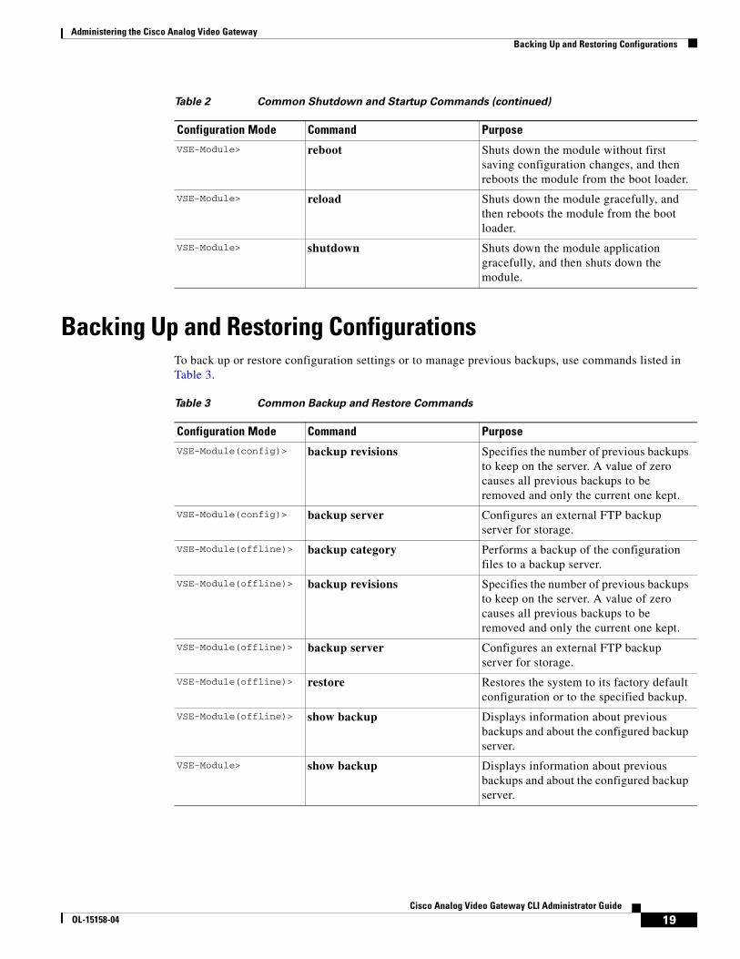
To start up or shut down the network module or the Cisco Analog Video Gateway application that runs on the module, use shutdown and startup commands as needed from Table 2.
Note • Some shutdown commands can potentially disrupt service. If command output for such a command displays a confirmation prompt, confirm by pressing Enter or cancel by typing n and pressing Enter. Alternatively, prevent the prompt from displaying by using the no-confirm keyword.
• Some commands shut down the module or application and then immediately restart it.
Table 2 Common Shutdown and Startup Commands
Configuration Mode Command Purpose
Router# service-module video-service-engine slot/0 reload
Shuts down the module operating system gracefully, and then restarts it from the boot loader.
Router# service-module video-service-engine slot/0 reset
Resets the hardware on a module. Use only to recover from shutdown or a failed state.
Caution Use this command with caution. It does not provide an orderly software shutdown, and it can impact file operations that are in progress.
Router# service-module video-service-engine slot/0 session
Accesses the specified network module and begins a module configuration session.
Router# service-module video-service-engine slot/0 shutdown
Shuts down the module operating system gracefully. Use this command sequence when removing or replacing a hot-swappable module during online insertion and removal (OIR).
Router# service-module video-service-engine slot/0 status
Displays configuration and status information for the module hardware and software.
Router(config)# shutdown Shuts down the entire system (host router and network module) gracefully.
VSE-Module bootloader>
boot Starts the boot loader, boot helper, or application.
VSE-Module(offline)> reload Performs a graceful halt and reboot of the module operating system.
18Cisco Analog Video Gateway CLI Administrator Guide
OL-15158-04
Administering the Cisco Analog Video GatewayBacking Up and Restoring Configurations
Backing Up and Restoring ConfigurationsTo back up or restore configuration settings or to manage previous backups, use commands listed in Table 3.
VSE-Module> reboot Shuts down the module without first saving configuration changes, and then reboots the module from the boot loader.
VSE-Module> reload Shuts down the module gracefully, and then reboots the module from the boot loader.
VSE-Module> shutdown Shuts down the module application gracefully, and then shuts down the module.
Table 2 Common Shutdown and Startup Commands (continued)
Configuration Mode Command Purpose
Table 3 Common Backup and Restore Commands
Configuration Mode Command Purpose
VSE-Module(config)> backup revisions Specifies the number of previous backups to keep on the server. A value of zero causes all previous backups to be removed and only the current one kept.
VSE-Module(config)> backup server Configures an external FTP backup server for storage.
VSE-Module(offline)> backup category Performs a backup of the configuration files to a backup server.
VSE-Module(offline)> backup revisions Specifies the number of previous backups to keep on the server. A value of zero causes all previous backups to be removed and only the current one kept.
VSE-Module(offline)> backup server Configures an external FTP backup server for storage.
VSE-Module(offline)> restore Restores the system to its factory default configuration or to the specified backup.
VSE-Module(offline)> show backup Displays information about previous backups and about the configured backup server.
VSE-Module> show backup Displays information about previous backups and about the configured backup server.
19Cisco Analog Video Gateway CLI Administrator Guide
OL-15158-04

Administering the Cisco Analog Video GatewayVerifying System Status
Verifying System StatusTo verify the status of an installation, upgrade, or downgrade, or to troubleshoot problems, use verification and troubleshooting commands as needed from Table 4.
Note Among keyword options for many show commands is the provision to display diagnostic output on your screen or to pipe it to a file or a URL.
Table 4 Common Verification and Troubleshooting Commands
Configuration Mode Command Purpose
Router# ping Pings a specified IP address to check network connectivity (does not accept a hostname as destination).
Router# show arp Displays the current Address Resolution Protocol (ARP) table.
Router# show clock Displays the current date and time.
Router# show configuration Displays the current boot loader configuration as entered by means of the configure command.
Router# show controllers video-service-engine
Displays interface debug information.
Router# show diag Displays standard Cisco IOS diagnostics information, including information about Cisco Analog Video Gateway.
Router# show hardware Displays information about network module and host-router hardware.
Router# show hosts Displays the default domain name, style of name lookup, list of name-server hosts, and cached list of hostnames and addresses
Router# show interfaces Displays information about all hardware interfaces, including network and disk.
Router# show interfaces video-service-engine
Displays information about the module side of the router-module interface.
Router# show ntp status Displays information about Network Time Protocol (NTP).
Router# show processes Displays a list of the application processes that are running.
Router# show running-config Displays the configuration commands that are in effect.
Router# show startup-config Displays the startup configuration.
20Cisco Analog Video Gateway CLI Administrator Guide
OL-15158-04

Administering the Cisco Analog Video GatewayVerifying System Status
Router# show tech-support Displays general information about the host router that is useful to Cisco technical support for problem diagnosis.
Router# show version Displays information about the loaded router-software or network module-boot loader version and also hardware and device information.
Router# test scp ping Pings the network module to check network connectivity.
Router# verify Displays version information for installed hardware and software.
VSE-Module> ping Pings a specified IP address to check network connectivity (does not accept a hostname as destination).
VSE-Module> show arp Displays the current Address Resolution Protocol (ARP) table.
VSE-Module> show clock Displays the current date and time.
VSE-Module> show config Displays the current boot loader configuration as entered by the configure command.
VSE-Module> show hosts Displays the default IP domain name, lookup style, name servers, and host table.
VSE-Module> show interfaces Displays information about the network module interfaces.
VSE-Module> show ntp status Displays information about Network Time Protocol (NTP).
VSE-Module> show processes Displays a list of the application processes that are running.
VSE-Module> show running-config Displays the configuration commands that are in effect.
VSE-Module> show software directory download
Displays the contents of the downgrade or download directory on the download FTP file server.
VSE-Module> show software download server
Displays the name and IP address of the configured download FTP file server.
VSE-Module> show software licenses Displays license information for installed packages.
VSE-Module> show software packages Displays version information for installed packages.
VSE-Module> show software versions Displays version information for installed software.
VSE-Module> show startup-config Displays the startup configuration.
Table 4 Common Verification and Troubleshooting Commands (continued)
Configuration Mode Command Purpose
21Cisco Analog Video Gateway CLI Administrator Guide
OL-15158-04

Administering the Cisco Analog Video GatewayDiagnostics and Logging Options
Diagnostics and Logging OptionsTo configure logging options for Cisco Analog Video Gateway, use logging commands as needed from Table 5.
Note Among keyword options for many log and trace commands is the provision to display diagnostic output on your screen or to save it to a file or a URL.
Diagnostics are of two types:
• System log (syslog)—Syslog is an industry-standard protocol for capturing the following events:
– Fatal exceptions that cause an application or system crash, during which normal error-handling paths are typically nonfunctional
– Application run-time errors that cause unusual conditions and configuration changes
The syslog file size is fixed at 10 MB. Syslog configurations survive a power failure.
VSE-Module> show tech-support Displays general information about the network module that is useful to Cisco technical support for problem diagnosis.
VSE-Module> show trace Displays the contents of the trace buffer.
VSE-Module> show version Displays information about the loaded router-software or network module-boot loader version and also hardware and device information.
VSE-Module> software remove Removes downloaded files (all files, downloaded package and payloads, or stored downgrade files created during an upgrade).
Table 4 Common Verification and Troubleshooting Commands (continued)
Configuration Mode Command Purpose
Table 5 Common Logging Commands
Configuration Mode Command Purpose
VSE-Module> log console monitor Configures error logging by means of console logging (logged messages are displayed on the console).
VSE-Module(config)> log console Configures error logging by means of console logging (logged messages are displayed on the console).
VSE-Module(config)> log server Configures error logging by means of a system-log (syslog) server (syslog is an industry-standard protocol for capturing log information for devices on a network).
22Cisco Analog Video Gateway CLI Administrator Guide
OL-15158-04

Administering the Cisco Analog Video GatewayAdding a DNS Server (Optional)
• Traces—Trace logs capture events related to the progress of a request through the system.
Trace logs survive a CPU reset; trace configurations survive a power failure. Log and display these with the trace commands.
To generate and display syslog and trace diagnostics, use trace commands as needed from Table 6.
Adding a DNS Server (Optional)Cisco Analog Video Gateway uses a cache-only domain name system (DNS) server that listens on port 53 for both User Datagram Protocol (UDP) and Transmission Control Protocol (TCP) packets. A typical use for such a server is to enable the application to continue operation in a branch office when the WAN is down and the server is on the other side of the WAN in an enterprise or service-provider data center.
The DNS server cache policy is to automatically revalidate a cached entry when its time to live (TTL) expires, and to discard an entry only when the parent DNS server is accessible and no longer contains the name. This differs from most DNS caches, which simply discard an entry when the TTL expires.
Note • Steps 1 and 2 opens the host router CLI and accesses the network module. The remaining steps configure the module return you to the host router CLI.
• Open, close, and clear a module session as described in the “Opening and Closing a Network Module Session” section on page 14.
SUMMARY STEPS
From the Host-Router CLI
1. service-module video-service-engine slot/0 session
Table 6 Common Trace Commands
Configuration Mode Command Purpose
SE-Module> clear trace Clears logged trace events for specified modules.
SE-Module> log trace Logs configured traces to the network module (can be done locally or remotely).
SE-Module> no trace Disables tracing for specified modules, entities, or activities.
SE-Module> show errors Displays error statistics by module, entity, or activity.
SE-Module> show trace Displays trace settings.
SE-Module> show trace buffer Displays the contents of the trace buffer.
SE-Module> show trace store Displays the contents of the traced messages that are stored.
SE-Module> trace Enables tracing (that is, generates error reports) for specified modules, entities, or activities.
23Cisco Analog Video Gateway CLI Administrator Guide
OL-15158-04

Administering the Cisco Analog Video GatewayAdding a DNS Server (Optional)
From the Service-Module Interface
2. configure terminal
3. hostname hostname
4. ip domain-name domain
5. ip name-server <ip-address> [<ip-address> …]
6. exit
7. show hosts
8. write
9. Control-Shift-6 x
From the Host-Router CLI
10. service-module video-service-engine slot/0 session clear
DETAILED STEPS
Command or Action Purpose
From the Host-Router CLI
Step 1 service-module video-service-engine slot/0 session
Example:Router# service-module video-service-engine 2/0 session
Opens a Cisco Analog Video Gateway module session.
From the Service-Module Interface
Step 2 configure terminal
Example:VSE-Module> configure terminal
Enters global configuration mode on the module.
Step 3 hostname hostname
Example:VSE-Module(config)> hostname hostname1
Specifies the DNS server hostname. The default is Router.
Step 4 ip domain-name domain
Example:VSE-Module(config)> ip domain-name domain1.com
Defines a default domain name for use in completing unqualified hostnames (names without a dotted-decimal domain name).
Step 5 ip name-server ip-address [<ip-address> …]
Example:VSE-Module(config)> ip name-server 10.0.0.0
Specifies the IP address for one or more DNS servers. The argument is as follows:
• ip-address—Server IP address
Step 6 exit
Example:VSE-Module(config)> exit
Exits global configuration mode on the module.
24Cisco Analog Video Gateway CLI Administrator Guide
OL-15158-04

Administering the Cisco Analog Video GatewayAdding a DNS Server (Optional)
Step 7 show hosts
Example:VSE-Module> show hosts
Displays the default domain name, style of name lookup, list of name-server hosts, and cached list of hostnames and addresses.
Step 8 write
Example:VSE-Module> write
Saves the new running configuration of the module.
Step 9 Press Control-Shift-6 x. Closes the module session.
From the Host-Router CLI
Step 10 service-module video-service-engine slot/0 session clear
Example:Router# service-module video-service-engine 1/0 session clear
Clears the module session for the specified module. When prompted to confirm this command, press Enter.
Command or Action Purpose
25Cisco Analog Video Gateway CLI Administrator Guide
OL-15158-04

Administering the Cisco Analog Video GatewayAdditional References
Additional ReferencesThe following sections provide references related to the Cisco Analog Video Gateway application.
Related Documents
Related Topic Document Title
Cisco Analog Video Gateway and the Video Surveillance Solution
• Release Notes for the Cisco Video Management and Storage System
• Connecting Cisco Analog Video Gateway Network Modules to the Network
• Cisco Analog Video Gateway Installation and Upgrade Guide
• Cisco Analog Video Gateway XML API Guide
• Connecting Cisco Video Management and Storage System Enhanced Network Modules to the Network
• Cisco Video Management and Storage System Installation and Upgrade Guide
• Cisco Video Management and Storage System CLI Administrator Guide
• Connecting Cisco Integrated Storage System Enhanced Network Modules to the Network
• Cisco Integrated Storage System Installation and Upgrade Guide
• Cisco Integrated Storage System CLI Administrator Guide
• Open Source License Notice
Cisco IOS software Cisco IOS Software
Network modules Installing Cisco Network Modules in Cisco Access Routers
Technical documentation, including feedback and assistance
What’s New in Cisco Product Documentation (including monthly listings of new and revised documents)
26Cisco Analog Video Gateway CLI Administrator Guide
OL-15158-04

Administering the Cisco Analog Video GatewayAdditional References
Technical Assistance
Description Link
For information on obtaining documentation, submitting a service request, and gathering additional information, see the monthly What’s New in Cisco Product Documentation, which also lists all new and revised Cisco technical documentation, at:
Subscribe to the What’s New in Cisco Product Documentation as a Really Simple Syndication (RSS) feed and set content to be delivered directly to your desktop using a reader application. The RSS feeds are a free service and Cisco currently supports RSS version 2.0.
http://www.cisco.com/en/US/docs/general/whatsnew/whatsnew.html
Cisco Feature Navigator website http://www.cisco.com/go/cfn
Use Cisco Feature Navigator to find information about platform support and Cisco IOS and Catalyst OS software image support. An account on Cisco.com is not required.
Cisco Software Center website http://www.cisco.com/public/sw-center/
27Cisco Analog Video Gateway CLI Administrator Guide
OL-15158-04

Administering the Cisco Analog Video GatewayAdditional References
28Cisco Analog Video Gateway CLI Administrator Guide
OL-15158-04

Configuring Video Parameters
Last Updated: August 17, 2009
This chapter describes how to configure the Cisco Analog Video Gateway video ports and video profiles. The Cisco Analog Video Gateway command-line interface (CLI) commands are used to add a new video profile or, if a video profile already exists, allow you to modify existing video profiles.
Whenever possible, configuration and management of the Cisco Analog Video Gateway module should be configured using the Video Surveillance Operations Manager (VSOM) graphical user interface.
This chapter covers the following topics:
• Configuring Video Ports, page 29
• Configuring Video Profiles, page 33
• Configuring Video Cross-Connect Loopback, page 45
Configuring Video PortsThe Cisco Analog Video Gateway consists of 16 video ports, which correspond to the 16 physical ports on the video service module.
Use the video port command to configure Cisco Analog Video Gateway port profile.
RestrictionsOnly video ports 0 and 1 can be configured as either input or output ports. Video ports 2 through 15 are input ports.
Note The brightness, contrast, hue, saturation, and sharpness CLI command options are applicable only to in or input direction. When direction is changed from out or output to in, brightness, contrast, hue, saturation, and sharpness values change to their default values.
SUMMARY STEPS
1. configure terminal
2. video port portnum
3. Video port command options:
29Cisco Analog Video Gateway CLI Administrator Guide
OL-15158-04

Configuring Video ParametersConfiguring Video Ports
Note Valid for version 1.2 and later.
• [brightness | contrast | default | description | direction | hue | saturation | sharpness | state]
Note Valid only for versions 1.0 and 1.1.
• [brightness | contrast | default | description | direction | hue | maxresolution | saturation | sharpness | state]
4. end
5. exit
6. show video port portnum or show video port summary
DETAILED STEPS
Command or Action Purpose
Step 1 configure terminal
Example:Router# configure terminal
Enters global configuration mode.
Step 2 video port portnum
Example:Router# VSE-Module(config)> video port 0Modifying existing portVSE-Module(config-port)>
Enters video port configuration mode.
portnum: Identifier for the video port integer value in the range of 0 to 15.
30Cisco Analog Video Gateway CLI Administrator Guide
OL-15158-04

Configuring Video ParametersConfiguring Video Ports
Step 3 Note The following command options are valid for version 1.2 and later:
[brightness | contrast | default | description | direction | hue | saturation | sharpness | state]
Note The following command options are only valid for versions 1.0 and 1.1:
[brightness | contrast | default | description | direction | hue | maxresolution | saturation | sharpness | state]
Example:VSE-Module(config)> video port 0Modifying existing portVSE-Module(config-port)> brightness 100VSE-Module(config-port)> contrast 80VSE-Module(config-port)> description “video port 0 config”VSE-Module(config-port)> direction outVSE-Module(config-port)> hue 50VSE-Module(config-port)> saturation 45VSE-Module(config-port)> sharpness 2VSE-Module(config-port)> state enabledVSE-Module(config-port)> endVSE-Module(config)> exitVSE-Module >
Configures a specific video port profile parameters.
brightness: Video brightness integer value in the range of –128 to 127.
Default: 0
contrast: Video contrast integer value in the range of –128 to 127.
Default: 0
default: Video port default value. Use the no form of this command to revert to the default values.
description: Video port description text in quotes. Up to 80 text characters allowed.
Default: “ ”
direction: Video port direction:
• in: input direction
• out: output direction
Default: input direction
hue: Video hue integer value in the range of –128 to 127.
Default: 0
maxresolution:
Note This command is only valid for versions 1.0 and 1.1.
Maximum height and width of the frame in Common Intermediate Format (CIF).
• CIF: 352 x 240 for NTSC; 352 x288 for PAL.
• 2CIF: 704 x 240 for NTSC; 704 x 288 for PAL. This option is available only in 1.1 and later versions.
• 4CIF: 704 x480 for NTSC; 704 x 576 for PAL.
Default: 4CIF.
saturation: Video saturation integer value in the range of –128 to 127.
Default: 0
sharpness: Video sharpness in the integer value range of 0 to 3.
Default: 0
state: Operational state of the video port: enabled or disabled.
Default: enabled
Step 4 end
Example:VSE-Module(config-port)> end
Exits video port configuration.
Command or Action Purpose
31Cisco Analog Video Gateway CLI Administrator Guide
OL-15158-04

Configuring Video ParametersConfiguring Video Ports
ExamplesUse the show video port portnum command to view the status of a specific video port. For example:
vse-module> show video port 0 description "Video port initial config" state enabled direction in maxResolution 4cif brightness 100 contrast 80 hue 75 saturation 110 sharpness 2
Use the show video port summary command to view the status of the video ports. For example:
vse-module> show video port summaryport state dir mxRes brightness contrast hue saturation sharpness======================================================================== 0 ena out - - - - - - 1 ena out - - - - - - 2 ena in 4cif 0 0 0 0 0 3 ena in 4cif 0 0 0 0 0 4 ena in 4cif 0 0 0 0 0 5 ena in 4cif 0 0 0 0 0 6 ena in 4cif 0 0 0 0 0 7 ena in 4cif 0 0 0 0 0 8 ena in 4cif 0 0 0 0 0 9 ena in 4cif 0 0 0 0 0 10 ena in 4cif 0 0 0 0 0 11 ena in 4cif 0 0 0 0 0 12 ena in 4cif 0 0 0 0 0 13 ena in 4cif 0 0 0 0 0 14 ena in 4cif 0 0 0 0 0 15 ena in 4cif 0 0 0 0 0vse-module>
Step 5 exit
Example:VSE-Module(config)> exit
Exits global configuration mode.
Step 6 show video port portnumorshow video port summary
Example:VSE-Module> show video port 0or VSE-Module> show video port summary
Displays the port configuration of a specific port number or a summary of the video ports.
Command or Action Purpose
32Cisco Analog Video Gateway CLI Administrator Guide
OL-15158-04

Configuring Video ParametersConfiguring Video Profiles
Configuring Video ProfilesThe Cisco Analog Video Gateway provides analog video gateway profiles to external video recorders, browsers, viewers, and players. The video profiles must be configured in the following order:
1. Video codec
2. Video motion region
3. Video motion detection
4. Video codec, motion region, and motion detection profiles must all be associated with a video stream profile
Use the procedures in following sections to configure video profiles:
• Video Codec Profile, page 33
• Video Motion Region Profile, page 38
• Video Motion Detection Profile, page 40
• Video Stream Profile, page 42
Video Codec ProfileA video codec profile can be assigned to multiple video ports. Use the video codec-profile command to configure a video codec profile.
SUMMARY STEPS
1. configure terminal
2. video codec-profile tag
3. [bitrate | codec | default | deinterlace | description | format | framerate | gopsize | maxbitrate | qualityfactor | resolution | skipfactor | state]
4. end
5. exit
6. show video codec tag or show video codec-profile user-configured summary or show video codec-profile dynamically-generated summary
33Cisco Analog Video Gateway CLI Administrator Guide
OL-15158-04
Configuring Video ParametersConfiguring Video Profiles
DETAILED STEPS
Command or Action Purpose
Step 1 configure terminal
Example:Router# configure terminal
Enters global configuration mode.
Step 2 video codec-profile tag
Example:VSE-Module(config)> video codec codec000Modifying existing codecVSE-Module(config-codec-profile)>
Enters the video codec profile configuration mode.
tag: Identifier for the video codec profile in the range of codec000 to codec999.
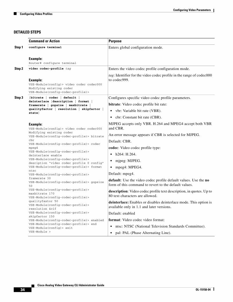
Step 3 [bitrate | codec | default | deinterlace |description | format | framerate | gopsize | maxbitrate | qualityfactor | resolution | skipfactor | state]
Example:VSE-Module(config)> video codec codec000Modifying existing codecVSE-Module(config-codec-profile)> bitrate cbrVSE-Module(config-codec-profile)> codec mpeg4VSE-Module(config-codec-profile)> deinterlace enableVSE-Module(config-codec-profile)> desription “video codec profile 0 config”VSE-Module(config-codec-profile)> format ntscVSE-Module(config-codec-profile)> framerate 30VSE-Module(config-codec-profile)> gopsize 50VSE-Module(config-codec-profile)> maxbitrate 170VSE-Module(config-codec-profile)> qualityfaxtor 50VSE-Module(config-codec-profile)> resolution 4cifVSE-Module(config-codec-profile)> skipfactor 150VSE-Module(config-codec-profile)> enabledVSE-Module(config-codec-profile)> endVSE-Module(config)> exitVSE-Module >
Configures specific video codec profile parameters.
bitrate: Video codec profile bit rate:
• vbr: Variable bit rate (VBR).
• cbr: Constant bit rate (CBR).
MJPEG accepts only VBR. H.264 and MPEG4 accept both VBR and CBR.
An error message appears if CBR is selected for MJPEG.
Default: CBR.
codec: Video codec profile type:
• h264: H.264.
• mjpeg: MJPEG.
• mpeg4: MPEG4.
Default: mpeg4.
default: Use the video codec profile default values. Use the no form of this command to revert to the default values.
description: Video codec profile text description, in quotes. Up to 80 text characters are allowed.
deinterlace: Enables or disables deinterlace mode. This option is available only in 1.1 and later versions.
Default: enabled
format: Video codec video format:
• ntsc: NTSC (National Television Standards Committee).
• pal: PAL (Phase Alternating Line).
34Cisco Analog Video Gateway CLI Administrator Guide
OL-15158-04

Configuring Video ParametersConfiguring Video Profiles
framerate: Video codec profile frame rate number that defines how many frames 1 second (fps) of video or audio contains:
• NTSC: 30 to 0.1.
• PAL: 25 to 0.0833 (up to 6 decimal places).
For example, a frame rate of 0.01 means 1 frame every 100 seconds.
Default: 10.
gopsize: Video codec profile group-of-picture (GOP) size. Integer value in the range of 0 to 600 for MPEG4 and H.264 only.
Default: 20.
maxbitrate: Video codec profile maximum bit rate in kbps. Not applicable to MJPEG.
• MPEG4: Integer value range of 168 to 2000
• H.264: Integer value in the range of 168 to 3000
Default: 768 for both MPEG4 and H.264 codec types
qualityfactor: Video codec profile quality factor. Applicable only to MJPEG codec. Integer value in the range of 0 to 100.
Default: 70.
resolution: Video Codec profile resolution in CIF:
• 4cif
• 2cif (This option available only in 1.1 and later versions.)
• cif
Default: 4cif.
skipfactor: Video codec profile skip factor (also called the skip rate). Integer value in the range of 1 to 300. See “Supported Skip Factor” section on page 36.
Default: 3
state: Operational state of the video codec profile: enabled or disabled.
Default: enabled.
Step 4 end
Example:VSE-Module(config-codec-profile)> end
Exits video codec-profile configuration mode.
Command or Action Purpose
35Cisco Analog Video Gateway CLI Administrator Guide
OL-15158-04

Configuring Video ParametersConfiguring Video Profiles
Supported Skip Factor
The skip factor reduces the frame rate in the video stream (frame skip ration) to reduce bandwidth when the full frame rate is not needed. The skip factor is defined by the following formulas for NTSC an PAL:
Frame Rate * Skip Factor = NTSC (30)
Frame Rate * Skip Factor = PAL (25)
The Cisco Analog Video Gateway module supports only the following specific skip rate factors:
• For NTSC, the supported skip factors are:
30/1, 30/2, 30/3, and 30/4
• For PAL, the supported skip factors are:
25/6, 25/10, and 25/15
If a skip factor falls outside those supported by the Cisco Analog Video Gateway, the closest supported skip factor is used. Table 7 shows a subset of possible frame rate/skip factor values for NTSC and PAL in the range of 1 to 300.
Step 5 exit
Example:VSE-Module(config)> exit
Exits global configuration mode.
Step 6 show video codec tagorshow video codec-profile user-configured summaryorshow video codec-profile dynamically-generated summary
Example:VSE-Module> show video port summary
Displays the video codec profile parameters for a specified codec profile, for dynamically generated codec profiles, and for user-configured codec profiles.
Command or Action Purpose
Table 7 Subset of Possible NTSC (30) and PAL (25) Frame Rate/Skip Factor Values
Skip FactorNTSC Frame Rate = 30/Skip Factor
PAL Frame Rate = 25/Skip Factor
1 30 25
2 15 12.5
3 10 8.333333
4 7.5 6.25
5 6 5
6 5 4.166666
7 4.285714 3.57
8 3.75 3.125
10 3 2.5
36Cisco Analog Video Gateway CLI Administrator Guide
OL-15158-04

Configuring Video ParametersConfiguring Video Profiles
Examples
The following example shows the video codec-profile codec000 parameters:
VSE-Module> show video codec-profile codec000description “video codec profile 0 config”state enabled codec mpeg4 format ntsc frameRate 0.2 skipFactor 150 resolution 4cif bitRate cbr maxBitRate 170 gopSize 50
The following example shows a user-configured codec profile summary:
VSE-Module> show video codec-profile user-configured summary tag state codec format frameRate bitRate mxBR gopSize QF SF resolution deinterlace========================================================================================codec000 ena mpeg4 ntsc 0.2 cbr 170 50 - 150 4cif codec001 ena mpeg4 ntsc 5 cbr 1000 15 - 6 cif codec002 ena mpeg4 ntsc 5 cbr 1000 15 - 6 cif codec003 ena mpeg4 pal 5 cbr 1000 15 - 5 cif codec004 ena mpeg4 ntsc 5 cbr 1000 15 - 6 cif codec005 ena mpeg4 ntsc 5 cbr 1000 15 - 6 cif codec006 ena mpeg4 ntsc 5 cbr 1000 15 - 6 cif codec007 ena mpeg4 ntsc 5 cbr 1000 15 - 6 cif codec008 ena h264 ntsc 5 cbr 1000 15 - 6 cif codec009 ena h264 ntsc 5 cbr 1000 15 - 6 cif codec010 ena h264 ntsc 3 cbr 1000 15 - 10 4cif codec011 ena h264 ntsc 5 cbr 1000 15 - 6 cif codec012 ena h264 ntsc 5 cbr 1000 15 - 6 cif codec013 ena h264 ntsc 5 cbr 1000 15 - 6 cif codec014 ena h264 ntsc 5 cbr 1000 15 - 6 cif codec015 ena h264 ntsc 5 cbr 1000 15 - 6 cif codec020 ena mpeg4 ntsc 10 cbr 384 20 - 3 cif codec099 ena mpeg4 ntsc 5 cbr 1000 15 - 6 cif codec100 ena mjpeg ntsc 5 vbr - - 50 6 cif codec200 ena mjpeg ntsc 5 vbr - - 80 6 cif codec999 ena mpeg4 ntsc 5 cbr 1000 15 - 6 cif codec030 ena mjpeg ntsc 30 vbr - - 100 1 cif httpx ena mjpeg ntsc 5 vbr 384 30 70 2 cif enabled
12 — 2.083333
15 2 —
25 — 1
30 1 —
50 — 0.5
60 0.5 —
250 — 0.1
300 0.1 —
Table 7 Subset of Possible NTSC (30) and PAL (25) Frame Rate/Skip Factor Values (continued)
Skip FactorNTSC Frame Rate = 30/Skip Factor
PAL Frame Rate = 25/Skip Factor
37Cisco Analog Video Gateway CLI Administrator Guide
OL-15158-04

Configuring Video ParametersConfiguring Video Profiles
Video Motion Region ProfileA video motion region profile can be assigned to multiple video ports. Use the video motion-region command to configure a video motion region profile. A video motion region defines an area in a video frame and assigns a numberical value to the region to identify it. A video motion region is defined by coordinates as a percentage in the integer range of 0 to 100:
• Lower-right X-coordinate
• Lower-right Y-coordinate
• Upper-left X-coordinate
• Upper-left Y-coordinate
The Cisco Analog Video Gateway currently supports 8 motion regions per video stream.
SUMMARY STEPS
1. configure terminal
2. video motion-region tag
3. [default | description | lowerrightcoordx | lowerrightcoordy | state | threshold | upperleftcoordx | upperleftcoordy]
4. end
5. exit
6. show video motion-region tag or show video motion-region summary
DETAILED STEPS
Command or Action Purpose
Step 1 configure terminal
Example:Router# configure terminal
Enters global configuration mode.
Step 2 video motion-region tag
Example:VSE-Module(config)> video motion-region mr000Adding new motionVSE-Module(config-motion-region)>
Enters video motion region configuration mode.
tag: Video motion region identifier in the range of mr000 to mr999.
38Cisco Analog Video Gateway CLI Administrator Guide
OL-15158-04

Configuring Video ParametersConfiguring Video Profiles
Step 3 [default | description | lowerrightcoordx | lowerrightcoordy | state | threshold | upperleftcoordx | upperleftcoordy]
Example:VSE-Module(config)> video motion-region mr000Adding new motionVSE-Module(config-motion-region)> description “video motion region 0 config”VSE-Module(config-motion-region)> lowerrightcoordx 25VSE-Module(config-motion-region)> lowerrightcoordy 50VSE-Module(config-motion-region)> upperleftcoordx 40VSE-Module(config-motion-region)> upperleftcoordy 60VSE-Module(config-motion-region)> state enabledVSE-Module(config-motion-region)> threshold 20
Configures video motion region profile parameters.
default: Video motion region default values. Use the no form of this command to revert to the default values.
description: Video motion region text description in quotes. Up to 80 text characters are allowed.
lowerrightcoordx: Video motion region lower-right X-coordinate. Integer percentage in the range of 0 to 100.
Default: 0.
lowerrightcoordy: Video motion region lower-right Y-coordinate. Integer percentage in the range of 0 to 100.
Default: 0.
state: Operational state of the video motion region: enabled or disabled.
Default: enabled.
threshold: Video motion region threshold. Integer value in the range of 1 to 100. The Motion Detection algorithm is most sensitive when threshold is set to 1, and is least sensitive when it is set to 100.
Default: 10.
upperleftcoordx: Video motion region upper-left X-coordinate. Integer percentage in the range of 0 to 100.
Default: 0.
upperleftcoordy: Video motion region upper-left Y-coordinate. Integer percentage in the of range 0 to 100.
Default: 0.
Step 4 end
Example:VSE-Module(config-motion-region)> end
Exits video motion region configuration mode.
Step 5 exit
Example:VSE-Module(config)> exit
Exits global configuration mode.
Step 6 show video motion-region tagorshow video motion-region summary
Example:VSE-Module> show video motion-region mr111
Displays video motion region for a specific region.
Command or Action Purpose
39Cisco Analog Video Gateway CLI Administrator Guide
OL-15158-04
Configuring Video ParametersConfiguring Video Profiles
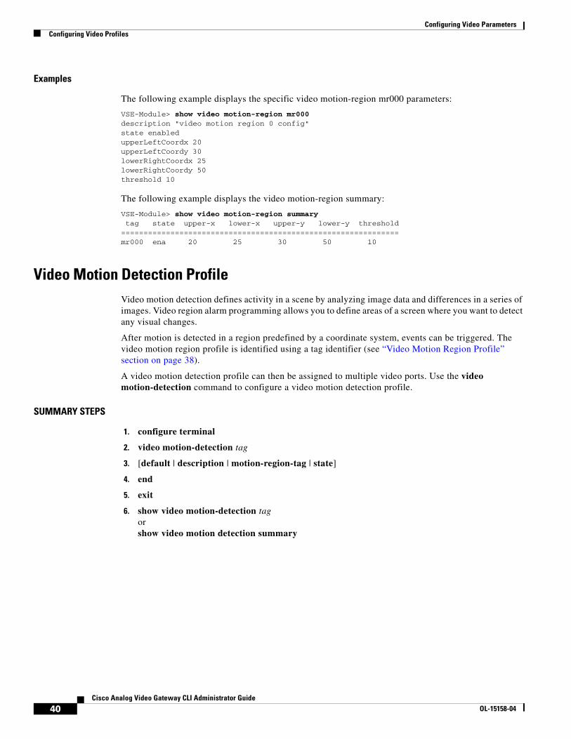
Examples
The following example displays the specific video motion-region mr000 parameters:
VSE-Module> show video motion-region mr000description "video motion region 0 config" state enabled upperLeftCoordx 20 upperLeftCoordy 30 lowerRightCoordx 25 lowerRightCoordy 50 threshold 10
The following example displays the video motion-region summary:
VSE-Module> show video motion-region summary tag state upper-x lower-x upper-y lower-y threshold ============================================================== mr000 ena 20 25 30 50 10
Video Motion Detection ProfileVideo motion detection defines activity in a scene by analyzing image data and differences in a series of images. Video region alarm programming allows you to define areas of a screen where you want to detect any visual changes.
After motion is detected in a region predefined by a coordinate system, events can be triggered. The video motion region profile is identified using a tag identifier (see “Video Motion Region Profile” section on page 38).
A video motion detection profile can then be assigned to multiple video ports. Use the video motion-detection command to configure a video motion detection profile.
SUMMARY STEPS
1. configure terminal
2. video motion-detection tag
3. [default | description | motion-region-tag | state]
4. end
5. exit
6. show video motion-detection tag or show video motion detection summary
40Cisco Analog Video Gateway CLI Administrator Guide
OL-15158-04

Configuring Video ParametersConfiguring Video Profiles
DETAILED STEPS
Command or Action Purpose
Step 1 configure terminal
Example:Router# configure terminal
Enters global configuration mode.
Step 2 video motion-detection tag
Example:VSE-Module(config)> video motion-detection md000Adding new motionVSE-Module(config-motion-detection)>
Enters video motion detection mode.
tag: Identifier for motion detection parameters in the range of md000 to md999.
Step 3 [default | description | motion-region-tag | state]
Example:VSE-Module(config)> video motion-detection md000Adding new motionVSE-Module(config-motion-detection)> description “video motion detection md000 config”VSE-Module(config-motion-detection)> motion-region-tag 10 mr000VSE-Module(config-motion-detection)> state enabledVSE-Module(config-motion-detection)> endVSE-Module(config)> exitVSE-Module > VSE-Module(config)> video stream-profile stream000Adding new streamVSE-Module(config-stream-profile)> codecprofiletag codec000
Configures video motion detection profile parameters.
default: Use the video motion detection default values. Use the no form of this command to revert to the default values.
description: Video motion detection text description in quotes. Up to 80 text characters are allowed.
motion-region-tag: Video motion region tag number (integer value in the range of 0 to 7).
Note The motion detection region tag cannot be assigned until the video motion region profile has been configured. If the video motion region profile has not been configured, the error message “The specified video motion region tag has not been configured” appears. See “Video Motion Region Profile” section on page 38 to define a viedo motion region profile.
state: Operational state of the video motion detection: enabled or disabled.
Default: enabled.
Step 4 end
Example:VSE-Module(config-motion-detection)> end
Exits video motion detection configuration mode.
Step 5 exit
Example:VSE-Module(config)> exit
Exits global configuration mode.
Step 6 show video motion-detection tagorshow video motion-detection summary
Example:VSE-Module> show video motion-detection md000
Displays the video motion detection profile for a specified motion detection tag or a motion detection summary for all configured motion detection tags.
41Cisco Analog Video Gateway CLI Administrator Guide
OL-15158-04
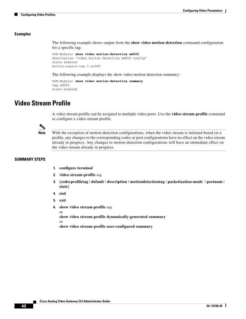
Configuring Video ParametersConfiguring Video Profiles
Examples
The following example shows output from the show video motion-detection command configuration for a specific tag:
VSE-Module> show video motion-detection md000description “video motion detection md000 config”state enabled motion-region-tag 5 mr000
The following example displays the show video motion detection summary:
VSE-Module> show video motion-detection summary tag md000 state enabled
Video Stream ProfileA video stream profile can be assigned to multiple video ports. Use the video stream-profile command to configure a video stream profile.
Note With the exception of motion detection configurations, when the video stream is initiated based on a profile, any changes to the corresponding codec or port configurations have no effect on the video stream already in progress. Any changes to motion detection configurations will have an immediate effect on the video stream already in progress.
SUMMARY STEPS
1. configure terminal
2. video stream-profile tag
3. [codecprofiletag | default | description | motiondetectiontag | packetization-mode | portnum | state]
4. end
5. exit
6. show video stream-profile tag or show video stream-profile dynamically-generated summary or show video stream-profile user-configured summary
42Cisco Analog Video Gateway CLI Administrator Guide
OL-15158-04

Configuring Video ParametersConfiguring Video Profiles
DETAILED STEPS
Command or Action Purpose
Step 1 configure terminal
Example:Router# configure terminal
Enters global configuration mode.
Step 2 video stream-profile tag
Example:VSE-Module(config)> video stream-profile stream000Adding new streamVSE-Module(config-stream-profile)>
Enters video stream profile configuration mode.
• tag: Video stream profile identifier in the range of stream000 to strean999.
Step 3 [codecprofiletag | default | description | motiondetectiontag | packetization-mode | portnum | state]
Example:VSE-Module(config)> video stream-profile stream000Adding new streamVSE-Module(config-stream-profile)> codecprofiletag codec000VSE-Module(config-stream-profile)> description “sample video stream profile 1”VSE-Module(config-stream-profile)> endVSE-Module(config > exitVSE-Module >VSE-Module(config)> video stream-profile stream111Modifying existing streamVSE-Module(config-stream-profile)> motiondetectiontag md111VSE-Module(config-stream-profile)> no defaultVSE-Module(config-stream-profile)> packetization-mode h264 RTPVSE-Module(config-stream-profile)> portnum 0VSE-Module(config-stream-profile)> state enabledVSE-Module(config-stream-profile)> endVSE-Module(config)> exitVSE-Module >
Configures parameters for a video stream profile.
codecprofiletag: Identifier for the video codec profile to be used with the video stream profile. String value in the range of codec000 to codec999.
default: Video stream profile default values for the video codec profile. Use the no form of this command to revert to the default values.
description: Video stream profile text description in quotes. Up to 80 text characters are allowed.
motiondetectiontag: The identifier for the video-codec motion detection used with the video stream profile. String value in the range of md000–md999.
packetization-mode: Video stream profile applicable only to H.264 RTP packetization mode (RFC-3984):
• non-interleaved mode
• single-network abstraction layer (NAL) unit mode
Default: non-interleaved.
Exits video stream profile configuration mode.
portnum: The port number used for the video stream profile. Integer value in the range of 0 to 15.
Default: 0.
Note The video stream profile must be attached to a port number; otherwise, port 0 is used as the default port.
state: Operational state of the video stream profile: enabled or disabled.
Default: enabled.
Step 4 end
Example:VSE-Module(config-video-stream-profile)> end
Exits video stream profile configuration mode.
43Cisco Analog Video Gateway CLI Administrator Guide
OL-15158-04

Configuring Video ParametersConfiguring Video Profiles
Examples
The following example shows the specific video stream profile stream000 parameters:
VSE-Module> show video stream-profile stream000description "video stream profile 0"state enabledportNum 0codecProfileTag codec000packetization-mode N/AmotionDetectionTag md000
The following example shows user-configured video stream profile parameters:
Step 5 exit
Example:VSE-Module(config)> exit
Exits global configuration mode.
Step 6 show video stream-profile tagorshow video stream-profile dynamically-generated summary orshow video stream-profile user-configured summary
Example:VSE-Module> show video stream-profile stream000
Displays video stream profile for a specific stream.
Command or Action Purpose
VSE-Module> show video stream-profile user-configured summary tag state CPTag MDTag portNum RTCPInactive RTCPBye RTCPTimer ICMPUn ICMPtimer PKmode=======================================================================================================stream000 ena codec000 md000 0 dis dis 25 dis 5 N/Astream001 ena codec001 - 3 sys sys 25 sys 5 N/Astream002 ena codec002 - 4 sys sys 25 sys 5 N/Astream003 ena codec003 - 5 sys sys 25 sys 5 N/Astream004 ena codec004 - 6 sys sys 25 sys 5 N/Astream005 ena codec005 - 7 sys sys 25 sys 5 N/Astream006 ena codec006 - 9 sys sys 25 sys 5 N/Astream007 ena codec007 - 9 sys sys 25 sys 5 N/Astream008 ena codec008 - 5 sys sys 25 sys 5 non-interleavedstream009 ena codec009 - 5 sys sys 25 sys 5 non-interleavedstream010 ena codec010 - 2 sys sys 25 sys 5 non-interleavedstream011 ena codec011 - 5 sys sys 25 sys 5 non-interleavedstream012 ena codec012 - 5 sys sys 25 sys 5 non-interleavedstream013 ena codec013 - 5 sys sys 25 sys 5 non-interleavedstream014 ena codec014 - 5 sys sys 25 sys 5 non-interleavedstream015 ena codec015 - 5 sys sys 25 sys 5 non-interleavedstream099 ena codec099 - 2 sys sys 25 sys 5 N/Astream100 ena codec100 - 5 sys sys 25 sys 5 N/Astream200 ena codec200 - 5 sys sys 25 sys 5 N/Astream300 ena codec200 - 6 sys sys 25 sys 5 N/Astream444 ena codec000 - 14 sys sys 25 sys 5 N/Astream999 ena codec999 - 7 sys sys 25 sys 5 N/Astream020 ena codec020 - 2 sys sys 25 sys 5 N/Astream030 ena codec030 - 3 sys sys 25 sys 5 N/A
44Cisco Analog Video Gateway CLI Administrator Guide
OL-15158-04

Configuring Video ParametersConfiguring Video Cross-Connect Loopback
Configuring Video Cross-Connect LoopbackThe video cross-connect loopback diagnostic command transmits a signal that is returned to the sending port after passing through all or a portion of a network or circuit. The returned signal is compared with the transmitted signal to evaluate the integrity of the equipment or transmission path. The video cross-connect loopback test mode is persistent across the Cisco Analog Video Gateway encoder reload.
Use the video xconn-lpbk command to configure and enable the Cisco Analog Video Gateway cross connect test mode.
SUMMARY STEPS
1. configure terminal
2. video xconn-lpbk-conn 0–1
3. [default | description | inport | state]
4. end
5. exit
6. show video xconn-lpbk-conn summary or show video xconn-lpbk-conn 0–1
DETAILED STEPS
Command or Action Purpose
Step 1 configure terminal
Example:Router# configure terminal
Enters global configuration mode.
Step 2 video xconn-lpbk-conn 0–1(config-xconn-lpbk-conn)#
Example:VSE-Module(config)> video xconn-lpbk-conn 1VSE-Module(config-xconn-lpbk-conn)#
Enters video cross-connect loopback configuration mode.
• 0–1: Video cross-connect loopback connection identifier in the range of 0 to 1.
45Cisco Analog Video Gateway CLI Administrator Guide
OL-15158-04

Configuring Video ParametersConfiguring Video Cross-Connect Loopback
Examples
The following example shows the specific video cross-connect loopback connection parameters:
VSE-Module> show video xconn-lpbk-conn 0
description “video connection 0“state enabledimport 2outport 0
The following example shows a summary of video cross-connect loopback connection parameters:
VSE-Module> show video xconn-lpbk-conn summary
xconn-lpbk-conn state inport outport
Step 3 [default | description | Inport | state]
Example:VSE-Module(config)> video config-xconn-lpbk-conn conn0VSE-Module(config-xconn-lpbk-conn)> description “ video connection 0”VSE-Module(config-xconn-lpbk-conn) endVSE-Module(config > exitVSE-Module >VSE-Module(config)> video config-xconn-lpbk-conn conn0VSE-Module(config-xconn-lpbk-conn)> noVSE-Module(config-xconn-lpbk-conn)> inport 0VSE-Module(config-xconn-lpbk-conn)> state enabledVSE-Module(config-xconn-lpbk-conn)>endVSE-Module(config)> exitVSE-Module >
Configures parameters for a video cross-connect loopback.
default: Video cross-connect loopback default values. Use the no form of this command to revert to the default values.
description: Video stream profile text description in quotes. Up to 80 text characters are allowed.
inport: Sets the video cross-connect loopback to import.
state: Operational state of the video cross-connect loopback mode: enabled or disabled.
Default: enabled.
Step 4 exit
Example:VSE-Module(config-xconn-lpbk-conn)>endVSE-Module(config)>
Exits video cross-connect loopback configuration mode.
Step 5 exit
Example:VSE-Module(config)> exitVSE-Module>
Exits global configuration mode.
Step 6 show video xconn-lpbk-conn summary or show video xconn-lpbk-conn 0–1
Example:VSE-Module> show video xconn-lpbk-conn 0
Displays video cross-connect loopback summary or for a specific connection.
Command or Action Purpose
46Cisco Analog Video Gateway CLI Administrator Guide
OL-15158-04

Configuring Video ParametersConfiguring Video Cross-Connect Loopback
=======================================================conn0 ena 1 0conn1 ena 1 0
47Cisco Analog Video Gateway CLI Administrator Guide
OL-15158-04

Configuring Video ParametersConfiguring Video Cross-Connect Loopback
48Cisco Analog Video Gateway CLI Administrator Guide
OL-15158-04

Configuring Contact Closure Profiles
Last Updated: August 17, 2009
Each Cisco Analog Video Gateway module comes with eight contact closure interfaces. Four contact closure interfaces can be configured as alarm inputs or as contact closure relay outputs. The other four contact closure interfaces are for inputs only. Alarm interfaces can be used to detect contact trigger events and to control external devices.
The Cisco Analog Video Gateway is designed to interact with local or remote controllers to manage and control the contact closure interfaces. Alarm interfaces are set to their proper states and monitor trigger events. When an alarm is detected, the source and severity of the alarm are determined, the system log file is updated, and predefined HTTP messages are sent to the controllers. For example, in response to the nature of the alarm, the alarm can request the Cisco Analog Video Gateway to adjust the camera, begin video streaming, or trigger the external devices.
The Cisco Analog Video Gateway has eight preconfigured contact closure ports. The contact closure ports have the following default configuration. You can only modify a contact closure port; you cannot add or delete a contact closure port.
Use the contactclosure-port command to configure the specified contact closure interface profile.
Whenever possible, configuration and management of the Cisco Analog Video Gateway module should be configured using the Video Surveillance Operations Manager (VSOM) graphical user interface.
Note In the VSOM, the state change from open-to-close is considered falling and the state change from close-to-open is considered rising.
SUMMARY STEPS
1. configure terminal
2. contactclosure-port portnum
3. [default | description | direction | relaystate | state]
4. end
5. exit
6. show contactclosure-port portnum or show contactclosure-port hw-state or show contactclosure-port summary
49Cisco Analog Video Gateway CLI Administrator Guide
OL-15158-04

Configuring Contact Closure Profiles
DETAILED STEPS
Examples
The following example shows the contact closure configuration parameters for a specified port 0:
Command or Action Purpose
Step 1 configure terminal
Example:Router# configure terminal
Enters global configuration mode.
Step 2 contactclosure-port portnum
Example:VSE-Module(config)> contactclosure-port 0Modifying existing portVSE-Module(config-contactclosure-port)>
Enters contact closure port configuration profile mode.
portnum: Contact closure ports. Integer value in the range of 0 to 7.
Step 3 [default | description | direction | relaystate | state]
Example:VSE-Module(config)> contactclosure-port 0Modifying existing portVSE-Module(config-contactclosure-port)> description “contact closure port 0 config”VSE-Module(config-contactclosure-port)> direction inVSE-Module(config-contactclosure-port)> relaystate closeVSE-Module(config-contactclosure-port)> state enabledVSE-Module(config-contactclosure-port)> VSE-Module(config-contactclosure-port)> VSE-Module(config-contactclosure-port)> endVSE-Module(config)> exitVSE-Module >
Configures a contact closure port profile.
default: Contact closure default values. Use the no form of this command to remove the default values.
description: Contact closure text description in quotes. Up to 80 text characters are allowed.
direction: Contact closure for output direction applies only to ports 0 to 3. Contact closure for the input direction applies to all contact closure ports. Default: in.
relaystate: Contact closure relay state: open or close. Default: open.
state: Operational state of the contact closure port: enabled or disabled. Default: disabled.
Step 4 end
Example:VSE-Module(config-contactclosure-port)> end
Exits contact closure port configuration.
Step 5 exit
Example:VSE-Module(config)> exit
Exits global configuration mode.
Step 6 show contactclosure-port portnumorshow contactclosure-port hw-stateorshow contactclosure-port summary
Example:VSE-Module> show contactclosure-port 0
Displays the contact closure configuration parameters for a specified port, displays the hardware state for all contact closure ports, or displays the contact closure port summary.
50Cisco Analog Video Gateway CLI Administrator Guide
OL-15158-04

Configuring Contact Closure Profiles
vse-module> show contactclosure-port 0 description “contact closure port 0 config”state enableddirection inrelayState close
The following example shows the hardware state (open or close) for evert contact closure port:
vse-module> show contactclosure-port hw-state 0: close1: close2: close3: close4: close5: close6: close7: close
The following example shows the contact closure port summary:
vse-module> show contactclosure-port summary port state direction relayState===================================== 0 ena in close 1 dis in open 2 dis in open 3 dis in open 4 dis in open 5 dis in open 6 dis in open 7 dis in open
51Cisco Analog Video Gateway CLI Administrator Guide
OL-15158-04

Configuring Contact Closure Profiles
52Cisco Analog Video Gateway CLI Administrator Guide
OL-15158-04

Configuring Alarm Monitor Profiles
Last Updated: August 17, 2009
The alarm monitor surveys every alarm interface for any alarm event. When an event is triggered, it notifies the alarm application, which passes the information to the configured monitor destination.
Whenever possible, configuration and management of the Analog Video Gateway module should be configured using the Video Surveillance Operations Manager (VSOM) graphical user interface.
Alarm monitor profiles should be configured in the following order (see Figure 3):
1. Destination profile
2. Monitor profile
3. Notifier profile
Figure 3 Order of Alarm Monitor Configurations
Alarm Monitor—Destination ProfileTo notify the client of an alarm condition when the configured alarm event is detected, use the alarm-monitor destination-profile command. The notification is configured to notify a preferred URL and backup URL, in case the preferred URL is unavailable.
2312
44
destination-profile
monitor-profile
notifier-profile
destination-profile
monitor-profile
notifier-profile
53Cisco Analog Video Gateway CLI Administrator Guide
OL-15158-04

Configuring Alarm Monitor ProfilesAlarm Monitor—Destination Profile
SUMMARY STEPS
1. configure terminal
2. alarm-monitor destination-profile tag
3. [default | description | primaryURL | secondaryURL]
4. end
5. exit
6. show alarm-monitor destination-profile tag or show alarm-monitor destination-profile summary
DETAILED STEPS
Command or Action Purpose
Step 1 configure terminal
Example:Router# configure terminal
Enters global configuration mode.
Step 2 alarm-monitor monitor-destination tag
Example:VSE-Module(config)> alarm-monitor destination- profile dest000Adding new profileVSE-Module(config-dest-profile)> default
Enters alarm-monitor destination-profile configuration mode.
tag: Identifier of the alarm-monitor destination-profile in the range of dest000 to dest999.
Step 3 [default | description | primaryURL | secondaryURL]
Example:VSE-Module(config)> alarm-monitor destination- profile dest000Adding new profileVSE-Module(config-dest-profile)> defaultVSE-Module(config-dest-profile)> description “alarm monitor destination profile 0”VSE-Module(config-dest-profile)> primaryURL "http://www.somewhere.com/cgi-bin/grabAlarm"VSE-Module(config-dest-profile)> secondaryURL "http://nowwhere.com/cgi-bin/captureAlarm"VSE-Module(config-dest-profile)> endVSE-Module(config)> exitVSE-Module>
Configures the alarm-monitor destination-profile parameters.
default: Resets alarm-monitor destination profile parameters to their default values.
description: The alarm-monitor destination-profile text description in quotes. Up to 80 text characters are allowed.
primaryURL: Preferred URL of the server that is capturing the message to notify the client when the configured alarm event is detected. For example, http://www.somewhere.com/cgi-bin/grabAlarm.
secondaryURL: Backup URL of the server that is capturing the message to notify the client when the configured alarm event is detected. For example, http://nowwhere.com/cgi-bin/captureAlarm.
Step 4 end
Example:VSE-Module(config-dest-profile)> end
Exits alarm-monitor destination-profile configuration mode.
54Cisco Analog Video Gateway CLI Administrator Guide
OL-15158-04

Configuring Alarm Monitor ProfilesAlarm Monitor—Monitor Profile
Examples
The following example shows the alarm monitor destination profile parameters for the specified destination dest000:
VSE-Module> show alarm-monitor destination-profile dest000description "Capture Alarms Message"primaryURL "http://www.somewhere.com/cgi-bin/grabAlarm"secondaryURL "http://nowwhere.com/cgi-bin/captureAlarm"
The following example shows the alarm monitor destination profile summary:
VSE-Module> show alarm-monitor destination-profile summary tag URL address==================================================dest000 primaryURL http://www.somewhere.com/cgi-bin/grabAlarm secondaryURL http://nowwhere.com/cgi-bin/captureAlarm
Alarm Monitor—Monitor ProfileUse the alarm-monitor monitor-profile command to configure the alarm monitor to keep track of the following port events: any change in contact closure port state, changes in contact closure port from closed to opened, changes in contact closure port from opened to closed, reloading of the system, detection of motion, and detection of a signal loss on the video port, or change in state is detected on the video port configured by the sourceTrigger keyword.
SUMMARY STEPS
1. configure terminal
2. alarm-monitor monitor-profile tag
3. [default | description | event | sourceTrigger | state]
4. end
5. exit
6. show alarm-monitor monitor-profile tag or show alarm-monitor notifier-profile summary
Step 5 exit
Example:VSE-Module(config)> exit
Exits global configuration mode.
Step 6 show alarm-monitor destination-profile tagorshow alarm-monitor destination-profile summary
Example:VSE-Module> show alarm-monitor destination-profile dest000
Displays the alarm-monitor destination profile for a specified destination or a summary of all configured destination profiles.
Command or Action Purpose
55Cisco Analog Video Gateway CLI Administrator Guide
OL-15158-04

Configuring Alarm Monitor ProfilesAlarm Monitor—Monitor Profile
DETAILED STEPS
Command or Action Purpose
Step 1 configure terminal
Example:Router# configure terminal
Enters global configuration mode.
Step 2 alarm-monitor monitor-profile tag
Example:VSE-Module(config)> alarm-monitor monitor- profile mon000Adding new profileVSE-Module(config-mon-profile)>
Enters alarm-monitor monitor-profile configuration mode.
tag: Identifier of the alarm-monitor monitor-profile in the range of mon000 to mon999.
56Cisco Analog Video Gateway CLI Administrator Guide
OL-15158-04

Configuring Alarm Monitor ProfilesAlarm Monitor—Monitor Profile
Step 3 [default | description | event | sourceTrigger | state]
Example:VSE-Module(config)> alarm-monitor monitor- profile mon000Adding new profileVSE-Module(config-mon-profile)> defaultVSE-Module(config-mon-profile)> description “alarm monitor profile mon000”VSE-Module(config-mon-profile)> endVSE-Module(config-mon-profile)> event ccport-any-state-changeVSE-Module(config-mon-profile)> sourceTrigger cc0VSE-Module(config-mon-profile)> state enabled VSE-Module(config-mon-profile)> endVSE-Module(config)> exitVSE-Module>
Configures the alarm-monitor monitor-profile parameters.
default: Alarm-monitor monitor-profile default values.
description: Alarm-monitor monitor-profile text description in quotes. Up to 80 text characters are allowed.
event: Alarm-monitor monitor-profile event.
• ccport-any-state-change: Monitor any change in the state of the contact closure port.
• ccport-close-to-open: Monitor contact closure state changes from close to open.
• ccport-open-to-close: Monitor contact closure state changes from open to close.
• system-reload: Monitor system reloads.
• video-motion-detection: Monitor motion detection.
• video-signal-change: Monitor any change in the video port signal (loss or detect) that is configured by the sourceTrigger keyword.
• video-signal-detect: Monitor valid signal detected on the video port that is configured by the sourceTrigger keyword.
• vport-signal-loss: Monitor signal loss detected on the video port that is configured by the sourceTrigger keyword.
• vport-state-change: Monitor change in port state (enabled/disabled) detected on the video port that is configured by the sourceTrigger keyword.
sourceTrigger: Alarm-monitor monitor-profile event source trigger keyword.
• vp-any: Event on any video port.
• vp0 to vp15: Video port event as a string value in the range of vp0 to vp15.
• cc0 to cc7: Contact closure port event. String value in the range of cc0 to cc7.
• stream000 to stream999: Video motion detection event. String value in the range of stream000 to stream999 (see Figure 4 on page 70).
state: Operational state of the alarm-monitor monitor-profile state: enabled or disabled.
Default: enabled.
Step 4 end
Example:VSE-Module(config-mon-profile)> end
Exits alarm-monitor monitor-profile configuration mode.
Command or Action Purpose
57Cisco Analog Video Gateway CLI Administrator Guide
OL-15158-04

Configuring Alarm Monitor ProfilesAlarm Monitor—Notifier Profile
Examples
The following example displays the alarm-monitor monitor-profile for the specified monitor-profile mon000:
VSE-module> show alarm-monitor monitor-profile mon000description "alarm monitor profile mon000"state enabledevent ccport-any-state-changesourceTrigger vp0
The following example displays the alarm-monitor monitor-profile summary:
tag state sourceTrigger event========================================================mon999 ena - -mon000 ena cc0 ccport-any-state-change
Alarm Monitor—Notifier ProfileUse the alarm-monitor notifier-profile command to set the unique identifier for the destination profile and monitor profile to use with the video alarm-monitor notifier-profile.
SUMMARY STEPS
1. configure terminal
2. alarm-monitor notifier-profile tag
3. [default | description | destinationprofiletag | monitorprofiletag | state]
4. end
5. exit
6. show alarm-monitor notifier-profile tag or show alarm-monitor notifier-profile summary
Step 5 exit
Example:VSE-Module(config-mon-profile)> exit
Exits global configuration mode.
Step 6 show alarm-monitor monitor-profile tagorshow alarm-monitor monitor-profile summary
Example:VSE-Module(config)> show alarm-monitor monitor-profile mon000
Displays the alarm-monitor monitor-profile configuration parameters for a specified monitor profile or for a summary of all configured monitor profiles.
Command or Action Purpose
58Cisco Analog Video Gateway CLI Administrator Guide
OL-15158-04

Configuring Alarm Monitor ProfilesAlarm Monitor—Notifier Profile
DETAILED STEPS
Command or Action Purpose
Step 1 configure terminal
Example:Router# configure terminal
Enters global configuration mode.
Step 2 alarm-monitor notifier-profile tag
Example:VSE-Module(config)> alarm-monitor notifier-profile not111Adding new profileVSE-Module(config-notifier-profile)>
Enters video alarm-monitor notifier-profile configuration mode.
tag: Video alarm-monitor notifier-profile identifier in the range of not000 to not999.
Step 3 [default | description | destinationprofiletag | monitorprofiletag | state]
Example:VSE-Module(config)> alarm-monitor notifier-profile not111Adding new profileVSE-Module(config-notifier-profile)> description “alarm notifier profile not000”VSE-Module(config-notifier-profile)> destinationprofiletag dest000VSE-Module(config-notifier-profile)> monitorprofiletag mon000VSE-Module(config-notifier-profile)> state enabledVSE-Module(config-notifier-profile)> endVSE-Module(config)> exitVSE-Module>
Configures a video alarm-monitor notifier-profile parameters.
default: Video alarm-monitor notifier-profile default settings.
description: Video alarm-monitor notifier-profile text description in quotes. Up to 80 text characters allowed.
destinationprofiletag: Unique identifier for the destination-profile to use with the video alarm-monitor notifier-profile in the range of dest000 to dest999.
monitorprofiletag: Unique identifier for the monitor-profile to use with the video alarm-monitor notifier-profile in the range of mon000 to mon999.
state: Operational state of the notifier-profile: enabled or disabled. Default: enabled.
Step 4 end
Example:VSE-Module(config-not-profile)> end
Exits the video alarm-monitor notifier-profile configuration mode.
Step 5 exit
Example:VSE-Module(config-not-profile)> exit
Exits global configuration mode.
Step 6 show alarm-monitor notifier-profile tagorshow alarm-monitor notifier-profile summary
Example:VSE-Module> show alarm-monitor notifier-profile not000
Displays the alarm-monitor notifier profile configuration parameters for a specified notifier-profile or for a summary of all configured notifier profiles.
59Cisco Analog Video Gateway CLI Administrator Guide
OL-15158-04

Configuring Alarm Monitor ProfilesAlarm Monitor—Notifier Profile
Examples
The following example shows the alarm-monitor notifier-profile parameters for the specified notifier profile not000:
VSE-Module> show alarm-monitor notifier-profile not000description "alarm notifier profile not000"state enabledmonitorProfileTag mon000destinationProfileTag dest000
The following example show the alarm-monitor notifier-profile summary:
VSE-Module> show alarm-monitor notifier-profile summary tag state destinationProfileTag monitorProfileTag============================================================not000 ena dest000 mon000
60Cisco Analog Video Gateway CLI Administrator Guide
OL-15158-04

Configuring Camera Controls
Last Updated: August 17, 2009
The Cisco Analog Video Gateway module has two RS-485 half-duplex interfaces that can be used to connect pan-tilt-zoom (PTZ) cameras. Security personnel can log in to the network module to reposition or otherwise control the PTZ cameras connected to the RS-485 interfaces.
The RS-485 application supports only the pass-through mode. The RS485 application does not sense the received PTZ encoded data; it simply sends the received data, unchanged, to the specified serial port.
Whenever possible, configuration and management of the Cisco Analog Video Gateway module should be configured using the Video Surveillance Operations Manager (VSOM) graphical user interface.
RestrictionsOne control device is on one RS-485 port, and the PTZ cameras are on the other RS-485 port. Local PTZ control sessions within two RS-485 ports are not supported.
Only remote PTZ control requests and responses are supported.
The network video recorder (NVR) can send multiple PTZ requests at the same time, but the RS-485 application processes them one at a time.
SUMMARY STEPS
1. configure terminal
2. rs485-port portnum
3. [baudrate | databits | default | description | parity | stopbits | state | termination-state]
4. end
5. exit
6. show rs485-port portnum or show rs485-port summary
61Cisco Analog Video Gateway CLI Administrator Guide
OL-15158-04
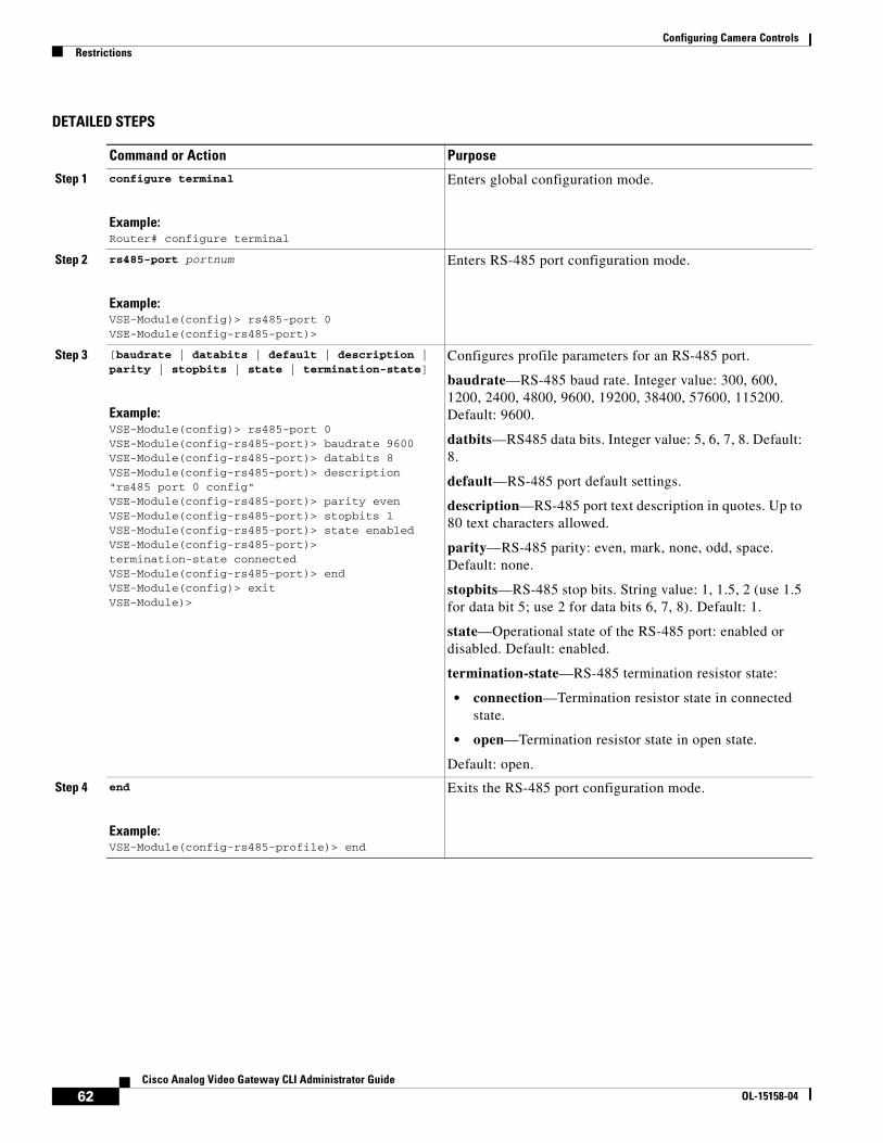
Configuring Camera ControlsRestrictions
DETAILED STEPS
Command or Action Purpose
Step 1 configure terminal
Example:Router# configure terminal
Enters global configuration mode.
Step 2 rs485-port portnum
Example:VSE-Module(config)> rs485-port 0VSE-Module(config-rs485-port)>
Enters RS-485 port configuration mode.
Step 3 [baudrate | databits | default | description | parity | stopbits | state | termination-state]
Example:VSE-Module(config)> rs485-port 0VSE-Module(config-rs485-port)> baudrate 9600VSE-Module(config-rs485-port)> databits 8VSE-Module(config-rs485-port)> description "rs485 port 0 config"VSE-Module(config-rs485-port)> parity evenVSE-Module(config-rs485-port)> stopbits 1VSE-Module(config-rs485-port)> state enabledVSE-Module(config-rs485-port)> termination-state connectedVSE-Module(config-rs485-port)> endVSE-Module(config)> exitVSE-Module)>
Configures profile parameters for an RS-485 port.
baudrate—RS-485 baud rate. Integer value: 300, 600, 1200, 2400, 4800, 9600, 19200, 38400, 57600, 115200. Default: 9600.
datbits—RS485 data bits. Integer value: 5, 6, 7, 8. Default: 8.
default—RS-485 port default settings.
description—RS-485 port text description in quotes. Up to 80 text characters allowed.
parity—RS-485 parity: even, mark, none, odd, space. Default: none.
stopbits—RS-485 stop bits. String value: 1, 1.5, 2 (use 1.5 for data bit 5; use 2 for data bits 6, 7, 8). Default: 1.
state—Operational state of the RS-485 port: enabled or disabled. Default: enabled.
termination-state—RS-485 termination resistor state:
• connection—Termination resistor state in connected state.
• open—Termination resistor state in open state.
Default: open.
Step 4 end
Example:VSE-Module(config-rs485-profile)> end
Exits the RS-485 port configuration mode.
62Cisco Analog Video Gateway CLI Administrator Guide
OL-15158-04

Configuring Camera ControlsExamples
ExamplesThe following example shows the configuration parameters for the specified RS-485 port 0:
VSE-module> show rs485-port 0 description "serial port 0 config"state enabledbaudrate 9600databits 8stopbits 1parity eventermination-state connected
The following example shows the configuration summary of all configured RS-485 ports:
VSE-module> show rs485-port summary port state baudrate databits stopbits parity termState================================================================= 0 ena 9600 8 1 even connected 1 ena 9600 8 1 none open
Step 5 exit
Example:VSE-Module(config)> exit
Exits global configuration mode.
Step 6 show rs485-port portnumorshow rs485-port summary
Example:VSE-Module(config)> show rs485-port 0
Displays the RS-485 configuration parameters for a specified RS-485 port or a summary of all configured RS-485 ports.
Command or Action Purpose
63Cisco Analog Video Gateway CLI Administrator Guide
OL-15158-04

Configuring Camera ControlsExamples
64Cisco Analog Video Gateway CLI Administrator Guide
OL-15158-04

Cisco Analog Video Gateway Command Reference
Last Updated: August 17, 2009
This chapter documents commands for the Cisco Analog Video Gateway module application and new commands for Cisco IOS:
• Cisco Analog Gateway Module Commands, page 65
• Cisco IOS Commands, page 119
Cisco Analog Gateway Module CommandsWhenever possible, configuration and management of the Cisco Analog Video Gateway module should be configured using the Video Surveillance Operations Manager (VSOM) graphical user interface. The following lists the command-line interface commands.
• alarm-monitor destination-profile
• alarm-monitor monitor-profile
• alarm-monitor notifier-profile
• contactclosure-port
• rs485-port
• show alarm-monitor destination-profile
• show alarm-monitor monitor-profile
• show alarm-monitor notifier-profile
• show contactclosure-port
• show rs485-port
• show videoport-led summary
• show video codec-profile
• show video dsp
• show video motion-detection
• show video motion-region
• show video port
• show video session
65Cisco Analog Video Gateway CLI Administrator Guide
OL-15158-04

Cisco Analog Video Gateway Command ReferenceCisco Analog Gateway Module Commands
• show video stream-profile
• show video xconn-lpbk-conn
• video codec-profile
• video motion-detection
• video motion-region
• video port
• video stream-profile
• video xconn-lpbk-conn
66Cisco Analog Video Gateway CLI Administrator Guide
OL-15158-04

Cisco Analog Video Gateway Command Referencealarm-monitor destination-profile
alarm-monitor destination-profileTo configure an alarm-monitor destination profile, use the alarm-monitor destination-profile command in global configuration mode. To use a default alarm-monitor destination profile, use the no form of this command.
alarm-monitor destination-profile tag [default | description | primaryURL | secondaryURL]
no alarm-monitor destination-profile tag
Syntax Description
Command Default No alarm monitor destination profile is configured.
Command Modes Global configuration
Command History
Usage Guidelines Alarm monitor profiles should be configured in the following order (see Figure 3 on page 53):
1. Destination profile
2. Monitor profile
3. Notifier profile
Examples The following example shows an alarm-monitor destination-profile configuration:
vse-module> show alarm-monitor destination-profile dest111
description "sample destination profile"primaryURL "http://www.somewhere.com/cgi-bin/grabAlarm"secondaryURL "http://nowhere.com/cgi-bin/captureAlarm"end destination-profile
tag Identifier for the alarm-monitor destination profile values in the range of dest000 to dest999.
default Use the default values for the alarm monitor destination profile. Use the no form of this command to restore the default alarm-monitor destination profile values.
description Description for the alarm monitor destination profile. Text with up to 80 string characters within quotation marks.
primaryurl URL used to notify the client when the configured alarm event is detected. (For example “http://www.somewhere.com/cgi-bin/grabAlarm”)
secondaryurl Backup URL used to notify the client when the configured alarm event is detected. (For example, “http://nowhere.com/cgi-bin/captureAlarm”)
version Modification
1.0 This command was introduced.
67Cisco Analog Video Gateway CLI Administrator Guide
OL-15158-04

Cisco Analog Video Gateway Command Referencealarm-monitor destination-profile
Related Commands Command Description
show alarm-monitor destination-profile
Displays alarm-monitor destination-profile configuration parameters.
68Cisco Analog Video Gateway CLI Administrator Guide
OL-15158-04

Cisco Analog Video Gateway Command Referencealarm-monitor monitor-profile
alarm-monitor monitor-profileTo configure an alarm-monitor monitor profile, use the alarm-monitor monitor-profile command in global configuration mode. To remove an alarm-monitor monitor profile, use the no form of this command.
alarm-monitor monitor-profile tag [default | description | event | sourceTrigger | state]
no alarm-monitor monitor-profile tag
Syntax Description tag Identifier for the alarm-monitor monitor-profile values in the range of mon000 to mon999.
default Uses the default values for the alarm-monitor monitor profile. Use the no form of this command to restore the default alarm-monitor monitor-profile values.
description Description for the alarm-monitor monitor profile. Text with up to 80 string characters within quotation marks.
event Event to monitor.
• ccporrt-any-state-change: Any change in the state of the contact-closure port.
• ccport-close-to-open: Contact-closure state changes from closed to open.
• ccport-open-to-close: Contact-closure state changes from open to closed.
• system-reload: System reload.
• video-motion-detection: Configured video motion detected.
• video-signal-change: Monitor any change in the video port signal (loss or detect) that is configured by the sourceTrigger keyword.
• video-signal-detect: Monitor valid signal detected on the video port that is configured by the sourceTrigger keyword.
• vport-signal-loss: Signal loss on the video port that is configured using the sourceTrigger keyword.
• vport-state-change: Any state change on the video port that is configured using the sourceTrigger keyword.
sourceTrigger String value to define the trigger event source to monitor.
• vp-any: Event on any video port.
• vp0 to vp15 for a video port event.
• cc0 to cc7 for a contact-closure port event.
• stream000 to stream999 for video motion detected (see Figure 4 on page 70).
state Operational state of the alarm-monitor monitor profile: enabled or disabled. Default: enabled.
69Cisco Analog Video Gateway CLI Administrator Guide
OL-15158-04

Cisco Analog Video Gateway Command Referencealarm-monitor monitor-profile
Command Modes Global configuration
Command History
Usage Guidelines Alarm monitor profiles should be configured in the following order (see Figure 3 on page 53):
1. destination profile
2. monitor profile
3. notifier profile
Figure 4 shows how a motion detection event source triggers the video stream.
Figure 4 Source Trigger Motion Detection Triggers Video Stream
Examples The following example shows an alarm-monitor monitor-profile configuration:
vse-module> show alarm-monitor monitor-profile mon000description "alarm monitor profile mon000"state enabledevent ccport-any-state-changesourceTrigger -
Related Commands
Version Modification
1.0 This command was introduced.
2312
43
Motion detection profile
Motion region profile
Stream profile
Notifier profile
Motion eventSource trigger
Monitor profile
Destinaiton profilehttp://somewhere.com/cgi-bin/
Command Description
show alarm-monitor monitor-profile
Displays alarm-monitor monitor-profile configuration parameters.
70Cisco Analog Video Gateway CLI Administrator Guide
OL-15158-04
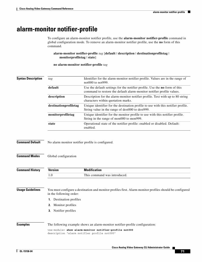
Cisco Analog Video Gateway Command Referencealarm-monitor notifier-profile
alarm-monitor notifier-profileTo configure an alarm-monitor notifier profile, use the alarm-monitor notifier-profile command in global configuration mode. To remove an alarm-monitor notifier profile, use the no form of this command.
alarm-monitor notifier-profile tag [default | description | destinationprofiletag | monitorprofiletag | state]
no alarm-monitor notifier-profile tag
Syntax Description
Command Default No alarm monitor notifier profile is configured.
Command Modes Global configuration
Command History
Usage Guidelines You must configure a destination and monitor profiles first. Alarm monitor profiles should be configured in the following order:
1. Destination profiles
2. Monitor profiles
3. Notifier profiles
Examples The following example shows an alarm-monitor notifier-profile configuration:
vse-module> show alarm-monitor notifier-profile not000description "alarm notifier profile not000"
tag Identifier for the alarm-monitor notifier profile. Values are in the range of not000 to not999.
default Use the default settings for the notifier profile. Use the no form of this command to restore the default alarm-monitor notifier profile values.
description Description for the alarm-monitor notifier profile. Text with up to 80 string characters within quotation marks.
destinationprofiletag Unique identifier for the destination profile to use with this notifier profile. String value in the range of dest000 to dest999.
monitorprofiletag Unique identifier for the monitor profile to use with this notifier profile. String in the range of mon000 to mon999.
state Operational state of the notifier profile: enabled or disabled. Default: enabled.
Version Modification
1.0 This command was introduced.
71Cisco Analog Video Gateway CLI Administrator Guide
OL-15158-04

Cisco Analog Video Gateway Command Referencealarm-monitor notifier-profile
state enabledmonitorProfileTag mon000destinationProfileTag dest000
Related Commands Command Description
show alarm-monitor notifier-profile
Displays alarm-monitor notifier-profile configuration parameters.
72Cisco Analog Video Gateway CLI Administrator Guide
OL-15158-04

Cisco Analog Video Gateway Command Referencecontactclosure-port
contactclosure-portTo configure a contact closure port, use the contactclosure-port command in global configuration mode. To restore the default values on the contact closure port, use the no form of this command.
contactclosure-port portnum [default | description | direction | relaystate | state]
Syntax Description
Command Default The contact closure ports retain their default configurations.
Command Modes Global configuration
Command History
Usage Guidelines Each module has eight contact closure interfaces. The first four contact closure interfaces can be configured as alarm inputs or relay outputs. The other interfaces can be configured only as inputs. The contact closure inputs are used to detect contact trigger events and the outputs are used to control external devices.
Examples The following example shows a contact closure port configuration:
vse-module> show contactclosure-port 0description ""state enableddirection inrelayState close
portnum Port number of contact closure ports in the integer value range of 0 to 7.
default Use the default values for the contact closure port. Use the no form of this command to restore the default contact closure values.
description Description of the contact closure port. Text with up to 80 string characters within quotation marks.
direction Direction of the contact closure port:
• in: input direction
• out: output direction
Default: in.
relaystate Relay state of the contact closure port: open or close. Default: close.
state Operational state of the contact closure port: enabled or disabled. Default: enabled.
Version Modification
1.0 This command was introduced.
73Cisco Analog Video Gateway CLI Administrator Guide
OL-15158-04

Cisco Analog Video Gateway Command Referencecontactclosure-port
Related Commands Command Description
show contactclosure-port Displays contact closure port configuration parameters.
74Cisco Analog Video Gateway CLI Administrator Guide
OL-15158-04

Cisco Analog Video Gateway Command Referencers485-port
rs485-portTo enter RS-485-port configuration mode to set pan, tilt, and zoom camera control, use the rs485-port command in global configuration mode. To restore the default values of the RS-485 port configuration, use the no form of this command.
rs485-port portnum [baudrate | databits | default | description | parity | state | stopbits | termination-state]
Syntax Description
Command Default No RS-485 port is configured.
Command Modes Global configuration
Command History
Usage Guidelines Observe the following guidelines:
• stopbit 1.5 applies only to databit 5.
• stopbit 2 applies only to databit 6, 7, or 8.
Use the end keyword to reprogram the serial port after a parameter (baud rate, databit, stop bit, or parity) has been changed.
Examples The following example shows the configuration for an RS-485 port:
portnum RS-485 port number: 0 or 1.
baudrate Baud rate for the RS-485 port. Set to integer value 300, 600, 1200, 2400, 4800, 9600, 19200, 38400, 57600, or 115200. Default: 9600.
databits Data bits for the RS-485 port. Set to integer values 5, 6, 7, or 8. Default: 8.
default Use the default values for the RS-485 port. Use the no form of this command to restore the default RS-485 port values.
description Description of the RS-485 port. Text with up to 80 string characters within quotation marks.
parity Parity for RS-485 port. Values are even, mark, none, odd, and space. Default: none.
state Operational state of RS-485 port: enabled or disabled. Default: enabled.
stopbits Stop bits for RS-485 port. Set stop bit value to: 1, 1.5, or 2. Use 1.5 for data bit 5, and 2 for data bits 6, 7, or 8. Default: 1.
termination-state Termination resistor state for RS-485 port. Values are open and connected. Default: open.
Version Modification
1.0 This command was introduced.
75Cisco Analog Video Gateway CLI Administrator Guide
OL-15158-04

Cisco Analog Video Gateway Command Referencers485-port
vse-module> show rs485-port 0
baudrate 19200databits 7description "sample rs485-port"parity markstate disabledstopbits 2termination-state connectedend rs485-port
Related Commands Command Description
show rs485-port Shows the current configuration of the RS-485 port.
76Cisco Analog Video Gateway CLI Administrator Guide
OL-15158-04

Cisco Analog Video Gateway Command Referenceshow alarm-monitor destination-profile
show alarm-monitor destination-profileTo display configuration parameters for alarm-monitor destination profiles, use the show alarm-monitor destination-profile command in user EXEC configuration mode.
show alarm-monitor destination-profile {tag | summary}
Syntax Description
Command Modes User EXEC
Command History
Usage Guidelines You can display a specified destination profile or a summary of all configured destination profiles.
Note The primary URLs and secondary URLs can carry messages, such as the identity of the source port.
Examples The following example shows a specific alarm-monitor destination profile:
vse-module> show alarm-monitor destination-profile dest111description "Capture Alarms Message"primaryURL "http://www.somewhere.com/cgi-bin/grabAlarm"secondaryURL "http://nowhere.com/cgi-bin/captureAlarm"
The following example shows all configured alarm-monitor destination profiles:
vse-module> show alarm-monitor destination-profile summarytag URL address==================================================dest111 primaryURL http://www.somewhere.com/cgi-bin/grabAlarm secondaryURL http://nowhere.com/cgi-bin/captureAlarm
Table 8 describes the significant fields in the example.
tag Identifier for the alarm-monitor destination profile values in the range of dest000 to dest999.
summary Displays all configured alarm-monitor destination profiles.
Version Modification
1.0 This command was introduced.
Table 8 show alarm-monitor destination-profile Field Descriptions
Field Description
description Description of the alarm monitor. Text with up to 80 string characters within quotation marks.
tag Identifier for the monitor profile value in the range of dest000 to dest999.
77Cisco Analog Video Gateway CLI Administrator Guide
OL-15158-04

Cisco Analog Video Gateway Command Referenceshow alarm-monitor destination-profile
Related Commands
primaryURL
SecondaryURL
URL
URLs to receive notification when the configured alarm event is detected:
• primaryURL: Primary URL to receive notification.
• secondaryURL: Backup URL to receive notification.
address Address of the primary and secondary URLs.
Table 8 show alarm-monitor destination-profile Field Descriptions (continued)
Field Description
Command Description
alarm-monitor destination-profile
Configures an alarm-monitor destination profile.
78Cisco Analog Video Gateway CLI Administrator Guide
OL-15158-04
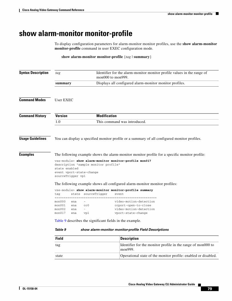
Cisco Analog Video Gateway Command Referenceshow alarm-monitor monitor-profile
show alarm-monitor monitor-profileTo display configuration parameters for alarm-monitor monitor profiles, use the show alarm-monitor monitor-profile command in user EXEC configuration mode.
show alarm-monitor monitor-profile {tag | summary}
Syntax Description
Command Modes User EXEC
Command History
Usage Guidelines You can display a specified monitor profile or a summary of all configured monitor profiles.
Examples The following example shows the alarm-monitor monitor profile for a specific monitor profile:
vse-module> show alarm-monitor monitor-profile mon017description "sample monitor profile"state enabledevent vport-state-changesourceTrigger vp1
The following example shows all configured alarm-monitor monitor profiles:
vse-module> show alarm-monitor monitor-profile summarytag state sourceTrigger event========================================================mon000 ena - video-motion-detectionmon001 ena cc0 ccport-open-to-closemon002 ena - video-motion-detectionmon017 ena vp1 vport-state-change
Table 9 describes the significant fields in the example.
tag Identifier for the alarm-monitor monitor profile values in the range of mon000 to mon999.
summary Displays all configured alarm-monitor monitor profiles.
Version Modification
1.0 This command was introduced.
Table 9 show alarm-monitor monitor-profile Field Descriptions
Field Description
tag Identifier for the monitor profile in the range of mon000 to mon999.
state Operational state of the monitor profile: enabled or disabled.
79Cisco Analog Video Gateway CLI Administrator Guide
OL-15158-04

Cisco Analog Video Gateway Command Referenceshow alarm-monitor monitor-profile
Related Commands
sourceTrigger Source that triggers the event being monitored:
• vp0 to vp15 for a video port event.
• cc0 to cc7 for a contact-closure port event.
• stream000 to stream999 for video motion detected.
event Type of event to monitor:
• ccporrt-any-state-change: Any change in the state of the contact closure port.
• ccport-close-to-open: Contact closure state changes from closed to open.
• ccport-open-to-close: Contact closure state changes from open to closed.
• system-reload: System reload.
• video-motion-detection: Configured video motion detected.
• vport-signal-loss: Signal loss on the video port that is configured using the sourceTrigger keyword.
• vport-state-change: Any state change on the video port that is configured using the sourceTrigger keyword.
Table 9 show alarm-monitor monitor-profile Field Descriptions (continued)
Field Description
Command Description
alarm-monitor monitor-profile
Configures an alarm-monitor monitor profile.
80Cisco Analog Video Gateway CLI Administrator Guide
OL-15158-04

Cisco Analog Video Gateway Command Referenceshow alarm-monitor notifier-profile
show alarm-monitor notifier-profileTo display configuration parameters for alarm monitor notifier profiles, use the show alarm-monitor notifier-profile command in user EXEC configuration mode.
show alarm-monitor notifier-profile {tag | summary}
Syntax Description
Command Modes User EXEC
Command History
Usage Guidelines You must first configure an alarm-monitor destination profile and an alarm-monitor monitor profile before you can associate them with the notifier profile.
You can display a specified notifier profile or a summary of all configured notifier profiles.
Examples The following example shows the alarm-monitor notifier profile for a specific monitor profile:
vse-module> show alarm-monitor notifier-profile not111description "sample notifier profile"state disabledmonitorProfileTag mon111destinationProfileTag dest111
The following example shows all configured alarm-monitor notifier profiles:
vse-module> show alarm-monitor notifier-profile summarytag state destinationProfileTag monitorProfileTag============================================================not000 ena not111 dis dest111 mon111
Table 10 describes the significant fields in the example.
tag Identifier for the alarm-monitor notifier profile. Values are in the range of not000 to not999.
summary Displays all configured alarm-monitor notifier profiles.
Version Modification
1.0 This command was introduced.
Table 10 show alarm-monitor notifier-profile Field Descriptions
Field Description
tag Identifier for the alarm monitor notifier profile values in the range of not000 to not999.
state Operational state of the notifier profile: enabled or disabled.
81Cisco Analog Video Gateway CLI Administrator Guide
OL-15158-04

Cisco Analog Video Gateway Command Referenceshow alarm-monitor notifier-profile
Related Commands
destinationProfileTag Destination profile to associate with the notifier profile. Values in the range of dest000 to dest999.
monitorProfileTag Monitor profile to associate with the notifier profile. Values in the range of mon000 to mon999.
Table 10 show alarm-monitor notifier-profile Field Descriptions (continued)
Field Description
Command Description
alarm-monitor notifier-profile
Configures an alarm-monitor notifier profile.
82Cisco Analog Video Gateway CLI Administrator Guide
OL-15158-04

Cisco Analog Video Gateway Command Referenceshow contactclosure-port
show contactclosure-portTo show the configuration and status of contact closure ports, use the show contactclosure-port command in user EXEC mode.
show contactclosure {portnum | summary | hw-state}
Syntax Description
Command Modes User EXEC
Command History
Usage Guidelines To display the configuration for:
• A specific contact closure port, enter the port number.
• All contact closure ports, use the summary keyword.
To list the state (open or close) of all contact closure ports, use the hw-state keyword. For example, show contactclosure hw-state.
Examples The following example shows the configuration for a specific contact closure port:
vse-module> show contactclosure 0description ""state disableddirection inrelayState open
The following example shows the configuration for all configure contact closure ports:
vse-module> show contactclosure-port summaryport state direction relayState===================================== 0 dis in open 1 dis in open 2 dis in open 3 dis in open 4 dis in open 5 dis in open 6 dis in open 7 dis in open
The following example shows the hardware state for all contact closure ports:
vse-module> show contactclosure hw-state0: close
portnum Port number of contact closure port integer values in the range of 0 to 7.
summary Displays all configured contact closure ports.
hw-state Displays all contact closure port hardware states.
Version Modification
1.0 This command was introduced.
83Cisco Analog Video Gateway CLI Administrator Guide
OL-15158-04

Cisco Analog Video Gateway Command Referenceshow contactclosure-port
1: close2: close3: close4: close5: close6: close7: close
Table 11 describes the significant fields in the example.
Related Commands
Table 11 show contactclosure-port Field Descriptions
Field Description
port Port number integer value in the range of 0 to 7.
state Operational state of the contact closure port: enabled or disabled.
direction • in: Input direction.
• out: Output direction.
relayState Relay state: open or close.
Command Description
contactclosure-port Configures contact closure ports.
84Cisco Analog Video Gateway CLI Administrator Guide
OL-15158-04

Cisco Analog Video Gateway Command Referenceshow rs485-port
show rs485-portTo display RS-485 port configuration parameters, use the show rs485-port command in user EXEC mode.
show rs485-port {portnum | summary}
Syntax Description
Command Modes User EXEC
Command History
Usage Guidelines To display the configuration for a specific RS-485 port, enter the port number. To display the configuration for all RS-485 ports, use the summary keyword.
Examples The following example shows the configuration for the specific RS-485 port 0:
vse-module> show rs485-port 0description "sample rs485 port 0"state enabledbaudrate 19200databits 7stopbits 2parity oddtermination-state connected
The following example shows the configuration for the specific RS-485 port 1:
vse-module> show rs485-port 1description ""state enabledbaudrate 9600databits 8stopbits 1parity nonetermination-state open
The following example shows all configured RS-485 ports:
vse-module> show rs485-port summaryport state baudrate databits stopbits parity termState================================================================= 0 ena 19200 7 2 odd connected 1 ena 9600 8 1 none open
Table 12 describes the significant fields in the example.
portnum RS-485 port number: 0 or 1.
summary Displays configuration parameters for all RS-485 ports.
Version Modification
1.0 This command was introduced.
85Cisco Analog Video Gateway CLI Administrator Guide
OL-15158-04

Cisco Analog Video Gateway Command Referenceshow rs485-port
Related Commands
Table 12 show rs485-port Field Descriptions
Field Description
port RS-485 port number: 0 or 1.
state Operational state of RS-485 port: enabled or disabled.
baudrate Baud rate of the RS-485 port.
databits Data bits of the RS-485 port.
stopbits Stop bits of the RS-485 port.
parity Parity of the RS-485 port.
termState Termination resistor state of the RS-485 port.
Command Description
rs485-port Configures an RS-485 port.
86Cisco Analog Video Gateway CLI Administrator Guide
OL-15158-04

Cisco Analog Video Gateway Command Referenceshow videoport-led summary
show videoport-led summaryTo display the status summary of the video port LEDs on the Cisco Analog Video Gateway module, use the show videoport-led command in user EXEC mode.
show videoport-led summary
Syntax Description
Command Modes User EXEC
Command History
Usage Guidelines Table 13 defines the video port LED states for video ports 0 to 15.
Examples The following example shows the states of the video port LEDs.
vse-module> show videoPortLed summaryPortNum Status======================0 AMBER1 GREEN2 OFF3 OFF4 OFF5 OFF6 OFF7 OFF8 OFF9 OFF10 OFF11 OFF12 OFF13 OFF14 OFF15 OFF
summary Displays a summary of all configured video port LED states.
Version Modification
1.0 This command was introduced.
Table 13 Video Port LED States
Port Status Description
Video Ports 0 to 15
Dual color:
Amber Green
Video port 0 LED status indicator:
Off: Video port is idle.
Amber: Video port is initializing.
Green: Video port is up; video input is detected or video output is active.
87Cisco Analog Video Gateway CLI Administrator Guide
OL-15158-04

Cisco Analog Video Gateway Command Referenceshow videoport-led summary
Related Commands Command Description
video port Configures a video port profile.
88Cisco Analog Video Gateway CLI Administrator Guide
OL-15158-04

Cisco Analog Video Gateway Command Referenceshow video codec-profile
show video codec-profileTo display video codec profile configuration parameters, use the show video codec-profile command in user EXEC mode.
show video codec-profile {tag | dynamically-generated summary | user-configured summary}
Syntax Description
Command Modes User EXEC
Command History
Usage Guidelines You cannot configure or request a dynamically generated codec or stream profile. You can only view these types of profiles by using the show video codec-profile dynamically-generated command.
Dynamically generated codec profiles apply only to an HTTP-initiated session and cannot be saved.
Examples The following example shows specific configuration parameters for a codec001 profile:
vse-module> show video codec-profile codec001description "p_test2"state enabledcodec mjpegformat ntscframeRate 15.0skipFactor 2resolution 2cifbitRate vbrqualityFactor 70deinterlace enabledskipfactor 2
The following example shows a configuration summary for dynamically generated video codec profiles:
vse-module> show video codec-profile dynamically-generated summary tag state codec format frameRate bitRate mxBR gopSize QF SF resolution deinterlace=========================================================================================httpx ena mjpeg ntsc 5 vbr 384 30 70 2 cif enabled
tag Identifier for the codec profile value in the range of codec000 to codec999.
dynamically-generated summary
Displays configuration summary for dynamically generated codec profiles.
user-configured summary
Displays configuration summary for all user-configured codec profiles.
Version Modification
1.0 This command was introduced.
1.1 This command was enhanced by adding selection options.
89Cisco Analog Video Gateway CLI Administrator Guide
OL-15158-04

Cisco Analog Video Gateway Command Referenceshow video codec-profile
The following example shows a configuration summary for all user-configured video codec profiles:
vse-module> show video codec-profile user-configured summary tag state codec format frameRate bitRate mxBR gopSize QF SF resolution deinterlace==========================================================================================codec000 ena mpeg4 ntsc 30 cbr 2000 30 - 1 4cif enabled
Table 14 describes the significant fields in the example.
Related Commands
Table 14 show video codec-profile Field Descriptions
Field Description
tag Identifier for the video codec profile in the range of codec000 to codec999.
state Operational state of the codec profile: enabled or disabled.
codec Codec type associated with the codec profile: H.264, MPEG4, or MJPEG.
format Video format of the codec profile: NTSC or PAL.
frameRate Frame rate of the codec profile: NTSC or PAL frame rate in fps. (See video codec-profile, page 106 for more details.)
bitRate Bit rate of the codec profile: CBR or VBR.
mxBR Maximum bit rate of the codec profile: 168 to 2000 KBps for codec MPEG4 and 168 to 3000 KBps for codec H.264.
gopSize Group-of-picture size of the codec profile in the range of 0 to 600.
QF Quality factor of the codec profile for MJPEG video codec only in the range of 0 to 100 percent.
SF Skip factor of the codec profile in the range of 1 to 100.
resolution Resolution of the codec profile: 4cif, 2cif, or cif.
deinterlace Indicates whether or not deinterlace mode is enabled. This indicator is available only in 1.1 and later versions.
Command Description
video codec-profile Configures a video codec profile.
90Cisco Analog Video Gateway CLI Administrator Guide
OL-15158-04
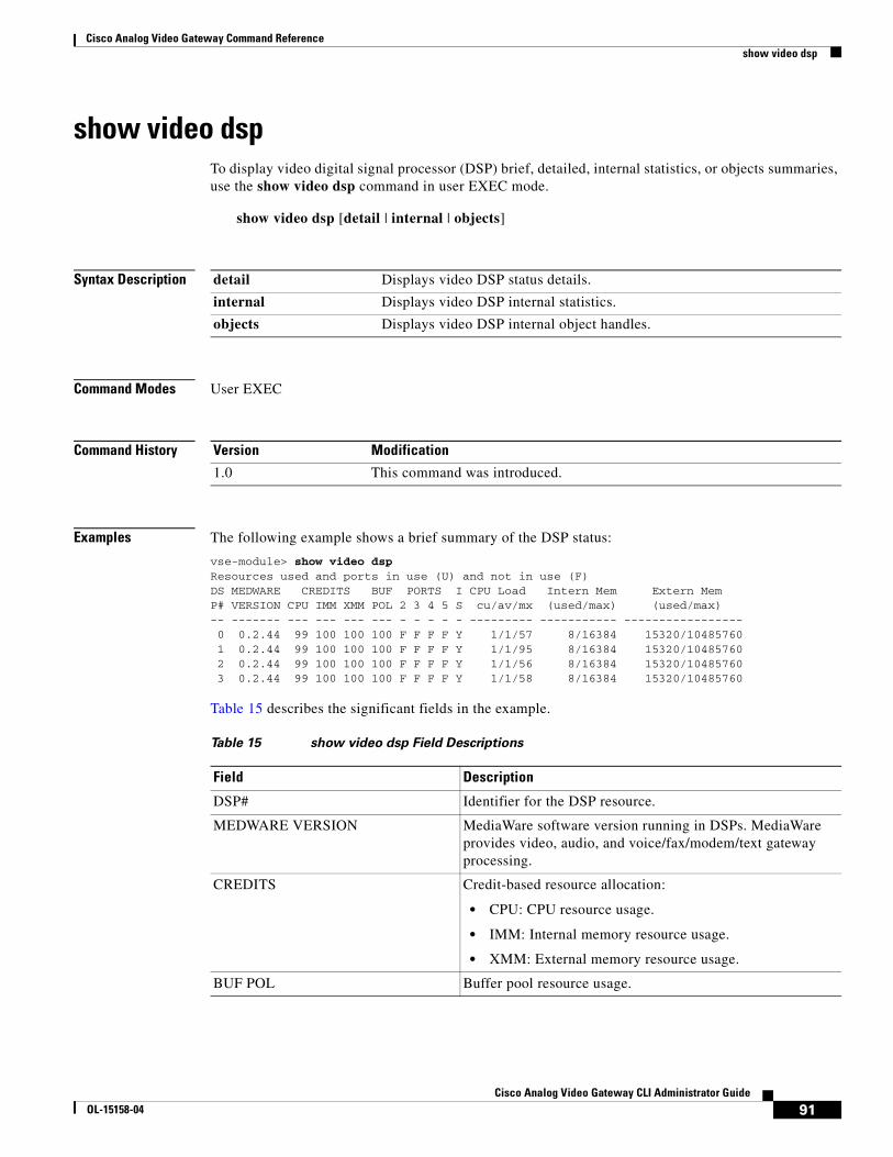
Cisco Analog Video Gateway Command Referenceshow video dsp
show video dspTo display video digital signal processor (DSP) brief, detailed, internal statistics, or objects summaries, use the show video dsp command in user EXEC mode.
show video dsp [detail | internal | objects]
Syntax Description
Command Modes User EXEC
Command History
Examples The following example shows a brief summary of the DSP status:
vse-module> show video dsp Resources used and ports in use (U) and not in use (F)DS MEDWARE CREDITS BUF PORTS I CPU Load Intern Mem Extern MemP# VERSION CPU IMM XMM POL 2 3 4 5 S cu/av/mx (used/max) (used/max)-- ------- --- --- --- --- - - - - - --------- ----------- ----------------- 0 0.2.44 99 100 100 100 F F F F Y 1/1/57 8/16384 15320/10485760 1 0.2.44 99 100 100 100 F F F F Y 1/1/95 8/16384 15320/10485760 2 0.2.44 99 100 100 100 F F F F Y 1/1/56 8/16384 15320/10485760 3 0.2.44 99 100 100 100 F F F F Y 1/1/58 8/16384 15320/10485760
Table 15 describes the significant fields in the example.
detail Displays video DSP status details.
internal Displays video DSP internal statistics.
objects Displays video DSP internal object handles.
Version Modification
1.0 This command was introduced.
Table 15 show video dsp Field Descriptions
Field Description
DSP# Identifier for the DSP resource.
MEDWARE VERSION MediaWare software version running in DSPs. MediaWare provides video, audio, and voice/fax/modem/text gateway processing.
CREDITS Credit-based resource allocation:
• CPU: CPU resource usage.
• IMM: Internal memory resource usage.
• XMM: External memory resource usage.
BUF POL Buffer pool resource usage.
91Cisco Analog Video Gateway CLI Administrator Guide
OL-15158-04

Cisco Analog Video Gateway Command Referenceshow video dsp
Related Commands
PORTS Video port resource usage for ports 2, 3, 4, and 5.
• F: Ports not in use.
• U: Ports in use.
CPU Load CPU loading:
• cu: Current CPU load.
• av: Average CPU load.
• mx: Maximum CPU load.
Intern Mem Internal memory resources:
• used: Internal memory used, in bytes.
• max: Maximum memory available, in bytes.
Extern Mem External memory resources:
• used: Internal memory used, in bytes.
• max: Maximum memory available, in bytes.
Table 15 show video dsp Field Descriptions (continued)
Field Description
Command Description
video port Configures video port profiles.
92Cisco Analog Video Gateway CLI Administrator Guide
OL-15158-04

Cisco Analog Video Gateway Command Referenceshow video motion-detection
show video motion-detectionTo display video motion detection configuration parameters, use the show video motion-detection command in user EXEC mode.
show video motion-detection {tag | summary}
Syntax Description
Command Modes User EXEC
Command History
Usage Guidelines You must first configure a motion region before you can associate it with a motion detection parameter.
Examples The following example shows configuration parameters for motion detection parameter mr111:
mpc8349e> show video motion-detection md111description "sample motion detection 1"state disabledmotionRegionTag_1 mr111motionRegionTag_2 mr222
The following example shows configuration parameters for motion detection parameter mr222:
mpc8349e> show video motion-detection md222description "sample motion detection 2"state enabledmotionRegionTag_1 mr111motionRegionTag_2 mr222
The following example shows configuration parameters for all motion detection parameters:
mpc8349e> show video motion-detection summarytag md011state enabled
tag md111state disabledmotionRegionTag_1 mr111motionRegionTag_2 mr222
tag md222state enabledmotionRegionTag_1 mr111motionRegionTag_2 mr222
tag Identifier for the video motion detection parameter. Values are in the range of md000 to md999.
summary Displays all configured video motion detection parameters.
Version Modification
1.0 This command was introduced.
93Cisco Analog Video Gateway CLI Administrator Guide
OL-15158-04

Cisco Analog Video Gateway Command Referenceshow video motion-detection
Table 16 describes the significant fields in the example.
Related Commands
Table 16 show video motion-detection Field Descriptions
Field Description
tag Identifier for the motion detection parameter.
state Operational state of the motion region: enabled or disabled.
motionRegionTag_x Motion region associated with motion detection parameters (where x is the number for the motion region tag). You can specify multiple motion region tags.
Command Description
video motion-detection
Configures video motion detection parameters.
94Cisco Analog Video Gateway CLI Administrator Guide
OL-15158-04

Cisco Analog Video Gateway Command Referenceshow video motion-region
show video motion-regionTo display video motion region configuration, use the show video motion-region command in user EXEC mode.
show video motion-region {tag | summary}
Syntax Description
Command Modes User EXEC
Command History
Usage Guidelines This command-line interface (CLI) command is used to show the motion region configuration. The upper-x motion region coordinate must be a smaller percentage than the lower-y coordinate.
Examples The following example shows a configuration parameters summary for all motion regions:
mpc8349e> show video motion-region summary tag state upper-x lower-x upper-y lower-y threshold==============================================================mr222 dis 20 300 30 250 90 mr111 ena 40 280 60 270 95
The following example shows configuration parameters for motion region mr111:
mpc8349e> show video motion-region mr111description "sample motion region 1"state enabledupperLeftCoordx 40upperLeftCoordy 60lowerRightCoordx 280lowerRightCoordy 270threshold 95
The following example shows configuration parameters for motion region mr222:
mpc8349e> show video motion-region mr222description "sample motion region 2"state disabledupperLeftCoordx 20upperLeftCoordy 30lowerRightCoordx 300lowerRightCoordy 250threshold 90
Table 17 describes the significant fields in the example.
tag Identifier for the video motion region.
summary Displays all configured video motion regions.
Version Modification
1.0 This command was introduced.
95Cisco Analog Video Gateway CLI Administrator Guide
OL-15158-04

Cisco Analog Video Gateway Command Referenceshow video motion-region
Related Commands
Table 17 show video motion-region Field Descriptions
Field Description
tag Identifier for the motion region.
state Operational state of the motion region: enabled or disabled.
upper-x Coordinate percentage for the upper-left area of the video screen.
lower-x Coordinate percentage for the lower-left area of the video screen.
upper-y Coordinate percentage for the upper-right area of the video screen.
lower-y Coordinate percentage for the lower-right area of the video screen.
threshold Motion vector threshold for the specified motion region.
Command Description
video motion-region Configures video motion region parameters.
96Cisco Analog Video Gateway CLI Administrator Guide
OL-15158-04

Cisco Analog Video Gateway Command Referenceshow video port
show video portTo display configuration parameters for video ports, use the show video port command in EXEC mode.
show video port {portnum | summary}
Syntax Description
Command Modes EXEC
Command History
Examples The following example shows configuration parameters for video port 0:
vse-module> show video port 0description ""state enableddirection inbrightness 0contrast 0hue 0saturation 0sharpness 0
The following example shows configuration parameters for all video ports:
vse-module> show video port summaryport state dir mxRes brightness contrast hue saturation sharpness==================================================================0 ena in 4cif 0 0 0 0 01 ena in 4cif 0 0 0 0 02 ena in 4cif 0 0 0 0 03 ena in 4cif 0 0 0 0 04 ena in 4cif 0 0 0 0 05 ena in 4cif 0 0 0 0 06 ena in 4cif 0 0 0 0 07 ena in 4cif 0 0 0 0 08 ena in 4cif 0 0 0 0 09 ena in 4cif 0 0 0 0 010 ena in 4cif 0 0 0 0 011 ena in 4cif 0 0 0 0 012 ena in 4cif 0 0 0 0 013 ena in 4cif 0 0 0 0 014 ena in 4cif 0 0 0 0 015 ena in 4cif 0 0 0 0 0
portnum Specifies the video port number.
summary Displays configuration parameters for all video ports.
Version Modification
1.0 This command was introduced.
97Cisco Analog Video Gateway CLI Administrator Guide
OL-15158-04

Cisco Analog Video Gateway Command Referenceshow video port
Table 18 describes the significant fields in the example.
Related Commands
Table 18 show video port Field Descriptions
Field Description
port Video port number.
state Operational state of the video port: enabled or disabled.
dir (direction) Direction of the video port: in for input, and out for output.
brightness Brightness setting of video port as an integer value in the range of –128 to 127.
contrast Contrast setting of video port as an integer value in the range of –128 to 127.
hue Hue setting for the video port as an integer value in the range of –128 to 127.
saturation Saturation setting for the video port as an integer value in the range of –128 to 127.
sharpness Sharpness setting for the video port as an integer value in the range of 0 to 3.
Command Description
video port Modifies an existing video port configuration.
98Cisco Analog Video Gateway CLI Administrator Guide
OL-15158-04

Cisco Analog Video Gateway Command Referenceshow video session
show video sessionTo display video session statistics, use the show video session command in user EXEC mode.
show video session {connection | history | library | rtcp | stream}
Syntax Description
Command Modes User EXEC
Command History
Examples The following example shows output from the show video session stream command:
vse-module# show video session stream
StreamId Sockfd IP Address Port Prot D O Pkts Count Bytes(K) TxDp kbps-------- ------ --------------- ----- ---- - - ---------- ---------- ---- -----00000001 000030 128.107.146.235 4730 RTP O Y 3330 3110 0 980 00000002 000031 128.107.146.235 4731 RTCP O N 0 0 0 0 00000101 000032 128.107.146.235 4730 RTP I N 0 0 0 0 00000102 000033 128.107.146.235 4731 RTCP I N 0 0 0 0
Table 19 describes the significant fields in the example.
connection Displays video session connection statistics.
history Displays video session historical statistics.
library Displays video session library statistics.
rtcp Displays video session real-time control protocol (RTCP) statistics.
stream Displays video session stream statistics.
Version Modification
1.0 This command was introduced.
Table 19 show video session stream Field Descriptions
Field Description
StreamID Video stream identifier.
Sockfd Socket field.
IP Address IP address.
Port Port number.
Prot Streaming protocol type.
D Direction (in or out).
O On: Yes or No.
Pkts Count Number of packets.
Bytes (K) Number of bytes (in thousands of bytes).
99Cisco Analog Video Gateway CLI Administrator Guide
OL-15158-04

Cisco Analog Video Gateway Command Referenceshow video session
The following example shows output from the show video session rtcp command:
vse-module# show video session rtcp
SessionID site RTPtx(s) RTPrx(s) DRate(%) DropCnt Jitter(ms) loopDelay 00000002-001f local 44bd54a7 00000000 0 0 0 ---- remote ---- ---- 0 0 4 28
Table 20 describes the significant fields in the example.
The following example shows output from the show video session connection command:
vse-module# show video session connection
S T R E A M M A N A G E R MW API C L IConnId AnEp isId Port PkEp osId IpAdress Encap Codec StreamId Profile------ ---- ---- ---- ---- ---- --------------- ----- ----- -------- --------- 188 180 180 2 179 179 128.107.146.235 rtp mpeg4 00000001 stream000
Table 21 describes the significant fields in the example.
TxDrp Number of transmission packets dropped.
kbps Session streaming rate, in kilobytes per second (KBps).
Table 19 show video session stream Field Descriptions (continued)
Field Description
Table 20 show video session rtcp Field Descriptions
Field Description
SessionID Video streaming session identifier.
site Site: local or remote.
RTPtx(s) Real-time Transport Protocol packet(s) transmitted.
RTPrx(s) Real-time Transport Protocol packet(s) received.
DRate(%) Drop rate, in percentage.
DropCnt Number of packets dropped.
Jitter(ms) Jitter signal variation, in milliseconds.
loopDelay Real-time Transport Control Protocol loop delay (in milliseconds).
Table 21 show video session connection Field Descriptions
Field Description
ConnId Connection identifier.
AnEp Analog endpoints
isId Input stream identifier.
Port Physical port number.
PkEp Packet endpoints.
osId Output stream identifier.
100Cisco Analog Video Gateway CLI Administrator Guide
OL-15158-04

Cisco Analog Video Gateway Command Referenceshow video session
Related Commands
IpAdress IP address.
Encap Encapsulation type.
Codec Codec type.
StreamId Streaming video identifier.
Profile Streaming video profile (for example, stream000).
Table 21 show video session connection Field Descriptions (continued)
Field Description
Command Description
video stream-profile Configures the video stream profile.
101Cisco Analog Video Gateway CLI Administrator Guide
OL-15158-04

Cisco Analog Video Gateway Command Referenceshow video stream-profile
show video stream-profileTo display video stream profile configuration parameters, use the show video stream-profile command in user EXEC mode.
show video stream-profile {tag | dynamically-generated summary | user-configured summary}
Syntax Description
Command Modes User EXEC
Command History
Usage Guidelines This command-line interface (CLI) command shows the video stream profile configuration.
Examples The following example shows a specific video stream profile:
vse-module> show video stream-profile stream011description "sample stream profile 011”state enabledportNum 0codecProfileTag -motionDetectionTag -
The following example shows all user-configured video stream profiles:
vse-module> show video stream-profile user-configured summary tag state codecProfileTag motionDetectionTag portNum===============================================================stream001 ena - - 0stream010 ena - - 0stream011 ena - - 0stream017 ena - - 0
The following example shows dynamically-generated video stream profiles:
vse-module> show video stream-profile dynamically-generated summary tag state codecProfileTag motionDetectionTag portNum===============================================================httpx ena - - 0
Table 22 describes the significant fields in the example.
tag Identifier for the video stream profile. String values are in the range of stream000 to stream999.
dynamically-generated summary
Displays a summary of dynamically generated video stream profiles.
user-configured summary Displays a summary of user-configured video stream profiles.
Version Modification
1.0 This command was introduced.
102Cisco Analog Video Gateway CLI Administrator Guide
OL-15158-04

Cisco Analog Video Gateway Command Referenceshow video stream-profile
Related Commands
Table 22 show video stream-profile Field Descriptions
Field Description
tag Identifier for the stream profile in the range of stream000 to stream999.
state Operational state of the stream profile: enabled or disabled.
codecProfileTag Identifier for the codec profile associated with the stream profile.
motionDetectionTag Identifier for the motion detection parameters associated with the stream profile.
portNum Port number associated with the stream profile.
Command Description
video stream-profile Creates a video stream profile.
103Cisco Analog Video Gateway CLI Administrator Guide
OL-15158-04

Cisco Analog Video Gateway Command Referenceshow video xconn-lpbk-conn
show video xconn-lpbk-connTo display video cross-connect loopback configuration parameters, use the show video xconn-lpbk-conn command in user EXEC mode.
show video xconn-lpbk-conn {0–1 | summary}
Syntax Description
Command Modes User EXEC
Command History
Usage Guidelines This command-line interface (CLI) command shows the video cross-connect loopback configuration to conduct video loopback diagnostic tests.
The video cross-connect loopback diagnostic command transmits a signal that is returned to the sending port after passing through all or a portion of a network or circuit. The returned signal is compared with the transmitted signal to evaluate the integrity of the equipment or transmission path. The video cross-connect loopback test mode is persistent across the Cisco Analog Video Gateway encoder reload.
Examples The following example shows the specific video cross-connect loopback connection parameters:
VSE-Module> show video xconn-lpbk-conn 0
description “video connection 0“state enabledimport 2outport 0
The following example shows a summary of video cross-connect loopback connection parameters:
VSE-Module> show video xconn-lpbk-conn summary
xconn-lpbk-conn state inport outport=======================================================conn0 ena 1 0conn1 ena 1 0
Table 23 describes the significant fields in the example.
0–1 Identifies the video cross-connect loopback connection in the range of 0 to 1.
summary Displays a summary video cross-connect loopback connections.
Version Modification
1.2 This command was introduced.
104Cisco Analog Video Gateway CLI Administrator Guide
OL-15158-04

Cisco Analog Video Gateway Command Referenceshow video xconn-lpbk-conn
Related Commands
Table 23 show video cross-connect loopback Field Descriptions
Field Description
xconn-lpbk-conn Identifies the connection as either conn0 or conn1.
state Operational state of the video cross-connect loopback test: enabled or disabled.
inport Displays the video cross-connect loopback inport.
outport Displays the video cross-connect loopback to outport.
Command Description
video xconn-lpbk-conn Configures and enables the Cisco Analog Video Gateway cross connect test mode.
105Cisco Analog Video Gateway CLI Administrator Guide
OL-15158-04

Cisco Analog Video Gateway Command Referencevideo codec-profile
video codec-profileTo create a video codec profile, use the video codec-profile command in video port configuration mode. To use the default video codec profile, use the no form of this command.
video codec-profile tag [bitrate | codec | default | deinterlace | description | format | framerate | gopsize | maxbitrate | qualityfactor | skipfactor | resolution | state]
no video codec-profile tag
Note The video codec profile cannot be removed until the streaming profile is removed.
Syntax Description tag Identifier for the video codec profile. String values are in the range of codec000 to codec999.
bitrate Bit rate for the video codec profile.
• variable bit rate (vbr): VBR. Used for MJPEG, MPEG4, and H.264.
• constant bit rate (cbr): CBR. Used for MPEG4 and H264 only.
Default: cbr.
codec Codec type for the video codec profile.
• h264: H.264.
• mjpeg: MJPEG.
• mpeg4: MPEG4.
Default: mpeg4.
default Use default values for the video codec profile. Use the no form of this command to use or restore the default video codec profile values.
deinterlace Enables or disables deinterlace mode. This option is available only in version 1.1 or later.
Default: enabled
description Description for the video codec profile. Text with up to 80 string characters within quotation marks.
format Format for the video codec profile:
• ntsc: NTSC video format.
• pal: PAL video format.
framerate Frame rate for the video codec profile, in frames per second (fps):
• NTSC frame rate: 30, 15, 10, 7.5, 6, 5, 4.28, 3.75, 3.33, 3, 2.72, 2.5, 2.31, 2.14, 2, 1.87, 1.76, 1.67, 1.58, 1.5, 1.43, 1.36, 1.3, 1.25, 1.2, 1.15, 1.11, 1.07, 1.03, 1, 0.99, 0.98, ..., 0.02, 0.01. Default: 5.
• PAL frame rate: 25, 12.5, 8.33, 6.25, 5, 4.17, 3.57, 3.13, 2.78, 2.5, 2.27, 2.08, 1.92, 1.79, 1.67, 1.56, 1.47, 1.39, 1.32, 1.25, 1.19, 1.14, 1.09, 1.04, 1.00, 0.99, 0.98, ..., 0.02, 0.01. Default: 10.
gopsize Group-of-picture (GOP) size for the video codec profile in the range of 0 to 600. Default: 20.
106Cisco Analog Video Gateway CLI Administrator Guide
OL-15158-04

Cisco Analog Video Gateway Command Referencevideo codec-profile
Command Default No video codec profile is configured.
Command Modes Video port configuration
Command History
Usage Guidelines When setting framerate, the default is 5 frames per second (fps). For example, a frame rate of 0.01 means 1 frame every 100 seconds.
When setting gopsize, set it for MPEG4 and H.264 only in frames. For example, if you have a frame rate of 15 fps and GOP size of 30 frames, it is set to 30/15 or 2 seconds.
When setting maxbitrate, it cannot be set for MJPEG because it uses a VBR algorithm.
The NTSC CIF resolution is:
• NTSC-CIF = 352 x 240 pixels
• NTSC-2CIF = 704 x 240 pixels
• NTSC-4CIF = 704 x 480 pixels
maxbitrate Maximum bit rate for the video codec profile.
• Integer value in the range of 168 to 2000 KBps for codec MPEG4.
• Integer value in the range of 168 to 3000 KBps for codec H.264.
Default: 768.
Note You cannot set a maxbitrate value for MJPEG because it uses a VBR algorithm.
qualityfactor Quality factor for MJPEG video codec only. Integer value in the range of 0 to 100 percent. Default: 70.
skipfactor Skip factor for the video codec profile. Integer value in the range of 1 to 100.
resolution Resolution for the video codec profile:
• 4cif: 4CIF
• 2cif: 2CIF (This option is only available in version 1.1 or later.)
• cif: CIF
Default: 4cif
state Operational state of the video codec profile: enabled or disabled. Default: enabled.
Version Modification
1.0 This command was introduced.
1.1 De-interlace enable/disable option added to this command.
Resolution option 2CIF added to this command.
107Cisco Analog Video Gateway CLI Administrator Guide
OL-15158-04

Cisco Analog Video Gateway Command Referencevideo codec-profile
The PAL CIF resolution is:
• PAL-CIF = 352 x 288 pixels
• PAL-2CIF = 704 x 288 pixels
• PAL-4CIF = 704 x 576 pixels
Examples This example shows video codec profile and stream profile configuration for video streaming with codec set to MPEG4, bitrate set to VBR, format set to NTSC, framerate is set to 30, gopsize is set to 20, and maxbitrate is set to 1000 KBps on video port 4.
VSE-module(config)> video codec-profile codec000VSE-module(config-codec-profile)> codec mpeg4VSE-module(config-codec-profile)> bitrate vbrVSE-module(config-codec-profile)> format ntscVSE-module(config-codec-profile)> framerate 30VSE-module(config-codec-profile)> gopsize 20VSE-module(config-codec-profile)> maxbitrate 1000VSE-module(config-codec-profile)> endVSE-module(config)> video stream-profile stream000VSE-module(config-stream-profile)> codecprofiletag codec000VSE-module(config-stream-profile)> portnum 4
Related Commands Command Description
show video codec-profile Displays video codec profile configuration parameters.
108Cisco Analog Video Gateway CLI Administrator Guide
OL-15158-04

Cisco Analog Video Gateway Command Referencevideo motion-detection
video motion-detectionTo create a video motion detection profile, use the video motion-detection command in video port configuration mode. To use a default video motion detection profile, use the no form of this command.
video motion-detection tag [default | description | motion-region-tag x y | state]
no video motion-detection tag
Syntax Description
Command Default No video motion detection profiles are configured.
Command Modes Video port configuration
Command History
Usage Guidelines A video motion region profile must be configured before it can be used by a video codec motion detection profile; otherwise, the following error message appears:
The specified video motion region tag has not been configured
Examples The following example shows a configuration for video motion detection md000:
vse-module> show video motion-detection md000description "video motion detection md000"state enabledmotion-region-tag 30 mr000
tag Identifier for the motion detection profile. String values are in the range of md000 to md999.
default Use default values for the video motion detection profile. Use the no form of this command to restore the default video motion detection profile values.
description Description for the video motion detection profile. Text with up to 80 string characters within quotation marks.
motion-region-tag x y Motion region to use for the video motion detection profile, where x specifies the motion region integer tag number in the range of 0 to 31, and y specifies the motion region tag in the range of mr000 to mr999.
state Operational state of the video motion detection profile: enabled or disabled. Default: enabled
Version Modification
1.0 This command was introduced.
109Cisco Analog Video Gateway CLI Administrator Guide
OL-15158-04

Cisco Analog Video Gateway Command Referencevideo motion-detection
Related Commands Command Description
show video motion-detection
Displays video motion detection configuration parameters.
110Cisco Analog Video Gateway CLI Administrator Guide
OL-15158-04

Cisco Analog Video Gateway Command Referencevideo motion-region
video motion-regionTo create a video motion region profile, use the video motion-region command in video port configuration mode. To use a default video motion region profile, use the no form of this command.
video motion-region tag [default | description | lowerrightcoordx | lowerrightcoordy | state | threshold | upperleftcoordx | upperleftcoordy]
no video motion-region tag
Syntax Description
Command Default No video motion region is configured.
Command Modes Video port configuration
Command History
Usage Guidelines The lower-right and upper-left coordinate values are whole percentage values. The upper-left x coordinate must be a smaller percentage value than the lower-right x coordinate.
Examples The following example shows the configuration for video motion region mr000.
vse-module> show video motion-region mr000 description "video motion region mr000"
tag Identifier for the motion region profile. String values are in the range of mr000 to mr999.
default Use default values for the video motion region profile. Use the no form of this command to restore the default video motion region profile values.
description Description for the video motion region profile. Text with up to 80 string characters within quotation marks.
lowerrightcoordx Lower-right x coordinate integer percentage value in the range of 0 to 100. Default: 0.
lowerrightcoordy Lower-right y coordinate integer percentage value in the range of 0 to 100. Default: 0.
state Operational state of the video motion region: enabled or disabled. Default: enabled.
threshold Motion region threshold value in the range of 1 to 100. Default: 10.
upperleftcoordx Upper-left x coordinate integer percentage value in the range of 0 to 100. Default: 0.
upperleftcoordy Upper-left y coordinate integer percentage value in the range of 0 to 100. Default: 0.
Version Modification
1.0 This command was introduced.
111Cisco Analog Video Gateway CLI Administrator Guide
OL-15158-04

Cisco Analog Video Gateway Command Referencevideo motion-region
state enabledupperLeftCoordx 25upperLeftCoordy 35lowerRightCoordx 30lowerRightCoordy 40threshold 10
Related Commands Command Description
show video motion-region
Displays video motion region configuration parameters.
112Cisco Analog Video Gateway CLI Administrator Guide
OL-15158-04

Cisco Analog Video Gateway Command Referencevideo port
video portTo enter video port configuration mode or to modify the default video port configuration, use the video port command in global configuration mode. To use the video port to the default values, use the no form of this command.
Note The following command is valid for version 1.2 and later.
video port portnum [brightness | contrast | default | description | direction | hue | saturation | sharpness | state]
Note The following command is only valid for versions 1.0 and 1.2.
video port portnum [brightness | contrast | default | description | direction | hue | maxresolution | saturation | sharpness | state]
no video port portnum
Syntax Description portnum Video port number in the range of 0 to 15.
brightness Brightness setting of video port as an integer value in the range of –128 to 127. Default: 0
contrast Contrast setting of video port as an integer value in the range of –128 to 127. Default: 0
default Returns the configuration to default values. Use the no form of this command to restore the default video port profile values.
description Description of the video port. Text with up to 80 string characters within quotation marks.
direction Video port direction:
• in: input direction.
• out: output direction.
Default: in.
hue Hue setting for the video port as an integer value in the range of –128 to 127. Default: 0.
maxresolution Note This command is valid only for versions 1.0 and 1.1.
Maximum resolution of the video port:
• 4cif: 4CIF resolution.
• 2cif: 2CIF resolution. This option is only available in version 1.1 or later.
• cif: CIF resolution.
Default: 4cif.
saturation Saturation setting for the video port as an integer value in the range of –128 to 127. Default: 0.
113Cisco Analog Video Gateway CLI Administrator Guide
OL-15158-04

Cisco Analog Video Gateway Command Referencevideo port
Command Default Video ports retain default configuration parameters.
Command Modes Global configuration
Command History
Usage Guidelines Video format is automatically detected, based on the hardware setting.
The maxresolution command is applicable only in versions 1.0 and 1.1 for the in (input) direction, so the Invalid input error appears if an attempt is made to apply the maxresolution command in the out (output) direction.
vse-module(config)> video port 0Modifying existing portvse-module(config-port)> description "sample video port 0"vse-module(config-port)> direction outvse-module(config-port)> maxresolution ? cif CIF resolutionvse-module(config-port)> maxresolution cifInvalid input. maxResolution is not applicable to output direction
Examples The following example shows the parameters configured for video port 0.
vse-module> show video port 0description ""state enableddirection inbrightness 125contrast 80hue 100saturation 0sharpness 0
Related Commands
sharpness Sharpness setting for the video port as an integer value in the range of 0 to 3. Default: 0.
state Operational state of the video port: enabled or disabled. Default: enabled.
Version Modification
1.0 This command was introduced.
1.1 Maximum resolution option 2CIF added to the command.
1.2 Maximum reslolution (maxresolution) command removed.
Command Description
show video port Displays configuration parameters for video ports.
114Cisco Analog Video Gateway CLI Administrator Guide
OL-15158-04

Cisco Analog Video Gateway Command Referencevideo stream-profile
video stream-profileTo create a video stream profile, use the video stream-profile command in video port configuration mode. To use a default video stream profile, use the no form of this command.
video stream-profile tag [codecprofiletag | default | description | motiondetectiontag | packetization-mode | portnum | state]
no video stream-profile tag
Syntax Description
Command Default No video stream profile is configured.
Command Modes Video port configuration
Command History
tag Identifier for this video stream profile values in the range of stream000 to stream999.
codecprofiletag Identifier for the video codec profile to use with the video stream profile values in the range of codec000 to codec999.
default Use default values for the video stream profile. Use the no form of this command to restore the default video stream profile values.
description Description for the video stream profile. Text with up to 80 string characters within quotation marks.
motiondetectiontag Identifier for video motion detection profile profile values in the range of md000 to md999 to use with the video stream profile.
packetization-mode H.264 real-time transport protocol (RTP) packetization mode (RFC-3984):
• non-interleaved: Non-interleaved mode.
• single-NAL: single Network Abstraction Layer (NAL) unit mode.
Default: non-interleaved.
portnum Port number to use for the video stream profile values in the range of 0 to 15.
state Operational state of the video stream profile: enabled or disabled. Default: enabled.
Version Modification
1.0 This command was introduced.
115Cisco Analog Video Gateway CLI Administrator Guide
OL-15158-04

Cisco Analog Video Gateway Command Referencevideo stream-profile
Usage Guidelines A video codec profile must be configured before it can be used by a video stream profile.
Note With the exception of motion detection configurations, once the video stream is initiated based on a profile, any changes to the corresponding codec or port configurations will have no effect on the video stream already in progress. Any changes to motion detection configurations will have an immediate effect on the video stream already in progress.
Examples The following example shows a streaming profile configuration of stream000:
vse-module> show video stream-profile stream000description "video stream profile 000"state enabledportNum 2codecProfileTag codec000packetization-mode non-interleavedmotionDetectionTag - md000
Related Commands Command Description
show video stream-profile
Displays video stream profile configuration parameters.
116Cisco Analog Video Gateway CLI Administrator Guide
OL-15158-04

Cisco Analog Video Gateway Command Referencevideo xconn-lpbk-conn
video xconn-lpbk-connTo configure a video cross-connect loopback diagnostic test, use the video xconn-lpbk-conn command in video cross-connect loopback configuration mode. To restore the video cross-connect loopback command to the default condition, use the no form of this command.
video xconn-lpbk-conn 0–1 [default | description | inport | state]
no video xconn-lpbk-conn
Syntax Description
Command Default No video cross-connect loopback is configured.
Command Modes Video cross-connect loopback configuration
Command History
Examples The following example shows the specific video cross-connect loopback connection parameters:
VSE-Module> show video xconn-lpbk-conn 0
description “video connection 0“state enabledimport 2outport 0
The following example shows a summary of video cross-connect loopback connection parameters:
VSE-Module> show video xconn-lpbk-conn summary
xconn-lpbk-conn state inport outport=======================================================conn0 ena 1 0conn1 ena 1 0
0–1 Identifies the video cross-connect loopback connection 0 or 1.
default Use default values for the video cross-connect loopback test. Use the no form of this command to restore the default condition.
description Description for the video cross-connect loopback configuration. Text with up to 80 string characters within quotation marks.
inport Identifies the video cross-connect inport.
state Operational state of the video stream profile: enabled or disabled. Default: enabled.
Version Modification
1.2 This command was introduced.
117Cisco Analog Video Gateway CLI Administrator Guide
OL-15158-04

Cisco Analog Video Gateway Command Referencevideo xconn-lpbk-conn
Related Commands Command Description
show video xconn-lpbk-conn
Displays the video cross-connect loopback configuration summary.
118Cisco Analog Video Gateway CLI Administrator Guide
OL-15158-04

Cisco Analog Video Gateway Command ReferenceCisco IOS Commands
Cisco IOS CommandsThis section documents new Cisco IOS commands. Use these commands to access and configure the Cisco Analog Video Gateway module from the host router.
• service-module video-service-engine, page 120
• show controllers video-service-engine, page 124
• show interfaces video-service-engine, page 122
119Cisco Analog Video Gateway CLI Administrator Guide
OL-15158-04

Cisco Analog Video Gateway Command Referenceservice-module video-service-engine
service-module video-service-engine To begin a network module session through a console connection, use the service-module video-service-engine command in privileged EXEC configuration mode.
service-module video-service-engine slot/port {session | password-reset | reload | reset | session | shutdown | statistics | status}
Syntax Description
Command Default None.
Command Modes Privileged EXEC
Command History
Usage Guidelines Use the service-module video-service-engine slot/port shutdown command before you remove the video network module from the router.
Removing the video encoder without using the proper shutdown sequence can result in corruption of the hard disk. After successful shutdown of the application, the Cisco IOS software displays a message indicating that the network module can be removed.
Only one session at a time is allowed into the network module from the internal network-module-side interface.
After starting a session, you can perform any video module configuration task. You first access the console in a user-level shell. To access the privileged EXEC command shell, in which most commands are available, use the enable command.
slot Number of the router chassis slot for the network module.
port Number of the video port on the network module. For network modules, always use 0. The slash mark (/) is required between the slot argument and the port argument.
password-reset Reset of network module password.
reload Reload network module.
reset Hardware reset of the network module.
session Network module session. Opens a Telnet session that provides the Cisco video encoder command-line interface (CLI) from the Cisco IOS interface side.
shutdown Shutdown of the network module.
statistics Shows the video network module reset statistics.
status Operational information about the network module.
Version Modification
12.4(11)T This command was introduced.
120Cisco Analog Video Gateway CLI Administrator Guide
OL-15158-04

Cisco Analog Video Gateway Command Referenceservice-module video-service-engine
After you finish configuring the module and exit the module console session, clear the session by using the service-module video-service-engine slot/port session clear command. At the confirmation prompt, press Enter to confirm the action, or press n to cancel.
Examples The following example shows a session being opened for a Cisco Analog Video Gateway module in slot 1:
Router# service-module video-service-engine 1/0 session
Trying 31.0.0.99, 2066 ... Openvse-module>
Related Commands Command Description
enable Enters privileged EXEC mode.
interface Configures an interface and enters interface configuration mode.
show diag Displays controller information for a network module.
show interface video-service engine Displays basic interface configuration information for the Cisco Analog Video Gateway network module.
121Cisco Analog Video Gateway CLI Administrator Guide
OL-15158-04

Cisco Analog Video Gateway Command Referenceshow interfaces video-service-engine
show interfaces video-service-engineTo display basic interface configuration information for an the video interface, use the show interfaces video-service-engine command in user EXEC mode.
show interfaces video-service-engine slot/port
Syntax Description
Defaults None
Command Modes User EXEC
Command History
Examples The following example shows the output from the show interfaces video-Service-Engine 1/0 command:
Router# show interfaces video-service-Engine 1/0
Video-Service-Engine1/0 is up, line protocol is up Hardware is BCM5703, address is 0015.629a.efe0 (bia 0015.629a.efe0) Internet address is 31.0.0.99/16 MTU 1500 bytes, BW 1000000 Kbit, DLY 10 usec, reliability 255/255, txload 1/255, rxload 1/255 Encapsulation ARPA, loopback not set Keepalive not set Full-duplex, 1000Mb/s, link type is force-up, media type is internal output flow-control is XON, input flow-control is XON ARP type: ARPA, ARP Timeout 04:00:00 Last input 00:00:09, output 00:00:09, output hang never Last clearing of "show interface" counters never Input queue: 0/75/0/0 (size/max/drops/flushes); Total output drops: 0 Queueing strategy: fifo Output queue: 0/512 (size/max) 5 minute input rate 0 bits/sec, 0 packets/sec 5 minute output rate 0 bits/sec, 0 packets/sec 43797 packets input, 1854377 bytes, 0 no buffer Received 18 broadcasts, 0 runts, 0 giants, 0 throttles 0 input errors, 0 CRC, 0 frame, 0 overrun, 0 ignored 0 watchdog, 0 multicast, 0 pause input 0 input packets with dribble condition detected 31682 packets output, 10485509 bytes, 0 underruns 0 output errors, 0 collisions, 4 interface resets 0 babbles, 0 late collision, 0 deferred
slot Number of the router chassis slot for the Cisco Analog Video Gateway module.
port Number of the video Cisco Analog Video Gateway module. For network modules, always use 0. The slash mark (/) is required between the slot argument and the port argument.
Version Modification
12.4(11)T This command was introduced.
122Cisco Analog Video Gateway CLI Administrator Guide
OL-15158-04

Cisco Analog Video Gateway Command Referenceshow interfaces video-service-engine
0 lost carrier, 0 no carrier, 0 pause output 0 output buffer failures, 0 output buffers swapped outRouter#
Related Commands Command Description
interface video-service-engine
Configures the interface slot and port numbers where the network module resides.
123Cisco Analog Video Gateway CLI Administrator Guide
OL-15158-04

Cisco Analog Video Gateway Command Referenceshow controllers video-service-engine
show controllers video-service-engineTo display controller information for video network module, use the show controllers video-service-engine command in the privileged EXEC mode.
show controllers video-service-engine slot/unit
Syntax Description
Command Default None
Command Modes Privileged EXEC
Command History
Examples The following example shows the output from the show controllers video-service-engine slot/unit command:
Router# show controllers video-Service-Engine 1/0Interface Video-Service-Engine1/0Hardware is BCM5703 Gig EthernetIDB: 657C708C, FASTSEND: 60E21D2C, MCI_INDEX: 0
INSTANCE=0x657C819C Rx Ring entries = 512 Rx Shadow = 0x657C8AEC Rx Ring = 0x2D7C3040 Rx Ring Head = 184 Rx Ring Last = 183 Rx Jumbo Ring entries = 256 Rx Jumbo Shadow = 0x657C9324 Rx Jumbo Ring = 0x2D7C7080 Rx Jumbo Ring Head = 0 Rx Jumbo Ring Last = 255 Rx Return Ring = 0x2D7CB0C0 Rx Return Ring Head = 696 Rx Return Ring Last = 695 Rx STD Ring Shadow (malloc) = 0x657C8AEC Rx STD Ring (malloc) = 0x2D7C3040 Rx JUMBO Ring Shadow (malloc) = 0x657C9324 Rx JUMBO Ring (malloc) = 0x2D7C7080 Rx Buffer Descr (malloc) = 0x2D7CB0C0 Tx Ring entries = 512 Tx Shadow = 0x657CA35C Tx Shadow Head = 2 Tx Shadow Tail = 2
slot Number of the router chassis slot for the video module.
unit Number of the video module. For network modules, always use 0. The slash mark (/) is required between the slot argument and the unit argument.
Version Modification
12.4(11)T This command was introduced.
124Cisco Analog Video Gateway CLI Administrator Guide
OL-15158-04

Cisco Analog Video Gateway Command Referenceshow controllers video-service-engine
Tx Shadow Tail Last = 1 Tx Shadow Free = 512 Tx Ring = 0x2D7D3100 Tx Count = 0 Tx Free = 512 Tx Buffer Descr = 0x2D7D3100 Tx Shadow (malloc) = 0x657CA35C Tx Ring (malloc) = 0x2D7D3100
Status block and mail_box information Status = 0x0, StatusTag = 0xB1 Status::RcvStdConIdx: 184 , RcvJumboConIdx: 0 , RcvMiniConIdx: 0 MBOX::RcvStdProdIdx:183 , RcvJumboProdIdx:255 , RcvMiniProdIdx: 0 Status::Send 0, SendConIdx: 2 , Rx Rtn 0, RcvProdIdx: 696 mail_box::Send 0,SendHostProdIdx: 2 , Rx Rtn 0,RcvRetConIdx: 695
Rings Status: *** RX Entry: 3 , Tx Entry: 14 ***
RX # duration RtnHead RtnTail ProdHead ProdTail [0 ] 35 693 694 181 182 [1 ] 31 694 695 182 183 [2 ] 40 695 696 183 184 [3 ] 29 676 677 164 165 [4 ] 35 677 678 165 166 [5 ] 30 678 679 166 167 [6 ] 31 679 680 167 168 [7 ] 31 680 681 168 169 [8 ] 29 681 682 169 170 [9 ] 28 682 683 170 171 [10] 35 683 684 171 172 [11] 38 684 685 172 173 [12] 38 685 686 173 174 [13] 35 686 687 174 175 [14] 36 687 688 175 176 [15] 34 688 689 176 177 [16] 36 689 690 177 178 [17] 41 690 691 178 179 [18] 31 691 692 179 180 [19] 32 692 693 180 181
TX # duration Send_head Send_tail [0 ] 3 442 443 [1 ] 5 504 505 [2 ] 4 505 506 [3 ] 3 506 507 [4 ] 5 443 444 [5 ] 4 507 508 [6 ] 2 444 445 [7 ] 0 508 509 [8 ] 3 509 510 [9 ] 3 510 511 [10] 3 445 446 [11] 4 511 0 [12] 4 0 1 [13] 5 1 2 [14] 4 499 500 [15] 3 500 501 [16] 3 441 442 [17] 4 501 502 [18] 3 502 503 [19] 3 503 504
PCI Register [0x4B000000]
125Cisco Analog Video Gateway CLI Administrator Guide
OL-15158-04

Cisco Analog Video Gateway Command Referenceshow controllers video-service-engine
PCI Msi Control = 0x5 PCI Msi addr = 0xBFFD7DF7, 0xDFFF97F4 PCI MiscHostCtrl = 0x10020098 PCI DMA Control = 0x763F0000 PCI PciState = 0x20FE PCI clk ctrl = 0xBF PCI ModeCtrl = 0x4030034 PCI MiscCfg = 0x83082 PCI MiscLocalCtrl = 0x1016F09
Mac Control Register [0x4B000400] MAC Mode = 0xE0480C Mac Status = 0x403 Mac Event = 0x1000 Mac Led = 0x880 Mac RX MTU = 0x2808 Mac Tx AutoNeg = 0x0 MAC Rx AutoNeg = 0x0 Mac Tx Mode = 0x52 Mac Tx Status = 0x8 Mac Tx Length = 0x2620 Mac Rx Mode = 0x406 Mac Rx Status = 0x0 Mac Serdes Ctrl = 0x616000 Mac Serdes Status = 0x140
General Control Register [0x4B006800] GCR Mode = 0x4030034, GCR MiscCfg = 0x83082 GCR LocalCtrl = 0x1016F09, GCR Timer = 0x878ABA6 Buf Mgr Address Space Begin = 0x4B004400 Buf Mgr Flow Control Low Water Mark Adr = 0x4B004414 Data = 0x130 Buf Mgr Flow Control High Water Mark Adr = 0x4B004418 Data = 0x17C
Hardware MAC Address Filters---------------------------- Hardware Perfect Address FiltersMAC addr[00] = 00-15-62-9A-EF-E0MAC addr[01] = 01-00-0C-CC-CC-CCMAC addr[02] = 01-80-C2-00-00-07MAC addr[03] = 00-00-00-00-00-00MAC addr[04] = 00-00-00-00-00-00MAC addr[05] = 00-00-00-00-00-00MAC addr[06] = 00-00-00-00-00-00MAC addr[07] = 00-00-00-00-00-00MAC addr[08] = 00-00-00-00-00-00MAC addr[09] = 00-00-00-00-00-00MAC addr[10] = 00-00-00-00-00-00MAC addr[11] = 00-00-00-00-00-00MAC addr[12] = 00-00-00-00-00-00MAC addr[13] = 00-00-00-00-00-00MAC addr[14] = 00-00-00-00-00-00MAC addr[15] = 00-00-00-00-00-00 Hardware Multicast Hash FiltersMAC Hash addr[00] = 00000000MAC Hash addr[01] = 00000000MAC Hash addr[02] = 00000000MAC Hash addr[03] = 00000000 Hardware Receive Rules FiltersReceive Rules Config = 00000008 Rule: [00] = 0x42000000 Value: [00] = 0x7FFFFFFF Rule: [01] = 0x06000004 Value: [01] = 0x7FFFFFFF Rule: [02] = 0x00000000
126Cisco Analog Video Gateway CLI Administrator Guide
OL-15158-04

Cisco Analog Video Gateway Command Referenceshow controllers video-service-engine
Value: [02] = 0x00000000 Rule: [03] = 0x00000000 Value: [03] = 0x00000000 Rule: [04] = 0x00000000 Value: [04] = 0x00000000 Rule: [05] = 0x00000000 Value: [05] = 0x00000000 Rule: [06] = 0x00000000 Value: [06] = 0x00000000 Rule: [07] = 0x00000000 Value: [07] = 0x00000000 Rule: [08] = 0x00000000 Value: [08] = 0x00000000 Rule: [09] = 0x00000000 Value: [09] = 0x00000000 Rule: [10] = 0x00000000 Value: [10] = 0x00000000 Rule: [11] = 0x00000000 Value: [11] = 0x00000000 Rule: [12] = 0x00000000 Value: [12] = 0x00000000 Rule: [13] = 0x00000000 Value: [13] = 0x00000000 Rule: [14] = 0x00000000 Value: [14] = 0x00000000 Rule: [15] = 0x00000000 Value: [15] = 0x00000000
Software MAC Address Filter (hash:length/addr/mask/hits)-------------------------------------------------------- 0x000: 0 ffff.ffff.ffff 0000.0000.0000 0 0x082: 0 0015.629a.efe0 0000.0000.0000 0 0x0C0: 0 0100.0ccc.cccc 0000.0000.0000 0 0x0C5: 0 0180.c200.0007 0000.0000.0000 0
Software filtered frames: 0 Unicast software filter needed: 0 Multicast software filter needed: 0 Promiscuous mode: 0
HARDWARE STATISTICS Rx good packets: 20152 Rx CRC: 0 Rx alignment: 0 Rx short: 0
Tx good frames: 31234 Tx maxm collisions: 0 Tx late collisions: 0 Tx underruns: 0 Tx lost carrier: 0 Tx deferred: 0 Tx single collision: 0 Tx multiple collision: 0 Tx total collisions: 0 -------- HW FLOW CONTROL STATS --------- Rx XON PAUSE Frames Received: 0 Rx XOFF PAUSE Frames Received: 0 Rx XOFF State Entered: 0 Tx XON Sent: 0 Tx XOFF Sent: 0
INTERRUPT STATISTICS CX = 75443
127Cisco Analog Video Gateway CLI Administrator Guide
OL-15158-04

Cisco Analog Video Gateway Command Referenceshow controllers video-service-engine
FR = 43763 CNA = 0 RNR = 0 MDI = 0 SWI = 0 FCP = 0
Full Promiscuous Mode = disabledLoopback Mode = disabled
I/O Congestion Counters: Standard Packet Count : 0 Jumbo Packet Count : 0
I2C Registers: AFS - Control Register : 0x4000D000 SMBUS Input Register : 0x00000464 SMBUS Output Register : 0x00004C61 SMBUS GRC Local Register : 0x01016F09
I2C Error Counter: Total I2C Output Errors : 0 Total I2C Input Errors : 0 I2C Transaction Errors : 0
Module Reset Statistics: CLI reset count = 3 CLI reload count = 0 Registration request timeout reset count = 2 Error recovery timeout reset count = 3 Module registration count = 4
The last IOS initiated event was a error recovery timeout reset at 23:26:57.306UTC Wed May 9 2007Router#
Related Commands Command Description
show interfaces integrated-service-engine
Displays basic interface configuration information for the video network module.
128Cisco Analog Video Gateway CLI Administrator Guide
OL-15158-04

CiOL-15158-04
G L O S S A R Y
A
AIC Alarm Indication Control.
appliance Alternate term for service module.
ARP Address Resolution Protocol. Internet protocol used to map an IP address to a MAC address.
ASP Advanced Simple Profile. See MPEG4 standard.
B
boot helper A small subset of the system software that runs on the Cisco Analog Video Gateway. It boots the module from the network and assists in software installation, software upgrades, disaster recovery, and other operations when the module cannot access its software.
boot loader A small set of system software that runs when the system first powers up. It loads the operating system (from the disk, network, external CompactFlash, or external USB flash), which loads and runs the Cisco Analog Video Gateway application. The boot loader may optionally load and run the boot helper.
BP Baseline Profile. See H.264 standard.
C
CIF Common Intermediate Format, usually referring to 352 x 240 pixels per picture for NTSC and 352 x 288 pixels per picture for PAL.
4CIF—Four Times CIF: 704 x 480 pixels per picture for NTSC, and 704 x 576 pixels per picture for PAL.
CODEC Coder and decoder. An encoder converts the source data into a compressed form prior to transmission or storage. The decoder converts the compressed data into a representation of the original data.
D
D1 This is an equivalent resolution of 4CIF, or 720 x 480 pixels per picture for NTSC and 720 x 576 pixels per picture for PAL.
GL-1sco Analog Video Gateway CLI Administrator Guide

Glossary
E
EXT3 Linux popular file system.
F
FTP File Transfer Protocol. Application protocol, part of the TCP/IP protocol stack, used for transferring files between network nodes.
G
GOP Group-of-pictures (GOP). The GOP layer contains a small number of frames (typically 12) coded so that they can be decoded completely as a unit, without reference to frames outside of the group. There are three types of frame:
Intracoded frames (I)—coded as single frames as in JPEG, without reference to any other frames.
Predictive coded frames (P)—coded as the difference from a motion compensated prediction frame, generated from an earlier I or P frame in the GOP.
Bidirectional coded frames (B)—coded as the difference between a bidirectional interpolated frames, generated from earlier and later I or P frames in the sequence (with motion compensation).
H
H.264, JVT/H.26L,
MPEG4 Part10,AVC
Video standard successor to MPEG-4 SP and ASP video coding (MPEG-4 Part 2). At the expense of much greater computational complexity, it provides compression rates that can well be 40% better than MPEG-4 SP/ASP.
J
JPEG Still image transmission and storage standards including digital photos—ISO.
M
MJPEG Motion JPEG—ISO.
MP Main Profile. See H.264 standard.
MPEG-4 MPEG-4, Part 2, Simple Profile (SP) and Advanced Simple Profile. SP is an improvement of H.263 for low-bit-rate application, mainly used for video streaming—ISO. ASP is higher quality and bit rate.
GL-2Cisco Analog Video Gateway CLI Administrator Guide
OL-15158-04

Glossary
N
network module An add-on board that plugs into Cisco 2800 and 3800 series Integrated Services Routers (ISRs).
NM Network module. In this case, the Cisco Analog Video Gateway.
NTSC National Television System Committee. It has 525 horizontal lines and 30 frames per second interlaced video.
NTP Network Time Protocol. Protocol built on top of TCP that ensures accurate local time-keeping with reference to radio and atomic clocks located on the Internet. This protocol is capable of synchronizing distributed clocks within milliseconds over long time periods.
NVR Network Video Recorder.
P
PAL Phase Alternate Line. It has 625 horizontal lines 25 frames per second interlaced video.
PTZ Pan-tilt-zoom.
Q
QoS Quality of service.
R
RaiserFS New Linux file system support.
RTCP Real-time Transport Control Protocol. Provides out-of-band control information for an RTP flow and feedback on the quality of service that is provided by RTP.
RSTP Real-time Streaming Protocol. Enables the controlled delivery of real-time data, such as audio and video. Sources of data can include both live data feeds, such as live audio and video, and stored content, such as prerecorded events. RTSP is designed to work with established protocols, such as RTP and HTTP.
S
service (or services)
engine
Alternate term for network module with installed application software.
GL-3Cisco Analog Video Gateway CLI Administrator Guide
OL-15158-04

Glossary
For terms not included in this glossary, see the following references:
• Cisco IOS Voice Configuration Library Glossary
• Internetworking Terms and Acronyms
service module Standalone content engine with its own startup and run-time configurations that are independent of the Cisco IOS configuration on the router.
syslog Industry-standard protocol for capturing log information for devices on a network.
T
TCP Transmission Control Protocol. Connection-oriented transport-layer protocol that provides reliable full-duplex data transmission. TCP is part of the TCP/IP protocol stack.
TFTP Trivial File Transfer Protocol. Simplified version of FTP that allows files to be transferred from one computer to another over a network, usually without the use of client authentication (for example, username and password).
U
UDP User Datagram Protocol. Connectionless transport-layer protocol in the TCP/IP protocol stack that exchanges datagrams without acknowledgments or guaranteed delivery, requiring that error processing and retransmission be handled by other protocols.
X
XML eXtended Markup Language. You can configure video profiles using the command-line interface (CLI) or the XML-based application programming interface (API).
Y
YUV YCbCr 4:2:2 extended precision 10-bits per component in Y0U0Y1V0 order.
GL-4Cisco Analog Video Gateway CLI Administrator Guide
OL-15158-04

CiOL-15158-04
I N D E X
A
accessibility
FTP file server 9
TFTP file server 9
adding DNS server 23
alarm, relay interfaces 5
alarm-monitor destination-profile command 67
alarm-monitor monitor-profile command 69
alarm-monitor notifier-profile command 71
alarms, control of 5
B
backing up module configuration settings 19
boot loader 14
C
checking Cisco IOS release 8
Cisco IOS command
service-module video-service-engine 120
show controller video-service-engine 124
show interface video-service-engine 122
Cisco IOS commands 65
Cisco IOS software 3
Cisco ISR 3
CLI, module Linux-based 11
CLI environment
entering 9
exiting 10
closing a module session 14
command
alarm-monitor destination-profile 67
alarm-monitor monitor-profile 69
alarm-monitor notifier-profile 71
contactclosure-port 73
rs485-port 75
service-module 10
session 10
show alarm-monitor destination-profile 77
show alarm-monitor monitor-profile 79
show alarm-monitor notifier-profile 81
show contactclosure 83
show rs485-port 85
show video codec-profile 89
show video dsp 91
show video motion-detection 93
show video motion-region 95
show video port 97
show videoportled 87
show video session 99
show video stream-profile 102
show video xconn-lpbk-conn 104
telnet 10
video codec-profile 106
video motion-detection 109
video motion-region 111
video port 113
video stream-profile 115
video xconn-lpbk-conn 117
compressed video stream 2
configuration mode, definition 9
configuration tasks, configuring module interface 12
configuring module interface 12
connecting video monitors to ports 3
I-1sco Analog Video Gateway CLI Administrator Guide

Index
console connection 9
contact closure
alarm inputs 4, 73
inputs and outputs 2
relay outputs 4, 73
contact closure interfaces 73
contact-closure interfaces 4
contactclosure-port command 73
contact trigger events 4, 73
control of external devices 4, 73
D
diagnostic commands 22
DNS server
adding 23
cache policy 23
E
entering CLI environment 9
exiting CLI environment 10
external input connections 1
F
FTP file server accessibility 9
I
interfaces, contact closure 4, 73
IOS command. See also Cisco IOS command.
IP video streams 1
IP video surveillance systems 1
L
LED states, video ports 87
I-2Cisco Analog Video Gateway CLI Administrator Guide
Linux-based application 3
Linux-based CLI 11
location of module in router 8
logging commands 22
M
modes, user EXEC, privileged EXEC, and configuration 9
module configuration prerequisites 8
module location in router 8
N
network video recorder 2
O
opening a module session 14
P
prerequisite, module configuration 8
privileged EXEC mode, definition 9
profile
video codec 4
video motion detection 4
profiles
video port 3
video services 3
video streaming 4
R
relay interfaces, alarm 5
repositioning remote cameras 2
restoring module configuration settings 19
rs485-port command 75
OL-15158-04

Index
S
service-module command 10
service-module video-service-engine Cisco IOS command 120
session command 10
show alarm-monitor destination-profile command 77
show alarm-monitor monitor-profile command 79
show alarm-monitor notifier-profile command 81
show contactclosure command 83
show controller video-service-engine Cisco IOS command 124
show interface video-service-engine Cisco IOS command 122
show rs485-port command 85
show video codec-profile command 89
show video dsp command 91
show video motion-detection command 93
show video motion-region command 95
show video port command 97
show videoportled command 87
show video session command 99
show video stream-profile command 102
show video xconn-lpbk-conn command 104
shutting down the network module 18
starting up the network module 18
syslog 22
T
telnet command 10
Telnet session 10
TFTP file server accessibility 9
trace logs 23
U
user EXEC mode, definition 9
OL-15158-04
V
verifying system status 20
video codec profile 4
video codec-profile command 106
video encoder 2
video monitor ports 3
video motion-detection command 109
video motion detection profile 4
video motion-region command 111
video port command 113
video port LED states 87
video port profiles 3
video services profiles 3
video streaming profiles 4
video stream-profile command 115
video surveillance sessions 3
video xconn-lpbk-conn command 117
I-3 Cisco Analog Video Gateway CLI Administrator Guide

Index
I-4Cisco Analog Video Gateway CLI Administrator Guide
OL-15158-04