Embed Size (px)
Citation preview
Cisco Aironet 1400 Series Outdoor Wireless Bridge 28-dBi Dish Antenna
Overview This document outlines the specifications and describes the operation and installation of the 28-dBi dish antenna, an optional antenna used with the Cisco Aironet 1400 Series Outdoor Wireless Bridge. This non-diversity parabolic antenna operates in the UNII-3 band (5725 to 5825 MHz). The antenna is designed to be mounted outdoors on a mast. The antenna is also designed to be used at either or both sides of a point-to-point installation or the non-root side of a point-to-multipoint installation.
When the antenna is used at both sites, point-to-point line-of-sight (LOS) range can be extended up to 12.9 miles (20.7 kilometers) at 54 Mbps. When the antenna is used at a client site and a 10-dBi sector antenna is used at the hub site, point-to-multipoint LOS range can be extended up to 3.8 miles (6.1 kilometers) at 54 Mbps.
The antenna is not compatible with other Cisco Aironet radio products operating in the 5-GHz frequency band.
The following information is provided in this document:
• Technical Specifications, page 2
• System Requirements, page 3
• Safety Precautions, page 3
• Installation Notes, page 4
• Obtaining Documentation and Submitting a Service Request, page 14
Note To meet regulatory restrictions, this antenna must be professionally installed.
Corporate Headquarters:
Copyright © 2003 Cisco Systems, Inc. All rights reserved.
Cisco Systems, Inc., 170 West Tasman Drive, San Jose, CA 95134-1706 USA
Technical Specifications
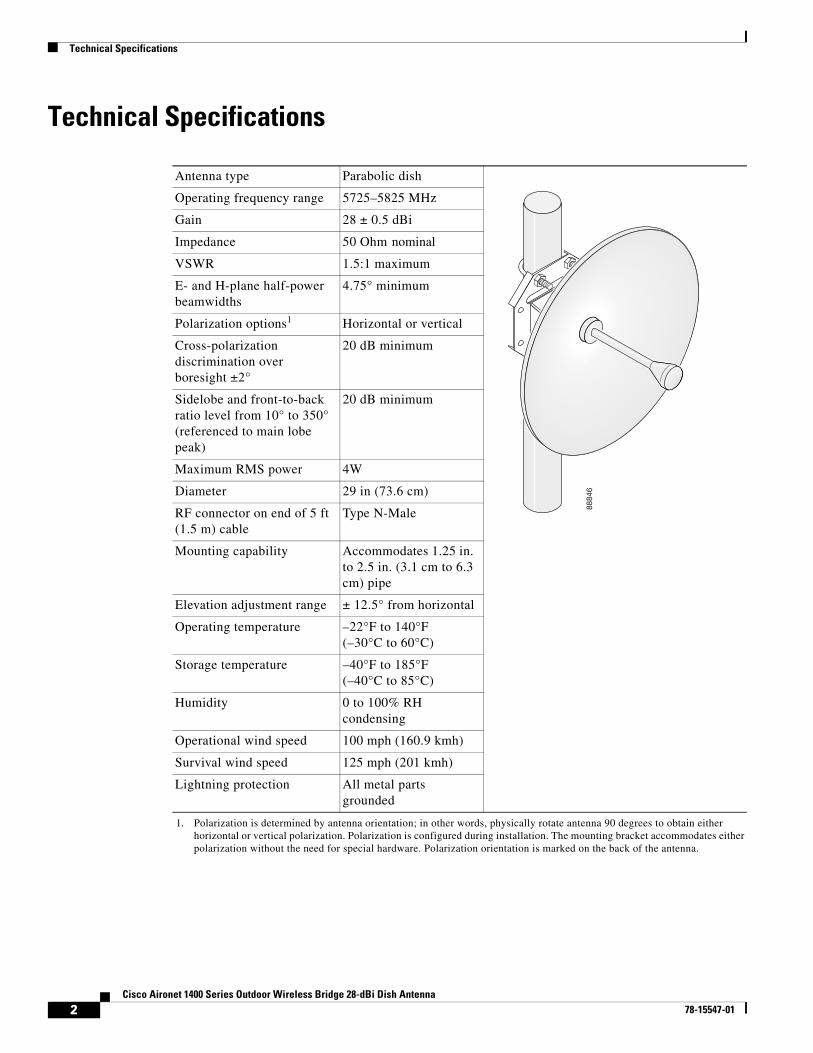
Technical Specifications
Antenna type Parabolic dish
Operating frequency range 5725–5825 MHz
Gain 28 ± 0.5 dBi
Impedance 50 Ohm nominal
VSWR 1.5:1 maximum
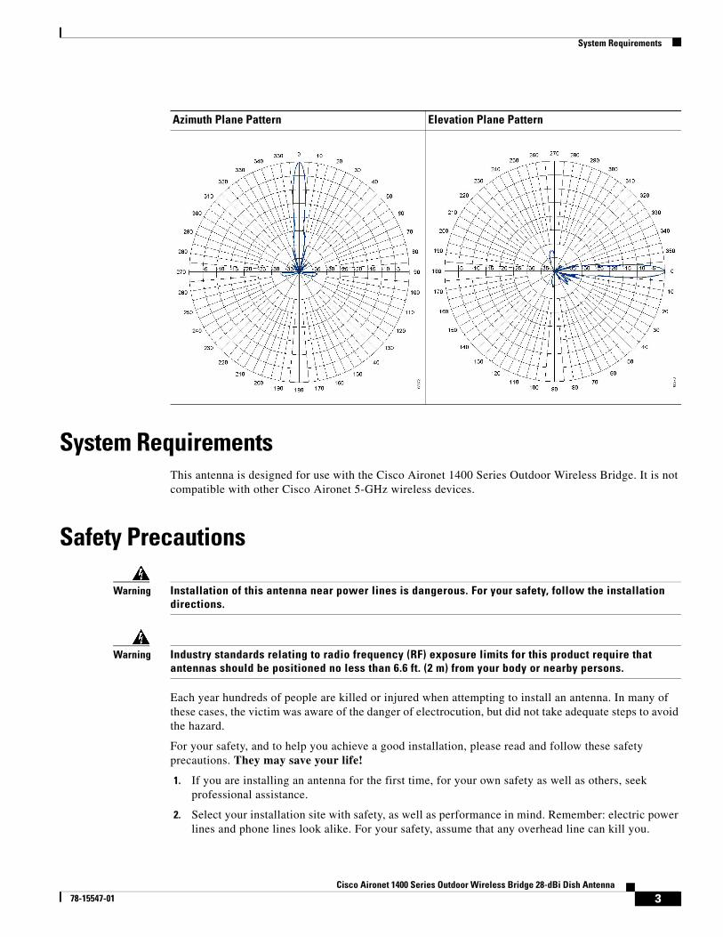
E- and H-plane half-power beamwidths
4.75° minimum
Polarization options1
1. Polarization is determined by antenna orientation; in other words, physically rotate antenna 90 degrees to obtain either horizontal or vertical polarization. Polarization is configured during installation. The mounting bracket accommodates either polarization without the need for special hardware. Polarization orientation is marked on the back of the antenna.
Horizontal or vertical
Cross-polarization discrimination over boresight ±2°
20 dB minimum
Sidelobe and front-to-back ratio level from 10° to 350° (referenced to main lobe peak)
20 dB minimum
Maximum RMS power 4W
Diameter 29 in (73.6 cm)
RF connector on end of 5 ft (1.5 m) cable
Type N-Male
Mounting capability Accommodates 1.25 in. to 2.5 in. (3.1 cm to 6.3 cm) pipe
Elevation adjustment range ± 12.5° from horizontal
Operating temperature –22°F to 140°F(–30°C to 60°C)
Storage temperature –40°F to 185°F(–40°C to 85°C)
Humidity 0 to 100% RH condensing
Operational wind speed 100 mph (160.9 kmh)
Survival wind speed 125 mph (201 kmh)
Lightning protection All metal parts grounded
8884
6
2Cisco Aironet 1400 Series Outdoor Wireless Bridge 28-dBi Dish Antenna
78-15547-01
System Requirements
System RequirementsThis antenna is designed for use with the Cisco Aironet 1400 Series Outdoor Wireless Bridge. It is not compatible with other Cisco Aironet 5-GHz wireless devices.
Safety Precautions
Warning Installation of this antenna near power lines is dangerous. For your safety, follow the installation directions.
Warning Industry standards relating to radio frequency (RF) exposure limits for this product require that antennas should be positioned no less than 6.6 ft. (2 m) from your body or nearby persons.
Each year hundreds of people are killed or injured when attempting to install an antenna. In many of these cases, the victim was aware of the danger of electrocution, but did not take adequate steps to avoid the hazard.
For your safety, and to help you achieve a good installation, please read and follow these safety precautions. They may save your life!
1. If you are installing an antenna for the first time, for your own safety as well as others, seek professional assistance.
2. Select your installation site with safety, as well as performance in mind. Remember: electric power lines and phone lines look alike. For your safety, assume that any overhead line can kill you.
Azimuth Plane Pattern Elevation Plane Pattern
3Cisco Aironet 1400 Series Outdoor Wireless Bridge 28-dBi Dish Antenna
78-15547-01
Installation Notes
3. Call your electric power company. Tell them your plans and ask them to come look at your proposed installation. This is a small inconvenience considering your life is at stake.
4. Plan your installation carefully and completely before you begin. Successful raising of a mast or tower is largely a matter of coordination. Each person should be assigned to a specific task, and should know what to do and when to do it. One person should be in charge of the operation to issue instructions and watch for signs of trouble.
5. When installing your antenna, remember:
a. Do not use a metal ladder.
b. Do not work on a wet or windy day.
c. Do dress properly—shoes with rubber soles and heels, rubber gloves, long sleeved shirt or jacket.
6. If the assembly starts to drop, get away from it and let it fall. Remember, the antenna, mast, cable, and metal guy wires are all excellent conductors of electrical current. Even the slightest touch of any of these parts to a power line complete an electrical path through the antenna and the installer: you!
7. If any part of the antenna system should come in contact with a power line, don’t touch it or try to remove it yourself. Call your local power company. They will remove it safely.
If an accident should occur with the power lines call for qualified emergency help immediately.
Installation Notes
Note To meet regulatory restrictions, this antenna must be professionally installed.
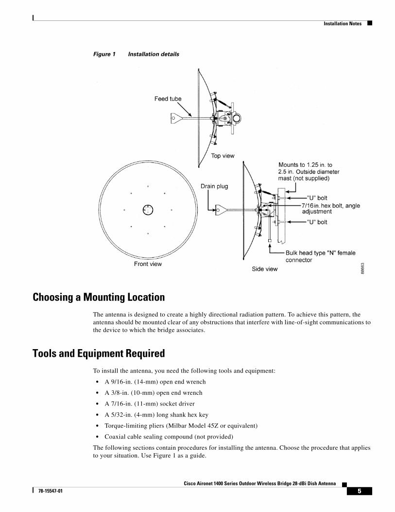
Figure 1 shows the antenna’s major components and how it is mounted on a mast.
4Cisco Aironet 1400 Series Outdoor Wireless Bridge 28-dBi Dish Antenna
78-15547-01
Installation Notes
Figure 1 Installation details
Choosing a Mounting LocationThe antenna is designed to create a highly directional radiation pattern. To achieve this pattern, the antenna should be mounted clear of any obstructions that interfere with line-of-sight communications to the device to which the bridge associates.
Tools and Equipment RequiredTo install the antenna, you need the following tools and equipment:
• A 9/16-in. (14-mm) open end wrench
• A 3/8-in. (10-mm) open end wrench
• A 7/16-in. (11-mm) socket driver
• A 5/32-in. (4-mm) long shank hex key
• Torque-limiting pliers (Milbar Model 45Z or equivalent)
• Coaxial cable sealing compound (not provided)
The following sections contain procedures for installing the antenna. Choose the procedure that applies to your situation. Use Figure 1 as a guide.
5Cisco Aironet 1400 Series Outdoor Wireless Bridge 28-dBi Dish Antenna
78-15547-01
Installation Notes
Mounting the AntennaA mounting kit is provided with the antenna. This kit enables you to mount the antenna to masts up to 2.5 in. (6.3 cm) in diameter. The antenna can be vertically or horizontally polarized, but it must be mounted so that the parabola is in the vertical plane.
Note To meet regulatory restrictions, the external antenna model of the bridge and its external antenna must be professionally installed.
Note To ensure correct installation and grounding, install the antenna in compliance with your local and national electrical codes: National Fire Protection Association (NFPA) 70, National Electrical Code (U.S.); Canadian Electrical Code, Part 1, CSA22.1 (Canada); and if local or are not available, refer to IEC 364, Part 1 through Part 7 (other countries).
Adjusting PolarizationA decal is attached to the star mounting plate indicating how the antenna should be mounted for vertical polarization. To obtain vertical polarization, mount the antenna so that the arrow on the decal is pointing up. To obtain horizontal polarization, rotate the antenna clockwise 90 degrees so that arrow on the decal is pointing to the right (at the 3 o’clock position).
Note The antennas of any two units that are intended to form a link and associate with one another must be set for the same polarization.
Mounting the Antenna to a Mast
Follow these steps to mount the antenna to a mast.
Step 1 Remove the four #10 cap screws, lock washers, and flat washers from the mounting kit’s hardware bag.
Step 2 Position the feed tube as shown in Figure 1, aligning the polarization pin on the feed tube with the hole in the dish.
Step 3 Insert cable through the hole and install screws with a 5/32-in. (4-mm) long shank hex key and tighten. Be sure to install the lock and flat washers. Do not overtighten.
Step 4 Position the connector through the slot on the square tube section of the mount structure and secure it in place using a lock washer and jam nut.
Step 5 Remove two U-bolts, V-blocks, and four 3/8-in. (10-mm) hex nuts, lock washers, and flat washers from the hardware bag.
Step 6 Determine the antenna polarization for your installation and position the antenna appropriately:
a. Vertical: the arrow on the decal is pointing up.
b. Horizontal: the arrow on the decal is pointing to the right (at the 3 o’clock position).
6Cisco Aironet 1400 Series Outdoor Wireless Bridge 28-dBi Dish Antenna
78-15547-01
Installation Notes
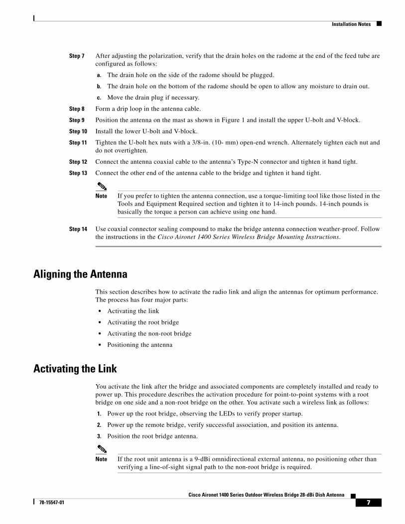
Step 7 After adjusting the polarization, verify that the drain holes on the radome at the end of the feed tube are configured as follows:
a. The drain hole on the side of the radome should be plugged.
b. The drain hole on the bottom of the radome should be open to allow any moisture to drain out.
c. Move the drain plug if necessary.
Step 8 Form a drip loop in the antenna cable.
Step 9 Position the antenna on the mast as shown in Figure 1 and install the upper U-bolt and V-block.
Step 10 Install the lower U-bolt and V-block.
Step 11 Tighten the U-bolt hex nuts with a 3/8-in. (10- mm) open-end wrench. Alternately tighten each nut and do not overtighten.
Step 12 Connect the antenna coaxial cable to the antenna’s Type-N connector and tighten it hand tight.
Step 13 Connect the other end of the antenna cable to the bridge and tighten it hand tight.
Note If you prefer to tighten the antenna connection, use a torque-limiting tool like those listed in the Tools and Equipment Required section and tighten it to 14-inch pounds. 14-inch pounds is basically the torque a person can achieve using one hand.
Step 14 Use coaxial connector sealing compound to make the bridge antenna connection weather-proof. Follow the instructions in the Cisco Aironet 1400 Series Wireless Bridge Mounting Instructions.
Aligning the AntennaThis section describes how to activate the radio link and align the antennas for optimum performance. The process has four major parts:
• Activating the link
• Activating the root bridge
• Activating the non-root bridge
• Positioning the antenna
Activating the LinkYou activate the link after the bridge and associated components are completely installed and ready to power up. This procedure describes the activation procedure for point-to-point systems with a root bridge on one side and a non-root bridge on the other. You activate such a wireless link as follows:
1. Power up the root bridge, observing the LEDs to verify proper startup.
2. Power up the remote bridge, verify successful association, and position its antenna.
3. Position the root bridge antenna.
Note If the root unit antenna is a 9-dBi omnidirectional external antenna, no positioning other than verifying a line-of-sight signal path to the non-root bridge is required.
7Cisco Aironet 1400 Series Outdoor Wireless Bridge 28-dBi Dish Antenna
78-15547-01
Installation Notes
If the initial antenna positioning is reasonably accurate, both bridges initialize and quickly associate with one another. If the bridges do not associate, the antennas may be poorly aligned and you must adjust the antenna position during the bridge startup cycle. Persistent association problems can indicate poor placement of the bridge or obstacles in the transmission path.
Use LED indications to verify the state of the bridge during the association process. The following section explains how to interpret LED indicators.
Installation Mode Indicators
When you power up the bridge for the first time, it starts in a special installation mode. The LEDs indicate the startup status, operating mode, association status, and received signal strength. This information simplifies the process of activating the link and positioning the antenna from the bridge mounting location.
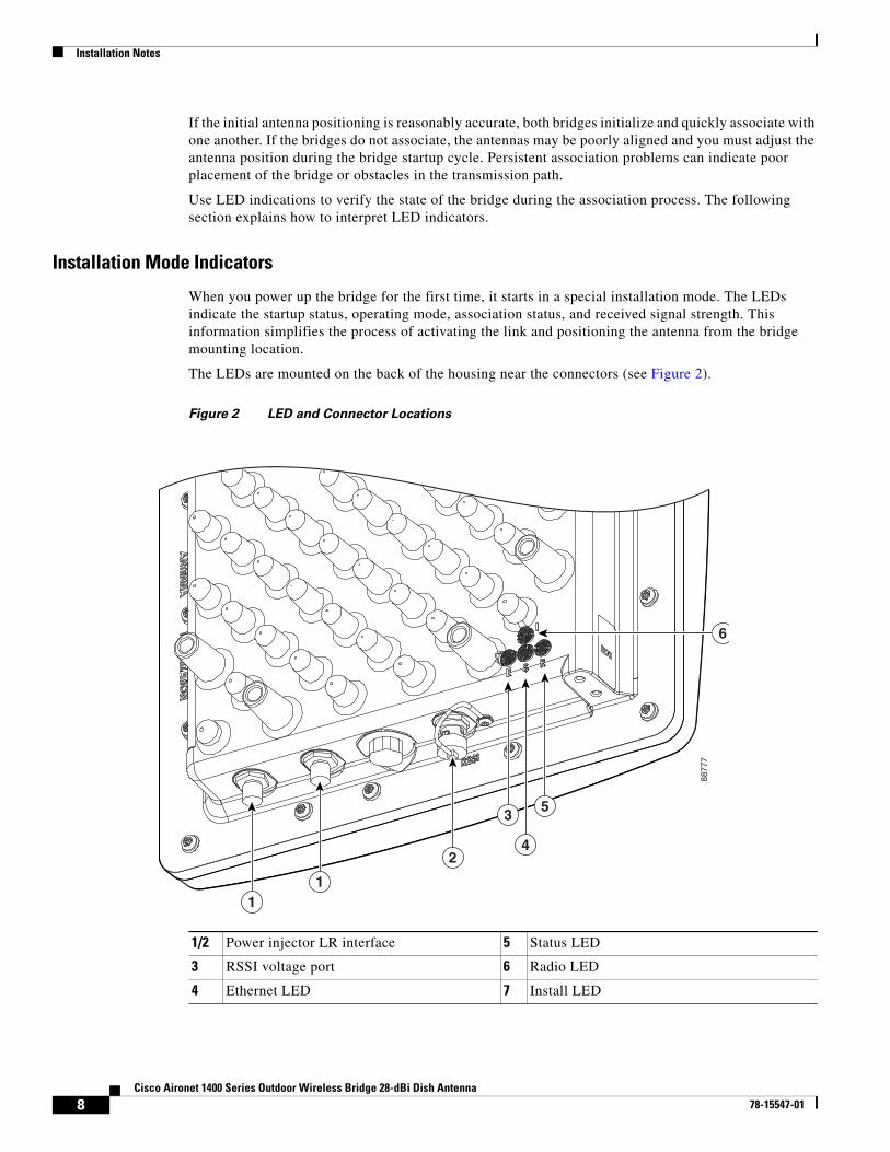
The LEDs are mounted on the back of the housing near the connectors (see Figure 2).
Figure 2 LED and Connector Locations
1/2 Power injector LR interface 5 Status LED
3 RSSI voltage port 6 Radio LED
4 Ethernet LED 7 Install LED
6
11
2
35
4
8877
7
8Cisco Aironet 1400 Series Outdoor Wireless Bridge 28-dBi Dish Antenna
78-15547-01
Installation Notes
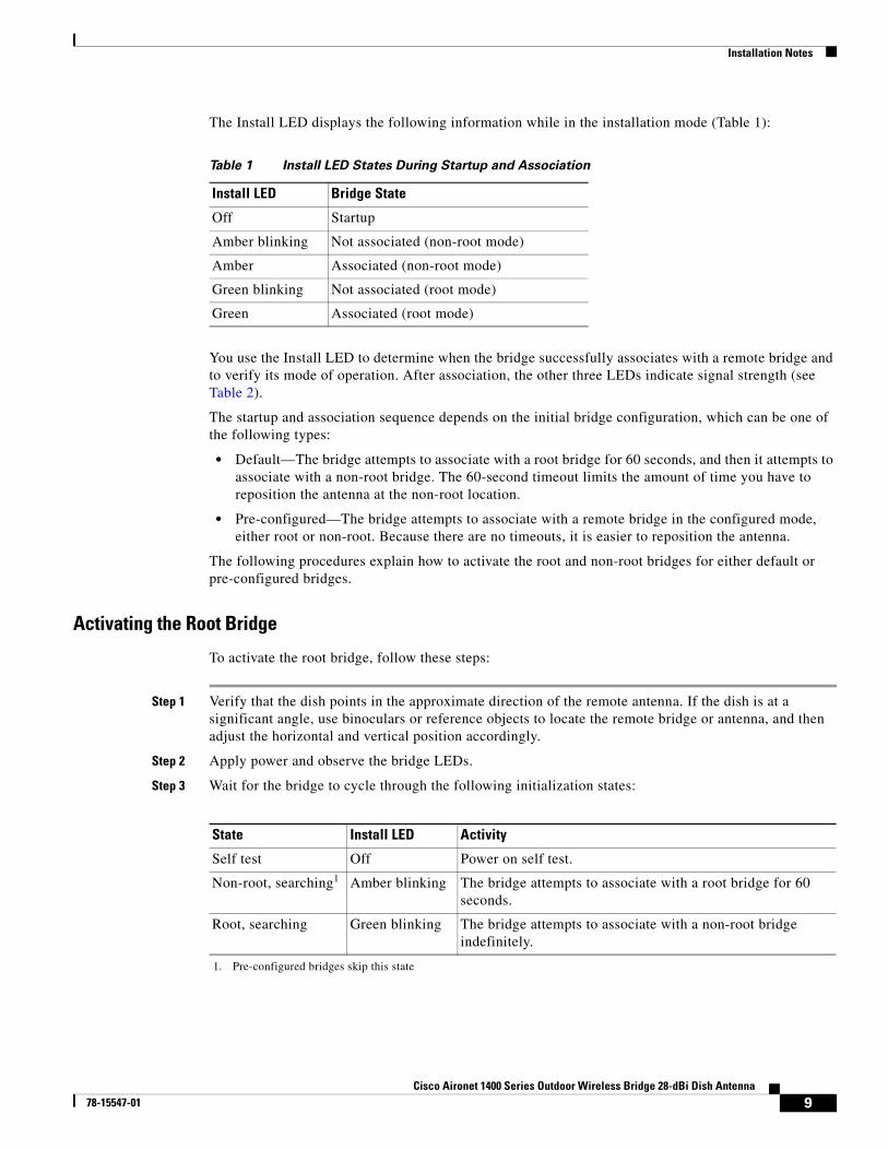
The Install LED displays the following information while in the installation mode (Table 1):
You use the Install LED to determine when the bridge successfully associates with a remote bridge and to verify its mode of operation. After association, the other three LEDs indicate signal strength (see Table 2).
The startup and association sequence depends on the initial bridge configuration, which can be one of the following types:
• Default—The bridge attempts to associate with a root bridge for 60 seconds, and then it attempts to associate with a non-root bridge. The 60-second timeout limits the amount of time you have to reposition the antenna at the non-root location.
• Pre-configured—The bridge attempts to associate with a remote bridge in the configured mode, either root or non-root. Because there are no timeouts, it is easier to reposition the antenna.
The following procedures explain how to activate the root and non-root bridges for either default or pre-configured bridges.
Activating the Root Bridge
To activate the root bridge, follow these steps:
Step 1 Verify that the dish points in the approximate direction of the remote antenna. If the dish is at a significant angle, use binoculars or reference objects to locate the remote bridge or antenna, and then adjust the horizontal and vertical position accordingly.
Step 2 Apply power and observe the bridge LEDs.
Step 3 Wait for the bridge to cycle through the following initialization states:
Table 1 Install LED States During Startup and Association
Install LED Bridge State
Off Startup
Amber blinking Not associated (non-root mode)
Amber Associated (non-root mode)
Green blinking Not associated (root mode)
Green Associated (root mode)
State Install LED Activity
Self test Off Power on self test.
Non-root, searching1
1. Pre-configured bridges skip this state
Amber blinking The bridge attempts to associate with a root bridge for 60 seconds.
Root, searching Green blinking The bridge attempts to associate with a non-root bridge indefinitely.
9Cisco Aironet 1400 Series Outdoor Wireless Bridge 28-dBi Dish Antenna
78-15547-01
Installation Notes
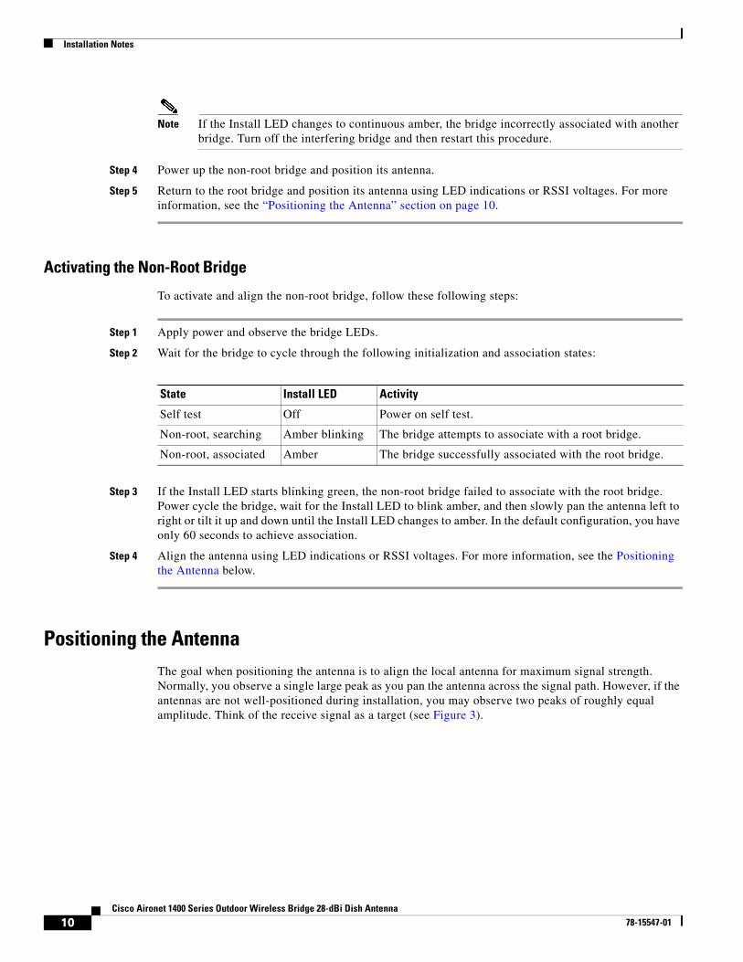
Note If the Install LED changes to continuous amber, the bridge incorrectly associated with another bridge. Turn off the interfering bridge and then restart this procedure.
Step 4 Power up the non-root bridge and position its antenna.
Step 5 Return to the root bridge and position its antenna using LED indications or RSSI voltages. For more information, see the “Positioning the Antenna” section on page 10.
Activating the Non-Root Bridge
To activate and align the non-root bridge, follow these following steps:
Step 1 Apply power and observe the bridge LEDs.
Step 2 Wait for the bridge to cycle through the following initialization and association states:
Step 3 If the Install LED starts blinking green, the non-root bridge failed to associate with the root bridge. Power cycle the bridge, wait for the Install LED to blink amber, and then slowly pan the antenna left to right or tilt it up and down until the Install LED changes to amber. In the default configuration, you have only 60 seconds to achieve association.
Step 4 Align the antenna using LED indications or RSSI voltages. For more information, see the Positioning the Antenna below.
Positioning the AntennaThe goal when positioning the antenna is to align the local antenna for maximum signal strength. Normally, you observe a single large peak as you pan the antenna across the signal path. However, if the antennas are not well-positioned during installation, you may observe two peaks of roughly equal amplitude. Think of the receive signal as a target (see Figure 3).
State Install LED Activity
Self test Off Power on self test.
Non-root, searching Amber blinking The bridge attempts to associate with a root bridge.
Non-root, associated Amber The bridge successfully associated with the root bridge.
10Cisco Aironet 1400 Series Outdoor Wireless Bridge 28-dBi Dish Antenna
78-15547-01
Installation Notes
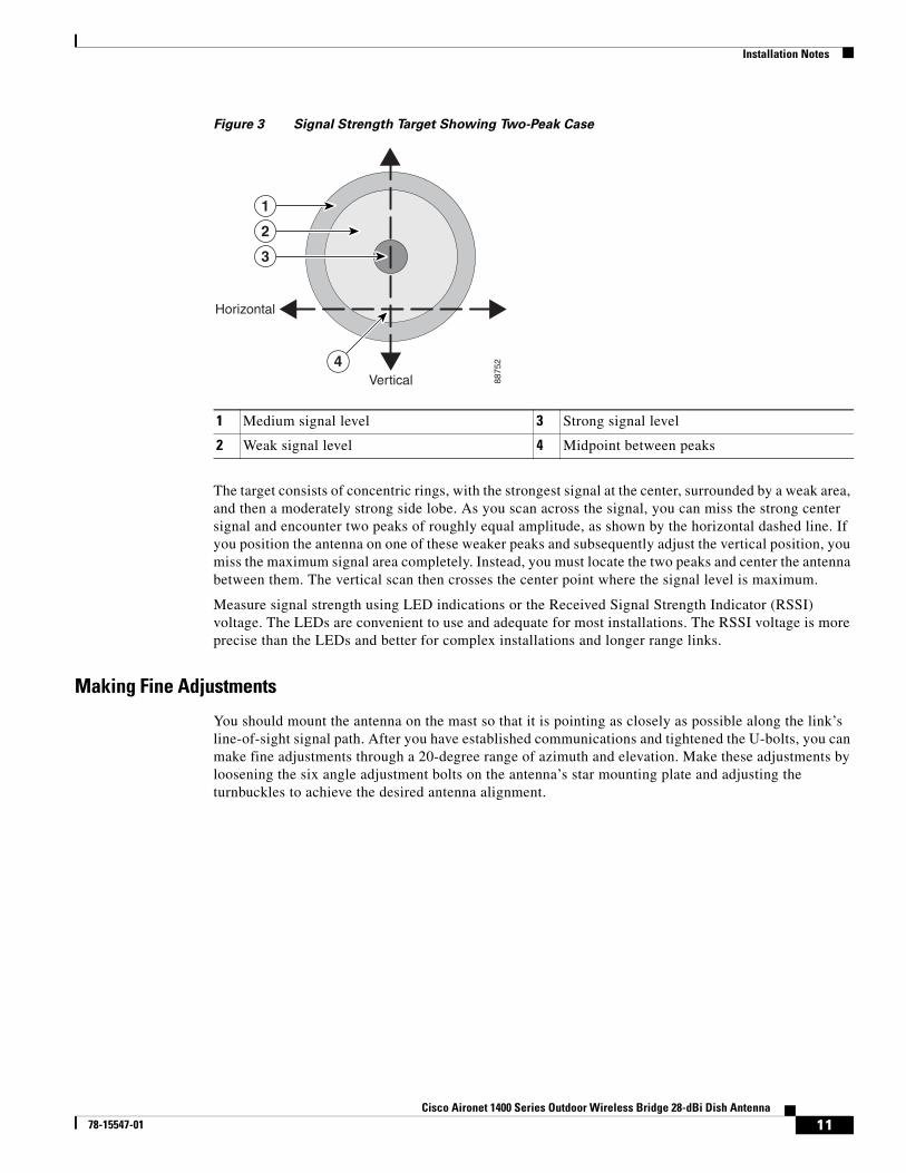
Figure 3 Signal Strength Target Showing Two-Peak Case
The target consists of concentric rings, with the strongest signal at the center, surrounded by a weak area, and then a moderately strong side lobe. As you scan across the signal, you can miss the strong center signal and encounter two peaks of roughly equal amplitude, as shown by the horizontal dashed line. If you position the antenna on one of these weaker peaks and subsequently adjust the vertical position, you miss the maximum signal area completely. Instead, you must locate the two peaks and center the antenna between them. The vertical scan then crosses the center point where the signal level is maximum.
Measure signal strength using LED indications or the Received Signal Strength Indicator (RSSI) voltage. The LEDs are convenient to use and adequate for most installations. The RSSI voltage is more precise than the LEDs and better for complex installations and longer range links.
Making Fine Adjustments
You should mount the antenna on the mast so that it is pointing as closely as possible along the link’s line-of-sight signal path. After you have established communications and tightened the U-bolts, you can make fine adjustments through a 20-degree range of azimuth and elevation. Make these adjustments by loosening the six angle adjustment bolts on the antenna’s star mounting plate and adjusting the turnbuckles to achieve the desired antenna alignment.
1 Medium signal level 3 Strong signal level
2 Weak signal level 4 Midpoint between peaks
Horizontal
Vertical
1
4
2
3
8875
2
11Cisco Aironet 1400 Series Outdoor Wireless Bridge 28-dBi Dish Antenna
78-15547-01
Installation Notes
Positioning the Antenna Using LED Indications
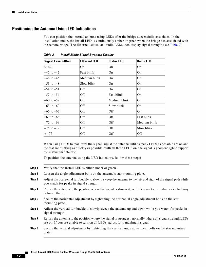
You can position the internal antenna using LEDs after the bridge successfully associates. In the installation mode, the Install LED is continuously amber or green when the bridge has associated with the remote bridge. The Ethernet, status, and radio LEDs then display signal strength (see Table 2).
When using LEDs to maximize the signal, adjust the antenna until as many LEDs as possible are on and the rest are blinking as quickly as possible. With all three LEDS on, the signal is good enough to support the maximum data rate.
To position the antenna using the LED indicators, follow these steps:
Step 1 Verify that the Install LED is either amber or green.
Step 2 Loosen the angle adjustment bolts on the antenna’s star mounting plate.
Step 3 Adjust the horizontal turnbuckle to slowly sweep the antenna to the left and right of the signal path while you watch for peaks in signal strength.
Step 4 Return the antenna to the position where the signal is strongest, or if there are two similar peaks, halfway between them.
Step 5 Secure the horizontal adjustment by tightening the horizontal angle adjustment bolts on the star mounting plate.
Step 6 Adjust the vertical turnbuckle to slowly sweep the antenna up and down while you watch for peaks in signal strength.
Step 7 Return the antenna to the position where the signal is strongest, normally where all signal strength LEDs are on. If you are unable to turn on all LEDs, adjust for a maximum signal.
Step 8 Secure the vertical adjustment by tightening the vertical angle adjustment bolts on the star mounting plate.
Table 2 Install Mode Signal Strength Display
Signal Level (dBm) Ethernet LED Status LED Radio LED
>–42 On On On
–45 to –42 Fast blink On On
–48 to –45 Medium blink On On
–51 to –48 Slow blink On On
–54 to –51 Off On On
–57 to –54 Off Fast blink On
–60 to –57 Off Medium blink On
–63 to –60 Off Slow blink On
–66 to –63 Off Off On
–69 to –66 Off Off Fast blink
–72 to –69 Off Off Medium blink
–75 to –72 Off Off Slow blink
< –75 Off Off Off
12Cisco Aironet 1400 Series Outdoor Wireless Bridge 28-dBi Dish Antenna
78-15547-01
Installation Notes
Positioning the Antenna Using the Received Signal Strength Indicator
The Received Signal Strength Indicator (RSSI) port produces a DC voltage that is proportional to the received signal level. The RSSI voltage is available whenever a signal is present, regardless of the bridge mode (installation or normal), association status, or pre-configuration. The RSSI port is a female BNC connector on the housing (see Figure 2).
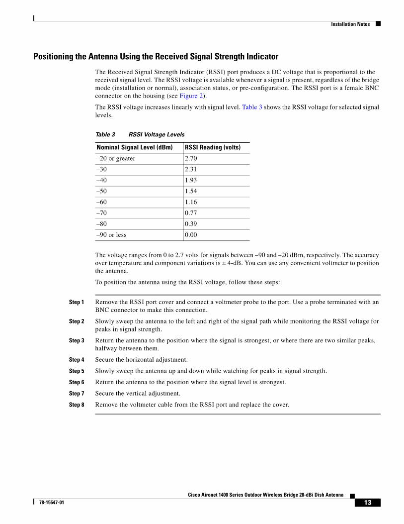
The RSSI voltage increases linearly with signal level. Table 3 shows the RSSI voltage for selected signal levels.
The voltage ranges from 0 to 2.7 volts for signals between –90 and –20 dBm, respectively. The accuracy over temperature and component variations is ± 4-dB. You can use any convenient voltmeter to position the antenna.
To position the antenna using the RSSI voltage, follow these steps:
Step 1 Remove the RSSI port cover and connect a voltmeter probe to the port. Use a probe terminated with an BNC connector to make this connection.
Step 2 Slowly sweep the antenna to the left and right of the signal path while monitoring the RSSI voltage for peaks in signal strength.
Step 3 Return the antenna to the position where the signal is strongest, or where there are two similar peaks, halfway between them.
Step 4 Secure the horizontal adjustment.
Step 5 Slowly sweep the antenna up and down while watching for peaks in signal strength.
Step 6 Return the antenna to the position where the signal level is strongest.
Step 7 Secure the vertical adjustment.
Step 8 Remove the voltmeter cable from the RSSI port and replace the cover.
Table 3 RSSI Voltage Levels
Nominal Signal Level (dBm) RSSI Reading (volts)
–20 or greater 2.70
–30 2.31
–40 1.93
–50 1.54
–60 1.16
–70 0.77
–80 0.39
–90 or less 0.00
13Cisco Aironet 1400 Series Outdoor Wireless Bridge 28-dBi Dish Antenna
78-15547-01
Obtaining Documentation and Submitting a Service RequestFor information on obtaining documentation, submitting a service request, and gathering additional information, see the monthly What’s New in Cisco Product Documentation, which also lists all new and revised Cisco technical documentation, at:
http://www.cisco.com/en/US/docs/general/whatsnew/whatsnew.html
Subscribe to the What’s New in Cisco Product Documentation as a Really Simple Syndication (RSS) feed and set content to be delivered directly to your desktop using a reader application. The RSS feeds are a free service and Cisco currently supports RSS Version 2.0.
Cisco and the Cisco Logo are trademarks of Cisco Systems, Inc. and/or its affiliates in the U.S. and other countries. A listing of Cisco's trademarks can be found at www.cisco.com/go/trademarks. Third party trademarks mentioned are the property of their respective owners. The use of the word partner does not imply a partnership relationship between Cisco and any other company. (1005R)
Copyright © 2003 Cisco Systems, Inc.
All rights reserved
14Cisco Aironet 1400 Series Outdoor Wireless Bridge 28-dBi Dish Antenna
78-15547-01