Embed Size (px)
Citation preview

Americas Headquarters:
Cisco Systems, Inc., 170 West Tasman Drive, San Jose, CA 95134-1706 USA
© 2016 Cisco Systems, Inc. All rights reserved.
Cisco Adaptive Security Appliance (ASA) 9.4(1)
Preparative Procedures & Operational User Guide for the Common Criteria Certified configuration
Version 1.2
October 24, 2016

Cisco Operational User Guide and Preparative Procedures
2
Contents Introduction ................................................................................................................................................... 6
ASA Version 9.4(1)/ASDM Version 7.4 Documentation Set .................................................................. 6
Audience ................................................................................................................................................... 7
Supported Hardware & Software Versions ............................................................................................... 7
Overview of the Cisco ASA Firewall & VPN Platforms .......................................................................... 8
Operational Environment Component & Usage ....................................................................................... 8
Example Deployment ................................................................................................................................ 9
Security Information ................................................................................................................................... 10
Organizational Security Policy ............................................................................................................... 10
Securing the Operational Environment ................................................................................................... 10
Certified Configuration ........................................................................................................................... 11
Features Prohibited from Use ............................................................................................................. 11
Physical Security ..................................................................................................................................... 11
Administrative Access ................................................................................................................................ 11
Monitoring & Maintenance ..................................................................................................................... 11
Systems Logs .......................................................................................................................................... 12
Administration ........................................................................................................................................ 12
Saving the Configuration ........................................................................................................................ 13
Backup and Restoration .......................................................................................................................... 13
Device Failover ....................................................................................................................................... 14
Deployment of the ASAv ............................................................................................................................ 14
Deployment Options and Guidelines for the ASAv and VMware .......................................................... 14
OVF File Guidelines ................................................................................................................................... 14
The selection of the asav-vi.ovf or asav-esxi.ovf file is based on the deployment target: .......................... 14
asav-vi—For deployment on vCenter ................................................................................................. 14
asav-esxi—For deployment on ESXi (no vCenter) ............................................................................ 14
Unpack the ASAv Software and Create a Day 0 Configuration File for VMware ............................. 14
Deploy the ASAv Using the VMware vSphere Standalone Client and a Day 0 Configuration ......... 17
Deploy the ASAv Using the OVF Tool and Day 0 Configuration ..................................................... 18
Access the ASAv Console .................................................................................................................. 19
Authentication to the ASA .......................................................................................................................... 19
Local and Remote Access ....................................................................................................................... 19
Cisco Operational User Guide and Preparative Procedures
3
Login Banners ......................................................................................................................................... 21
Usernames, Privileges, and Administrative Roles .................................................................................. 22
Usernames and Privileges ................................................................................................................... 22
Authorized Administrator ................................................................................................................... 22
Passwords ................................................................................................................................................ 23
Password Complexity, Length, and Uniqueness ................................................................................. 23
Password Policies ................................................................................................................................ 24
Set the Date and Time ............................................................................................................................. 25
Account Lockout after Failed Login Attempts ....................................................................................... 26
Secure Communications ............................................................................................................................. 27
Evaluated Cryptography ......................................................................................................................... 27
Configuring SSH ..................................................................................................................................... 27
RSA Key Generation .......................................................................................................................... 27
Restrict SSH Connections ................................................................................................................... 27
Enable SSHv2 and Disable SSHv1 ..................................................................................................... 28
Encryption Algorithms ........................................................................................................................ 28
Hashing Algorithms ............................................................................................................................ 28
Key-Exchange ..................................................................................................................................... 28
Authentication ..................................................................................................................................... 29
Idle Timeouts ...................................................................................................................................... 29
SCopy (disabled by default) ................................................................................................................ 29
Configuring TLS ..................................................................................................................................... 30
Specify the TLS Version ..................................................................................................................... 30
Specify the TLS Ciphersuites (optional) ............................................................................................. 30
Enabling SSL (TLS) VPN (optional) .................................................................................................. 31
Configuring IPsec ................................................................................................................................... 31
Managing Public Key Infrastructure (PKI) Keys................................................................................ 31
Enable IKEv2 ...................................................................................................................................... 32
IKEv2 Parameters for IKE Phase 1 (the IKE SA) .............................................................................. 32
IKEv2 Parameters for IKE Phase 2 (the IPsec SA) ............................................................................ 33
Create an Access-List and Assigning to Crypto Map ......................................................................... 33
Viewing an IPsec Configuration ......................................................................................................... 34
Clearing Security Associations ........................................................................................................... 35
Cisco Operational User Guide and Preparative Procedures
4
IPsec Authentication ........................................................................................................................... 35
VPN Client Access Restriction ........................................................................................................... 39
Configure an IP Address Assignment Policy ...................................................................................... 39
Specifying a VPN Session Idle Timeout ............................................................................................. 39
Firewall Functionality ................................................................................................................................. 40
Routed Mode and Transparent Mode...................................................................................................... 40
Routed Mode ....................................................................................................................................... 40
Transparent Mode ............................................................................................................................... 40
Setting Transparent or Routed Firewall Mode at the CLI ................................................................... 40
Audit Trail Full Mode ............................................................................................................................. 40
Enabling Syslog Host Status Monitoring ............................................................................................ 40
Recovering from Syslog Host Down .................................................................................................. 41
Traffic Flow Overview ........................................................................................................................... 41
Trusted & Untrusted Networks ........................................................................................................... 41
Stateful Inspection Overview .............................................................................................................. 42
Application Layer Protocol Inspection ............................................................................................... 42
Same-Security-Traffic ......................................................................................................................... 43
Access Lists ........................................................................................................................................ 43
Using the ‘Established’ Keyword ....................................................................................................... 44
Time-to-Live ....................................................................................................................................... 44
VLAN Interfaces ................................................................................................................................. 44
Interface Types .................................................................................................................................... 44
Servers and Proxies ............................................................................................................................. 45
Default Traffic Flow (without ACLs) ..................................................................................................... 45
Optional Traffic Inspection ..................................................................................................................... 47
Unicast RPF ........................................................................................................................................ 47
STP & Transparent Mode ................................................................................................................... 48
Inspect ICMP ...................................................................................................................................... 48
Inspect ARP ........................................................................................................................................ 48
Prohibit IPv6 Extension Header 0 ....................................................................................................... 48
Optional Authentication of Throughput Traffic ...................................................................................... 49
Mandatory Traffic Flow Controls ............................................................................................................... 49
Set “ip audit” Actions ............................................................................................................................. 50
Cisco Operational User Guide and Preparative Procedures
5
Do not disable certain signatures ............................................................................................................ 50
Define “ip audit” Policies ....................................................................................................................... 50
Apply “ip audit” Policies to Interfaces ................................................................................................... 50
Overview of Traffic to Be Dropped, and the Related Syslog Messages ................................................. 51
Logging and Log Messages ........................................................................................................................ 60
Timestamps in Audit Messages .............................................................................................................. 60
Usernames in Audit Messages ................................................................................................................ 60
Using TCP Syslog to Detect Syslog Host Down .................................................................................... 61
Timely Notification/Transmission of ACL Logging .............................................................................. 61
Secure Transmission of Audit Messages ................................................................................................ 61
Securing Syslog with TLS (Optional): ................................................................................................ 61
Securing Syslog with IPsec: ................................................................................................................ 62
Securing TACACS+ Accounting Messages with IPsec: .................................................................... 63
Auditable Events Certified Under Common Criteria .............................................................................. 63
ASA Installation.......................................................................................................................................... 69
Verification of Image and Hardware ...................................................................................................... 69
Adaptive Security Device Manager (ASDM) ............................................................................................. 70
Enabling HTTPS Access ......................................................................................................................... 71
Enable Idle-Timeouts of ASDM Sessions .............................................................................................. 71
Accessing ASDM from Your Workstation ............................................................................................. 71
Running ASDM .................................................................................................................................. 72
Network Services and Protocols ................................................................................................................. 73
Modes of Operation .................................................................................................................................... 76
Appendix: .................................................................................................................................................... 78
Acronyms & Abbreviations .................................................................................................................... 78
Obtaining Documentation ....................................................................................................................... 80
Obtaining Technical Assistance .............................................................................................................. 80
Cisco Technical Support & Documentation Website ............................................................................. 80
Submitting a Service Request ................................................................................................................. 80
Definitions of Service Request Severity ................................................................................................. 81
Obtaining Additional Publications and Information ............................................................................... 81
Cisco Operational User Guide and Preparative Procedures
6
Introduction This document describes how to install and configure the Cisco ASA Adaptive Security Appliance (ASA) running
software version 9.4(1.13) and Adaptive Security Appliance Virtual (ASAv) running software version 9.4(1.240) as
certified under Common Criteria as conformant to the Network Device Protection Profile (NDPP), Traffic Filter
Firewall Extended Package, and Virtual Private Network (VPN) Gateway Extended Package.
In this guide, “security appliance” and “adaptive security appliance” apply to all models of the Cisco ASA or ASAv
running version 9.4(1.13) or 9.4(1.240), unless specifically noted otherwise. Versions 9.4(1.13) and 9.4(1.240) will
be referred to as 9.4(1) hereinafter.
Note: Failure to follow the information provided in this document will result in the adaptive security appliance not
being compliant with the evaluation and may make it insecure.
This document is an addendum to other documentation available for installation and configuration of the Cisco ASA
with version 9.4(1), and this document should be read in its entirely before configuring the security appliance.
ASA Version 9.4(1)/ASDM Version 7.4 Documentation Set
ASA Release Notes—Release Notes for the Cisco ASA Series, 9.4(x)
http://www.cisco.com/c/en/us/td/docs/security/asa/asa94/release/notes/asarn94.html
ASDM Release Notes—Release Notes for Cisco ASDM, 7.4(x)
http://www.cisco.com/c/en/us/td/docs/security/asdm/7_4/release/notes/rn74.html
CLI Configuration: o General Operations CLI Configuration—Cisco ASA Series General Operations CLI
Configuration Guide, 9.4
http://www.cisco.com/c/en/us/td/docs/security/asa/asa94/configuration/general/asa-general-
cli.html
o Firewall CLI Configuration—Cisco ASA Series Firewall CLI Configuration Guide, 9.4
http://www.cisco.com/c/en/us/td/docs/security/asa/asa94/configuration/firewall/asa-firewall-
cli.html
o VPN CLI Configuration—Cisco ASA Series General Operations CLI Configuration Guide, 9.4
http://www.cisco.com/c/en/us/td/docs/security/asa/asa94/configuration/vpn/asa-vpn-cli.html
ASDM Configuration: o General Operations ASDM Configuration—Cisco ASA Series General Operations ASDM
Configuration Guide, 9.4
http://www.cisco.com/c/en/us/td/docs/security/asa/asa94/asdm74/general/asa-general-asdm.html
o Firewall ASDM Configuration—Cisco ASA Series Firewall ASDM Configuration Guide, 7.4
http://www.cisco.com/en/US/docs/security/asa/asa94/asdm74/firewall/asdm_74_firewall_config.h
tml
o VPN ASDM Configuration—Cisco ASA Series VPN ASDM Configuration Guide, 9.4
http://www.cisco.com/c/en/us/td/docs/security/asa/asa94/asdm74/vpn/asa-vpn-asdm.html
Command Reference—Cisco ASA Series Command Reference, 9.4
http://www.cisco.com/c/en/us/support/security/asa-5500-series-next-generation-firewalls/products-
command-reference-list.html
Cisco Adaptive Security Virtual Appliance (ASAv) - Quick Start Guide for Deploying ASAv on VMware,
9.4 http://www.cisco.com/c/en/us/td/docs/security/asa/asa94/asav/quick-start/asav-quick/asav-vmware.html
Cisco Adaptive Security Virtual Appliance (ASAv) – Smart Software Licensing for the ASAv, 9.4
https://www.cisco.com/c/en/us/td/docs/security/asa/asa94/configuration/general/asa-general-cli/intro-
license-smart.pdf
Cisco Operational User Guide and Preparative Procedures
7
Cisco AnyConnect Secure Mobility Client Administrator Guide,
http://www.cisco.com/c/en/us/td/docs/security/vpn_client/anyconnect/anyconnect40/administration/guide/b
_AnyConnect_Administrator_Guide_4-0.html
Syslog Messages—Cisco ASA Series Syslog Messages, 9.4
http://www.cisco.com/c/en/us/td/docs/security/asa/syslog-guide/syslogs.html
To find an HTML or PDF version of many Cisco titles go to www.cisco.com. Type the title in the ‘Search’ field
and click Go.
For the ASA 5500 series see also the online document Navigating the Cisco ASA 5500 Series Documentation.
http://www.cisco.com/c/en/us/td/docs/security/asa/roadmap/asaroadmap.html
Audience
This document is written for administrators configuring the Cisco ASA running software version 9.4(1). This
document assumes you are familiar with networks and network terminology, that you are a trusted individual, and
that you are trained to use the Internet and its associated terms and applications.
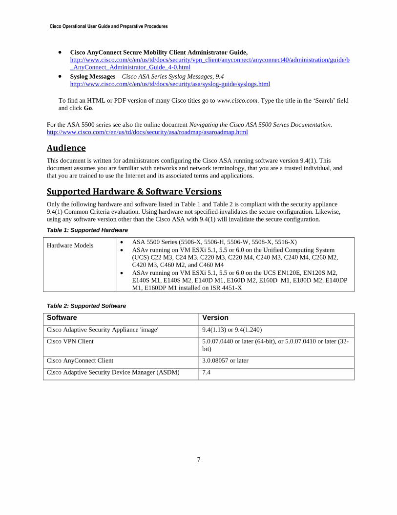
Supported Hardware & Software Versions
Only the following hardware and software listed in Table 1 and Table 2 is compliant with the security appliance
9.4(1) Common Criteria evaluation. Using hardware not specified invalidates the secure configuration. Likewise,
using any software version other than the Cisco ASA with 9.4(1) will invalidate the secure configuration.
Table 1: Supported Hardware
Hardware Models ASA 5500 Series (5506-X, 5506-H, 5506-W, 5508-X, 5516-X)
ASAv running on VM ESXi 5.1, 5.5 or 6.0 on the Unified Computing System
(UCS) C22 M3, C24 M3, C220 M3, C220 M4, C240 M3, C240 M4, C260 M2,
C420 M3, C460 M2, and C460 M4
ASAv running on VM ESXi 5.1, 5.5 or 6.0 on the UCS EN120E, EN120S M2,
E140S M1, E140S M2, E140D M1, E160D M2, E160D M1, E180D M2, E140DP
M1, E160DP M1 installed on ISR 4451-X
Table 2: Supported Software
Software Version
Cisco Adaptive Security Appliance 'image' 9.4(1.13) or 9.4(1.240)
Cisco VPN Client 5.0.07.0440 or later (64-bit), or 5.0.07.0410 or later (32-
bit)
Cisco AnyConnect Client 3.0.08057 or later
Cisco Adaptive Security Device Manager (ASDM) 7.4
Cisco Operational User Guide and Preparative Procedures
8
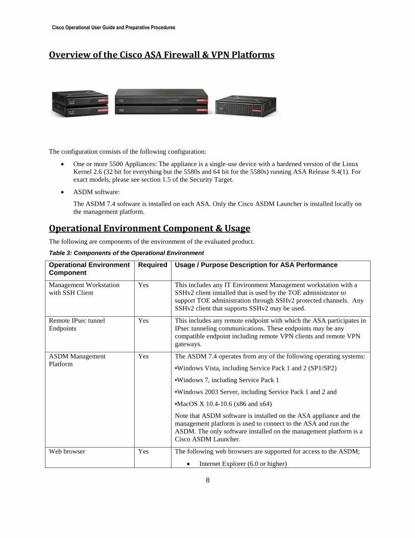
Overview of the Cisco ASA Firewall & VPN Platforms
The configuration consists of the following configuration:
One or more 5500 Appliances: The appliance is a single-use device with a hardened version of the Linux
Kernel 2.6 (32 bit for everything but the 5580s and 64 bit for the 5580s) running ASA Release 9.4(1). For
exact models, please see section 1.5 of the Security Target.
ASDM software:
The ASDM 7.4 software is installed on each ASA. Only the Cisco ASDM Launcher is installed locally on
the management platform.
Operational Environment Component & Usage
The following are components of the environment of the evaluated product.
Table 3: Components of the Operational Environment
Operational Environment Component
Required Usage / Purpose Description for ASA Performance
Management Workstation
with SSH Client
Yes This includes any IT Environment Management workstation with a
SSHv2 client installed that is used by the TOE administrator to
support TOE administration through SSHv2 protected channels. Any
SSHv2 client that supports SSHv2 may be used.
Remote IPsec tunnel
Endpoints Yes This includes any remote endpoint with which the ASA participates in
IPsec tunneling communications. These endpoints may be any
compatible endpoint including remote VPN clients and remote VPN
gateways.
ASDM Management
Platform Yes The ASDM 7.4 operates from any of the following operating systems:
•Windows Vista, including Service Pack 1 and 2 (SP1/SP2)
•Windows 7, including Service Pack 1
•Windows 2003 Server, including Service Pack 1 and 2 and
•MacOS X 10.4-10.6 (x86 and x64)
Note that ASDM software is installed on the ASA appliance and the
management platform is used to connect to the ASA and run the
ASDM. The only software installed on the management platform is a
Cisco ASDM Launcher.
Web browser Yes The following web browsers are supported for access to the ASDM;
Internet Explorer (6.0 or higher)
Cisco Operational User Guide and Preparative Procedures
9
Firefox (1.5 or higher)
Safari (2.0 or higher)
Chrome (18 or higher)
Note: Using the latest supported web browser version is
recommended.
Remote Authentication
Server No This includes any IT environment RADIUS AAA server that provides
single-use authentication mechanisms. This can be any RADIUS
AAA server that provides single-use authentication. The TOE
correctly leverages the services provided by this RADIUS AAA
server to provide single-use authentication to administrators.
Connections to remote AAA servers must be tunneled in IPsec.
NTP Server No The ASA supports communications with an NTP server. Using an
NTP server with support for NTPv3 is recommended.
Certificate Authority (CA) Yes The ASA supports OCSP communication with other CAs.
Audit (syslog) Server Yes A syslog server with the capability to support the ability to receive
syslog messages through an IPsec tunnel is required for use with the
ASA.
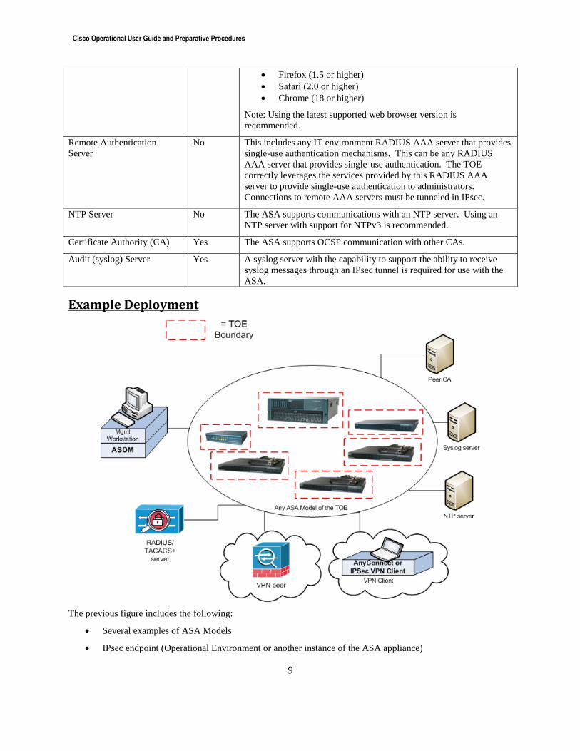
Example Deployment
The previous figure includes the following:
Several examples of ASA Models
IPsec endpoint (Operational Environment or another instance of the ASA appliance)
Cisco Operational User Guide and Preparative Procedures
10
Management Workstation (Operational Environment) with ASDM
Remote Authentication Server (Operational Environment)
NTP Server (Operational Environment)
Peer CA (Operational Environment)
Syslog server (Operational Environment)
Security Information In addition to the Regulatory Compliance and Safety Information for the Cisco ASA 5500 Series Adaptive Security
Appliance online documentation, the following sections provide additional security information for use with a
Common Criteria Certified adaptive security appliance.
Organizational Security Policy
Ensure that your security appliance is delivered, installed, managed, and operated in a manner that maintains an
organizational security policy. The online document Cisco ASA 5500 Series Configuration Guide using the CLI
provides guidance on how to define a security policy.
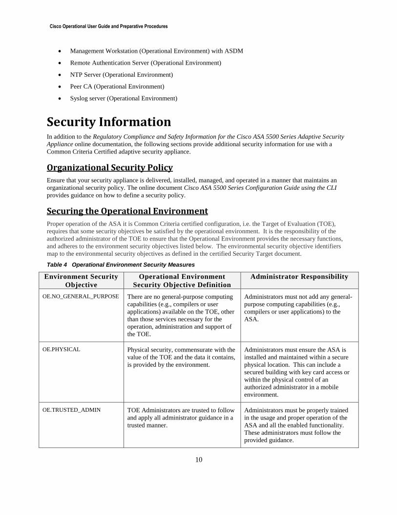
Securing the Operational Environment
Proper operation of the ASA it is Common Criteria certified configuration, i.e. the Target of Evaluation (TOE),
requires that some security objectives be satisfied by the operational environment. It is the responsibility of the
authorized administrator of the TOE to ensure that the Operational Environment provides the necessary functions,
and adheres to the environment security objectives listed below. The environmental security objective identifiers
map to the environmental security objectives as defined in the certified Security Target document.
Table 4 Operational Environment Security Measures
Environment Security
Objective
Operational Environment
Security Objective Definition
Administrator Responsibility
OE.NO_GENERAL_PURPOSE There are no general-purpose computing
capabilities (e.g., compilers or user
applications) available on the TOE, other
than those services necessary for the
operation, administration and support of
the TOE.
Administrators must not add any general-
purpose computing capabilities (e.g.,
compilers or user applications) to the
ASA.
OE.PHYSICAL Physical security, commensurate with the
value of the TOE and the data it contains,
is provided by the environment.
Administrators must ensure the ASA is
installed and maintained within a secure
physical location. This can include a
secured building with key card access or
within the physical control of an
authorized administrator in a mobile
environment.
OE.TRUSTED_ADMIN TOE Administrators are trusted to follow
and apply all administrator guidance in a
trusted manner.
Administrators must be properly trained
in the usage and proper operation of the
ASA and all the enabled functionality.
These administrators must follow the
provided guidance.
Cisco Operational User Guide and Preparative Procedures
11
Environment Security
Objective
Operational Environment
Security Objective Definition
Administrator Responsibility
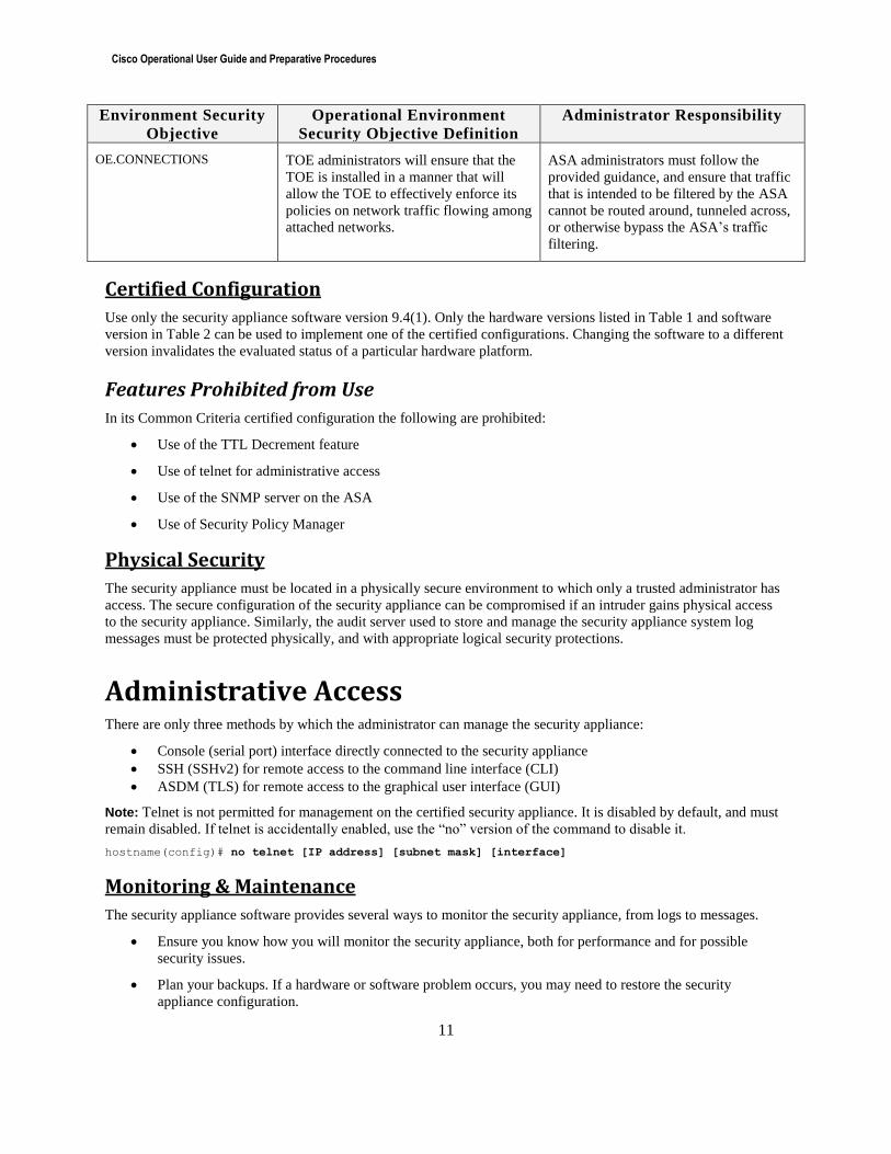
OE.CONNECTIONS
TOE administrators will ensure that the
TOE is installed in a manner that will
allow the TOE to effectively enforce its
policies on network traffic flowing among
attached networks.
ASA administrators must follow the
provided guidance, and ensure that traffic
that is intended to be filtered by the ASA
cannot be routed around, tunneled across,
or otherwise bypass the ASA’s traffic
filtering.
Certified Configuration
Use only the security appliance software version 9.4(1). Only the hardware versions listed in Table 1 and software
version in Table 2 can be used to implement one of the certified configurations. Changing the software to a different
version invalidates the evaluated status of a particular hardware platform.
Features Prohibited from Use
In its Common Criteria certified configuration the following are prohibited:
Use of the TTL Decrement feature
Use of telnet for administrative access
Use of the SNMP server on the ASA
Use of Security Policy Manager
Physical Security
The security appliance must be located in a physically secure environment to which only a trusted administrator has
access. The secure configuration of the security appliance can be compromised if an intruder gains physical access
to the security appliance. Similarly, the audit server used to store and manage the security appliance system log
messages must be protected physically, and with appropriate logical security protections.
Administrative Access There are only three methods by which the administrator can manage the security appliance:
Console (serial port) interface directly connected to the security appliance
SSH (SSHv2) for remote access to the command line interface (CLI)
ASDM (TLS) for remote access to the graphical user interface (GUI)
Note: Telnet is not permitted for management on the certified security appliance. It is disabled by default, and must
remain disabled. If telnet is accidentally enabled, use the “no” version of the command to disable it.
hostname(config)# no telnet [IP address] [subnet mask] [interface]
Monitoring & Maintenance
The security appliance software provides several ways to monitor the security appliance, from logs to messages.
Ensure you know how you will monitor the security appliance, both for performance and for possible
security issues.
Plan your backups. If a hardware or software problem occurs, you may need to restore the security
appliance configuration.
Cisco Operational User Guide and Preparative Procedures
12
The configuration of the security appliance should be reviewed regularly to ensure that the configuration
meets the security objectives of the organization in the face of the following:
o Changes in the security appliance configuration
o Changes in the security objectives
o Changes in the threats presented by the external network
Systems Logs
Cisco Security Appliance System Log Messages provides details on the security appliance system logs. The
following sections are not supported in the certified configuration:
Security Appliance System Log
o Receiving SNMP requests
o Sending SNMP Traps
Other Remote Management and Monitoring Tools
o Cisco Secure Policy Manager o SNMP Traps
Administration
The Security Management Function provides a command line interface (CLI) that allows an authorized
administrator to configure security functionality on the ASA either locally via the console port, remotely via ASDM,
or remotely using SSH to perform the following actions:
1. Enable or disable the operation of the product;
2. Enable or disable the multiple use authentication functions including;
a. Single-use authentication
b. Reusable password authentication
c. Certificate-based authentication of tunnel endpoints
3. Enable, disable, determine and modify the behavior of the audit trail management;
4. Enable, disable, determine and modify the behavior of the functionality to backup and restore data
including information flow rules, and audit trail data;
5. Enable, disable, determine and modify the behavior of communication of authorized external IT entities;
6. Delete attributes from a rule, modify attributes in a rule, add attributes to a rule for all security attributes
including;
a. Zone-based Firewall ACLs
b. VPN/IKE Policies
c. VLAN Policies
7. Query, modify, delete, and assign the administrator attributes including;
a. username
b. privilege level
c. password
8. Set the time and date used to form the timestamps;
9. Specify the limits for the number of authentication failures.
Upon successful identification and authentication, the administrator has access to the CLI that enables an
administrator to manage and monitor the ASA. The CLI is divided into different command modes. Each command
mode has its own set of commands available for the configuration, maintenance, and monitoring of the ASA. The
commands available depend on the current active mode. The use of specific commands allows navigation from one
command mode to another.
The command modes are grouped into two categories based on the Authorized Administrator role; “unprivileged” is
where an administrator can view configuration information but cannot change it, which is the initial login state when
logging into the CLI when privilege level is set to 1 and the command prompt is a “>”. The other mode is
Cisco Operational User Guide and Preparative Procedures
13
“privileged” mode which provides the ability to change configuration information, and the command prompt is a
hash, “#”.
The ASA supports multiple privilege levels for administrative sessions, the highest of which is a privilege 15.
Within the single local database, users can each be assigned a privilege level (0-14) and service-type set to “admin”.
(NOTE: In the Common Criteria certified configuration, usernames in the local user database must not have
privilege level 15 so that the ASA is able to enforce lockout of all local accounts, given that privilege level 15 is
exempt from lockout.)
The following applies when authentication and "exec" authorization are enabled: In order to be authorized for
"enabled" access, i.e, access to the privileged prompt, the user must have the their service-type set to “admin”. Note
that users in the local user database are automatically given “admin” service-tag if the service-type attribute is not
otherwise configured.
'aaa authentication ssh console LOCAL' sets the ASA to authenticate SSH users against the local database.
'aaa authorization exec' requires authorization of users before they can get to the exec console.
Upon successful login, by default, the administrator can access the unprivileged CLI commands. When the
administrator authenticates with the enable or login command, the administrator has access to privileged modes and
commands. Though the administrator could also use the unprivileged mode, all ASA relevant administrative
operations are performed in a privileged mode. The above listed management functions can only be performed by
the authorized administrator in a privileged mode.
The Security Management Function ensures that validated security attributes are entered by an authenticated
administrator
Saving the Configuration
The write memory command should be used frequently when making changes to the configuration of the security
appliance. If the security appliance reboots and resumes operation when uncommitted changes were made, these
changes will be lost and the security appliance will revert to the last configuration saved.
The security appliance loads the saved startup configuration and automatically copies this configuration into the
running configuration. As a user configures the running configuration to his specific needs he either saves the
running configuration or saves the updated configuration to the startup configuration. The running configuration is
held in volatile memory so if the security appliance is reloaded due to either operational reasons or operational error
and any changes have not been saved these changes will be lost.
Backup and Restoration
Note: Use of backup and restoration is optional in the certified configuration, but if backup and restoration are
performed over a network connection, encrypted connections must be used as described in this section.
The ASA provide the capability to backup and restore configuration information. This can be accomplished by
accessing the ASA through either the ASA CLI or the ASDM. Information regarding ASA Backup and Restoration
can be found in the “Backing Up Configuration Files” section of Cisco ASA 5500 Series Configuration Guide using
the CLI or the “Cisco ASA 5500 Series Configuration Guide using ASDM” section of Cisco ASA 5500 Series
Configuration Guide using ASDM.
To securely copy configuration files, log files, or software images to or from the ASA, use the copy command from
the ASA CLI:
copy http[s]://[user[:password]@]server[:port]/[path/]filename]”
Note: There is a “copy http” command, but be sure to use “copy https” (with the ‘s’).
Note: When using “copy https”, the encrypted channel is established before the password is transmitted, so the
password is not transmitted in plaintext.
Cisco Operational User Guide and Preparative Procedures
14
Device Failover
Configuration of failover is optional in the certified configuration, and evaluation of the encryption method used for
the failover connection was beyond the scope of the evaluation. However, if failover is enabled, the recommended
configuration is to enable encryption as described here.
When using failover, configure an authentication password to be used between the two firewall units, and ensure the
password used for the key complies with the “Password Complexity” guidance within this document. The command
is:
failover key {secret | hex key}
For more information see the sections on configuring failover in the online document Cisco ASA 5500 Series
Configuration Guide using the CLI or the “Configuring High Availability” section of Cisco ASA 5500 Series
Configuration Guide using ASDM.
Security Patch VMware ESXi To address critical security fixes, it is highly recommended that the patches are installed on the ESXi before ASAv
deployment. The following are links to the patches along with instructions to download and apply them:
ESXi 5.5 with patch ESXi550-201602401-SG:
https://kb.vmware.com/selfservice/microsites/search.do?language=en_US&cmd=displayKC&externalId=2
144357
ESXi 6.0 with patch ESXi600-201602401-SG:
https://kb.vmware.com/selfservice/microsites/search.do?language=en_US&cmd=displayKC&externalId=2
144057
Deployment of the ASAv
Deployment Options and Guidelines for the ASAv and VMware
OVF File Guidelines
The selection of the asav-vi.ovf or asav-esxi.ovf file is based on the deployment target:
asav-vi—For deployment on vCenter
asav-esxi—For deployment on ESXi (no vCenter)
Unpack the ASAv Software and Create a Day 0 Configuration File for VMware
You can prepare a Day 0 configuration file before you launch the ASAv. This file is a text file that contains the
ASAv configuration that will be applied when the ASAv is launched. This initial configuration is placed into a text
file named “day0-config” in a working directory you chose, and is manipulated into a day0.iso file that is mounted
and read on first boot. At the minimum, the Day 0 configuration file must contain commands that will activate the
management interface and set up the SSH server for public key authentication, but it can also contain a complete
ASA configuration. A default day0.iso containing an empty day0-config is provided with the release. The day0.iso
file (either your custom day0.iso or the default day0.iso) must be available during first boot.
Cisco Operational User Guide and Preparative Procedures
15
Note: To automatically license the ASAv during initial deployment, place the Smart Licensing Identity (ID) Token
that you downloaded from the Cisco Smart Software Manager in a text file named ‘idtoken’ in the same directory as
the Day 0 configuration file.
Note: If you want to deploy the ASAv in transparent mode, you must use a known running ASA config file in
transparent mode as the Day 0 configuration file. This does not apply to a Day 0 configuration file for a routed
firewall.
Note: We are using Linux in this example, but there are similar utilities for Windows.
Procedure
1. Download the ZIP file from Cisco.com, and save it to your local disk:
http://www.cisco.com/go/asa-software
Note: A Cisco.com login and Cisco service contract are required.
2. Unzip the file into a working directory. Do not remove any files from the directory. The following files are
included:
– asav-vi.ovf—For vCenter deployments.
– asav-esxi.ovf—For non-vCenter deployments.
– boot.vmdk—Boot disk image.
– disk0.vmdk—ASAv disk image.
– day0.iso—An ISO containing a day0-config file and optionally an idtoken file.
– asav-vi.mf—Manifest file for vCenter deployments.
– asav-esxi.mf—Manifest file for non-vCenter deployments.
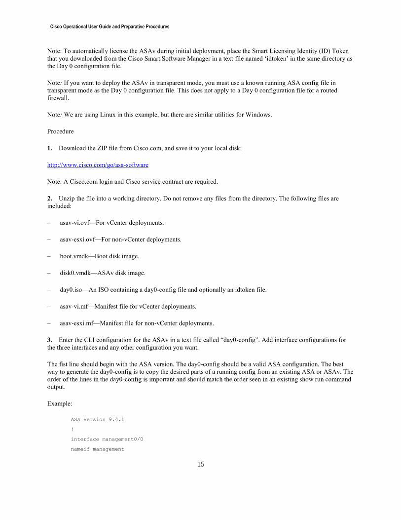
3. Enter the CLI configuration for the ASAv in a text file called “day0-config”. Add interface configurations for
the three interfaces and any other configuration you want.
The fist line should begin with the ASA version. The day0-config should be a valid ASA configuration. The best
way to generate the day0-config is to copy the desired parts of a running config from an existing ASA or ASAv. The
order of the lines in the day0-config is important and should match the order seen in an existing show run command
output.
Example:
ASA Version 9.4.1
!
interface management0/0
nameif management
Cisco Operational User Guide and Preparative Procedures
16
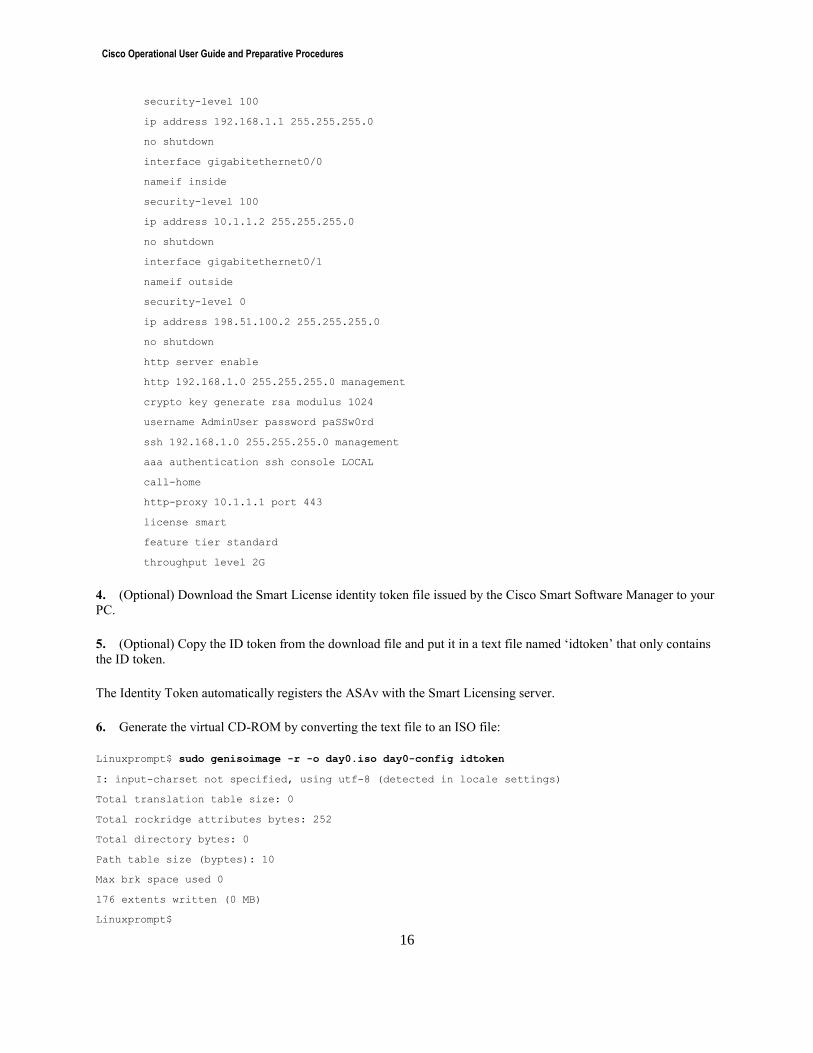
security-level 100
ip address 192.168.1.1 255.255.255.0
no shutdown
interface gigabitethernet0/0
nameif inside
security-level 100
ip address 10.1.1.2 255.255.255.0
no shutdown
interface gigabitethernet0/1
nameif outside
security-level 0
ip address 198.51.100.2 255.255.255.0
no shutdown
http server enable
http 192.168.1.0 255.255.255.0 management
crypto key generate rsa modulus 1024
username AdminUser password paSSw0rd
ssh 192.168.1.0 255.255.255.0 management
aaa authentication ssh console LOCAL
call-home
http-proxy 10.1.1.1 port 443
license smart
feature tier standard
throughput level 2G
4. (Optional) Download the Smart License identity token file issued by the Cisco Smart Software Manager to your
PC.
5. (Optional) Copy the ID token from the download file and put it in a text file named ‘idtoken’ that only contains
the ID token.
The Identity Token automatically registers the ASAv with the Smart Licensing server.
6. Generate the virtual CD-ROM by converting the text file to an ISO file:
Linuxprompt$ sudo genisoimage -r -o day0.iso day0-config idtoken
I: input-charset not specified, using utf-8 (detected in locale settings)
Total translation table size: 0
Total rockridge attributes bytes: 252
Total directory bytes: 0
Path table size (byptes): 10
Max brk space used 0
176 extents written (0 MB)
Linuxprompt$
Cisco Operational User Guide and Preparative Procedures
17
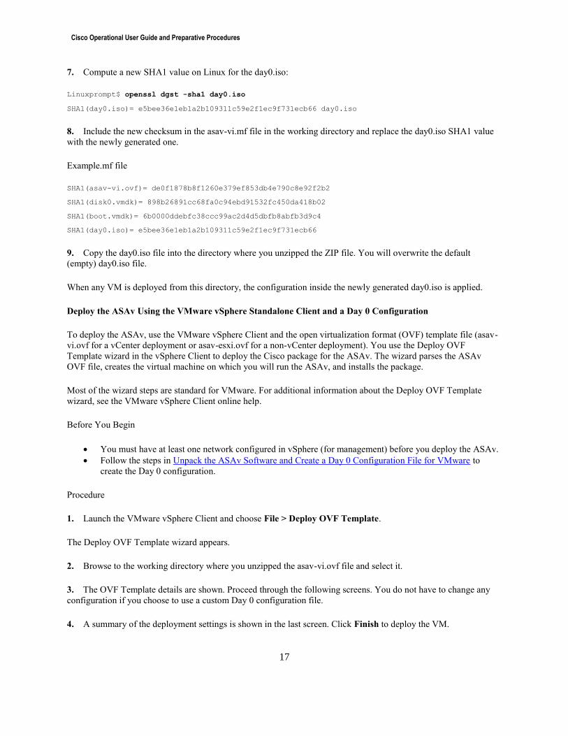
7. Compute a new SHA1 value on Linux for the day0.iso:
Linuxprompt$ openssl dgst -sha1 day0.iso
SHA1(day0.iso)= e5bee36e1eb1a2b109311c59e2f1ec9f731ecb66 day0.iso
8. Include the new checksum in the asav-vi.mf file in the working directory and replace the day0.iso SHA1 value
with the newly generated one.
Example.mf file
SHA1(asav-vi.ovf)= de0f1878b8f1260e379ef853db4e790c8e92f2b2
SHA1(disk0.vmdk)= 898b26891cc68fa0c94ebd91532fc450da418b02
SHA1(boot.vmdk)= 6b0000ddebfc38ccc99ac2d4d5dbfb8abfb3d9c4
SHA1(day0.iso)= e5bee36e1eb1a2b109311c59e2f1ec9f731ecb66
9. Copy the day0.iso file into the directory where you unzipped the ZIP file. You will overwrite the default
(empty) day0.iso file.
When any VM is deployed from this directory, the configuration inside the newly generated day0.iso is applied.
Deploy the ASAv Using the VMware vSphere Standalone Client and a Day 0 Configuration
To deploy the ASAv, use the VMware vSphere Client and the open virtualization format (OVF) template file (asav-
vi.ovf for a vCenter deployment or asav-esxi.ovf for a non-vCenter deployment). You use the Deploy OVF
Template wizard in the vSphere Client to deploy the Cisco package for the ASAv. The wizard parses the ASAv
OVF file, creates the virtual machine on which you will run the ASAv, and installs the package.
Most of the wizard steps are standard for VMware. For additional information about the Deploy OVF Template
wizard, see the VMware vSphere Client online help.
Before You Begin
You must have at least one network configured in vSphere (for management) before you deploy the ASAv.
Follow the steps in Unpack the ASAv Software and Create a Day 0 Configuration File for VMware to
create the Day 0 configuration.
Procedure
1. Launch the VMware vSphere Client and choose File > Deploy OVF Template.
The Deploy OVF Template wizard appears.
2. Browse to the working directory where you unzipped the asav-vi.ovf file and select it.
3. The OVF Template details are shown. Proceed through the following screens. You do not have to change any
configuration if you choose to use a custom Day 0 configuration file.
4. A summary of the deployment settings is shown in the last screen. Click Finish to deploy the VM.
Cisco Operational User Guide and Preparative Procedures
18
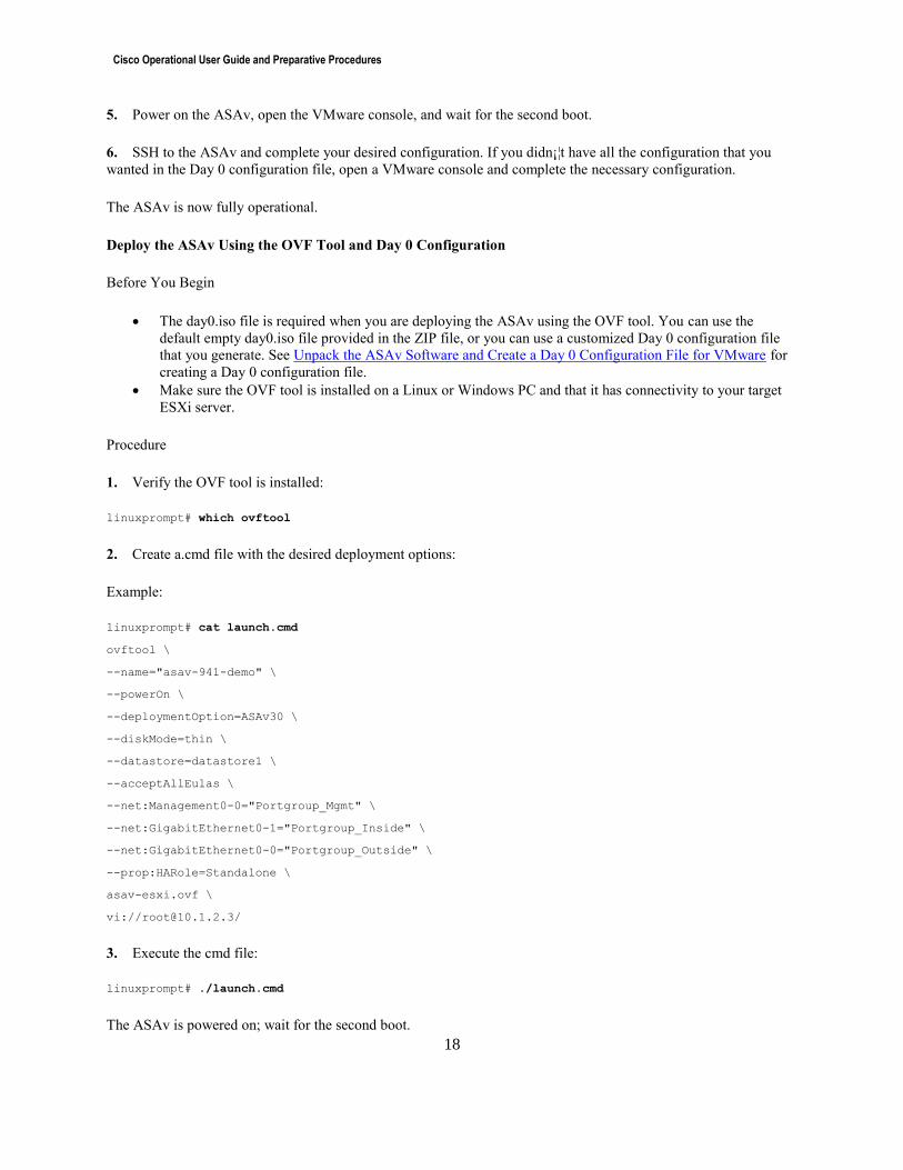
5. Power on the ASAv, open the VMware console, and wait for the second boot.
6. SSH to the ASAv and complete your desired configuration. If you didn¡¦t have all the configuration that you
wanted in the Day 0 configuration file, open a VMware console and complete the necessary configuration.
The ASAv is now fully operational.
Deploy the ASAv Using the OVF Tool and Day 0 Configuration
Before You Begin
The day0.iso file is required when you are deploying the ASAv using the OVF tool. You can use the
default empty day0.iso file provided in the ZIP file, or you can use a customized Day 0 configuration file
that you generate. See Unpack the ASAv Software and Create a Day 0 Configuration File for VMware for
creating a Day 0 configuration file.
Make sure the OVF tool is installed on a Linux or Windows PC and that it has connectivity to your target
ESXi server.
Procedure
1. Verify the OVF tool is installed:
linuxprompt# which ovftool
2. Create a.cmd file with the desired deployment options:
Example:
linuxprompt# cat launch.cmd
ovftool \
--name="asav-941-demo" \
--powerOn \
--deploymentOption=ASAv30 \
--diskMode=thin \
--datastore=datastore1 \
--acceptAllEulas \
--net:Management0-0="Portgroup_Mgmt" \
--net:GigabitEthernet0-1="Portgroup_Inside" \
--net:GigabitEthernet0-0="Portgroup_Outside" \
--prop:HARole=Standalone \
asav-esxi.ovf \
vi://[email protected]/
3. Execute the cmd file:
linuxprompt# ./launch.cmd
The ASAv is powered on; wait for the second boot.

Cisco Operational User Guide and Preparative Procedures
19
4. SSH to the ASAv to complete configuration as desired. If more configuration is required, open the VMware
console to the ASAv and apply the necessary configuration.
The ASAv is now fully operational.
Access the ASAv Console
In some cases with ASDM, you may need to use the CLI for troubleshooting. By default, you can access the built-in
VMware vSphere console. Alternatively, you can configure a network serial console, which has better capabilities,
including copy and paste.
Use the VMware vSphere Console
Configure a Network Serial Console Port
Authentication to the ASA
Local and Remote Access
Administrative access to any administrative interface (console, SSH, and/or ASDM) can be configured to use remote
AAA (RADIUS) authentication, and/or local authentication. For example, the following authentication mechanisms
would be viable configurations for each interface:
Console: Authenticate only to the local user database.
o Note: Configuring authentication at the console to use a remote AAA server is optional. It’s not
recommended to configure the console interface to authenticate ONLY to a remote AAA server
(without fallback to LOCAL) because login to the console interface would not be possible when
the remote AAA server is unavailable.
o Login to the console would be authenticated to accounts defined in the local user database (using
privilege levels 1-14 only, to be able to enforce lockout after successive failed login attempts).
Level 1 is the minimum level required for access to the console.
o Some commands, including use of the “enable” command are permitted at level 1. By default, no
commands are defined for levels 2-14. Additional commands (from the set of commands
available to level 15), can be applied to levels 2-14. Levels 2-14 inherit commands applied to
lower privilege levels, including level 1.
o Use of commands defined only for privilege level 15 would require use of the “enable” command
and entering the enable password.
SSH: Authenticate first to a remote AAA server, and fallback to local user database authentication if the
remote AAA server is unavailable.
o Note: Configuring fall-back to local authentication is optional. If no fallback to local is
configured, access via SSH is not possible when the remote AAA server is unavailable.
o Accounts defined on the remote AAA server can be defined as privilege level 15, or any other
level 1 or higher (level 1 is the minimum level required for access via SSH).
ASDM: Authenticate only to the remote AAA server, and never fallback to the local user database when
the remote AAA server is unavailable.
o Note: Not configuring fall-back to local authentication is optional, and would result in no access
via ASDM when the remote AAA server is unavailable.
o Accounts defined on the remote AAA server can be defined as privilege level 15, or any other
level 2 or higher (level 2 is the minimum level required for access via ASDM).
ASDM or SSH over IPsec from AnyConnect or Cisco VPN Client: Authenticate
o
Cisco Operational User Guide and Preparative Procedures
20
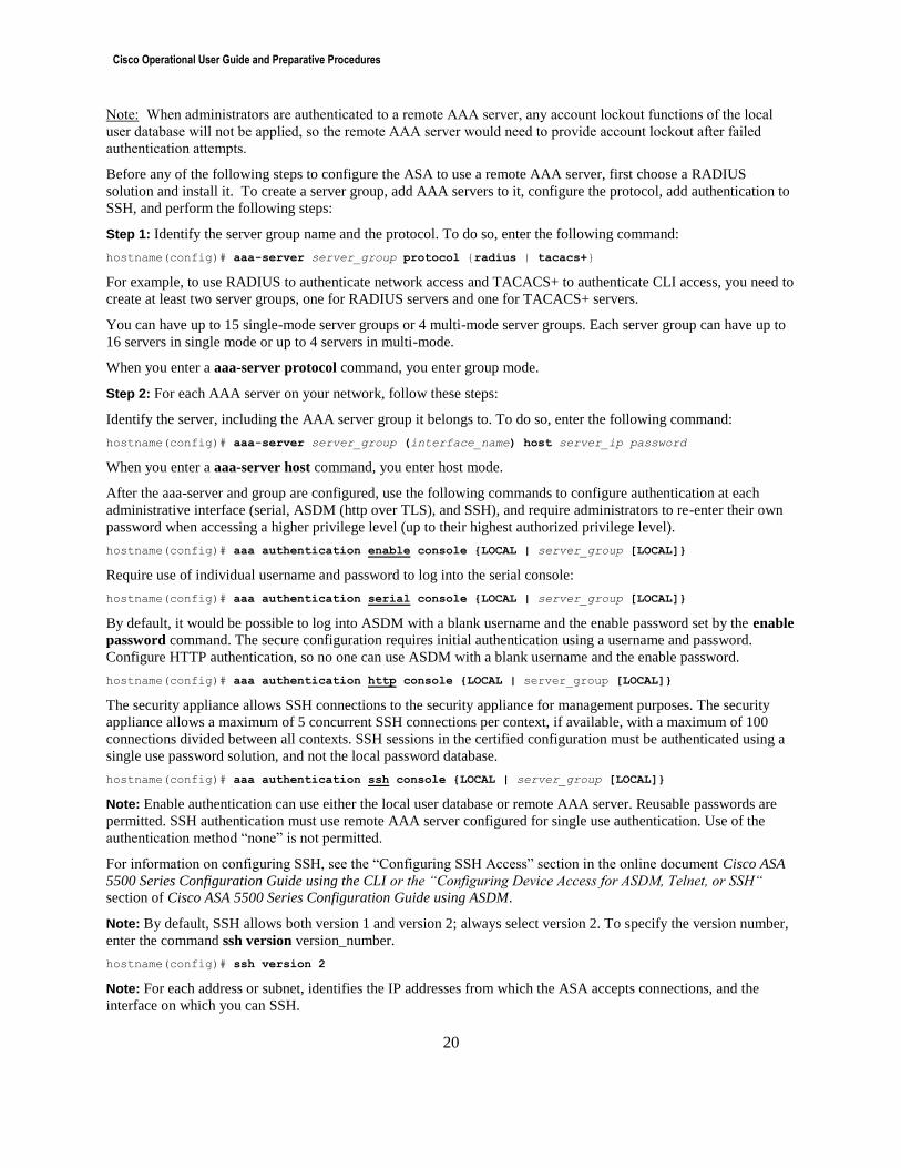
Note: When administrators are authenticated to a remote AAA server, any account lockout functions of the local
user database will not be applied, so the remote AAA server would need to provide account lockout after failed
authentication attempts.
Before any of the following steps to configure the ASA to use a remote AAA server, first choose a RADIUS
solution and install it. To create a server group, add AAA servers to it, configure the protocol, add authentication to
SSH, and perform the following steps:
Step 1: Identify the server group name and the protocol. To do so, enter the following command:
hostname(config)# aaa-server server_group protocol {radius | tacacs+}
For example, to use RADIUS to authenticate network access and TACACS+ to authenticate CLI access, you need to
create at least two server groups, one for RADIUS servers and one for TACACS+ servers.
You can have up to 15 single-mode server groups or 4 multi-mode server groups. Each server group can have up to
16 servers in single mode or up to 4 servers in multi-mode.
When you enter a aaa-server protocol command, you enter group mode.
Step 2: For each AAA server on your network, follow these steps:
Identify the server, including the AAA server group it belongs to. To do so, enter the following command:
hostname(config)# aaa-server server_group (interface_name) host server_ip password
When you enter a aaa-server host command, you enter host mode.
After the aaa-server and group are configured, use the following commands to configure authentication at each
administrative interface (serial, ASDM (http over TLS), and SSH), and require administrators to re-enter their own
password when accessing a higher privilege level (up to their highest authorized privilege level).
hostname(config)# aaa authentication enable console {LOCAL | server_group [LOCAL]}
Require use of individual username and password to log into the serial console:
hostname(config)# aaa authentication serial console {LOCAL | server_group [LOCAL]}
By default, it would be possible to log into ASDM with a blank username and the enable password set by the enable
password command. The secure configuration requires initial authentication using a username and password.
Configure HTTP authentication, so no one can use ASDM with a blank username and the enable password.
hostname(config)# aaa authentication http console {LOCAL | server_group [LOCAL]}
The security appliance allows SSH connections to the security appliance for management purposes. The security
appliance allows a maximum of 5 concurrent SSH connections per context, if available, with a maximum of 100
connections divided between all contexts. SSH sessions in the certified configuration must be authenticated using a
single use password solution, and not the local password database.
hostname(config)# aaa authentication ssh console {LOCAL | server_group [LOCAL]}
Note: Enable authentication can use either the local user database or remote AAA server. Reusable passwords are
permitted. SSH authentication must use remote AAA server configured for single use authentication. Use of the
authentication method “none” is not permitted.
For information on configuring SSH, see the “Configuring SSH Access” section in the online document Cisco ASA
5500 Series Configuration Guide using the CLI or the “Configuring Device Access for ASDM, Telnet, or SSH“
section of Cisco ASA 5500 Series Configuration Guide using ASDM.
Note: By default, SSH allows both version 1 and version 2; always select version 2. To specify the version number,
enter the command ssh version version_number.
hostname(config)# ssh version 2
Note: For each address or subnet, identifies the IP addresses from which the ASA accepts connections, and the
interface on which you can SSH.

Cisco Operational User Guide and Preparative Procedures
21
hostname(config)# ssh source_IP_address mask source_interface
Note: Instead of entering the enable command at the “>” prompt after establishing the SSH session, the
administrator shall enter “login” and then log in with a local database account and password. This results in all audit
events being attributed to that local user.
Login Banners
There are several configurable login banners on the ASA. The Common Criteria certified configuration requires
that an advisory notice and consent warning message be displayed prior to establishment of the administrative user
session.
During the CLI (console or SSH) login process, the “banner login” will be displayed prior to the end-user providing
their password, so the “login banner” can provide the warning that entering a password indicates consent.
asa(config)# banner login This is the login banner.
asa(config)# banner login NOTICE: If you do not consent to the xyz policies for this system,
asa(config)# banner login … do not enter a password in the command line interface (CLI).
asa(config)# banner login NOTICE: If you do not consent to the xyz policies for this system,
asa(config)# banner login … do not enter a password at the next ASDM login prompt.
asa(config)# banner login CLI Behavior: When connecting via CLI, this banner is displayed…
asa(config)# banner login … after a username is provided, but before the password is entered.
asa(config)# banner login ASDM Behavior… When connecting via ASDM, this banner is displayed
asa(config)# banner login … after the ASDM launcher prompts (but does not require) the end-user
asa(config)# banner login … to enter a username and password, but before sending them to the ASA.
During the ASDM login and after the username and password have been provided, the authentication credentials are
passed to the ASA. If the credentials are wrong, the user is prompted again for a username and password. If the
credentials are validated, the ASDM banner is displayed, but the administrator user session has not been started.
The administrative user session will not be established until the user clicks the “Continue” button. The ASDM
banner window has a “Continue” button that can be used to express consent, and a “Disconnect” button to
discontinue loading of ASDM and avoid establishing the interactive administrative user session. Here’s an example
of how to create an ASDM banner via the CLI:
asa(config)# banner asdm This is the ASDM banner.
asa(config)# banner asdm WARNING, YOUR ACTIVITIES WILL BE MONITORED!
asa(config)# banner asdm IF YOU DO NOT WISH TO CONSENT TO MONITORING, DISCONNECT NOW!
asa(config)# banner asdm By clicking "Continue", you consent to monitoring.
Cisco Operational User Guide and Preparative Procedures
22
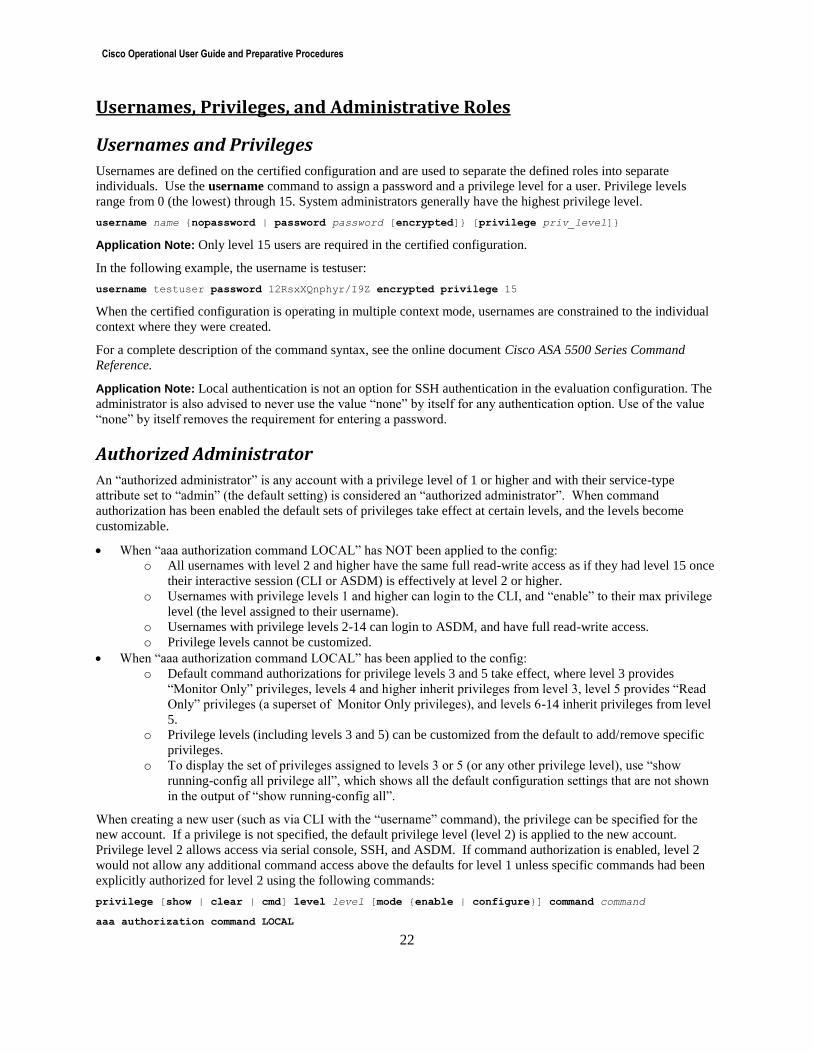
Usernames, Privileges, and Administrative Roles
Usernames and Privileges
Usernames are defined on the certified configuration and are used to separate the defined roles into separate
individuals. Use the username command to assign a password and a privilege level for a user. Privilege levels
range from 0 (the lowest) through 15. System administrators generally have the highest privilege level.
username name {nopassword | password password [encrypted]} [privilege priv_level]} Application Note: Only level 15 users are required in the certified configuration.
In the following example, the username is testuser:
username testuser password 12RsxXQnphyr/I9Z encrypted privilege 15
When the certified configuration is operating in multiple context mode, usernames are constrained to the individual
context where they were created.
For a complete description of the command syntax, see the online document Cisco ASA 5500 Series Command
Reference.
Application Note: Local authentication is not an option for SSH authentication in the evaluation configuration. The
administrator is also advised to never use the value “none” by itself for any authentication option. Use of the value
“none” by itself removes the requirement for entering a password.
Authorized Administrator
An “authorized administrator” is any account with a privilege level of 1 or higher and with their service-type
attribute set to “admin” (the default setting) is considered an “authorized administrator”. When command
authorization has been enabled the default sets of privileges take effect at certain levels, and the levels become
customizable.
When “aaa authorization command LOCAL” has NOT been applied to the config:
o All usernames with level 2 and higher have the same full read-write access as if they had level 15 once
their interactive session (CLI or ASDM) is effectively at level 2 or higher.
o Usernames with privilege levels 1 and higher can login to the CLI, and “enable” to their max privilege
level (the level assigned to their username).
o Usernames with privilege levels 2-14 can login to ASDM, and have full read-write access.
o Privilege levels cannot be customized.
When “aaa authorization command LOCAL” has been applied to the config:
o Default command authorizations for privilege levels 3 and 5 take effect, where level 3 provides
“Monitor Only” privileges, levels 4 and higher inherit privileges from level 3, level 5 provides “Read
Only” privileges (a superset of Monitor Only privileges), and levels 6-14 inherit privileges from level
5.
o Privilege levels (including levels 3 and 5) can be customized from the default to add/remove specific
privileges.
o To display the set of privileges assigned to levels 3 or 5 (or any other privilege level), use “show
running-config all privilege all”, which shows all the default configuration settings that are not shown
in the output of “show running-config all”.
When creating a new user (such as via CLI with the “username” command), the privilege can be specified for the
new account. If a privilege is not specified, the default privilege level (level 2) is applied to the new account.
Privilege level 2 allows access via serial console, SSH, and ASDM. If command authorization is enabled, level 2
would not allow any additional command access above the defaults for level 1 unless specific commands had been
explicitly authorized for level 2 using the following commands:
privilege [show | clear | cmd] level level [mode {enable | configure}] command command
aaa authorization command LOCAL
Cisco Operational User Guide and Preparative Procedures
23
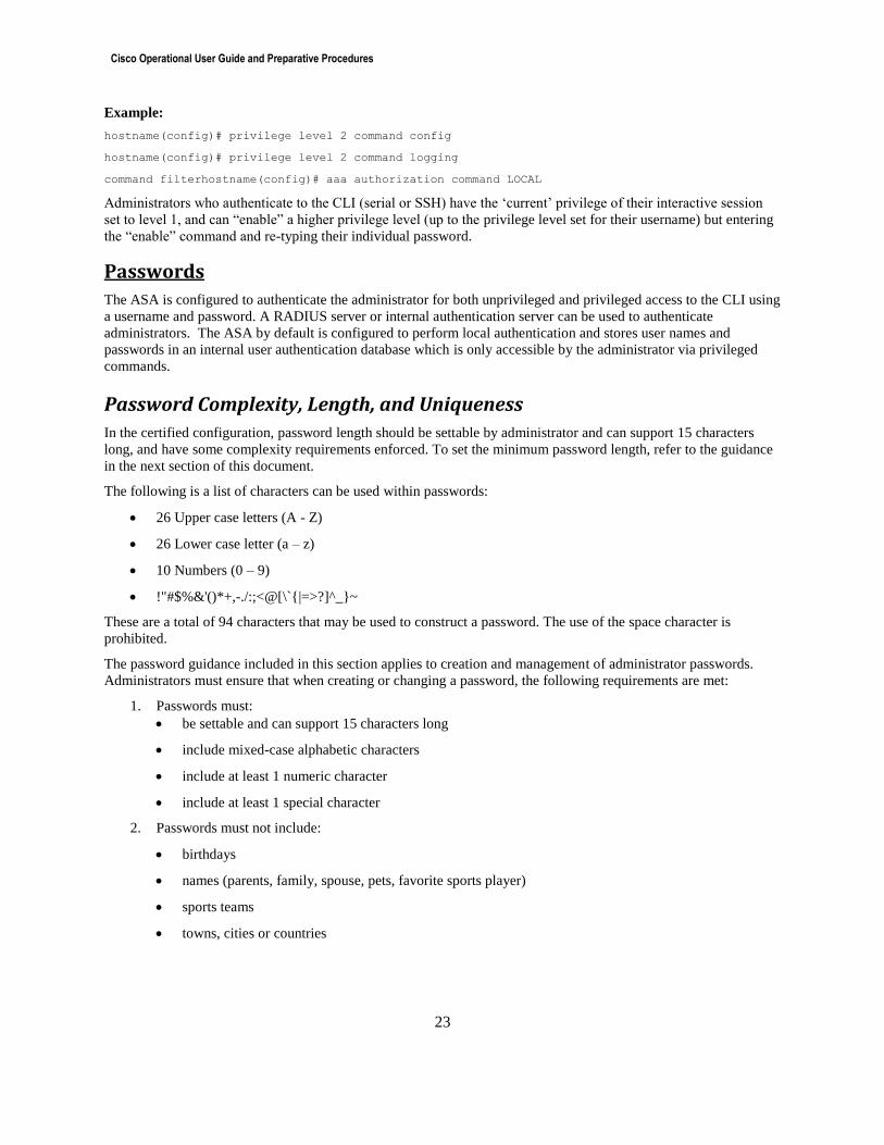
Example:
hostname(config)# privilege level 2 command config
hostname(config)# privilege level 2 command logging
command filterhostname(config)# aaa authorization command LOCAL
Administrators who authenticate to the CLI (serial or SSH) have the ‘current’ privilege of their interactive session
set to level 1, and can “enable” a higher privilege level (up to the privilege level set for their username) but entering
the “enable” command and re-typing their individual password.
Passwords
The ASA is configured to authenticate the administrator for both unprivileged and privileged access to the CLI using
a username and password. A RADIUS server or internal authentication server can be used to authenticate
administrators. The ASA by default is configured to perform local authentication and stores user names and
passwords in an internal user authentication database which is only accessible by the administrator via privileged
commands.
Password Complexity, Length, and Uniqueness
In the certified configuration, password length should be settable by administrator and can support 15 characters
long, and have some complexity requirements enforced. To set the minimum password length, refer to the guidance
in the next section of this document.
The following is a list of characters can be used within passwords:
26 Upper case letters (A - Z)
26 Lower case letter (a – z)
10 Numbers (0 – 9)
!"#$%&'()*+,-./:;<@[\`{|=>?]^_}~
These are a total of 94 characters that may be used to construct a password. The use of the space character is
prohibited.
The password guidance included in this section applies to creation and management of administrator passwords.
Administrators must ensure that when creating or changing a password, the following requirements are met:
1. Passwords must:
be settable and can support 15 characters long
include mixed-case alphabetic characters
include at least 1 numeric character
include at least 1 special character
2. Passwords must not include:
birthdays
names (parents, family, spouse, pets, favorite sports player)
sports teams
towns, cities or countries
Cisco Operational User Guide and Preparative Procedures
24
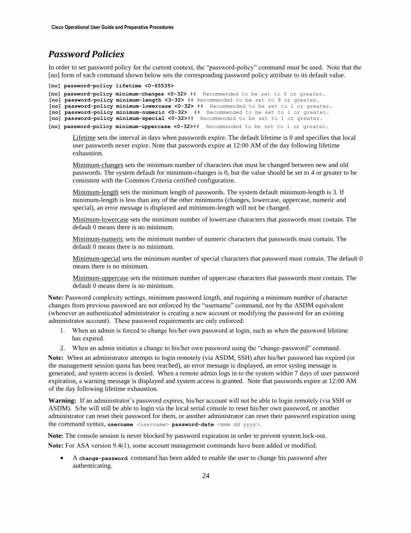
Password Policies
In order to set password policy for the current context, the “password-policy” command must be used. Note that the
[no] form of each command shown below sets the corresponding password policy attribute to its default value.
[no] password-policy lifetime <0-65535>
[no] password-policy minimum-changes <0-32> ## Recommended to be set to 4 or greater.
[no] password-policy minimum-length <3-32> ## Recommended to be set to 8 or greater.
[no] password-policy minimum-lowercase <0-32> ## Recommended to be set to 1 or greater.
[no] password-policy minimum-numeric <0-32> ## Recommended to be set to 1 or greater.
[no] password-policy minimum-special <0-32>## Recommended to be set to 1 or greater.
[no] password-policy minimum-uppercase <0-32>## Recommended to be set to 1 or greater.
Lifetime sets the interval in days when passwords expire. The default lifetime is 0 and specifies that local
user passwords never expire. Note that passwords expire at 12:00 AM of the day following lifetime
exhaustion.
Minimum-changes sets the minimum number of characters that must be changed between new and old
passwords. The system default for minimum-changes is 0, but the value should be set to 4 or greater to be
consistent with the Common Criteria certified configuration.
Minimum-length sets the minimum length of passwords. The system default minimum-length is 3. If
minimum-length is less than any of the other minimums (changes, lowercase, uppercase, numeric and
special), an error message is displayed and minimum-length will not be changed.
Minimum-lowercase sets the minimum number of lowercase characters that passwords must contain. The
default 0 means there is no minimum.
Minimum-numeric sets the minimum number of numeric characters that passwords must contain. The
default 0 means there is no minimum.
Minimum-special sets the minimum number of special characters that password must contain. The default 0
means there is no minimum.
Minimum-uppercase sets the minimum number of uppercase characters that passwords must contain. The
default 0 means there is no minimum.
Note: Password complexity settings, minimum password length, and requiring a minimum number of character
changes from previous password are not enforced by the “username” command, nor by the ASDM equivalent
(whenever an authenticated administrator is creating a new account or modifying the password for an existing
administrator account). These password requirements are only enforced:
1. When an admin is forced to change his/her own password at login, such as when the password lifetime
has expired.
2. When an admin initiates a change to his/her own password using the “change-password” command.
Note: When an administrator attempts to login remotely (via ASDM, SSH) after his/her password has expired (or
the management session quota has been reached), an error message is displayed, an error syslog message is
generated, and system access is denied. When a remote admin logs in to the system within 7 days of user password
expiration, a warning message is displayed and system access is granted. Note that passwords expire at 12:00 AM
of the day following lifetime exhaustion.
Warning: If an administrator’s password expires, his/her account will not be able to login remotely (via SSH or
ASDM). S/he will still be able to login via the local serial console to reset his/her own password, or another
administrator can reset their password for them, or another administrator can reset their password expiration using
the command syntax, username <username> password-date <mmm dd yyyy>.
Note: The console session is never blocked by password expiration in order to prevent system lock-out.
Note: For ASA version 9.4(1), some account management commands have been added or modified.
A change-password command has been added to enable the user to change his password after
authenticating.
Cisco Operational User Guide and Preparative Procedures
25
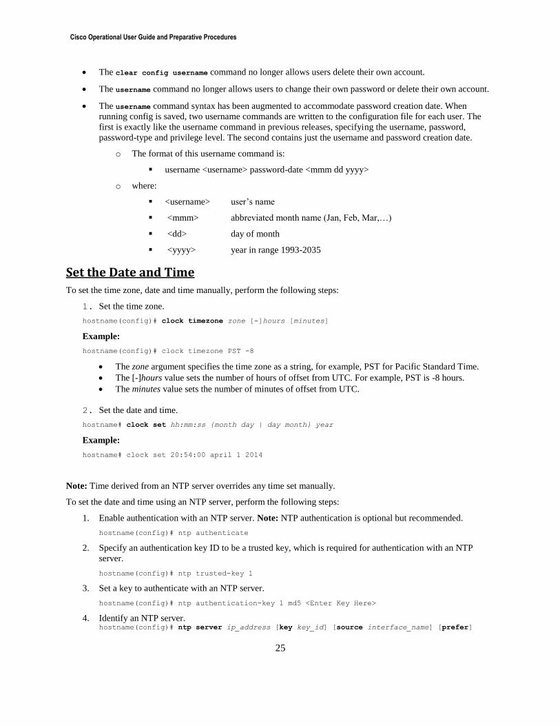
The clear config username command no longer allows users delete their own account.
The username command no longer allows users to change their own password or delete their own account.
The username command syntax has been augmented to accommodate password creation date. When
running config is saved, two username commands are written to the configuration file for each user. The
first is exactly like the username command in previous releases, specifying the username, password,
password-type and privilege level. The second contains just the username and password creation date.
o The format of this username command is:
username <username> password-date <mmm dd yyyy>
o where:
<username> user’s name
<mmm> abbreviated month name (Jan, Feb, Mar,…)
<dd> day of month
<yyyy> year in range 1993-2035
Set the Date and Time
To set the time zone, date and time manually, perform the following steps:
1. Set the time zone.
hostname(config)# clock timezone zone [-]hours [minutes]
Example:
hostname(config)# clock timezone PST -8
The zone argument specifies the time zone as a string, for example, PST for Pacific Standard Time.
The [-]hours value sets the number of hours of offset from UTC. For example, PST is -8 hours.
The minutes value sets the number of minutes of offset from UTC.
2. Set the date and time.
hostname# clock set hh:mm:ss {month day | day month} year
Example:
hostname# clock set 20:54:00 april 1 2014
Note: Time derived from an NTP server overrides any time set manually.
To set the date and time using an NTP server, perform the following steps:
1. Enable authentication with an NTP server. Note: NTP authentication is optional but recommended.
hostname(config)# ntp authenticate
2. Specify an authentication key ID to be a trusted key, which is required for authentication with an NTP
server.
hostname(config)# ntp trusted-key 1
3. Set a key to authenticate with an NTP server.
hostname(config)# ntp authentication-key 1 md5 <Enter Key Here>
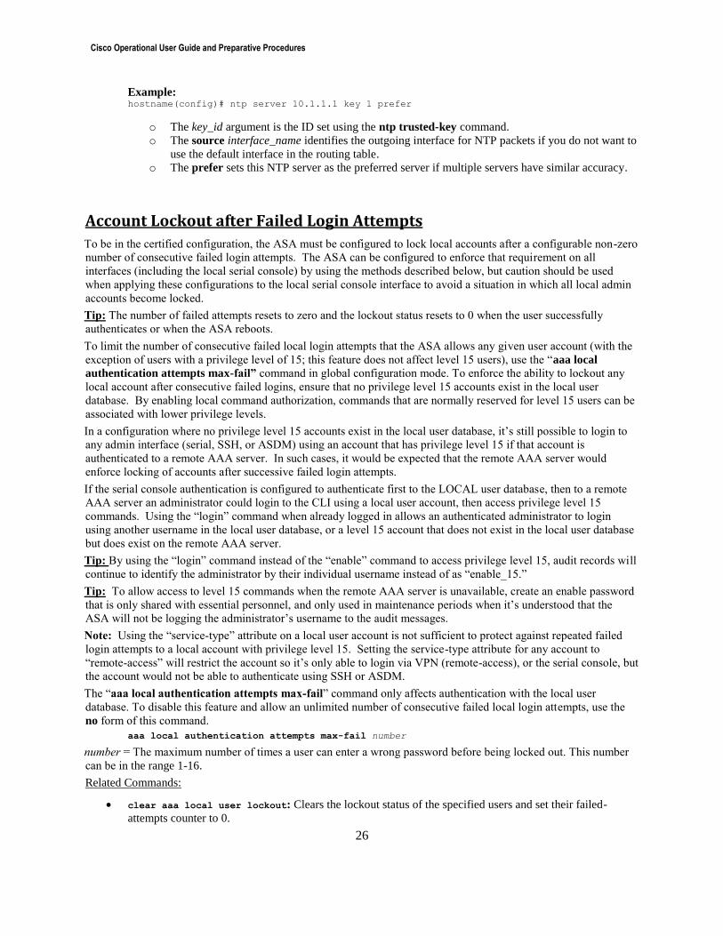
4. Identify an NTP server. hostname(config)# ntp server ip_address [key key_id] [source interface_name] [prefer]
Cisco Operational User Guide and Preparative Procedures
26
Example: hostname(config)# ntp server 10.1.1.1 key 1 prefer
o The key_id argument is the ID set using the ntp trusted-key command.
o The source interface_name identifies the outgoing interface for NTP packets if you do not want to
use the default interface in the routing table.
o The prefer sets this NTP server as the preferred server if multiple servers have similar accuracy.
Account Lockout after Failed Login Attempts
To be in the certified configuration, the ASA must be configured to lock local accounts after a configurable non-zero
number of consecutive failed login attempts. The ASA can be configured to enforce that requirement on all
interfaces (including the local serial console) by using the methods described below, but caution should be used
when applying these configurations to the local serial console interface to avoid a situation in which all local admin
accounts become locked.
Tip: The number of failed attempts resets to zero and the lockout status resets to 0 when the user successfully
authenticates or when the ASA reboots.
To limit the number of consecutive failed local login attempts that the ASA allows any given user account (with the
exception of users with a privilege level of 15; this feature does not affect level 15 users), use the “aaa local
authentication attempts max-fail” command in global configuration mode. To enforce the ability to lockout any
local account after consecutive failed logins, ensure that no privilege level 15 accounts exist in the local user
database. By enabling local command authorization, commands that are normally reserved for level 15 users can be
associated with lower privilege levels.
In a configuration where no privilege level 15 accounts exist in the local user database, it’s still possible to login to
any admin interface (serial, SSH, or ASDM) using an account that has privilege level 15 if that account is
authenticated to a remote AAA server. In such cases, it would be expected that the remote AAA server would
enforce locking of accounts after successive failed login attempts.
If the serial console authentication is configured to authenticate first to the LOCAL user database, then to a remote
AAA server an administrator could login to the CLI using a local user account, then access privilege level 15
commands. Using the “login” command when already logged in allows an authenticated administrator to login
using another username in the local user database, or a level 15 account that does not exist in the local user database
but does exist on the remote AAA server.
Tip: By using the “login” command instead of the “enable” command to access privilege level 15, audit records will
continue to identify the administrator by their individual username instead of as “enable_15.”
Tip: To allow access to level 15 commands when the remote AAA server is unavailable, create an enable password
that is only shared with essential personnel, and only used in maintenance periods when it’s understood that the
ASA will not be logging the administrator’s username to the audit messages.
Note: Using the “service-type” attribute on a local user account is not sufficient to protect against repeated failed
login attempts to a local account with privilege level 15. Setting the service-type attribute for any account to
“remote-access” will restrict the account so it’s only able to login via VPN (remote-access), or the serial console, but
the account would not be able to authenticate using SSH or ASDM.
The “aaa local authentication attempts max-fail” command only affects authentication with the local user
database. To disable this feature and allow an unlimited number of consecutive failed local login attempts, use the
no form of this command.
aaa local authentication attempts max-fail number
number = The maximum number of times a user can enter a wrong password before being locked out. This number
can be in the range 1-16.
Related Commands:
clear aaa local user lockout: Clears the lockout status of the specified users and set their failed-
attempts counter to 0.
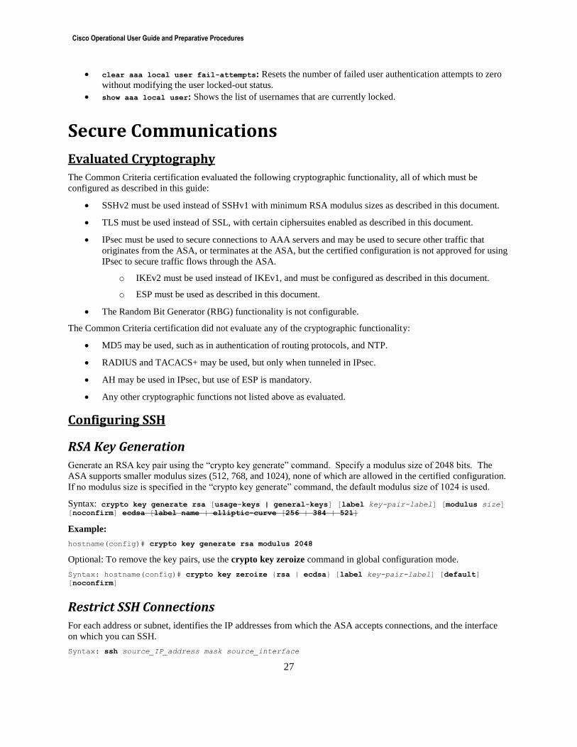
Cisco Operational User Guide and Preparative Procedures
27
clear aaa local user fail-attempts: Resets the number of failed user authentication attempts to zero
without modifying the user locked-out status.
show aaa local user: Shows the list of usernames that are currently locked.
Secure Communications
Evaluated Cryptography
The Common Criteria certification evaluated the following cryptographic functionality, all of which must be
configured as described in this guide:
SSHv2 must be used instead of SSHv1 with minimum RSA modulus sizes as described in this document.
TLS must be used instead of SSL, with certain ciphersuites enabled as described in this document.
IPsec must be used to secure connections to AAA servers and may be used to secure other traffic that
originates from the ASA, or terminates at the ASA, but the certified configuration is not approved for using
IPsec to secure traffic flows through the ASA.
o IKEv2 must be used instead of IKEv1, and must be configured as described in this document.
o ESP must be used as described in this document.
The Random Bit Generator (RBG) functionality is not configurable.
The Common Criteria certification did not evaluate any of the cryptographic functionality:
MD5 may be used, such as in authentication of routing protocols, and NTP.
RADIUS and TACACS+ may be used, but only when tunneled in IPsec.
AH may be used in IPsec, but use of ESP is mandatory.
Any other cryptographic functions not listed above as evaluated.
Configuring SSH
RSA Key Generation
Generate an RSA key pair using the “crypto key generate” command. Specify a modulus size of 2048 bits. The
ASA supports smaller modulus sizes (512, 768, and 1024), none of which are allowed in the certified configuration.
If no modulus size is specified in the “crypto key generate” command, the default modulus size of 1024 is used.
Syntax: crypto key generate rsa [usage-keys | general-keys] [label key-pair-label] [modulus size] [noconfirm] ecdsa [label name | elliptic-curve [256 | 384 | 521]
Example:
hostname(config)# crypto key generate rsa modulus 2048
Optional: To remove the key pairs, use the crypto key zeroize command in global configuration mode.
Syntax: hostname(config)# crypto key zeroize {rsa | ecdsa} [label key-pair-label] [default]
[noconfirm]
Restrict SSH Connections
For each address or subnet, identifies the IP addresses from which the ASA accepts connections, and the interface
on which you can SSH.
Syntax: ssh source_IP_address mask source_interface
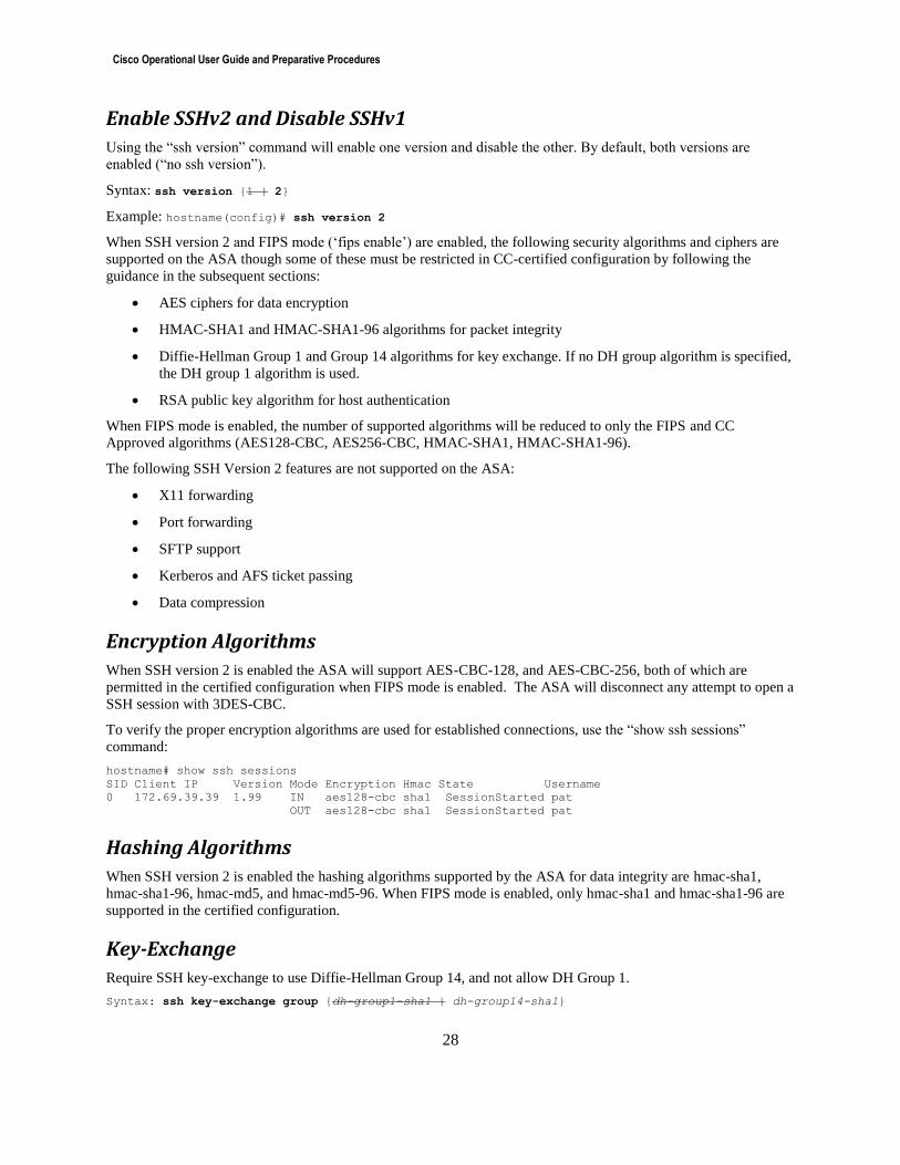
Cisco Operational User Guide and Preparative Procedures
28
Enable SSHv2 and Disable SSHv1
Using the “ssh version” command will enable one version and disable the other. By default, both versions are
enabled (“no ssh version”).
Syntax: ssh version {1 | 2}
Example: hostname(config)# ssh version 2
When SSH version 2 and FIPS mode (‘fips enable’) are enabled, the following security algorithms and ciphers are
supported on the ASA though some of these must be restricted in CC-certified configuration by following the
guidance in the subsequent sections:
AES ciphers for data encryption
HMAC-SHA1 and HMAC-SHA1-96 algorithms for packet integrity
Diffie-Hellman Group 1 and Group 14 algorithms for key exchange. If no DH group algorithm is specified,
the DH group 1 algorithm is used.
RSA public key algorithm for host authentication
When FIPS mode is enabled, the number of supported algorithms will be reduced to only the FIPS and CC
Approved algorithms (AES128-CBC, AES256-CBC, HMAC-SHA1, HMAC-SHA1-96).
The following SSH Version 2 features are not supported on the ASA:
X11 forwarding
Port forwarding
SFTP support
Kerberos and AFS ticket passing
Data compression
Encryption Algorithms
When SSH version 2 is enabled the ASA will support AES-CBC-128, and AES-CBC-256, both of which are
permitted in the certified configuration when FIPS mode is enabled. The ASA will disconnect any attempt to open a
SSH session with 3DES-CBC.
To verify the proper encryption algorithms are used for established connections, use the “show ssh sessions”
command:
hostname# show ssh sessions
SID Client IP Version Mode Encryption Hmac State Username
0 172.69.39.39 1.99 IN aes128-cbc sha1 SessionStarted pat
OUT aes128-cbc sha1 SessionStarted pat
Hashing Algorithms
When SSH version 2 is enabled the hashing algorithms supported by the ASA for data integrity are hmac-sha1,
hmac-sha1-96, hmac-md5, and hmac-md5-96. When FIPS mode is enabled, only hmac-sha1 and hmac-sha1-96 are
supported in the certified configuration.
Key-Exchange
Require SSH key-exchange to use Diffie-Hellman Group 14, and not allow DH Group 1.
Syntax: ssh key-exchange group {dh-group1-sha1 | dh-group14-sha1}
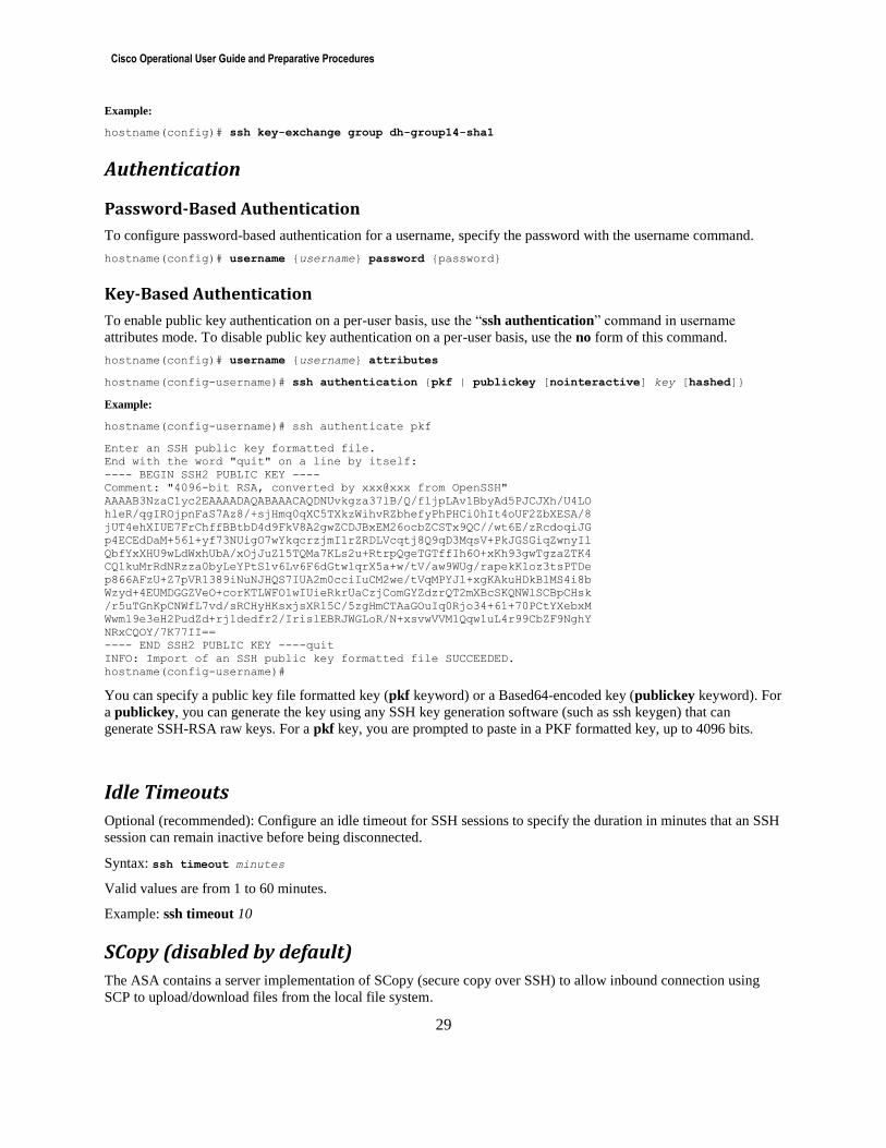
Cisco Operational User Guide and Preparative Procedures
29
Example:
hostname(config)# ssh key-exchange group dh-group14-sha1
Authentication
Password-Based Authentication
To configure password-based authentication for a username, specify the password with the username command.
hostname(config)# username {username} password {password}
Key-Based Authentication
To enable public key authentication on a per-user basis, use the “ssh authentication” command in username
attributes mode. To disable public key authentication on a per-user basis, use the no form of this command.
hostname(config)# username {username} attributes
hostname(config-username)# ssh authentication {pkf | publickey [nointeractive] key [hashed]}
Example:
hostname(config-username)# ssh authenticate pkf
Enter an SSH public key formatted file.
End with the word "quit" on a line by itself:
---- BEGIN SSH2 PUBLIC KEY ----
Comment: "4096-bit RSA, converted by xxx@xxx from OpenSSH"
AAAAB3NzaC1yc2EAAAADAQABAAACAQDNUvkgza37lB/Q/fljpLAv1BbyAd5PJCJXh/U4LO
hleR/qgIROjpnFaS7Az8/+sjHmq0qXC5TXkzWihvRZbhefyPhPHCi0hIt4oUF2ZbXESA/8
jUT4ehXIUE7FrChffBBtbD4d9FkV8A2gwZCDJBxEM26ocbZCSTx9QC//wt6E/zRcdoqiJG
p4ECEdDaM+56l+yf73NUigO7wYkqcrzjmI1rZRDLVcqtj8Q9qD3MqsV+PkJGSGiqZwnyIl
QbfYxXHU9wLdWxhUbA/xOjJuZ15TQMa7KLs2u+RtrpQgeTGTffIh6O+xKh93gwTgzaZTK4
CQ1kuMrRdNRzza0byLeYPtSlv6Lv6F6dGtwlqrX5a+w/tV/aw9WUg/rapekKloz3tsPTDe
p866AFzU+Z7pVR1389iNuNJHQS7IUA2m0cciIuCM2we/tVqMPYJl+xgKAkuHDkBlMS4i8b
Wzyd+4EUMDGGZVeO+corKTLWFO1wIUieRkrUaCzjComGYZdzrQT2mXBcSKQNWlSCBpCHsk
/r5uTGnKpCNWfL7vd/sRCHyHKsxjsXR15C/5zgHmCTAaGOuIq0Rjo34+61+70PCtYXebxM
Wwm19e3eH2PudZd+rj1dedfr2/IrislEBRJWGLoR/N+xsvwVVM1Qqw1uL4r99CbZF9NghY
NRxCQOY/7K77II==
---- END SSH2 PUBLIC KEY ----quit
INFO: Import of an SSH public key formatted file SUCCEEDED.
hostname(config-username)#
You can specify a public key file formatted key (pkf keyword) or a Based64-encoded key (publickey keyword). For
a publickey, you can generate the key using any SSH key generation software (such as ssh keygen) that can
generate SSH-RSA raw keys. For a pkf key, you are prompted to paste in a PKF formatted key, up to 4096 bits.
Idle Timeouts
Optional (recommended): Configure an idle timeout for SSH sessions to specify the duration in minutes that an SSH
session can remain inactive before being disconnected.
Syntax: ssh timeout minutes
Valid values are from 1 to 60 minutes.
Example: ssh timeout 10
SCopy (disabled by default)
The ASA contains a server implementation of SCopy (secure copy over SSH) to allow inbound connection using
SCP to upload/download files from the local file system.
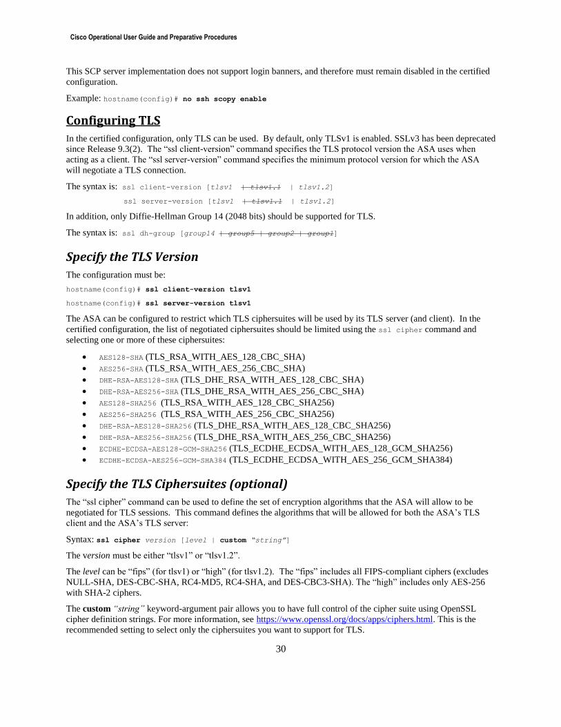
Cisco Operational User Guide and Preparative Procedures
30
This SCP server implementation does not support login banners, and therefore must remain disabled in the certified
configuration.
Example: hostname(config)# no ssh scopy enable
Configuring TLS
In the certified configuration, only TLS can be used. By default, only TLSv1 is enabled. SSLv3 has been deprecated
since Release 9.3(2). The “ssl client-version” command specifies the TLS protocol version the ASA uses when
acting as a client. The “ssl server-version” command specifies the minimum protocol version for which the ASA
will negotiate a TLS connection.
The syntax is: ssl client-version [tlsv1 | tlsv1.1 | tlsv1.2]
ssl server-version [tlsv1 | tlsv1.1 | tlsv1.2]
In addition, only Diffie-Hellman Group 14 (2048 bits) should be supported for TLS.
The syntax is: ssl dh-group [group14 | group5 | group2 | group1]
Specify the TLS Version
The configuration must be:
hostname(config)# ssl client-version tlsv1
hostname(config)# ssl server-version tlsv1
The ASA can be configured to restrict which TLS ciphersuites will be used by its TLS server (and client). In the
certified configuration, the list of negotiated ciphersuites should be limited using the ssl cipher command and
selecting one or more of these ciphersuites:
AES128-SHA (TLS_RSA_WITH_AES_128_CBC_SHA)
AES256-SHA (TLS_RSA_WITH_AES_256_CBC_SHA)
DHE-RSA-AES128-SHA (TLS_DHE_RSA_WITH_AES_128_CBC_SHA)
DHE-RSA-AES256-SHA (TLS_DHE_RSA_WITH_AES_256_CBC_SHA)
AES128-SHA256 (TLS_RSA_WITH_AES_128_CBC_SHA256)
AES256-SHA256 (TLS_RSA_WITH_AES_256_CBC_SHA256)
DHE-RSA-AES128-SHA256 (TLS_DHE_RSA_WITH_AES_128_CBC_SHA256)
DHE-RSA-AES256-SHA256 (TLS_DHE_RSA_WITH_AES_256_CBC_SHA256)
ECDHE-ECDSA-AES128-GCM-SHA256 (TLS_ECDHE_ECDSA_WITH_AES_128_GCM_SHA256)
ECDHE-ECDSA-AES256-GCM-SHA384 (TLS_ECDHE_ECDSA_WITH_AES_256_GCM_SHA384)
Specify the TLS Ciphersuites (optional)
The “ssl cipher” command can be used to define the set of encryption algorithms that the ASA will allow to be
negotiated for TLS sessions. This command defines the algorithms that will be allowed for both the ASA’s TLS
client and the ASA’s TLS server:
Syntax: ssl cipher version [level | custom “string”]
The version must be either “tlsv1” or “tlsv1.2”.
The level can be “fips” (for tlsv1) or “high” (for tlsv1.2). The “fips” includes all FIPS-compliant ciphers (excludes
NULL-SHA, DES-CBC-SHA, RC4-MD5, RC4-SHA, and DES-CBC3-SHA). The “high” includes only AES-256
with SHA-2 ciphers.
The custom “string” keyword-argument pair allows you to have full control of the cipher suite using OpenSSL
cipher definition strings. For more information, see https://www.openssl.org/docs/apps/ciphers.html. This is the
recommended setting to select only the ciphersuites you want to support for TLS.
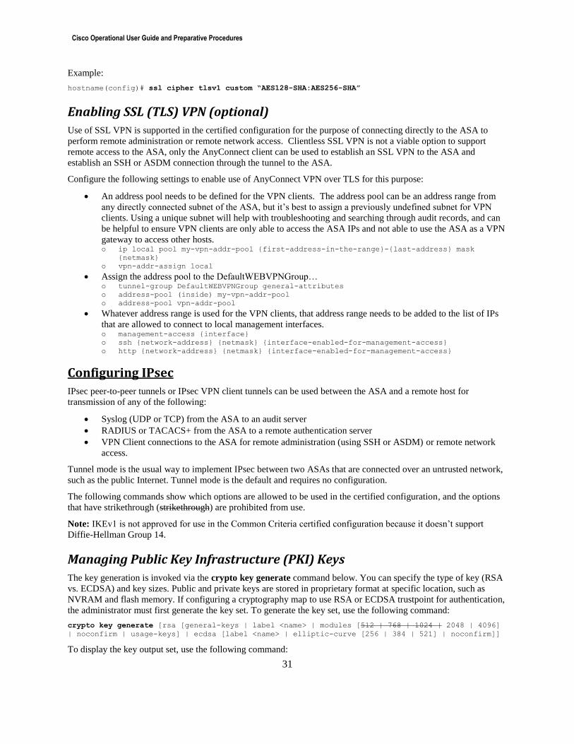
Cisco Operational User Guide and Preparative Procedures
31
Example:
hostname(config)# ssl cipher tlsv1 custom “AES128-SHA:AES256-SHA”
Enabling SSL (TLS) VPN (optional)
Use of SSL VPN is supported in the certified configuration for the purpose of connecting directly to the ASA to
perform remote administration or remote network access. Clientless SSL VPN is not a viable option to support
remote access to the ASA, only the AnyConnect client can be used to establish an SSL VPN to the ASA and
establish an SSH or ASDM connection through the tunnel to the ASA.
Configure the following settings to enable use of AnyConnect VPN over TLS for this purpose:
An address pool needs to be defined for the VPN clients. The address pool can be an address range from
any directly connected subnet of the ASA, but it’s best to assign a previously undefined subnet for VPN
clients. Using a unique subnet will help with troubleshooting and searching through audit records, and can
be helpful to ensure VPN clients are only able to access the ASA IPs and not able to use the ASA as a VPN
gateway to access other hosts. o ip local pool my-vpn-addr-pool {first-address-in-the-range}-{last-address} mask
{netmask}
o vpn-addr-assign local
Assign the address pool to the DefaultWEBVPNGroup… o tunnel-group DefaultWEBVPNGroup general-attributes
o address-pool (inside) my-vpn-addr-pool
o address-pool vpn-addr-pool
Whatever address range is used for the VPN clients, that address range needs to be added to the list of IPs
that are allowed to connect to local management interfaces. o management-access {interface}
o ssh {network-address} {netmask} {interface-enabled-for-management-access}
o http {network-address} {netmask} {interface-enabled-for-management-access}
Configuring IPsec
IPsec peer-to-peer tunnels or IPsec VPN client tunnels can be used between the ASA and a remote host for
transmission of any of the following:
Syslog (UDP or TCP) from the ASA to an audit server
RADIUS or TACACS+ from the ASA to a remote authentication server
VPN Client connections to the ASA for remote administration (using SSH or ASDM) or remote network
access.
Tunnel mode is the usual way to implement IPsec between two ASAs that are connected over an untrusted network,
such as the public Internet. Tunnel mode is the default and requires no configuration.
The following commands show which options are allowed to be used in the certified configuration, and the options
that have strikethrough (strikethrough) are prohibited from use.
Note: IKEv1 is not approved for use in the Common Criteria certified configuration because it doesn’t support
Diffie-Hellman Group 14.
Managing Public Key Infrastructure (PKI) Keys
The key generation is invoked via the crypto key generate command below. You can specify the type of key (RSA
vs. ECDSA) and key sizes. Public and private keys are stored in proprietary format at specific location, such as
NVRAM and flash memory. If configuring a cryptography map to use RSA or ECDSA trustpoint for authentication,
the administrator must first generate the key set. To generate the key set, use the following command:
crypto key generate [rsa [general-keys | label <name> | modules [512 | 768 | 1024 | 2048 | 4096]
| noconfirm | usage-keys] | ecdsa [label <name> | elliptic-curve [256 | 384 | 521] | noconfirm]]
To display the key output set, use the following command:
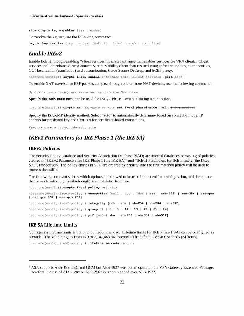
Cisco Operational User Guide and Preparative Procedures
32
show crypto key mypubkey [rsa | ecdsa]
To zeroize the key set, use the following command:
crypto key zeroize [rsa | ecdsa] [default | label <name> | noconfirm]
Enable IKEv2
Enable IKEv2, though enabling “client services” is irrelevant since that enables services for VPN clients. Client
services include enhanced AnyConnect Secure Mobility client features including software updates, client profiles,
GUI localization (translation) and customization, Cisco Secure Desktop, and SCEP proxy.
hostname(config)# crypto ikev2 enable interface-name [client-services [port port]]
To enable NAT traversal so ESP packets can pass through one or more NAT devices, use the following command:
Syntax: crypto isakmp nat-traversal seconds Use Main Mode
Specify that only main most can be used for IKEv2 Phase 1 when initiating a connection.
hostname(config)# crypto map map-name seq-num set ikev2 phase1-mode {main | aggressive}
Specify the ISAKMP identity method. Select “auto” to automatically determine based on connection type: IP
address for preshared key and Cert DN for certificate-based connections.
Syntax: crypto isakmp identity auto
IKEv2 Parameters for IKE Phase 1 (the IKE SA)
IKEv2 Policies
The Security Policy Database and Security Association Database (SAD) are internal databases consisting of policies
created in “IKEv2 Parameters for IKE Phase 1 (the IKE SA)” and “IKEv2 Parameters for IKE Phase 2 (the IPsec
SA)”, respectively. The policy entries in SPD are ordered by priority, and the first matched policy will be used to
process the traffic.
The following commands show which options are allowed to be used in the certified configuration, and the options
that have strikethrough (strikethrough) are prohibited from use.
hostname(config)# crypto ikev2 policy priority
hostname(config-ikev2-policy)# encryption [null | des | 3des | aes | aes-1921 | aes-256 | aes-gcm
| aes-gcm-192 | aes-gcm-256]
hostname(config-ikev2-policy)# integrity [md5 | sha | sha256 | sha384 | sha512]
hostname(config-ikev2-policy)# group [1 | 2 | 5 | 14 | 19 | 20 | 21 | 24]
hostname(config-ikev2-policy)# prf [md5 | sha | sha256 | sha384 | sha512]
IKE SA Lifetime Limits
Configuring lifetime limits is optional but recommended. Lifetime limits for IKE Phase 1 SAs can be configured in
seconds. The valid range is from 120 to 2,147,483,647 seconds. The default is 86,400 seconds (24 hours).
hostname(config-ikev2-policy)# lifetime seconds seconds
1 ASA supports AES-192 CBC and GCM but AES-192* was not an option in the VPN Gateway Extended Package.
Therefore, the use of AES-128* or AES-256* is recommended over AES-192*.
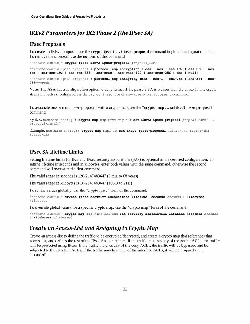
Cisco Operational User Guide and Preparative Procedures
33
IKEv2 Parameters for IKE Phase 2 (the IPsec SA)
IPsec Proposals
To create an IKEv2 proposal, use the crypto ipsec ikev2 ipsec-proposal command in global configuration mode.
To remove the proposal, use the no form of this command.
hostname(config)# crypto ipsec ikev2 ipsec-proposal proposal_name
hostname(config-ipsec-proposal)# protocol esp encryption [3des | aes | aes-192 | aes-256 | aes-
gcm | aes-gcm-192 | aes-gcm-256 | aes-gmac | aes-gmac-192 | aes-gmac-256 | des | null]
hostname(config-ipsec-proposal)# protocol esp integrity [md5 | sha-1 | sha-256 | sha-384 | sha-
512 | null]
Note: The ASA has a configuration option to deny tunnel if the phase 2 SA is weaker than the phase 1. The crypto
strength check is configured via the crypto ipsec ikev2 sa-strength-enforcement command.
To associate one or more ipsec-proposals with a crypto map, use the “crypto map … set ikev2 ipsec-proposal”
command.
Syntax: hostname(config)# crypto map map-name seq-num set ikev2 ipsec-proposal propsal-name1 [… proposal-name11]
Example: hostname(config)# crypto map map2 10 set ikev2 ipsec-proposal 128aes-sha 192aes-sha 256aes-sha
IPsec SA Lifetime Limits
Setting lifetime limits for IKE and IPsec security associations (SAs) is optional in the certified configuration. If
setting lifetime in seconds and in kilobytes, enter both values with the same command, otherwise the second
command will overwrite the first command.
The valid range in seconds is 120-2147483647 (2 min to 68 years)
The valid range in kilobytes is 10-2147483647 (10KB to 2TB)
To set the values globally, use the “crypto ipsec” form of the command:
hostname(config)# crypto ipsec security-association lifetime {seconds seconds | kilobytes
kilobytes}
To override global values for a specific crypto map, use the “crypto map” form of the command:
hostname(config)# crypto map map-name seq-num set security-association lifetime {seconds seconds
| kilobytes kilobytes}
Create an Access-List and Assigning to Crypto Map
Create an access-list to define the traffic to be encrypted/decrypted, and create a crypto map that references that
access-list, and defines the rest of the IPsec SA parameters. If the traffic matches any of the permit ACLs, the traffic
will be protected using IPsec. If the traffic matches any of the deny ACLs, the traffic will be bypassed and be
subjected to the interface ACLs. If the traffic matches none of the interface ACLs, it will be dropped (i.e.,
discarded).
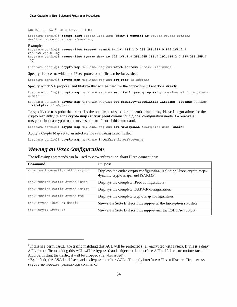
Cisco Operational User Guide and Preparative Procedures
34
Assign an ACL2 to a crypto map:
hostname(config)# access-list access-list-name {deny | permit} ip source source-netmask
destination destination-netmask log
Example: hostname(config)# access-list Protect permit ip 192.168.1.0 255.255.255.0 192.168.2.0
255.255.255.0 log
hostname(config)# access-list Bypass deny ip 192.168.1.0 255.255.255.0 192.168.2.0 255.255.255.0
log
hostname(config)# crypto map map-name seq-num match address access-list-number3
Specify the peer to which the IPsec-protected traffic can be forwarded:
hostname(config)# crypto map map-name seq-num set peer ip-address
Specify which SA proposal and lifetime that will be used for the connection, if not done already.
hostname(config)# crypto map map-name seq-num set ikev2 ipsec-proposal propsal-name1 [… proposal-
name11]
hostname(config)# crypto map map-name seq-num set security-association lifetime {seconds seconds
| kilobytes kilobytes}
To specify the trustpoint that identifies the certificate to send for authentication during Phase 1 negotiations for the
crypto map entry, use the crypto map set trustpoint command in global configuration mode. To remove a
trustpoint from a crypto map entry, use the no form of this command.
hostname(config)# crypto map map-name seq-num set trustpoint trustpoint-name [chain]
Apply a Crypto Map set to an interface for evaluating IPsec traffic:
hostname(config)# crypto map map-name interface interface-name
Viewing an IPsec Configuration
The following commands can be used to view information about IPsec connections:
Command Purpose
show running-configuration crypto Displays the entire crypto configuration, including IPsec, crypto maps,
dynamic crypto maps, and ISAKMP.
show running-config crypto ipsec Displays the complete IPsec configuration.
show running-config crypto isakmp Displays the complete ISAKMP configuration.
show running-config crypto map Displays the complete crypto map configuration.
show crypto ikev2 sa detail Shows the Suite B algorithm support in the Encryption statistics.
show crypto ipsec sa Shows the Suite B algorithm support and the ESP IPsec output.
2 If this is a permit ACL, the traffic matching this ACL will be protected (i.e., encrypted with IPsec). If this is a deny
ACL, the traffic matching this ACL will be bypassed and subject to the interface ACLs. If there are no interface
ACL permitting the traffic, it will be dropped (i.e., discarded). 3 By default, the ASA lets IPsec packets bypass interface ACLs. To apply interface ACLs to IPsec traffic, use: no
sysopt connection permit-vpn command.
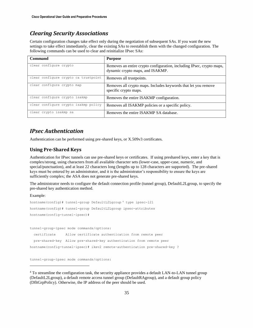
Cisco Operational User Guide and Preparative Procedures
35
Clearing Security Associations
Certain configuration changes take effect only during the negotiation of subsequent SAs. If you want the new
settings to take effect immediately, clear the existing SAs to reestablish them with the changed configuration. The
following commands can be used to clear and reinitialize IPsec SAs:
Command Purpose
clear configure crypto Removes an entire crypto configuration, including IPsec, crypto maps,
dynamic crypto maps, and ISAKMP.
clear configure crypto ca trustpoint Removes all trustpoints.
clear configure crypto map Removes all crypto maps. Includes keywords that let you remove
specific crypto maps.
clear configure crypto isakmp Removes the entire ISAKMP configuration.
clear configure crypto isakmp policy Removes all ISAKMP policies or a specific policy.
clear crypto isakmp sa Removes the entire ISAKMP SA database.
IPsec Authentication
Authentication can be performed using pre-shared keys, or X.509v3 certificates.
Using Pre-Shared Keys
Authentication for IPsec tunnels can use pre-shared keys or certificates. If using preshared keys, enter a key that is
complex/strong, using characters from all available character sets (lower-case, upper-case, numeric, and
special/punctuation), and at least 22 characters long (lengths up to 128 characters are supported). The pre-shared
keys must be entered by an administrator, and it is the administrator’s responsibility to ensure the keys are
sufficiently complex; the ASA does not generate pre-shared keys.
The administrator needs to configure the default connection profile (tunnel group), DefaultL2Lgroup, to specify the
pre-shared key authentication method.
Example:
hostname(config)# tunnel-group DefaultL2Lgroup 4 type ipsec-l2l
hostname(config)# tunnel-group DefaultL2Lgroup ipsec-attributes
hostname(config-tunnel-ipsec)#
tunnel-group-ipsec mode commands/options:
certificate Allow certificate authentication from remote peer
pre-shared-key Allow pre-shared-key authentication from remote peer
hostname(config-tunnel-ipsec)# ikev2 remote-authentication pre-shared-key ?
tunnel-group-ipsec mode commands/options:
4 To streamline the configuration task, the security appliance provides a default LAN-to-LAN tunnel group
(DefaultL2Lgroup), a default remote access tunnel group (DefaultRAgroup), and a default group policy
(DfltGrpPolicy). Otherwise, the IP address of the peer should be used.

Cisco Operational User Guide and Preparative Procedures
36
0 Specifies an UNENCRYPTED password will follow
8 Specifies an ENCRYPTED password will follow
WORD < 129 char Enter an alphanumeric string between 1-128 characters
hex Configure a hex pre-shared-key
hostname(config-tunnel-ipsec)# $ ikev2 remote-authentication pre-shared-key hex ?
tunnel-group-ipsec mode commands/options:
Hex-string Enter a hex pre-shared-key between 2-256 even number of
characters
Note: The pre-shared-key type indicates what format of the pre-shared key is being entered at the CLI. Type 8
indicates the key being entered is in encrypted format and will be conditioned with the Password-Based Key
Derivation Function 2 (PBKDF2) with SHA-256 hashed secret. Type 8 cannot be combined with the ‘hex’ keyword
as the two options are mutually exclusive. Type 0 is the default and means that the pre-shared-key being entered at
the CLI is in plaintext format.
Using X.509v3 Digital Certificates
ASA supports X.509v3 certificates as defined by RFC 5280. Public key infrastructure (PKI) credentials, such as
private keys and certificates are stored in a specific location, such as NVRAM and flash memory. The identification
and authentication, and authorization security functions protect an unauthorized user from gaining access to the
storage.
Digital certificates provide digital identification for authentication. A digital certificate includes information that
identifies a device or user, such as the common name, serial number, company, department, state, country, or IP
address. CAs are trusted authorities that “sign” certificates to verify their authenticity, thereby guaranteeing the
identity of the device or user. CAs issue digital certificates in the context of a PKI, which uses public-key or private-
key encryption to ensure security.
For authentication using digital certificates, at least one identity certificate and its issuing CA certificate must exist
on an ASA. This configuration allows multiple identities, roots, and certificate hierarchies. The ASA evaluates third-
party certificates against CRLs, also called authority revocation lists, all the way from the identity certificate up the
chain of subordinate certificate authorities.
Descriptions of several different types of available digital certificates follow:
• A CA certificate is used to sign other certificates. It is self-signed and called a root certificate. A
certificate that is issued by another CA certificate is called a subordinate certificate.
• CAs also issue identity certificates, which are certificates for specific systems or hosts.
The ASA CA integrates an independent certificate authority feature on the ASA, deploys certificates, and provides
secure revocation checking of issued certificates. The ASA CA provides a secure, configurable, in-house authority
for certificate authentication with user enrollment through a website login page.
When a certificate is issued, it is valid for a fixed period of time. Sometimes a CA revokes a certificate before this
time period expires; for example, because of security concerns or a change of name or association. CAs periodically
issue a signed list of revoked certificates. Enabling revocation checking forces the ASA to check that the CA has not
revoked a certificate each time that it uses the certificate for authentication.
When the administrator enables revocation checking, the ASA checks certificate revocation status during the PKI
certificate validation process, which can use either CRL checking, OCSP, or both. OCSP is only used when the first
method returns an error (for example, indicating that the server is unavailable).

Cisco Operational User Guide and Preparative Procedures
37
With CRL checking, the ASA retrieves, parses, and caches CRLs, which provide a complete list of revoked (and
unrevoked) certificates with their certificate serial numbers. The ASA evaluates certificates according to CRLs, also
called authority revocation lists, from the identity certificate up the chain of subordinate certificate authorities.
OCSP offers a more scalable method of checking revocation status in that it localizes certificate status through a
validation authority, which it queries for status of a specific certificate.
CRLs
CRLs provide the ASA with one way of determining whether a certificate that is within its valid time range has been
revoked by the issuing CA. CRL configuration is part of configuration of a trustpoint.
The administrator can configure the ASA to make CRL checks mandatory when authenticating a certificate by using
the revocation-check crl command. The administrator can also make the CRL check optional by using the
revocation-check crl none command, which allows the certificate authentication to succeed when the CA is
unavailable to provide updated CRL data for certificate validation.
The ASA can retrieve CRLs from CAs using HTTP, SCEP, or LDAP. CRLs retrieved for each trustpoint are cached
for a configurable amount of time for each trustpoint.
OCSP
OCSP provides the ASA with a way of determining whether a certificate that is within its valid time range has been
revoked by the issuing CA. OCSP configuration is part of trustpoint configuration.
OCSP localizes certificate status on a validation authority (an OCSP server, also called the responder) which the
ASA queries for the status of a specific certificate. This method provides better scalability and more up-to-date
revocation status than does CRL checking, and helps organizations with large PKI installations deploy and expand
secure networks.
Note: The ASA allows a five-second time skew for OCSP responses.
You can configure the ASA to make OCSP checks mandatory when authenticating a certificate by using the
revocation-check ocsp command. You can also make the OCSP check optional by using the revocation-check
ocsp none command, which allows the certificate authentication to succeed when the validation authority is
unavailable to provide updated OCSP data.
Generate Certificate Signing Request (CSR)
Generate a RSA or ECDSA key pair. See “Managing Public Key Infrastructure (PKI) Keys” section.
Example:
hostname(config)# crypto key generate rsa label RSA-key modulus 2048
Create and configure a CA trustpoint.
Example:
hostname(config)# crypto ca trustpoint myCA
hostname(config-ca-trustpoint)# enrollment terminal
hostname(config-ca-trustpoint)# subject-name CN=<name>,OU=<unit>,O=<company>,C=<country>
hostname(config-ca-trustpoint)# keypair RSA-key
hostname(config-ca-trustpoint)# revocation-check crl
hostname(config-ca-trustpoint)# write memory
hostname(config-ca-trustpoint)# exit
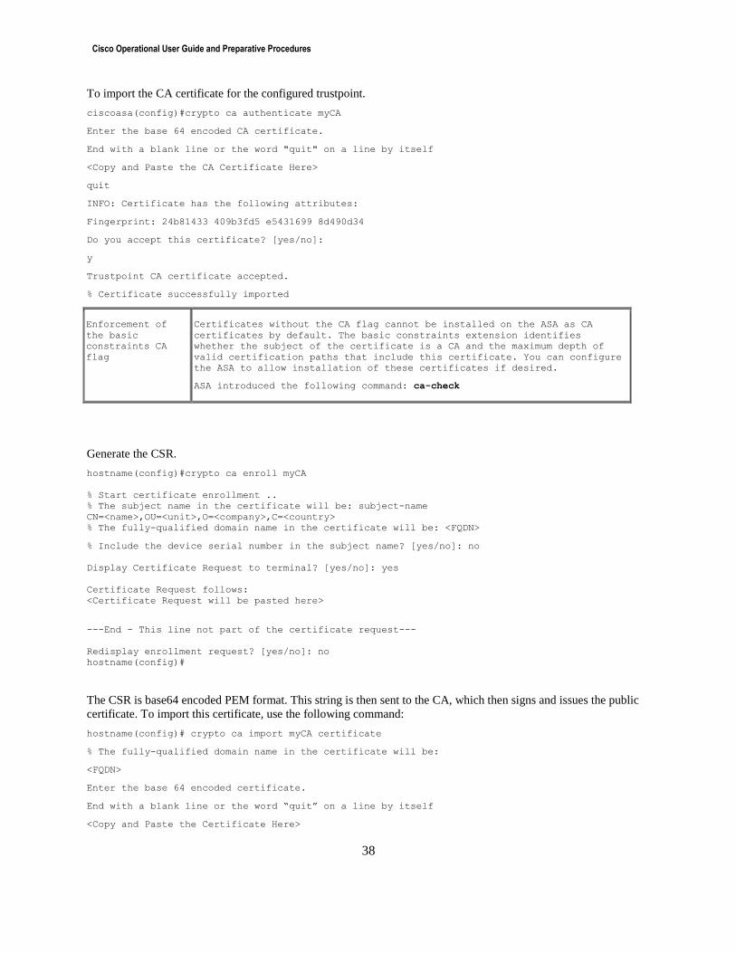
Cisco Operational User Guide and Preparative Procedures
38
To import the CA certificate for the configured trustpoint.
ciscoasa(config)#crypto ca authenticate myCA
Enter the base 64 encoded CA certificate.
End with a blank line or the word "quit" on a line by itself
<Copy and Paste the CA Certificate Here>
quit
INFO: Certificate has the following attributes:
Fingerprint: 24b81433 409b3fd5 e5431699 8d490d34
Do you accept this certificate? [yes/no]:
y
Trustpoint CA certificate accepted.
% Certificate successfully imported
Enforcement of
the basic
constraints CA
flag
Certificates without the CA flag cannot be installed on the ASA as CA
certificates by default. The basic constraints extension identifies
whether the subject of the certificate is a CA and the maximum depth of
valid certification paths that include this certificate. You can configure
the ASA to allow installation of these certificates if desired.
ASA introduced the following command: ca-check
Generate the CSR.
hostname(config)#crypto ca enroll myCA
% Start certificate enrollment ..
% The subject name in the certificate will be: subject-name
CN=<name>,OU=<unit>,O=<company>,C=<country>
% The fully-qualified domain name in the certificate will be: <FQDN>
% Include the device serial number in the subject name? [yes/no]: no
Display Certificate Request to terminal? [yes/no]: yes
Certificate Request follows:
<Certificate Request will be pasted here>
---End - This line not part of the certificate request---
Redisplay enrollment request? [yes/no]: no
hostname(config)#
The CSR is base64 encoded PEM format. This string is then sent to the CA, which then signs and issues the public
certificate. To import this certificate, use the following command:
hostname(config)# crypto ca import myCA certificate
% The fully-qualified domain name in the certificate will be:
<FQDN>
Enter the base 64 encoded certificate.
End with a blank line or the word “quit” on a line by itself
<Copy and Paste the Certificate Here>
Cisco Operational User Guide and Preparative Procedures
39
quit
INFO: Certificate successfully imported
Verify that the enrollment process was successful by displaying certificate details issued for the ASA and the CA
certificate for the trustpoint.
hostname(config)# show crypto ca server certificate
To specify the trustpoint that identifies the certificate to send for authentication during Phase 1 negotiations for the
crypto map entry, use the crypto map set trustpoint command in global configuration mode.
hostname(config)# crypto map map-name seq-num set trustpoint trustpoint-name [chain]
VPN Client Access Restriction
The administrators can restrict which remote VPN client access based on IP address or time range (also known as
access hours). To restrict access based on IP address(s), define ACL to deny such connection from those addresses.
To restrict access based on the access hours, the administrator can use the following command:
vpn-access-hours value {time-range-name | none}
This can be applied on per-user-basis or as part of a group policy which applies it to all the users in the group.
Configure an IP Address Assignment Policy
The ASA can use one or more of the following methods for assigning IP addresses to remote access clients. If you
configure more than one address assignment method, the ASA searches each of the options until it finds an IP
address. By default, all methods are enabled.
• aaa — Retrieves addresses from an external authentication, authorization, and accounting server on a per-
user basis.
• dhcp — Obtains IP addresses from a DHCP server. If you want to use DHCP, you must configure a
DHCP server. You must also define the range of IP addresses that the DHCP server can use.
• local — Internally configured address pools are the easiest method of address pool assignment to
configure. If you choose local, you must also use the ip-local-pool command to define the range of IP
addresses to use. This method is available for IPv4 and IPv6 assignment policies.
Specifying a VPN Session Idle Timeout
Configure the user timeout period using the following command in group-policy configuration mode or in username
configuration mode:
hostname(config-group-policy)#vpn-idle-timeout {minutes | none}
hostname(config-username)#vpn-idle-timeout {minutes | none}
AnyConnect:
hostname(config-webvpn)# default-idle-timeout seconds
The range for this value is 60-86400 seconds; the default idle timeout in seconds is 1800 seconds (30 min).
Note: A non-zero idle timeout value is required by ASA for all AnyConnect connections.
Cisco Operational User Guide and Preparative Procedures
40
Firewall Functionality The firewall component of the product has three modes of operation: routed, transparent and audit trail full modes.
The authorized administrator can configure the security appliance to run in routed or transparent mode. In either of
these modes the security appliance can be configured to run as a single context or as multiple contexts. If multiple
contexts is chosen, all the contexts must run as either routed or transparent, a mixture of both is not allowed. For
more information, see the “Security Context Overview” section in the online document Cisco ASA 5500 Series
Configuration Guide using the CLI or Firewall Functional Overview section in the online document Cisco ASA 5500
Series Configuration Guide using ASDM.
NOTE: Multiple Contexts are not supported on the ASA 5505.
Routed Mode and Transparent Mode
Routed Mode
This is the default mode set on the security appliance. The IP address of the security appliance can be seen on the
outside network. The product allows for Network Address Translation to be configured in this mode.
Transparent Mode
In transparent mode the IP address of the security appliance is not visible to the outside network. Traffic being sent
must be addressed to its end destination. Network Address Translation cannot be configured in this mode. When
modes are changed the security appliance clears the previously configured mode as some commands are not usable
in both modes. In either routed or transparent mode access lists have to be configured to allow traffic to flow.
Setting Transparent or Routed Firewall Mode at the CLI
By default, the security appliance runs in routed firewall mode. If you want to run in transparent firewall mode, you
must set the mode using the Command Line Interface (CLI) before you configure anything else on the security
appliance. (When you change modes, the adaptive security appliance clears the configuration, because many
commands are not supported in both modes.)
To set the mode at the CLI, see the “Configuring the Transparent or Routed Firewall” in the online document Cisco
ASA 5500 Series Configuration Guide using the CLI or the “Configuring the Transparent or Routed Firewall”
section of Cisco ASA 5500 Series Configuration Guide using ASDM.
Audit Trail Full Mode
Note: Enabling this feature is optional in the certified configuration.
The ASA can be configured to prohibit traffic flow across the ASA when syslog messages cannot be sent to the
syslog server. In order to support this functionality, the ASA must be configured to use TCP syslog instead of the
default UDP syslog. Using the connection-oriented TCP protocol instead of connectionless UDP allows the ASA to
track the replies from the syslog server for each message sent to the server.
Enabling Syslog Host Status Monitoring
When this functionality is enabled, and the audit server appears full, unavailable, or otherwise unresponsive, any
traffic arriving at a network interface will not be allowed to pass through the security appliance.
The security appliance tries to reconnect to the syslog server five times, and while retrying the connection it stops all
new connections through the security appliance.

Cisco Operational User Guide and Preparative Procedures
41
To enable this feature, use the no logging permit-hostdown command. By default, if logging has been configured
to use TCP syslog, the ASA does not allow new network access sessions when the syslog server is unavailable for
any reason.
Applicable syslog error messages:
Message ID: 414003
o Explanation: This message indicates that the TCP syslog server for remote host logging is successful,
is connected to the server, and that new connections are permitted or denied based on the logging
permit-hostdown policy. If logging permit-hostdown is configured, a new connection is permitted. If
not configured, a new connection is denied.
o Recommended Action: Check whether or not the configured TCP syslog server is up. To permit new
connections through the ASA, use “logging permit-hostdown”. To deny new connections, use “no
logging permit-hostdown”.
o Syntax: %ASA-3-414003: TCP Syslog Server intf: IP_Address/port not responding. New connections
are [permitted|denied] based on logging permit-hostdown policy.
o Variables:
intf—Interface of the adaptive security appliance to which the server is connected
IP_Address—IP address of the remote TCP syslog server
port—Port of the remote TCP syslog server
Message ID: 414004
o Explanation: A retry to the TCP syslog server has been successful, and the connection has been
established. This message is the first to reach the syslog server after a successful connection.
o Recommended Action None required.
o Syntax: %ASA-6-414004: TCP Syslog Server intf: IP_Address/port - Connection restored
o Variables:
intf—Interface of the adaptive security appliance to which the server is connected
IP_Address—IP address of the remote TCP syslog server
port—Port of the remote TCP syslog server
Recovering from Syslog Host Down
To recover from the disk-full condition, perform the following steps:
Step 1Resolve the connectivity issues with the syslog server and/or the log storage issues on the syslog server.
Step 2On the ASA check that syslog is disabled with the show logging command. If the syslog server has disabled
the connection, the display contains the “disable” keyword.
Step 3Disable logging to the syslog server with the no logging host command:
no logging host dmz1 10.0.0.2
Step 4Restart logging with the logging host command:
logging host dmz1 10.0.0.2 tcp/1468
Step 5Check that the server is now enabled with the show logging command. The “disabled” keyword should no
longer be visible.
Traffic Flow Overview
Trusted & Untrusted Networks
The security appliance can be used to isolate your network from the Internet or from another network. A trusted
network is usually your internal network and an untrusted network may be the Internet or any other network.
Therefore, the security appliance must be configured so that it acts as the only network connection between your
internal network and any external networks. The security appliance will deny any information flows for which no
Cisco Operational User Guide and Preparative Procedures
42
rule is defined. Your security implementation is based on the control of traffic from one network to the other, and
should support the security policy of your organization/agency/enterprise.
The security appliance supports the following protocols: ICMP, ICMPv6, IPv4, IPv6, TCP and UDP5. For TCP and
UDP traffic (and ICMP when you enable stateful ICMP inspection), service policies operate on traffic flows, and not
just individual packets. If traffic is part of an existing connection that matches a feature in a policy on one interface,
that traffic flow cannot also match the same feature in a policy on another interface; only the first policy is used.
Stateful Inspection Overview
All traffic that goes through the ASA is inspected using the Adaptive Security Algorithm and either allowed through
or dropped. A simple packet filter can check for the correct source address, destination address, and ports, but it does
not check that the packet sequence or flags are correct. A filter also checks every packet against the filter, which can
be a slow process.
A stateful firewall like the ASA, however, takes into consideration the state of a packet:
Is this a new connection?
If it is a new connection, the ASA has to check the packet against access lists and perform other tasks to
determine if the packet is allowed or denied. To perform this check, the first packet of the session goes through
the "session management path," and depending on the type of traffic, it might also pass through the "control
plane path."
The session management path is responsible for the following tasks:
– Performing the access list checks
– Performing route lookups
– Allocating NAT translations (xlates)
– Establishing sessions in the "fast path"
The ASA creates forward and reverse flows in the fast path for TCP traffic; the ASA also creates connection
state information for connectionless protocols like UDP, ICMP (when you enable ICMP inspection), so that
they can also use the fast path.
Is this an established connection?
If the connection is already established, the ASA does not need to re-check packets; most matching packets can
go through the "fast" path in both directions. The fast path is responsible for the following tasks:
– IP checksum verification
– Session lookup
– TCP sequence number check
– NAT translations based on existing sessions
– Layer 3 and Layer 4 header adjustments
Application Layer Protocol Inspection
Inspection engines are required for services that embed IP addressing in formation in the user data packet or that
open secondary channels on dynamically assigned ports. Many protocols open secondary TCP or UDP ports. The
5 These protocols are the only ones that were evaluated.
Cisco Operational User Guide and Preparative Procedures
43
initial session on a well-known port is used to negotiate dynamically assigned port numbers. When you enable
application inspection for a service that uses dynamically assigned ports, the ASA monitors sessions to identify the
dynamic port assignments, and permits data exchange on these ports for the duration of the specific session. For
example, to inspect FTP
Create an FTP inspection policy map:
hostname(config)# policy-map type inspect ftp policy_map_name
hostname(config-pmap)#
If you created an FTP class map, specify it by entering the following command:
hostname(config-pmap)# class class_map_name
hostname(config-pmap-c)#
Specify the action you want to perform on the matching traffic by entering the following command:
hostname(config-pmap-c)# reset [log]
The reset keyword drops the packet, closes the connection, and sends a TCP reset to the server or client. Add the log
keyword to send a system log message.
When a user establishes a connection, the ASA checks the packet against ACLs, creates an address translation, and
creates an entry for the session in the fast path, so that further packets can bypass time-consuming checks. However,
the fast path relies on predictable port numbers and does not perform address translations inside a packet.
Many protocols open secondary TCP or UDP ports. The initial session on a well-known port is used to negotiate
dynamically assigned port numbers. If you use applications like these, then you need to enable application
inspection
When you enable application inspection for a service that uses dynamically assigned ports, the ASA monitors
sessions to identify the dynamic port assignments, and permits data exchange on these ports for the duration of the
specific session.
Same-Security-Traffic
The same-security-traffic command is not allowed in the certified configuration. When this command is enabled
traffic is allowed to pass between interfaces with the same security level, regardless of current security policy. When
same-security-traffic is enabled, any AAA statements configured using “include” are bypassed.
Access Lists
The access-list command operates on a first-match basis. Therefore, the last rule added to the access list is the last
rule checked. Administrators must take note of this when entering the initial rules during the configuration, as it may
impact the remainder of the rule parsing. In addition, the following attributes can be configurable for the following
protocols within an access-list:
o ICMPv4 (Type, Code)
o ICMPv6 (Type, Code)
o IPv4 (Source Address, Destination Address, Transport Layer Protocol)
o IPv6 (Source Address, Destination Address, Transport Layer Protocol)
o TCP (Source Port, Destination Port)
o UDP (Source Port, Destination Port)
Configure Extended ACLs
An extended ACL is composed of all ACEs with the same ACL ID or name. Extended ACLs are the most complex
and feature-rich type of ACL.
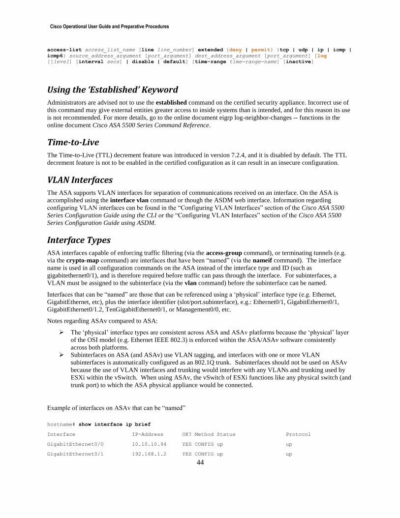
Cisco Operational User Guide and Preparative Procedures
44
access-list access_list_name [line line_number] extended {deny | permit} {tcp | udp | ip | icmp |
icmp6} source_address_argument [port_argument] dest_address_argument [port_argument] [log
[[level] [interval secs] | disable | default] [time-range time-range-name] [inactive]
Using the ‘Established’ Keyword
Administrators are advised not to use the established command on the certified security appliance. Incorrect use of
this command may give external entities greater access to inside systems than is intended, and for this reason its use
is not recommended. For more details, go to the online document eigrp log-neighbor-changes -- functions in the
online document Cisco ASA 5500 Series Command Reference.
Time-to-Live
The Time-to-Live (TTL) decrement feature was introduced in version 7.2.4, and it is disabled by default. The TTL
decrement feature is not to be enabled in the certified configuration as it can result in an insecure configuration.
VLAN Interfaces
The ASA supports VLAN interfaces for separation of communications received on an interface. On the ASA is
accomplished using the interface vlan command or though the ASDM web interface. Information regarding
configuring VLAN interfaces can be found in the “Configuring VLAN Interfaces” section of the Cisco ASA 5500
Series Configuration Guide using the CLI or the “Configuring VLAN Interfaces” section of the Cisco ASA 5500
Series Configuration Guide using ASDM.
Interface Types
ASA interfaces capable of enforcing traffic filtering (via the access-group command), or terminating tunnels (e.g.
via the crypto-map command) are interfaces that have been “named” (via the nameif command). The interface
name is used in all configuration commands on the ASA instead of the interface type and ID (such as
gigabitethernet0/1), and is therefore required before traffic can pass through the interface. For subinterfaces, a
VLAN must be assigned to the subinterface (via the vlan command) before the subinterface can be named.
Interfaces that can be “named” are those that can be referenced using a ‘physical’ interface type (e.g. Ethernet,
GigabitEthernet, etc), plus the interface identifier (slot/port.subinterface), e.g.: Ethernet0/1, GigabitEthernet0/1,
GigabitEthernet0/1.2, TenGigabitEthernet0/1, or Management0/0, etc.
Notes regarding ASAv compared to ASA:
The ‘physical’ interface types are consistent across ASA and ASAv platforms because the ‘physical’ layer
of the OSI model (e.g. Ethernet IEEE 802.3) is enforced within the ASA/ASAv software consistently
across both platforms.
Subinterfaces on ASA (and ASAv) use VLAN tagging, and interfaces with one or more VLAN
subinterfaces is automatically configured as an 802.1Q trunk. Subinterfaces should not be used on ASAv
because the use of VLAN interfaces and trunking would interfere with any VLANs and trunking used by
ESXi within the vSwitch. When using ASAv, the vSwitch of ESXi functions like any physical switch (and
trunk port) to which the ASA physical appliance would be connected.
Example of interfaces on ASAv that can be “named”
hostname# show interface ip brief
Interface IP-Address OK? Method Status Protocol
GigabitEthernet0/0 10.10.10.94 YES CONFIG up up
GigabitEthernet0/1 192.168.1.2 YES CONFIG up up
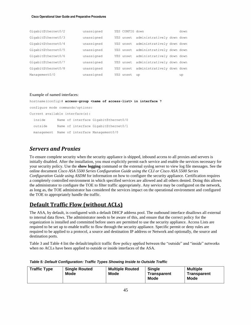
Cisco Operational User Guide and Preparative Procedures
45
GigabitEthernet0/2 unassigned YES CONFIG down down
GigabitEthernet0/3 unassigned YES unset administratively down down
GigabitEthernet0/4 unassigned YES unset administratively down down
GigabitEthernet0/5 unassigned YES unset administratively down down
GigabitEthernet0/6 unassigned YES unset administratively down down
GigabitEthernet0/7 unassigned YES unset administratively down down
GigabitEthernet0/8 unassigned YES unset administratively down down
Management0/0 unassigned YES unset up up
Example of named interfaces:
hostname(config)# access-group <name of access-list> in interface ?
configure mode commands/options:
Current available interface(s):
inside Name of interface GigabitEthernet0/0
outside Name of interface GigabitEthernet0/1
management Name of interface Management0/0
Servers and Proxies
To ensure complete security when the security appliance is shipped, inbound access to all proxies and servers is
initially disabled. After the installation, you must explicitly permit each service and enable the services necessary for
your security policy. Use the show logging command or the external syslog server to view log file messages. See the
online document Cisco ASA 5500 Series Configuration Guide using the CLI or Cisco ASA 5500 Series
Configuration Guide using ASDM for information on how to configure the security appliance. Certification requires
a completely controlled environment in which specified services are allowed and all others denied. Doing this allows
the administrator to configure the TOE to filter traffic appropriately. Any service may be configured on the network,
as long as, the TOE administrator has considered the services impact on the operational environment and configured
the TOE to appropriately handle the traffic.
Default Traffic Flow (without ACLs)
The ASA, by default, is configured with a default DHCP address pool. The outbound interface disallows all external
to internal data flows. The administrator needs to be aware of this, and ensure that the correct policy for the
organization is installed and committed before users are permitted to use the security appliance. Access Lists are
required to be set up to enable traffic to flow through the security appliance. Specific permit or deny rules are
required to be applied to a protocol, a source and destination IP address or Network and optionally, the source and
destination ports.
Table 3 and Table 4 list the default/implicit traffic flow policy applied between the “outside” and “inside” networks
when no ACLs have been applied to outside or inside interfaces of the ASA.
Table 5: Default Configuration: Traffic Types Showing Inside to Outside Traffic
Traffic Type Single Routed Mode
Multiple Routed Mode
Single Transparent Mode
Multiple Transparent Mode
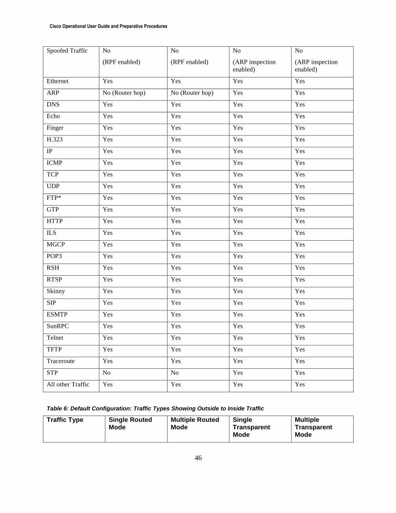
Cisco Operational User Guide and Preparative Procedures
46
Spoofed Traffic No
(RPF enabled)
No
(RPF enabled)
No
(ARP inspection
enabled)
No
(ARP inspection
enabled)
Ethernet Yes Yes Yes Yes
ARP No (Router hop) No (Router hop) Yes Yes
DNS Yes Yes Yes Yes
Echo Yes Yes Yes Yes
Finger Yes Yes Yes Yes
H.323 Yes Yes Yes Yes
IP Yes Yes Yes Yes
ICMP Yes Yes Yes Yes
TCP Yes Yes Yes Yes
UDP Yes Yes Yes Yes
FTP* Yes Yes Yes Yes
GTP Yes Yes Yes Yes
HTTP Yes Yes Yes Yes
ILS Yes Yes Yes Yes
MGCP Yes Yes Yes Yes
POP3 Yes Yes Yes Yes
RSH Yes Yes Yes Yes
RTSP Yes Yes Yes Yes
Skinny Yes Yes Yes Yes
SIP Yes Yes Yes Yes
ESMTP Yes Yes Yes Yes
SunRPC Yes Yes Yes Yes
Telnet Yes Yes Yes Yes
TFTP Yes Yes Yes Yes
Traceroute Yes Yes Yes Yes
STP No No Yes Yes
All other Traffic Yes Yes Yes Yes
Table 6: Default Configuration: Traffic Types Showing Outside to Inside Traffic
Traffic Type Single Routed Mode
Multiple Routed Mode
Single Transparent Mode
Multiple Transparent Mode
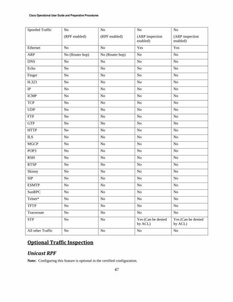
Cisco Operational User Guide and Preparative Procedures
47
Spoofed Traffic No
(RPF enabled)
No
(RPF enabled)
No
(ARP inspection
enabled)
No
(ARP inspection
enabled)
Ethernet No No Yes Yes
ARP No (Router hop) No (Router hop) No No
DNS No No No No
Echo No No No No
Finger No No No No
H.323 No No No No
IP No No No No
ICMP No No No No
TCP No No No No
UDP No No No No
FTP No No No No
GTP No No No No
HTTP No No No No
ILS No No No No
MGCP No No No No
POP3 No No No No
RSH No No No No
RTSP No No No No
Skinny No No No No
SIP No No No No
ESMTP No No No No
SunRPC No No No No
Telnet* No No No No
TFTP No No No No
Traceroute No No No No
STP No No Yes (Can be denied
by ACL)
Yes (Can be denied
by ACL)
All other Traffic No No No No
Optional Traffic Inspection
Unicast RPF
Note: Configuring this feature is optional in the certified configuration.
Cisco Operational User Guide and Preparative Procedures
48
To enable Unicast RPF, use the ip verify reverse-path command in global configuration mode. Unicast RPF guards
against IP spoofing (a packet uses an incorrect source IP address to obscure its true source) by ensuring that all
packets have a source IP address that matches the correct source interface according to the routing table. Unicast
RPF is only applicable when a context is operating in routing mode. hostname(config)# ip verify reverse-path interface outside
hostname(config)# ip verify reverse-path interface inside
STP & Transparent Mode
Note: Configuring this feature is optional in the certified configuration.
Spanning Tree Protocol (STP) is passed through the firewall by default in transparent mode. This default operation
of the product can be mitigated by creating an access list to block the traffic.
hostname(config)# access-list layer2 ethertype deny bpdu
Inspect ICMP
Note: Configuring this feature is optional in the certified configuration.
To configure the ICMP inspection engine, use the inspect icmp command in class configuration mode. Class
configuration mode is accessible from policy map configuration mode. The inspect icmp command is required to
prevent ICMP traffic from passing through the firewall in the event the remote syslog server should fail.
hostname(config)# class-map icmp-class hostname(config-cmap)# match default-inspection-traffic hostname(config-cmap)# exit hostname(config)# policy-map icmp_policy hostname(config-pmap)# class icmp-class hostname(config-pmap-c)# inspect icmp hostname(config-pmap-c)# exit hostname(config)# service-policy icmp_policy interface outside
Inspect ARP
Note: Configuring this feature is optional in the certified configuration.
To configure the ARP inspection engine, use the arp-inspection command in global configuration mode. ARP
inspection is required when a firewall context is operating in transparent mode, to prevent IP spoofing of traffic. To complete the configuration of ARP inspection the administrator must create static ARP entries for each host
protected by the firewall context.
hostname(config)# arp inside 192.0.2.0 0050.abcd.1234
hostname(config)# arp-inspection outside enable
hostname(config)# arp-inspection inside enable
Prohibit IPv6 Extension Header 0
Warning: Do not permit IPv6 Extension Header 0 packets using these commands. For example,
object service IPv6-0
service 0
access-list acl_name extended permit object IPv6-0 host IPv6_address1 host IPv6_address2 log
log_number interval interval_number
Cisco Operational User Guide and Preparative Procedures
49
Optional Authentication of Throughput Traffic
Note: Configuring this feature is optional in the certified configuration.
Warning: Authentication of Telnet and FTP flows through the ASA can be configured in more than one way:
through use of “aaa authentication match”, or “aaa authentication include”. ASDM will always use “aaa
authentication match” with a matching named access -list. If the CLI is used to configure this function using the
“aaa authentication include” command, the ASDM cannot be used to subsequently modify function, and the CLI
must be used instead. For best results, use one of either GUI or CLI to configure and reconfigure this function.
To configure AAA for Telnet and FTP using cut-through proxies, you must first configure the AAA server group
and authentication settings (via CLI or GUI). The following procedures and examples show how to configure this
function via the CLI after the AAA server settings are in effect.
Enable authentication of Telnet and FTP using the aaa authentication include {telnet, ftp} command.
Note: Running FTP and TELNET servers on non-standard ports will result in those flows not requiring RADIUS or
TACACS+ authentication and is therefore not to be allowed in the certified configuration.
Hostname (config)# aaa-server aaasrvgrp protocol radius
hostname (config-aaa-server-group)# exit
hostname (config)# aaa-server aaasrvgrp host 10.0.0.2
hostname (config-aaa-server-host)# authentication-port 1645
hostname (config-aaa-server-host)# timeout 10
hostname (config-aaa-server-host)# retry-interval 2
hostname (config-aaa-server-host)# exit
hostname (config)# aaa authentication include telnet outside 0 0 0 0 aaasrvgrp
hostname (config)# aaa authentication include ftp outside 0 0 0 0 aaasrvgrp
hostname (config)# aaa authentication include telnet inside 0 0 0 0 aaasrvgrp
hostname (config)# aaa authentication include ftp inside 0 0 0 0 aaasrvgrp
To ensure that separate sessions from a multi-user machine are not able to piggy-back on an existing authentication
request, ensure that the timeout for authentication is set to 0, for no caching of authentication data.
hostname (config)# timeout uauth 0:00:00
Mandatory Traffic Flow Controls In its Common Criteria certified configuration, the ASA must be drop certain traffic at all enabled interfaces at all
times. Some of the traffic that must be dropped will be dropped at all times, regardless of configuration, other traffic
will be dropped by ACLs, and still other traffic will be dropped by the “ip audit” feature.
The “ip audit” feature is configured with the following commands:
ip audit attack Sets the default actions for packets that match an attack signature.
ip audit info Sets the default actions for packets that match an informational signature.
ip audit name Creates a named audit policy that identifies the actions to take when a packet matches an attack
signature or an informational signature.
ip audit interface Assigns an audit policy to an interface.
show running-config ip audit signature Shows the configuration for the ip audit signature command.
Cisco Operational User Guide and Preparative Procedures
50
Set “ip audit” Actions
Set the actions to be taken when packets match “info” signatures and “attack” signatures. The default action for “ip
audit info” and “ip audit attack” is to audit only. The certified configuration requires the action to include “drop”,
and optionally allows the action to include “audit” and/or “reset”.
Syntax for “info” signatures: ip audit info [action [alarm] [drop] [reset]]
Allowed settings:
ip audit info action drop
ip audit info action alarm drop
ip audit info action drop reset
ip audit info action alarm drop reset
Syntax for “attack” signatures: ip audit attack [action [alarm] [drop] [reset]]
Allowed settings:
ip audit attack action drop
ip audit attack action alarm drop
ip audit attack action drop reset
ip audit attack action alarm drop reset
Do not disable certain signatures
When “ip audit” has been enabled for either “info” or “attack” signatures, the full set of “info” or “attack” signatures
defined in syslog message range 4000xx (400000-400099), will be enabled. Individual signatures can be disabled
with the “ip audit signature” command, but the following signatures must remain enabled in the Common Criteria
certified configuration:
4000001, IP options-Bad Option List
4000004, IP options-Loose Source Route
4000006, IP options-Strict Source Route
4000007, IP Fragment Attack
4000009, IP Fragments Overlap
4000023, Fragmented ICMP Traffic
4000025, Ping of Death Attack
Define “ip audit” Policies
Define two “ip audit” policies, one for “info” events, and one for “attack” events, and set the “action” to “drop”:
Syntax: ip audit name name {info | attack} [action [alarm] [drop] [reset]]
Example:
hostname(config)# ip audit name infopolicy info action drop
hostname(config)# ip audit name attackpolicy attack action drop
Apply “ip audit” Policies to Interfaces
Apply both “ip audit” policies to each enabled interface.
Syntax: ip audit interface interface_name policy_name
Examples:
hostname(config)# ip audit interface inside infopolicy
Cisco Operational User Guide and Preparative Procedures
51
hostname(config)# ip audit interface inside attackpolicy
hostname(config)# ip audit interface outside infopolicy
hostname(config)# ip audit interface outside attackpolicy
Overview of Traffic to Be Dropped, and the Related Syslog Messages
1) Packets which are invalid fragments a) Fragments are considered invalid by the ASA when they violate fragmentation rules, such as with a
“teardrop” attack.
b) Syslog messages related to invalid fragments
i) Syslog messages generated regardless of the “ip audit name”settings (1) IP Overlapping Fragments (Teardrop)
(a) Condition: The ASA discarded an IP packet with a teardrop signature containing either a
small offset or fragment overlapping. This is a hostile event that circumvents the ASA or an
Intrusion Detection System.
(b) %ASA-2-106020: Deny IP teardrop fragment (size = number, offset = number) from
IP_address to IP_address
(2) Malformed IP fragments
(a) Condition: An IP fragment is malformed, for example: the total size of the reassembled IP packet
exceeds the maximum possible size of 65,535 bytes. (b) %ASA-4-209004: Invalid IP fragment, size = bytes exceeds maximum size = bytes: src =
source_address, dest = dest_address, proto = protocol, id = number
(3) Fragmented decapsulated IPsec packets
(a) Condition: A decapsulatd IPsec packet included an IP fragment with an offset less than or
equal to 128 bytes. The latest version of the security architecture for IP RFC recommends 128
bytes as the minimum IP fragment offset to prevent reassembly attacks. This may be part of
an attack. This message is rate limited to no more than one message every five seconds.
(b) %ASA-4-402118: IPSEC: Received an protocol packet (SPI=spi, sequence number seq_num)
from remote_IP (username) to local_IP containing an illegal IP fragment of length frag_len
with offset frag_offset.
(4) Malformed NetBIOS Datagram (NBDGM) fragments
(a) The NBDGM fragment format is incorrect.
(b) %ASA-4-423005: {Allowed | Dropped} NBDGM pkt_type_name fragment with
error_reason_str from ifc_name:ip_address/port to ifc_name:ip_address/port.
i) Additional syslog messages generated by “ip audit name <name> info action audit drop”
None.
ii) Additional syslog messages generated by “ip audit name <name> attack action audit drop”
IP Fragment Attack, message number 400007 (see table below)
IP Overlapping Fragments (Teardrop), message number 400009 (see table below)
Fragmented ICMP Traffic, message number 400023 (see table below)
Ping of Death Attack, message number 400025 (see table below).
2) Fragmented IP packets which cannot be re-assembled completely a) Fragmented IP packets cannot be re-assembled completely if they exceed the configurable allowed
parameters for reassembly
b) Configuration of fragmentation rules:
i) To show the current fragmentation limits: hostname# show fragment
hostname# show running-config fragment
ii) To adjust the fragmentation settings: fragment reassembly {full | virtual} {size | chain | timeout limit} [interface]
o reassembly full | virtual Specifies the full or virtual reassembly for IP fragments that are
routed through the ASA. IP fragments that terminate at the ASA are always fully
reassembled.
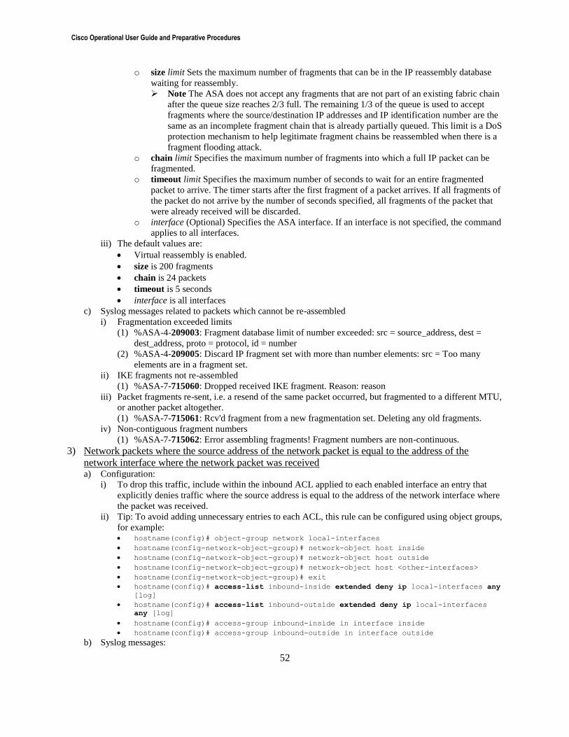
Cisco Operational User Guide and Preparative Procedures
52
o size limit Sets the maximum number of fragments that can be in the IP reassembly database
waiting for reassembly.
Note The ASA does not accept any fragments that are not part of an existing fabric chain
after the queue size reaches 2/3 full. The remaining 1/3 of the queue is used to accept
fragments where the source/destination IP addresses and IP identification number are the
same as an incomplete fragment chain that is already partially queued. This limit is a DoS
protection mechanism to help legitimate fragment chains be reassembled when there is a
fragment flooding attack.
o chain limit Specifies the maximum number of fragments into which a full IP packet can be
fragmented.
o timeout limit Specifies the maximum number of seconds to wait for an entire fragmented
packet to arrive. The timer starts after the first fragment of a packet arrives. If all fragments of
the packet do not arrive by the number of seconds specified, all fragments of the packet that
were already received will be discarded.
o interface (Optional) Specifies the ASA interface. If an interface is not specified, the command
applies to all interfaces.
iii) The default values are:
Virtual reassembly is enabled.
size is 200 fragments
chain is 24 packets
timeout is 5 seconds
interface is all interfaces
c) Syslog messages related to packets which cannot be re-assembled
i) Fragmentation exceeded limits
(1) %ASA-4-209003: Fragment database limit of number exceeded: src = source_address, dest =
dest_address, proto = protocol, id = number
(2) %ASA-4-209005: Discard IP fragment set with more than number elements: src = Too many
elements are in a fragment set.
ii) IKE fragments not re-assembled
(1) %ASA-7-715060: Dropped received IKE fragment. Reason: reason
iii) Packet fragments re-sent, i.e. a resend of the same packet occurred, but fragmented to a different MTU,
or another packet altogether.
(1) %ASA-7-715061: Rcv'd fragment from a new fragmentation set. Deleting any old fragments.
iv) Non-contiguous fragment numbers
(1) %ASA-7-715062: Error assembling fragments! Fragment numbers are non-continuous.
3) Network packets where the source address of the network packet is equal to the address of the
network interface where the network packet was received a) Configuration:
i) To drop this traffic, include within the inbound ACL applied to each enabled interface an entry that
explicitly denies traffic where the source address is equal to the address of the network interface where
the packet was received.
ii) Tip: To avoid adding unnecessary entries to each ACL, this rule can be configured using object groups,
for example: hostname(config)# object-group network local-interfaces
hostname(config-network-object-group)# network-object host inside
hostname(config-network-object-group)# network-object host outside
hostname(config-network-object-group)# network-object host <other-interfaces>
hostname(config-network-object-group)# exit
hostname(config)# access-list inbound-inside extended deny ip local-interfaces any
[log]
hostname(config)# access-list inbound-outside extended deny ip local-interfaces
any [log]
hostname(config)# access-group inbound-inside in interface inside
hostname(config)# access-group inbound-outside in interface outside
b) Syslog messages:
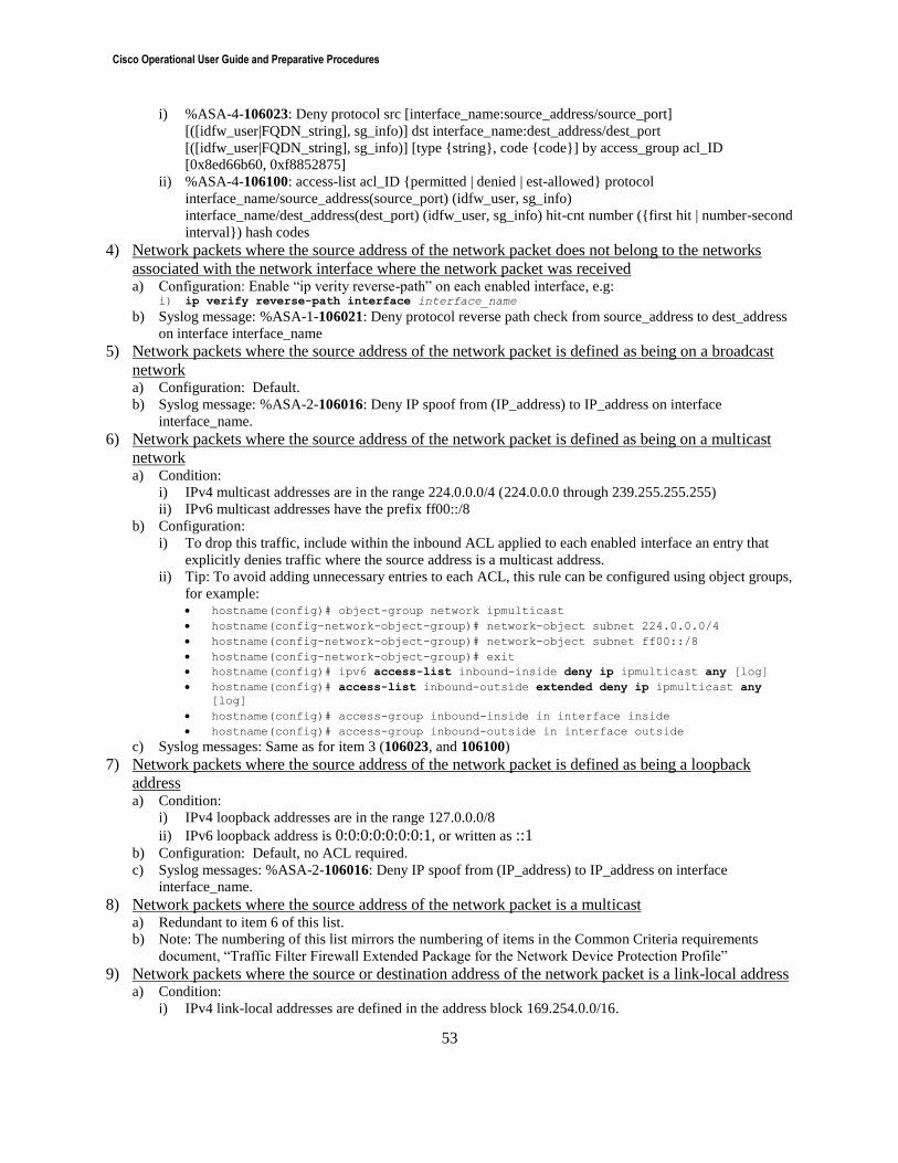
Cisco Operational User Guide and Preparative Procedures
53
i) %ASA-4-106023: Deny protocol src [interface_name:source_address/source_port]
[([idfw_user|FQDN_string], sg_info)] dst interface_name:dest_address/dest_port
[([idfw_user|FQDN_string], sg_info)] [type {string}, code {code}] by access_group acl_ID
[0x8ed66b60, 0xf8852875]
ii) %ASA-4-106100: access-list acl_ID {permitted | denied | est-allowed} protocol
interface_name/source_address(source_port) (idfw_user, sg_info)
interface_name/dest_address(dest_port) (idfw_user, sg_info) hit-cnt number ({first hit | number-second
interval}) hash codes
4) Network packets where the source address of the network packet does not belong to the networks
associated with the network interface where the network packet was received a) Configuration: Enable “ip verity reverse-path” on each enabled interface, e.g:
i) ip verify reverse-path interface interface_name
b) Syslog message: %ASA-1-106021: Deny protocol reverse path check from source_address to dest_address
on interface interface_name
5) Network packets where the source address of the network packet is defined as being on a broadcast
network a) Configuration: Default.
b) Syslog message: %ASA-2-106016: Deny IP spoof from (IP_address) to IP_address on interface
interface_name.
6) Network packets where the source address of the network packet is defined as being on a multicast
network a) Condition:
i) IPv4 multicast addresses are in the range 224.0.0.0/4 (224.0.0.0 through 239.255.255.255)
ii) IPv6 multicast addresses have the prefix ff00::/8
b) Configuration:
i) To drop this traffic, include within the inbound ACL applied to each enabled interface an entry that
explicitly denies traffic where the source address is a multicast address.
ii) Tip: To avoid adding unnecessary entries to each ACL, this rule can be configured using object groups,
for example: hostname(config)# object-group network ipmulticast
hostname(config-network-object-group)# network-object subnet 224.0.0.0/4
hostname(config-network-object-group)# network-object subnet ff00::/8
hostname(config-network-object-group)# exit
hostname(config)# ipv6 access-list inbound-inside deny ip ipmulticast any [log]
hostname(config)# access-list inbound-outside extended deny ip ipmulticast any
[log]
hostname(config)# access-group inbound-inside in interface inside
hostname(config)# access-group inbound-outside in interface outside
c) Syslog messages: Same as for item 3 (106023, and 106100)
7) Network packets where the source address of the network packet is defined as being a loopback
address a) Condition:
i) IPv4 loopback addresses are in the range 127.0.0.0/8
ii) IPv6 loopback address is 0:0:0:0:0:0:0:1, or written as ::1
b) Configuration: Default, no ACL required.
c) Syslog messages: %ASA-2-106016: Deny IP spoof from (IP_address) to IP_address on interface
interface_name.
8) Network packets where the source address of the network packet is a multicast a) Redundant to item 6 of this list.
b) Note: The numbering of this list mirrors the numbering of items in the Common Criteria requirements
document, “Traffic Filter Firewall Extended Package for the Network Device Protection Profile”
9) Network packets where the source or destination address of the network packet is a link-local address a) Condition:
i) IPv4 link-local addresses are defined in the address block 169.254.0.0/16.
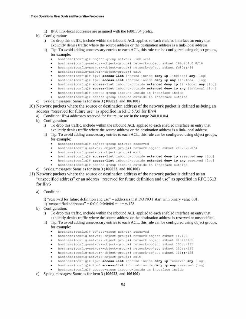
Cisco Operational User Guide and Preparative Procedures
54
ii) IPv6 link-local addresses are assigned with the fe80::/64 prefix.
b) Configuration:
i) To drop this traffic, include within the inbound ACL applied to each enabled interface an entry that
explicitly denies traffic where the source address or the destination address is a link-local address.
ii) Tip: To avoid adding unnecessary entries to each ACL, this rule can be configured using object groups,
for example: hostname(config)# object-group network linklocal
hostname(config-network-object-group)# network-object subnet 169.254.0.0/16
hostname(config-network-object-group)# network-object subnet fe80::/64
hostname(config-network-object-group)# exit
hostname(config)# ipv6 access-list inbound-inside deny ip linklocal any [log]
hostname(config)# ipv6 access-list inbound-inside deny ip any linklocal [log]
hostname(config)# access-list inbound-outside extended deny ip linklocal any [log]
hostname(config)# access-list inbound-outside extended deny ip any linklocal [log]
hostname(config)# access-group inbound-inside in interface inside
hostname(config)# access-group inbound-outside in interface outside
c) Syslog messages: Same as for item 3 (106023, and 106100)
10) Network packets where the source or destination address of the network packet is defined as being an
address “reserved for future use” as specified in RFC 5735 for IPv4 a) Condition: IPv4 addresses reserved for future use are in the range 240.0.0.0/4.
b) Configuration:
i) To drop this traffic, include within the inbound ACL applied to each enabled interface an entry that
explicitly denies traffic where the source address or the destination address is a link-local address.
ii) Tip: To avoid adding unnecessary entries to each ACL, this rule can be configured using object groups,
for example: hostname(config)# object-group network reserved
hostname(config-network-object-group)# network-object subnet 240.0.0.0/4
hostname(config-network-object-group)# exit
hostname(config)# access-list inbound-outside extended deny ip reserved any [log]
hostname(config)# access-list inbound-outside extended deny ip any reserved [log]
hostname(config)# access-group inbound-outside in interface outside
c) Syslog messages: Same as for item 3 (106023, and 106100)
11) Network packets where the source or destination address of the network packet is defined as an
“unspecified address” or an address “reserved for future definition and use” as specified in RFC 3513
for IPv6
a) Condition:
i) “reserved for future definition and use” = addresses that DO NOT start with binary value 001. ii) “unspecified addresses” = 0:0:0:0:0:0:0:0 = :: = ::/128
b) Configuration:
i) To drop this traffic, include within the inbound ACL applied to each enabled interface an entry that
explicitly denies traffic where the source address or the destination address is reserved or unspecified.
ii) Tip: To avoid adding unnecessary entries to each ACL, this rule can be configured using object groups,
for example: hostname(config)# object-group network reserved
hostname(config-network-object-group)# network-object subnet ::/128
hostname(config-network-object-group)# network-object subnet 010::/125
hostname(config-network-object-group)# network-object subnet 100::/125
hostname(config-network-object-group)# network-object subnet 110::/125
hostname(config-network-object-group)# network-object subnet 111::/125
hostname(config-network-object-group)# exit
hostname(config)# ipv6 access-list inbound-inside deny ip reserved any [log]
hostname(config)# ipv6 access-list inbound-inside deny ip any reserved [log]
hostname(config)# access-group inbound-inside in interface inside
c) Syslog messages: Same as for item 3 (106023, and 106100)
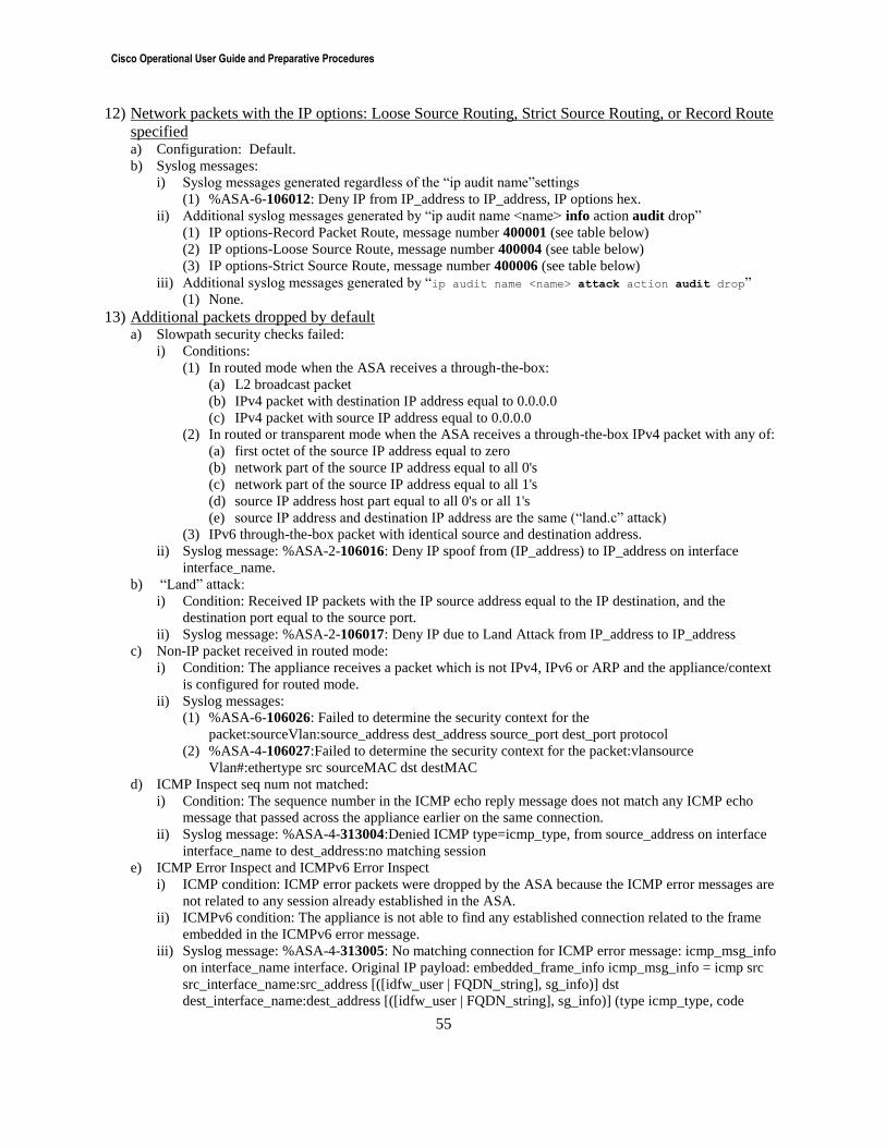
Cisco Operational User Guide and Preparative Procedures
55
12) Network packets with the IP options: Loose Source Routing, Strict Source Routing, or Record Route
specified a) Configuration: Default.
b) Syslog messages:
i) Syslog messages generated regardless of the “ip audit name”settings
(1) %ASA-6-106012: Deny IP from IP_address to IP_address, IP options hex.
ii) Additional syslog messages generated by “ip audit name <name> info action audit drop”
(1) IP options-Record Packet Route, message number 400001 (see table below)
(2) IP options-Loose Source Route, message number 400004 (see table below)
(3) IP options-Strict Source Route, message number 400006 (see table below)
iii) Additional syslog messages generated by “ip audit name <name> attack action audit drop”
(1) None.
13) Additional packets dropped by default a) Slowpath security checks failed:
i) Conditions:
(1) In routed mode when the ASA receives a through-the-box:
(a) L2 broadcast packet
(b) IPv4 packet with destination IP address equal to 0.0.0.0
(c) IPv4 packet with source IP address equal to 0.0.0.0
(2) In routed or transparent mode when the ASA receives a through-the-box IPv4 packet with any of:
(a) first octet of the source IP address equal to zero
(b) network part of the source IP address equal to all 0's
(c) network part of the source IP address equal to all 1's
(d) source IP address host part equal to all 0's or all 1's
(e) source IP address and destination IP address are the same (“land.c” attack)
(3) IPv6 through-the-box packet with identical source and destination address.
ii) Syslog message: %ASA-2-106016: Deny IP spoof from (IP_address) to IP_address on interface
interface_name.
b) “Land” attack:
i) Condition: Received IP packets with the IP source address equal to the IP destination, and the
destination port equal to the source port.
ii) Syslog message: %ASA-2-106017: Deny IP due to Land Attack from IP_address to IP_address
c) Non-IP packet received in routed mode:
i) Condition: The appliance receives a packet which is not IPv4, IPv6 or ARP and the appliance/context
is configured for routed mode.
ii) Syslog messages:
(1) %ASA-6-106026: Failed to determine the security context for the
packet:sourceVlan:source_address dest_address source_port dest_port protocol
(2) %ASA-4-106027:Failed to determine the security context for the packet:vlansource
Vlan#:ethertype src sourceMAC dst destMAC
d) ICMP Inspect seq num not matched:
i) Condition: The sequence number in the ICMP echo reply message does not match any ICMP echo
message that passed across the appliance earlier on the same connection.
ii) Syslog message: %ASA-4-313004:Denied ICMP type=icmp_type, from source_address on interface
interface_name to dest_address:no matching session
e) ICMP Error Inspect and ICMPv6 Error Inspect
i) ICMP condition: ICMP error packets were dropped by the ASA because the ICMP error messages are
not related to any session already established in the ASA.
ii) ICMPv6 condition: The appliance is not able to find any established connection related to the frame
embedded in the ICMPv6 error message.
iii) Syslog message: %ASA-4-313005: No matching connection for ICMP error message: icmp_msg_info
on interface_name interface. Original IP payload: embedded_frame_info icmp_msg_info = icmp src
src_interface_name:src_address [([idfw_user | FQDN_string], sg_info)] dst
dest_interface_name:dest_address [([idfw_user | FQDN_string], sg_info)] (type icmp_type, code
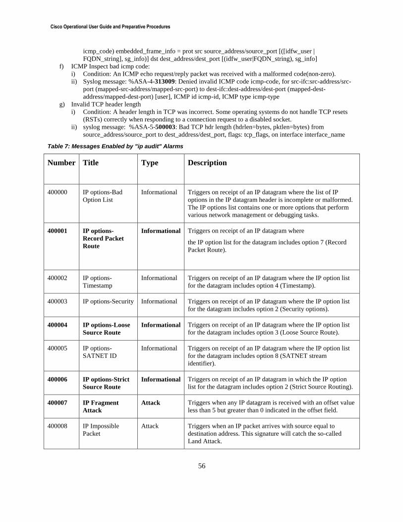
Cisco Operational User Guide and Preparative Procedures
56
icmp_code) embedded_frame_info = prot src source_address/source_port [([idfw_user |
FQDN_string], sg_info)] dst dest_address/dest_port [(idfw_user|FQDN_string), sg_info]
f) ICMP Inspect bad icmp code:
i) Condition: An ICMP echo request/reply packet was received with a malformed code(non-zero).
ii) Syslog message: %ASA-4-313009: Denied invalid ICMP code icmp-code, for src-ifc:src-address/src-
port (mapped-src-address/mapped-src-port) to dest-ifc:dest-address/dest-port (mapped-dest-
address/mapped-dest-port) [user], ICMP id icmp-id, ICMP type icmp-type
g) Invalid TCP header length
i) Condition: A header length in TCP was incorrect. Some operating systems do not handle TCP resets
(RSTs) correctly when responding to a connection request to a disabled socket.
ii) syslog message: %ASA-5-500003: Bad TCP hdr length (hdrlen=bytes, pktlen=bytes) from
source_address/source_port to dest_address/dest_port, flags: tcp_flags, on interface interface_name
Table 7: Messages Enabled by "ip audit" Alarms
Number Title Type Description
400000 IP options-Bad
Option List Informational Triggers on receipt of an IP datagram where the list of IP
options in the IP datagram header is incomplete or malformed.
The IP options list contains one or more options that perform
various network management or debugging tasks.
400001 IP options-
Record Packet
Route
Informational Triggers on receipt of an IP datagram where
the IP option list for the datagram includes option 7 (Record
Packet Route).
400002 IP options-
Timestamp
Informational Triggers on receipt of an IP datagram where the IP option list
for the datagram includes option 4 (Timestamp).
400003 IP options-Security Informational Triggers on receipt of an IP datagram where the IP option list
for the datagram includes option 2 (Security options).
400004 IP options-Loose
Source Route
Informational Triggers on receipt of an IP datagram where the IP option list
for the datagram includes option 3 (Loose Source Route).
400005 IP options-
SATNET ID
Informational Triggers on receipt of an IP datagram where the IP option list
for the datagram includes option 8 (SATNET stream
identifier).
400006 IP options-Strict
Source Route
Informational Triggers on receipt of an IP datagram in which the IP option
list for the datagram includes option 2 (Strict Source Routing).
400007 IP Fragment
Attack
Attack Triggers when any IP datagram is received with an offset value
less than 5 but greater than 0 indicated in the offset field.
400008 IP Impossible
Packet
Attack Triggers when an IP packet arrives with source equal to
destination address. This signature will catch the so-called
Land Attack.

Cisco Operational User Guide and Preparative Procedures
57
400009 IP Overlapping
Fragments
(Teardrop)
Attack Triggers when two fragments contained within the same IP
datagram have offsets that indicate that they share positioning
within the datagram. This could mean that fragment A is being
completely overwritten by fragment B, or that fragment A is
partially being overwritten by fragment B. Some operating
systems do not properly handle fragments that overlap in this
manner and may throw exceptions or behave in other
undesirable ways upon receipt of overlapping fragments, which
is how the Teardrop attack works to create a DoS.
400010 ICMP Echo Reply Informational Triggers when a IP datagram is received with the protocol field
of the IP header set to 1 (ICMP) and the type field in the ICMP
header set to 0 (Echo Reply).
400011 ICMP Host
Unreachable
Informational Triggers when an IP datagram is received with the protocol
field of the IP header set to 1 (ICMP) and the type field in the
ICMP header set to 3 (Host Unreachable).
400012 ICMP Source
Quench
Informational Triggers when an IP datagram is received with the protocol
field of the IP header set to 1 (ICMP) and the type field in the
ICMP header set to 4 (Source Quench).
400013 ICMP Redirect Informational Triggers when a IP datagram is received with the protocol field
of the IP header set to 1 (ICMP) and the type field in the ICMP
header set to 5 (Redirect).
400014 ICMP Echo
Request
Informational Triggers when a IP datagram is received with the protocol field
of the IP header set to 1 (ICMP) and the type field in the ICMP
header set to 8 (Echo Request).
400015 ICMP Time
Exceeded for a
Datagram
Informational Triggers when a IP datagram is received with the protocol field
of the IP header set to 1 (ICMP) and the type field in the ICMP
header set to 11(Time Exceeded for a Datagram).
400016 ICMP Parameter
Problem on
Datagram
Informational Triggers when a IP datagram is received with the protocol field
of the IP header set to 1 (ICMP) and the type field in the ICMP
header set to 12 (Parameter Problem on Datagram).
400017 ICMP Timestamp
Request
Informational Triggers when a IP datagram is received with the protocol field
of the IP header set to 1 (ICMP) and the type field in the ICMP
header set to 13 (Timestamp Request).
400018 ICMP Timestamp
Reply
Informational Triggers when a IP datagram is received with the protocol field
of the IP header set to 1 (ICMP) and the type field in the ICMP
header set to 14 (Timestamp Reply).
400019 ICMP Information
Request
Informational Triggers when a IP datagram is received with the protocol field
of the IP header set to 1 (ICMP) and the type field in the ICMP
header set to 15 (Information Request).
400020 ICMP Information
Reply
Informational Triggers when a IP datagram is received with the protocol field
of the IP header set to 1 (ICMP) and the type field in the ICMP
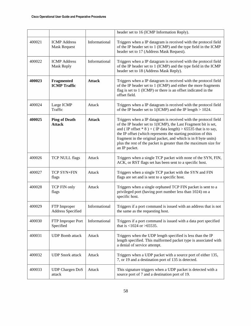
Cisco Operational User Guide and Preparative Procedures
58
header set to 16 (ICMP Information Reply).
400021 ICMP Address
Mask Request
Informational Triggers when a IP datagram is received with the protocol field
of the IP header set to 1 (ICMP) and the type field in the ICMP
header set to 17 (Address Mask Request).
400022 ICMP Address
Mask Reply
Informational Triggers when a IP datagram is received with the protocol field
of the IP header set to 1 (ICMP) and the type field in the ICMP
header set to 18 (Address Mask Reply).
400023 Fragmented
ICMP Traffic
Attack Triggers when a IP datagram is received with the protocol field
of the IP header set to 1 (ICMP) and either the more fragments
flag is set to 1 (ICMP) or there is an offset indicated in the
offset field.
400024 Large ICMP
Traffic
Attack Triggers when a IP datagram is received with the protocol field
of the IP header set to 1(ICMP) and the IP length > 1024.
400025 Ping of Death
Attack
Attack Triggers when a IP datagram is received with the protocol field
of the IP header set to 1(ICMP), the Last Fragment bit is set,
and ( IP offset * 8 ) + ( IP data length) > 65535 that is to say,
the IP offset (which represents the starting position of this
fragment in the original packet, and which is in 8 byte units)
plus the rest of the packet is greater than the maximum size for
an IP packet.
400026 TCP NULL flags Attack Triggers when a single TCP packet with none of the SYN, FIN,
ACK, or RST flags set has been sent to a specific host.
400027 TCP SYN+FIN
flags
Attack Triggers when a single TCP packet with the SYN and FIN
flags are set and is sent to a specific host.
400028 TCP FIN only
flags
Attack Triggers when a single orphaned TCP FIN packet is sent to a
privileged port (having port number less than 1024) on a
specific host.
400029 FTP Improper
Address Specified
Informational Triggers if a port command is issued with an address that is not
the same as the requesting host.
400030 FTP Improper Port
Specified
Informational Triggers if a port command is issued with a data port specified
that is <1024 or >65535.
400031 UDP Bomb attack Attack Triggers when the UDP length specified is less than the IP
length specified. This malformed packet type is associated with
a denial of service attempt.
400032 UDP Snork attack Attack Triggers when a UDP packet with a source port of either 135,
7, or 19 and a destination port of 135 is detected.
400033 UDP Chargen DoS
attack
Attack This signature triggers when a UDP packet is detected with a
source port of 7 and a destination port of 19.
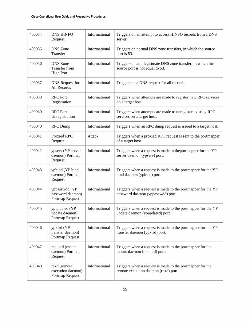
Cisco Operational User Guide and Preparative Procedures
59
400034 DNS HINFO
Request
Informational Triggers on an attempt to access HINFO records from a DNS
server.
400035 DNS Zone
Transfer
Informational Triggers on normal DNS zone transfers, in which the source
port is 53.
400036 DNS Zone
Transfer from
High Port
Informational Triggers on an illegitimate DNS zone transfer, in which the
source port is not equal to 53.
400037 DNS Request for
All Records
Informational Triggers on a DNS request for all records.
400038 RPC Port
Registration
Informational Triggers when attempts are made to register new RPC services
on a target host.
400039 RPC Port
Unregistration
Informational Triggers when attempts are made to unregister existing RPC
services on a target host.
400040 RPC Dump Informational Triggers when an RPC dump request is issued to a target host.
400041 Proxied RPC
Request
Attack Triggers when a proxied RPC request is sent to the portmapper
of a target host.
400042 ypserv (YP server
daemon) Portmap
Request
Informational Triggers when a request is made to theportmapper for the YP
server daemon (ypserv) port.
400043 ypbind (YP bind
daemon) Portmap
Request
Informational Triggers when a request is made to the portmapper for the YP
bind daemon (ypbind) port.
400044 yppasswdd (YP
password daemon)
Portmap Request
Informational Triggers when a request is made to the portmapper for the YP
password daemon (yppasswdd) port.
400045 ypupdated (YP
update daemon)
Portmap Request
Informational Triggers when a request is made to the portmapper for the YP
update daemon (ypupdated) port.
400046 ypxfrd (YP
transfer daemon)
Portmap Request
Informational Triggers when a request is made to the portmapper for the YP
transfer daemon (ypxfrd) port.
400047 mountd (mount
daemon) Portmap
Request
Informational Triggers when a request is made to the portmapper for the
mount daemon (mountd) port.
400048 rexd (remote
execution daemon)
Portmap Request
Informational Triggers when a request is made to the portmapper for the
remote execution daemon (rexd) port.
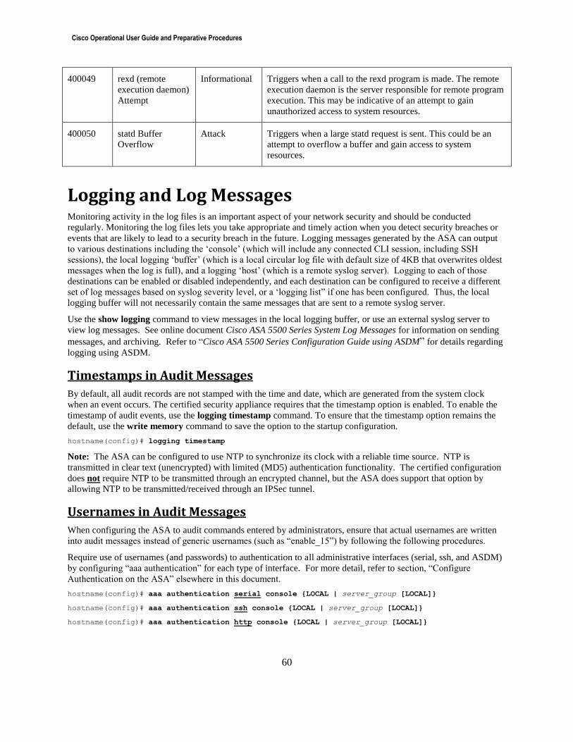
Cisco Operational User Guide and Preparative Procedures
60
400049 rexd (remote
execution daemon)
Attempt
Informational Triggers when a call to the rexd program is made. The remote
execution daemon is the server responsible for remote program
execution. This may be indicative of an attempt to gain
unauthorized access to system resources.
400050 statd Buffer
Overflow
Attack Triggers when a large statd request is sent. This could be an
attempt to overflow a buffer and gain access to system
resources.
Logging and Log Messages Monitoring activity in the log files is an important aspect of your network security and should be conducted
regularly. Monitoring the log files lets you take appropriate and timely action when you detect security breaches or
events that are likely to lead to a security breach in the future. Logging messages generated by the ASA can output
to various destinations including the ‘console’ (which will include any connected CLI session, including SSH
sessions), the local logging ‘buffer’ (which is a local circular log file with default size of 4KB that overwrites oldest
messages when the log is full), and a logging ‘host’ (which is a remote syslog server). Logging to each of those
destinations can be enabled or disabled independently, and each destination can be configured to receive a different
set of log messages based on syslog severity level, or a ‘logging list” if one has been configured. Thus, the local
logging buffer will not necessarily contain the same messages that are sent to a remote syslog server.
Use the show logging command to view messages in the local logging buffer, or use an external syslog server to
view log messages. See online document Cisco ASA 5500 Series System Log Messages for information on sending
messages, and archiving. Refer to “Cisco ASA 5500 Series Configuration Guide using ASDM” for details regarding
logging using ASDM.
Timestamps in Audit Messages
By default, all audit records are not stamped with the time and date, which are generated from the system clock
when an event occurs. The certified security appliance requires that the timestamp option is enabled. To enable the
timestamp of audit events, use the logging timestamp command. To ensure that the timestamp option remains the
default, use the write memory command to save the option to the startup configuration.
hostname(config)# logging timestamp
Note: The ASA can be configured to use NTP to synchronize its clock with a reliable time source. NTP is
transmitted in clear text (unencrypted) with limited (MD5) authentication functionality. The certified configuration
does not require NTP to be transmitted through an encrypted channel, but the ASA does support that option by
allowing NTP to be transmitted/received through an IPSec tunnel.
Usernames in Audit Messages
When configuring the ASA to audit commands entered by administrators, ensure that actual usernames are written
into audit messages instead of generic usernames (such as “enable_15”) by following the following procedures.
Require use of usernames (and passwords) to authentication to all administrative interfaces (serial, ssh, and ASDM)
by configuring “aaa authentication” for each type of interface. For more detail, refer to section, “Configure
Authentication on the ASA” elsewhere in this document.
hostname(config)# aaa authentication serial console {LOCAL | server_group [LOCAL]}
hostname(config)# aaa authentication ssh console {LOCAL | server_group [LOCAL]}
hostname(config)# aaa authentication http console {LOCAL | server_group [LOCAL]}
Cisco Operational User Guide and Preparative Procedures
61
Instead of creating an “enable password” for any privilege level, require administrators to re-enter their own
password to access the higher privilege level (up to their highest authorized privilege level) using the following
command.
hostname(config)# aaa authentication enable console {LOCAL | server_group [LOCAL]}
Using TCP Syslog to Detect Syslog Host Down
By default, auditing events are transported to the remote syslog server over UDP. The certified security appliance
requires auditing events to be transported over TCP. The TCP option is configured using the logging host interface
ip_address tcp/port_number command. With TCP logging configured, new sessions through the certified security
appliance will be disallowed if log messages cannot be forwarded to the remote host.
If using the “no-logging-permit-hostdown” feature to stop the flow of traffic across the ASA when the connection to
syslog server(s) is down, the use of TCP syslog is required. By default, auditing events are transported to remote
syslog servers over UDP. To ensure that audit events are reliably delivered to the remote syslog server the TCP
option should be employed. The logging host <ip-address> tcp/<port-number> command is used to achieve
this.
Timely Notification/Transmission of ACL Logging
When using the “log” keyword at the end of ACL entries to log denied packets, there’s a default delay between the
time the packet is denied and when the resulting syslog message is generated. The default interval for generation of
syslog messages for packets denied by ACLs is 300 seconds (five minutes). Valid values are from 1 to 3600
seconds. To modify the time interval between these messages, use the “access-list alert-interval” command
in global configuration mode. To return to the default settings, use the no form of this command. hostname(config)# access-list alert-interval secs
Secure Transmission of Audit Messages
To ensure audit messages are transmitted securely from the ASA to the remote syslog server, configure the
connection to each syslog host to use IPsec to encrypt syslog messages as the messages leave the ASA.
Securing Syslog with TLS (Optional):
To transmit the messages using TLS, add the “secure” keyword to the “logging host” command, e.g.:
hostname(config)# logging host inside 10.2.2.3 secure
Configure TLS on the ASA as described in the “Secure Communications” section of this document.
This outbound TLS connection from the ASA to the syslog server is not related to any TLS VPN configuration, but
instead uses TLS functionality similar to what’s used for ASDM – though the outbound connection to the syslog
server uses the TLS client on ASA whereas the inbound connection from ASDM uses the TLS server of the ASA.
Verifying the Syslog Server’s Certificate
When syslog over TCP is enabled on the ASA the ASA can verify the syslog server’s identity using the server’s
public certificate, though the syslog server may not attempt to validate the ASA’s (TLS client’s) certificate.
To view the installed CA and server certificates:
hostname# show crypto ca trustpool
To import CA or server certificates, do one or more of the following:
a) Install the default set of root CA certificates to the ASA:
hostname(config)# crypto ca trustpool import default
Cisco Operational User Guide and Preparative Procedures
62
a) Install the certificate of a non-default CA server to the ASA: Example…
hostname# copy https://some-CA.com/some-CA-cert.p7b disk0:
hostname(config)# crypto ca trustpool import url disk0:/some-CA-cert.p7b
a) Install the syslog server’s public certificate to the ASA: Example…
hostname# copy https://some-SERVER.com/some-SERVER-cert.p7b disk0:
hostname(config)# crypto ca trustpool import url disk0:/some-SERVER-cert.p7b
Configuring the Syslog Server
Configure TLS on the remote syslog server in a manner consistent with the TLS configuration on the ASA,
including ensuring the remote TLS server supports at least one of the TLS ciphersuites listed in the “Secure
Communications” section of this document.
Known compatible syslog servers include Kiwi Syslog Server release 9.2 or later; or syslog-ng release 2.0 or later.
Only one syslog server is required.
Kiwi Syslog Server software, installation instructions and guidance can be obtained from:
http://www.kiwisyslog.com/
Syslog-ng software, installation instructions and guidance can be obtained from:
http://www.balabit.com/network-security/syslog-ng
Install the syslog server per installation instructions provided with the syslog server software. Configure the host
operating system to restrict access to syslog data to authorized personnel only. Configure the system to accept
inbound syslog over TLS from the IP address of the ASA using the IP address of the ASA’s interface that would be
used to transmit packets to the server (refer to the ASA’s routing table using “show route”).
To install a server certificate on syslog server (necessary when the syslog server is running on separate host from the
CA server), follow below steps:
1. Request certificate from Certification Authority (CA), specifying "Server Authentication Certificate" as
certificate purpose.
2. Copy the certificate to host where the syslog server is installed.
3. Install the certificate on syslog server host. For example, if the syslog server is running on Microsoft
Windows, use the Microsoft Management Console (MMC):
a. Start > Run > [type] mmc [Enter] > [Inside MMC Console] File > Add/Remove Snap-in > Add >
Certificate > Add > Computer account > Next > Local computer > Finish > Close > OK
b. Expand Certificates > Personal folder > Certificates (Local Computer) right click > All tasks >
Import > Specify path to browse for file and import it to Personal folder.
4. In the syslog server software select that certificate as the one to use for the secure TCP connection.
Securing Syslog with IPsec:
To transmit the messages using IPsec, configure a crypto map to encrypt outbound syslog traffic (UDP syslog or
TCP syslog) with IPsec.
Configure IPsec on the ASA as described in the “Secure Communications” section of this document.
Configure IPsec on the remote IPsec peer by following guidance for that remote system, and configuring the IPsec
parameters to be consistent with those configured on the ASA for connection to that peer.
Cisco Operational User Guide and Preparative Procedures
63
Securing TACACS+ Accounting Messages with IPsec:
To transmit the TACACS+ accounting messages using IPsec, configure a crypto map to encrypt outbound
TACACS+ traffic with IPsec.
Configure IPsec as described in the “Secure Communications” section of this document.
Configure IPsec on the remote IPsec peer by following guidance for that remote system, and configuring the IPsec
parameters to be consistent with those configured on the ASA for connection to that peer.
Auditable Events Certified Under Common Criteria
The following list shows how to enable logging of the auditable event types required during the Common Criteria
evaluation, though it’s not required to enable any auditing in the certified configuration.
When auditing is configured as described above with “logging timestamp” enabled, all audit messages will include
at least the following details: Date and time of the event, type of event, subject identity, and the outcome (success or
failure) of the event. Some of the audit events in the table below will include additional detail consistent with the
Common Criteria certification requirements, such as an IP address or username.
To enable logging for all configured output locations, use the logging enable command in global configuration
mode. To disable logging, use the no form of this command.
Syntax: hostname(config)# logging enable
To define a list of events as a logging list, use the logging list command.
Syntax: hostname(config)# logging list name {level level [class event_class] | message start_id[-end_id]}
To send any these log messages to a syslog server, use the “logging host” command as described above to configure
the connection to the syslog server, and use the “logging trap” to set a syslog severity level or define a list of
messages to be send to logging hosts.
Syntax: hostname(config)# logging trap [logging_list | level]
To store messages in the local logging buffer, use the “logging buffer” command.
Syntax: hostname(config)# logging buffered [logging_list | level]
1) Miscellaneous Events
a) Auditable Event: Start-up of the audit functions
i) Additional message details: No additional information.
ii) Configuration required for generating the syslog messages:
(1) Enable logging with severity level 5 (includes the “logging enable” command), or with a logging
list including the message ID(s) below. iii) Syslog messages:
(1) At startup:
(a) %ASA-5-111008: User 'Config’ executed the 'string' command.
(i) Where ‘string’ is some line in the startup-config that appear after the ‘logging enable’
command.
(b) %ASA-6-199002: Startup completed. Beginning operation.
(2) While running:
(a) %ASA-5-111008: User 'username' executed the 'logging enable’ command.
b) Auditable Event: Changes to the time (e.g. via NTP).
i) Additional message details:
(1) The old and new values for the time.
(2) Origin of the attempt to change the time (e.g., IP address).
ii) Configuration required for generating the syslog messages:
(1) Enable logging with severity level 5, or with a logging list including the message ID(s) below.
Cisco Operational User Guide and Preparative Procedures
64
iii) Syslog messages:
(1) %ASA-5-771001: CLOCK: System clock set, source: src, before: time, after: time
(2) %ASA-5-771002: CLOCK: System clock set, source: src, IP ip, before: time, after: time
c) Auditable Event: Initiation of software updates
i) Additional message details: As described below for “All administrative actions”.
ii) Configuration required for generating the syslog messages: As described below for “All
administrative actions”.
iii) Syslog messages: As described below for “All administrative actions”, where the “string” of the
command includes any of:
(a) “boot system” followed by any image name
(b) “rename” followed by the name of an image file identified as a “boot system” image.
(c) “copy” followed by the name of an image file identified as a “boot system” image.
2) Identification, Authentication, and Authorization
a) Auditable Event: All administrative actions
i) Additional message details: Login IDs (usernames).
ii) Configuration required for generating the syslog messages:
(1) Use the “aaa authentication” commands as described in the “Usernames in Audit Messages”
section of this guide.
(2) Enable logging with severity level 5 (for non-show commands) or 7 (for show commands), or with
a logging list including the message ID(s) below. iii) Syslog messages:
(1) %ASA-5-111008: User 'username' executed the 'string' command.
(2) %ASA-7-111009: User ‘username’ executed cmd:’string’
(3) %ASA-5-111010: User 'username', running 'CLI' from IP ip-address, executed 'string'
b) Auditable Event: All use of the identification and authentication mechanism.
i) Additional message details: Provided user identity, origin of the attempt (e.g., IP address).
ii) Configuration required for generating the syslog messages:
(1) Enable logging with severity level 4, 5, or 6, or with a logging list including the message ID(s)
below. iii) Syslog messages:
(1) %ASA-4-109033: Authentication failed for admin user user from src_IP. Interactive challenge
processing is not supported for protocol connections
(2) %ASA-5-502103: User priv level changed: Uname: user From: privilege_level To: privilege_level
(3) %ASA-6-605004: Login denied from source-address/source-port to interface:destination/service
for user “username6”
(4) %ASA-6-605005: Login permitted from source-address/source-port to
interface:destination/service for user “username”
(5) %ASA-6-611101: User authentication succeeded: Uname: user
(6) %ASA-6-611102: User authentication failed: Uname: user
c) Auditable Event: Any attempts at unlocking of an interactive session.
i) Additional message details: No additional information.
ii) Configuration required for generating the syslog messages:
(1) Not applicable. The administrative sessions do not support session locking.
iii) Syslog messages:
(1) None.
d) Auditable Event: The termination of a remote SSH session due to inactivity.
i) Additional message details: No additional information.
ii) Configuration required for generating the syslog messages:
(1) Enable logging with severity level 4, or with a logging list including the message ID(s) below.
6 In a failed login attempt, the presumed username will be shown as “*****”. This is intended to prevent user from
accidentally entering their password in the username field and having it logged.
Cisco Operational User Guide and Preparative Procedures
65
iii) Syslog messages:
(1) %ASA-4-113019: Group = group, Username = username, IP = peer_address, Session disconnected. Session Type: type, Duration: duration, Bytes xmt: count,
Bytes rcv: count, Reason: reason (a) Where ‘reason’ = “Idle Timeout”
e) Auditable Event: The termination of a remote ASDM session (cookie) due to inactivity.
i) Additional message details: No additional information.
ii) Configuration required for generating the syslog messages:
(1) ASDM uses a series of short-lived HTTPS sessions for each active ASDM client. These temporary
HTTPS sessions process session TLS negotiation parameters, as well as reading and updating the
ASA configuration. Following initial TLS session negotiation and password-based authentication,
a cookie is used to authenticate the subsequent actions initiated from the ASDM client. The
cookie expires when either http server timeout expires, “http server idle-timeout” or “http server
session-timeout”. Thus, the most specific messages to use to track termination of an authenticated
ASDM ‘session’ are those that show expiration of the cookie, and those are debug messages.
(2) Warnings about performance impact:
(a) Generating the audit messages to indicate when cookies expire requires enabling debug
messages, which can have an impact on performance.
(b) Enabling “debug http” can generate a large number of debug messages, which can quickly fill
the local buffer. To avoid filling the local logging buffer with debug messages do not
configure “logging buffered debug”, or increase the size of the local logging buffer using the
“logging buffer-size” command.
(c) Transmitting debug messages to a syslog server can generate a relatively large amount of
syslog messages
(d) Due to the impact on performance, the “debug http” is not persistent in the configuration so
the CLI session must remain open for the 711001 messages to be generated.
(3) To generate the correct debug message, enable “debug http” at least to level 16, for example:
(a) hostname# debug http 16
(4) To redirect debugging messages to logs as syslog message 711001 issued at severity level 7, use
the “logging debug-trace” command in global configuration mode. Example:
(a) hostname(config)# logging debug-trace
(5) Prior to entering enabling “logging debug-trace” all debug messages that were enabled with the
“debug” command would be output to the active CLI sessions. Once the “logging debug-trace”
command has been added to the running configuration, the following informational message will
be output to the active CLI session:
(a) INFO: 'logging debug-trace' is enabled. All debug messages are currently being redirected to
syslog:711001 and will not appear in any monitor session.
iii) Syslog messages:
(1) %ASA-7-711001: HTTP: Session <ID> (user) expires in <time>
(2) %ASA-7-711001: HTTP: Session: <ID> (user) is expired. Deleted. f) Auditable Event: The termination of an interactive session.
i) Additional message details: No additional information.
ii) Configuration required for generating the syslog messages:
(1) Enable logging with severity level 5, or with a logging list including the message ID(s) below. iii) Syslog messages:
(1) %ASA-5-611103: User logged out: Uname: user
(2) %ASA-5-611104: Serial console idle timeout exceeded
3) SSH inbound for remote administration
a) Auditable Event: Initiation and establishment of an SSH session.
i) Additional message details:
(1) Identification of the initiator and target of failed trusted channels establishment attempt.
ii) Configuration required for generating the syslog messages:
(1) Enable logging with severity level 7, or with a logging list including the message ID(s) below. iii) Syslog messages:
Cisco Operational User Guide and Preparative Procedures
66
(1) %ASA-7-710001: TCP access requested from source_address/source_port to
interface_name:dest_address/service
(2) %ASA-7-710002: {TCP|UDP} access permitted from source_address/source_port to
interface_name:dest_address/service
b) Auditable Event: Termination of an SSH session
i) Additional message details:
(1) Remote endpoint of connection (IP address).
ii) Configuration required for generating the syslog messages:
(1) Enable logging with severity level 6, or with a logging list including the message ID(s) below. iii) Syslog messages:
(1) %ASA-6-315011: SSH session from IP_address on interface interface_name for user user disconnected
by SSH server, reason: reason
(a) Where ‘reason’ could include: Terminated by operator (i.e. by an authenticated ASA administrator
via the “ssh disconnect” command); Time-out activated.
c) Auditable Event: Failure to establish an SSH session
i) Additional message details:
(1) Remote endpoint of connection (IP address).
(2) Reason for failure to establish.
ii) Configuration required for generating the syslog messages:
(1) Enable logging with severity level 6, or with a logging list including the message ID(s) below. iii) Syslog messages:
(1) %ASA-6-315011: SSH session from IP_address on interface interface_name for user user disconnected
by SSH server, reason: reason
(a) Where ‘reason’ could include: Bad checkbytes; CRC check failed; Decryption failure; Format
error; Internal error; Invalid cipher type; Invalid message type; Out of memory; Rejected by server;
Reset by client; status code (hex).
4) TLS/HTTPS inbound for remote administration, or outbound for ESMTP
a) Auditable Event: Initiation and establishment of a TLS/HTTPS session.
i) Additional message details:
(1) Identification of the initiator and target of failed trusted channels establishment attempt.
(2) Identification of the claimed user identity.
ii) Configuration required for generating the syslog messages:
(1) Enable logging with severity level 6 or 7, or with a logging list including the message ID(s) below. iii) Syslog messages:
(1) %ASA-6-108007: TLS started on ESMTP session between client client-side interface-name: client IP
address/client port and server server-side interface-name: server IP address/server port
(2) %ASA-7-710001: TCP access requested from source_address/source_port to
interface_name:dest_address/service
(3) %ASA-7-710002: {TCP|UDP} access permitted from source_address/source_port to
interface_name:dest_address/service
(4) %ASA-6-725001 Starting SSL handshake with remote_device interface_name: IP_address/port for
SSL_version session.
(5) %ASA-6-725002 Device completed SSL handshake with remote_device interface_name:
IP_address/port
(6) %ASA-6-725003 SSL client interface_name: IP_address/port request to resume previous session.
(7) %ASA-6-725004 Device requesting certificate from SSL client interface_name: IP_address/port for
authentication.
(8) %ASA-6-725005 SSL server interface_name: IP_address/port requesting our device certificate for
authentication.
(9) %ASA-7-725008 SSL client interface_name: IP_address/port proposes the following number cipher(s).
(10) %ASA-7-725009 Device proposes the following number cipher(s) to SSL server interface_name:
IP_address/port.
(11) %ASA-7-725012 Device chooses cipher: cipher_name for SSL session with client
interface_name:IP_address/port
(12) %ASA-7-725013 SSL Server interface_name:IP_address/port chooses cipher: cipher_name
b) Auditable Event: Termination of a TLS/HTTPS session.
Cisco Operational User Guide and Preparative Procedures
67
i) Additional message details:
(1) Remote endpoint of connection (IP address).
ii) Configuration required for generating the syslog messages:
(1) Enable logging with severity level 6, or with a logging list including the message ID(s) below.
iii) Syslog messages: (1) %ASA-6-725007 SSL session with remote_device interface_name: IP_address/port terminated.
c) Auditable Event: Failure to establish a TLS/HTTPS session.
i) Additional message details:
(1) Remote endpoint of connection (IP address).
(2) Reason for failure to establish.
ii) Configuration required for generating the syslog messages:
(1) Enable logging with severity level 7, or with a logging list including the message ID(s) below. (2) To redirect debugging messages to logs as syslog message, use the “logging debug-trace”
command in global configuration mode. iii) Syslog messages:
(1) %ASA-6-725001: Starting SSL handshake with peer-type interface: src-ip/src-port to dst-ip/dst-port for
protocol session
Follow by 725011, 725014, and 711001
(2) %ASA-7-725011: Cipher[order number]: cipher_name
(3) %ASA-7-725014: SSL lib error. Function: SSL3_GET_CLIENT_HELLO Reason: no shared cipher
(4) %ASA-7-711001: error:1408A0C1:SSL routines:SSL3_GET_CLIENT_HELLO:no shared
cipher@s3_srvr.c:2023
Follow by 302014 and 609002 both of which include “duration 0:00:00”
(5) %ASA-6-302014: Teardown TCP connection id for interface: real-address/real-port [(idfw_user)] to
real-address/real-port [(idfw_user)] duration 0:00:00 bytes bytes [reaon] [(user)]
(6) %ASA-7-609002: Teardown local-host zone-name/*:ip-address duration time
5) IPsec for secure transmission of Syslog, RADIUS, or other protocols
a) Auditable Event: Initiation and establishment of an IPsec SA.
i) Additional message details:
(1) Identification of the initiator and target of failed trusted channels establishment attempt.
ii) Configuration required for generating the syslog messages:
(1) Enable logging with severity level 5, 6, or 7, or with a logging list including the message ID(s)
below. iii) Syslog messages:
(1) %ASA-7-710001: TCP access requested from source_address/source_port to
interface_name:dest_address/service
(2) %ASA-7-710002: {TCP|UDP} access permitted from source_address/source_port to
interface_name:dest_address/service
(3) %ASA-6-602303: IPSEC: An direction tunnel_type SA (SPI=spi) between local_IP and remote_IP
(username) has been created.
(4) %ASA-5-713041: IKE Initiator: new or rekey Phase 1 or 2, Intf interface_number, IKE Peer IP_address
local Proxy Address IP_address, remote Proxy Address IP_address, Crypto map (crypto map tag)
(5) %ASA-5-713049: Security negotiation complete for tunnel_type type (group_name)
Initiator/Responder, Inbound SPI = SPI, Outbound SPI = SPI
(6) %ASA-7-713066: IKE Remote Peer configured for SA: SA_name
(7) %ASA-7-715027: IPsec SA Proposal # chosen_proposal, Transform # chosen_transform acceptable
Matches global IPsec SA entry # crypto_map_index
b) Auditable Event: Termination of an IPsec SA.
i) Additional message details:
(1) Remote endpoint of connection (IP address)
ii) Configuration required for generating the syslog messages:
(1) Enable logging with severity level 3, 5, or 6, or with a logging list including the message ID(s)
below.
Cisco Operational User Guide and Preparative Procedures
68
iii) Syslog messages: (1) %ASA-6-602304: IPSEC: An direction tunnel_type SA (SPI=spi) between local_IP and remote_IP
(username) has been deleted.
(2) %ASA-5-713050: Connection terminated for peer IP_address. Reason: termination reason Remote
Proxy IP_address, Local Proxy IP_address
(a) Where reasons include: IPsec SA Idle Timeout ; IPsec SA Max Time Exceeded ; Administrator
Reset ; Administrator Reboot ; Administrator Shutdown ; Session Disconnected ; Session Error
Terminated ; Peer Terminate
(3) %ASA-3-713123: IKE lost contact with remote peer, deleting connection (keepalive type:
keepalive_type)
c) Auditable Event: Failure to establish an IPsec SA.
i) Additional message details:
(1) Remote endpoint of connection (IP address).
(2) Reason for failure to establish.
ii) Configuration required for generating the syslog messages:
(1) Enable logging with severity level 3, 4, or 6, or with a logging list including the message ID(s)
below. iii) Syslog messages:
(1) %ASA-3-316001: Denied new tunnel to IP_address. VPN peer limit (platform_vpn_peer_limit)
exceeded
(2) %ASA-3-602305: IPSEC: SA creation error, source source address, destination destination address,
reason error string
(3) %ASA-3-713042: IKE Initiator unable to find policy: Intf interface_number, Src: source_address, Dst:
dest_address
(4) %ASA-3-713061: Tunnel rejected: Crypto Map Policy not found for Src:source_address, Dst:
dest_address!
(5) %ASA-3-713062: IKE Peer address same as our interface address IP_address
(6) %ASA-3-713063: IKE Peer address not configured for destination IP_address
(7) %ASA-3-713065: IKE Remote Peer did not negotiate the following: proposal attribute
6) CA Establishment
i) %ASA-6-717056: Attempting type revocation check from Src Interface:Src IP/Src Port to Dst IP/Dst Port
using protocol7
7) Traffic Filtering
a) Auditable Event: Application of rules configured with the ‘log’ operation
i) Additional message details:
(1) Source and destination addresses
(2) Source and destination ports
(3) Transport Layer Protocol
(4) Local interface
ii) Configuration required for generating the syslog messages:
(1) Enable logging with severity level 3, or with a logging list including the message ID(s) below. iii) Syslog messages:
(1) %ASA-3-710003: {TCP|UDP} access denied by ACL from source_IP/source_port to
interface_name:dest_IP/service
b) Auditable Event: Indication of packets dropped due to too much network traffic
i) Additional message details:
(1) Local interface that is unable to process packets
ii) Configuration required for generating the syslog messages:
(1) Enable logging with severity level 3, or with a logging list including the message ID(s) below. iii) Syslog messages:
(1) TCP and UDP connections:
(a) %ASA-3-201002: Too many TCP connections on {static|xlate} global_address! econns nconns
7 For more details, please review the Cisco ASA Series Syslog Messages Guide
Cisco Operational User Guide and Preparative Procedures
69
(b) %ASA-3-201004: Too many UDP connections on {static|xlate} global_address!udp connections
limit
(c) %ASA-3-201005: FTP data connection failed for IP_address IP_address
(d) %ASA-3-201010: Embryonic connection limit exceeded econns/limit for dir packet from
source_address/source_port to dest_address/dest_port on interface interface_name
(e) %ASA-3-202011: Connection limit exceeded econns/limit for dir packet from
source_address/source_port to dest_address/dest_port on interface interface_name
(2) IP connections and address translations
(a) %ASA-2-201003: Embryonic limit exceeded nconns/elimit for outside_address/outside_port
(global_address) inside_address/inside_port on interface interface_name
(b) %ASA-3-201011: Connection limit exceeded cnt/limit for dir packet from sip/sport to dip/dport on
interface if_name.
(c) %ASA-3-202010: [NAT | PAT] pool exhausted for pool-name, port range [1-511 | 512-1023 |
1024-65535]. Unable to create protocol connection from in-interface:src-ip/src-port to out-
interface:dst-ip/dst-port
(3) On ASAv interface
(a) [Scanning] drop rate-2 exceeded Current burst rate is burst_rate per seconds, max
configured rate is max_rate; Current average rate is num_packets per second, max
configured is 4; Cumulative total count is total_packets_count
ASA Installation Read the online document Cisco ASA 5505 Quick Start Guide, or Cisco ASA 5500 Series Quick Start Guide before
installing the security appliance.
To install and maintain the ASA in the Common Criteria certified configuration, it’s necessary for the ASA to be
running in “FIPS mode,” and the use of FIPS mode is fully compatible with the Common Criteria evaluated
configuration. To configure the ASA in FIPS mode (e.g., fips enable), read the FIPS 140-2 Non-Proprietary
Security Policy for the Cisco ASA.
Note: The ASA software image running on the ASA hardware cannot be updated/patched, it can only be replaced,
requiring reboot to a different software image. There are no means to support self-updating of ASA software.
Verification of Image and Hardware
To verify that the security appliance software and hardware was not tampered with during delivery, perform the
following steps:
Step 1: Before unpacking the security appliance, inspect the physical packaging the equipment was delivered in.
Verify that the external cardboard packing is printed with the Cisco Systems logo and motifs. If it is not, contact the
supplier of the equipment, Cisco Systems or an authorized Cisco distributor/partner.
Step 2: Verify that the packaging has not obviously been opened and resealed by examining the tape that seals the
package. If the package appears to have been resealed, contact the supplier of the equipment (Cisco Systems or an
authorized Cisco distributor/partner).
Step 3: Verify that the box has a white tamper-resistant, tamper-evident Cisco Systems barcoded label applied to the
external cardboard box. If it does not, contact the supplier of the equipment (Cisco Systems or an authorized Cisco
distributor/partner). This label will include the Cisco product number, serial number, and other information
regarding the contents of the box.
Step 4: Note the serial number of the security appliance on the shipping documentation. The serial number
displayed on the white label affixed to the outer box will be that of the security appliance. Verify the serial number
on the shipping documentation matches the serial number on the separately mailed invoice for the equipment. If it
does not, contact the supplier of the equipment (Cisco Systems or an authorized Cisco distributor/partner).
Cisco Operational User Guide and Preparative Procedures
70
Step 5: Verify that the box was indeed shipped from the expected supplier of the equipment (Cisco Systems or an
authorized Cisco distributor/partner). This can be done by verifying with the supplier that they shipped the box with
the courier company that delivered the box and that the consignment note number for the shipment matches that
used on the delivery. Also verify that the serial numbers of the items shipped match the serial numbers of the items
delivered. This verification should be performed by some mechanism that was not involved in the actual equipment
delivery, for example, phone/FAX or other online tracking service.
Step 6: Once the security appliance is unpacked, inspect the unit. Verify that the serial number displayed on the unit
itself matches the serial number on the shipping documentation and the invoice. Also, verify the hardware received
is the correct TOE model. If it does not, contact the supplier of the equipment (Cisco Systems or an authorized
Cisco distributor/partner).
Step 7: Download a Common Criteria evaluated software image file from Cisco.com onto a trusted computer
system. To access this site, you must be a registered user and you must be logged in. Software images are available
from Cisco.com at: http://www.cisco.com/kobayashi/sw-center/
Step 8: Download the asa941-13-lfbff-k8.SPA, asa941-13-smp-k8.bin, or asav941-240.zip file from Cisco
Connection Online (CCO) to a local server or workstation. https://software.cisco.com/download/navigator.html
Optional: Once the file is downloaded, verify that it was not tampered with by using an MD5 utility to compute an
MD5 hash for the downloaded file and compare this with the MD5 hash for the image from this document. If the
MD5 hashes do not match, contact Cisco TAC. Refer to the table below for the MD5 hash values.
Step 9: To copy the image that was downloaded from the web to the flash drive on the ASA, enter the following
commands:
copy tftp:/<ip-address>/asa941-13-lfbff-k8.SPA disk0:
or
copy tftp:/<ip-address>/asa941-13-smp-k8.bin disk0:
Step 10: To properly verify the integrity of the ASA binary image, that’s part of the CCO image downloaded from
Cisco.com, use the “verify” command with the “/signature” option in order to verify the digital signature. The digital
signature uses 2048-bit RSA with SHA-512. For example,
verify /signature disk0:/ asa941-13-lfbff-k8.SPA
or
verify /signature disk0:/asa941-13-smp-k8.bin
Step 11: Start your security appliance as described in the “Getting Started” chapter in the online document Cisco
ASA 5500 Series Configuration Guide using the CLI. Confirm that your security appliance loads the image correctly
and completes internal self-checks. At the prompt, enter the show version command as follows. Verify that the
version is 9.4(1). If the security appliance image fails to load, or if the security appliance version is not 9.4(1),
contact Cisco TAC.
The following is sample output from the show version command output, displaying the security appliance version:
hostname# show version
Cisco Adaptive Security Appliance Software Version <Check Correct Version>
<truncated output>
Adaptive Security Device Manager (ASDM) To use ASDM, you need to enable the HTTPS server, and allow HTTPS connections to the adaptive security
appliance. All of these tasks are completed if you use the setup command. This section describes how to manually
configure ASDM access and how to login to ASDM.
The security appliance allows a maximum of 5 concurrent ASDM instances per context, if available, with a
maximum of 32 ASDM instances between all contexts.
Cisco Operational User Guide and Preparative Procedures
71
Enabling HTTPS Access
To configure ASDM access, follow these steps:
Step 1: To identify the IP addresses from which the adaptive security appliance accepts HTTPS connections, enter
the following command for each address or subnet:
hostname(config)# http source_IP_address mask source_interface
Step 2: To enable the HTTPS server, enter the following command:
hostname(config)# http server enable [port]
By default, the port is 443. If you change the port number, be sure to include the new port in the ASDM access
URL. For example, if you change it to port 444, that port number would be specified in the browser with the
following syntax:
https://10.1.1.1:444
Step 3: To specify the location of the ASDM image, enter the following command:
hostname(config)# asdm image disk0:/asdmfile
For example, to enable the HTTPS server and let a host on the inside interface with an address of 192.168.1.2 access
ASDM, enter the following commands:
hostname(config)# crypto key generate rsa modulus 2048 # use modulus size 2048 or greater
hostname(config)# write mem
hostname(config)# http server enable
hostname(config)# http 192.168.1.2 255.255.255.255 inside
To allow all users on the 192.168.3.0 network to access ASDM on the inside interface, enter the following
command:
hostname(config)# http 192.168.3.0 255.255.255.0 inside
Enable Idle-Timeouts of ASDM Sessions
Enable automatic session locking for ASDM sessions after a period of inactivity using the following
commands:
hostname(config)# http server idle-timeout {minutes}
hostname(config)# aaa authentication http console
Accessing ASDM from Your Workstation
From a supported web browser on the adaptive security appliance network, enter the following URL:
https://interface_ip_address[:port]
With the factory default configuration, clients on the 192.168.1.0/24 inside network can access ASDM. To allow
other clients to access ASDM see the “Configuring Device Access for ASDM, Telnet, or SSH" section below.
See the following Ethernet connection guidelines when using the factory default configurations:
ASA 5506: The switch port to which you connect to ASDM can be any port, except for Ethernet 0/0
ASA 5508 and higher: The interface to which you connect to ASDM is Management 0/0
For more information, see the online document Factory Default Configurations. If you do not have a factory default
configuration, see the online document Cisco ASA 5500 Series Configuration Guide using the CLI for instructions to
access the Command Line Interface and the setup command to perform minimum initial configuration.
Cisco Operational User Guide and Preparative Procedures
72
Running ASDM
The web page that loads when connecting to https://interface_ip_address[:port] displays buttons to:
Run ASDM
Install ASDM Launcher
Run Startup Wizard
To maintain the ASA in its certified configuration, do not use “Install ASDM Launcher” and if a copy of ASDM
Launcher has already been installed to your workstation, do not use it. Always use the “Run ASDM” option, which
will load the ASDM software directly from the ASA.
Note: If you are using the Factory Default Configuration, you do not need a username or password. Leave these
fields blank to login to ASDM.
For more information see the online document Cisco Security Appliance Configuration Guide using ASDM.
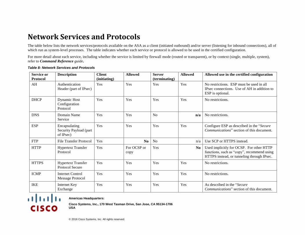
Americas Headquarters:
Cisco Systems, Inc., 170 West Tasman Drive, San Jose, CA 95134-1706 USA
© 2016 Cisco Systems, Inc. All rights reserved.
Network Services and Protocols The table below lists the network services/protocols available on the ASA as a client (initiated outbound) and/or server (listening for inbound connections), all of
which run as system-level processes. The table indicates whether each service or protocol is allowed to be used in the certified configuration.
For more detail about each service, including whether the service is limited by firewall mode (routed or transparent), or by context (single, multiple, system),
refer to Command Reference guide.
Table 8: Network Services and Protocols
Service or
Protocol
Description Client
(initiating)
Allowed Server
(terminating)
Allowed Allowed use in the certified configuration
AH Authentication
Header (part of IPsec)
Yes Yes Yes Yes No restrictions. ESP must be used in all
IPsec connections. Use of AH in addition to
ESP is optional.
DHCP Dynamic Host
Configuration
Protocol
Yes Yes Yes Yes No restrictions.
DNS Domain Name
Service
Yes Yes No n/a No restrictions.
ESP Encapsulating
Security Payload (part
of IPsec)
Yes Yes Yes Yes Configure ESP as described in the “Secure
Communications” section of this document.
FTP File Transfer Protocol Yes No No n/a Use SCP or HTTPS instead.
HTTP Hypertext Transfer
Protocol
Yes For OCSP or
copy
Yes No Used implicitly for OCSP. For other HTTP
functions, such as “copy”, recommend using
HTTPS instead, or tunneling through IPsec.
HTTPS Hypertext Transfer
Protocol Secure
Yes Yes Yes Yes No restrictions.
ICMP Internet Control
Message Protocol
Yes Yes Yes Yes No restrictions.
IKE Internet Key
Exchange
Yes Yes Yes Yes As described in the “Secure
Communications” section of this document.
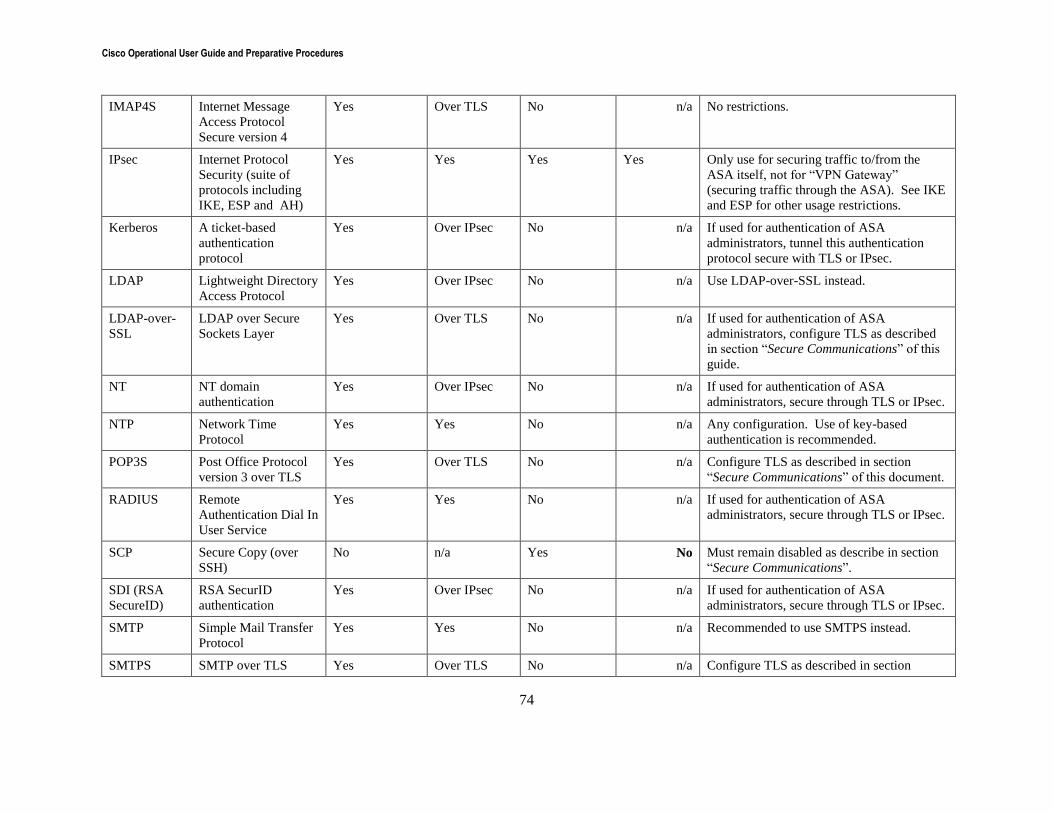
Cisco Operational User Guide and Preparative Procedures
74
IMAP4S Internet Message
Access Protocol
Secure version 4
Yes Over TLS No n/a No restrictions.
IPsec Internet Protocol
Security (suite of
protocols including
IKE, ESP and AH)
Yes Yes Yes Yes Only use for securing traffic to/from the
ASA itself, not for “VPN Gateway”
(securing traffic through the ASA). See IKE
and ESP for other usage restrictions.
Kerberos A ticket-based
authentication
protocol
Yes Over IPsec No n/a If used for authentication of ASA
administrators, tunnel this authentication
protocol secure with TLS or IPsec.
LDAP Lightweight Directory
Access Protocol
Yes Over IPsec No n/a Use LDAP-over-SSL instead.
LDAP-over-
SSL
LDAP over Secure
Sockets Layer
Yes Over TLS No n/a If used for authentication of ASA
administrators, configure TLS as described
in section “Secure Communications” of this
guide.
NT NT domain
authentication
Yes Over IPsec No n/a If used for authentication of ASA
administrators, secure through TLS or IPsec.
NTP Network Time
Protocol
Yes Yes No n/a Any configuration. Use of key-based
authentication is recommended.
POP3S Post Office Protocol
version 3 over TLS
Yes Over TLS No n/a Configure TLS as described in section
“Secure Communications” of this document.
RADIUS Remote
Authentication Dial In
User Service
Yes Yes No n/a If used for authentication of ASA
administrators, secure through TLS or IPsec.
SCP Secure Copy (over
SSH)
No n/a Yes No Must remain disabled as describe in section
“Secure Communications”.
SDI (RSA
SecureID)
RSA SecurID
authentication
Yes Over IPsec No n/a If used for authentication of ASA
administrators, secure through TLS or IPsec.
SMTP Simple Mail Transfer
Protocol
Yes Yes No n/a Recommended to use SMTPS instead.
SMTPS SMTP over TLS Yes Over TLS No n/a Configure TLS as described in section
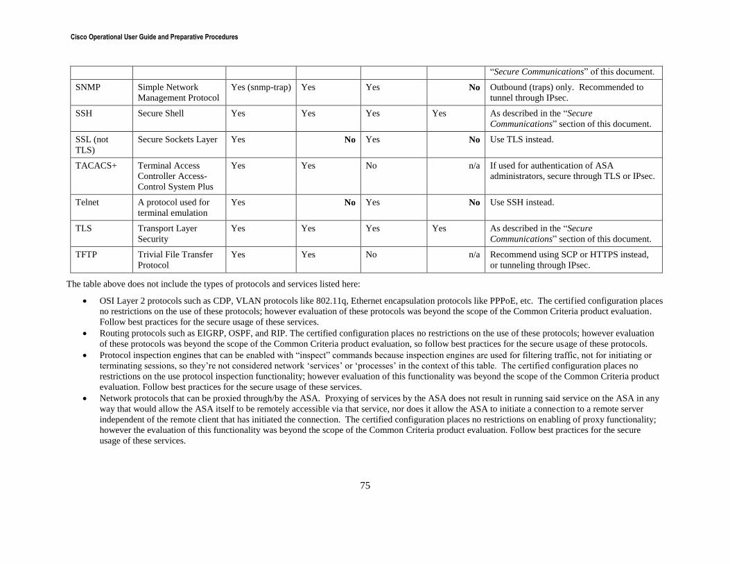
Cisco Operational User Guide and Preparative Procedures
75
“Secure Communications” of this document.
SNMP Simple Network
Management Protocol
Yes (snmp-trap) Yes Yes No Outbound (traps) only. Recommended to
tunnel through IPsec.
SSH Secure Shell Yes Yes Yes Yes As described in the “Secure
Communications” section of this document.
SSL (not
TLS)
Secure Sockets Layer Yes No Yes No Use TLS instead.
TACACS+ Terminal Access
Controller Access-
Control System Plus
Yes Yes No n/a If used for authentication of ASA
administrators, secure through TLS or IPsec.
Telnet A protocol used for
terminal emulation
Yes No Yes No Use SSH instead.
TLS Transport Layer
Security
Yes Yes Yes Yes As described in the “Secure
Communications” section of this document.
TFTP Trivial File Transfer
Protocol
Yes Yes No n/a Recommend using SCP or HTTPS instead,
or tunneling through IPsec.
The table above does not include the types of protocols and services listed here:
OSI Layer 2 protocols such as CDP, VLAN protocols like 802.11q, Ethernet encapsulation protocols like PPPoE, etc. The certified configuration places
no restrictions on the use of these protocols; however evaluation of these protocols was beyond the scope of the Common Criteria product evaluation.
Follow best practices for the secure usage of these services.
Routing protocols such as EIGRP, OSPF, and RIP. The certified configuration places no restrictions on the use of these protocols; however evaluation
of these protocols was beyond the scope of the Common Criteria product evaluation, so follow best practices for the secure usage of these protocols.
Protocol inspection engines that can be enabled with “inspect” commands because inspection engines are used for filtering traffic, not for initiating or
terminating sessions, so they’re not considered network ‘services’ or ‘processes’ in the context of this table. The certified configuration places no
restrictions on the use protocol inspection functionality; however evaluation of this functionality was beyond the scope of the Common Criteria product
evaluation. Follow best practices for the secure usage of these services.
Network protocols that can be proxied through/by the ASA. Proxying of services by the ASA does not result in running said service on the ASA in any
way that would allow the ASA itself to be remotely accessible via that service, nor does it allow the ASA to initiate a connection to a remote server
independent of the remote client that has initiated the connection. The certified configuration places no restrictions on enabling of proxy functionality;
however the evaluation of this functionality was beyond the scope of the Common Criteria product evaluation. Follow best practices for the secure
usage of these services.
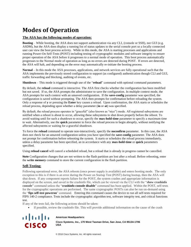
Americas Headquarters:
Cisco Systems, Inc., 170 West Tasman Drive, San Jose, CA 95134-1706 USA
© 2016 Cisco Systems, Inc. All rights reserved.
Modes of Operation The ASA has the following modes of operation:
Booting – While booting, the ASA does not support authentication via any CLI, (console or SSH), nor GUI (e.g.
ASDM), but the ASA does display a running list of status updates to the serial console port so a locally connected
user can view the boot process activity. While in this mode, the ASA is starting processes and applications and
running Power-On Self-Tests (POST) including testing of cryptographic modules and software integrity to ensure
proper operation of the ASA before it progresses to a normal mode of operation. This boot process automatically
progresses to the Normal mode of operation as long as no errors are detected during POST. If errors are detected,
the ASA will halt, and depending on the error may automatically re-initiate the booting process.
Normal – In this mode the ASA processes, applications, and network services are fully operational such that the
ASA implements the previously stored configuration to support (as configured) authentication though CLI and GUI,
traffic forwarding and blocking, auditing of events, etc.
Shutdown – This mode is triggered through use of the “reload” command with optional command parameters.
By default, the reload command is interactive. The ASA first checks whether the configuration has been modified
but not saved. If so, the ASA prompts the administrator to save the configuration. In multiple context mode, the
ASA prompts for each context with an unsaved configuration. If the save-config parameter was specified, the
configuration is saved without prompting. The ASA then prompts for confirmation before reloading the system.
Only a response of y or pressing the Enter key causes a reload. Upon confirmation, the ASA starts or schedules the
reload process, depending upon whether a delay parameter (in or at) was specified.
By default, the reload process operates in “graceful” (also known as “nice”) mode. All registered subsystems are
notified when a reboot is about to occur, allowing these subsystems to shut down properly before the reboot. To
avoid waiting until for such a shutdown to occur, specify the max-hold-time parameter to specify a maximum time
to wait. Alternatively, use the quick parameter to force the reload process to begin abruptly, without notifying the
affected subsystems or waiting for a graceful shutdown.
To force the reload command to operate non-interactively, specify the noconfirm parameter. In this case, the ASA
does not check for an unsaved configuration unless you have specified the save-config parameter. The ASA does
not prompt for confirmation before rebooting the system. It starts or schedules the reload process immediately,
unless a delay parameter has been specified, an in accordance with any max-hold-time or quick parameters
specified.
Using reload cancel will cancel a scheduled reload, but a reload that is already in progress cannot be cancelled.
Note Configuration changes that are not written to the flash partition are lost after a reload. Before rebooting, enter
the write memory command to store the current configuration in the flash partition.
Self-Testing:
Following operational error, the ASA reboots (once power supply is available) and enters booting mode. The only
exception to this is if there is an error during the Power on Startup Test (POST) during bootup, then the ASA will
shut down. If any component reports failure for the POST, the system crashes and appropriate information is
displayed on the screen, and saved in the crashinfo file, which can be viewed via the CLI with the “show crashinfo
console” command unless the “crashinfo console disable” command has been applied. Within the POST, self-tests
for the cryptographic operations are performed. The same cryptographic POSTs can also be run on-demand using
the “fips self-test poweron” command. Entering this command causes the device to run all self-tests required for
FIPS 140-2 compliance. Tests include the cryptographic algorithm test, software integrity test, and critical functions
test.
If any of the tests fail, the following actions should be taken:
If possible, review the crashinfo file. This will provide additional information on the cause of the crash

Cisco Operational User Guide and Preparative Procedures
77
Restart the ASA to perform POST and determine if normal operation can be resumed
If the problem persists, contact Cisco Technical Assistance via http://www.cisco.com/techsupport or 1 800
553-2447
If necessary, return the ASA to Cisco under guidance of Cisco Technical Assistance.
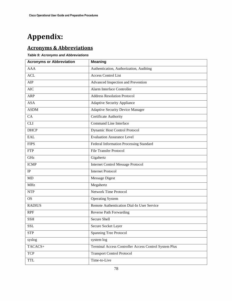
Cisco Operational User Guide and Preparative Procedures
78
Appendix:
Acronyms & Abbreviations Table 9: Acronyms and Abbreviations
Acronyms or Abbreviation Meaning
AAA Authentication, Authorization, Auditing
ACL Access Control List
AIP Advanced Inspection and Prevention
AIC Alarm Interface Controller
ARP Address Resolution Protocol
ASA Adaptive Security Appliance
ASDM Adaptive Security Device Manager
CA Certificate Authority
CLI Command Line Interface
DHCP Dynamic Host Control Protocol
EAL Evaluation Assurance Level
FIPS Federal Information Processing Standard
FTP File Transfer Protocol
GHz Gigahertz
ICMP Internet Control Message Protocol
IP Internet Protocol
MD Message Digest
MHz Megahertz
NTP Network Time Protocol
OS Operating System
RADIUS Remote Authentication Dial-In User Service
RPF Reverse Path Forwarding
SSH Secure Shell
SSL Secure Socket Layer
STP Spanning Tree Protocol
syslog system log
TACACS+ Terminal Access Controller Access Control System Plus
TCP Transport Control Protocol
TTL Time-to-Live

Cisco Operational User Guide and Preparative Procedures
79
UDP User Datagram Protocol
VPN Virtual Private Network
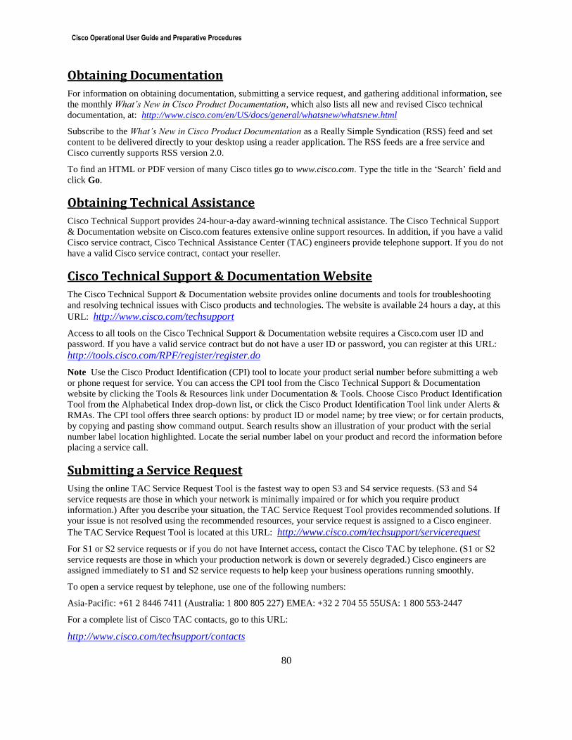
Cisco Operational User Guide and Preparative Procedures
80
Obtaining Documentation
For information on obtaining documentation, submitting a service request, and gathering additional information, see
the monthly What’s New in Cisco Product Documentation, which also lists all new and revised Cisco technical
documentation, at: http://www.cisco.com/en/US/docs/general/whatsnew/whatsnew.html
Subscribe to the What’s New in Cisco Product Documentation as a Really Simple Syndication (RSS) feed and set
content to be delivered directly to your desktop using a reader application. The RSS feeds are a free service and
Cisco currently supports RSS version 2.0.
To find an HTML or PDF version of many Cisco titles go to www.cisco.com. Type the title in the ‘Search’ field and
click Go.
Obtaining Technical Assistance
Cisco Technical Support provides 24-hour-a-day award-winning technical assistance. The Cisco Technical Support
& Documentation website on Cisco.com features extensive online support resources. In addition, if you have a valid
Cisco service contract, Cisco Technical Assistance Center (TAC) engineers provide telephone support. If you do not
have a valid Cisco service contract, contact your reseller.
Cisco Technical Support & Documentation Website
The Cisco Technical Support & Documentation website provides online documents and tools for troubleshooting
and resolving technical issues with Cisco products and technologies. The website is available 24 hours a day, at this
URL: http://www.cisco.com/techsupport
Access to all tools on the Cisco Technical Support & Documentation website requires a Cisco.com user ID and
password. If you have a valid service contract but do not have a user ID or password, you can register at this URL:
http://tools.cisco.com/RPF/register/register.do
Note Use the Cisco Product Identification (CPI) tool to locate your product serial number before submitting a web
or phone request for service. You can access the CPI tool from the Cisco Technical Support & Documentation
website by clicking the Tools & Resources link under Documentation & Tools. Choose Cisco Product Identification
Tool from the Alphabetical Index drop-down list, or click the Cisco Product Identification Tool link under Alerts &
RMAs. The CPI tool offers three search options: by product ID or model name; by tree view; or for certain products,
by copying and pasting show command output. Search results show an illustration of your product with the serial
number label location highlighted. Locate the serial number label on your product and record the information before
placing a service call.
Submitting a Service Request
Using the online TAC Service Request Tool is the fastest way to open S3 and S4 service requests. (S3 and S4
service requests are those in which your network is minimally impaired or for which you require product
information.) After you describe your situation, the TAC Service Request Tool provides recommended solutions. If
your issue is not resolved using the recommended resources, your service request is assigned to a Cisco engineer.
The TAC Service Request Tool is located at this URL: http://www.cisco.com/techsupport/servicerequest
For S1 or S2 service requests or if you do not have Internet access, contact the Cisco TAC by telephone. (S1 or S2
service requests are those in which your production network is down or severely degraded.) Cisco engineers are
assigned immediately to S1 and S2 service requests to help keep your business operations running smoothly.
To open a service request by telephone, use one of the following numbers:
Asia-Pacific: +61 2 8446 7411 (Australia: 1 800 805 227) EMEA: +32 2 704 55 55USA: 1 800 553-2447
For a complete list of Cisco TAC contacts, go to this URL:
http://www.cisco.com/techsupport/contacts
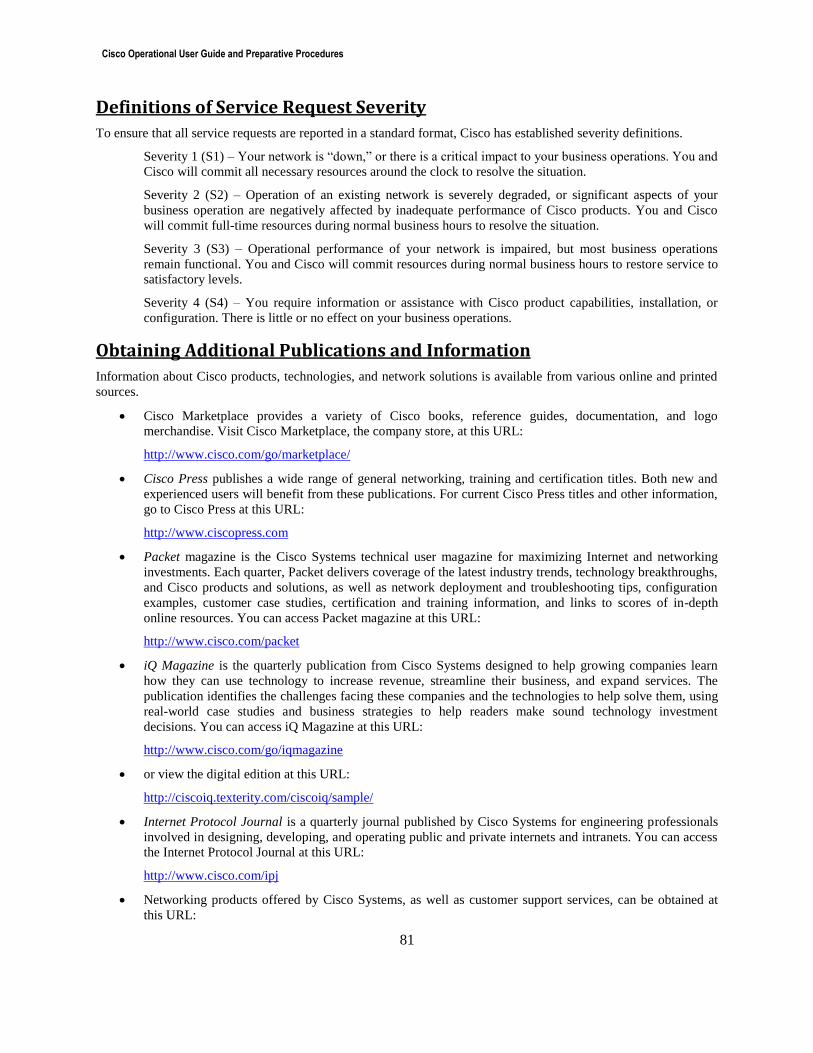
Cisco Operational User Guide and Preparative Procedures
81
Definitions of Service Request Severity
To ensure that all service requests are reported in a standard format, Cisco has established severity definitions.
Severity 1 (S1) – Your network is “down,” or there is a critical impact to your business operations. You and
Cisco will commit all necessary resources around the clock to resolve the situation.
Severity 2 (S2) – Operation of an existing network is severely degraded, or significant aspects of your
business operation are negatively affected by inadequate performance of Cisco products. You and Cisco
will commit full-time resources during normal business hours to resolve the situation.
Severity 3 (S3) – Operational performance of your network is impaired, but most business operations
remain functional. You and Cisco will commit resources during normal business hours to restore service to
satisfactory levels.
Severity 4 (S4) – You require information or assistance with Cisco product capabilities, installation, or
configuration. There is little or no effect on your business operations.
Obtaining Additional Publications and Information
Information about Cisco products, technologies, and network solutions is available from various online and printed
sources.
Cisco Marketplace provides a variety of Cisco books, reference guides, documentation, and logo
merchandise. Visit Cisco Marketplace, the company store, at this URL:
http://www.cisco.com/go/marketplace/
Cisco Press publishes a wide range of general networking, training and certification titles. Both new and
experienced users will benefit from these publications. For current Cisco Press titles and other information,
go to Cisco Press at this URL:
http://www.ciscopress.com
Packet magazine is the Cisco Systems technical user magazine for maximizing Internet and networking
investments. Each quarter, Packet delivers coverage of the latest industry trends, technology breakthroughs,
and Cisco products and solutions, as well as network deployment and troubleshooting tips, configuration
examples, customer case studies, certification and training information, and links to scores of in-depth
online resources. You can access Packet magazine at this URL:
http://www.cisco.com/packet
iQ Magazine is the quarterly publication from Cisco Systems designed to help growing companies learn
how they can use technology to increase revenue, streamline their business, and expand services. The
publication identifies the challenges facing these companies and the technologies to help solve them, using
real-world case studies and business strategies to help readers make sound technology investment
decisions. You can access iQ Magazine at this URL:
http://www.cisco.com/go/iqmagazine
or view the digital edition at this URL:
http://ciscoiq.texterity.com/ciscoiq/sample/
Internet Protocol Journal is a quarterly journal published by Cisco Systems for engineering professionals
involved in designing, developing, and operating public and private internets and intranets. You can access
the Internet Protocol Journal at this URL:
http://www.cisco.com/ipj
Networking products offered by Cisco Systems, as well as customer support services, can be obtained at
this URL:

Cisco Operational User Guide and Preparative Procedures
82
http://www.cisco.com/en/US/products/index.html
Networking Professionals Connection is an interactive website for networking professionals to share
questions, suggestions, and information about networking products and technologies with Cisco experts
and other networking professionals. Join a discussion at this URL:
http://www.cisco.com/discuss/networking
World-class networking training is available from Cisco. You can view current offerings at this URL:
http://www.cisco.com/en/US/learning/index.html

Cisco Operational User Guide and Preparative Procedures
83
CCDE, CCENT, CCSI, Cisco Eos, Cisco Explorer, Cisco HealthPresence, Cisco IronPort, the Cisco logo, Cisco Nurse Connect, Cisco Pulse, Cisco SensorBase, Cisco
StackPower, Cisco StadiumVision, Cisco TelePresence, Cisco TrustSec, Cisco Unified Computing System, Cisco WebEx, DCE, Flip Channels, Flip for Good, Flip
Mino, Flipshare (Design), Flip Ultra, Flip Video, Flip Video (Design), Instant Broadband, and Welcome to the Human Network are trademarks; Changing the Way
We Work, Live, Play, and Learn, Cisco Capital, Cisco Capital (Design), Cisco:Financed (Stylized), Cisco Store, Flip Gift Card, and One Million Acts of Green are
service marks; and Access Registrar, Aironet, AllTouch, AsyncOS, Bringing the Meeting To You, Catalyst, CCDA, CCDP, CCIE, CCIP, CCNA, CCNP, CCSP,
CCVP, Cisco, the Cisco Certified Internetwork Expert logo, Cisco IOS, Cisco Lumin, Cisco Nexus, Cisco Press, Cisco Systems, Cisco Systems Capital, the Cisco
Systems logo, Cisco Unity, Collaboration Without Limitation, Continuum, EtherFast, EtherSwitch, Event Center, Explorer, Follow Me Browsing, GainMaker,
iLYNX, IOS, iPhone, IronPort, the IronPort logo, Laser Link, LightStream, Linksys, MeetingPlace, MeetingPlace Chime Sound, MGX, Networkers, Networking
Academy, PCNow, PIX, PowerKEY, PowerPanels, PowerTV, PowerTV (Design), PowerVu, Prisma, ProConnect, ROSA, SenderBase, SMARTnet, Spectrum Expert,
StackWise, WebEx, and the WebEx logo are registered trademarks of Cisco and/or its affiliates in the United States and certain other countries.
All other trademarks mentioned in this document or website are the property of their respective owners. The use of the word partner does not imply a partnership
relationship between Cisco and any other company. (1002R)
Copyright 2015 Cisco Systems, Inc. All rights reserved.