Embed Size (px)
Citation preview
Cisco 3700 Series RoutersHardware Installation Guide
Corporate HeadquartersCisco Systems, Inc.170 West Tasman DriveSan Jose, CA 95134-1706 USAhttp://www.cisco.comTel: 408 526-4000
800 553-NETS (6387)Fax: 408 526-4100
Text Part Number: OL-2180-08
THE SPECIFICATIONS AND INFORMATION REGARDING THE PRODUCTS IN THIS MANUAL ARE SUBJECT TO CHANGE WITHOUT NOTICE. ALL STATEMENTS, INFORMATION, AND RECOMMENDATIONS IN THIS MANUAL ARE BELIEVED TO BE ACCURATE BUT ARE PRESENTED WITHOUT WARRANTY OF ANY KIND, EXPRESS OR IMPLIED. USERS MUST TAKE FULL RESPONSIBILITY FOR THEIR APPLICATION OF ANY PRODUCTS.
THE SOFTWARE LICENSE AND LIMITED WARRANTY FOR THE ACCOMPANYING PRODUCT ARE SET FORTH IN THE INFORMATION PACKET THAT SHIPPED WITH THE PRODUCT AND ARE INCORPORATED HEREIN BY THIS REFERENCE. IF YOU ARE UNABLE TO LOCATE THE SOFTWARE LICENSE OR LIMITED WARRANTY, CONTACT YOUR CISCO REPRESENTATIVE FOR A COPY.
The following information is for FCC compliance of Class A devices: This equipment has been tested and found to comply with the limits for a Class A digital device, pursuant to part 15 of the FCC rules. These limits are designed to provide reasonable protection against harmful interference when the equipment is operated in a commercial environment. This equipment generates, uses, and can radiate radio-frequency energy and, if not installed and used in accordance with the instruction manual, may cause harmful interference to radio communications. Operation of this equipment in a residential area is likely to cause harmful interference, in which case users will be required to correct the interference at their own expense.
The following information is for FCC compliance of Class B devices: The equipment described in this manual generates and may radiate radio-frequency energy. If it is not installed in accordance with Cisco’s installation instructions, it may cause interference with radio and television reception. This equipment has been tested and found to comply with the limits for a Class B digital device in accordance with the specifications in part 15 of the FCC rules. These specifications are designed to provide reasonable protection against such interference in a residential installation. However, there is no guarantee that interference will not occur in a particular installation.
Modifying the equipment without Cisco’s written authorization may result in the equipment no longer complying with FCC requirements for Class A or Class B digital devices. In that event, your right to use the equipment may be limited by FCC regulations, and you may be required to correct any interference to radio or television communications at your own expense.
You can determine whether your equipment is causing interference by turning it off. If the interference stops, it was probably caused by the Cisco equipment or one of its peripheral devices. If the equipment causes interference to radio or television reception, try to correct the interference by using one or more of the following measures:
• Turn the television or radio antenna until the interference stops.
• Move the equipment to one side or the other of the television or radio.
• Move the equipment farther away from the television or radio.
• Plug the equipment into an outlet that is on a different circuit from the television or radio. (That is, make certain the equipment and the television or radio are on circuits controlled by different circuit breakers or fuses.)
Modifications to this product not authorized by Cisco Systems, Inc. could void the FCC approval and negate your authority to operate the product.
The Cisco implementation of TCP header compression is an adaptation of a program developed by the University of California, Berkeley (UCB) as part of UCB’s public domain version of the UNIX operating system. All rights reserved. Copyright © 1981, Regents of the University of California.
NOTWITHSTANDING ANY OTHER WARRANTY HEREIN, ALL DOCUMENT FILES AND SOFTWARE OF THESE SUPPLIERS ARE PROVIDED “AS IS” WITH ALL FAULTS. CISCO AND THE ABOVE-NAMED SUPPLIERS DISCLAIM ALL WARRANTIES, EXPRESSED OR IMPLIED, INCLUDING, WITHOUT LIMITATION, THOSE OF MERCHANTABILITY, FITNESS FOR A PARTICULAR PURPOSE AND NONINFRINGEMENT OR ARISING FROM A COURSE OF DEALING, USAGE, OR TRADE PRACTICE.
IN NO EVENT SHALL CISCO OR ITS SUPPLIERS BE LIABLE FOR ANY INDIRECT, SPECIAL, CONSEQUENTIAL, OR INCIDENTAL DAMAGES, INCLUDING, WITHOUT LIMITATION, LOST PROFITS OR LOSS OR DAMAGE TO DATA ARISING OUT OF THE USE OR INABILITY TO USE THIS MANUAL, EVEN IF CISCO OR ITS SUPPLIERS HAVE BEEN ADVISED OF THE POSSIBILITY OF SUCH DAMAGES
CCSP, the Cisco Square Bridge logo, Follow Me Browsing, and StackWise are trademarks of Cisco Systems, Inc.; Changing the Way We Work, Live, Play, and Learn, and iQuick Study are service marks of Cisco Systems, Inc.; and Access Registrar, Aironet, ASIST, BPX, Catalyst, CCDA, CCDP, CCIE, CCIP, CCNA, CCNP, Cisco, the Cisco Certified Internetwork Expert logo, Cisco IOS, Cisco Press, Cisco Systems, Cisco Systems Capital, the Cisco Systems logo, Cisco Unity, Empowering the Internet Generation, Enterprise/Solver, EtherChannel, EtherFast, EtherSwitch, Fast Step, FormShare, GigaDrive, GigaStack, HomeLink, Internet Quotient, IOS, IP/TV, iQ Expertise, the iQ logo, iQ Net Readiness Scorecard, LightStream, Linksys, MeetingPlace, MGX, the Networkers logo, Networking Academy, Network Registrar, Packet, PIX, Post-Routing, Pre-Routing, ProConnect, RateMUX, ScriptShare, SlideCast, SMARTnet, StrataView Plus, SwitchProbe, TeleRouter, The Fastest Way to Increase Your Internet Quotient, TransPath, and VCO are registered trademarks of Cisco Systems, Inc. and/or its affiliates in the United States and certain other countries.
All other trademarks mentioned in this document or Website are the property of their respective owners. The use of the word partner does not imply a partnership relationship between Cisco and any other company. (0411R)
Book TitleCopyright © 2000-2003 Cisco Systems, Inc.All rights reserved.
OL-2180-08
C O N T E N T S
Preface vii
Objectives vii
Audience viii
Organization viii
Conventions viii
Safety Warnings ix
Related Documentation xiv
Obtaining Documentation xvi
Cisco.com xvi
Ordering Documentation xvi
Documentation Feedback xvi
Obtaining Technical Assistance xvii
Cisco Technical Support Website xvii
Submitting a Service Request xvii
Definitions of Service Request Severity xviii
Obtaining Additional Publications and Information xviii
C H A P T E R 1 Overview of Cisco 3700 Series Routers 1-1
Hardware Features 1-1
Cisco 3725 1-1
Cisco 3745 1-2
Modules, Interface Cards, and Memory 1-3
Memory 1-4
Interface Numbering 1-5
Cisco 3725 Interfaces 1-5
Cisco 3745 Interfaces 1-7
Power Supply Options 1-9
Internal –48 V Telephony Power Modules 1-9
System Specifications 1-11
Regulatory Compliance 1-12
C H A P T E R 2 Preparing to Install the Router 2-1
Safety Recommendations 2-1
iiiCisco 3700 Series Routers Hardware Installation Guide
Contents
Safety with Electricity 2-2
Preventing Electrostatic Discharge Damage 2-2
General Site Requirements 2-3
Power Supply Considerations 2-3
Site Environment 2-4
Site Configuration 2-4
Equipment Racks 2-4
Installation Checklist 2-5
Creating a Site Log 2-6
Inspecting the Router 2-6
Required Tools and Equipment for Installation and Maintenance 2-7
Console and Auxiliary Port Considerations 2-8
Console Port Connections 2-8
Auxiliary Port Connections 2-8
Preparing to Connect to a Network 2-9
Ethernet Connections 2-9
Token Ring Connections 2-10
Serial Connections 2-10
ISDN BRI Connections 2-12
56-K/Switched-56-kbps DSU/CSU Connections 2-13
C H A P T E R 3 Installing the Router 3-1
Installing Modules, Interface Cards, and Power Supplies 3-1
Setting Up the Chassis 3-2
Setting the Chassis on a Desktop 3-2
Rack-Mounting the Chassis 3-3
Installing the Chassis Ground Connection 3-8
Cisco 3725 Router Ground Connection 3-9
Cisco 3745 Router Ground Connection 3-10
Power Connections 3-11
Connecting Routers to AC Power 3-12
Connecting Routers to a DC-Input Power Supply 3-12
Connecting Routers to the Cisco Redundant Power System 3-20
Connecting WAN, LAN, and Voice Cables 3-20
Ports and Cabling 3-20
Connection Procedures and Precautions 3-21
Connecting to a Console Terminal or Modem 3-22
Connecting to the Console Port 3-22
ivCisco 3700 Series Routers Hardware Installation Guide
OL-2180-08
Contents
Connecting to the Auxiliary Port 3-24
Identifying a Rollover Cable 3-25
Powering Up the Router 3-26
Checklist for Power Up 3-26
Front Panel Indicators 3-26
Power-Up Procedure 3-27
Configuring the Router 3-29
Initial Configuration Using SDM 3-29
Initial Configuration Using the Setup Command Facility 3-29
Initial Configuration Using the CLI (Manual Configuration) 3-32
A P P E N D I X A Troubleshooting A-1
Solving Problems A-2
Troubleshooting the Power and Cooling Systems A-2
Environmental Reporting Features A-3
Troubleshooting Modules, Cables, and Connections A-3
Reading Front-Panel LEDs A-4
Reading Rear Panel LEDs A-6
Error Messages A-8
Recovering a Lost Password A-12
A P P E N D I X B Using the ROM Monitor B-1
Entering ROM Monitor Mode B-1
Enter ROM Monitor Mode by Using the reload Command B-2
Enter ROM Monitor Mode by Resetting the Configuration Register B-2
ROM Monitor Commands B-2
ROM Monitor Syntax Conventions B-3
ROM Monitor Command Descriptions B-3
Boot Commands in the ROM Monitor B-3
Informational Commands in the ROM Monitor B-5
Other Useful ROM Monitor Commands B-6
Debugging Commands in the ROM Monitor B-6
Configuration Register B-6
Recovering Cisco IOS Software Images B-8
Description and Options of the xmodem Command B-8
A P P E N D I X C Configuration Register C-1
Configuration Register Settings C-1
vCisco 3700 Series Routers Hardware Installation Guide
OL-2180-08
Contents
Changing Configuration Register Settings C-2
Configuring the Boot Field C-3
Enabling Booting from CompactFlash Memory C-5
IN D E X
viCisco 3700 Series Routers Hardware Installation Guide
OL-2180-08
Preface
This preface discusses the objectives, audience, organization, and conventions of this hardware installation guide, and points to related documents that have information beyond the scope of this document. It contains the following sections:
• Objectives, page vii
• Audience, page viii
• Organization, page viii
• Conventions, page viii
• Safety Warnings, page ix
• Related Documentation, page xiv
• Obtaining Documentation, page xvi
• Documentation Feedback, page xvi
• Obtaining Technical Assistance, page xvii
• Obtaining Additional Publications and Information, page xviii
ObjectivesThis guide explains how to install, maintain, and troubleshoot your router hardware. It also includes instructions for the router ROM monitor and configuration register.
Although this guide provides minimum software configuration information, it is not comprehensive. For detailed software configuration information, see the Software Configuration Guide for Cisco 2600 Series, Cisco 3600 Series, and Cisco 3700 Series Routers and the Cisco IOS configuration guide and command reference publications. These publications are available online on Cisco.com. See the “Obtaining Documentation” section on page xvi for more information.
This guide describes several router models that are similar in functionality but differ in the number of interfaces supported. Some information provided may not apply to your particular router model.
viiCisco 3700 Series Routers Hardware Installation Guide
OL-2180-08
PrefaceAudience
AudienceThis guide is designed for the person installing, configuring, and maintaining the router, who should be familiar with electronic circuitry and wiring practices and has experience as an electronic or electromechanical technician. It identifies certain procedures that should be performed only by trained and qualified personnel.
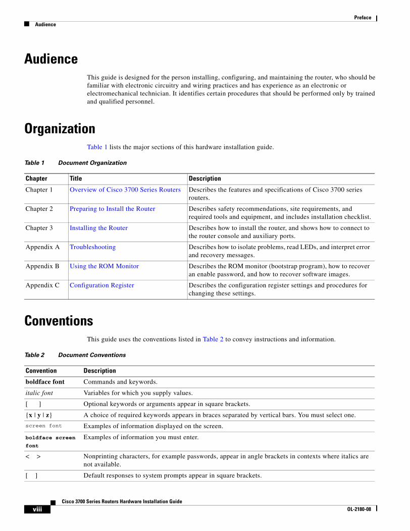
OrganizationTable 1 lists the major sections of this hardware installation guide.
ConventionsThis guide uses the conventions listed in Table 2 to convey instructions and information.
Table 1 Document Organization
Chapter Title Description
Chapter 1 Overview of Cisco 3700 Series Routers Describes the features and specifications of Cisco 3700 series routers.
Chapter 2 Preparing to Install the Router Describes safety recommendations, site requirements, and required tools and equipment, and includes installation checklist.
Chapter 3 Installing the Router Describes how to install the router, and shows how to connect to the router console and auxiliary ports.
Appendix A Troubleshooting Describes how to isolate problems, read LEDs, and interpret error and recovery messages.
Appendix B Using the ROM Monitor Describes the ROM monitor (bootstrap program), how to recover an enable password, and how to recover software images.
Appendix C Configuration Register Describes the configuration register settings and procedures for changing these settings.
Table 2 Document Conventions
Convention Description
boldface font Commands and keywords.
italic font Variables for which you supply values.
[ ] Optional keywords or arguments appear in square brackets.
{x | y | z} A choice of required keywords appears in braces separated by vertical bars. You must select one.
screen font Examples of information displayed on the screen.
boldface screen font
Examples of information you must enter.
< > Nonprinting characters, for example passwords, appear in angle brackets in contexts where italics are not available.
[ ] Default responses to system prompts appear in square brackets.
viiiCisco 3700 Series Routers Hardware Installation Guide
OL-2180-08
PrefaceSafety Warnings
Note Means reader take note. Notes contain helpful suggestions or references to material not covered in the manual.
Timesaver Means the described action saves time. You can save time by performing the action described in the paragraph.
Tip Means the following information will help you solve a problem. The tips information might not be troubleshooting or even an action, but could be useful information, similar to a Timesaver.
Caution Means reader be careful. In this situation, you might do something that could result in equipment damage or loss of data.
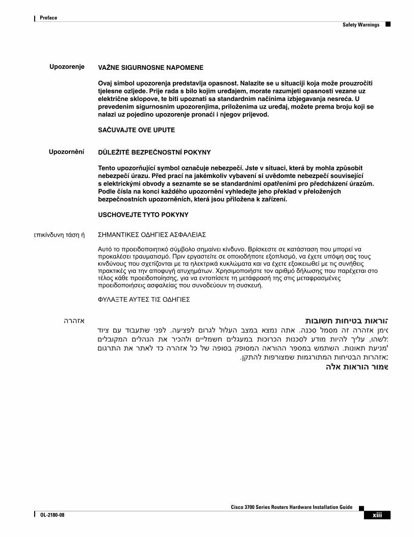
Safety WarningsSafety warnings appear throughout this publication in procedures that, if performed incorrectly, may harm you. A warning symbol precedes each warning statement. To see translations of the warnings that appear in this publication, see the Cisco 2600 Series, Cisco 3600 Series, and Cisco 3700 Series Regulatory Compliance and Safety Information document that accompanied your router.
Warning IMPORTANT SAFETY INSTRUCTIONS
This warning symbol means danger. You are in a situation that could cause bodily injury. Before you work on any equipment, be aware of the hazards involved with electrical circuitry and be familiar with standard practices for preventing accidents. Use the statement number provided at the end of each warning to locate its translation in the translated safety warnings that accompanied this device. Statement 1071
SAVE THESE INSTRUCTIONS
Waarschuwing BELANGRIJKE VEILIGHEIDSINSTRUCTIES
Dit waarschuwingssymbool betekent gevaar. U verkeert in een situatie die lichamelijk letsel kan veroorzaken. Voordat u aan enige apparatuur gaat werken, dient u zich bewust te zijn van de bij elektrische schakelingen betrokken risico's en dient u op de hoogte te zijn van de standaard praktijken om ongelukken te voorkomen. Gebruik het nummer van de verklaring onderaan de waarschuwing als u een vertaling van de waarschuwing die bij het apparaat wordt geleverd, wilt raadplegen.
BEWAAR DEZE INSTRUCTIES
ixCisco 3700 Series Routers Hardware Installation Guide
OL-2180-08
PrefaceSafety Warnings
Varoitus TÄRKEITÄ TURVALLISUUSOHJEITA
Tämä varoitusmerkki merkitsee vaaraa. Tilanne voi aiheuttaa ruumiillisia vammoja. Ennen kuin käsittelet laitteistoa, huomioi sähköpiirien käsittelemiseen liittyvät riskit ja tutustu onnettomuuksien yleisiin ehkäisytapoihin. Turvallisuusvaroitusten käännökset löytyvät laitteen mukana toimitettujen käännettyjen turvallisuusvaroitusten joukosta varoitusten lopussa näkyvien lausuntonumeroiden avulla.
SÄILYTÄ NÄMÄ OHJEET
Attention IMPORTANTES INFORMATIONS DE SÉCURITÉ
Ce symbole d'avertissement indique un danger. Vous vous trouvez dans une situation pouvant entraîner des blessures ou des dommages corporels. Avant de travailler sur un équipement, soyez conscient des dangers liés aux circuits électriques et familiarisez-vous avec les procédures couramment utilisées pour éviter les accidents. Pour prendre connaissance des traductions des avertissements figurant dans les consignes de sécurité traduites qui accompagnent cet appareil, référez-vous au numéro de l'instruction situé à la fin de chaque avertissement.
CONSERVEZ CES INFORMATIONS
Warnung WICHTIGE SICHERHEITSHINWEISE
Dieses Warnsymbol bedeutet Gefahr. Sie befinden sich in einer Situation, die zu Verletzungen führen kann. Machen Sie sich vor der Arbeit mit Geräten mit den Gefahren elektrischer Schaltungen und den üblichen Verfahren zur Vorbeugung vor Unfällen vertraut. Suchen Sie mit der am Ende jeder Warnung angegebenen Anweisungsnummer nach der jeweiligen Übersetzung in den übersetzten Sicherheitshinweisen, die zusammen mit diesem Gerät ausgeliefert wurden.
BEWAHREN SIE DIESE HINWEISE GUT AUF.
Avvertenza IMPORTANTI ISTRUZIONI SULLA SICUREZZA
Questo simbolo di avvertenza indica un pericolo. La situazione potrebbe causare infortuni alle persone. Prima di intervenire su qualsiasi apparecchiatura, occorre essere al corrente dei pericoli relativi ai circuiti elettrici e conoscere le procedure standard per la prevenzione di incidenti. Utilizzare il numero di istruzione presente alla fine di ciascuna avvertenza per individuare le traduzioni delle avvertenze riportate in questo documento.
CONSERVARE QUESTE ISTRUZIONI
Advarsel VIKTIGE SIKKERHETSINSTRUKSJONER
Dette advarselssymbolet betyr fare. Du er i en situasjon som kan føre til skade på person. Før du begynner å arbeide med noe av utstyret, må du være oppmerksom på farene forbundet med elektriske kretser, og kjenne til standardprosedyrer for å forhindre ulykker. Bruk nummeret i slutten av hver advarsel for å finne oversettelsen i de oversatte sikkerhetsadvarslene som fulgte med denne enheten.
TA VARE PÅ DISSE INSTRUKSJONENE
xCisco 3700 Series Routers Hardware Installation Guide
OL-2180-08
PrefaceSafety Warnings
Aviso INSTRUÇÕES IMPORTANTES DE SEGURANÇA
Este símbolo de aviso significa perigo. Você está em uma situação que poderá ser causadora de lesões corporais. Antes de iniciar a utilização de qualquer equipamento, tenha conhecimento dos perigos envolvidos no manuseio de circuitos elétricos e familiarize-se com as práticas habituais de prevenção de acidentes. Utilize o número da instrução fornecido ao final de cada aviso para localizar sua tradução nos avisos de segurança traduzidos que acompanham este dispositivo.
GUARDE ESTAS INSTRUÇÕES
¡Advertencia! INSTRUCCIONES IMPORTANTES DE SEGURIDAD
Este símbolo de aviso indica peligro. Existe riesgo para su integridad física. Antes de manipular cualquier equipo, considere los riesgos de la corriente eléctrica y familiarícese con los procedimientos estándar de prevención de accidentes. Al final de cada advertencia encontrará el número que le ayudará a encontrar el texto traducido en el apartado de traducciones que acompaña a este dispositivo.
GUARDE ESTAS INSTRUCCIONES
Varning! VIKTIGA SÄKERHETSANVISNINGAR
Denna varningssignal signalerar fara. Du befinner dig i en situation som kan leda till personskada. Innan du utför arbete på någon utrustning måste du vara medveten om farorna med elkretsar och känna till vanliga förfaranden för att förebygga olyckor. Använd det nummer som finns i slutet av varje varning för att hitta dess översättning i de översatta säkerhetsvarningar som medföljer denna anordning.
SPARA DESSA ANVISNINGAR
xiCisco 3700 Series Routers Hardware Installation Guide
OL-2180-08
PrefaceSafety Warnings
Aviso INSTRUÇÕES IMPORTANTES DE SEGURANÇA
Este símbolo de aviso significa perigo. Você se encontra em uma situação em que há risco de lesões corporais. Antes de trabalhar com qualquer equipamento, esteja ciente dos riscos que envolvem os circuitos elétricos e familiarize-se com as práticas padrão de prevenção de acidentes. Use o número da declaração fornecido ao final de cada aviso para localizar sua tradução nos avisos de segurança traduzidos que acompanham o dispositivo.
GUARDE ESTAS INSTRUÇÕES
Advarsel VIGTIGE SIKKERHEDSANVISNINGER
Dette advarselssymbol betyder fare. Du befinder dig i en situation med risiko for legemesbeskadigelse. Før du begynder arbejde på udstyr, skal du være opmærksom på de involverede risici, der er ved elektriske kredsløb, og du skal sætte dig ind i standardprocedurer til undgåelse af ulykker. Brug erklæringsnummeret efter hver advarsel for at finde oversættelsen i de oversatte advarsler, der fulgte med denne enhed.
GEM DISSE ANVISNINGER
xiiCisco 3700 Series Routers Hardware Installation Guide
OL-2180-08
PrefaceSafety Warnings
xiiiCisco 3700 Series Routers Hardware Installation Guide
OL-2180-08
PrefaceRelated Documentation
Related DocumentationThe Cisco IOS software running your Cisco 3700 series router includes extensive features and functionality. For information that is beyond the scope of this document, or for additional information, use the following resources.
Timesaver Make sure that you have access to the documents listed in Table 3. Some of these documents are available in print, and all are on CD-ROM and on the World Wide Web. If you need to order printed documents, see the “Obtaining Documentation” section on page xvi.
xivCisco 3700 Series Routers Hardware Installation Guide
OL-2180-08
PrefaceRelated Documentation
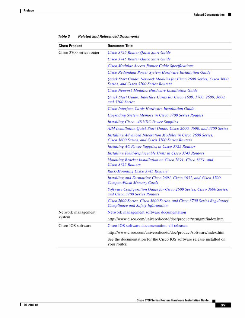
Table 3 Related and Referenced Documents
Cisco Product Document Title
Cisco 3700 series router Cisco 3725 Router Quick Start Guide
Cisco 3745 Router Quick Start Guide
Cisco Modular Access Router Cable Specifications
Cisco Redundant Power System Hardware Installation Guide
Quick Start Guide: Network Modules for Cisco 2600 Series, Cisco 3600 Series, and Cisco 3700 Series Routers
Cisco Network Modules Hardware Installation Guide
Quick Start Guide: Interface Cards for Cisco 1600, 1700, 2600, 3600, and 3700 Series
Cisco Interface Cards Hardware Installation Guide
Upgrading System Memory in Cisco 3700 Series Routers
Installing Cisco –48 VDC Power Supplies
AIM Installation Quick Start Guide: Cisco 2600, 3600, and 3700 Series
Installing Advanced Integration Modules in Cisco 2600 Series, Cisco 3600 Series, and Cisco 3700 Series Routers
Installing AC Power Supplies in Cisco 3725 Routers
Installing Field-Replaceable Units in Cisco 3745 Routers
Mounting Bracket Installation on Cisco 2691, Cisco 3631, and Cisco 3725 Routers
Rack-Mounting Cisco 3745 Routers
Installing and Formatting Cisco 2691, Cisco 3631, and Cisco 3700 CompactFlash Memory Cards
Software Configuration Guide for Cisco 2600 Series, Cisco 3600 Series, and Cisco 3700 Series Routers
Cisco 2600 Series, Cisco 3600 Series, and Cisco 3700 Series Regulatory Compliance and Safety Information
Network management system
Network management software documentation
http://www.cisco.com/univercd/cc/td/doc/product/rtrmgmt/index.htm
Cisco IOS software Cisco IOS software documentation, all releases.
http://www.cisco.com/univercd/cc/td/doc/product/software/index.htm
See the documentation for the Cisco IOS software release installed on your router.
xvCisco 3700 Series Routers Hardware Installation Guide
OL-2180-08
PrefaceObtaining Documentation
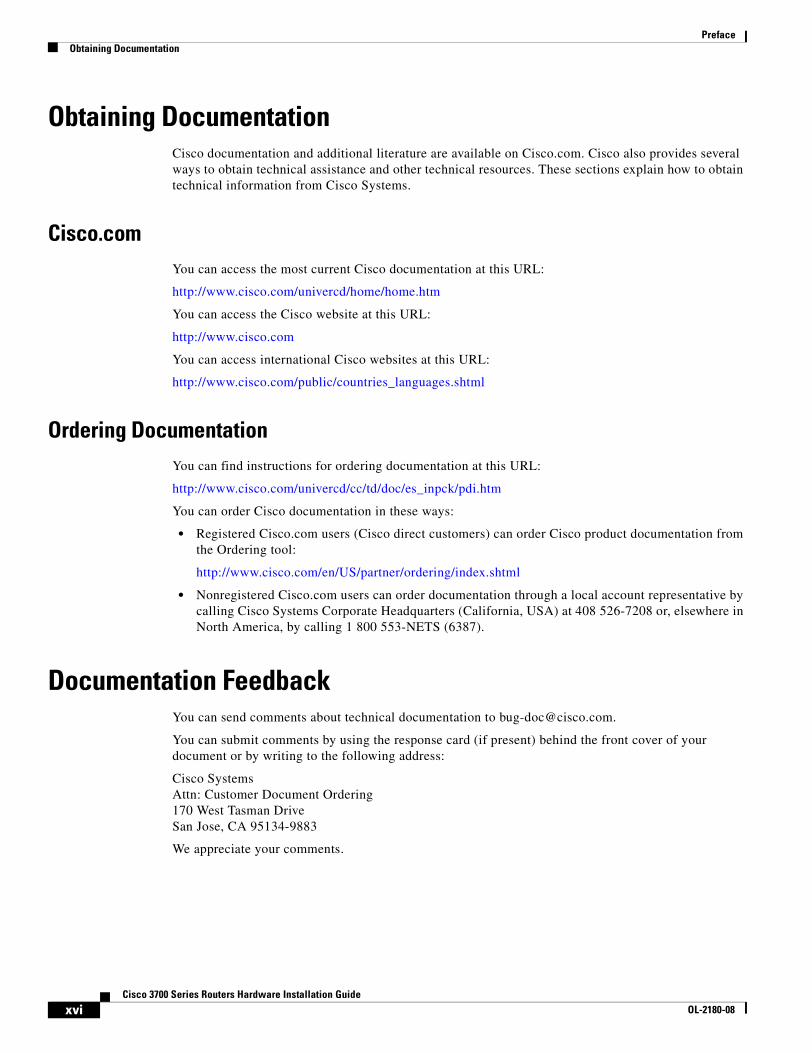
Obtaining DocumentationCisco documentation and additional literature are available on Cisco.com. Cisco also provides several ways to obtain technical assistance and other technical resources. These sections explain how to obtain technical information from Cisco Systems.
Cisco.comYou can access the most current Cisco documentation at this URL:
http://www.cisco.com/univercd/home/home.htm
You can access the Cisco website at this URL:
http://www.cisco.com
You can access international Cisco websites at this URL:
http://www.cisco.com/public/countries_languages.shtml
Ordering DocumentationYou can find instructions for ordering documentation at this URL:
http://www.cisco.com/univercd/cc/td/doc/es_inpck/pdi.htm
You can order Cisco documentation in these ways:
• Registered Cisco.com users (Cisco direct customers) can order Cisco product documentation from the Ordering tool:
http://www.cisco.com/en/US/partner/ordering/index.shtml
• Nonregistered Cisco.com users can order documentation through a local account representative by calling Cisco Systems Corporate Headquarters (California, USA) at 408 526-7208 or, elsewhere in North America, by calling 1 800 553-NETS (6387).
Documentation FeedbackYou can send comments about technical documentation to [email protected].
You can submit comments by using the response card (if present) behind the front cover of your document or by writing to the following address:
Cisco SystemsAttn: Customer Document Ordering170 West Tasman DriveSan Jose, CA 95134-9883
We appreciate your comments.
xviCisco 3700 Series Routers Hardware Installation Guide
OL-2180-08
PrefaceObtaining Technical Assistance
Obtaining Technical AssistanceFor all customers, partners, resellers, and distributors who hold valid Cisco service contracts, Cisco Technical Support provides 24-hour-a-day, award-winning technical assistance. The Cisco Technical Support Website on Cisco.com features extensive online support resources. In addition, Cisco Technical Assistance Center (TAC) engineers provide telephone support. If you do not hold a valid Cisco service contract, contact your reseller.
Cisco Technical Support WebsiteThe Cisco Technical Support Website provides online documents and tools for troubleshooting and resolving technical issues with Cisco products and technologies. The website is available 24 hours a day, 365 days a year, at this URL:
http://www.cisco.com/techsupport
Access to all tools on the Cisco Technical Support Website requires a Cisco.com user ID and password. If you have a valid service contract but do not have a user ID or password, you can register at this URL:
http://tools.cisco.com/RPF/register/register.do
Note Use the Cisco Product Identification (CPI) tool to locate your product serial number before submitting a web or phone request for service. You can access the CPI tool from the Cisco Technical Support Website by clicking the Tools & Resources link under Documentation & Tools. Choose Cisco Product Identification Tool from the Alphabetical Index drop-down list, or click the Cisco Product Identification Tool link under Alerts & RMAs. The CPI tool offers three search options: by product ID or model name; by tree view; or for certain products, by copying and pasting show command output. Search results show an illustration of your product with the serial number label location highlighted. Locate the serial number label on your product and record the information before placing a service call.
Submitting a Service RequestUsing the online TAC Service Request Tool is the fastest way to open S3 and S4 service requests. (S3 and S4 service requests are those in which your network is minimally impaired or for which you require product information.) After you describe your situation, the TAC Service Request Tool provides recommended solutions. If your issue is not resolved using the recommended resources, your service request is assigned to a Cisco TAC engineer. The TAC Service Request Tool is located at this URL:
http://www.cisco.com/techsupport/servicerequest
For S1 or S2 service requests or if you do not have Internet access, contact the Cisco TAC by telephone. (S1 or S2 service requests are those in which your production network is down or severely degraded.) Cisco TAC engineers are assigned immediately to S1 and S2 service requests to help keep your business operations running smoothly.
To open a service request by telephone, use one of the following numbers:
Asia-Pacific: +61 2 8446 7411 (Australia: 1 800 805 227)EMEA: +32 2 704 55 55USA: 1 800 553-2447
For a complete list of Cisco TAC contacts, go to this URL:
http://www.cisco.com/techsupport/contacts
xviiCisco 3700 Series Routers Hardware Installation Guide
OL-2180-08
PrefaceObtaining Additional Publications and Information
Definitions of Service Request SeverityTo ensure that all service requests are reported in a standard format, Cisco has established severity definitions.
Severity 1 (S1)—Your network is “down,” or there is a critical impact to your business operations. You and Cisco will commit all necessary resources around the clock to resolve the situation.
Severity 2 (S2)—Operation of an existing network is severely degraded, or significant aspects of your business operation are negatively affected by inadequate performance of Cisco products. You and Cisco will commit full-time resources during normal business hours to resolve the situation.
Severity 3 (S3)—Operational performance of your network is impaired, but most business operations remain functional. You and Cisco will commit resources during normal business hours to restore service to satisfactory levels.
Severity 4 (S4)—You require information or assistance with Cisco product capabilities, installation, or configuration. There is little or no effect on your business operations.
Obtaining Additional Publications and InformationInformation about Cisco products, technologies, and network solutions is available from various online and printed sources.
• Cisco Marketplace provides a variety of Cisco books, reference guides, and logo merchandise. Visit Cisco Marketplace, the company store, at this URL:
http://www.cisco.com/go/marketplace/
• The Cisco Product Catalog describes the networking products offered by Cisco Systems, as well as ordering and customer support services. Access the Cisco Product Catalog at this URL:
http://cisco.com/univercd/cc/td/doc/pcat/
• Cisco Press publishes a wide range of general networking, training and certification titles. Both new and experienced users will benefit from these publications. For current Cisco Press titles and other information, go to Cisco Press at this URL:
http://www.ciscopress.com
• Packet magazine is the Cisco Systems technical user magazine for maximizing Internet and networking investments. Each quarter, Packet delivers coverage of the latest industry trends, technology breakthroughs, and Cisco products and solutions, as well as network deployment and troubleshooting tips, configuration examples, customer case studies, certification and training information, and links to scores of in-depth online resources. You can access Packet magazine at this URL:
http://www.cisco.com/packet
• iQ Magazine is the quarterly publication from Cisco Systems designed to help growing companies learn how they can use technology to increase revenue, streamline their business, and expand services. The publication identifies the challenges facing these companies and the technologies to help solve them, using real-world case studies and business strategies to help readers make sound technology investment decisions. You can access iQ Magazine at this URL:
http://www.cisco.com/go/iqmagazine
xviiiCisco 3700 Series Routers Hardware Installation Guide
OL-2180-08

PrefaceObtaining Additional Publications and Information
• Internet Protocol Journal is a quarterly journal published by Cisco Systems for engineering professionals involved in designing, developing, and operating public and private internets and intranets. You can access the Internet Protocol Journal at this URL:
http://www.cisco.com/ipj
• World-class networking training is available from Cisco. You can view current offerings at this URL:
http://www.cisco.com/en/US/learning/index.html
xixCisco 3700 Series Routers Hardware Installation Guide
OL-2180-08

PrefaceObtaining Additional Publications and Information
xxCisco 3700 Series Routers Hardware Installation Guide
OL-2180-08
Cisco 3700 SeriOL-2180-08
C H A P T E R 1
Overview of Cisco 3700 Series RoutersCisco 3700 series routers are modular access routers with LAN and WAN connections that can be configured by means of interchangeable network modules and interface cards.
This chapter describes the features and specifications of the routers and includes the following sections:
• Hardware Features, page 1-1
• Modules, Interface Cards, and Memory, page 1-3
• Memory, page 1-4
• Interface Numbering, page 1-5
• Power Supply Options, page 1-9
• System Specifications, page 1-11
• Regulatory Compliance, page 1-12
Hardware FeaturesCisco 3700 series includes the Cisco 3725 and the Cisco 3745 routers, which provide the following features:
• Cisco 3700 CompactFlash memory cards
• Advanced integration module (AIM) slots
• Support for double-wide network modules
• Two sockets for synchronized DRAM (SDRAM)
• User-configurable memory (shared memory or processor memory)
• Two Fast Ethernet ports
• High-speed console and auxiliary ports (up to 115.2 kbps)
Cisco 3725Cisco 3725 routers include the following additional features:
• High-performance 240-MHz Reduced Instruction Set Computer (RISC) processor
• Up to 256 MB SDRAM
• Up to 128 MB CompactFlash memory
1-1es Routers Hardware Installation Guide
Chapter 1 Overview of Cisco 3700 Series Routers Hardware Features
• Two slots for network modules, one of which can accommodate a double-wide network module
• Three interface card slots
• Two Cisco 3700 CompactFlash slots (one external and one internal)
• Two AIM slots
• Installation in a 19- or 23-inch rack or on a desk
• Support for Cisco Redundant Power System
• 2-rack unit (RU) chassis height
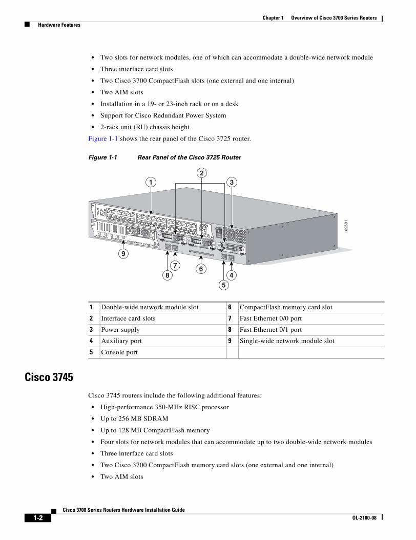
Figure 1-1 shows the rear panel of the Cisco 3725 router.
Figure 1-1 Rear Panel of the Cisco 3725 Router
Cisco 3745Cisco 3745 routers include the following additional features:
• High-performance 350-MHz RISC processor
• Up to 256 MB SDRAM
• Up to 128 MB CompactFlash memory
• Four slots for network modules that can accommodate up to two double-wide network modules
• Three interface card slots
• Two Cisco 3700 CompactFlash memory card slots (one external and one internal)
• Two AIM slots
1 Double-wide network module slot 6 CompactFlash memory card slot
2 Interface card slots 7 Fast Ethernet 0/0 port
3 Power supply 8 Fast Ethernet 0/1 port
4 Auxiliary port 9 Single-wide network module slot
5 Console port62
691
SEE MANUAL BEFORE INSTALLATION
AL
CD
LPRDTD
SEE MANUAL BEFORE INSTALLATIONDSU56K
AL
CD
LPRDTD
SEE MANUAL BEFORE INSTALLATIONDSU56K
ENV0
BANK 4 BANK 3 BANK 2 BANK 1 BANK 0
NM-HDV
VWIC2MFT-E1 SEE
MANUALBEFOREINSTALLATION
CTRLR E2CTRLR E1
AL
LP
CD
1 32
46
5
7
9
8
1-2Cisco 3700 Series Routers Hardware Installation Guide
OL-2180-08
Chapter 1 Overview of Cisco 3700 Series Routers Modules, Interface Cards, and Memory
• Installation in a 19- or 23-inch rack or on a desk
• Support for Cisco Redundant Power System
• 3-rack unit (RU) chassis height
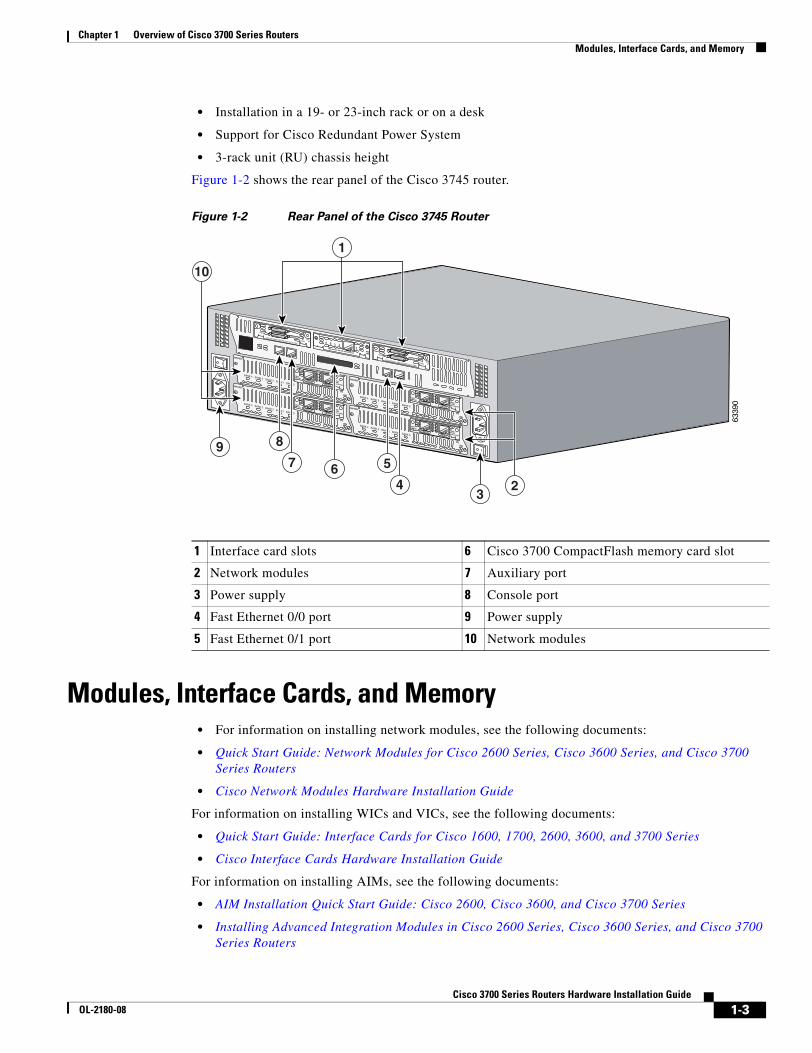
Figure 1-2 shows the rear panel of the Cisco 3745 router.
Figure 1-2 Rear Panel of the Cisco 3745 Router
Modules, Interface Cards, and Memory• For information on installing network modules, see the following documents:
• Quick Start Guide: Network Modules for Cisco 2600 Series, Cisco 3600 Series, and Cisco 3700 Series Routers
• Cisco Network Modules Hardware Installation Guide
For information on installing WICs and VICs, see the following documents:
• Quick Start Guide: Interface Cards for Cisco 1600, 1700, 2600, 3600, and 3700 Series
• Cisco Interface Cards Hardware Installation Guide
For information on installing AIMs, see the following documents:
• AIM Installation Quick Start Guide: Cisco 2600, Cisco 3600, and Cisco 3700 Series
• Installing Advanced Integration Modules in Cisco 2600 Series, Cisco 3600 Series, and Cisco 3700 Series Routers
1 Interface card slots 6 Cisco 3700 CompactFlash memory card slot
2 Network modules 7 Auxiliary port
3 Power supply 8 Console port
4 Fast Ethernet 0/0 port 9 Power supply
5 Fast Ethernet 0/1 port 10 Network modules
6339
0
EN
V0
BANK 4 BANK 3 BANK 2 BANK 1 BANK 0
NM-HDV
VWIC2MFT-E1 SEE
MANUALBEFOREINSTALLATION
CTRLR E2
CTRLR E1
AL
LP
CD
EN
V0
BANK 4 BANK 3 BANK 2 BANK 1 BANK 0
NM-HDV
VWIC2MFT-E1 SEE
MANUALBEFOREINSTALLATION
CTRLR E2
CTRLR E1
AL
LP
CD
EN
V0
BANK 4 BANK 3 BANK 2 BANK 1 BANK 0
NM-HDV
VWIC2MFT-E1 SEE
MANUALBEFOREINSTALLATION
CTRLR E2
CTRLR E1
AL
LP
CD
EN
V0
BANK 4 BANK 3 BANK 2 BANK 1 BANK 0
NM-HDV
VWIC2MFT-E1 SEE
MANUALBEFOREINSTALLATION
CTRLR E2
CTRLR E1
AL
LP
CD
SEE MANUAL BEFORE INSTALLATION
SERIAL 1
SERIAL 0
CONN
CONNWIC
2T
SEE MANUAL BEFORE INSTALLATION
SERIAL 1
SERIAL 0
CONN
CONNWIC
2T
SEE MANUAL BEFORE INSTALLATIONDSU56K
CD
ALLPRDTD
8
7 6
9
3
5
4 2
1
10
1-3Cisco 3700 Series Routers Hardware Installation Guide
OL-2180-08
Chapter 1 Overview of Cisco 3700 Series Routers Memory
For information on installing DRAM, SDRAM, NVRAM, and CompactFlash memory, see:
• Upgrading System Memory in Cisco 3700 Series Routers
• Installing Field-Replaceable Units in Cisco 3745 Routers
For information on installing CompactFlash memory cards, see:
• Installing and Formatting Cisco 2691, Cisco 3631, and Cisco 3700 CompactFlash Memory Cards
MemoryCisco 3700 series routers support the following types of memory:
• SDRAM—Stores the running configuration and routing tables and is used for packet buffering by the network interfaces. Cisco IOS software executes from SDRAM memory.
• NVRAM—Stores the system configuration file and virtual configuration register. For more information, see Appendix C, “Configuration Register.” CompactFlash memory—Stores the operating system software image. You can increase CompactFlash memory by adding Cisco 3700 CompactFlash memory cards. See the Installing and Formatting Cisco 3631 and Cisco 3700 CompactFlash Memory Cards document.
• EPROM-based memory—Stores the ROM monitor, which allows you to boot an operating system software image from internal or external CompactFlash memory.
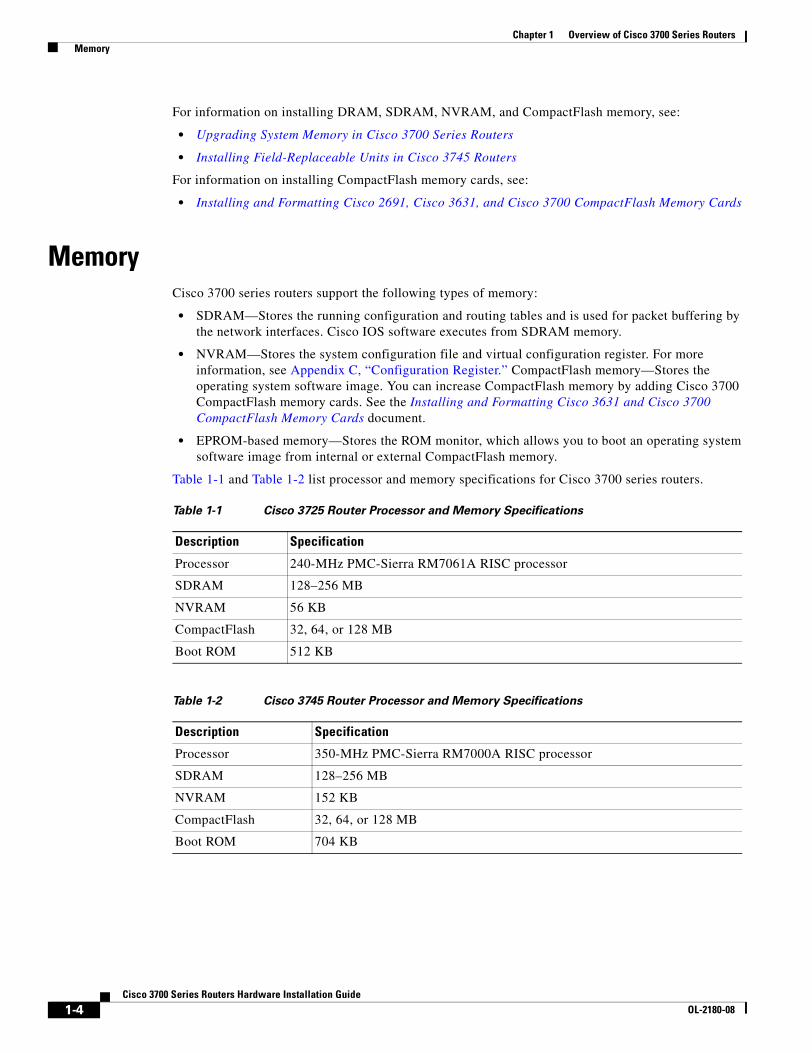
Table 1-1 and Table 1-2 list processor and memory specifications for Cisco 3700 series routers.
Table 1-1 Cisco 3725 Router Processor and Memory Specifications
Description Specification
Processor 240-MHz PMC-Sierra RM7061A RISC processor
SDRAM 128–256 MB
NVRAM 56 KB
CompactFlash 32, 64, or 128 MB
Boot ROM 512 KB
Table 1-2 Cisco 3745 Router Processor and Memory Specifications
Description Specification
Processor 350-MHz PMC-Sierra RM7000A RISC processor
SDRAM 128–256 MB
NVRAM 152 KB
CompactFlash 32, 64, or 128 MB
Boot ROM 704 KB
1-4Cisco 3700 Series Routers Hardware Installation Guide
OL-2180-08
Chapter 1 Overview of Cisco 3700 Series Routers Interface Numbering
Interface NumberingThis section describes numbering conventions for interfaces on Cisco 3725 and Cisco 3745 routers.
Cisco 3725 InterfacesEach individual interface (port) on a Cisco 3725 router is identified by number, as described in the following sections.
WAN and LAN Interface Numbering
The Cisco 3725 router chassis contains the following WAN and LAN interface types:
• Two built-in Fast Ethernet LAN interfaces
• Three slots in which you can install WAN interface cards (WICs)
• One single-wide slot (slot 1) in which you can install one network module
• One double-wide slot (slot 2) in which you can install one single-wide or double-wide network module
The numbering format is interface-type slot-number/interface-number. Two examples are:
• FastEthernet 0/0
• Serial 1/2
The slot numbers are as follows:
• 0 for all built-in interfaces
• 0 for all WIC interfaces
• 1 for interfaces in the single-wide network module slot
• 2 for interfaces in the double-wide network module slot
Interface (port) numbers begin at 0 for each interface type, and continue from right to left and (if necessary) from bottom to top.
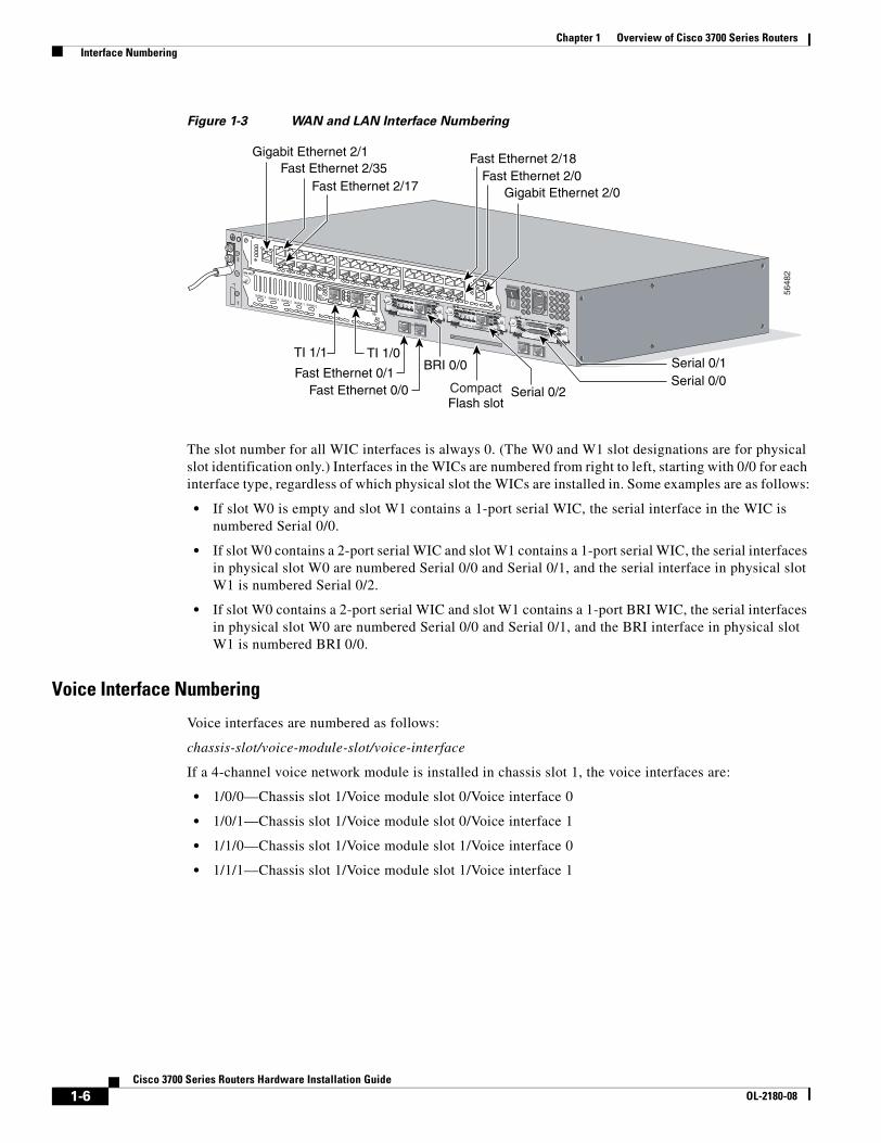
Figure 1-3 shows an example of interface numbering on a Cisco 3725 router with these interfaces:
• A WIC in each WIC slot (containing interfaces Serial 0/0 and Serial 0/1 in physical slot W0, interface Serial 0/2 in physical slot W1, and interface BRI 0/0 in physical slot W2)
• A 2-port T1 network module in slot 1 (containing the following ports: T1 1/0 and T1 1/1)
• A 36-port EtherSwitch network module in slot 2 (containing the following ports: Fast Ethernet 2/0 through 2/35, and Gigabit Ethernet 2/0 and 2/1)
• Two built-in Ethernet 10/100-Mbps interfaces—Fast Ethernet 0/0 and Fast Ethernet 0/1
1-5Cisco 3700 Series Routers Hardware Installation Guide
OL-2180-08
Chapter 1 Overview of Cisco 3700 Series Routers Interface Numbering
Figure 1-3 WAN and LAN Interface Numbering
The slot number for all WIC interfaces is always 0. (The W0 and W1 slot designations are for physical slot identification only.) Interfaces in the WICs are numbered from right to left, starting with 0/0 for each interface type, regardless of which physical slot the WICs are installed in. Some examples are as follows:
• If slot W0 is empty and slot W1 contains a 1-port serial WIC, the serial interface in the WIC is numbered Serial 0/0.
• If slot W0 contains a 2-port serial WIC and slot W1 contains a 1-port serial WIC, the serial interfaces in physical slot W0 are numbered Serial 0/0 and Serial 0/1, and the serial interface in physical slot W1 is numbered Serial 0/2.
• If slot W0 contains a 2-port serial WIC and slot W1 contains a 1-port BRI WIC, the serial interfaces in physical slot W0 are numbered Serial 0/0 and Serial 0/1, and the BRI interface in physical slot W1 is numbered BRI 0/0.
Voice Interface Numbering
Voice interfaces are numbered as follows:
chassis-slot/voice-module-slot/voice-interface
If a 4-channel voice network module is installed in chassis slot 1, the voice interfaces are:
• 1/0/0—Chassis slot 1/Voice module slot 0/Voice interface 0
• 1/0/1—Chassis slot 1/Voice module slot 0/Voice interface 1
• 1/1/0—Chassis slot 1/Voice module slot 1/Voice interface 0
• 1/1/1—Chassis slot 1/Voice module slot 1/Voice interface 1
Serial 0/2CompactFlash slot
5648
2
SEE MANUAL BEFORE INSTALLATION
AL
CD
LPRDTD
SEE MANUAL BEFORE INSTALLATIONDSU56K
AL
CD
LPRDTD
SEE MANUAL BEFORE INSTALLATIONDSU56K
ENV0
BANK 4 BANK 3 BANK 2 BANK 1 BANK 0
NM-HDV
VWIC2MFT-E1 SEE
MANUALBEFOREINSTALLATION
CTRLR E2CTRLR E1
AL
LP
CD
Gigabit Ethernet 2/1Fast Ethernet 2/35
Fast Ethernet 2/17 Gigabit Ethernet 2/0Fast Ethernet 2/0
Fast Ethernet 2/18
Serial 0/1Serial 0/0
TI 1/1 TI 1/0
Fast Ethernet 0/1Fast Ethernet 0/0
BRI 0/0
1
2
1-6Cisco 3700 Series Routers Hardware Installation Guide
OL-2180-08
Chapter 1 Overview of Cisco 3700 Series Routers Interface Numbering
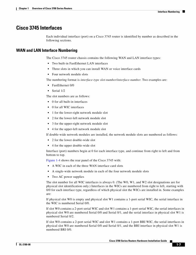
Cisco 3745 InterfacesEach individual interface (port) on a Cisco 3745 router is identified by number as described in the following sections.
WAN and LAN Interface Numbering
The Cisco 3745 router chassis contains the following WAN and LAN interface types:
• Two built-in FastEthernet LAN interfaces
• Three slots in which you can install WAN or voice interface cards
• Four network module slots
The numbering format is interface-type slot-number/interface-number. Two examples are:
• FastEthernet 0/0
• Serial 1/2
The slot numbers are as follows:
• 0 for all built-in interfaces
• 0 for all WIC interfaces
• 1 for the lower-right network module slot
• 2 for the lower-left network module slot
• 3 for the upper-right network module slot
• 4 for the upper-left network module slot
If double-wide network modules are installed, the network module slots are numbered as follows:
• 2 for the lower double-wide slot
• 4 for the upper double-wide slot
Interface (port) numbers begin at 0 for each interface type, and continue from right to left and from bottom to top.
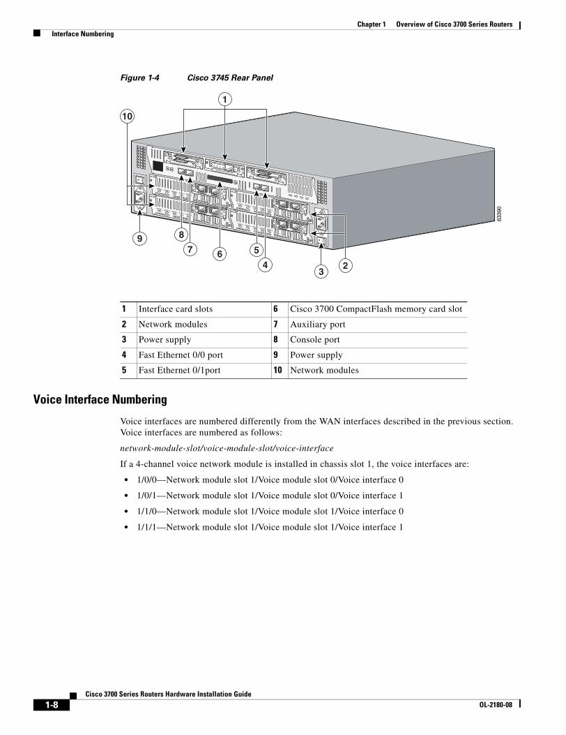
Figure 1-4 shows the rear panel of the Cisco 3745 with:
• A WIC in each of the three WAN interface card slots
• A single-wide network module in each of the four network module slots
• Two AC power supplies
The slot number for all WIC interfaces is always 0. (The W0, W1, and W2 slot designations are for physical slot identification only.) Interfaces in the WICs are numbered from right to left, starting with 0/0 for each interface type, regardless of which physical slot the WICs are installed in. Some examples are:
If physical slot W0 is empty and physical slot W1 contains a 1-port serial WIC, the serial interface in the WIC is numbered Serial 0/0.
If slot W0 contains a 2-port serial WIC and slot W1 contains a 1-port serial WIC, the serial interfaces in physical slot W0 are numbered Serial 0/0 and Serial 0/1, and the serial interface in physical slot W1 is numbered Serial 0/2.
If slot W0 contains a 2-port serial WIC and slot W1 contains a 1-port BRI WIC, the serial interfaces in physical slot W0 are numbered Serial 0/0 and Serial 0/1, and the BRI interface in physical slot W1 is numbered BRI 0/0.
1-7Cisco 3700 Series Routers Hardware Installation Guide
OL-2180-08
Chapter 1 Overview of Cisco 3700 Series Routers Interface Numbering
Figure 1-4 Cisco 3745 Rear Panel
Voice Interface Numbering
Voice interfaces are numbered differently from the WAN interfaces described in the previous section. Voice interfaces are numbered as follows:
network-module-slot/voice-module-slot/voice-interface
If a 4-channel voice network module is installed in chassis slot 1, the voice interfaces are:
• 1/0/0—Network module slot 1/Voice module slot 0/Voice interface 0
• 1/0/1—Network module slot 1/Voice module slot 0/Voice interface 1
• 1/1/0—Network module slot 1/Voice module slot 1/Voice interface 0
• 1/1/1—Network module slot 1/Voice module slot 1/Voice interface 1
1 Interface card slots 6 Cisco 3700 CompactFlash memory card slot
2 Network modules 7 Auxiliary port
3 Power supply 8 Console port
4 Fast Ethernet 0/0 port 9 Power supply
5 Fast Ethernet 0/1port 10 Network modules
6339
0
EN
V0
BANK 4 BANK 3 BANK 2 BANK 1 BANK 0
NM-HDV
VWIC2MFT-E1 SEE
MANUALBEFOREINSTALLATION
CTRLR E2
CTRLR E1
AL
LP
CD
EN
V0
BANK 4 BANK 3 BANK 2 BANK 1 BANK 0
NM-HDV
VWIC2MFT-E1 SEE
MANUALBEFOREINSTALLATION
CTRLR E2
CTRLR E1
AL
LP
CD
EN
V0
BANK 4 BANK 3 BANK 2 BANK 1 BANK 0
NM-HDV
VWIC2MFT-E1 SEE
MANUALBEFOREINSTALLATION
CTRLR E2
CTRLR E1
AL
LP
CD
EN
V0
BANK 4 BANK 3 BANK 2 BANK 1 BANK 0
NM-HDV
VWIC2MFT-E1 SEE
MANUALBEFOREINSTALLATION
CTRLR E2
CTRLR E1
AL
LP
CD
SEE MANUAL BEFORE INSTALLATION
SERIAL 1
SERIAL 0
CONN
CONNWIC
2T
SEE MANUAL BEFORE INSTALLATION
SERIAL 1
SERIAL 0
CONN
CONNWIC
2T
SEE MANUAL BEFORE INSTALLATIONDSU56K
CD
ALLPRDTD
8
7 6
9
3
5
4 2
1
10
1-8Cisco 3700 Series Routers Hardware Installation Guide
OL-2180-08
Chapter 1 Overview of Cisco 3700 Series Routers Power Supply Options
Power Supply OptionsTable 1-3 lists the power supply options supported by Cisco 3700 series routers. Depending on the configuration specified when you placed your order, your router may not support all of these options.
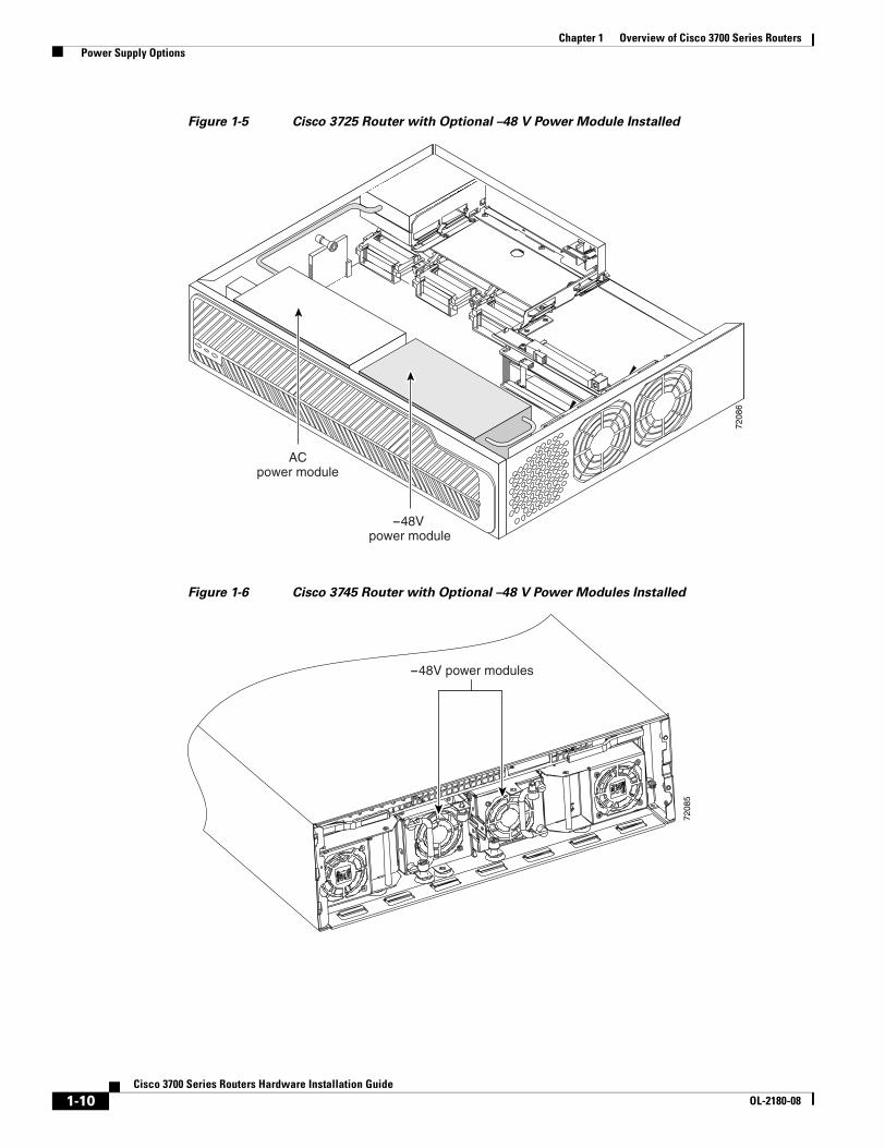
Internal –48 V Telephony Power ModulesCisco 3700 series routers provide inline power to IP phones connected to the router through Ethernet switch network modules. This power is supplied by special –48 V modules that connect directly to the chassis power supplies in Cisco 3725 and Cisco 3745 routers. A single –48 V power module meets the power needs of up to 36 IP phones. A Cisco 3745 router with two –48 V power modules installed provides redundant power for up to 36 IP phones. Figure 1-5 and Figure 1-6 show the –48 -V power modules as they appear when installed in Cisco 3700 series routers.
Table 1-3 Power Supply Options for Cisco 3700 Series Routers
Power Supply Option Cisco 3725 Cisco 3745
AC input power Yes Yes
DC input power Yes Yes
–48-V telephony power module to provide inline power to IP phones Yes Yes
Dual hot-swappable power supplies No Yes1
1. Because of increased power consumption in high-temperature environments, a fully loaded Cisco 3745 router requires both power supplies when ambient temperature exceeds 104°F (40°C). Cisco 3745 routers operating under these conditions do not support the online replacement of power supplies.
Compatible with Cisco Redundant Power System Yes Yes
1-9Cisco 3700 Series Routers Hardware Installation Guide
OL-2180-08
Chapter 1 Overview of Cisco 3700 Series Routers Power Supply Options
Figure 1-5 Cisco 3725 Router with Optional –48 V Power Module Installed
Figure 1-6 Cisco 3745 Router with Optional –48 V Power Modules Installed
7208
6
-48V power module
ACpower module
7208
5
-48V power modules
1-10Cisco 3700 Series Routers Hardware Installation Guide
OL-2180-08
Chapter 1 Overview of Cisco 3700 Series Routers System Specifications
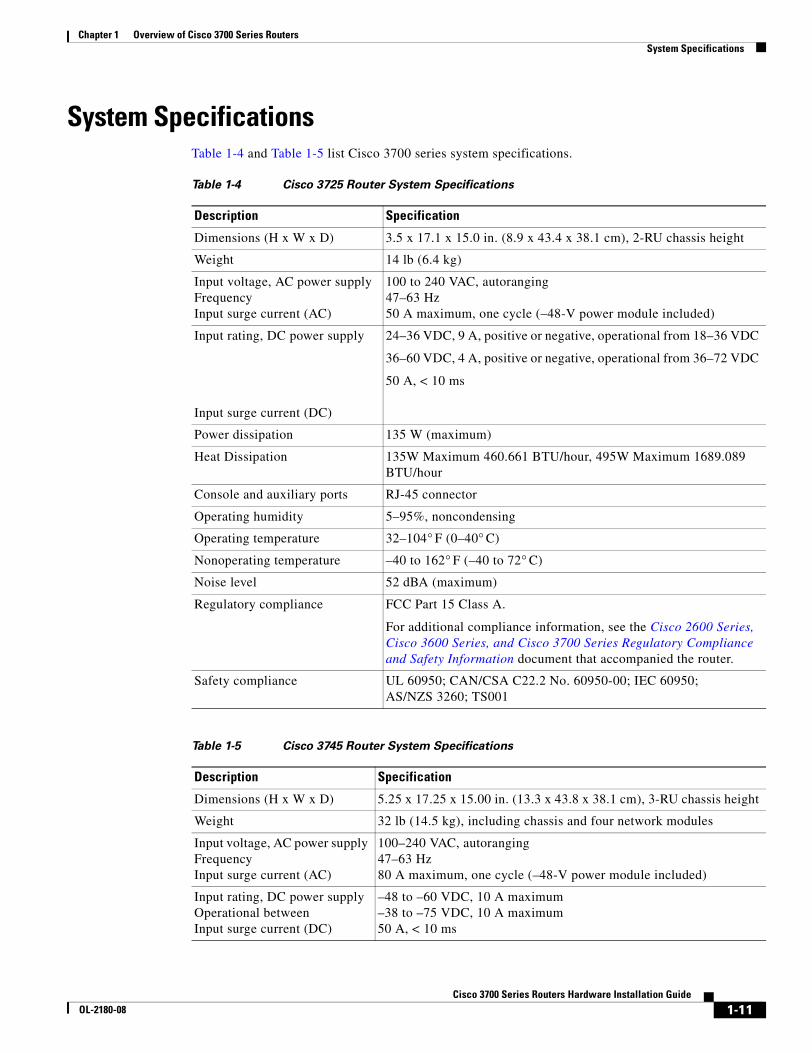
System SpecificationsTable 1-4 and Table 1-5 list Cisco 3700 series system specifications.
Table 1-4 Cisco 3725 Router System Specifications
Description Specification
Dimensions (H x W x D) 3.5 x 17.1 x 15.0 in. (8.9 x 43.4 x 38.1 cm), 2-RU chassis height
Weight 14 lb (6.4 kg)
Input voltage, AC power supplyFrequencyInput surge current (AC)
100 to 240 VAC, autoranging47–63 Hz50 A maximum, one cycle (–48-V power module included)
Input rating, DC power supply
Input surge current (DC)
24–36 VDC, 9 A, positive or negative, operational from 18–36 VDC
36–60 VDC, 4 A, positive or negative, operational from 36–72 VDC
50 A, < 10 ms
Power dissipation 135 W (maximum)
Heat Dissipation 135W Maximum 460.661 BTU/hour, 495W Maximum 1689.089 BTU/hour
Console and auxiliary ports RJ-45 connector
Operating humidity 5–95%, noncondensing
Operating temperature 32–104° F (0–40° C)
Nonoperating temperature –40 to 162° F (–40 to 72° C)
Noise level 52 dBA (maximum)
Regulatory compliance FCC Part 15 Class A.
For additional compliance information, see the Cisco 2600 Series, Cisco 3600 Series, and Cisco 3700 Series Regulatory Compliance and Safety Information document that accompanied the router.
Safety compliance UL 60950; CAN/CSA C22.2 No. 60950-00; IEC 60950; AS/NZS 3260; TS001
Table 1-5 Cisco 3745 Router System Specifications
Description Specification
Dimensions (H x W x D) 5.25 x 17.25 x 15.00 in. (13.3 x 43.8 x 38.1 cm), 3-RU chassis height
Weight 32 lb (14.5 kg), including chassis and four network modules
Input voltage, AC power supplyFrequencyInput surge current (AC)
100–240 VAC, autoranging47–63 Hz80 A maximum, one cycle (–48-V power module included)
Input rating, DC power supplyOperational betweenInput surge current (DC)
–48 to –60 VDC, 10 A maximum–38 to –75 VDC, 10 A maximum50 A, < 10 ms
1-11Cisco 3700 Series Routers Hardware Installation Guide
OL-2180-08
Chapter 1 Overview of Cisco 3700 Series Routers Regulatory Compliance
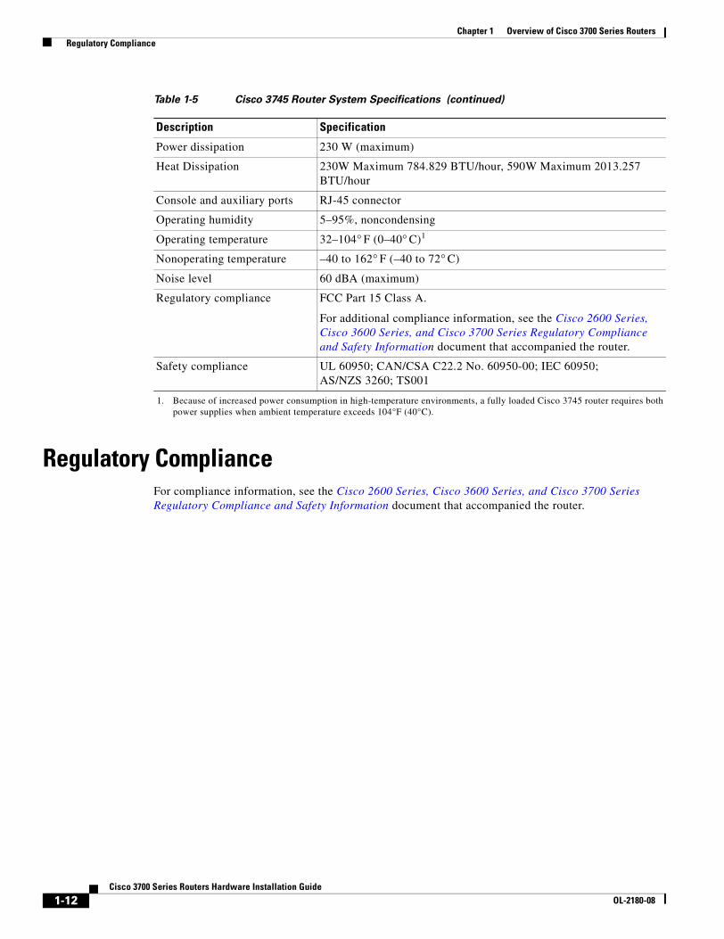
Regulatory ComplianceFor compliance information, see the Cisco 2600 Series, Cisco 3600 Series, and Cisco 3700 Series Regulatory Compliance and Safety Information document that accompanied the router.
Power dissipation 230 W (maximum)
Heat Dissipation 230W Maximum 784.829 BTU/hour, 590W Maximum 2013.257 BTU/hour
Console and auxiliary ports RJ-45 connector
Operating humidity 5–95%, noncondensing
Operating temperature 32–104° F (0–40° C)1
Nonoperating temperature –40 to 162° F (–40 to 72° C)
Noise level 60 dBA (maximum)
Regulatory compliance FCC Part 15 Class A.
For additional compliance information, see the Cisco 2600 Series, Cisco 3600 Series, and Cisco 3700 Series Regulatory Compliance and Safety Information document that accompanied the router.
Safety compliance UL 60950; CAN/CSA C22.2 No. 60950-00; IEC 60950; AS/NZS 3260; TS001
1. Because of increased power consumption in high-temperature environments, a fully loaded Cisco 3745 router requires both power supplies when ambient temperature exceeds 104°F (40°C).
Table 1-5 Cisco 3745 Router System Specifications (continued)
Description Specification
1-12Cisco 3700 Series Routers Hardware Installation Guide
OL-2180-08
Cisco 3700 SeriOL-2180-07
C H A P T E R 2
Preparing to Install the RouterThis chapter describes site requirements and equipment needed to install your Cisco 3700 series router. It includes the following sections:
• Safety Recommendations, page 2-1
• General Site Requirements, page 2-3
• Installation Checklist, page 2-5
• Creating a Site Log, page 2-6
• Inspecting the Router, page 2-6
• Required Tools and Equipment for Installation and Maintenance, page 2-7
• Console and Auxiliary Port Considerations, page 2-8
• Preparing to Connect to a Network, page 2-9
After you have completed this chapter, proceed to Chapter 3, “Installing the Router,” for installation instructions.
Safety RecommendationsFollow these guidelines to ensure general safety:
• Keep the chassis area clear and dust-free during and after installation.
• If you remove the chassis cover, put it in a safe place.
• Keep tools and chassis components away from walk areas.
• Do not wear loose clothing that could get caught in the chassis. Fasten your tie or scarf and roll up your sleeves.
• Wear safety glasses when working under conditions that might be hazardous to your eyes.
• Do not perform any action that creates a hazard to people or makes the equipment unsafe.
2-1es Routers Hardware Installation Guide
Chapter 2 Preparing to Install the RouterSafety Recommendations
Safety with ElectricityFollow these guidelines when working on equipment powered by electricity:
Warning Read the installation instructions before connecting the system to the power source. Statement 1004
• Locate the emergency power-off switch in the room in which you are working. Then, if an electrical accident occurs, you can quickly turn off the power.
• Disconnect all power before doing the following:
– Installing or removing a chassis
– Working near power supplies
• Look carefully for possible hazards in your work area, such as moist floors, ungrounded power extension cables, frayed power cords, and missing safety grounds.
• Do not work alone if hazardous conditions exist.
• Never assume that power is disconnected from a circuit. Always check.
• If an electrical accident occurs, proceed as follows:
– Use caution; do not become a victim yourself.
– Turn off power to the device.
– If possible, send another person to get medical aid. Otherwise, assess the victim’s condition and then call for help.
– Determine if the person needs rescue breathing or external cardiac compressions; then take appropriate action.
In addition, use the following guidelines when working with any equipment that is disconnected from a power source, but still connected to telephone wiring or other network cabling:
• Never install telephone wiring during a lightning storm.
• Never install telephone jacks in wet locations unless the jack is specifically designed for it.
• Never touch uninsulated telephone wires or terminals unless the telephone line is disconnected at the network interface.
• Use caution when installing or modifying telephone lines.
Preventing Electrostatic Discharge Damage Electrostatic discharge (ESD) can damage equipment and impair electrical circuitry. It can occur if electronic printed circuit cards are improperly handled and can cause complete or intermittent failures. Always follow ESD prevention procedures when removing and replacing modules:
• Ensure that the router chassis is electrically connected to earth ground.
• Wear an ESD-preventive wrist strap, ensuring that it makes good skin contact. Connect the clip to an unpainted surface of the chassis frame to channel unwanted ESD voltages safely to ground. To guard against ESD damage and shocks, the wrist strap and cord must operate effectively.
• If no wrist strap is available, ground yourself by touching a metal part of the chassis.
2-2Cisco 3700 Series Routers Hardware Installation Guide
OL-2180-07
Chapter 2 Preparing to Install the RouterGeneral Site Requirements
Caution For the safety of your equipment, periodically check the resistance value of the antistatic strap. It should be between 1 and 10 megohms (Mohm).
General Site RequirementsThis section describes the requirements your site must meet for safe installation and operation of your router. Ensure that the site is properly prepared before beginning installation. If you are experiencing shutdowns or unusually high errors with your existing equipment, this section can also help you isolate the cause of failures and prevent future problems.
Power Supply ConsiderationsCheck the power at your site to ensure that you are receiving “clean” power (free of spikes and noise). Install a power conditioner if necessary.
Warning The device is designed for connection to TN and IT power systems. Statement 1007
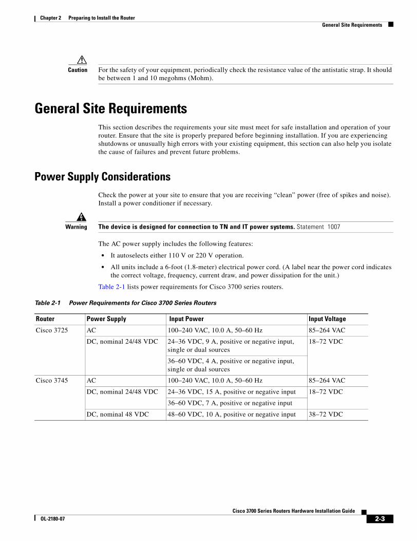
The AC power supply includes the following features:
• It autoselects either 110 V or 220 V operation.
• All units include a 6-foot (1.8-meter) electrical power cord. (A label near the power cord indicates the correct voltage, frequency, current draw, and power dissipation for the unit.)
Table 2-1 lists power requirements for Cisco 3700 series routers.
Table 2-1 Power Requirements for Cisco 3700 Series Routers
Router Power Supply Input Power Input Voltage
Cisco 3725 AC 100–240 VAC, 10.0 A, 50–60 Hz 85–264 VAC
DC, nominal 24/48 VDC 24–36 VDC, 9 A, positive or negative input, single or dual sources
18–72 VDC
36–60 VDC, 4 A, positive or negative input, single or dual sources
Cisco 3745 AC 100–240 VAC, 10.0 A, 50–60 Hz 85–264 VAC
DC, nominal 24/48 VDC 24–36 VDC, 15 A, positive or negative input 18–72 VDC
36–60 VDC, 7 A, positive or negative input
DC, nominal 48 VDC 48–60 VDC, 10 A, positive or negative input 38–72 VDC
2-3Cisco 3700 Series Routers Hardware Installation Guide
OL-2180-07
Chapter 2 Preparing to Install the RouterGeneral Site Requirements
Site EnvironmentCisco 3700 series routers can be placed on a desktop or installed in a rack. The location of your router and the layout of your equipment rack or wiring room are extremely important considerations for proper operation. Equipment placed too close together, inadequate ventilation, and inaccessible panels can cause malfunctions and shutdowns, and can make maintenance difficult. Plan for access to both front and rear panels of the router.
When planning your site layout and equipment locations, remember the precautions described in the next section, “Site Configuration,” to help avoid equipment failures and reduce the possibility of environmentally caused shutdowns. If you are currently experiencing shutdowns or an unusually high number of errors with your existing equipment, these precautions may help you isolate the cause of the failures and prevent future problems.
Site ConfigurationThe following precautions will help you plan an acceptable operating environment for your router and will help you avoid environmentally caused equipment failures:
• Ensure that the room where your router operates has adequate circulation. Electrical equipment generates heat. Without adequate circulation, ambient air temperature may not cool equipment to acceptable operating temperatures.
• Always follow ESD-prevention procedures described in the “Preventing Electrostatic Discharge Damage” section on page 2-2 to avoid damage to equipment. Damage from static discharge can cause immediate or intermittent equipment failure.
• Ensure that the chassis cover or mainboard tray and module rear panels are secure. All empty network module slots, interface card slots, and power supply bays must have filler panels installed. The chassis is designed to allow cooling air to flow within it, through specially designed cooling slots. A chassis with uncovered openings will create air leaks, which may interrupt and reduce the flow of air across internal components.
Equipment RacksCisco 3700 series routers include brackets for use with a 19-inch rack or, if specified in your order, optional larger brackets for use with a 23-inch rack.
The following information will help you plan your equipment rack configuration:
• Allow clearance around the rack for maintenance.
• Enclosed racks must have adequate ventilation. Ensure that the rack is not congested, because each router generates heat. An enclosed rack should have louvered sides and a fan to provide cooling air. Heat generated by equipment near the bottom of the rack can be drawn upward into the intake ports of the equipment above.
• When mounting a chassis in an open rack, ensure that the rack frame does not block the intake ports or exhaust ports. If the chassis is installed on slides, check the position of the chassis when it is seated into the rack.
2-4Cisco 3700 Series Routers Hardware Installation Guide
OL-2180-07
Chapter 2 Preparing to Install the RouterInstallation Checklist
• Baffles can help to isolate exhaust air from intake air, which also helps to draw cooling air through the chassis. The best placement of the baffles depends on the airflow patterns in the rack, which can be found by experimenting with different configurations.
• When equipment installed in a rack (particularly in an enclosed rack) fails, try operating the equipment by itself, if possible. Power down other equipment in the rack (and in adjacent racks) to allow the router being tested a maximum of cooling air and clean power.
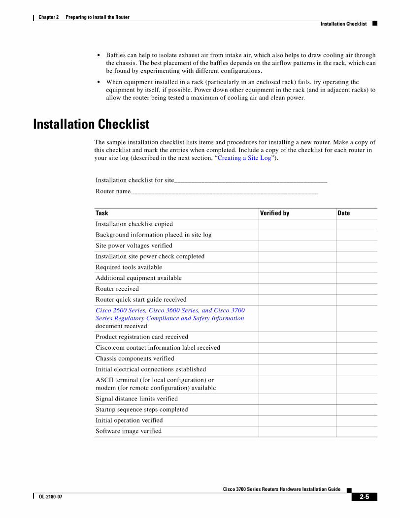
Installation ChecklistThe sample installation checklist lists items and procedures for installing a new router. Make a copy of this checklist and mark the entries when completed. Include a copy of the checklist for each router in your site log (described in the next section, “Creating a Site Log”).
Installation checklist for site_____________________________________________
Router name_______________________________________________________
Task Verified by Date
Installation checklist copied
Background information placed in site log
Site power voltages verified
Installation site power check completed
Required tools available
Additional equipment available
Router received
Router quick start guide received
Cisco 2600 Series, Cisco 3600 Series, and Cisco 3700 Series Regulatory Compliance and Safety Information document received
Product registration card received
Cisco.com contact information label received
Chassis components verified
Initial electrical connections established
ASCII terminal (for local configuration) or modem (for remote configuration) available
Signal distance limits verified
Startup sequence steps completed
Initial operation verified
Software image verified
2-5Cisco 3700 Series Routers Hardware Installation Guide
OL-2180-07
Chapter 2 Preparing to Install the RouterCreating a Site Log
Creating a Site LogThe site log provides a record of all actions related to the router. Keep it in an accessible place near the chassis where anyone who performs tasks has access to it. Use the installation checklist to verify steps in the installation and maintenance of the router. Site Log entries might include the following information:
• Installation progress—Make a copy of the installation checklist and insert it into the site log. Make entries as each procedure is completed.
• Upgrade and maintenance procedures—Use the site log as a record of ongoing router maintenance and expansion history. A site log might include the following events:
– Installation of network modules
– Removal or replacement of network modules and other upgrades
– Configuration changes
– Maintenance schedules and requirements
– Maintenance procedures performed
– Intermittent problems
– Comments and notes
Inspecting the RouterDo not unpack the router until you are ready to install it. If the final installation site will not be ready for some time, keep the chassis in its shipping container to prevent accidental damage. When you are ready to install the router, proceed with unpacking it.
The router, cables, publications, and any optional equipment you ordered may be shipped in more than one container. When you unpack the containers, check the packing list to ensure that you received all the following items:
• Router
• 6-foot (1.8-meter) power cord
• Rack-mount brackets
• Ground lug
• Cable guides (for Cisco 3725 routers)
• RJ-45-to-DB-9 adapter cable
• RJ-45-to-DB-25 adapter cable
• Optional equipment (such as network connection cables or additional rack-mount brackets)
• Cisco 3725 Router Quick Start Guide, if applicable
• Cisco 3745 Router Quick Start Guide, if applicable
• Cisco 2600 Series, Cisco 3600 Series, and Cisco 3700 Series Regulatory Compliance and Safety Information document
Inspect all items for shipping damage. If anything appears to be damaged, or if you encounter problems installing or configuring your router, contact customer service. Warranty, service, and support information is in the quick start guide that shipped with your router.
2-6Cisco 3700 Series Routers Hardware Installation Guide
OL-2180-07
Chapter 2 Preparing to Install the RouterRequired Tools and Equipment for Installation and Maintenance
Required Tools and Equipment for Installation and MaintenanceYou need the following tools and equipment to install and upgrade the router and its components:
• ESD-preventive cord and wrist strap
• Number 2 Phillips screwdriver
• Flat-blade screwdrivers: small, about 3/16-in. (0.5 cm) and medium, about 1/4-in. (0.6-cm)
– To install or remove modules
– To remove the cover or mainboard tray, if you are upgrading memory or other components
• Screws that fit your rack
• Wire crimper
• AWG 6 (13 mm2) wire to connect the router chassis to earth ground
In addition, depending on the type of modules you plan to use, you might need the following equipment to connect a port to an external network:
• Cables for connection to the WAN and LAN ports (dependent on configuration)
Note For more information on cable specifications, see the online document Cisco Modular Access Router Cable Specifications located on Cisco.com.
• Ethernet hub or PC with a network interface card for connection to the Ethernet (LAN) ports
• Console terminal (an ASCII terminal or a PC running terminal emulation software) configured for 9600 bps, 8 data bits, no parity, and 2 stop bits
• Modem for connection to the auxiliary port for remote administrative access (optional)
• Token Ring media attachment unit (MAU) for any Token Ring interfaces installed in your router
• Data service unit (DSU) or channel service unit/data service unit (CSU/DSU) as appropriate for serial interfaces
• External CSU for any CT1/PRI modules without a built-in CSU
• NT1 device for ISDN BRI S/T interfaces (if not supplied by your service provider)
2-7Cisco 3700 Series Routers Hardware Installation Guide
OL-2180-07
Chapter 2 Preparing to Install the RouterConsole and Auxiliary Port Considerations
Console and Auxiliary Port ConsiderationsThe router includes an asynchronous serial console port and an auxiliary port. The console and auxiliary ports provide access to the router either locally using a console terminal connected to the console port, or remotely using a modem connected to the auxiliary port. This section discusses important cabling information to consider before connecting the router to a console terminal or modem.
The main difference between the console and auxiliary ports is that the auxiliary port supports hardware flow control and the console port does not. Flow control paces the transmission of data between a sending device and a receiving device. Flow control ensures that the receiving device can absorb the data sent to it before the sending device sends more. When the buffers on the receiving device are full, a message is sent to the sending device to suspend transmission until the data in the buffers has been processed. Because the auxiliary port supports flow control, it is ideally suited for use with the high-speed transmissions of a modem. Console terminals send data at slower speeds than modems; therefore, the console port is ideally suited for use with console terminals.
Console Port ConnectionsThe router has an EIA/TIA-232 asynchronous serial console port (RJ-45). Depending on the cable and the adapter used, this port will appear as a DTE or DCE device at the end of the cable.
For connection to a PC running terminal emulation software, your router is provided with an RJ-45 to DB-9 adapter cable.
To connect the router to an ASCII terminal, use an RJ-45 rollover cable and an RJ-45-to-DB-25 female adapter (not provided).
The default parameters for the console port are 9600 bps, 8 data bits, no parity, and 2 stop bits. The console port does not support hardware flow control. For detailed information about installing a console terminal, see the “Connecting to a Console Terminal or Modem” section on page 3-22.
For cable and port pinouts, see the document Cisco Modular Access Router Cable Specifications on Cisco.com.
Auxiliary Port ConnectionsThe router has an EIA/TIA-232 asynchronous serial auxiliary port (RJ-45) that supports flow control. Depending on the cable and the adapter used, this port will appear as a DTE or DCE device at the end of the cable.
For connection to a modem, your router is provided with an RJ-45-to-DB-25 adapter cable.
For detailed information about connecting devices to the auxiliary port, see the “Connecting to a Console Terminal or Modem” section on page 3-22.
For cable and port pinouts, see the document Cisco Modular Access Router Cable Specifications on Cisco.com.
2-8Cisco 3700 Series Routers Hardware Installation Guide
OL-2180-07
Chapter 2 Preparing to Install the RouterPreparing to Connect to a Network
Preparing to Connect to a NetworkWhen setting up your router, consider distance limitations and potential electromagnetic interference (EMI) as defined by the applicable local and international regulations.
Network connection considerations are provided for several types of network interfaces and are described in the following sections:
• Ethernet Connections, page 2-9
• Token Ring Connections, page 2-10
• Serial Connections, page 2-10
• ISDN BRI Connections, page 2-12
• 56-K/Switched-56-kbps DSU/CSU Connections, page 2-13
See the following online documents for more information about network connections and interfaces:
• Cisco Network Modules Hardware Installation Guide
• Cisco Interface Cards Installation Guide
• Cisco Modular Access Router Cable Specifications
Warning To avoid electric shock, do not connect safety extra-low voltage (SELV) circuits to telephone-network voltage (TNV) circuits. LAN ports contain SELV circuits, and WAN ports contain TNV circuits. Some LAN and WAN ports both use RJ-45 connectors. Statement 1021
Ethernet ConnectionsThe IEEE has established Ethernet as standard IEEE 802.3. The most common Ethernet implementations are as follows:
• 100BASE-T—2-pair Category 5 or unshielded twisted-pair (UTP) straight-through RJ-45 cable.
• 10BASE-2—Ethernet on thin coaxial cable, also known as thin Ethernet. The maximum segment distance is 607 feet (186 meters).
• 10BASE-5—Ethernet on thick coaxial cable, also known as thick Ethernet. The maximum segment distance is 1,640 feet (500 meters).
• 10BASE-T—Ethernet on unshielded twisted-pair (UTP) cable. The maximum segment distance is 328 feet (100 meters). UTP cables look like the wiring used for ordinary telephones; however, UTP cables meet certain electrical standards that telephone cables do not meet.
See the Cisco Modular Access Router Cable Specifications document for information about Ethernet cables, connectors, and pinouts. This document is available on Cisco.com.
2-9Cisco 3700 Series Routers Hardware Installation Guide
OL-2180-07
Chapter 2 Preparing to Install the RouterPreparing to Connect to a Network
Token Ring ConnectionsThe IEEE has established Token Ring as standard IEEE 802.5. Specifications indicate a maximum segment distance of 328 feet (100 meters) for UTP cabling.
Note To ensure agency compliance with FCC Class B electromagnetic emissions requirements (EMI), make sure that you use a shielded RJ-45 Token Ring cable when connecting your router to a Token Ring network.
Token Ring can operate at two different ring speeds: 4 and 16 Mbps. All devices on the Token Ring must use the same operating speed.
Use a Token Ring cable to connect the router to a switch. See the section “Token Ring Port Pinouts” in the Cisco Modular Access Router Cable Specifications document for Token Ring port pinouts. This document is available on Cisco.com.
Serial ConnectionsSerial connections are provided by WAN interface cards and network modules. For more information on WAN interface cards, see the Cisco Interface Cards Installation Guide. For more information on network modules, see the Cisco Network Modules Hardware Installation Guide. These documents are available on Cisco.com.
Before you connect a device to a serial port, you need to know the following:
• Type of device—data terminal equipment (DTE) or data communications equipment (DCE)—that you are connecting to the synchronous serial interface
• Type of connector—male or female—required to connect to the device
• Signaling standard required by the device
Configuring Serial Connections
The serial ports on the asynchronous/synchronous serial network modules and the serial WAN interface card use DB-60 connectors. Serial ports can be configured as DTE or DCE, depending on the serial cable used.
Serial DTE or DCE Devices
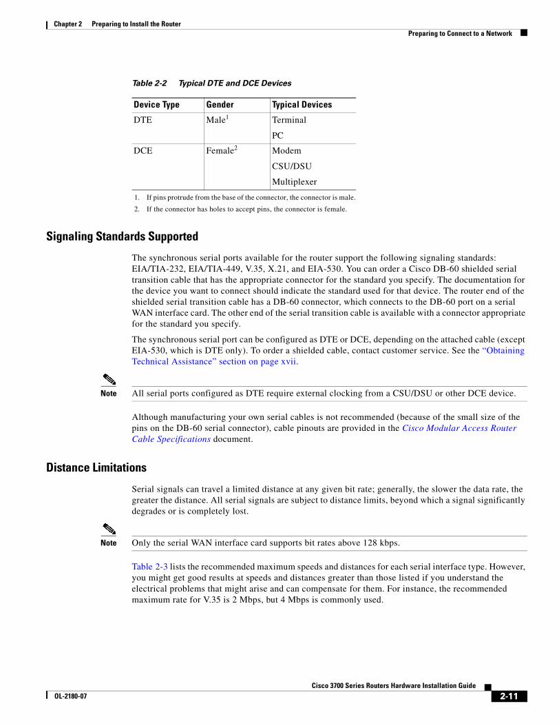
A device that communicates over a synchronous serial interface is either a DTE or a DCE device. A DCE device provides a clock signal that paces the communications between the device and the router. A DTE device does not provide a clock signal. DTE devices usually connect to DCE devices. The documentation that accompanied the device should indicate whether it is a DTE or DCE device. (Some devices have a jumper to select either DTE or DCE mode.) Table 2-2 lists typical DTW and DCE devices.
2-10Cisco 3700 Series Routers Hardware Installation Guide
OL-2180-07
Chapter 2 Preparing to Install the RouterPreparing to Connect to a Network
Signaling Standards Supported
The synchronous serial ports available for the router support the following signaling standards: EIA/TIA-232, EIA/TIA-449, V.35, X.21, and EIA-530. You can order a Cisco DB-60 shielded serial transition cable that has the appropriate connector for the standard you specify. The documentation for the device you want to connect should indicate the standard used for that device. The router end of the shielded serial transition cable has a DB-60 connector, which connects to the DB-60 port on a serial WAN interface card. The other end of the serial transition cable is available with a connector appropriate for the standard you specify.
The synchronous serial port can be configured as DTE or DCE, depending on the attached cable (except EIA-530, which is DTE only). To order a shielded cable, contact customer service. See the “Obtaining Technical Assistance” section on page xvii.
Note All serial ports configured as DTE require external clocking from a CSU/DSU or other DCE device.
Although manufacturing your own serial cables is not recommended (because of the small size of the pins on the DB-60 serial connector), cable pinouts are provided in the Cisco Modular Access Router Cable Specifications document.
Distance Limitations
Serial signals can travel a limited distance at any given bit rate; generally, the slower the data rate, the greater the distance. All serial signals are subject to distance limits, beyond which a signal significantly degrades or is completely lost.
Note Only the serial WAN interface card supports bit rates above 128 kbps.
Table 2-3 lists the recommended maximum speeds and distances for each serial interface type. However, you might get good results at speeds and distances greater than those listed if you understand the electrical problems that might arise and can compensate for them. For instance, the recommended maximum rate for V.35 is 2 Mbps, but 4 Mbps is commonly used.
Table 2-2 Typical DTE and DCE Devices
Device Type Gender Typical Devices
DTE Male1
1. If pins protrude from the base of the connector, the connector is male.
Terminal
PC
DCE Female2
2. If the connector has holes to accept pins, the connector is female.
Modem
CSU/DSU
Multiplexer
2-11Cisco 3700 Series Routers Hardware Installation Guide
OL-2180-07
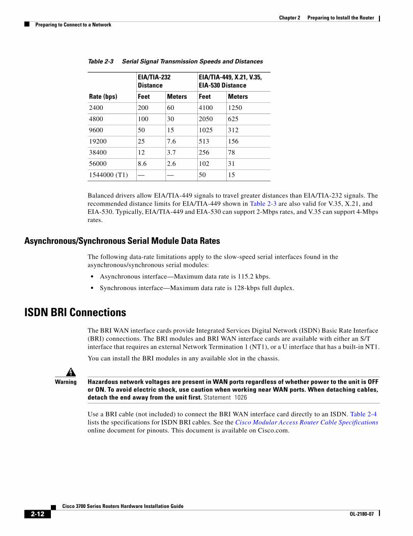
Chapter 2 Preparing to Install the RouterPreparing to Connect to a Network
Balanced drivers allow EIA/TIA-449 signals to travel greater distances than EIA/TIA-232 signals. The recommended distance limits for EIA/TIA-449 shown in Table 2-3 are also valid for V.35, X.21, and EIA-530. Typically, EIA/TIA-449 and EIA-530 can support 2-Mbps rates, and V.35 can support 4-Mbps rates.
Asynchronous/Synchronous Serial Module Data Rates
The following data-rate limitations apply to the slow-speed serial interfaces found in the asynchronous/synchronous serial modules:
• Asynchronous interface—Maximum data rate is 115.2 kbps.
• Synchronous interface—Maximum data rate is 128-kbps full duplex.
ISDN BRI ConnectionsThe BRI WAN interface cards provide Integrated Services Digital Network (ISDN) Basic Rate Interface (BRI) connections. The BRI modules and BRI WAN interface cards are available with either an S/T interface that requires an external Network Termination 1 (NT1), or a U interface that has a built-in NT1.
You can install the BRI modules in any available slot in the chassis.
Warning Hazardous network voltages are present in WAN ports regardless of whether power to the unit is OFF or ON. To avoid electric shock, use caution when working near WAN ports. When detaching cables, detach the end away from the unit first. Statement 1026
Use a BRI cable (not included) to connect the BRI WAN interface card directly to an ISDN. Table 2-4 lists the specifications for ISDN BRI cables. See the Cisco Modular Access Router Cable Specifications online document for pinouts. This document is available on Cisco.com.
Table 2-3 Serial Signal Transmission Speeds and Distances
Rate (bps)
EIA/TIA-232 Distance
EIA/TIA-449, X.21, V.35, EIA-530 Distance
Feet Meters Feet Meters
2400 200 60 4100 1250
4800 100 30 2050 625
9600 50 15 1025 312
19200 25 7.6 513 156
38400 12 3.7 256 78
56000 8.6 2.6 102 31
1544000 (T1) — — 50 15
2-12Cisco 3700 Series Routers Hardware Installation Guide
OL-2180-07
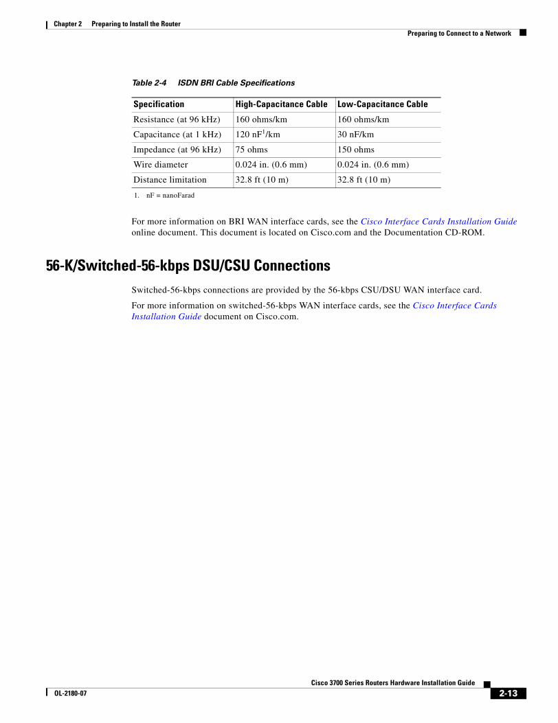
Chapter 2 Preparing to Install the RouterPreparing to Connect to a Network
For more information on BRI WAN interface cards, see the Cisco Interface Cards Installation Guide online document. This document is located on Cisco.com and the Documentation CD-ROM.
56-K/Switched-56-kbps DSU/CSU ConnectionsSwitched-56-kbps connections are provided by the 56-kbps CSU/DSU WAN interface card.
For more information on switched-56-kbps WAN interface cards, see the Cisco Interface Cards Installation Guide document on Cisco.com.
Table 2-4 ISDN BRI Cable Specifications
Specification High-Capacitance Cable Low-Capacitance Cable
Resistance (at 96 kHz) 160 ohms/km 160 ohms/km
Capacitance (at 1 kHz) 120 nF1/km
1. nF = nanoFarad
30 nF/km
Impedance (at 96 kHz) 75 ohms 150 ohms
Wire diameter 0.024 in. (0.6 mm) 0.024 in. (0.6 mm)
Distance limitation 32.8 ft (10 m) 32.8 ft (10 m)
2-13Cisco 3700 Series Routers Hardware Installation Guide
OL-2180-07

Chapter 2 Preparing to Install the RouterPreparing to Connect to a Network
2-14Cisco 3700 Series Routers Hardware Installation Guide
OL-2180-07
Cisco 3700 SeriOL-2180-08
C H A P T E R 3
Installing the RouterThis chapter describes how to install your Cisco 3700 series router and connect it to networks and external devices. It includes the following sections:
• Installing Modules, Interface Cards, and Power Supplies, page 3-1
• Setting Up the Chassis, page 3-2
• Installing the Chassis Ground Connection, page 3-8
• Power Connections, page 3-11
• Connecting WAN, LAN, and Voice Cables, page 3-20
• Connecting to a Console Terminal or Modem, page 3-22
• Powering Up the Router, page 3-26
• Configuring the Router, page 3-29
Warning Only trained and qualified personnel should be allowed to install, replace, or service this equipment. Statement 1030
Warning This unit is intended for installation in restricted access areas. A restricted access area can be accessed only through the use of a special tool, lock and key, or other means of security. Statement 1017
Installing Modules, Interface Cards, and Power SuppliesCisco routers are normally shipped with network modules, WAN interface cards (WICs), voice interface cards (VICs), advanced integration modules (AIMs), and power supplies already installed. If you need to remove or install any of these items, see the applicable documents online.
For network modules:
• Quick Start Guide: Network Modules for Cisco 2600 Series, Cisco 3600 Series, and Cisco 3700 Series Routers
• Cisco Network Modules Hardware Installation Guide
3-1es Routers Hardware Installation Guide
Chapter 3 Installing the Router Setting Up the Chassis
For WICs and VICs:
• Quick Start Guide: Interface Cards for Cisco 1600, 1700, 2600, 3600, and 3700 Series
• Cisco Interface Cards Hardware Installation Guide
For AIMs:
• Quick Start Guide: Advanced Integration Module Installation in Cisco 2600 Series, Cisco 3600 Series, and Cisco 3700 Series Routers
• Installing Advanced Integration Modules in Cisco 2600 Series, Cisco 3600 Series, and Cisco 3700 Series Routers
For internal power supplies:
• Installing Field-Replaceable Units in Cisco 3745 Routers
• Installing AC Power Supplies in Cisco 3725 Routers
For external power supplies:
• Cisco RPS Hardware Installation Guide
For –48 V telephony power modules:
• Installing Cisco -48 VDC Power Supplies
Note If modules, interface cards, or power supplies need to be removed or installed, Cisco suggests that you perform the installation or removal before you install the chassis. If a chassis cover needs to be removed, the chassis may have to be removed from the rack to permit cover removal.
Note The Cisco 3745 accommodates two AC or two DC hot-swappable power supplies in bays at the rear of the unit. Each unit provides up to 230 W of power, and a single installed power supply meets the router’s requirements. The second installed power supply provides redundancy, load sharing, and increased system availability. Either power supply can be removed without affecting system operation.
If the required network modules, interface cards, and power supplies are already installed, proceed to the “Setting Up the Chassis” section on page 3-2.
Setting Up the ChassisYou can set the chassis on a desktop or install it in a rack. Select the procedure that best meets the needs of your network. These procedures are described in the following sections:
• Setting the Chassis on a Desktop, page 3-2
• Rack-Mounting the Chassis, page 3-3
Setting the Chassis on a DesktopYou can place Cisco 3700 series routers on a desktop or shelf.
3-2Cisco 3700 Series Routers Hardware Installation Guide
OL-2180-08
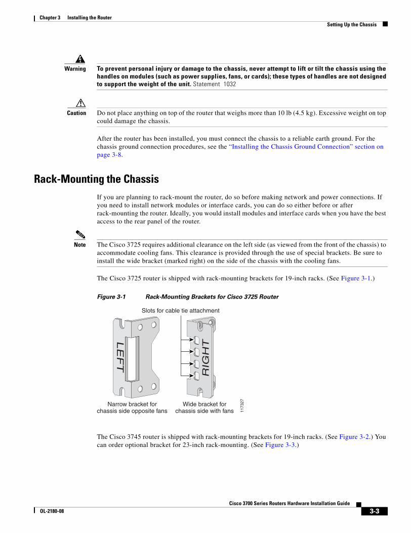
Chapter 3 Installing the Router Setting Up the Chassis
Warning To prevent personal injury or damage to the chassis, never attempt to lift or tilt the chassis using the handles on modules (such as power supplies, fans, or cards); these types of handles are not designed to support the weight of the unit. Statement 1032
Caution Do not place anything on top of the router that weighs more than 10 lb (4.5 kg). Excessive weight on top could damage the chassis.
After the router has been installed, you must connect the chassis to a reliable earth ground. For the chassis ground connection procedures, see the “Installing the Chassis Ground Connection” section on page 3-8.
Rack-Mounting the ChassisIf you are planning to rack-mount the router, do so before making network and power connections. If you need to install network modules or interface cards, you can do so either before or after rack-mounting the router. Ideally, you would install modules and interface cards when you have the best access to the rear panel of the router.
Note The Cisco 3725 requires additional clearance on the left side (as viewed from the front of the chassis) to accommodate cooling fans. This clearance is provided through the use of special brackets. Be sure to install the wide bracket (marked right) on the side of the chassis with the cooling fans.
The Cisco 3725 router is shipped with rack-mounting brackets for 19-inch racks. (See Figure 3-1.)
Figure 3-1 Rack-Mounting Brackets for Cisco 3725 Router
The Cisco 3745 router is shipped with rack-mounting brackets for 19-inch racks. (See Figure 3-2.) You can order optional bracket for 23-inch rack-mounting. (See Figure 3-3.)
1173
27
LE
FT
RIG
HT
Slots for cable tie attachment
Narrow bracket forchassis side opposite fans
Wide bracket forchassis side with fans
3-3Cisco 3700 Series Routers Hardware Installation Guide
OL-2180-08
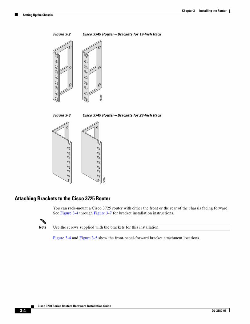
Chapter 3 Installing the Router Setting Up the Chassis
Figure 3-2 Cisco 3745 Router—Brackets for 19-Inch Rack
Figure 3-3 Cisco 3745 Router—Brackets for 23-Inch Rack
Attaching Brackets to the Cisco 3725 Router
You can rack-mount a Cisco 3725 router with either the front or the rear of the chassis facing forward. See Figure 3-4 through Figure 3-7 for bracket installation instructions.
Note Use the screws supplied with the brackets for this installation.
Figure 3-4 and Figure 3-5 show the front-panel-forward bracket attachment locations.
6289
272
067
3-4Cisco 3700 Series Routers Hardware Installation Guide
OL-2180-08
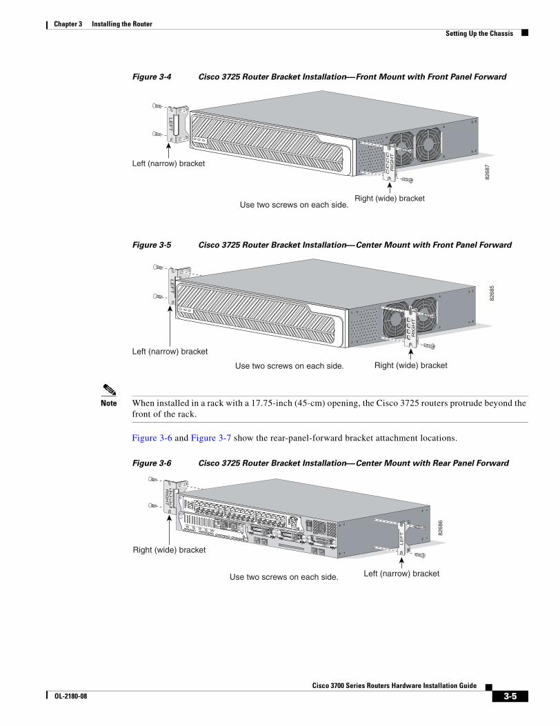
Chapter 3 Installing the Router Setting Up the Chassis
Figure 3-4 Cisco 3725 Router Bracket Installation—Front Mount with Front Panel Forward
Figure 3-5 Cisco 3725 Router Bracket Installation—Center Mount with Front Panel Forward
Note When installed in a rack with a 17.75-inch (45-cm) opening, the Cisco 3725 routers protrude beyond the front of the rack.
Figure 3-6 and Figure 3-7 show the rear-panel-forward bracket attachment locations.
Figure 3-6 Cisco 3725 Router Bracket Installation—Center Mount with Rear Panel Forward
8268
7
LE
FT
Left (narrow) bracket
Right (wide) bracket
RIG
HT
Use two screws on each side.
8268
5
LE
FT
Left (narrow) bracket
Right (wide) bracket
RIG
HT
Use two screws on each side.
RIG
HT
8268
6
SEE MANUAL BEFORE INSTALLATION
AL
CD
LPRDTD
SEE MANUAL BEFORE INSTALLATIONDSU56K
AL
CD
LPRDTD
SEE MANUAL BEFORE INSTALLATIONDSU56K
ENV0
BANK 4 BANK 3 BANK 2 BANK 1 BANK 0
NM-HDV
VWIC2MFT-E1 SEE
MANUALBEFOREINSTALLATION
CTRLR E2CTRLR E1
AL
LP
CD
LE
FT
Right (wide) bracket
Left (narrow) bracketUse two screws on each side.
3-5Cisco 3700 Series Routers Hardware Installation Guide
OL-2180-08
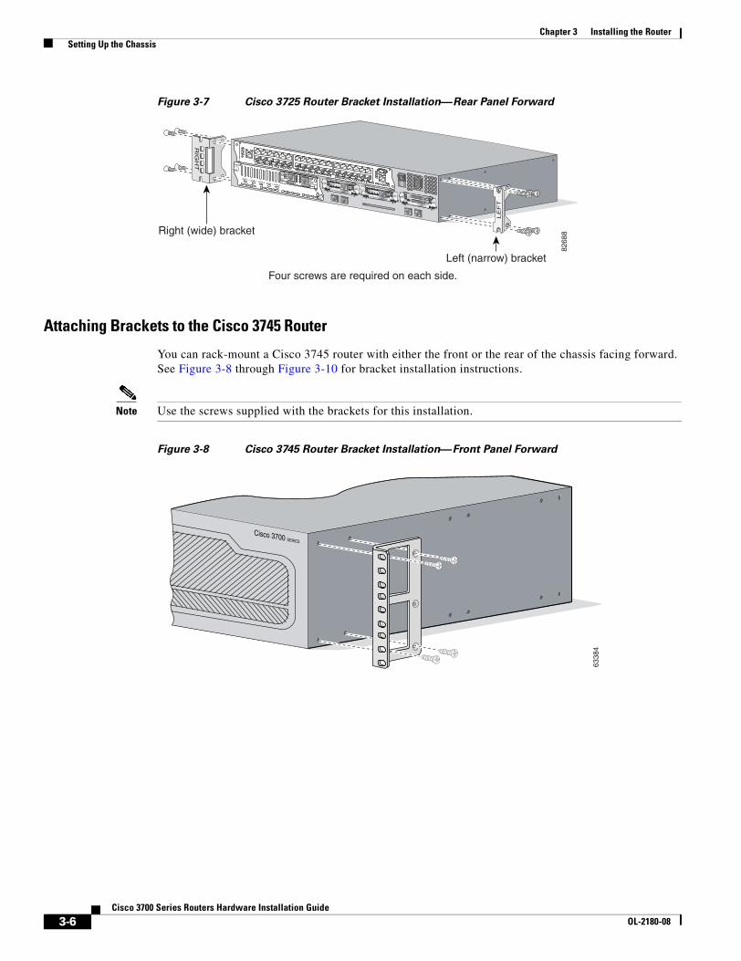
Chapter 3 Installing the Router Setting Up the Chassis
Figure 3-7 Cisco 3725 Router Bracket Installation—Rear Panel Forward
Attaching Brackets to the Cisco 3745 Router
You can rack-mount a Cisco 3745 router with either the front or the rear of the chassis facing forward. See Figure 3-8 through Figure 3-10 for bracket installation instructions.
Note Use the screws supplied with the brackets for this installation.
Figure 3-8 Cisco 3745 Router Bracket Installation—Front Panel Forward
RIG
HT
Right (wide) bracket
8268
8
SEE MANUAL BEFORE INSTALLATION
AL
CD
LPRDTD
SEE MANUAL BEFORE INSTALLATIONDSU56K
AL
CD
LPRDTD
SEE MANUAL BEFORE INSTALLATIONDSU56K
ENV0
BANK 4 BANK 3 BANK 2 BANK 1 BANK 0
NM-HDV
VWIC2MFT-E1 SEE
MANUALBEFOREINSTALLATION
CTRLR E2CTRLR E1
AL
LP
CD
LE
FT
Left (narrow) bracket
Four screws are required on each side.
Cisco 3700 SERIES
6338
4
3-6Cisco 3700 Series Routers Hardware Installation Guide
OL-2180-08
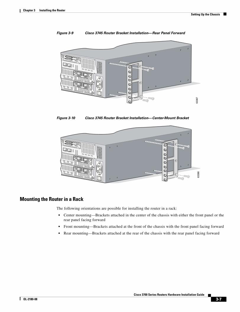
Chapter 3 Installing the Router Setting Up the Chassis
Figure 3-9 Cisco 3745 Router Bracket Installation—Rear Panel Forward
Figure 3-10 Cisco 3745 Router Bracket Installation—Center-Mount Bracket
Mounting the Router in a Rack
The following orientations are possible for installing the router in a rack:
• Center mounting—Brackets attached in the center of the chassis with either the front panel or the rear panel facing forward
• Front mounting—Brackets attached at the front of the chassis with the front panel facing forward
• Rear mounting—Brackets attached at the rear of the chassis with the rear panel facing forward
6338
7
EN
V0
BANK 3 BANK 2 BANK 1 BANK 0
VWIC2MFT-E1 SEE
MANUALBEFOREINSTALLATION
CTRLR E2
CTRLR E1
AL
LP
CD
EN
V0
BANK 3 BANK 2 BANK 1 BANK 0
VWIC2MFT-E1 SEE
MANUALBEFOREINSTALLATION
CTRLR E2
CTRLR E1
AL
LP
CD
SEE MANUAL BEFORE INSTALLATION
SERIAL 1
SERIAL 0
CONN
CONNWIC
2T
6338
8
EN
V0
BANK 3 BANK 2 BANK 1 BANK 0
VWIC2MFT-E1 SEE
MANUALBEFOREINSTALLATION
CTRLR E2
CTRLR E1
AL
LP
CD
EN
V0
BANK 3 BANK 2 BANK 1 BANK 0
VWIC2MFT-E1 SEE
MANUALBEFOREINSTALLATION
CTRLR E2
CTRLR E1
AL
LP
CD
SEE MANUAL BEFORE INSTALLATION
SERIAL 1
SERIAL 0
CONN
CONNWIC
2T
3-7Cisco 3700 Series Routers Hardware Installation Guide
OL-2180-08
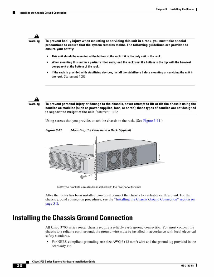
Chapter 3 Installing the Router Installing the Chassis Ground Connection
Warning To prevent personal injury or damage to the chassis, never attempt to lift or tilt the chassis using the handles on modules (such as power supplies, fans, or cards); these types of handles are not designed to support the weight of the unit. Statement 1032
Using screws that you provide, attach the chassis to the rack. (See Figure 3-11.)
Figure 3-11 Mounting the Chassis in a Rack (Typical)
After the router has been installed, you must connect the chassis to a reliable earth ground. For the chassis ground connection procedures, see the “Installing the Chassis Ground Connection” section on page 3-8.
Installing the Chassis Ground ConnectionAll Cisco 3700 series router chassis require a reliable earth ground connection. You must connect the chassis to a reliable earth ground; the ground wire must be installed in accordance with local electrical safety standards.
• For NEBS-compliant grounding, use size AWG 6 (13 mm2) wire and the ground lug provided in the accessory kit.
Warning To prevent bodily injury when mounting or servicing this unit in a rack, you must take special precautions to ensure that the system remains stable. The following guidelines are provided to ensure your safety:
• This unit should be mounted at the bottom of the rack if it is the only unit in the rack.
• When mounting this unit in a partially filled rack, load the rack from the bottom to the top with the heaviest component at the bottom of the rack.
• If the rack is provided with stabilizing devices, install the stabilizers before mounting or servicing the unit in the rack. Statement 1006
Cisco 3700 SERIES
6273
5
Note: The brackets can also be installed with the rear panel forward.
3-8Cisco 3700 Series Routers Hardware Installation Guide
OL-2180-08
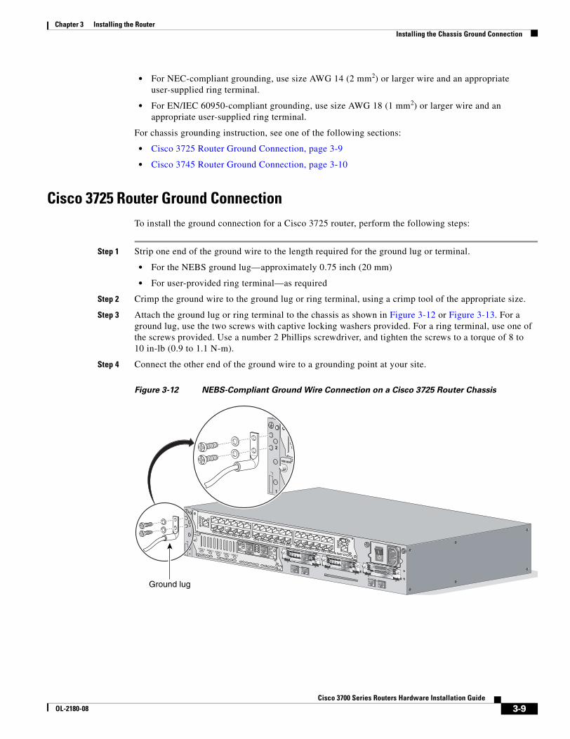
Chapter 3 Installing the Router Installing the Chassis Ground Connection
• For NEC-compliant grounding, use size AWG 14 (2 mm2) or larger wire and an appropriate user-supplied ring terminal.
• For EN/IEC 60950-compliant grounding, use size AWG 18 (1 mm2) or larger wire and an appropriate user-supplied ring terminal.
For chassis grounding instruction, see one of the following sections:
• Cisco 3725 Router Ground Connection, page 3-9
• Cisco 3745 Router Ground Connection, page 3-10
Cisco 3725 Router Ground ConnectionTo install the ground connection for a Cisco 3725 router, perform the following steps:
Step 1 Strip one end of the ground wire to the length required for the ground lug or terminal.
• For the NEBS ground lug—approximately 0.75 inch (20 mm)
• For user-provided ring terminal—as required
Step 2 Crimp the ground wire to the ground lug or ring terminal, using a crimp tool of the appropriate size.
Step 3 Attach the ground lug or ring terminal to the chassis as shown in Figure 3-12 or Figure 3-13. For a ground lug, use the two screws with captive locking washers provided. For a ring terminal, use one of the screws provided. Use a number 2 Phillips screwdriver, and tighten the screws to a torque of 8 to 10 in-lb (0.9 to 1.1 N-m).
Step 4 Connect the other end of the ground wire to a grounding point at your site.
Figure 3-12 NEBS-Compliant Ground Wire Connection on a Cisco 3725 Router Chassis
SEE MANUAL BEFORE INSTALLATION
AL
CD
LPRDTD
SEE MANUAL BEFORE INSTALLATIONDSU56K
AL
CD
LPRDTD
SEE MANUAL BEFORE INSTALLATIONDSU56K
ENV0
BANK 4 BANK 3 BANK 2 BANK 1 BANK 0
NM-HDV
VWIC2MFT-E1 SEE
MANUALBEFOREINSTALLATION
CTRLR E2CTRLR E1
AL
LP
CD
1
2
BAN
NM-HDV
1
2
Ground lug
3-9Cisco 3700 Series Routers Hardware Installation Guide
OL-2180-08
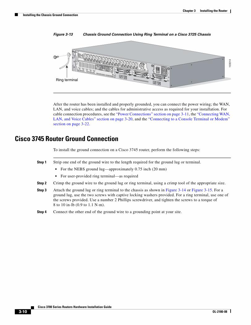
Chapter 3 Installing the Router Installing the Chassis Ground Connection
Figure 3-13 Chassis Ground Connection Using Ring Terminal on a Cisco 3725 Chassis
After the router has been installed and properly grounded, you can connect the power wiring; the WAN, LAN, and voice cables; and the cables for administrative access as required for your installation. For cable connection procedures, see the “Power Connections” section on page 3-11, the “Connecting WAN, LAN, and Voice Cables” section on page 3-20, and the “Connecting to a Console Terminal or Modem” section on page 3-22.
Cisco 3745 Router Ground ConnectionTo install the ground connection on a Cisco 3745 router, perform the following steps:
Step 1 Strip one end of the ground wire to the length required for the ground lug or terminal.
• For the NEBS ground lug—approximately 0.75 inch (20 mm)
• For user-provided ring terminal—as required
Step 2 Crimp the ground wire to the ground lug or ring terminal, using a crimp tool of the appropriate size.
Step 3 Attach the ground lug or ring terminal to the chassis as shown in Figure 3-14 or Figure 3-15. For a ground lug, use the two screws with captive locking washers provided. For a ring terminal, use one of the screws provided. Use a number 2 Phillips screwdriver, and tighten the screws to a torque of 8 to 10 in-lb (0.9 to 1.1 N-m).
Step 4 Connect the other end of the ground wire to a grounding point at your site.
1030
14
SEE MANUAL BEFORE INSTALLATION
AL
CD
LPRDTD
SEE MANUAL BEFORE INSTALLATIONDSU56K
AL
CD
LPRDTD
SEE MANUAL BEFORE INSTALLATIONDSU56K
ENV0
BANK 4 BANK 3 BANK 2 BANK 1 BANK 0
NM-HDV
VWIC2MFT-E1 SEE
MANUALBEFOREINSTALLATION
CTRLR E2CTRLR E1
AL
LP
CD
1
2
Ring terminal
3-10Cisco 3700 Series Routers Hardware Installation Guide
OL-2180-08
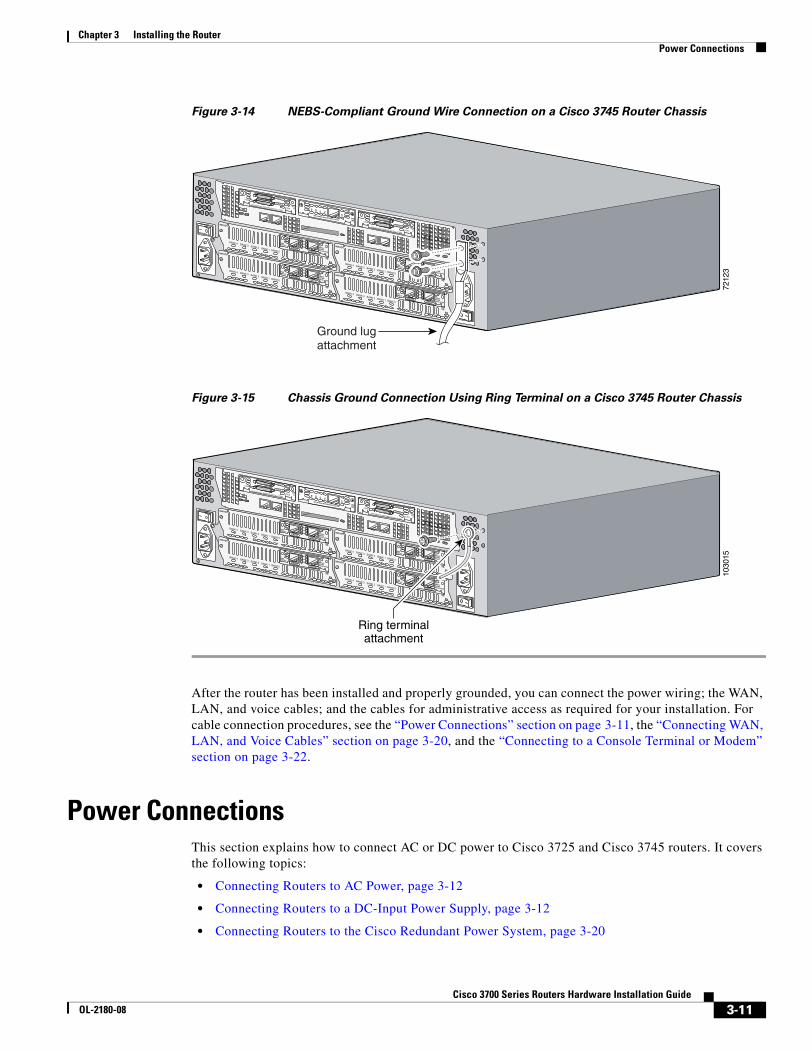
Chapter 3 Installing the Router Power Connections
Figure 3-14 NEBS-Compliant Ground Wire Connection on a Cisco 3745 Router Chassis
Figure 3-15 Chassis Ground Connection Using Ring Terminal on a Cisco 3745 Router Chassis
After the router has been installed and properly grounded, you can connect the power wiring; the WAN, LAN, and voice cables; and the cables for administrative access as required for your installation. For cable connection procedures, see the “Power Connections” section on page 3-11, the “Connecting WAN, LAN, and Voice Cables” section on page 3-20, and the “Connecting to a Console Terminal or Modem” section on page 3-22.
Power ConnectionsThis section explains how to connect AC or DC power to Cisco 3725 and Cisco 3745 routers. It covers the following topics:
• Connecting Routers to AC Power, page 3-12
• Connecting Routers to a DC-Input Power Supply, page 3-12
• Connecting Routers to the Cisco Redundant Power System, page 3-20
7212
3
EN
V0
BANK 4 BANK 3 BANK 2 BANK 1 BANK 0
NM-HDV
VWIC2MFT-E1 SEE
MANUALBEFOREINSTALLATION
CTRLR E2
CTRLR E1
AL
LP
CD
EN
V0
BANK 4 BANK 3 BANK 2 BANK 1 BANK 0
NM-HDV
VWIC2MFT-E1 SEE
MANUALBEFOREINSTALLATION
CTRLR E2
CTRLR E1
AL
LP
CD
EN
V0
BANK 4 BANK 3 BANK 2 BANK 1 BANK 0
NM-HDV
VWIC2MFT-E1 SEE
MANUALBEFOREINSTALLATION
CTRLR E2
CTRLR E1
AL
LP
CD
EN
V0
BANK 4 BANK 3 BANK 2 BANK 1 BANK 0
NM-HDV
VWIC2MFT-E1 SEE
MANUALBEFOREINSTALLATION
CTRLR E2
CTRLR E1
AL
LP
CD
SEE MANUAL BEFORE INSTALLATION
SERIAL 1
SERIAL 0
CONN
CONNWIC
2T
SEE MANUAL BEFORE INSTALLATION
SERIAL 1
SERIAL 0
CONN
CONNWIC
2T
SEE MANUAL BEFORE INSTALLATIONDSU56K
CD
ALLPRDTD
Ground lugattachment
1030
15
EN
V0
BANK 4 BANK 3 BANK 2 BANK 1 BANK 0
NM-HDV
VWIC2MFT-E1 SEE
MANUALBEFOREINSTALLATION
CTRLR E2
CTRLR E1
AL
LP
CD
EN
V0
BANK 4 BANK 3 BANK 2 BANK 1 BANK 0
NM-HDV
VWIC2MFT-E1 SEE
MANUALBEFOREINSTALLATION
CTRLR E2
CTRLR E1
AL
LP
CD
EN
V0
BANK 4 BANK 3 BANK 2 BANK 1 BANK 0
NM-HDV
VWIC2MFT-E1 SEE
MANUALBEFOREINSTALLATION
CTRLR E2
CTRLR E1
AL
LP
CD
EN
V0
BANK 4 BANK 3 BANK 2 BANK 1 BANK 0
NM-HDV
VWIC2MFT-E1 SEE
MANUALBEFOREINSTALLATION
CTRLR E2
CTRLR E1
AL
LP
CD
SEE MANUAL BEFORE INSTALLATION
SERIAL 1
SERIAL 0
CONN
CONNWIC
2T
SEE MANUAL BEFORE INSTALLATION
SERIAL 1
SERIAL 0
CONN
CONNWIC
2T
SEE MANUAL BEFORE INSTALLATIONDSU56K
CD
ALLPRDTD
Ring terminalattachment
3-11Cisco 3700 Series Routers Hardware Installation Guide
OL-2180-08
Chapter 3 Installing the Router Power Connections
Connecting Routers to AC PowerIf your router uses AC power, connect it to a 15 A, 120 VAC (10 A, 240 VAC) circuit with overcurrent protection.
Note The input voltage tolerance limits for AC power are 85 and 264 VAC.
Warning AC connected units must have a permanent ground connection in addition to the power cable ground wire. NEBS-compliant grounding satisfies this requirement. Statement 284
Warning This product relies on the building’s installation for short-circuit (overcurrent) protection. Ensure that the protective device is rated not greater than:15A, 120VAC (10A, 240VAC). Statement 1005
Caution To comply with Telcordia NEBS GR-1089-Core and EN 300386 requirements, you must use foil twisted-pair cable that is properly grounded at both ends.
Connecting Routers to a DC-Input Power Supply
Warning Before performing any of the following procedures, ensure that power is removed from the DC circuit. Statement 1003
Warning Use copper conductors only. Statement 1025
Note The installation must comply with the 1996 National Electric Code (NEC) and other applicable codes.
If your router has a DC-input power supply, follow the directions in this section for proper wiring. A router with a DC-input power supply has a terminal block for the DC power connections.
Depending on the type of router you are installing, see one of the following procedures:
• Wiring the DC-Input Power Supply in Cisco 3725 Routers, page 3-12
• Wiring the DC-Input Power Supply in Cisco 3745 Routers, page 3-17
Wiring the DC-Input Power Supply in Cisco 3725 Routers
If your Cisco 3725 router has a DC-input power supply, follow the directions in this section for proper wiring.
3-12Cisco 3700 Series Routers Hardware Installation Guide
OL-2180-08
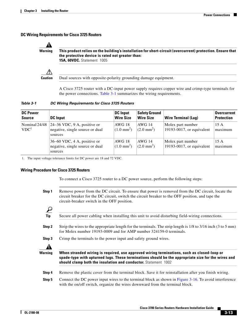
Chapter 3 Installing the Router Power Connections
DC Wiring Requirements for Cisco 3725 Routers
Warning This product relies on the building’s installation for short-circuit (overcurrent) protection. Ensure that the protective device is rated not greater than:15A, 60VDC. Statement 1005
Caution Dual sources with opposite-polarity grounding damage equipment.
A Cisco 3725 router with a DC-input power supply requires copper wire and crimp-type terminals for the power connections. Table 3-1 summarizes the wiring requirements.
Wiring Procedure for Cisco 3725 Routers
To connect a Cisco 3725 router to a DC power source, perform the following steps:
Step 1 Remove power from the DC circuit. To ensure that power is removed from the DC circuit, locate the circuit breaker for the DC circuit, switch the circuit breaker to the OFF position, and tape the circuit-breaker switch in the OFF position.
Tip Secure all power cabling when installing this unit to avoid disturbing field-wiring connections.
Step 2 Strip the wires to the appropriate length for the terminals. The strip length is 1/8 to 3/16 inch (3 to 5 mm) for Molex number 19193-0009 and for AMP number 324159-0 terminals.
Step 3 Crimp the terminals to the power input and safety ground wires.
Warning When stranded wiring is required, use approved wiring terminations, such as closed-loop or spade-type with upturned lugs. These terminations should be the appropriate size for the wires and should clamp both the insulation and conductor. Statement 1002
Step 4 Remove the plastic cover from the terminal block. Save it for reinstallation after you finish wiring.
Step 5 Connect the DC power input wires to the terminal block as shown in Figure 3-16. To avoid interference with the on/off switch, organize the wires downward from the terminal block.
Table 3-1 DC Wiring Requirements for Cisco 3725 Routers
DC Power Source DC Input
DC Input Wire Size
Safety Ground Wire Size Wire Terminal (Lug)
Overcurrent Protection
Nominal 24/48 VDC1
1. The input voltage tolerance limits for DC power are 18 and 72 VDC.
24–36 VDC, 9 A, positive or negative, single source or dual sources
AWG 18 (1.0 mm2)
AWG 14 (2.0 mm2)
Molex part number 19193-0017, or equivalent
15 A maximum
36–60 VDC, 4 A, positive or negative, single source or dual sources
AWG 18 (1.0 mm2)
AWG 14 (2.0 mm2)
Molex part number 19193-0017, or equivalent
15 A maximum
3-13Cisco 3700 Series Routers Hardware Installation Guide
OL-2180-08
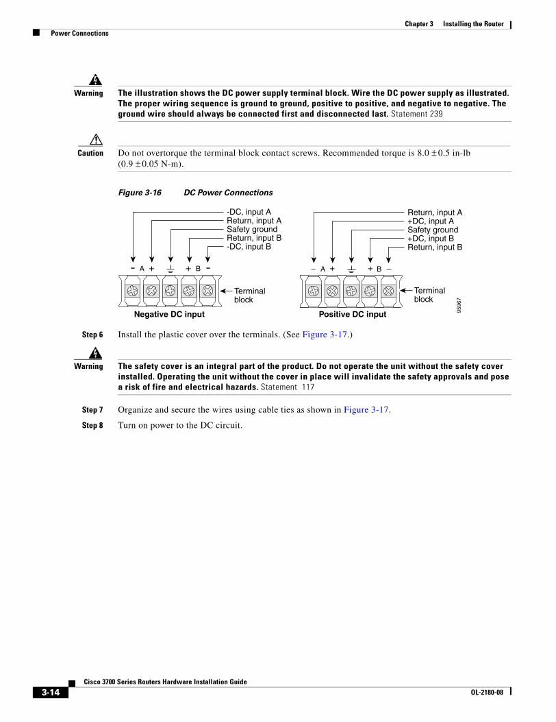
Chapter 3 Installing the Router Power Connections
Warning The illustration shows the DC power supply terminal block. Wire the DC power supply as illustrated. The proper wiring sequence is ground to ground, positive to positive, and negative to negative. The ground wire should always be connected first and disconnected last. Statement 239
Caution Do not overtorque the terminal block contact screws. Recommended torque is 8.0 ± 0.5 in-lb (0.9 ± 0.05 N-m).
Figure 3-16 DC Power Connections
Step 6 Install the plastic cover over the terminals. (See Figure 3-17.)
Warning The safety cover is an integral part of the product. Do not operate the unit without the safety cover installed. Operating the unit without the cover in place will invalidate the safety approvals and pose a risk of fire and electrical hazards. Statement 117
Step 7 Organize and secure the wires using cable ties as shown in Figure 3-17.
Step 8 Turn on power to the DC circuit.
9596
7
A + B+A + + B
Terminalblock
Negative DC input Positive DC input
Terminalblock
-DC, input BReturn, input BSafety groundReturn, input A-DC, input A
Return, input B+DC, input BSafety ground+DC, input AReturn, input A
3-14Cisco 3700 Series Routers Hardware Installation Guide
OL-2180-08
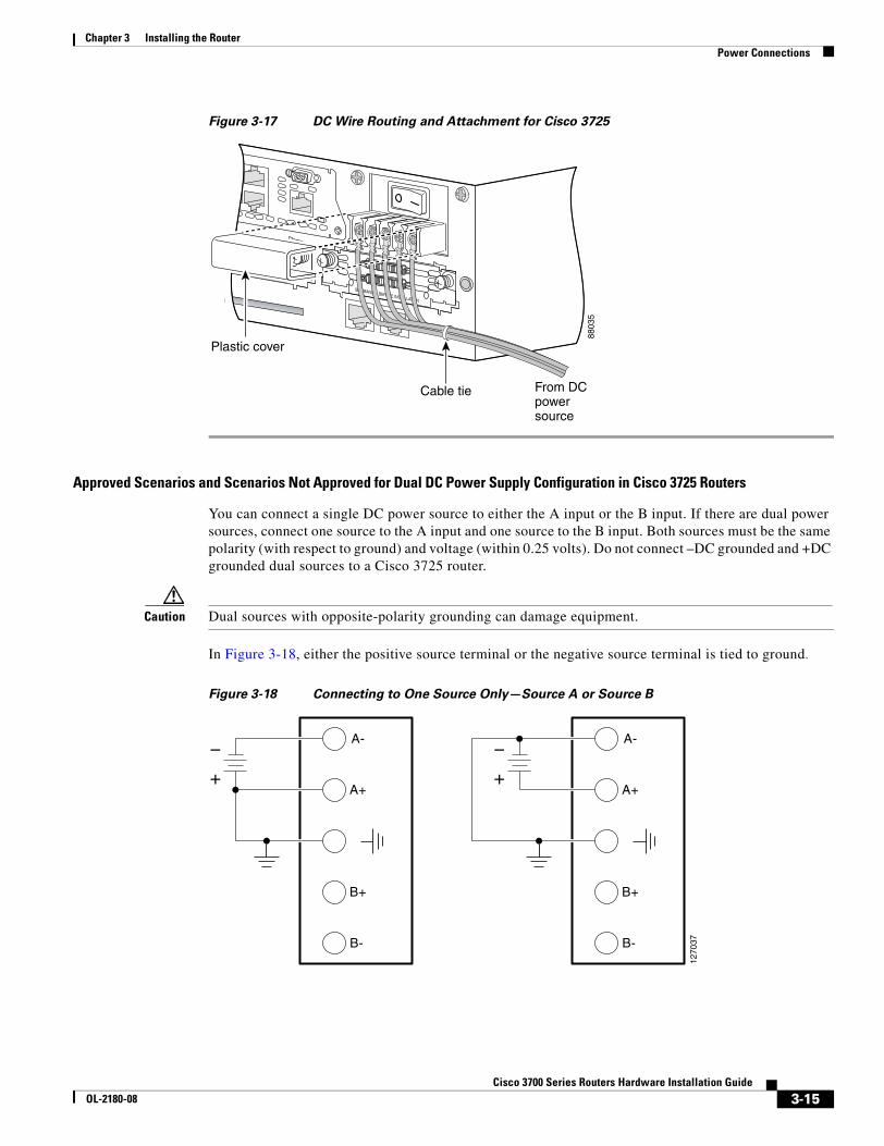
Chapter 3 Installing the Router Power Connections
Figure 3-17 DC Wire Routing and Attachment for Cisco 3725
Approved Scenarios and Scenarios Not Approved for Dual DC Power Supply Configuration in Cisco 3725 Routers
You can connect a single DC power source to either the A input or the B input. If there are dual power sources, connect one source to the A input and one source to the B input. Both sources must be the same polarity (with respect to ground) and voltage (within 0.25 volts). Do not connect –DC grounded and +DC grounded dual sources to a Cisco 3725 router.
Caution Dual sources with opposite-polarity grounding can damage equipment.
In Figure 3-18, either the positive source terminal or the negative source terminal is tied to ground.
Figure 3-18 Connecting to One Source Only—Source A or Source B
8803
5
AL
CD
LP
BEFORE INSTALLATIONDSU56K
SEE MANUAL BEFORE INSTALLATION
Cable tie From DCpower source
Plastic cover
A-
1270
37
A+
B+
B-
+
A-
A+
B+
B-
+
3-15Cisco 3700 Series Routers Hardware Installation Guide
OL-2180-08
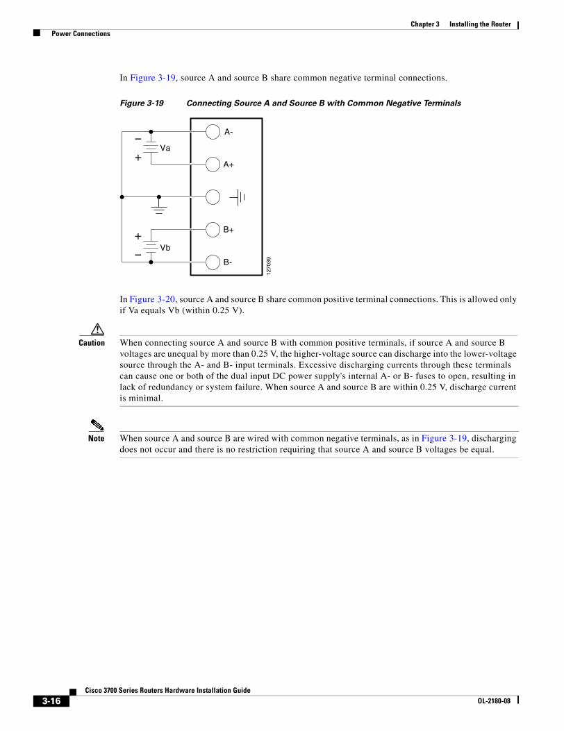
Chapter 3 Installing the Router Power Connections
In Figure 3-19, source A and source B share common negative terminal connections.
Figure 3-19 Connecting Source A and Source B with Common Negative Terminals
In Figure 3-20, source A and source B share common positive terminal connections. This is allowed only if Va equals Vb (within 0.25 V).
Caution When connecting source A and source B with common positive terminals, if source A and source B voltages are unequal by more than 0.25 V, the higher-voltage source can discharge into the lower-voltage source through the A- and B- input terminals. Excessive discharging currents through these terminals can cause one or both of the dual input DC power supply's internal A- or B- fuses to open, resulting in lack of redundancy or system failure. When source A and source B are within 0.25 V, discharge current is minimal.
Note When source A and source B are wired with common negative terminals, as in Figure 3-19, discharging does not occur and there is no restriction requiring that source A and source B voltages be equal.
A-
1270
39
A+
B+
B-
Va
Vb
+
+
3-16Cisco 3700 Series Routers Hardware Installation Guide
OL-2180-08
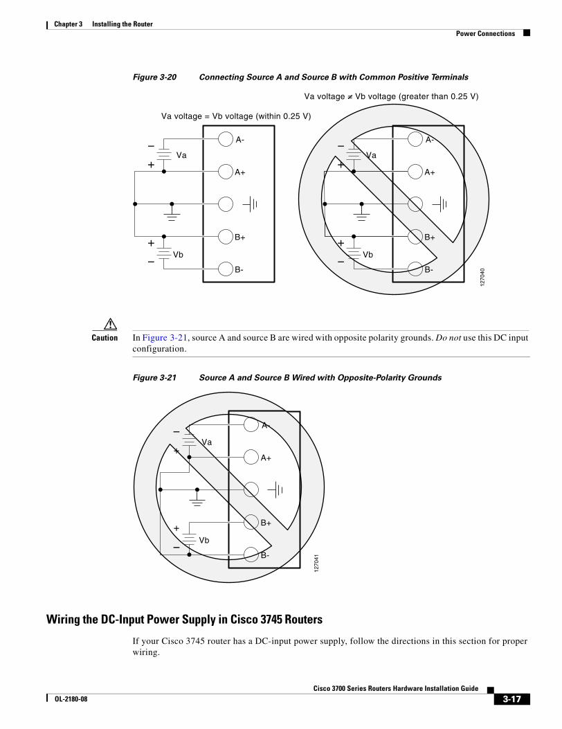
Chapter 3 Installing the Router Power Connections
Figure 3-20 Connecting Source A and Source B with Common Positive Terminals
Caution In Figure 3-21, source A and source B are wired with opposite polarity grounds. Do not use this DC input configuration.
Figure 3-21 Source A and Source B Wired with Opposite-Polarity Grounds
Wiring the DC-Input Power Supply in Cisco 3745 Routers
If your Cisco 3745 router has a DC-input power supply, follow the directions in this section for proper wiring.
A-
A+
B+
B-
Va
Vb
+
+
1270
40
A-
A+
B+
B-
Va
Vb
+
+
A-
Va voltage = Vb voltage (within 0.25 V)
Va voltage = Vb voltage (greater than 0.25 V)
A+
B+
B-
Va
Vb
+
+
A-
1270
41
A+
B+
B-
Va
Vb
+
+
A-
A+
B+
B-
Va
Vb
+
+
3-17Cisco 3700 Series Routers Hardware Installation Guide
OL-2180-08
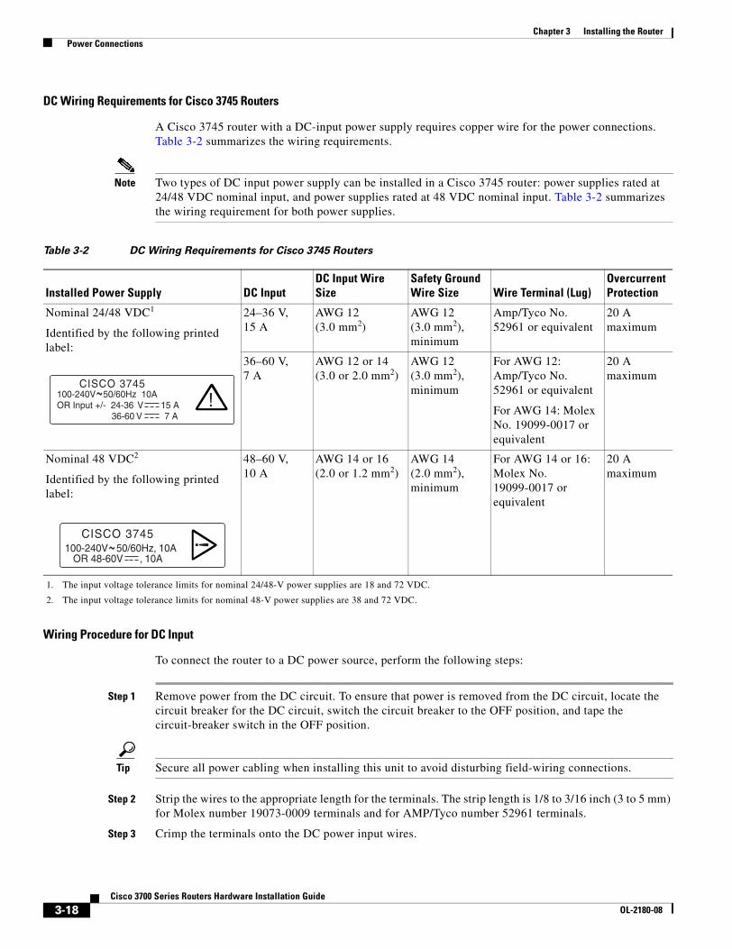
Chapter 3 Installing the Router Power Connections
DC Wiring Requirements for Cisco 3745 Routers
A Cisco 3745 router with a DC-input power supply requires copper wire for the power connections. Table 3-2 summarizes the wiring requirements.
Note Two types of DC input power supply can be installed in a Cisco 3745 router: power supplies rated at 24/48 VDC nominal input, and power supplies rated at 48 VDC nominal input. Table 3-2 summarizes the wiring requirement for both power supplies.
Wiring Procedure for DC Input
To connect the router to a DC power source, perform the following steps:
Step 1 Remove power from the DC circuit. To ensure that power is removed from the DC circuit, locate the circuit breaker for the DC circuit, switch the circuit breaker to the OFF position, and tape the circuit-breaker switch in the OFF position.
Tip Secure all power cabling when installing this unit to avoid disturbing field-wiring connections.
Step 2 Strip the wires to the appropriate length for the terminals. The strip length is 1/8 to 3/16 inch (3 to 5 mm) for Molex number 19073-0009 terminals and for AMP/Tyco number 52961 terminals.
Step 3 Crimp the terminals onto the DC power input wires.
Table 3-2 DC Wiring Requirements for Cisco 3745 Routers
Installed Power Supply DC InputDC Input Wire Size
Safety Ground Wire Size Wire Terminal (Lug)
Overcurrent Protection
Nominal 24/48 VDC1
Identified by the following printed label:
1. The input voltage tolerance limits for nominal 24/48-V power supplies are 18 and 72 VDC.
24–36 V, 15 A
AWG 12 (3.0 mm2)
AWG 12 (3.0 mm2), minimum
Amp/Tyco No. 52961 or equivalent
20 A maximum
36–60 V, 7 A
AWG 12 or 14(3.0 or 2.0 mm2)
AWG 12 (3.0 mm2), minimum
For AWG 12: Amp/Tyco No. 52961 or equivalent
For AWG 14: Molex No. 19099-0017 or equivalent
20 A maximum
Nominal 48 VDC2
Identified by the following printed label:
2. The input voltage tolerance limits for nominal 48-V power supplies are 38 and 72 VDC.
48–60 V, 10 A
AWG 14 or 16(2.0 or 1.2 mm2)
AWG 14 (2.0 mm2), minimum
For AWG 14 or 16: Molex No. 19099-0017 or equivalent
20 A maximum
100-240V 50/60Hz 10A OR Input +/- 24-36 V 15 A 36-60 V 7 A
!CISCO 3745~
100-240V 50/60Hz, 10A OR 48-60V , 10A
!CISCO 3745~
3-18Cisco 3700 Series Routers Hardware Installation Guide
OL-2180-08
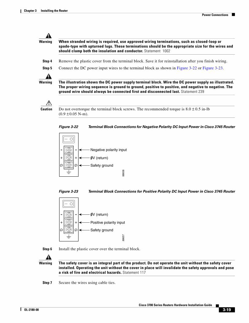
Chapter 3 Installing the Router Power Connections
Warning When stranded wiring is required, use approved wiring terminations, such as closed-loop or spade-type with upturned lugs. These terminations should be the appropriate size for the wires and should clamp both the insulation and conductor. Statement 1002
Step 4 Remove the plastic cover from the terminal block. Save it for reinstallation after you finish wiring.
Step 5 Connect the DC power input wires to the terminal block as shown in Figure 3-22 or Figure 3-23.
Warning The illustration shows the DC power supply terminal block. Wire the DC power supply as illustrated. The proper wiring sequence is ground to ground, positive to positive, and negative to negative. The ground wire should always be connected first and disconnected last. Statement 239
Caution Do not overtorque the terminal block screws. The recommended torque is 8.0 ± 0.5 in-lb (0.9 ± 0.05 N-m).
Figure 3-22 Terminal Block Connections for Negative Polarity DC Input Power in Cisco 3745 Router
Figure 3-23 Terminal Block Connections for Positive Polarity DC Input Power in Cisco 3745 Router
Step 6 Install the plastic cover over the terminal block.
Warning The safety cover is an integral part of the product. Do not operate the unit without the safety cover installed. Operating the unit without the cover in place will invalidate the safety approvals and pose a risk of fire and electrical hazards. Statement 117
Step 7 Secure the wires using cable ties.
8865
8
0V (return)
Negative polarity input
Safety ground
8865
7
0V (return)
Positive polarity input
Safety ground
3-19Cisco 3700 Series Routers Hardware Installation Guide
OL-2180-08
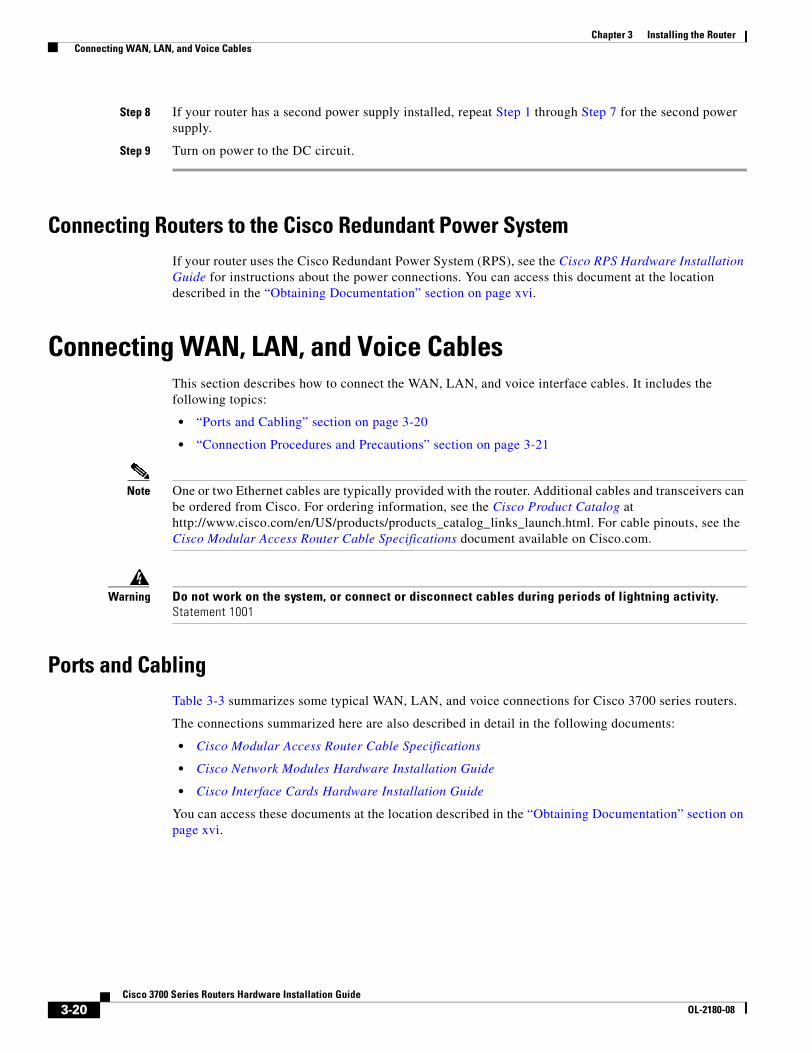
Chapter 3 Installing the Router Connecting WAN, LAN, and Voice Cables
Step 8 If your router has a second power supply installed, repeat Step 1 through Step 7 for the second power supply.
Step 9 Turn on power to the DC circuit.
Connecting Routers to the Cisco Redundant Power SystemIf your router uses the Cisco Redundant Power System (RPS), see the Cisco RPS Hardware Installation Guide for instructions about the power connections. You can access this document at the location described in the “Obtaining Documentation” section on page xvi.
Connecting WAN, LAN, and Voice CablesThis section describes how to connect the WAN, LAN, and voice interface cables. It includes the following topics:
• “Ports and Cabling” section on page 3-20
• “Connection Procedures and Precautions” section on page 3-21
Note One or two Ethernet cables are typically provided with the router. Additional cables and transceivers can be ordered from Cisco. For ordering information, see the Cisco Product Catalog at http://www.cisco.com/en/US/products/products_catalog_links_launch.html. For cable pinouts, see the Cisco Modular Access Router Cable Specifications document available on Cisco.com.
Warning Do not work on the system, or connect or disconnect cables during periods of lightning activity. Statement 1001
Ports and CablingTable 3-3 summarizes some typical WAN, LAN, and voice connections for Cisco 3700 series routers.
The connections summarized here are also described in detail in the following documents:
• Cisco Modular Access Router Cable Specifications
• Cisco Network Modules Hardware Installation Guide
• Cisco Interface Cards Hardware Installation Guide
You can access these documents at the location described in the “Obtaining Documentation” section on page xvi.
3-20Cisco 3700 Series Routers Hardware Installation Guide
OL-2180-08
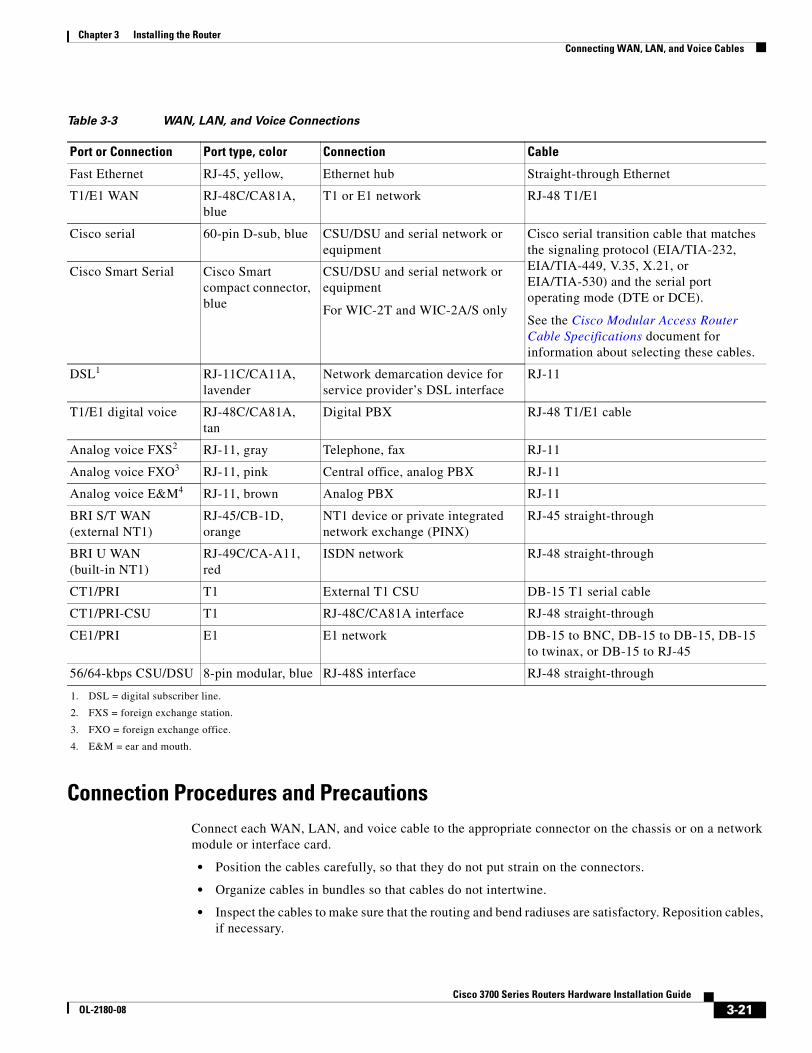
Chapter 3 Installing the Router Connecting WAN, LAN, and Voice Cables
Connection Procedures and PrecautionsConnect each WAN, LAN, and voice cable to the appropriate connector on the chassis or on a network module or interface card.
• Position the cables carefully, so that they do not put strain on the connectors.
• Organize cables in bundles so that cables do not intertwine.
• Inspect the cables to make sure that the routing and bend radiuses are satisfactory. Reposition cables, if necessary.
Table 3-3 WAN, LAN, and Voice Connections
Port or Connection Port type, color Connection Cable
Fast Ethernet RJ-45, yellow, Ethernet hub Straight-through Ethernet
T1/E1 WAN RJ-48C/CA81A, blue
T1 or E1 network RJ-48 T1/E1
Cisco serial 60-pin D-sub, blue CSU/DSU and serial network or equipment
Cisco serial transition cable that matches the signaling protocol (EIA/TIA-232, EIA/TIA-449, V.35, X.21, or EIA/TIA-530) and the serial port operating mode (DTE or DCE).
See the Cisco Modular Access Router Cable Specifications document for information about selecting these cables.
Cisco Smart Serial Cisco Smart compact connector, blue
CSU/DSU and serial network or equipment
For WIC-2T and WIC-2A/S only
DSL1
1. DSL = digital subscriber line.
RJ-11C/CA11A, lavender
Network demarcation device for service provider’s DSL interface
RJ-11
T1/E1 digital voice RJ-48C/CA81A, tan
Digital PBX RJ-48 T1/E1 cable
Analog voice FXS2
2. FXS = foreign exchange station.
RJ-11, gray Telephone, fax RJ-11
Analog voice FXO3
3. FXO = foreign exchange office.
RJ-11, pink Central office, analog PBX RJ-11
Analog voice E&M4
4. E&M = ear and mouth.
RJ-11, brown Analog PBX RJ-11
BRI S/T WAN (external NT1)
RJ-45/CB-1D, orange
NT1 device or private integrated network exchange (PINX)
RJ-45 straight-through
BRI U WAN (built-in NT1)
RJ-49C/CA-A11, red
ISDN network RJ-48 straight-through
CT1/PRI T1 External T1 CSU DB-15 T1 serial cable
CT1/PRI-CSU T1 RJ-48C/CA81A interface RJ-48 straight-through
CE1/PRI E1 E1 network DB-15 to BNC, DB-15 to DB-15, DB-15 to twinax, or DB-15 to RJ-45
56/64-kbps CSU/DSU 8-pin modular, blue RJ-48S interface RJ-48 straight-through
3-21Cisco 3700 Series Routers Hardware Installation Guide
OL-2180-08
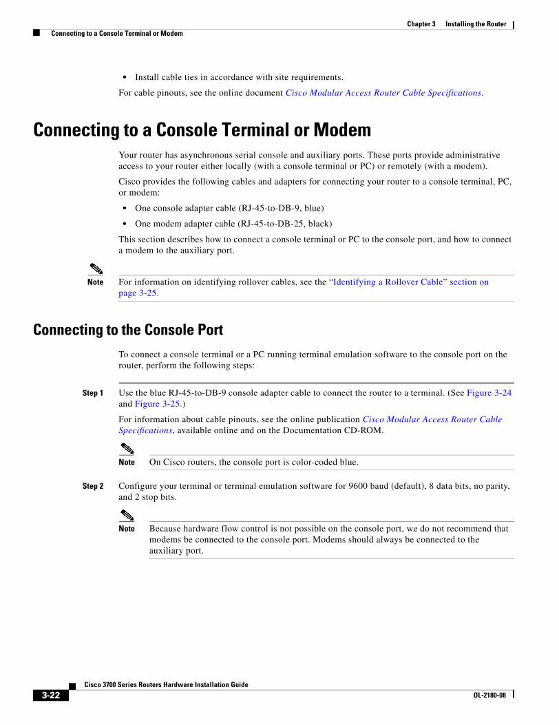
Chapter 3 Installing the Router Connecting to a Console Terminal or Modem
• Install cable ties in accordance with site requirements.
For cable pinouts, see the online document Cisco Modular Access Router Cable Specifications.
Connecting to a Console Terminal or ModemYour router has asynchronous serial console and auxiliary ports. These ports provide administrative access to your router either locally (with a console terminal or PC) or remotely (with a modem).
Cisco provides the following cables and adapters for connecting your router to a console terminal, PC, or modem:
• One console adapter cable (RJ-45-to-DB-9, blue)
• One modem adapter cable (RJ-45-to-DB-25, black)
This section describes how to connect a console terminal or PC to the console port, and how to connect a modem to the auxiliary port.
Note For information on identifying rollover cables, see the “Identifying a Rollover Cable” section on page 3-25.
Connecting to the Console PortTo connect a console terminal or a PC running terminal emulation software to the console port on the router, perform the following steps:
Step 1 Use the blue RJ-45-to-DB-9 console adapter cable to connect the router to a terminal. (See Figure 3-24 and Figure 3-25.)
For information about cable pinouts, see the online publication Cisco Modular Access Router Cable Specifications, available online and on the Documentation CD-ROM.
Note On Cisco routers, the console port is color-coded blue.
Step 2 Configure your terminal or terminal emulation software for 9600 baud (default), 8 data bits, no parity, and 2 stop bits.
Note Because hardware flow control is not possible on the console port, we do not recommend that modems be connected to the console port. Modems should always be connected to the auxiliary port.
3-22Cisco 3700 Series Routers Hardware Installation Guide
OL-2180-08
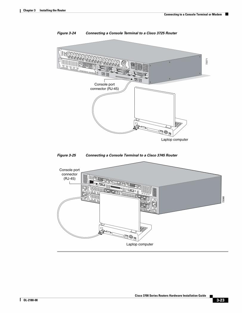
Chapter 3 Installing the Router Connecting to a Console Terminal or Modem
Figure 3-24 Connecting a Console Terminal to a Cisco 3725 Router
Figure 3-25 Connecting a Console Terminal to a Cisco 3745 Router
7207
1
SEE MANUAL BEFORE INSTALLATION
AL
CD
LPRDTD
SEE MANUAL BEFORE INSTALLATIONDSU56K
AL
CD
LPRDTD
SEE MANUAL BEFORE INSTALLATIONDSU56K
ENV0
BANK 4 BANK 3 BANK 2 BANK 1 BANK 0
NM-HDV
VWIC2MFT-E1 SEE
MANUALBEFOREINSTALLATION
CTRLR E2CTRLR E1
AL
LP
CD
Console portconnector (RJ-45)
Laptop computer
7206
8
EN
V0
BANK 4 BANK 3 BANK 2 BANK 1 BANK 0
NM-HDV
VWIC2MFT-E1 SEE
MANUALBEFOREINSTALLATION
CTRLR E2
CTRLR E1
AL
LP
CD
EN
V0
BANK 4 BANK 3 BANK 2 BANK 1 BANK 0
NM-HDV
VWIC2MFT-E1 SEE
MANUALBEFOREINSTALLATION
CTRLR E2
CTRLR E1
AL
LP
CD
EN
V0
BANK 4 BANK 3 BANK 2 BANK 1 BANK 0
NM-HDV
VWIC2MFT-E1 SEE
MANUALBEFOREINSTALLATION
CTRLR E2
CTRLR E1
AL
LP
CD
EN
V0
BANK 4 BANK 3 BANK 2 BANK 1 BANK 0
NM-HDV
VWIC2MFT-E1 SEE
MANUALBEFOREINSTALLATION
CTRLR E2
CTRLR E1
AL
LP
CD
SEE MANUAL BEFORE INSTALLATION
SERIAL 1
SERIAL 0
CONN
CONNWIC
2T
SEE MANUAL BEFORE INSTALLATION
SERIAL 1
SERIAL 0
CONN
CONNWIC
2T
SEE MANUAL BEFORE INSTALLATIONDSU56K
CD
ALLPRDTD
Console portconnector(RJ-45)
Laptop computer
3-23Cisco 3700 Series Routers Hardware Installation Guide
OL-2180-08
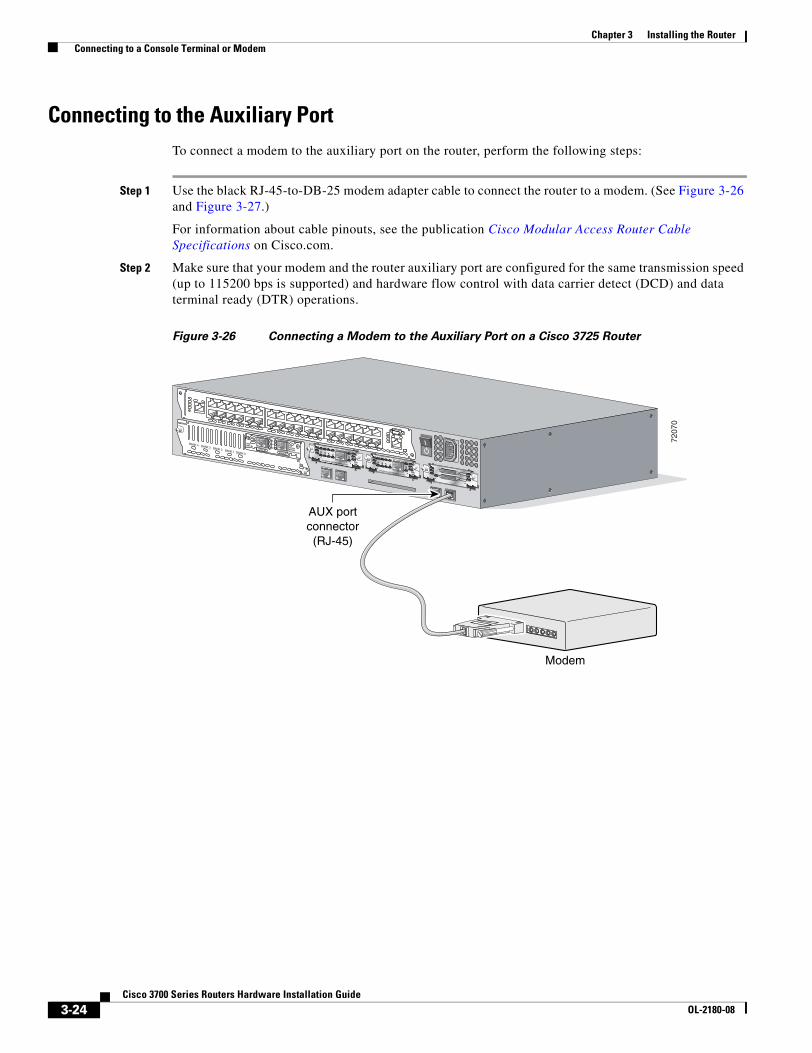
Chapter 3 Installing the Router Connecting to a Console Terminal or Modem
Connecting to the Auxiliary PortTo connect a modem to the auxiliary port on the router, perform the following steps:
Step 1 Use the black RJ-45-to-DB-25 modem adapter cable to connect the router to a modem. (See Figure 3-26 and Figure 3-27.)
For information about cable pinouts, see the publication Cisco Modular Access Router Cable Specifications on Cisco.com.
Step 2 Make sure that your modem and the router auxiliary port are configured for the same transmission speed (up to 115200 bps is supported) and hardware flow control with data carrier detect (DCD) and data terminal ready (DTR) operations.
Figure 3-26 Connecting a Modem to the Auxiliary Port on a Cisco 3725 Router
7207
0
SEE MANUAL BEFORE INSTALLATION
AL
CD
LPRDTD
SEE MANUAL BEFORE INSTALLATIONDSU56K
AL
CD
LPRDTD
SEE MANUAL BEFORE INSTALLATIONDSU56K
ENV0
BANK 4 BANK 3 BANK 2 BANK 1 BANK 0
NM-HDV
VWIC2MFT-E1 SEE
MANUALBEFOREINSTALLATION
CTRLR E2CTRLR E1
AL
LP
CD
Modem
AUX portconnector(RJ-45)
3-24Cisco 3700 Series Routers Hardware Installation Guide
OL-2180-08
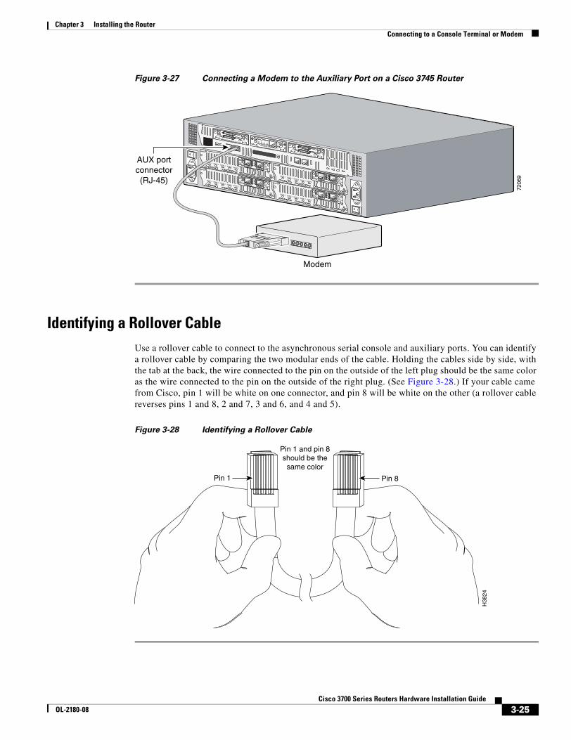
Chapter 3 Installing the Router Connecting to a Console Terminal or Modem
Figure 3-27 Connecting a Modem to the Auxiliary Port on a Cisco 3745 Router
Identifying a Rollover CableUse a rollover cable to connect to the asynchronous serial console and auxiliary ports. You can identify a rollover cable by comparing the two modular ends of the cable. Holding the cables side by side, with the tab at the back, the wire connected to the pin on the outside of the left plug should be the same color as the wire connected to the pin on the outside of the right plug. (See Figure 3-28.) If your cable came from Cisco, pin 1 will be white on one connector, and pin 8 will be white on the other (a rollover cable reverses pins 1 and 8, 2 and 7, 3 and 6, and 4 and 5).
Figure 3-28 Identifying a Rollover Cable
7206
9
EN
V0
BANK 4 BANK 3 BANK 2 BANK 1 BANK 0
NM-HDV
VWIC2MFT-E1 SEE
MANUALBEFOREINSTALLATION
CTRLR E2
CTRLR E1
AL
LP
CD
EN
V0
BANK 4 BANK 3 BANK 2 BANK 1 BANK 0
NM-HDV
VWIC2MFT-E1 SEE
MANUALBEFOREINSTALLATION
CTRLR E2
CTRLR E1
AL
LP
CD
EN
V0
BANK 4 BANK 3 BANK 2 BANK 1 BANK 0
NM-HDV
VWIC2MFT-E1 SEE
MANUALBEFOREINSTALLATION
CTRLR E2
CTRLR E1
AL
LP
CD
EN
V0
BANK 4 BANK 3 BANK 2 BANK 1 BANK 0
NM-HDV
VWIC2MFT-E1 SEE
MANUALBEFOREINSTALLATION
CTRLR E2
CTRLR E1
AL
LP
CD
SEE MANUAL BEFORE INSTALLATION
SERIAL 1
SERIAL 0
CONN
CONNWIC
2T
SEE MANUAL BEFORE INSTALLATION
SERIAL 1
SERIAL 0
CONN
CONNWIC
2T
SEE MANUAL BEFORE INSTALLATIONDSU56K
CD
ALLPRDTD
Modem
AUX portconnector(RJ-45)
Pin 1 Pin 8H
3824
Pin 1 and pin 8should be the
same color
3-25Cisco 3700 Series Routers Hardware Installation Guide
OL-2180-08
Chapter 3 Installing the Router Powering Up the Router
Powering Up the Router
Warning The plug-socket combination must be accessible at all times because it serves as the main disconnecting device. Statement 1019
Caution To ensure adequate cooling, never operate the router unless the unit is completely closed.
This section covers the following topics:
• Checklist for Power Up, page 3-26
• Front Panel Indicators, page 3-26
• Power-Up Procedure, page 3-27
Checklist for Power UpYou are ready to power up the Cisco router if the following steps are completed:
• The chassis is securely mounted.
• Power and interface cables are connected.
• Your PC terminal emulation program is configured for 9600 baud, 8 data bits, 1 stop bit, and no parity.
• You have selected passwords for access control.
• You have determined the IP addresses for the Ethernet and serial interfaces.
Front Panel IndicatorsThe meanings of the LED indicators for Cisco 3725 and Cisco 3745 routers are described in the following sections. For more detailed information about the LEDs, see Appendix A, “Troubleshooting.”
Cisco 3725 LED Indicators
The following indicator LEDs on the front of the chassis provide power, activity, and status information:
• Power (green)—LED is on when power is on
• SYS/RPS (green):
– Rapid blinking (200 ms)—System is booting
– Slow blinking (1 s)—Redundant power supply (RPS) failure
– Continuous on—System OK
• Activity (green)—Blinks during system activity, such as interrupts and packet transfers
3-26Cisco 3700 Series Routers Hardware Installation Guide
OL-2180-08
Chapter 3 Installing the Router Powering Up the Router
Cisco 3745 LED Indicators
The following indicator LEDs on the front of the chassis provide power, activity, and status information:
• SYS—System status:
– Blinking green during bootup—System is booting
– Continuous green—System booted and OK
– Blinking green continuing after bootup—System is in ROM monitor mode
– Amber—System malfunction
• ACT—Activity:
– Blinking or continuous green during system activity, such as interrupts and packet transfers
• SYS PS1 or SYS PS2—Chassis power supply number 1 or number 2 status:
– Off—Powered off, not installed, or faulty
– Continuous green—Installed and operating
– Amber—Installed and powered off or faulty
• –48V PS1 or –48V PS2—IP power module number 1 or number 2 status:
– Off—Faulty or not installed
– Continuous green—Installed and operating
– Amber—Installed and powered off or faulty
Power-Up ProcedureTo power up your Cisco router and verify that it goes through its initialization and self-test, follow this procedure. When the procedure is finished, the Cisco router is ready to configure.
If you encounter problems when you power up the router, see Appendix A, “Troubleshooting.” For information about the ROM monitor and the bootstrap program, see Appendix B, “Using the ROM Monitor.” For information about the configuration register, see Appendix C, “Configuration Register.”
Note To view the boot sequence through a terminal session, you must have a console connection to the Cisco router before it powers up.
Step 1 Make sure that your PC is powered up and connected as described in the “Checklist for Power Up” section on page 3-26.
Step 2 Move the power switch to the ON position.
Note Cisco 3745 routers may have one or two chassis power supplies. A router may operate with either power supply or with both power supplies in use. Two power supplies provide redundancy.
3-27Cisco 3700 Series Routers Hardware Installation Guide
OL-2180-08
Chapter 3 Installing the Router Powering Up the Router
The following indications appear:
• Cisco 3725 router
– The green power LED on the front of the chassis comes on.
– The fan operates.
• Cisco 3745 router
– The green SYS PS1 LED on the front of the chassis comes on if power supply 1 is in use; the green SYS PS2 LED comes on if power supply 2 is in use.
– The fan operates.
Depending on your installation, Fast Ethernet (0/0, 0/1) and Network Module (Active, Ready) LEDs might also come on.
If you encounter problems when you power up the router, see Appendix A, “Troubleshooting.”
Messages begin to appear in your terminal emulation program window.
Caution Do not press any keys on the keyboard until the messages stop. Any keys pressed during this time are interpreted as the first command typed when the messages stop, which might cause the router to power down and start over. It takes a few minutes for the messages to stop.
You may see different startup messages:
• If you see the following messages, the router has booted with a configuration file and is ready for initial configuration using Security Device Manager (SDM).
yourname con0 is now available
Press RETURN to get started.
If SDM is installed on your router, we recommend using SDM to perform the initial configuration. For configuration procedures using SDM, see the quick start guide that shipped with your router.
You can also access the Cisco 3700 series routers quick start guides online at:
http://www.cisco.com/univercd/cc/td/doc/product/access/acs_mod/cis3700/37xx_qsg/index.htm
• If you see the following messages, the router has booted and is ready for initial configuration using the setup command facility or the command line interface (CLI).
--- System Configuration Dialog ---
At any point you may enter a question mark '?' for help.Use ctrl-c to abort configuration dialog at any prompt.Default settings are in square brackets '[]'.
Would you like to enter the initial configuration dialog? [yes/no]:
To learn how to use the setup command facility to configure the router, see the “Initial Configuration Using the Setup Command Facility” section on page 3-29. To learn how to use the CLI to configure the router, see the “Initial Configuration Using the CLI (Manual Configuration)” section on page 3-32.
3-28Cisco 3700 Series Routers Hardware Installation Guide
OL-2180-08
Chapter 3 Installing the Router Configuring the Router
Note If the rommon 1> prompt appears, your system has booted in ROM monitor mode. For information on the ROM monitor, see the router rebooting and ROM monitor information in the Cisco IOS Configuration Fundamentals Configuration Guide for your Cisco IOS software release.
Configuring the RouterYou can configure your router by using one of the following tools:
• Security Device Manager. If your router was purchased with a VPN bundle, Security Device Manager is installed on the router. See the “Initial Configuration Using SDM” section on page 3-29.
• Setup command facility. You can use the setup command facility to prompt you for basic router information. After the configuration file has been created, you can use the CLI or use Security Device Manager to perform additional configuration. See the “Initial Configuration Using the Setup Command Facility” section on page 3-29.
• Command-line interface (CLI). If you prefer to use the Cisco IOS CLI, see the “Initial Configuration Using the CLI (Manual Configuration)” section on page 3-32 for instructions on how to use the CLI.
Note If you need help with interface and port numbering, see the “Interface Numbering” section on page 1-5.
Initial Configuration Using SDMIf Security Device Manager has been installed on your router, the following messages appear at the end of the startup sequence:
yourname con0 is now available
Press RETURN to get started.
For configuration procedures using SDM, see the quick start guide that shipped with your router.
You can also access the Cisco 3700 series routers quick start guides online at:
http://www.cisco.com/univercd/cc/td/doc/product/access/acs_mod/cis3700/37xx_qsg/index.htm
Initial Configuration Using the Setup Command FacilityThis section shows how to use the setup command facility to configure a host name for the router, set passwords, and configure an interface for communication with the management network. If you see the following messages at the end of the startup sequence, the setup command facility has been invoked automatically:
--- System Configuration Dialog ---
At any point you may enter a question mark '?' for help.Use ctrl-c to abort configuration dialog at any prompt.Default settings are in square brackets '[]'.
Would you like to enter the initial configuration dialog? [yes/no]:
3-29Cisco 3700 Series Routers Hardware Installation Guide
OL-2180-08
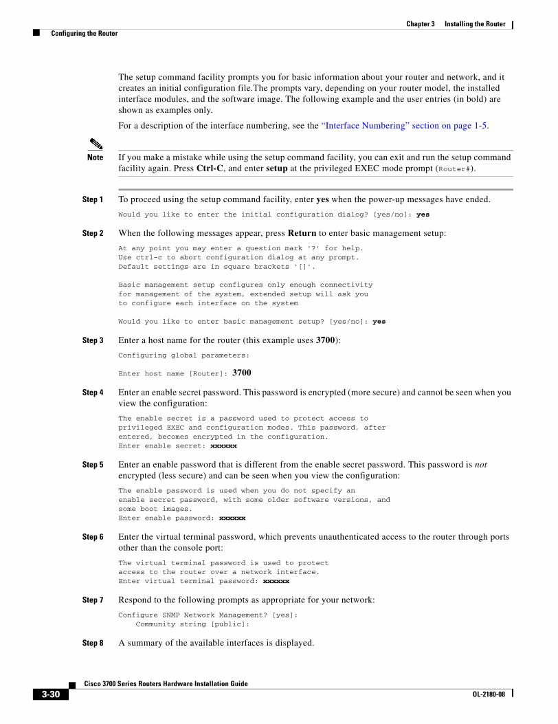
Chapter 3 Installing the Router Configuring the Router
The setup command facility prompts you for basic information about your router and network, and it creates an initial configuration file.The prompts vary, depending on your router model, the installed interface modules, and the software image. The following example and the user entries (in bold) are shown as examples only.
For a description of the interface numbering, see the “Interface Numbering” section on page 1-5.
Note If you make a mistake while using the setup command facility, you can exit and run the setup command facility again. Press Ctrl-C, and enter setup at the privileged EXEC mode prompt (Router#).
Step 1 To proceed using the setup command facility, enter yes when the power-up messages have ended.
Would you like to enter the initial configuration dialog? [yes/no]: yes
Step 2 When the following messages appear, press Return to enter basic management setup:
At any point you may enter a question mark '?' for help.Use ctrl-c to abort configuration dialog at any prompt.Default settings are in square brackets '[]'.
Basic management setup configures only enough connectivityfor management of the system, extended setup will ask youto configure each interface on the system
Would you like to enter basic management setup? [yes/no]: yes
Step 3 Enter a host name for the router (this example uses 3700):
Configuring global parameters:
Enter host name [Router]: 3700
Step 4 Enter an enable secret password. This password is encrypted (more secure) and cannot be seen when you view the configuration:
The enable secret is a password used to protect access toprivileged EXEC and configuration modes. This password, afterentered, becomes encrypted in the configuration.Enter enable secret: xxxxxx
Step 5 Enter an enable password that is different from the enable secret password. This password is not encrypted (less secure) and can be seen when you view the configuration:
The enable password is used when you do not specify anenable secret password, with some older software versions, andsome boot images.Enter enable password: xxxxxx
Step 6 Enter the virtual terminal password, which prevents unauthenticated access to the router through ports other than the console port:
The virtual terminal password is used to protectaccess to the router over a network interface.Enter virtual terminal password: xxxxxx
Step 7 Respond to the following prompts as appropriate for your network:
Configure SNMP Network Management? [yes]: Community string [public]:
Step 8 A summary of the available interfaces is displayed.
3-30Cisco 3700 Series Routers Hardware Installation Guide
OL-2180-08
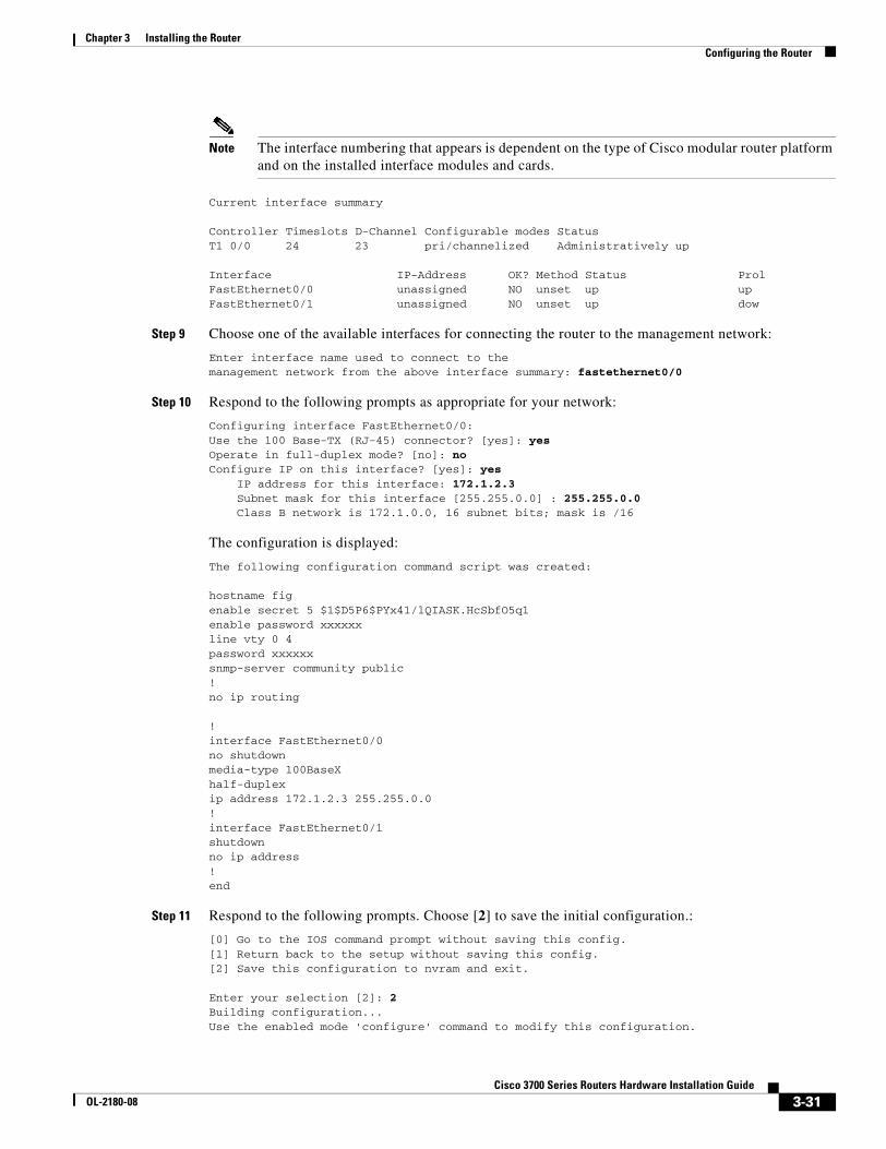
Chapter 3 Installing the Router Configuring the Router
Note The interface numbering that appears is dependent on the type of Cisco modular router platform and on the installed interface modules and cards.
Current interface summary
Controller Timeslots D-Channel Configurable modes StatusT1 0/0 24 23 pri/channelized Administratively up
Interface IP-Address OK? Method Status ProlFastEthernet0/0 unassigned NO unset up up FastEthernet0/1 unassigned NO unset up dow
Step 9 Choose one of the available interfaces for connecting the router to the management network:
Enter interface name used to connect to themanagement network from the above interface summary: fastethernet0/0
Step 10 Respond to the following prompts as appropriate for your network:
Configuring interface FastEthernet0/0:Use the 100 Base-TX (RJ-45) connector? [yes]: yesOperate in full-duplex mode? [no]: noConfigure IP on this interface? [yes]: yes IP address for this interface: 172.1.2.3 Subnet mask for this interface [255.255.0.0] : 255.255.0.0 Class B network is 172.1.0.0, 16 subnet bits; mask is /16
The configuration is displayed:
The following configuration command script was created:
hostname figenable secret 5 $1$D5P6$PYx41/lQIASK.HcSbfO5q1enable password xxxxxxline vty 0 4password xxxxxxsnmp-server community public!no ip routing
!interface FastEthernet0/0no shutdownmedia-type 100BaseXhalf-duplexip address 172.1.2.3 255.255.0.0!interface FastEthernet0/1shutdownno ip address!end
Step 11 Respond to the following prompts. Choose [2] to save the initial configuration.:
[0] Go to the IOS command prompt without saving this config.[1] Return back to the setup without saving this config.[2] Save this configuration to nvram and exit.
Enter your selection [2]: 2Building configuration...Use the enabled mode 'configure' command to modify this configuration.
3-31Cisco 3700 Series Routers Hardware Installation Guide
OL-2180-08
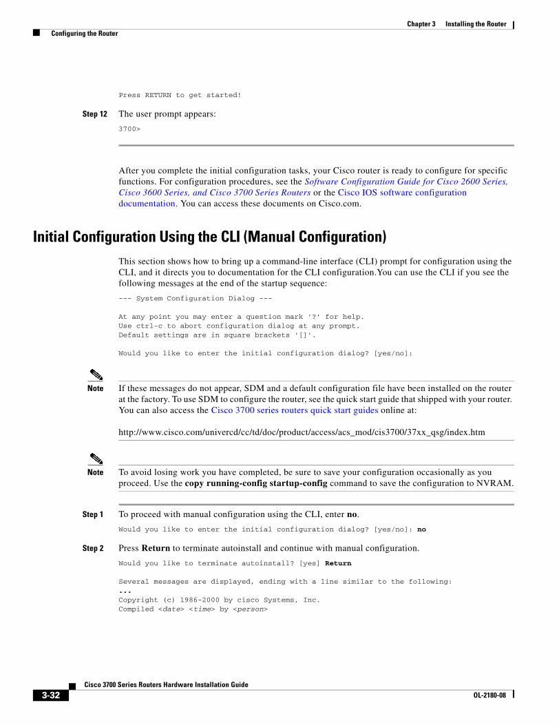
Chapter 3 Installing the Router Configuring the Router
Press RETURN to get started!
Step 12 The user prompt appears:
3700>
After you complete the initial configuration tasks, your Cisco router is ready to configure for specific functions. For configuration procedures, see the Software Configuration Guide for Cisco 2600 Series, Cisco 3600 Series, and Cisco 3700 Series Routers or the Cisco IOS software configuration documentation. You can access these documents on Cisco.com.
Initial Configuration Using the CLI (Manual Configuration)This section shows how to bring up a command-line interface (CLI) prompt for configuration using the CLI, and it directs you to documentation for the CLI configuration.You can use the CLI if you see the following messages at the end of the startup sequence:
--- System Configuration Dialog ---
At any point you may enter a question mark '?' for help.Use ctrl-c to abort configuration dialog at any prompt.Default settings are in square brackets '[]'.
Would you like to enter the initial configuration dialog? [yes/no]:
Note If these messages do not appear, SDM and a default configuration file have been installed on the router at the factory. To use SDM to configure the router, see the quick start guide that shipped with your router. You can also access the Cisco 3700 series routers quick start guides online at:
http://www.cisco.com/univercd/cc/td/doc/product/access/acs_mod/cis3700/37xx_qsg/index.htm
Note To avoid losing work you have completed, be sure to save your configuration occasionally as you proceed. Use the copy running-config startup-config command to save the configuration to NVRAM.
Step 1 To proceed with manual configuration using the CLI, enter no.
Would you like to enter the initial configuration dialog? [yes/no]: no
Step 2 Press Return to terminate autoinstall and continue with manual configuration.
Would you like to terminate autoinstall? [yes] Return
Several messages are displayed, ending with a line similar to the following:...Copyright (c) 1986-2000 by cisco Systems, Inc.Compiled <date> <time> by <person>
3-32Cisco 3700 Series Routers Hardware Installation Guide
OL-2180-08
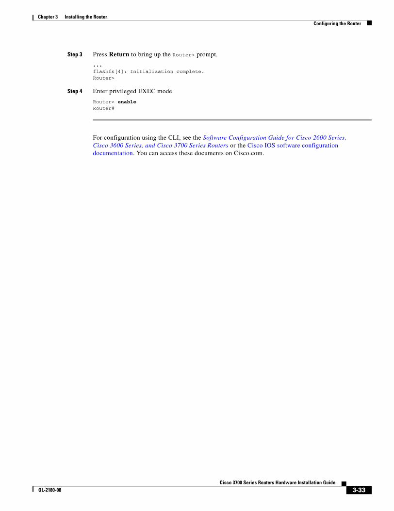
Chapter 3 Installing the Router Configuring the Router
Step 3 Press Return to bring up the Router> prompt.
...flashfs[4]: Initialization complete.Router>
Step 4 Enter privileged EXEC mode.
Router> enable Router#
For configuration using the CLI, see the Software Configuration Guide for Cisco 2600 Series, Cisco 3600 Series, and Cisco 3700 Series Routers or the Cisco IOS software configuration documentation. You can access these documents on Cisco.com.
3-33Cisco 3700 Series Routers Hardware Installation Guide
OL-2180-08

Chapter 3 Installing the Router Configuring the Router
3-34Cisco 3700 Series Routers Hardware Installation Guide
OL-2180-08
Cisco 3700 SeriOL-2180-08
A P P E N D I X A
TroubleshootingYour Cisco 3700 series router goes through extensive testing and burn-in before leaving the factory. If you encounter problems, use the information in this appendix to help isolate problems or to eliminate the router as the source of the problem.
This appendix includes the following sections:
• Solving Problems, page A-2
• Reading Front-Panel LEDs, page A-4
• Reading Rear Panel LEDs, page A-6
• Error Messages, page A-8
• Recovering a Lost Password, page A-12
Note To troubleshoot a network module, see the online Cisco Network Modules Hardware Installation Guide; to troubleshoot interface cards, see the online Cisco Interface Cards Installation Guide.
If you cannot locate the source of the problem, contact a customer service representative for information on how to proceed. For information about obtaining technical support, see the “Obtaining Technical Assistance” section on page xvii. Before you call, have the following information ready:
• Chassis type and serial number
• Maintenance agreement or warranty information
• Type of software and version number
• Date you received the new chassis
• Brief description of the problem
• Brief explanation of the steps you have taken to isolate the problem
A-1es Routers Hardware Installation Guide
Appendix A Troubleshooting Solving Problems
Solving ProblemsThe key to solving problems is to isolate the problem to a specific subsystem by comparing what the router is doing to what it should be doing.
The LEDs on the front and rear panel of the router enable you to determine router performance and operation. LEDs are described in the following sections:
• Reading Front-Panel LEDs, page A-4
• Reading Rear Panel LEDs, page A-6
When solving problems, consider the following router subsystems:
• Power and cooling systems—External power source, power cable, router power supply and circuit breaker, and router blower and fan. Also consider inadequate ventilation or air circulation.
• Modules—LEDs on the modules help identify a failure.
• Cables—External cables that connect the router to the network.
Troubleshooting the Power and Cooling SystemsBoth the system LED and the fans can help you troubleshoot a power problem. Check the following items to help isolate the problem:
• With the power switch on, does the system LED stay on or blink?
– If the LED is green, the router is receiving power and is functional.
– If the LED is amber, the router is receiving power but is not functional.
– If the LED is off, check the power source and power cable.
• With the power switch on and the system LED on, do the fans operate?
– If no, check the fans.
• With the power switch on and the system LED off, do the fans operate?
– If yes, the router is receiving power. The fans are connected directly to the DC outputs of the power supply.
– If no, check the power source and power cable.
• Does the router shut down after being on for a short time?
– Check for an environmentally induced shutdown. See the next section, “Environmental Reporting Features.”
– Check the environmental site requirements in the “General Site Requirements” section on page 2-3.
– Check for a power supply failure by inspecting the system and power supply LEDs on the front panel. If they are green, the power supplies are functional.
A-2Cisco 3700 Series Routers Hardware Installation Guide
OL-2180-08
Appendix A Troubleshooting Solving Problems
• Router partially boots, but LEDs do not go on.
– Check for a power supply failure by inspecting the system LED on the front panel of the router. If the system LED is on, the power supply is functional.
– If the system LED is not on, see the “Obtaining Technical Assistance” section on page xvii for information about customer service.
– Check for a power supply failure by inspecting the power supply LEDs on the front panel. See the “Reading Front-Panel LEDs” section on page A-4 for power supply LED descriptions.
Environmental Reporting FeaturesIf the router is operating at an abnormally high temperature, the following message is displayed on the console screen:
%SYS-1-OVERTEMP: System detected OVERTEMPERATURE condition. Please resolve cooling
problem immediately!
Some causes of abnormally high router temperature are as follows:
• Fan failure
• Air conditioner failure in the room
• Air blockage to cooling vents
Take steps to correct the problem. See also the “Site Environment” section on page 2-4 and the “Equipment Racks” section on page 2-4.
Troubleshooting Modules, Cables, and ConnectionsNetwork problems can be caused by a module; cables or cable connections; or external devices such as a modem, transceiver, hub, wall jack, WAN interface, or terminal. Check for the following symptoms to help isolate the problem:
• Module is not recognized by the router.
– Make sure that the module is firmly seated in its slot.
– Check the LEDs on the module. Each module has its own set of LEDs. For information on these LEDs, see the online Cisco Network Modules Hardware Installation Guide.
– Make sure you have a version of Cisco IOS software that supports the module. Check the online Software Configuration Guide for Cisco 2600, Cisco 3600, and Cisco 3700 Series Routers or accompanying configuration note for software requirements for the network module.
• Module is recognized, but interface ports do not initialize.
– Make sure that the module is firmly seated in its slot.
– Check external cable connections.
– Make sure that you have a version of Cisco IOS software that supports the network module and interface card. Check the Cisco Network Modules Hardware Installation Guide and the Cisco Interface Cards Hardware Installation Guide or accompanying configuration notes for the affected network module and interface card software requirements.
A-3Cisco 3700 Series Routers Hardware Installation Guide
OL-2180-08
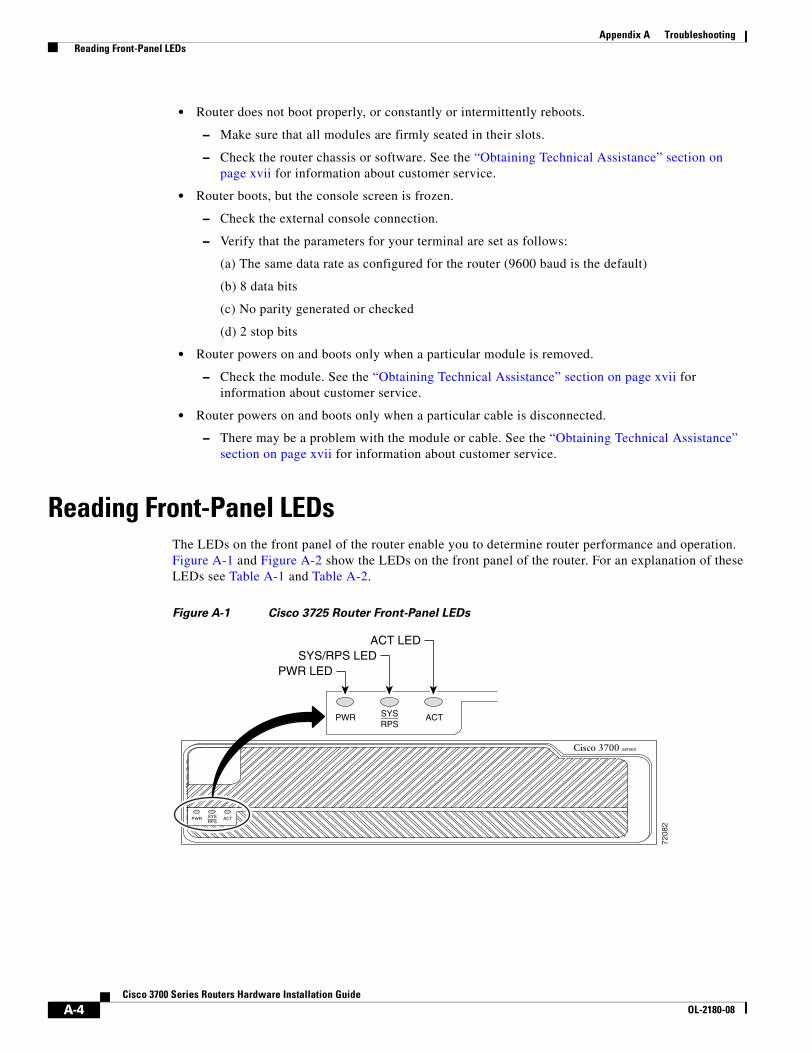
Appendix A Troubleshooting Reading Front-Panel LEDs
• Router does not boot properly, or constantly or intermittently reboots.
– Make sure that all modules are firmly seated in their slots.
– Check the router chassis or software. See the “Obtaining Technical Assistance” section on page xvii for information about customer service.
• Router boots, but the console screen is frozen.
– Check the external console connection.
– Verify that the parameters for your terminal are set as follows:
(a) The same data rate as configured for the router (9600 baud is the default)
(b) 8 data bits
(c) No parity generated or checked
(d) 2 stop bits
• Router powers on and boots only when a particular module is removed.
– Check the module. See the “Obtaining Technical Assistance” section on page xvii for information about customer service.
• Router powers on and boots only when a particular cable is disconnected.
– There may be a problem with the module or cable. See the “Obtaining Technical Assistance” section on page xvii for information about customer service.
Reading Front-Panel LEDsThe LEDs on the front panel of the router enable you to determine router performance and operation. Figure A-1 and Figure A-2 show the LEDs on the front panel of the router. For an explanation of these LEDs see Table A-1 and Table A-2.
Figure A-1 Cisco 3725 Router Front-Panel LEDs
7208
2
Cisco 3700 SERIES
PWR LEDSYS/RPS LED
ACT LED
PWR SYSRPS
ACT
PWR SYSRPS
ACT
A-4Cisco 3700 Series Routers Hardware Installation Guide
OL-2180-08
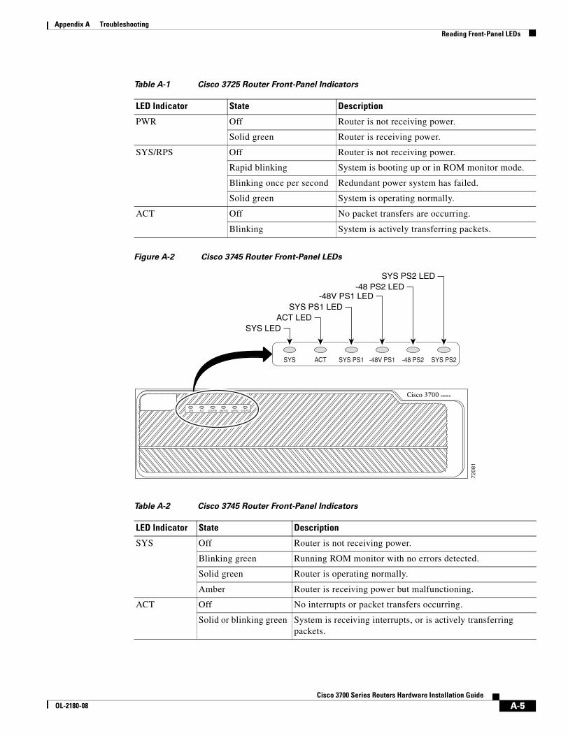
Appendix A Troubleshooting Reading Front-Panel LEDs
Figure A-2 Cisco 3745 Router Front-Panel LEDs
Table A-1 Cisco 3725 Router Front-Panel Indicators
LED Indicator State Description
PWR Off Router is not receiving power.
Solid green Router is receiving power.
SYS/RPS Off Router is not receiving power.
Rapid blinking System is booting up or in ROM monitor mode.
Blinking once per second Redundant power system has failed.
Solid green System is operating normally.
ACT Off No packet transfers are occurring.
Blinking System is actively transferring packets.
Table A-2 Cisco 3745 Router Front-Panel Indicators
LED Indicator State Description
SYS Off Router is not receiving power.
Blinking green Running ROM monitor with no errors detected.
Solid green Router is operating normally.
Amber Router is receiving power but malfunctioning.
ACT Off No interrupts or packet transfers occurring.
Solid or blinking green System is receiving interrupts, or is actively transferring packets.
7208
1
Cisco 3700 SERIES
SYS LEDACT LED
SYS PS1 LED-48V PS1 LED
-48 PS2 LEDSYS PS2 LED
A-5Cisco 3700 Series Routers Hardware Installation Guide
OL-2180-08
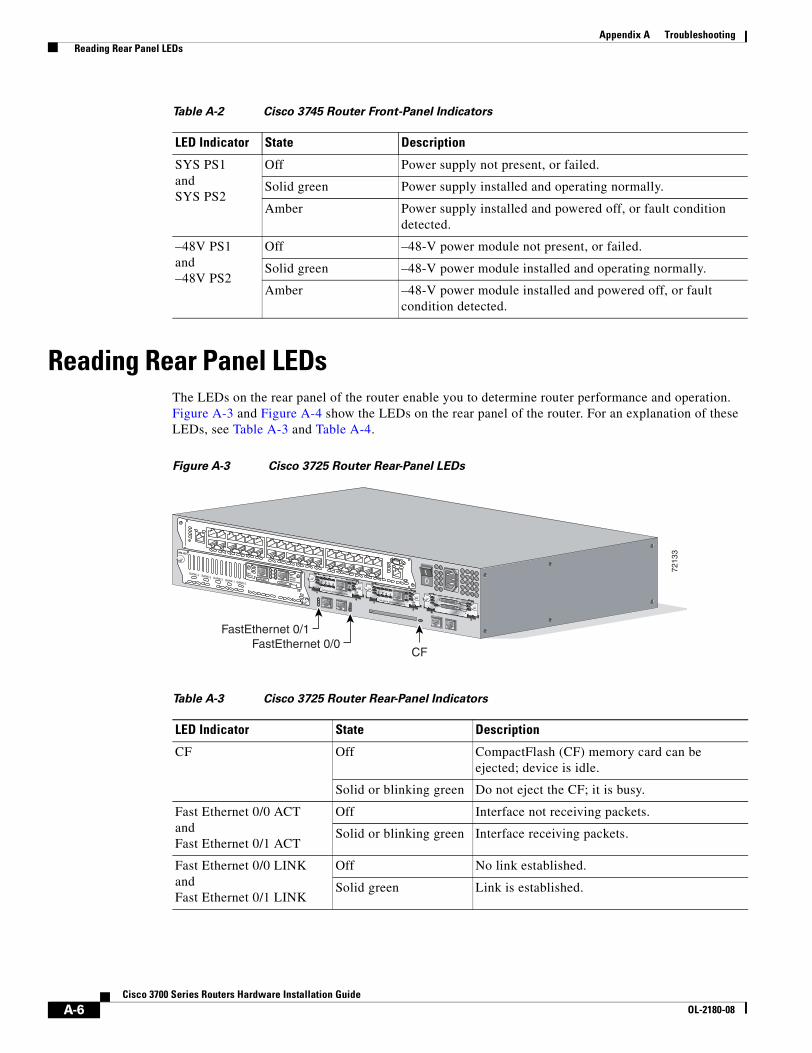
Appendix A Troubleshooting Reading Rear Panel LEDs
Reading Rear Panel LEDsThe LEDs on the rear panel of the router enable you to determine router performance and operation. Figure A-3 and Figure A-4 show the LEDs on the rear panel of the router. For an explanation of these LEDs, see Table A-3 and Table A-4.
Figure A-3 Cisco 3725 Router Rear-Panel LEDs
SYS PS1andSYS PS2
Off Power supply not present, or failed.
Solid green Power supply installed and operating normally.
Amber Power supply installed and powered off, or fault condition detected.
–48V PS1and –48V PS2
Off –48-V power module not present, or failed.
Solid green –48-V power module installed and operating normally.
Amber –48-V power module installed and powered off, or fault condition detected.
Table A-2 Cisco 3745 Router Front-Panel Indicators
LED Indicator State Description
Table A-3 Cisco 3725 Router Rear-Panel Indicators
LED Indicator State Description
CF Off CompactFlash (CF) memory card can be ejected; device is idle.
Solid or blinking green Do not eject the CF; it is busy.
Fast Ethernet 0/0 ACTandFast Ethernet 0/1 ACT
Off Interface not receiving packets.
Solid or blinking green Interface receiving packets.
Fast Ethernet 0/0 LINKandFast Ethernet 0/1 LINK
Off No link established.
Solid green Link is established.
7213
3
SEE MANUAL BEFORE INSTALLATION
AL
CD
LPRDTD
SEE MANUAL BEFORE INSTALLATIONDSU56K
AL
CD
LPRDTD
SEE MANUAL BEFORE INSTALLATIONDSU56K
ENV0
BANK 4 BANK 3 BANK 2 BANK 1 BANK 0
NM-HDV
VWIC2MFT-E1 SEE
MANUALBEFOREINSTALLATION
CTRLR E2CTRLR E1
AL
LP
CD
CF
FastEthernet 0/1FastEthernet 0/0
A-6Cisco 3700 Series Routers Hardware Installation Guide
OL-2180-08
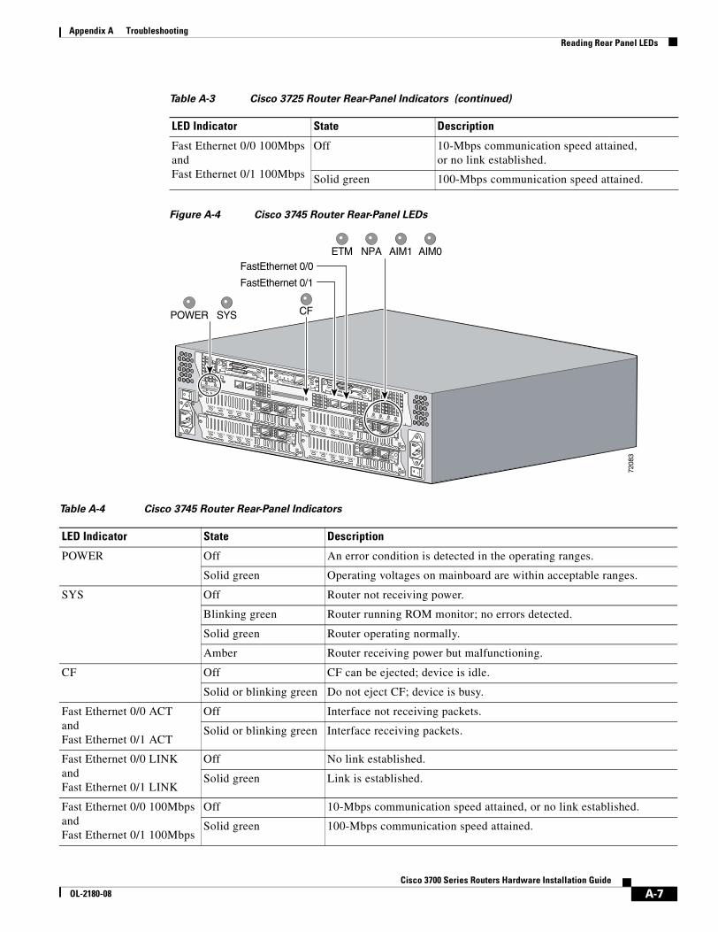
Appendix A Troubleshooting Reading Rear Panel LEDs
Figure A-4 Cisco 3745 Router Rear-Panel LEDs
Fast Ethernet 0/0 100MbpsandFast Ethernet 0/1 100Mbps
Off 10-Mbps communication speed attained, or no link established.
Solid green 100-Mbps communication speed attained.
Table A-3 Cisco 3725 Router Rear-Panel Indicators (continued)
LED Indicator State Description
Table A-4 Cisco 3745 Router Rear-Panel Indicators
LED Indicator State Description
POWER Off An error condition is detected in the operating ranges.
Solid green Operating voltages on mainboard are within acceptable ranges.
SYS Off Router not receiving power.
Blinking green Router running ROM monitor; no errors detected.
Solid green Router operating normally.
Amber Router receiving power but malfunctioning.
CF Off CF can be ejected; device is idle.
Solid or blinking green Do not eject CF; device is busy.
Fast Ethernet 0/0 ACTandFast Ethernet 0/1 ACT
Off Interface not receiving packets.
Solid or blinking green Interface receiving packets.
Fast Ethernet 0/0 LINKandFast Ethernet 0/1 LINK
Off No link established.
Solid green Link is established.
Fast Ethernet 0/0 100MbpsandFast Ethernet 0/1 100Mbps
Off 10-Mbps communication speed attained, or no link established.
Solid green 100-Mbps communication speed attained.
7208
3
EN
V0
BANK 4 BANK 3 BANK 2 BANK 1 BANK 0
NM-HDV
VWIC2MFT-E1 SEE
MANUALBEFOREINSTALLATION
CTRLR E2
CTRLR E1
AL
LP
CD
EN
V0
BANK 4 BANK 3 BANK 2 BANK 1 BANK 0
NM-HDV
VWIC2MFT-E1 SEE
MANUALBEFOREINSTALLATION
CTRLR E2
CTRLR E1
AL
LP
CD
EN
V0
BANK 4 BANK 3 BANK 2 BANK 1 BANK 0
NM-HDV
VWIC2MFT-E1 SEE
MANUALBEFOREINSTALLATION
CTRLR E2
CTRLR E1
AL
LP
CD
EN
V0
BANK 4 BANK 3 BANK 2 BANK 1 BANK 0
NM-HDV
VWIC2MFT-E1 SEE
MANUALBEFOREINSTALLATION
CTRLR E2
CTRLR E1
AL
LP
CD
SEE MANUAL BEFORE INSTALLATION
SERIAL 1
SERIAL 0
CONN
CONNWIC
2T
SEE MANUAL BEFORE INSTALLATION
SERIAL 1
SERIAL 0
CONN
CONNWIC
2T
SEE MANUAL BEFORE INSTALLATIONDSU56K
CD
ALLPRDTD
ETM NPA AIM1 AIM0
POWER SYSTEM
POWER SYS CF
FastEthernet 0/0
FastEthernet 0/1
ETM NPA AIM1 AIM0
A-7Cisco 3700 Series Routers Hardware Installation Guide
OL-2180-08
Appendix A Troubleshooting Error Messages
Error MessagesCisco IOS software displays system error and recovery messages on an external device console terminal screen. (For more information, see the “Connecting to a Console Terminal or Modem” section on page 3-22.)
The terminal should display one of the following prompts:
Router> (indicates the user EXEC command mode)
or
Router# (indicates the privileged EXEC command mode)
The Cisco IOS software checks the system condition once every 30 seconds. If the condition still exists, the error message appears again; if the error condition has cleared, a recovery message appears.
Table A-5 describes system error and recovery messages and LED conditions that might accompany them.
Note Table A-5 does not provide a complete list of system LED conditions. (For all LED conditions that can occur in your router, see the “Reading Front-Panel LEDs” section on page A-4 and the “Reading Rear Panel LEDs” section on page A-6.)
ETM Off Enhanced timing module (ETM) not present.
Amber ETM present with failure.
Solid green ETM present and enabled.
NPA Not used Reserved for future development.
AIM0andAIM1
Off Advanced integration module (AIM) not present.
Amber AIM present with failure.
Solid green AIM present and enabled.
Table A-4 Cisco 3745 Router Rear-Panel Indicators (continued)
LED Indicator State Description
A-8Cisco 3700 Series Routers Hardware Installation Guide
OL-2180-08
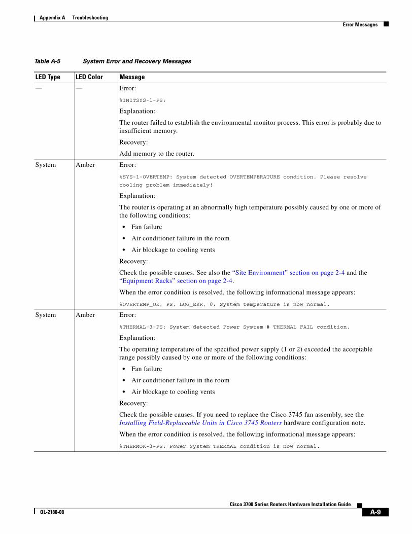
Appendix A Troubleshooting Error Messages
Table A-5 System Error and Recovery Messages
LED Type LED Color Message
— — Error:
%INITSYS-1-PS:
Explanation:
The router failed to establish the environmental monitor process. This error is probably due to insufficient memory.
Recovery:
Add memory to the router.
System Amber Error:
%SYS-1-OVERTEMP: System detected OVERTEMPERATURE condition. Please resolve
cooling problem immediately!
Explanation:
The router is operating at an abnormally high temperature possibly caused by one or more of the following conditions:
• Fan failure
• Air conditioner failure in the room
• Air blockage to cooling vents
Recovery:
Check the possible causes. See also the “Site Environment” section on page 2-4 and the “Equipment Racks” section on page 2-4.
When the error condition is resolved, the following informational message appears:
%OVERTEMP_OK, PS, LOG_ERR, 0: System temperature is now normal.
System Amber Error:
%THERMAL-3-PS: System detected Power System # THERMAL FAIL condition.
Explanation:
The operating temperature of the specified power supply (1 or 2) exceeded the acceptable range possibly caused by one or more of the following conditions:
• Fan failure
• Air conditioner failure in the room
• Air blockage to cooling vents
Recovery:
Check the possible causes. If you need to replace the Cisco 3745 fan assembly, see the Installing Field-Replaceable Units in Cisco 3745 Routers hardware configuration note.
When the error condition is resolved, the following informational message appears:
%THERMOK-3-PS: Power System THERMAL condition is now normal.
A-9Cisco 3700 Series Routers Hardware Installation Guide
OL-2180-08
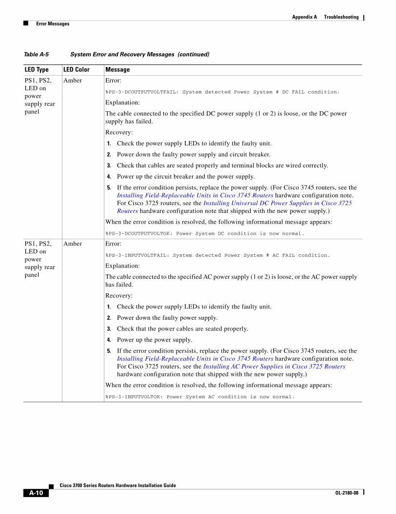
Appendix A Troubleshooting Error Messages
PS1, PS2, LED on power supply rear panel
Amber Error:
%PS-3-DCOUTPUTVOLTFAIL: System detected Power System # DC FAIL condition.
Explanation:
The cable connected to the specified DC power supply (1 or 2) is loose, or the DC power supply has failed.
Recovery:
1. Check the power supply LEDs to identify the faulty unit.
2. Power down the faulty power supply and circuit breaker.
3. Check that cables are seated properly and terminal blocks are wired correctly.
4. Power up the circuit breaker and the power supply.
5. If the error condition persists, replace the power supply. (For Cisco 3745 routers, see the Installing Field-Replaceable Units in Cisco 3745 Routers hardware configuration note. For Cisco 3725 routers, see the Installing Universal DC Power Supplies in Cisco 3725 Routers hardware configuration note that shipped with the new power supply.)
When the error condition is resolved, the following informational message appears:
%PS-3-DCOUTPUTVOLTOK: Power System DC condition is now normal.
PS1, PS2, LED on power supply rear panel
Amber Error:
%PS-3-INPUTVOLTFAIL: System detected Power System # AC FAIL condition.
Explanation:
The cable connected to the specified AC power supply (1 or 2) is loose, or the AC power supply has failed.
Recovery:
1. Check the power supply LEDs to identify the faulty unit.
2. Power down the faulty power supply.
3. Check that the power cables are seated properly.
4. Power up the power supply.
5. If the error condition persists, replace the power supply. (For Cisco 3745 routers, see the Installing Field-Replaceable Units in Cisco 3745 Routers hardware configuration note. For Cisco 3725 routers, see the Installing AC Power Supplies in Cisco 3725 Routers hardware configuration note that shipped with the new power supply.)
When the error condition is resolved, the following informational message appears:
%PS-3-INPUTVOLTOK: Power System AC condition is now normal.
Table A-5 System Error and Recovery Messages (continued)
LED Type LED Color Message
A-10Cisco 3700 Series Routers Hardware Installation Guide
OL-2180-08
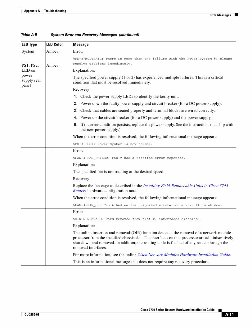
Appendix A Troubleshooting Error Messages
System
PS1, PS2, LED on power supply rear panel
Amber
Amber
Error:
%PS-3-MULTFAIL: There is more than one failure with the Power System #; please
resolve problems immediately.
Explanation:
The specified power supply (1 or 2) has experienced multiple failures. This is a critical condition that must be resolved immediately.
Recovery:
1. Check the power supply LEDs to identify the faulty unit.
2. Power down the faulty power supply and circuit breaker (for a DC power supply).
3. Check that cables are seated properly and terminal blocks are wired correctly.
4. Power up the circuit breaker (for a DC power supply) and the power supply.
5. If the error condition persists, replace the power supply. See the instructions that ship with the new power supply.)
When the error condition is resolved, the following informational message appears:
%PS-3-PSOK: Power System is now normal.
— — Error:
%FAN-3-FAN_FAILED: Fan # had a rotation error reported.
Explanation:
The specified fan is not rotating at the desired speed.
Recovery:
Replace the fan cage as described in the Installing Field-Replaceable Units in Cisco 3745 Routers hardware configuration note.
When the error condition is resolved, the following informational message appears:
%FAN-3-FAN_OK: Fan # had earlier reported a rotation error. It is ok now.
— — Error:
%OIR-6-REMCARD: Card removed from slot x, interfaces disabled.
Explanation:
The online insertion and removal (OIR) function detected the removal of a network module processor from the specified chassis slot. The interfaces on that processor are administratively shut down and removed. In addition, the routing table is flushed of any routes through the removed interfaces.
For more information, see the online Cisco Network Modules Hardware Installation Guide.
This is an informational message that does not require any recovery procedure.
Table A-5 System Error and Recovery Messages (continued)
LED Type LED Color Message
A-11Cisco 3700 Series Routers Hardware Installation Guide
OL-2180-08
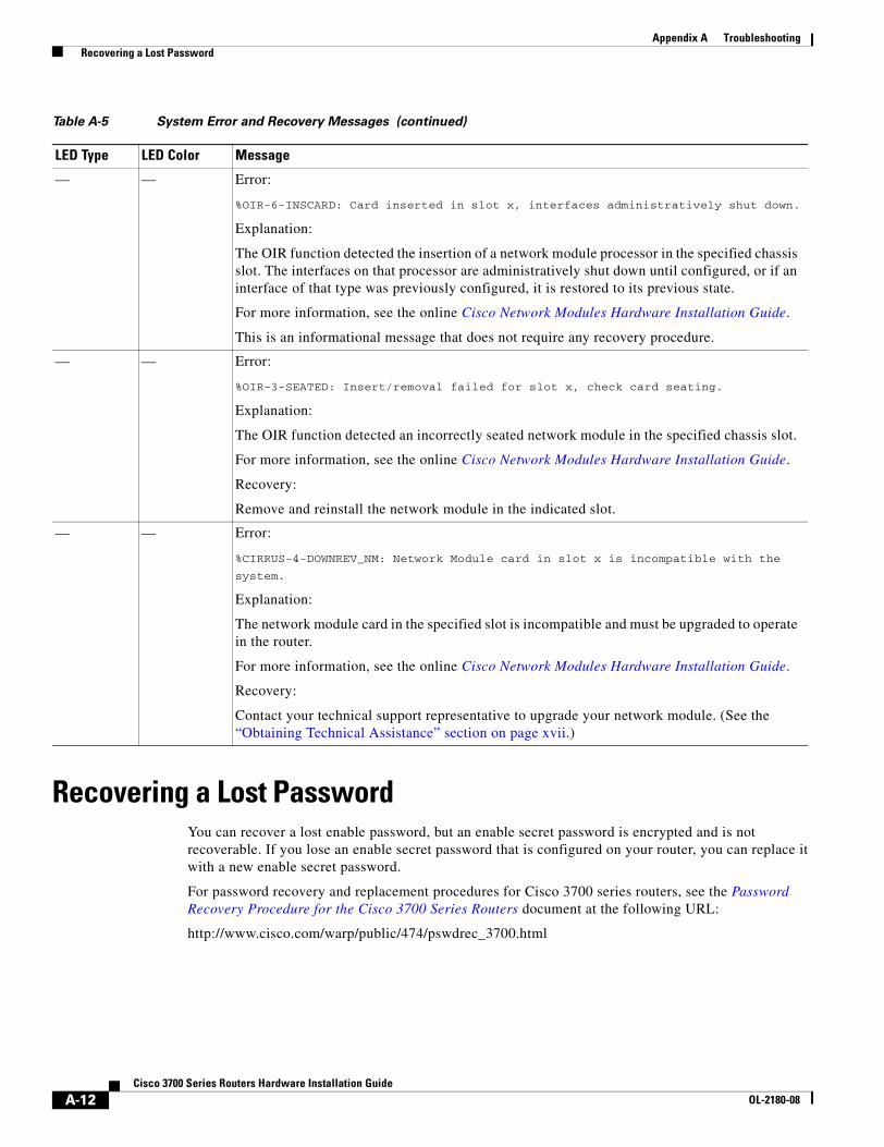
Appendix A Troubleshooting Recovering a Lost Password
Recovering a Lost PasswordYou can recover a lost enable password, but an enable secret password is encrypted and is not recoverable. If you lose an enable secret password that is configured on your router, you can replace it with a new enable secret password.
For password recovery and replacement procedures for Cisco 3700 series routers, see the Password Recovery Procedure for the Cisco 3700 Series Routers document at the following URL:
http://www.cisco.com/warp/public/474/pswdrec_3700.html
— — Error:
%OIR-6-INSCARD: Card inserted in slot x, interfaces administratively shut down.
Explanation:
The OIR function detected the insertion of a network module processor in the specified chassis slot. The interfaces on that processor are administratively shut down until configured, or if an interface of that type was previously configured, it is restored to its previous state.
For more information, see the online Cisco Network Modules Hardware Installation Guide.
This is an informational message that does not require any recovery procedure.
— — Error:
%OIR-3-SEATED: Insert/removal failed for slot x, check card seating.
Explanation:
The OIR function detected an incorrectly seated network module in the specified chassis slot.
For more information, see the online Cisco Network Modules Hardware Installation Guide.
Recovery:
Remove and reinstall the network module in the indicated slot.
— — Error:
%CIRRUS-4-DOWNREV_NM: Network Module card in slot x is incompatible with the
system.
Explanation:
The network module card in the specified slot is incompatible and must be upgraded to operate in the router.
For more information, see the online Cisco Network Modules Hardware Installation Guide.
Recovery:
Contact your technical support representative to upgrade your network module. (See the “Obtaining Technical Assistance” section on page xvii.)
Table A-5 System Error and Recovery Messages (continued)
LED Type LED Color Message
A-12Cisco 3700 Series Routers Hardware Installation Guide
OL-2180-08
Cisco 3700 SeriOL-2180-08
A P P E N D I X B
Using the ROM MonitorThis appendix describes the ROM monitor (also called the bootstrap program), the firmware that runs when your Cisco 3700 series router is powered up or reset. During normal operation, the ROM monitor helps to initialize the processor hardware and boot the operating system software. You can also use the ROM monitor to isolate or eliminate hardware problems and recover a corrupted Cisco IOS software image.
This appendix includes the following sections:
• Entering ROM Monitor Mode, page B-1
• ROM Monitor Commands, page B-2
• ROM Monitor Syntax Conventions, page B-3
• ROM Monitor Command Descriptions, page B-3
• Recovering Cisco IOS Software Images, page B-8
Entering ROM Monitor ModeTo use the ROM monitor, you must have access to the console port. See the “Connecting to a Console Terminal or Modem” section on page 3-22 for information on connecting the console cable.
There are two ways of entering the ROM monitor mode:
• Use the reload command and the Break key to enter the ROM monitor mode for one-time use.
Break (system interrupt) is always enabled for 60 seconds after the router reboots, regardless of whether Break is configured on or off in the configuration register (see Appendix C, “Configuration Register”). During this 60-second period, you can break to the ROM monitor prompt by pressing the Break key.
Note If your console terminal does not have a Break key, see the terminal emulator documentation for instructions on generating a break (system interrupt).
• Set the configuration register so that the router enters the ROM monitor mode whenever it boots.
The new configuration register value, 0x0, is effective after the router is rebooted with the reload command. The router remains in the ROM monitor and does not boot the operating system.
As long as the configuration register value remains 0x0, you must manually boot the operating system from the console. See the boot command in the “ROM Monitor Command Descriptions” section on page B-3.
B-1es Routers Hardware Installation Guide
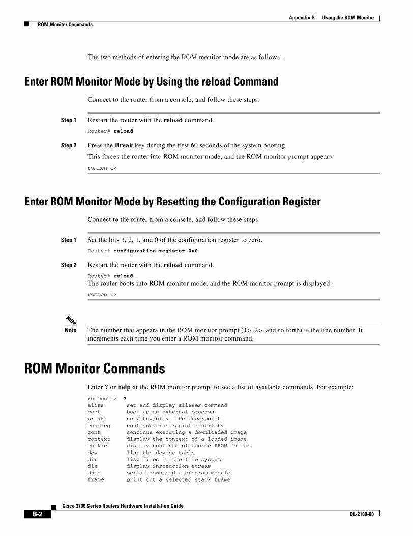
Appendix B Using the ROM Monitor ROM Monitor Commands
The two methods of entering the ROM monitor mode are as follows.
Enter ROM Monitor Mode by Using the reload CommandConnect to the router from a console, and follow these steps:
Step 1 Restart the router with the reload command.
Router# reload
Step 2 Press the Break key during the first 60 seconds of the system booting.
This forces the router into ROM monitor mode, and the ROM monitor prompt appears:
rommon 1>
Enter ROM Monitor Mode by Resetting the Configuration RegisterConnect to the router from a console, and follow these steps:
Step 1 Set the bits 3, 2, 1, and 0 of the configuration register to zero.
Router# configuration-register 0x0
Step 2 Restart the router with the reload command.
Router# reload
The router boots into ROM monitor mode, and the ROM monitor prompt is displayed:
rommon 1>
Note The number that appears in the ROM monitor prompt (1>, 2>, and so forth) is the line number. It increments each time you enter a ROM monitor command.
ROM Monitor CommandsEnter ? or help at the ROM monitor prompt to see a list of available commands. For example:
rommon 1> ?alias set and display aliases commandboot boot up an external processbreak set/show/clear the breakpointconfreg configuration register utilitycont continue executing a downloaded imagecontext display the context of a loaded imagecookie display contents of cookie PROM in hexdev list the device tabledir list files in the file systemdis display instruction streamdnld serial download a program moduleframe print out a selected stack frame
B-2Cisco 3700 Series Routers Hardware Installation Guide
OL-2180-08
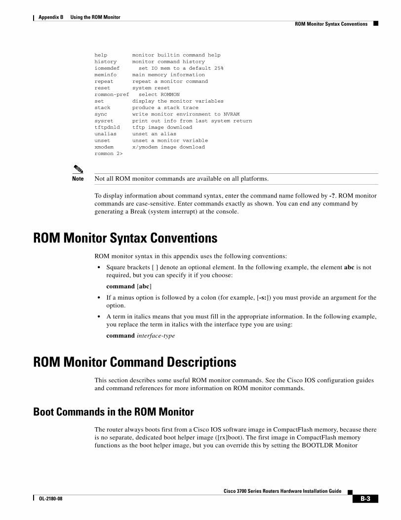
Appendix B Using the ROM Monitor ROM Monitor Syntax Conventions
help monitor builtin command helphistory monitor command historyiomemdef set IO mem to a default 25%meminfo main memory informationrepeat repeat a monitor commandreset system resetrommon-pref select ROMMONset display the monitor variablesstack produce a stack tracesync write monitor environment to NVRAMsysret print out info from last system returntftpdnld tftp image downloadunalias unset an aliasunset unset a monitor variablexmodem x/ymodem image downloadrommon 2>
Note Not all ROM monitor commands are available on all platforms.
To display information about command syntax, enter the command name followed by -?. ROM monitor commands are case-sensitive. Enter commands exactly as shown. You can end any command by generating a Break (system interrupt) at the console.
ROM Monitor Syntax ConventionsROM monitor syntax in this appendix uses the following conventions:
• Square brackets [ ] denote an optional element. In the following example, the element abc is not required, but you can specify it if you choose:
command [abc]
• If a minus option is followed by a colon (for example, [-s:]) you must provide an argument for the option.
• A term in italics means that you must fill in the appropriate information. In the following example, you replace the term in italics with the interface type you are using:
command interface-type
ROM Monitor Command DescriptionsThis section describes some useful ROM monitor commands. See the Cisco IOS configuration guides and command references for more information on ROM monitor commands.
Boot Commands in the ROM MonitorThe router always boots first from a Cisco IOS software image in CompactFlash memory, because there is no separate, dedicated boot helper image ([rx]boot). The first image in CompactFlash memory functions as the boot helper image, but you can override this by setting the BOOTLDR Monitor
B-3Cisco 3700 Series Routers Hardware Installation Guide
OL-2180-08
Appendix B Using the ROM Monitor ROM Monitor Command Descriptions
environment variable to point to another image. The first image in CompactFlash memory is invoked if the ROM monitor does not recognize a device ID specified in the boot command. The router cannot boot if there is no Cisco IOS software image in CompactFlash memory.
To boot a router from a Cisco IOS software image on a TFTP server (netboot), the installed DRAM must be adequate to hold two uncompressed Cisco IOS software images: the image from CompactFlash memory and the image downloaded from the TFTP server.
If the router is configured to boot from a TFTP server (boot bits in the configuration register are set from 2 to 15), the router first boots from the image in CompactFlash memory. It decompresses that image in DRAM, parses the boot system commands, downloads the Cisco IOS software image from the TFTP server, and decompresses it in DRAM. After the Cisco IOS software image from the TFTP server is in DRAM, the DRAM memory occupied by the boot helper image is released.
Note Booting from a TFTP server is useful if the router does not have enough CompactFlash memory to hold large images. With a small image in CompactFlash memory (just large enough to support the necessary interfaces), the router boots from CompactFlash, and then the larger image is downloaded from the TFTP server.
The boot command syntax is as follows, where:
• partition is a partition number in CompactFlash memory
• filename is the Cisco IOS software image file name
• tftpserver is the IP address of the TFTP server
• -x directs the router to load the image but not execute the boot process
• -v (Verbose) specifies that progress print setting messages and error information be displayed
boot [flash: [partition: [filename]] | slot0: [partition: [filename]] | slot1: [partition: [filename]] | filename tftpserver] [-x] [-v]
Some examples of boot commands are as follows:
Note In all boot commands, boot can be entered as b.
• boot—Boots from the first Cisco IOS software image in internal CompactFlash memory.
• boot flash:—Boots from the first Cisco IOS software image in internal CompactFlash memory.
• boot flash: partition:—Boots from the first Cisco IOS software image in the specified partition in internal CompactFlash memory.
• boot flash: filename—Boots from the specified IOS software image in internal CompactFlash memory.
• boot flash: partition: filename—Boots from the specified Cisco IOS software image in the specified partition in internal CompactFlash memory.
• boot slot0:—Boots from the first Cisco IOS software image in the first partition in the CompactFlash memory card in slot 0.
• boot slot0:2:—Boots from the first Cisco IOS software image in the second partition in the CompactFlash memory card in slot 0.
• boot slot0: filename— Boots from the specified Cisco IOS software image in the CompactFlash memory card in slot 0.
B-4Cisco 3700 Series Routers Hardware Installation Guide
OL-2180-08
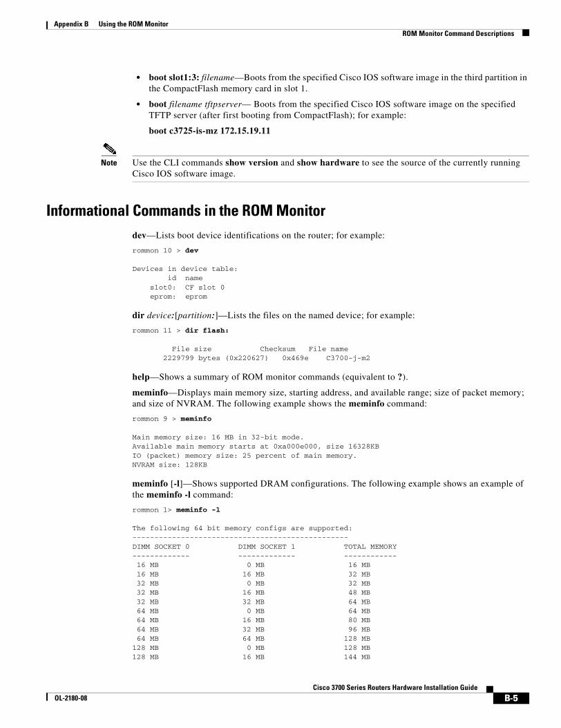
Appendix B Using the ROM Monitor ROM Monitor Command Descriptions
• boot slot1:3: filename—Boots from the specified Cisco IOS software image in the third partition in the CompactFlash memory card in slot 1.
• boot filename tftpserver— Boots from the specified Cisco IOS software image on the specified TFTP server (after first booting from CompactFlash); for example:
boot c3725-is-mz 172.15.19.11
Note Use the CLI commands show version and show hardware to see the source of the currently running Cisco IOS software image.
Informational Commands in the ROM Monitordev—Lists boot device identifications on the router; for example:
rommon 10 > dev
Devices in device table:id name
slot0: CF slot 0eprom: eprom
dir device:[partition:]—Lists the files on the named device; for example:
rommon 11 > dir flash:
File size Checksum File name 2229799 bytes (0x220627) 0x469e C3700-j-m2
help—Shows a summary of ROM monitor commands (equivalent to ?).
meminfo—Displays main memory size, starting address, and available range; size of packet memory; and size of NVRAM. The following example shows the meminfo command:
rommon 9 > meminfo
Main memory size: 16 MB in 32-bit mode.Available main memory starts at 0xa000e000, size 16328KBIO (packet) memory size: 25 percent of main memory.NVRAM size: 128KB
meminfo [-l]—Shows supported DRAM configurations. The following example shows an example of the meminfo -l command:
rommon 1> meminfo -l
The following 64 bit memory configs are supported:------------------------------------------------- DIMM SOCKET 0 DIMM SOCKET 1 TOTAL MEMORY------------- ------------- ------------ 16 MB 0 MB 16 MB 16 MB 16 MB 32 MB 32 MB 0 MB 32 MB 32 MB 16 MB 48 MB 32 MB 32 MB 64 MB 64 MB 0 MB 64 MB 64 MB 16 MB 80 MB 64 MB 32 MB 96 MB 64 MB 64 MB 128 MB128 MB 0 MB 128 MB128 MB 16 MB 144 MB
B-5Cisco 3700 Series Routers Hardware Installation Guide
OL-2180-08
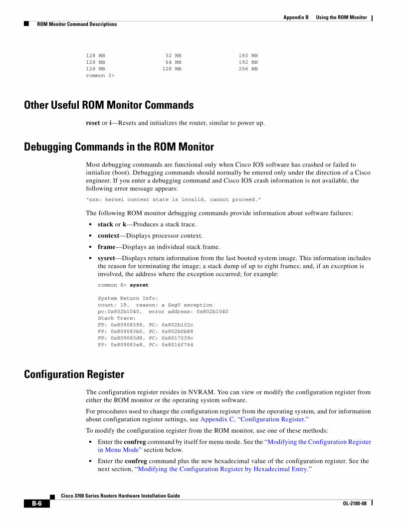
Appendix B Using the ROM Monitor ROM Monitor Command Descriptions
128 MB 32 MB 160 MB128 MB 64 MB 192 MB128 MB 128 MB 256 MBrommon 2>
Other Useful ROM Monitor Commandsreset or i—Resets and initializes the router, similar to power up.
Debugging Commands in the ROM MonitorMost debugging commands are functional only when Cisco IOS software has crashed or failed to initialize (boot). Debugging commands should normally be entered only under the direction of a Cisco engineer. If you enter a debugging command and Cisco IOS crash information is not available, the following error message appears:
“xxx: kernel context state is invalid, cannot proceed.”
The following ROM monitor debugging commands provide information about software failures:
• stack or k—Produces a stack trace.
• context—Displays processor context.
• frame—Displays an individual stack frame.
• sysret—Displays return information from the last booted system image. This information includes the reason for terminating the image; a stack dump of up to eight frames; and, if an exception is involved, the address where the exception occurred; for example:
rommon 8> sysret
System Return Info:count: 19, reason: a SegV exceptionpc:0x802b1040, error address: 0x802b1040Stack Trace:FP: 0x80908398, PC: 0x802b102cFP: 0x809083b0, PC: 0x802b0b88FP: 0x809083d8, PC: 0x8017039cFP: 0x809083e8, PC: 0x8016f764
Configuration RegisterThe configuration register resides in NVRAM. You can view or modify the configuration register from either the ROM monitor or the operating system software.
For procedures used to change the configuration register from the operating system, and for information about configuration register settings, see Appendix C, “Configuration Register.”
To modify the configuration register from the ROM monitor, use one of these methods:
• Enter the confreg command by itself for menu mode. See the “Modifying the Configuration Register in Menu Mode” section below.
• Enter the confreg command plus the new hexadecimal value of the configuration register. See the next section, “Modifying the Configuration Register by Hexadecimal Entry.”
B-6Cisco 3700 Series Routers Hardware Installation Guide
OL-2180-08
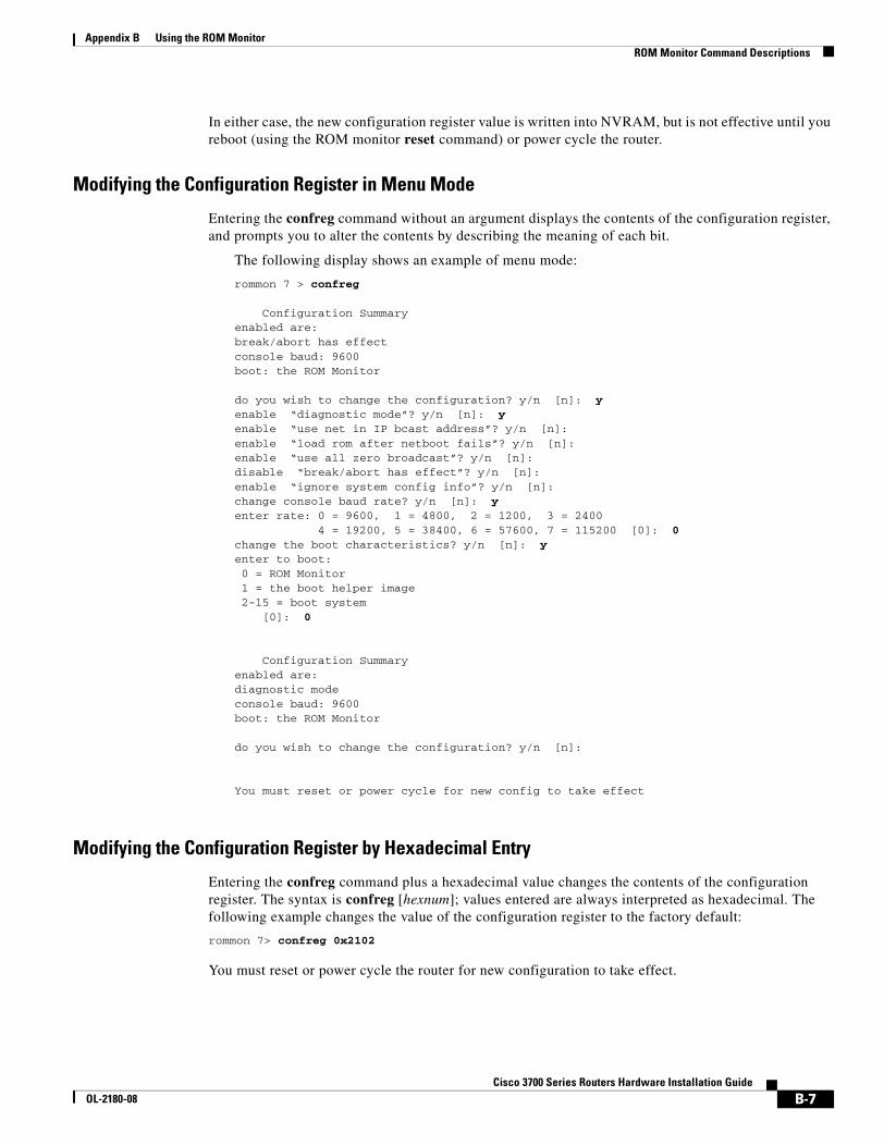
Appendix B Using the ROM Monitor ROM Monitor Command Descriptions
In either case, the new configuration register value is written into NVRAM, but is not effective until you reboot (using the ROM monitor reset command) or power cycle the router.
Modifying the Configuration Register in Menu Mode
Entering the confreg command without an argument displays the contents of the configuration register, and prompts you to alter the contents by describing the meaning of each bit.
The following display shows an example of menu mode:
rommon 7 > confreg
Configuration Summaryenabled are:break/abort has effectconsole baud: 9600boot: the ROM Monitor
do you wish to change the configuration? y/n [n]: yenable “diagnostic mode”? y/n [n]: yenable “use net in IP bcast address”? y/n [n]: enable “load rom after netboot fails”? y/n [n]: enable “use all zero broadcast”? y/n [n]: disable “break/abort has effect”? y/n [n]: enable “ignore system config info”? y/n [n]: change console baud rate? y/n [n]: yenter rate: 0 = 9600, 1 = 4800, 2 = 1200, 3 = 2400
4 = 19200, 5 = 38400, 6 = 57600, 7 = 115200 [0]: 0change the boot characteristics? y/n [n]: yenter to boot: 0 = ROM Monitor 1 = the boot helper image 2-15 = boot system [0]: 0
Configuration Summaryenabled are:diagnostic modeconsole baud: 9600boot: the ROM Monitor
do you wish to change the configuration? y/n [n]:
You must reset or power cycle for new config to take effect
Modifying the Configuration Register by Hexadecimal Entry
Entering the confreg command plus a hexadecimal value changes the contents of the configuration register. The syntax is confreg [hexnum]; values entered are always interpreted as hexadecimal. The following example changes the value of the configuration register to the factory default:
rommon 7> confreg 0x2102
You must reset or power cycle the router for new configuration to take effect.
B-7Cisco 3700 Series Routers Hardware Installation Guide
OL-2180-08
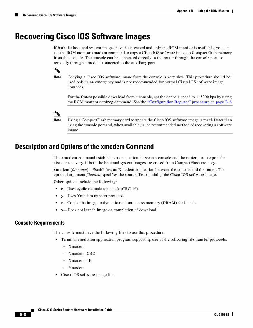
Appendix B Using the ROM Monitor Recovering Cisco IOS Software Images
Recovering Cisco IOS Software ImagesIf both the boot and system images have been erased and only the ROM monitor is available, you can use the ROM monitor xmodem command to copy a Cisco IOS software image to CompactFlash memory from the console. The console can be connected directly to the router through the console port, or remotely through a modem connected to the auxiliary port.
Note Copying a Cisco IOS software image from the console is very slow. This procedure should be used only in an emergency and is not recommended for normal Cisco IOS software image upgrades.
For the fastest possible download from a console, set the console speed to 115200 bps by using the ROM monitor confreg command. See the “Configuration Register” procedure on page B-6.
Note Using a CompactFlash memory card to update the Cisco IOS software image is much faster than using the console port and, when available, is the recommended method of recovering a software image.
Description and Options of the xmodem CommandThe xmodem command establishes a connection between a console and the router console port for disaster recovery, if both the boot and system images are erased from CompactFlash memory.
xmodem [filename]—Establishes an Xmodem connection between the console and the router. The optional argument filename specifies the source file containing the Cisco IOS software image.
Other options include the following:
• c—Uses cyclic redundancy check (CRC-16).
• y—Uses Ymodem transfer protocol.
• r—Copies the image to dynamic random-access memory (DRAM) for launch.
• x—Does not launch image on completion of download.
Console Requirements
The console must have the following files to use this procedure:
• Terminal emulation application program supporting one of the following file transfer protocols:
– Xmodem
– Xmodem–CRC
– Xmodem–1K
– Ymodem
• Cisco IOS software image file
B-8Cisco 3700 Series Routers Hardware Installation Guide
OL-2180-08
Appendix B Using the ROM Monitor Recovering Cisco IOS Software Images
Procedure for the xmodem Command
To copy the Cisco IOS software image from a console to CompactFlash memory, perform the following steps:
Step 1 Connect the console using the instructions in the “Connecting to a Console Terminal or Modem” section on page 3-22.
Step 2 Power up the router. The power-on self-test diagnostics run, and the boot ROM searches for a valid boot image and Cisco IOS software image in CompactFlash memory. If the boot image and Cisco IOS software image are not found, the ROM monitor prompt appears:
rommon 1>
Step 3 Enter the xmodem command and the name of the source file containing the Cisco IOS software image:
rommon 1> xmodem filename
Step 4 Messages similar to the following appear:
Do not start upload program yet...File size Checksum File name2537948 bytes (0x26b9dc) 3700-boot-l
WARN: This operation will ERASE bootflash. If the xmodemdownload to bootflash fails, you will lose any good imageyou may already have in bootflash.Invoke this application only for disaster recovery.
Do you wish to continue? [yes/no]:
Step 5 Enter yes to copy the Cisco IOS software image into CompactFlash memory. Messages similar to the following appear:
Ready to receive file prog ...
Erasing flash at 0x3000000
program flash location 0x3000000
Transfer complete!
The router is now ready to boot from the Cisco IOS software image. Enter the ROM monitor reset command to reboot the router.
Note If you have set the console speed to 115200, you may wish to reset it to the previous speed or to the factory default speed (typically 9600 bps). See the “Configuration Register” procedure on page B-6.
B-9Cisco 3700 Series Routers Hardware Installation Guide
OL-2180-08

Appendix B Using the ROM Monitor Recovering Cisco IOS Software Images
B-10Cisco 3700 Series Routers Hardware Installation Guide
OL-2180-08
Cisco 3700 SeriOL-2180-08
A P P E N D I X C
Configuration RegisterThis appendix describes the factory default settings of the configuration register, and procedures for changing those settings.
This appendix includes the following sections:
• Configuration Register Settings, page C-1
• Changing Configuration Register Settings, page C-2
• Configuring the Boot Field, page C-3
• Enabling Booting from CompactFlash Memory, page C-5
Configuration Register SettingsThe router has a 16-bit configuration register in NVRAM. You can use the configuration register to perform the following tasks:
• Set and display the configuration register value.
• Force the router into the ROM monitor (bootstrap program).
• Select a boot source and default boot filename.
• Enable or disable the Break function.
• Control broadcast addresses.
• Load operating software from ROM.
Table C-1 describes each of the configuration register bits.
Table C-1 Configuration Bit Meanings
BitNumber Hexadecimal Meaning
00–03 0x0000–0x000F Boot field. (See Table C-2.)
06 0x0040 Causes the system software to ignore the contents of NVRAM.
07 0x0080 OEM bit enabled.
08 0x0100 Break disabled.
09 0x0200 Causes the system to use the secondary bootstrap. This bit is typically not used (set to 0).
C-1es Routers Hardware Installation Guide
Appendix C Configuration Register Changing Configuration Register Settings
Changing Configuration Register SettingsYou might want to modify the value in the configuration register to perform the following tasks:
• Recover a lost password.
• Change the console data rate.
• Enable or disable the Break function.
• Manually boot the operating system using the b command at the ROM monitor prompt.
• Force the router to automatically boot its system image in CompactFlash memory, or boot in accordance with any boot system commands stored in the router’s configuration file in NVRAM.
You can change the configuration register either from the ROM monitor or from the operating system software. To change the configuration register from the ROM monitor, see the “Configuration Register” section on page B-6. To change the configuration register from the system software, perform the following steps:
Step 1 Connect a console terminal to the console port of the router as described in the “Connecting to the Console Port” section on page 3-22, using the blue RJ-45 to DB-9 console adapter cable.
Note If you have a terminal with a DB-25 port, use an RJ-45 rollover cable and DB-25 adapter. The RJ-45-to-DB-25 adapter (Cisco part number 29-0810-01) can be purchased from Cisco.
For information about cable pinouts, see the publication Cisco Modular Access Router Cable Specifications on Cisco.com.
Step 2 Configure your terminal or terminal emulation software for 9600 bps (default), 8 data bits, no parity, and 2 stop bits.
Step 3 Power up the router.
Step 4 When asked if you would like to enter the initial dialog, answer no:
Would you like to enter the initial dialog? [yes]: no
Your router is now in the normal operating mode.
10 0x0400 IP broadcast with all zeros.
5, 11, 12 0x0020, 0x0800, 0x1000
Console line speed.
13 0x2000 Boots default ROM software if the network boot fails.
14 0x4000 IP broadcasts do not have net numbers.
15 0x8000 Enables diagnostic messages and ignores the contents of NVRAM.
Table C-1 Configuration Bit Meanings (continued)
BitNumber Hexadecimal Meaning
C-2Cisco 3700 Series Routers Hardware Installation Guide
OL-2180-08
Appendix C Configuration Register Configuring the Boot Field
Step 5 After a few seconds, you see the user EXEC prompt (Router>). Enter the enable command and your password to enter privileged EXEC mode:
Router> enablePassword: passwordRouter#
Step 6 At the privileged EXEC prompt (Router#), enter the configure terminal command:
Router# configure terminal
Enter configuration commands, one per line.Edit with DELETE, CTRL/W, and CTRL/U; end with CTRL/Z
Step 7 Enter the config-register value command, where value is a hexadecimal number preceded by 0x (see Table C-2), to set the contents of the configuration register:
Router(config)# config-register 0x value
Note Cisco IOS software does not allow you to change the console speed bits directly with the config-register command. To change the console speed, complete this sequence:
Router# configure terminal
Router(config)# line console 0
Router(config-line)# speed 9600
Step 8 Press Ctrl-Z to exit configuration mode.
Step 9 Copy the new console speed to NVRAM:
Router# copy run start
The new settings are saved to NVRAM, but they are not effective until the router restarts; for example, when you switch the power off and on or when you enter a reload command from the console.
Step 10 Enter the show version command to display the configuration register value currently in effect and the value that will be used at the next reload. The value is shown on the last line of the display:
Configuration register is 0x142 (will be 0x142 at next reload)
Step 11 Reboot the router. The new value is effective after the router reboots.
Configuring the Boot FieldThe lowest four bits of the configuration register (bits 3, 2, 1, and 0) form the boot field. (See Table C-2.)
Table C-2 Explanation of Boot Field Configuration Register Bits (00 to 03)
Boot Field Meaning
00 Stays at the ROM monitor on a reload or power cycle.
01 Boots the first image in CompactFlash memory as a system image.
02-F Enables default booting from CompactFlash memory.
Enables boot system commands that override default booting from CompactFlash memory.
C-3Cisco 3700 Series Routers Hardware Installation Guide
OL-2180-08
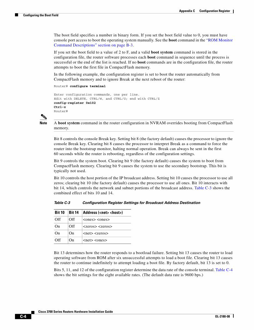
Appendix C Configuration Register Configuring the Boot Field
The boot field specifies a number in binary form. If you set the boot field value to 0, you must have console port access to boot the operating system manually. See the boot command in the “ROM Monitor Command Descriptions” section on page B-3.
If you set the boot field to a value of 2 to F, and a valid boot system command is stored in the configuration file, the router software processes each boot command in sequence until the process is successful or the end of the list is reached. If no boot commands are in the configuration file, the router attempts to boot the first file in CompactFlash memory.
In the following example, the configuration register is set to boot the router automatically from CompactFlash memory and to ignore Break at the next reboot of the router:
Router# configure terminal
Enter configuration commands, one per line.Edit with DELETE, CTRL/W, and CTRL/U; end with CTRL/Z config-register 0x102Ctrl-zRouter#
Note A boot system command in the router configuration in NVRAM overrides booting from CompactFlash memory.
Bit 8 controls the console Break key. Setting bit 8 (the factory default) causes the processor to ignore the console Break key. Clearing bit 8 causes the processor to interpret Break as a command to force the router into the bootstrap monitor, halting normal operation. Break can always be sent in the first 60 seconds while the router is rebooting, regardless of the configuration settings.
Bit 9 controls the system boot. Clearing bit 9 (the factory default) causes the system to boot from CompactFlash memory. Clearing bit 9 causes the system to use the secondary bootstrap. This bit is typically not used.
Bit 10 controls the host portion of the IP broadcast address. Setting bit 10 causes the processor to use all zeros; clearing bit 10 (the factory default) causes the processor to use all ones. Bit 10 interacts with bit 14, which controls the network and subnet portions of the broadcast address. Table C-3 shows the combined effect of bits 10 and 14.
Bit 13 determines how the router responds to a bootload failure. Setting bit 13 causes the router to load operating software from ROM after six unsuccessful attempts to load a boot file. Clearing bit 13 causes the router to continue indefinitely to attempt loading a boot file. By factory default, bit 13 is set to 0.
Bits 5, 11, and 12 of the configuration register determine the data rate of the console terminal. Table C-4 shows the bit settings for the eight available rates. (The default data rate is 9600 bps.)
Table C-3 Configuration Register Settings for Broadcast Address Destination
Bit 10 Bit 14 Address (<net> <host>)
Off Off <ones> <ones>
On Off <zeros> <zeros>
On On <net> <zeros>
Off On <net> <ones>
C-4Cisco 3700 Series Routers Hardware Installation Guide
OL-2180-08
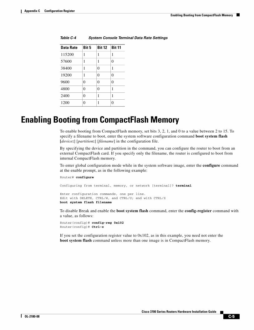
Appendix C Configuration Register Enabling Booting from CompactFlash Memory
Enabling Booting from CompactFlash MemoryTo enable booting from CompactFlash memory, set bits 3, 2, 1, and 0 to a value between 2 to 15. To specify a filename to boot, enter the system software configuration command boot system flash [device:] [partition:] [filename] in the configuration file.
By specifying the device and partition in the command, you can configure the router to boot from an external CompactFlash card. If you specify only the filename, the router is configured to boot from internal CompactFlash memory.
To enter global configuration mode while in the system software image, enter the configure command at the enable prompt, as in the following example:
Router# configure
Configuring from terminal, memory, or network [terminal]? terminal
Enter configuration commands, one per line.Edit with DELETE, CTRL/W, and CTRL/U; end with CTRL/Zboot system flash filename
To disable Break and enable the boot system flash command, enter the config-register command with a value, as follows:
Router(config)# config-reg 0x102Router(config)# Ctrl-z
If you set the configuration register value to 0x102, as in this example, you need not enter the boot system flash command unless more than one image is in CompactFlash memory.
Table C-4 System Console Terminal Data Rate Settings
Data Rate Bit 5 Bit 12 Bit 11
115200 1 1 1
57600 1 1 0
38400 1 0 1
19200 1 0 0
9600 0 0 0
4800 0 0 1
2400 0 1 1
1200 0 1 0
C-5Cisco 3700 Series Routers Hardware Installation Guide
OL-2180-08

Appendix C Configuration Register Enabling Booting from CompactFlash Memory
C-6Cisco 3700 Series Routers Hardware Installation Guide
OL-2180-08
Cisco 3700 Series ROL-2180-08
I N D E X
Symbols
? (help) command B-2
Numerics
–48 V PS1 LED in Cisco 3745 A-6
–48 V PS2 LED in Cisco 3745 A-6
–48 V telephony power modules 1-9, 1-10
A
AC power connection 3-11, 3-12
ACT LED
Cisco 3725 A-5
Cisco 3745 A-5
AIMs, installing 1-3
asynchronous serial data rates 2-12
auxiliary port
connecting to 3-24, 3-25
description 2-8
B
baud rate
See data rate
boot command B-4
boot helper image B-3
booting from CompactFlash memory C-5
boot system command C-4
bracket installation
for Cisco 3725 3-4 to 3-6
for Cisco 3745 3-6 to 3-7
brackets, rack-mounting 3-4
break (interrupt) command C-4
C
cables, provided 2-6
Caution symbol, meaning ix
chassis
desktop installation 3-2
dimensions 1-11
grounding 3-9, 3-10, 3-11
rack-mounting 3-3 to 3-8
views 1-2, 1-3
Cisco IOS software
locating documentation xv
recovering images B-8
Cisco Redundant Power System 3-20
CLI for configuration 3-32
CompactFlash memory
booting from C-5
description 1-4
compliance 1-12
configuration
using CLI 3-32
using SDM 3-29
using setup command facility 3-29
configuration register
bits C-1
boot field C-3, C-4
broadcast address C-4
changing settings B-6, C-2
console terminal data rate C-5
enabling booting from CompactFlash memory C-5
IN-1outers Hardware Installation Guide
Index
modifying from ROM monitor B-6
settings C-1 to C-5
confreg command B-7
connections
AC power 3-11, 3-12
asynchronous/synchronous serial 2-10, 2-12
auxiliary port 3-24
console port 2-8, 3-22
CSU/DSU 2-13
DCE 2-10
DTE 2-10
Ethernet 2-9
ISDN BRI 2-12
LAN 3-21
modem 3-24
network 2-9
serial 2-10, 2-12
Token Ring 2-10
voice 3-21
WAN 3-21
console port
connecting to 3-22, 3-23
connections 3-23
description 2-8
speed B-9
console terminal connections 3-23
context command B-6
cooling recommendations 2-4
CSU/DSU connections 2-13
D
data rate
asynchronous serial 2-12
modem 3-24
setting for console terminal C-2, C-4
DCE and DTE devices 2-10
DCE connections 2-10
DC power connections
IN-2Cisco 3700 Series Routers Hardware Installation Guide
Cisco 3725 3-12 to 3-15
Cisco 3745 3-17 to 3-20
DC wiring requirements
Cisco 3725 3-13
Cisco 3745 3-18
DC wiring routing
Cisco 3725 3-15
debugging commands B-6
desktop installation 3-2
dev command B-5
dimensions, chassis 1-11
dir command B-5
distance limitations, serial signals 2-11
documentation
Cisco IOS software xv
conventions viii
on CD-ROM xiv
on the Web xiv
organization viii
related xiv
DTE and DCE devices 2-10
DTE connections 2-10
E
electrical safety guidelines 2-2
electrostatic discharge damage
See ESD
EPROM-based memory 1-4
error messages A-8 to A-12
ESD 2-2
Ethernet cable types 2-9
F
flash memory
See CompactFlash memory
frame command B-6
OL-2180-08

Index
front panel LEDs 3-26, A-4, A-5
G
ground connection
Cisco 3725 3-9, 3-10
Cisco 3745 3-10, 3-11
lug attachment 3-9, 3-11
H
help command B-5
high temperature, troubleshooting A-3
humidity, specifications 1-11, 1-12
I
i command B-6
installation
checklist 2-5
desktop 3-2
rack-mounting 3-3 to 3-8
site requirements 2-3
tools required 2-7
interface numbering
LAN interfaces
Cisco 3725 1-5
Cisco 3745 1-7
voice
Cisco 3725 1-6
Cisco 3745 1-8
WAN interfaces
Cisco 3725 1-5
Cisco 3745 1-7
IOS software
See Cisco IOS software
IP telephony power modules 1-9, 1-10
ISDN BRI 2-12, 2-13
OL-2180-08
cable specifications 2-13
L
LAN
connections 3-20, 3-21
interface numbering
Cisco 3725 1-5
Cisco 3745 1-7
interface types 2-9, 2-10
LEDs
front panel 3-26, A-4, A-5
rear panel A-6 to A-8
lightning safety 2-2
lost password, recovering A-12
M
meminfo command B-5
memory 1-4
modem connection 3-24, 3-25
mounting brackets 3-3, 3-4
N
netboot B-4
network connections 2-9
network modules, installing 1-3
nonvolatile random-access memory
See NVRAM
NVRAM 1-4
P
packing list 2-6
password recovery A-12
port numbering 1-5 to 1-8
power
IN-3Cisco 3700 Series Routers Hardware Installation Guide
Index
options 1-9
requirements 2-3
specifications 1-11
power supply
connections 3-11 to 3-20
LEDs A-5, A-6
power-up procedure 3-27
processor specifications 1-4
R
rack-mounting the chassis 3-3 to 3-8
racks, equipment 2-4
rear panel LEDs A-6 to A-8
recovering
Cisco IOS software images B-8
lost password A-12
regulatory compliance 1-12
related documents xv
reload command B-2, C-3
reset command B-6
rollover cable 3-25
ROM monitor B-1 to B-9
commands B-2 to B-7
S
safety
guidelines 2-1, 2-2
warnings, translations ix
SDM for configuration 3-29
SDRAM 1-4
serial connections 2-10
signals 2-11
speeds and distances 2-12
setup command facility 3-29
show hardware command B-5
show version command B-5, C-3
IN-4Cisco 3700 Series Routers Hardware Installation Guide
signaling standards, serial 2-11
site
configuration 2-4
environment 2-4
log 2-6
requirements 2-3
slot numbering 1-5 to 1-8
software image recovery procedure B-8
specifications
Cisco 3725 1-11
Cisco 3745 1-11
memory 1-4
processor 1-4
serial ports 2-11, 2-12
system 1-11
stack command B-6
static electricity damage 2-2
switched-56-kbps connections 2-13
synchronous dynamic random-access memory
See SDRAM
SYS/RPS LED in Cisco 3725 A-5
SYS LED in Cisco 3745 A-5
SYS PS1 LED in Cisco 3745 A-6
SYS PS2 LED in Cisco 3745 A-6
sysret command B-6
T
telephone jacks, safety during installation 2-2
telephony power modules 1-9, 1-10
temperature, operating 1-11, 1-12
TFTP server B-4
Token Ring connections 2-10
tools required for installation 2-7
troubleshooting
cables A-3
connections A-3
cooling system A-2
error messages A-8 to A-12
OL-2180-08
Index
front panel LEDs A-4, A-5
high temperature A-3
modules A-3
power system A-2
rear panel LEDs A-6 to A-8
V
ventilation 2-4
voice
connections 3-21
interface numbering
Cisco 3725 1-6
Cisco 3745 1-8
W
WAN
connections 3-21
interface numbering
Cisco 3725 1-5
Cisco 3745 1-7
Warning symbol, meaning ix
wiring
power supplies 3-11 to 3-20
telephone 2-2
X
xmodem command B-8
OL-2180-08
IN-5Cisco 3700 Series Routers Hardware Installation Guide
Index
IN-6Cisco 3700 Series Routers Hardware Installation Guide
OL-2180-08