Embed Size (px)
Citation preview

1
CISC452Telecommunications Systems
Lesson 5Switching, SS7 and the Intelligent Network

2
Public Switched Telephone Network (PSTN)? Traffic over a major
“highway” system
? PSTN constructed by AT&T’s research division, Bell Labs, by standardized transfer methods and central office switches

3
Switching
? (definition) “The establishment on demand, of an individual connection from a desired inlet to a desired outlet within a set of inlets and outlets for as long as is required for the transfer of information.”

4
Switching...
? “The establishment on demand, of an individual connection from a desired inlet to a desired outlet within a set of inlets and outlets for as long as is required for the transfer of information.”

5
Switching
? (definition) What goes in, comes out, for as long as desired from within the network until one party hangs up

6
Intro to Switching
? A switch routes a call based on a number system
e.g 1 302 369 6923
access code
area code
exchange code
subscriber code

7
Intro to Switching
LocalEnd Office
TandemSwitch
TrunkGroup
Transit
End Office
Transit Concentrator
Transit
• Local (line-to-line) switching• Transit (tandem)• Call distribution

8
Switching System
Switching Matrix
Subscriber Lines
Trunks
Signaling
Control
9
Essential Switch Functions
? Interconnection
? Control
? Alerting
? Attending
? Information receiving
? Information sending
? Busy Testing
? Supervising

10
Functions of Switching Systems
? Signalingmonitor line activity
send incoming information to control function
send control signals to outgoing lines
? Controlprocess signaling and set-up/knock down connections
? Switchingmake connections between input and output lines

11
Basic Switch Requirements
? A switch must be able to connect any incoming call to one of a multitude of outgoing calls
? A switch must have the ability to hold and terminate calls
? A switch has to prevent new calls from intruding into circuits already in use

12
General Switch Requirements
? Speed of call setup should be kept short relative to the call holding time
? Grade of service should be high.99 overall
.95 busy-hour
? HIGH availability!

13
Switching Methods
? ConnectivityFull: any input to any output
? BlockingBlocking: Possibility exists that call setup may fail due to insufficient switching resources
Non-blocking: If any input Ij and output Oj are free, they can be connected

14
Time Division Switching
? Time mapping of inputs and outputs
I1 I2 . . . . . . In
O1 O2 . . . . . . O36 . . . . . .

15
Space Division Switching
? Spatial mapping of inputs and outputs
Used primarily in analog switching systems
SpaceI1
In
.
.
.
.
.
.
O1
Om

16
Space-Time-Space Switching
I1 I2 . . . . . . In
O1 O2 . . . . . . O36 . . . . . .

17
Single Stage Switches
? Crosspoint switchesComplex - many crosspoints ( i × j )
Poor utilization of crosspoints
Not fault tolerant

18
Multiple Stage Switches
? Input connected to output via two or more smaller switches
? Crosspoints shared by several possible connections (potential for blocking)
? Possible to provide multiple paths between any 2 ports

19
Three Stage Switch Matrix(Multiple Stage Switch example)
20
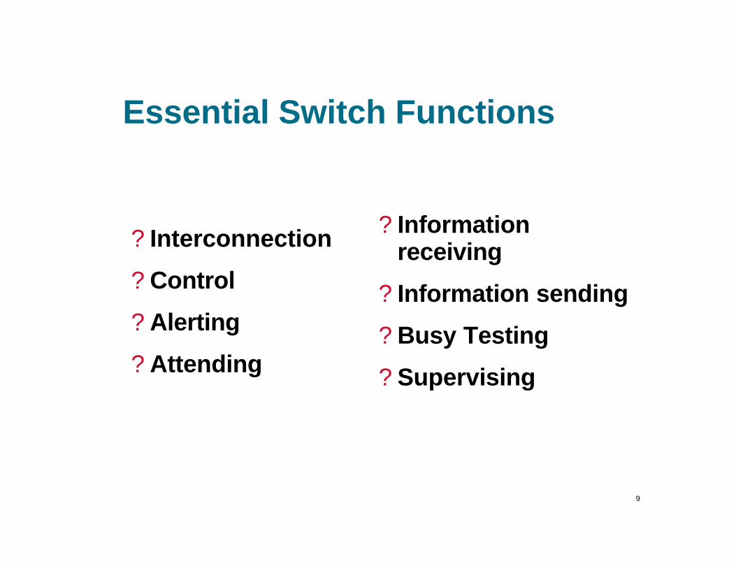
Reducing Cross-point Complexity
? Increase number of stages
? Allow some blocking
? Switch in more than one dimension

21
Number of Cross-pointsNon-blocking SwitchNbr of Lines 3-Stage 1-Stage
128 7,680 16,256512 63,488 261,6352K 516,096 4.2M8K 4.2M 67M
32K 33M 1B128K 268M 17B

22
Digital Switching
? Most of the switching in US is digital, why?
Transmission is digital
Maintenance of signal quality
Leverage improvements in density of Integrated Circuits
Advanced features and services through software
Integration of voice/data services
23
Signaling
? (definition) The exchange of information between call components required to provide and maintain service
? (examples) Dialing digits, providing dial tone, accessing voice mail, sending a call waiting tone, *69, etc.

24
Functions of Signaling
? Supervisory Signaling
? Address Signaling
? Call Progress Signaling

25
Supervisory Signaling
? Provides information on line or circuit condition
? “It [signaling] informs a switch whether a circuit (internal to switch) or a trunk (external to switch) is busy or idle; a called party is off-hook or on-hook…”

26
Supervisory Signals (cont’d)
? Some supervisory signals:Request for service - off-hook
Ready to receive address - dial tone
Call alerting - ringing
Call termination - on-hook
Request for operator - hook-switch flash
Called party station ringing - ring back
Network/called station busy - busy tone
27
Address Signaling
? Directs and routes a telephone call to the called subscriber
? If there is more than one switch involved in the call setup, signaling is required between switches (interregister switching)

28
Address Signaling:DTMF Signaling(dual tone multi frequency)
1 2 3 A
4 5 6 B
7 8 9 C
* 0 # D
1209 1366 1477 1633
697
770
852
941

29
Call-Progress Signaling(Audible - Visible)
? Categorized by audio/visual signals sent in a forward and backward direction
? Forward Direction: A signal sent to your phone which tells it to ring
30
Call-Progress Signaling(cont’d) (Audible - Visible)
? Backward Signaling:Ringback - the distant telephone you are
calling is ringing
Busyback - the called line is busy
ATB -All trunks are busy (sometimes a voice announcement is used)
Loud Warble - Telephone is off hook
31
Signaling Techniques
? In band signaling
? Out-of-band signaling- CCS signaling
? E&M signaling
? MF signaling

32
In - Band Signaling
? Signaling path = voice path
? Voice path clogged with signaling
? Busy calls, congestion, and “ring-no-answers” result in 20-35% of incomplete calls
? Slower call setup due to channel sharing

33
Signaling Techniques
? In-channel signaling
•SF Signaling (2600 Hz)•MF Signaling•DTMF Signaling
In-band•DC Current (on-/off-hook•Dial pulses (10 pps)•20 Hz Ringing voltage
Out-of-band

34
Out - of - Band Signaling
? Signaling path done on a separate channel
? Voice path dedicated only to voice
? Much faster call setup and knockdown
? Led to SS7 and AIN

35
Signaling Techniques
? Common Channel Signaling (CCS)
SignalingNetwork
Dedicated data link between systems• Trunk group associated• Trunk group disassociated

36
Advantages of CCS
? One signaling path needed per trunk group
? Faster and simpler to transfer information between control processors
? No possibility of interference with speech path
? Signaling can’t be accessed by customer

37
Advantages of CCS
? Value-added services of a signaling control point
Shared processing for small offices
Allows centralized decision making (flow mgmt)
Permits Advanced Intelligent Network (AIN) services

38
Disadvantages of CCS
? CCS links can be a single point of failure
? No inherent testing of speech path by call setup signaling
? CCS response time is critical

39
Trunk Group DisassociatedCCS
Speech PathsCCS Data Link
Signaling Switching Center

40
Trunk Group Associated CCS
TR-303Trunk Group
TR-303Control
Link
CO SwitchDLC

41
E&M Signaling
? Used mostly for trunk supervision on an analog network
? E-lead: carries signals to the switching equipment
? M-lead: carries signals away from the switching equipment

42
E&M Example
Condition at Condition atDirection A B
Signal SignalA to B B to A M - Lead E - Lead M - Lead E - Lead
On - Hook On - Hook Ground Open Ground OpenOff - Hook On - Hook Battery Open Ground GroundOn - Hook Off - Hook Ground Ground Battery OpenOff - Hook Off - Hook Battery Ground Battery Ground

43
MF Signaling
? Used primarily for interregister signaling
R 1 System
CCITT No. 5 Signaling Code
R 2 System Code
44
Signaling/Switching Dependence
? Signaling and Switching are closely tied. Signaling allows switching to automate the network.

45
Call Processing - Local Call? Detect off-hook condition
? Send dial-tone to calling station
? Collect dialed digits
? Translate digits to a called number
? Route call
? Prepare connection between stations
? Send ring voltage to called station / ring-back tone to calling station
? Detect off-hook by called station and cut-through the call
? Detect disconnect and terminate call

46
Call Flow - Common Case
STP
LNP Database
302-451-5200 302-831-1946
302-451 302-224
• Subscriber ports numberto a new switch• Switches are direct connected
47
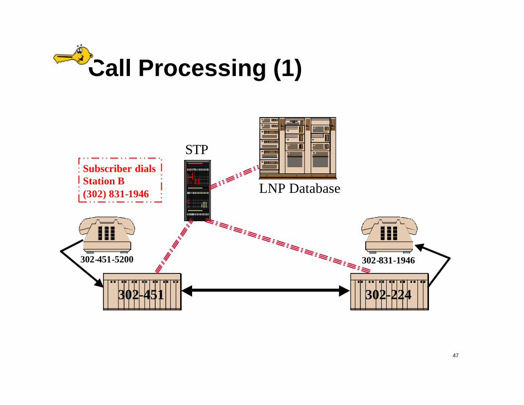
Call Processing (1)
STP
LNP Database
302-451-5200 302-831-1946
302-451 302-224
Subscriber dialsStation B(302) 831-1946

48
Call Processing (2)
STP
LNP Database
302-451-5200 302-831-1946
302-451 302-224Switch determines that Station Bis in a portable NPA-NXX (302-831)and doesn’t reside on the switch

49
Call Processing (3)
STP
LNP Database
302-451-5200 302-831-1946
302-451 302-224Switch sends query to the SCPbased on digits dialed

50
Call Processing (4)
STP
LNP Database
302-451-5200 302-831-1946
302-451 302-224
SCP returns the LRNof the recipient switch

51
Call Processing (5)
STP
LNP Database
302-451-5200 302-831-1946
302-451 302-224Switch analyzes the LRN,determines the route and completes the call

52
Call Processing (6)
STP
LNP Database
302-451-5200 302-831-1946
302-451 302-224Recipient switch receives call, determines that the LRN is local and completes call

53
Progression of Technology
? Electromechanical Switchescrossbar, step-by-step
? SPC with relaysAT&T/Lucent 1A ESS
? SPC with electronic switchesAT&T/Lucent 4 ESS
? DigitalAT&T/Lucent 5 ESS, Nortel DMSx00

54
A typical CO…way back

55
Early Switch Technology"(snort) Here at the Phone Company we
handle eighty four billion calls a year. Serving everyone from presidents and kings to scum of the earth. (snort) We realize that every so often you can't get an operator, for no apparent reason your phone goes out of order [plucks plug out of switchboard], or perhaps you get charged for a call you didn't make. We don't care.
Watch this -- [bangs on a switch panel like a cheap piano] just lost Peoria. (snort) You see, this phone system consists of a multibillion-dollar matrix of space-age technology that is so sophisticated, even we can't handle it. But that's your problem, isn't it ? Next time you complain about your phone service, why don't you try using two Dixie cups with a string. We don't care. We don't have to. (snort) We're the Phone Company."
Lily (Ernestine) Tomlin on Saturday Night Live
56
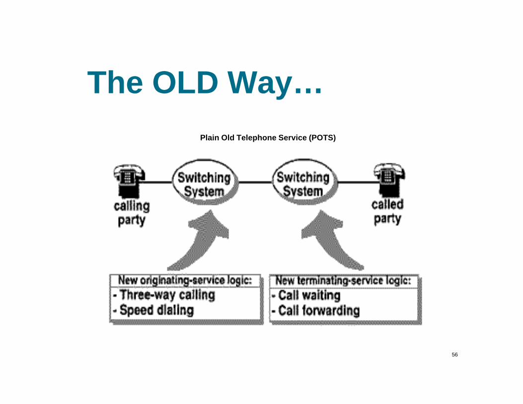
The OLD Way…Plain Old Telephone Service (POTS)

57
How Did POTS work?
? All switching logic had to be “hard-wired”
? Analog transmission
? Pre-1960’s technology
? In - band signaling

58
Technology Limitations
? Switching systems were not easily scalable because changes had to be implemented in Hardware
? As systems were upgraded, services were not the same in all areas
? The existing technology was not able to handle the changing needs of callers
59
Technology Limitations(cont’d)
? As modems became popular the nature of calls changing from voice to data put a strain on the analog switches due to the variation in the length of calls. Data calls tend to be much longer than voice calls.

60
Something About Digital...
? “The North American PSTN will be entirely digital by the year 2000”
- Roger Freeman

61
SS7
? Signaling System No. 7 takes a whole new (digital) approach to signaling. With the new approach comes great functionality and better service.

62
SS7 Requirements? Optimized for operation with digital
(ISDN) networks
? can meet present and future requirements for information transfer for inter processor transactions
? to provide a reliable means of information transfer in correct sequence and without loss or duplication

63
SS7 Signaling Links
? Out of band signaling
? Messages exchanged over 56 or 64K bi-directional signaling links
? Supports services requiring database systems (IN)
? Allows for improved control over fraudulent network usage

64
SS7 Signaling Points
? 3 types of signaling points:1) SSP(Service Switching Point)
2) STP(Signal Transfer Point)
3) Service Control Point

65
SS7 Signaling Points Diagram
66
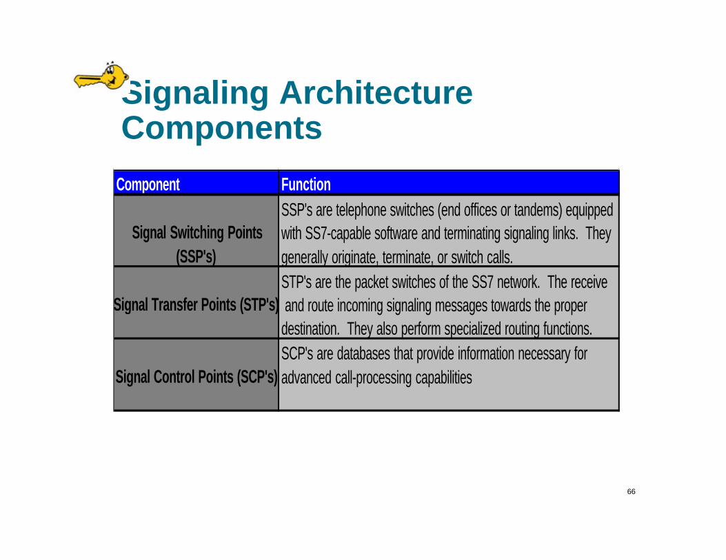
Signaling Architecture Components
Component FunctionSSP's are telephone switches (end offices or tandems) equipped
Signal Switching Points with SS7-capable software and terminating signaling links. They (SSP's) generally originate, terminate, or switch calls.
STP's are the packet switches of the SS7 network. The receive Signal Transfer Points (STP's) and route incoming signaling messages towards the proper
destination. They also perform specialized routing functions.SCP's are databases that provide information necessary for
Signal Control Points (SCP's) advanced call-processing capabilities

67
SS7 Signaling Links

68
SS7 Link Types? “A” Link: An access link connects a SSP or
SCP to an STP.
? “B” Link: A bridge link connects an STP to another STP.
? “C” Link: A cross link connects two “mated pair” STP. This is done to improve reliability
? “D” Link: A diagonal links similarly to a B link
? “E” Link: An extended link connects an SSP to an extra STP in the event that the A link cannot reach one.
? “F” Link: A fully associated link connects SSP’s

69
SS7 Relationship to OSIOSI Model SS7
7 Application6 Presentation SCCP (signaling5 Session connection control)4 Transport3 Network Signaling Network Functions2 Data Link Signaling Link Control1 Physical Signaling Data Link

70
SS7 Data-Link Layer (Layer 1)
? Physical layer in OSI
? Two bi-directional transmission paths for signaling
? Two data channels running in opposite directions at same date rate (usually 56-64K)

71
SS7 Signal Link Layer (Layer 2)
? Signal unit alignment and delimitation
? Error detection
? Error correction (preventive cyclic retransmission method)
? Flow Control

72
SS7 Signal Units
? Signaling units come in three types1) MSU (message signal unit) - carries
signaling information
2) LSSU (link station signal unit) -
carries the link status information
3) FISU (Fill-in signal unit) - fills in idle
time

73
SS7 Network Functions (Layer 3)
? Message-handling functions* message routing: used at each signaling point to determine the outgoing link
* message discrimination: determines if a received message is destined for it, or another point
* message distribution: delivers received message to correct user part

74
SS7 Network Functions (Layer 3)
? Traffic Management Functions* To control message routing. This
includes modification of message routing to destination points, or to continue normal routing.
* Control signaling traffic by avoiding irregularities in message flow
* Flow control

75
SS7 Network Functions (Layer 3)
? Link Management* Can restore the availability of a link set
* Monitors status of signaling link
* Corrects out-of-service links
* Can provision new signaling links
* Automatically configures/reconfigures
signaling links

76
SS7 Connection Control Part
? Services:- connection oriented
- connection-less
- peer-to-peer communication
* Connection established
* Data transfer starts
* Connection releases
77
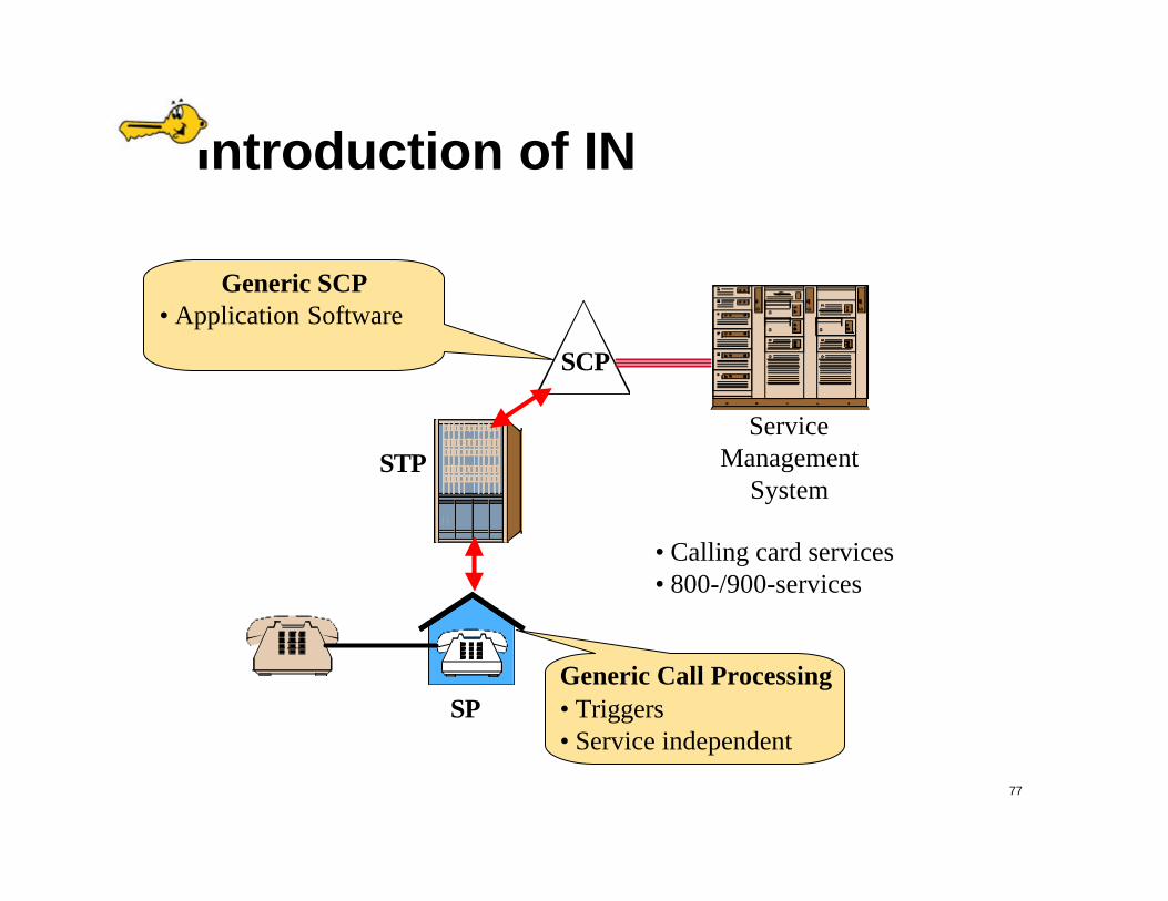
Introduction of IN
STP
SP
SCP
ServiceManagement
System
• Calling card services• 800-/900-services
Generic Call Processing• Triggers• Service independent
Generic SCP• Application Software

78
Advanced Intelligent Network (AIN)
? Service-independent telecommunications
? Intelligence moved out of switchesSignaling Switching Center
STP STP
SP SP
79
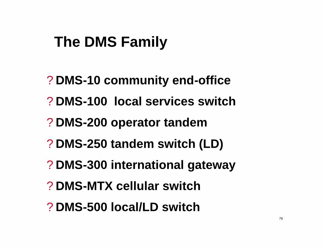
The DMS Family
? DMS-10 community end-office
? DMS-100 local services switch
? DMS-200 operator tandem
? DMS-250 tandem switch (LD)
? DMS-300 international gateway
? DMS-MTX cellular switch
? DMS-500 local/LD switch
80
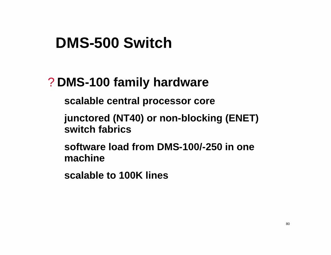
DMS-500 Switch
? DMS-100 family hardwarescalable central processor core
junctored (NT40) or non-blocking (ENET) switch fabrics
software load from DMS-100/-250 in one machine
scalable to 100K lines

81
DMS SuperNode Architecture
DMS-Core ApplicationProcessors
DMS-Bus
NET
PM
IOC
DS512Links
DS30Links
DS512(16) DS30 muxedonto fiber
DS30(32) 10-bit channels

82
DMS-Core Duplex Architecture
SLMMS
port 1I/F
MSport 0
I/FMemory
CallMgmtProc
Plane 032-bit system bus
SLMMS
port 1I/F
MSport 0
I/FMemory
CallMgmtProc
Plane 032-bit system bus
Port crossovers
Fiber links toMessage Switch
Fiber links toMessage Switch
I/F toTerminals
I/F toTerminals
Port crossovers
MC68020 /RISC
(10) 6/24MB

83
DMS-Bus Structure
4MBMemory
ControlProcessor
68020
BusArbitrator
SystemClock
AddressMapper
PortInterface
PortInterface
Processor bus (control)
Transaction Bus(messages)
...
Port Interface Capacity
• 4 ports/card, 20 cards/shelf• 2 cards dedicated to DMS-Core interface• 2 cards dedicated to up to (4) I/O Controllers• 16 cards for up to 32 network modules (64,000 channels)
Stratum1/2/3

84
System Load Module
SystemBus I/F
ControllerSCSI
SLM 0
SystemBus I/F
ControllerSCSI
SLM 1
Cross-over BusPlane 0 DMS-Core Plane 1 DMS-Core

85
I/O Controller
Input/Output Controller
System Bus
MTC TC DDC TC
86
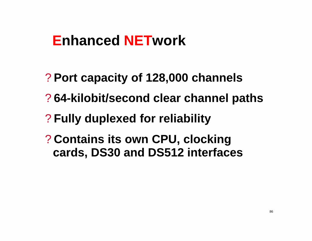
Enhanced NETwork
? Port capacity of 128,000 channels
? 64-kilobit/second clear channel paths
? Fully duplexed for reliability
? Contains its own CPU, clocking cards, DS30 and DS512 interfaces

87
ENET Layout
FSP
Plane 0 shelf 0
Plane 0 shelf 1
Plane 0 shelf 2
Plane 0 shelf 3
Cooling
FSP
Plane 1 shelf 0
Plane 1 shelf 1
Plane 1 shelf 2
Plane 1 shelf 3
Cooling

88
ENET Design
Processor/Clocking
01
To DMSBus
DS512
LinkI/F
(16) DS30or
(4) DS512
16KDS0
4KDS0
Connected in a2x2 Matrix

89
ENET Connections
ENET 0
ENET 1
DS512LinkCntrlr
DS512LinkCntrlr
XPM DS30
XPM DS30

90
Typical Trunk Module
(4)DS30
DigitalTrunk Module
(5) PRI’s or120 DS0’s
(4)DS30
DigitalTrunk Module
(4) E-1’s120 DS0’s

91
Link Peripheral Processor
? Dual local message switches (LMS) attached to the DMS-Bus
? Up to three Link Interface Shelves with up to 12 links(LIU7)/shelf
? Any LMS to any LIU7

92
Support Systems
? Clockinginternal clocks - stratum 1/2/3
external clock source (BITS)
? Powerredundant DC power feeds from PDCs
AC power via redundant inverters
? MAPpairs of terminals, printers
? Software Data Manager (SDM)

93
Alarms
? Minor/major/critical (stall detection) alarms
contact closures
light panels and bells
? System events logged to disk, printers

94
Local Number Portability
“You CAN take it with you!“You CAN take it with you!

95
Telecom Act of 1996
? Opening of local service competitionCollocation
Virtual Collocation
Unbundling of Services
Access to local loop

96
Objectives of LNP
? Ability to move an end-user’s telephone service from switch to switch while keeping the original Directory Number (DN)
scope of portability
service
location
provider
features
E911 information
97
LNP Implementation
? Based upon Bellcore AIN 0.1 protocol
? NPA-NXX are declared portable as readied
? Databases maintained by Martin Marietta Data Systems