Embed Size (px)
Citation preview
CIS 636/736 Wed 30 Jan 2008 4/42
CIS 636/736: (Introduction to) Computer Graphics
Lecture 4 of 42
Viewing 3: Graphics Pipeline
Monday, 30 January 2008
Adapted with Permission
W. H. Hsu
http://www.kddresearch.org
Andries van Dam 18 Slides
CIS 636/736 Wed 30 Jan 2008 4/42
Online Recorded Lectures for CIS 636Introduction to Computer Graphics
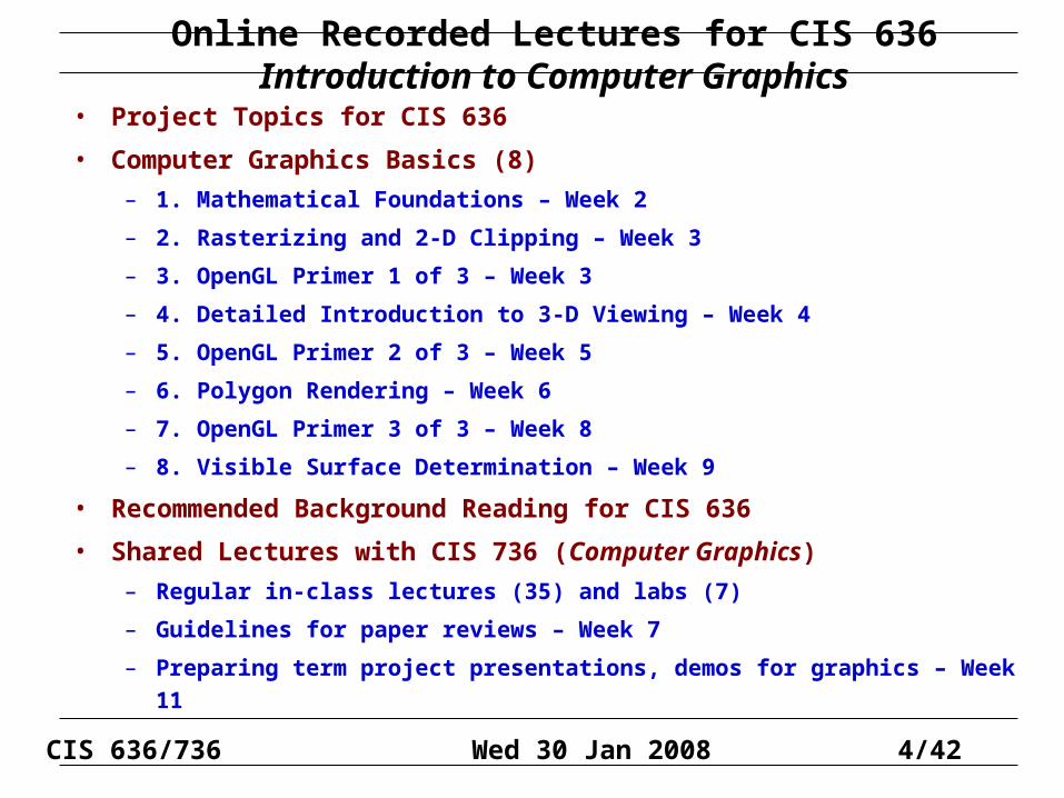
• Project Topics for CIS 636
• Computer Graphics Basics (8)
– 1. Mathematical Foundations – Week 2
– 2. Rasterizing and 2-D Clipping – Week 3
– 3. OpenGL Primer 1 of 3 – Week 3
– 4. Detailed Introduction to 3-D Viewing – Week 4
– 5. OpenGL Primer 2 of 3 – Week 5
– 6. Polygon Rendering – Week 6
– 7. OpenGL Primer 3 of 3 – Week 8
– 8. Visible Surface Determination – Week 9
• Recommended Background Reading for CIS 636
• Shared Lectures with CIS 736 (Computer Graphics)
– Regular in-class lectures (35) and labs (7)
– Guidelines for paper reviews – Week 7
– Preparing term project presentations, demos for graphics – Week 11
CIS 636/736 Wed 30 Jan 2008 4/42
Online Recorded Lectures for CIS 736Computer Graphics
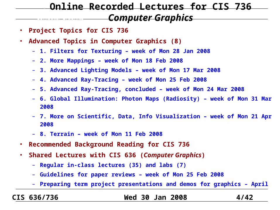
• Project Topics for CIS 736
• Advanced Topics in Computer Graphics (8)
– 1. Filters for Texturing – week of Mon 28 Jan 2008
– 2. More Mappings – week of Mon 18 Feb 2008
– 3. Advanced Lighting Models – week of Mon 17 Mar 2008
– 4. Advanced Ray-Tracing – week of Mon 25 Feb 2008
– 5. Advanced Ray-Tracing, concluded – week of Mon 24 Mar 2008
– 6. Global Illumination: Photon Maps (Radiosity) – week of Mon 31 Mar 2008
– 7. More on Scientific, Data, Info Visualization – week of Mon 21 Apr 2008
– 8. Terrain – week of Mon 11 Feb 2008
• Recommended Background Reading for CIS 736
• Shared Lectures with CIS 636 (Computer Graphics)
– Regular in-class lectures (35) and labs (7)
– Guidelines for paper reviews – week of Mon 25 Feb 2008
– Preparing term project presentations and demos for graphics – April
Online Recorded Lectures for CIS 736Computer Graphics
CIS 636/736 Wed 30 Jan 2008 4/42Andries van Dam September 16, 2003 3D Viewing II 18/21
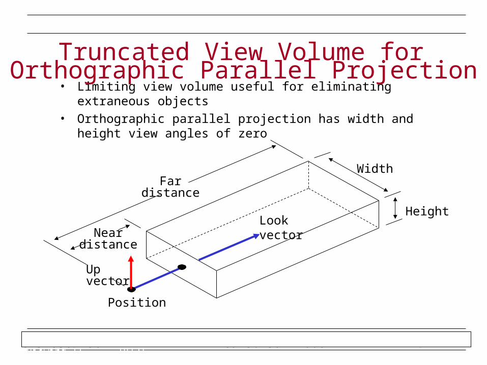
• Limiting view volume useful for eliminating extraneous objects
• Orthographic parallel projection has width and height view angles of zero
Truncated View Volume forOrthographic Parallel Projection
Height
Width
Look vectorNear distance
Position
Far distance
Up vector
CIS 636/736 Wed 30 Jan 2008 4/42Andries van Dam September 16, 2003 3D Viewing II 19/21
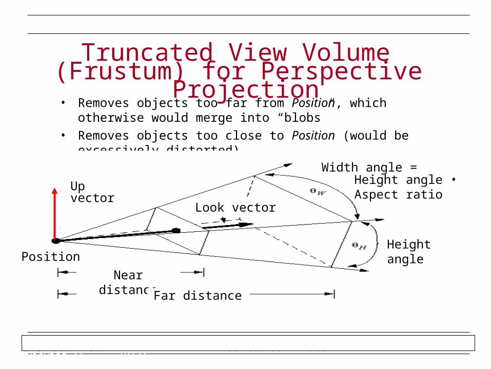
• Removes objects too far from Position, which otherwise would merge into “blobs”
• Removes objects too close to Position (would be excessively distorted)
Truncated View Volume (Frustum) for Perspective
Projection
Position
Near distance
Far distance
Height angle
Width angle =
Look vector
Up vector Height angle • Aspect ratio
CIS 636/736 Wed 30 Jan 2008 4/42Andries van Dam September 16, 2003 3D Viewing II 20/21
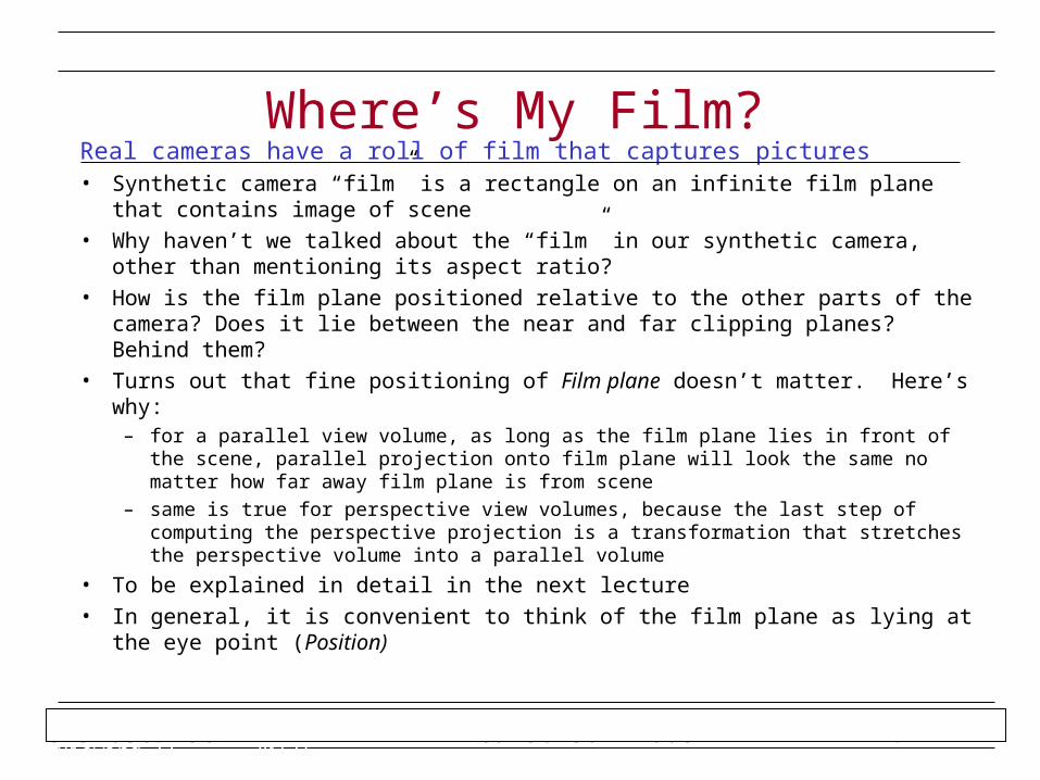
Real cameras have a roll of film that captures pictures• Synthetic camera “film” is a rectangle on an infinite film plane that contains image
of scene
• Why haven’t we talked about the “film” in our synthetic camera, other than mentioning its aspect ratio?
• How is the film plane positioned relative to the other parts of the camera? Does it lie between the near and far clipping planes? Behind them?
• Turns out that fine positioning of Film plane doesn’t matter. Here’s why:– for a parallel view volume, as long as the film plane lies in front of the scene, parallel
projection onto film plane will look the same no matter how far away film plane is from scene
– same is true for perspective view volumes, because the last step of computing the perspective projection is a transformation that stretches the perspective volume into a parallel volume
• To be explained in detail in the next lecture
• In general, it is convenient to think of the film plane as lying at the eye point (Position)
Where’s My Film?
CIS 636/736 Wed 30 Jan 2008 4/42Andries van Dam September 16, 2003 3D Viewing II 21/21
• Carlbom, Ingrid and Paciorek, Joseph, “Planar Geometric Projections and Viewing Transformations,” Computing Surveys, Vol. 10, No. 4 December 1978
• Kemp, Martin, The Science of Art, Yale University Press, 1992
• Mitchell, William J., The Reconfigured Eye, MIT Press, 1992
• Foley, van Dam, et. al., Computer Graphics: Principles and Practice, Addison-Wesley, 1995
• Wernecke, Josie, The Inventor Mentor, Addison-Wesley, 1994
Sources
CIS 636/736 Wed 30 Jan 2008 4/42Andries van Dam September 18, 2003 3D Viewing III 2/42
• Reduce degrees of freedom; five steps to specifying view volume– position the camera (and therefore its view/film plane)
– point it at what you want to see, with the camera in the orientation you want
– define the field of view (for a perspective view volume, aspect ratio of film and angle of view: somewhere between wide angle, normal, and zoom; for a parallel view volume, width and height)
– choose perspective or parallel projection
– determine the focal distance
Stage One: Specifying a ViewVolume
CIS 636/736 Wed 30 Jan 2008 4/42Andries van Dam September 18, 2003 3D Viewing III 3/42
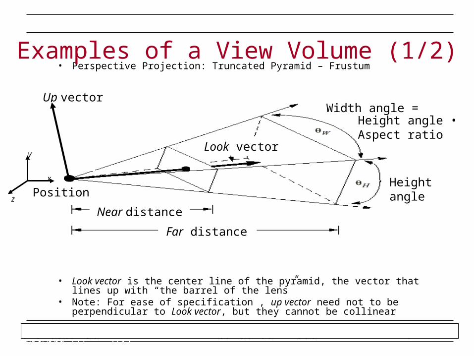
• Perspective Projection: Truncated Pyramid – Frustum
• Look vector is the center line of the pyramid, the vector that lines up with “the barrel of the lens”
• Note: For ease of specification , up vector need not to be perpendicular to Look vector, but they cannot be collinear
Examples of a View Volume (1/2)
Position
Near distance
Far distance
Height angle
Width angle =
Look vector
Up vector
Height angle • Aspect ratio
x
y
z
CIS 636/736 Wed 30 Jan 2008 4/42Andries van Dam September 18, 2003 3D Viewing III 4/42
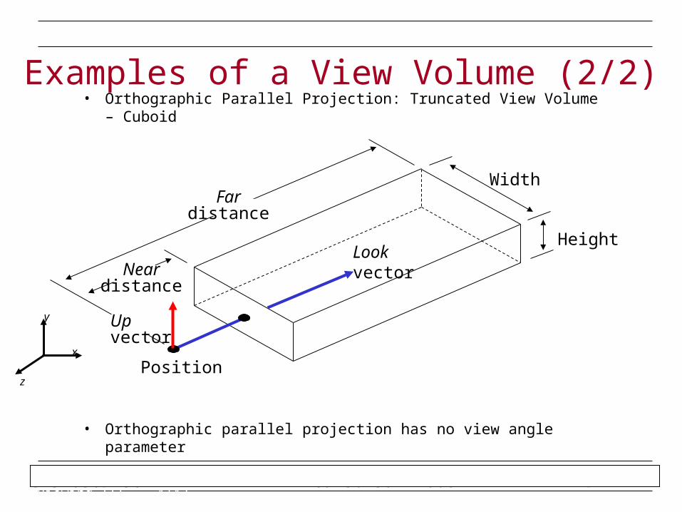
• Orthographic Parallel Projection: Truncated View Volume – Cuboid
• Orthographic parallel projection has no view angle parameter
Examples of a View Volume (2/2)
Height
Width
Look vectorNear distance
Position
Far distance
Up vector
x
y
z
CIS 636/736 Wed 30 Jan 2008 4/42Andries van Dam September 18, 2003 3D Viewing III 5/42
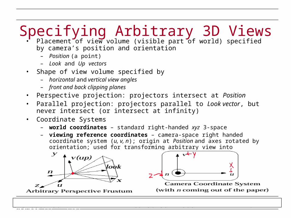
• Placement of view volume (visible part of world) specified by camera’s position and orientation
– Position (a point)– Look and Up vectors
• Shape of view volume specified by– horizontal and vertical view angles– front and back clipping planes
• Perspective projection: projectors intersect at Position• Parallel projection: projectors parallel to Look vector, but never intersect (or intersect
at infinity)• Coordinate Systems
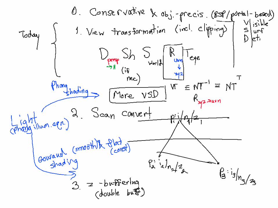
– world coordinates – standard right-handed xyz 3-space– viewing reference coordinates – camera-space right handed coordinate system (u, v, n);
origin at Position and axes rotated by orientation; used for transforming arbitrary view into canonical view
Specifying Arbitrary 3D Views
CIS 636/736 Wed 30 Jan 2008 4/42Andries van Dam September 18, 2003 3D Viewing III 6/42
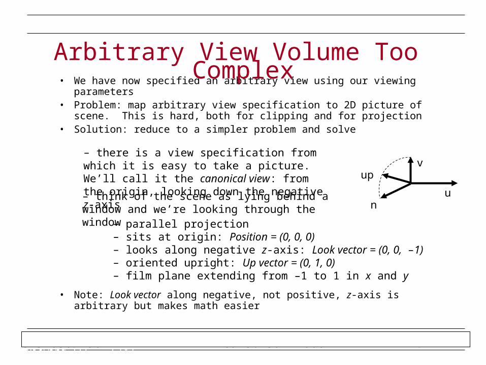
• We have now specified an arbitrary view using our viewing parameters• Problem: map arbitrary view specification to 2D picture of scene. This is
hard, both for clipping and for projection• Solution: reduce to a simpler problem and solve
• Note: Look vector along negative, not positive, z-axis is arbitrary but makes math easier
Arbitrary View Volume Too Complex
– there is a view specification from which it is easy to take a picture. We’ll call it the canonical view: from the origin, looking down the negative z-axis
– parallel projection– sits at origin: Position = (0, 0, 0)– looks along negative z-axis: Look vector = (0, 0, –1)– oriented upright: Up vector = (0, 1, 0)– film plane extending from –1 to 1 in x and y
– think of the scene as lying behind a window and we’re looking through the window
up
n
v
u
CIS 636/736 Wed 30 Jan 2008 4/42Andries van Dam September 18, 2003 3D Viewing III 7/42
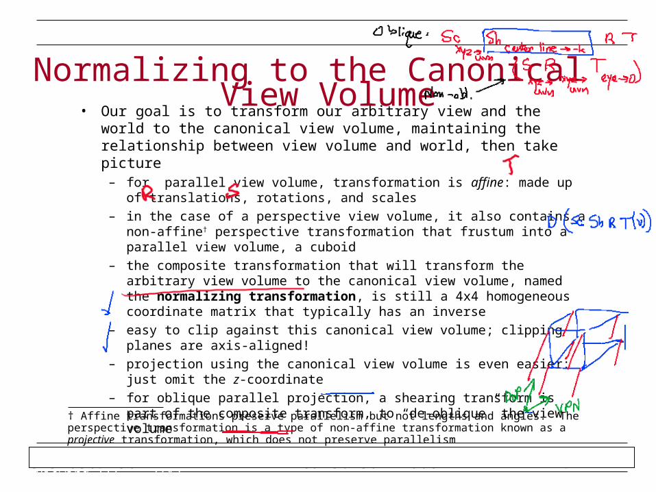
• Our goal is to transform our arbitrary view and the world to the canonical view volume, maintaining the relationship between view volume and world, then take picture
– for parallel view volume, transformation is affine: made up of translations, rotations, and scales
– in the case of a perspective view volume, it also contains a non-affine† perspective transformation that frustum into a parallel view volume, a cuboid
– the composite transformation that will transform the arbitrary view volume to the canonical view volume, named the normalizing transformation, is still a 4x4 homogeneous coordinate matrix that typically has an inverse
– easy to clip against this canonical view volume; clipping planes are axis-aligned!
– projection using the canonical view volume is even easier: just omit the z-coordinate
– for oblique parallel projection, a shearing transform is part of the composite transform, to “de-oblique” the view volume
Normalizing to the Canonical View Volume
† Affine transformations preserve parallelism but not lengths and angles. The perspective transformation is a type of non-affine transformation known as a projective transformation, which does not preserve parallelism
CIS 636/736 Wed 30 Jan 2008 4/42Andries van Dam September 18, 2003 3D Viewing III 8/42
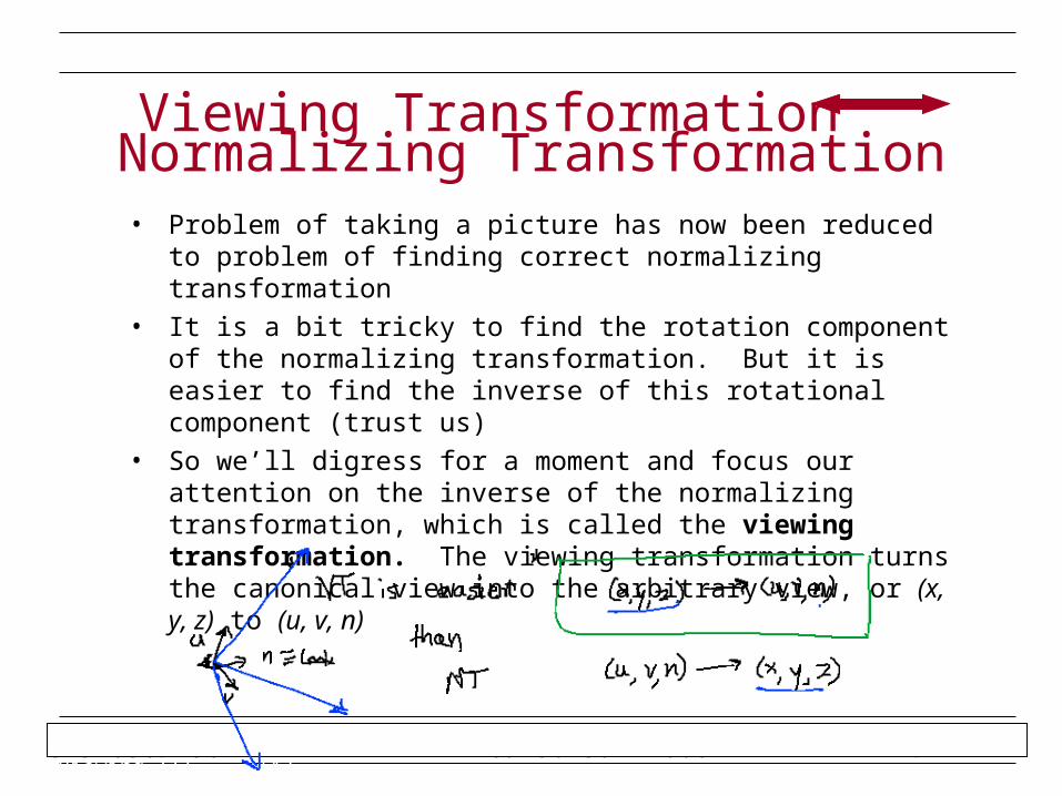
• Problem of taking a picture has now been reduced to problem of finding correct normalizing transformation
• It is a bit tricky to find the rotation component of the normalizing transformation. But it is easier to find the inverse of this rotational component (trust us)
• So we’ll digress for a moment and focus our attention on the inverse of the normalizing transformation, which is called the viewing transformation. The viewing transformation turns the canonical view into the arbitrary view, or (x, y, z) to (u, v, n)
Viewing Transformation Normalizing Transformation
CIS 636/736 Wed 30 Jan 2008 4/42Andries van Dam September 18, 2003 3D Viewing III 9/42
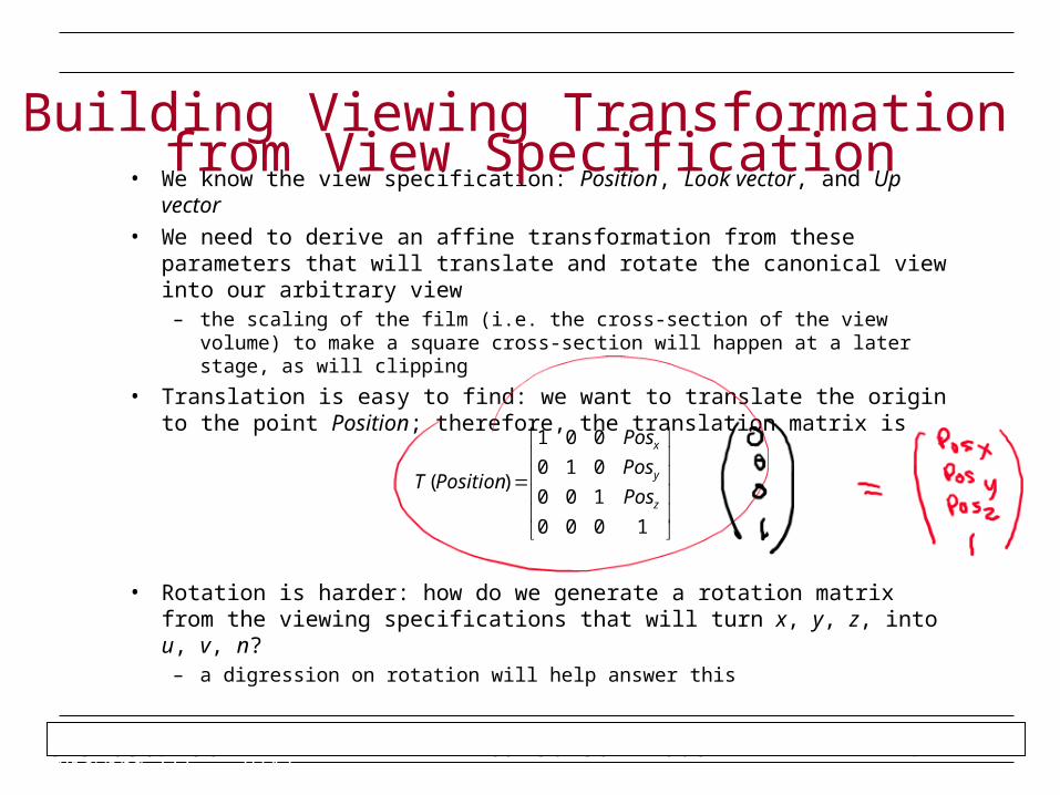
• We know the view specification: Position, Look vector, and Up vector
• We need to derive an affine transformation from these parameters that will translate and rotate the canonical view into our arbitrary view
– the scaling of the film (i.e. the cross-section of the view volume) to make a square cross-section will happen at a later stage, as will clipping
• Translation is easy to find: we want to translate the origin to the point Position; therefore, the translation matrix is
• Rotation is harder: how do we generate a rotation matrix from the viewing specifications that will turn x, y, z, into u, v, n?
– a digression on rotation will help answer this
Building Viewing Transformation from View Specification
1000
100
010
001
)(z
y
x
Pos
Pos
Pos
PositionT
CIS 636/736 Wed 30 Jan 2008 4/42Andries van Dam September 18, 2003 3D Viewing III 10/42
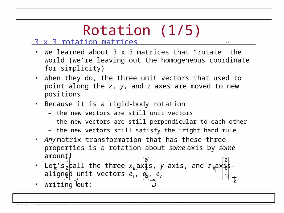
3 x 3 rotation matrices• We learned about 3 x 3 matrices that “rotate” the world (we’re leaving
out the homogeneous coordinate for simplicity)
• When they do, the three unit vectors that used to point along the x, y, and z axes are moved to new positions
• Because it is a rigid-body rotation– the new vectors are still unit vectors
– the new vectors are still perpendicular to each other
– the new vectors still satisfy the “right hand rule”
• Any matrix transformation that has these three properties is a rotation about some axis by some amount!
• Let’s call the three x-axis, y-axis, and z-axis-aligned unit vectors e1, e2, e3
• Writing out:
Rotation (1/5)
0
0
1
1e
0
1
0
2e
1
0
0
3e
CIS 636/736 Wed 30 Jan 2008 4/42Andries van Dam September 18, 2003 3D Viewing III 11/42
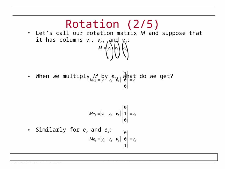
• Let’s call our rotation matrix M and suppose that it has columns v1, v2, and v3:
• When we multiply M by e1, what do we get?
• Similarly for e2 and e3:
Rotation (2/5)
321 vvvM
23212
0
1
0
vvvvMe
33213
1
0
0
vvvvMe
13211
0
0
1
vvvvMe
CIS 636/736 Wed 30 Jan 2008 4/42Andries van Dam September 18, 2003 3D Viewing III 12/42
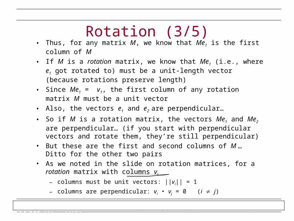
• Thus, for any matrix M, we know that Me1 is the first column of M
• If M is a rotation matrix, we know that Me1 (i.e., where e1 got rotated to) must be a unit-length vector (because rotations preserve length)
• Since Me1 = v1, the first column of any rotation matrix M must be a unit vector
• Also, the vectors e1 and e2 are perpendicular…
• So if M is a rotation matrix, the vectors Me1 and Me2 are perpendicular… (if you start with perpendicular vectors and rotate them, they’re still perpendicular)
• But these are the first and second columns of M … Ditto for the other two pairs
• As we noted in the slide on rotation matrices, for a rotation matrix with columns vi
– columns must be unit vectors: ||vi|| = 1
– columns are perpendicular: vi • vj = 0 (i j)
Rotation (3/5)
CIS 636/736 Wed 30 Jan 2008 4/42Andries van Dam September 18, 2003 3D Viewing III 13/42
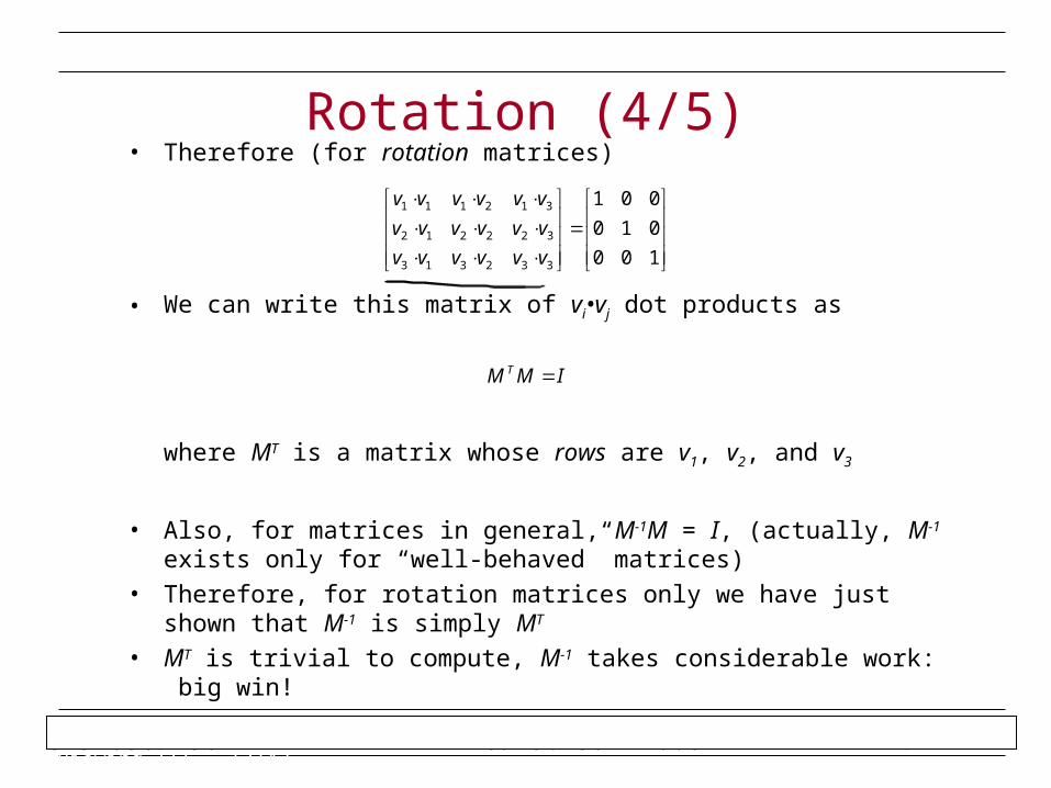
• Therefore (for rotation matrices)
• We can write this matrix of vi•vj dot products as
where MT is a matrix whose rows are v1, v2, and v3
• Also, for matrices in general, M-1M = I, (actually, M-1 exists only for “well-behaved” matrices)
• Therefore, for rotation matrices only we have just shown that M-1 is simply MT
• MT is trivial to compute, M-1 takes considerable work: big win!
Rotation (4/5)
100
010
001
332313
322212
312111
vvvvvv
vvvvvv
vvvvvv
IMM T
CIS 636/736 Wed 30 Jan 2008 4/42Andries van Dam September 18, 2003 3D Viewing III 14/42
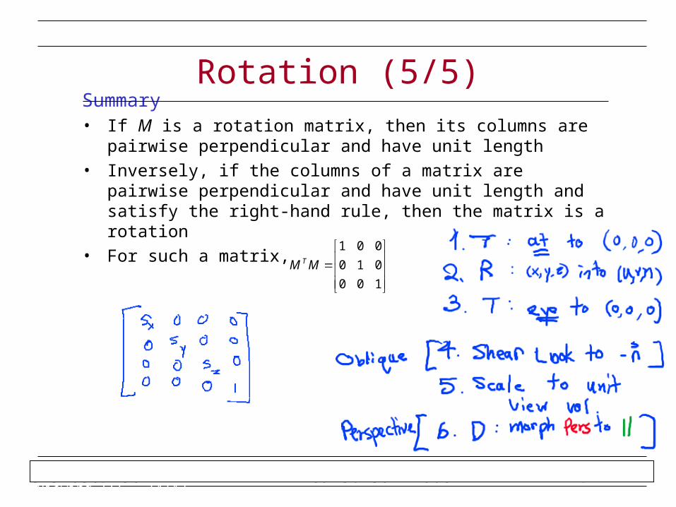
Summary• If M is a rotation matrix, then its columns are pairwise perpendicular and
have unit length
• Inversely, if the columns of a matrix are pairwise perpendicular and have unit length and satisfy the right-hand rule, then the matrix is a rotation
• For such a matrix,
Rotation (5/5)
100
010
001
MM T
CIS 636/736 Wed 30 Jan 2008 4/42Andy van Dam October 21, 2003 Realism 22/42
• These notes have been created and revised each year by many generations of CS123 TAs and by John Hughes and Andy van Dam
• Updated in 2001-2005 by John Alex (former 123 TA and Pixarian, now a Ph.D. student at MIT), others
• See also Chapter 14 in the book
Realism in Computer Graphics
CIS 736 Computer Graphics
Realistic Rendering and Animation
This WeekReading: Shading
Adapted with Permission
W. H. Hsu
http://www.kddresearch.org
CIS 636/736 Wed 30 Jan 2008 4/42Andy van Dam October 21, 2003 Realism 23/42
Roadmap• We tend to mean physical realism
• How much can you deliver?– what medium are you delivering on? (still images, movie/video special effects, VR, etc.)
– how much resources are you willing to spend? (time, money, processing power)
• How much do you want or need?– content
– users
• There are many categories of realism:– geometry and modeling
– rendering
– behavior
– interaction
• And many techniques for achieving varying amounts of realism within each category
• Achieving realism usually requires making trade-offs– realistic in some categories and not in others
– concentrate on the aspects most useful to your application
• When resources run short, use hacks!
Realism in Computer Graphics
CIS 636/736 Wed 30 Jan 2008 4/42Andy van Dam October 21, 2003 Realism 24/42
• What is “realism”?– King Kong vs. Jurassic Park
– Final Fantasy
• In the early days of computer graphics, focus was primarily directed towards producing still images
• With still images, “realism” typically meant approaching “photorealism.” Goal was to accurately reconstruct a scene at a particular slice of time
• Emphasis was placed on accurately modeling geometry and light reflection properties of surfaces
• With the increasing production of animated graphics—commercials, movies, special effects, cartoons—a new standard of “realism” became important—behavior
• Behavior over time:– character animation
– natural phenomena: cloth, fur, hair, skin, smoke, water, clouds, wind
– Newtonian physics: things that bump, collide, fall, scatter, bend, shatter, etc.
Realism and Media (1/2)
CIS 636/736 Wed 30 Jan 2008 4/42Andy van Dam October 21, 2003 Realism 25/42
Real-time vs. Non-real-time• “Realistic” static images and animations are usually rendered in batch,
and viewed later. They can often take hours per frame to produce. Time is a relatively unlimited resource
• In contrast, other apps emphasize real-time output:– graphics workstations: data visualization, 3D design ≈10Hz
– video games ≈60Hz
– virtual reality ≈10-60Hz
• Real-time requirements drastically reduce time available for geometric complexity, behavior simulation, rendering, etc.
• Additionally, any media that involves user interaction (e.g., all of the above) also requires real-time interaction handling
Realism and Media (2/2)
CIS 636/736 Wed 30 Jan 2008 4/42Andy van Dam October 21, 2003 Realism 26/42
Cost vs. Quality• Many computer graphics media (e.g., film vs. video vs. CRT)
• Many categories of realism to attend to (far from exhaustive):– geometry
– behavior
– rendering
– interaction
• In a worst-case scenario (e.g., VR), we have to attend to all of these categories within an extremely limited time-budget
• The optimal balance of techniques for achieving “realism” depends a great deal on context of use:
– medium
– user
– content
– resources (especially hardware)
• We will elaborate on these four points next…
Trade-offs 1
CIS 636/736 Wed 30 Jan 2008 4/42Andy van Dam October 21, 2003 Realism 27/42
• Medium– as said before, different media have different needs– consider a doctor examining patient’s x-rays– if the doctor is examining static transparencies, resolution and
accuracy matter most– if the same doctor is interactively browsing a 3D dataset of the
patient’s body online, she may be willing to sacrifice resolution or accuracy for faster navigation and the ability to zoom in at higher resolution on regions of interest
• User– expert vs. novice users– data visualization: novice may see a clip of data visualization on the
news, doesn’t care about fine detail (e.g., weather maps)– in contrast, expert at workstation will examine details much more
closely and stumble over artifacts and small errors—“expertise” involves acute sensitivity to small fluctuations in data, anomalies, patterns, features
– in general, “what does the user care (most) about?”
Trade-offs 2