Embed Size (px)
Citation preview
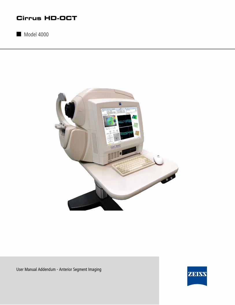
User Manual Addendum - Anterior Segment Imaging
DR
AFT/P
RE-R
ELEA
SE/C
ON
FID
EN
TIA
L
5/1
5/0
9Cirrus HD-OCT
■ Model 4000

Cirrus HD-OCT User Manual Addendum - Anterior Segment Imaging PN 2660021133274 B
DR
AFT/P
RE-R
ELEA
SE/C
ON
FID
EN
TIA
L
5/1
5/0
9
Copyright
© Carl Zeiss Meditec, Inc. All rights reserved.
Trademarks
Cirrus HD-OCT is a trademark of Carl Zeiss Meditec, Inc. in the United States and/or other countries.
All other trademarks used in this document are the property of their respective owners.

Cirrus HD-OCT User Manual Addendum - Anterior Segment Imaging PN 2660021133274 B
Anterior Segment 1
Anterior Segment The Cirrus™ HD-OCT is primarily used for imaging and measuring structures in theposterior eye. By changing the focus of the OCT beam, it can also be used to image andmeasure structures in the anterior segment such as the cornea. This addendum providesinstructions and information about imaging and measuring the anterior segment with theCirrus HD-OCT. Additional information on all facets of the Cirrus instrument can be foundin the Cirrus User Manual.
Carl Zeiss Meditec designed this Addendum to serve as a training, usage and referenceguide for proper scanning and operation. We assume that users are clinicians ortechnicians with professional training or experience in the use of ophthalmic imagingequipment, and in diagnostic interpretation of the images generated. While we offertraining in the use of the Cirrus HD-OCT, we do not offer instruction in diagnosticinterpretation of the images generated. This manual does not attempt to do so.
Intended Use
The Cirrus HD-OCT with Retinal Nerve Fiber Layer and Macular Normative Databases isindicated for in-vivo viewing, axial cross-sectional, and three-dimensional imaging andmeasurement of anterior and posterior ocular structures.
Indications for Use
The Cirrus HD-OCT is a non-contact, high resolution tomographic and biomicroscopicimaging device. It is indicated for in-vivo viewing, axial cross-sectional, andthree-dimensional imaging and measurement of anterior and posterior ocular structures,including cornea, retina, retinal nerve fiber layer, macula, and optic disc. The CirrusHD-OCT with Retinal Nerve Fiber Layer (RNFL) and Macular Normative Databases is aquantitative tool for the comparison of retinal nerve fiber layer and the macula in thehuman retina to a database of known normal subjects. It is intended for use as adiagnostic device to aid in the detection and management of ocular diseases including, butnot limited to, macular holes, cystoid macular edema, diabetic retinopathy, age-relatedmacular degeneration, and glaucoma.
☞ Note: The Cirrus HD-OCT is not intended to be used as the sole diagnosticfor disease.

Anterior Segment
Cirrus HD-OCT User Manual Addendum - Anterior Segment Imaging PN 2660021133274 B
2
Acquiring Anterior Segment Scans
These instructions address two scan acquisition options, and subsequent analyses, for theAnterior Segment. The acquire options are:
• Anterior Segment Cube 512x128
• Anterior Segment 5 Line Raster
The HD-OCT imaging specifications for anterior segment scanning are the same asdescribed in Chapter 10, Specifications, of the Cirrus HD-OCT User Manual, within thecentral 0.5 mm depth and central 2 mm width of the displayed tomograms. The bestimaging performance occurs in the center of the imaging region.
Upon choosing an anterior segment scan,
• The LSO illumination of the retina is turned off.
• The internal fixation target is centered.
• The iris illumination is dimmed by default. This is to avoid causing pupillaryconstriction.
• You will hear a click as the internal lens is brought into position.
Some controls and displays used for posterior eye scanning are not present for anteriorsegment image acquisition. These are:
• The Center control (Z-offset) for the OCT scan display is not present. The OCT displaycan be centered vertically in the live OCT window by using the Chinrest controlbuttons or the mouse scroll wheel.
• Even though there is no fundus image, the Focus control buttons are still available foradjusting the focus of the fixation target.
• The scan pattern is now displayed over the iris image. The scan pattern cannot bemoved, and the size of the scan is fixed. The 5-line raster scans can be rotated.

Cirrus HD-OCT User Manual Addendum - Anterior Segment Imaging PN 2660021133274 B
Anterior Segment 3
Anterior Segment Cube 512x128
This scan mode generates a volume of data through a 4 millimeter square grid by acquiringa series of 128 horizontal scan lines each composed of 512 A-scans. It also acquires a pairof high definition scans through the center of the cube in the vertical and horizontaldirections that are composed of 1024 A-scans each. The Anterior Segment Cube 512x128has the same scan characteristics as the Macular Cube 512x128. This scan can be used formeasuring the central corneal thickness and create a 3-D image of the data. Choosing thisoption produces the Anterior Segment 512x128 Cube Acquire screen, Figure 1.
Figure 1 Acquire Screen, Anterior Segment Cube 512x128
AlignmentBars
Anterior Segment
Cirrus HD-OCT User Manual Addendum - Anterior Segment Imaging PN 2660021133274 B
4
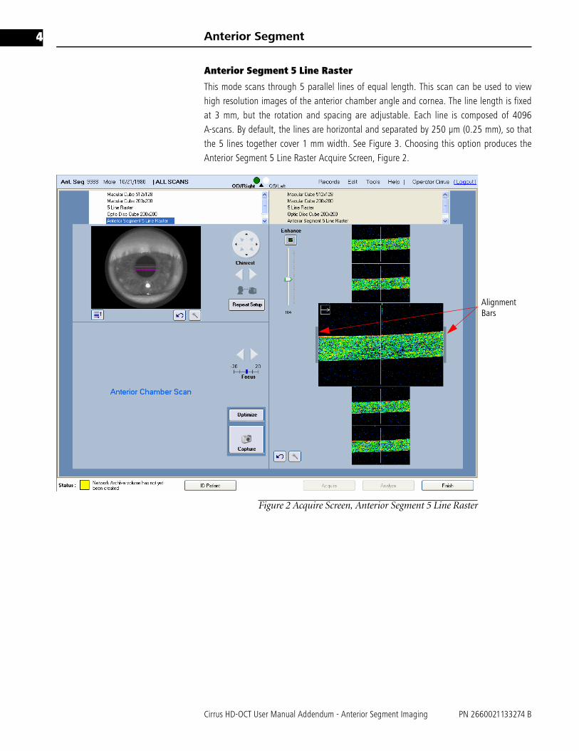
Anterior Segment 5 Line Raster
This mode scans through 5 parallel lines of equal length. This scan can be used to viewhigh resolution images of the anterior chamber angle and cornea. The line length is fixedat 3 mm, but the rotation and spacing are adjustable. Each line is composed of 4096A-scans. By default, the lines are horizontal and separated by 250 μm (0.25 mm), so thatthe 5 lines together cover 1 mm width. See Figure 3. Choosing this option produces theAnterior Segment 5 Line Raster Acquire Screen, Figure 2.
Figure 2 Acquire Screen, Anterior Segment 5 Line Raster
AlignmentBars

Cirrus HD-OCT User Manual Addendum - Anterior Segment Imaging PN 2660021133274 B
Anterior Segment 5
Menu selections on the Acquire Screen
Under the iris viewport, select this button to bring up the Custom Scan Pattern menushown on the left. This allows you to adjust the rotation and spacing of the 5 Line Rasterscan. All adjustments apply to all 5 lines jointly.
• For Rotation (default 0 degrees is horizontal), click the up arrow (for counterclockwiserotation) or down arrow (for clockwise rotation) or type in a value to adjust the anglein the ranges of 0 to 90 or 270 to 359 degrees. Values typed in from 91 to 269 areautomatically changed to the corresponding value 180 degrees opposite.
• For line Spacing, you can select among the following options, in millimeters: 0 (fivelines in same location), 0.01, 0.025, 0.05, 0.075, 0.125, 0.2, 0.25.
Options and Reset buttons
Each area has an Options button , which opens additional controls to adjust theimage settings for that viewport. These controls include brightness, contrast and/orillumination. An example appears at left, for the iris image. Each area also has a Resetbutton , to return the settings to their default or initial positions.
Alignment for Scanning the Central Cornea
These instructions are applicable to both Anterior Segment 512x128 Cube Scan and theAnterior Segment 5 Line Raster.
1. From the ID Patient screen, click Acquire. 2. Before the patient puts his or her chin on the chinrest, click to select the desired scan
type for either eye. You might hear a click sound as the auxiliary lens is moved intoposition. You can have the patient look at the internal fixation, which will always bestraight ahead, or the external fixation device. You may optionally adjust the focus ofthe internal fixation for the patient using the manual Focus adjustment.
3. Adjust the region of the iris visible in the iris viewport. Coarse adjustments are madeby using the X-Y controls to move the chinrest, as needed, until the pupil is visible.Clicking on a chinrest control arrow moves the eye in the direction indicated by thearrow. See Figure 3.

Anterior Segment
Cirrus HD-OCT User Manual Addendum - Anterior Segment Imaging PN 2660021133274 B
6
.
Figure 3 Iris viewport
4. Center the pupil in the iris viewport by clicking the center of the pupil. Clickinganywhere in the iris viewport centers the field of view of the camera over the clickpoint.
5. Adjust the distance to the patient using the chinrest control until you see the corneain the OCT scan display. The mouse scroll wheel may be used to make fineadjustments. The best OCT image is obtained when the cornea is placed between thegray bars alongside the scan display. See Figure 4.
Figure 4 OCT Placement
6. Click the Enhance button to improve the quality of the OCT image.
☞ Note: The Optimize button does not position the scan when taking AnteriorSegment scans. It only performs the Enhance function.
☞ Note: If the patient’s cornea is perfectly centered, a strong reflection from theanterior cornea can produce bright artifacts in the OCT scan display (Figure 5). The
Click pupil center to align
Z Controls
X-Y ControlsAlign
Focus
Cirrus HD-OCT User Manual Addendum - Anterior Segment Imaging PN 2660021133274 B
Anterior Segment 7
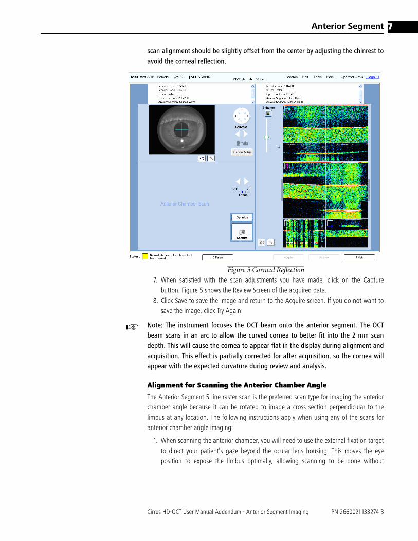
scan alignment should be slightly offset from the center by adjusting the chinrest toavoid the corneal reflection.
Figure 5 Corneal Reflection
7. When satisfied with the scan adjustments you have made, click on the Capturebutton. Figure 5 shows the Review Screen of the acquired data.
8. Click Save to save the image and return to the Acquire screen. If you do not want tosave the image, click Try Again.
☞ Note: The instrument focuses the OCT beam onto the anterior segment. The OCTbeam scans in an arc to allow the curved cornea to better fit into the 2 mm scandepth. This will cause the cornea to appear flat in the display during alignment andacquisition. This effect is partially corrected for after acquisition, so the cornea willappear with the expected curvature during review and analysis.
Alignment for Scanning the Anterior Chamber Angle
The Anterior Segment 5 line raster scan is the preferred scan type for imaging the anteriorchamber angle because it can be rotated to image a cross section perpendicular to thelimbus at any location. The following instructions apply when using any of the scans foranterior chamber angle imaging:
1. When scanning the anterior chamber, you will need to use the external fixation targetto direct your patient’s gaze beyond the ocular lens housing. This moves the eyeposition to expose the limbus optimally, allowing scanning to be done without

Anterior Segment
Cirrus HD-OCT User Manual Addendum - Anterior Segment Imaging PN 2660021133274 B
8
interference from the eyelids. In scanning the superior angle, the iris illumination lightcan be used as a fixation target. When imaging the temporal angle, it is helpful tocover the fellow eye, to allow the patient to fixate with the scanned eye.
2. Adjust the area of the eye visible in the iris viewport until you are able to view thecornioscleral junction. Coarse adjustments are made by using the X-Y controls to movethe chinrest, as needed, until the pupil is visible. Clicking on a chinrest control arrowmoves the eye in the direction indicated by the arrow. The angle recess often appearsshadowed by the sclera. Moving the scan slightly to another location along thelimbus can sometimes avoid local shadowing.
3. Center the scan on the corneal limbus. The live OCT image should show the top of thecornea and should be almost horizontally aligned; a slight tilt is acceptable and canimprove visualization of angle structures. Figure 6 shows a well-aligned scan and liveOCT image. Note that the iris may not be well focused when scanning the angle.
Figure 6 Anterior Chamber Angle Scan
4. Proceed with Enhance and Capture, then review the scan as described in the sectionon corneal scanning.

Cirrus HD-OCT User Manual Addendum - Anterior Segment Imaging PN 2660021133274 B
Anterior Segment 9
Scan Review
Scan review of anterior segment images (Figure 7) is similar to that of posterior scanimages. For more detailed information, see the Cirrus 4.0 User Manual. The followingdifferences, however, should be noted.
Figure 7 Scan Review for Cube 512x128
Iris Video Image Window – Cube 512x128
The overlay on the iris image (upper left in Figure 7) indicates the location of the acquiredOCT data scan.
LSO Window
The LSO window, located on the lower left side of the Scan Review screen (Figure 7), isnot illuminated for Anterior Segment scans. However, navigation sliders are available inthis window, allowing for easier navigation through the cube data in the scan.
☞ Note: The signal strength indicator is not displayed for anterior segment review; it isonly displayed for posterior scans.

Anterior Segment
Cirrus HD-OCT User Manual Addendum - Anterior Segment Imaging PN 2660021133274 B
10
Figure 8 Scan Review, 5 Line Raster
Iris Video Image Window – 5 Line Raster
The 5 Line Raster overlay on the iris image (upper left in Figure 8) indicates the locationof the acquired OCT data scan. Scan review is accomplished by clicking on an individualline of the 5 Line Raster scan overlay. The scan line selected is then highlighted in darkblue. The vertical row of images on the right side of the scan review screen correspond toeach of the individual scan lines. The selected scan line is magnified for greater clarity ofdetail, as shown in the middle image of the review screen (Figure 8).
The fundus (LSO) image is not displayed. Also, the signal strength indicator is not displayedfor the anterior segment review; it is only displayed for posterior scans.
selectedscan forreview

Cirrus HD-OCT User Manual Addendum - Anterior Segment Imaging PN 2660021133274 B
Anterior Segment 11
Anterior Segment Scan Analysis
To analyze or print either an Anterior Segment 5 Line Raster or an Anterior Segment Cube512x128 scan, click Analyze from the ID Patient screen. Select the desired Anterior Segmentscan from the scan list on the left then click on the appropriate analysis in the right-handcolumn. The Anterior Segment Analysis is the only analysis protocol available for theAnterior Segment Cube 512x128 scan.
Figure 9 Anterior Segment Cube Analysis Screen
The Anterior Segment Analysis screen (Figure 9) for the Anterior Segment Cube 512x128scan displays the Iris Viewport with the scan area and scan navigators superimposed. TheX slice (fast - B scan) is shown in the upper OCT image and the Y slice (slow - B scan) isshown below it. You may click on either OCT window and use the scroll wheel on themouse to scroll through the slices or move the slice navigators in the Iris Viewport.

Anterior Segment
Cirrus HD-OCT User Manual Addendum - Anterior Segment Imaging PN 2660021133274 B
12
The High Definition Image Analysis
The High Definition Image Analysis is the only analysis available for the Anterior SegmentFive line raster. The analysis screen displays the Iris Viewport with the scan patternsuperimposed. The thumbnails of the 5 slices are shown below the Iris Viewport. The largescan image on the right corresponds to the thumbnail surrounded by a blue frame and thehighlighted scan line. Clicking on another thumbnail image or the line will replace thelarge image with the chosen scan. Figure 10 shows a high definition analysis screen of ananterior chamber angle.
Figure 10 Anterior Segment 5 Line Raster Analysis Screen
Anterior Segment Imaging
The Cirrus HD-OCT can produce high resolution images of the anterior segment allowingvisualization of fine details of the corneal and anterior chamber anatomy.

Cirrus HD-OCT User Manual Addendum - Anterior Segment Imaging PN 2660021133274 B
Anterior Segment 13
The Central Cornea
The corneal epithelium, Bowman's membrane and stroma are generally visible in thetomograms. (Figure 11). Measurement of the Central Corneal Thickness (CCT) can bedone and is described in this manual.
Figure 11 Corneal Image
Epithelium
Bowman’sMembrane
Stroma
Anterior Segment
Cirrus HD-OCT User Manual Addendum - Anterior Segment Imaging PN 2660021133274 B
14
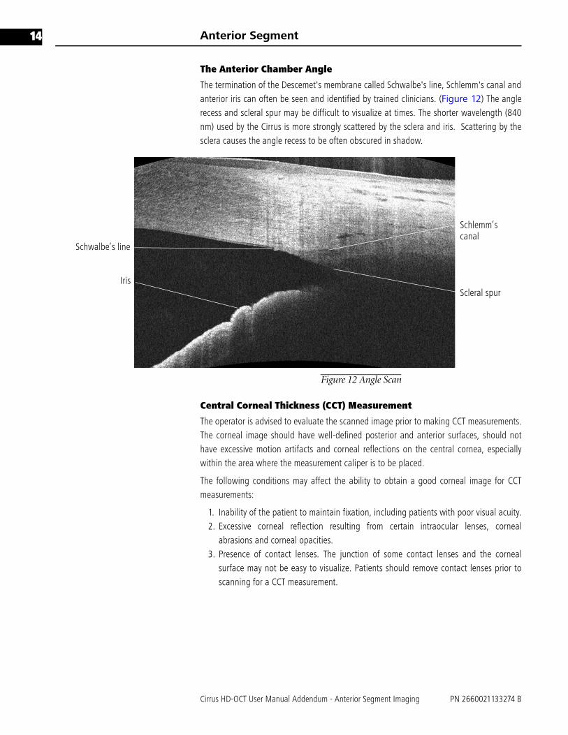
The Anterior Chamber Angle
The termination of the Descemet's membrane called Schwalbe's line, Schlemm's canal andanterior iris can often be seen and identified by trained clinicians. (Figure 12) The anglerecess and scleral spur may be difficult to visualize at times. The shorter wavelength (840nm) used by the Cirrus is more strongly scattered by the sclera and iris. Scattering by thesclera causes the angle recess to be often obscured in shadow.
Figure 12 Angle Scan
Central Corneal Thickness (CCT) Measurement
The operator is advised to evaluate the scanned image prior to making CCT measurements.The corneal image should have well-defined posterior and anterior surfaces, should nothave excessive motion artifacts and corneal reflections on the central cornea, especiallywithin the area where the measurement caliper is to be placed.
The following conditions may affect the ability to obtain a good corneal image for CCTmeasurements:
1. Inability of the patient to maintain fixation, including patients with poor visual acuity.2. Excessive corneal reflection resulting from certain intraocular lenses, corneal
abrasions and corneal opacities. 3. Presence of contact lenses. The junction of some contact lenses and the corneal
surface may not be easy to visualize. Patients should remove contact lenses prior toscanning for a CCT measurement.
Schlemm’scanal
Schwalbe’s line
IrisScleral spur

Cirrus HD-OCT User Manual Addendum - Anterior Segment Imaging PN 2660021133274 B
Anterior Segment 15
Central corneal measurements should be made at the apex of the cornea. To determine theapical area:
1. Estimate where the center of the pupil is on the image and move the scan navigatorsso that they intersect at that point.
2. Click on the ruler button, and align the ruler vertically against the mauve slicenavigator on the horizontal scan.
3. The apical area, being closest to the instrument lens, has the highest scans of theentire scan volume. Check to make sure that the measurement is being made on thehighest scans by moving the slice navigators up and down. Use the ruler as areference point in doing so.
4. The CCT measurement should be made at the intersection of the highest horizontaland vertical scans, using the ruler on the horizontal scan. The intersection of thescans is identified by the position of the mauve slice navigator. Adjust the position ofthe ruler and place the white horizontal lines of the ruler ends on the anterior andposterior surfaces of the cornea. The measurement is in microns. See Figure 13 forthe correct position of the ruler and the proper placement of the calipers.
Figure 13 Positioning the Ruler
☞ Note: Vertical distances on the tomogram reliably show tissue thickness and tissuerefractive index. Horizontal distances cannot be measured quantitatively on thesetomograms. When applied to Anterior Segment Scans, the Ruler measures onlyvertical distances, with the scale factor set appropriately for measurements withinthe cornea.
☞ Note: The Ruler is calibrated for measuring corneal tissue only, based on therefractive index of the cornea. It is not calibrated for other tissue types.
☞ Note: The Anterior Scan Cube 512x128 will initially be presented in theHigh-definition mode. Click on the Show/Hide High-Resolution Images button to
Anterior Segment
Cirrus HD-OCT User Manual Addendum - Anterior Segment Imaging PN 2660021133274 B
16
allow scrolling through the cube images or move a slice navigator to a differentslice.
☞ Note: For the Anterior Segment 5 Line Raster scan, only the ruler buttons areavailable.
Anterior Segment Function Buttons
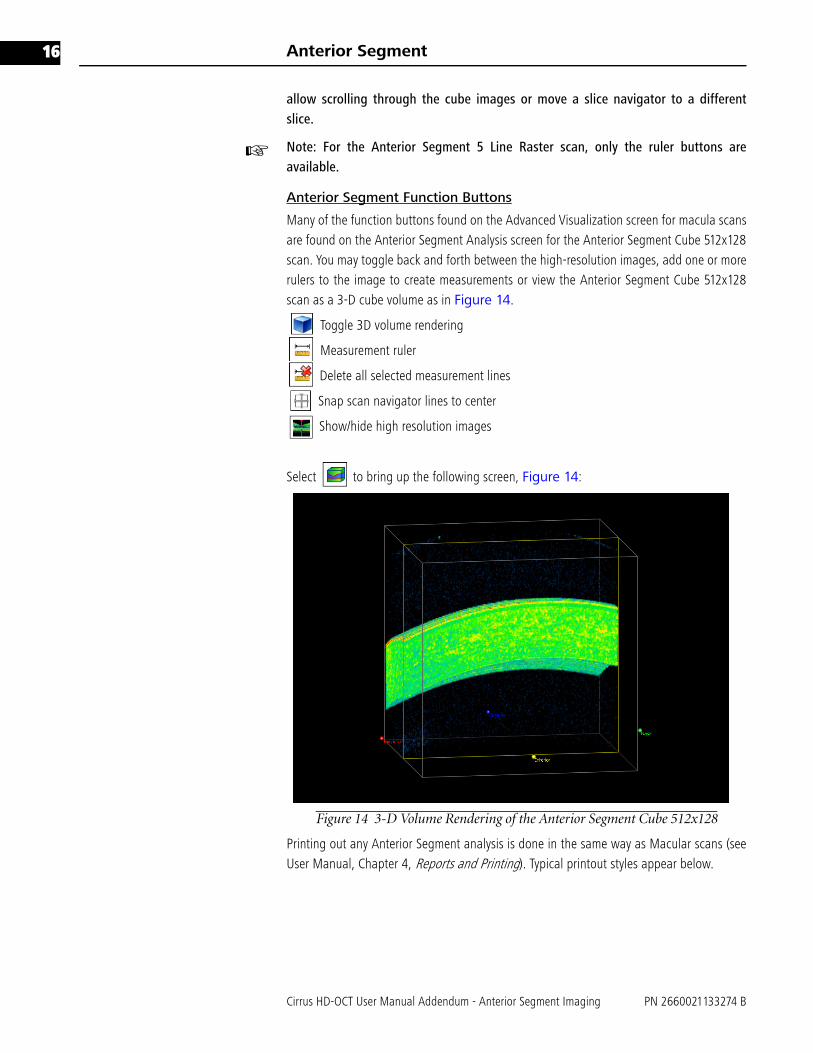
Many of the function buttons found on the Advanced Visualization screen for macula scansare found on the Anterior Segment Analysis screen for the Anterior Segment Cube 512x128scan. You may toggle back and forth between the high-resolution images, add one or morerulers to the image to create measurements or view the Anterior Segment Cube 512x128scan as a 3-D cube volume as in Figure 14.
Toggle 3D volume rendering
Measurement ruler
Delete all selected measurement lines
Snap scan navigator lines to center
Show/hide high resolution images
Select to bring up the following screen, Figure 14:
Figure 14 3-D Volume Rendering of the Anterior Segment Cube 512x128
Printing out any Anterior Segment analysis is done in the same way as Macular scans (seeUser Manual, Chapter 4, Reports and Printing). Typical printout styles appear below.
Cirrus HD-OCT User Manual Addendum - Anterior Segment Imaging PN 2660021133274 B
Anterior Segment 17
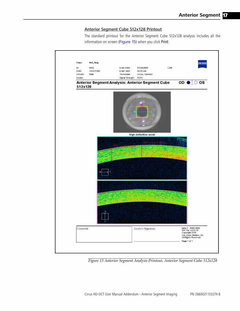
Anterior Segment Cube 512x128 Printout
The standard printout for the Anterior Segment Cube 512x128 analysis includes all theinformation on screen (Figure 15) when you click Print:
Figure 15 Anterior Segment Analysis Printout, Anterior Segment Cube 512x128

Anterior Segment
Cirrus HD-OCT User Manual Addendum - Anterior Segment Imaging PN 2660021133274 B
18
Anterior Segment 5 Line Raster Printout
The standard printout for the Anterior Segment 5 Line Raster analysis includes all theinformation on screen (Figure 16) when you click Print:
Figure 16 High Definition Images Printout, Anterior Segment 5 Line Raster

Cirrus HD-OCT User Manual Addendum - Anterior Segment Imaging PN 2660021133274 B
Anterior Segment 19
Anterior Segment Accuracy, Repeatability and Reproducibility
Benchtop Scanning Accuracy, Repeatability and Reproducibility
Accuracy, repeatability, and reproducibility of scanning in the Cirrus HD-OCT have beenmeasured in benchtop studies. Table 1 below summarizes the results for axial dimensionsin the basic image geometry.
Accuracy is reported as a 95% confidence interval for the absolute difference between ameasured and actual distance. Repeatability and reproducibility are given both as standarddeviation (SD) estimates and as estimates for the 95% upper limit of the differencebetween two measurements. The Repeatability Limit = 2.8 X Repeatability SD. TheReproducibility Limit = 2.8 X Reproducibility SD.
Cirrus HD-OCT Repeatability in Measuring Central Corneal Thickness
A study was conducted to determine repeatability and reproducibility of the Cirrus HD-OCTinstrument measurements of central corneal thickness (CCT). Phase I of the study enrolled28 subjects and was designed to determine inter-device variability, wherein each subjectwas imaged 3 times during a single visit on each of three Cirrus OCT instruments by oneoperator. Phase II enrolled 22 subjects and was designed to determine inter-operatorvariability, wherein each subject was imaged three times during a single visit by each ofthree operators. Phases I and II enrolled different subjects.
The Cirrus HD-OCT repeatability and reproducibility are shown in Table 2. Mean thicknessof each phase and overall (Phase I and II combined) are also shown. Since the randomerror variability from Phase II of the study was larger than that from Phase I, the variancecomponents from Phase II were used to estimate the random measurement variability andthe repeatability standard deviation.
Repeatability SD is the standard deviation under repeatability conditions. The RepeatabilityLimit = 2.8 X Repeatability SD. It provides a 95% upper limit for the difference of twoindependent repeated measurements of the same cornea measured at the same study site.Reproducibility SD is the standard deviation under reproducibility conditions. TheReproducibility Limit = 2.8 X Reproducibility SD. The reproducibility standard deviation was
Table 1 Cirrus HD-OCT Benchtop Accuracy, Repeatability and Reproducibility
Measurement Accuracy
(μm)
Repeatability
SD (μm)
Repeatability
Limit (μm)1Reproducibility
SD (μm)
Reproducibility
Limit (μm)2Average
Measurement
(μm)
Axial Distance in Tissue
6.2 2.6 7.1 2.7 7.6 1165.6
1Repeatability Limit is the upper 95% limit for the difference between repeated results. Per ISO 5725-1 and ISO 5725-6,Repeatability Limit = 2.8 x Repeatability SD
2Reproducibility Limit is the upper 95% limit calculated for the difference between individual measurements using differentoperators and instruments. Each test object was imaged three times by two operators on each of five instruments. Per ISO5725-1 and ISO 5725-6, Reproducibility Limit = 2.8 x Reproducibility SD.

Anterior Segment
Cirrus HD-OCT User Manual Addendum - Anterior Segment Imaging PN 2660021133274 B
20
estimated by the square root of the sum of random measurement variability, inter-devicevariability, and inter-operator variability.
Difference in Central Corneal Thickness measurement Between Cirrus HD-OCT and Ultrasound Pachymetry
Table 3 shows the mean difference in central corneal thickness measurements betweenCirrus HD-OCT and ultrasound pachymetry. The negative difference means that the CirrusCCT measurement is thinner than the ultrasound CCT measurement. This data was takenfrom a total of 50 eyes enrolled in one site measured by a single operator for each device.
OCT devices in general measure thinner than ultrasound pachymetry. The Visante UserManual reports an average measurement difference of 15.1 microns. In the literature,reported differences between OCT and ultrasound pachymetry range from 11.64 to 49.4microns (see References).
(1) Sallet G. Comparison of optical and ultrasound central corneal pachymetry. Bull Soc BelgeOphthalmol 2001;281:35-38
(2) Ho T, Cheng A, Rao S, Lau S, Leung C, Lam D. Central Corneal thickness measurementsusing Orbscan II, Visante, ultrasound, and Pentacam pachymetry after laser in situkeratomileusis for myopia. J Cataract Refract Surg 2007;33:1177-1182.
(3) Zhao PS, Wong TY, Wong WL, Saw SM, Aung T. Comparison of central corneal thicknessmeasurements by visante anterior segment optical coherence tomography with ultrasoundpachymetry. Am J Ophthalmol 2007 Jun;143(6):1047-9
(4) Bechmann M, Thiel MJ, Roesen B et al. Central corneal thickness determined with opticalcoherence tomography in various types of glaucoma. Br.J. Ophthalmol 2000;84:1233-1237
(5) Bechmann M, Thiel MJ, Neubauer AS et al. Central corneal thickness measurement with aretinal optical coherence tomography device versus standard ultrasonic pachymetry. Cornea2001;20:50-54.
(6) Kim HY, Budenz DL, Lee PS, Feuer WJ, Barton K. Comparison of central corneal thicknessusing anterior segment optical coherence tomography vs. ultrasound pachymetry. Am JOphthalmol. 2008; 145(2):228-232
(7) Li E, Mohamed S, Leung C, Rao S, Cheng A, Cheung C, Lam D. Agreement among 3 methodsto Measure corneal thickness: Ultrasound pachymetry, Orbscan II, and Visante AnteriorSegment Optical Coherence Tomography. Ophthalmol 2007; 114 (10) 1842 - 1847
Table 2 Cirrus HD-OCT repeatability and reproducibility in measuring central corneal thickness
Cirrus HD-OCT Repeatability Cirrus HD-OCT Reproducibility Mean Thickness (μm)
Repeatability
SD (μm)
Repeatability
Limits (μm)1Reproducibility
SD (μm)
Reproducibility
Limits (μm)2Phase
I
Phase
II
Overall
4.08 11.42 4.23 11.84 544.25 532.25 538.251Repeatability Limit is the upper 95% limit for the difference between repeated results. Per ISO 5725-1 and ISO 5725-6,Repeatability Limit = 2.8 x Repeatability SD
2Reproducibility Limit is the upper 95% limit calculated for the difference between results repeated using different opera-tors. Each subject was imaged three times during a single visit by each of three operators. Per ISO 5725-1 and ISO 5725-6,Reproducibility Limit = 2.8 x Reproducibility SD.
Table 3 Difference in Central Corneal Thickness Measurement Between Cirrus HD-OCT
and Ultrasound Pachymetry
95% CI of the Difference
Mean Difference SD Lower Upper
Cirrus CCT- Ultrasound pachymetry CCT (μm)
-9.06 5.63 -10.66 -7.46


Carl Zeiss Meditec, Inc.
5160 Hacienda Drive
Dublin, CA 94568
USA
Toll Free: 1-800-341-6968
Phone: 1-925-557-4100
Fax: 1-925-557-4101
www.meditec.zeiss.com
Carl Zeiss Meditec AG
Goeschwitzer Strasse 51-52
07745 Jena
Germany
Phone: +49 36 41 22 03 33
Fax: +49 36 41 22 01 12
www.meditec.zeiss.com
PN 2660021133274 B
Cirrus HD-OCT 4.0 Addendum
Anterior Segment Imaging
Specifications subject to change without notice