Embed Size (px)
Citation preview

1
Circulation Phenomena
2
Circulation Phenomena in the Clinkerization Process René Hasler, Daniel Brassel
PT 99/14503/E 1. INTRODUCTION..................................................................................................…...... 510
2. MECHANISM OF THE CIRCULATION PHENOMENA
........................................….... 513
3. CIRCULATING ELEMENTS IN THE KILN SYSTEM ............................................…...
520
3.1 Input of Circulating Elements ....................................................................…........ 520
3.2 Enrichment of Circulating Elements / Endangered Zones for Encrustation
Formation ................................................................................................................... 520
3.3 Output of Circulating Elements ..................................................................…....... 521
3.4 Volatility of Circulating Elements.................................................................…...... 525
3.5 Condensation of Circulating Elements ...........................................................…... 536
4. TYPICAL APPEARANCE OF BUILD-UPS.................................................................. 538
5. KILN OPERATION PROBLEMS DUE TO CIRCULATING ELEMENTS.....................
547
6. IDENTIFICATION OF PROBLEMS WITH ENCRUSTATIONS AND BUILD-UPS
..... 547
6.1 Material Balance ......................................................................................…......... 548
6.2 Criteria and Indicators to Assess the Build-up Problem.............................…....... 549
6.3 Example of a Circulation Phenomena Problem .........................................…....... 553
7. MEASURES AGAINST BUILD-UP FORMATION .......................................................
556
7.1 General Measures....................................................................................…......... 556
7.2 “Intelligent“ Cleaning .................................................................................…........ 556
7.3 Measures against Chloride Problems ........................................................…....... 561
7.4 Measures against Sulfur Problems ............................................................…....... 561
7.5 Measures against Alkali Problems ...............................................................….... 564
8. MATHEMATICAL MODEL TO SIMULATE THE CYCLES OF THE CIRCULATING

3
ELEMENTS...............................................................................................................….... 565
4
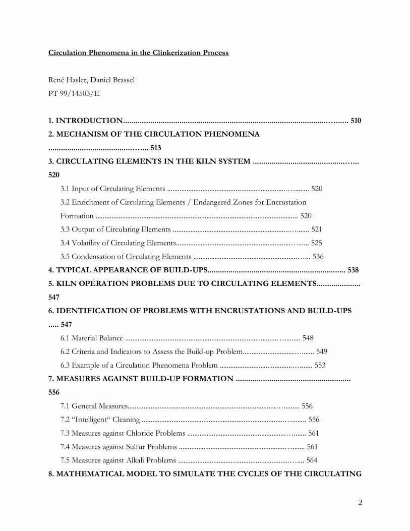
SUMMARY
This chapter describes the circulation of volatile elements in the kiln system. It indicates the
tolerable inputs of circulating elements so that no excessive build-up and clogging problems
arise.
In particular it shall serve as guideline how an encrustation problem, caused by volatile elements,
is systematically solved. 1. INTRODUCTION
Alkali, sulfur and chlorine compounds (hereafter called circulating or volatile elements, see
below) in raw materials and fuels utilized for the cement manufacture, when present in high
concentrations often given rise to difficulties in kiln operation with build-up formation, mainly in
the preheater and the kiln inlet section. Volatile Elements (VE):
Sulfur SO3
Potassium K2O
Sodium Na2O
Chlorine Cl
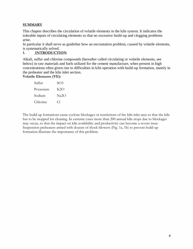
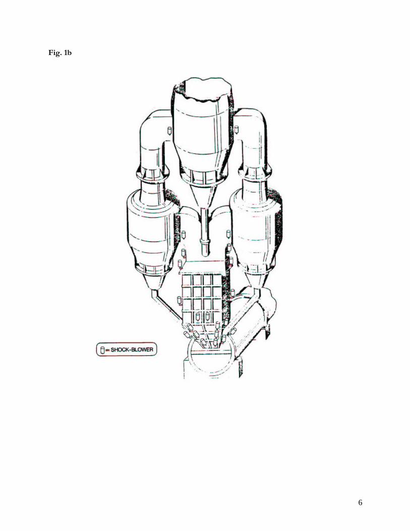
The build-up formations cause cyclone blockages or restrictions of the kiln inlet area so that the kiln has to be stopped for cleaning. In extreme cases more than 200 annual kiln stops due to blockages may occur, so that the impact on kiln availability and productivity can become a severe issue. Suspension preheaters armed with dozens of shock blowers (Fig. 1a, 1b) to prevent build-up formation illustrate the importance of this problem.
5
Fig. 1a
6
Fig. 1b
7
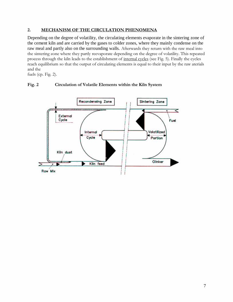
2. MECHANISM OF THE CIRCULATION PHENOMENA
Depending on the degree of volatility, the circulating elements evaporate in the sintering zone of
the cement kiln and are carried by the gases to colder zones, where they mainly condense on the
raw meal and partly also on the surrounding walls. Afterwards they return with the raw meal into the sintering zone where they partly reevaporate depending on the degree of volatility. This repeated process through the kiln leads to the establishment of internal cycles (see Fig. 5). Finally the cycles reach equilibrium so that the output of circulating elements is equal to their input by the raw aterials and the fuels (cp. Fig. 2). Fig. 2 Circulation of Volatile Elements within the Kiln System

8
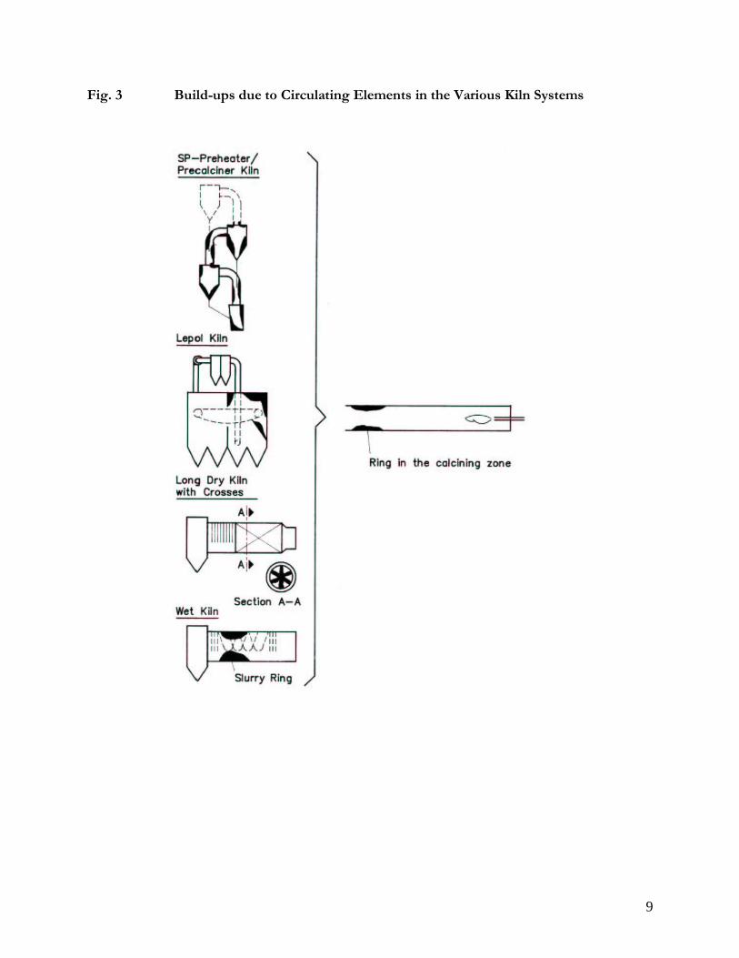
Almost all the circulating elements finally leave the system with the clinker. However, this is only the case when beforehand sufficiently high internal cycles of the volatile elements have been formed. The extents of these cycles depend on the degree of volatility of the circulating elements. As the latter recondense on the colder raw meal and the surrounding walls, the formed sticky molten salts are able to reduce the fluidability of the raw meal and, if present in sufficient quantities, to glue it finally on the walls. From time to time, especially during a change of the temperature profile, pieces of build-ups fall down and mainly block the cyclone outlets (Fig. 3).
9
Fig. 3 Build-ups due to Circulating Elements in the Various Kiln Systems
10
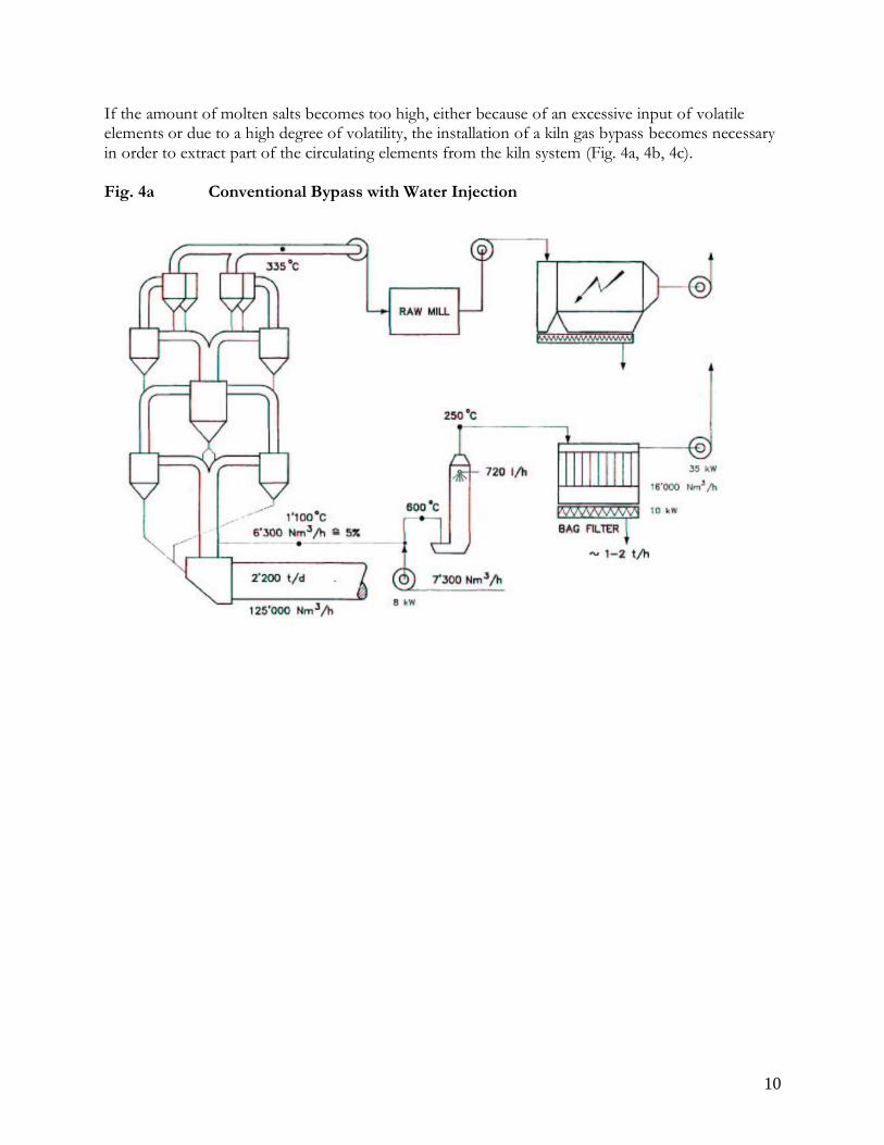
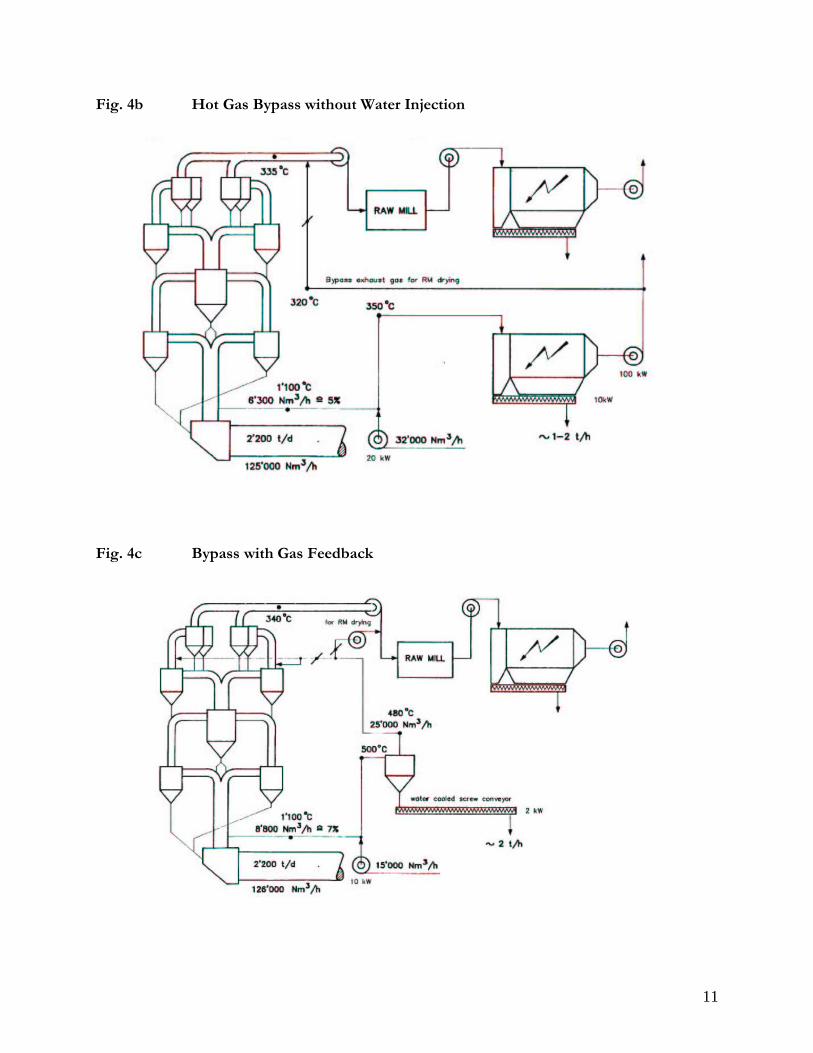
If the amount of molten salts becomes too high, either because of an excessive input of volatile elements or due to a high degree of volatility, the installation of a kiln gas bypass becomes necessary in order to extract part of the circulating elements from the kiln system (Fig. 4a, 4b, 4c). Fig. 4a Conventional Bypass with Water Injection
11
Fig. 4b Hot Gas Bypass without Water Injection Fig. 4c Bypass with Gas Feedback
12
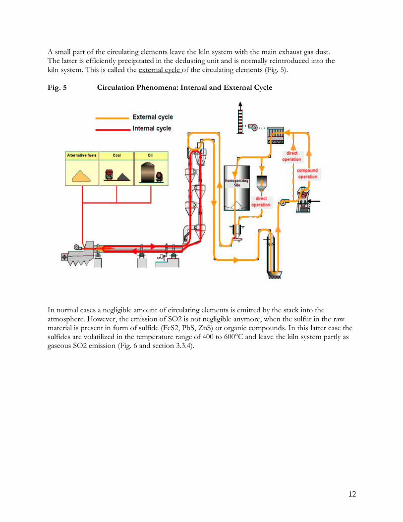
A small part of the circulating elements leave the kiln system with the main exhaust gas dust. The latter is efficiently precipitated in the dedusting unit and is normally reintroduced into the kiln system. This is called the external cycle of the circulating elements (Fig. 5). Fig. 5 Circulation Phenomena: Internal and External Cycle In normal cases a negligible amount of circulating elements is emitted by the stack into the atmosphere. However, the emission of SO2 is not negligible anymore, when the sulfur in the raw material is present in form of sulfide (FeS2, PbS, ZnS) or organic compounds. In this latter case the sulfides are volatilized in the temperature range of 400 to 600°C and leave the kiln system partly as gaseous SO2 emission (Fig. 6 and section 3.3.4).
13
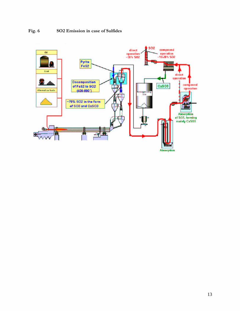
Fig. 6 SO2 Emission in case of Sulfides
14
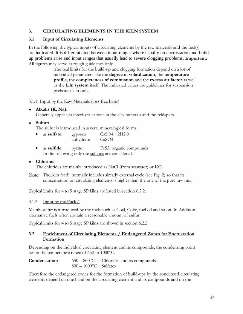
3. CIRCULATING ELEMENTS IN THE KILN SYSTEM
3.1 Input of Circulating Elements
In the following the typical inputs of circulating elements by the raw materials and the fuel(s)
are indicated. It is differentiated between input ranges where usually no encrustation and build-
up problems arise and input ranges that usually lead to severe clogging problems. Important: All figures may serve as rough guidelines only.
The real limits for the build-up and clogging formation depend on a lot of individual parameters like the degree of volatilization, the temperature profile, the completeness of combustion and the excess air factor as well as the kiln system itself. The indicated values are guidelines for suspension preheater kiln only.
3.1.1 Input by the Raw Materials (loss free basis)
Alkalis (K, Na): Generally appear as interlayer cations in the clay minerals and the feldspars.
Sulfur: The sulfur is introduced in several mineralogical forms:
as sulfate: gypsum CaSO4 · 2H2O anhydrate CaSO4
as sulfide: pyrite FeS2, organic compounds In the following only the sulfates are considered.
Chlorine: The chlorides are mainly introduced as NaCl (from seawater) or KCl.
Note: The„kiln feed“ normally includes already external cycle (see Fig. 2) so that its concentration on circulating elements is higher than the one of the pure raw mix.
Typical limits for 4 to 5 stage SP kilns are listed in section 6.2.2.
3.1.2 Input by the Fuel(s)
Mainly sulfur is introduced by the fuels such as Coal, Coke, fuel oil and so on. In Addition alternative fuels often contain a reasonable amount of sulfur.
Typical limits for 4 to 5 stage SP kilns are shown in section 6.2.2.
3.2 Enrichment of Circulating Elements / Endangered Zones for Encrustation Formation
Depending on the individual circulating element and its compounds, the condensing point lies in the temperature range of 650 to 1000°C.
Condensation: 650 – 800°C : Chlorides and its compounds 800 – 1000°C : Sulfates
Therefore the endangered zones for the formation of build-ups by the condensed circulating elements depend on one hand on the circulating element and its compounds and on the
15
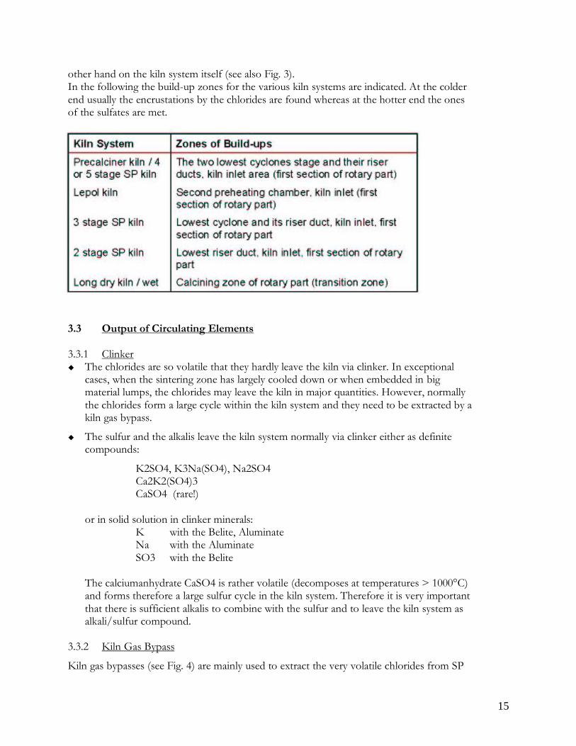
other hand on the kiln system itself (see also Fig. 3). In the following the build-up zones for the various kiln systems are indicated. At the colder end usually the encrustations by the chlorides are found whereas at the hotter end the ones of the sulfates are met. 3.3 Output of Circulating Elements
3.3.1 Clinker The chlorides are so volatile that they hardly leave the kiln via clinker. In exceptional
cases, when the sintering zone has largely cooled down or when embedded in big material lumps, the chlorides may leave the kiln in major quantities. However, normally the chlorides form a large cycle within the kiln system and they need to be extracted by a kiln gas bypass.
The sulfur and the alkalis leave the kiln system normally via clinker either as definite compounds:
K2SO4, K3Na(SO4), Na2SO4 Ca2K2(SO4)3 CaSO4 (rare!)
or in solid solution in clinker minerals: K with the Belite, Aluminate Na with the Aluminate SO3 with the Belite
The calciumanhydrate CaSO4 is rather volatile (decomposes at temperatures > 1000°C) and forms therefore a large sulfur cycle in the kiln system. Therefore it is very important that there is sufficient alkalis to combine with the sulfur and to leave the kiln system as alkali/sulfur compound.
3.3.2 Kiln Gas Bypass
Kiln gas bypasses (see Fig. 4) are mainly used to extract the very volatile chlorides from SP
16
preheater kilns. Chloride bypasses withdraw typically 5 to 15% of the kiln gases. The hot gases from the kiln inlet are quenched down by fresh air, sometimes supported by injection of water into the quench chamber, to a temperature below 600°C. The gaseous chlorides condense onto the withdrawn dust particles and are separated finally in an electrostatic precipitator or a bagfilter (see Fig. 5a, 5b, 5c).
In rare cases kiln gas bypasses are also applied in case of too much CaSO4 and not sufficient alkalis. Also for the production of low alkali clinker large kiln gas bypasses are used (20 to 50% of the kiln gases) in order to withdraw the alkalis from the kiln charge and to produce a clinker with an alkali content of < 0.6% (i.e. Na2Oeq < 0.6%). Thereby the alkalis are volatilized by hard burning and by injection of chlorides into the kiln (see also section 0).
The bypass dust must be discarded e.g. into the quarry or is partly reutilized as additive to the cement, or in rare cases may be sold as filler material. A ballpark figure for the amount of bypass dust: 15 g/kg cli per 10% bypass
Due to the extraction of the bypass gases additional heat loss arise. The specific value per % bypass depends on the kiln system:
Precalciner kilns: 8 – 11 kJ/kg cli
Preheater kilns: 20 kJ/kg cli
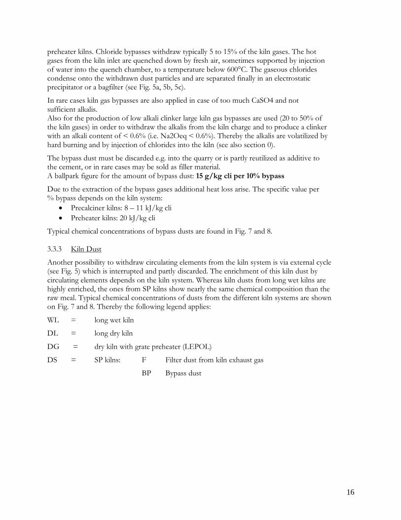
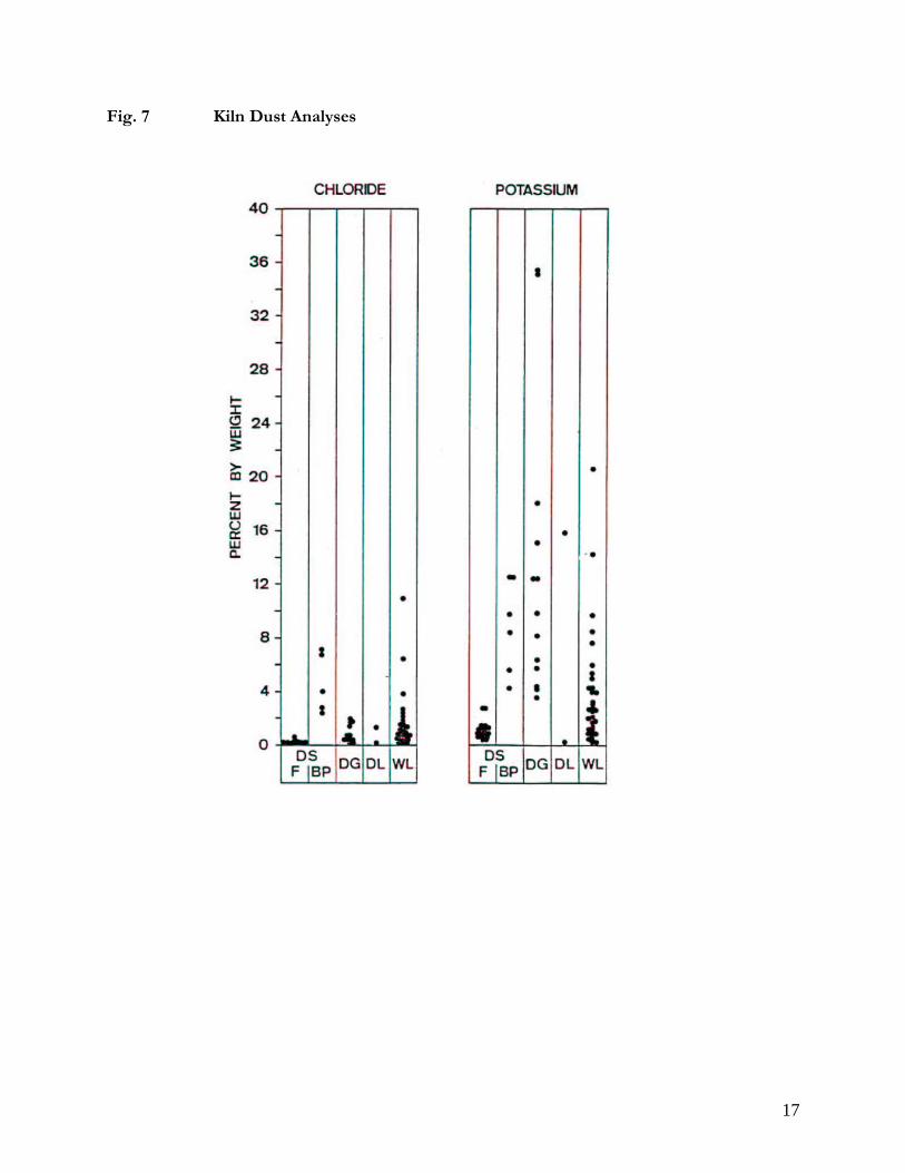
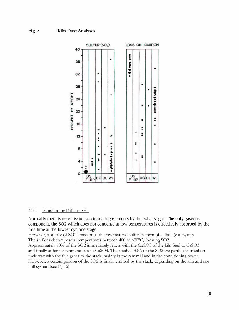
Typical chemical concentrations of bypass dusts are found in Fig. 7 and 8.
3.3.3 Kiln Dust
Another possibility to withdraw circulating elements from the kiln system is via external cycle (see Fig. 5) which is interrupted and partly discarded. The enrichment of this kiln dust by circulating elements depends on the kiln system. Whereas kiln dusts from long wet kilns are highly enriched, the ones from SP kilns show nearly the same chemical composition than the raw meal. Typical chemical concentrations of dusts from the different kiln systems are shown on Fig. 7 and 8. Thereby the following legend applies:
WL = long wet kiln
DL = long dry kiln
DG = dry kiln with grate preheater (LEPOL)
DS = SP kilns: F Filter dust from kiln exhaust gas
BP Bypass dust
17
Fig. 7 Kiln Dust Analyses
18
Fig. 8 Kiln Dust Analyses 3.3.4 Emission by Exhaust Gas
Normally there is no emission of circulating elements by the exhaust gas. The only gaseous
component, the SO2 which does not condense at low temperatures is effectively absorbed by the
free lime at the lowest cyclone stage. However, a source of SO2 emission is the raw material sulfur in form of sulfide (e.g. pyrite). The sulfides decompose at temperatures between 400 to 600°C, forming SO2. Approximately 70% of the SO2 immediately reacts with the CaCO3 of the kiln feed to CaSO3 and finally at higher temperatures to CaSO4. The residual 30% of the SO2 are partly absorbed on their way with the flue gases to the stack, mainly in the raw mill and in the conditioning tower. However, a certain portion of the SO2 is finally emitted by the stack, depending on the kiln and raw mill system (see Fig. 6).
19
3.4 Volatility of Circulating Elements
3.4.1 Definition of Total Volatility
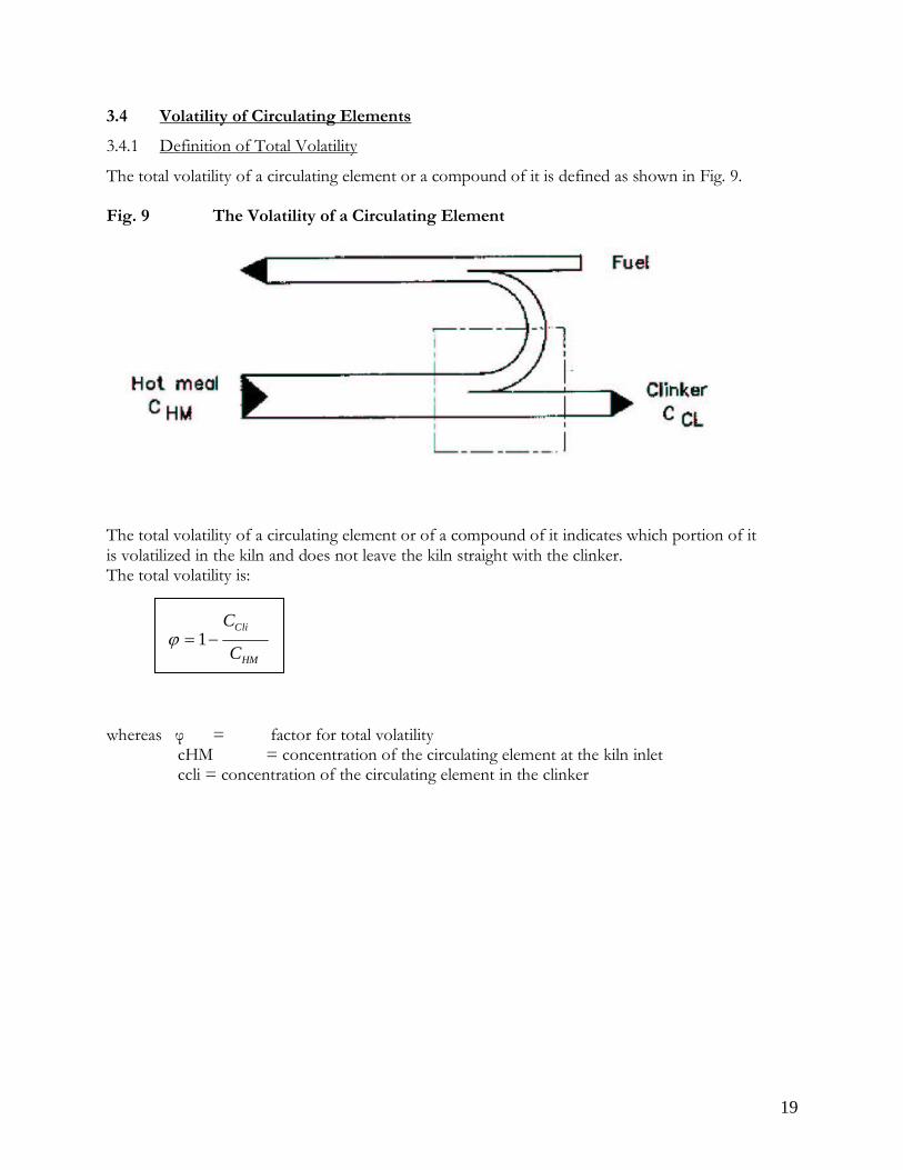
The total volatility of a circulating element or a compound of it is defined as shown in Fig. 9.
Fig. 9 The Volatility of a Circulating Element The total volatility of a circulating element or of a compound of it indicates which portion of it is volatilized in the kiln and does not leave the kiln straight with the clinker. The total volatility is: whereas φ = factor for total volatility
cHM = concentration of the circulating element at the kiln inlet ccli = concentration of the circulating element in the clinker
HM
Cli
C
C 1
20
3.4.2 Affinity of the Circulating Elements
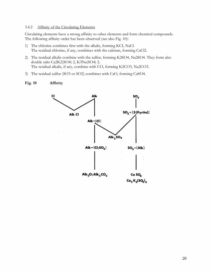
Circulating elements have a strong affinity to other elements and form chemical compounds. The following affinity order has been observed (see also Fig. 10):
1) The chlorine combines first with the alkalis, forming KCI, NaCl. The residual chlorine, if any, combines with the calcium, forming CaCl2.
2) The residual alkalis combine with the sulfur, forming K2SO4, Na2SO4. They form also double salts Ca2K2(SO4) 2, K3Na(SO4) 2. The residual alkalis, if any, combine with CO, forming K2CO3, Na2CO3.
3) The residual sulfur (SO3 or SO2) combines with CaO, forming CaSO4.
Fig. 10 Affinity
21
3.4.3 Volatility of the Circulating Element Compounds
3.4.3.1 General
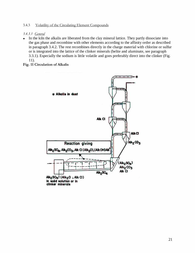
In the kiln the alkalis are liberated from the clay mineral lattice. They partly dissociate into
the gas phase and recombine with other elements according to the affinity order as described
in paragraph 3.4.2. The rest recombines directly in the charge material with chlorine or sulfur
or is integrated into the lattice of the clinker minerals (belite and aluminate, see paragraph
3.3.1). Especially the sodium is little volatile and goes preferably direct into the clinker (Fig.
11). Fig. 11 Circulation of Alkalis
22
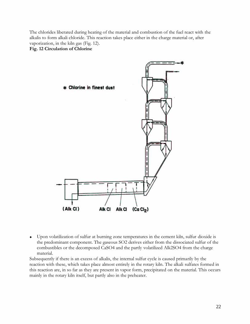
The chlorides liberated during heating of the material and combustion of the fuel react with the alkalis to form alkali chloride. This reaction takes place either in the charge material or, after vaporization, in the kiln gas (Fig. 12). Fig. 12 Circulation of Chlorine Upon volatilization of sulfur at burning zone temperatures in the cement kiln, sulfur dioxide is
the predominant component. The gaseous SO2 derives either from the dissociated sulfur of the combustibles or the decomposed CaSO4 and the partly volatilized Alk2SO4 from the charge material.
Subsequently if there is an excess of alkalis, the internal sulfur cycle is caused primarily by the reaction with these, which takes place almost entirely in the rotary kiln. The alkali sulfates formed in this reaction are, in so far as they are present in vapor form, precipitated on the material. This occurs mainly in the rotary kiln itself, but partly also in the preheater.
23
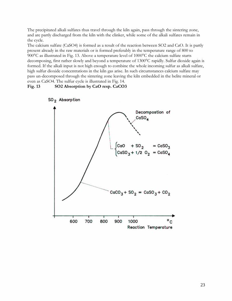
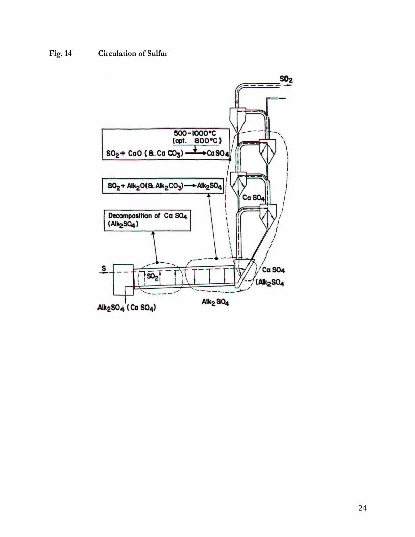
The precipitated alkali sulfates thus travel through the kiln again, pass through the sintering zone, and are partly discharged from the kiln with the clinker, while some of the alkali sulfates remain in the cycle. The calcium sulfate (CaSO4) is formed as a result of the reaction between SO2 and CaO. It is partly present already in the raw materials or is formed preferably in the temperature range of 800 to 900°C as illustrated in Fig. 13. Above a temperature level of 1000°C the calcium sulfate starts decomposing, first rather slowly and beyond a temperature of 1300°C rapidly. Sulfur dioxide again is formed. If the alkali input is not high enough to combine the whole incoming sulfur as alkali sulfate, high sulfur dioxide concentrations in the kiln gas arise. In such circumstances calcium sulfate may pass un-decomposed through the sintering zone leaving the kiln embedded in the belite mineral or even as CaSO4. The sulfur cycle is illustrated in Fig. 14. Fig. 13 SO2 Absorption by CaO resp. CaCO3
24
Fig. 14 Circulation of Sulfur
25
3.4.3.2 Volatility of the Compounds of Circulating Elements
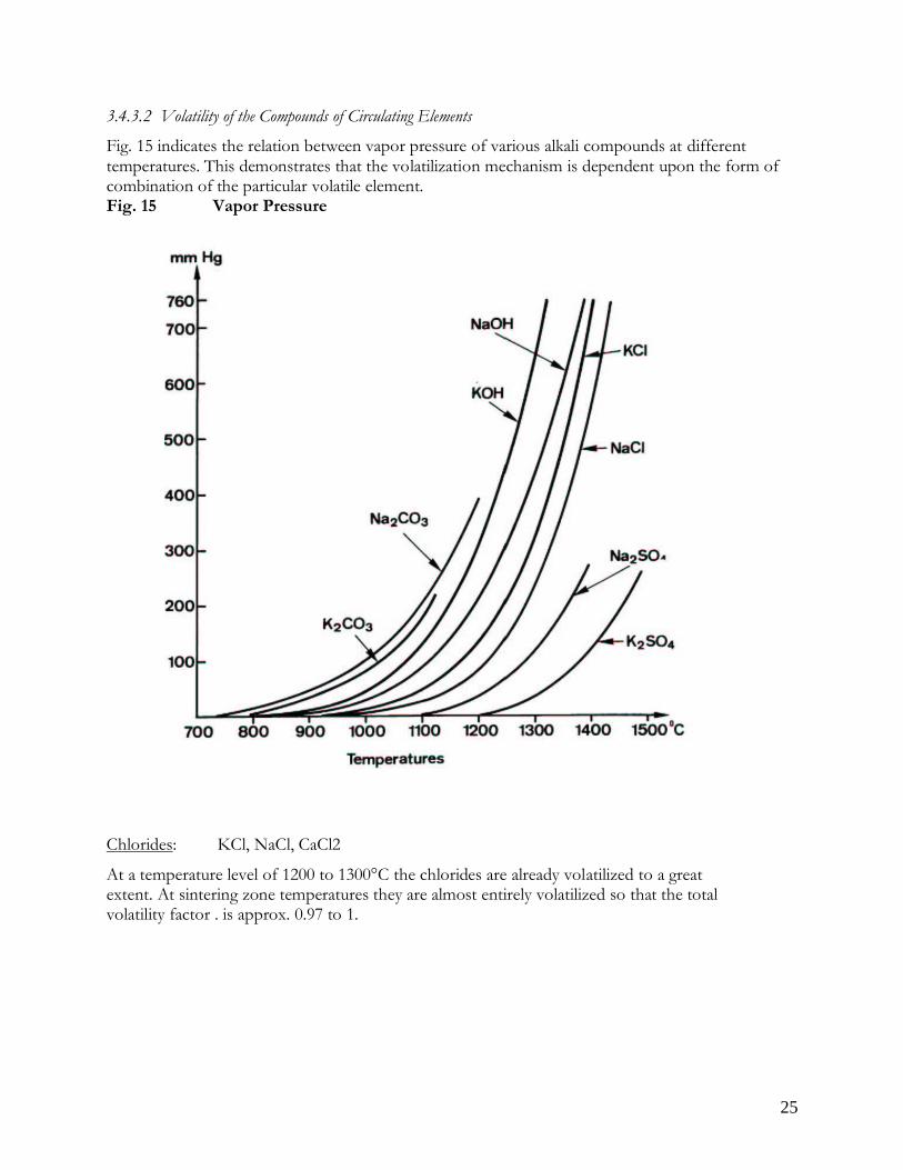
Fig. 15 indicates the relation between vapor pressure of various alkali compounds at different temperatures. This demonstrates that the volatilization mechanism is dependent upon the form of combination of the particular volatile element. Fig. 15 Vapor Pressure Chlorides: KCl, NaCl, CaCl2
At a temperature level of 1200 to 1300°C the chlorides are already volatilized to a great extent. At sintering zone temperatures they are almost entirely volatilized so that the total volatility factor . is approx. 0.97 to 1.
26
Sulfates: Alk2SO4, CaSO4
Basically, the Alk2SO4 are little volatile, whereas the CaSO4 is highly volatile.
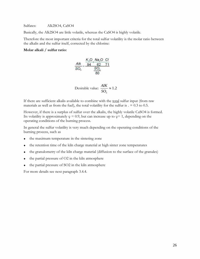
Therefore the most important criteria for the total sulfur volatility is the molar ratio between the alkalis and the sulfur itself, corrected by the chlorine:
Molar alkali / sulfur ratio:
Desirable value: 2.13
SO
AIK
If there are sufficient alkalis available to combine with the total sulfur input (from raw materials as well as from the fuel), the total volatility for the sulfur is . = 0.3 to 0.5.
However, if there is a surplus of sulfur over the alkalis, the highly volatile CaSO4 is formed. Its volatility is approximately φ = 0.9, but can increase up to φ= 1, depending on the operating conditions of the burning process.
In general the sulfur volatility is very much depending on the operating conditions of the burning process, such as
the maximum temperature in the sintering zone
the retention time of the kiln charge material at high sinter zone temperatures
the granulometry of the kiln charge material (diffusion to the surface of the granules)
the partial pressure of O2 in the kiln atmosphere
the partial pressure of SO2 in the kiln atmosphere
For more details see next paragraph 3.4.4.
27
3.4.4 Parameters Influencing the Volatility of the Sulfur Compounds
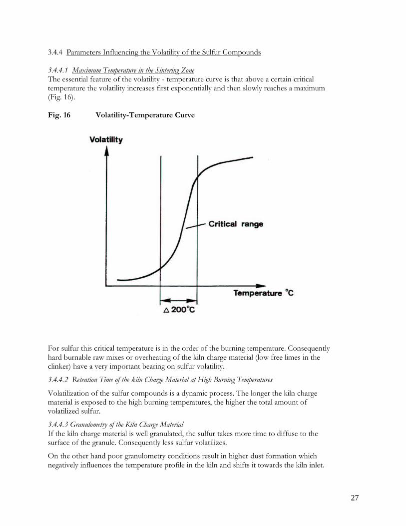
3.4.4.1 Maximum Temperature in the Sintering Zone The essential feature of the volatility - temperature curve is that above a certain critical temperature the volatility increases first exponentially and then slowly reaches a maximum (Fig. 16).
Fig. 16 Volatility-Temperature Curve For sulfur this critical temperature is in the order of the burning temperature. Consequently hard burnable raw mixes or overheating of the kiln charge material (low free limes in the clinker) have a very important bearing on sulfur volatility.
3.4.4.2 Retention Time of the kiln Charge Material at High Burning Temperatures
Volatilization of the sulfur compounds is a dynamic process. The longer the kiln charge material is exposed to the high burning temperatures, the higher the total amount of volatilized sulfur.
3.4.4.3 Granulometry of the Kiln Charge Material If the kiln charge material is well granulated, the sulfur takes more time to diffuse to the surface of the granule. Consequently less sulfur volatilizes.
On the other hand poor granulometry conditions result in higher dust formation which negatively influences the temperature profile in the kiln and shifts it towards the kiln inlet.
28
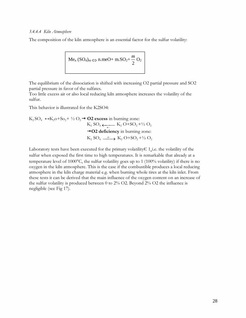
3.4.4.4 Kiln Atmosphere
The composition of the kiln atmosphere is an essential factor for the sulfur volatility: The equilibrium of the dissociation is shifted with increasing O2 partial pressure and SO2 partial pressure in favor of the sulfates. Too little excess air or also local reducing kiln atmosphere increases the volatility of the sulfur.
This behavior is illustrated for the K2SO4:
K2 SO4 ↔K2o+So2+ ½ O2 O2 excess in burning zone: K2 SO4
K2 O+SO2 +½ O2
O2 deficiency in burning zone:
K2 SO4 K2 O+SO2 +½ O2
Laboratory tests have been executed for the primary volatilityЄ ¸1 i.e. the volatility of the
sulfur when exposed the first time to high temperatures. It is remarkable that already at a
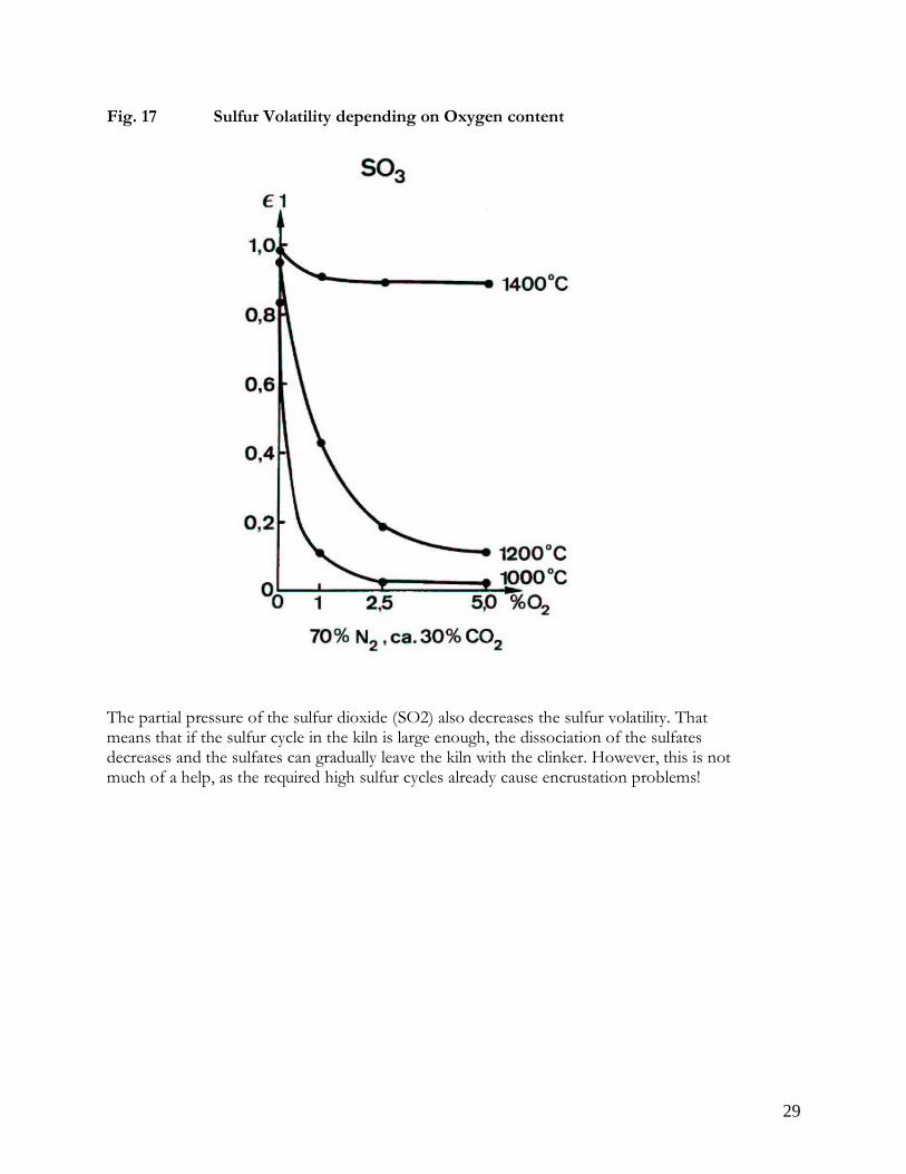
temperature level of 1000°C, the sulfur volatility goes up to 1 (100% volatility) if there is no oxygen in the kiln atmosphere. This is the case if the combustible produces a local reducing atmosphere in the kiln charge material e.g. when burning whole tires at the kiln inlet. From these tests it can be derived that the main influence of the oxygen content on an increase of the sulfur volatility is produced between 0 to 2% O2. Beyond 2% O2 the influence is negligible (see Fig 17).
Men (SO4)m n.meO+ m.SO2+2
mO2
29
Fig. 17 Sulfur Volatility depending on Oxygen content The partial pressure of the sulfur dioxide (SO2) also decreases the sulfur volatility. That means that if the sulfur cycle in the kiln is large enough, the dissociation of the sulfates decreases and the sulfates can gradually leave the kiln with the clinker. However, this is not much of a help, as the required high sulfur cycles already cause encrustation problems!
30
3.5 Condensation of Circulating Elements
As previously stated, the circulating elements volatilize in the hot zones of the kiln and condense at the colder areas of the kiln system (internal cycle).
Melting point and boiling point (at 1 bar) of some chlorides, sulfates and carbonates are listed below. Generally speaking it can be stated that the chlorides condense at lower temperatures than the sulfates.
Melting Point [°C] Boiling Point [°C] at 1 bar Chlorides NaCl 801 1413
KCl 776 1500 (sublim.)
CaCl2 772 > 1600
Sulfates Na2SO4 84 ?
K2SO4 1069 1689
CaSO4 1280 (d) -
Carbonates Na2CO3 851 (decomp.)
K2CO3 891 (decomp.)
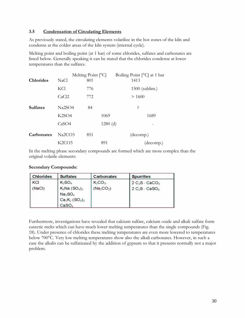
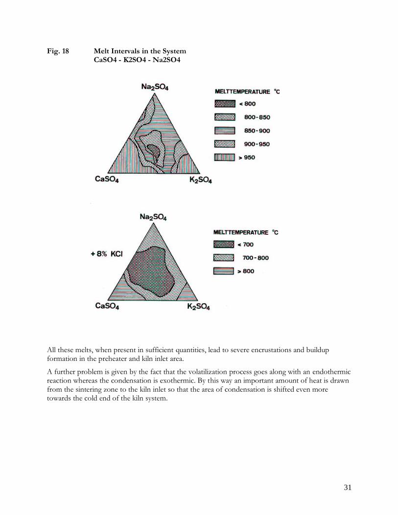
In the melting phase secondary compounds are formed which are more complex than the original volatile elements: Secondary Compounds: Furthermore, investigations have revealed that calcium sulfate, calcium oxide and alkali sulfate form eutectic melts which can have much lower melting temperatures than the single compounds (Fig. 18). Under presence of chlorides these melting temperatures are even more lowered to temperatures below 700°C. Very low melting temperatures show also the alkali carbonates. However, in such a case the alkalis can be sulfatizated by the addition of gypsum so that it presents normally not a major problem.
31
Fig. 18 Melt Intervals in the System CaSO4 - K2SO4 - Na2SO4
All these melts, when present in sufficient quantities, lead to severe encrustations and buildup formation in the preheater and kiln inlet area.
A further problem is given by the fact that the volatilization process goes along with an endothermic reaction whereas the condensation is exothermic. By this way an important amount of heat is drawn from the sintering zone to the kiln inlet so that the area of condensation is shifted even more towards the cold end of the kiln system.
32
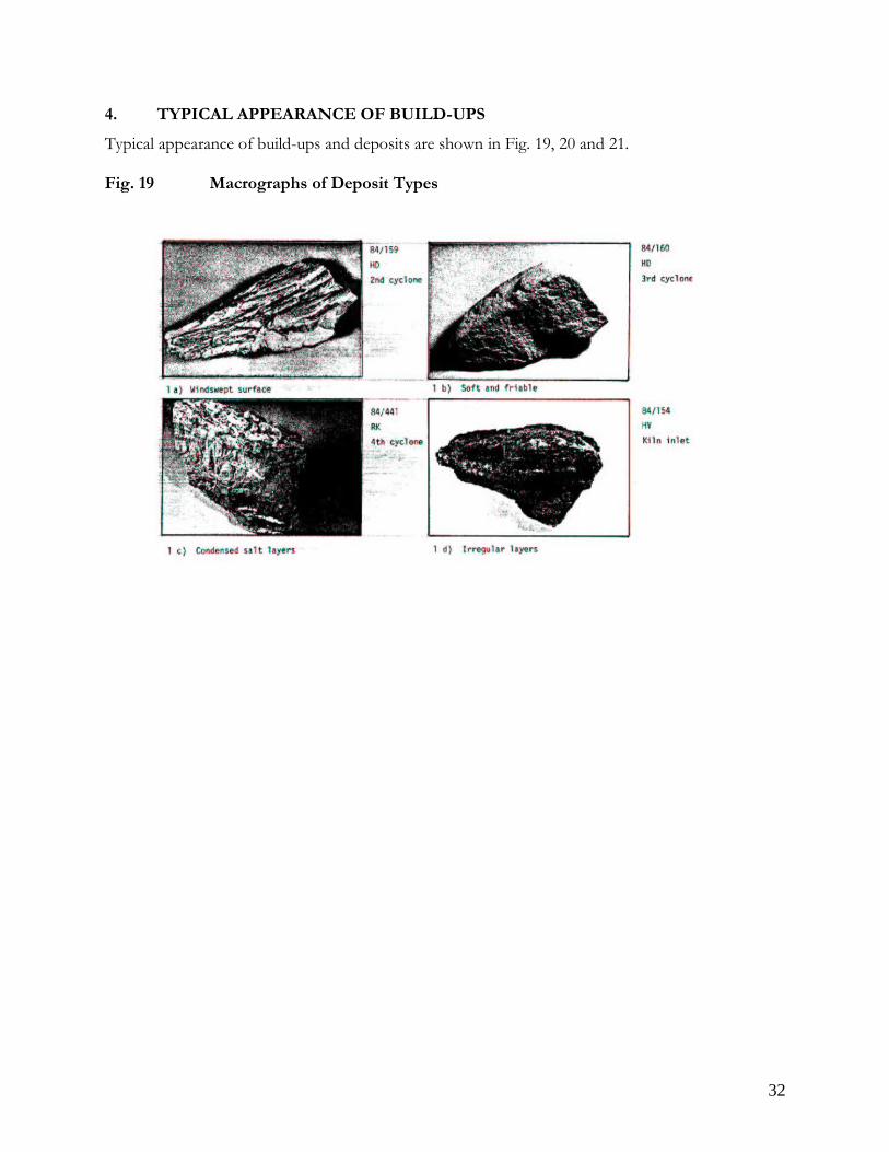
4. TYPICAL APPEARANCE OF BUILD-UPS
Typical appearance of build-ups and deposits are shown in Fig. 19, 20 and 21.
Fig. 19 Macrographs of Deposit Types
33
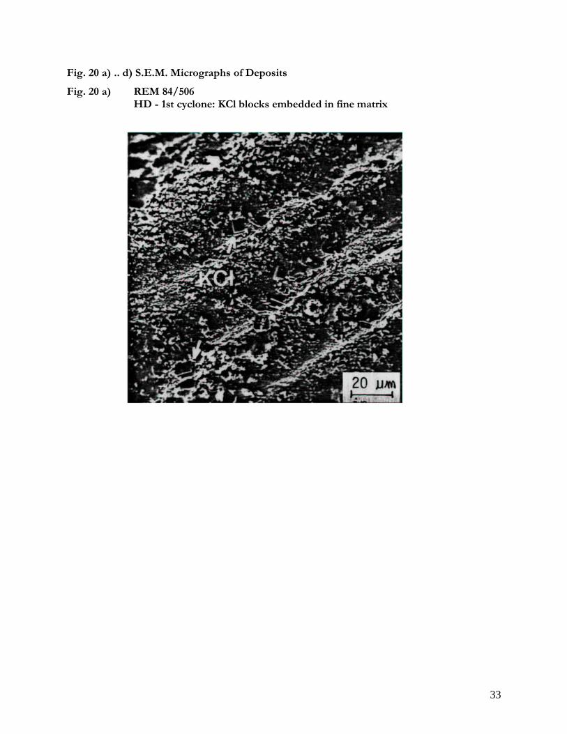
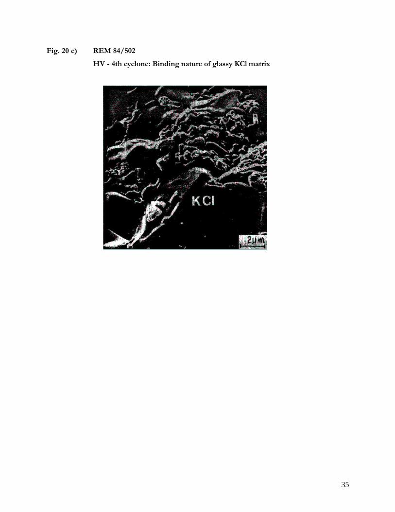
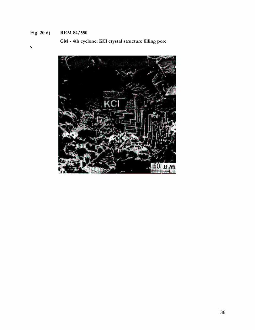
Fig. 20 a) .. d) S.E.M. Micrographs of Deposits
Fig. 20 a) REM 84/506 HD - 1st cyclone: KCl blocks embedded in fine matrix
34
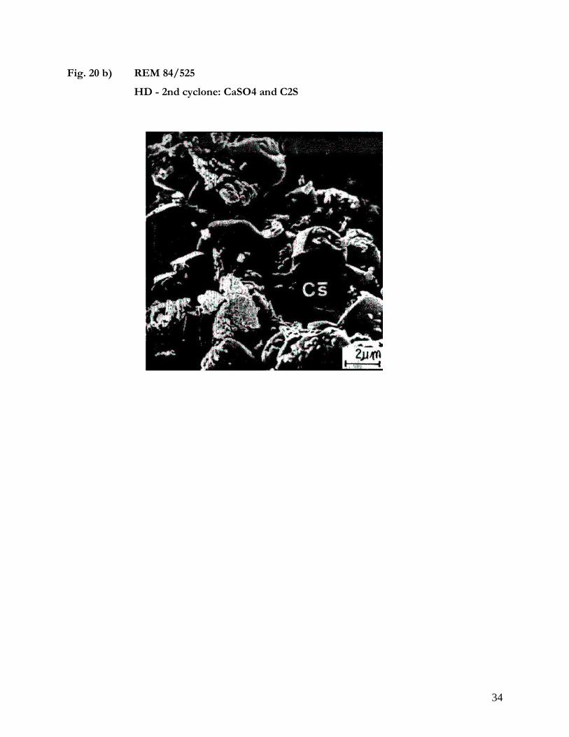
Fig. 20 b) REM 84/525
HD - 2nd cyclone: CaSO4 and C2S
35
Fig. 20 c) REM 84/502
HV - 4th cyclone: Binding nature of glassy KCl matrix
36
Fig. 20 d) REM 84/550
GM - 4th cyclone: KCl crystal structure filling pore x
37
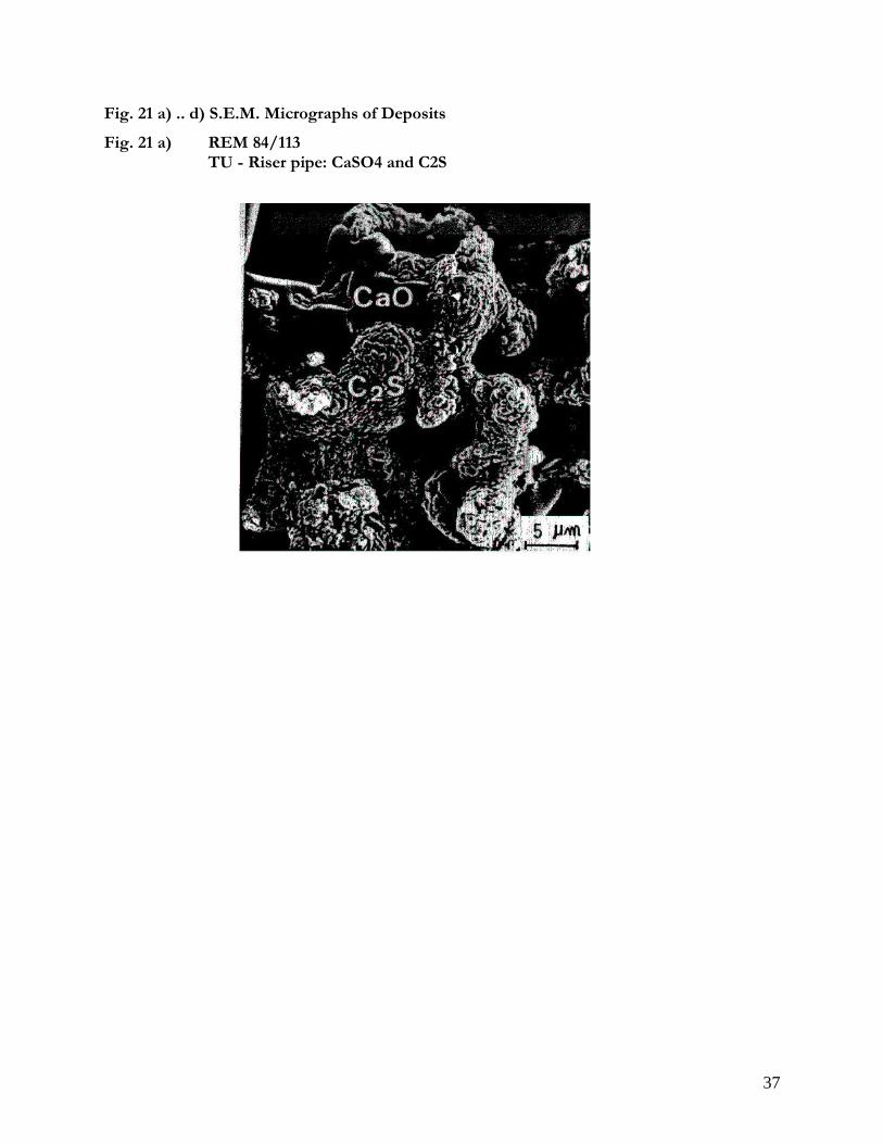
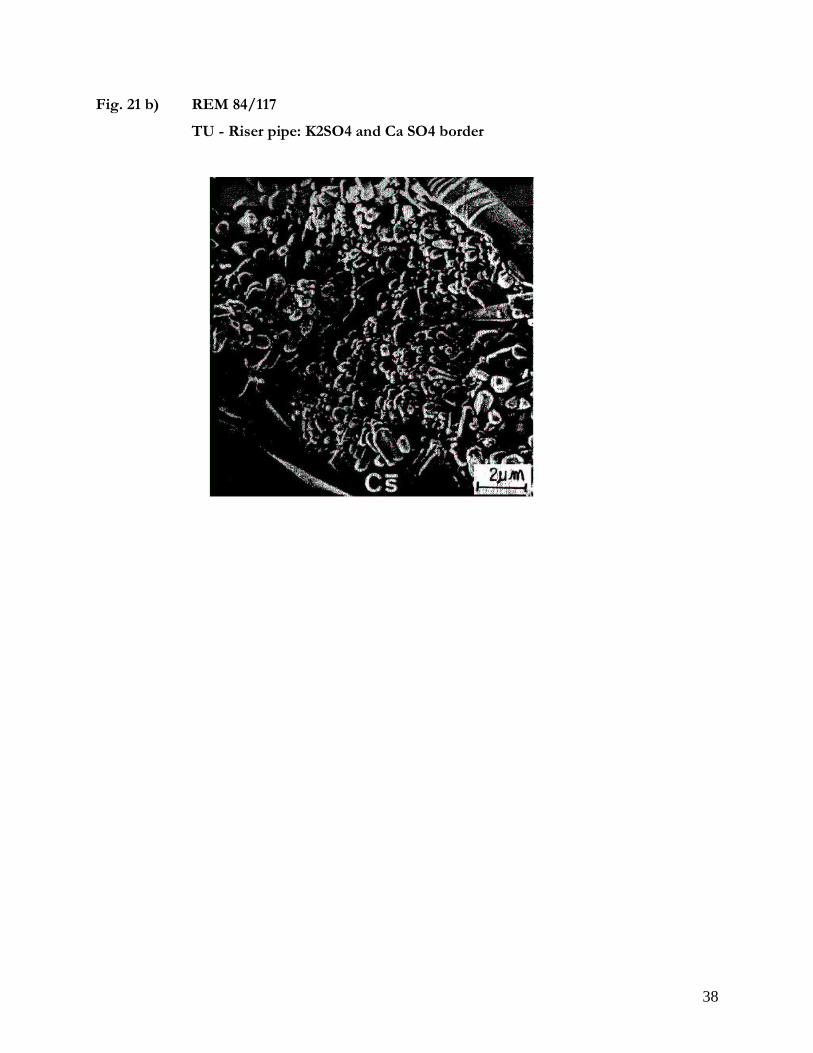
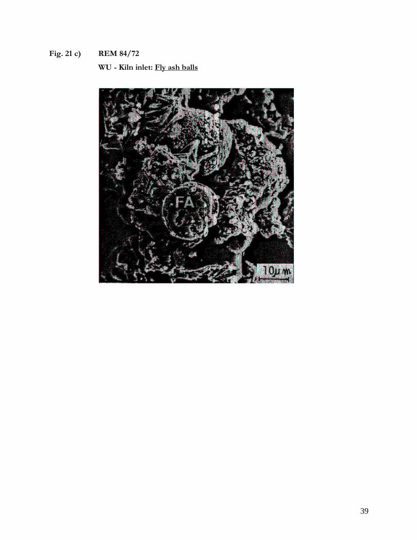
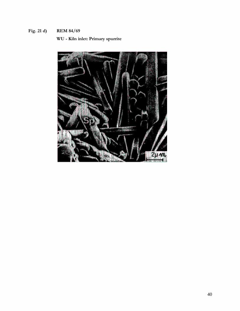
Fig. 21 a) .. d) S.E.M. Micrographs of Deposits
Fig. 21 a) REM 84/113 TU - Riser pipe: CaSO4 and C2S
38
Fig. 21 b) REM 84/117
TU - Riser pipe: K2SO4 and Ca SO4 border
39
Fig. 21 c) REM 84/72
WU - Kiln inlet: Fly ash balls
40
Fig. 21 d) REM 84/69
WU - Kiln inlet: Primary spurrite
41
5. KILN OPERATION PROBLEMS DUE TO CIRCULATING ELEMENTS
The consequences due to high internal cycles of the circulating elements are rather severe.
First it starts by an increased encrustation and build-up formation at the kiln inlet area and the lower part of the preheater. As a consequence the pressure loss across the system increases and at the same time also the inbleeding false air quantity increases. This reduces the maximum kiln draft and thus the maximum clinker production. When the kiln operator tries to compensate the lower available kiln draft by a lower excess air rate, the situation becomes even worse as the sulfur cycle further increases. Studies have revealed that a high chloride cycle impedes also complete combustion. This in turn further increases the sulfur cycle.
High sulfur cycles lead to a poorly granulated clinker and therefore to dust formation. The dust entrains the heat from the burning zone to the kiln inlet, so that the cycles of the volatile elements further increase due to a longer residence time at high temperatures. Furthermore, the high cycles of volatile elements transport the heat of the sintering zone to the area of condensation by the endothermic - exothermic reactions, causing the same effect as the dust cycles described above.
The result of these mechanisms is always the same:
Frequent kiln stops due to encrustation and clogging problems, i.e. reduced kiln utilization factor ( reduction of OEE)
Reduction of the maximum kiln production
Higher heat consumption
Formation of unstable coating at the transition zone and thus high refractory consumption
6. IDENTIFICATION OF PROBLEMS WITH ENCRUSTATIONS AND BUILD-UPS
Chlorides, sulfates, alkalis or any combination of them can cause encrustation and build-up problems. Therefore a detailed analysis is a prerequisite to find an appropriate solution.
The analysis can consist of eight steps as follows: 1) Systematic analysis of the hot meal (cp section 6.1)
(every shift: LOI, SO3, Cl, K2O, Na2O)
2) Comparison with the defined limits of circulating elements in the hot meal!
Chlorine problem, sulfur problem, alkali problem of combination?
3) Performing of a material balance with the inputs and outputs of the circulating elements (cp section 6.1).
Where do the circulating elements come from? 4) Comparison with typical tolerable inputs of circulating elements by raw materials and
fuels.
Which amount is critical?
5) Calculation of the molar alkali / sulfur ratio and comparison with standard.
Are there enough alkali present to withdraw the sulfur within the clinker?
42
6) Calculation of the sulfur volatility and comparison with the standard.
Why sulfur problem?: too high inputs?
unfavorable alkali / sulfur ratio?
because of kiln operation?
7) Detailed recording where the build-ups occur and possible a chemical analysis of a typical build-up peace.
8) Specific measures against build-up formation (see section 7). 6.1 Material Balance
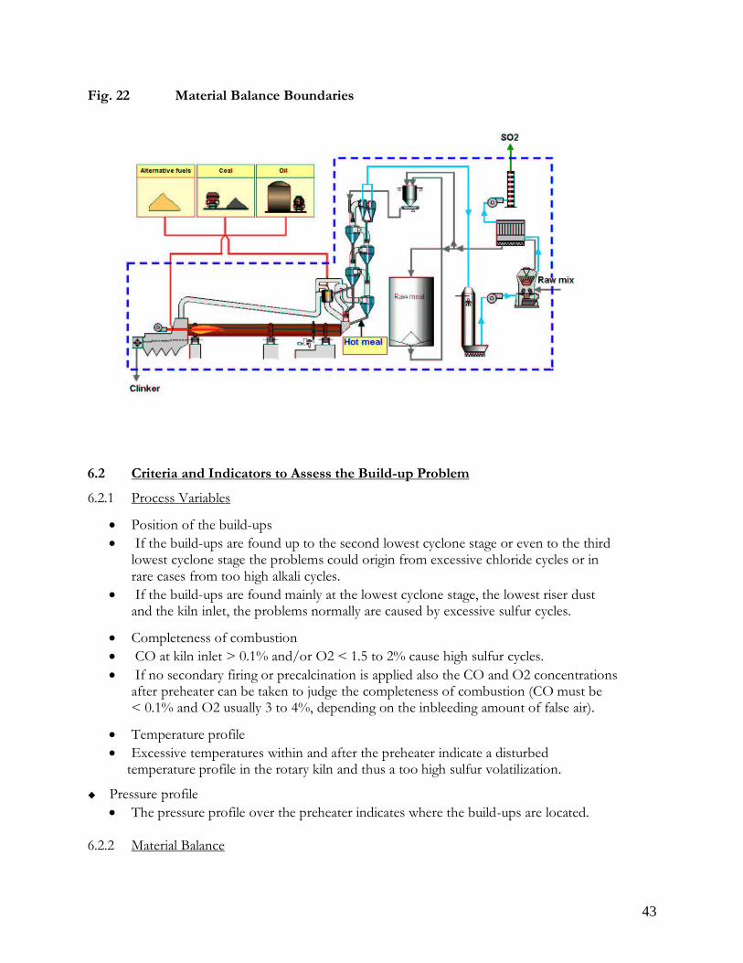
Definition of the balance boundary (Fig. 22):
Shall the external cycle be included or excluded?
Please note that the kiln feed includes the external cycle so that the concentration on volatile elements is higher than the real inputs by the raw material. In this case the kiln dust must be taken into account as further output!
Taking material samples over a sufficiently large period
The sampling period should be at least 8 hours of representative kiln operation.
From every input and output an hourly spot sample shall be taken. The spot samples of the individual inputs and outputs are finally combined to one integrated sample.
The following quantities for the individual spot samples shall be taken: raw mix (before grinding): ~ 20.0 kg meal or dust: ~0.5 kg clinker: ~5.0 kg fuel: ~0.5 kg
Besides the samples for the material balance also samples of the hot meal at kiln inlet (outlet of the lower most cyclone stage) shall be taken, observing the same frequency and sample quantity as stated above.
43
Fig. 22 Material Balance Boundaries 6.2 Criteria and Indicators to Assess the Build-up Problem
6.2.1 Process Variables
Position of the build-ups
If the build-ups are found up to the second lowest cyclone stage or even to the third lowest cyclone stage the problems could origin from excessive chloride cycles or in rare cases from too high alkali cycles.
If the build-ups are found mainly at the lowest cyclone stage, the lowest riser dust and the kiln inlet, the problems normally are caused by excessive sulfur cycles.
Completeness of combustion
CO at kiln inlet > 0.1% and/or O2 < 1.5 to 2% cause high sulfur cycles.
If no secondary firing or precalcination is applied also the CO and O2 concentrations after preheater can be taken to judge the completeness of combustion (CO must be < 0.1% and O2 usually 3 to 4%, depending on the inbleeding amount of false air).
Temperature profile
Excessive temperatures within and after the preheater indicate a disturbed temperature profile in the rotary kiln and thus a too high sulfur volatilization.
Pressure profile
The pressure profile over the preheater indicates where the build-ups are located. 6.2.2 Material Balance
44
First a material balance must be performed as described in paragraph 6.1. Afterwards, the following evaluation shall be done:
1. Input of circulating elements
It has to be determined in which form the sulfur is present in the raw materials, as sulfate or sulfide. When present as sulfide, part of it will leave the kiln system as emission via exhaust gas stack! Therefore the sulfur emission by the stack has to be deducted from the overall sulfur when judging a potential sulfur problem in the kiln.
The inputs of circulating elements (without emitted sulfur through the stack!) should be compared to the ones given below in order to check whether they are in a normal range where usually no build-ups are formed or whether they are too high. This, of course, is only a rough guideline.
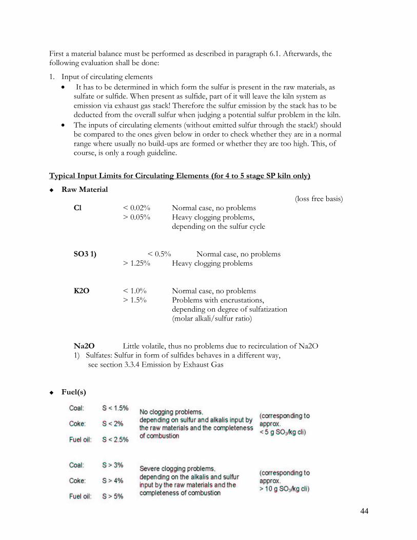
Typical Input Limits for Circulating Elements (for 4 to 5 stage SP kiln only)
Raw Material (loss free basis)
Cl < 0.02% Normal case, no problems > 0.05% Heavy clogging problems,
depending on the sulfur cycle
SO3 1) < 0.5% Normal case, no problems > 1.25% Heavy clogging problems
K2O < 1.0% Normal case, no problems > 1.5% Problems with encrustations,
depending on degree of sulfatization (molar alkali/sulfur ratio)
Na2O Little volatile, thus no problems due to recirculation of Na2O 1) Sulfates: Sulfur in form of sulfides behaves in a different way, see section 3.3.4 Emission by Exhaust Gas
Fuel(s)

45
Gas: ulfur content is normally zero!
Alkali / sulfur ratio (A/S)
The A/S ratio should be preferably at 1.2 or in a range between 0.8 to 1.5. Compare it to the A/S ratio of the investigated case, deducting first the emitted sulfur from the total sulfur input by the raw mix and the fuel.
46
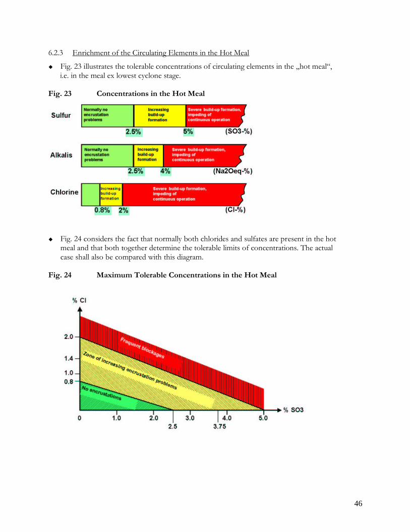
6.2.3 Enrichment of the Circulating Elements in the Hot Meal
Fig. 23 illustrates the tolerable concentrations of circulating elements in the „hot meal“, i.e. in the meal ex lowest cyclone stage.
Fig. 23 Concentrations in the Hot Meal Fig. 24 considers the fact that normally both chlorides and sulfates are present in the hot
meal and that both together determine the tolerable limits of concentrations. The actual case shall also be compared with this diagram.
Fig. 24 Maximum Tolerable Concentrations in the Hot Meal
47
6.2.4 Total Sulfur Volatility
With the formula for the total volatility (see section 3.4.1) the individual total volatilities of the sulfates shall be calculated.
If . of the sulfur is > 0.7 and if at the same time the A/S ratio is within the range of 0.8 to 1.2, the sulfur cycle is definitely too high and needs improvements by measures as stated in section 7.4.
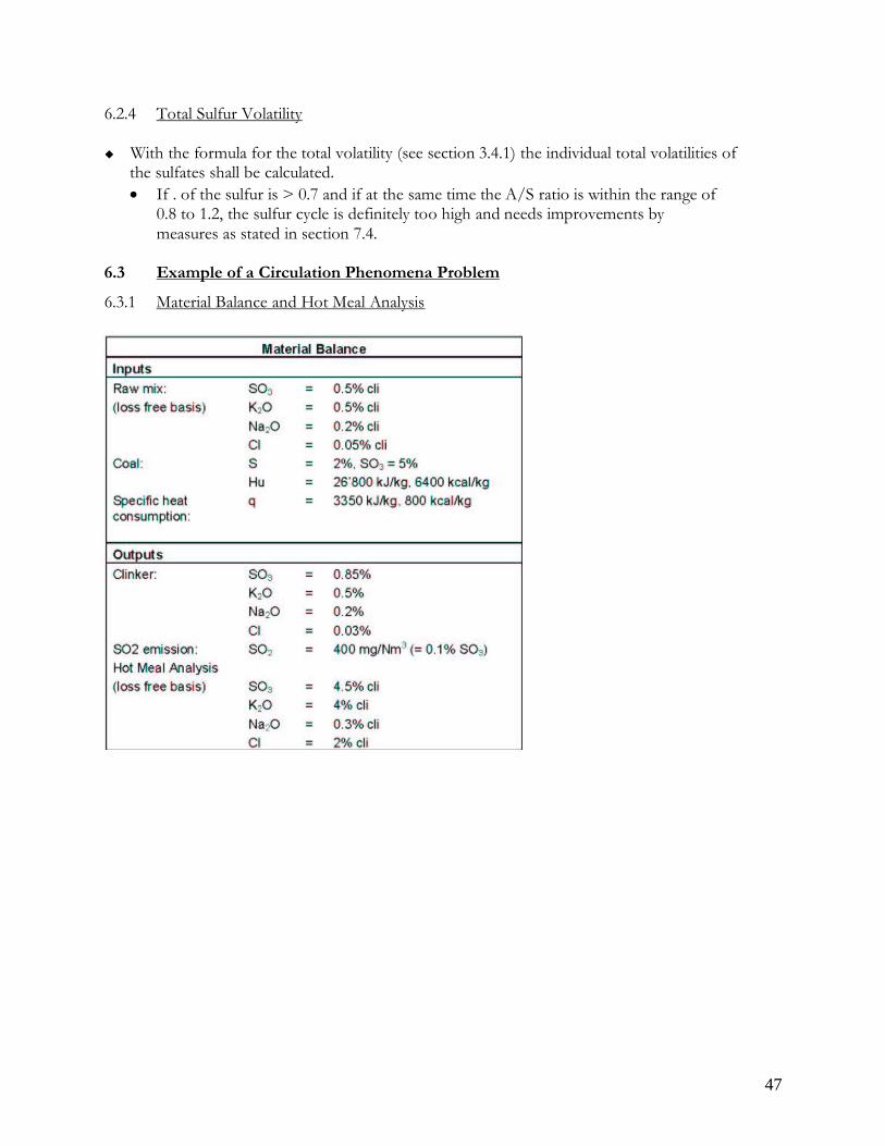
6.3 Example of a Circulation Phenomena Problem
6.3.1 Material Balance and Hot Meal Analysis
48
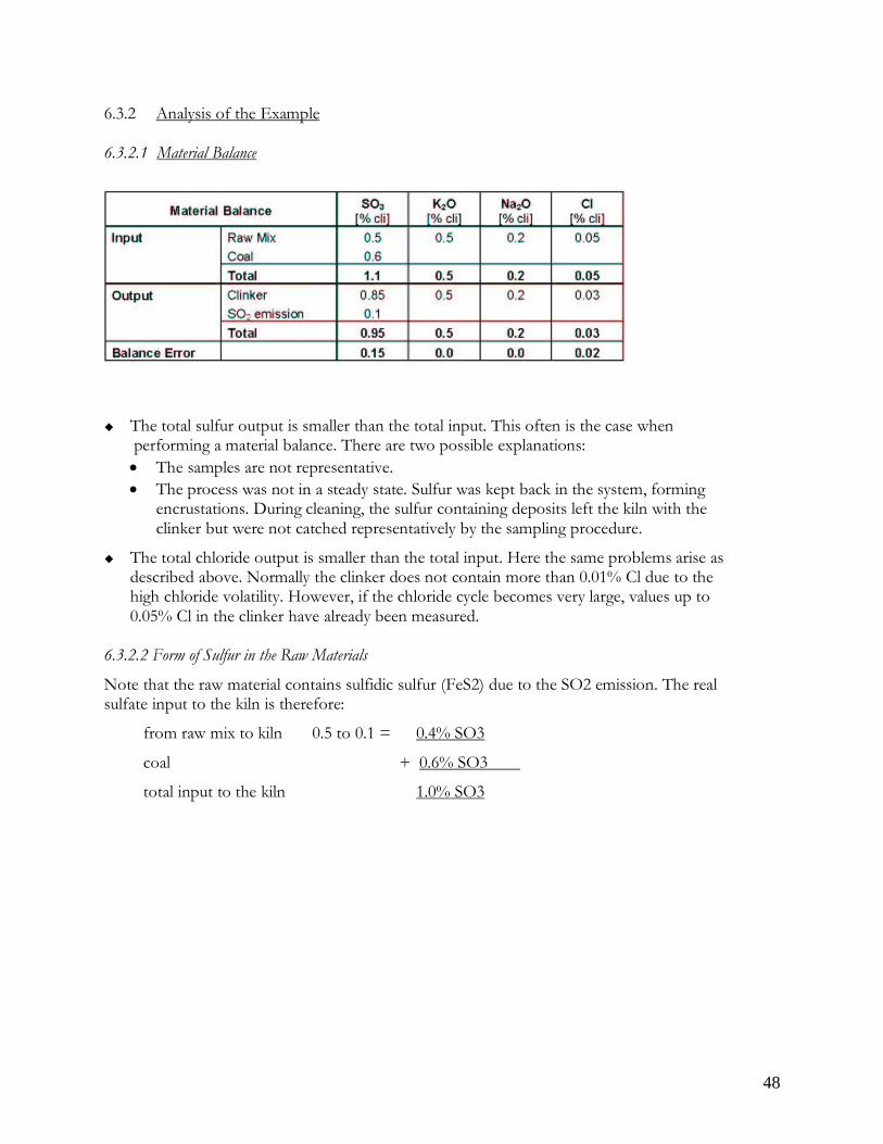
6.3.2 Analysis of the Example
6.3.2.1 Material Balance The total sulfur output is smaller than the total input. This often is the case when
performing a material balance. There are two possible explanations:
The samples are not representative.
The process was not in a steady state. Sulfur was kept back in the system, forming encrustations. During cleaning, the sulfur containing deposits left the kiln with the clinker but were not catched representatively by the sampling procedure.
The total chloride output is smaller than the total input. Here the same problems arise as described above. Normally the clinker does not contain more than 0.01% Cl due to the high chloride volatility. However, if the chloride cycle becomes very large, values up to 0.05% Cl in the clinker have already been measured.
6.3.2.2 Form of Sulfur in the Raw Materials
Note that the raw material contains sulfidic sulfur (FeS2) due to the SO2 emission. The real sulfate input to the kiln is therefore:
from raw mix to kiln 0.5 to 0.1 = 0.4% SO3
coal + 0.6% SO3
total input to the kiln 1.0% SO3
49
6.3.2.3 Comparison with Typical Inputs of Circulating Elements (see section 6.2.2) Inputs by the raw materials:
SO3 = 0.4% (sulfates only!) o.k.
K2O and Na2O o.k.
Cl = 0.05% very high, bypass required
Sulfur inputs by the coal:
S = 2% high, but within the normal range
6.3.2.4 Alkali / Sulfur Ratio
AIS 63.0
80
0̀.171
05.0
62
2.0
94
5.0
80
%71
%
62
%
94
%
3
22
SO
NaK CIOO
*) total input to the kiln (see section 6.3.2.2)
The A/S ratio is outside of the desirable range of 0.8 to 1.5.
6.3.2.5 Enrichment of Circulating Elements in the Hot Meal
Comparison with tolerable concentrations of circulating elements (see section 6.2.2)
SO3 = 4.5% High, far beyond normal limit, problems with encrustation
Alkalis: Slightly above normal, but highly desirable
0.66 · 4 + 0.3 =2.9% due to the large sulfur input!
Cl = 2% High, far beyond normal limit, problems with encrustations
Comparison with diagram for maximum concentrations (see section 6.2.2)
SO3 = 4.5% Cl = 2%
6.3.2.6 Total Sulfur Volatility (SO3)
φ= 81.05.4
85.011
CC
HM
CN
frequent blockages to be expected
50
φ > 0.7: Because of the low A/S ratio, a substantial portion of the sulfur is in form of CaSO4 which leads to the high volatility of > 0.7.
7. MEASURES AGAINST BUILD-UP FORMATION
7.1 General Measures
Reduction of the Inputs of Circulating Elements
The most obvious measure against build-up formation is to reduce the input of circulating elements. It is normally not possible to change the main raw materials. However, sometimes a minor component that contains a substantial amount of circulating elements can be replaced. In most cases the sulfur content of the fuel is more easy to change. Please note that the fuel may also contain considerable amounts of chlorides.
The circulating elements of the raw materials in the quarry deposits are often not homogeneously distributed. In such cases prehomogenization of the raw materials combined with selective quarrying helps to reduce peak inputs of circulating elements into the kiln system.
Smooth Kiln Operation
In many cases the cycles of circulating elements are frequently increased by an inadequate kiln operation applying to drastic changes in fuel feed and draft.
Also the best kiln operator cannot apply during his daily work of 8 h such a super constant kiln operation. Therefore the author is of the strong opinion that only a fully automatic kiln control will provide optimal results (cp. LINKman).
7.2 “Intelligent“ Cleaning
Important: The more circulating elements are introduced into the kiln system the better and more efficient cleaning methods have to be applied!
Preheaters have to be controlled and cleaned at least once a shift to remove immediately possible build-ups! Therefore a experienced tower guard is needed.
On each platform enough cleaning slots are required to manually clean the riser duct and the inlet chamber whenever it is necessary. At particularly critical spots additional slots should be installed.
Critical locations where always material deposits are built shall be armed with air blasters. Please note that mostly several blasters for one location must be installed since their cleaning radius is rather small (< 0.5 m). The blasters should always shoot in the direction of material flow (see Fig. 25).
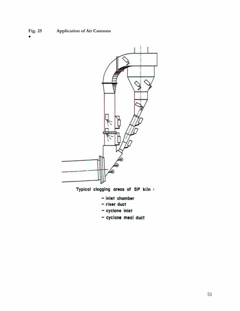
51
Fig. 25 Application of Air Cannons
52
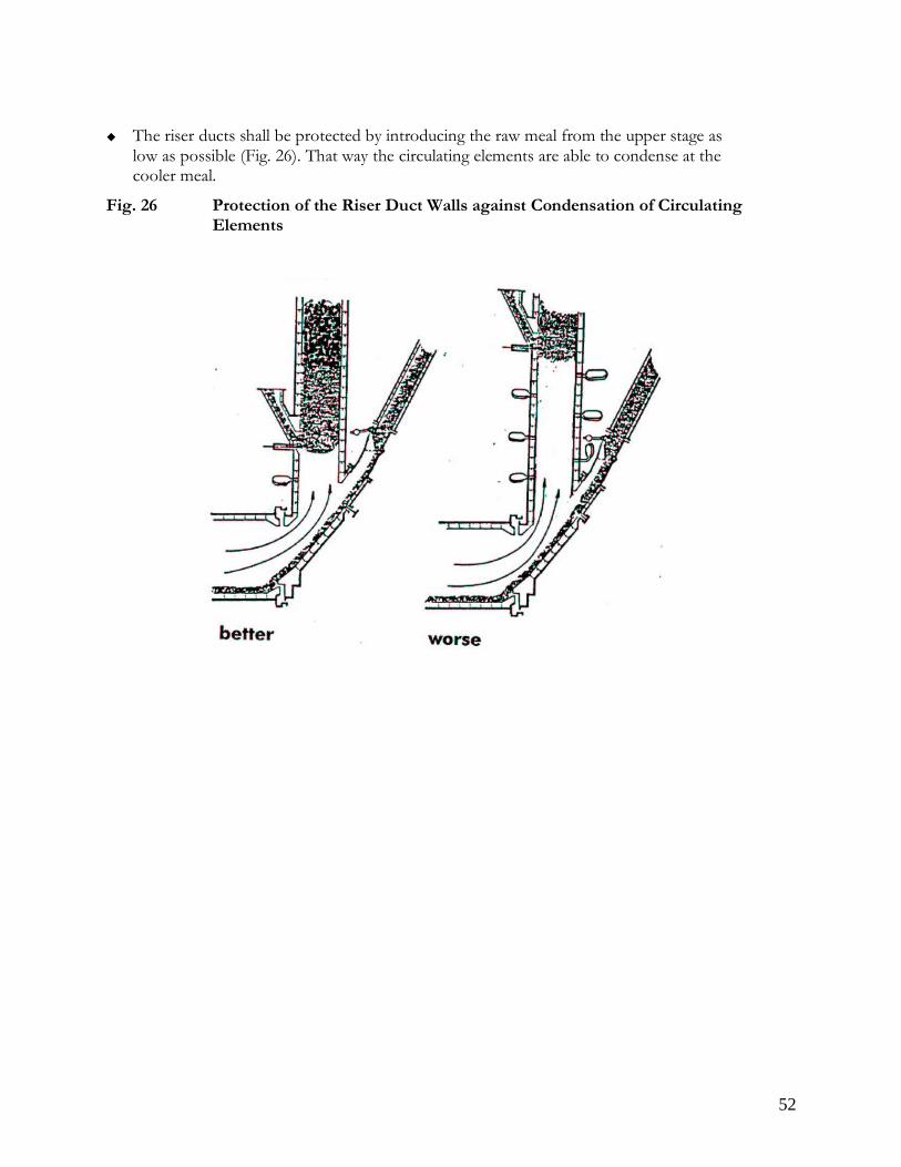
The riser ducts shall be protected by introducing the raw meal from the upper stage as
low as possible (Fig. 26). That way the circulating elements are able to condense at the cooler meal.
Fig. 26 Protection of the Riser Duct Walls against Condensation of Circulating Elements
53
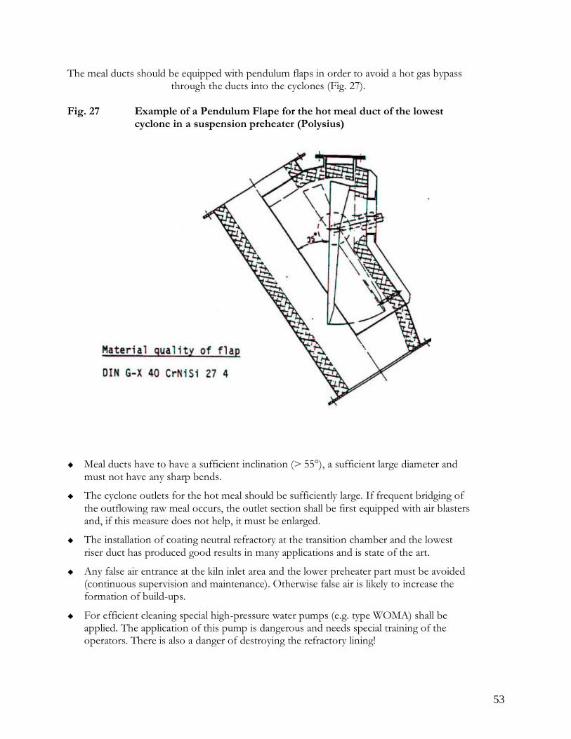
The meal ducts should be equipped with pendulum flaps in order to avoid a hot gas bypass through the ducts into the cyclones (Fig. 27).
Fig. 27 Example of a Pendulum Flape for the hot meal duct of the lowest cyclone in a suspension preheater (Polysius)
Meal ducts have to have a sufficient inclination (> 55°), a sufficient large diameter and
must not have any sharp bends.
The cyclone outlets for the hot meal should be sufficiently large. If frequent bridging of the outflowing raw meal occurs, the outlet section shall be first equipped with air blasters and, if this measure does not help, it must be enlarged.
The installation of coating neutral refractory at the transition chamber and the lowest riser duct has produced good results in many applications and is state of the art.
Any false air entrance at the kiln inlet area and the lower preheater part must be avoided (continuous supervision and maintenance). Otherwise false air is likely to increase the formation of build-ups.
For efficient cleaning special high-pressure water pumps (e.g. type WOMA) shall be applied. The application of this pump is dangerous and needs special training of the operators. There is also a danger of destroying the refractory lining!
54
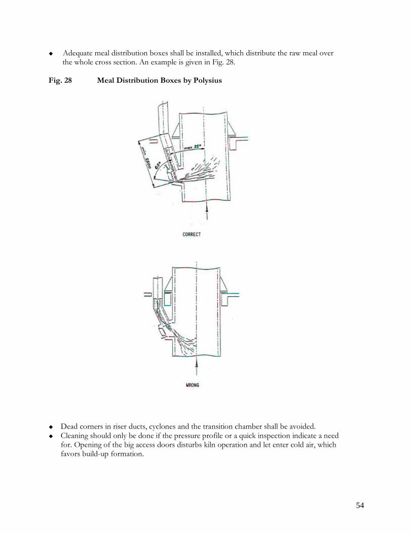
Adequate meal distribution boxes shall be installed, which distribute the raw meal over the whole cross section. An example is given in Fig. 28.
Fig. 28 Meal Distribution Boxes by Polysius Dead corners in riser ducts, cyclones and the transition chamber shall be avoided. Cleaning should only be done if the pressure profile or a quick inspection indicate a need
for. Opening of the big access doors disturbs kiln operation and let enter cold air, which favors build-up formation.
55
7.3 Measures against Chloride Problems
Important: With the clinker chlorine can only be withdrawn to a very limited amount (0.01 to maximum 0.02% Cl). Therefore the measures against chlorine build-ups are limited.
Reduction of the Volatility
There is little chance to decrease the chlorine and chlorine volatility as evaporation takes place at a low temperature range (800 to 1000°C).
Discarding of Dust (external cycle)
For long dry and wet kilns as well as for Lepol kilns the chlorides are effectively withdrawn from the kiln by discarding the finest fraction of the total of the kiln dust.
For preheater kiln dust discarding is normally not very efficient as the accumulation of chlorides in the dust is small. However, in case of a large internal chloride cycle this measure could help to keep it at a lower level. The effect of the measure can be calculated by a material balance.
Reduction of the Sulfur Cycle
Build-up formation is provoked by all circulating elements together. As the chloride cycle cannot be effectively influenced, all possible measures should be taken to reduce the sulfur cycle as it increases the tolerance threshold for chlorine.
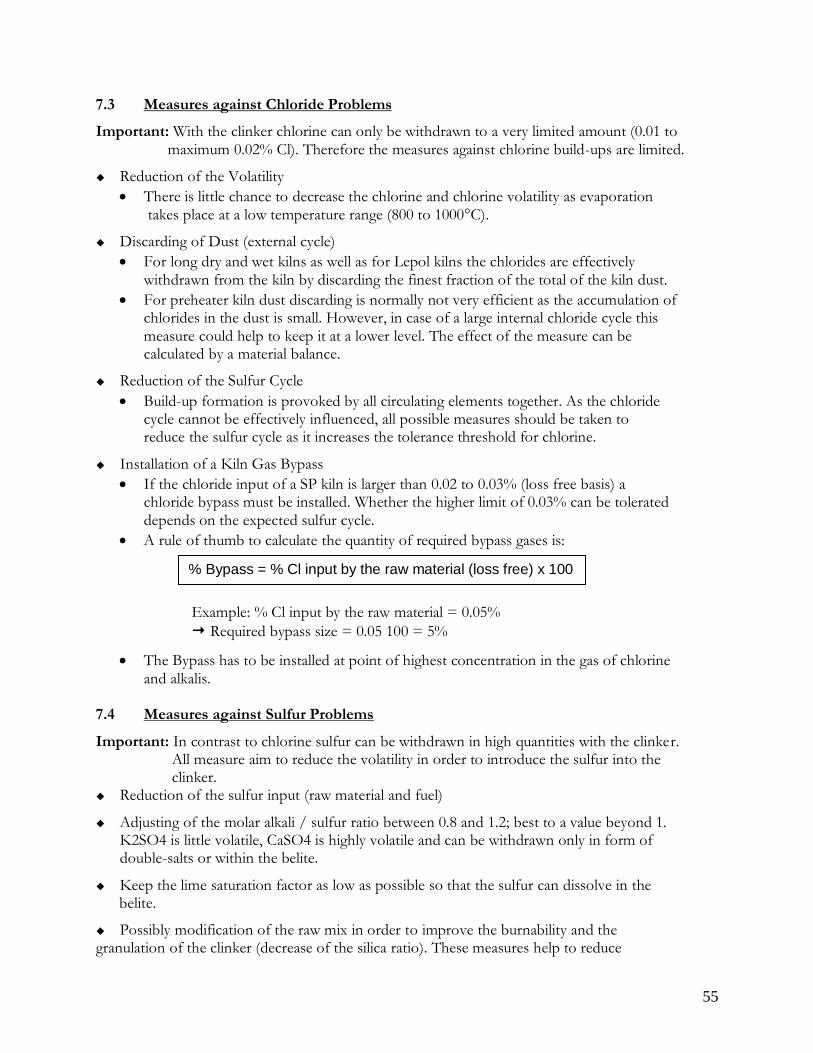
Installation of a Kiln Gas Bypass
If the chloride input of a SP kiln is larger than 0.02 to 0.03% (loss free basis) a chloride bypass must be installed. Whether the higher limit of 0.03% can be tolerated depends on the expected sulfur cycle.
A rule of thumb to calculate the quantity of required bypass gases is:
Example: % Cl input by the raw material = 0.05%
Required bypass size = 0.05 100 = 5%
The Bypass has to be installed at point of highest concentration in the gas of chlorine and alkalis.
7.4 Measures against Sulfur Problems
Important: In contrast to chlorine sulfur can be withdrawn in high quantities with the clinker. All measure aim to reduce the volatility in order to introduce the sulfur into the clinker.
Reduction of the sulfur input (raw material and fuel)
Adjusting of the molar alkali / sulfur ratio between 0.8 and 1.2; best to a value beyond 1. K2SO4 is little volatile, CaSO4 is highly volatile and can be withdrawn only in form of double-salts or within the belite.
Keep the lime saturation factor as low as possible so that the sulfur can dissolve in the belite.
Possibly modification of the raw mix in order to improve the burnability and the granulation of the clinker (decrease of the silica ratio). These measures help to reduce
% Bypass = % Cl input by the raw material (loss free) x 100
56
the required maximum temperature in the burning zone and to reduce the sulfur volatilization from the clinker granules. Minimal fluctuations in the chemistry and the quantity of the kiln feed so that constazburning conditions can be maintained. Avoid overburning! High sulfur content means a porous clinker. In this case not a high
litre weight is needed to produce low free lime! For quality control drop litre weight or adjust regularly the rated value for the litre weight to the free lime values.
High sulfur cycles produce a dusty kiln atmosphere. Do not burn down the dust at all costs in order to avoid overheating.
Sufficient excess air at the kiln inlet to avoid reducing conditions (2% O2). Please note that the measurement of O2 at kiln inlet is a spot sample and does not necessarily represent the whole inlet cross section. The 2% O2 can therefore be a guide value only. Attention: Too much excess air produces high kiln inlet temperatures, which again
increase the sulfur volatility. Use carefully excess air! Do not tolerate any CO at the kiln inlet, i.e. CO < 0.05%.
Introduce automatic kiln control (LINKman) in order to stabalize the kiln operation.
The burner should be directed parallel to the kiln axis and should not point to the kiln charge in order to avoid local reducing burning conditions.
The burner itself should be of the latest design, which produces a short and stable flame in order to have the shortest possible retention time of the kiln charge in the high temperature zone and low kiln inlet temperatures are achieved. As a result the sulfur volatility is minimized.
Apply secondary firing or precalcination to reduce the thermal load in the sintering zone. This possibility is very limited when the kiln inlet temperatures are too high and reducing conditions occur. In this case heavy sulfur build-ups or even build-ups from the first clinker mineralization result.
Very good dispersion of all liquid fuels in order to achieve a short flame (enough viscosity and atomizing pressure).
Solid fuels (also alternative fuels) should be enough prepared. The main fuel at the main burner should have the fineness of coal! Use coarser fractions only limited in the main burner (10 to 20% heat). Coarse particles make the flame longer and so increase the sulfur volatility. Introduce additional coarse fuel fractions separate above the flame and not directly into the flame.
If solid fuels (e.g. used tires) are burnt at the kiln inlet, lifters shall be installed in order to keep the fuel pieces at the surface of the kiln charge and to avoid local reducing burning conditions.
Permanent control of pressure fluctuations in the pneumatic pipes at the burner head. Pulsation < ± 5 mbar! Avoid long transport pipe and keep the velocity > 30 m/s.
In case of extremely high sulfur inputs and a alkali deficiency at the same time kiln gas bypasses are applied. But these are by far not as efficient as for chlorine problems. Remark: Especially for long dry and wet kilns discarding of dust is a very effective
measure to withdraw the sulfur from the kiln. This does not hold true for SP
57
kilns as the accumulation of sulfur in the external cycle is small. For SP kilns the installation of a kiln gas bypass may become necessary if there are almost no alkalis to extract the sulfur from the kiln.
Shifting of the condensation area of the sulfur towards the kiln inlet and the first zone of the rotary part.
This effect is achieved by increasing the A/S ratio and by avoiding high kiln inlet temperatures.
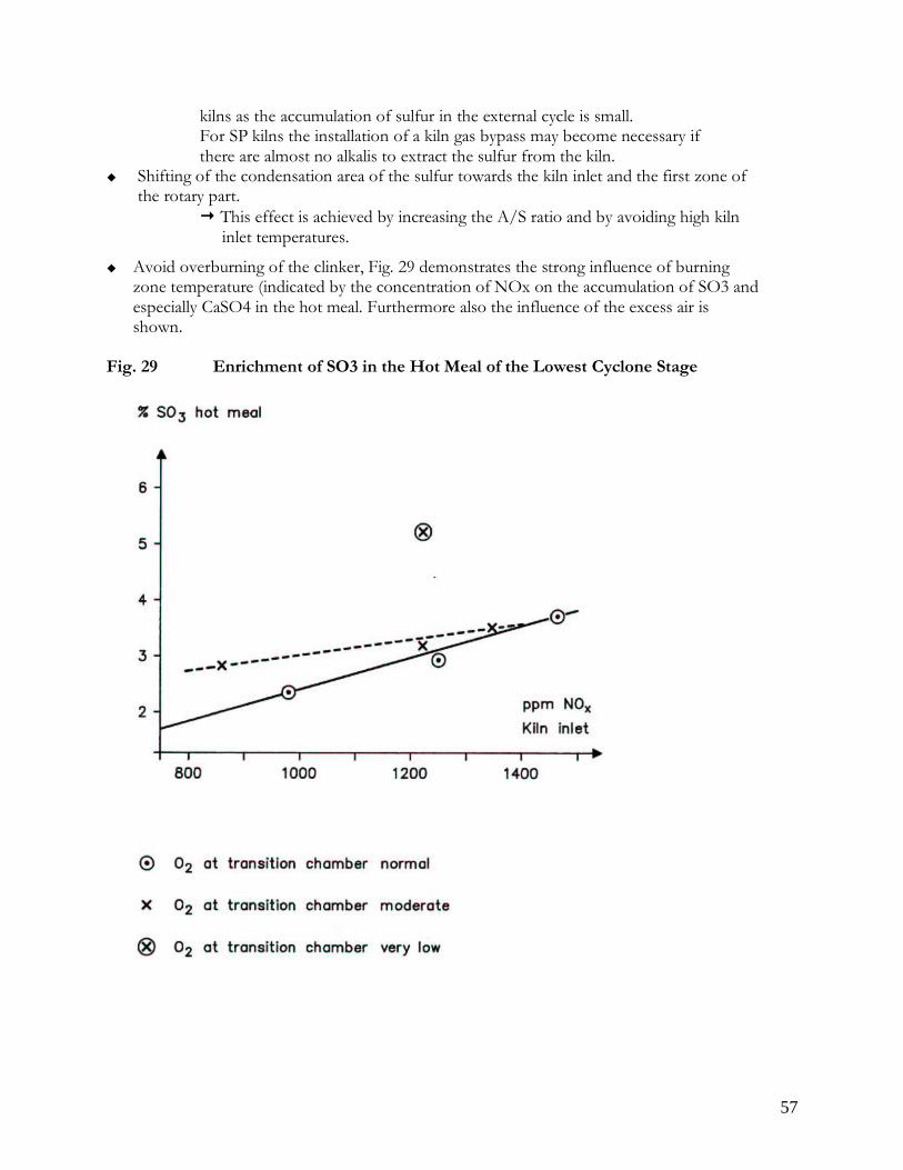
Avoid overburning of the clinker, Fig. 29 demonstrates the strong influence of burning zone temperature (indicated by the concentration of NOx on the accumulation of SO3 and especially CaSO4 in the hot meal. Furthermore also the influence of the excess air is shown.
Fig. 29 Enrichment of SO3 in the Hot Meal of the Lowest Cyclone Stage
58
7.5 Measures against Alkali Problems
Alkali Volatility
In absence of sulfur the alkali volatility is very high and creates problems in the preheater. In such a case the raw mix can be sulfatizated by addition of gypsum.
Low Alkali Clinker
If low alkali clinker must be produced, all measures must be taken to increase the alkali volatility, such as ✷ reducing the sulfur input ✷ producing a long and stable flame ✷ applying hard burning (CaOfree < 1), if possible reducing the burnability by
increasing the silica ration ✷ applying a minimum of excess air ✷ chlorination of the raw mix either by burning chloride ✷ containing solvents or adding CaCl2
In case of long dry or wet kilns the alkalis are withdrawn by discarding a fraction or the total dust of the external cycle. In case of a SP kiln a (large) kiln gas bypass is required.
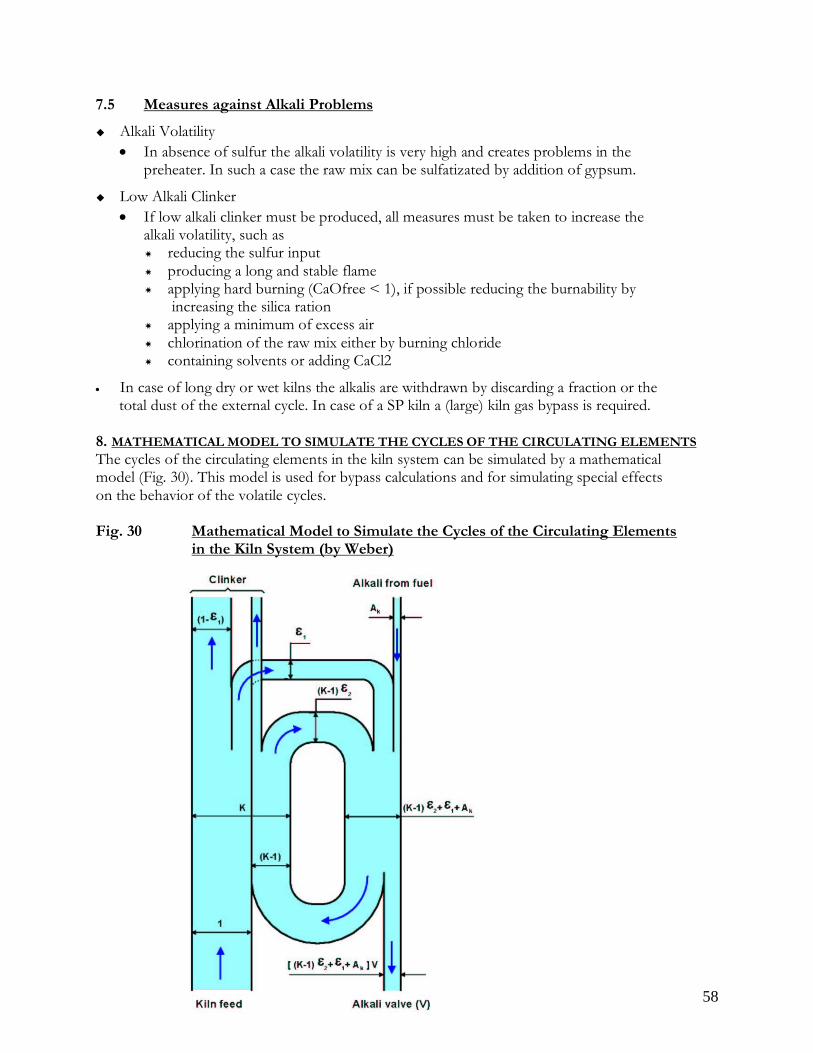
8. MATHEMATICAL MODEL TO SIMULATE THE CYCLES OF THE CIRCULATING ELEMENTS
The cycles of the circulating elements in the kiln system can be simulated by a mathematical model (Fig. 30). This model is used for bypass calculations and for simulating special effects on the behavior of the volatile cycles.
Fig. 30 Mathematical Model to Simulate the Cycles of the Circulating Elements in the Kiln System (by Weber)