Embed Size (px)
Citation preview

A-72www.ittcannon.com
Dimensions shown in inches (mm)Specifications and dimensions subject to change
Circ
ular
A
ITT Cannon is the foremost manufac-turer of MS and MS type connectorswith the widest range of connectorstyles, sizes and variations in theindustry. These connectors utilize thefinest materials, which, along withprecision manufacturing and rigidquality control, assure ITT Cannoncustomers of the finest quality con-nectors. The MS A & B product linehas environmentally safe green andblack zinc alloy plating. The Black
zinc plating is RoHS complaint. Theplating is a high quality, uniform fin-ish. The contact, which are preloadedin the insulator, have beenredesigned such that the solder cupsremain in the proper orientation andwill not rotate during wiring termina-tion. The contacts are machined forstrength and durability and platedwith silver. The Cannon MS A&Bdesign meets the performancerequirements of the MIL-C-5015. The
product is available in all the popularsizes and configurations available inClass A (solid end bell) and Class B(split end bell) versions.
Applications:• Industrial Controls• Test Equipment• Traffic Signals• Bus Systems
• High strength aluminum alloy connector
• High strength plastic insulators
• Environmentally safe shell finishes
• Protected against corrosion
• High quality plating finish
• Threaded coupling
• Product is tooled and available in 50 insert patterns
• Machined contacts
• Low cost
• UL recognized
Temperature Range: –55°C to 125°C (-67°F to 257°F)Current Rating: 13 A to 150 A*
Durability: 500 mating cycles min.Wire Accommodation: 0 to 20 AWG*
No. of Contacts: 2 to 48Termination: Solder
*Depending on contact size.
hsiniFlairetaMnoitpircseDGreen Zinc Standard, Black Zinc (RoHS), OD CADyollA munimulAllehS—citsalP draHrotalusnI
revliSyollA reppoC ro ssarBtcatnoC
ELECTRICAL SERVICE DATATest current ratings of contacts andallowable voltage drop under test con-ditions when assembled as in serviceare shown below. Maximum total cur-rent to be carried per connector is thesame as the allowable in wire bundlesas specified in MIL-W-5088.
Contact Test Current Potential DropSize (amps) (millivolts)16 13 4912 23 428 46 284 80 230 150 21
HIGH POTENTIAL TEST VOLTAGEMS connectors show no evidence of breakdown with the test voltage givenbelow is applied between the two closest contacts and between the shell andthe contacts closest to the shell for a period of one minute.
Test Air CreepageMS Voltage Suggested* Spacing Distance
Service (RMS) Operating Voltages Nom. Nom.Rating 60 cps DC AC (rms) (inches) (inches)
Inst. 1000 250 200 1/16A 2000 700 500 1/16 1/8D 2800 1250 900 1/8 3/16E 3500 1750 1250 3/16 1/4B 4500 2450 1750 1/4 5/16C 7000 4200 3000 5/16 1
*As indicated in previous MS Specification and to be used by designer only as a guide.
CA/MS A&B
Product Features and Benefits
Performance Specifications
Materials and Finishes
ca_A1-A163.qxd:Layout 1 2/9/11 7:49 PM Page 72

A-73www.ittcannon.com
Dimensions shown in inches (mm)Specifications and dimensions subject to change
Circular
ACA/MS 3100A wall mounting recepta-cles are used to carry wires throughwalls or bulkheads, or to provide themeans of disconnection at a bulk-head. CA/MS 3100A receptacles matewith CA/MS 3106 and 3108 plugs.
CA/MS 3101A cable connectingreceptacles are used for cable extension requirements wheremounting provisions are unnecessary.CA/MS 3101A plugs mate with3106A/B and 3108B connectors.
Note: The D revision of MIL-C-5015has changed the nomenclature of the3101 from receptacle to plugs.
CA/MS 3102A box mounted recepta-cles are used in junction boxes or asan integral part of equipment. CA/MS3102A receptacles will mate with3106 and 3108 plugs.
CA/MS 3106A straight plug utilizes asolid endbell. The CA/MS 3106Amates with 3100, 3101, and 3102connectors
CA/MS 3106B is identical to the3106A straight plug except it utilizesa split endbell. CA/MS 3106B mateswith 3100, 3101, and 3102 connec-tors.
CA/MS 3108B 90° angle plugs areused where there is limited space adwhere wires must be brought atabrupt angles. This plug will matewith 3100, 3101, and 3102 connec-tors.
MS A&BIntroduction
ca_A1-A163.qxd:Layout 1 2/9/11 7:49 PM Page 73
A-74www.ittcannon.com
Dimensions shown in inches (mm)Specifications and dimensions subject to change
Circ
ular
A
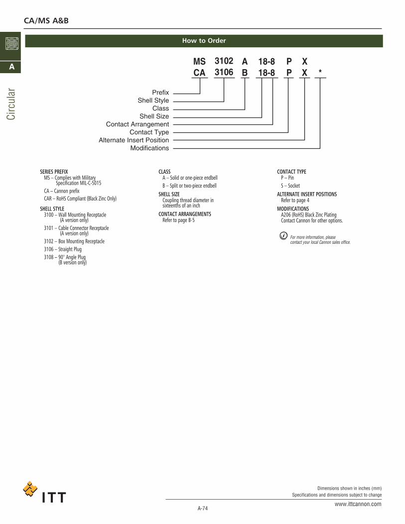
How to Order
SERIES PREFIXMS – Complies with Military
Specification MIL-C-5015CA – Cannon prefixCAR – RoHS Compliant (Black Zinc Only)
SHELL STYLE3100 – Wall Mounting Receptacle
(A version only)3101 – Cable Connector Receptacle
(A version only)3102 – Box Mounting Receptacle3106 – Straight Plug3108 – 90° Angle Plug
(B version only)
CLASSA – Solid or one-piece endbellB – Split or two-piece endbell
SHELL SIZECoupling thread diameter insixteenths of an inch
CONTACT ARRANGEMENTSRefer to page B-5
CONTACT TYPEP – Pin S – Socket
ALTERNATE INSERT POSITIONSRefer to page 4
MODIFICATIONSA206 (RoHS) Black Zinc PlatingContact Cannon for other options.
For more information, pleasecontact your local Cannon sales office.
CA/MS A&B
ca_A1-A163.qxd:Layout 1 2/9/11 7:49 PM Page 74
A-75www.ittcannon.com
Dimensions shown in inches (mm)Specifications and dimensions subject to change
Circular
A
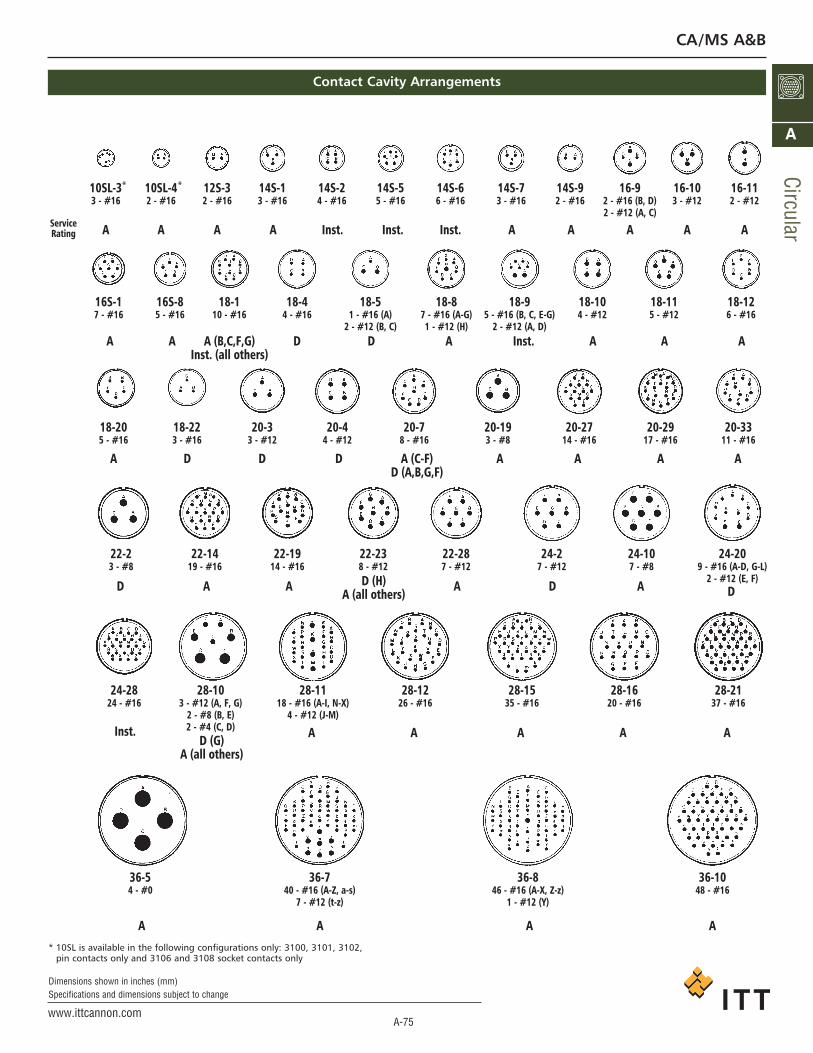
* 10SL is available in the following configurations only: 3100, 3101, 3102,pin contacts only and 3106 and 3108 socket contacts only
CA/MS A&B
Contact Cavity Arrangements
10SL-3 10SL-4 12S-3 14S-1 14S-2 14S-5 14S-6 14S-7 14S-9 16-9 16-10 16-11
AServiceRating A A A A A A A AInst. Inst. Inst.
A A A (B,C,F,G)Inst. (all others)
D Inst. A A AD A
A D D D A A A AA (C-F)D (A,B,G,F)
D A A D A DD (H)
A (all others)A
D (G)A (all others)
A A A A AInst.
A A A A
3 - #16 2 - #16 2 - #16 3 - #16 4 - #16 5 - #16 6 - #16 3 - #16 2 - #16 2 - #16 (B, D) 3 - #12 2 - #122 - #12 (A, C)
16S-1 16S-8 18-1 18-4 18-5 18-8 18-9 18-10 18-11 18-127 - #16 5 - #16 10 - #16 4 - #16 1 - #16 (A) 7 - #16 (A-G) 5 - #16 (B, C, E-G) 4 - #12 5 - #12 6 - #16
2 - #12 (B, C) 1 - #12 (H) 2 - #12 (A, D)
18-20 18-22 20-3 20-4 20-7 20-19 20-27 20-29 20-335 - #16 3 - #16 3 - #12 4 - #12 8 - #16 3 - #8 14 - #16 17 - #16 11 - #16
22-2 22-14 22-19 22-23 22-28 24-2 24-10 24-203 - #8 19 - #16 14 - #16 8 - #12 7 - #12 7 - #12 7 - #8 9 - #16 (A-D, G-L)
2 - #12 (E, F)
24-28 28-10 28-11 28-12 28-15 28-16 28-2124 - #16 3 - #12 (A, F, G) 18 - #16 (A-I, N-X) 26 - #16 35 - #16 20 - #16 37 - #16
2 - #8 (B, E) 4 - #12 (J-M)2 - #4 (C, D)
01-638-637-635-6361# - 84)z-Z ,X-A( 61# - 64)s-a ,Z-A( 61# - 040# - 4
)Y( 21# - 1)z-t( 21# - 7
* *
ca_A1-A163.qxd:Layout 1 2/9/11 7:49 PM Page 75

A-76www.ittcannon.com
Dimensions shown in inches (mm)Specifications and dimensions subject to change
Circ
ular
A
MS3100A CA/CAR 3100A
CA/MS A&B
Wall Mounting Receptacle - Solid Endbell
ITT CANNONHARDWARE
KIT NO.(BLACK ZINC)
ITT CANNONHARDWARE
KIT NO.(GREEN ZINC)
*
* 10SL is available in the following configurations only: 3100, 3101, 3102,pin contacts only and 3106 and 3108 socket contacts only
ca_A1-A163.qxd:Layout 1 2/9/11 7:49 PM Page 76
A-77www.ittcannon.com
Dimensions shown in inches (mm)Specifications and dimensions subject to change
Circular
A
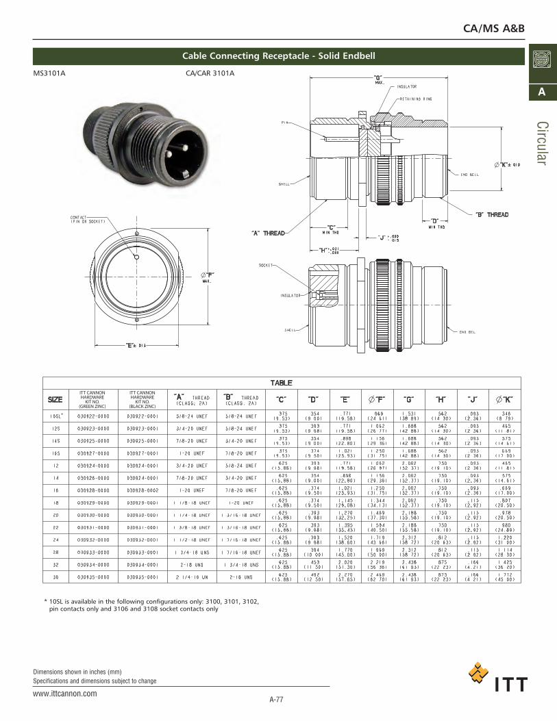
MS3101A CA/CAR 3101A
CA/MS A&B
Cable Connecting Receptacle - Solid Endbell
* 10SL is available in the following configurations only: 3100, 3101, 3102,pin contacts only and 3106 and 3108 socket contacts only
ITT CANNONHARDWARE
KIT NO.(BLACK ZINC)
ITT CANNONHARDWARE
KIT NO.(GREEN ZINC)
*
ca_A1-A163.qxd:Layout 1 2/9/11 7:49 PM Page 77

A-78www.ittcannon.com
Dimensions shown in inches (mm)Specifications and dimensions subject to change
Circ
ular
A
CA/MS A&B
Box Mounting Receptacle
ITT CANNONHARDWARE
KIT NO.(BLACK ZINC)
ITT CANNONHARDWARE
KIT NO.(GREEN ZINC)
MS3102A CA/CAR 3102A
*
* 10SL is available in the following configurations only: 3100, 3101, 3102,pin contacts only and 3106 and 3108 socket contacts only
ca_A1-A163.qxd:Layout 1 2/9/11 7:49 PM Page 78
A-79www.ittcannon.com
Dimensions shown in inches (mm)Specifications and dimensions subject to change
Circular
A
CA/MS A&B
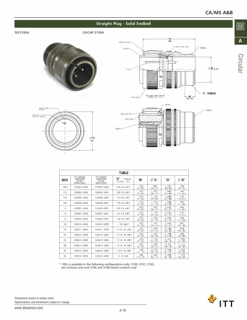
Straight Plug - Solid Endbell
ITT CANNONHARDWARE
KIT NO.(BLACK ZINC)
ITT CANNONHARDWARE
KIT NO.(GREEN ZINC)
MS3106A CA/CAR 3106A
*
* 10SL is available in the following configurations only: 3100, 3101, 3102,pin contacts only and 3106 and 3108 socket contacts only
ca_A1-A163.qxd:Layout 1 2/9/11 7:50 PM Page 79

A-80www.ittcannon.com
Dimensions shown in inches (mm)Specifications and dimensions subject to change
Circ
ular
A
CA/MS A&B
Straight Plug - Split Endbell
ITT CANNONHARDWARE
KIT NO.(BLACK ZINC)
ITT CANNONHARDWARE
KIT NO.(GREEN ZINC)
MS3106B CA/CAR 3106B
*
* 10SL is available in the following configurations only: 3100, 3101, 3102,pin contacts only and 3106 and 3108 socket contacts only
ca_A1-A163.qxd:Layout 1 2/9/11 7:50 PM Page 80
A-81www.ittcannon.com
Dimensions shown in inches (mm)Specifications and dimensions subject to change
A
CA/MS A&B
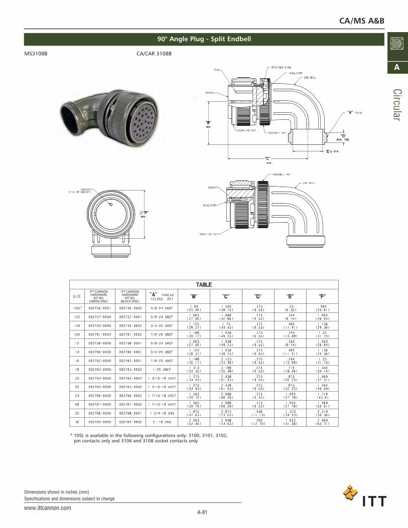
90° Angle Plug - Split Endbell
ITT CANNONHARDWARE
KIT NO.(BLACK ZINC)
ITT CANNONHARDWARE
KIT NO.(GREEN ZINC)
MS3108B CA/CAR 3108B
*
* 10SL is available in the following configurations only: 3100, 3101, 3102,pin contacts only and 3106 and 3108 socket contacts only
Circular
ca_A1-A163.qxd:Layout 1 2/9/11 7:50 PM Page 81
A-82www.ittcannon.com
Dimensions shown in inches (mm)Specifications and dimensions subject to change
Circ
ular
A
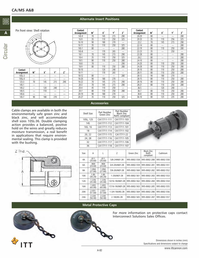
Cable clamps are available in both theenvironmentally safe green zinc andblack zinc, and will accommodateshell sizes 10SL-36. Double clampingaction provides a balanced, positivehold on the wires and greatly reducesmoisture transmission, a real benefitin applications that require environ-mental sealing. This clamp is providedwith the bushing.
For more information on protective caps contactInterconnect Solutions Sales Offices.
Shell Size Part NumberGreen Zinc
Part NumberBlack Zinc
RoHS compliant10SL, 12S CA17711-111 CA17711-103
14S CA17711-112 CA17711-10416S, 16 CA17711-113 CA17711-101
18 CA17711-114 CA17711-10220, 22 CA17711-115 CA17711-2224, 28 CA17711-116 CA17711-105
32 CA17711-117 CA17711-10636 CA17711-118 CA17711-107
Size A L Z Green ZincBlack Zinc
RoHS compliant
Cadmium
4A .811(20.60)
.811(20.60) 5/8-24INEF-2B 995-0002-558 995-0002-280 995-0002-550
6A .969(24.60)
.969(24.60) 3/4-20UNEF-2B 995-0002-559 995-0002-281 995-0002-551
8A 1.094(27.80)
1.094(27.80) 7/8-20UNEF-2B 995-0002-560 995-0002-282 995-0002-552
10A 1.89(30.20)
1.89(30.20) 1-20UNEF-2B 995-0002-561 995-0002-283 995-0002-553
12A 1.378(35.00)
1.378(35.00) 13/16-18UNEF-2B 995-0002-562 995-0002-284 995-0002-554
16A 1.693(43.00)
1.693(43.00) 17/16-18UNEF-2B 995-0002-563 995-0002-285 995-0002-555
20A 2.031(51.60)
2.031(51.60) 1-3/4-18UNS-2B 995-0002-564 995-0002-286 995-0002-556
24A 2.220(56.40)
2.220(56.40) 2-18UNS-2B 995-0002-565 995-0002-287 995-0002-557
Accessories
Metal Protective Caps
CA/MS A&B
Alternate Insert Positions
Pin front view: Shell rotation ContactArrangement W˚ X˚ Y˚ Z˚
14S-9 70 145 215 29016-9 35 110 250 325
16-10 90 180 270 —16-11 35 110 250 32516S-1 80 — — 28016S-8 — 170 265 —18-1 70 145 215 29018-4 35 110 250 32518-5 80 110 250 28018-8 70 — — 29018-9 80 110 250 280
18-10 — 120 240 —18-11 — 170 265 —18-12 80 — — 28018-20 90 180 270 —18-22 70 145 215 29020-3 70 145 215 29020-4 45 110 250 —20-7 80 110 250 280
20-19 90 180 270 —20-27 35 110 250 325
ContactArrangement W˚ X˚ Y˚ Z˚
20-29 80 — — 28020-33 35 110 256 32522-2 70 145 215 290
22-14 80 — — 28022-19 80 110 250 28022-23 35 — 250 —22-28 80 — — 28024-2 80 — — 280
24-10 80 — — 28024-20 80 110 250 28024-28 80 110 250 28028-10 80 110 250 28028-11 80 110 250 28028-12 90 180 270 —28-15 80 110 250 28028-16 80 110 250 28028-21 80 110 250 28036-5 — 120 240 —36-7 80 110 250 28036-8 80 110 250 280
36-10 80 125 235 280
ContactArrangement W˚ X˚ Y˚ Z˚
10SL-3 — — — —10SL-4 — — — —12S-3 70 145 215 29014S-1 — — — —14S-2 — 120 240 —14S-5 — 110 — —14S-6 — — — —14S-7 90 180 270 —
ca_A1-A163.qxd:Layout 1 2/9/11 7:50 PM Page 82

A-83www.ittcannon.com
Dimensions shown in inches (mm)Specifications and dimensions subject to change
Circular
A
MS-E/F/R/ERMIL-C-5015 Connectors
How to Order
ITT Cannon is the foremost manufacturer of MS andMS type connectors with the widest range of connec-tor styles, sizes and variations in the industry. Theseconnectors utilize the finest materials, which, alongwith precision manufacturing and rigid quality con-trol, assure ITT Cannon customers of the finest qual-ity connectors.These circular connectors were originally designedfor aircraft, but are now widely used in many otherfields. They are particularly suitable for commercialapplications requiring low cost and high reliability.
ENVIRONMENTAL RESISTANT MS-E, MS-F, MS-R,AND F80 (Solder/Crimp Termination)MS-E, MS-F and MS-R are similar to MS-A and MS-Bconnectors but have resilient insulators and wiresealing grommets for extreme environmental condi-tions and high altitude sealing. MS-E’s and MS-F’shave a mechanical cable clamp; the MS-R has ashorter, lighter weight endbell without the cableclamp. Both the MS-F and MS-R have O rings to sup-plement the interfacial seal. Shells are aluminumalloy. Contacts are silver plated copper alloy. The F80modification (crimp contact termination) is availablein E, R, F and BFR styles with resilient insulators.
POTTING ER CONNEC-TORS (Solder ContactTermination)These Lightweight pot-ting connectors provideresistance to salt water,fuels, etc., and will with-stand the effects of highvibration. 3100 and 3106connectors with plasticpotting cups and resilient inserts meet the requirements ofMS3103 and MS25183. Contacts are silver plated copper orbrass. ER insulators are resilient; shells are aluminum alloy.A 90º plug (3108ER) is also available.
ACCESSORIESAccessories to fit fit MSconnectors includejunction shells, protec-tive caps, dummy orstowage receptacles,cable clamps, telescop-ing bushings.
PREFIXMS - Conforms to latest MIL-C-5015
revision.CA - Cannon designation (for any
modification)CAR - RoHS compliant
SHELL STYLE3100 - Wall mounting receptacle3101 - Cable connecting plug3102 - Box mounting receptacle3106 - Straight plug3108 - 90º angle plug
CLASSE - with resilient insulator and integral
clamp for cable strain reliefF - same as E, however style 3106 with
O-ring seal under the coupling nut
* When ordering MS3106F to theCannon part number, designate CA06R.
SHELL SIZE10S, 12S, 14S, 16S, 16, 18, 20, 22, 24, 28, 32 and 36.
CONTACT ARRANGEMENTSSee pages A-85 to A-89
CONTACT TYPEP - PinS - Socket
ALTERNATE INSERT POSITIONW, X, Y and Z (omit for “Normal), see page A-89
MODIFICATION CODEA71 - Electroless Nickel Hardware, RoHSA176 - Contacts hard gold over nickel, RoHSA206 - Black zinc cobalt hardware, RoHSF42 - Connector supplied without endbell, grommet and ferruleF80 - Snap-in crimp contactsF183 - Snap-in crimp contacts for metric conductorsDN - CA3106 (plug only), endbell for shrink boot adapterA232 - Black zinc cobalt hardware,
RoHS European versionA233 - Green zinc cobalt hardware,
European version
In the latest revision of MIL-C-5015, a newclass of environment-resistant connectorswas added. This new class F connector super-sedes the previous class E connector. TheMS3106F has an O ring under the couplingnut. The class E will be available upon requestfor existing programs, and upon ordering willalso bear the E nomenclature on the shell.MS-F and MS-R connectors are designed tooperate in the extreme environmental condi-tions of high altitude flight and must be com-pletely sealed to withstand moisture, conden-sation, vibration, corona and flashovercaused by high altitude environments. Theyhave resilient grommet with internal restric-tions in the wire cavities which act as O ringsaround the wires. This allows the wires toslide thru the grommet with a minimum offriction, yet when the ferrule is seated andthe endbell tightened it provides a perfectwire seal thru a wide variety of wire diame-ters. This seal at the rear, plus the interfacialseal at the front, effects a completely environ-ment-resistant assembly when the plug ismated to and F or R receptacle. Sockets are ofthe closed-entry type.The temperature range for this connector is -55ºC (67ºF) to +125º (+257ºF) and meetsthe requirements of MIL-C-5015.The F80 modification (crimp contact termina-tion) is available in resilient insulators in theE, R, F, and BFR styles, creating a large selec-tion of insert assemblies and hardware.Components are identical to the MS-5015except that the contacts are modified forcrimp termination providing and inexpensivecrimp contact connector with the proven reli-ability of and complete intermateability withthe MS-5015 series. Cable clamps have beenintegrally designed with the endbell on MS-Eand MS-F connectors. Class R is without thecable clamp.
PREFIX
SHELL STYLE
CLASS
SHELL SIZE
CONTACT ARRANGEMENT
CONTACT TYPE
ALTERNATE INSERT POSITION
MODIFICATION CODE
MS 3106 R 18 - 1 P W *CA 3106 F 18 - 1 S - F80*
ca_A1-A163.qxd:Layout 1 2/9/11 7:50 PM Page 83

A-84www.ittcannon.com
Dimensions shown in inches (mm)Specifications and dimensions subject to change
Circ
ular
A
MIL-DTL-5015MS-E/F/R
MATERIALS AND FINISHES
Shell Material Aluminum AlloyFinish O.D. Chromate coating
over cadmium plating
Insulator Material Polychloroprene (resilient)
Contacts Material Brass or copper alloyFinish Silver plateTermination Tinned solder pot
Performance and Material Specifications
WIRING
For class E, F, and R connectors, satisfactory moisture sealing will be obtained if AWG and MS wire sizes and insulation outside diameters are governed by this table.
Contact Wire Size Insulation OD LimitSize (MIL-W-5086) (inches)
16 16 thru 20 .064 (1.63) min. to .130 (3.30) max.12 12 thru 14 .114 (2.90) min. to .170 (4.32) max.8 8 thru 10 .164 (4.17) min. to .255 (6.48) max.4 4 thru 6 .275 (6.98) min. to .370 (9.40) max.0 0 thru 2 .415 (10.54) min to .550 (13.97)max.
ELECTRICAL SERVICE DATA
Test current ratings of contacts and allowable voltage dropunder test conditions when assembled as in service are shownbelow. Maximum total current to be carried per connector is thesame as the allowable in wire bundles as specified in MIL-W-5088.
Contact Test Current Potential DropSize (amps) (millivolts)
16 13 4912 23 428 46 264 80 230 150 21
THERMOCOUPLE CONTACTS
SIzes 12 and 16 contacts, machined from matching thermocouple lead wire alloys, can be supplied in ITT Cannonconnectors. These thermocouple contacts maintain continuity from thermal-sensor leads through a bulkhead ofother closures in temperature measuring applications.These contacts for matching lead wires are detailed by the standards of the Instrument Society of America (ISA).
ISA Standards MaterialJ and Y Iron and constantan
K Chromel and alumelT Copper and constantan
Since the thermocouple connector applications determines the soldering methods and materials to be used, ther-mocouple contacts, identified by permanent markings, are normally supplied with untinned solder pots.Thermocouple contacts are supplied only in connectors having resilient insulators.
HIGH POTENTIAL TEST VOLTAGE
MS connectors show no evidence of breakdown when the test voltage given below is applied between the twoclosest contacts and between the shell and the contacts closest to the shell for a period of one minute.
Test Air CreepageMS Voltage Suggested* Spacing Distance
Service (RMS) Operating Voltages Nom. Nom.Rating 60 cps DC AC (rms) (inches) (inches)
Inst. 1000 250 200 1/16A 2000 700 500 1/16 1/8D 2800 1250 900 1/8 3/16E 3500 1750 1250 3/16 1/4B 4500 2450 1750 1/4 5/16C 7000 4200 3000 5/16 1
*As indicated in previous MS specification and to be used by designer only as a guide.
ca_A1-A163.qxd:Layout 1 2/9/11 7:50 PM Page 84
A-85www.ittcannon.com
Dimensions shown in inches (mm)Specifications and dimensions subject to change
Circular
A
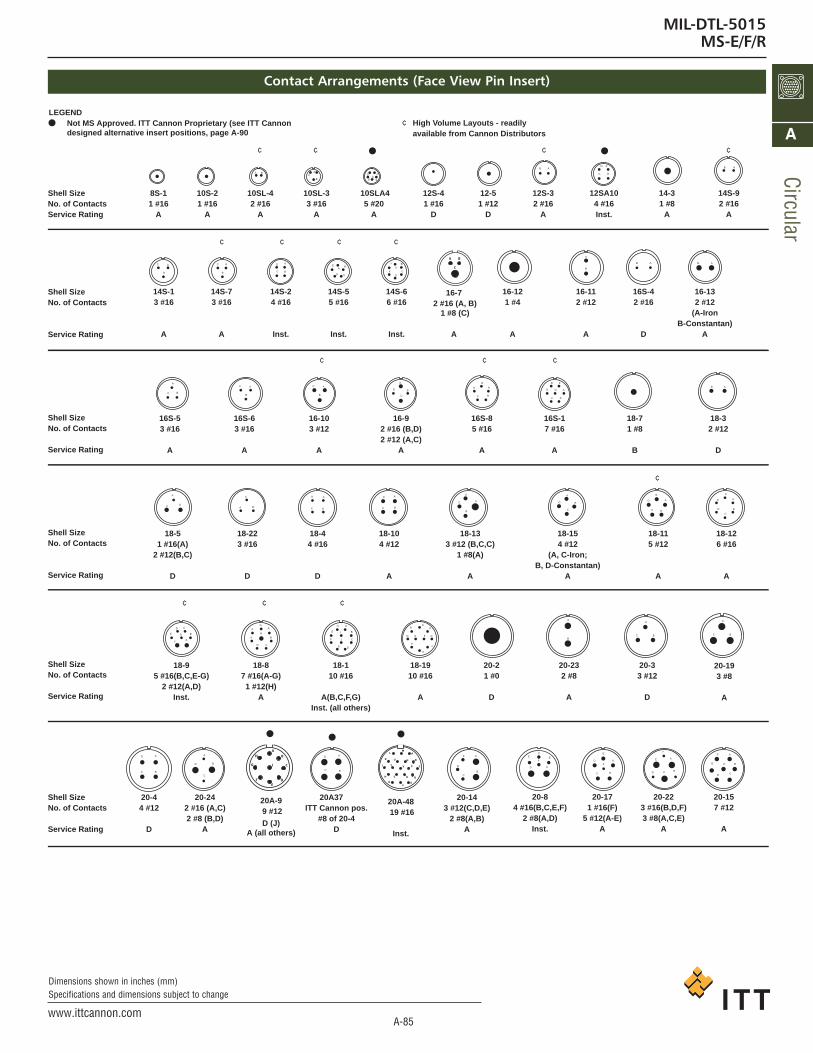
MIL-DTL-5015MS-E/F/R
Contact Arrangements (Face View Pin Insert)
LEGEND
Not MS Approved. ITT Cannon Proprietary (see ITT Cannon
designed alternative insert positions, page A-90
Shell Size
No. of Contacts
Service Rating
8S-1
1 #16
A
10S-2
1 #16
A
10SL-4
2 #16
A
10SL-3
3 #16
A
10SLA4
5 #20
A
12S-4
1 #16
D
12-5
1 #12
D
12S-3
2 #16
A
12SA10
4 #16
Inst.
14-3
1 #8
A
14S-9
2 #16
A
16-13
2 #12
(A-Iron
B-Constantan)
A
16S-4
2 #16
D
16-11
2 #12
A
16-12
1 #4
A
14S-6
6 #16
Inst.
14S-5
5 #16
Inst.
14S-2
4 #16
Inst.
14S-7
3 #16
A
14S-1
3 #16
A
16S-5
3 #16
A
16S-6
3 #16
A
16-10
3 #12
A
16-9
2 #16 (B,D)
2 #12 (A,C)
A
16S-8
5 #16
A
16S-1
7 #16
A
18-7
1 #8
B
18-3
2 #12
D
18-12
6 #16
A
18-11
5 #12
A
18-15
4 #12
(A, C-Iron;
B, D-Constantan)
A
18-13
3 #12 (B,C,C)
1 #8(A)
A
18-10
4 #12
A
18-4
4 #16
D
18-22
3 #16
D
18-5
1 #16(A)
2 #12(B,C)
D
18-9
5 #16(B,C,E-G)
2 #12(A,D)
Inst.
18-8
7 #16(A-G)
1 #12(H)
A
18-1
10 #16
A(B,C,F,G)
Inst. (all others)
18-19
10 #16
A
20-2
1 #0
D
20-23
2 #8
A
20-3
3 #12
D
20-19
3 #8
A
20-15
7 #12
A
20-22
3 #16(B,D,F)
3 #8(A,C,E)
A
20-17
1 #16(F)
5 #12(A-E)
A
20-8
4 #16(B,C,E,F)
2 #8(A,D)
Inst.
20-14
3 #12(C,D,E)
2 #8(A,B)
A
20A37
ITT Cannon pos.
#8 of 20-4
D
20-24
2 #16 (A,C)
2 #8 (B,D)
A
20-4
4 #12
D
Shell Size
No. of Contacts
Service Rating
Shell Size
No. of Contacts
Service Rating
Shell Size
No. of Contacts
Service Rating
Shell Size
No. of Contacts
Service Rating
Shell Size
No. of Contacts
Service Rating
High Volume Layouts - readily
available from Cannon Distributors
¢
¢¢¢¢
¢¢¢¢
¢¢¢
¢
¢ ¢ ¢
A A
A
AA AB
ABA
A
B
BB
BB
BB
B
AA
AA
AA
A
CC
C
C
C
BB
B BB
B
B
BB
B
B
A
AC
C
C C
C
C C
CC
C
C
B
BA
A
A A
A
A
A
AA
A
AC
C
C
DD
D
D DD
DD
DD
D
E
E FE
G
E
F
B
BB
B
B
BB
B
BB
B
B
B
CCC
C
C
C
CC
C
C
C
C
C
G
A
AA
A
A
AAA
A
AAA
A
BB
C
AA
DD
D
DD
D
D
D
D
DD
D
E
E
EEE
E
E
E
EF
F
F
F
G
G
G
G
H
H
H
J
J
I
K
FF
FF
D
E
EF B
D
BC
B
B B
C CD
E
B
A B
C
A
B
C
DE
F
G
H
J
F
A
B
C
D
EG
H
J
K
LM
N
P
R
T
S
V
U
20A-48
19 #16
Inst.
20A-9
9 #12
D (J)
A (all others)
16-7
2 #16 (A, B)
1 #8 (C)
A
ca_A1-A163.qxd:Layout 1 2/9/11 7:50 PM Page 85
A-86www.ittcannon.com
Dimensions shown in inches (mm)Specifications and dimensions subject to change
Circ
ular
A
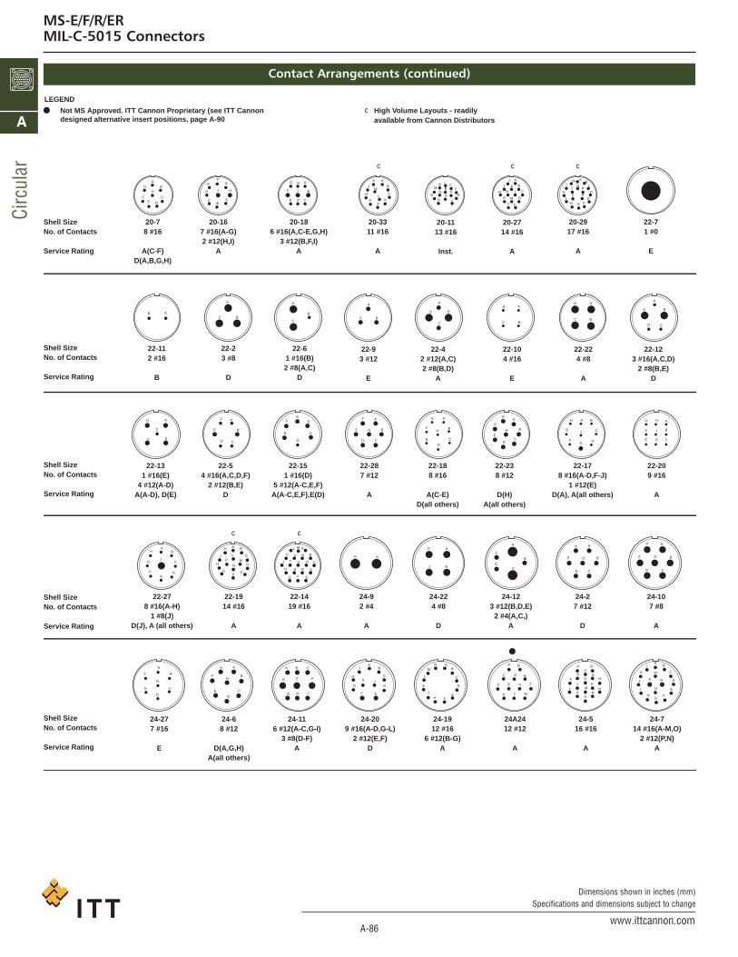
MS-E/F/R/ERMIL-C-5015 Connectors
Contact Arrangements (continued)
LEGEND
Shell Size
No. of Contacts
Service Rating
20-7
8 #16
A(C-F)
D(A,B,G,H)
20-16
7 #16(A-G)
2 #12(H,I)
A
20-18
6 #16(A,C-E,G,H)
3 #12(B,F,I)
A
20-33
11 #16
A
20-11
13 #16
Inst.
20-27
14 #16
A
20-29
17 #16
A
22-7
1 #0
E
22-12
3 #16(A,C,D)
2 #8(B,E)
D
22-22
4 #8
A
22-10
4 #16
E
22-4
2 #12(A,C)
2 #8(B,D)
A
22-9
3 #12
E
22-6
1 #16(B)
2 #8(A,C)
D
22-2
3 #8
D
22-11
2 #16
B
22-13
1 #16(E)
4 #12(A-D)
A(A-D), D(E)
22-5
4 #16(A,C,D,F)
2 #12(B,E)
D
22-15
1 #16(D)
5 #12(A-C,E,F)
A(A-C,E,F),E(D)
22-28
7 #12
A
22-18
8 #16
A(C-E)
D(all others)
22-23
8 #12
D(H)
A(all others)
22-17
8 #16(A-D,F-J)
1 #12(E)
D(A), A(all others)
22-20
9 #16
A
24-10
7 #8
A
24-2
7 #12
D
24-12
3 #12(B,D,E)
2 #4(A,C,)
A
24-22
4 #8
D
24-9
2 #4
A
22-14
19 #16
A
22-19
14 #16
A
22-27
8 #16(A-H)
1 #8(J)
D(J), A (all others)
24-27
7 #16
E
24-6
8 #12
D(A,G,H)
A(all others)
24-11
6 #12(A-C,G-I)
3 #8(D-F)
A
24-20
9 #16(A-D,G-L)
2 #12(E,F)
D
24-19
12 #16
6 #12(B-G)
A
24A24
12 #12
A
24-5
16 #16
A
24-7
14 #16(A-M,O)
2 #12(P,N)
A
Shell Size
No. of Contacts
Service Rating
Shell Size
No. of Contacts
Service Rating
Shell Size
No. of Contacts
Service Rating
Shell Size
No. of Contacts
Service Rating
¢
¢¢
¢ ¢
A
A
A A A AA
AA
AAAAAA
AA
B
B
BBB
B
B
B C
C
CCC
C
CC DDD
DDDD
D
EE
E
EE E
E
EEE
E
EE E
EEE
A A A
A
AA A A
AAAAA
AAA
BB
BB
B
B B
BB
BB
B BB B
BC
C
CC C
C C
CC
C
CC
C
CC
DD
D
D D
D
DD
D
D
DD
D
DD
E EEF
FF
G
G
G
H
H
H
JJ
K
L
M
M
N
N
P P
RS
T
U
V
L
K
J
E
E
F
F
FF
F
F
F
F
F
FFF
FF
FFF
JJ
HH
HH
G
G
G G
G
G
GG
G
G
G
H
H
H
H
H
H
H
I
JJ
J
J
J
J
K
K
K
K
K
L
L
L
LL
M
M
M
M
N
N
N O
P
PS
R
G
G
G
A
A A
A
A A
B
BB
BB
B
BB
B
B
B
B B BB
CC
CC
C
C CC
C
C
C
C
C
C
D
D
D D D
DD
D
D
D
D
E
E
EE
E
E
E
E
F
F
F
F
G
G
G
H H
HJ
J
J
J
K
K
K
L
L
LM
M
M
NN
NP
RS
TF
F F
GG G
H J J M
L
J
K
H
H
H
Not MS Approved. ITT Cannon Proprietary (see ITT Cannon
designed alternative insert positions, page A-90
High Volume Layouts - readily
available from Cannon Distributors
¢
ca_A1-A163.qxd:Layout 1 2/9/11 7:50 PM Page 86
A-87www.ittcannon.com
Dimensions shown in inches (mm)Specifications and dimensions subject to change
Circular
A
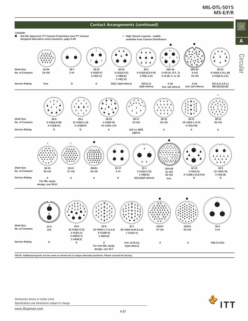
MIL-DTL-5015MS-E/F/R
Contact Arrangements (continued)
LEGEND
Shell Size
No. of Contacts
Service Rating
24-28
24 #16
Inst.
28-7
2 #4
D
28-22
3 #16(D-F)
3 #4(A-C)
D
28-10
3 #12(A,F,G)
2 #8(B,E)
2 #4(C,D)
D(G), A(all others)
28-1
6 #12(A,B,D-F,H)
3 #8(C,J,G)
D(A,E,J)
A(all others)
28-19
6 #16(A-C,H,L,M)
4 #12(E,G,J,K)
A(C,E,G,J,K,L)
B(H,M),D(A,B)
28-12
26 #16
A
28-11
18 #16(A-I, N-X)
4 #12(J-M)
A
28-16
20 #16
A
28-17
15 #16
A(A-L), B(R)
D(M-P)
28-20
4 #16(K-N)
10 #12(A-J,P)
A
28-2
12 #16(A,L,N)
2 #12(M,P)
D
28-9
6 #16(A,H-M)
6 #12(B-G)
D
28-15
35 #16
A
For MIL equip
design, use 28-21
28-21
37 #16
A
28A51
43 #16
A
32-17
4 #4
D
32-1
3 #12(A,C,D)
2 #0(B,E)
E(A),D(all others)
32-15
2 #0(A,G)
6 #12(B,C,D,E,F,H)
D
32-9
12 #16(C-N)
2 #4(A,B)
D
36-4
3 #0
A(B,C),C(A)
32A10
54 #16
AA
32A47
47 #16
32-7
28 #16(A-N,W-Z,a-k)
7 #12(O-V)
Inst. (A,B,h,j)
A(all others)
32-8
24 #16(A-L,T-Z,a-e)
6 #12(M-S)
2 #8(O,R)
A
For new MIL equip.
design, use 32-7
32-6
16 #16(A-O,S)
2 #12(U,V)
3 #8(P,R,T)
2 #4(W,X)
A
Shell Size
No. of Contacts
Service Rating
Shell Size
No. of Contacts
Service Rating
Shell Size
No. of Contacts
Service Rating
*NOTE: Additional layouts are the same as shown but in unique alternate positioins. Please consult the factory.
¢
¢¢
A
A
A
A
B
B
B
BC C
C
D
DD
EE
E
F
FF
G GH J
K L M N P Q
R S T U V
W X Y Z
A
A
A
AA A
A
A
A
A
A A A
B
B
B
BBB
BB
B
B
B BB
C
C
C
CC
C
C
C
C
C
C C
C
D
DD
D
DD
D
DD
D
D
D
E
E
E
EEE
E
E
E
E
E
E
E
F
F
F
F
F F
F
F
F
F
F
F
G
G
G
G
G
G
G
G
G
G
G
GG
H
HH
H
H
HH
H H
H
H H
H
J
J
JI I
J
J
J
J
J
J
JI
JJ
J
K
L
L
L
L
L
L
LL
L L
K
K
K
K
K
K K
K
K
K
L
M
M
M
M
MM M
M
M
M
M
N
N
N
N
N
N
N
N
N
P
P
P
P P
P
P
PP
O
O
Q
R
R
R
R
R
R
R
S
S
S
S
S
S
T
T
T
T
T
T
U
U
U
UU
U
V
V
V
VV
V
W
WW
W
W
X
X
X
XX
Y
Y
Y
Z
Z
a
a
b
b
c
c
d
d
e
e f g h
j kl m
A
A
A
AA
AA
B
B
B
B
B
BB
C
C
C
C
CCC
D
D
D
D
D
D D
EE
EE
EE
F
F
F
F F
G
G
G
G
H
H
H
H
J
J
I
JG H J
L
L
LL
KK
KK
M
M
M M
N
N
N N
P
P
O
O
P P
R
R
RR
SS
SS
T
T
TT
U
U
UU
V
V
V V
W
W
WW
X
X
X
Y
Y
Y
ZZ
ZZ
a
a
a
b
b
b
c
c
a b cc
d
d
dd
e
e
ee
ff
ff
g
g
gg
h
h
hh
j
j
jj
kk
kk
l
ln p r s
m n p q r
s t u v w
x y
A
A
B
B
C
C D E F G
H J
L
K
M N
lm n p r s
t u v w y
m
Z
ab
d
A
ZYXW
VUTSRQP
NGFEDC
B
MLKJH
ed
AB
ba
f mkjhg n
t ACr AAp u
AHAFAEAD
v
AK
AL
AJ
AQAPANAMAS AT
ARAWAVAU
F
AB
C
D
E
G
H
J K
L
M
NP
Q
R
T
S
Z Y X
W
VU
bd
a
c
28A-63
9 #12
19 #16
A (e)
Inst. (all others)
28A-16
5 #16 (A, D-F, J)
4 #4 (B, C, G, H)
A (e)
Inst. (all others)
32A-69
41 #20
20 #16
Inst.
A
A
B
32-5
2#0
D
Not MS Approved. ITT Cannon Proprietary (see ITT Cannon
designed alternative insert positions, page A-90
High Volume Layouts - readily
available from Cannon Distributors
¢
ca_A1-A163.qxd:Layout 1 2/9/11 7:50 PM Page 87

A-88www.ittcannon.com
Dimensions shown in inches (mm)Specifications and dimensions subject to change
Circ
ular
A
MS-E/F/R/ERMIL-C-5015 Connectors
Contact Arrangements (continued)
Shell Size
No. of Contacts
Service Rating
36-5
4 #0
A
36-6
4 #4(B,C,E,F)
2 #0(A,D)
A
36-14
6 #16(K-N,P,Q)
5 #12(B,D,F,H,J)
5 #8(A,C,E,G,I)
D
36A16
18 #12
(B,C,V,J,K,M,N,
R, T-Iron; A,D-F,H,L
P,S,U-Constantan)
A
36A46
27 #12
A
36-9
14 #16(A-G,Z-f)
14 #12(H-N,S-Y)
2 #8(O,R)
1 #4(P)
A
36A66
52 #16(A-c,h-AK)
4 #12(d,e,f,g)
A
36A34
52 #16
A
36-10
48 #16
A
36-8
46 #16(A-X,Z-z
1 #12(Y)
A
36-7
40 #16(A-Z,a-s)
7 #12(t-z)
A
36-15
35 #16
D(m), A (all others)
40A33
7 #8(G-N)
6 #4(A-F)
A
40-10
16 #16(A,B,E-H,M,N,P
Q,V-Y,b,c)
9 #8(C,D,I,L,O,R,U,Z,a)
4 #4(K,J,S,T)
A
40A27
60 #16
A
40-56
85 #16
A
48-5
90 #16(A-BL,BN-BT,BW,BX)
1 #8(CD)
9 #12(BM,BU,BV,BY-CC,CE)
A
44-1
36 #16(A-S,Z-t
6 #12(T-Y)
D
Shell Size
No. of Contacts
Service Rating
Shell Size
No. of Contacts
Service Rating
Shell Size
No. of Contacts
Service Rating
¢
†
A
B C D E F G
H J K L M N P Q R
S T U V W X Y Z a b
c d e f g h j k m n p
q
AA AB AC AD AE AF AG AH AJ AK AL
AM AN AP AQ AR AS AT AU AV AW
AX AY AZ BA BB BC BD BE BF BG
BH BJ BK BL
BMBM BP BQ BR
BSBU BV
BW BXBT
BZ
BY
CCCD
CA
CB
CE
AA AB
AC AD AE AF AG AJ AK AL AM AN
AP AR AS AT AU AV AW AX AY
AZ BA BB BC BD BE BF BG
BJ BK BL BNBM BP BR
BS BU BVBT
r s t u v w x y z
A124
2322
21
20
19
18
1716
1514
35
50
59
60
54
4241
53
52
51
36
40
39
38
37
25
43
55
58
49
34
13
2
26
44
56
57
48
33
12
34
2827
45
46
47
32
11
29
30
31
10
5
6
7
8
98
A
A
BB
B
C
C
C
D
D
D
E
E
E
F
F
F
G
G
H
H
H
J
J
JI
K
K
K
L
L
L
M
M
M
N
N
ON
P
P
R
R
S
S
T
T
U
U
V
V
W
W
X
X
Y
Y
Z
Z
a
a
b
b
c
c
d
d e
f
f
g
g
h i
h
j
j
k
k
m
m
n
n
o
p
p
q r
r
s
s
t
t
u v w x y z
AAA A
A
A
AAA
AAA
B
B
B
B
B
B
BBB
BB
C
C
C
C
C
C
CC
CCC
C
D
D
D
D
DD
DDDD
D
D
E
E
E
E
E
EEE
E
E
E
F
F
F
F
F
FFFFF
F
G
G
G
G
GG
G
G
G
H
H
H
H
H
HHHH
H
J
J
J
J
JJ
JJ
J
J
II
I
I
I
K
K
K
K
KKK
KK
K
LL
L
L
LL
LLL
L
M
M
M
M
MMM
MM
M
N N
N
N
NN
N
NN
N
O
OOO
P
P
P
PP
PPPP
Q
Q
Q
R
R
R
RR
RRR
R
S
S
S
SS
SS
S
S
T
T
T
TT
TT
T
T
U
U
U
UUU
UU
U
V
V
VV
V
VVV
W
W
WW
WW
W
W
X
X
XX
XX
X
X
Y
Y
YY
YYY
Y
Z
Z
ZZ
ZZZ
Z
a
a
a
aaaa
a
b b
bb
bb
b
b
c c
cc
cc
c
c
d
d
dd
ddd
d
e
e
e
eee
e
f
ff
ff
ff g
ggg
gg
hh
hhhh l
iii
jj
jj
j
kkkkk
k
mm
mm
m
m
nn
nnn
pp
ppp
rrr
r
r
ssss
s
tt
t
t
t
uu
uu
u vvvv
v wwww
w xxx
xx
yy
yy
zz AA AA
AB AB
AK AJ AM
AD ADAE AEAF AFAGAG
AC AC
zz
z
†
Not MS Approved. ITT Cannon Proprietary (see ITT Cannon
designed alternative insert positions, page A-90
High Volume Layouts - readily
available from Cannon Distributors
¢
ca_A1-A163.qxd:Layout 1 2/9/11 7:50 PM Page 88

A-89www.ittcannon.com
Dimensions shown in inches (mm)Specifications and dimensions subject to change
Circular
A
MIL-DTL-5015MS-E/F/R
MS Alternate Insert Positions
Normal Position
A B
AB
AB
AB
AB
Position W Position X Position Y Position Z
All views are looking into front of pin insert of rear of socket insert.
Contact Alternate PositionsShell Arrange- Wire DegreesSize ment Size Service Rating W X Y Z8S 8S-1 1 #16 A - - - -
10S 10S-2 1 #16 A - - - -10SL-4 2 #16 A - - - -10SL-3 3 #16 A - - - -
12 12-5 1 #12 D - - - -12S 12S-4 1 #16 D - - - -
12S-3 2 #16 A 70 145 215 29014 14-3 1 #8 A - - - -14S 14S-1 3 #16 A - - - -
14S-2 4 #16 Inst. - 120 240 -14S-5 5 #16 Inst. - 110 - -14S-6 6 #16 Inst. - - - -14S-7 3 #16 A 90 180 270 -14S-9 2 #16 A 70 145 215 290
16 16-7 2#16 A 80 110 250 2801#8
16-9 2 #16 A 35 110 250 3252 #12
16-10 3 #12 A 90 180 270 -16-12 1 #4 A - - - -16-11 2 #12 A 35 110 250 32516-13 2 #12 A 35 110 250 325
16S 16S-1 7 #16 A 80 - - 28016S-4 2 #16 D 35 110 250 32516S-5 3 #16 A 70 145 215 29016S-6 3 #16 A 90 180 270 -16S-8 5 #16 A - 170 265 -
18 18-1 10 #16 A(B,C,F,G) 70 145 215 290Inst.(all others)
18-3 2 #12 D 35 110 250 32518-4 4 #16 D 35 110 250 32518-5 1 #16 D 80 110 250 280
2 #1218-7 1 #8 B - - - -18-8 7 #16 A 70 - - 290
1 #1218-9 5 #16 Inst. 80 110 250 280
2 #1218-10 4 #12 A - 120 240 -18-11 5 #12 A - 170 265 -18-12 6 #16 A 80 - - 28018-13 3 #12 A 80 110 250 280
1 #818-15 4 #12 A - 120 240 -18-19 10 #16 A - 120 240 -18-22 3 #16 D 70 145 215 290
20 20-2 1 #0 D - - - -20-3 3 #12 D 70 145 215 29020-4 4 #12 D 45 110 250 -20-7 8 #16 A(C-F) 80 110 250 280
D(A,B,G,H)20-8 4 #16 Inst. 80 110 250 280
2 #820-14 3 #12 A 80 110 250 280
2 #820-15 7 #12 A 80 - - 28020-16 7 #16 A 80 110 250 280
2 #1220-17 1 #16 A 90 180 270 -
5 #1220-18 6 #16 A 35 110 250 325
3 #1220-19 3 #8 A 90 180 270 -
Contact Alternate PositionsShell Arrange- Wire DegreesSize ment Size Service Rating W X Y Z20 20-22 3 #16 A 80 110 250 280
3 #820-23 2 #8 A 35 110 250 32520-24 2 #16 A 35 110 250 325
2 #820-27 14 #16 A 35 110 250 32520-29 17 #16 A 80 - - 28020-33 11 #16 A - - - -
22 22-2 3 #8 D 70 145 215 29022-4 2 #12 A 35 110 250 325
2 #822-5 4 #16 D 35 110 250 325
2 #1222-6 1 #16 D 80 110 250 280
2 #822-7 1 #0 E - - - -22-9 3 #12 E 70 145 215 29022-10 4 #16 E 35 110 250 32522-11 2 #16 B 35 110 250 32522-12 3 #16 D 80 110 250 280
2 #822-13 1 #16 A(A-D) 35 110 250 325
4 #12 D(E)22-14 19 #16 A 80 - - 28022-15 1 #16 A(A-C,E,F) 80 110 250 280
5 #12 E(D)22-17 8 #16 D(A) 80 110 250 280
1 #12 A(all others)22-18 8 #16 A(C-E) 80 110 250 280
D(all others)22-19 14 #16 A 80 110 250 28022-20 9 #16 A 35 110 250 32522-22 4 #8 A - 110 250 -22-23 8 #12 D(H) 35 - 250 -
A(all others)22-27 8 #16 D(J) 80 - 250 280
1 #8 A(all others)22-28 7 #12 A 80 - - 280
24 24-2 7 #12 D 80 - - 28024-5 16 #16 A 80 110 250 28024-6 8 #12 D(A,G,H) 80 110 250 280
A(all others)24-7 14 #16 A 80 110 250 280
2 #1224-9 2 #4 A 35 110 250 325
24-10 7 #8 A 80 - - 28024-11 6 #12 A 35 110 250 325
3 #824-12 3 #12 A 80 110 250 280
2 #424-20 9 #16 D 80 110 250 280
2 #1224-22 4 #8 D 45 110 250 -24-27 7 #16 E 80 - - 28024-28 24 #16 Inst. 80 110 250 280
28 28-1 6 #12 D(A,E,J) 80 110 250 2803 #8 A(all others)
28-2 12 #16 D 35 110 250 3252 #12
28-7 2 #4 D 35 110 250 32528-9 6 #16 80 110 250 280
6 #12 D
Contact Alternate PositionsShell Arrange- Wire DegreesSize ment Size Service Rating W X Y Z28 28-10 3 #12 D(G) 80 110 250 280
2 #8 A(all others)2 #4
28-11 18 #16 A 80 110 250 2804 #12
28-12 26 #16 A 90 180 270 -28-15 35 #16 A 80 110 250 28028-16 20 #16 A 80 110 250 28028-17 15 #16 A(A-L),B(R) 80 110 250 280
D(M-P)28-19 6 #16 A(C,E,G,J,K,L) 80 110 250 280
4 #12 B(H,M), D(A,B)28-20 4 #16 A 80 110 250 280
10 #1628-21 37 #16 A 80 110 250 28028-22 3 #16 D 70 145 215 290
3 #432 32-1 3 #12 E(A) 80 110 250 280
2 #0 D(all others)32-5 2 #0 D 80 110 250 32532-6 16 #16 A 80 110 250 280
2 #123 #82 #4
32-7 28 #16 Inst.(A,B,h,j) 80 125 235 2807 #12 A(all others)
32-8 24 #16 A 80 125 235 2806 #12
32-9 12 #16 D 80 110 250 2802 #4
32-15 2 #0 D 35 110 250 2806 #12
32-17 4 #4 D 45 110 250 -36 36-4 3 #0 A(B,C) 70 145 215 290
D(A)36-5 4 #0 A - 120 240 -36-6 4 #4 A 35 110 250 325
2 #036-7 40 #16 A 80 110 250 280
7-1236-8 46 #16 A 80 110 250 280
1 #1236-9 14 #16 A 80 125 235 280
14 #122 #81 #4
36-10 48 #16 A 80 125 235 28036-14 6 #16 D 90 180 270 -
5 #125 #8
36-15 35 #16 D(m) 60 125 245 305A(all others)
40 40-10 16 #16 A 65 125 225 3109 #84 #4
40-56 85 #16 A 72 144 216 28844 44-1 36 #16 D 65 125 225 310
6 #1248 48-5 90 #16 A 65 125 225 310
1 #89 #12
ca_A1-A163.qxd:Layout 1 2/9/11 7:50 PM Page 89

A-90www.ittcannon.com
Dimensions shown in inches (mm)Specifications and dimensions subject to change
Circ
ular
A
MS-E/F/R/ERMIL-C-5015 Connectors
ITT Cannon Designated Alternate Insert Positions
Shell Contact Wire Service AvailableSize Arrangement Size Rating Position
20 20A-9 9#12 D (J)A (all others)
20 20A-48 19#16 Inst. 4 928 28A-16 5#16 A (e)
4#4 Inst (all others) 2 1228 28A-63 9#12 A (e)
19#16 Inst (all others)32 32A-69 41#20
20#16 Inst 3 820 22021 25522 29023 16524 33025 23526 125
2201712
4
98,13
116
22195,315
21181614
NOTE: Front view of pin insulator rotates as shown.
Not MS approved.
ca_A1-A163.qxd:Layout 1 2/9/11 7:50 PM Page 90

A-91www.ittcannon.com
Dimensions shown in inches (mm)Specifications and dimensions subject to change
ShellSize8S10S10SL12S14S16S1214161820222428323640
BMin.
.375 (9.53)
.375 (9.53)
.375 (9.53)
.375 (9.53)
.375 (9.53)
.375 (9.53).625 (15.88).625 (15.88).625 (15.88).625 (15.88).625 (15.88).625 (15.88).625 (15.88).625 (15.88).625 (15.88).625 (15.88).625 (15.88)
EMax.
.235 (5.97)
.235 (5.97)
.297 (7.54)
.297 (7.54).422 (10.72).547 (13.89).297 (7.54).422 (10.72).547 (13.89).610 (15.49).735 (18.67).740 (18.80).922 (23.42).922 (23.42)1.235 (31.37)1.360 (34.54)1.628 (41.35)
EMin.
.102 (2.59)
.102 (2.59)
.140 (3.56)
.140 (3.56)
.195 (4.95)
.255 (6.48)
.140 (3.56)
.195 (4.95)
.255 (6.48)
.285 (7.24)
.350 (8.89)
.350 (8.89).468 (11.89).468 (11.89).664 (15.87).694 (17.63).911 (23.14)
KMax.
.125 (3.18)
.125 (3.18)
.125 (3.18)
.140 (3.56)
.140 (3.56)
.140 (3.56)
.146 (3.71)
.146 (3.71)
.146 (3.71)
.180 (4.57)
.180 (4.57)
.180 (4.57)
.203 (5.16)
.203 (5.16)
.203 (5.16)
.203 (5.16)
.203 (5.16)
LMax.
2.250 (57.15)2.250 (57.15)2.250 (57.15)2.250 (57.15)2.250 (57.15)2.250 (57.15)2.625 (66.68)2.625 (66.68)2.625 (66.68)2.688 (68.28)2.750 (69.85)2.750 (69.85)2.969 (75.44)3.031 (76.99)3.031 (76.99)3.281 (84.34)3.560 (89.66)†
L1
Max.1.838 (46.69)1.838 (46.69)1.838 (46.69)1.838 (46.69)1.838 (46.69)1.838 (46.69)2.181 (55.40)2.181 (55.40)2.181 (55.40)2.181 (55.40)2.181 (55.40)2.181 (55.40)2.181 (55.40)2.181 (55.40)2.322 (58.98)2.322 (58.98)2.427 (61.65)†
E+.031-.000
.562 (14.27)
.562 (14.27)
.562 (14.27)
.562 (14.27)
.562 (14.27)
.562 (14.27)
.750 (19.05)
.750 (19.05)
.750 (19.05)
.750 (19.05)
.750 (19.05)
.750 (19.05)
.812 (20.62)
.812 (20.62)
.875 (22.23)
.875 (22.23)
.875 (22.23)
PMax.
.890 (22.61)
.890 (22.61)
.970 (24.64)
.970 (24.64)1.150 (29.21)1.250 (31.75).970 (24.64)1.150 (29.21)1.250 (31.75)1.450 (36.83)1.570 (39.88)1.570 (39.88)1.880 (47.75)1.880 (47.75)2.205 (56.01)2.400 (60.96)2.840 (72.14)
R± .005
.594 (15.09)
.719 (18.26)
.719 (18.26)
.812 (20.62)
.906 (23.01)
.969 (24.61)
.812 (20.62)
.906 (23.01)
.969 (24.61)1.062 (26.97)1.156 (29.36)1.250 (31.75)1.375 (34.93)1.562 (39.67)1.750 (44.45)1.938 (49.23)2.188 (55.58)
S± .031
.875 (22.23)1.000 (25.40)1.000 (25.40)1.094 (27.79)1.188 (30.18)1.281 (32.54)1.094 (27.79)1.188 (30.18)1.281 (32.54)1.375 (34.93)1.500 (38.10)1.625 (41.28)1.750 (44.45)2.000 (50.80)2.250 (57.15)2.500 (63.50)2.750 (69.85)
T+ .010- .005
.120 (3.05)
.120 (3.05)
.120 (3.05)
.120 (3.05)
.120 (3.05)
.120 (3.05)
.120 (3.05)
.120 (3.05)
.120 (3.05)
.120 (3.05)
.120 (3.05)
.120 (3.05)
.147 (3.73)
.147 (3.73)
.173 (4.39)
.173 (4.39)
.173 (4.39)
VMax.
.840 (21.34)
.840 (21.34)
.900 (22.86)
.900 (22.86)1.100 (27.94)1.200 (30.48).900 (22.86)1.100 (27.94)1.200 (30.48)1.300 (33.02)1.500 (38.10)1.500 (38.10)1.740 (44.20)1.740 (44.20)2.075 (52.71)2.300 (58.42)2.688 (68.28)
WMax.
1.046 (26.57)1.046 (26.57)1.125 (28.58)1.125 (28.58)1.343 (34.11)1.484 (37.69)1.125 (28.58)1.343 (34.11)1.484 (37.69)1.609 (40.87)1.890 (48.01)1.890 (48.01)2.170 (55.12)2.170 (55.12)2.656 (67.46)2.922 (74.22)
-
† Not to MS specification
MS3100E / MS3100FIntegral Cable Clamp
CA3100E / CA3100E MS3100F wall mountingreceptacles are used to carrywires thru walls or bulkheads,or to provide a means ofdisconnection at a bulkhead.MS3100F receptacles matewith 3106 and 3108 plugs.
MS3100E is identical toMS3100F and is available uponrequest. For new equipment,customer should specifyMS3100F.
R0013ACR0013SM The MS3100R receptacle isidentical in purpose to theMS3100F. The MS3100Rfeatures a shorter lightweight endbell and mateswith 3106 and 3108 plugs.
Shell Size A Thread8S 1/2-28UNEF-2A10S 5/8-24UNEF-2A10SL 5/8-24UNEF-2A12S 3/4-20UNEF-2A14S 7/8-20UNEF-2A16S 1-20UNEF-2A12 3/4-20UNEF-2A14 7/8-20UNEF-2A
Shell Size A Thread16 1-20UNEF-2A18 1-1/8-18UNEF-2A20 1-1/4-18UNEF-2A22 1-3/8-18UNEF-2A24 1-1/2-18UNEF-2A28 1-3/4-18UNS-2A32 2-18UNS-2A36 2-1/4-16UN-2A40 2-1/2-16UN-2A
W
V
A Thd.
T Dia.4 Mtg. Holes
STyp.
RTyp.
B
M
L
K
E
P
T Dia.4 Mtg. Holes
R Typ.
S Typ.
A Thd.
B
M
1L
K
MIL-DTL-5015 ConnectorsMS-E/F/R
Wall Mounting Receptacle
A
Circular
Performance Specifications - Page A-84
Contact, Ceiling Plugs, Assembly Tools - Page A-105
Contact Arrangements - Page A-85 – A-89
ca_A1-A163.qxd:Layout 1 2/9/11 7:50 PM Page 91
A-92www.ittcannon.com
Dimensions shown in inches (mm)Specifications and dimensions subject to change
Circ
ular
A
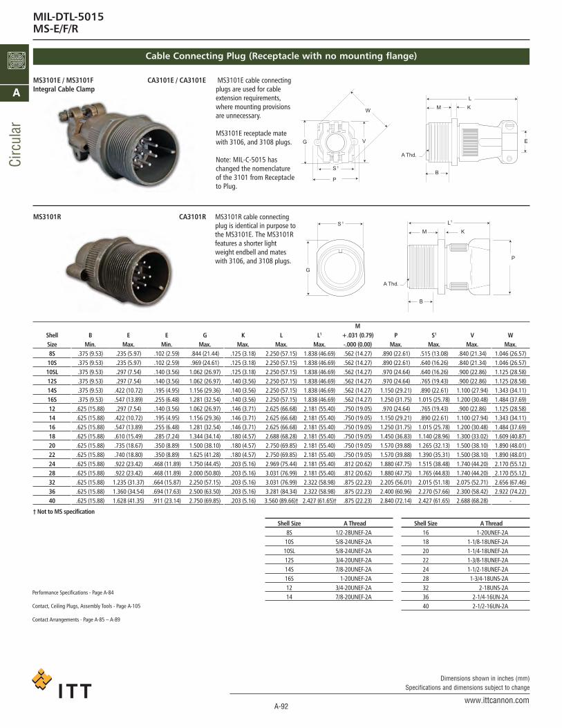
MIL-DTL-5015MS-E/F/R
Cable Connecting Plug (Receptacle with no mounting flange)
† Not to MS specification
ShellSize8S10S10SL12S14S16S1214161820222428323640
BMin.
.375 (9.53)
.375 (9.53)
.375 (9.53)
.375 (9.53)
.375 (9.53)
.375 (9.53).625 (15.88).625 (15.88).625 (15.88).625 (15.88).625 (15.88).625 (15.88).625 (15.88).625 (15.88).625 (15.88).625 (15.88).625 (15.88)
EMax.
.235 (5.97)
.235 (5.97)
.297 (7.54)
.297 (7.54).422 (10.72).547 (13.89).297 (7.54).422 (10.72).547 (13.89).610 (15.49).735 (18.67).740 (18.80).922 (23.42).922 (23.42)1.235 (31.37)1.360 (34.54)1.628 (41.35)
EMin.
.102 (2.59)
.102 (2.59)
.140 (3.56)
.140 (3.56)
.195 (4.95)
.255 (6.48)
.140 (3.56)
.195 (4.95)
.255 (6.48)
.285 (7.24)
.350 (8.89)
.350 (8.89).468 (11.89).468 (11.89).664 (15.87).694 (17.63).911 (23.14)
GMax.
.844 (21.44)
.969 (24.61)1.062 (26.97)1.062 (26.97)1.156 (29.36)1.281 (32.54)1.062 (26.97)1.156 (29.36)1.281 (32.54)1.344 (34.14)1.500 (38.10)1.625 (41.28)1.750 (44.45)2.000 (50.80)2.250 (57.15)2.500 (63.50)2.750 (69.85)
KMax.
.125 (3.18)
.125 (3.18)
.125 (3.18)
.140 (3.56)
.140 (3.56)
.140 (3.56)
.146 (3.71)
.146 (3.71)
.146 (3.71)
.180 (4.57)
.180 (4.57)
.180 (4.57)
.203 (5.16)
.203 (5.16)
.203 (5.16)
.203 (5.16)
.203 (5.16)
LMax.
2.250 (57.15)2.250 (57.15)2.250 (57.15)2.250 (57.15)2.250 (57.15)2.250 (57.15)2.625 (66.68)2.625 (66.68)2.625 (66.68)2.688 (68.28)2.750 (69.85)2.750 (69.85)2.969 (75.44)3.031 (76.99)3.031 (76.99)3.281 (84.34)3.560 (89.66)†
L1
Max.1.838 (46.69)1.838 (46.69)1.838 (46.69)1.838 (46.69)1.838 (46.69)1.838 (46.69)2.181 (55.40)2.181 (55.40)2.181 (55.40)2.181 (55.40)2.181 (55.40)2.181 (55.40)2.181 (55.40)2.181 (55.40)2.322 (58.98)2.322 (58.98)2.427 (61.65)†
M+.031 (0.79)-.000 (0.00).562 (14.27).562 (14.27).562 (14.27).562 (14.27).562 (14.27).562 (14.27).750 (19.05).750 (19.05).750 (19.05).750 (19.05).750 (19.05).750 (19.05).812 (20.62).812 (20.62).875 (22.23).875 (22.23).875 (22.23)
PMax.
.890 (22.61)
.890 (22.61)
.970 (24.64)
.970 (24.64)1.150 (29.21)1.250 (31.75).970 (24.64)1.150 (29.21)1.250 (31.75)1.450 (36.83)1.570 (39.88)1.570 (39.88)1.880 (47.75)1.880 (47.75)2.205 (56.01)2.400 (60.96)2.840 (72.14)
S1
Max..515 (13.08).640 (16.26).640 (16.26).765 (19.43).890 (22.61)1.015 (25.78).765 (19.43).890 (22.61)1.015 (25.78)1.140 (28.96)1.265 (32.13)1.390 (35.31)1.515 (38.48)1.765 (44.83)2.015 (51.18)2.270 (57.66)2.427 (61.65)
VMax.
.840 (21.34)
.840 (21.34)
.900 (22.86)
.900 (22.86)1.100 (27.94)1.200 (30.48).900 (22.86)1.100 (27.94)1.200 (30.48)1.300 (33.02)1.500 (38.10)1.500 (38.10)1.740 (44.20)1.740 (44.20)2.075 (52.71)2.300 (58.42)2.688 (68.28)
WMax.
1.046 (26.57)1.046 (26.57)1.125 (28.58)1.125 (28.58)1.343 (34.11)1.484 (37.69)1.125 (28.58)1.343 (34.11)1.484 (37.69)1.609 (40.87)1.890 (48.01)1.890 (48.01)2.170 (55.12)2.170 (55.12)2.656 (67.46)2.922 (74.22)
-
MS3101E / MS3101FIntegral Cable Clamp
CA3101E / CA3101E MS3101E cable connectingplugs are used for cableextension requirements,where mounting provisionsare unnecessary.
MS3101E receptacle matewith 3106, and 3108 plugs.
Note: MIL-C-5015 haschanged the nomenclatureof the 3101 from Receptacleto Plug.
R1013ACR1013SM MS3101R cable connectingplug is identical in purpose tothe MS3101E. The MS3101Rfeatures a shorter lightweight endbell and mates
.sgulp 8013 dna ,6013 htiw
Performance Specifications - Page XXX
Contact, Ceiling Plugs, Assembly Tools - Page XXX
Contact Arrangements - Page XXX
Shell Size A Thread8S 1/2-28UNEF-2A10S 5/8-24UNEF-2A10SL 5/8-24UNEF-2A12S 3/4-20UNEF-2A14S 7/8-20UNEF-2A16S 1-20UNEF-2A12 3/4-20UNEF-2A14 7/8-20UNEF-2A
Shell Size A Thread16 1-20UNEF-2A18 1-1/8-18UNEF-2A20 1-1/4-18UNEF-2A22 1-3/8-18UNEF-2A24 1-1/2-18UNEF-2A28 1-3/4-18UNS-2A32 2-18UNS-2A36 2-1/4-16UN-2A40 2-1/2-16UN-2A
W
G
S 1
P
V
A Thd.
B
M
L
K
E
G
S 1
P
A Thd.
B
M
1L
K
Performance Specifications - Page A-84
Contact, Ceiling Plugs, Assembly Tools - Page A-105
Contact Arrangements - Page A-85 – A-89
ca_A1-A163.qxd:Layout 1 2/9/11 7:50 PM Page 92

A-93www.ittcannon.com
Dimensions shown in inches (mm)Specifications and dimensions subject to change
Circular
A
† Not to MS specification
ShellSize8S10S10SL12S14S16S1214161820222428323640
EMax.
.235 (5.97)
.235 (5.97)
.297 (7.54)
.297 (7.54).422 (10.72).547 (13.89).297 (7.54).422 (10.72).547 (13.89).610 (15.49).735 (18.67).740 (18.80).922 (23.42).922 (23.42)1.235 (31.37)1.360 (34.54)1.628 (41.35)
EMin.
.102 (2.59)
.102 (2.59)
.140 (3.56)
.140 (3.56)
.195 (4.95)
.255 (6.48)
.140 (3.56)
.195 (4.95)
.255 (6.48)
.285 (7.24)
.350 (8.89)
.350 (8.89).468 (11.89).468 (11.89).664 (15.87).694 (17.63).911 (23.14)
J**Max.
.536 (13.61)
.536 (13.61)
.536 (13.61)
.536 (13.61)
.536 (13.61)
.536 (13.61)
.724 (18.39)
.724 (18.39)
.724 (18.39)
.724 (18.39)
.724 (18.39)
.724 (18.39)
.724 (18.39)
.724 (18.39)
.724 (18.39)
.724 (18.39)
.724 (18.39)
LMax.
2.250 (57.15)2.250 (57.15)2.250 (57.15)2.250 (57.15)2.250 (57.15)2.250 (57.15)2.625 (66.68)2.625 (66.68)2.625 (66.68)2.688 (68.28)2.750 (69.85)2.750 (69.85)2.969 (75.44)3.031 (76.99)3.031 (76.99)3.281 (84.34)3.560 (89.66)†
L1
Max.1.838 (46.69)1.838 (46.69)1.838 (46.69)1.838 (46.69)1.838 (46.69)1.838 (46.69)2.181 (55.40)2.181 (55.40)2.181 (55.40)2.181 (55.40)2.181 (55.40)2.181 (55.40)2.181 (55.40)2.181 (55.40)2.322 (58.98)2.322 (58.98)2.427 (61.65)†
NMax.
.890 (22.61)
.890 (22.61)
.970 (24.64)
.970 (24.64)1.150 (29.21)1.250 (31.75).970 (24.64)1.150 (29.21)1.250 (31.75)1.450 (36.83)1.570 (39.88)1.570 (39.88)1.880 (47.75)1.880 (47.75)2.205 (56.01)2.400 (60.96)2.840 (72.14)
P1
Max..844 (21.44).969 (24.61).969 (24.61)1.062 (26.97)1.156 (29.36)1.250 (31.75)1.062 (26.97)1.156 (29.36)1.250 (31.75)1.344 (34.14)1.469 (37.31)1.594 (40.49)1.719 (43.66)1.969 (50.01)2.219 (56.36)2.469 (62.71)2.723 (69.16)†
VMax.
.840 (21.34)
.840 (21.34)
.900 (22.86)
.900 (22.86)1.100 (27.94)1.200 (30.48).900 (22.86)1.100 (27.94)1.200 (30.48)1.300 (33.02)1.500 (38.10)1.500 (38.10)1.740 (44.20)1.740 (44.20)2.075 (52.71)2.300 (58.42)2.688 (68.28)
WMax.
1.046 (26.57)1.046 (26.57)1.125 (28.58)1.125 (28.58)1.343 (34.11)1.484 (37.69)1.125 (28.58)1.343 (34.11)1.484 (37.69)1.609 (40.87)1.890 (48.01)1.890 (48.01)2.170 (55.12)2.170 (55.12)2.656 (67.46)2.922 (74.22)
-
MS3106E / MS3106F CA3106E / CA3106E MS3106F straight plugs matewith 3100, 3102 and 3102receptacles.
MS3106E is available uponrequest. For new equipment,customer should specifyMS3106F. MS3106E is identicalto MS3106F except to O-ringunder the coupling nut.
R6013ACR6013SM MS3106R straight plug isidentical in purpose to theMS3106F. The MS3106R hasthe shorter endbell. This plugwill mate with 3100, 3101, and3102 receptacles.
Straight Plug
N
J**
A
1L1P
WA Thd.
V
J**
L
1PE
MIL-DTL-5015 ConnectorsMS-E/F/R
MS3102E / MS3102R CA3102E / CA3102R
MS3102E and MS3102R box mounting receptacles are used injunction boxes or as an integral part of equipment. Theseconnectors are identical in construction and will mate with3106 and 3108 plugs. For new equipment, customers shouldspecify MS3102R.
Box Mounting Receptacle
X DIMENSIONMax. Solder Pot Ext. - Pin or Socket
Contact SizeShell Size 16 12 8 4 0
8S, 10S, 10SL .534 - - - -12S, 14S, 16S .518 - - - -
12 .705 .705 - - -14 .705 .705 .767 - -16 .705 .705 .767 .767 -18 .674 .674 .736 .736 -
20, 22 .674 .674 .736 .736 .97124, 28 .612 .612 .674 .674 .90932, 36 .549 .549 .611 .611 .846
LM K
P
XB
T Dia.4 Mtg. Holes
A Thd.(Class-2A)
Max. SolderPot Extension
RS
ca_A1-A163.qxd:Layout 1 2/9/11 7:50 PM Page 93

A-94www.ittcannon.com
Dimensions shown in inches (mm)Specifications and dimensions subject to change
Circ
ular
A
MIL-DTL-5015 ConnectorsMS-E/F/R
Shell Size A Thread8S 1/2-28UNEF-2A10S 5/8-24UNEF-2A10SL 5/8-24UNEF-2A12S 3/4-20UNEF-2A14S 7/8-20UNEF-2A16S 1-20UNEF-2A12 3/4-20UNEF-2A14 7/8-20UNEF-2A
Shell Size A Thread16 1-20UNEF-2A18 1-1/8-18UNEF-2A20 1-1/4-18UNEF-2A22 1-3/8-18UNEF-2A24 1-1/2-18UNEF-2A28 1-3/4-18UNS-2A32 2-18UNS-2A36 2-1/4-16UN-2A40 2-1/2-16UN-2A
Straight Plug (continued)
† Not to MS specification
ShellSize8S10S10SL12S14S16S1214161820222428323640
BMin.
.375 (9.53)
.375 (9.53)
.375 (9.53)
.375 (9.53)
.375 (9.53)
.375 (9.53).625 (15.88).625 (15.88).625 (15.88).625 (15.88).625 (15.88).625 (15.88).625 (15.88).625 (15.88).625 (15.88).625 (15.88).625 (15.88)
J**Max.
.536 (13.61)
.536 (13.61)
.536 (13.61)
.536 (13.61)
.536 (13.61)
.536 (13.61)
.724 (18.39)
.724 (18.39)
.724 (18.39)
.724 (18.39)
.724 (18.39)
.724 (18.39)
.724 (18.39)
.724 (18.39)
.724 (18.39)
.724 (18.39)
.724 (18.39)
KMax.
.125 (3.18)
.125 (3.18)
.125 (3.18)
.140 (3.56)
.140 (3.56)
.140 (3.56)
.146 (3.71)
.146 (3.71)
.146 (3.71)
.180 (4.57)
.180 (4.57)
.180 (4.57)
.203 (5.16)
.203 (5.16)
.203 (5.16)
.203 (5.16)
.203 (5.16)
LMax.
1.040 (26.42)1.040 (26.42)1.040 (26.42)1.040 (26.42)1.040 (26.42)1.040 (26.42)1.400 (35.56)1.400 (35.56)1.400 (35.56)1.400 (35.56)1.400 (35.56)1.400 (35.56)1.400 (35.56)1.400 (35.56)1.400 (35.56)1.400 (35.56)1.400 (35.56)
L3
Max.2.156 (54.76)2.156 (54.76)2.188 (55.58)2.188 (55.58)2.312 (58.72)2.406 (61.11)2.531 (64.29)2.688 (68.28)2.781 (70.64)2.844 (72.24)3.250 (82.55)3.250 (82.55)3.719 (94.46)3.719 (94.46)4.188 (106.38)4.297 (109.14)7.211 (183.16)†
M+.031 (0.79)-.000 (0.00).562 (14.27).562 (14.27).562 (14.27).562 (14.27).562 (14.27).562 (14.27).750 (19.05).750 (19.05).750 (19.05).750 (19.05).750 (19.05).750 (19.05).812 (20.62).812 (20.62).875 (22.23).875 (22.23).875 (22.23)
PMax.
.426 (10.86)
.520 (13.21)
.614 (15.60)
.614 (15.60)
.739 (18.77)
.664 (21.95)
.614 (15.60)
.739 (18.77)
.864 (21.95)
.989 (25.12)1.145 (29.08)1.270 (32.26)1.395 (35.43)1.614 (41.00)1.864 (47.35)2.051 (52.10)2.390 (60.71)
P1
Max..844 (21.44).969 (24.61).969 (24.61)1.062 (26.97)1.156 (29.36)1.250 (31.75)1.062 (26.97)1.156 (29.36)1.250 (31.75)1.344 (34.14)1.469 (37.31)1.594 (40.49)1.719 (43.66)1.969 (50.01)2.219 (56.36)2.469 (62.71)2.723 (69.16)†
R± .005
.594 (15.09)
.719 (18.26)
.719 (18.26)
.812 (20.62)
.906 (23.01)
.969 (24.61)
.812 (20.62)
.906 (23.01)
.969 (24.61)1.062 (26.97)1.156 (29.36)1.250 (31.75)1.375 (34.93)1.562 (39.67)1.750 (44.45)1.938 (49.23)2.188 (55.58)
S± .031
.875 (22.23)1.000 (25.40)1.000 (25.40)1.094 (27.79)1.188 (30.18)1.281 (32.54)1.094 (27.79)1.188 (30.18)1.281 (32.54)1.375 (34.93)1.500 (38.10)1.625 (41.28)1.750 (44.45)2.000 (50.80)2.250 (57.15)2.500 (63.50)2.750 (69.85)
T+ .010- .005
.120 (3.05)
.120 (3.05)
.120 (3.05)
.120 (3.05)
.120 (3.05)
.120 (3.05)
.120 (3.05)
.120 (3.05)
.120 (3.05)
.120 (3.05)
.120 (3.05)
.120 (3.05)
.147 (3.73)
.147 (3.73)
.173 (4.39)
.173 (4.39)
.173 (4.39)
V1
Max.1.281 (30.94)1.250 (31.75)1.281 (32.54)1.281 (32.54)1.406 (35.71)1.531 (38.89)1.281 (32.54)1.406 (35.71)1.531 (38.89)1.593 (40.46)1.656 (42.06)1.718 (43.64)1.890 (48.01)1.968 (49.99)2.187 (55.55)2.406 (61.11)5.875 (149.22)
X1
Max..811 (20.60).842 (21.39).873 (22.17).873 (22.17).936 (23.77).998 (25.35).873 (22.17).936 (23.77).998 (25.35)1.061 (26.95)1.123 (28.52)1.186 (30.12)1.263 (32.08)1.342 (34.09)1.561 (39.65)1.780 (45.21)
-
YMax.
1.640 (41.66)1.640 (41.66)1.703 (43.26)1.703 (43.26)1.765 (44.83)1.796 (45.62)2.062 (52.37)2.125 (53.98)2.156 (54.76)2.250 (57.15)2.312 (58.72)2.312 (58.72)2.531 (64.29)2.531 (64.29)2.750 (69.85)2.875 (73.02)5.690 (144.53)
MS3108E / MS3108R CA3108E / CA3108R MS3108R 90° angle plugs with O-ringseal (less cable clamp) and theMS3108E 90° angle plugs (less O-ringseal with cable clamp) are used wherethere is limited space and where wiresmust be brought at abrupt angles.These plugs will mate with 3100,3101 and 3102 receptacles.
Performance Specifications - Page A-74
Contact, Ceiling Plugs, Assembly Tools - Page A-95
Contact Arrangements - Page A-75 – A-79
90° Angle Plug
A ThreadShell Box Mounting 90° AngleSize Receptacle Plug8S 1/2-28UNEF-2A 1/2-28UNEF-2B10S 5/8-24UNEF-2A 5/8-24UNEF-2B10SL 5/8-24UNEF-2A 5/8-24UNEF-2B12S 3/4-20UNEF-2A 3/4-20UNEF-2B14S 7/8-20UNEF-2A 7/8-20UNEF-2B16S 1-20UNEF-2A 1-20UNEF-2B12 3/4-20UNEF-2A 3/4-20UNEF-2B14 7/8-20UNEF-2A 7/8-20UNEF-2B
A ThreadShell Box Mounting 90° AngleSize Receptacle Plug16 1-20UNEF-2A 1-20UNEF-2B18 1-1/8-18UNEF-2A 1-1/8-18UNEF-2B20 1-1/4-18UNEF-2A 1-1/4-18UNEF-2B22 1-3/8-18UNEF-2A 1-3/8-18UNEF-2B24 1-1/2-18UNEF-2A 1-1/2-18UNEF-2B28 1-3/4-18UNS-2A 1-3/4-18UNS-2B32 2-18UNS-2A 2-18UNS-2B36 2-1/4-16UN-2A 2-1/4-16UN-2B40 2-1/2-16UN-2A 2-1/2-16UN-2B
J**
A Thd.(Class-2B)
End ofThread
(MS3108R)
Thread forAttachment
of M85049/41(MS3057)
Cable Clamp
Y
3L
1V
1P
1X
Performance Specifications - Page A-84
Contact, Ceiling Plugs, Assembly Tools - Page A-105
Contact Arrangements - Page A-85 – A-89
Performance Specifications - Page A-84
Contact, Ceiling Plugs, Assembly Tools - Page A-105
Contact Arrangements - Page A-85 – A-89
ca_A1-A163.qxd:Layout 1 2/9/11 7:50 PM Page 94

A-95www.ittcannon.com
Dimensions shown in inches (mm)Specifications and dimensions subject to change
Circular
A
MIL-DTL-5015 ConnectorsMS-E/F/R
Components
Endbell
Ferrule
Grommet
Pin Contacts
Insulator
Coupling Nut
Barrel
O Ring
CABLE
CLAMP
MS3106RCA3106R
Straight Plug
Note: Class F is not applicable to MS3108 shell style. * Class E inactive for new design. Use Class F or R.
MS3106FCA06R
Straight Plug
MS3106E*CA3106E
Straight Plug
MS3108ECA3108E
90° Angle Plug
MS3108RCA3108R
90° Angle Plug
ca_A1-A163.qxd:Layout 1 2/9/11 7:50 PM Page 95
A-96www.ittcannon.com
Dimensions shown in inches (mm)Specifications and dimensions subject to change
Circ
ular
A
MIL-DTL-5015 ConnectorsMS-E/F/R
ShellSize8S10S10SL12S14S16S12141618202224283236
LMax.
1.531 (38.89)1.531 (38.89)1.531 (38.89)1.531 (38.89)1.531 (38.89)1.531 (38.89)1.968 (49.99)1.968 (49.99)1.968 (49.99)1.968 (49.99)2.188 (55.58)2.188 (55.58)2.188 (55.58)2.188 (55.58)2.188 (55.58)2.188 (55.58)
R± .005 (±0.13)
.594 (15.09)
.719 (18.26)
.719 (18.26)
.812 (20.62)
.906 (23.01)
.969 (24.61)
.812 (20.62)
.906 (23.01)
.969 (24.61)1.062 (26.97)1.156 (29.36)1.250 (31.75)1.375 (34.93)1.562 (39.67)1.750 (44.45)1.938 (49.23)
SMax.
.906 (23.01)1.031 (26.19)1.031 (26.19)1.125 (28.58)1.219 (30.96)1.312 (33.32)1.125 (28.58)1.219 (30.96)1.312 (33.32)1.406 (35.71)1.531 (38.89)1.656 (42.06)1.781 (45.24)2.031 (51.59)2.281 (57.94)2.531 (64.29)
R+.010 (+0.25)
-.005 (-.031).120 (3.05).120 (3.05).120 (3.05).120 (3.05).120 (3.05).120 (3.05).120 (3.05).120 (3.05).120 (3.05).120 (3.05).120 (3.05).120 (3.05).147 (3.73).147 (3.73).173 (4.39).173 (4.39)
AThread
1/2-28UNEF-2A5/8-24NEF-2A5/8-24NEF-2A
3/4-20UNEF-2A7/8-20UNEF-2A1-20UNEF-2A
3/4-20UNEF-2A3/4-20UNEF-2A1-20UNEF-2A
1-1/8-180NEF-2A1-1/4-18NEF-2A1-3/8-18NEF-2A1-1/2-18NEF-2A1-3/4-18NS-2A
2-18NS-2A2-1/4-16UN-2A
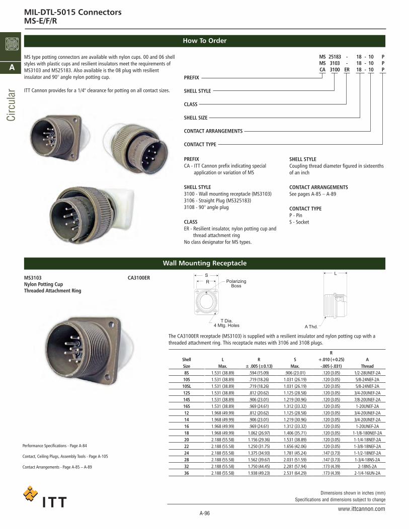
MS 25183 - 18 - 10 PMS 3103 - 18 - 10 PCA 3100 ER 18 - 10 P
PREFIX
SHELL STYLE
CLASS
SHELL SIZE
CONTACT ARRANGEMENTS
CONTACT TYPE
PREFIXCA - ITT Cannon prefix indicating special
application or variation of MS
SHELL STYLE3100 - Wall mounting receptacle (MS3103)3106 - Straight Plug (MS325183)3108 - 90° angle plug
CLASSER - Resilient insulator, nylon potting cup and
thread attachment ringNo class designator for MS types.
How To Order
Wall Mounting Receptacle
SHELL STYLECoupling thread diameter figured in sixteenthsof an inch
CONTACT ARRANGEMENTSSee pages A-85 – A-89
CONTACT TYPEP - PinS - Socket
MS type potting connectors are available with nylon cups. 00 and 06 shellstyles with plastic cups and resilient insulators meet the requirements ofMS3103 and MS25183. Also available is the 08 plug with resilient insulator and 90° angle nylon potting cup.
ITT Cannon provides for a 1/4" clearance for potting on all contact sizes.
The CA3100ER receptacle (MS3103) is supplied with a resilient insulator and nylon potting cup with athreaded attachment ring. This receptacle mates with 3106 and 3108 plugs.
Performance Specifications - Page XXX
Contact, Ceiling Plugs, Assembly Tools - Page XXX
Contact Arrangements - Page XXX
MS3103Nylon Potting CupThreaded Attachment Ring
CA3100ER SR Polarizing
Boss
T Dia.4 Mtg. Holes A Thd.
L
Performance Specifications - Page A-84
Contact, Ceiling Plugs, Assembly Tools - Page A-105
Contact Arrangements - Page A-85 – A-89
ca_A1-A163.qxd:Layout 1 2/9/11 7:50 PM Page 96

A-97www.ittcannon.com
Dimensions shown in inches (mm)Specifications and dimensions subject to change
Circular
A
MIL-DTL-5015 ConnectorsMS-E/F/R
Straight Plug
90° Angle Plug
MS25183Nylon Potting CupRubber Gasket
Nylon Potting CupRubber Gasket
CA3108ER
CA3106ER
The CA3106ER plug is supplied with resilient insulators, nylon potting cups with threaded attachment rings,and a rubber gasket under the coupling nut. This plug mates with 3100, 3101 and 3102 recaptacles.
The CA3108ER is supplied with resilient insulator, 90º nylon potting cup and threaded attachment ring with arubber gasket under the coupling nut. This plug mates with 3100, 3101 and 3102 receptacles.
CA3106ER
Shell J L P ASize Max. Max. Max. Thread8S .536 (13.61) 1.562 (39.67) .844 (21.44) 1/2-28UNEF-2B10S .536 (13.61) 1.562 (39.67) .969 (21.44) 5/8-24UNEF-2B10SL .536 (13.61) 1.562 (39.67) .969 (21.44) 5/8-24UNEF-2B12S .536 (13.61) 1.562 (39.67) 1.062 (21.44) 3/4-20UNEF-2B14S .536 (13.61) 1.562 (39.67) 1.156 (21.44) 7/8-20UNEF-2B16S .536 (13.61) 1.562 (39.67) 1.250 (21.44) 1-20UNEF-2B12 .724 (18.39) 2.000 (50.80) 1.062 (26.97) 3/4-20UNEF-2B14 .724 (18.39) 2.000 (50.80) 1.156 (29.36) 7/8-20UNEF-2B16 .724 (18.39) 2.000 (50.80) 1.250 (31.75) 1-20UNEF-2B18 .724 (18.39) 2.000 (50.80) 1.344 (34.14) 1-1/8-18UNEF-2B20 .724 (18.39) 2.125 (53.98) 1.469 (37.31) 1-1/4-18UNEF-2B22 .724 (18.39) 2.125 (53.98) 1.594 (40.49) 1-3/8-18UNEF-2B24 .724 (18.39) 2.125 (53.98) 1.719 (43.66) 1-1/2-18UNEF-2B28 .724 (18.39) 2.125 (53.98) 1.969 (50.01) 1-3/4-18UNS-2B32 .724 (18.39) 2.180 (55.37) 1.219 (30.96) 2-18UNS-2B36 .724 (18.39) 2.180 (55.37) 2.469 (62.71) 2-1/4-16UN-2B40 .724 (18.39) 2.180 (55.37) 2.723 (69.16) 2-1/2-16UN-2B
CA3108ERL Max.
For Arr. For Arr.w/#16 w/#8
B D   P AMax. Max. Contacts Contacts Max. Thread
------------
.563(13.61) 1.040(26.42) 1.463(37.16) - 969(24.61) 5/8-24UNEF-2B
.563(13.61) 1.040(26.42) 1.600(40.64) - 1.062(26.97) 3/4-24UNEF-2B
.563(13.61) 1.040(26.42) 1.600(40.64) 2.300(58.42) 1.156(29.36) 7/8-20UNEF-2B
.563(13.61) 1.290(32.77) 1.600(40.64) 2.550(64.77) 1.250(31.75) 1-20UNEF-2B
.724(18.39) 1.040(26.42) 1.910(48.51) - 1.062(26.97) 3/4-20UNEF-2B
.724(18.39) 1.040(26.42) 1.910(48.51) 2.610(66.29) 1.156(29.36) 7/8-20UNEF-2B
.724(18.39) 1.290(32.77) 1.910(48.51) 2.850(72.39) 1.250(31.75) 1-20UNEF-2B
.724(18.39) 1.290(32.77) 2.100(53.34) 2.850(72.39) 1.344(34.14) 1-1/8-18UNEF-2B
.724(18.39) 1.540(39.12) 2.100(53.34) 2.850(72.39) 1.469(37.31) 1-1/4-18UNEF-2B
.724(18.39) 1.540(39.12) 2.100(53.34) 2.850(72.39) 1.594(40.49) 1-3/8-18UNEF-2B
.724(18.39) 1.790(45.47) 2.281(57.94) 2.985(75.82) 1.719(43.66) 1-1/2-18UNEF-2B
.724(18.39) 2.040(51.82) 2.485(63.12) 2.985(75.82) 1.969(50.01) 1-3/4-18UNS-2B
.724(18.39) 2.290(58.17) 2.485(63.12) 2.985(75.82) 1.219(30.96) 2-18UNS-2B
.724(18.39) 2.540(64.52) 2.485(63.12) 2.985(75.82) 2.469(62.71) 2-1/4-16UN-2B
P
A Thd.
Gasket
Length ofEngagement
Metal Potting Ring
J
To endof
contact
1/4"
L
P Dia. PolarizingGroove
A Thd.
BL
D
MetalPotting Ring
Performance Specifications - Page A-84
Contact, Ceiling Plugs, Assembly Tools - Page A-105
Contact Arrangements - Page A-85 – A-89
ca_A1-A163.qxd:Layout 1 2/9/11 7:50 PM Page 97

A-98www.ittcannon.com
Dimensions shown in inches (mm)Specifications and dimensions subject to change
Circ
ular
A
MIL-DTL-5015 ConnectorsMS
Straight Plug with Shrink Boot Adapter
CA3106E-DN
CA3106E-DN is a straight plug withendbell for shrink boot adapters.Crimp and solder versions are avail-able (please indicate ...F80 or ...F183).CA3106-DN mate with 3100, 3101and 3102 shell styles.
Order reference A B C D E F L PPin insert* Thread min. max. ±0.2 ±0,2 0,5 max. max.CA3106E10SL-**-P-DN 5/8-24NEF-2B 7,7 13,2 15,5 17,0 11,7 11,7 50,0CA3106E12S-**-P-DN 3/4-20UNEF-2B 7,9 13,2 15,5 17,8 11,8 58,8 25,6CA3106E14S-**-P-DN 7/8-20UNEF-2B 10,6 17,0 19,1 19,1 11,7 50,0 28,6CA3106E16S-**-P-DN 1-20UNEF-2B 13,5 21,9 23,9 23,9 11,5 50,0 31,8CA3106E12-**-P-DN 3/4-20UNEF-2B 7,9 13,2 15,5 17,8 11,7 50,0 25,6CA3106E14-**-P-DN 7/8-20UNEF-2B 10,6 17,0 19,1 20,1 11,7 60,0 28,6CA3106E16-**-P-DN 1-20UNEF-2B 13,5 21,9 23,9 23,5 11,5 60,0 31,8CA3106E18-**-P-DN 1-1/8-18NEF-2B 14,6 21,9 23,9 26,5 12,7 60,0 34,1CA3106E20-**-P-DN 1-1/4-18NEF-2B 18,5 26,6 29,6 30,2 12,7 65,0 37,3CA3106E22-**-P-DN 1-3/8-18NEF-2B 20,8 26,2 29,6 33,6 12,7 65,0 40,5CA3106E24-**-P-DN 1-1/2-16NEF-2B 24,6 34,5 37,8 36,1 12,7 65,0 43,8CA3106E28-**-P-DN 1-3/4-18NS-2B 27,0 34,5 37,8 41,4 12,7 65,0 50,0CA3106E32-**-P-DN 2-18NS-2B 33,3 43,6 47,8 48,6 15,2 70,0 56,3CA3106E36-**-P-DN 2-1/4-16UN-2B 38,5 43,6 47,8 54,8 15,2 80,0 62,7
*For socket inserts substitute S for P**Add contact arrangement number (see pages A-85 – A-89)
ca_A1-A163.qxd:Layout 1 2/9/11 7:50 PM Page 98

A-99www.ittcannon.com
Dimensions shown in inches (mm)Specifications and dimensions subject to change
Circular
A
MIL-DTL-5015 Bulkhead ReceptaclesBFR/TBF
BFR 14S - S P * 1TBF 20 - 15 PS *
PREFIXSHELL SIZECONTACT ARRANGEMENTCONTACT TYPEALTERNATE POSITIONMOUNTING (BFR ONLY)
PREFIXBFR - Bulkhead fittingsTBF - Thru bulkhead fittings
SHELL SIZECoupling thread diameter figured in sixteenthsof an inch.
CONTACT ARRANGEMENTSSee pages A-85 – A-89
How To Order
Thru-Bulkhead Receptacle
CONTACT TYPEP - Pin; S - Socket; PS - pin and socket (TBF only)
ALTERNATE POSITION(Consult factory for available alternate positions.)
MOUNTING-1 obligatory code, BFR only
TBF and BFR pressurized bulkhead receptacles mate with standardMS type plugs (3106 and 3108) if contact arrangements correspond.Both the BFR and TBF have resilient insulators. The TBF (thru bulkhead fitting) version has a double faced construction allowingmating from both ends. An O-ring is supplied as standard on boththe BFR and TBF. Contacts are silver plated copper or brass alloy.Shells are aluminum alloy.
TBF thru-bulkhead fittings have pressurized resilient insulators. Special double-faced pin and socket contact construction permits cable components to be wiredand tested in the shop and then to be plugged into the mounted TBF plug tocomplete the installation. The TBF mates with 3106, 3107 and 3108 plugs.
TBF - Resilient Insulator
Pin Insert Ends Socket Insert Ends
A-85 – A-89 egaP - stnemegnarrA tcatnoC A-105 egaP - slooT ylbmessA ,sgulP gnilaeS ,stcatnoCA-84 egaP - snoitacificepS ecnamrofreP
ShellSize8S10S10SL12S14S16S1214161820222428323640
KMax.
.125 (3.18)
.125 (3.18)
.125 (3.18)
.140 (3.56)
.140 (3.56)
.140 (3.56).146 ( 3.71).146 ( 3.71).146 ( 3.71).180 (4.57).180 (4.57).180 (4.57).203 (5.16).203 (5.16).203 (5.16).203 (5.16).203 (5.16)
LMax.
1.482 (37.64)1.482 (37.64)1.482 (37.64)1.482 (37.64)1.482 (37.64)1.482 (37.64)2.030 (51.56)2.030 (51.56)2.030 (51.56)2.030 (51.56)2.030 (51.56)2.030 (51.56)2.030 (51.56)2.030 (51.56)2.030 (51.56)2.030 (51.56)2.030 (51.56)
M+.031 (0.79)-.000 (0.00).562 (14.27).562 (14.27).562 (14.27).562 (14.27).562 (14.27).562 (14.27).750 (19.05).750 (19.05).750 (19.05).750 (19.05).750 (19.05).750 (19.05).812 (20.62).812 (20.62).875 (22.22).812 (20.62).875 (22.22)
R±.005 (0.13).594 (15.09).179 (18.26).179 (18.26).812 (20.62).906 (23.01).968 (24.59).812 (20.62).906 (23.01).968 (24.59)1.062 (26.97)1.156 (29.36)1.250 (31.75)1.375 (34.92)1.562 (39.67)1.750 (44.45)1.938 (49.23)2.188 (55.58)
S±.031 (0.79).875 (22.22)1.000 (25.40)1.000 (25.40)1.094 (27.79)1.188 (30.18)1.281 (32.54)1.094 (27.79)1.188 (30.18)1.281 (32.54)1.375 (34.92)1.500 (38.10)1.625 (34.28)1.750 (44.45)2.000 (50.80)2.250 (57.15)2.500 (63.50)2.750 (69.85)
T+.010 (0.25)-.005 (0.13).120 (3.05).120 (3.05).120 (3.05).120 (3.05).120 (3.05).120 (3.05).120 (3.05).120 (3.05).120 (3.05).120 (3.05).120 (3.05).120 (3.05).147 (3.73).147 (3.73).173 (4.39).173 (4.39).173 (4.39)
VMax.
.325 (8.26)
.325 (8.26)
.325 (8.26)
.325 (8.26)
.325 (8.26)
.325 (8.26).445 (11.30).445 (11.30).445 (11.30).445 (11.30).445 (11.30).445 (11.30).383 (9.73).383 (9.73).320 (8.13).383 (9.73).383 (9.73)
AThread
1/2-28UNEF-2A5/8-24UNEF-2A5/8-24UNEF-2A3/4-20UNEF-2A7/8-20UNEF-2A1-20UNEF-2A
3/4-20UNEF-2A7/8-20UNEF-2A1-20UNEF-2A
1-1/8-18UNEF-2A1-1/4-18UNEF-2A1-3/8-18UNEF-2A1-1/2-18UNEF-2A1-3/4-18UNS-2A
2-18UNS-2A2-1/4-16UN-2A
Polarizing Boss Polarizing Boss
STyp.
RTyp.
Panel Thickness
AThd.
V
L
KSocketSide
MPinSide
T Dia.4 Mtg. Holes
ca_A1-A163.qxd:Layout 1 2/9/11 7:50 PM Page 99

A-100www.ittcannon.com
Dimensions shown in inches (mm)Specifications and dimensions subject to change
Circ
ular
A
MIL-DTL-5015 Bulkhead ReceptaclesBFR/TBF
Pressurized Bulkhead Receptacle
Mounting Dimensions
BFR pressurized bulkhead receptacles withstand the air leakagerequirements of MIL-C-5015 not to exceed 1 cu. in. of air perhour when subjected to a pressure differential of 30 psi at -55°C.Insulators are resilient material bonded to aluminum shell. Bothpin and socket assemblies are available. The BFR will mate withstandard MS type 3106 and 3108 plugs.
TYPE 1
ShellInsulatorLock Nut
O RingPosition Pin
MountingPart No. Example
StandardPolychloropreneHex with 6 wire holesNeopreneStandardFigure 1 or 2BFR-14S-SP-1
BFR
ShellSize8S10S10SL12S14S16S12141618202224283236
CMax.
.853 (21.67)
.853 (21.67)
.853 (21.67)
.853 (21.67)
.853 (21.67)
.853 (21.67)1.244 (31.60)1.244 (31.60)1.244 (31.60)1.244 (31.60)1.244 (31.60)1.244 (31.60)1.244 (31.60)1.244 (31.60)1.244 (31.60)1.244 (31.60)
GMax.
.895 (22.73)1.015 (25.78)1.015 (25.78)1.077 (27.36)1.203 (30.56)1.327 (33.71)1.077 (27.36)1.203 (30.56)1.327 (33.71)1.453 (36.91)1.577 (40.06)1.577 (40.06)1.827 (48.41)1.953 (49.61)2.203 (55.96)2.577 (65.46)
HMax.
1.077 (27.36)1.203 (30.56)1.203 (30.56)1.327 (33.71)1.453 (36.91)1.577 (40.06)1.327 (33.71)1.453 (36.91)1.577 (40.06)1.703 (43.26)1.827 (46.41)1.953 (49.61)2.077 (52.76)2.327 (59.11)2.577 (65.45)2.827 (71.81)
LMax.
1.087 (27.61)1.087 (27.61)1.087 (27.61)1.087 (27.61)1.087 (27.61)1.087 (27.61)1.525 (38.74)1.525 (38.74)1.525 (38.74)1.525 (38.74)1.525 (38.74)1.525 (38.74)1.525 (38.74)1.525 (38.74)1.525 (38.74)1.525 (38.74)
MMax.
.702 (17.83)
.822 (20.88)
.822 (20.88)
.955 (24.26)1.072 (27.23)1.265 (32.13).955 (24.26)1.072 (27.23)1.265 (32.13)1.395 (35.43)1.515 (38.48)1.635 (41.53)1.765 (44.83)2.015 (51.18)2.205 (56.01)2.455 (62.36)
NMax.
.820 (20.83)
.960 (24.38)
.960 (24.38)1.110 (28.19)1.250 (31.75)1.460 (37.08)1.110 (28.19)1.250 (31.75)1.460 (37.08)1.610 (40.89)1.750 (44.45)1.900 (48.26)2.030 (51.56)2.330 (59.18)2.550 (64.77)2.840 (72.14)
#16.140 (3.56).140 (3.56).140 (3.56).140 (3.56).140 (3.56).140 (3.56).062 (1.57).062 (1.57).062 (1.57).062 (1.57).062 (1.57).062 (1.57).062 (1.57).062 (1.57).062 (1.57).062 (1.57)
#12------
.062 (1.57)
.062 (1.57)
.062 (1.57)
.062 (1.57)
.062 (1.57)
.062 (1.57)
.062 (1.57)
.062 (1.57)
.062 (1.57)
.062 (1.57)
T Max.Solder Pot Ext.
#8-------
.125 (3.18)
.125 (3.18)
.125 (3.18)
.125 (3.18)
.125 (3.18)
.125 (3.18)
.125 (3.18)
.125 (3.18)
.125 (3.18)
#4--------
.125 (3.18)
.125 (3.18)
.125 (3.18)
.125 (3.18)
.125 (3.18)
.125 (3.18)
.125 (3.18)
.125 (3.18)
#0----------
.359 (9.12)
.359 (9.12)
.359 (9.12)
.359 (9.12)
.359 (9.12)
.359 (9.12)
VMax.
.250 (6.35)
.250 (6.35)
.250 (6.35)
.250 (6.35)
.375 (9.52)
.375 (9.52)
.375 (9.52)
.375 (9.52)
.375 (9.52)
.375 (9.52)
.375 (9.52)
.375 (9.52)
.375 (9.52)
.375 (9.52)
.375 (9.52)
.312 (7.92)
Shell Size A Thread8S 1/2-28UNEF-2A10S 5/8-24UNEF-2A10SL 5/8-24UNEF-2A12S 3/4-20UNEF-2A14S 7/8-20UNEF-2A16S 1-20UNEF-2A12 3/4-20UNEF-2A14 7/8-20UNEF-2A
Shell Size A Thread16 1-20UNEF-2A18 1-1/8-18UNEF-2A20 1-1/4-18UNEF-2A22 1-3/8-18UNEF-2A24 1-1/2-18UNEF-2A28 1-3/4-18UNS-2A32 2-18UNS-2A36 2-1/4-16UN-2A
A E F±.005 +.015 (0.38) ±.005
Shell Size (0.13) -.000 (0.00) (0.13)8S .323 (8.20) .500 (12.70) .373 (9.47)
10S, 10SL .385 (9.78) .625 (15.88) .435 (11.05)12S, 12 .448 (11.38) .750 (19.05) .498 (12.65)14S, 14 .510 (12.95) .875 (22.22) .560 (14.22)16S, 16 .573 (14.55) 1.000 (25.40) .623 (15.82)
18 .635 (16.13) 1.125 (28.58) .685 (17.40)
A E F±.005 +.015 (0.38) ±.005
Shell Size (0.13) -.000 (0.00) (0.13)20 .698 (17.73) 1.250 (31.75) .748 (19.00)22 .760 (19.30) 1.375 (34.92) .810 (20.57)24 .823 (20.90) 1.500 (38.10) .873 (22.17)28 .948 (24.08) 1.750 (44.45) .998 (25.35)32 1.073 (27.25) 2.000 (50.80) 1.123 (28.52)36 1.198 (30.43) 2.250 (57.15) 1.248 (31.70)
Performance Specifications - Page XXContacts, Sealing Plugs, Assembly Tool - Page XXContact Arrangements - Page XX
Across Hex
N
M
L
CT G
H
AThd.
V Panel Thickness
Standard Position
Pin is 3/32" Dia.
E
A
E
F
.102 (2.59)
.097 (2.46) DIA.102 (2.59).097 (2.46) DIA
Fig. 1 Fig. 2
Performance Specifications - Page A-84
Contact, Ceiling Plugs, Assembly Tools - Page A-105
Contact Arrangements - Page A-85 – A-89
ca_A1-A163.qxd:Layout 1 2/9/11 7:50 PM Page 100
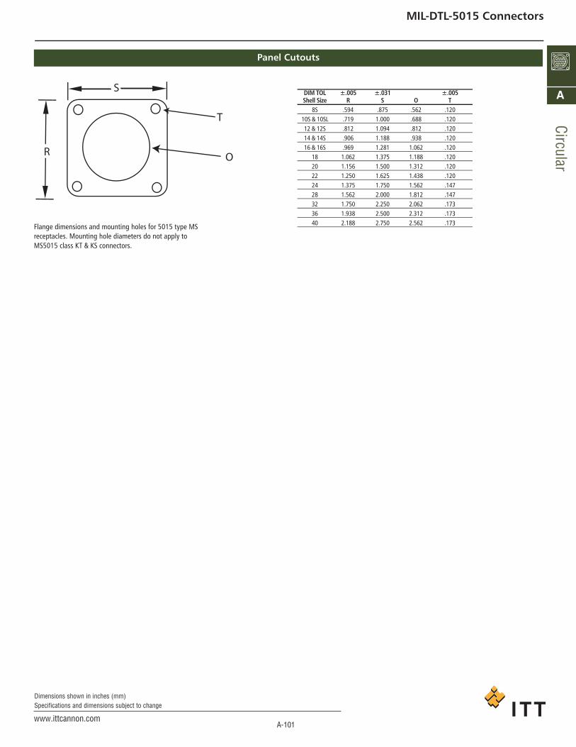
A-101www.ittcannon.com
Dimensions shown in inches (mm)Specifications and dimensions subject to change
Circular
A
MIL-DTL-5015 Connectors
Panel Cutouts
Flange dimensions and mounting holes for 5015 type MSreceptacles. Mounting hole diameters do not apply toMS5015 class KT & KS connectors.
DIM TOL ±.005 ±.031 ±.005Shell Size R S O T
8S .594 .875 .562 .12010S & 10SL .719 1.000 .688 .12012 & 12S .812 1.094 .812 .12014 & 14S .906 1.188 .938 .12016 & 16S .969 1.281 1.062 .120
18 1.062 1.375 1.188 .12020 1.156 1.500 1.312 .12022 1.250 1.625 1.438 .12024 1.375 1.750 1.562 .14728 1.562 2.000 1.812 .14732 1.750 2.250 2.062 .17336 1.938 2.500 2.312 .17340 2.188 2.750 2.562 .173
S
R
T
O
ca_A1-A163.qxd:Layout 1 2/9/11 7:50 PM Page 101
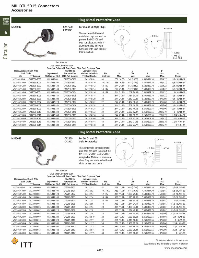
A-102www.ittcannon.com
Dimensions shown in inches (mm)Specifications and dimensions subject to change
Circ
ular
A
MIL-DTL-5015 ConnectorsAccessories
Plug Metal Protective Caps
Plug Metal Protective Caps
03571AC24052SMCA19741
For 06 and 08 Style Plugs
These externally threadedmetal dust caps are used toprotect the MS3106 andMS3108 plugs. Material isaluminum alloy. They arefurnished with sash chain orless sash chain.
9022AC34052SMCA2322
For 00, 01 and 02 Style Receptacles
These internally threaded metaldust caps are used to protect theMS3100, MS3101 and MS3102receptacles. Material is aluminumalloy. They are furnished with sashchain or less sash chain.
Part NumberOlive Drab Chromate Over
Cadmium Finish with Sash Chain Olive Drab Chromate OverDChsiniF muimdaCeb llitS yaMhtiW hsiniF dezidonA kcalB
Sash Chain Superceded Purchased by Without Sash Chain Fits B Dia. E Dia. AMS ITT Cannon MS Number (Ref) ITTC Part Number ITTC Part Number Shell Size Max. Max. Max. Max. Thread
MS25042-8DA CA17530-8000 MS25042-8D CA17530-5100 CA19741-8 8S .656 (16.66) .562 (14.27) 4.500 (114.30) .166 (4.22) 1/2-28UNEF-2AMS25042-10DA CA17530-8001 MS25042-10D CA17530-5101 CA19741-10 10S, 10SL .656 (16.66) .687 (17.45) 4.500 (114.30) .166 (4.22) 5/8-24UNEF-2AMS25042-12DA CA17530-8002 MS25042-12D CA17530-5102 CA19741-12 12, 12S .844 (21.44) .812 (20.62) 5.500 (139.70) .166 (4.22) 3/4-20UNEF-2AMS25042-14DA CA17530-8003 MS25042-14D CA17530-5103 CA19741-14 14, 14S .844 (21.44) .937 (23.80) 5.500 (139.70) .166 (4.22) 7/8-20UNEF-2AMS25042-16DA CA17530-8004 MS25042-16D CA17530-5104 CA19741-16 16, 16S .844 (21.44) 1.062 (26.97) 5.500 (139.70) .166 (4.22) 1-20UNEF-2AMS25042-18DA CA17530-8005 MS25042-18D CA17530-5105 CA19741-18 18 .844 (21.44) 1.187 (30.15) 5.500 (139.70) .166 (4.22) 1-1/8-18UNEF-2AMS25042-20DA CA17530-8006 MS25042-20D CA17530-5106 CA19741-20 20 .844 (21.44) 1.312 (33.32) 5.500 (139.70) .197 (5.00) 1-1/4-18UNEF-2AMS25042-22DA CA17530-8007 MS25042-22D CA17530-5107 CA19741-22 22 .844 (21.44) 1.437 (36.50) 5.500 (139.70) .197 (5.00) 1-3/8-18UNEF-2AMS25042-24DA CA17530-8008 MS25042-24D CA17530-5108 CA19741-24 24 .844 (21.44) 1.562 (39.67) 6.000 (152.40) .197 (5.00) 1-1/2-18UNEF-2AMS25042-28DA CA17530-8009 MS25042-28D CA17530-5109 CA19741-28 28 .844 (21.44) 1.812 (46.02) 8.250 (209.55) .197 (5.00) 1-3/4-18UNEF-2AMS25042-32DA CA17530-8010 MS25042-32D CA17530-5110 CA19741-32 32 .844 (21.44) 2.062 (52.37) 8.250 (209.55) .228 (5.79) 2-18UNEF-2AMS25042-36DA CA17530-8011 MS25042-36D CA17530-5111 CA19741-36 36 .844 (21.44) 2.312 (58.72) 8.250 (209.55) .228 (5.79) 2-1/4-16UN-2AMS25042-40DA CA17530-8012 MS25042-40D CA17530-5112 CA19741-40 40 .844 (21.44) 2.562 (65.07) 8.250 (209.55) .228 (5.79) 2-1/2-16UN-2AMS25042-44DA CA17530-8013 MS25042-44D CA17530-5113 CA19741-44 44 .844 (21.44) 2.812 (71.42) 8.250 (209.55) .228 (5.79) 2-3/4-16UN-2AMS25042-48DA CA17530-8014 MS25042-48D CA17530-5114 CA19741-48 48 .844 (21.44) 3.062 (77.77) 8.250 (209.55) .228 (5.79) 3-16UN-2A
Part NumberOlive Drab Chromate Over
Cadmium Finish with Sash Chain Olive Drab Chromate OverDChsiniF muimdaCeb llitS yaMhtiW hsiniF dezidonA kcalB
Sash Chain Superceded Purchased by Without Sash Chain Fits B Dia. E Dia. AMS ITT Cannon MS Number (Ref) ITTC Part Number ITTC Part Number Shell Size Max. Max. Max. Max. Thread
MS25043-8DA CA2209-8000 MS25043-8D CA2209-5100 CA2322-1 8S .469 (11.91) .688 (17.48) 4.500 (114.30) .150 (3.81) 1/2-28UNEF-2BMS25043-10DA CA2209-8001 MS25043-10D CA2209-5101 CA2322-2 10S, 10SL .469 (11.91) .815 (20.70) 4.500 (114.30) .150 (3.81) 5/8-24UNEF-2BMS25043-12DA CA2209-8002 MS25043-12D CA2209-5102 CA2322-3 12, 12S .469 (11.91) 1.000 (25.40) 5.500 (139.70) .150 (3.81) 3/4-20UNEF-2BMS25043-14DA CA2209-8003 MS25043-14D CA2209-5103 CA2322-4 14, 14S .469 (11.91) 1.125 (28.58) 5.500 (139.70) .150 (3.81) 7/8-20UNEF-2BMS25043-16DA CA2209-8004 MS25043-16D CA2209-5104 CA2322-5 16, 16S .469 (11.91) 1.188 (30.18) 5.500 (139.70) .150 (3.81) 1-20UNEF-2BMS25043-18DA CA2209-8005 MS25043-18D CA2209-5105 CA2322-6 18 .469 (11.91) 1.344 (34.14) 5.500 (139.70) .150 (3.81) 1-1/8-18UNEF-2BMS25043-20DA CA2209-8006 MS25043-20D CA2209-5106 CA2322-7 20 .469 (11.91) 1.469 (37.31) 5.500 (139.70) .150 (3.81) 1-1/4-18UNEF-2BMS25043-22DA CA2209-8007 MS25043-22D CA2209-5107 CA2322-8 22 .469 (11.91) 1.594 (40.49) 5.500 (139.70) .150 (3.81) 1-3/8-18UNEF-2BMS25043-24DA CA2209-8008 MS25043-24D CA2209-5108 CA2322-9 24 .469 (11.91) 1.719 (43.66) 6.000 (152.40) .181 (4.60) 1-1/2-18UNEF-2BMS25043-28DA CA2209-8009 MS25043-28D CA2209-5109 CA2322-10 28 .531 (13.49) 1.969 (50.01) 8.250 (209.55) .181 (4.60) 1-3/4-18UNS-2BMS25043-32DA CA2209-8010 MS25043-32D CA2209-5110 CA2322-11 32 .531 (13.49) 2.219 (56.36) 8.250 (209.55) .197 (5.00) 2-18UNS-2BMS25043-36DA CA2209-8011 MS25043-36D CA2209-5111 CA2322-12 36 .531 (13.49) 2.469 (62.71) 8.250 (209.55) .197 (5.00) 2-1/4-16UN-2BMS25043-40DA CA2209-8012 MS25043-40D CA2209-5112 CA2322-13 40 .531 (13.49) 2.719 (69.06) 8.250 (209.55) .197 (5.00) 2-1/2-16UN-2BMS25043-44DA CA2209-8013 MS25043-44D CA2209-5113 CA2322-14 44 .531 (13.49) 2.969 (75.41) 8.250 (209.55) .197 (5.00) 2-3/4-16UN-2BMS25043-48DA CA2209-8014 MS25043-48D CA2209-5114 CA2322-15 48 .531 (13.49) 3.188 (80.98) 8.250 (209.55) .197 (5.00) 3-16UN-2B
C Dia.
D Dia.
E
B
A Thd.
.250 Min.Perf. Thd.
C Dia.
D Dia.
B
E
A Thd.
Gasket
ca_A1-A163.qxd:Layout 1 2/9/11 7:50 PM Page 102

A-103www.ittcannon.com
Dimensions shown in inches (mm)Specifications and dimensions subject to change
Circular
A
MIL-DTL-5015 ConnectorsAccessories
Cable Clamp
Telescoping Bushing
M85049-41With or without bushing
M85049-41 cable clamp is made for plugs and receptacles that have an endbellwith external conduit threads. The double clamping action provides a balanced,positive hold on the wires and greatly reduces moisture transmission. Provision ismade for safety wiring. This clamp is supplied without bushing; to order bushing,add “with bushing” after part number.
MS3420/MS39056(REF.)
CA18220
Telescoping gland bushing (used with M85049/41 cableclamp) keep dirt, oil and moisture out of endbell. Taping orwrapping wires is eliminated since bushing protects wiresgoing through clamp. Combinations of bushings may be usedto decrease cable entry diameter to improve sealing.
*To order cable clamp with bushing, add “with bushing” after part number.
PartNumber*
M85049/41-3AM85049/41-4AM85049/41-6AM85049/41-8AM85049/41-10AM85049/41-12AM85049/41-16AM85049/41-20AM85049/41-24AM85049/41-28AM85049/41-32AM85049/41-40A
SupercededPart NumberMS3057-3AMS3057-4AMS3057-6AMS3057-8AMS3057-10AMS3057-12AMS3057-16AMS3057-20AMS3057-24AMS3057-28AMS3057-32AMS3057-40A
FitsShell Size
8S-10S10SL, 12S, 12
14S, 1416S, 16
1820, 2224, 28
3236404448
AccommodatesMS Bushings
MS3420-3MS3420-4MS3420-6MS3420-8MS3420-10MS3420-12
MS3420-16,12MS3420-20,16MS3420-24,20MS3420-24,20
MS3420-32,28,24MS3420-40,32,28
EMin.
.102 (2.59)
.140 (3.56)
.195 (4.95)
.255 (6.48)
.285 (7.24)
.350 (8.89).468 (11.89).664 (16.87).694 (17.63).911 (23.14)
--
EMax.
.250 (6.35)
.312 (7.92).438 (11.13).562 (14.27).625 (15.88).750 (19.05).938 (23.83)1.250 (31.75)1.375 (34.92)1.625 (41.28)1.875 (47.62)2.375 (60.32)
L±.031 (0.79).812 (20.62).812 (20.62).875 (22.22).938 (23.83).938 (23.83).938 (23.83)1.031 (26.19)1.094 (27.79)1.156 (29.36)1.688 (42.88)1.750 (44.45)1.750 (44.45)
P±0.31 (0.79).688 (17.48).812 (20.62).969 (24.61)1.094 (27.79)1.188 (30.18)1.375 (34.92)1.656 (42.06)2.031 (51.59)2.219 (56.36)2.500 (63.50)2.781 (70.64)3.281 (83.34)
R±0.31 (0.79).812 (20.62).875 (22.22)1.062 (26.97)1.156 (29.36)1.250 (31.75)1.496 (37.31)1.688 (42.88)2.031 (51.59)2.281 (57.94)2.688 (68.28)2.938 (74.63)3.500 (88.90)
AThread
1/2-28UNEF-2B5/8-24UNEF-2B3/4-20UNEF-2B7/8-20UNEF-2B1-20UNEF-2B
1-3/16-18UNEF-2B1-7/16-18UNEF-2B1-3/4-18UNS-2B
2-18UNS-2B2-1/4-16UN-2B2-1/2-16UN-2B
3-16UN-2B
MS PartNumber
MS3420-3MS3420-4MS3420-6MS3420-8MS3420-10MS3420-12MS3420-16MS3420-20MS3420-24MS3420-28MS3420-32MS3420-40
SupercededMS PartNumber
MS39056-1MS39056-2MS39056-3MS39056-4MS39056-5MS39056-6MS39056-7MS39056-8MS39056-9MS39056-10MS39056-11MS39056-12
ITT CannonPart NumberCA18220-3CA18220-4CA18220-6CA18220-8CA18220-10CA18220-12CA18220-16CA18220-20CA18220-24CA18220-28CA18220-32CA18220-40
FitsShell Size
8S-10S10SL, 12S, 12
14S, 1416S, 16
1820, 2224, 28
3236404448
C±0.16 (0.41)
.379 (9.63).505 (12.83).619 (15.72).744 (18.90).869 (22.07)1.064 (27.03)1.314 (33.38)1.596 (40.54)1.847 (46.91)2.085 (52.96)2.335 (59.31)2.835 (72.01)
L±0.31 (0.79)2.875 (73.02)2.750 (69.85)2.625 (66.68)2.500 (63.50)2.375 (60.32)2.250 (57.15)2.125 (53.98)2.000 (50.80)1.875 (47.62)1.750 (44.45)1.625 (41.28)1.500 (38.10)
R±0.16 (0.41)
.130 (3.30)
.200 (5.59)
.312 (7.92).437 (11.10).562 (14.27).625 (15.88).750 (19.05).937 (23.80)1.250 (31.75)1.375 (34.92)1.624 (41.25)1.874 (47.60)
Telescoping bushing with
M85049/41 cable clamp
R
C
L
R
L
P
E
.063A Thd.
2 PlacesSafety Wires Holes
ca_A1-A163.qxd:Layout 1 2/9/11 7:50 PM Page 103

A-104www.ittcannon.com
Dimensions shown in inches (mm)Specifications and dimensions subject to change
Circ
ular
A
MIL-DTL-5015 ConnectorsAccessories
Plastic Protective Caps
Protective dust caps are designed to cover thecoupling and conduit ends of MS connectorswhere there is a possibility of foreign matteraccumulating on the interior of the connector orof damage to the threaded parts. Material is redpolyethylene. Plastic dust caps can be reused, butare not intended to replace the standardaluminum dust caps shown in preceding pages.
MS3106/MS3108MS3100F,R MS3102F,R MS-F (only) F,R
Part Coupling Solder Coupling Solder Solder Coupling SolderNumber End Pot End End Pot End Pot End End Pot End
)19.11( 964.S8S8000-8540-520025-0459-000 8S 8S, 10S 8S 8S, 10S025-0460-000 10S, 10SL 10SL, 12S, 12 10S, 10SL 10SL, 12S, 12025-0462-000 12S, 12 14S, 14 12S, 12 14S, 14025-0463-000 14S, 14 16S, 16 14S, 14 16S, 16
81000-6640-52002000-7640-520220202000-8640-520422222000-9640-52082000-0740-52023000-1740-52063000-2740-52004000-3740-52044000-4740-52084000-5740-520
025-0477-000 10S, 10SL025-0478-000 12S, 12025-0479-000 14S, 14025-0480-000 16S, 16025-0484-000 18025-0486-000 22025-0487-000 24025-0488-000 28025-0489-000 32025-0490-000 36025-0491-000 40025-0492-000 44025-0493-000 48
818461 ,S618161 ,S61000-8940-52022 ,02226322 ,02000-9940-52082 ,420442 ,42000-0050-520
2344822382000-1050-5206323236323000-2050-5200482 ,42630463000-3050-5204422 ,02044404000-4050-52084818484000-5050-520
028181000-7050-5204242000-0150-520
025-0511-000 44 48 44S8000-8060-520
21 ,S21 ,LS01000-9060-52041 ,S41000-0160-52061 ,S61000-1160-520
82000-2160-52023000-3160-52063000-4160-520
AMax..673.734.848.9731.0981.2091.3961.5001.6251.8702.1202.3702.5012.8723.122.802.9111.0361.1611.2901.5401.6651.9072.1572.4122.6722.9223.1721.2401.4271.6771.9852.2452.4952.7423.2571.3651.7403.007.643.829.9541.0791.8392.0892.376
BMax..440.440.700.700.700.700.700.700.700.700.700.700.700.700.700.491.571.571.571.576.576.576.576.576.576.576.576.576.700.700.700.700.700.700.700.700.700.700.700.440.700.700.700.700.700.700
CMax..430.490.600.730.850.9501.1501.2401.3601.6101.8602.1102.3102.5902.840.550.669.794.9191.0281.2781.4031.6451.8952.1402.3902.6402.890.9901.1171.4201.7301.9802.2302.4802.9801.1101.4902.730.400.580.710.8301.5701.8202.010
DMax..486.546.656.786.9081.0161.2161.3061.4261.6761.9262.1762.3802.6602.910.616.725.850.9751.0941.3441.4691.7111.9612.2162.4662.7162.9661.0561.1831.4861.7962.0462.2962.5463.0461.1761.5562.796.456.636.766.8861.6261.8762.066
EMax..583.644.758.8831.0081.1191.3081.4051.5301.7752.0252.2752.4912.77230.22.712.821.9461.0711.1951.4451.5701.8122.0622.3172.5722.8223.0721.1501.3371.5871.8952.1552.4002.6523.1571.2751.6502.907.553.739.864.9891.7441.9942.231
Wt.Lb.
.0012
.0014
.0022
.0028
.0033
.0042
.0054
.0060
.0067
.0087
.0103
.0141
.0164
.0186
.0222
.0017
.0022
.0027
.0033
.0044
.0058
.0066
.0084
.0102
.0132
.0163
.0186
.0213
.0044
.0055
.0072
.0095
.0114
.0134
.0186
.0233
.0050
.0077
.0220
.0011
.0021
.0028
.0032
.0088
.0100
.0132
Dimensions
025-XXXX-000
A
B
C D E
.06
.13
ca_A1-A163.qxd:Layout 1 2/9/11 7:50 PM Page 104

A-105www.ittcannon.com
Dimensions shown in inches (mm)Specifications and dimensions subject to change
Circular
A
MIL-DTL-5015 ConnectorsAccessories
F80 Assembly Instructions
ITT Cannon provides a complete line of crimp insertion and extraction tooling to be usedwith CA-F80 contacts as follows.
Contact Hand Crimp Power Crimp CrimpSize Tool* Locator Tool* Head Locator Gauge16 M-2252/1-01 TH-70-1 CBT-53012 M-2252/1-01 TP567 CBT-600/600B CCH-12-7 CCHP-12-2 -8 - - CBT-600/600B CCH-8-1 CCHP-8-1 CCH-8-14 - - CBT-600/600B CCH-4-1 CCHP-4-1 CCH-4-10 - - CBT-600B CCH-0-1 CCHP-0-9 CCH-0
*The M-22520/1-01 is the MIL standard crimp tool for #12 thru #20 contacts and whenused with crimp #12, 16 and 20 contacts for the CA-F80.
**The CBT-600 is recommended for crimping of #4 thru #12 contacts. The CBT-600B for#0 thru #8. The appropriate locators and crimp heads are available as shown above.
Crimp Tool
Crimping Contacts
1. Check the crimp tool to be sure that the proper crimphead locator is used.
2. Cycle to tool to be sure the indentors are open.3. Place the contact, mating end first, into the tool.4. Insert the stripped wire into the hollow end of the
contact. Be sure the wire is inserted as far as it willgo.
5. Close the tool completely to crimp. Unless the tool isclosed completely, the tool will not release thecontact.
6. Remove the crimped contact from the tool. Check theinspection hole to verify that the wire is fully inserted.
Insertion/Extraction Tools
Insertion and extraction tools used for these connectorsare available for contact sizes 16 thru 0 as shown.
Contact Insertion Extraction HandleSize Tools Tools Color16 CIT-16 CET-16-4 Blue
(038895-0000) (038888-0004)12 CIT-12 CET-12-2 Yellow
(038896-0000) (038890-0002)8 CIT-8 CET-8 Red4 CIT-4 CET-4 Blue0 CIT-0 CET-0 Yellow
Insertion of Contacts
1. Before inserting the contacts, remove the endbell,grommets, and ferrule from the receptacle. Removethe endbell, grommet, ferrule, and coupling nut fromthe plug. Slide the hardware over the wire bundle inthe proper order for reassembly after all the contactsare inserted.
2. To assist insertion of contacts, lubricate insert cavitieswith isopropyl alcohol. Alcohol will evaporate andwill not leave a conductive film. Caution: Never useany lubricant other than isopropyl alcohol. Hold theplug or receptacle body firmly and insert the wiredcontacts as far as possible by hand. Starting at oneside of the insulator, work progressively from contactto contact across the layout. When inserting socketcontacts, be sure to provide fixture space below thefront face to permit length of guide pins for #16 and#12 contacts to clear insulator face.
3. Place the correct insertion tool on the contact so thatthe wire runs along the groove in the tool. (Tool tipwill butt against the shoulder.)
4. Beginning with a cavity on the outer edge of the plug,apply a slow, even pressure perpendicular to theinsulator face until the contact snaps into position. Ifcontacts are not inserted all the way prior toremoving insertion tool, do not try to reinsert theinsertion tool. Instead, using the extraction tool, pushthe contact back to the position it was in when theinsertion tool was originally placed over the contactfor push-in; otherwise the inside of contact cavitymay be damaged by reinserting the insertion tool.
5. Inspect the front end of the insulator to assure thatthe contacts are inserted to the proper depth.
Completion
After all the cavities have been filled, slide the hardwareback into position on the barrel. Tighten the endbelluntil the ferrule and endbell are flush. Compression ofthe grommet in this manner results in maximum sealingcharacteristics of the plug.
Extraction of Contacts
1. Select the appropriate tool. (Tool tips are reversible foreither pin or socket.) Place the extraction tool over thepin or into the socket.
2. Apply a slow, even pressure to push the contact outof the rear of the insulator.
Recommended Wire Stripping
Contacts
Contact Part NumbersF80
Contact Size Pin Socket16S 330-0345-016 031-0554-16116 330-0351-016 031-0560-16112 330-0351-012 031-0560-1218 330-0351-008 031-0560-0814 330-0351-004 031-0560-0410 330-0351-000 031-0560-001
Guide Pins
Guide pins are used to assist insertion of socket contactSizes #16 and #12. Larger sizes do not require guidepins.
Contact Guide Pin#16 226-1017-000#12 226-1018-000
Wire Hole Fillers
Wire ITT CannonSize AWG Part Number Color
20 225-1000-000 Red16/16S 225-0017-000 Blue
12 225-0018-000 Yellow8 225-0019-000 White4 225-8502-000 Green0 225-8503-000 Black
035/025-TBC006-TBC
SIZE 16
SIZE 8
SIZE 0
SIZE 4
SIZE 12
1/4" 1/4"
7/16"
11/16"
5/8"
ca_A1-A163.qxd:Layout 1 2/9/11 7:50 PM Page 105