Embed Size (px)
Citation preview

Issue 2: Page 1 of 27 CIRCULAR 62100-9-1
Issued by theAdministrator of Vehicle Standardsin consultation with theAustralian Motor Vehicle Certification Boardcomprising Commonwealth, State and Territory representatives
CIRCULAR 62/00-9 - 1
TEST PROCEDURES
ADR 62/00 - Mechanical Connections Between Vehicles
"A Guide for Inspectors"
This Circular is relevant to the Third Edition of the
Australian Design Rules gazetted as
National Standards under the Motor Vehicle Standards Act

CIRCULAR 62/00-9-1 Page 2of 27 Issue 2

Issue 3: August 1994 Page 3of 27 CIRCULAR 62/00-9-1
CONTENTS
Page
1. Scope 5
2. Selection of Test Components 52.1 Applicable Assemblies 52.2 Identification of Test Components 5
3. Equipment and Testing Procedures 53.1 Couplings 5
3.1.1 Fifth Wheel Assemblies 53.1.2 Fifth Wheel Kingpins 53.1 3 50 mm Pin Type Couplings 133.1.4 50 nun Ball Couplings 193.1.5 127 nun Ball Couplings 203.1.6 Hook Couplings 20
3.2 Towbars 213.3 Safety Chain Attachments 223.4 Drawbars 24
4. Calibrations and Orders of Accuracy 24
5. Summary of Evidence Report 24
6. Procedures for Designs with Certificationto Alternative Standards 25
7. References 25
8. Acknowledgements 25
Annex A - Testing Fixtures for 50 mm coupling bodies and coupling balls 26
Annex B - Figure 1 - Pintle Hook and Towing Eye 27
ERRATUM
Amendment

CIRCULAR 62/00-9-1 TEST PROCEDURE
CIRCULAR 62/00-9-1 Page 4 of 27 Issue 3: August 1994
ERRATUM
The equation given in item 3.2.2 of page 22 of 27 of Circular 62100-9-1 is incorrect. The correctequation is:
3.2.2 Calculation of D-Value for ME, NB and NC Vehicles. The D-value for the dynamic or statictest force required for these vehicles may be calculated from the m s of the towing vehicle and theAggregate Trailer Mass marked on the towbar, according to the following equation
Gk x Ga
D =Gk + Ga
WhereD = D - value in tonnesGk = mass of towing vehicle in tonnesGA = aggregate trailer mass for which the towbar is rated in tonnes
(AS2213-1984 Section 4) (Section 3.1.3)

CIRCULAR 62/00-9-1 TEST PROCEDURE
Issue 2: Page 5 of 27 CIRCULAR 62/00-9-1
SCOPE
This procedure when read in conjunction with AustralianDesign Rule 62/00 -'Mechanical Connections betweenVehicles'and other Circulars issued by the Administratorprovides sufficient information, without reference to otherstandards, to conduct and audit tests related to therequirements of devices for mechanical connections betweenvehicles and their fitment. The equipment, orders ofaccuracy and step by step actions described in this procedureare drawn from the standards and recommended practicesquoted in the ADR and from accepted testing and laboratorypractices. While conformance with this procedure issufficient to demonstrate compliance with the ADR, otherequipment, orders of accuracy and procedures may be usedprovided it can be shown that they demonstrate compliancewith the ADR. Several of the test procedures used in thisCircular are taken from relevant Australian Standards asreferred to in the ADR. These procedures are reprinted byarrangement with Standards Australia. For convenientreference the ADR and Australian Standard Clause Numbersare quoted in brackets against appropriate paragraphs in thisprocedure. This procedure is intended primarily as a guidefor officers of the Australian Department of Transport andCommunications or Agents acting on behalf of theAdministrator when they carry out audit inspections of TestFacilities or witness tests for compliance with the ADR. Thisand other Circulars dealing with Test Procedures for ADRsmay also be useful to vehicle manufacturers and testingorganizations. Nothing in this Circular, however, absolvesthe manufacturer from complying with the requirements asspecified in the ADR which always remains the primaryreference.
1. SELECTION OF TEST COMPONENTS
In general only production components are satisfactory fortesting to the requirements of this Design Rule. Howeverprototype assemblies maybe tested provided that they arefully representative of production components in respect ofmaterial, treatment, including welding and dimensions.1.1 Applicable. AssembliesAll towing and hitch assemblies, except for Road Trains (seeCircular 63100-9-1) used between a towing vehicle and atrailer are subject of this Design Rule.
The particular towing hitch by virtue of its towing capacitywill be dedicated to appropriate categories of towingvehicles and the appropriate category of trailer. For each testprogram all relative components are to be uniquely identifiedby part number, drawing number and revision or issue status.Such information is to be included in all test records andreports.1.2 Identification of Test ComponentsTest related components shall be representative of the designcondition as reflected in the production drawings. The testcomponents should be assembled using production partswhich have passed through normal quality assuranceprocedures. They should then be identified againstproduction drawings. If prototype components are used theyshould be individually inspected for both dimensional andmaterial specification compliance given in their respectivedrawings.
2. EQUIPMENT AND TESTING PROCEDURES
Testing of towing connections, towbars, drawbars etc maybe by dynamic or static testing procedures as described fbreach type of system. As the forces involved are large,substantial test rigs are required and in some cases need tobe constructed to accept all or part of a vehicle, either atowing vehicle or trailer. Each part of the ADR for aparticular connection type is described in the followingsections some of which are extracts from the relevantAustralian Standard. Where any part of the attachedAustralian Standard is not relevant for ADR 62100 it hashad a line drawn through it.2.1 Couplings3.1.1 Fifth Wheel Assemblies (Clause 62.5.3.1)
The following test procedures are reproduced fromAS 1773-1990 'Installation of Fifth Wheel andTurntable Assemblies' relevant to Fifth WheelKingpins.Two test procedures are concerned:3.11.1 Appendix A - Dynamic Test Method3.1.1.2 Appendix B - Static Over Turning MomentTest Method3.1.1.3 Appendix C. Selection of Fifth WheelAssemblies. Describes the methods for thecalculation of D-value ratings for the test methodsdescribed in Section 3.1.1.1 and 3.1.1.23.1.1.4 Section 2, Rating. Analysis of Test Results.Issue 2: Page 5 of 27 CIRCULAR 62100-9-1
CIRCULAR 62/00-9-1 TEST PROCEDURE
CIRCULAR 62/00-9-1 Page 6 of 27 Issue 2:
Section 3.1.1.1
9 AS 1773-1990
APPENDIX A
DYNAMIC TEST METHOD
(This Appendix forms an integral part of this Standard.)
A1 SCOPE. This Appendix sets out a method for dynamic testing of fifth wheel assemblies.
A2 PRINCIPLE. Longitudinal alternating and vertical oscillating test loads are appliedsimultaneously for a specified number of cycles.
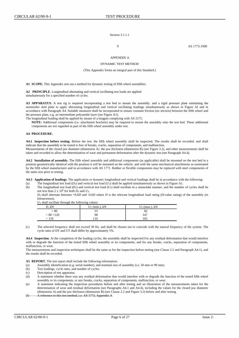
A3 APPARATUS. A test rig is required incorporating a test bed to mount the assembly. and a rigid pressure plate simulating thesemitrailer skid plate to apply alternating longitudinal and vertical oscillating loadings simultaneously as shown in Figure AI and inaccordance with Paragraph A4. Suitable measures shall be incorporated to ensure constant friction (no stiction) between the fifth wheel andthe pressure plate, e.g. an intermediate polyamide layer (see Figure A1).The longitudinal loading shall be applied by means of a kingpin complying with AS 2175.
NOTE: Additional components (i.e. attachment brackets) may be required to mount the assembly onto the test bed. These additionalcomponents are not regarded as part of the fifth wheel assembly under test.
A4 PROCEDURE.
A4.1 Inspection before testing. Before the test. the fifth wheel assembly shall be inspected. The results shall be recorded. and shallindicate that the assembly to be tested is free of breaks, cracks. separation of components, and malfunction.Measurements of the closed jaw diameter (dimension A). the jaw thickness (dimension B) (see Figure 3.2), and other measurements shall betaken and recorded to allow the determination of wear and permanent deformation after the dynamic test (see Paragraph A4.4).
A4.2 Installation of assembly. The fifth wheel assembly and additional components (as applicable) shall be mounted on the test bed in aposition geometrically identical with the position it will be mounted on the vehicle. and with the same mechanical attachments as nominatedby the fifth wheel manufacturer and in accordance with AS 1771. Rubber or flexible components may be replaced with steel components ofthe same size prior to testing.
A4.3 Application of loadings. The application or dynamic longitudinal and vertical loadings shall be in accordance with the following:(a) The longitudinal test load (DT) and vertical test load (UT) shall be applied simultaneously as shown in Figure A1.(b) The longitudinal test load (DT) and vertical test load (UT) shall oscillate in a sinusoidat manner, and the number of cycles shall be
not less than 2 x 10⁶ for both DT and UT.DT shall alternate between +0.6D and -0.6D where D is the relevant longitudinal load rating (D-value rating) of the assembly (inkilonewtons).UT shall oscillate through the following values:
D, kN UT (min.), kN UT (max.), kN= 80 55 82
> 80 =120 98 147> 120 110 165
(c) The selected frequency shall not exceed 30 Hz. and shall be chosen not to coincide with the natural frequency of the system. Thecycle rates of DT and UT shall differ by approximately 5%.
A4.4 Inspection. At the completion of the loading cycles, the assembly shall be inspected For any residual deformation that would interferewith or degrade the function of the tested fifth wheel assembly or its components, and for any breaks, cracks, separation of components,malfunction, or wear.The measurements and inspection techniques shall be the same as for the inspection before testing (see Clause 2.2 and Paragraph A4.1), andthe results shall be recorded.
A5 REPORT. The test report shall include the following information:(a) Assembly identification (e.g. serial number), and nominal size of assembly (i.e. 50 mm or 90 mm).(b) Test loadings. cycle rates, and number of cycles.(c) Description of test apparatus.(d) A statement whether there was any residual deformation that would interfere with or degrade the function of the tested fifth wheel
assembly or its components, or any breaks, cracks, separation of components, malfunction, or wear.(e) A statement indicating the inspection procedures before and after testing and an illustration of the measurements taken for the
determination of wear and residual deformation (see Paragraphs A4.1 and A4.4), including the values for the closed jaw diameter(dimension A) and the jaw thickness (dimension B) (see Clause 2.2 and Figure 3.2) before and after testing.
(f) A reference to this test method, i.e. AS 1773, Appendix A
CIRCULAR 62/00-9-1 TEST PROCEDURE
Issue 2: Page 7 of 27 CIRCULAR 62/00-9-1
Section 3.1.1.1
AS 1773 – 1990 10

CIRCULAR 62/00-9-1 TEST PROCEDURE
CIRCULAR 62/00-9-1 Page 8 of 27 Issue 2:
Section 3.1.1.2
11 AS 1773 - 1990
APPENDIX B
STATIC OVERTURNING MOMENT TEST METHOD(This Appendix forms an integral part of this Standard.)
B1 SCOPE. This Appendix sets out a method for static overturning moment testing of fifth wheel assemblies.
B2 PRINCIPLE. A specified static test load is applied to the fifth wheel through a kingpin and simulated skid plate to replicate theoverturning moment imposed on the fifth wheel assembly in seMce.
B3 APPARATUS. A test rig is required incorporating a test bed to mount the assembly and a rigid bar or pressure plate simulating thesemitrailer skid plate. to apply a static overturning moment as shown in Figure Bl. A kingpin complying with AS 2175 through which theoverturning momcnt is applied.
NOTE: Additional components (i.e. attachment brackets) may he required to mount the assembly onto the test bed. Thew additionalcomponents are not regarded as pan of the fifth wheel assembly under test.
B4 PROCEDURE.B4.1 Inspection before testing. Before the test. the fifth wheel assembly shall be inspected. The results shall be recorded. and shall indicatethat the assembly to be tested is free of breaks. cracks, separation of components, and malfunction.Measurements of the closed jaw diameter (dimension A) and the jaw thickness (dimension 8) (see Clause 2.2 and Figure 3.2) and othersuitable measurements shall be taken and recorded to allow the determination of permanent deformation after the test (see Paragraph B4.4).
B4.2 nstallation of assembly. The fifth wheel assembly and additional components (as applicable) shall be mounted on the test bed in aposition geometrically identical with the position it will be mounted on the vehicle, and with the same mechanical attachments as nominatedby the fifth wheel manufacturer and in accordance with AS 1771.
B4.3 Application of loading. A vertical force (F.) shall be applied to the bar or pressure plate as shown in Figure B I (e.g. through ahydraulic ram) such that this force (F.) multiplied by the horizontal displacement (hd) from the extreme edge of the fifth wheel coupler plategives an overturning moment (A.0 of not less than 112 kN.m.This overturning moment shall be applied in a plane at right angles to the longitudinal centrcline of the fifth wheel.
B4.4 Inspection after testing. After the test. the aumbly shall be inspected for any residual deformation that would interfere with or degradethe function of the tested fifth wheel assembly or its components, and for any breaks. cracks, separation of components. or malfunction.The measurements and inspection techniques shall he the same as for the inspection before testing (see Paragraph B4.1), and the resultsshall be recorded.
B5 REPORT. The test report shall include the following information:(a) Assembly identification (e.g. serial number), and nominal size of assembly (i.e. 50 mm or 90 mm).
(b) Test loading (F.). the moment arm (dimension Ad), and the resulting overturning moment (A1).
(c) Description of test apparatus.
(d) A statement whether there was any residual deformation that would interfere with or degrade the function of the tested fifth wheelassembly or its components. or any breaks, cracks, separation of components. or malfunction.
(e) A statement indicating the inspection procedures used before and after testing and an illustration of the measurements taken for thedetermination of residual deformation (see Paragraph B4.1 and B4.4), including the values for the closed jaw diameter (dimensionA) and the jaw thickness (dimension B) ~ Clause 2.2 and Figure 3.2) before and after testing.
(f) A reference to this test method, i.e AS 1773, Appendix B
COPYRIGHT

CIRCULAR 62/00-9-1 TEST PROCEDURE
Issue 2: Page 9 of 27 CIRCULAR 62/00-9-1
Section 3.1.1.2
AS 1773 – 1990 12
FIGURE B1 APPLICATION OF STATIC OVERTURNING MOMENT

CIRCULAR 62/00-9-1 TEST PROCEDURE
CIRCULAR 62/00-9-1 Page 10 of 27 Issue 3: August 1994
Section 3.1.1.3
13 AS 1773-1990
APPENDIX C
SELECTION OF FIFTH WHEEL ASSEMBLIES(This Appendix does not form an integral part of this Standard.)
C1 SCOPE. This Appendix sets out equations for the calculation of required D-value ratings to facilitate the selection of fifthwheel assemblies.
NOTES:1. Fifth wheel assemblies should he selected so as to have a D-value rating which equals or exceeds the value calculated using the
appropriate equation given in this Appendix. However, where the installation of the assembly reduces the fore-aft pitch angles toless than that specified in Clause 3.2 (e.g. restricted oscillation fifth wheels on converter dollies) additional- loadings may occur in the fifth wheel and it may be necessary to use a fifth wheel with a higher rating. Stronger components withhigher ratings may also be necessary for particular applications outside the scope of this Standard, e.g. in off-road operations.
2. Fifth wheel assemblies on converter dollies should be chosen so as to allow their use in triple road trains operating at maximumpermissible loads to avoid compatibility problems.
3. Where both a fifth wheel and a kingpin are D-value rated and are connected in a vehicle combination. the component with thelower rating will determine the overall rating for that towing connection. Where a D-value rated fifth wheel and a M-rated kingpinare connected in a vehicle combination. the overall connection will be regarded as M-rated. The rating of kingpins is specified inAS 2175.
C2 CALCULATION OF REQUIRED D-VALUE RATINGS. The minimum D-value rating for a particular application can bedetermined from the appropriate equation as follows:
NOTE: The calculated D-value should be rounded up to an integral value.
For an articulated vehicle with one trailer:
D= 5.9 TRM C2(1)
For the coupling on a prime mover towing more than one trailer:
D = 4.9R (T + 0.08R)M C2(2)
For the coupling on a converter dolly:D = 4.9T (R + 0.08T)
M - Uact C2(3)
Where
D = D-value. in kilonewtons
M - Gross combination mass in tonnes
T = sum or the maximum towing vehicle(s) axle loads. in tonnesNOTE. For a coupling on a converter dolly this is the maximum laden mass of all vehicles ahead of the converter dolly plus the tareman of the converter dolly
U = actual maximum vertical fifth wheel loading, in tonnes
R = sum of the maximum towed vehicle(s) axle loads plus the static mass (U.,) carried by the coupling. in tonnes.NOTE: Fifth wheel assemblies approved under ECE Regulation 55 are marked with a rating for T and R in the form *T/R tonne (e.g. '15/27tonne' where T - 15 t and R - 27 t). This rating may he converted to a D-value using the following equation-
D= 5.9TR
T + R -U act.
C3 D_VALUES FOR PARTICULAR VEHICLE COMBINATIONS A number of typical vehicle combinations and thecorresponding D-values are given in Tables C1 to C3. Where applicable, the tare mass of a converter dolly has been assumed to be 2.5 t

CIRCULAR 62/00-9-1 TEST PROCEDURE
Issue 2: Page 11 of 27 CIRCULAR 62/00-9-1
Section 3.1.1.4
AS 1773-1990 6
SECTION 2 RATING
2.1 GENERAL. Fifth wheels shall be rated by a D-value rating. The rating shall be expressed in integralnumbers, in kilonewtons (see also Clause 1.4.3). For the determination and verification of this rating. the testsdescribed in Appendix A and Appendix B shall be performed in accordance with Clause 2.2.
2.2 TEST PERFORMANCE. When a single fifth wheel assembly is tested in accordance with both AppendixA and Appendix B, no component of the assembly shall show any residua'. deformation that would interfere withor degrade the function of the assembly, nor shall there be any breaks, cracks, separation of components,malfunction. nor wear in excess of the following limits, when measuredin any direction (see Figure 3.2):
(a) Fifth wheels for 50 mm kingpins:(i) Dimension A (maximum)…………………………………………………………53 mm.(ii) Dimension B (minimum)………………………………………………………….22 mm.
(b) Fifth wheels for 90 mm kingpins:(i) Dimension A (maximum)…………………………………………………………92 ram.(ii) Dimension B (minimum)………………………………………………………….22 mm.
NOTE: The above wear limits are also recommended wear limits for in-service operations (see Appendix D).

CIRCULAR 62/00-9-1 TEST PROCEDURE
CIRCULAR 62/00-9-1 Page 12 of 27 Issue 2:
Section 3.1.1.4
AS 1773 – 1990 8
Millimetres
Closed jawdiameter
A
Jaw thickness
B
Coupler plate jawcentreline
C
Coupler platethroat
D
Couplierplate well
depthE
Type offifth wheel
Nom Tolerance Nom Tolerance Nom Tolerance Nom Tolernace (min)50 mm 51.0 +0.4, - 0 25 +0, - 3 52 +2, - 1 73.5 +1, - 0 8890 mm 89,4 +0.3, - 0 25 +0, - 3 40 +2, - 1 114.3 +1.5, - 0 79
NOTES:
1. This Figure shows a typical locking system. Other locking systerns are not prohibited.2. All dimensions relate to the locked position of the f-afth wheel.3. The jaw engagement on the joumal of the kingpin (we AS 2175) should entirely rat within the envelope defined by the dimensions8 and C.4. The closed jaw diameter and the jaw thickness should be considered in conjunction with the wear limits specified in Clause 2.2.
FIGURE 3.2 DIMENSIONAL REQUIREMENTS FOR INTERCHANGEABILITY

CIRCULAR 62/00-9-1 TEST PROCEDURE
Issue 2: Page 13 of 27 CIRCULAR 62/00-9-1
3.12 Fifth Wheel Wingpins (Clause 62.532)The following test procedures for theseKingpins is reproduced from AS 2175-1990"Articulated Vehicles Kingpins'.Procedures from AS 2175 are:3.12.1 Appendix A - Dynamic Test Method3.12.1.1 Section 2. Rating3.1.2.1.2 Figure 4.1 Basic Dimensions of
Kingpins.3.1.2.2 Appendix B - Selection of D-RatedKingpins. This appendix describes the method of calculatingthe D -rating of a kingpin for use in the Dynamic TestMethod, referred to in Appendix A, Section 3.1.2.1.3.1.2.3 Appendix D - Describes the methods of attachment ofthe test kingpin to the senu-trailer skid plate fixture for testingas described in Section 3.1.2.1, Appendix A.

CIRCULAR 62/00-9-1 TEST PROCEDURE
CIRCULAR 62/00-9-1 Page 14 of 27 Issue 2:
Section 3.1.2.1
AS 2175-1990 14
APPENDIX A
DYNAMIC TEST METHOD(This Appendix forms an integral part of this Standard.)
A1 SCOPE. This Appendix sets out a method for dynamic testing of D-rated kingpins.
A2 PRINCIPLE. A horizontal alternating test load is applied for a specified number of cycles.
A3 APPARATUS. A test rig is required incorporating a test bed simulating the trailer skid plate to mount the kingpin. An alternatinghorizontal loading shall be applied at the centre of the kingpin journal by a device simulating fifth wheel jaws, as shown in Figure A1.The attachment of the kingpin to the simulated trailer skid plate should be in accordance with Appendix D.
A4 PROCEDURE.
A4.1 Inspection before testing. Before the test the kingpin shall be inspected by magnetic particle inspection using the proceduresoutlined in AS 1171. The results shall be recorded and shall indicate that the kingpin to be tested is free of cracks.Measurements of dimensions F, G, and H (see Clause 2.2 and Figure 4.1) and suitable other measurements shall be taken and recorded toallow the determination of wear and permanent deformation after the dynamic test (see Paragraph A4.4).
A4.2 Installation of kingpin. The kingpin shall be mounted on the test bed in a position geometrically identical with the position it will bemounted on the skid plate, and with the same mechanical attachments as nominated by the kingpin manufacturer.
A4.3 Dynamic test load. The test load (DT) shall be alternating in a sinusoidal manner. It shall alternate between + 0.6D and - 0.6D whereD is the relevant D-value rating (in kilonewtons). The number of cycles shall be not less than 2 X 10⁶. See Appendix B Calculation ofD-ValueThe selected frequency shall not exceed 30 Hz, and shall be chosen not to coincide with the natural frequency of the system.
A4.4 Inspection after testing. At the completion of the loading cycles, the kingpin shall be inspected for any residual deformation thatwould interfere with or degrade the function of the kingpin. and for any breaks, cracks, separation of components, or wear. Themeasurement and inspection techniques shall be the same as for the inspection before testing (see Paragraph A4. 1), and the results shall berecorded.
A5 REPORT. The test report shall include the following information:(a) Kingpin identification (e.g. serial number), and nominal size of kingpin (i.e. 50 mm or 90 ;nm)(b) Test loading, cycle rate, and number of cycles.(c) Description of test apparatus.(d) A statement whether there was any residual deformation that would interfere with or degrade the function of the kingpin, or any
breaks, cracks, separation of components, or wear.(f) A statement indicating the inspection procedures before and after testing and an illustration of the measurements taken for the
determination of wear and residual deformation (see Paragraphs A4.1 and A4.4), including the values for dimensions F, G, and H(see Clause 2.2 and Figure 4.1) before and after testing.
(g) A reference to this test method, i.e. AS 2175, Appendix A

CIRCULAR 62/00-9-1 TEST PROCEDURE
Issue 2: Page 15 of 27 CIRCULAR 62/00-9-1
Section 3.1.2.1.1
7 AS 2175-1990
SECTION 2 RATING
2.2 RATING BY D-VALUE (D-RATED KINGPINS). When a D-rated kingpin is tested in accordance with AppendixA, there shall be no residual deformation that would interfere with or degrade the function of the kingpin, nor shall there beany breaks, cracks, or separation of components, nor wear in excess of the following limits, when measured in any direction(see Figure 4. l):(a) 50 mm kingpins:
(i) Dimension F (minimum) ........................................…………………………………………..49 mm(ii) Dimension G (minimum) ..........................................………………………………………...71 mm(iii) Dimension H (maximum) ..........................................……………………………………….73 mm
Section 3.1.2.1.2
AS 2175-1990 10

CIRCULAR 62/00-9-1 TEST PROCEDURE
CIRCULAR 62/00-9-1: Page 16 of 27 Issue 2:
Section 3.1.2.2
15 AS 2175-1990
APPENDIX B
SELECTION OF D-RATED KINGPINS(This Appendix does not form an integral part of this Standard.)
B1 SCOPE. This Appendix sets out equations for the calculation of required D-value ratings to facilitate theselection of kingpins.
NOTES:1. Kingpins should be selected so as to have a D-value rating which equals; or exceeds the value calculated
using the equations given in this Appendix. However, stronger components with higher ratings may benecessary for particular applications outside the scope of this Standard, e.g. in off-road operations (seealso Clause 1.1).
2. Wherc both a fifth wheel and a kingpin are D-value rated and are connected in a vehicle combination.the component with the lower rating will determine the overall rating for that towing connection.Where a D-value rated fifth wheel and a M-rated kingpin are connected in a vehicle combination. theoverall connection will be regarded as M-rated.The rating of fifth wheels is specified in AS 1773.
B2 CALCULATION OF REQUIRED D-VALUE RATINGS. The minimum D-value rating for a particularapplication can be determined from the appropriate equation as follows:
NOTE: The calculated D-value should be rounded up to an integral value. For an articulated vehicle with onetrailer:
D = 5.9TR ….B2(1)M
For the coupling on a prime mover towing more than one trailer:D = 4.9R (T + 0.08R) …B2(2)
M For the coupling on a converter dolly:
D = 4.9T (R + 0.08T) …B2(3)M - Uact
whereD = D-value, in kilonewtonsM = Gross combination mass, in tonnesT = sum of the maximum towing vehicle(s) axle loads, in tonnes
NOTE: For a coupling on a converter dolly this is the maximum laden mass of all vehiclesahead of the converter dolly plus the tare mass of the converter dolly
Uact = actual maximum vertical fifth wheel loading, in tonnesR = sum of the maximum towed vehicle(s) axle loads plus the static mass (Uact) carried by the
coupling, in tonnes.NOTE: Fifth wheel assemblies approved under ECE Regulation 55 are marked with a rating forT and R in the form '77R tonne' (e.g. '15/27 tonne' where T = 15 t and R = 27 t). This ratingmay be converted to a D-value using the following equation -
D = 5.9TRT + R - Uact
B3 D-VALUES FOR PARTICULAR VEHICLE COMBINATIONS. A number of typical vehiclecombinations and the corresponding D-values are given in Tables B1 to B3. Where applicable, the tare mass ofa converter dolly has been assumed to be 2.5 t.
COPYRIGHT

CIRCULAR 62/00-9-1 TEST PROCEDURE
Issue 2 Page 17of 27 CIRCULAR 62/00-9-1
Section 3.1.23
19 AS 2175-1990
APPENDIX DGUIDELINES FOR THE ATTACHMENT OF KINGPIN TO SKID PLATE
(This Appendix does not form an integral part of this Standard.)
D1 SCOPE. This Appendix sets out recommendations for the attachment of a kingpin to the semitrailer skidplate.
NOTE: Although the recommendations on methods of attachments are not mandatory in this Standard, theymay be specifiedas statutory requirements by Regulatory Authorities if considered appropriate.
D2 STRENGTH OF ATTACHMENT. A recommended method for evaluating the strength of attachment of akingpin is illustrated in Figure D1.The test frame shown in Figure D2 is attached to the kingpin and a horizontal force (Fh) is applied to the testframe (e.g. through a hydraulic ram) such that this force (Fh) multiplied by the vertical displacement from theskid plate (Vd), gives a moment of not less than 112 kN.m (as illustrated in the Figure D1). The value of thedisplacement (Vd) should be between 440 mm and 460 min.The kingpin and skid plate should be capable of withstanding the resulting static horizontal and vertical loadswithout failure or permanent deformation for at least 30 s.
D3 METHODS OF ATTACHMENT. The kingpin should preferably be attached to the skid plate by bolting toa housing which has been welded to the skid plate (see Note 1).For flange bolt-in kingpins, the bolts used should he of Grade 8.8 in accordance with AS 1110 and as shown inFigure 4.2. The bolt should be tightened to a torque of 120 N.m to 140 N.m for M16 bolts or 330 N.m to 370N.m for M20 bolts. Adequate provision for locking shall be made, e.g. wire locking. Spring washers are notpermissible.
If the kingpin is to be welded to the skid plate, a suitable design must be used which allows the welding to beapplied sufficiently far from the critical areas of the pin to prevent adverse heat effects. Welding is notpermissible in the zone bounded by the broken line in Figure 4.5 (see Clause 4.3). All welding must be subject toprocess control, in particular preheating of the immediate weld zone to not less than 200 °C and not more than300 °C (see Note 2), use of low hydrogen techniques, and where necessary post-weld heat treatment.
When fixed in position, the kingpin axis must be at an angle of 90 1 0 to the skid plate in all directions.NOTES:1. Bolt-in kingpins are preferred as they are easier to replace once worn. and are not prone to localized
heat effects from welding.2. A preheating temperature of 300°C should not be exceeded under any circumstances.

CIRCULAR 62/00-9-1 TEST PROCEDURE
CIRCULAR 62/00-9-1 Page 18 of 27 Issue 2:
Section 3.1.2.4
DIMENSIONS IN MILLIMETRES
FIGURE D2 TEST FRAME
COPYRIGHT

CIRCULAR 62/00-9-1 TEST PROCEDURE
Issue 2 Page 19 of 27 CIRCULAR 62/00-9-1
3.1.3 50 mm Pin Type Couplings (Clause 62.5-3-3)Test procedures for 50 mm Pin TypeCouplings are reproduced from AS2213-1984 "50 mm Pin Type Couplings andDrawbar Eyes for Trailers". Procedures fromAS 2213-1984 are:3.1.3.1 Section 4 - Methods of SelectingCouplings and Drawbar Eyes for a ParticularApplication.
This section describes the method of calculatingD-value being the dynamic load rating forcombinations of drawing vehicles and trailers foruse in testing the coupling assembly.3.1.3.2 Section 5 - Methods of Testing Couplingsand Drawbar Eyes
9 AS 2213-1994
SECTION 4. METHOD OF SELECTING COUPLINGS AND DRAWBAR EYES FOR A PARTICULARAPPLICATION
4.1 METHOD. Trailer couplings and drawbar eyes shall berated by their manufacturer for a particular D-value (in tonnes)and tested in accordance with Section 5. All couplings and eyesfor use in a particular combination shall be selected by usingthe appropriate formula as follows:
For a rigid truck with one trailer:
D = Gk x GA……………………………(1) Gk + GA
For an articulated vehicle with one trailer:
D = 0.7 Gk x GA ………………..……(2)Gk + GA
For a rigid truck with two trailers:
D = 0.85 Gk x GA…………………..(3) Gk + GA
For an articulated vehicle with two trailers:
D = 0.65 Gk x GA …………....(4)Gk + GA
For a rigid truck with three trailers:
D = Gk x GA
Gk + GA ………………..…(5)
where
D = D-value, in tonnes
Gk = maximum mass in the combination ahead of theforemost pin coupling, in tonnesGA = maximum mass in the combination behindthe foremost pin coupling, in tonnes
SECTION 5. METHOD OF TESTING COUPLINGS AND DRAWBAR EYES
5.1 TEST METHOD. The coupling and drawbar eye shall bemounted on a test bed in positions geometrically identical withthe positions in which they will he mounted on the vehicles,and with the same mechanical attachments as nominated by thecoupling manufacturer for mounting. Rubber or flexiblecomponents may be replaced with steel components of thesame size prior to testing.
The drawbar shall be in the straight-ahead position, butinclined to the vertical at an angle of inclination a determinedfrom the following equation:
tan a = 1.5FV
1.2Fh
where
FV = rated vertical load, in tonnesFh = rated D-value, in tonnes
The coupling and drawbar eye shall then be subjected to anoscillating test load in accordance with Clause 5.2.
5.2 TEST LOAD.5.2.1 Magnitude. The oscillating test load FP shall
be determined from the following equation:
FP = v (Fh2 + FV
2 )
where
FP = oscillating test load, in tonnesFh = 1.2 x rated D-value, in tonnesFV. = 1.5 x rated vertical load, in tonnes
5.2.2 Application. The oscillating test load shall be applied asfollows:
(a) Where slack is present between the coupling pin and drawbareye, the load shall be applied in tension, and shall oscillatebetween zero and FP.
(b) Where a special stack-free coupling pin or a special slack-freedrawbar eye is used, the load shall he applied alternately intension and compression, and shall oscillate between +0.5Fp
and -0.5Fp.
In either case, the oscillating test load shall be applied for 2 x 10⁶ cycles.
5.3 TEST CRITERIA. The coupling or drawbar eye shall not fail, andno evidence of cracking or physical deformation shall be visible.

CIRCULAR 62/00-9-1 TEST PROCEDURE
CIRCULAR 62/00-9-1 Page 20 of 27 Issue 2:
3.1.4 50 mm Ball Couplings (Clause 62-5-3.4)
50 min Ball couplings consist of two parts- 50 mm diameter coupling ball, attached to a towbarfixed to the drawing vehicle- coupling body to accept a 50 inin coupling ballattached to the drawbar of a trailer.
AS D 18 1968 - 50 min Ball Couplings (for Automotivepurposes)
- refers to the requirements and limits the towingcapacity of such coupling assemblies to 5000 lb (2.27t) (This standard is presently under review)3.1.4.1 Compliance demonstration is by static testmethods using a testing load factor of 3 times therated capacity of the coupling ball or coupling body.Coupling balls are tested at the maximum load ratingof 2.27 t x 3 while the coupling body is tested at 3times its rated capacity.3.1.4.2 TEST EQU1PMENTTest equipment for both components should consistof:3.1.4.2.1 A universal testing machine with loadcapacity (at least 3 times the maximum capacity ofthe component being tested) to 10 t (or 100 kN)capable of measuring forces applied.3.1.4.2.2 A substantial fixture (representing a trailerdrawbar) to which the test coupling body is attachedand fixed to the universal testing machine.3.1.4.2.3 A 50 mm coupling ball and substantialtongue or lug representing the towbar which isattached to the other head of the universal testingmachine.
NOTE 1 Care should be taken in testing that test forces arein alignment with the test components and the testingmachine.NOTE 2 See Annex A for typical illustrations of test fixturesfor testing in the various directions concerned in theprocedure.
3.1.4.3 Test Procedure for Coupling BodyThe test coupling body shall be attached to thedrawbar fixtures described above according to themanufacturers installation and adjustment instructionsand the following static loads applied via thecoupling ball as described in Section 3.1.4.2.(sequence is not important)3.1.4.3.1 Forward longitudinal direction Test load, 3times the aggregate trailer mass for which thecoupling body is rated.3.1.4.3.2 Rearward longitudinal direction Test load,3 times the aggregate trailer mass for which thecoupling body is rated.3.1.4.3.3 Transverse direction Tests are to be carriedout in both left hand and right hand directions.Test load, 1 times the aggregate trailer mass forwhich the coupling body is rated.3.1.4.3.4 Downward vertical direction Test load, 0.5times the aggregate trailer mass forwhich the coupling body is rated.3.1.4.3.5 Upward vertical direction Test load, 0.5times the aggregate trailer mass for which thecoupling body is rated.
3.1.4.4 Test Procedure for Coupling BallsThe test coupling ball shall be attached to the testfixture representing the towbar tongue or lugaccording to the manufacturers instructions and alongitudinal static force of 66 kN applied through acorrectly adjusted coupling body of sufficientcapacity.
NOTE: This testing force in kN is 2.27 t x g x 3 test loadfactorNOTE: g = 9.81 m/s2.In each case the test load shall be held for a minimum of 1second.
3.1.4.5 Analysis of ResultsAfter the tests the coupling ball or coupling bodyshall be carefully examined.There shall be no residual deformation that wouldinterfere or degrade the function of the coupling bodyor coupling ball, nor shall there be any fractures orseparation of components.3.1.4.6 Reporting of ResultsThe Test Facility shall prepare a report describing thecomponents tested, and their rating where applicable,the test equipment used, the forces and time attainedduring the tests, their direction and results of theexamination of the test components after the test.
3.1.5 127 mm Ball Couplings (Clause 62.5.3.5)127 mm Ball Couplings consist of two parts:- 127 mm diameter coupling ball attached to a towingbracket on the drawing vehicle- coupling body to accept the 127 mm coupling balltogether with components for locking one to the otherand attached to the drawbar of a trailer.One of two test methods for compliance may be used:- Static tests:longitudinal tension and compression of theassembly of 1.6 D-Value (Clause 62.5.3.5.1.1) and: vertical tension and compression of 0.5 times D -value (Clause 62.5.3.5.1.2) or- Dynamic oscillating force 0.6 x D-Value inlongitudinal direction and 0.2 x D in verticaldirection applied concurrently. (Clause 65.5.3.5.1.3)
NOTE. Care must be taken in testing that the test forces arein alignment with the test components and the testingmachines.
3.1.5.1 TEST EQUIPMENT3.1.5.1.1 Static Test EquipmentA universal testing machine similar to that describedin Section 3.1.4.2 above of adequate capacitytogether with suitable fixtures to which the couplingball and coupling body may be

CIRCULAR 62/00-9-1 TEST PROCEDURE
Issue 2: Page 21 of 27 CIRCULAR 62/00-9-1
attached
3.1.5.1.2 Dynamic Test EquipmentA hydraulic testing system with appropriate valvesand controls that is capable of applying oscillationforces of up to some 200 kN at a frequency notexceeding 10 HZ. The test frequency will need to bechosen not to coincide with the natural frequency ofthe system. Two rams are required to applyconcurrent forces in the longitudinal direction and inthe vertical direction. Equipment to measureoscillating forces, frequency and time are requiredtogether with protective systems for shutdown in theevent of fracture or failure of the test components.The same control system shall be capable of applyingthe longitudinal and vertical forces so their frequencydiffers by some 5 %.Fixtures are also required to attach the coupling bodyand coupling ball to the dynamic testing fixturesusing fastenings recommended or supplied by themanufacturer.3.1.5.1.3 Calculation of D-ValueD-Value, being the dynamic load in tonnes, shall becalculated for a particular combination of drawingvehicle and one or more trailers from the equations inSection 3.1.3. (AS 2213-1984)This calculated value shall be used for the static anddynamic test methods.3.1.5.2 Test Procedure3.1.5.2.1 Static Test ProcedureAttach the test coupling ball and coupling body bythe fixtures to the universal testing machine describedin Section 3.1.5.1.1. The coupling body should becarefully adjusted to fit the coupling ball as instructedby the manufacturer. Apply the derived test load(taking account of instrument uncertainty)- longitudinal tension and compressiondirection with a load of 1.6 x D -value.Upon completion of the longitudinal test reset thefixtures and apply the derived load:- in vertical tension and compression direction of0.5 x D -value.The test load should be steadily applied and held fora minimum of 1 second.3.1.5.2.2 Dynamic Test-ProcedureAttach the test coupling ball and coupling body bythe fixtures and fastening to the dynamic test rigdescribed in Section 3.1.5.1.2 above. The couplingbody shall be carefully adjusted to fit the couplingball as instructed by the manufacturer. Aftercalculation of D-value (Section 3.13.1.3) apply thedynamic oscillation force of
0.6 x D in longitudinal direction 0.2 x D in the verticaldirection
These forces are to be applied concurrently for aminimum of 2 million cycles at a frequency notexceeding 10 HZ. The frequency between theforces being applied in the longitudinal and verticaldirection shall differ by approximately 5%. Careshould be taken that the test frequency does notcoincide with the natural frequency of the system.
At regular intervals the test machine shouldbe stopped and the fastenings and fixtures andtest components checked for condition andsecurity, resecuring as required.At the end of the test period the testcomponents shall be removed.3.1.5.3 Analysis of ResultsAfter the tests the coupling ball or couplingbody shall be carefully examined.There shall be no residual deformation thatwould interfere or degrade the function of thecoupling body or coupling ball, nor shallthere be any fractures or separation ofcomponents.3.1.5.4 Reporting of ResultsA report describing the testing method, staticor dynamic, the components tested and theirstatus, the equipment used, calculation ofD-value, results of inspections during thedynamic test, and results of the examinationof the test components after the test iscompleted shall be made.
3.1.6 Hook Couplings (Clause 62.5.3.6) Hookcouplings consist of two parts:- a pintle or hook towing device which is attached tothe drawing vehicle- a lunette or towing eye attached to the drawbar ofthe trailer.The assembly is illustrated at Annex B, Figure 1.One of two test methods for compliance maybe used:- static longitudinal tension and compression of 1.6 xD -value ordynamic oscillation force of 0.6 x D -value.
3.1.6.1 Test Equipment3.1.6.1.1 Static Test EquipmentA universal testing machine and fixtures asdescribed in Section 3.1.4.2 is suitable forthis test.3.1.6.1.2 Dynamic Test EquipmentThe dynamic test rig and fixtures described inSection 3.1.5.12 is suitable for this test exceptthat only one loading ram is required.3.1.6.13 Calculation of D-ValueD-Value, being the dynamic load in tonnes,shall be calculated for a particularcombination of drawing vehicle and one ormore trailers from the equations in Section3.1.3. (AS 2213-1994)This calculated value shall be used for thestatic and dynamic test methods.3.1.6.2 Test Procedure3.1.6.2.1 Static TestAttach the test book or pintle on a fixturerepresenting the towbar attached to thedrawing vehicle which is in turn attached toone head of the universal testing machine.The lunette or towing eye shall be attached toa
CIRCULAR 62/00-9-1 TEST PROCEDURE
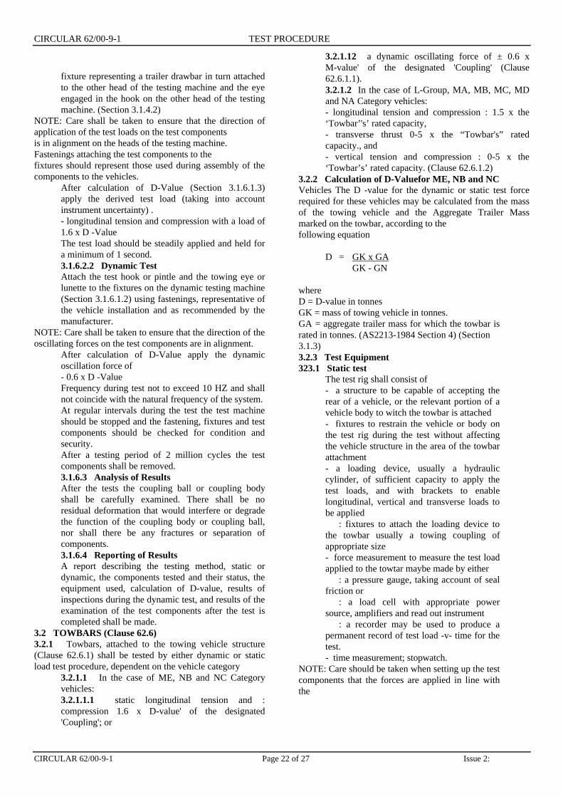
CIRCULAR 62/00-9-1 Page 22 of 27 Issue 2:
fixture representing a trailer drawbar in turn attachedto the other head of the testing machine and the eyeengaged in the hook on the other head of the testingmachine. (Section 3.1.4.2)
NOTE: Care shall be taken to ensure that the direction ofapplication of the test loads on the test componentsis in alignment on the heads of the testing machine.Fastenings attaching the test components to thefixtures should represent those used during assembly of thecomponents to the vehicles.
After calculation of D-Value (Section 3.1.6.1.3)apply the derived test load (taking into accountinstrument uncertainty) .- longitudinal tension and compression with a load of1.6 x D -ValueThe test load should be steadily applied and held fora minimum of 1 second.3.1.6.2.2 Dynamic TestAttach the test hook or pintle and the towing eye orlunette to the fixtures on the dynamic testing machine(Section 3.1.6.1.2) using fastenings, representative ofthe vehicle installation and as recommended by themanufacturer.
NOTE: Care shall be taken to ensure that the direction of theoscillating forces on the test components are in alignment.
After calculation of D-Value apply the dynamicoscillation force of- 0.6 x D -ValueFrequency during test not to exceed 10 HZ and shallnot coincide with the natural frequency of the system.At regular intervals during the test the test machineshould be stopped and the fastening, fixtures and testcomponents should be checked for condition andsecurity.After a testing period of 2 million cycles the testcomponents shall be removed.3.1.6.3 Analysis of ResultsAfter the tests the coupling ball or coupling bodyshall be carefully examined. There shall be noresidual deformation that would interfere or degradethe function of the coupling body or coupling ball,nor shall there be any fractures or separation ofcomponents.3.1.6.4 Reporting of ResultsA report describing the testing method, static ordynamic, the components tested and their status, theequipment used, calculation of D-value, results ofinspections during the dynamic test, and results of theexamination of the test components after the test iscompleted shall be made.
3.2 TOWBARS (Clause 62.6)3.2.1 Towbars, attached to the towing vehicle structure(Clause 62.6.1) shall be tested by either dynamic or staticload test procedure, dependent on the vehicle category
3.2.1.1 In the case of ME, NB and NC Categoryvehicles:3.2.1.1.1 static longitudinal tension and :compression 1.6 x D-value' of the designated'Coupling'; or
3.2.1.12 a dynamic oscillating force of ± 0.6 xM-value' of the designated 'Coupling' (Clause62.6.1.1).3.2.1.2 In the case of L-Group, MA, MB, MC, MDand NA Category vehicles:- longitudinal tension and compression : 1.5 x the‘Towbar’'s’ rated capacity,- transverse thrust 0-5 x the “Towbar's” ratedcapacity., and- vertical tension and compression : 0-5 x the‘Towbar’s’ rated capacity. (Clause 62.6.1.2)
3.2.2 Calculation of D-Valuefor ME, NB and NCVehicles The D -value for the dynamic or static test forcerequired for these vehicles may be calculated from the massof the towing vehicle and the Aggregate Trailer Massmarked on the towbar, according to thefollowing equation
D = GK x GAGK - GN
whereD = D-value in tonnesGK = mass of towing vehicle in tonnes.GA = aggregate trailer mass for which the towbar israted in tonnes. (AS2213-1984 Section 4) (Section3.1.3)3.2.3 Test Equipment323.1 Static test
The test rig shall consist of- a structure to be capable of accepting therear of a vehicle, or the relevant portion of avehicle body to witch the towbar is attached- fixtures to restrain the vehicle or body onthe test rig during the test without affectingthe vehicle structure in the area of the towbarattachment- a loading device, usually a hydrauliccylinder, of sufficient capacity to apply thetest loads, and with brackets to enablelongitudinal, vertical and transverse loads tobe applied
: fixtures to attach the loading device tothe towbar usually a towing coupling ofappropriate size- force measurement to measure the test loadapplied to the towtar maybe made by either
: a pressure gauge, taking account of sealfriction or
: a load cell with appropriate powersource, amplifiers and read out instrument
: a recorder may be used to produce apermanent record of test load -v- time for thetest.- time measurement; stopwatch.
NOTE: Care should be taken when setting up the testcomponents that the forces are applied in line withthe

CIRCULAR 62/00-9-1 TEST PROCEDURE
CIRCULAR 62/00-9-1 Page 23 of 27 Issue 2:
heads of the testing machine.3.2.3.2 Dynamic Test EquipmentThe dynamic test rig and fixtures described in Section3.13.12 is suitable for this test except that theapplication of the oscillation load is only required inone direction.
3.2.4 Test Procedure3.2.4.1 Static TestThe towbar shall be mounted to the vehicle bodyaccording to the towbar and vehicle manufacturersinstallation instructions using the fastening providedin the towbar installation kit tightened to theirminimum tightening torque.The loading device shall be attached to the towingtongue or lug of the towbar taking care that thedirection of loading is aligned in the test direction.3.2.4.1.1 Application of Test Loads for VehicleCategories ME, NB and NCFrom calculation of D-value (Section 322) and takingaccount of instrument uncertainty steadily apply a testforce of 1.6 x D in longitudinal tension direction,followed by a test in the compression direction.The test force shall be steadily applied and held for aminimum of one second. Remove the towbar from thetest fixture for detailed examination.3.2.4.1.2 Application of Test Loads for VehicleCategories, L-Group, MA, MB, MC, MD and NAFrom the aggregate trailer mass for which the towbaris rated apply the following static loads afterapplication of a settling load of approximately 10%of the test load to the system. The test loads shall begradually applied through a coupling ball andmaintained for not less than 1 second. Sequence isnot critical.(a) Forward longitudinal load. Maximum load, 1.5times the aggregate trailer mass for which the towbaris rated.(b) Rearward longitudinal load. Maximum load, 1.5times the aggregate trailer mass for which the towbaris rated.(c) Transverse load. Tests are to be carried out inboth left hand and right hand directions.Maximum load, 0.5 times the aggregate trailer massfor which the towbar is rated.(d) Downward vertical load. Maximum load, 0.5times the aggregate trailer mass for which the towbaris rated.(e) Upward vertical load Maximum load 0.5 times theaggregate trailer mass for which the towbar is rated.After completion of the force applications the towbarshall be removed from the test rig and inspected.3.2.4.2 Dynamic Test Procedure. VehicleCategories ME, NB and NCThe towbar shall be mounted on the vehicle bodywhich has been fastened to the test rig, according tothe towbar and vehicle manufacturers installationinstructions using fasteners provided in the towbar
installation kit, tightened to their minimumtightening torque.The dynamic loading device shall be attachedto the towbar coupling fixture using anappropriate coupling for the D-value rating ofthe towbar, taking care that the direction ofapplication of the oscillating force ishorizontal at the centre line of the system.From the D-value calculated in Section 3.2.2apply the oscillating dynamic load of ± 0.61Dat a frequency of not exceeding 10 HZ for 2million cycles. The test frequency shall bechosen not to coincide with the naturalfrequency of the system.At regular intervals the test machine shouldbe stopped and the towbar, its attachmentsand the vehicle structure carefully examined.If fastening torque is reduced they should beretightened to the correct torque and the testallowed to proceed.
3.2.4 Analysis of Results of Tests.3.2.4.1 On completion of static or dynamictests the towbar and vehicle structure to wtichit was attached shall be carefully examined.3.2.4.2 The vehicle structure including the`Towbar' shall withstand the forces appliedwithout any residual deformation that wouldinterfere with or degrade the function of theassembly, nor shall there be any breaks,cracks, or separation of components, or thevehicle structure (Clause 62.6.1).
3.2.5 Reporting of Results.The Test Facility shall prepare a report describingthe components and vehicle tested, D -value whererequired, test loads, directions of application of thetest load, whether the test was a static or a dynamictest and the results of the examination of the towbarandvehicle structure.3.3 SAFETY CHAIN ATTACHNIENTS (Clause6222)The static strength of safety chain attachments to thetowbar shall be tested at the following load- Longitudinal tension of the Towbars rated towingcapacity- Vertical load, 0.5 x the Towbars rated towingcapacity Where the tow bar has a towing capacity of2.5 t ormore it shall be fitted with 2 safety chain attachmentseach of which shall withstand the test loads above.These tests are usually carried out together with thestatic load tests on the towbar as described in Section3.2.3.3.1 Test EquipmentThe static load test equipment described in Section 3.2.3.1 issuitable for this test. The towbar may beattached to a testing fixture on the test rig rather than a
CIRCULAR 62/00-9-1 TEST PROCEDURE
CIRCULAR 62/00-9-1 Page 24 of 27 Issue 2:
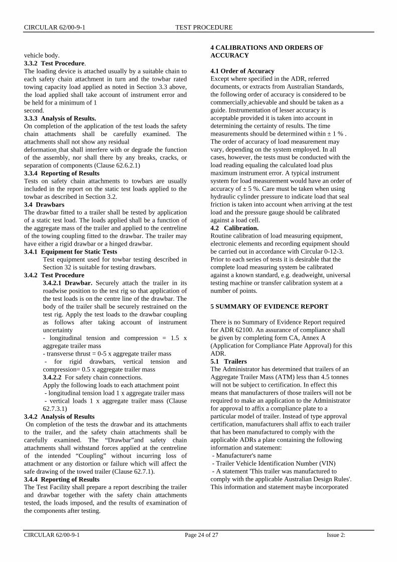
vehicle body.3.3.2 Test Procedure.The loading device is attached usually by a suitable chain toeach safety chain attachment in turn and the towbar ratedtowing capacity load applied as noted in Section 3.3 above,the load applied shall take account of instrument error andbe held for a minimum of 1second.3.3.3 Analysis of Results.On completion of the application of the test loads the safetychain attachments shall be carefully examined. Theattachments shall not show any residualdeformation that shall interfere with or degrade the functionof the assembly, nor shall there by any breaks, cracks, orseparation of components (Clause 62.6.2.1)3.3.4 Reporting of ResultsTests on safety chain attachments to towbars are usuallyincluded in the report on the static test loads applied to thetowbar as described in Section 3.2.3.4 DrawbarsThe drawbar fitted to a trailer shall be tested by applicationof a static test load. The loads applied shall be a function ofthe aggregate mass of the trailer and applied to the centrelineof the towing coupling fitted to the drawbar. The trailer mayhave either a rigid drawbar or a hinged drawbar.3.4.1 Equipment for Static Tests
Test equipment used for towbar testing described inSection 32 is suitable for testing drawbars.
3.4.2 Test Procedure3.4.2.1 Drawbar. Securely attach the trailer in itsroadwise position to the test rig so that application ofthe test loads is on the centre line of the drawbar. Thebody of the trailer shall be securely restrained on thetest rig. Apply the test loads to the drawbar couplingas follows after taking account of instrumentuncertainty- longitudinal tension and compression = 1.5 xaggregate trailer mass- transverse thrust = 0-5 x aggregate trailer mass - for rigid drawbars, vertical tension andcompression= 0.5 x aggregate trailer mass3.4.2.2 For safety chain connections.Apply the following loads to each attachment point - longitudinal tension load 1 x aggregate trailer mass - vertical loads 1 x aggregate trailer mass (Clause62.7.3.1)
3.4.2 Analysis of Results On completion of the tests the drawbar and its attachmentsto the trailer, and the safety chain attachments shall becarefully examined. The “Drawbar”and safety chainattachments shall withstand forces applied at the centrelineof the intended “Coupling” without incurring loss ofattachment or any distortion or failure which will affect thesafe drawing of the towed trailer (Clause 62.7.1).3.4.4 Reporting of ResultsThe Test Facility shall prepare a report describing the trailerand drawbar together with the safety chain attachmentstested, the loads imposed, and the results of examination ofthe components after testing.
4 CALIBRATIONS AND ORDERS OFACCURACY
4.1 Order of AccuracyExcept where specified in the ADR, referreddocuments, or extracts from Australian Standards,the following order of accuracy is considered to becommercially achievable and should be taken as aguide. Instrumentation of lesser accuracy isacceptable provided it is taken into account indetermining the certainty of results. The timemeasurements should be determined within ± 1 % .The order of accuracy of load measurement mayvary, depending on the system employed. In allcases, however, the tests must be conducted with theload reading equaling the calculated load plusmaximum instrument error. A typical instrumentsystem for load measurement would have an order ofaccuracy of ± 5 %. Care must be taken when usinghydraulic cylinder pressure to indicate load that sealfriction is taken into account when arriving at the testload and the pressure gauge should be calibratedagainst a load cell.4.2 Calibration.Routine calibration of load measuring equipment,electronic elements and recording equipment shouldbe carried out in accordance with Circular 0-12-3.Prior to each series of tests it is desirable that thecomplete load measuring system be calibratedagainst a known standard, e.g. deadweight, universaltesting machine or transfer calibration system at anumber of points.
5 SUMMARY OF EVIDENCE REPORT
There is no Summary of Evidence Report requiredfor ADR 62100. An assurance of compliance shallbe given by completing form CA, Annex A(Application for Compliance Plate Approval) for thisADR.5.1 TrailersThe Administrator has determined that trailers of anAggregate Trailer Mass (ATM) less than 4.5 tonneswill not be subject to certification. In effect thismeans that manufacturers of those trailers will not berequired to make an application to the Administratorfor approval to affix a compliance plate to aparticular model of trailer. Instead of type approvalcertification, manufacturers shall affix to each trailerthat has been manufactured to comply with theapplicable ADRs a plate containing the followinginformation and statement: - Manufacturer's name - Trailer Vehicle Identification Number (VIN) - A statement 'This trailer was manufactured tocomply with the applicable Australian Design Rules'.This information and statement maybe incorporated

CIRCULAR 62/00-9-1 TEST PROCEDURE
Issue 2: Page 25 of 27 CIRCULAR 62/00-9-1
into the trailer plate referred to above. It is the responsibilityof the person or company manufacturing a trailer to ensurethat the trailer, when first supplied to the market meets therequirements of the ADRs.5.2 RegistrationRegistration of vehicles remains the responsibility of theStates and Territories. Trailer manufacturers should consultthe registering authority, where their trailers will beregistered, for registration procedures (such asinspection).(Circular 0-2-7)
6 PROCEDURE FOR DESIGNS WITHCERTIFICATION TO ALTERNATIVE STANDARDS
There are no Alternative Standards for this Design Rule.
7 REFERENCES
ADR ReferencesADR DefinitionsADR 38/00 - Trailer Brake SystemsADR 62/00 - Mechanical Connections between vehiclesAustralian StandardsAS D-18-1968 50 rnm Ball Couplings (for AutomotivePurposes) including Amendment 1AS 1771-1987 Installation of Fifth Wheel and TurntableAssembliesAS 1773-1990 Articulated Vehicles - Fifth WheelAssemblies.AS 1872-1976 Safety Chains for Trailers and Caravans.AS 2174-1978 Recommendations for Positions and Heightsof Fifth Wheels for Articulated Vehicles.
AS 2175-1990 Articulated Vehicles – KingpinsAS 2213-1984 50 mm Pin Type Couplings and DrawbarEyes for Trailers.AS 2321-1979 Short Link Chain for Lifting Purposes.CircularsCircular 0-12-2 - General Requirements for Test Facilities.Circular 0-12-3 - General Requirements for Calibration ofTesting Equipment and Instrumentation.Circular 0-3-5 - Trailer Make and Model Designation.Circular 0-2-7 - Certification of Trailers less than 4-5 tonnesAggregate Trailer Mass.Circular 0-4-10 - Third Edition ADR's CertificationProcedures for Trailers.Other ReferencesVehicle Standards Bulletin No.1 Building Small Trailers,July 199 1, Issued by the Administrator.ISO 1103 Road Vehicles - Caravans and Light TrailersCoupling Ball - Dimensional CharacteristicsISO 3853 Road Vehicles - Caravans and Light TrailersTowing Brackets and Coupling Balls - Strength Tests SAE Standard J684 Trailer Couplings Hitches and SafetyChains - Automotive Type.ECE R 55 Mechanical Coupling Components ofCombinations of Vehicles.
8 ACKNOWLEDGEMENTS
The approval of Standards Australia to reproducerelevant parts of Australian Standards in this Circularis acknowledged.

CIRCULAR 62/00-9-1 TEST PROCEDURE
CIRCULAR 62/00-9-1 Page 26 of 27 Issue 2:
ANNEX A
TYPICAL TEST FIXTURES FOR 50 mm COUPLING BALLS AND COUPLING BODIES

CIRCULAR 62/00-9-1 TEST PROCEDURE
Issue 2: Page 27 of 27 CIRCULAR 62/00-9-1
ANNEX B
Figure 1 Pintle Hook and Towing Eye


![DEPARTMENT of commerce - NIST · DEPARTMENTOFCOMMERCE Circular ofTHE BureauofStandards No.62 SOAP [ThirdEdition] JANUARY24,1923 PRICE,5CENTS SoldonlybytheSuperintendentofDocuments](https://img.pdfslide.us/doc/110x75/60d4a058b5815513a2289494/department-of-commerce-nist-departmentofcommerce-circular-ofthe-bureauofstandards.jpg)