Embed Size (px)
Citation preview
Circuits: Light-Up Creatures Teacher version
In this lab you will explore current, voltage and resistance and their relationships as given by the Ohm’s law. You will also explore of how resistance can be arranged within circuits as well as be exposed to the concept of power (advanced version only). California Science Content Standards:
• 5. Electric and Magnetic Phenomena: Electric and magnetic phenomena are related and have many practical applications.
• 5a. Students know how to predict the voltage or current in simple direct current (DC) electric circuits constructed from batteries, wires, resistors, and capacitors.
• 5b. Students know how to solve problems involving Ohm’s Law. • 5e. Students know charged particles are sources of electrical fields and are subject to the
forces of the electrical fields from other charges. • 5f. Students know magnetic materials and electric currents (moving electric charges) are
sources of magnetic fields and are subject to forces arising from the magnetic fields of other sources.
Prerequisites:
• Requires basic understanding of electricity • Advanced version requires use of fractions
Complete List of Materials:
for each group of 2-4 students: • 6 size-D dry cells (batteries) • 6 pieces of copper wire with crocodile clips connects • 2 12V light bulbs with metallic connects (does not require bulb holders) • 1 multi-meter • Pencil **TEACHER NOTE** There is a Squishy Circuits activity at the end of the lab which requires additional materials listed in that section. This activity is meant to be a fun extension of the concepts learned in this lab, so there is no formal section for it in the student labs.
Key Concepts:
• Concept of an atom: An atom comprises of a central nucleus that is surrounded by electron shells. The nucleus is made up of positively charged protons and neutrally charged neutrons. The electron shells that surround the nucleus are occupied by negatively charged electrons. An atom is electrically neutral, because at any one point, it has the same number of protons and electrons.
• Properties of charges: Like charges attract each other while unlike charges repel each other. Negative attracts positive, whereas positive repels positive and negative repels negative.
• Current: When a large positive charge is brought near an electron, it can move towards the positively charged source leaving its electron shell. The movement of electrons or flow of electrons is defined as current. Current is measured in Amperes (A).
• Voltage: Voltage is defined as stored electrical energy. Energy is the capacity to do work. We eat food everyday so that we get the energy we need to do our daily tasks. Just like we need energy to move, electrons need energy to move and we can provide that to them in stored forms called voltage. Voltage is measured in Volts (V). Example of electrical energy storing devices: batteries
• Resistance: It literally means it’s says. Resistance is the resistance to the flow of electrons or resistance to flow of current. Resistance is measured in Ohms (Ω).
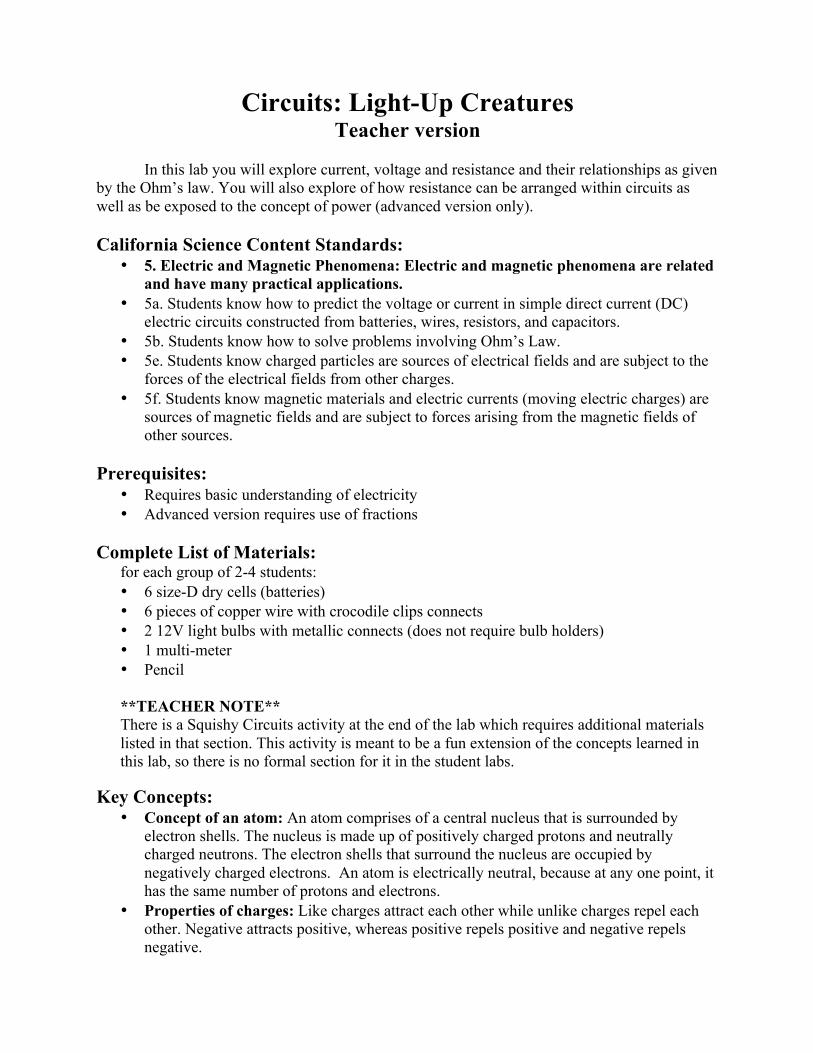
• Circuit: A circuit is a closed loop of electron flow. The simplest representation of a circuit is provided below:
Introductory Mini-lecture:
The negative terminal is the part of the battery with an excess of electrons, giving the end a net negative charge. The positive terminal has a deficiency of electrons, giving it a net positive charge. The electrons closest to the positive terminal are pulled towards the positive terminal. As the electrons move, a deficiency of electrons is created in the atoms from that specific area, leaving behind a net positive charge. These ions (charged atoms) then attract the electrons of their neighboring atoms pulling them towards the ions and the effect continues down the entire circuit. At the negative terminal, electrons in atoms closest to the terminal are repelled away by the negative charge of the terminal to the neighboring atoms, giving them a net negative charge. The negative charge of these ions then repels electrons of the neighboring atoms similarly and the effect continues down the entire circuit. This is how current flows through a circuit. Electrons flow from ‘-’ve terminal to ‘+’ve terminal, but the general convention is to consider that current flows from ‘+’ve to ‘-’ve terminal.
- +
Connecting wires
Indicates flow of current
Battery with ‘-
Resistor
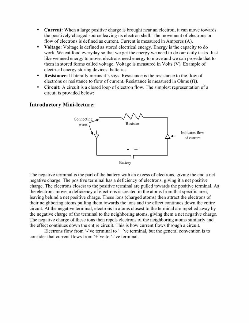
Part I: Resistance- Series and Parallel combinations There are different ways in which we can set different resistances across our circuits. Two ways of combining resistors, which are electrical components with known values of resistance, are: 1) in series, and 2) in parallel.
1) Resistors are said to be in series if they are placed one after another in a circuit as shown in the diagram below:
The same amount of current, I, flows through each resistor, but the total voltage, V, supplied from the battery gets divided amongst the two resistors.
Total Resistance, RT(Ω) = R1 (Ω) + R2 (Ω)
2) Resistors are said to be in parallel if they are arranged such that all resistors in parallel
receive the same voltage with different amounts of current flowing through each of them, as shown below:
Tungsten bulbs are used as resistors in this experiment.
Resistor 1 Resistor 2
Resistor 1
Resistor 2
ADVANCED VERSION ONLY
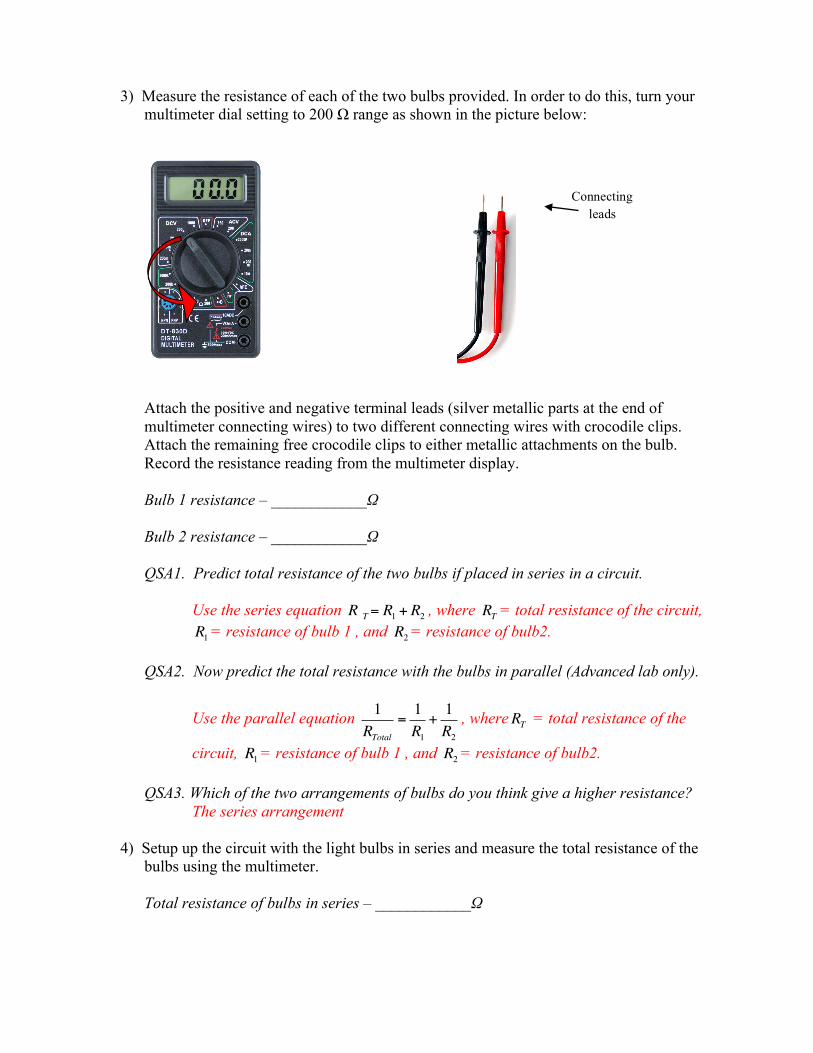
3) Measure the resistance of each of the two bulbs provided. In order to do this, turn your multimeter dial setting to 200 Ω range as shown in the picture below:
Attach the positive and negative terminal leads (silver metallic parts at the end of multimeter connecting wires) to two different connecting wires with crocodile clips. Attach the remaining free crocodile clips to either metallic attachments on the bulb. Record the resistance reading from the multimeter display. Bulb 1 resistance – ____________Ω Bulb 2 resistance – ____________Ω QSA1. Predict total resistance of the two bulbs if placed in series in a circuit.
Use the series equation R T= R1 + R2 , where RT = total resistance of the circuit, R1 = resistance of bulb 1 , and R2 = resistance of bulb2.
QSA2. Now predict the total resistance with the bulbs in parallel (Advanced lab only).
Use the parallel equation 1RTotal
=1R1+1R2
, whereRT = total resistance of the
circuit, R1 = resistance of bulb 1 , and R2 = resistance of bulb2.
QSA3. Which of the two arrangements of bulbs do you think give a higher resistance? The series arrangement
4) Setup up the circuit with the light bulbs in series and measure the total resistance of the
bulbs using the multimeter.
Total resistance of bulbs in series – ____________Ω
Connecting leads
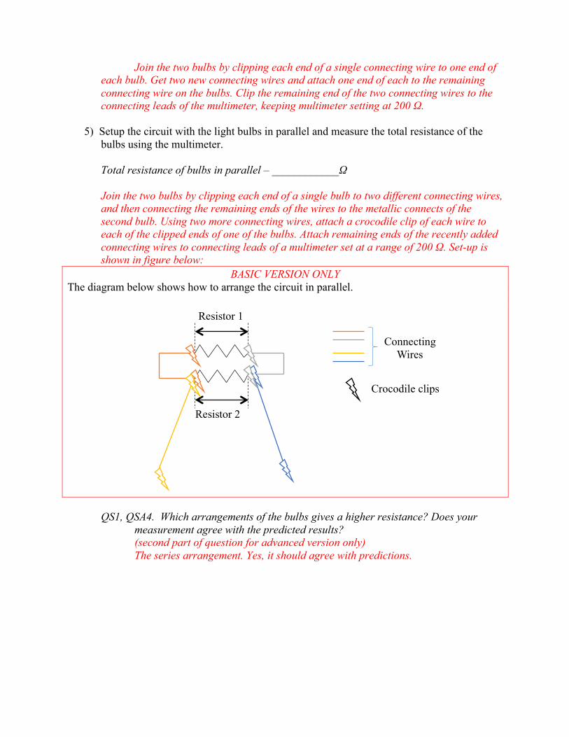
Join the two bulbs by clipping each end of a single connecting wire to one end of each bulb. Get two new connecting wires and attach one end of each to the remaining connecting wire on the bulbs. Clip the remaining end of the two connecting wires to the connecting leads of the multimeter, keeping multimeter setting at 200 Ω.
5) Setup the circuit with the light bulbs in parallel and measure the total resistance of the
bulbs using the multimeter.
Total resistance of bulbs in parallel – ____________Ω Join the two bulbs by clipping each end of a single bulb to two different connecting wires, and then connecting the remaining ends of the wires to the metallic connects of the second bulb. Using two more connecting wires, attach a crocodile clip of each wire to each of the clipped ends of one of the bulbs. Attach remaining ends of the recently added connecting wires to connecting leads of a multimeter set at a range of 200 Ω. Set-up is shown in figure below:
BASIC VERSION ONLY The diagram below shows how to arrange the circuit in parallel.
QS1, QSA4. Which arrangements of the bulbs gives a higher resistance? Does your measurement agree with the predicted results? (second part of question for advanced version only) The series arrangement. Yes, it should agree with predictions.
Resistor 1
Resistor 2
Connecting Wires
Crocodile clips
Part II: Ohm’s Law- Relationship of Current (I), Voltage (V) and Resistance (R)
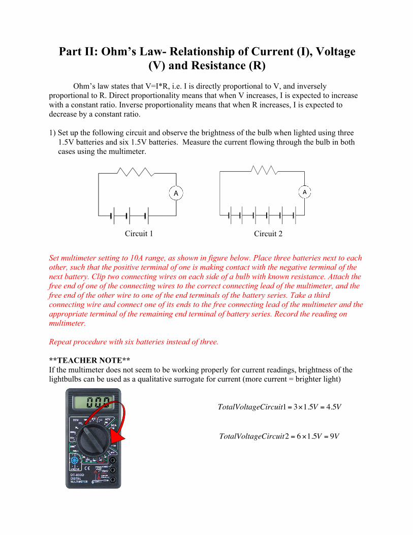
Ohm’s law states that V=I*R, i.e. I is directly proportional to V, and inversely proportional to R. Direct proportionality means that when V increases, I is expected to increase with a constant ratio. Inverse proportionality means that when R increases, I is expected to decrease by a constant ratio. 1) Set up the following circuit and observe the brightness of the bulb when lighted using three
1.5V batteries and six 1.5V batteries. Measure the current flowing through the bulb in both cases using the multimeter.
Set multimeter setting to 10A range, as shown in figure below. Place three batteries next to each other, such that the positive terminal of one is making contact with the negative terminal of the next battery. Clip two connecting wires on each side of a bulb with known resistance. Attach the free end of one of the connecting wires to the correct connecting lead of the multimeter, and the free end of the other wire to one of the end terminals of the battery series. Take a third connecting wire and connect one of its ends to the free connecting lead of the multimeter and the appropriate terminal of the remaining end terminal of battery series. Record the reading on multimeter. Repeat procedure with six batteries instead of three. **TEACHER NOTE** If the multimeter does not seem to be working properly for current readings, brightness of the lightbulbs can be used as a qualitative surrogate for current (more current = brighter light)
TotalVoltageCircuit1= 3×1.5V = 4.5V
TotalVoltageCircuit2 = 6×1.5V = 9V
Circuit 1 Circuit 2
Current through circuit with 3 batteries – ____________Amps Current through circuit with 6 batteries – ____________Amps QS2, QSA5. Which battery arrangement gave a higher current reading, three or six?
The six battery arrangement should give higher current reading. QSA6. Calculate the ratio of voltage to current for both circuits. What does this number represent?
To calculate ratio of voltage to current, divide the respective voltages of each circuit by its respective current. The answer should be equivalent to the resistor and be the same for both circuits.
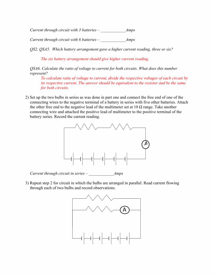
2) Set up the two bulbs in series as was done in part one and connect the free end of one of the connecting wires to the negative terminal of a battery in series with five other batteries. Attach the other free end to the negative lead of the multimeter set at 10 Ω range. Take another connecting wire and attached the positive lead of multimeter to the positive terminal of the battery series. Record the current reading.
Current through circuit in series – ____________Amps 3) Repeat step 2 for circuit in which the bulbs are arranged in parallel. Read current flowing
through each of two bulbs and record observations.
A
A
Current through circuit in parallel – ____________Amps QS3, QSA7. Which resistor arrangement gave the higher current reading?
The bulbs in parallel arrangement should give higher reading, with both readings are combined
QS4, QSA8. What does this tell us about the relationship of current with respect to the resistance?
As resistance increases, current decreases. QSA9. Find the ratio of voltage to current for each resistor arrangement. What does the ratio represent?
Divide voltage by the overall current flowing through the circuit as read from the multimeter. The ratio should reflect the resistance of the circuit.
Optional Post Lab Activity: Squishy Circuits Activity originally developed by St. Thomas University
(http://courseweb.stthomas.edu/apthomas/SquishyCircuits/)
Normal playdough is conducting due to the salt used in the dough recipe. This activity uses both conducting and insulating playdough recipes to make circuits and illuminate small LEDs. **TEACHER NOTE** This activity is meant to be a fun extension of the concepts learned in this lab, so there is no formal section for it in the student labs. Complete List of Materials: For the conductive dough:
• 1 cup water • 1.5 cups flour (Replace with gluten-free flour if desired) • 1/4 cup salt • 3 Tbsp. Cream of Tartar* (or 9 Tbsp. of lemon juice may be substituted) • 1 Tbsp. Vegetable Oil • Food Coloring (optional)
For the insulating dough:
• 1/2 cup flour • 1/2 cup sugar • 3 Tbsp. vegetable oil • 1/2 cup deionized (or distilled) water (Regular tap water can be used, but the resistance of
the dough will be lower.) Hardware:
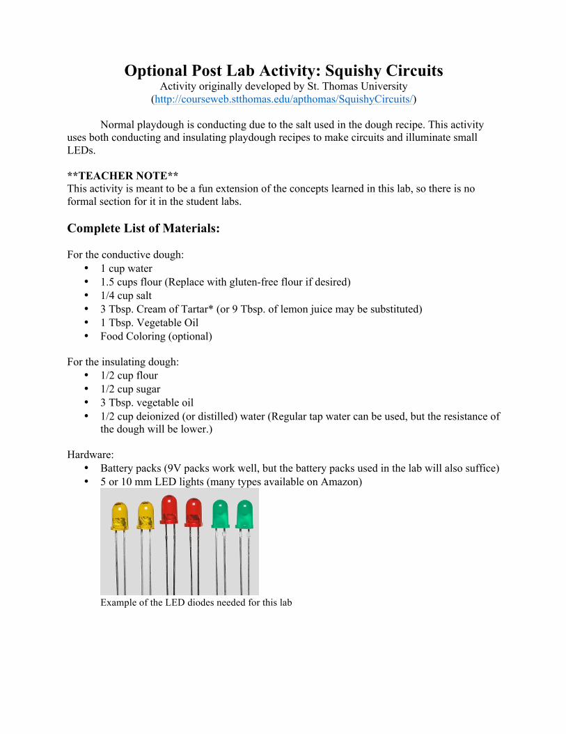
• Battery packs (9V packs work well, but the battery packs used in the lab will also suffice) • 5 or 10 mm LED lights (many types available on Amazon)
Example of the LED diodes needed for this lab
Pre-Lab Preparation: It is best to make the insulating and conductive doughs different colors, so the students can distinguish them, and they don’t get mixed up during the lab. Make the insulating dough:
1. Mix the solid ingredients in a pan, setting aside half a cup of flour for later use. 2. Add a small amount (1 tbsp.) of deionized water. 3. Repeat this step until the majority of the water is absorbed 4. Knead the mixture into one “lump” 5. Knead more water into the dough until it has a sticky texture 6. Knead in flour until desired consistency is achieved
**TEACHER NOTE** The conducting dough will feel more like bread dough than normal playdough. More flour can be kneaded in to make it less sticky. Make the conductive dough:
1. Mix water, 1 cup flour, cream of tartar, vegetable oil, salt, and food coloring in a medium-size pot squishy dough
2. Cook over medium heat, stirring continuously 3. The mixture will begin to boil and get chunky – keep stirring until it forms a ball in the
center of the pot 4. Place the ball on a lightly floured surface. (Caution: it’s hot!) 5. After the ball cools, slowly knead in the remaining flour until it reaches the desired
texture **TEACHER NOTE** If you have a favorite playdough recipe, you can use that in place of the conductive dough as long as it includes salt in the recipe. Store in an airtight container; done properly, the dough can last several weeks. Condensation is normal; just knead any excess moisture into the dough and it should be ready for use. Activity Mini-Lecture: The conducting dough is like the wires from the earlier parts of the lab, and the insulating dough is filler to keep the pieces of conducting dough from touching. Why can’t the pieces of conducting dough touch? Electrons like to take the path of least resistance; the same reason why you walk down the hallway instead of through the walls. The dough has less resistance than the LED diodes, so if the conducting dough is touching, the electrons will go through the dough rather than the LED. The insulating dough can’t carry electrons at all, so it is used to prevent them from going straight through the dough and force the electrons to travel through the LED lights.
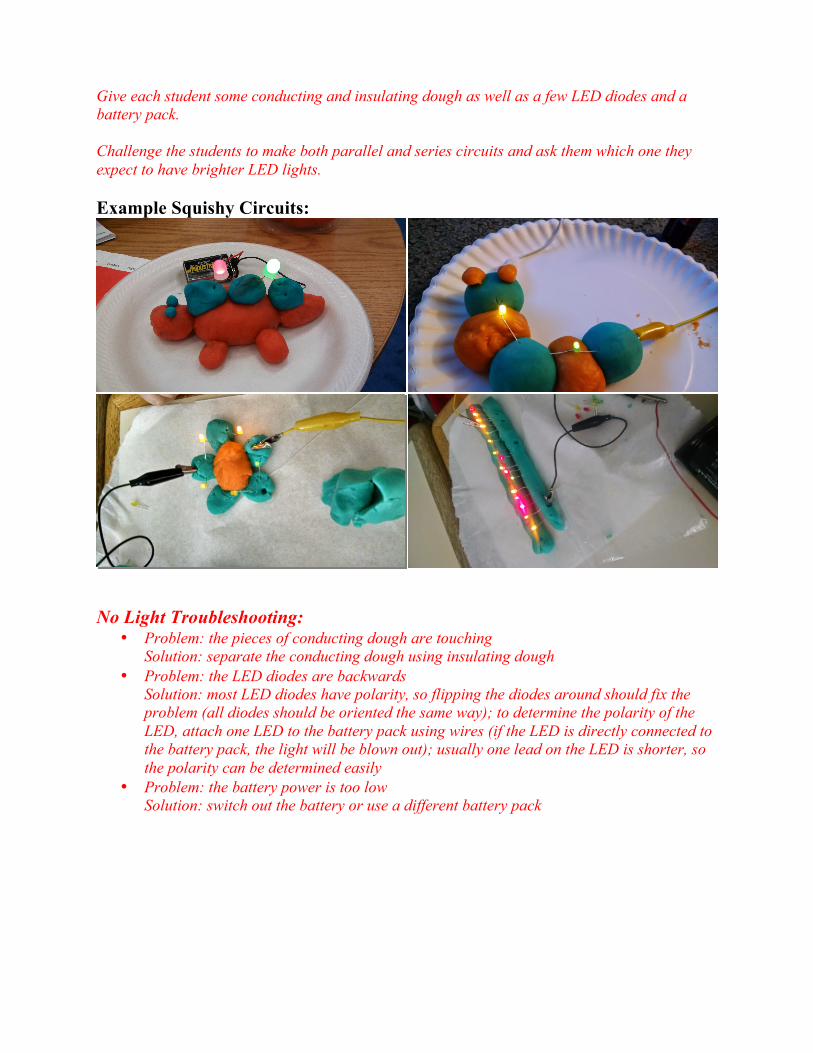
Give each student some conducting and insulating dough as well as a few LED diodes and a battery pack. Challenge the students to make both parallel and series circuits and ask them which one they expect to have brighter LED lights. Example Squishy Circuits:
No Light Troubleshooting:
• Problem: the pieces of conducting dough are touching Solution: separate the conducting dough using insulating dough
• Problem: the LED diodes are backwards Solution: most LED diodes have polarity, so flipping the diodes around should fix the problem (all diodes should be oriented the same way); to determine the polarity of the LED, attach one LED to the battery pack using wires (if the LED is directly connected to the battery pack, the light will be blown out); usually one lead on the LED is shorter, so the polarity can be determined easily
• Problem: the battery power is too low Solution: switch out the battery or use a different battery pack